UHABS-7 Team Ho ̅ ku ̅ waʻa i The Department of Mechanical Engineering at the University of Hawaii at Manoa presents UHABS-7 Critical Design Report CDR-F20-S2-P01 Team Ho ̅ ku ̅ waʻa Tarah Aniya [TA], Creselle Morales [CM], Zoey Akagi-Bustin [ZA], Peyton Young [PY], Gabriel Cartner [GC], Stephen Kaopuiki III [SK], Sung Min Jeong [SM] ME 481 Section 002 Fall 2020 Dr. Trevor Sorensen December 14, 2020

Welcome message from author
This document is posted to help you gain knowledge. Please leave a comment to let me know what you think about it! Share it to your friends and learn new things together.
Transcript
UHABS-7
Team Ho̅ku̅waʻa
i
The Department of Mechanical Engineering at the University of Hawaii at Manoa presents
UHABS-7 Critical Design Report CDR-F20-S2-P01
Team Ho̅ku̅waʻa
Tarah Aniya [TA], Creselle Morales [CM], Zoey Akagi-Bustin [ZA], Peyton Young [PY], Gabriel Cartner [GC], Stephen Kaopuiki III [SK], Sung Min Jeong [SM]
ME 481 Section 002 Fall 2020
Dr. Trevor Sorensen December 14, 2020
UHABS-7
Team Ho̅ku̅waʻa
ii
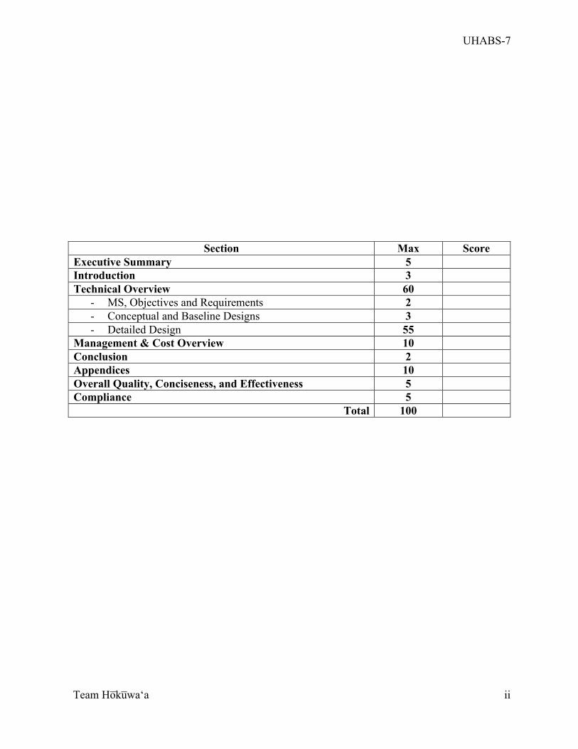
Section Max Score Executive Summary 5 Introduction 3 Technical Overview 60
- MS, Objectives and Requirements 2 - Conceptual and Baseline Designs 3 - Detailed Design 55
Management & Cost Overview 10 Conclusion 2 Appendices 10 Overall Quality, Conciseness, and Effectiveness 5 Compliance 5
Total 100
UHABS-7
Team Ho̅ku̅waʻa
iii
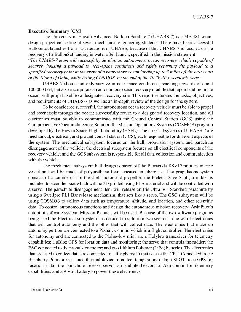
Executive Summary [CM] The University of Hawaii Advanced Balloon Satellite 7 (UHABS-7) is a ME 481 senior
design project consisting of seven mechanical engineering students. There have been successful Balloonsat launches from past iterations of UHABS; because of this UHABS-7 is focused on the recovery of a BallonSat landing in water after launch, specified in the mission statement: “The UHABS-7 team will successfully develop an autonomous ocean recovery vehicle capable of securely housing a payload to near-space conditions and safely returning the payload to a specified recovery point in the event of a near-shore ocean landing up to 5 miles off the east coast of the island of Oahu, while testing COSMOS, by the end of the 2020/2021 academic year.”
UHABS-7 should not only survive in near space conditions, reaching upwards of about 100,000 feet, but also incorporate an autonomous ocean recovery module that, upon landing in the ocean, will propel itself to a designated recovery site. This report reiterates the tasks, objectives, and requirements of UHABS-7 as well as an in-depth review of the design for the system.
To be considered successful, the autonomous ocean recovery vehicle must be able to propel and steer itself through the ocean; successfully return to a designated recovery location, and all electronics must be able to communicate with the Ground Control Station (GCS) using the Comprehensive Open-architecture Solution for Mission Operations Systems (COSMOS) program developed by the Hawaii Space Flight Laboratory (HSFL). The three subsystems of UHABS-7 are mechanical, electrical, and ground control station (GCS), each responsible for different aspects of the system. The mechanical subsystem focuses on the hull, propulsion system, and parachute disengagement of the vehicle; the electrical subsystem focuses on all electrical components of the recovery vehicle; and the GCS subsystem is responsible for all data collection and communication with the vehicle.
The mechanical subsystem hull design is based off the Barracuda XSV17 military marine vessel and will be made of polyurethane foam encased in fiberglass. The propulsions system consists of a commercial-of-the-shelf motor and propellor, the Fielect Drive Shaft; a rudder is included to steer the boat which will be 3D printed using PLA material and will be controlled with a servo. The parachute disengagement item will release an Iris Ultra 36” Standard parachute by using a Swellpro PL1 Bar release mechanism, that acts like a servo. The GSC subsystem will be using COSMOS to collect data such as temperature, altitude, and location, and other scientific data. To control autonomous functions and design the autonomous mission recovery, ArduPilot’s autopilot software system, Mission Planner, will be used. Because of the two software programs being used the Electrical subsystem has decided to split into two sections, one set of electronics that will control autonomy and the other that will collect data. The electronics that make up autonomy portion are connected to a Pixhawk 4 mini which is a flight controller. The electronics for autonomy and are connected to the Pixhawk 4 mini are a Holybro transceiver for telemetry capabilities; a uBlox GPS for location data and monitoring; the servo that controls the rudder; the ESC connected to the propulsion motor; and two Lithium Polymer (LiPo) batteries. The electronics that are used to collect data are connected to a Raspberry Pi that acts as the CPU. Connected to the Raspberry Pi are a resistance thermal device to collect temperature data; a SPOT trace GPS for location data; the parachute release servo; an audible beacon; a Aerocomm for telemetry capabilities; and a 9 Volt battery to power these electronics.
UHABS-7
Team Ho̅ku̅waʻa
iv
Due to FAA regulations, the recovery vehicle has a max weight limit of 6lbs. The current weight of the vehicle with every component included is 5.96 lbs. The total volume of the boat is 302.12 in3 and the total power required for the system is 306.69 W.
The UHABS-7 team’s budget is based on four major components. These include the mechanical subsystem, the electrical subsystem, the GCS subsystem, and testing costs. With a 20% margin the total budget is $3289.20. The current funding the team is applying for is $2,000 from the University of Hawaii at Manoa (UHM) Mechanical Engineering Department, creating a deficit of $1289.20. To account for this deficit, the team will ask for sponsorship from entities that can use atmospheric data or that are interested in student lead research projects. Some examples of these entities include the American Meteorology Society (AMS), Makai Oceans Engineering, Surf News Network, and the International Pacific Research Center. With the aid from such sponsors, the UHABS-7 team will be appropriately funded for the duration of this project. Currently, the team has completed their preliminary design. Moving forward, the mechanical subsystem will finalize the hull design, propulsion system, and parachute disengagement system; the electrical subsystem will finalize all electronics; and GCS will work on the launch and recovery mission.
UHABS-7
Team Ho̅ku̅waʻa
v
Table of Contents Executive Summary [CM] ............................................................................................................. iii Table of Contents ............................................................................................................................ v
List of Figures .............................................................................................................................. viii
List of Tables ................................................................................................................................. ix
Glossary ......................................................................................................................................... xi
1 Introduction [PY] ......................................................................................................................... 1
2 Technical Overview ..................................................................................................................... 4
2.1 Objectives and Requirements [TA] ...................................................................................... 4
2.1.1 Mission Statement [TA] ................................................................................................. 4
2.1.2 Objectives and Success Criteria [TA] ............................................................................ 4
2.2 Conceptual and Basic Designs [CM, PY] ............................................................................. 6
2.3 Detailed Design ..................................................................................................................... 8
2.3.1 Top-Level System [TA] ................................................................................................. 8
2.3.1.1 System Architecture [TA] ..................................................................................... 10
2.3.1.2 Operations Concept [TA] ...................................................................................... 11
2.3.1.3 Top-Level Functional Flow Block Diagram [TA] ................................................ 12
2.3.1.4 Overall Configuration [PY] .................................................................................. 13
2.3.1.5 Performance Analyses [SM, GC, ZA, SK] ........................................................... 20
2.3.1.6 FMECA [TA] ........................................................................................................ 21
2.3.1.7 Safety Engineering [PY] ....................................................................................... 22
2.3.1.8 Human Factors Engineering [CM] ........................................................................ 23
2.3.1.9 Fabrication Plan [PY] ........................................................................................... 23
2.3.1.10 Integration & Test Plan [TA] .............................................................................. 23
2.3.1.11 Accessibility, Availability, Maintainability [TA] ............................................... 28
2.3.1.12 Weight & Volume Budgets (total system) [PY] ................................................. 30
2.3.1.13 Power Budget and Power Profile (total system) [PY] ........................................ 33
2.3.2 Subsystems ................................................................................................................... 36
2.3.2.1 Mechanical [SM] .................................................................................................. 36
2.3.2.1.1 Subsystem Team Roles & Responsibilities [SM] .......................................... 36
2.3.2.1.2 Changes in subsystem design since PDR with rationale [SM] ...................... 36
2.3.2.1.3 Functional (Flow) Block Diagram with External Interfaces [SM] ................ 36
UHABS-7
Team Ho̅ku̅waʻa
vi
2.3.2.1.4 Subsystem Weight & Volume Budgets Values [SM] .................................... 38
2.3.2.1.5 Description [SM] ........................................................................................... 40
2.3.2.1.6 Results of Technical Analyses [SM] .............................................................. 41
2.3.2.1.7 Risk Analysis [SM] ........................................................................................ 42
2.3.2.1.8 Detailed Test Plan [SM] ................................................................................. 44
2.3.2.1.9 Subsystem WBS [CM] ................................................................................... 44
2.3.2.1.10 Subsystem Schedule using combined WBS and Gantt Chart [CM] ............ 45
2.3.2.1.11 Requirements vs. Implementation [SM] ...................................................... 46
2.3.2.1.12 Remaining Issues and Concerns [SM] ......................................................... 46
2.3.2.2 Electrical [GC] ...................................................................................................... 47
2.3.2.2.1 Subsystem Team Roles & Responsibilities [GC] .......................................... 47
2.3.2.2.2 Changes in subsystem design since PDR with rationale [GC] ...................... 47
2.3.2.2.3 Functional (Flow) Block Diagram with External Interfaces [GC] ................ 47
2.3.2.2.4 Subsystem Weight & Volume Budgets [GC] ................................................ 50
2.3.2.2.5 Subsystem Power Budget [GC] ..................................................................... 51
2.3.2.2.6 Description [GC] ............................................................................................ 51
2.3.2.2.7 Results of Technical Analyses [GC] .............................................................. 56
2.3.2.2.8 Risk Analysis [GC] ........................................................................................ 58
2.3.2.2.9 Detailed Test Plan [GC] ................................................................................. 61
2.3.2.2.10 Subsystem WBS [CM] ................................................................................. 62
2.3.2.2.11 Subsystem Schedule [CM] ........................................................................... 62
2.3.2.2.12 Requirements vs. Implementation [GC] ...................................................... 63
2.3.2.2.13 Remaining Issues and Concerns [GC] ......................................................... 63
2.3.2.3 Ground Control Station [ZA, SK] ......................................................................... 64
2.3.2.3.1 Subsystem Team Roles & Responsibilities [ZA, SK] ................................... 64
2.3.2.3.2 Changes in subsystem design since PDR with rationale [ZA] ...................... 64
2.3.2.3.3 Functional (Flow) Block Diagram with External Interfaces [ZA] ................. 65
2.3.2.3.4 Subsystem Power Budget [ZA, SK] .............................................................. 67
2.3.2.3.5 Description [SK] ............................................................................................ 67
2.3.2.3.6 Results of Technical Analyses [ZA] .............................................................. 68
2.3.2.3.7 Risk Analysis [ZA] ........................................................................................ 72
2.3.2.3.8 Detailed Test Plan [SK] ................................................................................. 74
UHABS-7
Team Ho̅ku̅waʻa
vii
2.3.2.3.9 Subsystem WBS [CM] ................................................................................... 75
2.3.2.3.10 Subsystem Schedule [CM] ........................................................................... 76
2.3.2.3.11 Requirements vs. Implementation [SK] ....................................................... 76
2.3.2.3.12 Remaining Issues and Concerns [ZA] ......................................................... 77
3 Management and Cost Overview ............................................................................................... 78
3.1 Team Organization [CM] .................................................................................................... 78
3.2 Project WBS [CM] .............................................................................................................. 79
3.3 System-Level Schedule [CM] ............................................................................................. 79
3.4 Hardware Acquisition Status/Plan [PY] ............................................................................. 81
3.5 Risks Management [TA] ..................................................................................................... 82
3.6 Configuration and Change Management [TA] ................................................................... 83
3.7 Financial Budget [PY] ........................................................................................................ 85
3.8 Documentation List [TA] .................................................................................................... 87
3.9 Requirements vs Implementation [TA] .............................................................................. 88
3.10 Remaining Issues and Concerns [PY] ............................................................................... 89
4 Conclusion [ZA, CM] ................................................................................................................ 90
References ..................................................................................................................................... 91
Appendix ..................................................................................................................................... A-1
UHABS-7
Team Ho̅ku̅waʻa
viii
List of Figures Figure 1: External configuration of the recovery vehicle. .............................................................. 8 Figure 2: Internal configuration of the recovery vehicle. ............................................................... 9 Figure 3: Internal configuration of the Pelican Box of the Payload Module. ................................. 9 Figure 4: UHABS-7 System Architecture. ................................................................................... 10 Figure 5: UHABS-7 Operations Concept diagram. ...................................................................... 11 Figure 6: UHABS-7 Top-Level Functional Flow Block Diagram. .............................................. 12 Figure 7: The model of the recovery vehicle with important features labeled. ............................ 13 Figure 8: Isometric View of Recovery Vehicle. ........................................................................... 14 Figure 9: Side View of Recovery Vehicle. ................................................................................... 15 Figure 10: Front View of Recovery Vehicle. ................................................................................ 15 Figure 11: Top View of the Hull ................................................................................................... 16 Figure 12: Back View of the Hull. ................................................................................................ 17 Figure 13: Model of the Pelican case with components labeled. .................................................. 18 Figure 14: Exploded view of the recovery vehicle. ...................................................................... 19 Figure 15: The rudder system with important features labeled. ................................................... 20 Figure 16: Recovery system fault tree for system-level analysis. ................................................ 22 Figure 17: UHABS-7 System-Level assembly diagram. .............................................................. 25 Figure 18: Power profile of the UHABS-7 team. ......................................................................... 34 Figure 19: Overview of mechanical system. ................................................................................. 37 Figure 20: Functional flow block diagram of mechanical system. ............................................... 37 Figure 21: SolidWorks model of the hull. .................................................................................... 38 Figure 22: Mechanical layout of the recovery system. ................................................................. 40 Figure 23: Mechanical physics calculations. ................................................................................ 41 Figure 24: Mechanical Subsystem Work Breakdown Structure. .................................................. 45 Figure 25: Mechanical system Gantt Chart. ................................................................................. 45 Figure 26: Subsystem Functional Flow Block Diagram. .............................................................. 48 Figure 27: Overall FFBD with highlighted components of electrical subsystem. ........................ 49 Figure 28: Raspberry group wiring. .............................................................................................. 53 Figure 29: Pixhawk group wiring. ................................................................................................ 53 Figure 30: Labeled Image of pelican box layout and components. .............................................. 54 Figure 31: Exploded image of pelican box. .................................................................................. 55 Figure 32: Components attached to the hull. ................................................................................ 56 Figure 33: Power analysis of the electrical subsystem. ................................................................ 57 Figure 34: FMECA analysis for all electrical components. .......................................................... 59 Figure 35: Electrical Subsystem Work Breakdown Structure. ..................................................... 62 Figure 36: Electrical Subsystem Gantt Chart. ............................................................................... 62 Figure 37: GCS system architecture. ............................................................................................ 65 Figure 38: FFBD of the GCS along with other subsystems. ........................................................ 66 Figure 39: FFBD of GCS with component integration. ................................................................ 66 Figure 40: Ardupilot waypoint parameters for autonomous recovery. ......................................... 69 Figure 41: Operations logic flow chart of the GCS. ..................................................................... 71 Figure 42: Software flowchart for the GCS. ................................................................................. 72
UHABS-7
Team Ho̅ku̅waʻa
ix
Figure 43: Ground Control Station Work Breakdown Structure. ................................................. 76 Figure 44: Ground Control Station Gantt Chart. .......................................................................... 76 Figure 45: Team Organization Chart. ........................................................................................... 78 Figure 46: Work Breakdown Structure of entire UHABS-7 team. ............................................... 79 Figure 47: UHABS-7 Gantt Chart. ............................................................................................... 80 Figure 48: UHABS-7 System Level Gantt Chart. ........................................................................ 81 Figure 49: UHABS-7 Total Risk Cube graphically representing all technical, cost, and schedule risks. .............................................................................................................................................. 83 Figure 50: A pie chart depicting the percentage of the budget each component is responsible for........................................................................................................................................................ 86
List of Tables Table 1: UHABS-7 Objectives and Success Criteria. ..................................................................... 5 Table 2: UHABS-7 Critical Items List (CIL). .............................................................................. 21 Table 3: Operational System FMECA example for failure of the propulsion system on impact. 21 Table 4: Reliability, accessibility, maintainability, and availability of the UHABS-7 subsystems and overall system. ........................................................................................................................ 28 Table 5: Volume budget of the vehicle. ........................................................................................ 31 Table 6: Mass budget of the UHABS-7 system ............................................................................ 32 Table 7: The power budget for the UHABS-7 team. .................................................................... 33 Table 8: Values for the power profile. .......................................................................................... 34 Table 9: Overall mass of mechanical subsystem. ......................................................................... 39 Table 10: The volume budget for the mechanical subsystem. ...................................................... 40 Table 11: Risk Identification for Mechanical System .................................................................. 42 Table 12: Proactive and Reactive Risk Mitigation. ..................................................................... 42 Table 13: FMECA of the mechanical subsystem. ........................................................................ 43 Table 14: Requirements vs Implementation of recovery system. ................................................. 46 Table 15: Weight and Volume table of all electrical components. ............................................... 50 Table 16: Power budget of the electrical subsystem. .................................................................... 51 Table 17: Components of Raspberry group. ................................................................................. 52 Table 18: Components of Pixhawk group. ................................................................................... 52 Table 19: Unassociated components. ............................................................................................ 53 Table 20: Electrical Requirements vs. Implementations .............................................................. 63 Table 21: Power budget for the UHABS-7 Ground Station Subsystem. ...................................... 67 Table 22: Components by manufacturer and model for Ground Station Subsystem. .................. 68 Table 23: COSMOS agents to ensure communication between the GCS and the RV. ................ 69 Table 24: Risk identification chart of the GCS. ............................................................................ 73 Table 25: Risk mitigation chart for the GCS. ............................................................................... 73 Table 26: FMECA of the GCS for low and medium criticality. ................................................... 74 Table 27: FMECA of the GCS for high criticality. ...................................................................... 74 Table 28: Testing plan and success criteria for each other components a part of Ground Station........................................................................................................................................................ 75
UHABS-7
Team Ho̅ku̅waʻa
x
Table 29: Requirements and Implementations for the Ground Station, all currently in progress for completion. .................................................................................................................................... 77 Table 30: Excerpt from the UHABS-7 Change Log. .................................................................... 85 Table 31: Generalized budget for a single system. ....................................................................... 85 Table 32: Generalized budget for the entire system. .................................................................... 85 Table 33: Current funding for the UHABS-7 team. ..................................................................... 87 Table 34: Sponsors contacted by the UHABS-7 team. ................................................................. 87 Table 35: UHABS-7 Documentation List. .................................................................................... 88 Table 36: System-level requirements vs. implementations with their current status at CDR. ..... 88 Table 37: UHABS-7 System Specification Document. .............................................................. A-1 Table 38: Electrical subsystem itemized budget. ........................................................................ B-1 Table 39: Mechanical subsystem itemized budget. .................................................................... B-1 Table 40: GCS subsystem itemized budget. ............................................................................... B-1 Table 41: Testing costs itemized budget. .................................................................................... B-2 Table 42: Operational system level FMECA. ................................................................................. 1 Table 43: Mechanical subsystem technical Risk Watch List. ......................................................... 1 Table 44: Electrical subsystem technical Risk Watch List. ............................................................ 2 Table 45: GCS technical Risk Watch List. ..................................................................................... 2 Table 46: Cost Risk Watch List. ..................................................................................................... 2 Table 47: Schedule Risk Watch List. .............................................................................................. 2 Table 48: UHABS-7 Change Log. .................................................................................................. 3
UHABS-7
Team Ho̅ku̅waʻa
xi
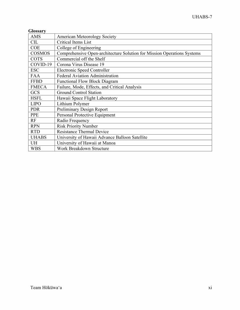
Glossary AMS American Meteorology Society CIL Critical Items List COE College of Engineering COSMOS Comprehensive Open-architecture Solution for Mission Operations Systems COTS Commercial off the Shelf COVID-19 Corona Virus Disease 19 ESC Electronic Speed Controller FAA Federal Aviation Administration FFBD Functional Flow Block Diagram FMECA Failure, Mode, Effects, and Critical Analysis GCS Ground Control Station HSFL Hawaii Space Flight Laboratory LIPO Lithium Polymer PDR Preliminary Design Report PPE Personal Protective Equipment RF Radio Frequency RPN Risk Priority Number RTD Resistance Thermal Device UHABS University of Hawaii Advance Balloon Satellite UH University of Hawaii at Manoa WBS Work Breakdown Structure
UHABS-7
Team Ho̅ku̅waʻa
1
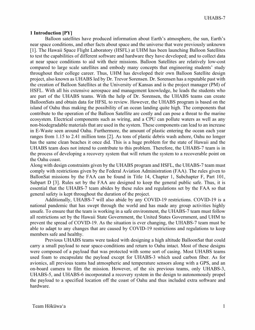
1 Introduction [PY] Balloon satellites have produced information about Earth’s atmosphere, the sun, Earth’s
near space conditions, and other facts about space and the universe that were previously unknown [1]. The Hawaii Space Flight Laboratory (HSFL) at UHM has been launching Balloon Satellites to test the capabilities of different software and hardware they have developed; and to collect data at near space conditions to aid with their missions. Balloon Satellites are relatively low-cost compared to large scale satellites and embody many concepts that engineering students’ study throughout their college career. Thus, UHM has developed their own Balloon Satellite design project, also known as UHABS led by Dr. Trevor Sorensen. Dr. Sorensen has a reputable past with the creation of Balloon Satellites at the University of Kansas and is the project manager (PM) of HSFL. With all his extensive aerospace and management knowledge, he leads the students who are part of the UHABS teams. With the help of Dr. Sorensen, the UHABS teams can create BalloonSats and obtain data for HFSL to review. However, the UHABS program is based on the island of Oahu thus making the possibility of an ocean landing quite high. The components that contribute to the operation of the Balloon Satellite are costly and can pose a threat to the marine ecosystem. Electrical components such as wiring, and a CPU can pollute waters as well as any non-biodegradable materials that are used in the system. These components can lead to an increase in E-Waste seen around Oahu. Furthermore, the amount of plastic entering the ocean each year ranges from 1.15 to 2.41 million tons [2]. As tons of plastic debris wash ashore, Oahu no longer has the same clean beaches it once did. This is a huge problem for the state of Hawaii and the UHABS team does not intend to contribute to this problem. Therefore, the UHABS-7 team is in the process of developing a recovery system that will return the system to a recoverable point on the Oahu coast. Along with design constraints given by the UHABS program and HSFL, the UHABS-7 team must comply with restrictions given by the Federal Aviation Administration (FAA). The rules given to BallonSat missions by the FAA can be found in Title 14, Chapter 1, Subchapter F, Part 101, Subpart D [3]. Rules set by the FAA are designed to keep the general public safe. Thus, it is essential that the UHABS-7 team abides by these rules and regulations set by the FAA so that general safety is kept throughout the duration of the project.
Additionally, UHABS-7 will also abide by any COVID-19 restrictions. COVID-19 is a national pandemic that has swept through the world and has made any group activities highly unsafe. To ensure that the team is working in a safe environment, the UHABS-7 team must follow all restrictions set by the Hawaii State Government, the United States Government, and UHM to prevent the spread of COVID-19. As the situation is ever changing, the UHABS-7 team must be able to adapt to any changes that are caused by COVID-19 restrictions and regulations to keep members safe and healthy. Previous UHABS teams were tasked with designing a high altitude BalloonSat that could carry a small payload to near space-conditions and return to Oahu intact. Most of these designs were composed of a payload that was protected with some sort of casing. Most UHABS teams used foam to encapsulate the payload except for UHABS-3 which used carbon fiber. As for avionics, all previous teams had atmospheric and temperature sensors along with a GPS, and an on-board camera to film the mission. However, of the six previous teams, only UHABS-3, UHABS-5, and UHABS-6 incorporated a recovery system in the design to autonomously propel the payload to a specified location off the coast of Oahu and thus included extra software and hardware.
UHABS-7
Team Ho̅ku̅waʻa
2
For the general structure of the UHABS team, the team would design a payload capable of surviving near space conditions and aquatic and terrestrial landings. The teams would then send the payload to near space conditions or a set altitude using a helium filled weather balloon. The payload would then disengage from the weather balloon or the balloon would rupture. Next, the payload would descend via a parachute at a specific speed and would send location data to the team as it fell to allow for retrieval of the payload. For all previous teams, the system would also have to collect atmospheric data and use COSMOS to connect with the GCS. For UHABS-3, UHABS-5, and UHABS-6 the payload had an autonomous recovery system that would propel the payload to a specified location just off the coast of Oahu. According to final reports, only UHABS-1, UHABS-4, and UHABS-6 successfully launched [4][5][6].
As mentioned previously, UHABS-3, UHABS-5, and UHABS-6 incorporated an autonomous recovery for the payload and thus will be referenced for the duration of UHABS-7. UHABS-3 encased the payload with carbon fiber and used paddle wheels to propel the vehicle along the water. The UHABS-5 team attempted to manufacture a Styrofoam casing shaped as a catamaran boat and used thrusters to travel through the ocean. The UHABS-6 team incorporated the catamaran design from the UHABS-5 team but used a combination of a rudder system and an oscillation fin that used the rolling of the waves to propel the vehicle. However, these teams were unfortunately all incapable of successfully recovering the vehicle. The UHABS-3 team’s design proved to be poorly manufactured as it proved to not be watertight and the encasing of the paddle wheel would not reopen which negated all ability to repair it. UHABS-5 was unable to perform the mission in the allotted time as the team could not replace a faulty motor which caused the vehicle to shake excessively and not function. The UHABS-6 team’s design proved to also be faulty and due to time constraints had to be cast aside for a commercially bought model. However, after a successful launch, the commercially bought model was never retrieved [6] [7] [8].
There are many other universities that have developed BalloonSats like the ones that the UHABS teams have created. What sets the UHABS teams apart from other universities is the need for a reliable recovery system since Oahu is an island and ocean landings are most likely to occur. UHABS-7 will take on the mission of creating an autonomous ocean recovery vehicle to aide future UHABS team in completing their own Balloon Satellite mission. The UHABS-7 team will design and create a recovery vehicle that will autonomously propel itself to a set location for retrieval by one of the team members. Along with the integration of COSMOS as a means for mission control, the UHABS-7 team will create a system that will maintain continuous communication with the recovery vehicle through the entirety of the mission to send commands and collect data. There will be a ground control station team that will monitor the status of the mission to aid in the recovery of the vehicle, data collection, and command communication. COSMOS has proven to be a complex system to use as noted by previous UHABS teams. With that information, the GCS team is using the knowledge from members of the HSFL and previous UHABS teams to help understand this complex software.
Unlike its predecessors UHABS-7 will not be launching a Balloon Satellite to near-space conditions but will implement tests that will mimic atmospheric environments that other Balloon Satellites have encountered. This gives the UHABS-7 team an opportunity to focus on the autonomous recovery portion of the UHABS mission. To manufacture the recovery vehicle, the UHABS-7 team had many design decisions to consider. One main design consideration that the team had to focus on was the type of material the hull of the vehicle should be made from. There are multiple materials that would work with the UHABS-7 design. However, finding a material that was cost efficient and would fit into the team’s design was difficult. Also, the team had to
UHABS-7
Team Ho̅ku̅waʻa
3
select all the components being used to power the vehicle and control it. While selecting components, some design considerations included the weight, cost, as well as the compatibility of each component. Component compatibility is extremely important as components must function together if the system is to be successful. The UHABS-7 team also had to consider how to manufacture the vehicle. There are multiple manufacturing processes and finding the correct manufacturing process that would be suitable for the proposed design is vital to ensure that the vehicle is manufactured exactly as the team meant it to be. The team also had to select testing locations as well as testing materials. The team took into consideration the safety of each testing sight, what was to be tested at each testing sight, and possible testing costs.
The following report includes all analysis conducted throughout the duration of the UHABS-7 project up to the end of the Fall 2020 semester. This entails analysis pertaining to design choices, calculations to solidify design choices, research about components, and models and mockups to better describe and illustrate the UHABS-7 system. Each subsystem of the UHABS-7 team has made important design decisions that have altered the project and they are presented in the following report. The report also includes team management which describes the budget of the UHABS-7 system, possible risks, changes from previous reports and presentations, issues and concerns, the system architecture, and scheduling for the UHABS-7 team. This report highlights important details of the design, important calculations, subsystem components and work, as well as important decisions that occurred on the management side of the project.
UHABS-7
Team Ho̅ku̅waʻa
4
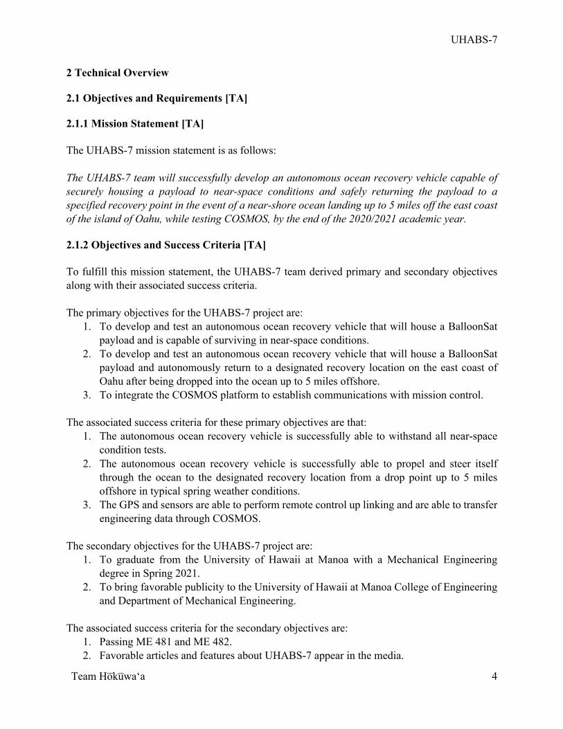
2 Technical Overview 2.1 Objectives and Requirements [TA] 2.1.1 Mission Statement [TA] The UHABS-7 mission statement is as follows: The UHABS-7 team will successfully develop an autonomous ocean recovery vehicle capable of securely housing a payload to near-space conditions and safely returning the payload to a specified recovery point in the event of a near-shore ocean landing up to 5 miles off the east coast of the island of Oahu, while testing COSMOS, by the end of the 2020/2021 academic year. 2.1.2 Objectives and Success Criteria [TA] To fulfill this mission statement, the UHABS-7 team derived primary and secondary objectives along with their associated success criteria. The primary objectives for the UHABS-7 project are:
1. To develop and test an autonomous ocean recovery vehicle that will house a BalloonSat payload and is capable of surviving in near-space conditions.
2. To develop and test an autonomous ocean recovery vehicle that will house a BalloonSat payload and autonomously return to a designated recovery location on the east coast of Oahu after being dropped into the ocean up to 5 miles offshore.
3. To integrate the COSMOS platform to establish communications with mission control. The associated success criteria for these primary objectives are that:
1. The autonomous ocean recovery vehicle is successfully able to withstand all near-space condition tests.
2. The autonomous ocean recovery vehicle is successfully able to propel and steer itself through the ocean to the designated recovery location from a drop point up to 5 miles offshore in typical spring weather conditions.
3. The GPS and sensors are able to perform remote control up linking and are able to transfer engineering data through COSMOS.
The secondary objectives for the UHABS-7 project are:
1. To graduate from the University of Hawaii at Manoa with a Mechanical Engineering degree in Spring 2021.
2. To bring favorable publicity to the University of Hawaii at Manoa College of Engineering and Department of Mechanical Engineering.
The associated success criteria for the secondary objectives are:
1. Passing ME 481 and ME 482. 2. Favorable articles and features about UHABS-7 appear in the media.
UHABS-7
Team Ho̅ku̅waʻa
5
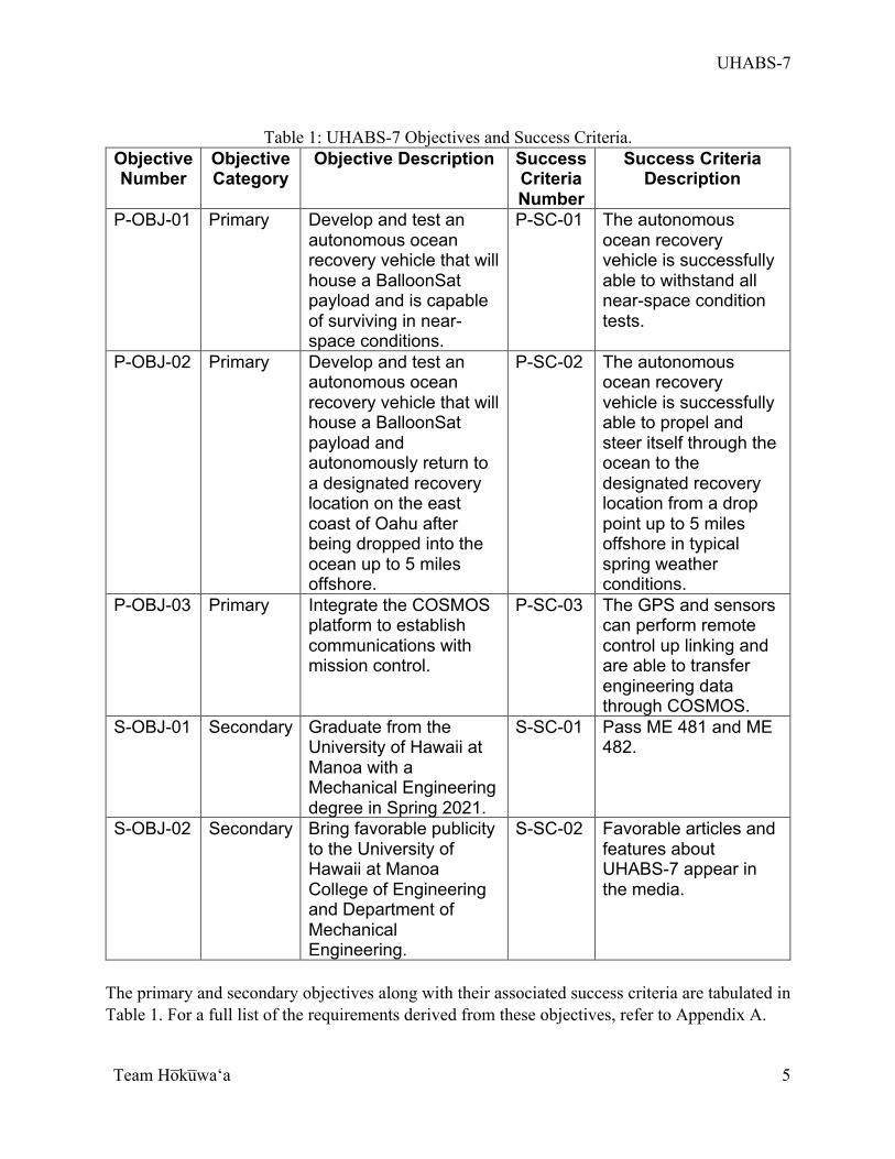
Table 1: UHABS-7 Objectives and Success Criteria.
Objective Number
Objective Category
Objective Description Success Criteria Number
Success Criteria Description
P-OBJ-01 Primary Develop and test an autonomous ocean recovery vehicle that will house a BalloonSat payload and is capable of surviving in near-space conditions.
P-SC-01 The autonomous ocean recovery vehicle is successfully able to withstand all near-space condition tests.
P-OBJ-02 Primary Develop and test an autonomous ocean recovery vehicle that will house a BalloonSat payload and autonomously return to a designated recovery location on the east coast of Oahu after being dropped into the ocean up to 5 miles offshore.
P-SC-02 The autonomous ocean recovery vehicle is successfully able to propel and steer itself through the ocean to the designated recovery location from a drop point up to 5 miles offshore in typical spring weather conditions.
P-OBJ-03 Primary Integrate the COSMOS platform to establish communications with mission control.
P-SC-03 The GPS and sensors can perform remote control up linking and are able to transfer engineering data through COSMOS.
S-OBJ-01 Secondary Graduate from the University of Hawaii at Manoa with a Mechanical Engineering degree in Spring 2021.
S-SC-01 Pass ME 481 and ME 482.
S-OBJ-02 Secondary Bring favorable publicity to the University of Hawaii at Manoa College of Engineering and Department of Mechanical Engineering.
S-SC-02 Favorable articles and features about UHABS-7 appear in the media.
The primary and secondary objectives along with their associated success criteria are tabulated in Table 1. For a full list of the requirements derived from these objectives, refer to Appendix A.
UHABS-7
Team Ho̅ku̅waʻa
6
2.2 Conceptual and Basic Designs [CM, PY] The conceptual design proposed during the project proposal stated that the recovery vehicle
would be a boat with a parachute attached. Since the preliminary design review, the hull of the boat and propulsion system have been changed. The hull design is based off the XSV-17 marine vessel used in military applications. It was chosen due to its low center of gravity and wave piercing design, which eliminates the potential of the boat remaining capsized. The shape will be similar in design but will be scaled to the size that the team needs. The hull will be manufactured and assembled by the team with polyurethane foam encased in fiberglass. The propulsion system will include a commercial-off-the shelf (COTS) motor. A COTS thruster was chosen instead of designing one from scratch because other areas of the project, namely communication via COSMOS, need more team resources and focus. The COTS motor will be fitted with a COTS motor shaft and propeller, the Fielect Drive Shaft. To steer the boat a 3D printed rudder is included that will be made of PLA material; it will be controlled with a servo. The release mechanism of the vehicle is the Swellpro Waterproof Drone Bait Release for Splash Drones PL1, which is a COTS servo mechanism. This servo has a weight capacity of 8.75 to 10.5 pounds which is more than enough to hold the system as the maximum weight of the system should be no more than 6 pounds.
The electrical subsystem will be maintained within the recovery device. It is a combination of components that provide power, enable the team to control the boat or other components, and record data collected by sensors on board the vehicle. The electrical subsystem is split into two parts, one part that controls autonomy and another that will collect data. The data collection portion of the electrical subsystem will be controlled by a Raspberry Pi which will be powered by a 9 Volt battery. The data the sensors will be required to collect include the temperature and position of the device. To monitor temperature, a resistance thermal device (RTD) was chosen due to its wide range of temperatures that can be measured. There will be two GPS’ on board the recovery vehicle. The GPS that is part of the data collection part of the electrical subsystem is the SPOT Trace GPS. This GPS is included in the event of loss of connection with the other GPS on board the vehicle. This will allow the team to recover the vehicle in the event of this GPS failing. The parachute release mechanism mentioned previously is a part of the data collection portion as well as the audible beacon. The audible beacon is an amplified speaker designed for the Raspberry Pi. To enable telemetry, an Aerocomm was added to the system. This is a RF transceiver that was used in previous UHABS projects and is a part of the data collection portion. For the autonomy portion, a Pixhawk 4 mini will be used as a flight controller. A HolyBro transceiver set is connected to the Pixhawk 4 mini to allow for telemetry communication with the GSC. Also connected to the Pixhawk 4 mini is a GPS, the rudder’s steering servo, an ESC connected to the propulsion system motor, and the batteries. The two batteries that power this section are Lithium polymer (LiPo) batteries.
For the ground control station subsystem, there will be two laptops running two different software programs. One will run COSMOS which will command and receive all data collection functions. COSMOS will be composed of two nodes; one is GCS that will send commands and receive data from the recovery boat; the other node is the recovery vehicle’s payload which will receive commands from the GCS and send collected data to the GCS. COSMOS implements QT creator to create agents that will build data collection functions. The agents that are being built for the data collection side are to operate the following functions: radio, control, raspberry pi, temperature, disengagement, beacon, and images. COSMOS will be connected to the data
UHABS-7
Team Ho̅ku̅waʻa
7
collection electronics in the electrical subsystem via the Aerocommn. The other laptop will be running ArduPilot’s mission planner. Mission planner will be used to control all autonomous functions in the recovery vehicle as well as design the autonomous recovery mission. Mission planer will be connected to the recovery boat via the HolyBro transceiver. The HolyBro transceiver is connected to the Pixhawk 4 mini that will process that commands received from Mission Planner and control the electronics responsible for autonomy.
UHABS-7
Team Ho̅ku̅waʻa
8
2.3 Detailed Design 2.3.1 Top-Level System [TA]
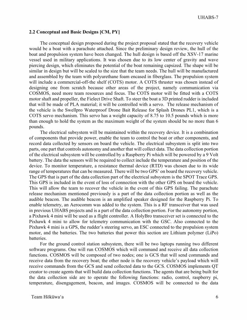
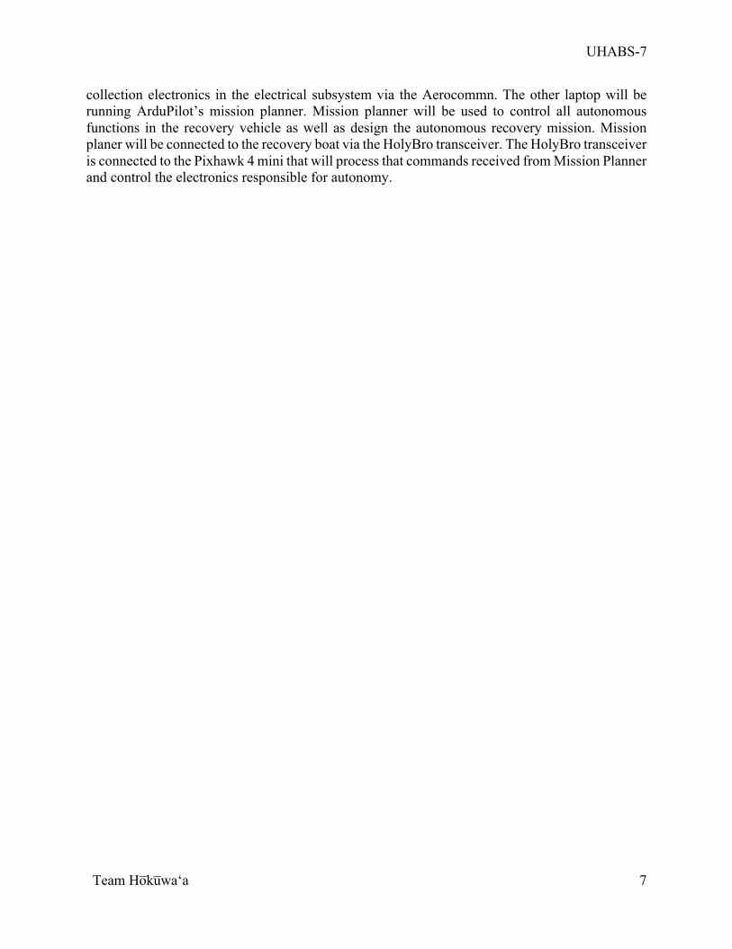
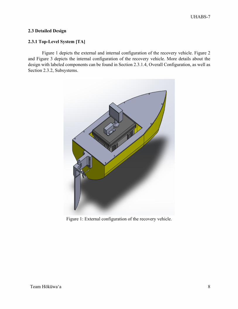
Figure 1 depicts the external and internal configuration of the recovery vehicle. Figure 2 and Figure 3 depicts the internal configuration of the recovery vehicle. More details about the design with labeled components can be found in Section 2.3.1.4, Overall Configuration, as well as Section 2.3.2, Subsystems.
Figure 1: External configuration of the recovery vehicle.
UHABS-7
Team Ho̅ku̅waʻa
9
Figure 2: Internal configuration of the recovery vehicle.
Figure 3: Internal configuration of the Pelican Box of the Payload Module.
UHABS-7
Team Ho̅ku̅waʻa
10
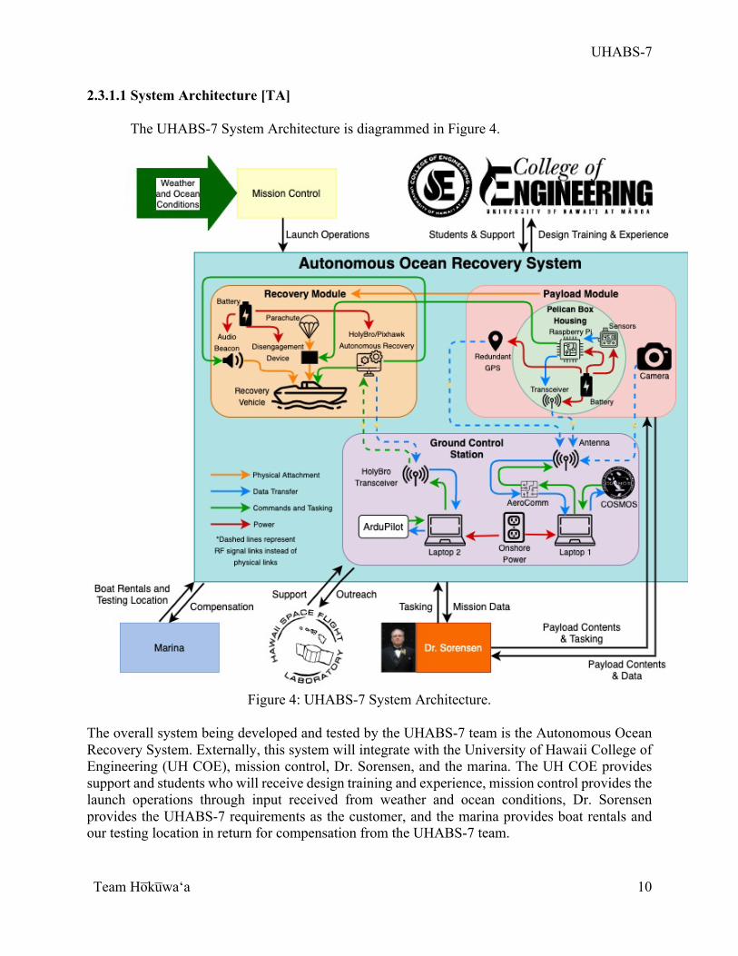
2.3.1.1 System Architecture [TA] The UHABS-7 System Architecture is diagrammed in Figure 4.
Figure 4: UHABS-7 System Architecture.
The overall system being developed and tested by the UHABS-7 team is the Autonomous Ocean Recovery System. Externally, this system will integrate with the University of Hawaii College of Engineering (UH COE), mission control, Dr. Sorensen, and the marina. The UH COE provides support and students who will receive design training and experience, mission control provides the launch operations through input received from weather and ocean conditions, Dr. Sorensen provides the UHABS-7 requirements as the customer, and the marina provides boat rentals and our testing location in return for compensation from the UHABS-7 team.
UHABS-7
Team Ho̅ku̅waʻa
11
Internally, the Autonomous Ocean Recovery System is composed of three subsystems: Recovery Module, Payload Module, and Ground Control Station (GCS). The Recovery Module is composed of the recovery vehicle which integrates with the audio beacon, parachute disengagement device and parachute, and the autonomous recovery module, as well as the onboard electrical power. The Payload Module is composed of the Pelican Box Housing, which was chosen to house the sensitive onboard electronic components, the camera, and the redundant GPS. The Ground Control Station is composed of two laptops, one of which will run the ArduPilot software and connect to the recovery vehicle through a HolyBro transceiver, and the second of which will run COSMOS and connect to the recovery vehicle through Aerocomm. 2.3.1.2 Operations Concept [TA]
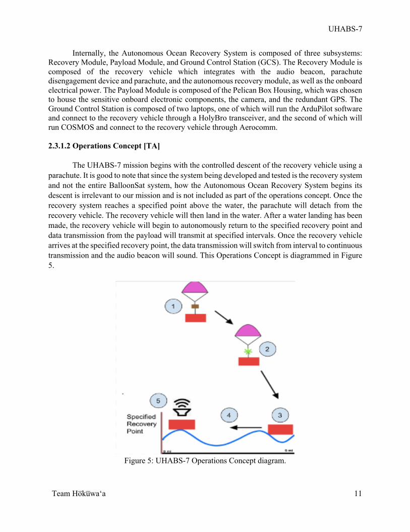
The UHABS-7 mission begins with the controlled descent of the recovery vehicle using a
parachute. It is good to note that since the system being developed and tested is the recovery system and not the entire BalloonSat system, how the Autonomous Ocean Recovery System begins its descent is irrelevant to our mission and is not included as part of the operations concept. Once the recovery system reaches a specified point above the water, the parachute will detach from the recovery vehicle. The recovery vehicle will then land in the water. After a water landing has been made, the recovery vehicle will begin to autonomously return to the specified recovery point and data transmission from the payload will transmit at specified intervals. Once the recovery vehicle arrives at the specified recovery point, the data transmission will switch from interval to continuous transmission and the audio beacon will sound. This Operations Concept is diagrammed in Figure 5.
Figure 5: UHABS-7 Operations Concept diagram.
UHABS-7
Team Ho̅ku̅waʻa
12
The full system operation will be verified in two separate tests: (1) a descent and detachment test of the parachute with the boat headed in the correct direction at the UH diving pool and (2) a test of the autonomous return of the recovery vehicle after being placed in the ocean up to 5 miles offshore.
2.3.1.3 Top-Level Functional Flow Block Diagram [TA]
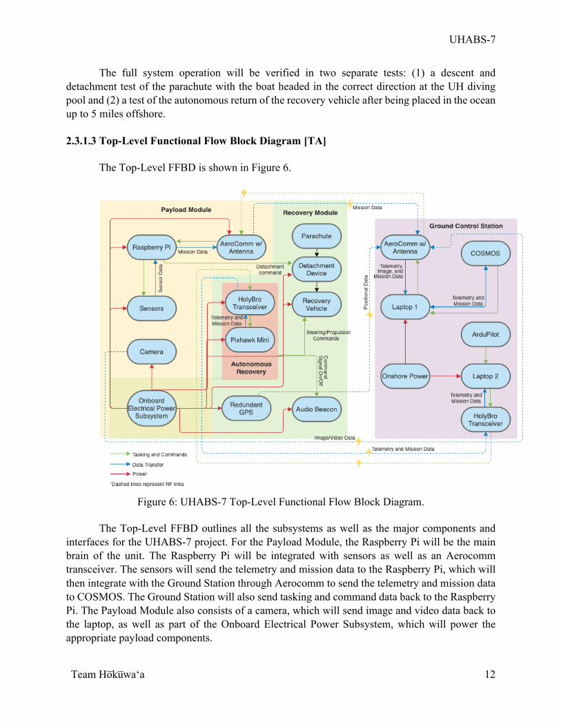
The Top-Level FFBD is shown in Figure 6.
Figure 6: UHABS-7 Top-Level Functional Flow Block Diagram.
The Top-Level FFBD outlines all the subsystems as well as the major components and
interfaces for the UHABS-7 project. For the Payload Module, the Raspberry Pi will be the main brain of the unit. The Raspberry Pi will be integrated with sensors as well as an Aerocomm transceiver. The sensors will send the telemetry and mission data to the Raspberry Pi, which will then integrate with the Ground Station through Aerocomm to send the telemetry and mission data to COSMOS. The Ground Station will also send tasking and command data back to the Raspberry Pi. The Payload Module also consists of a camera, which will send image and video data back to the laptop, as well as part of the Onboard Electrical Power Subsystem, which will power the appropriate payload components.
UHABS-7
Team Ho̅ku̅waʻa
13
For the Recovery Module, the Autonomous Recovery module will integrate with the recovery vehicle and audio beacon. The Autonomous Recovery module is composed of a HolyBro transceiver and a Pixhawk Mini, which will send commands to control the steering and propulsion units of the recovery vehicle for navigation back to the designated recovery point. The Autonomous Recovery module will also send a command to the audio beacon to turn on at the appropriate time, as well as interface with the Ground Control Station to receive manual tasking if needed. The Recovery Module also includes the parachute, which will be attached to the recovery vehicle through a detachment device, a redundant GPS, and part of the Onboard Electrical Power Subsystem, which will provide power to the appropriate components of the Recovery Module.
In the Ground Control Station (GCS), two laptops will be powered by onshore power. The first laptop will run COSMOS and connect to the Payload Module to receive sensor and mission data through the Aerocomm transceivers. The second laptop will run ArduPilot and connect to the Recovery Module through the HolyBro transceivers. The main goal of the GCS is to receive telemetry and mission data from the recovery vehicle. However, if necessary, the GCS will have the ability to manually send commands to the recovery vehicle. 2.3.1.4 Overall Configuration [PY]
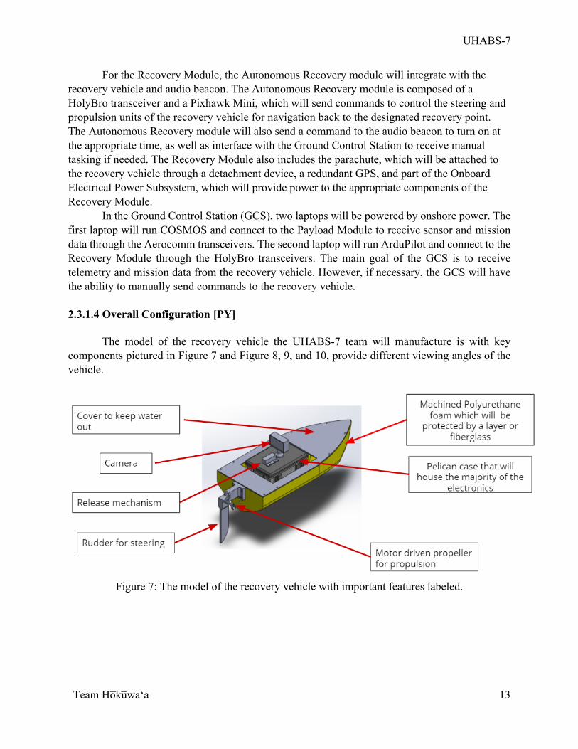
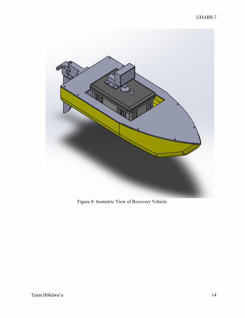
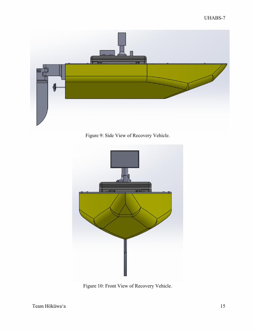
The model of the recovery vehicle the UHABS-7 team will manufacture is with key
components pictured in Figure 7 and Figure 8, 9, and 10, provide different viewing angles of the vehicle.
Figure 7: The model of the recovery vehicle with important features labeled.
UHABS-7
Team Ho̅ku̅waʻa
14
Figure 8: Isometric View of Recovery Vehicle.
UHABS-7
Team Ho̅ku̅waʻa
15
Figure 9: Side View of Recovery Vehicle.
Figure 10: Front View of Recovery Vehicle.
UHABS-7
Team Ho̅ku̅waʻa
16
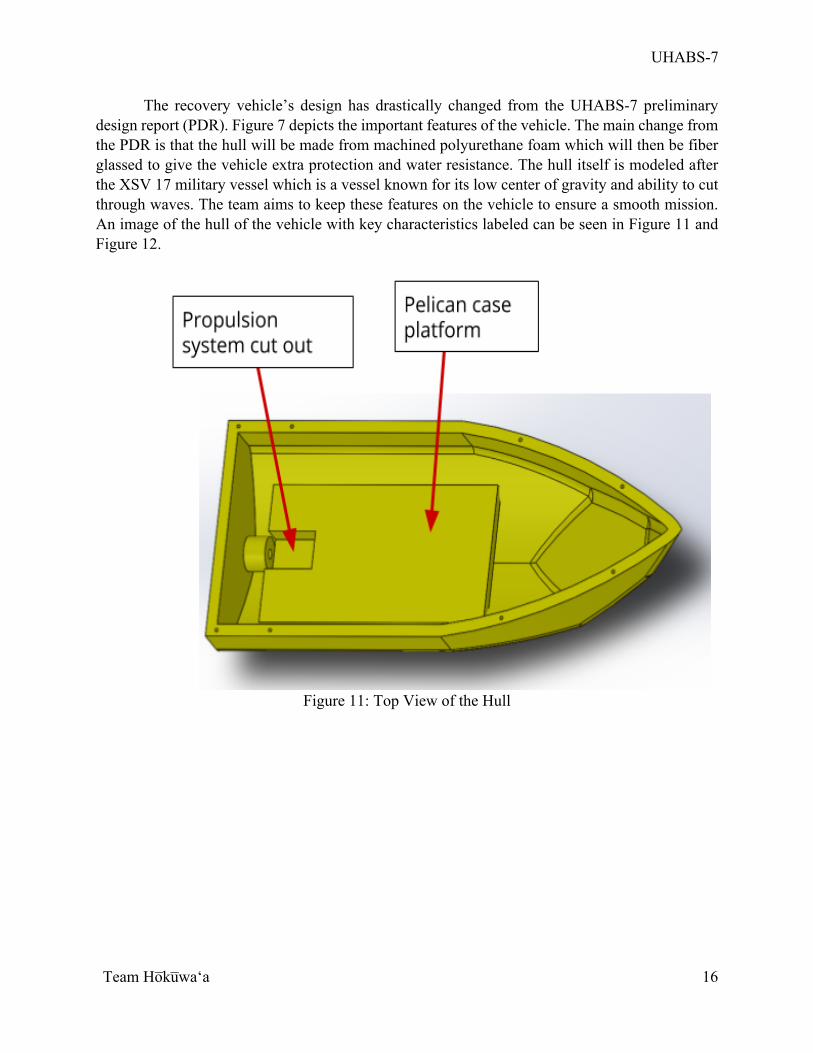
The recovery vehicle’s design has drastically changed from the UHABS-7 preliminary design report (PDR). Figure 7 depicts the important features of the vehicle. The main change from the PDR is that the hull will be made from machined polyurethane foam which will then be fiber glassed to give the vehicle extra protection and water resistance. The hull itself is modeled after the XSV 17 military vessel which is a vessel known for its low center of gravity and ability to cut through waves. The team aims to keep these features on the vehicle to ensure a smooth mission. An image of the hull of the vehicle with key characteristics labeled can be seen in Figure 11 and Figure 12.
Figure 11: Top View of the Hull
UHABS-7
Team Ho̅ku̅waʻa
17
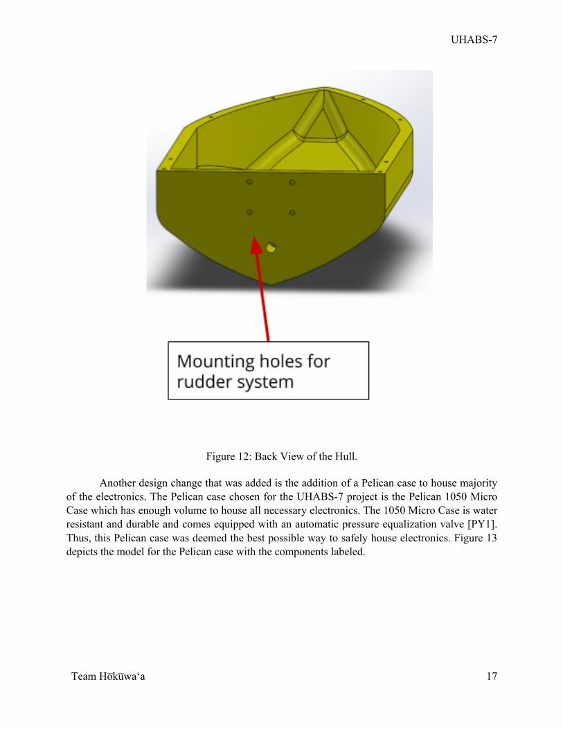
Figure 12: Back View of the Hull.
Another design change that was added is the addition of a Pelican case to house majority
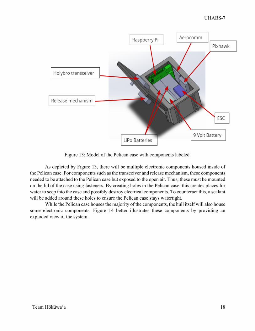
of the electronics. The Pelican case chosen for the UHABS-7 project is the Pelican 1050 Micro Case which has enough volume to house all necessary electronics. The 1050 Micro Case is water resistant and durable and comes equipped with an automatic pressure equalization valve [PY1]. Thus, this Pelican case was deemed the best possible way to safely house electronics. Figure 13 depicts the model for the Pelican case with the components labeled.
UHABS-7
Team Ho̅ku̅waʻa
18
Figure 13: Model of the Pelican case with components labeled.
As depicted by Figure 13, there will be multiple electronic components housed inside of
the Pelican case. For components such as the transceiver and release mechanism, these components needed to be attached to the Pelican case but exposed to the open air. Thus, these must be mounted on the lid of the case using fasteners. By creating holes in the Pelican case, this creates places for water to seep into the case and possibly destroy electrical components. To counteract this, a sealant will be added around these holes to ensure the Pelican case stays watertight.
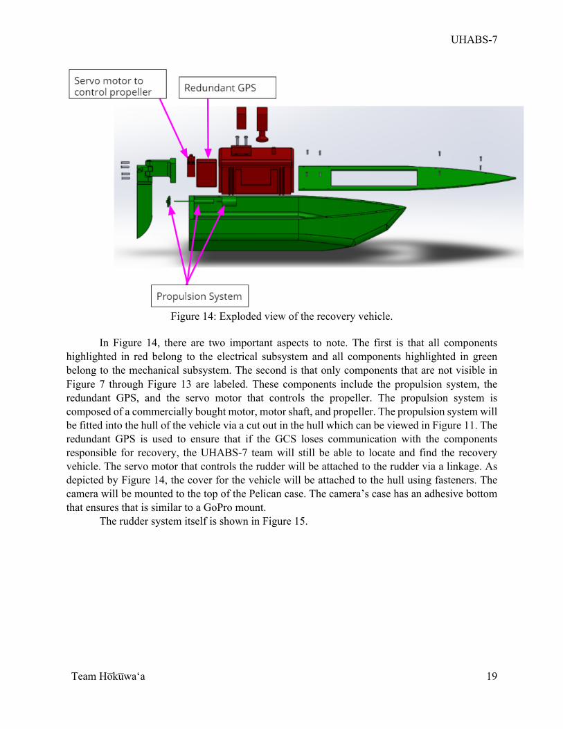
While the Pelican case houses the majority of the components, the hull itself will also house some electronic components. Figure 14 better illustrates these components by providing an exploded view of the system.
UHABS-7
Team Ho̅ku̅waʻa
19
Figure 14: Exploded view of the recovery vehicle.
In Figure 14, there are two important aspects to note. The first is that all components
highlighted in red belong to the electrical subsystem and all components highlighted in green belong to the mechanical subsystem. The second is that only components that are not visible in Figure 7 through Figure 13 are labeled. These components include the propulsion system, the redundant GPS, and the servo motor that controls the propeller. The propulsion system is composed of a commercially bought motor, motor shaft, and propeller. The propulsion system will be fitted into the hull of the vehicle via a cut out in the hull which can be viewed in Figure 11. The redundant GPS is used to ensure that if the GCS loses communication with the components responsible for recovery, the UHABS-7 team will still be able to locate and find the recovery vehicle. The servo motor that controls the rudder will be attached to the rudder via a linkage. As depicted by Figure 14, the cover for the vehicle will be attached to the hull using fasteners. The camera will be mounted to the top of the Pelican case. The camera’s case has an adhesive bottom that ensures that is similar to a GoPro mount.
The rudder system itself is shown in Figure 15.
UHABS-7
Team Ho̅ku̅waʻa
20
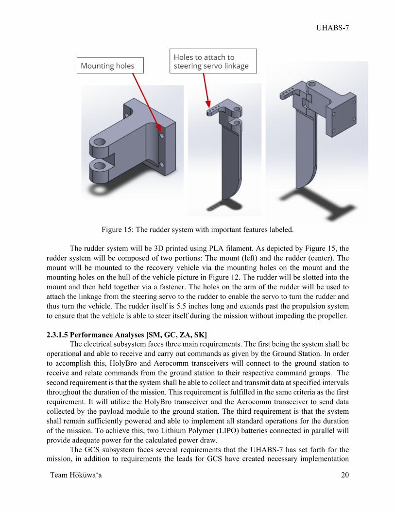
Figure 15: The rudder system with important features labeled.
The rudder system will be 3D printed using PLA filament. As depicted by Figure 15, the
rudder system will be composed of two portions: The mount (left) and the rudder (center). The mount will be mounted to the recovery vehicle via the mounting holes on the mount and the mounting holes on the hull of the vehicle picture in Figure 12. The rudder will be slotted into the mount and then held together via a fastener. The holes on the arm of the rudder will be used to attach the linkage from the steering servo to the rudder to enable the servo to turn the rudder and thus turn the vehicle. The rudder itself is 5.5 inches long and extends past the propulsion system to ensure that the vehicle is able to steer itself during the mission without impeding the propeller.
2.3.1.5 Performance Analyses [SM, GC, ZA, SK]
The electrical subsystem faces three main requirements. The first being the system shall be operational and able to receive and carry out commands as given by the Ground Station. In order to accomplish this, HolyBro and Aerocomm transceivers will connect to the ground station to receive and relate commands from the ground station to their respective command groups. The second requirement is that the system shall be able to collect and transmit data at specified intervals throughout the duration of the mission. This requirement is fulfilled in the same criteria as the first requirement. It will utilize the HolyBro transceiver and the Aerocomm transceiver to send data collected by the payload module to the ground station. The third requirement is that the system shall remain sufficiently powered and able to implement all standard operations for the duration of the mission. To achieve this, two Lithium Polymer (LIPO) batteries connected in parallel will provide adequate power for the calculated power draw.
The GCS subsystem faces several requirements that the UHABS-7 has set forth for the mission, in addition to requirements the leads for GCS have created necessary implementation
UHABS-7
Team Ho̅ku̅waʻa
21
plans. The requirements governing the GCS revolves around data collection, communication to and from the recovery vehicle, and location positioning. Specifically, the GCS is required to: utilize COSMOS as flight software, maintain communication with the recovery vehicle for the entire autonomous recovery phase, be able to monitor and receive the vehicle’s location at any point, and be able to receive telemetry data. It is of high importance that these requirements are implemented for complete control over the recovery vehicle; implementation will be continually worked on for the entire duration of the project. 2.3.1.6 FMECA [TA]
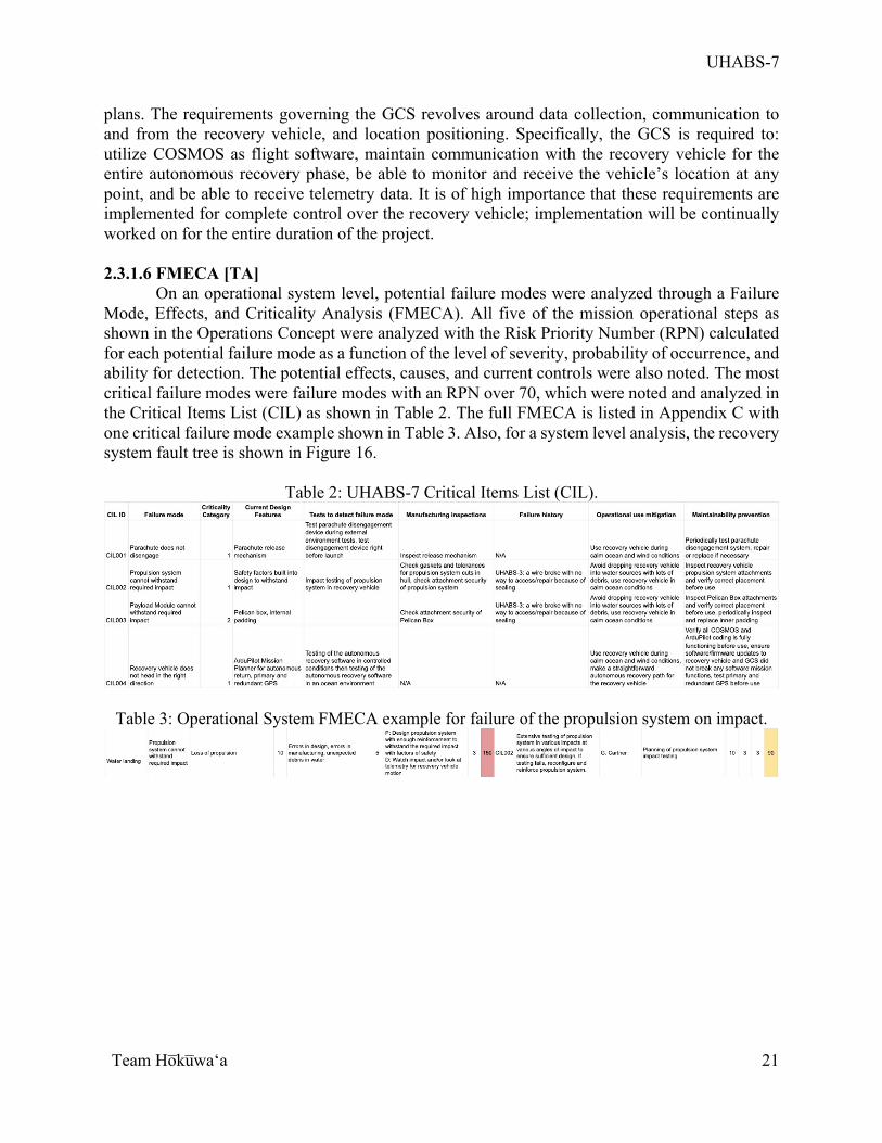
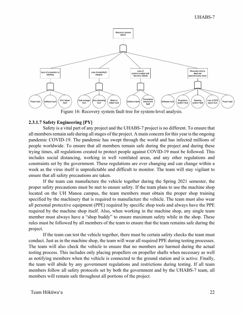
On an operational system level, potential failure modes were analyzed through a Failure Mode, Effects, and Criticality Analysis (FMECA). All five of the mission operational steps as shown in the Operations Concept were analyzed with the Risk Priority Number (RPN) calculated for each potential failure mode as a function of the level of severity, probability of occurrence, and ability for detection. The potential effects, causes, and current controls were also noted. The most critical failure modes were failure modes with an RPN over 70, which were noted and analyzed in the Critical Items List (CIL) as shown in Table 2. The full FMECA is listed in Appendix C with one critical failure mode example shown in Table 3. Also, for a system level analysis, the recovery system fault tree is shown in Figure 16.
Table 2: UHABS-7 Critical Items List (CIL).
Table 3: Operational System FMECA example for failure of the propulsion system on impact.
UHABS-7
Team Ho̅ku̅waʻa
22
Figure 16: Recovery system fault tree for system-level analysis.
2.3.1.7 Safety Engineering [PY]
Safety is a vital part of any project and the UHABS-7 project is no different. To ensure that all members remain safe during all stages of the project. A main concern for this year is the ongoing pandemic COVID-19. The pandemic has swept through the world and has infected millions of people worldwide. To ensure that all members remain safe during the project and during these trying times, all regulations created to protect people against COVID-19 must be followed. This includes social distancing, working in well ventilated areas, and any other regulations and constraints set by the government. These regulations are ever changing and can change within a week as the virus itself is unpredictable and difficult to monitor. The team will stay vigilant to ensure that all safety precautions are taken.
If the team can manufacture the vehicle together during the Spring 2021 semester, the proper safety precautions must be met to ensure safety. If the team plans to use the machine shop located on the UH Manoa campus, the team members must obtain the proper shop training specified by the machinery that is required to manufacture the vehicle. The team must also wear all personal protective equipment (PPE) required by specific shop tools and always have the PPE required by the machine shop itself. Also, when working in the machine shop, any single team member must always have a “shop buddy” to ensure maximum safety while in the shop. These rules must be followed by all members of the team to ensure that the team remains safe during the project.
If the team can test the vehicle together, there must be certain safety checks the team must conduct. Just as in the machine shop, the team will wear all required PPE during testing processes. The team will also check the vehicle to ensure that no members are harmed during the actual testing process. This includes only placing propellers on propeller shafts when necessary as well as notifying members when the vehicle is connected to the ground station and is active. Finally, the team will abide by any government regulations and restrictions during testing. If all team members follow all safety protocols set by both the government and by the UHABS-7 team, all members will remain safe throughout all portions of the project.
UHABS-7
Team Ho̅ku̅waʻa
23
2.3.1.8 Human Factors Engineering [CM] This system is intended to be used by the people in HSFL and others who have a Balloon Satellite system. For someone that would use this system with the teams ground control station laptops, the user would have to “arm” the vehicle and mission planner and then press ‘start mission” to initiate the start of the recovery mission. If a user will be using a different laptop then the COSMOS and Mission Planner Software program must be downloaded, as well as all mission files designed by the UHABS-7 team. After everything is downloaded the ground controls station electronics must be hooked up to that laptop and connected to the electronics on the recovery vehicle. Once everything is connected the vehicle is ready to be recovered. 2.3.1.9 Fabrication Plan [PY]
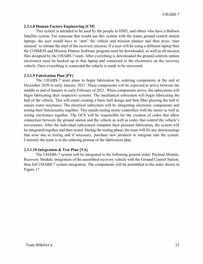
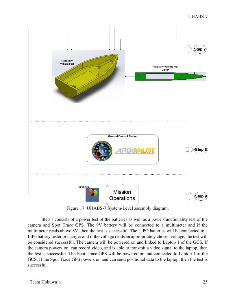
The UHABS-7 team plans to begin fabrication by ordering components at the end of December 2020 to early January 2021. These components will be expected to arrive between the middle to end of January to early February of 2021. When components arrive, the subsystems will begin fabricating their respective systems. The mechanical subsystem will begin fabricating the hull of the vehicle. This will entail creating a basic hull design and then fiber glassing the hull to ensure water resistance. The electrical subsystem will be integrating electronic components and testing their functionality together. This entails testing motor controllers with the motor as well as wiring electronics together. The GCS will be responsible for the creation of codes that allow connection between the ground station and the vehicle as well as codes that control the vehicle’s movements. After the individual subsystems complete their personal fabrication, the system will be integrated together and then tested. During the testing phase, the team will fix any shortcomings that arise due to testing and if necessary, purchase new products to integrate into the system. Currently the team is in the ordering portion of the fabrication plan. 2.3.1.10 Integration & Test Plan [TA] The UHABS-7 system will be integrated in the following general order: Payload Module, Recovery Module, integration of the assembled recovery vehicle with the Ground Control Station, then full UHABS-7 system integration. The components will be assembled in the order shown in Figure 17.
UHABS-7
Team Ho̅ku̅waʻa
24
UHABS-7
Team Ho̅ku̅waʻa
25
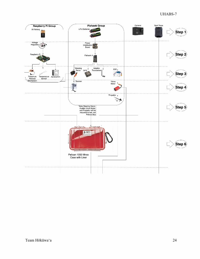
Figure 17: UHABS-7 System-Level assembly diagram.
Step 1 consists of a power test of the batteries as well as a power/functionality test of the camera and Spot Trace GPS. The 9V battery will be connected to a multimeter and if the multimeter reads above 8V, then the test is successful. The LIPO batteries will be connected to a LiPo battery tester or charger and if the voltage reads an appropriately chosen voltage, the test will be considered successful. The camera will be powered on and linked to Laptop 1 of the GCS. If the camera powers on, can record video, and is able to transmit a video signal to the laptop, then the test is successful. The Spot Trace GPS will be powered on and connected to Laptop 1 of the GCS. If the Spot Trace GPS powers on and can send positional data to the laptop, then the test is successful.
UHABS-7
Team Ho̅ku̅waʻa
26
Step 2 consists of connecting the voltage regulator from the 9V battery to the Raspberry Pi as well as the power distribution board from the LiPo batteries to the Pixhawk. To test for power, the Raspberry Pi will be connected to an LED. If the Raspberry Pi LED and the Pixhawk power LED turns on, then the test is successful.
Step 3 consists of attaching the parachute release mechanism, the temperature sensor, and Aerocomm to the Raspberry Pi, as well as attaching the steering servo, the GPS, the HolyBro transceiver, and the ESC to the Pixhawk. For the Raspberry Pi group, the Aerocomm transceiver will be attached first, then integrated with COSMOS of the Ground Control Station. If COSMOS recognizes and can connect with the Aerocomm transceiver and Raspberry Pi, then the test is successful. The temperature sensor will then be connected to the Raspberry Pi. If the temperature sensor data can be read in COSMOS, then the test is successful. The parachute release mechanism will then be connected to the Raspberry Pi. Python code will be uploaded to the Raspberry Pi to test the parachute release mechanism and if the release actuator opens and closes on command, then the test is successful. For the Pixhawk group, the HolyBro transceiver will be attached first, then a test will be done to connect the Pixhawk to ArduPilot of the GCS. If ArduPilot can connect with the recovery vehicle’s HolyBro transceiver and Pixhawk, then the test is successful. The GPS will be connected to the Pixhawk next, and if ArduPilot receives positioning data from the GPS, then the test is successful. The ESC will then be connected to the Pixhawk. If the ESC power LED turns on when connected to the Pixhawk, then the test is considered successful. Finally, the steering servo will be connected and the ArduPilot program will be used to test control of the steering servo. If the steering servo rotates appropriately according to the ArduPilot program commands, then the test is successful.
Step 4 consists of connecting the rudder to the steering servo and the drive motor to the ESC. To test the rudder function, the ArduPilot program will run the same commands as the Step 3 commands to test the steering servo. If the rudder can turn appropriately according to the ArduPilot program commands, then the test is successful. To test the drive motor function, the ArduPilot program will send propulsion commands to the drive motor. If the drive motor powers on/off and speed is appropriately controlled through the propulsion commands, then the test is successful.
Step 5 consists of connecting the propellor to the drive motor. The same propulsion commands used to test the drive motor in Step 4 will be used to test the propellor function. If the propellor rotates appropriately based on the received commands, then the test is successful.
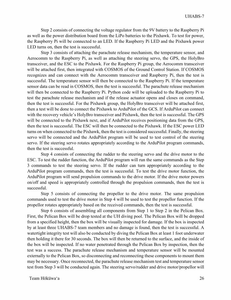
Step 6 consists of assembling all components from Step 1 to Step 2 in the Pelican Box. First, the Pelican Box will be drop tested at the UH diving pool. The Pelican Box will be dropped from a specified height, then the box will be visually inspected for damage. If the box is inspected by at least three UHABS-7 team members and no damage is found, then the test is successful. A watertight integrity test will also be conducted by diving the Pelican Box at least 1 foot underwater then holding it there for 30 seconds. The box will then be returned to the surface, and the inside of the box will be inspected. If no water penetrated through the Pelican Box by inspection, then the test was a success. The parachute release mechanism and temperature sensor will be mounted externally to the Pelican Box, so disconnecting and reconnecting these components to mount them may be necessary. Once reconnected, the parachute release mechanism test and temperature sensor test from Step 3 will be conducted again. The steering servo/rudder and drive motor/propellor will
UHABS-7
Team Ho̅ku̅waʻa
27
be mounted external to the Pelican Box on the recovery vehicle hull, so disconnecting and reconnecting these components may be required to keep these components outside of the Pelican Box. The tests for each component from Step 4 and Step 5 will be retested once the components are reconnected outside of the Pelican Box. There will also be a physical attachment security test for the components mounted internally and externally to the Pelican Box. All components will be tested by hand for attachment security, and if the components feel adequately attached by at least three UHABS-7 team members, then the test is successful.
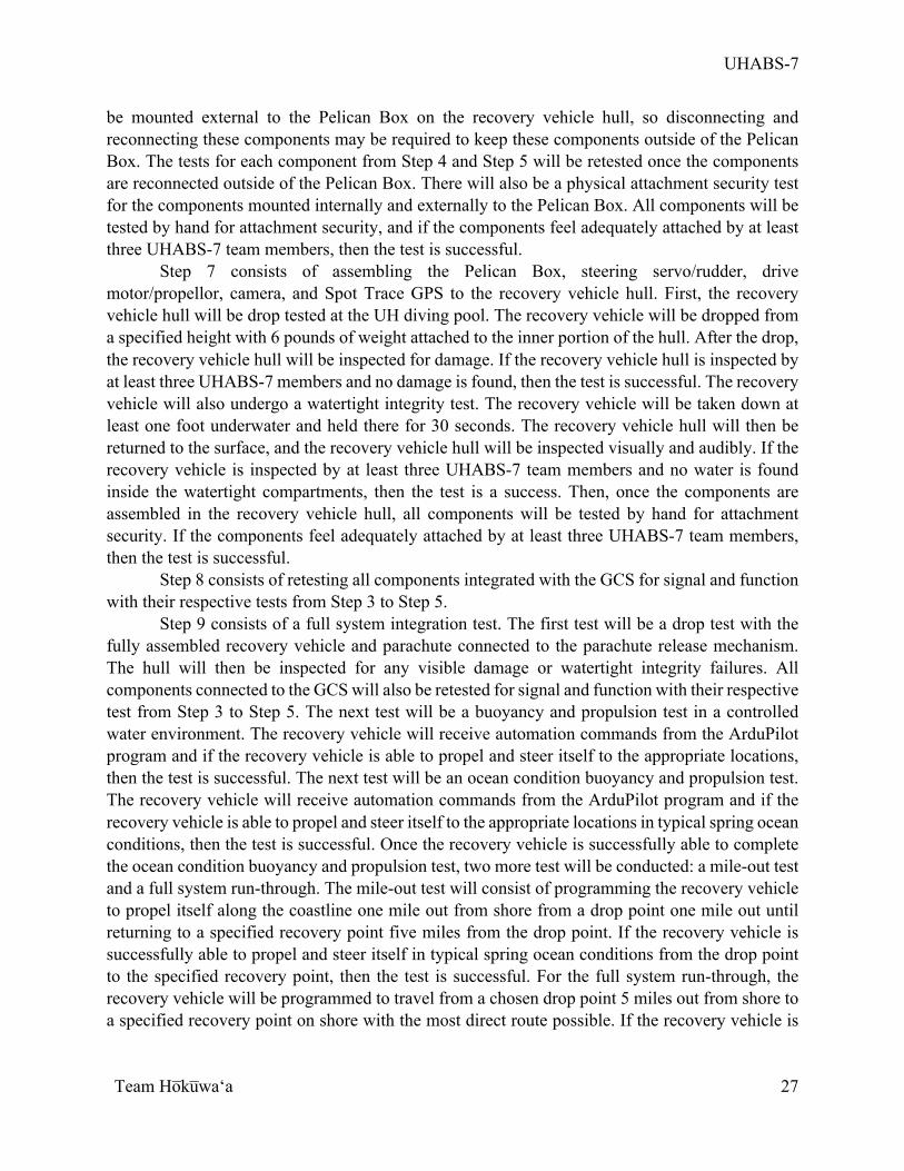
Step 7 consists of assembling the Pelican Box, steering servo/rudder, drive motor/propellor, camera, and Spot Trace GPS to the recovery vehicle hull. First, the recovery vehicle hull will be drop tested at the UH diving pool. The recovery vehicle will be dropped from a specified height with 6 pounds of weight attached to the inner portion of the hull. After the drop, the recovery vehicle hull will be inspected for damage. If the recovery vehicle hull is inspected by at least three UHABS-7 members and no damage is found, then the test is successful. The recovery vehicle will also undergo a watertight integrity test. The recovery vehicle will be taken down at least one foot underwater and held there for 30 seconds. The recovery vehicle hull will then be returned to the surface, and the recovery vehicle hull will be inspected visually and audibly. If the recovery vehicle is inspected by at least three UHABS-7 team members and no water is found inside the watertight compartments, then the test is a success. Then, once the components are assembled in the recovery vehicle hull, all components will be tested by hand for attachment security. If the components feel adequately attached by at least three UHABS-7 team members, then the test is successful.
Step 8 consists of retesting all components integrated with the GCS for signal and function with their respective tests from Step 3 to Step 5.
Step 9 consists of a full system integration test. The first test will be a drop test with the fully assembled recovery vehicle and parachute connected to the parachute release mechanism. The hull will then be inspected for any visible damage or watertight integrity failures. All components connected to the GCS will also be retested for signal and function with their respective test from Step 3 to Step 5. The next test will be a buoyancy and propulsion test in a controlled water environment. The recovery vehicle will receive automation commands from the ArduPilot program and if the recovery vehicle is able to propel and steer itself to the appropriate locations, then the test is successful. The next test will be an ocean condition buoyancy and propulsion test. The recovery vehicle will receive automation commands from the ArduPilot program and if the recovery vehicle is able to propel and steer itself to the appropriate locations in typical spring ocean conditions, then the test is successful. Once the recovery vehicle is successfully able to complete the ocean condition buoyancy and propulsion test, two more test will be conducted: a mile-out test and a full system run-through. The mile-out test will consist of programming the recovery vehicle to propel itself along the coastline one mile out from shore from a drop point one mile out until returning to a specified recovery point five miles from the drop point. If the recovery vehicle is successfully able to propel and steer itself in typical spring ocean conditions from the drop point to the specified recovery point, then the test is successful. For the full system run-through, the recovery vehicle will be programmed to travel from a chosen drop point 5 miles out from shore to a specified recovery point on shore with the most direct route possible. If the recovery vehicle is
UHABS-7
Team Ho̅ku̅waʻa
28
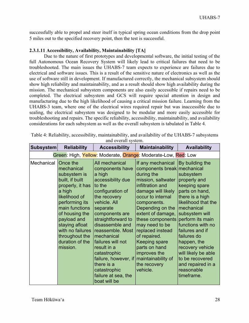
successfully able to propel and steer itself in typical spring ocean conditions from the drop point 5 miles out to the specified recovery point, then the test is successful. 2.3.1.11 Accessibility, Availability, Maintainability [TA]
Due to the nature of first prototypes and developmental software, the initial testing of the full Autonomous Ocean Recovery System will likely lead to critical failures that need to be troubleshooted. The main issues the UHABS-7 team expects to experience are failures due to electrical and software issues. This is a result of the sensitive nature of electronics as well as the use of software still in development. If manufactured correctly, the mechanical subsystem should show high reliability and maintainability, and as a result should show high availability during the mission. The mechanical subsystem components are also easily accessible if repairs need to be completed. The electrical subsystem and GCS will require special attention in design and manufacturing due to the high likelihood of causing a critical mission failure. Learning from the UHABS-3 team, where one of the electrical wires required repair but was inaccessible due to sealing, the electrical subsystem was designed to be modular and more easily accessible for troubleshooting and repairs. The specific reliability, accessibility, maintainability, and availability considerations for each subsystem as well as the overall subsystem is tabulated in Table 4. Table 4: Reliability, accessibility, maintainability, and availability of the UHABS-7 subsystems
and overall system. Subsystem Reliability Accessibility Maintainability Availability
Green: High, Yellow: Moderate, Orange: Moderate-Low, Red: Low Mechanical Once the
mechanical subsystem is built, if built properly, it has a high likelihood of performing its main functions of housing the payload and staying afloat with no failures throughout the duration of the mission.
All mechanical components have a high accessibility due to the configuration of the recovery vehicle. All separate components are straightforward to disassemble and reassemble. Most mechanical failures will not result in a catastrophic failure, however, if there is a catastrophic failure at sea, the boat will be
If any mechanical components break during the mission, saltwater infiltration and damage will likely occur to internal components. Depending on the extent of damage, these components may need to be replaced instead of repaired. Keeping spare parts on hand improves the maintainability of the recovery vehicle.
By building the mechanical subsystem properly and keeping spare parts on hand, there is a high likelihood that the mechanical subsystem will perform its main functions with no failures and if failures do happen, the recovery vehicle will likely be able to be recovered and repaired in a reasonable timeframe.
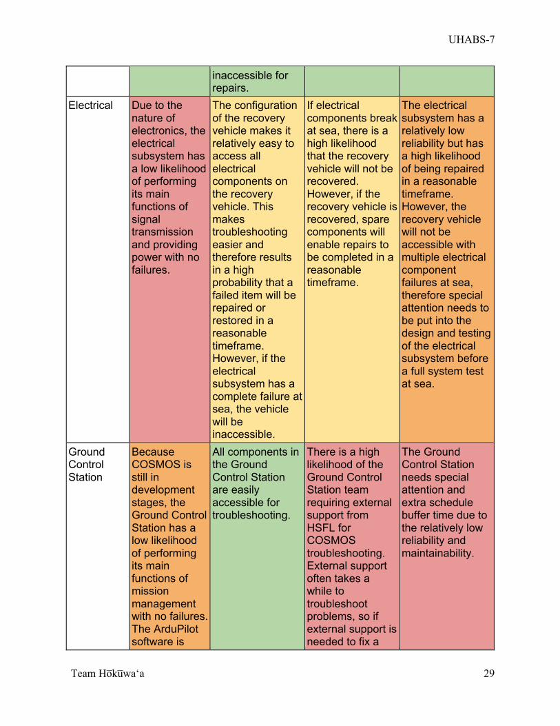
UHABS-7
Team Ho̅ku̅waʻa
29
inaccessible for repairs.
Electrical Due to the nature of electronics, the electrical subsystem has a low likelihood of performing its main functions of signal transmission and providing power with no failures.
The configuration of the recovery vehicle makes it relatively easy to access all electrical components on the recovery vehicle. This makes troubleshooting easier and therefore results in a high probability that a failed item will be repaired or restored in a reasonable timeframe. However, if the electrical subsystem has a complete failure at sea, the vehicle will be inaccessible.
If electrical components break at sea, there is a high likelihood that the recovery vehicle will not be recovered. However, if the recovery vehicle is recovered, spare components will enable repairs to be completed in a reasonable timeframe.
The electrical subsystem has a relatively low reliability but has a high likelihood of being repaired in a reasonable timeframe. However, the recovery vehicle will not be accessible with multiple electrical component failures at sea, therefore special attention needs to be put into the design and testing of the electrical subsystem before a full system test at sea.
Ground Control Station
Because COSMOS is still in development stages, the Ground Control Station has a low likelihood of performing its main functions of mission management with no failures. The ArduPilot software is
All components in the Ground Control Station are easily accessible for troubleshooting.
There is a high likelihood of the Ground Control Station team requiring external support from HSFL for COSMOS troubleshooting. External support often takes a while to troubleshoot problems, so if external support is needed to fix a
The Ground Control Station needs special attention and extra schedule buffer time due to the relatively low reliability and maintainability.
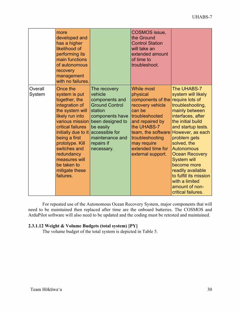
UHABS-7
Team Ho̅ku̅waʻa
30
more developed and has a higher likelihood of performing its main functions of autonomous recovery management with no failures.
COSMOS issue, the Ground Control Station will take an extended amount of time to troubleshoot.
Overall System
Once the system is put together, the integration of the system will likely run into various mission critical failures initially due to it being a first prototype. Kill switches and redundancy measures will be taken to mitigate these failures.
The recovery vehicle components and Ground Control station components have been designed to be easily accessible for maintenance and repairs if necessary.
While most physical components of the recovery vehicle can be troubleshooted and repaired by the UHABS-7 team, the software troubleshooting may require extended time for external support.
The UHABS-7 system will likely require lots of troubleshooting, mainly between interfaces, after the initial build and startup tests. However, as each problem gets solved, the Autonomous Ocean Recovery System will become more readily available to fulfill its mission with a limited amount of non-critical failures.
For repeated use of the Autonomous Ocean Recovery System, major components that will need to be maintained then replaced after time are the onboard batteries. The COSMOS and ArduPilot software will also need to be updated and the coding must be retested and maintained. 2.3.1.12 Weight & Volume Budgets (total system) [PY]
The volume budget of the total system is depicted in Table 5.
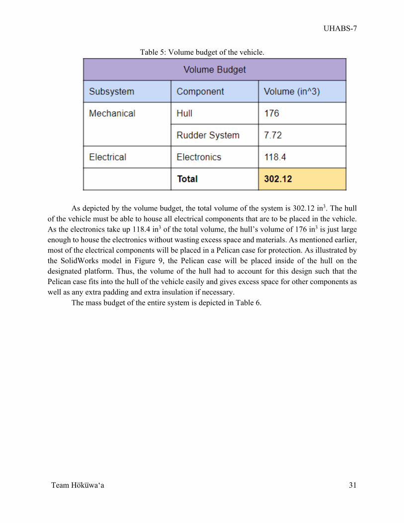
UHABS-7
Team Ho̅ku̅waʻa
31
Table 5: Volume budget of the vehicle.
As depicted by the volume budget, the total volume of the system is 302.12 in3. The hull
of the vehicle must be able to house all electrical components that are to be placed in the vehicle. As the electronics take up 118.4 in3 of the total volume, the hull’s volume of 176 in3 is just large enough to house the electronics without wasting excess space and materials. As mentioned earlier, most of the electrical components will be placed in a Pelican case for protection. As illustrated by the SolidWorks model in Figure 9, the Pelican case will be placed inside of the hull on the designated platform. Thus, the volume of the hull had to account for this design such that the Pelican case fits into the hull of the vehicle easily and gives excess space for other components as well as any extra padding and extra insulation if necessary.
The mass budget of the entire system is depicted in Table 6.
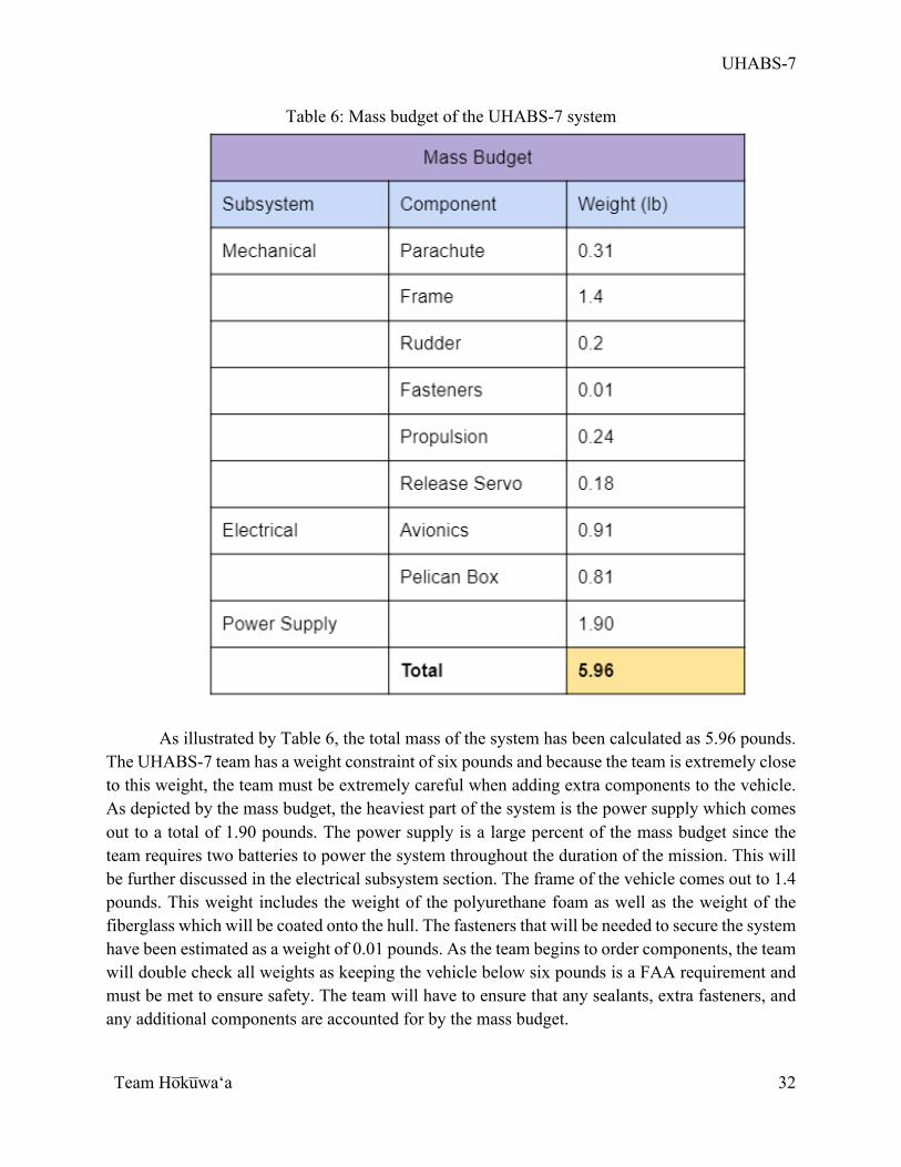
UHABS-7
Team Ho̅ku̅waʻa
32
Table 6: Mass budget of the UHABS-7 system
As illustrated by Table 6, the total mass of the system has been calculated as 5.96 pounds. The UHABS-7 team has a weight constraint of six pounds and because the team is extremely close to this weight, the team must be extremely careful when adding extra components to the vehicle. As depicted by the mass budget, the heaviest part of the system is the power supply which comes out to a total of 1.90 pounds. The power supply is a large percent of the mass budget since the team requires two batteries to power the system throughout the duration of the mission. This will be further discussed in the electrical subsystem section. The frame of the vehicle comes out to 1.4 pounds. This weight includes the weight of the polyurethane foam as well as the weight of the fiberglass which will be coated onto the hull. The fasteners that will be needed to secure the system have been estimated as a weight of 0.01 pounds. As the team begins to order components, the team will double check all weights as keeping the vehicle below six pounds is a FAA requirement and must be met to ensure safety. The team will have to ensure that any sealants, extra fasteners, and any additional components are accounted for by the mass budget.
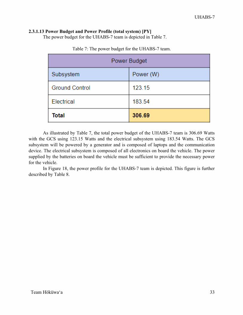
UHABS-7
Team Ho̅ku̅waʻa
33
2.3.1.13 Power Budget and Power Profile (total system) [PY] The power budget for the UHABS-7 team is depicted in Table 7.
Table 7: The power budget for the UHABS-7 team.
As illustrated by Table 7, the total power budget of the UHABS-7 team is 306.69 Watts with the GCS using 123.15 Watts and the electrical subsystem using 183.54 Watts. The GCS subsystem will be powered by a generator and is composed of laptops and the communication device. The electrical subsystem is composed of all electronics on board the vehicle. The power supplied by the batteries on board the vehicle must be sufficient to provide the necessary power for the vehicle.
In Figure 18, the power profile for the UHABS-7 team is depicted. This figure is further described by Table 8.
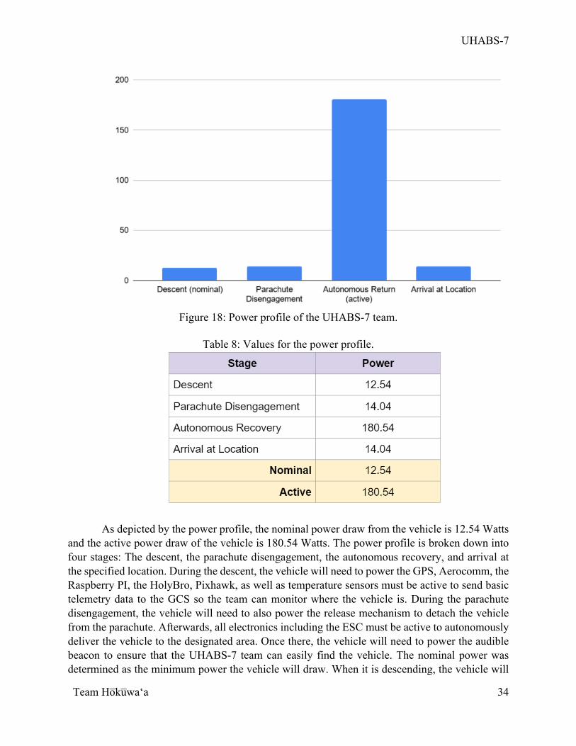
UHABS-7
Team Ho̅ku̅waʻa
34
Figure 18: Power profile of the UHABS-7 team.
Table 8: Values for the power profile.
As depicted by the power profile, the nominal power draw from the vehicle is 12.54 Watts and the active power draw of the vehicle is 180.54 Watts. The power profile is broken down into four stages: The descent, the parachute disengagement, the autonomous recovery, and arrival at the specified location. During the descent, the vehicle will need to power the GPS, Aerocomm, the Raspberry PI, the HolyBro, Pixhawk, as well as temperature sensors must be active to send basic telemetry data to the GCS so the team can monitor where the vehicle is. During the parachute disengagement, the vehicle will need to also power the release mechanism to detach the vehicle from the parachute. Afterwards, all electronics including the ESC must be active to autonomously deliver the vehicle to the designated area. Once there, the vehicle will need to power the audible beacon to ensure that the UHABS-7 team can easily find the vehicle. The nominal power was determined as the minimum power the vehicle will draw. When it is descending, the vehicle will
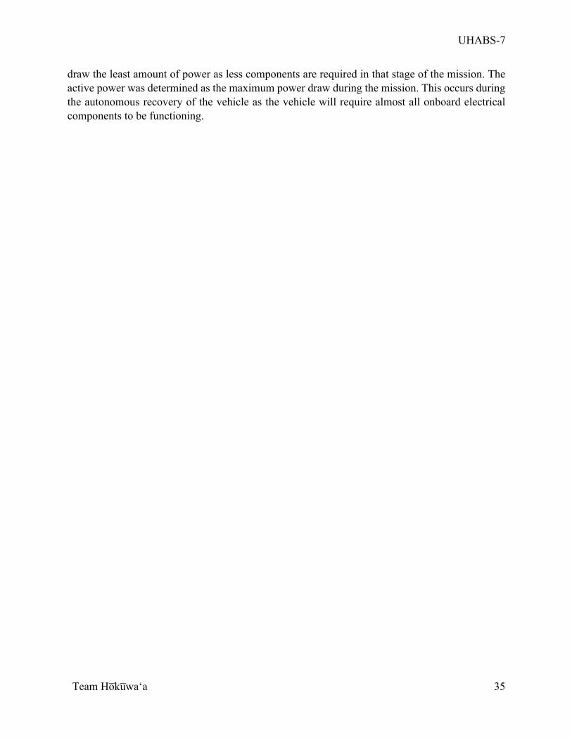
UHABS-7
Team Ho̅ku̅waʻa
35
draw the least amount of power as less components are required in that stage of the mission. The active power was determined as the maximum power draw during the mission. This occurs during the autonomous recovery of the vehicle as the vehicle will require almost all onboard electrical components to be functioning.
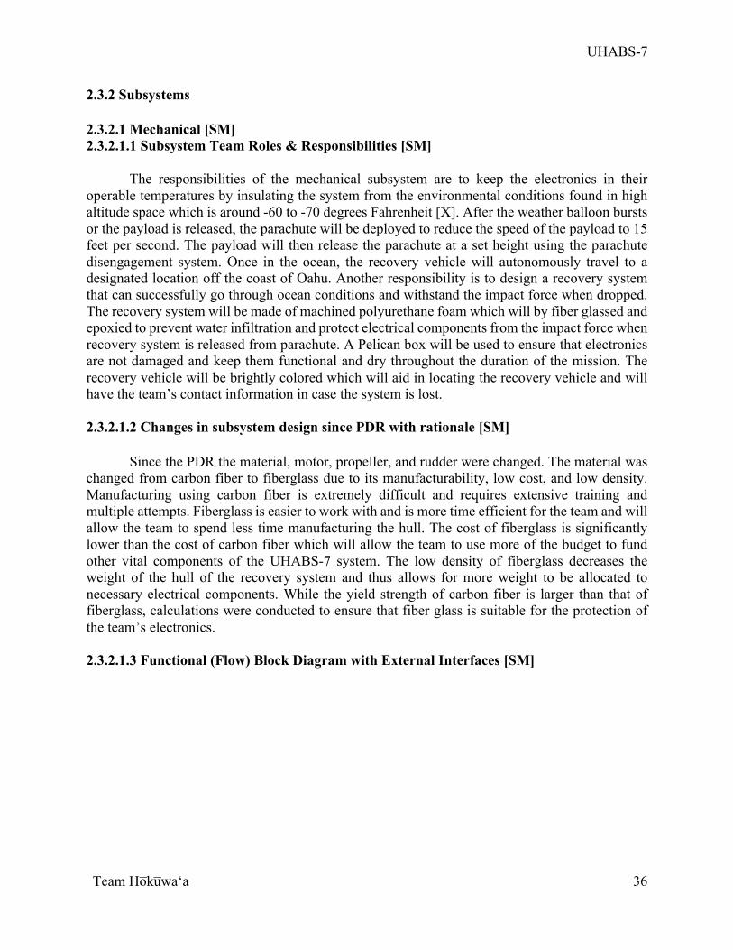
UHABS-7
Team Ho̅ku̅waʻa
36
2.3.2 Subsystems 2.3.2.1 Mechanical [SM] 2.3.2.1.1 Subsystem Team Roles & Responsibilities [SM]
The responsibilities of the mechanical subsystem are to keep the electronics in their operable temperatures by insulating the system from the environmental conditions found in high altitude space which is around -60 to -70 degrees Fahrenheit [X]. After the weather balloon bursts or the payload is released, the parachute will be deployed to reduce the speed of the payload to 15 feet per second. The payload will then release the parachute at a set height using the parachute disengagement system. Once in the ocean, the recovery vehicle will autonomously travel to a designated location off the coast of Oahu. Another responsibility is to design a recovery system that can successfully go through ocean conditions and withstand the impact force when dropped. The recovery system will be made of machined polyurethane foam which will by fiber glassed and epoxied to prevent water infiltration and protect electrical components from the impact force when recovery system is released from parachute. A Pelican box will be used to ensure that electronics are not damaged and keep them functional and dry throughout the duration of the mission. The recovery vehicle will be brightly colored which will aid in locating the recovery vehicle and will have the team’s contact information in case the system is lost. 2.3.2.1.2 Changes in subsystem design since PDR with rationale [SM]
Since the PDR the material, motor, propeller, and rudder were changed. The material was changed from carbon fiber to fiberglass due to its manufacturability, low cost, and low density. Manufacturing using carbon fiber is extremely difficult and requires extensive training and multiple attempts. Fiberglass is easier to work with and is more time efficient for the team and will allow the team to spend less time manufacturing the hull. The cost of fiberglass is significantly lower than the cost of carbon fiber which will allow the team to use more of the budget to fund other vital components of the UHABS-7 system. The low density of fiberglass decreases the weight of the hull of the recovery system and thus allows for more weight to be allocated to necessary electrical components. While the yield strength of carbon fiber is larger than that of fiberglass, calculations were conducted to ensure that fiber glass is suitable for the protection of the team’s electronics. 2.3.2.1.3 Functional (Flow) Block Diagram with External Interfaces [SM]
UHABS-7
Team Ho̅ku̅waʻa
37
Figure 19: Overview of mechanical system.
Figure 20: Functional flow block diagram of mechanical system.
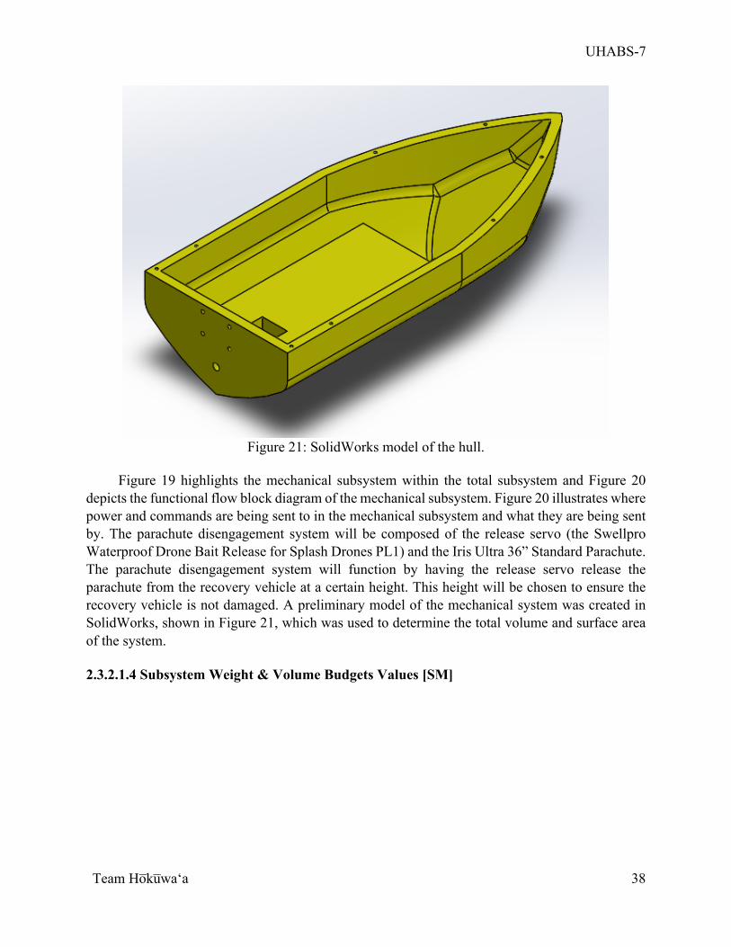
UHABS-7
Team Ho̅ku̅waʻa
38
Figure 21: SolidWorks model of the hull.
Figure 19 highlights the mechanical subsystem within the total subsystem and Figure 20
depicts the functional flow block diagram of the mechanical subsystem. Figure 20 illustrates where power and commands are being sent to in the mechanical subsystem and what they are being sent by. The parachute disengagement system will be composed of the release servo (the Swellpro Waterproof Drone Bait Release for Splash Drones PL1) and the Iris Ultra 36” Standard Parachute. The parachute disengagement system will function by having the release servo release the parachute from the recovery vehicle at a certain height. This height will be chosen to ensure the recovery vehicle is not damaged. A preliminary model of the mechanical system was created in SolidWorks, shown in Figure 21, which was used to determine the total volume and surface area of the system. 2.3.2.1.4 Subsystem Weight & Volume Budgets Values [SM]
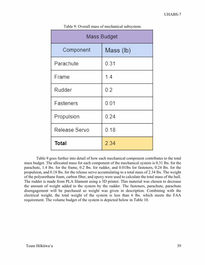
UHABS-7
Team Ho̅ku̅waʻa
39
Table 9: Overall mass of mechanical subsystem.
Table 9 goes further into detail of how each mechanical component contributes to the total mass budget. The allocated mass for each component of the mechanical system is 0.31 lbs. for the parachute, 1.4 lbs. for the frame, 0.2 lbs. for rudder, and 0.01lbs for fasteners, 0.24 lbs. for the propulsion, and 0.18 lbs. for the release servo accumulating to a total mass of 2.34 lbs. The weight of the polyurethane foam, carbon fiber, and epoxy were used to calculate the total mass of the hull. The rudder is made from PLA filament using a 3D printer. This material was chosen to decrease the amount of weight added to the system by the rudder. The fasteners, parachute, parachute disengagement will be purchased so weight was given in description. Combining with the electrical weight, the total weight of the system is less than 6 lbs. which meets the FAA requirement. The volume budget of the system is depicted below in Table 10.
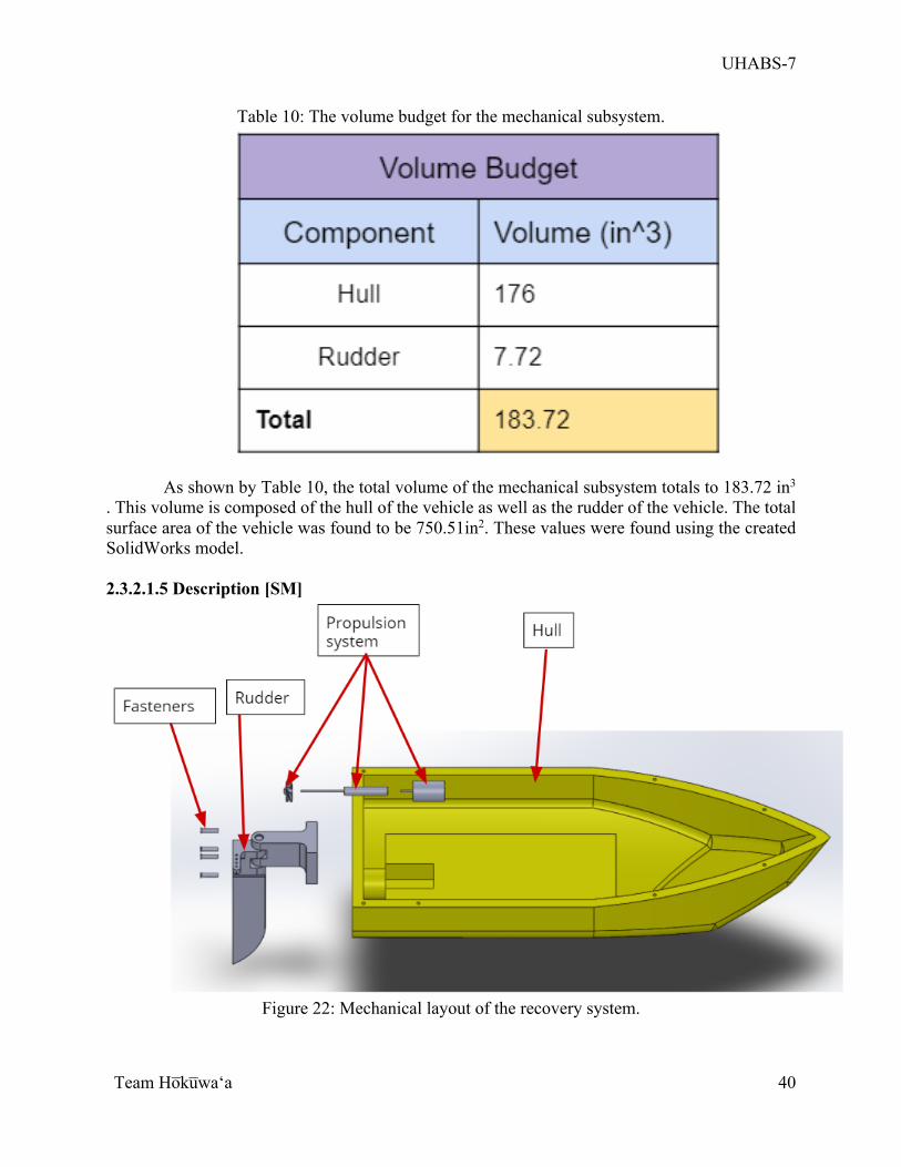
UHABS-7
Team Ho̅ku̅waʻa
40
Table 10: The volume budget for the mechanical subsystem.
As shown by Table 10, the total volume of the mechanical subsystem totals to 183.72 in3 . This volume is composed of the hull of the vehicle as well as the rudder of the vehicle. The total surface area of the vehicle was found to be 750.51in2. These values were found using the created SolidWorks model. 2.3.2.1.5 Description [SM]
Figure 22: Mechanical layout of the recovery system.
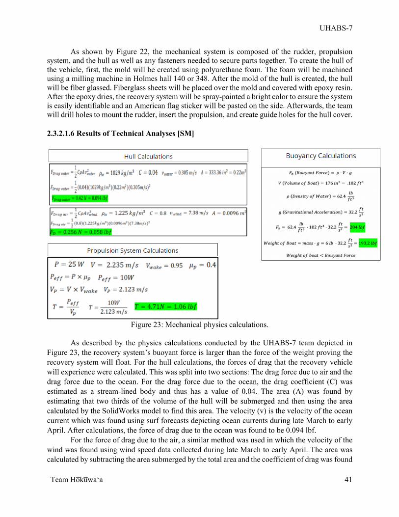
UHABS-7
Team Ho̅ku̅waʻa
41
As shown by Figure 22, the mechanical system is composed of the rudder, propulsion system, and the hull as well as any fasteners needed to secure parts together. To create the hull of the vehicle, first, the mold will be created using polyurethane foam. The foam will be machined using a milling machine in Holmes hall 140 or 348. After the mold of the hull is created, the hull will be fiber glassed. Fiberglass sheets will be placed over the mold and covered with epoxy resin. After the epoxy dries, the recovery system will be spray-painted a bright color to ensure the system is easily identifiable and an American flag sticker will be pasted on the side. Afterwards, the team will drill holes to mount the rudder, insert the propulsion, and create guide holes for the hull cover.
2.3.2.1.6 Results of Technical Analyses [SM]
Figure 23: Mechanical physics calculations.
As described by the physics calculations conducted by the UHABS-7 team depicted in
Figure 23, the recovery system’s buoyant force is larger than the force of the weight proving the recovery system will float. For the hull calculations, the forces of drag that the recovery vehicle will experience were calculated. This was split into two sections: The drag force due to air and the drag force due to the ocean. For the drag force due to the ocean, the drag coefficient (C) was estimated as a stream-lined body and thus has a value of 0.04. The area (A) was found by estimating that two thirds of the volume of the hull will be submerged and then using the area calculated by the SolidWorks model to find this area. The velocity (v) is the velocity of the ocean current which was found using surf forecasts depicting ocean currents during late March to early April. After calculations, the force of drag due to the ocean was found to be 0.094 lbf.
For the force of drag due to the air, a similar method was used in which the velocity of the wind was found using wind speed data collected during late March to early April. The area was calculated by subtracting the area submerged by the total area and the coefficient of drag was found
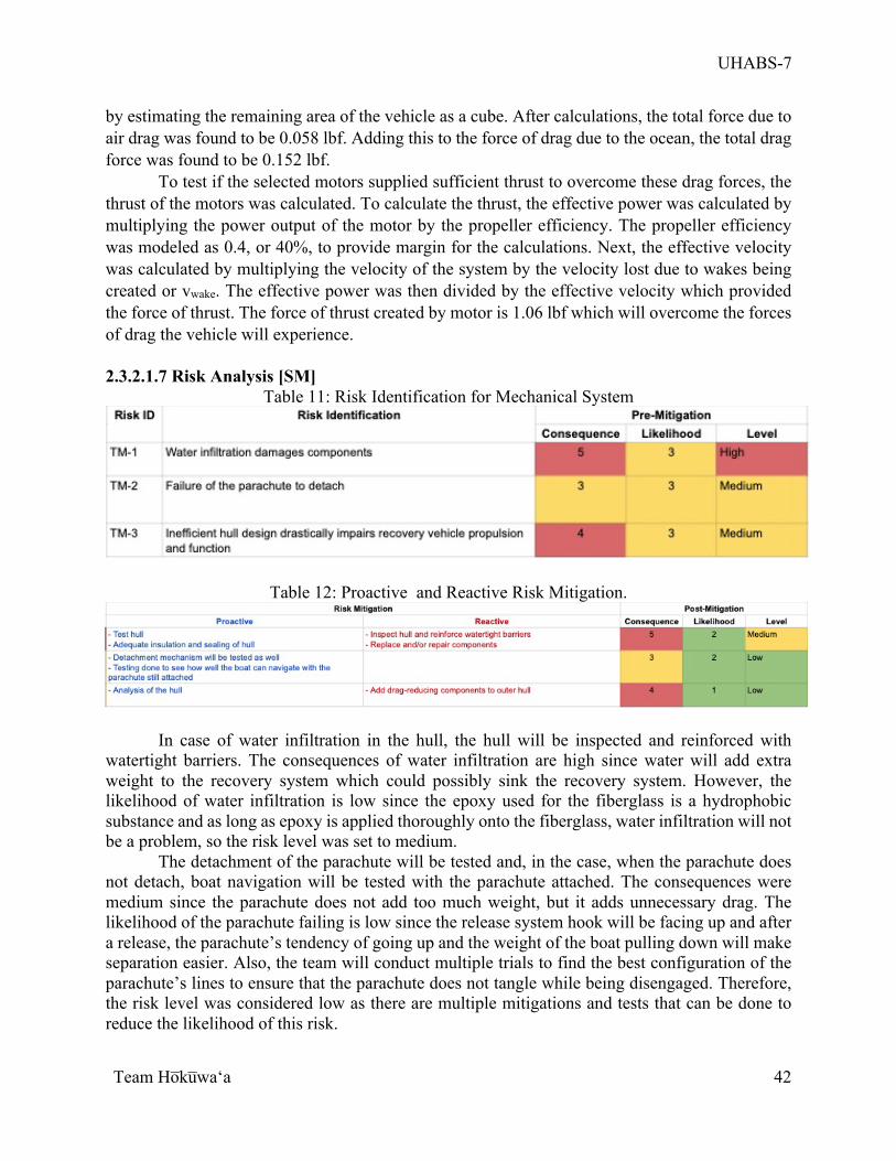
UHABS-7
Team Ho̅ku̅waʻa
42
by estimating the remaining area of the vehicle as a cube. After calculations, the total force due to air drag was found to be 0.058 lbf. Adding this to the force of drag due to the ocean, the total drag force was found to be 0.152 lbf.
To test if the selected motors supplied sufficient thrust to overcome these drag forces, the thrust of the motors was calculated. To calculate the thrust, the effective power was calculated by multiplying the power output of the motor by the propeller efficiency. The propeller efficiency was modeled as 0.4, or 40%, to provide margin for the calculations. Next, the effective velocity was calculated by multiplying the velocity of the system by the velocity lost due to wakes being created or vwake. The effective power was then divided by the effective velocity which provided the force of thrust. The force of thrust created by motor is 1.06 lbf which will overcome the forces of drag the vehicle will experience. 2.3.2.1.7 Risk Analysis [SM]
Table 11: Risk Identification for Mechanical System
Table 12: Proactive and Reactive Risk Mitigation.
In case of water infiltration in the hull, the hull will be inspected and reinforced with watertight barriers. The consequences of water infiltration are high since water will add extra weight to the recovery system which could possibly sink the recovery system. However, the likelihood of water infiltration is low since the epoxy used for the fiberglass is a hydrophobic substance and as long as epoxy is applied thoroughly onto the fiberglass, water infiltration will not be a problem, so the risk level was set to medium.
The detachment of the parachute will be tested and, in the case, when the parachute does not detach, boat navigation will be tested with the parachute attached. The consequences were medium since the parachute does not add too much weight, but it adds unnecessary drag. The likelihood of the parachute failing is low since the release system hook will be facing up and after a release, the parachute’s tendency of going up and the weight of the boat pulling down will make separation easier. Also, the team will conduct multiple trials to find the best configuration of the parachute’s lines to ensure that the parachute does not tangle while being disengaged. Therefore, the risk level was considered low as there are multiple mitigations and tests that can be done to reduce the likelihood of this risk.
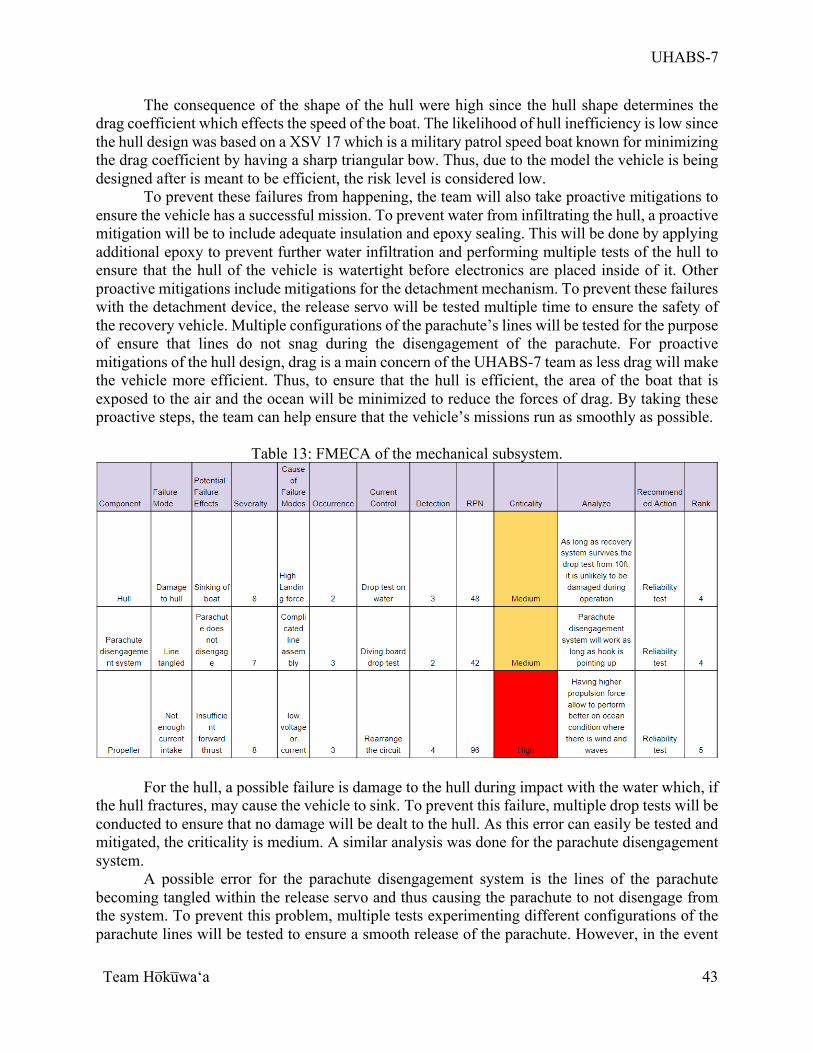
UHABS-7
Team Ho̅ku̅waʻa
43
The consequence of the shape of the hull were high since the hull shape determines the drag coefficient which effects the speed of the boat. The likelihood of hull inefficiency is low since the hull design was based on a XSV 17 which is a military patrol speed boat known for minimizing the drag coefficient by having a sharp triangular bow. Thus, due to the model the vehicle is being designed after is meant to be efficient, the risk level is considered low.
To prevent these failures from happening, the team will also take proactive mitigations to ensure the vehicle has a successful mission. To prevent water from infiltrating the hull, a proactive mitigation will be to include adequate insulation and epoxy sealing. This will be done by applying additional epoxy to prevent further water infiltration and performing multiple tests of the hull to ensure that the hull of the vehicle is watertight before electronics are placed inside of it. Other proactive mitigations include mitigations for the detachment mechanism. To prevent these failures with the detachment device, the release servo will be tested multiple time to ensure the safety of the recovery vehicle. Multiple configurations of the parachute’s lines will be tested for the purpose of ensure that lines do not snag during the disengagement of the parachute. For proactive mitigations of the hull design, drag is a main concern of the UHABS-7 team as less drag will make the vehicle more efficient. Thus, to ensure that the hull is efficient, the area of the boat that is exposed to the air and the ocean will be minimized to reduce the forces of drag. By taking these proactive steps, the team can help ensure that the vehicle’s missions run as smoothly as possible.
Table 13: FMECA of the mechanical subsystem.
For the hull, a possible failure is damage to the hull during impact with the water which, if the hull fractures, may cause the vehicle to sink. To prevent this failure, multiple drop tests will be conducted to ensure that no damage will be dealt to the hull. As this error can easily be tested and mitigated, the criticality is medium. A similar analysis was done for the parachute disengagement system.
A possible error for the parachute disengagement system is the lines of the parachute becoming tangled within the release servo and thus causing the parachute to not disengage from the system. To prevent this problem, multiple tests experimenting different configurations of the parachute lines will be tested to ensure a smooth release of the parachute. However, in the event
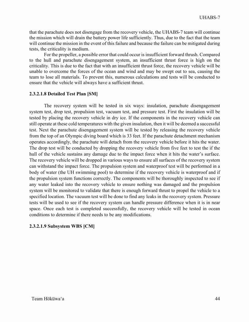
UHABS-7
Team Ho̅ku̅waʻa
44
that the parachute does not disengage from the recovery vehicle, the UHABS-7 team will continue the mission which will drain the battery power life sufficiently. Thus, due to the fact that the team will continue the mission in the event of this failure and because the failure can be mitigated during tests, the criticality is medium.
For the propeller, a possible error that could occur is insufficient forward thrush. Compared to the hull and parachute disengagement system, an insufficient thrust force is high on the criticality. This is due to the fact that with an insufficient thrust force, the recovery vehicle will be unable to overcome the forces of the ocean and wind and may be swept out to sea, causing the team to lose all materials. To prevent this, numerous calculations and tests will be conducted to ensure that the vehicle will always have a sufficient thrust. 2.3.2.1.8 Detailed Test Plan [SM]
The recovery system will be tested in six ways: insulation, parachute disengagement system test, drop test, propulsion test, vacuum test, and pressure test. First the insulation will be tested by placing the recovery vehicle in dry ice. If the components in the recovery vehicle can still operate at these cold temperatures with the given insulation, then it will be deemed a successful test. Next the parachute disengagement system will be tested by releasing the recovery vehicle from the top of an Olympic diving board which is 33 feet. If the parachute detachment mechanism operates accordingly, the parachute will detach from the recovery vehicle before it hits the water. The drop test will be conducted by dropping the recovery vehicle from five feet to test the if the hull of the vehicle sustains any damage due to the impact force when it hits the water’s surface. The recovery vehicle will be dropped in various ways to ensure all surfaces of the recovery system can withstand the impact force. The propulsion system and waterproof test will be performed in a body of water (the UH swimming pool) to determine if the recovery vehicle is waterproof and if the propulsion system functions correctly. The components will be thoroughly inspected to see if any water leaked into the recovery vehicle to ensure nothing was damaged and the propulsion system will be monitored to validate that there is enough forward thrust to propel the vehicle to a specified location. The vacuum test will be done to find any leaks in the recovery system. Pressure tests will be used to see if the recovery system can handle pressure difference when it is in near space. Once each test is completed successfully, the recovery vehicle will be tested in ocean conditions to determine if there needs to be any modifications. 2.3.2.1.9 Subsystem WBS [CM]
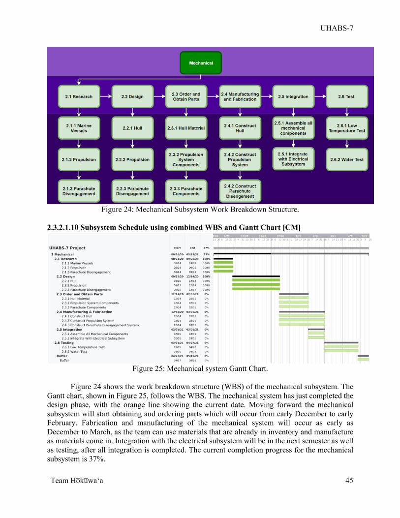
UHABS-7
Team Ho̅ku̅waʻa
45
Figure 24: Mechanical Subsystem Work Breakdown Structure.
2.3.2.1.10 Subsystem Schedule using combined WBS and Gantt Chart [CM]
Figure 25: Mechanical system Gantt Chart.
Figure 24 shows the work breakdown structure (WBS) of the mechanical subsystem. The
Gantt chart, shown in Figure 25, follows the WBS. The mechanical system has just completed the design phase, with the orange line showing the current date. Moving forward the mechanical subsystem will start obtaining and ordering parts which will occur from early December to early February. Fabrication and manufacturing of the mechanical system will occur as early as December to March, as the team can use materials that are already in inventory and manufacture as materials come in. Integration with the electrical subsystem will be in the next semester as well as testing, after all integration is completed. The current completion progress for the mechanical subsystem is 37%.
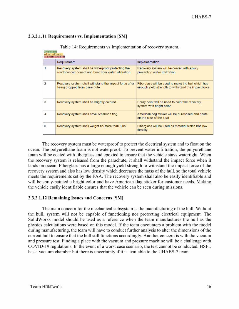
UHABS-7
Team Ho̅ku̅waʻa
46
2.3.2.1.11 Requirements vs. Implementation [SM]
Table 14: Requirements vs Implementation of recovery system.
The recovery system must be waterproof to protect the electrical system and to float on the ocean. The polyurethane foam is not waterproof. To prevent water infiltration, the polyurethane foam will be coated with fiberglass and epoxied to ensure that the vehicle stays watertight. When the recovery system is released from the parachute, it shall withstand the impact force when it lands on ocean. Fiberglass has a large enough yield strength to withstand the impact force of the recovery system and also has low density which decreases the mass of the hull, so the total vehicle meets the requirements set by the FAA. The recovery system shall also be easily identifiable and will be spray-painted a bright color and have American flag sticker for customer needs. Making the vehicle easily identifiable ensures that the vehicle can be seen during missions. 2.3.2.1.12 Remaining Issues and Concerns [SM]
The main concern for the mechanical subsystem is the manufacturing of the hull. Without the hull, system will not be capable of functioning nor protecting electrical equipment. The SolidWorks model should be used as a reference when the team manufactures the hull as the physics calculations were based on this model. If the team encounters a problem with the model during manufacturing, the team will have to conduct further analysis to alter the dimensions of the current hull to ensure that the hull still functions accordingly. Another concern is with the vacuum and pressure test. Finding a place with the vacuum and pressure machine will be a challenge with COVID-19 regulations. In the event of a worst case scenario, the test cannot be conducted. HSFL has a vacuum chamber but there is uncertainty if it is available to the UHABS-7 team.
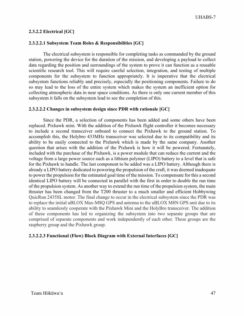
UHABS-7
Team Ho̅ku̅waʻa
47
2.3.2.2 Electrical [GC] 2.3.2.2.1 Subsystem Team Roles & Responsibilities [GC]
The electrical subsystem is responsible for completing tasks as commanded by the ground station, powering the device for the duration of the mission, and developing a payload to collect data regarding the position and surroundings of the system to prove it can function as a reusable scientific research tool. This will require careful selection, integration, and testing of multiple components for the subsystem to function appropriately. It is imperative that the electrical subsystem functions reliably and precisely, especially the positioning components. Failure to do so may lead to the loss of the entire system which makes the system an inefficient option for collecting atmospheric data in near space conditions. As there is only one current member of this subsystem it falls on the subsystem lead to see the completion of this. 2.3.2.2.2 Changes in subsystem design since PDR with rationale [GC]
Since the PDR, a selection of components has been added and some others have been replaced. Pixhawk mini. With the addition of the Pixhawk flight controller it becomes necessary to include a second transceiver onboard to connect the Pixhawk to the ground station. To accomplish this, the Holybro 433MHz transceiver was selected due to its compatibility and its ability to be easily connected to the Pixhawk which is made by the same company. Another question that arises with the addition of the Pixhawk is how it will be powered. Fortunately, included with the purchase of the Pixhawk, is a power module that can reduce the current and the voltage from a large power source such as a lithium polymer (LIPO) battery to a level that is safe for the Pixhawk to handle. The last component to be added was a LIPO battery. Although there is already a LIPO battery dedicated to powering the propulsion of the craft, it was deemed inadequate to power the propulsion for the estimated goal time of the mission. To compensate for this a second identical LIPO battery will be connected in parallel with the first in order to double the run time of the propulsion system. As another way to extend the run time of the propulsion system, the main thruster has been changed from the T200 thruster to a much smaller and efficient Hobbywing QuicRun 2435SL motor. The final change to occur in the electrical subsystem since the PDR was to replace the initial uBLOX Max-M8Q GPS and antenna to the uBLOX M8N GPS unit due to its ability to seamlessly cooperate with the Pixhawk Mini and the HolyBro transceiver. The addition of these components has led to organizing the subsystem into two separate groups that are comprised of separate components and work independently of each other. These groups are the raspberry group and the Pixhawk group.
2.3.2.2.3 Functional (Flow) Block Diagram with External Interfaces [GC]
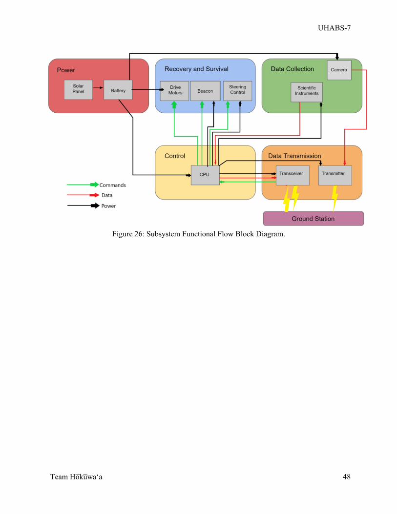
UHABS-7
Team Ho̅ku̅waʻa
48
Figure 26: Subsystem Functional Flow Block Diagram.
UHABS-7
Team Ho̅ku̅waʻa
49
Figure 27: Overall FFBD with highlighted components of electrical subsystem.
Pictured in Figure 26 is the functional flow block diagram for the electrical subsystem.
Contained in the diagram is a basic expected configuration of the subsystem and how the flow of data, commands, and power, based upon grouping. The power group is dedicated to supplying power to the rest of the components; it is anticipated that one battery will be used to power all components of the entire electrical subsystem that do not have an internal power supply. If it is determined that this battery is not capable of providing power during the duration of the mission, a solar panel will be added to recharge the battery during the mission.
The recovery and survival group encompasses all instruments necessary for the survival and recovery of the system. This group primarily concerns the propulsion and steering systems but may include a heater or pressure regulator to ensure the survival and functionality of onboard equipment as well as a beacon to help aid in recovery.
The third group is data collection. The components that comprise this system are the scientific instruments used to collect data during the mission. The type of data that must be collected will determine what instruments are on board during the mission. It is anticipated that these instruments will include a thermometer and a pressure sensor.
The fourth group is the data transmission group and is responsible for all components that send and receive data to and from the ground control station. This mainly includes any transmitters and transceivers that the on-board equipment is compatible with. Both a transceiver and transmitter were included since the previous UHABS team needed to utilize two separate transmitters to send
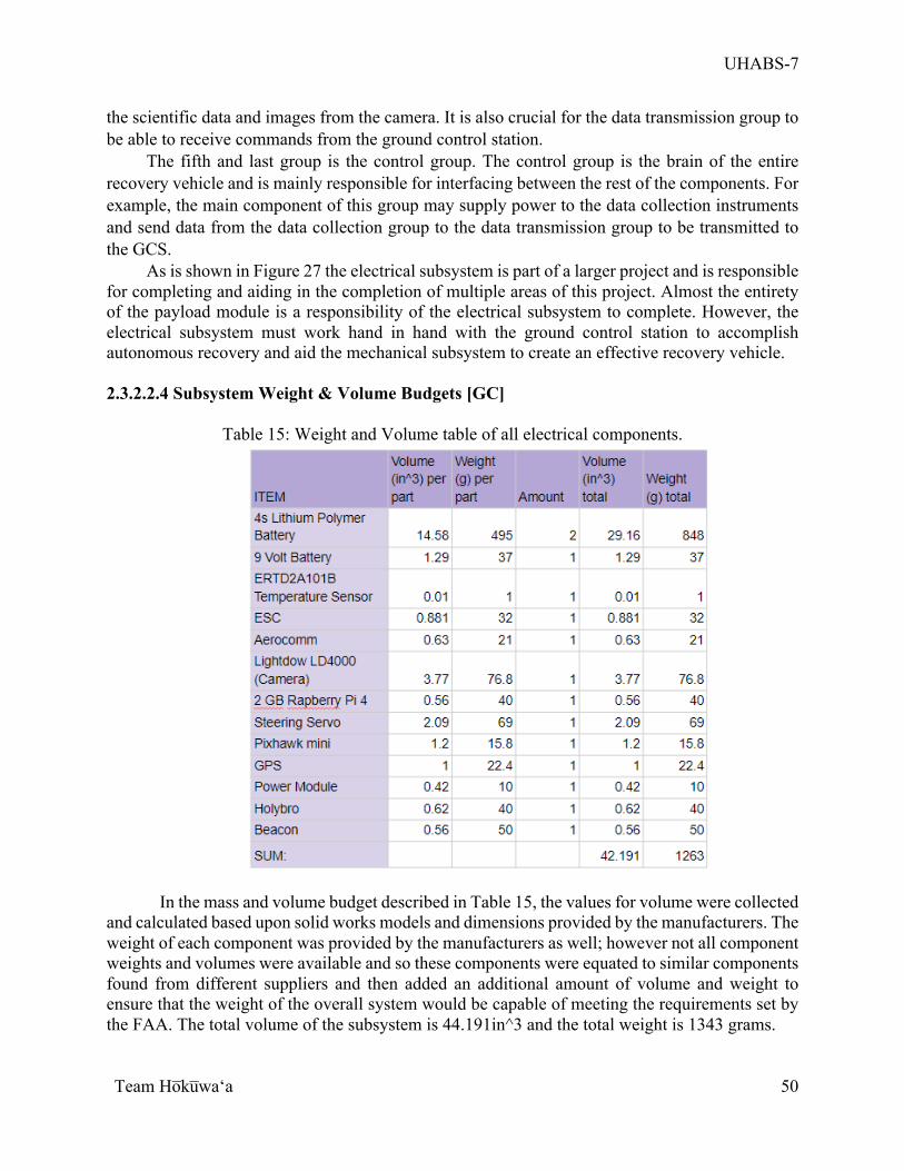
UHABS-7
Team Ho̅ku̅waʻa
50
the scientific data and images from the camera. It is also crucial for the data transmission group to be able to receive commands from the ground control station.
The fifth and last group is the control group. The control group is the brain of the entire recovery vehicle and is mainly responsible for interfacing between the rest of the components. For example, the main component of this group may supply power to the data collection instruments and send data from the data collection group to the data transmission group to be transmitted to the GCS.
As is shown in Figure 27 the electrical subsystem is part of a larger project and is responsible for completing and aiding in the completion of multiple areas of this project. Almost the entirety of the payload module is a responsibility of the electrical subsystem to complete. However, the electrical subsystem must work hand in hand with the ground control station to accomplish autonomous recovery and aid the mechanical subsystem to create an effective recovery vehicle. 2.3.2.2.4 Subsystem Weight & Volume Budgets [GC]
Table 15: Weight and Volume table of all electrical components.
In the mass and volume budget described in Table 15, the values for volume were collected and calculated based upon solid works models and dimensions provided by the manufacturers. The weight of each component was provided by the manufacturers as well; however not all component weights and volumes were available and so these components were equated to similar components found from different suppliers and then added an additional amount of volume and weight to ensure that the weight of the overall system would be capable of meeting the requirements set by the FAA. The total volume of the subsystem is 44.191in^3 and the total weight is 1343 grams.
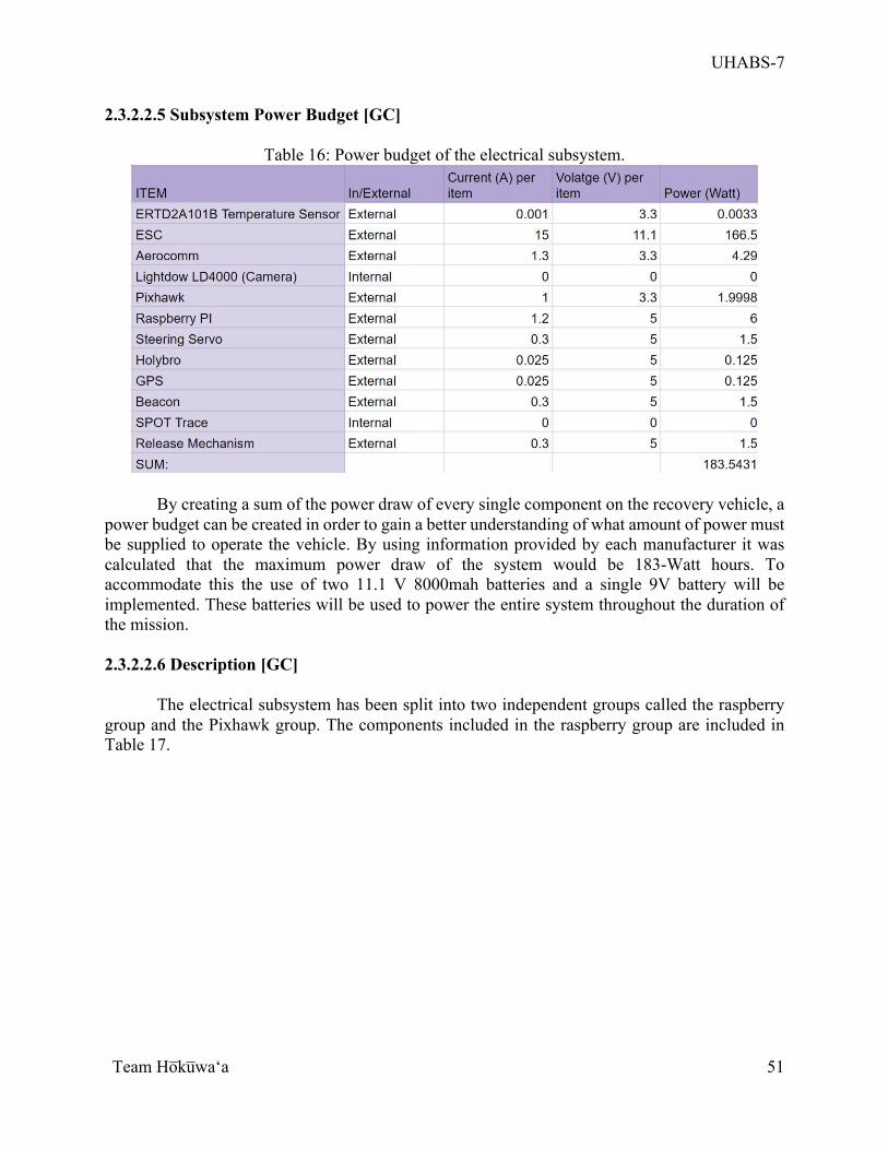
UHABS-7
Team Ho̅ku̅waʻa
51
2.3.2.2.5 Subsystem Power Budget [GC]
Table 16: Power budget of the electrical subsystem.
By creating a sum of the power draw of every single component on the recovery vehicle, a power budget can be created in order to gain a better understanding of what amount of power must be supplied to operate the vehicle. By using information provided by each manufacturer it was calculated that the maximum power draw of the system would be 183-Watt hours. To accommodate this the use of two 11.1 V 8000mah batteries and a single 9V battery will be implemented. These batteries will be used to power the entire system throughout the duration of the mission. 2.3.2.2.6 Description [GC]
The electrical subsystem has been split into two independent groups called the raspberry
group and the Pixhawk group. The components included in the raspberry group are included in Table 17.
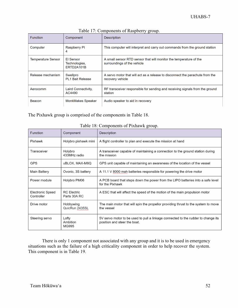
UHABS-7
Team Ho̅ku̅waʻa
52
Table 17: Components of Raspberry group.
The Pixhawk group is comprised of the components in Table 18.
Table 18: Components of Pixhawk group.
There is only 1 component not associated with any group and it is to be used in emergency situations such as the failure of a high criticality component in order to help recover the system. This component is in Table 19.
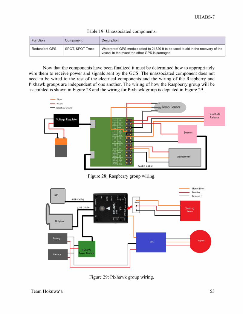
UHABS-7
Team Ho̅ku̅waʻa
53
Table 19: Unassociated components.
Now that the components have been finalized it must be determined how to appropriately wire them to receive power and signals sent by the GCS. The unassociated component does not need to be wired to the rest of the electrical components and the wiring of the Raspberry and Pixhawk groups are independent of one another. The wiring of how the Raspberry group will be assembled is shown in Figure 28 and the wiring for Pixhawk group is depicted in Figure 29.
Figure 28: Raspberry group wiring.
Figure 29: Pixhawk group wiring.
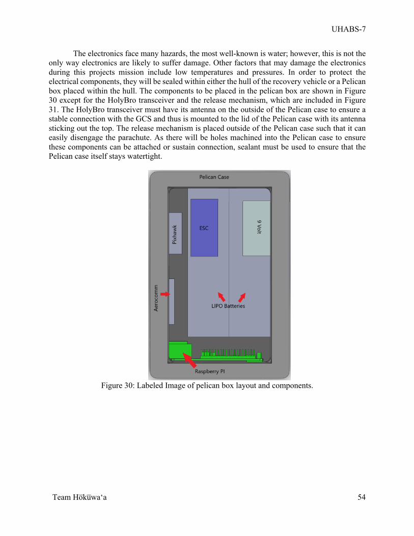
UHABS-7
Team Ho̅ku̅waʻa
54
The electronics face many hazards, the most well-known is water; however, this is not the only way electronics are likely to suffer damage. Other factors that may damage the electronics during this projects mission include low temperatures and pressures. In order to protect the electrical components, they will be sealed within either the hull of the recovery vehicle or a Pelican box placed within the hull. The components to be placed in the pelican box are shown in Figure 30 except for the HolyBro transceiver and the release mechanism, which are included in Figure 31. The HolyBro transceiver must have its antenna on the outside of the Pelican case to ensure a stable connection with the GCS and thus is mounted to the lid of the Pelican case with its antenna sticking out the top. The release mechanism is placed outside of the Pelican case such that it can easily disengage the parachute. As there will be holes machined into the Pelican case to ensure these components can be attached or sustain connection, sealant must be used to ensure that the Pelican case itself stays watertight.
Figure 30: Labeled Image of pelican box layout and components.
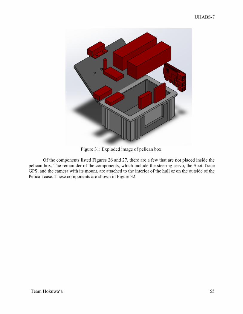
UHABS-7
Team Ho̅ku̅waʻa
55
Figure 31: Exploded image of pelican box.
Of the components listed Figures 26 and 27, there are a few that are not placed inside the
pelican box. The remainder of the components, which include the steering servo, the Spot Trace GPS, and the camera with its mount, are attached to the interior of the hull or on the outside of the Pelican case. These components are shown in Figure 32.
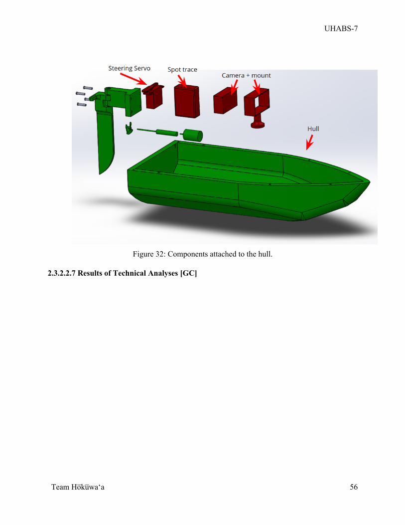
UHABS-7
Team Ho̅ku̅waʻa
56
Figure 32: Components attached to the hull.
2.3.2.2.7 Results of Technical Analyses [GC]
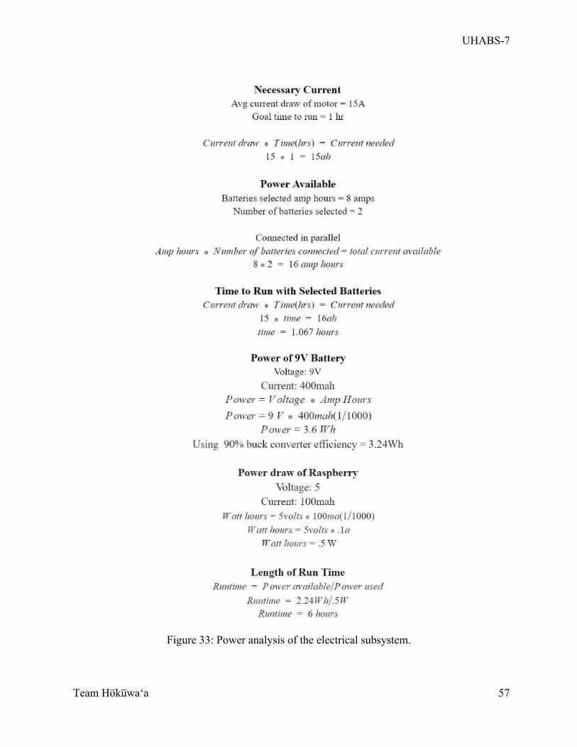
UHABS-7
Team Ho̅ku̅waʻa
57
Figure 33: Power analysis of the electrical subsystem.
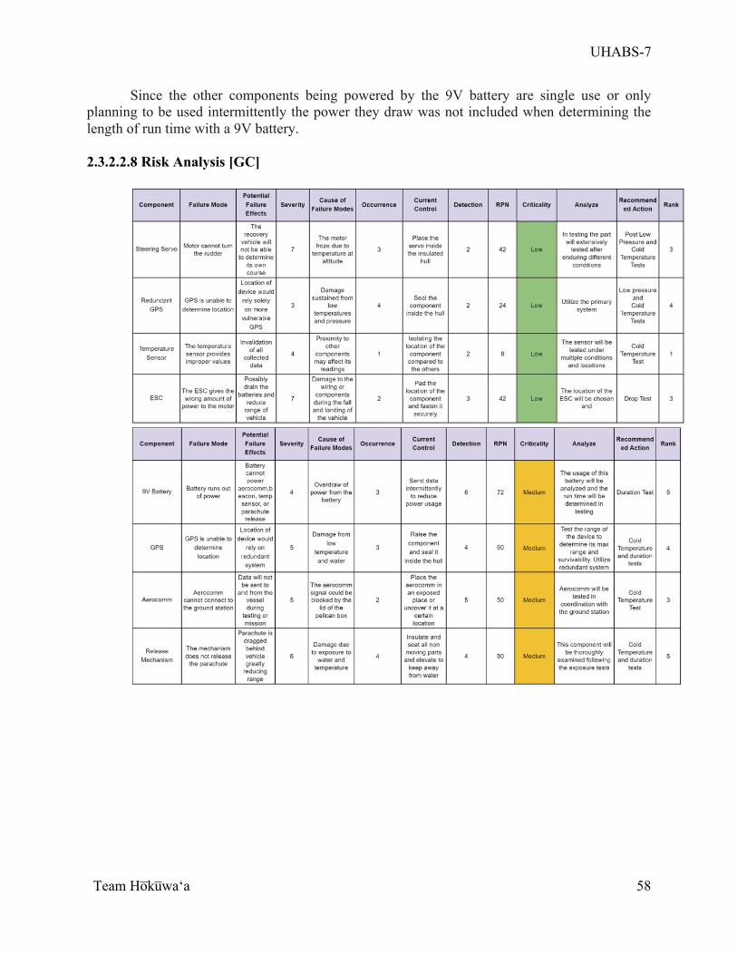
UHABS-7
Team Ho̅ku̅waʻa
58
Since the other components being powered by the 9V battery are single use or only planning to be used intermittently the power they draw was not included when determining the length of run time with a 9V battery. 2.3.2.2.8 Risk Analysis [GC]
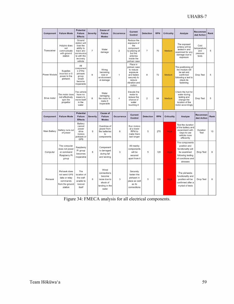
UHABS-7
Team Ho̅ku̅waʻa
59
Figure 34: FMECA analysis for all electrical components.
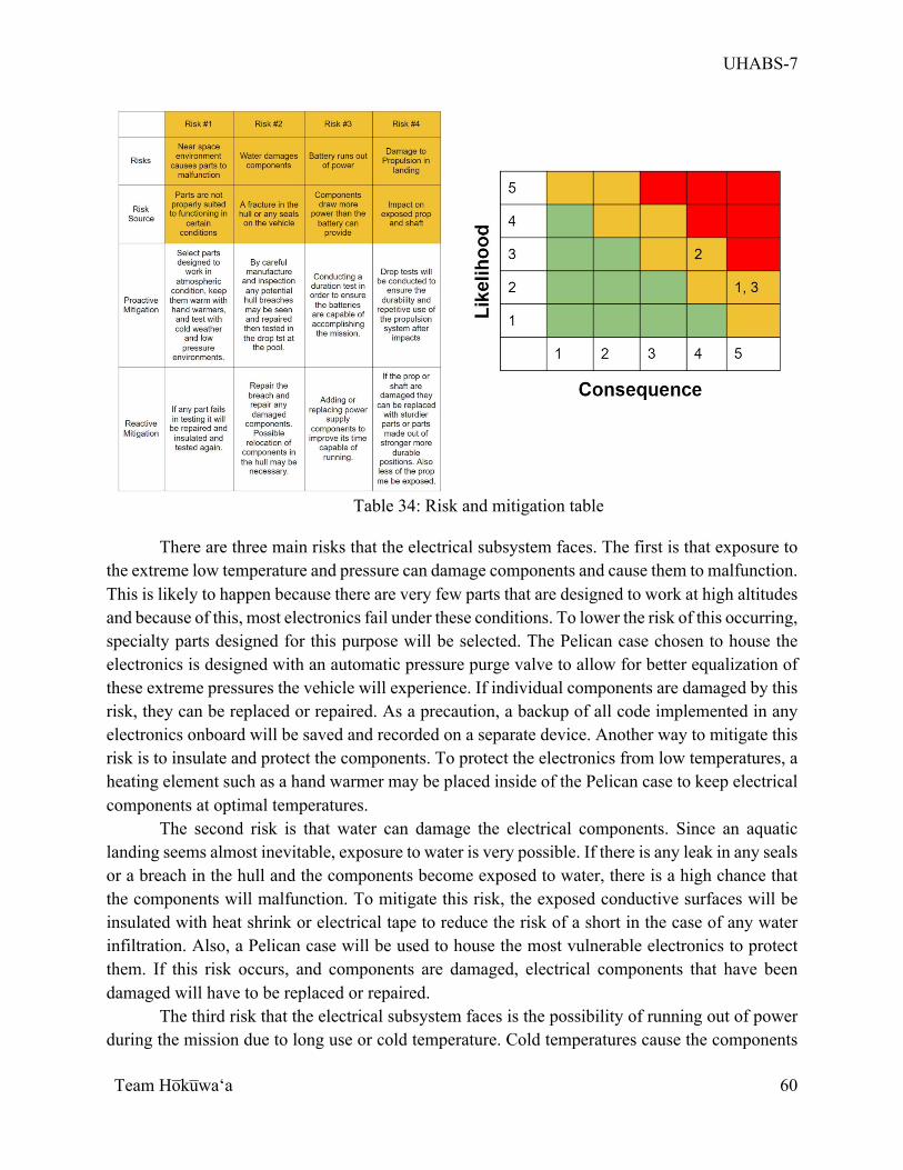
UHABS-7
Team Ho̅ku̅waʻa
60
Table 34: Risk and mitigation table
There are three main risks that the electrical subsystem faces. The first is that exposure to
the extreme low temperature and pressure can damage components and cause them to malfunction. This is likely to happen because there are very few parts that are designed to work at high altitudes and because of this, most electronics fail under these conditions. To lower the risk of this occurring, specialty parts designed for this purpose will be selected. The Pelican case chosen to house the electronics is designed with an automatic pressure purge valve to allow for better equalization of these extreme pressures the vehicle will experience. If individual components are damaged by this risk, they can be replaced or repaired. As a precaution, a backup of all code implemented in any electronics onboard will be saved and recorded on a separate device. Another way to mitigate this risk is to insulate and protect the components. To protect the electronics from low temperatures, a heating element such as a hand warmer may be placed inside of the Pelican case to keep electrical components at optimal temperatures.
The second risk is that water can damage the electrical components. Since an aquatic landing seems almost inevitable, exposure to water is very possible. If there is any leak in any seals or a breach in the hull and the components become exposed to water, there is a high chance that the components will malfunction. To mitigate this risk, the exposed conductive surfaces will be insulated with heat shrink or electrical tape to reduce the risk of a short in the case of any water infiltration. Also, a Pelican case will be used to house the most vulnerable electronics to protect them. If this risk occurs, and components are damaged, electrical components that have been damaged will have to be replaced or repaired.
The third risk that the electrical subsystem faces is the possibility of running out of power during the mission due to long use or cold temperature. Cold temperatures cause the components
UHABS-7
Team Ho̅ku̅waʻa
61
to draw more current and thus deplete the batteries faster. In order to remedy this problem, a solar panel can be fitted to charge the battery when it is low, or the battery can also be oversized and use resistors and transistors that will step down the power to make it safe for the components. A solar panel is a more likely option as continuous charging of the batteries would be a large asset to the team.
The fourth risk is that the exposed propulsion system sustains damage due to the force of a water landing. To reduce the risk of this happening during the mission the components will be subjected to a drop test into water at the UH pool that will place the propulsion system under stress to demonstrate if it meets its strength requirements. If the components are irreparably damaged in the drop test the shaft can be swapped out of one of thicker diameter and the prop can be purchased as metal instead of plastic.
2.3.2.2.9 Detailed Test Plan [GC]
By sending electronics to a high altitude, they will be exposed to two different extremes that have the potential to damage the components or render them inoperable. These conditions are low temperature and pressure. In order to test functionality, the system will be placed in a container filled with dry ice to test that the components are functional in a low temperature environment. This test will also serve to test that the insulation of the device is able to protect the components within a low temperature environment. As mentioned previously, one way to protect these components is to place hand or foot warmers inside of the recovery vehicle to produce heat and keep the components warm enough to function properly. To test for functionality in low pressure, the system will be placed in a vacuum chamber borrowed from HSFL or the team will construct a pressure chamber with a vacuum pump and all components will be used to ensure functionality. Assuming that all components remain functional during the tests, the system will be considered ready to attempt a mission. If certain components are damaged in either test, they will be reselected or alternatively protected to ensure their future success. If components fail to function properly or the team loses connection with the vehicle, the team will identify the problem and fix accordingly. A final test will involve running the propulsion motor under load to determine its actual run time and help the team determine the vehicle’s range.
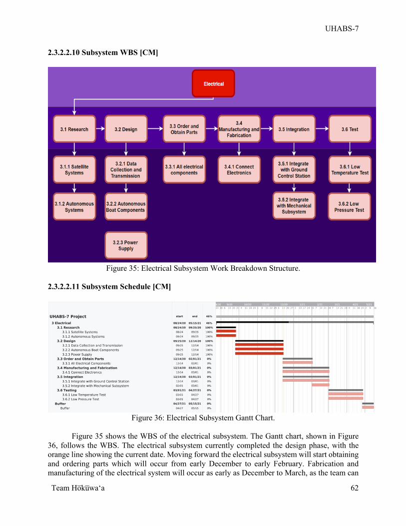
UHABS-7
Team Ho̅ku̅waʻa
62
2.3.2.2.10 Subsystem WBS [CM]
Figure 35: Electrical Subsystem Work Breakdown Structure.
2.3.2.2.11 Subsystem Schedule [CM]
Figure 36: Electrical Subsystem Gantt Chart.
Figure 35 shows the WBS of the electrical subsystem. The Gantt chart, shown in Figure
36, follows the WBS. The electrical subsystem currently completed the design phase, with the orange line showing the current date. Moving forward the electrical subsystem will start obtaining and ordering parts which will occur from early December to early February. Fabrication and manufacturing of the electrical system will occur as early as December to March, as the team can
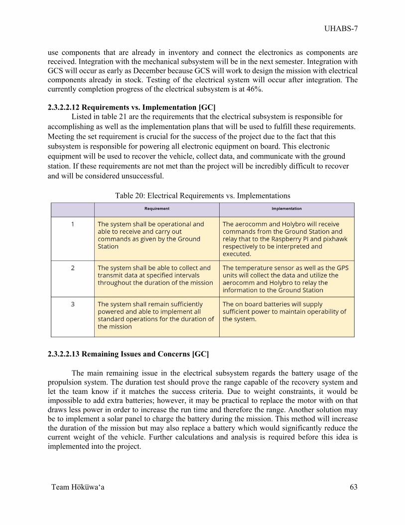
UHABS-7
Team Ho̅ku̅waʻa
63
use components that are already in inventory and connect the electronics as components are received. Integration with the mechanical subsystem will be in the next semester. Integration with GCS will occur as early as December because GCS will work to design the mission with electrical components already in stock. Testing of the electrical system will occur after integration. The currently completion progress of the electrical subsystem is at 46%.
2.3.2.2.12 Requirements vs. Implementation [GC]
Listed in table 21 are the requirements that the electrical subsystem is responsible for accomplishing as well as the implementation plans that will be used to fulfill these requirements. Meeting the set requirement is crucial for the success of the project due to the fact that this subsystem is responsible for powering all electronic equipment on board. This electronic equipment will be used to recover the vehicle, collect data, and communicate with the ground station. If these requirements are not met than the project will be incredibly difficult to recover and will be considered unsuccessful.
Table 20: Electrical Requirements vs. Implementations
2.3.2.2.13 Remaining Issues and Concerns [GC]
The main remaining issue in the electrical subsystem regards the battery usage of the propulsion system. The duration test should prove the range capable of the recovery system and let the team know if it matches the success criteria. Due to weight constraints, it would be impossible to add extra batteries; however, it may be practical to replace the motor with on that draws less power in order to increase the run time and therefore the range. Another solution may be to implement a solar panel to charge the battery during the mission. This method will increase the duration of the mission but may also replace a battery which would significantly reduce the current weight of the vehicle. Further calculations and analysis is required before this idea is implemented into the project.
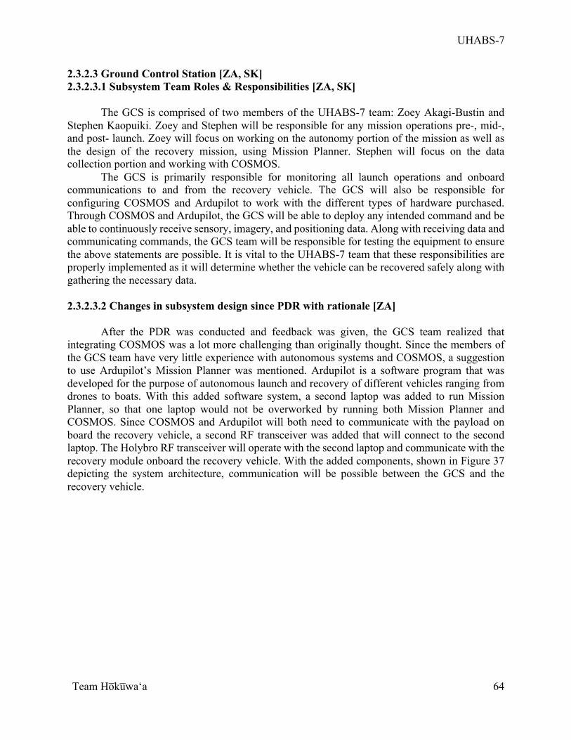
UHABS-7
Team Ho̅ku̅waʻa
64
2.3.2.3 Ground Control Station [ZA, SK] 2.3.2.3.1 Subsystem Team Roles & Responsibilities [ZA, SK]
The GCS is comprised of two members of the UHABS-7 team: Zoey Akagi-Bustin and Stephen Kaopuiki. Zoey and Stephen will be responsible for any mission operations pre-, mid-, and post- launch. Zoey will focus on working on the autonomy portion of the mission as well as the design of the recovery mission, using Mission Planner. Stephen will focus on the data collection portion and working with COSMOS.
The GCS is primarily responsible for monitoring all launch operations and onboard communications to and from the recovery vehicle. The GCS will also be responsible for configuring COSMOS and Ardupilot to work with the different types of hardware purchased. Through COSMOS and Ardupilot, the GCS will be able to deploy any intended command and be able to continuously receive sensory, imagery, and positioning data. Along with receiving data and communicating commands, the GCS team will be responsible for testing the equipment to ensure the above statements are possible. It is vital to the UHABS-7 team that these responsibilities are properly implemented as it will determine whether the vehicle can be recovered safely along with gathering the necessary data.
2.3.2.3.2 Changes in subsystem design since PDR with rationale [ZA]
After the PDR was conducted and feedback was given, the GCS team realized that integrating COSMOS was a lot more challenging than originally thought. Since the members of the GCS team have very little experience with autonomous systems and COSMOS, a suggestion to use Ardupilot’s Mission Planner was mentioned. Ardupilot is a software program that was developed for the purpose of autonomous launch and recovery of different vehicles ranging from drones to boats. With this added software system, a second laptop was added to run Mission Planner, so that one laptop would not be overworked by running both Mission Planner and COSMOS. Since COSMOS and Ardupilot will both need to communicate with the payload on board the recovery vehicle, a second RF transceiver was added that will connect to the second laptop. The Holybro RF transceiver will operate with the second laptop and communicate with the recovery module onboard the recovery vehicle. With the added components, shown in Figure 37 depicting the system architecture, communication will be possible between the GCS and the recovery vehicle.
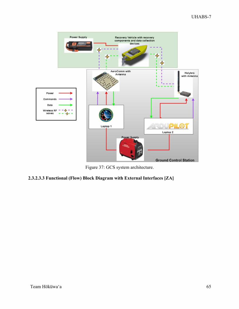
UHABS-7
Team Ho̅ku̅waʻa
65
Figure 37: GCS system architecture.
2.3.2.3.3 Functional (Flow) Block Diagram with External Interfaces [ZA]
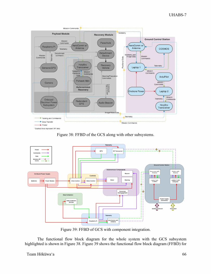
UHABS-7
Team Ho̅ku̅waʻa
66
Figure 38: FFBD of the GCS along with other subsystems.
Figure 39: FFBD of GCS with component integration.
The functional flow block diagram for the whole system with the GCS subsystem
highlighted is shown in Figure 38. Figure 39 shows the functional flow block diagram (FFBD) for
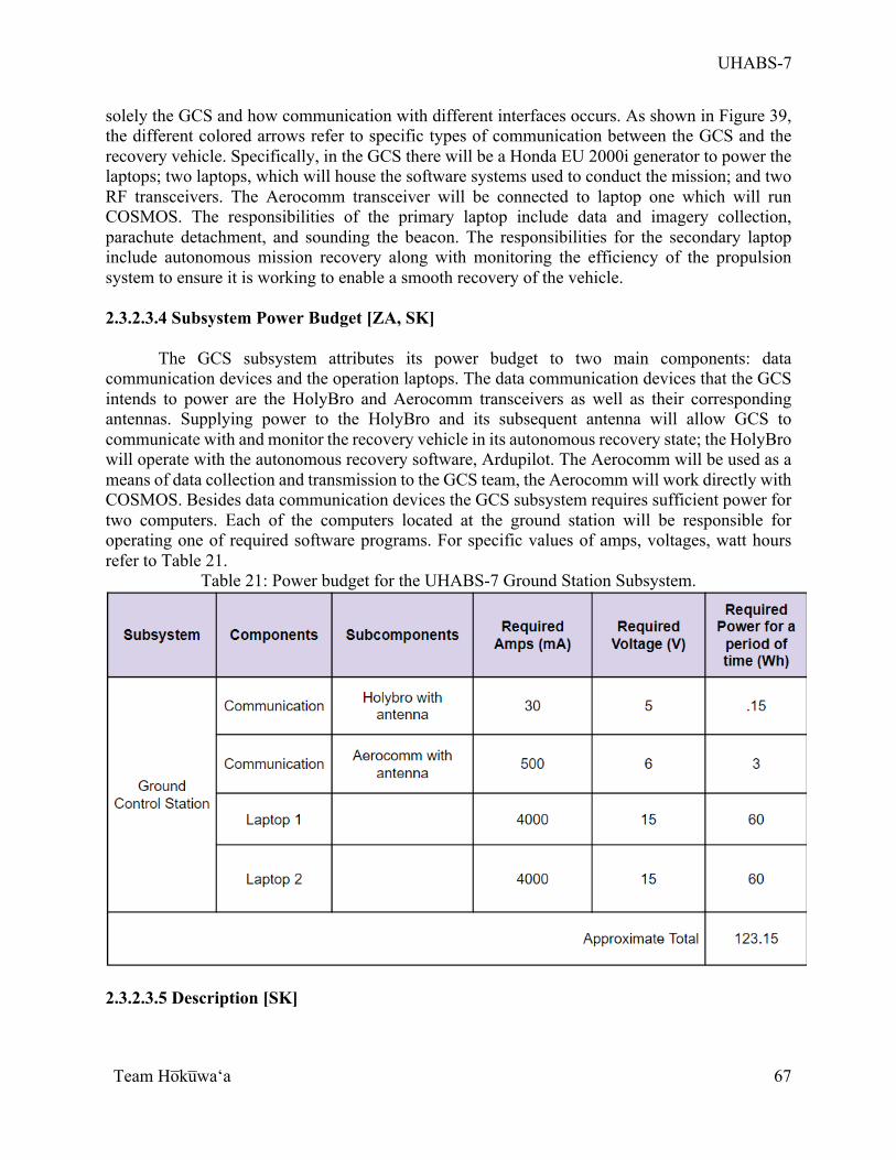
UHABS-7
Team Ho̅ku̅waʻa
67
solely the GCS and how communication with different interfaces occurs. As shown in Figure 39, the different colored arrows refer to specific types of communication between the GCS and the recovery vehicle. Specifically, in the GCS there will be a Honda EU 2000i generator to power the laptops; two laptops, which will house the software systems used to conduct the mission; and two RF transceivers. The Aerocomm transceiver will be connected to laptop one which will run COSMOS. The responsibilities of the primary laptop include data and imagery collection, parachute detachment, and sounding the beacon. The responsibilities for the secondary laptop include autonomous mission recovery along with monitoring the efficiency of the propulsion system to ensure it is working to enable a smooth recovery of the vehicle. 2.3.2.3.4 Subsystem Power Budget [ZA, SK]
The GCS subsystem attributes its power budget to two main components: data
communication devices and the operation laptops. The data communication devices that the GCS intends to power are the HolyBro and Aerocomm transceivers as well as their corresponding antennas. Supplying power to the HolyBro and its subsequent antenna will allow GCS to communicate with and monitor the recovery vehicle in its autonomous recovery state; the HolyBro will operate with the autonomous recovery software, Ardupilot. The Aerocomm will be used as a means of data collection and transmission to the GCS team, the Aerocomm will work directly with COSMOS. Besides data communication devices the GCS subsystem requires sufficient power for two computers. Each of the computers located at the ground station will be responsible for operating one of required software programs. For specific values of amps, voltages, watt hours refer to Table 21.
Table 21: Power budget for the UHABS-7 Ground Station Subsystem.
2.3.2.3.5 Description [SK]
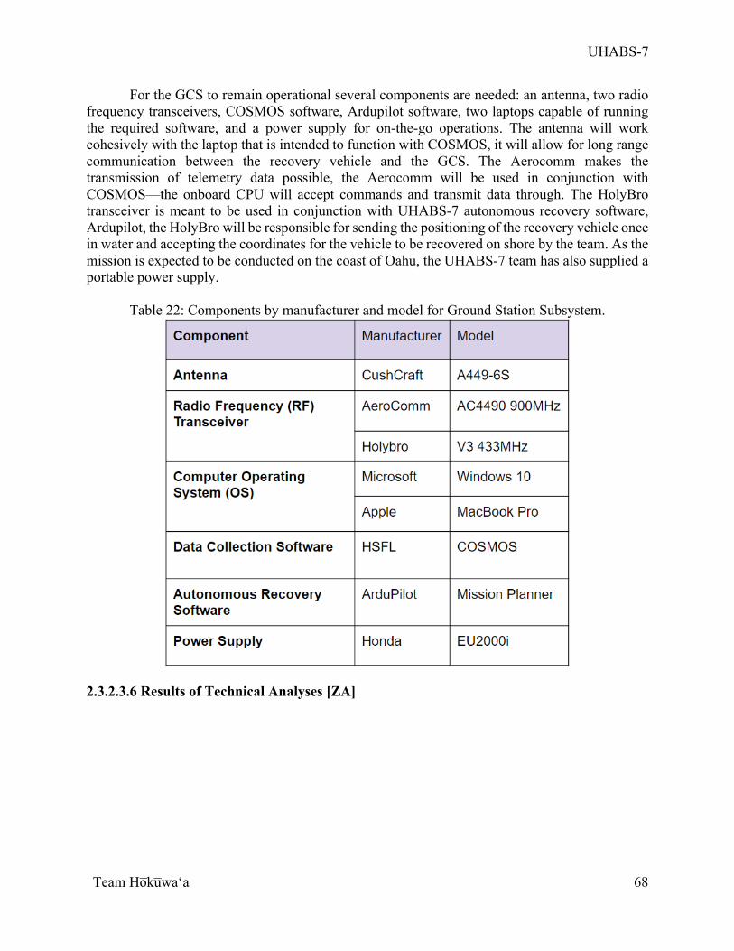
UHABS-7
Team Ho̅ku̅waʻa
68
For the GCS to remain operational several components are needed: an antenna, two radio frequency transceivers, COSMOS software, Ardupilot software, two laptops capable of running the required software, and a power supply for on-the-go operations. The antenna will work cohesively with the laptop that is intended to function with COSMOS, it will allow for long range communication between the recovery vehicle and the GCS. The Aerocomm makes the transmission of telemetry data possible, the Aerocomm will be used in conjunction with COSMOS—the onboard CPU will accept commands and transmit data through. The HolyBro transceiver is meant to be used in conjunction with UHABS-7 autonomous recovery software, Ardupilot, the HolyBro will be responsible for sending the positioning of the recovery vehicle once in water and accepting the coordinates for the vehicle to be recovered on shore by the team. As the mission is expected to be conducted on the coast of Oahu, the UHABS-7 team has also supplied a portable power supply.
Table 22: Components by manufacturer and model for Ground Station Subsystem.
2.3.2.3.6 Results of Technical Analyses [ZA]
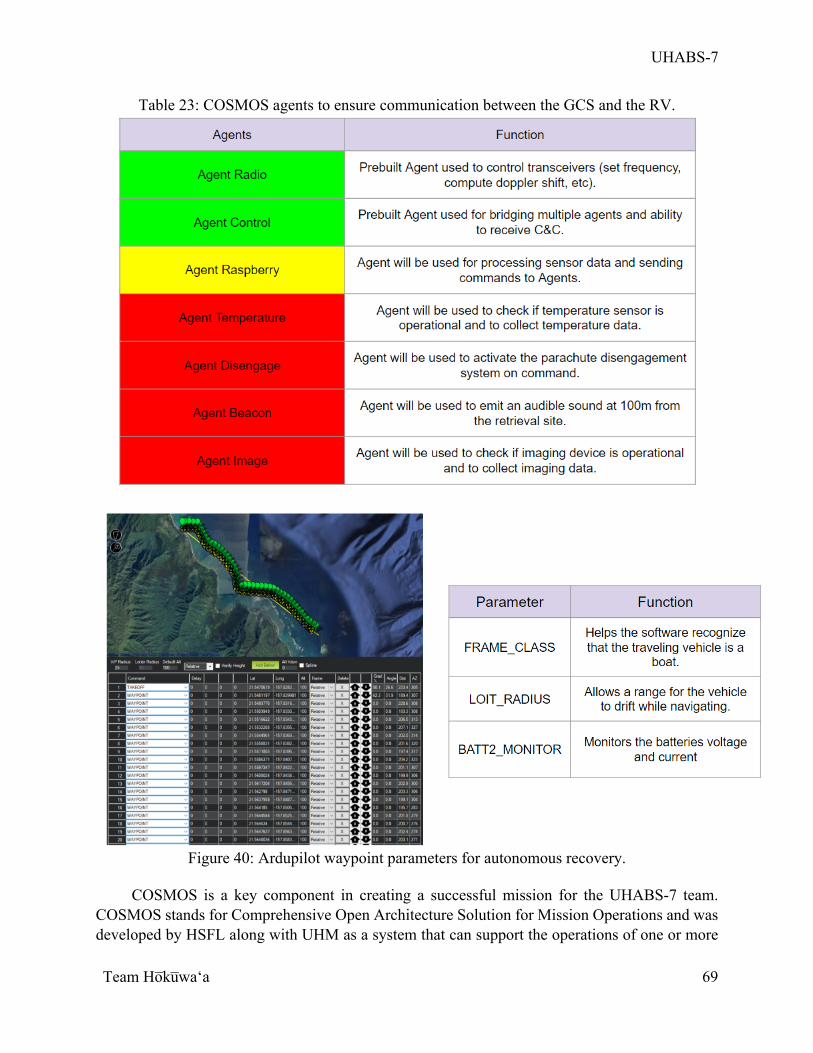
UHABS-7
Team Ho̅ku̅waʻa
69
Table 23: COSMOS agents to ensure communication between the GCS and the RV.
Figure 40: Ardupilot waypoint parameters for autonomous recovery.
COSMOS is a key component in creating a successful mission for the UHABS-7 team.
COSMOS stands for Comprehensive Open Architecture Solution for Mission Operations and was developed by HSFL along with UHM as a system that can support the operations of one or more
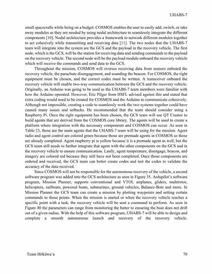
UHABS-7
Team Ho̅ku̅waʻa
70
small spacecrafts while being on a budget. COSMOS enables the user to easily add, switch, or take away modules as they are needed by using nodal architecture to seamlessly integrate the different components [10]. Nodal architecture provides a framework to network different modules together to act cohesively while transmitting and receiving data [11]. The two nodes that the UHABS-7 team will integrate into the system are the GCS and the payload in the recovery vehicle. The first node, which is the GCS, will be the station for receiving data and sending commands to the payload on the recovery vehicle. The second node will be the payload module onboard the recovery vehicle which will receive the commands and send data to the GCS.
Throughout the mission, COSMOS will oversee receiving data from sensors onboard the recovery vehicle, the parachute disengagement, and sounding the beacon. For COSMOS, the right equipment must be chosen, and the correct codes must be written. A transceiver onboard the recovery vehicle will enable two-way communication between the GCS and the recovery vehicle. Originally, an Arduino was going to be used as the UHABS-7 team members were familiar with how the Arduino operated. However, Eric Pilger from HSFL advised against this and stated that extra coding would need to be created for COSMOS and the Arduino to communicate cohesively. Although not impossible, creating a code to seamlessly work the two systems together could have caused many issues and setbacks. He recommended that the team should consider using a Raspberry Pi. Once the right equipment has been chosen, the GCS team will use QT Creator to build agents that are derived from the COSMOS core library. The agents will be used to create a platform where integration with the necessary components and COSMOS can occur. As seen in Table 23, those are the main agents that the UHABS-7 team will be using for the mission. Agent radio and agent control are colored green because those are premade agents in COSMOS so those are already completed. Agent raspberry pi is yellow because it is a premade agent as well, but the GCS team still needs to further integrate that agent with the other components on the GCS and in the recovery vehicle to ensure communication. Lastly, agent temperature, disengage, beacon, and imagery are colored red because they still have not been completed. Once those components are ordered and received, the GCS team can better create codes and test the codes to validate the accuracy of the data received.
Since COSMOS will not be responsible for the autonomous recovery of the vehicle, a second software program was added into the GCS architecture as seen in Figure 35. Ardupilot’s software program, Mission Planner, supports conventional and VTOL airplanes, gliders, multirotor, helicopters, sailboats, powered boats, submarines, ground vehicles, Balance-Bots and more. In Mission Planner the GCS team can create a mission by plotting waypoints and setting certain commands to those points. When the mission is started or when the recovery vehicle reaches a specific point with a task, the recovery vehicle will be sent a command to perform. As seen in Figure 40 the parameters can range from monitoring the batter to ensuring the boat does not drift out of a given radius. With the help of this software program, UHABS-7 will be able to design and complete a smooth autonomous launch and recovery of the recovery vehicle.
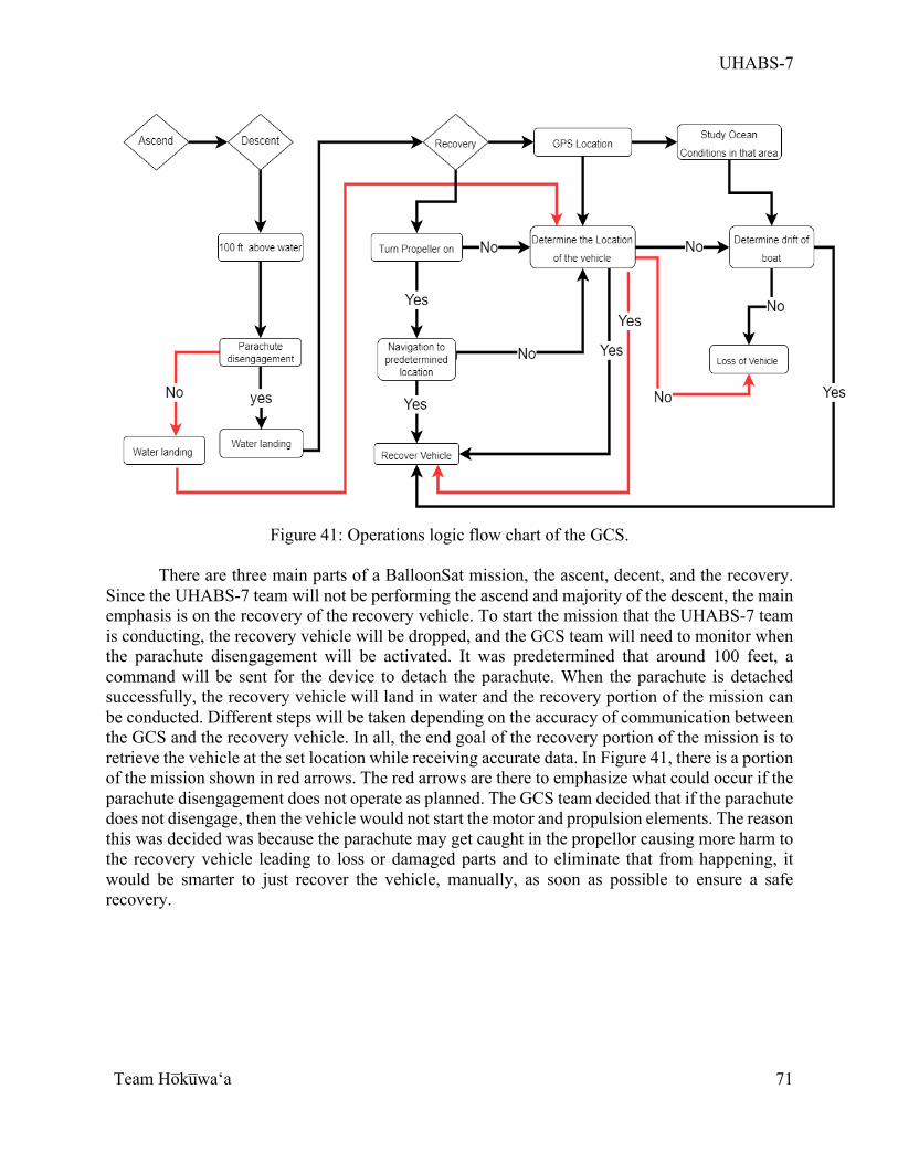
UHABS-7
Team Ho̅ku̅waʻa
71
Figure 41: Operations logic flow chart of the GCS.
There are three main parts of a BalloonSat mission, the ascent, decent, and the recovery.
Since the UHABS-7 team will not be performing the ascend and majority of the descent, the main emphasis is on the recovery of the recovery vehicle. To start the mission that the UHABS-7 team is conducting, the recovery vehicle will be dropped, and the GCS team will need to monitor when the parachute disengagement will be activated. It was predetermined that around 100 feet, a command will be sent for the device to detach the parachute. When the parachute is detached successfully, the recovery vehicle will land in water and the recovery portion of the mission can be conducted. Different steps will be taken depending on the accuracy of communication between the GCS and the recovery vehicle. In all, the end goal of the recovery portion of the mission is to retrieve the vehicle at the set location while receiving accurate data. In Figure 41, there is a portion of the mission shown in red arrows. The red arrows are there to emphasize what could occur if the parachute disengagement does not operate as planned. The GCS team decided that if the parachute does not disengage, then the vehicle would not start the motor and propulsion elements. The reason this was decided was because the parachute may get caught in the propellor causing more harm to the recovery vehicle leading to loss or damaged parts and to eliminate that from happening, it would be smarter to just recover the vehicle, manually, as soon as possible to ensure a safe recovery.
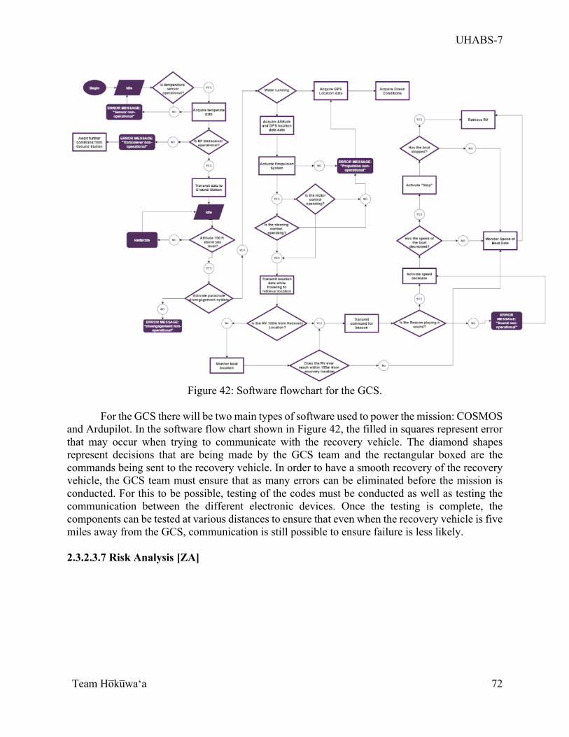
UHABS-7
Team Ho̅ku̅waʻa
72
Figure 42: Software flowchart for the GCS.
For the GCS there will be two main types of software used to power the mission: COSMOS
and Ardupilot. In the software flow chart shown in Figure 42, the filled in squares represent error that may occur when trying to communicate with the recovery vehicle. The diamond shapes represent decisions that are being made by the GCS team and the rectangular boxed are the commands being sent to the recovery vehicle. In order to have a smooth recovery of the recovery vehicle, the GCS team must ensure that as many errors can be eliminated before the mission is conducted. For this to be possible, testing of the codes must be conducted as well as testing the communication between the different electronic devices. Once the testing is complete, the components can be tested at various distances to ensure that even when the recovery vehicle is five miles away from the GCS, communication is still possible to ensure failure is less likely. 2.3.2.3.7 Risk Analysis [ZA]
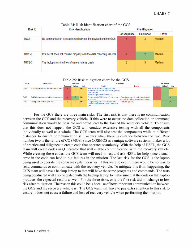
UHABS-7
Team Ho̅ku̅waʻa
73
Table 24: Risk identification chart of the GCS.
Table 25: Risk mitigation chart for the GCS.
For the GCS there are three main risks. The first risk is that there is no communication between the GCS and the recovery vehicle. If this were to occur, no data collection or command communication would be possible and could lead to the loss of the recovery vehicle. To ensure that this does not happen, the GCS will conduct extensive testing with all the components individually as well as a whole. The GCS team will also test the components while at different distances to ensure communication still occurs when there is distance between the two. Risk number two is the failure of COSMOS. Since COSMOS is a unique software system, it takes a lot of practice and diligence to create code that operates seamlessly. With the help of HSFL, the GCS team will create codes in QT creator that will enable communication with the recovery vehicle. While creating these codes, the GCS team will need to test and ask HSFL for help since a small error in the code can lead to big failures in the mission. The last risk for the GCS is the laptop being used to operate the software system crashes. If this were to occur, there would be no way to send commands or communicate with the recovery vehicle. To mitigate this from happening, the GCS team will have a backup laptop to that will have the same programs and commands. The tests being conducted will also be tested with the backup laptop to make sure that the code on that laptop produces the expected results as well. For the three risks, only the first risk did not change to low risk after mitigation. The reason this could be is because of how important communication between the GCS and the recovery vehicle is. The GCS team will have to pay extra attention to this risk to ensure it does not cause a failure and loss of recovery vehicle when performing the mission.
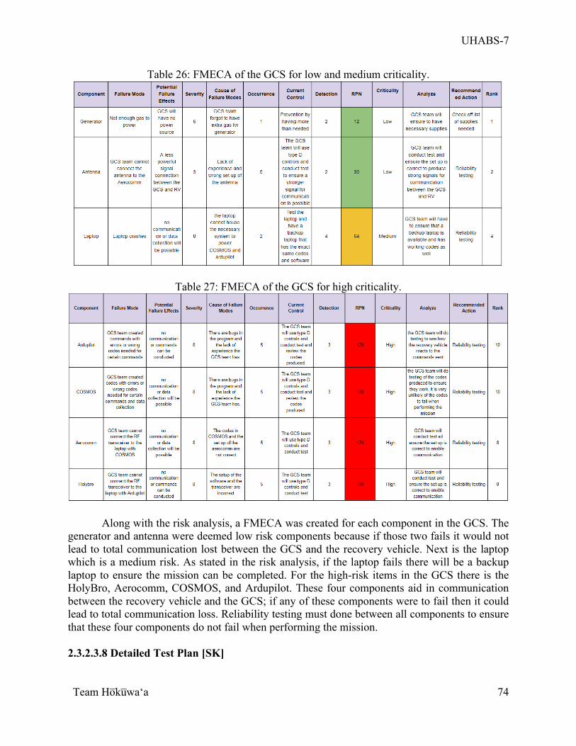
UHABS-7
Team Ho̅ku̅waʻa
74
Table 26: FMECA of the GCS for low and medium criticality.
Table 27: FMECA of the GCS for high criticality.
Along with the risk analysis, a FMECA was created for each component in the GCS. The generator and antenna were deemed low risk components because if those two fails it would not lead to total communication lost between the GCS and the recovery vehicle. Next is the laptop which is a medium risk. As stated in the risk analysis, if the laptop fails there will be a backup laptop to ensure the mission can be completed. For the high-risk items in the GCS there is the HolyBro, Aerocomm, COSMOS, and Ardupilot. These four components aid in communication between the recovery vehicle and the GCS; if any of these components were to fail then it could lead to total communication loss. Reliability testing must done between all components to ensure that these four components do not fail when performing the mission. 2.3.2.3.8 Detailed Test Plan [SK]
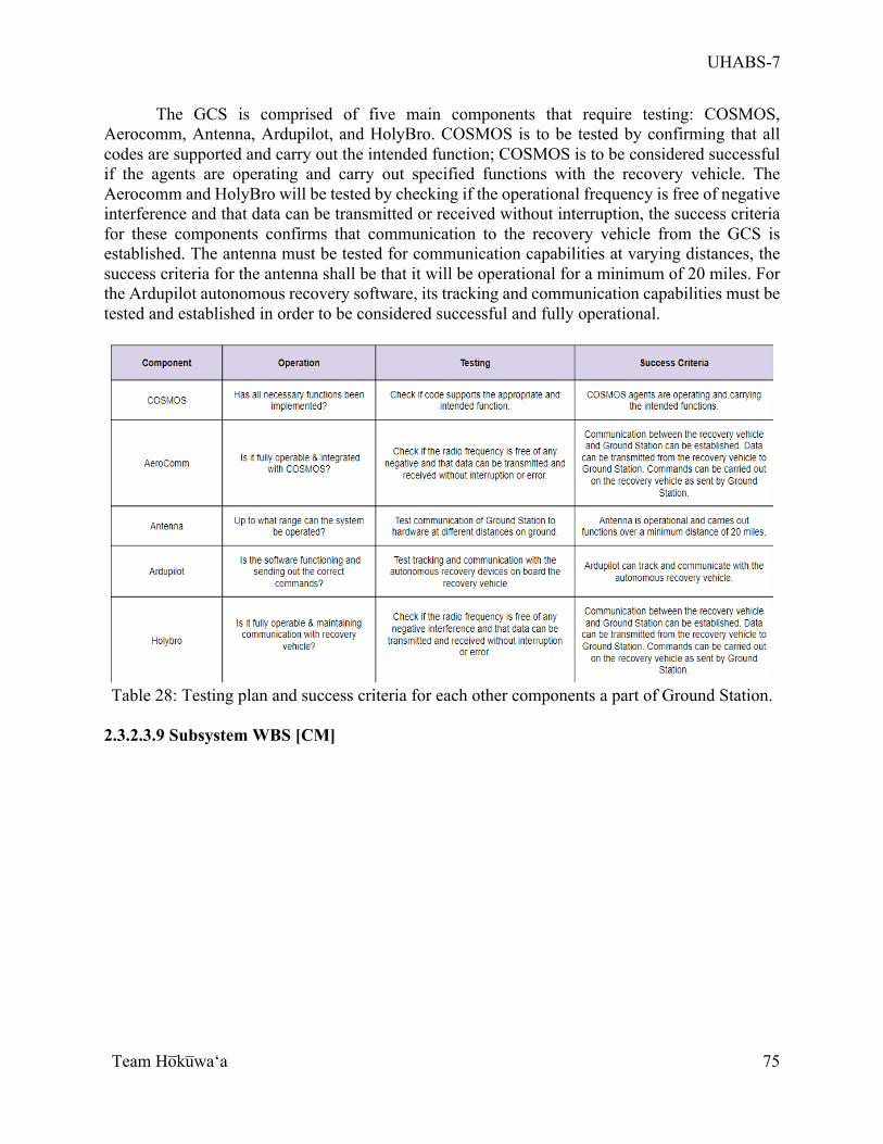
UHABS-7
Team Ho̅ku̅waʻa
75
The GCS is comprised of five main components that require testing: COSMOS, Aerocomm, Antenna, Ardupilot, and HolyBro. COSMOS is to be tested by confirming that all codes are supported and carry out the intended function; COSMOS is to be considered successful if the agents are operating and carry out specified functions with the recovery vehicle. The Aerocomm and HolyBro will be tested by checking if the operational frequency is free of negative interference and that data can be transmitted or received without interruption, the success criteria for these components confirms that communication to the recovery vehicle from the GCS is established. The antenna must be tested for communication capabilities at varying distances, the success criteria for the antenna shall be that it will be operational for a minimum of 20 miles. For the Ardupilot autonomous recovery software, its tracking and communication capabilities must be tested and established in order to be considered successful and fully operational.
Table 28: Testing plan and success criteria for each other components a part of Ground Station.
2.3.2.3.9 Subsystem WBS [CM]
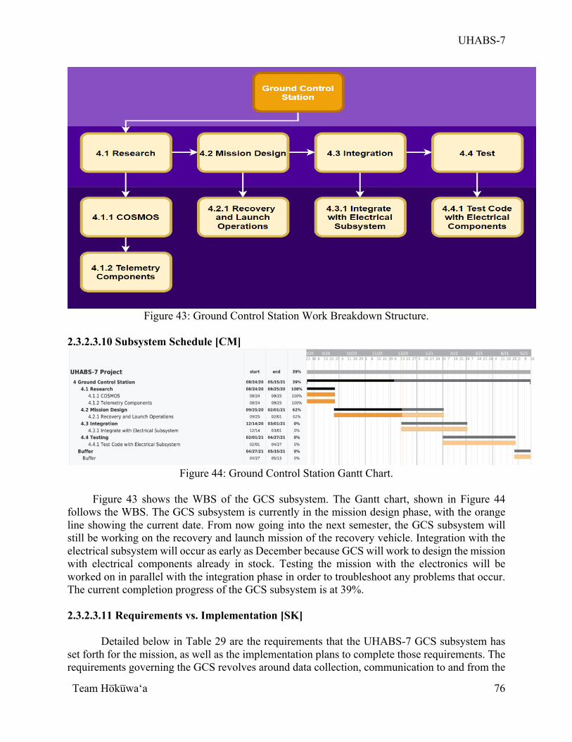
UHABS-7
Team Ho̅ku̅waʻa
76
Figure 43: Ground Control Station Work Breakdown Structure.
2.3.2.3.10 Subsystem Schedule [CM]
Figure 44: Ground Control Station Gantt Chart.
Figure 43 shows the WBS of the GCS subsystem. The Gantt chart, shown in Figure 44
follows the WBS. The GCS subsystem is currently in the mission design phase, with the orange line showing the current date. From now going into the next semester, the GCS subsystem will still be working on the recovery and launch mission of the recovery vehicle. Integration with the electrical subsystem will occur as early as December because GCS will work to design the mission with electrical components already in stock. Testing the mission with the electronics will be worked on in parallel with the integration phase in order to troubleshoot any problems that occur. The current completion progress of the GCS subsystem is at 39%.
2.3.2.3.11 Requirements vs. Implementation [SK]
Detailed below in Table 29 are the requirements that the UHABS-7 GCS subsystem has
set forth for the mission, as well as the implementation plans to complete those requirements. The requirements governing the GCS revolves around data collection, communication to and from the

UHABS-7
Team Ho̅ku̅waʻa
77
recovery vehicle, and location positioning. It is of high importance that these requirements are implemented for complete control over the recovery vehicle; implementation will be continually worked on for the entire duration of the project.
Table 29: Requirements and Implementations for the Ground Station, all currently in
progress for completion.
2.3.2.3.12 Remaining Issues and Concerns [ZA]
When this project was first assigned, the GCS leads struggled with downloading COSMOS as the software was having difficulty running on a Mac interface. After having conversations with members of HSFL, the GCS leads met with Eric Pilger and Kasey Hagi. During the meeting, it was found that there were bugs in the original COSMOS code which is why the software was not operating as it was intended to. Once Eric found the source of these bugs and removed them, the system began functioning as intended. Next, the GCS team had to look at the system because the components onboard the recovery vehicle must be compatible with COSMOS and Ardupilot. For the GCS leads, COSMOS has been very difficult to navigate and fully understand. Due to a lack of experience with COSMOS, programming the subsystems to work cohesively will be an ongoing challenge for the GCS team. Since this problem arose, the GCS team decided to make COSMOS solely responsible for the sound of the beacon, the detachment of the parachute and data collection. With the aid of Ardupilot, autonomous mission control can be completed. Moving forward, one main concern the GCS team has is the amount of support they will receive from the HSFL team. In past reports done by previous UHABS teams, members of HSFL have helped with the integration of COSMOS [10][11]. Secondly, the GCS team will need to figure out a way for the recovery vehicle to autonomously propel itself to the recovery location if communication is lost. The GCS team hopes to gain knowledge and aid from HSFL but with COVID-19 restrictions and the busy schedule of the HSFL members, it has been difficult to schedule meetings with them to fully understand how integration of the software with each component will work.
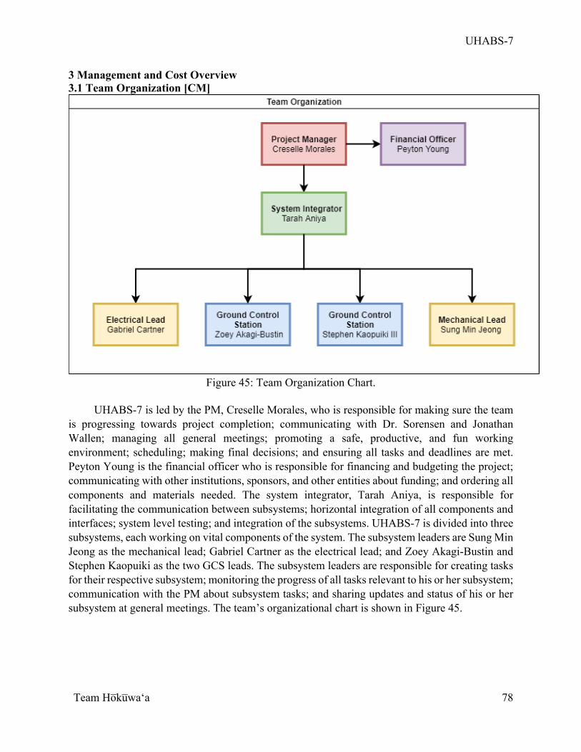
UHABS-7
Team Ho̅ku̅waʻa
78
3 Management and Cost Overview 3.1 Team Organization [CM]
Figure 45: Team Organization Chart.
UHABS-7 is led by the PM, Creselle Morales, who is responsible for making sure the team
is progressing towards project completion; communicating with Dr. Sorensen and Jonathan Wallen; managing all general meetings; promoting a safe, productive, and fun working environment; scheduling; making final decisions; and ensuring all tasks and deadlines are met. Peyton Young is the financial officer who is responsible for financing and budgeting the project; communicating with other institutions, sponsors, and other entities about funding; and ordering all components and materials needed. The system integrator, Tarah Aniya, is responsible for facilitating the communication between subsystems; horizontal integration of all components and interfaces; system level testing; and integration of the subsystems. UHABS-7 is divided into three subsystems, each working on vital components of the system. The subsystem leaders are Sung Min Jeong as the mechanical lead; Gabriel Cartner as the electrical lead; and Zoey Akagi-Bustin and Stephen Kaopuiki as the two GCS leads. The subsystem leaders are responsible for creating tasks for their respective subsystem; monitoring the progress of all tasks relevant to his or her subsystem; communication with the PM about subsystem tasks; and sharing updates and status of his or her subsystem at general meetings. The team’s organizational chart is shown in Figure 45.
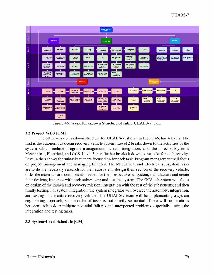
UHABS-7
Team Ho̅ku̅waʻa
79
Figure 46: Work Breakdown Structure of entire UHABS-7 team.
3.2 Project WBS [CM]
The entire work breakdown structure for UHABS-7, shown in Figure 46, has 4 levels. The first is the autonomous ocean recovery vehicle system. Level 2 breaks down to the activities of the system which include program management, system integration, and the three subsystems Mechanical, Electrical, and GCS. Level 3 then further breaks it down to the tasks for each activity. Level 4 then shows the subtasks that are focused on for each task. Program management will focus on project management and managing finances. The Mechanical and Electrical subsystem tasks are to do the necessary research for their subsystem; design their section of the recovery vehicle; order the materials and components needed for their respective subsystem; manufacture and create their designs; integrate with each subsystem; and test the system. The GCS subsystem will focus on design of the launch and recovery mission; integration with the rest of the subsystems; and then finally testing. For system integration, the system integrator will oversee the assembly, integration, and testing of the entire recovery vehicle. The UHABS-7 team will be implementing a system engineering approach, so the order of tasks is not strictly sequential. There will be iterations between each task to mitigate potential failures and unexpected problems, especially during the integration and testing tasks.
3.3 System-Level Schedule [CM]
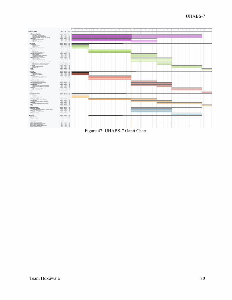
UHABS-7
Team Ho̅ku̅waʻa
80
Figure 47: UHABS-7 Gantt Chart.
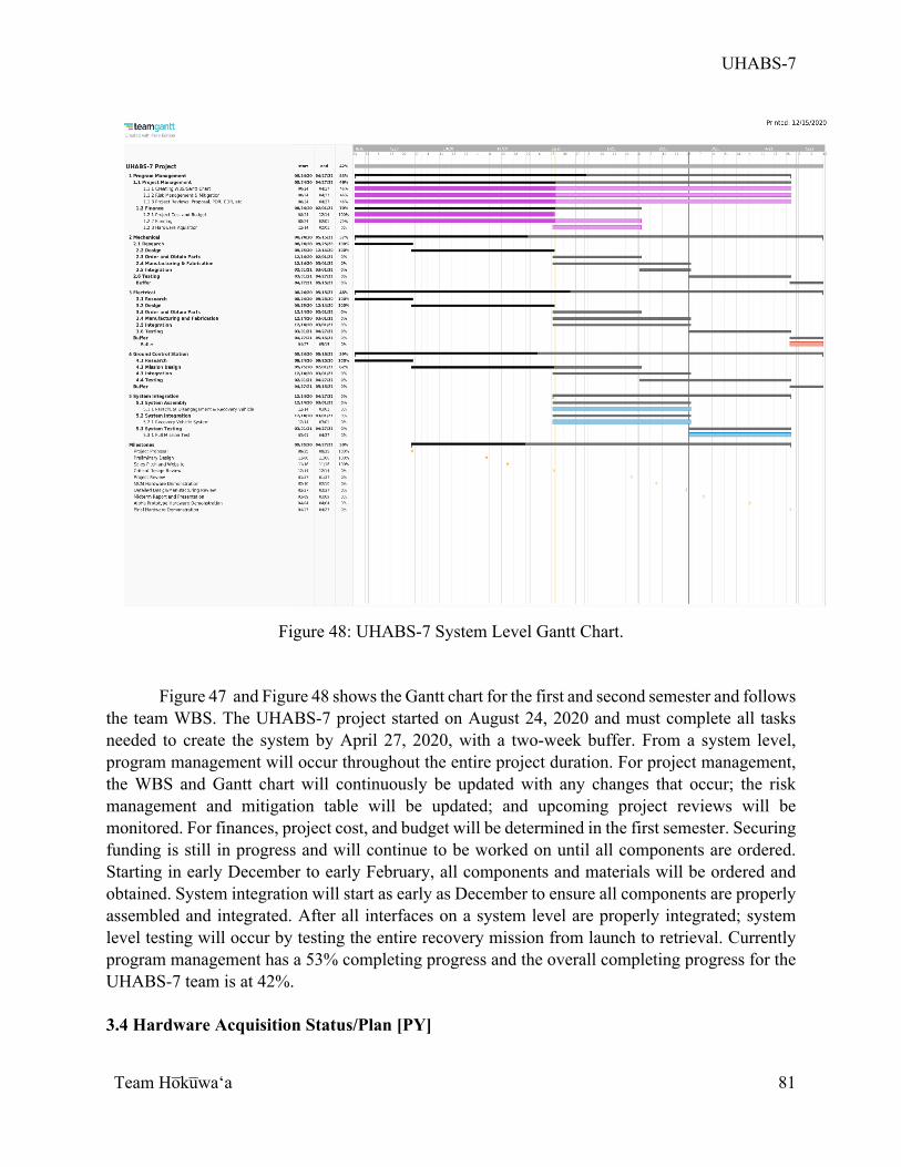
UHABS-7
Team Ho̅ku̅waʻa
81
Figure 48: UHABS-7 System Level Gantt Chart.
Figure 47 and Figure 48 shows the Gantt chart for the first and second semester and follows
the team WBS. The UHABS-7 project started on August 24, 2020 and must complete all tasks needed to create the system by April 27, 2020, with a two-week buffer. From a system level, program management will occur throughout the entire project duration. For project management, the WBS and Gantt chart will continuously be updated with any changes that occur; the risk management and mitigation table will be updated; and upcoming project reviews will be monitored. For finances, project cost, and budget will be determined in the first semester. Securing funding is still in progress and will continue to be worked on until all components are ordered. Starting in early December to early February, all components and materials will be ordered and obtained. System integration will start as early as December to ensure all components are properly assembled and integrated. After all interfaces on a system level are properly integrated; system level testing will occur by testing the entire recovery mission from launch to retrieval. Currently program management has a 53% completing progress and the overall completing progress for the UHABS-7 team is at 42%. 3.4 Hardware Acquisition Status/Plan [PY]
UHABS-7
Team Ho̅ku̅waʻa
82
The UHABS-7 team plans to begin ordering components from the end of December 2020 to the beginning of January 2021. The team expects these components to arrive between the middle of January to early February. This will give the team two and a half to three months to manufacture the system and test the system. The two and a half to three months of time allotted for manufacturing and testing is crucial to the team. First, the parts that the team orders can be damaged due to shipping and if so, must be sent back to the provider to be replaced, which will cost the team time. Furthermore, the team will be testing the vehicle in aquatic environments where electronics may sustain water damage. While the team will be ordering replacement parts for the electronics in the event of water damage to these components, having a large amount of time to address the errors that caused the failure is crucial that the team does not waste resources. Currently, the team is still on schedule to begin ordering these components by the end of December 2020. The components for each subsystem have been chosen and will be ordered before the start of the Spring 2021 academic semester. As will be later mentioned, the team currently still requires funding and will use the funding from the department of mechanical engineering to begin ordering vital components to begin manufacturing the vehicle.
3.5 Risks Management [TA]
For the UHABS-7 project, the subsystem leaders are responsible for identifying the technical risks for their respective subsystems, the Financial Manager is responsible for identifying the cost and funding risks, and the Project Manager is responsible for identifying the scheduling risks. These risks are managed in the UHABS-7 Risk Watch List, a spreadsheet tracking the technical, cost, and scheduling risks. The UHABS-7 Risk Watch List also includes a Risk Cube to visually track the current risks. The Total Risk Cube, which includes the impact and likelihood of all technical, cost, and schedule risks, is shown in Figure 49. The risks in the Total Risk Cube are identified by their Risk IDs. The associated technical, cost, and schedule risks with proactive and reactive mitigations can be found in Appendix C.
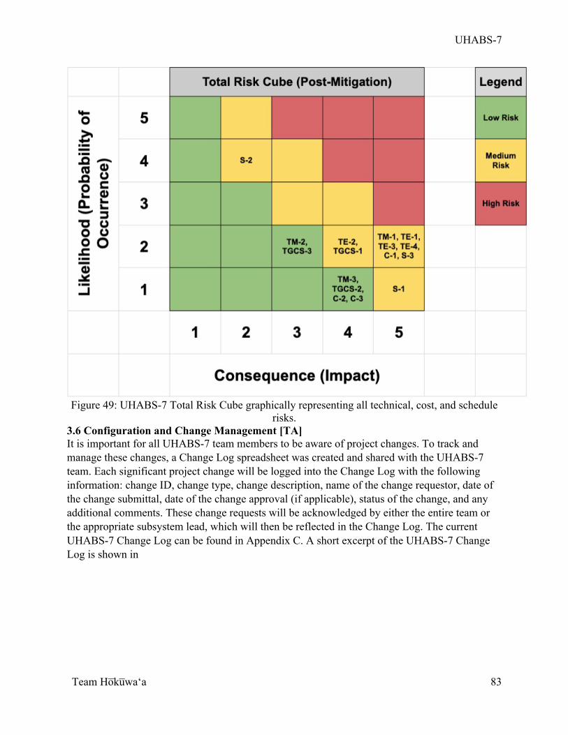
UHABS-7
Team Ho̅ku̅waʻa
83
Figure 49: UHABS-7 Total Risk Cube graphically representing all technical, cost, and schedule
risks. 3.6 Configuration and Change Management [TA] It is important for all UHABS-7 team members to be aware of project changes. To track and manage these changes, a Change Log spreadsheet was created and shared with the UHABS-7 team. Each significant project change will be logged into the Change Log with the following information: change ID, change type, change description, name of the change requestor, date of the change submittal, date of the change approval (if applicable), status of the change, and any additional comments. These change requests will be acknowledged by either the entire team or the appropriate subsystem lead, which will then be reflected in the Change Log. The current UHABS-7 Change Log can be found in Appendix C. A short excerpt of the UHABS-7 Change Log is shown in

UHABS-7
Team Ho̅ku̅waʻa
84
Table 30.
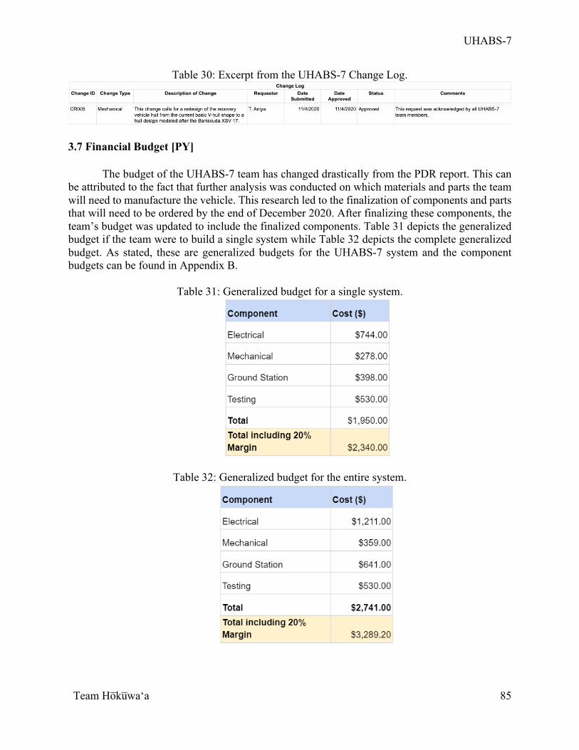
UHABS-7
Team Ho̅ku̅waʻa
85
Table 30: Excerpt from the UHABS-7 Change Log.
3.7 Financial Budget [PY]
The budget of the UHABS-7 team has changed drastically from the PDR report. This can be attributed to the fact that further analysis was conducted on which materials and parts the team will need to manufacture the vehicle. This research led to the finalization of components and parts that will need to be ordered by the end of December 2020. After finalizing these components, the team’s budget was updated to include the finalized components. Table 31 depicts the generalized budget if the team were to build a single system while Table 32 depicts the complete generalized budget. As stated, these are generalized budgets for the UHABS-7 system and the component budgets can be found in Appendix B.
Table 31: Generalized budget for a single system.
Table 32: Generalized budget for the entire system.
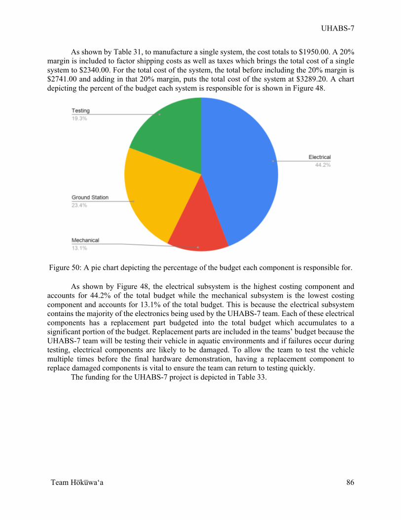
UHABS-7
Team Ho̅ku̅waʻa
86
As shown by Table 31, to manufacture a single system, the cost totals to $1950.00. A 20% margin is included to factor shipping costs as well as taxes which brings the total cost of a single system to $2340.00. For the total cost of the system, the total before including the 20% margin is $2741.00 and adding in that 20% margin, puts the total cost of the system at $3289.20. A chart depicting the percent of the budget each system is responsible for is shown in Figure 48.
Figure 50: A pie chart depicting the percentage of the budget each component is responsible for.
As shown by Figure 48, the electrical subsystem is the highest costing component and
accounts for 44.2% of the total budget while the mechanical subsystem is the lowest costing component and accounts for 13.1% of the total budget. This is because the electrical subsystem contains the majority of the electronics being used by the UHABS-7 team. Each of these electrical components has a replacement part budgeted into the total budget which accumulates to a significant portion of the budget. Replacement parts are included in the teams’ budget because the UHABS-7 team will be testing their vehicle in aquatic environments and if failures occur during testing, electrical components are likely to be damaged. To allow the team to test the vehicle multiple times before the final hardware demonstration, having a replacement component to replace damaged components is vital to ensure the team can return to testing quickly.
The funding for the UHABS-7 project is depicted in Table 33.
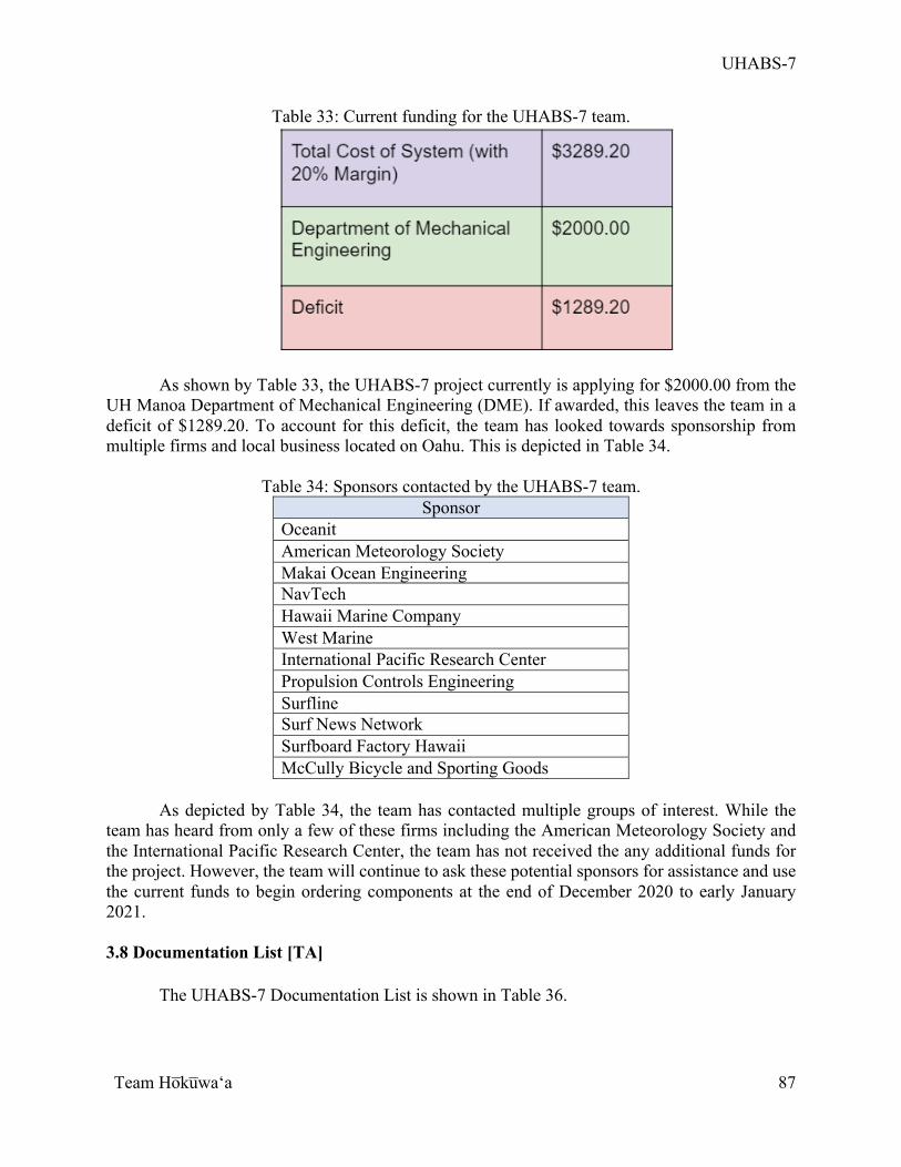
UHABS-7
Team Ho̅ku̅waʻa
87
Table 33: Current funding for the UHABS-7 team.
As shown by Table 33, the UHABS-7 project currently is applying for $2000.00 from the
UH Manoa Department of Mechanical Engineering (DME). If awarded, this leaves the team in a deficit of $1289.20. To account for this deficit, the team has looked towards sponsorship from multiple firms and local business located on Oahu. This is depicted in Table 34.
Table 34: Sponsors contacted by the UHABS-7 team. Sponsor
Oceanit American Meteorology Society Makai Ocean Engineering NavTech Hawaii Marine Company West Marine International Pacific Research Center Propulsion Controls Engineering Surfline Surf News Network Surfboard Factory Hawaii McCully Bicycle and Sporting Goods
As depicted by Table 34, the team has contacted multiple groups of interest. While the
team has heard from only a few of these firms including the American Meteorology Society and the International Pacific Research Center, the team has not received the any additional funds for the project. However, the team will continue to ask these potential sponsors for assistance and use the current funds to begin ordering components at the end of December 2020 to early January 2021. 3.8 Documentation List [TA] The UHABS-7 Documentation List is shown in Table 36.
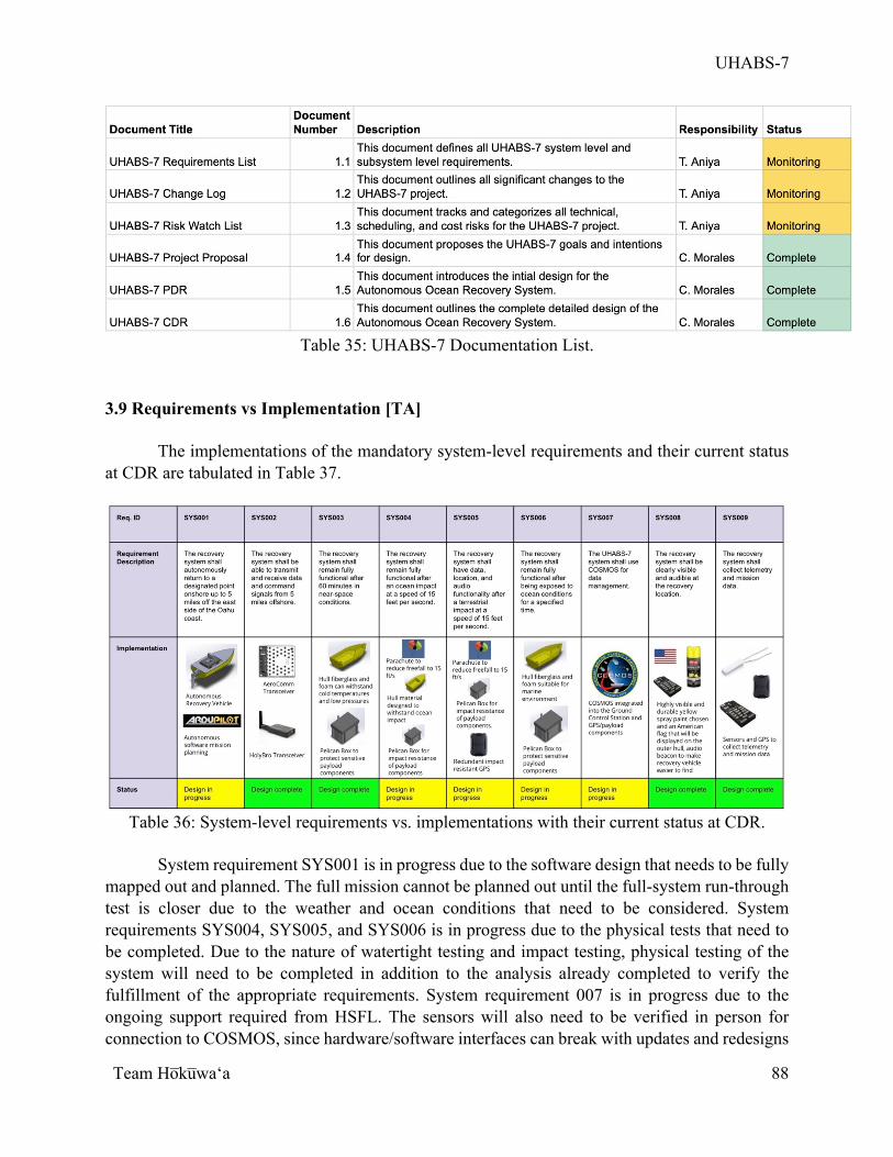
UHABS-7
Team Ho̅ku̅waʻa
88
Table 35: UHABS-7 Documentation List.
3.9 Requirements vs Implementation [TA]
The implementations of the mandatory system-level requirements and their current status at CDR are tabulated in Table 37.
Table 36: System-level requirements vs. implementations with their current status at CDR.
System requirement SYS001 is in progress due to the software design that needs to be fully
mapped out and planned. The full mission cannot be planned out until the full-system run-through test is closer due to the weather and ocean conditions that need to be considered. System requirements SYS004, SYS005, and SYS006 is in progress due to the physical tests that need to be completed. Due to the nature of watertight testing and impact testing, physical testing of the system will need to be completed in addition to the analysis already completed to verify the fulfillment of the appropriate requirements. System requirement 007 is in progress due to the ongoing support required from HSFL. The sensors will also need to be verified in person for connection to COSMOS, since hardware/software interfaces can break with updates and redesigns

UHABS-7
Team Ho̅ku̅waʻa
89
to the software. The rest of the system requirements are complete because they have been designed into the recovery vehicle system. 3.10 Remaining Issues and Concerns [PY] While the UHABS-7 team has conducted extensive research to manufacture a recovery vehicle for a BalloonSat, there are still some issues and concerns that are present. A major issue is the current mass of the vehicle. The vehicle’s current weight is extremely close to the maximum weight set by the FAA. While the team has included multiple components to the mass budget of the system, the margin that the team currently has is extremely small. Moving forward, the team will have to conserve the weight of the vehicle as they move into the manufacturing phase of the project.
An additional major concern for the UHABS-7 team is the implementation of COSMOS. Precious UHABS teams have struggled with this aspect of the project as COSMOS is difficult to master. The UHABS-7 team is currently in contact with multiple HSFL members trying to understand how to fully use COSMOS and how to set up agents and commands in the interface. However, due to the HSFL members being extremely busy, the team has found it difficult to gain much information as to how to use COSMOS and how to implement it into the system. Also, the team has faced a major setback as one of the GCS subsystem leads’ laptop crashed recently and they must now start from the beginning with COSMOS. The team will ensure that they are able to understand COSMOS and how it can aid in the UHABS-7 mission.
Another concern for the UHABS-7 project is the lifespan of the battery. The batteries selected by the UHABS-7 team will power all electrical components of the vehicle. However, due to the fact that the recovery vehicle has to travel five miles, the battery lifespan is a huge concern for the team. A possible solution to this problem entails adding solar panels to the system to recharge the battery during the mission. While this will ensure that the battery of the vehicle is constantly charged, there may be many moments during the mission where the vehicle is charging and without power. Currents may move the vehicle during these portions of no power and may move the vehicle extremely far from the designated target. Thus, extensive research must be conducted before implementation of solar panels.
Finally, the last major concern for the UHABS-7 team is a loss of communication with the GCS during the mission. If connection is lost with the vehicle, the team may be unable to recover the vehicle as the GPS on board the vehicle is connected to the GCS. A redundant GPS has been added to the system which can be tracked via other devices besides the GCS, but if this GPS signal is lost, the vehicle will be lost. These problems must be addressed as the UHABS-7 team moves forward towards the manufacturing phase of the project.
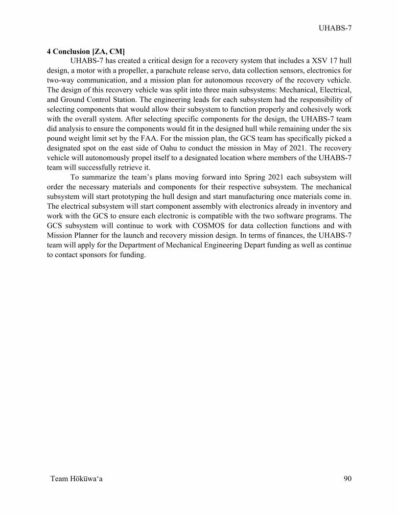
UHABS-7
Team Ho̅ku̅waʻa
90
4 Conclusion [ZA, CM] UHABS-7 has created a critical design for a recovery system that includes a XSV 17 hull
design, a motor with a propeller, a parachute release servo, data collection sensors, electronics for two-way communication, and a mission plan for autonomous recovery of the recovery vehicle. The design of this recovery vehicle was split into three main subsystems: Mechanical, Electrical, and Ground Control Station. The engineering leads for each subsystem had the responsibility of selecting components that would allow their subsystem to function properly and cohesively work with the overall system. After selecting specific components for the design, the UHABS-7 team did analysis to ensure the components would fit in the designed hull while remaining under the six pound weight limit set by the FAA. For the mission plan, the GCS team has specifically picked a designated spot on the east side of Oahu to conduct the mission in May of 2021. The recovery vehicle will autonomously propel itself to a designated location where members of the UHABS-7 team will successfully retrieve it.
To summarize the team’s plans moving forward into Spring 2021 each subsystem will order the necessary materials and components for their respective subsystem. The mechanical subsystem will start prototyping the hull design and start manufacturing once materials come in. The electrical subsystem will start component assembly with electronics already in inventory and work with the GCS to ensure each electronic is compatible with the two software programs. The GCS subsystem will continue to work with COSMOS for data collection functions and with Mission Planner for the launch and recovery mission design. In terms of finances, the UHABS-7 team will apply for the Department of Mechanical Engineering Depart funding as well as continue to contact sponsors for funding.
UHABS-7
Team Ho̅ku̅waʻa
91
References [1] Sites.wff.nasa.gov. 2020. Scientific Balloons. [online] Available at: <https://sites.wff.nasa.gov/balloons/docs/outreach/Scientific%20Balloons%20Facts.pdf> [Accessed 03 November 2020]. [2] theoceancleanup.com. 2020. The Great Pacific Garbage Patch | The Ocean Cleanup. [online] Available at: <https://theoceancleanup.com/great-pacific-garbage-patch/> [Accessed 03 November 2020]. [3] ecfr.gov. 2020. Electronic Code Of FederalRegulations (Ecfr). [online] Available at: <https://www.ecfr.gov/cgi-bin/text-idx?SID=ce2fdebc9a188698e43b879eec03cf64&mc=true&node=sp14.2.101.d&rgn=div6>[Accessed 03 November 2020]. [4] Asada, M., Balderama, C., Culter, K., Nunes, M., and Stercho, A., 2009, “Theia 1 Payload Module Final Report,” University of Hawaii at Manoa College of Engineering, Hawaii, Honolulu. [5] Yoshimoto, D., De Leon, J., Domingo, J., Poon, M., Ha, A., Butay, K., Pitpit, T., Gershom, Y., Onodera, B., Alexander, Z., Rayno, M., Howard, M., Peters, K., Morrison-Fogel, D., Bisquera, C., Kim, K., Kaeo, W., Shay, E., Oshiro, C., Guyett, E., Reyes, P., and Ang, J., 2017, “UH Advanced BalloonSat System Mission #4,” University of Hawaii at Manoa College of Engineering, Hawaii, Honolulu. [6] Feria, C., Inafuku, B., Keomaka J., Quach, A., Shimokusu, T., Tolentino, R., Yokoyama, A., 2018, “Mission Project Proposal Team Makahiki Wai,” University of Hawaii at Manoa College of Engineering, Hawaii, Honolulu [7] Aragon, F., Geonzon, A., Hu, K., Nelson, J., and Prince, J., 2015, “BALLOONSAT PROJECT,” University of Hawaii at Manoa College of Engineering, Hawaii, Honolulu. [8] Aipa, L., Arine, D., Bui, A., Calaro, K., Clark, K., Liu, K., Paz, R., Tan, R., Torigoe, J., Valdez, E., Yamaguchi, J., and Yang, J., 2018, “Final Report for UHABS-5 Zeppelin,” University of Hawaii at Manoa College of Engineering, Hawaii, Honolulu. [9] Buycasesforless.com. 2020. Pelican™ 1050 Micro Case With Liner | Pelicancasesforless.Com. [online] Available at: <https://www.buycasesforless.com/p-11464-pelican-1050-micro-case-with-liner.aspx> [Accessed 14 December 2020].
[10] Hawai’i Space Flight Laboratory, 2017, “Comprehensive Open-architecture Solution form Mission Operations Systems”, from https://http://cosmosproject.org/

UHABS-7
Team Ho̅ku̅waʻa
92
[11] L. Kon; H. Ishikawa; Y. Inoie; S. Kano, 1989, “Network and nodal system architecture for intelligent network”, from https://ieeexplore.ieee.org/document/64146
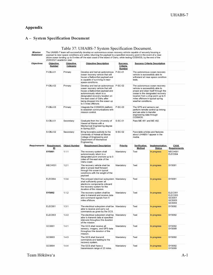
UHABS-7
Team Ho̅ku̅waʻa
A-1
Appendix A – System Specification Document
Table 37: UHABS-7 System Specification Document.
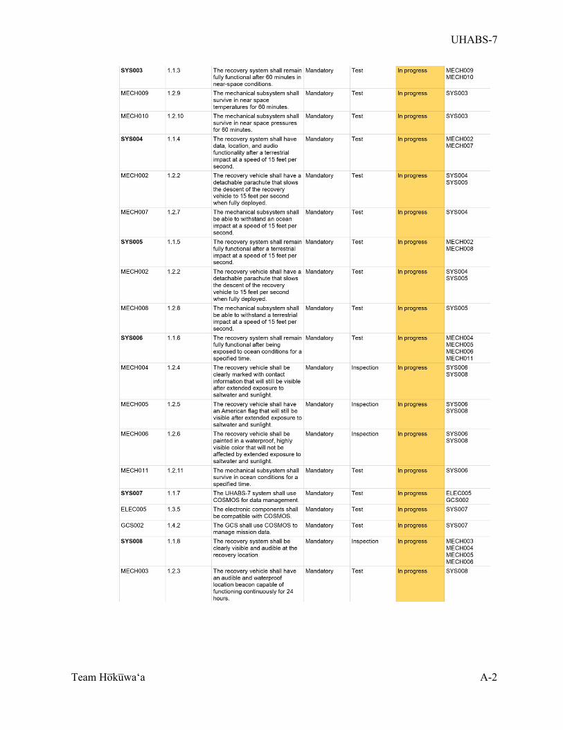
UHABS-7
Team Ho̅ku̅waʻa
A-2
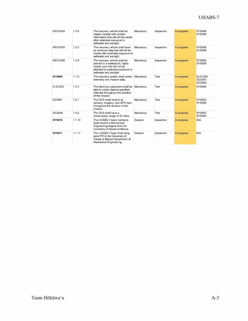
UHABS-7
Team Ho̅ku̅waʻa
A-3
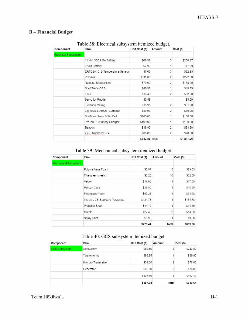
UHABS-7
Team Ho̅ku̅waʻa
B-1
B – Financial Budget
Table 38: Electrical subsystem itemized budget.
Table 39: Mechanical subsystem itemized budget.
Table 40: GCS subsystem itemized budget.
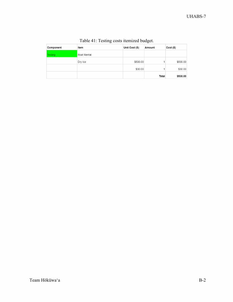
UHABS-7
Team Ho̅ku̅waʻa
B-2
Table 41: Testing costs itemized budget.
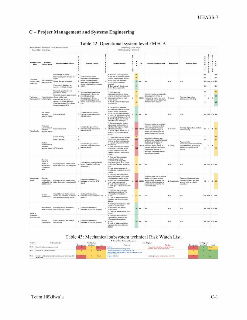
UHABS-7
Team Ho̅ku̅waʻa
C-1
C – Project Management and Systems Engineering
Table 42: Operational system level FMECA.
Table 43: Mechanical subsystem technical Risk Watch List.
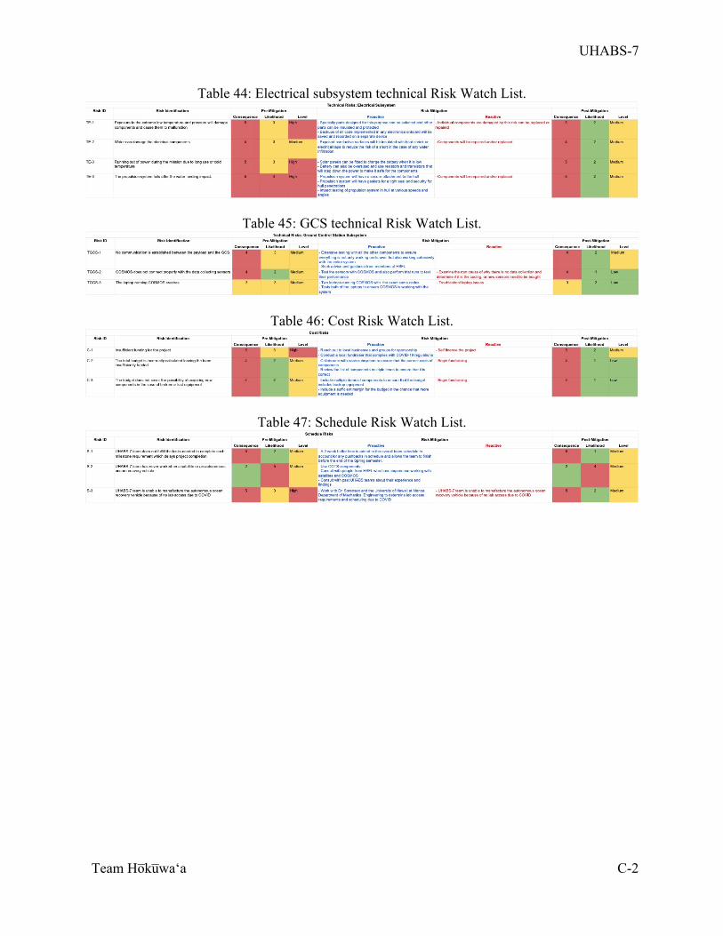
UHABS-7
Team Ho̅ku̅waʻa
C-2
Table 44: Electrical subsystem technical Risk Watch List.
Table 45: GCS technical Risk Watch List.
Table 46: Cost Risk Watch List.
Table 47: Schedule Risk Watch List.
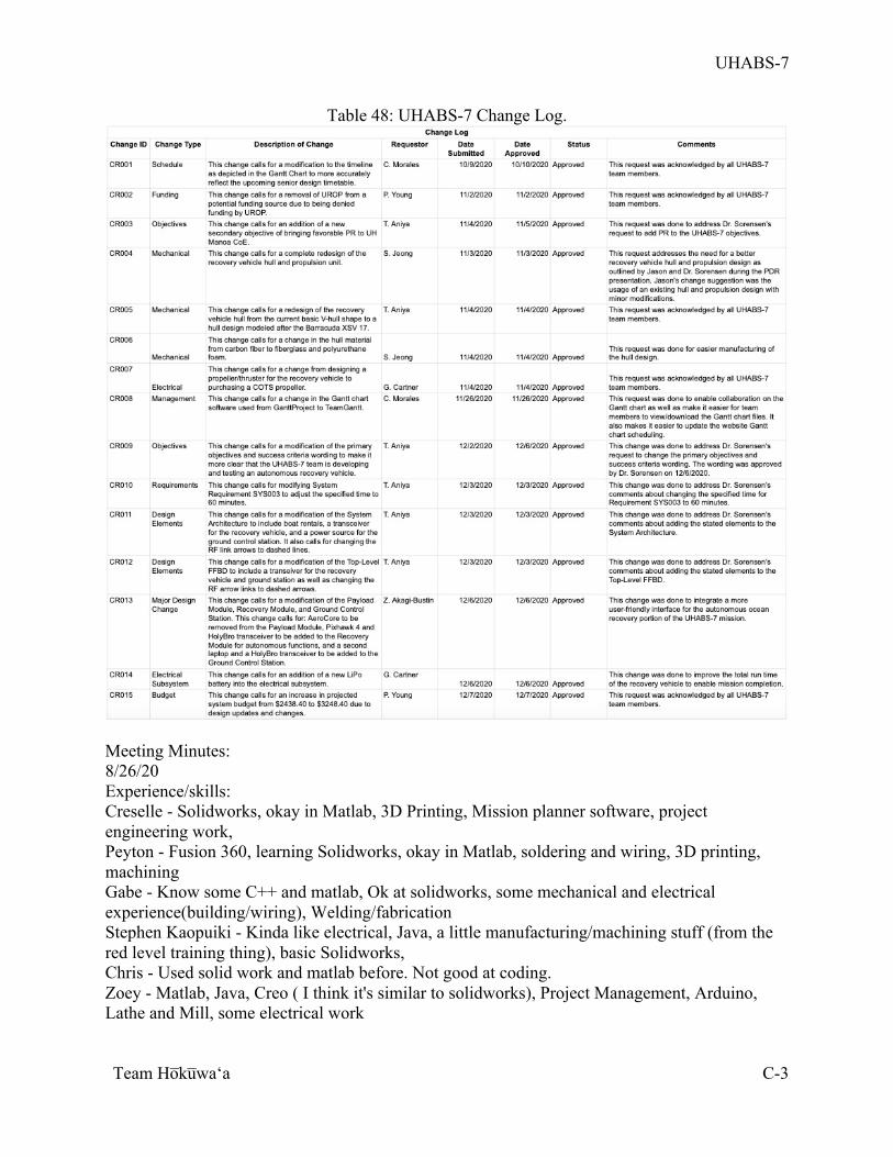
UHABS-7
Team Ho̅ku̅waʻa
C-3
Table 48: UHABS-7 Change Log.
Meeting Minutes: 8/26/20 Experience/skills: Creselle - Solidworks, okay in Matlab, 3D Printing, Mission planner software, project engineering work, Peyton - Fusion 360, learning Solidworks, okay in Matlab, soldering and wiring, 3D printing, machining Gabe - Know some C++ and matlab, Ok at solidworks, some mechanical and electrical experience(building/wiring), Welding/fabrication Stephen Kaopuiki - Kinda like electrical, Java, a little manufacturing/machining stuff (from the red level training thing), basic Solidworks, Chris - Used solid work and matlab before. Not good at coding. Zoey - Matlab, Java, Creo ( I think it's similar to solidworks), Project Management, Arduino, Lathe and Mill, some electrical work
UHABS-7
Team Ho̅ku̅waʻa
C-4
Tarah - Solidworks, coding experience in Python, MATLAB, mechanical and building experience, welding/brazing, machine shop experience, taking system engineering Roles:
• Project Manager: Creselle/Zoey • System Integrator: Tarah/Zoey • Financial Officer: Peyton/Gabe
o Material sourcing: Peyton o Fundraising/Sponsor
• Software: • Coding: Tarah/Zoey/Peyton • Modeling: Creselle
• Hardware: Gabe/Peyton o Electrical: Stephen o Mechanical: Chris/Tarah
Previous Mission Statement: Link to previous team: https://uhabs6.weebly.com/ Primary
1. To develop a reliable, high altitude BalloonSat system capable of carrying small payloads to a near-space environment.
2. To develop a recovery system which enables the BalloonSat module to land safely in the ocean or on land.
3. To develop a recovery system able to autonomously propel the payload to a designated recovery site if an ocean landing occurs.
4. To utilize and test COSMOS as operations and flight software for the Hawaii Space Flight Laboratory (HSFL).
Secondary
5. To obtain images and video during the flight phase. 6. To collect atmospheric data and state-of-health data during the flight phase Questions:
• What kind of data that we want to collect • Range of telemetry we need • Weather balloons • How to recover • Software we will need to recover the boat
o What is COSMOS? o How to use COSMOS
• Are there any sponsors that were used before • What kind of funding do we have • Who are we doing this for? Competition? For his space lab? • What equipment do we have already?
8/31/20:
URL: https://uhabs6.weebly.com/
UHABS-7
Team Ho̅ku̅waʻa
C-5
S: Wash your hands P: Define suggested mission of BalloonSat Team A: Set team roles, create code of conduct, research potential missions using C: Listed below E: Create a mission statement R: - F: Creselle - R: Peyton - O: Everyone - S: Everyone - T: Creselle Agenda:
• Decide on project mission • Create code of conduct • Assign group roles • Research previous team’s BalloonSat • Decide project goals
Code of Conduct:
1. Be respectful, honest, and courteous to other members 2. Be on time 3. If you are gonna miss a meeting or be late let the team know 4. Admit mistakes and be open to hearing advice from others
1. Don’t take stuff personally 2. Ask for help when help is needed
5. Tackle the issue not the person 6. Maintain professionalism 7. Majority wins for every group decision
Possible Goals:
1. Create a satellite capable of using a balloon to travel to and survive in a near-space environment while transporting a payload
Our mission statement: The purpose of Balloonsat is to create a satellite that is capable of traveling to near space environments and returning back to earth. What we are trying to accomplish and questions:
• No real problem? o Just making it
• Funding? • Retrieval
o Are we going to retrieve it? o What kind of software do we need if so
• Balloon o It will pop after a certain distance is reached(How far into space do we want?) o Size of the balloon and how much to inflate(With hydrogen or helium)?
UHABS-7
Team Ho̅ku̅waʻa
C-6
• Payload o Just a weight carried by balloon or do we want to record something o How are we going to protect the payload on ascent and descent o For recording data what do we want(temp,pic,video, distance,etc) o How heavy is it going to be and what is the limit on weight: 6 pounds total weight
• Parachute o How big with what material
Things to ask Sorensen: • How far did the last balloonsat traveled to space
o Size of balloon and how much inflation with what kind of gas(est how far ballon travel with size and inflation) Helium
o stemBigger balloon travels further? o Don’t need to go up to max alt of 10,000
• What kind of info did the last balloons recorded? o For the info it recorded do we need to retrieved it to view it or can we bluetooth to
device so we don’t have to retrieve it • What is left of the previous years system?
o They have a prototype hall, some of the electronics, most if it is actually gone because it was
• Why are we making this? o For HSFL? For fun? Just because it was done before? o Purpose: To provide a reliable platform to provide HSFL to test things safely on.
• What do you expect from us for this project • Need to have an autonomous recovery system. :) Perfect it
o 6 pound weight max does not count balloon and parachute. FAA regulation § What other constraints of these types do we have? § No more than 50 lb strength cord § Funding:
§ Have 2 grand (needs to be confirmed) § We have RCUH § UROP
• Not required to get to full altitude • Why we making BalloonSat:
• Not a VIP but we want it to be • Provide a reliable platform for HSFL to use to test things at a near space
environment • We have some sort of code left for us • Use COSMOS
• Use web based • https://www.hsfl.hawaii.edu/projects/cosmos/ • Work on it early to understand it!!!!!!
Record: Latitude, longitude, altitude, temperature, humidity • Since it records longitude and latitude maybe be we can program boat to come to
longitude and latitude that we are standing when contact with water What Telemetry
UHABS-7
Team Ho̅ku̅waʻa
C-7
Call this type of thing: Near? Sat Mistakes
• Not working and integrating COSMOS code If we just work on recovery system does that mean we have to create the ballonsat? Yes but looks like it wont be graded heavily on the balloon itself Looks like the recovery is the most important thing Airboat Boat Maybe control it from air? Design glider(Use trade wind?) Or design the parachute certain way so the payload lands on oahu Recommandations by 9/4 FRP- NEXT WEEK 9/2/20: S: Bring keys out when surfing P: Talk about top level requirements and team structure A: - Decide mission statement
• Finalize team structure/roles and subsystems needed • Implement system engineering methods to define interfaces of system • Set up weekly meeting time
C: Established on 8/31/20 meeting E: R: - F: Creselle - R: Peyton - O: Chris - S: Everyone - T: Everyone Brainstorm ideas:
• Boat (will need to be powered/propelled thru water): o Sub o Surface boat
§ https://youtu.be/_v1EV6du1jk § https://youtu.be/hA_W52T4H34
• Plane (can be gravity based or propelled): o Glider that returns to takeoff point
§ https://youtu.be/rpBnurznFio § https://youtu.be/YqQr4tHLKOo
Possible Mission Statements: 1. Create a recovery system for the balloon satellite.
1. Only focus on the recovery 2. Balloonsat already provided/designed
gotta build from scratch, Also need to withstand environment at 100000 feet Last team failed by doing it from scratch He wants us to design and build and analyze our own system
UHABS-7
Team Ho̅ku̅waʻa
C-8
Doesn’t want us to buy off the shelf Don’t fail (need it to function) Bright colored parachute, emit sound that can be heard from 100 meters away Satellite and recovery system separate: One team did this in the past Can’t fly em separately Advantage is that we can have 12 pounds total and not just 6 pounds Problem is what happens when land in ocean as two different things How can we tow it Super challenging Focus on water landings Land landing: Audible beacon can be heard from 100 yards away Bright color parachute Ocean Landing: More likely Air landing is possible Cool sea plane idea Submarine no need build ourselves Making aircraft will be difficult Within 3 to 5 miles of shore Still need to collect data no matter what
2. Improve last design iteration from previous years. a. Collecting more data b. Maximize altitude c. Improve upon the design of the satellite itself Weekly Team Meeting: Friday- 11:30-12:30 AM Subsystem Ideas:
• BalloonSat: Leader: o
• Recovery System: Leader: o
• Mission Ops/System Integrator (mainly doing cosmos) : o Leaders:
COSMOS problems: WINDOWS:
• Unable to access BIOS and change settings to enable virtualization • Unable to use Hyper-V for visualization • Unable to change the settings in virtual box to match settings set in the instructions (the
following settings) o Go to settings and change the base memory and number of processors to the
maximum recommended. Also increase the video memory to maximum. If available, you can enable hardware acceleration as well.
MAC:
• Cosmos-core isn't found even after following the installation steps Design Constraints:
• Better off with boat than airplane
UHABS-7
Team Ho̅ku̅waʻa
C-9
o Remote control? o Autonomous
• Aim for 3 to 5 miles offshore o Design the parachute certain way or based on luck? o
9/9/20: S: Don’t touch a hot stove top P: Discuss RFP A: - Finalize proposal (15 mins)
• Work on subsystems C: Established on 8/31/20 meeting E: Have a finalized proposal
• Work on subsystems R: - F: Creselle - R: Gabe - O: Chris - S: Stephen - T: Peyton Meeting Length: 1:35:30 “The mission we would like to do for our senior project is to create a recovery system for the balloon satellite.” Roles:
• Program Manager: Creselle • Financial Officer: Peyton • BalloonSat: Leader: Gabe • Recovery System: Leader: Chris • Mission Ops (mainly doing cosmos) : Zoey, Stephen • System Integrator: Zoey, Tarah
IMPORTANT DATES:
• System Requirements Review and proposal presentation: September 21, 2020
• Written proposal due: September 25, 2020 @6:00 PM
Questions:
- COSMOS
- ask about stuff from last year
- What type of data collection tests are we doing?
UHABS-7
Team Ho̅ku̅waʻa
C-10
- able to temp (dry ice for hours), thermo vacuum chamber (partial vacuum), survive in air density(5% 100000ft), distance testing of transmitter,
- No mission this year
- Only recovery
- Helium is expensive (less than $100 to $500-600)
Focus on recovery but don’t have to actually fly the balloon it just has to “work”
• Can test in parts not entire flight • Would be good to farther out (but not needed) • First test would be lagoon (let’s start small with a pool/ don’t go above
and beyond) o Good final test would be in the ocean (NOT NEEDED)
§ Needed or would like? § Maybe just paddle it out to a surf break and see how it
handles the waves? § Minimum test would be: quarter mile out to test gps
(hawaii kai lagoon, can get choppy, maybe ala moana but inside because not choppy),
§ Minimum height of drop to get parachute to open: highest platform in diving thing (olympic heights)
§ Boat started upon impact of water and automatically drove out to pool edge
§ If team cannot get trained in workshop for COSMOS before CDR: must change plans
§ Minimum passing altitude: 40,000-50,000 ft § Test in those max conditions § Past 50,000 you go into jet streams and projected
course will be way off § Burst altitude is about 60,000 ft (last team)
At first, just designing and shit but definitely get an early jump on COSMOS NO SIMULATED PAYLOAD
• Make it close to satellite as possible • During tests sensors must work in near space environment
Mission Requirements: Things the system must do. E.g “The system shall meet all the power requirements for its electronic components”
• Functional Requirements: E.g:The recovery system shall autonomously drive out 10ft within 10 seconds.
UHABS-7
Team Ho̅ku̅waʻa
C-11
Task for everyone: Create at least one mission statement and 3 functional requirements. Bring ideas to the meeting on Friday.
ASK SORENSON
• Authority to Proceed (ATP): September 28, 2020 • Preliminary Design Review: October 28, 2020 • PDR Written Report due: November 6, 2020 • Critical Design Review: November 30, 2020 • CDR Final Design Report Due Date: December 11, 2020
Mission Requirements Brainstorming:
• The system shall meet the requirements to achieve autonomous recovery. • The system shall meet the requirements to survive in near space
conditions. • The system shall meet the requirements to survive in marine
environments. • The system shall meet the requirements to transmit data/communicate
using COSMOS. • The system shall meet regulations set by the Federal Aviation
Administration. (Functional requirements will define those dimensions/weight)
• The system shall be easily identifiable and provide contact information.
Function requirements:
• Satellite system o The system shall survive in conditions similar to 100,000ft in
altitude. o The system shall weigh no more than 6lbs.
• Data transmission: o The sensors shall be compatible with COSMOS o The sensors shall be able to transmit up to a distance of [X]
• Recovery System • The system shall have a beacon that can be heard from 100 yds
away.
• Must be autonomous
9/11/20: S: Drink water P: Discuss RFP A: - Brainstorm FR C: Established on 8/31/20 meeting
UHABS-7
Team Ho̅ku̅waʻa
C-12
E: Brainstorm FR R: - F: Creselle - R: Gabe - O: Chris - S: Stephen - T: Peyton Brainstorming session: Potential MR:
• The system shall be able to navigate and move in ocean currents • The system shall collect relevant data in accordance to customer requirements
o Might need to be more specific o (kinda the same) The system will be capable of passing all tests required by
Sorenson • The system shall be sufficiently protected such that the system will remain intact
throughout the duration of the mission • The system will be able to meet set design requirements
o reword/elaborate • The system shall have an autonomous recovery system
Potential FR:
• The system must be able to navigate its way to land in the case of a water landing o More specific o Must be able to navigate minimum 5 miles from shore o In the event of an aquatic landing, the system will be able to autonomously return
to a specified location if within 5 miles of the location • The ballonSat system must be well insulated thermally and water proof
o What do you define well as? § At a certain point, altitude, etc
• The balloonSat shall be waterproof/water resistant in the case of a water landing • The system will be water resistant and have sufficient flotation such that it can
survive marine conditions The balloonSat shall be able to operate in low atmospheric conditions
• Define the range The balloonSat shall be able to transmit data from long distances
• distance? The cosmos program must be able to collect data when the ballonsat is in air, on land, and in water.
• The system must be able to transmit data during the entire flight and recovery. • The COSMOS system must be able to receive data during the duration of the
flight and recovery. • The satellite system will be capable of communication with a ground station • - The recovery shall continuously transmit data to ground station until it is
physically recovered
UHABS-7
Team Ho̅ku̅waʻa
C-13
The battery of the system will be capable of powering the system throughout the duration of the mission
• System should have enough power to pull the weight of payload and parachute when it lands on water
§ Add a time frame for flight • The recovery system shall have a battery recharge system.
§ Says solar in the RFP The system will have the following data collection instruments:
• A • B • C
The recovery system will be able to support the weight of the satellite • Specific weight (6lbs)
The recovery system will be able to return the satellite to a specified location in tact • Define “in tact” (can work? Parts are there?) • Maybe we just need to recover 50% of system
The entire system will be able to survive both an aquatic and terrestrial landing • Maybe take out terrestrial if not focused
The entire system will be under 6 pounds as described by FAA regulations The system will descend to the ground via a parachute
• State when the parachute has to open, distance from ground The satellite shall include a parachute to slow descent speed to a maximum 15ft/s before landing.
• The line/string connecting parachute to payload should not get tangled during operation and able to hold weight of the payload
The recovery system shall be waterproof to survive in marine conditions. 9/14/20: S: Stay hydrated P: To begin preparing to start the project proposal A: - Read/discuss new RFP (20 minutes)
• ME 491 system engineering (40 minutes) o Discuss interfaces
• Talk about Mission Requirements and Functional Requirements (1-2 hr) • Begin working on the project proposal (Rest of meeting) (If we time)
C: Established on first meeting E: Have a general idea of what the mission requirements and functional requirements should be R: Below F: Creselle R: Peyton O:Zoey S: Stephen T: Tarah RFP Notes:
• UHABS 1, 4 and 6 were successful but 6 did not have recovery • Provide near space environment for testing shit • Needs to have autonomous recovery
UHABS-7
Team Ho̅ku̅waʻa
C-14
• Need to use as much equipment and components from previous teams as possible • Max descent of 15 ft/s • During the entire flight the BalloonSat takes environmental and engineering
measurements, images,and collects science data, which are stored on board and transmitted to the team’s ground station.
• Capable of receiving uplinked commands • Live streamed video pointed down and received by ground station • Audible beacon must sound for at least 24 hours and audible for 100 yards in bushes • American flag not affected by water/sunlight • 6lb limit for one module but if doing multiple than total weight must not exceed 12lbs • Recovery:
o Autonomously propel itself to the coast of Oahu for recovery o Parachute will be detached from the satellite o Batteries will charge during the day using solar power o Send position and engineering information to a ground station on a regular basis o Transmit continuously when the satellite has reached destination
Presentation requirements:
• 20 minutes presentation time (hard time limit), 10 minutes questions • All team members present own sections • Business professional dress code • Presentation Content:
o All slides (except Title Slide) must show the slide number and the total number of slides in the main presentation (not including Backup Slides) e.g. 14/37
o The name of the student presenter should be on the first slide of a contiguous set of slides that the student is presenting
o The proposal presentation should cover all of the essential elements covered in the written proposal
Questions for Sorensen:
• How to contact Miguel (contacted him 2 times and no response via email) o Jonathan Advice: Understand COSMOS this semester and then implement next
semester o Eric pilger [email protected]
these are the three emails i found for him in the UHM directory § [email protected] § [email protected] § [email protected] § [email protected]
• How close to the coast do you want it? • Ans: Given it a specified location: EX: Beach outside the reef and can be picked
up by a paddle board or surf board. If within 100 yards (derived requirement) of where we tell it to go that’s a W.
§ Not specified of actual distance: Probs like within 300 yards should be fine
§ Basically be in the area
UHABS-7
Team Ho̅ku̅waʻa
C-15
What kind of ocean conditions? Like in winter or summer • Ans: Typical conditions for late April or early May
§ No need survive a hurricane/tropical storm § If the swell is huge or clouds are too much no flight
Max time should it last before returning? Hours? Days? Months? A year? • Ans: Should be able to get a signal for a of 24 hours
§ 24 hours is a target time § Min is about 12 hours
It’s mentioned in the RFP that the satellite should send “essential engineering information” to the ground station
• What kind of information is this? • Ans: Internal temperature and internal pressure, battery level, orientation(IMU?)
(not important but would like to have),, position, acceleration It also states that the satellite should send information on a regular basis: What time intervals should this be?
• Ans: Dependent on the design § Derived requirement § Probably as a minimum of every hour § Once on ocean § No need like every 10 seconds cuz that drains the battery § Want immediately after landing and then more frequently after that so that
we know where it is going § When in flight, moving fast so we can track when it has landed and stuff § Not gonna be moving super fast when on the ocean § Landing mode: once hits the water, send signal for each minute for like
10-15 mins (to see general current direction) § Cruise mode: every hour or so § Send out a specified signal for when landing so that we know when it’s
landed and then send out a signal for when big cruising § When within target range send more frequently
Last years grade for presentation: mid 80’s • Ave: 84.5
Sorenson is the only grader for report • Biggest part of grade is report
Run slides by Jonathon • Let’s set up a meeting with Jonathon to present to him
IF WE HAVE A FEW MISTAKES IN THE PRESENTATION, THAT’S ALL GOOD Potential MR:
• The system shall be able to navigate and move in ocean currents • The system shall collect relevant data in accordance to customer requirements
o Might need to be more specific o (kinda the same) The system will be capable of passing all tests required by
Sorenson • The system shall be sufficiently protected such that the system will remain intact
throughout the duration of the mission o (reword)
UHABS-7
Team Ho̅ku̅waʻa
C-16
• The system will be able to meet set design requirements o reword/elaborate
• The system shall meet the requirements to achieve autonomous recovery. o The system shall have an autonomous recovery system
• The system shall meet the requirements to survive in near space conditions.
• The system shall meet the requirements to survive in marine environments.
• The system shall meet the requirements to transmit data/communicate using COSMOS.
• The system shall meet regulations set by the Federal Aviation Administration. (Functional requirements will define those dimensions/weight)
• The system shall be easily identifiable and provide contact information. o (reword)
• The BalloonSat shall be able to transmit data to the ground station throughout the duration of the mission
Potential FR:
• The system must be able to navigate its way to land in the case of a water landing o More specific o Must be able to navigate minimum 5 miles from shore o In the event of an aquatic landing, the system will be able to autonomously return
to a specified location if within 5 miles of the location • The ballonSat system must be well insulated thermally and water proof
o What do you define well as? § At a certain point, altitude, etc
• The balloonSat shall be waterproof/water resistant in the case of a water landing • The system will be water resistant and have sufficient flotation such that it can
survive marine conditions The balloonSat shall be able to operate in low atmospheric conditions
• Define the range The balloonSat shall be able to transmit data from long distances
• Distance? The cosmos program must be able to coll\ect data when the ballonsat is in air, on land, and in water.
• The system must be able to transmit data during the entire flight and recovery. • The COSMOS system must be able to receive data during the duration of the
flight and recovery. • The satellite system will be capable of communication with a ground station • - The recovery shall continuously transmit data to ground station until it is
physically recovered The battery of the system will be capable of powering the system throughout the duration of the mission
• System should have enough power to pull the weight of payload and parachute when it lands on water
UHABS-7
Team Ho̅ku̅waʻa
C-17
§ Add a time frame for flight • The recovery system shall have a power system capable of lasting at least 24 hrs.
§ Says solar in the RFP The system will have the following data collection instruments:
• A • B • C
The recovery system will be able to support the weight of the satellite • Specific weight (6lbs)
The recovery system will be able to return the satellite to a specified location in tact • Define “in tact” (can work? Parts are there?) • Maybe we just need to recover 50% of system
The entire system will be able to survive both an aquatic and terrestrial landing (more of a satellite requirement but we are focusing on recovery so not needed)
• Maybe take out terrestrial if not focused •
The system will descend to the ground via a parachute at a maximum speed of 15 ft/s. • State when the parachute has to open, distance from ground
The satellite shall include a parachute to slow descent speed to a maximum 15ft/s before landing.
• The line/string connecting parachute to payload should not get tangled during operation and able to hold weight of the payload
Satellite system • The system shall survive in conditions similar to 50,000ft in
altitude. Data transmission:
• The sensors shall be compatible with COSMOS • The sensors shall be able to transmit up to a distance of [X]
• Recovery System • The system shall have a beacon that can be heard from 100 yds
away. • The system shall be a bright color. • The system shall have an american flag.
FOR WEDNESDAY:
• Do research on the project: o Look at the design paper and the presentation o Look at online resources o Know system architecture and free flow block diagram
• Questions: o Are we gonna leave the parachute in the water?
FOR FRIDAY:
• Have rough draft of presentation 9/16/20: S: Look both ways before crossing the street
UHABS-7
Team Ho̅ku̅waʻa
C-18
P: To get started on the presentation A:
• Ask Sorenson questions: 20 minutes • Work on presentation (1-2 hr)
E: Have an idea of what will go into the slides R: Below F: Creselle R: Peyton O: Tarah S: Zoey T: Stephen Send pdf or ppt of presentation after. 9/23/20: S: When you fall surfing, don’t hit the reef. It hurts P: Understand what we need to do for our project proposal and begin work A: Go over the layout of the project proposal (10 min) Go over functional requirements (30 min) Questions (Remainder of meeting) C: Set before E: To have a grasp of the project proposal R F: Creselle R: Peyton O: Zoey S: Gabe T: Stephen Function Requirements:
• Mechanical: o During descent, the recovery vehicle will descend at a maximum speed of 15 ft/s o The system shall weigh no more than 12lbs total
• Electrical: o Needs to have a beacon that can be heard from 100 yards away in scrub o The BalloonSat module shall have an audible location beacon capable of
functioning continuously for at least 24 hours. 9/28/20: S: When you fall off your surfboard, don’t land on the fins P: To begin research for our PDR A: Discuss what to research/literature survey stuff C: Stated before E: - find different types of boats (Chris)
• Find different autonomy software (Gabe) • COSMOS research(Zoey and Stephen)
UHABS-7
Team Ho̅ku̅waʻa
C-19
• Background research on BallonSat (Peyton, Creselle, Tarah) R: Shown below F: Creselle R: Peyton O: zoey S: Creselle T: Stephen Mechanical Shape of chassis Flat bottom hull High stability and can carry higher load Req small engine but more vulnerable to weather Best in calm water Least expensive to build V-shape hull Cut through waves easier than flat bottom Vulnerable to sharp turns Takes bit more power than flat hull Fast, distance boat Expensive to build Multi-hull(Ex:Catamaran, Trimaran) Buoyant and high stability Large deck space Vulnerable in choppy water More stable in salt water compared to flat hull HIgh drag and low performance and efficiency compared to others Most expensive to build Other Info Wider-Stable but more water resistance Narrow-Fast/less resistance but unstable
Type of propulsion system Water jet propulsion-Takes in water from inlet and shoots out using propeller through outlet Solar propulsion-Converting heat to electricity Wind propulsion-Using sail and wind Design Double hatch-Extra waterproof to electrical component Materials(Just for operating boat) Servo:Steer and operate radio control vehicle($35) CNC coupling(or bolt/nut)($20) ESC(Electronic Speed Control)($40) Motor($60)
UHABS-7
Team Ho̅ku̅waʻa
C-20
Electrical General -https://stac.berkeley.edu/project/balloon -https://www.stratoflights.com/en/ -https://www.sciencedirect.com/science/article/pii/S2468067218300579 COSMOS -http://www.williamosman.com/2016/08/cosmos-and-arduino-20-telemetry-system.html -https://www.youtube.com/watch?v=fJb2a5U4gSI Premade flight/data loggers. -https://www.stratoflights.com/en/shop/datalogger/ -what I learned These systems are capable of logging pressure as well as anything that a homemade system could. These systems are typically more than twice the cost of a homemade system but include amazing software for analyzing the data. How to make our own data loggers -https://www.instructables.com/id/The-Ultimate-High-Altitude-Weather-Balloon-Data-Lo/ -https://www.instructables.com/The-Easiest-Arduino-High-Altitude-Balloon-Data-Log/ -https://www.youtube.com/playlist?list=PLxyM2a_cfnzggc734oPitiypC2rsXpU5U -what I learned It is possible to create our own data logging system capable of surviving during this mission. Multiple systems that were capable of measuring altitude, temperature, wind speed, ascent/descent rates, longitude, latitude, time and date were constructed and tested successfully by other individuals for an estimated cost of 100$. There is a wealth of available information on the construction and programming of these arduino based systems. While they record the data from a gps, an external one must be used to broadcast the location of the system for recovery. GPS -https://www.overlookhorizon.com/how-to-launch-weather-balloons/tracking-systems/ -https://www.youtube.com/watch?v=7ed5JTelBwY -https://journals.sagepub.com/doi/full/10.1177/1550147719860990 -https://www.highaltitudescience.com/pages/tracking-a-weather-balloon -what I learned There are 3 main ways for us to be able to track our system during the flight. These ways are radio tracking, GPS tracking, and cellular tracking. Since the system must survive a water landing cellular tracking is not an option because cellular service near the shoreline of oahu is spotty and basically nonexistent 5 miles from the coast which would cause us to lose contact with the system. It is also illegal according to the FAA.Radio tracking is usually a reliable method of tracking. The concern of using it in this project is how well it would work out in the ocean where there are little to no radio frequencies. Another concern is that in the US people need a license to operate a ham radio which would be able to locate our device. One advantage to using our radio is that we could relatively inexpensively create our own. In my opinion GPS would be the best way to go for this project. The limitations of this type of tracking is mitigated by the environment we expect it to work in. The limitations are that it must be pointed up to the
UHABS-7
Team Ho̅ku̅waʻa
C-21
sky and have no overhead objects to block its signal. There is no overhead obstructions in the ocean and since it will be on a craft designed for water then orientation should not be an issue either.
Background Stuff: West Virginia Team
• file:///C:/Users/Administrator/Downloads/a-balloon-satellites-project-course.pdf • Made it to 87000 feet • Had a shit load of sensors
Montana Team: • http://www.ae.utexas.edu/courses/ase463q/design_pages/spring04/balloonsat/balloon
.htm • Has design as well as detachment from parachute • Parachute physics • Had a parachute ring to prevent tangling • Beacon information • GPS and GPS receiver • Transceiver • Camera • Launch Test
How to make a BalloonSat Demo: • https://geojournalism.org/2013/08/balloon-mapping-how-to-make-your-own-low-
flying-satellite/ • Pretty basic, but it gets the core concepts
Making a BalloonSat: • https://www.popularmechanics.com/space/a6062/space-ballooners-backyard-genius-
awards/ • Looks like they use a separate battery for the camera • Used an APRS tracker, GPS, and camera
Space Center: • https://spacecenter.uark.edu/reu/pastprograms/2011/mayer_carolyn_abstract.pdf • 3D printed the hull
Flight Controller Stuff: • https://dojofordrones.com/drone-flight-controller/
University of Michigan
• https://sites.google.com/a/umich.edu/highaltitudesolutions/home • Michigan Balloon Recovery and Satellite Testbed (MBuRST) • Fly scientific and satellite payloads on high-altitude weather balloons • Developing a long-term balloon flights with sponsorship from NASA JPL • FTU cut tests successful up to 70,000 ft (used to cancel flights to avoid bad landings) •
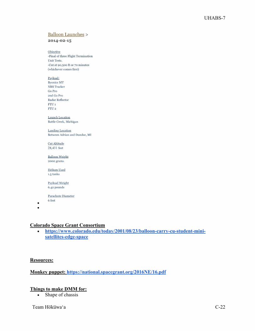
UHABS-7
Team Ho̅ku̅waʻa
C-22
• •
Colorado Space Grant Consortium
• https://www.colorado.edu/today/2001/08/23/balloon-carry-cu-student-mini-satellites-edge-space
Resources: Monkey puppet: https://national.spacegrant.org/2016NE/16.pdf
Things to make DMM for: • Shape of chassis
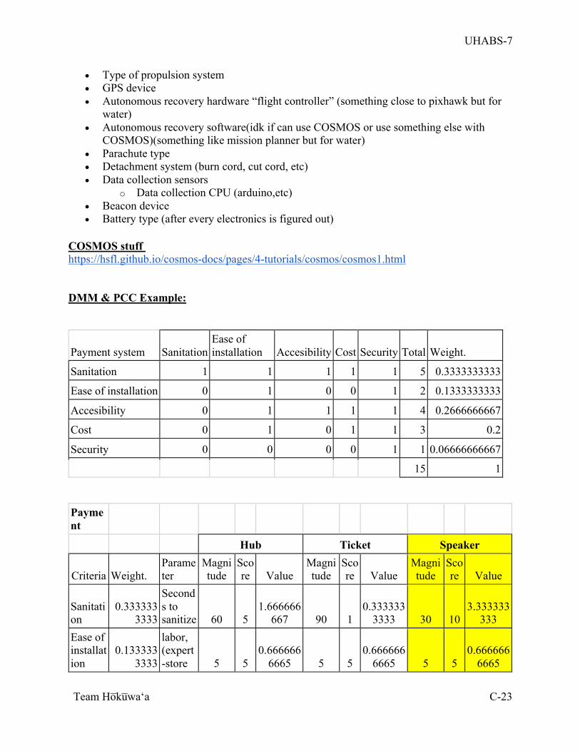
UHABS-7
Team Ho̅ku̅waʻa
C-23
• Type of propulsion system • GPS device • Autonomous recovery hardware “flight controller” (something close to pixhawk but for
water) • Autonomous recovery software(idk if can use COSMOS or use something else with
COSMOS)(something like mission planner but for water) • Parachute type • Detachment system (burn cord, cut cord, etc) • Data collection sensors
o Data collection CPU (arduino,etc) • Beacon device • Battery type (after every electronics is figured out)
COSMOS stuff https://hsfl.github.io/cosmos-docs/pages/4-tutorials/cosmos/cosmos1.html
DMM & PCC Example:
Payment system Sanitation Ease of installation Accesibility Cost Security Total Weight.
Sanitation 1 1 1 1 1 5 0.3333333333
Ease of installation 0 1 0 0 1 2 0.1333333333
Accesibility 0 1 1 1 1 4 0.2666666667
Cost 0 1 0 1 1 3 0.2
Security 0 0 0 0 1 1 0.06666666667
15 1
Payment
Hub Ticket Speaker
Criteria Weight. Parameter
Magnitude
Score Value
Magnitude
Score Value
Magnitude
Score Value
Sanitation
0.3333333333
Seconds to sanitize 60 5
1.666666667 90 1
0.3333333333 30 10
3.333333333
Ease of installation
0.1333333333
labor, (expert-store 5 5
0.6666666665 5 5
0.6666666665 5 5
0.6666666665
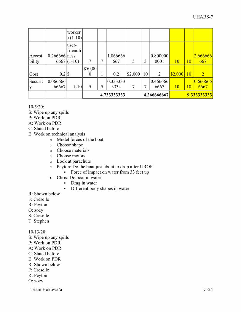
UHABS-7
Team Ho̅ku̅waʻa
C-24
worker) (1-10)
Accesibility
0.2666666667
user-friendliness (1-10) 7 7
1.866666667 5 3
0.8000000001 10 10
2.666666667
Cost 0.2 $ $50,00
0 1 0.2 $2,000 10 2 $2,000 10 2 Security
0.06666666667 1-10 5 5
0.3333333334 7 7
0.4666666667 10 10
0.6666666667
4.733333333 4.266666667 9.333333333 10/5/20: S: Wipe up any spills P: Work on PDR A: Work on PDR C: Stated before E: Work on technical analysis
o Model forces of the boat o Choose shape o Choose materials o Choose motors o Look at parachute o Peyton: Do the boat just about to drop after UROP
§ Force of impact on water from 33 feet up • Chris: Do boat in water
§ Drag in water § Different body shapes in water
R: Shown below F: Creselle R: Peyton O: zoey S: Creselle T: Stephen 10/13/20: S: Wipe up any spills P: Work on PDR A: Work on PDR C: Stated before E: Work on PDR R: Shown below F: Creselle R: Peyton O: zoey
UHABS-7
Team Ho̅ku̅waʻa
C-25
S: Creselle T: stephen Notes of Report:
• Add more into executive summary o Timeline o Basic concepts o Go more into team members
• FORMATTING • Be more specific • Attune to what he wants • WORDING • More specifically label figures • ASK HIM QUESTIONS
o Clarify with him as we are writing so there is no misunderstanding and we can trace that back to him
Questions: • What is primary and secondary?
o COMOS was listed as one of the things we had to use § Make it a primary
• Define project statements and goals • Cannot be modified • Primary: technical/commercial
§ To be able to build a successful product • Secondary: political/hidden
§ Secondary definitely gotta be like stuff that is not mentioned in the RFP § Nothing soft set (all HARD set) § “More uhh of the uhh hidden objectives” -Sorensen
Table 2 comment • Remember in presentation that we showed system level interfaces • Diagrams without words • We took the comment and didn’t do what he wanted • Wasn’t typical way for describing interfaces and wasted pages • We showed how the parts are connected • Need to show what each arrow of connection means • Identify connections of what they are
§ That way, we say what we needed to in single diagram and no need table 2 § Put table in PDR or CDR where we describing ICD
§ Just between two elements in the system • This should be as informative as possible • Color code them • Like what Gabe did
• Expand on what kinda data • Go a little deeper into the arrows
Tell him the software Priorities:
• Pick electronics
UHABS-7
Team Ho̅ku̅waʻa
C-26
• Pick design Get raspberry pi maybe? 11/16/20: S: Do not overload an outlet P: Talk about things we need for CDR A: Formatting for CDR C: established E : give tasks to everyone to work on R: F: Creselle R: Peyton O: Tarah S: Creselle T: Zoey Electronics:
• think about obstacle avoidance • Gotta think of autonomous code
Mechanical: • Finalize propeller design • Fix physics calculations • Need to do simulation modeling • Finalize material
Finances: • Work on funding and sponsorship
Related Documents