CDHD Servo Drive Functional Safety Reference Manual Revision 2.2

Welcome message from author
This document is posted to help you gain knowledge. Please leave a comment to let me know what you think about it! Share it to your friends and learn new things together.
Transcript

CDHD Servo Drive
Functional Safety
Reference Manual Revision 2.2


CDHD
Functional Safety Reference Manual 3
Revision History
Doc. Rev.
Date Remarks
2.2 Oct. 2015 Models and product ordering updates. Updated for SIL 3/PL e Cat.4
2.1 Jan.2015 minor fixes, cover graphic
2.0 7 Oct. 2014 Revised and added to CDHD documentation set.
1.0 27 July 2014 Formal version. Size 4A has STO_A. Final reliability values for STO_A. Updated current drain.
0.7 29 May 2014 Update of Reliability data, after calculation on final circuit (STO_A circuit version 3.2). Added maximum frequency of OSSD test pulses.
0.6 19 May 2014 STO cable length is limited to less than 30m. The product must be mounted inside an IP54 or better enclosure. Added description of unlikely failure in Exceptional Circumstance.
0.5 6 Apr 2014 Changed Altitude rating. Removed Trademarks.
0.4 13 Mar 2014 Added a section for Installation – identifies the STO connector and describes the pinout.
0.3 27 Feb 2014 Added note about possible motor movement of 120 electrical degrees.
0.2 18 Feb 2014 Added typical system configuration. Added block diagram showing the circuit principle. Added STO state diagnostics for EtherCAT. Updated requirements for STO cable to be spatially separated from environmental stress.
0.1 Feb 2014 Preliminary version.
Copyright Notice © 2015 Servotronix Motion Control Ltd.
All rights reserved. No part of this work may be reproduced or transmitted in any form or by any means without prior written permission of Servotronix Motion Control Ltd.
Disclaimer The information in this manual was accurate and reliable at the time of its release. Servotronix Motion Control Ltd. reserves the right to change the specifications of the product described in this manual without notice at any time.
Trademarks All marks in this manual are the property of their respective owners.
Contact Information Servotronix Motion Control Ltd. 21C Yagia Kapayim Street Petach Tikva 49130, Israel Tel: +972 (3) 927 3800 Fax: +972 (3) 922 8075 Website: www.servotronix.com
Technical Support If you need assistance with the installation and configuration of the product, contact Servotronix technical support: [email protected]

CDHD
4 Functional Safety Reference Manual

CDHD
Functional Safety Reference Manual 5
Contents 1 Introduction ________________________________________________ 7
1.1 About This Manual ................................................................................... 7 1.2 STO Function Definition ............................................................................ 7 1.3 STO Modules in CDHD Servo Drives ........................................................... 8
2 Certified Products ____________________________________________ 9 2.1 Product Ordering Options ......................................................................... 9 2.2 Products Approved for Functional Safety .................................................... 9 2.3 STO Certification and Reliability Data ........................................................ 10
3 STO Specifications __________________________________________ 11 3.1 Functional Safety ................................................................................... 11 3.2 Electrical Specification............................................................................. 11 3.3 Environmental Specifications ................................................................... 12 3.4 Environmental Standards Compliance ....................................................... 12
4 STO System Requirements ____________________________________ 13 4.1 Power Supply ......................................................................................... 13 4.2 STO Cable ............................................................................................. 13
5 Installation ________________________________________________ 14 5.1 STO Connector ....................................................................................... 14 5.2 Pinout ................................................................................................... 14 5.3 Mating Connector ................................................................................... 15 5.4 Typical System Configuration ................................................................... 15
6 Using STO _________________________________________________ 16 6.1 STO Benefits .......................................................................................... 16 6.2 STO in Use ............................................................................................ 16 6.3 STO Diagnostics ..................................................................................... 17
6.3.1 7-Segment Display on Drive Panel ................................................. 17 6.3.2 Serial Communication .................................................................. 17 6.3.3 CANopen and EtherCAT ................................................................ 17
6.4 Recovery from an STO Event ................................................................... 17 6.5 Prohibited Use of STO ............................................................................. 18 6.6 Exceptional Circumstance ........................................................................ 18
7 Maintenance _______________________________________________ 19

CDHD
6 Functional Safety Reference Manual

CDHD
Functional Safety Reference Manual 7
1 Introduction
1.1 About This Manual
Functional safety in the CDHD servo drive is implemented by means of the safe torque off (STO) function, which prevents unexpected startup and uncontrolled stops. STO ensures that the drive will not provide a rotational field within the motor, thereby preventing the motor from generating a torque on the shaft.
This manual describes the characteristics and use of the STO function in the CDHD series of servo drives.
Not all drives in the CDHD product line are certified for functional safety.
The information in this manual is applicable only to drives that are certified for functional safety, and whose part numbers include the suffix -ST.
This manual includes critical operational information, including expected behavior of motion systems when using the STO function, limitations in its use, and requirements for periodic testing by the user.
Note: The term STO function engaged means that power to the STO circuit has been removed, and power to the motor is inhibited.
1.2 STO Function Definition
The STO function is defined in standard EN/IEC 61800-5-2, and relates to an uncontrolled stop as per stop category 0 of IEC 60204-1.
Standard EN/IEC 61800-5-2, defines the functional safety requirements for adjustable speed electrical power drive systems. According to this standard, when the STO function is engaged, power that can cause motion is not applied to the motor.
The STO function may be used where power removal is required to prevent an unexpected startup.
Warning: Drives with a suspended load must have an additional mechanical safety block (such as a motor-holding brake) since the drive cannot hold the load when STO is engaged. Serious injury could result if the load is not properly safeguarded.
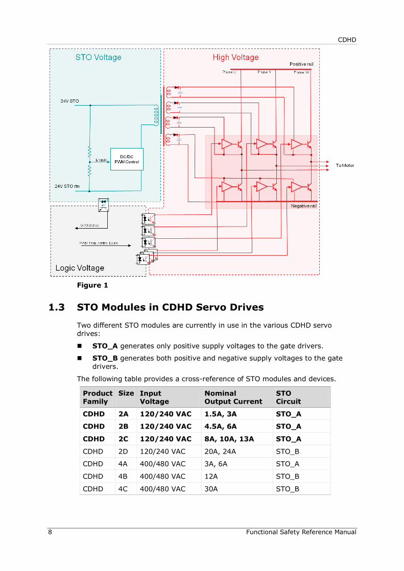
The STO function in the CDHD removes power from the gate drivers of the power module, effectively inhibiting PWM pulses from driving the IGBTs, as shown in Figure 1.
CDHD
8 Functional Safety Reference Manual
Figure 1
1.3 STO Modules in CDHD Servo Drives
Two different STO modules are currently in use in the various CDHD servo drives:
STO_A generates only positive supply voltages to the gate drivers.
STO_B generates both positive and negative supply voltages to the gate drivers.
The following table provides a cross-reference of STO modules and devices.
Product Family
Size Input Voltage
Nominal Output Current
STO Circuit
CDHD 2A 120/240 VAC 1.5A, 3A STO_A
CDHD 2B 120/240 VAC 4.5A, 6A STO_A
CDHD 2C 120/240 VAC 8A, 10A, 13A STO_A
CDHD 2D 120/240 VAC 20A, 24A STO_B
CDHD 4A 400/480 VAC 3A, 6A STO_A
CDHD 4B 400/480 VAC 12A STO_B
CDHD 4C 400/480 VAC 30A STO_B

CDHD
Functional Safety Reference Manual 9
2 Certified Products
2.1 Product Ordering Options
The ordering options that comprise the various model numbers of the drives in the CDHD product line are shown in Figure 2.
Note: To inquire about latest product availability, contact Servotronix.
Figure 2
2.2 Products Approved for Functional Safety
The following CDHD models are certified for STO functional safety:
120/240 VAC 1.5A to 13A
CDHD-aaa2Adde-ST
where:
aaa = 1D5, 003, 4D5, 006, 008, 010, 012 and 013 [continuous current]
dd = AP, AF, EC, PB [interfaces]
e = 1, 2 or 0 [number of analog inputs]
CDHD – 006 2A AP1 – ST
Rating 120/240 VAC
Cont [A rms]
Peak [A rms]
1D5 1.5 4.5
003 3 9
4D5 4.5 18
006 6 18
008 8 28
010 10 28
013 13 28
020 20 48
024 24 48
400/480 VAC
Cont [A rms]
Peak [A rms]
003 3 9
006 6 18
012 12 24
024 24 72
030 30 90
CDHD Servo Drive – HD Series
AC and Controller Input Power Supply
2A Input Single Phase 120 L-L VAC +10% -15% 50/60 Hz Input Single Phase 240 L-L VAC +10% -15% 50/60 Hz Input Three Phase 120-240 L-L VAC +10% -15% 50/60 Hz
4D
AC Input Power Supply: - Input Three Phase 400 L-L VAC +10% -15% 50/60 Hz - Input Three Phase 480 L-L VAC +10% -15% 50/60 Hz 24 VDC input for control board power supply
Motor Type and Safe Torque Off (STO) Function Functional Safety Certified*
[blank] Rotary and linear servo motors. No
-RO Rotary servo motors. Available for 120/240 VAC drives, all models.
No
-ST Rotary and linear servo motors. Available for 120/240 VAC drives: models 1D5, 003, 005, 008, 010, 013.
Yes
-RT Rotary servo motors. Available for 120/240 VAC drives: models 1D5, 003, 005, 008, 010, 013.
Yes
* Functional safety certification option not available for following: 120/240 VAC drives: models 020, 024 400/480 VAC drives: all models
Communication Interfaces Analog Inputs PB0 PWM Power Block none
APx Analog Voltage, Pulse Train Ref, RS232 1* or 2
AFx Analog Voltage, Pulse Train Ref, CANopen, USB, RS232 1* or 2
ECx EtherCAT, USB, RS232 1 or 2*
EB2 EtherCAT, USB. For 120/240 VAC drives only. Available in selected markets; send inquiries to [email protected]
2
* Recommended configuration x = 1: One analog input, 16 bit x = 2: Two analog inputs, 14 bit each

CDHD
10 Functional Safety Reference Manual
2.3 STO Certification and Reliability Data
STO implementation on the CDHD has been certified by TuV Rheinland.
The safety circuit implementation for the STO function in the CDHD conforms to SIL 3 according to IEC 61508-2, and PL e, Cat. 4 according to ISO 13849-1.
The following table shows the functional safety data for the CDHD drives:
STO Circuit SFF MTTFd PFH* PFDAVG** PL Cat.
STO_A 98.9% 66757.5 1.71E-9 1.5E-4 e 4
STO_B Pending Pending Pending Pending Pending Pending * Probability of failure per hour ** Probability of failure on demand, calculated as one demand per year
Refer to the section Exceptional Circumstance.

CDHD
Functional Safety Reference Manual 11
3 STO Specifications
3.1 Functional Safety
Feature Specification
Performance Level Performance level (PL) e, category 4 (ISO 13849-1)
Safety Integrity Level SIL 3 (IEC 61508 / IEC 62061 / 61800-5-2)
3.2 Electrical Specification
Feature Details Specification
STO supply voltage
Nominal voltage 24 VDC
Voltage levels in accordance with Type 2 EN 61131-2, with exception (operation from 15 VDC and not 11 VDC)
15–30 VDC: STO function not engaged (motion allowed) 0–5 VDC: STO function engaged (motion inhibited) 5–15 VDC: functionality is neither defined nor guaranteed
Power supply characteristics Must be a SELV/PELV power supply
Current drain At 15 VDC Less than 300 mA
At 24 VDC Less than 200 mA
At 30 VDC Less than 150 mA
Maximum reaction time
Time within which the motion is inhibited
40 ms
Maximum duration of OSSD test pulse
OSSD test pulse is ignored by the drive
1 ms
Maximum frequency of OSSD test pulses
Absolute maximum frequency of 1 ms test pulses that will be successfully filtered by the drive
475 Hz
Connector specification
Housing and crimp Pollution degree 3
Housing: Molex P/N 436450400 or equivalent Crimp: Molex P/N 0430300001 or equivalent
Wire gauge Ideal cable wire gauge is 22 AWG (0.34 mm2). Current drain by the STO circuit is less than 0.25A, thus 24 AWG (0.25 mm2) wire is also suitable.
CDHD
12 Functional Safety Reference Manual
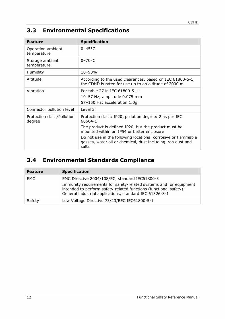
3.3 Environmental Specifications
Feature Specification
Operation ambient temperature
0–45°C
Storage ambient temperature
0–70°C
Humidity 10–90%
Altitude According to the used clearances, based on IEC 61800-5-1, the CDHD is rated for use up to an altitude of 2000 m
Vibration Per table 27 in IEC 61800-5-1: 10–57 Hz; amplitude 0.075 mm 57–150 Hz; acceleration 1.0g
Connector pollution level Level 3
Protection class/Pollution degree
Protection class: IP20, pollution degree: 2 as per IEC 60664-1 The product is defined IP20, but the product must be mounted within an IP54 or better enclosure Do not use in the following locations: corrosive or flammable gasses, water oil or chemical, dust including iron dust and salts
3.4 Environmental Standards Compliance
Feature Specification
EMC EMC Directive 2004/108/EC, standard IEC61800-3 Immunity requirements for safety-related systems and for equipment intended to perform safety-related functions (functional safety) – General industrial applications, standard IEC 61326-3-1
Safety Low Voltage Directive 73/23/EEC IEC61800-5-1
CDHD
Functional Safety Reference Manual 13
4 STO System Requirements
4.1 Power Supply
To avoid a high voltage level at the STO input, a low voltage must be used for safety related parts.
A voltage supply unit of 24 volts must be used. This voltage supply unit must comply with PELV/SELV, as per EN 60204-1 (Safety of Machinery - Electrical Equipment of Machines - Part 1: General Requirements).
Note: The CDHD internal 24 VDC supply is not approved for use in safety applications, and is thus prohibited for use as the STO power supply.
4.2 STO Cable
The STO cable must be less than 30 meters in length to conform to EN 61326-3-1.
Shielded and double insulated cables must be used. Double insulation refers to the need for a cable jacket on the wire that supplies the power.
The cable shield must be connected to the ground of the power supply.
The ideal gauge for the cable wire is 22 AWG (0.34 mm2). Since current drain by the STO circuit is less than 0.25A, 24 AWG (0.25 mm2) is also suitable.
The STO cable must be spatially separated from any sources of environmental stress, be it mechanical, electrical, thermal or chemical.

CDHD
14 Functional Safety Reference Manual
5 Installation
5.1 STO Connector
STO uses interface P1 on all CDHD models.
Figure 3
5.2 Pinout
The following table shows the pinout of the STO connector.
Pin Pin Label Function
1 24V STO Enable
2 GND STO Return
3 24V Return from the internal supply. Can be used to bypass the STO function, for use in non-safety applications only. The internal 24 VDC supply is not approved for use in safety applications.
4 24 VDC Supply from within the CDHD. Can be used to bypass the STO function, for use in non-safety applications only. The internal 24 VDC supply is not approved for use in safety applications.
CDHD
Functional Safety Reference Manual 15
5.3 Mating Connector
The following table shows the specifications for the mating connector:
Item All Models
Manufacturer Molex*
Housing PN and 4-pin crimp PN
436450400* and 0430300001*
Wire gauge 26–28 AWG * Or equivalent.
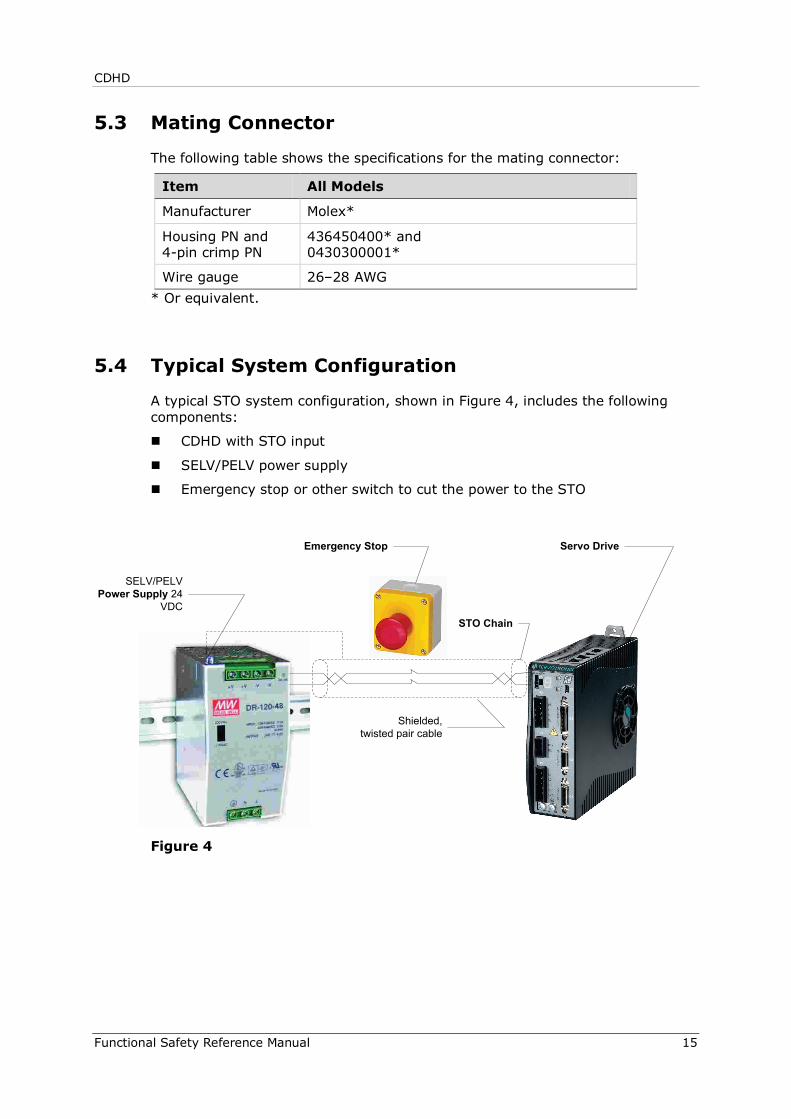
5.4 Typical System Configuration
A typical STO system configuration, shown in Figure 4, includes the following components:
CDHD with STO input
SELV/PELV power supply
Emergency stop or other switch to cut the power to the STO
Figure 4
SELV/PELV Power Supply 24
VDC
Emergency Stop Servo Drive
Shielded, twisted pair cable
STO Chain

CDHD
16 Functional Safety Reference Manual
6 Using STO
6.1 STO Benefits
The advantage of the integrated STO safety function over standard safety technology using electromechanical switchgear is the elimination of separate components and the effort required to wire and service them.
In addition, the function has a shorter switching time than the electromechanical components in conventional safety solutions.
6.2 STO in Use
The STO function serves exclusively to provide a safe stop of the motion system according to the STO specification in IEC 61800-5-2. Triggering the STO function results in power being removed from the motor control circuits, and, as a result the motor is without control. When STO is triggered while the motor is in motion, the motor shaft and its linked mechanical elements coast until brought to a stop by their own friction.
The immediate effect of STO is that the drive cannot supply any torque-generating energy. STO can be used in applications where the motor is expected to reach a standstill within a sufficiently short time based on the load and friction, and when coasting down of the motor will not have any impact on safety.
Figure 5 illustrates what happens to the motor when the STO function is engaged. The graph depicts a motor being driven in constant velocity mode, and the coasting of the motor to a stop when the power to the STO circuit is removed.
The graph shows motor speed as a function of time. It compares the behavior of the motor when brought to a controlled stop (STO function not engaged – VCMD and V traces) and when coasting to a stop (STO function engaged – Ref traces).
Figure 5

CDHD
Functional Safety Reference Manual 17
6.3 STO Diagnostics
STO status and diagnostic information is available in the following ways.
6.3.1 7-Segment Display on Drive Panel The drive’s 7-segment display shows a steady n if the STO is engaged (STO
power is removed) while the drive is disabled. This indicates a Warning condition.
The drive’s 7-segment display shows a flashing n if the STO is engaged (STO power is removed) while the drive is enabled. This indicates a Fault condition.
6.3.2 Serial Communication Using serial communications (terminal), the query ST returns a list of status reports. The status varies slightly when the STO is engaged (STO power is removed), depending on whether the drive is enabled or disabled at time STO power was removed.
If the drive is disabled and the STO is engaged (STO power is removed), a Warning condition occurs, and the status report shows the warning:
Drive Inactive Drive not ready: No SW enable Warnings Exist: WRN 1 STO Signal Not Connected
If the drive is enabled and the STO power is removed, this is a fault condition, and the status report indicates a fault. Drive Inactive Drive not ready: No SW enable Fault exists Fault exists: FLT 4 STO Fault
Since the drive was enabled and a fault occurred, the Fault Recovery procedure must be performed.
6.3.3 CANopen and EtherCAT If the drive is enabled and the STO power is removed, a fault condition occurs.
Object 603Fh sub-index 0 provides the error code for the current errors.
The STO fault code is 12673 (decimal).
6.4 Recovery from an STO Event
If the drive is disabled while the STO function is engaged, no recovery procedure is required. Once the STO power is restored, the drive is functional as usual.
If the drive is enabled while the STO function is engaged, the drive enters a Fault state. A fault recovery procedure is required since the drive fault status is latched, and the drive cannot be enabled until the fault status is explicitly cleared.
CDHD
18 Functional Safety Reference Manual
After the STO power is restored, a Fault Clear command must be executed. After a successful Fault Clear, the drive is again functional.
Fault Clear can be performed in any of the following ways:
Toggling Drive Enable. This is done either by executing a drive disable command (K) followed by the enabled (EN) command, or by toggling the Remote Enable line (REMOTE).
In some systems a specific drive input is defined as Alarm Clear. In such a system, toggling the input clears the fault.
Executing the clear faults command (CLEARFAULTS)
If the STO fault condition no longer exists, the drive is reenabled.
6.5 Prohibited Use of STO
The STO function must not be used in conditions where external influences will create a hazard when the function is engaged, as for example, the dropping of a suspended load.
The STO function is specifically prohibited for use in elevator applications. In these cases, additional measures (such as mechanical brakes) are required to prevent any hazard.
6.6 Exceptional Circumstance
A short circuit of two non-adjacent IGBTs within a brief time can produce a movement of up to a 120 electrical degrees, even if the STO function is engaged. Such an event is highly unlikely but possible. However, the probability of such a failure is 1.5 × 10⁻¹⁵ per hour (without common cause failure), and is thus considered negligible.
CDHD
Functional Safety Reference Manual 19
7 Maintenance
Users must perform a manual test of the STO function at least once a year.
The diagnostic test entails removing the STO supply voltage and verifying that the drive is indeed in the STO Fault state, and that motion is inhibited.
The maintenance procedure is performed as follows:
1. Set up the system such that nominal STO voltage is supplied to the drive, and the drive is enabled.
2. Remove (or switch off) the STO power supply. Verify that:
The drive is in a Fault state, and the STO Fault is indicated.
The drive cannot be enabled.
3. Restore the STO voltage, and clear the fault. Verify that the drive can be enabled.


CDHD Functional Safety Reference Guide Rev. 2.2
Servotronix Motion Control Ltd. 21C Yagia Kapayim Street Petach Tikva 49130, Israel Tel: +972 (3) 927 3800 Fax: +972 (3) 922 8075 Website: www.servotronix.com
Related Documents