CDA-Village on Park North Building Demolition & Surface Parking Lot Build Back Project No. 2021072 MISCELLANEOUS ROUGH CARPENTRY 06 10 53 - 1 SECTION 06 10 53 - MISCELLANEOUS ROUGH CARPENTRY PART 1 GENERAL 1.01 SECTION INCLUDES A. Roofing nailers. B. Preservative treated wood materials. C. Concealed wood blocking, nailers, and supports. 1.02 SUBMITTALS A. Product Data: Provide technical data on wood preservative materials and application instructions. 1.03 DELIVERY, STORAGE, AND HANDLING A. General: Cover wood products to protect against moisture. Support stacked products to prevent deformation and to allow air circulation. PART 2 PRODUCTS 2.01 GENERAL REQUIREMENTS A. Dimension Lumber: Comply with PS 20 and requirements of specified grading agencies. 1. Species: Spruce-Pine-Fir (South), unless otherwise indicated. 2. If no species is specified, provide species graded by the agency specified; if no grading agency is specified, provide lumber graded by grading agency meeting the specified requirements. 3. Grading Agency: Grading agency whose rules are approved by the Board of Review, American Lumber Standard Committee (www.alsc.org) and who provides grading service for the species and grade specified; provide lumber stamped with grade mark unless otherwise indicated. 2.02 DIMENSION LUMBER FOR CONCEALED APPLICATIONS A. Grading Agency: Southern Pine Inspection Bureau, Inc; SPIB (GR). B. Sizes: Nominal sizes as indicated on drawings, S4S. C. Moisture Content: S-dry or MC19. D. Miscellaneous Framing, Blocking, Nailers, Grounds, and Furring: 1. Lumber: S4S, No.2 or Standard Grade. 2. Boards: Standard or No.3. 2.03 CONSTRUCTION PANELS A. Other Applications: 1. Plywood Concealed From View But Located Within Exterior Enclosure: PS 1, C-C Plugged or better, Exterior grade.

Welcome message from author
This document is posted to help you gain knowledge. Please leave a comment to let me know what you think about it! Share it to your friends and learn new things together.
Transcript

CDA-Village on Park North Building Demolition & Surface Parking Lot Build Back
Project No. 2021072
MISCELLANEOUS ROUGH CARPENTRY
06 10 53 - 1
SECTION 06 10 53 - MISCELLANEOUS ROUGH CARPENTRY
PART 1 GENERAL
1.01 SECTION INCLUDES
A. Roofing nailers.
B. Preservative treated wood materials.
C. Concealed wood blocking, nailers, and supports.
1.02 SUBMITTALS
A. Product Data: Provide technical data on wood preservative materials and application
instructions.
1.03 DELIVERY, STORAGE, AND HANDLING
A. General: Cover wood products to protect against moisture. Support stacked products to prevent
deformation and to allow air circulation.
PART 2 PRODUCTS
2.01 GENERAL REQUIREMENTS
A. Dimension Lumber: Comply with PS 20 and requirements of specified grading agencies.
1. Species: Spruce-Pine-Fir (South), unless otherwise indicated.
2. If no species is specified, provide species graded by the agency specified; if no grading
agency is specified, provide lumber graded by grading agency meeting the specified
requirements.
3. Grading Agency: Grading agency whose rules are approved by the Board of Review,
American Lumber Standard Committee (www.alsc.org) and who provides grading service
for the species and grade specified; provide lumber stamped with grade mark unless
otherwise indicated.
2.02 DIMENSION LUMBER FOR CONCEALED APPLICATIONS
A. Grading Agency: Southern Pine Inspection Bureau, Inc; SPIB (GR).
B. Sizes: Nominal sizes as indicated on drawings, S4S.
C. Moisture Content: S-dry or MC19.
D. Miscellaneous Framing, Blocking, Nailers, Grounds, and Furring:
1. Lumber: S4S, No.2 or Standard Grade.
2. Boards: Standard or No.3.
2.03 CONSTRUCTION PANELS
A. Other Applications:
1. Plywood Concealed From View But Located Within Exterior Enclosure: PS 1, C-C
Plugged or better, Exterior grade.

CDA-Village on Park North Building Demolition & Surface Parking Lot Build Back
Project No. 2021072
MISCELLANEOUS ROUGH CARPENTRY
06 10 53 - 2
2. Plywood Exposed to View But Not Exposed to Weather: PS 1, A-D, or better.
3. Other Locations: PS 1, C-D Plugged or better.
2.04 ACCESSORIES
A. Fasteners and Anchors:
1. Metal and Finish: Hot-dipped galvanized steel complying with ASTM A153/A153M for
high humidity and preservative-treated wood locations, unfinished steel elsewhere.
2.05 FACTORY WOOD TREATMENT
A. Treated Lumber and Plywood: Comply with requirements of AWPA U1 - Use Category System
for wood treatments determined by use categories, expected service conditions, and specific
applications.
1. Preservative-Treated Wood: Provide lumber and plywood marked or stamped by an
ALSC-accredited testing agency, certifying level and type of treatment in accordance with
AWPA standards.
B. Preservative Treatment:
1. Preservative Pressure Treatment of Lumber Above Grade: AWPA U1, Use Category
UC3B, Commodity Specification A using waterborne preservative to 0.10 lb/cu ft retention.
a. Kiln dry lumber after treatment to maximum moisture content of 19 percent.
b. Treat lumber in contact with flashing or waterproofing.
c. Treat lumber in contact with masonry or concrete.
d. Treat lumber in other locations as indicated.
2. Preservative Pressure Treatment of Plywood Above Grade: AWPA U1, Use Category
UC2 and UC3B, Commodity Specification F using waterborne preservative to 0.25 lb/cu ft
retention.
a. Kiln dry plywood after treatment to maximum moisture content of 19 percent.
b. Treat plywood in contact with flashing or waterproofing.
c. Treat plywood in contact with masonry or concrete.
d. Treat plywood in other locations as indicated.
PART 3 EXECUTION
3.01 INSTALLATION - GENERAL
A. Select material sizes to minimize waste.
B. Reuse scrap to the greatest extent possible; clearly separate scrap for use on site as accessory
components, including: shims, bracing, and blocking.
C. Where treated wood is used on interior, provide temporary ventilation during and immediately
after installation sufficient to remove indoor air contaminants.
3.02 BLOCKING, NAILERS, AND SUPPORTS
CDA-Village on Park North Building Demolition & Surface Parking Lot Build Back
Project No. 2021072
MISCELLANEOUS ROUGH CARPENTRY
06 10 53 - 3
A. Provide framing and blocking members as indicated or as required to support finishes, fixtures,
specialty items, and trim.
B. In metal stud walls, provide continuous blocking around door and window openings for
anchorage of frames, securely attached to stud framing.
C. In walls, provide blocking attached to studs as backing and support for wall-mounted items,
unless item can be securely fastened to two or more studs or other method of support is
explicitly indicated.
D. Where ceiling-mounting is indicated, provide blocking and supplementary supports above
ceiling, unless other method of support is explicitly indicated.
3.03 ROOF-RELATED CARPENTRY
A. Coordinate installation of roofing carpentry with deck construction, framing of roof openings,
and roofing assembly installation.
END OF SECTION

This page intentionally left blank

CDA-Village on Park North Building Demolition & Surface Parking Lot Build Back
Project No. 2021072
PREPARATION FOR RE-ROOFING
07 01 50.19 - 1
SECTION 07 01 50.19 - PREPARATION FOR RE-ROOFING
PART 1 GENERAL
1.01 SECTION INCLUDES
A. Partial replacement of existing roofing system in preparation for replacement roofing system in
designated areas as indicated on drawings.
B. Removal of existing flashing and counterflashings.
C. Temporary roofing protection.
1.02 SUBMITTALS
A. Product Data: Submit for each type of material.
1.03 FIELD CONDITIONS
A. Existing Roofing System: EPDM single-ply roofing.
B. Do not remove existing roofing membrane when weather conditions threaten the integrity of
building contents or intended continued occupancy.
C. Maintain continuous temporary protection prior to and during installation of new roofing system.
D. Provide notice at least three days before starting activities that will affect normal building
operations.
E. Verify that occupants have been evacuated from building areas when work on structurally
impaired roof decking is scheduled to begin.
F. Owner will occupy building areas directly below re-roofing area.
1. Provide Owner with at least 48 hours written notice of roofing activities that may affect
their operations and to allow them to prepare for upcoming activities as necessary.
2. Do not disrupt Owner's operations or activities.
3. Maintain access of Owner's personnel to corridors, existing walkways, and adjacent
buildings.
1.04 WARRANTY
A. Existing Warranties: Perform this work using methods and materials that will maintain existing
roof system warranties.
1. Notify existing roof system warrantor prior to starting this work and obtain written
instructions for procedures necessary to maintain this existing warranty.
2. Upon completion of this work, notify warrantor of reroofing completion and obtain
documentation to verify that existing roofing system has been inspected and warranty is
still in effect.
a. Submit documentation upon project closeout.
PART 2 PRODUCTS
2.01 MATERIALS

CDA-Village on Park North Building Demolition & Surface Parking Lot Build Back
Project No. 2021072
PREPARATION FOR RE-ROOFING
07 01 50.19 - 2
A. Patching Materials: Provide necessary materials in accordance with requirements of existing
roofing system.
B. Temporary Roofing Protection Materials:
1. Contractor's responsibility to select appropriate materials for temporary protection of
roofing areas as determined necessary for this work.
C. Roofing Recover Materials:
1. Contractor's responsibility to select appropriate materials for roofing re-cover as
determined necessary for this work to match existing.
2.02 ACCESSORIES
A. Fasteners: Type and size as required and compatible with existing and new roofing system to
resist local wind uplift.
PART 3 EXECUTION
3.01 EXAMINATION
A. Verify that existing roof surface has been cleared of materials being removed from existing
roofing system and ready for next phase of work as required.
3.02 PREPARATION
A. Sweep roof surface clean of loose matter.
B. Remove loose refuse and dispose of properly off-site.
3.03 MATERIAL REMOVAL
A. Remove only existing roofing materials that can be replaced with new materials the same day.
B. Remove metal counter flashings.
C. Remove insulation and fasteners, cant strips, and blocking.
D. Remove vapor retarder and underlay.
E. Repair existing metal deck surface to provide smooth working surface for new roof system.
3.04 INSTALLATION
A. Coordinate scope of this work with requirements for installation of new roofing system. Comply
with manufacturer's instructions.
3.05 PROTECTION
A. Provide protection of existing roofing system that is not having work performed on it.
B. Do not permit traffic over unprotected or repaired deck surface.
C. Install recover board over existing membrane.
3.06 SCHEDULES
A. Existing Roofing Areas as Indicated: Remove existing perimeter flashings, base flashings,
counter flashings, roofing membrane, insulation, and vapor retarder.
END OF SECTION

CDA-Village on Park North Building Demolition & Surface Parking Lot Build Back
Project No. 2021072
THERMAL INSULATION
07 21 00 - 1
SECTION 07 21 00 - THERMAL INSULATION
PART 1 GENERAL
1.01 SECTION INCLUDES
A. Board insulation at cavity wall construction, perimeter foundation wall, and underside of floor
slabs.
B. Foam insulation for filling gaps.
1.02 SUBMITTALS
A. Product Data: Provide data on product characteristics, performance criteria, and product
limitations.
PART 2 PRODUCTS
2.01 APPLICATIONS
A. Insulation Under Concrete Slabs: Extruded polystyrene (XPS) board.
B. Insulation at Perimeter of Foundation: Extruded polystyrene (XPS) board.
C. Insulation Inside Walls (ci): Polyisocyanurate board.
2.02 FOAM BOARD INSULATION MATERIALS
A. Extruded Polystyrene (XPS) Board Insulation: Complies with ASTM C578 with either natural
skin or cut cell surfaces.
1. Type and Compressive Resistance: Type VI, 40 psi (276 kPa), minimum.
2. Flame Spread Index (FSI): Class A - 0 to 25, when tested in accordance with ASTM E84.
3. Smoke Developed Index (SDI): 450 or less, when tested in accordance with ASTM E84.
4. Type and Thermal Resistance, R-value: Type VI, 5.0 (0.88) per 1 inch thickness at 75
degrees F mean temperature.
5. Board Edges: Square.
6. Products:
a. Certainteed Corp.
b. DuPont de Nemours, Inc; Styrofoam Brand Square Edge: building.dupont.com/#sle.
c. Johns Manville Corp.
d. Owens Corning Corporation; FOAMULAR Extruded Polystyrene (XPS)
Insulation: www.ocbuildingspec.com/#sle.
e. Or approved equal.
B. Polyisocyanurate (ISO) Board Insulation: Rigid cellular foam, complying with ASTM C1289.
1. Classifications:
a. Type I: Faced with aluminum foil on both major surfaces of the core foam.
1) Class 2 - Glass fiber reinforced or non-reinforced core foam.
2) Compressive Strength: 16 psi, minimum.
CDA-Village on Park North Building Demolition & Surface Parking Lot Build Back
Project No. 2021072
THERMAL INSULATION
07 21 00 - 2
3) Thermal Resistance, R-value: At 1-1/2 inch thick; 9.0 at 75 degrees F.
4) Tested to pass NFPA 285 with wall configurations indicated on Drawings.
2. Flame Spread Index (FSI): Class A - 0 to 25, when tested in accordance with ASTM E84.
3. Smoke Developed Index (SDI): 450 or less, when tested in accordance with ASTM E84.
4. Water Vapor Permeance: 1.2 perm, maximum, at 1 inch thickness, and when tested in
accordance with ASTM E96/E96M, desiccant method.
5. Complies with fire resistance requirements indicated on drawings as part of an exterior
non-load-bearing exterior wall assembly when tested in accordance with NFPA 285.
6. Board Edges: Square.
7. Products:
a. Atlas Roofing Corporation; ACFoam-II Polyiso Roof
Insulation: www.atlasroofing.com/#sle.
b. Atlas Roofing Corporation; EnergyShield CGF PRO: www.atlasroofing.com/#sle.
c. Carlisle Coatings & Waterproofing, Inc; R2+ Matte: www.carlisleccw.com/#sle.
d. Dow Chemical Company; THERMAX (ci): www.dowbuildingsolutions.com/#sle.
e. Hunter Panels; Xci Foil (Class A): www.hunterpanels.com/#sle.
f. Johns Manville; AP Foil-Faced: www.jm.com/#sle.
g. Rmax Inc; ECOMAXci FR: www.rmax.com/#sle.
h. Or approved equal.
2.03 FOAM INSULATION
A. Gap and Crack Filler: Manufacturer's standard urethane or isocyanurate, single component mix
for producing low or no expansion, rigid, closed-cell foam sealant by frothing in place;1.5-lb.
nominal density.
1. Manufacturers: Provide one of the following:
a. Dow Building Solutions.
b. Touch ‘n Foam.
c. Todol Products.
2.04 ACCESSORIES
A. Tape: Reinforced polyethylene film with acrylic pressure sensitive adhesive.
1. Application: Sealing of interior circular penetrations, such as pipes or cables.
2. Width: Are required for application.
3. Temperature Resistance: Minus 40 degrees F to 212 degrees F
B. Tape joints of rigid insulation in accordance with roofing and insulation manufacturers'
instructions.
C. Insulation Fasteners: Appropriate for purpose intended and approved by roofing manufacturer.
D. Adhesive: Type recommended by insulation manufacturer for application.
CDA-Village on Park North Building Demolition & Surface Parking Lot Build Back
Project No. 2021072
THERMAL INSULATION
07 21 00 - 3
PART 3 EXECUTION
3.01 EXAMINATION
A. Verify substrate surfaces are flat, free of honeycomb, fins, irregularities, or materials or
substances that may impede adhesive bond.
3.02 BOARD INSTALLATION AT FOUNDATION PERIMETER
A. Install boards horizontally on foundation perimeter.
1. Place boards to maximize adhesive contact.
2. Install in running bond pattern.
3. Butt edges and ends tightly to adjacent boards and to protrusions.
B. Cut and fit insulation tightly to protrusions or interruptions to the insulation plane.
C. Immediately following application of board insulation, place protective boards over exposed
insulation surfaces.
1. Apply adhesive in five continuous beads per board length.
2. Install boards horizontally or vertically from base of foundation to top of insulation.
3. Butt boards tightly, with joints staggered from insulation joints.
3.03 BOARD INSTALLATION AT CAVITY WALLS
A. Apply adhesive to back of boards:
B. Install boards to fit snugly between wall ties.
C. Install boards horizontally on walls.
1. Place boards to maximize adhesive contact.
2. Install in running bond pattern.
3. Butt edges and ends tightly to adjacent boards and protrusions.
4. Fill gaps greater than 1/8-inch with spray foam or sealant as indicated in insulation
manufacturer's ICC/ES evaluation report.
D. Cut and fit insulation tightly to protrusions or interruptions to the insulation plane.
3.04 BOARD INSTALLATION UNDER CONCRETE SLABS
A. Place insulation under slabs on grade after base for slab has been compacted.
B. Cut and fit insulation tightly to protrusions or interruptions to the insulation plane.
C. Prevent insulation from being displaced or damaged while placing slab.
3.05 FOAM INSULATION
A. Spray foam insulation into miscellaneous voids and cavity spaces around exterior door frames,
window system frames, storefront frames, window sills, louver openings, and as indicated.
1. Install gap and crack filler in joints up to 1/2-inch wide.
2. Install spray foam in joints greater than 1/2-inch wide.
3.06 PROTECTION
CDA-Village on Park North Building Demolition & Surface Parking Lot Build Back
Project No. 2021072
THERMAL INSULATION
07 21 00 - 4
A. Do not permit installed insulation to be damaged prior to its concealment.
END OF SECTION

CDA-Village on Park North Building Demolition & Surface Parking Lot Build Back
Project No. 2021072
AIR BARRIERS
07 27 00 - 1
SECTION 07 27 00 - AIR BARRIERS
PART 1 GENERAL
1.01 SECTION INCLUDES
A. Air barriers.
1.02 SUBMITTALS
A. Product Data: Provide data on material characteristics, performance criteria, and limitations.
B. Shop Drawings: Provide drawings of special joint conditions.
C. Manufacturer's Installation Instructions: Indicate preparation, installation methods, and storage
and handling criteria.
1.03 QUALITY ASSURANCE
A. Air Barrier Association of America (ABAA) Evaluated Air Barrier Assemblies;
www.airbarrier.org/#sle: Use evaluated materials from a single manufacturer regularly engaged
in air barrier material manufacture, and use secondary materials approved in writing by primary
material manufacturer.
B. Installer Qualifications: Company specializing in performing the work of this section with
minimum three years documented experience.
C. Manufacturer Qualification: Use evaluated materials from a single manufacturer regularly
engaged in air barrier material manufacture, and use secondary materials approved in writing
by primary material manufacturer.
1.04 FIELD CONDITIONS
A. Maintain temperature and humidity recommended by materials manufacturers before, during,
and after installation.
PART 2 PRODUCTS
2.01 AIR BARRIER MATERIALS (AIR IMPERMEABLE AND WATER VAPOR IMPERMEABLE)
A. Air and Vapor Barrier, Fluid-Applied:
1. Air Permeance: 0.004 cfm/sq ft, maximum, when tested in accordance with ASTM E2178.
2. Water Vapor Permeance: 1 perm, maximum, when tested in accordance with ASTM
E96/E96M using Procedure A - Desiccant Method, at 73.4 degrees F.
3. Water Penetration Resistance Around Nails: Pass, when tested in accordance with ASTM
D1970/D1970M.
4. Ultraviolet (UV) and Weathering Resistance: Approved in writing by manufacturer for up
to 60 days of weather exposure.
5. Surface Burning Characteristics: Flame spread index of 25 or less, smoke developed
index of 450 or less, Class A when tested in accordance with ASTM E84.
6. Complies with NFPA 285 requirements for wall assembly.
CDA-Village on Park North Building Demolition & Surface Parking Lot Build Back
Project No. 2021072
AIR BARRIERS
07 27 00 - 2
7. Seam and Perimeter Tape: As recommended by sheet manufacturer.
8. Products:
a. Carlisle Coatings and Waterproofing, Inc: www.carlisleccw.com/#sle.
b. GCP Applied Technologies: www.gcpat.com/#sle.
c. Tremco Commercial Sealants & Waterproofing: www.tremcosealants.com/#sle.
2.02 ACCESSORIES
A. Sealants, Tapes, and Accessories for Sealing Air Barrier and Adjacent Substrates: As
indicated or in compliance with air barrier manufacturer's installation instructions.
B. Sealant for Cracks and Joints In Substrates: Resilient elastomeric joint sealant compatible with
substrate and air barrier materials.
1. Application: Apply at 30 to 40 mil, 0.030 to 0.040 inch, nominal thickness.
C. Primer: Liquid applied polymer.
D. Flexible Flashing: Self-adhesive sheet flashing complying with ASTM D1970/D1970M, except
slip resistance requirement waived if not installed on roof.
E. Preformed Transition Membrane: Semirigid silicone or polyester composition, tapered edges,
tear resistant.
F. Liquid Flashing: One part, fast curing, nonsag, elastomeric, gun grade, trowelable.
PART 3 EXECUTION
3.01 EXAMINATION
A. Verify that surfaces and conditions are ready for work of this section.
B. Where existing conditions are responsibility of another installer, notify Architect of
unsatisfactory conditions.
C. Do not proceed with this work until unsatisfactory conditions have been corrected.
3.02 PREPARATION
A. Remove projections, protruding fasteners, and loose or foreign matter that might interfere with
proper installation.
B. Clean and prime substrate surfaces to receive adhesives and sealants in accordance with
manufacturer's installation instructions.
3.03 INSTALLATION
A. Install materials in accordance with manufacturer's installation instructions.
B. Air Barriers: Install continuous airtight barrier over surfaces indicated, with sealed seams and
with sealed joints to adjacent surfaces.
C. Apply sealants and adhesives within recommended temperature range in accordance with
manufacturer's installation instructions.
D. Fluid-Applied Coatings or Membranes:

CDA-Village on Park North Building Demolition & Surface Parking Lot Build Back
Project No. 2021072
AIR BARRIERS
07 27 00 - 3
1. Prepare substrate in accordance with manufacturer's installation instructions; treat joints in
substrate and between dissimilar materials as indicated.
2. Where exterior masonry veneer is being installed, install masonry anchors before
installing air barrier over masonry; provide airtight seal around anchors.
3. Apply bead or trowel coat of mastic sealant with minimum thickness of 1/4 inch along
coating seams, rough cuts, and as recommended by manufacturer.
4. Use flashing to seal to adjacent construction and to bridge joints in coating substrate.
E. Openings and Penetrations in Exterior Air Barriers:
1. Install flashing over sills, covering entire sill frame member, extending at least 5 inches
onto air barrier and at least 6 inches up jambs; mechanically fasten stretched edges.
2. At openings with nonflanged frames, seal air barrier to each side of framing at opening
using flashing at least 9 inches wide, and covering entire depth of framing.
3. At head of openings, install flashing under air barrier extending at least 2 inches beyond
face of jambs; seal air barrier to flashing.
4. At interior face of openings, seal gap between window/door frame and rough framing,
using joint sealant over backer rod.
5. Service and Other Penetrations: Form flashing around penetrating item and seal to air
barrier surface.
3.04 FIELD QUALITY CONTROL
A. Do not cover installed air barriers until required inspections have been completed.
B. Take digital photographs of each portion of installation prior to covering up air barriers.
3.05 PROTECTION
A. Do not leave materials exposed to weather longer than recommended by manufacturer.
END OF SECTION

This page intentionally left blank
CDA-Village on Park North Building Demolition & Surface Parking Lot Build Back
Project No. 2021072
SHEET METAL FLASHING AND TRIM
07 62 00 - 1
SECTION 07 62 00 - SHEET METAL FLASHING AND TRIM
PART 1 GENERAL
1.01 SECTION INCLUDES
A. Fabricated sheet metal items, including flashings and counterflashings.
B. Sealants for joints within sheet metal fabrications.
1.02 QUALITY ASSURANCE
A. Perform work in accordance with SMACNA (ASMM) requirements and standard details, except
as otherwise indicated.
1.03 DELIVERY, STORAGE, AND HANDLING
A. Stack material to prevent twisting, bending, and abrasion, and to provide ventilation. Slope
metal sheets to ensure drainage.
B. Prevent contact with materials that could cause discoloration or staining.
PART 2 PRODUCTS
2.01 SHEET MATERIALS
A. Pre-Finished Aluminum: ASTM B209 (ASTM B209M); 20 gage, (0.032 inch) thick; plain finish
shop pre-coated with fluoropolymer coating.
1. Fluoropolymer Coating: High Performance Organic Finish, AAMA 2604; multiple coat,
thermally cured fluoropolymer finish system.
2. Color: As selected by Architect from manufacturer's standard colors.
B. Stainless Steel: ASTM A666, Type 304 alloy, soft temper, 28 gauge, (0.0156 inch) thick;
smooth No. 4 - Brushed finish.
2.02 FABRICATION
A. Form sections true to shape, accurate in size, square, and free from distortion or defects.
B. Fabricate cleats of same material as sheet, one gauge thicker, minimum 1.5 inches wide,
interlocking with sheet.
C. Form pieces in longest possible lengths.
D. Hem exposed edges on underside 1/2 inch; miter and seam corners.
E. Form material with lapped seams, except where otherwise indicated; at moving joints, use
sealed lapped, bayonet-type or interlocking hooked seams.
F. Fabricate corners from one piece with minimum 18 inch long legs; seam for rigidity, seal with
sealant.
G. Fabricate flashings to allow toe to extend 2 inches over roofing gravel. Return and brake
edges.
2.03 ACCESSORIES
CDA-Village on Park North Building Demolition & Surface Parking Lot Build Back
Project No. 2021072
SHEET METAL FLASHING AND TRIM
07 62 00 - 2
A. Fasteners: Stainless steel, with soft neoprene washers.
B. Primer: Zinc chromate type.
C. Concealed Sealants: Non-curing butyl sealant.
D. Exposed Sealants: ASTM C920; elastomeric sealant, with minimum movement capability as
recommended by manufacturer for substrates to be sealed; color to match adjacent material.
E. Plastic Cement: ASTM D4586/D4586M, Type I.
PART 3 EXECUTION
3.01 PREPARATION
A. Install starter and edge strips, and cleats before starting installation.
B. Back paint concealed metal surfaces with protective backing paint to a minimum dry film
thickness of 15 mil.
3.02 INSTALLATION
A. Secure flashings in place using concealed fasteners.
B. Apply plastic cement compound between metal flashings and felt flashings.
C. Fit flashings tight in place; make corners square, surfaces true and straight in planes, and lines
accurate to profiles.
D. Seal metal joints watertight.
END OF SECTION

CDA-Village on Park North Building Demolition & Surface Parking Lot Build Back
Project No. 2021072
ROOF SPECIALTIES
07 71 00 - 1
SECTION 07 71 00 - ROOF SPECIALTIES
PART 1 GENERAL
1.01 SECTION INCLUDES
A. Manufactured roof specialties, including copings.
1.02 SUBMITTALS
A. Product Data: Provide data on shape of components, materials and finishes, anchor types and
locations.
B. Shop Drawings: Indicate configuration and dimension of components, adjacent construction,
required clearances and tolerances, and other affected work.
C. Samples: Submit two samples, 3 inch wide by 4 inch high, illustrating finish and color.
D. Manufacturer's Installation Instructions: Indicate special procedures, fasteners, supporting
members, and perimeter conditions requiring special attention.
PART 2 PRODUCTS
2.01 MANUFACTURERS
A. Roof Edge Flashings and Copings:
1. ATAS International, Inc: www.atas.com/#sle.
2. Metal-Era Inc: www.metalera.com/#sle.
3. OMG Roofing Products: www.omgroofing.com/#sle.
4. Or approved equal.
2.02 COMPONENTS
A. Copings: Factory fabricated to sizes required; corners mitered; concealed fasteners.
1. Configuration: Concealed continuous hold down cleat at both legs; internal splice piece at
joints of same material, thickness, and finish as cap; concealed stainless steel fasteners.
2. Pull-Off Resistance: Tested in accordance with ANSI/SPRI/FM 4435/ES-1 using test
method RE-3 to positive and negative design wind pressure as defined by applicable local
building code.
3. Wall Width: As indicated on drawings.
4. Outside Face Height: As indicated on drawings.
5. Inside Face Height: As indicated on drawings.
6. Material: Formed aluminum sheet, 0.040 inch thick, minimum.
7. Finish: 70 percent polyvinylidene fluoride.
8. Color: To be selected by Architect from manufacturer's standard range.
2.03 FINISHES
A. PVDF (Polyvinylidene Fluoride) Coating: Superior Performance Organic Finish, AAMA 2605;
multiple coat, thermally cured fluoropolymer finish system; color as indicated.
CDA-Village on Park North Building Demolition & Surface Parking Lot Build Back
Project No. 2021072
ROOF SPECIALTIES
07 71 00 - 2
2.04 ACCESSORIES
A. Sealant for Joints in Linear Components: As recommended by component manufacturer.
PART 3 EXECUTION
3.01 EXAMINATION
A. Verify that deck, curbs, roof membrane, base flashing, and other items affecting work of this
Section are in place and positioned correctly.
3.02 INSTALLATION
A. Install components in accordance with manufacturer's instructions and NRCA (RM) applicable
requirements.
B. Seal joints within components when required by component manufacturer.
C. Anchor components securely.
D. Coordinate installation of components of this section with installation of roofing membrane and
base flashings.
E. Coordinate installation of sealants and roofing cement with work of this section to ensure water
tightness.
END OF SECTION

CDA-Village on Park North Building Demolition & Surface Parking Lot Build Back
Project No. 2021072
JOINT SEALANTS
07 92 00 - 1
SECTION 07 92 00 - JOINT SEALANTS
PART 1 GENERAL
1.01 SECTION INCLUDES
A. Nonsag gunnable joint sealants.
B. Joint backings and accessories.
1.02 SUBMITTALS
A. Product Data for Sealants: Submit manufacturer's technical data sheets for each product to be
used, that includes the following.
1. Physical characteristics, including movement capability, VOC content, hardness, cure
time, and color availability.
2. List of backing materials approved for use with the specific product.
3. Substrates that product is known to satisfactorily adhere to and with which it is compatible.
4. Substrates the product should not be used on.
1.03 WARRANTY
A. Correct defective work within a five year period after Date of Substantial Completion.
B. Warranty: Include coverage for installed sealants and accessories that fail to
achieve watertight seal , exhibit loss of adhesion or cohesion, or do not cure.
PART 2 PRODUCTS
2.01 MANUFACTURERS
A. Non-Sag Sealants: Permits application in joints on vertical surfaces without sagging or
slumping.
1. Bostik Inc: www.bostik-us.com/#sle.
2. Dow Chemical Company: consumer.dow.com/en-us/industry/ind-building-
construction.html/#sle.
3. Master Builders Solutions by BASF: www.master-builders-solutions.basf.us/en-us/#sle.
4. Momentive Performance Materials, Inc (formerly GE
Silicones): www.momentive.com/#sle.
5. Pecora Corporation: www.pecora.com/#sle.
6. Sika Corporation: www.usa-sika.com/#sle.
7. Tremco Commercial Sealants & Waterproofing: www.tremcosealants.com/#sle.
8. Or approved equal.
2.02 JOINT SEALANT APPLICATIONS
A. Scope:

CDA-Village on Park North Building Demolition & Surface Parking Lot Build Back
Project No. 2021072
JOINT SEALANTS
07 92 00 - 2
1. Exterior Joints: Seal open joints, whether or not the joint is indicated on drawings, unless
specifically indicated not to be sealed. Exterior joints to be sealed include, but are not
limited to, the following items.
a. Wall expansion and control joints.
b. Joints between door, window, and other frames and adjacent construction.
c. Joints between different exposed materials.
d. Openings below ledge angles in masonry.
e. Other joints indicated below.
2. Interior Joints: Do not seal interior joints unless specifically indicated to be sealed. Interior
joints to be sealed include, but are not limited to, the following items.
a. Joints between door, window, and other frames and adjacent construction.
b. Other joints indicated below.
3. Do not seal the following types of joints.
a. Intentional weepholes in masonry.
b. Joints indicated to be treated with manufactured expansion joint cover or some other
type of sealing device.
c. Joints where sealant is specified to be provided by manufacturer of product to be
sealed.
d. Joints where installation of sealant is specified in another section.
e. Joints between suspended panel ceilings/grid and walls.
B. Exterior Joints: Use non-sag non-staining silicone sealant, unless otherwise indicated.
C. Interior Joints: Use non-sag polyurethane sealant, unless otherwise indicated.
1. Wall and Ceiling Joints in Non-Wet Areas: Acrylic emulsion latex sealant.
2.03 NONSAG JOINT SEALANTS
A. Non-Staining Silicone Sealant: ASTM C920, Grade NS, Uses M and A; not expected to
withstand continuous water immersion or traffic.
1. Movement Capability: Plus and minus 35 percent, minimum.
2. Non-Staining To Porous Stone: Non-staining to light-colored natural stone when tested in
accordance with ASTM C1248.
3. Dirt Pick-Up: Reduced dirt pick-up compared to other silicone sealants.
4. Hardness Range: 15 to 35, Shore A, when tested in accordance with ASTM C661.
5. Color: To be selected by Architect from manufacturer's full range.
B. Polyurethane Sealant: ASTM C920, Grade NS, Uses M and A; single or multi-component; not
expected to withstand continuous water immersion or traffic.
1. Movement Capability: Plus and minus 35 percent, minimum.
2. Hardness Range: 20 to 35, Shore A, when tested in accordance with ASTM C661.
3. Color: To be selected by Architect from manufacturer's standard range.

CDA-Village on Park North Building Demolition & Surface Parking Lot Build Back
Project No. 2021072
JOINT SEALANTS
07 92 00 - 3
4. Service Temperature Range: Minus 40 to 180 degrees F.
C. Acrylic Emulsion Latex: Water-based; ASTM C834, single component, non-staining, non-
bleeding, non-sagging; not intended for exterior use.
1. Color: Standard colors matching finished surfaces, Type OP (opaque).
2. Grade: ASTM C834; Grade Minus 18 Degrees C (0 Degrees F).
D. Acrylic Latex Sealant: ASTM C834; for use as acoustical sealant and in firestopping systems
for expansion joints and through penetrations.
1. Color: Standard colors matching finished surfaces.
2. Fire Rated System: Complies with UL 263 and ASTM E119 with UL fire resistance
classifications.
2.04 ACCESSORIES
A. Backer Rod: Cylindrical cellular foam rod with surface that sealant will not adhere to,
compatible with specific sealant used, and recommended by backing and sealant
manufacturers for specific application.
1. Closed Cell and Bi-Cellular: 25 to 33 percent larger in diameter than joint width.
B. Backing Tape: Self-adhesive polyethylene tape with surface that sealant will not adhere to and
recommended by tape and sealant manufacturers for specific application.
C. Masking Tape: Self-adhesive, nonabsorbent, non-staining, removable without adhesive
residue, and compatible with surfaces adjacent to joints and sealants.
D. Joint Cleaner: Non-corrosive and non-staining type, type recommended by sealant
manufacturer; compatible with joint forming materials.
E. Primers: Type recommended by sealant manufacturer to suit application; non-staining.
PART 3 EXECUTION
3.01 EXAMINATION
A. Verify that joints are ready to receive work.
B. Verify that backing materials are compatible with sealants.
C. Verify that backer rods are of the correct size.
3.02 PREPARATION
A. Remove loose materials and foreign matter that could impair adhesion of sealant.
B. Clean joints, and prime as necessary, in accordance with manufacturer's instructions.
C. Perform preparation in accordance with manufacturer's instructions and ASTM C1193.
D. Mask elements and surfaces adjacent to joints from damage and disfigurement due to sealant
work; be aware that sealant drips and smears may not be completely removable.
3.03 INSTALLATION
A. Perform work in accordance with sealant manufacturer's requirements for preparation of
surfaces and material installation instructions.

CDA-Village on Park North Building Demolition & Surface Parking Lot Build Back
Project No. 2021072
JOINT SEALANTS
07 92 00 - 4
B. Perform installation in accordance with ASTM C1193.
C. Perform acoustical sealant application work in accordance with ASTM C919.
D. Measure joint dimensions and size joint backers to achieve the following, unless otherwise
indicated:
1. Width/depth ratio of 2:1.
2. Neck dimension no greater than 1/3 of the joint width.
3. Surface bond area on each side not less than 75 percent of joint width.
E. Install bond breaker backing tape where backer rod cannot be used.
F. Install sealant free of air pockets, foreign embedded matter, ridges, and sags, and without
getting sealant on adjacent surfaces.
G. Do not install sealant when ambient temperature is outside manufacturer's recommended
temperature range, or will be outside that range during the entire curing period, unless
manufacturer's approval is obtained and instructions are followed.
H. Nonsag Sealants: Tool surface concave, unless otherwise indicated; remove masking tape
immediately after tooling sealant surface.
END OF SECTION

CDA-Village on Park North Building Demolition & Surface Parking Lot Build Back
Project No. 2021072
HOLLOW METAL DOORS AND FRAMES
08 11 13 - 1
SECTION 08 11 13 - HOLLOW METAL DOORS AND FRAMES
PART 1 GENERAL
1.01 SECTION INCLUDES
A. Thermally insulated hollow metal doors with frames.
1.02 SUBMITTALS
A. Product Data: Materials and details of design and construction, hardware locations,
reinforcement type and locations, anchorage and fastening methods, and finishes.
B. Shop Drawings: Details of each opening, showing elevations, glazing, frame profiles, and any
indicated finish requirements.
C. Installation Instructions: Manufacturer's published instructions, including any special installation
instructions relating to this project.
1.03 DELIVERY, STORAGE, AND HANDLING
A. Comply with NAAMM HMMA 840 or ANSI/SDI A250.8 (SDI-100) in accordance with specified
requirements.
B. Protect with resilient packaging; avoid humidity build-up under coverings; prevent corrosion and
adverse effects on factory applied painted finish.
PART 2 PRODUCTS
2.01 MANUFACTURERS
A. Hollow Metal Doors and Frames:
1. Ceco Door, an Assa Abloy Group company: www.assaabloydss.com/#sle.
2. Curries, an Assa Abloy Group company: www.assaabloydss.com/#sle.
3. Mesker, dormakaba Group: www.meskeropeningsgroup.com/#sle.
4. Republic Doors, an Allegion brand: www.republicdoor.com/#sle.
5. Steelcraft, an Allegion brand: www.allegion.com/#sle.
6. Or approved equal.
2.02 PERFORMANCE REQUIREMENTS
A. Requirements for Hollow Metal Doors and Frames:
1. Steel Sheet: Comply with one or more of the following requirements; galvannealed steel
complying with ASTM A653/A653M, cold-rolled steel complying with ASTM
A1008/A1008M, or hot-rolled pickled and oiled (HRPO) steel complying with ASTM
A1011/A1011M, commercial steel (CS) Type B, for each.
2. Accessibility: Comply with ICC A117.1 and ADA Standards.
3. Exterior Door Top Closures: Flush end closure channel, with top and door faces aligned.
4. Door Edge Profile: Manufacturers standard for application indicated.
5. Typical Door Face Sheets: Flush.
CDA-Village on Park North Building Demolition & Surface Parking Lot Build Back
Project No. 2021072
HOLLOW METAL DOORS AND FRAMES
08 11 13 - 2
6. Glazed Lights: Non-removable stops on non-secure side; sizes and configurations as
indicated on drawings. Style: Manufacturers standard.
7. Hardware Preparations, Selections and Locations: Comply with NAAMM HMMA 830 and
NAAMM HMMA 831 or BHMA A156.115 and ANSI/SDI A250.8 (SDI-100) in accordance
with specified requirements.
8. Zinc Coating for Typical Interior and/or Exterior Locations: Provide metal components
zinc-coated (galvanized) and/or zinc-iron alloy-coated (galvannealed) by the hot-dip
process in accordance with ASTM A653/A653M, with manufacturer's standard coating
thickness, unless noted otherwise for specific hollow metal doors and frames.
a. Based on SDI Standards: Provide at least A40/ZF120 (galvannealed) when
necessary, coating not required for typical interior door applications, and at least
A60/ZF180 (galvannealed) for corrosive locations.
B. Combined Requirements: If a particular door and frame unit is indicated to comply with more
than one type of requirement, comply with the specified requirements for each type; for
instance, an exterior door that is also indicated as being sound-rated must comply with the
requirements specified for exterior doors and for sound-rated doors; where two requirements
conflict, comply with the most stringent.
2.03 HOLLOW METAL DOORS
A. Door Finish: Factory primed and field finished.
B. Exterior Doors: Thermally insulated.
1. Based on SDI Standards: ANSI/SDI A250.8 (SDI-100).
a. Level 3 - Extra Heavy-duty.
b. Physical Performance Level A 1 000 000 cycles; in accordance with ANSI/SDI
A250.4.
c. Model 2 - Seamless.
d. Door Face Metal Thickness: 16 gage, 0.053 inch, minimum.
e. Zinc Coating: A60/ZF180 galvannealed coating; ASTM A653/A653M.
2. Door Core Material: Polyurethane, 1.8 lbs/cu ft minimum density.
a. Foam Plastic Insulation: Manufacturer's standard board insulation with maximum
flame spread index (FSI) of 75, and maximum smoke developed index (SDI) of 450 in
accordance with ASTM E84, and completely enclosed within interior of door.
3. Door Thickness: 1-3/4 inches, nominal.
2.04 HOLLOW METAL FRAMES
A. Comply with standards and/or custom guidelines as indicated for corresponding door in
accordance with applicable door frame requirements.
B. Frame Finish: Factory primed and field finished.
C. Exterior Door Frames: Full profile/continuously welded type.

CDA-Village on Park North Building Demolition & Surface Parking Lot Build Back
Project No. 2021072
HOLLOW METAL DOORS AND FRAMES
08 11 13 - 3
1. Galvanizing: Components hot-dipped zinc-iron alloy-coated (galvannealed) in accordance
with ASTM A653/A653M, with A60/ZF180 coating.
2. Frame Metal Thickness: 14 gauge, 0.067 inch, minimum.
3. Weatherstripping: Separate, see Section 08 71 00.
D. Transom Bars: Fixed, of profile same as jamb and head.
E. Provide mortar guard boxes for hardware cut-outs in frames to be installed in masonry or to be
grouted.
F. Frames in Masonry Walls: Size to suit masonry coursing with head member 4 inches high to fill
opening without cutting masonry units.
G. Frames Wider than 48 inches: Reinforce with steel channel fitted tightly into frame head, flush
with top.
2.05 FINISHES
A. Primer: Rust-inhibiting, complying with ANSI/SDI A250.10, door manufacturer's standard.
2.06 ACCESSORIES
A. Removable Stops: Formed sheet steel, mitered or butted corners; prepared for countersink
style tamper proof screws.
B. Mechanical Fasteners for Concealed Metal-to-Metal Connections: Self-drilling, self-tapping,
steel with electroplated zinc finish.
C. Grout for Frames: Mortar grout complying with ASTM C476 with maximum slump of 4 inches
as measured in accordance with ASTM C143/C143M for hand troweling in place; plaster grout
and thinner pumpable grout are prohibited.
D. Silencers: Resilient rubber, fitted into drilled hole; provide three on strike side of single door,
three on center mullion of pairs, and two on head of pairs without center mullions.
E. Temporary Frame Spreaders: Provide for factory- or shop-assembled frames.
PART 3 EXECUTION
3.01 PREPARATION
A. Coat inside of frames to be installed in masonry or to be grouted, with bituminous coating, prior
to installation.
3.02 INSTALLATION
A. Install doors and frames in accordance with manufacturer's instructions and related
requirements of specified door and frame standards or custom guidelines indicated.
B. Coordinate frame anchor placement with wall construction.
C. Grout frames in masonry construction, using hand trowel methods; brace frames so that
pressure of grout before setting will not deform frames.
D. Install door hardware as specified in Section 08 71 00.
E. Coordinate installation of electrical connections to electrical hardware items.
CDA-Village on Park North Building Demolition & Surface Parking Lot Build Back
Project No. 2021072
HOLLOW METAL DOORS AND FRAMES
08 11 13 - 4
3.03 TOLERANCES
A. Clearances Between Door and Frame: Comply with related requirements of specified frame
standards or custom guidelines indicated in accordance with SDI 117 or NAAMM HMMA 861.
B. Maximum Diagonal Distortion: 1/16 inch measured with straight edge, corner to corner.
3.04 ADJUSTING
A. Adjust for smooth and balanced door movement.
END OF SECTION

CDA-Village on Park North Building Demolition & Surface Parking Lot Build Back
Project No. 2021072
ALUMINUM-FRAMED STOREFRONTS
08 43 13 - 1
SECTION 08 43 13 - ALUMINUM-FRAMED STOREFRONTS
PART 1 GENERAL
1.01 SECTION INCLUDES
A. Aluminum-framed storefront, with vision glass.
B. Aluminum doors and frames.
C. Weatherstripping.
1.02 ADMINISTRATIVE REQUIREMENTS
A. Coordinate with installation of other components that comprise the exterior enclosure.
1.03 SUBMITTALS
A. Product Data: Provide component dimensions, describe components within assembly,
anchorage and fasteners, glass and infill, door hardware, and internal drainage details.
B. Shop Drawings: Indicate system dimensions, framed opening requirements and tolerances,
affected related work, expansion and contraction joint location and details, and field welding
required.
C. Samples: Submit two samples 4 by 4 inches in size illustrating finished aluminum surface,
glass, glazing materials.
D. Manufacturer's Certificate: Certify that the products supplied meet or exceed the specified
requirements.
E. Hardware Schedule: Complete itemization of each item of hardware to be provided for each
door, cross-referenced to door identification numbers in Contract Documents.
F. Warranty: Submit manufacturer warranty and ensure forms have been completed in Owner's
name and registered with manufacturer.
1.04 DELIVERY, STORAGE, AND HANDLING
A. Handle products of this section in accordance with AAMA CW-10.
B. Protect finished aluminum surfaces with wrapping. Do not use adhesive papers or sprayed
coatings that bond to aluminum when exposed to sunlight or weather.
1.05 FIELD CONDITIONS
A. Do not install sealants when ambient temperature is less than 40 degrees F. Maintain this
minimum temperature during and 48 hours after installation.
PART 2 PRODUCTS
2.01 BASIS OF DESIGN -- FRAMING FOR INSULATING GLAZING
A. Center-Set Style, Thermally-Broken:
1. Basis of Design: Kawneer; Trifab Framing System.
2. Vertical Mullion Dimensions: 2 inches wide by 6 inches deep.
CDA-Village on Park North Building Demolition & Surface Parking Lot Build Back
Project No. 2021072
ALUMINUM-FRAMED STOREFRONTS
08 43 13 - 2
B. Other Manufacturers: Provide either the product identified as "Basis of Design" or an
equivalent product of one of the manufacturers listed below:
1. EFCO Corporation.
2. Manko Window Systems, Inc[<>]: www.mankowindows.com/#sle.
3. TRACO.
4. Tubelite, Inc.
5. Wausau Window and Wall Systems; Apogee Wausau Group.
6. YKK AP America Inc: www.ykkap.com/#sle.
2.02 BASIS OF DESIGN -- SWINGING DOORS
A. Wide Stile, Insulating Glazing, Thermally-Broken.
1. Basis of Design: Kawneer.
2.03 ALUMINUM-FRAMED STOREFRONT
A. Aluminum-Framed Storefront: Factory fabricated, factory finished aluminum framing members
with infill, and related flashings, anchorage and attachment devices.
1. Finish: Class I natural anodized.
a. Factory finish all surfaces that will be exposed in completed assemblies.
2. Fabrication: Joints and corners flush, hairline, and weatherproof, accurately fitted and
secured; prepared to receive anchors and hardware; fasteners and attachments
concealed from view; reinforced as required for imposed loads.
3. Construction: Eliminate noises caused by wind and thermal movement, prevent vibration
harmonics, and prevent "stack effect" in internal spaces.
4. System Internal Drainage: Drain to the exterior by means of a weep drainage network any
water entering joints, condensation occurring in glazing channel, and migrating moisture
occurring within system.
5. Expansion/Contraction: Provide for expansion and contraction within system components
caused by cycling temperature range of 170 degrees F over a 12 hour period without
causing detrimental effect to system components, anchorages, and other building
elements.
6. Movement: Allow for movement between storefront and adjacent construction, without
damage to components or deterioration of seals.
7. Perimeter Clearance: Minimize space between framing members and adjacent
construction while allowing expected movement.
8. Air and Vapor Seal: Maintain continuous air barrier and vapor retarder throughout
assembly, primarily in line with inside pane of glazing and inner sheet of infill panel and
heel bead of glazing compound.
B. Performance Requirements
CDA-Village on Park North Building Demolition & Surface Parking Lot Build Back
Project No. 2021072
ALUMINUM-FRAMED STOREFRONTS
08 43 13 - 3
1. Wind Loads: Design and size components to withstand the specified load requirements
without damage or permanent set, when tested in accordance with ASTM E330/E330M,
using loads 1.5 times the design wind loads and 10 second duration of maximum load.
a. Design Wind Loads: Comply with requirements of ASCE 7.
b. Member Deflection: Limit member deflection to flexure limit of glass in any direction,
with full recovery of glazing materials.
2. Air Leakage: 0.06 cfm/sq ft maximum leakage of storefront wall area when tested in
accordance with ASTM E283/E283M at 1.57 psf pressure difference.
3. Condensation Resistance Factor of Framing: 50, minimum, measured in accordance with
AAMA 1503.
4. Overall U-value Including Glazing: 0.48 Btu/(hr sq ft deg F), maximum.
2.04 COMPONENTS
A. Aluminum Framing Members: Tubular aluminum sections, thermally broken with interior
section insulated from exterior, drainage holes and internal weep drainage system.
1. Framing members for interior applications need not be thermally broken.
2. Glazing Stops: Flush.
B. Glazing: As specified in Section 08 80 00.
C. Swing Doors: Glazed aluminum.
1. Thickness: 1-3/4 inches.
2. Top Rail: 4 inches wide.
3. Vertical Stiles: 4-1/2 inches wide.
4. Bottom Rail: 10 inches wide.
5. Finish: Same as storefront.
2.05 MATERIALS
A. Extruded Aluminum: ASTM B221 (ASTM B221M).
B. Fasteners: Stainless steel.
C. Concealed Flashings: Stainless steel, 26 gauge, 0.0187 inch minimum thickness.
D. Glazing Gaskets: Type to suit application to achieve weather, moisture, and air infiltration
requirements.
E. Glazing Accessories: As specified in Section 08 80 00.
F. Air Barrier: Provide transition materials compatible with Section 07 25 00.
2.06 FINISHES
A. Class I Natural Anodized Finish: AAMA 611 AA-M12C22A41 Clear anodic coating not less
than 0.7 mils thick.
2.07 HARDWARE
A. For each door, include weatherstripping, sill sweep strip, and threshold.
CDA-Village on Park North Building Demolition & Surface Parking Lot Build Back
Project No. 2021072
ALUMINUM-FRAMED STOREFRONTS
08 43 13 - 4
B. Other Door Hardware: As specified in Section 08 71 00.
C. Weatherstripping: Wool pile, continuous and replaceable; provide on all doors.
D. Sill Sweep Strips: Resilient seal type, of neoprene; provide on all doors.
E. Threshold: Extruded aluminum, one piece per door opening, ribbed surface; provide on all
doors.
PART 3 EXECUTION
3.01 EXAMINATION
A. Verify dimensions, tolerances, and method of attachment with other work.
B. Verify that wall openings and adjoining air and vapor seal materials are ready to receive work of
this section.
3.02 INSTALLATION
A. Install wall system in accordance with manufacturer's instructions.
B. Attach to structure to permit sufficient adjustment to accommodate construction tolerances and
other irregularities.
C. Provide alignment attachments and shims to permanently fasten system to building structure.
D. Align assembly plumb and level, free of warp or twist. Maintain assembly dimensional
tolerances, aligning with adjacent work.
E. Provide thermal isolation where components penetrate or disrupt building insulation.
F. Install sill flashings. Turn up ends and edges; seal to adjacent work to form water tight dam.
G. Where fasteners penetrate sill flashings, make watertight by seating and sealing fastener heads
to sill flashing.
H. Set thresholds in bed of sealant and secure.
I. Install glass in accordance with Section 08 80 00, using glazing method required to achieve
performance criteria.
J. Touch-up minor damage to factory applied finish; replace components that cannot be
satisfactorily repaired.
K. Coordinate with Section 07 27 00 contractor for air barrier integrity.
3.03 TOLERANCES
A. Maximum Variation from Plumb: 0.06 inch per 3 feet non-cumulative or 0.06 inch per 10 feet,
whichever is less.
B. Maximum Misalignment of Two Adjoining Members Abutting in Plane: 1/32 inch.
3.04 FIELD QUALITY CONTROL
A. Water-Spray Test: Provide water spray quality test of installed storefront components in
accordance with AAMA 501.2 during construction process and before installation of interior
finishes.
1. Perform a minimum of two tests in each designated area as directed by Architect.
CDA-Village on Park North Building Demolition & Surface Parking Lot Build Back
Project No. 2021072
ALUMINUM-FRAMED STOREFRONTS
08 43 13 - 5
2. Conduct tests in each area prior to 10 percent and 50 percent completion of this work.
B. Repair or replace storefront components that have failed designated field testing, and retest to
verify performance complies with specified requirements.
3.05 ADJUSTING
A. Adjust operating hardware and sash for smooth operation.
3.06 CLEANING
A. Remove protective material from pre-finished aluminum surfaces.
B. Wash down surfaces with a solution of mild detergent in warm water, applied with soft, clean
wiping cloths, and take care to remove dirt from corners and to wipe surfaces clean.
3.07 PROTECTION
A. Protect installed products from damage until Date of Substantial Completion.
END OF SECTION

This page intentionally left blank
CDA-Village on Park North Building Demolition & Surface Parking Lot Build Back
Project No. 2021072
ALUMINUM WINDOWS
08 51 13 - 1
SECTION 08 51 13 - ALUMINUM WINDOWS
PART 1 GENERAL
1.01 SECTION INCLUDES
A. Extruded aluminum windows with fixed sash.
B. Factory glazing.
1.02 SUBMITTALS
A. Product Data: Include component dimensions, information on glass and glazing, and internal
drainage details.
B. Shop Drawings: Indicate opening dimensions, framed opening tolerances, anchorage locations
, and installation requirements.
C. Grade Substantiation: Prior to submitting shop drawings or starting fabrication, submit one of
the following showing compliance with specified grade:
1. Evidence of AAMA Certification.
2. Evidence of WDMA Certification.
3. Evidence of CSA Certification.
4. Test report(s) by independent testing agency itemizing compliance and acceptable to
authorities having jurisdiction.
D. Test Reports: Prior to submitting shop drawings or starting fabrication, submit test report(s) by
independent testing agency showing compliance with performance requirements in excess of
those prescribed by specified grade.
1.03 DELIVERY, STORAGE, AND HANDLING
A. Comply with requirements of AAMA CW-10.
B. Protect finished surfaces with wrapping paper or strippable coating during installation. Do not
use adhesive papers or sprayed coatings that bond to substrate when exposed to sunlight or
weather.
1.04 WARRANTY
A. Manufacturer Warranty: Provide 5-year manufacturer warranty against failure of glass seal on
insulating glass units, including interpane dusting or misting. Include provision for replacement
of failed units. Complete forms in Owner's name and register with manufacturer.
B. Manufacturer Warranty: Provide 10-year manufacturer warranty against excessive degradation
of exterior finish. Include provision for replacement of units with excessive fading, chalking, or
flaking. Complete forms in Owner's name and register with manufacturer.
PART 2 PRODUCTS
2.01 MANUFACTURERS
A. Aluminum Windows Manufacturers:
CDA-Village on Park North Building Demolition & Surface Parking Lot Build Back
Project No. 2021072
ALUMINUM WINDOWS
08 51 13 - 2
1. Manko Window Systems, Inc: www.mankowindows.com/#sle.
2. TRACO: www.traco.com/#sle.
3. Wausau Window and Wall Systems: www.wausauwindow.com/#sle.
4. Or approved equal.
2.02 ALUMINUM WINDOWS
A. Aluminum Windows: Extruded aluminum frame and sash, factory fabricated, factory finished,
with operating hardware, related flashings, and anchorage and attachment devices.
1. Provide factory-glazed units.
2. Fabrication: Joints and corners flush, hairline, and weatherproof, accurately fitted and
secured; prepared to receive anchors; fasteners and attachments concealed from view;
reinforced as required for operating hardware and imposed loads.
3. Perimeter Clearance: Minimize space between framing members and adjacent
construction while allowing expected movement.
4. Movement: Accommodate movement between window and perimeter framing and
deflection of lintel, without damage to components or deterioration of seals.
5. System Internal Drainage: Drain to the exterior by means of a weep drainage network any
water entering joints, condensation occurring in glazing channel, and migrating moisture
occurring within system.
B. Fixed, Non-Operable Type:
1. Construction: Thermally broken.
2. Glazing: Double; clear; low-e.
3. Exterior Finish: Class I natural anodized.
4. Interior Finish: Class I natural anodized.
2.03 PERFORMANCE REQUIREMENTS
A. Grade: AAMA/WDMA/CSA 101/I.S.2/A440 requirements for specific window type:
1. Performance Class (PC): CW.
B. Design Pressure (DP): In accordance with applicable codes.
C. Water Leakage: No uncontrolled leakage on interior face when tested in accordance with
ASTM E331 at differential pressure of 12.11 psf.
D. Air Leakage: 0.1 cfm/sq ft maximum leakage per unit area of outside window frame dimension
when tested at 1.57 psf pressure difference in accordance with ASTM E283/E283M.
E. Condensation Resistance Factor of Frame: 50, measured in accordance with AAMA 1503.
F. Overall Thermal Transmittance (U-value): 0.35, maximum, including glazing, measured on
window sizes required for this project.
2.04 COMPONENTS
CDA-Village on Park North Building Demolition & Surface Parking Lot Build Back
Project No. 2021072
ALUMINUM WINDOWS
08 51 13 - 3
A. Frames: Size as indicated; thermally broken with interior portion of frame insulated from
exterior portion; flush glass stops of snap-on type.
B. Glazing: See Section 08 80 00.
C. Fasteners: Stainless steel.
D. Sealant for Setting Sills and Sill Flashing: Non-curing butyl type.
2.05 MATERIALS
A. Extruded Aluminum: ASTM B221 (ASTM B221M), 6063 alloy, T6 temper.
2.06 FINISHES
A. Class I Natural Anodized Finish: AAMA 611 AA-M12C22A41, clear anodic coating not less
than 0.7 mil thick.
PART 3 EXECUTION
3.01 PRIME WINDOW INSTALLATION
A. Install windows in accordance with manufacturer's instructions.
B. Attach window frame and shims to perimeter opening to accommodate construction tolerances
and other irregularities.
C. Align window plumb and level, free of warp or twist. Maintain dimensional tolerances and
alignment with adjacent work.
D. Install sill and sill end angles.
E. Provide thermal isolation where components penetrate or disrupt building insulation. Pack
fibrous insulation in shim spaces at perimeter of assembly to maintain continuity of thermal
barrier.
3.02 TOLERANCES
A. Maximum Variation from Level or Plumb: 1/16 inches every 3 ft non-cumulative or 1/8 inches
per 10 ft, whichever is less.
END OF SECTION

This page intentionally left blank

CDA-Village on Park North Building Demolition & Surface Parking Lot Build BackProject No. 2021072
DOOR HARDWARE08 71 00 - 1
SECTION 08 71 00 - DOOR HARDWARE
PART 1 - GENERAL
1.1 DESCRIPTION OF WORK:
A. This section includes the following and as indicated in the hardware schedule at the end of this section:
1. Hinges2. Lock and Latch sets3. Lock Cylinders and Keys4. Exit Device5. Closers6. Stops7. Coordinators8. Light and/or Sound Seals9. Weatherstripping10. Thresholds11. Astragals12. Silencers
B. Related sections:
1. Division 8 Section "Steel Doors and Frames" 2. Division 8 Section "Aluminum Entrances and Storefronts" for hardware supplied
by the Aluminum Entrance Supplier. 3. Division 8 Section "Aluminum Entrances and Storefronts" for Cylinder and Keys
supplied by this Section.
1.2 QUALITY ASSURANCE:
A. Single Source Responsibility: Obtain each type of hardware from the same supplier.
B. Fire-Rated Openings: Provide door hardware for fire-rated openings that complies with NFPA Standard No. 80 and requirements of authorities having jurisdiction. Provide only items of door hardware that are listed and are identical to products tested by UL or other testing and inspecting organization acceptable to authorities having jurisdiction.
1.3 SUBMITTALS:
A. Submit five copies of complete and detailed hardware schedule. Include product data on all hardware items being submitted.
B. The submitted schedule shall use symbol/letter designations and format shown on construction documents hardware schedule. The submitted schedule shall enumerate all scheduled openings in the same order as they appear on construction documents hardware schedule.
C. List door frames and borrowed light frames in separate schedules.
D. Submit five copies of proposed keying schedule indicating clearly how the Owner’s final instructions on keying of locks has been fulfilled.

CDA-Village on Park North Building Demolition & Surface Parking Lot Build BackProject No. 2021072
DOOR HARDWARE08 71 00 - 2
E. Submit sample of each item of finish hardware that differs from that specified.
F. Samples submitted may be used on the project and will be delivered to the building site where comparison will be made with other hardware furnished.
1.4 PRODUCT DELIVERY:
A. Mark each item as to contents and location in the building for which it is intended.
B. Ship prepaid the hardware templates and/or physical hardware, as required, to metal door and frame manufacturers and wood door manufacturers.
C. Deliver drawings, templates and directions for installation of shell housing for high security lock box when unit is to be recessed mounted in poured-in-place concrete or masonry walls.
PART 2 - PRODUCTS
2.1 FINISH HARDWARE SCHEDULE:
A. Refer to schedule bound in the drawings for hardware requirements.
2.2 ANCHORS & FASTENERS:
A. Furnish as required and of proper size for the purpose for which it is intended.
B. Anchors in solid material shall be with machine screws in expansion shields. Furnish toggle bolts where walls are not solid material.
2.3 HINGES:
A. Non-removable pins on exterior doors and interior locked doors swinging out. Furnish non-rising pins on all other doors.
B. Stainless steel hinges on exterior doors swinging out and steel hinges for all other doors.
1. Exterior Hinge Finish: B.H.M.A. 630, stainless steel metal, satin (US32D).2. Interior Hinge Finish: B.H.M.A. 626, satin chromium plated (US26D).
C. Number of Hinges:
1. Three on doors less than 89 inches.2. Four on doors 89 inches and over.
D. Hinge size: Provide hinges of the following heights and weights for door sizes as indicated below:
1. 1 3/4 inches thick by 40 inches or less wide: 4 1/2 inches standard weight (0.134 inches)
2. 1 3/4 inches thick by 40 inches+ to 44 inches wide: 4-1/2 inches heavy weight (0.146 inches)
3. 1 3/4 inch thick by 44 inches+ to 48 inches wide: 5 inches heavy weight (0.185 inches)
E. Acceptable Manufacturers: Stanley, McKinney, Hager.
CDA-Village on Park North Building Demolition & Surface Parking Lot Build BackProject No. 2021072
DOOR HARDWARE08 71 00 - 3
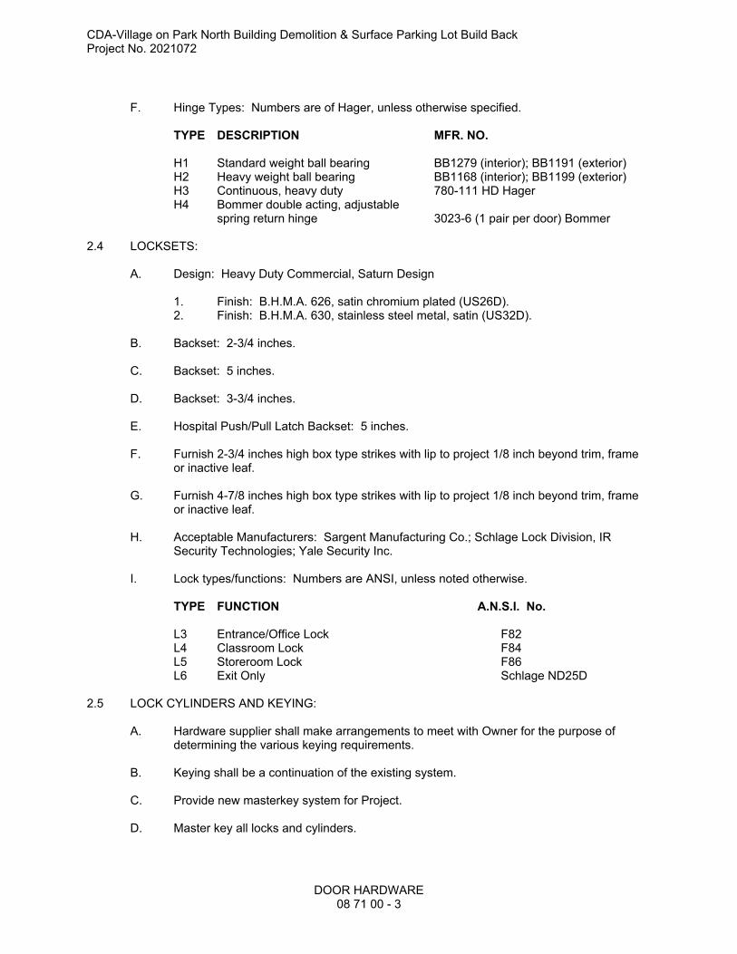
F. Hinge Types: Numbers are of Hager, unless otherwise specified.
TYPE DESCRIPTION MFR. NO.
H1 Standard weight ball bearing BB1279 (interior); BB1191 (exterior)H2 Heavy weight ball bearing BB1168 (interior); BB1199 (exterior)H3 Continuous, heavy duty 780-111 HD Hager H4 Bommer double acting, adjustable
spring return hinge 3023-6 (1 pair per door) Bommer
2.4 LOCKSETS:
A. Design: Heavy Duty Commercial, Saturn Design
1. Finish: B.H.M.A. 626, satin chromium plated (US26D).2. Finish: B.H.M.A. 630, stainless steel metal, satin (US32D).
B. Backset: 2-3/4 inches.
C. Backset: 5 inches.
D. Backset: 3-3/4 inches.
E. Hospital Push/Pull Latch Backset: 5 inches.
F. Furnish 2-3/4 inches high box type strikes with lip to project 1/8 inch beyond trim, frame or inactive leaf.
G. Furnish 4-7/8 inches high box type strikes with lip to project 1/8 inch beyond trim, frame or inactive leaf.
H. Acceptable Manufacturers: Sargent Manufacturing Co.; Schlage Lock Division, IR Security Technologies; Yale Security Inc.
I. Lock types/functions: Numbers are ANSI, unless noted otherwise.
TYPE FUNCTION A.N.S.I. No.
L3 Entrance/Office Lock F82L4 Classroom Lock F84L5 Storeroom Lock F86L6 Exit Only Schlage ND25D
2.5 LOCK CYLINDERS AND KEYING:
A. Hardware supplier shall make arrangements to meet with Owner for the purpose of determining the various keying requirements.
B. Keying shall be a continuation of the existing system.
C. Provide new masterkey system for Project.
D. Master key all locks and cylinders.

CDA-Village on Park North Building Demolition & Surface Parking Lot Build BackProject No. 2021072
DOOR HARDWARE08 71 00 - 4
E. Furnish five master keys for each master keyed set and three nickel silver change keys for each lock.
F. Stamp "DO NOT DUPLICATE" on all keys.
G. Furnish visual key control for all cylinders. Stamp proper key symbol on the bow of each key and on the face of the cylinder plug of each cylinder.
H. Cylinders shall be supplied by manufacturer of locksets.
I. Furnish manufacturer’s standard 6-pin tumbler cylinders.
J. Provide cylinders for Aluminum Entrance systems where scheduled, deadbolts, exit devices.
K. Metals: Construct lock cylinder parts from brass or bronze, stainless steel, or nickel-silver. Aluminum, zinc, or plastic parts are not acceptable. Exposed finish shall match lockset, deadbolt, or exit device.
L. Deliver keys to the Owner via registered mail.
2.6 EXIT DEVICES:
A. U.L. listed for safety requirements as well as listed for label doors.
B. Include cylinders with exit devices.
C. Provide cylinder dogging for non-fire rated exit devices.
D. Exit Device Finish:
1. B.H.M.A. 626, satin chromium plated (US26D).
E. Acceptable Manufacturers: Von Duprin, Sargent, Precision.
F. Exit Device Types: Numbers are of Von Duprin
TYPE DESCRIPTION MFR. NO.
ED1 Rim Exit Device <99 series>ED2 Concealed Vertical Rod Device <9947 series>ED3 Surface Mounted Vertical Rod <9927 series>
G. Where lever trim is indicated, provide lever to match specified locksets.
2.7 DOOR CLOSERS:
A. Size according to manufacturer's printed recommendation.
B. Provide arms, accessories, and non-metallic closer covers with the following finish:
1. Powder coated Aluminum.
OR:
E. Provide arms, accessories, and metallic closer covers with the following finish:
CDA-Village on Park North Building Demolition & Surface Parking Lot Build BackProject No. 2021072
DOOR HARDWARE08 71 00 - 5
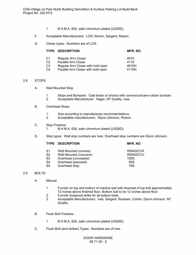
1. B.H.M.A. 652, satin chromium plated (US26D).
F. Acceptable Manufacturers: LCN, Norton, Sargent, Rixson.
G. Closer types: Numbers are of LCN.
TYPE DESCRIPTION MFR. NO.
C1 Regular Arm Closer 4010C2 Parallel Arm Closer 4110C3 Regular Arm Closer with hold open 4010HC4 Parallel Arm Closer with hold open 4110H
2.8 STOPS:
A. Wall Mounted Stop
1. Stops and Bumpers: Cast brass or bronze with convex/concave rubber bumper.2. Acceptable Manufacturer: Hager, NT Quality, Ives.
B. Overhead Stops
1. Size according to manufactures recommendations.2. Acceptable manufacturers: Glynn-Johnson, Rixson.
C. Stop Finishes:1. B.H.M.A. 626, satin chromium plated (US26D).
D. Stop types: Wall stop numbers are Ives: Overhead stop numbers are Glynn Johnson.
TYPE DESCRIPTION MFR. NO
S1 Wall Mounted (convex) WS402CVXS2 Wall Mounted (concave) WS402CCVS3 Overhead (concealed) 100SS4 Overhead (exposed) 90SS5 Overhead Stop 79S
2.9 BOLTS:
A. Manual
1. Furnish on top and bottom of inactive leaf with downset of top bolt approximately 72 inches above finished floor. Bottom bolt to be 12 inches above floor.
2. Furnish dustproof strike for all bottom bolts.3. Acceptable Manufacturers: Ives, Sargent, Russwin, Corbin, Glynn-Johnson, NT
Quality.
B. Flush Bolt Finishes:
1. B.H.M.A. 626, satin chromium plated (US26D).
C. Flush Bolt (and strikes) Types: Numbers are of Ives.
CDA-Village on Park North Building Demolition & Surface Parking Lot Build BackProject No. 2021072
DOOR HARDWARE08 71 00 - 6
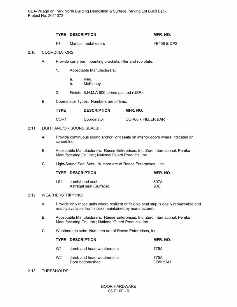
TYPE DESCRIPTION MFR. NO.
F1 Manual, metal doors FB458 & DP2
2.10 COORDINATORS:
A. Provide carry bar, mounting brackets, filler and rub plate.
1. Acceptable Manufacturers:
a. Ives.b. McKinney
2. Finish: B.H.M.A 600, prime painted (USP).
B. Coordinator Types: Numbers are of Ives.
TYPE DESCRIPTION MFR. NO.
COR1 Coordinator COR60 x FILLER BAR
2.11 LIGHT AND/OR SOUND SEALS:
A. Provide continuous sound and/or light seals on interior doors where indicated or scheduled.
B. Acceptable Manufacturers: Reese Enterprises, Inc; Zero International; Pemko Manufacturing Co.,Inc.; National Guard Products, Inc.
C. Light/Sound Seal Sets: Number are of Reese Enterprises, Inc.
TYPE DESCRIPTION MFR. NO.
LS1 Jamb/head seal 807AAstragal seal (Surface) 93C
2.12 WEATHERSTRIPPING:
A. Provide only those units where resilient or flexible seal strip is easily replaceable and readily available from stocks maintained by manufacturer.
B. Acceptable Manufacturers: Reese Enterprises, Inc; Zero International; Pemko Manufacturing Co., Inc.; National Guard Products, Inc.
C. Weatherstrip sets: Numbers are of Reese Enterprises, Inc.
TYPE DESCRIPTION MFR. NO.
W1 Jamb and head weatherstrip 775A
W2 Jamb and head weatherstrip 775ADoor bottom/shoe DB595AU
2.13 THRESHOLDS:
CDA-Village on Park North Building Demolition & Surface Parking Lot Build BackProject No. 2021072
DOOR HARDWARE08 71 00 - 7
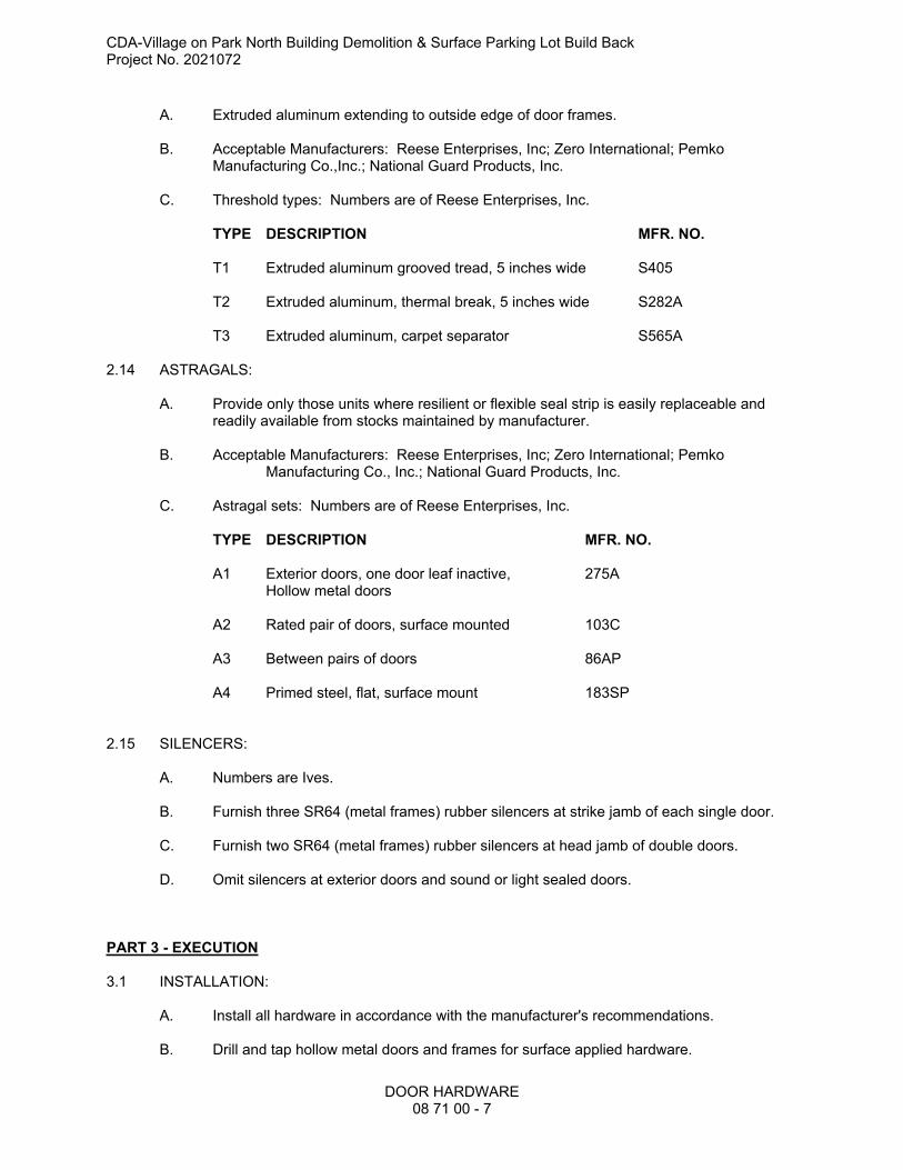
A. Extruded aluminum extending to outside edge of door frames.
B. Acceptable Manufacturers: Reese Enterprises, Inc; Zero International; Pemko Manufacturing Co.,Inc.; National Guard Products, Inc.
C. Threshold types: Numbers are of Reese Enterprises, Inc.
TYPE DESCRIPTION MFR. NO.
T1 Extruded aluminum grooved tread, 5 inches wide S405
T2 Extruded aluminum, thermal break, 5 inches wide S282A
T3 Extruded aluminum, carpet separator S565A
2.14 ASTRAGALS:
A. Provide only those units where resilient or flexible seal strip is easily replaceable and readily available from stocks maintained by manufacturer.
B. Acceptable Manufacturers: Reese Enterprises, Inc; Zero International; Pemko Manufacturing Co., Inc.; National Guard Products, Inc.
C. Astragal sets: Numbers are of Reese Enterprises, Inc.
TYPE DESCRIPTION MFR. NO.
A1 Exterior doors, one door leaf inactive, 275AHollow metal doors
A2 Rated pair of doors, surface mounted 103C
A3 Between pairs of doors 86AP
A4 Primed steel, flat, surface mount 183SP
2.15 SILENCERS:
A. Numbers are Ives.
B. Furnish three SR64 (metal frames) rubber silencers at strike jamb of each single door.
C. Furnish two SR64 (metal frames) rubber silencers at head jamb of double doors.
D. Omit silencers at exterior doors and sound or light sealed doors.
PART 3 - EXECUTION
3.1 INSTALLATION:
A. Install all hardware in accordance with the manufacturer's recommendations.
B. Drill and tap hollow metal doors and frames for surface applied hardware.

CDA-Village on Park North Building Demolition & Surface Parking Lot Build BackProject No. 2021072
DOOR HARDWARE08 71 00 - 8
C. Remove all applied hardware until painting is completed, then reinstall.
D. Locate hardware as follows unless shown otherwise on the drawings:
1. Hinges: Upper edge of top hinge 5 inches below frame head rabbet, lower edge of bottom hinge 10 inches above finished floor and space center hinges equal distance between top and bottom hinges.
2. Locksets: 40 inches above the finished floor to centerline of strike.3. Stops: Install on door if wall condition is not applicable.4. Flush Bolts: Edge mount.5. Exit Device Push Bar: Center line 39 inches above finished floor.6. Door Pulls: Center line 42 inches above finished floor. Center between door
E. Secure wool pile inserts in kerfs in door edges with white glue and small brads spaced 12 inches on center.
F. Install door weatherstripping continuous without coping at hardware. Mount hardware to be located in the same location over the weatherstripping.
3.2 ADJUSTMENT:
A. Adjust all operating hardware in accordance with manufacturer's recommendations.
B. Deliver to Owner all installation and adjustment tools and two copies of each installation sheet furnished with hardware items.
END SECTION 08 70 00
CDA-Village on Park North Building Demolition & Surface Parking Lot Build Back
Project No. 2021072
GLAZING
08 80 00 - 1
SECTION 08 80 00 - GLAZING
PART 1 GENERAL
1.01 SECTION INCLUDES
A. Insulating glass units.
B. Glazing units.
C. Glazing compounds and accessories.
1.02 SUBMITTALS
A. Product Data on Insulating Glass Unit and Glazing Unit Glazing Types: Provide structural,
physical and environmental characteristics, size limitations, special handling and installation
requirements.
B. Product Data on Glazing Compounds and Accessories: Provide chemical, functional, and
environmental characteristics, limitations, special application requirements, and identify
available colors.
C. Samples: Submit two samples 12 by 12 inch in size of insulated glass units.
D. Warranty Documentation: Submit manufacturer warranty and ensure that forms have been
completed in Owner's name and registered with manufacturer.
1.03 QUALITY ASSURANCE
A. Perform Work in accordance with GANA (GM), GANA (SM), GANA (LGRM), and IGMA TM-
3000 for glazing installation methods.
1.04 FIELD CONDITIONS
A. Do not install glazing when ambient temperature is less than 40 degrees F.
B. Maintain minimum ambient temperature before, during and 24 hours after installation of glazing
compounds.
1.05 WARRANTY
A. Insulating Glass Units: Provide a ten (10) year manufacturer warranty to include coverage for
seal failure, interpane dusting or misting, including providing products to replace failed units.
PART 2 PRODUCTS
2.01 MANUFACTURERS
A. Float Glass Manufacturers:
1. AGC Glass North America, Inc: www.agcglass.com/#sle.
2. Cardinal Glass Industries: www.cardinalcorp.com/#sle.
3. Guardian Glass, LLC: www.guardianglass.com/#sle.
4. Pilkington North America Inc: www.pilkington.com/na/#sle.
5. Vitro Architectural Glass (formerly PPG Glass): www.vitroglazings.com/#sle.

CDA-Village on Park North Building Demolition & Surface Parking Lot Build Back
Project No. 2021072
GLAZING
08 80 00 - 2
6. Or approved equal.
2.02 PERFORMANCE REQUIREMENTS - EXTERIOR GLAZING ASSEMBLIES
A. Provide type and thickness of exterior glazing assemblies to support assembly dead loads, and
to withstand live loads caused by positive and negative wind pressure acting normal to plane of
glass.
1. Design Pressure: Calculated in accordance with ASCE 7.
2. Comply with ASTM E1300 for design load resistance of glass type, thickness, dimensions,
and maximum lateral deflection of supported glass.
3. Provide glass edge support system sufficiently stiff to limit the lateral deflection of
supported glass edges to less than 1/175 of their lengths under specified design load.
4. Glass thicknesses listed are minimum.
B. Vapor Retarder and Air Barrier Seals: Provide completed assemblies that maintain continuity
of building enclosure vapor retarder and air barrier.
1. In conjunction with vapor retarder and joint sealer materials described in other sections.
C. Thermal and Optical Performance: Provide exterior glazing products with performance
properties as indicated. Performance properties are in accordance with manufacturer's
published data as determined with the following procedures and/or test methods:
1. Center of Glass U-Value: Comply with NFRC 100 using Lawrence Berkeley National
Laboratory (LBNL) WINDOW 6.3 computer program.
2. Center of Glass Solar Heat Gain Coefficient (SHGC): Comply with NFRC 200 using
Lawrence Berkeley National Laboratory (LBNL) WINDOW 6.3 computer program.
3. Solar Optical Properties: Comply with NFRC 300 test method.
2.03 GLASS MATERIALS
A. Float Glass: Provide float glass based glazing unless otherwise indicated.
1. Annealed Type: ASTM C1036, Type I - Transparent Flat, Class 1 - Clear, Quality - Q3.
2. Kind HS - Heat-Strengthened Type: Complies with ASTM C1048.
3. Kind FT - Fully Tempered Type: Complies with ASTM C1048.
2.04 INSULATING GLASS UNITS
A. Manufacturers:
1. Any of the manufacturers specified for float glass.
2. Fabricator certified by glass manufacturer for type of glass, coating, and treatment
involved and capable of providing specified warranty.
B. Insulating Glass Units: Types as indicated.
1. Durability: Certified by an independent testing agency to comply with ASTM E2190.
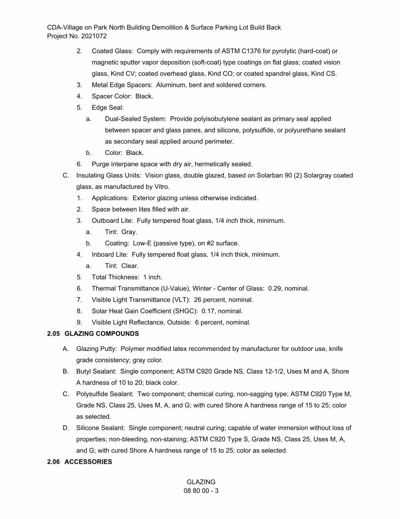
CDA-Village on Park North Building Demolition & Surface Parking Lot Build Back
Project No. 2021072
GLAZING
08 80 00 - 3
2. Coated Glass: Comply with requirements of ASTM C1376 for pyrolytic (hard-coat) or
magnetic sputter vapor deposition (soft-coat) type coatings on flat glass; coated vision
glass, Kind CV; coated overhead glass, Kind CO; or coated spandrel glass, Kind CS.
3. Metal Edge Spacers: Aluminum, bent and soldered corners.
4. Spacer Color: Black.
5. Edge Seal:
a. Dual-Sealed System: Provide polyisobutylene sealant as primary seal applied
between spacer and glass panes, and silicone, polysulfide, or polyurethane sealant
as secondary seal applied around perimeter.
b. Color: Black.
6. Purge interpane space with dry air, hermetically sealed.
C. Insulating Glass Units: Vision glass, double glazed, based on Solarban 90 (2) Solargray coated
glass, as manufactured by Vitro.
1. Applications: Exterior glazing unless otherwise indicated.
2. Space between lites filled with air.
3. Outboard Lite: Fully tempered float glass, 1/4 inch thick, minimum.
a. Tint: Gray.
b. Coating: Low-E (passive type), on #2 surface.
4. Inboard Lite: Fully tempered float glass, 1/4 inch thick, minimum.
a. Tint: Clear.
5. Total Thickness: 1 inch.
6. Thermal Transmittance (U-Value), Winter - Center of Glass: 0.29, nominal.
7. Visible Light Transmittance (VLT): 26 percent, nominal.
8. Solar Heat Gain Coefficient (SHGC): 0.17, nominal.
9. Visible Light Reflectance, Outside: 6 percent, nominal.
2.05 GLAZING COMPOUNDS
A. Glazing Putty: Polymer modified latex recommended by manufacturer for outdoor use, knife
grade consistency; gray color.
B. Butyl Sealant: Single component; ASTM C920 Grade NS, Class 12-1/2, Uses M and A, Shore
A hardness of 10 to 20; black color.
C. Polysulfide Sealant: Two component; chemical curing, non-sagging type; ASTM C920 Type M,
Grade NS, Class 25, Uses M, A, and G; with cured Shore A hardness range of 15 to 25; color
as selected.
D. Silicone Sealant: Single component; neutral curing; capable of water immersion without loss of
properties; non-bleeding, non-staining; ASTM C920 Type S, Grade NS, Class 25, Uses M, A,
and G; with cured Shore A hardness range of 15 to 25; color as selected.
2.06 ACCESSORIES
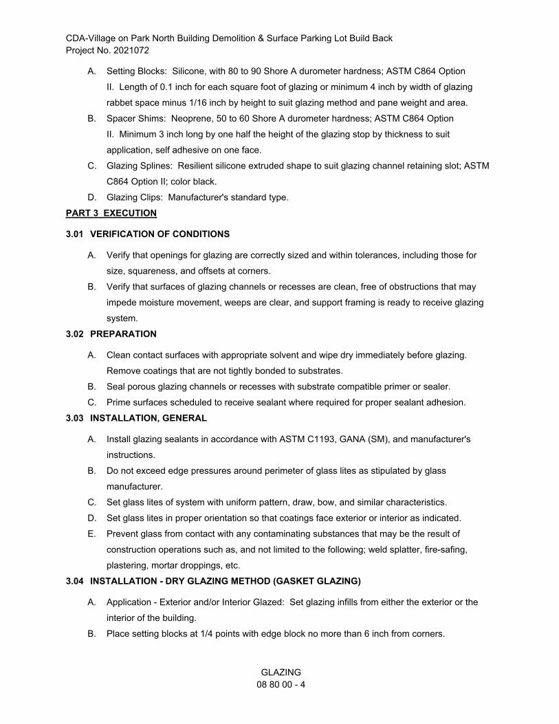
CDA-Village on Park North Building Demolition & Surface Parking Lot Build Back
Project No. 2021072
GLAZING
08 80 00 - 4
A. Setting Blocks: Silicone, with 80 to 90 Shore A durometer hardness; ASTM C864 Option
II. Length of 0.1 inch for each square foot of glazing or minimum 4 inch by width of glazing
rabbet space minus 1/16 inch by height to suit glazing method and pane weight and area.
B. Spacer Shims: Neoprene, 50 to 60 Shore A durometer hardness; ASTM C864 Option
II. Minimum 3 inch long by one half the height of the glazing stop by thickness to suit
application, self adhesive on one face.
C. Glazing Splines: Resilient silicone extruded shape to suit glazing channel retaining slot; ASTM
C864 Option II; color black.
D. Glazing Clips: Manufacturer's standard type.
PART 3 EXECUTION
3.01 VERIFICATION OF CONDITIONS
A. Verify that openings for glazing are correctly sized and within tolerances, including those for
size, squareness, and offsets at corners.
B. Verify that surfaces of glazing channels or recesses are clean, free of obstructions that may
impede moisture movement, weeps are clear, and support framing is ready to receive glazing
system.
3.02 PREPARATION
A. Clean contact surfaces with appropriate solvent and wipe dry immediately before glazing.
Remove coatings that are not tightly bonded to substrates.
B. Seal porous glazing channels or recesses with substrate compatible primer or sealer.
C. Prime surfaces scheduled to receive sealant where required for proper sealant adhesion.
3.03 INSTALLATION, GENERAL
A. Install glazing sealants in accordance with ASTM C1193, GANA (SM), and manufacturer's
instructions.
B. Do not exceed edge pressures around perimeter of glass lites as stipulated by glass
manufacturer.
C. Set glass lites of system with uniform pattern, draw, bow, and similar characteristics.
D. Set glass lites in proper orientation so that coatings face exterior or interior as indicated.
E. Prevent glass from contact with any contaminating substances that may be the result of
construction operations such as, and not limited to the following; weld splatter, fire-safing,
plastering, mortar droppings, etc.
3.04 INSTALLATION - DRY GLAZING METHOD (GASKET GLAZING)
A. Application - Exterior and/or Interior Glazed: Set glazing infills from either the exterior or the
interior of the building.
B. Place setting blocks at 1/4 points with edge block no more than 6 inch from corners.
CDA-Village on Park North Building Demolition & Surface Parking Lot Build Back
Project No. 2021072
GLAZING
08 80 00 - 5
C. Rest glazing on setting blocks and push against fixed stop with sufficient pressure on gasket to
attain full contact.
D. Install removable stops without displacing glazing gasket; exert pressure for full continuous
contact.
3.05 INSTALLATION - DRY GLAZING METHOD (TAPE AND GASKET SPLINE GLAZING)
A. Application - Exterior Glazed: Set glazing infills from the exterior of the building.
B. Cut glazing tape to length; install on glazing pane. Seal corners by butting tape and sealing
junctions with butyl sealant.
C. Place setting blocks at 1/4 points with edge block no more than 6 inch from corners.
D. Rest glazing on setting blocks and push against fixed stop with sufficient pressure to attain full
contact.
E. Install removable stops without displacing glazing spline. Exert pressure for full continuous
contact.
F. Carefully trim protruding tape with knife.
3.06 INSTALLATION - WET GLAZING METHOD (SEALANT AND SEALANT)
A. Application - Exterior Glazed: Set glazing infills from the exterior of the building.
B. Place setting blocks at 1/4 points and install glazing pane or unit.
C. Install removable stops with glazing centered in space by inserting spacer shims both sides at
24 inch intervals, 1/4 inch below sight line.
D. Fill gaps between glazing and stops with silicone type sealant to depth of bite on glazing, but
not more than 3/8 inch below sight line to ensure full contact with glazing and continue the air
and vapor seal.
E. Apply sealant to uniform line, flush with sight line. Tool or wipe sealant surface smooth.
3.07 INSTALLATION - PRESSURE GLAZED SYSTEMS
A. Application - Exterior Glazed: Set glazing infills from exterior side of building.
B. Place setting blocks at 1/4 points with edge block no more than 6 inch from corners.
C. Rest glazing on setting blocks and push against fixed stop with sufficient pressure on gasket to
attain full contact.
D. Install pressure plates without displacing glazing gasket; exert pressure for full continuous
contact.
3.08 CLEANING
A. Remove excess glazing materials from finish surfaces immediately after application using
solvents or cleaners recommended by manufacturers.
B. Remove non-permanent labels immediately after glazing installation is complete.
C. Clean glass and adjacent surfaces after sealants are fully cured.
CDA-Village on Park North Building Demolition & Surface Parking Lot Build Back
Project No. 2021072
GLAZING
08 80 00 - 6
D. Clean glass on both exposed surfaces not more than 4 days prior to Date of Substantial
Completion in accordance with glass manufacturer's written recommendations.
3.09 PROTECTION
A. After installation, mark pane with an 'X' by using removable plastic tape or paste; do not mark
heat absorbing or reflective glass units.
B. Remove and replace glass that is damaged during construction period prior to Date of
Substantial Completion.
END OF SECTION

CDA-Village on Park North Building Demolition & Surface Parking Lot Build Back
Project No. 2021072
GYPSUM BOARD ASSEMBLIES
09 21 16 - 1
SECTION 09 21 16 - GYPSUM BOARD ASSEMBLIES
PART 1 GENERAL
1.01 SECTION INCLUDES
A. Metal stud wall framing.
B. Gypsum sheathing.
C. Gypsum wallboard.
D. Joint treatment and accessories.
1.02 SUBMITTALS
A. Product Data: Provide data on metal framing, gypsum board, accessories, and joint finishing
system.
PART 2 PRODUCTS
2.01 METAL FRAMING MATERIALS
A. Non-structural Framing System Components: ASTM C645; galvanized sheet steel, of size and
properties necessary to comply with ASTM C754 for the spacing indicated, with maximum
deflection of wall framing of L/240 at 5 psf.
1. Studs: "C" shaped.
2. Runners: U shaped, sized to match studs.
3. Ceiling Channels: C-shaped.
4. Furring Members: Hat-shaped sections, minimum depth of 7/8 inch.
B. Partition Head To Structure Connections: Provide track fastened to structure with legs of
sufficient length to accommodate deflection, for friction fit of studs cut short.
C. Non-structural Framing Accessories:
1. Ceiling Hangers: Type and size as specified in ASTM C754 for spacing required.
2. Framing Connectors: ASTM A653/A653M G90 galvanized steel clips; secures cold rolled
channel to wall studs for lateral bracing.
2.02 BOARD MATERIALS
A. Manufacturers - Gypsum-Based Board:
1. CertainTeed Corporation: www.certainteed.com/#sle.
2. Georgia-Pacific Gypsum: www.gpgypsum.com/#sle.
3. National Gypsum Company: www.nationalgypsum.com/#sle.
4. USG Corporation: www.usg.com/#sle.
B. Gypsum Wallboard: Paper-faced gypsum panels as defined in ASTM C1396/C1396M; sizes to
minimize joints in place; ends square cut.
1. Application: Use for vertical surfaces and ceilings, unless otherwise indicated.
2. Mold Resistance: Score of 10, when tested in accordance with ASTM D3273.

CDA-Village on Park North Building Demolition & Surface Parking Lot Build Back
Project No. 2021072
GYPSUM BOARD ASSEMBLIES
09 21 16 - 2
3. At Assemblies Indicated with Fire-Resistance Rating: Use type required by indicated
tested assembly; if no tested assembly is indicated, use Type X board, UL or WH listed.
4. Thickness: 5/8-inch.
C. Exterior Sheathing Board: Sizes to minimize joints in place; ends square cut.
1. Application: Exterior sheathing, unless otherwise indicated.
2. Mold Resistance: Score of 10, when tested in accordance with ASTM D3273.
3. Glass Mat Faced Sheathing: Glass mat faced gypsum substrate as defined in ASTM
C1177/C1177M.
4. Type X Thickness: 5/8 inch.
5. Edges: Square.
6. Glass Mat Faced Products:
a. CertainTeed Corporation; GlasRoc Type X Exterior
Sheathing: www.certainteed.com/#sle.
b. Georgia-Pacific Gypsum; DensGlass Fireguard
Sheathing: www.gpgypsum.com/#sle.
c. National Gypsum Company; Gold Bond eXP
Sheathing: www.nationalgypsum.com/#sle.
2.03 GYPSUM WALLBOARD ACCESSORIES
A. Acoustic Sealant: Acrylic emulsion latex or water-based elastomeric sealant; do not use
solvent-based non-curing butyl sealant.
B. Beads, Joint Accessories, and Other Trim: ASTM C1047, rigid plastic, unless noted otherwise.
1. Corner Beads: Standard profile, for 90 degree outside corners.
a. Products:
1) CertainTeed Corporation; No-Coat Drywall Corner: www.certainteed.com/#sle.
2) ClarkDietrich; Strait-Flex Big-Stick: www.clarkdietrich.com/#sle.
3) Trim-Tex, Inc; Corner Bead: www.trim-tex.com/#sle.
2. L-Trim with Tear-Away Strip: Sized to fit 5/8 inch thick gypsum wallboard.
3. Expansion Joints:
a. Type: V-shaped PVC with tear away fins.
C. Joint Materials: ASTM C475/C475M and as recommended by gypsum board manufacturer for
project conditions.
1. Paper Tape: 2 inch wide, creased paper tape for joints and corners.
2. Joint Compound: Drying type, vinyl-based, ready-mixed.
D. Finishing Compound: Surface coat and primer, takes the place of skim coating.

CDA-Village on Park North Building Demolition & Surface Parking Lot Build Back
Project No. 2021072
GYPSUM BOARD ASSEMBLIES
09 21 16 - 3
E. Screws for Fastening of Gypsum Panel Products to Cold-Formed Steel Studs Less than 0.033
inches in Thickness and Wood Members: ASTM C1002; self-piercing tapping screws,
corrosion-resistant.
F. Screws for Fastening of Gypsum Panel Products to Steel Members from 0.033 to 0.112 inch in
Thickness: ASTM C954; steel drill screws, corrosion-resistant.
G. Anchorage to Substrate: Tie wire, nails, screws, and other metal supports, of type and size to
suit application; to rigidly secure materials in place.
PART 3 EXECUTION
3.01 EXAMINATION
A. Verify that project conditions are appropriate for work of this section to commence.
3.02 FRAMING INSTALLATION
A. Metal Framing: Install in accordance with ASTM C754 and manufacturer's instructions.
B. Suspended Ceilings and Soffits: Space framing and furring members as indicated.
C. Studs: Space studs at 16 inches on center.
1. Partitions Terminating at Structure: Attach extended leg top runner to structure, maintain
clearance between top of studs and structure, and brace both flanges of studs with
continuous bridging.
D. Openings: Reinforce openings as required for weight of doors or operable panels, using not
less than double studs at jambs.
E. Standard Wall Furring: Install at concrete and masonry walls scheduled to receive gypsum
board, not more than 4 inches from floor and ceiling lines and abutting walls. Secure in place
on alternate channel flanges at maximum 24 inches on center.
3.03 BOARD INSTALLATION
A. Comply with ASTM C840, GA-216, and manufacturer's instructions. Install to minimize butt end
joints, especially in highly visible locations.
B. Fire-Resistance-Rated Construction: Install gypsum board in strict compliance with
requirements of assembly listing.
C. Exterior Sheathing: Comply with ASTM C1280. Install sheathing vertically, with edges butted
tight and ends occurring over firm bearing.
D. Installation on Metal Framing: Use screws for attachment of gypsum board except face layer of
nonrated double-layer assemblies, which may be installed by means of adhesive lamination.
3.04 INSTALLATION OF TRIM AND ACCESSORIES
A. Control Joints: Place control joints consistent with lines of building spaces and as indicated.
1. Not more than 30 feet apart on walls and ceilings over 50 feet long.
B. Corner Beads: Install at external corners, using longest practical lengths.
C. Edge Trim: Install at locations where gypsum board abuts dissimilar materials.
CDA-Village on Park North Building Demolition & Surface Parking Lot Build Back
Project No. 2021072
GYPSUM BOARD ASSEMBLIES
09 21 16 - 4
3.05 JOINT TREATMENT
A. Paper Faced Gypsum Board: Use paper joint tape, embed with drying type joint compound and
finish with drying type joint compound.
B. Finish gypsum board in accordance with levels defined in ASTM C840, as follows:
1. Level 4: Walls and ceilings to receive paint finish or wall coverings, unless otherwise
indicated.
2. Level 1: Wall areas above finished ceilings, whether or not accessible in the completed
construction.
C. Tape, fill, and sand exposed joints, edges, and corners to produce smooth surface ready to
receive finishes.
1. Feather coats of joint compound so that camber is maximum 1/32 inch.
2. Taping, filling, and sanding are not required at base layer of double-layer applications.
3.06 TOLERANCES
A. Maximum Variation of Finished Gypsum Board Surface from True Flatness: 1/8 inch in 10 feet
in any direction.
END OF SECTION
CDA-Village on Park North Building Demolition & Surface Parking Lot Build Back
Project No. 2021072
PAINTING AND COATING
09 90 00 - 1
SECTION 09 90 00 - PAINTING AND COATING
PART 1 GENERAL
1.01 SECTION INCLUDES
A. Surface preparation.
B. Interior painting and coating systems.
C. Exterior painting and coating systems.
D. Scope:
1. Finish surfaces exposed to view, unless fully factory-finished and unless otherwise
indicated, including the following:
a. Exterior:
1) Concrete: Cementitious siding, Flexboard, Transite, non-roof shingles, common
brick, stucco, tilt-up, precast, and poured-in-place cement.
2) Masonry: Concrete masonry units (CMU), cinder or concrete block.
3) Metal: Aluminum, galvanized.
4) Metal, Miscellaneous: Iron, ornamental iron, structural iron and steel, ferrous
metal.
b. Interior:
1) Metal: Aluminum and galvanized.
2) Metal: Structural steel columns, joists, trusses, beams, miscellaneous and
ornamental iron, structural iron, and ferrous metal.
3) Drywall: Walls, ceilings, gypsum board, and similar items.
1.02 REFERENCE STANDARDS
A. 40 CFR 59, Subpart D - National Volatile Organic Compound Emission Standards for
Architectural Coatings; U.S. Environmental Protection Agency current edition.
B. SSPC-SP 1 - Solvent Cleaning 2015, with Editorial Revision (2016).
C. SSPC-SP 2 - Hand Tool Cleaning 2018.
D. SSPC-SP 6 - Commercial Blast Cleaning 2007.
E. SSPC-SP 13 - Surface Preparation of Concrete 2018.
1.03 SUBMITTALS
A. Product Data: Provide complete list of products to be used, with the following information for
each:
1. Product characteristics.
2. Surface preparation instructions and recommendations.
3. Primer requirements and finish specification.
CDA-Village on Park North Building Demolition & Surface Parking Lot Build Back
Project No. 2021072
PAINTING AND COATING
09 90 00 - 2
4. Storage and handling requirements and recommendations.
5. Application methods.
6. Clean-up information.
B. Samples: Submit four paper draw down samples, 8-1/2 by 11 inches in size, illustrating range
of colors available for each finishing product specified.
C. Maintenance Data: Submit coating maintenance manual including finish schedule showing
where each product/color/finish was used, product technical data sheets, care and cleaning
instructions, touch-up procedures, repair of painted and finished surfaces, and color samples of
each color and finish used.
D. Maintenance Materials: Furnish the following for Owner's use in maintenance of project.
1. Extra Paint and Finish Materials: 1 gallon of each color; from the same product run, store
where directed.
2. Label each container with color in addition to manufacturer's label.
1.04 QUALITY ASSURANCE
A. Applicator Qualifications: Company specializing in performing the type of work specified with
minimum 3 years experience and approved by manufacturer.
1.05 DELIVERY, STORAGE, AND HANDLING
A. Deliver products to site in sealed and labeled containers; inspect to verify acceptability.
B. Container Label: Include manufacturer's name, type of paint, product name, product
code, color designation, VOC content, batch date, environmental handling, surface
preparation, application, and use instructions.
C. Paint Materials: Store at a minimum of 45 degrees F and a maximum of 90 degrees F, in
ventilated area, and as required by manufacturer's instructions.
1.06 FIELD CONDITIONS
A. Do not apply materials when environmental conditions are outside the ranges required by
manufacturer.
B. Follow manufacturer's recommended procedures for producing the best results, including
testing of substrates, moisture in substrates, and humidity and temperature limitations.
PART 2 PRODUCTS
2.01 MANUFACTURERS
A. Basis of Design Products: Subject to compliance with requirements, provide Sherwin-Williams
Company (The) products indicated; www.sherwin-williams.com/#sle.
B. Comparable Products: Products of approved manufacturers will be considered in accordance
with 01 60 00 - Product Requirements, and the following:
1. Products are approved by manufacturer in writing for application specified.
CDA-Village on Park North Building Demolition & Surface Parking Lot Build Back
Project No. 2021072
PAINTING AND COATING
09 90 00 - 3
2. Products that meet or exceed performance and physical characteristics of basis of design
products.
3. Other Acceptable Manufacturers:
a. Benjamin Moore.
b. Diamond Vogel Paints.
c. Hallman Lindsay.
d. PPG Paints.
2.02 PAINTINGS AND COATINGS
A. General:
1. Provide factory-mixed coatings unless otherwise indicated.
2. When required, mix coatings to correct consistency in accordance with manufacturer's
instructions before application.
3. Do not reduce, thin, or dilute coatings or add materials to coatings unless specifically
indicated in manufacturer's instructions.
B. Volatile Organic Compound (VOC) Content:
1. Provide paints and finishes that comply with the most stringent requirements specified in
the following:
a. 40 CFR 59, Subpart D--National Volatile Organic Compound Emission Standards for
Architectural Coatings.
b. Ozone Transport Commission (OTC) Phase II Model Rule, Architectural and
Industrial Maintenance Coatings; www.otcair.org.
c. Architectural coatings VOC limits of State in which the project is located.
2. Determination of VOC Content: Testing and calculation in accordance with 40 CFR 59,
Subpart D (EPA Method 24), exclusive of colorants added to a tint base and water added
at project site, or other method acceptable to authorities having jurisdiction.
C. Accessory Materials: Provide primers, sealers, cleaning agents, cleaning cloths, sanding
materials, and clean-up materials as required for final completion of painted surfaces.
2.03 PAINT SYSTEMS - EXTERIOR
A. Concrete: Cementitious siding, Flexboard, Transite, non-roof shingles, common brick, stucco,
tilt-up, precast, and poured-in-place cement.
1. Latex Systems:
a. Satin Finish:
1) 1st Coat: Sherwin-Williams Loxon Concrete and Masonry Primer Sealer
LX02W50: www.sherwin-williams.com/#sle.
a) 5.3 to 8 mils wet, 2.1 to 3.2 mils dry.
2) 2nd and 3rd Coat: Sherwin-Williams A-100 Exterior Latex Satin, A82
Series: www.sherwin-williams.com/#sle.
CDA-Village on Park North Building Demolition & Surface Parking Lot Build Back
Project No. 2021072
PAINTING AND COATING
09 90 00 - 4
a) 4 mils wet, 1.5 mils dry per coat.
B. Masonry: Concrete masonry units (CMU), cinder or concrete block.
1. Latex Systems:
a. Satin Finish:
1) 1st Coat: Sherwin-Williams PrepRite Block Filler, B25W25: www.sherwin-
williams.com/#sle.
a) 75 to 125 sq ft/gal.
2) 2nd and 3rd Coat: Sherwin-Williams A-100 Exterior Latex Satin, A82
Series: www.sherwin-williams.com/#sle.
a) 4 mils wet, 1.5 mils dry per coat.
C. Metal: Aluminum, galvanized.
1. Latex Systems:
a. Semi-Gloss Finish:
1) 1st and 2nd Coats: Sherwin-Williams Pro Industrial Acrylic Semi-Gloss, B66-650
Series: www.sherwin-williams.com/#sle.
a) 2 to 4 mils dry per coat.
D. Metal, Miscellaneous: Iron, ornamental iron, structural iron and steel, ferrous metal.
1. Latex Systems:
a. Semi-Gloss Finish:
1) 1st Coat: Sherwin-Williams Pro Industrial Pro-Cryl Universal Primer, B66-1310
Series: www.sherwin-williams.com/#sle.
a) 5 to 10 mils wet, 1.8 to 3.6 mils dry per coat.
2) 2nd and 3rd Coat: Sherwin-Williams Pro Industrial Acrylic Semi-Gloss, B66-650
Series: www.sherwin-williams.com/#sle.
a) 2 to 4 mils dry per coat.
2.04 PAINT SYSTEMS - INTERIOR
A. Metal: Aluminum and galvanized.
1. Alkyd Systems, Water Based:
a. Semi-Gloss Finish:
1) 1st Coat: Sherwin-Williams Pro Industrial Pro-Cryl Universal Primer, B66-1310
Series: www.sherwin-williams.com/#sle.
a) 5 mils wet, 2 mils dry per coat.
2) 2nd and 3rd Coat: Sherwin-Williams Pro Industrial Water Based Alkyd Urethane
Enamel Semi-Gloss, B53-1150 Series: www.sherwin-williams.com/#sle.
CDA-Village on Park North Building Demolition & Surface Parking Lot Build Back
Project No. 2021072
PAINTING AND COATING
09 90 00 - 5
a) 4 to 5 mils wet, 1.4 to 1.7 mils dry per coat.
B. Metal: Structural steel columns, joists, trusses, beams, miscellaneous and ornamental iron,
structural iron, and ferrous metal.
1. Alkyd Systems, Water Based:
a. Semi-Gloss Finish:
1) 1st Coat: Sherwin-Williams Pro Industrial Pro-Cryl Universal Primer, B66-1310
Series: www.sherwin-williams.com/#sle.
a) 5 mils wet, 2 mils dry per coat.
2) 2nd and 3rd Coat: Sherwin-Williams Pro Industrial Water Based Alkyd Urethane
Enamel Semi-Gloss, B53-1150 Series: www.sherwin-williams.com/#sle.
a) 4 to 5 mils wet, 1.4 to 1.7 mils dry per coat.
C. Drywall: Walls, ceilings, gypsum board, and similar items.
1. Latex Systems:
a. Eg-Shel Finish: Walls.
1) 1st Coat: Sherwin-Williams ProMar 200 Zero VOC Interior Latex Primer,
B28W2600: www.sherwin-williams.com/#sle.
a) 4 mils wet, 1.5 mils dry per coat.
2) 2nd and 3rd Coat: Sherwin-Williams ProMar 200 Zero VOC Eg-Shel, B20-2600
Series: www.sherwin-williams.com/#sle.
a) 4 mils wet, 1.7 mils dry per coat.
b. Flat Finish: Ceilings.
1) 1st Coat: Sherwin-Williams ProMar 200 Zero VOC Interior Latex Primer,
B28W2600: www.sherwin-williams.com/#sle.
a) 4 mils wet, 1.5 mils dry per coat.
2) 2nd and 3rd Coat: Sherwin-Williams ProMar 200 Zero VOC Latex Flat, B30-
2600 Series: www.sherwin-williams.com/#sle.
a) 4 mils wet, 1.6 mils dry per coat.
PART 3 EXECUTION
3.01 EXAMINATION
A. Verify that surfaces are ready to receive work as instructed by the product manufacturer.
B. Examine surfaces scheduled to be finished prior to commencement of work. Report any
condition that may potentially effect proper application.
C. Test shop-applied primer for compatibility with subsequent cover materials.
3.02 PREPARATION

CDA-Village on Park North Building Demolition & Surface Parking Lot Build Back
Project No. 2021072
PAINTING AND COATING
09 90 00 - 6
A. Clean surfaces thoroughly and correct defects prior to application.
B. Prepare surfaces using the methods recommended by the manufacturer for achieving the best
result for the substrate under the project conditions.
C. Remove mildew from impervious surfaces by scrubbing with solution of water and
bleach. Rinse with clean water and allow surface to dry.
D. Concrete:
1. Remove release agents, curing compounds, efflorescence, and chalk.
2. Fill bug holes, air pockets, and other voids with cement patching compound.
3. Prepare concrete according to SSPC-SP 13.
E. Masonry: Remove efflorescence and chalk.
F. Gypsum Board: Fill minor defects with filler compound; sand smooth and remove dust prior to
painting.
G. Aluminum: Remove surface contamination and oil; wash with solvent according to SSPC-SP 1.
H. Galvanized Surfaces:
1. Remove surface contamination and oils and wash with solvent according to SSPC-SP 1.
2. Prepare surface according to SSPC-SP 2.
I. Ferrous Metal:
1. Solvent clean according to SSPC-SP 1.
2. Shop-Primed Surfaces: Sand and scrape to remove loose primer and rust. Feather
edges to make touch-up patches inconspicuous. Prime bare steel surfaces.
3. Remove rust, loose mill scale, and other foreign substances using methods recommended
by paint manufacturer and blast cleaning according to SSPC-SP 6. Protect from corrosion
until coated.
3.03 APPLICATION
A. Remove unfinished louvers, grilles, covers, and access panels on mechanical and electrical
components and paint separately.
B. Apply products in accordance with manufacturer's written instructions.
C. Apply coatings at spread rate required to achieve manufacturer's recommended dry film
thickness.
D. Regardless of number of coats specified, apply additional coats until complete hide is achieved.
3.04 PRIMING
A. Apply primer to all surfaces unless specifically not required by coating manufacturer. Apply in
accordance with coating manufacturer's instructions.
B. Primers specified in painting schedules may be omitted on items that are factory primed or
factory finished if acceptable to top coat manufacturers.
3.05 CLEANING

CDA-Village on Park North Building Demolition & Surface Parking Lot Build Back
Project No. 2021072
PAINTING AND COATING
09 90 00 - 7
A. Collect waste material that could constitute a fire hazard, place in closed metal containers, and
remove daily from site.
B. Clean surfaces immediately of overspray, splatter, and excess material.
C. After coating has cured, clean and replace finish hardware, fixtures, and fittings previously
removed.
3.06 PROTECTION
A. Protect finished coatings from damage until completion of project.
B. Touch-up damaged finishes after Substantial Completion.
END OF SECTION

This page intentionally left blank

CDA-Village on Park North Building Demolition & Surface Parking Lot Build Back
Project No. 2021072
COMMON WORK RESULTS FOR PLUMBING 22 05 00 - 1
SECTION 22 05 00 – COMMON WORK RESULTS FOR PLUMBING
PART 1 - GENERAL
1.1 RELATED DOCUMENTS
A. Applicable provisions of Division 1 shall govern work under this section.
1.2 LEAD FREE REQUIREMENTS
A. All materials that contact potable water shall be lead free. Lead free refers to the wetted surface of pipe, fittings and fixtures in potable water systems that have a weighted average lead content ≤0.25% per the Federal Safe Drinking Water Act as amended January 4th 2011 Section 1417.
B. This requirement applies to all of the subsequent Plumbing Specification Sections and Plumbing Drawings and supersedes any part or model number that may conflict with this requirement.
1.3 CODES AND PERMITS
A. Perform all work in strict accordance with the requirements of the State of Wisconsin Plumbing Code. Requirements outlined therein shall be minimum as related to this work.
B. Arrange for Code required inspections and pay for same if not covered by permit costs.
C. Arrange and pay for required utility extension costs.
1.4 DESCRIPTION OF WORK
A. Provide all labor, materials, equipment, tools and services for complete removal of the plumbing and sewer as indicated or reasonably implied by the drawings and specifications. If an item is shown or specified, it shall be considered sufficient for inclusion as part of this contract work.
B. Contractor shall verify all job conditions at the site and report any discrepancies to the Engineer immediately.
1.5 WORK PRIORITY AND COORDINATION
A. Contractor, his mechanics and subcontractors shall cooperate with all others so construction/demolition may proceed without hindrances and in all cases to the best interests of the Owner. Confer with other trades regarding any work that may affect this work and arrange for the removal of piping, etc. with other disciplines.
1.6 DRAWINGS
A. Consult the drawings for the general location of all equipment and piping to be removed or demolished. While the sizes and locations have been indicated, the Contractor shall properly adjust his work to meet conditions as they actually exist on the premises.
1.7 SUBMITTALS
A. Furnish shop drawings on items as indicated in individual sections including temporary

CDA-Village on Park North Building Demolition & Surface Parking Lot Build Back
Project No. 2021072
COMMON WORK RESULTS FOR PLUMBING 22 05 00 - 2
piping, including caps and plugs. Submit in electronic form to Engineer for review. The contractor acknowledges its responsibility to submit complete shop drawings and other required submittals. Incomplete submittals will be returned to the contractor unreviewed. No time extensions or cost increases will be allowed for delays caused by return of incomplete submittals.
B. All Plumbing piping and fittings installed in a potable water system shall meet the Reduction of Lead in drinking water act 2011. All wetted surfaces shall not have more than the weighted average of 0.25% lead. Manufactures model listings are for reference only. It shall be plumbing contractor’s responsibility that products installed shall meet this requirement and should be NSF/ANSI certified.
1.8 REMODELING WORK
A. Wherever remodeling work or demolition of existing equipment, piping, etc. is a part of plans and specifications, Contractor shall visit the site and thoroughly examine all existing conditions. Provide all required work necessary for removal of existing unused components. Coordinate and schedule all system shut-downs with occupant prior to beginning work.
B. Contractors shall notify the Architect at least 10 days prior to the bid closing date of any deviations or required changes that are noticed. No allowance for additional costs for work related to existing conditions will be permitted after bidding unless proof of hidden work could not be determined by inspection or examination by the Contractor.
1.9 HOUSEKEEPING
A. This Contractor shall periodically remove debris caused by his operations. On completion he shall remove all debris from his work and leave the site in the same condition as when they arrived.
1.10 PROTECTION OF MATERIALS AND EQUIPMENT
A. Materials and equipment shall be protected at all times. This Contractor shall be responsible for all damage caused directly or indirectly by his employees. Pipe openings shall be closed with caps or plugs during installation. Equipment shall be tightly covered and protected against dirt, water, and chemical or mechanical injury. At the completion of all work, the area shall be returned in the same condition as when the contractor arrived.
1.11 INSTRUCTIONS
A. The Contractor shall review with the Owner's representative and other trades, the complete method of and phasing of all work and work to be demolished.
1.12 GUARANTEE
A. Refer to Division 1 for guarantees and warranties. In addition to the requirements in Division 1, this Contractor shall meet the following requirements.
B. In entering into a contract covering this work, the contractor accepts the specifications and guarantees that the work will be carried out in accordance with the requirements of this specification or such modifications as may be made under the contract documents.
C. Contractor further guarantees that the workmanship and material will be of the best procurable and that only experienced workmen familiar with each particular class of work will be employed.
CDA-Village on Park North Building Demolition & Surface Parking Lot Build Back
Project No. 2021072
COMMON WORK RESULTS FOR PLUMBING 22 05 00 - 3
PART 2 - PRODUCTS
2.1 QUALITY REQUIREMENTS
A. Items indicated on the drawings and in the specifications are listed by manufacturer in order to describe minimum quality requirements.
B. All materials and equipment furnished shall be new and shall be the standard products of manufacturers regularly engaged in the production of Plumbing and Fire Protection materials and equipment.
2.2 CODES
A. Comply with requirements of the state of Wisconsin Plumbing Code.
PART 3 - EXECUTION
3.1 DEMOLITION
A. Perform all demolition as indicated on the drawings to accomplish work. Where demolition work is to be performed adjacent to existing work that remains in an occupied area, construct temporary dust partition to minimize the amount of contamination of the occupied space. Where pipe is removed and not reconnected with new work, cap ends of existing services as if they were new work. Coordinate work with the Building Owner to minimize disruption to the existing building occupants.
B. All pipe, fixtures, equipment, wiring and associated conduit, insulation and similar items demolished, abandoned, or deactivated are to be removed from the site by the Contractor except as specifically noted otherwise. All designated equipment is to be turned over to the user agency for their use at a place and time so designated. Maintain the condition of material and/or equipment that is indicated to be reused equal to that existing before work began.
END SECTION 22 05 0

This page intentionally left blank
CDA-Village on Park North Building Demolition & Surface Parking Lot Build BackProject No. 2021072
ELECTRICAL GENERAL REQUIREMENTS26 00 00 - 1
SECTION 26 00 00 ELECTRICAL GENERAL REQUIREMENTS
PART 1 - GENERAL
1.1 RELATED DOCUMENTS
A. All drawings and general provisions of the Contract, including General and Supplementary Conditions and Division 01 Specification Sections, apply to this Section and the work of this Contractor.
B. Contractor shall review the entire set of documents, including those in the scope of all others, to determine any items that require coordination with electrical equipment or require power, systems or technology provisions. This coordination and provisions shall be provided by the Contractor.
C. All Division 26 Specifications, Electrical Drawings relate and apply to each other as applicable and fall under the requirements of this section.
1.2 CODES AND PERMITS
A. Perform all work in accordance with all state, local and municipal electrical codes, ordinances and authorities having jurisdiction.
B. Submit required paperwork for permits and inspections and pay all associated fees.
1.3 DRAWINGS
A. The Contractor shall be responsible for providing and constructing complete and fully-functional systems.
1. The Contractor acknowledges and understands that the drawings are a two-dimensional representation or a three-dimensional object.
a. Drawings may be based on imperfect or assumed data, code interpretations and may include unforeseen conflicts and items requiring field coordination.
b. Drawings do not show all accessories and equipment necessary for complete and fully functional systems.
c. While the sizes and locations, of design-basis equipment, may be indicated, the Contractor shall properly make all adjustments to meet conditions as they actually exist on the premises.
2. It is the Contractors responsibility to provide all the additional items necessary to create complete and fully functional systems and to adjust work to meet the requirements of all local codes, ordinances and AHJ requirements, applicable industry standards and manufacturers’ requirements, while meeting the intent/design of the contract documents.
a. Adjustments that influence the design/intent of the documents shall be approved by the Architect/Engineer.
b. Contractor shall coordinate and provide all changes required at no additional cost.
c. The Contractor shall make such changes at his expense, included changes required to other Contractors’ work.

CDA-Village on Park North Building Demolition & Surface Parking Lot Build BackProject No. 2021072
ELECTRICAL GENERAL REQUIREMENTS26 00 00 - 2
B. Should equipment, which contractor proposes to install, require other space conditions, other utility service, or other structural support than those indicated on the drawings, the Contractor shall arrange for such changes with other affected Contractors and with the Architect.
1. Required changes shall be noted on the submittal cover sheet. 2. The Contractor shall make such changes at his expense, included changes
required to other Contractors’ work.
C. Equipment and devices shall provide adequate clearance as determined by applicable codes and manufacturers’ instructions for entry, servicing and maintenance.
D. Adjustments shall be discussed with the Engineer with the view to convenience of operation and noninterference with other work.
1. The Engineer reserves the right to change the location of any conduit, device or piece of equipment to suit conditions, with no added cost to the Owner or the Project Contingency if the requested change does not modify the scope of work.
1.4 CONFLICTING INFORMATION
1. Where conflicting information occurs within the contract documents or between the contract documents and any codes, ordinances, industry standards or authorities having jurisdiction, it shall be brought to the attention of the Engineer prior to bidding.
2. If conflict cannot be clarified or resolved prior to the bid date, the Contractor shall bid the most expensive option that meets the intent and shall provide a deduct, during construction, if Engineer allows the less costly option.
1.5 SUBMITTALS
A. Submit complete manufacturers’ product data, dimensioned shop drawings field test reports and, where required, floorplan layouts and system riser diagrams.
1. Contractors shall provide submittals to Engineer in a timely manner, well before ordering of equipment is necessary, as to not require an expedited review.
2. Incomplete submittals or those that do not meet all the requirements will be returned to the Contractor unreviewed.
3. No time extensions or cost increases will be allowed for delays caused by returned, rejected, noted or incomplete submittals.
4. Submittal review by Architect or Engineer is for general conformance only and does not relieve Contractor of responsibility to fulfill all specifications and requirements of contract documents.
B. Electronic Submittals
1. All electronic submittals shall utilize the Portable Document File (PDF) format. 2. All files shall be fully searchable using the PDF reader “find” functionality. 3. Files that contain data for more than one device or piece of equipment shall have
a hyperlinked table of contents or shall utilize the bookmark functionality.
a. The Table of Contents or Bookmarks shall allow the reviewer to jump directly to each submitted piece of equipment, without scrolling through the document.
b. Bookmarks or Table of Contents items shall be labeled to correspond with the nomenclature or symbol used in the construction documents.
CDA-Village on Park North Building Demolition & Surface Parking Lot Build BackProject No. 2021072
ELECTRICAL GENERAL REQUIREMENTS26 00 00 - 3
4. Information relating to one device or piece of equipment shall be grouped together in a single location in the document. This label shall be located at the top of every page.
5. The nomenclature or symbology used on the drawings and specifications shall be clearly marked on the submittal page for that item.
6. Information, including part numbers, shall not be duplicated, in any way, on different pages of the submittal.
a. Part numbers and options chosen shall be clearly marked on the item’s cut sheet or shop drawing.
b. Bill of materials or table of contents shall not provide duplicate information, including part numbers, of that which is shown on the cut sheets or shop drawings.
7. Any information that refers to equipment, options or accessories not being provided for this project shall be crossed out.
8. These requirements are in addition to Division 1 requirements. See Division 1 for additional requirements.
1.6 COORDINATION
A. Coordinate chases, slots, inserts, sleeves, and openings with general construction work and arrange in building structure during progress of construction to facilitate the electrical installations that follow.
1. Set inserts and sleeves in poured-in-place concrete, masonry work, and other structural components as they are constructed.
B. Sequence, coordinate, and integrate installing electrical materials and equipment for efficient flow of the Work. Coordinate installing large equipment requiring positioning before closing in the building.
C. Coordinate location of access panels and doors for electrical items that are concealed by finished surfaces. Access doors and panels are specified in Division 08 "Access Doors."
D. Coordinate all work with Division 23. Electrical Contractor shall provide all wiring and final connection to all line voltage thermostats. Thermostat provided and installed by Division 23. Electrical contractor shall provide monitoring and final connection to all duct type smoke detectors furnished with HVAC units as detailed on the electrical plans.
E. All electrical drawings are to be read in conjunction with the project specifications and all other related contract drawings.
F. The contractor shall examine the site and observe the conditions under which the work will be done or other circumstances which will affect the contemplated work. No allowance will be made subsequently in the connection for any error or negligence on the contractor’s part.
G. The contractor shall verify exact location, size and extent of all existing utilities, obstructions and/or other conditions which may affect the proposed work under the project. The contractor shall take every precaution to prevent damage to existing work and shall repair any damage as a result of this work.
H. The contractor shall verify all door swings in the field and mount switches on knob side of doors or as approved by the architect.

CDA-Village on Park North Building Demolition & Surface Parking Lot Build BackProject No. 2021072
ELECTRICAL GENERAL REQUIREMENTS26 00 00 - 4
I. The contractor shall carefully examine all contract drawings/specifications and be responsible for the proper fittings of materials and equipment at each location as indicated without substantial alteration. The drawings are generally diagrammatic and because of the small scale of the drawings, it is not possible to indicate all offsets, fittings and accessories which may be required. Furnishing such fittings that are required to meet such conditions shall be furnished and installed at no cost.
1.7 OPERATIONS AND MAINTENANCE MANUALS
A. Operation and Maintenance Manuals shall include the following information for all devices, systems and equipment:
1. Standard operating instructions.2. Complete repair parts lists.3. Summary of maintenance procedures required monthly, yearly, etc. for all
equipment. If none are required, this shall be noted.4. Copies of approved submittals.5. Warranty information for all equipment, systems and devices.6. See Division 1 for additional requirements.
1.8 WARRANTY
A. Provide 1-year warranty to include all parts and labor.
PART 2 - PRODUCTS
2.1 QUALITY REQUIREMENTS
A. Items indicated on the drawings and in the specifications are listed by manufacturer in order to describe minimum quality requirements.
B. All materials and equipment furnished shall be new and shall be the standard products of manufacturers regularly engaged in the production of Electrical materials and equipment.
C. All products shall be warranted as required by these specifications, regardless of manufacturer’s standard warranty terms.
1. Where items are required to have warranty terms beyond the standard manufacturer’s warranty, an extended warranty, which meets or exceeds these requirements shall be provided at no additional cost.
2. Where the factory will not warrant the item, per this specifications, the contractor shall provide the warranty service and replacement, per specifications.
3. Where no warranty requirements are provided in the specifications, the manufacturer’s warranty terms of the basis of design product shall be applied to equals provided.
PART 3 - EXECUTION
3.1 WORK PRIORITY AND COORDINATION
A. Coordinate arrangement, clearances and installation sequence, prior to installation, with all other contractors to ensure:
1. Proper clearance per applicable codes2. Proper clearance for maintenance and operation per manufacturer.3. Future expansion capability where specified.4. Layout of lighting fixtures as shown on plans.
CDA-Village on Park North Building Demolition & Surface Parking Lot Build BackProject No. 2021072
ELECTRICAL GENERAL REQUIREMENTS26 00 00 - 5
5. Proper layout of other devices with code-required spacing or location.6. Coordination of chases, slots, inserts, sleeves, and openings with general
construction work and arrange.7. Electrical, Systems or Technology provisions required for other Contractor’s
equipment, whether shown or not in the construction documents. 8. Coordinate location of access panels and doors for electrical items that are
concealed by finished surfaces or, otherwise, made inaccessible by other equipment or surfaces.
9. Where electrical identification devices are applied to field-finished surfaces, coordinate installation of identification devices with completion of finished surface.
10. Where electrical identification markings and devices will be concealed by acoustical ceilings and similar finishes, coordinate installation of these items before ceiling installation
B. PROJECT CONDITIONS
1. The Electrical Contractor shall review the conduit system and shall notify the Consultant, the Architect and the Electrical Engineer of any deficiencies or inadequacies in the conduit system design prior to submitting a bid.
2. The Electrical Contractor shall visit the site and/or review the Architectural Drawings prior to submitting a bid. No allowance or claim for additional services or fees will be allowed for failing to observe or verify conditions that may affect the installation.
3. The Electrical Contractor shall report in writing to the Architect, Consultant and Electrical Engineer any discrepancies between the specification, drawings, and existing conditions prior to submitting a bid.
3.2 HOUSEKEEPING
A. This Contractor shall remove debris caused by his operations at the end of each day. On completion he shall remove all debris from his work and leave same neat and clean, ready for use by the Owner.
3.3 CLEANING AND PROTECTION OF MATERIALS AND EQUIPMENT
A. This Contractor shall be responsible for all damage caused directly or indirectly by subcontractors and employees.
1. Protect materials, equipment and installations and maintain conditions to ensure that coatings, finishes, and cabinets are without damage or deterioration at time of Substantial Completion.
2. Equipment shall be tightly covered and protected against dirt, water, and chemical or mechanical injury
a. Any equipment or material damaged shall be removed from the site immediately and replaced at the cost of the Contractor.
b. Any equipment or material exposed to conditions that it is not designed for, shall be removed from the site immediately and replaced at the cost of the Contractor.
B. At the completion of all work, the equipment shall be thoroughly cleaned and delivered to the Owner in a condition satisfactory to the Engineer.
C. Equipment used during construction shall be returned to the original condition, which may include such items as replacing lamps, cleaning lenses, and replacing damaged devices.
CDA-Village on Park North Building Demolition & Surface Parking Lot Build BackProject No. 2021072
ELECTRICAL GENERAL REQUIREMENTS26 00 00 - 6
D. On completion of installation, including outlets, fittings, and devices, inspect exposed finish. Remove burrs, dirt, paint spots, and construction debris.
3.4 INSTRUCTIONS
A. The Contractor shall review with the Owner's representative complete operating and maintenance procedures for equipment and systems installed under this contract. Provide 1 days of instructions during normal working hours when systems are fully operational and before final payment.
END SECTION 26 00 00
CDA-Village on Park North Building Demolition & Surface Parking Lot Build BackProject No. 2021072
COMMON WORK FOR ELECTRICAL26 05 00 - 1
SECTION 26 05 00 – COMMON WORK FOR ELECTRICAL
PART 1 - GENERAL
1.1 RELATED DOCUMENTS
A. All drawings and general provisions of the Contract, including General and Supplementary Conditions and Division 01 Specification Sections, apply to this Section and the work of this Contractor.
B. Requirements of 26 00 00 apply to this section.
1.2 QUALITY ASSURANCE
A. Electrical Components, Devices, and Accessories:
1. Listed and labeled as defined in NFPA 70, Article 100, by a testing agency acceptable to authorities having jurisdiction, and marked for intended use.
2. Comply with NFPA 70.
PART 2 - PRODUCTS
2.1 TOUCHUP PAINT
A. Paint materials shall meet minimum requirements as specified in Division 9 Section "Painting."
B. For Equipment:
1. Equipment manufacturer's paint selected to match installed equipment finish.
C. For Galvanized Surfaces:
1. Zinc-rich paint recommended by item manufacturer.
PART 3 - EXECUTION
3.1 FIRESTOPPING
A. Apply firestopping to cable and raceway penetrations of fire-rated floor and wall assemblies to achieve fire-resistance rating of the assembly. Firestopping materials and installation requirements are specified in Division 7

CDA-Village on Park North Building Demolition & Surface Parking Lot Build BackProject No. 2021072
COMMON WORK FOR ELECTRICAL26 05 00 - 2
3.2 REMODEL WORK
A. Wherever remodeling work or demolition of existing equipment, light fixtures, conduit, etc. is a part of plans and specifications, Contractor shall visit the site and thoroughly examine all existing conditions.
1. Provide all required work necessary for interconnection of existing services with new system and removal of existing unused components.
2. Provide all required work necessary for reconnection of existing services disrupted by remodeling or demolition.
B. Contractors shall notify the Architect at least 10 days prior to the bid closing date of any deviations or required changes that are noticed based on existing conditions
1. No allowance for additional costs for work related to existing conditions will be permitted after bidding unless proof of hidden work, breakage or damage could not be determined by inspection or examination by the Contractor.
3.3 DEMOLITION
A. Coordinate requirements of Demolition with Division 02 requirements.
B. Wherever demolition of existing equipment, light fixtures, conduit, etc. is a part of plans and specifications, Contractor shall visit the site and thoroughly examine all existing conditions.
1. Provide all required work necessary for reconnection of existing services disrupted by demolition.
C. Protect existing electrical equipment and installations indicated to remain.
1. If damaged or disturbed in the course of the Work, remove damaged portions and install new products of equal capacity, quality, and functionality.
D. Accessible Work:
1. Remove exposed electrical equipment and installations, indicated to be demolished, in their entirety.
E. Abandoned Work:
1. Cut and remove buried raceway and wiring, indicated to be abandoned in place, 2 inches below the surface of adjacent construction.
2. Cap raceways and patch surface to match existing finish.
F. Demolished Items
1. Remove demolished material from Project site.2. Arrange with Owner to retain the following demolished equipment or material for
spare stock or use in future projects.

CDA-Village on Park North Building Demolition & Surface Parking Lot Build BackProject No. 2021072
COMMON WORK FOR ELECTRICAL26 05 00 - 3
a. Electrical equipment, devices, luminaires, cabling, and materials as noted on drawings.
G. Relocated Items
1. Remove, store, repair, clean, reinstall, reconnect, and make operational components indicated for relocation.
3.4 CUTTING AND PATCHING
A. Cut, channel, chase, and drill floors, walls, partitions, ceilings, and other surfaces required to permit electrical installations.
1. All cutting, repair and refinishing shall be performed by skilled tradespeople to the standards called out in the pertinent sections.
2. Repair and refinish disturbed finish materials and other surfaces to match adjacent undisturbed surfaces.
3. Install new fireproofing where existing firestopping has been disturbed.
B. Structural analysis and x-ray shall be performed prior to cutting or drilling any structural element, precast panel or above grade slab.
3.5 FINISHING AND TOUCHUP PAINTING
A. Touchup: Clean field welds and abraded areas of shop paint. Paint exposed areas immediately after erecting hangers and supports. Use same materials as used for shop painting. Comply with SSPC-PA 1 requirements for touching up field-painted surfaces.
B. Touchup: Comply with requirements in Division 09 for cleaning and touchup painting of field welds, bolted connections, and abraded areas of shop paint on miscellaneous metal.
C. Galvanized Surfaces: Clean welds, bolted connections, and abraded areas and apply galvanizing-repair paint to comply with ASTM A 780 and Division 09
3.6 CLEANING AND PROTECTION
A. Protect equipment and installations and maintain conditions to ensure that coatings, finishes, and cabinets are without damage or deterioration at time of Substantial Completion.
B. On completion of installation:
1. Inspect exposed finish, including outlets, fittings, and devices
C. Remove burrs, dirt, paint spots, and construction debris.
3.7 FIELD QUALITY CONTROL
A. Inspect installed components for damage and faulty work, including the following:
1. Electrical demolition.2. Cutting and patching for electrical construction.3. Touchup painting.
CDA-Village on Park North Building Demolition & Surface Parking Lot Build BackProject No. 2021072
COMMON WORK FOR ELECTRICAL26 05 00 - 4
END OF SECTION 26 05 00
CDA-Village on Park North Building Demolition & Surface Parking Lot Build BackProject No. 2021072
LOW-VOLTAGE ELECTRICAL POWER CONDUCTORS AND CABLES 26 05 19 - 1
SECTION 26 05 19 - LOW-VOLTAGE ELECTRICAL POWER CONDUCTORS AND CABLES
PART 1 - GENERAL
1.1 RELATED DOCUMENTS
A. Drawings and general provisions of the Contract, including General and Supplementary Conditions and Division 01 Specification Sections, apply to this Section.
B. Requirements of 26 00 00 apply to this section.
1.2 SUBMITTALS
A. Product Data: For each type of product.
B. Voltage Drop Calculations.
C. Qualification Data: For testing agency.
D. Field quality-control reports.
1.3 QUALITY ASSURANCE
A. Testing Agency Qualifications: Member Company of NETA or an NRTL.
1. Testing Agency's Field Supervisor: Certified by NETA to supervise on-site testing.
PART 2 - PRODUCTS
2.1 CONDUCTORS AND CABLES
A. Manufacturers: Subject to compliance with requirements, provide products by one of the following:
1. Alpha Wire.2. Belden Inc.3. Encore Wire Corporation.4. General Cable Technologies Corporation.5. Southwire Company6. Cerro Wire
B. Copper Conductors: Comply with NEMA WC 70/ICEA S-95-658.
C. Conductor Insulation: Comply with NEMA WC 70/ICEA S-95-658 for Type THW-2, Type THHN-2-THWN-2, Type XHHW-2, Type UF, Type USE and Type SO.

CDA-Village on Park North Building Demolition & Surface Parking Lot Build BackProject No. 2021072
LOW-VOLTAGE ELECTRICAL POWER CONDUCTORS AND CABLES 26 05 19 - 2
D. Multiconductor Cable: Comply with NEMA WC 70/ICEA S-95-658 for metal-clad cable, Type MC, Type SO and Type USE with ground wire. Use only where specifically indicated on documents.
E. VFC Cable:
1. Comply with UL 1277, UL 1685 and NFPA 70 for Type TC-ER cable.2. Type TC-ER with oversized cross-linked polyethylene insulation, spiral-wrapped
foil plus 85 percent coverage braided shields and insulated full-size ground wire and sunlight- and oil-resistant outer PVC jacket.
2.2 CONNECTORS AND SPLICES
A. Manufacturers: Subject to compliance with requirements available manufacturers offering products that may be incorporated into the Work include, but are not limited to, the following:
1. AFC Cable Systems, Inc.2. Gardner Bender.3. Hubbell Power Systems, Inc.4. Ideal Industries, Inc.5. Ilsco; a branch of Bardes Corporation.6. NSi Industries LLC.7. O-Z/Gedney; a brand of the EGS Electrical Group.8. 3M; Electrical Markets Division.9. Tyco Electronics.
B. Description: Factory-fabricated connectors and splices of size, ampacity rating, material, type and class for application and service indicated.
2.3 SYSTEM DESCRIPTION
A. Electrical Components, Devices and Accessories: Listed and labeled as defined in NFPA 70, by a qualified testing agency, and marked for intended location and application.
B. Comply with NFPA 70.
PART 3 - EXECUTION
3.1 CONDUCTOR MATERIAL APPLICATIONS
A. Feeders: Copper. Solid for No. 10 AWG and smaller, stranded for No. 8 AWG and larger.
B. Branch Circuits: Copper. Solid for No. 12 AWG and smaller, stranded for No. 10 AWG and larger. Stranded conductors shall be used with compression connectors serving motors and equipment regardless of size.
3.2 CONDUCTOR INSULATION AND MULTICONDUCTOR CABLE APPLICATIONS AND WIRING METHODS
A. Exposed Feeders: Type THHN-2-THWN-2, single conductors in raceway or Type XHHW-2, single conductors in raceway.
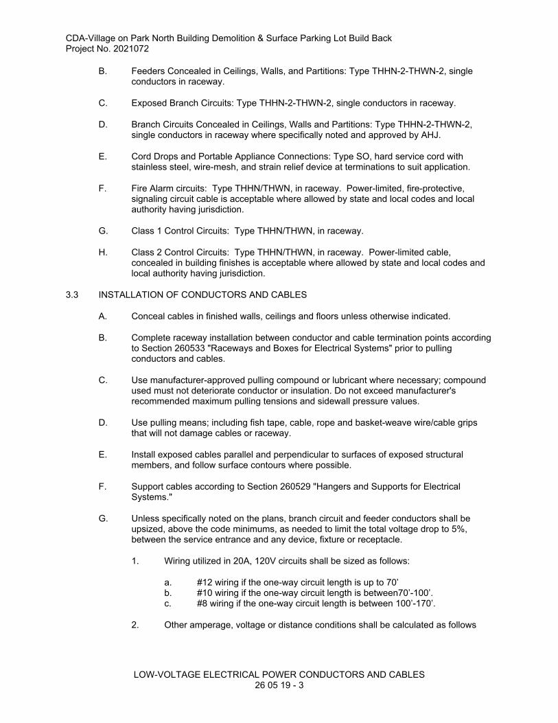
CDA-Village on Park North Building Demolition & Surface Parking Lot Build BackProject No. 2021072
LOW-VOLTAGE ELECTRICAL POWER CONDUCTORS AND CABLES 26 05 19 - 3
B. Feeders Concealed in Ceilings, Walls, and Partitions: Type THHN-2-THWN-2, single conductors in raceway.
C. Exposed Branch Circuits: Type THHN-2-THWN-2, single conductors in raceway.
D. Branch Circuits Concealed in Ceilings, Walls and Partitions: Type THHN-2-THWN-2, single conductors in raceway where specifically noted and approved by AHJ.
E. Cord Drops and Portable Appliance Connections: Type SO, hard service cord with stainless steel, wire-mesh, and strain relief device at terminations to suit application.
F. Fire Alarm circuits: Type THHN/THWN, in raceway. Power-limited, fire-protective, signaling circuit cable is acceptable where allowed by state and local codes and local authority having jurisdiction.
G. Class 1 Control Circuits: Type THHN/THWN, in raceway.
H. Class 2 Control Circuits: Type THHN/THWN, in raceway. Power-limited cable, concealed in building finishes is acceptable where allowed by state and local codes and local authority having jurisdiction.
3.3 INSTALLATION OF CONDUCTORS AND CABLES
A. Conceal cables in finished walls, ceilings and floors unless otherwise indicated.
B. Complete raceway installation between conductor and cable termination points according to Section 260533 "Raceways and Boxes for Electrical Systems" prior to pulling conductors and cables.
C. Use manufacturer-approved pulling compound or lubricant where necessary; compound used must not deteriorate conductor or insulation. Do not exceed manufacturer's recommended maximum pulling tensions and sidewall pressure values.
D. Use pulling means; including fish tape, cable, rope and basket-weave wire/cable grips that will not damage cables or raceway.
E. Install exposed cables parallel and perpendicular to surfaces of exposed structural members, and follow surface contours where possible.
F. Support cables according to Section 260529 "Hangers and Supports for Electrical Systems."
G. Unless specifically noted on the plans, branch circuit and feeder conductors shall be upsized, above the code minimums, as needed to limit the total voltage drop to 5%, between the service entrance and any device, fixture or receptacle.
1. Wiring utilized in 20A, 120V circuits shall be sized as follows:
a. #12 wiring if the one-way circuit length is up to 70’b. #10 wiring if the one-way circuit length is between70’-100’.c. #8 wiring if the one-way circuit length is between 100’-170’.
2. Other amperage, voltage or distance conditions shall be calculated as follows

CDA-Village on Park North Building Demolition & Surface Parking Lot Build BackProject No. 2021072
LOW-VOLTAGE ELECTRICAL POWER CONDUCTORS AND CABLES 26 05 19 - 4
a. Where branch circuits and feeders serve hardwired loads, 2-times the full load current of all loads on the circuit/feeder (up to 80% of the breaker rating) shall be used to calculate voltage drop.
b. Where branch circuits and feeders serve receptacles or panelboards, 80% of the breaker rating shall be used to calculate voltage drop.
3. Where conductors are upsized to account for voltage drop, it is acceptable mix conductor sizes within the same circuit, provided the voltage drop does not exceed 5% and this practice is not prohibited by local codes or AHJ requirements.
a. It is recognized that many pieces of equipment cannot accommodate upsized wiring due to lug or wiring compartment size and that short runs of smaller wire have a minimal effect on the total voltage drop. Examples of this include (but are not limited to):
1) Between a panelboard and a nearby lighting relay panel.2) From the base to the top of a site lighting pole3) The final drop to a receptacle or fixture.4) Fixture whips and device pigtails.
3.4 CONNECTIONS
A. Tighten electrical connectors and terminals according to manufacturer's published torque-tightening values. If manufacturer's torque values are not indicated, use those specified in UL 486A-486B.
B. Make splices, terminations and taps that are compatible with conductor material and that possess equivalent or better mechanical strength and insulation ratings than unspliced conductors.
C. Wiring at Outlets: Install conductor at each outlet, with at least 12 inches of slack.
3.5 IDENTIFICATION
A. Identify and color-code conductors and cables according to Section 260553 "Identification for Electrical Systems."
B. Identify each spare conductor at each end with identity number and location of other end of conductor, and identify as spare conductor.
3.6 FIRESTOPPING
A. Apply firestopping to electrical penetrations of fire-rated floor and wall assemblies to restore original fire-resistance rating of assembly. Firestopping materials and installation requirements are specified in Division 7
3.7 FIELD QUALITY CONTROL
A. Perform the following tests and inspections with the assistance of a factory-authorized service representative:
1. After installing conductors and cables and before electrical circuitry has been energized, test feeder conductors for compliance with NETA requirements.
2. Perform visual and mechanical inspection on all conductors.

CDA-Village on Park North Building Demolition & Surface Parking Lot Build BackProject No. 2021072
LOW-VOLTAGE ELECTRICAL POWER CONDUCTORS AND CABLES 26 05 19 - 5
3. Certify compliance with test parameters.

CDA-Village on Park North Building Demolition & Surface Parking Lot Build BackProject No. 2021072
LOW-VOLTAGE ELECTRICAL POWER CONDUCTORS AND CABLES 26 05 19 - 6
B. Test and Inspection Reports: Prepare a written report to record the following:
1. Procedures used.2. Results that comply with requirements.3. Results that do not comply with requirements and corrective action taken to
achieve compliance with requirements.
C. Cables will be considered defective if they do not pass tests and inspections.
END OF SECTION 26 05 19

CDA-Village on Park North Building Demolition & Surface Parking Lot Build BackProject No. 2021072
GROUNDING AND BONDING FOR ELECTRICAL SYSTEMS26 05 26 - 1
SECTION 26 05 26 - GROUNDING AND BONDING FOR ELECTRICAL SYSTEMS
PART 1 - GENERAL
1.1 RELATED DOCUMENTS
A. Drawings and general provisions of the Contract, including General and Supplementary Conditions and Division 01 Specification Sections, apply to this Section.
B. Requirements of 26 00 00 apply to this section.
1.2 ACTION SUBMITTALS
A. Product Data: For each type of product indicated.
1.3 QUALITY ASSURANCE
A. Electrical Components, Devices and Accessories: Listed and labeled as defined in NFPA 70, by a qualified testing agency, and marked for intended location and application.
B. Comply with UL 467 for grounding and bonding materials and equipment.
PART 2 - PRODUCTS
2.1 MANUFACTURERS
A. Manufacturers: Subject to compliance with requirements, manufacturers offering products that may be incorporated into the Work include, but are not limited to, the following:
1. Burndy; Part of Hubbell Electrical Systems.2. ERICO International Corporation.3. Galvan Industries, Inc.; Electrical Products Division, LLC.4. O-Z/Gedney; A Brand of the EGS Electrical Group.
2.2 SYSTEM DESCRIPTION
A. Electrical Components, Devices and Accessories: Listed and labeled as defined in NFPA 70, by a qualified testing agency, and marked for intended location and application.
B. Comply with UL 467 for grounding and bonding materials and equipment.
2.3 CONDUCTORS
A. Insulated Conductors: Copper wire or cable insulated for 600 V unless otherwise required by applicable Code or authorities having jurisdiction.
2.4 CONNECTORS
A. Listed and labeled by an NRTL acceptable to authorities having jurisdiction for applications in which used and for specific types, sizes, and combinations of conductors and other items connected.
B. Bolted Connectors for Conductors and Pipes: Copper or copper alloy compression type.

CDA-Village on Park North Building Demolition & Surface Parking Lot Build BackProject No. 2021072
GROUNDING AND BONDING FOR ELECTRICAL SYSTEMS26 05 26 - 2
PART 3 - EXECUTION
3.1 APPLICATIONS
A. Conductors: Install solid conductor for No. 8 AWG and smaller, and stranded conductors for No. 6 AWG and larger unless otherwise indicated.
B. Conductor Terminations and Connections:
1. Pipe and Equipment Grounding Conductor Terminations: Bolted connectors.2. Connections to Structural Steel: Welded connectors.
3.2 EQUIPMENT GROUNDING
A. Install insulated equipment grounding conductors with the following items, in addition to those required by NFPA 70:
1. Feeders and branch circuits.2. Lighting circuits.3. Receptacle circuits.4. Single-phase motor and appliance branch circuits.5. Three-phase motor and appliance branch circuits.6. Flexible raceway circuits.
B. Air-Duct Equipment Circuits: Install insulated equipment grounding conductor to duct-mounted electrical devices operating at 120 V and more, including air cleaners, heaters, dampers, humidifiers, and other duct electrical equipment. Bond conductor to each unit and to air duct and connected metallic piping.
C. Water Heater, Heat-Tracing, and Antifrost Heating Cables: Install a separate insulated equipment grounding conductor to each electric water heater and heat-tracing cable. Bond conductor to heater units, piping, connected equipment, and components.
3.3 INSTALLATION
A. Grounding Conductors: Route along shortest and straightest paths possible unless otherwise indicated or required by Code. Avoid obstructing access or placing conductors where they may be subjected to strain, impact, or damage.
B. Bonding Straps and Jumpers: Install in locations accessible for inspection and maintenance except where routed through short lengths of conduit.
1. Bonding to Structure: Bond straps directly to basic structure, taking care not to penetrate any adjacent parts.
2. Bonding to Equipment Mounted on Vibration Isolation Hangers and Supports: Install bonding so vibration is not transmitted to rigidly mounted equipment.
3. Use exothermic-welded connectors for outdoor locations; if a disconnect-type connection is required, use a bolted clamp.
C. Bonding Interior Metal Ducts: Bond metal air ducts to equipment grounding conductors of associated fans, blowers, electric heaters, and air cleaners. Install bonding jumper to bond across flexible duct connections to achieve continuity.
3.4 FIELD QUALITY CONTROL
A. Perform tests and inspections.

CDA-Village on Park North Building Demolition & Surface Parking Lot Build BackProject No. 2021072
GROUNDING AND BONDING FOR ELECTRICAL SYSTEMS26 05 26 - 3
1. After installing grounding system but before permanent electrical circuits have been energized, test for compliance with requirements.
2. Inspect physical and mechanical condition. Verify tightness of accessible, bolted, electrical connections with a calibrated torque wrench according to manufacturer's written instructions.
B. Grounding system will be considered defective if it does not pass tests and inspections.C. Prepare test and inspection reports.
END OF SECTION 26 05 26

This page intentionally left blank

CDA-Village on Park North Building Demolition & Surface Parking Lot Build BackProject No. 2021072
HANGERS AND SUPPORTS FOR ELECTRICAL SYSTEMS26 05 29 - 1
SECTION 26 05 29 - HANGERS AND SUPPORTS FOR ELECTRICAL SYSTEMS
PART 1 - GENERAL
1.1 RELATED DOCUMENTS
A. Drawings and general provisions of the Contract, including General and Supplementary Conditions and Division 01 Specification Sections, apply to this Section.
B. Requirements of 26 00 00 apply to this section.
1.2 DEFINITIONS
A. EMT: Electrical metallic tubing.
B. IMC: Intermediate metal conduit.C. RMC: Rigid metal conduit.
1.3 PERFORMANCE REQUIREMENTS
A. Delegated Design: Design supports for multiple raceways, including comprehensive engineering analysis by a qualified professional engineer, using performance requirements and design criteria indicated.
B. Design supports for multiple raceways capable of supporting combined weight of supported systems and its contents.
C. Design equipment supports capable of supporting combined operating weight of supported equipment and connected systems and components.
D. Rated Strength: Adequate in tension, shear, and pullout force to resist maximum loads calculated or imposed for this Project, with a minimum structural safety factor of five (5) times the applied force.
1.4 ACTION SUBMITTALS
A. Product Data: For the following:
1. Steel slotted support systems.Individual raceway supports.
B. Shop Drawings: Show fabrication and installation details and include calculations for the following:
1. Trapeze hangers and supports. Include Product Data for components.

CDA-Village on Park North Building Demolition & Surface Parking Lot Build BackProject No. 2021072
HANGERS AND SUPPORTS FOR ELECTRICAL SYSTEMS26 05 29 - 2
2. Steel slotted channel systems. Include Product Data for components.3. Equipment supports.
1.5 INFORMATIONAL SUBMITTALS
A. Welding certificates.
1.6 QUALITY ASSURANCE
A. Welding: Qualify procedures and personnel according to AWS D1.1/D1.1M, "Structural Welding Code - Steel."
B. Comply with NFPA 70.
1.7 COORDINATION
A. Coordinate size and location of concrete bases. Cast anchor-bolt inserts into bases. Concrete, reinforcement and formwork requirements are specified together with concrete Specifications.
PART 2 - PRODUCTS
2.1 SUPPORT, ANCHORAGE, AND ATTACHMENT COMPONENTS
A. Steel Slotted Support Systems: Comply with MFMA-4, factory-fabricated components for field assembly.
1. Manufacturers: Subject to compliance with requirements, provide products by one of the following:
a. Allied Tube & Conduit.b. Cooper B-Line, Inc.c. ERICO International Corporation.d. GS Metals Corp.e. Thomas & Betts Corporation.f. Unistrut; Atkore International.g. Wesanco, Inc.
2. Painted Coatings: Manufacturer's standard painted coating applied according to MFMA-4.
3. Channel Dimensions: Selected for applicable load criteria.
B. Raceway and Cable Supports: As described in NECA 1 and NECA 101.C. Conduit and Cable Support Devices: Steel hangers, clamps, and associated fittings,
designed for types and sizes of raceway or cable to be supported.D. Support for Conductors in Vertical Conduit: Factory-fabricated assembly consisting of
threaded body and insulating wedging plug or plugs for non-armored electrical conductors or cables in riser conduits. Plugs shall have number, size and shape of conductor gripping pieces as required to suit individual conductors or cables supported. Body shall be malleable iron.
E. Structural Steel for Fabricated Supports and Restraints: ASTM A 36/A 36M, steel plates, shape, and bars; black and galvanized.
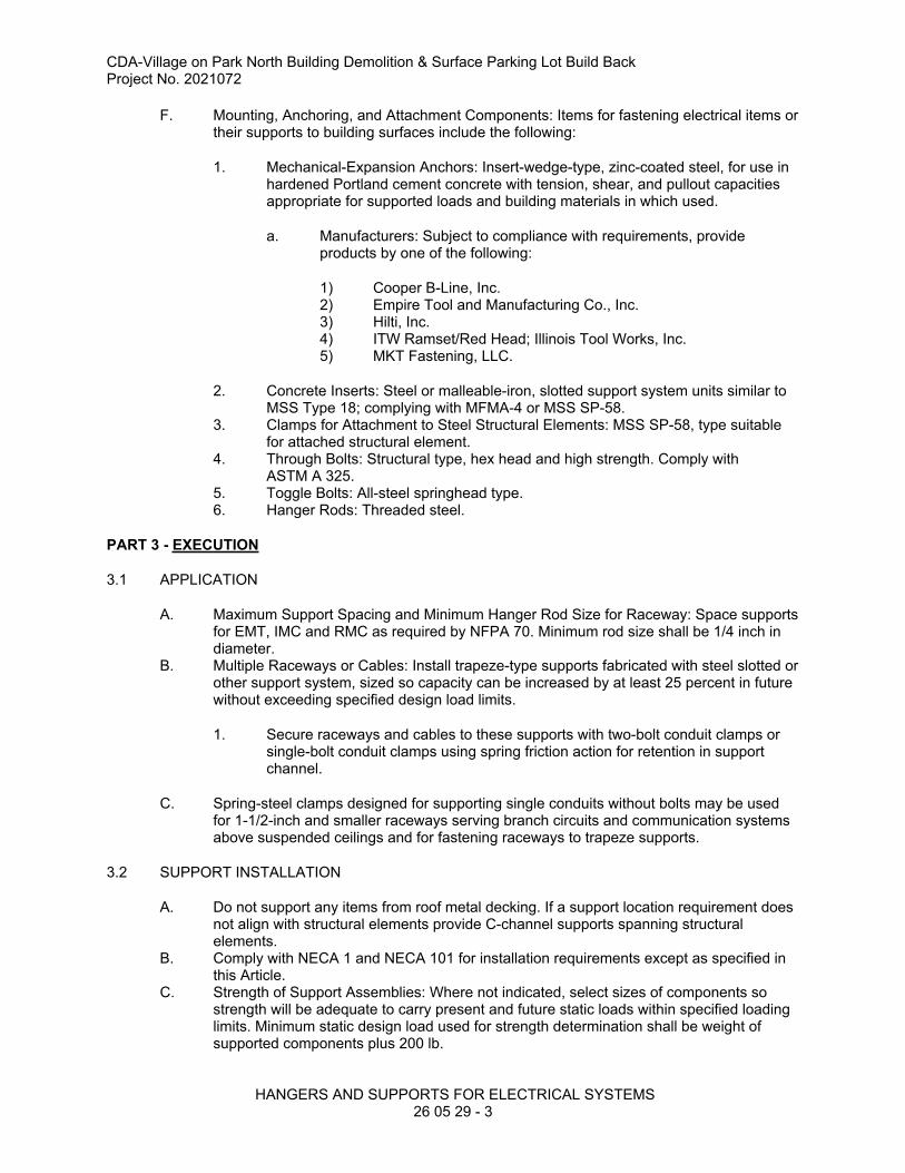
CDA-Village on Park North Building Demolition & Surface Parking Lot Build BackProject No. 2021072
HANGERS AND SUPPORTS FOR ELECTRICAL SYSTEMS26 05 29 - 3
F. Mounting, Anchoring, and Attachment Components: Items for fastening electrical items or their supports to building surfaces include the following:
1. Mechanical-Expansion Anchors: Insert-wedge-type, zinc-coated steel, for use in hardened Portland cement concrete with tension, shear, and pullout capacities appropriate for supported loads and building materials in which used.
a. Manufacturers: Subject to compliance with requirements, provide products by one of the following:
1) Cooper B-Line, Inc.2) Empire Tool and Manufacturing Co., Inc.3) Hilti, Inc.4) ITW Ramset/Red Head; Illinois Tool Works, Inc.5) MKT Fastening, LLC.
2. Concrete Inserts: Steel or malleable-iron, slotted support system units similar to MSS Type 18; complying with MFMA-4 or MSS SP-58.
3. Clamps for Attachment to Steel Structural Elements: MSS SP-58, type suitable for attached structural element.
4. Through Bolts: Structural type, hex head and high strength. Comply with ASTM A 325.
5. Toggle Bolts: All-steel springhead type.6. Hanger Rods: Threaded steel.
PART 3 - EXECUTION
3.1 APPLICATION
A. Maximum Support Spacing and Minimum Hanger Rod Size for Raceway: Space supports for EMT, IMC and RMC as required by NFPA 70. Minimum rod size shall be 1/4 inch in diameter.
B. Multiple Raceways or Cables: Install trapeze-type supports fabricated with steel slotted or other support system, sized so capacity can be increased by at least 25 percent in future without exceeding specified design load limits.
1. Secure raceways and cables to these supports with two-bolt conduit clamps or single-bolt conduit clamps using spring friction action for retention in support channel.
C. Spring-steel clamps designed for supporting single conduits without bolts may be used for 1-1/2-inch and smaller raceways serving branch circuits and communication systems above suspended ceilings and for fastening raceways to trapeze supports.
3.2 SUPPORT INSTALLATION
A. Do not support any items from roof metal decking. If a support location requirement does not align with structural elements provide C-channel supports spanning structural elements.
B. Comply with NECA 1 and NECA 101 for installation requirements except as specified in this Article.
C. Strength of Support Assemblies: Where not indicated, select sizes of components so strength will be adequate to carry present and future static loads within specified loading limits. Minimum static design load used for strength determination shall be weight of supported components plus 200 lb.

CDA-Village on Park North Building Demolition & Surface Parking Lot Build BackProject No. 2021072
HANGERS AND SUPPORTS FOR ELECTRICAL SYSTEMS26 05 29 - 4
D. Mounting and Anchorage of Surface-Mounted Equipment and Components: Anchor and fasten electrical items and their supports to building structural elements by the following methods unless otherwise indicated by code:
1. To Wood: Fasten with lag screws or through bolts.2. To New Concrete: Bolt to concrete inserts.3. To Masonry: Approved toggle-type bolts on hollow masonry units and expansion
anchor fasteners on solid masonry units.4. To Existing Concrete: Expansion anchor fasteners.5. To Steel: Welded threaded studs complying with AWS D1.1/D1.1M, with lock
washers and nuts, beam clamps (MSS Type 19, 21, 23, 25, or 27) complying with MSS SP-69.
6. To Light Steel: Sheet metal screws.7. Items Mounted on Hollow Walls and Nonstructural Building Surfaces: Mount
cabinets, panelboards, disconnect switches, control enclosures, pull and junction boxes, transformers, and other devices on slotted-channel racks attached to substrate.
E. Drill holes for expansion anchors in concrete at locations and to depths that avoid reinforcing bars.
3.3 PAINTING
A. Touchup: Clean field welds and abraded areas of shop paint. Paint exposed areas immediately after erecting hangers and supports. Use same materials as used for shop painting. Comply with SSPC-PA 1 requirements for touching up field-painted surfaces.
1. Apply paint by brush or spray to provide minimum dry film thickness of 2.0 mils.
B. Touchup: Comply with requirements in Section 09 91 00 "Painting" for cleaning and touchup painting of field welds, bolted connections, and abraded areas of shop paint on miscellaneous metal.
C. Galvanized Surfaces: Clean welds, bolted connections, and abraded areas and apply galvanizing-repair paint to comply with ASTM A 780.
END OF SECTION 26 05 29

CDA-Village on Park North Building Demolition & Surface Parking Lot Build BackProject No. 2021072
RACEWAYS AND BOXES FOR ELECTRICAL SYSTEMS26 05 33 - 1
SECTION 26 05 33 - RACEWAYS AND BOXES FOR ELECTRICAL SYSTEMS
PART 1 - GENERAL
1.1 RELATED DOCUMENTS
A. Drawings and general provisions of the Contract, including General and Supplementary Conditions and Division 1 Specification Sections, apply to this Section.
B. Requirements of 26 00 00 apply to this section.
1.2 DEFINITIONS
A. EMT: Electrical metallic tubingB. FMC: Flexible metal conduit.C. IMC: Intermediate metal conduit.D. LFMC: Liquidtight flexible metal conduit.
1.3 SUBMITTALS
A. Product Data: For surface raceways, wireways and fittings, floor boxes, hinged-cover enclosures, and cabinets.
B. Shop Drawings: Show fabrication and installation details of components for raceways, fittings, boxes, enclosures, and cabinets.
1.4 QUALITY ASSURANCE
A. Electrical Components, Devices, and Accessories: Listed and labeled as defined in NFPA 70, Article 100, by a testing agency acceptable to authorities having jurisdiction, and marked for intended use.
B. Comply with NFPA 70.
1.5 COORDINATION
A. Coordinate layout and installation of raceways, boxes, enclosures, cabinets, and suspension system with other construction that penetrates ceilings or is supported by them, including light fixtures, HVAC equipment, fire-suppression system, and partition assemblies.
B. Coordinate fire rated partition penetrations and sealants.
PART 2 - PRODUCTS
2.1 MANUFACTURERS
A. In other Part 2 articles where subparagraph titles below introduce lists, the following requirements apply for product selection:
1. Available Manufacturers: Subject to compliance with requirements, manufacturers offering products that may be incorporated into the Work include, but are not limited to, the manufacturers specified.
2. Manufacturers: Subject to compliance with requirements, provide products by the manufacturers specified.

CDA-Village on Park North Building Demolition & Surface Parking Lot Build BackProject No. 2021072
RACEWAYS AND BOXES FOR ELECTRICAL SYSTEMS26 05 33 - 2
2.2 METAL CONDUIT AND TUBING
A. Manufacturers
1. AFC Cable Systems, Inc.2. Alflex Inc.3. Anamet Electrical, Inc.; Anaconda Metal Hose.4. Electri-Flex Co.5. Grinnell Co./Tyco International; Allied Tube and Conduit Div.6. LTV Steel Tubular Products Company.7. Manhattan/CDT/Cole-Flex.8. O-Z Gedney; Unit of General Signal.9. Wheatland Tube Co.
B. Rigid Steel Conduit: ANSI C80.1.
C. IMC: ANSI C80.6.
D. Plastic-Coated Steel Conduit and Fittings: NEMA RN 1.
E. Plastic-Coated IMC and Fittings: NEMA RN 1.
F. EMT and Fittings: ANSI C80.3.
1. Fittings: Set-screw or compression type.2. Fittings: All steel, set screw, water tight, concrete tight.
a. Insulated throat connectors. b. No push-on or indenter types permitted.
3. Conduit Bodies: All steel threaded conduit bodies.
G. FMC: Zinc-coated steel.
H. LFMC: Flexible steel conduit with PVC jacket.
I. Fittings: NEMA FB 1; compatible with conduit and tubing materials.
J. Refer to color code requirements on Sheet E001.
2.3 BOXES, ENCLOSURES, AND CABINETS
A. Manufacturers
1. Cooper Crouse-Hinds; Div. of Cooper Industries, Inc.2. Emerson/General Signal; Appleton Electric Company.3. Erickson Electrical Equipment Co.4. Hoffman.5. Hubbell, Inc.; Killark Electric Manufacturing Co.6. O-Z/Gedney; Unit of General Signal.7. RACO; Division of Hubbell, Inc.8. Robroy Industries, Inc.; Enclosure Division.9. Scott Fetzer Co.; Adalet-PLM Division.10. Spring City Electrical Manufacturing Co.11. Thomas & Betts Corporation.12. Walker Systems, Inc.; Wiremold Company (The).13. Woodhead, Daniel Company; Woodhead Industries, Inc. Subsidiary.14. Strongwell Corp.

CDA-Village on Park North Building Demolition & Surface Parking Lot Build BackProject No. 2021072
RACEWAYS AND BOXES FOR ELECTRICAL SYSTEMS26 05 33 - 3
B. Sheet Metal Outlet and Device Boxes: NEMA OS 1.
C. Cast-Metal Outlet and Device Boxes: NEMA FB 1, Type FD, with gasketed cover.
D. Small Sheet Metal Pull and Junction Boxes: NEMA OS 1.
E. Hinged-Cover Enclosures: NEMA 250, Type 1, with continuous hinge cover and flush latch.
1. Metal Enclosures: Steel, finished inside and out with manufacturer's standard enamel.
F. Cabinets: NEMA 250, Type 1, galvanized steel box with removable interior panel and removable front, finished inside and out with manufacturer's standard enamel. Hinged door in front cover with flush latch and concealed hinge. Key latch to match panelboards. Include metal barriers to separate wiring of different systems and voltage and include accessory feet where required for freestanding equipment.
G. Refer to color code requirements on Sheet E001.
2.4 FACTORY FINISHES
A. Finish: For raceway, enclosure, or cabinet components, provide manufacturer's standard prime-coat finish ready for field painting.
B. Finish: For raceway, enclosure, or cabinet components, provide manufacturer's standard paint applied to factory-assembled surface raceways, enclosures, and cabinets before shipping.
PART 3 - EXECUTION
3.1 RACEWAY APPLICATION
A. Indoors:
1. Exposed: EMT.2. Concealed: EMT.3. Connection to Vibrating Equipment (Including Transformers and Hydraulic,
Pneumatic, Electric Solenoid, or Motor-Driven Equipment): FMC; except use LFMC in damp or wet locations.
4. Damp or Wet Locations: Rigid steel conduit.5. Boxes and Enclosures: NEMA 250, Type 1, except as follows:
a. Damp or Wet Locations: NEMA 250, Type 4 metallic.
B. Minimum Raceway Size: 3/4-inch trade size (DN 21).
C. Raceway Fittings: Compatible with raceways and suitable for use and location.
1. Intermediate Steel Conduit: Use threaded rigid steel conduit fittings, unless otherwise indicated.
3.2 INSTALLATION

CDA-Village on Park North Building Demolition & Surface Parking Lot Build BackProject No. 2021072
RACEWAYS AND BOXES FOR ELECTRICAL SYSTEMS26 05 33 - 4
A. Keep raceways at least 6 inches (150 mm) away from parallel runs of flues and steam or hot-water pipes. Install horizontal raceway runs above water and steam piping.
B. Complete raceway installation before starting conductor installation.
C. Support raceways as specified in Division 26 Section "Common Work Results for Electrical."
D. Install temporary closures to prevent foreign matter from entering raceways.
E. Protect stub-ups from damage where conduits rise through floor slabs. Arrange so curved portions of bends are not visible above the finished slab.
F. Make bends and offsets so ID is not reduced. Keep legs of bends in the same plane and keep straight legs of offsets parallel, unless otherwise indicated.
G. Conceal conduit and EMT within finished walls, ceilings, and floors, unless otherwise indicated.
1. Install concealed raceways with a minimum of bends in the shortest practical distance, considering type of building construction and obstructions, unless otherwise indicated.
H. Install exposed raceways parallel or at right angles to nearby surfaces or structural members and follow surface contours as much as possible.
1. Run parallel or banked raceways together on common supports.2. Make parallel bends in parallel or banked runs. Use factory elbows only where
elbows can be installed parallel; otherwise, provide field bends for parallel raceways.
I. Join raceways with fittings designed and approved for that purpose and make joints tight.
1. Use insulating bushings to protect conductors.
J. Tighten set screws of threadless fittings with suitable tools.
K. Terminations:
1. Where raceways are terminated with locknuts and bushings, align raceways to enter squarely and install locknuts with dished part against box. Use two locknuts, one inside and one outside box.
2. Where raceways are terminated with threaded hubs, screw raceways or fittings tightly into hub so end bears against wire protection shoulder. Where chase nipples are used, align raceways so coupling is square to box; tighten chase nipple so no threads are exposed.
L. Install pull wires in empty raceways. Use polypropylene or monofilament plastic line with not less than 200-lb (90-kg) tensile strength. Leave at least 12 inches (300 mm) of slack at each end of pull wire.
M. Telephone and Signal System Raceways, 2-Inch Trade Size (DN 53) and Smaller: In addition to above requirements, install raceways in maximum lengths of 150 feet (45 m) and with a maximum of two 90-degree bends or equivalent. Separate lengths with pull or junction boxes where necessary to comply with these requirements.

CDA-Village on Park North Building Demolition & Surface Parking Lot Build BackProject No. 2021072
RACEWAYS AND BOXES FOR ELECTRICAL SYSTEMS26 05 33 - 5
N. Install raceway sealing fittings at suitable, approved, and accessible locations and fill them with UL-listed sealing compound. For concealed raceways, install each fitting in a flush steel box with a blank cover plate having a finish similar to that of adjacent plates or surfaces. Install raceway sealing fittings at the following points:
1. Where conduits pass from warm to cold locations, such as boundaries of refrigerated spaces.
2. Where otherwise required by NFPA 70.
O. Stub-up Connections: Extend conduits through concrete floor for connection to freestanding equipment. Install with an adjustable top or coupling threaded inside for plugs set flush with finished floor. Extend conductors to equipment with rigid steel conduit; FMC may be used 6 inches (150 mm) above the floor. Install screwdriver-operated, threaded plugs flush with floor for future equipment connections.
P. Flexible Connections: Use maximum of 72 inches (1830 mm) of flexible conduit for recessed and semirecessed lighting fixtures; for equipment subject to vibration, noise transmission, or movement; and for all motors. Use LFMC in damp or wet locations. Install separate ground conductor across flexible connections.
Q. Install hinged-cover enclosures and cabinets plumb. Support at each corner.
R. Refer to color code requirements on Sheet E001.
3.3 PROTECTION
A. Provide final protection and maintain conditions that ensure coatings, finishes, and cabinets are without damage or deterioration at time of Substantial Completion.
1. Repair damage to galvanized finishes with zinc-rich paint recommended by manufacturer.
2. Repair damage to PVC or paint finishes with matching touchup coating recommended by manufacturer.
3.4 CLEANING
A. After completing installation of exposed, factory-finished raceways and boxes, inspect exposed finishes and repair damaged finishes.
END OF SECTION 26 05 33

This page intentionally left blank
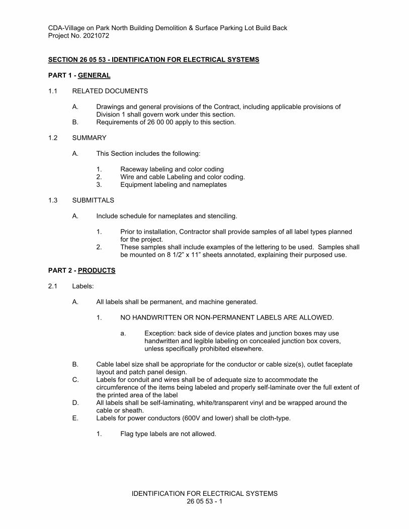
CDA-Village on Park North Building Demolition & Surface Parking Lot Build BackProject No. 2021072
IDENTIFICATION FOR ELECTRICAL SYSTEMS26 05 53 - 1
SECTION 26 05 53 - IDENTIFICATION FOR ELECTRICAL SYSTEMS
PART 1 - GENERAL
1.1 RELATED DOCUMENTS
A. Drawings and general provisions of the Contract, including applicable provisions of Division 1 shall govern work under this section.
B. Requirements of 26 00 00 apply to this section.
1.2 SUMMARY
A. This Section includes the following:
1. Raceway labeling and color coding2. Wire and cable Labeling and color coding.3. Equipment labeling and nameplates
1.3 SUBMITTALS
A. Include schedule for nameplates and stenciling.
1. Prior to installation, Contractor shall provide samples of all label types planned for the project.
2. These samples shall include examples of the lettering to be used. Samples shall be mounted on 8 1/2” x 11” sheets annotated, explaining their purposed use.
PART 2 - PRODUCTS
2.1 Labels:
A. All labels shall be permanent, and machine generated.
1. NO HANDWRITTEN OR NON-PERMANENT LABELS ARE ALLOWED.
a. Exception: back side of device plates and junction boxes may use handwritten and legible labeling on concealed junction box covers, unless specifically prohibited elsewhere.
B. Cable label size shall be appropriate for the conductor or cable size(s), outlet faceplate layout and patch panel design.
C. Labels for conduit and wires shall be of adequate size to accommodate the circumference of the items being labeled and properly self-laminate over the full extent of the printed area of the label
D. All labels shall be self-laminating, white/transparent vinyl and be wrapped around the cable or sheath.
E. Labels for power conductors (600V and lower) shall be cloth-type.
1. Flag type labels are not allowed.

CDA-Village on Park North Building Demolition & Surface Parking Lot Build BackProject No. 2021072
IDENTIFICATION FOR ELECTRICAL SYSTEMS26 05 53 - 2
2.2 Identification Nameplates:
A. Non-Fading, Weather Resistant, Engraved three-layer laminated plastic
1. Normal Systems shall use black letters on a white background.2. Instructions shall utilize black letters on a white background.
2.3 Instructional Signs:
A. Non-Fading, Weather Resistant, Engraved three-layer laminated plastic
1. Instructions shall utilize black letters on a white background.
2.4 Interior Warning Labels
A. Factory-printed, multicolor, pressure-sensitive adhesive labels, configured for display on front cover, door, or other access to equipment unless otherwise indicated.
2.5 Colored Tape:
A. Scotch #35 tape in appropriate colors for system voltage and phase.B. Adhesive type labels not permitted except for phase and wire identification. C. Machine generated adhesive labels shall be permitted for device plates, 4-11/16” and
smaller junction boxes, Fire alarm and control devices.
2.6 Colored Conduit
A. Factory dyed conduit available in the following colors
1. Black2. Red3. Orange4. Yellow5. Green6. Blue7. Purple8. White
B. Colored conduit shall meet all requirements of 26 05 33 in addition to being color coded.
PART 3 - EXECUTION
3.1 GENERAL
A. Where mixed voltages are used in one building (e.g. 480 volt, 208 volt) each switch, switchboard, junction box, equipment, etc., on each system must be labeled for voltage in addition to other requirements listed herein.
B. All branch circuit and power panels must be identified with the same symbol used in circuit directory in main distribution center.
3.2 INSTALLATION
A. All labels, signs, nameplates installed on equipment receiving a field finish (such as panelboards in finished spaces) shall be installed after final finishes have been applied.
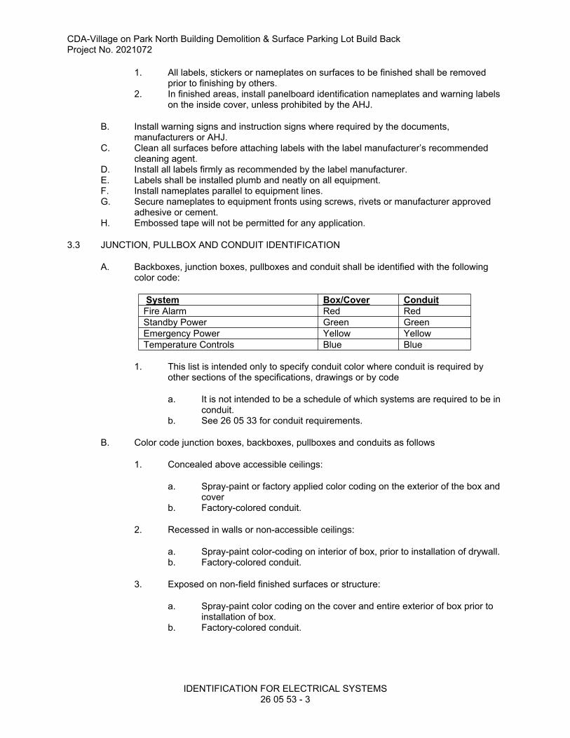
CDA-Village on Park North Building Demolition & Surface Parking Lot Build BackProject No. 2021072
IDENTIFICATION FOR ELECTRICAL SYSTEMS26 05 53 - 3
1. All labels, stickers or nameplates on surfaces to be finished shall be removed prior to finishing by others.
2. In finished areas, install panelboard identification nameplates and warning labels on the inside cover, unless prohibited by the AHJ.
B. Install warning signs and instruction signs where required by the documents, manufacturers or AHJ.
C. Clean all surfaces before attaching labels with the label manufacturer’s recommended cleaning agent.
D. Install all labels firmly as recommended by the label manufacturer.E. Labels shall be installed plumb and neatly on all equipment.F. Install nameplates parallel to equipment lines.G. Secure nameplates to equipment fronts using screws, rivets or manufacturer approved
adhesive or cement.H. Embossed tape will not be permitted for any application.
3.3 JUNCTION, PULLBOX AND CONDUIT IDENTIFICATION
A. Backboxes, junction boxes, pullboxes and conduit shall be identified with the following color code:
System Box/Cover Conduit
Fire Alarm Red Red
Standby Power Green Green
Emergency Power Yellow Yellow
Temperature Controls Blue Blue
1. This list is intended only to specify conduit color where conduit is required by other sections of the specifications, drawings or by code
a. It is not intended to be a schedule of which systems are required to be in conduit.
b. See 26 05 33 for conduit requirements.
B. Color code junction boxes, backboxes, pullboxes and conduits as follows
1. Concealed above accessible ceilings:
a. Spray-paint or factory applied color coding on the exterior of the box and cover
b. Factory-colored conduit.
2. Recessed in walls or non-accessible ceilings:
a. Spray-paint color-coding on interior of box, prior to installation of drywall. b. Factory-colored conduit.
3. Exposed on non-field finished surfaces or structure:
a. Spray-paint color coding on the cover and entire exterior of box prior to installation of box.
b. Factory-colored conduit.

CDA-Village on Park North Building Demolition & Surface Parking Lot Build BackProject No. 2021072
IDENTIFICATION FOR ELECTRICAL SYSTEMS26 05 53 - 4
4. Exposed on painted surfaces or structure which have not received final painting by others at the time of installation.
a. Spray-paint color coding on inside of box and cover, prior to surface painting by others (to avoid overspray onto finished surfaces).
b. Exterior of box and cover shall be painted to match surface.c. No conduit color coding required.d. Conduit shall be painted to match surface.
5. Exposed on surfaces that have already received final painting at the time of installation or unpainted decorative surfaces such as brick, stone or wood surfaces
a. Spray-paint color coding on inside of box, prior to installation of box. b. Exterior of box and cover shall be painted per architect’s color selection,
prior to installation.c. No conduit color-coding required.d. Conduit and supports shall be painted per architect’s color selection,
prior to installation.
C. Other systems shall be identified as shown on details or approved shop drawings.
3.4 POWER AND CONTROL WIRE IDENTIFICATION
A. Provide wire markers on each conductor in panelboard gutters, pull boxes, outlet and junction boxes, and at load connection.
1. Identify with branch circuit or feeder number for power and lighting circuits, and with control wire number as indicated on schematic and interconnection diagrams or equipment manufacturer's shop drawings for control wiring.
2. All wiring shall be labeled within 2 to 4 inches of terminations. Each end of a wire or cable shall be labeled as soon as it is terminated including wiring used for temporary purposes.
3.5 WIRING DEVICE IDENTIFICATION
1. Wall switches, receptacles, occupancy sensors, wall dimmers, device plates and box covers, poke-through fittings, access floor boxes, emergency power transfer devices, photocells and time clocks shall be identified with circuit numbers and source.
a. In exposed areas, identifications should be made inside of device covers, unless directed otherwise.
b. Use machine-generated labels, or neatly hand-written permanent marker.
3.6 NAMEPLATE ENGRAVING
A. Provide nameplates of minimum letter height as scheduled below.
1. Panelboards:
a. 1 inch (25 mm)
1) Identify equipment designation.
CDA-Village on Park North Building Demolition & Surface Parking Lot Build BackProject No. 2021072
IDENTIFICATION FOR ELECTRICAL SYSTEMS26 05 53 - 5
b. 1/2 inch (13 mm)
1) Identify voltage rating, source and room location of the source.
2. Equipment Enclosures:
a. 1 inch (25 mm)
1) Identify equipment designation.
3. Individual Circuit Breakers, Disconnect Switches, Enclosed Switches, and Motor Starters:
a. ½ inch (13 mm)
1) Identify source and load served.
4. Junction boxes:
a. Junction boxes may be neatly identified using a permanent marker
1) Identify system source(s) and load(s) served.
3.7 PANELBOARD DIRECTORIES
1. Typed directories for panels must be covered with clear plastic, have a metal frame.
a. Room number on directories shall be Owner's numbers not Plan numbers unless Owner so specifies.
3.8 COMMUNICATION, SECURITY, AUDIO/VISUAL RACEWAY LABELING
A. All conduits installed for Telecommunications, Data, Technology, Security, Surveillance or A/V Equipment shall be clearly labeled.
1. Label according to ANSI/TIA/EIA-606 and the following. 2. Both ends of the conduits shall be labeled.3. If the end of the conduit is concealed the inside of the junction box or floorbox
shall be labeled.4. All labels shall be mechanical, no hand written labels. 5. The label shall indicate the location of the far end of the conduit run and a unique
conduit number. (i.e. TR-1A-01 or Room #216 – 01).6. Individual drops from above ceiling to a wall backbox box do not required
labeling.7. All room numbers shall be the final Owner numbering, not the Plan numbering.
3.9 IDENTIFICATION MATERIALS AND DEVICES
A. Install at locations for most convenient viewing without interference with operation and maintenance of equipment.
B. Coordinate names, abbreviations, colors, and other designations used for electrical identification with corresponding designations indicated in the Contract Documents or required by codes and standards. Use consistent designations throughout Project.
C. Self-Adhesive Identification Products: Clean surfaces before applying.

CDA-Village on Park North Building Demolition & Surface Parking Lot Build BackProject No. 2021072
IDENTIFICATION FOR ELECTRICAL SYSTEMS26 05 53 - 6
D. Tag and label circuits designated to be extended in the future. Identify source and circuit numbers in each cabinet, pull and junction box, and outlet box. Color-coding may be used for voltage and phase identification.
E. Color-code 208/120-V system secondary service, feeder, and branch-circuit conductors throughout the secondary electrical system as follows:
1. Phase A: Black.2. Phase B: Red.3. Phase C: Blue.
F. Install warning, caution, and instruction signs where required to comply with 29 CFR, Chapter XVII, Part 1910.145, and where needed to ensure safe operation and maintenance of electrical systems and of items to which they connect. Install engraved plastic-laminated instruction signs with approved legend where instructions are needed for system or equipment operation. Install metal-backed butyrate signs for outdoor items.
END OF SECTION 26 05 53

CDA-Village on Park North Building Demolition & Surface Parking Lot Build BackProject No. 2021072
LIGHTING CONTROL PANELS26 09 28 - 1
SECTION 26 09 28 LIGHTING CONTROL PANELS
PART 1 - GENERAL
1.1 SCOPE
A. The work under this section includes power supplies, relays, control equipment, enclosures, and low-voltage switches associated with low voltage lighting control. Included are the following topics:
1.2 SUBMITTALS
A. Submit product data indicating system and component construction, ratings, and operating parameters.
B. Submit manufacturer's installation instructions.
1.3 RECORD DOCUMENTS
A. Provide drawings showing where the lighting control panels are located within the building. Provide schedules indicating switch locations (room numbers) in the building and the associated relay number(s) in the panels. If multiple lighting control panels are networked together, provide a riser diagram showing how the lighting control panels are connected to each other.
1.4 OPERATION AND MAINTENANCE DATA
A. All operations and maintenance data shall comply with the submission and content requirements specified under section GENERAL REQUIREMENTS.
1.5 WARRANTY
A. Manufacturer shall supply a 3-year warranty on all hardware and software. A limited 10-year warranty shall be provided on all relay cards.
PART 2 - PRODUCTS
2.1 SYSTEM DESCRIPTION
A. The lighting control system shall consist of low voltage relay control panel(s) with up to 64 programmable switch inputs and up to 48 control relay outputs per panel capable of controlling both on/off functions and 0-10V dimming per zone.
B. Each low voltage lighting control panel shall be microprocessor controlled with a touch-screen display or Handheld Display Unit (HDU) interface. The touch-screen shall provide relay status information viewable through a protected windowed enclosure. All local programming shall be permissible through the self-prompting touch-screen. The low voltage lighting control panels will be networked together, and capable of connecting to the Temperature Control System.
CDA-Village on Park North Building Demolition & Surface Parking Lot Build BackProject No. 2021072
LIGHTING CONTROL PANELS26 09 28 - 2
C. Programmable intelligence shall include Time-Of-Day control, 32 holiday dates, warn occupants of an impending off, timed inputs, preset control, auto daylight savings, astronomical clock w/offsets, local control, digital switches, and network overrides:
Time-Of-Day Scheduling64 Time-Of-Day/holiday schedules for 365 day programming
Holidays32 holiday dates
Warn OffFlash lights and provide an extra 1 second to 99 minutes of illumination for interior lights
PresetPre-programmed switch patterns
Timed InputsSwitch input timers 1-999 minutes
Timed OverridesTimed override from the touch-screen 1-999 Overrides minutes, resumes to normal schedule
Local ControlFrom integral touch-screen or HDU, and local switch
Astronomical ClockLongitude and latitude input with sunset-sunrise offsets to customize outdoor lighting
Auto Daylight Savings AdjustAutomatically adjusts the clock at the appropriate dates, selectable
PrioritiesEstablishes a hierarchy for inputs and network control commands
MaskingMasking provides permissions related to switch inputs and network commands, thereby ensuring software security.
Soft-LinkingGroup linking for rapid programming
Global LinkingEach panel shall provide 64 addressable groups for network linking of control commands
Analog InputsFour analog inputs
D. The control panel shall be capable of reporting whether the relays are overridden via software, override switches, or via on board hardware override. Relay status shall not only disclose commanded relay status but next scheduled state to occur.
E. Each control panel shall provide a Warn Off (flashing of the lights) for interior light fixtures to inform the occupants of an impending OFF command. The Warn Off command shall provide adjustable time duration of 1 second to 99 extra minutes. The occupants may exit the premises with adequate lighting or cancel the Warn Off by overriding the lighting zone. This option occurs with all OFF commands except local overrides.

CDA-Village on Park North Building Demolition & Surface Parking Lot Build BackProject No. 2021072
LIGHTING CONTROL PANELS26 09 28 - 3
F. The controller shall permit lighting to be overridden ON for after-hours use or cleaning. The controller shall provide optional switch timer assignments or timed overrides. The override choices for various relays shall provide special event occurrences and the controller shall return to the programmed state after the override event. Also, the controller shall provide priority and masking choices to customize the functions of switch inputs, thereby enabling switches to function differently at different times of the day to meet special facility operational requirements. These overrides shall be digital, network, or hard-wired inputs.
G. Programming of the controller may be accomplished through the local integral touch-screen or HDU. Descriptive information shall assist the user to employ the system without a programming manual.
H. The lighting control system may also be fully programmed through PC programming software. Programming shall be permitted through a direct RS-232 connection, modem, or TCP/IP.
I. Priorities and/or Masking shall be assigned to inputs, telephone override, and global commands to ensure building integrity. Priorities enable or disable the inputs based on user actuation of overrides. Masks shall permit: ON only, OFF only and ON & OFF control for intelligent after-hours utilization of the controlled facility based on Time-Of-Day scheduling in the controller.
J. The control system shall provide networking between lighting control panels. One network may support a maximum of 254 control panels. Panels shall permit data sharing for global control. All inputs (no limitation) are transferable over the network to create any switching pattern required. The maximum length of the lighting control network shall be 4000 feet. Repeaters are available to extend the network as needed. Networks that rely on a single time clock for system operation shall not be acceptable.
K. The lighting control system shall log all control events. The controller shall monitor all relay actuations, switch inputs and user intervention. Log reports shall be available for any duration of time the operator chooses through the integral touch-screen or through the network software. Runtimes for each relay shall be available from the integral touch-screen or through the network software.
L.Operator Interface
1. The control panel programming interface resides in firmware in the control panel. The programming interface shall consist of a circuit board mounted touch-screen or Handheld Display Unit (HDU) capable of linking switch inputs to relay outputs and schedule assignments. Systems that utilize blocking diode technology for relay assignments shall not be acceptable.
2. The integral touch-screen or HDU shall provide access to the main programming features. The touch-screen shall permit the user to manually command any or all relays individually. Each panel shall control its own loads from internal memory. A control system that solely relies on a central control computer/processor or external time clocks shall not be permitted.
M. Inputs and Outputs
1. The controller shall provide timers for each input/output. Each input/output timer shall be capable of 0-999 minutes. Software shall enable or disable input/outputs based on Priorities, Masks or Time-Of-Day scheduling.
2. Switches: The lighting controller shall support digitally addressable LED annunciated switches. The digital switch network requires CAT 6 cabling between switches. The digital switches shall control any relay group combination on the lighting control network. Data communications status feedback for system

CDA-Village on Park North Building Demolition & Surface Parking Lot Build BackProject No. 2021072
LIGHTING CONTROL PANELS26 09 28 - 4
checkout and troubleshooting (transmit and receive LED’s) shall be visible on both the controller and interface.
3. Switches shall be organized as one (1) to six (6) momentary contact buttons on a single mounting plate intended to fit into a single gang wallbox. Each button shall have an integral status LED indicator.
4. The switch configuration shall permit custom labeling for multiple button switch locations. The switch configuration shall be Decora™ form and function.
N. Dry Contact Inputs
1. The control system shall permit 32 dry contacts inputs for override purposes. Momentary 3 wire or 2 wire (toggle) inputs shall be supported. Maintained contacts shall be supported as 2 wire (SPST) inputs. Inputs shall be dry contacts (24 VDC @ 12 ma. internally supplied to the inputs). The 24 VDC power supply is provided with an auto-resettable fuse. Should an inappropriate electrical connection be made the design will protect the board and switches until the fault is removed. Any switch input shall be software linked to any number of relays for override control. The control panel shall have dry contact inputs on the logic board.
O. Lighted Switch Outputs (LSO)
1. The controller shall provide an output for pilot light wall switch annunciation of dry contact inputs. A fourth connection point on the controller board shall provide power to illuminate pilot light switches. This option shall confirm relay operation. When a relay is in the “ON” position the pilot light switch shall be illuminated. The pilot light outputs shall be software selectable to offer either incandescent, LED illumination or locator.
P. Photocell Control
1. The controller shall accept either dry contact or analog ambient light sensors. The controller shall provide power for the sensor thereby eliminating any external power supply. Sensors shall provide for outdoor, indoor or skylight applications and issue a command to the controller once the threshold is reached. The sensor shall provide either software or user adjustable dead band control.
Q. Network Overrides
1. The controller shall accept network commands issued from other inputs or controllers on the network. The controller shall provide this feature without the need to add extra equipment to the controller. Network overrides can be issued from the Telephone Interface Module (TIM), Photocells, Motion Sensors, Digital or Dry Contact Switches, or other controllers.
2. Service Override & Priority Override: The control panel shall provide a three position master-service override for the control unit.
3. The master service override provides a single three-position switch with the option of All Off, Auto, and All On, respectively. This master switch shall operate all of the relays in the controller. This switch shall override and supersede all commands from the logic board when the switch is in the All On or All Off position. The master switch shall function to override all the relays should the logic board programming differ from the space function.
4. The system shall report all master service overrides to the controller and shall be accessible via network query.
5. The system shall remember the last command to the individual relays. Upon returning the master override switch to the Auto position, the relays shall return to the most recent command state. This will occur even if the last command happened during the master override condition.

CDA-Village on Park North Building Demolition & Surface Parking Lot Build BackProject No. 2021072
LIGHTING CONTROL PANELS26 09 28 - 5
6. Additionally, the system shall provide external priority override for the entire panel. Through an externally maintained contact the override card shall place the panel in a priority state. This external contact will supersede any other programmed state and will command all the relays ON or OFF depending on operational choice. This priority state will continue until the external contact is removed. Once the external override is removed the control panel will return the relays to the appropriate programmed state.
7. Relay Card: The system shall utilize normally open control relays, which are rated to 20 amps at 120/277 VAC. The relays shall be magnetically held and are provided in groups of four relays per card. Each relay card shall permit individual override and LED confirmation of relay state. The relays shall be rated for 10 million mechanical operations. The wire terminations shall be able to accept 10 AWG. A limited 10-year warranty shall be provided on the individual relay cards.
8. Provide 2-pole relays as required for loads.
R. Diagnostic Aids
1. Each control panel shall incorporate diagnostic aids for confirmation of proper operation, or in case of failure these aids shall guide the individual in rapid troubleshooting of the system.
2. The control panels shall employ both a backlit touch-screen and LED’s to indicate:
� POWER (LED) � SYSTEM OK (LED)� NETWORK COMMUNICATIONS (LED)� ON/OFF STATUS of EACH RELAY (LED & touch-screen)� SYSTEM CLOCK and DATE (touch-screen)� PROGRAMMING CONFIRMATION (touch-screen)� CONTROL PANEL SUBNET NETWORK COMMUNICATIONS (TX & RX LED’s)
3. Status Indication of Relays: The system shall provide visible status indication of all relays through the window of each control panel. The visual indication shall disclose On/Off status and relay number.
4. Relay status shall also be visible via actual indication on the relay card. The serial standard relay cards shall provide visual status of the relay state and also the override state. The relay status LED shall also provide indication to the user if the relay is in a hand actuation condition. Each serial standard relay card shall permit manual overrides for each individual relay. The serial latched relay card shall provide relay status and permit hand actuation.
2.2 PROGRAMMING SOFTWARE
A. The PC based interface software accessory provides access to lighting control system files within a Microsoft Windows®‚ environment. The software shall support Windows 7 and above. The optional software package shall allow individual and network panel programming to be executed locally via direct connection, or remotely through a TCP/IP connection or modem. The central programming software shall permit the user to modify the control panel programming or configuration in an “OFF-LINE” mode. This software package shall store all programmed data and archive for future use. Systems using third party software are not acceptable. Systems that are not capable of creating program backups are not acceptable.
B. The following features shall be standard in the PC based software:
Standard Software Features: � Real Time Relay Status Monitoring� Alpha-Numeric Descriptors

CDA-Village on Park North Building Demolition & Surface Parking Lot Build BackProject No. 2021072
LIGHTING CONTROL PANELS26 09 28 - 6
� Communications: Direct, Network, TCP/IP and Modem� Network Status Indication� Global Software Modifications� Manual Relay Commands� Remote Pattern Commands� Preset Options� User Management – Password protection and privilege modification for multi-user
security� Logging of Controller Actions (switch inputs, TIM commands, and relay
actuations)� Remote Commander – (entire network global commands from one screen)
File Maintenance:Archive ProgramsData Base RestorationUploading and Downloading of ProgramsSnap Shots indication of changes and flawless panel restoration.
Software package shall permit the PC to be utilized for other functions (i.e. word processing, database, etc.) besides lighting control. Systems that require an “on-line” dedicated computer for control system operation shall not be acceptable.
2.3 SYSTEM MANAGEMENT SOFTWARE
A. System Management Software requires the Ethernet Interface Module (EIM) accessory, connection to the building LAN, and Windows® 7 operating system or above.
B. The lighting zones may be controlled through a graphical representation software package. The software permits up to 255 floors or site plans to be illustrated for intuitive control. The software provides real-time feedback to the operator of network control overrides. The software shall be accessible through an Ethernet network permitting more than one location control access to the site. The software shall accept AutoCAD® drawing files to reduce programming set up of the control software.
2.4 MISCELLANEOUS
A. Modular Design
1. The control system shall employ all modular connectors to avoid repeat wiring in case of component failure. The system CPU board shall be mounted on quick release hinge pins that shall permit an entire change out of the controller in less than 1 minute.
2. All connections for the dry contact inputs shall incorporate modular connectors. The relay board shall be modular and designed for rapid field replacement or upgrading.
B. Memory Back-up
1. The system shall utilize a memory back-up device that is system integrated and shall be non-serviceable. The data in Flash Memory shall be protected against power interruptions for the life of the product. The power interrupt protection circuit shall be entirely maintenance-free.
C. Power Supply
1. A power supply shall be provided integral to the lighting control panel(s). The power supply shall incorporate the use of a multi-tapped transformer. The panel shall not require specification of voltage for each control location.

CDA-Village on Park North Building Demolition & Surface Parking Lot Build BackProject No. 2021072
LIGHTING CONTROL PANELS26 09 28 - 7

CDA-Village on Park North Building Demolition & Surface Parking Lot Build BackProject No. 2021072
LIGHTING CONTROL PANELS26 09 28 - 8
D. Enclosure
1. Each control panel shall be enclosed in a lockable NEMA class 1 enclosure. The enclosure shall be manufactured out of 1/16” steel and shall provide pre-punched knockouts for efficient installation. Include space for 10-percent minimum additional relays in each cabinet and enclosure.
E. Barriers
1. The control panel enclosure shall be provided with barriers for separating line and low voltage circuits. Barriers shall also be provided for voltage separation or for separation of emergency circuits from normal power circuits. Emergency circuit barriers shall be painted red to denote the emergency circuits.
F. Switch Plates
1. Switch Plates shall be thermoplastic. The switch plate color shall match the switches furnished by the Lighting Control Panel manufacturer.
PART 3 - EXECUTION
3.1 EXAMINATION
A. Verify panel relay quantities and low-voltage switch quantities.
B. Verify that surfaces are ready to receive work.
C. Verify that required utilities are available, in proper location, and ready for use.
D. Beginning of installation means installer accepts existing conditions.
3.2 INSTALLATION
A. Install in accordance with manufacturer's instructions.
B. Network the low-voltage switches together.
3.3 FACTORY COMMISSIONING
A. Provide factory commissioning for a complete and operational system. Program the system as described in SEQUENCE OF OPERATION.
B. Provide one additional factory commissioning follow-up site visit for making any user agency-desired programming changes after one month of operation.
C. Turn over programming software to Owner.
3.4 SEQUENCE OF OPERATION
A. Refer to Drawings for description of lighting control requirements.
CDA-Village on Park North Building Demolition & Surface Parking Lot Build BackProject No. 2021072
LIGHTING CONTROL PANELS26 09 28 - 9
3.5 FACTORY SUPPORT
A. Factory telephone support shall be available at no cost to the owner. Factory assistance shall consist of solving programming or application questions concerning the control equipment.
3.6 OWNER TRAINING
A. Provide one four-hour training session to Owner.
END OF SECTION

This page intentionally left blank
CDA-Village on Park North Building Demolition & Surface Parking Lot Build BackProject No. 2021072
PANELBOARDS
26 24 16 - 1
SECTION 26 24 16 - PANELBOARDS
PART 1 - GENERAL
1.1 RELATED DOCUMENTS
A. All drawings and general provisions of the Contract, including General and Supplementary Conditions and Division 01 Specification Sections, apply to this Section and the work of this Contractor.
B. Requirements of 26 05 00 apply to this section.
1.2 DEFINITIONS
A. ATS: Acceptance testing specification.
B. GFCI: Ground-fault circuit interrupter.
C. GFEP: Ground-fault equipment protection.
D. MCCB: Molded-case circuit breaker.
E. VPR: Voltage protection rating.
1.3 ACTION SUBMITTALS
A. Product Data: For each type of panelboard.
1. Include materials, switching and overcurrent protective devices, SPDs, accessories, and
components indicated.
2. Include dimensions and manufacturers' technical data on features, performance,
electrical characteristics, ratings, and finishes.
B. Shop Drawings: For each panelboard and related equipment.
1. Include dimensioned plans, elevations, sections, and details.
2. Show tabulations of installed devices with nameplates, conductor termination sizes,
equipment features, and ratings.
CDA-Village on Park North Building Demolition & Surface Parking Lot Build BackProject No. 2021072
PANELBOARDS
26 24 16 - 2
3. Detail enclosure types including mounting and anchorage, environmental protection,
knockouts, corner treatments, covers and doors, gaskets, hinges, and locks.
4. Detail bus configuration, current, and voltage ratings.
5. Short-circuit current rating of panelboards and overcurrent protective devices.
6. Include evidence of NRTL listing for series rating of installed devices.
7. Detail features, characteristics, ratings, and factory settings of individual overcurrent
protective devices and auxiliary components.
8. Include wiring diagrams for power, signal, and control wiring.
1.4 INFORMATIONAL SUBMITTALS
A. Qualification Data: For testing agency.
B. Panelboard Schedules: For installation in panelboards. Submit final versions after any load
balancing or adjustments.
1.5 CLOSEOUT SUBMITTALS
A. Operation and Maintenance Data: For panelboards and components to include in emergency,
operation, and maintenance manuals. In addition to items specified in Section 017823
"Operation and Maintenance Data," include the following:
1. Manufacturer's written instructions for testing and adjusting overcurrent protective
devices.
2. Time-current curves, including selectable ranges for each type of overcurrent protective
device that allows adjustments.
1.6 MAINTENANCE MATERIAL SUBMITTALS

CDA-Village on Park North Building Demolition & Surface Parking Lot Build BackProject No. 2021072
PANELBOARDS
26 24 16 - 3
A. Furnish extra materials that match products installed and that are packaged with protective
covering for storage and identified with labels describing contents.
1. Keys: two spares for each type of panelboard cabinet lock.
2. Circuit Breakers Including GFCI and GFEP Types: two spares for each panelboard.
1.7 QUALITY ASSURANCE
A. Manufacturer Qualifications: ISO 9001 or 9002 certified.
1.8 DELIVERY, STORAGE, AND HANDLING
A. Remove loose packing and flammable materials from inside panelboards.
B. Handle and prepare panelboards for installation according to NEMA PB 1.
1.9 FIELD CONDITIONS
A. Environmental Limitations:
1. Do not deliver or install panelboards until spaces are enclosed and weathertight, wet
work in spaces is complete and dry, work above panelboards is complete, and temporary
HVAC system is operating and maintaining ambient temperature and humidity conditions
at occupancy levels during the remainder of the construction period.
2. Rate equipment for continuous operation under the following conditions unless otherwise
indicated:

CDA-Village on Park North Building Demolition & Surface Parking Lot Build BackProject No. 2021072
PANELBOARDS
26 24 16 - 4
a. Ambient Temperature:
1) 23°F to plus 104°F for panelboards with breakers.
b. Altitude: Not exceeding 6600 feet.
B. Service Conditions: NEMA PB 1, usual service conditions, as follows:
1. Ambient temperatures within limits specified.
2. Altitude not exceeding 6600 feet.
1.10 WARRANTY
A. Manufacturer's Warranty: Manufacturer agrees to repair or replace panelboards that fail in
materials or workmanship within specified warranty period.
1. Panelboard Warranty Period: 18 months from date of Substantial Completion.
PART 2 - PRODUCTS
2.1 PANELBOARD COMMON REQUIREMENTS
A. Product Selection for Restricted Space: Drawings indicate maximum dimensions for
panelboards including clearances between panelboards and adjacent surfaces and other items.
Comply with indicated maximum dimensions.
B. Electrical Components, Devices, and Accessories: Listed and labeled as defined in NFPA 70,
by a qualified testing agency, and marked for intended location and application.
C. Comply with NEMA PB 1.
D. Comply with NFPA 70.
CDA-Village on Park North Building Demolition & Surface Parking Lot Build BackProject No. 2021072
PANELBOARDS
26 24 16 - 5
E. Enclosures: Flush and Surface-mounted, dead-front cabinets.
1. Rated for environmental conditions at installed location.
a. Indoor Dry and Clean Locations: NEMA 250, Type 1
b. Outdoor Locations: NEMA 250, Type 3R
2. Height: 84 inches maximum.
3. Skirt for Surface-Mounted Panelboards: Same gage and finish as panelboard front with
flanges for attachment to panelboard, wall, and ceiling or floor.
4. Finishes:
a. Panels and Trim: Steel and galvanized steel, factory finished immediately after
cleaning and pretreating with manufacturer's standard two-coat, baked-on finish
consisting of prime coat and thermosetting topcoat.
b. Back Boxes: Galvanized steel.
F. Incoming Mains:
1. Location: Top or Bottom as required for installation.
2. Main Breaker: Main lug interiors up to 400 amperes shall be field convertible to main
breaker.
G. Phase, Neutral, and Ground Buses:
1. Material: Tin-plated aluminum.
a. Plating shall run entire length of bus.
b. Bus shall be fully rated the entire length.
CDA-Village on Park North Building Demolition & Surface Parking Lot Build BackProject No. 2021072
PANELBOARDS
26 24 16 - 6
2. Interiors shall be factory assembled into a unit. Replacing switching and protective
devices shall not disturb adjacent units or require removing the main bus connectors.
3. Equipment Ground Bus: Adequate for feeder and branch-circuit equipment grounding
conductors; bonded to box.
4. Where required on drawings provide Isolated Ground Bus: Adequate for branch-circuit
isolated ground conductors; insulated from box.
5. Extra-Capacity Neutral Bus: Neutral bus rated 200 percent of phase bus and listed and
labeled by an NRTL acceptable to authority having jurisdiction, as suitable for nonlinear
loads in electronic-grade panelboards and others designated on Drawings. Connectors
shall be sized for double-sized or parallel conductors as indicated on Drawings. Do not
mount neutral bus in gutter.
H. Conductor Connectors: Suitable for use with conductor material and sizes. See panel
schedules and one line for required options.
1. Material: Tin-plated aluminum.
2. Terminations shall allow use of 75°C rated conductors without derating.
3. Size: Lugs suitable for indicated conductor sizes, with additional gutter space, if required,
for larger conductors.
4. Main and Neutral Lugs: Mechanical type, with a lug on the neutral bar for each pole in the
panelboard.
5. Ground Lugs and Bus-Configured Terminators: Mechanical type, with a lug on the bar for
each pole in the panelboard.
6. Feed-Through Lugs: Mechanical type, suitable for use with conductor material. Locate at
opposite end of bus from incoming lugs or main device.
7. Subfeed (Double) Lugs: Mechanical type suitable for use with conductor material. Locate
at same end of bus as incoming lugs or main device.
8. Extra-Capacity Neutral Lugs: Rated 200 percent of phase lugs mounted on extra-capacity
neutral bus.
I. NRTL Label: Panelboards or load centers shall be labeled by an NRTL acceptable to authority
having jurisdiction for use as service equipment with one or more main service disconnecting
and overcurrent protective devices. Panelboards or load centers shall have meter enclosures,
wiring, connections, and other provisions for utility metering. Coordinate with utility company for
exact requirements.
J. Future Devices: Panelboards or load centers shall have mounting brackets, bus connections,
filler plates, and necessary appurtenances required for future installation of devices.
1. Percentage of Future Space Capacity: as shown on panel schedules.
K. Panelboard Short-Circuit Current Rating: Fully rated to interrupt symmetrical short-circuit current
available at terminals. Assembly listed by an NRTL for 100 percent interrupting capacity.
CDA-Village on Park North Building Demolition & Surface Parking Lot Build BackProject No. 2021072
PANELBOARDS
26 24 16 - 7
1. Panelboards and overcurrent protective devices rated 240 V or less shall have short-
circuit ratings as shown on Drawings, but not less than 10,000 A rms symmetrical.
2.2 PERFORMANCE REQUIREMENTS
1. The term "withstand" means "the unit will remain in place without separation of any parts
from the device when subjected to the seismic forces specified."
2.3 POWER PANELBOARDS
A. Provide product by one of the following
1. Eaton
2. General Electric
3. Siemens
4. Square D
B. Panelboards: NEMA PB 1, distribution type.
C. Doors: Secured with vault-type latch with tumbler lock; keyed alike.
1. For doors more than 36 inches high, provide two latches, keyed alike.
D. Mains: Circuit breaker or Lugs-Only as shown on the Panel Schedules or One Line.
E. Branch Overcurrent Protective Devices for Circuit-Breaker Frame Sizes 125 A and Smaller:
Bolt-on circuit breakers.
F. Branch Overcurrent Protective Devices for Circuit-Breaker Frame Sizes Larger than 125 A: Bolt-
on circuit breakers.
2.4 LIGHTING AND APPLIANCE BRANCH-CIRCUIT PANELBOARDS
A. Provide product by one of the following
1. Eaton
2. General Electric
3. Siemens
4. Square D
B. Panelboards: NEMA PB 1, lighting and appliance branch-circuit type.
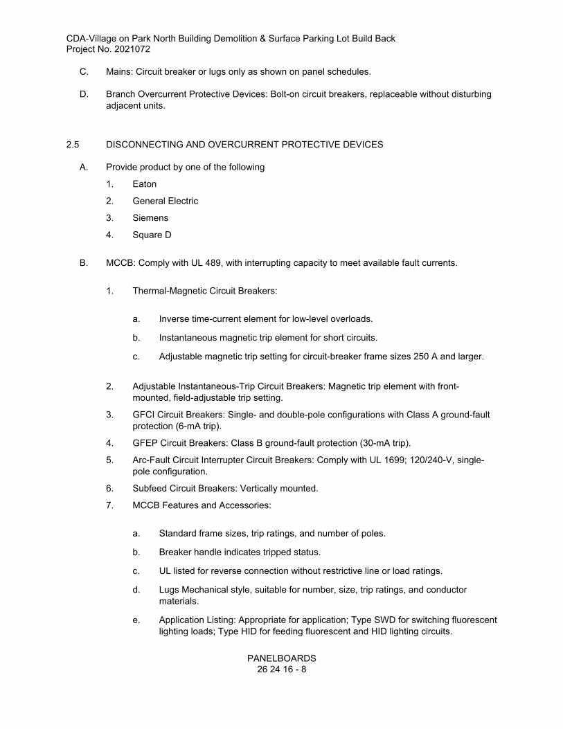
CDA-Village on Park North Building Demolition & Surface Parking Lot Build BackProject No. 2021072
PANELBOARDS
26 24 16 - 8
C. Mains: Circuit breaker or lugs only as shown on panel schedules.
D. Branch Overcurrent Protective Devices: Bolt-on circuit breakers, replaceable without disturbing
adjacent units.
2.5 DISCONNECTING AND OVERCURRENT PROTECTIVE DEVICES
A. Provide product by one of the following
1. Eaton
2. General Electric
3. Siemens
4. Square D
B. MCCB: Comply with UL 489, with interrupting capacity to meet available fault currents.
1. Thermal-Magnetic Circuit Breakers:
a. Inverse time-current element for low-level overloads.
b. Instantaneous magnetic trip element for short circuits.
c. Adjustable magnetic trip setting for circuit-breaker frame sizes 250 A and larger.
2. Adjustable Instantaneous-Trip Circuit Breakers: Magnetic trip element with front-
mounted, field-adjustable trip setting.
3. GFCI Circuit Breakers: Single- and double-pole configurations with Class A ground-fault
protection (6-mA trip).
4. GFEP Circuit Breakers: Class B ground-fault protection (30-mA trip).
5. Arc-Fault Circuit Interrupter Circuit Breakers: Comply with UL 1699; 120/240-V, single-
pole configuration.
6. Subfeed Circuit Breakers: Vertically mounted.
7. MCCB Features and Accessories:
a. Standard frame sizes, trip ratings, and number of poles.
b. Breaker handle indicates tripped status.
c. UL listed for reverse connection without restrictive line or load ratings.
d. Lugs Mechanical style, suitable for number, size, trip ratings, and conductor
materials.
e. Application Listing: Appropriate for application; Type SWD for switching fluorescent
lighting loads; Type HID for feeding fluorescent and HID lighting circuits.

CDA-Village on Park North Building Demolition & Surface Parking Lot Build BackProject No. 2021072
PANELBOARDS
26 24 16 - 9
f. Ground-Fault Protection: Integrally mounted relay and trip unit with adjustable
pickup and time-delay settings, push-to-test feature, and ground-fault indicator.
g. Shunt Trip: 120-V trip coil energized from separate circuit, set to trip at 55 percent
of rated voltage.
h. Undervoltage Trip: Set to operate at 35 to 75 percent of rated voltage with field-
adjustable 0.1- to 0.6-second time delay.
i. Rating Plugs: Three-pole breakers with ampere ratings greater than 150 amperes
shall have interchangeable rating plugs or electronic adjustable trip units.
j. Multipole units enclosed in a single housing with a single handle
k. Device specified in "Handle Padlocking Device" Subparagraph below can be used
as a safety disconnect device if it has fixed attachment and is configured to allow
locking in the off position.
l. Handle Padlocking Device: Fixed attachment, for locking circuit-breaker handle in
off position.
2.6 IDENTIFICATION
A. Panelboard Label: Manufacturer's name and trademark, voltage, amperage, number of phases,
and number of poles shall be located on the interior of the panelboard door.
B. Breaker Labels: Faceplate shall list current rating, UL and IEC certification standards, and AIC
rating.
C. Circuit Directory: Directory card inside panelboard door, mounted in transparent card holder
1. Circuit directory shall identify specific purpose with detail sufficient to distinguish it from
all other circuits.
D. Circuit Directory: Provide circuit directory as shown in 26 05 53 Identification for Electrical
Systems.
1. Circuit directory shall identify specific purpose with detail sufficient to distinguish it from
all other circuits.
PART 3 - EXECUTION
3.1 EXAMINATION
A. Verify actual conditions with field measurements prior to ordering panelboards to verify that
equipment fits in allocated space in, and comply with, minimum required clearances specified in
NFPA 70.
B. Receive, inspect, handle, and store panelboards according to NEMA PB 1.1.
C. Examine panelboards before installation. Reject panelboards that are damaged, rusted, or have
been subjected to water saturation.

CDA-Village on Park North Building Demolition & Surface Parking Lot Build BackProject No. 2021072
PANELBOARDS
26 24 16 - 10
D. Examine elements and surfaces to receive panelboards for compliance with installation
tolerances and other conditions affecting performance of the Work.
E. Proceed with installation only after unsatisfactory conditions have been corrected.
3.2 INSTALLATION
A. Coordinate layout and installation of panelboards and components with other construction that
penetrates walls or is supported by them, including electrical and other types of equipment,
raceways, piping, encumbrances to workspace clearance requirements, and adjacent surfaces.
Maintain required workspace clearances and required clearances for equipment access doors
and panels.
B. Comply with NECA 1.
C. Install panelboards and accessories according to NEMA PB 1.1.
D. Equipment Mounting:
1. Attach panelboard to the vertical finished or structural surface behind the panelboard.
E. Temporary Lifting Provisions: Remove temporary lifting eyes, channels, and brackets and
F. Mount top of trim no higher than 90 inches above finished floor unless otherwise indicated or
required by products.
G. Mount panelboard cabinet plumb and rigid without distortion of box.
H. Mount recessed panelboards with fronts uniformly flush with wall finish and mating with back
box.
I. Mount surface-mounted panelboards to steel slotted supports 1 1/4 inch in depth. Orient steel
slotted supports vertically.
J. Install overcurrent protective devices and controllers not already factory installed.
1. Set field-adjustable, circuit-breaker trip ranges.
2. Tighten bolted connections and circuit breaker connections using calibrated torque
wrench or torque screwdriver per manufacturer's written instructions.
K. Make grounding connections and bond neutral for services and separately derived systems to
ground. Make connections to grounding electrodes, separate grounds for isolated ground bars,
and connections to separate ground bars.
L. Install filler plates in unused spaces.
M. Stub eight 1-inch empty conduits from recessed panelboard into accessible ceiling space or
space designated to be ceiling space in the future. Stub four 1-inch empty conduits into raised
floor space or below slab not on grade.
N. Arrange conductors in gutters into groups and bundle and wrap with wire ties after completing
load balancing or adjustments.
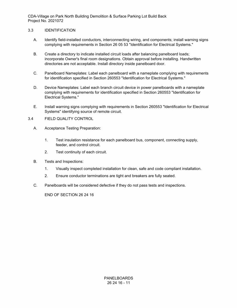
CDA-Village on Park North Building Demolition & Surface Parking Lot Build BackProject No. 2021072
PANELBOARDS
26 24 16 - 11
3.3 IDENTIFICATION
A. Identify field-installed conductors, interconnecting wiring, and components; install warning signs
complying with requirements in Section 26 05 53 "Identification for Electrical Systems."
B. Create a directory to indicate installed circuit loads after balancing panelboard loads;
incorporate Owner's final room designations. Obtain approval before installing. Handwritten
directories are not acceptable. Install directory inside panelboard door.
C. Panelboard Nameplates: Label each panelboard with a nameplate complying with requirements
for identification specified in Section 260553 "Identification for Electrical Systems."
D. Device Nameplates: Label each branch circuit device in power panelboards with a nameplate
complying with requirements for identification specified in Section 260553 "Identification for
Electrical Systems."
E. Install warning signs complying with requirements in Section 260553 "Identification for Electrical
Systems" identifying source of remote circuit.
3.4 FIELD QUALITY CONTROL
A. Acceptance Testing Preparation:
1. Test insulation resistance for each panelboard bus, component, connecting supply,
feeder, and control circuit.
2. Test continuity of each circuit.
B. Tests and Inspections:
1. Visually inspect completed installation for clean, safe and code compliant installation.
2. Ensure conductor terminations are tight and breakers are fully seated.
C. Panelboards will be considered defective if they do not pass tests and inspections.
END OF SECTION 26 24 16

This page intentionally left blank

CDA-Village on Park North Building Demolition & Surface Parking Lot Build BackProject No. 2021072
INTERIOR LIGHTING26 51 00 - 1
SECTION 26 51 00 - INTERIOR LIGHTING
PART 1 - GENERAL
1.1 RELATED DOCUMENTS
A. Drawings and general provisions of the Contract, including General and Supplementary Conditions and Division 01 Specification Sections, apply to this Section.
B. Requirements of 26 00 00 apply to this section.
1.2 DEFINITIONS
A. CCT: Correlated color temperature.
B. CRI: Color-rendering index.C. LER: Luminaire efficacy rating.D. LED: Light Emitting DiodeE. Lumen: Measured output of lamp, luminaire, or both.F. Luminaire: Complete lighting fixture, including driver housing if provided.
1.3 SUBMITTALS
A. Product Data: For each type of lighting fixture, arranged in order of fixture designation. Include data on features, accessories, finishes, and the following:
1. Physical description of lighting fixture including dimensions.2. Energy-efficiency data.3. For dimmed LED:
a. Test results and a signed certification stating:
1) That the driver/module/dimmer combination, utilized on this project, has been tested and provides smooth, flicker-free, dimming down to the level indicated.
2) That each dimmer has capability of reliably dimming the quantity of fixtures shown connected (or that dimming amplifiers or additional dimmers have been provided).
B. Shop Drawings:
1. Detail equipment assemblies and indicate dimensions, weights, loads, required clearances, method of field assembly, components, and location and size of each field connection.
2. Wiring Diagrams: For power, signal, and control wiring.
C. Installation instructions.D. Product Certificates: For each type of driver for bi-level and dimmer-controlled fixtures,
from manufacturer.E. Warranty: Sample of warranty.F. Operation and Maintenance Data: For lighting equipment and fixtures to include in
emergency, operation, and maintenance manuals.
1. Provide a list of all lamp types used on Project; use ANSI and manufacturers' codes.
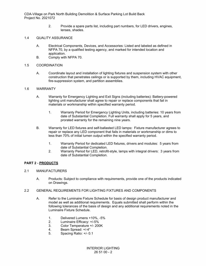
CDA-Village on Park North Building Demolition & Surface Parking Lot Build BackProject No. 2021072
INTERIOR LIGHTING26 51 00 - 2
2. Provide a spare parts list, including part numbers, for LED drivers, engines, lenses, shades.
1.4 QUALITY ASSURANCE
A. Electrical Components, Devices, and Accessories: Listed and labeled as defined in NFPA 70, by a qualified testing agency, and marked for intended location and application.
B. Comply with NFPA 70.
1.5 COORDINATION
A. Coordinate layout and installation of lighting fixtures and suspension system with other construction that penetrates ceilings or is supported by them, including HVAC equipment, fire-suppression system, and partition assemblies.
1.6 WARRANTY
A. Warranty for Emergency Lighting and Exit Signs (including batteries): Battery-powered lighting unit manufacturer shall agree to repair or replace components that fail in materials or workmanship within specified warranty period.
1. Warranty Period for Emergency Lighting Units, including batteries: 10 years from date of Substantial Completion. Full warranty shall apply for 5 years, and prorated warranty for the remaining nine years.
B. Warranty for LED fixtures and self-ballasted LED lamps: Fixture manufacturer agrees to repair or replace any LED component that fails in materials or workmanship or dims to less than 70% of initial lumen output within the specified warranty period.
1. Warranty Period for dedicated LED fixtures, drivers and modules: 5 years from date of Substantial Completion.
2. Warranty Period for LED, retrofit-style, lamps with integral drivers: 3 years from date of Substantial Completion.
PART 2 - PRODUCTS
2.1 MANUFACTURERS
A. Products: Subject to compliance with requirements, provide one of the products indicated on Drawings.
2.2 GENERAL REQUIREMENTS FOR LIGHTING FIXTURES AND COMPONENTS
A. Refer to the Luminaire Fixture Schedule for basis of design product manufacturer and model as well as additional requirements. Equals submitted shall perform within the following tolerances of the basis of design and any additional requirements noted in the Luminaire Fixture Schedule.
1. Delivered Lumens +10%, -5%2. Luminaire Efficacy: +/-5%3. Color Temperature +/- 200K4. Beam Spread: +/-4°5. Spacing Ratio: +/- 0.1
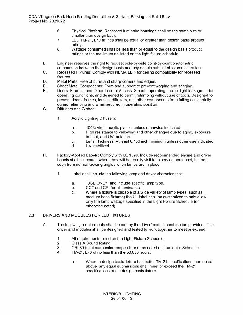
CDA-Village on Park North Building Demolition & Surface Parking Lot Build BackProject No. 2021072
INTERIOR LIGHTING26 51 00 - 3
6. Physical Platform: Recessed luminaire housings shall be the same size or smaller than design basis.
7. LED TM-21, L70 ratings shall be equal or greater than design basis product ratings.
8. Wattage consumed shall be less than or equal to the design basis product ratings or the maximum as listed on the light fixture schedule.
B. Engineer reserves the right to request side-by-side point-by-point photometric comparison between the design basis and any equals submitted for consideration.
C. Recessed Fixtures: Comply with NEMA LE 4 for ceiling compatibility for recessed fixtures.
D. Metal Parts: Free of burrs and sharp corners and edges.E. Sheet Metal Components: Form and support to prevent warping and sagging.F. Doors, Frames, and Other Internal Access: Smooth operating, free of light leakage under
operating conditions, and designed to permit relamping without use of tools. Designed to prevent doors, frames, lenses, diffusers, and other components from falling accidentally during relamping and when secured in operating position.
G. Diffusers and Globes:
1. Acrylic Lighting Diffusers:
a. 100% virgin acrylic plastic, unless otherwise indicated. b. High resistance to yellowing and other changes due to aging, exposure
to heat, and UV radiation.c. Lens Thickness: At least 0.156 inch minimum unless otherwise indicated.d. UV stabilized.
H. Factory-Applied Labels: Comply with UL 1598. Include recommended engine and driver. Labels shall be located where they will be readily visible to service personnel, but not seen from normal viewing angles when lamps are in place.
1. Label shall include the following lamp and driver characteristics:
a. "USE ONLY" and include specific lamp type.b. CCT and CRI for all luminaires.c. Where a fixture is capable of a wide variety of lamp types (such as
medium base fixtures) the UL label shall be customized to only allow only the lamp wattage specified in the Light Fixture Schedule (or otherwise noted).
2.3 DRIVERS AND MODULES FOR LED FIXTURES
A. The following requirements shall be met by the driver/module combination provided. The driver and modules shall be designed and tested to work together to meet or exceed:
1. All requirements listed on the Light Fixture Schedule.2. Class A Sound Rating3. CRI 80 (minimum) color temperature or as noted on Luminaire Schedule4. TM-21, L70 of no less than the 50,000 hours.
a. Where a design basis fixture has better TM-21 specifications than noted above, any equal submissions shall meet or exceed the TM-21 specifications of the design basis fixture.
CDA-Village on Park North Building Demolition & Surface Parking Lot Build BackProject No. 2021072
INTERIOR LIGHTING26 51 00 - 4
5. All LED driver/module combinations connected to dimmers shall be tested and certified by the dimmer manufacturer to:
a. Provide smooth, flicker free, dimming down to percentage indicated on Light Fixture Schedule.
b. Control all of the fixtures shown on the plan connected to that dimmer, providing smooth, flicker free, dimming down to the percentage indicated on Light Fixture Schedule.
c. Provide the ability to be dimmed up from off without needing to be brought to 100% first.
d. Maintain Class A sound rating throughout entire dimming spectrum.e. Where fixtures/dimmers combinations are specified that have not already
been tested and certified, Contractor shall:
1) Arrange for testing with dimmer manufacturer.2) Provide test fixtures to dimmer manufacturer.3) Pay any fees or shipping costs associated with testing.4) Provide test results with shop drawing submittals.
f. In the event of a failure to comply with tests, Contractor shall provide an alternate driver/dimmer which meets this specification and functions as required.
g. In the event that the fixture passes the initial tests and issues arise after the fixtures are installed, Contractor, Fixture Manufacturer and Controls Manufacturer shall fully coordinate and cooperate with each other to remedy the problem at no cost to the project.
2.4 EXIT SIGNS
A. General Requirements for Exit Signs: Comply with UL 924; for sign colors, visibility, luminance, and lettering size, comply with authorities having jurisdiction.
B. Internally Illuminated Signs:
1. Lamps for AC Operation: LEDs, 50,000 hours minimum rated lamp life.2. Self-Powered Exit Signs (Battery Type): Integral automatic charger in a self-
contained power pack.
a. Battery: Sealed, maintenance-free, nickel-cadmium type.b. Charger: Fully automatic, solid-state type with sealed transfer relay.c. Operation: Relay automatically energizes lamp from battery when circuit
voltage drops to 80% of nominal voltage or below. When normal voltage is restored, relay disconnects lamps from battery, and battery is automatically recharged and floated on charger.
d. Test Push Button: Push-to-test type, in unit housing, simulates loss of normal power and demonstrates unit operability.
e. LED Indicator Light: Indicates normal power on. Normal glow indicates trickle charge; bright glow indicates charging at end of discharge cycle.
f. Integral Self-Test: Factory-installed electronic device automatically initiates code-required test of unit emergency operation at required intervals. Test failure is annunciated by an integral audible alarm and a flashing red LED.
CDA-Village on Park North Building Demolition & Surface Parking Lot Build BackProject No. 2021072
INTERIOR LIGHTING26 51 00 - 5
2.5 LIGHTING FIXTURE SUPPORT COMPONENTS
A. Comply with Section 260529 "Hangers and Supports for Electrical Systems" for channel- and angle-iron supports and nonmetallic channel and angle supports.
B. Single-Stem Hangers: As provided by manufacturer or 1/2-inch steel tubing with swivel ball fittings and ceiling canopy. Finish same as fixture.
C. Twin-Stem Hangers: As provided by manufacturer or Two, 1/2-inch steel tubes with single canopy designed to mount a single fixture. Finish same as fixture.
D. Concealed Wires: As indicated or ASTM A 641/A 641M, Class 3, soft temper, zinc-coated steel, 12 gauge.
E. Wires for Humid Spaces or exposed installation: ASTM A 580/A 580M, Composition 302 or 304, stainless steel aircraft cable, 12 gauge.
F. Rod Hangers: 3/16-inch minimum diameter, cadmium-plated, threaded steel rod.G. Hook Hangers: Integrated assembly matched to fixture and line voltage and equipped
with threaded attachment, cord, and locking-type plug.
PART 3 - EXECUTION
3.1 INSTALLATION
A. General
1. Fixture types, trims and mounting shall be coordinated with the material/construction that it is attached to or recessed in. Contractor shall verify all parameters and shall provide all fixture accessories or options required for mounting in the ceiling type provided or existing.
2. All accessories and mounting equipment shall be provided for mounting.3. Fixture mounting and layout shall be coordinated with other trades' equipment,
casework and architectural details and elevations.4. Contractor shall verify if any ceiling conditions require fire-rated tents.5. Contractor shall verify if any ceilings require IC rated fixtures and shall provide
equal or better fixtures that are IC rated.6. Contractor shall verify if any above ceiling insulation contact conditions exist,
including proximately to insulated ductwork or piping, will require IC rated fixtures and shall provide equal or better fixtures that are IC rated, to comply with NEC.
B. Lighting fixtures:
1. Set level, plumb, and square with ceilings and walls unless otherwise indicated.2. Install lamps in each luminaire.
C. Lay-in Ceiling Lighting Fixtures Supports: Use grid as a support element.
1. Install ceiling support system rods or wires, independent of the ceiling suspension devices, for each fixture. Locate not more than 6 inches from lighting fixture corners.
2. Support Clips: Fasten to lighting fixtures and to ceiling grid members at or near each fixture corner with clips that are UL listed for the application.
3. Fixtures of Sizes Less Than Ceiling Grid: Install as indicated on reflected ceiling plans or center in acoustical panel, and support fixtures independently with at least two 3/4-inch (20-mm) metal channels spanning and secured to ceiling tees.
END OF SECTION 26 51 00

This page intentionally left blank
CDA-Village on Park North Building Demolition & Surface Parking Lot Build BackProject No. 2021072
EXTERIOR LIGHTING26 56 00 - 1
SECTION 26 56 00 - EXTERIOR LIGHTING
PART 1 - GENERAL
1.1 RELATED DOCUMENTS
A. Drawings and general provisions of the Contract, including General and Supplementary Conditions and Division 01 Specification Sections, apply to this Section.
B. Requirements of 26 05 00 apply to this section.
1.2 SUMMARY
A. Section Includes:
1. Exterior luminaires with light engines and drivers.2. Luminaire-mounted photoelectric and occupancy sensor controls.3. Poles and accessories.
1.3 DEFINITIONS
A. CCT: Correlated color temperature.
B. CRI: Color-rendering index.
C. HID: High-intensity discharge.
D. LER: Luminaire efficacy rating.
E. Luminaire: Complete lighting fixture, including LED driver housing if provided.
F. Pole: Luminaire support structure, including tower used for large area illumination.
G. Standard: Same definition as "Pole" above.
1.4 STRUCTURAL ANALYSIS CRITERIA FOR POLE SELECTION
A. Dead Load: Weight of luminaire and its horizontal and vertical supports, lowering devices, and supporting structure, applied as stated in AASHTO LTS-4-M.
B. Live Load: Single load of 500 lbf, distributed as stated in AASHTO LTS-4-M.
C. Ice Load: Load of 3 lbf/sq. ft., applied as stated in AASHTO LTS-4-M Ice Load Map.
D. Wind Load: Pressure of wind on pole and luminaire and banners and banner arms, calculated and applied as stated in AASHTO LTS-4-M.
1. Basic wind speed for calculating wind load for poles 50 feet high or less is 100 mph.
CDA-Village on Park North Building Demolition & Surface Parking Lot Build BackProject No. 2021072
EXTERIOR LIGHTING26 56 00 - 2
a. Wind Importance Factor: 1.0b. Minimum Design Life: 25 years.c. Velocity Conversion Factors: 1.0.
1.5 SUBMITTALS
A. Product Data: For each luminaire, pole, and support component, arranged in order of lighting unit designation. Include data on features, accessories, finishes, and the following:
1. Physical description of luminaire, including materials, dimensions, effective projected area, and verification of indicated parameters.
2. Details of attaching luminaires and accessories.3. Details of installation and construction.4. Luminaire materials.5. Photometric data based on laboratory tests of each luminaire type, complete with
indicated LED light engines, drivers, and accessories.
a. Manufacturer Certified Data: Photometric data shall be certified by manufacturer's laboratory with a current accreditation under the National Voluntary Laboratory Accreditation Program for Energy Efficient Lighting Products.
6. Photoelectric and occupancy sensor controls.7. LED drivers, including energy-efficiency data.8. LED light engines, including life, output, CCT, CRI, lumens, and energy-efficiency
data.9. Materials, dimensions, and finishes of poles.10. Means of attaching luminaires to supports, and indication that attachment is
suitable for components involved.11. Anchor bolts for poles.12. Manufactured pole foundations.
B. Shop Drawings: Include plans, elevations, sections, details, and attachments to other work.
1. Detail equipment assemblies and indicate dimensions, weights, loads, required clearances, method of field assembly, components, and location and size of each field connection.
2. Anchor-bolt templates keyed to specific poles and certified by manufacturer.3. Design calculations, certified by a qualified professional engineer, indicating
strength of screw foundations and soil conditions on which they are based.
4. Wiring Diagrams: For power, signal, and control wiring.
C. Pole and Support Component Certificates: Signed by manufacturers of poles, certifying that products are designed for indicated load requirements in AASHTO LTS-4-M and that load imposed by luminaire and attachments has been included in design. The certification shall be based on design calculations by a professional engineer.
D. Field quality-control reports.
CDA-Village on Park North Building Demolition & Surface Parking Lot Build BackProject No. 2021072
EXTERIOR LIGHTING26 56 00 - 3
E. Warranty: Sample of warranty.
1.6 CLOSEOUT SUBMITTALS
A. Operation and Maintenance Data: For luminaires and poles.
1.7 QUALITY ASSURANCE
A. Luminaire Photometric Data Testing Laboratory Qualifications: Provided by an independent agency, with the experience and capability to conduct the testing indicated, that is an NRTL as defined by OSHA in 29 CFR 1910.
B. Electrical Components, Devices, and Accessories: Listed and labeled as defined in NFPA 70, by a qualified testing agency, and marked for intended location and application.
C. Comply with IEEE C2, "National Electrical Safety Code."
D. Comply with NFPA 70.
1.8 DELIVERY, STORAGE, AND HANDLING
A. Package aluminum poles for shipping according to ASTM B 660.
B. Store poles on decay-resistant-treated skids at least 12 inches above grade and vegetation. Support poles to prevent distortion and arrange to provide free air circulation.
C. Handle wood poles so they will not be damaged. Do not use pointed tools that can indent pole surface more than 1/4 inch deep. Do not apply tools to section of pole to be installed below ground line.
D. Retain factory-applied pole wrappings on fiberglass and laminated wood poles until right before pole installation. Handle poles with web fabric straps.
E. Retain factory-applied pole wrappings on metal poles until right before pole installation. For poles with nonmetallic finishes, handle with web fabric straps.
1.9 WARRANTY
A. Warranty: Manufacturer's standard form in which manufacturer agrees to repair or replace products that fail in materials or workmanship; that corrode; or that fade, stain, perforate, erode, or chalk due to effects of weather or solar radiation within specified warranty period. Manufacturer may exclude lightning damage, hail damage, vandalism, abuse, or unauthorized repairs or alterations from special warranty coverage.
1. Warranty Period for Luminaires: 5 years from date of Substantial Completion.2. Warranty Period for Metal Corrosion: 5 years from date of Substantial
Completion.3. Warranty Period for Color Retention and Painted finishes: 5 years from date of
Substantial Completion.4. Warranty Period for Poles: Repair or replace lighting poles and standards that fail
in finish, materials, and workmanship within manufacturer's standard warranty period, but not less than 5 years from date of Substantial Completion.
CDA-Village on Park North Building Demolition & Surface Parking Lot Build BackProject No. 2021072
EXTERIOR LIGHTING26 56 00 - 4
PART 2 - PRODUCTS
2.1 MANUFACTURERS
A. Products: Subject to compliance with requirements, provide product indicated on Drawings
2.2 GENERAL REQUIREMENTS FOR LUMINAIRES
A. Luminaires shall comply with UL 1598 and be listed and labeled for installation in wet locations by an NRTL acceptable to authorities having jurisdiction.
1. LER Tests Incandescent Fixtures: Where LER is specified, test according to NEMA LE 5A.
2. LER Tests Fluorescent Fixtures: Where LER is specified, test according to NEMA LE 5 and NEMA LE 5A as applicable.
3. LER Tests HID Fixtures: Where LER is specified, test according to NEMA LE 5B.
B. Lateral Light Distribution Patterns: Comply with IESNA RP-8 for parameters of lateral light distribution patterns indicated for luminaires.
C. Metal Parts: Free of burrs and sharp corners and edges.
D. Sheet Metal Components: Corrosion-resistant aluminum unless otherwise indicated. Form and support to prevent warping and sagging.
E. Housings: Rigidly formed, weather- and light-tight enclosures that will not warp, sag, or deform in use. Provide filter/breather for enclosed luminaires.
F. Doors, Frames, and Other Internal Access: Smooth operating, free of light leakage under operating conditions, and designed to permit relamping without use of tools. Designed to prevent doors, frames, lenses, diffusers, and other components from falling accidentally during relamping and when secured in operating position. Doors shall be removable for cleaning or replacing lenses. Designed to disconnect LED driver when door opens.
G. Exposed Hardware Material: Stainless steel.
H. Plastic Parts: High resistance to yellowing and other changes due to aging, exposure to heat, and UV radiation.
I. Light Shields: Metal baffles, factory installed and field adjustable, arranged to block light distribution to indicated portion of normally illuminated area or field.
J. Reflecting surfaces shall have minimum reflectance as follows unless otherwise indicated:
1. White Surfaces: 85 %.2. Specular Surfaces: 83 %.3. Diffusing Specular Surfaces: 75 %.
K. Lenses and Refractors Gaskets: Use heat- and aging-resistant resilient gaskets to seal and cushion lenses and refractors in luminaire doors.
L. Luminaire Finish: Manufacturer's standard paint applied to factory-assembled and -tested luminaire before shipping.

CDA-Village on Park North Building Demolition & Surface Parking Lot Build BackProject No. 2021072
EXTERIOR LIGHTING26 56 00 - 5
a. Color: As noted on Light Fixture Schedule
M. Factory-Applied Finish for Aluminum Luminaires: Comply with NAAMM's "Metal Finishes Manual for Architectural and Metal Products" for recommendations for applying and designating finishes.
1. Finish designations prefixed by AA comply with the system established by the Aluminum Association for designating aluminum finishes.
2. Color: As Indicated on Light Fixture Schedule and as follows
1) Class I, Clear Anodic Finish: AA-M32C22A41 (Mechanical Finish: medium satin; Chemical Finish: etched, medium matte; Anodic Coating: Architectural Class I, clear coating 0.018 mm or thicker) complying with AAMA 611.
N. Factory-Applied Labels: Comply with UL 1598. Labels shall be located where they will be readily visible to service personnel, but not seen from normal viewing angles when LED light engines are in place.
2.3 LUMINAIRE-MOUNTED PHOTOELECTRIC RELAYS
A. Comply with UL 773 or UL 773A.
B. Contact Relays: Factory mounted, single throw, designed to fail in the on position, and factory set to turn light unit on at 1.5 to 3 fc and off at 4.5 to 10 fc with 15-second minimum time delay. Relay shall have directional lens in front of photocell to prevent artificial light sources from causing false turnoff.
1. Relay with locking-type receptacle shall comply with ANSI C136.10.2. Adjustable window slide for adjusting on-off set points.
2.4 DRIVERS FOR LED MODULES
A. Electronic driver tested and certified for use with the LED module provided.
1. Shall provide Lumen output as indicated on the Light Fixture Schedule2. Shall drive LED module, appropriately to maintain the required life and lumen
maintenance.
B. Driver shall be protected from or shall be suitable to operate in the presence of the following exterior conditions:
1. Moisture2. Vibration/Wind3. Insect/Vermin4. Dust and Dirt5. Ambient Temperatures down to -20°F6. Ambient Temperatures up to 100°F
2.5 LED MODULES
A. Module shall be tested and certified for use with the driver provided.
B. Shall provide Lumen output as indicated on the Light Fixture Schedule

CDA-Village on Park North Building Demolition & Surface Parking Lot Build BackProject No. 2021072
EXTERIOR LIGHTING26 56 00 - 6
C. Shall provide to provide at least 70% rated output at rated life.
D. CRI 80 (minimum), color temperature as noted on Light Fixture Schedule
E. Module shall be protected from or shall be suitable to operate in the presence of the following exterior conditions:
1. Moisture2. Vibration/Wind3. Insect/Vermin4. Dust and Dirt5. Ambient Temperatures down to -20°F6. Ambient Temperatures up to 100°F
2.6 GENERAL REQUIREMENTS FOR POLES AND SUPPORT COMPONENTS
A. Structural Characteristics: Comply with AASHTO LTS-4-M.
1. Wind-Load Strength of Poles: Adequate at indicated heights above grade without failure, permanent deflection, or whipping in steady winds of speed indicated in "Structural Analysis Criteria for Pole Selection" Article.
2. Strength Analysis: For each pole, multiply the actual equivalent projected area of luminaires and brackets by a factor of 1.1 to obtain the equivalent projected area to be used in pole selection strength analysis.
B. Luminaire Attachment Provisions: Comply with luminaire manufacturers' mounting requirements. Use stainless-steel fasteners and mounting bolts unless otherwise indicated.
C. Mountings, Fasteners, and Appurtenances: Corrosion-resistant items compatible with support components.
1. Materials: Shall not cause galvanic action at contact points.2. Anchor Bolts, Leveling Nuts, Bolt Caps, and Washers: Hot-dip galvanized after
fabrication unless otherwise indicated.3. Anchor-Bolt Template: Plywood or steel.
D. Handhole: Oval-shaped, with minimum clear opening of 2-1/2 by 5 inches, with cover secured by stainless-steel captive screws. Provide on all poles.
E. Concrete Pole Foundations: Cast in place, as shown on the Drawings, with anchor bolts to match pole-base flange. Concrete, reinforcement, and formwork are specified in Section 033000 "Cast-in-Place Concrete."
F. Power-Installed Screw Foundations: Factory fabricated by pole manufacturer, with structural steel complying with ASTM A 36/A 36M and hot-dip galvanized according to ASTM A 123/A 123M; and with top-plate and mounting bolts to match pole base flange and strength required to support pole, luminaire, and accessories.
G. Breakaway Supports: Frangible breakaway supports, tested by an independent testing agency acceptable to authorities having jurisdiction, according to AASHTO LTS-4-M.
CDA-Village on Park North Building Demolition & Surface Parking Lot Build BackProject No. 2021072
EXTERIOR LIGHTING26 56 00 - 7
2.7 STEEL POLES
A. Poles: Comply with ASTM A 500, Grade B, carbon steel with a minimum yield of 46,000 psig; one-piece construction up to 40 feet in height with access handhole in pole wall.
1. Shape: as indicated on Light Fixture Schedule.2. Mounting Provisions: Butt flange for bolted mounting on foundation or breakaway
support.
B. Pole-Top Tenons: Fabricated to support luminaire or luminaires and brackets indicated, and securely fastened to pole top.
C. Grounding and Bonding Lugs: Welded 1/2-inch threaded lug, complying with requirements in Section 260526 "Grounding and Bonding for Electrical Systems," listed for attaching grounding and bonding conductors of type and size listed in that Section, and accessible through handhole.
D. Factory-Painted Finish: Comply with NAAMM's "Metal Finishes Manual for Architectural and Metal Products" for recommendations for applying and designating finishes.
1. Surface Preparation: Clean surfaces to comply with SSPC-SP 1, "Solvent Cleaning," to remove dirt, oil, grease, and other contaminants that could impair paint bond. Grind welds and polish surfaces to a smooth, even finish. Remove mill scale and rust, if present, from uncoated steel, complying with SSPC-SP 5/NACE No. 1, "White Metal Blast Cleaning," or with SSPC-SP 8, "Pickling."
2. Interior Surfaces of Pole: One coat of bituminous paint, or otherwise treat for equal corrosion protection.
3. Exterior Surfaces: Manufacturer's standard finish consisting of one or more coats of primer and two finish coats of high-gloss, high-build polyurethane enamel.
a. Color: As indicated on Luminaire Schedule.
2.8 POLE ACCESSORIES
A. Base Covers: Manufacturers' standard metal units, arranged to cover pole's mounting bolts and nuts. Finish same as pole.
PART 3 - EXECUTION
3.1 LUMINAIRE INSTALLATION
A. Adjust luminaires that require field adjustment or aiming. Include adjustment of photoelectric device to prevent false operation of relay by artificial light sources, favoring a north orientation.
3.2 POLE INSTALLATION
A. Alignment: Align pole foundations and poles for optimum directional alignment of luminaires and their mounting provisions on the pole.
CDA-Village on Park North Building Demolition & Surface Parking Lot Build BackProject No. 2021072
EXTERIOR LIGHTING26 56 00 - 8
B. Clearances: Maintain the following minimum horizontal distances of poles from surface and underground features unless otherwise indicated on Drawings:
1. Fire Hydrants and Storm Drainage Piping: 60 inches.2. Water, Gas, Electric, Communication, and Sewer Lines: 10 feet.3. Trees: 5 feet from tree trunk.
C. Concrete Pole Foundations: Set anchor bolts according to anchor-bolt templates furnished by pole manufacturer. Concrete materials, installation, and finishing requirements are specified in Section 033000 "Cast-in-Place Concrete."
3.3 CORROSION PREVENTION
A. Steel Conduits: Comply with Section 260533 "Raceways and Boxes for Electrical Systems."
3.4 GROUNDING
A. Bond metal poles and support structures according to Section 260526 "Grounding and Bonding for Electrical Systems."
1. Install grounding conductor pigtail in the base for connecting luminaire to grounding system.
3.5 FIELD QUALITY CONTROL
A. Inspect each installed fixture for damage. Replace damaged fixtures and components.
B. Illumination Observations: Verify normal operation of lighting units after installing luminaires and energizing circuits with normal power source.
1. Verify operation of photoelectric and occupancy sensor controls.
END OF SECTION 26 56 00
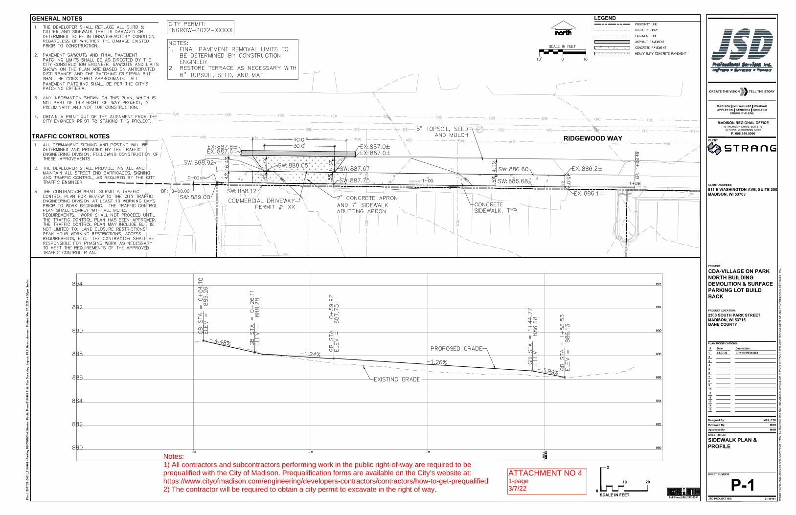
ATTACHMENT NO 41-page3/7/22
Notes:1) All contractors and subcontractors performing work in the public right-of-way are required to beprequalified with the City of Madison. Prequalification forms are available on the City’s website at: https://www.cityofmadison.com/engineering/developers-contractors/contractors/how-to-get-prequalified2) The contractor will be required to obtain a city permit to excavate in the right of way.
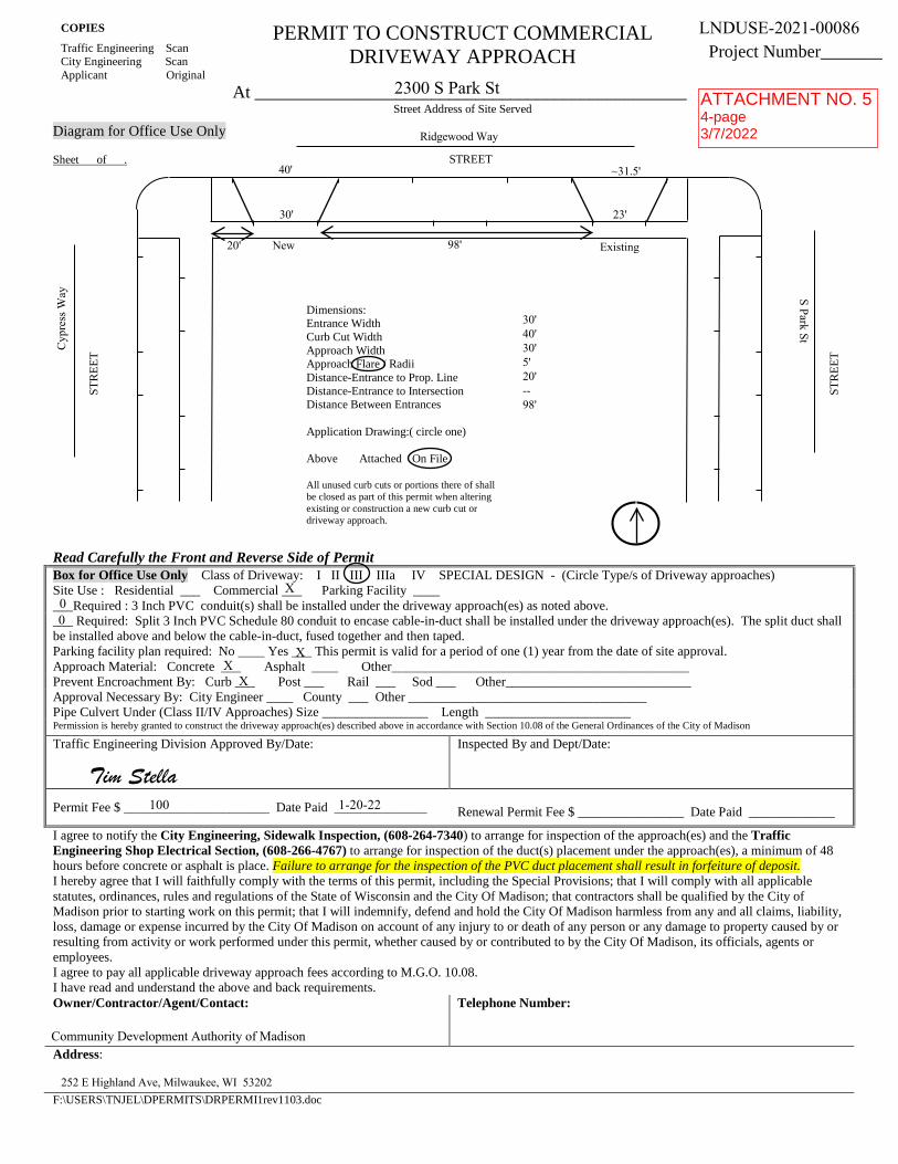
COPIES PERMIT TO CONSTRUCT COMMERCIAL DRIVEWAY APPROACH Traffic Engineering Scan
City Engineering Scan Applicant Original
Project Number_______
At _________________________________________________ Street Address of Site Served
Diagram for Office Use Only
Sheet of .
Read Carefully the Front and Reverse Side of Permit Box for Office Use Only Class of Driveway: I II III IIIa IV SPECIAL DESIGN - (Circle Type/s of Driveway approaches) Site Use : Residential ___ Commercial ___ Parking Facility _______Required : 3 Inch PVC conduit(s) shall be installed under the driveway approach(es) as noted above. ___ Required: Split 3 Inch PVC Schedule 80 conduit to encase cable-in-duct shall be installed under the driveway approach(es). The split duct shall be installed above and below the cable-in-duct, fused together and then taped. Parking facility plan required: No ____ Yes ___ This permit is valid for a period of one (1) year from the date of site approval. Approach Material: Concrete ___ Asphalt ____ Other_____________________________________________ Prevent Encroachment By: Curb ___ Post ___ Rail ___ Sod ___ Other____________________________ Approval Necessary By: City Engineer ____ County ___ Other ____________________________________ Pipe Culvert Under (Class II/IV Approaches) Size ________________ Length ______________________ Permission is hereby granted to construct the driveway approach(es) described above in accordance with Section 10.08 of the General Ordinances of the City of Madison
Traffic Engineering Division Approved By/Date: Inspected By and Dept/Date:
Permit Fee $ ______________________ Date Paid ______________ Renewal Permit Fee $ ________________ Date Paid _____________
I agree to notify the City Engineering, Sidewalk Inspection, (608-264-7340) to arrange for inspection of the approach(es) and the Traffic Engineering Shop Electrical Section, (608-266-4767) to arrange for inspection of the duct(s) placement under the approach(es), a minimum of 48 hours before concrete or asphalt is place. Failure to arrange for the inspection of the PVC duct placement shall result in forfeiture of deposit. I hereby agree that I will faithfully comply with the terms of this permit, including the Special Provisions; that I will comply with all applicable statutes, ordinances, rules and regulations of the State of Wisconsin and the City Of Madison; that contractors shall be qualified by the City of Madison prior to starting work on this permit; that I will indemnify, defend and hold the City Of Madison harmless from any and all claims, liability, loss, damage or expense incurred by the City Of Madison on account of any injury to or death of any person or any damage to property caused by or resulting from activity or work performed under this permit, whether caused by or contributed to by the City Of Madison, its officials, agents or employees. I agree to pay all applicable driveway approach fees according to M.G.O. 10.08. I have read and understand the above and back requirements. Owner/Contractor/Agent/Contact: Telephone Number:
Address:
F:\USERS\TNJEL\DPERMITS\DRPERMI1rev1103.doc
STREET
STR
EET
STR
EET
Dimensions: Entrance Width Curb Cut Width Approach Width Approach Flare / Radii Distance-Entrance to Prop. Line Distance-Entrance to Intersection Distance Between Entrances
Application Drawing:( circle one)
Above Attached On File
All unused curb cuts or portions there of shall be closed as part of this permit when altering existing or construction a new curb cut or driveway approach.
X
XX
X
LNDUSE-2021-00086
2300 S Park St
100 1-20-22
Community Development Authority of Madison
252 E Highland Ave, Milwaukee, WI 53202
00
Tim Stella
Ridgewood Way
ExistingNew
40'
30' 23'
20' 98'
~31.5'
30'40'30'5'20'--98'
S Park St
Cyp
ress
Way
ATTACHMENT NO. 54-page3/7/2022

TYPES OF DRIVEWAY APPROACHESCLASS I DRIVEWAY APPROACH FOUR OR LESS STALLS RESIDENTIAL WITH RAISED CURB PERMIT IS ISSUED BY THE CITY
ENGINEER CLASS II DRIVEWAY APPROACH FOUR OR LESS STALLS RESIDENTIAL WITH SHOULDERS WITHOUT RAISED CURB PERMIT IS
ISSUED BY THE CITY ENGINEER CLASS III DRIVEWAY APPROACH ALL OF THOSE, WHICH CONNECT A STREET WHEN RAISED CURBS ARE USED WITH PRIVATE
OR PUBLIC PROPERTY AND WHICH ARE USED FOR COMMERCIAL USE OR RESIDENTIAL WITH MORE THAN FOUR STALLS PERMIT IS ISSUED BY THE CITY TRAFFIC ENGINEER.
CLASS IV DRIVEWAY APPROACH SAME AS CLASS III BUT LOCATED WHERE THE STREET IS CONSTRUCTED WITH SHOULDERS
WITHOUT RAISED CURBS PERMIT IS ISSUED BY THE CITY TRAFFIC ENGINEER. CLASS V DRIVEWAY APPROACH FOR EMERGENCY FIRE EQUIPMENT PERMIT IS ISSUED BY THE CITY TRAFFIC ENGINEER. SPECIAL DESIGN SPECIAL DESIGN PERMITTED BY THE CITY TRAFFIC ENGINEER
DESIGN CRITERIA
CLASS I
CLASS II CLASS III CLASS IV
ENTRANCE WIDTH 20' MAX. 30' MAX. 30' MAX. 40' MAX. CURB CUT WIDTH 30' MAX. 50' MAX APPROACH WIDTH 50' MAX. 70' MAX. APPROACH FLARE 5' MAX. 10' MAX. 5' MIN. TO 10’ MAX. 20' MAX. ENTRANCE TO PROPERTY LINE 5' MIN. * 5' MIN. * 5' MIN. * 5' MIN. * ENTRANCE TO INTERSECTION 10' MIN. 10' MIN. ** ** DISTANCE BETWEEN ENTRANCES 10' MIN. 10' MIN. 10' MIN. 10' MIN.
* SUBJECT TO SPECIAL PROVISIONS IN 10.08** SUBJECT TO THE CITY TRAFFIC ENGINEER ‘S REQUIREMENTS FOR THE FACILITY.
THE CURB AND GUTTER OPENING FOR DRIVEWAY APPROACHES SHALL BE CONSTRUCTED IN ACCORDANCE WITH SECTION 303.2(M), ENTITLED “PROFILE SAWCUTS”, AND STANDARD DETAIL DRAWING NUMBERS 3.02 AND 3.06 OF THE CITY OF MADISON STANDARD SPECIFICATIONS FOR PUBLIC WORKS CONSTRUCTION.
PER SECTION 302.2(C) OF STANDARD SPECIFICATIONS FOR PUBLIC WORKS CONSTRUCTION, CURB AND GUTTER SECTIONS SHALL BE INSTALLED IN MINIMUM LENGTHS OF SIX (6) FEET, AND MAXIMUM LENGTHS OF FIFTEEN (15) FEET.
SIDEWALK SECTIONS POURED THROUGH A COMMERCIAL DRIVEWAY OPENING SHALL BE 7” IN THICKNESS.
EXISTING CURB AND GUTTER SECTIONS THAT ARE SAW CUT AND ARE TO REMAIN IN PLACE SHALL BE A MINIMUM OF SIX (6) FEET IN LENGTH.
ALL DRIVEWAY APPROACHES SHALL BE CONSTRUCTED AND THE RIGHT-OF-WAY AREA ADJACENT TO OR BETWEEN APPROACHES SHALL BE GRADED AT THE PERMITTEE’S EXPENSE, SUBJECT TO DRAINAGE REQUIREMENTS AS REQUIRED BY THE BOARD.
THE CONSTRUCTION OF THE DRIVEWAYS AND APPROACHES SHALL NOT INTERFERE WITH ANY EXISTING STRUCTURE ON ANY STREET RIGHT-OF-WAY WITHOUT SPECIFIC PERMISSION IN WRITING FROM THE BOARD AND OTHER OWNER THEREOF.
NO ENTRANCE OR APPROACH SHALL BE RELOCATED OR ITS DIMENSIONS ALTERED WITHOUT WRITTEN PERMISSION OF THE BOARD.
APPLICATION FOR A PERMIT TO CONSTRUCT OR RECONSTRUCT ANY DRIVEWAY ENTRANCE AND APPROACH TO A SITE SHALL ALSO COVER THE RECONSTRUCT OR CLOSING OF ALL NON-CONFORMING OR UNUSED ENTRANCES AND APPROACHES TO THE SAME SITE.
NO DRIVEWAY APPROACH SHALL BE CONSTRUCTED BETWEEN THE CURB AND GUTTER AND PROPERTY LINE OF ANY STREET UNLESS THE ENTIRE COMBINED CURB AND GUTTER SHALL FIRST HAVE BEEN REMOVED, AND THE SAME REPLACE WITH A DRIVEWAY GUTTER WHICH SHALL BE CONSTRUCTED SEPARATE FROM THE APPROACH ITSELF.
IT SHALL BE THE APPLICANT’S RESPONSIBLE TO LOCATE THE CITY LIMITS ON THE PLAN AND RECOGNIZE WHICH IF ANY MUNICIPAL OR GOVERNMENTAL UNIT HAS JURISDICTION AT THE ENTRANCE. THEN THE APPLICANT, OWNER LESSOR OR LESSEE SHALL BE RESPONSIBLE TO SECURE ALL PROPER PERMITS AND APPROVALS FROM ANY MUNICIPAL OR GOVERNMENTAL UNIT HAVING JURISDICTION AT THE ENTRANCE. THE APPLICANT SHALL PROVIDE COPIES OF ALL APPROVED PERMITS TO THE CITY TRAFFIC ENGINEER.
IF REQUIRED BY THE TRAFFIC ENGINEER, POLYVINYL CHLORIDE (PVC) CONDUIT(S) UP TO THREE (3)INCHES IN DIAMETER SHALL BE PLACED WITHIN TWELVE (12) INCHES BACK OF THE CURB LINE AND A MINIMUM OF TWENTY-FOUR (24) INCHES BELOW THE FLOW LINE AND EXTENDING TO THE INTERSECTING POINT OF THE CURB RADIUS AND THE CURB LINE UNDER EACH DRIVEWAY APPROACH. THIS CONDUIT SHALL BE TURNED UP AT EACH END TO TERRACE FINISH GRADE USING A 90 DEGREE ELECTRICAL ELBOW AND CAPPED AT THIS GRADE WITH A PERMANENT PVC CAP. (SEE FIGURE 8 IN SEC. 10.08(6)(B)1.)
NO TRAVEL LAND SHALL BE TEMPORARILY BLOCKED, INHIBITED OR CLOSED WITHOUT NOTIFICATION OF THE CITY TRAFFIC ENGINEERING DEPT. FAILURE TO NOTIFY MAY RESULT IN AND IMMEDIATE CITATION AND/OR REVOCATION OF THIS PERMIT.

Community Development Authority of us BankThe City of Madison - Villager Mailc/o Founders 3 Management Company252 E Highland AveMilwaukee, Wl 53202 414-271-1111 075000022
**** ONE HUNDRED AND 00/100 DOLLARS
1650
TO THEORDER OF
DATE
l5L
01/17/2022 $100.00*****
Traffic Engineering Department City of Madison Treasurer
215 Martin Luther King Jr. Blvd Ste 109
Madison, WI 53703-2986
^s^^^yy&.&y:
n'OO 1&50H- 1:0750000331: IB 3 3B ^l, 3 3BOiii
DATE:01/17/2022 CK#:1650 TOTAL:$100.00***** BANK:Village on Park US Bank Ckg(213lck2)PAYEE;Traffic Engineering Department City of Madison Treasurer(v0007307)
Property Address - Code
The Village on Park - 2131
Invoice - Date Description
LNDUSE-2021-00086 - 01/17/22
Amount
100.00
100.00
City of Madison, N1OFFICE
210 Martin Luther King, Jr. Blvd.Madison, WI
(608) 266-4761Welcome
115830-0008 PATRICK H 01/20/2022 10-.39AM
NISCELLANEOUSDRIVEWAY REVIEM PLAN(45041)2022 Item: 450411,0 @ 100.00
DRIVEWAY REVIEW PLAN(45041) 100,00
Subtotal 100.00Total 100.00
CHECK 100,00Check Number001650
Change due 0.
Paid by: COMMUNITY DEVELQMENT AUTHORITY
Coitttfients: LNOUSE-2021-000862300 S PARK STSTRANG INC
66^ttlte&6V6t(ysm^Ayto^(rf/•••,. •^•lus^ . ^ggp^<«««,,^ ^ ^^,,I^S^WRm fWH.fm • •.••_1 ;,;•---- "-^M^
1ti-4ti tsjts guinj^a -Ajjy,&o:/^o; ^1^1^;'",
^y^;,f;;^'•.•;'•
^'•^••^ ?l/lt/,3&gS ^OC.Oti*'^£Si<. &,r^4i8»ai^-.ttw<!»S ?srb4fl i-uith*£ Ato$ .^,. ^^r'?,^-;^.', ''«.u.»«, »i i,ilnn-»f..y;^,;.^ ,' !_s^^^.-
^^aSa^....——
Thank you for your payment
CUSTOMER COPY
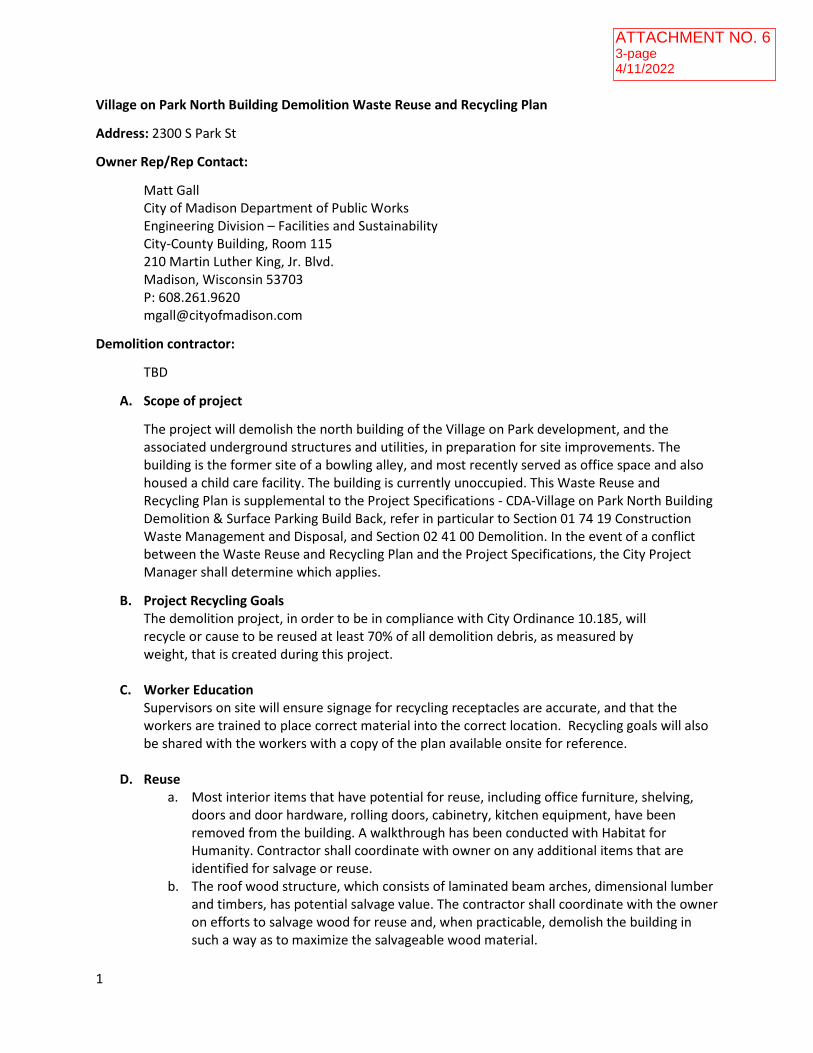
1
Village on Park North Building Demolition Waste Reuse and Recycling Plan
Address: 2300 S Park St
Owner Rep/Rep Contact:
Matt Gall
City of Madison Department of Public Works
Engineering Division – Facilities and Sustainability
City-County Building, Room 115
210 Martin Luther King, Jr. Blvd.
Madison, Wisconsin 53703
P: 608.261.9620
Demolition contractor:
TBD
A. Scope of project
The project will demolish the north building of the Village on Park development, and the
associated underground structures and utilities, in preparation for site improvements. The
building is the former site of a bowling alley, and most recently served as office space and also
housed a child care facility. The building is currently unoccupied. This Waste Reuse and
Recycling Plan is supplemental to the Project Specifications - CDA-Village on Park North Building
Demolition & Surface Parking Build Back, refer in particular to Section 01 74 19 Construction
Waste Management and Disposal, and Section 02 41 00 Demolition. In the event of a conflict
between the Waste Reuse and Recycling Plan and the Project Specifications, the City Project
Manager shall determine which applies.
B. Project Recycling Goals
The demolition project, in order to be in compliance with City Ordinance 10.185, will
recycle or cause to be reused at least 70% of all demolition debris, as measured by
weight, that is created during this project.
C. Worker Education
Supervisors on site will ensure signage for recycling receptacles are accurate, and that the
workers are trained to place correct material into the correct location. Recycling goals will also
be shared with the workers with a copy of the plan available onsite for reference.
D. Reuse
a. Most interior items that have potential for reuse, including office furniture, shelving,
doors and door hardware, rolling doors, cabinetry, kitchen equipment, have been
removed from the building. A walkthrough has been conducted with Habitat for
Humanity. Contractor shall coordinate with owner on any additional items that are
identified for salvage or reuse.
b. The roof wood structure, which consists of laminated beam arches, dimensional lumber
and timbers, has potential salvage value. The contractor shall coordinate with the owner
on efforts to salvage wood for reuse and, when practicable, demolish the building in
such a way as to maximize the salvageable wood material.
ATTACHMENT NO. 63-page4/11/2022

2
c. Some of the playground equipment will be relocated to another site by others before
demolition work commences. Contractor shall remove and dispose of any playground
equipment and materials that remain in accordance with the Project Specifications and
this document.
E. Description of Material Anticipated to be Generated
a. Concrete
b. Brick
c. Clean wood
d. Structural salvage wood
e. Mixed wood waste
f. Drywall
g. Windows
h. HVAC equipment, wiring, and ductwork
i. Carpeting, vinyl, and vinyl base
j. Fluorescent light tubes
k. Electrical wiring
l. Metal gutters, metal siding
m. Roofing materials
n. Plumbing fixtures, including several stainless steel sinks in good condition.
o. Commercial kitchen equipment (electric range, exhaust hood, dishwasher and
dishwashing sink.
p. Playground equipment, synthetic playground mulch, chain link fence, two sheds
F. Miscellaneous refuse and recycling
Will be disposed of according to City of Madison Streets Division guidelines.
G. Material Disposition/Material Handling
Metal
All metal items will be separated and placed into a metal recycling dumpster. Duct work,
gutters, wiring, piping, and other metal items will be placed into this container. This will
be hauled to a City certified construction and demolition materials recycler for recycling.
Hazardous Materials – Mercury, Asbestos, etc.
a. Building will be inspected and tested for universals wastes, lead. These materials will
be safely removed by the contractor prior to demolition.
b. No Mercury thermostats are known to be in the building.
c. Fluorescent light bulbs will be removed and recycled.
d. Excess HVAC maintenance chemicals, and cleaning chemicals, will be used
elsewhere on site or disposed of through Dane County Clean Sweep.
e. Interior Asbestos Containing Materials (ACM) as identified in Attachment No13-
Asbestos Inspection Report and Location Map have been remediated. The concrete
floor in Mechanical Room 105 has been remediated of ACM, but residual staining
from non-friable black mastic remains. Dispose of concrete in landfill, in accordance
with WDNR regulations.
f. Refer to Project Specifications Section 02 41 00 for ACM on the roof structure to be
remediated as part of this project.

3
Concrete, Asphalt, and Brick
The basement slab will be broken up to allow for water infiltration, and remain in
place as fill. The remaining material will be hauled to the City certified construction
and demolition materials recycler for recycling.
Clean Wood
Wood waste from roof structure , subfloor, and other wood will be deposited into a
comingled construction debris recycling dumpster to be processed by the
construction and demolition recycling facility located at Dane County Construction
and Demolition Recycling Facility, 7102 U.S. Highway 12, or City certified
construction and demolition materials recycler. Contractor shall coordinate with
owner for wood materials identified for salvage.
Roofing materials
The roofing membrane roofing and insulation will be hauled to a City certified
construction and demolition materials recycler for recycling.
Carpeting and flooring
Shall be assessed by third party for recycling potential.
Appliances
Appliances such as the commercial range, dishwasher, and HVAC equipment shall be
assessed for resale value, or removed and hauled to City certified construction and
demolition materials recycler for recycling.
Mixed Loads of Debris
Clean drywall, and other recyclable construction debris (such as the clean wood
noted above) shall be placed into a comingled recycling dumpster, and hauled to
Dane County Construction and Demolition Recycling Facility, 7102 U.S. Highway 12,
or other City certified construction and demolition materials recycler.
H. Compliance
The demolition contractor shall monitor and track all loads of material. Upon
completion of the project the compliance report, shall be completed. The
compliance report is available on the City of Madison Streets Divisions’ website.
Appropriate weight tickets and/or invoices will be included with the compliance
report when it is submitted.

~SewerPlugPermit~
City of Madison Engineering Division210 Martin Luther King, Jr. Blvd. City-County Building Suite 115 Madison WI 53703
Permit to Abandon Sanitary and/or Storm Sewer Lateral
This permit is issued to the Owner/Representative of Owner, of the property located at the address shown below to abandon the private sanitary and/or storm sewer lateral(s)that served this property. The Owner/Representative of Owner agrees to perform all work in accordance with Sections 29.13(5) and 37.05(7) of the Madison General Ordinances and is subject to the following conditions:
The Owner/Representative of Owner shall excavate, expose and plug the existing sanitary and/or storm lateral(s) on the above property at the point where it enters public right-of-way or easements.
The Owner/Representative of Owner shall notify City Engineering Construction Inspector at least 24 hours in advance and shall allow entry on the property to inspect the sewer plug.
The Owner/Representative of Owner shall backfill the excavation with supervision of the City Engineer to insure no damage is done to the lateral plug by the backfill operation.
All conditions of the permit must be adhered to and the disconnection or abandonment must be successfully inspected by the City Inspector in order for the Owner/Representative of Owner to obtain any refund of the deposit.The Owner/Representative of Owner shall assume all responsibility for any damage done to persons or property which may result due to the abandoning of the lateral(s).
The Owner/Representative of Owner shall satisfactorily comply with the above conditions within 60 days after the date on this form unless the time is extended in writing by the City Engineer.
1.
2.
3.
4.
5.
6.
SCHEDULE INSPECTION AT LEAST 24 HOURS IN ADVANCE
Contact: Adam Vanden Heuvel, Construction Inspector 2 Office: 266-4514 Cell Phone: (608)520-2513 E-mail: [email protected]
Permit No. ENGSRP-2022-01024
Permit Issued To:
Matt Gall
Property Address:
2300 S Park STNUMBER OF LATERALS TO BE ABANDONED
AUTHORIZED BY:
Robert F. Phillips, P.E. City Engineer
ISSUE DATE: 03/25/2022
EXPIRATION DATE: 03/25/2023SANITARY STORM 0 Permanent: Permanent:
Temporary: Temporary:
0
0 1
ATTACHMENT NO. 71-page3/25/2022

State of Wisconsin DEPARTMENT OF NATURAL RESOURCES South Central Region Headquarters 3911 Fish Hatchery Road Fitchburg, WI 53711-5397
dnr.wi.gov wisconsin.gov
Tony Evers, Governor Preston D. Cole, Secretary
Telephone (608) 275-3266 Toll Free 1-888-936-7463
TTY Access via relay - 711
March 1, 2022
Matt Wachter
CDA
215 Martin Luther King Jr Blvd
Madison WI 53703 Via email: [email protected]
SUBJECT: Coverage Under WPDES General Permit No. WI-S067831-06: Construction Site Storm Water Runoff
Permittee Name: CDA
Site Name: CDA - Village on Park Build Back
FIN: 80772
Dear Permittee:
The Wisconsin Department of Natural Resources received your Water Resources Application for Project Permits or Notice of
Intent, on January 05, 2022, for the CDA - Village on Park Build Back site and has evaluated the information provided
regarding storm water discharges from your construction site. We have determined that your construction site activities will
be regulated under ch. 283, Wis. Stats., ch. NR 216, Wis. Adm. Code, and in accordance with Wisconsin Pollutant Discharge
Elimination System (WPDES) General Permit No. WI-S067831-06, Construction Site Storm Water Runoff. All erosion
control and storm water management activities undertaken at the site must be done in accordance with the terms and
conditions of the general permit.
The Start Date of permit coverage for this site is March 01, 2022. The maximum period of permit coverage for this site is
limited to 3 years from the Start Date. Therefore, permit coverage automatically expires and terminates 3 years from the
Start Date and storm water discharges are no longer authorized unless another Notice of Intent and application fee to retain
coverage under this permit or a reissued version of this permit is submitted to the Department 14 working days prior to
expiration.
A copy of the general permit along with extensive storm water information including technical standards, forms, guidance
and other documents is accessible on the Department’s storm water program Internet site. To obtain a copy of the general
permit, please download it and the associated documents listed below from the following Department Internet site:
http://dnr.wi.gov/topic/stormwater/construction/forms.html
• Construction Site Storm Water Runoff WPDES general permit No. WI-S067831-06
• Construction site inspection report form
• Notice of Termination form
If, for any reason, you are unable to access these documents over the Internet, please contact me and I will send them to you.
To ensure compliance with the general permit, please read it carefully and be sure you understand its contents. Please take
special note of the following requirements (This is not a complete list of the terms and conditions of the general permit.):
1. The Construction Site Erosion Control Plan and Storm Water Management Plan that you completed prior to
submitting your permit application must be implemented and maintained throughout construction. Failure to do so may
result in enforcement action by the Department.
ATTACHMENT NO. 83-page3/1/2022

Page 2
2. The general permit requires that erosion and sediment controls be routinely inspected at least every 7 days, and
within 24 hours after a rainfall event of 0.5 inches or greater. Weekly written reports of all inspections must be
maintained. The reports must contain the following information:
a. Date, time, and exact place of inspection;
b. Name(s) of individual(s) performing inspection;
c. An assessment of the condition of erosion and sediment controls;
d. A description of any erosion and sediment control implementation and maintenance performed;
e. A description of the site’s present phase of construction.
3. A Certificate of Permit Coverage must be posted in a conspicuous place on the construction site. The Certificate
of Permit Coverage (WDNR Publication # WT-813) is enclosed for your use.
4. When construction activities have ceased and the site has undergone final stabilization, a Notice of Termination
(NOT) of coverage under the general permit must be submitted to the Department.
It is important that you read and understand the terms and conditions of the general permit because they have the force of law
and apply to you. Your project may lose its permit coverage if you do not comply with its terms and conditions. The
Department may also withdraw your project from coverage under the general permit and require that you obtain an individual
WPDES permit instead, based on the Department's own motion, upon the filing of a written petition by any person, or upon
your request.
If you believe that you have a right to challenge this decision to grant permit coverage, you should know that the Wisconsin
statutes and administrative rules establish time periods within which requests to review Department decisions must be filed.
For judicial review of a decision pursuant to ss. 227.52 and 227.53, Wis. Stats., you have 30 days after the decision is mailed,
or otherwise served by the Department, to file your petition with the appropriate circuit court and serve the petition on the
Department. Such a petition for judicial review must name the Department of Natural Resources as the respondent.
To request a contested case hearing pursuant to s. 227.42, Wis. Stats., you have 30 days after the decision is mailed, or
otherwise served by the Department, to serve a petition for hearing on the Secretary of the Department of Natural Resources.
All requests for contested case hearings must be made in accordance with s. NR 2.05(5), Wis. Adm. Code, and served on the
Secretary in accordance with s. NR 2.03, Wis. Adm. Code. The filing of a request for a contested case hearing is not a
prerequisite for judicial review and does not extend the 30-day period for filing a petition for judicial review.
Thank you for your cooperation with the Construction Site Storm Water Discharge Permit Program. If you have any
questions concerning the contents of this letter or the general permit, please contact Eric Rortvedt at (608) 235-7655.
Sincerely,
Eric S. Rortvedt, P.E.
South Central Region
Water Resources Engineer
ENCLOSURE: Certificate of Permit Coverage

UNDER THE
WPDES CONSTRUCTION SITE STORM WATER RUNOFF PERMIT Permit No. WI-S067831-06
Under s. NR 216.455(2), Wis. Adm. Code, landowners of construction sites with storm water discharges regulated by the Wisconsin Department of Natural Resources (WDNR) Storm Water Permit Program are required to post this certificate in a conspicuous place at the construction site. This certifies that the site has been granted WDNR storm water permit coverage. The landowner must implement and maintain erosion control practices to limit sediment-contaminated runoff to waters of the state in accordance with the permit.
EROSION CONTROL COMPLAINTS should be reported to the WDNR Tip Line at
1-800-TIP-WDNR (1-800-847-9367) Please provide the following information to the Tip Line: WDNR Site No. (FIN): 80772
Site Name: CDA - Village on Park Build Back
Address/Location: 2300 South Park Street, City of MADISON Additional Information: Landowner: CDA
Landowner's Contact Person: Matt Wachter Contact Telephone Number: (608) 267-8730
Permit Start Date: March 01, 2022 By: WDNR Publication # WT-813 (10/11)
CERTIFICATE OF PERMIT COVERAGE
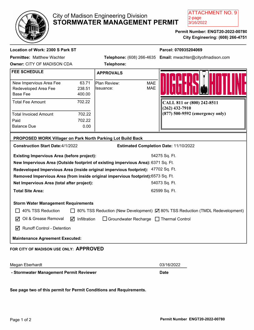
ATTACHMENT NO. 92-page3/16/2022

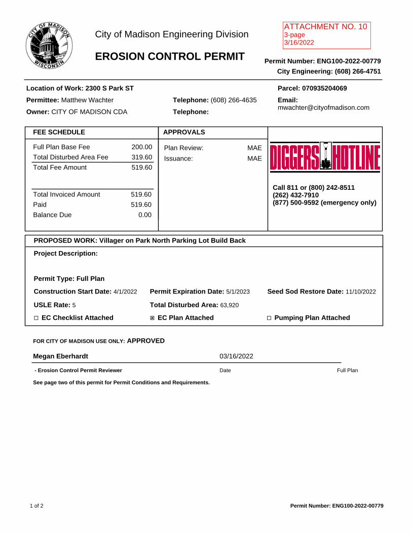
Full Plan Base Fee 200.00
Total Disturbed Area Fee 319.60
Total Fee Amount 519.60
Total Invoiced Amount
Paid
Balance Due
519.60
519.60
0.00
FEE SCHEDULE APPROVALS
Plan Review: MAE
Issuance: MAE
Call 811 or (800) 242-8511(262) 432-7910(877) 500-9592 (emergency only)
PROPOSED WORK: Villager on Park North Parking Lot Build Back
Project Description:
Permit Type: Full Plan
Construction Start Date: 4/1/2022 Permit Expiration Date: 5/1/2023 Seed Sod Restore Date: 11/10/2022
USLE Rate: 5 Total Disturbed Area: 63,920
¨ EC Checklist Attached ý EC Plan Attached ¨ Pumping Plan Attached
FOR CITY OF MADISON USE ONLY: APPROVED
Megan Eberhardt 03/16/2022
Full Plan - Erosion Control Permit Reviewer Date
See page two of this permit for Permit Conditions and Requirements.
1 of 2 Permit Number: ENG100-2022-00779
City of Madison Engineering Division
EROSION CONTROL PERMIT Permit Number: ENG100-2022-00779
City Engineering: (608) 266-4751
Location of Work: 2300 S Park ST
Permittee: Matthew Wachter
Owner: CITY OF MADISON CDA
Parcel: 070935204069
Telephone: (608) 266-4635
Telephone:
Email: [email protected]
ATTACHMENT NO. 103-page3/16/2022
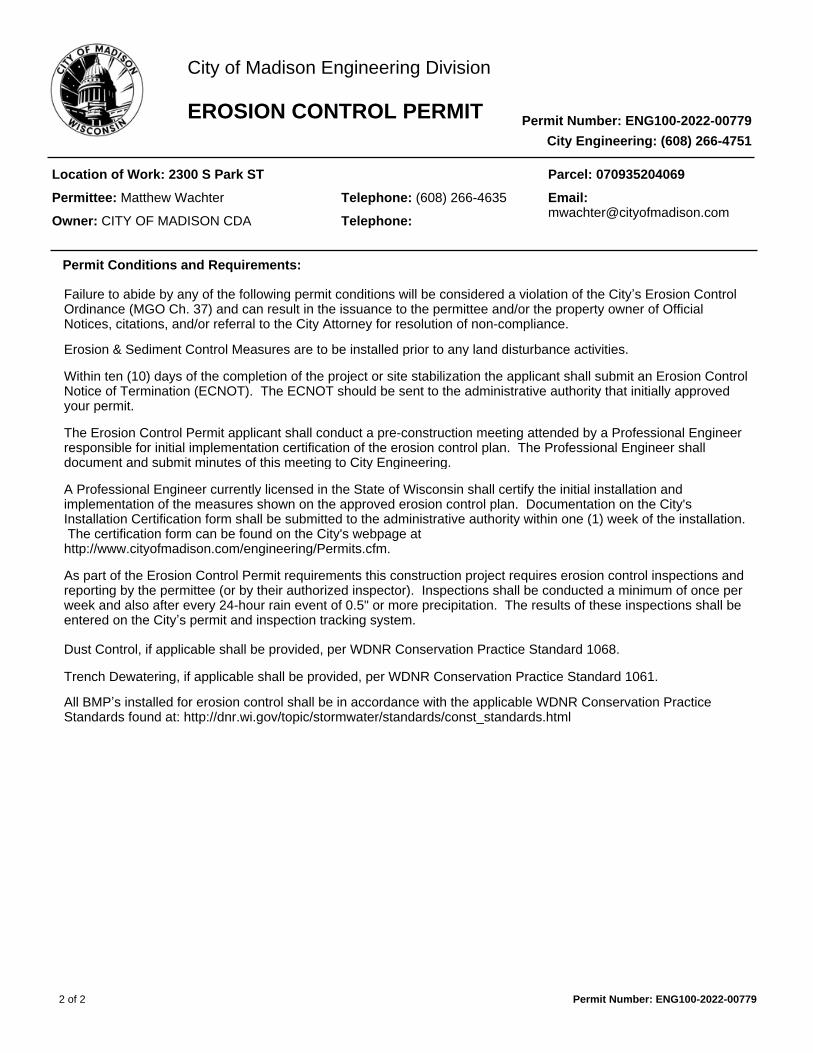
Failure to abide by any of the following permit conditions will be considered a violation of the City’s Erosion ControlOrdinance (MGO Ch. 37) and can result in the issuance to the permittee and/or the property owner of Official Notices, citations, and/or referral to the City Attorney for resolution of non-compliance.
Erosion & Sediment Control Measures are to be installed prior to any land disturbance activities.
Within ten (10) days of the completion of the project or site stabilization the applicant shall submit an Erosion Control Notice of Termination (ECNOT). The ECNOT should be sent to the administrative authority that initially approved your permit.
The Erosion Control Permit applicant shall conduct a pre-construction meeting attended by a Professional Engineer responsible for initial implementation certification of the erosion control plan. The Professional Engineer shall document and submit minutes of this meeting to City Engineering.
A Professional Engineer currently licensed in the State of Wisconsin shall certify the initial installation and implementation of the measures shown on the approved erosion control plan. Documentation on the City's Installation Certification form shall be submitted to the administrative authority within one (1) week of the installation. The certification form can be found on the City's webpage at http://www.cityofmadison.com/engineering/Permits.cfm.
As part of the Erosion Control Permit requirements this construction project requires erosion control inspections and reporting by the permittee (or by their authorized inspector). Inspections shall be conducted a minimum of once per week and also after every 24-hour rain event of 0.5" or more precipitation. The results of these inspections shall be entered on the City’s permit and inspection tracking system.
Dust Control, if applicable shall be provided, per WDNR Conservation Practice Standard 1068.
Trench Dewatering, if applicable shall be provided, per WDNR Conservation Practice Standard 1061.
All BMP’s installed for erosion control shall be in accordance with the applicable WDNR Conservation Practice Standards found at: http://dnr.wi.gov/topic/stormwater/standards/const_standards.html
Permit Conditions and Requirements:
2 of 2 Permit Number: ENG100-2022-00779
City of Madison Engineering Division
EROSION CONTROL PERMIT Permit Number: ENG100-2022-00779
City Engineering: (608) 266-4751
Location of Work: 2300 S Park ST
Permittee: Matthew Wachter
Owner: CITY OF MADISON CDA
Parcel: 070935204069
Telephone: (608) 266-4635
Telephone:
Email: [email protected]

City of Madison Engineering Erosion Control Enforcement
Standard Operation Procedures & Common Requirements (Updated 6/16/2015)
To better provide uniform oversight and obtain erosion control compliance on projects under the City Engineering’s jurisdiction for inspection and enforcement.
1. Warnings will be provided twice during the duration of a project for erosion control violations of MGO
Ch 37. Any violations after the two warnings will result in the issuance of a citation. 2. Non-compliance violations and warnings for administrative and field items will be tracked separately. 3. Administrative non-compliance shall include, but not be limited to: failure to hold a required
preconstruction meeting, failure to submit erosion control plan initial implementation certification form, failure to complete weekly inspection report, or failure to complete a post-rain event inspection report.
4. For permitted projects that are required to submit weekly inspection reports, compliance checks are run
automatically every Monday morning at 6:00 AM. To be considered in compliance, an online inspection report must be completed before this automatic compliance check is performed. Property owners, applicants, and authorized inspectors will receive an automatic email notice that the required inspection report has not been completed. This is not to be considered a reminder system; if this email notice is sent, the site is already in non-compliance.
5. Post-rain event inspection report compliance will be run manually by City Engineering 48 hours after
the rain event day. Notices of non-compliance will be sent to property owners, applicants, and authorized inspectors for permitted projects that have not completed the required inspection report.
6. Property owners, applicants, and their authorized inspectors will NOT be reminded by City Engineering
when a rain event requiring inspection occurs (0.5 inches or larger). The permit holder or their authorized inspector(s) will need to check for rainfall amounts. The rain gauge closest to the construction site should be used to determine rainfall amount. West Side: http://infosyahara.org/rainfallgauges_station2
East Side: http://w1.weather.gov/data/obhistory/KMSN.html In the event the closest rain gauge is out of order, the gauge for the other side of town shall be referenced. If both gauges are out of order, default to the “Madison Area” Location on the National Weather Service website: http://www.nws.noaa.gov/climate/xmacis.php?wfo=mkx Rain gauges at the construction site or any other location will not be acceptable, as they cannot be verified by City inspection staff in a timely manner.
7. Field non-compliance shall include, but is not limited to: land disturbance work without a permit,
working without erosion control measures installed, improperly installed erosion control measures, failure to maintain erosion control measures, tracking of sediment onto adjacent streets or property, discharge of silt laden runoff or pump discharge from the site, etc.
8. Field violations will generate warnings from the City inspector that will be conveyed on-site to the
project superintendant (if available) and by email notice to the property owner, applicant, and authorized inspector.
9. If the usual notice and citation methods fail to result in the permitted site being brought into compliance
with MGO Ch 37 requirements, additional enforcement measures such as, but not limited to, stop work orders or referral to the City Attorney will be used.
10. In the case of a safety hazard, City inspection staff will attempt to obtain immediate corrective action to
remedy on the part of the contractor, property owner, or applicant. If immediate action is not available (unable to contact, or parties refuse to comply immediately), then City Engineering will take measures necessary to correct the hazard. These costs will be billed to the property owner as a special charge per Madison General Ordinances. In the case of a refusal to comply, this will result in an immediate field violation and issuance of a citation as well.

ATTACHMENT NO. 112-page3/17/2022
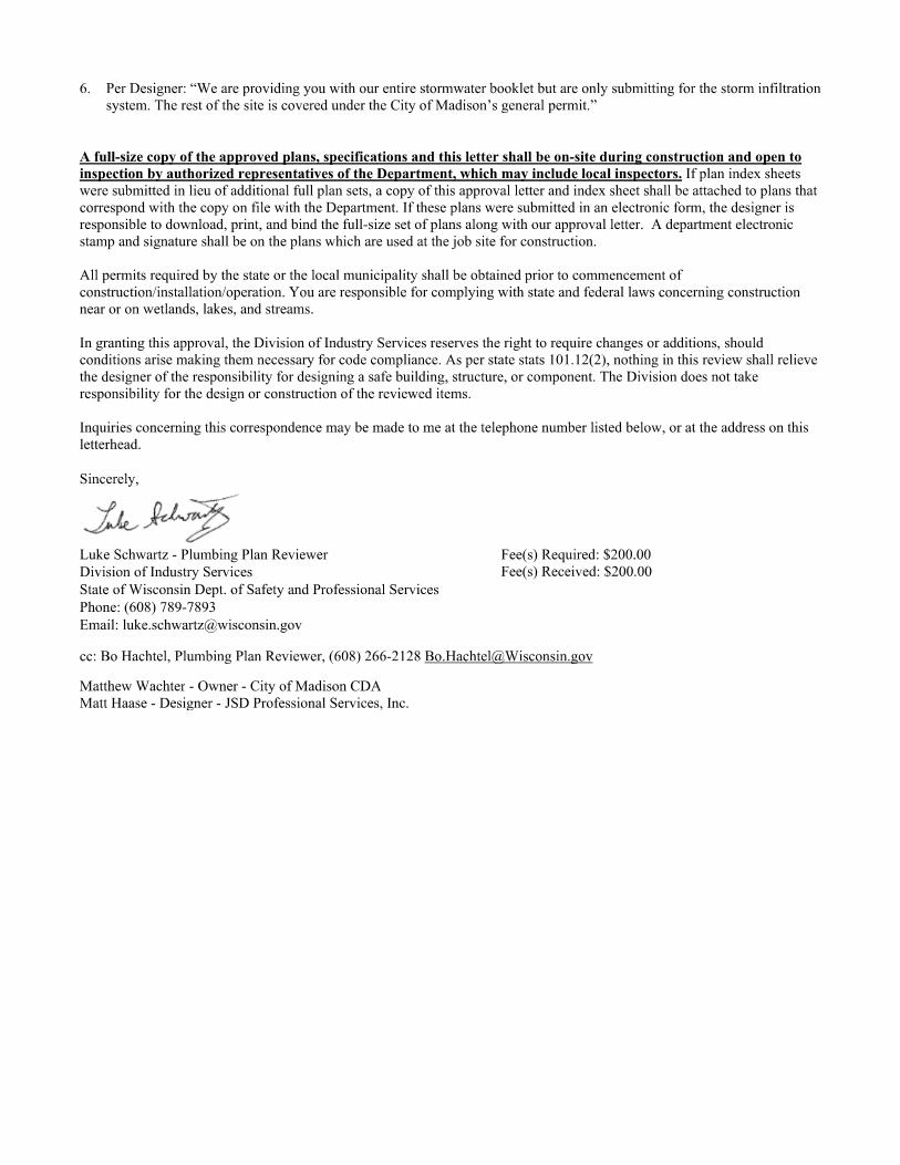

ASBESTOS INSPECTION AND BULK SAMPLING
PRIOR TO DEMOLITION
LOCATION
2210 SOUTH PARK ST MADISON, WI
CLIENT FOUNDERS 3
ERIC BOSWELL
DATE OF INSPECTION FEBRUARY 16, 2021
Advanced Health and Safety 5940 Seminole Centre Court Ste 225A
Madison, WI 53711 www.madisonasbestos.com
ATTACHMENT NO. 621-page2/21/2021
ATTACHMENT NO 1321-page2/16/21
enmrg
Text Box
ATTACHMENT NO 12 19-page 2/16/21
ASBESTOS INSPECTION & BULK SAMPLING
2210 S Park St in Madison, Wisconsin Advanced Health & Safety LLC (AHS) was contacted to conduct an asbestos survey at the aforementioned property. AHS inspected the property on February 16, 2021. The property was inspected for the presence of asbestos containing building materials. Bulk samples were taken for building materials found suspect to contain asbestos, as discussed with the client. All samples were shipped overnight via Fed Ex. and were submitted to Triangle Environmental Services for analysis by Polarized Light Microscopy (PLM). Four separate categories of materials (if applicable) will be listed for the property: The first list (List A) will be of materials found to contain asbestos, which are friable or may become friable during demolition. It is required that these materials be removed by a certified asbestos abatement contractor prior to a demolition. All asbestos materials in List A must be removed prior to a fire training burn. The second list (List B) will contain materials found to contain asbestos but are described as Category II non-friable. If the building is to be demolished, it is required that these materials be removed by a certified asbestos abatement contractor prior to a demolition. All asbestos materials in List B must be removed prior to a fire training burn. The third list (List C) will contain materials found to contain asbestos but are described as Category I non-friable. If the building is to be demolished, the materials may be able to remain in the building during demolition if proper steps are taken and they do not become friable. These proper steps include but are not limited to: notifying the demolition contractor of the presence of asbestos, utilizing wet methods during demolition, notifying the landfill accepting the waste that not-friable Category I asbestos materials are present, and manifesting the waste. Also, if any of the building materials are to be recycled (ie, crushing concrete) than the asbestos must be removed from this building material. NESHAPS (DNR) does not regulate materials found at < 1% asbestos, however OSHA does still regulate materials that contain < 1% asbestos. If materials in List C are likely to be disturbed, the contractor shall ensure compliance with all appropriate OSHA regulations. All asbestos materials in List C must be removed prior to a fire training burn. The fourth list (List D) will include materials that were sampled and found not to contain asbestos. Removal is not required for these materials. Note: while abatement may/may not “required” for a demolition of a single family residence, it is recommended for disposal as well as neighbor relations & liability purposes. If any suspect materials are found during demolition/burn that has not been sampled during this inspection, work should cease and Advanced Health & Safety should be contacted to assess the situation. Inaccessible areas may exist inside walls.
ATTACHMENT NO. 621-page2/21/2021
ATTACHMENT NO 1321-page2/16/21
enmrg
Text Box
ATTACHMENT NO 12 21-page 2/16/21
enmrg
Text Box
ATTACHMENT NO 12 19-page 2/16/21
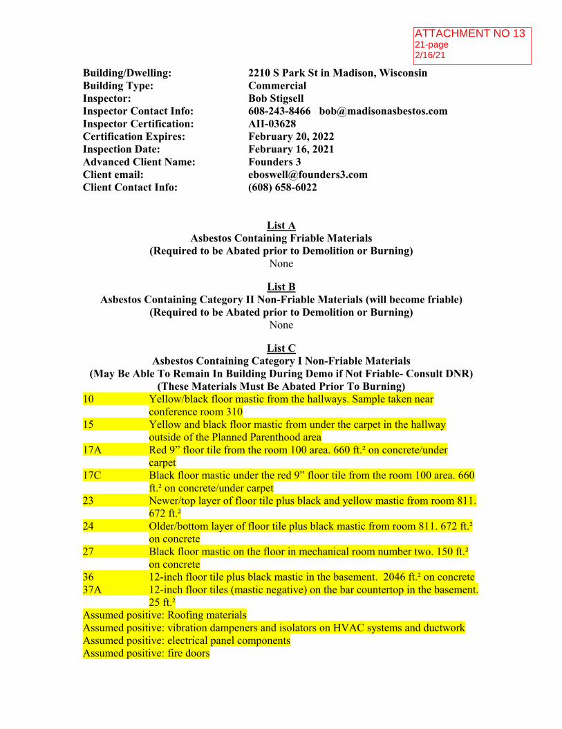
Building/Dwelling: 2210 S Park St in Madison, Wisconsin Building Type: Commercial Inspector: Bob Stigsell Inspector Contact Info: 608-243-8466 [email protected] Inspector Certification: AII-03628 Certification Expires: February 20, 2022 Inspection Date: February 16, 2021 Advanced Client Name: Founders 3 Client email: [email protected] Client Contact Info: (608) 658-6022
List A Asbestos Containing Friable Materials
(Required to be Abated prior to Demolition or Burning) None
List B
Asbestos Containing Category II Non-Friable Materials (will become friable) (Required to be Abated prior to Demolition or Burning)
None
List C Asbestos Containing Category I Non-Friable Materials
(May Be Able To Remain In Building During Demo if Not Friable- Consult DNR) (These Materials Must Be Abated Prior To Burning)
10 Yellow/black floor mastic from the hallways. Sample taken near conference room 310
15 Yellow and black floor mastic from under the carpet in the hallway outside of the Planned Parenthood area
17A Red 9” floor tile from the room 100 area. 660 ft.² on concrete/under carpet
17C Black floor mastic under the red 9” floor tile from the room 100 area. 660 ft.² on concrete/under carpet
23 Newer/top layer of floor tile plus black and yellow mastic from room 811. 672 ft.²
24 Older/bottom layer of floor tile plus black mastic from room 811. 672 ft.² on concrete
27 Black floor mastic on the floor in mechanical room number two. 150 ft.² on concrete
36 12-inch floor tile plus black mastic in the basement. 2046 ft.² on concrete 37A 12-inch floor tiles (mastic negative) on the bar countertop in the basement.
25 ft.² Assumed positive: Roofing materials Assumed positive: vibration dampeners and isolators on HVAC systems and ductwork Assumed positive: electrical panel components Assumed positive: fire doors
ATTACHMENT NO. 621-page2/21/2021
ATTACHMENT NO 1321-page2/16/21
enmrg
Text Box
ATTACHMENT NO 12 21-page 2/16/21
enmrg
Text Box
ATTACHMENT NO 12 19-page 2/16/21
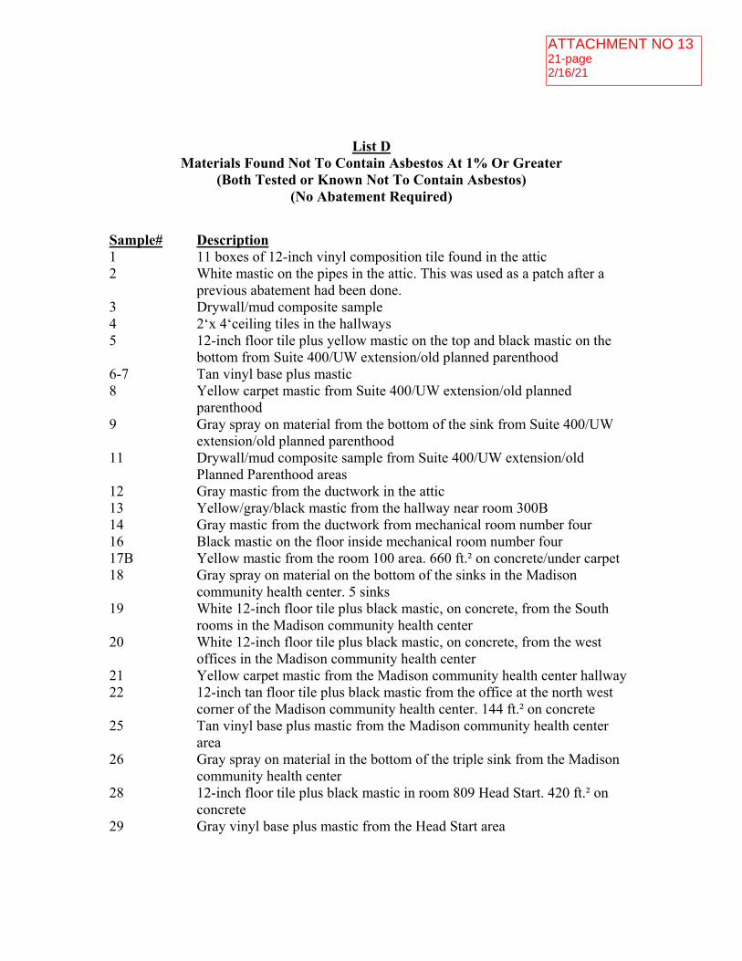
List D
Materials Found Not To Contain Asbestos At 1% Or Greater (Both Tested or Known Not To Contain Asbestos)
(No Abatement Required)
Sample# Description 1 11 boxes of 12-inch vinyl composition tile found in the attic 2 White mastic on the pipes in the attic. This was used as a patch after a
previous abatement had been done. 3 Drywall/mud composite sample 4 2‘x 4‘ceiling tiles in the hallways 5 12-inch floor tile plus yellow mastic on the top and black mastic on the
bottom from Suite 400/UW extension/old planned parenthood 6-7 Tan vinyl base plus mastic 8 Yellow carpet mastic from Suite 400/UW extension/old planned
parenthood 9 Gray spray on material from the bottom of the sink from Suite 400/UW
extension/old planned parenthood 11 Drywall/mud composite sample from Suite 400/UW extension/old
Planned Parenthood areas 12 Gray mastic from the ductwork in the attic 13 Yellow/gray/black mastic from the hallway near room 300B 14 Gray mastic from the ductwork from mechanical room number four 16 Black mastic on the floor inside mechanical room number four 17B Yellow mastic from the room 100 area. 660 ft.² on concrete/under carpet 18 Gray spray on material on the bottom of the sinks in the Madison
community health center. 5 sinks 19 White 12-inch floor tile plus black mastic, on concrete, from the South
rooms in the Madison community health center 20 White 12-inch floor tile plus black mastic, on concrete, from the west
offices in the Madison community health center 21 Yellow carpet mastic from the Madison community health center hallway 22 12-inch tan floor tile plus black mastic from the office at the north west
corner of the Madison community health center. 144 ft.² on concrete 25 Tan vinyl base plus mastic from the Madison community health center
area 26 Gray spray on material in the bottom of the triple sink from the Madison
community health center 28 12-inch floor tile plus black mastic in room 809 Head Start. 420 ft.² on
concrete 29 Gray vinyl base plus mastic from the Head Start area
ATTACHMENT NO. 621-page2/21/2021
ATTACHMENT NO 1321-page2/16/21
enmrg
Text Box
ATTACHMENT NO 12 21-page 2/16/21
enmrg
Text Box
ATTACHMENT NO 12 19-page 2/16/21

30 12 inch floor tile plus black mastic in room 807 Head Start. 420 ft.² on concrete. 14‘x 36‘in room 805. 36‘x 36‘in room 703. 466 ft.² in room 701. 36‘x 14‘in room 803.
31 Maroon vinyl base plus yellow mastic from the Head Start hallway 32 Yellow carpet mastic from the Head Start hallway 33-35 Spray on material on the ceiling in the basement 37B Black mastic on the bar countertop in the basement. 25 ft.² 38 Stair treads between the basement and the first floor 39 White mastic on the fiberglass pipelines in the basement mechanical room
ATTACHMENT NO. 621-page2/21/2021
ATTACHMENT NO 1321-page2/16/21
enmrg
Text Box
ATTACHMENT NO 12 21-page 2/16/21
enmrg
Text Box
ATTACHMENT NO 12 19-page 2/16/21

LICENSES/CERTIFICATION
BOB STIGSELL
LEAD INSPECTOR: LII-3628
ASBESTOS INSPECTOR: AII-3628
ASBESTOS SUPERVISOR: ACS-3628
ASBESTOS PROJECT DESIGNER: APD-3628
LEAD-SAFE RENOVATOR: LSR-3628
ASBESTOS MANAGEMENT PLANNER: AMP-3628
A COPY OF THE LICENSES WILL BE MADE AVAILABLE UPON REQUEST.
ATTACHMENT NO. 621-page2/21/2021
ATTACHMENT NO 1321-page2/16/21
enmrg
Text Box
ATTACHMENT NO 12 21-page 2/16/21
enmrg
Text Box
ATTACHMENT NO 12 19-page 2/16/21

ASBESTOS SAMPLING RESULTS
ATTACHMENT NO. 621-page2/21/2021
ATTACHMENT NO 1321-page2/16/21
enmrg
Text Box
ATTACHMENT NO 12 21-page 2/16/21
enmrg
Text Box
ATTACHMENT NO 12 19-page 2/16/21
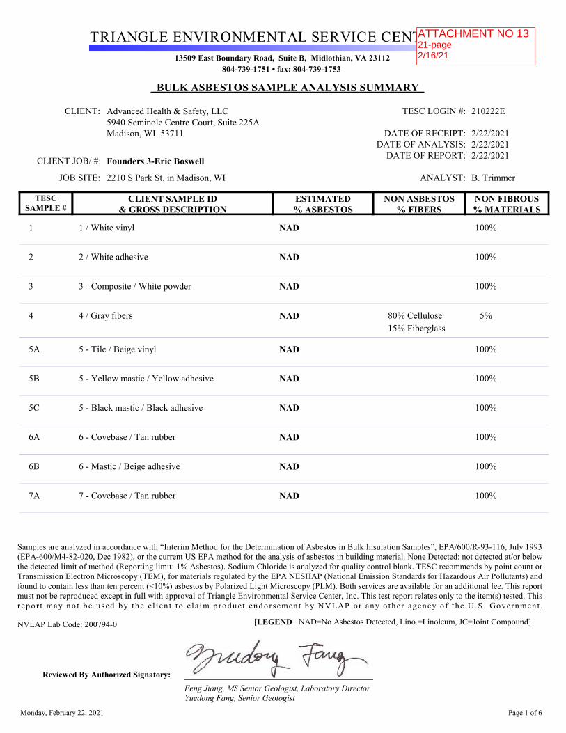
Advanced Health & Safety, LLC
TRIANGLE ENVIRONMENTAL SERVICE CENTER, INC.13509 East Boundary Road, Suite B, Midlothian, VA 23112
804-739-1751 • fax: 804-739-1753
BULK ASBESTOS SAMPLE ANALYSIS SUMMARY
5940 Seminole Centre Court, Suite 225AMadison, WI 53711
Founders 3-Eric Boswell
2210 S Park St. in Madison, WI
210222E
2/22/20212/22/20212/22/2021
B. TrimmerJOB SITE:
TESC LOGIN #:
DATE OF RECEIPT:DATE OF ANALYSIS:
DATE OF REPORT:
ANALYST:
TESCSAMPLE #
CLIENT SAMPLE ID& GROSS DESCRIPTION
ESTIMATED% ASBESTOS
NON ASBESTOS% FIBERS
NON FIBROUS% MATERIALS
CLIENT:
CLIENT JOB/ #:
1 1 / White vinyl NAD 100%
2 2 / White adhesive NAD 100%
3 3 - Composite / White powder NAD 100%
4 4 / Gray fibers NAD 5%80% Cellulose15% Fiberglass
5A 5 - Tile / Beige vinyl NAD 100%
5B 5 - Yellow mastic / Yellow adhesive NAD 100%
5C 5 - Black mastic / Black adhesive NAD 100%
6A 6 - Covebase / Tan rubber NAD 100%
6B 6 - Mastic / Beige adhesive NAD 100%
7A 7 - Covebase / Tan rubber NAD 100%
Monday, February 22, 2021 Page 1 of 6
Samples are analyzed in accordance with “Interim Method for the Determination of Asbestos in Bulk Insulation Samples”, EPA/600/R-93-116, July 1993(EPA-600/M4-82-020, Dec 1982), or the current US EPA method for the analysis of asbestos in building material. None Detected: not detected at/or belowthe detected limit of method (Reporting limit: 1% Asbestos). Sodium Chloride is analyzed for quality control blank. TESC recommends by point count orTransmission Electron Microscopy (TEM), for materials regulated by the EPA NESHAP (National Emission Standards for Hazardous Air Pollutants) andfound to contain less than ten percent (<10%) asbestos by Polarized Light Microscopy (PLM). Both services are available for an additional fee. This reportmust not be reproduced except in full with approval of Triangle Environmental Service Center, Inc. This test report relates only to the item(s) tested. Thisrepo r t may no t be u sed by the c l i en t to c la im p roduc t endorsement by NVLAP or any o ther agency o f the U.S . Government .
NVLAP Lab Code: 200794-0 LEGEND NAD=No Asbestos Detected, Lino.=Linoleum, JC=Joint Compound] [
Reviewed By Authorized Signatory: Feng Jiang, MS Senior Geologist, Laboratory DirectorYuedong Fang, Senior Geologist
ATTACHMENT NO. 621-page2/21/2021
ATTACHMENT NO 1321-page2/16/21
enmrg
Text Box
ATTACHMENT NO 12 21-page 2/16/21
enmrg
Text Box
ATTACHMENT NO 12 19-page 2/16/21
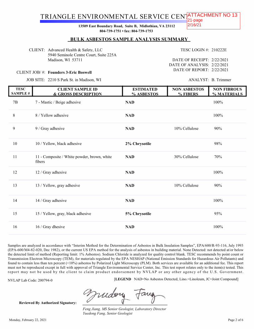
Advanced Health & Safety, LLC
TRIANGLE ENVIRONMENTAL SERVICE CENTER, INC.13509 East Boundary Road, Suite B, Midlothian, VA 23112
804-739-1751 • fax: 804-739-1753
BULK ASBESTOS SAMPLE ANALYSIS SUMMARY
5940 Seminole Centre Court, Suite 225AMadison, WI 53711
Founders 3-Eric Boswell
2210 S Park St. in Madison, WI
210222E
2/22/20212/22/20212/22/2021
B. TrimmerJOB SITE:
TESC LOGIN #:
DATE OF RECEIPT:DATE OF ANALYSIS:
DATE OF REPORT:
ANALYST:
TESCSAMPLE #
CLIENT SAMPLE ID& GROSS DESCRIPTION
ESTIMATED% ASBESTOS
NON ASBESTOS% FIBERS
NON FIBROUS% MATERIALS
CLIENT:
CLIENT JOB/ #:
7B 7 - Mastic / Beige adhesive NAD 100%
8 8 / Yellow adhesive NAD 100%
9 9 / Gray adhesive NAD 90%10% Cellulose
10 10 / Yellow, black adhesive 2% Chrysotile 98%
11 11 - Composite / White powder, brown, white fibers
NAD 70%30% Cellulose
12 12 / Gray adhesive NAD 100%
13 13 / Yellow, gray adhesive NAD 90%10% Cellulose
14 14 / Gray adhesive NAD 100%
15 15 / Yellow, gray, black adhesive 5% Chrysotile 95%
16 16 / Gray dhesive NAD 100%
Monday, February 22, 2021 Page 2 of 6
Samples are analyzed in accordance with “Interim Method for the Determination of Asbestos in Bulk Insulation Samples”, EPA/600/R-93-116, July 1993(EPA-600/M4-82-020, Dec 1982), or the current US EPA method for the analysis of asbestos in building material. None Detected: not detected at/or belowthe detected limit of method (Reporting limit: 1% Asbestos). Sodium Chloride is analyzed for quality control blank. TESC recommends by point count orTransmission Electron Microscopy (TEM), for materials regulated by the EPA NESHAP (National Emission Standards for Hazardous Air Pollutants) andfound to contain less than ten percent (<10%) asbestos by Polarized Light Microscopy (PLM). Both services are available for an additional fee. This reportmust not be reproduced except in full with approval of Triangle Environmental Service Center, Inc. This test report relates only to the item(s) tested. Thisrepo r t may no t be u sed by the c l i en t to c la im p roduc t endorsement by NVLAP or any o ther agency o f the U.S . Government .
NVLAP Lab Code: 200794-0 LEGEND NAD=No Asbestos Detected, Lino.=Linoleum, JC=Joint Compound] [
Reviewed By Authorized Signatory: Feng Jiang, MS Senior Geologist, Laboratory DirectorYuedong Fang, Senior Geologist
ATTACHMENT NO. 621-page2/21/2021
ATTACHMENT NO 1321-page2/16/21
enmrg
Text Box
ATTACHMENT NO 12 21-page 2/16/21
enmrg
Text Box
ATTACHMENT NO 12 19-page 2/16/21

Advanced Health & Safety, LLC
TRIANGLE ENVIRONMENTAL SERVICE CENTER, INC.13509 East Boundary Road, Suite B, Midlothian, VA 23112
804-739-1751 • fax: 804-739-1753
BULK ASBESTOS SAMPLE ANALYSIS SUMMARY
5940 Seminole Centre Court, Suite 225AMadison, WI 53711
Founders 3-Eric Boswell
2210 S Park St. in Madison, WI
210222E
2/22/20212/22/20212/22/2021
B. TrimmerJOB SITE:
TESC LOGIN #:
DATE OF RECEIPT:DATE OF ANALYSIS:
DATE OF REPORT:
ANALYST:
TESCSAMPLE #
CLIENT SAMPLE ID& GROSS DESCRIPTION
ESTIMATED% ASBESTOS
NON ASBESTOS% FIBERS
NON FIBROUS% MATERIALS
CLIENT:
CLIENT JOB/ #:
17A 17 - Tile / Red vinyl 2% Chrysotile 98%
17B 17 - Yellow mastic / Yellow adhesive NAD 100%
17C 17 - Black mastic / Black adhesive 8% Chrysotile 92%
18 18 / Gray adhesive NAD 90%10% Cellulose
19A 19 - Tile / White vinyl NAD 100%
19B 19 - Mastic / Black adhesive NAD 100%
20A 20 - Tile / White vinyl NAD 100%
20B 20 - Mastic / Black adhesive NAD 100%
21 21 / Yellow adhesive NAD 100%
22A 22 - Tile / Tan vinyl NAD 100%
Monday, February 22, 2021 Page 3 of 6
Samples are analyzed in accordance with “Interim Method for the Determination of Asbestos in Bulk Insulation Samples”, EPA/600/R-93-116, July 1993(EPA-600/M4-82-020, Dec 1982), or the current US EPA method for the analysis of asbestos in building material. None Detected: not detected at/or belowthe detected limit of method (Reporting limit: 1% Asbestos). Sodium Chloride is analyzed for quality control blank. TESC recommends by point count orTransmission Electron Microscopy (TEM), for materials regulated by the EPA NESHAP (National Emission Standards for Hazardous Air Pollutants) andfound to contain less than ten percent (<10%) asbestos by Polarized Light Microscopy (PLM). Both services are available for an additional fee. This reportmust not be reproduced except in full with approval of Triangle Environmental Service Center, Inc. This test report relates only to the item(s) tested. Thisrepo r t may no t be u sed by the c l i en t to c la im p roduc t endorsement by NVLAP or any o ther agency o f the U.S . Government .
NVLAP Lab Code: 200794-0 LEGEND NAD=No Asbestos Detected, Lino.=Linoleum, JC=Joint Compound] [
Reviewed By Authorized Signatory: Feng Jiang, MS Senior Geologist, Laboratory DirectorYuedong Fang, Senior Geologist
ATTACHMENT NO. 621-page2/21/2021
ATTACHMENT NO 1321-page2/16/21
enmrg
Text Box
ATTACHMENT NO 12 19-page 2/16/21

Advanced Health & Safety, LLC
TRIANGLE ENVIRONMENTAL SERVICE CENTER, INC.13509 East Boundary Road, Suite B, Midlothian, VA 23112
804-739-1751 • fax: 804-739-1753
BULK ASBESTOS SAMPLE ANALYSIS SUMMARY
5940 Seminole Centre Court, Suite 225AMadison, WI 53711
Founders 3-Eric Boswell
2210 S Park St. in Madison, WI
210222E
2/22/20212/22/20212/22/2021
B. TrimmerJOB SITE:
TESC LOGIN #:
DATE OF RECEIPT:DATE OF ANALYSIS:
DATE OF REPORT:
ANALYST:
TESCSAMPLE #
CLIENT SAMPLE ID& GROSS DESCRIPTION
ESTIMATED% ASBESTOS
NON ASBESTOS% FIBERS
NON FIBROUS% MATERIALS
CLIENT:
CLIENT JOB/ #:
22B 22 - Mastic / Black adhesive NAD 100%
23A 23 - Tile / Brown vinyl 2% Chrysotile 98%
23B 23 - Mastic / Black adhesive 10% Chrysotile 90%
24A 24 - Tile / White vinyl 2% Chrysotile 98%
24B 24 - Mastic / Black adhesive 10% Chrysotile 90%
25A 25 - Covebase / Tan rubber NAD 100%
25B 25 - Mastic / Beige adhesive NAD 100%
26 26 / Gray adhesive NAD 90%10% Cellulose
27 27 / Black adhesive 5% Chrysotile 95%
28A 28 - Tile / White vinyl NAD 100%
Monday, February 22, 2021 Page 4 of 6
Samples are analyzed in accordance with “Interim Method for the Determination of Asbestos in Bulk Insulation Samples”, EPA/600/R-93-116, July 1993(EPA-600/M4-82-020, Dec 1982), or the current US EPA method for the analysis of asbestos in building material. None Detected: not detected at/or belowthe detected limit of method (Reporting limit: 1% Asbestos). Sodium Chloride is analyzed for quality control blank. TESC recommends by point count orTransmission Electron Microscopy (TEM), for materials regulated by the EPA NESHAP (National Emission Standards for Hazardous Air Pollutants) andfound to contain less than ten percent (<10%) asbestos by Polarized Light Microscopy (PLM). Both services are available for an additional fee. This reportmust not be reproduced except in full with approval of Triangle Environmental Service Center, Inc. This test report relates only to the item(s) tested. Thisrepo r t may no t be u sed by the c l i en t to c la im p roduc t endorsement by NVLAP or any o ther agency o f the U.S . Government .
NVLAP Lab Code: 200794-0 LEGEND NAD=No Asbestos Detected, Lino.=Linoleum, JC=Joint Compound] [
Reviewed By Authorized Signatory: Feng Jiang, MS Senior Geologist, Laboratory DirectorYuedong Fang, Senior Geologist
ATTACHMENT NO. 621-page2/21/2021
ATTACHMENT NO 1321-page2/16/21
enmrg
Text Box
ATTACHMENT NO 12 21-page 2/16/21
enmrg
Text Box
ATTACHMENT NO 12 19-page 2/16/21

Advanced Health & Safety, LLC
TRIANGLE ENVIRONMENTAL SERVICE CENTER, INC.13509 East Boundary Road, Suite B, Midlothian, VA 23112
804-739-1751 • fax: 804-739-1753
BULK ASBESTOS SAMPLE ANALYSIS SUMMARY
5940 Seminole Centre Court, Suite 225AMadison, WI 53711
Founders 3-Eric Boswell
2210 S Park St. in Madison, WI
210222E
2/22/20212/22/20212/22/2021
B. TrimmerJOB SITE:
TESC LOGIN #:
DATE OF RECEIPT:DATE OF ANALYSIS:
DATE OF REPORT:
ANALYST:
TESCSAMPLE #
CLIENT SAMPLE ID& GROSS DESCRIPTION
ESTIMATED% ASBESTOS
NON ASBESTOS% FIBERS
NON FIBROUS% MATERIALS
CLIENT:
CLIENT JOB/ #:
28B 28 - Mastic / Black adhesive NAD 100%
29A 29 - Covebase / Gray rubber NAD 100%
29B 29 - Mastic / Beige adhesive NAD 100%
30A 30 - Tile / Beige vinyl NAD 100%
30B 30 - Mastic / Black adhesive NAD 100%
31A 31 - Covebase / Maroon rubber NAD 100%
31B 31 - Mastic / Yellow adhesive NAD 100%
32 32 / Yellow adhesive NAD 100%
33 33 / White powder NAD 100%
34 34 / White powder NAD 100%
35 35 / White powder NAD 100%
Monday, February 22, 2021 Page 5 of 6
Samples are analyzed in accordance with “Interim Method for the Determination of Asbestos in Bulk Insulation Samples”, EPA/600/R-93-116, July 1993(EPA-600/M4-82-020, Dec 1982), or the current US EPA method for the analysis of asbestos in building material. None Detected: not detected at/or belowthe detected limit of method (Reporting limit: 1% Asbestos). Sodium Chloride is analyzed for quality control blank. TESC recommends by point count orTransmission Electron Microscopy (TEM), for materials regulated by the EPA NESHAP (National Emission Standards for Hazardous Air Pollutants) andfound to contain less than ten percent (<10%) asbestos by Polarized Light Microscopy (PLM). Both services are available for an additional fee. This reportmust not be reproduced except in full with approval of Triangle Environmental Service Center, Inc. This test report relates only to the item(s) tested. Thisrepo r t may no t be u sed by the c l i en t to c la im p roduc t endorsement by NVLAP or any o ther agency o f the U.S . Government .
NVLAP Lab Code: 200794-0 LEGEND NAD=No Asbestos Detected, Lino.=Linoleum, JC=Joint Compound] [
Reviewed By Authorized Signatory: Feng Jiang, MS Senior Geologist, Laboratory DirectorYuedong Fang, Senior Geologist
ATTACHMENT NO. 621-page2/21/2021
ATTACHMENT NO 1321-page2/16/21
enmrg
Text Box
ATTACHMENT NO 12 21-page 2/16/21
enmrg
Text Box
ATTACHMENT NO 12 19-page 2/16/21

Advanced Health & Safety, LLC
TRIANGLE ENVIRONMENTAL SERVICE CENTER, INC.13509 East Boundary Road, Suite B, Midlothian, VA 23112
804-739-1751 • fax: 804-739-1753
BULK ASBESTOS SAMPLE ANALYSIS SUMMARY
5940 Seminole Centre Court, Suite 225AMadison, WI 53711
Founders 3-Eric Boswell
2210 S Park St. in Madison, WI
210222E
2/22/20212/22/20212/22/2021
B. TrimmerJOB SITE:
TESC LOGIN #:
DATE OF RECEIPT:DATE OF ANALYSIS:
DATE OF REPORT:
ANALYST:
TESCSAMPLE #
CLIENT SAMPLE ID& GROSS DESCRIPTION
ESTIMATED% ASBESTOS
NON ASBESTOS% FIBERS
NON FIBROUS% MATERIALS
CLIENT:
CLIENT JOB/ #:
36A 36 - Tile / Tan, brown vinyl 2% Chrysotile 98%
36B 36 - Mastic / Black adhesive 8% Chrysotile 92%
37A 37 - Tile / Beige vinyl 2% Chrysotile 98%
37B 37 - Mastic / Black adhesive NAD 100%
38A 38 - Tread / Brown rubber NAD 100%
38B 38 - Mastic / Brown rubber NAD 100%
39 39 / Yellow fibers, white adhesive NAD 20%80% Fiberglass
Total Samples/Layers Analyzed: 58
Monday, February 22, 2021 Page 6 of 6
Samples are analyzed in accordance with “Interim Method for the Determination of Asbestos in Bulk Insulation Samples”, EPA/600/R-93-116, July 1993(EPA-600/M4-82-020, Dec 1982), or the current US EPA method for the analysis of asbestos in building material. None Detected: not detected at/or belowthe detected limit of method (Reporting limit: 1% Asbestos). Sodium Chloride is analyzed for quality control blank. TESC recommends by point count orTransmission Electron Microscopy (TEM), for materials regulated by the EPA NESHAP (National Emission Standards for Hazardous Air Pollutants) andfound to contain less than ten percent (<10%) asbestos by Polarized Light Microscopy (PLM). Both services are available for an additional fee. This reportmust not be reproduced except in full with approval of Triangle Environmental Service Center, Inc. This test report relates only to the item(s) tested. Thisrepo r t may no t be u sed by the c l i en t to c la im p roduc t endorsement by NVLAP or any o ther agency o f the U.S . Government .
NVLAP Lab Code: 200794-0 LEGEND NAD=No Asbestos Detected, Lino.=Linoleum, JC=Joint Compound] [
Reviewed By Authorized Signatory: Feng Jiang, MS Senior Geologist, Laboratory DirectorYuedong Fang, Senior Geologist
ATTACHMENT NO. 621-page2/21/2021
ATTACHMENT NO 1321-page2/16/21
enmrg
Text Box
ATTACHMENT NO 12 21-page 2/16/21
enmrg
Text Box
ATTACHMENT NO 12 19-page 2/16/21

2rc1\eac
Sample#1
2
[[u[iltEtl
Advanced client Name: Founders 3-Eric BoswellClient Contact Info: [email protected] Phone Number: 608.659.6022Prroject site Location: 2210 s park St in Madison, wISampling Date: February 16,202l
Asbestos Bulk Sampline
{.nalvsis for:Advanced Health & Safefy LLC59)40 Seminole Centre Ct., Ste.225AMadison, Wisconsin 5371 IPh: 608-243-8466 [email protected]
Analvzed bv:TESC13509 East Boundary RoaLd, Ste BMidlothian, Virginia Z3l t2Phone: 804-739-1751
At:-\-
J45
6-78
Description1 1 boxes of 12-inch vinyl composition tile found in the atticwhite mastic on the pipes in the attic. This was used as a patch after aprevious abatement had been done.Drywall/mud composite sample2'x 4'ceiling tiles in the hallwaysl2-inch floor tile plus yellow mastic on the top and black mastic on thebottom flom suite 400ruw extension/old planned parenthoodTan vinyl base plus masticYellow carpet mastic from Suite 400/uw extension/old plannedparenthoodGray spray on material from the bottom of the sink from Suite 40r0/UWextension/old planned parenthoodYellow/black mastic from the hallways near conference room 310Drywall/mud composite sample from Suite 400/uw extension/olclPlanned Parenthood areasGray mastic f'rom the ductwork in the atticYellow/graylblack mastic from the hallway near room 3008Gray mastic from the ductwork from mechanical room number fc,urYellow and black mastic from under the carpet in the hallway outsiide ofthe Planned Parenthood area
Advanced Health and Safety5940 Seminole Centre Court Ste 225A
10llx21a]Jt4l5
Madison, WI 5371Iwww.madisonasbestos. com
2' e E' 2l q.'3oe,^-
ATTACHMENT NO. 621-page2/21/2021
ATTACHMENT NO 1321-page2/16/21
enmrg
Text Box
ATTACHMENT NO 12 21-page 2/16/21
enmrg
Text Box
ATTACHMENT NO 12 19-page 2/16/21

e\calaE_
l(;lil
l8i
19
20
3l3233-353637
2t22
"25
27
2930
[[u[iltEIHEALTH & SATTTY
Black mastic on the floor inside mechanical room number fourRed 9" floor tile plus black mastic from the room 100 area. 660 ft.2 onconcrete/under carpetGray spray on material on the bottom of the sinks in the Madisoncommunity health center. 5 sinkswhite 12-inch floor tile plus brack mastic, on concrete, from the ljouthrooms in the Madison community health centerwhite l2-inch floor tile plus black mastic, on concrete, from the r,rrestoffices in the Madison community health centerYellow carpet mastic from the Madison community health center hallwayl2-inch tan floor tile plus black mastic from the ofhce at the north westcorner of the Madison community health center. 144 ft., on concreteNewer/top layer of floor tile plus black and yellow mastic from room g l l.672 ft.2older/bottom layer of floor tile plus black mastic from room g 11. 672 ft,,on concreteTan vinyl base plus mastic from the Madison community health centerateaGray spray on material in the bottom of the triple sink from the Madisoncommunity health centerBlack mastic on the floor in mechanical room number two. 150 ft., onconcrete12-inch floor tile plus black mastic in room g09 Head start.420 ft.2 onconcreteGray vinyl base plus mastic from the Head Start area12 inch for tile plus black mastic in room g07 Head Start. 420 ft., onconcrete. 74'x 36'in room 805. 36'x 36'in room 703. 466 ft., in room701. 36'x 14'in room 803.Maroon vinyl base plus yellow mastic from the Head start hallwa'yYellow carpet mastic from the Head Start hallwaySpray on material on the ceiling in the basement12-inch floor tile plus black mastic in the basement. 2046 ft., on concretel?-,ar:h floor tiles plus black mastic on the bar countertop in the basement.25 ft.2Stair treads between the basement and the first floorwhite mastic on the fiberglass pipelines in the basement mechanical room
Advanced Health and Safety5940 Seminole Centre Court Ste 2254
Madison, WI 5371Iwww.madisonasbestos. com
3839
2.9)'Al q;Jon"--
ATTACHMENT NO. 621-page2/21/2021
ATTACHMENT NO 1321-page2/16/21
enmrg
Text Box
ATTACHMENT NO 12 21-page 2/16/21
enmrg
Text Box
ATTACHMENT NO 12 19-page 2/16/21
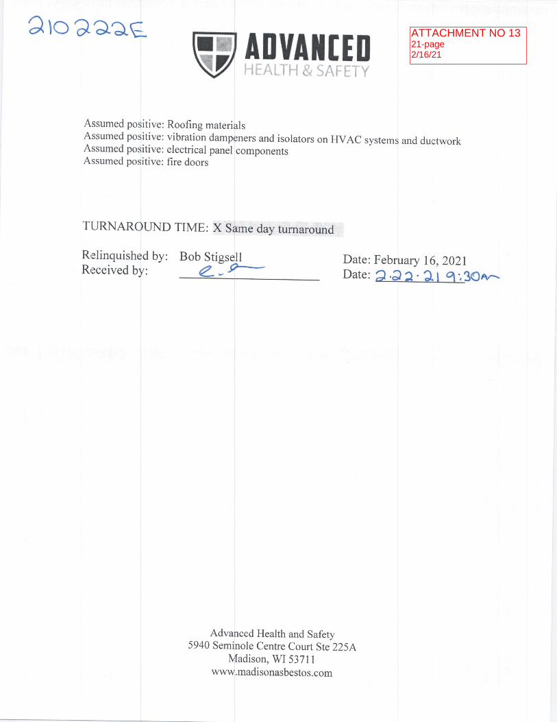
2roaaag
Assumed positive: Roofing materialsAssumed positive: vibration dampeners and isolators on HVAC systemsAssumed positive: electrical panel componentsAssumed positive: fire doors
Date: Feb 1t5,2021Date: ), '.39an
vtruAilrrrand ductwork
TURNAROLND TIME: X Same day turnaround
R,elinquished by: Bob StigseJlR,:ceivedby: 4--*
Advanced Health and Safety5940 Seminole Centre Court Ste 225A
Madison, WI 53711www.madisonasbestos. com
ATTACHMENT NO. 621-page2/21/2021
ATTACHMENT NO 1321-page2/16/21
enmrg
Text Box
ATTACHMENT NO 12 21-page 2/16/21
enmrg
Text Box
ATTACHMENT NO 12 19-page 2/16/21

)tC>1aaf@ Triangle Environmental Serrvice Center, lnc.
Chain of Custody13509 E. Boundary Road, Suite B, Midlothian ,VA23LL2
Tel: (804) 739-7LSt, Fax: (804)739-1753
Sample #: Material Description: Volume/Area (Air) Date Siamples(,- r h r.l i^, .. ivl :r^ lel r,,,. h//gizt(*,'u ,r \(-7 I
7-) ,-J:.L (ttp:. I a)A*,v9-7"2 I
7-3 t,
Speciia I I nstructions:
Page L of 2. pages
4-- 2'2a.'?-1 q'.3oe--
ATTACHMENT NO. 621-page2/21/2021
ATTACHMENT NO 1321-page2/16/21
enmrg
Text Box
ATTACHMENT NO 12 21-page 2/16/21
enmrg
Text Box
ATTACHMENT NO 12 19-page 2/16/21

DR
AW
ING
SE
T
SH
EE
T NO
.
SH
EET TITLE
PR
OJEC
T TITLE
PR
OJE
CT N
O.
DATE
CH
EC
KE
D
DR
AWN
RE
VIS
ION
S
FILE N
AM
E
STR
ANG
, INC
.C
OP
YR
IGH
T
SD
2005050
VILLA
GER
MA
LL
22022224 S. P
ARK ST.
MA
DIS
ON
, WI. 53713
2005
041905
A201
EX
ISTIN
G FIR
ST
FLOO
R PLAN
AR
EA
CA
LCU
LATION LB
FMR
2005050A202
WIC
-
15
10
17A-C
23-24
27
enmrg
Text Box
ATTACHMENT NO 12 21-page 2/16/21
enmrg
Text Box
ATTACHMENT NO 12 19-page 2/16/21

Sample Description ACM Location Quantity
10 Yellow/black floor mastic. Corridor 87 ~300 ft.²
15 Yellow and black floor mastic from under the carpet.
Corridor 87 ~300 ft.²
17A-C Red 9-inch floor tile and mastic Throughout storage 95, Benefit 96 and office 97
~660 ft.²
23 Newer/top layer of floor tile plus black and yellow mastic
H.S. Parents 106 ~672 ft.²
24 older/bottom layer of floor tile plus black and yellow mastic
Sample taken from room currently labeled as 811
~672 ft.²
27 Black floor mastic adhesive Mechanical 105 ~150 ft.²
36 12-inch floor tile plus black mastic Basement floor 2046 ft.²
37A 12-inch floor tile Countertop bar in the basement
~25 ft.²
ATTACHMENT NO. 621-page2/21/2021
ATTACHMENT NO 1321-page2/16/21
enmrg
Text Box
ATTACHMENT NO 12 21-page 2/16/21
enmrg
Text Box
ATTACHMENT NO 12 19-page 2/16/21

RBE Project #: 21226
Owners Project #:Descr:
Project:
Asbestos Abatement
Village on Park, Asbestos Abatement2210 S Park StMadison WI 53713
To:
SENDING:
Notice of Intent
Worker/Supervisor State Certification Cards
Daily Project Logs
Final Waste Manifest signed by landfill
Certificate of Insurance
SUBMITTED:For Your Records
Page: 1
Robinson Brothers Environmental, Inc.220 Raemisch RdWaunakee WI 53597Phone: 608-849-6980Fax: 608-849-6722
Post Project Submittal Document: 00000001Date: 1/12/2022
Matt Gall [email protected]
x
x
x
x
x
ATTACHMENT NO 135-page1/12/22

PROJECT INFORMATION
Notification ID:Notification Type:
Project Type:
22-0807
Original
Renovation with abatement
Abtment Start Date: Abtment End Date:
Working Days:Start Hours: End Hours:
Ordered Demolition:Emergency: Emergency Date:
Schedule/Comments:
12/13/2021 12/20/2021
7:00 am 5:00 pm
N/A
N/A N/A
Notification Status:
Mo,Tu,We,Th,Fr
Submitted
Demolition or Renovation Start Date:
Demolition or Renovation End Date:
Insp Start Date: Insp End Date:Inspector:
02/16/2021 02/16/2021
STIGSELL ROBERT [#3628]
Remove:4,825 sq ft floor tile and mastic
Submitted By: ANNA J SCHLEIF 11/29/2021 02:17 pm
Postmark Date: 11/29/2021
12/13/2021 12/31/2021
FACILITY INFORMATION
Name:
Address 2:Address 1:
City: County:Zip Code:
Village Park
2210 S Park St
MADISON DANE
53713
Prior Use: Current Use:Commercial Commercial
Age: Size (sqft):Stories No:
50 10000
1
Owner Name:
Address 2:Address 1:
City: State:Zip Code:Contact: Phone No:
City of Madison
201 Martin Luther King Jr Blvd
MADISON WI
53703
Matt Gall 608-261-9620
Email:
Structures Demolished:
11/29/2021 2:18:20 PM 1Page:
Asbestos Notification Summary
State of Wisconsin Department of Natural Resources
Bureau of Air Management
ATTACHMENT NO 135-page1/12/22
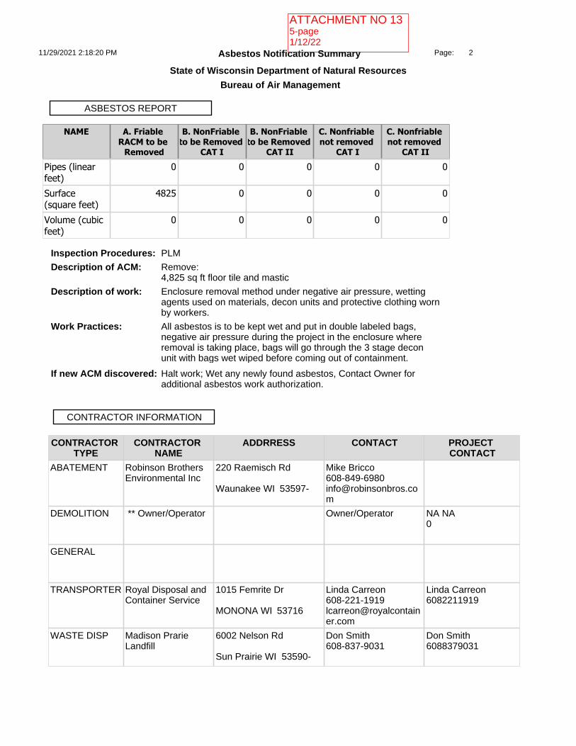
CONTRACTOR TYPE
CONTRACTOR NAME
ADDRRESS CONTACT PROJECT CONTACT
ABATEMENT Robinson Brothers Environmental Inc
220 Raemisch Rd
Waunakee WI 53597-
Mike [email protected]
DEMOLITION ** Owner/Operator
Owner/Operator NA NA0
GENERAL
TRANSPORTER Royal Disposal and Container Service
1015 Femrite Dr
MONONA WI 53716
Linda [email protected]
Linda Carreon6082211919
WASTE DISP Madison Prarie Landfill
6002 Nelson Rd
Sun Prairie WI 53590-
Don Smith608-837-9031
Don Smith6088379031
CONTRACTOR INFORMATION
NAME A. Friable RACM to be
Removed
B. NonFriable to be Removed
CAT I
B. NonFriable to be Removed
CAT II
C. Nonfriable not removed
CAT I
C. Nonfriable not removed
CAT IIPipes (linear feet)
0 0 0 0 0
Surface (square feet)
4825 0 0 0 0
Volume (cubic feet)
0 0 0 0 0
ASBESTOS REPORT
Inspection Procedures:Description of ACM:
Work Practices:
Description of work:
If new ACM discovered:
PLM
Remove:4,825 sq ft floor tile and mastic
Enclosure removal method under negative air pressure, wetting agents used on materials, decon units and protective clothing worn by workers.
All asbestos is to be kept wet and put in double labeled bags, negative air pressure during the project in the enclosure where removal is taking place, bags will go through the 3 stage decon unit with bags wet wiped before coming out of containment.
Halt work; Wet any newly found asbestos, Contact Owner for additional asbestos work authorization.
11/29/2021 2:18:20 PM 2Page:
Asbestos Notification Summary
State of Wisconsin Department of Natural Resources
Bureau of Air Management
ATTACHMENT NO 135-page1/12/22

Fee: Paid:
FEE INFORMATION
700 700 Date: 11/29/2021 2:17:56 PM
11/29/2021 2:18:20 PM 3Page:
Asbestos Notification Summary
State of Wisconsin Department of Natural Resources
Bureau of Air Management
ATTACHMENT NO 135-page1/12/22

ATTACHMENT NO 135-page1/12/22
Related Documents