ALLOWABLE WALL HEIGHTS clarkdietrich.com The technical content of this literature is effective 11/1/12 and supersedes all previous information. 26 Pub. No. CD-STR-TechGuide 11/12 Complies with AISI S100-07 NASPEC with 2010 supplement • IBC 2012 26 Exterior curtain wall overview Allowable wall heights—curtain wall framing. Exterior curtain walls must be designed to withstand the highest winds anticipated for the particular construction location. Wind pressures can be found in the project's structural drawings under the “general notes” section. Please contact technical services at 888-437-3244 for help converting wind speeds (mph) to wind loads (psf). The tables on the following pages provide allowable height limitations for exterior curtain walls subjected to lateral transverse loads. Members shown vary in depth, flange width and steel thickness. Select the studs that are right for your application, also taking into account the acceptable deflection level. General Notes: 1 Lateral loads have been multiplied by 0.7 for deflection determination per IBC 2012 Table 1604.3. 2 The strength increase due to cold work of forming was incorporated for flexural strength as applicable per section A7.2 of AISI-NASPEC, 2007 with 2010 supplement. 3 Limiting heights based on continuous support of each flange over the full length of the stud. 4 Heights based on steel properties only (i.e., composite wall considerations not included in the deflection calculations). 5 All values are based on Fy=33ksi for 33mil and 43mil studs, and Fy=50ksi for 54mil, 68mil and 97mil studs. 6 Adding additional horizontal bridging will not reduce the actual deflection in the wall. To reduce the deflection of a wall stud, either a heavier member is required or an intermediate structural support must be provided. 7 Horizontal structural bridging (or bracing) is defaulted to be at 4 ft. on center for the purposes of the values shown in this catalog. The actual bridging that is ultimately provided is to be determined by the licensed specialty engineer responsible for the cold-formed steel design for the given project. 8 For a top-of-wall application which requires slip track for primary structure movement, mechanical bridging is recommended within 12" of the top of the stud. Deflection. L/240 Length (height) of stud, in inches, divided by 240 (exterior siding or EIFS) L/360 Length (height) of stud, in inches, divided by 360 (exterior stucco) L/600 Length (height) of stud, in inches, divided by 600 (exterior brick) L/720 Length (height) of stud, in inches, divided by 720 (exterior brick) ± wind pressure (psf) Allowable wall height Structural system (by others) Deep leg slip track Vertical deflection gap for primary structure movement as required by E.O.R. Additional lateral bracing required within 12" of slip track Max. deflection Lateral bracing as required Load/Span Table Wind Pressure Notes. IBC 2012/ASCE 7-10 only Due to changes in the model building codes, design wind pressures determined using IBC 2012/ASCE 7-10 are strength level loads (LRFD) in comparison to those determined in earlier IBC codes which were service level loads (ASD). The load/span tables that follow are based on service level (ASD) wind loads. Therefore, to properly use the load/span tables in this catalog, multiply the IBC 2012/ASCE 7-10 design wind pressures by 0.6 (reference section 2.4 ASCE 7-10) prior to entering the load/span tables. Example: • ASCE 7-10 Calculated Design Wind Pressure = 16psf (strength level loads, LRFD) • Convert to service level load (ASD) = 16psf x 0.6 = 10psf • Use 10psf as the Pressure Value used in this table to determine the member span Any other building code The load/span tables that follow are based on service level (ASD) wind loads. If the wind load being used meets this criterion, it does not need to be modified prior to using the tables.

CD Structural ExtCurainWallHeights
Oct 25, 2015
Welcome message from author
This document is posted to help you gain knowledge. Please leave a comment to let me know what you think about it! Share it to your friends and learn new things together.
Transcript
A L L O W A B L E W A L L H E I G H T S
clarkdietrich.comThe technical content of this literature is effective 11/1/12 and supersedes all previous information.
26
Pub. No. CD-STR-TechGuide 11/12Complies with AISI S100-07 NASPEC with 2010 supplement • IBC 2012
26
Notes:1 Studs are checked for simple-span deflection and stress. Stress calculations are
made for mid-span fully braced moment, end shear through the unperforated section, and shear moment interaction through the perforated section 10" away from the end bearing.
2 A 1/3 stress increase is not used.3 Limiting heights are based on continuous lateral support of each flange over the
full height of the stud.4 Listed limiting heights are based on steel properties only.
5 Web crippling check based on 1-inch end bearing. Where limiting heights are followed by "e," web stiffeners are required.
6 For bending, studs are assumed to be adequately braced to develop full allowable moment capacity. Stud distortional buckling based on an assumed Kφ=0.
7 Cells marked with an " * " have h/t > 200, and thus require end stiffeners.8 Capacities are calculated according to the AISI-NASPEC S100-2007,
with 2010 supplement. A 1-1/2" by 4" knockout spaced no closer than 24" o.c. is assumed.
9 All values are based on Fy=33ksi for 33mil and 43mil studs, and Fy=50ksi for 54mil, 68mil and 97mil studs.
10 For deflection calculations, 15psf and higher wind pressures have been multiplied by 0.7, in accordance with footnote "f" of IBC table 1604.3.
11 Lateral loads have not been modified for strength checks. Full loads are applied.
Exterior curtain wall overview
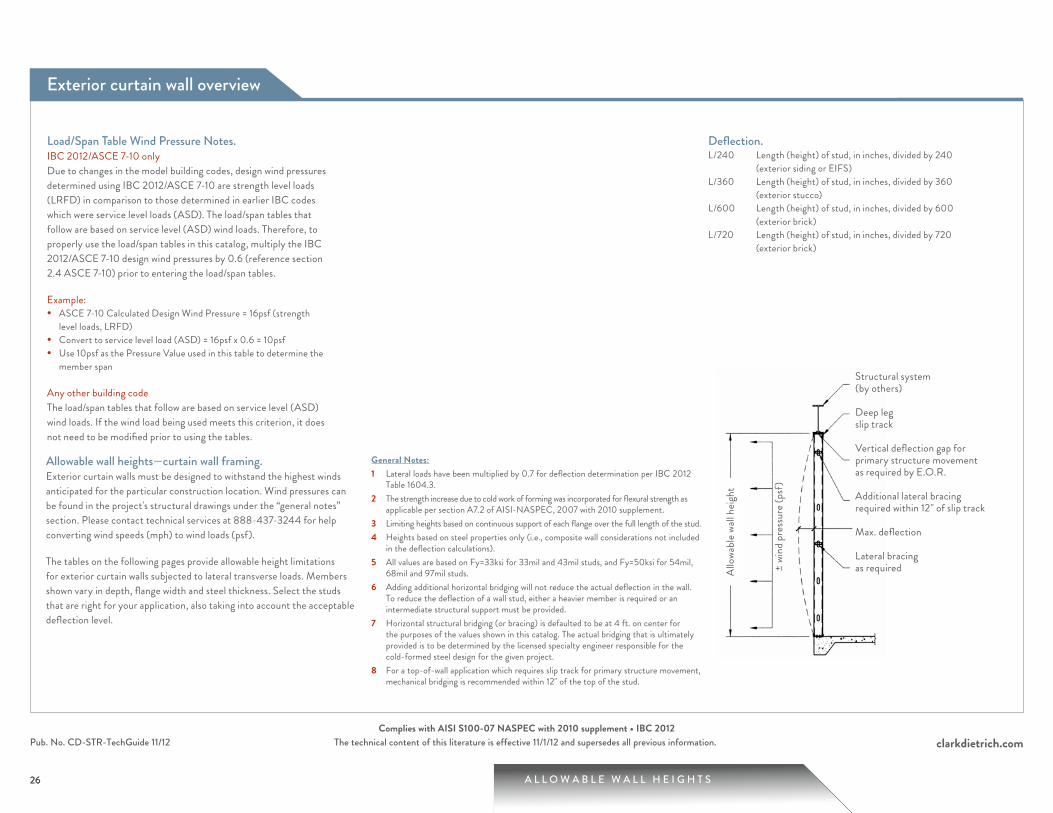
Allowable wall heights—curtain wall framing.Exterior curtain walls must be designed to withstand the highest winds anticipated for the particular construction location. Wind pressures can be found in the project's structural drawings under the “general notes” section. Please contact technical services at 888-437-3244 for help converting wind speeds (mph) to wind loads (psf).
The tables on the following pages provide allowable height limitations for exterior curtain walls subjected to lateral transverse loads. Members shown vary in depth, flange width and steel thickness. Select the studs that are right for your application, also taking into account the acceptable deflection level.
General Notes:1 Lateral loads have been multiplied by 0.7 for deflection determination per IBC 2012
Table 1604.3.2 The strength increase due to cold work of forming was incorporated for flexural strength as
applicable per section A7.2 of AISI-NASPEC, 2007 with 2010 supplement.3 Limiting heights based on continuous support of each flange over the full length of the stud.4 Heights based on steel properties only (i.e., composite wall considerations not included
in the deflection calculations).5 All values are based on Fy=33ksi for 33mil and 43mil studs, and Fy=50ksi for 54mil,
68mil and 97mil studs. 6 Adding additional horizontal bridging will not reduce the actual deflection in the wall.
To reduce the deflection of a wall stud, either a heavier member is required or an intermediate structural support must be provided.
7 Horizontal structural bridging (or bracing) is defaulted to be at 4 ft. on center for the purposes of the values shown in this catalog. The actual bridging that is ultimately provided is to be determined by the licensed specialty engineer responsible for the cold-formed steel design for the given project.
8 For a top-of-wall application which requires slip track for primary structure movement, mechanical bridging is recommended within 12" of the top of the stud.
Deflection.L/240 Length (height) of stud, in inches, divided by 240
(exterior siding or EIFS)L/360 Length (height) of stud, in inches, divided by 360
(exterior stucco)L/600 Length (height) of stud, in inches, divided by 600
(exterior brick)L/720 Length (height) of stud, in inches, divided by 720
(exterior brick)
± wi
nd p
ress
ure (
psf)
Allo
wabl
e wall
heig
ht
Structural system (by others)
Deep leg slip track
Vertical deflection gap for primary structure movement as required by E.O.R.
Additional lateral bracing required within 12" of slip track
Max. deflection
Lateral bracing as required
Load/Span Table Wind Pressure Notes.IBC 2012/ASCE 7-10 onlyDue to changes in the model building codes, design wind pressures determined using IBC 2012/ASCE 7-10 are strength level loads (LRFD) in comparison to those determined in earlier IBC codes which were service level loads (ASD). The load/span tables that follow are based on service level (ASD) wind loads. Therefore, to properly use the load/span tables in this catalog, multiply the IBC 2012/ASCE 7-10 design wind pressures by 0.6 (reference section 2.4 ASCE 7-10) prior to entering the load/span tables.
Example:• ASCE 7-10 Calculated Design Wind Pressure = 16psf (strength
level loads, LRFD)• Convert to service level load (ASD) = 16psf x 0.6 = 10psf• Use 10psf as the Pressure Value used in this table to determine the
member span
Any other building codeThe load/span tables that follow are based on service level (ASD) wind loads. If the wind load being used meets this criterion, it does not need to be modified prior to using the tables.
27 A L L O W A B L E W A L L H E I G H T S
clarkdietrich.comThe technical content of this literature is effective 11/1/12 and supersedes all previous information.Pub. No. CD-STR-TechGuide 11/12Complies with AISI S100-07 NASPEC with 2010 supplement • IBC 2012
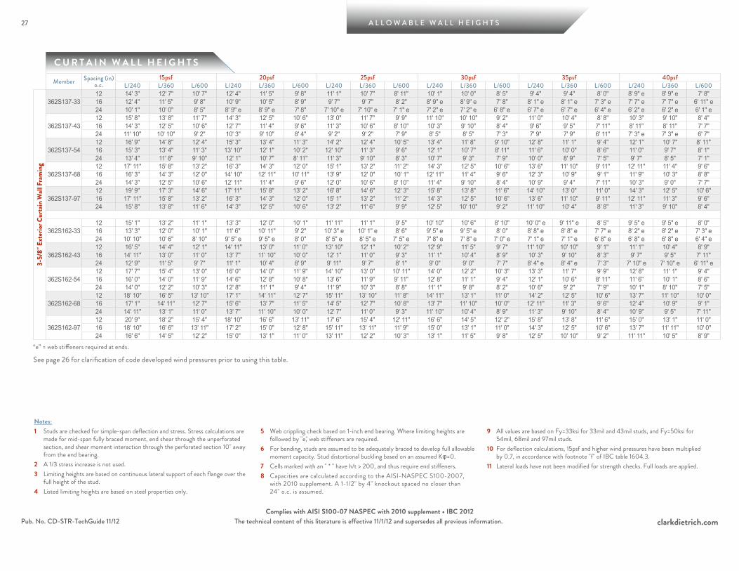
C U R T A I N W A L L H E I G H T S
Notes:1 Studs are checked for simple-span deflection and stress. Stress calculations are
made for mid-span fully braced moment, end shear through the unperforated section, and shear moment interaction through the perforated section 10" away from the end bearing.
2 A 1/3 stress increase is not used.3 Limiting heights are based on continuous lateral support of each flange over the
full height of the stud.4 Listed limiting heights are based on steel properties only.
5 Web crippling check based on 1-inch end bearing. Where limiting heights are followed by "e," web stiffeners are required.
6 For bending, studs are assumed to be adequately braced to develop full allowable moment capacity. Stud distortional buckling based on an assumed Kφ=0.
7 Cells marked with an " * " have h/t > 200, and thus require end stiffeners.8 Capacities are calculated according to the AISI-NASPEC S100-2007,
with 2010 supplement. A 1-1/2" by 4" knockout spaced no closer than 24" o.c. is assumed.
9 All values are based on Fy=33ksi for 33mil and 43mil studs, and Fy=50ksi for 54mil, 68mil and 97mil studs.
10 For deflection calculations, 15psf and higher wind pressures have been multiplied by 0.7, in accordance with footnote "f" of IBC table 1604.3.
11 Lateral loads have not been modified for strength checks. Full loads are applied.
Member Spacing (in) o.c.
15psf 20psf 25psf 30psf 35psf 40psfL/240 L/360 L/600 L/240 L/360 L/600 L/240 L/360 L/600 L/240 L/360 L/600 L/240 L/360 L/600 L/240 L/360 L/600
3-5/
8" E
xter
ior C
urta
in W
all F
ram
ing
362S137-3312 14' 3" 12' 7" 10' 7" 12' 4" 11' 5" 9' 8" 11' 1" 10' 7" 8' 11" 10' 1" 10' 0" 8' 5" 9' 4" 9' 4" 8' 0" 8' 9" e 8' 9" e 7' 8" 16 12' 4" 11' 5" 9' 8" 10' 9" 10' 5" 8' 9" 9' 7" 9' 7" 8' 2" 8' 9" e 8' 9" e 7' 8" 8' 1" e 8' 1" e 7' 3" e 7' 7" e 7' 7" e 6' 11" e24 10' 1" 10' 0" 8' 5" 8' 9" e 8' 9" e 7' 8" 7' 10" e 7' 10" e 7' 1" e 7' 2" e 7' 2" e 6' 8" e 6' 7" e 6' 7" e 6' 4" e 6' 2" e 6' 2" e 6' 1" e
362S137-4312 15' 8" 13' 8" 11' 7" 14' 3" 12' 5" 10' 6" 13' 0" 11' 7" 9' 9" 11' 10" 10' 10" 9' 2" 11' 0" 10' 4" 8' 8" 10' 3" 9' 10" 8' 4" 16 14' 3" 12' 5" 10' 6" 12' 7" 11' 4" 9' 6" 11' 3" 10' 6" 8' 10" 10' 3" 9' 10" 8' 4" 9' 6" 9' 5" 7' 11" 8' 11" 8' 11" 7' 7" 24 11' 10" 10' 10" 9' 2" 10' 3" 9' 10" 8' 4" 9' 2" 9' 2" 7' 9" 8' 5" 8' 5" 7' 3" 7' 9" 7' 9" 6' 11" 7' 3" e 7' 3" e 6' 7"
362S137-5412 16' 9" 14' 8" 12' 4" 15' 3" 13' 4" 11' 3" 14' 2" 12' 4" 10' 5" 13' 4" 11' 8" 9' 10" 12' 8" 11' 1" 9' 4" 12' 1" 10' 7" 8' 11" 16 15' 3" 13' 4" 11' 3" 13' 10" 12' 1" 10' 2" 12' 10" 11' 3" 9' 6" 12' 1" 10' 7" 8' 11" 11' 6" 10' 0" 8' 6" 11' 0" 9' 7" 8' 1" 24 13' 4" 11' 8" 9' 10" 12' 1" 10' 7" 8' 11" 11' 3" 9' 10" 8' 3" 10' 7" 9' 3" 7' 9" 10' 0" 8' 9" 7' 5" 9' 7" 8' 5" 7' 1"
362S137-6812 17' 11" 15' 8" 13' 2" 16' 3" 14' 3" 12' 0" 15' 1" 13' 2" 11' 2" 14' 3" 12' 5" 10' 6" 13' 6" 11' 10" 9' 11" 12' 11" 11' 4" 9' 6" 16 16' 3" 14' 3" 12' 0" 14' 10" 12' 11" 10' 11" 13' 9" 12' 0" 10' 1" 12' 11" 11' 4" 9' 6" 12' 3" 10' 9" 9' 1" 11' 9" 10' 3" 8' 8" 24 14' 3" 12' 5" 10' 6" 12' 11" 11' 4" 9' 6" 12' 0" 10' 6" 8' 10" 11' 4" 9' 10" 8' 4" 10' 9" 9' 4" 7' 11" 10' 3" 9' 0" 7' 7"
362S137-9712 19' 9" 17' 3" 14' 6" 17' 11" 15' 8" 13' 2" 16' 8" 14' 6" 12' 3" 15' 8" 13' 8" 11' 6" 14' 10" 13' 0" 11' 0" 14' 3" 12' 5" 10' 6" 16 17' 11" 15' 8" 13' 2" 16' 3" 14' 3" 12' 0" 15' 1" 13' 2" 11' 2" 14' 3" 12' 5" 10' 6" 13' 6" 11' 10" 9' 11" 12' 11" 11' 3" 9' 6" 24 15' 8" 13' 8" 11' 6" 14' 3" 12' 5" 10' 6" 13' 2" 11' 6" 9' 9" 12' 5" 10' 10" 9' 2" 11' 10" 10' 4" 8' 8" 11' 3" 9' 10" 8' 4"
362S162-3312 15' 1" 13' 2" 11' 1" 13' 3" 12' 0" 10' 1" 11' 11" 11' 1" 9' 5" 10' 10" 10' 6" 8' 10" 10' 0" e 9' 11" e 8' 5" 9' 5" e 9' 5" e 8' 0" 16 13' 3" 12' 0" 10' 1" 11' 6" 10' 11" 9' 2" 10' 3" e 10' 1" e 8' 6" 9' 5" e 9' 5" e 8' 0" 8' 8" e 8' 8" e 7' 7" e 8' 2" e 8' 2" e 7' 3" e24 10' 10" 10' 6" 8' 10" 9' 5" e 9' 5" e 8' 0" 8' 5" e 8' 5" e 7' 5" e 7' 8" e 7' 8" e 7' 0" e 7' 1" e 7' 1" e 6' 8" e 6' 8" e 6' 8" e 6' 4" e
362S162-4312 16' 5" 14' 4" 12' 1" 14' 11" 13' 0" 11' 0" 13' 10" 12' 1" 10' 2" 12' 9" 11' 5" 9' 7" 11' 10" 10' 10" 9' 1" 11' 1" 10' 4" 8' 9" 16 14' 11" 13' 0" 11' 0" 13' 7" 11' 10" 10' 0" 12' 1" 11' 0" 9' 3" 11' 1" 10' 4" 8' 9" 10' 3" 9' 10" 8' 3" 9' 7" 9' 5" 7' 11" 24 12' 9" 11' 5" 9' 7" 11' 1" 10' 4" 8' 9" 9' 11" 9' 7" 8' 1" 9' 0" 9' 0" 7' 7" 8' 4" e 8' 4" e 7' 3" 7' 10" e 7' 10" e 6' 11" e
362S162-5412 17' 7" 15' 4" 13' 0" 16' 0" 14' 0" 11' 9" 14' 10" 13' 0" 10' 11" 14' 0" 12' 2" 10' 3" 13' 3" 11' 7" 9' 9" 12' 8" 11' 1" 9' 4" 16 16' 0" 14' 0" 11' 9" 14' 6" 12' 8" 10' 8" 13' 6" 11' 9" 9' 11" 12' 8" 11' 1" 9' 4" 12' 1" 10' 6" 8' 11" 11' 6" 10' 1" 8' 6" 24 14' 0" 12' 2" 10' 3" 12' 8" 11' 1" 9' 4" 11' 9" 10' 3" 8' 8" 11' 1" 9' 8" 8' 2" 10' 6" 9' 2" 7' 9" 10' 1" 8' 10" 7' 5"
362S162-6812 18' 10" 16' 5" 13' 10" 17' 1" 14' 11" 12' 7" 15' 11" 13' 10" 11' 8" 14' 11" 13' 1" 11' 0" 14' 2" 12' 5" 10' 6" 13' 7" 11' 10" 10' 0" 16 17' 1" 14' 11" 12' 7" 15' 6" 13' 7" 11' 5" 14' 5" 12' 7" 10' 8" 13' 7" 11' 10" 10' 0" 12' 11" 11' 3" 9' 6" 12' 4" 10' 9" 9' 1" 24 14' 11" 13' 1" 11' 0" 13' 7" 11' 10" 10' 0" 12' 7" 11' 0" 9' 3" 11' 10" 10' 4" 8' 9" 11' 3" 9' 10" 8' 4" 10' 9" 9' 5" 7' 11"
362S162-9712 20' 9" 18' 2" 15' 4" 18' 10" 16' 6" 13' 11" 17' 6" 15' 4" 12' 11" 16' 6" 14' 5" 12' 2" 15' 8" 13' 8" 11' 6" 15' 0" 13' 1" 11' 0" 16 18' 10" 16' 6" 13' 11" 17' 2" 15' 0" 12' 8" 15' 11" 13' 11" 11' 9" 15' 0" 13' 1" 11' 0" 14' 3" 12' 5" 10' 6" 13' 7" 11' 11" 10' 0" 24 16' 6" 14' 5" 12' 2" 15' 0" 13' 1" 11' 0" 13' 11" 12' 2" 10' 3" 13' 1" 11' 5" 9' 8" 12' 5" 10' 10" 9' 2" 11' 11" 10' 5" 8' 9"
“e” = web stiffeners required at ends.
See page 26 for clarification of code developed wind pressures prior to using this table.
A L L O W A B L E W A L L H E I G H T S
clarkdietrich.comThe technical content of this literature is effective 11/1/12 and supersedes all previous information.
28
Pub. No. CD-STR-TechGuide 11/12Complies with AISI S100-07 NASPEC with 2010 supplement • IBC 2012
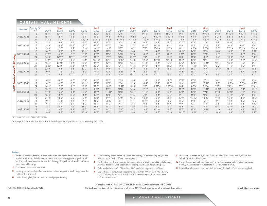
C U R T A I N W A L L H E I G H T S
28
Notes:1 Studs are checked for simple-span deflection and stress. Stress calculations are
made for mid-span fully braced moment, end shear through the unperforated section, and shear moment interaction through the perforated section 10" away from the end bearing.
2 A 1/3 stress increase is not used.3 Limiting heights are based on continuous lateral support of each flange over the
full height of the stud.4 Listed limiting heights are based on steel properties only.
5 Web crippling check based on 1-inch end bearing. Where limiting heights are followed by "e," web stiffeners are required.
6 For bending, studs are assumed to be adequately braced to develop full allowable moment capacity. Stud distortional buckling based on an assumed Kφ=0.
7 Cells marked with an " * " have h/t > 200, and thus require end stiffeners.8 Capacities are calculated according to the AISI-NASPEC S100-2007,
with 2010 supplement. A 1-1/2" by 4" knockout spaced no closer than 24" o.c. is assumed.
9 All values are based on Fy=33ksi for 33mil and 43mil studs, and Fy=50ksi for 54mil, 68mil and 97mil studs.
10 For deflection calculations, 15psf and higher wind pressures have been multiplied by 0.7, in accordance with footnote "f" of IBC table 1604.3.
11 Lateral loads have not been modified for strength checks. Full loads are applied.
Member Spacing (in) o.c.
15psf 20psf 25psf 30psf 35psf 40psfL/240 L/360 L/600 L/240 L/360 L/600 L/240 L/360 L/600 L/240 L/360 L/600 L/240 L/360 L/600 L/240 L/360 L/600
3-5/
8" E
xter
ior C
urta
in W
all F
ram
ing
362S200-3312 15' 11" 13' 11" 11' 8" 13' 11" 12' 7" 10' 8" 12' 5" 11' 8" 9' 10" 11' 4" e 11' 0" e 9' 3" 10' 6" e 10' 6" e 8' 10" 9' 10" e 9' 10" e 8' 5" e16 13' 11" 12' 7" 10' 8" 12' 1" 11' 5" 9' 8" 10' 9" e 10' 8" e 9' 0" 9' 10" e 9' 10" e 8' 5" e 9' 1" e 9' 1" e 8' 0" e 8' 6" e 8' 6" e 7' 8" e24 11' 4" e 11' 0" e 9' 3" 9' 10" e 9' 10" e 8' 5" e 8' 10" e 8' 10" e 7' 10" e 8' 0" e 8' 0" e 7' 4" e 7' 5" e 7' 5" e 7' 0" e 7' 0" e 7' 0" e 6' 8" e
362S200-4312 17' 4" 15' 2" 12' 9" 15' 9" 13' 9" 11' 7" 14' 8" 12' 9" 10' 9" 13' 8" 12' 0" 10' 2" 12' 8" 11' 5" 9' 8" 11' 10" 10' 11" 9' 3" 16 15' 9" 13' 9" 11' 7" 14' 4" 12' 6" 10' 7" 13' 0" 11' 7" 9' 10" 11' 10" 10' 11" 9' 3" 11' 0" 10' 5" 8' 9" 10' 3" 9' 11" 8' 4" 24 13' 8" 12' 0" 10' 2" 11' 10" 10' 11" 9' 3" 10' 7" 10' 2" 8' 7" 9' 8" e 9' 7" e 8' 1" 9' 0" e 9' 0" e 7' 8" 8' 5" e 8' 5" e 7' 4" e
362S200-5412 18' 7" 16' 3" 13' 8" 16' 11" 14' 9" 12' 5" 15' 8" 13' 8" 11' 7" 14' 9" 12' 11" 10' 11" 14' 0" 12' 3" 10' 4" 13' 5" 11' 9" 9' 11" 16 16' 11" 14' 9" 12' 5" 15' 4" 13' 5" 11' 4" 14' 3" 12' 5" 10' 6" 13' 5" 11' 9" 9' 11" 12' 9" 11' 2" 9' 5" 12' 2" 10' 8" 9' 0" 24 14' 9" 12' 11" 10' 11" 13' 5" 11' 9" 9' 11" 12' 5" 10' 11" 9' 2" 11' 9" 10' 3" 8' 8" 11' 2" 9' 9" 8' 2" 10' 8" 9' 4" 7' 10"
362S200-6812 19' 11" 17' 5" 14' 8" 18' 1" 15' 10" 13' 4" 16' 10" 14' 8" 12' 5" 15' 10" 13' 10" 11' 8" 15' 0" 13' 1" 11' 1" 14' 4" 12' 7" 10' 7" 16 18' 1" 15' 10" 13' 4" 16' 5" 14' 4" 12' 1" 15' 3" 13' 4" 11' 3" 14' 4" 12' 7" 10' 7" 13' 8" 11' 11" 10' 1" 13' 1" 11' 5" 9' 7" 24 15' 10" 13' 10" 11' 8" 14' 4" 12' 7" 10' 7" 13' 4" 11' 8" 9' 10" 12' 7" 11' 0" 9' 3" 11' 11" 10' 5" 8' 9" 11' 5" 10' 0" 8' 5"
362S200-9712 22' 0" 19' 3" 16' 3" 20' 0" 17' 6" 14' 9" 18' 7" 16' 3" 13' 8" 17' 6" 15' 3" 12' 11" 16' 7" 14' 6" 12' 3" 15' 11" 13' 11" 11' 8" 16 20' 0" 17' 6" 14' 9" 18' 2" 15' 11" 13' 5" 16' 11" 14' 9" 12' 5" 15' 11" 13' 11" 11' 8" 15' 1" 13' 2" 11' 1" 14' 5" 12' 7" 10' 8" 24 17' 6" 15' 3" 12' 11" 15' 11" 13' 11" 11' 8" 14' 9" 12' 11" 10' 10" 13' 11" 12' 1" 10' 3" 13' 2" 11' 6" 9' 9" 12' 7" 11' 0" 9' 3"
362S250-4312 18' 4" 16' 0" 13' 6" 16' 7" 14' 6" 12' 3" 15' 5" 13' 6" 11' 4" 14' 1" 12' 8" 10' 8" 13' 0" 12' 1" 10' 2" 12' 2" 11' 6" 9' 9" 16 16' 7" 14' 6" 12' 3" 14' 11" 13' 2" 11' 2" 13' 4" 12' 3" 10' 4" 12' 2" 11' 6" 9' 9" 11' 3" 10' 11" 9' 3" 10' 6" e 10' 6" e 8' 10" 24 14' 1" 12' 8" 10' 8" 12' 2" 11' 6" 9' 9" 10' 11" 10' 8" 9' 0" 9' 11" e 9' 11" e 8' 6" 9' 2" e 9' 2" e 8' 1" e 8' 7" e 8' 7" e 7' 9" e
362S250-5412 19' 7" 17' 1" 14' 5" 17' 9" 15' 6" 13' 1" 16' 6" 14' 5" 12' 2" 15' 6" 13' 7" 11' 5" 14' 9" 12' 11" 10' 10" 14' 1" 12' 4" 10' 5" 16 17' 9" 15' 6" 13' 1" 16' 2" 14' 1" 11' 11" 15' 0" 13' 1" 11' 1" 14' 1" 12' 4" 10' 5" 13' 5" 11' 8" 9' 10" 12' 10" 11' 2" 9' 5" 24 15' 6" 13' 7" 11' 5" 14' 1" 12' 4" 10' 5" 13' 1" 11' 5" 9' 8" 12' 4" 10' 9" 9' 1" 11' 8" 10' 3" 8' 7" 11' 2" 9' 9" 8' 3"
362S250-6812 21' 0" 18' 5" 15' 6" 19' 1" 16' 8" 14' 1" 17' 9" 15' 6" 13' 1" 16' 8" 14' 7" 12' 4" 15' 10" 13' 10" 11' 8" 15' 2" 13' 3" 11' 2" 16 19' 1" 16' 8" 14' 1" 17' 4" 15' 2" 12' 10" 16' 1" 14' 1" 11' 11" 15' 2" 13' 3" 11' 2" 14' 5" 12' 7" 10' 7" 13' 9" 12' 0" 10' 2" 24 16' 8" 14' 7" 12' 4" 15' 2" 13' 3" 11' 2" 14' 1" 12' 4" 10' 5" 13' 3" 11' 7" 9' 9" 12' 7" 11' 0" 9' 3" 12' 0" 10' 6" 8' 10"
362S250-9712 23' 4" 20' 4" 17' 2" 21' 2" 18' 6" 15' 7" 19' 8" 17' 2" 14' 6" 18' 6" 16' 2" 13' 8" 17' 7" 15' 4" 12' 11" 16' 10" 14' 8" 12' 5" 16 21' 2" 18' 6" 15' 7" 19' 3" 16' 10" 14' 2" 17' 10" 15' 7" 13' 2" 16' 10" 14' 8" 12' 5" 16' 0" 13' 11" 11' 9" 15' 3" 13' 4" 11' 3" 24 18' 6" 16' 2" 13' 8" 16' 10" 14' 8" 12' 5" 15' 7" 13' 8" 11' 6" 14' 8" 12' 10" 10' 10" 13' 11" 12' 2" 10' 3" 13' 4" 11' 8" 9' 10"
“e” = web stiffeners required at ends.
See page 26 for clarification of code developed wind pressures prior to using this table.
29 A L L O W A B L E W A L L H E I G H T S
clarkdietrich.comThe technical content of this literature is effective 11/1/12 and supersedes all previous information.Pub. No. CD-STR-TechGuide 11/12Complies with AISI S100-07 NASPEC with 2010 supplement • IBC 2012
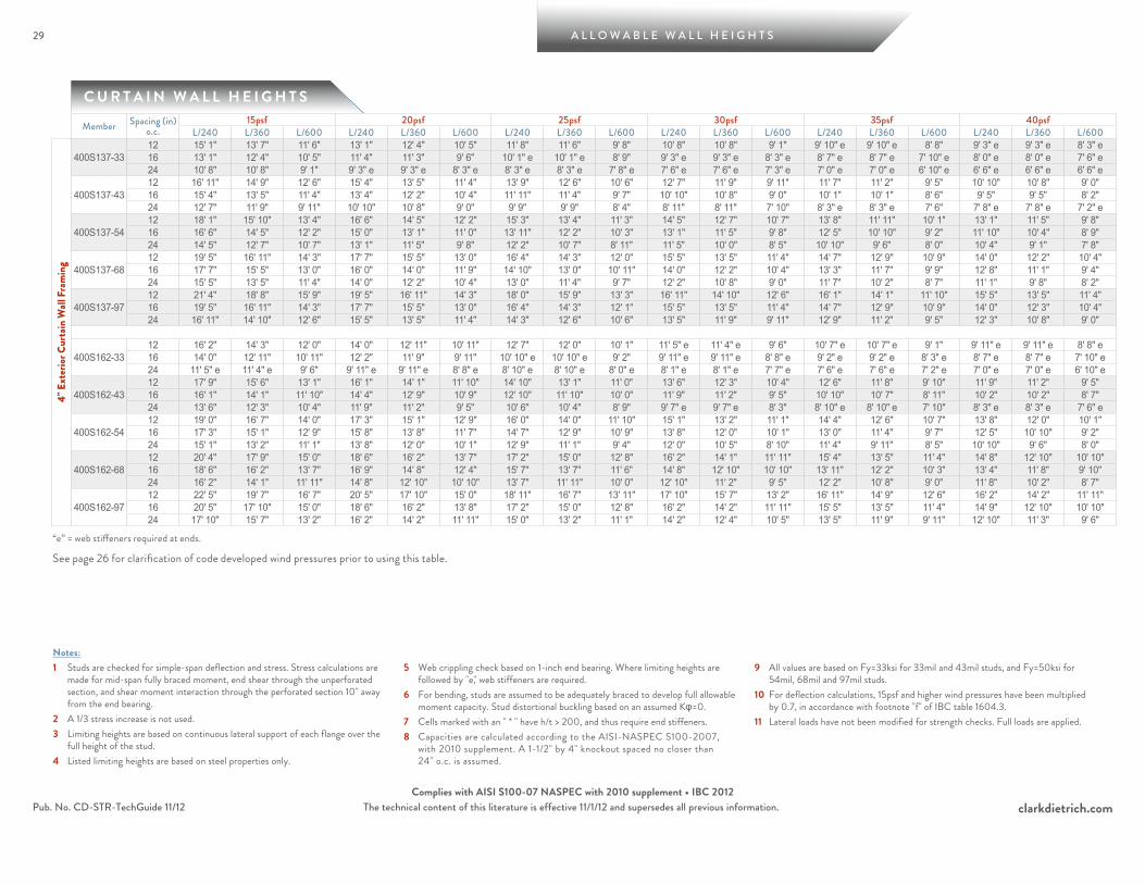
C U R T A I N W A L L H E I G H T S
Notes:1 Studs are checked for simple-span deflection and stress. Stress calculations are
made for mid-span fully braced moment, end shear through the unperforated section, and shear moment interaction through the perforated section 10" away from the end bearing.
2 A 1/3 stress increase is not used.3 Limiting heights are based on continuous lateral support of each flange over the
full height of the stud.4 Listed limiting heights are based on steel properties only.
5 Web crippling check based on 1-inch end bearing. Where limiting heights are followed by "e," web stiffeners are required.
6 For bending, studs are assumed to be adequately braced to develop full allowable moment capacity. Stud distortional buckling based on an assumed Kφ=0.
7 Cells marked with an " * " have h/t > 200, and thus require end stiffeners.8 Capacities are calculated according to the AISI-NASPEC S100-2007,
with 2010 supplement. A 1-1/2" by 4" knockout spaced no closer than 24" o.c. is assumed.
9 All values are based on Fy=33ksi for 33mil and 43mil studs, and Fy=50ksi for 54mil, 68mil and 97mil studs.
10 For deflection calculations, 15psf and higher wind pressures have been multiplied by 0.7, in accordance with footnote "f" of IBC table 1604.3.
11 Lateral loads have not been modified for strength checks. Full loads are applied.
Member Spacing (in) o.c.
15psf 20psf 25psf 30psf 35psf 40psfL/240 L/360 L/600 L/240 L/360 L/600 L/240 L/360 L/600 L/240 L/360 L/600 L/240 L/360 L/600 L/240 L/360 L/600
4" E
xter
ior C
urta
in W
all F
ram
ing
400S137-3312 15' 1" 13' 7" 11' 6" 13' 1" 12' 4" 10' 5" 11' 8" 11' 6" 9' 8" 10' 8" 10' 8" 9' 1" 9' 10" e 9' 10" e 8' 8" 9' 3" e 9' 3" e 8' 3" e16 13' 1" 12' 4" 10' 5" 11' 4" 11' 3" 9' 6" 10' 1" e 10' 1" e 8' 9" 9' 3" e 9' 3" e 8' 3" e 8' 7" e 8' 7" e 7' 10" e 8' 0" e 8' 0" e 7' 6" e24 10' 8" 10' 8" 9' 1" 9' 3" e 9' 3" e 8' 3" e 8' 3" e 8' 3" e 7' 8" e 7' 6" e 7' 6" e 7' 3" e 7' 0" e 7' 0" e 6' 10" e 6' 6" e 6' 6" e 6' 6" e
400S137-4312 16' 11" 14' 9" 12' 6" 15' 4" 13' 5" 11' 4" 13' 9" 12' 6" 10' 6" 12' 7" 11' 9" 9' 11" 11' 7" 11' 2" 9' 5" 10' 10" 10' 8" 9' 0" 16 15' 4" 13' 5" 11' 4" 13' 4" 12' 2" 10' 4" 11' 11" 11' 4" 9' 7" 10' 10" 10' 8" 9' 0" 10' 1" 10' 1" 8' 6" 9' 5" 9' 5" 8' 2" 24 12' 7" 11' 9" 9' 11" 10' 10" 10' 8" 9' 0" 9' 9" 9' 9" 8' 4" 8' 11" 8' 11" 7' 10" 8' 3" e 8' 3" e 7' 6" 7' 8" e 7' 8" e 7' 2" e
400S137-5412 18' 1" 15' 10" 13' 4" 16' 6" 14' 5" 12' 2" 15' 3" 13' 4" 11' 3" 14' 5" 12' 7" 10' 7" 13' 8" 11' 11" 10' 1" 13' 1" 11' 5" 9' 8" 16 16' 6" 14' 5" 12' 2" 15' 0" 13' 1" 11' 0" 13' 11" 12' 2" 10' 3" 13' 1" 11' 5" 9' 8" 12' 5" 10' 10" 9' 2" 11' 10" 10' 4" 8' 9" 24 14' 5" 12' 7" 10' 7" 13' 1" 11' 5" 9' 8" 12' 2" 10' 7" 8' 11" 11' 5" 10' 0" 8' 5" 10' 10" 9' 6" 8' 0" 10' 4" 9' 1" 7' 8"
400S137-6812 19' 5" 16' 11" 14' 3" 17' 7" 15' 5" 13' 0" 16' 4" 14' 3" 12' 0" 15' 5" 13' 5" 11' 4" 14' 7" 12' 9" 10' 9" 14' 0" 12' 2" 10' 4" 16 17' 7" 15' 5" 13' 0" 16' 0" 14' 0" 11' 9" 14' 10" 13' 0" 10' 11" 14' 0" 12' 2" 10' 4" 13' 3" 11' 7" 9' 9" 12' 8" 11' 1" 9' 4" 24 15' 5" 13' 5" 11' 4" 14' 0" 12' 2" 10' 4" 13' 0" 11' 4" 9' 7" 12' 2" 10' 8" 9' 0" 11' 7" 10' 2" 8' 7" 11' 1" 9' 8" 8' 2"
400S137-9712 21' 4" 18' 8" 15' 9" 19' 5" 16' 11" 14' 3" 18' 0" 15' 9" 13' 3" 16' 11" 14' 10" 12' 6" 16' 1" 14' 1" 11' 10" 15' 5" 13' 5" 11' 4" 16 19' 5" 16' 11" 14' 3" 17' 7" 15' 5" 13' 0" 16' 4" 14' 3" 12' 1" 15' 5" 13' 5" 11' 4" 14' 7" 12' 9" 10' 9" 14' 0" 12' 3" 10' 4" 24 16' 11" 14' 10" 12' 6" 15' 5" 13' 5" 11' 4" 14' 3" 12' 6" 10' 6" 13' 5" 11' 9" 9' 11" 12' 9" 11' 2" 9' 5" 12' 3" 10' 8" 9' 0"
400S162-3312 16' 2" 14' 3" 12' 0" 14' 0" 12' 11" 10' 11" 12' 7" 12' 0" 10' 1" 11' 5" e 11' 4" e 9' 6" 10' 7" e 10' 7" e 9' 1" 9' 11" e 9' 11" e 8' 8" e16 14' 0" 12' 11" 10' 11" 12' 2" 11' 9" 9' 11" 10' 10" e 10' 10" e 9' 2" 9' 11" e 9' 11" e 8' 8" e 9' 2" e 9' 2" e 8' 3" e 8' 7" e 8' 7" e 7' 10" e24 11' 5" e 11' 4" e 9' 6" 9' 11" e 9' 11" e 8' 8" e 8' 10" e 8' 10" e 8' 0" e 8' 1" e 8' 1" e 7' 7" e 7' 6" e 7' 6" e 7' 2" e 7' 0" e 7' 0" e 6' 10" e
400S162-4312 17' 9" 15' 6" 13' 1" 16' 1" 14' 1" 11' 10" 14' 10" 13' 1" 11' 0" 13' 6" 12' 3" 10' 4" 12' 6" 11' 8" 9' 10" 11' 9" 11' 2" 9' 5" 16 16' 1" 14' 1" 11' 10" 14' 4" 12' 9" 10' 9" 12' 10" 11' 10" 10' 0" 11' 9" 11' 2" 9' 5" 10' 10" 10' 7" 8' 11" 10' 2" 10' 2" 8' 7" 24 13' 6" 12' 3" 10' 4" 11' 9" 11' 2" 9' 5" 10' 6" 10' 4" 8' 9" 9' 7" e 9' 7" e 8' 3" 8' 10" e 8' 10" e 7' 10" 8' 3" e 8' 3" e 7' 6" e
400S162-5412 19' 0" 16' 7" 14' 0" 17' 3" 15' 1" 12' 9" 16' 0" 14' 0" 11' 10" 15' 1" 13' 2" 11' 1" 14' 4" 12' 6" 10' 7" 13' 8" 12' 0" 10' 1" 16 17' 3" 15' 1" 12' 9" 15' 8" 13' 8" 11' 7" 14' 7" 12' 9" 10' 9" 13' 8" 12' 0" 10' 1" 13' 0" 11' 4" 9' 7" 12' 5" 10' 10" 9' 2" 24 15' 1" 13' 2" 11' 1" 13' 8" 12' 0" 10' 1" 12' 9" 11' 1" 9' 4" 12' 0" 10' 5" 8' 10" 11' 4" 9' 11" 8' 5" 10' 10" 9' 6" 8' 0"
400S162-6812 20' 4" 17' 9" 15' 0" 18' 6" 16' 2" 13' 7" 17' 2" 15' 0" 12' 8" 16' 2" 14' 1" 11' 11" 15' 4" 13' 5" 11' 4" 14' 8" 12' 10" 10' 10" 16 18' 6" 16' 2" 13' 7" 16' 9" 14' 8" 12' 4" 15' 7" 13' 7" 11' 6" 14' 8" 12' 10" 10' 10" 13' 11" 12' 2" 10' 3" 13' 4" 11' 8" 9' 10" 24 16' 2" 14' 1" 11' 11" 14' 8" 12' 10" 10' 10" 13' 7" 11' 11" 10' 0" 12' 10" 11' 2" 9' 5" 12' 2" 10' 8" 9' 0" 11' 8" 10' 2" 8' 7"
400S162-9712 22' 5" 19' 7" 16' 7" 20' 5" 17' 10" 15' 0" 18' 11" 16' 7" 13' 11" 17' 10" 15' 7" 13' 2" 16' 11" 14' 9" 12' 6" 16' 2" 14' 2" 11' 11" 16 20' 5" 17' 10" 15' 0" 18' 6" 16' 2" 13' 8" 17' 2" 15' 0" 12' 8" 16' 2" 14' 2" 11' 11" 15' 5" 13' 5" 11' 4" 14' 9" 12' 10" 10' 10" 24 17' 10" 15' 7" 13' 2" 16' 2" 14' 2" 11' 11" 15' 0" 13' 2" 11' 1" 14' 2" 12' 4" 10' 5" 13' 5" 11' 9" 9' 11" 12' 10" 11' 3" 9' 6"
“e” = web stiffeners required at ends.
See page 26 for clarification of code developed wind pressures prior to using this table.
A L L O W A B L E W A L L H E I G H T S
clarkdietrich.comThe technical content of this literature is effective 11/1/12 and supersedes all previous information.
30
Pub. No. CD-STR-TechGuide 11/12Complies with AISI S100-07 NASPEC with 2010 supplement • IBC 2012
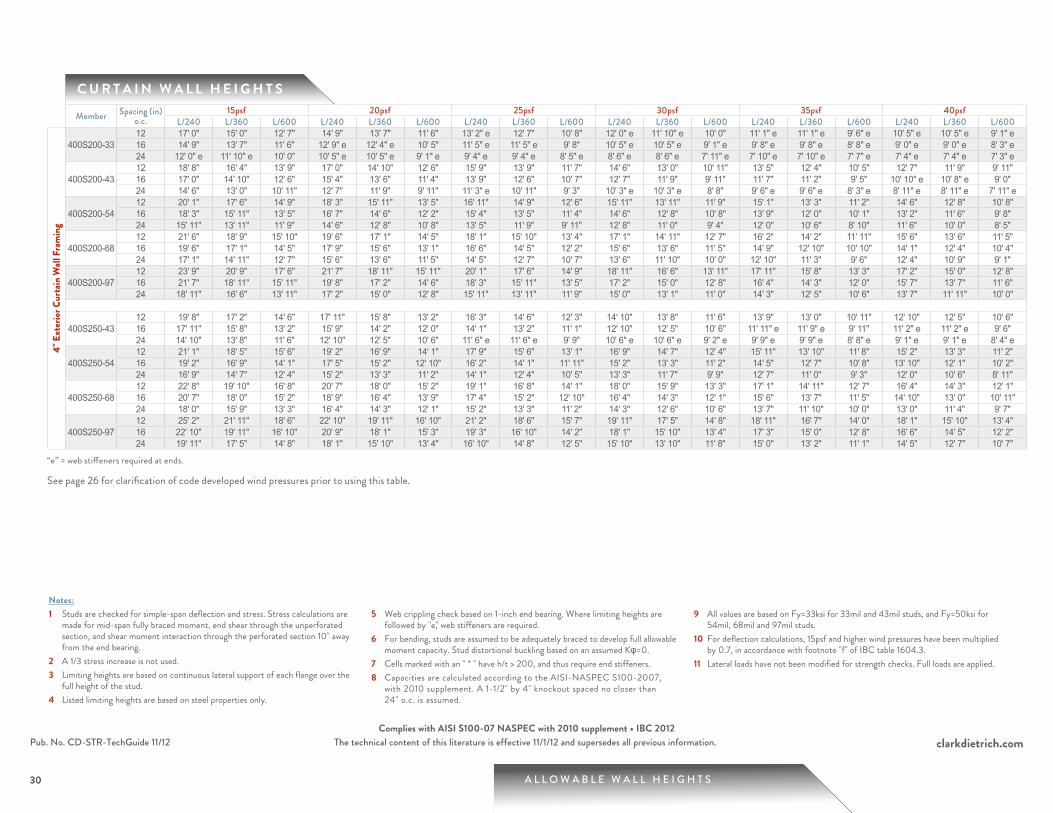
C U R T A I N W A L L H E I G H T S
30
Notes:1 Studs are checked for simple-span deflection and stress. Stress calculations are
made for mid-span fully braced moment, end shear through the unperforated section, and shear moment interaction through the perforated section 10" away from the end bearing.
2 A 1/3 stress increase is not used.3 Limiting heights are based on continuous lateral support of each flange over the
full height of the stud.4 Listed limiting heights are based on steel properties only.
5 Web crippling check based on 1-inch end bearing. Where limiting heights are followed by "e," web stiffeners are required.
6 For bending, studs are assumed to be adequately braced to develop full allowable moment capacity. Stud distortional buckling based on an assumed Kφ=0.
7 Cells marked with an " * " have h/t > 200, and thus require end stiffeners.8 Capacities are calculated according to the AISI-NASPEC S100-2007,
with 2010 supplement. A 1-1/2" by 4" knockout spaced no closer than 24" o.c. is assumed.
9 All values are based on Fy=33ksi for 33mil and 43mil studs, and Fy=50ksi for 54mil, 68mil and 97mil studs.
10 For deflection calculations, 15psf and higher wind pressures have been multiplied by 0.7, in accordance with footnote "f" of IBC table 1604.3.
11 Lateral loads have not been modified for strength checks. Full loads are applied.
Member Spacing (in) o.c.
15psf 20psf 25psf 30psf 35psf 40psfL/240 L/360 L/600 L/240 L/360 L/600 L/240 L/360 L/600 L/240 L/360 L/600 L/240 L/360 L/600 L/240 L/360 L/600
4" E
xter
ior C
urta
in W
all F
ram
ing
400S200-3312 17' 0" 15' 0" 12' 7" 14' 9" 13' 7" 11' 6" 13' 2" e 12' 7" 10' 8" 12' 0" e 11' 10" e 10' 0" 11' 1" e 11' 1" e 9' 6" e 10' 5" e 10' 5" e 9' 1" e16 14' 9" 13' 7" 11' 6" 12' 9" e 12' 4" e 10' 5" 11' 5" e 11' 5" e 9' 8" 10' 5" e 10' 5" e 9' 1" e 9' 8" e 9' 8" e 8' 8" e 9' 0" e 9' 0" e 8' 3" e24 12' 0" e 11' 10" e 10' 0" 10' 5" e 10' 5" e 9' 1" e 9' 4" e 9' 4" e 8' 5" e 8' 6" e 8' 6" e 7' 11" e 7' 10" e 7' 10" e 7' 7" e 7' 4" e 7' 4" e 7' 3" e
400S200-4312 18' 8" 16' 4" 13' 9" 17' 0" 14' 10" 12' 6" 15' 9" 13' 9" 11' 7" 14' 6" 13' 0" 10' 11" 13' 5" 12' 4" 10' 5" 12' 7" 11' 9" 9' 11" 16 17' 0" 14' 10" 12' 6" 15' 4" 13' 6" 11' 4" 13' 9" 12' 6" 10' 7" 12' 7" 11' 9" 9' 11" 11' 7" 11' 2" 9' 5" 10' 10" e 10' 8" e 9' 0" 24 14' 6" 13' 0" 10' 11" 12' 7" 11' 9" 9' 11" 11' 3" e 10' 11" 9' 3" 10' 3" e 10' 3" e 8' 8" 9' 6" e 9' 6" e 8' 3" e 8' 11" e 8' 11" e 7' 11" e
400S200-5412 20' 1" 17' 6" 14' 9" 18' 3" 15' 11" 13' 5" 16' 11" 14' 9" 12' 6" 15' 11" 13' 11" 11' 9" 15' 1" 13' 3" 11' 2" 14' 6" 12' 8" 10' 8" 16 18' 3" 15' 11" 13' 5" 16' 7" 14' 6" 12' 2" 15' 4" 13' 5" 11' 4" 14' 6" 12' 8" 10' 8" 13' 9" 12' 0" 10' 1" 13' 2" 11' 6" 9' 8" 24 15' 11" 13' 11" 11' 9" 14' 6" 12' 8" 10' 8" 13' 5" 11' 9" 9' 11" 12' 8" 11' 0" 9' 4" 12' 0" 10' 6" 8' 10" 11' 6" 10' 0" 8' 5"
400S200-6812 21' 6" 18' 9" 15' 10" 19' 6" 17' 1" 14' 5" 18' 1" 15' 10" 13' 4" 17' 1" 14' 11" 12' 7" 16' 2" 14' 2" 11' 11" 15' 6" 13' 6" 11' 5" 16 19' 6" 17' 1" 14' 5" 17' 9" 15' 6" 13' 1" 16' 6" 14' 5" 12' 2" 15' 6" 13' 6" 11' 5" 14' 9" 12' 10" 10' 10" 14' 1" 12' 4" 10' 4" 24 17' 1" 14' 11" 12' 7" 15' 6" 13' 6" 11' 5" 14' 5" 12' 7" 10' 7" 13' 6" 11' 10" 10' 0" 12' 10" 11' 3" 9' 6" 12' 4" 10' 9" 9' 1"
400S200-9712 23' 9" 20' 9" 17' 6" 21' 7" 18' 11" 15' 11" 20' 1" 17' 6" 14' 9" 18' 11" 16' 6" 13' 11" 17' 11" 15' 8" 13' 3" 17' 2" 15' 0" 12' 8" 16 21' 7" 18' 11" 15' 11" 19' 8" 17' 2" 14' 6" 18' 3" 15' 11" 13' 5" 17' 2" 15' 0" 12' 8" 16' 4" 14' 3" 12' 0" 15' 7" 13' 7" 11' 6" 24 18' 11" 16' 6" 13' 11" 17' 2" 15' 0" 12' 8" 15' 11" 13' 11" 11' 9" 15' 0" 13' 1" 11' 0" 14' 3" 12' 5" 10' 6" 13' 7" 11' 11" 10' 0"
400S250-4312 19' 8" 17' 2" 14' 6" 17' 11" 15' 8" 13' 2" 16' 3" 14' 6" 12' 3" 14' 10" 13' 8" 11' 6" 13' 9" 13' 0" 10' 11" 12' 10" 12' 5" 10' 6" 16 17' 11" 15' 8" 13' 2" 15' 9" 14' 2" 12' 0" 14' 1" 13' 2" 11' 1" 12' 10" 12' 5" 10' 6" 11' 11" e 11' 9" e 9' 11" 11' 2" e 11' 2" e 9' 6" 24 14' 10" 13' 8" 11' 6" 12' 10" 12' 5" 10' 6" 11' 6" e 11' 6" e 9' 9" 10' 6" e 10' 6" e 9' 2" e 9' 9" e 9' 9" e 8' 8" e 9' 1" e 9' 1" e 8' 4" e
400S250-5412 21' 1" 18' 5" 15' 6" 19' 2" 16' 9" 14' 1" 17' 9" 15' 6" 13' 1" 16' 9" 14' 7" 12' 4" 15' 11" 13' 10" 11' 8" 15' 2" 13' 3" 11' 2" 16 19' 2" 16' 9" 14' 1" 17' 5" 15' 2" 12' 10" 16' 2" 14' 1" 11' 11" 15' 2" 13' 3" 11' 2" 14' 5" 12' 7" 10' 8" 13' 10" 12' 1" 10' 2" 24 16' 9" 14' 7" 12' 4" 15' 2" 13' 3" 11' 2" 14' 1" 12' 4" 10' 5" 13' 3" 11' 7" 9' 9" 12' 7" 11' 0" 9' 3" 12' 0" 10' 6" 8' 11"
400S250-6812 22' 8" 19' 10" 16' 8" 20' 7" 18' 0" 15' 2" 19' 1" 16' 8" 14' 1" 18' 0" 15' 9" 13' 3" 17' 1" 14' 11" 12' 7" 16' 4" 14' 3" 12' 1" 16 20' 7" 18' 0" 15' 2" 18' 9" 16' 4" 13' 9" 17' 4" 15' 2" 12' 10" 16' 4" 14' 3" 12' 1" 15' 6" 13' 7" 11' 5" 14' 10" 13' 0" 10' 11" 24 18' 0" 15' 9" 13' 3" 16' 4" 14' 3" 12' 1" 15' 2" 13' 3" 11' 2" 14' 3" 12' 6" 10' 6" 13' 7" 11' 10" 10' 0" 13' 0" 11' 4" 9' 7"
400S250-9712 25' 2" 21' 11" 18' 6" 22' 10" 19' 11" 16' 10" 21' 2" 18' 6" 15' 7" 19' 11" 17' 5" 14' 8" 18' 11" 16' 7" 14' 0" 18' 1" 15' 10" 13' 4" 16 22' 10" 19' 11" 16' 10" 20' 9" 18' 1" 15' 3" 19' 3" 16' 10" 14' 2" 18' 1" 15' 10" 13' 4" 17' 3" 15' 0" 12' 8" 16' 6" 14' 5" 12' 2" 24 19' 11" 17' 5" 14' 8" 18' 1" 15' 10" 13' 4" 16' 10" 14' 8" 12' 5" 15' 10" 13' 10" 11' 8" 15' 0" 13' 2" 11' 1" 14' 5" 12' 7" 10' 7"
“e” = web stiffeners required at ends.
See page 26 for clarification of code developed wind pressures prior to using this table.

31 A L L O W A B L E W A L L H E I G H T S
clarkdietrich.comThe technical content of this literature is effective 11/1/12 and supersedes all previous information.Pub. No. CD-STR-TechGuide 11/12Complies with AISI S100-07 NASPEC with 2010 supplement • IBC 2012
C U R T A I N W A L L H E I G H T S
Notes:1 Studs are checked for simple-span deflection and stress. Stress calculations are
made for mid-span fully braced moment, end shear through the unperforated section, and shear moment interaction through the perforated section 10" away from the end bearing.
2 A 1/3 stress increase is not used.3 Limiting heights are based on continuous lateral support of each flange over the
full height of the stud.4 Listed limiting heights are based on steel properties only.
5 Web crippling check based on 1-inch end bearing. Where limiting heights are followed by "e," web stiffeners are required.
6 For bending, studs are assumed to be adequately braced to develop full allowable moment capacity. Stud distortional buckling based on an assumed Kφ=0.
7 Cells marked with an " * " have h/t > 200, and thus require end stiffeners.8 Capacities are calculated according to the AISI-NASPEC S100-2007,
with 2010 supplement. A 1-1/2" by 4" knockout spaced no closer than 24" o.c. is assumed.
9 All values are based on Fy=33ksi for 33mil and 43mil studs, and Fy=50ksi for 54mil, 68mil and 97mil studs.
10 For deflection calculations, 15psf and higher wind pressures have been multiplied by 0.7, in accordance with footnote "f" of IBC table 1604.3.
11 Lateral loads have not been modified for strength checks. Full loads are applied.
Member Spacing (in) o.c.
15psf 20psf 25psf 30psf 35psf 40psfL/240 L/360 L/600 L/240 L/360 L/600 L/240 L/360 L/600 L/240 L/360 L/600 L/240 L/360 L/600 L/240 L/360 L/600
6" E
xter
ior C
urta
in W
all F
ram
ing
600S137-3312 19' 1" 18' 7" 15' 8" 16' 6" e 16' 6" e 14' 3" 14' 9" e 14' 9" e 13' 3" e 13' 6" e 13' 6" e 12' 5" e 12' 6" e 12' 6" e 11' 10" e 11' 8" e 11' 8" e 11' 4" e16 16' 6" e 16' 6" e 14' 3" 14' 4" e 14' 4" e 12' 11" e 12' 10" e 12' 10" e 12' 0" e 11' 8" e 11' 8" e 11' 4" e 10' 10" e 10' 10" e 10' 9" e 10' 1" e 10' 1" e 10' 1" e24 13' 6" e 13' 6" e 12' 5" e 11' 8" e 11' 8" e 11' 4" e 10' 5" e 10' 5" e 10' 5" e 9' 6" e 9' 6" e 9' 6" e 8' 10" e 8' 10" e 8' 10" e 8' 3" e 8' 3" e 8' 3" e
600S137-4312 22' 11" 20' 5" 17' 3" 19' 10" 18' 6" 15' 8" 17' 9" 17' 3" 14' 6" 16' 3" 16' 2" 13' 8" 15' 0" e 15' 0" e 13' 0" 14' 0" e 14' 0" e 12' 5" 16 19' 10" 18' 6" 15' 8" 17' 2" 16' 10" 14' 2" 15' 5" 15' 5" 13' 2" 14' 0" e 14' 0" e 12' 5" 13' 0" e 13' 0" e 11' 9" e 12' 2" e 12' 2" e 11' 3" e24 16' 3" 16' 2" 13' 8" 14' 0" e 14' 0" e 12' 5" 12' 7" e 12' 7" e 11' 6" e 11' 6" e 11' 6" e 10' 10" e 10' 7" e 10' 7" e 10' 4" e 9' 11" e 9' 11" e 9' 10" e
600S137-5412 25' 1" 21' 11" 18' 5" 22' 9" 19' 11" 16' 9" 21' 2" 18' 5" 15' 7" 19' 11" 17' 4" 14' 8" 18' 11" 16' 6" 13' 11" 18' 1" 15' 9" 13' 4" 16 22' 9" 19' 11" 16' 9" 20' 8" 18' 1" 15' 3" 19' 2" 16' 9" 14' 2" 18' 1" 15' 9" 13' 4" 17' 2" 15' 0" 12' 8" 16' 4" 14' 4" 12' 1" 24 19' 11" 17' 4" 14' 8" 18' 1" 15' 9" 13' 4" 16' 9" 14' 8" 12' 4" 15' 4" 13' 9" 11' 8" 14' 3" 13' 1" 11' 1" 13' 4" 12' 6" 10' 7"
600S137-6812 26' 10" 23' 5" 19' 9" 24' 5" 21' 4" 18' 0" 22' 8" 19' 9" 16' 8" 21' 4" 18' 7" 15' 8" 20' 3" 17' 8" 14' 11" 19' 4" 16' 11" 14' 3" 16 24' 5" 21' 4" 18' 0" 22' 2" 19' 4" 16' 4" 20' 7" 18' 0" 15' 2" 19' 4" 16' 11" 14' 3" 18' 5" 16' 1" 13' 7" 17' 7" 15' 4" 12' 11" 24 21' 4" 18' 7" 15' 8" 19' 4" 16' 11" 14' 3" 18' 0" 15' 8" 13' 3" 16' 11" 14' 9" 12' 5" 16' 1" 14' 0" 11' 10" 15' 4" 13' 5" 11' 4"
600S137-9712 29' 8" 25' 11" 21' 10" 27' 0" 23' 7" 19' 10" 25' 0" 21' 10" 18' 5" 23' 7" 20' 7" 17' 4" 22' 5" 19' 7" 16' 6" 21' 5" 18' 8" 15' 9" 16 27' 0" 23' 7" 19' 10" 24' 6" 21' 5" 18' 1" 22' 9" 19' 10" 16' 9" 21' 5" 18' 8" 15' 9" 20' 4" 17' 9" 15' 0" 19' 5" 17' 0" 14' 4" 24 23' 7" 20' 7" 17' 4" 21' 5" 18' 8" 15' 9" 19' 10" 17' 4" 14' 8" 18' 8" 16' 4" 13' 9" 17' 9" 15' 6" 13' 1" 17' 0" 14' 10" 12' 6"
600S162-3312 20' 6" e 19' 6" 16' 6" 17' 9" e 17' 9" e 15' 0" 15' 11" e 15' 11" e 13' 11" e 14' 6" e 14' 6" e 13' 1" e 13' 5" e 13' 5" e 12' 5" e 12' 7" e 12' 7" e 11' 11" e16 17' 9" e 17' 9" e 15' 0" 15' 5" e 15' 5" e 13' 7" e 13' 9" e 13' 9" e 12' 8" e 12' 7" e 12' 7" e 11' 11" e 11' 8" e 11' 8" e 11' 3" e 10' 11" e 10' 11" e 10' 10" e24 14' 6" e 14' 6" e 13' 1" e 12' 7" e 12' 7" e 11' 11" e 11' 3" e 11' 3" e 11' 0" e 10' 3" e 10' 3" e 10' 3" e 9' 6" e 9' 6" e 9' 6" e 8' 11" e 8' 11" e 8' 11" e
600S162-4312 24' 4" 21' 3" 17' 11" 22' 0" 19' 4" 16' 4" 19' 8" 17' 11" 15' 2" 17' 11" e 16' 11" 14' 3" 16' 7" e 16' 1" e 13' 6" 15' 6" e 15' 4" e 12' 11" 16 22' 0" 19' 4" 16' 4" 19' 0" 17' 7" 14' 10" 17' 0" e 16' 4" e 13' 9" 15' 6" e 15' 4" e 12' 11" 14' 5" e 14' 5" e 12' 4" e 13' 5" e 13' 5" e 11' 9" e24 17' 11" e 16' 11" 14' 3" 15' 6" e 15' 4" e 12' 11" 13' 11" e 13' 11" e 12' 0" e 12' 8" e 12' 8" e 11' 4" e 11' 9" e 11' 9" e 10' 9" e 11' 0" e 11' 0" e 10' 3" e
600S162-5412 26' 2" 22' 10" 19' 3" 23' 9" 20' 9" 17' 6" 22' 1" 19' 3" 16' 3" 20' 9" 18' 1" 15' 3" 19' 8" 17' 3" 14' 6" 18' 10" 16' 6" 13' 11" 16 23' 9" 20' 9" 17' 6" 21' 7" 18' 10" 15' 11" 20' 0" 17' 6" 14' 9" 18' 10" 16' 6" 13' 11" 17' 11" 15' 8" 13' 2" 17' 2" 15' 0" 12' 7" 24 20' 9" 18' 1" 15' 3" 18' 10" 16' 6" 13' 11" 17' 6" 15' 3" 12' 11" 16' 6" 14' 5" 12' 2" 15' 8" 13' 8" 11' 6" 14' 8" 13' 1" 11' 0"
600S162-6812 28' 0" 24' 6" 20' 8" 25' 6" 22' 3" 18' 9" 23' 8" 20' 8" 17' 5" 22' 3" 19' 5" 16' 5" 21' 2" 18' 5" 15' 7" 20' 3" 17' 8" 14' 11" 16 25' 6" 22' 3" 18' 9" 23' 2" 20' 3" 17' 1" 21' 6" 18' 9" 15' 10" 20' 3" 17' 8" 14' 11" 19' 2" 16' 9" 14' 2" 18' 4" 16' 0" 13' 6" 24 22' 3" 19' 5" 16' 5" 20' 3" 17' 8" 14' 11" 18' 9" 16' 5" 13' 10" 17' 8" 15' 5" 13' 0" 16' 9" 14' 8" 12' 4" 16' 0" 14' 0" 11' 10"
600S162-9712 31' 1" 27' 2" 22' 11" 28' 3" 24' 8" 20' 9" 26' 2" 22' 11" 19' 4" 24' 8" 21' 6" 18' 2" 23' 5" 20' 5" 17' 3" 22' 5" 19' 7" 16' 6" 16 28' 3" 24' 8" 20' 9" 25' 8" 22' 5" 18' 11" 23' 10" 20' 9" 17' 6" 22' 5" 19' 7" 16' 6" 21' 3" 18' 7" 15' 8" 20' 4" 17' 9" 15' 0" 24 24' 8" 21' 6" 18' 2" 22' 5" 19' 7" 16' 6" 20' 9" 18' 2" 15' 4" 19' 7" 17' 1" 14' 5" 18' 7" 16' 3" 13' 8" 17' 9" 15' 6" 13' 1"
“e” = web stiffeners required at ends.
See page 26 for clarification of code developed wind pressures prior to using this table.

A L L O W A B L E W A L L H E I G H T S
clarkdietrich.comThe technical content of this literature is effective 11/1/12 and supersedes all previous information.
32
Pub. No. CD-STR-TechGuide 11/12Complies with AISI S100-07 NASPEC with 2010 supplement • IBC 2012
C U R T A I N W A L L H E I G H T S
32
Notes:1 Studs are checked for simple-span deflection and stress. Stress calculations are
made for mid-span fully braced moment, end shear through the unperforated section, and shear moment interaction through the perforated section 10" away from the end bearing.
2 A 1/3 stress increase is not used.3 Limiting heights are based on continuous lateral support of each flange over the
full height of the stud.4 Listed limiting heights are based on steel properties only.
5 Web crippling check based on 1-inch end bearing. Where limiting heights are followed by "e," web stiffeners are required.
6 For bending, studs are assumed to be adequately braced to develop full allowable moment capacity. Stud distortional buckling based on an assumed Kφ=0.
7 Cells marked with an " * " have h/t > 200, and thus require end stiffeners.8 Capacities are calculated according to the AISI-NASPEC S100-2007,
with 2010 supplement. A 1-1/2" by 4" knockout spaced no closer than 24" o.c. is assumed.
9 All values are based on Fy=33ksi for 33mil and 43mil studs, and Fy=50ksi for 54mil, 68mil and 97mil studs.
10 For deflection calculations, 15psf and higher wind pressures have been multiplied by 0.7, in accordance with footnote "f" of IBC table 1604.3.
11 Lateral loads have not been modified for strength checks. Full loads are applied.
Member Spacing (in) o.c.
15psf 20psf 25psf 30psf 35psf 40psfL/240 L/360 L/600 L/240 L/360 L/600 L/240 L/360 L/600 L/240 L/360 L/600 L/240 L/360 L/600 L/240 L/360 L/600
6" E
xter
ior C
urta
in W
all F
ram
ing
600S200-3312 21' 11" e 20' 6" e 17' 3" 18' 11" e 18' 7" e 15' 8" e 16' 11" e 16' 11" e 14' 7" e 15' 6" e 15' 6" e 13' 8" e 14' 4" e 14' 4" e 13' 0" e 13' 5" e 13' 5" e 12' 5" e16 18' 11" e 18' 7" e 15' 8" e 16' 5" e 16' 5" e 14' 3" e 14' 8" e 14' 8" e 13' 3" e 13' 5" e 13' 5" e 12' 5" e 12' 5" e 12' 5" e 11' 10" e 11' 7" e 11' 7" e 11' 4" e24 15' 6" e 15' 6" e 13' 8" e 13' 5" e 13' 5" e 12' 5" e 12' 0" e 12' 0" e 11' 7" e 10' 11" e 10' 11" e 10' 10" e 10' 2" e 10' 2" e 10' 2" e 9' 6" e 9' 6" e 9' 6" e
600S200-4312 25' 7" 22' 4" 18' 10" 22' 8" 20' 4" 17' 2" 20' 3" 18' 10" 15' 11" 18' 6" e 17' 9" e 15' 0" 17' 1" e 16' 10" e 14' 3" 16' 0" e 16' 0" e 13' 7" e16 22' 8" 20' 4" 17' 2" 19' 7" e 18' 5" 15' 7" 17' 7" e 17' 2" e 14' 5" 16' 0" e 16' 0" e 13' 7" e 14' 10" e 14' 10" e 12' 11" e 13' 10" e 13' 10" e 12' 4" e24 18' 6" e 17' 9" e 15' 0" 16' 0" e 16' 0" e 13' 7" e 14' 4" e 14' 4" e 12' 7" e 13' 1" e 13' 1" e 11' 11" e 12' 1" e 12' 1" e 11' 3" e 11' 4" e 11' 4" e 10' 9" e
600S200-5412 27' 6" 24' 0" 20' 3" 24' 11" 21' 10" 18' 5" 23' 2" 20' 3" 17' 1" 21' 10" 19' 1" 16' 1" 20' 9" 18' 1" 15' 3" 19' 10" 17' 4" 14' 7" 16 24' 11" 21' 10" 18' 5" 22' 8" 19' 10" 16' 8" 21' 1" 18' 5" 15' 6" 19' 10" 17' 4" 14' 7" 18' 10" 16' 5" 13' 10" 18' 0" 15' 9" 13' 3" 24 21' 10" 19' 1" 16' 1" 19' 10" 17' 4" 14' 7" 18' 5" 16' 1" 13' 7" 17' 4" 15' 1" 12' 9" 16' 2" 14' 4" 12' 1" 15' 1" e 13' 9" 11' 7"
600S200-6812 29' 6" 25' 9" 21' 9" 26' 9" 23' 5" 19' 9" 24' 10" 21' 9" 18' 4" 23' 5" 20' 5" 17' 3" 22' 3" 19' 5" 16' 4" 21' 3" 18' 7" 15' 8" 16 26' 9" 23' 5" 19' 9" 24' 4" 21' 3" 17' 11" 22' 7" 19' 9" 16' 8" 21' 3" 18' 7" 15' 8" 20' 2" 17' 8" 14' 11" 19' 4" 16' 10" 14' 3" 24 23' 5" 20' 5" 17' 3" 21' 3" 18' 7" 15' 8" 19' 9" 17' 3" 14' 6" 18' 7" 16' 3" 13' 8" 17' 8" 15' 5" 13' 0" 16' 10" 14' 9" 12' 5"
600S200-9712 32' 9" 28' 7" 24' 1" 29' 9" 26' 0" 21' 11" 27' 7" 24' 1" 20' 4" 26' 0" 22' 8" 19' 2" 24' 8" 21' 7" 18' 2" 23' 7" 20' 7" 17' 5" 16 29' 9" 26' 0" 21' 11" 27' 0" 23' 7" 19' 11" 25' 1" 21' 11" 18' 6" 23' 7" 20' 7" 17' 5" 22' 5" 19' 7" 16' 6" 21' 5" 18' 9" 15' 10" 24 26' 0" 22' 8" 19' 2" 23' 7" 20' 7" 17' 5" 21' 11" 19' 2" 16' 2" 20' 7" 18' 0" 15' 2" 19' 7" 17' 1" 14' 5" 18' 9" 16' 4" 13' 10"
600S250-4312 26' 10" 23' 5" 19' 9" 23' 3" 21' 3" 17' 11" 20' 10" e 19' 9" 16' 8" 19' 0" e 18' 7" e 15' 8" 17' 7" e 17' 7" e 14' 11" e 16' 5" e 16' 5" e 14' 3" e16 23' 3" 21' 3" 17' 11" 20' 2" e 19' 4" 16' 4" 18' 0" e 17' 11" e 15' 2" 16' 5" e 16' 5" e 14' 3" e 15' 3" e 15' 3" e 13' 6" e 14' 3" e 14' 3" e 12' 11" e24 19' 0" e 18' 7" e 15' 8" 16' 5" e 16' 5" e 14' 3" e 14' 8" e 14' 8" e 13' 3" e 13' 5" e 13' 5" e 12' 5" e 12' 5" e 12' 5" e 11' 10" e 11' 7" e 11' 7" e 11' 4" e
600S250-5412 28' 8" 25' 0" 21' 1" 26' 0" 22' 9" 19' 2" 24' 2" 21' 1" 17' 10" 22' 9" 19' 10" 16' 9" 21' 7" 18' 10" 15' 11" 20' 8" 18' 1" 15' 3" 16 26' 0" 22' 9" 19' 2" 23' 8" 20' 8" 17' 5" 21' 11" 19' 2" 16' 2" 20' 8" 18' 1" 15' 3" 19' 7" 17' 2" 14' 6" 18' 9" 16' 5" 13' 10" 24 22' 9" 19' 10" 16' 9" 20' 8" 18' 1" 15' 3" 19' 2" 16' 9" 14' 2" 17' 10" 15' 9" 13' 4" 16' 6" 15' 0" 12' 8" 15' 6" e 14' 4" 12' 1"
600S250-6812 30' 11" 27' 0" 22' 9" 28' 1" 24' 6" 20' 8" 26' 1" 22' 9" 19' 2" 24' 6" 21' 5" 18' 1" 23' 4" 20' 4" 17' 2" 22' 3" 19' 6" 16' 5" 16 28' 1" 24' 6" 20' 8" 25' 6" 22' 3" 18' 10" 23' 8" 20' 8" 17' 5" 22' 3" 19' 6" 16' 5" 21' 2" 18' 6" 15' 7" 20' 3" 17' 8" 14' 11" 24 24' 6" 21' 5" 18' 1" 22' 3" 19' 6" 16' 5" 20' 8" 18' 1" 15' 3" 19' 6" 17' 0" 14' 4" 18' 6" 16' 2" 13' 7" 17' 8" 15' 5" 13' 0"
600S250-9712 34' 4" 30' 0" 25' 4" 31' 3" 27' 3" 23' 0" 29' 0" 25' 4" 21' 4" 27' 3" 23' 10" 20' 1" 25' 11" 22' 8" 19' 1" 24' 9" 21' 8" 18' 3" 16 31' 3" 27' 3" 23' 0" 28' 4" 24' 9" 20' 11" 26' 4" 23' 0" 19' 5" 24' 9" 21' 8" 18' 3" 23' 6" 20' 7" 17' 4" 22' 6" 19' 8" 16' 7" 24 27' 3" 23' 10" 20' 1" 24' 9" 21' 8" 18' 3" 23' 0" 20' 1" 16' 11" 21' 8" 18' 11" 15' 11" 20' 7" 18' 0" 15' 2" 19' 8" 17' 2" 14' 6"
600S300-5412 29' 3" 25' 7" 21' 7" 26' 7" 23' 3" 19' 7" 24' 8" 21' 7" 18' 2" 23' 3" 20' 3" 17' 1" 22' 1" 19' 3" 16' 3" 21' 1" 18' 5" 15' 7" 16 26' 7" 23' 3" 19' 7" 24' 2" 21' 1" 17' 10" 22' 5" 19' 7" 16' 6" 21' 1" 18' 5" 15' 7" 20' 1" 17' 6" 14' 9" 19' 2" 16' 9" 14' 2" 24 23' 3" 20' 3" 17' 1" 21' 1" 18' 5" 15' 7" 19' 7" 17' 1" 14' 5" 18' 2" 16' 1" 13' 7" 16' 10" 15' 4" 12' 11" 15' 9" e 14' 8" 12' 4"
600S300-6812 31' 11" 27' 11" 23' 6" 29' 0" 25' 4" 21' 5" 26' 11" 23' 6" 19' 10" 25' 4" 22' 2" 18' 8" 24' 1" 21' 0" 17' 9" 23' 0" 20' 2" 17' 0" 16 29' 0" 25' 4" 21' 5" 26' 4" 23' 0" 19' 5" 24' 6" 21' 5" 18' 0" 23' 0" 20' 2" 17' 0" 21' 11" 19' 1" 16' 1" 20' 11" 18' 3" 15' 5" 24 25' 4" 22' 2" 18' 8" 23' 0" 20' 2" 17' 0" 21' 5" 18' 8" 15' 9" 20' 2" 17' 7" 14' 10" 19' 1" 16' 8" 14' 1" 18' 3" 16' 0" 13' 6"
600S300-9712 35' 8" 31' 2" 26' 4" 32' 5" 28' 4" 23' 11" 30' 1" 26' 4" 22' 2" 28' 4" 24' 9" 20' 10" 26' 11" 23' 6" 19' 10" 25' 9" 22' 6" 19' 0" 16 32' 5" 28' 4" 23' 11" 29' 6" 25' 9" 21' 8" 27' 4" 23' 11" 20' 2" 25' 9" 22' 6" 19' 0" 24' 5" 21' 4" 18' 0" 23' 5" 20' 5" 17' 3" 24 28' 4" 24' 9" 20' 10" 25' 9" 22' 6" 19' 0" 23' 11" 20' 10" 17' 7" 22' 6" 19' 8" 16' 7" 21' 4" 18' 8" 15' 9" 20' 5" 17' 10" 15' 1"
“e” = web stiffeners required at ends. See page 26 for clarification of code developed wind pressures prior to using this table.

33 A L L O W A B L E W A L L H E I G H T S
clarkdietrich.comThe technical content of this literature is effective 11/1/12 and supersedes all previous information.Pub. No. CD-STR-TechGuide 11/12Complies with AISI S100-07 NASPEC with 2010 supplement • IBC 2012
C U R T A I N W A L L H E I G H T S
Notes:1 Studs are checked for simple-span deflection and stress. Stress calculations are
made for mid-span fully braced moment, end shear through the unperforated section, and shear moment interaction through the perforated section 10" away from the end bearing.
2 A 1/3 stress increase is not used.3 Limiting heights are based on continuous lateral support of each flange over the
full height of the stud.4 Listed limiting heights are based on steel properties only.
5 Web crippling check based on 1-inch end bearing. Where limiting heights are followed by "e," web stiffeners are required.
6 For bending, studs are assumed to be adequately braced to develop full allowable moment capacity. Stud distortional buckling based on an assumed Kφ=0.
7 Cells marked with an " * " have h/t > 200, and thus require end stiffeners.8 Capacities are calculated according to the AISI-NASPEC S100-2007,
with 2010 supplement. A 1-1/2" by 4" knockout spaced no closer than 24" o.c. is assumed.
9 All values are based on Fy=33ksi for 33mil and 43mil studs, and Fy=50ksi for 54mil, 68mil and 97mil studs.
10 For deflection calculations, 15psf and higher wind pressures have been multiplied by 0.7, in accordance with footnote "f" of IBC table 1604.3.
11 Lateral loads have not been modified for strength checks. Full loads are applied.
Member Spacing (in) o.c.
15psf 20psf 25psf 30psf 35psf 40psfL/240 L/360 L/600 L/240 L/360 L/600 L/240 L/360 L/600 L/240 L/360 L/600 L/240 L/360 L/600 L/240 L/360 L/600
8" E
xter
ior C
urta
in W
all F
ram
ing
800S137-3312 21' 10" e 21' 10" e 19' 7" e 18' 11" e 18' 11" e 17' 9" e 16' 11" e 16' 11" e 16' 6" e 15' 5" e 15' 5" e 15' 5" e 14' 3" e 14' 3" e 14' 3" e 13' 4" e 13' 4" e 13' 4" e16 18' 11" e 18' 11" e 17' 9" e 16' 4" e 16' 4" e 16' 2" e 14' 8" e 14' 8" e 14' 8" e 13' 4" e 13' 4" e 13' 4" e 12' 4" e 12' 4" e 12' 4" e 11' 7" e 11' 7" e 11' 7" e24 15' 5" e 15' 5" e 15' 5" e 13' 4" e 13' 4" e 13' 4" e 11' 11" e 11' 11" e 11' 11" e 10' 11" e 10' 11" e 10' 11" e 10' 1" e 10' 1" e 10' 1" e 9' 5" e 9' 5" e 9' 5" e
800S137-4312 26' 6" 25' 6" 21' 6" 22' 11" 22' 11" 19' 7" 20' 6" e 20' 6" e 18' 2" 18' 9" e 18' 9" e 17' 1" e 17' 4" e 17' 4" e 16' 3" e 16' 3" e 16' 3" e 15' 6" e16 22' 11" 22' 11" 19' 7" 19' 10" e 19' 10" e 17' 9" 17' 9" e 17' 9" e 16' 6" e 16' 3" e 16' 3" e 15' 6" e 15' 0" e 15' 0" e 14' 9" e 14' 1" e 14' 1" e 14' 1" e24 18' 9" e 18' 9" e 17' 1" e 16' 3" e 16' 3" e 15' 6" e 14' 6" e 14' 6" e 14' 5" e 13' 3" e 13' 3" e 13' 3" e 12' 3" e 12' 3" e 12' 3" e 11' 6" e 11' 6" e 11' 6" e
800S137-5412 31' 5" 27' 6" 23' 2" 28' 7" 24' 11" 21' 1" 26' 6" 23' 2" 19' 6" 24' 11" 21' 10" 18' 5" 23' 4" 20' 8" 17' 6" 21' 9" 19' 10" 16' 8" 16 28' 7" 24' 11" 21' 1" 25' 11" 22' 8" 19' 1" 23' 10" 21' 1" 17' 9" 21' 9" 19' 10" 16' 8" 20' 2" 18' 10" 15' 10" 18' 10" 18' 0" 15' 2" 24 24' 11" 21' 10" 18' 5" 21' 9" 19' 10" 16' 8" 19' 6" 18' 5" 15' 6" 17' 9" 17' 4" 14' 7" 16' 6" e 16' 5" e 13' 10" 15' 5" e 15' 5" e 13' 3"
800S137-6812 34' 0" 29' 8" 25' 0" 30' 11" 27' 0" 22' 9" 28' 8" 25' 0" 21' 1" 27' 0" 23' 7" 19' 10" 25' 7" 22' 5" 18' 11" 24' 6" 21' 5" 18' 1" 16 30' 11" 27' 0" 22' 9" 28' 1" 24' 6" 20' 8" 26' 0" 22' 9" 19' 2" 24' 6" 21' 5" 18' 1" 23' 3" 20' 4" 17' 2" 22' 3" 19' 5" 16' 5" 24 27' 0" 23' 7" 19' 10" 24' 6" 21' 5" 18' 1" 22' 9" 19' 10" 16' 9" 21' 0" 18' 8" 15' 9" 19' 5" 17' 9" 15' 0" 18' 2" 17' 0" 14' 4"
800S137-9712 37' 9" 32' 11" 27' 10" 34' 3" 29' 11" 25' 3" 31' 10" 27' 10" 23' 5" 29' 11" 26' 2" 22' 1" 28' 5" 24' 10" 20' 11" 27' 2" 23' 9" 20' 1" 16 34' 3" 29' 11" 25' 3" 31' 2" 27' 2" 22' 11" 28' 11" 25' 3" 21' 4" 27' 2" 23' 9" 20' 1" 25' 10" 22' 7" 19' 0" 24' 9" 21' 7" 18' 3" 24 29' 11" 26' 2" 22' 1" 27' 2" 23' 9" 20' 1" 25' 3" 22' 1" 18' 7" 23' 9" 20' 9" 17' 6" 22' 7" 19' 9" 16' 8" 21' 7" 18' 10" 15' 11"
800S162-3312 23' 8" e 23' 8" e 20' 4" e 20' 6" e 20' 6" e 18' 6" e 18' 4" e 18' 4" e 17' 2" e 16' 9" e 16' 9" e 16' 2" e 15' 6" e 15' 6" e 15' 4" e 14' 6" e 14' 6" e 14' 6" e16 20' 6" e 20' 6" e 18' 6" e 17' 9" e 17' 9" e 16' 10" e 15' 11" e 15' 11" e 15' 7" e 14' 6" e 14' 6" e 14' 6" e 13' 5" e 13' 5" e 13' 5" e 12' 7" e 12' 7" e 12' 7" e24 16' 9" e 16' 9" e 16' 2" e 14' 6" e 14' 6" e 14' 6" e 13' 0" e 13' 0" e 13' 0" e 11' 10" e 11' 10" e 11' 10" e 11' 0" e 11' 0" e 11' 0" e 10' 3" e 10' 3" e 10' 3" e
800S162-4312 28' 7" 26' 7" 22' 5" 24' 9" e 24' 2" 20' 4" 22' 1" e 22' 1" e 18' 11" 20' 2" e 20' 2" e 17' 9" e 18' 8" e 18' 8" e 16' 11" e 17' 6" e 17' 6" e 16' 2" e16 24' 9" e 24' 2" 20' 4" 21' 5" e 21' 5" e 18' 6" 19' 2" e 19' 2" e 17' 2" e 17' 6" e 17' 6" e 16' 2" e 16' 2" e 16' 2" e 15' 4" e 15' 2" e 15' 2" e 14' 8" e24 20' 2" e 20' 2" e 17' 9" e 17' 6" e 17' 6" e 16' 2" e 15' 8" e 15' 8" e 15' 0" e 14' 3" e 14' 3" e 14' 1" e 13' 3" e 13' 3" e 13' 3" e 12' 4" e 12' 4" e 12' 4" e
800S162-5412 32' 8" 28' 7" 24' 1" 29' 9" 25' 11" 21' 11" 27' 7" 24' 1" 20' 4" 25' 11" 22' 8" 19' 1" 24' 8" 21' 6" 18' 2" 23' 5" 20' 7" 17' 4" 16 29' 9" 25' 11" 21' 11" 27' 0" 23' 7" 19' 11" 25' 1" 21' 11" 18' 6" 23' 5" 20' 7" 17' 4" 21' 8" 19' 7" 16' 6" 20' 3" 18' 9" 15' 9" 24 25' 11" 22' 8" 19' 1" 23' 5" 20' 7" 17' 4" 20' 11" 19' 1" 16' 2" 19' 1" 18' 0" 15' 2" 17' 8" e 17' 1" e 14' 5" 16' 6" e 16' 4" e 13' 9"
800S162-6812 35' 4" 30' 10" 26' 0" 32' 1" 28' 1" 23' 8" 29' 10" 26' 0" 22' 0" 28' 1" 24' 6" 20' 8" 26' 8" 23' 3" 19' 8" 25' 6" 22' 3" 18' 9" 16 32' 1" 28' 1" 23' 8" 29' 2" 25' 6" 21' 6" 27' 1" 23' 8" 19' 11" 25' 6" 22' 3" 18' 9" 24' 3" 21' 2" 17' 10" 23' 2" 20' 3" 17' 1" 24 28' 1" 24' 6" 20' 8" 25' 6" 22' 3" 18' 9" 23' 8" 20' 8" 17' 5" 22' 3" 19' 5" 16' 5" 20' 9" 18' 6" 15' 7" 19' 5" 17' 8" 14' 11"
800S162-9712 39' 3" 34' 4" 28' 11" 35' 8" 31' 2" 26' 4" 33' 2" 28' 11" 24' 5" 31' 2" 27' 3" 23' 0" 29' 7" 25' 11" 21' 10" 28' 4" 24' 9" 20' 11" 16 35' 8" 31' 2" 26' 4" 32' 5" 28' 4" 23' 11" 30' 1" 26' 4" 22' 2" 28' 4" 24' 9" 20' 11" 26' 11" 23' 6" 19' 10" 25' 9" 22' 6" 19' 0" 24 31' 2" 27' 3" 23' 0" 28' 4" 24' 9" 20' 11" 26' 4" 23' 0" 19' 5" 24' 9" 21' 7" 18' 3" 23' 6" 20' 6" 17' 4" 22' 6" 19' 8" 16' 7"
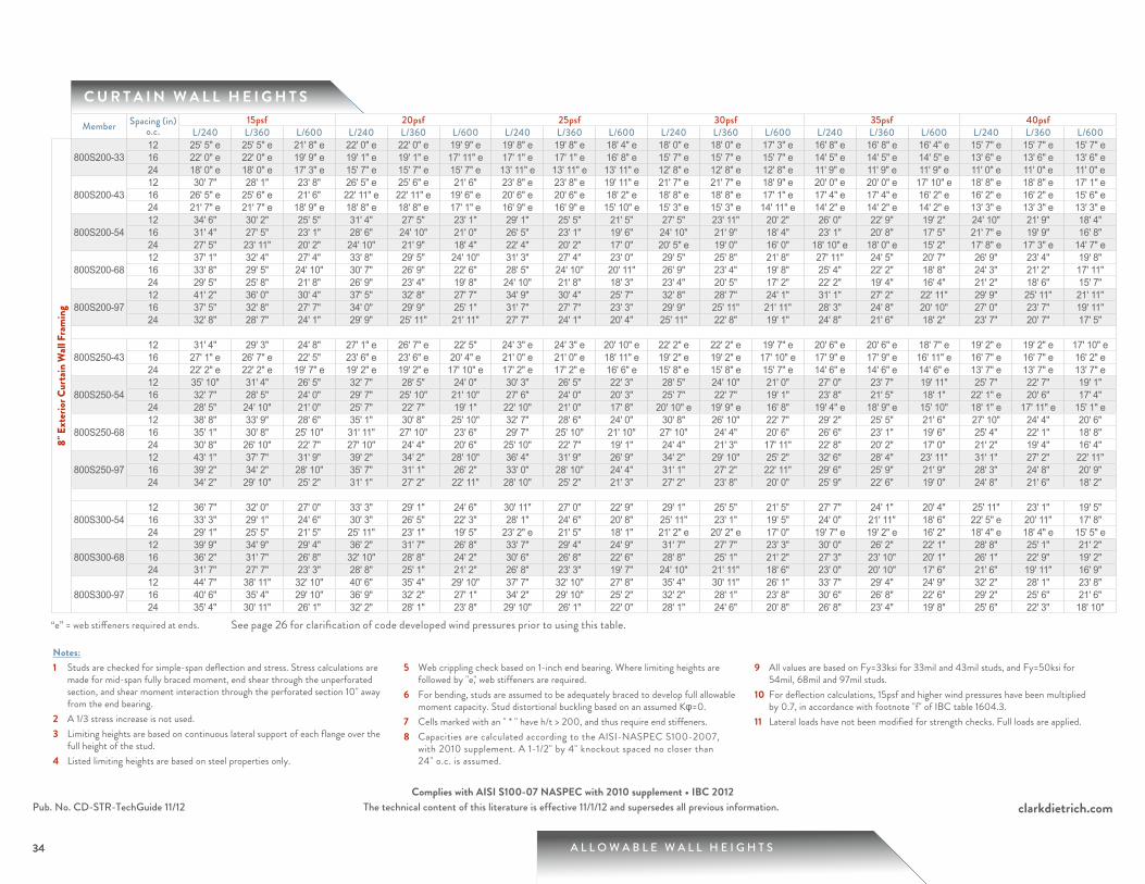
“e” = web stiffeners required at ends.
See page 26 for clarification of code developed wind pressures prior to using this table.
A L L O W A B L E W A L L H E I G H T S
clarkdietrich.comThe technical content of this literature is effective 11/1/12 and supersedes all previous information.
34
Pub. No. CD-STR-TechGuide 11/12Complies with AISI S100-07 NASPEC with 2010 supplement • IBC 2012
C U R T A I N W A L L H E I G H T S
34
Notes:1 Studs are checked for simple-span deflection and stress. Stress calculations are
made for mid-span fully braced moment, end shear through the unperforated section, and shear moment interaction through the perforated section 10" away from the end bearing.
2 A 1/3 stress increase is not used.3 Limiting heights are based on continuous lateral support of each flange over the
full height of the stud.4 Listed limiting heights are based on steel properties only.
5 Web crippling check based on 1-inch end bearing. Where limiting heights are followed by "e," web stiffeners are required.
6 For bending, studs are assumed to be adequately braced to develop full allowable moment capacity. Stud distortional buckling based on an assumed Kφ=0.
7 Cells marked with an " * " have h/t > 200, and thus require end stiffeners.8 Capacities are calculated according to the AISI-NASPEC S100-2007,
with 2010 supplement. A 1-1/2" by 4" knockout spaced no closer than 24" o.c. is assumed.
9 All values are based on Fy=33ksi for 33mil and 43mil studs, and Fy=50ksi for 54mil, 68mil and 97mil studs.
10 For deflection calculations, 15psf and higher wind pressures have been multiplied by 0.7, in accordance with footnote "f" of IBC table 1604.3.
11 Lateral loads have not been modified for strength checks. Full loads are applied.
Member Spacing (in) o.c.
15psf 20psf 25psf 30psf 35psf 40psfL/240 L/360 L/600 L/240 L/360 L/600 L/240 L/360 L/600 L/240 L/360 L/600 L/240 L/360 L/600 L/240 L/360 L/600
8" E
xter
ior C
urta
in W
all F
ram
ing
800S200-3312 25' 5" e 25' 5" e 21' 8" e 22' 0" e 22' 0" e 19' 9" e 19' 8" e 19' 8" e 18' 4" e 18' 0" e 18' 0" e 17' 3" e 16' 8" e 16' 8" e 16' 4" e 15' 7" e 15' 7" e 15' 7" e16 22' 0" e 22' 0" e 19' 9" e 19' 1" e 19' 1" e 17' 11" e 17' 1" e 17' 1" e 16' 8" e 15' 7" e 15' 7" e 15' 7" e 14' 5" e 14' 5" e 14' 5" e 13' 6" e 13' 6" e 13' 6" e24 18' 0" e 18' 0" e 17' 3" e 15' 7" e 15' 7" e 15' 7" e 13' 11" e 13' 11" e 13' 11" e 12' 8" e 12' 8" e 12' 8" e 11' 9" e 11' 9" e 11' 9" e 11' 0" e 11' 0" e 11' 0" e
800S200-4312 30' 7" 28' 1" 23' 8" 26' 5" e 25' 6" e 21' 6" 23' 8" e 23' 8" e 19' 11" e 21' 7" e 21' 7" e 18' 9" e 20' 0" e 20' 0" e 17' 10" e 18' 8" e 18' 8" e 17' 1" e16 26' 5" e 25' 6" e 21' 6" 22' 11" e 22' 11" e 19' 6" e 20' 6" e 20' 6" e 18' 2" e 18' 8" e 18' 8" e 17' 1" e 17' 4" e 17' 4" e 16' 2" e 16' 2" e 16' 2" e 15' 6" e24 21' 7" e 21' 7" e 18' 9" e 18' 8" e 18' 8" e 17' 1" e 16' 9" e 16' 9" e 15' 10" e 15' 3" e 15' 3" e 14' 11" e 14' 2" e 14' 2" e 14' 2" e 13' 3" e 13' 3" e 13' 3" e
800S200-5412 34' 6" 30' 2" 25' 5" 31' 4" 27' 5" 23' 1" 29' 1" 25' 5" 21' 5" 27' 5" 23' 11" 20' 2" 26' 0" 22' 9" 19' 2" 24' 10" 21' 9" 18' 4" 16 31' 4" 27' 5" 23' 1" 28' 6" 24' 10" 21' 0" 26' 5" 23' 1" 19' 6" 24' 10" 21' 9" 18' 4" 23' 1" 20' 8" 17' 5" 21' 7" e 19' 9" 16' 8" 24 27' 5" 23' 11" 20' 2" 24' 10" 21' 9" 18' 4" 22' 4" 20' 2" 17' 0" 20' 5" e 19' 0" 16' 0" 18' 10" e 18' 0" e 15' 2" 17' 8" e 17' 3" e 14' 7" e
800S200-6812 37' 1" 32' 4" 27' 4" 33' 8" 29' 5" 24' 10" 31' 3" 27' 4" 23' 0" 29' 5" 25' 8" 21' 8" 27' 11" 24' 5" 20' 7" 26' 9" 23' 4" 19' 8" 16 33' 8" 29' 5" 24' 10" 30' 7" 26' 9" 22' 6" 28' 5" 24' 10" 20' 11" 26' 9" 23' 4" 19' 8" 25' 4" 22' 2" 18' 8" 24' 3" 21' 2" 17' 11" 24 29' 5" 25' 8" 21' 8" 26' 9" 23' 4" 19' 8" 24' 10" 21' 8" 18' 3" 23' 4" 20' 5" 17' 2" 22' 2" 19' 4" 16' 4" 21' 2" 18' 6" 15' 7"
800S200-9712 41' 2" 36' 0" 30' 4" 37' 5" 32' 8" 27' 7" 34' 9" 30' 4" 25' 7" 32' 8" 28' 7" 24' 1" 31' 1" 27' 2" 22' 11" 29' 9" 25' 11" 21' 11" 16 37' 5" 32' 8" 27' 7" 34' 0" 29' 9" 25' 1" 31' 7" 27' 7" 23' 3" 29' 9" 25' 11" 21' 11" 28' 3" 24' 8" 20' 10" 27' 0" 23' 7" 19' 11" 24 32' 8" 28' 7" 24' 1" 29' 9" 25' 11" 21' 11" 27' 7" 24' 1" 20' 4" 25' 11" 22' 8" 19' 1" 24' 8" 21' 6" 18' 2" 23' 7" 20' 7" 17' 5"
800S250-4312 31' 4" 29' 3" 24' 8" 27' 1" e 26' 7" e 22' 5" 24' 3" e 24' 3" e 20' 10" e 22' 2" e 22' 2" e 19' 7" e 20' 6" e 20' 6" e 18' 7" e 19' 2" e 19' 2" e 17' 10" e16 27' 1" e 26' 7" e 22' 5" 23' 6" e 23' 6" e 20' 4" e 21' 0" e 21' 0" e 18' 11" e 19' 2" e 19' 2" e 17' 10" e 17' 9" e 17' 9" e 16' 11" e 16' 7" e 16' 7" e 16' 2" e24 22' 2" e 22' 2" e 19' 7" e 19' 2" e 19' 2" e 17' 10" e 17' 2" e 17' 2" e 16' 6" e 15' 8" e 15' 8" e 15' 7" e 14' 6" e 14' 6" e 14' 6" e 13' 7" e 13' 7" e 13' 7" e
800S250-5412 35' 10" 31' 4" 26' 5" 32' 7" 28' 5" 24' 0" 30' 3" 26' 5" 22' 3" 28' 5" 24' 10" 21' 0" 27' 0" 23' 7" 19' 11" 25' 7" 22' 7" 19' 1" 16 32' 7" 28' 5" 24' 0" 29' 7" 25' 10" 21' 10" 27' 6" 24' 0" 20' 3" 25' 7" 22' 7" 19' 1" 23' 8" 21' 5" 18' 1" 22' 1" e 20' 6" 17' 4" 24 28' 5" 24' 10" 21' 0" 25' 7" 22' 7" 19' 1" 22' 10" 21' 0" 17' 8" 20' 10" e 19' 9" e 16' 8" 19' 4" e 18' 9" e 15' 10" 18' 1" e 17' 11" e 15' 1" e
800S250-6812 38' 8" 33' 9" 28' 6" 35' 1" 30' 8" 25' 10" 32' 7" 28' 6" 24' 0" 30' 8" 26' 10" 22' 7" 29' 2" 25' 5" 21' 6" 27' 10" 24' 4" 20' 6" 16 35' 1" 30' 8" 25' 10" 31' 11" 27' 10" 23' 6" 29' 7" 25' 10" 21' 10" 27' 10" 24' 4" 20' 6" 26' 6" 23' 1" 19' 6" 25' 4" 22' 1" 18' 8" 24 30' 8" 26' 10" 22' 7" 27' 10" 24' 4" 20' 6" 25' 10" 22' 7" 19' 1" 24' 4" 21' 3" 17' 11" 22' 8" 20' 2" 17' 0" 21' 2" 19' 4" 16' 4"
800S250-9712 43' 1" 37' 7" 31' 9" 39' 2" 34' 2" 28' 10" 36' 4" 31' 9" 26' 9" 34' 2" 29' 10" 25' 2" 32' 6" 28' 4" 23' 11" 31' 1" 27' 2" 22' 11" 16 39' 2" 34' 2" 28' 10" 35' 7" 31' 1" 26' 2" 33' 0" 28' 10" 24' 4" 31' 1" 27' 2" 22' 11" 29' 6" 25' 9" 21' 9" 28' 3" 24' 8" 20' 9" 24 34' 2" 29' 10" 25' 2" 31' 1" 27' 2" 22' 11" 28' 10" 25' 2" 21' 3" 27' 2" 23' 8" 20' 0" 25' 9" 22' 6" 19' 0" 24' 8" 21' 6" 18' 2"
800S300-5412 36' 7" 32' 0" 27' 0" 33' 3" 29' 1" 24' 6" 30' 11" 27' 0" 22' 9" 29' 1" 25' 5" 21' 5" 27' 7" 24' 1" 20' 4" 25' 11" 23' 1" 19' 5" 16 33' 3" 29' 1" 24' 6" 30' 3" 26' 5" 22' 3" 28' 1" 24' 6" 20' 8" 25' 11" 23' 1" 19' 5" 24' 0" 21' 11" 18' 6" 22' 5" e 20' 11" 17' 8" 24 29' 1" 25' 5" 21' 5" 25' 11" 23' 1" 19' 5" 23' 2" e 21' 5" 18' 1" 21' 2" e 20' 2" e 17' 0" 19' 7" e 19' 2" e 16' 2" 18' 4" e 18' 4" e 15' 5" e
800S300-6812 39' 9" 34' 9" 29' 4" 36' 2" 31' 7" 26' 8" 33' 7" 29' 4" 24' 9" 31' 7" 27' 7" 23' 3" 30' 0" 26' 2" 22' 1" 28' 8" 25' 1" 21' 2" 16 36' 2" 31' 7" 26' 8" 32' 10" 28' 8" 24' 2" 30' 6" 26' 8" 22' 6" 28' 8" 25' 1" 21' 2" 27' 3" 23' 10" 20' 1" 26' 1" 22' 9" 19' 2" 24 31' 7" 27' 7" 23' 3" 28' 8" 25' 1" 21' 2" 26' 8" 23' 3" 19' 7" 24' 10" 21' 11" 18' 6" 23' 0" 20' 10" 17' 6" 21' 6" 19' 11" 16' 9"
800S300-9712 44' 7" 38' 11" 32' 10" 40' 6" 35' 4" 29' 10" 37' 7" 32' 10" 27' 8" 35' 4" 30' 11" 26' 1" 33' 7" 29' 4" 24' 9" 32' 2" 28' 1" 23' 8" 16 40' 6" 35' 4" 29' 10" 36' 9" 32' 2" 27' 1" 34' 2" 29' 10" 25' 2" 32' 2" 28' 1" 23' 8" 30' 6" 26' 8" 22' 6" 29' 2" 25' 6" 21' 6" 24 35' 4" 30' 11" 26' 1" 32' 2" 28' 1" 23' 8" 29' 10" 26' 1" 22' 0" 28' 1" 24' 6" 20' 8" 26' 8" 23' 4" 19' 8" 25' 6" 22' 3" 18' 10"
“e” = web stiffeners required at ends. See page 26 for clarification of code developed wind pressures prior to using this table.
35 A L L O W A B L E W A L L H E I G H T S
clarkdietrich.comThe technical content of this literature is effective 11/1/12 and supersedes all previous information.Pub. No. CD-STR-TechGuide 11/12Complies with AISI S100-07 NASPEC with 2010 supplement • IBC 2012
C U R T A I N W A L L H E I G H T S
Notes:1 Studs are checked for simple-span deflection and stress. Stress calculations are
made for mid-span fully braced moment, end shear through the unperforated section, and shear moment interaction through the perforated section 10" away from the end bearing.
2 A 1/3 stress increase is not used.3 Limiting heights are based on continuous lateral support of each flange over the
full height of the stud.4 Listed limiting heights are based on steel properties only.
5 Web crippling check based on 1-inch end bearing. Where limiting heights are followed by "e," web stiffeners are required.
6 For bending, studs are assumed to be adequately braced to develop full allowable moment capacity. Stud distortional buckling based on an assumed Kφ=0.
7 Cells marked with an " * " have h/t > 200, and thus require end stiffeners.8 Capacities are calculated according to the AISI-NASPEC S100-2007,
with 2010 supplement. A 1-1/2" by 4" knockout spaced no closer than 24" o.c. is assumed.
9 All values are based on Fy=33ksi for 33mil and 43mil studs, and Fy=50ksi for 54mil, 68mil and 97mil studs.
10 For deflection calculations, 15psf and higher wind pressures have been multiplied by 0.7, in accordance with footnote "f" of IBC table 1604.3.
11 Lateral loads have not been modified for strength checks. Full loads are applied.
Member Spacing (in) o.c.
15psf 20psf 25psf 30psf 35psf 40psfL/240 L/360 L/600 L/240 L/360 L/600 L/240 L/360 L/600 L/240 L/360 L/600 L/240 L/360 L/600 L/240 L/360 L/600
10" E
xter
ior C
urta
in W
all F
ram
ing
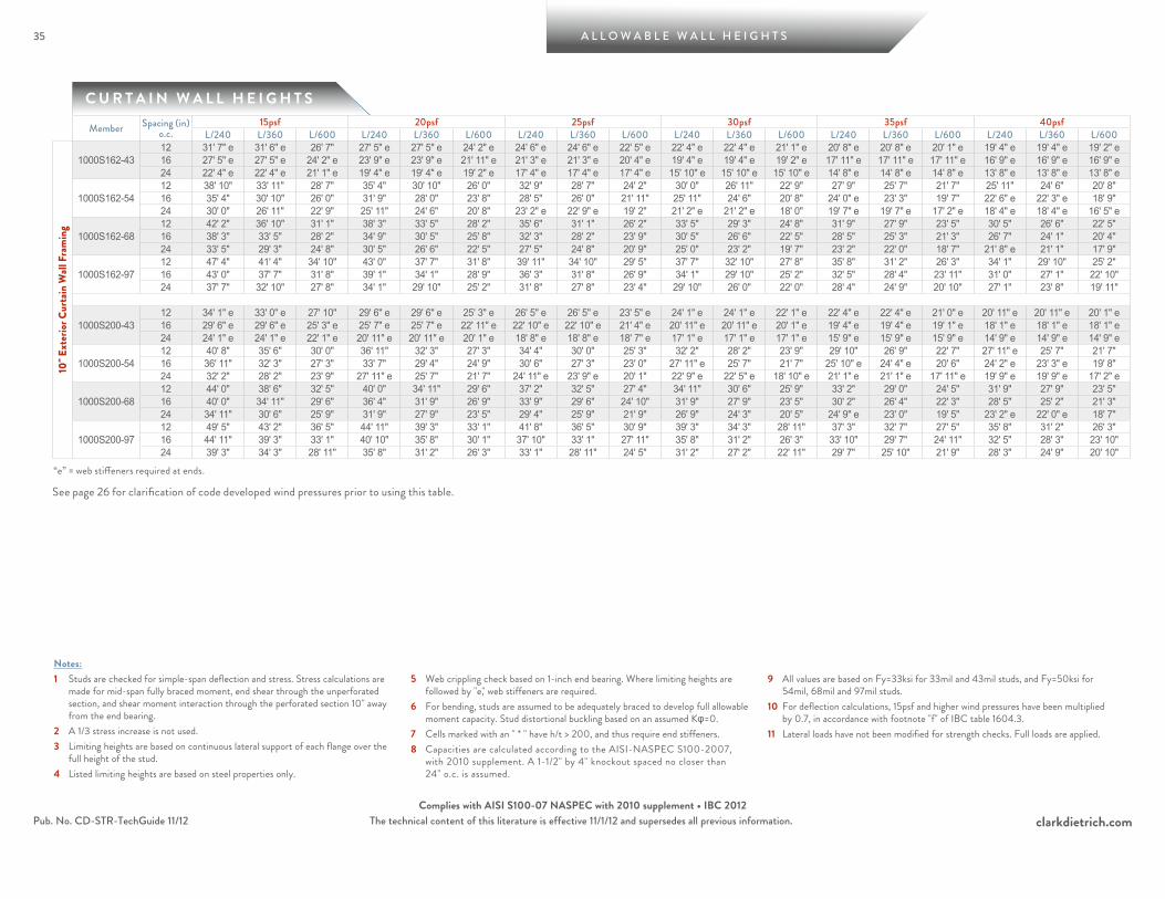
1000S162-4312 31' 7" e 31' 6" e 26' 7" 27' 5" e 27' 5" e 24' 2" e 24' 6" e 24' 6" e 22' 5" e 22' 4" e 22' 4" e 21' 1" e 20' 8" e 20' 8" e 20' 1" e 19' 4" e 19' 4" e 19' 2" e16 27' 5" e 27' 5" e 24' 2" e 23' 9" e 23' 9" e 21' 11" e 21' 3" e 21' 3" e 20' 4" e 19' 4" e 19' 4" e 19' 2" e 17' 11" e 17' 11" e 17' 11" e 16' 9" e 16' 9" e 16' 9" e24 22' 4" e 22' 4" e 21' 1" e 19' 4" e 19' 4" e 19' 2" e 17' 4" e 17' 4" e 17' 4" e 15' 10" e 15' 10" e 15' 10" e 14' 8" e 14' 8" e 14' 8" e 13' 8" e 13' 8" e 13' 8" e
1000S162-5412 38' 10" 33' 11" 28' 7" 35' 4" 30' 10" 26' 0" 32' 9" 28' 7" 24' 2" 30' 0" 26' 11" 22' 9" 27' 9" 25' 7" 21' 7" 25' 11" 24' 6" 20' 8" 16 35' 4" 30' 10" 26' 0" 31' 9" 28' 0" 23' 8" 28' 5" 26' 0" 21' 11" 25' 11" 24' 6" 20' 8" 24' 0" e 23' 3" 19' 7" 22' 6" e 22' 3" e 18' 9" 24 30' 0" 26' 11" 22' 9" 25' 11" 24' 6" 20' 8" 23' 2" e 22' 9" e 19' 2" 21' 2" e 21' 2" e 18' 0" 19' 7" e 19' 7" e 17' 2" e 18' 4" e 18' 4" e 16' 5" e
1000S162-6812 42' 2" 36' 10" 31' 1" 38' 3" 33' 5" 28' 2" 35' 6" 31' 1" 26' 2" 33' 5" 29' 3" 24' 8" 31' 9" 27' 9" 23' 5" 30' 5" 26' 6" 22' 5" 16 38' 3" 33' 5" 28' 2" 34' 9" 30' 5" 25' 8" 32' 3" 28' 2" 23' 9" 30' 5" 26' 6" 22' 5" 28' 5" 25' 3" 21' 3" 26' 7" 24' 1" 20' 4" 24 33' 5" 29' 3" 24' 8" 30' 5" 26' 6" 22' 5" 27' 5" 24' 8" 20' 9" 25' 0" 23' 2" 19' 7" 23' 2" 22' 0" 18' 7" 21' 8" e 21' 1" 17' 9"
1000S162-9712 47' 4" 41' 4" 34' 10" 43' 0" 37' 7" 31' 8" 39' 11" 34' 10" 29' 5" 37' 7" 32' 10" 27' 8" 35' 8" 31' 2" 26' 3" 34' 1" 29' 10" 25' 2" 16 43' 0" 37' 7" 31' 8" 39' 1" 34' 1" 28' 9" 36' 3" 31' 8" 26' 9" 34' 1" 29' 10" 25' 2" 32' 5" 28' 4" 23' 11" 31' 0" 27' 1" 22' 10" 24 37' 7" 32' 10" 27' 8" 34' 1" 29' 10" 25' 2" 31' 8" 27' 8" 23' 4" 29' 10" 26' 0" 22' 0" 28' 4" 24' 9" 20' 10" 27' 1" 23' 8" 19' 11"
1000S200-4312 34' 1" e 33' 0" e 27' 10" 29' 6" e 29' 6" e 25' 3" e 26' 5" e 26' 5" e 23' 5" e 24' 1" e 24' 1" e 22' 1" e 22' 4" e 22' 4" e 21' 0" e 20' 11" e 20' 11" e 20' 1" e16 29' 6" e 29' 6" e 25' 3" e 25' 7" e 25' 7" e 22' 11" e 22' 10" e 22' 10" e 21' 4" e 20' 11" e 20' 11" e 20' 1" e 19' 4" e 19' 4" e 19' 1" e 18' 1" e 18' 1" e 18' 1" e24 24' 1" e 24' 1" e 22' 1" e 20' 11" e 20' 11" e 20' 1" e 18' 8" e 18' 8" e 18' 7" e 17' 1" e 17' 1" e 17' 1" e 15' 9" e 15' 9" e 15' 9" e 14' 9" e 14' 9" e 14' 9" e
1000S200-5412 40' 8" 35' 6" 30' 0" 36' 11" 32' 3" 27' 3" 34' 4" 30' 0" 25' 3" 32' 2" 28' 2" 23' 9" 29' 10" 26' 9" 22' 7" 27' 11" e 25' 7" 21' 7" 16 36' 11" 32' 3" 27' 3" 33' 7" 29' 4" 24' 9" 30' 6" 27' 3" 23' 0" 27' 11" e 25' 7" 21' 7" 25' 10" e 24' 4" e 20' 6" 24' 2" e 23' 3" e 19' 8" 24 32' 2" 28' 2" 23' 9" 27' 11" e 25' 7" 21' 7" 24' 11" e 23' 9" e 20' 1" 22' 9" e 22' 5" e 18' 10" e 21' 1" e 21' 1" e 17' 11" e 19' 9" e 19' 9" e 17' 2" e
1000S200-6812 44' 0" 38' 6" 32' 5" 40' 0" 34' 11" 29' 6" 37' 2" 32' 5" 27' 4" 34' 11" 30' 6" 25' 9" 33' 2" 29' 0" 24' 5" 31' 9" 27' 9" 23' 5" 16 40' 0" 34' 11" 29' 6" 36' 4" 31' 9" 26' 9" 33' 9" 29' 6" 24' 10" 31' 9" 27' 9" 23' 5" 30' 2" 26' 4" 22' 3" 28' 5" 25' 2" 21' 3" 24 34' 11" 30' 6" 25' 9" 31' 9" 27' 9" 23' 5" 29' 4" 25' 9" 21' 9" 26' 9" 24' 3" 20' 5" 24' 9" e 23' 0" 19' 5" 23' 2" e 22' 0" e 18' 7"
1000S200-9712 49' 5" 43' 2" 36' 5" 44' 11" 39' 3" 33' 1" 41' 8" 36' 5" 30' 9" 39' 3" 34' 3" 28' 11" 37' 3" 32' 7" 27' 5" 35' 8" 31' 2" 26' 3" 16 44' 11" 39' 3" 33' 1" 40' 10" 35' 8" 30' 1" 37' 10" 33' 1" 27' 11" 35' 8" 31' 2" 26' 3" 33' 10" 29' 7" 24' 11" 32' 5" 28' 3" 23' 10" 24 39' 3" 34' 3" 28' 11" 35' 8" 31' 2" 26' 3" 33' 1" 28' 11" 24' 5" 31' 2" 27' 2" 22' 11" 29' 7" 25' 10" 21' 9" 28' 3" 24' 9" 20' 10"
“e” = web stiffeners required at ends.
See page 26 for clarification of code developed wind pressures prior to using this table.
A L L O W A B L E W A L L H E I G H T S
clarkdietrich.comThe technical content of this literature is effective 11/1/12 and supersedes all previous information.
36
Pub. No. CD-STR-TechGuide 11/12Complies with AISI S100-07 NASPEC with 2010 supplement • IBC 2012
C U R T A I N W A L L H E I G H T S
36
Notes:1 Studs are checked for simple-span deflection and stress. Stress calculations are
made for mid-span fully braced moment, end shear through the unperforated section, and shear moment interaction through the perforated section 10" away from the end bearing.
2 A 1/3 stress increase is not used.3 Limiting heights are based on continuous lateral support of each flange over the
full height of the stud.4 Listed limiting heights are based on steel properties only.
5 Web crippling check based on 1-inch end bearing. Where limiting heights are followed by "e," web stiffeners are required.
6 For bending, studs are assumed to be adequately braced to develop full allowable moment capacity. Stud distortional buckling based on an assumed Kφ=0.
7 Cells marked with an " * " have h/t > 200, and thus require end stiffeners.8 Capacities are calculated according to the AISI-NASPEC S100-2007,
with 2010 supplement. A 1-1/2" by 4" knockout spaced no closer than 24" o.c. is assumed.
9 All values are based on Fy=33ksi for 33mil and 43mil studs, and Fy=50ksi for 54mil, 68mil and 97mil studs.
10 For deflection calculations, 15psf and higher wind pressures have been multiplied by 0.7, in accordance with footnote "f" of IBC table 1604.3.
11 Lateral loads have not been modified for strength checks. Full loads are applied.
Member Spacing (in) o.c.
15psf 20psf 25psf 30psf 35psf 40psfL/240 L/360 L/600 L/240 L/360 L/600 L/240 L/360 L/600 L/240 L/360 L/600 L/240 L/360 L/600 L/240 L/360 L/600
10" E
xter
ior C
urta
in W
all F
ram
ing
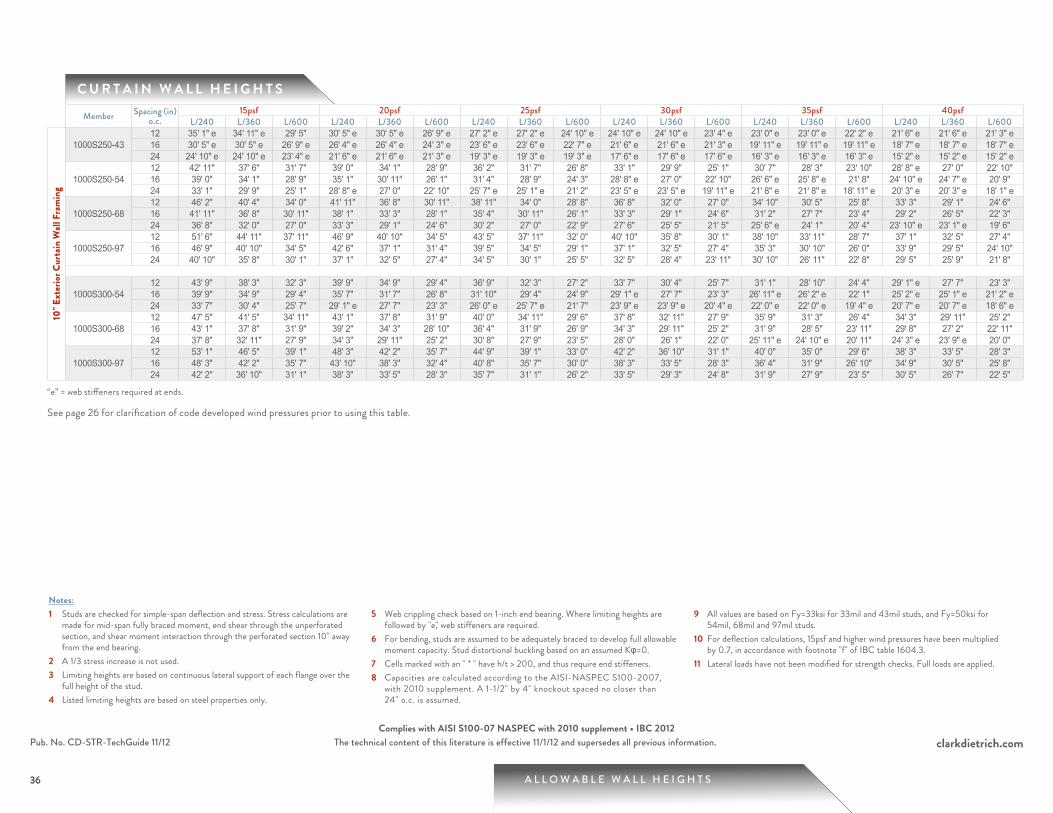
1000S250-4312 35' 1" e 34' 11" e 29' 5" 30' 5" e 30' 5" e 26' 9" e 27' 2" e 27' 2" e 24' 10" e 24' 10" e 24' 10" e 23' 4" e 23' 0" e 23' 0" e 22' 2" e 21' 6" e 21' 6" e 21' 3" e16 30' 5" e 30' 5" e 26' 9" e 26' 4" e 26' 4" e 24' 3" e 23' 6" e 23' 6" e 22' 7" e 21' 6" e 21' 6" e 21' 3" e 19' 11" e 19' 11" e 19' 11" e 18' 7" e 18' 7" e 18' 7" e24 24' 10" e 24' 10" e 23' 4" e 21' 6" e 21' 6" e 21' 3" e 19' 3" e 19' 3" e 19' 3" e 17' 6" e 17' 6" e 17' 6" e 16' 3" e 16' 3" e 16' 3" e 15' 2" e 15' 2" e 15' 2" e
1000S250-5412 42' 11" 37' 6" 31' 7" 39' 0" 34' 1" 28' 9" 36' 2" 31' 7" 26' 8" 33' 1" 29' 9" 25' 1" 30' 7" 28' 3" 23' 10" 28' 8" e 27' 0" 22' 10" 16 39' 0" 34' 1" 28' 9" 35' 1" 30' 11" 26' 1" 31' 4" 28' 9" 24' 3" 28' 8" e 27' 0" 22' 10" 26' 6" e 25' 8" e 21' 8" 24' 10" e 24' 7" e 20' 9" 24 33' 1" 29' 9" 25' 1" 28' 8" e 27' 0" 22' 10" 25' 7" e 25' 1" e 21' 2" 23' 5" e 23' 5" e 19' 11" e 21' 8" e 21' 8" e 18' 11" e 20' 3" e 20' 3" e 18' 1" e
1000S250-6812 46' 2" 40' 4" 34' 0" 41' 11" 36' 8" 30' 11" 38' 11" 34' 0" 28' 8" 36' 8" 32' 0" 27' 0" 34' 10" 30' 5" 25' 8" 33' 3" 29' 1" 24' 6" 16 41' 11" 36' 8" 30' 11" 38' 1" 33' 3" 28' 1" 35' 4" 30' 11" 26' 1" 33' 3" 29' 1" 24' 6" 31' 2" 27' 7" 23' 4" 29' 2" 26' 5" 22' 3" 24 36' 8" 32' 0" 27' 0" 33' 3" 29' 1" 24' 6" 30' 2" 27' 0" 22' 9" 27' 6" 25' 5" 21' 5" 25' 6" e 24' 1" 20' 4" 23' 10" e 23' 1" e 19' 6"
1000S250-9712 51' 6" 44' 11" 37' 11" 46' 9" 40' 10" 34' 5" 43' 5" 37' 11" 32' 0" 40' 10" 35' 8" 30' 1" 38' 10" 33' 11" 28' 7" 37' 1" 32' 5" 27' 4" 16 46' 9" 40' 10" 34' 5" 42' 6" 37' 1" 31' 4" 39' 5" 34' 5" 29' 1" 37' 1" 32' 5" 27' 4" 35' 3" 30' 10" 26' 0" 33' 9" 29' 5" 24' 10" 24 40' 10" 35' 8" 30' 1" 37' 1" 32' 5" 27' 4" 34' 5" 30' 1" 25' 5" 32' 5" 28' 4" 23' 11" 30' 10" 26' 11" 22' 8" 29' 5" 25' 9" 21' 8"
1000S300-5412 43' 9" 38' 3" 32' 3" 39' 9" 34' 9" 29' 4" 36' 9" 32' 3" 27' 2" 33' 7" 30' 4" 25' 7" 31' 1" 28' 10" 24' 4" 29' 1" e 27' 7" 23' 3" 16 39' 9" 34' 9" 29' 4" 35' 7" 31' 7" 26' 8" 31' 10" 29' 4" 24' 9" 29' 1" e 27' 7" 23' 3" 26' 11" e 26' 2" e 22' 1" 25' 2" e 25' 1" e 21' 2" e24 33' 7" 30' 4" 25' 7" 29' 1" e 27' 7" 23' 3" 26' 0" e 25' 7" e 21' 7" 23' 9" e 23' 9" e 20' 4" e 22' 0" e 22' 0" e 19' 4" e 20' 7" e 20' 7" e 18' 6" e
1000S300-6812 47' 5" 41' 5" 34' 11" 43' 1" 37' 8" 31' 9" 40' 0" 34' 11" 29' 6" 37' 8" 32' 11" 27' 9" 35' 9" 31' 3" 26' 4" 34' 3" 29' 11" 25' 2" 16 43' 1" 37' 8" 31' 9" 39' 2" 34' 3" 28' 10" 36' 4" 31' 9" 26' 9" 34' 3" 29' 11" 25' 2" 31' 9" 28' 5" 23' 11" 29' 8" 27' 2" 22' 11" 24 37' 8" 32' 11" 27' 9" 34' 3" 29' 11" 25' 2" 30' 8" 27' 9" 23' 5" 28' 0" 26' 1" 22' 0" 25' 11" e 24' 10" e 20' 11" 24' 3" e 23' 9" e 20' 0"
1000S300-9712 53' 1" 46' 5" 39' 1" 48' 3" 42' 2" 35' 7" 44' 9" 39' 1" 33' 0" 42' 2" 36' 10" 31' 1" 40' 0" 35' 0" 29' 6" 38' 3" 33' 5" 28' 3" 16 48' 3" 42' 2" 35' 7" 43' 10" 38' 3" 32' 4" 40' 8" 35' 7" 30' 0" 38' 3" 33' 5" 28' 3" 36' 4" 31' 9" 26' 10" 34' 9" 30' 5" 25' 8" 24 42' 2" 36' 10" 31' 1" 38' 3" 33' 5" 28' 3" 35' 7" 31' 1" 26' 2" 33' 5" 29' 3" 24' 8" 31' 9" 27' 9" 23' 5" 30' 5" 26' 7" 22' 5"
“e” = web stiffeners required at ends.
See page 26 for clarification of code developed wind pressures prior to using this table.
37 A L L O W A B L E W A L L H E I G H T S
clarkdietrich.comThe technical content of this literature is effective 11/1/12 and supersedes all previous information.Pub. No. CD-STR-TechGuide 11/12Complies with AISI S100-07 NASPEC with 2010 supplement • IBC 2012
C U R T A I N W A L L H E I G H T S
Notes:1 Studs are checked for simple-span deflection and stress. Stress calculations are
made for mid-span fully braced moment, end shear through the unperforated section, and shear moment interaction through the perforated section 10" away from the end bearing.
2 A 1/3 stress increase is not used.3 Limiting heights are based on continuous lateral support of each flange over the
full height of the stud.4 Listed limiting heights are based on steel properties only.
5 Web crippling check based on 1-inch end bearing. Where limiting heights are followed by "e," web stiffeners are required.
6 For bending, studs are assumed to be adequately braced to develop full allowable moment capacity. Stud distortional buckling based on an assumed Kφ=0.
7 Cells marked with an " * " have h/t > 200, and thus require end stiffeners.8 Capacities are calculated according to the AISI-NASPEC S100-2007,
with 2010 supplement. A 1-1/2" by 4" knockout spaced no closer than 24" o.c. is assumed.
9 All values are based on Fy=33ksi for 33mil and 43mil studs, and Fy=50ksi for 54mil, 68mil and 97mil studs.
10 For deflection calculations, 15psf and higher wind pressures have been multiplied by 0.7, in accordance with footnote "f" of IBC table 1604.3.
11 Lateral loads have not been modified for strength checks. Full loads are applied.
Member Spacing (in) o.c.
15psf 20psf 25psf 30psf 35psf 40psfL/240 L/360 L/600 L/240 L/360 L/600 L/240 L/360 L/600 L/240 L/360 L/600 L/240 L/360 L/600 L/240 L/360 L/600
12" E
xter
ior C
urta
in W
all F
ram
ing
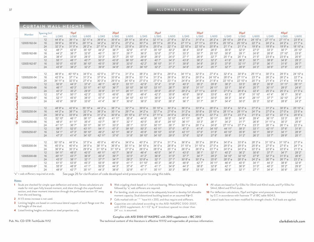
1200S162-5412 44' 8" e 39' 1" e 32' 11" e 39' 6" e 35' 6" e 29' 11" e 35' 4" e 32' 11" e 27' 9" e 32' 3" e 31' 0" e 26' 2" e 29' 10" e 29' 5" e 24' 10" e 27' 11" e 27' 11" e 23' 9" e 16 39' 6" e 35' 6" e 29' 11" e 34' 2" e 32' 3" e 27' 2" e 30' 7" e 29' 11" e 25' 3" e 27' 11" e 27' 11" e 23' 9" e 25' 10" e 25' 10" e 22' 7" e 24' 2" e 24' 2" e 21' 7" e24 32' 3" e 31' 0" e 26' 2" e 27' 11" e 27' 11" e 23' 9" e 25' 0" e 25' 0" e 22' 1" e 22' 10" e 22' 10" e 20' 9" e 21' 1" e 21' 1" e 19' 8" e 19' 9" e 19' 9" e 18' 10" e
1200S162-6812 48' 7" 42' 6" 35' 10" 44' 2" 38' 7" 32' 6" 41' 0" 35' 10" 30' 2" 38' 4" 33' 8" 28' 5" 35' 6" 32' 0" 27' 0" 33' 3" 30' 7" 25' 10" 16 44' 2" 38' 7" 32' 6" 40' 1" 35' 1" 29' 7" 36' 5" 32' 6" 27' 5" 33' 3" 30' 7" 25' 10" 30' 9" 29' 1" 24' 6" 28' 9" 27' 10" 23' 6" 24 38' 4" 33' 8" 28' 5" 33' 3" 30' 7" 25' 10" 29' 8" 28' 5" 24' 0" 27' 1" 26' 9" 22' 7" 25' 1" e 25' 1" e 21' 5" 23' 6" e 23' 6" e 20' 6"
1200S162-9712 55' 1" 48' 1" 40' 7" 50' 0" 43' 8" 36' 10" 46' 5" 40' 7" 34' 3" 43' 8" 38' 2" 32' 2" 41' 6" 36' 3" 30' 7" 39' 8" 34' 8" 29' 3" 16 50' 0" 43' 8" 36' 10" 45' 5" 39' 8" 33' 6" 42' 2" 36' 10" 31' 1" 39' 8" 34' 8" 29' 3" 37' 9" 32' 11" 27' 9" 36' 1" 31' 6" 26' 7" 24 43' 8" 38' 2" 32' 2" 39' 8" 34' 8" 29' 3" 36' 10" 32' 2" 27' 2" 34' 8" 30' 4" 25' 7" 32' 7" 28' 9" 24' 3" 30' 6" 27' 6" 23' 3"
1200S200-5412 46' 9" e 40' 10" e 34' 5" e 42' 5" e 37' 1" e 31' 3" e 38' 3" e 34' 5" e 29' 0" e 34' 11" e 32' 5" e 27' 4" e 32' 4" e 30' 9" e 25' 11" e 30' 3" e 29' 5" e 24' 10" e 16 42' 5" e 37' 1" e 31' 3" e 37' 0" e 33' 8" e 28' 5" e 33' 1" e 31' 3" e 26' 5" e 30' 3" e 29' 5" e 24' 10" e 28' 0" e 27' 11" e 23' 7" e 26' 2" e 26' 2" e 22' 7" e24 34' 11" e 32' 5" e 27' 4" e 30' 3" e 29' 5" e 24' 10" e 27' 0" e 27' 0" e 23' 1" e 24' 8" e 24' 8" e 21' 8" e 22' 10" e 22' 10" e 20' 7" e 21' 4" e 21' 4" e 19' 8" e
1200S200-6812 50' 8" 44' 3" 37' 4" 46' 1" 40' 3" 33' 11" 42' 9" 37' 4" 31' 6" 40' 3" 35' 2" 29' 8" 38' 2" 33' 5" 28' 2" 35' 9" 31' 11" 26' 11" 16 46' 1" 40' 3" 33' 11" 41' 10" 36' 7" 30' 10" 38' 10" 33' 11" 28' 7" 35' 9" 31' 11" 26' 11" 33' 1" 30' 4" 25' 7" 30' 11" 29' 0" 24' 6" 24 40' 3" 35' 2" 29' 8" 35' 9" 31' 11" 26' 11" 31' 11" 29' 8" 25' 0" 29' 2" e 27' 11" e 23' 6" 27' 0" e 26' 6" e 22' 4" 25' 3" e 25' 3" e 21' 5" e
1200S200-9712 57' 4" 50' 1" 42' 3" 52' 1" 45' 6" 38' 5" 48' 4" 42' 3" 35' 8" 45' 6" 39' 9" 33' 6" 43' 3" 37' 9" 31' 10" 41' 4" 36' 1" 30' 6" 16 52' 1" 45' 6" 38' 5" 47' 4" 41' 4" 34' 10" 43' 11" 38' 5" 32' 4" 41' 4" 36' 1" 30' 6" 39' 3" 34' 4" 28' 11" 37' 7" 32' 10" 27' 8" 24 45' 6" 39' 9" 33' 6" 41' 4" 36' 1" 30' 6" 38' 5" 33' 6" 28' 3" 36' 1" 31' 7" 26' 7" 34' 4" 30' 0" 25' 3" 32' 6" 28' 8" 24' 2"
1200S250-5412 48' 8" e 42' 6" e 35' 10" e 44' 2" e 38' 7" e 32' 7" e 39' 6" e 35' 10" e 30' 3" e 36' 0" e 33' 9" e 28' 5" e 33' 4" e 32' 0" e 27' 0" e 31' 2" e 30' 8" e 25' 10" e 16 44' 2" e 38' 7" e 32' 7" e 38' 3" e 35' 1" e 29' 7" e 34' 2" e 32' 7" e 27' 6" e 31' 2" e 30' 8" e 25' 10" e 28' 11" e 28' 11" e 24' 7" e 27' 0" e 27' 0" e 23' 6" e24 36' 0" e 33' 9" e 28' 5" e 31' 2" e 30' 8" e 25' 10" e 27' 11" e 27' 11" e 24' 0" e 25' 6" e 25' 6" e 22' 7" e 23' 7" e 23' 7" e 21' 5" e 22' 1" e 22' 1" e 20' 6" e
1200S250-6812 52' 10" 46' 1" 38' 11" 48' 0" 41' 11" 35' 4" 44' 6" 38' 11" 32' 10" 41' 11" 36' 7" 30' 11" 39' 5" 34' 9" 29' 4" 36' 11" 33' 3" 28' 1" 16 48' 0" 41' 11" 35' 4" 43' 7" 38' 1" 32' 1" 40' 5" 35' 4" 29' 10" 36' 11" 33' 3" 28' 1" 34' 2" 31' 7" 26' 8" 31' 11" e 30' 3" 25' 6" 24 41' 11" 36' 7" 30' 11" 36' 11" 33' 3" 28' 1" 33' 0" 30' 11" 26' 1" 30' 1" e 29' 1" e 24' 6" 27' 11" e 27' 7" e 23' 3" 26' 1" e 26' 1" e 22' 3" e
1200S250-9712 59' 7" 52' 0" 43' 11" 54' 1" 47' 3" 39' 10" 50' 3" 43' 11" 37' 0" 47' 3" 41' 4" 34' 10" 44' 11" 39' 3" 33' 1" 42' 11" 37' 6" 31' 8" 16 54' 1" 47' 3" 39' 10" 49' 2" 42' 11" 36' 3" 45' 8" 39' 10" 33' 8" 42' 11" 37' 6" 31' 8" 40' 10" 35' 8" 30' 1" 39' 0" 34' 1" 28' 9" 24 47' 3" 41' 4" 34' 10" 42' 11" 37' 6" 31' 8" 39' 10" 34' 10" 29' 5" 37' 6" 32' 9" 27' 8" 35' 8" 31' 2" 26' 3" 33' 7" 29' 9" 25' 1"
1200S300-5412 50' 10" e 44' 5" e 37' 5" e 45' 0" e 40' 4" e 34' 0" e 40' 3" e 37' 5" e 31' 7" e 36' 9" e 35' 3" e 29' 9" e 34' 0" e 33' 6" e 28' 3" e 31' 10" e 31' 10" e 27' 0" e16 45' 0" e 40' 4" e 34' 0" e 38' 11" e 36' 8" e 30' 11" e 34' 10" e 34' 0" e 28' 8" e 31' 10" e 31' 10" e 27' 0" e 29' 5" e 29' 5" e 25' 8" e 27' 6" e 27' 6" e 24' 7" e24 36' 9" e 35' 3" e 29' 9" e 31' 10" e 31' 10" e 27' 0" e 28' 5" e 28' 5" e 25' 1" e 26' 0" e 26' 0" e 23' 7" e 24' 0" e 24' 0" e 22' 5" e 22' 6" e 22' 6" e 21' 5" e
1200S300-6812 54' 11" 48' 0" 40' 5" 49' 11" 43' 7" 36' 9" 46' 4" 40' 5" 34' 1" 43' 5" 38' 1" 32' 1" 40' 2" 36' 2" 30' 6" 37' 7" 34' 7" 29' 2" 16 49' 11" 43' 7" 36' 9" 45' 4" 39' 7" 33' 5" 41' 2" 36' 9" 31' 0" 37' 7" 34' 7" 29' 2" 34' 10" 32' 10" 27' 9" 32' 7" e 31' 5" e 26' 6" 24 43' 5" 38' 1" 32' 1" 37' 7" 34' 7" 29' 2" 33' 8" e 32' 1" 27' 1" 30' 8" e 30' 3" e 25' 6" 28' 5" e 28' 5" e 24' 2" e 26' 7" e 26' 7" e 23' 2" e
1200S300-9712 61' 5" 53' 8" 45' 3" 55' 9" 48' 9" 41' 1" 51' 10" 45' 3" 38' 2" 48' 9" 42' 7" 35' 11" 46' 4" 40' 5" 34' 1" 44' 3" 38' 8" 32' 8" 16 55' 9" 48' 9" 41' 1" 50' 8" 44' 3" 37' 4" 47' 1" 41' 1" 34' 8" 44' 3" 38' 8" 32' 8" 42' 1" 36' 9" 31' 0" 40' 3" 35' 2" 29' 8" 24 48' 9" 42' 7" 35' 11" 44' 3" 38' 8" 32' 8" 41' 1" 35' 11" 30' 3" 38' 8" 33' 10" 28' 6" 36' 8" 32' 1" 27' 1" 34' 4" 30' 8" 25' 11"
“e” = web stiffeners required at ends. See page 26 for clarification of code developed wind pressures prior to using this table.
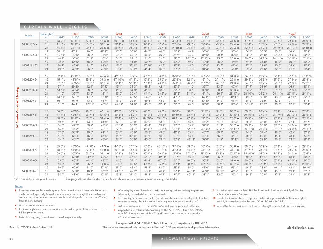
A L L O W A B L E W A L L H E I G H T S
clarkdietrich.comThe technical content of this literature is effective 11/1/12 and supersedes all previous information.
38
Pub. No. CD-STR-TechGuide 11/12Complies with AISI S100-07 NASPEC with 2010 supplement • IBC 2012
C U R T A I N W A L L H E I G H T S
38
Notes:1 Studs are checked for simple-span deflection and stress. Stress calculations are
made for mid-span fully braced moment, end shear through the unperforated section, and shear moment interaction through the perforated section 10" away from the end bearing.
2 A 1/3 stress increase is not used.3 Limiting heights are based on continuous lateral support of each flange over the
full height of the stud.4 Listed limiting heights are based on steel properties only.
5 Web crippling check based on 1-inch end bearing. Where limiting heights are followed by "e," web stiffeners are required.
6 For bending, studs are assumed to be adequately braced to develop full allowable moment capacity. Stud distortional buckling based on an assumed Kφ=0.
7 Cells marked with an " * " have h/t > 200, and thus require end stiffeners.8 Capacities are calculated according to the AISI-NASPEC S100-2007,
with 2010 supplement. A 1-1/2" by 4" knockout spaced no closer than 24" o.c. is assumed.
9 All values are based on Fy=33ksi for 33mil and 43mil studs, and Fy=50ksi for 54mil, 68mil and 97mil studs.
10 For deflection calculations, 15psf and higher wind pressures have been multiplied by 0.7, in accordance with footnote "f" of IBC table 1604.3.
11 Lateral loads have not been modified for strength checks. Full loads are applied.
Member Spacing (in) o.c.
15psf 20psf 25psf 30psf 35psf 40psfL/240 L/360 L/600 L/240 L/360 L/600 L/240 L/360 L/600 L/240 L/360 L/600 L/240 L/360 L/600 L/240 L/360 L/600
14" E
xter
ior C
urta
in W
all F
ram
ing
1400S162-5412 48' 2" e 43' 11" e 37' 1" e 41' 8" e 39' 11" e 33' 8" e 37' 4" e 37' 1" e 31' 3" e 34' 1" e 34' 1" e 29' 5" e 31' 6" e 31' 6" e 27' 11" e 29' 6" e 29' 6" e 26' 9" e16 41' 8" e 39' 11" e 33' 8" e 36' 1" e 36' 1" e 30' 7" e 32' 4" e 32' 4" e 28' 5" e 29' 6" e 29' 6" e 26' 9" e 27' 4" e 27' 4" e 25' 5" e 25' 6" e 25' 6" e 24' 3" e24 34' 1" e 34' 1" e 29' 5" e 29' 6" e 29' 6" e 26' 9" e 26' 4" e 26' 4" e 24' 10" e 24' 1" e 24' 1" e 23' 4" e 22' 3" e 22' 3" e 22' 2" e 20' 10" e 20' 10" e 20' 10" e
1400S162-6812 54' 10" 47' 11" 40' 5" 49' 10" 43' 6" 36' 8" 44' 7" 40' 5" 34' 1" 40' 9" 38' 0" 32' 1" 37' 8" 36' 1" 30' 5" 35' 3" 34' 6" 29' 1" 16 49' 10" 43' 6" 36' 8" 43' 2" 39' 6" 33' 4" 38' 8" 36' 8" 30' 11" 35' 3" 34' 6" 29' 1" 32' 8" 32' 8" 27' 8" 30' 6" e 30' 6" e 26' 6" 24 40' 9" 38' 0" 32' 1" 35' 3" 34' 6" 29' 1" 31' 6" 31' 6" 27' 0" 28' 10" e 28' 10" e 25' 5" 26' 8" e 26' 8" e 24' 2" e 24' 11" e 24' 11" e 23' 1" e
1400S162-9712 62' 5" 54' 6" 46' 0" 56' 8" 49' 6" 41' 9" 52' 7" 46' 0" 38' 9" 49' 6" 43' 3" 36' 6" 47' 0" 41' 1" 34' 8" 45' 0" 39' 4" 33' 2" 16 56' 8" 49' 6" 41' 9" 51' 6" 45' 0" 37' 11" 47' 10" 41' 9" 35' 3" 45' 0" 39' 4" 33' 2" 42' 9" 37' 4" 31' 6" 40' 0" 35' 9" 30' 1" 24 49' 6" 43' 3" 36' 6" 45' 0" 39' 4" 33' 2" 41' 4" 36' 6" 30' 9" 37' 9" 34' 4" 29' 0" 34' 11" 32' 7" 27' 6" 32' 8" 31' 2" 26' 4"
1400S200-5412 52' 4" e 45' 11" e 38' 8" e 45' 4" e 41' 8" e 35' 2" e 40' 7" e 38' 8" e 32' 8" e 37' 0" e 36' 5" e 30' 9" e 34' 3" e 34' 3" e 29' 2" e 32' 1" e 32' 1" e 27' 11" e16 45' 4" e 41' 8" e 35' 2" e 39' 3" e 37' 10" e 31' 11" e 35' 2" e 35' 2" e 29' 8" e 32' 1" e 32' 1" e 27' 11" e 29' 8" e 29' 8" e 26' 6" e 27' 9" e 27' 9" e 25' 4" e24 37' 0" e 36' 5" e 30' 9" e 32' 1" e 32' 1" e 27' 11" e 28' 8" e 28' 8" e 25' 11" e 26' 2" e 26' 2" e 24' 5" e 24' 3" e 24' 3" e 23' 2" e 22' 8" e 22' 8" e 22' 2" e
1400S200-6812 57' 1" 49' 10" 42' 1" 51' 10" 45' 4" 38' 3" 48' 2" 42' 1" 35' 6" 44' 0" 39' 7" 33' 5" 40' 9" 37' 7" 31' 9" 38' 1" 36' 0" 30' 4" 16 51' 10" 45' 4" 38' 3" 46' 8" 41' 2" 34' 9" 41' 9" 38' 3" 32' 3" 38' 1" 36' 0" 30' 4" 35' 3" e 34' 2" 28' 10" 33' 0" e 32' 8" e 27' 7" 24 44' 0" 39' 7" 33' 5" 38' 1" 36' 0" 30' 4" 34' 1" e 33' 5" e 28' 2" 31' 1" e 31' 1" e 26' 6" 28' 10" e 28' 10" e 25' 2" e 26' 11" e 26' 11" e 24' 1" e
1400S200-9712 64' 10" 56' 7" 47' 9" 58' 11" 51' 5" 43' 5" 54' 8" 47' 9" 40' 3" 51' 5" 44' 11" 37' 11" 48' 10" 42' 8" 36' 0" 46' 9" 40' 10" 34' 5" 16 58' 11" 51' 5" 43' 5" 53' 6" 46' 9" 39' 5" 49' 8" 43' 5" 36' 7" 46' 9" 40' 10" 34' 5" 44' 5" 38' 9" 32' 9" 42' 6" 37' 1" 31' 3" 24 51' 5" 44' 11" 37' 11" 46' 9" 40' 10" 34' 5" 43' 5" 37' 11" 32' 0" 40' 5" 35' 8" 30' 1" 37' 5" 33' 11" 28' 7" 35' 0" 32' 5" 27' 4"
1400S250-5412 54' 5" e 47' 9" e 40' 3" e 47' 1" e 43' 5" e 36' 7" e 42' 2" e 40' 3" e 34' 0" e 38' 6" e 37' 11" e 32' 0" e 35' 7" e 35' 7" e 30' 4" e 33' 4" e 33' 4" e 29' 0" e16 47' 1" e 43' 5" e 36' 7" e 40' 10" e 39' 5" e 33' 3" e 36' 6" e 36' 6" e 30' 10" e 33' 4" e 33' 4" e 29' 0" e 30' 10" e 30' 10" e 27' 7" e 28' 10" e 28' 10" e 26' 5" e24 38' 6" e 37' 11" e 32' 0" e 33' 4" e 33' 4" e 29' 0" e 29' 10" e 29' 10" e 26' 11" e 27' 2" e 27' 2" e 25' 4" e 25' 2" e 25' 2" e 24' 1" e 23' 7" e 23' 7" e 23' 1" e
1400S250-6812 59' 5" 51' 11" 43' 9" 54' 0" 47' 2" 39' 9" 50' 0" 43' 9" 36' 11" 45' 8" 41' 2" 34' 9" 42' 3" 39' 1" 33' 0" 39' 7" 37' 5" 31' 7" 16 54' 0" 47' 2" 39' 9" 48' 5" 42' 10" 36' 2" 43' 4" 39' 9" 33' 6" 39' 7" 37' 5" 31' 7" 36' 7" e 35' 7" e 30' 0" 34' 3" e 34' 0" e 28' 8" 24 45' 8" 41' 2" 34' 9" 39' 7" 37' 5" 31' 7" 35' 4" e 34' 9" e 29' 4" 32' 3" e 32' 3" e 27' 7" e 29' 11" e 29' 11" e 26' 2" e 28' 0" e 28' 0" e 25' 1" e
1400S250-9712 67' 3" 58' 9" 49' 6" 61' 1" 53' 4" 45' 0" 56' 8" 49' 6" 41' 9" 53' 4" 46' 7" 39' 4" 50' 8" 44' 3" 37' 4" 48' 6" 42' 4" 35' 9" 16 61' 1" 53' 4" 45' 0" 55' 6" 48' 6" 40' 11" 51' 6" 45' 0" 37' 11" 48' 6" 42' 4" 35' 9" 46' 1" 40' 3" 33' 11" 44' 1" 38' 6" 32' 5" 24 53' 4" 46' 7" 39' 4" 48' 6" 42' 4" 35' 9" 45' 0" 39' 4" 33' 2" 41' 11" 37' 0" 31' 2" 38' 10" 35' 2" 29' 8" 36' 3" 33' 7" 28' 4"
1400S300-5412 55' 5" e 48' 5" e 40' 10" e 48' 3" e 44' 0" e 37' 1" e 43' 2" e 40' 10" e 34' 5" e 39' 5" e 38' 5" e 32' 5" e 36' 6" e 36' 6" e 30' 9" e 34' 1" e 34' 1" e 29' 5" e16 48' 3" e 44' 0" e 37' 1" e 41' 9" e 39' 11" e 33' 8" e 37' 5" e 37' 1" e 31' 3" e 34' 1" e 34' 1" e 29' 5" e 31' 7" e 31' 7" e 28' 0" e 29' 7" e 29' 7" e 26' 9" e24 39' 5" e 38' 5" e 32' 5" e 34' 1" e 34' 1" e 29' 5" e 30' 6" e 30' 6" e 27' 4" e 27' 10" e 27' 10" e 25' 9" e 25' 10" e 25' 10" e 24' 5" e 24' 2" e 24' 2" e 23' 4" e
1400S300-6812 61' 0" 53' 3" 44' 11" 55' 5" 48' 5" 40' 10" 51' 2" 44' 11" 37' 11" 46' 9" 42' 3" 35' 8" 43' 3" 40' 2" 33' 10" 40' 6" e 38' 5" 32' 5" 16 55' 5" 48' 5" 40' 10" 49' 7" 44' 0" 37' 1" 44' 4" 40' 10" 34' 5" 40' 6" e 38' 5" 32' 5" 37' 6" e 36' 6" e 30' 9" 35' 1" e 34' 11" e 29' 5" 24 46' 9" 42' 3" 35' 8" 40' 6" e 38' 5" 32' 5" 36' 2" e 35' 8" e 30' 1" 33' 1" e 33' 1" e 28' 4" e 30' 7" e 30' 7" e 26' 11" e 28' 7" e 28' 7" e 25' 9" e
1400S300-9712 69' 3" 60' 6" 51' 0" 62' 11" 55' 0" 46' 4" 58' 5" 51' 0" 43' 1" 55' 0" 48' 0" 40' 6" 52' 3" 45' 7" 38' 6" 49' 11" 43' 8" 36' 10" 16 62' 11" 55' 0" 46' 4" 57' 2" 49' 11" 42' 2" 53' 1" 46' 4" 39' 1" 49' 11" 43' 8" 36' 10" 47' 5" 41' 5" 35' 0" 45' 5" 39' 8" 33' 5" 24 55' 0" 48' 0" 40' 6" 49' 11" 43' 8" 36' 10" 46' 4" 40' 6" 34' 2" 42' 11" 38' 1" 32' 2" 39' 8" 36' 3" 30' 6" 37' 2" 34' 8" 29' 3"
“e” = web stiffeners required at ends. See page 26 for clarification of code developed wind pressures prior to using this table.
Related Documents