Welcome message from author
This document is posted to help you gain knowledge. Please leave a comment to let me know what you think about it! Share it to your friends and learn new things together.
Transcript


CISCO 60%40%
D-Link
3 Com
Nortel
Cygnus
Etc..
Cisco’s Market Share

Router is an internetworking component, that connects networks which are at different geographical
locations.

Serial 1 Serial 0 AUIE 0
Console
V.35 modem
modem
Telephone
PC
AUX
Diagram of 2501 series Router
Interfaces on a Router

1. Ethernet It is a LAN interface. Some of the models have an RJ45 port for 10baseT or 10/100. And some other have a 15 pin female connector AUI (Attachment Unit Interface).
2. Serial It is a 60 pin female WAN interface for leased line
3. BRI/PRI It is a RJ45 WAN interface for ISDN
4.Console It is a RJ45 Connector used to configure the Router for the first time.
5. Auxiliary RJ45 Connector for remote access administration.

Routers
Modular Fixed
Modular Routers
These type of routers have up gradable slots, and the number of ports can be increased just by adding cards in the slots.
Fixed Routers
These types of routers have fixed number of ports.
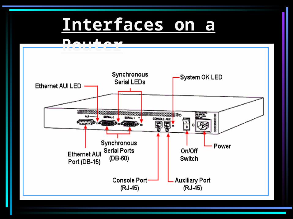
Cisco Router’s Series
Cisco 700, 800, 1600, 1700, 2500, 2600, 3600, 4000, 5000, 7000,10000, 12000.
Fixed Modular
700, 800,….2500 2600,….., 12000
1750 & 1751 exceptionally are Modular Routers.
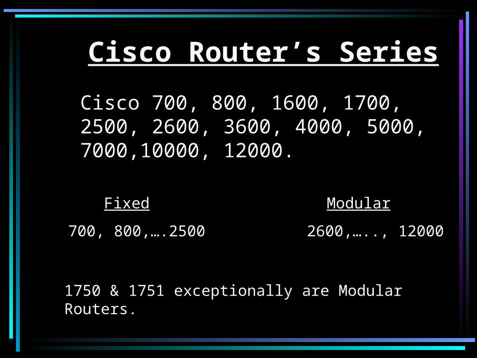
Cisco’s Hierarchical Model

Access Layer- Manage access control and policy, separate collision domain, and also known as Desktop Layer.
700, …, 2500
Distribution Layer- It is also called communication point between core and access layer, Basic function is routing. Fault tolerance, Implement Policies.
2600, …, 5000
Core Layer- It is known as core of network and responsible to transfer heavy traffic reliable and in quick manner, protect from
workgroup access support.
7000, …, 12000

Transceiver

Internal Components of a Router

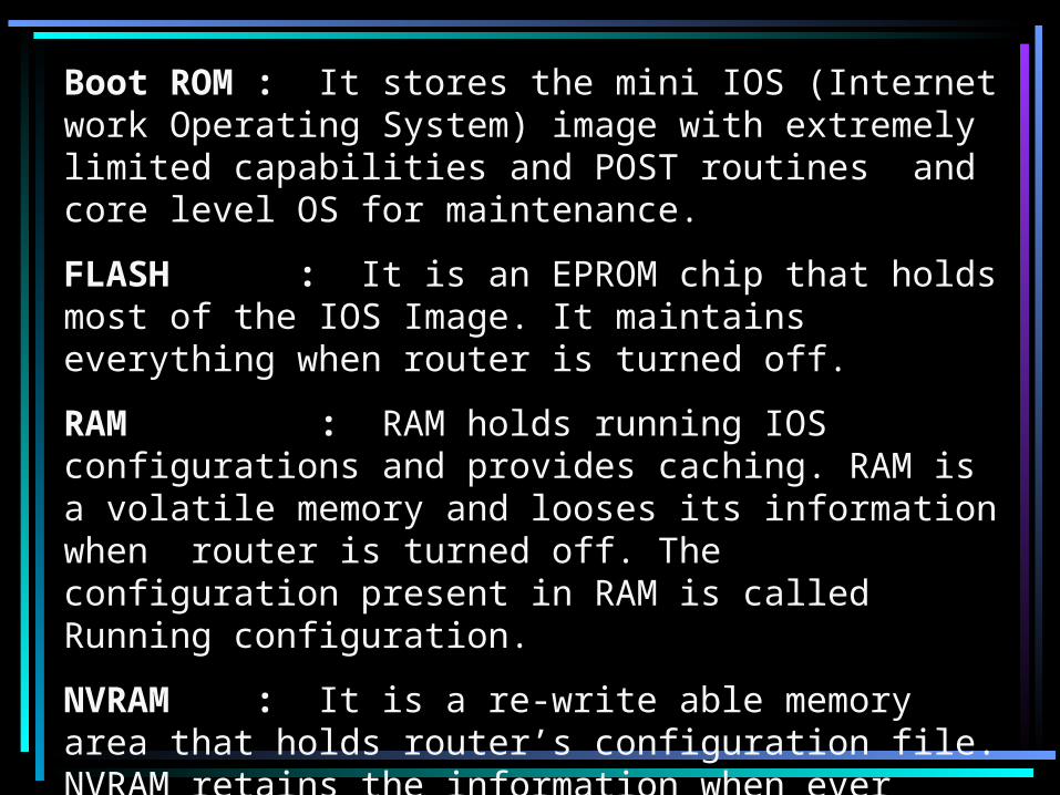
Boot ROM : It stores the mini IOS (Internet work Operating System) image with extremely limited capabilities and POST routines and core level OS for maintenance.
FLASH : It is an EPROM chip that holds most of the IOS Image. It maintains everything when router is turned off.
RAM : RAM holds running IOS configurations and provides caching. RAM is a volatile memory and looses its information when router is turned off. The configuration present in RAM is called Running configuration.
NVRAM : It is a re-write able memory area that holds router’s configuration file. NVRAM retains the information when ever router is rebooted. Once configuration is saved, it will be saved in NVRAM and this configuration is called Startup Configuration.

Configuration of a Router Router for the first time is configured through the CONSOLE
port.COM port of a PC is connected to the console port of router with a console cable by using a transceiver. Router is accessible by a tool. In windows, it is called HYPER TEMINAL. As soon as the router is powered on and accessed, the following things happen,
POST
BOOT STRAP
FLASH
NVRAM
Setup Mode
ROM (mini IOS)If IOS is Corrupted

• POST- A post is a program stored in ROM is executed first. Checks hardware components of the router first .
• BOOTSTRAP- The program is stored in ROM that is used to execute. This program find and locate the IOS from possible location of IOS can be Flash.TFTP server and mini IOS,by deafult IOS loaded from flash memory in all cisco router.
• Once he IOS is loaded. It finds and loads configuration file stored in NVRAM. This file is called Startup-configuration and is only there if we copies to running-config file into NVRAM. If a startup-config file is not in NVRAM, the router will start the setup mode

In Setup mode, there will be a message,
“Would You Like To Enter The Initial Configuration [Y/N]” :
If “Y” then, initial configuration starts.
If “N” would you like to terminate the auto installation?
Press “RETURN” to get started……You will land on the default prompt of the Router “ ROUTER >”.
Router>_

Working Modes Of a Router
1. User Mode (Default mode)
2. Privilege or Administrative Mode
3. Global Configuration Mode
4. Interface Configuration Mode
5. Line Configuration Mode
6. Router Mode
7. Sub-Interface Mode

USER MODE
Router> is the user mode, I,e the default prompt. It means that when ever a router boots successfully it lands into the user mode. Router cannot be configured from this mode, but it is used for just monitoring purpose. Router> en
Router #
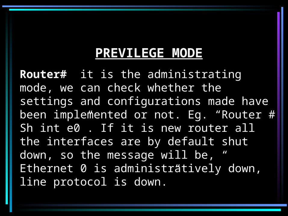
PREVILEGE MODE
Router# it is the administrating mode, we can check whether the settings and configurations made have been implemented or not. Eg. “Router # Sh int e0”. If it is new router all the interfaces are by default shut down, so the message will be, “ Ethernet 0 is administratively down, line protocol is down.”
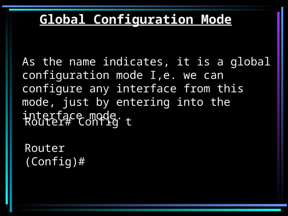
Router# Config t
Router (Config)#
Global Configuration Mode
As the name indicates, it is a global configuration mode I,e. we can configure any interface from this mode, just by entering into the interface mode.
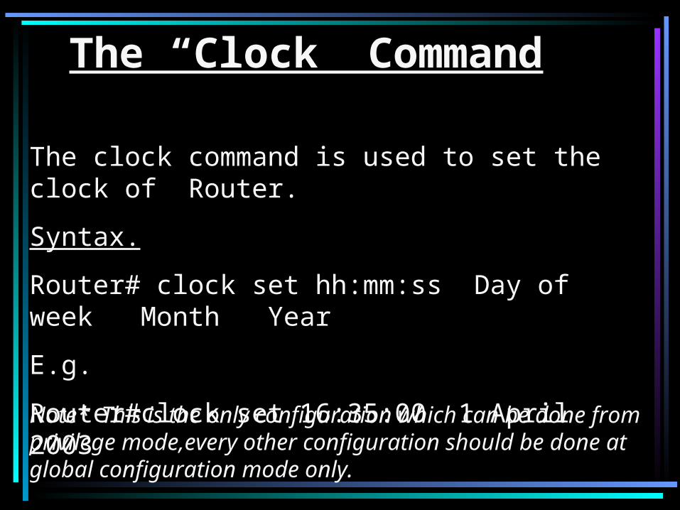
The “Clock” Command
The clock command is used to set the clock of Router.
Syntax.
Router# clock set hh:mm:ss Day of week Month Year
E.g.
Router#clock set 16:35:00 1 April 2003
Note* This is the only configuration which can be done from privilege mode,every other configuration should be done at global configuration mode only.
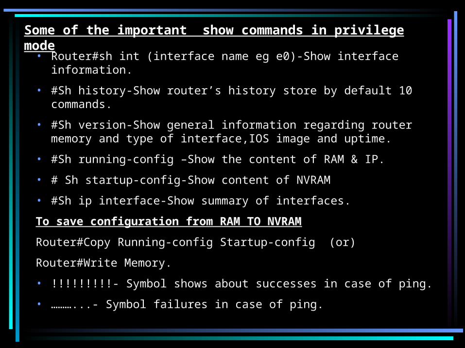
Some of the important show commands in privilege mode
• Router#sh int (interface name eg e0)-Show interface information.
• #Sh history-Show router’s history store by default 10 commands.
• #Sh version-Show general information regarding router memory and type of interface,IOS image and uptime.
• #Sh running-config –Show the content of RAM & IP.
• # Sh startup-config-Show content of NVRAM
• #Sh ip interface-Show summary of interfaces.
To save configuration from RAM TO NVRAM
Router#Copy Running-config Startup-config (or)
Router#Write Memory.
• !!!!!!!!!- Symbol shows about successes in case of ping.
• ………...- Symbol failures in case of ping.
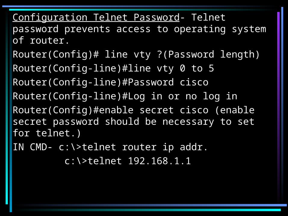
Configuration Telnet Password- Telnet password prevents access to operating system of router.Router(Config)# line vty ?(Password length)Router(Config-line)#line vty 0 to 5Router(Config-line)#Password ciscoRouter(Config-line)#Log in or no log inRouter(Config)#enable secret cisco (enable secret password should be necessary to set for telnet.)IN CMD- c:\>telnet router ip addr.
c:\>telnet 192.168.1.1

• To configure Hostname (or) Identification of Router over the network.
Router#config t
Router(config)#Hostname R_2503
Router(config)#^Z

Previlege PASSWORDS
Enable Password Enable Secret
Enable Password:- It is global command restricts access to the previlege mode, the password is in clear text.
Router(config)#Enable password 123
Enable Secret:-Here the password is in encrypted form.
Router(config)#Enable secret cisco

CONFIGURING INTERFACES
LAN interface (ETHERNET Port)
WAN interface (SERIAL Port)
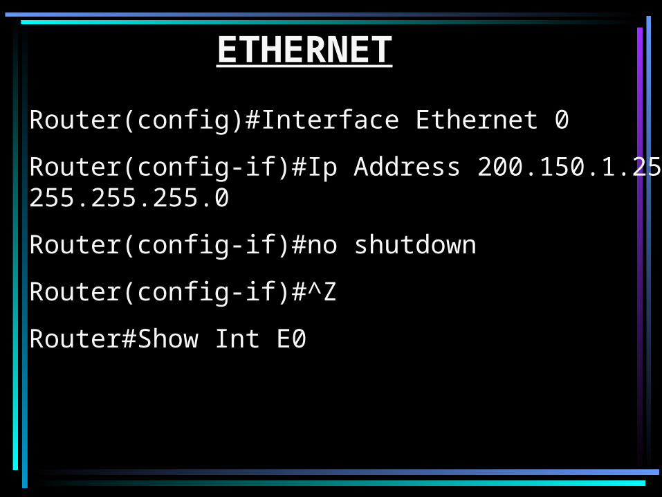
ETHERNET
Router(config)#Interface Ethernet 0
Router(config-if)#Ip Address 200.150.1.254 255.255.255.0
Router(config-if)#no shutdown
Router(config-if)#^Z
Router#Show Int E0
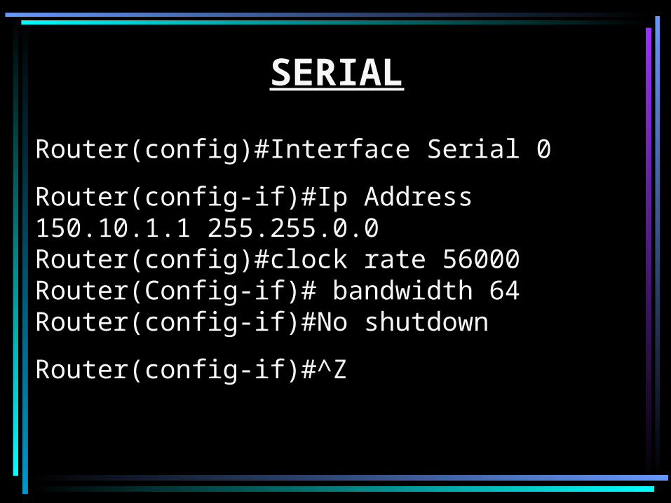
SERIAL
Router(config)#Interface Serial 0
Router(config-if)#Ip Address 150.10.1.1 255.255.0.0Router(config)#clock rate 56000Router(Config-if)# bandwidth 64Router(config-if)#No shutdown
Router(config-if)#^Z

The “CDP”It’s a Cisco's proprietary protocol called the Cisco Discovery Protocol, that gives you a summary of all the directly connected Cisco devices. CDP is a L2 protocol, that discovers neighbor regardless of which protocol suite they are running. When a cisco device boots up, the CDP is loaded by default, but can be disabled at interface level.
* The CDP is limited to the immediate neighbors only…
The summary includes Device Identifier(eg. Switch configured name or domain name), Port Identifier (eg. Ethernet 0 and serial 0.), Capabilities list (eg. The device can act as a source route bridge as well as a router), Platform (eg. Cisco 2600).
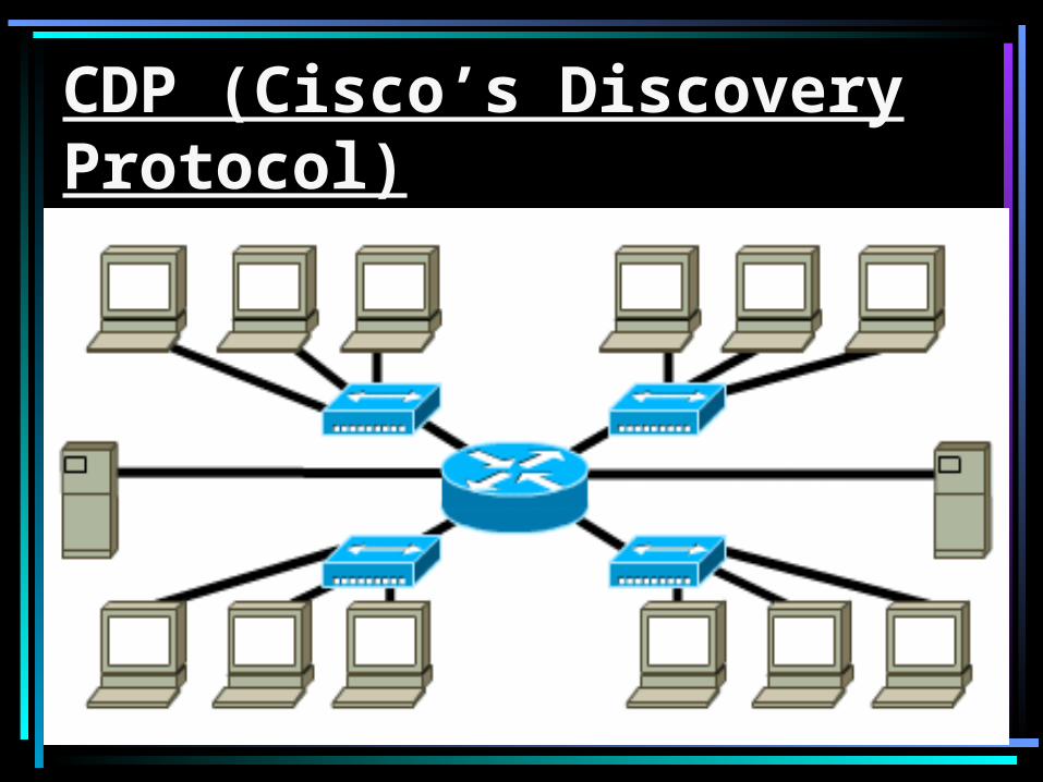
CDP (Cisco’s Discovery Protocol)
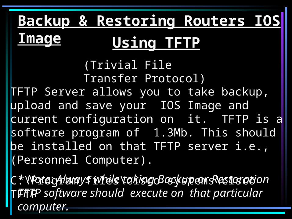
Backup & Restoring Routers IOS Image
Using TFTP
(Trivial File Transfer Protocol)
TFTP Server allows you to take backup, upload and save your IOS Image and current configuration on it. TFTP is a software program of 1.3Mb. This should be installed on that TFTP server i.e., (Personnel Computer).
C:\Program files\cisco systems\cisco TFTP
* Note: Always while taking Backup or Restoration TFTP software should execute on that particular computer.

• Notification things1) First assign IP address on router’s
ethernet interface.2) Assign an IP address of TFTP server in
LAN card setting. This address also of PC on which we are working.
3) Ping both address successfully TFTP server address and router’s IP address.

Backup Sources :
1. Through Telnet Session.
2. Through Console Session.
3. Through Auxillary Port (Remote Session)
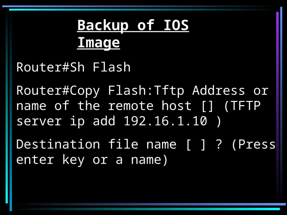
Backup of IOS Image
Router#Sh Flash
Router#Copy Flash:Tftp Address or name of the remote host [] (TFTP server ip add 192.16.1.10 )
Destination file name [ ] ? (Press enter key or a name)

Leased line WAN Setup
Case 1: The distance between the locations is greater than 5 Km.
Requirements
A pair of Routers, Leased line, pair of leased line modems V.35,
Pair of G.703 Modem.
Case 2: The distance between the two locations is less than 5Km.
Requirements
A pair of Routers, Leased line and pair of leased line modem.
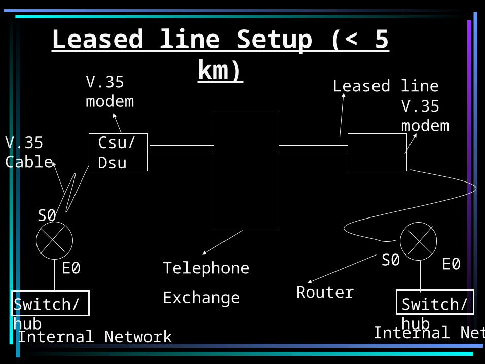
Leased line Setup (< 5 km)
Internal Network Internal Network
V.35 Cable Csu/Dsu
Switch/hub
V.35 modem
S0
E0 S0 E0
Switch/hubRouter
V.35 modem
Leased line
Telephone
Exchange

RoutingRouting is of three types.
• Static - Static routing is done by the users. These paths are stored in the routing table.
•Advantage:No overhead on the router CPU,No bandwidth usage between routers, Security(administrator only allows routing to certain networks).
•Disadvantage: If one network is added to the internetwork the administrator must add a route to it on all routers. It is not feasible network because it would be a full time job.

• Dynamic - In dynamic routing, the path is fixed by the protocol. The paths will be changing depending on the length of the path. Always the shortest path is preferred. It is the process of using protocol to find and update routing tables on routers, and easier than static or default routing.
• Autonomous No. – It is group of router our network under single administrative control. unique number from 1-65,535 to differentiate for other AS. Routing updates of one AS is normally no forwarded other AS.
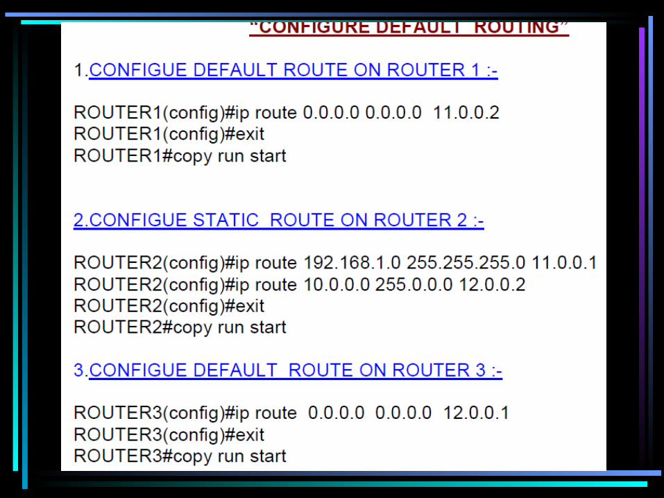
• Default - When the destination is known, static and dynamic routing is done. For unknown destinations, default routing is employed. It works on stub networks, means have only one exit port out of the network. To configure a default route, use wild cards in the network address and mask locations of a static route.
• Routing Protocol – Used by router to learn or find path by sending and receiving updates and decided best path which specific destination. E.g. RIP, EIGRP.
• Routed Protocol – Used to carry network traffic such as file download, upload e-mails, application data etc. e.g. IP, SPX
• Permanent – If the interface is shut down or he router cannot communicate to the next hop router, the route is automatically discarded from the routing table choosing the permanent option keeps the entry in the routing table no matters what happens.

• Administrative Distance – by default static routes have an administrative distance of 1. We can change the default value by adding an administrative weight at the end of the command. 0 – 255, for static routing 0-1. It is used to rate trustworthiness of routing information received on a router for a neighbor router. Where 0 is the most trusted and 255 means traffic will be passed via this route. Lowest value reliable.
• Default administrative Distance: Directly connected interface --- 0; Static Route --- 0,1; EIGRP --- 90; OSPF --- 110; IGRP --- 100; IS-IS --- 115; RIP --- 120; External EIGRP --- 170;
Unknown Destination --- 255
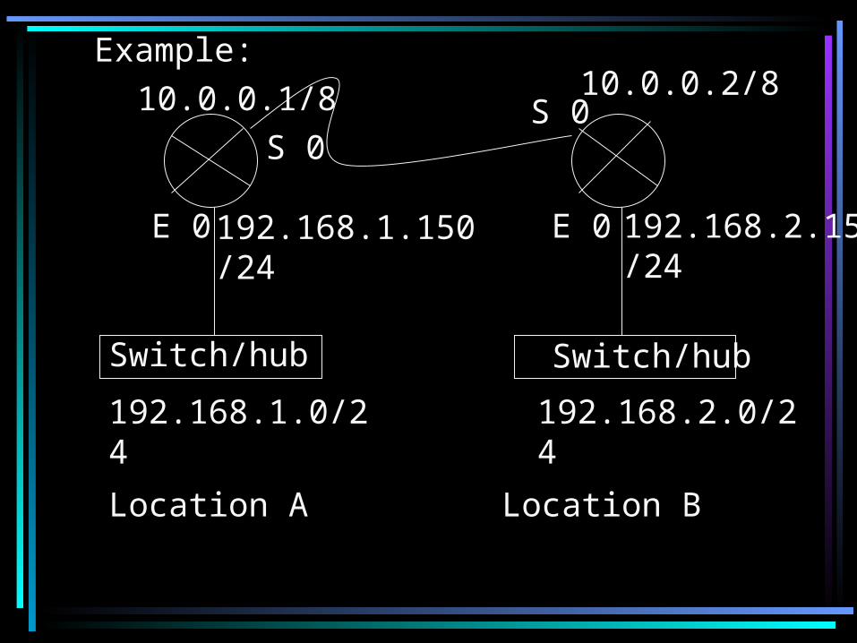
Example:
Switch/hub Switch/hub
E 0 E 0
S 0S 0
192.168.1.0/24 192.168.2.0/24
192.168.1.150/24 192.168.2.150/24
10.0.0.1/8 10.0.0.2/8
Location A Location B
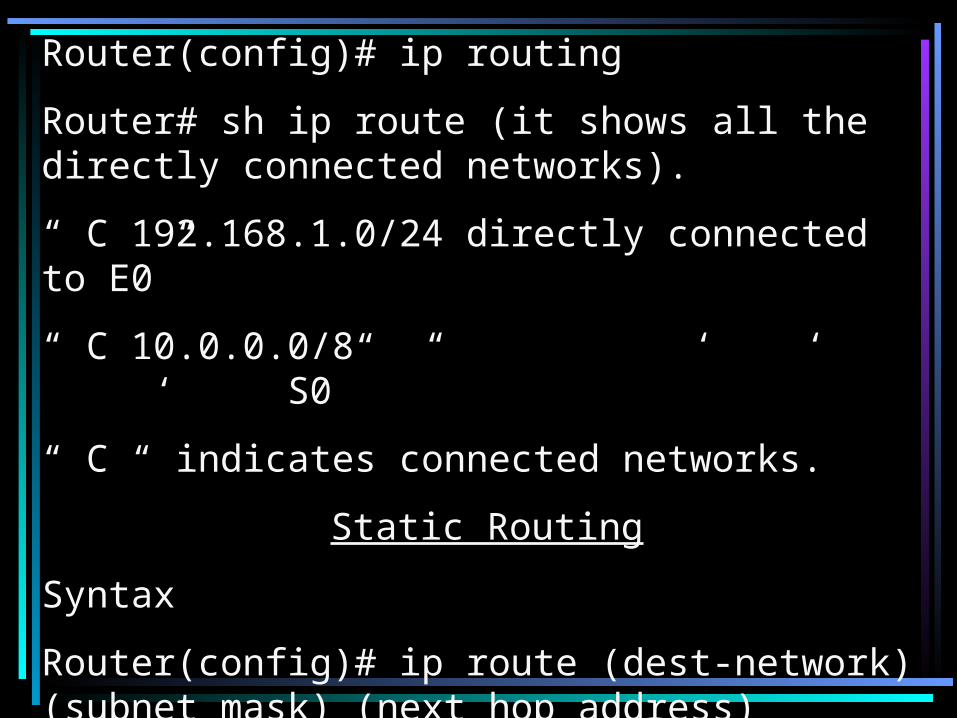
Router(config)# ip routing
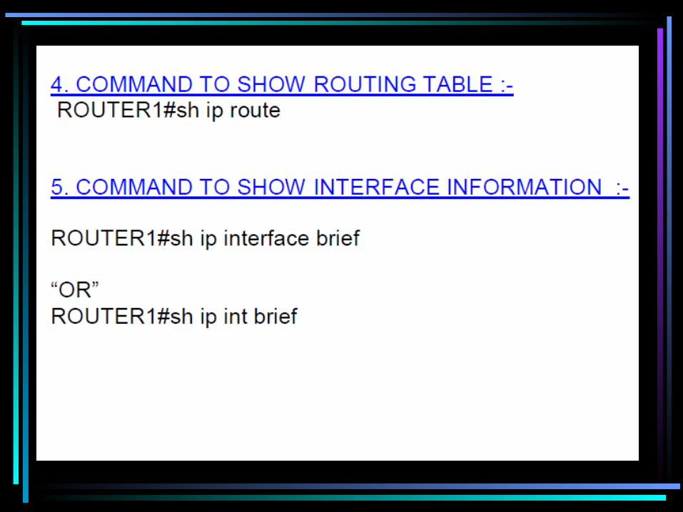
Router# sh ip route (it shows all the directly connected networks).
“ C 192.168.1.0/24 directly connected to E0”
“ C 10.0.0.0/8 “ ‘ ‘ ‘ S0”
“ C “ indicates connected networks.
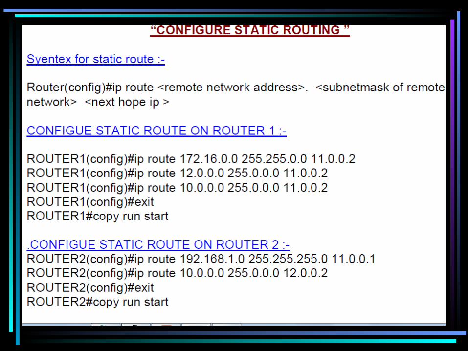
Static Routing
Syntax
Router(config)# ip route (dest-network) (subnet mask) (next hop address)

Location A
Router(config)# ip routing
Router(config)# ip route 192.168.2.0 255.255.255.0 10.0.0.2
Note* if we don’t know the address of next hop, we can just write the name of the hop.
Router(config)# ip route 192.168.2.0 255.255.255.0 S0
Location B
Router(config)# ip routing
Router(config)# ip route 192.168.1.0 255.255.255.0 10.0.0.1

Router# sh ip route
C 192.168.1.0/24 directly connected to E0
C 10.0.0.0/8 “ ‘ “ “ S0
S 192.168.2.0/24 [1/0] via 10.0.0.2
•“S” represents static. [a/b] ~ [1/0], here a=1 is the administrative distance value and b has no significance in static routing. For static and default routing b can be 0 or 1. Lesser the administrative distance value, higher the preference.

“Tracert”, “Trace Route” and “Route print”.C:\> tracert
C:\> route print
Router# trace route (gives the complete route)
Router# sh arp (to check MAC addresses)
Default Routing
Router(config)# ip routing
Router(config)#ip route DA (S/N mask next) (next hop address)
Router(config)# ip route 0.0.0.0 0.0.0.0 s1

Router# sh ip route
C 192.168.1.0/24 directly connected to E0
C 10.0.0.0/8 “ “ to S0
S* 0.0.0.0/0 “ “ to S0

• METRIC – Metric is used by protocol to decide best path reach specific destination different protocol take different approach and deciding best path.
e.g. RIP use hop count as metric while OSPF use and IGRP used bandwidth and delay.

Classification Of Routing Protocols
Distance Vector
Hybrid Routing
Link State
Distance Vector: the distance vector approach determines the direction and the distance to any link in the internetwork. When the topology in a distance vector routing protocol changes, routing table updates in the router must occur. This update process proceeds step-by-step router to router. E.g. RIP and IGRP.It is use local broadcast 255.255.255.255 to exchange routing updates
Link State : it recreates the exact topology of the entire network(at least the partition of the network where the router is situated).Typically called shortest path first, the routers each create three separate tables. One of these tables keeps track of directly attached neighbor E.g. OSPF.

• Hybrid Routing : it combines aspects of the link state and the distance vector
algorithm.
Functions of a distance vector routing protocol.
Identification of source of information
Discovering routes
Select the best route
Maintain Route information
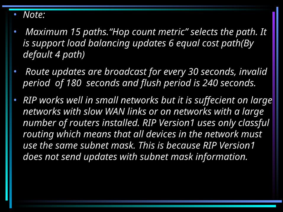
• Note:
• Maximum 15 paths.“Hop count metric” selects the path. It is support load balancing updates 6 equal cost path(By default 4 path)
• Route updates are broadcast for every 30 seconds, invalid period of 180 seconds and flush period is 240 seconds.
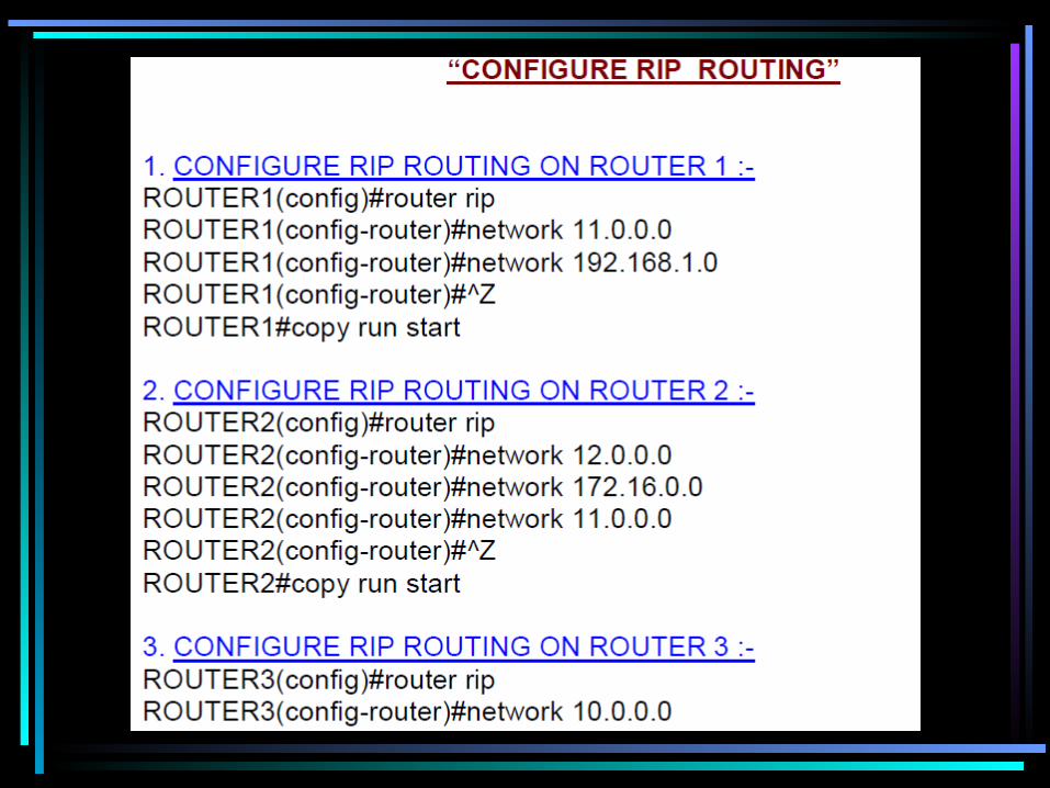
• RIP works well in small networks but it is suffecient on large networks with slow WAN links or on networks with a large number of routers installed. RIP Version1 uses only classful routing which means that all devices in the network must use the same subnet mask. This is because RIP Version1 does not send updates with subnet mask information.
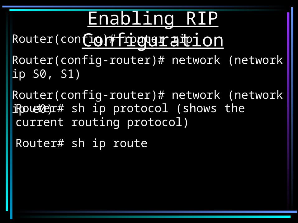
Router(config)# router rip
Router(config-router)# network (network ip S0, S1)
Router(config-router)# network (network ip e0)
Enabling RIP Configuration
Router# sh ip protocol (shows the current routing protocol)
Router# sh ip route
IGRPIGRP was created in part to overcome the
limitations of RIP (maximum hop count of only 15, and a single routing metric) when used within large networks. IGRP supports multiple metrics for each route. IGRP is considered a classful routing protocol.

172.16.1.0
E0 S2 S2 S3 S3 E0
192.168.1.0
172.16.1.1
10.1.1.1
10.1.1.2
10.2.2.2
10.2.2.3192.168.1.1
Router rip
Network 172.16.0.0
Network 10.0.0.0
Router rip
Network 10.0.0.0 Router rip
Network 192.168.1.0
Network 10.0.0.0

Configuring IGRPSyntaxes.
Router(config)#router igrp autonomous number
This defines IGRP as the routing protocol.
Router(config-router)#Network network-ip
Selects directly connected networks.
Router(config-router)#variance multiplier
Configures unequal-cost load balancing by defining difference between the best metric and the worst acceptable metric.

Autonomous System 100172.16.1.0
E0 S2 S2 S3 S3 E0
192.168.1.0
172.16.1.1
10.1.1.1
10.1.1.2
10.2.2.2
10.2.2.3192.168.1.1
Router igrp 100
Network 172.16.0.0
Network 10.0.0.0
Router igrp 100
Network 10.0.0.0
Router igrp 100
Network 192.168.1.0
Network 10.0.0.0

IP Classless CommandRouter(config)# ip classless
A router by default assumes that all the subnets of a directly connected network should be present in the routing table. If a packet is received with a destination address, of an unknown subnet of directly attached network, the router assumes that the subnet does not exists and drops the packet. This happens even if routing table has a default route.For the above condition if IP Classless is configured, and if any packet is received, then the router will match it to the default route and forward it to the next hop specified by the default route.

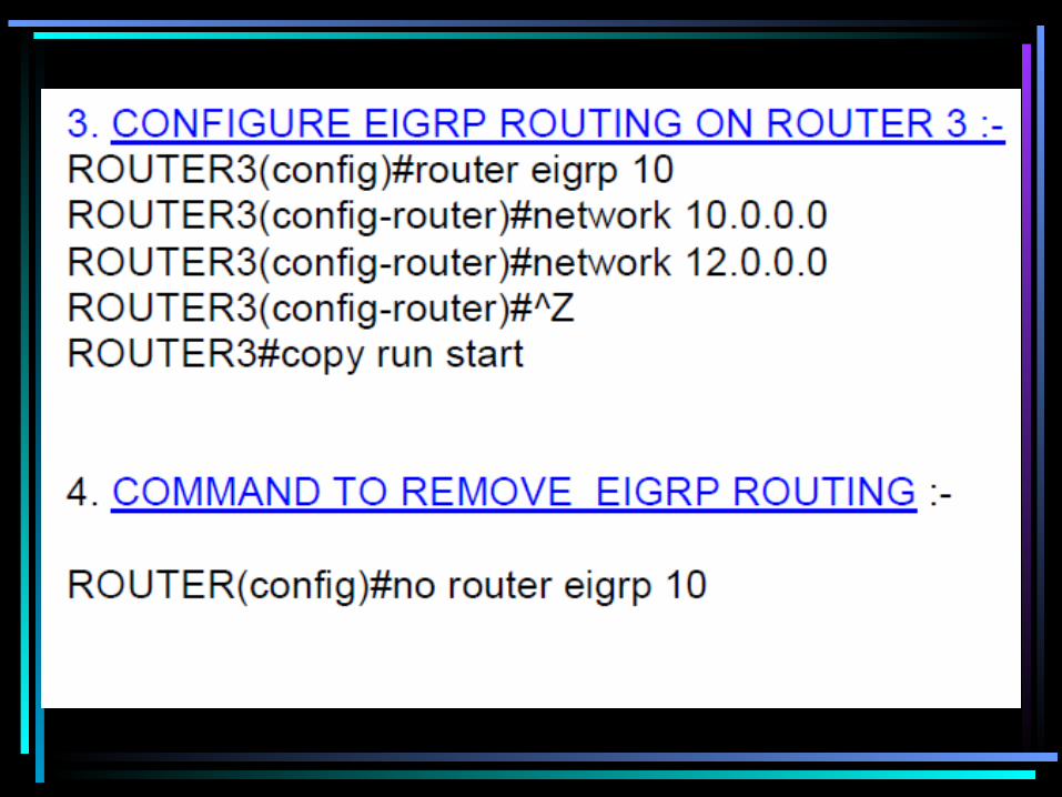
EIGRP• EIGRP is more of link state protocol.
EIGRP is still a distance vector protocol, but it uses a different algorithm, called the DUAL algorithm to calculate its routes. Enhanced Interior Gateway Routing Protocol (EIGRP) is considered a scalable routing protocol. It is a classless protocol permitting VLSMs, route authentication and supernetting. Routing updates are not performed periodically.

Calculation of Wildcard Mask
WCM = BCM-SNM
1. 192.168.1.0/24
255.255.255.255
- 255.255.255. 0
0 . 0 . 0 .255
2. 192.168.1.0/27
255.255.255.255
- 255.255.255.224
0 . 0 . 0 . 31
3. 192.160.1.10 0.0.0.0
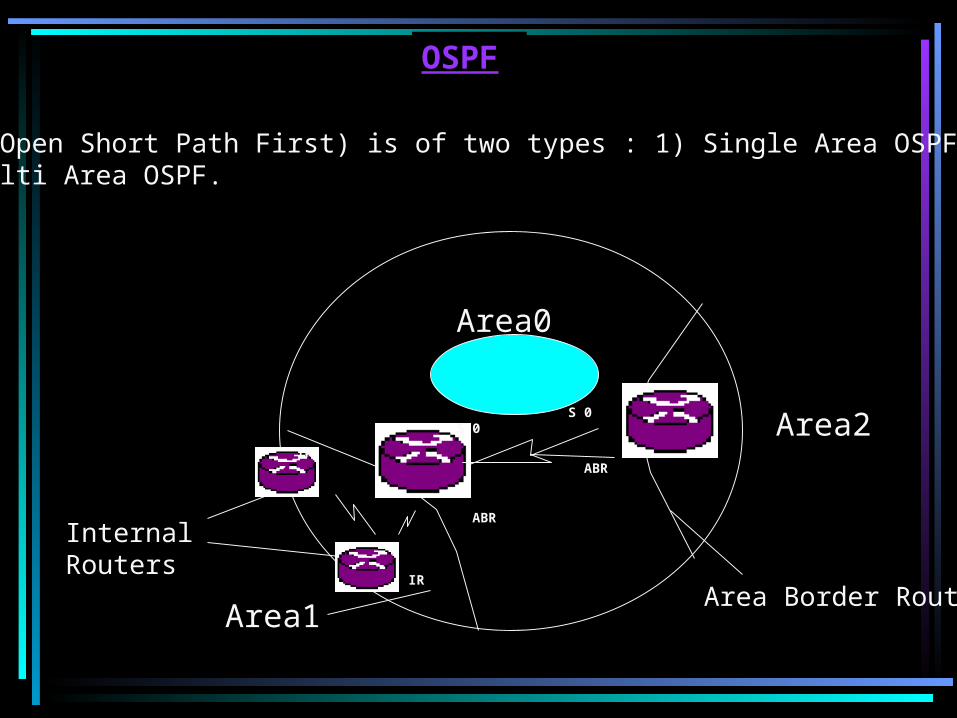
OSPF
OSPF(Open Short Path First) is of two types : 1) Single Area OSPF and2) Multi Area OSPF.
Internal Routers
Area1
Area2
Area Border RouterIR
IR
ABR
ABR
Area0
S 0S 0
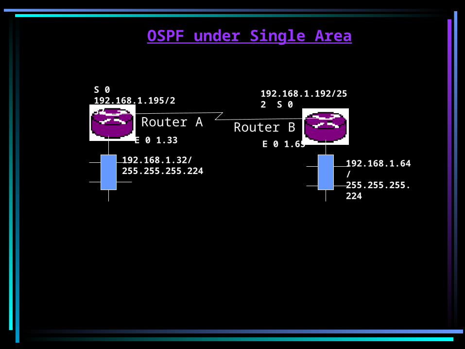
Router A Router B
S 0 192.168.1.195/252 192.168.1.192/252 S 0
E 0 1.65
192.168.1.32/255.255.255.224
192.168.1.64/255.255.255.224
E 0 1.33
OSPF under Single Area

(Config)# ip routing(Config-Router)# router OSPF 6573(Config-Router)# network 192.168.1.32 0.0.0.31 area 1(Config-Router)# area 1 range 192.168.1.32 255.255.255.224(Config-Router)# network 192.168.1.192 0.0.0.3 area 1(Config-Router)# area 1 range 192.168.1.192 255.255.255.224

(Config)# ip routing(Config-Router)# router OSPF 6573(Config-Router)# network 192.168.1.64 0.0.0.31 area 1(Config-Router)# area 1 range 192.168.1.64 255.255.255.224(Config-Router)# network 192.168.1.195 0.0.0.3 area 1(Config-Router)# area 1 range 192.168.1.195 255.255.255.252
Configuration of Router B--------------------------------

OSPF under Different Areas
Area 0
192.168.1.0 192.168.5.0
Area 1 Area 2
E0 E0
5.50
Router A Router B
1.50
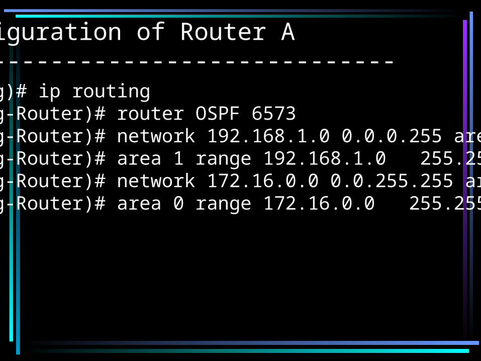
(Config)# ip routing(Config-Router)# router OSPF 6573(Config-Router)# network 192.168.1.0 0.0.0.255 area 1(Config-Router)# area 1 range 192.168.1.0 255.255.255.0(Config-Router)# network 172.16.0.0 0.0.255.255 area 0(Config-Router)# area 0 range 172.16.0.0 255.255.0.0
Configuration of Router A--------------------------------

Configuration of Router B--------------------------------
(Config)# ip routing(Config-Router)# router OSPF 6573(Config-Router)# network 192.168.5.0 0.0.0.255 area 2(Config-Router)# area 2 range 192.168.5.0 255.255.255.0(Config-Router)# network 172.16.0.0 0.0.255.255 area 0(Config-Router)# area 0 range 172.16.0.0 255.255.0.0

Access Control ListIt is also called Network Traffic Control
Management (NTCM). We can provide restrictions to individual users, subnets and services etc.
ACL
Standard ACL Extended ACL
Any access list is identified by its number.
S. A. L 1 – 99
Ex. A. L 100 - 199
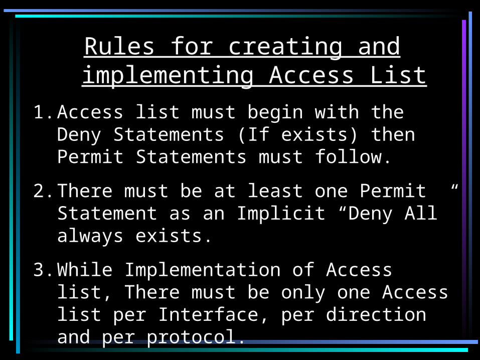
Rules for creating and implementing Access List
1. Access list must begin with the Deny Statements (If exists) then Permit Statements must follow.
2. There must be at least one Permit Statement as an Implicit “Deny All” always exists.
3. While Implementation of Access list, There must be only one Access list per Interface, per direction and per protocol.

Standard Access List
Router A Router B
S 0 172.16.1.1 172.16.1.2 S 0
E 0 5.50
1.1
1.21.3
1.45.1
5.2
5.4
5.3
E 0 1.50
Syntax
Router(config)# Access-list ALNO P/D Src Src-WCM
Router(config)# Int <name of interface>
Router(Config-if)#Ip Access-Group <Direction>
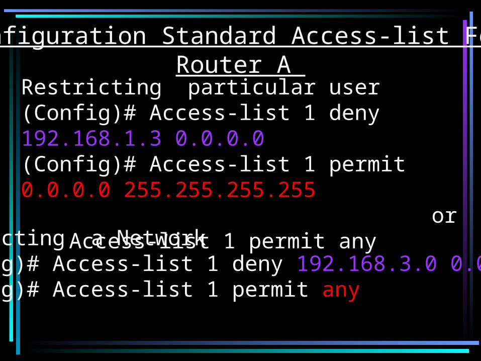
Configuration Standard Access-list For Router A
Restricting particular user(Config)# Access-list 1 deny 192.168.1.3 0.0.0.0(Config)# Access-list 1 permit 0.0.0.0 255.255.255.255 or
Access-list 1 permit anyRestricting a Network(Config)# Access-list 1 deny 192.168.3.0 0.0.0.255(Config)# Access-list 1 permit any

Extended Access List
Router A Router B
S 0 172.16.1.1 172.16.1.2 S 0
E 0 5.50
1.1
1.21.3
1.4 5.1
5.2
5.4
5.3
E 0 1.50
1.20

Configuration of Router A
(Config)# Access-list 101 deny TCP 192.168.5.0 0.0.0.255 192.168.1.20 0.0.0.0 eq FTP
(Config)# Access-list 101 permit IP any any
Implementation
(Config)#int E0
(config-if)# IP Access-group 101 Out

NAT(Network Address Translation)
Router A Router B
S 0 172.16.1.1 172.16.1.2 S 0
E 0 5.50
1.1
1.2192.168.1.3
1.4 5.1
5.2
5.4
5.3
E 0 1.50
Note : 192.168.1.3 is denied from entering the network of 5.0.So it will enter with mask.

Configuration of Router A --------------------------------# Config t(Config)# int E 0(Config-if)# ip address 192.168.1.50 255.255.255.0(Config-if)# no shut(Config-if)# exit
(Config)# int S 0(Config-if)# ip address 172.16.1.1 255.255.0.0(Config-if)# clock rate 56000(Config-if)# bandwidth 64(Config-if)# no shut(Config-if)# exit
(Config)# ip routing(Config-Router)# ip route 192.168.5.0 255.255.255.0 172.16.1.2
(Config)# int E 0(Config-if)# ip nat inside

(Config)# int S 0(Config-if)# ip nat outside
(Config)# access-list 1 permit 192.168.1.3 0.0.0.0(Config)# ip nat inside source list 1 int S 0 overload
# Config t(Config)# int E 0(Config-if)# ip address 192.168.5.50 255.255.255.0(Config-if)# no shut(Config-if)# exit
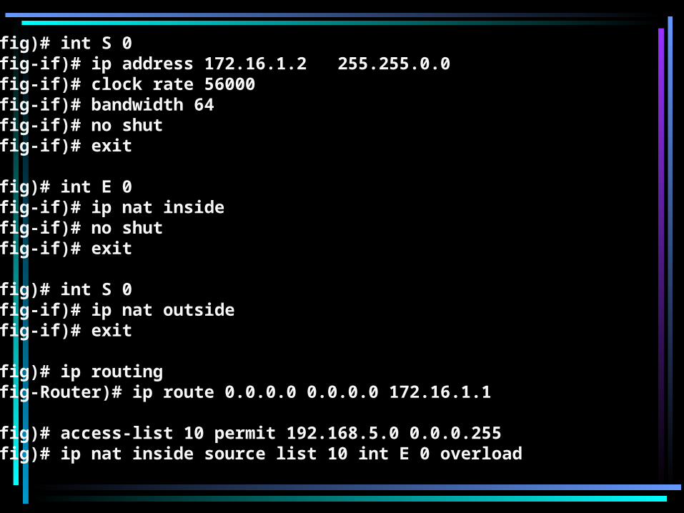
(Config)# int S 0(Config-if)# ip address 172.16.1.2 255.255.0.0(Config-if)# clock rate 56000(Config-if)# bandwidth 64(Config-if)# no shut(Config-if)# exit
Configuration of Router B --------------------------------

(Config)# ip routing(Config-Router)# ip route 192.168.1.0 255.255.255.0 172.16.1.1
(Config)# access-list 10 deny 192.168.1.3 0.0.0.0(Config)# access-list 10 permit any
(Config)# int E 0(Config-if)# ip access-group 10 out
Note : Only Public IP can go to the Internetworking world.

A Scenario of providing Net access to the IP's of Router B
Natting
Router ARouter B
Switch
Routing
Leased line
Routing5.0
5.501.50
172.16.1.1 172.16.1.2
192.168.1.99

Configuration of Router A --------------------------------
# Config t(Config)# int E 0(Config-if)# ip address 192.168.1.50 255.255.255.0(Config-if)# no shut(Config-if)# exit
(Config)# int S 0(Config-if)# ip address 172.16.1.1 255.255.0.0(Config-if)# clock rate 56000(for DCE)(Config-if)# bandwidth 64(Config-if)# no shut(Config-if)# exit
(Config)# ip routing(Config-Router)# ip route 0.0.0.0 0.0.0.0 192.168.1.99

(Config)# int S 0(Config-if)# ip nat inside((Config-if)# exit
(Config)# access-list 10 permit 172.16.0.0 0.0.255.255(Config)# ip nat inside source list 10 int E 0 overload
(Config)# int E 0(Config-if)# ip nat outside(Config-if)# no shut(Config-if)# exit
Configuration of Router B --------------------------------# Config t(Config)# int E 0(Config-if)# ip address 192.168.5.50 255.255.255.0(Config-if)# no shut(Config-if)# exit
(Config)# int S 0(Config-if)# ip address 172.16.1.2 255.255.0.0(Config-if)# clock rate 56000(Config-if)# bandwidth 64(Config-if)# no shut(Config-if)# exit
(Config)# int E 0(Config-if)# ip nat inside(Config-if)# no shut(Config-if)# exit
(Config)# int S 0(Config-if)# ip nat outside(Config-if)# exit
(Config)# ip routing(Config-Router)# ip route 0.0.0.0 0.0.0.0 172.16.1.1
(Config)# access-list 10 permit 192.168.5.0 0.0.0.255(Config)# ip nat inside source list 10 int E 0 overload

PPP(Point-to-Point) using PAP protocol
Router A(ISDN)
Router B(Zoom)
S 0 172.16.1.1 172.16.1.2 S 0
E 0 5.501.1
1.21.3
1.4 5.1
5.2
5.4
5.3
E 0 1.50
Internet based leased line
NOTE : Passwords of both should be same.

Configuration of Router A --------------------------------# Config t(Config)# int E 0(Config-if)# ip address 192.168.1.50 255.255.255.0(Config-if)# no shut(Config-if)# exit
(Config)# int S 0(Config-if)# ip address 172.16.1.1 255.255.0.0(Config-if)# clock rate 56000(for DCE)(Config-if)# bandwidth 64(Config-if)# no shut(Config-if)# exit
(Config)# ip routing(Config-Router)# ip route 192.168.5.0 255.255.255.0 172.16.1.2
(Config)# int S 0(Config-if)# encapsulation ppp(Config-if)# ppp authentication PAP(Config-if)# ppp PAP sent-username zoom password cisco

Configuration of Router B --------------------------------
# Config t(Config)# int E 0(Config-if)# ip address 192.168.5.50 255.255.255.0(Config-if)# no shut(Config-if)# exit
(Config)# int S 0(Config-if)# ip address 172.16.1.2 255.255.0.0(Config-if)# clock rate 56000(for DCE)(Config-if)# bandwidth 64(Config-if)# no shut(Config-if)# exit
(Config)# ip routing(Config-Router)# ip route 192.168.1.0 255.255.255.0 172.16.1.1
(Config)# int S 0(Config-if)# encapsulation ppp(Config-if)# ppp authentication PAP(Config-if)# ppp PAP sent-username ISP password cisco
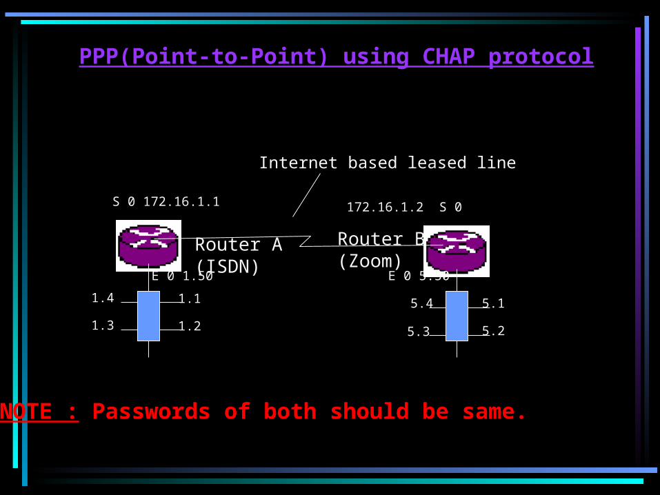
PPP(Point-to-Point) using CHAP protocol
Router A(ISDN)
Router B(Zoom)
S 0 172.16.1.1 172.16.1.2 S 0
E 0 5.50
1.1
1.21.3
1.4 5.1
5.2
5.4
5.3
E 0 1.50
Internet based leased line
NOTE : Passwords of both should be same.

Configuration of Router A --------------------------------
# Config t(Config)# int E 0(Config-if)# ip address 192.168.1.50 255.255.255.0(Config-if)# no shut(Config-if)# exit
(Config)# int S 0(Config-if)# ip address 172.16.1.1 255.255.0.0(Config-if)# clock rate 56000(for DCE)(Config-if)# bandwidth 64(Config-if)# no shut(Config-if)# exit
(Config)# ip routing(Config-Router)# ip route 192.168.5.0 255.255.255.0 172.16.1.2
(Config)# int S 0(Config-if)# encapsulation ppp(Config-if)# ppp authentication CHAP(Config-if)# ppp CHAP hostname zoom (Config-if)# ppp CHAP password cisco
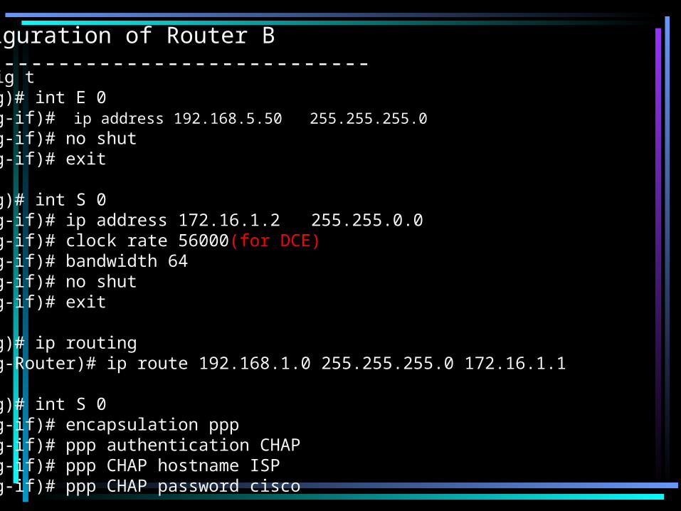
Configuration of Router B --------------------------------# Config t(Config)# int E 0(Config-if)# ip address 192.168.5.50 255.255.255.0(Config-if)# no shut(Config-if)# exit
(Config)# int S 0(Config-if)# ip address 172.16.1.2 255.255.0.0(Config-if)# clock rate 56000(for DCE)(Config-if)# bandwidth 64(Config-if)# no shut(Config-if)# exit
(Config)# ip routing(Config-Router)# ip route 192.168.1.0 255.255.255.0 172.16.1.1
(Config)# int S 0(Config-if)# encapsulation ppp(Config-if)# ppp authentication CHAP(Config-if)# ppp CHAP hostname ISP(Config-if)# ppp CHAP password cisco

DDR(Dial on Demand Routing)
Router A Router B
S 0 172.16.1.1 172.16.1.2 S 0
E 0 5.50
1.1
1.21.3
1.4 5.1
5.2
5.4
5.3
E 0 1.50
ISP

# Config t(Config)# isdn switch-type basic-net 3
(Config)# int E 0/1(Config-if)# ip address 192.168.1.50 255.255.255.0(Config-if)# no shut(Config-if)# exit
(Config)# int Bri 1/0(Config-if)# no ip address(Config-if)# encapsulation ppp(Config-if)# no cdp enable(Config-if)# no shut(Config-if)# exit
(Config)# int dialer 1(Config-if)# ip address negotiated(Config-if)# encapsulation ppp(Config-if)# no cdp enable(Config-if)# ppp authentication CHAP PAP callin(Config-if)# ppp CHAP hostname unicomin@hd2(Config-if)# ppp CHAP password password

(Config-if)# ppp PAP sent-username unicomin@hd2 password password(Config-if)# dialer in-band (Config-if)# dialer string 3328400(Config-if)# dialer idle-time out 180(Config-if)# dialer hold-queue 10(Config-if)# exit
(Config)# access-list 1 permit 192.168.1.0 0.0.0.255(Config)# dialer-list 1 protocol ip permit
((Config)# int bri 1/0(Config-if)# dialer rotary-group 1(Config-if)# no shut(Config-if)# exit
(Config)# int dialer 1(Config-if)# dialer-group 1(Config-if)# exit
(Config)# ip routing(Config-router)# ip route 0.0.0.0 0.0.0.0 dialer 1 2
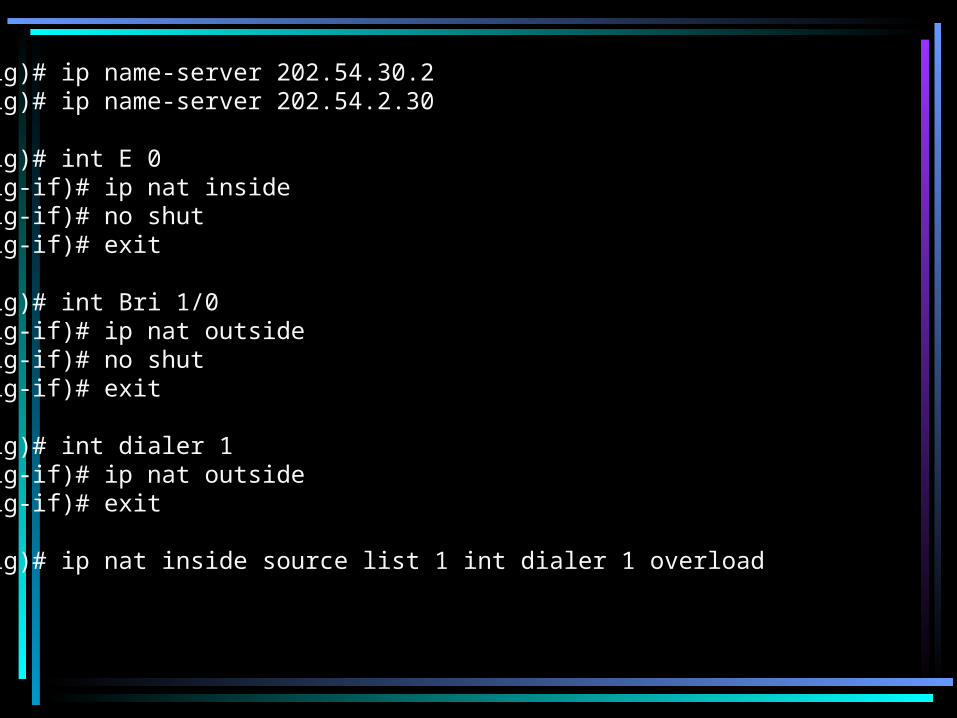
(Config)# ip name-server 202.54.30.2(Config)# ip name-server 202.54.2.30
(Config)# int E 0(Config-if)# ip nat inside(Config-if)# no shut(Config-if)# exit
(Config)# int Bri 1/0(Config-if)# ip nat outside(Config-if)# no shut(Config-if)# exit
(Config)# int dialer 1(Config-if)# ip nat outside(Config-if)# exit
(Config)# ip nat inside source list 1 int dialer 1 overload


Iso(OSI)International organization for standardizationIso has designed a reference model called osi reference model (open system interconnection). It has 7 layers. It says that Any n/w for comunication needs 7 layers1. Application layerThe user uses application layer to send the data. The protocols@ this layer are ftp,http,smtp(e-mail) telenet etc.2. Presentation layerPresentation layer takes the data from application layer and presentIn different formats for securing reason. The services offered @This layer areCompression – decompressionCoding – decodingEncryption - decryption

3. Session layerEstablishing the session or the conectivity n/w n/w 1 & n/w 2 is doneBy the session layer.It 1. Establishes a session
2. maintains it &3. Terminates it b/w the application
4. Transport layerEnd-end connectivity during a session b/w two application is doneBy the transport layer. It also decides the type of connection like tcp or udp i.e. connection oriented or connection less.Services:SequencingFlow ctrl, error detection & correctionTransport layer info + data is called segment.

5. Netwrok layerLogical addressing is done at thenetwork layer i.e. source address &destination address are attached to the data.
Protocols @network layer
Routed protocols routing protocolsEg: ip,ipx eg: rip,igrp,ospf
Routed protocols: they always carry the data along with themRouting protocol: they identify the path for routed protocol to carry the dataAt this layer routers & layer 3 switches forms packets.

Data link layer
MAC LLCMedia access control logical link control framing of data
Ip address is lik the pincode & MAC address is like house number.Here layer2 switches are used.Wab protocols used at this layer are PPP,HDLC,FP,X.25 etc.Here error checking CRC bits are added to the packetsDLL info+ packets --> frames

7 physical layerTakes care of physical connectivity i.e connector,cable etc. hereFrames are converted to bits (1’s & 0’s).The devices like hubs, repeaters,cables & connectors are used at this layer.
I P Addressing Now a days ip ver4 is followed. It is a 32-bit addressing scheme. 32bits are divided into 4 octets of 8 bits each.i.e 8-8-8-8. i.e (1’s & 0’s)-(1’s & 0s)-(1’s & 0’s)-(1’s & 0’s).(binary format). The ip address is maximum of 255 & min of 0.In future ip ver 6 is expected. It is 128 bit scheme.Ip adresses are clsassified into different classes.

Class A 0 - 127Class B 128 - 191Class C 192 - 223Class D 224 - 239Class E 240 - 255
8-8-8-8M.S.O Most Significant Ocate considering MSO
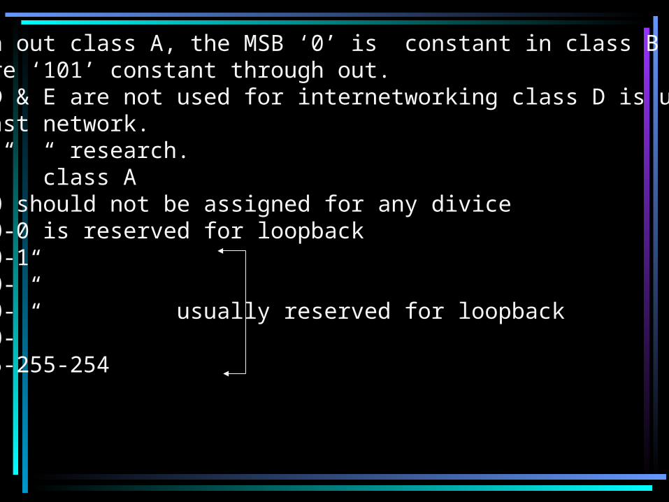
Through out class A, the MSB ‘0’ is constant in class B the Msbs are ‘101’ constant through out.Class D & E are not used for internetworking class D is used forMulticast network.“ E “ “ “ research.
class A0-0-0-0 should not be assigned for any divice127-0-0-0 is reserved for loopback127-0-0-1127-0-0-”127-0-0-” usually reserved for loopback127-0-0-”127-255-255-254

Hence 0 & 127 cannot be used for adressing so actual range will be 1 to 126.All ip addresses are divided into two.1.network I.d2.host I.d in class a address there is 1n\w I.d postion & 3 host I.d postion I,e N-H-H-H..Class A N-H-H-HClass B N-N-H-HClass C N-N-N-H
Network Ids are represented by 1s & host ids are by 0s.

Types of ip adresses IP address
public ip address private ip address
Public network: the public address is defined with routing over the Internet it is given by I.S.P & routing table is created on the internet.
Private network: for internal network I,e intranet, all the ip addresses Are governed by a body called INTERNIC. If we are a part of asiaPacefic then it is governed by APNIC.
We can run our private network with any ip addresses of our choice But it should not be connected to internet.

Range of addresses for private networkClass A 10.0.0.0 to 10.255.255.255Class B 172.16.0.0 to 172.31.255.255Class C 192.168.0.0 to 192.168.255.255
Private ip addresses donot have routing.To meet the demand of no.of networks, the network is broken Into smaller networks called subnets.Eg: find no.of subnets, hosts/s.n subnet mask & valid ip addressesFor a class c address.192.168.1.0/24‘24’ shows the network bits24= 3 octate position bits are enough, therefore no need to borrowAny bits from host position.=24 network & no hostDefault subet mask is 255.255.255.0 & valid ip addresses are 192.168.1.0 network
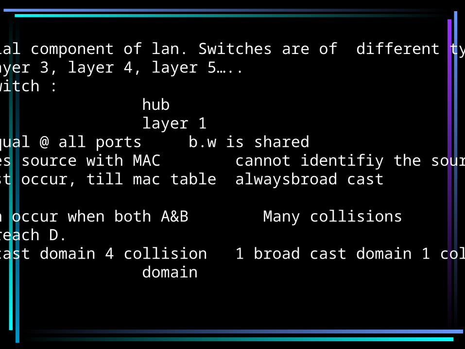
Switch An essential component of lan. Switches are of different types likeLayer 2 layer 3, layer 4, layer 5…..Layer 2 switch :Switch hub•Layer 2 layer 1•b.w is equal @ all ports b.w is shared•Identifies source with MAC cannot identifiy the source•Broad cast occur, till mac table alwaysbroad cast Is built•Collision occur when both A&B Many collisionsWants to reach D.•1 broad cast domain 4 collision 1 broad cast domain 1 collisionDomains domain

Switches
Access layer Distribution layer Core layer
Access layer swithc: catalyst 1912 Catalyst – manufacturer, but it is now owned by cisco.12 port switch
Switch
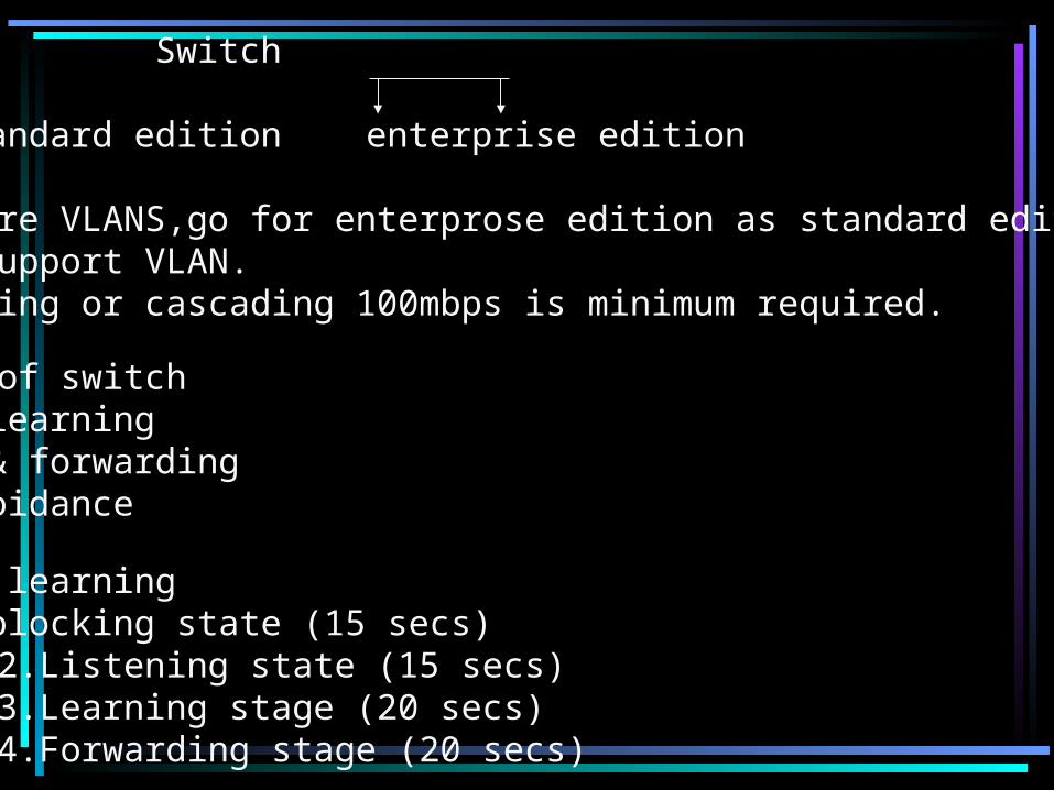
standard edition enterprise edition
To configure VLANS,go for enterprose edition as standard editionWill not support VLAN.For uplinking or cascading 100mbps is minimum required.
Functions of switch1. Adress learning 2. Filter & forwarding3. Loop avoidance
1. Address learningBooting 1.blocking state (15 secs)
2.Listening state (15 secs)3.Learning stage (20 secs)4.Forwarding stage (20 secs)

The switch will always learn the MAC address from the source itselfThe source should atleast communicate once to learn the MAC address.
2. Filter & forwarding : store & forward cut through fragment freeOn access layer the default is fragment free we can change to anyOf the3 mentioned above.
1.store & forward: it stores the whole information (1500 bytesEthernet) into buffer, then checks for errors, looks for destination In MAC table and then forward.
2. Cut through: no error checking.as soon as a packet arrivesIt looks into MAC table & forward.
3.loop avoidance: consider a scenario where pc1 wants to communicate To pc2. Switch a makes entry of pc1 in its MAC table as it is a new Switch. This looping is before the MAC table I s made. This is called Initial flood or broad cast storm.
STP: spanning tree protocol. To avoid loops in case of a cascaded Switch stp is enabled by default.
Related Documents