CC-MODELER: A TOPOLOGY GENERATOR FOR 3-D CITY MODELS Armin Gruen Xinhua Wang Institute of Geodesy and Photogrammetry Swiss Federal Institute of Technology (ETH) Zurich ETH Hoenggerberg, CH-8093 Zurich E-mail: [email protected] SWITZERLAND KEY WORDS: 3-D City models, topology generator, building reconstruction, visualization ABSTRACT In this paper, we introduce a semi-automated topology generator for 3-D objects, CC-Modeler (CyberCity Modeler). Given the data as point clouds measured on Analytical Plotters or Digital Stations, we present a new method for fitting planar structures to the measured sets of point clouds. While this topology generator has been originally designed to model buildings, it can also be used for other objects, which may be approximated by polyhedron surfaces. We have used it so far for roads, rivers, parking lots, ships, etc. CC-Modeler is a generic topology generator. The problem of fit- ting planar faces to point clouds is treated as a Consistent Labeling problem, which is solved by probabilistic relaxation. Once the faces are defined and the related points are determined we apply a simultaneous least squares adjustment in order to fit the faces jointly to the given measurements in an optimal way. We first present the processing flow of the CC-Modeler. Then the algorithm of structuring the 3-D point data is outlined. Finally, we show the results of several data sets which have been produced with CC-Modeler. 1. INTRODUCTION The generation of 3-D city models is a relevant and chal- lenging task, both from practical and scientific point of views. Photogrammetry is an appropriate tool to provide information about man-made objects, vegetation cover and the like. Recently, many approaches for automated and semi-automated extraction of buildings and roads from aerial images have been proposed (Gruen et al., 1997). Due to the complexity of the natural scene and the lack of performance of image understanding algorithms the fully automated methods cannot guarantee results sta- ble and reliable enough for practical use. Therefore we are investigating also into semi-automated approaches which would give the human operator strong computational sup- port in order to generate 3-D city models from aerial im- ages efficiently. We have developed a method which fits generic building models to measured, unstructured 3-D point clouds, which have been generated by a human op- erator on an Analytical Plotter or a Digital Station (Dan, 1997, Gruen, 1998). This system TOBAGO, although well proven in many pilot projects, is restricted to the modeling of buildings. With CC-Modeler (CyberCity Modeler) we present a new method for fitting planar structures to measured sets of point clouds. While this topology generator has been originally designed to model buildings, it can also be used for other objects, which may be approximated by polyhedron surfaces. We have used it so far for roads, rivers, parking lots, ships, etc. CC- Modeler is a generic topology generator and, from a prac- tical point of view, it can be considered a generalization of our previous modeler TOBAGO. However, it follows a totally different algorithmic principle. In the following section we will introduce the overall data flow scheme of CC-Modeler. In section 3 the key recon- struction algorithm is explained and finally some data sets which have been generated with CC-Modeler are pre- sented. 2. GENERAL DATA FLOW To generate 3-D descriptions of man-made objects from aerial photographs involves two major components: pho- togrammetric measurements and automated structuring. In CC-Modeler, the feature identification and measurement is implemented in manual mode, on an Analytical Plotter or a Digital Station. During the data acquisition 3-D points belonging to a single object should be coded into two different types according to their functionality and structure: boundary points and interior points (see Figure 4). Although the human operator tends to measure the points in a particular order, CC-Modeler can work with arbitrary sequences of measured interior points. Since the human operator is responsible for the interpretation and measurement, it is possible to acquire any level of object detail for buildings, roads, waterways, and other objects. With this technique, hundreds of objects can be measured in one day. CC-Modeler is an automatic topology generator for 3-D objects. The main components of the system are shown in Figure 1. The first obligatory step is preprocessing, which includes the control of measurement order of the bound- ary points (BP), detection of redundant points, and deter- mination of the possible groups of faces, based on adja- cent (BP) point pair sets (compare section 3). The next D. Fritsch, M. Englich & M. Sester, eds, 'IAPRS', Vol. 32/4, ISPRS Commission IV Symposium on GIS - Between Visions and Applications, Stuttgart, Germany.

Welcome message from author
This document is posted to help you gain knowledge. Please leave a comment to let me know what you think about it! Share it to your friends and learn new things together.
Transcript

CC-MODELER: A TOPOLOGY GENERATOR FOR 3-D CITY MODELS
Armin Gruen Xinhua WangInstitute of Geodesy and Photogrammetry
Swiss Federal Institute of Technology (ETH) ZurichETH Hoenggerberg, CH-8093 Zurich
E-mail: [email protected]
KEY WORDS: 3-D City models, topology generator, building reconstruction, visualization
ABSTRACT
In this paper, we introduce a semi-automated topology generator for 3-D objects, CC-Modeler (CyberCity Modeler).Given the data as point clouds measured on Analytical Plotters or Digital Stations, we present a new method for fittingplanar structures to the measured sets of point clouds. While this topology generator has been originally designed tomodel buildings, it can also be used for other objects, which may be approximated by polyhedron surfaces. We haveused it so far for roads, rivers, parking lots, ships, etc. CC-Modeler is a generic topology generator. The problem of fit-ting planar faces to point clouds is treated as a Consistent Labeling problem, which is solved by probabilistic relaxation.Once the faces are defined and the related points are determined we apply a simultaneous least squares adjustment inorder to fit the faces jointly to the given measurements in an optimal way. We first present the processing flow of theCC-Modeler. Then the algorithm of structuring the 3-D point data is outlined. Finally, we show the results of severaldata sets which have been produced with CC-Modeler.
1. INTRODUCTION
The generation of 3-D city models is a relevant and chal-lenging task, both from practical and scientific point ofviews. Photogrammetry is an appropriate tool to provideinformation about man-made objects, vegetation coverand the like. Recently, many approaches for automatedand semi-automated extraction of buildings and roadsfrom aerial images have been proposed (Gruen et al.,1997). Due to the complexity of the natural scene and thelack of performance of image understanding algorithmsthe fully automated methods cannot guarantee results sta-ble and reliable enough for practical use. Therefore we areinvestigating also into semi-automated approaches whichwould give the human operator strong computational sup-port in order to generate 3-D city models from aerial im-ages efficiently. We have developed a method which fitsgeneric building models to measured, unstructured 3-Dpoint clouds, which have been generated by a human op-erator on an Analytical Plotter or a Digital Station (Dan,1997, Gruen, 1998). This system TOBAGO, althoughwell proven in many pilot projects, is restricted to themodeling of buildings. With CC-Modeler (CyberCityModeler) we present a new method for fitting planarstructures to measured sets of point clouds. While thistopology generator has been originally designed to modelbuildings, it can also be used for other objects, which maybe approximated by polyhedron surfaces. We have used itso far for roads, rivers, parking lots, ships, etc. CC-Modeler is a generic topology generator and, from a prac-tical point of view, it can be considered a generalizationof our previous modeler TOBAGO. However, it follows atotally different algorithmic principle.
In the following section we will introduce the overall dataflow scheme of CC-Modeler. In section 3 the key recon-struction algorithm is explained and finally some data setswhich have been generated with CC-Modeler are pre-sented.
2. GENERAL DATA FLOW
To generate 3-D descriptions of man-made objects fromaerial photographs involves two major components: pho-togrammetric measurements and automated structuring. InCC-Modeler, the feature identification and measurementis implemented in manual mode, on an Analytical Plotteror a Digital Station. During the data acquisition 3-Dpoints belonging to a single object should be coded intotwo different types according to their functionality andstructure: boundary points and interior points (see Figure4). Although the human operator tends to measure thepoints in a particular order, CC-Modeler can work witharbitrary sequences of measured interior points. Since thehuman operator is responsible for the interpretation andmeasurement, it is possible to acquire any level of objectdetail for buildings, roads, waterways, and other objects.With this technique, hundreds of objects can be measuredin one day.CC-Modeler is an automatic topology generator for 3-Dobjects. The main components of the system are shown inFigure 1. The first obligatory step is preprocessing, whichincludes the control of measurement order of the bound-ary points (BP), detection of redundant points, and deter-mination of the possible groups of faces, based on adja-cent (BP) point pair sets (compare section 3). The next
D. Fritsch, M. Englich & M. Sester, eds, 'IAPRS', Vol. 32/4, ISPRS Commission IV Symposium on GIS - Between Visions and Applications,Stuttgart, Germany.
Step is to build the face model of the 3-D object, i.e. todetermine how many faces the 3-D object has, whichpoints define an exact face and what spatial relations thefaces take on. This is implemented through a ConsistentLabeling algorithm by probability relaxation operations,in which two procedures are involved, the initial prob-ability determination and the relaxation processing. Thedetailed algorithm will be presented in the following sec-tion. As the results of Consistent Labeling, CC-Modelerdelivers the face definition for every face. Then, leastsquares adjustment is performed for all faces simultane-ously, fitting the individual faces in an optimal way to themeasured points and considering the fact that individualpoints may be member of more than one face. This ad-justment is amended by observation equations that modelorthogonality constraints of pairs of straight lines. Finally,a vector description of 3-D objects is obtained, which isrepresented in a self-developed data structure (V3D). Forthe purpose of visualization, the CC-Modeler can alsotriangulate the faces to get its TIN structure. Although the
procedure is automated, human intervention and interac-tion with the automatic procedures is also available, asoutlined in Figure 1.V3D is a self-developed vector data structure, whichbuilds the facet model of objects (Figure 2). The basicgeometric element in this diagram is the point. Points areused to express faces or line segments. The object consistsof faces, and the polyline consists of line segments. Oncesome attributes are attached, an object or polyline be-comes an entity class. In addition, CC-Modeler has theability to map images onto a 3-D object or DTM in orderto create a more natural scene. The texture, taken from theoriginal images, is attached to an exact face as a specialattribute. The DTM is considered a particular entity classin V3D. With the help of interfaces, one can convenientlytranslate the V3D data structure into different data files,such as DXF, IV, and AutoLisp, which are readable byAutoCAD, MicroStation, Polytrim, ArcView and Inven-tor.
class
class
class
DTM
Object
Polyline
Texture
Face
Line
TIN
Point
Figure 2: The data structure of V3D
Analytical plotter Digital station
Point clouds
PreprocessingInitial probabilities
Relaxation processing
Face definition& L.S adjustment
V3D Interface
Triangulation
Vector models
Visualization
DTM Texture mapping
AutoLisp
DXF
IV
AutoCAD
MicroStation
Polytrim
ArcView
Inventor
Edit
Figure 1: The data flow of CC-Modeler(I) --- Interactive functions
(I)
(I)
(I)
Analytical plotter Digital station
Point clouds
PreprocessingInitial probabilities
Relaxation processing
Face definition& L.S adjustment
V3D Interface
Triangulation
Vector models
Visualization
DTM Texture mapping
AutoLisp
DXF
IV
AutoCAD
MicroStation
Polytrim
ArcView
Inventor
Edit
Figure 1: The data flow of CC-Modeler(I) --- Interactive functions
(I)
(I)
D. Fritsch, M. Englich & M. Sester, eds, 'IAPRS', Vol. 32/4, ISPRS Commission IV Symposium on GIS - Between Visions and Applications,Stuttgart, Germany.

Figure 3: An overview of the CC-Modeler userinterface
CC-Modeler has been successfully implemented on work-stations (Sun SPARC) under X-Windows and OSF/Motif.Figure 3 is an overview of the CC-Modeler userinterface.One can optionally set CC-Modeler to work in the auto-matic or the interactive mode. When working in the inter-active mode, one can edit or modify 3-D objects with thehelp of 2-D or 3-D views, if any mistakes occur due toinadequate point measurements. With the 2-D view, CC-Modeler will project the vector data of 3-D objects ontothe original image (see Figure 3) to help check the results.In the 3-D mode, a 3-D vector model of the object will beshown to monitor the procedure.CC-Modeler is a general topology generator. It works notonly with buildings, but also with other objects like trees,waterways, bridges, roads, etc. Moreover, CC-Modelercan combine a face model of a DTM with 3-D objects.
3. STRUCTURING THE 3-D POINT DATA
Assuming that a 3-D point cloud for each object of inter-est has been generated, e.g. by photogrammetric stereomodel measurement. The sequence of the points shouldbe partly in a semi-ordered fashion such that the boundarypoints of an object (P1, ..., P10 in Figure 4) are to be meas-ured either clockwise or counter-clockwise and labeled
(BP). All other points (called "interior points", and therecould be many more than shown in Figure 4) can bemeasured in an arbitrary sequence and are labeled (IP).The points of an object are expressed as the nodes of agraph, and each line is expressed as an edge with twonodes. The topology structure of this object is shown inFigure 4 together with the related graph. Obviously, everysub-circuit in the related graph is a basic face of the ob-ject, and every two neighbor points (BP) can be alwaysconsidered as a basic edge of a sub-circuit. Thus, ourproblem is to investigate how to construct every sub-circuit based on two adjacent points (BP) as its basicedge.From a geometric point of view, every two adjacentpoints (BP) together with an interior point construct apossible face (such as P1 P2 with P13 in Figure 4). Then,to combine the adjacent points (BP) with different interiorpoints will bring about different faces. Vice versa, everyinterior point (IP) may belong to more than one face.In theory, the labeling methods are various, but only onesolution is desired, which meets the inherent topologicalconstraint of the object. Therefore, our problem is to de-termine for instance which interior points (P13, P12 in Fig-ure 4) lie on the face group determined by an adjacentpoint pair (P1 P2), and what link order those points take toconstruct a face (P1 �P2 �P13 �P12 ).
D. Fritsch, M. Englich & M. Sester, eds, 'IAPRS', Vol. 32/4, ISPRS Commission IV Symposium on GIS - Between Visions and Applications,Stuttgart, Germany.

The whole of the 3-D points, expressed as a set G, can bedecomposed into two subsets, i.e. the adjacent point (BP)pair set C and the interior points (IP) set A. According tograph theory, if a set of nodes of a graph G can be dividedinto two non-empty subsets A and C, such that an edge ofG connects with a node of A and a node of C, this graph iscalled a Bipartite Graph. Our problem of generating thetopology of a 3-D object is equivalent to the determina-tion of the spatial relation between the elements in the setG, particularly that between the set A and the set C.Therefore, we define our problem as a Bipartite GraphMatching (Wilson, 1979) or a one-multiple ConsistentLabeling problem (Haralick, Shapiro, 1979). Figure 5shows the principle of Consistent Labeling.
For the solution of Consistent Labeling many methodshave been proposed (Rosenfeld et al., 1976, Li, Wang,1996). With CC-Modeler, we use a labeling algorithmbased on probabilistic relaxation. The labeling probabil-ity, i.e. the probability of labeling each interior point asbelonging to an exact face group, is modified according to
the observations and the geometric constraints.We have an objective set A {A1, A2, …, An} which will belabeled into m classes, and the class set is expressed as C{C1, C2, …, Cm}. The labeling procedure is interrelated.For example, labeling Ai � Cj will affect the result of la-beling Ah � Ck. The interrelation is defined as a coopera-tive coefficient ��i, j; �h, k��. Assuming that pij is theprobability of Ai � Cj, and Gi is the adjacent area of Ai,then the standard relaxation approach is expressed as:
1
1 )1(
�� �
�ni
nijn
ijnij
norm
qpp (1a)
)1(1
1 nij
m
j
nij
ni qpnorm �� �
�
� (1b)
nhk
iGh
m
k
nij pkhjiq � �
� ��
1
)),(;,(� (1c)
The traditional relaxation algorithm must be modified towork in our case, because our labeling procedure is not aone-one correspondence, but that of multiple matching.This means that an element in the objective set A may belabeled into more than one class sets.
The formula (1) is a recursive equation. nijp is the prob-
ability of labeling i to j in the nth recursion, and10 �� n
ijp is always valid. The variable nijq can be con-
sidered as the added magnitude of the probability labelingi to j in the next recursion step, and 0�n
ijq . In fact, twotypes of possibilities always exist, i.e. labeling Ai � Cj
and Ai � Cj. Assume that ijp is the probability of labeling
Ai � Cj, and the ijq is the added magnitude of ijp , suchthat:
Set G {An , Cm}
A1
A2
Ai
An
…
…
C1
C2
Cj
Cm
…
…
Figure 5: The principle of Consistent Labeling
P1
P3P4
P5 P6
P7 P8
P9P10
P11
P12P13
P2 P1P2
P3P4
P5 P6
P7 P8
P9 P10
P12P13
P11P1, …, P10 : Boundary points (BP)
P11, …, P13 : Interior points (IP)
(a) (b)
Figure 4: (a) Point definition in CC-Modeler(b) Related graph
D. Fritsch, M. Englich & M. Sester, eds, 'IAPRS', Vol. 32/4, ISPRS Commission IV Symposium on GIS - Between Visions and Applications,Stuttgart, Germany.

nij
nij pp ��1 (2a)
� �� � nhk
iGh
m
k
nij pkhjiq � �
� ��
1
,;,� (2b)
Thus the modified relaxation algorithm is expressed as:
1
1 )1(
�� �
�ni
nijn
ijnij
norm
qpp (2c)
��
��
� � ����
m
j
nij
nij
nij
nij
ni qpqpnorm
1
1 )1()1( (2d)
Where nijp expresses the probability that event Ai � Cj is
1, i.e. the probability that the objective element Ai belongsto the class Cj. ��i, j; �h, k�� is the cooperative coefficient.If the event of Ai � Cj and Ah � Ck being fully coopera-tive, ��i, j; �h, k�� = 1, on the contrary, -1. If the event Ai
� Cj is not related with the event Ah � Ck , ��i, j; �h, k��= 0. For our problem, the following formula is employedto compute ��i, j; �h, k��
� �� �� �� ��
�
�
��
kjfor
kjforkhji
0
cos,;,
�� (3)
Where � is the internal angle between the normal vectorsconstructed by the faces Ai � Cj and Ah � Ck. Notice thatto compute ��i, j; �h, k�� one should follow a basic crite-rion, i.e. the result of labeling Ai (or Ah) to Cj (or Ck)should lead to a graph in which no intersection betweenevery two circuits exists.It should be noticed that the determination of the initialprobability for ijp is very important. Good initial proabil-ities cannot only accelerate the iterative procedure, butalso improve the reliability of labeling results. The initialprobability of Ai � Cj can be determined according to thespatial distance from Ai to Cj. The following formula is
employed:
)()(
)()(21
0
dMindMax
jiddMaxpij �
���� �� (4)
Max(d) is the longest distance between element Cj andevery point in the adjacent area of Ai and Min(d) is theshortest one. d(i�j) is the distance from Ai to Cj. �1 = 0.1and �1 = 0.8 are constants which are determined empiri-cally.The procedure of formula (1) and (2) is iterative. Finally,the labeling results of every objective point Ai is determined according to the probability ijp . Thus every elem-
ent Cj in the class set C together with all labeled elements(IP) constitute its maximum element group. To constructthe final face, this element group is ordered by a spatialsearch procedure. Figure 6 shows the procedure, in whichP1P2 is the basic link, Pi (i = 3, 4, ..., 7) are the interiorpoints. The first step is to calculate the centre of the pointgroup, Pc. If PcP2 is considered as the base, all internalangles that the vector PcPi (i = 3, 4, ..., 7) generates inrelation to the base PcP2 can be obtained (see Figure6(b)). Obviously, ordering the point group is equivalent toordering these internal angles, which is a simple proce-dure. Thus the final ordering is shown in Figure 6 (c).We have obtained the face definition with a (BP) pair asits basic edge. In some particular situations, a roof unitmay have some faces that are constructed by (IP) points.Therefore, CC-Modeler links all face groups to generate awhole loop, and then checks it. If any sub-loop exists, anew face is defined.In the follow-up step all planar faces are simultaneouslyfit to their related 3-D point observations by a joint leastsquares adjustment. These observation equations areamended by observation equations which model the or-thogonality constraints of pairs of straight lines to ensurethat measurement errors do not lead to a violation ofbuilding construction rules. The complete adjustment isperformed iteratively in the following manner:
P2P1
P3
P5
P7P4
P6
P2P1
P3
P5
P7P4
P6
P4
P2P1
P3
P5
P7
P6Pc
(a) (b) (c)
Figure 6: Principle of ordering an element group
(a) Original points (b) Centering of points (c) Ordering result
D. Fritsch, M. Englich & M. Sester, eds, 'IAPRS', Vol. 32/4, ISPRS Commission IV Symposium on GIS - Between Visions and Applications,Stuttgart, Germany.

(1) Individual plane adjustmentAssuming that the face Fj is composed of k points (in-cluding interior points and boundary points), the adjustedobservations of these points should fit an exact planarface function. Each point i gives an observation equationof the form:
ipjDizjCiyjBixjAiv ;���� (5)
ip ...... weight for plane condition
jA , jB , jC , jD ...... estimated parameters.
(2) Projection of measured points onto all planes underconsideration of orthogonality constraintsIn a second step we formulate for all faces Fj and allpoints (i) the following observation equations:
kipDzCyBxA
dzCdyBdxAvi
jijijij
ijijiji�
����
���;
)( (6)
The unknown parameters dxi ,dyi ,dzi represent changes tothe original point locations such that the adjusted pointlocation is optimal with respect to the fitted planes.For m faces, these observation equations are set up si-multaneously.The geometric orthogonality constraint of straight lines isinvolved as an additional observation equation. A toler-ance parameter (usually �6°) for the deviations from or-thogonality is selected. This procedure is performed in2-D in the x-y plane.Assuming that the angle between the straight lines l1
)),(),,(( 11 iiii yxyx �� and l2 )),(),,(( 11 �� iiii yxyx , is less
or more than the tolerance allows (see Figure 7), the fol-lowing equation is formulated:
1,,11,,1
1,,1
1,,1
)(
)(
����
��
��
������
����
����
iiiiiiii
iiiii
iiiii
xxyy
dyyy
dxxxv
(7)
Equations (6) and (7) are solved simultaneously. Step (1)and (2) are performed in an iterative manner. After thesolution of (6), (7) the system (5) is solved again with
improved point coordinates and a new solution of (6), (7)is computed.In a follow-up step, every face can be triangulated for thepurpose of visualization. Here an algorithm similar toDelauney triangulation is employed.The photogrammetric measurement principle allows for afree choice of the object resolution, accuracy and fidelity.The CC-Modeler generates a planar world, in whichcurved surfaces can be approximated by a set of planarpatches. Special objects can be generated and inserted.We have demonstrated this with trees (compare Figure 8),waterways and some houses with curved-shape. CC-Modeler has been successfully applied to several datasets. The results are overall positive.
4. RESULTS OF SEVERAL PROJECTSAND VISUALIZATION
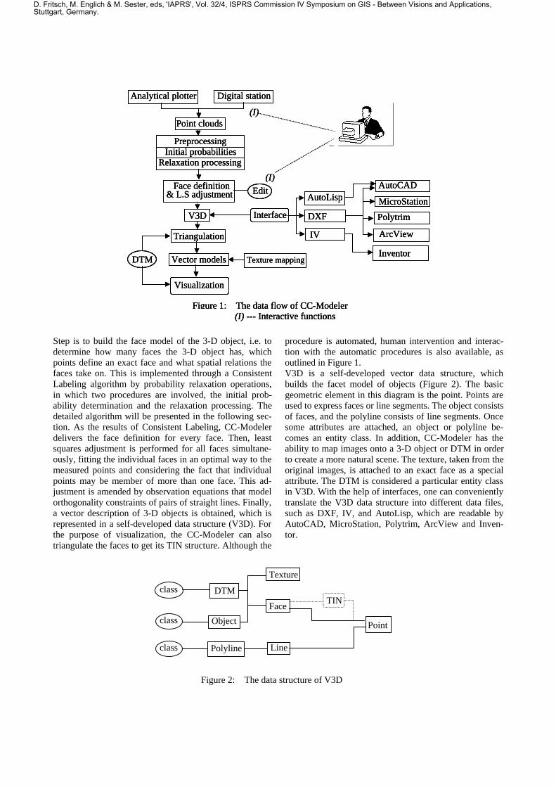
CC-Modeler has been tested in several projects (Zurich,Dietikon, Regensdorf), the statistics of which are pre-sented in Table 1. "Structured automatically" refers to thenumber of roof units that CC-Modeler builds successfullywith full automatic processing, and "structured interac-tively" refers to the number of roof units that needed to bemanually modified in some faces. Obviously, the successrate of CC-Modeler's automatic processing is up to 95%,and almost all roof units can be constructed by using theconvenient editing tools. The main factor determining theperformance is the degree of familiarity of the humanoperator with the concept of automated reconstruction.With a person well familiar with CC-Modeler, 400 ormore roof units can be generated per day.
Table 1: CC-Modeler statistics of three projects
Project Total No. ofroof units
StructuredAutomatically
Structuredinteractively
Failures
Zurich Hauptbahnhof 1733 1656 76 1Dietikon 298 290 8 0
Regensdorf 925 894 30 1Total 2956 2840 114 2
),( ii yx
),( 11 �� ii yx
),( 11 �� ii yx�
l1
l2
Figure 7: Geometric orthogonality
D. Fritsch, M. Englich & M. Sester, eds, 'IAPRS', Vol. 32/4, ISPRS Commission IV Symposium on GIS - Between Visions and Applications,Stuttgart, Germany.

Figure 8: City model “Zurich Hauptbahnhof” generated with CC-Modeler
Figure 9: Data set of Dietikon project
D. Fritsch, M. Englich & M. Sester, eds, 'IAPRS', Vol. 32/4, ISPRS Commission IV Symposium on GIS - Between Visions and Applications,Stuttgart, Germany.
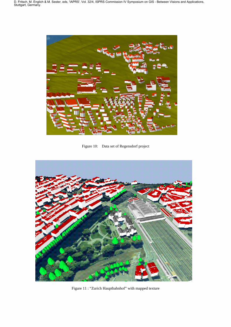
Figure 10: Data set of Regensdorf project
Figure 11 : “Zurich Hauptbahnhof” with mapped texture
D. Fritsch, M. Englich & M. Sester, eds, 'IAPRS', Vol. 32/4, ISPRS Commission IV Symposium on GIS - Between Visions and Applications,Stuttgart, Germany.

For the visualization and animation of the data sets we usevarious software: AutoCAD, MicroStation, Inventor, andPolytrim. Figure 8 shows a view of the city model "ZurichHauptbahnhof", including buildings, rivers, trees andDTM. Figure 9 and Figure 10 show "Dietikon" and "Re-gensdorf". For photorealistic rendering we combine thevector data of the buildings and the DTM with imageraster data. The raster images are taken from aerial im-ages. Figure 11 shows the result of mapping image dataonto the DTM and some roofs.CC-Modeler can also map digital images taken with stillvideo cameras onto 3-D faces such as the walls of build-ings.
5. CONCLUSION
CC-Modeler is a powerful data acquisition tool for thegeneration of 3-D city models. Our experiments show thatit is flexible, reliable and accurate. In three pilot projectswe have achieved a success rate of 95% percent in fullyautomated structuring mode. Remaining problems areindicated and can be solved interactively. We have devel-oped our own data structure V3D with interfaces to a va-riety of CAD and visualization packages. CC-Modelercannot only reconstruct multiple kinds of 3-D objectssuch as buildings, waterways, roads, trees, DTM, etc., butalso map images onto 3-D objects. This can be combinedwith data from general land use, communication systems,pipeline, property and administrative boundaries, etc. togenerate a complete 3-D city model. If required, the datagenerated with CC-Modeler may be operated by a database management system to form a Spatial InformationSystem (SIS). This in turn can be integrated into a multi-media environment for the purpose of better user interac-tion. This is also one of our further research goal.
Acknowledgments: The data sets "Regensdorf" and"Dietikon" have been generated with assistance of Swis-
sphoto+Vermessung AG, Regensdorf. The data set "Zu-rich Hauptbahnhof" was produced for the City of ZurichSurveying Office and includes a DTM provided by thisoffice. We appreciate very much the cooperation of bothpartners.CC-Modeler is available as commercial software packagefrom Born&Partner, Bellikon, CH, Fax: +41 56 4701862.
REFERENCES
Dan, H., 1996. Rekonstruktion generischer Gebäudemod-elle aus Punktwolken und deren Abbildungskorrek-turen in Orthobilden. Dissertation Nr. 11759 ETHZurich, Mitteilungen Nr.60 des Instituts für Geodäsieund Photogrammetrie, 93 pages.
Gruen,A., 1998. TOBAGO- a semi-automated approachfor the generation of 3-D building models. ISPRS J.Photogrammetry & Remote Sensing, Vol.53, No.2,pp.108-118.
Gruen, A., Baltsavias, E., Henricsson, O., (eds.), 1997.Automated extraction of man-made objects fromaerial and space images(II). Proceedings of the MonteVerita Workshop May 1997, Birkhauser Verlag,Basel.
Haralick, R. M., Shapiro, L. G., 1979. The consistentlabeling problem: Part I. IEEE Transaction on PatternAnalysis and Machine Intelligence, Vol.1, No.2,pp.173-184.
Li, D., Wang, X., 1996. Relational structure descriptionand matching algorithm for 3D objects. InternationalArchives of Photogrammetry and Remote Sensing,Vol. XXXI, Part B3, pp.442-448.
Rosenfeld, A., Hummel, R. A., Zucker, S. W., 1976.Scene labeling by relaxation operations. IEEE Trans-action on System, Man, and Cybernetics, Vol.6,No.6, pp.420-433.
Wilson, R. J., 1979. Introduction to Graph Theory. Aca-demic Press, New York, pp.115-118.
D. Fritsch, M. Englich & M. Sester, eds, 'IAPRS', Vol. 32/4, ISPRS Commission IV Symposium on GIS - Between Visions and Applications,Stuttgart, Germany.
Related Documents