Westinghouse Savannah River Company Closure Business Unit Planning Integration & Technology Department Aiken, SC 29808 PREPARED FOR THE U. S. DEPARTMENT OF ENERGY UNDER CONTRACT NO. DE-AC09-96S CBU-PIT-2005-00120 REVISION 0 June 16, 2005 KEYWORDS: Tank Closure, Ancillary Equipment RETENTION: PERMANENT CLASSIFICATION: U Does not contain UCNI Ancillary Equipment Residual Radioactivity Estimate To Support Tank Closure Activities For F-Tank Farm T. B. Caldwell

Welcome message from author
This document is posted to help you gain knowledge. Please leave a comment to let me know what you think about it! Share it to your friends and learn new things together.
Transcript
Westinghouse Savannah River Company Closure Business Unit Planning Integration & Technology Department Aiken, SC 29808
PREPARED FOR THE U. S. DEPARTMENT OF ENERGY UNDER CONTRACT NO. DE-AC09-96S
CBU-PIT-2005-00120 REVISION 0 June 16, 2005
KEYWORDS: Tank Closure,
Ancillary Equipment
RETENTION: PERMANENT CLASSIFICATION: U Does not contain UCNI
Ancillary Equipment
Residual Radioactivity Estimate To Support Tank Closure Activities
For F-Tank Farm
T. B. Caldwell

Ancillary Equipment Residual Radioactivity Estimate CBU-PIT-2005-00120 To Support Tank Closure Activities Revision 0 For F-Tank Farm June 16, 2005 Page 3 of 43
SUMMARY OF REVISIONS
Revision Number Date of Issue Description of Changes
0 June 16, 2005 Initial Issue

Ancillary Equipment Residual Radioactivity Estimate CBU-PIT-2005-00120 To Support Tank Closure Activities Revision 0 For F-Tank Farm June 16, 2005 Page 4 of 43
TABLE OF CONTENTS
PAGE 1.0 Purpose................................................................................................................................5
2.0 Methodology .......................................................................................................................5 2.1 Establishing a Representative Source Term ............................................................5 2.2 Methodology for Evaluating Transfer Piping Systems ............................................6 2.3 Methodology for Evaluating Pump Tanks and Evaporators ...................................6
3.0 Estimation of Residue In Transfer Piping Systems ........................................................6 3.1 Residue by Diffusion into Metal...............................................................................6 3.2 Residue by Diffusion into Oxide Film......................................................................8 3.3 Residue of Particles Left Behind After a Flush........................................................9 3.4 Comparison to Field Characterization Data.........................................................11
4.0 Estimation of Residue in Pump Tanks and Evaporators.............................................11 4.1 Pump Tanks............................................................................................................11 4.2 Evaporators (including Overheads Tanks)............................................................12 4.3 242-3F Concentrate Transfer System ....................................................................13
5.0 Summary of Results.........................................................................................................14
5.1 Estimate of Residual Mass.....................................................................................14 5.2 Summary of Isotopes ..............................................................................................15
References.....................................................................................................................................16
Appendix I – Source Term Summary Table .............................................................................18
Appendix II – Estimation of Diffusion of Isotopes into Carbon and Stainless Steels............20
Appendix III – Line Segment Listing for F-Tank Farm ..........................................................27
Appendix IV – Verification of Residual Radioactivity in Buried Pipes Using Characterization Data........................................................................................36
Summary of Tables
Table 1 Isotopic Concentration of Waste....................................................................................5 Table 2 Surface Concentration by Diffusion into Metal.............................................................6 Table 3 Surface Concentration by Diffusion into Oxide Layer ..................................................8 Table 4 Surface Concentration by Residue after Flushing .........................................................9 Table 5 Analytical Estimate of Residual Radioactivity in Buried Pipe for F-Tank Farm........10 Table 6 Isotopes with Higher Inventory Based on the Field Survey Method...........................11 Table 7 Analytical Estimate of Residual Radioactivity in F-Tank Farm Pump Tanks ............12 Table 8 Estimate of Residual Radioactivity in F-Tank Farm Evaporators ...............................12 Table 9 Estimate of Residual Radioactivity in 242-F CTS Tank .............................................13 Table 10 Estimate of Residual Radioactivity in F-Tank Farm Ancillary Equipment.................15

Ancillary Equipment Residual Radioactivity Estimate CBU-PIT-2005-00120 To Support Tank Closure Activities Revision 0 For F-Tank Farm June 16, 2005 Page 5 of 43
Ancillary Equipment Residual Radioactivity Estimate to Support Tank Closure Activities for F-Tank Farm
1.0 PurposeThe amount of radioactivity left behind in ancillary equipment must be accounted before facility closure. Previously, a conservative estimate of 20% of what is left in waste tanks was assumed as the source term contributor for ancillary equipment, which includes equipment such as buried pipes (transfer lines), pump tanks and evaporators [Tank Closure Modules for Tanks 17 and 20, 1997]. Upon further consideration, this globally applied factor is unnecessarily conservative. This paper documents the method and results in which a reasonable source term is applied for performance assessment modeling or for curies at closure reporting. 2.0 Methodology
Ancillary equipment is buried pipe (transfer lines), pump tanks, and evaporators. Over the operating life of the facility, radioactive waste comes in physical contact with these components, contaminating them and hence, leaving a small amount of contamination on the components. The degree of contamination depends on many factors, which include, but are not limited to, the service life of the component, the material of construction, and the type of waste in contact with the component.
For the purpose of this effort ancillary equipment was further divided into two categories. They are 1) buried pipe, and 2) pump tanks and evaporators. 2.1 Establishing a Representative Source Term The contaminating medium is waste defined by Georgeton and Hester (1995). Though F-Tank Farm predominately received waste from F-Canyon, streams from both canyons are considered in the source term with the exception of Th-232 and its daughter Ra-228, which is negligible in F-Tank Farm. The references for additional radionuclides are found in Appendix I. The following table is a summary of the source term used in this report (taken from Appendix I).
Table 1 – Isotopic Concentration of Waste (Curies per gallon) (Continued)
Isotope Isotopic
Concentration Isotope Isotopic
Concentration Isotope Isotopic
Concentration
H−3 7.28E-03 Cs−137 1.07E+01 U−238 5.35E-07 C−14 7.80E-08 Ba−137m 1.01E+01 Np−237 2.39E-06 Al-26 1.13E-05 Ce−144 1.60E-04 Pu−238 3.33E-01 Co−60 4.42E-02 Pr−144 1.60E-04 Pu−239 2.97E-03 Ni−59 8.56E-05 Pm−147 7.46E-01 Pu−240 2.08E-03 Ni−63 8.55E-03 Sm−151 2.22E-01 Pu−241 2.42E-01 Se−79 6.13E-05 Eu−152 1.73E-03 Pu−242 3.01E-06 Sr−90 8.52E+00 Eu−154 9.34E-02 Pu−244 1.39E-08 Y−90 8.52E+00 Eu−155 8.52E-02 Am−241 8.32E-03
Nb−94 4.60E-08 Ra−226 9.26E-08 Am−242m 1.13E-05 Tc−99 1.20E-03 Ra−228 0.00E+00 Am−243 2.93E-06
Rh−106 1.13E-03 Ac−227 2.79E-09 Cm−242 9.24E-06 Ru−106 1.13E-03 Th−229 7.98E-03 Cm−243 1.98E-06 Te−125 1.06E-02 Th−230 1.18E-07 Cm−244 4.44E-05

Ancillary Equipment Residual Radioactivity Estimate CBU-PIT-2005-00120 To Support Tank Closure Activities Revision 0 For F-Tank Farm June 16, 2005 Page 6 of 43
Table 1 – Isotopic Concentration of Waste (Curies per gallon) (Continued)
Isotope Isotopic
Concentration Isotope Isotopic
Concentration Isotope Isotopic
Concentration Sb−125 4.35E-02 Th−232 0.00E+00 Cm−245 2.83E-09 Sb−126 1.60E-05 Pa−231 2.80E-09 Cm−247 3.32E-16
Sb−126m 1.14E-04 U−232 7.87E-07 Cm−248 3.46E-16 Sn−126 1.14E-04 U−233 1.28E-02 Bk−249 2.39E-18 I−129 1.14E-06 U−234 1.33E-06 Cf−249 1.98E-15
Cs−134 3.13E-02 U−235 1.47E-08 Cs−135 7.09E-07 U−236 3.38E-07
2.2 Methodology for Evaluating Transfer Piping Systems
The amount of residue in the piping systems was determined analytically. The results were compared to results from standard characterization techniques using field surveys. Waste in contact with piping systems adheres to the pipe in three ways: 1) diffusion into the metal; 2) diffusion into the oxide film; 3) residue left behind after a transfer and flush. Diffusion calculations assume a 100-year contact time and a 100°C exposure temperature. Appendix II describes the methodology in which diffusion estimates are made. 2.3 Methodology for Evaluating Pump Tanks and Evaporators
Pump tanks and evaporators differ from piping systems with respect to such features as geometry and usage. Only residue left behind after rinsing and flushing is considered for these components. Field characterization data for the F-Tank Farm evaporators (including the 242-3F Concentrate Transfer System pump tank) will be used to estimate the residual radioactivity for each evaporator. 3.0 Estimation of Residue in Transfer Piping Systems A list of transfer piping in the tank farm is in Appendix III. The list identifies the pipe diameter, material of construction, and the core pipe dimensions.
3.1 Residue by Diffusion into Metal Diffusion is the technique for carburizing and nitriding of metals; and therefore is a known industrial transport phenomenon. Appendix II provides the derivation of the diffusion correlations. The following table provides a summary of the results.
Table 2 – Surface Concentration by Diffusion into Metal (continued)
Diffusion Coefficient (cm2/sec)
Surface Concentration (Ci per ft2)
Isotope Carbon Steel Stainless Carbon Steel Stainless H-3 9.70E-08 1.48E-09 3.67E-03 4.54E-04 C-14 1.50E-17 1.80E-21 4.89E-13 5.36E-15 Al-26 5.48E-23 7.08E-35 1.36E-13 1.54E-19 Co-60 2.59E-36 2.42E-43 1.15E-16 3.52E-20 Ni-59 2.01E-33 4.27E-40 6.21E-18 2.86E-21 Ni-63 2.01E-33 4.27E-40 6.20E-16 2.86E-19 Se-79 2.00E-32 2.79E-43 1.40E-17 5.24E-23 Sr-90 1.64E-33 3.77E-44 5.58E-13 2.68E-18

Ancillary Equipment Residual Radioactivity Estimate CBU-PIT-2005-00120 To Support Tank Closure Activities Revision 0 For F-Tank Farm June 16, 2005 Page 7 of 43
Table 2 – Surface Concentration by Diffusion into Metal (continued)
Diffusion Coefficient (cm2/sec)
Surface Concentration (Ci per ft2)
Isotope Carbon Steel Stainless Carbon Steel Stainless Y-90 9.13E-34 2.39E-44 4.17E-13 2.13E-18
Nb-94 2.97E-34 1.00E-44 1.28E-21 7.44E-27 Tc-99 1.70E-31 4.44E-45 8.00E-16 1.29E-22
Rh-106 8.10E-32 3.01E-45 5.23E-16 1.01E-22 Ru-106 3.91E-32 2.07E-45 3.63E-16 8.35E-23 Te-125 3.19E-34 2.02E-46 3.07E-16 2.44E-22 Sb-125 1.05E-36 2.73E-46 7.20E-17 1.16E-21 Sb-126 1.05E-36 2.73E-46 2.64E-20 4.27E-25
Sb-126m 6.17E-34 2.73E-46 4.58E-18 3.05E-24 Sn-126 1.20E-33 3.74E-46 6.40E-18 3.57E-24 I-129 1.67E-34 1.50E-46 2.38E-20 2.26E-26
Cs-134 4.65E-35 8.54E-47 3.46E-16 4.68E-22 Cs-135 4.65E-35 8.54E-47 7.83E-21 1.06E-26 Cs-137 4.65E-35 8.54E-47 1.18E-13 1.59E-19
Ba-137m 2.49E-35 6.51E-47 8.14E-14 1.32E-19 Ce-144 7.26E-36 3.87E-47 6.97E-19 1.61E-24 Pr-144 3.97E-36 3.02E-47 5.15E-19 1.42E-24 Pm-147 1.21E-36 1.87E-47 1.33E-15 5.23E-21 Sm-151 6.71E-37 1.49E-47 2.94E-16 1.39E-21 Eu-152 3.76E-37 1.19E-47 1.72E-18 9.67E-24 Eu-154 3.76E-37 1.19E-47 9.27E-17 5.22E-22 Eu-155 3.76E-37 1.19E-47 8.45E-17 4.76E-22 Ra-226 8.55E-43 2.09E-49 1.39E-25 6.85E-29 Ra-228 8.55E-43 2.09E-49 0.00E+00 0.00E+00 Ac-227 5.33E-43 1.86E-49 3.30E-27 1.95E-30 Th-229 3.34E-43 1.67E-49 7.46E-21 5.28E-24 Th-230 3.34E-43 1.67E-49 1.11E-25 7.83E-29 Th-232 3.34E-43 1.67E-49 0.00E+00 0.00E+00 Pa-231 2.09E-43 1.50E-49 2.07E-27 1.75E-30 U-232 1.32E-43 1.35E-49 4.62E-25 4.68E-28 U-233 1.32E-43 1.35E-49 7.50E-21 7.60E-24 U-234 1.32E-43 1.35E-49 7.81E-25 7.91E-28 U-235 1.32E-43 1.35E-49 8.63E-27 8.74E-30 U-236 1.32E-43 1.35E-49 1.98E-25 2.01E-28 U-238 1.32E-43 1.35E-49 3.14E-25 3.18E-28
Np-237 8.30E-44 1.22E-49 1.11E-24 1.35E-27 Pu-238 5.25E-44 1.10E-49 1.24E-19 1.79E-22 Pu-239 5.25E-44 1.10E-49 1.10E-21 1.60E-24 Pu-240 5.25E-44 1.10E-49 7.70E-22 1.12E-24 Pu-241 5.25E-44 1.10E-49 8.97E-20 1.30E-22 Pu-242 5.25E-44 1.10E-49 1.12E-24 1.62E-27 Pu-244 5.25E-44 1.10E-49 5.16E-27 7.48E-30 Am-241 3.33E-44 1.00E-49 2.46E-21 4.26E-24
Am-242m 3.33E-44 1.00E-49 3.32E-24 5.77E-27 Am-243 3.33E-44 1.00E-49 8.64E-25 1.50E-27 Cm-242 2.11E-44 9.12E-50 2.17E-24 4.52E-27 Cm-243 2.11E-44 9.12E-50 4.65E-25 9.66E-28

Ancillary Equipment Residual Radioactivity Estimate CBU-PIT-2005-00120 To Support Tank Closure Activities Revision 0 For F-Tank Farm June 16, 2005 Page 8 of 43
Table 2 – Surface Concentration by Diffusion into Metal (continued)
Diffusion Coefficient (cm2/sec)
Surface Concentration (Ci per ft2)
Isotope Carbon Steel Stainless Carbon Steel Stainless Cm-244 2.11E-44 9.12E-50 1.05E-23 2.17E-26 Cm-245 2.11E-44 9.12E-50 6.65E-28 1.38E-30 Cm-247 2.11E-44 9.12E-50 7.81E-35 1.62E-37 Cm-248 2.11E-44 9.12E-50 8.14E-35 1.69E-37 Bk-249 1.35E-44 8.33E-50 4.49E-37 1.12E-39 Cf-249 8.60E-45 7.62E-50 2.97E-34 8.83E-37
3.2 Residue by Diffusion into Oxide Film Stainless and carbon steels form an oxide film, which provides corrosion protection. Diffusion data of the isotopes into the films is sparse; therefore, a conservative assumption equates the isotopic concentration of the layer equivalent to that of sludge. The oxide film thicknesses for the two metals are,
Stainless steel 10 µm (the layer is usually much less than this [in the hundreds of nanometer realm], but for the sake of conservatism, the 10-micron value is used) [Odeka and Ueda, 1995]
Carbon steel 0.018 inches (the thickness of rust from 100 years of accumulation on the pipe walls at a rate of approximately 0.9 mils per 5 years) [Wiersma, 2002]
Therefore, the specific volume of oxide for 304L stainless steel was found to be 2.454×10⁻⁴ gallons per square foot; the specific volume for carbon steel was found to be 1.122×10⁻² gallons per square foot. The following table shows the results of multiplying the source term by these volumetric terms.
Table 3 – Surface Concentration by Diffusion into Oxide Layer (Curies per ft2) (Continued)
Isotope Carbon Steel Stainless Steel Isotope Carbon Steel Stainless Steel
H-3 8.17E-05 1.79E-06 Ra-228 0.00E+00 0.00E+00 C-14 8.76E-10 1.92E-11 Ac-227 3.13E-11 6.85E-13 Al-26 1.27E-07 2.78E-09 Th-229 8.96E-05 1.96E-06 Co-60 4.96E-04 1.09E-05 Th-230 1.33E-09 2.91E-11 Ni-59 9.60E-07 2.10E-08 Th-232 0.00E+00 0.00E+00 Ni-63 9.60E-05 2.10E-06 Pa-231 3.14E-11 6.87E-13 Se-79 6.88E-07 1.50E-08 U-232 8.83E-09 1.93E-10 Sr-90 9.56E-02 2.09E-03 U-233 1.43E-04 3.14E-06 Y-90 9.56E-02 2.09E-03 U-234 1.49E-08 3.26E-10
Nb-94 5.16E-10 1.13E-11 U-235 1.65E-10 3.61E-12 Tc-99 1.35E-05 2.95E-07 U-236 3.79E-09 8.30E-11
Rh-106 1.27E-05 2.78E-07 U-238 6.00E-09 1.31E-10 Ru-106 1.27E-05 2.78E-07 Np-237 2.68E-08 5.87E-10 Te-125 1.19E-04 2.61E-06 Pu-238 3.74E-03 8.18E-05 Sb-125 4.88E-04 1.07E-05 Pu-239 3.33E-05 7.29E-07 Sb-126 1.79E-07 3.92E-09 Pu-240 2.33E-05 5.10E-07
Sb-126m 1.28E-06 2.80E-08 Pu-241 2.71E-03 5.93E-05 Sn-126 1.28E-06 2.80E-08 Pu-242 3.38E-08 7.39E-10 I-129 1.28E-08 2.80E-10 Pu-244 1.56E-10 3.41E-12

Ancillary Equipment Residual Radioactivity Estimate CBU-PIT-2005-00120 To Support Tank Closure Activities Revision 0 For F-Tank Farm June 16, 2005 Page 9 of 43
Table 3 – Surface Concentration by Diffusion into Oxide Layer (Curies per ft2) (Continued)
Isotope Carbon Steel Stainless Steel Isotope Carbon Steel Stainless Steel Cs-134 3.51E-04 7.69E-06 Am-241 9.34E-05 2.04E-06 Cs-135 7.96E-09 1.74E-10 Am-242m 1.26E-07 2.76E-09 Cs-137 1.20E-01 2.62E-03 Am-243 3.28E-08 7.18E-10
Ba-137m 1.13E-01 2.48E-03 Cm-242 1.04E-07 2.27E-09 Ce-144 1.79E-06 3.92E-08 Cm-243 2.22E-08 4.85E-10 Pr-144 1.79E-06 3.92E-08 Cm-244 4.98E-07 1.09E-08 Pm-147 8.37E-03 1.83E-04 Cm-245 3.17E-11 6.94E-13 Sm-151 2.49E-03 5.45E-05 Cm-247 3.73E-18 8.15E-20 Eu-152 1.94E-05 4.25E-07 Cm-248 3.88E-18 8.49E-20 Eu-154 1.05E-03 2.29E-05 Bk-249 2.68E-20 5.87E-22 Eu-155 9.56E-04 2.09E-05 Cf-249 2.22E-17 4.85E-19 Ra-226 1.04E-09 2.27E-11
3.3 Residue of Particles Left Behind After a Flush Water is used to flush transfer piping. The waste concentrations follow an exponential decay curve with respect to time [Caldwell, 1999],
VtQ
oeCtC−
=)( (1)
Let F equal the number of flush volumes, and since Q = V / t, the previous equation becomes,
FoeCC −= (2)
Where CO is the initial concentration and F is the number of flush volumes. In this case, F = 3 for the number of volumes.
On a per area basis, the following equation applies:
Cper unit area = 0.156 C d (3)
Where C is concentration in Ci/gallon and d is pipe diameter in inches Table 4 – Surface Concentration by Residue after Flushing (Curies per ft2) (Continued)
Core Pipe Size Core Pipe Size
Isotope 2-inch 3-inch 4-inch Isotope 2-inch 3-inch 3-inch
H-3 1.17E-04 1.73E-04 2.27E-04 Ra-228 0.00E+00 0.00E+00 0.00E+00 C-14 1.25E-09 1.86E-09 2.44E-09 Ac-227 4.48E-11 6.65E-11 8.72E-11 Al-26 1.81E-07 2.69E-07 3.53E-07 Th-229 1.28E-04 1.90E-04 2.49E-04 Co-60 7.09E-04 1.05E-03 1.38E-03 Th-230 1.90E-09 2.82E-09 3.70E-09 Ni-59 1.37E-06 2.04E-06 2.67E-06 Th-232 0.00E+00 0.00E+00 0.00E+00 Ni-63 1.37E-04 2.04E-04 2.67E-04 Pa-231 4.49E-11 6.67E-11 8.75E-11 Se-79 9.83E-07 1.46E-06 1.91E-06 U-232 1.26E-08 1.87E-08 2.46E-08 Sr-90 1.37E-01 2.03E-01 2.66E-01 U-233 2.05E-04 3.04E-04 3.99E-04 Y-90 1.37E-01 2.03E-01 2.66E-01 U-234 2.13E-08 3.17E-08 4.15E-08
Nb-94 7.37E-10 1.09E-09 1.44E-09 U-235 2.36E-10 3.50E-10 4.59E-10 Tc-99 1.92E-05 2.86E-05 3.75E-05 U-236 5.42E-09 8.05E-09 1.06E-08

Ancillary Equipment Residual Radioactivity Estimate CBU-PIT-2005-00120 To Support Tank Closure Activities Revision 0 For F-Tank Farm June 16, 2005 Page 10 of 43
Table 4 – Surface Concentration by Residue after Flushing (Curies per ft2) (Continued) Core Pipe Size Core Pipe Size
Isotope 2-inch 3-inch 4-inch Isotope 2-inch 3-inch 3-inch Rh-106 1.82E-05 2.70E-05 3.54E-05 U-238 8.58E-09 1.27E-08 1.67E-08 Ru-106 1.82E-05 2.70E-05 3.54E-05 Np-237 3.83E-08 5.69E-08 7.47E-08 Te-125 1.70E-04 2.53E-04 3.32E-04 Pu-238 5.35E-03 7.94E-03 1.04E-02 Sb-125 6.98E-04 1.04E-03 1.36E-03 Pu-239 4.76E-05 7.07E-05 9.27E-05 Sb-126 2.56E-07 3.80E-07 4.99E-07 Pu-240 3.33E-05 4.94E-05 6.49E-05
Sb-126m 1.83E-06 2.71E-06 3.56E-06 Pu-241 3.88E-03 5.76E-03 7.55E-03 Sn-126 1.83E-06 2.71E-06 3.56E-06 Pu-242 4.83E-08 7.17E-08 9.40E-08 I-129 1.83E-08 2.71E-08 3.56E-08 Pu-244 2.23E-10 3.31E-10 4.35E-10
Cs-134 5.02E-04 7.46E-04 9.78E-04 Am-241 1.33E-04 1.98E-04 2.60E-04 Cs-135 1.14E-08 1.69E-08 2.22E-08 Am-242m 1.81E-07 2.68E-07 3.52E-07 Cs-137 1.71E-01 2.54E-01 3.33E-01 Am-243 4.69E-08 6.96E-08 9.14E-08
Ba-137m 1.62E-01 2.40E-01 3.15E-01 Cm-242 1.48E-07 2.20E-07 2.89E-07 Ce-144 2.56E-06 3.80E-06 4.99E-06 Cm-243 3.17E-08 4.70E-08 6.17E-08 Pr-144 2.56E-06 3.80E-06 4.99E-06 Cm-244 7.12E-07 1.06E-06 1.39E-06 Pm-147 1.20E-02 1.78E-02 2.33E-02 Cm-245 4.53E-11 6.73E-11 8.83E-11 Sm-151 3.56E-03 5.29E-03 6.94E-03 Cm-247 5.32E-18 7.90E-18 1.04E-17 Eu-152 2.78E-05 4.12E-05 5.41E-05 Cm-248 5.55E-18 8.24E-18 1.08E-17 Eu-154 1.50E-03 2.22E-03 2.92E-03 Bk-249 3.83E-20 5.69E-20 7.47E-20 Eu-155 1.37E-03 2.03E-03 2.66E-03 Cf-249 3.17E-17 4.70E-17 6.17E-17 Ra-226 1.49E-09 2.20E-09 2.89E-09
The total affected surface according to Appendix III is 34,089 ft2. Therefore, using data derived from Tables 2, 3, and 4, the results for the following isotopes for buried pipe using analytical methods are shown in the following table.
Table 5 – Analytical Estimate of Residual Radioactivity in Buried Pipe for F-Tank Farm (Cont)
Isotope Remaining
Curies Isotope Remaining
Curies Isotope Remaining
Curies
H-3 2.25E+01 Cs-137 8.43E+03 U-238 4.23E-04 C-14 6.17E-05 Ba-137m 7.98E+03 Np-237 1.89E-03 Al-26 8.94E-03 Ce-144 1.26E-01 Pu-238 2.64E+02 Co-60 3.50E+01 Pr-144 1.26E-01 Pu-239 2.35E+00 Ni-59 6.77E-02 Pm-147 5.90E+02 Pu-240 1.64E+00 Ni-63 6.76E+00 Sm-151 1.76E+02 Pu-241 1.91E+02 Se-79 4.85E-02 Eu-152 1.37E+00 Pu-242 2.38E-03 Sr-90 6.74E+03 Eu-154 7.39E+01 Pu-244 1.10E-05 Y-90 6.74E+03 Eu-155 6.74E+01 Am-241 6.58E+00
Nb-94 3.64E-05 Ra-226 7.32E-05 Am-242m 8.91E-03 Tc-99 9.49E-01 Ra-228 0.00E+00 Am-243 2.31E-03
Rh-106 8.97E-01 Ac-227 2.21E-06 Cm-242 7.30E-03 Ru-106 8.97E-01 Th-229 6.31E+00 Cm-243 1.56E-03 Te-125 8.40E+00 Th-230 9.37E-05 Cm-244 3.51E-02 Sb-125 3.44E+01 Th-232 0.00E+00 Cm-245 2.24E-06 Sb-126 1.26E-02 Pa-231 2.21E-06 Cm-247 2.63E-13
Sb-126m 9.02E-02 U-232 6.22E-04 Cm-248 2.74E-13 Sn-126 9.02E-02 U-233 1.01E+01 Bk-249 1.89E-15

Ancillary Equipment Residual Radioactivity Estimate CBU-PIT-2005-00120 To Support Tank Closure Activities Revision 0 For F-Tank Farm June 16, 2005 Page 11 of 43
Table 5 – Analytical Estimate of Residual Radioactivity in Buried Pipe for F-Tank Farm (Cont)
Isotope Remaining
Curies Isotope Remaining
Curies Isotope Remaining
Curies I-129 9.02E-04 U-234 1.05E-03 Cf-249 1.56E-12
Cs-134 2.48E+01 U-235 1.16E-05 Cs-135 5.61E-04 U-236 2.67E-04
3.4 Comparison to Field Characterization Data Appendix IV demonstrates another method in which to estimate residual pipe activity. Using field surveys, known isotopic distributions, and estimated dose-to-curie factors, an estimate of source term for some of the isotopes are established. The following isotopes in Table 6 were found to have a greater radionuclide inventory than the values predicted using the analytical methods. For conservatism, these values supersede those predicted in Table 5.
Table 6. Isotopes with Higher Inventory Based on the Field Survey Method
Isotope Analytical
Method (Curies)
Field Characterization Method (Curies)
C-14 6.17E-05 1.79E-03 U-234 1.05E-03 1.64E-03 U-235 1.16E-05 2.69E-05 U-238 4.23E-04 1.24E-03 Pu-242 2.38E-03 1.22E-02 Am-241 6.58E+00 1.06E+01
Am-241m 8.91E-03 1.40E-02 Am-243 2.31E-03 3.45E-02 Cm-244 3.51E-02 3.09E-01 Cm-245 2.24E-06 1.42E-04 Cm-247 2.63E-13 2.30E-09
4.0 Estimation of Residue in Pump Tanks and Evaporators
4.1 Pump Tanks
There are three pump tanks in F-Tank Farm: FPT-1, FPT-2, and FPT-3. They have a nominal capacity of 8,000 gallons each. Rather than a typical three volume flush as prescribed for piping systems, pump tanks are physically accessible for more rigorous waste removal. It is anticipated that these facilities will undergo extensive cleaning, and surpass the cleanliness level achieved with simple flushing. For the purpose of this evaluation a four-volume water flush is used. The following table shows the inventory in the pump tanks assuming all three tanks were completely filled with waste and then a four volume rinse is performed.
Table 7 – Analytical Estimate of Residual Radioactivity in F-Tank Farm Pump Tanks

Ancillary Equipment Residual Radioactivity Estimate CBU-PIT-2005-00120 To Support Tank Closure Activities Revision 0 For F-Tank Farm June 16, 2005 Page 12 of 43
Isotope Remaining
Curies Isotope Remaining
Curies Isotope Remaining
Curies
H-3 3.20E+00 Cs-137 4.69E+03 U-238 2.35E-04 C-14 3.43E-05 Ba-137m 4.43E+03 Np-237 1.05E-03 Al-26 4.97E-03 Ce-144 7.02E-02 Pu-238 1.47E+02 Co-60 1.94E+01 Pr-144 7.02E-02 Pu-239 1.30E+00 Ni-59 3.76E-02 Pm-147 3.28E+02 Pu-240 9.13E-01 Ni-63 3.76E+00 Sm-151 9.76E+01 Pu-241 1.06E+02 Se-79 2.69E-02 Eu-152 7.61E-01 Pu-242 1.32E-03 Sr-90 3.75E+03 Eu-154 4.11E+01 Pu-244 6.11E-06 Y-90 3.75E+03 Eu-155 3.74E+01 Am-241 3.66E+00
Nb-94 2.02E-05 Ra-226 4.07E-05 Am-242m 4.95E-03 Tc-99 5.27E-01 Ra-228 0.00E+00 Am-243 1.29E-03
Rh-106 4.99E-01 Ac-227 1.23E-06 Cm-242 4.06E-03 Ru-106 4.99E-01 Th-229 3.51E+00 Cm-243 8.68E-04 Te-125 4.67E+00 Th-230 5.21E-05 Cm-244 1.95E-02 Sb-125 1.91E+01 Th-232 0.00E+00 Cm-245 1.24E-06 Sb-126 7.01E-03 Pa-231 1.23E-06 Cm-247 1.46E-13
Sb-126m 5.01E-02 U-232 3.46E-04 Cm-248 1.52E-13 Sn-126 5.01E-02 U-233 5.62E+00 Bk-249 1.05E-15 I-129 5.01E-04 U-234 5.85E-04 Cf-249 8.68E-13
Cs-134 1.38E+01 U-235 6.46E-06 Cs-135 3.12E-04 U-236 1.49E-04
4.2 Evaporators (including Overheads Tanks)
The 242-F Evaporator and the 242-16F Evaporator were included as ancillary equipment. Each evaporator is similar in service use, design, size, capacity, and materials of construction. The 242-F Evaporator has been characterized by Nguyen (2005). Doubling the inventory reported in Nguyen (2005) for the 242-F Evaporator vessel (including the accompanying Overheads Tanks) reveals the residual inventory for the two F-Tank Farm evaporators as shown in the following table,
Table 8 – Estimate of Residual Radioactivity in F-Tank Farm Evaporators (Cont’d)
Isotope Remaining
Curies Isotope Remaining
Curies Isotope Remaining
Curies
H-3 2.91E-01 Cs-137 1.97E+02 U-238 1.52E-03 C-14 4.74E-02 Ba-137m 1.86E+02 Np-237 2.22E-03 Al-26 6.44E-04 Ce-144 3.03E-09 Pu-238 1.12E+00 Co-60 2.51E-01 Pr-144 1.51E-06 Pu-239 2.95E+00 Ni-59 2.79E+00 Pm-147 7.48E-02 Pu-240 1.10E+00 Ni-63 2.53E+02 Sm-151 3.75E-01 Pu-241 8.96E+00 Se-79 2.67E-04 Eu-152 1.62E-03 Pu-242 8.97E-03 Sr-90 1.15E+01 Eu-154 4.12E-02 Pu-244 3.37E-09 Y-90 1.15E+01 Eu-155 2.19E-02 Am-241 8.36E-01
Nb-94 1.22E-07 Ra-226 3.29E-08 Am-242m 4.05E-02 Tc-99 2.60E-01 Ra-228 0.00E+00 Am-243 5.04E-08
Rh-106 1.20E-04 Ac-227 4.78E-09 Cm-242 2.62E-22 Ru-106 1.20E-04 Th-229 6.43E-05 Cm-243 7.80E-07 Te-125 6.16E-02 Th-230 4.03E-06 Cm-244 2.81E-06 Sb-125 2.52E-01 Th-232 0.00E+00 Cm-245 1.98E-12

Ancillary Equipment Residual Radioactivity Estimate CBU-PIT-2005-00120 To Support Tank Closure Activities Revision 0 For F-Tank Farm June 16, 2005 Page 13 of 43
Table 8 – Estimate of Residual Radioactivity in F-Tank Farm Evaporators (Cont’d)
Isotope Remaining
Curies Isotope Remaining
Curies Isotope Remaining
Curies Sb-126 3.16E-03 Pa-231 1.33E-08 Cm-247 1.78E-20
Sb-126m 2.26E-02 U-232 1.54E-03 Cm-248 4.11E-21 Sn-126 2.26E-02 U-233 2.26E-02 Bk-249 1.55E-30 I-129 1.90E-02 U-234 1.46E-02 Cf-249 1.14E-22
Cs-134 2.16E-01 U-235 2.09E-05 Cs-135 2.67E-03 U-236 1.63E-04
4.3 242-3F Concentrate Transfer System
The 242-3F Concentrate Transfer System (CTS) pump tank is characterized in Nguyen (2005). The results are summarized in the following table.
Table 9 – Estimate of Residual Radioactivity in 242-3F CTS Tank
Isotope Remaining
Curies Isotope Remaining
Curies Isotope Remaining
Curies
H-3 1.08E-01 Cs-137 4.55E+02 U-238 2.62E-04 C-14 1.48E-01 Ba-137m 4.30E+02 Np-237 3.16E-04 Al-26 2.01E-03 Ce-144 9.46E-09 Pu-238 6.95E-01 Co-60 5.58E-02 Pr-144 4.73E-06 Pu-239 9.80E-01 Ni-59 8.72E+00 Pm-147 2.34E-01 Pu-240 2.57E-01 Ni-63 7.91E+02 Sm-151 1.17E+00 Pu-241 3.56E+00 Se-79 1.18E-06 Eu-152 5.07E-03 Pu-242 8.72E-04 Sr-90 3.58E+01 Eu-154 1.29E-01 Pu-244 1.05E-08 Y-90 3.58E+01 Eu-155 6.83E-02 Am-241 6.95E-01
Nb-94 3.83E-07 Ra-226 3.13E-09 Am-242m 1.27E-01 Tc-99 7.30E-02 Ra-228 0.00E+00 Am-243 1.58E-07
Rh-106 3.77E-04 Ac-227 7.96E-10 Cm-242 8.18E-22 Ru-106 3.77E-04 Th-229 6.10E-06 Cm-243 2.44E-06 Te-125 1.93E-01 Th-230 3.83E-07 Cm-244 8.78E-06 Sb-125 7.89E-01 Th-232 0.00E+00 Cm-245 6.18E-12 Sb-126 9.88E-03 Pa-231 2.21E-09 Cm-247 5.56E-20
Sb-126m 7.06E-02 U-232 4.81E-03 Cm-248 1.28E-20 Sn-126 7.06E-02 U-233 2.14E-03 Bk-249 4.83E-30 I-129 5.94E-02 U-234 1.39E-03 Cf-249 3.57E-22
Cs-134 6.76E-01 U-235 3.49E-06 Cs-135 8.36E-03 U-236 1.44E-05

Ancillary Equipment Residual Radioactivity Estimate CBU-PIT-2005-00120 To Support Tank Closure Activities Revision 0 For F-Tank Farm June 16, 2005 Page 14 of 43
5.0 Summary of Results 5.1 Estimate of Residual Mass
The amount of actual residue left behind, which includes inert material, is estimated by performing a mass balance on the ancillary volumes. The following assumptions are made for this estimation,
Average Specific Gravity of Sludge Particles, SGslurry = 3.0 Average Specific Gravity of Carrier Liquid, SGliquid = 1.2 Mass Fraction of Solids in the Slurry, xsolids = 0.12 [Poirier, 1993]
The specific gravity of a slurry is determined from the following equation [Caldwell, 2005],
−+=
liquidsolidssolids
liquidslurry SGSGx
SGSG
1111 (4)
From Equation (4) and using the given assumptions, the average sludge slurry specific gravity is approximately 1.29. A summary of the volumes is listed below:
Total Pipe Volume = 15,402 gallons (derived from Appendix III) Total Pump Tank Volume = 24,000 gallons (from Section 4.1)
After flushing (three volumes for pipes and four volumes for pump tanks), the wet residual volume is approximately 1,206 gallons. Using the above specific gravity, this correlates to 13,012 pounds of wet slurry or approximately 1,561 pounds of dry solids. According to Nguyen (2005), the residual volume in the concentrate transfer system tank is 60 gallons. The volume for the 242-F Evaporator (including overheads tanks) is 142.3 gallons. Hence, the estimated evaporator residual for the 242-F and 242-16F Evaporators is approximately 284.3 gallons. This adds to a total residual volume for the evaporator systems and CTS of 344.6 gallons. These volumes are considered settled, and an 80% weight fraction is assumed. Therefore, the settled specific gravity of the solids is estimated at 2.31. This correlates to roughly 6,633 pounds of wet material or approximately 5,307 pound of dry solids. Therefore, the total estimated mass of dry solids remaining in the ancillary equipment is 6,868 pounds or 3.12 × 10⁶ grams. 5.2 Summary of Isotopes
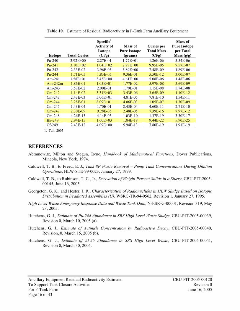
Table 10 is developed by combining the results for each isotope from Tables 7, 8, and 9 with the maximum value from Tables 5 and 6. This summarizes the predicted estimated residual radioactive material for F-Tank Farm after closure activities are completed.

Ancillary Equipment Residual Radioactivity Estimate CBU-PIT-2005-00120 To Support Tank Closure Activities Revision 0 For F-Tank Farm June 16, 2005 Page 15 of 43
Table 10. Estimate of Residual Radioactivity in F-Tank Farm Ancillary Equipment
Isotope Total Curies
Specific1 Activity of
Isotope (Ci/g)
Mass of Pure Isotope
(grams)
Curies per Total Mass
(Ci/g)
Mass of Pure Isotope
per Total Mass (g/g)
H-3 2.61E+01 9.69E+03 2.69E-03 8.38E-06 8.65E-10 C-14 1.97E-01 4.45E+00 4.44E-02 6.34E-08 1.42E-08 Al-26 1.66E-02 1.92E-02 8.63E-01 5.32E-09 2.77E-07 Co-60 5.47E+01 1.13E+03 4.84E-02 1.76E-05 1.55E-08 Ni-59 1.16E+01 8.00E-02 1.45E+02 3.73E-06 4.66E-05 Ni-63 1.05E+03 5.67E+01 1.86E+01 3.38E-04 5.97E-06 Se-79 7.57E-02 4.10E-03 1.85E+01 2.43E-08 5.93E-06 Sr-90 1.05E+04 1.38E+02 7.63E+01 3.38E-03 2.45E-05 Y-90 1.05E+04 5.45E+05 1.93E-02 3.38E-03 6.20E-09 Nb-94 5.71E-05 1.87E-01 3.05E-04 1.83E-11 9.80E-11 Tc-99 1.81E+00 1.71E-02 1.06E+02 5.81E-07 3.40E-05 Rh-106 1.40E+00 3.57E+09 3.91E-10 4.48E-07 1.26E-16 Ru-106 1.40E+00 3.30E+03 4.23E-04 4.48E-07 1.36E-10 Te-125m 1.33E+01 1.82E+04 7.32E-04 4.28E-06 2.35E-10 Sb-125 5.46E+01 1.04E+03 5.25E-02 1.75E-05 1.68E-08 Sb-126 3.27E-02 8.29E+04 3.94E-07 1.05E-08 1.27E-13 Sb-126m 2.33E-01 7.79E+07 3.00E-09 7.49E-08 9.62E-16 Sn-126 2.33E-01 3.00E-02 7.78E+00 7.49E-08 2.50E-06 I-129 7.98E-02 1.77E-04 4.51E+02 2.56E-08 1.45E-04 Cs-134 3.94E+01 1.29E+03 3.06E-02 1.27E-05 9.81E-09 Cs-135 1.19E-02 1.10E-03 1.08E+01 3.82E-09 3.47E-06 Cs-137 1.38E+04 8.67E+01 1.59E+02 4.42E-03 5.10E-05 Ba-137m 1.30E+04 5.38E+08 2.42E-05 4.18E-03 7.77E-12 Ce-144 1.97E-01 3.18E+03 6.18E-05 6.31E-08 1.98E-11 Pr-144 1.97E-01 7.53E+07 2.61E-09 6.31E-08 8.38E-16 Pm-147 9.19E+02 9.28E+02 9.90E-01 2.95E-04 3.18E-07 Sm-151 2.75E+02 2.00E+01 1.37E+01 8.82E-05 4.41E-06 Eu-152 2.14E+00 1.74E+02 1.23E-02 6.86E-07 3.94E-09 Eu-154 1.15E+02 2.70E+02 4.26E-01 3.70E-05 1.37E-07 Eu-155 1.05E+02 4.85E+02 2.16E-01 3.37E-05 6.94E-08 Ra-226 1.14E-04 9.80E-01 1.16E-04 3.66E-11 3.73E-11 Ra-228 0.00E+00 2.73E+02 0.00E+00 0.00E+00 0.00E+00 Ac-227 3.44E-06 7.22E+01 4.77E-08 1.10E-12 1.53E-14 Th-229 9.82E+00 2.12E-01 4.63E+01 3.15E-06 1.49E-05 Th-230 1.50E-04 2.06E-02 7.29E-03 4.82E-11 2.34E-09 Th-232 0.00E+00 1.09E-07 0.00E+00 0.00E+00 0.00E+00 Pa-231 3.46E-06 4.70E-02 7.36E-05 1.11E-12 2.36E-11 U-232 7.32E-03 2.24E+01 3.27E-04 2.35E-09 1.05E-10 U-233 1.58E+01 9.65E-03 1.63E+03 5.06E-06 5.24E-04 U-234 1.82E-02 6.21E-03 2.93E+00 5.85E-09 9.41E-07 U-235 5.78E-05 2.16E-06 2.68E+01 1.86E-11 8.59E-06 U-236 5.94E-04 6.48E-05 9.16E+00 1.91E-10 2.94E-06 U-238 3.26E-03 3.36E-07 9.70E+03 1.05E-09 3.11E-03 Np-237 5.47E-03 7.05E-04 7.76E+00 1.76E-09 2.49E-06 Pu-238 4.12E+02 1.71E+01 2.41E+01 1.32E-04 7.73E-06 Pu-239 7.59E+00 6.20E-02 1.22E+02 2.44E-06 3.93E-05
Ancillary Equipment Residual Radioactivity Estimate CBU-PIT-2005-00120 To Support Tank Closure Activities Revision 0 For F-Tank Farm June 16, 2005 Page 16 of 43
Table 10. Estimate of Residual Radioactivity in F-Tank Farm Ancillary Equipment
Isotope Total Curies
Specific1 Activity of
Isotope (Ci/g)
Mass of Pure Isotope
(grams)
Curies per Total Mass
(Ci/g)
Mass of Pure Isotope
per Total Mass (g/g)
Pu-240 3.92E+00 2.27E-01 1.72E+01 1.26E-06 5.54E-06 Pu-241 3.10E+02 1.04E+02 2.98E+00 9.95E-05 9.57E-07 Pu-242 2.33E-02 3.96E-03 5.89E+00 7.48E-09 1.89E-06 Pu-244 1.71E-05 1.83E-05 9.36E-01 5.50E-12 3.00E-07 Am-241 1.58E+01 3.43E+00 4.61E+00 5.08E-06 1.48E-06 Am-242m 1.86E-01 1.05E+01 1.77E-02 5.97E-08 5.69E-09 Am-243 3.57E-02 2.00E-01 1.79E-01 1.15E-08 5.74E-08 Cm-242 1.14E-02 3.31E+03 3.43E-06 3.65E-09 1.10E-12 Cm-243 2.43E-03 5.06E+01 4.81E-05 7.81E-10 1.54E-11 Cm-244 3.28E-01 8.09E+01 4.06E-03 1.05E-07 1.30E-09 Cm-245 1.43E-04 1.70E-01 8.43E-04 4.60E-11 2.71E-10 Cm-247 2.30E-09 9.28E-05 2.48E-05 7.39E-16 7.97E-12 Cm-248 4.26E-13 4.14E-03 1.03E-10 1.37E-19 3.30E-17 Bk-249 2.94E-15 1.60E+03 1.84E-18 9.44E-22 5.90E-25 Cf-249 2.43E-12 4.09E+00 5.94E-13 7.80E-19 1.91E-19
1. Tuli, 2005 REFERENCES Abramowitz, Milton and Stegun, Irene, Handbook of Mathematical Functions, Dover Publications,
Mineola, New York, 1974.
Caldwell, T. B., to Freed, E. J., Tank 8F Waste Removal – Pump Tank Concentrations During Dilution Operations, HLW-STE-99-0023, January 27, 1999.
Caldwell, T. B., to Robinson, T. C., Jr., Derivation of Weight Percent Solids in a Slurry, CBU-PIT-2005-00145, June 16, 2005.
Georgeton, G. K., and Hester, J. R., Characterization of Radionuclides in HLW Sludge Based on Isotopic Distribution in Irradiated Assemblies (U), WSRC-TR-94-0562, Revision 1, January 27, 1995.
High Level Waste Emergency Response Data and Waste Tank Data, N-ESR-G-00001, Revision 319, May 23, 2005.
Hutchens, G. J., Estimate of Pu-244 Abundance in SRS High Level Waste Sludge, CBU-PIT-2005-00039, Revision 0, March 10, 2005 (a).
Hutchens, G. J., Estimate of Actinide Concentration by Radioactive Decay, CBU-PIT-2005-00040, Revision, 0, March 15, 2005 (b).
Hutchens, G. J., Estimate of Al-26 Abundance in SRS High Level Waste, CBU-PIT-2005-00041, Revision 0, March 30, 2005.

Ancillary Equipment Residual Radioactivity Estimate CBU-PIT-2005-00120 To Support Tank Closure Activities Revision 0 For F-Tank Farm June 16, 2005 Page 17 of 43
REFERENCES (Continued) Industrial Wastewater Closure Module for the High-Level Waste Tank 17 System, Revision 2,
Construction Permit Number 17,424-IW, United States Department of Energy, Savannah River Site, Aiken, South Carolina, 29808, August 26, 1997.
Industrial Wastewater Closure Module for the High-Level Waste Tank 20 System, Construction Permit Number 17,424-IW, United States Department of Energy, Savannah River Site, Aiken, South Carolina, 29808, January 8, 1997.
Ledbetter, L. A., Waste Characterization of Ni-63 in High Level Waste Sludge, CBU-PIT-2005-00017, Revision 0, January 31, 2005.
Nguyen, Q. L., Inventory of Residual Radionuclides Remaining in the 242-F Evaporator System, CBU-PIT-2005-00075, Revision 0, June 16, 2005.
O’Bryant, R. F. and Weiss, W. R., HLW Supernate Radionuclide Characterization, WSRC-TR-94-00290, Revision 4, March 12, 2003.
O’Bryant, R. F., to Robinson, T. C., F-Tank Farm Transfer Characterization Documentation, ESH-WPF-2005-00050, June 7, 2005(a).
O’Bryant, R. F., Characterization of Radionuclides in PUREX Waste Sludge from F-Area High Level Waste Tanks, Revision 2, June 16, 2005(b).
Odaka, K, and Ueda, S, Dependence of out-gassing rate on surface oxide layer thickness in type 304 stainless steel before and after surface oxidation in air Mechanical Engineering Research Laboratory, Ibaraki, Japan. 13th International Vacuum Congress and 9th International Conference on Solid Surfaces, Yokohama, Japan, 25-29, Sept. 1995.
Poirier, M. R., to Looper, M. G., ESP Sludge Transfers from H-Area to S-Area, WSRC-RP-93-576, April 15, 1993.
Tran, H. Q. Total Iodine-129 Curie Inventory Report, CBU-PIT-2005-00033, Revision 0, February 14, 2005 (a).
Tran, H. Q., Waste Characterization of Nb-94 in High Level Waste Sludge, CBU-PIT-2005-00044, Revision 0, February 23, 2005 (b).
Tran, H. Q., Compilation of Additional Radionuclide Data for SRS HLW Sludge to be Included in Waste Characterization System (WCS II), CBU-PIT-2005-00034, Revision 0, March 1, 2005 (c).
Tuli, J. K., Nuclear Wallet Cards, 6th Edition, National Nuclear Data Center Brookhaven National Laboratory, January 2000.
Savannah River Site Liquid Waste Facilities – Waste Characterization System, Version 1.5, March 1, 2005.
Shewmon, Paul, Diffusion in Solids, The Minerals, Metals, and Materials Society, Warrendale, Pennsylvania, 1989.
Weist, R.C. (ed.), CRC Handbook of Chemistry and Physics, 59th ed., CRC Press, Inc., Boca Raton, Florida, 1979.
Wiersma, B. J., to Cook, J. R., Calculation of the Amount of Corrosion Product in HLW Tank 19, Interoffice Memorandum, SRT-MTS-2002-20004, Rev. 1, February 8, 2002.

APPENDIX I – Source Term Summary Table
Ancillary Equipment Residual Radioactivity Estimate CBU-PIT-2005-00120 To Support Tank Closure Activities Revision 0 For F-Tank Farm June 16, 2005 Page 18 of 43
The following table of parent and daughter isotopes is generated from various sources. In general, the maximum concentrations were chosen when given an option of the type of waste characterized. Isotopes in secular equilibrium with the parent are shown in italics. The reference source terms are given as “fresh” waste with a post-reactor aging period of 180 days. The last day of production for SRS is assumed to be August 31, 1988. Therefore, date of the Reference Source Term is February 27, 1989. The source term date is June 1, 2005. The elapsed time is 5.1304E+08 seconds.
Table I-1. Source Term Summary (Continued)
Isotope
Reference Source Term
(Ci/gallon) Halflife Halflife Units
Halflife (sec)
Source Term
(Ci/gallon) Reference Table or Page H-3 1.82E-02 1.23E+01 y 3.88E+08 7.28E-03 Georgeton and Hester (1995) Table III C-14 7.82E-08 5.73E+03 y 1.81E+11 7.80E-08 Georgeton and Hester (1995) Table IV Al-26 1.13E-05 7.17E+05 y 2.26E+13 1.13E-05 Hutchens (2005c) Page 8 Co-60 3.72E-01 1.93E+03 d 1.67E+08 4.42E-02 Georgeton and Hester (1995) Table IV Ni-59 8.56E-05 7.60E+04 y 2.40E+12 8.56E-05 Georgeton and Hester (1995) Table III Ni-63 9.57E-03 1.00E+02 y 3.16E+09 8.55E-03 Ledbetter (2005) Table 1 Se-79 6.13E-05 1.1E+06 y 3.50E+13 6.13E-05 Georgeton and Hester (1995) Table III Sr-90 1.26E+01 2.88E+01 y 9.09E+08 8.52E+00 Georgeton and Hester (1995) Table III Y-90 1.26E+01 6.40E+01 h 2.30E+05 8.52E+00 Georgeton and Hester (1995) Secular Equilibrium with Sr-90 Nb-94 4.60E-08 2.03E+04 y 6.41E+11 4.60E-08 Tran (2005b) Table 4 Tc-99 1.20E-03 2.11E+05 y 6.66E+12 1.20E-03 Georgeton and Hester (1995) Table III Rh-106 6.86E+01 2.98E+01 s 2.98E+01 1.13E-03 Georgeton and Hester (1995) Table III Ru-106 6.86E+01 3.74E+02 d 3.23E+07 1.13E-03 Georgeton and Hester (1995) Table III Te-125m 6.30E-01 5.74E+01 d 4.96E+06 1.06E-02 Tran (2005c) Page 9 Sb-125 2.58E+00 2.76E+00 y 8.71E+07 4.35E-02 Tran (2005c) Table 7 Sb-126 1.60E-05 1.25E+01 d 1.08E+06 1.60E-05 Tran (2005c) Table 10 Sb-126m 1.14E-04 1.92E+01 m 1.15E+03 1.14E-04 Tran (2005c) Page 9 Sn-126 1.14E-04 1.00E+05 y 3.00E+12 1.14E-04 Georgeton and Hester (1995) Table III I-129 1.14E-06 1.57E+07 y 4.95E+14 5.04E-06 Tran (2005a) Page 3 (based on 301.7 pCi/ml) Cs-134 7.32E+00 7.55E+02 d 6.52E+07 3.13E-02 Georgeton and Hester (1995) Table IV Cs-135 7.09E-07 2.30E+06 y 7.30E+13 7.09E-07 WCS Sludge 1.5 (Version 6.1.05) Sheet "RadComp" Cs-137 1.55E+01 3.01E+01 y 9.50E+08 1.07E+01 Georgeton and Hester (1995) Table III Ba-137m 1.47E+01 2.55E+00 m 1.53E+02 1.01E+01 Georgeton and Hester (1995) Secular Equilibrium with Cs-137 Ce-144 3.03E+02 2.85E+02 d 2.46E+07 1.60E-04 Georgeton and Hester (1995) Table III Pr-144 3.03E+02 1.73E+01 m 1.04E+03 1.60E-04 WCS Sludge 1.5 (Version 6.1.05) Sheet "RadComp" Pm-147 5.50E+01 2.62E+00 y 8.27E+07 7.46E-01 Georgeton and Hester (1995) Table III Sm-151 2.50E-01 9.00E+01 y 3.00E+09 2.22E-01 Tran (2005c) Table 5

APPENDIX I – Source Term Summary Table
Ancillary Equipment Residual Radioactivity Estimate CBU-PIT-2005-00120 To Support Tank Closure Activities Revision 0 For F-Tank Farm June 16, 2005 Page 19 of 43
Table I-1. Source Term Summary (Continued)
Isotope
Reference Source Term
(Ci/gallon) Halflife Halflife Units
Halflife (sec)
Source Term
(Ci/gallon) Reference Table or Page Eu-152 3.99E-03 1.35E+01 y 4.26E+08 1.73E-03 Tran (2005c) Table 5 Eu-154 3.47E-01 8.59E+00 y 2.71E+08 9.34E-02 Georgeton and Hester (1995) Table IV Eu-155 9.12E-01 4.76E+00 y 1.50E+08 8.52E-02 Tran (2005c) Table 5 Ra-226 9.26E-08 1.60E+03 y 5.10E+10 9.26E-08 Hutchens (2005b) Page 8 Ra-228 0.00E+00 5.75E+00 y 1.81E+08 0.00E+00 Hutchens (2005b) Page 8 Ac-227 2.79E-09 2.18E+01 y 6.88E+08 2.79E-09 Hutchens (2005b) Page 10 Th-229 1.12E-02 7.34E+03 y 2.32E+11 7.98E-03 Hutchens (2005b) Page 9 Th-230 1.18E-07 7.54E+04 y 2.38E+12 1.18E-07 Hutchens (2005b) Page 8 Th-232 0.00E+00 1.41E+10 y 4.45E+17 0.00E+00 Hutchens (2005b) Page 8 Pa-231 2.80E-09 3.28E+04 y 1.04E+12 2.80E-09 Hutchens (2005b) Page 10 U-232 9.27E-07 6.89E+01 y 2.17E+09 7.87E-07 Georgeton and Hester (1995) Table IV U-233 1.80E-02 1.59E+05 y 5.02E+12 1.28E-02 Georgeton and Hester (1995) Table IX - Scale to Sr-90 "Adjusted" U-234 1.33E-06 2.46E+05 y 7.76E+12 1.33E-06 Georgeton and Hester (1995) Table IV U-235 1.47E-08 7.04E+08 y 2.22E+16 1.47E-08 Georgeton and Hester (1995) Table IV U-236 3.38E-07 2.34E+07 y 7.38E+14 3.38E-07 Georgeton and Hester (1995) Table IV U-238 5.35E-07 4.47E+09 y 1.41E+17 5.35E-07 Georgeton and Hester (1995) Table III Np-237 2.39E-06 2.14E+06 y 6.75E+13 2.39E-06 Georgeton and Hester (1995) Table IV Pu-238 3.79E-01 8.77E+01 y 2.77E+09 3.33E-01 Georgeton and Hester (1995) Table IV Pu-239 2.97E-03 2.41E+04 y 7.61E+11 2.97E-03 Georgeton and Hester (1995) Table IV Pu-240 2.08E-03 6.56E+03 y 2.07E+11 2.08E-03 Georgeton and Hester (1995) Table IV Pu-241 5.32E-01 1.43E+01 y 4.51E+08 2.42E-01 Georgeton and Hester (1995) Table IV Pu-242 3.01E-06 3.73E+05 y 1.18E+13 3.01E-06 Georgeton and Hester (1995) Table IV Pu-244 1.39E-08 8.00E+07 y 2.52E+15 1.39E-08 Hutchens (2005a) Page 3 Am-241 8.54E-03 4.32E+02 y 1.36E+10 8.32E-03 Georgeton and Hester (1995) Table III Am-242m 1.22E-05 1.41E+02 y 4.45E+09 1.13E-05 Georgeton and Hester (1995) Table III Am-243 2.93E-06 7.37E+03 y 2.33E+11 2.93E-06 Tran (2005c) Table 5 Cm-242 1.00E-05 1.63E+02 d 1.41E+07 9.24E-06 Tran (2005c) Table 5 Cm-243 2.91E-06 2.91E+01 y 9.18E+08 1.98E-06 Tran (2005c) Page 12 Cm-244 8.28E-05 1.81E+01 y 5.71E+08 4.44E-05 Georgeton and Hester (1995) Table IV Cm-245 2.83E-09 8.50E+03 y 2.70E+11 2.83E-09 Georgeton and Hester (1995) Table IV Cm-247 3.32E-16 1.56E+07 y 4.92E+14 3.32E-16 Tran (2005c) Table 5 Cm-248 3.46E-16 3.48E+05 y 1.10E+13 3.46E-16 Tran (2005c) Table 5 Bk-249 5.06E-13 3.30E+02 d 2.90E+07 2.39E-18 Tran (2005c) Table 5 Cf-249 2.04E-15 3.51E+02 y 1.11E+10 1.98E-15 Tran (2005c) Table 5
APPENDIX II
Ancillary Equipment Residual Radioactivity Estimate CBU-PIT-2005-00120 To Support Tank Closure Activities Revision 0 For F-Tank Farm June 16, 2005 Page 20 of 43
ESTIMATION OF DIFFUSION OF ISOTOPES INTO CARBON AND STAINLESS STEELS
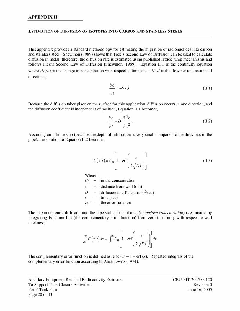
This appendix provides a standard methodology for estimating the migration of radionuclides into carbon and stainless steel. Shewmon (1989) shows that Fick’s Second Law of Diffusion can be used to calculate diffusion in metal; therefore, the diffusion rate is estimated using published lattice jump mechanisms and follows Fick’s Second Law of Diffusion [Shewmon, 1989]. Equation II.1 is the continuity equation where tc ∂∂ is the change in concentration with respect to time and J
r⋅∇− is the flow per unit area in all
directions,
Jt
c r⋅−∇=
∂
∂. (II.1)
Because the diffusion takes place on the surface for this application, diffusion occurs in one direction, and the diffusion coefficient is independent of position, Equation II.1 becomes,
2
2
x
cD
t
c
∂
∂=
∂
∂. (II.2)
Assuming an infinite slab (because the depth of infiltration is very small compared to the thickness of the pipe), the solution to Equation II.2 becomes,
( )
−=
tD
xCtxC
2erf1, 0 (II.3)
Where: C0 = initial concentration x = distance from wall (cm) D = diffusion coefficient (cm2/sec) t = time (sec) erf = the error function
The maximum curie diffusion into the pipe walls per unit area (or surface concentration) is estimated by integrating Equation II.3 (the complementary error function) from zero to infinity with respect to wall thickness,
( ) dxtD
xCdxtxC ∫∫
∞∞
−=
0 00 2erf1, .
The complementary error function is defined as, erfc (x) = 1 – erf (x). Repeated integrals of the complementary error function according to Abramowitz (1974),

APPENDIX II
Ancillary Equipment Residual Radioactivity Estimate CBU-PIT-2005-00120 To Support Tank Closure Activities Revision 0 For F-Tank Farm June 16, 2005 Page 21 of 43
∫∞ −=x
nn dttx )(erfc)(erfc 1ii , (II.4)
where i is the integral operator ∫∞⋅=
xdti . [Note that i is not the imaginary unit 1− ].
Expressed as a single integral [Abramowitz, 1974],
dten
xtx t
x
nn 2
!
)(2)( erfc −
∞
⌡
⌠ −=
πi (II.5)
Of interest is,
∫∞
→==
xn
xnxdxx 1 where)( erfclim)(erfc
0i (II.6)
∫∞ −
→−=
xt
xdtext
2
)(2
lim0 π
(II.7)
−= ∫∫∞ −∞ −
→44 344 21
)(erfc
0
22 22lim
x
xt
xt
xdtexdtet
ππ (II.8)
−= ∫
∞ −
→)(erfc
2lim
2
0xxdtet
xt
x π (II.9)
Let u = t2 and du = 2t dt, then t dt= ½ du, then,
2
22
2
2
1)1(
2
1
2
12 x
xxuu
xt eeduedtet −
∞∞ −−∞ − =−== ∫∫π
(II.10)
So that,
∫∞ −
→
−=
0 0)(erfc
2
12lim)(erfc
2
xxedxx xx π
(II.11)
ππ
1)(erfclim
2
0=
−=
−
→xx
e x
x (II.12)

APPENDIX II
Ancillary Equipment Residual Radioactivity Estimate CBU-PIT-2005-00120 To Support Tank Closure Activities Revision 0 For F-Tank Farm June 16, 2005 Page 22 of 43
After an appropriate change of variables from Equation II.3, Equation II.12 yields,
(II.13) A paucity of data for diffusion coefficients for the isotopes tracked herein encourages the use of published works on isotopic tracers. Diffusion behavior of the unknown isotopes is estimated by plotting the behavior of known tracer elements in magnetic iron and non-magnetic iron. The Arrhenius equation defines the diffusion coefficient (D) D = D0
e –Q/RT (II.14)
Where R = 0.0019872 kcal/mole-K D0 = Frequency Factor (cm2/sec) Q = Activation Energy (kcal/mole) T = Temperature (K)
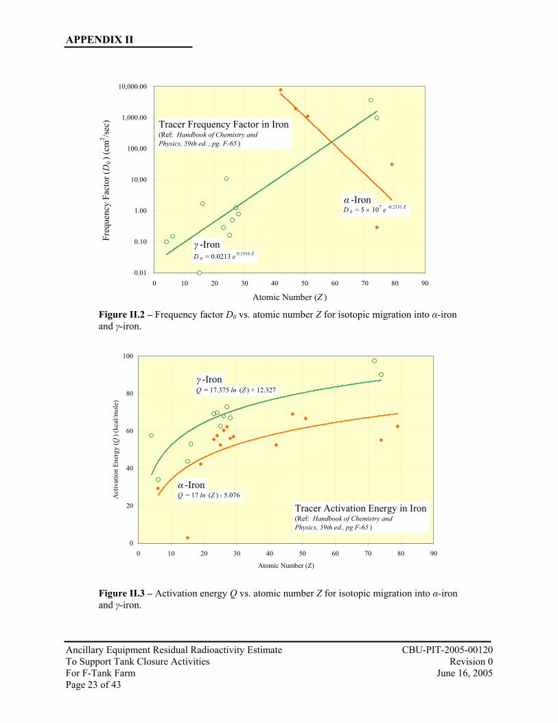
Because diffusivity of a solute partially depends on atomic number (Z), plots of Z versus the frequency factor (D0) and the activation energy (Q) show a relationship. Though other factors such as melting point of the solvent, elastic constants, and position in the periodic table also influence the frequency factor and activation energy, Figures 1 through 3 illustrate a rough order relationship at the expense of a more exhaustive analysis. For the sake of this study, these relationships are sufficient to gain an understanding of the diffusion contribution to the ancillary equipment source term.
Figure II.1 – Frequency Factor D0 vs. atomic number Z for low Z-number isotopic migration into α-iron.
D 0 = 0.0364Z + 1.5835
-
1.00
2.00
3.00
4.00
5.00
6.00
7.00
8.00
0 5 10 15 20 25 30 35
Atomic Number (Z )
Freq
uenc
y Fa
ctor
(D0
) (cm
2 /sec
)
Tracer Frequency Factor in α -IronFor Low Z Numbers(Ref: Handbook of Chemistry andPhysics, 59th ed., pg F-65 )
( )π
tDCdx
tD
xCdxtxC 00 00
22
erf1, =
−= ∫∫
∞∞
APPENDIX II
Ancillary Equipment Residual Radioactivity Estimate CBU-PIT-2005-00120 To Support Tank Closure Activities Revision 0 For F-Tank Farm June 16, 2005 Page 23 of 43
Figure II.2 – Frequency factor D0 vs. atomic number Z for isotopic migration into α-iron and γ-iron.
Figure II.3 – Activation energy Q vs. atomic number Z for isotopic migration into α-iron and γ-iron.
0.01
0.10
1.00
10.00
100.00
1,000.00
10,000.00
0 10 20 30 40 50 60 70 80 90
Atomic Number (Z )
Freq
uenc
y Fa
ctor
(D0
) (cm
2 /sec
) Tracer Frequency Factor in Iron(Ref: Handbook of Chemistry andPhysics, 59th ed. , pg. F-65 )
γ -IronD 0 = 0.0213 e 0.1516 Z
α -IronD 0 = 5 × 10⁷ e -0.2131 Z
0
20
40
60
80
100
0 10 20 30 40 50 60 70 80 90
Atomic Number (Z)
Act
ivat
ion
Ener
gy (Q
) (kc
al/m
ole)
Tracer Activation Energy in Iron(Ref: Handbook of Chemistry andPhysics, 59th ed., pg F-65 )
γ -IronQ = 17.375 ln (Z ) + 12.327
α -IronQ = 17 ln (Z ) - 5.076

APPENDIX II
Ancillary Equipment Residual Radioactivity Estimate CBU-PIT-2005-00120 To Support Tank Closure Activities Revision 0 For F-Tank Farm June 16, 2005 Page 24 of 43
Carbon steel is predominantly an alloy of α-iron, whereas stainless steel is an austenitic alloy of iron and non-ferritic metals and possesses a crystalline structure similar to γ-iron. Therefore, Figures II.1 through II.3 provide the following correlations: For stainless steel pipes: D0 = 0.0213 e 0.1516 Z (II.15) Q = 17.375 ln (Z) + 12.327 (II.16) For carbon steel pipes: D0 = 0.0364 Z + 1.5835 for Z < 42 (II.17) D0 = 5 × 10⁷ e -0.2131 Z for Z ≥ 42 (II.18) Q = 17 ln (Z) – 5.076 (II.19) The isotopes in bold listed in Table II.1 use the diffusion data found in Weist (1979) rather than ascertained from the correlations above.
Table II.1 – Isotopic Diffusion Data Estimation
Frequency Factor (D0) cm2/sec Activation Energy (Q) kcal/mole
Isotope Z Carbon Steel Stainless Steel Carbon Steel Stainless Steel H-3 1 1.6199E+00 2.4787E-02 1.2327E+01 1.2327E+01 C-14 6 2.2000E+00 1.5000E-01 2.9300E+01 3.4000E+01 Al-26 13 2.0567E+00 1.5286E-01 3.8528E+01 5.6893E+01 Co-60 27 7.1900E+00 1.2500E+00 6.2200E+01 7.2900E+01 Ni-59 28 1.3000E+00 7.7000E-01 5.6000E+01 6.7000E+01 Ni-63 28 1.3000E+00 7.7000E-01 5.6000E+01 6.7000E+01 Se-79 34 2.8211E+00 3.6890E+00 5.4872E+01 7.3598E+01 Sr-90 38 2.9667E+00 6.7649E+00 5.6763E+01 7.5530E+01 Y-90 39 3.0031E+00 7.8723E+00 5.7205E+01 7.5981E+01
Nb-94 41 3.0759E+00 1.0661E+01 5.8055E+01 7.6850E+01 Tc-99 43 5.2408E+03 1.4436E+01 5.8864E+01 7.7678E+01
Rh-106 44 4.2350E+03 1.6800E+01 5.9255E+01 7.8077E+01 Ru-106 45 3.4222E+03 1.9550E+01 5.9637E+01 7.8468E+01 Te-125 52 7.6996E+02 5.6495E+01 6.2095E+01 8.0980E+01 Sb-125 51 1.1000E+03 4.8548E+01 6.6600E+01 8.0642E+01 Sb-126 51 1.1000E+03 4.8548E+01 6.6600E+01 8.0642E+01
Sb-126m 51 9.5283E+02 4.8548E+01 6.1765E+01 8.0642E+01 Sn-126 50 1.1791E+03 4.1719E+01 6.1428E+01 8.0298E+01 I-129 53 6.2218E+02 6.5743E+01 6.2419E+01 8.1311E+01
Cs-134 55 4.0628E+02 8.9028E+01 6.3049E+01 8.1954E+01 Cs-135 55 4.0628E+02 8.9028E+01 6.3049E+01 8.1954E+01 Cs-137 55 4.0628E+02 8.9028E+01 6.3049E+01 8.1954E+01
Ba-137m 56 3.2830E+02 1.0360E+02 6.3355E+01 8.2267E+01 Ce-144 58 2.1438E+02 1.4030E+02 6.3952E+01 8.2877E+01 Pr-144 59 1.7323E+02 1.6326E+02 6.4242E+01 8.3174E+01 Pm-147 61 1.1312E+02 2.2109E+02 6.4809E+01 8.3753E+01 Sm-151 62 9.1408E+01 2.5728E+02 6.5085E+01 8.4036E+01 Eu-152 63 7.3865E+01 2.9939E+02 6.5357E+01 8.4314E+01

APPENDIX II
Ancillary Equipment Residual Radioactivity Estimate CBU-PIT-2005-00120 To Support Tank Closure Activities Revision 0 For F-Tank Farm June 16, 2005 Page 25 of 43
Table II.1 – Isotopic Diffusion Data Estimation
Frequency Factor (D0) cm2/sec Activation Energy (Q) kcal/mole
Isotope Z Carbon Steel Stainless Steel Carbon Steel Stainless Steel Eu-154 63 7.3865E+01 2.9939E+02 6.5357E+01 8.4314E+01 Eu-155 63 7.3865E+01 2.9939E+02 6.5357E+01 8.4314E+01 Ra-226 88 3.5870E-01 1.3250E+04 7.1039E+01 9.0121E+01 Ra-228 88 3.5870E-01 1.3250E+04 7.1039E+01 9.0121E+01 Ac-227 89 2.8986E-01 1.5419E+04 7.1231E+01 9.0317E+01 Th-229 90 2.3423E-01 1.7943E+04 7.1421E+01 9.0511E+01 Th-230 90 2.3423E-01 1.7943E+04 7.1421E+01 9.0511E+01 Th-232 90 2.3423E-01 1.7943E+04 7.1421E+01 9.0511E+01 Pa-231 91 1.8927E-01 2.0880E+04 7.1609E+01 9.0703E+01 U-232 92 1.5295E-01 2.4298E+04 7.1794E+01 9.0893E+01 U-233 92 1.5295E-01 2.4298E+04 7.1794E+01 9.0893E+01 U-234 92 1.5295E-01 2.4298E+04 7.1794E+01 9.0893E+01 U-235 92 1.5295E-01 2.4298E+04 7.1794E+01 9.0893E+01 U-236 92 1.5295E-01 2.4298E+04 7.1794E+01 9.0893E+01 U-238 92 1.5295E-01 2.4298E+04 7.1794E+01 9.0893E+01
Np-237 93 1.2359E-01 2.8276E+04 7.1978E+01 9.1081E+01 Pu-238 94 9.9872E-02 3.2904E+04 7.2160E+01 9.1267E+01 Pu-239 94 9.9872E-02 3.2904E+04 7.2160E+01 9.1267E+01 Pu-240 94 9.9872E-02 3.2904E+04 7.2160E+01 9.1267E+01 Pu-241 94 9.9872E-02 3.2904E+04 7.2160E+01 9.1267E+01 Pu-242 94 9.9872E-02 3.2904E+04 7.2160E+01 9.1267E+01 Pu-244 94 9.9872E-02 3.2904E+04 7.2160E+01 9.1267E+01 Am-241 95 8.0704E-02 3.8290E+04 7.2340E+01 9.1451E+01
Am-242m 95 8.0704E-02 3.8290E+04 7.2340E+01 9.1451E+01 Am-243 95 8.0704E-02 3.8290E+04 7.2340E+01 9.1451E+01 Cm-242 96 6.5215E-02 4.4558E+04 7.2518E+01 9.1633E+01 Cm-243 96 6.5215E-02 4.4558E+04 7.2518E+01 9.1633E+01 Cm-244 96 6.5215E-02 4.4558E+04 7.2518E+01 9.1633E+01 Cm-245 96 6.5215E-02 4.4558E+04 7.2518E+01 9.1633E+01 Cm-247 96 6.5215E-02 4.4558E+04 7.2518E+01 9.1633E+01 Cm-248 96 6.5215E-02 4.4558E+04 7.2518E+01 9.1633E+01 Bk-249 97 5.2699E-02 5.1852E+04 7.2694E+01 9.1813E+01 Cf-249 98 4.2584E-02 6.0340E+04 7.2868E+01 9.1991E+01
Applying D0 and Q to the Arrhenius equation (Equation II.14) gives an estimate of the diffusion coefficient and subsequently the surface concentration of each isotope (Equation II.13).

APPENDIX II
Ancillary Equipment Residual Radioactivity Estimate CBU-PIT-2005-00120 To Support Tank Closure Activities Revision 0 For F-Tank Farm June 16, 2005 Page 26 of 43
Table II.2 shows the diffusion coefficient via the application of Equations II.15 through II.19.
Table II.2 Diffusion Coefficient Estimation Diffusion Coefficient (D)
cm2/sec
Isotope Carbon Steel Stainless
Steel H-3 9.70E-08 1.48E-09 C-14 1.50E-17 1.80E-21 Al-26 5.48E-23 7.08E-35 Co-60 2.59E-36 2.42E-43 Ni-59 2.01E-33 4.27E-40 Ni-63 2.01E-33 4.27E-40 Se-79 2.00E-32 2.79E-43 Sr-90 1.64E-33 3.77E-44 Y-90 9.13E-34 2.39E-44
Nb-94 2.97E-34 1.00E-44 Tc-99 1.70E-31 4.44E-45
Rh-106 8.10E-32 3.01E-45 Ru-106 3.91E-32 2.07E-45 Te-125 3.19E-34 2.02E-46 Sb-125 1.05E-36 2.73E-46 Sb-126 1.05E-36 2.73E-46
Sb-126m 6.17E-34 2.73E-46 Sn-126 1.20E-33 3.74E-46 I-129 1.67E-34 1.50E-46
Cs-134 4.65E-35 8.54E-47 Cs-135 4.65E-35 8.54E-47 Cs-137 4.65E-35 8.54E-47
Ba-137m 2.49E-35 6.51E-47 Ce-144 7.26E-36 3.87E-47 Pr-144 3.97E-36 3.02E-47 Pm-147 1.21E-36 1.87E-47 Sm-151 6.71E-37 1.49E-47 Eu-152 3.76E-37 1.19E-47 Eu-154 3.76E-37 1.19E-47 Eu-155 3.76E-37 1.19E-47 Ra-226 8.55E-43 2.09E-49 Ra-228 8.55E-43 2.09E-49 Ac-227 5.33E-43 1.86E-49 Th-229 3.34E-43 1.67E-49 Th-230 3.34E-43 1.67E-49 Th-232 3.34E-43 1.67E-49 Pa-231 2.09E-43 1.50E-49 U-232 1.32E-43 1.35E-49 U-233 1.32E-43 1.35E-49 U-234 1.32E-43 1.35E-49 U-235 1.32E-43 1.35E-49 U-236 1.32E-43 1.35E-49 U-238 1.32E-43 1.35E-49
Diffusion Coefficient (D) cm2/sec
Isotope Carbon Steel Stainless
Steel Np-237 8.30E-44 1.22E-49 Pu-238 5.25E-44 1.10E-49 Pu-239 5.25E-44 1.10E-49 Pu-240 5.25E-44 1.10E-49 Pu-241 5.25E-44 1.10E-49 Pu-242 5.25E-44 1.10E-49 Pu-244 5.25E-44 1.10E-49 Am-241 3.33E-44 1.00E-49
Am-242m 3.33E-44 1.00E-49 Am-243 3.33E-44 1.00E-49 Cm-242 2.11E-44 9.12E-50 Cm-243 2.11E-44 9.12E-50 Cm-244 2.11E-44 9.12E-50 Cm-245 2.11E-44 9.12E-50 Cm-247 2.11E-44 9.12E-50 Cm-248 2.11E-44 9.12E-50 Bk-249 1.35E-44 8.33E-50 Cf-249 8.60E-45 7.62E-50

APPENDIX III – Line Segments
Ancillary Equipment Residual Radioactivity Estimate CBU-PIT-2005-00120 To Support Tank Closure Activities Revision 0 For F-Tank Farm June 16, 2005 Page 27 of 43
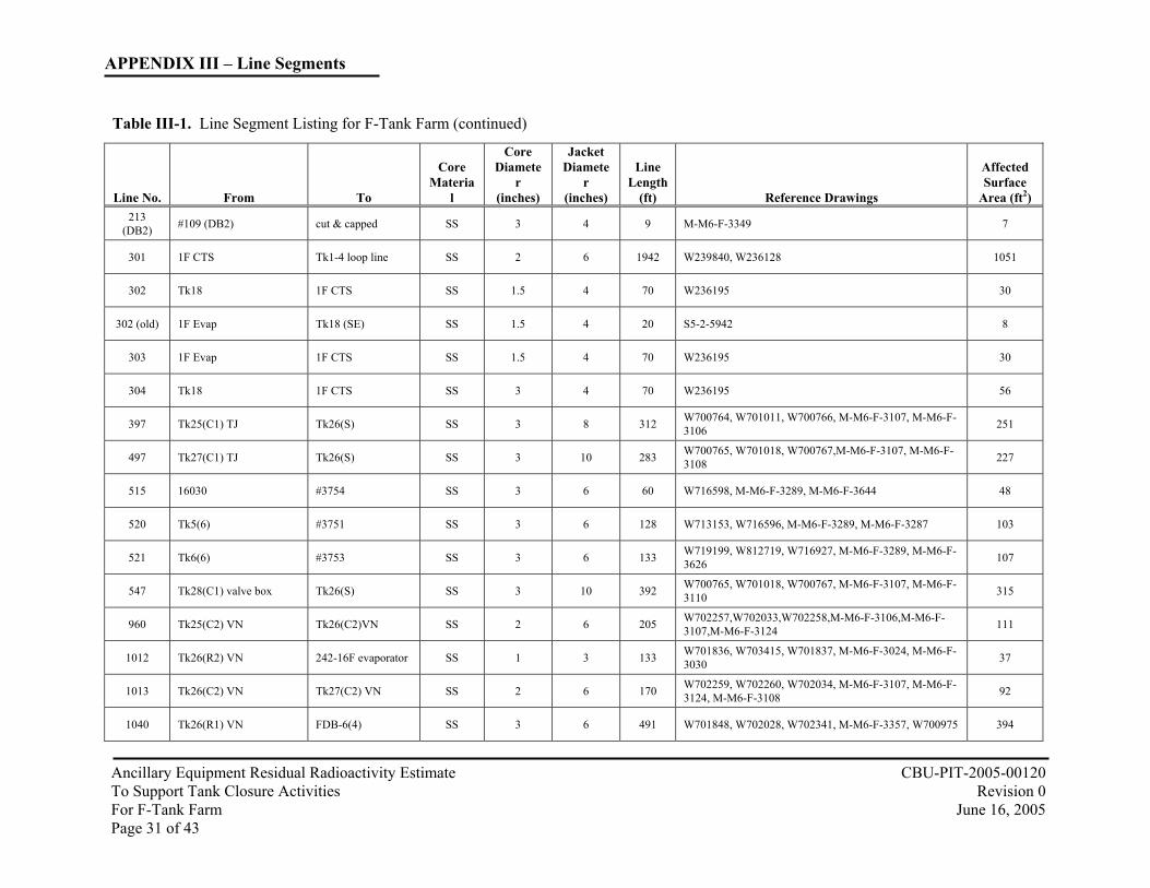
Table III-1. Line Segment Listing for F-Tank Farm (continued)
Line No. From To
Core Materia
l
Core Diamete
r (inches)
Jacket Diamete
r (inches)
Line Length
(ft) Reference Drawings
Affected Surface
Area (ft2)
1 1F Evap 1F CTS SS 3 4 50 S5-2-5943, S5-2-5970 40
2 Tk33(C2) VN Tk34(C2) VN SS 2 3 190 W239840, W238338, W259468, M-M6-F-3355 103
2 (old) 1F Evap Tk18 SS 3 6 80 S5-2-5970, S5-2-1388, W164177 64
3 FDB-1(28) Tk18 SS 3 6 430 W163901, W164193 345
4 FDB-1(29) Tk17 SS 3 6 480 W163901 386
7 Tk17 Tk19 SS 4 6 55 W717008 58
8 Tk20 Tk18 SS 4 6 55 W717613 58
9 #9000 Tk19 (NW) CS 3 4 35 W709575, W717164, W716823, M-M6-F-3363 97
11 1F Evap 1F CTS SS 3 4 50 S5-2-5943, S5-2-5970 40
73 Tk44 (C1) TJ Tk26 (C1) SS 3 10 447 W706328, W703325, W701873, M-M6-F-3107, M-M6-F-3111 359
74 Tk45 (C1) TJ Tk26 (C1) SS 3 10 289 W706328, W703325, W703416, M-M6-F-3107, M-M6-F-3112 232
75 Tk46 (C1) Tk26 (C1) SS 3 10 404 W706330, W703325, W703418, M-M6-F-3107, M-M6-F-3113 324
76 Tk47(C1)TJ Tk26 (C1) SS 3 10 547 W706330, W703325, W703418, M-M6-F-3107, M-M6-F-3114 439
100 (221F) 221-F #1475 SS 3 10 1661 W713074, W713075, W712364, W700782, M-M6-F-3119 1334
100 (IAL) FDB-2(26) HiPt flush pit (6) SS 3 4 4288 W235672, W714300, W234806, M-M6-F-3310, M-M6-F-3349, M-M6-F-3309 3444

APPENDIX III – Line Segments
Ancillary Equipment Residual Radioactivity Estimate CBU-PIT-2005-00120 To Support Tank Closure Activities Revision 0 For F-Tank Farm June 16, 2005 Page 28 of 43
Table III-1. Line Segment Listing for F-Tank Farm (continued)
Line No. From To
Core Materia
l
Core Diamete
r (inches)
Jacket Diamete
r (inches)
Line Length
(ft) Reference Drawings
Affected Surface
Area (ft2) 101
(DB4) FDB-4(5) FPP-2(6) pump in. SS 3 0 34 W701347, M-M6-F-3121, M-M6-F-3116, 27
101 (IAL) HiPt flush pit (4) FDB-2(25) SS 3 4 4288 W234806, M-M6-F-3310, M-M6-F-3349, M-M6-F-3309, W712694, W714758 3444
101(221F) 221-F #1478 SS 3 10 1661 W713074, W713075, W712364, W700782, M-M6-F-3116 1334
102 (221F) 221-F #1488 SS 3 10 1661 W713074, W713075, W712364, W700782, M-M6-F-3116 1334
102 (DB2) FPP-1(5) FDB-2(35) SS 3 4 46 W236643, W235672, W2017868, M-M6-F-3350, M-M6-
F-3349, M-M6-F-3309 37
102 (DB4) FDB-4(2) FPP-3(6) pump in. SS 3 0 50 W2017868, W701347, M-M6-F-3121, M-M6-F-3119 40
103 (DB2) FDB-2(36) FPP-1 (4) SS 3 4 40 W236643, M-M6-F-3350, M-M6-F-3349, M-M6-F-3309 32
103 (DB4) FDB-4(7) FPP-1(1) SS 3 4 153 W718059, W236643, W701123, M-M6-F-3350, M-M6-F-
3121 123
103(221F) 221-F #1476 SS 3 10 1661 W713074, W713075, W712364, W700782, M-M6-F-3119 1334
104 (DB2) FDB-2(27) FDB-1(8) SS 3 4 1000 W235672, W236672, W2017868, M-M6-F-3349, M-M6-
F-3359 803
104 (DB4) FDB-4(9) FDB-3(9) SS 3 10 150 W701347, W701121, W712694, M-M6-F-3121, M-M6-F-
3353 120
105 Tk27(S) VN FDB-4(11) SS 3 10 108 W700932, W701016, W701227, M-M6-F-3121, M-M6-F-3108 87
106 (DB2) FPP-1(2) FDB-2(28) SS 3 4 22 W236643, W235672, M-M6-F-3349, M-M6-F-3350,
W712694 18
106 (DB4) Tk28(S) valve box FDB-4(10) SS 3 10 538 W700932, W701016, W701227, M-M6-F-3121, M-M6-F-
3110 432
107 (DB2) FDB-2(33) Tk18 SS 3 4 643 W236672, M-M6-F-3349, M-M6-F-3364 516
107 (DB4) Tk26(C1) TJ FDB-4(13) SS 3 10 118 W700928, W701014, W700782, M-M6-F-3107, M-M6-F-
3121 95

APPENDIX III – Line Segments
Ancillary Equipment Residual Radioactivity Estimate CBU-PIT-2005-00120 To Support Tank Closure Activities Revision 0 For F-Tank Farm June 16, 2005 Page 29 of 43
Table III-1. Line Segment Listing for F-Tank Farm (continued)
Line No. From To
Core Materia
l
Core Diamete
r (inches)
Jacket Diamete
r (inches)
Line Length
(ft) Reference Drawings
Affected Surface
Area (ft2) 108
(DB2) FDB-2(32) FDB-3(15) SS 3 4 80 W238338, W238427, M-M6-F-3349, M-M6-F-3353 64
108 (DB4) Tk25(C1) TJ FDB-4(16) SS 3 8 323 W700782, W701013, W713153, M-M6-F-3106, M-M6-F-
3121 259
108 (Tk18) FDB-2(32) Tk18 SS 3 4 450 W235672 361
109 (DB2) FDB-2(37) #3754 & #3755 SS 3 8 60 W718172, M-M6-F-3289, M-M6-F-3349 48
109 (DB4) FDB-4(12) Tk26(C1) VN SS 3 10 118 W700928, W701014, W700782, M-M6-F-3107, M-M6-F-
3121 95
110 #17015 FDB-2(31) SS 3 6 285 W236672, W236643, M-M6-F-3288, M-M6-F-3349, W714298 229
110 (cut) Tk7(2) cut & capped SS 3 4 23 W814578, M-M6-F-3288 18
111 FDB-2(30) FDB-3(16) SS 3 8 57 W238273, W706053, W238155, M-M6-F-3353, M-M6-F-3349 46
112 FDB-2(29) FDB-3(17) SS 3 8 67 W2017868, W713210, W238318, M-M6-F-3349, M-M6-F-3353 54
114 FDB-1(30) FPP-1(1A) SS 3 8 640 W718377, W702321, W238318, M-M6-F-3350, M-M6-F-3359, W702327 514
115 FDB-1(31) cut & capped SS 3 8 10 M-M6-F-3359 8
116 FDB-1(32) cut & capped SS 3 8 10 M-M6-F-3359 8
117 FDB-1(33) cut & capped SS 3 8 10 M-M6-F-3359 8
118 #5016 #213 SS 3 10 296 S5-2-5090, W235672, W709589, M-M6-F-4032 238 118
(DB1) FDB-1(7) cut & capped SS 3 10 519 M-M6-F-3359 417 151
(DB3) Tk33(NW)VN FDB-3(4) SS 3 8 190 W238318, W238338, W238155, M-M6-F-3353 153
151 (DB4) FPP-2(5) pump out FDB-4(6) SS 3 0 46 W701347, W700566, W2017868, M-M6-F-3121, M-M6-
F-3116 37
152 (DB3) FDB-3(3) Tk33(NW)VN SS 3 8 190 W238318, W238338, W238155, M-M6-F-3353 153

APPENDIX III – Line Segments
Ancillary Equipment Residual Radioactivity Estimate CBU-PIT-2005-00120 To Support Tank Closure Activities Revision 0 For F-Tank Farm June 16, 2005 Page 30 of 43
Table III-1. Line Segment Listing for F-Tank Farm (continued)
Line No. From To
Core Materia
l
Core Diamete
r (inches)
Jacket Diamete
r (inches)
Line Length
(ft) Reference Drawings
Affected Surface
Area (ft2) 152
(DB4) FPP-2(7) TJ FDB-4(4) SS 3 0 36 W701347, W713770, W700566, M-M6-F-3121, M-M6-F-3116 29
156 Tk34 (C1) VN FDB-3(2) SS 3 8 295 W238318, W238338, M-M6-F-3353 237
157 FDB-3(1) Tk34 (C1) VN SS 3 8 295 W238318, W238338, M-M6-F-3353 237
161 FDB-3 sump FDB-2 sump SS 1.5 4 84 M-M6-F-3349, M-M6-F-3353 35
176 (old) 1F Evap Tk18 (SW) SS 3 6 20 S5-2-5942, W231025 16 176A 1F CTS Tk7 SS 3 4 500 S5-2-5931, S5-2-5932, S5-2-5942 402
176B Tk7 1F Evap SS 3 4 40 W701934, S5-2-5932 32
177 (old) 1F Evap Tk18 (SW) SS 3 6 20 S5-2-5942, W231025 16
177A 1F CTS Tk7 SS 3 4 500 S5-2-5931, S5-2-5932, S5-2-5942 402
177B 1F Evap Tk18 (SW) SS 3 6 20 S5-2-5942, W231025 16
201 FPP-3(5) pump out FDB-4(3) SS 3 0 56 W2017868, W701347, M-M6-F-3121, M-M6-F-3119 45
202 FPP-3(7) TJ FDB-4(1) SS 3 0 47 W2017868, W701347, M-M6-F-3121, M-M6-F-3119 38
210 Tk4(6)TJ #3752 SS 3 10 227 W728976,W716927,W716595,W713153, M-M6-F-3583, M-M6-F-3289 182
211 Tk3(5) TJ Tk7(6) VN SS 3 10 272 W710315, W713153, M-M6-F-3287, M-M6-F-3288 218
212 Tk2(3)TJ Tk7(6) VN SS 3 10 420 W710315, W713153, M-M6-F-3583, M-M6-F-3288 337
213 #118 Tk7(6) VN SS 3 10 376 W710315, W713153, M-M6-F-3288, M-M6-F-4032 302
213 (Tk1) Tk1(3)TJ cut & capped SS 3 10 34 M-M6-F-3287 27
APPENDIX III – Line Segments
Ancillary Equipment Residual Radioactivity Estimate CBU-PIT-2005-00120 To Support Tank Closure Activities Revision 0 For F-Tank Farm June 16, 2005 Page 31 of 43
Table III-1. Line Segment Listing for F-Tank Farm (continued)
Line No. From To
Core Materia
l
Core Diamete
r (inches)
Jacket Diamete
r (inches)
Line Length
(ft) Reference Drawings
Affected Surface
Area (ft2) 213
(DB2) #109 (DB2) cut & capped SS 3 4 9 M-M6-F-3349 7
301 1F CTS Tk1-4 loop line SS 2 6 1942 W239840, W236128 1051
302 Tk18 1F CTS SS 1.5 4 70 W236195 30
302 (old) 1F Evap Tk18 (SE) SS 1.5 4 20 S5-2-5942 8
303 1F Evap 1F CTS SS 1.5 4 70 W236195 30
304 Tk18 1F CTS SS 3 4 70 W236195 56
397 Tk25(C1) TJ Tk26(S) SS 3 8 312 W700764, W701011, W700766, M-M6-F-3107, M-M6-F-3106 251
497 Tk27(C1) TJ Tk26(S) SS 3 10 283 W700765, W701018, W700767,M-M6-F-3107, M-M6-F-3108 227
515 16030 #3754 SS 3 6 60 W716598, M-M6-F-3289, M-M6-F-3644 48
520 Tk5(6) #3751 SS 3 6 128 W713153, W716596, M-M6-F-3289, M-M6-F-3287 103
521 Tk6(6) #3753 SS 3 6 133 W719199, W812719, W716927, M-M6-F-3289, M-M6-F-3626 107
547 Tk28(C1) valve box Tk26(S) SS 3 10 392 W700765, W701018, W700767, M-M6-F-3107, M-M6-F-3110 315
960 Tk25(C2) VN Tk26(C2)VN SS 2 6 205 W702257,W702033,W702258,M-M6-F-3106,M-M6-F-3107,M-M6-F-3124 111
1012 Tk26(R2) VN 242-16F evaporator SS 1 3 133 W701836, W703415, W701837, M-M6-F-3024, M-M6-F-3030 37
1013 Tk26(C2) VN Tk27(C2) VN SS 2 6 170 W702259, W702260, W702034, M-M6-F-3107, M-M6-F-3124, M-M6-F-3108 92
1040 Tk26(R1) VN FDB-6(4) SS 3 6 491 W701848, W702028, W702341, M-M6-F-3357, W700975 394

APPENDIX III – Line Segments
Ancillary Equipment Residual Radioactivity Estimate CBU-PIT-2005-00120 To Support Tank Closure Activities Revision 0 For F-Tank Farm June 16, 2005 Page 32 of 43
Table III-1. Line Segment Listing for F-Tank Farm (continued)
Line No. From To
Core Materia
l
Core Diamete
r (inches)
Jacket Diamete
r (inches)
Line Length
(ft) Reference Drawings
Affected Surface
Area (ft2)
1054 Tk27(C2) VN Tk28(C2) VN SS 2 6 172 W702262, W702126, M-M6-F-3108, M-M6-F-3124, M-M6-F-3110 93
1104 Tk28(C2) VN FDB-5(9) SS 2 10 357 W702293, W702294, W702035, M-M6-F-3123, M-M6-F-3124, M-M6-F-3110 193
1209 3-valve box W328-15-3 Tk28 TTJ SS 3 6 23 M-M6F-3110, W2021381, W818659, W818679 18
1377 242-16F evaporator (24) Tk26(C3) VN SS 2 6 75 W701134, W701135, W701403, M-M6-F-3024, M-M6-F-3030 41
1378 242-16F evaporator (23) Tk25(C3) VN SS 2 6 110 W701132, W701133, W701402, M-M6-F-3024, M-M6-F-3031 60
1379 242-16F evaporator (10) Tk27(C3) VN SS 2 6 77 W701387, W701388, W701407, M-M6-F-3024, M-M6-F-3027 42
1380 242-16F evaporator (11) Tk28(C3) VN SS 2 6 176 W702644, W702645, W701408, M-M6-F-3024, M-M6-F-3031 95
1383 242-16F evaporator (22) Tk44(C3) VN SS 2 6 190 W706010, W706011, W705722, M-M6-F-3024, M-M6-F-3032 103
1384 242-16F evaporator (21) Tk45(C3) VN SS 2 6 97 W706012, W706013, W705723, M-M6-F-3024, M-M6-F-3032 52
1385 242-16F evaporator (13) Tk46(C3) VN SS 2 6 97 W706014, W706015, W705724, M-M6-F-3024, M-M6-F-3033 52
1386 242-16F evaporator (12) Tk47(C3) VN SS 2 6 181 W706016, W706017, W705725, M-M6-F-3024, M-M6-F-3033 98
1408 242-16F Evap. Tk27(M) CRC SS 1.5 6 115 W703008, W703009, W703051, M-M6-F-3026, M-M6-F-3027, M-M6-F-3028 48
1414 Tk27(M) CRC 242-16F Evap. SS 1.5 6 115 W703008, W703009, W703051, M-M6-F-3026, M-M6-F-3027, M-M6-F-3028 48
1461 Tk44(C1) TJ FDB-4(20) SS 3 10 483 W705250, W702129, W702302, M-M6-F-3121, M-M6-F-3111 388
1462 Tk45(C1) TJ FDB-4(19) SS 3 10 340 W705250, W702130, W702302, M-M6-F-3121, M-M6-F-3112 273
1467 Tk46(C1) VN FDB-4(18) SS 3 10 685 W705253, W702130, W701347, M-M6-F-3113, M-M6-F-3121 550

APPENDIX III – Line Segments
Ancillary Equipment Residual Radioactivity Estimate CBU-PIT-2005-00120 To Support Tank Closure Activities Revision 0 For F-Tank Farm June 16, 2005 Page 33 of 43
Table III-1. Line Segment Listing for F-Tank Farm (continued)
Line No. From To
Core Materia
l
Core Diamete
r (inches)
Jacket Diamete
r (inches)
Line Length
(ft) Reference Drawings
Affected Surface
Area (ft2)
1468 Tk47 (C1) FDB-4(17) SS 3 10 826 W705253, W702130, W701347, M-M6-F-3114, M-M6-F-3121 663
1472 FDB-3(10) FDB-4(8) SS 3 10 150 W701347, W701121, W712694, M-M6-F-3121, M-M6-F-3353 120
1475 #100 (221F) FPP-3(1) SS 3 6 434 W701552, W701937, W704855,W700782, M-M6-F-3119 349 1476 #103 (221F) FPP-3(2) SS 3 10 650 W703322, W703333, W704857, W700782, M-M6-F-3119 522
1478 #101 (221F) FPP-2(1) SS 3 10 650 W703322, W703333, W704857, W700782, M-M6-F-3116 522
1488 #102 (221F) FPP-2(2) SS 3 6 161 W702671, W702672, W701122, W700782, M-M6-F-3116 129
3260 FDB-6 sump FPP-3(3A) SS 3 6 248 M-M6-F-3357, M-M6-F-3119,W702358, W702359, W701791,W700975 199
3261 Tk33(C2) VN FDB-5 (3) SS 2 6 141 W239840, W702026, W702734,M-M6-F-3123, M-M6-F-3355 76
3265 FDB-5(1) F-CTS 242-3F SS 2 8 1910 W702026, W702027, W702734, M-M6-F-3123, M-M6-F-3356 1034
3265-B 1F CTS Tk33-34 SS 2 8 22 W702026 12
3266 242-F Evap. FDB-6(5) SS 3 6 324 W700975, W701934, W702732, M-M6-F-3357, W701196 260
3267 Tk7 (1) VN FDB-6(1) SS 3 6 192 W700975, W701934, W702732, M-M6-F-3357 154
3273 Tk25(C2) VN FDB-5(10) SS 2 6 393 W702295, W702127, W702032, M-M6-F-3124, M-M6-F-3123, M-M6-F-3106 213
3274 FDB-5 Waste drain FPP-2(3) SS 3 6 124 M-M6-F-3116, M-M6-F-3123,W700975,W702543,W701793 100
3275 F-CTS 242-3F FDB-5(2) SS 2 8 1910 W702026, W702027, W702734, M-M6-F-3123, M-M6-F-3356 1034
3275-B 1F CTS Tk33-34 SS 2 8 22 W702026 12
3276 Tk34 (C2) VN FDB-5(4) SS 2 6 141 W239840, W702026, W702734,M-M6-F-3123, M-M6-F-3355 76

APPENDIX III – Line Segments
Ancillary Equipment Residual Radioactivity Estimate CBU-PIT-2005-00120 To Support Tank Closure Activities Revision 0 For F-Tank Farm June 16, 2005 Page 34 of 43
Table III-1. Line Segment Listing for F-Tank Farm (continued)
Line No. From To
Core Materia
l
Core Diamete
r (inches)
Jacket Diamete
r (inches)
Line Length
(ft) Reference Drawings
Affected Surface
Area (ft2)
3277 FDB-6(6) 242-F Evap. SS 3 6 324 W700975, W701934, W702732, M-M6-F-3357, W701196 260
3278 FDB-6(2) Tk7(1) VN SS 3 6 192 W700975, W701934, W702732, M-M6-F-3357 154
3751 #520 #3754 SS 3 6 2 M-M6-F-3289, W719199 2
3752 #210 #3754 SS 3 6 2 M-M6-F-3289, W719199 2
3753 #521 #3754 SS 3 6 2 M-M6-F-3289, W719199 2
3754 #515 #109 & #3755 SS 3 6 55 M-M6-F-3289, W719199 44
3755 #109 & #3754 #103 SS 3 6 3 M-M6-F-3289, W719199, M-M6-F-3350 2
4878 Tk17 (R) TTP Tk18(W) SS 3 4 112 M-M6-F-3363, W717008, S5-2-3524, M-M6-F-4032 90
5016 Tk18 (NE) TTP #118 SS 3 4 54 M-M6-F-4032, W719182, W719183, S5-2-5090 43
9000 #9001 #9 CS 2 0 2 P-R1-F-0005, P-R1-F-0014, P-R1-F-0013, M-M6-F-3363 2
9001 Tank 18 (W) #9000 CS 3 4 108 W717164, M-M6-F-3363, M-M6-F-4032 300
9852 Tk20(NW) Valve box Tk18 SS 4 6 8 M-M6-F-3364, W717613, W164193, W719905 8
16030 Tank 8 (6) #515 SS 3 4 20 M-M6-F-3644, P-P1-F-2346, P-R1-F-0004 16
16075 Tank 8 (6) LDB-17 SS 3 4 8 M-M6-F-3644, P-P1-F-2346, P-R1-F-0004 6
16076 LDB-17 #515 SS 3 4 12 M-M6-F-3644, P-P1-F-2346, P-R1-F-0004 10
17015 Tk7(4) TTP #110 SS 3 6 96 W2017868, W814578, W814579, M-M6-F-3288, M-M6-F-3614 77

APPENDIX III – Line Segments
Ancillary Equipment Residual Radioactivity Estimate CBU-PIT-2005-00120 To Support Tank Closure Activities Revision 0 For F-Tank Farm June 16, 2005 Page 35 of 43
Table III-1. Line Segment Listing for F-Tank Farm (continued)
Line No. From To
Core Materia
l
Core Diamete
r (inches)
Jacket Diamete
r (inches)
Line Length
(ft) Reference Drawings
Affected Surface
Area (ft2)
GDL 1F Evap Tk17-20 SS 3 12 36 W231025 29
Misc-1 Tk19 Tk18 SS 3 4 144 S5-2-3524 116
Misc-2 Tk17 Tk18 SS 3 4 106 S5-2-3524 85
Total 34,089

APPENDIX IV Verification of Residual Radioactivity in Buried Pipes Using Characterization Data
Ancillary Equipment Residual Radioactivity Estimate CBU-PIT-2005-00120 To Support Tank Closure Activities Revision 0 For F-Tank Farm June 16, 2005 Page 36 of 43
The F Tank Farm (FTF) waste is characterized as sludge and supernate. The supernate waste for the both F and H Tank Farms is characterized under waste stream FHW00001 [O’Bryant and Weiss, 2003]. F-Tank Farm Sludge is characterized under FTK00002-1 [O’Bryant, 2005b]
Table IV-1. Isotopic Distribution for Characterization Mean Distribution Bounding Distribution
Isotopes FHW00001 FTK00002-1 Maximum Normalized H-3 1.59E-03 0.00E+00 1.59E-03 1.57E-03 C-14 9.44E-07 1.07E-08 9.44E-07 9.34E-07
Co-60 1.01E-02 1.42E-03 1.01E-02 9.96E-03 Ni-59 9.98E-06 1.30E-05 1.30E-05 1.29E-05 Ni-63 3.33E-08 0.00E+00 3.33E-08 3.29E-08 Se-79 0.00E+00 9.04E-06 9.04E-06 8.94E-06 Sr-90 2.29E-02 4.47E-01 4.47E-01 4.43E-01 Y-90 2.29E-02 4.47E-01 4.47E-01 4.43E-01 Tc-99 9.60E-05 1.56E-04 1.56E-04 1.55E-04
Ru-106 0.00E+00 4.13E-05 4.13E-05 4.09E-05 Rh-106 0.00E+00 4.13E-05 4.13E-05 4.09E-05 Sb-125 0.00E+00 1.62E-03 1.62E-03 1.61E-03 Sn-126 0.00E+00 1.68E-05 1.68E-05 1.66E-05 I-129 9.93E-08 7.45E-10 9.93E-08 9.83E-08
Cs-134 0.00E+00 1.18E-05 1.18E-05 1.17E-05 Cs-135 0.00E+00 1.05E-07 1.05E-07 1.04E-07 Cs-137 4.83E-01 3.28E-02 3.28E-02 3.25E-02
Ba-137m 4.57E-01 3.11E-02 3.11E-02 3.07E-02 Ce-144 0.00E+00 1.30E-05 1.30E-05 1.29E-05 Pr-144 0.00E+00 1.30E-05 1.30E-05 1.29E-05 Pm-147 1.04E-03 2.91E-02 2.91E-02 2.88E-02 Eu-154 2.41E-04 2.06E-03 2.06E-03 2.04E-03 U-232 0.00E+00 7.85E-09 7.85E-09 7.77E-09 U-233 4.97E-08 3.88E-07 3.88E-07 3.84E-07 U-234 4.71E-08 8.63E-07 8.63E-07 8.54E-07 U-235 1.42E-08 1.12E-08 1.42E-08 1.40E-08 U-236 0.00E+00 6.01E-09 6.01E-09 5.94E-09 U-238 2.04E-08 6.55E-07 6.55E-07 6.48E-07
Np-237 2.31E-08 5.10E-07 5.10E-07 5.04E-07 Np-239 1.82E-05 0.00E+00 1.82E-05 1.80E-05 Pu-238 6.23E-04 4.13E-04 6.23E-04 6.17E-04 Pu-239 1.30E-05 1.55E-04 1.55E-04 1.54E-04 Pu-240 2.70E-04 3.31E-05 2.70E-04 2.67E-04 Pu-241 3.46E-04 6.01E-04 6.01E-04 5.95E-04 Pu-242 6.41E-06 5.60E-08 6.41E-06 6.34E-06 Am-241 2.39E-04 5.60E-03 5.60E-03 5.54E-03
Am-242m 7.39E-06 2.02E-06 7.39E-06 7.31E-06 Am-243 1.82E-05 0.00E+00 1.82E-05 1.80E-05 Cm-244 1.63E-04 1.40E-04 1.63E-04 1.61E-04 Cm-245 7.49E-08 3.55E-09 7.49E-08 7.41E-08 Cm-246 2.48E-07 0.00E+00 2.48E-07 2.46E-07 Cm-247 1.21E-12 0.00E+00 1.21E-12 1.20E-12

APPENDIX IV Verification of Residual Radioactivity in Buried Pipes Using Characterization Data
Ancillary Equipment Residual Radioactivity Estimate CBU-PIT-2005-00120 To Support Tank Closure Activities Revision 0 For F-Tank Farm June 16, 2005 Page 37 of 43
Line Tie-in Surveys
Historical radiological surveys [O’Bryant, 2005a] were collected to evaluate the typical dose rates associated with F Tank Farm transfer lines. The majority of F Tank Farm line work occurred between 2001 and 2002. The focus of this work was Tanks 7 and 18. Review of the surveys showed a range of values between “not detected” and 60 mrem/hr at 30 cm for whole body dose rates, with most of the readings falling below 15 mrem/hr. The results are summarized in the following table [O’Bryant, 2005a].
Table IV-2. Transfer Line Survey Data
Date Survey No. Tank
Affiliation
Maximum Whole Body Dose Rate
(mrem/hour @ 30 cm) 1/16/2001 359 7 8 3/22/2001 2238 34 0 1/28/2002 755 7 60 1/30/2002 789 7 15 2/4/2002 907 18 to 7 0 2/5/2002 930 7 5
2/11/2002 1061 7 8 2/12/2002 1093 7 8 2/13/2002 1115 18 to 7 1 2/14/2002 1158 18 to 7 2 2/18/2002 1211 18 to 7 2 2/19/2002 1262 7 5 2/25/2002 1393 18 to 7 0 2/25/2002 1395 7 5 2/26/2002 1424 7 5 2/26/2002 1425 18 to 7 0 2/27/2002 1455 7 5 2/27/2002 1458 7 0 2/27/2002 1467 18 to 7 2 3/5/2002 1613 7 5 3/6/2002 1651 7 10 3/6/2002 1657 18 to 7 0 3/7/2002 1680 7 8 3/7/2002 1692 18 to 7 0
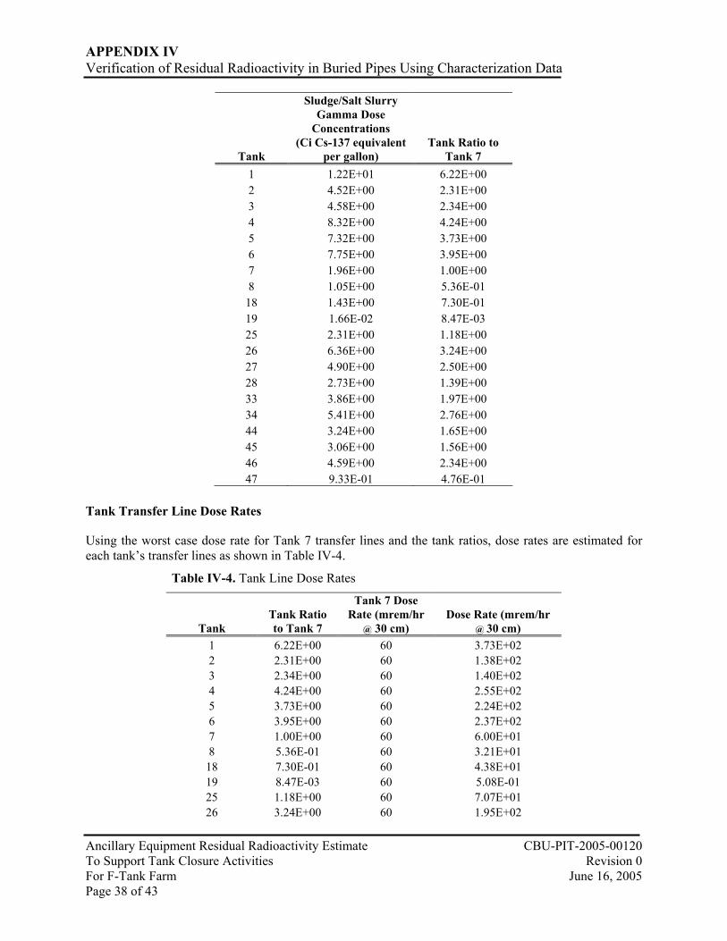
The maximum dose rate of 60 mrem at 30 cm for the Tank 7 transfer line tie-in on January 28, 2002, (from Survey No. 755 of O’Bryant, 2005a) will be used as worst case. Tank Concentrations
Worst case F Tank Farm transfer line residual has been determined to be sludge. The F Tank Farm Tank Concentrations for sludge are taken from the High Level Waste Emergency Response Data and Waste Tank Data (2005) and are summarized in the table below. In addition, the individual tank concentrations are ascertained by taking a ratio to the Tank 7 concentration as shown.
Table IV-3. Tank Ratios
APPENDIX IV Verification of Residual Radioactivity in Buried Pipes Using Characterization Data
Ancillary Equipment Residual Radioactivity Estimate CBU-PIT-2005-00120 To Support Tank Closure Activities Revision 0 For F-Tank Farm June 16, 2005 Page 38 of 43
Tank
Sludge/Salt Slurry Gamma Dose
Concentrations (Ci Cs-137 equivalent
per gallon) Tank Ratio to
Tank 7 1 1.22E+01 6.22E+00 2 4.52E+00 2.31E+00 3 4.58E+00 2.34E+00 4 8.32E+00 4.24E+00 5 7.32E+00 3.73E+00 6 7.75E+00 3.95E+00 7 1.96E+00 1.00E+00 8 1.05E+00 5.36E-01
18 1.43E+00 7.30E-01 19 1.66E-02 8.47E-03 25 2.31E+00 1.18E+00 26 6.36E+00 3.24E+00 27 4.90E+00 2.50E+00 28 2.73E+00 1.39E+00 33 3.86E+00 1.97E+00 34 5.41E+00 2.76E+00 44 3.24E+00 1.65E+00 45 3.06E+00 1.56E+00 46 4.59E+00 2.34E+00 47 9.33E-01 4.76E-01
Tank Transfer Line Dose Rates
Using the worst case dose rate for Tank 7 transfer lines and the tank ratios, dose rates are estimated for each tank’s transfer lines as shown in Table IV-4.
Table IV-4. Tank Line Dose Rates (Continued)
Tank Tank Ratio to Tank 7
Tank 7 Dose Rate (mrem/hr
@ 30 cm) Dose Rate (mrem/hr
@ 30 cm) 1 6.22E+00 60 3.73E+02 2 2.31E+00 60 1.38E+02 3 2.34E+00 60 1.40E+02 4 4.24E+00 60 2.55E+02 5 3.73E+00 60 2.24E+02 6 3.95E+00 60 2.37E+02 7 1.00E+00 60 6.00E+01 8 5.36E-01 60 3.21E+01
18 7.30E-01 60 4.38E+01 19 8.47E-03 60 5.08E-01 25 1.18E+00 60 7.07E+01 26 3.24E+00 60 1.95E+02

APPENDIX IV Verification of Residual Radioactivity in Buried Pipes Using Characterization Data
Ancillary Equipment Residual Radioactivity Estimate CBU-PIT-2005-00120 To Support Tank Closure Activities Revision 0 For F-Tank Farm June 16, 2005 Page 39 of 43
Table IV-4. Tank Line Dose Rates (Continued)
Tank Tank Ratio to Tank 7
Tank 7 Dose Rate (mrem/hr
@ 30 cm) Dose Rate (mrem/hr
@ 30 cm) 27 2.50E+00 60 1.50E+02 28 1.39E+00 60 8.36E+01 33 1.97E+00 60 1.18E+02 34 2.76E+00 60 1.66E+02 44 1.65E+00 60 9.92E+01 45 1.56E+00 60 9.37E+01 46 2.34E+00 60 1.41E+02 47 4.76E-01 60 2.86E+01
The dose rates for each tank will be used in determining, the curies of Cs-137 for each line. Transfer Line Dose-to-Curie (DTC)
The F Tank Farm Transfer lines consist of carbon steel and stainless steel lines of various sizes. Site software SRS-DTC-3.10 by WMG, Inc (1998) was used to estimate the dose to curie conversion (DTC) factor. Each line was modeled as a hollow cylinder, using the core radius as the inner radius and the jacket radius as the outer radius. The length of the pipe was modeled as two feet because of the standard detector distance of 30 cm. For conservatism, the source between the core and jacket was assumed to be iron. The source inner (sludge) was assumed to have a specific gravity of 1.2. A summary of the resulting DTC conversion factors are given in the following table.
Table IV-5. Dose to Curie Conversion Factors
Core (in) Jacket (in)
DTC (mrem/hr-Ci
of Cs -137 1 3 9.89E+02 2 3 1.23E+03 2 4 8.50E+02 2 6 4.91E+02 2 8 3.32E+02 2 10 2.45E+02 3 4 1.11E+03 3 6 5.63E+02 3 8 3.60E+02 3 10 2.59E+02 4 6 6.88E+02
Using the DTC conversion factor for a given pipe size with the corresponding Tank Dose Rate will result in curies of Cs-137 for each line.
The following table shows the results of applying the tank dose rates to the lines listed in Appendix III. Note that 1½-inch core diameter lines are depicted in the following table as two-inch lines.
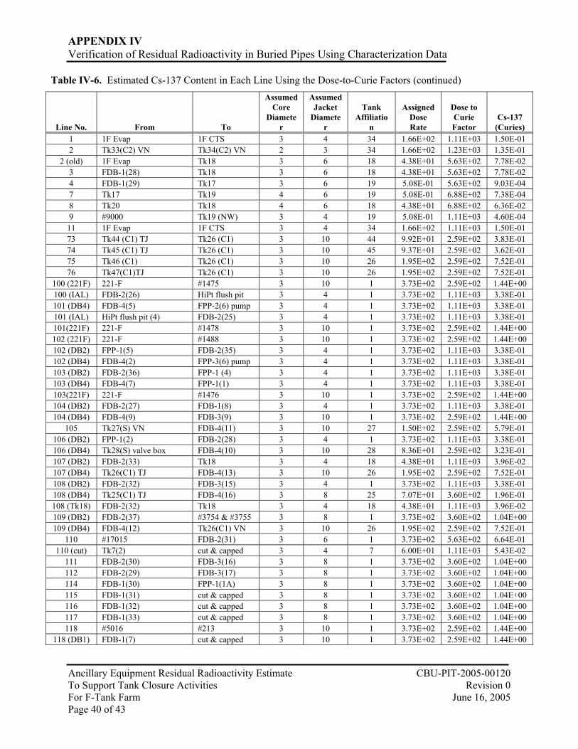
APPENDIX IV Verification of Residual Radioactivity in Buried Pipes Using Characterization Data
Ancillary Equipment Residual Radioactivity Estimate CBU-PIT-2005-00120 To Support Tank Closure Activities Revision 0 For F-Tank Farm June 16, 2005 Page 40 of 43
Table IV-6. Estimated Cs-137 Content in Each Line Using the Dose-to-Curie Factors (continued)
Line No. From To
Assumed Core
Diameter
Assumed Jacket
Diameter
Tank Affiliatio
n
Assigned Dose Rate
Dose to Curie Factor
Cs-137 (Curies)
1 1F Evap 1F CTS 3 4 34 1.66E+02 1.11E+03 1.50E-01 2 Tk33(C2) VN Tk34(C2) VN 2 3 34 1.66E+02 1.23E+03 1.35E-01
2 (old) 1F Evap Tk18 3 6 18 4.38E+01 5.63E+02 7.78E-02 3 FDB-1(28) Tk18 3 6 18 4.38E+01 5.63E+02 7.78E-02 4 FDB-1(29) Tk17 3 6 19 5.08E-01 5.63E+02 9.03E-04 7 Tk17 Tk19 4 6 19 5.08E-01 6.88E+02 7.38E-04 8 Tk20 Tk18 4 6 18 4.38E+01 6.88E+02 6.36E-02 9 #9000 Tk19 (NW) 3 4 19 5.08E-01 1.11E+03 4.60E-04 11 1F Evap 1F CTS 3 4 34 1.66E+02 1.11E+03 1.50E-01 73 Tk44 (C1) TJ Tk26 (C1) 3 10 44 9.92E+01 2.59E+02 3.83E-01 74 Tk45 (C1) TJ Tk26 (C1) 3 10 45 9.37E+01 2.59E+02 3.62E-01 75 Tk46 (C1) Tk26 (C1) 3 10 26 1.95E+02 2.59E+02 7.52E-01 76 Tk47(C1)TJ Tk26 (C1) 3 10 26 1.95E+02 2.59E+02 7.52E-01
100 (221F) 221-F #1475 3 10 1 3.73E+02 2.59E+02 1.44E+00 100 (IAL) FDB-2(26) HiPt flush pit 3 4 1 3.73E+02 1.11E+03 3.38E-01 101 (DB4) FDB-4(5) FPP-2(6) pump 3 4 1 3.73E+02 1.11E+03 3.38E-01 101 (IAL) HiPt flush pit (4) FDB-2(25) 3 4 1 3.73E+02 1.11E+03 3.38E-01 101(221F) 221-F #1478 3 10 1 3.73E+02 2.59E+02 1.44E+00 102 (221F) 221-F #1488 3 10 1 3.73E+02 2.59E+02 1.44E+00 102 (DB2) FPP-1(5) FDB-2(35) 3 4 1 3.73E+02 1.11E+03 3.38E-01 102 (DB4) FDB-4(2) FPP-3(6) pump 3 4 1 3.73E+02 1.11E+03 3.38E-01 103 (DB2) FDB-2(36) FPP-1 (4) 3 4 1 3.73E+02 1.11E+03 3.38E-01 103 (DB4) FDB-4(7) FPP-1(1) 3 4 1 3.73E+02 1.11E+03 3.38E-01 103(221F) 221-F #1476 3 10 1 3.73E+02 2.59E+02 1.44E+00 104 (DB2) FDB-2(27) FDB-1(8) 3 4 1 3.73E+02 1.11E+03 3.38E-01 104 (DB4) FDB-4(9) FDB-3(9) 3 10 1 3.73E+02 2.59E+02 1.44E+00
105 Tk27(S) VN FDB-4(11) 3 10 27 1.50E+02 2.59E+02 5.79E-01 106 (DB2) FPP-1(2) FDB-2(28) 3 4 1 3.73E+02 1.11E+03 3.38E-01 106 (DB4) Tk28(S) valve box FDB-4(10) 3 10 28 8.36E+01 2.59E+02 3.23E-01 107 (DB2) FDB-2(33) Tk18 3 4 18 4.38E+01 1.11E+03 3.96E-02 107 (DB4) Tk26(C1) TJ FDB-4(13) 3 10 26 1.95E+02 2.59E+02 7.52E-01 108 (DB2) FDB-2(32) FDB-3(15) 3 4 1 3.73E+02 1.11E+03 3.38E-01 108 (DB4) Tk25(C1) TJ FDB-4(16) 3 8 25 7.07E+01 3.60E+02 1.96E-01 108 (Tk18) FDB-2(32) Tk18 3 4 18 4.38E+01 1.11E+03 3.96E-02 109 (DB2) FDB-2(37) #3754 & #3755 3 8 1 3.73E+02 3.60E+02 1.04E+00 109 (DB4) FDB-4(12) Tk26(C1) VN 3 10 26 1.95E+02 2.59E+02 7.52E-01
110 #17015 FDB-2(31) 3 6 1 3.73E+02 5.63E+02 6.64E-01 110 (cut) Tk7(2) cut & capped 3 4 7 6.00E+01 1.11E+03 5.43E-02
111 FDB-2(30) FDB-3(16) 3 8 1 3.73E+02 3.60E+02 1.04E+00 112 FDB-2(29) FDB-3(17) 3 8 1 3.73E+02 3.60E+02 1.04E+00 114 FDB-1(30) FPP-1(1A) 3 8 1 3.73E+02 3.60E+02 1.04E+00 115 FDB-1(31) cut & capped 3 8 1 3.73E+02 3.60E+02 1.04E+00 116 FDB-1(32) cut & capped 3 8 1 3.73E+02 3.60E+02 1.04E+00 117 FDB-1(33) cut & capped 3 8 1 3.73E+02 3.60E+02 1.04E+00 118 #5016 #213 3 10 1 3.73E+02 2.59E+02 1.44E+00
118 (DB1) FDB-1(7) cut & capped 3 10 1 3.73E+02 2.59E+02 1.44E+00

APPENDIX IV Verification of Residual Radioactivity in Buried Pipes Using Characterization Data
Ancillary Equipment Residual Radioactivity Estimate CBU-PIT-2005-00120 To Support Tank Closure Activities Revision 0 For F-Tank Farm June 16, 2005 Page 41 of 43
Table IV-6. Estimated Cs-137 Content in Each Line Using the Dose-to-Curie Factors (continued)
Line No. From To
Assumed Core
Diameter
Assumed Jacket
Diameter
Tank Affiliatio
n
Assigned Dose Rate
Dose to Curie Factor
Cs-137 (Curies)
151 (DB3) Tk33(NW)VN FDB-3(4) 3 8 33 1.18E+02 3.60E+02 3.28E-01 151 (DB4) FPP-2(5) pump out FDB-4(6) 3 4 1 3.73E+02 1.11E+03 3.38E-01 152 (DB3) FDB-3(3) Tk33(NW)VN 3 8 33 1.18E+02 3.60E+02 3.28E-01 152 (DB4) FPP-2(7) TJ FDB-4(4) 3 4 1 3.73E+02 1.11E+03 3.38E-01
156 Tk34 (C1) VN FDB-3(2) 3 8 34 1.66E+02 3.60E+02 4.60E-01 157 FDB-3(1) Tk34 (C1) VN 3 8 34 1.66E+02 3.60E+02 4.60E-01 161 FDB-3 sump FDB-2 sump 2 4 1 3.73E+02 8.50E+02 4.40E-01
176 (old) 1F Evap Tk18 (SW) 3 6 18 4.38E+01 5.63E+02 7.78E-02 176A 1F CTS Tk7 3 4 7 6.00E+01 1.11E+03 5.43E-02 176B Tk7 1F Evap 3 4 7 6.00E+01 1.11E+03 5.43E-02
177 (old) 1F Evap Tk18 (SW) 3 6 18 4.38E+01 5.63E+02 7.78E-02 177A 1F CTS Tk7 3 4 7 6.00E+01 1.11E+03 5.43E-02 177B 1F Evap Tk18 (SW) 3 6 18 4.38E+01 5.63E+02 7.78E-02 201 FPP-3(5) pump out FDB-4(3) 3 4 1 3.73E+02 1.11E+03 3.38E-01 202 FPP-3(7) TJ FDB-4(1) 3 4 1 3.73E+02 1.11E+03 3.38E-01 210 Tk4(6)TJ #3752 3 10 4 2.55E+02 2.59E+02 9.83E-01 211 Tk3(5) TJ Tk7(6) VN 3 10 3 1.40E+02 2.59E+02 5.41E-01 212 Tk2(3)TJ Tk7(6) VN 3 10 2 1.38E+02 2.59E+02 5.34E-01 213 #118 Tk7(6) VN 3 10 7 6.00E+01 2.59E+02 2.32E-01
213 (Tk1) Tk1(3)TJ cut & capped 3 10 1 3.73E+02 2.59E+02 1.44E+00 213 (DB2) #109 (DB2) cut & capped 3 4 1 3.73E+02 1.11E+03 3.38E-01
301 1F CTS Tk1-4 loop line 2 6 1 3.73E+02 4.91E+02 7.61E-01 302 Tk18 1F CTS 2 4 18 4.38E+01 8.50E+02 5.15E-02
302 (old) 1F Evap Tk18 (SE) 2 4 18 4.38E+01 8.50E+02 5.15E-02 303 1F Evap 1F CTS 2 4 18 4.38E+01 8.50E+02 5.15E-02 304 Tk18 1F CTS 3 4 18 4.38E+01 1.11E+03 3.96E-02 397 Tk25(C1) TJ Tk26(S) 3 8 26 1.95E+02 3.60E+02 5.40E-01 497 Tk27(C1) TJ Tk26(S) 3 10 26 1.95E+02 2.59E+02 7.52E-01 515 16030 #3754 3 6 1 3.73E+02 5.63E+02 6.64E-01 520 Tk5(6) #3751 3 6 5 2.24E+02 5.63E+02 3.98E-01 521 Tk6(6) #3753 3 6 6 2.37E+02 5.63E+02 4.22E-01 547 Tk28(C1) valve box Tk26(S) 3 10 26 1.95E+02 2.59E+02 7.52E-01 960 Tk25(C2) VN Tk26(C2)VN 2 6 26 1.95E+02 4.91E+02 3.97E-01 1012 Tk26(R2) VN 242-16F Evap. 1 3 26 1.95E+02 9.89E+02 1.97E-01 1013 Tk26(C2) VN Tk27(C2) VN 2 6 26 1.95E+02 4.91E+02 3.97E-01 1040 Tk26(R1) VN FDB-6(4) 3 6 26 1.95E+02 5.63E+02 3.46E-01 1054 Tk27(C2) VN Tk28(C2) VN 2 6 27 1.50E+02 4.91E+02 3.06E-01 1104 Tk28(C2) VN FDB-5(9) 2 10 28 8.36E+01 2.45E+02 3.41E-01 1209 3-valve box W328-15-3 Tk28 TTJ 3 6 28 8.36E+01 5.63E+02 1.48E-01 1377 242-16F evaporator (24) Tk26(C3) VN 2 6 26 1.95E+02 4.91E+02 3.97E-01 1378 242-16F evaporator (23) Tk25(C3) VN 2 6 25 7.07E+01 4.91E+02 1.44E-01 1379 242-16F evaporator (10) Tk27(C3) VN 2 6 27 1.50E+02 4.91E+02 3.06E-01 1380 242-16F evaporator (11) Tk28(C3) VN 2 6 28 8.36E+01 4.91E+02 1.70E-01 1383 242-16F evaporator (22) Tk44(C3) VN 2 6 44 9.92E+01 4.91E+02 2.02E-01 1384 242-16F evaporator (21) Tk45(C3) VN 2 6 45 9.37E+01 4.91E+02 1.91E-01 1385 242-16F evaporator (13) Tk46(C3) VN 2 6 46 1.41E+02 4.91E+02 2.86E-01

APPENDIX IV Verification of Residual Radioactivity in Buried Pipes Using Characterization Data
Ancillary Equipment Residual Radioactivity Estimate CBU-PIT-2005-00120 To Support Tank Closure Activities Revision 0 For F-Tank Farm June 16, 2005 Page 42 of 43
Table IV-6. Estimated Cs-137 Content in Each Line Using the Dose-to-Curie Factors (continued)
Line No. From To
Assumed Core
Diameter
Assumed Jacket
Diameter
Tank Affiliatio
n
Assigned Dose Rate
Dose to Curie Factor
Cs-137 (Curies)
1386 242-16F evaporator (12) Tk47(C3) VN 2 6 47 2.86E+01 4.91E+02 5.82E-02 1408 242-16F Evap. Tk27(M) CRC 2 6 27 1.50E+02 4.91E+02 3.06E-01 1414 Tk27(M) CRC 242-16F Evap. 2 6 27 1.50E+02 4.91E+02 3.06E-01 1461 Tk44(C1) TJ FDB-4(20) 3 10 44 9.92E+01 2.59E+02 3.83E-01 1462 Tk45(C1) TJ FDB-4(19) 3 10 45 9.37E+01 2.59E+02 3.62E-01 1467 Tk46(C1) VN FDB-4(18) 3 10 46 1.41E+02 2.59E+02 5.43E-01 1468 Tk47 (C1) FDB-4(17) 3 10 47 2.86E+01 2.59E+02 1.10E-01 1472 FDB-3(10) FDB-4(8) 3 10 1 3.73E+02 2.59E+02 1.44E+00 1475 #100 (221F) FPP-3(1) 3 6 1 3.73E+02 5.63E+02 6.64E-01 1476 #103 (221F) FPP-3(2) 3 10 1 3.73E+02 2.59E+02 1.44E+00 1478 #101 (221F) FPP-2(1) 3 10 1 3.73E+02 2.59E+02 1.44E+00 1488 #102 (221F) FPP-2(2) 3 6 1 3.73E+02 5.63E+02 6.64E-01 3260 FDB-6 sump FPP-3(3A) 3 6 1 3.73E+02 5.63E+02 6.64E-01 3261 Tk33(C2) VN FDB-5 (3) 2 6 33 1.18E+02 4.91E+02 2.41E-01 3265 FDB-5(1) F-CTS 242-3F 2 8 1 3.73E+02 3.32E+02 1.13E+00
3265-B 1F CTS Tk33-34 2 8 34 1.66E+02 3.32E+02 4.99E-01 3266 242-F Evap. FDB-6(5) 3 6 1 3.73E+02 5.63E+02 6.64E-01 3267 Tk7 (1) VN FDB-6(1) 3 6 7 6.00E+01 5.63E+02 1.07E-01 3273 Tk25(C2) VN FDB-5(10) 2 6 25 7.07E+01 4.91E+02 1.44E-01 3274 FDB-5 Waste drain FPP-2(3) 3 6 1 3.73E+02 5.63E+02 6.64E-01 3275 F-CTS 242-3F FDB-5(2) 2 8 1 3.73E+02 3.32E+02 1.13E+00
3275-B 1F CTS Tk33-34 2 8 34 1.66E+02 3.32E+02 4.99E-01 3276 Tk34 (C2) VN FDB-5(4) 2 6 34 1.66E+02 4.91E+02 3.37E-01 3277 FDB-6(6) 242-F Evap. 3 6 1 3.73E+02 5.63E+02 6.64E-01 3278 FDB-6(2) Tk7(1) VN 3 6 7 6.00E+01 5.63E+02 1.07E-01 3751 #520 #3754 3 6 1 3.73E+02 5.63E+02 6.64E-01 3752 #210 #3754 3 6 1 3.73E+02 5.63E+02 6.64E-01 3753 #521 #3754 3 6 1 3.73E+02 5.63E+02 6.64E-01 3754 #515 #109 & #3755 3 6 1 3.73E+02 5.63E+02 6.64E-01 3755 #109 & #3754 #103 3 6 1 3.73E+02 5.63E+02 6.64E-01 4878 Tk17 (R) TTP Tk18(W) 3 4 18 4.38E+01 1.11E+03 3.96E-02 5016 Tk18 (NE) TTP #118 3 4 18 4.38E+01 1.11E+03 3.96E-02 9000 #9001 #9 2 3 1 3.73E+02 1.23E+03 3.04E-01 9001 Tank 18 (W) #9000 3 4 18 4.38E+01 1.11E+03 3.96E-02 9852 Tk20(NW) Valve box Tk18 4 6 18 4.38E+01 6.88E+02 6.36E-02
16030 Tank 8 (6) #515 3 4 8 3.21E+01 1.11E+03 2.91E-02 16075 Tank 8 (6) LDB-17 3 4 8 3.21E+01 1.11E+03 2.91E-02 16076 LDB-17 #515 3 4 1 3.73E+02 1.11E+03 3.38E-01 17015 Tk7(4) TTP #110 3 6 7 6.00E+01 5.63E+02 1.07E-01 GDL 1F Evap Tk17-20 3 10 18 4.38E+01 2.59E+02 1.69E-01
Misc-1 Tk19 Tk18 3 4 18 4.38E+01 1.11E+03 3.96E-02 Misc-2 Tk17 Tk18 3 4 18 4.38E+01 1.11E+03 3.96E-02

APPENDIX IV Verification of Residual Radioactivity in Buried Pipes Using Characterization Data
Ancillary Equipment Residual Radioactivity Estimate CBU-PIT-2005-00120 To Support Tank Closure Activities Revision 0 For F-Tank Farm June 16, 2005 Page 43 of 43
A summary for each isotope is listed in the following table
Table IV-7. Isotopic Inventory F-Tank via Waste Characterization from Surveys (continued)
Isotope Curies Isotope Curies Isotope Curies H-3 3.24E+00 Cs-134 2.42E-02 Np-237 1.04E-03 C-14 1.93E-03 Cs-135 2.14E-04 Np-239 3.71E-02
Co-60 2.06E+01 Cs-137 6.71E+01 Pu-238 1.27E+00 Ni-59 2.66E-02 Ba-137m 6.35E+01 Pu-239 3.17E-01 Ni-63 6.80E-05 Ce-144 2.65E-02 Pu-240 5.51E-01 Se-79 1.85E-02 Pr-144 2.65E-02 Pu-241 1.23E+00 Sr-90 9.14E+02 Pm-147 5.94E+01 Pu-242 1.31E-02 Y-90 9.14E+02 Eu-154 4.21E+00 Am-241 1.14E+01 Tc-99 3.20E-01 U-232 1.60E-05 Am-242m 1.51E-02
Ru-106 8.45E-02 U-233 7.93E-04 Am-243 3.71E-02 Rh-106 8.45E-02 U-234 1.76E-03 Cm-244 3.33E-01 Sb-125 3.32E+00 U-235 2.90E-05 Cm-245 1.53E-04 Sn-126 3.43E-02 U-236 1.23E-05 Cm-246 5.08E-04 I-129 2.03E-04 U-238 1.34E-03 Cm-247 2.48E-09
Related Documents


