CBI All In One UPS Power Solutions CBI All In One UPS Power Solutions combine the requirements for several applications in just one device which can be used as power supply unit, battery charger, battery care module or backup module. The available power is automatically distributed among load and battery, while supplying power to the load always is the first priority. The maximum available current of the load output is two times the value of the device’s rated current. If the device is disconnected from the main power source, the battery will supply the load until the battery voltage reaches 1.5 V per cell. This prevents the battery from deep discharge. CBI devices provide microprocessor controlled battery charging. Using algorithms, the battery’s condition will be detected and based on that, an appropriate charging mode is chosen. The real-time diagnostics system will continuously monitor the charging progress and indicate possibly occurring faults such as elements in short circuit, accidental reverse polarity connection or disconnection of the battery by the battery fault LED and a flashing code of the diagnosis LED. CBI All In One UPS Power Solutions are suitable for open/sealed lead acid-, lead gel- and optionally Ni-Cd batteries. By using the battery-select-jumper, it is possible to set predefined charging curves for those battery types. The available charging options are recovery-, boost- and trickle charge.All CB devices are built in a rugged metal case with a DIN rail mounting bracket. • Nominal Input Voltage 115-230-277VAC • Output Voltage 12VDC • Output Current 3, 6, 10, 35A • Adjustable Charging Current 20%-100% of Output Current • Working temperature: -25°C to 70°C • EMC standards: IEC/EN 60335-2-29 Battery chargers; EN60950 / UL1950 Electrical safety; EN54-4 Fire Detection and fire alarm systems; 89/336/EEC EMC Directive; 2006/95/EC (Low Voltage); DIN41773 (Charging cycle); Emission : IEC 61000-6-4; Immunity: IEC 61000-6-2. CE • Nominal Input Voltage 115-230-277VAC • Output Voltage 24VDC • Output Current 3, 5, 10, 20A • Adjustable Charging Current 20%-100% of Output Current • Working temperature: -25°C to 70°C • EMC standards: IEC/EN 60335-2-29 Battery chargers; EN60950 / UL1950 Electrical safety; EN54-4 Fire Detection and fire alarm systems; 89/336/EEC EMC Directive; 2006/95/EC (Low Voltage); DIN41773 (Charging cycle); Emission : IEC 61000-6- 4; Immunity: IEC 61000-6-2. CE • Nominal Input Voltage 115-230-277VAC • Output Voltage 48VDC • Output Current 5, 10A • Adjustable Charging Current 20%-100% of Output Current • Working temperature: -25°C to 70°C • EMC standards: IEC/EN 60335-2-29 Battery chargers; EN60950 / UL1950 Electrical safety; EN54-4 Fire Detection and fire alarm systems; 89/336/EEC EMC Directive; 2006/95/EC (Low Voltage); DIN41773 (Charging cycle); Emission : IEC 61000-6- 4; Immunity: IEC 61000-6-2. CE

Welcome message from author
This document is posted to help you gain knowledge. Please leave a comment to let me know what you think about it! Share it to your friends and learn new things together.
Transcript

CBI All In One UPS Power SolutionsCBI All In One UPS Power Solutions combine the requirements for several applications in just one devicewhich can be used as power supply unit, battery charger, battery care module or backup module. Theavailable power is automatically distributed among load and battery, while supplying power to the loadalways is the first priority. The maximum available current of the load output is two times the value ofthe device’s rated current.
If the device is disconnected from the main power source, the battery will supply the load until thebattery voltage reaches 1.5 V per cell. This prevents the battery from deep discharge. CBI devicesprovide microprocessor controlled battery charging. Using algorithms, the battery’s condition will bedetected and based on that, an appropriate charging mode is chosen. The real-time diagnostics systemwill continuously monitor the charging progress and indicate possibly occurring faults such as elementsin short circuit, accidental reverse polarity connection or disconnection of the battery by the battery faultLED and a flashing code of the diagnosis LED. CBI All In One UPS Power Solutions are suitable foropen/sealed lead acid-, lead gel- and optionally Ni-Cd batteries. By using the battery-select-jumper, it ispossible to set predefined charging curves for those battery types. The available charging options arerecovery-, boost- and trickle charge.All CB devices are built in a rugged metal case with a DIN railmounting bracket.
• Nominal Input Voltage 115-230-277VAC• Output Voltage 12VDC• Output Current 3, 6, 10, 35A• Adjustable Charging Current 20%-100% of Output Current• Working temperature: -25°C to 70°C• EMC standards: IEC/EN 60335-2-29 Battery chargers; EN60950 /
UL1950 Electrical safety; EN54-4 Fire Detection and fire alarm systems; 89/336/EEC EMC Directive; 2006/95/EC (Low Voltage); DIN41773 (Charging cycle); Emission : IEC 61000-6-4; Immunity: IEC 61000-6-2. CE
• Nominal Input Voltage 115-230-277VAC• Output Voltage 24VDC• Output Current 3, 5, 10, 20A• Adjustable Charging Current 20%-100% of Output Current• Working temperature: -25°C to 70°C• EMC standards: IEC/EN 60335-2-29 Battery chargers; EN60950 / UL1950
Electrical safety; EN54-4 Fire Detection and fire alarm systems; 89/336/EEC EMC Directive; 2006/95/EC (Low Voltage); DIN41773 (Charging cycle); Emission : IEC 61000-6-4; Immunity: IEC 61000-6-2. CE
• Nominal Input Voltage 115-230-277VAC• Output Voltage 48VDC• Output Current 5, 10A• Adjustable Charging Current 20%-100% of Output Current• Working temperature: -25°C to 70°C• EMC standards: IEC/EN 60335-2-29 Battery chargers; EN60950 / UL1950
Electrical safety; EN54-4 Fire Detection and fire alarm systems; 89/336/EEC EMC Directive; 2006/95/EC (Low Voltage); DIN41773 (Charging cycle); Emission : IEC 61000-6-4; Immunity: IEC 61000-6-2. CE
Via Luigi Barchi 9/B – Reggio Emilia 42124 – Italy Tel. +39 0522 345518 – Fax +39 0522 345551 – mail: [email protected] www.adelsystem.com Instruction Manual All In One_r17.doc
Pag
e 1
- C
hap
ter:
All
In O
ne:
Unin
terr
uptible
Pow
er
Supp
ly O
utp
ut V
dc
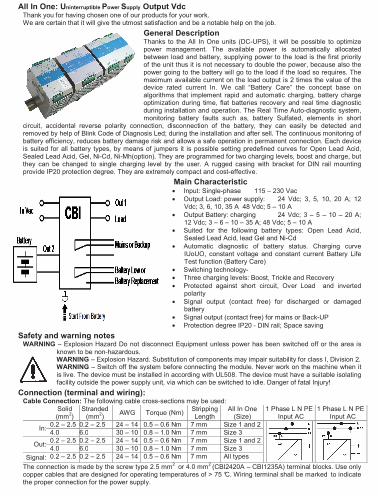
All In One: Uninterruptible Power Supply Output VdcThank you for having chosen one of our products for your work. We are certain that it will give the utmost satisfaction and be a notable help on the job.
General Description Thanks to the All In One units (DC-UPS), it will be possible to optimize power management. The available power is automatically allocated between load and battery, supplying power to the load is the first priority of the unit thus it is not necessary to double the power, because also the power going to the battery will go to the load if the load so requires. The maximum available current on the load output is 2 times the value of the device rated current In. We call “Battery Care” the concept base on algorithms that implement rapid and automatic charging, battery charge optimization during time, flat batteries recovery and real time diagnostic during installation and operation. The Real Time Auto-diagnostic system, monitoring battery faults such as, battery Sulfated, elements in short
circuit, accidental reverse polarity connection, disconnection of the battery, they can easily be detected and removed by help of Blink Code of Diagnosis Led; during the installation and after sell. The continuous monitoring of battery efficiency, reduces battery damage risk and allows a safe operation in permanent connection. Each device is suited for all battery types, by means of jumpers it is possible setting predefined curves for Open Lead Acid, Sealed Lead Acid, Gel, Ni-Cd, Ni-Mh(option). They are programmed for two charging levels, boost and charge, but they can be changed to single charging level by the user. A rugged casing with bracket for DIN rail mounting provide IP20 protection degree. They are extremely compact and cost-effective.
Main Characteristic • Input: Single-phase 115 – 230 Vac
• Output Load: power supply: 24 Vdc; 3, 5, 10, 20 A; 12 Vdc; 3, 6, 10, 35 A 48 Vdc; 5 – 10 A
• Output Battery: charging 24 Vdc; 3 – 5 – 10 – 20 A; 12 Vdc; 3 – 6 – 10 – 35 A; 48 Vdc; 5 – 10 A
• Suited for the following battery types: Open Lead Acid, Sealed Lead Acid, lead Gel and Ni-Cd
• Automatic diagnostic of battery status. Charging curve IUoUO, constant voltage and constant current Battery Life Test function (Battery Care)
• Switching technology-
• Three charging levels: Boost, Trickle and Recovery
• Protected against short circuit, Over Load and inverted polarity
• Signal output (contact free) for discharged or damaged battery
• Signal output (contact free) for mains or Back-UP
• Protection degree IP20 - DIN rail; Space saving
Safety and warning notes WARNING – Explosion Hazard Do not disconnect Equipment unless power has been switched off or the area is
known to be non-hazardous. WARNING – Explosion Hazard. Substitution of components may impair suitability for class I, Division 2. WARNING – Switch off the system before connecting the module. Never work on the machine when it
is live. The device must be installed in according with UL508. The device must have a suitable isolating facility outside the power supply unit, via which can be switched to idle. Danger of fatal Injury!
Connection (terminal and wiring): Cable Connection: The following cable cross-sections may be used:
Solid (mm
2)
Stranded (mm
2)
AWG Torque (Nm) Stripping Length
All In One (Size)
1 Phase L N PEInput AC
1 Phase L N PEInput AC
0.2 – 2.5 0.2 – 2.5 24 – 14 0.5 – 0.6 Nm 7 mm Size 1 and 2In:
4.0 6.0 30 – 10 0.8 – 1.0 Nm 7 mm Size 3
0.2 – 2.5 0.2 – 2.5 24 – 14 0.5 – 0.6 Nm 7 mm Size 1 and 2Out:
4.0 6.0 30 – 10 0.8 – 1.0 Nm 7 mm Size 3
Signal: 0.2 – 2.5 0.2 – 2.5 24 – 14 0.5 – 0.6 Nm 7 mm All types
The connection is made by the screw type 2.5 mm2
or 4.0 mm2 (CBI2420A – CBI1235A) terminal blocks. Use only
copper cables that are designed for operating temperatures of > 75 °C. Wiring terminal shall be marked to indicate the proper connection for the power supply.
Pa
ge
3 -
Ch
ap
ter:
Op
era
tin
g a
nd
Dis
pla
y E
lem
en
t:
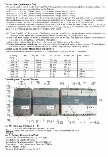
Output Load (Main input ON) The output Load in normal mode, Main Input Vac Voltage present, follow the charging battery dc output voltage. The minimum and maximum range stabilized are the following: - CBI12xx:11 – 14,4 Vdc; (Without battery connected out. Voltage fixed at 12Vdc) - CBI24xx:22 – 28.8 Vdc; (Without battery connected out. Voltage fixed at 24Vdc) - CBI48xx:44 – 57.6 Vdc; (Without battery connected out. Voltage fixed at 48Vdc) Thanks to the All In One units, it will be possible to manage the power. The available power, is automatically allocated between load and battery: supplying power to the load is the first priority of the unit; thus it is not necessary to double the power, and also the power available for the battery will go to the load if the load requires so: in “Power Boost Mode” the maximum current on the load output is the 2 times the rated current 2 x In (Iload = In+ Ibatt) in continuous operation and 3 times the rated current 3 x In (Iload = 2In+ Ibatt) for 4 seconds; after this parameter the devices is electrically protected against overload and short circuit.
- In “Power Boost Mode”, if the current of the battery generate current to the load for a time more than 4 minutes, the device give message (8 Blink), consequently means that the battery it is going to unloading.
- If the Main Input Voltage fall below a Threshold level (50% of the Typ. Vac input) the battery it is immediately connected to the Output Load, without any interruption.
- voltage dips: In this situation the voltage in the output load it is the same of the battery. - To Avoid deep battery discharge, the battery will supply the load until battery voltage reaches 1.5 V/cell. Below
this level the device automatically switches off to prevent Deep discharge and battery damage.
Output Load In Buffer Mode (Main input OFF) Some example of buffering time depending on LOAD Output in function to the Ah of the battery.
Buffering Time
BATT1.2 Ah BATT 3 Ah BATT7.2 Ah BATT12 Ah BATT100 Ah
Load 1.5 A 20 min 60 min 200 min 400 min /
Load 3 A 8 min 30 min 120 min 240 min /
Load 5 A 3 min 15 min 55 min 100 min /
Load 7.5 A 2 min 10 min 30 min 60 min /
Load 10 A No 7 min 20 min 45 min 20 h
Load 12 A No 3 min 12 min 30 min 600 min
Load 15 A No No 9 min 20 min 400 min
Load 20 A No No 7 min 13 min 240 min
Operating and Display Element:
No. 10: Input AC Port pin. L – N: 1 Phase Switching Power Supplies L, N, PE . Size 2 and Size 3 BRIDGE ONLY for input 115 Vac, and connect L, N, PE .
No. 3: Battery Connection Port: Connect the battery between pin. 3 (–) and 4 (+) One battery (12 Vdc) for CBI12xx; Two battery (12 Vdc) connected in Series for CBI24xx; Four battery (12 Vdc) connected in Series for CBI48xx;
No. 4: Output Load: Connect this Output to the load 1 (-). 2 (+).
3
4
5
6
7
8
10
11
2 1
12
9
13 14
Size 1 Size 2 Size 3
1112
1210 10 3
4 4 3
11 9
15
Pa
ge
5 -
Ch
ap
ter:
Op
era
tin
g a
nd
Dis
pla
y E
lem
en
t:
No. 12: Battery Management Configurations Preliminary Operations: One device for all battery types. Completely automatic, all devices are suitable to charge most batteries types thank to User Selectable charging curves. They can charge open lead acid, sealed lead acid, Gel and Ni-Cd, Ni-MH batteries. It is possible to change or add other charging curves connecting the device to a portable PC. Caution: Switch off the system before Setting the jumper. Only jumper in position 5 Refresh ON/OFF state whit Power.
Battery Type Selection
Jumper Position (Size 1 and Size 3)
Jumper Position (Size 2)
Trickle/Float charge (Volt/Cell)
Fast/Bulk charge (Volt/Cell)
Open Lead 2.23 2.40
Sealed Lead Low 2.25 2.40
Sealed Lead High 2.27 2.40
Gel Battery 2.30 2.40
Gel Battery (1) 2.30 2.40
NiCd – NiMh (1) 10% Imax Trimmer 1.70–(12V);1.5–
(24V)
Functional Setting Function
Battery Life test ON Jumper present: Life test enabled.
Fast Charge Enable Jumper present: fast charge enabled.
“Battery Start” (without Input Main)
(2)
RTCONN cable for connection to external Push bottom mounted on front Panel of the external system.
Fast Recovery Charge (3)
Not available
Jumper present: Fast Recovery Charge, enabled only for Size 3. Possibility to recharge the battery also when the voltage is close to Zero with the maximum power of the device. To be careful, the Load Output voltage follow the voltage of the battery.
Notice: 1 Be care full, in NiCd-NiMh Option, the Sealed Lead High charging curve is deleted.
NiCd-NiMh (Options to be defined by Order). End-of-charge determined by negative ∆V detection of battery
voltage (-5mV/cell). If no negative ∆V but only a “flat” profile is detected fast charge is terminated after 10 min. General end-of-charge timeout set to 16 hours. Trickle charge current is regulated at 10% of max current
corresponding to trimmer position. In order to detect end-of-charge negative ∆V, charging current must be set at
least at 30% of nominal battery capacity (0,3 C); with lower values of charging current negative ∆V detection is not guaranteed.
2 Don’t leave the juper in position 5; penalty discharge in Back up mode completely the battery close to Zero. For Size 2: must be require CBI2410A/S or CBI485A/S ( /S means start with battery functions, otherwise only start with Input Main)
3 Jumper selection n.7 is available only on CBI 420W and 480W (Size 3)
No. 5: Charging Level Current:
It is possible set the max recharging current for the batteries by trimmer (Charging Level). The current adjustment goes from 20% ÷ 100% of In. Set the maximum charging current between 10% and 20% of the battery capacity.
No. 11: Auxiliary Output RJ 45 behind the label in SIZE 1 and SIZE 3; remove the window label to find the connector, For SIZE 2: CBI2410 and CBI485 require /ARJ code for RJ45 connector. It is possible connect:
• Temperature sensor, for ambient temperature charging compensation. With this it is possible to active the
specifications of the EN54-4 firing norm.
• Connection for external display to remote N° 3 led of the internal device.
Pa
ge
7 -
Ch
ap
ter:
Pro
tectio
n F
ea
ture
s
Charging Curve Automatic multi-stage operation and real time diagnostic allows fast recharge and recovery of deep discharged batteries, adding value and reliability to the system hosting the CBI device. The type of charging is Voltages stabilized and Current stabilized IUoUo. Three charging modes are identified by a flashing code on a Diagnosis LED. To maintain the Output Load in lower Voltage state, don’t put jumper in position 5, in this case no boost charge but only Float charge.
State Diagnosis LED Battery Fault LED Trickle 1 Blink/sec OFF
Boost 2 Blink/sec OFF Charging Type
Recovery 5 Blink/sec OFF
Compensation Recharges in temperature (For SIZE 2: CBI2410 and CBI485 require /ARJ code)
Connecting to RJ45 Auxiliary Output the cable RJTEMP (supplied separately), the CBI will vary the voltage of battery charging in depending of the temperature:
CBI Model Fast Charge Trickle charge
CBI12xx (12Vdc) -2.5mV/°C -1.5mV/°C
CBI24xx (24Vdc) -5mV/°C -3mV/°C
CBI48xx (48Vdc) -10mV/°C -6mV/°C
The sensor place on cable RJTEMP must be applied on the battery. If the sensor is not connected or if the sensor is defective, the led Low Batt is on and the led Diagnosis continues to show the status of the battery: trickle charge, fast charge or recovery charge.
Protection Features On the primary side: the device is equipped whit an internally fuse. If the internal fuse is activated, it is most probable
that there is a fault in the device. If happen, the device must be checked in the factory.
On the secondary side Battery and load: The device is electrically protected against short circuits and overload. Inversion polarity: the module it is automatically protected against inversion of battery polarity and connection of load
inverted. Over current and output short circuit: the unit limits the output current (see the technical data). Deep discharge : not possible. The unit disconnects the battery when a minimum voltage level is reached.
Pa
ge
2 -
Ch
ap
ter:
Ou
tpu
t P
ow
er
con
ne
ctio
ns:
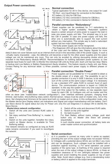
Output Power connections: Normal connection Typical application for All In One device, one output for Load “DC Bus”, one Input/Output for connection to the battery. N°1 battery (12 Vdc) for CBI12xx; N°2 battery (12 Vdc) connected in Series for CBI24x x; N°4 battery (12 Vdc) connected in Series for CBI48x x;
Parallel connection “Redundancy” Power supplies can be paralleled for 1+1 redundancy to obtain a higher system availability. Redundant systems
require a certain amount of extra power to support the load in case one power supply unit fails. The simplest way is to put two CBI in parallel. In case one power supply unit fails, the other one is automatically able to support the load current without any interruption. This simple way to build a redundant system has two major disadvantages: - The faulty power supply can not be recognized.
- The Diagnosis LED will give the informations about the status of the Load and the Battery (see Display Signals for more
data).It does not cover failures such as an internal short circuit in the secondary side of the power supply. In such a -virtually nearly impossible - case, the defective unit becomes a load for the other power supplies and the output voltage can not be maintained any more. This can only be avoided by utilizing decoupling diodes which are included in the Redundancy Module MR220. Recommendations for building redundant power systems: a) Use separate input fuses for each CBI. b) Monitor the individual CBI units by three LED. Each unit has two relay: Mains or backup and Low Battery or Battery Replacement (faulty situation). This feature reports a faulty unit; see Relay Contact Rating for any technical detail. c) When possible, connect each power supply to different phases or circuits.
Parallel connection “Double Power” Power supplies can be paralleled for 1+1=2 parallel to obtain a the double power of a single unit. The possibility to put in parallel connection it is only in SIZE 3 devices, to be reach the sum of the current at the same output voltage. It is necessary to use a standard UTP cable RJ45 to connect Aux2 of each device. The communication protocol is based on CAN2.0A standard. In this way the system have only One output for the Load and One output for the battery. a) Use separate input fuses for each CBI. b) Configure one unit as master and the
other as slave (see “master/slave network configuration”). User interface elements (jumpers, charging level trimmer, start button, time-buffering rotary switch, thermal sensor, relays) must be used on master only, not on the slave. Set charging level trimmers at the same level both on master and on slave. In this configuration mode, only the Master device give Display status Led indications and Signal port output mains/backup and low battery. Don’t use Slave device for signal status but only for Power unit, only the Led Diagnosis it is always ON to identify the Slave Device.
Master/slave network configuration
1. Switch off the units and connect RJ45 cable in Aux 2
2. Set rotary switches“Time Buffering” in, master: 0; slave: 1
3. Switch on the units together; hereafter the rotary switch on Master device, is available for Time Buffering setting.
The network remains so configured as long as RJ45 cable remains connected. If you want to reconfigure the network:
4. Switch off the units and disconnect RJ45 cable; 5. Switch on the units together 6. Go back to point 1. For Start Battery without mains voltage, push start button only on Master (the Slave will powerup sequentially). In such double power connection, all battery tests are under master control and synchronization
Serial connection: a) It is possible to connect as many units in series as needed, providing the sum of the output voltage does not exceed 150Vdc. b) Voltages with a potential above 60Vdc are not SELV any more and can be dangerous. Such voltages must be installed with a protection against touching. c) For serial operation use power supplies of the same type. d) Earthing of the output is required when the sum of the output voltage is above 60Vdc. e) Keep an installation clearance of 10 mm (left/right) between two power supplies and avoid installing the power supplies on top of each other. Note: Avoid return voltage (e.g. from a decelerating motor or battery) which is applied to the output terminals.
Pa
ge
4 -
Ch
ap
ter:
Op
era
tin
g a
nd
Dis
pla
y E
lem
en
t:
No. 1, 2 Signal Ports (output Isolated): Connections for, No. 2: Main/Back Up: Input Main On/Off. Contact: 5,6,7 No. 1: Low Battery, Fault connections systems, Battery replacement. Contact: 8,9,10
Relay Contact Rating: Max.DC1: 30 Vdc 1 A; AC1: 60 Vac 1A : Resistive load (EN 60947-4-1)
Min.1mA at 5 Vdc: Min. permissive load
Signal Output port true table:
Port N°2 - Led N°6 Main/Back-Up
Port N°1 - Led N°6 Fault Battery
5-6 Closed 5-7 Closed 8-9 Closed (OK)
8-10 Closed
ON � - led off � - led off Main Input Vac
OFF � - led On (1) � - led off
YES � - led On � - led On The battery in BackUP it is less than
30% cap? NO � - led On � - led off
YES � - led off � - led On (2) Battery or system Fault? NO � - led off � - led off
Note: (1) For better efficiency of the system, filter relay Main/Back up with a delay of at least 5 seconds before give alarm Main Lost, example: connection to PLC. (2) See Diagnosis Led
No. 6, 7 and 8 Display Signals No.6: Led Main/Back Up: Input Main On/Off No.7: Led Low Battery(capacity less than 30%), Fault connections systems, Battery replacement. No.8: Led Battery charge mode, Led Diagnosis. Diagnosis of the system through “blinking code” signal
Monitoring Control
Chart: State
LED Diagnosis (No.8)
LED Battery Fault (No.7)
Trickle 1 Blink/sec OFF
Boost 2 Blink/sec OFF
Charging Type
Recovery 5 Blink/sec OFF
Reverse polarity or high battery Voltage (over 32.5Vdc for CBI24xxA)
1 Blink/pause ON
Battery No connected 2 Blink/pause ON
Element in Short Circuit 3 Blink/pause ON
Over Load or short circuit on the load 4 Blink/pause ON
Bad battery; Internal impedance Bad or Bad battery wire connection.
5 Blink/pause ON
Life test not possible 6 Blink/pause ON
Bad thermal sensor 7 Blink/pause ON
Boost condition; battery discharge after 4 min. of overload. 8 Blink/pause ON
Internal fault 9 Blink/pause ON
Low battery (under 18.5Vdc for CBI24xxA) Only if started from battery, no Main input. Form Jumper N°5 or Pus h Bottom
10 Blink/pause ON
CAN bus error 11 Blink/pause
Life test not possible; Parallel mode on Slave Device 12 Blink/pause
Bad battery wire connection; Parallel mode on Slave Device
13 Blink/pause
Auto diagnosis
of the system
Boost condition; battery discharge after 4 min. of overload; Parallel mode on Slave Device
15 Blink/pause
No. 9, 12: Start from Battery, No Main Vac No. 9: Push-bottom, for 3 sec., in the front panel for switch ON the system without the “Main input Vac” but only the battery connected. ( Not present in CBI2410XX and CBI485XX) No.12: (Jumper n.5) It is also available the same function for remote start from the battery, via RTCONN cable connected in the Push bottom mounted on front Panel of the external system. Standard function for all
products, Size 2 only with code CBI2410A/S and CB485A/S.
Pa
ge
6 -
Ch
ap
ter:
Ba
tte
ry C
are
No. 13: Time Buffering Setting Time buffering it is enabled when the Input main is switched OFF. It is possible setting by the position of the rotate switch present in model SIZE 3, for the other devices, must require the time buffering fro the factory. The output LOAD time ON depending on position of the Switch. Switch positions:
Switch position 0 1 2 3 4 5 6 7 8 9
Time Buffering (min.) � 0.5 2 5 10 15 20 30 45 60
If the switch is in 0 position the Time Buffering maintain ON state until the battery it is completed discharged. Anyway to prevent risk of damage, the product disconnect the batteries when a minimum voltage level is reached.
No. 14: Auxiliary Output “Aux 2” Present only in CBI2420A and CBI1235A it is provided of CAN2.0A connection. Connection for external Intelligent display.
No. 15: Auxiliary Output “Aux 3” Present only in CBI2420A and CBI1235A : Not used.
Battery Care The Battery Care philosophy is base on algorithms that implement rapid and automatic charging, battery charge optimization during time, flat batteries recovery and real time diagnostic during installation and operation. The Real Time Auto-diagnostic system, monitoring battery faults such as, elements in short circuit, accidental reverse polarity connection, disconnection of the battery, they can easily be detected and removed by help of Blink Code of Diagnosis Led; during the installation and after sell. Each device is suited for all battery types, by means of jumpers it is possible setting predefined curves for Open Lead Acid, Sealed Lead Acid, Gel, Ni-Cd(option).They guarantees battery reliability in time by continuously testing the internal impedance status, avoids any possible risk of damages and grants also a permanent, reliable and safe connection of the battery to the power supply. The system, through a battery stimulation circuit with algorithms of evaluation of the detected parameter, is able to recognize sulphated batteries or batteries with a short-circuited element. Battery Test: Automatic. Every 60 sec. check battery connection. Every 220 minute in trickle charge, make the test of the battery efficiency. The fault is signalized with relay commutation and diagnosis led blinking.
Diagnostic Type Checks: Check for accidental disconnection of the battery cables:
All In One detects accidental disconnection and immediately switched off the output power.
Battery not connected: If the battery is not connected no output power.
Test of quality wire connections: During trickle charge the quality (resistance) on the battery connection is checked every 20 sec. This to detect if the cable connection has been properly made.
Battery in Open Circuit or Sulphated: Every 220 minute. All In One tests of internal impedance, in trickle charging mode.
Reverse Polarity check: If the battery it is connected with inverted polarity, All In One is automatically protected.
Test of battery voltage connections: Appropriate voltage check, to prevent connection of wrong battery types, more or less than the nominal voltage.
End of Charge check
When the battery it is completely full, the device automatically switch in trickle charging mode.
Check for Battery Cells in short circuit Thanks to specific algorithms of evaluation, the CBs recognize batteries with cells in internal short circuit. In trickle charge every 2 hours test of element in short circuit.
Diagnosis of battery and device All CBI devices support the user during installation and operation. A Blink code of Diagnosis Led allows to discriminate among various possible faults. Error conditions, “LED Battery Fault” ON and “LED Diagnosis” blinking with sequence; see Display Signal section.
Pa
ge
8 -
Ch
ap
ter:
Th
erm
al be
ha
vio
ur
Thermal behaviour Surrounding air temperature 50°C. For ambient tempe rature of over 50°C, the output current must be red uced by 2.5% per °C. Max 70°C At the temperature of 70°C th e output current will be 50% of In. The equipment does not switch off in case of ambient temperature above 70°C or thermal overload. The devices are protected for Over temperature conditions “worst case”; in this situations the device Shut-down the output and automatic restart when temperature inside fall.
Standards and Certification Electrical Safety: Assembling device: UL508, IEC/EN 60950 (VDE 0805) and EN 50178 (VDE 0160). Installation according: IEC/EN 60950. Input / Output separation: SELV EN 60950-1 and PELV EN 60204-1. Double or reinforced insulation. EMC Standards Immunity: EN 61000-4-2, EN 61000-4-3, EN 61000-4-4, EN 61000-4-5. EMC Standards Emission: EN 61000-6-4, EN 61000-6-3, EN 61000-3-2 (see data sheet for each device) Standards Conformity: Safety of Electrical Equipment Machines: EN 60204-1.
The CE mark in According to EMC 2004/108/EC and Low voltage directive 2006/95/EEC
Norms and Certifications In Conformity to: IEC/EN 60335-2-29 Battery chargers; EN60950 / UL1950; Electrical safety EN54-4 Fire Detection and fire alarm systems; 89/336/EEC EMC Directive; 2006/95/EC (Low Voltage); DIN41773 (Charging cycle); Emission: IEC 61000-6-4; Immunity: IEC 61000-6-2. CE.
Rail Mounting:
All modules must have a minimum vertical and horizontal distance of 10 cm to this power supply in order to guarantee sufficient auto convection. Depending on the ambient temperature and load of the device, the temperature of the housing can become very high!
Via Luigi Barchi 9/B – Reggio Emilia 42124 – Italy Tel. +39 0522 345518 – Fax +39 0522 345551 – mail: [email protected] www.adelsystem.com Instruction Manual All In One_r17.doc
Pag
e 1
- C
hap
ter:
All
In O
ne:
Unin
terr
uptible
Pow
er
Supp
ly O
utp
ut V
dc
All In One: Uninterruptible Power Supply Output VdcThank you for having chosen one of our products for your work. We are certain that it will give the utmost satisfaction and be a notable help on the job.
General Description Thanks to the All In One units (DC-UPS), it will be possible to optimize power management. The available power is automatically allocated between load and battery, supplying power to the load is the first priority of the unit thus it is not necessary to double the power, because also the power going to the battery will go to the load if the load so requires. The maximum available current on the load output is 2 times the value of the device rated current In. We call “Battery Care” the concept base on algorithms that implement rapid and automatic charging, battery charge optimization during time, flat batteries recovery and real time diagnostic during installation and operation. The Real Time Auto-diagnostic system, monitoring battery faults such as, battery Sulfated, elements in short
circuit, accidental reverse polarity connection, disconnection of the battery, they can easily be detected and removed by help of Blink Code of Diagnosis Led; during the installation and after sell. The continuous monitoring of battery efficiency, reduces battery damage risk and allows a safe operation in permanent connection. Each device is suited for all battery types, by means of jumpers it is possible setting predefined curves for Open Lead Acid, Sealed Lead Acid, Gel, Ni-Cd, Ni-Mh(option). They are programmed for two charging levels, boost and charge, but they can be changed to single charging level by the user. A rugged casing with bracket for DIN rail mounting provide IP20 protection degree. They are extremely compact and cost-effective.
Main Characteristic • Input: Single-phase 115 – 230 Vac
• Output Load: power supply: 24 Vdc; 3, 5, 10, 20 A; 12 Vdc; 3, 6, 10, 35 A 48 Vdc; 5 – 10 A
• Output Battery: charging 24 Vdc; 3 – 5 – 10 – 20 A; 12 Vdc; 3 – 6 – 10 – 35 A; 48 Vdc; 5 – 10 A
• Suited for the following battery types: Open Lead Acid, Sealed Lead Acid, lead Gel and Ni-Cd
• Automatic diagnostic of battery status. Charging curve IUoUO, constant voltage and constant current Battery Life Test function (Battery Care)
• Switching technology-
• Three charging levels: Boost, Trickle and Recovery
• Protected against short circuit, Over Load and inverted polarity
• Signal output (contact free) for discharged or damaged battery
• Signal output (contact free) for mains or Back-UP
• Protection degree IP20 - DIN rail; Space saving
Safety and warning notes WARNING – Explosion Hazard Do not disconnect Equipment unless power has been switched off or the area is
known to be non-hazardous. WARNING – Explosion Hazard. Substitution of components may impair suitability for class I, Division 2. WARNING – Switch off the system before connecting the module. Never work on the machine when it
is live. The device must be installed in according with UL508. The device must have a suitable isolating facility outside the power supply unit, via which can be switched to idle. Danger of fatal Injury!
Connection (terminal and wiring): Cable Connection: The following cable cross-sections may be used:
Solid (mm
2)
Stranded (mm
2)
AWG Torque (Nm) Stripping Length
All In One (Size)
1 Phase L N PEInput AC
1 Phase L N PEInput AC
0.2 – 2.5 0.2 – 2.5 24 – 14 0.5 – 0.6 Nm 7 mm Size 1 and 2In:
4.0 6.0 30 – 10 0.8 – 1.0 Nm 7 mm Size 3
0.2 – 2.5 0.2 – 2.5 24 – 14 0.5 – 0.6 Nm 7 mm Size 1 and 2Out:
4.0 6.0 30 – 10 0.8 – 1.0 Nm 7 mm Size 3
Signal: 0.2 – 2.5 0.2 – 2.5 24 – 14 0.5 – 0.6 Nm 7 mm All types
The connection is made by the screw type 2.5 mm2
or 4.0 mm2 (CBI2420A – CBI1235A) terminal blocks. Use only
copper cables that are designed for operating temperatures of > 75 °C. Wiring terminal shall be marked to indicate the proper connection for the power supply.
Pa
ge
3 -
Ch
ap
ter:
Op
era
tin
g a
nd
Dis
pla
y E
lem
en
t:
Output Load (Main input ON) The output Load in normal mode, Main Input Vac Voltage present, follow the charging battery dc output voltage. The minimum and maximum range stabilized are the following: - CBI12xx:11 – 14,4 Vdc; (Without battery connected out. Voltage fixed at 12Vdc) - CBI24xx:22 – 28.8 Vdc; (Without battery connected out. Voltage fixed at 24Vdc) - CBI48xx:44 – 57.6 Vdc; (Without battery connected out. Voltage fixed at 48Vdc) Thanks to the All In One units, it will be possible to manage the power. The available power, is automatically allocated between load and battery: supplying power to the load is the first priority of the unit; thus it is not necessary to double the power, and also the power available for the battery will go to the load if the load requires so: in “Power Boost Mode” the maximum current on the load output is the 2 times the rated current 2 x In (Iload = In+ Ibatt) in continuous operation and 3 times the rated current 3 x In (Iload = 2In+ Ibatt) for 4 seconds; after this parameter the devices is electrically protected against overload and short circuit.
- In “Power Boost Mode”, if the current of the battery generate current to the load for a time more than 4 minutes, the device give message (8 Blink), consequently means that the battery it is going to unloading.
- If the Main Input Voltage fall below a Threshold level (50% of the Typ. Vac input) the battery it is immediately connected to the Output Load, without any interruption.
- voltage dips: In this situation the voltage in the output load it is the same of the battery. - To Avoid deep battery discharge, the battery will supply the load until battery voltage reaches 1.5 V/cell. Below
this level the device automatically switches off to prevent Deep discharge and battery damage.
Output Load In Buffer Mode (Main input OFF) Some example of buffering time depending on LOAD Output in function to the Ah of the battery.
Buffering Time
BATT1.2 Ah BATT 3 Ah BATT7.2 Ah BATT12 Ah BATT100 Ah
Load 1.5 A 20 min 60 min 200 min 400 min /
Load 3 A 8 min 30 min 120 min 240 min /
Load 5 A 3 min 15 min 55 min 100 min /
Load 7.5 A 2 min 10 min 30 min 60 min /
Load 10 A No 7 min 20 min 45 min 20 h
Load 12 A No 3 min 12 min 30 min 600 min
Load 15 A No No 9 min 20 min 400 min
Load 20 A No No 7 min 13 min 240 min
Operating and Display Element:
No. 10: Input AC Port pin. L – N: 1 Phase Switching Power Supplies L, N, PE . Size 2 and Size 3 BRIDGE ONLY for input 115 Vac, and connect L, N, PE .
No. 3: Battery Connection Port: Connect the battery between pin. 3 (–) and 4 (+) One battery (12 Vdc) for CBI12xx; Two battery (12 Vdc) connected in Series for CBI24xx; Four battery (12 Vdc) connected in Series for CBI48xx;
No. 4: Output Load: Connect this Output to the load 1 (-). 2 (+).
3
4
5
6
7
8
10
11
2 1
12
9
13 14
Size 1 Size 2 Size 3
1112
1210 10 3
4 4 3
11 9
15
Pa
ge
5 -
Ch
ap
ter:
Op
era
tin
g a
nd
Dis
pla
y E
lem
en
t:
No. 12: Battery Management Configurations Preliminary Operations: One device for all battery types. Completely automatic, all devices are suitable to charge most batteries types thank to User Selectable charging curves. They can charge open lead acid, sealed lead acid, Gel and Ni-Cd, Ni-MH batteries. It is possible to change or add other charging curves connecting the device to a portable PC. Caution: Switch off the system before Setting the jumper. Only jumper in position 5 Refresh ON/OFF state whit Power.
Battery Type Selection
Jumper Position (Size 1 and Size 3)
Jumper Position (Size 2)
Trickle/Float charge (Volt/Cell)
Fast/Bulk charge (Volt/Cell)
Open Lead 2.23 2.40
Sealed Lead Low 2.25 2.40
Sealed Lead High 2.27 2.40
Gel Battery 2.30 2.40
Gel Battery (1) 2.30 2.40
NiCd – NiMh (1) 10% Imax Trimmer 1.70–(12V);1.5–
(24V)
Functional Setting Function
Battery Life test ON Jumper present: Life test enabled.
Fast Charge Enable Jumper present: fast charge enabled.
“Battery Start” (without Input Main)
(2)
RTCONN cable for connection to external Push bottom mounted on front Panel of the external system.
Fast Recovery Charge (3)
Not available
Jumper present: Fast Recovery Charge, enabled only for Size 3. Possibility to recharge the battery also when the voltage is close to Zero with the maximum power of the device. To be careful, the Load Output voltage follow the voltage of the battery.
Notice: 1 Be care full, in NiCd-NiMh Option, the Sealed Lead High charging curve is deleted.
NiCd-NiMh (Options to be defined by Order). End-of-charge determined by negative ∆V detection of battery
voltage (-5mV/cell). If no negative ∆V but only a “flat” profile is detected fast charge is terminated after 10 min. General end-of-charge timeout set to 16 hours. Trickle charge current is regulated at 10% of max current
corresponding to trimmer position. In order to detect end-of-charge negative ∆V, charging current must be set at
least at 30% of nominal battery capacity (0,3 C); with lower values of charging current negative ∆V detection is not guaranteed.
2 Don’t leave the juper in position 5; penalty discharge in Back up mode completely the battery close to Zero. For Size 2: must be require CBI2410A/S or CBI485A/S ( /S means start with battery functions, otherwise only start with Input Main)
3 Jumper selection n.7 is available only on CBI 420W and 480W (Size 3)
No. 5: Charging Level Current:
It is possible set the max recharging current for the batteries by trimmer (Charging Level). The current adjustment goes from 20% ÷ 100% of In. Set the maximum charging current between 10% and 20% of the battery capacity.
No. 11: Auxiliary Output RJ 45 behind the label in SIZE 1 and SIZE 3; remove the window label to find the connector, For SIZE 2: CBI2410 and CBI485 require /ARJ code for RJ45 connector. It is possible connect:
• Temperature sensor, for ambient temperature charging compensation. With this it is possible to active the
specifications of the EN54-4 firing norm.
• Connection for external display to remote N° 3 led of the internal device.
Pa
ge
7 -
Ch
ap
ter:
Pro
tectio
n F
ea
ture
s
Charging Curve Automatic multi-stage operation and real time diagnostic allows fast recharge and recovery of deep discharged batteries, adding value and reliability to the system hosting the CBI device. The type of charging is Voltages stabilized and Current stabilized IUoUo. Three charging modes are identified by a flashing code on a Diagnosis LED. To maintain the Output Load in lower Voltage state, don’t put jumper in position 5, in this case no boost charge but only Float charge.
State Diagnosis LED Battery Fault LED Trickle 1 Blink/sec OFF
Boost 2 Blink/sec OFF Charging Type
Recovery 5 Blink/sec OFF
Compensation Recharges in temperature (For SIZE 2: CBI2410 and CBI485 require /ARJ code)
Connecting to RJ45 Auxiliary Output the cable RJTEMP (supplied separately), the CBI will vary the voltage of battery charging in depending of the temperature:
CBI Model Fast Charge Trickle charge
CBI12xx (12Vdc) -2.5mV/°C -1.5mV/°C
CBI24xx (24Vdc) -5mV/°C -3mV/°C
CBI48xx (48Vdc) -10mV/°C -6mV/°C
The sensor place on cable RJTEMP must be applied on the battery. If the sensor is not connected or if the sensor is defective, the led Low Batt is on and the led Diagnosis continues to show the status of the battery: trickle charge, fast charge or recovery charge.
Protection Features On the primary side: the device is equipped whit an internally fuse. If the internal fuse is activated, it is most probable
that there is a fault in the device. If happen, the device must be checked in the factory.
On the secondary side Battery and load: The device is electrically protected against short circuits and overload. Inversion polarity: the module it is automatically protected against inversion of battery polarity and connection of load
inverted. Over current and output short circuit: the unit limits the output current (see the technical data). Deep discharge : not possible. The unit disconnects the battery when a minimum voltage level is reached.
Pa
ge
2 -
Ch
ap
ter:
Ou
tpu
t P
ow
er
con
ne
ctio
ns:
Output Power connections: Normal connection Typical application for All In One device, one output for Load “DC Bus”, one Input/Output for connection to the battery. N°1 battery (12 Vdc) for CBI12xx; N°2 battery (12 Vdc) connected in Series for CBI24x x; N°4 battery (12 Vdc) connected in Series for CBI48x x;
Parallel connection “Redundancy” Power supplies can be paralleled for 1+1 redundancy to obtain a higher system availability. Redundant systems
require a certain amount of extra power to support the load in case one power supply unit fails. The simplest way is to put two CBI in parallel. In case one power supply unit fails, the other one is automatically able to support the load current without any interruption. This simple way to build a redundant system has two major disadvantages: - The faulty power supply can not be recognized.
- The Diagnosis LED will give the informations about the status of the Load and the Battery (see Display Signals for more
data).It does not cover failures such as an internal short circuit in the secondary side of the power supply. In such a -virtually nearly impossible - case, the defective unit becomes a load for the other power supplies and the output voltage can not be maintained any more. This can only be avoided by utilizing decoupling diodes which are included in the Redundancy Module MR220. Recommendations for building redundant power systems: a) Use separate input fuses for each CBI. b) Monitor the individual CBI units by three LED. Each unit has two relay: Mains or backup and Low Battery or Battery Replacement (faulty situation). This feature reports a faulty unit; see Relay Contact Rating for any technical detail. c) When possible, connect each power supply to different phases or circuits.
Parallel connection “Double Power” Power supplies can be paralleled for 1+1=2 parallel to obtain a the double power of a single unit. The possibility to put in parallel connection it is only in SIZE 3 devices, to be reach the sum of the current at the same output voltage. It is necessary to use a standard UTP cable RJ45 to connect Aux2 of each device. The communication protocol is based on CAN2.0A standard. In this way the system have only One output for the Load and One output for the battery. a) Use separate input fuses for each CBI. b) Configure one unit as master and the
other as slave (see “master/slave network configuration”). User interface elements (jumpers, charging level trimmer, start button, time-buffering rotary switch, thermal sensor, relays) must be used on master only, not on the slave. Set charging level trimmers at the same level both on master and on slave. In this configuration mode, only the Master device give Display status Led indications and Signal port output mains/backup and low battery. Don’t use Slave device for signal status but only for Power unit, only the Led Diagnosis it is always ON to identify the Slave Device.
Master/slave network configuration
1. Switch off the units and connect RJ45 cable in Aux 2
2. Set rotary switches“Time Buffering” in, master: 0; slave: 1
3. Switch on the units together; hereafter the rotary switch on Master device, is available for Time Buffering setting.
The network remains so configured as long as RJ45 cable remains connected. If you want to reconfigure the network:
4. Switch off the units and disconnect RJ45 cable; 5. Switch on the units together 6. Go back to point 1. For Start Battery without mains voltage, push start button only on Master (the Slave will powerup sequentially). In such double power connection, all battery tests are under master control and synchronization
Serial connection: a) It is possible to connect as many units in series as needed, providing the sum of the output voltage does not exceed 150Vdc. b) Voltages with a potential above 60Vdc are not SELV any more and can be dangerous. Such voltages must be installed with a protection against touching. c) For serial operation use power supplies of the same type. d) Earthing of the output is required when the sum of the output voltage is above 60Vdc. e) Keep an installation clearance of 10 mm (left/right) between two power supplies and avoid installing the power supplies on top of each other. Note: Avoid return voltage (e.g. from a decelerating motor or battery) which is applied to the output terminals.
Pa
ge
4 -
Ch
ap
ter:
Op
era
tin
g a
nd
Dis
pla
y E
lem
en
t:
No. 1, 2 Signal Ports (output Isolated): Connections for, No. 2: Main/Back Up: Input Main On/Off. Contact: 5,6,7 No. 1: Low Battery, Fault connections systems, Battery replacement. Contact: 8,9,10
Relay Contact Rating: Max.DC1: 30 Vdc 1 A; AC1: 60 Vac 1A : Resistive load (EN 60947-4-1)
Min.1mA at 5 Vdc: Min. permissive load
Signal Output port true table:
Port N°2 - Led N°6 Main/Back-Up
Port N°1 - Led N°6 Fault Battery
5-6 Closed 5-7 Closed 8-9 Closed (OK)
8-10 Closed
ON � - led off � - led off Main Input Vac
OFF � - led On (1) � - led off
YES � - led On � - led On The battery in BackUP it is less than
30% cap? NO � - led On � - led off
YES � - led off � - led On (2) Battery or system Fault? NO � - led off � - led off
Note: (1) For better efficiency of the system, filter relay Main/Back up with a delay of at least 5 seconds before give alarm Main Lost, example: connection to PLC. (2) See Diagnosis Led
No. 6, 7 and 8 Display Signals No.6: Led Main/Back Up: Input Main On/Off No.7: Led Low Battery(capacity less than 30%), Fault connections systems, Battery replacement. No.8: Led Battery charge mode, Led Diagnosis. Diagnosis of the system through “blinking code” signal
Monitoring Control
Chart: State
LED Diagnosis (No.8)
LED Battery Fault (No.7)
Trickle 1 Blink/sec OFF
Boost 2 Blink/sec OFF
Charging Type
Recovery 5 Blink/sec OFF
Reverse polarity or high battery Voltage (over 32.5Vdc for CBI24xxA)
1 Blink/pause ON
Battery No connected 2 Blink/pause ON
Element in Short Circuit 3 Blink/pause ON
Over Load or short circuit on the load 4 Blink/pause ON
Bad battery; Internal impedance Bad or Bad battery wire connection.
5 Blink/pause ON
Life test not possible 6 Blink/pause ON
Bad thermal sensor 7 Blink/pause ON
Boost condition; battery discharge after 4 min. of overload. 8 Blink/pause ON
Internal fault 9 Blink/pause ON
Low battery (under 18.5Vdc for CBI24xxA) Only if started from battery, no Main input. Form Jumper N°5 or Pus h Bottom
10 Blink/pause ON
CAN bus error 11 Blink/pause
Life test not possible; Parallel mode on Slave Device 12 Blink/pause
Bad battery wire connection; Parallel mode on Slave Device
13 Blink/pause
Auto diagnosis
of the system
Boost condition; battery discharge after 4 min. of overload; Parallel mode on Slave Device
15 Blink/pause
No. 9, 12: Start from Battery, No Main Vac No. 9: Push-bottom, for 3 sec., in the front panel for switch ON the system without the “Main input Vac” but only the battery connected. ( Not present in CBI2410XX and CBI485XX) No.12: (Jumper n.5) It is also available the same function for remote start from the battery, via RTCONN cable connected in the Push bottom mounted on front Panel of the external system. Standard function for all
products, Size 2 only with code CBI2410A/S and CB485A/S.
Pa
ge
6 -
Ch
ap
ter:
Ba
tte
ry C
are
No. 13: Time Buffering Setting Time buffering it is enabled when the Input main is switched OFF. It is possible setting by the position of the rotate switch present in model SIZE 3, for the other devices, must require the time buffering fro the factory. The output LOAD time ON depending on position of the Switch. Switch positions:
Switch position 0 1 2 3 4 5 6 7 8 9
Time Buffering (min.) � 0.5 2 5 10 15 20 30 45 60
If the switch is in 0 position the Time Buffering maintain ON state until the battery it is completed discharged. Anyway to prevent risk of damage, the product disconnect the batteries when a minimum voltage level is reached.
No. 14: Auxiliary Output “Aux 2” Present only in CBI2420A and CBI1235A it is provided of CAN2.0A connection. Connection for external Intelligent display.
No. 15: Auxiliary Output “Aux 3” Present only in CBI2420A and CBI1235A : Not used.
Battery Care The Battery Care philosophy is base on algorithms that implement rapid and automatic charging, battery charge optimization during time, flat batteries recovery and real time diagnostic during installation and operation. The Real Time Auto-diagnostic system, monitoring battery faults such as, elements in short circuit, accidental reverse polarity connection, disconnection of the battery, they can easily be detected and removed by help of Blink Code of Diagnosis Led; during the installation and after sell. Each device is suited for all battery types, by means of jumpers it is possible setting predefined curves for Open Lead Acid, Sealed Lead Acid, Gel, Ni-Cd(option).They guarantees battery reliability in time by continuously testing the internal impedance status, avoids any possible risk of damages and grants also a permanent, reliable and safe connection of the battery to the power supply. The system, through a battery stimulation circuit with algorithms of evaluation of the detected parameter, is able to recognize sulphated batteries or batteries with a short-circuited element. Battery Test: Automatic. Every 60 sec. check battery connection. Every 220 minute in trickle charge, make the test of the battery efficiency. The fault is signalized with relay commutation and diagnosis led blinking.
Diagnostic Type Checks: Check for accidental disconnection of the battery cables:
All In One detects accidental disconnection and immediately switched off the output power.
Battery not connected: If the battery is not connected no output power.
Test of quality wire connections: During trickle charge the quality (resistance) on the battery connection is checked every 20 sec. This to detect if the cable connection has been properly made.
Battery in Open Circuit or Sulphated: Every 220 minute. All In One tests of internal impedance, in trickle charging mode.
Reverse Polarity check: If the battery it is connected with inverted polarity, All In One is automatically protected.
Test of battery voltage connections: Appropriate voltage check, to prevent connection of wrong battery types, more or less than the nominal voltage.
End of Charge check
When the battery it is completely full, the device automatically switch in trickle charging mode.
Check for Battery Cells in short circuit Thanks to specific algorithms of evaluation, the CBs recognize batteries with cells in internal short circuit. In trickle charge every 2 hours test of element in short circuit.
Diagnosis of battery and device All CBI devices support the user during installation and operation. A Blink code of Diagnosis Led allows to discriminate among various possible faults. Error conditions, “LED Battery Fault” ON and “LED Diagnosis” blinking with sequence; see Display Signal section.
Pa
ge
8 -
Ch
ap
ter:
Th
erm
al be
ha
vio
ur
Thermal behaviour Surrounding air temperature 50°C. For ambient tempe rature of over 50°C, the output current must be red uced by 2.5% per °C. Max 70°C At the temperature of 70°C th e output current will be 50% of In. The equipment does not switch off in case of ambient temperature above 70°C or thermal overload. The devices are protected for Over temperature conditions “worst case”; in this situations the device Shut-down the output and automatic restart when temperature inside fall.
Standards and Certification Electrical Safety: Assembling device: UL508, IEC/EN 60950 (VDE 0805) and EN 50178 (VDE 0160). Installation according: IEC/EN 60950. Input / Output separation: SELV EN 60950-1 and PELV EN 60204-1. Double or reinforced insulation. EMC Standards Immunity: EN 61000-4-2, EN 61000-4-3, EN 61000-4-4, EN 61000-4-5. EMC Standards Emission: EN 61000-6-4, EN 61000-6-3, EN 61000-3-2 (see data sheet for each device) Standards Conformity: Safety of Electrical Equipment Machines: EN 60204-1.
The CE mark in According to EMC 2004/108/EC and Low voltage directive 2006/95/EEC
Norms and Certifications In Conformity to: IEC/EN 60335-2-29 Battery chargers; EN60950 / UL1950; Electrical safety EN54-4 Fire Detection and fire alarm systems; 89/336/EEC EMC Directive; 2006/95/EC (Low Voltage); DIN41773 (Charging cycle); Emission: IEC 61000-6-4; Immunity: IEC 61000-6-2. CE.
Rail Mounting:
All modules must have a minimum vertical and horizontal distance of 10 cm to this power supply in order to guarantee sufficient auto convection. Depending on the ambient temperature and load of the device, the temperature of the housing can become very high!
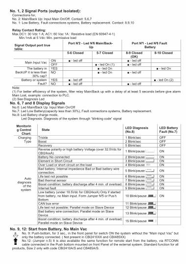
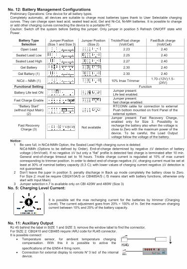
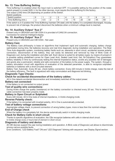
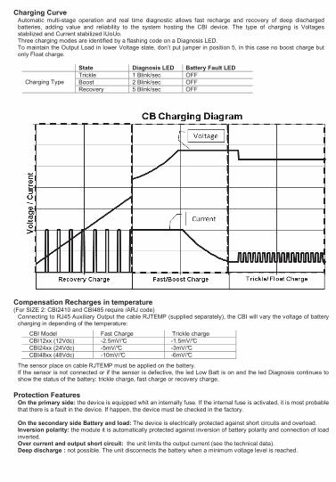
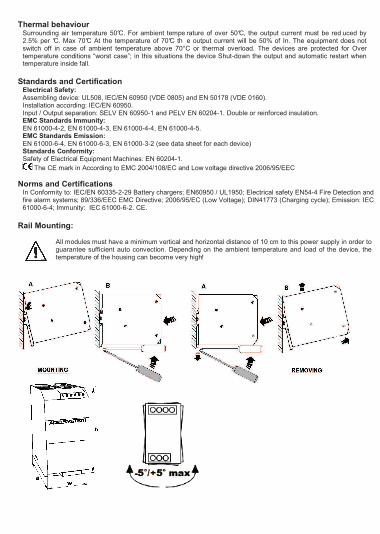
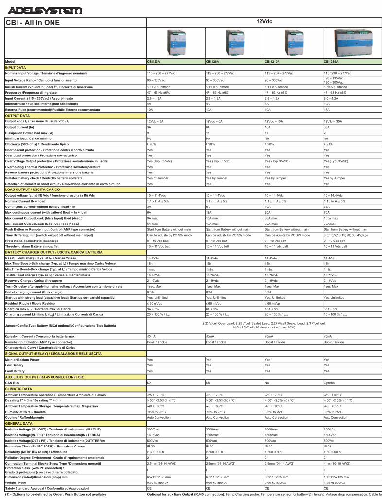
www.adelsystem.com
CBI - All in ONE
Model CBI123A CBI126A CBI1210A CBI1235A CBI243A CBI245A CBI2410A CBI2420A CBI485A CBI4810A
INPUT DATA
Nominal Input Voltage / Tensione d’ingresso nominale 115 – 230 – 277Vac 115 – 230 – 277Vac 115 – 230 – 277Vac 115 / 230 – 277Vac 115 – 230 – 277Vac 115 – 230 – 277Vac 115 / 230 – 277Vac 115 / 230 – 277Vac 115 / 230 – 277Vac 115 / 230 – 277Vac
Input Voltage Range / Campo di funzionamento 90 – 305Vac 90 – 305Vac 90 – 305Vac 90 – 135Vac
180 – 305Vac90 – 305Vac 90 – 305Vac
90 – 135Vac
180 – 305Vac
90 – 135Vac
180 – 305Vac
90 – 135Vac
180 – 305Vac
90 – 135Vac
180 – 305Vac
Inrush Current (Vn and In Load) I2t / Corrente di Inserzione 11 A 5msec 11 A 5msec 11 A 5msec 35 A 5msec 11 A 5msec 11 A 5msec 16 A 5msec 35 A 5msec 16 A 5msec 35 A 5msec
Frequency /Frequenza di Ingresso 47 – 63 Hz ±6% 47 – 63 Hz ±6% 47 – 63 Hz ±6% 47 – 63 Hz ±6% 47 – 63 Hz ±6% 47 – 63 Hz ±6% 47 – 63 Hz ±6% 47 – 63 Hz ±6% 47 – 63 Hz ±6% 47 – 63 Hz ±6%
Input Current (115 – 230Vac) / Assorbimento 2.8 – 1.3A 2.8 – 1.3A 2.8 – 1.3A 8.0 – 4.2A 2.8 – 1.3A 2.8 – 1.3A 3.3 – 2.2A 8.0 – 4.2A 3.3 – 2.2A 8.0 – 4.2A
Internal Fuse / Fusibile Interno (non sostituibile) 4A 4A 4A 10A 4A 4A 6.3A 10A 6.3A 10A
External Fuse (recommended)/ Fusibile Esterno raccomandato 10A 10A 10A 16A 10A 10A 16A 16A 16A 16A
OUTPUT DATA
Output Vdc / IN / Tensione di uscita Vdc / IN 12Vdc – 3A 12Vdc – 6A 12Vdc – 10A 12Vdc – 35A 24Vdc – 3A 24Vdc – 5A 24Vdc – 10A 24Vdc – 20A 48Vdc – 5A 48Vdc – 10A
Output Current (In) 3A 6A 10A 35A 3A 5A 10A 20A 5A 10A
Dissipation Power load max (W) 9 17 17 28 13 17 28 54 28 54
Minimum load / Carico minimo No No No No No No No No No No
Efficiency (50% of In) / Rendimento tipico 90% 90% 90% > 91% 90% 90% 83% > 91% 83% > 91%
Short-circuit protection / Protezione contro il corto circuito Yes Yes Yes Yes Yes Yes Yes Yes Yes Yes
Over Load protection / Protezione sovraccarico Yes Yes Yes Yes Yes Yes Yes Yes Yes Yes
Over Voltage Output protection / Protezione sovratensione in uscita Yes (Typ. 35Vdc) Yes (Typ. 35Vdc) Yes (Typ. 35Vdc) Yes (Typ. 35Vdc) Yes (Typ. 35Vdc) Yes (Typ. 35Vdc) Yes (Typ. 35Vdc) Yes (Typ. 35Vdc) Yes (Typ. 90Vdc) Yes (Typ. 90Vdc)
Overheating Thermal Protection / Protezione sovratemperatura Yes Yes Yes Yes Yes Yes Yes Yes Yes Yes
Reverse battery protection / Protezione inversione batteria Yes Yes Yes Yes Yes Yes Yes Yes Yes Yes
Sulfated battery check / Controllo batteria solfatata Yes by Jumper Yes by Jumper Yes by Jumper Yes by Jumper Yes by Jumper Yes by Jumper Yes by Jumper Yes by Jumper Yes by Jumper Yes by Jumper
Detection of element in short circuit / Relevazione elemento in corto circuito Yes Yes Yes Yes Yes Yes Yes Yes Yes Yes
LOAD OUTPUT / USCITA CARICO
Output voltage (at at IN) Vdc / Tensione di uscita (a IN) Vdc 10 – 14.4Vdc 10 – 14.4Vdc 10 – 14.4Vdc 10 – 14.4Vdc 22 – 28.8Vdc 22 – 28.8Vdc 22 – 28.8Vdc 22 – 28.8Vdc 44 – 57.6Vdc 44 – 57.6Vdc
Nominal Current IN = Iload 1.1 x In A ± 5% 1.1 x In A ± 5% 1.1 x In A ± 5% 1.1 x In A ± 5% 1.1 x In A ± 5% 1.1 x In A ± 5% 1.1 x In A ± 5% 1.1 x In A ± 5% 1.1 x In A ± 5% 1.1 x In A ± 5%
Continuous current (without battery) Iload = In 3A 6A 10A 35A 3A 5A 10A 20A 5A 10A
Max continuous current (with battery) Iload = In + Ibatt 6A 12A 20A 70A 6A 10A 20A 40A 10A 20A
Max current Output Load: (Main Input) Iload (4sec.) 9A max 18A max 30A max 105A max 9A max 15A max 30A max 60A max 15A max 30A max
Max current Output Load: (Back Up) Iload (4sec.) 6A max 12A max 20A max 70A max 6A max 10A max 20A max 40A max 10A max 20A max
Push Button or Remote Input Control (AMP type connector) Start from Battery without main Start from Battery without main Start from Battery without main Start from Battery without main Start from Battery without main Start from Battery without main Start from Battery without main (1) Start from Battery without main Start from Battery without main (1) Start from Battery without main
Time Buffering; min (switch output off without main input) Can be aduste by PC SW mode Can be aduste by PC SW mode Can be aduste by PC SW mode 0.5;1;3;5;10;15; 20; 30; 45;60; Can be aduste by PC SW mode Can be aduste by PC SW mode 5 min standard - Require: SW S31 0.5;1;3;5;10;15; 20; 30; 45;60; 5 min standard - Require: SW S31 0.5;1;3;5;10;15; 20; 30; 45;60;
Protections against total discharge 9 – 10 Vdc batt 9 – 10 Vdc batt 9 – 10 Vdc batt 9 – 10 Vdc batt 19 – 20 Vdc batt 19 – 20 Vdc batt 19 – 20 Vdc batt 19 – 20 Vdc batt 38 – 40 Vdc batt 38 – 40 Vdc batt
Threshold alarm Battery almost flat 10 – 11 Vdc batt 10 – 11 Vdc batt 10 – 11 Vdc batt 10 – 11 Vdc batt 20 – 21 Vdc batt 20 – 21 Vdc batt 20 – 21 Vdc batt 20 – 21 Vdc batt 40 – 42 Vdc batt 40 – 42 Vdc batt
BATTERY CHARGER OUTPUT / USCITA CARICA BATTERIA
Boost – Bulk charge (Typ. at IN) / Carica Veloce 14.4Vdc 14.4Vdc 14.4Vdc 14.4Vdc 28.8Vdc 28.8Vdc 28.8Vdc 28.8Vdc 57.6 57.6
Max.Time Boost–Bulk charge (Typ. at IN) / Tempo massimo Carica Veloce 15h 15h 15h 15h 15h 15h 15h 15h 15h 15h
Min.Time Boost–Bulk charge (Typ. at IN) / Tempo minimo Carica Veloce 1min. 1min. 1min. 1min. 1min. 1min. 1min. 1min. 1min. 1min.
Trickle-Float charge (Typ. at IN) / Carica di mantenimento 13.75Vdc 13.75Vdc 13.75Vdc 13.75Vdc 27.5Vdc 27.5Vdc 27.5Vdc 27.5Vdc 55Vdc 55Vdc
Recovery Charge / Carica di recupero 2 – 9Vdc 2 – 9Vdc 2 – 9Vdc 2 – 9Vdc 2 – 16Vdc 2 – 16Vdc 2 – 16Vdc 2 – 16Vdc 2 – 24Vdc 2 – 24Vdc
Turn-On delay after applying mains voltage / Accensione con tensione di rete 1sec. Max 1sec. Max 1sec. Max 1sec. Max 1sec. Max 1sec. Max 1.5sec. Max 1sec. Max 1.5sec. Max 1sec. Max
End of charging current (Bulk charge) 0.3A 0.3A 0.3A 0.3A 0.3A 0.3A 0.3A
Start up with strong load (capacitive load)/ Start up con carichi capacitivi Yes, Unlimited Yes, Unlimited Yes, Unlimited Yes, Unlimited Yes, Unlimited Yes, Unlimited Yes, Unlimited Yes, Unlimited Yes, Unlimited Yes, Unlimited
Residual Ripple / Ripple Residuo 60 mVpp 60 mVpp 60 mVpp 60 mVpp 60 mVpp 60 mVpp 60 mVpp
Charging max Ibatt / Corrente max. di Carica 3A ± 5% 6A ± 5% 10A ± 5% 35A ± 5% 3A ± 5% 5A ± 5% 10A ± 5% 10A ± 5% 5A ± 5% 10A ± 5%
Charging current Limiting IN (Iadj) / Limitazione Corrente di Carica 20 ÷ 100 % / Ibatt 20 ÷ 100 % / Ibatt 20 ÷ 100 % / Ibatt 10 ÷ 100 % / Ibatt 20 ÷ 100 % / Ibatt 20 ÷ 100 % / Ibatt 20 ÷ 100 % / Ibatt 10 ÷ 100 % / Ibatt 20 ÷ 100 % / Ibatt 10 ÷ 100 % / Ibatt
Jumper Config.Type Battery (NiCd optional)/Configurazione Tipo Batteria
Quieshent Current / Consumo da batteria max. 5mA 5mA 5mA 5mA 5mA 5mA 5mA 5mA 5mA 5mA
Remote Input Control (AMP Type connector) Boost / Trickle Boost / Trickle Boost / Trickle Boost / Trickle Boost / Trickle Boost / Trickle Boost / Trickle Boost / Trickle Boost / Trickle Boost / Trickle
Characteristic Curve / Caratteristiche di Carica
SIGNAL OUTPUT (RELAY) / SEGNALAZIONE RELÈ USCITA
Main or Backup Power Yes Yes Yes Yes Yes Yes Yes Yes Yes Yes
Low Battery Yes Yes Yes Yes Yes Yes Yes Yes Yes Yes
Fault Battery Yes Yes Yes Yes Yes Yes Yes Yes Yes Yes
AUXILIARY OUTPUT (RJ 45 CONNECTION) FOR:
CAN Bus No No No Optional No No No Optional No Optional
CLIMATIC DATA
Ambient Temperature operation / Temperatura Ambiente di Lavoro -25 ÷ +70°C -25 ÷ +70°C -25 ÷ +70°C -25 ÷ +70°C -25 ÷ +70°C -25 ÷ +70°C -25 ÷ +70°C -25 ÷ +70°C -25 ÷ +70°C -25 ÷ +70°C
De rating Tª > (In) / De rating Tª > (In) > 50° -2.5%(In) / °C > 50° -2.5%(In) / °C > 50° -2.5%(In) / °C > 50° -2.5%(In) / °C > 50° -2.5%(In) / °C > 50° -2.5%(In) / °C > 50° -2.5%(In) / °C > 50° -2.5%(In) / °C > 50° -2.5%(In) / °C > 50° -2.5%(In) / °C
Ambient Temperature Storage / Temperatura max. Magazzino -40 ÷ +85°C -40 ÷ +85°C -40 ÷ +85°C -40 ÷ +85°C -40 ÷ +85°C -40 ÷ +85°C -40 ÷ +85°C -40 ÷ +85°C -40 ÷ +85°C -40 ÷ +85°C
Humidity at 25 °C / Umidità 95% to 25°C 95% to 25°C 95% to 25°C 95% to 25°C 95% to 25°C 95% to 25°C 95% to 25°C 95% to 25°C 95% to 25°C 95% to 25°C
Cooling / Raffreddamento Auto Convection Auto Convection Auto Convection Auto Convection Auto Convection Auto Convection Auto Convection Auto Convection Auto Convection Auto Convection
GENERAL DATA
Isolation Voltage (IN / OUT) / Tensione di Isolamento (IN / OUT) 3000Vac 3000Vac 3000Vac 3000Vac 3000Vac 3000Vac 3000Vac 3000Vac 3000Vac 3000Vac
Isolation Voltage(IN / PE) / Tensione di Isolamento(IN / TERRA) 1605Vac 1605Vac 1605Vac 1605Vac 1605Vac 1605Vac 1605Vac 1605Vac 1605Vac 1605Vac
Isolation Voltage(OUT / PE) / Tensione di Isolamento(OUT/TERRA) 500Vac 500Vac 500Vac 500Vac 500Vac 500Vac 500Vac 500Vac 500Vac 500Vac
Protection Class (EN/IEC 60529) / Protezione Classe IP 20 IP 20 IP 20 IP 20 IP 20 IP 20 IP 20 IP 20 IP 20 IP 20
Reliability (MTBF IEC 61709) / Affidabilità > 300 000 h > 300 000 h > 300 000 h > 300 000 h > 300 000 h > 300 000 h > 300 000 h > 300 000 h > 300 000 h > 300 000 h
Pollution Degree Environment / Grado d'inquinamento ambientale 2 2 2 2 2 2 2 2 2 2
Connection Terminal Blocks Screw Type / Dimensione morsetti 2,5mm (24-14 AWG) 2,5mm (24-14 AWG) 2,5mm (24-14 AWG) 4mm (30-10 AWG) 2,5mm (24-14 AWG) 2,5mm (24-14 AWG) 2,5mm (24-14 AWG) 4mm (30-10 AWG) 2,5mm (24-14 AWG) 4mm (30-10 AWG)
Protection class (with PE connected) / Grado di protezione (con cavo di terra collegato)
I I I I I I I I I I
Dimension (w-h-d)/Dimensioni (l-h-p) mm 65x115x135 mm 65x115x135 mm 65x115x135 mm 150x115x135 mm 65x115x135 mm 65x115x135 mm 100x115x135 mm 150x115x135 mm 100x115x135 mm 150x115x135 mm
Weight / Peso 0.60 kg approx 0.60 kg approx 0.60 kg approx 1.55 kg approx 0.60 kg approx 0.60 kg approx 0.85 kg approx 1.55 kg approx 0.85 kg approx 1.55 kg approx
Safety Standard Approval / Conformità ed Approvazioni CE CE CE CE CE CE CE CE CE CE
(1) - Options to be defined by Order, Push Button not available Optional for auxiliary Output (RJ45 connection): Temp Charging probe: Temperature sensor for battery 2m lenght. Voltage drop compensation: Cable for battery connection 2m lenght. Remote monitoring Display. Can Bus Cable.
IUoUo, Automatic, 3 stage / IUoUo, Automatico a 3 Stadi
12Vdc 24Vdc 48Vdc
2.23 V/cell Open Lead, 2.25 V/cell Sealed Lead, 2.27 V/cell Sealed Lead, 2.3 V/cell gel;
NiCd 1.5V/cell (10 elem.) trickle (Imax 10%)
2.23 V/cell Open Lead, 2.25 V/cell Sealed Lead, 2.27 V/cell Sealed Lead, 2.3 V/cell gel;
NiCd 1.5V/cell (20 elem.) trickle (Imax 10%)
2.23 V/cell Open Lead, 2.25 V/cell Sealed Lead,
2.27 V/cell Sealed Lead, 2.3 V/cell gel;
NiCd 1.5V/cell (40 elem.) trickle (Imax 10%)
All specification are subject to change without notice Rev. 09 - 2011 Instruction Manual All In One Pag 2_r1.5.xls
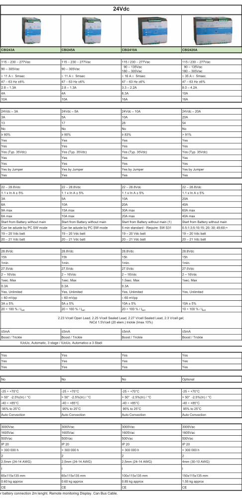
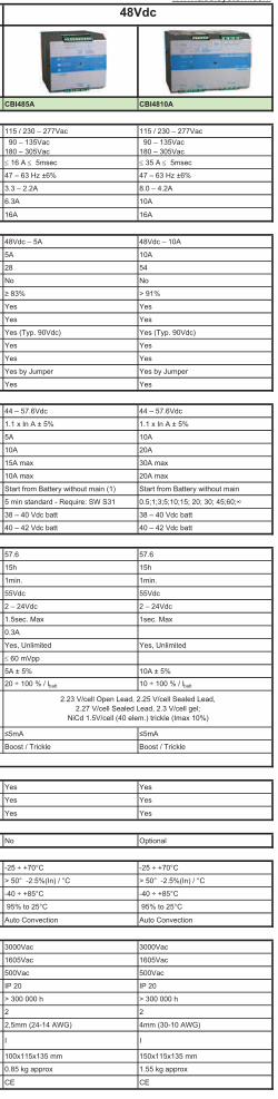
Related Documents


![DECEMBER 1967 - CBI · Letter FROM The Editor. Please Report Change of Address Immediately! Direct All Correspondence to Ex-CBI ROUNDUP, established ]946, is a reminiscing magazine](https://static.cupdf.com/doc/110x72/603cc53110888514654d368a/december-1967-letter-from-the-editor-please-report-change-of-address-immediately.jpg)
