CAVIDYNE TM , LLC 5077 Fruitville Rd.; Ste 109-157 Sarasota, FL 34232 Phone: (352) 275-5319 www.caviblaster.com Model 1030-ROV Version 2.1

Welcome message from author
This document is posted to help you gain knowledge. Please leave a comment to let me know what you think about it! Share it to your friends and learn new things together.
Transcript
CAVIDYNETM
, LLC
5077 Fruitville Rd.; Ste 109-157 Sarasota, FL 34232
Phone: (352) 275-5319 www.caviblaster.com
Model 1030-ROV
Version 2.1

© 2013 O&M Manual Version 2.0 CaviDyneTM 5077 Fruitville Rd.; Ste 109-157 Sarasota, FL 34234 U.S.A. Phone 352.275 5319
Page 2/29
CAVIDYNETM
LLC is not responsible for damages or injuries resulting from a failure to comply with instructions in this manual. Please read and study the entire manual carefully before use.
The CaviBlaster® 1030-ROV must only be operated and maintained by trained personnel.
This equipment generates high pressure water and is intended for underwater use only. Serious personal injury or death and equipment/property damage may result from improper use.
© 2013 O&M Manual Version 2.0 CaviDyneTM 5077 Fruitville Rd.; Ste 109-157 Sarasota, FL 34234 U.S.A. Phone 352.275 5319
Page 3/29
TABLE OF CONTENTS
1.0 UNIT SPECIFICATIONS ................................................................................................5
2.0 GENERAL DESCRIPTION ............................................................................................6
2.1 Using this Manual (Version 1.3) ..................................................................................9
2.2 Conventions ................................................................................................................9
2.3 Scope .........................................................................................................................9
2.4 Terms and Abbreviations ............................................................................................9
3.0 SAFETY INFORMATION ............................................................................................. 10
3.1 Personal Safety ........................................................................................................ 10
3.2 Personal Protective Equipment................................................................................. 11
3.3 Modification to the Equipment................................................................................... 12
4. 0 INSTALLATION .......................................................................................................... 13
4.1 Uncrating and Lifting ................................................................................................. 13
4.3 Initial Set-Up ............................................................................................................. 14
5.0 OPERATION ................................................................................................................ 15
5.1 Preparing the CaviBlaster® for Operation ................................................................. 15
5.2 Startup of the CaviBlaster® ...................................................................................... 15
5.3 Normal Operation ..................................................................................................... 16
5.4 Adjusting the CaviBlaster® for Maximum Performance ............................................ 17
5.5 Recommendations for Effective Results ................................................................... 19
6.0 MAINTENANCE ........................................................................................................... 22
6.1 Basic Preventive Maintenance Recommendations ................................................... 23
6.3 Pump Service ........................................................................................................... 23
6.4 Inspection/Cleaning of Water Inlet Strainer .............................................................. 23
8.0 TROUBLESHOOTING ................................................................................................. 24
9.0 REPLACEMENT PARTS ............................................................................................. 25
APPENDIX - COMPONENT LITERATURE ....................................................................... 26

© 2013 O&M Manual Version 2.0 CaviDyneTM 5077 Fruitville Rd.; Ste 109-157 Sarasota, FL 34234 U.S.A. Phone 352.275 5319
Page 4/29
LIST OF FIGURES & TABLES
Figure 2.1 – CaviBlaster® 1030-ROV General Features ................................................. 7
Figure 2.2 – CaviBlaster® 1030-ROV General Features ................................................. 8 Figure 4.1 – Lifting Guidelines ....................................................................................... 13
Figure 5.1 – Lance Pressure Calibration ....................................................................... 19 Figure 5.2 – Lance Position for Best Cleaning Results ................................................. 20 Figure 9.1 – Parts List ................................................................................................... 26
Figure 9.2 – UDOR GSC Pump Breakdown .................................................................. 28
This space intentionally left blank
© 2013 O&M Manual Version 2.0 CaviDyneTM 5077 Fruitville Rd.; Ste 109-157 Sarasota, FL 34234 U.S.A. Phone 352.275 5319
Page 5/29
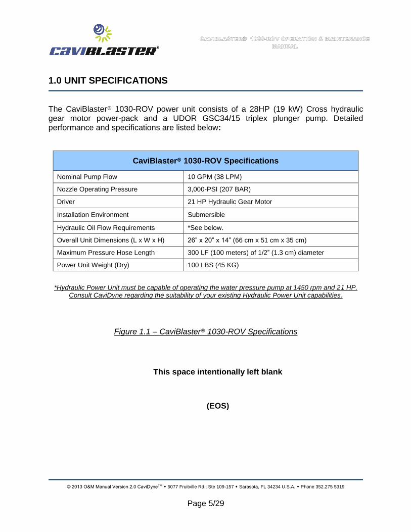
1.0 UNIT SPECIFICATIONS
The CaviBlaster® 1030-ROV power unit consists of a 28HP (19 kW) Cross hydraulic gear motor power-pack and a UDOR GSC34/15 triplex plunger pump. Detailed performance and specifications are listed below:
CaviBlaster® 1030-ROV Specifications
Nominal Pump Flow 10 GPM (38 LPM)
Nozzle Operating Pressure 3,000-PSI (207 BAR)
Driver 21 HP Hydraulic Gear Motor
Installation Environment Submersible
Hydraulic Oil Flow Requirements *See below.
Overall Unit Dimensions (L x W x H) 26” x 20” x 14” (66 cm x 51 cm x 35 cm)
Maximum Pressure Hose Length 300 LF (100 meters) of 1/2” (1.3 cm) diameter
Power Unit Weight (Dry) 100 LBS (45 KG)
*Hydraulic Power Unit must be capable of operating the water pressure pump at 1450 rpm and 21 HP. Consult CaviDyne regarding the suitability of your existing Hydraulic Power Unit capabilities.
Figure 1.1 – CaviBlaster® 1030-ROV Specifications
This space intentionally left blank
(EOS)

© 2013 O&M Manual Version 2.0 CaviDyneTM 5077 Fruitville Rd.; Ste 109-157 Sarasota, FL 34234 U.S.A. Phone 352.275 5319
Page 6/29
2.0 GENERAL DESCRIPTION
The CaviBlaster® 1030-ROV high-pressure water power unit allows the operator to use the water flow and pressure to generate cavitation at the end of the proprietary nozzle.
The CaviBlaster® cleans the surface of any underwater structure using the energy released by the implosion of the bubbles during the cavitation process. When directed at the surface being cleaned, the energy released by the collapsing bubbles causes marine growth to be removed from the surface.
The system consists of a portable high-pressure pumping unit designed for submersible ROV use and a high pressure cavitation lance (connected to ROV manipulator) with connecting high pressure hose.
The system is normally supplied with an integral pressure compensator, pressure compensation can also be achieved using the ROV onboard pressure system. Consult CaviDyneTM for acceptable pressure compensation options.
The CaviBlaster® 1030-ROV power unit is a complete “plug and play” system built on a supporting platform that allows quick deployment and/or installation of the unit. Water is supplied directly from the unit operating environment.
The unit is equipped with many features to maintain safety while operating at pressures of 3,000-psi (207 BAR).
For more information on the CaviBlaster® system please visit us at:
www.caviblaster.com

© 2013 O&M Manual Version 2.0 CaviDyneTM 5077 Fruitville Rd.; Ste 109-157 Sarasota, FL 34234 U.S.A. Phone 352.275 5319
Page 7/29
Figure 2.1 – CaviBlaster® 1030-ROV General Features
Oil pressure compensator (pump side must be completely filled with oil)
Pressure pump (pump must be completely filled with oil)
Oil pressure compensator fill port
Hydraulic motor
Pressure regulating valve
Water inlet strainer
Hydraulic oil connections (direction of pump rotation not important)
Strainer

© 2013 O&M Manual Version 2.0 CaviDyneTM 5077 Fruitville Rd.; Ste 109-157 Sarasota, FL 34234 U.S.A. Phone 352.275 5319
Page 8/29
Figure 2.2 – CaviBlaster® 1030-ROV General Features
Relief valve
Pressure regulating valve
Pulse dampener
Water inlet strainer
Optional pressure gage. (Standard units supplied with plug)
© 2013 O&M Manual Version 2.0 CaviDyneTM 5077 Fruitville Rd.; Ste 109-157 Sarasota, FL 34234 U.S.A. Phone 352.275 5319
Page 9/29
2.1 Using this Manual
Every attempt has been made to ensure that this documentation is complete and accurate at the time of publication. It is imperative; however, that anyone attempting to use this manual must have good comprehension of how this equipment operates. Further, this manual can in no way replace the common sense of an individual. If at any time this manual seems to contradict itself, or common sense, discontinue the procedure, re-read the section, and seek assistance from CaviDyneTM or other personnel familiar with the operation of this equipment.
2.2 Conventions
The first time a component is mentioned, it is typically followed by a figure reference; e.g., Water inlet strainer (See Figure 2.2). Figure numbers and section numbers are always coincident.
When other sections are referenced the SECTION NAME will appear in italic caps. The electronic version allows users to click on the section name or figure reference to jump to that section. The words “This space intentionally left blank” will appear where there is more than 3 inches of white space. (EOS) will appear above the page number on the last page of each section.
2.3 Scope
This manual covers installation, operation, and maintenance of the CaviBlaster® 1030-ROV. It is essential that personnel who will operate and/or service this equipment familiarize themselves with this manual. Standard components, such as the unit motor and pump, are covered by the manufacturer’s literature found in the Appendix.
2.4 Terms and Abbreviations
CCW Counterclockwise
CW Clockwise
EOS End of Section
GPM Gallons Per Minute
HP Horsepower
LPM Liters Per Minute
PPE Personal Protective Equipment
PSI Pounds Per Square Inch (without suffix, assumed to be gauge pressure).
(EOS)
© 2013 O&M Manual Version 2.0 CaviDyneTM 5077 Fruitville Rd.; Ste 109-157 Sarasota, FL 34234 U.S.A. Phone 352.275 5319
Page 10/29
3.0 SAFETY INFORMATION
The CaviBlaster® 1030-ROV power unit is an inherently powerful and potentially dangerous piece of equipment; however, with proper care and training it can be operated safely. The 1030-ROV must only be operated by personnel that have read and understand this manual. It is intended to reinforce and review safety techniques to prevent personal injuries and property damage. Users must comply with all local, state, and national laws concerning high-pressure water jetting equipment as well as all underwater work regulations. It is strongly recommended that this entire manual be reviewed in-depth before operating or servicing this equipment. Service work should only be performed by individuals who are proficient in using this equipment. Refer to the applicable section in this manual for the correct procedures prior to any installation, setup, or maintenance work. Note that the oil pressure compensator is not a pressurized component and therefore not a safety hazard. It is open at one end and connected to the pressure pump oil chamber at the other end. Its purpose is simply to balance the oil pressure in the water pressure pump with the unit’s surrounding environmental pressure to prevent damage to the water pressure pump and it’s seals.
3.1 Personal Safety
Operation of the CaviBlaster® 1030-ROV underwater submersible ROV-mounted cleaning system must only be operated by personnel who have been trained in its use. Operation of the system without the proper training can result in property
damage and damage to the CaviBlaster® unit.
CaviDyneTM, LLC is not responsible for damages resulting from a failure to comply with instructions in this manual. Please read carefully before use.
© 2013 O&M Manual Version 2.0 CaviDyneTM 5077 Fruitville Rd.; Ste 109-157 Sarasota, FL 34234 U.S.A. Phone 352.275 5319
Page 11/29
If maintenance or repair of the CaviBlaster® is being conducted out of the water, remember that the unit generates a high pressure water jet stream. Never direct the jet stream at a person or animal. Never direct the jet stream toward power lines or other high voltage equipment.
Ensure that there is a safe area to work while operating or maintaining the CaviBlaster® 1030-ROV.
Seek immediate medical attention if the operator suffers an injury as the result of contact with the high-pressure water stream. Serious personal injury can result from an untreated water injection wound.
3.2 Personal Protective Equipment
Always wear appropriate Personal Protective Equipment (PPE) when performing maintenance or calibration on this equipment.
Personnel operating or working in the vicinity of the power unit should wear appropriate hearing protection when the CaviBlaster® during maintenance or calibration procedures.
Personnel performing maintenance or calibration procedures on the CaviBlaster® 1030-ROV system should always wear neoprene or heavy rubber gloves to provide protection to the hands and, in particular, to the nails. The gloves will absorb most of the energy produced by bursting cavitation bubbles and prevent the cavitation bubbles from contacting the operators’ hands. The gloves will also protect operators’ hands from the initial shockwave when the lance is activated.
Failure to wear appropriate PPE may result in personal injury.

© 2013 O&M Manual Version 2.0 CaviDyneTM 5077 Fruitville Rd.; Ste 109-157 Sarasota, FL 34234 U.S.A. Phone 352.275 5319
Page 12/29
3.3 Modification to the Equipment
Do not make any unauthorized modifications or repairs to this equipment. Components used throughout this assembly were specifically designed or selected to safely meet the unique high-pressure requirements. Only replace parts with those recommended by or supplied by CaviDyneTM. Any unapproved modifications will void the equipment warranty. Unauthorized modification or part substitution can result in serious personal injury or property damage.
This space intentionally left blank
Unauthorized replacement of any part may lead to catastrophic equipment failure and serious personal injury.
(EOS)
© 2013 O&M Manual Version 2.0 CaviDyneTM 5077 Fruitville Rd.; Ste 109-157 Sarasota, FL 34234 U.S.A. Phone 352.275 5319
Page 13/29
4. 0 INSTALLATION
The CaviBlaster® 1030-ROV must be securely attached to the ROV using the vibration mounts supplied or other secure fastening mechanism.
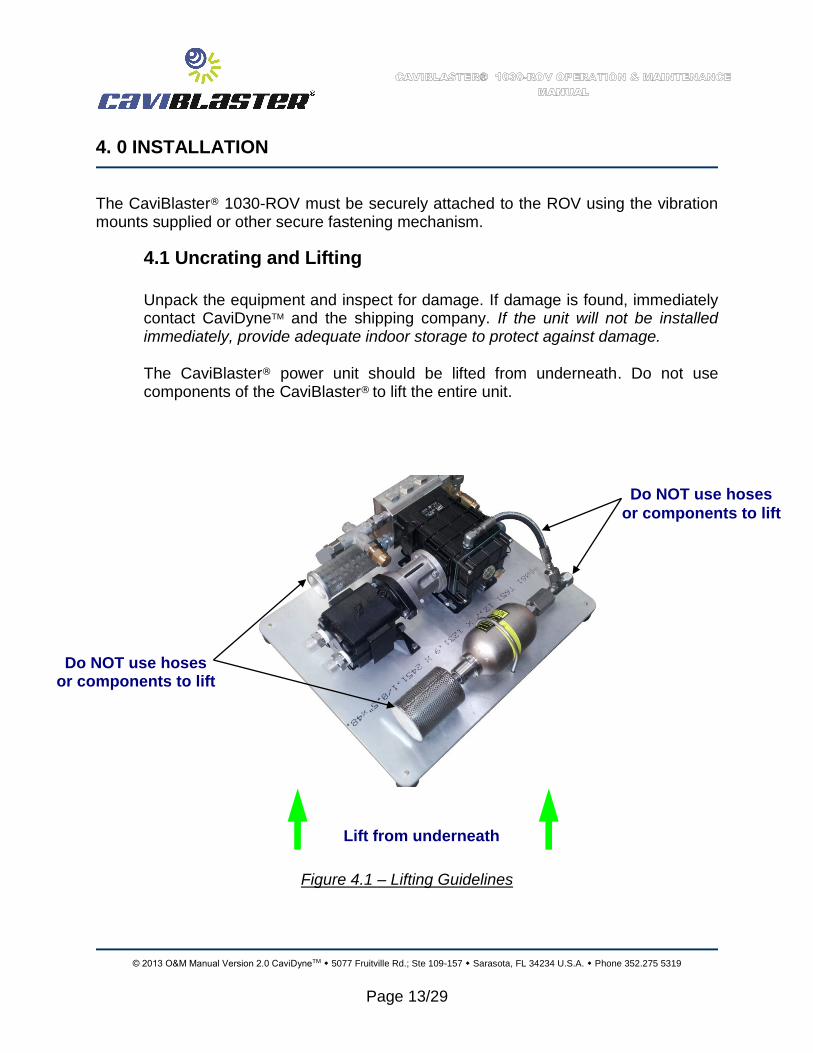
4.1 Uncrating and Lifting
Unpack the equipment and inspect for damage. If damage is found, immediately contact CaviDyneTM and the shipping company. If the unit will not be installed immediately, provide adequate indoor storage to protect against damage. The CaviBlaster® power unit should be lifted from underneath. Do not use components of the CaviBlaster® to lift the entire unit.
Figure 4.1 – Lifting Guidelines
Lift from underneath
Do NOT use hoses
or components to lift
Do NOT use hoses or components to lift

© 2013 O&M Manual Version 2.0 CaviDyneTM 5077 Fruitville Rd.; Ste 109-157 Sarasota, FL 34234 U.S.A. Phone 352.275 5319
Page 14/29
4.3 Initial Set-Up After first receiving the CaviBlaster® power unit, the following must be completed: See Figures 2.1 and 2.2 for item locations.
1. Remove hose between pump and oil pressure compensator.
2. Add oil to pump by completely filling pump to top of fill port.
3. Reconnect hose to pump only.
4. Stand unit on end with pump at top, hold hose upright to prevent leakage.
5. Remove oil pressure compensator fill port cap.
6. Fill oil pressure compensator and hose with oil.
7. Reconnect hose to oil pressure compensator and allow unit to sit for several minutes to allow any trapped air to escape.
8. Top off oil pressure compensator as required.
9. Replace oil pressure compensator fill port cap.
10. Set unit back down on vibration mounts.
11. Connect hydraulic power unit hoses.
12. Connect water pressure hose.
The CaviBlaster® 1030-ROV can be used with seawater but must be flushed and rinsed with fresh water after every use in seawater. Failure to flush and rinse the power unit after use in seawater will result in increased wear and tear on components and can cause the pump valve(s) to stick in the open position. This will prevent the system from producing the correct operating pressure.
EOS
Pump fluids may have been removed for shipment. Check ALL fluid levels prior to starting.

© 2013 O&M Manual Version 2.0 CaviDyneTM 5077 Fruitville Rd.; Ste 109-157 Sarasota, FL 34234 U.S.A. Phone 352.275 5319
Page 15/29
5.0 OPERATION
The CaviBlaster® 1030-ROV should only be operated by properly trained personnel who are familiar with the contents of the manual. Review the safety requirements found in Section 3 before operating.
5.1 Preparing the CaviBlaster® for Operation
The following checklist should be completed in advance, so that the unit is always ready for immediate use. This should be completed after each use.
1) Inspect the CaviBlaster® power unit, hoses, JIC fittings and lance for any
signs of damage.
2) Inspect the water inlet strainer to ensure that it is not clogged (See Figure 2.2). Clean if necessary.
3) Check for proper pressure pump oil level (See pump Owner’s Manual found in the Appendix). Add oil (SAE 30 non-detergent) if necessary. PUMP MUST BE COMPLETELY FILLED.
Incorrect oils should not be used as they may damage the equipment.
5.2 Startup of the CaviBlaster®
Before starting the CaviBlaster® 1030-ROV unit, review all safety requirements found in Section 3.0 SAFETY INFORMATION. This equipment should only be operated by individuals who have read and understand the CaviBlaster® Operation and Maintenance Manual.

© 2013 O&M Manual Version 2.0 CaviDyneTM 5077 Fruitville Rd.; Ste 109-157 Sarasota, FL 34234 U.S.A. Phone 352.275 5319
Page 16/29
1) Verify that the unit has been properly prepared for operation as described in Section 4.
2) Verify that the lance is properly connected to the CaviBlaster® and the
ROV.
3) Run the ROV hydraulic system to verify that the CaviBlaster® hydraulic motor and pressure pump are functioning correctly.
5.3 Normal Operation
Normal operation of the CaviBlaster® system is defined as user control of water flow via the lance. In the absence of a diver, control of the power unit is accomplished by the ROV manipulator. Should a problem develop with the control valve, discontinue using the CaviBlaster® until fixed.
Review the safety requirements for PPE and safe operation before proceeding.
1) The ROV hydraulic system needs to be operating at a capacity that matches the water pressure pump requirements for the CaviBlaster®
1030-ROV to function correctly. Unlike gasoline or diesel engines, a hydraulic motor will run as fast as the oil supply it receives, which means that the hydraulic oil supply must be adjusted to match the water pressure pump requirements. Consult with CaviDyneTM to determine if your high pressure oil supply unit is suitable for the CaviBlaster® 1030-ROV.
2) Activate the cleaning cavitation stream by turning ON the hydraulic power unit.
Although the CaviBlaster® system is safe to use when submerged in water, the system generates a high-pressure (up to 3,000-psi [207 bar]) water stream, which can cause injury when the lance is out of the water. ALWAYS keep the lance submerged when the pressure pump is engaged.

© 2013 O&M Manual Version 2.0 CaviDyneTM 5077 Fruitville Rd.; Ste 109-157 Sarasota, FL 34234 U.S.A. Phone 352.275 5319
Page 17/29
5.4 Adjusting the CaviBlaster® for Maximum Performance
The pressure at the nozzle of the lance has to be maintained within certain limits to achieve cavitation and for best performance results. If using a calibration pressure gauge situated between the pressure hose and the CaviBlaster® lance, the water pressure should be 3,000-psi (207 BAR) with the lance submerged and the hydraulic power unit operating. For best results, repeat this calibration procedure if cleaning performance degrades, or every 3 months at a maximum.
To calibrate the pressure at the lance, follow the procedure below:
- Stop the hydraulic power unit to discharge any residual pressure in the hose
lines. - Disconnect the lance from the main hose line. - Attach the calibration gauge between the main hose line and the lance and
tighten the JIC connections. (See figure 5.1) - Submerge the lance. Because of the danger of the operator coming in contact
the water stream from the cavitating nozzle, CaviDyneTM does NOT recommend calibrating the lance out of the water. Use extra care to avoid the water stream if doing so.
- Ensure that the cavitation nozzle is pointed away from the diver’s or operator’s hands, arms and body.
- Start the hydraulic power unit. - Hold the lance tight and observe the calibration gauge. - Turn the knob on top of the pressure regulating valve until pressure reads
3,000-psi (207 BAR) on the calibration gauge. Turning the knob clockwise will increase the pressure and turning it counter clockwise will decrease the pressure.
A CALIBRATION GAUGE IS RECOMMENDED WITH EVERY UNIT. CONNECT BETWEAN THE END OF THE HOSE AND THE LANCE.

© 2013 O&M Manual Version 2.0 CaviDyneTM 5077 Fruitville Rd.; Ste 109-157 Sarasota, FL 34234 U.S.A. Phone 352.275 5319
Page 18/29
This space intentionally left blank
DO NOT ADJUST THE PRESSURE AT THE LANCE TO MORE THAN 3,000-PSI (207 BAR). HIGHER PRESSURE WILL NOT IMPROVE PEFORMANCE AND COULD RESULT IN SERIOUS DAMAGE TO THE PUMP.
HOSES ARE RATED FOR 4,000-PSI (272 BAR) PRESSURES ABOVE 4,000-PSI (272 BAR) COULD RESULT IN HOSE FAILURE.
© 2013 O&M Manual Version 2.0 CaviDyneTM 5077 Fruitville Rd.; Ste 109-157 Sarasota, FL 34234 U.S.A. Phone 352.275 5319
Page 19/29
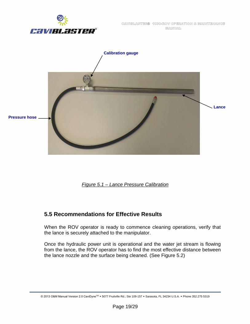
Figure 5.1 – Lance Pressure Calibration
5.5 Recommendations for Effective Results
When the ROV operator is ready to commence cleaning operations, verify that the lance is securely attached to the manipulator. Once the hydraulic power unit is operational and the water jet stream is flowing from the lance, the ROV operator has to find the most effective distance between the lance nozzle and the surface being cleaned. (See Figure 5.2)
Calibration gauge
Pressure hose
Lance
© 2013 O&M Manual Version 2.0 CaviDyneTM 5077 Fruitville Rd.; Ste 109-157 Sarasota, FL 34234 U.S.A. Phone 352.275 5319
Page 20/29
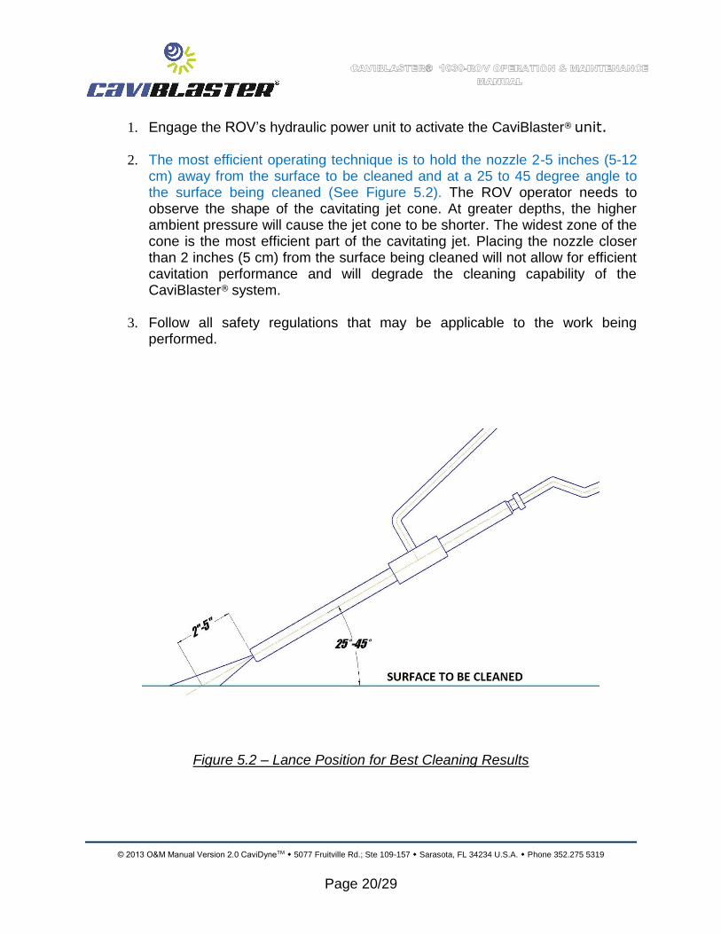
1. Engage the ROV’s hydraulic power unit to activate the CaviBlaster® unit.
2. The most efficient operating technique is to hold the nozzle 2-5 inches (5-12 cm) away from the surface to be cleaned and at a 25 to 45 degree angle to the surface being cleaned (See Figure 5.2). The ROV operator needs to observe the shape of the cavitating jet cone. At greater depths, the higher ambient pressure will cause the jet cone to be shorter. The widest zone of the cone is the most efficient part of the cavitating jet. Placing the nozzle closer than 2 inches (5 cm) from the surface being cleaned will not allow for efficient cavitation performance and will degrade the cleaning capability of the CaviBlaster® system.
3. Follow all safety regulations that may be applicable to the work being
performed.
Figure 5.2 – Lance Position for Best Cleaning Results
© 2013 O&M Manual Version 2.0 CaviDyneTM 5077 Fruitville Rd.; Ste 109-157 Sarasota, FL 34234 U.S.A. Phone 352.275 5319
Page 21/29
5.6 Shutting Down the CaviBlaster® 1030-ROV. 1. Shut down the ROV hydraulic power unit, this will turn off the pressure pump
and relieve pressure in the system.
2. It is now safe to remove the lance from the water. 3. Flush the system and rinse the power unit with fresh water at the end of the
day or work shift.
This space intentionally left blank
EOS

© 2013 O&M Manual Version 2.0 CaviDyneTM 5077 Fruitville Rd.; Ste 109-157 Sarasota, FL 34234 U.S.A. Phone 352.275 5319
Page 22/29
6.0 MAINTENANCE
Maintenance on this unit should be restricted to authorized personal that have been properly trained. Review this manual, especially Section 3.0 SAFETY INFORMATION, prior to performing any service on this equipment.
Equipment must be OFF and pressure released from all hoses prior to performing any service work.
Only replace parts with those supplied or approved by CaviDyneTM. Use of any other parts may lead to equipment failure and severe personal injury.
CAVIBLASTER® MUST BE FLUSHED AND RINSED WITH FRESH WATER AFTER EACH USE IN SEA WATER.
FAILURE TO FLUSH AND RINSE THE UNIT WILL RESULT IN PREMATURE WEAR AND TEAR ON THE COMPONENTS AND DECREASED SERVICE LIFE.
Failure to flush and rinse the unit can cause the pump valve(s) to stick in the open position. This will prevent the system from producing the correct operating pressure.
© 2013 O&M Manual Version 2.0 CaviDyneTM 5077 Fruitville Rd.; Ste 109-157 Sarasota, FL 34234 U.S.A. Phone 352.275 5319
Page 23/29
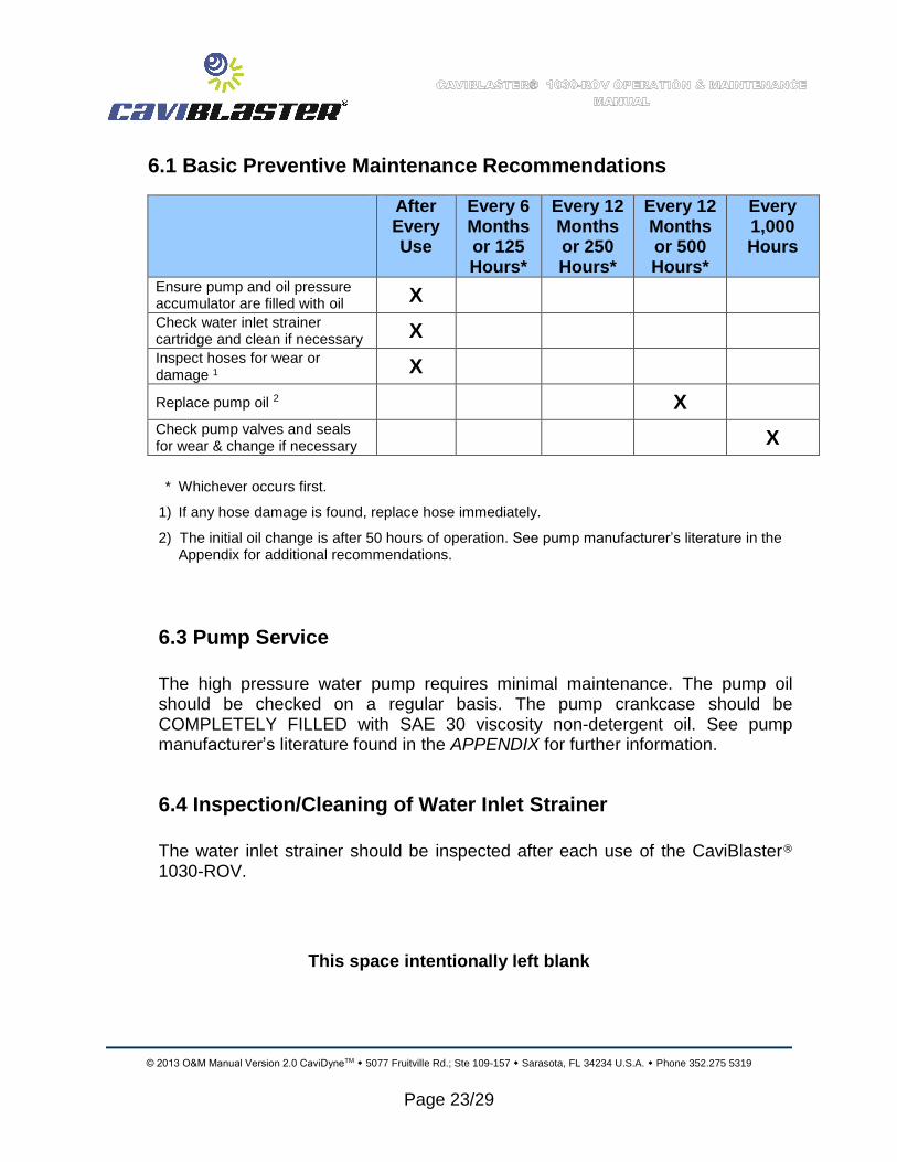
6.1 Basic Preventive Maintenance Recommendations
After Every Use
Every 6 Months or 125 Hours*
Every 12 Months or 250 Hours*
Every 12 Months or 500 Hours*
Every 1,000 Hours
Ensure pump and oil pressure accumulator are filled with oil X
Check water inlet strainer cartridge and clean if necessary X
Inspect hoses for wear or damage 1 X
Replace pump oil 2 X
Check pump valves and seals for wear & change if necessary
X
* Whichever occurs first.
1) If any hose damage is found, replace hose immediately.
2) The initial oil change is after 50 hours of operation. See pump manufacturer’s literature in the Appendix for additional recommendations.
6.3 Pump Service
The high pressure water pump requires minimal maintenance. The pump oil should be checked on a regular basis. The pump crankcase should be COMPLETELY FILLED with SAE 30 viscosity non-detergent oil. See pump manufacturer’s literature found in the APPENDIX for further information.
6.4 Inspection/Cleaning of Water Inlet Strainer
The water inlet strainer should be inspected after each use of the CaviBlaster® 1030-ROV.
This space intentionally left blank

© 2013 O&M Manual Version 2.0 CaviDyneTM 5077 Fruitville Rd.; Ste 109-157 Sarasota, FL 34234 U.S.A. Phone 352.275 5319
Page 24/29
8.0 TROUBLESHOOTING
1. WATER IN CRANK CASE
- Check the pump seals for damage - Check the plungers for cracks - Check the plunger rod O-ring for damage - Check oil pressure compensator bladder for damage
2. LANCE IS NOT CLEANING PROPERLY
a. Remove the CaviBlaster® unit from the water and mount the lance securely in a vice or test stand. Make sure the lance is pointed away from any personnel and any electrical systems or components in the area. The water jet from the lance can travel 30 to 40 feet (9 to 12 meters).
b. Connect the hydraulic motor to a hydraulic power unit and start the hydraulic power unit. Verify that the hydraulic power unit is delivering the correct RPM (1450) and HP (21) required to operate the water pressure pump.
c. If water is leaking out of the hose, fittings or connections replace the damaged component and securely tighten all connections.
d. If water is leaking from the lance body contact CaviDyneTM
for further instructions.
e. Check lance and nozzle for foreign particles;
Visual inspection
Insert a small wire into nozzle orifices to check for obstruction(s) and “back-flush” with compressed air or pressurized water.
This space intentionally left blank
(EOS)

© 2013 O&M Manual Version 2.0 CaviDyneTM 5077 Fruitville Rd.; Ste 109-157 Sarasota, FL 34234 U.S.A. Phone 352.275 5319
Page 25/29
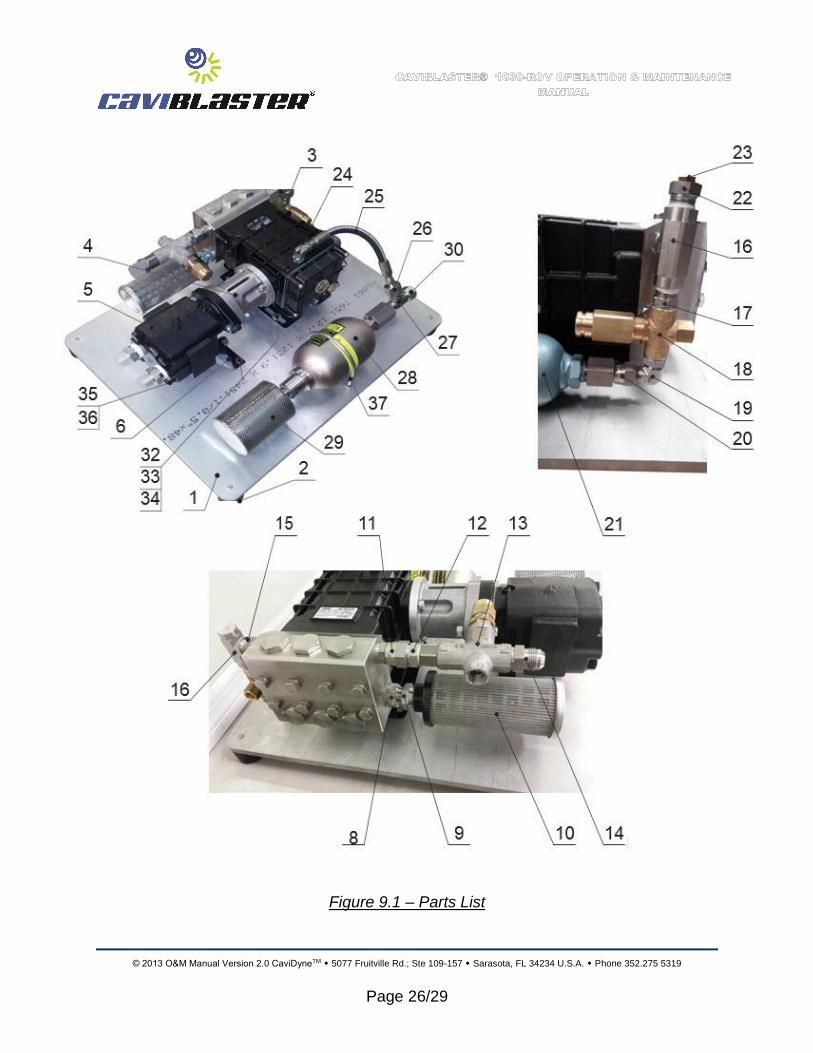
9.0 REPLACEMENT PARTS
CaviBlaster® 1030-ROV POWER UNIT REPLACEMENT PARTS
RECOMMENDED ORDER QTY
QUANTITY PER ASSEMBLY
PART DESCRIPTION PART NUMBER
1 1 Water inlet strainer CASS-20-1-100-316
1 1 Pump seal kit UD-99
1 1 Pump valve kit UD-116
1 1 Pump stainless kit UD-117
1 1 Pump plunger rod o-ring kit UD-119
1 1 Regulating unloader repair kit UB 402 / K
1 1 Relief valve repair kit UB 402 / K
1 1 Oil pressure compensator S245A1QTTB3
1 1 Oil fill hose with fittings HD06-011-0-A106-
A106-SS
1 1 Hytrel spider 16624329-24/32
All parts can be ordered from:
CAVIDYNETM
, LLC
5077 Fruitville Rd.; Ste 109-157 Sarasota, FL 34235 USA
Phone: (352) 275-5319
Email: [email protected] www.caviblaster.com
(EOS)
© 2013 O&M Manual Version 2.0 CaviDyneTM 5077 Fruitville Rd.; Ste 109-157 Sarasota, FL 34234 U.S.A. Phone 352.275 5319
Page 26/29
Figure 9.1 – Parts List

© 2013 O&M Manual Version 2.0 CaviDyneTM 5077 Fruitville Rd.; Ste 109-157 Sarasota, FL 34234 U.S.A. Phone 352.275 5319
Page 27/29
ITEM QTY DESCRIPTION CONFIGURATION
1 1 1 1FPP 137-8073 PL ROV WITH PRESSURE COMPENSATOR
1 2 1 1FPP 137-8097 PL ROV NOACC WITHOUT PRESSURE COMPENSATOR
2 4 GRAINGER 2NPF3 ISOLATION MOUNT
3 1 UDOR GSC34/20S PUMP - 81017
4 1 UDOR GSC34/20S KIT - 81017
5 1 PERMCO M2100A7831DZA10-29 HYDRAULIC MOTOR
6 1 UDOR 04-1202.48 MOTOR BRACKET
7 1 GUARDIAN SINTERED STEEL HUB, SIZE 24/32, STYLE "B" 7/8" BORE x 1/4" KEY
8 1 ADAPTER 7022-12-12-SS 12FJS-12MBSPP
9 1 ADAPTER 2404-12-16-SS 12MJ-16MP
10 1 FLOWEZY CASS-20-1-100-316 STST
11 1 ADAPTER 7022-08-12-SS 08MBSPP-12FJJ
12 1 ADAPTER 7002-08-12-SS 08MBSPP-12MJ
13 1 UDOR UB402-06 UNLOADER VB43
14 1 ADAPTER 7002-08-08-SS 08MBSPP-08MJ
15 1 ADAPTER 7042-08-08-SS 08FP-08MBSPP
16 1 ADAPTER 5604-08-08-08-SS 08FP-08FP-08MP
17 1 ADAPTER 7032-08-06-SS 08MP-06MBSPP
18 1 UDOR SV220 RELIEF VALVE 60.0525.00
19 1 ADAPTER 7202-08-06-SS 08MJ-06MBSPP 900
20 1 ADAPTER 6506-08-08-SS 08FP-08FJS
21 1 CAT 6029-SS PULSATION DAMPENER
22 1 ADAPTER 5406-08-04-SS 08MP-04FP
23 3 1 PLUG 5406P-04-SS 04MP HEX PLUG
24 1 1 ADAPTER 7202-06-06-NWO-SS 06MJ-06MBSPPAORB 900
25 1 1 HOSE HD06-010-0-A106-A106-SS 06FJS-06FJS
26 1 1 ADAPTER 2406-12-06 12FJ-06MJ
27 1 1 ADAPTER 2605-12-12-12-SS 12MP-12MJ-12MJ
28 1 1 ACCINC A1QTTBC3100SS COMPENSATOR
29 1 1 ACCINC AI S 440-SS STRAINER
30 1 1 BRENNAN 0304-C-12 JIC CAP NUT
31 2 1 ADAPTER 2408-06 06JICS PLUG
32 6 HDW 3/8-16 x 1-1/4 HHCS-SS
33 12 HDW 3/8 FW-SS 71018
34 6 HDW 3/8-16 NYLOK NUT-SS 70862
35 2 HDW 9/16-12 x 5-1/2 HHCS-ZP-G8
36 1 2 HDW 9/16-12 NYLOK NUT 2137033
37 1 1 HDW 3/8-16 x 4-1/2 U-BOLT
38 1 METALPHOTO 137-8031 NAMEPLATE
39 4 HDW 1/4-20 x 3/4" BHCS-SS 73754
** 1 PRESSURE GAGE SUB/LFC-212-5000-G. OPTIONAL
1. Supplied with standard units equipped with a pressure compensator.
2. Supplied only with units NOT equipped with a pressure compensator.
3. Supplied with standard units not equipped with a pressure gage.
** Pressure gage is an optional extra and must be specified at time of order.
1030-ROV PARTS LIST
© 2013 O&M Manual Version 2.0 CaviDyneTM 5077 Fruitville Rd.; Ste 109-157 Sarasota, FL 34234 U.S.A. Phone 352.275 5319
Page 28/29
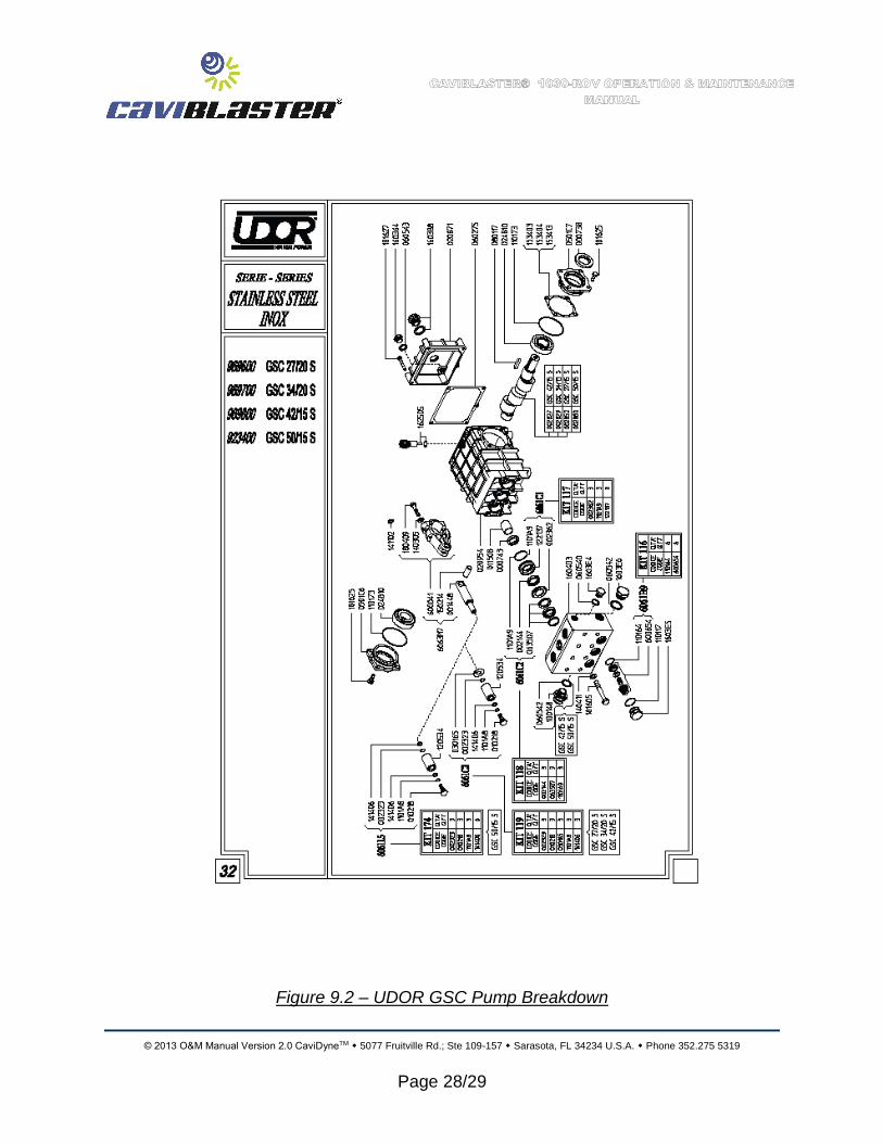
Figure 9.2 – UDOR GSC Pump Breakdown
© 2013 O&M Manual Version 2.0 CaviDyneTM 5077 Fruitville Rd.; Ste 109-157 Sarasota, FL 34234 U.S.A. Phone 352.275 5319
Page 29/29
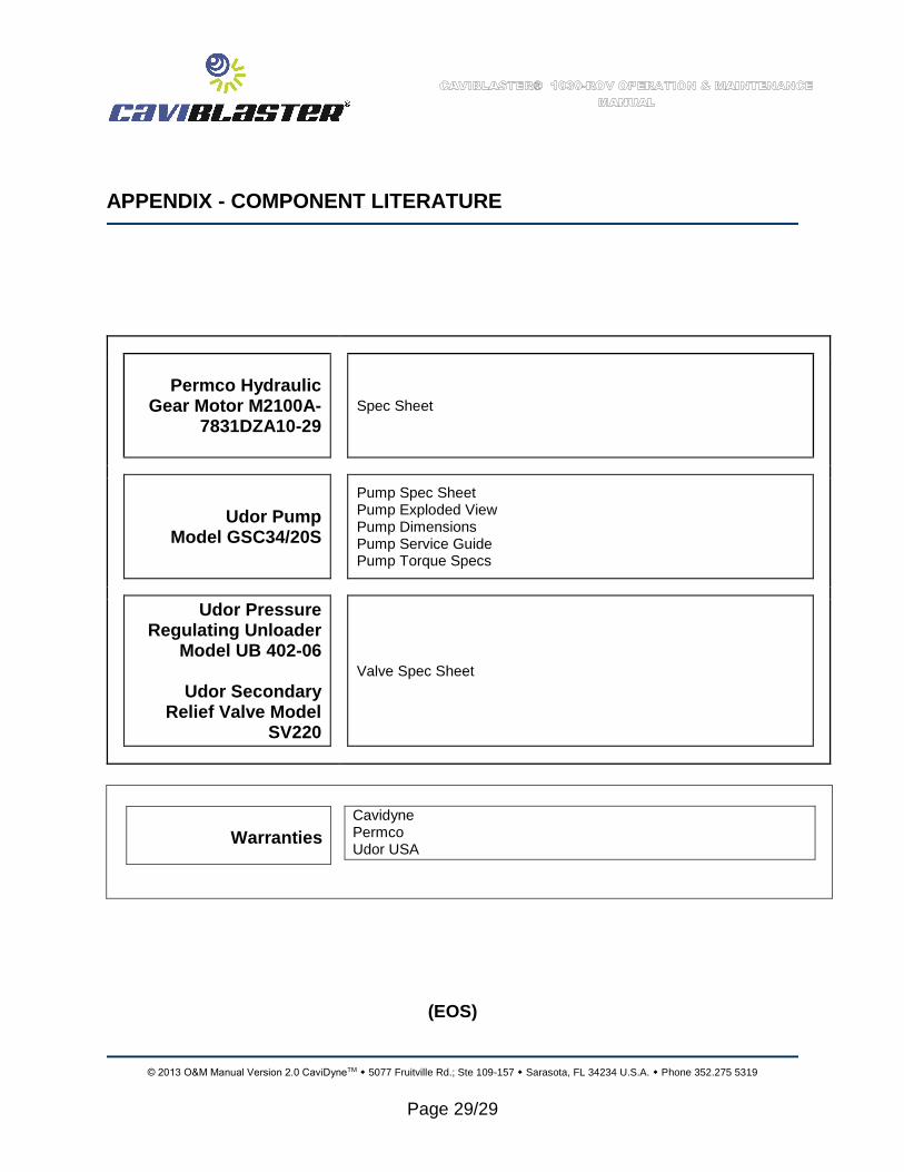
APPENDIX - COMPONENT LITERATURE
Permco Hydraulic Gear Motor M2100A-
7831DZA10-29
Spec Sheet
Udor Pump Model GSC34/20S
Pump Spec Sheet Pump Exploded View Pump Dimensions Pump Service Guide Pump Torque Specs
Udor Pressure Regulating Unloader
Model UB 402-06
Udor Secondary Relief Valve Model
SV220
Valve Spec Sheet
Warranties
Cavidyne Permco Udor USA
(EOS)
Related Documents