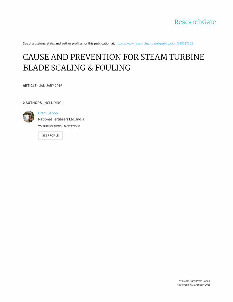
See discussions, stats, and author profiles for this publication at: https://www.researchgate.net/publication/290537155 CAUSE AND PREVENTION FOR STEAM TURBINE BLADE SCALING & FOULING ARTICLE · JANUARY 2016 2 AUTHORS, INCLUDING: Prem Baboo National Fertilizers Ltd.,India 25 PUBLICATIONS 0 CITATIONS SEE PROFILE Available from: Prem Baboo Retrieved on: 16 January 2016

Welcome message from author
This document is posted to help you gain knowledge. Please leave a comment to let me know what you think about it! Share it to your friends and learn new things together.
Transcript
Seediscussions,stats,andauthorprofilesforthispublicationat:https://www.researchgate.net/publication/290537155
CAUSEANDPREVENTIONFORSTEAMTURBINEBLADESCALING&FOULING
ARTICLE·JANUARY2016
2AUTHORS,INCLUDING:
PremBaboo
NationalFertilizersLtd.,India
25PUBLICATIONS0CITATIONS
SEEPROFILE
Availablefrom:PremBaboo
Retrievedon:16January2016

CAUSE AND PREVENTION
FOR
STEAM TURBINE BLADE
SCALING & FOULING
Author
Prem Baboo
Sr. Manager (Prod)
National Fertilizers Ltd., Vijaipur 473111, India
Mob. +919425735974
Sr. Advisor & Expert, www.ureaknowhow.com
Fellow of Institutions of Engineers (India)
ABSTRACT
The paper intended to deposition of wang scaling/deposition & corrosion on turbine blades. How to deposit these scales?
Prevention and control the deposits. Major steam turbine problems causes and effects. Practical examples of our shut down
experience of 40 ata & 100 ata steam turbines. Lab analysis detail report of wet steam cleaning and sand blasting cleaning of
the blades.
INTRODUCTION
There are several types of wang scaling which form on the turbine blading and cause this fouling/scaling. According to the
analysis of the process parameters, the impact on the process was following are the causes of deposition
1. Deposition of solids carried in the steam from the boiler water
2. Chemical reaction between chemicals in the steam and the material in the turbine blades. The first type is the most
common, and is readily distinguished from the other in that it is largely soluble in water, and is washed off with
Comparative ease, whereas the other type of deposit adheres to the blades very tenaciously.
After the sample analysis, our Analysis Department confirmed that poor quality of steam and high content of Na+ and SiO2
in steam caused scaling of the blades and nozzles of the steam turbine, because we used the steam from Fertilizers
companies for the purpose of process optimization and added Sodium Hydroxide (NaOH) and Sodium Phosphate (Na3PO4)
& Silica (SiO2) for regulating the pH value of boiler feed water and for removing the scale.
The deposition of solids carried in the steam appears to be the major cause of difficulty. The efforts of this research have
been directed entirely toward a study of this type of deposit, and no study has been made of the other type.
The steam turbine is the simplest and most efficient machine for converting heat energy into mechanical works and kinetic
energy. Turbines are available small size to very large size that is no limit for sizing.
HOW TO DEPOSIT THESE SCALES ON STEAM TURBINE BLADE?
Insufficient pre-treatment, depending on quality of the Boiler feed water, sooner or later usually leads to inorganic salt
deposits, and thus to a loss of efficiency of the turbine. At high temperature and elevated pH of BFW the deposition takes
place on turbine blades, the BFW contain some quantity of Phosphate, silica, ammonia in ppm. Besides the possibility of an
elaborate mechanical cleaning it is sometimes attempted to clean the turbine with saturated steam or ammoniac alkaline
rinses to remove scaling on the closed machine. These procedures are far less effective than the mechanical revision
themselves.
Results of Poor Water Treatment
In the ideal situation, water would be feed to a boiler free of any impurities. Unfortunately, this is not the case. Water clean-
up is always required. The following items are the most problematic to steam turbines:
1. Calcium (Ca) scale– Calcium forms
2. With sulphates (SO4) and other compounds to form calcium sulphate, calcium bicarbonate, calcium carbonate,
calcium chloride, and calcium nitrate.
3. During evaporation, these chemicals adhere to boiler tube walls forming scale. Its formation increases with the rate
of evaporation so these deposits will be heaviest where the gas temperatures are highest. Scale is a non-conductor
of heat which leads to a decreased heat transfer of the boiler tubes, and can result in tube failure due to higher tube
metal temperatures. Build-up of scale also clogs piping systems and can cause control valves and safety valves to
stick.
SILICA (SiO2)
Silica can formed scale at low pressures below 40 bars. Above 40 bars, silica starts to volatize, passing over with steam to
potentially form deposits on the steam turbine diaphragms and blades. These deposits change the steam path components
profiles resulting in energy losses and wheel chamber pressure of turbine rise. The degree of loss depends upon the amount
of the deposits, their thickness and their degree of roughness. For example, if the nozzle area of the first stage flow path was

reduced by 10%, the output of the steam turbine would be approximately 3% less. A similar loss could occur if the gas
turbine received steam for power augmentation purposes. For same power of output steam quantity is more required.
SODIUM (Na)
Sodium can combine with hydroxide ions creating sodium hydroxide (caustic). Highly stressed areas of steam turbines can
be attacked by sodium hydroxide and cause stress-corrosion cracks to occur.
CHLORIDE (Cl)
Chlorides of calcium, magnesium, and sodium, and other metals are normally found in natural water supplies. All of these
chlorides are very soluble in water and therefore, can carry over with steam to the steam turbine. Chlorides are frequently
found in turbine deposits and will cause corrosion of austenitic stainless steel and pitting of steel. Corrosion resistant
materials protect themselves by forming a protective oxide layer on their surface.
IRON (Fe) –
High iron is not found in raw water but high concentrations can come from rusted piping and exfoliation of boiler tubes.
Iron is found in condensate return in a particle form as it does not dissolve in water. The detrimental aspect of iron is called
steam turbine solid particle erosion, which causes significant erosion of steam turbine steam path components.
OXYGEN (O2) –
Oxygen is found in feed water and its partial pressure is relatively high so it will require a near saturation temperature to
disassociate itself from water. Oxygen in combination with water will attack iron and cause corrosion. The reaction occurs
in two steps:
Fe++ + 2.OH → Fe (OH) 2
(Ferrous Ion) (Hydroxyl Ion) (Ferrous hydroxide)
Then
4 Fe (OH) 2 + O2 + 2 H2O → Fe (OH) 3
(Soluble Ferrous Hydroxide) (Dissolved Oxygen) (Water) (Insoluble ferric
Hydroxide)
The ferric hydroxide is highly insoluble and precipitates on heated surfaces. The precipitate is called magnetite or rust. The
closer the water is to the saturation temperature, the more corrosion will occur. For removing Oxygen in BFW Hydrazine
dozing is done the total oxygen react with hydrazine convert into Nitrogen and water. The nitrogen is vent out to
atmosphere.
CARBON DIOXIDE (CO2)
Carbon dioxide can react with water to form carbonic acid (H2CO3). Carbonic acid will cause corrosion in steam and return
lines. Carbon dioxide can originate from condenser air leakage or bicarbonate (HCO3) alkalinity in the feed water
pH
The pH value of water is a measure of its alkalinity or acidity and has a direct bearing on the corrosive properties. All water
contains alkaline (hydroxyl, OH) ions and hydrogen (H) ions. .At high pH value and high temperature deposition takes place
on turbine blade
.
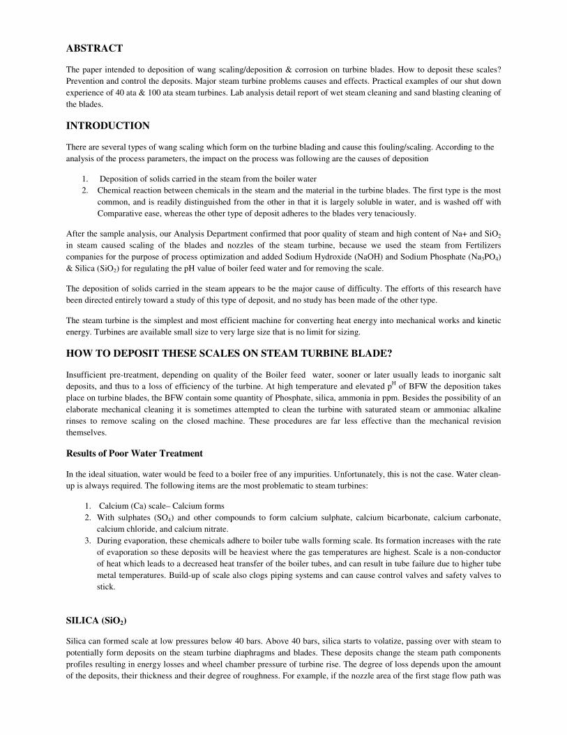
DEPOSITION BY LOW PRESSURE GLAND STEAM
When plant in start-up condition the heating of turbine starts in this period before start-up gland steam takes in
line this low pressure steam taken for medium pressure steam (24 ata) to 15 ata then again let down to 1.1 ata
this steam is contaminated with iron because the de superheating water contain Iron so the deposition on turbine
blade takes place however this steam again superheated after let down pressure from 15 to 1.1 ata. The gland
steam diagram shown in the figure-1 & 2.The deposition as shown in the figure-5.
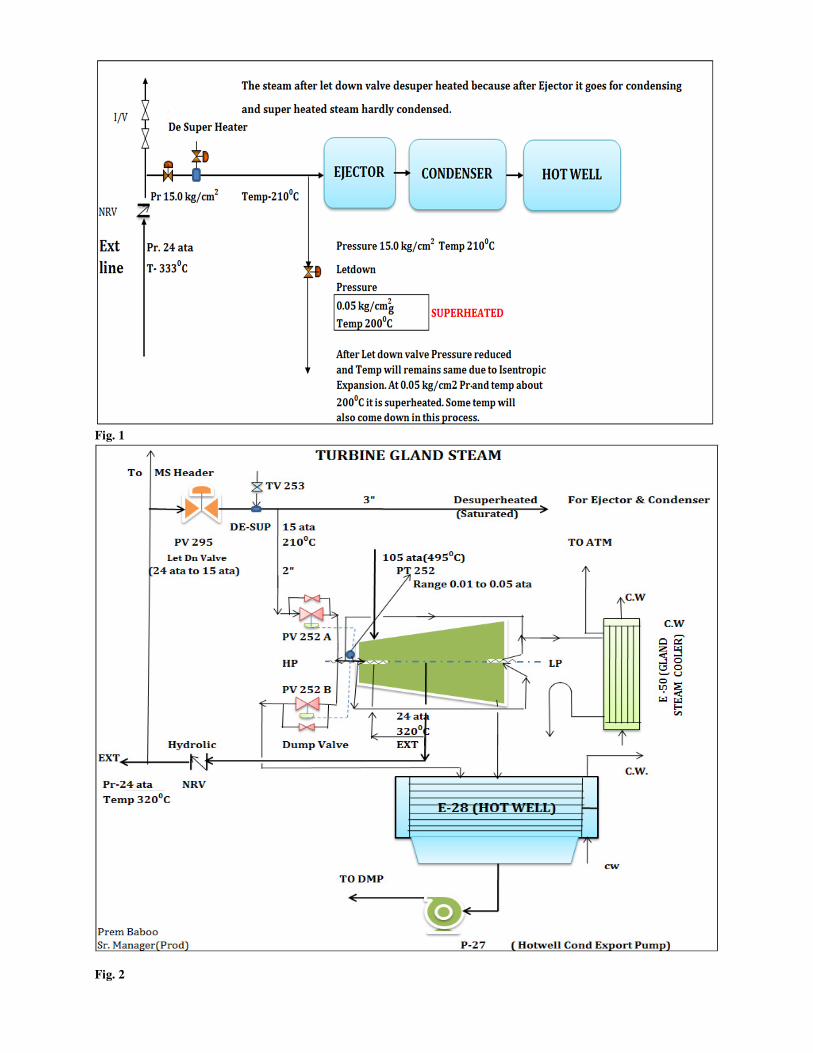
Fig. 1
Fig. 2

The available cleaning method includes
1. Blasting with suitable medium(sand)
2. Water washing.
3. Hand cleaning with suitable solvent
4. Wet Steam Cleaning.
1. Blast cleaning-
Blast cleaning is the suitable and most commonly used method of removing deposits from the rotating portion of the units,
once it is available for cleaning. This essential as it allows Nondestructive test (NDT) examination and removes even most
persistent deposits.
Fig.3 (cleaning with sand blasting)
2. (i) Water Cleaning(open casing) or Ground floor
Water washing will dissolve soluble deposits in the unit, but the insoluble deposits must be removed by mechanical force
which require a high pressure jet and with sand blasting also. without blasting the shower method is made faster with higher
pressure but some risk is also there like bending of the blades, generally the low pressure side thinned blade easily band
with high pressure jet. So the blasting method is more convenient at low pressure.
The “on line” water washing is found to be affective on the geothermal unit that operates on steam, which is initially in the
wet region. It has more beneficial procedure. The water washing is more beneficial and can remove chemically water
soluble aggressive compound from hideout.
(ii) Close water cleaning
In casing close condition the washing is carried out with the condensate at 100°C. The turbine is cooled or heated up to
100°C and filled with the condensate via a turbine drain. The rotor is turned or barred by hand and the condensate is drained
after 2 to 4 hours. It is then again filled with the condensate at 100°C (but up to the rotor centre-level), the rotor is rotated
and the condensate is drained after sometime. This process is repeated several times.
3. Hand Cleaning with suitable solvent.
This process is slow process but suitable for certain surfaces are inaccessible . The extended parts of the blade that can be
damaged with blasting, this process is suitable.
4. Wet steam Cleaning
TURBINE WASHING PROCEDURE
After Compressor Stopped Condensate export Pump (P-27) taken in line, make up valve open, KS(live steam) valve closed
and vent valve to be opened. Oil circulation and barring to be taken in line. When the line temperature came down to 2500 C
then washing started as per following steps. The washing arrangement as per figure No. 4.and reading is tabulate as per
table no.1.
1) KS(very high pressure steam) steam (live steam) all isolation valves closed and bypass valve closed,
2) Lube oil pump running.

3) Condensate pumps running, it may be stopped after 4-5 hrs. Make up valve closed. And open drain valve.
4) CO2 suction line I / V open interlock to be bypassed from Inst/maint.
5) Reset the compressor.
6) Keep 1st I/valve full open and 2
nd I/V slightly open on the line connecting 15 ata motive steam and adjust the
condensate so as to maintain the line temperature at 165°C to 175°C and pressure about 10-11 ata.
7) Follow the normal Compressor start up procedure.
8) After opening of HP/LP valves adjust the rpm of turbine to 800 to 1000 by adjusting the inlet steam.
9) Analyse the condensate for Phosphate, silica, PH and conductivity after every two hours.
10) Washing to be carried out till the two consecutive readings are same.
11) The mixed steam is refilled to carry out purging for 10~30 min. During the purging via steam, the condensate and
impurities are drained through open drain line when the filled condensate reaches 80% , and the condensate is
refilled and the vacuumizing is conducted after the drainage; the cylinder drain and the inlet nipple are connected
after the condensate is drained from the cylinder, meanwhile, the main steam pipe is heated. The procedure may be
shortened according to the cleaning time or the purging may not be conducted, but the condensate must be
drained. 12) The steam washing line with proper connections and support of the steam lines to the turbine are important as well
as the steam drains with PG & TG arrangement and at least two drains line provided, If the steam supply lines are
putting a load on the turbine, it is likely to cause the turbine to vibrate and will cause mechanical distress to the
attachment locations. Similarly, when steam turbines are started, there is a warm-up time to heat the turbine to the
proper temperature level before admitting full starting steam. The heating rate must be slowly up to 100 0C and
then rate should be 3-4 0 per minutes.
Fig. 4

Fig. 5
Fig. 6

Table -1
Turbine Component Characteristics and Failure Mechanisms
Steam turbine blading have either impulse blading or reaction blading. Impulse blading is high velocity fluids entering the
turbine blade, incident and emergent are the same angle by a blade profile that efficiently turns the direction of the fluid
with little pressure change, and by decreasing the velocity of the fluid as it leaves the blade to extract energy. Steam turbine
blading can be subjected to several failure mechanisms in service. These mechanisms are shown in the Table 2.For high
pressure steam turbines to operate with high reliability and availability, the ability to regularly inspect and assess the steam
blading condition is important as any of the failure mechanisms in Table 2.
Turbine washing to reduce deposition and improve efficiency of the turbine in terms of power. This can be done to optimize
the wheel chamber pressure the wash is usually completed when the concentration of corrosion such as sodium, phosphate
silica is minimum level.
Steam turbine blading can be subjected to several failure mechanisms in service. These mechanisms are indicated in Table 2
along with the resultant damage and typical causes of failure. For steam turbines to operate with high reliability and
availability, the ability to regularly inspect and assess the steam blading condition is important as any of the failure
mechanisms in Table 1 can lead to failure if left undiagnosed or neglected.
Reaction blading is characterized by high velocity fluids entering the turbine blade, but not as high as impulse velocity
levels, by a blade profile that efficiently allows the fluid to expand while passing through the blade, and by decreasing both
the velocity and pressure of the fluid as it exits from the blade to extract energy. Typical reaction blading has tear-drop
shaped leading edges with a tapered thickness to the trailing edge. The blades may have twist to their shape which may
range from low amounts of twist or reaction at the base of the blade to high twist or reaction at the tip of the blade.
Regardless of the blading type, the blade tips may be covered with bands peened to their tips which connect several blades
together in groups, or the blades may have integral shrouds which are part of the blades, or may have no tip cover bands or
shrouds (free standing). The blade shrouds and cover bands are utilized to keep the passing steam from leaking over the tip
of the blades which reduces efficiency and power output and to reduce or dampen the vibration characteristics of the
blading. Both stationary and rotating blading can have shrouds or covers depending on the turbine design.
Typical reaction blading has tear-drop shaped leading edges with a tapered thickness to the trailing edge. The blades may
have twist to their shape which may range from low amounts of twist or reaction at the base of the blade to high twist or
reaction at the tip of the blade.
A turbine may have a single row or stage of stationary and rotating blading or may have multiple rows or stages of blading.

Table-2
CONCLISION
In brief in short shut the turbine blade cleaning can be carried out with wet steam. The wet steam cleaning can be done in
short time of interval. The arrangement may be prepared before taken shut down of the plant. Lab sampling schedule may
be discussed with lab staff for certain time interval. For long shut the turbine washing can be carried out with chemical, sand
blasting with nozzle jet. The steam turbine is very reliable equipment having life about 25-30 years. The turbine overhaul
can be done 8-10 years. About five percent problem due to the deposition and corrosion problems. The depositions are
mostly observed on LP side of blade. The root causes blade failures include high stress on the blades bad steam chemistry as
discussed above.
References –
1. International Association of Engineering Insurers 38th Annual Conference – Moscow 2005, IMIA – WGP 42 (05)
2. Steam turbine Corrosion and deposits Problems and solutions by Otakar Jonas & Lee Machemer, Jonas Inc.
Related Documents