User Manual CATV RF Optical Receiver 1310-1550 nm 45-862/1003 MHz L-RF-19R-RX

Welcome message from author
This document is posted to help you gain knowledge. Please leave a comment to let me know what you think about it! Share it to your friends and learn new things together.
Transcript
User Manual
CATV RF Optical Receiver 1310-1550
nm 45-862/1003 MHz
L-RF-19R-RX

OpticalOpticalOptical ReceiverReceiverReceiver ManualManualManual
- -1
1. Product SummaryThis is our latest high-end two-way output CATV network optical receiver. The pre-amp adopts fullGaAs MMIC amplify module and the post-amp adopts GaAs amplify module. Optimization circuitdesigns, coupled with the company 10 years professional design experience, make the equipmentachieve high performance index. The parameters will be displayed by singlechip to make theengineering debug more convenient. It is the best choice for CATV network.
2. Performance Characteristics High response PIN photoelectric conversion tube. Optimizing circuit design, SMT production process, optimizing the whole signal path, makes
the photoelectronic signal transmission more fluent. Professional RF attenuation chips, good RF attenuation and equilibrium linear, high precision. GaAs amplifier device, power doubly output, high gain and low distortion. Singlechip controls the whole work, digital display the parameters, easy and intuitive operation,
and stable performance. Excellent AGC characteristic, when the input optical power range is -9~+2dBm, the output
lever remain unchanged, CTB and CSO basically unchanged. Reserved the data communication interface, can connect the Ethernet transponder, access to the
network management system.
3. Technical Parameters
3.1 Link testing conditionsThe performance parameters of this manual according to the measuring method of <Specifications and methods of measurement on optical node used in CATV systems >, and testedin the following conditions.Test conditions:1. Forward optical receive part: with 10km standard optical fiber, passive optical attenuatorand standard optical transmitter composed the testing link. Set 59 PAL-D analog TV channelsignal at range of 45/87MHz ~ 550MHz under the specified link loss. Transmit digitalmodulation signal at range of 550MHz~862/1003MHz, the digital modulation signal level (in 8MHz bandwidth) is 10dB lower than analog signal carrier level. When the input optical power ofoptical receiver is -2dBm, the RF output level is 108dBμV, with 9dB output tilt, measure theC/CTB, C/CSO and C/N.2. Backward optical transmit part: Link flatness and NPR dynamic range are the link indexeswhich is composed of backward optical transmitter and backward optical receiver.Note: When the rated output level is the system full configuration and the receiving opticalpower is -2dBm, equipment meets the maximum output level of link index. When the systemconfiguration reduce (that is, actual transmission channels reduce), the output level of equipmentwill be increased.Friendly Notice: Suggest you setting the RF signal to 6~9dB slope output in the practicalengineering application to improve the nonlinear index (under the node) of the cable system.

OpticalOpticalOptical ReceiverReceiverReceiver ManualManualManual
- -2
3.2 Technical Parameters
Item Unit Technical ParametersForward optical receiving part
Optical ParametersReceive Optical Power dBm -9 ~ +2Optical Return Loss dB >45
Optical Receiving Wavelength nm 1100 ~ 1600Optical Connector Type FC/APC, SC/APC or specified by the user
Fiber Type Single ModeLink Parameters
C/N dB ≥ 51(-2dBm Input)C/CTB dB ≥ 65 Output level 108 dBμV
Equilibrium 6dBC/CSO dB ≥ 60RF parameters
Frequency Range MHz 45 ~862/1003Flatness in Band dB ±0.75Rated Output Level dBμV ≥ 108Max Output Level dBμV ≥ 114Output Return Loss dB ≥14Output Impedance Ω 75
Electrical control EQ range dB 0~10Electrical control ATT range dB 0~20
Reverse Optical Transmit PartOptical Parameters
Optical Emission Wavelength nm 1310±10, 1550±10 or specified by the userOutput Optical Power mW 0.5, 1, 2Optical Connector Type FC/APC, SC/APC or specified by the user
RF ParametersFrequency Range MHz 5 ~ 65(or specified by the user)Flatness In Band dB ±1Input Level dBμV 72 ~85
Output Impedance Ω 75General Performance
Power Voltage V A: AC(150~265)V; B: AC(35~90)V; C: DC48VOperating Temperature ℃ -40~60Storage Temperature ℃ -40~65Relative Humidity % Max 95% no condensationConsumption VA ≤ 30Dimension mm 483(L)╳ 345(W)╳ 44(H)
Note:Forward RF index given above is measured when the final stage using the GaAs 25dBpower doubly module. Different modules, different parameters.

OpticalOpticalOptical ReceiverReceiverReceiver ManualManualManual
- -3
4. Block diagram
5. Relation Table of Input Optical Power and CNR

OpticalOpticalOptical ReceiverReceiverReceiver ManualManualManual
- -4
6. Function Display and Operating InstructionMode: Mode selection button.▲ :up button, increase the value of parameters.▼ :down button, decrease the value of parameters.
The following is the detailed instructions:
OpticalOpticalOptical ReceiverReceiverReceiver ManualManualManual
- -5
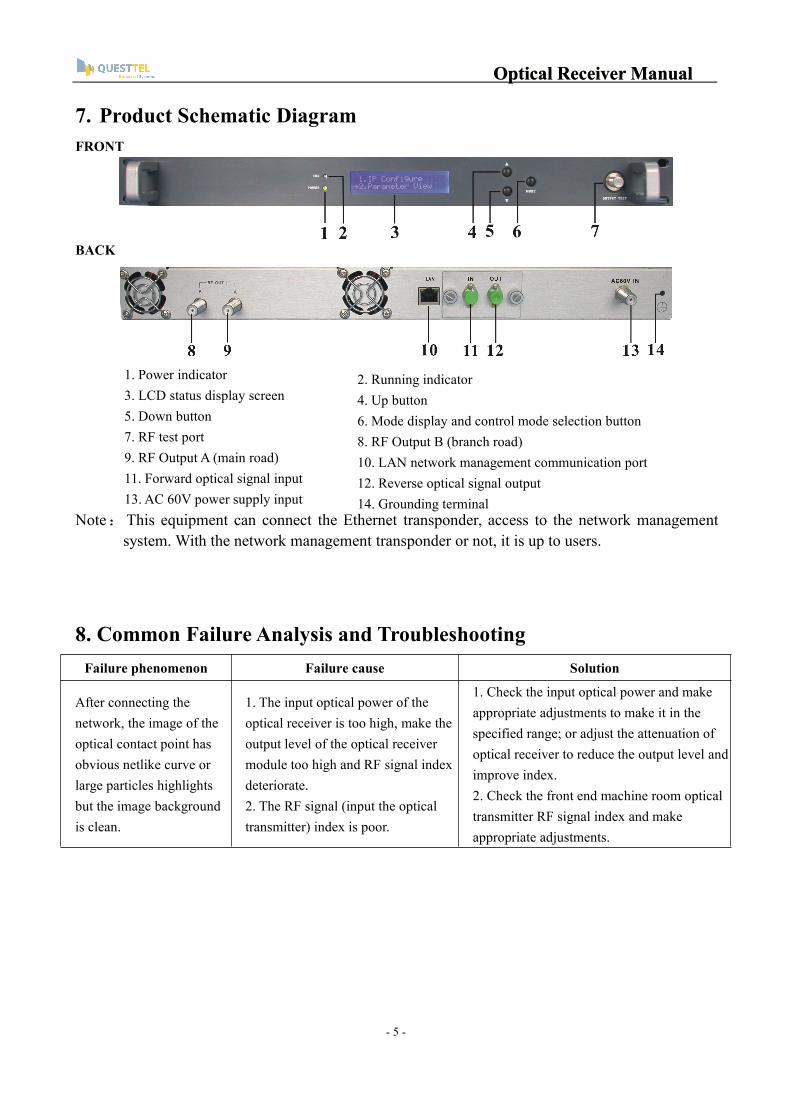
7. Product Schematic DiagramFRONT
BACK
1. Power indicator3. LCD status display screen5. Down button7. RF test port9. RF Output A (main road)11. Forward optical signal input13. AC 60V power supply input
Note:This equipment can connect the Ethernet transponder, access to the network managementsystem. With the network management transponder or not, it is up to users.
8. Common Failure Analysis and TroubleshootingFailure phenomenon Failure cause Solution
After connecting thenetwork, the image of theoptical contact point hasobvious netlike curve orlarge particles highlightsbut the image backgroundis clean.
1. The input optical power of theoptical receiver is too high, make theoutput level of the optical receivermodule too high and RF signal indexdeteriorate.2. The RF signal (input the opticaltransmitter) index is poor.
1. Check the input optical power and makeappropriate adjustments to make it in thespecified range; or adjust the attenuation ofoptical receiver to reduce the output level andimprove index.2. Check the front end machine room opticaltransmitter RF signal index and makeappropriate adjustments.
2. Running indicator4. Up button6. Mode display and control mode selection button8. RF Output B (branch road)10. LAN network management communication port12. Reverse optical signal output14. Grounding terminal

OpticalOpticalOptical ReceiverReceiverReceiver ManualManualManual
- -6
After connecting thenetwork, the image of theoptical contact point hasobvious noises.
1. The input optical power of theoptical receiver is not high enough,results in the decrease of C/N.2. The optical fiber active connectoror adapter of the optical receiver hasbeen polluted.3. The RF signal level input theoptical transmitter is too low, makemodulation degree of the laser is notenough.4. The C/N index of system linksignal is too low.
1. Check the received optical power of theoptical contact point and make appropriateadjustments to make it in the specified range.2. Recover the received optical power of theoptical contact point by cleaning the opticalfiber connector or adapter etc methods.Specific operation methods see “Clean andmaintenance method of the optical fiberactive connector”.3. Check the RF signal level input the opticaltransmitter and adjust to the required inputrange. (When the input channels number lessthan 15, should higher than nominal value.)4. Use a spectrum analyzer to check thesystem link C/N and make appropriateadjustments. Make sure the system link signalC/N﹥51dB.
After connecting thenetwork, the images ofseveral optical contactpoints randomly appearobvious noises or brighttraces.
The optical contact point has opencircuit signal interference or stronginterference signal intrusion.
1. Check if there is strong interference signalsource; change the optical contact pointlocation if possible to avoid the influence ofstrong interference signal source.2. Check the cable lines of the optical contactpoint, if there is shielding net or situation thatthe RF connector shielding effect is not good.3. Tightly closed the equipment enclosure toensure the shielding effect; if possible addshielding cover to the optical contact pointand reliable grounding.
After connecting thenetwork, the images ofseveral optical contactpoints appear one or twohorizontal bright traces.
Power supply AC ripple interferencebecause of the bad earth of equipmentor power supply.
Check grounding situation of the equipment,make sure that every equipment in the linehas been reliably grounding and thegrounding resistance must be﹤4Ω.
After connecting thenetwork, the receivedoptical power of the opticalcontact point is unstableand has large continuouschange. The output RFsignal is unstable, too. Butthe detected output opticalpower of the opticaltransmitter is normal.
The optical fiber active connectortypes do not match, maybe the APCtype connect to PC type, make theoptical signal cannot normaltransmission.The optical fiber active connector oradapter may be polluted seriously orthe adapter has been damaged.
1. Check the type of optical fiber activeconnector and adopt the APC type opticalfiber active connector to ensure the normaltransmission of optical signal.2. Clean the polluted optical fiber activeconnector or adapter. Specific operationmethods see “Clean and maintenance methodof the optical fiber active connector”.3. Replace the damaged adapter.

OpticalOpticalOptical ReceiverReceiverReceiver ManualManualManual
- -7
9. Clean and maintenance method of the optical fiber active connectorIn many times, we consider the decline of the optical power as the equipment faults, but
actually it may be caused by that the optical fiber connector was polluted by dust or dirt. Inspect thefiber connector, component, or bulkhead with a fiberscope. If the connector is dirty, clean it with acleaning technique following these steps:1. Turn off the device power supply and carefully pull off the optical fiber connector from the
adapter.2. Wash carefully with good quality lens wiping paper and medical absorbent alcohol cotton. If
use the medical absorbent alcohol cotton, still need to wait 1~2 minutes after wash, let theconnector surface dry in the air.
3. Cleaned optical connector should be connected to optical power meter to measure outputoptical power to affirm whether it has been cleaned up.
4. When connect the cleaned optical connector back to adapter, should notice to make forceappropriate to avoid china tube in the adapter crack.
5. The optical fiber connector should be cleaned in pairs. If optical power is on the low side afterclean, the adapter may be polluted, clean it. (Note: Adapter should be carefully operated, so asto avoid hurting inside fiber.
6. Use compressed air or degrease alcohol cotton to wash the adapter carefully. When usecompressed air, the muzzle aims at china tube of the adapter, clean the china tube withcompressed air. When use degrease alcohol cotton, insert directions need be consistent,otherwise can’t reach a good clean effect.
Related Documents


