CATIA Photo Studio CATIA® V5R19 TABLE OF CONTENTS Introduction .............................................................. 1 Photo Studio ........................................................ 2 Toolbars ........................................................... 4 Photo Studio Workbench .............................................. 6 Photo Studio Basics ........................................................ 7 Loading a Product ................................................... 8 Creating a Quick Render .............................................. 9 Environments ............................................................ 11 Interactive Qualities of Environments ................................... 13 Types of Environment ............................................... 15 Creating an Environment ............................................. 16 Un-rendered Walls .................................................. 17 Deactivated Walls .................................................. 20 Hide/Show & Deactivating Walls ...................................... 21 Scaling Environments ............................................... 23 Properties of Environments ........................................... 27 Moving environments ............................................... 28 Moving environments with the Bounding Box ...................... 28 Moving environments with the Compass .......................... 29 Moving environments using its Properties ......................... 30 Applying Materials to Environments .................................... 31 Procedural Textures ................................................. 33 Applying Images Files to Environments ................................. 34 Adjusting Mapped Images ............................................ 35 Environment Walls and Shadows ...................................... 42 Multiple Environments .............................................. 46 Activating and Deactivating Environments ............................... 47 Up-Pickable Environments ........................................... 48 Table of Contents, Page i © Wichita State University

Welcome message from author
This document is posted to help you gain knowledge. Please leave a comment to let me know what you think about it! Share it to your friends and learn new things together.
Transcript
CATIA Photo Studio CATIA® V5R19
TABLE OF CONTENTS
Introduction . . . . . . . . . . . . . . . . . . . . . . . . . . . . . . . . . . . . . . . . . . . . . . . . . . . . . . . . . . . . . . 1Photo Studio . . . . . . . . . . . . . . . . . . . . . . . . . . . . . . . . . . . . . . . . . . . . . . . . . . . . . . . . 2Toolbars . . . . . . . . . . . . . . . . . . . . . . . . . . . . . . . . . . . . . . . . . . . . . . . . . . . . . . . . . . . 4Photo Studio Workbench . . . . . . . . . . . . . . . . . . . . . . . . . . . . . . . . . . . . . . . . . . . . . . 6
Photo Studio Basics . . . . . . . . . . . . . . . . . . . . . . . . . . . . . . . . . . . . . . . . . . . . . . . . . . . . . . . . 7Loading a Product . . . . . . . . . . . . . . . . . . . . . . . . . . . . . . . . . . . . . . . . . . . . . . . . . . . 8Creating a Quick Render . . . . . . . . . . . . . . . . . . . . . . . . . . . . . . . . . . . . . . . . . . . . . . 9
Environments . . . . . . . . . . . . . . . . . . . . . . . . . . . . . . . . . . . . . . . . . . . . . . . . . . . . . . . . . . . . 11Interactive Qualities of Environments . . . . . . . . . . . . . . . . . . . . . . . . . . . . . . . . . . . 13Types of Environment . . . . . . . . . . . . . . . . . . . . . . . . . . . . . . . . . . . . . . . . . . . . . . . 15Creating an Environment . . . . . . . . . . . . . . . . . . . . . . . . . . . . . . . . . . . . . . . . . . . . . 16Un-rendered Walls . . . . . . . . . . . . . . . . . . . . . . . . . . . . . . . . . . . . . . . . . . . . . . . . . . 17Deactivated Walls . . . . . . . . . . . . . . . . . . . . . . . . . . . . . . . . . . . . . . . . . . . . . . . . . . 20Hide/Show & Deactivating Walls . . . . . . . . . . . . . . . . . . . . . . . . . . . . . . . . . . . . . . 21Scaling Environments . . . . . . . . . . . . . . . . . . . . . . . . . . . . . . . . . . . . . . . . . . . . . . . 23Properties of Environments . . . . . . . . . . . . . . . . . . . . . . . . . . . . . . . . . . . . . . . . . . . 27Moving environments . . . . . . . . . . . . . . . . . . . . . . . . . . . . . . . . . . . . . . . . . . . . . . . 28
Moving environments with the Bounding Box . . . . . . . . . . . . . . . . . . . . . . 28Moving environments with the Compass . . . . . . . . . . . . . . . . . . . . . . . . . . 29Moving environments using its Properties . . . . . . . . . . . . . . . . . . . . . . . . . 30
Applying Materials to Environments . . . . . . . . . . . . . . . . . . . . . . . . . . . . . . . . . . . . 31Procedural Textures . . . . . . . . . . . . . . . . . . . . . . . . . . . . . . . . . . . . . . . . . . . . . . . . . 33Applying Images Files to Environments . . . . . . . . . . . . . . . . . . . . . . . . . . . . . . . . . 34Adjusting Mapped Images . . . . . . . . . . . . . . . . . . . . . . . . . . . . . . . . . . . . . . . . . . . . 35Environment Walls and Shadows . . . . . . . . . . . . . . . . . . . . . . . . . . . . . . . . . . . . . . 42Multiple Environments . . . . . . . . . . . . . . . . . . . . . . . . . . . . . . . . . . . . . . . . . . . . . . 46Activating and Deactivating Environments . . . . . . . . . . . . . . . . . . . . . . . . . . . . . . . 47Up-Pickable Environments . . . . . . . . . . . . . . . . . . . . . . . . . . . . . . . . . . . . . . . . . . . 48
Table of Contents, Page i© Wichita State University
CATIA Photo Studio CATIA® V5R19
Cameras . . . . . . . . . . . . . . . . . . . . . . . . . . . . . . . . . . . . . . . . . . . . . . . . . . . . . . . . . . . . . . . . 49Creating a Camera . . . . . . . . . . . . . . . . . . . . . . . . . . . . . . . . . . . . . . . . . . . . . . . . . . 49Understanding Camera Representation . . . . . . . . . . . . . . . . . . . . . . . . . . . . . . . . . . 52Multiple Cameras . . . . . . . . . . . . . . . . . . . . . . . . . . . . . . . . . . . . . . . . . . . . . . . . . . . 55Camera Commands Toolbar . . . . . . . . . . . . . . . . . . . . . . . . . . . . . . . . . . . . . . . . . . 57Update From View . . . . . . . . . . . . . . . . . . . . . . . . . . . . . . . . . . . . . . . . . . . . . . . . . . 58Manipulating Cameras . . . . . . . . . . . . . . . . . . . . . . . . . . . . . . . . . . . . . . . . . . . . . . . 59
Moving a Camera by Updating the View . . . . . . . . . . . . . . . . . . . . . . . . . . 59Moving a Camera with the Compass or Bounding Box . . . . . . . . . . . . . . . 61Moving a Camera with its Manipulator Handles . . . . . . . . . . . . . . . . . . . . . 63Moving a Camera using its Position Tab . . . . . . . . . . . . . . . . . . . . . . . . . . . 64Moving a Camera using the Lens Tab . . . . . . . . . . . . . . . . . . . . . . . . . . . . . 65
Lens Type . . . . . . . . . . . . . . . . . . . . . . . . . . . . . . . . . . . . . . . . . . . . . . . . . . . . . . . . . 67Zoom Features – Focal Length and Focal Scale . . . . . . . . . . . . . . . . . . . . . . . . . . . 71Manipulate Focal . . . . . . . . . . . . . . . . . . . . . . . . . . . . . . . . . . . . . . . . . . . . . . . . . . . 73Modifying the View Angle . . . . . . . . . . . . . . . . . . . . . . . . . . . . . . . . . . . . . . . . . . . 74
Stickers . . . . . . . . . . . . . . . . . . . . . . . . . . . . . . . . . . . . . . . . . . . . . . . . . . . . . . . . . . . . . . . . . 77Mapping Types . . . . . . . . . . . . . . . . . . . . . . . . . . . . . . . . . . . . . . . . . . . . . . . . . . . . 78Creating Stickers . . . . . . . . . . . . . . . . . . . . . . . . . . . . . . . . . . . . . . . . . . . . . . . . . . . 79Mapping Type . . . . . . . . . . . . . . . . . . . . . . . . . . . . . . . . . . . . . . . . . . . . . . . . . . . . . 83Flipping and Sizing Stickers . . . . . . . . . . . . . . . . . . . . . . . . . . . . . . . . . . . . . . . . . . 85Orienting and Translating Stickers . . . . . . . . . . . . . . . . . . . . . . . . . . . . . . . . . . . . . 88Scaling Stickers Disproportionately . . . . . . . . . . . . . . . . . . . . . . . . . . . . . . . . . . . . . 90Scaling and Positioning Stickers with the Compass . . . . . . . . . . . . . . . . . . . . . . . . 93Scaling Stickers with the Sticker Manipulator Handle . . . . . . . . . . . . . . . . . . . . . . 94Applying Stickers to Multiple Faces . . . . . . . . . . . . . . . . . . . . . . . . . . . . . . . . . . . . 95Spherical Mapping . . . . . . . . . . . . . . . . . . . . . . . . . . . . . . . . . . . . . . . . . . . . . . . . . . 96Layering Stickers . . . . . . . . . . . . . . . . . . . . . . . . . . . . . . . . . . . . . . . . . . . . . . . . . . 101Lighting Options . . . . . . . . . . . . . . . . . . . . . . . . . . . . . . . . . . . . . . . . . . . . . . . . . . 103Making a Color Transparent . . . . . . . . . . . . . . . . . . . . . . . . . . . . . . . . . . . . . . . . . 106Modifying the Sticker Default Image . . . . . . . . . . . . . . . . . . . . . . . . . . . . . . . . . . . 108
Materials . . . . . . . . . . . . . . . . . . . . . . . . . . . . . . . . . . . . . . . . . . . . . . . . . . . . . . . . . . . . . . 109Applying Materials . . . . . . . . . . . . . . . . . . . . . . . . . . . . . . . . . . . . . . . . . . . . . . . . 110Copying and Pasting Materials . . . . . . . . . . . . . . . . . . . . . . . . . . . . . . . . . . . . . . . 114Positioning and Scaling Materials using the Compass . . . . . . . . . . . . . . . . . . . . . 115Material Properties . . . . . . . . . . . . . . . . . . . . . . . . . . . . . . . . . . . . . . . . . . . . . . . . . 116
Lighting Tab . . . . . . . . . . . . . . . . . . . . . . . . . . . . . . . . . . . . . . . . . . . . . . . . 118Texture Tab . . . . . . . . . . . . . . . . . . . . . . . . . . . . . . . . . . . . . . . . . . . . . . . . 133
Material Libraries . . . . . . . . . . . . . . . . . . . . . . . . . . . . . . . . . . . . . . . . . . . . . . . . . . 147Creating a Material Library . . . . . . . . . . . . . . . . . . . . . . . . . . . . . . . . . . . . 147Adding new materials . . . . . . . . . . . . . . . . . . . . . . . . . . . . . . . . . . . . . . . . 149Adding New Families to a Library . . . . . . . . . . . . . . . . . . . . . . . . . . . . . . . 150Deleting Materials and Families . . . . . . . . . . . . . . . . . . . . . . . . . . . . . . . . 150Copying and Pasting Materials between Families . . . . . . . . . . . . . . . . . . . 150Returning to CATIA’s Default Library . . . . . . . . . . . . . . . . . . . . . . . . . . . 151
Table of Contents, Page ii ©Wichita State University
CATIA Photo Studio CATIA® V5R19
Lighting . . . . . . . . . . . . . . . . . . . . . . . . . . . . . . . . . . . . . . . . . . . . . . . . . . . . . . . . . . . . . . . 153Creating a Light Source . . . . . . . . . . . . . . . . . . . . . . . . . . . . . . . . . . . . . . . . . . . . . 154Light Properties . . . . . . . . . . . . . . . . . . . . . . . . . . . . . . . . . . . . . . . . . . . . . . . . . . . 159
Lighting Tab . . . . . . . . . . . . . . . . . . . . . . . . . . . . . . . . . . . . . . . . . . . . . . . . 159Shadows Tab . . . . . . . . . . . . . . . . . . . . . . . . . . . . . . . . . . . . . . . . . . . . . . . 173Area Tab . . . . . . . . . . . . . . . . . . . . . . . . . . . . . . . . . . . . . . . . . . . . . . . . . . . 175Indirect Illumination Tab . . . . . . . . . . . . . . . . . . . . . . . . . . . . . . . . . . . . . . 177Position Tab . . . . . . . . . . . . . . . . . . . . . . . . . . . . . . . . . . . . . . . . . . . . . . . . 179
Punctual (Standard) Light Characteristics and Common Uses . . . . . . . . . . . . . . . 180Surfacic (Area) Light Characteristics and Common Uses . . . . . . . . . . . . . . . . . . . 181Light Commands Toolbar . . . . . . . . . . . . . . . . . . . . . . . . . . . . . . . . . . . . . . . . . . . 183Turning lights on and off . . . . . . . . . . . . . . . . . . . . . . . . . . . . . . . . . . . . . . . . . . . . 188Three Point Light Set-up . . . . . . . . . . . . . . . . . . . . . . . . . . . . . . . . . . . . . . . . . . . . 189
Shootings . . . . . . . . . . . . . . . . . . . . . . . . . . . . . . . . . . . . . . . . . . . . . . . . . . . . . . . . . . . . . . 193Creating a Shooting . . . . . . . . . . . . . . . . . . . . . . . . . . . . . . . . . . . . . . . . . . . . . . . . 194Active Shootings . . . . . . . . . . . . . . . . . . . . . . . . . . . . . . . . . . . . . . . . . . . . . . . . . . 206Editing Shootings . . . . . . . . . . . . . . . . . . . . . . . . . . . . . . . . . . . . . . . . . . . . . . . . . . 207
Managing Rendered Output . . . . . . . . . . . . . . . . . . . . . . . . . . . . . . . . . . . . . . . . . . . . . . . . 209Saving Single-Frames from On Screen Output . . . . . . . . . . . . . . . . . . . . . . . . . . . 209Saving Animations . . . . . . . . . . . . . . . . . . . . . . . . . . . . . . . . . . . . . . . . . . . . . . . . . 212Tool Options Settings . . . . . . . . . . . . . . . . . . . . . . . . . . . . . . . . . . . . . . . . . . . . . . 215
Animation . . . . . . . . . . . . . . . . . . . . . . . . . . . . . . . . . . . . . . . . . . . . . . . . . . . . . . . . . . . . . 217Previewing the Turntable Animation . . . . . . . . . . . . . . . . . . . . . . . . . . . . . . . . . . . 220Rendering the Turntable Animation . . . . . . . . . . . . . . . . . . . . . . . . . . . . . . . . . . . 222Simulation Animations . . . . . . . . . . . . . . . . . . . . . . . . . . . . . . . . . . . . . . . . . . . . . 224Rendering the Simulation Animation . . . . . . . . . . . . . . . . . . . . . . . . . . . . . . . . . . 227
Photo Studio Easy Tools . . . . . . . . . . . . . . . . . . . . . . . . . . . . . . . . . . . . . . . . . . . . . . . . . . 229Custom Scenes . . . . . . . . . . . . . . . . . . . . . . . . . . . . . . . . . . . . . . . . . . . . . . . . . . . . 232
Practice Problems . . . . . . . . . . . . . . . . . . . . . . . . . . . . . . . . . . . . . . . . . . . . . . . . . . . . . . . . 239Problem #1 . . . . . . . . . . . . . . . . . . . . . . . . . . . . . . . . . . . . . . . . . . . . . . . . . . . . . . . 239Problem #2 . . . . . . . . . . . . . . . . . . . . . . . . . . . . . . . . . . . . . . . . . . . . . . . . . . . . . . . 240Problem #3 . . . . . . . . . . . . . . . . . . . . . . . . . . . . . . . . . . . . . . . . . . . . . . . . . . . . . . . 241Problem #4 . . . . . . . . . . . . . . . . . . . . . . . . . . . . . . . . . . . . . . . . . . . . . . . . . . . . . . . 242Problem #5 . . . . . . . . . . . . . . . . . . . . . . . . . . . . . . . . . . . . . . . . . . . . . . . . . . . . . . . 243
Table of Contents, Page iii© Wichita State University
CATIA Photo Studio CATIA® V5R19
Introduction
CATIA Version 5 Photo Studio
Upon completion of this course, the student should have a full understanding of thefollowing topics:
- Environments, lights, and cameras
- Texture creation and application
- Turntable and simulation animations
- Basic lighting techniques
- Rendering
Introduction, Page 1© Wichita State University
CATIA Photo Studio CATIA® V5R19
Photo Studio
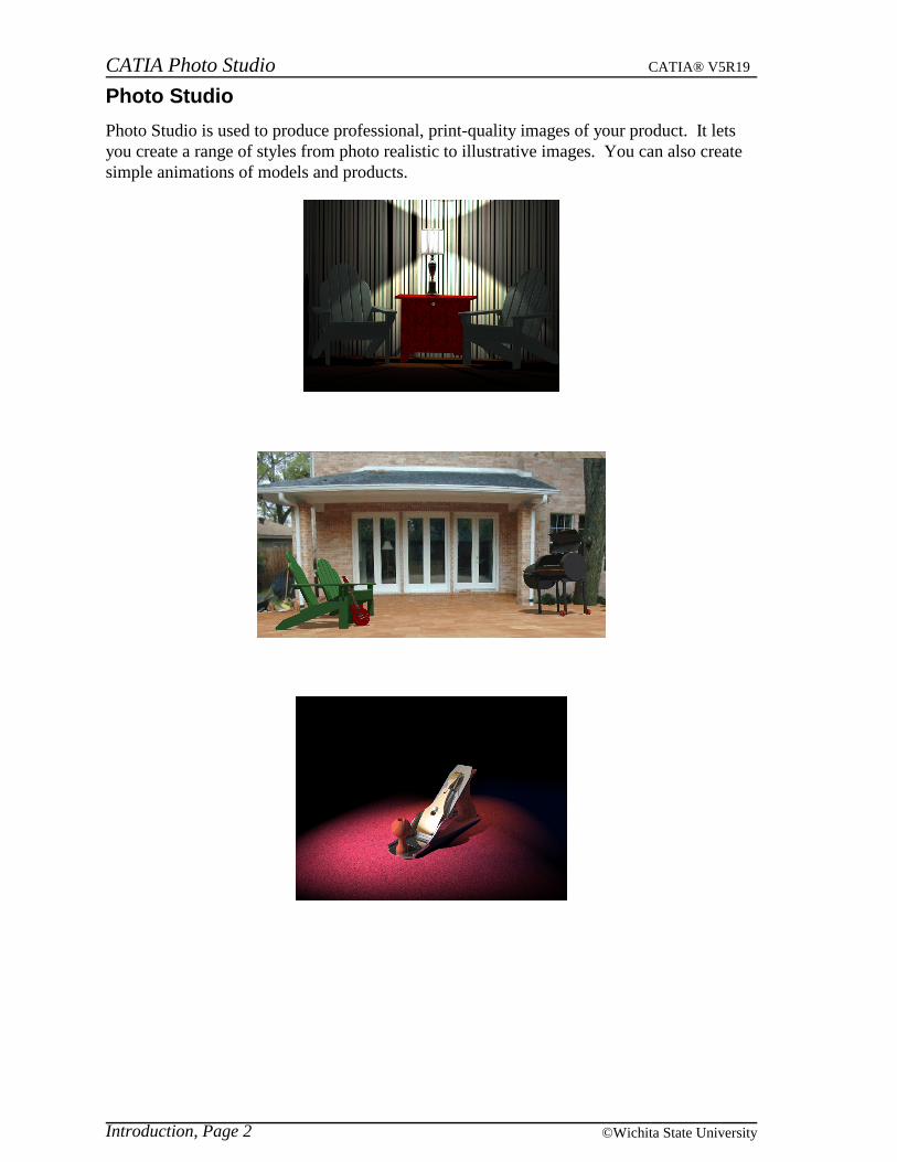
Photo Studio is used to produce professional, print-quality images of your product. It letsyou create a range of styles from photo realistic to illustrative images. You can also createsimple animations of models and products.
Introduction, Page 2 ©Wichita State University
CATIA Photo Studio CATIA® V5R19
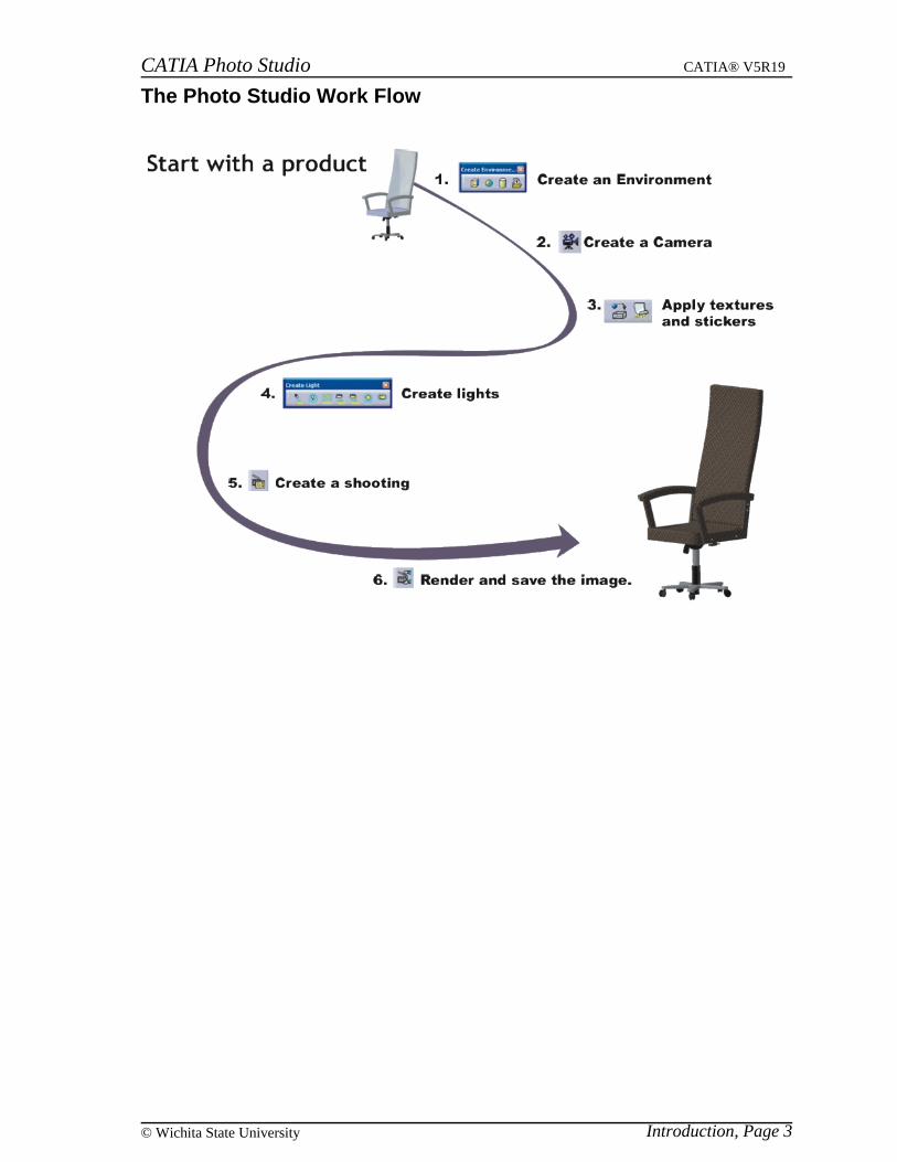
The Photo Studio Work Flow
Introduction, Page 3© Wichita State University
CATIA Photo Studio CATIA® V5R19
Lighting
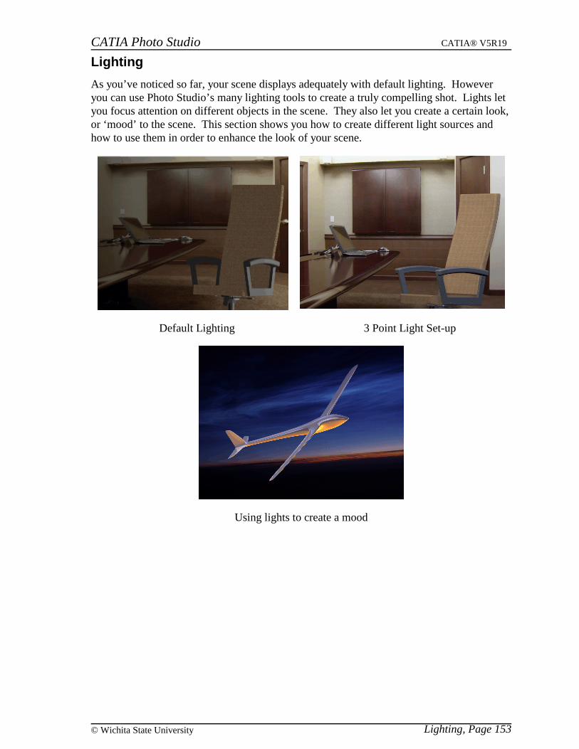
As you’ve noticed so far, your scene displays adequately with default lighting. Howeveryou can use Photo Studio’s many lighting tools to create a truly compelling shot. Lights letyou focus attention on different objects in the scene. They also let you create a certain look,or ‘mood’ to the scene. This section shows you how to create different light sources andhow to use them in order to enhance the look of your scene.
Default Lighting 3 Point Light Set-up
Using lights to create a mood
Lighting, Page 153© Wichita State University
CATIA Photo Studio CATIA® V5R19
Creating a Light Source
There are a number of available lighting options.
Create a new product document.
Take a look at the Create Light toolbar.
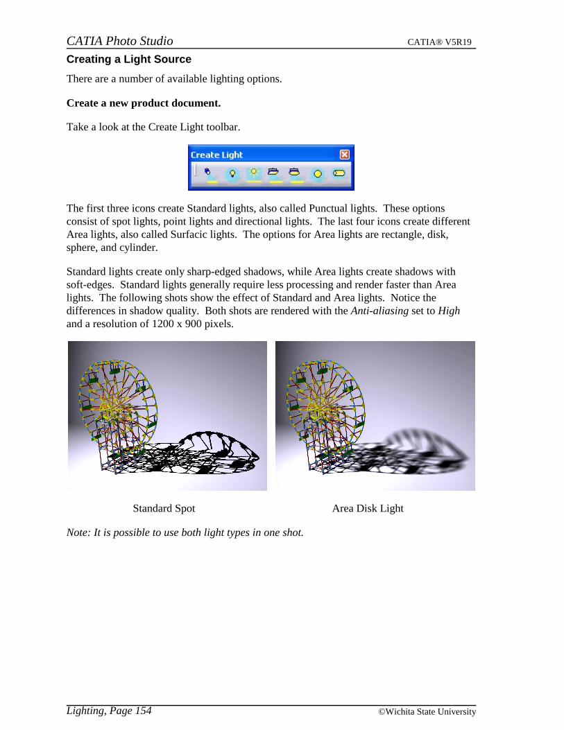
The first three icons create Standard lights, also called Punctual lights. These optionsconsist of spot lights, point lights and directional lights. The last four icons create differentArea lights, also called Surfacic lights. The options for Area lights are rectangle, disk,sphere, and cylinder.
Standard lights create only sharp-edged shadows, while Area lights create shadows withsoft-edges. Standard lights generally require less processing and render faster than Arealights. The following shots show the effect of Standard and Area lights. Notice thedifferences in shadow quality. Both shots are rendered with the Anti-aliasing set to Highand a resolution of 1200 x 900 pixels.
Standard Spot Area Disk Light
Note: It is possible to use both light types in one shot.
Lighting, Page 154 ©Wichita State University
CATIA Photo Studio CATIA® V5R19
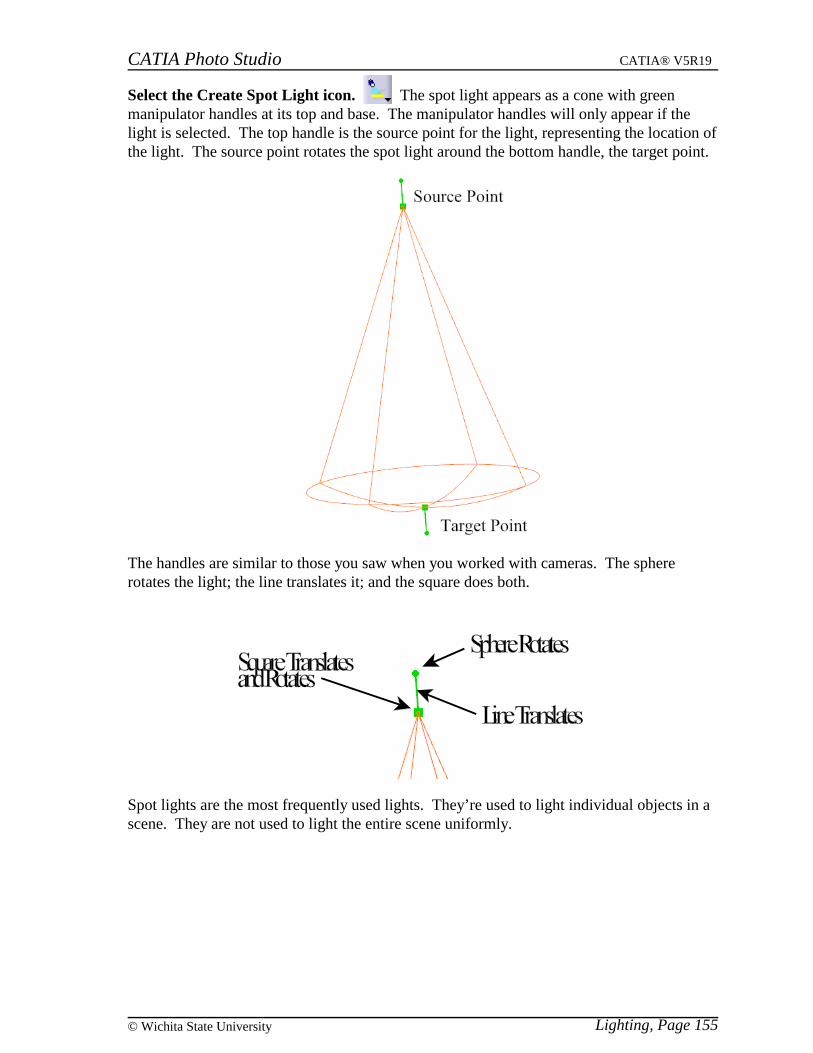
Select the Create Spot Light icon. The spot light appears as a cone with greenmanipulator handles at its top and base. The manipulator handles will only appear if thelight is selected. The top handle is the source point for the light, representing the location ofthe light. The source point rotates the spot light around the bottom handle, the target point.
The handles are similar to those you saw when you worked with cameras. The sphererotates the light; the line translates it; and the square does both.
Spot lights are the most frequently used lights. They’re used to light individual objects in ascene. They are not used to light the entire scene uniformly.
Lighting, Page 155© Wichita State University
CATIA Photo Studio CATIA® V5R19
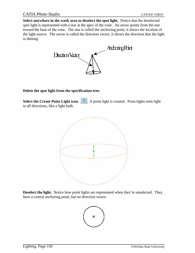
Select anywhere in the work area to deselect the spot light. Notice that the deselectedspot light is represented with a star at the apex of the cone. An arrow points from the startoward the base of the cone. The star is called the anchoring point, it shows the location ofthe light source. The arrow is called the direction vector, it shows the direction that the lightis shining.
Delete the spot light from the specification tree.
Select the Create Point Light icon. A point light is created. Point lights emit lightin all directions, like a light bulb.
Deselect the light. Notice how point lights are represented when they’re unselected. Theyhave a central anchoring point, but no direction vector.
Lighting, Page 156 ©Wichita State University
CATIA Photo Studio CATIA® V5R19
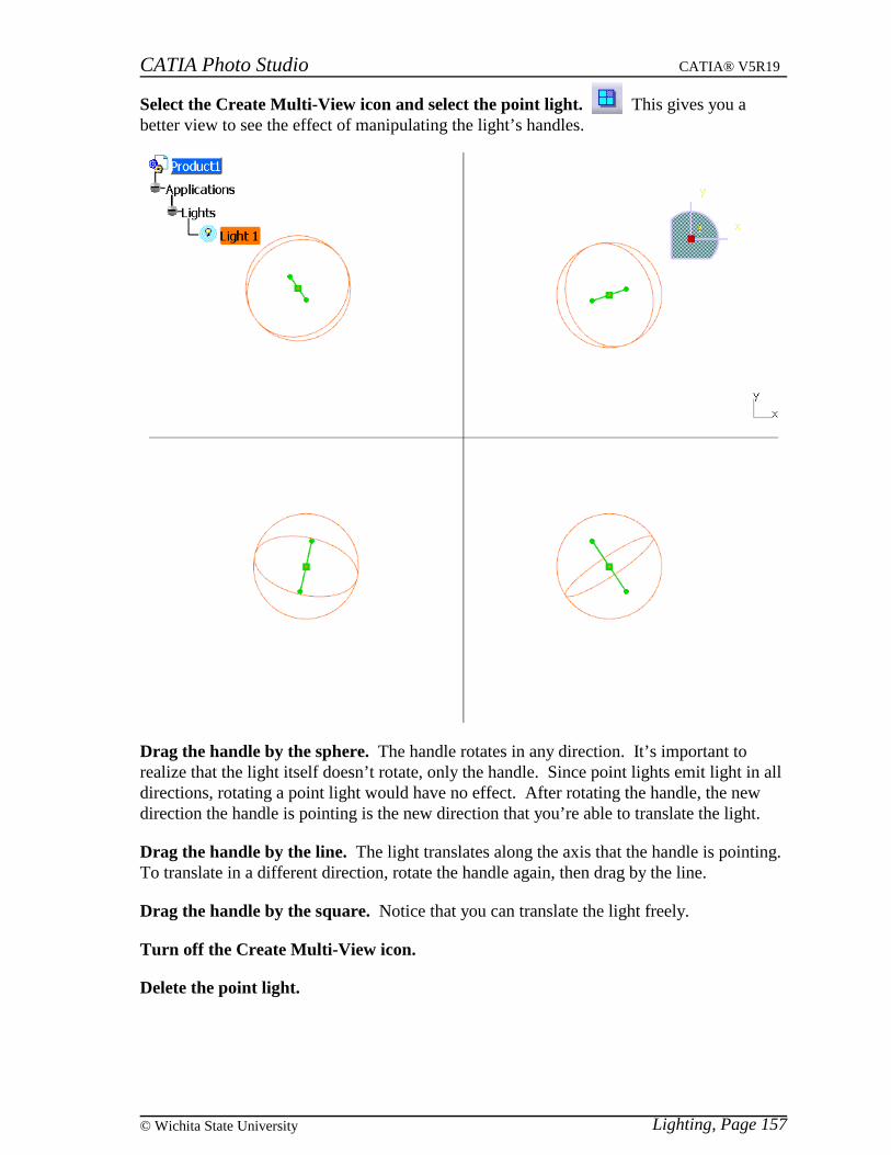
Select the Create Multi-View icon and select the point light. This gives you abetter view to see the effect of manipulating the light’s handles.
Drag the handle by the sphere. The handle rotates in any direction. It’s important torealize that the light itself doesn’t rotate, only the handle. Since point lights emit light in alldirections, rotating a point light would have no effect. After rotating the handle, the newdirection the handle is pointing is the new direction that you’re able to translate the light.
Drag the handle by the line. The light translates along the axis that the handle is pointing.To translate in a different direction, rotate the handle again, then drag by the line.
Drag the handle by the square. Notice that you can translate the light freely.
Turn off the Create Multi-View icon.
Delete the point light.
Lighting, Page 157© Wichita State University
CATIA Photo Studio CATIA® V5R19
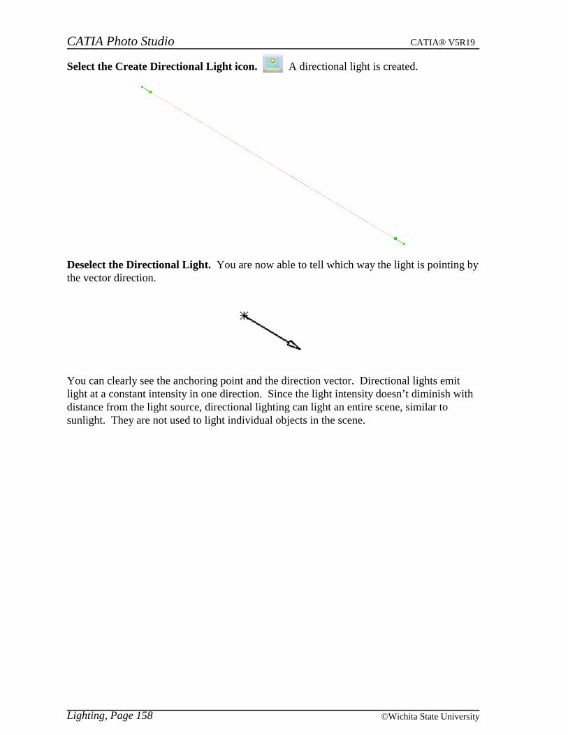
Select the Create Directional Light icon. A directional light is created.
Deselect the Directional Light. You are now able to tell which way the light is pointing bythe vector direction.
You can clearly see the anchoring point and the direction vector. Directional lights emitlight at a constant intensity in one direction. Since the light intensity doesn’t diminish withdistance from the light source, directional lighting can light an entire scene, similar tosunlight. They are not used to light individual objects in the scene.
Lighting, Page 158 ©Wichita State University
CATIA Photo Studio CATIA® V5R19
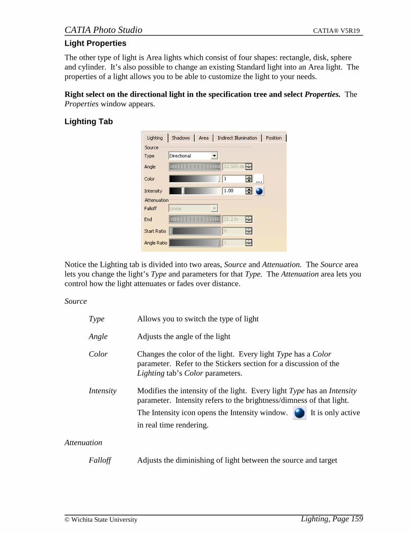
Light Properties
The other type of light is Area lights which consist of four shapes: rectangle, disk, sphereand cylinder. It’s also possible to change an existing Standard light into an Area light. Theproperties of a light allows you to be able to customize the light to your needs.
Right select on the directional light in the specification tree and select Properties. TheProperties window appears.
Lighting Tab
Notice the Lighting tab is divided into two areas, Source and Attenuation. The Source arealets you change the light’s Type and parameters for that Type. The Attenuation area lets youcontrol how the light attenuates or fades over distance.
Source
Type Allows you to switch the type of light
Angle Adjusts the angle of the light
Color Changes the color of the light. Every light Type has a Colorparameter. Refer to the Stickers section for a discussion of theLighting tab’s Color parameters.
Intensity Modifies the intensity of the light. Every light Type has an Intensityparameter. Intensity refers to the brightness/dimness of that light.
The Intensity icon opens the Intensity window. It is only active
in real time rendering.
Attenuation
Falloff Adjusts the diminishing of light between the source and target
Lighting, Page 159© Wichita State University
CATIA Photo Studio CATIA® V5R19
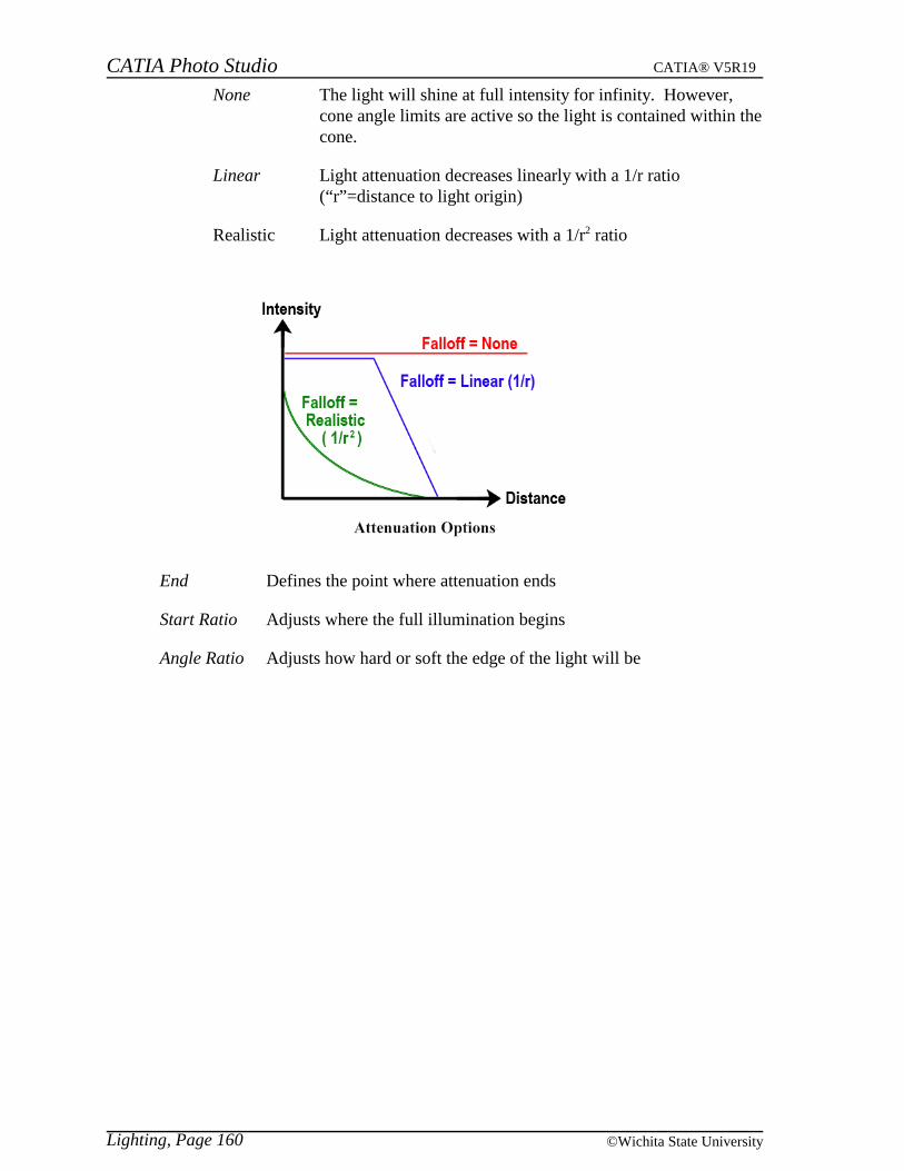
None The light will shine at full intensity for infinity. However,cone angle limits are active so the light is contained within thecone.
Linear Light attenuation decreases linearly with a 1/r ratio(“r”=distance to light origin)
Realistic Light attenuation decreases with a 1/r2 ratio
End Defines the point where attenuation ends
Start Ratio Adjusts where the full illumination begins
Angle Ratio Adjusts how hard or soft the edge of the light will be
Lighting, Page 160 ©Wichita State University
CATIA Photo Studio CATIA® V5R19
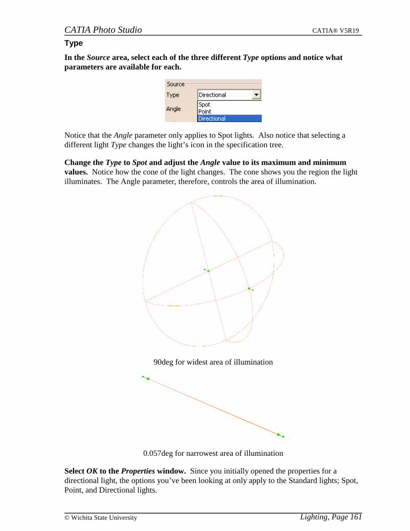
Type
In the Source area, select each of the three different Type options and notice whatparameters are available for each.
Notice that the Angle parameter only applies to Spot lights. Also notice that selecting adifferent light Type changes the light’s icon in the specification tree.
Change the Type to Spot and adjust the Angle value to its maximum and minimumvalues. Notice how the cone of the light changes. The cone shows you the region the lightilluminates. The Angle parameter, therefore, controls the area of illumination.
90deg for widest area of illumination
0.057deg for narrowest area of illumination
Select OK to the Properties window. Since you initially opened the properties for adirectional light, the options you’ve been looking at only apply to the Standard lights; Spot,Point, and Directional lights.
Lighting, Page 161© Wichita State University
CATIA Photo Studio CATIA® V5R19
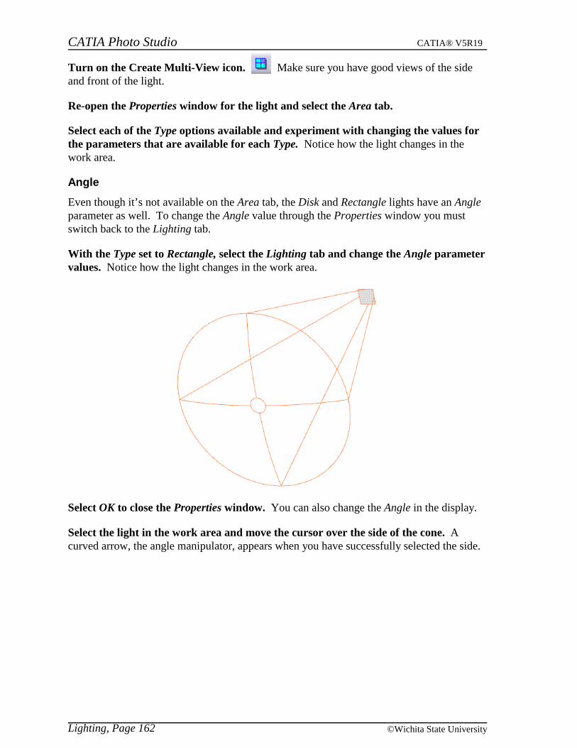
Turn on the Create Multi-View icon. Make sure you have good views of the sideand front of the light.
Re-open the Properties window for the light and select the Area tab.
Select each of the Type options available and experiment with changing the values forthe parameters that are available for each Type. Notice how the light changes in thework area.
Angle
Even though it’s not available on the Area tab, the Disk and Rectangle lights have an Angleparameter as well. To change the Angle value through the Properties window you mustswitch back to the Lighting tab.
With the Type set to Rectangle, select the Lighting tab and change the Angle parametervalues. Notice how the light changes in the work area.
Select OK to close the Properties window. You can also change the Angle in the display.
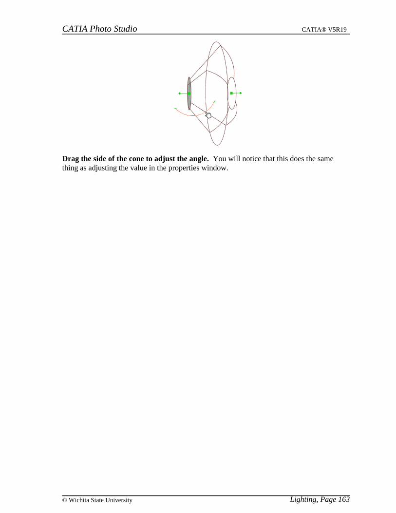
Select the light in the work area and move the cursor over the side of the cone. Acurved arrow, the angle manipulator, appears when you have successfully selected the side.
Lighting, Page 162 ©Wichita State University
CATIA Photo Studio CATIA® V5R19
Drag the side of the cone to adjust the angle. You will notice that this does the samething as adjusting the value in the properties window.
Lighting, Page 163© Wichita State University

CATIA Photo Studio CATIA® V5R19
Falloff
Attenuation is the diminishing of light from full strength (at the light source) to zero (at thelight target) within the perimeters of the light. Think of the perimeter as the boundary of thelight, i.e., the cone that encloses the light. The perimeter is what you see when you selectthe light.
Another name for attenuation is falloff. All lights, except directional lights, have falloff.Directional lights shine at a constant intensity over an infinite distance so there is nodiminishing of light.
Under the Attenuation section of the Lighting tab, select the drop down menu forFalloff. You can choose from three types.
Select Linear for now.
Lighting, Page 164 ©Wichita State University
CATIA Photo Studio CATIA® V5R19
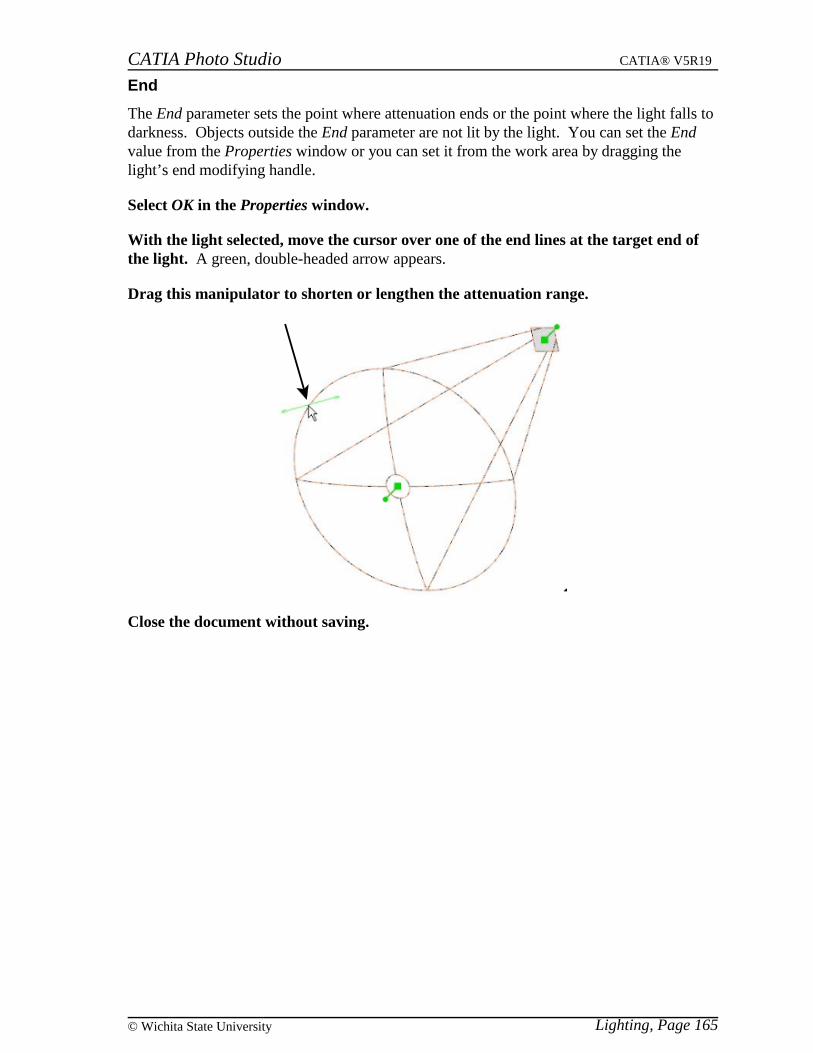
End
The End parameter sets the point where attenuation ends or the point where the light falls todarkness. Objects outside the End parameter are not lit by the light. You can set the Endvalue from the Properties window or you can set it from the work area by dragging thelight’s end modifying handle.
Select OK in the Properties window.
With the light selected, move the cursor over one of the end lines at the target end ofthe light. A green, double-headed arrow appears.
Drag this manipulator to shorten or lengthen the attenuation range.
Close the document without saving.
Lighting, Page 165© Wichita State University
CATIA Photo Studio CATIA® V5R19
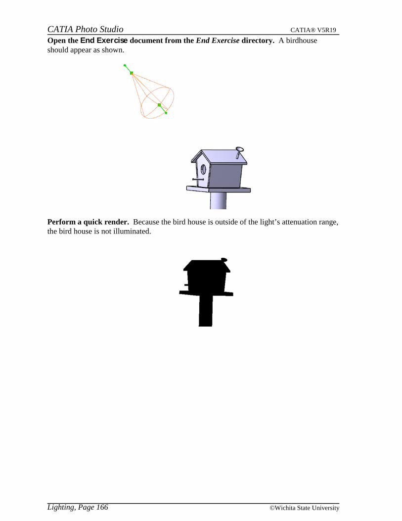
Open the End Exercise document from the End Exercise directory. A birdhouseshould appear as shown.
Perform a quick render. Because the bird house is outside of the light’s attenuation range,the bird house is not illuminated.
Lighting, Page 166 ©Wichita State University
CATIA Photo Studio CATIA® V5R19
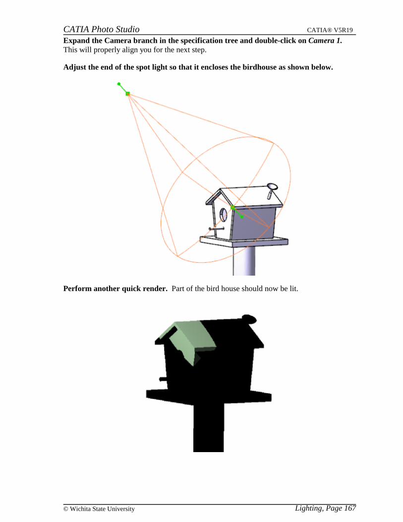
Expand the Camera branch in the specification tree and double-click on Camera 1.This will properly align you for the next step.
Adjust the end of the spot light so that it encloses the birdhouse as shown below.
Perform another quick render. Part of the bird house should now be lit.
Lighting, Page 167© Wichita State University
CATIA Photo Studio CATIA® V5R19
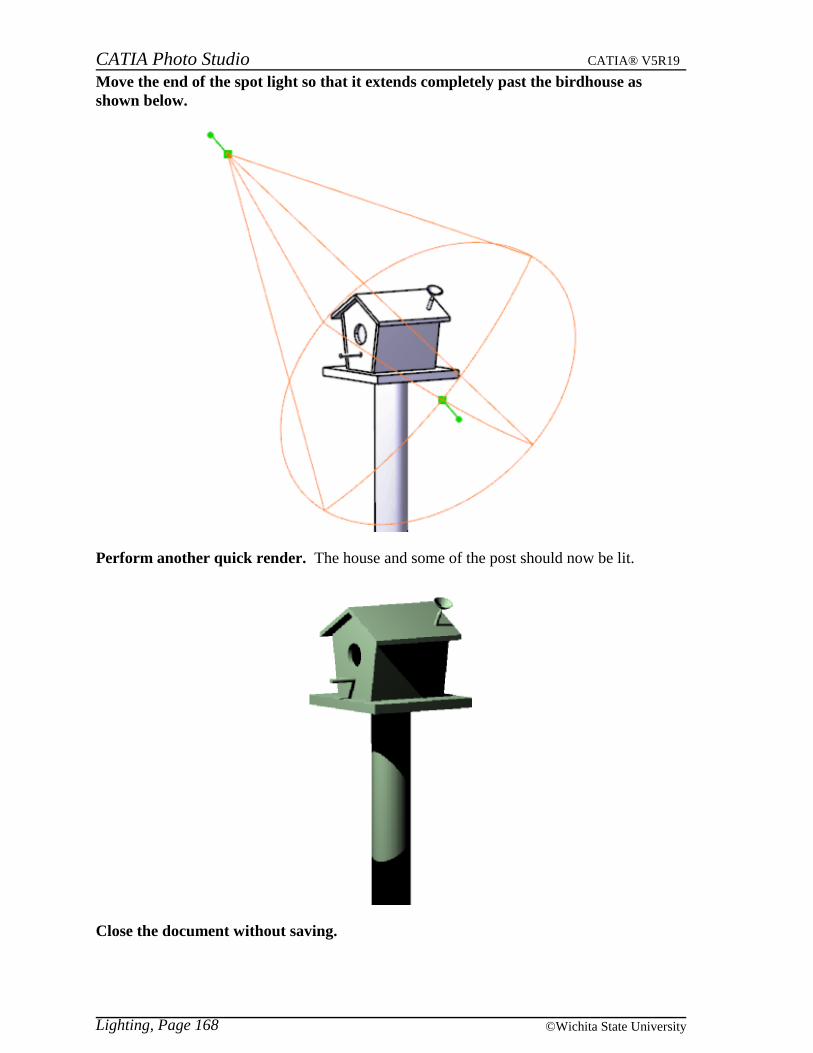
Move the end of the spot light so that it extends completely past the birdhouse asshown below.
Perform another quick render. The house and some of the post should now be lit.
Close the document without saving.
Lighting, Page 168 ©Wichita State University
CATIA Photo Studio CATIA® V5R19
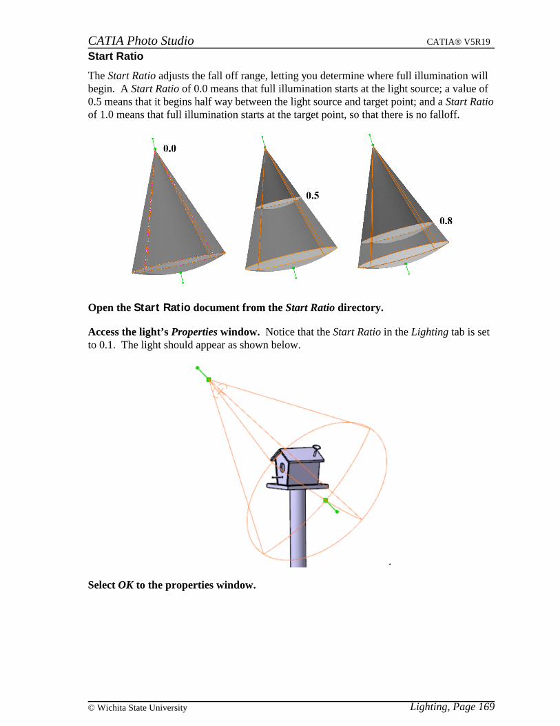
Start Ratio
The Start Ratio adjusts the fall off range, letting you determine where full illumination willbegin. A Start Ratio of 0.0 means that full illumination starts at the light source; a value of0.5 means that it begins half way between the light source and target point; and a Start Ratioof 1.0 means that full illumination starts at the target point, so that there is no falloff.
Open the Start Ratio document from the Start Ratio directory.
Access the light’s Properties window. Notice that the Start Ratio in the Lighting tab is setto 0.1. The light should appear as shown below.
Select OK to the properties window.
Lighting, Page 169© Wichita State University
CATIA Photo Studio CATIA® V5R19
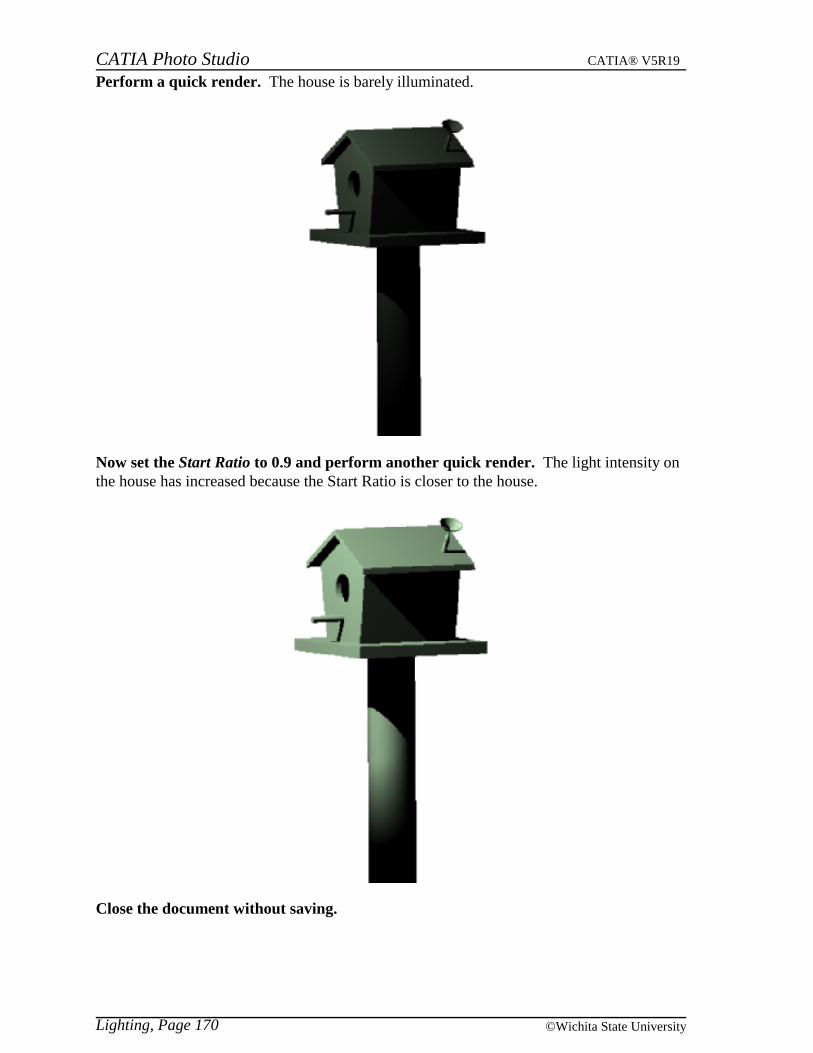
Perform a quick render. The house is barely illuminated.
Now set the Start Ratio to 0.9 and perform another quick render. The light intensity onthe house has increased because the Start Ratio is closer to the house.
Close the document without saving.
Lighting, Page 170 ©Wichita State University

CATIA Photo Studio CATIA® V5R19
Angle Ratio
The Angle Ratio determines how hard or soft the edge of the light is. Only spot, rectangle,and disk lights have this parameter.
Open the Angle Ratio document from the Angle Ratio directory and look at the lightsetup. The light is focused on the front of the birdhouse, and the target point is locatedabout halfway to the back of the birdhouse.
Lighting, Page 171© Wichita State University
CATIA Photo Studio CATIA® V5R19
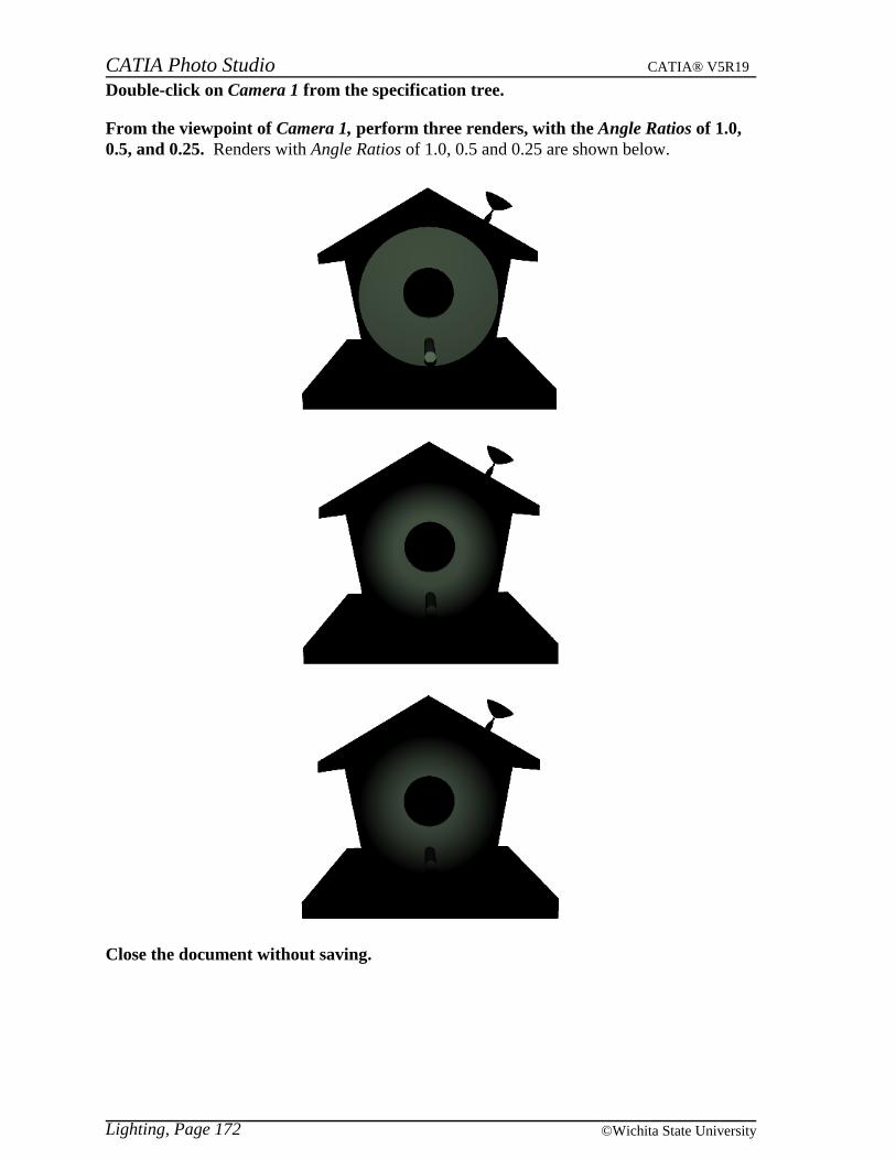
Double-click on Camera 1 from the specification tree.
From the viewpoint of Camera 1, perform three renders, with the Angle Ratios of 1.0,0.5, and 0.25. Renders with Angle Ratios of 1.0, 0.5 and 0.25 are shown below.
Close the document without saving.
Lighting, Page 172 ©Wichita State University
CATIA Photo Studio CATIA® V5R19
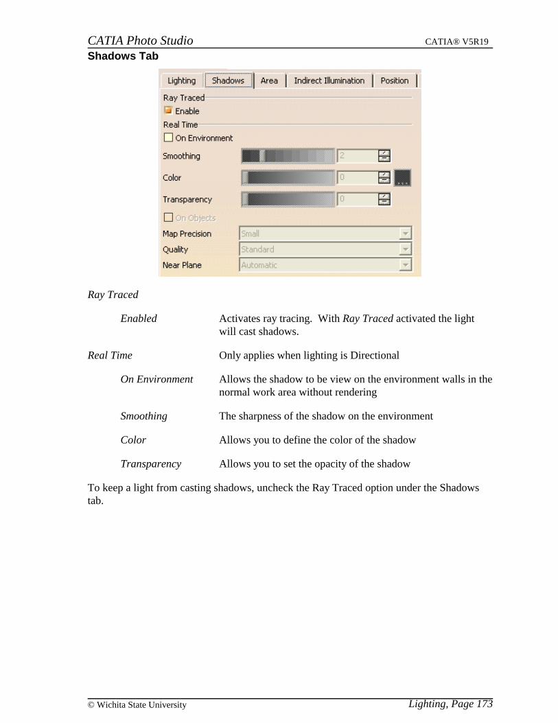
Shadows Tab
Ray Traced
Enabled Activates ray tracing. With Ray Traced activated the lightwill cast shadows.
Real Time Only applies when lighting is Directional
On Environment Allows the shadow to be view on the environment walls in thenormal work area without rendering
Smoothing The sharpness of the shadow on the environment
Color Allows you to define the color of the shadow
Transparency Allows you to set the opacity of the shadow
To keep a light from casting shadows, uncheck the Ray Traced option under the Shadowstab.
Lighting, Page 173© Wichita State University

CATIA Photo Studio CATIA® V5R19
Open the Shadows document from the Shadows directory.
Perform a render from the viewpoint of Camera 1. In this case the Ray Traced option isdeactivated so there should not be any shadows.
In the Properties window of Light 1, turn on the Ray Traced option in the Shadows tab.
Perform another render from the viwpoint of Camera 1. This time the view will showshadows from the light.
Close the document without saving.
Lighting, Page 174 ©Wichita State University
Related Documents


