CATIA Electrical Design CATIA® V5R19 TABLE OF CONTENTS Introduction .............................................................. 1 Electrical Design .................................................... 2 Electrical Part Design Workbench ....................................... 4 Electrical Assembly Design Workbench .................................. 5 Bottom Toolbar ..................................................... 6 Catalog Browser ............................................... 6 External System Management .................................... 6 Electrical Part Design ....................................................... 7 Mounting Equipment ................................................. 7 Mounting Equipment with Cavity ................................. 8 Defining a Cavity ....................................... 10 Mounting Equipment with Cavity Connection Point .................. 15 Defining a Cavity Connection Point ........................ 16 Mounting Equipment with a Bundle Connection Point ................ 20 Defining a Bundle Connection Point ........................ 20 Equipment ........................................................ 24 Shells ............................................................ 31 Shell Equipment with a Shell Connection Point ..................... 35 Defining a Shell Connection Point ......................... 36 Shell Equipment with a Back Shell Connection Point ................. 40 Defining a Back Shell Connection Point ..................... 41 Connector ......................................................... 43 Single Insert Connector ........................................ 43 Single Insert Connector with Connector Connection Point ....... 43 Defining a Connector Connection Point ..................... 47 Stud, Terminal Strip, Terminal Block ............................. 53 External Splice ............................................... 58 Multi Insert Connectors ........................................ 60 Defining Terminations ................................... 63 Contacts .......................................................... 66 Filler Plug ......................................................... 68 Back Shell ........................................................ 70 Protection Part ..................................................... 76 Supports .......................................................... 81 Multi-Position Supports ........................................ 88 Adaptive Supports ............................................ 91 Table of Contents, Page i © Wichita State University

Welcome message from author
This document is posted to help you gain knowledge. Please leave a comment to let me know what you think about it! Share it to your friends and learn new things together.
Transcript

CATIA Electrical Design CATIA® V5R19
TABLE OF CONTENTS
Introduction . . . . . . . . . . . . . . . . . . . . . . . . . . . . . . . . . . . . . . . . . . . . . . . . . . . . . . . . . . . . . . 1Electrical Design . . . . . . . . . . . . . . . . . . . . . . . . . . . . . . . . . . . . . . . . . . . . . . . . . . . . 2Electrical Part Design Workbench . . . . . . . . . . . . . . . . . . . . . . . . . . . . . . . . . . . . . . . 4Electrical Assembly Design Workbench . . . . . . . . . . . . . . . . . . . . . . . . . . . . . . . . . . 5Bottom Toolbar . . . . . . . . . . . . . . . . . . . . . . . . . . . . . . . . . . . . . . . . . . . . . . . . . . . . . 6
Catalog Browser . . . . . . . . . . . . . . . . . . . . . . . . . . . . . . . . . . . . . . . . . . . . . . . 6External System Management . . . . . . . . . . . . . . . . . . . . . . . . . . . . . . . . . . . . 6
Electrical Part Design . . . . . . . . . . . . . . . . . . . . . . . . . . . . . . . . . . . . . . . . . . . . . . . . . . . . . . . 7Mounting Equipment . . . . . . . . . . . . . . . . . . . . . . . . . . . . . . . . . . . . . . . . . . . . . . . . . 7
Mounting Equipment with Cavity . . . . . . . . . . . . . . . . . . . . . . . . . . . . . . . . . 8Defining a Cavity . . . . . . . . . . . . . . . . . . . . . . . . . . . . . . . . . . . . . . . 10
Mounting Equipment with Cavity Connection Point . . . . . . . . . . . . . . . . . . 15Defining a Cavity Connection Point . . . . . . . . . . . . . . . . . . . . . . . . 16
Mounting Equipment with a Bundle Connection Point . . . . . . . . . . . . . . . . 20Defining a Bundle Connection Point . . . . . . . . . . . . . . . . . . . . . . . . 20
Equipment . . . . . . . . . . . . . . . . . . . . . . . . . . . . . . . . . . . . . . . . . . . . . . . . . . . . . . . . 24Shells . . . . . . . . . . . . . . . . . . . . . . . . . . . . . . . . . . . . . . . . . . . . . . . . . . . . . . . . . . . . 31
Shell Equipment with a Shell Connection Point . . . . . . . . . . . . . . . . . . . . . 35Defining a Shell Connection Point . . . . . . . . . . . . . . . . . . . . . . . . . 36
Shell Equipment with a Back Shell Connection Point . . . . . . . . . . . . . . . . . 40Defining a Back Shell Connection Point . . . . . . . . . . . . . . . . . . . . . 41
Connector . . . . . . . . . . . . . . . . . . . . . . . . . . . . . . . . . . . . . . . . . . . . . . . . . . . . . . . . . 43Single Insert Connector . . . . . . . . . . . . . . . . . . . . . . . . . . . . . . . . . . . . . . . . 43
Single Insert Connector with Connector Connection Point . . . . . . . 43Defining a Connector Connection Point . . . . . . . . . . . . . . . . . . . . . 47
Stud, Terminal Strip, Terminal Block . . . . . . . . . . . . . . . . . . . . . . . . . . . . . 53External Splice . . . . . . . . . . . . . . . . . . . . . . . . . . . . . . . . . . . . . . . . . . . . . . . 58Multi Insert Connectors . . . . . . . . . . . . . . . . . . . . . . . . . . . . . . . . . . . . . . . . 60
Defining Terminations . . . . . . . . . . . . . . . . . . . . . . . . . . . . . . . . . . . 63Contacts . . . . . . . . . . . . . . . . . . . . . . . . . . . . . . . . . . . . . . . . . . . . . . . . . . . . . . . . . . 66Filler Plug . . . . . . . . . . . . . . . . . . . . . . . . . . . . . . . . . . . . . . . . . . . . . . . . . . . . . . . . . 68Back Shell . . . . . . . . . . . . . . . . . . . . . . . . . . . . . . . . . . . . . . . . . . . . . . . . . . . . . . . . 70Protection Part . . . . . . . . . . . . . . . . . . . . . . . . . . . . . . . . . . . . . . . . . . . . . . . . . . . . . 76Supports . . . . . . . . . . . . . . . . . . . . . . . . . . . . . . . . . . . . . . . . . . . . . . . . . . . . . . . . . . 81
Multi-Position Supports . . . . . . . . . . . . . . . . . . . . . . . . . . . . . . . . . . . . . . . . 88Adaptive Supports . . . . . . . . . . . . . . . . . . . . . . . . . . . . . . . . . . . . . . . . . . . . 91
Table of Contents, Page i© Wichita State University

CATIA Electrical Design CATIA® V5R19
Electrical Catalogs . . . . . . . . . . . . . . . . . . . . . . . . . . . . . . . . . . . . . . . . . . . . . . . . . . . . . . . . 97Catalog Environment . . . . . . . . . . . . . . . . . . . . . . . . . . . . . . . . . . . . . . . . . . . . . . . . 97
Catalog Editor Workbench . . . . . . . . . . . . . . . . . . . . . . . . . . . . . . . . . . . . . 98Terminology . . . . . . . . . . . . . . . . . . . . . . . . . . . . . . . . . . . . . . . . . . . . . . . . . 98
Catalog Structure . . . . . . . . . . . . . . . . . . . . . . . . . . . . . . . . . . . . . . . . . . . . . . . . . . . 99Chapters . . . . . . . . . . . . . . . . . . . . . . . . . . . . . . . . . . . . . . . . . . . . . . . . . . . . 99Linking to Other Catalogs . . . . . . . . . . . . . . . . . . . . . . . . . . . . . . . . . . . . . 101Families . . . . . . . . . . . . . . . . . . . . . . . . . . . . . . . . . . . . . . . . . . . . . . . . . . . 102Part Families . . . . . . . . . . . . . . . . . . . . . . . . . . . . . . . . . . . . . . . . . . . . . . . 104
Design Table . . . . . . . . . . . . . . . . . . . . . . . . . . . . . . . . . . . . . . . . . 104Keywords . . . . . . . . . . . . . . . . . . . . . . . . . . . . . . . . . . . . . . . . . . . . . . . . . . 114
Creating . . . . . . . . . . . . . . . . . . . . . . . . . . . . . . . . . . . . . . . . . . . . . 114Modifying . . . . . . . . . . . . . . . . . . . . . . . . . . . . . . . . . . . . . . . . . . . . 116Copying . . . . . . . . . . . . . . . . . . . . . . . . . . . . . . . . . . . . . . . . . . . . . 118Reordering . . . . . . . . . . . . . . . . . . . . . . . . . . . . . . . . . . . . . . . . . . . 120Removing . . . . . . . . . . . . . . . . . . . . . . . . . . . . . . . . . . . . . . . . . . . . 121
Catalog Data . . . . . . . . . . . . . . . . . . . . . . . . . . . . . . . . . . . . . . . . . . . . . . . . . . . . . . 122Adding a Component . . . . . . . . . . . . . . . . . . . . . . . . . . . . . . . . . . . . . . . . . 122Adding Generative Parts . . . . . . . . . . . . . . . . . . . . . . . . . . . . . . . . . . . . . . 126Filtering . . . . . . . . . . . . . . . . . . . . . . . . . . . . . . . . . . . . . . . . . . . . . . . . . . . 128Synchronizing Chapters . . . . . . . . . . . . . . . . . . . . . . . . . . . . . . . . . . . . . . . 131
Catalog Browser . . . . . . . . . . . . . . . . . . . . . . . . . . . . . . . . . . . . . . . . . . . . . . . . . . . 132
Electrical Assembly Design . . . . . . . . . . . . . . . . . . . . . . . . . . . . . . . . . . . . . . . . . . . . . . . . 135Electrical Properties at the Instance and Reference . . . . . . . . . . . . . . . . . . . . . . . . 135Defining Electrical Assembly Devices . . . . . . . . . . . . . . . . . . . . . . . . . . . . . . . . . 143Assembling Electrical Devices . . . . . . . . . . . . . . . . . . . . . . . . . . . . . . . . . . . . . . . 146
Electrical Assembly Constraints . . . . . . . . . . . . . . . . . . . . . . . . . . . . . . . . 152Electrically Related Objects . . . . . . . . . . . . . . . . . . . . . . . . . . . . . . . . . . . . 156
Assembling Electrical Devices and Adding Connection Points . . . . . . . . . . . . . . 159Assembling Electrical Devices Utilizing and Electrical Catalogs . . . . . . . . . . . . . 164
Problems . . . . . . . . . . . . . . . . . . . . . . . . . . . . . . . . . . . . . . . . . . . . . . . . . . . . . . . . . . . . . . 171Problem #1.0 . . . . . . . . . . . . . . . . . . . . . . . . . . . . . . . . . . . . . . . . . . . . . . . . . . . . . 171Problem #2.0 . . . . . . . . . . . . . . . . . . . . . . . . . . . . . . . . . . . . . . . . . . . . . . . . . . . . . 173Problem #3.0 . . . . . . . . . . . . . . . . . . . . . . . . . . . . . . . . . . . . . . . . . . . . . . . . . . . . . 174
Table of Contents, Page ii ©Wichita State University
CATIA Electrical Design CATIA® V5R19
Appendix A . . . . . . . . . . . . . . . . . . . . . . . . . . . . . . . . . . . . . . . . . . . . . . . . . . . . . . . . . . . . 177Equipment & Systems - Electrical Harness Discipline - Electrical Assembly Design -
General . . . . . . . . . . . . . . . . . . . . . . . . . . . . . . . . . . . . . . . . . . . . . . . . . . . . 177Equipment & Systems - Electrical Harness Discipline - Electrical Assembly Design -
Electrical Library Access . . . . . . . . . . . . . . . . . . . . . . . . . . . . . . . . . . . . . . 178
Appendix B . . . . . . . . . . . . . . . . . . . . . . . . . . . . . . . . . . . . . . . . . . . . . . . . . . . . . . . . . . . . 179Device Types . . . . . . . . . . . . . . . . . . . . . . . . . . . . . . . . . . . . . . . . . . . . . . . . . . . . . 179
Mounting Equipment . . . . . . . . . . . . . . . . . . . . . . . . . . . . . . . . . . . . . . . . . 179Equipment . . . . . . . . . . . . . . . . . . . . . . . . . . . . . . . . . . . . . . . . . . . . . . . . . 179Shell . . . . . . . . . . . . . . . . . . . . . . . . . . . . . . . . . . . . . . . . . . . . . . . . . . . . . . 180Single Insert Connector . . . . . . . . . . . . . . . . . . . . . . . . . . . . . . . . . . . . . . . 180Stud, Terminal Strip, Terminal Block . . . . . . . . . . . . . . . . . . . . . . . . . . . . 181External Splice . . . . . . . . . . . . . . . . . . . . . . . . . . . . . . . . . . . . . . . . . . . . . . 181Multi Insert Connector . . . . . . . . . . . . . . . . . . . . . . . . . . . . . . . . . . . . . . . . 181Contact . . . . . . . . . . . . . . . . . . . . . . . . . . . . . . . . . . . . . . . . . . . . . . . . . . . . 181Filler Plug . . . . . . . . . . . . . . . . . . . . . . . . . . . . . . . . . . . . . . . . . . . . . . . . . . 182Back Shell . . . . . . . . . . . . . . . . . . . . . . . . . . . . . . . . . . . . . . . . . . . . . . . . . 182
Connections . . . . . . . . . . . . . . . . . . . . . . . . . . . . . . . . . . . . . . . . . . . . . . . . . . . . . . 183Cavity . . . . . . . . . . . . . . . . . . . . . . . . . . . . . . . . . . . . . . . . . . . . . . . . . . . . . 183Termination . . . . . . . . . . . . . . . . . . . . . . . . . . . . . . . . . . . . . . . . . . . . . . . . 183Connector Connection Point . . . . . . . . . . . . . . . . . . . . . . . . . . . . . . . . . . . 183Bundle Connection Point . . . . . . . . . . . . . . . . . . . . . . . . . . . . . . . . . . . . . . 183Cavity Connection Point . . . . . . . . . . . . . . . . . . . . . . . . . . . . . . . . . . . . . . 184Back Shell Connection Point . . . . . . . . . . . . . . . . . . . . . . . . . . . . . . . . . . . 184Shell Connection Point . . . . . . . . . . . . . . . . . . . . . . . . . . . . . . . . . . . . . . . 184
Table of Contents, Page iii© Wichita State University

CATIA Electrical Design CATIA® V5R19
Introduction
CATIA Version 5 Electrical Design
Upon completion of this course the student should have a full understanding of thefollowing topics:
- Defining electrical parts and assemblies
- Defining electrical connection points
- Defining support parts
- Storing electrical parts into catalogs
- Assembling electrical parts
Introduction, Page 1© Wichita State University

CATIA Electrical Design CATIA® V5R19
Electrical Design
Electrical Design is the first phase of defining an electrical harness. Before you can begindefining the wire segments and bundles, you need to first build the electrical parts. Theactual building of the parts is done utilizing part design, generative shape design, and otherpart related workbenches. Once the model is developed, you are ready to begin defining theelectrical properties for that model. Any part that is to be used with the electrical harnessshould have all necessary electrical properties defined prior to trying to build a harness.
There are three stages to defining an electrical part. You must first always build the part. This can generally be the most difficult aspect since you will need to determine the level ofcomplexity for the part. The more complex you make the part, the more detailed it willbecome and the more information you can put into the part and take out of the part. Take,for example, a simple electrical cord plug.
This type of plug can be modeled and electrified in a number of different degrees ofcomplexity. You could model the plug as a single cylinder where only the wire connectionpoint is identified.
This type of model is easily created and can rapidly be used when defining electricalproperties, however it lacks a lot of information. In this case, you would indicate that thewire bundle would connect to the connector via one termination point. You would thenhave to have adequate documentation to indicate which wire was to connect to whichterminal, as well as the number of terminals, terminal arrangement, etc. This type of plug isoften used more for space reservation and rapid proof of concept rather than a final design.
Introduction, Page 2 ©Wichita State University

CATIA Electrical Design CATIA® V5R19
The next level of complexity would be to indicate that the plug has three connection points.
Although there is little change in the model, you will be able to define more informationwith the electrical terminations on this model. In this case, you will be able to define eachspecific termination and the route of the wire from pin to pin. Although there is not a highamount of part detail, you will have a higher amount of electrical detail just by adding a fewextra points in the model.
The highest level of detail would be to define the entire product.
At this point, you would have a very high level of detail for both the digital design of themodel and the electrical properties for this assembly. In this case, you would not only beable to define the contacts for the electrical part, but you would also be able to define theshells, back shells, supports, and all other components for the plug. Keep in mind, althoughthis type of assembly does show and have the most detail, it also takes the longest to build.
When determining what you will need to build, be sure to take into account how long youwant to spend building the part, and what information you need to pull from the part. If youfind you need a high level of information from the part, you will need to be highly detailedfor the product.
In this course, you will utilize two electrical workbenches along with all your part andassembly workbenches. It will be assumed that you have a good understanding of PartDesign and Assembly Design, as well as some understanding of Wireframe and Surfaces. Inthis course you will primarily be using the Electrical Part Design and Electrical AssemblyDesign workbenches to electrify your parts and products.
Introduction, Page 3© Wichita State University

CATIA Electrical Design CATIA® V5R19
Stud, Terminal Strip, Terminal Block
A stud is generally a device used to terminate a wire, or group of wires at a commonlocation. Terminal strips and terminal blocks also allow for wire termination at a commonmodel location, but not necessarily in the same physical place. Grounding or powerdistribution points are often one of these devices where a series of wires all come together ata common point. These devices can have one cavity connection point and multiple bundleconnection points or cavities defined. You can also have termination points directly definedon them as well.
Stud, Terminal Strip,Terminal Block
Connection Type
Can Connect to thisConnection Type
On this type of Device
CavityCavity Connection
PointContact
Cavity Connection Point CavityMounting Equipment
EquipmentShell
Bundle Connection PointBundle Segment
ExtremityBundle Segment
Notice, to connect things such as a contact to your stud you will need to define a cavity onthe device. Many times you may not model your device with cavities (holes / pockets). Inthis exercise, you will not only define the stud equipment, but you will also look at“fooling” the system into allowing for the types of connections you wish to make. Eventhough you will only be looking at a stud device, keep in mind, the exact same options andmethods are available for the terminal strips and terminal blocks.
Open the Stud document. This is a simple grounding post model that you will define as astud connector, then define the various connection types on it.
Electrical Part Design, Page 53© Wichita State University
CATIA Electrical Design CATIA® V5R19
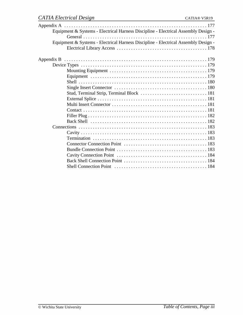
Note that there are no cavities on this stud, however, you will still want to be able to definecontact connection points to allow for terminals to be attached to the stud (for example, theterminal shown below).
Select the Define Connector icon and select the part. This will display the connectordefinition window.
Change the connector Type to Stud and change the Part Number to Ground Stud. Atthis moment, you will not define terminations on the grounding stud. Terminations canalways be added at a later time.
Select OK when done. At this point, you are ready to define the necessary connectionpoints on the grounding stud.
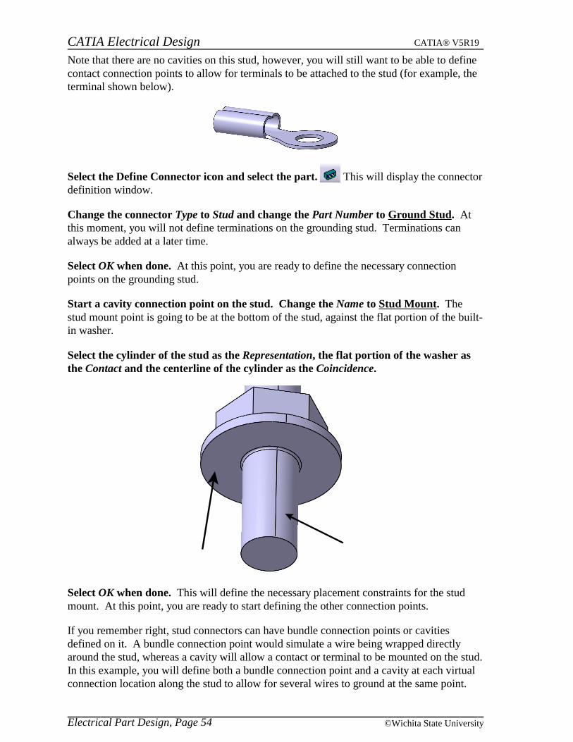
Start a cavity connection point on the stud. Change the Name to Stud Mount. Thestud mount point is going to be at the bottom of the stud, against the flat portion of the built-in washer.
Select the cylinder of the stud as the Representation, the flat portion of the washer asthe Contact and the centerline of the cylinder as the Coincidence.
Select OK when done. This will define the necessary placement constraints for the studmount. At this point, you are ready to start defining the other connection points.
If you remember right, stud connectors can have bundle connection points or cavitiesdefined on it. A bundle connection point would simulate a wire being wrapped directlyaround the stud, whereas a cavity will allow a contact or terminal to be mounted on the stud.In this example, you will define both a bundle connection point and a cavity at each virtualconnection location along the stud to allow for several wires to ground at the same point.
Electrical Part Design, Page 54 ©Wichita State University

CATIA Electrical Design CATIA® V5R19
Start a bundle connection point on the Ground Stud. Change the name to BCP1. Thiswill identify this as the first bundle connection point.
In this case you will be representing the bundle connection points as a point along the stud.
Press the third mouse button while on the Representation field and select Create Point. This will allow you to create the necessary point to represent the bundle connection point onthe fly. This will display the point definition window.
With the point type set to Coordinates, set the point at (0,0,0.075). Select OK whendone. This will put the point at 0.075in along the Z-axis. This will display the bundleconnection point window when you select OK.
Notice that the representation and the point definition were defined just by creating the onepoint. When you select a point as the representation, the point placement constraint isautomatically defined.
Since you will not know or want to control the initial condition of the bundle, you will notbe defining an initial condition.
Select OK to the Bundle Connection Point Definition window. This will establish thebundle connection point.
Electrical Part Design, Page 55© Wichita State University

CATIA Electrical Design CATIA® V5R19
Now you are going to define a cavity at the exact same location, thus allowing the user toterminate a bundle or a contact at the stud.
Select the Define Cavity icon and select the stud. Change the Id Number toContactCP1. This will indicate the first contact connection point. Even though you do nothave a physical cavity in the stud, you will be able to define the cavity via the point createdwith the bundle connection point.
Note: If you did not want the bundle connection point, you could always create the pointfirst, then define it with the cavity connection point. You cannot, however, create the pointon the fly with the representation of the cavity connection point.
Select the point created earlier as the Representation. Now you can define the necessaryplacement constraints for the cavity.
Select the same point as the Contact placement constraint. Select the centerline of thestud as the Coincidence placement constraint. Again, since you do not want to force thecontact in any particular direction, you do not need to define an orientation constraint. Keepin mind, if you did want to define an orientation constraint, you would need to generate aline that goes through the coincidence and contact locations.
Select OK when done. This will establish a cavity on the model to allow for a cavityconnection point in a contact to attach.
Electrical Part Design, Page 56 ©Wichita State University

CATIA Electrical Design CATIA® V5R19
At this point, you can now attach a contact or a bundle at the same location.
Feel free to create a few more connection points along the length of the stud. Creatingthe additional connection points is not required, however, it makes for good practice todefine the necessary connection points. Be sure to space the connection points out along thelength of the stud.
Note: Publications not shown for clarity.
Save and close your document.
Electrical Part Design, Page 57© Wichita State University
CATIA Electrical Design CATIA® V5R19
External Splice
An external splice is similar to a junction box. The external splice only allows for bundleconnection points and is not designed to be a wire by wire splice. Wire to wire spliceswithin a geometric bundle is an internal splice and is only available when in the ElectricalAssembly Design workbench.
External SpliceConnection Type
Can Connect to thisConnection Type
On this type of Device
Bundle Connection PointBundle Segment
ExtremityBundle Segment
The only type of connection point that can be defined on the external splice is a bundlesegment.
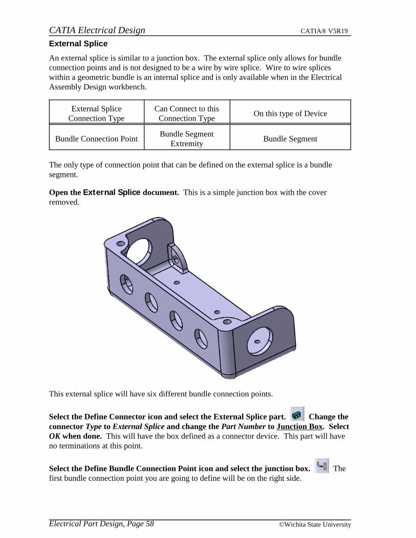
Open the External Splice document. This is a simple junction box with the coverremoved.
This external splice will have six different bundle connection points.
Select the Define Connector icon and select the External Splice part. Change theconnector Type to External Splice and change the Part Number to Junction Box. SelectOK when done. This will have the box defined as a connector device. This part will haveno terminations at this point.
Select the Define Bundle Connection Point icon and select the junction box. Thefirst bundle connection point you are going to define will be on the right side.
Electrical Part Design, Page 58 ©Wichita State University

CATIA Electrical Design CATIA® V5R19
Change the Name of the bundle connection point to Lg BCP 1 and select the right holeas the Representation. This hole is shown below.
Create a point at the center of the hole as the Point placement constraint and select theplanar face as the Initial Condition placement constraint. This will have the first bundleconnection point defined for the external splice.
Select OK when done. Creating the bundle connection point for the external splice is nodifferent than creating the bundle connection point for any of the other type of device.
Create the other necessary bundle connection points around the front and left side ofthe external splice. You should end up with the following electrical connection points.
Note: Publications not shown for clarity.
Save and close your document.
Electrical Part Design, Page 59© Wichita State University

CATIA Electrical Design CATIA® V5R19
Multi Insert Connectors
Multi insert connectors only allow for connections to single insert connectors and mountingequipment. Generally multi insert connectors work good for “Y” adapters or splitters whereyou will have multiple single insert connectors connecting. Multi insert connectors can alsobe used in the place of an external splice when several connectors are connecting together,rather than the bundle segments themselves.
Multi Insert ConnectorConnection Type
Can Connect to thisConnection Type
On this type of Device
Connector ConnectionPoint
Connector ConnectionPoint
Single Insert Connector
Cavity Connection Point Cavity Mounting Equipment
Open the Multi Insert Connector document. This is a mockup of a coax cable splitter.
Using the Define Connector icon, define this part as a Multi Insert Connector. Change the Part Number to Cable TV Splitter and leave the Number of Terminations atzero and select OK. Even though you are going to end up defining eight terminations forthis model (two per connector) you will be learning to define this after the fact for thisconnector.
Now that the device is defined as a multi insert connector, you are now ready to define thecavity connection point for mounting to other mounting equipment devices.
Select the Define Cavity Connection Point icon and select the connector. You willbe defining the cavity connection point with just a contact constraint. Since this type ofconnector does not specifically go into a cavity, just the contact placement constraint willsuffice.
Electrical Part Design, Page 60 ©Wichita State University

CATIA Electrical Design CATIA® V5R19
Change the Name to Connection Face and select the bottom face of the connector asshown below for the Representation and the Contact placement constraint. This willhave the cavity connection point defined.
Select OK when done. Now that the cavity connection point is defined, you are ready tostart defining the connector connection points.
Select the Define Connector Connection Point icon and select the connector. Thiswill start the connector connection point. The first connection point you will define will bethe input connection point.
Change the Name to Input and select the cylinder for the Representation. This surfaceis shown below.
Electrical Part Design, Page 61© Wichita State University

CATIA Electrical Design CATIA® V5R19
Select the front face of the connector as the Contact placement constraint. Again, thissurface is shown.
Select the centerline of the connector as the Coincidence placement constraint. Thiswill have the connector connection point defined.
Select OK when done. Now all you need to do is define the terminations for the inputconnector connection point.
Electrical Part Design, Page 62 ©Wichita State University

CATIA Electrical Design CATIA® V5R19
Defining Terminations
Terminations can be defined on any type of connector. Keep in mind, the terminations arejust simply the termination of a wire at the connector. Terminations can only be defined inthe following type of equipment:
Equipment Shell
Single Insert Connector Multi Insert Connector
Stud (only one) External Splice
Internal Splice Terminal Strip
Contact (Only One)
Select the Define Termination icon and select the connector. This will display theTermination Definition window.
Look familiar? This is the same window that is displayed when you double select on atermination from the tree. If you remember, the Id Number simply defines the terminationidentifier and the Representation defines the geometry that will highlight when the terminalis selected.
Change the Id Number to Input_Ground and select the outer surface of the inputconnector as the Representation. This surface is shown below.
Select OK when done. This will have your first termination defined.
Electrical Part Design, Page 63© Wichita State University

CATIA Electrical Design CATIA® V5R19
Using the Define Termination icon, define another termination for the tip. Setthe Id Number to Input_Tip and select the inner cylindrical surface as theRepresentation. This is shown below.
Select OK when done. This will have the two terminations defined for the input.
Electrical Part Design, Page 64 ©Wichita State University

CATIA Electrical Design CATIA® V5R19
Create the necessary connector connection points and terminations for the threeoutput connectors. This will have all the necessary connections and terminations defined.
Note: Publications not shown for clarity.
Save and close your document.
Electrical Part Design, Page 65© Wichita State University

CATIA Electrical Design CATIA® V5R19
Contacts
Contacts can be any type of device used to make the physical electrical power transmissionfrom one connector to another.
Contact Connection TypeCan Connect to this
Connection TypeOn this type of Device
Cavity Connection Point Cavity
Mounting EquipmentEquipment
ShellSingle Insert Connector
Back Shell
Bundle Connection PointBundle Segment
ExtremityBundle Segment
Open the Contact document. This is a simple round terminal that you will define as acontact.
Select the Define Contact icon and select the terminal. This will display theContact Definition window.
Change the Part Number to 0.25 Round Terminal and select OK. This will define thepart as an electrical contact, and define a contact termination in the specification tree.
Electrical Part Design, Page 66 ©Wichita State University

CATIA Electrical Design CATIA® V5R19
Now all you need to do is define the bundle connection point and a cavity connection point.
Select the Define Cavity Connection Point icon and select the terminal. Changethe cavity connection point Name to Terminal Hole. Select the surface of the hole asthe Representation. This will have the cavity connection point definition started.
Select the bottom of the terminal as the Contact placement constraint. This surface isshown below.
Select the centerline of the hole as the Coincidence placement constraint. Select OKwhen done. This will have the cavity connection point defined.
All you have left is to define the bundle connection point at the back of the terminal. Thiswill be left for you to complete. You can use the point at the back center as the bundleconnection point placement constraint.
This will have the terminal defined.
Save and close your document.
Electrical Part Design, Page 67© Wichita State University
CATIA Electrical Design CATIA® V5R19
Filler Plug
Filler plugs are devices designed to fill unused cavities in various types of equipment. Fillerplug equipment is a very simple definition, only allowing cavity connection points.
Filler Plug ConnectionType
Can Connect to thisConnection Type
On this type of Device
Cavity Connection Point Cavity
Mounting EquipmentEquipment
ShellSingle Insert Connector
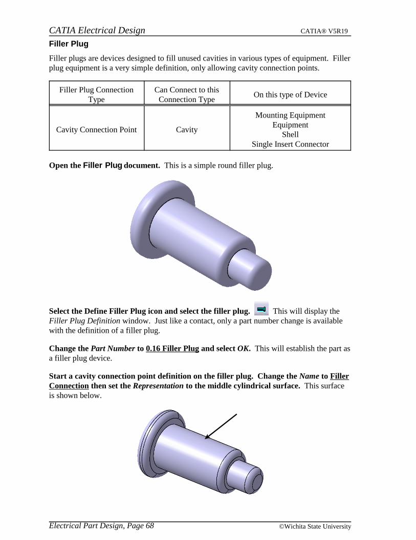
Open the Filler Plug document. This is a simple round filler plug.
Select the Define Filler Plug icon and select the filler plug. This will display theFiller Plug Definition window. Just like a contact, only a part number change is availablewith the definition of a filler plug.
Change the Part Number to 0.16 Filler Plug and select OK. This will establish the part asa filler plug device.
Start a cavity connection point definition on the filler plug. Change the Name to FillerConnection then set the Representation to the middle cylindrical surface. This surfaceis shown below.
Electrical Part Design, Page 68 ©Wichita State University

CATIA Electrical Design CATIA® V5R19
Select the ledge of the larger surface as the Contact placement constraint and thecenterline of the filler plug as the Coincidence placement constraint. The contactplacement constraint surface is shown below.
Select OK when done. This will have the filler plug defined.
Save and close the document.
Electrical Part Design, Page 69© Wichita State University
Related Documents