Cathodic Protection Measurement Basics Michael J. Placzek, P.E. Senior Engineer Ark Engineering and Field Services

Welcome message from author
This document is posted to help you gain knowledge. Please leave a comment to let me know what you think about it! Share it to your friends and learn new things together.
Transcript

Cathodic Protection
Measurement Basics
Michael J. Placzek, P.E.Senior Engineer
Ark Engineering and Field Services

CP Measurements
Pipe-To-Soil Potentials
CP Current Flow
Resistance
Rectifier Readings

Pipe-To-Soil Potentials
Voltmeter
Digital, Analog, Computerized
High Input Impedance
Rugged
Lead Wires
Tight Connections
Secure To Structure
Low Resistance As Possible
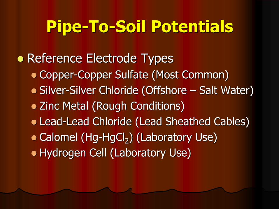
Pipe-To-Soil Potentials
Reference Electrode Types
Copper-Copper Sulfate (Most Common)
Silver-Silver Chloride (Offshore – Salt Water)
Zinc Metal (Rough Conditions)
Lead-Lead Chloride (Lead Sheathed Cables)
Calomel (Hg-HgCl2) (Laboratory Use)
Hydrogen Cell (Laboratory Use)

Pipe-To-Soil Potentials To Maintain Criteria of SP-0169
Cu-CuSO4 (-) 0.850 V
Ag-AgCl (Sat KCl) {4.6M} (-) 0.733 V
Ag-AgCl (KCl @ 3.5M) (-) 0.739 V
Ag-AgCl (KCl @ 1.0M) (-) 0.756 V
Ag-AgCl (Seawater) (-) 0.784 V
Zinc Metal (+) 0.228 V
Be Very Careful With Ag-AgCl References. The KCl Concentrations Shift the Potential

Pipe-To-Soil Potentials
Cu-CuSO4 Reference Electrode
Temperature Sensitive
Copper-Copper Sulfate Ref: 0.5 mV per oF
Shift Positive When Colder
Contaminant Free
Clean Bar and Tip
Clear Solution
Saturated Solution
Distilled Water with Blue Crystals Left Over

Pipe-To-Soil Potentials Position
Directly Over Structure
Closer The Better But Don’t Touch Structure
Good Electrolyte Contact
Tip Contact to Ground
Thick Layers of Crushed Rock
Watch out for Unknowns like:
Geoplastic sheets under stone
Asphalt layers under concrete pavement (old
roads)
Paved Over Trolley Tracks (Old Cities)
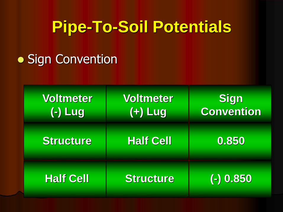
Pipe-To-Soil Potentials
Sign Convention
Voltmeter
(-) Lug
Voltmeter
(+) Lug
Sign
Convention
Structure
StructureHalf Cell
Half Cell 0.850
(-) 0.850

CP Current Flow
Direct Readings
Inconvenient
Slow
Dangerous
Meter in Series with Circuit
Off Too Long
Sway Readings
Shunt Readings
Accurate and Faster
Voltmeter Across Known Resistance

CP Current Flow
Shunt Readings Rated in Ohms0.001 Ohm: 1 mV = 1 Amp 25 Amp Max
0.01 Ohm: 1 mV = 0.1 Amp 8 Amp Max
0.1 Ohm: 1 mV = 0.01 Amp 2 Amp Max
Shunt Readings By Proportion50 mV = 50 Amps 1 mV = 1 Amp
50 mV = 100 Amps 1 mV = 2 Amps
100 mV = 100 Amps 1 mV = 1 Amp
50 mV = 60 Amp 1 mV = 1.2 Amps

CP Current Flow
ANODE
ANODE
ANODE
+1.250
mV
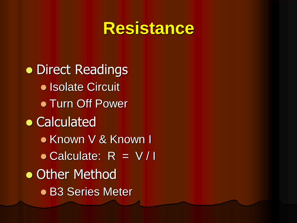
Resistance
Direct Readings
Isolate Circuit
Turn Off Power
Calculated
Known V & Known I
Calculate: R = V / I
Other Method
B3 Series Meter

Rectifier Readings
AC Input
Voltage at Disconnect or Behind Breaker
Current by Clamp-On Ammeter
Power = (3600 x Kh x N) / T
AC Throughput
Voltage Across Main Lugs of Taps
DC Output
Voltage Across the Output Lugs
Current: Voltage Across the Shunt
Efficiency
Power Out / Power In
Related Documents