You'll be entered into a quarterly drawing for free Cisco Press books by returning this survey! Cisco is dedicated to customer satisfaction and would like to hear your thoughts on these printed manuals. Please visit the Cisco Product Comments on-line survey at www.cisco.com/go/crc to submit your comments about accessing Cisco technical manuals. Thank you for your time General Information 1 Years of networking experience: Years of experience with Cisco products: 2 I have these network types: LAN Backbone WAN Other: 3 I have these Cisco products: Switches Routers Other (specify models): 4 I perform these types of tasks: H/W installation and/or maintenance S/W configuration Network management Other: 5 I use these types of documentation: H/W installation H/W configuration S/W configuration Command reference Quick reference Release notes Online help Other: 6 I access this information through: % Cisco.com % CD-ROM % Printed manuals % Other: 7 I prefer this access method: Cisco.com CD-ROM Printed manuals Other: 8 I use the following three product features the most: Document Information Document Title: Catalyst 3750 Switch System Message Guide Part Number: 78-15166-04 S/W Release: Cisco IOS 12.1(19)EA1 On a scale of 1–5 (5 being the best), please let us know how we rate in the following areas: The document is complete. The information is accurate. The information is well organized. The information I wanted was easy to find. The document is written at my technical level of understanding. The information I found was useful to my job. Please comment on our lowest scores: Mailing Information Organization Date Contact Name Mailing Address City State/Province Zip/Postal Code Country Phone ( ) Extension E-mail Fax ( ) May we contact you further concerning our documentation? Yes No You can also send us your comments by e-mail to [email protected], or by fax to 408-527-8089. When mailing this card from outside of the United States, please enclose in an envelope addressed to the location on the back of this card with the required postage or fax to 1-408-527-8089.

Welcome message from author
This document is posted to help you gain knowledge. Please leave a comment to let me know what you think about it! Share it to your friends and learn new things together.
Transcript
You'll be entered into a quarterly drawing for free Cisco Press books by returning this survey! Cisco is dedicated to customer satisfaction and would like to hear your thoughts on these printed manuals. Please visit the Cisco Product Comments on-line survey at www.cisco.com/go/crc to submit your comments about accessing Cisco technical manuals. Thank you for your time
General Information1 Years of networking experience: Years of experience with Cisco products:
2 I have these network types: LAN Backbone WAN
Other:
3 I have these Cisco products: Switches Routers
Other (specify models):
4 I perform these types of tasks: H/W installation and/or maintenance S/W configuration
Network management Other:
5 I use these types of documentation: H/W installation H/W configuration S/W configuration
Command reference Quick reference Release notes Online help
Other:
6 I access this information through: % Cisco.com % CD-ROM % Printed manuals
% Other:
7 I prefer this access method: Cisco.com CD-ROM Printed manuals
Other:
8 I use the following three product features the most:
Document InformationDocument Title: Catalyst 3750 Switch System Message Guide
Part Number: 78-15166-04 S/W Release: Cisco IOS 12.1(19)EA1
On a scale of 1–5 (5 being the best), please let us know how we rate in the following areas:
The document is complete. The information is accurate.
The information is well organized. The information I wanted was easy to find.
The document is written at mytechnical level of understanding.
The information I found was useful to my job.
Please comment on our lowest scores:
Mailing InformationOrganization Date
Contact Name
Mailing Address
City State/Province Zip/Postal Code
Country Phone ( ) Extension
E-mail Fax ( )
May we contact you further concerning our documentation? Yes No
You can also send us your comments by e-mail to [email protected], or by fax to 408-527-8089.
When mailing this card from outside of the United States, please enclose in an envelope addressed to the location on the back of this card with the required postage or fax to 1-408-527-8089.
BUSINESS REPLY MAILF I R S T - C L A S S M A I L P E R M I T N O . 4 6 3 1 S A N J O S E C A
POSTAGE WILL BE PAID BY ADDRESSEE
NO POSTAGENECESSARY
IF MAILEDIN THE
UNITED STATES
DOCUMENT RESOURCE CONNECTIONCISCO SYSTEMS INC170 WEST TASMAN DRSAN JOSE CA 95134-9916
Catalyst 3750 Switch System Message GuideCisco IOS Release 12.1(19)EA1February 2004
Corporate HeadquartersCisco Systems, Inc.170 West Tasman DriveSan Jose, CA 95134-1706 USAhttp://www.cisco.comTel: 408 526-4000
800 553-NETS (6387)Fax: 408 526-4100
Customer Order Number: DOC-7815166=Text Part Number: 78-15166-04
THE SPECIFICATIONS AND INFORMATION REGARDING THE PRODUCTS IN THIS MANUAL ARE SUBJECT TO CHANGE WITHOUT NOTICE. ALL STATEMENTS, INFORMATION, AND RECOMMENDATIONS IN THIS MANUAL ARE BELIEVED TO BE ACCURATE BUT ARE PRESENTED WITHOUT WARRANTY OF ANY KIND, EXPRESS OR IMPLIED. USERS MUST TAKE FULL RESPONSIBILITY FOR THEIR APPLICATION OF ANY PRODUCTS.
THE SOFTWARE LICENSE AND LIMITED WARRANTY FOR THE ACCOMPANYING PRODUCT ARE SET FORTH IN THE INFORMATION PACKET THAT SHIPPED WITH THE PRODUCT AND ARE INCORPORATED HEREIN BY THIS REFERENCE. IF YOU ARE UNABLE TO LOCATE THE SOFTWARE LICENSE OR LIMITED WARRANTY, CONTACT YOUR CISCO REPRESENTATIVE FOR A COPY.
The Cisco implementation of TCP header compression is an adaptation of a program developed by the University of California, Berkeley (UCB) as part of UCB’s public domain version of the UNIX operating system. All rights reserved. Copyright © 1981, Regents of the University of California.
NOTWITHSTANDING ANY OTHER WARRANTY HEREIN, ALL DOCUMENT FILES AND SOFTWARE OF THESE SUPPLIERS ARE PROVIDED “AS IS” WITH ALL FAULTS. CISCO AND THE ABOVE-NAMED SUPPLIERS DISCLAIM ALL WARRANTIES, EXPRESSED OR IMPLIED, INCLUDING, WITHOUT LIMITATION, THOSE OF MERCHANTABILITY, FITNESS FOR A PARTICULAR PURPOSE AND NONINFRINGEMENT OR ARISING FROM A COURSE OF DEALING, USAGE, OR TRADE PRACTICE.
IN NO EVENT SHALL CISCO OR ITS SUPPLIERS BE LIABLE FOR ANY INDIRECT, SPECIAL, CONSEQUENTIAL, OR INCIDENTAL DAMAGES, INCLUDING, WITHOUT LIMITATION, LOST PROFITS OR LOSS OR DAMAGE TO DATA ARISING OUT OF THE USE OR INABILITY TO USE THIS MANUAL, EVEN IF CISCO OR ITS SUPPLIERS HAVE BEEN ADVISED OF THE POSSIBILITY OF SUCH DAMAGES.
CCIP, CCSP, the Cisco Arrow logo, the Cisco Powered Network mark, Cisco Unity, Follow Me Browsing, FormShare, and StackWise are trademarks of Cisco Systems, Inc.; Changing the Way We Work, Live, Play, and Learn, and iQuick Study are service marks of Cisco Systems, Inc.; and Aironet, ASIST, BPX, Catalyst, CCDA, CCDP, CCIE, CCNA, CCNP, Cisco, the Cisco Certified Internetwork Expert logo, Cisco IOS, the Cisco IOS logo, Cisco Press, Cisco Systems, Cisco Systems Capital, the Cisco Systems logo, Empowering the Internet Generation, Enterprise/Solver, EtherChannel, EtherSwitch, Fast Step, GigaStack, Internet Quotient, IOS, IP/TV, iQ Expertise, the iQ logo, iQ Net Readiness Scorecard, LightStream, MGX, MICA, the Networkers logo, Networking Academy, Network Registrar, Packet, PIX, Post-Routing, Pre-Routing, RateMUX, Registrar, ScriptShare, SlideCast, SMARTnet, StrataView Plus, Stratm, SwitchProbe, TeleRouter, The Fastest Way to Increase Your Internet Quotient, TransPath, and VCO are registered trademarks of Cisco Systems, Inc. and/or its affiliates in the United States and certain other countries.
All other trademarks mentioned in this document or Website are the property of their respective owners. The use of the word partner does not imply a partnership relationship between Cisco and any other company. (0401R)
Catalyst 3750 Switch System Message GuideCopyright © 2003–2004 Cisco Systems, Inc. All rights reserved.
78-15166-04
C O N T E N T S
Preface v
Audience v
Purpose v
Conventions v
Related Publications vi
Obtaining Documentation vii
Cisco.com vii
Ordering Documentation vii
Documentation Feedback vii
Obtaining Technical Assistance viii
Cisco TAC Website viii
Opening a TAC Case viii
TAC Case Priority Definitions viii
Obtaining Additional Publications and Information ix
C H A P T E R 1 System Message Overview 1-1
How to Read System Messages 1-1
Error Message Traceback Reports 1-4
Output Interpreter 1-4
Bug Toolkit 1-5
Contacting TAC 1-5
C H A P T E R 2 Message and Recovery Procedures 2-1
ACLMGR Messages 2-2
CFGMGR Messages 2-5
CMP Messages 2-7
DOT1X (802.1X) Messages 2-8
DTP Messages 2-13
EC Messages 2-14
ETHCNTR Messages 2-18
EXPRESS_SETUP Messages 2-19
GBIC/SFP Security Messages 2-20
HARDWARE Messages 2-21
iiiCatalyst 3750 Switch System Message Guide
Contents
HLFM Messages 2-23
IDBMAN Messages 2-24
ILPOWER (Power over Ethernet) Messages 2-26
IMAGEMGR Messages 2-28
PHY Messages 2-29
PLATFORM Messages 2-30
PLATFORM_FBM Messages 2-31
PLATFORM _IPC Messages 2-32
PLATFORM_PBR Messages 2-33
PLATFORM_PM Messages 2-35
PLATFORM_RPC Messages 2-36
PLATFORM_SPAN Messages 2-38
PLATFORM_UCAST Messages 2-38
PLATFORM_VLAN Messages 2-40
PM Messages 2-41
QOSMGR Messages 2-48
SDM Message 2-53
SPAN Messages 2-53
SPANTREE Messages 2-54
SPANTREE_FAST Messages 2-60
SPANTREE_VLAN_SW Messages 2-61
STACKMGR Messages 2-61
SUPERVISOR Messages 2-63
SUPQ Messages 2-64
SW_VLAN Messages 2-65
TCAMMGR Messages 2-70
UDLD Messages 2-72
UFAST_MCAST_SW Messages 2-73
VQPCLIENT Messages 2-74
IN D E X
ivCatalyst 3750 Switch System Message Guide
78-15166-04
Preface
AudienceThis guide is for the networking professional managing the Catalyst 3750 switch or switch stack, hereafter referred to as the switch. Before using this guide, you should have experience working with the Cisco IOS and the switch software features.
PurposeThis guide describes only the Catalyst 3750-specific system messages that you might encounter. For a complete list of Cisco IOS system error messages, refer to the Cisco IOS Software System Error Messages, Cisco IOS Release 12.1.
This guide does not describe how to install your switch or how to configure software features on your switch. It also does not provide detailed information about commands that have been created or changed for use by the switch. For hardware installation information, refer to the hardware installation guide that shipped with your switch. For software information, refer to the software configuration guide and the command reference for this release.
ConventionsThis publication uses these conventions to convey instructions and information:
Command descriptions use these conventions:
• Commands and keywords are in boldface text.
• Arguments for which you supply values are in italic.
• Square brackets ([ ]) mean optional elements.
• Braces ({ }) group required choices, and vertical bars ( | ) separate the alternative elements.
• Braces and vertical bars within square brackets ([{ | }]) mean a required choice within an optional element.
vCatalyst 3750 Switch System Message Guide
78-15166-04
PrefaceRelated Publications
Interactive examples use these conventions:
• Terminal sessions and system displays are in screen font.
• Information you enter is in boldface screen font.
• Nonprinting characters, such as passwords or tabs, are in angle brackets (< >).
Notes use this convention and symbol:
Note Means reader take note. Notes contain helpful suggestions or references to materials not in this manual.
Related PublicationsThese documents provide complete information about the switch and are available from this Cisco.com site:
http://www.cisco.com/univercd/cc/td/doc/product/lan/cat3750/index.htm
Note Before installing, configuring, or upgrading the switch, refer to these documents:
• For initial configuration information, refer to the “Using Express Setup” chapter or the “Configuring the Switch with the CLI-Based Setup Program” appendix in the hardware installation guide.
• For CMS requirements, refer to the “Getting Started with CMS” chapter in the software configuration guide.
• For cluster requirements, refer to the release notes.
• For upgrading information, refer to the “Downloading Software” section in the release notes.
You can order printed copies of documents with a DOC-xxxxxx= number from the Cisco.com sites and from the telephone numbers listed in the “Obtaining Documentation” section on page vii.
• Release Notes for the Catalyst 3750 Switch (not orderable but available on Cisco.com)
• Catalyst 3750 Switch Software Configuration Guide (order number DOC-7815164=)
• Catalyst 3750 Switch Command Reference (order number DOC-7815165=)
• Catalyst 3750 Switch System Message Guide (order number DOC-7815166=)
• Cluster Management Suite (CMS) online help (available only from the switch CMS software)
• Catalyst 3750 Switch Hardware Installation Guide (order number DOC-7815136=)
• Cisco Small Form-Factor Pluggable Modules Installation Notes (order number DOC-7815160=)
• Cisco CWDM GBIC and CWDM SFP Installation Note (not orderable but available on Cisco.com)
viCatalyst 3750 Switch System Message Guide
78-15166-04
PrefaceObtaining Documentation
Obtaining DocumentationCisco documentation and additional literature are available on Cisco.com. Cisco also provides several ways to obtain technical assistance and other technical resources. These sections explain how to obtain technical information from Cisco Systems.
Cisco.comYou can access the most current Cisco documentation on the World Wide Web at this URL:
http://www.cisco.com/univercd/home/home.htm
You can access the Cisco website at this URL:
http://www.cisco.com
International Cisco websites can be accessed from this URL:
http://www.cisco.com/public/countries_languages.shtml
Ordering DocumentationYou can find instructions for ordering documentation at this URL:
http://www.cisco.com/univercd/cc/td/doc/es_inpck/pdi.htm
You can order Cisco documentation in these ways:
• Registered Cisco.com users (Cisco direct customers) can order Cisco product documentation from the Ordering tool:
http://www.cisco.com/en/US/partner/ordering/index.shtml
• Nonregistered Cisco.com users can order documentation through a local account representative by calling Cisco Systems Corporate Headquarters (California, USA) at 408 526-7208 or, elsewhere in North America, by calling 800 553-NETS (6387).
Documentation FeedbackYou can submit e-mail comments about technical documentation to [email protected].
You can submit comments by using the response card (if present) behind the front cover of your document or by writing to the following address:
Cisco SystemsAttn: Customer Document Ordering170 West Tasman DriveSan Jose, CA 95134-9883
We appreciate your comments.
viiCatalyst 3750 Switch System Message Guide
78-15166-04
PrefaceObtaining Technical Assistance
Obtaining Technical AssistanceFor all customers, partners, resellers, and distributors who hold valid Cisco service contracts, the Cisco Technical Assistance Center (TAC) provides 24-hour-a-day, award-winning technical support services, online and over the phone. Cisco.com features the Cisco TAC website as an online starting point for technical assistance. If you do not hold a valid Cisco service contract, please contact your reseller.
Cisco TAC WebsiteThe Cisco TAC website provides online documents and tools for troubleshooting and resolving technical issues with Cisco products and technologies. The Cisco TAC website is available 24 hours a day, 365 days a year. The Cisco TAC website is located at this URL:
http://www.cisco.com/tac
Accessing all the tools on the Cisco TAC website requires a Cisco.com user ID and password. If you have a valid service contract but do not have a login ID or password, register at this URL:
http://tools.cisco.com/RPF/register/register.do
Opening a TAC CaseUsing the online TAC Case Open Tool is the fastest way to open P3 and P4 cases. (P3 and P4 cases are those in which your network is minimally impaired or for which you require product information.) After you describe your situation, the TAC Case Open Tool automatically recommends resources for an immediate solution. If your issue is not resolved using the recommended resources, your case will be assigned to a Cisco TAC engineer. The online TAC Case Open Tool is located at this URL:
http://www.cisco.com/tac/caseopen
For P1 or P2 cases (P1 and P2 cases are those in which your production network is down or severely degraded) or if you do not have Internet access, contact Cisco TAC by telephone. Cisco TAC engineers are assigned immediately to P1 and P2 cases to help keep your business operations running smoothly.
To open a case by telephone, use one of the following numbers:
Asia-Pacific: +61 2 8446 7411 (Australia: 1 800 805 227) EMEA: +32 2 704 55 55 USA: 1 800 553-2447
For a complete listing of Cisco TAC contacts, go to this URL:
http://www.cisco.com/warp/public/687/Directory/DirTAC.shtml
TAC Case Priority DefinitionsTo ensure that all cases are reported in a standard format, Cisco has established case priority definitions.
Priority 1 (P1)—Your network is “down” or there is a critical impact to your business operations. You and Cisco will commit all necessary resources around the clock to resolve the situation.
Priority 2 (P2)—Operation of an existing network is severely degraded, or significant aspects of your business operation are negatively affected by inadequate performance of Cisco products. You and Cisco will commit full-time resources during normal business hours to resolve the situation.
viiiCatalyst 3750 Switch System Message Guide
78-15166-04
PrefaceObtaining Additional Publications and Information
Priority 3 (P3)—Operational performance of your network is impaired, but most business operations remain functional. You and Cisco will commit resources during normal business hours to restore service to satisfactory levels.
Priority 4 (P4)—You require information or assistance with Cisco product capabilities, installation, or configuration. There is little or no effect on your business operations.
Obtaining Additional Publications and InformationInformation about Cisco products, technologies, and network solutions is available from various online and printed sources.
• Cisco Marketplace provides a variety of Cisco books, reference guides, and logo merchandise. Go to this URL to visit the company store:
http://www.cisco.com/go/marketplace/
• The Cisco Product Catalog describes the networking products offered by Cisco Systems, as well as ordering and customer support services. Access the Cisco Product Catalog at this URL:
http://cisco.com/univercd/cc/td/doc/pcat/
• Cisco Press publishes a wide range of general networking, training and certification titles. Both new and experienced users will benefit from these publications. For current Cisco Press titles and other information, go to Cisco Press online at this URL:
http://www.ciscopress.com
• Packet magazine is the Cisco quarterly publication that provides the latest networking trends, technology breakthroughs, and Cisco products and solutions to help industry professionals get the most from their networking investment. Included are networking deployment and troubleshooting tips, configuration examples, customer case studies, tutorials and training, certification information, and links to numerous in-depth online resources. You can access Packet magazine at this URL:
http://www.cisco.com/packet
• iQ Magazine is the Cisco bimonthly publication that delivers the latest information about Internet business strategies for executives. You can access iQ Magazine at this URL:
http://www.cisco.com/go/iqmagazine
• Internet Protocol Journal is a quarterly journal published by Cisco Systems for engineering professionals involved in designing, developing, and operating public and private internets and intranets. You can access the Internet Protocol Journal at this URL:
http://www.cisco.com/ipj
• Training—Cisco offers world-class networking training. Current offerings in network training are listed at this URL:
http://www.cisco.com/en/US/learning/index.html
ixCatalyst 3750 Switch System Message Guide
78-15166-04
PrefaceObtaining Additional Publications and Information
xCatalyst 3750 Switch System Message Guide
78-15166-04
Catal78-15166-04
C H A P T E R 1
System Message OverviewThis guide describes the Catalyst 3750-specific system messages. During operation, the system software sends these messages to the console (and, optionally, to a logging server on another system). Not all system messages indicate problems with your system. Some messages are purely informational, whereas others can help diagnose problems with communications lines, internal hardware, or the system software. This guide also includes error messages that appear when the system fails.
Note For information about system messages that are not Catalyst 3750 platform-specific, refer to the Cisco IOS Software System Messages for Cisco IOS Release 12.1.
This chapter contains these sections:
• How to Read System Messages, page 1-1
• Error Message Traceback Reports, page 1-4
How to Read System MessagesSystem log messages can contain up to 80 characters and a percent sign (%), which follows the optional sequence number or time stamp information, if configured. Messages are displayed in this format:
seq no:timestamp: %facility-severity-MNEMONIC:description (hostname-n)
By default, a switch sends the output from system messages to a logging process. In a switch stack, stack members append their hostnames to the output from system messages and redirect the output to the logging process on the stack master.
Each system message begins with a percent sign (%) and is structured as follows:
%FACILITY-SEVERITY-MNEMONIC: Message-text
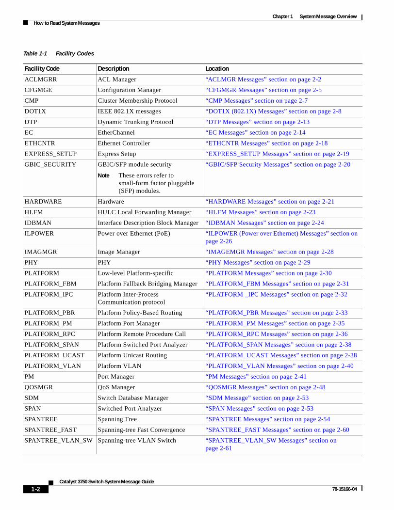
• FACILITY is a code consisting of two or more uppercase letters that show the facility to which the message refers. A facility can be a hardware device, a protocol, or a module of the system software. Table 1-1 lists Catalyst 3750-specific facility codes. These messages are described in Chapter 2, “Message and Recovery Procedures,” in alphabetical order by facility code with the most severe (lowest number) errors described first.
1-1yst 3750 Switch System Message Guide
Chapter 1 System Message OverviewHow to Read System Messages
Table 1-1 Facility Codes
Facility Code Description Location
ACLMGRR ACL Manager “ACLMGR Messages” section on page 2-2
CFGMGE Configuration Manager “CFGMGR Messages” section on page 2-5
CMP Cluster Membership Protocol “CMP Messages” section on page 2-7
DOT1X IEEE 802.1X messages “DOT1X (802.1X) Messages” section on page 2-8
DTP Dynamic Trunking Protocol “DTP Messages” section on page 2-13
EC EtherChannel “EC Messages” section on page 2-14
ETHCNTR Ethernet Controller “ETHCNTR Messages” section on page 2-18
EXPRESS_SETUP Express Setup “EXPRESS_SETUP Messages” section on page 2-19
GBIC_SECURITY GBIC/SFP module security
Note These errors refer to small-form factor pluggable (SFP) modules.
“GBIC/SFP Security Messages” section on page 2-20
HARDWARE Hardware “HARDWARE Messages” section on page 2-21
HLFM HULC Local Forwarding Manager “HLFM Messages” section on page 2-23
IDBMAN Interface Description Block Manager “IDBMAN Messages” section on page 2-24
ILPOWER Power over Ethernet (PoE) “ILPOWER (Power over Ethernet) Messages” section on page 2-26
IMAGMGR Image Manager “IMAGEMGR Messages” section on page 2-28
PHY PHY “PHY Messages” section on page 2-29
PLATFORM Low-level Platform-specific “PLATFORM Messages” section on page 2-30
PLATFORM_FBM Platform Fallback Bridging Manager “PLATFORM_FBM Messages” section on page 2-31
PLATFORM_IPC Platform Inter-Process Communication protocol
“PLATFORM _IPC Messages” section on page 2-32
PLATFORM_PBR Platform Policy-Based Routing “PLATFORM_PBR Messages” section on page 2-33
PLATFORM_PM Platform Port Manager “PLATFORM_PM Messages” section on page 2-35
PLATFORM_RPC Platform Remote Procedure Call “PLATFORM_RPC Messages” section on page 2-36
PLATFORM_SPAN Platform Switched Port Analyzer “PLATFORM_SPAN Messages” section on page 2-38
PLATFORM_UCAST Platform Unicast Routing “PLATFORM_UCAST Messages” section on page 2-38
PLATFORM_VLAN Platform VLAN “PLATFORM_VLAN Messages” section on page 2-40
PM Port Manager “PM Messages” section on page 2-41
QOSMGR QoS Manager “QOSMGR Messages” section on page 2-48
SDM Switch Database Manager “SDM Message” section on page 2-53
SPAN Switched Port Analyzer “SPAN Messages” section on page 2-53
SPANTREE Spanning Tree “SPANTREE Messages” section on page 2-54
SPANTREE_FAST Spanning-tree Fast Convergence “SPANTREE_FAST Messages” section on page 2-60
SPANTREE_VLAN_SW Spanning-tree VLAN Switch “SPANTREE_VLAN_SW Messages” section on page 2-61
1-2Catalyst 3750 Switch System Message Guide
78-15166-04
Chapter 1 System Message OverviewHow to Read System Messages
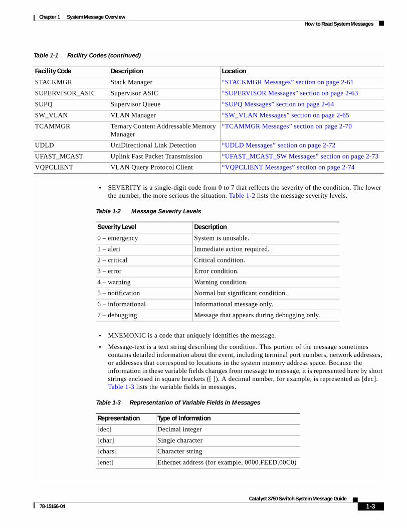
• SEVERITY is a single-digit code from 0 to 7 that reflects the severity of the condition. The lower the number, the more serious the situation. Table 1-2 lists the message severity levels.
• MNEMONIC is a code that uniquely identifies the message.
• Message-text is a text string describing the condition. This portion of the message sometimes contains detailed information about the event, including terminal port numbers, network addresses, or addresses that correspond to locations in the system memory address space. Because the information in these variable fields changes from message to message, it is represented here by short strings enclosed in square brackets ([ ]). A decimal number, for example, is represented as [dec]. Table 1-3 lists the variable fields in messages.
STACKMGR Stack Manager “STACKMGR Messages” section on page 2-61
SUPERVISOR_ASIC Supervisor ASIC “SUPERVISOR Messages” section on page 2-63
SUPQ Supervisor Queue “SUPQ Messages” section on page 2-64
SW_VLAN VLAN Manager “SW_VLAN Messages” section on page 2-65
TCAMMGR Ternary Content Addressable Memory Manager
“TCAMMGR Messages” section on page 2-70
UDLD UniDirectional Link Detection “UDLD Messages” section on page 2-72
UFAST_MCAST Uplink Fast Packet Transmission “UFAST_MCAST_SW Messages” section on page 2-73
VQPCLIENT VLAN Query Protocol Client “VQPCLIENT Messages” section on page 2-74
Table 1-1 Facility Codes (continued)
Facility Code Description Location
Table 1-2 Message Severity Levels
Severity Level Description
0 – emergency System is unusable.
1 – alert Immediate action required.
2 – critical Critical condition.
3 – error Error condition.
4 – warning Warning condition.
5 – notification Normal but significant condition.
6 – informational Informational message only.
7 – debugging Message that appears during debugging only.
Table 1-3 Representation of Variable Fields in Messages
Representation Type of Information
[dec] Decimal integer
[char] Single character
[chars] Character string
[enet] Ethernet address (for example, 0000.FEED.00C0)
1-3Catalyst 3750 Switch System Message Guide
78-15166-04
Chapter 1 System Message OverviewError Message Traceback Reports
All syslog messages generated by a switch other than the master switch are displayed ending with (Switch-x) where Switch-x is the number of the stack member generating the message. Syslog messages generated by the master switch are displayed with no hostname string.
This example shows a partial switch system message for a stack master and a stack member switch (hostname Switch-2):
00:00:46: %LINK-3-UPDOWN: Interface Port-channel1, changed state to up00:00:47: %LINK-3-UPDOWN: Interface GigabitEthernet1/0/1, changed state to up00:00:47: %LINK-3-UPDOWN: Interface GigabitEthernet1/0/2, changed state to up00:00:48: %LINEPROTO-5-UPDOWN: Line protocol on Interface Vlan1, changed state to down 00:00:48: %LINEPROTO-5-UPDOWN: Line protocol on Interface GigabitEthernet1/0/1, changed state to down 2 *Mar 1 18:46:11: %SYS-5-CONFIG_I: Configured from console by vty2 (10.34.195.36)18:47:02: %SYS-5-CONFIG_I: Configured from console by vty2 (10.34.195.36)*Mar 1 18:48:50.483 UTC: %SYS-5-CONFIG_I: Configured from console by vty2 (10.34.195.36)
00:00:46: %LINK-3-UPDOWN: Interface Port-channel1, changed state to up (Switch-2)00:00:47: %LINK-3-UPDOWN: Interface GigabitEthernet1/0/1, changed state to up (Switch-2)00:00:47: %LINK-3-UPDOWN: Interface GigabitEthernet1/0/2, changed state to up (Switch-2)00:00:48: %LINEPROTO-5-UPDOWN: Line protocol on Interface Vlan1, changed state to down (Switch-2)00:00:48: %LINEPROTO-5-UPDOWN: Line protocol on Interface GigabitEthernet1/0/1, changed state to down 2 (Switch-2)
Error Message Traceback ReportsSome messages describe internal errors and contain traceback information. This information is very important and should be included when you report a problem to your technical support representative.
This message example includes traceback information:
-Process= "Exec", level= 0, pid= 17-Traceback= 1A82 1AB4 6378 A072 1054 1860
Some system messages ask you to copy the error messages and take further action. These online tools also provide more information about system error messages.
Output InterpreterThe Output Interpreter provides additional information and suggested fixes based on the output of many CLI commands, such as the the show tech-support privileged EXEC command. You can access the Output Interpreter at this URL:
https://www.cisco.com/cgi-bin/Support/OutputInterpreter/home.pl
[hex] Hexadecimal integer
[inet] Internet address
Table 1-3 Representation of Variable Fields in Messages (continued)
Representation Type of Information
1-4Catalyst 3750 Switch System Message Guide
78-15166-04

Chapter 1 System Message OverviewError Message Traceback Reports
Bug ToolkitThe Bug Toolkit provides information on open and closed caveats, and allows you to search for all known bugs in a specific Cisco IOS Release. You can access the Bug Toolkit at this URL:
http://www.cisco.com/cgi-bin/Support/Bugtool/home.pl.
Contacting TACIf you cannot determine the nature of the error, see the “Obtaining Technical Assistance” section on page viii for further information.
1-5Catalyst 3750 Switch System Message Guide
78-15166-04
Chapter 1 System Message OverviewError Message Traceback Reports
1-6Catalyst 3750 Switch System Message Guide
78-15166-04
Catal78-15166-04
C H A P T E R 2
Message and Recovery ProceduresThis chapter describes the Catalyst 3750-specific system messages in alphabetical order by facility. Within each facility, the messages are listed by severity levels 0 to 7: 0 is the highest severity level, and 7 is the lowest severity level. Each message is followed by an explanation and a recommended action.
Note The messages listed in this chapter do not include the hostname or the date/time stamp designation that displays only if the software is configured for system log messaging.
The chapter includes these message facilities:
• ACLMGR Messages, page 2-2
• CFGMGR Messages, page 2-5
• CMP Messages, page 2-7
• DOT1X (802.1X) Messages, page 2-8
• DTP Messages, page 2-13
• EC Messages, page 2-14
• ETHCNTR Messages, page 2-18
• EXPRESS_SETUP Messages, page 2-19
• GBIC/SFP Security Messages, page 2-20
• HARDWARE Messages, page 2-21
• HLFM Messages, page 2-23
• IDBMAN Messages, page 2-24
• ILPOWER (Power over Ethernet) Messages, page 2-26
• IMAGEMGR Messages, page 2-28
• PHY Messages, page 2-29
• PLATFORM Messages, page 2-30
• PLATFORM_FBM Messages, page 2-31
• PLATFORM _IPC Messages, page 2-32
• PLATFORM_PBR Messages, page 2-33
• PLATFORM_PM Messages, page 2-35
• PLATFORM_RPC Messages, page 2-36
2-1yst 3750 Switch System Message Guide
Chapter 2 Message and Recovery ProceduresACLMGR Messages
• PLATFORM_SPAN Messages, page 2-38
• PLATFORM_UCAST Messages, page 2-38
• PLATFORM_VLAN Messages, page 2-40
• PM Messages, page 2-41
• QOSMGR Messages, page 2-48
• SDM Message, page 2-53
• SPAN Messages, page 2-53
• SPANTREE Messages, page 2-54
• SPANTREE_FAST Messages, page 2-60
• SPANTREE_VLAN_SW Messages, page 2-61
• STACKMGR Messages, page 2-61
• SUPERVISOR Messages, page 2-63
• SUPQ Messages, page 2-64
• SW_VLAN Messages, page 2-65
• TCAMMGR Messages, page 2-70
• UDLD Messages, page 2-72
• UFAST_MCAST_SW Messages, page 2-73
• VQPCLIENT Messages, page 2-74
ACLMGR MessagesThis section contains the access control list (ACL) manager messages. Most messages in this section are the result of a switch memory shortage, which includes hardware memory and label space but not CPU memory. Both kinds of memory shortages are described.
Error Message ACLMGR-2-NOMAP: Cannot create ACL Manager data structures for VLAN Map [chars]
Explanation This message means that the ACL manager was unable to allocate the data structures needed to describe a VLAN map in a form that can be loaded into hardware. This error is most likely caused by lack of free memory. [chars] is the VLAN map name.
Recommended Action Reduce other system activity to ease memory demands.
Error Message ACLMGR-2-NOVLB: Cannot create memory block for VLAN [dec]
Explanation This message means that the ACL manager was unable to save per-VLAN information needed for its correct operation. Some per-interface features, such as access groups or VLAN maps, will not be configured correctly. [dec] is the VLAN number.
Recommended Action Use a less complicated configuration that requires less memory.
2-2Catalyst 3750 Switch System Message Guide
78-15166-04
Chapter 2 Message and Recovery ProceduresACLMGR Messages
Error Message ACLMGR-2-NOVMR: Cannot create VMR data structures for access list [chars]
Explanation This message means that the ACL manager was unable to allocate the value-mask result (VMR) data structures needed to describe an ACL in a form that can be loaded into hardware. This error is most likely caused by lack of available memory. [chars] is the access-list name.
Recommended Action Use a less complicated configuration that requires less memory.
Error Message ACLMGR-3-ACLTCAMFULL: Acl Tcam Full. Drop packets on Output Acl label [dec] on [chars] [chars]
Explanation This message means that there are too many ACLs configured for the platform-specific ACL TCAM table to support. [dec] is the label number, and [chars] represents the layer. The first [chars] is for Layer 3; the second for Layer 2. If only one layer of TCAM is full, only one string is displayed, and the other string is NULL.
Recommended Action Reduce the number of IP or MAC access lists to be applied to interfaces.
Error Message ACLMGR-3-AUGMENTFAIL: Augmenting of access-map [chars] on [chars] label [dec] failed
Explanation This message means that the system ran out of CPU DRAM when attempting to merge internally required elements with the configured access maps. The first [chars] is the access-map name, the second [chars] is the direction in which the map was applied (input or output), and [dec] is the label number.
Recommended Action Reduce other system activity to ease memory demands.
Error Message ACLMGR-3-INSERTFAIL: Insert of access-map [chars] #[dec] into [chars] label [dec] failed
Explanation This message means that the system ran out of CPU memory when trying to merge sections of an access map. The first [chars] is the map name, and the second [chars] is the direction in which the map was applied. The first [dec] is the entry number, and the second [dec] is the label number.
Recommended Action Reduce other system activity to ease memory demands. For example, remove any ACLs that have been defined but are not now used. Use simpler ACLs with fewer access control entries (ACEs). Use fewer VLANs, and remove any unneeded VLANs from the VLAN database.
Error Message ACLMGR-3-MAXRECURSION: Too many ([dec]) levels of recursion while merging ACLs (code [dec]).
Explanation This message means that the configuration is too complicated for the platform-specific ACL merge code to support. The most likely cause is too many separate access lists in a single VLAN map or policy map. The first [dec] is the number of levels of recursion. The second [dec] is an internal code number of the merge stage that encountered the problem.
Recommended Action Reduce the number of IP or MAC access lists (considered separately) in any one VLAN or policy map to fewer than the number of levels reported by this log message.
2-3Catalyst 3750 Switch System Message Guide
78-15166-04
Chapter 2 Message and Recovery ProceduresACLMGR Messages
Error Message ACLMGR-3-MERGEFAIL: [chars] ACL merge error [dec] ([chars]) on [chars] label [dec]
Explanation This message means that the ACL manager was unable to complete the merge of the configured features into a form suitable for loading into the hardware. Packets potentially affected by this feature will be sent to the CPU for processing instead. The most likely cause is specifying an ACL that is too large or too complex for the system. The first [chars] is the ACL-type error (ip or mac), the first [dec] is the error code, the second [chars] is the message string for the preceding error code, the second [dec] is the label number, and the third [chars] is either input or output.
Recommended Action Specify a smaller and less complicated configuration.
Error Message ACLMGR-3-NOLABEL: Cannot allocate [chars] label for interface [chars]
Explanation This message means that the ACL manager was unable to allocate a label for the features on this interface. This means that the hardware cannot be programmed to implement the features, and packets for this interface will be filtered in software. There is a limit of 256 labels per direction. The first [chars] is the direction (input or output); the second [chars] is the interface name.
Recommended Action Use a simpler configuration. Use the same ACLs on multiple interfaces, if possible.
Error Message ACLMGR-3-RELOADED: Reloading [chars] label [dec] feature
Explanation This message means that the ACL manager is now able to load more of the configured features on this label into the hardware. One or more features had previously been unloaded because of lack of space. [chars] is the direction (input or output), and [dec] is the label number.
Recommended Action No action is required.
Error Message ACLMGR-3-UNKNOWNACTION: Unknown VMR access group action [hex]
Explanation This message means that an internal software error has occurred.
Recommended Action Find out more about the error by using the show tech-support privileged EXEC command and by copying the error message exactly as it appears on the console or system log and entering it in the Output Interpreter tool. Use the Bug Toolkit to look for similar reported problems. For more information about these online tools and about contacting Cisco, see the “Error Message Traceback Reports” section on page 1-4.
Error Message ACLMGR-3-UNLOADING: Unloading [chars] label [dec] feature
Explanation This message means that the ACL manager was unable to fit the complete configuration into the hardware, so some features will be applied in software. This prevents some or all of the packets in a VLAN from being forwarded in hardware and requires them to be forwarded by the CPU. Multicast packets might be dropped entirely instead of being forwarded. [chars] is the direction (input or output), and [dec] is the label number.
Recommended Action Use a simpler configuration. Use the same ACLs on multiple interfaces, if possible.
2-4Catalyst 3750 Switch System Message Guide
78-15166-04
Chapter 2 Message and Recovery ProceduresCFGMGR Messages
CFGMGR MessagesThis section contains configuration manager messages.
Error Message CFGMGR-1-UNABLE_TO_SEND_RUN_CFG: unable to send running-cfg, bits: [hex], retrying...
Explanation This message means that the system is unsuccessfully attempting to distribute the running configuration to the stack member switches. [hex] is the bit representation of the switch number.
Recommended Action Find out more about the error by using the show tech-support privileged EXEC command and by copying the error message exactly as it appears on the console or system log and entering it in the Output Interpreter tool. Use the Bug Toolkit to look for similar reported problems. For more information about these online tools and about contacting Cisco, see the “Error Message Traceback Reports” section on page 1-4.
Error Message CFGMGR-1-UNABLE_TO_SEND_STARTUP_CFG: unable to send startup-cfg, bits: [hex], retrying...
Explanation This message means that the system is unsuccessfully attempting to distribute the startup configuration file to the stack member switches. [hex] is the bit representation of the switch number.
Recommended Action Find out more about the error by using the show tech-support privileged EXEC command and by copying the error message exactly as it appears on the console or system log and entering it in the Output Interpreter tool. Use the Bug Toolkit to look for similar reported problems. For more information about these online tools and about contacting Cisco, see the “Error Message Traceback Reports” section on page 1-4.
Error Message CFGMGR-3-ERROR_APPLYING_STARTUP_CFG: Error Applying Startup Config to Running Config
Explanation This message means that the system encountered an error when it was automatically applying the startup configuration to the running configuration.
Recommended Action Find out more about the error by using the show tech-support privileged EXEC command and by copying the error message exactly as it appears on the console or system log and entering it in the Output Interpreter tool. Use the Bug Toolkit to look for similar reported problems. For more information about these online tools and about contacting Cisco, see the “Error Message Traceback Reports” section on page 1-4.
Error Message CFGMGR-4-SLAVE_WRITING_STARTUP_CFG: only master can do that
Explanation This message means that a stack member switch (slave) attempted to write to the startup configuration file; only the stack master can write to the startup configuration file.
Recommended Action No action is required.
2-5Catalyst 3750 Switch System Message Guide
78-15166-04
Chapter 2 Message and Recovery ProceduresCFGMGR Messages
Error Message CFGMGR-6-APPLYING_RUNNING_CFG: as new master
Explanation This message means that a new stack master is applying the backed-up running configuration.
Recommended Action No action is required.
Error Message CFGMGR-6-SPURIOUS_SLAVE_ADD: CFG MGR Recvd Spurious New Slave Notification: [int]
Explanation This message means that configuration manager received a notification about adding a stack member switch (slave) that already exists in the stack. [int] is the switch number.
Recommended Action Find out more about the error by using the show tech-support privileged EXEC command and by copying the error message exactly as it appears on the console or system log and entering it in the Output Interpreter tool. Use the Bug Toolkit to look for similar reported problems. For more information about these online tools and about contacting Cisco, see the “Error Message Traceback Reports” section on page 1-4.
Error Message CFGMGR-6-UNABLE_TO_NVGEN_BUSY_RUNNING_CFG: config file busy, retrying...
Explanation This message means that the stack master is temporarily unable to generate the stack running configuration because another process is generating the configuration file.
Recommended Action No action is required. The action will be tried again.
Error Message CFGMGR-6-UNABLE_TO_NVGEN_RUNNING_CFG: config file too large...
Explanation This message means that the stack master is unable to generate the stack running configuration because the configuration file is too large.
Recommended Action Remove some configuration commands.
2-6Catalyst 3750 Switch System Message Guide
78-15166-04
Chapter 2 Message and Recovery ProceduresCMP Messages
CMP MessagesThis section contains the Cluster Membership Protocol (CMP) messages.
Error Message CMP-5-ADD: The Device is added to the cluster (Cluster Name: [chars], CMDR IP Address [IP_address])
Explanation This message means that the device is added to the cluster. [chars] is the cluster name, and [inet] is the Internet address of the command switch.
Recommended Action No action is required.
Error Message CMP-5-MEMBER_CONFIG_UPDATE: Received member configuration from member [dec]
Explanation This message means that the active or standby command switch received a member configuration. [dec] is the member number of the sender.
Recommended Action No action is required.
Error Message CMP-5-MGMT_VLAN_CHNG: The management vlan has been changed to [dec]
Explanation This message means that the management VLAN has changed. [dec] is the new management VLAN number.
Recommended Action No action is required.
Error Message CMP-5-NBR_UPD_SIZE_TOO_BIG: Number of neighbors in neighbor update is [int], maximum number of neighbors allowed in neighbor update is [int]
Explanation This message means that the number of cluster neighbors in the clustering neighbor update packet exceeds the number of neighbors supported by the clustering module. The first [int] is the new number of neighbors, and the second [int] the maximum number of neighbors.
Recommended Action No action is required.
Error Message CMP-5-REMOVE: The Device is removed from the cluster (Cluster Name: [chars])
Explanation This message means that the device is removed from the cluster. [chars] is the cluster name.
Recommended Action No action is required.
2-7Catalyst 3750 Switch System Message Guide
78-15166-04
Chapter 2 Message and Recovery ProceduresDOT1X (802.1X) Messages
DOT1X (802.1X) MessagesThis section contains the IEEE 802.1X messages.
Error Message DOT1X-5-ERR_CHANNELLING: Dot1x can not be enabled on Channelling ports.
Explanation This message means that 802.1X could not be enabled on the channeling port. Trying to set 802.1X port-control to auto or force-unauthorized (force_unauth) mode on a channeling port, which is not allowed, caused this condition.
Recommended Action Disable channeling on the interface, and then enable 802.1X.
Error Message DOT1X-5-ERR_DYNAMIC: Dot1x can not be enabled on Dynamic ports.
Explanation This message means that 802.1X could not be enabled on the dynamic mode port. Trying to set 802.1X port-control to auto or force-unauthorized (force_unauth) mode on a dynamic mode port, which is not allowed, caused this condition.
Recommended Action Disable dynamic mode on the interface, and then enable 802.1X.
Error Message DOT1X-5-ERR_DYNAMIC_VLAN: Dot1x can not be enabled on dynamic VLAN ports.
Explanation This message means that 802.1X could not be enabled on the dynamic VLAN port. Trying to set 802.1X port-control to auto or force-unauthorized (force_unauth) mode on a dynamic VLAN port, which is not allowed, caused this condition.
Recommended Action Disable dynamic VLAN configuration on the interface, and then enable 802.1X.
Error Message DOT1X-5-ERR_INVALID_AAA_ATTR: Got invalid AAA attribute settings [chars]
Explanation This message means that the authorization settings obtained are either unsupported or invalid.
Recommended Action Change the settings to valid values.
Error Message DOT1X-5-ERR_INVALID_TUNNEL_MEDIUM_TYPE: Got an invalid value [chars] for TUNNEL_MEDIUM_TYPE [chars]
Explanation This message means that the provided tunnel medium is either unsupported or invalid.
Recommended Action Change the value to a valid tunnel medium.
2-8Catalyst 3750 Switch System Message Guide
78-15166-04
Chapter 2 Message and Recovery ProceduresDOT1X (802.1X) Messages
Error Message DOT1X-5-ERR_INVALID_TUNNEL_TYPE: Got an invalid value of [chars] for TUNNEL_TYPE [chars]
Explanation This message means that the provided tunnel type is either unsupported or invalid.
Recommended Action Change the value to a valid tunnel type.
Error Message DOT1X-5-ERR_MULTI_ACCESS: Dot1x can not be enabled on voice vlan configured ports.
Explanation This message means that 802.1X could not be enabled on a voice VLAN-configured port. Trying to set 802.1X port-control to auto or force-unauthorized (force_unauth) mode on a voice VLAN-configured port, which is not allowed, caused this condition.
Recommended Action Disable voice VLAN on the interface, and then enable 802.1X.
Error Message DOT1X-5-ERR_PER_USR_IP_ACL: Applied per-user IP ACL was unsuccessful on interface [chars]
Explanation This message means that 802.1X could not apply a per-user IP ACL, possibly because of an invalid per-user base (or pub) ACL from the RADIUS server. [chars] is the interface.
Recommended Action Examine the RADIUS pub ACL, and configure a valid one.
Error Message DOT1X-5-ERR_PER_USR_MAC_ACL: Applied per-user MAC ACL was unsuccessful on interface [chars]
Explanation This message means that 802.1X could not apply a per-user MAC ACL, possibly because of an invalid per-user base (or pub) ACL from the RADIUS server. [chars] is the interface.
Recommended Action Examine the RADIUS pub ACL, and configure a valid one.
Error Message DOT1X-5-ERR_PROTO_TUNNELLING: Dot1x can not be enabled on protocol tunnelling enabled ports.
Explanation This message means that 802.1X could not be enabled on the protocol-tunneling-enabled port. Trying to set 802.1X port-control to auto or force-unauthorized (force_unauth) mode on a protocol-tunneling-enabled port, which is not allowed, caused this condition.
Recommended Action Change the voice VLAN or the access VLAN on the interface, and then enable 802.1X.
Error Message DOT1X-5-ERR_RADIUSVLAN_EQ_VVLAN: RADIUS attempted to assign a VLAN to Dot1x port [chars] whose Voice VLAN is same as AccessVlan
Explanation This message means that the RADIUS server attempted to assign a VLAN to a supplicant on a port with a voice VLAN that is equal to the access VLAN. [chars] is the port number.
Recommended Action Either update the RADIUS configuration to not assign the VLAN equal to the voice VLAN, or change the voice VLAN on this port.
2-9Catalyst 3750 Switch System Message Guide
78-15166-04
Chapter 2 Message and Recovery ProceduresDOT1X (802.1X) Messages
Error Message DOT1X-5-ERR_RSPAN_VLAN: Dot1x can not be enabled on ports configured in Remote SPAN vlan.
Explanation This message means that 802.1X could not be enabled on the remote SPAN VLAN port. Trying to set 802.1X port-control to auto or force-unauthorized (force_unauth) mode on a port that is in a remote SPAN VLAN, which is not allowed, caused this condition.
Recommended Action Disable remote SPAN on the VLAN, and then enable 802.1X.
Error Message DOT1X-5-ERR_TRUNK: Dot1x can not be enabled on Trunk port.
Explanation This message means that 802.1X could not be enabled on the trunk port. Trying to set 802.1X port control to auto or force-unauthorized (force_unauth) mode on a trunk port, which is not allowed, caused this condition.
Recommended Action Disable trunking on the interface, and then enable 802.1X.
Error Message DOT1X-5-ERR_TUNNEL: Dot1x can not be enabled on 802.1q tunnelling enabled ports.
Explanation This message means that 802.1X could not be enabled on the 802.1Q tunnelling-enabled-port. Trying to set 802.1X port-control to auto or force-unauthorized (force_unauth) mode on a 802.1Q-tunnel-enabled port, which is not allowed, caused this condition.
Recommended Action Disable 802.1Q tunnelling on the interface, and then enable 802.1X.
Error Message DOT1X-5-ERR_VLAN_INTERNAL: The VLAN [dec] is being used internally and cannot be assiged for use on the Dot1x port [chars] Vlan
Explanation This message means that the VLAN is used internally and cannot be assigned again for use on this port. [dec] is the VLAN ID. [chars] is the port number.
Recommended Action Update the configuration to not use this VLAN.
Error Message DOT1X-5-ERR_VLAN_INVALID: The VLAN [dec] is invalid and cannot be assiged for use on the 802.1X port [chars] Vlan
Explanation This message means that the specified VLAN is out of range and cannot be assigned for use on this port. [dec] is the VLAN ID. [chars] is the port number.
Recommended Action Update the configuration to use a valid VLAN.
Error Message DOT1X-5-ERR_VLAN_NOT_ASSIGNABLE: RADIUS tried to assign a VLAN to dot1x port [chars] whose VLAN cannot be assigned
Explanation This message means that the RADIUS server tried to assign a VLAN to a supplicant on a port whose VLAN cannot be changed, such as a routed port. [chars] is the port number.
Recommended Action There is no recommended action.
2-10Catalyst 3750 Switch System Message Guide
78-15166-04
Chapter 2 Message and Recovery ProceduresDOT1X (802.1X) Messages
Error Message DOT1X-5-ERR_VLAN_NOT_FOUND: Attempt to assign non-existent [chars] VLAN [chars] to dot1x port [chars]
Explanation This message means that an attempt to assign a VLAN to a supplicant on a port fails because the VLAN was not found in the VTP database. [chars] is the port number.
Recommended Action Make sure that the VLAN exists, or use another VLAN.
Error Message DOT1X-5-ERR_VLAN_RESERVED: The VLAN [dec] is a reserved vlan and cannot be assiged for use on the Dot1x port [chars] Vlan
Explanation This message means that the VLAN specified is a reserved VLAN and cannot be assigned for use on this port. [dec] is the VLAN ID. [chars] is the port number.
Recommended Action Update the configuration to not use this VLAN.
Error Message DOT1X-5-ERR_VLAN_RSPAN_CONFIGURED: VLAN [dec] is configured as a Remote SPAN VLAN, which has Dot1x enabled interface(s) configured. Please disable Dot1x on all ports in this VLAN or do not enable RSPAN on this VLAN.
Explanation This message means that remote SPAN should not be enabled on a VLAN in which ports are configured with 802.1X enabled. [dec] is the VLAN ID.
Recommended Action Either disable the remote SPAN configuration on the VLAN, or disable 802.1X on all the ports in this VLAN.
Error Message DOT1X-5-INVALID_INPUT: Dot1x Interface parameter is Invalid on interface [chars].
Explanation This message means that the 802.1X interface parameter is out of the specified range or is invalid. [chars] is the interface.
Recommended Action Refer to the CLI help by entering a ? after the command to see the valid range.
Error Message DOT1X-5-INVALID_MAC: Invalid MAC address(zero,broadcast or multicast mac address [chars] is trying to authenticate).
Explanation This message means that authentication was attempted for a zero, broadcast, or multicast MAC address using 802.1X. 802.1X authentication is allowed only for a valid nonzero, nonbroadcast, or nonmulticast source MAC address.
Recommended Action Connect a 802.1X-supported host to the 802.1X-enabled port.
Error Message DOT1X-4-MEM_UNAVAIL: Memory was not available to perform the 802.1X action.
Explanation This message means that the system memory is not sufficient to perform the 802.1X authentication.
Recommended Action Reduce other system activity to reduce memory demands. If possible, upgrade to a larger memory configuration.
2-11Catalyst 3750 Switch System Message Guide
78-15166-04
Chapter 2 Message and Recovery ProceduresDOT1X (802.1X) Messages
Error Message DOT1X-4-MSG_ERR: Unknown message event received.
Explanation This message means that the 802.1X process received an unknown message event.
Recommended Action Restart the 802.1X process by entering the dot1x system-auth-control global configuration command. If this message recurs, reload the device.
Error Message DOT1X-5-NOT_DOT1X_CAPABLE: Dot1x disabled on interface [chars] because it is not an Ethernet interface.
Explanation This message means that you can enable 802.1X authentication only on Ethernet interfaces. [chars] is the interface.
Recommended Action Enable 802.1X authentication only on Ethernet interfaces.
Error Message DOT1X-4-PROC_START_ERR: Dot1x unable to start.
Explanation This message means that the system failed to create the 802.1X process.
Recommended Action Restart the 802.1X process by entering the dot1x system-auth-control global configuration command. If this message recurs, reload the device.
Error Message DOT1X-3-ROUTEDPORT: Received vlan id ([dec]) from RADIUS for routed port [chars].
Explanation This message means that during 802.1X authorization, the RADIUS server provided a VLAN ID for a routed port. [chars] is the port number.
Recommended Action Either remove the VLAN ID from the RADIUS configuration, or configure the port as an access port.
Error Message DOT1X-5-SECURITY_VIOLATION: Security violation on interface [chars], New MAC address [enet] is seen on the interface in [chars] mode.
Explanation This message means that the port on the specified interface is configured in single-host mode. Any new host that the interface detects is perceived as a security violation. The port has been disabled. The first [chars] is the interface. [enet] is the MAC address. The second [chars] is the mode.
Recommended Action Verify that the port is configured to use only one host. Enter the shutdown interface configuration command and then the no shutdown interface configuration command to restart the port.
Error Message DOT1X-4-UNKN_ERR: An unknown operational error occurred.
Explanation This message means that the 802.1X process cannot operate because of an internal system error.
Recommended Action No action is required.
2-12Catalyst 3750 Switch System Message Guide
78-15166-04
Chapter 2 Message and Recovery ProceduresDTP Messages
DTP MessagesThis section contains the Dynamic Trunking Protocol (DTP) messages.
Error Message DTP-4-MEM_UNAVAIL: Memory was not available to perform the trunk negotiation action
Explanation This message means that the system is unable to negotiate trunks because of a lack of memory.
Recommended Action Reduce other system activity to ease memory demands.
Error Message DTP-4-TMRERR: An internal timer error occurred when trunking on interface [chars]
Explanation This message means that a timer used by the trunking protocol unexpectedly expired. [chars] is the trunked interface.
Recommended Action This problem is corrected internally and has no long-term ramifications. However, if more problems with trunking occur, reload the switch by using the reload privileged EXEC command.
Error Message DTP-4-UNKN_ERR: An unknown operational error occurred
Explanation This message means that the system is unable to negotiate trunks because an internal operation generated an unexpected error.
Recommended Action Reload the switch by using the reload privileged EXEC command.
Error Message DTP-5-ILGLCFG: Illegal config (on, isl--on,dot1q) on [chars]
Explanation This message means that one end of the trunk link is configured as on with ISL encapsulation and that the other end is configured as on with 802.1Q encapsulation. [chars] is the interface.
Recommended Action This configuration is illegal and will not establish a trunk between two switches. You must change the encapsulation type so that both ends of the trunk match.
Error Message DTP-5-NONTRUNKPORTON: Port [chars] has become non-trunk
Explanation This message means that the interface changed from a trunk port to an access port. [chars] is the interface that changed.
Recommended Action This message is provided for information only.
2-13Catalyst 3750 Switch System Message Guide
78-15166-04
Chapter 2 Message and Recovery ProceduresEC Messages
Error Message DTP-5-TRUNKPORTCHG: Port [chars] has changed from [chars] trunk to [chars] trunk
Explanation This message means that the encapsulation type of the trunk port has changed. The first [chars] is the interface, the second is the original encapsulation type, and the third [chars] is the new encapsulation type.
Recommended Action This message is provided for information only.
Error Message DTP-5-TRUNKPORTON: Port [chars] has become [chars] trunk
Explanation This message means that the interface has changed from an access port to a trunk port. The first [chars] is the interface, and the second [chars] is the encapsulation type.
Recommended Action This message is provided for information only.
EC MessagesThis section contains the EtherChannel, Link Aggregation Control Protocol (LACP), and Port Aggregation Protocol (PAgP) messages.
Error Message EC-4-NOMEM: Not enough memory available for [chars]
Explanation This message means that either the LACP or the PAgP EtherChannel could not obtain the memory it needed to initialize the required data structures. [chars] is the name of the data structure.
Recommended Action Find out more about the error by using the show tech-support privileged EXEC command and by copying the error message exactly as it appears on the console or system log and entering it in the Output Interpreter tool. Use the Bug Toolkit to look for similar reported problems. For more information about these online tools and about contacting Cisco, see the “Error Message Traceback Reports” section on page 1-4.
Error Message EC-5-BUNDLE: Interface [chars] joined port-channel [chars]
Explanation This message means that the listed interface joined the specified EtherChannel. The first [chars] is the physical interface, and the second [chars] is the EtherChannel interface.
Recommended Action No action is required.
Error Message EC-5-CANNOT_ALLOCATE_AGGREGATOR: Aggregator limit reached, cannot allocate aggregator for group [dec]
Explanation This message means that a new aggregator cannot be allocated in the group. [dec] is the affected group.
Recommended Action Change the port attributes of the ports in the group so that they match and join the same aggregator.
2-14Catalyst 3750 Switch System Message Guide
78-15166-04
Chapter 2 Message and Recovery ProceduresEC Messages
Error Message EC-5-CANNOT_BUNDLE1: Port-channel [chars] is down, port [chars] will remain stand-alone.
Explanation This message means that the state of the port channel (EtherChannel) is down, for example, the port channel might be administratively disabled or disconnected. The physical interface cannot join the bundle (EtherChannel) until the state of the port channel is up. The first [chars] is the EtherChannel. The second [chars] is the port number.
Recommended Action Ensure that the other ports in the bundle have the same configuration.
Error Message EC-5-CANNOT_BUNDLE2: [chars] is not compatible with [chars] and will be suspended ([chars])
Explanation This message means that the interface has different interface attributes than other ports in the EtherChannel. For the interface to join the bundle (EtherChannel), change the interface attributes to match the EtherChannel attributes. The first [chars] is the interface to be bundled, the second [chars] is the physical interface (a switch port or a routed port) that is already in the bundle, and the third [chars] is the reason for the incompatibility.
Recommended Action Change the interface attributes to match the EtherChannel attributes.
Error Message EC-5-CANNOT_BUNDLE_LACP: [chars] is not compatible with aggregators in channel [dec] and cannot attach to them ([chars])
Explanation This message means that the port has different port attributes than the port channel or ports within the port channel. For the port to join the bundle, change the port attributes so that they match the port. [chars] is the incompatible port. [chars] is the short interface name, such as Gi0/1, [dec] is the channel group number, and the last [chars] is the reason.
Recommended Action Match the port attributes to the port channel.
Error Message EC-5-CANNOT_BUNDLE_QOS: Removed [chars] from port channel because a QoS policy cannot be supported across multiple DFC cards.
Explanation This message means that the port cannot join the port channel because the quality of service (QoS) policy attached to the port channel cannot support multiple Distributed Forwarding Cards (DFC). [chars] is the affected port.
Recommended Action Place the port in another port channel, or remove the QoS policy from the port channel.
Error Message EC-5-DONTBNDL: [chars] suspended: incompatible partner port with [chars]
Explanation The configuration of the partner port differs from the configuration of other ports in the bundle. A port can only join the bundle when its global configuration and the configuration of the partner port are the same as other ports in the bundle.
Recommended Action Verify that the configuration of the partner ports is the same for all ports in the bundle.
2-15Catalyst 3750 Switch System Message Guide
78-15166-04
Chapter 2 Message and Recovery ProceduresEC Messages
Error Message EC-5-ERRPROT: Channel protocol mismatch for interface [chars] in group [dec]: the interface can not be added to the channel group
Explanation This message means that the interface cannot be added to the channel group with the specified mode. [chars] is the interface, and [dec] is the channel group.
Recommended Action Change the channel group or the mode for the interface.
Error Message EC-5-ERRPROT2: Command rejected: the interface [chars] is already part of a channel with a different type of protocol enabled
Explanation This message means that the interface cannot be selected for the specified protocol because it is already part of a channel with a different type of protocol enabled. [chars] is the interface.
Recommended Action Remove the interface from the channel group.
Error Message EC-5-ERRPROT3: Command rejected: the interface [chars] is already part of a channel
Explanation This message means that the interface cannot be unselected for the specified protocol because it is already part of a channel group. [chars] is the interface.
Recommended Action Remove the interface from the channel group.
Error Message EC-5-L3DONTBNDL1: [chars] suspended: PAgP not enabled on the remote port.
Explanation This message means that PAgP is enabled on the Layer 3 interface, but the partner port is not enabled for PAgP. In this mode, the port is placed in a suspended state. [chars] is the Layer 3 interface.
Recommended Action Enable PAgP on the remote side by using the channel-group interface configuration command.
Error Message EC-5-L3DONTBNDL2: [chars] suspended: LACP currently not enabled on the remote port." [chars] identifies the interface.
Explanation This message means that LACP is enabled on a Layer 3 interface, but the partner port does not have LACP enabled. In this mode, the port is put in a suspended state.
Recommended Action Enable LACP on the remote side.
Error Message EC-5-NOLACP: Invalid EC mode, LACP not enabled
Explanation This message means that the EtherChannel mode cannot be set because Link Aggregation Control Protocol (LACP) is not included in the software image.
Recommended Action Install a software image that includes LACP, and set the EC mode to on.
2-16Catalyst 3750 Switch System Message Guide
78-15166-04
Chapter 2 Message and Recovery ProceduresEC Messages
Error Message EC-5-NOPAGP: Invalid EC mode, PAgP not enabled
Explanation This message means that PAgP is not included in the Cisco IOS image and that the EtherChannel mode cannot be set to desirable or auto.
Recommended Action Obtain an image with PAgP included, or set the mode to on by using the channel-group channel-group-number mode on interface configuration command.
Error Message EC-5-PORTDOWN: Shutting down [chars] as its port-channel is admin-down
Explanation This message means that the administrative state of the port is controlled by the administrative state of its aggregate port. If the administrative state of the aggregate port is down, the administrative state of the port is also forced to be down.
Recommended Action Enter the no shutdown interface configuration command on the aggregate port to activate the aggregation port.
Error Message EC-5-STAYDOWN: [chars] will remain down as its port-channel [chars] is admin-down.
Explanation This message means that the administrative state of the aggregation port overrides that of the affected port. If the aggregation port is administratively down, all ports in the aggregation port are forced to be administratively down.
Recommended Action Enter the no shutdown interface configuration command on the aggregation port to activate (unshut) the aggregation port.
Error Message EC-5-STAYDOWN: no-shut not allowed on [chars]. Module [dec] not online
Explanation This message means that an interface with an EtherChannel configuration cannot be enabled by using the no shutdown interface configuration command because it is a member of an EtherChannel group and that EtherChannel group has been administratively shut down. The interface has an EtherChannel configuration, but no information is available yet about its port channel. [chars] is the interface, and [dec] is the module.
Recommended Action No action is required. Wait until the module is online to find out the port-channel setting of the EtherChannel.
Error Message EC-5-UNBUNDLE: Interface [chars] left the port-channel [chars]
Explanation This message means that the listed interface left the specified EtherChannel. The first [chars] is the physical interface, which can be a switch port or a routed port, and the second [chars] is the EtherChannel.
Recommended Action No action is required.
2-17Catalyst 3750 Switch System Message Guide
78-15166-04
Chapter 2 Message and Recovery ProceduresETHCNTR Messages
Error Message EC-5-UNSUITABLE: [chars] will not join any port-channel, [chars]
Explanation This message means that one of the interfaces cannot join the EtherChannel because it is configured for PortFast, as a VLAN Membership Policy Server (VMPS), for 802.1X, as a voice VLAN, or as a Switched Port Analyzer (SPAN) destination port. All of these are unsuitable configurations for EtherChannels. The first [chars] is the interface name, and the second [chars] describes the details of the unsuitable configuration.
Recommended Action Reconfigure the port; remove the unsuitable configuration.
ETHCNTR MessagesThis section contains the Ethernet controller messages. These messages are a result of a failure of the switch software when trying to program the hardware. Most of these errors lead to incorrect switch behavior, and you should call your Cisco technical support representative.
Error Message ETHCNTR-3-HALF_DUX_COLLISION_EXCEED_THRESHOLD: Collision at [chars] exceed threshold. Consider as loop-back.
Explanation This message means that the collisions at a half-duplex port exceeded the threshold, and the port is considered as a loopback. [chars] is the port where the threshold was exceeded.
Recommended Action No action is required. The port goes into error-disabled mode until the problem is resolved.
Error Message ETHCNTR-3-LOOP_BACK_DETECTED: Loop-back detected on [chars].
Explanation This message means that a loopback condition might be the result of a balun cable incorrectly connected into a port. [chars] is the interface name.
Recommended Action Check the cables. If a balun cable is connected and the loopback condition is desired, no action is required. Otherwise, connect the correct cable, and then enable the port.
Error Message ETHCNTR-3-NO_HARDWARE_RESOURCES: Not enough hardware resources. Shutting down [chars]
Explanation This message means that there are too many VLANs and routed ports configured. [chars] is the short interface name, such as Gi0/1, or the VLAN name, such as VLAN0002.
Recommended Action Reduce the total number of VLANs and routed ports to less than 1023. To preserve configuration and connections across reboots, save the configuration.
2-18Catalyst 3750 Switch System Message Guide
78-15166-04
Chapter 2 Message and Recovery ProceduresEXPRESS_SETUP Messages
EXPRESS_SETUP MessagesThis section contains messages for the Express Setup feature.
Error Message EXPRESS_SETUP-3-UNABLE_TO_RESET_CONFIG: [chars]
Explanation This message means the system is unable to reset the configuration. [chars] is a text string that explains why the reset failed. For example, error renaming config file, error removing config file, or error removing private config file.
Recommended Action Find out more about the error by using the show tech-support privileged EXEC command and by copying the error message exactly as it appears on the console or system log and entering it in the Output Interpreter tool. Use the Bug Toolkit to look for similar reported problems. For more information about these online tools and about contacting Cisco, see the “Error Message Traceback Reports” section on page 1-4.
Error Message EXPRESS_SETUP-6-CONFIG_IS_RESET: [chars]
Explanation This message means the configuration is reset. [chars] is a text message that clarifies the reset event, such as The configuration is reset and the system will now reboot.
Recommended Action Find out more about the error by using the show tech-support privileged EXEC command and by copying the error message exactly as it appears on the console or system log and entering it in the Output Interpreter tool. Use the Bug Toolkit to look for similar reported problems. For more information about these online tools and about contacting Cisco, see the “Error Message Traceback Reports” section on page 1-4.
Error Message EXPRESS_SETUP-6-MODE_ENTERED:
Explanation Express Setup mode is active.
Recommended Action No action is required.
Error Message EXPRESS_SETUP-6-MODE_EXITED
Explanation Express Setup mode is no longer active.
Recommended Action No action is required.
2-19Catalyst 3750 Switch System Message Guide
78-15166-04
Chapter 2 Message and Recovery ProceduresGBIC/SFP Security Messages
GBIC/SFP Security MessagesThis section contains the Cisco Gigabit Interface Converter (GBIC) and small form-factor pluggable (SFP) module security messages. The GBIC and SFP modules have a serial EEPROM that contains the serial number, security code, and cyclic redundancy check (CRC). When the module is inserted into the switch, the software reads the EEPROM to recompute the security code and CRC. The software generates an error message if the CRC is invalid or if the recomputed security code does not match the one stored in the EEPROM.
Note The switch supports SFP modules and does not support GBIC modules. Although the error message text refers to GBIC interfaces and modules, the messages from the switch actually refer to the SFP interfaces and modules.
Error Message GBIC_SECURITY_UNIQUE-3-DUPLICATE_GBIC: GBIC interface [dec]/[dec] is a duplicate of GBIC interface [dec]/[dec]
Explanation This message means that the SFP module was identified as a Cisco SFP module, but its vendor ID and serial number match that of another interface on the system. The first [dec]/[dec] is the interface of the duplicate SPF module, and the second [dec]/[dec] is the interface of the existing module.
Recommended Action Cisco SFP modules are assigned unique serial numbers. Verify that the module was obtained from Cisco or a supported vendor.
Error Message GBIC_SECURITY-4-GBIC_INTERR: Internal error occurred in setup for GBIC interface [chars]
Explanation This message means that the system could not allocate resources or had some other problem during the setup for the specified SFP interface. [chars] is the interface in which the SFP module is installed.
Recommended Action Reload the switch by using the reload privileged EXEC command. If the problem persists, find out more about the error by using the show tech-support privileged EXEC command and by copying the error message exactly as it appears on the console or system log and entering it in the Output Interpreter tool. Use the Bug Toolkit to look for similar reported problems. For more information about these online tools and about contacting Cisco, see the “Error Message Traceback Reports” section on page 1-4.
Error Message GBIC_SECURITY_CRYPT-4-ID_MISMATCH: Identification check failed for GBIC interface [chars]
Explanation This message means that the SFP module was identified as a Cisco SFP module, but the system was unable to verify its identity. [chars] is the interface in which the module is installed.
Recommended Action Check the list of supported SFP modules for this version of the system software. An upgrade might be required for newer modules. Otherwise, verify that the module was obtained from Cisco or a supported vendor.
2-20Catalyst 3750 Switch System Message Guide
78-15166-04
Chapter 2 Message and Recovery ProceduresHARDWARE Messages
Error Message GBIC_SECURITY_CRYPT-4-UNRECOGNIZED_VENDOR: GBIC interface [chars] manufactured by an unrecognized vendor
Explanation This message means that the SFP module was identified as a Cisco SFP module, but the system was unable to match its manufacturer with one of the known list of Cisco SFP vendors. [chars] is the interface in which the module is installed.
Recommended Action Check the list of supported SFP modules for this version of the system software. An upgrade might be required for newer modules.
Error Message GBIC_SECURITY_CRYPT-4-VN_DATA_CRC_ERROR: GBIC interface [chars] has bad crc
Explanation This message means that the SFP module was identified as a Cisco SFP module, but it does not have a valid CRC in the EEPROM data. [chars] is the interface in which the module is installed.
Recommended Action Check the list of supported SFP modules for this version of the system software. An upgrade might be required for newer modules. Even if unrecognized, the module might operate but with limited functionality.
Error Message GBIC_SECURITY_UNIQUE-4-DUPLICATE_SN: GBIC interface [dec]/[dec] has the same serial number as another GBIC interface
Explanation This message means that the SFP module was identified as a Cisco SFP module, but its serial number matches that of another interface on the system. [dec]/[dec] is the interface in which the duplicate module is installed.
Recommended Action Cisco SFP modules are assigned unique serial numbers. Verify that the module was obtained from Cisco or a supported vendor.
HARDWARE MessagesThis section contains hardware messages.
Error Message HARDWARE-3-ASICNUM_ERROR: Port-ASIC number [dec] is invalid
Explanation This message means that the port ASIC number used is invalid. Each port ASIC is identified by an ID. [dec] is the ASIC number.
Recommended Action Find out more about the error by using the show tech-support privileged EXEC command and by copying the error message exactly as it appears on the console or system log and entering it in the Output Interpreter tool. Use the Bug Toolkit to look for similar reported problems. For more information about these online tools and about contacting Cisco, see the “Error Message Traceback Reports” section on page 1-4.
2-21Catalyst 3750 Switch System Message Guide
78-15166-04
Chapter 2 Message and Recovery ProceduresHARDWARE Messages
Error Message HARDWARE-3-INDEX_ERROR: Index value [dec] is invalid
Explanation This message means that the index into the hardware table is out-of-range. [dec] is the index value.
Recommended Action Find out more about the error by using the show tech-support privileged EXEC command and by copying the error message exactly as it appears on the console or system log and entering it in the Output Interpreter tool. Use the Bug Toolkit to look for similar reported problems. For more information about these online tools and about contacting Cisco, see the “Error Message Traceback Reports” section on page 1-4.
Error Message HARDWARE-3-INTRNUM_ERROR: Port-ASIC Interrupt number [dec] is invalid
Explanation This message means that the interrupt ID used in a port ASIC is invalid. [dec] is the interrupt number.
Recommended Action Find out more about the error by using the show tech-support privileged EXEC command and by copying the error message exactly as it appears on the console or system log and entering it in the Output Interpreter tool. Use the Bug Toolkit to look for similar reported problems. For more information about these online tools and about contacting Cisco, see the “Error Message Traceback Reports” section on page 1-4.
Error Message HARDWARE-3-PORTNUM_ERROR: port number [dec] is invalid
Explanation This message means that the port number used is invalid (out of range). Each interface in a given port ASIC is identified by an index value. [dec] is the port number.
Recommended Action Find out more about the error by using the show tech-support privileged EXEC command and by copying the error message exactly as it appears on the console or system log and entering it in the Output Interpreter tool. Use the Bug Toolkit to look for similar reported problems. For more information about these online tools and about contacting Cisco, see the “Error Message Traceback Reports” section on page 1-4.
Error Message HARDWARE-3-STATS_ERROR: Statistics ID [dec] is invalid
Explanation This message means that the statistics ID used is out of range. The statistics supported by the port ASIC are identified by an ID. [dec] is the statistics ID.
Recommended Action Find out more about the error by using the show tech-support privileged EXEC command and by copying the error message exactly as it appears on the console or system log and entering it in the Output Interpreter tool. Use the Bug Toolkit to look for similar reported problems. For more information about these online tools and about contacting Cisco, see the “Error Message Traceback Reports” section on page 1-4.
2-22Catalyst 3750 Switch System Message Guide
78-15166-04
Chapter 2 Message and Recovery ProceduresHLFM Messages
HLFM MessagesThis section contains messages from the local forwarding manager.
Error Message HLFM-3-MACFREE_ERROR: MAC address [enet], vlan [dec] is still referenced; cannot free
Explanation This message means an attempt was made to free a MAC address before releasing all references to it. [enet] is the MAC address, and [dec] is the VLAN ID.
Recommended Action Find out more about the error by using the show tech-support privileged EXEC command and by copying the error message exactly as it appears on the console or system log and entering it in the Output Interpreter tool. Use the Bug Toolkit to look for similar reported problems. For more information about these online tools and about contacting Cisco, see the “Error Message Traceback Reports” section on page 1-4.
Error Message HLFM-3-MAP_ERROR: IP address [IP_address] not in mac tables, mac-address [enet], vlan [dec]
Explanation This message means that the IP address and MAC address tables are out of sync. [IP_address] is the IP address, [enet] is the MAC address, and [dec] is the VLAN ID.
Recommended Action Find out more about the error by using the show tech-support privileged EXEC command and by copying the error message exactly as it appears on the console or system log and entering it in the Output Interpreter tool. Use the Bug Toolkit to look for similar reported problems. For more information about these online tools and about contacting Cisco, see the “Error Message Traceback Reports” section on page 1-4.
Error Message HLFM-3-MOD_SD: Failed to modify Station Descriptor with index [dec], vlan [dec], di [dec], error [dec], mad [dec], ref-count [dec]
Explanation This message means that the forwarding manager attempted to modify a station descriptor that is no longer in use or is invalid. The first [dec] is the station index, the second [dec] is the VLAN ID, the third [dec] is the destination index, the fourth [dec] is the error code, the fifth [dec] is the MAC address descriptor, and the sixth [dec] is the ref-count for this MAC address descriptor.
Recommended Action Find out more about the error by using the show tech-support privileged EXEC command and by copying the error message exactly as it appears on the console or system log and entering it in the Output Interpreter tool. Use the Bug Toolkit to look for similar reported problems. For more information about these online tools and about contacting Cisco, see the “Error Message Traceback Reports” section on page 1-4.
2-23Catalyst 3750 Switch System Message Guide
78-15166-04
Chapter 2 Message and Recovery ProceduresIDBMAN Messages
IDBMAN MessagesThis section contains the interface description block manager (IDBMAN) messages.
Error Message IDBMAN-3-AGGPORTMISMATCH: [chars]: [chars]([dec] / [dec]) does match internal slot/port state [chars]([dec] / [dec])
Explanation This message means that there is an internal error that caused an invalid aggregate port to be used by the software.
Recommended Action Find out more about the error by using the show tech-support privileged EXEC command and by copying the error message exactly as it appears on the console or system log and entering it in the Output Interpreter tool. Use the Bug Toolkit to look for similar reported problems. For more information about these online tools and about contacting Cisco, see the “Error Message Traceback Reports” section on page 1-4.
Error Message IDBMAN-3-DELETEDAGGPORT: [chars]([dec] / [dec]) Group [dec] has been deleted, but is being reused.
Explanation This message means that there is an internal error that caused an interface that has been deleted to be reused for a new aggregate port.
Recommended Action Find out more about the error by using the show tech-support privileged EXEC command and by copying the error message exactly as it appears on the console or system log and entering it in the Output Interpreter tool. Use the Bug Toolkit to look for similar reported problems. For more information about these online tools and about contacting Cisco, see the “Error Message Traceback Reports” section on page 1-4.
Error Message IDBMAN-3-INVALIDAGGPORTBANDWIDTH: [chars]([dec] / [dec]) has an invalid bandwidth value of [dec]
Explanation This message means that there is an internal error that caused an invalid bandwidth to be used for an aggregate port.
Recommended Action Find out more about the error by using the show tech-support privileged EXEC command and by copying the error message exactly as it appears on the console or system log and entering it in the Output Interpreter tool. Use the Bug Toolkit to look for similar reported problems. For more information about these online tools and about contacting Cisco, see the “Error Message Traceback Reports” section on page 1-4.
2-24Catalyst 3750 Switch System Message Guide
78-15166-04
Chapter 2 Message and Recovery ProceduresIDBMAN Messages
Error Message IDBMAN-3-INVALIDPORT: [chars]: trying to use invalid port number [dec] ( Max [dec] )
Explanation This message means that there is an internal error that caused an invalid port number to be used by the software.
Recommended Action Find out more about the error by using the show tech-support privileged EXEC command and by copying the error message exactly as it appears on the console or system log and entering it in the Output Interpreter tool. Use the Bug Toolkit to look for similar reported problems. For more information about these online tools and about contacting Cisco, see the “Error Message Traceback Reports” section on page 1-4.
Error Message IDBMAN-3-INVALIDVLAN: [chars]: trying to use invalid Vlan [dec]
Explanation This message means that there is an internal error that caused an invalid VLAN to be used by the software.
Recommended Action Find out more about the error by using the show tech-support privileged EXEC command and by copying the error message exactly as it appears on the console or system log and entering it in the Output Interpreter tool. Use the Bug Toolkit to look for similar reported problems. For more information about these online tools and about contacting Cisco, see the “Error Message Traceback Reports” section on page 1-4.
Error Message IDBMAN-3-NOTANAGGPORT: [chars]( [dec] / [dec] ) is not an aggregate port
Explanation This message means that there is an internal error that caused an interface that is not an aggregate port to be used for aggregate port operations.
Recommended Action Find out more about the error by using the show tech-support privileged EXEC command and by copying the error message exactly as it appears on the console or system log and entering it in the Output Interpreter tool. Use the Bug Toolkit to look for similar reported problems. For more information about these online tools and about contacting Cisco, see the “Error Message Traceback Reports” section on page 1-4.
Error Message IDBMAN-3-PORTNOTINAGGPORT: [chars]([dec] / [dec]) is not present in Aggport [chars [([dec] / [dec])
Explanation This message means that there is an internal error that caused an invalid port to be referred to be part of an aggregate port.
Recommended Action Find out more about the error by using the show tech-support privileged EXEC command and by copying the error message exactly as it appears on the console or system log and entering it in the Output Interpreter tool. Use the Bug Toolkit to look for similar reported problems. For more information about these online tools and about contacting Cisco, see the “Error Message Traceback Reports” section on page 1-4.
2-25Catalyst 3750 Switch System Message Guide
78-15166-04
Chapter 2 Message and Recovery ProceduresILPOWER (Power over Ethernet) Messages
Error Message IDBMAN-3-VLANNOTSET: [chars]: Vlan [dec] not set since it already has Vlan [dec]
Explanation This message means that there is an internal error that caused an interface to not have its VLAN set to the requested value.
Recommended Action Find out more about the error by using the show tech-support privileged EXEC command and by copying the error message exactly as it appears on the console or system log and entering it in the Output Interpreter tool. Use the Bug Toolkit to look for similar reported problems. For more information about these online tools and about contacting Cisco, see the “Error Message Traceback Reports” section on page 1-4.
Error Message IDBMAN-4-ACTIVEPORTSINAGGPORT: [chars]( [dec] / [dec] ) has [dec] active ports, but is being removed
Explanation This message means that there is an internal error that caused an aggregate port with active ports to be removed.
Recommended Action Find out more about the error by using the show tech-support privileged EXEC command and by copying the error message exactly as it appears on the console or system log and entering it in the Output Interpreter tool. Use the Bug Toolkit to look for similar reported problems. For more information about these online tools and about contacting Cisco, see the “Error Message Traceback Reports” section on page 1-4.
ILPOWER (Power over Ethernet) MessagesThis section contains the Power over Ethernet (PoE) messages.
Error Message ILPOWER-3-CONTROLLER_ERR: Controller error, Controller number [dec]: [chars]
Explanation This message means that an error reported or caused by the PoE controller is detected. [dec] is the controller instance, which is 0 to 5 on a 24-port PoE switch and 0 to 11 on a 48-port PoE switch. [chars] describes the error.
Recommended Action Find out more about the error by using the show tech-support privileged EXEC command and by copying the error message exactly as it appears on the console or system log and entering it in the Output Interpreter tool. Use the Bug Toolkit to look for similar reported problems. For more information about these online tools and about contacting Cisco, see the “Error Message Traceback Reports” section on page 1-4.
2-26Catalyst 3750 Switch System Message Guide
78-15166-04
Chapter 2 Message and Recovery ProceduresILPOWER (Power over Ethernet) Messages
Error Message ILPOWER-3-CONTROLLER_IF_ERR: Controller interface error, Power Controller: [chars]
Explanation This message means that an interface error is detected between the PoE controller and the system. [chars] describes the error.
Recommended Action Find out more about the error by using the show tech-support privileged EXEC command and by copying the error message exactly as it appears on the console or system log and entering it in the Output Interpreter tool. Use the Bug Toolkit to look for similar reported problems. For more information about these online tools and about contacting Cisco, see the “Error Message Traceback Reports” section on page 1-4.
Error Message ILPOWER-3-CONTROLLER_PORT_ERR: Controller port error, Interface [chars]: [chars]
Explanation This message means that a port error reported by the PoE controller is detected. The first [chars] is the interface. The second [chars] describes the error.
Recommended Action Find out more about the error by using the show tech-support privileged EXEC command and by copying the error message exactly as it appears on the console or system log and entering it in the Output Interpreter tool. Use the Bug Toolkit to look for similar reported problems. For more information about these online tools and about contacting Cisco, see the “Error Message Traceback Reports” section on page 1-4.
Error Message ILPOWER-3-ILPOWER_INTERNAL_IF_ERROR: Inline Power internal error, interface [chars]: [chars]
Explanation This message means that a software check failed during PoE processing. The first [chars] is the interface. The second [chars] describes the error.
Recommended Action Find out more about the error by using the show tech-support privileged EXEC command and by copying the error message exactly as it appears on the console or system log and entering it in the Output Interpreter tool. Use the Bug Toolkit to look for similar reported problems. For more information about these online tools and about contacting Cisco, see the “Error Message Traceback Reports” section on page 1-4.
Error Message ILPOWER-5-AC-DISCONNECT:Interface [chars]:AC disconnect
Explanation This message means the powered device is no longer connected to the switch, or the connected powered device is being powered by an external AC power source. No power is on the switch PoE port. [chars] is the interface.
Recommended Action No action is required.
Error Message ILPOWER-5-ILPOWER_POWER_DENY:Interface [chars]:inline power denied
Explanation This message means there is not enough power remaining in the switch to supply to the PoE port. [chars] is the interface.
Recommended Action Connect the powered device to an external AC power source.
2-27Catalyst 3750 Switch System Message Guide
78-15166-04
Chapter 2 Message and Recovery ProceduresIMAGEMGR Messages
Error Message ILPOWER-5-POWER_GRANTED:Interface [chars]:Power granted
Explanation This message means that there is enough power available in the switch and that power is on the PoE port. [chars] is the interface.
Recommended Action No action is required.
Error Message ILPOWER-7-DETECT:Interface [chars]:Power Device detected:[chars]
Explanation This message means the switch has detected the attached powered device. The first [chars] is the interface. The second [chars] is the Cisco pre-standard powered device or the IEEE-compliant powered device.
Recommended Action No action is required.
IMAGEMGR MessagesThis section contains image manager messages, related to image compatibility within the stack.
Error Message IMAGEMGR-6-AUTO_ADVISE_SW_INITIATED: Auto-advise-software process initiated for systems [bits: [hex]]
Explanation This message means that systems with incompatible software have been detected in the switch stack. Auto-advise software informs you when not all switches in the stack are running the same software version. The stack master then attempts to upgrade all switches running different versions to the version that the master is running. The stack finds out whether or not software is available to be copied to the incompatible systems and if so, advises you how to copy it. Otherwise, the system informs you that the software on the switch stack needs to be updated. [bits [hex]] is the bit representation of the switch number.
Recommended Action No action is required.
Error Message IMAGEMGR-6-AUTO_ADVISE_SW: [chars]
Explanation This message means that a line of output from the auto-advise-software process is being displayed. [chars] is a text message reporting status of the upgrade process.
Recommended Action No action is required.
Error Message IMAGEMGR-6-AUTO_COPY_SW_INITIATED: Auto-copy-software process initiated for systems [bits: [hex]]
Explanation This message means that systems with incompatible software have been detected in the switch stack. The stack now finds out whether or not software is available to be copied to the incompatible systems and whether or not it is appropriate to copy the software automatically. [bits [hex]] is the bit representation of the switch number.
Recommended Action No action is required.
2-28Catalyst 3750 Switch System Message Guide
78-15166-04
Chapter 2 Message and Recovery ProceduresPHY Messages
Error Message IMAGEMGR-6-AUTO_COPY_SW: [chars]
Explanation This message means that a line of output from the auto-copy-software process is being displayed. [chars] is a text message reporting status of the upgrade process.
Recommended Action No action is required.
Error Message IMAGEMGR-6-AUTO_DOWNLOAD_SW_INITIATED: Auto-download-software process initiated for systems [bits: [hex]]
Explanation This message means that systems with incompatible software have been detected in the switch stack. The stack now attempts to download software from a previously configured location and to install it to make the systems compatible. [bits [hex]] is the bit representation of the switch number.
Recommended Action No action is required.
Error Message IMAGEMGR-6-AUTO_DOWNLOAD_SW: [chars]
Explanation This message means that a line of output from the auto-download-software process is being displayed. [chars] is a text message reporting the status of the upgrade process.
Recommended Action No action is required.
PHY MessagesThis section contains the PHY messages.
Error Message PHY-4-CHECK_SUM_FAILED: SFP EEPROM data check sum failed for SFP interface [chars].
Explanation This message means that the SFP module was identified as a Cisco SFP, but the system cannot read the vendor data information to verify whether it is correct. [chars] is the interface in which the SFP module is installed.
Recommended Action Remove and then reinsert the SFP module. If it fails again with the same error message, the SFP might be defective.
Error Message PHY-4-EXCESSIVE_ERRORS: Excessive FCS, data, or idle word errors found on interface [chars].
Explanation This message means that the system detected excessive frame check sequence (FCS), data word, or idle word errors on the specified interface. [chars] is the interface.
Recommended Action Enter the show interface privileged EXEC command on the specified interface, and check for cyclic redundancy check (CRC) and other input errors. If errors are excessive, enter the shutdown interface configuration command and then the no shutdown interface configuration command to reset the interface.
2-29Catalyst 3750 Switch System Message Guide
78-15166-04
Chapter 2 Message and Recovery ProceduresPLATFORM Messages
PLATFORM MessagesThis section contains low-level platform specific messages.
Error Message PLATFORM-1-CRASHED: [chars]
Explanation This message means that the system is attempting to display the failure message from the previous failure. [chars] is the description of the error message.
Recommended Action Find out more about the error by using the show tech-support privileged EXEC command and by copying the error message exactly as it appears on the console or system log and entering it in the Output Interpreter tool. Use the Bug Toolkit to look for similar reported problems. For more information about these online tools and about contacting Cisco, see the “Error Message Traceback Reports” section on page 1-4.
Error Message PLATFORM-3-NO_HARDWARE_RESOURCES: Not enough hardware resources. Shutting down [chars]
Explanation This message means that there are too many VLANs and routed ports. [chars] is the short interface name, such as Gi0/1, or the VLAN name, such as VLAN0002.
Recommended Action Reduce the total number of VLANs and routed ports to be less than 1023. To preserve configurations and connections across reboots, save the configuration.
Error Message PLATFORM-3-PW_REC_HRPC_BAD_LENGTH: Received incompatible length (=[dec]) in set-password-recovery HRPC message from box [dec].
Explanation This message means that the system received an incompatible length parameter in the set-password-recovery HRPC message. This can be caused by a stack operating with incompatible software versions on different stack members. The first [dec] is the length and the second [dec] is the switch.
Recommended Action Make sure that all stack members are running compatible software images. If the problem persists, find out more about the error by using the show tech-support privileged EXEC command and by copying the error message exactly as it appears on the console or system log and entering it in the Output Interpreter tool. Use the Bug Toolkit to look for similar reported problems. For more information about these online tools and about contacting Cisco, see the “Error Message Traceback Reports” section on page 1-4.
Error Message PLATFORM-3-PW_REC_HRPC_NOT_ON_MASTER: Set-password-recovery HRPC msg from box [dec] received on master.
Explanation This message means that the stack master has received a set-password-recovery HRPC message. These messages should be received on stack member switches only. [dec] is the switch.
Recommended Action Find out more about the error by using the show tech-support privileged EXEC command and by copying the error message exactly as it appears on the console or system log and entering it in the Output Interpreter tool. Use the Bug Toolkit to look for similar reported problems. For more information about these online tools and about contacting Cisco, see the “Error Message Traceback Reports” section on page 1-4.
2-30Catalyst 3750 Switch System Message Guide
78-15166-04
Chapter 2 Message and Recovery ProceduresPLATFORM_FBM Messages
Error Message PLATFORM-3-PW_REC_HRPC_ONLY_ON_MASTER: Get-password-recovery HRPC msg from box [dec] received on slave.
Explanation This message means that a stack member switch has received a get-password-recovery HRPC message. These messages should only be received by the stack master. [dec] is the switch.
Recommended Action Find out more about the error by using the show tech-support privileged EXEC command and by copying the error message exactly as it appears on the console or system log and entering it in the Output Interpreter tool. Use the Bug Toolkit to look for similar reported problems. For more information about these online tools and about contacting Cisco, see the “Error Message Traceback Reports” section on page 1-4.
PLATFORM_FBM MessagesThis section contains the platform Fallback Bridging Manager (FBM) messages.
Error Message PLATFORM_FBM-4-RECOVERED: Fallback bridging recovered from resource crunch.
Explanation This message means that fallback bridging has recovered from an earlier lack of resource.
Recommended Action No action is required.
Error Message PLATFORM_FBM-4-RESOURCE_CRUNCH: Fallback bridging on bridge-group [dec] is experiencing a resource crunch. One or more bridge-groups may not be functional. It will recover automatically when system recovers from resource crunch. Delete the bridge-group to immediately recover.
Explanation This message means that fallback bridging could not be configured properly. The most likely cause is a TCAM-full condition on at least one stack member.
Recommended Action The switch automatically recovers, but this could take some time. For an immediate recovery, use the shutdown interface configuration command to disable the port and stop the traffic flow to the switch. Use the clear mac-address-table dynamic privileged EXEC command to remove all MAC addresses from the TCAM. Use the no shutdown interface configuration command to re-enable the port.
2-31Catalyst 3750 Switch System Message Guide
78-15166-04
Chapter 2 Message and Recovery ProceduresPLATFORM _IPC Messages
PLATFORM _IPC MessagesThis section contains the Catalyst 3750 Inter-Process Communication (IPC) protocol messages. The IPC protocol handles communication between the stack master switch and stack member switches.
Error Message PLATFORM_IPC-3-COMMON: [chars]
Explanation This message means that there has been an IPC failure. [chars] describes the error message.
Recommended Action Find out more about the error by using the show tech-support privileged EXEC command and by copying the error message exactly as it appears on the console or system log and entering it in the Output Interpreter tool. Use the Bug Toolkit to look for similar reported problems. For more information about these online tools and about contacting Cisco, see the “Error Message Traceback Reports” section on page 1-4.
Error Message PLATFORM_IPC-3-MASTER: [chars]
Explanation This message means that there has been an IPC failure on the stack master. [chars] describes the error message.
Recommended Action Find out more about the error by using the show tech-support privileged EXEC command and by copying the error message exactly as it appears on the console or system log and entering it in the Output Interpreter tool. Use the Bug Toolkit to look for similar reported problems. For more information about these online tools and about contacting Cisco, see the “Error Message Traceback Reports” section on page 1-4.
Error Message PLATFORM_IPC-3-SLAVE: [chars]
Explanation This message means that there has been an IPC failure on a stack member (slave) switch. [chars] describes the error message.
Recommended Action Find out more about the error by using the show tech-support privileged EXEC command and by copying the error message exactly as it appears on the console or system log and entering it in the Output Interpreter tool. Use the Bug Toolkit to look for similar reported problems. For more information about these online tools and about contacting Cisco, see the “Error Message Traceback Reports” section on page 1-4.
Error Message PLATFORM_IPC-3-STACK_EVENT: [chars]
Explanation This message means that there has been an IPC failure in the stack. [chars] describes the error message.
Recommended Action Find out more about the error by using the show tech-support privileged EXEC command and by copying the error message exactly as it appears on the console or system log and entering it in the Output Interpreter tool. Use the Bug Toolkit to look for similar reported problems. For more information about these online tools and about contacting Cisco, see the “Error Message Traceback Reports” section on page 1-4.
2-32Catalyst 3750 Switch System Message Guide
78-15166-04
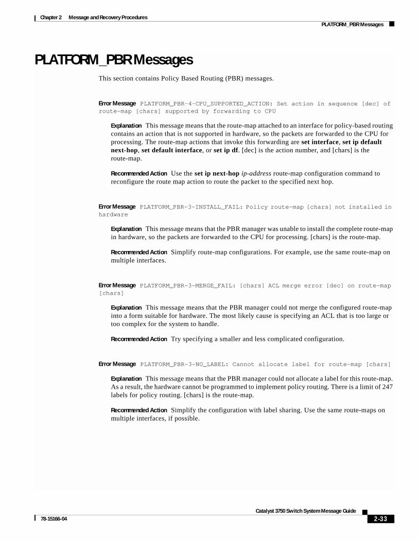
Chapter 2 Message and Recovery ProceduresPLATFORM_PBR Messages
PLATFORM_PBR MessagesThis section contains Policy Based Routing (PBR) messages.
Error Message PLATFORM_PBR-4-CPU_SUPPORTED_ACTION: Set action in sequence [dec] of route-map [chars] supported by forwarding to CPU
Explanation This message means that the route-map attached to an interface for policy-based routing contains an action that is not supported in hardware, so the packets are forwarded to the CPU for processing. The route-map actions that invoke this forwarding are set interface, set ip default next-hop, set default interface, or set ip df. [dec] is the action number, and [chars] is the route-map.
Recommended Action Use the set ip next-hop ip-address route-map configuration command to reconfigure the route map action to route the packet to the specified next hop.
Error Message PLATFORM_PBR-3-INSTALL_FAIL: Policy route-map [chars] not installed in hardware
Explanation This message means that the PBR manager was unable to install the complete route-map in hardware, so the packets are forwarded to the CPU for processing. [chars] is the route-map.
Recommended Action Simplify route-map configurations. For example, use the same route-map on multiple interfaces.
Error Message PLATFORM_PBR-3-MERGE_FAIL: [chars] ACL merge error [dec] on route-map [chars]
Explanation This message means that the PBR manager could not merge the configured route-map into a form suitable for hardware. The most likely cause is specifying an ACL that is too large or too complex for the system to handle.
Recommended Action Try specifying a smaller and less complicated configuration.
Error Message PLATFORM_PBR-3-NO_LABEL: Cannot allocate label for route-map [chars]
Explanation This message means that the PBR manager could not allocate a label for this route-map. As a result, the hardware cannot be programmed to implement policy routing. There is a limit of 247 labels for policy routing. [chars] is the route-map.
Recommended Action Simplify the configuration with label sharing. Use the same route-maps on multiple interfaces, if possible.
2-33Catalyst 3750 Switch System Message Guide
78-15166-04
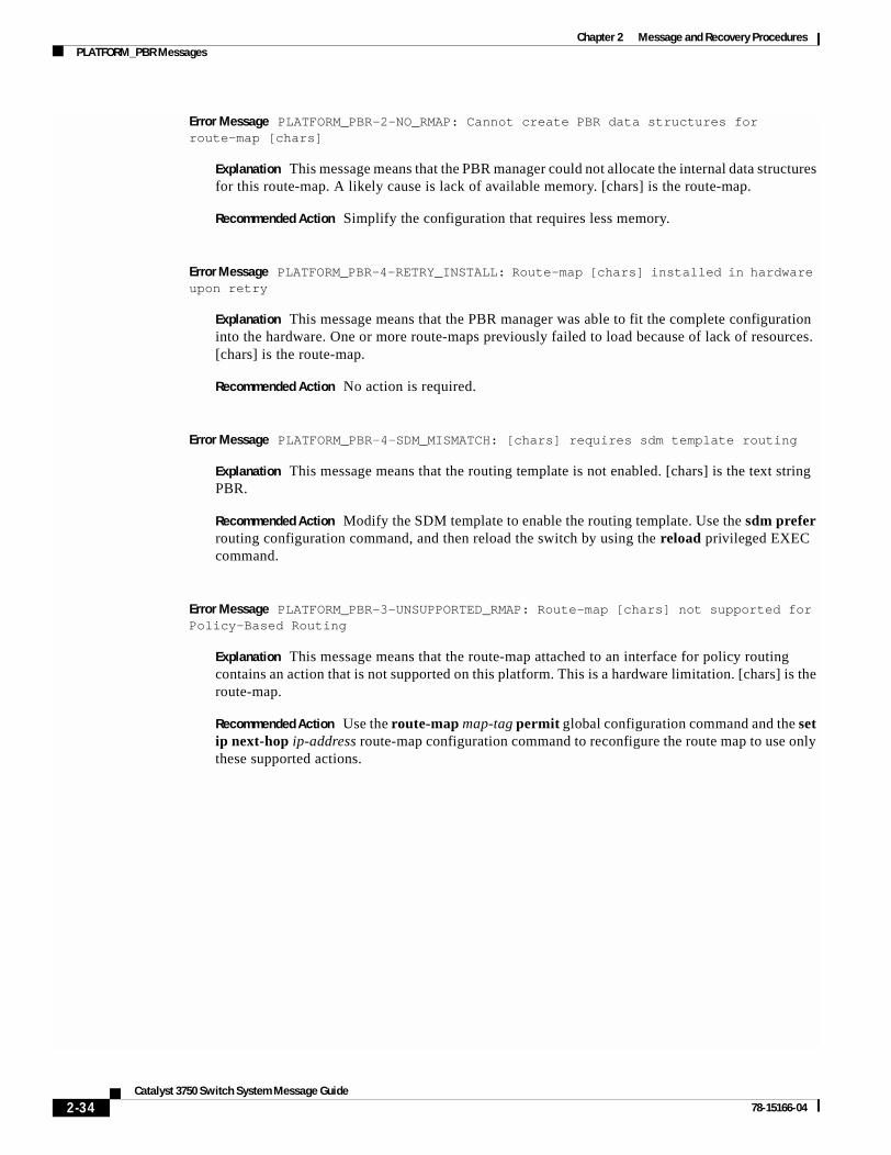
Chapter 2 Message and Recovery ProceduresPLATFORM_PBR Messages
Error Message PLATFORM_PBR-2-NO_RMAP: Cannot create PBR data structures for route-map [chars]
Explanation This message means that the PBR manager could not allocate the internal data structures for this route-map. A likely cause is lack of available memory. [chars] is the route-map.
Recommended Action Simplify the configuration that requires less memory.
Error Message PLATFORM_PBR-4-RETRY_INSTALL: Route-map [chars] installed in hardware upon retry
Explanation This message means that the PBR manager was able to fit the complete configuration into the hardware. One or more route-maps previously failed to load because of lack of resources. [chars] is the route-map.
Recommended Action No action is required.
Error Message PLATFORM_PBR-4-SDM_MISMATCH: [chars] requires sdm template routing
Explanation This message means that the routing template is not enabled. [chars] is the text string PBR.
Recommended Action Modify the SDM template to enable the routing template. Use the sdm prefer routing configuration command, and then reload the switch by using the reload privileged EXEC command.
Error Message PLATFORM_PBR-3-UNSUPPORTED_RMAP: Route-map [chars] not supported for Policy-Based Routing
Explanation This message means that the route-map attached to an interface for policy routing contains an action that is not supported on this platform. This is a hardware limitation. [chars] is the route-map.
Recommended Action Use the route-map map-tag permit global configuration command and the set ip next-hop ip-address route-map configuration command to reconfigure the route map to use only these supported actions.
2-34Catalyst 3750 Switch System Message Guide
78-15166-04
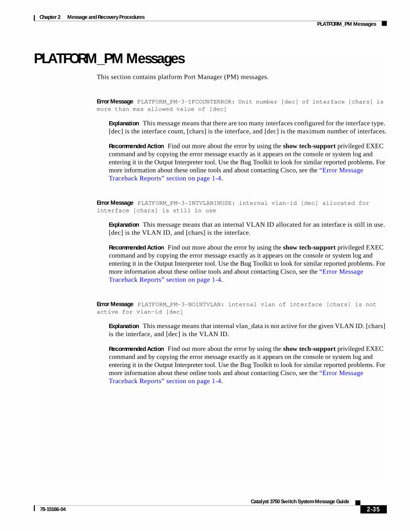
Chapter 2 Message and Recovery ProceduresPLATFORM_PM Messages
PLATFORM_PM MessagesThis section contains platform Port Manager (PM) messages.
Error Message PLATFORM_PM-3-IFCOUNTERROR: Unit number [dec] of interface [chars] is more than max allowed value of [dec]
Explanation This message means that there are too many interfaces configured for the interface type. [dec] is the interface count, [chars] is the interface, and [dec] is the maximum number of interfaces.
Recommended Action Find out more about the error by using the show tech-support privileged EXEC command and by copying the error message exactly as it appears on the console or system log and entering it in the Output Interpreter tool. Use the Bug Toolkit to look for similar reported problems. For more information about these online tools and about contacting Cisco, see the “Error Message Traceback Reports” section on page 1-4.
Error Message PLATFORM_PM-3-INTVLANINUSE: internal vlan-id [dec] allocated for interface [chars] is still in use
Explanation This message means that an internal VLAN ID allocated for an interface is still in use. [dec] is the VLAN ID, and [chars] is the interface.
Recommended Action Find out more about the error by using the show tech-support privileged EXEC command and by copying the error message exactly as it appears on the console or system log and entering it in the Output Interpreter tool. Use the Bug Toolkit to look for similar reported problems. For more information about these online tools and about contacting Cisco, see the “Error Message Traceback Reports” section on page 1-4.
Error Message PLATFORM_PM-3-NOINTVLAN: internal vlan of interface [chars] is not active for vlan-id [dec]
Explanation This message means that internal vlan_data is not active for the given VLAN ID. [chars] is the interface, and [dec] is the VLAN ID.
Recommended Action Find out more about the error by using the show tech-support privileged EXEC command and by copying the error message exactly as it appears on the console or system log and entering it in the Output Interpreter tool. Use the Bug Toolkit to look for similar reported problems. For more information about these online tools and about contacting Cisco, see the “Error Message Traceback Reports” section on page 1-4.
2-35Catalyst 3750 Switch System Message Guide
78-15166-04
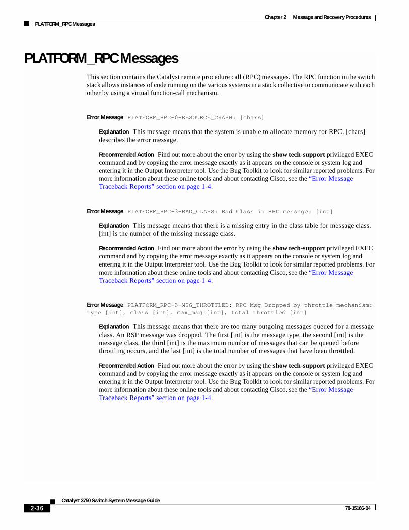
Chapter 2 Message and Recovery ProceduresPLATFORM_RPC Messages
PLATFORM_RPC MessagesThis section contains the Catalyst remote procedure call (RPC) messages. The RPC function in the switch stack allows instances of code running on the various systems in a stack collective to communicate with each other by using a virtual function-call mechanism.
Error Message PLATFORM_RPC-0-RESOURCE_CRASH: [chars]
Explanation This message means that the system is unable to allocate memory for RPC. [chars] describes the error message.
Recommended Action Find out more about the error by using the show tech-support privileged EXEC command and by copying the error message exactly as it appears on the console or system log and entering it in the Output Interpreter tool. Use the Bug Toolkit to look for similar reported problems. For more information about these online tools and about contacting Cisco, see the “Error Message Traceback Reports” section on page 1-4.
Error Message PLATFORM_RPC-3-BAD_CLASS: Bad Class in RPC message: [int]
Explanation This message means that there is a missing entry in the class table for message class. [int] is the number of the missing message class.
Recommended Action Find out more about the error by using the show tech-support privileged EXEC command and by copying the error message exactly as it appears on the console or system log and entering it in the Output Interpreter tool. Use the Bug Toolkit to look for similar reported problems. For more information about these online tools and about contacting Cisco, see the “Error Message Traceback Reports” section on page 1-4.
Error Message PLATFORM_RPC-3-MSG_THROTTLED: RPC Msg Dropped by throttle mechanism: type [int], class [int], max_msg [int], total throttled [int]
Explanation This message means that there are too many outgoing messages queued for a message class. An RSP message was dropped. The first [int] is the message type, the second [int] is the message class, the third [int] is the maximum number of messages that can be queued before throttling occurs, and the last [int] is the total number of messages that have been throttled.
Recommended Action Find out more about the error by using the show tech-support privileged EXEC command and by copying the error message exactly as it appears on the console or system log and entering it in the Output Interpreter tool. Use the Bug Toolkit to look for similar reported problems. For more information about these online tools and about contacting Cisco, see the “Error Message Traceback Reports” section on page 1-4.
2-36Catalyst 3750 Switch System Message Guide
78-15166-04
Chapter 2 Message and Recovery ProceduresPLATFORM_RPC Messages
Error Message PLATFORM_RPC-3-PERSISTENT_UNABLE_TO_SEND: System is consistently unable to send RPC message: [chars], paks_outstanding: [int]
Explanation This message means that the system is experiencing a persistent low-level transport failure in sending RPC messages. [chars] is a description of the error returned by the low-level packet-sending driver that triggered the error (usually one of these: fifo full, fifo empty, out of buf, out of mem, null pointer, misc failure), and [int] is the number of packets outstanding (packets from the RPC code to the driver that have not yet been sent).
Recommended Action Find out more about the error by using the show tech-support privileged EXEC command and by copying the error message exactly as it appears on the console or system log and entering it in the Output Interpreter tool. Use the Bug Toolkit to look for similar reported problems. For more information about these online tools and about contacting Cisco, see the “Error Message Traceback Reports” section on page 1-4.
Error Message PLATFORM_RPC-3-RESP_FAIL: Unexpected response or failure, class [dec], req [dec], switch [dec], error [dec], [chars]
Explanation This message means that the platform received an unexpected response. The first [dec] is RPC request class, the second [dec] is the RPC request number, the third [dec] is the destination switch number, the fourth [dec] is the returned error number, and [chars] is an optional comment.
Recommended Action Find out more about the error by using the show tech-support privileged EXEC command and by copying the error message exactly as it appears on the console or system log and entering it in the Output Interpreter tool. Use the Bug Toolkit to look for similar reported problems. For more information about these online tools and about contacting Cisco, see the “Error Message Traceback Reports” section on page 1-4.
Error Message PLATFORM_RPC-3-SEND_FAIL: Failed to send RPC message in class [dec], req [dec], [chars]
Explanation This message means that there is a local resource error or that too many outgoing messages are queued for the message class. The first [dec] is RPC request class, the second [dec] is the RPC request number, and [chars] is an optional comment.
Recommended Action Find out more about the error by using the show tech-support privileged EXEC command and by copying the error message exactly as it appears on the console or system log and entering it in the Output Interpreter tool. Use the Bug Toolkit to look for similar reported problems. For more information about these online tools and about contacting Cisco, see the “Error Message Traceback Reports” section on page 1-4.
2-37Catalyst 3750 Switch System Message Guide
78-15166-04

Chapter 2 Message and Recovery ProceduresPLATFORM_SPAN Messages
Error Message PLATFORM_RPC-3-UNABLE_TO_SEND: System is unable to send RPC message: [chars], paks_outstanding: [int]
Explanation This message means that the system had a low-level transport failure when trying to send an RPC message. [chars] is a description of the error returned by the low-level packet sending driver that triggered the error (usually one of these: fifo full, fifo empty, out of buf, out of mem, null pointer, misc failure), and [int] is the number of packets outstanding (packets from the RPC code to the driver that have not yet been sent).
Recommended Action Find out more about the error by using the show tech-support privileged EXEC command and by copying the error message exactly as it appears on the console or system log and entering it in the Output Interpreter tool. Use the Bug Toolkit to look for similar reported problems. For more information about these online tools and about contacting Cisco, see the “Error Message Traceback Reports” section on page 1-4.
PLATFORM_SPAN MessagesThis section contains the Switched Port Analyzer (SPAN) messages.
Error Message PLATFORM_SPAN-3-PACKET_DROP: Decreases egress SPAN rate
Explanation This message means that egress SPAN rates are falling because SPAN is enabled with multicast routing or fallback bridging.
Recommended Action Find out more about the error by using the show tech-support privileged EXEC command and by copying the error message exactly as it appears on the console or system log and entering it in the Output Interpreter tool. Use the Bug Toolkit to look for similar reported problems. For more information about these online tools and about contacting Cisco, see the “Error Message Traceback Reports” section on page 1-4.
PLATFORM_UCAST MessagesThis section contains platform unicast routing messages.
Error Message PLATFORM_UCAST-3-ADJ: [chars]
Explanation This message means that the adjacency module for unicast routing encountered an error. [chars] describes the error.
Recommended Action Find out more about the error by using the show tech-support privileged EXEC command and by copying the error message exactly as it appears on the console or system log and entering it in the Output Interpreter tool. Use the Bug Toolkit to look for similar reported problems. For more information about these online tools and about contacting Cisco, see the “Error Message Traceback Reports” section on page 1-4.
2-38Catalyst 3750 Switch System Message Guide
78-15166-04

Chapter 2 Message and Recovery ProceduresPLATFORM_UCAST Messages
Error Message PLATFORM_UCAST-3-ARP: [chars]
Explanation This message means that ARP module for unicast routing encountered an error. [chars] describes the error.
Recommended Action Find out more about the error by using the show tech-support privileged EXEC command and by copying the error message exactly as it appears on the console or system log and entering it in the Output Interpreter tool. Use the Bug Toolkit to look for similar reported problems. For more information about these online tools and about contacting Cisco, see the “Error Message Traceback Reports” section on page 1-4.
Error Message PLATFORM_UCAST-3-CEF: [chars]
Explanation This message means that the Cisco Express Forwarding (CEF) module for unicast routing encountered an error. [chars] describes the error.
Recommended Action Find out more about the error by using the show tech-support privileged EXEC command and by copying the error message exactly as it appears on the console or system log and entering it in the Output Interpreter tool. Use the Bug Toolkit to look for similar reported problems. For more information about these online tools and about contacting Cisco, see the “Error Message Traceback Reports” section on page 1-4.
Error Message PLATFORM_UCAST-3-DYNAMIC: [chars]
Explanation This message means that the dynamic address tracking mechanism for unicast routing encountered an error. [chars] describes the error.
Recommended Action Find out more about the error by using the show tech-support privileged EXEC command and by copying the error message exactly as it appears on the console or system log and entering it in the Output Interpreter tool. Use the Bug Toolkit to look for similar reported problems. For more information about these online tools and about contacting Cisco, see the “Error Message Traceback Reports” section on page 1-4.
Error Message PLATFORM_UCAST-3-ERROR: [chars]
Explanation This message means that an internal unicast routing error occurred. [chars] describes the error.
Recommended Action Find out more about the error by using the show tech-support privileged EXEC command and by copying the error message exactly as it appears on the console or system log and entering it in the Output Interpreter tool. Use the Bug Toolkit to look for similar reported problems. For more information about these online tools and about contacting Cisco, see the “Error Message Traceback Reports” section on page 1-4.
2-39Catalyst 3750 Switch System Message Guide
78-15166-04

Chapter 2 Message and Recovery ProceduresPLATFORM_VLAN Messages
Error Message PLATFORM_UCAST-3-HSRP: [chars]
Explanation This message means that Hot Standby Router Protocol (HSRP) module for unicast routing encountered an error. [chars] describes the error.
Recommended Action Find out more about the error by using the show tech-support privileged EXEC command and by copying the error message exactly as it appears on the console or system log and entering it in the Output Interpreter tool. Use the Bug Toolkit to look for similar reported problems. For more information about these online tools and about contacting Cisco, see the “Error Message Traceback Reports” section on page 1-4.
Error Message PLATFORM_UCAST-3-INTERFACE: [chars]
Explanation This message means that a unicast routing interface error occurred. [chars] describes the error.
Recommended Action Find out more about the error by using the show tech-support privileged EXEC command and by copying the error message exactly as it appears on the console or system log and entering it in the Output Interpreter tool. Use the Bug Toolkit to look for similar reported problems. For more information about these online tools and about contacting Cisco, see the “Error Message Traceback Reports” section on page 1-4.
Error Message PLATFORM_UCAST-3-RPC: [chars]
Explanation This message means that the RPC module for unicast routing encountered an error. [chars] describes the error.
Recommended Action Find out more about the error by using the show tech-support privileged EXEC command and by copying the error message exactly as it appears on the console or system log and entering it in the Output Interpreter tool. Use the Bug Toolkit to look for similar reported problems. For more information about these online tools and about contacting Cisco, see the “Error Message Traceback Reports” section on page 1-4.
PLATFORM_VLAN MessagesThis section contains platform VLAN messages.
Error Message PLATFORM_VLAN-3-LOCK_FAIL: Failed to lock vlan-id [dec], associated mapped vlan id value [dec]
Explanation This message means that the VLAN lock operation failed. This can occur if the VLAN is already active in the system or if the VLAN ID is not active. The first [dec] is the VLAN ID, and the second [dec] is the mapped-vlan-id (MVID).
Recommended Action Find out more about the error by using the show tech-support privileged EXEC command and by copying the error message exactly as it appears on the console or system log and entering it in the Output Interpreter tool. Use the Bug Toolkit to look for similar reported problems. For more information about these online tools and about contacting Cisco, see the “Error Message Traceback Reports” section on page 1-4.
2-40Catalyst 3750 Switch System Message Guide
78-15166-04
Chapter 2 Message and Recovery ProceduresPM Messages
Error Message PLATFORM_VLAN-3-MVID_ERROR: Mapped Vlan ID value [dec] associated with vlan-id [dec] is invalid
Explanation This message means that an active VLAN is not correctly associated with a mapped-vlan-id (MVID). The first [dec] is the VLAN ID, and the second [dec] is the MVID.
Recommended Action Find out more about the error by using the show tech-support privileged EXEC command and by copying the error message exactly as it appears on the console or system log and entering it in the Output Interpreter tool. Use the Bug Toolkit to look for similar reported problems. For more information about these online tools and about contacting Cisco, see the “Error Message Traceback Reports” section on page 1-4.
Error Message PLATFORM_VLAN-3-UNLOCK_FAIL: Failed to unlock vlan-id [dec], associated mapped vlan id value [dec]
Explanation This message means that the switch failed to unlock a VLAN ID. The most likely cause is that the VLAN is already unlocked. The first [dec] is the VLAN ID, and the second [dec] is the MVID.
Recommended Action Find out more about the error by using the show tech-support privileged EXEC command and by copying the error message exactly as it appears on the console or system log and entering it in the Output Interpreter tool. Use the Bug Toolkit to look for similar reported problems. For more information about these online tools and about contacting Cisco, see the “Error Message Traceback Reports” section on page 1-4.
PM MessagesThis section contains the port manager messages. The port manager is a state machine that controls all the logical and physical interfaces. All features, such as VLANs, UDLD, and so forth, work with the port manager to provide switch functions.
Error Message PM-2-LOW_SP_MEM: Switch process available memory is less than [dec] bytes
Explanation This message means that the available memory for the switch processor is low. This can occur when too many Layer 2 VLANs are configured. [dec] is the available memory.
Recommended Action Remove features from the system to reduce memory usage.
Error Message PM-2-NOMEM: Not enough memory available for [chars]
Explanation This message means that the port manager subsystem could not obtain the memory it needed to initialize the specified operation. [chars] is the port manager operation.
Recommended Action Find out more about the error by using the show tech-support privileged EXEC command and by copying the error message exactly as it appears on the console or system log and entering it in the Output Interpreter tool. Use the Bug Toolkit to look for similar reported problems. For more information about these online tools and about contacting Cisco, see the “Error Message Traceback Reports” section on page 1-4.
2-41Catalyst 3750 Switch System Message Guide
78-15166-04
Chapter 2 Message and Recovery ProceduresPM Messages
Error Message PM-2-VLAN_ADD: Failed to add VLAN [dec] - [chars].
Explanation This message means that the software failed to add the VLAN to the VLAN Trunking Protocol (VTP) database. [dec] is the VLAN ID, and [chars] specifies the reason for the failure.
Recommended Action Find out more about the error by using the show tech-support privileged EXEC command and by copying the error message exactly as it appears on the console or system log and entering it in the Output Interpreter tool. Use the Bug Toolkit to look for similar reported problems. For more information about these online tools and about contacting Cisco, see the “Error Message Traceback Reports” section on page 1-4.
Error Message PM-3-ERR_INCOMP_PORT: [dec]/[dec] is set to inactive because [dec]/[dec] is a [chars] port
Explanation This message means that the private host port cannot be configured because the trunk private VLAN promiscuous port and a SPAN destination port cannot be configured on the same coil. The first [dec]/[dec] is the private host port, the second [dec]/[dec] is the incompatible port, and [chars] is the incompatible port type.
Recommended Action Try to configure the incompatible ports on different coils.
Error Message PM-3-INTERNALERROR: Port Manager Internal Software Error ([chars]: [chars]: [dec]: [chars])
Explanation This message means that an internal software error occurred in the port manager. The parameters identify the problem for Cisco technical support.
Recommended Action Find out more about the error by using the show tech-support privileged EXEC command and by copying the error message exactly as it appears on the console or system log and entering it in the Output Interpreter tool. Use the Bug Toolkit to look for similar reported problems. For more information about these online tools and about contacting Cisco, see the “Error Message Traceback Reports” section on page 1-4.
Error Message PM-4-BAD_APP_ID: an invalid application id ([dec]) was detected
Explanation This message means that the port manager detected an invalid request. [dec] is the application ID.
Recommended Action Find out more about the error by using the show tech-support privileged EXEC command and by copying the error message exactly as it appears on the console or system log and entering it in the Output Interpreter tool. Use the Bug Toolkit to look for similar reported problems. For more information about these online tools and about contacting Cisco, see the “Error Message Traceback Reports” section on page 1-4.
2-42Catalyst 3750 Switch System Message Guide
78-15166-04
Chapter 2 Message and Recovery ProceduresPM Messages
Error Message PM-4-BAD_APP_REQ: an invalid [chars] request by the ’[chars]’ application was detected
Explanation This message means that the port manager detected an invalid request. The first [chars] is the invalid request, and the second [chars] is the application making the request.
Recommended Action Find out more about the error by using the show tech-support privileged EXEC command and by copying the error message exactly as it appears on the console or system log and entering it in the Output Interpreter tool. Use the Bug Toolkit to look for similar reported problems. For more information about these online tools and about contacting Cisco, see the “Error Message Traceback Reports” section on page 1-4.
Error Message PM-4-BAD_CARD_COOKIE: an invalid card cookie was detected
Explanation This message means that the port manager detected an invalid request.
Recommended Action Find out more about the error by using the show tech-support privileged EXEC command and by copying the error message exactly as it appears on the console or system log and entering it in the Output Interpreter tool. Use the Bug Toolkit to look for similar reported problems. For more information about these online tools and about contacting Cisco, see the “Error Message Traceback Reports” section on page 1-4.
Error Message PM-4-BAD_CARD_SLOT: an invalid card slot ([dec]) was detected
Explanation This message means that the port manager detected an invalid request. [dec] is the slot number.
Recommended Action Find out more about the error by using the show tech-support privileged EXEC command and by copying the error message exactly as it appears on the console or system log and entering it in the Output Interpreter tool. Use the Bug Toolkit to look for similar reported problems. For more information about these online tools and about contacting Cisco, see the “Error Message Traceback Reports” section on page 1-4.
Error Message PM-4-BAD_COOKIE: [chars] was detected
Explanation This message means that the port manager detected an invalid request. [chars] is the invalid request.
Recommended Action Find out more about the error by using the show tech-support privileged EXEC command and by copying the error message exactly as it appears on the console or system log and entering it in the Output Interpreter tool. Use the Bug Toolkit to look for similar reported problems. For more information about these online tools and about contacting Cisco, see the “Error Message Traceback Reports” section on page 1-4.
2-43Catalyst 3750 Switch System Message Guide
78-15166-04
Chapter 2 Message and Recovery ProceduresPM Messages
Error Message PM-4-BAD_HA_ENTRY_EVENT: Invalid Host access entry event ([dec]) is received
Explanation This message means that an invalid host access entry event was received; the host access table entry event should be an add, delete, or update event. [dec] is the event that is received.
Recommended Action Find out more about the error by using the show tech-support privileged EXEC command and by copying the error message exactly as it appears on the console or system log and entering it in the Output Interpreter tool. Use the Bug Toolkit to look for similar reported problems. For more information about these online tools and about contacting Cisco, see the “Error Message Traceback Reports” section on page 1-4.
Error Message PM-4-BAD_PORT_COOKIE: an invalid port cookie was detected
Explanation This message means that the port manager detected an invalid request.
Recommended Action Find out more about the error by using the show tech-support privileged EXEC command and by copying the error message exactly as it appears on the console or system log and entering it in the Output Interpreter tool. Use the Bug Toolkit to look for similar reported problems. For more information about these online tools and about contacting Cisco, see the “Error Message Traceback Reports” section on page 1-4.
Error Message PM-4-BAD_PORT_NUMBER: an invalid port number ([dec]) was detected
Explanation This message means that the port manager detected an invalid request. [dec] is the port number.
Recommended Action Find out more about the error by using the show tech-support privileged EXEC command and by copying the error message exactly as it appears on the console or system log and entering it in the Output Interpreter tool. Use the Bug Toolkit to look for similar reported problems. For more information about these online tools and about contacting Cisco, see the “Error Message Traceback Reports” section on page 1-4.
Error Message PM-4-BAD_VLAN_COOKIE: an invalid vlan cookie was detected
Explanation This message means that the port manager detected an invalid request.
Recommended Action Find out more about the error by using the show tech-support privileged EXEC command and by copying the error message exactly as it appears on the console or system log and entering it in the Output Interpreter tool. Use the Bug Toolkit to look for similar reported problems. For more information about these online tools and about contacting Cisco, see the “Error Message Traceback Reports” section on page 1-4.
2-44Catalyst 3750 Switch System Message Guide
78-15166-04
Chapter 2 Message and Recovery ProceduresPM Messages
Error Message PM-4-BAD_VLAN_ID: an invalid vlan id ([dec]) was detected
Explanation This message means that the port manager detected an invalid request. [dec] is the VLAN ID.
Recommended Action Find out more about the error by using the show tech-support privileged EXEC command and by copying the error message exactly as it appears on the console or system log and entering it in the Output Interpreter tool. Use the Bug Toolkit to look for similar reported problems. For more information about these online tools and about contacting Cisco, see the “Error Message Traceback Reports” section on page 1-4.
Error Message PM-4-ERR_DISABLE: [chars] error detected on [chars], putting [chars] in err-disable state
Explanation This message means that the port manager detected a misconfiguration or misbehavior and placed the interface in an error-disabled state. A recovery is attempted after the configured retry time (the default is 5 minutes). The first [chars] is the error, and the second and third [chars] are the affected interfaces.
Recommended Action Find out more about the error by using the show tech-support privileged EXEC command and by copying the error message exactly as it appears on the console or system log and entering it in the Output Interpreter tool. Use the Bug Toolkit to look for similar reported problems. For more information about these online tools and about contacting Cisco, see the “Error Message Traceback Reports” section on page 1-4.
Error Message PM-4-ERR_RECOVER: Attempting to recover from [chars] err-disable state on [chars]
Explanation This message means that the port manager is attempting to bring the interface up after taking it down to the error-disabled state. The first [chars] is the error, and the second [chars] is the affected interface.
Recommended Action Find out more about the error by using the show tech-support privileged EXEC command and by copying the error message exactly as it appears on the console or system log and entering it in the Output Interpreter tool. Use the Bug Toolkit to look for similar reported problems. For more information about these online tools and about contacting Cisco, see the “Error Message Traceback Reports” section on page 1-4.
Error Message PM-4-EXT_VLAN_INUSE: VLAN [dec] currently in use by [chars]
Explanation This message means that the port manager failed to allocate the VLAN for external use because the VLAN is being used by another feature. [dec] is the VLAN that is being used, and [chars] is the feature that is using it.
Recommended Action Reconfigure the feature (for example, the routed port) to use another internal VLAN or to request another available VLAN.
2-45Catalyst 3750 Switch System Message Guide
78-15166-04
Chapter 2 Message and Recovery ProceduresPM Messages
Error Message PM-4-EXT_VLAN_NOTAVAIL: VLAN [dec] not available in Port Manager
Explanation This message means that the port manager failed to allocate the requested VLAN. The VLAN is probably being used as an internal VLAN by other features. [dec] is the requested VLAN.
Recommended Action Try to configure a different VLAN on the device.
Error Message PM-4-INACTIVE: putting [chars] in inactive state because [chars]
Explanation This message means that the port manager has been blocked from creating a virtual port for the switch port and VLAN, causing the port to be in an inactive state. The reason for this condition is specified in the error message. The first [chars] is the interface name, and the second [chars] is the reason.
Recommended Action Find out more about the error by using the show tech-support privileged EXEC command and by copying the error message exactly as it appears on the console or system log and entering it in the Output Interpreter tool. Use the Bug Toolkit to look for similar reported problems. For more information about these online tools and about contacting Cisco, see the “Error Message Traceback Reports” section on page 1-4.
Error Message PM-4-INT_FAILUP: [chars] failed to come up. No internal VLAN available
Explanation This message means that the port manager failed to allocate an internal VLAN, and therefore the interface cannot be enabled. [chars] is the interface name.
Recommended Action Remove the extended-range VLAN by using the no vlan vlan-id global configuration command to free up resources.
Error Message PM-4-INT_VLAN_NOTAVAIL: Failed to allocate internal VLAN in Port Manager
Explanation This message means that the port manager failed to find any available internal VLAN.
Recommended Action Delete some extended-range VLANs created by users, or remove some features (such as routed ports) that require internal VLAN allocation. To delete extended-range VLANs, use the no vlan vlan-id global configuration command. To delete a routed port, use the no switchport interface configuration command.
Error Message PM-4-INVALID_HOST_ACCESS_ENTRY: Invalid Host access entry type ([dec]) is received
Explanation This message means that an invalid host access entry type was received; the host access entry should be a configured or dynamic type. [dec] is the entry type that is received.
Recommended Action Find out more about the error by using the show tech-support privileged EXEC command and by copying the error message exactly as it appears on the console or system log and entering it in the Output Interpreter tool. Use the Bug Toolkit to look for similar reported problems. For more information about these online tools and about contacting Cisco, see the “Error Message Traceback Reports” section on page 1-4.
2-46Catalyst 3750 Switch System Message Guide
78-15166-04

Chapter 2 Message and Recovery ProceduresPM Messages
Error Message PM-4-LIMITS: Virtual port count for [chars] exceeded the recommended limit of [dec]
Explanation This message means that the virtual port count exceeded the recommended limit of 1200 virtual ports per module and 4500 per switch. [chars] is the module name (for example, switch or the module number), and [dec] is the recommended limit.
Recommended Action Find out more about the error by using the show tech-support privileged EXEC command and by copying the error message exactly as it appears on the console or system log and entering it in the Output Interpreter tool. Use the Bug Toolkit to look for similar reported problems. For more information about these online tools and about contacting Cisco, see the “Error Message Traceback Reports” section on page 1-4.
Error Message PM-4-NO_SUBBLOCK: No PM subblock found for [chars]
Explanation This message means that the port manager failed to find the subblock for this interface. [chars] is the interface name.
Recommended Action Find out more about the error by using the show tech-support privileged EXEC command and by copying the error message exactly as it appears on the console or system log and entering it in the Output Interpreter tool. Use the Bug Toolkit to look for similar reported problems. For more information about these online tools and about contacting Cisco, see the “Error Message Traceback Reports” section on page 1-4.
Error Message PM-4-PVLAN_TYPE_CFG_ERR: Failed to set VLAN [dec] to a [chars] VLAN
Explanation This message means that the platform failed to set a private VLAN type. [dec] is the VLAN ID.
Recommended Action Find out more about the error by using the show tech-support privileged EXEC command and by copying the error message exactly as it appears on the console or system log and entering it in the Output Interpreter tool. Use the Bug Toolkit to look for similar reported problems. For more information about these online tools and about contacting Cisco, see the “Error Message Traceback Reports” section on page 1-4.
Error Message PM-4-TOO_MANY_APP: application ’[chars]’ exceeded registration limit
Explanation This message means that the port manager detected an invalid request. [chars] is the application.
Recommended Action Find out more about the error by using the show tech-support privileged EXEC command and by copying the error message exactly as it appears on the console or system log and entering it in the Output Interpreter tool. Use the Bug Toolkit to look for similar reported problems. For more information about these online tools and about contacting Cisco, see the “Error Message Traceback Reports” section on page 1-4.
2-47Catalyst 3750 Switch System Message Guide
78-15166-04
Chapter 2 Message and Recovery ProceduresQOSMGR Messages
Error Message PM-4-UNKNOWN_HOST_ACCESS: Invalid Host access value ([dec]) is received
Explanation This message means that the host access table is being accessed with an invalid host access value. [dec] is the value that is received.
Recommended Action Find out more about the error by using the show tech-support privileged EXEC command and by copying the error message exactly as it appears on the console or system log and entering it in the Output Interpreter tool. Use the Bug Toolkit to look for similar reported problems. For more information about these online tools and about contacting Cisco, see the “Error Message Traceback Reports” section on page 1-4.
Error Message PM-4-VMPS_CFG: Dynamic access VLAN [dec] same as voice vlan on [chars].
Explanation This message means that the access VLAN ID on the VMPS server is the same as the voice VLAN ID on the interface. [dec] is the access VLAN ID, and [chars] is the physical interface.
Recommended Action Assign the access VLAN on the VMPS server to a VLAN ID that is different from the voice VLAN ID.
QOSMGR MessagesThis section contains the quality of service (QoS) manager messages. An incorrect QoS setting causes these messages.
Error Message QOSMGR-3-FEATURE_NOT_FOUND: Cannot find feature for [chars]
Explanation This message means that an internal software error has occurred. [chars] is the description of the feature that the software cannot find.
Recommended Action Find out more about the error by using the show tech-support privileged EXEC command and by copying the error message exactly as it appears on the console or system log and entering it in the Output Interpreter tool. Use the Bug Toolkit to look for similar reported problems. For more information about these online tools and about contacting Cisco, see the “Error Message Traceback Reports” section on page 1-4.
Error Message QOSMGR-3-FILTERTYPE_INVALID: Internal Error Invalid Policy filtertype [dec]
Explanation This message means that an internal software error has occurred. [dec] is the invalid filter type identification.
Recommended Action Find out more about the error by using the show tech-support privileged EXEC command and by copying the error message exactly as it appears on the console or system log and entering it in the Output Interpreter tool. Use the Bug Toolkit to look for similar reported problems. For more information about these online tools and about contacting Cisco, see the “Error Message Traceback Reports” section on page 1-4.
2-48Catalyst 3750 Switch System Message Guide
78-15166-04
Chapter 2 Message and Recovery ProceduresQOSMGR Messages
Error Message QOSMGR-3-MERGE_RES_COUNT: Internal Error Invalid count
Explanation This message means that an internal software error has occurred.
Recommended Action Find out more about the error by using the show tech-support privileged EXEC command and by copying the error message exactly as it appears on the console or system log and entering it in the Output Interpreter tool. Use the Bug Toolkit to look for similar reported problems. For more information about these online tools and about contacting Cisco, see the “Error Message Traceback Reports” section on page 1-4.
Error Message QOSMGR-3-NO_POLICER_QOSLABEL: Creating port Class Label Failed
Explanation This message means that an internal software error has occurred.
Recommended Action Find out more about the error by using the show tech-support privileged EXEC command and by copying the error message exactly as it appears on the console or system log and entering it in the Output Interpreter tool. Use the Bug Toolkit to look for similar reported problems. For more information about these online tools and about contacting Cisco, see the “Error Message Traceback Reports” section on page 1-4.
Error Message QOSMGR-3-NO_VMR_QOSLABEL: qm_generate_vmrs have no qos label
Explanation This message means that an internal software error has occurred.
Recommended Action Find out more about the error by using the show tech-support privileged EXEC command and by copying the error message exactly as it appears on the console or system log and entering it in the Output Interpreter tool. Use the Bug Toolkit to look for similar reported problems. For more information about these online tools and about contacting Cisco, see the “Error Message Traceback Reports” section on page 1-4.
Error Message QOSMGR-3-NULL_POLICER: Internal Error Invalid Policer
Explanation This message means that an internal software error has occurred.
Recommended Action Find out more about the error by using the show tech-support privileged EXEC command and by copying the error message exactly as it appears on the console or system log and entering it in the Output Interpreter tool. Use the Bug Toolkit to look for similar reported problems. For more information about these online tools and about contacting Cisco, see the “Error Message Traceback Reports” section on page 1-4.
Error Message QOSMGR-3-POLICER_RES_COUNT: Internal Error Invalid Policer count
Explanation This message means that an internal software error has occurred.
Recommended Action Find out more about the error by using the show tech-support privileged EXEC command and by copying the error message exactly as it appears on the console or system log and entering it in the Output Interpreter tool. Use the Bug Toolkit to look for similar reported problems. For more information about these online tools and about contacting Cisco, see the “Error Message Traceback Reports” section on page 1-4.
2-49Catalyst 3750 Switch System Message Guide
78-15166-04
Chapter 2 Message and Recovery ProceduresQOSMGR Messages
Error Message QOSMGR-3-POLICYMAP_NOT_FOUND: Cannot find policymap for [chars]
Explanation This message means that an internal software error has occurred. [chars] is the policy map name.
Recommended Action Find out more about the error by using the show tech-support privileged EXEC command and by copying the error message exactly as it appears on the console or system log and entering it in the Output Interpreter tool. Use the Bug Toolkit to look for similar reported problems. For more information about these online tools and about contacting Cisco, see the “Error Message Traceback Reports” section on page 1-4.
Error Message QOSMGR-3-QUEUE_PTR_ERROR: queue pointers out of order [hex] [hex] [hex] [hex]
Explanation This message means that an internal software error has occurred. [hex] [hex] [hex] [hex] are the software-computed queue pointer values. The parameters provide error details for Cisco Technical Support.
Recommended Action Find out more about the error by using the show tech-support privileged EXEC command and by copying the error message exactly as it appears on the console or system log and entering it in the Output Interpreter tool. Use the Bug Toolkit to look for similar reported problems. For more information about these online tools and about contacting Cisco, see the “Error Message Traceback Reports” section on page 1-4.
Error Message QOSMGR-3-RESERVE_COUNT_ERROR: Reserved Count Exceeding total [dec]
Explanation This message means that an internal software error has occurred in the allocated reserved buffers. [dec] is the reserved count computed by the software.
Recommended Action Find out more about the error by using the show tech-support privileged EXEC command and by copying the error message exactly as it appears on the console or system log and entering it in the Output Interpreter tool. Use the Bug Toolkit to look for similar reported problems. For more information about these online tools and about contacting Cisco, see the “Error Message Traceback Reports” section on page 1-4.
Error Message QOSMGR-3-RESOURCE_INTERNAL: Internal Error in resource allocation
Explanation This message means that an internal software error has occurred.
Recommended Action Find out more about the error by using the show tech-support privileged EXEC command and by copying the error message exactly as it appears on the console or system log and entering it in the Output Interpreter tool. Use the Bug Toolkit to look for similar reported problems. For more information about these online tools and about contacting Cisco, see the “Error Message Traceback Reports” section on page 1-4.
2-50Catalyst 3750 Switch System Message Guide
78-15166-04
Chapter 2 Message and Recovery ProceduresQOSMGR Messages
Error Message QOSMGR-3-VMRSEQ_INVALID: Internal Error Invalid VMR sequence
Explanation This message means that an internal software error has occurred.
Recommended Action Find out more about the error by using the show tech-support privileged EXEC command and by copying the error message exactly as it appears on the console or system log and entering it in the Output Interpreter tool. Use the Bug Toolkit to look for similar reported problems. For more information about these online tools and about contacting Cisco, see the “Error Message Traceback Reports” section on page 1-4.
Error Message QOSMGR-4-ACTION_NOT_SUPPORTED: Action is not supported in policymap [chars]
Explanation This message means that an action other than the set, trust, and police policy-map class configuration commands was configured in a policy map. This is a hardware limitation. [chars] is the name of the policy map.
Recommended Action Configure only the supported actions of set, trust, and police when in policy-map class configuration mode.
Error Message QOSMGR-4-CLASS_NOT_SUPPORTED: Classification is not supported in classmap [chars]
Explanation This message means that an unsupported match class-map configuration command was configured in a policy map and attached to an egress interface or that more than one match class-map command was configured. This is a hardware limitation. [chars] is the class-map name.
Recommended Action Reconfigure the class map or the policy map. Use only the match ip dscp dscp-list class-map configuration command in a policy map that is attached to an egress interface. Only one match per class map is supported.
Error Message QOSMGR-4-COMMAND_FAILURE: Execution of [chars] command failed
Explanation This message means that the command to configure a QoS setting failed. This is possibly due to lack of hardware resources. [chars] is the description of the command.
Recommended Action Check if any other messages indicate resource failure. If other messages indicate that the hardware resources are exceeded, retry the command with a smaller configuration. Find out more about the error by using the show tech-support privileged EXEC command and by copying the error message exactly as it appears on the console or system log and entering it in the Output Interpreter tool. Use the Bug Toolkit to look for similar reported problems. For more information about these online tools and about contacting Cisco, see the “Error Message Traceback Reports” section on page 1-4.
2-51Catalyst 3750 Switch System Message Guide
78-15166-04
Chapter 2 Message and Recovery ProceduresQOSMGR Messages
Error Message QOSMGR-4-HARDWARE_NOT_SUPPORTED: Hardware limitation has reached for policymap [chars]
Explanation This message means that the policy map configuration has exceeded the limitation of the hardware. You configured more QoS ACL entries than the number specified in the Switch Database Management (sdm) template. [chars] is the policy-map name.
Recommended Action Reconfigure the class map or the policy map, and reduce the number of QoS ACLs.
Error Message QOSMGR-4-MATCH_NOT_SUPPORTED: Match type is not supported in classmap [chars]
Explanation This message means that an unsupported match type was entered. Only the access-group acl-index-or-name, ip dscp dscp-list, and ip precedence ip-precedence-list match types are supported with the match class-map configuration command. [chars] is the name of the class map.
Recommended Action Reconfigure the class map; use only the match access-group, match ip dscp, and match ip precedence class-map configuration commands within the class map.
Error Message QOSMGR-4-NOT_SUPPORTED: Action ’[chars]’ is not supported for a policymap attached to output side.
Explanation This message means that a set or trust policy-map class configuration command was configured in a policy map and attached to an egress interface. A warning message is logged, and the actions do not take affect. This is a hardware limitation. [chars] is either the set or trust action.
Recommended Action Do not configure a set or trust policy-map class configuration command in a policy map and attach it to an egress interface. These policy-map actions are supported only on ingress interfaces.
Error Message QOSMGR-4-POLICER_PLATFORM_NOT_SUPPORTED: Policer configuration has exceeded hardware limitation for policymap [chars]
Explanation This message means that the policy-map configuration has exceeded the limitation of the hardware. You configured more policers together in all policy maps (by using the police or police aggregate policy-map class configuration command) than supported by hardware. [chars] is the policy-map name.
Recommended Action Reconfigure the class maps or the policy maps, or delete the policy map from some interfaces.
2-52Catalyst 3750 Switch System Message Guide
78-15166-04
Chapter 2 Message and Recovery ProceduresSDM Message
Error Message QOSMGR-4-POLICER_POLICY_NOT_SUPPORTED: Number of policers has exceeded per policy hardware limitation for policymap [chars]
Explanation This message means that the policy-map configuration has exceeded the limitation of the hardware. You configured more policers in a policy map (by using the police or police aggregate policy-map class configuration command) than supported. [chars] is the policy-map name.
Recommended Action Reconfigure the class map or the policy map, and reduce the number of policers.
SDM MessageThis section contains the Switch Database Manager (SDM) message.
Error Message SDM-6-MISMATCH_ADVISE: [chars]
Explanation This message means that a stack member cannot support the SDM template that the stack master is using. Switches in the SDM mismatch state are not functional stack members. This error follows the STACKMGR-6-SWITCH_ADDED_SDM error message if it reports SDM_MISMATCH. [chars] displays mismatch information and recommended corrective actions.
Recommended Action Downgrade the SDM template of the master switch to make it compatible with the stack member switches. For example, if the master switch uses aggregator routing, the error message recommends downgrading the master to desktop routing by using the sdm prefer vlan desktop global configuration command.
SPAN MessagesThis section contains the Switched Port Analyzer (SPAN) messages.
Error Message SPAN-3-MEM_UNAVAIL: Memory was not available to perform the SPAN operation
Explanation This message means that the system was unable to perform a SPAN operation because of a lack of memory.
Recommended Action Reduce other system activity to ease the memory demands.
Error Message SPAN-3-UNKN_ERR: An internal error occurred during a SPAN operation.
Explanation This message means that SPAN detected an error in its internal operation.
Recommended Action The error might be transient. Try the SPAN operation again. If a second attempt also fails, reload the switch by using the reload privileged EXEC command to complete the operation.
2-53Catalyst 3750 Switch System Message Guide
78-15166-04
Chapter 2 Message and Recovery ProceduresSPANTREE Messages
Error Message SPAN-3-UNKN_ERR_PORT: An internal error occurred when configuring SPAN on port [chars]
Explanation This message means that SPAN detected an error in its internal operation. [chars] is the interface.
Recommended Action The error might be transient. Try the SPAN operation again. If the second attempt also fails, reload the switch by using the reload privileged EXEC command to complete the operation.
SPANTREE MessagesThis section contains the spanning-tree messages.
Error Message SPANTREE-2-BLOCK_BPDUGUARD: Received BPDU on port [chars] with BPDU Guard enabled. Disabling port.
Explanation This message means that a bridge protocol data unit (BPDU) was received on an interface that has the spanning tree BPDU guard feature enabled. As a result, the interface was administratively shut down. [chars] is the name of the interface.
Recommended Action Either remove the device sending BPDUs, or disable the BPDU guard feature. The BPDU guard feature can be locally configured on the interface or globally configured on all ports that have PortFast enabled. To disable BPDU guard on an interface, use the no spanning-tree bpduguard enable interface configuration command. To disable BPDU guard globally, use the no spanning-tree portfast bpduguard default global configuration command. After you have removed the device or disabled BPDU guard, re-enable the interface by entering the no shutdown interface configuration command.
Error Message SPANTREE-2-BLOCK_PVID_LOCAL: Blocking [chars] on [chars]. Inconsistent local vlan.
Explanation This message means that the spanning-tree port associated with the listed spanning-tree instance and interface will be held in the spanning-tree blocking state until the port VLAN ID (PVID) inconsistency is resolved. The listed spanning-tree instance is that of the native VLAN ID of the listed interface. The first [chars] is the interface, and the second [chars] is the spanning-tree instance.
Recommended Action Verify that the configuration of the native VLAN ID is consistent on the interfaces on each end of the 802.1Q trunk connection. When corrected, spanning tree automatically unblocks the interfaces, as appropriate.
2-54Catalyst 3750 Switch System Message Guide
78-15166-04
Chapter 2 Message and Recovery ProceduresSPANTREE Messages
Error Message SPANTREE-2-BLOCK_PVID_PEER: Blocking [chars] on [chars]. Inconsistent peer vlan.
Explanation This message means that the spanning-tree port associated with the listed spanning-tree instance and interface will be held in the spanning-tree blocking state until the port VLAN ID (PVID) inconsistency is resolved. The listed spanning-tree instance is that of the native VLAN ID of the interface on the peer switch to which the listed interface is connected. The first [chars] is the interface, and the second [chars] is the spanning-tree instance.
Recommended Action Verify that the configuration of the native VLAN ID is consistent on the interfaces on each end of the 802.1Q trunk connection. When interface inconsistencies are corrected, spanning tree automatically unblocks the interfaces.
Error Message SPANTREE-2-CHNL_MISCFG: Detected loop due to etherchannel misconfiguration of [chars] [chars]
Explanation This message means that a misconfiguration of a channel group has been detected. For example, the ports on one side of the EtherChannel either are not configured to be in the channel or failed to bundle into the channel and the other side has successfully bundled the ports into the EtherChannel. The first [chars] is the port, and the second [chars] is the VLAN.
Recommended Action Identify the local ports using the show interfaces status err-disabled privileged EXEC command, and then check the EtherChannel configuration on the remote device by using the show etherchannel summary privileged EXEC command on the remote device. After the configuration is correct, enter the shutdown and then no shutdown interface configuration commands on the associated port-channel interfaces.
Error Message SPANTREE-2-LOOPGUARD_BLOCK: Loop guard blocking port [chars] on [chars].
Explanation This message means that the spanning-tree message age timer has expired because no bridge protocol data units (BPDUs) were received from the designated bridge. Because this condition could be caused by a unidirectional-link failure, the interface is put into the blocking state and marked as loop-guard-inconsistent to prevent possible loops from being created. The first [chars] is the name of this port, and the second [chars] is the spanning-tree mode displayed in the show spanning-tree privileged EXEC command.
Recommended Action Enter the show spanning-tree inconsistentports privileged EXEC command to review the list of interfaces with loop-guard inconsistencies. Find out why devices connected to the listed ports are not sending BPDUs. One reason might be that they are not running the STP. If so, you should disable loop guard on the inconsistent interfaces by using the spanning-tree guard none interface configuration command or by starting STP on the remote side of the links.
Error Message SPANTREE-2-LOOPGUARD_CONFIG_CHANGE: Loop guard [chars] on port [chars] on [chars].
Explanation This message means that the spanning-tree loop-guard configuration for the listed interface has been changed. If enabled, the interface is placed into the blocking state. It is marked as loop-guard-inconsistent when the message-age timer expires because no BPDUs were received
2-55Catalyst 3750 Switch System Message Guide
78-15166-04
Chapter 2 Message and Recovery ProceduresSPANTREE Messages
from the designated bridge. This feature is mainly used to detect unidirectional links. The first [chars] is the loop-guard state (enable or disable), the second [chars] is the interface name, and the third [chars] is the spanning-tree instance.
Recommended Action Verify that this is the desired configuration for the listed interface. Correct it if this is not the desired configuration; otherwise, no further action is required.
Error Message SPANTREE-2-LOOPGUARD_UNBLOCK: Loop guard unblocking port [chars] on [chars].
Explanation This message means that the listed interface has received a BPDU, and therefore, if the inconsistency was caused by a unidirectional link failure, the problem no longer exists. The loop-guard-inconsistency is cleared for the interface, which is taken out of the blocking state, if appropriate. The first [chars] is the name of this port, and the second [chars] is the spanning-tree mode displayed in the show spanning-tree privileged EXEC command.
Recommended Action No action is required.
Error Message SPANTREE-2-PVSTSIM_FAIL: Superior PVST BPDU received on VLAN [dec] port [chars], claiming root [dec]:[enet]. Invoking root guard to block the port
Explanation This message means that root guard blocked a port that might cause a spanning-tree loop. When a PVST+ switch is connected to an MST switch, the IST root (MSTOO) becomes the root for all PVST+ spanning trees. A loop can occur if any of the PVST+ spanning trees have a better root than IST. To prevent the loop, root guard blocks the port on the MST switch that receives the superior message from the PVST+ side. The first [dec] is the VLAN ID, [chars] is the short interface name, such as Gi0/1, the second [dec] is the root bridge priority, and [enet] is the root bridge MAC address.
Recommended Action When STP converges after a new switch or switch port is added to the topology, root guard might temporarily block the port and then automatically restore it. If the port remains blocked, identify the root bridge from this error message, and configure a less favorable priority for the VLAN spanning tree. There could be other superior PVST roots, and the port cannot recover until all such roots are cleared. Alternatively, try disabling and then enabling the VLAN port.
Error Message SPANTREE-2-RECV_1Q_NON_1QTRUNK: Received 802.1Q BPDU on non 802.1Q trunk [chars] [chars].
Explanation This message means that the listed interface on which a Shared Spanning Tree Protocol (SSTP) BPDU was received was in trunk mode but was not using 802.1Q encapsulation. The first [chars] is the port, and the second [chars] is the VLAN.
Recommended Action Verify that the configuration and operational state of the listed interface and that of the interface to which it is connected are in the same mode (access or trunk). If the mode is trunk, verify that both interfaces have the same encapsulation (ISL or 802.1Q). If the encapsulation types are different, use the switchport trunk encapsulation interface configuration command to make them consistent. When the encapsulation is consistent, spanning tree automatically unblocks the interface.
2-56Catalyst 3750 Switch System Message Guide
78-15166-04
Chapter 2 Message and Recovery ProceduresSPANTREE Messages
Error Message SPANTREE-2-RECV_BAD_TLV: Received SSTP BPDU with bad TLV on [chars] [chars].
Explanation This message means that the listed interface received an SSTP BPDU without the VLAN ID tag. The BPDU is discarded. The first [chars] is the port, and the second [chars] is the VLAN that received the SSTP BPDU.
Recommended Action Find out more about the error by using the show tech-support privileged EXEC command and by copying the error message exactly as it appears on the console or system log and entering it in the Output Interpreter tool. Use the Bug Toolkit to look for similar reported problems. For more information about these online tools and about contacting Cisco, see the “Error Message Traceback Reports” section on page 1-4.
Error Message SPANTREE-2-RECV_PVID_ERR: Received BPDU with inconsistent peer vlan id [dec] on [chars] [chars].
Explanation This message means that the listed interface received an SSTP BPDU that is tagged with a VLAN ID that does not match the VLAN ID on which the BPDU was received. This occurs when the native VLAN is not consistently configured on both ends of an 802.1Q trunk. [dec] is the VLAN ID, the first [chars] is the port, and the second [chars] is the VLAN.
Recommended Action Verify that the configurations of the native VLAN ID is consistent on the interfaces on each end of the 802.1Q trunk connection. When the configurations are consistent, spanning tree automatically unblocks the interfaces.
Error Message SPANTREE-2-ROOTGUARD_BLOCK: Root guard blocking port [chars] on [chars].
Explanation This message means that on the listed interface a BPDU was received that advertises a superior spanning-tree root bridge (lower bridge ID, lower path cost, and so forth) than that in use. The interface is put into blocking state and marked as root-guard inconsistent to prevent a suboptimal spanning-tree topology from forming. The first [chars] is the name of this port, and the second [chars] is the spanning-tree mode displayed in the output of the show spanning-tree privileged EXEC command.
Recommended Action Enter the show spanning-tree inconsistentports privileged EXEC command to review the list of interfaces with root-guard inconsistencies. Find out why devices connected to the listed ports are sending BPDUs with a superior root bridge, and take action to prevent more occurrences. When the inaccurate BPDUs have been stopped, the interfaces automatically recover and resume normal operation. Make sure that it is appropriate to have root guard enabled on the interface.
Error Message SPANTREE-2-ROOTGUARD_CONFIG_CHANGE: Root guard [chars] on port [chars] on [chars].
Explanation This message means that the spanning-tree root guard configuration for the listed interface has changed. If enabled, any BPDU received on this interface that advertises a superior spanning-tree root bridge (lower bridge ID, lower path cost, and so forth) to that already in use
2-57Catalyst 3750 Switch System Message Guide
78-15166-04
Chapter 2 Message and Recovery ProceduresSPANTREE Messages
causes the interface to be put into the blocking state and marked as root-guard inconsistent. The first [chars] is the root-guard state (enable or disable), the second [chars] is the interface, and the third [chars] is the spanning-tree instance.
Recommended Action Verify that this is the desired configuration for the listed interface. Correct it if it is not the desired configuration; otherwise, no action is required.
Error Message SPANTREE-2-ROOTGUARD_UNBLOCK: Root guard unblocking port [chars] on [chars].
Explanation This message means that the listed interface is no longer receiving BPDUs advertising a superior root bridge (lower bridge ID, lower path cost, and so forth). The root-guard inconsistency is cleared for the interface, and the blocking state is removed from the interface. The first [chars] is the name of this port, and the second [chars] is the spanning-tree mode displayed in show spanning-tree privileged EXEC command.
Recommended Action No action is required.
Error Message SPANTREE-2-UNBLOCK_CONSIST_PORT: Unblocking [chars] on [chars]. Port consistency restored.
Explanation This message means that the port VLAN ID or port type inconsistencies have been resolved and spanning tree will unblock the listed interface of the listed spanning-tree instance as appropriate. The first [chars] is the interface, and the second [chars] is the spanning-tree instance.
Recommended Action No action is required.
Error Message SPANTREE-3-BAD_PORTNUM_SIZE: Rejected an attempt to set the port number field size to [dec] bits (valid range is [dec] to [dec] bits).
Explanation This message means that an error occurred in the platform-specific code that caused it to request more or less bits than are possible. The spanning-tree port identifier is a 16-bit field, which is divided evenly between the port priority and port number, with each subfield being 8 bits. This allows the port number field to represent port numbers between 1 and 255. However, on systems with more than 255 ports, the size of port number portion of the port ID must be increased to support the number of ports. This is performed by the STP subsystem at system initialization because the maximum number of ports on a particular platform will not change. This error occurs because of an error in the platform-specific code, which causes it to request more or less bits than are possible. The first [dec] is the number of bits for the port number, and the second and third [dec] describe the valid range.
Recommended Action Find out more about the error by using the show tech-support privileged EXEC command and by copying the error message exactly as it appears on the console or system log and entering it in the Output Interpreter tool. Use the Bug Toolkit to look for similar reported problems. For more information about these online tools and about contacting Cisco, see the “Error Message Traceback Reports” section on page 1-4.
2-58Catalyst 3750 Switch System Message Guide
78-15166-04
Chapter 2 Message and Recovery ProceduresSPANTREE Messages
Error Message SPANTREE-3-PORT_SELF_LOOPED: [chars] disabled.- received BPDU src mac ([enet]) same as that of interface
Explanation This message means that a BPDU was received on the listed interface with a source MAC address that matches the one assigned to the listed interface. This means that a port might be looped back to itself, possibly because of an installed diagnostic cable. The interface will be administratively shut down. [chars] is the interface that received the BPDU, and [enet] is the source MAC address.
Recommended Action Check the interface configuration and any cable connected to the interface. When the problem is resolved, re-enable the interface by entering the no shutdown interface configuration command.
Error Message SPANTREE-4-PORT_NOT_FORWARDING: [chars] [chars] [chars] [chars]
Explanation This message means that the port is not forwarding packets. For example, it might not be forwarding state information.
Recommended Action Find out more about the error by using the show tech-support privileged EXEC command and by copying the error message exactly as it appears on the console or system log and entering it in the Output Interpreter tool. Use the Bug Toolkit to look for similar reported problems. For more information about these online tools and about contacting Cisco, see the “Error Message Traceback Reports” section on page 1-4.
Error Message SPANTREE-5-EXTENDED_SYSID: Extended SysId [chars] for type [chars]
Explanation This message means that the extended system ID feature is either enabled or disabled for the given type of spanning tree. If enabled, the spanning-tree instance identifier is stored in the lower portion of the bridge ID priority field and limits the allowed values for the bridge priority from 0 to 61440, in increments of 4096. If disabled, the bridge ID priority field consists only of the configured priority, but some spanning-tree features might not be available on a given platform (for example, support for 4096 VLANs). On some platforms, this feature might be mandatory. The first [chars] is the extended system ID state (enable or disable), and the second [chars] is the spanning-tree instance.
Recommended Action No action is required.
Error Message SPANTREE-6-PORT_STATE: Port [chars] instance [dec] moving from [chars] to [chars].
Explanation This message means that the port state changed.
Recommended Action No action is required.
2-59Catalyst 3750 Switch System Message Guide
78-15166-04
Chapter 2 Message and Recovery ProceduresSPANTREE_FAST Messages
Error Message SPANTREE-7-BLOCK_PORT_TYPE: Blocking [chars] on [chars]. Inconsistent port type.
Explanation This message means that the listed interface is being held in the spanning-tree blocking state until the port-type inconsistency is resolved. The first [chars] is the interface, and the second [chars] is the spanning-tree instance.
Recommended Action Verify that the configuration and operational states of the listed interface and those of the interface to which it is connected are in the same mode (access or trunk). If the mode is trunk, verify that both interfaces have the same encapsulation (ISL or 802.1Q). When these parameters are consistent, spanning tree automatically unblocks the interface.
Error Message SPANTREE-7-RECV_1Q_NON_TRUNK: Received 802.1Q BPDU on non trunk [chars] [chars].
Explanation This message means that an SSTP BPDU was received on the listed interface, which is not an operational trunking interface. The first [chars] is the port name, and the second [chars] is the VLAN name.
Recommended Action Verify that the configuration and operational state of the listed interface and that of the interface to which it is connected are in the same mode (access or trunk). If the mode is trunk, verify that both interfaces have the same encapsulation (none, ISL, or 802.1Q). When these parameters are consistent, spanning tree automatically unblocks the interface.
SPANTREE_FAST MessagesThis section contains the spanning-tree fast-convergence message.
Error Message SPANTREE_FAST-7-PORT_FWD_UPLINK: [chars] [chars] moved to Forwarding (UplinkFast).
Explanation This message means that the listed interface has been selected as the new path to the root switch for the listed spanning-tree instance. The first [chars] is the spanning-tree instance, and the second [chars] is the interface.
Recommended Action No action is required.
2-60Catalyst 3750 Switch System Message Guide
78-15166-04
Chapter 2 Message and Recovery ProceduresSPANTREE_VLAN_SW Messages
SPANTREE_VLAN_SW MessagesThe section contains the per-VLAN spanning-tree-specific switch message.
Error Message SPANTREE_VLAN_SW-2-MAX_INSTANCE: Platform limit of [dec] STP instances exceeded. No instance created for [chars] (port [chars]).
Explanation This message means that the number of currently active VLAN spanning-tree instances has reached a platform-specific limit. No additional VLAN instances will be created until the number of existing instances drops below the platform limit. [dec] is the spanning-tree instance limit, and the first [chars] is the smallest VLAN number of those VLANs that are unable to have STP instances created.
Recommended Action Reduce the number of currently active spanning-tree instances by either disabling some of the currently active spanning-tree instances or deleting the VLANs associated with them. You must manually enable the spanning trees that could not be created because of limited instances.
STACKMGR MessagesThis section contains stack manager system messages. These messages are related to the status of switches within the stack.
Error Message STACKMGR-6-HDM_GET_DEVICE_RECORD_FAIL: Device Manager could not get device record.
Explanation This message means that this switch could not get the device record for some or all other switches in the stack.
Recommended Action Find out more about the error by using the show tech-support privileged EXEC command and by copying the error message exactly as it appears on the console or system log and entering it in the Output Interpreter tool. Use the Bug Toolkit to look for similar reported problems. For more information about these online tools and about contacting Cisco, see the “Error Message Traceback Reports” section on page 1-4.
Error Message STACKMGR-6-MASTER_ELECTED: Switch [dec] has been elected as MASTER of the stack
Explanation This message means that the specified switch has been elected stack master. [dec] is the switch number of the elected stack master.
Recommended Action No action is required.
2-61Catalyst 3750 Switch System Message Guide
78-15166-04
Chapter 2 Message and Recovery ProceduresSTACKMGR Messages
Error Message STACKMGR-6-MASTER_READY: Master Switch [dec] is READY
Explanation This message means that the stack master is ready for use. [dec] is the stack master switch number.
Recommended Action No action is required.
Error Message STACKMGR-6-MSG_FAIL: Failed to retrieve stack message from port-asic [dec] in direction [dec]
Explanation This message means that stack manager module failed to retrieve stack messages. The first [dec] is the ASIC ID, and the second [dec] is the direction.
Recommended Action No action is required.
Error Message STACKMGR-6-NORECORD: Switch removed event for switch [dec] with no switch record
Explanation This message means that the stack manager received a switch-removed event for which there is no switch record. [dec] is the switch number.
Recommended Action No action is required.
Error Message STACKMGR-6-STACK_LINK_CHANGE: Stack Port [chars] Switch [dec] has changed to state [chars]
Explanation This message means that the specified stack port status has changed state to up or down. The first [chars] is the stack port (1 or 2), [dec] is the switch number, and the second [chars] is the new state (up or down).
Recommended Action No action is required.
Error Message STACKMGR-6-SWITCH_ADDED: Switch [dec] has been ADDED to the stack
Explanation This message means that the specified stack member switch has been added to the stack. [dec] is the switch number.
Recommended Action No action is required.
Error Message STACKMGR-6-SWITCH_ADDED_SDM: Switch [dec] has been ADDED to the stack (SDM_MISMATCH)
Explanation This message means that the specified switch has been added to the stack. [dec] is the switch number. SDM_MISMATCH means that the added switch cannot support the SDM template that the stack master is using. Subsequent SDM-6-MISMATCH_ADVISE messages explain the mismatch and recommend corrective actions.
Recommended Action No action is required unless SDM_MISMATCH is displayed. For SDM_MISMATCH corrective actions, see SDM-6-MISMATCH_ADVISE.
2-62Catalyst 3750 Switch System Message Guide
78-15166-04
Chapter 2 Message and Recovery ProceduresSUPERVISOR Messages
Error Message STACKMGR-6-SWITCH_ADDED_VM: Switch [dec] has been ADDED to the stack (VERSION_MISMATCH)
Explanation This message means that a switch that has been added to the stack has a different software version. [dec] is the switch number.
Recommended Action No action is required.
Error Message STACKMGR-6-SWITCH_READY: Switch [dec] is READY
Explanation This message means that the switch is ready. [dec] is the switch number.
Recommended Action No action is required.
Error Message STACKMGR-6-SWITCH_REMOVED: Switch [dec] has been REMOVED from the stack
Explanation This message means that the specified switch has been removed from the stack. [dec] is the switch number.
Recommended Action No action is required.
SUPERVISOR MessagesThis section contains the supervisor ASIC error message. This ASIC controls the CPU and the switch send and receive ports.
Error Message SUPERVISOR-3-FATAL: [chars]
Explanation This message means that an internal error occurred in the supervisor ASIC. [chars] is the detailed error message.
Recommended Action Find out more about the error by using the show tech-support privileged EXEC command and by copying the error message exactly as it appears on the console or system log and entering it in the Output Interpreter tool. Use the Bug Toolkit to look for similar reported problems. For more information about these online tools and about contacting Cisco, see the “Error Message Traceback Reports” section on page 1-4.
2-63Catalyst 3750 Switch System Message Guide
78-15166-04
Chapter 2 Message and Recovery ProceduresSUPQ Messages
SUPQ MessagesThis section contains the supervisor queue error messages. These messages are related to CPU and send and receive queues.
Error Message SUPQ-3-THROTTLE_CPU_QUEUE: Invalid application ID [dec] used for throttling
Explanation This message means that an application has passed an invalid application ID for throttle check. [dec] is the internal application identifier.
Recommended Action Find out more about the error by using the show tech-support privileged EXEC command and by copying the error message exactly as it appears on the console or system log and entering it in the Output Interpreter tool. Use the Bug Toolkit to look for similar reported problems. For more information about these online tools and about contacting Cisco, see the “Error Message Traceback Reports” section on page 1-4.
Error Message SUPQ-4-CPUHB_RECV_STARVE: [chars]
Explanation This message means that the system has detected that messages directed to the CPU are delayed. [chars] is the detailed error message.
Recommended Action Find out more about the error by using the show tech-support privileged EXEC command and by copying the error message exactly as it appears on the console or system log and entering it in the Output Interpreter tool. Use the Bug Toolkit to look for similar reported problems. For more information about these online tools and about contacting Cisco, see the “Error Message Traceback Reports” section on page 1-4.
Error Message SUPQ-4-CPUHB_SLOW_TRANSMIT: [chars]
Explanation This message means that the system is warning you about a slowdown of the transmit interface. [chars] is the detailed error message.
Recommended Action Find out more about the error by using the show tech-support privileged EXEC command and by copying the error message exactly as it appears on the console or system log and entering it in the Output Interpreter tool. Use the Bug Toolkit to look for similar reported problems. For more information about these online tools and about contacting Cisco, see the “Error Message Traceback Reports” section on page 1-4.
Error Message SUPQ-4-CPUHB_TX_FAIL: [chars]
Explanation This message means that the system is warning you about the transmit interface discarding the heartbeat message.
Recommended Action Find out more about the error by using the show tech-support privileged EXEC command and by copying the error message exactly as it appears on the console or system log and entering it in the Output Interpreter tool. Use the Bug Toolkit to look for similar reported problems. For more information about these online tools and about contacting Cisco, see the “Error Message Traceback Reports” section on page 1-4.
2-64Catalyst 3750 Switch System Message Guide
78-15166-04
Chapter 2 Message and Recovery ProceduresSW_VLAN Messages
Error Message SUPQ-4-PORT_QUEUE_STUCK: Port queue Stuck for asic [dec] port [dec] queue [dec]
Explanation This message means that the system has detected that an interface queue is not being cleared in a reasonable time. The first [dec] is the ASIC, the second [dec] is the interface, and the third [dec] is the queue number.
Recommended Action Find out more about the error by using the show tech-support privileged EXEC command and by copying the error message exactly as it appears on the console or system log and entering it in the Output Interpreter tool. Use the Bug Toolkit to look for similar reported problems. For more information about these online tools and about contacting Cisco, see the “Error Message Traceback Reports” section on page 1-4.
Error Message SUPQ-4-RECV_QUEUE_STUCK: Receive queue Stuck for asic [dec] queue [dec]
Explanation This message means that the system has detected that the receive queue is not being cleared in a reasonable time. The first [dec] is the ASIC, and the second [dec] is the queue number.
Recommended Action Find out more about the error by using the show tech-support privileged EXEC command and by copying the error message exactly as it appears on the console or system log and entering it in the Output Interpreter tool. Use the Bug Toolkit to look for similar reported problems. For more information about these online tools and about contacting Cisco, see the “Error Message Traceback Reports” section on page 1-4.
SW_VLAN MessagesThis section contains the VLAN manager messages. The VLAN manager receives information from the VTP and enables the proper VLAN membership on all interfaces through the port manager.
Error Message SW_VLAN-3-VLAN_PM_NOTIFICATION_FAILURE: VLAN Manager synchronization failure with Port Manager over [chars]
Explanation This message means that the VLAN manager dropped a notification from the port manager because of a lack of ready pool space. [chars] is the type of port manager notification.
Recommended Action Find out more about the error by using the show tech-support privileged EXEC command and by copying the error message exactly as it appears on the console or system log and entering it in the Output Interpreter tool. Use the Bug Toolkit to look for similar reported problems. For more information about these online tools and about contacting Cisco, see the “Error Message Traceback Reports” section on page 1-4.
2-65Catalyst 3750 Switch System Message Guide
78-15166-04
Chapter 2 Message and Recovery ProceduresSW_VLAN Messages
Error Message SW_VLAN-3-VTP_PROTOCOL_ERROR: VTP protocol code internal error: [chars]
Explanation This message means that the VTP code encountered an unexpected error while processing a configuration request, a packet, or a timer expiration. [chars] is the internal error.
Recommended Action Find out more about the error by using the show tech-support privileged EXEC command and by copying the error message exactly as it appears on the console or system log and entering it in the Output Interpreter tool. Use the Bug Toolkit to look for similar reported problems. For more information about these online tools and about contacting Cisco, see the “Error Message Traceback Reports” section on page 1-4.
Error Message SW_VLAN-4-BAD_PM_VLAN_COOKIE_RETURNED: VLAN manager unexpectedly received a bad PM VLAN cookie from the Port Manager, VLAN indicated: [dec]
Explanation This message means that the VLAN manager received an upcall and a VLAN cookie from the port manager, which translated to a bad VLAN number. [dec] is the VLAN ID.
Recommended Action Find out more about the error by using the show tech-support privileged EXEC command and by copying the error message exactly as it appears on the console or system log and entering it in the Output Interpreter tool. Use the Bug Toolkit to look for similar reported problems. For more information about these online tools and about contacting Cisco, see the “Error Message Traceback Reports” section on page 1-4.
Error Message SW_VLAN-4-BAD_STARTUP_VLAN_CONFIG_FILE: Failed to configure VLAN from startup-config. Fallback to use VLAN configuration file from non-volatile memory
Explanation This message means that the VLAN software did not use the VLAN configuration from the startup-configuration file. It will use the binary VLAN configuration file in NVRAM memory.
Recommended Action No action is required.
Error Message SW_VLAN-4-BAD_VLAN_CONFIGURATION_FILE: VLAN configuration file contained incorrect verification word: [hex]
Explanation This message means that the VLAN configuration file read by the VLAN manager did not begin with the correct value. The VLAN configuration file is invalid, and it has been rejected. [hex] is the incorrect verification value.
Recommended Action Find out more about the error by using the show tech-support privileged EXEC command and by copying the error message exactly as it appears on the console or system log and entering it in the Output Interpreter tool. Use the Bug Toolkit to look for similar reported problems. For more information about these online tools and about contacting Cisco, see the “Error Message Traceback Reports” section on page 1-4.
2-66Catalyst 3750 Switch System Message Guide
78-15166-04

Chapter 2 Message and Recovery ProceduresSW_VLAN Messages
Error Message SW_VLAN-4-BAD_VLAN_CONFIGURATION_FILE_VERSION: VLAN configuration file contained unknown file version: [dec]
Explanation This message means that the VLAN configuration file read by the VLAN manager contained an unrecognized file version number, which might mean an attempt to regress to an older version of the VLAN manager software. [dec] is the file version number.
Recommended Action Find out more about the error by using the show tech-support privileged EXEC command and by copying the error message exactly as it appears on the console or system log and entering it in the Output Interpreter tool. Use the Bug Toolkit to look for similar reported problems. For more information about these online tools and about contacting Cisco, see the “Error Message Traceback Reports” section on page 1-4.
Error Message SW_VLAN-4-BAD_VLAN_TIMER_ACTIVE_VALUE: Encountered incorrect VLAN timer active value: [chars]
Explanation This message means that, because of a software error, a VLAN timer was detected as active when it should have been inactive or as inactive when it should have been active. [chars] is the VLAN timer active value.
Recommended Action Find out more about the error by using the show tech-support privileged EXEC command and by copying the error message exactly as it appears on the console or system log and entering it in the Output Interpreter tool. Use the Bug Toolkit to look for similar reported problems. For more information about these online tools and about contacting Cisco, see the “Error Message Traceback Reports” section on page 1-4.
Error Message SW_VLAN-4-EXT_VLAN_CREATE_FAIL: Failed to create VLANs [chars]: [chars]
Explanation The message means that the software failed to create VLANs. The first [chars] is the Layer 2 VLAN list, and the second [chars] describes the reason for the failure.
Recommended Action Find out more about the error by using the show tech-support privileged EXEC command and by copying the error message exactly as it appears on the console or system log and entering it in the Output Interpreter tool. Use the Bug Toolkit to look for similar reported problems. For more information about these online tools and about contacting Cisco, see the “Error Message Traceback Reports” section on page 1-4.
Error Message SW_VLAN-4-EXT_VLAN_INTERNAL_ERROR: Extended VLAN manager received an internal error [dec] from [chars]: [chars]
Explanation This message means that an unexpected error code was received by the VLAN manager from the extended-range VLAN configuration software. [dec] is the error code. The first [chars] is the function, and the second [chars] describes the error code.
Recommended Action Find out more about the error by using the show tech-support privileged EXEC command and by copying the error message exactly as it appears on the console or system log and entering it in the Output Interpreter tool. Use the Bug Toolkit to look for similar reported problems. For more information about these online tools and about contacting Cisco, see the “Error Message Traceback Reports” section on page 1-4.
2-67Catalyst 3750 Switch System Message Guide
78-15166-04
Chapter 2 Message and Recovery ProceduresSW_VLAN Messages
Error Message SW_VLAN-4-EXT_VLAN_INVALID_DATABASE_DATA: Extended VLAN manager received bad data of type [chars]: value [dec] from function [chars]
Explanation This message means that invalid data was received by the extended-range VLAN manager from an extended-range VLAN configuration database routine. The first [chars] is the data type, [dec] is the number received, and the second [chars] is the function name.
Recommended Action Find out more about the error by using the show tech-support privileged EXEC command and by copying the error message exactly as it appears on the console or system log and entering it in the Output Interpreter tool. Use the Bug Toolkit to look for similar reported problems. For more information about these online tools and about contacting Cisco, see the “Error Message Traceback Reports” section on page 1-4.
Error Message SW_VLAN-4-IFS_FAILURE: VLAN manager encountered file operation error: call = [chars] / file = [chars] / code = [dec] ([chars]) / bytes transferred = [dec]
Explanation This message means that the VLAN manager received an unexpected error return from a Cisco IOS file system (IFS) call while reading the VLAN database. The first [chars] is the name of the function call, and the second [chars] is the file name. [dec] is the error code, the third [chars] is the textual interpretation of the error code, and the second [dec] is the number of bytes transferred.
Recommended Action Find out more about the error by using the show tech-support privileged EXEC command and by copying the error message exactly as it appears on the console or system log and entering it in the Output Interpreter tool. Use the Bug Toolkit to look for similar reported problems. For more information about these online tools and about contacting Cisco, see the “Error Message Traceback Reports” section on page 1-4.
Error Message SW_VLAN-4-NO_PM_COOKIE_RETURNED: VLAN manager unexpectedly received a null [chars] type cookie from the Port Manager, data reference: [chars]
Explanation This message means that the VLAN manager queried the port manager for a reference cookie but received a NULL pointer instead. The first [chars] is the type of port manager cookie, and the second [chars] is the interface or VLAN that is the source of the problem.
Recommended Action Find out more about the error by using the show tech-support privileged EXEC command and by copying the error message exactly as it appears on the console or system log and entering it in the Output Interpreter tool. Use the Bug Toolkit to look for similar reported problems. For more information about these online tools and about contacting Cisco, see the “Error Message Traceback Reports” section on page 1-4.
Error Message SW_VLAN-4-STARTUP_EXT_VLAN_CONFIG_FILE_FAILED: Failed to configure extended range VLAN from startup-config. Error [chars]
Explanation This message means that the VLAN software failed to use an extended-range VLAN configuration from the startup configuration file. All extended-range VLAN configurations are lost after the system boots up. [chars] is a description of the error code.
Recommended Action No action is required.
2-68Catalyst 3750 Switch System Message Guide
78-15166-04

Chapter 2 Message and Recovery ProceduresSW_VLAN Messages
Error Message SW_VLAN-4-VTP_INTERNAL_ERROR: VLAN manager received an internal error [dec] from vtp function [chars]: [chars]
Explanation This message means that the VLAN manager received an unexpected error code from the VTP configuration software. [dec] is the error code, the first [chars] is the VTP function, and the second [chars] is the error-code description.
Recommended Action Find out more about the error by using the show tech-support privileged EXEC command and by copying the error message exactly as it appears on the console or system log and entering it in the Output Interpreter tool. Use the Bug Toolkit to look for similar reported problems. For more information about these online tools and about contacting Cisco, see the “Error Message Traceback Reports” section on page 1-4.
Error Message SW_VLAN-4-VTP_INVALID_DATABASE_DATA: VLAN manager received bad data of type [chars]: value [dec] from vtp database function [chars]
Explanation This message means that the VLAN manager received invalid data from a VTP configuration database routine. The first [chars] is the data type; [dec] is the inappropriate value that was received, and the second [chars] is the VTP database function.
Recommended Action Find out more about the error by using the show tech-support privileged EXEC command and by copying the error message exactly as it appears on the console or system log and entering it in the Output Interpreter tool. Use the Bug Toolkit to look for similar reported problems. For more information about these online tools and about contacting Cisco, see the “Error Message Traceback Reports” section on page 1-4.
Error Message SW_VLAN-4-VTP_INVALID_EVENT_DATA: VLAN manager received bad data of type [chars]: value [dec] while being called to handle a [chars] event
Explanation This message means that the VLAN manager received invalid data from the VTP configuration software. The first [chars] is the data type, [dec] is the value of that data, and the second [chars] is the VTP event.
Recommended Action Find out more about the error by using the show tech-support privileged EXEC command and by copying the error message exactly as it appears on the console or system log and entering it in the Output Interpreter tool. Use the Bug Toolkit to look for similar reported problems. For more information about these online tools and about contacting Cisco, see the “Error Message Traceback Reports” section on page 1-4.
Error Message SW_VLAN-4-VTP_USER_NOTIFICATION: VTP protocol user notification: [chars]
Explanation This message means that the VTP code encountered an unusual diagnostic situation. [chars] is a description of the situation.
Recommended Action Find out more about the error by using the show tech-support privileged EXEC command and by copying the error message exactly as it appears on the console or system log and entering it in the Output Interpreter tool. Use the Bug Toolkit to look for similar reported problems. For more information about these online tools and about contacting Cisco, see the “Error Message Traceback Reports” section on page 1-4.
2-69Catalyst 3750 Switch System Message Guide
78-15166-04
Chapter 2 Message and Recovery ProceduresTCAMMGR Messages
Error Message SW_VLAN-6-OLD_CONFIG_FILE_READ: Old version [dec] VLAN configuration file detected and read OK. Version [dec] files will be written in the future.
Explanation This message means that the VLAN software detected an old version of the VLAN configuration file format. It interpreted the file without a problem, but it will create files using the new format in the future. The first [dec] is the old version number, and the second [dec] is the new version number.
Recommended Action No action is required.
Error Message SW_VLAN-6-VTP_MODE_CHANGE: VLAN manager changing device mode from [chars] to [chars].
Explanation This message means that an automatic VTP mode device change occurred upon receipt of a VLAN configuration database message containing more than a set number of VLANs. The first [chars] is the previous mode, and the second [chars] is the current mode.
Recommended Action No action is required.
TCAMMGR MessagesThis section contains the Ternary Content Addressable Memory Manager (TCAMMGR) messages.
Error Message TCAMMGR-3-GROW_ERROR: cam region [dec] can not grow
Explanation This message means that the specified CAM region is configured as a static region with a fixed number of entries, and a caller requested to add more CAM entries. [dec] is the CAM region.
Recommended Action Find out more about the error by using the show tech-support privileged EXEC command and by copying the error message exactly as it appears on the console or system log and entering it in the Output Interpreter tool. Use the Bug Toolkit to look for similar reported problems. For more information about these online tools and about contacting Cisco, see the “Error Message Traceback Reports” section on page 1-4.
Error Message TCAMMGR-3-HANDLE_ERROR: cam handle [hex] is invalid
Explanation This message means that the CAM handle used by the caller is not valid. [hex] is the handle value.
Recommended Action Find out more about the error by using the show tech-support privileged EXEC command and by copying the error message exactly as it appears on the console or system log and entering it in the Output Interpreter tool. Use the Bug Toolkit to look for similar reported problems. For more information about these online tools and about contacting Cisco, see the “Error Message Traceback Reports” section on page 1-4.
2-70Catalyst 3750 Switch System Message Guide
78-15166-04
Chapter 2 Message and Recovery ProceduresTCAMMGR Messages
Error Message TCAMMGR-3-INDEX_ERROR: cam value/mask index [dec] is invalid
Explanation This message means that the CAM index used by the caller is not valid. [dec] is the index value.
Recommended Action Find out more about the error by using the show tech-support privileged EXEC command and by copying the error message exactly as it appears on the console or system log and entering it in the Output Interpreter tool. Use the Bug Toolkit to look for similar reported problems. For more information about these online tools and about contacting Cisco, see the “Error Message Traceback Reports” section on page 1-4.
Error Message TCAMMGR-3-MOVE_ERROR: cam entry move from index [int] to index [int] failed
Explanation This message means that moving a CAM entry from one index to another failed. [int] is the index value.
Recommended Action Find out more about the error by using the show tech-support privileged EXEC command and by copying the error message exactly as it appears on the console or system log and entering it in the Output Interpreter tool. Use the Bug Toolkit to look for similar reported problems. For more information about these online tools and about contacting Cisco, see the “Error Message Traceback Reports” section on page 1-4.
Error Message TCAMMGR-3-REGION_ERROR: cam region [dec] is invalid
Explanation This message means that the CAM region is not valid. [dec] is the region.
Recommended Action Find out more about the error by using the show tech-support privileged EXEC command and by copying the error message exactly as it appears on the console or system log and entering it in the Output Interpreter tool. Use the Bug Toolkit to look for similar reported problems. For more information about these online tools and about contacting Cisco, see the “Error Message Traceback Reports” section on page 1-4.
Error Message TCAMMGR-3-REGMASK_ERROR: invalid cam region [dec] mask [dec] pair
Explanation This message means that a caller attempted to install an entry with an invalid mask for the region. Only a predetermined set of masks is allowed in a region. The first [dec] is the region, and the second [dec] is the mask.
Recommended Action Find out more about the error by using the show tech-support privileged EXEC command and by copying the error message exactly as it appears on the console or system log and entering it in the Output Interpreter tool. Use the Bug Toolkit to look for similar reported problems. For more information about these online tools and about contacting Cisco, see the “Error Message Traceback Reports” section on page 1-4.
2-71Catalyst 3750 Switch System Message Guide
78-15166-04
Chapter 2 Message and Recovery ProceduresUDLD Messages
UDLD MessagesThis section contains UniDirectional Link Detection (UDLD) messages.
Error Message UDLD-3-UDLD_IDB_ERROR: UDLD error handling [chars] interface: [chars]
Explanation This message means that a software error occurred in UDLD processing associated with a specific interface. The first [chars] is the event, and the second [chars] is the interface.
Recommended Action Find out more about the error by using the show tech-support privileged EXEC command and by copying the error message exactly as it appears on the console or system log and entering it in the Output Interpreter tool. Use the Bug Toolkit to look for similar reported problems. For more information about these online tools and about contacting Cisco, see the “Error Message Traceback Reports” section on page 1-4.
Error Message UDLD-3-UDLD_INTERNAL_ERROR: UDLD internal error: [chars]
Explanation This message means that a software check failed during UDLD processing. [chars] is a description of the internal error.
Recommended Action Find out more about the error by using the show tech-support privileged EXEC command and by copying the error message exactly as it appears on the console or system log and entering it in the Output Interpreter tool. Use the Bug Toolkit to look for similar reported problems. For more information about these online tools and about contacting Cisco, see the “Error Message Traceback Reports” section on page 1-4.
Error Message UDLD-3-UDLD_INTERNAL_IF_ERROR: UDLD internal error, interface [chars]: [chars]
Explanation This message means that a software check failed during UDLD processing. The first [chars] is the interface, and the second [chars] is a description of the error.
Recommended Action Find out more about the error by using the show tech-support privileged EXEC command and by copying the error message exactly as it appears on the console or system log and entering it in the Output Interpreter tool. Use the Bug Toolkit to look for similar reported problems. For more information about these online tools and about contacting Cisco, see the “Error Message Traceback Reports” section on page 1-4.
Error Message UDLD-4-UDLD_PORT_DISABLED: UDLD disabled interface [chars], [chars] detected
Explanation This message means that the UDLD Protocol disabled an interface because it detected connections between neighbors that were functioning only in one direction, which might potentially cause spanning-tree loops or interfere with connectivity. The cause is likely to be hardware related, either due to a bad port, a bad cable, or a misconfigured cable. The first [chars] is the interface, and the second [chars] is the error detected.
Recommended Action Try to correct the configuration, or locate the bad cable. If you are not successful, find out more about the error by using the show tech-support privileged EXEC command and by copying the error message exactly as it appears on the console or system log and entering it in the Output
2-72Catalyst 3750 Switch System Message Guide
78-15166-04
Chapter 2 Message and Recovery ProceduresUFAST_MCAST_SW Messages
Interpreter tool. Use the Bug Toolkit to look for similar reported problems. For more information about these online tools and about contacting Cisco, see the “Error Message Traceback Reports” section on page 1-4.
Error Message UDLD-6-UDLD_PORT_RESET: UDLD reset interface [chars]
Explanation This message means that the UDLD Protocol detected a unidirectional connection between neighbors. Reset the port that was disabled by UDLD by using the udld reset privileged EXEC command or through a hardware action such as a link-state change. [chars] is the interface.
Recommended Action Find out more about the error by using the show tech-support privileged EXEC command and by copying the error message exactly as it appears on the console or system log and entering it in the Output Interpreter tool. Use the Bug Toolkit to look for similar reported problems. For more information about these online tools and about contacting Cisco, see the “Error Message Traceback Reports” section on page 1-4.
UFAST_MCAST_SW MessagesThis section contains UplinkFast (UFAST) Packet Transmission messages.
Error Message UFAST_MCAST_SW-3-PROC_START_ERROR: No process available for transmitting UplinkFast packets.
Explanation This message means that UplinkFast packets will not be sent because the process could not be created.
Recommended Action UplinkFast does not work unless you reload the switch software. If this problem persists even after reload, find out more about the error by using the show tech-support privileged EXEC command and by copying the error message exactly as it appears on the console or system log and entering it in the Output Interpreter tool. Use the Bug Toolkit to look for similar reported problems. For more information about these online tools and about contacting Cisco, see the “Error Message Traceback Reports” section on page 1-4.
Error Message UFAST_MCAST_SW-4-MEM_NOT_AVAILABLE: No memory is available for transmitting UplinkFast packets on Vlan [dec].
Explanation This message means that UplinkFast packets will not be sent on VLAN [dec] due to memory limitations. [dec] is the VLAN ID.
Recommended Action Reduce other system activity to ease memory demands. If conditions warrant, upgrade to a larger memory configuration.
2-73Catalyst 3750 Switch System Message Guide
78-15166-04
Chapter 2 Message and Recovery ProceduresVQPCLIENT Messages
VQPCLIENT MessagesThis section contains VLAN Query Protocol (VQP) Client messages.
Error Message VQPCLIENT-2-CHUNKFAIL: Could not allocate memory for VQP
Explanation This message means that an error occurred when the system tried to allocate memory for the VQP client.
Recommended Action Find out more about the error by using the show tech-support privileged EXEC command and by copying the error message exactly as it appears on the console or system log and entering it in the Output Interpreter tool. Use the Bug Toolkit to look for similar reported problems. For more information about these online tools and about contacting Cisco, see the “Error Message Traceback Reports” section on page 1-4.
Error Message VQPCLIENT-2-DENY: Host [enet] denied on interface [chars]
Explanation This message means that the VLAN Membership Policy Server (VMPS) has denied access for the given host MAC address to an interface. [enet] is the host MAC address, and [chars] is the interface name.
Recommended Action No action is normally required. If you think that the host should have been allowed access, verify the configuration on the VMPS.
Error Message VQPCLIENT-2-INITFAIL: Platform-specific VQP initialization failed. Quitting
Explanation This message means that an error occurred during initialization of the VQP client platform-specific code.
Recommended Action Find out more about the error by using the show tech-support privileged EXEC command and by copying the error message exactly as it appears on the console or system log and entering it in the Output Interpreter tool. Use the Bug Toolkit to look for similar reported problems. For more information about these online tools and about contacting Cisco, see the “Error Message Traceback Reports” section on page 1-4.
Error Message VQPCLIENT-2-IPSOCK: Could not obtain IP socket
Explanation This message means that an error occurred when the system attempted to open an IP socket to the VMPS.
Recommended Action Find out more about the error by using the show tech-support privileged EXEC command and by copying the error message exactly as it appears on the console or system log and entering it in the Output Interpreter tool. Use the Bug Toolkit to look for similar reported problems. For more information about these online tools and about contacting Cisco, see the “Error Message Traceback Reports” section on page 1-4.
2-74Catalyst 3750 Switch System Message Guide
78-15166-04
Chapter 2 Message and Recovery ProceduresVQPCLIENT Messages
Error Message VQPCLIENT-2-PROCFAIL: Could not create process for VQP. Quitting
Explanation This message means that an error occurred while creating a process for the VQP client.
Recommended Action Find out more about the error by using the show tech-support privileged EXEC command and by copying the error message exactly as it appears on the console or system log and entering it in the Output Interpreter tool. Use the Bug Toolkit to look for similar reported problems. For more information about these online tools and about contacting Cisco, see the “Error Message Traceback Reports” section on page 1-4.
Error Message VQPCLIENT-2-SHUTDOWN: Interface [chars] shutdown by VMPS
Explanation This message means that the VMPS has directed that an interface be shut down. [chars] is the interface name.
Recommended Action No action is normally required. If you think that the port should not have been shut down, then verify the configuration on the VMPS.
Error Message VQPCLIENT-2-TOOMANY: Interface [chars] shutdown by active host limit
Explanation This message means that the system has shut down an interface because too many hosts have requested access to that port. [chars] is the interface name.
Recommended Action To reactivate the port, remove the excess hosts, and enter a no shutdown interface configuration command on the interface.
Error Message VQPCLIENT-3-THROTTLE: Throttling VLAN change on [chars]
Explanation This message means that an attempt was made to change the VLAN assignment for an interface more often than once every 10 seconds. The VLAN change is denied. [chars] is the name of the interface.
Recommended Action No action is normally required. If the message recurs, verify the VMPS configuration. Verify that unexpected hosts are not connected to the port.
Error Message VQPCLIENT-3-VLANNAME: Invalid VLAN ([chars]) in response
Explanation This message means that the VMPS has specified a VLAN name that is unknown to the switch. [chars] is the invalid VLAN name.
Recommended Action Make sure that the VLAN exists on the switch. Verify the VMPS configuration.
Error Message VQPCLIENT-3-IFNAME: Invalid interface ([chars]) in response
Explanation This message means that the VMPS has sent an unsolicited response with an unknown interface name. [chars] is the name of the unknown interface.
Recommended Action Verify the VMPS configuration.
2-75Catalyst 3750 Switch System Message Guide
78-15166-04
Chapter 2 Message and Recovery ProceduresVQPCLIENT Messages
Error Message VQPCLIENT-7-NEXTSERV: Trying next VMPS
Explanation This message means that the system has lost connectivity with the current VMPS and is changing to the next server in its list.
Recommended Action This is a debug message only. No action is required.
Error Message VQPCLIENT-7-PROBE: Probing primary server [IP_address]
Explanation This message means that the system is trying to reestablish connectivity with the primary VMPS at the given IP address.
Recommended Action This is a debug message only. No action is required.
Error Message VQPCLIENT-7-RECONF: Reconfirming VMPS responses
Explanation This message means that the switch is reconfirming all responses with the VMPS.
Recommended Action This is a debug message only. No action is required.
2-76Catalyst 3750 Switch System Message Guide
78-15166-04
Catalyst78-15166-04
I N D E X
A
abbreviations
char, variable field 1-3
chars, variable field 1-3
dec, variable field 1-3
enet, variable field 1-3
hex, variable field 1-4
inet, variable field 1-4
Access Control List manager messages
See ACLMGR messages
ACLMGR messages 2-2
audience v
B
bug toolkit 1-5
C
CFGMGR messages 2-5
Cisco Technical Assistance Center viii
Cluster Membership Protocol messages
See CMP messages
cluster requirements
See release notes vi
CMP messages 2-7
CMS requirements
See switch software configuration guide vi
codes 1-1
configuration, initial
See hardware installation guide
conventions
command v
for examples vi
publication v
text v
D
date/time stamp designations 2-1
documentation
feedback vii
obtaining
world wide web vii
ordering vii
documentation, related vi
document conventions v
DOT1X (802.1X) messages 2-8
DTP messages 2-13
Dynamic Trunking Protocol messages
See DTP messages
E
EC messages 2-14
ETHCNTR messages 2-18
EtherChannel controller messages
See ETHCNTR messages
EtherChannel messages
See EC messages
examples, conventions for vi
EXPRESS_SETUP messages 2-19
IN-1 3750 Switch System Message Guide
Index
F
facility codes
description 1-2
in system messages 1-1
table 1-2
feedback to Cisco Systems, web vii
format of system messages 1-1
G
GBIC security messages 2-20
Gigabit Interface Converter (SPF) security messages
See GBIC
guide
audience v
purpose of v
H
hardware messages 2-21
HLFM messages 2-23
hostnames in system messages 1-1
I
IDBMANmessages 2-24
ILPOWER (Power over Ethernet) messages 2-26
image manager messages 2-28
See IMAGEMGR
IMAGEMGR messages 2-28
initial configuration
See hardware installation guide
interface description block manager messages
See IDBMAN messages
inter-process communication protocol messages
See Platform FBM messages
See Platform IPC messages
IN-2Catalyst 3750 Switch System Message Guide
L
local forwarding manager messages
See HLFM
M
message codes 1-2
message mnemonic code 1-3
messages
ACL Manager 2-2
CFGMGR, Configuration Manager messages
See CFGMGR messages
CMP 2-7
DOT1X (802.1X) 2-8
DTP 2-13, 2-14
ETHCNTR 2-18
EXPRESS_SETUP 2-19
GBIC security 2-20
hardware 2-21
HLFM 2-23
IDBMAN 2-24
IMAGEMGR 2-28
PAgP
PHY 2-29
platform 2-30
platform FBM 2-31
platform IPC 2-32
platform PBR 2-33
platform PM 2-35
platform RPC 2-36
platform SPAN 2-38
platform UCAST 2-38
platform VLAN 2-40
PM 2-41
Power over Ethernet (ILPOWER) 2-26
QOSMGR 2-48
SDM 2-53
SPAN 2-53
78-15166-04
Index
SPANTREE 2-54
SPANTREE_FAST 2-60
SPANTREE_VLAN_SWITCH 2-61
stack manager 2-61
STACKMGR 2-61
SUPERVISOR 2-63
supervisor ASIC 2-63
SUPQ 2-64
TCAMMGR 2-70
UDLD 2-72
UFAST_MCAST_SW 2-73
VQPCLIENT 2-74
message severity levels
description 1-3
table 1-3
message text definition 1-3
mmemonic code 1-3
N
notes
date/time stamp designation 2-1
described vi
O
output interpreter 1-4
P
PAgP messages
See EC messages
PHY messages 2-29
Platform FBM messages 2-31
Platform IPC messages 2-32
Platform messages 2-30
Platform PBR messages 2-33
Platform PM messages 2-35
78-15166-04
Platform RPC messages 2-36
Platform SPAN messages 2-38
Platform UCAST messages 2-38
Platform VLAN messages 2-40
PM messages 2-41
PoE messages 2-26
policy-based routing messages
See Platform PBR messages
Port Aggregation Protocol messages
See PAgP messages
port manager messages
See PM messages
port manager messages, platform
See Platform PM messages
Power over Ethernet messages
See PoE messages or ILPOWER messages
publications, related vi
publications for products, technologies, and network solutions ix
Q
QOSMGR messages 2-48
quality of service manager messages
See QOSMGR messages
R
remote procedure call messages
See Platform RPC messages
requirements
cluster
See release notes vi
CMS
See switch software configuration guide vi
S
SDM messages 2-53
IN-3Catalyst 3750 Switch System Message Guide
Index
security device manager messages
See SDM messages
severity levels
description 1-3
table 1-3
SFP security messages
See GBIC security messages
small form-factor pluggable module messages
See SFP security messages and Gigabit Interface Converter (SPF) security messages
SPAN messages 2-53
spanning tree fast convergence
See SPANTREE_FAST messages
spanning tree messages
See SPANTREE messages
spanning tree per-VLAN messages
See SPANTREE_VLAN_SWITCH messages
SPANTREE_FAST messages 2-60
SPANTREE_VLAN_SWITCH Messages 2-61
SPANTREE Messages 2-54
stack manager messages 2-61
See STACKMGR messages
STACKMGR messages 2-61
supervisor ASIC messages 2-63
SUPERVISOR messages 2-63
supervisor queue messages
See SUPQ messages
SUPQ messages 2-64
switched port analyzer messages
See SPAN messages
switched port analyzer messages, platform
See Platform SPAN messages
system message format 1-1
T
tables
message severity levels 1-3
variable fields 1-3
IN-4Catalyst 3750 Switch System Message Guide
TAC
case priority definitions viii
toll-free telephone numbers viii
website viii
TAC, contacting 1-5
TCAM manager messages 2-70
TCAMMGR messages 2-70
technical assistance
case priority definitions viii
TAC viii
TAC website viii
toll-free telephone numbers viii
ternary content addressable memory manager messages
See TCAMMGR messages
time stamp information 1-1
traceback reports 1-4
U
UDLD messages 2-72
UFAST_MCAST_SW messages 2-73
unicast routing messages
See Platform UCAST messages
UniDirectional Link Detection messages
See UDLD messages
upgrading information
See release notes vi
UplinkFast packet transmission messages
See UFAST_MCAST_SW messages
V
variable fields
definition 1-3
table 1-3
VLAN manager messages
messages
SW_VLAN 2-65
78-15166-04
Index
VLAN Query Protocol Client messages
See VQPCLIENT messages
VQPCLIENT messages 2-74
VTP messages
See SW_VLAN messages
78-15166-04
IN-5Catalyst 3750 Switch System Message Guide
Index
IN-6Catalyst 3750 Switch System Message Guide
78-15166-04
Related Documents
![Catalyst 3750 Switch Cisco IOS Commands - shutdown … · Chapter 2 Catalyst 3750 Switch Cisco IOS Commands shutdown 0-709 Catalyst 3750 Switch Command Reference OL-8552-09 0V] shutdown](https://static.cupdf.com/doc/110x72/5b90f2e009d3f22c258cf6a1/catalyst-3750-switch-cisco-ios-commands-shutdown-chapter-2-catalyst-3750-switch.jpg)