Americas Headquarters Cisco Systems, Inc. 170 West Tasman Drive San Jose, CA 95134-1706 USA http://www.cisco.com Tel: 408 526-4000 800 553-NETS (6387) Fax: 408 527-0883 Catalyst 2918 Switch Software Configuration Guide Cisco IOS Release 12.2(44)SE January 2008 Text Part Number: OL-14979-01

Welcome message from author
This document is posted to help you gain knowledge. Please leave a comment to let me know what you think about it! Share it to your friends and learn new things together.
Transcript
Catalyst 2918 Switch Software Configuration GuideCisco IOS Release 12.2(44)SE January 2008
Americas HeadquartersCisco Systems, Inc.170 West Tasman DriveSan Jose, CA 95134-1706 USAhttp://www.cisco.comTel: 408 526-4000
800 553-NETS (6387)Fax: 408 527-0883
Text Part Number: OL-14979-01

THE SPECIFICATIONS AND INFORMATION REGARDING THE PRODUCTS IN THIS MANUAL ARE SUBJECT TO CHANGE WITHOUT NOTICE. ALL STATEMENTS, INFORMATION, AND RECOMMENDATIONS IN THIS MANUAL ARE BELIEVED TO BE ACCURATE BUT ARE PRESENTED WITHOUT WARRANTY OF ANY KIND, EXPRESS OR IMPLIED. USERS MUST TAKE FULL RESPONSIBILITY FOR THEIR APPLICATION OF ANY PRODUCTS.
THE SOFTWARE LICENSE AND LIMITED WARRANTY FOR THE ACCOMPANYING PRODUCT ARE SET FORTH IN THE INFORMATION PACKET THAT SHIPPED WITH THE PRODUCT AND ARE INCORPORATED HEREIN BY THIS REFERENCE. IF YOU ARE UNABLE TO LOCATE THE SOFTWARE LICENSE OR LIMITED WARRANTY, CONTACT YOUR CISCO REPRESENTATIVE FOR A COPY.
The Cisco implementation of TCP header compression is an adaptation of a program developed by the University of California, Berkeley (UCB) as part of UCB’s public domain version of the UNIX operating system. All rights reserved. Copyright © 1981, Regents of the University of California.
NOTWITHSTANDING ANY OTHER WARRANTY HEREIN, ALL DOCUMENT FILES AND SOFTWARE OF THESE SUPPLIERS ARE PROVIDED “AS IS” WITH ALL FAULTS. CISCO AND THE ABOVE-NAMED SUPPLIERS DISCLAIM ALL WARRANTIES, EXPRESSED OR IMPLIED, INCLUDING, WITHOUT LIMITATION, THOSE OF MERCHANTABILITY, FITNESS FOR A PARTICULAR PURPOSE AND NONINFRINGEMENT OR ARISING FROM A COURSE OF DEALING, USAGE, OR TRADE PRACTICE.
IN NO EVENT SHALL CISCO OR ITS SUPPLIERS BE LIABLE FOR ANY INDIRECT, SPECIAL, CONSEQUENTIAL, OR INCIDENTAL DAMAGES, INCLUDING, WITHOUT LIMITATION, LOST PROFITS OR LOSS OR DAMAGE TO DATA ARISING OUT OF THE USE OR INABILITY TO USE THIS MANUAL, EVEN IF CISCO OR ITS SUPPLIERS HAVE BEEN ADVISED OF THE POSSIBILITY OF SUCH DAMAGES.
CCVP, the Cisco logo, and Welcome to the Human Network are trademarks of Cisco Systems, Inc.; Changing the Way We Work, Live, Play, and Learn is a service mark of Cisco Systems, Inc.; and Access Registrar, Aironet, Catalyst, CCDA, CCDP, CCIE, CCIP, CCNA, CCNP, CCSP, Cisco, the Cisco Certified Internetwork Expert logo, Cisco IOS, Cisco Press, Cisco Systems, Cisco Systems Capital, the Cisco Systems logo, Cisco Unity, Enterprise/Solver, EtherChannel, EtherFast, EtherSwitch, Fast Step, Follow Me Browsing, FormShare, GigaDrive, HomeLink, Internet Quotient, IOS, iPhone, IP/TV, iQ Expertise, the iQ logo, iQ Net Readiness Scorecard, iQuick Study, LightStream, Linksys, MeetingPlace, MGX, Networkers, Networking Academy, Network Registrar, PIX, ProConnect, ScriptShare, SMARTnet, StackWise, The Fastest Way to Increase Your Internet Quotient, and TransPath are registered trademarks of Cisco Systems, Inc. and/or its affiliates in the United States and certain other countries.
All other trademarks mentioned in this document or Website are the property of their respective owners. The use of the word partner does not imply a partnership relationship between Cisco and any other company. (0711R)
Any Internet Protocol (IP) addresses used in this document are not intended to be actual addresses. Any examples, command display output, and figures included in the document are shown for illustrative purposes only. Any use of actual IP addresses in illustrative content is unintentional and coincidental.
Catalyst 2918 Switch Software Configuration Guide
©2008 Cisco Systems, Inc. All rights reserved.
OL-14979-01
C O N T E N T S
Preface xxvii
Audience xxvii
Purpose xxvii
Conventions xxvii
Related Publications xxviii
Obtaining Documentation, Obtaining Support, and Security Guidelines xxix
C H A P T E R 1 Overview 1-1
Features 1-1
Ease-of-Deployment and Ease-of-Use Features 1-2
Performance Features 1-2
Management Options 1-3
Manageability Features 1-3
Availability and Redundancy Features 1-4
VLAN Features 1-5
Security Features 1-5
QoS and CoS Features 1-6
Monitoring Features 1-7
Default Settings After Initial Switch Configuration 1-7
Network Configuration Examples 1-9
Design Concepts for Using the Switch 1-9
Small to Medium-Sized Network Using Catalyst 2918 Switches 1-12
Where to Go Next 1-13
C H A P T E R 2 Using the Command-Line Interface 2-1
Understanding Command Modes 2-1
Understanding the Help System 2-3
Understanding Abbreviated Commands 2-4
Understanding no and default Forms of Commands 2-4
Understanding CLI Error Messages 2-5
Using Configuration Logging 2-5
iiiCatalyst 2918 Switch Software Configuration Guide
Contents
Using Command History 2-5
Changing the Command History Buffer Size 2-6
Recalling Commands 2-6
Disabling the Command History Feature 2-6
Using Editing Features 2-7
Enabling and Disabling Editing Features 2-7
Editing Commands through Keystrokes 2-7
Editing Command Lines that Wrap 2-9
Searching and Filtering Output of show and more Commands 2-9
Accessing the CLI 2-10
Accessing the CLI through a Console Connection or through Telnet 2-10
C H A P T E R 3 Assigning the Switch IP Address and Default Gateway 3-1
Understanding the Boot Process 3-1
Assigning Switch Information 3-2
Default Switch Information 3-3
Understanding DHCP-Based Autoconfiguration 3-3
DHCP Client Request Process 3-4
Understanding DHCP-based Autoconfiguration and Image Update 3-4
DHCP Autoconfiguration 3-5
DHCP Auto-Image Update 3-5
Limitations and Restrictions 3-5
Configuring DHCP-Based Autoconfiguration 3-6
DHCP Server Configuration Guidelines 3-6
Configuring the TFTP Server 3-7
Configuring the DNS 3-7
Configuring the Relay Device 3-7
Obtaining Configuration Files 3-8
Example Configuration 3-9
Configuring the DHCP Auto Configuration and Image Update Features 3-11
Configuring DHCP Autoconfiguration (Only Configuration File) 3-11
Configuring DHCP Auto-Image Update (Configuration File and Image) 3-12
Configuring the Client 3-13
Manually Assigning IP Information 3-14
Checking and Saving the Running Configuration 3-14
ivCatalyst 2918 Switch Software Configuration Guide
OL-14979-01
Contents
Modifying the Startup Configuration 3-15
Default Boot Configuration 3-16
Automatically Downloading a Configuration File 3-16
Specifying the Filename to Read and Write the System Configuration 3-16
Booting Manually 3-17
Booting a Specific Software Image 3-18
Controlling Environment Variables 3-18
Scheduling a Reload of the Software Image 3-20
Configuring a Scheduled Reload 3-20
Displaying Scheduled Reload Information 3-21
C H A P T E R 4 Configuring Cisco IOS CNS Agents 4-1
Understanding Cisco Configuration Engine Software 4-1
Configuration Service 4-2
Event Service 4-3
NameSpace Mapper 4-3
What You Should Know About the CNS IDs and Device Hostnames 4-3
ConfigID 4-3
DeviceID 4-4
Hostname and DeviceID 4-4
Using Hostname, DeviceID, and ConfigID 4-4
Understanding Cisco IOS Agents 4-5
Initial Configuration 4-5
Incremental (Partial) Configuration 4-6
Synchronized Configuration 4-6
Configuring Cisco IOS Agents 4-6
Enabling Automated CNS Configuration 4-6
Enabling the CNS Event Agent 4-7
Enabling the Cisco IOS CNS Agent 4-8
Enabling an Initial Configuration 4-9
Enabling a Partial Configuration 4-11
Displaying CNS Configuration 4-12
C H A P T E R 5 Clustering Switches 5-1
Understanding Switch Clusters 5-1
Cluster Command Switch Characteristics 5-2
Standby Cluster Command Switch Characteristics 5-3
Candidate Switch and Cluster Member Switch Characteristics 5-3
vCatalyst 2918 Switch Software Configuration Guide
OL-14979-01
Contents
Planning a Switch Cluster 5-4
Automatic Discovery of Cluster Candidates and Members 5-4
Discovery Through CDP Hops 5-5
Discovery Through Non-CDP-Capable and Noncluster-Capable Devices 5-5
Discovery Through Different VLANs 5-6
Discovery Through Different Management VLANs 5-7
Discovery of Newly Installed Switches 5-8
HSRP and Standby Cluster Command Switches 5-9
Virtual IP Addresses 5-10
Other Considerations for Cluster Standby Groups 5-10
Automatic Recovery of Cluster Configuration 5-11
IP Addresses 5-12
Hostnames 5-12
Passwords 5-12
SNMP Community Strings 5-13
TACACS+ and RADIUS 5-13
LRE Profiles 5-13
Using the CLI to Manage Switch Clusters 5-13
Catalyst 1900 and Catalyst 2820 CLI Considerations 5-14
Using SNMP to Manage Switch Clusters 5-14
C H A P T E R 6 Configuring SDM Templates 6-1
Understanding the SDM Templates 6-1
Configuring the Switch SDM Template 6-2
Default SDM Template 6-2
SDM Template Configuration Guidelines 6-2
Setting the SDM Template 6-2
Displaying the SDM Templates 6-3
C H A P T E R 7 Administering the Switch 7-1
Managing the System Time and Date 7-1
Understanding the System Clock 7-1
Understanding Network Time Protocol 7-2
Configuring NTP 7-3
Default NTP Configuration 7-4
Configuring NTP Authentication 7-4
Configuring NTP Associations 7-5
Configuring NTP Broadcast Service 7-6
viCatalyst 2918 Switch Software Configuration Guide
OL-14979-01
Contents
Configuring NTP Access Restrictions 7-8
Configuring the Source IP Address for NTP Packets 7-10
Displaying the NTP Configuration 7-11
Configuring Time and Date Manually 7-11
Setting the System Clock 7-11
Displaying the Time and Date Configuration 7-12
Configuring the Time Zone 7-12
Configuring Summer Time (Daylight Saving Time) 7-13
Configuring a System Name and Prompt 7-14
Default System Name and Prompt Configuration 7-15
Configuring a System Name 7-15
Understanding DNS 7-15
Default DNS Configuration 7-16
Setting Up DNS 7-16
Displaying the DNS Configuration 7-17
Creating a Banner 7-17
Default Banner Configuration 7-17
Configuring a Message-of-the-Day Login Banner 7-17
Configuring a Login Banner 7-18
Managing the MAC Address Table 7-19
Building the Address Table 7-20
MAC Addresses and VLANs 7-20
Default MAC Address Table Configuration 7-20
Changing the Address Aging Time 7-20
Removing Dynamic Address Entries 7-21
Configuring MAC Address Notification Traps 7-21
Adding and Removing Static Address Entries 7-23
Configuring Unicast MAC Address Filtering 7-24
Displaying Address Table Entries 7-26
Managing the ARP Table 7-26
C H A P T E R 8 Configuring Switch-Based Authentication 8-1
Preventing Unauthorized Access to Your Switch 8-1
Protecting Access to Privileged EXEC Commands 8-2
Default Password and Privilege Level Configuration 8-2
Setting or Changing a Static Enable Password 8-3
Protecting Enable and Enable Secret Passwords with Encryption 8-3
Disabling Password Recovery 8-5
viiCatalyst 2918 Switch Software Configuration Guide
OL-14979-01
Contents
Setting a Telnet Password for a Terminal Line 8-6
Configuring Username and Password Pairs 8-6
Configuring Multiple Privilege Levels 8-7
Setting the Privilege Level for a Command 8-8
Changing the Default Privilege Level for Lines 8-9
Logging into and Exiting a Privilege Level 8-9
Controlling Switch Access with TACACS+ 8-10
Understanding TACACS+ 8-10
TACACS+ Operation 8-12
Configuring TACACS+ 8-12
Default TACACS+ Configuration 8-13
Identifying the TACACS+ Server Host and Setting the Authentication Key 8-13
Configuring TACACS+ Login Authentication 8-14
Configuring TACACS+ Authorization for Privileged EXEC Access and Network Services 8-16
Starting TACACS+ Accounting 8-17
Displaying the TACACS+ Configuration 8-17
Controlling Switch Access with RADIUS 8-17
Understanding RADIUS 8-18
RADIUS Operation 8-19
Configuring RADIUS 8-19
Default RADIUS Configuration 8-20
Identifying the RADIUS Server Host 8-20
Configuring RADIUS Login Authentication 8-23
Defining AAA Server Groups 8-25
Configuring RADIUS Authorization for User Privileged Access and Network Services 8-27
Starting RADIUS Accounting 8-28
Configuring Settings for All RADIUS Servers 8-29
Configuring the Switch to Use Vendor-Specific RADIUS Attributes 8-29
Configuring the Switch for Vendor-Proprietary RADIUS Server Communication 8-31
Displaying the RADIUS Configuration 8-31
Configuring the Switch for Local Authentication and Authorization 8-32
Configuring the Switch for Secure Shell 8-33
Understanding SSH 8-33
SSH Servers, Integrated Clients, and Supported Versions 8-33
Limitations 8-34
Configuring SSH 8-34
Configuration Guidelines 8-34
Setting Up the Switch to Run SSH 8-35
Configuring the SSH Server 8-36
viiiCatalyst 2918 Switch Software Configuration Guide
OL-14979-01
Contents
Displaying the SSH Configuration and Status 8-36
Configuring the Switch for Secure Socket Layer HTTP 8-37
Understanding Secure HTTP Servers and Clients 8-37
Certificate Authority Trustpoints 8-37
CipherSuites 8-39
Configuring Secure HTTP Servers and Clients 8-39
Default SSL Configuration 8-39
SSL Configuration Guidelines 8-40
Configuring a CA Trustpoint 8-40
Configuring the Secure HTTP Server 8-41
Configuring the Secure HTTP Client 8-42
Displaying Secure HTTP Server and Client Status 8-43
Configuring the Switch for Secure Copy Protocol 8-43
Information About Secure Copy 8-44
C H A P T E R 9 Configuring IEEE 802.1x Port-Based Authentication 9-1
Understanding IEEE 802.1x Port-Based Authentication 9-1
Device Roles 9-2
Authentication Process 9-3
Authentication Initiation and Message Exchange 9-5
Ports in Authorized and Unauthorized States 9-7
IEEE 802.1x Host Mode 9-7
IEEE 802.1x Accounting 9-8
IEEE 802.1x Accounting Attribute-Value Pairs 9-8
Using IEEE 802.1x Authentication with VLAN Assignment 9-9
Using IEEE 802.1x Authentication with Guest VLAN 9-11
Using IEEE 802.1x Authentication with Voice VLAN Ports 9-12
Using IEEE 802.1x Authentication with Port Security 9-12
Using IEEE 802.1x Authentication with MAC Authentication Bypass 9-13
Configuring IEEE 802.1x Authentication 9-14
Default IEEE 802.1x Authentication Configuration 9-15
IEEE 802.1x Authentication Configuration Guidelines 9-16
IEEE 802.1x Authentication 9-16
VLAN Assignment and Guest VLAN 9-17
MAC Authentication Bypass 9-17
Upgrading from a Previous Software Release 9-17
Configuring IEEE 802.1x Authentication 9-17
Configuring the Switch-to-RADIUS-Server Communication 9-19
Configuring the Host Mode 9-20
ixCatalyst 2918 Switch Software Configuration Guide
OL-14979-01
Contents
Configuring Periodic Re-Authentication 9-21
Manually Re-Authenticating a Client Connected to a Port 9-21
Changing the Quiet Period 9-22
Changing the Switch-to-Client Retransmission Time 9-22
Setting the Switch-to-Client Frame-Retransmission Number 9-23
Setting the Re-Authentication Number 9-24
Configuring IEEE 802.1x Accounting 9-24
Configuring a Guest VLAN 9-25
Configuring MAC Authentication Bypass 9-26
Disabling IEEE 802.1x Authentication on the Port 9-27
Resetting the IEEE 802.1x Authentication Configuration to the Default Values 9-27
Displaying IEEE 802.1x Statistics and Status 9-28
C H A P T E R 10 Configuring Interface Characteristics 10-1
Understanding Interface Types 10-1
Port-Based VLANs 10-2
Switch Ports 10-2
Access Ports 10-2
Trunk Ports 10-3
EtherChannel Port Groups 10-3
Dual-Purpose Uplink Ports 10-4
Connecting Interfaces 10-4
Using Interface Configuration Mode 10-4
Procedures for Configuring Interfaces 10-5
Configuring a Range of Interfaces 10-6
Configuring and Using Interface Range Macros 10-7
Configuring Ethernet Interfaces 10-9
Default Ethernet Interface Configuration 10-9
Setting the Type of a Dual-Purpose Uplink Port 10-10
Configuring Interface Speed and Duplex Mode 10-12
Speed and Duplex Configuration Guidelines 10-12
Setting the Interface Speed and Duplex Parameters 10-13
Configuring IEEE 802.3x Flow Control 10-14
Configuring Auto-MDIX on an Interface 10-15
Adding a Description for an Interface 10-16
Configuring the System MTU 10-16
xCatalyst 2918 Switch Software Configuration Guide
OL-14979-01
Contents
Monitoring and Maintaining the Interfaces 10-18
Monitoring Interface Status 10-18
Clearing and Resetting Interfaces and Counters 10-19
Shutting Down and Restarting the Interface 10-19
C H A P T E R 11 Configuring Smartports Macros 11-1
Understanding Smartports Macros 11-1
Configuring Smartports Macros 11-2
Default Smartports Macro Configuration 11-2
Smartports Macro Configuration Guidelines 11-3
Creating Smartports Macros 11-4
Applying Smartports Macros 11-5
Applying Cisco-Default Smartports Macros 11-6
Displaying Smartports Macros 11-8
C H A P T E R 12 Configuring VLANs 12-1
Understanding VLANs 12-1
Supported VLANs 12-2
VLAN Port Membership Modes 12-3
Configuring Normal-Range VLANs 12-4
Token Ring VLANs 12-5
Normal-Range VLAN Configuration Guidelines 12-5
VLAN Configuration Mode Options 12-6
VLAN Configuration in config-vlan Mode 12-6
VLAN Configuration in VLAN Database Configuration Mode 12-6
Saving VLAN Configuration 12-6
Default Ethernet VLAN Configuration 12-7
Creating or Modifying an Ethernet VLAN 12-8
Deleting a VLAN 12-9
Assigning Static-Access Ports to a VLAN 12-10
Configuring Extended-Range VLANs 12-11
Default VLAN Configuration 12-11
Extended-Range VLAN Configuration Guidelines 12-12
Creating an Extended-Range VLAN 12-12
Displaying VLANs 12-13
Configuring VLAN Trunks 12-14
Trunking Overview 12-14
IEEE 802.1Q Configuration Considerations 12-15
Default Layer 2 Ethernet Interface VLAN Configuration 12-15
xiCatalyst 2918 Switch Software Configuration Guide
OL-14979-01
Contents
Configuring an Ethernet Interface as a Trunk Port 12-16
Interaction with Other Features 12-16
Configuring a Trunk Port 12-16
Defining the Allowed VLANs on a Trunk 12-17
Changing the Pruning-Eligible List 12-18
Configuring the Native VLAN for Untagged Traffic 12-19
Configuring Trunk Ports for Load Sharing 12-20
Load Sharing Using STP Port Priorities 12-20
Load Sharing Using STP Path Cost 12-22
Configuring VMPS 12-23
Understanding VMPS 12-23
Dynamic-Access Port VLAN Membership 12-24
Default VMPS Client Configuration 12-25
VMPS Configuration Guidelines 12-25
Configuring the VMPS Client 12-25
Entering the IP Address of the VMPS 12-26
Configuring Dynamic-Access Ports on VMPS Clients 12-26
Reconfirming VLAN Memberships 12-27
Changing the Reconfirmation Interval 12-27
Changing the Retry Count 12-28
Monitoring the VMPS 12-28
Troubleshooting Dynamic-Access Port VLAN Membership 12-29
VMPS Configuration Example 12-29
C H A P T E R 13 Configuring VTP 13-1
Understanding VTP 13-1
The VTP Domain 13-2
VTP Modes 13-3
VTP Advertisements 13-3
VTP Version 2 13-4
VTP Pruning 13-4
Configuring VTP 13-6
Default VTP Configuration 13-6
VTP Configuration Options 13-7
VTP Configuration in Global Configuration Mode 13-7
VTP Configuration in VLAN Database Configuration Mode 13-7
xiiCatalyst 2918 Switch Software Configuration Guide
OL-14979-01
Contents
VTP Configuration Guidelines 13-8
Domain Names 13-8
Passwords 13-8
VTP Version 13-8
Configuration Requirements 13-9
Configuring a VTP Server 13-9
Configuring a VTP Client 13-11
Disabling VTP (VTP Transparent Mode) 13-12
Enabling VTP Version 2 13-13
Enabling VTP Pruning 13-14
Adding a VTP Client Switch to a VTP Domain 13-14
Monitoring VTP 13-16
C H A P T E R 14 Configuring Voice VLAN 14-1
Understanding Voice VLAN 14-1
Cisco IP Phone Voice Traffic 14-2
Cisco IP Phone Data Traffic 14-2
Configuring Voice VLAN 14-3
Default Voice VLAN Configuration 14-3
Voice VLAN Configuration Guidelines 14-3
Configuring a Port Connected to a Cisco 7960 IP Phone 14-4
Configuring Cisco IP Phone Voice Traffic 14-4
Displaying Voice VLAN 14-5
C H A P T E R 15 Configuring STP 15-1
Understanding Spanning-Tree Features 15-1
STP Overview 15-2
Spanning-Tree Topology and BPDUs 15-3
Bridge ID, Switch Priority, and Extended System ID 15-4
Spanning-Tree Interface States 15-4
Blocking State 15-5
Listening State 15-6
Learning State 15-6
Forwarding State 15-6
Disabled State 15-7
How a Switch or Port Becomes the Root Switch or Root Port 15-7
Spanning Tree and Redundant Connectivity 15-8
Spanning-Tree Address Management 15-8
Accelerated Aging to Retain Connectivity 15-8
xiiiCatalyst 2918 Switch Software Configuration Guide
OL-14979-01
Contents
Spanning-Tree Modes and Protocols 15-9
Supported Spanning-Tree Instances 15-9
Spanning-Tree Interoperability and Backward Compatibility 15-10
STP and IEEE 802.1Q Trunks 15-10
Configuring Spanning-Tree Features 15-10
Default Spanning-Tree Configuration 15-11
Spanning-Tree Configuration Guidelines 15-12
Changing the Spanning-Tree Mode. 15-13
Disabling Spanning Tree 15-14
Configuring the Root Switch 15-14
Configuring a Secondary Root Switch 15-16
Configuring Port Priority 15-16
Configuring Path Cost 15-18
Configuring the Switch Priority of a VLAN 15-19
Configuring Spanning-Tree Timers 15-20
Configuring the Hello Time 15-20
Configuring the Forwarding-Delay Time for a VLAN 15-21
Configuring the Maximum-Aging Time for a VLAN 15-21
Configuring the Transmit Hold-Count 15-22
Displaying the Spanning-Tree Status 15-22
C H A P T E R 16 Configuring MSTP 16-1
Understanding MSTP 16-2
Multiple Spanning-Tree Regions 16-2
IST, CIST, and CST 16-2
Operations Within an MST Region 16-3
Operations Between MST Regions 16-3
IEEE 802.1s Terminology 16-5
Hop Count 16-5
Boundary Ports 16-6
IEEE 802.1s Implementation 16-6
Port Role Naming Change 16-6
Interoperation Between Legacy and Standard Switches 16-7
Detecting Unidirectional Link Failure 16-7
Interoperability with IEEE 802.1D STP 16-8
Understanding RSTP 16-8
Port Roles and the Active Topology 16-9
Rapid Convergence 16-9
Synchronization of Port Roles 16-11
xivCatalyst 2918 Switch Software Configuration Guide
OL-14979-01
Contents
Bridge Protocol Data Unit Format and Processing 16-12
Processing Superior BPDU Information 16-12
Processing Inferior BPDU Information 16-13
Topology Changes 16-13
Configuring MSTP Features 16-13
Default MSTP Configuration 16-14
MSTP Configuration Guidelines 16-14
Specifying the MST Region Configuration and Enabling MSTP 16-15
Configuring the Root Switch 16-17
Configuring a Secondary Root Switch 16-18
Configuring Port Priority 16-19
Configuring Path Cost 16-20
Configuring the Switch Priority 16-21
Configuring the Hello Time 16-22
Configuring the Forwarding-Delay Time 16-23
Configuring the Maximum-Aging Time 16-23
Configuring the Maximum-Hop Count 16-24
Specifying the Link Type to Ensure Rapid Transitions 16-24
Designating the Neighbor Type 16-25
Restarting the Protocol Migration Process 16-25
Displaying the MST Configuration and Status 16-26
C H A P T E R 17 Configuring Optional Spanning-Tree Features 17-1
Understanding Optional Spanning-Tree Features 17-1
Understanding Port Fast 17-2
Understanding BPDU Guard 17-2
Understanding BPDU Filtering 17-3
Understanding UplinkFast 17-3
Understanding BackboneFast 17-5
Understanding EtherChannel Guard 17-7
Understanding Root Guard 17-8
Understanding Loop Guard 17-9
Configuring Optional Spanning-Tree Features 17-9
Default Optional Spanning-Tree Configuration 17-9
Optional Spanning-Tree Configuration Guidelines 17-10
Enabling Port Fast 17-10
Enabling BPDU Guard 17-11
Enabling BPDU Filtering 17-12
Enabling UplinkFast for Use with Redundant Links 17-13
xvCatalyst 2918 Switch Software Configuration Guide
OL-14979-01
Contents
Enabling BackboneFast 17-13
Enabling EtherChannel Guard 17-14
Enabling Root Guard 17-15
Enabling Loop Guard 17-15
Displaying the Spanning-Tree Status 17-16
C H A P T E R 18 Configuring IGMP Snooping 18-1
Understanding IGMP Snooping 18-1
IGMP Versions 18-2
Joining a Multicast Group 18-3
Leaving a Multicast Group 18-4
Immediate Leave 18-5
IGMP Configurable-Leave Timer 18-5
IGMP Report Suppression 18-5
Configuring IGMP Snooping 18-6
Default IGMP Snooping Configuration 18-6
Enabling or Disabling IGMP Snooping 18-6
Setting the Snooping Method 18-7
Configuring a Multicast Router Port 18-8
Configuring a Host Statically to Join a Group 18-9
Enabling IGMP Immediate Leave 18-9
Configuring the IGMP Leave Timer 18-10
Configuring TCN-Related Commands 18-11
Controlling the Multicast Flooding Time After a TCN Event 18-11
Recovering from Flood Mode 18-12
Disabling Multicast Flooding During a TCN Event 18-12
Configuring the IGMP Snooping Querier 18-13
Disabling IGMP Report Suppression 18-14
Displaying IGMP Snooping Information 18-14
Configuring IGMP Filtering and Throttling 18-16
Default IGMP Filtering and Throttling Configuration 18-16
Configuring IGMP Profiles 18-17
Applying IGMP Profiles 18-18
Setting the Maximum Number of IGMP Groups 18-19
Configuring the IGMP Throttling Action 18-19
Displaying IGMP Filtering and Throttling Configuration 18-20
xviCatalyst 2918 Switch Software Configuration Guide
OL-14979-01
Contents
C H A P T E R 19 Configuring Port-Based Traffic Control 19-1
Configuring Storm Control 19-1
Understanding Storm Control 19-1
Default Storm Control Configuration 19-3
Configuring Storm Control and Threshold Levels 19-3
Configuring Small-Frame Arrival Rate 19-5
Configuring Protected Ports 19-6
Default Protected Port Configuration 19-6
Protected Port Configuration Guidelines 19-6
Configuring a Protected Port 19-7
Configuring Port Blocking 19-7
Default Port Blocking Configuration 19-7
Blocking Flooded Traffic on an Interface 19-7
Configuring Port Security 19-8
Understanding Port Security 19-9
Secure MAC Addresses 19-9
Security Violations 19-10
Default Port Security Configuration 19-11
Port Security Configuration Guidelines 19-11
Enabling and Configuring Port Security 19-12
Enabling and Configuring Port Security Aging 19-17
Displaying Port-Based Traffic Control Settings 19-18
C H A P T E R 20 Configuring CDP 20-1
Understanding CDP 20-1
Configuring CDP 20-2
Default CDP Configuration 20-2
Configuring the CDP Characteristics 20-2
Disabling and Enabling CDP 20-3
Disabling and Enabling CDP on an Interface 20-4
Monitoring and Maintaining CDP 20-4
xviiCatalyst 2918 Switch Software Configuration Guide
OL-14979-01
Contents
C H A P T E R 21 Configuring LLDP 21-1
Understanding LLDP 21-1
Configuring LLDP 21-2
Default LLDP Configuration 21-2
Configuring LLDP Characteristics 21-2
Disabling and Enabling LLDP Globally 21-3
Disabling and Enabling LLDP on an Interface 21-4
Monitoring and Maintaining LLDP 21-5
C H A P T E R 22 Configuring UDLD 22-1
Understanding UDLD 22-1
Modes of Operation 22-1
Methods to Detect Unidirectional Links 22-2
Configuring UDLD 22-3
Default UDLD Configuration 22-4
Configuration Guidelines 22-4
Enabling UDLD Globally 22-5
Enabling UDLD on an Interface 22-5
Resetting an Interface Disabled by UDLD 22-6
Displaying UDLD Status 22-6
C H A P T E R 23 Configuring SPAN 23-1
Understanding SPAN 23-1
Local SPAN 23-2
SPAN Concepts and Terminology 23-2
SPAN Sessions 23-2
Monitored Traffic 23-3
Source Ports 23-4
Source VLANs 23-4
VLAN Filtering 23-5
Destination Port 23-5
SPAN Interaction with Other Features 23-6
Configuring SPAN 23-7
Default SPAN Configuration 23-7
xviiiCatalyst 2918 Switch Software Configuration Guide
OL-14979-01
Contents
Configuring Local SPAN 23-7
SPAN Configuration Guidelines 23-7
Creating a Local SPAN Session 23-8
Creating a Local SPAN Session and Configuring Incoming Traffic 23-11
Specifying VLANs to Filter 23-12
Displaying SPAN Status 23-13
C H A P T E R 24 Configuring RMON 24-1
Understanding RMON 24-1
Configuring RMON 24-2
Default RMON Configuration 24-3
Configuring RMON Alarms and Events 24-3
Collecting Group History Statistics on an Interface 24-5
Collecting Group Ethernet Statistics on an Interface 24-5
Displaying RMON Status 24-6
C H A P T E R 25 Configuring System Message Logging 25-1
Understanding System Message Logging 25-1
Configuring System Message Logging 25-2
System Log Message Format 25-2
Default System Message Logging Configuration 25-3
Disabling Message Logging 25-4
Setting the Message Display Destination Device 25-4
Synchronizing Log Messages 25-5
Enabling and Disabling Time Stamps on Log Messages 25-7
Enabling and Disabling Sequence Numbers in Log Messages 25-7
Defining the Message Severity Level 25-8
Limiting Syslog Messages Sent to the History Table and to SNMP 25-9
Enabling the Configuration-Change Logger 25-10
Configuring UNIX Syslog Servers 25-11
Logging Messages to a UNIX Syslog Daemon 25-11
Configuring the UNIX System Logging Facility 25-12
Displaying the Logging Configuration 25-13
xixCatalyst 2918 Switch Software Configuration Guide
OL-14979-01
Contents
C H A P T E R 26 Configuring SNMP 26-1
Understanding SNMP 26-1
SNMP Versions 26-2
SNMP Manager Functions 26-3
SNMP Agent Functions 26-4
SNMP Community Strings 26-4
Using SNMP to Access MIB Variables 26-4
SNMP Notifications 26-5
SNMP ifIndex MIB Object Values 26-5
Configuring SNMP 26-6
Default SNMP Configuration 26-6
SNMP Configuration Guidelines 26-6
Disabling the SNMP Agent 26-7
Configuring Community Strings 26-8
Configuring SNMP Groups and Users 26-9
Configuring SNMP Notifications 26-11
Setting the Agent Contact and Location Information 26-14
Limiting TFTP Servers Used Through SNMP 26-15
SNMP Examples 26-15
Displaying SNMP Status 26-16
C H A P T E R 27 Configuring QoS 27-1
Understanding QoS 27-1
Basic QoS Model 27-3
Classification 27-3
Queueing Overview 27-4
Weighted Tail Drop 27-4
Queueing on Ingress Queues 27-5
Queueing on Egress Queues 27-6
Packet Modification 27-8
Configuring Standard QoS 27-8
Default Standard QoS Configuration 27-8
Default Ingress Queue Configuration 27-9
Default Egress Queue Configuration 27-9
General QoS Guidelines 27-10
Enabling QoS Globally 27-10
xxCatalyst 2918 Switch Software Configuration Guide
OL-14979-01
Contents
Configuring Classification Using Port Trust States 27-11
Configuring the Trust State on Ports within the QoS Domain 27-11
Configuring the CoS Value for an Interface 27-13
Enabling DSCP Transparency Mode 27-13
Configuring Ingress Queue Characteristics 27-14
Mapping CoS Values to an Ingress Queue 27-14
Configuring the Ingress Priority Queue 27-15
Configuring Egress Queue Characteristics 27-16
Configuration Guidelines 27-17
Mapping CoS Values to an Egress Queue and to a Threshold ID 27-17
Configuring the Egress Expedite Queue 27-18
Displaying Standard QoS Information 27-19
C H A P T E R 28 Configuring EtherChannels 28-1
Understanding EtherChannels 28-1
EtherChannel Overview 28-2
Port-Channel Interfaces 28-3
Port Aggregation Protocol 28-4
PAgP Modes 28-4
PAgP Interaction with Other Features 28-5
Link Aggregation Control Protocol 28-5
LACP Modes 28-5
LACP Interaction with Other Features 28-6
EtherChannel On Mode 28-6
Load Balancing and Forwarding Methods 28-6
Configuring EtherChannels 28-8
Default EtherChannel Configuration 28-9
EtherChannel Configuration Guidelines 28-9
Configuring Layer 2 EtherChannels 28-10
Configuring EtherChannel Load Balancing 28-12
Configuring the PAgP Learn Method and Priority 28-13
Configuring LACP Hot-Standby Ports 28-14
Configuring the LACP System Priority 28-15
Configuring the LACP Port Priority 28-15
Displaying EtherChannel, PAgP, and LACP Status 28-16
xxiCatalyst 2918 Switch Software Configuration Guide
OL-14979-01
Contents
C H A P T E R 29 Troubleshooting 29-1
Recovering from a Software Failure 29-2
Recovering from a Lost or Forgotten Password 29-3
Procedure with Password Recovery Enabled 29-4
Procedure with Password Recovery Disabled 29-6
Recovering from a Command Switch Failure 29-7
Replacing a Failed Command Switch with a Cluster Member 29-8
Replacing a Failed Command Switch with Another Switch 29-9
Recovering from Lost Cluster Member Connectivity 29-11
Preventing Autonegotiation Mismatches 29-11
SFP Module Security and Identification 29-11
Monitoring SFP Module Status 29-12
Using Ping 29-12
Understanding Ping 29-12
Executing Ping 29-13
Using Layer 2 Traceroute 29-13
Understanding Layer 2 Traceroute 29-14
Usage Guidelines 29-14
Displaying the Physical Path 29-15
Using IP Traceroute 29-15
Understanding IP Traceroute 29-15
Executing IP Traceroute 29-16
Using TDR 29-17
Understanding TDR 29-17
Running TDR and Displaying the Results 29-17
Using Debug Commands 29-18
Enabling Debugging on a Specific Feature 29-18
Enabling All-System Diagnostics 29-19
Redirecting Debug and Error Message Output 29-19
Using the show platform forward Command 29-19
Using the crashinfo Files 29-21
Basic crashinfo Files 29-21
Extended crashinfo Files 29-21
A P P E N D I X A Supported MIBs A-1
MIB List A-1
Using FTP to Access the MIB Files A-3
xxiiCatalyst 2918 Switch Software Configuration Guide
OL-14979-01
Contents
A P P E N D I X B Working with the Cisco IOS File System, Configuration Files, and Software Images B-1
Working with the Flash File System B-1
Displaying Available File Systems B-2
Setting the Default File System B-3
Displaying Information about Files on a File System B-3
Changing Directories and Displaying the Working Directory B-3
Creating and Removing Directories B-4
Copying Files B-4
Deleting Files B-5
Creating, Displaying, and Extracting tar Files B-5
Creating a tar File B-6
Displaying the Contents of a tar File B-6
Extracting a tar File B-7
Displaying the Contents of a File B-7
Working with Configuration Files B-8
Guidelines for Creating and Using Configuration Files B-8
Configuration File Types and Location B-9
Creating a Configuration File By Using a Text Editor B-9
Copying Configuration Files By Using TFTP B-10
Preparing to Download or Upload a Configuration File By Using TFTP B-10
Downloading the Configuration File By Using TFTP B-11
Uploading the Configuration File By Using TFTP B-11
Copying Configuration Files By Using FTP B-12
Preparing to Download or Upload a Configuration File By Using FTP B-12
Downloading a Configuration File By Using FTP B-13
Uploading a Configuration File By Using FTP B-14
Copying Configuration Files By Using RCP B-15
Preparing to Download or Upload a Configuration File By Using RCP B-15
Downloading a Configuration File By Using RCP B-16
Uploading a Configuration File By Using RCP B-17
Clearing Configuration Information B-18
Clearing the Startup Configuration File B-18
Deleting a Stored Configuration File B-18
Working with Software Images B-18
Image Location on the Switch B-19
tar File Format of Images on a Server or Cisco.com B-19
xxiiiCatalyst 2918 Switch Software Configuration Guide
OL-14979-01
Contents
Copying Image Files By Using TFTP B-20
Preparing to Download or Upload an Image File By Using TFTP B-21
Downloading an Image File By Using TFTP B-21
Uploading an Image File By Using TFTP B-23
Copying Image Files By Using FTP B-23
Preparing to Download or Upload an Image File By Using FTP B-24
Downloading an Image File By Using FTP B-25
Uploading an Image File By Using FTP B-26
Copying Image Files By Using RCP B-27
Preparing to Download or Upload an Image File By Using RCP B-28
Downloading an Image File By Using RCP B-29
Uploading an Image File By Using RCP B-31
A P P E N D I X C Unsupported Commands in Cisco IOS Release 12.2(44)SE C-1
Access Control Lists C-1
Unsupported Privileged EXEC Commands C-1
Unsupported Global Configuration Commands C-1
Unsupported Interface Configuration Commands C-1
Unsupported Route-Map Configuration Commands C-2
Boot Loader Commands C-2
Unsupported Global Configuration Commands C-2
Debug Commands C-2
Unsupported Privileged EXEC Commands C-2
IEEE 802.1x Commands C-2
Unsupported Privileged EXEC Command C-2
Unsupported Global Configuration Command C-2
IGMP Snooping Commands C-2
Unsupported Global Configuration Commands C-2
Interface Commands C-3
Unsupported Privileged EXEC Commands C-3
Unsupported Global Configuration Commands C-3
Unsupported Interface Configuration Commands C-3
MAC Address Commands C-3
Unsupported Privileged EXEC Commands C-3
Unsupported Global Configuration Commands C-3
Miscellaneous C-4
Unsupported Privileged EXEC Commands C-4
Unsupported Global Configuration Commands C-4
xxivCatalyst 2918 Switch Software Configuration Guide
OL-14979-01
Contents
Network Address Translation (NAT) Commands C-4
Unsupported Privileged EXEC Commands C-4
QoS C-4
Unsupported Global Configuration Command C-4
Unsupported Interface Configuration Commands C-4
Unsupported Policy-Map Configuration Command C-5
RADIUS C-5
Unsupported Global Configuration Commands C-5
SNMP C-5
Unsupported Global Configuration Commands C-5
Spanning Tree C-5
Unsupported Global Configuration Command C-5
Unsupported Interface Configuration Command C-5
VLAN C-6
Unsupported Global Configuration Command C-6
Unsupported vlan-config Command C-6
Unsupported User EXEC Commands C-6
VTP C-6
Unsupported Privileged EXEC Commands C-6
I N D E X
xxvCatalyst 2918 Switch Software Configuration Guide
OL-14979-01

Contents
xxviCatalyst 2918 Switch Software Configuration Guide
OL-14979-01
Preface
AudienceThis guide is for the networking professional managing the Catalyst 2918 switch, hereafter referred to as the switch module. Before using this guide, you should have experience working with the Cisco IOS software and be familiar with the concepts and terminology of Ethernet and local area networking.
PurposeThis guide provides the information that you need to configure Cisco IOS software features on your switch. The Catalyst 2918 software provides enterprise-class intelligent services.
This guide provides procedures for using the commands that have been created or changed for use with the Catalyst 2918 switch. It does not provide detailed information about these commands. For detailed information about these commands, see the Catalyst 2918 Switch Command Reference for this release. For information about the standard Cisco IOS Release 12.2 commands, see the Cisco IOS documentation set available from the Cisco.com home page at Technical Support & Documentation > Cisco IOS Software.
This guide does not provide detailed information on the graphical user interfaces (GUIs) for the embedded device manager that you can use to manage the switch. However, the concepts in this guide are applicable to the GUI user. For information about the device manager, see the switch online help. This guide does not describe system messages you might encounter or how to install your switch. For more information, see the Catalyst 2918 Switch System Message Guide for this release and the Catalyst 2918 Switch Hardware Installation Guide.
For documentation updates, see the release notes for this release.
ConventionsThis publication uses these conventions to convey instructions and information:
Command descriptions use these conventions:
• Commands and keywords are in boldface text.
• Arguments for which you supply values are in italic.
• Square brackets ([ ]) mean optional elements.
xxviiCatalyst 2918 Switch Software Configuration Guide
OL-14979-01
Preface
• Braces ({ }) group required choices, and vertical bars ( | ) separate the alternative elements.
• Braces and vertical bars within square brackets ([{ | }]) mean a required choice within an optional element.
Interactive examples use these conventions:
• Terminal sessions and system displays are in screen font.
• Information you enter is in boldface screen font.
• Nonprinting characters, such as passwords or tabs, are in angle brackets (< >).
Notes, cautions, and timesavers use these conventions and symbols:
Note Means reader take note. Notes contain helpful suggestions or references to materials not contained in this manual.
Caution Means reader be careful. In this situation, you might do something that could result in equipment damage or loss of data.
Related PublicationsThese documents provide complete information about the switch and are available from this Cisco.com site:
http://www.cisco.com/web/CN/products/products_netsol/switches/products/ca2918/ tsd_products_support_series_home.html
• Release Notes for the Catalyst 2918 Switch
Note Before installing, configuring, or upgrading the switch, refer to the release notes on Cisco.com for the latest information.
• Catalyst 2918 Switch Software Configuration Guide
• Catalyst 2918 Switch Command Reference
• Catalyst 2918 Switch System Message Guide
• Catalyst 2918 Switch Getting Started Guide
• Regulatory Compliance and Safety Information for the Catalyst 2918 Switch
• Cisco Small Form-Factor Pluggable Modules Installation Notes
xxviiiCatalyst 2918 Switch Software Configuration Guide
OL-14979-01
Preface
Obtaining Documentation, Obtaining Support, and Security Guidelines
For information on obtaining documentation, submitting a service request, and gathering additional information, see the monthly What’s New in Cisco Product Documentation, which also lists all new and revised Cisco technical documentation, at:
http://www.cisco.com/en/US/docs/general/whatsnew/whatsnew.html
Subscribe to the What’s New in Cisco Product Documentation as a Really Simple Syndication (RSS) feed and set content to be delivered directly to your desktop using a reader application. The RSS feeds are a free service and Cisco currently supports RSS version 2.0.
xxixCatalyst 2918 Switch Software Configuration Guide
OL-14979-01

Preface
xxxCatalyst 2918 Switch Software Configuration Guide
OL-14979-01
OL-14979-01
C H A P T E R 1
OverviewThis chapter provides these topics about the Catalyst 2918 switch software:
• Features, page 1-1
• Default Settings After Initial Switch Configuration, page 1-7
• Network Configuration Examples, page 1-9
• Where to Go Next, page 1-13
In this document, IP refers to IP Version 4 (IPv4).
Features Some features described in this chapter are available only on the cryptographic (supports encryption) version of the software. You must obtain authorization to use this feature and to download the cryptographic version of the software from Cisco.com. For more information, see the release notes for this release.
The switch has these features:
• Ease-of-Deployment and Ease-of-Use Features, page 1-2
• Performance Features, page 1-2
• Management Options, page 1-3
• Manageability Features, page 1-3 (includes a feature requiring the cryptographic version of the software)
• Availability and Redundancy Features, page 1-4
• VLAN Features, page 1-5
• Security Features, page 1-5 (includes a feature requiring the cryptographic version of the software)
• QoS and CoS Features, page 1-6
• Monitoring Features, page 1-7
1-1Catalyst 2918 Switch Software Configuration Guide
Chapter 1 OverviewFeatures
Ease-of-Deployment and Ease-of-Use FeaturesThe switch ships with these features to make the deployment and the use easier:
• Express Setup for quickly configuring a switch for the first time with basic IP information, contact information, switch and Telnet passwords, and Simple Network Management Protocol (SNMP) information through a browser-based program. For more information about Express Setup, see the getting started guide.
• User-defined and Cisco-default Smartports macros for creating custom switch configurations for simplified deployment across the network.
• An embedded device manager GUI for configuring and monitoring a single switch through a web browser. For information about launching the device manager, see the getting started guide. For more information about the device manager, see the switch online help.
• Switch clustering technology for
– Unified configuration, monitoring, authentication, and software upgrade of multiple, cluster-capable switches, regardless of their geographic proximity and interconnection media, including Ethernet, Fast Ethernet, Fast EtherChannel, small form-factor pluggable (SFP) modules, Gigabit Ethernet, and Gigabit EtherChannel connections. For a list of cluster-capable switches, see the release notes.
– Automatic discovery of candidate switches and creation of clusters of up to 16 switches that can be managed through a single IP address.
– Extended discovery of cluster candidates that are not directly connected to the command switch.
Performance FeaturesThe switch ships with these performance features:
• Autosensing of port speed and autonegotiation of duplex mode on all switch ports for optimizing bandwidth
• Automatic-medium-dependent interface crossover (auto-MDIX) capability on 10/100 and 10/100/1000 Mb/s interfaces and on 10/100/1000 BASE-TX SFP module interfaces that enables the interface to automatically detect the required cable connection type (straight-through or crossover) and to configure the connection appropriately
• Support for up to 9000 bytes for frames that are bridged in hardware, and up to 2000 bytes for frames that are bridged by software
• IEEE 802.3x flow control on all ports (the switch does not send pause frames)
• EtherChannel for enhanced fault tolerance and for providing up to 8 Gb/s (Gigabit EtherChannel) or 800 Mb/s (Fast EtherChannel) full-duplex bandwidth among switches, routers, and servers
• Port Aggregation Protocol (PAgP) and Link Aggregation Control Protocol (LACP) for automatic creation of EtherChannel links
• Forwarding of Layer 2 packets at Gigabit line rate
• Per-port storm control for preventing broadcast, multicast, and unicast storms
• Port blocking on forwarding unknown Layer 2 unknown unicast, multicast, and bridged broadcast traffic
• Internet Group Management Protocol (IGMP) snooping for IGMP Versions 1, 2, and 3 for efficiently forwarding multimedia and multicast traffic
1-2Catalyst 2918 Switch Software Configuration Guide
OL-14979-01
Chapter 1 OverviewFeatures
• IGMP report suppression for sending only one IGMP report per multicast router query to the multicast devices (supported only for IGMPv1 or IGMPv2 queries)
• IGMP snooping querier support to configure switch to generate periodic IGMP general query messages
• IGMP filtering for controlling the set of multicast groups to which hosts on a switch port can belong
• IGMP throttling for configuring the action when the maximum number of entries is in the IGMP forwarding table
• IGMP leave timer for configuring the leave latency for the network
• Switch Database Management (SDM) templates for allocating system resources to maximize support for user-selected features
• Configurable small-frame arrival threshold to prevent storm control when small frames (64 bytes or less) arrive on an interface at a specified rate (the threshold)
Management OptionsThese are the options for configuring and managing the switch:
• An embedded device manager—The device manager is a GUI that is integrated in the software image. You use it to configure and to monitor a single switch. For information about launching the device manager, see the getting started guide. For more information about the device manager, see the switch online help.
• CLI—The Cisco IOS software supports desktop- and multilayer-switching features. You can access the CLI either by connecting your management station directly to the switch console port or by using Telnet from a remote management station. For more information about the CLI, see Chapter 2, “Using the Command-Line Interface.”
• SNMP—SNMP management applications such as CiscoWorks2000 LAN Management Suite (LMS) and HP OpenView. You can manage from an SNMP-compatible management station that is running platforms such as HP OpenView or SunNet Manager. The switch supports a comprehensive set of MIB extensions and four remote monitoring (RMON) groups. For more information about using SNMP, see Chapter 26, “Configuring SNMP.”
• CNS—Cisco Networking Services is network management software that acts as a configuration service for automating the deployment and management of network devices and services. You can automate initial configurations and configuration updates by generating switch-specific configuration changes, sending them to the switch, executing the configuration change, and logging the results.
For more information about CNS, see Chapter 4, “Configuring Cisco IOS CNS Agents.”
Manageability FeaturesThese are the manageability features:
• CNS embedded agents for automating switch management, configuration storage, and delivery
• DHCP for automating configuration of switch information (such as IP address, default gateway, hostname, and Domain Name System [DNS] and TFTP server names)
• DHCP relay for forwarding User Datagram Protocol (UDP) broadcasts, including IP address requests, from DHCP clients
1-3Catalyst 2918 Switch Software Configuration Guide
OL-14979-01
Chapter 1 OverviewFeatures
• DHCP server for automatic assignment of IP addresses and other DHCP options to IP hosts
• DHCP-based autoconfiguration and image update to download a specified configuration a new image to a large number of switches
• Directed unicast requests to a DNS server for identifying a switch through its IP address and its corresponding hostname and to a TFTP server for administering software upgrades from a TFTP server
• Address Resolution Protocol (ARP) for identifying a switch through its IP address and its corresponding MAC address
• Unicast MAC address filtering to drop packets with specific source or destination MAC addresses
• Cisco Discovery Protocol (CDP) Versions 1 and 2 for network topology discovery and mapping between the switch and other Cisco devices on the network
• Link Layer Discovery Protocol (LLDP) for interoperability with third-party IP phones
• Network Time Protocol (NTP) for providing a consistent time stamp to all switches from an external source
• Cisco IOS File System (IFS) for providing a single interface to all file systems that the switch uses
• Configuration logging to log and to view changes to the switch configuration
• Unique device identifier to provide product identification information through a show inventory user EXEC command display
• In-band management access through the device manager over a Netscape Navigator or Microsoft Internet Explorer browser session
• In-band management access for up to 16 simultaneous Telnet connections for multiple CLI-based sessions over the network
• In-band management access for up to five simultaneous, encrypted Secure Shell (SSH) connections for multiple CLI-based sessions over the network (requires the cryptographic version of the software)
• In-band management access through SNMP Versions 1, 2c, and 3 get and set requests
• Out-of-band management access through the switch console port to a directly attached terminal or to a remote terminal through a serial connection or a modem
• Secure Copy Protocol (SCP) feature to provide a secure and authenticated method for copying switch configuration or switch image files (requires the cryptographic version of the software)
Availability and Redundancy FeaturesThese are the availability and redundancy features:
• UniDirectional Link Detection (UDLD) and aggressive UDLD for detecting and disabling unidirectional links on fiber-optic interfaces caused by incorrect fiber-optic wiring or port faults
• IEEE 802.1D Spanning Tree Protocol (STP) for redundant backbone connections and loop-free networks. STP has these features:
– Up to 64 spanning-tree instances supported
– Per-VLAN spanning-tree plus (PVST+) for load balancing across VLANs
– Rapid PVST+ for load balancing across VLANs and providing rapid convergence of spanning-tree instances
1-4Catalyst 2918 Switch Software Configuration Guide
OL-14979-01
Chapter 1 OverviewFeatures
– UplinkFast and BackboneFast for fast convergence after a spanning-tree topology change and for achieving load balancing between redundant uplinks, including Gigabit uplinks
• IEEE 802.1s Multiple Spanning Tree Protocol (MSTP) for grouping VLANs into a spanning-tree instance and for providing multiple forwarding paths for data traffic and load balancing and rapid per-VLAN Spanning-Tree plus (rapid-PVST+) based on the IEEE 802.1w Rapid Spanning Tree Protocol (RSTP) for rapid convergence of the spanning tree by immediately changing root and designated ports to the forwarding state
• Optional spanning-tree features available in PVST+, rapid-PVST+, and MSTP mode:
– Port Fast for eliminating the forwarding delay by enabling a port to immediately change from the blocking state to the forwarding state
– BPDU guard for shutting down Port Fast-enabled ports that receive bridge protocol data units (BPDUs)
– BPDU filtering for preventing a Port Fast-enabled port from sending or receiving BPDUs
– Root guard for preventing switches outside the network core from becoming the spanning-tree root
– Loop guard for preventing alternate or root ports from becoming designated ports because of a failure that leads to a unidirectional link
VLAN FeaturesThese are the VLAN features:
• Support for up to 64 VLANs for assigning users to VLANs associated with appropriate network resources, traffic patterns, and bandwidth
• Support for VLAN IDs in the 1 to 4094 range as allowed by the IEEE 802.1Q standard
• VLAN Query Protocol (VQP) for dynamic VLAN membership
• IEEE 802.1Q trunking encapsulation on all ports for network moves, adds, and changes; management and control of broadcast and multicast traffic; and network security by establishing VLAN groups for high-security users and network resources
• Dynamic Trunking Protocol (DTP) for negotiating trunking on a link between two devices and for negotiating the type of trunking encapsulation (IEEE 802.1Q) to be used
• VLAN Trunking Protocol (VTP) and VTP pruning for reducing network traffic by restricting flooded traffic to links destined for stations receiving the traffic
• Voice VLAN for creating subnets for voice traffic from Cisco IP Phones
• VLAN 1 minimization for reducing the risk of spanning-tree loops or storms by allowing VLAN 1 to be disabled on any individual VLAN trunk link. With this feature enabled, no user traffic is sent or received on the trunk. The switch CPU continues to send and receive control protocol frames.
• Port security on a PVLAN host to limit the number of MAC addresses learned on a port, or define which MAC addresses may be learned on a port
Security FeaturesThe switch ships with these security features:
1-5Catalyst 2918 Switch Software Configuration Guide
OL-14979-01
Chapter 1 OverviewFeatures
• Password-protected access (read-only and read-write access) to management interfaces (device manager, Network Assistant, and the CLI) for protection against unauthorized configuration changes
• Multilevel security for a choice of security level, notification, and resulting actions
• Static MAC addressing for ensuring security
• Protected port option for restricting the forwarding of traffic to designated ports on the same switch
• Port security option for limiting and identifying MAC addresses of the stations allowed to access the port
• VLAN aware port security option to shut down the VLAN on the port when a violation occurs, instead of shutting down the entire port.
• Port security aging to set the aging time for secure addresses on a port
• BPDU guard for shutting down a Port Fast-configured port when an invalid configuration occurs
• IEEE 802.1x port-based authentication to prevent unauthorized devices (clients) from gaining access to the network. These features are supported:
– VLAN assignment for restricting IEEE 802.1x-authenticated users to a specified VLAN
– Port security for controlling access to IEEE 802.1x ports
– Voice VLAN to permit a Cisco IP Phone to access the voice VLAN regardless of the authorized or unauthorized state of the port
– IP phone detection enhancement to detect and recognize a Cisco IP phone.
– Guest VLAN to provide limited services to non-IEEE 802.1x-compliant users
– IEEE 802.1x accounting to track network usage
• TACACS+, a proprietary feature for managing network security through a TACACS server
• RADIUS for verifying the identity of, granting access to, and tracking the actions of remote users through authentication, authorization, and accounting (AAA) services
• Secure Socket Layer (SSL) Version 3.0 support for the HTTP 1.1 server authentication, encryption, and message integrity and HTTP client authentication to allow secure HTTP communications (requires the cryptographic version of the software)
• Voice aware IEEE 802.1x security
QoS and CoS FeaturesThese are the QoS and CoS features:
• Classification
– IEEE 802.1p CoS marking priorities on a per-port basis for protecting the performance of mission-critical applications
– Trusted port states (CoS and IP precedence) within a QoS domain and with a port bordering another QoS domain
• Ingress queueing and scheduling
– Two configurable ingress queues for user traffic (one queue can be the priority queue)
– Weighted tail drop (WTD) as the congestion-avoidance mechanism for managing the queue lengths and providing drop precedences for different traffic classifications
1-6Catalyst 2918 Switch Software Configuration Guide
OL-14979-01
Chapter 1 OverviewDefault Settings After Initial Switch Configuration
– Thresholds and queue-lengths are predefined and fixed
– Shaped round robin (SRR) as the scheduling service for specifying the rate at which packets are sent to the internal ring
– Ratios and buffers/thresholds are predefined and fixed
• Egress queues and scheduling
– Four egress queues per port
– WTD as the congestion-avoidance mechanism for managing the queue lengths and providing drop precedences for different traffic classifications
– Thresholds and queue-lengths are predefined and fixed
– SRR as the scheduling service for specifying the rate at which packets are dequeued to the egress interface
– Ratios and buffers/thresholds are predefined and fixed
Monitoring FeaturesThese are the monitoring features:
• Switch LEDs that provide port- and switch-level status
• MAC address notification traps and RADIUS accounting for tracking users on a network by storing the MAC addresses that the switch has learned or removed
• Switched Port Analyzer (SPAN) for traffic monitoring on any port or VLAN
• SPAN support of Intrusion Detection Systems (IDS) to monitor, repel, and report network security violations
• Four groups (history, statistics, alarms, and events) of embedded RMON agents for network monitoring and traffic analysis
• Syslog facility for logging system messages about authentication or authorization errors, resource issues, and time-out events
• Layer 2 traceroute to identify the physical path that a packet takes from a source device to a destination device
• Time Domain Reflector (TDR) to diagnose and resolve cabling problems on 10/100 and 10/100/1000 copper Ethernet ports
• SFP module diagnostic management interface to monitor physical or operational status of an SFP module
Default Settings After Initial Switch ConfigurationThe switch is designed for plug-and-play operation, requiring only that you assign basic IP information to the switch and connect it to the other devices in your network. If you have specific network needs, you can change the interface-specific and system-wide settings.
Note For information about assigning an IP address by using the browser-based Express Setup program, see the getting started guide. For information about assigning an IP address by using the CLI-based setup program, see the hardware installation guide.
1-7Catalyst 2918 Switch Software Configuration Guide
OL-14979-01
Chapter 1 OverviewDefault Settings After Initial Switch Configuration
If you do not configure the switch at all, the switch operates with these default settings:
• Default switch IP address, subnet mask, and default gateway is 0.0.0.0. For more information, see Chapter 3, “Assigning the Switch IP Address and Default Gateway.”
• Default domain name is not configured. For more information, see Chapter 3, “Assigning the Switch IP Address and Default Gateway.”
• Switch cluster is disabled. For more information about switch clusters, see Chapter 5, “Clustering Switches.”
• No passwords are defined. For more information, see Chapter 7, “Administering the Switch.”
• System name and prompt is Switch. For more information, see Chapter 7, “Administering the Switch.”
• NTP is enabled. For more information, see Chapter 7, “Administering the Switch.”
• DNS is enabled. For more information, see Chapter 7, “Administering the Switch.”
• TACACS+ is disabled. For more information, see Chapter 8, “Configuring Switch-Based Authentication.”
• RADIUS is disabled. For more information, see Chapter 8, “Configuring Switch-Based Authentication.”
• The standard HTTP server and Secure Socket Layer (SSL) HTTPS server are both enabled. For more information, see Chapter 8, “Configuring Switch-Based Authentication.”
• IEEE 802.1x is disabled. For more information, see Chapter 9, “Configuring IEEE 802.1x Port-Based Authentication.”
• Port parameters
– Interface speed and duplex mode is autonegotiate. For more information, see Chapter 10, “Configuring Interface Characteristics.”
– Auto-MDIX is enabled. For more information, see Chapter 10, “Configuring Interface Characteristics.”
– Flow control is off. For more information, see Chapter 10, “Configuring Interface Characteristics.”
• No Smartports macros are defined. For more information, see Chapter 11, “Configuring Smartports Macros.”
• VLANs
– Default VLAN is VLAN 1. For more information, see Chapter 12, “Configuring VLANs.”
– VLAN trunking setting is dynamic auto (DTP). For more information, see Chapter 12, “Configuring VLANs.”
– Trunk encapsulation is negotiate. For more information, see Chapter 12, “Configuring VLANs.”
– VTP mode is server. For more information, see Chapter 13, “Configuring VTP.”
– VTP version is Version 1. For more information, see Chapter 13, “Configuring VTP.”
– Voice VLAN is disabled. For more information, see Chapter 14, “Configuring Voice VLAN.”
• STP, PVST+ is enabled on VLAN 1. For more information, see Chapter 15, “Configuring STP.”
• MSTP is disabled. For more information, see Chapter 16, “Configuring MSTP.”
• Optional spanning-tree features are disabled. For more information, see Chapter 17, “Configuring Optional Spanning-Tree Features.”
1-8Catalyst 2918 Switch Software Configuration Guide
OL-14979-01
Chapter 1 OverviewNetwork Configuration Examples
• IGMP snooping is enabled. No IGMP filters are applied. For more information, see Chapter 18, “Configuring IGMP Snooping.”
• IGMP throttling setting is deny. For more information, see Chapter 18, “Configuring IGMP Snooping.”
• The IGMP snooping querier feature is disabled. For more information, see Chapter 18, “Configuring IGMP Snooping.”
• Port-based traffic
– Broadcast, multicast, and unicast storm control is disabled. For more information, see Chapter 19, “Configuring Port-Based Traffic Control.”
– No protected ports are defined. For more information, see Chapter 19, “Configuring Port-Based Traffic Control.”
– Unicast and multicast traffic flooding is not blocked. For more information, see Chapter 19, “Configuring Port-Based Traffic Control.”
– No secure ports are configured. For more information, see Chapter 19, “Configuring Port-Based Traffic Control.”
• CDP is enabled. For more information, see Chapter 20, “Configuring CDP.”
• UDLD is disabled. For more information, see Chapter 22, “Configuring UDLD.”
• SPAN disabled. For more information, see Chapter 23, “Configuring SPAN.”
• RMON is disabled. For more information, see Chapter 24, “Configuring RMON.”
• Syslog messages are enabled and appear on the console. For more information, see Chapter 25, “Configuring System Message Logging.”
• SNMP is enabled (Version 1). For more information, see Chapter 26, “Configuring SNMP.”
• QoS is disabled. For more information, see Chapter 27, “Configuring QoS.”
• No EtherChannels are configured. For more information, see Chapter 28, “Configuring EtherChannels.”
Network Configuration ExamplesThis section provides network configuration concepts and includes examples of using the switch to create dedicated network segments and interconnecting the segments through Fast Ethernet and Gigabit Ethernet connections.
• “Design Concepts for Using the Switch” section on page 1-9
• “Small to Medium-Sized Network Using Catalyst 2918 Switches” section on page 1-12
Design Concepts for Using the SwitchAs your network users compete for network bandwidth, it takes longer to send and receive data. When you configure your network, consider the bandwidth required by your network users and the relative priority of the network applications that they use.
1-9Catalyst 2918 Switch Software Configuration Guide
OL-14979-01
Chapter 1 OverviewNetwork Configuration Examples
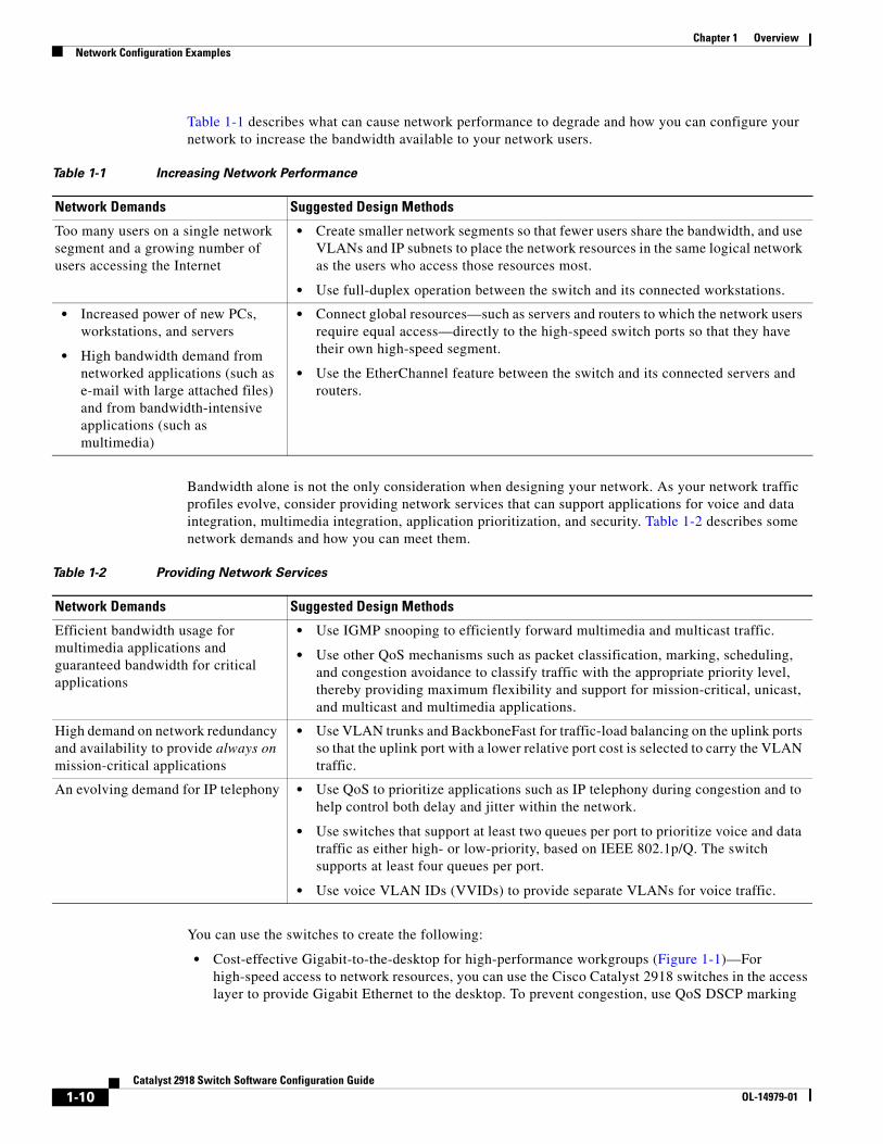
Table 1-1 describes what can cause network performance to degrade and how you can configure your network to increase the bandwidth available to your network users.
Table 1-1 Increasing Network Performance
Network Demands Suggested Design Methods
Too many users on a single network segment and a growing number of users accessing the Internet
• Create smaller network segments so that fewer users share the bandwidth, and use VLANs and IP subnets to place the network resources in the same logical network as the users who access those resources most.
• Use full-duplex operation between the switch and its connected workstations.
• Increased power of new PCs, workstations, and servers
• High bandwidth demand from networked applications (such as e-mail with large attached files) and from bandwidth-intensive applications (such as multimedia)
• Connect global resources—such as servers and routers to which the network users require equal access—directly to the high-speed switch ports so that they have their own high-speed segment.
• Use the EtherChannel feature between the switch and its connected servers and routers.
Bandwidth alone is not the only consideration when designing your network. As your network traffic profiles evolve, consider providing network services that can support applications for voice and data integration, multimedia integration, application prioritization, and security. Table 1-2 describes some network demands and how you can meet them.
Table 1-2 Providing Network Services
Network Demands Suggested Design Methods
Efficient bandwidth usage for multimedia applications and guaranteed bandwidth for critical applications
• Use IGMP snooping to efficiently forward multimedia and multicast traffic.
• Use other QoS mechanisms such as packet classification, marking, scheduling, and congestion avoidance to classify traffic with the appropriate priority level, thereby providing maximum flexibility and support for mission-critical, unicast, and multicast and multimedia applications.
High demand on network redundancy and availability to provide always on mission-critical applications
• Use VLAN trunks and BackboneFast for traffic-load balancing on the uplink ports so that the uplink port with a lower relative port cost is selected to carry the VLAN traffic.
An evolving demand for IP telephony • Use QoS to prioritize applications such as IP telephony during congestion and to help control both delay and jitter within the network.
• Use switches that support at least two queues per port to prioritize voice and data traffic as either high- or low-priority, based on IEEE 802.1p/Q. The switch supports at least four queues per port.
• Use voice VLAN IDs (VVIDs) to provide separate VLANs for voice traffic.
You can use the switches to create the following:
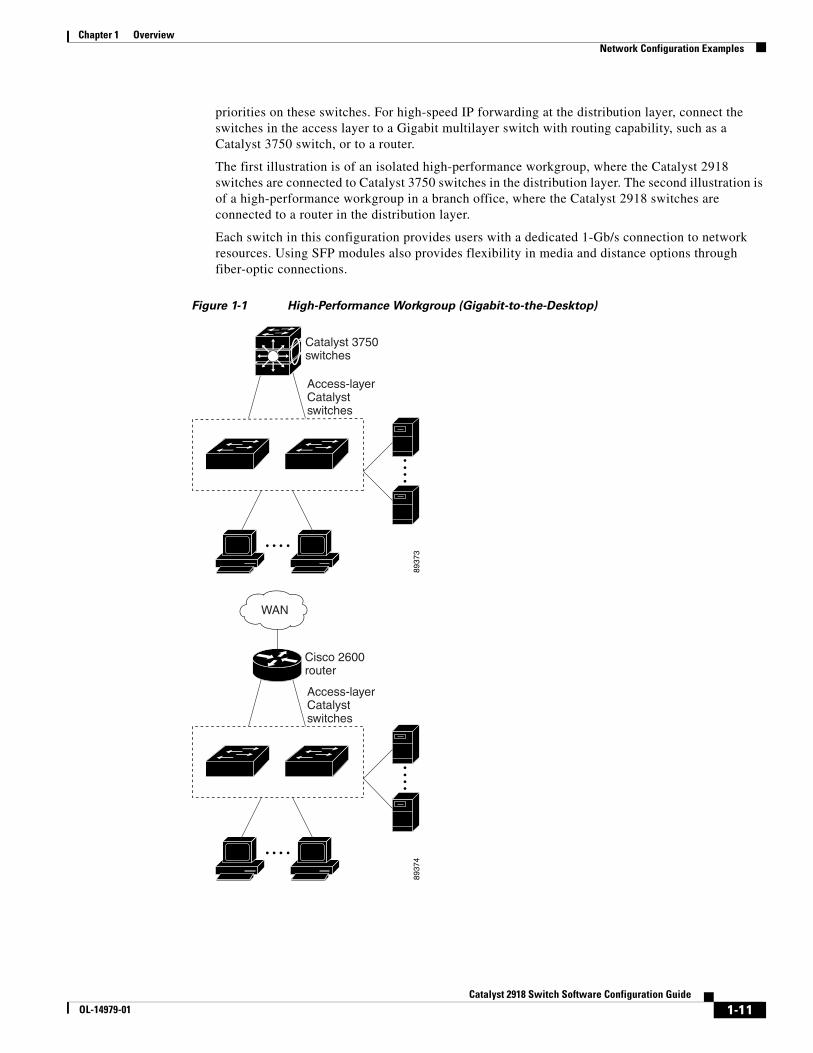
• Cost-effective Gigabit-to-the-desktop for high-performance workgroups (Figure 1-1)—For high-speed access to network resources, you can use the Cisco Catalyst 2918 switches in the access layer to provide Gigabit Ethernet to the desktop. To prevent congestion, use QoS DSCP marking
1-10Catalyst 2918 Switch Software Configuration Guide
OL-14979-01
Chapter 1 OverviewNetwork Configuration Examples
priorities on these switches. For high-speed IP forwarding at the distribution layer, connect the switches in the access layer to a Gigabit multilayer switch with routing capability, such as a Catalyst 3750 switch, or to a router.
The first illustration is of an isolated high-performance workgroup, where the Catalyst 2918 switches are connected to Catalyst 3750 switches in the distribution layer. The second illustration is of a high-performance workgroup in a branch office, where the Catalyst 2918 switches are connected to a router in the distribution layer.
Each switch in this configuration provides users with a dedicated 1-Gb/s connection to network resources. Using SFP modules also provides flexibility in media and distance options through fiber-optic connections.
Figure 1-1 High-Performance Workgroup (Gigabit-to-the-Desktop)
8937
3
Access-layerCatalystswitches
Catalyst 3750switches
8937
4
Cisco 2600router
Access-layerCatalystswitches
WAN
1-11Catalyst 2918 Switch Software Configuration Guide
OL-14979-01
Chapter 1 OverviewNetwork Configuration Examples
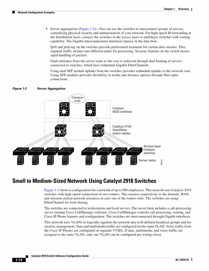
• Server aggregation (Figure 1-2)—You can use the switches to interconnect groups of servers, centralizing physical security and administration of your network. For high-speed IP forwarding at the distribution layer, connect the switches in the access layer to multilayer switches with routing capability. The Gigabit interconnections minimize latency in the data flow.
QoS and policing on the switches provide preferential treatment for certain data streams. They segment traffic streams into different paths for processing. Security features on the switch ensure rapid handling of packets.
Fault tolerance from the server racks to the core is achieved through dual homing of servers connected to switches, which have redundant Gigabit EtherChannels.
Using dual SFP module uplinks from the switches provides redundant uplinks to the network core. Using SFP modules provides flexibility in media and distance options through fiber-optic connections.
Figure 1-2 Server Aggregation
8937
6
Campuscore
Catalyst6500 switches
Catalyst 3750StackWiseswitch stacks
Access-layerCatalystswitches
Server racks
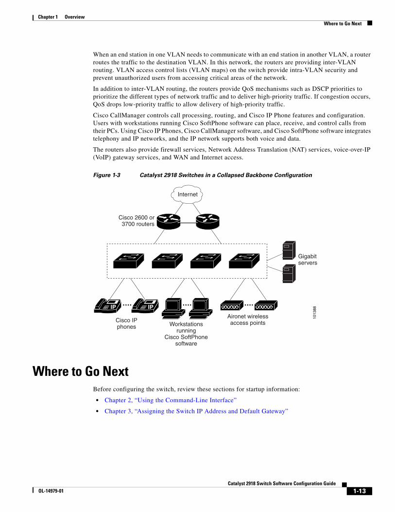
Small to Medium-Sized Network Using Catalyst 2918 SwitchesFigure 1-3 shows a configuration for a network of up to 500 employees. This network uses Catalyst 2918 switches with high-speed connections to two routers. This ensures connectivity to the Internet, WAN, and mission-critical network resources in case one of the routers fails. The switches are using EtherChannel for load sharing.
The switches are connected to workstations and local servers. The server farm includes a call-processing server running Cisco CallManager software. Cisco CallManager controls call processing, routing, and Cisco IP Phone features and configuration. The switches are interconnected through Gigabit interfaces.
This network uses VLANs to logically segment the network into well-defined broadcast groups and for security management. Data and multimedia traffic are configured on the same VLAN. Voice traffic from the Cisco IP Phones are configured on separate VVIDs. If data, multimedia, and voice traffic are assigned to the same VLAN, only one VLAN can be configured per wiring closet.
1-12Catalyst 2918 Switch Software Configuration Guide
OL-14979-01
Chapter 1 OverviewWhere to Go Next
When an end station in one VLAN needs to communicate with an end station in another VLAN, a router routes the traffic to the destination VLAN. In this network, the routers are providing inter-VLAN routing. VLAN access control lists (VLAN maps) on the switch provide intra-VLAN security and prevent unauthorized users from accessing critical areas of the network.
In addition to inter-VLAN routing, the routers provide QoS mechanisms such as DSCP priorities to prioritize the different types of network traffic and to deliver high-priority traffic. If congestion occurs, QoS drops low-priority traffic to allow delivery of high-priority traffic.
Cisco CallManager controls call processing, routing, and Cisco IP Phone features and configuration. Users with workstations running Cisco SoftPhone software can place, receive, and control calls from their PCs. Using Cisco IP Phones, Cisco CallManager software, and Cisco SoftPhone software integrates telephony and IP networks, and the IP network supports both voice and data.
The routers also provide firewall services, Network Address Translation (NAT) services, voice-over-IP (VoIP) gateway services, and WAN and Internet access.
Figure 1-3 Catalyst 2918 Switches in a Collapsed Backbone Configuration
Gigabitservers
1013
88
Cisco 2600 or3700 routers
Internet
Cisco IPphones Workstations
runningCisco SoftPhone
software
Aironet wirelessaccess points
IP IP
Where to Go NextBefore configuring the switch, review these sections for startup information:
• Chapter 2, “Using the Command-Line Interface”
• Chapter 3, “Assigning the Switch IP Address and Default Gateway”
1-13Catalyst 2918 Switch Software Configuration Guide
OL-14979-01

Chapter 1 OverviewWhere to Go Next
1-14Catalyst 2918 Switch Software Configuration Guide
OL-14979-01
OL-14979-01
C H A P T E R 2
Using the Command-Line InterfaceThis chapter describes the Cisco IOS command-line interface (CLI) and how to use it to configure your Catalyst 2918 switch. It contains these sections:
• Understanding Command Modes, page 2-1
• Understanding the Help System, page 2-3
• Understanding Abbreviated Commands, page 2-4
• Understanding no and default Forms of Commands, page 2-4
• Understanding CLI Error Messages, page 2-5
• Using Configuration Logging, page 2-5
• Using Command History, page 2-5
• Using Editing Features, page 2-7
• Searching and Filtering Output of show and more Commands, page 2-9
• Accessing the CLI, page 2-10
Understanding Command ModesThe Cisco IOS user interface is divided into many different modes. The commands available to you depend on which mode you are currently in. Enter a question mark (?) at the system prompt to obtain a list of commands available for each command mode.
When you start a session on the switch, you begin in user mode, often called user EXEC mode. Only a limited subset of the commands are available in user EXEC mode. For example, most of the user EXEC commands are one-time commands, such as show commands, which show the current configuration status, and clear commands, which clear counters or interfaces. The user EXEC commands are not saved when the switch reboots.
To have access to all commands, you must enter privileged EXEC mode. Normally, you must enter a password to enter privileged EXEC mode. From this mode, you can enter any privileged EXEC command or enter global configuration mode.
Using the configuration modes (global, interface, and line), you can make changes to the running configuration. If you save the configuration, these commands are stored and used when the switch reboots. To access the various configuration modes, you must start at global configuration mode. From global configuration mode, you can enter interface configuration mode and line configuration mode.
2-1Catalyst 2918 Switch Software Configuration Guide
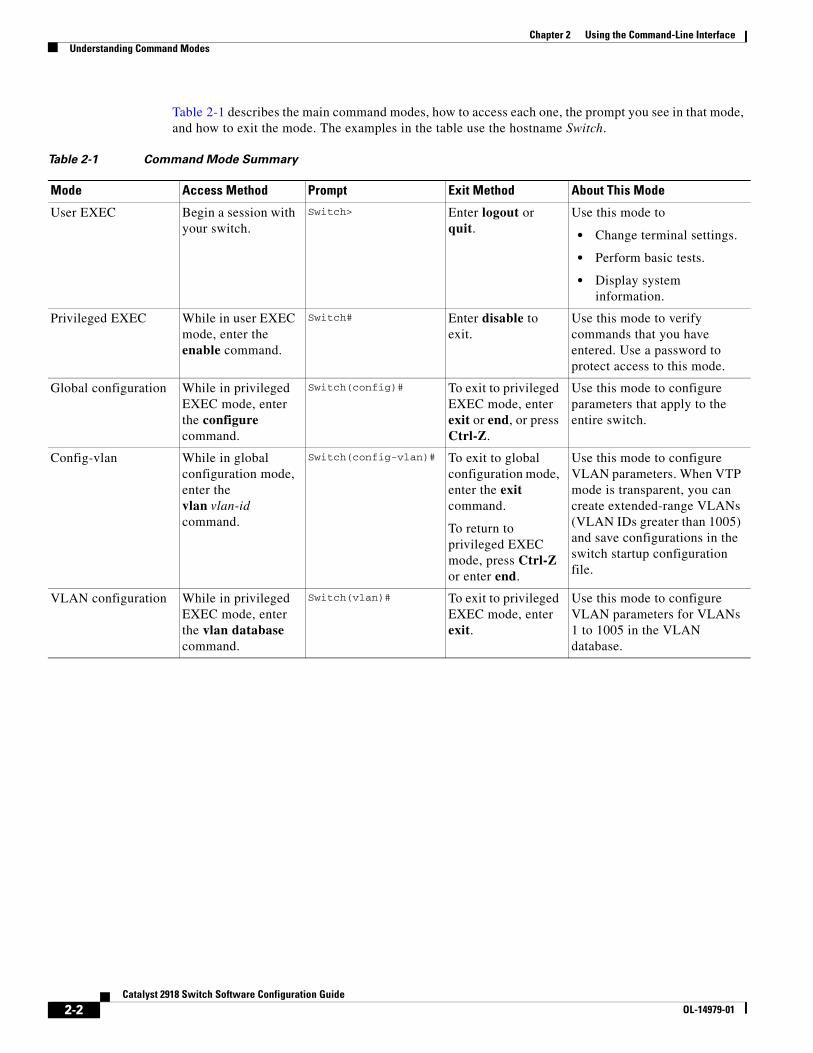
Chapter 2 Using the Command-Line InterfaceUnderstanding Command Modes
Table 2-1 describes the main command modes, how to access each one, the prompt you see in that mode, and how to exit the mode. The examples in the table use the hostname Switch.
Table 2-1 Command Mode Summary
Mode Access Method Prompt Exit Method About This Mode
User EXEC Begin a session with your switch.
Switch> Enter logout or quit.
Use this mode to
• Change terminal settings.
• Perform basic tests.
• Display system information.
Privileged EXEC While in user EXEC mode, enter the enable command.
Switch# Enter disable to exit.
Use this mode to verify commands that you have entered. Use a password to protect access to this mode.
Global configuration While in privileged EXEC mode, enter the configure command.
Switch(config)# To exit to privileged EXEC mode, enter exit or end, or press Ctrl-Z.
Use this mode to configure parameters that apply to the entire switch.
Config-vlan While in global configuration mode, enter the vlan vlan-id command.
Switch(config-vlan)# To exit to global configuration mode, enter the exit command.
To return to privileged EXEC mode, press Ctrl-Z or enter end.
Use this mode to configure VLAN parameters. When VTP mode is transparent, you can create extended-range VLANs (VLAN IDs greater than 1005) and save configurations in the switch startup configuration file.
VLAN configuration While in privileged EXEC mode, enter the vlan database command.
Switch(vlan)# To exit to privileged EXEC mode, enter exit.
Use this mode to configure VLAN parameters for VLANs 1 to 1005 in the VLAN database.
2-2Catalyst 2918 Switch Software Configuration Guide
OL-14979-01
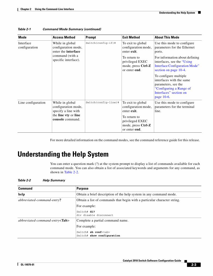
Chapter 2 Using the Command-Line InterfaceUnderstanding the Help System
For more detailed information on the command modes, see the command reference guide for this release.
Understanding the Help SystemYou can enter a question mark (?) at the system prompt to display a list of commands available for each command mode. You can also obtain a list of associated keywords and arguments for any command, as shown in Table 2-2.
Interface configuration
While in global configuration mode, enter the interface command (with a specific interface).
Switch(config-if)# To exit to global configuration mode, enter exit.
To return to privileged EXEC mode, press Ctrl-Z or enter end.
Use this mode to configure parameters for the Ethernet ports.
For information about defining interfaces, see the “Using Interface Configuration Mode” section on page 10-4.
To configure multiple interfaces with the same parameters, see the “Configuring a Range of Interfaces” section on page 10-6.
Line configuration While in global configuration mode, specify a line with the line vty or line console command.
Switch(config-line)# To exit to global configuration mode, enter exit.
To return to privileged EXEC mode, press Ctrl-Z or enter end.
Use this mode to configure parameters for the terminal line.
Table 2-1 Command Mode Summary (continued)
Mode Access Method Prompt Exit Method About This Mode
Table 2-2 Help Summary
Command Purpose
help Obtain a brief description of the help system in any command mode.
abbreviated-command-entry? Obtain a list of commands that begin with a particular character string.
For example:
Switch# di?dir disable disconnect
abbreviated-command-entry<Tab> Complete a partial command name.
For example:
Switch# sh conf<tab>Switch# show configuration
2-3Catalyst 2918 Switch Software Configuration Guide
OL-14979-01
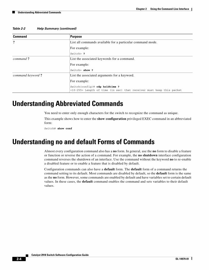
Chapter 2 Using the Command-Line InterfaceUnderstanding Abbreviated Commands
Understanding Abbreviated CommandsYou need to enter only enough characters for the switch to recognize the command as unique.
This example shows how to enter the show configuration privileged EXEC command in an abbreviated form:
Switch# show conf
Understanding no and default Forms of CommandsAlmost every configuration command also has a no form. In general, use the no form to disable a feature or function or reverse the action of a command. For example, the no shutdown interface configuration command reverses the shutdown of an interface. Use the command without the keyword no to re-enable a disabled feature or to enable a feature that is disabled by default.
Configuration commands can also have a default form. The default form of a command returns the command setting to its default. Most commands are disabled by default, so the default form is the same as the no form. However, some commands are enabled by default and have variables set to certain default values. In these cases, the default command enables the command and sets variables to their default values.
? List all commands available for a particular command mode.
For example:
Switch> ?
command ? List the associated keywords for a command.
For example:
Switch> show ?
command keyword ? List the associated arguments for a keyword.
For example:
Switch(config)# cdp holdtime ?<10-255> Length of time (in sec) that receiver must keep this packet
Table 2-2 Help Summary (continued)
Command Purpose
2-4Catalyst 2918 Switch Software Configuration Guide
OL-14979-01
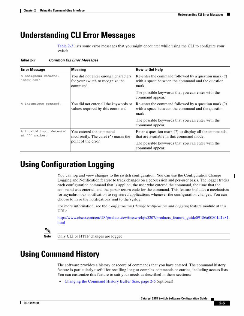
Chapter 2 Using the Command-Line InterfaceUnderstanding CLI Error Messages
Understanding CLI Error MessagesTable 2-3 lists some error messages that you might encounter while using the CLI to configure your switch.
Table 2-3 Common CLI Error Messages
Error Message Meaning How to Get Help
% Ambiguous command: "show con"
You did not enter enough characters for your switch to recognize the command.
Re-enter the command followed by a question mark (?) with a space between the command and the question mark.
The possible keywords that you can enter with the command appear.
% Incomplete command. You did not enter all the keywords or values required by this command.
Re-enter the command followed by a question mark (?) with a space between the command and the question mark.
The possible keywords that you can enter with the command appear.
% Invalid input detected at ‘^’ marker.
You entered the command incorrectly. The caret (^) marks the point of the error.
Enter a question mark (?) to display all the commands that are available in this command mode.
The possible keywords that you can enter with the command appear.
Using Configuration LoggingYou can log and view changes to the switch configuration. You can use the Configuration Change Logging and Notification feature to track changes on a per-session and per-user basis. The logger tracks each configuration command that is applied, the user who entered the command, the time that the command was entered, and the parser return code for the command. This feature includes a mechanism for asynchronous notification to registered applications whenever the configuration changes. You can choose to have the notifications sent to the syslog.
For more information, see the Configuration Change Notification and Logging feature module at this URL:
http://www.cisco.com/en/US/products/sw/iosswrel/ps5207/products_feature_guide09186a00801d1e81.html
Note Only CLI or HTTP changes are logged.
Using Command HistoryThe software provides a history or record of commands that you have entered. The command history feature is particularly useful for recalling long or complex commands or entries, including access lists. You can customize this feature to suit your needs as described in these sections:
• Changing the Command History Buffer Size, page 2-6 (optional)
2-5Catalyst 2918 Switch Software Configuration Guide
OL-14979-01
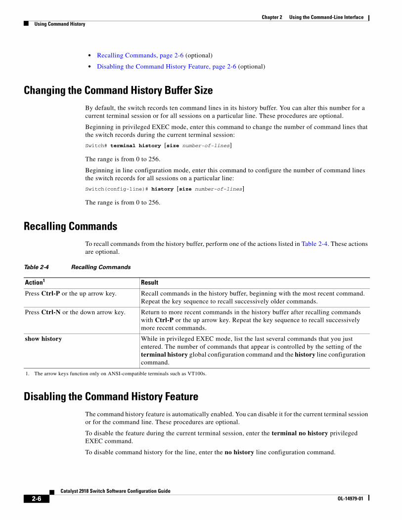
Chapter 2 Using the Command-Line InterfaceUsing Command History
• Recalling Commands, page 2-6 (optional)
• Disabling the Command History Feature, page 2-6 (optional)
Changing the Command History Buffer SizeBy default, the switch records ten command lines in its history buffer. You can alter this number for a current terminal session or for all sessions on a particular line. These procedures are optional.
Beginning in privileged EXEC mode, enter this command to change the number of command lines that the switch records during the current terminal session:
Switch# terminal history [size number-of-lines]
The range is from 0 to 256.
Beginning in line configuration mode, enter this command to configure the number of command lines the switch records for all sessions on a particular line:
Switch(config-line)# history [size number-of-lines]
The range is from 0 to 256.
Recalling CommandsTo recall commands from the history buffer, perform one of the actions listed in Table 2-4. These actions are optional.
Table 2-4 Recalling Commands
Action
1. The arrow keys function only on ANSI-compatible terminals such as VT100s.
1
Press Ctrl-P or the up arrow key. Recall commands in the history buffer, beginning with the most recent command. Repeat the key sequence to recall successively older commands.
Press Ctrl-N or the down arrow key. Return to more recent commands in the history buffer after recalling commands with Ctrl-P or the up arrow key. Repeat the key sequence to recall successively more recent commands.
show history While in privileged EXEC mode, list the last several commands that you just entered. The number of commands that appear is controlled by the setting of the terminal history global configuration command and the history line configuration command.
Disabling the Command History FeatureThe command history feature is automatically enabled. You can disable it for the current terminal session or for the command line. These procedures are optional.
To disable the feature during the current terminal session, enter the terminal no history privileged EXEC command.
To disable command history for the line, enter the no history line configuration command.
Result
2-6Catalyst 2918 Switch Software Configuration Guide
OL-14979-01
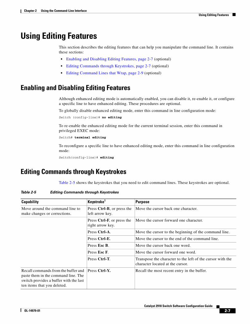
Chapter 2 Using the Command-Line InterfaceUsing Editing Features
Using Editing FeaturesThis section describes the editing features that can help you manipulate the command line. It contains these sections:
• Enabling and Disabling Editing Features, page 2-7 (optional)
• Editing Commands through Keystrokes, page 2-7 (optional)
• Editing Command Lines that Wrap, page 2-9 (optional)
Enabling and Disabling Editing FeaturesAlthough enhanced editing mode is automatically enabled, you can disable it, re-enable it, or configure a specific line to have enhanced editing. These procedures are optional.
To globally disable enhanced editing mode, enter this command in line configuration mode:
Switch (config-line)# no editing
To re-enable the enhanced editing mode for the current terminal session, enter this command in privileged EXEC mode:
Switch# terminal editing
To reconfigure a specific line to have enhanced editing mode, enter this command in line configuration mode:
Switch(config-line)# editing
Editing Commands through KeystrokesTable 2-5 shows the keystrokes that you need to edit command lines. These keystrokes are optional.
Table 2-5 Editing Commands through Keystrokes
Capability Keystroke1 Purpose
Move around the command line to make changes or corrections.
Press Ctrl-B, or press the left arrow key.
Move the cursor back one character.
Press Ctrl-F, or press the right arrow key.
Move the cursor forward one character.
Press Ctrl-A. Move the cursor to the beginning of the command line.
Press Ctrl-E. Move the cursor to the end of the command line.
Press Esc B. Move the cursor back one word.
Press Esc F. Move the cursor forward one word.
Press Ctrl-T. Transpose the character to the left of the cursor with the character located at the cursor.
Recall commands from the buffer and paste them in the command line. The switch provides a buffer with the last ten items that you deleted.
Press Ctrl-Y. Recall the most recent entry in the buffer.
2-7Catalyst 2918 Switch Software Configuration Guide
OL-14979-01
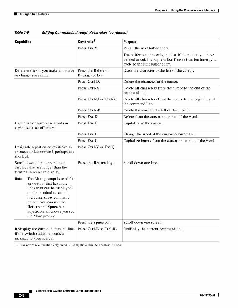
Chapter 2 Using the Command-Line InterfaceUsing Editing Features
Press Esc Y. Recall the next buffer entry.
The buffer contains only the last 10 items that you have deleted or cut. If you press Esc Y more than ten times, you cycle to the first buffer entry.
Delete entries if you make a mistake or change your mind.
Press the Delete or Backspace key.
Erase the character to the left of the cursor.
Press Ctrl-D. Delete the character at the cursor.
Press Ctrl-K. Delete all characters from the cursor to the end of the command line.
Press Ctrl-U or Ctrl-X. Delete all characters from the cursor to the beginning of the command line.
Press Ctrl-W. Delete the word to the left of the cursor.
Press Esc D. Delete from the cursor to the end of the word.
Capitalize or lowercase words or capitalize a set of letters.
Press Esc C. Capitalize at the cursor.
Press Esc L. Change the word at the cursor to lowercase.
Press Esc U. Capitalize letters from the cursor to the end of the word.
Designate a particular keystroke as an executable command, perhaps as a shortcut.
Press Ctrl-V or Esc Q.
Scroll down a line or screen on displays that are longer than the terminal screen can display.
Note The More prompt is used for any output that has more lines than can be displayed on the terminal screen, including show command output. You can use the Return and Space bar keystrokes whenever you see the More prompt.
Press the Return key. Scroll down one line.
Press the Space bar. Scroll down one screen.
Redisplay the current command line if the switch suddenly sends a message to your screen.
Press Ctrl-L or Ctrl-R. Redisplay the current command line.
1. The arrow keys function only on ANSI-compatible terminals such as VT100s.
Table 2-5 Editing Commands through Keystrokes (continued)
Capability Keystroke1 Purpose
2-8Catalyst 2918 Switch Software Configuration Guide
OL-14979-01
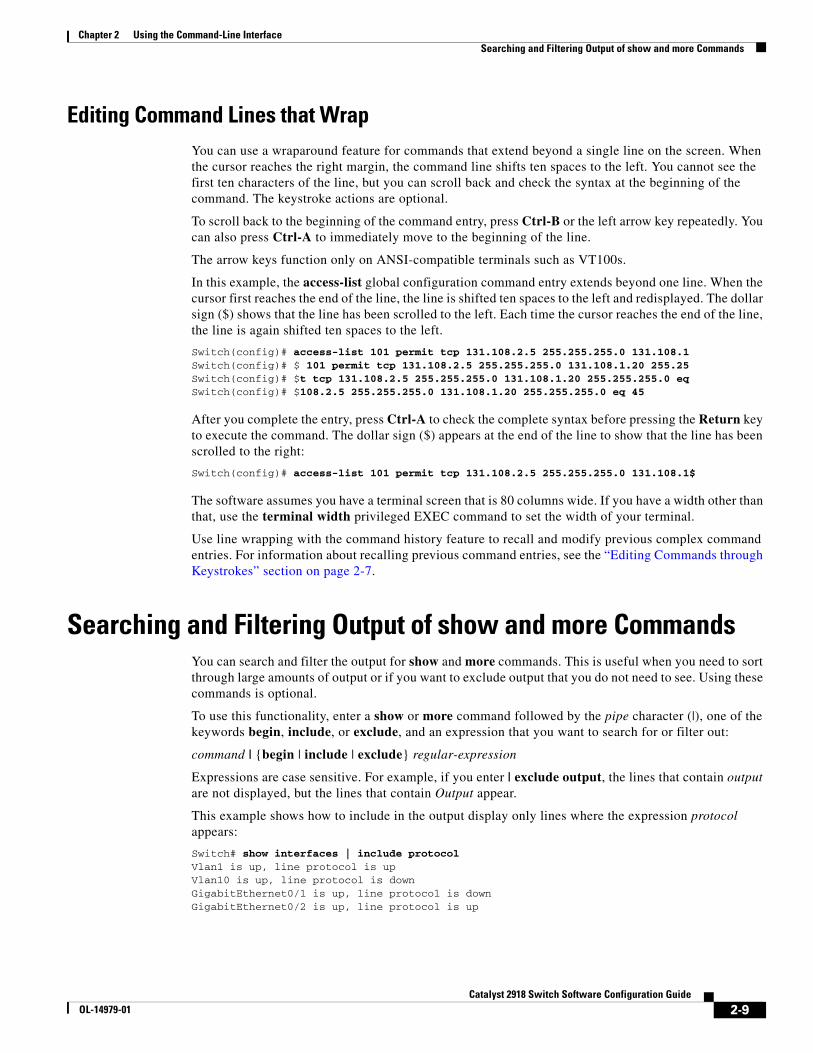
Chapter 2 Using the Command-Line InterfaceSearching and Filtering Output of show and more Commands
Editing Command Lines that WrapYou can use a wraparound feature for commands that extend beyond a single line on the screen. When the cursor reaches the right margin, the command line shifts ten spaces to the left. You cannot see the first ten characters of the line, but you can scroll back and check the syntax at the beginning of the command. The keystroke actions are optional.
To scroll back to the beginning of the command entry, press Ctrl-B or the left arrow key repeatedly. You can also press Ctrl-A to immediately move to the beginning of the line.
The arrow keys function only on ANSI-compatible terminals such as VT100s.
In this example, the access-list global configuration command entry extends beyond one line. When the cursor first reaches the end of the line, the line is shifted ten spaces to the left and redisplayed. The dollar sign ($) shows that the line has been scrolled to the left. Each time the cursor reaches the end of the line, the line is again shifted ten spaces to the left.
Switch(config)# access-list 101 permit tcp 131.108.2.5 255.255.255.0 131.108.1Switch(config)# $ 101 permit tcp 131.108.2.5 255.255.255.0 131.108.1.20 255.25Switch(config)# $t tcp 131.108.2.5 255.255.255.0 131.108.1.20 255.255.255.0 eqSwitch(config)# $108.2.5 255.255.255.0 131.108.1.20 255.255.255.0 eq 45
After you complete the entry, press Ctrl-A to check the complete syntax before pressing the Return key to execute the command. The dollar sign ($) appears at the end of the line to show that the line has been scrolled to the right:
Switch(config)# access-list 101 permit tcp 131.108.2.5 255.255.255.0 131.108.1$
The software assumes you have a terminal screen that is 80 columns wide. If you have a width other than that, use the terminal width privileged EXEC command to set the width of your terminal.
Use line wrapping with the command history feature to recall and modify previous complex command entries. For information about recalling previous command entries, see the “Editing Commands through Keystrokes” section on page 2-7.
Searching and Filtering Output of show and more CommandsYou can search and filter the output for show and more commands. This is useful when you need to sort through large amounts of output or if you want to exclude output that you do not need to see. Using these commands is optional.
To use this functionality, enter a show or more command followed by the pipe character (|), one of the keywords begin, include, or exclude, and an expression that you want to search for or filter out:
command | {begin | include | exclude} regular-expression
Expressions are case sensitive. For example, if you enter | exclude output, the lines that contain output are not displayed, but the lines that contain Output appear.
This example shows how to include in the output display only lines where the expression protocol appears:
Switch# show interfaces | include protocolVlan1 is up, line protocol is upVlan10 is up, line protocol is downGigabitEthernet0/1 is up, line protocol is downGigabitEthernet0/2 is up, line protocol is up
2-9Catalyst 2918 Switch Software Configuration Guide
OL-14979-01
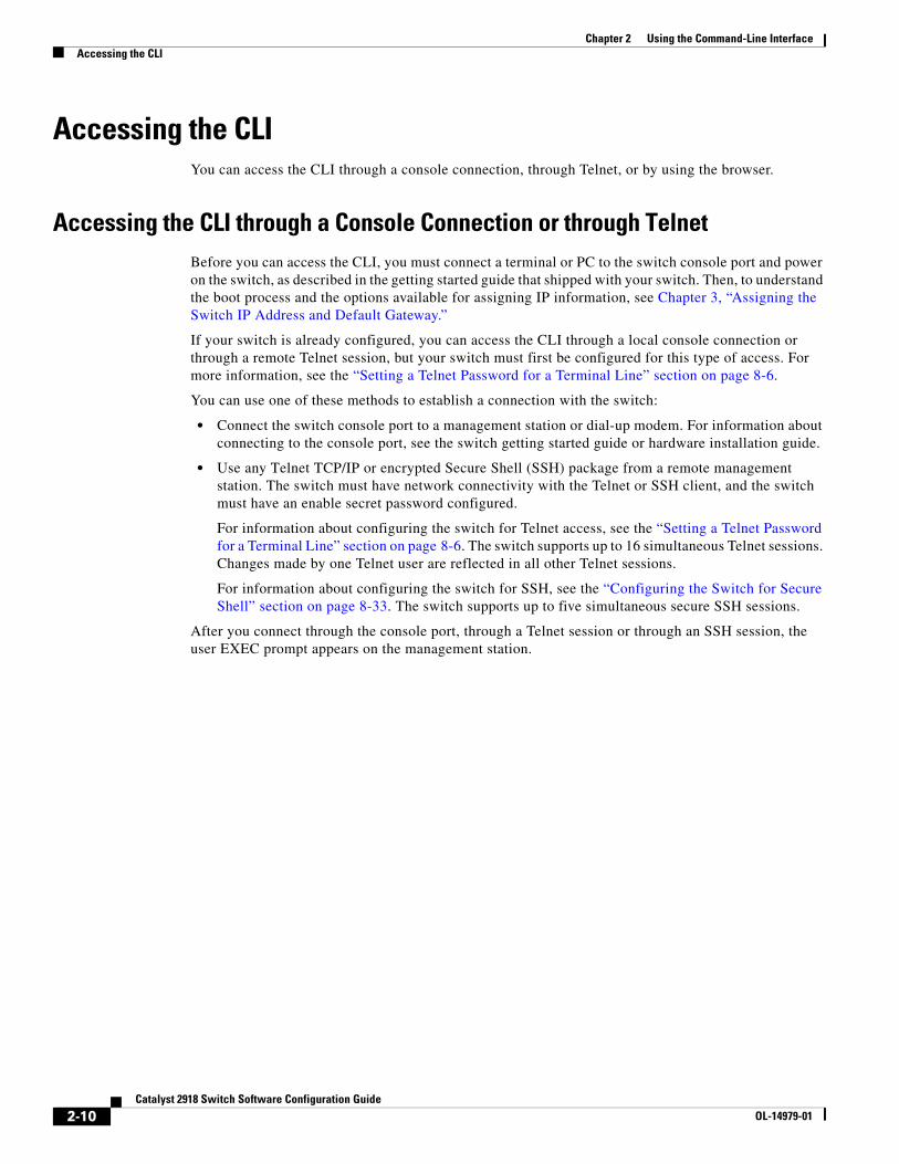
Chapter 2 Using the Command-Line InterfaceAccessing the CLI
Accessing the CLIYou can access the CLI through a console connection, through Telnet, or by using the browser.
Accessing the CLI through a Console Connection or through TelnetBefore you can access the CLI, you must connect a terminal or PC to the switch console port and power on the switch, as described in the getting started guide that shipped with your switch. Then, to understand the boot process and the options available for assigning IP information, see Chapter 3, “Assigning the Switch IP Address and Default Gateway.”
If your switch is already configured, you can access the CLI through a local console connection or through a remote Telnet session, but your switch must first be configured for this type of access. For more information, see the “Setting a Telnet Password for a Terminal Line” section on page 8-6.
You can use one of these methods to establish a connection with the switch:
• Connect the switch console port to a management station or dial-up modem. For information about connecting to the console port, see the switch getting started guide or hardware installation guide.
• Use any Telnet TCP/IP or encrypted Secure Shell (SSH) package from a remote management station. The switch must have network connectivity with the Telnet or SSH client, and the switch must have an enable secret password configured.
For information about configuring the switch for Telnet access, see the “Setting a Telnet Password for a Terminal Line” section on page 8-6. The switch supports up to 16 simultaneous Telnet sessions. Changes made by one Telnet user are reflected in all other Telnet sessions.
For information about configuring the switch for SSH, see the “Configuring the Switch for Secure Shell” section on page 8-33. The switch supports up to five simultaneous secure SSH sessions.
After you connect through the console port, through a Telnet session or through an SSH session, the user EXEC prompt appears on the management station.
2-10Catalyst 2918 Switch Software Configuration Guide
OL-14979-01
OL-14979-01
C H A P T E R 3
Assigning the Switch IP Address and Default GatewayThis chapter describes how to create the initial switch configuration (for example, assigning the IP address and default gateway information) for the Catalyst 2918 switch by using a variety of automatic and manual methods. It also describes how to modify the switch startup configuration.
Note For complete syntax and usage information for the commands used in this chapter, see the command reference for this release and the Cisco IOS IP Command Reference, Volume 1 of 3: Addressing and Services, Release 12.2.
This chapter consists of these sections:
• Understanding the Boot Process, page 3-1
• Assigning Switch Information, page 3-2
• Checking and Saving the Running Configuration, page 3-14
• Modifying the Startup Configuration, page 3-15
• Scheduling a Reload of the Software Image, page 3-20
Understanding the Boot ProcessTo start your switch, you need to follow the procedures in the Getting Started Guide or the hardware installation guide for installing and powering on the switch and setting up the initial switch configuration (IP address, subnet mask, default gateway, secret and Telnet passwords, and so forth).
The normal boot process involves the operation of the boot loader software, which performs these activities:
• Performs low-level CPU initialization. It initializes the CPU registers, which control where physical memory is mapped, its quantity, its speed, and so forth.
• Performs power-on self-test (POST) for the CPU subsystem. It tests the CPU DRAM and the portion of the flash device that makes up the flash file system.
• Initializes the flash file system on the system board.
• Loads a default operating system software image into memory and boots up the switch.
3-1Catalyst 2918 Switch Software Configuration Guide
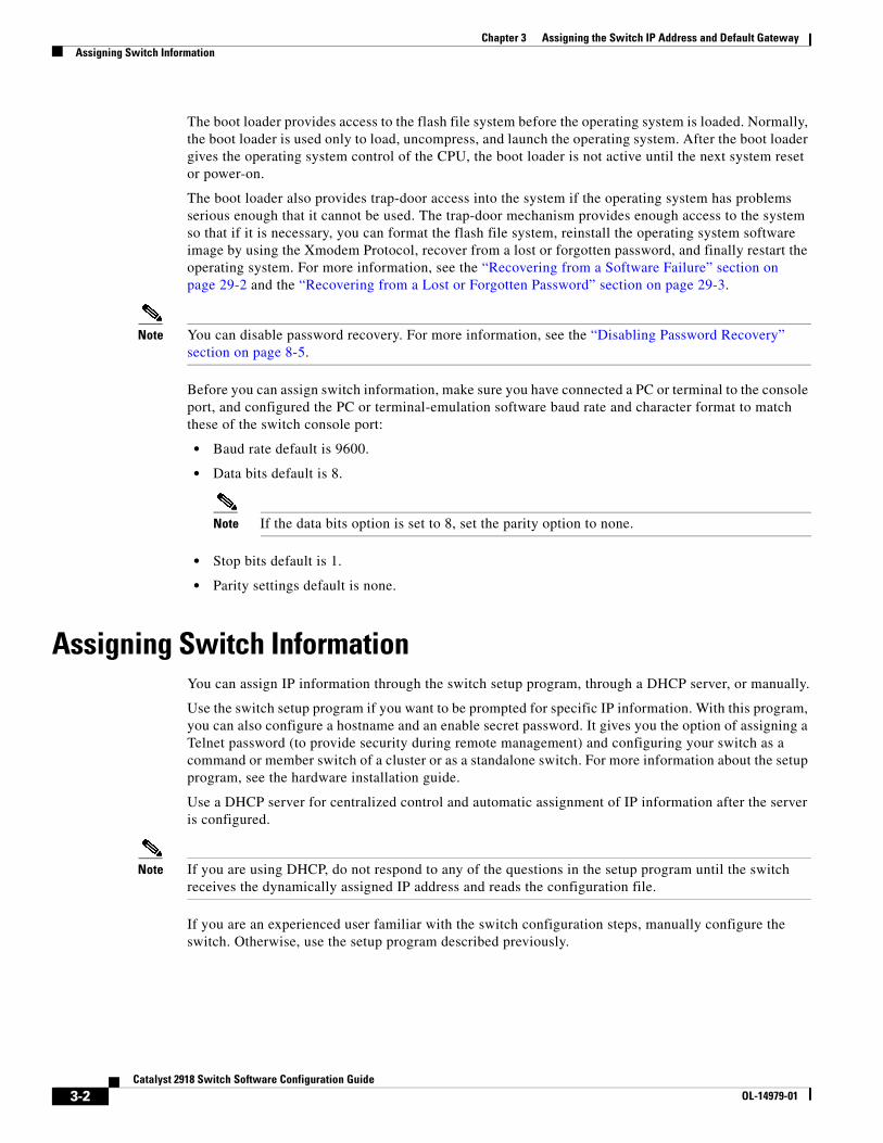
Chapter 3 Assigning the Switch IP Address and Default GatewayAssigning Switch Information
The boot loader provides access to the flash file system before the operating system is loaded. Normally, the boot loader is used only to load, uncompress, and launch the operating system. After the boot loader gives the operating system control of the CPU, the boot loader is not active until the next system reset or power-on.
The boot loader also provides trap-door access into the system if the operating system has problems serious enough that it cannot be used. The trap-door mechanism provides enough access to the system so that if it is necessary, you can format the flash file system, reinstall the operating system software image by using the Xmodem Protocol, recover from a lost or forgotten password, and finally restart the operating system. For more information, see the “Recovering from a Software Failure” section on page 29-2 and the “Recovering from a Lost or Forgotten Password” section on page 29-3.
Note You can disable password recovery. For more information, see the “Disabling Password Recovery” section on page 8-5.
Before you can assign switch information, make sure you have connected a PC or terminal to the console port, and configured the PC or terminal-emulation software baud rate and character format to match these of the switch console port:
• Baud rate default is 9600.
• Data bits default is 8.
Note If the data bits option is set to 8, set the parity option to none.
• Stop bits default is 1.
• Parity settings default is none.
Assigning Switch InformationYou can assign IP information through the switch setup program, through a DHCP server, or manually.
Use the switch setup program if you want to be prompted for specific IP information. With this program, you can also configure a hostname and an enable secret password. It gives you the option of assigning a Telnet password (to provide security during remote management) and configuring your switch as a command or member switch of a cluster or as a standalone switch. For more information about the setup program, see the hardware installation guide.
Use a DHCP server for centralized control and automatic assignment of IP information after the server is configured.
Note If you are using DHCP, do not respond to any of the questions in the setup program until the switch receives the dynamically assigned IP address and reads the configuration file.
If you are an experienced user familiar with the switch configuration steps, manually configure the switch. Otherwise, use the setup program described previously.
3-2Catalyst 2918 Switch Software Configuration Guide
OL-14979-01
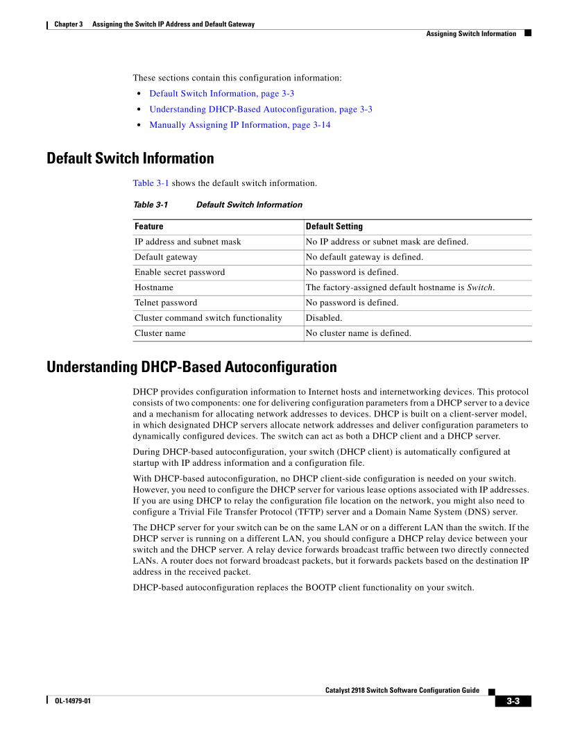
Chapter 3 Assigning the Switch IP Address and Default GatewayAssigning Switch Information
These sections contain this configuration information:
• Default Switch Information, page 3-3
• Understanding DHCP-Based Autoconfiguration, page 3-3
• Manually Assigning IP Information, page 3-14
Default Switch InformationTable 3-1 shows the default switch information.
Table 3-1 Default Switch Information
Feature Default Setting
IP address and subnet mask No IP address or subnet mask are defined.
Default gateway No default gateway is defined.
Enable secret password No password is defined.
Hostname The factory-assigned default hostname is Switch.
Telnet password No password is defined.
Cluster command switch functionality Disabled.
Cluster name No cluster name is defined.
Understanding DHCP-Based AutoconfigurationDHCP provides configuration information to Internet hosts and internetworking devices. This protocol consists of two components: one for delivering configuration parameters from a DHCP server to a device and a mechanism for allocating network addresses to devices. DHCP is built on a client-server model, in which designated DHCP servers allocate network addresses and deliver configuration parameters to dynamically configured devices. The switch can act as both a DHCP client and a DHCP server.
During DHCP-based autoconfiguration, your switch (DHCP client) is automatically configured at startup with IP address information and a configuration file.
With DHCP-based autoconfiguration, no DHCP client-side configuration is needed on your switch. However, you need to configure the DHCP server for various lease options associated with IP addresses. If you are using DHCP to relay the configuration file location on the network, you might also need to configure a Trivial File Transfer Protocol (TFTP) server and a Domain Name System (DNS) server.
The DHCP server for your switch can be on the same LAN or on a different LAN than the switch. If the DHCP server is running on a different LAN, you should configure a DHCP relay device between your switch and the DHCP server. A relay device forwards broadcast traffic between two directly connected LANs. A router does not forward broadcast packets, but it forwards packets based on the destination IP address in the received packet.
DHCP-based autoconfiguration replaces the BOOTP client functionality on your switch.
3-3Catalyst 2918 Switch Software Configuration Guide
OL-14979-01
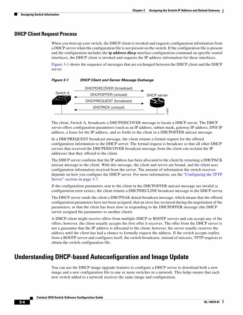
Chapter 3 Assigning the Switch IP Address and Default GatewayAssigning Switch Information
DHCP Client Request Process
When you boot up your switch, the DHCP client is invoked and requests configuration information from a DHCP server when the configuration file is not present on the switch. If the configuration file is present and the configuration includes the ip address dhcp interface configuration command on specific routed interfaces, the DHCP client is invoked and requests the IP address information for those interfaces.
Figure 3-1 shows the sequence of messages that are exchanged between the DHCP client and the DHCP server.
Figure 3-1 DHCP Client and Server Message Exchange
Switch A
DHCPACK (unicast)
DHCPREQUEST (broadcast)
DHCPOFFER (unicast)
DHCPDISCOVER (broadcast)
DHCP server
5180
7
The client, Switch A, broadcasts a DHCPDISCOVER message to locate a DHCP server. The DHCP server offers configuration parameters (such as an IP address, subnet mask, gateway IP address, DNS IP address, a lease for the IP address, and so forth) to the client in a DHCPOFFER unicast message.
In a DHCPREQUEST broadcast message, the client returns a formal request for the offered configuration information to the DHCP server. The formal request is broadcast so that all other DHCP servers that received the DHCPDISCOVER broadcast message from the client can reclaim the IP addresses that they offered to the client.
The DHCP server confirms that the IP address has been allocated to the client by returning a DHCPACK unicast message to the client. With this message, the client and server are bound, and the client uses configuration information received from the server. The amount of information the switch receives depends on how you configure the DHCP server. For more information, see the “Configuring the TFTP Server” section on page 3-7.
If the configuration parameters sent to the client in the DHCPOFFER unicast message are invalid (a configuration error exists), the client returns a DHCPDECLINE broadcast message to the DHCP server.
The DHCP server sends the client a DHCPNAK denial broadcast message, which means that the offered configuration parameters have not been assigned, that an error has occurred during the negotiation of the parameters, or that the client has been slow in responding to the DHCPOFFER message (the DHCP server assigned the parameters to another client).
A DHCP client might receive offers from multiple DHCP or BOOTP servers and can accept any of the offers; however, the client usually accepts the first offer it receives. The offer from the DHCP server is not a guarantee that the IP address is allocated to the client; however, the server usually reserves the address until the client has had a chance to formally request the address. If the switch accepts replies from a BOOTP server and configures itself, the switch broadcasts, instead of unicasts, TFTP requests to obtain the switch configuration file.
Understanding DHCP-based Autoconfiguration and Image UpdateYou can use the DHCP image upgrade features to configure a DHCP server to download both a new image and a new configuration file to one or more switches in a network. This helps ensure that each new switch added to a network receives the same image and configuration.
3-4Catalyst 2918 Switch Software Configuration Guide
OL-14979-01
Chapter 3 Assigning the Switch IP Address and Default GatewayAssigning Switch Information
There are two types of DHCP image upgrades: DHCP autoconfiguration and DHCP auto-image update.
DHCP Autoconfiguration
DHCP autoconfiguration downloads a configuration file to one or more switches in your network from a DHCP server. The downloaded configuration file becomes the running configuration of the switch. It does not over write the bootup configuration saved in the flash, until you reload the switch.
DHCP Auto-Image Update
You can use DHCP auto-image upgrade with DHCP autoconfiguration to download both a configuration and a new image to one or more switches in your network. The switch (or switches) downloading the new configuration and the new image can be blank (or only have a default factory configuration loaded).
If the new configuration is downloaded to a switch that already has a configuration, the downloaded configuration is appended to the configuration file stored on the switch. (Any existing configuration is not overwritten by the downloaded one.)
Note To enable a DHCP auto-image update on the switch, the TFTP server where the image and configuration files are located must be configured with the correct option 67 (the configuration filename), option 66 (the DHCP server hostname) option 150 (the TFTP server address), and option 125 (description of the file) settings. For procedures to configure the switch as a DHCP server, see the “Configuring DHCP-Based Autoconfiguration” section on page 3-6 and the “Configuring DHCP” section of the “IP addressing and Services” section of the Cisco IOS IP Configuration Guide, Release 12.2.
After you install the switch in your network, the auto-image update feature starts. The downloaded configuration file is saved in the running configuration of the switch, and the new image is downloaded and installed on the switch. When you reboot the switch, the configuration is stored in the saved configuration on the switch.
Limitations and Restrictions
These are the limitations:
• The DHCP-based autoconfiguration with a saved configuration process stops if there is not at least one Layer 3 interface in an up state without an assigned IP address in the network.
• Unless you configure a timeout, the DHCP-based autoconfiguration with a saved configuration feature tries indefinitely to download an IP address.
• The auto-install process stops if a configuration file cannot be downloaded or it the configuration file is corrupted.
Note The configuration file that is downloaded from TFTP is merged with the existing configuration in the running configuration but is not saved in the NVRAM unless you enter the write memory or copy running-configuration startup-configuration privileged EXEC command. Note that if the downloaded configuration is saved to the startup configuration, the feature is not triggered during subsequent system restarts.
3-5Catalyst 2918 Switch Software Configuration Guide
OL-14979-01
Chapter 3 Assigning the Switch IP Address and Default GatewayAssigning Switch Information
Configuring DHCP-Based AutoconfigurationThese sections contain this configuration information:
• DHCP Server Configuration Guidelines, page 3-6
• Configuring the TFTP Server, page 3-7
• Configuring the DNS, page 3-7
• Configuring the Relay Device, page 3-7
• Obtaining Configuration Files, page 3-8
• Example Configuration, page 3-9
If your DHCP server is a Cisco device, see the “Configuring DHCP” section of the “IP Addressing and Services” section of the Cisco IOS IP Configuration Guide, Release 12.2 for additional information about configuring DHCP.
DHCP Server Configuration Guidelines
Follow these guidelines if you are configuring a device as a DHCP server:
You should configure the DHCP server with reserved leases that are bound to each switch by the switch hardware address.
If you want the switch to receive IP address information, you must configure the DHCP server with these lease options:
• IP address of the client (required)
• Subnet mask of the client (required)
• DNS server IP address (optional)
• Router IP address (default gateway address to be used by the switch) (required)
If you want the switch to receive the configuration file from a TFTP server, you must configure the DHCP server with these lease options:
• TFTP server name (required)
• Boot filename (the name of the configuration file that the client needs) (recommended)
• Hostname (optional)
Depending on the settings of the DHCP server, the switch can receive IP address information, the configuration file, or both.
If you do not configure the DHCP server with the lease options described previously, it replies to client requests with only those parameters that are configured. If the IP address and the subnet mask are not in the reply, the switch is not configured. If the router IP address or the TFTP server name are not found, the switch might send broadcast, instead of unicast, TFTP requests. Unavailability of other lease options does not affect autoconfiguration.
3-6Catalyst 2918 Switch Software Configuration Guide
OL-14979-01
Chapter 3 Assigning the Switch IP Address and Default GatewayAssigning Switch Information
Configuring the TFTP Server
Based on the DHCP server configuration, the switch attempts to download one or more configuration files from the TFTP server. If you configured the DHCP server to respond to the switch with all the options required for IP connectivity to the TFTP server, and if you configured the DHCP server with a TFTP server name, address, and configuration filename, the switch attempts to download the specified configuration file from the specified TFTP server.
If you did not specify the configuration filename, the TFTP server, or if the configuration file could not be downloaded, the switch attempts to download a configuration file by using various combinations of filenames and TFTP server addresses. The files include the specified configuration filename (if any) and these files: network-config, cisconet.cfg, hostname.config, or hostname.cfg, where hostname is the switch’s current hostname. The TFTP server addresses used include the specified TFTP server address (if any) and the broadcast address (255.255.255.255).
For the switch to successfully download a configuration file, the TFTP server must contain one or more configuration files in its base directory. The files can include these files:
• The configuration file named in the DHCP reply (the actual switch configuration file).
• The network-confg or the cisconet.cfg file (known as the default configuration files).
• The router-confg or the ciscortr.cfg file (These files contain commands common to all switches. Normally, if the DHCP and TFTP servers are properly configured, these files are not accessed.)
If you specify the TFTP server name in the DHCP server-lease database, you must also configure the TFTP server name-to-IP-address mapping in the DNS-server database.
If the TFTP server to be used is on a different LAN from the switch, or if it is to be accessed by the switch through the broadcast address (which occurs if the DHCP server response does not contain all the required information described previously), a relay must be configured to forward the TFTP packets to the TFTP server. For more information, see the “Configuring the Relay Device” section on page 3-7. The preferred solution is to configure the DHCP server with all the required information.
Configuring the DNS
The DHCP server uses the DNS server to resolve the TFTP server name to an IP address. You must configure the TFTP server name-to-IP address map on the DNS server. The TFTP server contains the configuration files for the switch.
You can configure the IP addresses of the DNS servers in the lease database of the DHCP server from where the DHCP replies will retrieve them. You can enter up to two DNS server IP addresses in the lease database.
The DNS server can be on the same or on a different LAN as the switch. If it is on a different LAN, the switch must be able to access it through a router.
Configuring the Relay Device
You must configure a relay device, also referred to as a relay agent, when a switch sends broadcast packets that require a response from a host on a different LAN. Examples of broadcast packets that the switch might send are DHCP, DNS, and in some cases, TFTP packets. You must configure this relay device to forward received broadcast packets on an interface to the destination host.
If the relay device is a Cisco router, enable IP routing (ip routing global configuration command), and configure helper addresses by using the ip helper-address interface configuration command.
3-7Catalyst 2918 Switch Software Configuration Guide
OL-14979-01
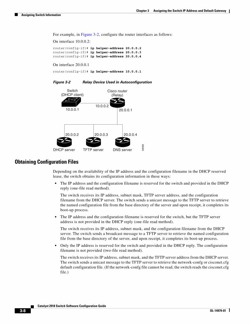
Chapter 3 Assigning the Switch IP Address and Default GatewayAssigning Switch Information
For example, in Figure 3-2, configure the router interfaces as follows:
On interface 10.0.0.2:
router(config-if)# ip helper-address 20.0.0.2router(config-if)# ip helper-address 20.0.0.3router(config-if)# ip helper-address 20.0.0.4
On interface 20.0.0.1
router(config-if)# ip helper-address 10.0.0.1
Figure 3-2 Relay Device Used in Autoconfiguration
Switch(DHCP client)
Cisco router(Relay)
4906
8
DHCP server TFTP server DNS server
20.0.0.2 20.0.0.3
20.0.0.110.0.0.2
10.0.0.1
20.0.0.4
Obtaining Configuration Files
Depending on the availability of the IP address and the configuration filename in the DHCP reserved lease, the switch obtains its configuration information in these ways:
• The IP address and the configuration filename is reserved for the switch and provided in the DHCP reply (one-file read method).
The switch receives its IP address, subnet mask, TFTP server address, and the configuration filename from the DHCP server. The switch sends a unicast message to the TFTP server to retrieve the named configuration file from the base directory of the server and upon receipt, it completes its boot-up process.
• The IP address and the configuration filename is reserved for the switch, but the TFTP server address is not provided in the DHCP reply (one-file read method).
The switch receives its IP address, subnet mask, and the configuration filename from the DHCP server. The switch sends a broadcast message to a TFTP server to retrieve the named configuration file from the base directory of the server, and upon receipt, it completes its boot-up process.
• Only the IP address is reserved for the switch and provided in the DHCP reply. The configuration filename is not provided (two-file read method).
The switch receives its IP address, subnet mask, and the TFTP server address from the DHCP server. The switch sends a unicast message to the TFTP server to retrieve the network-confg or cisconet.cfg default configuration file. (If the network-confg file cannot be read, the switch reads the cisconet.cfg file.)
3-8Catalyst 2918 Switch Software Configuration Guide
OL-14979-01
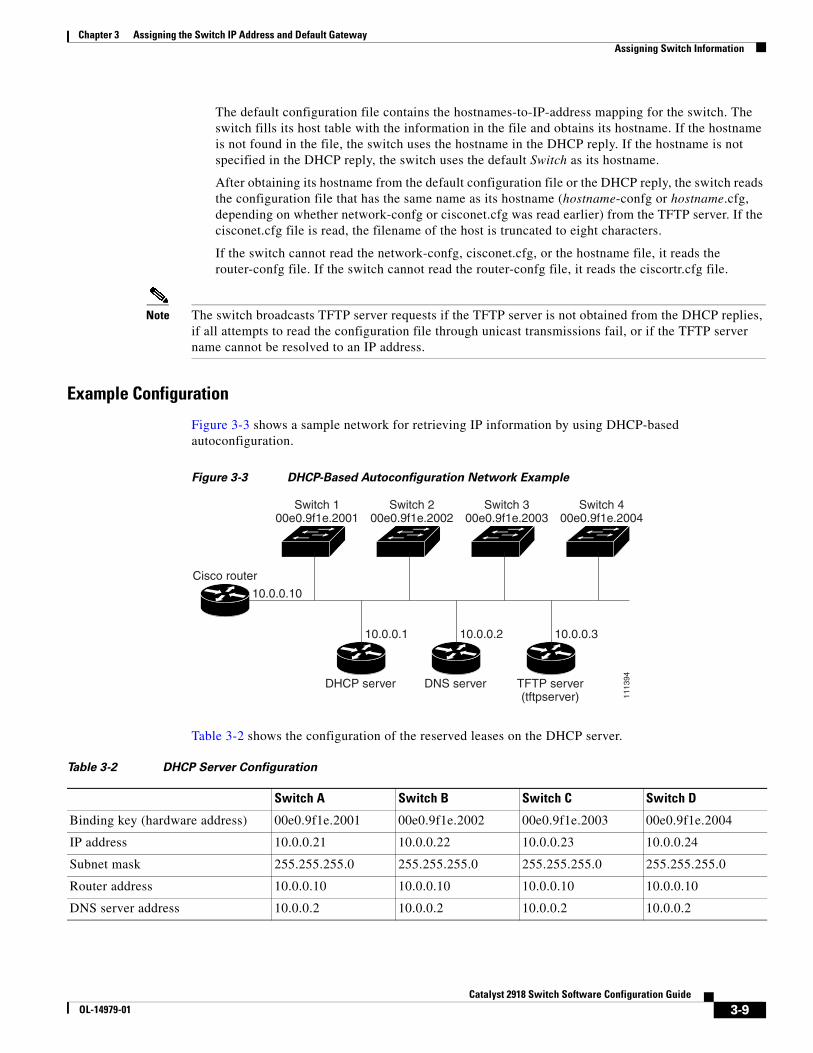
Chapter 3 Assigning the Switch IP Address and Default GatewayAssigning Switch Information
The default configuration file contains the hostnames-to-IP-address mapping for the switch. The switch fills its host table with the information in the file and obtains its hostname. If the hostname is not found in the file, the switch uses the hostname in the DHCP reply. If the hostname is not specified in the DHCP reply, the switch uses the default Switch as its hostname.
After obtaining its hostname from the default configuration file or the DHCP reply, the switch reads the configuration file that has the same name as its hostname (hostname-confg or hostname.cfg, depending on whether network-confg or cisconet.cfg was read earlier) from the TFTP server. If the cisconet.cfg file is read, the filename of the host is truncated to eight characters.
If the switch cannot read the network-confg, cisconet.cfg, or the hostname file, it reads the router-confg file. If the switch cannot read the router-confg file, it reads the ciscortr.cfg file.
Note The switch broadcasts TFTP server requests if the TFTP server is not obtained from the DHCP replies, if all attempts to read the configuration file through unicast transmissions fail, or if the TFTP server name cannot be resolved to an IP address.
Example Configuration
Figure 3-3 shows a sample network for retrieving IP information by using DHCP-based autoconfiguration.
Figure 3-3 DHCP-Based Autoconfiguration Network Example
Switch 100e0.9f1e.2001
Cisco router
1113
94
Switch 200e0.9f1e.2002
Switch 300e0.9f1e.2003
DHCP server DNS server TFTP server(tftpserver)
10.0.0.1
10.0.0.10
10.0.0.2 10.0.0.3
Switch 400e0.9f1e.2004
Table 3-2 shows the configuration of the reserved leases on the DHCP server.
Table 3-2 DHCP Server Configuration
Switch A Switch B Switch C Switch D
Binding key (hardware address) 00e0.9f1e.2001 00e0.9f1e.2002 00e0.9f1e.2003 00e0.9f1e.2004
IP address 10.0.0.21 10.0.0.22 10.0.0.23 10.0.0.24
Subnet mask 255.255.255.0 255.255.255.0 255.255.255.0 255.255.255.0
Router address 10.0.0.10 10.0.0.10 10.0.0.10 10.0.0.10
DNS server address 10.0.0.2 10.0.0.2 10.0.0.2 10.0.0.2
3-9Catalyst 2918 Switch Software Configuration Guide
OL-14979-01
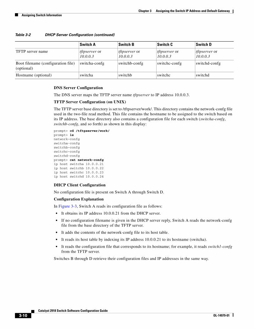
Chapter 3 Assigning the Switch IP Address and Default GatewayAssigning Switch Information
DNS Server Configuration
The DNS server maps the TFTP server name tftpserver to IP address 10.0.0.3.
TFTP Server Configuration (on UNIX)
The TFTP server base directory is set to /tftpserver/work/. This directory contains the network-confg file used in the two-file read method. This file contains the hostname to be assigned to the switch based on its IP address. The base directory also contains a configuration file for each switch (switcha-confg, switchb-confg, and so forth) as shown in this display:
prompt> cd /tftpserver/work/prompt> lsnetwork-confgswitcha-confgswitchb-confgswitchc-confgswitchd-confgprompt> cat network-confgip host switcha 10.0.0.21ip host switchb 10.0.0.22ip host switchc 10.0.0.23ip host switchd 10.0.0.24
DHCP Client Configuration
No configuration file is present on Switch A through Switch D.
Configuration Explanation
In Figure 3-3, Switch A reads its configuration file as follows:
• It obtains its IP address 10.0.0.21 from the DHCP server.
• If no configuration filename is given in the DHCP server reply, Switch A reads the network-confg file from the base directory of the TFTP server.
• It adds the contents of the network-confg file to its host table.
• It reads its host table by indexing its IP address 10.0.0.21 to its hostname (switcha).
• It reads the configuration file that corresponds to its hostname; for example, it reads switch1-confg from the TFTP server.
Switches B through D retrieve their configuration files and IP addresses in the same way.
TFTP server name tftpserver or 10.0.0.3
tftpserver or 10.0.0.3
tftpserver or 10.0.0.3
tftpserver or 10.0.0.3
Boot filename (configuration file) (optional)
switcha-confg switchb-confg switchc-confg switchd-confg
Hostname (optional) switcha switchb switchc switchd
Table 3-2 DHCP Server Configuration (continued)
Switch A Switch B Switch C Switch D
3-10Catalyst 2918 Switch Software Configuration Guide
OL-14979-01
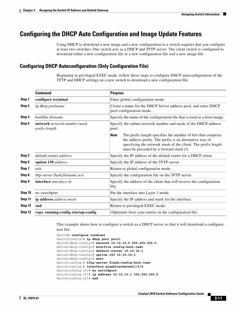
Chapter 3 Assigning the Switch IP Address and Default GatewayAssigning Switch Information
Configuring the DHCP Auto Configuration and Image Update FeaturesUsing DHCP to download a new image and a new configuration to a switch requires that you configure at least two switches: One switch acts as a DHCP and TFTP server. The client switch is configured to download either a new configuration file or a new configuration file and a new image file.
Configuring DHCP Autoconfiguration (Only Configuration File)
Beginning in privileged EXEC mode, follow these steps to configure DHCP autoconfiguration of the TFTP and DHCP settings on a new switch to download a new configuration file.
Command Purpose
Step 1 configure terminal Enter global configuration mode.
Step 2 ip dhcp poolname Create a name for the DHCP Server address pool, and enter DHCP pool configuration mode.
Step 3 bootfile filename Specify the name of the configuration file that is used as a boot image.
Step 4 network network-number mask prefix-length
Specify the subnet network number and mask of the DHCP address pool.
Note The prefix length specifies the number of bits that comprise the address prefix. The prefix is an alternative way of specifying the network mask of the client. The prefix length must be preceded by a forward slash (/).
Step 5 default-router address Specify the IP address of the default router for a DHCP client.
Step 6 option 150 address Specify the IP address of the TFTP server.
Step 7 exit Return to global configuration mode.
Step 8 tftp-server flash:filename.text Specify the configuration file on the TFTP server.
Step 9 interface interface-id Specify the address of the client that will receive the configuration file.
Step 10 no switchport Put the interface into Layer 3 mode.
Step 11 ip address address mask Specify the IP address and mask for the interface.
Step 12 end Return to privileged EXEC mode.
Step 13 copy running-config startup-config (Optional) Save your entries in the configuration file.
This example shows how to configure a switch as a DHCP server so that it will download a configura-tion file:Switch# configure terminalSwitch(config)# ip dhcp pool pool1Switch(dhcp-config)# network 10.10.10.0 255.255.255.0Switch(dhcp-config)# bootfile config-boot.text Switch(dhcp-config)# default-router 10.10.10.1Switch(dhcp-config)# option 150 10.10.10.1Switch(dhcp-config)# exitSwitch(config)# tftp-server flash:config-boot.textSwitch(config)# interface gigabitethernet1/0/4 Switch(config-if)# no switchportSwitch(config-if)# ip address 10.10.10.1 255.255.255.0Switch(config-if)# end
3-11Catalyst 2918 Switch Software Configuration Guide
OL-14979-01
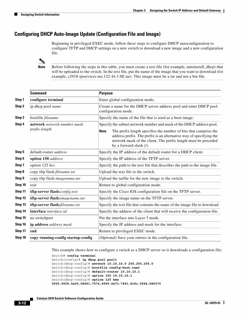
Chapter 3 Assigning the Switch IP Address and Default GatewayAssigning Switch Information
Configuring DHCP Auto-Image Update (Configuration File and Image)
Beginning in privileged EXEC mode, follow these steps to configure DHCP autoconfiguration to configure TFTP and DHCP settings on a new switch to download a new image and a new configuration file.
Note Before following the steps in this table, you must create a text file (for example, autoinstall_dhcp) that will be uploaded to the switch. In the text file, put the name of the image that you want to download (for example, c2918-ipservices-mz.122-44.3.SE.tar). This image must be a tar and not a bin file.
Command Purpose
Step 1 configure terminal Enter global configuration mode.
Step 2 ip dhcp pool name Create a name for the DHCP server address pool and enter DHCP pool configuration mode.
Step 3 bootfile filename Specify the name of the file that is used as a boot image.
Step 4 network network-number mask prefix-length
Specify the subnet network number and mask of the DHCP address pool.
Note The prefix length specifies the number of bits that comprise the address prefix. The prefix is an alternative way of specifying the network mask of the client. The prefix length must be preceded by a forward slash (/).
Step 5 default-router address Specify the IP address of the default router for a DHCP client.
Step 6 option 150 address Specify the IP address of the TFTP server.
Step 7 option 125 hex Specify the path to the text file that describes the path to the image file.
Step 8 copy tftp flash filename.txt Upload the text file to the switch.
Step 9 copy tftp flash imagename.tar Upload the tarfile for the new image to the switch.
Step 10 exit Return to global configuration mode.
Step 11 tftp-server flash:config.text Specify the Cisco IOS configuration file on the TFTP server.
Step 12 tftp-server flash:imagename.tar Specify the image name on the TFTP server.
Step 13 tftp-server flash:filename.txt Specify the text file that contains the name of the image file to download
Step 14 interface interface-id Specify the address of the client that will receive the configuration file.
Step 15 no switchport Put the interface into Layer 3 mode.
Step 16 ip address address mask Specify the IP address and mask for the interface.
Step 17 end Return to privileged EXEC mode.
Step 18 copy running-config startup-config (Optional) Save your entries in the configuration file.
This example shows how to configure a switch as a DHCP server so it downloads a configuration file:Switch# config terminalSwitch(config)# ip dhcp pool pool1Switch(dhcp-config)# network 10.10.10.0 255.255.255.0Switch(dhcp-config)# bootfile config-boot.text Switch(dhcp-config)# default-router 10.10.10.1Switch(dhcp-config)# option 150 10.10.10.1Switch(dhcp-config)# option 125 hex 0000.0009.0a05.08661.7574.6f69.6e73.7461.6c6c.5f64.686370
3-12Catalyst 2918 Switch Software Configuration Guide
OL-14979-01
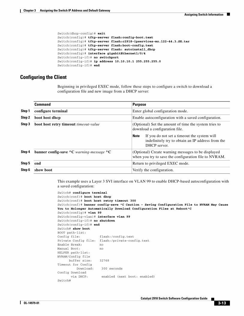
Chapter 3 Assigning the Switch IP Address and Default GatewayAssigning Switch Information
Switch(dhcp-config)# exitSwitch(config)# tftp-server flash:config-boot.textSwitch(config)# tftp-server flash:c2918-ipservices-mz.122-44.3.SE.tarSwitch(config)# tftp-server flash:boot-config.textSwitch(config)# tftp-server flash: autoinstall_dhcpSwitch(config)# interface gigabitEthernet1/0/4Switch(config-if)# no switchportSwitch(config-if)# ip address 10.10.10.1 255.255.255.0Switch(config-if)# end
Configuring the Client
Beginning in privileged EXEC mode, follow these steps to configure a switch to download a configuration file and new image from a DHCP server:
Command Purpose
Step 1 configure terminal Enter global configuration mode.
Step 2 boot host dhcp Enable autoconfiguration with a saved configuration.
Step 3 boot host retry timeout timeout-value (Optional) Set the amount of time the system tries to download a configuration file.
Note If you do not set a timeout the system will indefinitely try to obtain an IP address from the DHCP server.
Step 4 banner config-save ^C warning-message ^C (Optional) Create warning messages to be displayed when you try to save the configuration file to NVRAM.
Step 5 end Return to privileged EXEC mode.
Step 6 show boot Verify the configuration.
This example uses a Layer 3 SVI interface on VLAN 99 to enable DHCP-based autoconfiguration with a saved configuration:
Switch# configure terminal Switch(conf)# boot host dhcpSwitch(conf)# boot host retry timeout 300Switch(conf)# banner config-save ^C Caution - Saving Configuration File to NVRAM May Cause You to Nolonger Automatically Download Configuration Files at Reboot^CSwitch(config)# vlan 99Switch(config-vlan)# interface vlan 99Switch(config-if)# no shutdownSwitch(config-if)# endSwitch# show bootBOOT path-list:Config file: flash:/config.textPrivate Config file: flash:/private-config.textEnable Break: noManual Boot: noHELPER path-list:NVRAM/Config file buffer size: 32768Timeout for Config Download: 300 secondsConfig Download via DHCP: enabled (next boot: enabled)Switch#
3-13Catalyst 2918 Switch Software Configuration Guide
OL-14979-01
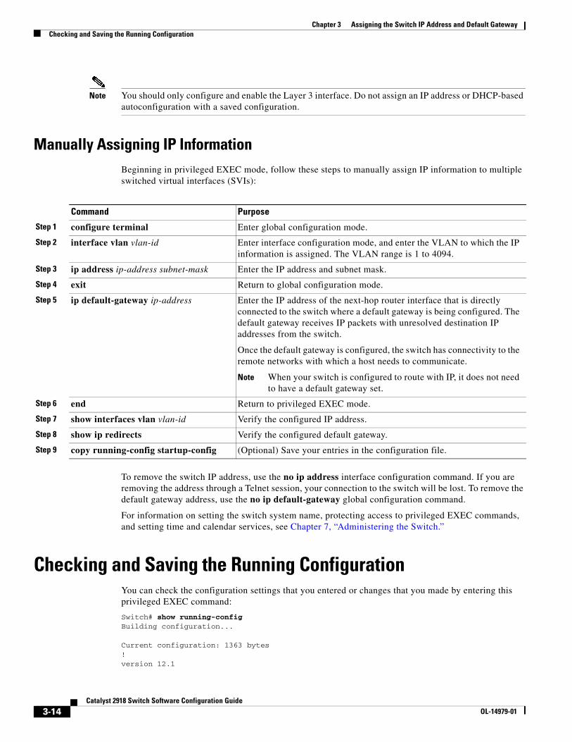
Chapter 3 Assigning the Switch IP Address and Default GatewayChecking and Saving the Running Configuration
Note You should only configure and enable the Layer 3 interface. Do not assign an IP address or DHCP-based autoconfiguration with a saved configuration.
Manually Assigning IP InformationBeginning in privileged EXEC mode, follow these steps to manually assign IP information to multiple switched virtual interfaces (SVIs):
Command Purpose
Step 1 configure terminal Enter global configuration mode.
Step 2 interface vlan vlan-id Enter interface configuration mode, and enter the VLAN to which the IP information is assigned. The VLAN range is 1 to 4094.
Step 3 ip address ip-address subnet-mask Enter the IP address and subnet mask.
Step 4 exit Return to global configuration mode.
Step 5 ip default-gateway ip-address Enter the IP address of the next-hop router interface that is directly connected to the switch where a default gateway is being configured. The default gateway receives IP packets with unresolved destination IP addresses from the switch.
Once the default gateway is configured, the switch has connectivity to the remote networks with which a host needs to communicate.
Note When your switch is configured to route with IP, it does not need to have a default gateway set.
Step 6 end Return to privileged EXEC mode.
Step 7 show interfaces vlan vlan-id Verify the configured IP address.
Step 8 show ip redirects Verify the configured default gateway.
Step 9 copy running-config startup-config (Optional) Save your entries in the configuration file.
To remove the switch IP address, use the no ip address interface configuration command. If you are removing the address through a Telnet session, your connection to the switch will be lost. To remove the default gateway address, use the no ip default-gateway global configuration command.
For information on setting the switch system name, protecting access to privileged EXEC commands, and setting time and calendar services, see Chapter 7, “Administering the Switch.”
Checking and Saving the Running ConfigurationYou can check the configuration settings that you entered or changes that you made by entering this privileged EXEC command:
Switch# show running-configBuilding configuration...
Current configuration: 1363 bytes!version 12.1
3-14Catalyst 2918 Switch Software Configuration Guide
OL-14979-01
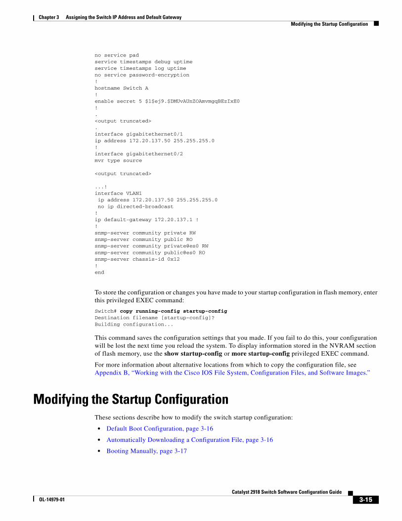
Chapter 3 Assigning the Switch IP Address and Default GatewayModifying the Startup Configuration
no service padservice timestamps debug uptimeservice timestamps log uptimeno service password-encryption!hostname Switch A !enable secret 5 $1$ej9.$DMUvAUnZOAmvmgqBEzIxE0!.<output truncated>.interface gigabitethernet0/1ip address 172.20.137.50 255.255.255.0 !interface gigabitethernet0/2mvr type source
<output truncated>
...!interface VLAN1 ip address 172.20.137.50 255.255.255.0 no ip directed-broadcast!ip default-gateway 172.20.137.1 !!snmp-server community private RWsnmp-server community public ROsnmp-server community private@es0 RWsnmp-server community public@es0 ROsnmp-server chassis-id 0x12! end
To store the configuration or changes you have made to your startup configuration in flash memory, enter this privileged EXEC command:
Switch# copy running-config startup-configDestination filename [startup-config]?Building configuration...
This command saves the configuration settings that you made. If you fail to do this, your configuration will be lost the next time you reload the system. To display information stored in the NVRAM section of flash memory, use the show startup-config or more startup-config privileged EXEC command.
For more information about alternative locations from which to copy the configuration file, see Appendix B, “Working with the Cisco IOS File System, Configuration Files, and Software Images.”
Modifying the Startup ConfigurationThese sections describe how to modify the switch startup configuration:
• Default Boot Configuration, page 3-16
• Automatically Downloading a Configuration File, page 3-16
• Booting Manually, page 3-17
3-15Catalyst 2918 Switch Software Configuration Guide
OL-14979-01
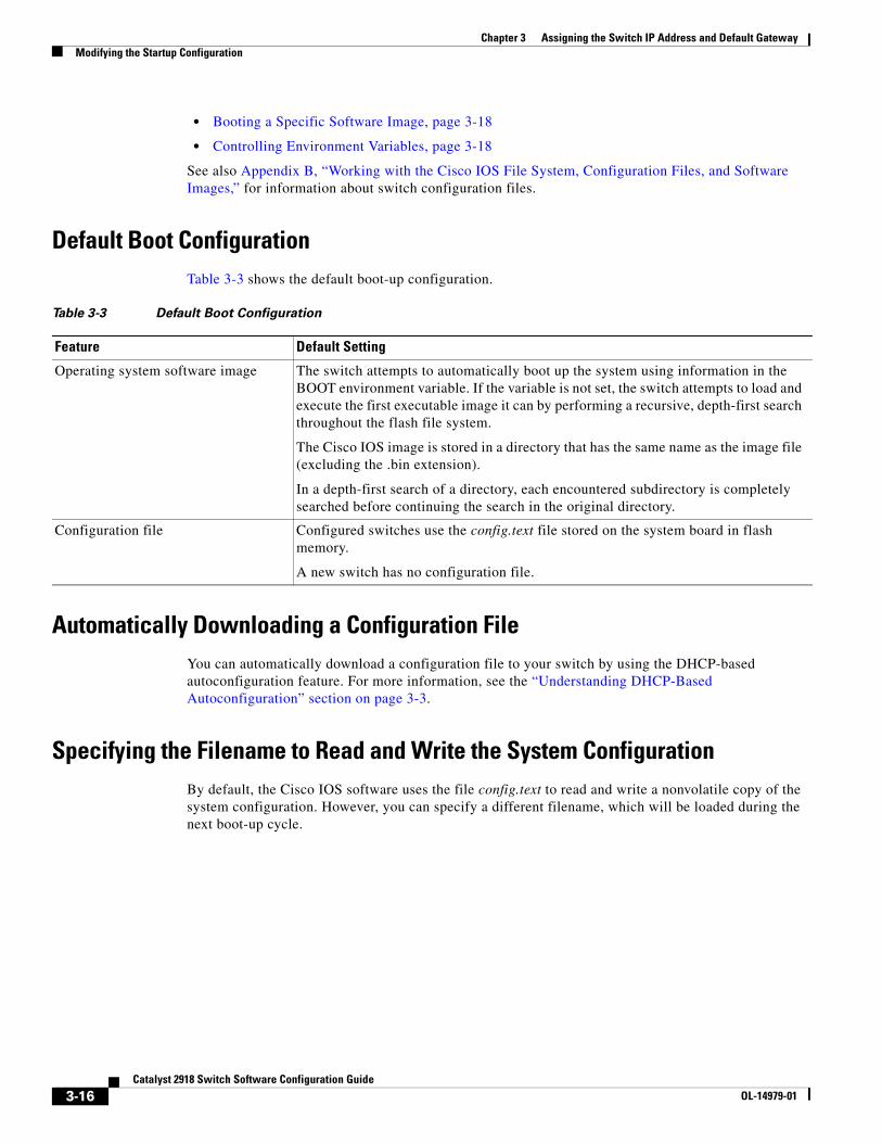
Chapter 3 Assigning the Switch IP Address and Default GatewayModifying the Startup Configuration
• Booting a Specific Software Image, page 3-18
• Controlling Environment Variables, page 3-18
See also Appendix B, “Working with the Cisco IOS File System, Configuration Files, and Software Images,” for information about switch configuration files.
Default Boot ConfigurationTable 3-3 shows the default boot-up configuration.
Table 3-3 Default Boot Configuration
Feature Default Setting
Operating system software image The switch attempts to automatically boot up the system using information in the BOOT environment variable. If the variable is not set, the switch attempts to load and execute the first executable image it can by performing a recursive, depth-first search throughout the flash file system.
The Cisco IOS image is stored in a directory that has the same name as the image file (excluding the .bin extension).
In a depth-first search of a directory, each encountered subdirectory is completely searched before continuing the search in the original directory.
Configuration file Configured switches use the config.text file stored on the system board in flash memory.
A new switch has no configuration file.
Automatically Downloading a Configuration File You can automatically download a configuration file to your switch by using the DHCP-based autoconfiguration feature. For more information, see the “Understanding DHCP-Based Autoconfiguration” section on page 3-3.
Specifying the Filename to Read and Write the System ConfigurationBy default, the Cisco IOS software uses the file config.text to read and write a nonvolatile copy of the system configuration. However, you can specify a different filename, which will be loaded during the next boot-up cycle.
3-16Catalyst 2918 Switch Software Configuration Guide
OL-14979-01
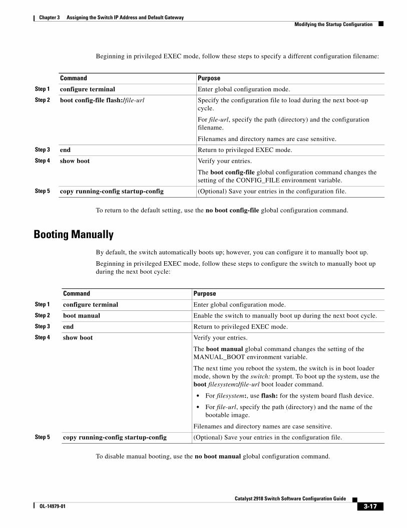
Chapter 3 Assigning the Switch IP Address and Default GatewayModifying the Startup Configuration
Beginning in privileged EXEC mode, follow these steps to specify a different configuration filename:
Command Purpose
Step 1 configure terminal Enter global configuration mode.
Step 2 boot config-file flash:/file-url Specify the configuration file to load during the next boot-up cycle.
For file-url, specify the path (directory) and the configuration filename.
Filenames and directory names are case sensitive.
Step 3 end Return to privileged EXEC mode.
Step 4 show boot Verify your entries.
The boot config-file global configuration command changes the setting of the CONFIG_FILE environment variable.
Step 5 copy running-config startup-config (Optional) Save your entries in the configuration file.
To return to the default setting, use the no boot config-file global configuration command.
Booting ManuallyBy default, the switch automatically boots up; however, you can configure it to manually boot up.
Beginning in privileged EXEC mode, follow these steps to configure the switch to manually boot up during the next boot cycle:
Command Purpose
Step 1 configure terminal Enter global configuration mode.
Step 2 boot manual Enable the switch to manually boot up during the next boot cycle.
Step 3 end Return to privileged EXEC mode.
Step 4 show boot Verify your entries.
The boot manual global command changes the setting of the MANUAL_BOOT environment variable.
The next time you reboot the system, the switch is in boot loader mode, shown by the switch: prompt. To boot up the system, use the boot filesystem:/file-url boot loader command.
• For filesystem:, use flash: for the system board flash device.
• For file-url, specify the path (directory) and the name of the bootable image.
Filenames and directory names are case sensitive.
Step 5 copy running-config startup-config (Optional) Save your entries in the configuration file.
To disable manual booting, use the no boot manual global configuration command.
3-17Catalyst 2918 Switch Software Configuration Guide
OL-14979-01
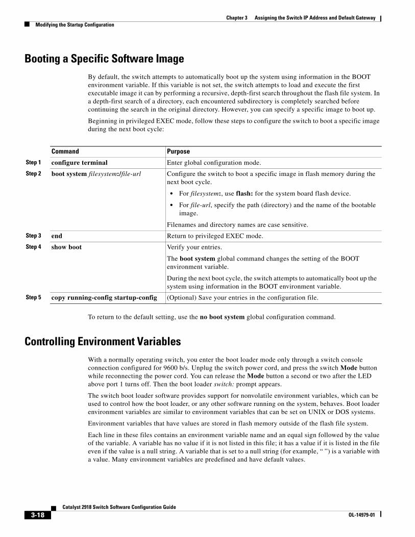
Chapter 3 Assigning the Switch IP Address and Default GatewayModifying the Startup Configuration
Booting a Specific Software ImageBy default, the switch attempts to automatically boot up the system using information in the BOOT environment variable. If this variable is not set, the switch attempts to load and execute the first executable image it can by performing a recursive, depth-first search throughout the flash file system. In a depth-first search of a directory, each encountered subdirectory is completely searched before continuing the search in the original directory. However, you can specify a specific image to boot up.
Beginning in privileged EXEC mode, follow these steps to configure the switch to boot a specific image during the next boot cycle:
Command Purpose
Step 1 configure terminal Enter global configuration mode.
Step 2 boot system filesystem:/file-url Configure the switch to boot a specific image in flash memory during the next boot cycle.
• For filesystem:, use flash: for the system board flash device.
• For file-url, specify the path (directory) and the name of the bootable image.
Filenames and directory names are case sensitive.
Step 3 end Return to privileged EXEC mode.
Step 4 show boot Verify your entries.
The boot system global command changes the setting of the BOOT environment variable.
During the next boot cycle, the switch attempts to automatically boot up the system using information in the BOOT environment variable.
Step 5 copy running-config startup-config (Optional) Save your entries in the configuration file.
To return to the default setting, use the no boot system global configuration command.
Controlling Environment VariablesWith a normally operating switch, you enter the boot loader mode only through a switch console connection configured for 9600 b/s. Unplug the switch power cord, and press the switch Mode button while reconnecting the power cord. You can release the Mode button a second or two after the LED above port 1 turns off. Then the boot loader switch: prompt appears.
The switch boot loader software provides support for nonvolatile environment variables, which can be used to control how the boot loader, or any other software running on the system, behaves. Boot loader environment variables are similar to environment variables that can be set on UNIX or DOS systems.
Environment variables that have values are stored in flash memory outside of the flash file system.
Each line in these files contains an environment variable name and an equal sign followed by the value of the variable. A variable has no value if it is not listed in this file; it has a value if it is listed in the file even if the value is a null string. A variable that is set to a null string (for example, “ ”) is a variable with a value. Many environment variables are predefined and have default values.
3-18Catalyst 2918 Switch Software Configuration Guide
OL-14979-01
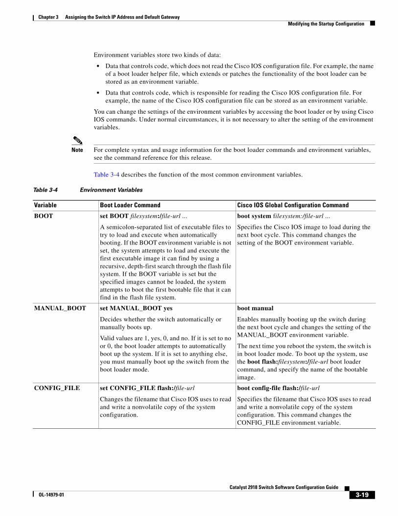
Chapter 3 Assigning the Switch IP Address and Default GatewayModifying the Startup Configuration
Environment variables store two kinds of data:
• Data that controls code, which does not read the Cisco IOS configuration file. For example, the name of a boot loader helper file, which extends or patches the functionality of the boot loader can be stored as an environment variable.
• Data that controls code, which is responsible for reading the Cisco IOS configuration file. For example, the name of the Cisco IOS configuration file can be stored as an environment variable.
You can change the settings of the environment variables by accessing the boot loader or by using Cisco IOS commands. Under normal circumstances, it is not necessary to alter the setting of the environment variables.
Note For complete syntax and usage information for the boot loader commands and environment variables, see the command reference for this release.
Table 3-4 describes the function of the most common environment variables.
Table 3-4 Environment Variables
Variable Boot Loader Command Cisco IOS Global Configuration Command
BOOT set BOOT filesystem:/file-url ...
A semicolon-separated list of executable files to try to load and execute when automatically booting. If the BOOT environment variable is not set, the system attempts to load and execute the first executable image it can find by using a recursive, depth-first search through the flash file system. If the BOOT variable is set but the specified images cannot be loaded, the system attempts to boot the first bootable file that it can find in the flash file system.
boot system filesystem:/file-url ...
Specifies the Cisco IOS image to load during the next boot cycle. This command changes the setting of the BOOT environment variable.
MANUAL_BOOT set MANUAL_BOOT yes
Decides whether the switch automatically or manually boots up.
Valid values are 1, yes, 0, and no. If it is set to no or 0, the boot loader attempts to automatically boot up the system. If it is set to anything else, you must manually boot up the switch from the boot loader mode.
boot manual
Enables manually booting up the switch during the next boot cycle and changes the setting of the MANUAL_BOOT environment variable.
The next time you reboot the system, the switch is in boot loader mode. To boot up the system, use the boot flash:filesystem:/file-url boot loader command, and specify the name of the bootable image.
CONFIG_FILE set CONFIG_FILE flash:/file-url
Changes the filename that Cisco IOS uses to read and write a nonvolatile copy of the system configuration.
boot config-file flash:/file-url
Specifies the filename that Cisco IOS uses to read and write a nonvolatile copy of the system configuration. This command changes the CONFIG_FILE environment variable.
3-19Catalyst 2918 Switch Software Configuration Guide
OL-14979-01
Chapter 3 Assigning the Switch IP Address and Default GatewayScheduling a Reload of the Software Image
Scheduling a Reload of the Software ImageYou can schedule a reload of the software image to occur on the switch at a later time (for example, late at night or during the weekend when the switch is used less), or you can synchronize a reload network-wide (for example, to perform a software upgrade on all switches in the network).
Note A scheduled reload must take place within approximately 24 days.
Configuring a Scheduled ReloadTo configure your switch to reload the software image at a later time, use one of these commands in privileged EXEC mode:
• reload in [hh:]mm [text]
This command schedules a reload of the software to take affect in the specified minutes or hours and minutes. The reload must take place within approximately 24 days. You can specify the reason for the reload in a string up to 255 characters in length.
• reload at hh:mm [month day | day month] [text]
This command schedules a reload of the software to take place at the specified time (using a 24-hour clock). If you specify the month and day, the reload is scheduled to take place at the specified time and date. If you do not specify the month and day, the reload takes place at the specified time on the current day (if the specified time is later than the current time) or on the next day (if the specified time is earlier than the current time). Specifying 00:00 schedules the reload for midnight.
Note Use the at keyword only if the switch system clock has been set (through Network Time Protocol (NTP), the hardware calendar, or manually). The time is relative to the configured time zone on the switch. To schedule reloads across several switches to occur simultaneously, the time on each switch must be synchronized with NTP.
The reload command halts the system. If the system is not set to manually boot up, it reboots itself. Use the reload command after you save the switch configuration information to the startup configuration (copy running-config startup-config).
If your switch is configured for manual booting, do not reload it from a virtual terminal. This restriction prevents the switch from entering the boot loader mode and thereby taking it from the remote user’s control.
If you modify your configuration file, the switch prompts you to save the configuration before reloading. During the save operation, the system requests whether you want to proceed with the save if the CONFIG_FILE environment variable points to a startup configuration file that no longer exists. If you proceed in this situation, the system enters setup mode upon reload.
This example shows how to reload the software on the switch on the current day at 7:30 p.m:
Switch# reload at 19:30Reload scheduled for 19:30:00 UTC Wed Jun 5 1996 (in 2 hours and 25 minutes)Proceed with reload? [confirm]
3-20Catalyst 2918 Switch Software Configuration Guide
OL-14979-01
Chapter 3 Assigning the Switch IP Address and Default GatewayScheduling a Reload of the Software Image
This example shows how to reload the software on the switch at a future time:
Switch# reload at 02:00 jun 20Reload scheduled for 02:00:00 UTC Thu Jun 20 1996 (in 344 hours and 53 minutes)Proceed with reload? [confirm]
To cancel a previously scheduled reload, use the reload cancel privileged EXEC command.
Displaying Scheduled Reload InformationTo display information about a previously scheduled reload or to find out if a reload has been scheduled on the switch, use the show reload privileged EXEC command.
It displays reload information including the time the reload is scheduled to occur and the reason for the reload (if it was specified when the reload was scheduled).
3-21Catalyst 2918 Switch Software Configuration Guide
OL-14979-01

Chapter 3 Assigning the Switch IP Address and Default GatewayScheduling a Reload of the Software Image
3-22Catalyst 2918 Switch Software Configuration Guide
OL-14979-01
OL-14979-01
C H A P T E R 4
Configuring Cisco IOS CNS AgentsThis chapter describes how to configure the Cisco IOS CNS agents on the Catalyst 2918 switch.
Note For complete configuration information for the Cisco Configuration Engine, see this URL on Cisco.com http://www.cisco.com/en/US/products/sw/netmgtsw/ps4617/tsd_products_support_series_home.html
This chapter consists of these sections:
• Understanding Cisco Configuration Engine Software, page 4-1
• Understanding Cisco IOS Agents, page 4-5
• Configuring Cisco IOS Agents, page 4-6
• Displaying CNS Configuration, page 4-12
Understanding Cisco Configuration Engine SoftwareThe Cisco Configuration Engine is network management software that acts as a configuration service for automating the deployment and management of network devices and services (see Figure 4-1). Each Configuration Engine manages a group of Cisco devices (switches and routers) and the services that they deliver, storing their configurations and delivering them as needed. The Configuration Engine automates initial configurations and configuration updates by generating device-specific configuration changes, sending them to the device, executing the configuration change, and logging the results.
The Configuration Engine supports standalone and server modes and has these CNS components:
• Configuration service (web server, file manager, and namespace mapping server)
• Event service (event gateway)
• Data service directory (data models and schema)
In standalone mode, the Configuration Engine supports an embedded Directory Service. In this mode, no external directory or other data store is required. In server mode, the Configuration Engine supports the use of a user-defined external directory.
4-1Catalyst 2918 Switch Software Configuration Guide
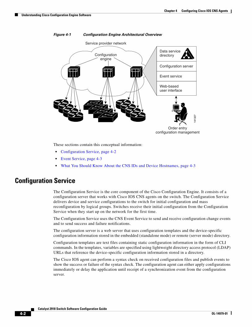
Chapter 4 Configuring Cisco IOS CNS AgentsUnderstanding Cisco Configuration Engine Software
Figure 4-1 Configuration Engine Architectural Overview
Configurationengine
Service provider network
Order entryconfiguration management
Data servicedirectory
Configuration server
Event service
Web-baseduser interface
1413
27
These sections contain this conceptual information:
• Configuration Service, page 4-2
• Event Service, page 4-3
• What You Should Know About the CNS IDs and Device Hostnames, page 4-3
Configuration ServiceThe Configuration Service is the core component of the Cisco Configuration Engine. It consists of a configuration server that works with Cisco IOS CNS agents on the switch. The Configuration Service delivers device and service configurations to the switch for initial configuration and mass reconfiguration by logical groups. Switches receive their initial configuration from the Configuration Service when they start up on the network for the first time.
The Configuration Service uses the CNS Event Service to send and receive configuration change events and to send success and failure notifications.
The configuration server is a web server that uses configuration templates and the device-specific configuration information stored in the embedded (standalone mode) or remote (server mode) directory.
Configuration templates are text files containing static configuration information in the form of CLI commands. In the templates, variables are specified using lightweight directory access protocol (LDAP) URLs that reference the device-specific configuration information stored in a directory.
The Cisco IOS agent can perform a syntax check on received configuration files and publish events to show the success or failure of the syntax check. The configuration agent can either apply configurations immediately or delay the application until receipt of a synchronization event from the configuration server.
4-2Catalyst 2918 Switch Software Configuration Guide
OL-14979-01
Chapter 4 Configuring Cisco IOS CNS AgentsUnderstanding Cisco Configuration Engine Software
Event ServiceThe Cisco Configuration Engine uses the Event Service for receipt and generation of configuration events. The event agent is on the switch and facilitates the communication between the switch and the event gateway on the Configuration Engine.
The Event Service is a highly capable publish-and-subscribe communication method. The Event Service uses subject-based addressing to send messages to their destinations. Subject-based addressing conventions define a simple, uniform namespace for messages and their destinations.
NameSpace Mapper
The Configuration Engine includes the NameSpace Mapper (NSM) that provides a lookup service for managing logical groups of devices based on application, device or group ID, and event.
Cisco IOS devices recognize only event subject-names that match those configured in Cisco IOS software; for example, cisco.cns.config.load. You can use the namespace mapping service to designate events by using any desired naming convention. When you have populated your data store with your subject names, NSM changes your event subject-name strings to those known by Cisco IOS.
For a subscriber, when given a unique device ID and event, the namespace mapping service returns a set of events to which to subscribe. Similarly, for a publisher, when given a unique group ID, device ID, and event, the mapping service returns a set of events on which to publish.
What You Should Know About the CNS IDs and Device HostnamesThe Cisco Configuration Engine assumes that a unique identifier is associated with each configured switch. This unique identifier can take on multiple synonyms, where each synonym is unique within a particular namespace. The event service uses namespace content for subject-based addressing of messages.
The Configuration Engine intersects two namespaces, one for the event bus and the other for the configuration server. Within the scope of the configuration server namespace, the term ConfigID is the unique identifier for a device. Within the scope of the event bus namespace, the term DeviceID is the CNS unique identifier for a device.
Because the Configuration Engine uses both the event bus and the configuration server to provide configurations to devices, you must define both ConfigID and Device ID for each configured switch.
Within the scope of a single instance of the configuration server, no two configured switches can share the same value for ConfigID. Within the scope of a single instance of the event bus, no two configured switches can share the same value for DeviceID.
ConfigID
Each configured switch has a unique ConfigID, which serves as the key into the Configuration Engine directory for the corresponding set of switch CLI attributes. The ConfigID defined on the switch must match the ConfigID for the corresponding switch definition on the Configuration Engine.
The ConfigID is fixed at startup time and cannot be changed until the device restarts, even if the switch hostname is reconfigured.
4-3Catalyst 2918 Switch Software Configuration Guide
OL-14979-01
Chapter 4 Configuring Cisco IOS CNS AgentsUnderstanding Cisco Configuration Engine Software
DeviceID
Each configured switch participating on the event bus has a unique DeviceID, which is analogous to the switch source address so that the switch can be targeted as a specific destination on the bus. All switches configured with the cns config partial global configuration command must access the event bus. Therefore, the DeviceID, as originated on the switch, must match the DeviceID of the corresponding switch definition in the Configuration Engine.
The origin of the DeviceID is defined by the Cisco IOS hostname of the switch. However, the DeviceID variable and its usage reside within the event gateway adjacent to the switch.
The logical Cisco IOS termination point on the event bus is embedded in the event gateway, which in turn functions as a proxy on behalf of the switch. The event gateway represents the switch and its corresponding DeviceID to the event bus.
The switch declares its hostname to the event gateway immediately after the successful connection to the event gateway. The event gateway couples the DeviceID value to the Cisco IOS hostname each time this connection is established. The event gateway caches this DeviceID value for the duration of its connection to the switch.
Hostname and DeviceID
The DeviceID is fixed at the time of the connection to the event gateway and does not change even when the switch hostname is reconfigured.
When changing the switch hostname on the switch, the only way to refresh the DeviceID is to break the connection between the switch and the event gateway. Enter the no cns event global configuration command followed by the cns event global configuration command.
When the connection is re-established, the switch sends its modified hostname to the event gateway. The event gateway redefines the DeviceID to the new value.
Caution When using the Configuration Engine user interface, you must first set the DeviceID field to the hostname value that the switch acquires after–not before–you use the cns config initial global configuration command at the switch. Otherwise, subsequent cns config partial global configuration command operations malfunction.
Using Hostname, DeviceID, and ConfigID
In standalone mode, when a hostname value is set for a switch, the configuration server uses the hostname as the DeviceID when an event is sent on hostname. If the hostname has not been set, the event is sent on the cn=<value> of the device.
In server mode, the hostname is not used. In this mode, the unique DeviceID attribute is always used for sending an event on the bus. If this attribute is not set, you cannot update the switch.
These and other associated attributes (tag value pairs) are set when you run Setup on the Configuration Engine.
Note For more information about running the setup program on the Configuration Engine, see the Configuration Engine setup and configuration guide at this URL on cisco.com: http://www.cisco.com/en/US/products/sw/netmgtsw/ps4617/products_installation_and_configuration_guide_book09186a00803b59db.html
4-4Catalyst 2918 Switch Software Configuration Guide
OL-14979-01
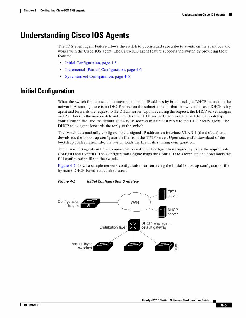
Chapter 4 Configuring Cisco IOS CNS AgentsUnderstanding Cisco IOS Agents
Understanding Cisco IOS AgentsThe CNS event agent feature allows the switch to publish and subscribe to events on the event bus and works with the Cisco IOS agent. The Cisco IOS agent feature supports the switch by providing these features:
• Initial Configuration, page 4-5
• Incremental (Partial) Configuration, page 4-6
• Synchronized Configuration, page 4-6
Initial ConfigurationWhen the switch first comes up, it attempts to get an IP address by broadcasting a DHCP request on the network. Assuming there is no DHCP server on the subnet, the distribution switch acts as a DHCP relay agent and forwards the request to the DHCP server. Upon receiving the request, the DHCP server assigns an IP address to the new switch and includes the TFTP server IP address, the path to the bootstrap configuration file, and the default gateway IP address in a unicast reply to the DHCP relay agent. The DHCP relay agent forwards the reply to the switch.
The switch automatically configures the assigned IP address on interface VLAN 1 (the default) and downloads the bootstrap configuration file from the TFTP server. Upon successful download of the bootstrap configuration file, the switch loads the file in its running configuration.
The Cisco IOS agents initiate communication with the Configuration Engine by using the appropriate ConfigID and EventID. The Configuration Engine maps the Config ID to a template and downloads the full configuration file to the switch.
Figure 4-2 shows a sample network configuration for retrieving the initial bootstrap configuration file by using DHCP-based autoconfiguration.
Figure 4-2 Initial Configuration Overview
TFTPserver
DHCP relay agentdefault gatewayDistribution layer
ConfigurationEngine
Access layerswitches
1413
28
DHCPserver
VWAN
4-5Catalyst 2918 Switch Software Configuration Guide
OL-14979-01
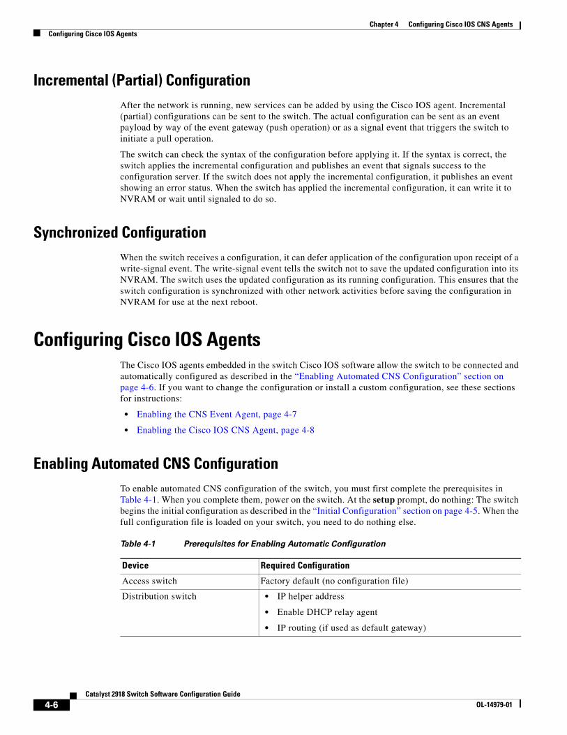
Chapter 4 Configuring Cisco IOS CNS AgentsConfiguring Cisco IOS Agents
Incremental (Partial) ConfigurationAfter the network is running, new services can be added by using the Cisco IOS agent. Incremental (partial) configurations can be sent to the switch. The actual configuration can be sent as an event payload by way of the event gateway (push operation) or as a signal event that triggers the switch to initiate a pull operation.
The switch can check the syntax of the configuration before applying it. If the syntax is correct, the switch applies the incremental configuration and publishes an event that signals success to the configuration server. If the switch does not apply the incremental configuration, it publishes an event showing an error status. When the switch has applied the incremental configuration, it can write it to NVRAM or wait until signaled to do so.
Synchronized ConfigurationWhen the switch receives a configuration, it can defer application of the configuration upon receipt of a write-signal event. The write-signal event tells the switch not to save the updated configuration into its NVRAM. The switch uses the updated configuration as its running configuration. This ensures that the switch configuration is synchronized with other network activities before saving the configuration in NVRAM for use at the next reboot.
Configuring Cisco IOS AgentsThe Cisco IOS agents embedded in the switch Cisco IOS software allow the switch to be connected and automatically configured as described in the “Enabling Automated CNS Configuration” section on page 4-6. If you want to change the configuration or install a custom configuration, see these sections for instructions:
• Enabling the CNS Event Agent, page 4-7
• Enabling the Cisco IOS CNS Agent, page 4-8
Enabling Automated CNS ConfigurationTo enable automated CNS configuration of the switch, you must first complete the prerequisites in Table 4-1. When you complete them, power on the switch. At the setup prompt, do nothing: The switch begins the initial configuration as described in the “Initial Configuration” section on page 4-5. When the full configuration file is loaded on your switch, you need to do nothing else.
Table 4-1 Prerequisites for Enabling Automatic Configuration
Device Required Configuration
Access switch Factory default (no configuration file)
Distribution switch • IP helper address
• Enable DHCP relay agent
• IP routing (if used as default gateway)
4-6Catalyst 2918 Switch Software Configuration Guide
OL-14979-01
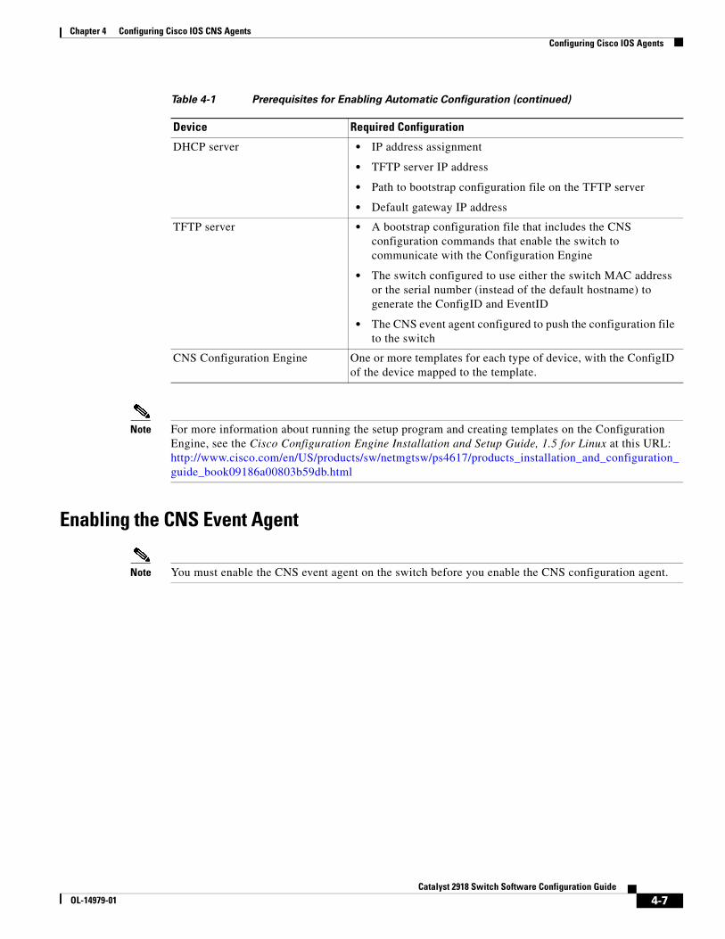
Chapter 4 Configuring Cisco IOS CNS AgentsConfiguring Cisco IOS Agents
Note For more information about running the setup program and creating templates on the Configuration Engine, see the Cisco Configuration Engine Installation and Setup Guide, 1.5 for Linux at this URL: http://www.cisco.com/en/US/products/sw/netmgtsw/ps4617/products_installation_and_configuration_guide_book09186a00803b59db.html
Enabling the CNS Event Agent
Note You must enable the CNS event agent on the switch before you enable the CNS configuration agent.
DHCP server • IP address assignment
• TFTP server IP address
• Path to bootstrap configuration file on the TFTP server
• Default gateway IP address
TFTP server • A bootstrap configuration file that includes the CNS configuration commands that enable the switch to communicate with the Configuration Engine
• The switch configured to use either the switch MAC address or the serial number (instead of the default hostname) to generate the ConfigID and EventID
• The CNS event agent configured to push the configuration file to the switch
CNS Configuration Engine One or more templates for each type of device, with the ConfigID of the device mapped to the template.
Table 4-1 Prerequisites for Enabling Automatic Configuration (continued)
Device Required Configuration
4-7Catalyst 2918 Switch Software Configuration Guide
OL-14979-01
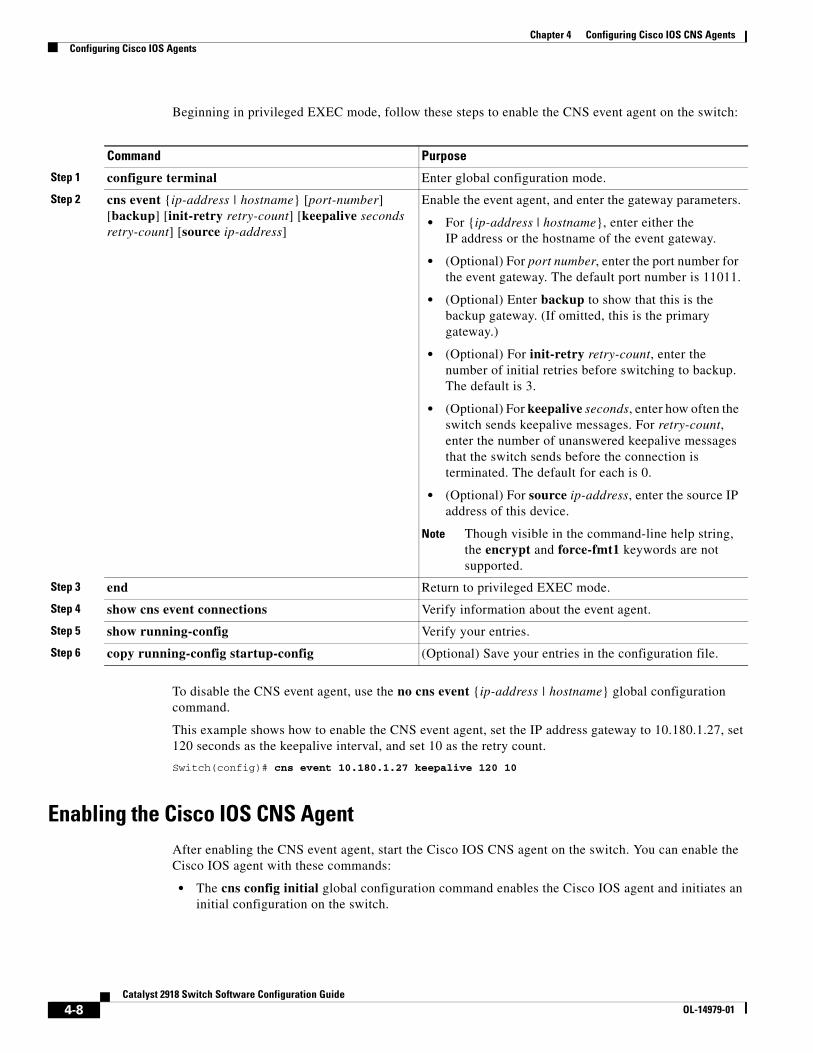
Chapter 4 Configuring Cisco IOS CNS AgentsConfiguring Cisco IOS Agents
Beginning in privileged EXEC mode, follow these steps to enable the CNS event agent on the switch:
Command Purpose
Step 1 configure terminal Enter global configuration mode.
Step 2 cns event {ip-address | hostname} [port-number] [backup] [init-retry retry-count] [keepalive seconds retry-count] [source ip-address]
Enable the event agent, and enter the gateway parameters.
• For {ip-address | hostname}, enter either the IP address or the hostname of the event gateway.
• (Optional) For port number, enter the port number for the event gateway. The default port number is 11011.
• (Optional) Enter backup to show that this is the backup gateway. (If omitted, this is the primary gateway.)
• (Optional) For init-retry retry-count, enter the number of initial retries before switching to backup. The default is 3.
• (Optional) For keepalive seconds, enter how often the switch sends keepalive messages. For retry-count, enter the number of unanswered keepalive messages that the switch sends before the connection is terminated. The default for each is 0.
• (Optional) For source ip-address, enter the source IP address of this device.
Note Though visible in the command-line help string, the encrypt and force-fmt1 keywords are not supported.
Step 3 end Return to privileged EXEC mode.
Step 4 show cns event connections Verify information about the event agent.
Step 5 show running-config Verify your entries.
Step 6 copy running-config startup-config (Optional) Save your entries in the configuration file.
To disable the CNS event agent, use the no cns event {ip-address | hostname} global configuration command.
This example shows how to enable the CNS event agent, set the IP address gateway to 10.180.1.27, set 120 seconds as the keepalive interval, and set 10 as the retry count.
Switch(config)# cns event 10.180.1.27 keepalive 120 10
Enabling the Cisco IOS CNS AgentAfter enabling the CNS event agent, start the Cisco IOS CNS agent on the switch. You can enable the Cisco IOS agent with these commands:
• The cns config initial global configuration command enables the Cisco IOS agent and initiates an initial configuration on the switch.
4-8Catalyst 2918 Switch Software Configuration Guide
OL-14979-01
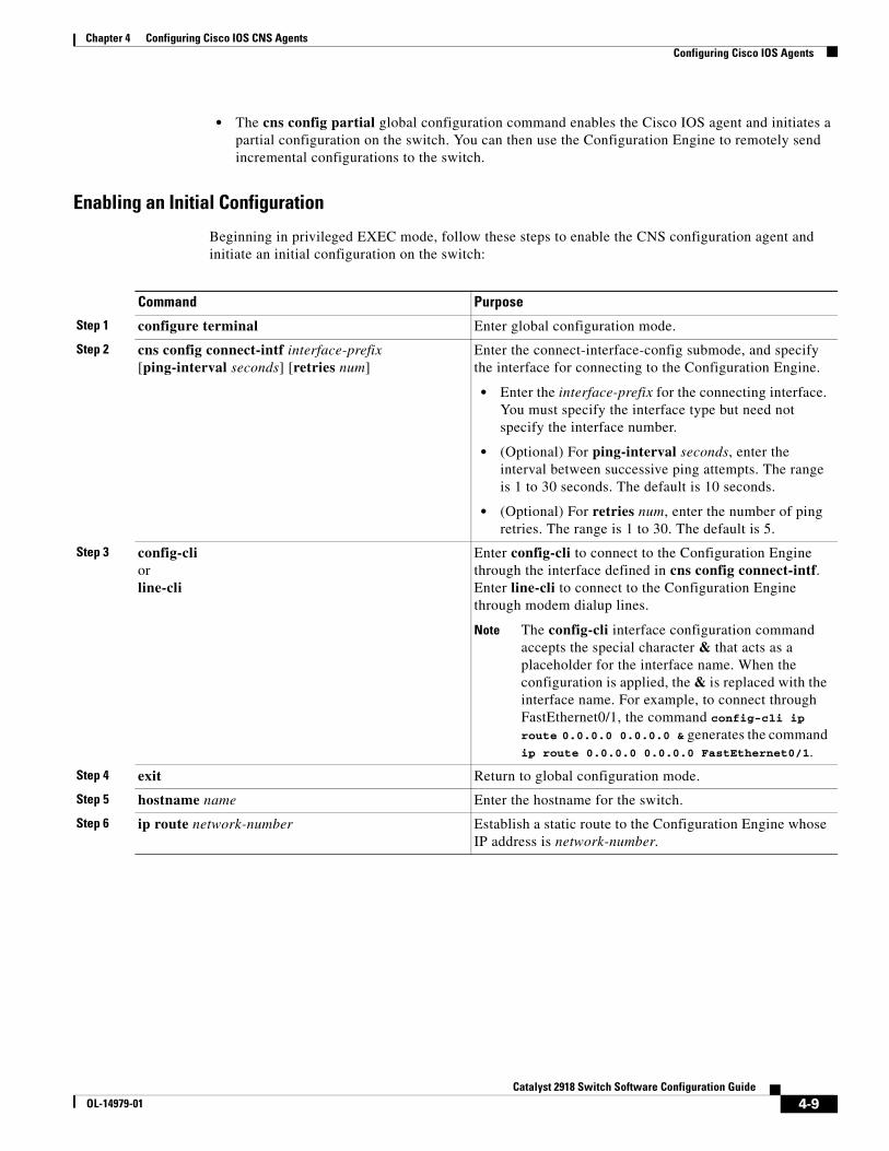
Chapter 4 Configuring Cisco IOS CNS AgentsConfiguring Cisco IOS Agents
• The cns config partial global configuration command enables the Cisco IOS agent and initiates a partial configuration on the switch. You can then use the Configuration Engine to remotely send incremental configurations to the switch.
Enabling an Initial Configuration
Beginning in privileged EXEC mode, follow these steps to enable the CNS configuration agent and initiate an initial configuration on the switch:
Command Purpose
Step 1 configure terminal Enter global configuration mode.
Step 2 cns config connect-intf interface-prefix [ping-interval seconds] [retries num]
Enter the connect-interface-config submode, and specify the interface for connecting to the Configuration Engine.
• Enter the interface-prefix for the connecting interface. You must specify the interface type but need not specify the interface number.
• (Optional) For ping-interval seconds, enter the interval between successive ping attempts. The range is 1 to 30 seconds. The default is 10 seconds.
• (Optional) For retries num, enter the number of ping retries. The range is 1 to 30. The default is 5.
Step 3 config-cli or line-cli
Enter config-cli to connect to the Configuration Engine through the interface defined in cns config connect-intf. Enter line-cli to connect to the Configuration Engine through modem dialup lines.
Note The config-cli interface configuration command accepts the special character & that acts as a placeholder for the interface name. When the configuration is applied, the & is replaced with the interface name. For example, to connect through FastEthernet0/1, the command config-cli ip route 0.0.0.0 0.0.0.0 & generates the command ip route 0.0.0.0 0.0.0.0 FastEthernet0/1.
Step 4 exit Return to global configuration mode.
Step 5 hostname name Enter the hostname for the switch.
Step 6 ip route network-number Establish a static route to the Configuration Engine whose IP address is network-number.
4-9Catalyst 2918 Switch Software Configuration Guide
OL-14979-01
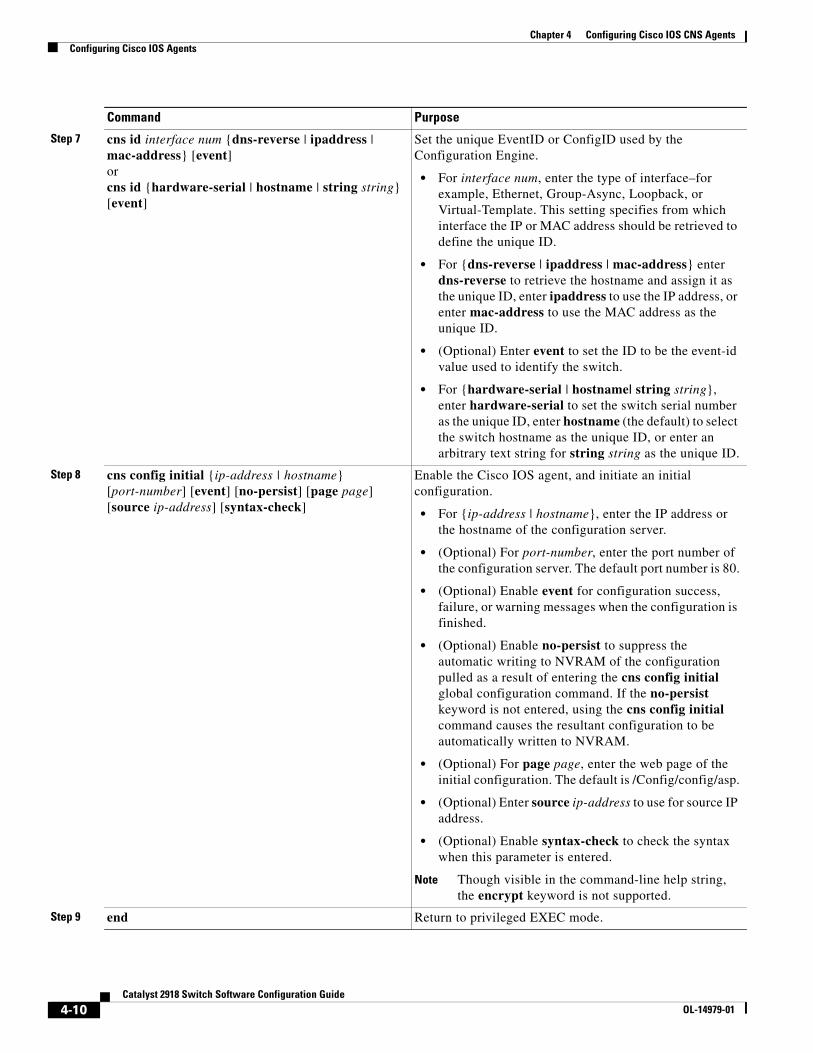
Chapter 4 Configuring Cisco IOS CNS AgentsConfiguring Cisco IOS Agents
Step 7 cns id interface num {dns-reverse | ipaddress | mac-address} [event] or cns id {hardware-serial | hostname | string string} [event]
Set the unique EventID or ConfigID used by the Configuration Engine.
• For interface num, enter the type of interface–for example, Ethernet, Group-Async, Loopback, or Virtual-Template. This setting specifies from which interface the IP or MAC address should be retrieved to define the unique ID.
• For {dns-reverse | ipaddress | mac-address} enter dns-reverse to retrieve the hostname and assign it as the unique ID, enter ipaddress to use the IP address, or enter mac-address to use the MAC address as the unique ID.
• (Optional) Enter event to set the ID to be the event-id value used to identify the switch.
• For {hardware-serial | hostname| string string}, enter hardware-serial to set the switch serial number as the unique ID, enter hostname (the default) to select the switch hostname as the unique ID, or enter an arbitrary text string for string string as the unique ID.
Step 8 cns config initial {ip-address | hostname} [port-number] [event] [no-persist] [page page] [source ip-address] [syntax-check]
Enable the Cisco IOS agent, and initiate an initial configuration.
• For {ip-address | hostname}, enter the IP address or the hostname of the configuration server.
• (Optional) For port-number, enter the port number of the configuration server. The default port number is 80.
• (Optional) Enable event for configuration success, failure, or warning messages when the configuration is finished.
• (Optional) Enable no-persist to suppress the automatic writing to NVRAM of the configuration pulled as a result of entering the cns config initial global configuration command. If the no-persist keyword is not entered, using the cns config initial command causes the resultant configuration to be automatically written to NVRAM.
• (Optional) For page page, enter the web page of the initial configuration. The default is /Config/config/asp.
• (Optional) Enter source ip-address to use for source IP address.
• (Optional) Enable syntax-check to check the syntax when this parameter is entered.
Note Though visible in the command-line help string, the encrypt keyword is not supported.
Step 9 end Return to privileged EXEC mode.
Command Purpose
4-10Catalyst 2918 Switch Software Configuration Guide
OL-14979-01
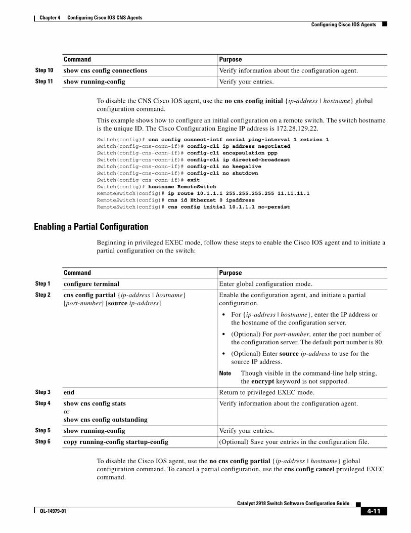
Chapter 4 Configuring Cisco IOS CNS AgentsConfiguring Cisco IOS Agents
To disable the CNS Cisco IOS agent, use the no cns config initial {ip-address | hostname} global configuration command.
This example shows how to configure an initial configuration on a remote switch. The switch hostname is the unique ID. The Cisco Configuration Engine IP address is 172.28.129.22.
Switch(config)# cns config connect-intf serial ping-interval 1 retries 1Switch(config-cns-conn-if)# config-cli ip address negotiatedSwitch(config-cns-conn-if)# config-cli encapsulation pppSwitch(config-cns-conn-if)# config-cli ip directed-broadcastSwitch(config-cns-conn-if)# config-cli no keepaliveSwitch(config-cns-conn-if)# config-cli no shutdownSwitch(config-cns-conn-if)# exitSwitch(config)# hostname RemoteSwitchRemoteSwitch(config)# ip route 10.1.1.1 255.255.255.255 11.11.11.1RemoteSwitch(config)# cns id Ethernet 0 ipaddressRemoteSwitch(config)# cns config initial 10.1.1.1 no-persist
Enabling a Partial Configuration
Beginning in privileged EXEC mode, follow these steps to enable the Cisco IOS agent and to initiate a partial configuration on the switch:
Command Purpose
Step 1 configure terminal Enter global configuration mode.
Step 2 cns config partial {ip-address | hostname} [port-number] [source ip-address]
Enable the configuration agent, and initiate a partial configuration.
• For {ip-address | hostname}, enter the IP address or the hostname of the configuration server.
• (Optional) For port-number, enter the port number of the configuration server. The default port number is 80.
• (Optional) Enter source ip-address to use for the source IP address.
Note Though visible in the command-line help string, the encrypt keyword is not supported.
Step 3 end Return to privileged EXEC mode.
Step 4 show cns config stats or show cns config outstanding
Verify information about the configuration agent.
Step 5 show running-config Verify your entries.
Step 6 copy running-config startup-config (Optional) Save your entries in the configuration file.
To disable the Cisco IOS agent, use the no cns config partial {ip-address | hostname} global configuration command. To cancel a partial configuration, use the cns config cancel privileged EXEC command.
Step 10 show cns config connections Verify information about the configuration agent.
Step 11 show running-config Verify your entries.
Command Purpose
4-11Catalyst 2918 Switch Software Configuration Guide
OL-14979-01
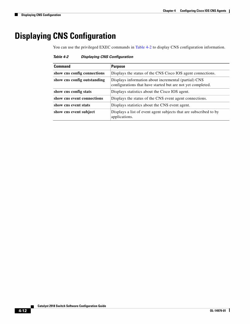
Chapter 4 Configuring Cisco IOS CNS AgentsDisplaying CNS Configuration
Displaying CNS ConfigurationYou can use the privileged EXEC commands in Table 4-2 to display CNS configuration information.
Table 4-2 Displaying CNS Configuration
Command Purpose
show cns config connections Displays the status of the CNS Cisco IOS agent connections.
show cns config outstanding Displays information about incremental (partial) CNS configurations that have started but are not yet completed.
show cns config stats Displays statistics about the Cisco IOS agent.
show cns event connections Displays the status of the CNS event agent connections.
show cns event stats Displays statistics about the CNS event agent.
show cns event subject Displays a list of event agent subjects that are subscribed to by applications.
4-12Catalyst 2918 Switch Software Configuration Guide
OL-14979-01
OL-14979-01
C H A P T E R 5
Clustering SwitchesThis chapter provides the concepts and procedures to create and manage Catalyst 2918 switch clusters. You can create and manage switch clusters by using the command-line interface (CLI) or SNMP. For complete procedures, see the online help. For the CLI cluster commands, see the switch command reference.
This chapter focuses on Catalyst 2918 switch clusters. It also includes guidelines and limitations for clusters mixed with other cluster-capable Catalyst switches, but it does not provide complete descriptions of the cluster features for these other switches. For complete cluster information for a specific Catalyst platform, refer to the software configuration guide for that switch.
This chapter consists of these sections:
• Understanding Switch Clusters, page 5-1
• Planning a Switch Cluster, page 5-4
• Using the CLI to Manage Switch Clusters, page 5-13
• Using SNMP to Manage Switch Clusters, page 5-14
Note We do not recommend using the ip http access-class global configuration command to limit access to specific hosts or networks. Access should be controlled through the cluster command switch.
Understanding Switch ClustersA switch cluster is a set of up to 16 connected, cluster-capable Catalyst switches that are managed as a single entity. The switches in the cluster use the switch clustering technology so that you can configure and troubleshoot a group of different Catalyst desktop switch platforms through a single IP address.
In a switch cluster, 1 switch must be the cluster command switch and up to 15 other switches can be cluster member switches. The total number of switches in a cluster cannot exceed 16 switches. The cluster command switch is the single point of access used to configure, manage, and monitor the cluster member switches. Cluster members can belong to only one cluster at a time.
5-1Catalyst 2918 Switch Software Configuration Guide
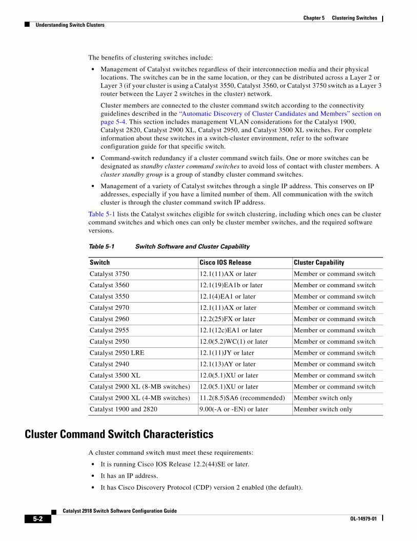
Chapter 5 Clustering SwitchesUnderstanding Switch Clusters
The benefits of clustering switches include:
• Management of Catalyst switches regardless of their interconnection media and their physical locations. The switches can be in the same location, or they can be distributed across a Layer 2 or Layer 3 (if your cluster is using a Catalyst 3550, Catalyst 3560, or Catalyst 3750 switch as a Layer 3 router between the Layer 2 switches in the cluster) network.
Cluster members are connected to the cluster command switch according to the connectivity guidelines described in the “Automatic Discovery of Cluster Candidates and Members” section on page 5-4. This section includes management VLAN considerations for the Catalyst 1900, Catalyst 2820, Catalyst 2900 XL, Catalyst 2950, and Catalyst 3500 XL switches. For complete information about these switches in a switch-cluster environment, refer to the software configuration guide for that specific switch.
• Command-switch redundancy if a cluster command switch fails. One or more switches can be designated as standby cluster command switches to avoid loss of contact with cluster members. A cluster standby group is a group of standby cluster command switches.
• Management of a variety of Catalyst switches through a single IP address. This conserves on IP addresses, especially if you have a limited number of them. All communication with the switch cluster is through the cluster command switch IP address.
Table 5-1 lists the Catalyst switches eligible for switch clustering, including which ones can be cluster command switches and which ones can only be cluster member switches, and the required software versions.
Table 5-1 Switch Software and Cluster Capability
Switch Cisco IOS Release Cluster Capability
Catalyst 3750 12.1(11)AX or later Member or command switch
Catalyst 3560 12.1(19)EA1b or later Member or command switch
Catalyst 3550 12.1(4)EA1 or later Member or command switch
Catalyst 2970 12.1(11)AX or later Member or command switch
Catalyst 2960 12.2(25)FX or later Member or command switch
Catalyst 2955 12.1(12c)EA1 or later Member or command switch
Catalyst 2950 12.0(5.2)WC(1) or later Member or command switch
Catalyst 2950 LRE 12.1(11)JY or later Member or command switch
Catalyst 2940 12.1(13)AY or later Member or command switch
Catalyst 3500 XL 12.0(5.1)XU or later Member or command switch
Catalyst 2900 XL (8-MB switches) 12.0(5.1)XU or later Member or command switch
Catalyst 2900 XL (4-MB switches) 11.2(8.5)SA6 (recommended) Member switch only
Catalyst 1900 and 2820 9.00(-A or -EN) or later Member switch only
Cluster Command Switch CharacteristicsA cluster command switch must meet these requirements:
• It is running Cisco IOS Release 12.2(44)SE or later.
• It has an IP address.
• It has Cisco Discovery Protocol (CDP) version 2 enabled (the default).
5-2Catalyst 2918 Switch Software Configuration Guide
OL-14979-01
Chapter 5 Clustering SwitchesUnderstanding Switch Clusters
• It is not a command or cluster member switch of another cluster.
• It is connected to the standby cluster command switches through the management VLAN and to the cluster member switches through a common VLAN.
Standby Cluster Command Switch CharacteristicsA standby cluster command switch must meet these requirements:
• It is running Cisco IOS 12.2(44)SE or later.
• It has an IP address.
• It has CDP version 2 enabled.
• It is connected to the command switch and to other standby command switches through its management VLAN.
• It is connected to all other cluster member switches (except the cluster command and standby command switches) through a common VLAN.
• It is redundantly connected to the cluster so that connectivity to cluster member switches is maintained.
• It is not a command or member switch of another cluster.
Note Standby cluster command switches must be the same type of switches as the cluster command switch. For example, if the cluster command switch is a Catalyst switch, the standby cluster command switches must also be Catalyst switches. Refer to the switch configuration guide of other cluster-capable switches for their requirements on standby cluster command switches.
Candidate Switch and Cluster Member Switch CharacteristicsCandidate switches are cluster-capable switches that have not yet been added to a cluster. Cluster member switches are switches that have actually been added to a switch cluster. Although not required, a candidate or cluster member switch can have its own IP address and password (for related considerations, see the “IP Addresses” section on page 5-12 and “Passwords” section on page 5-12).
To join a cluster, a candidate switch must meet these requirements:
• It is running cluster-capable software.
• It has CDP version 2 enabled.
• It is not a command or cluster member switch of another cluster.
• If a cluster standby group exists, it is connected to every standby cluster command switch through at least one common VLAN. The VLAN to each standby cluster command switch can be different.
• It is connected to the cluster command switch through at least one common VLAN.
5-3Catalyst 2918 Switch Software Configuration Guide
OL-14979-01
Chapter 5 Clustering SwitchesPlanning a Switch Cluster
Note Catalyst 1900, Catalyst 2820, Catalyst 2900 XL, Catalyst 2950, and Catalyst 3500 XL candidate and cluster member switches must be connected through their management VLAN to the cluster command switch and standby cluster command switches. For complete information about these switches in a switch-cluster environment, refer to the software configuration guide for that specific switch. This requirement does not apply if you have a Catalyst 2970, Catalyst 3550, Catalyst 3560, or Catalyst 3750 cluster command switch. Candidate and cluster member switches can connect through any VLAN in common with the cluster command switch.
Planning a Switch ClusterAnticipating conflicts and compatibility issues is a high priority when you manage several switches through a cluster. This section describes these guidelines, requirements, and caveats that you should understand before you create the cluster:
• Automatic Discovery of Cluster Candidates and Members, page 5-4
• HSRP and Standby Cluster Command Switches, page 5-9
• IP Addresses, page 5-12
• Hostnames, page 5-12
• Passwords, page 5-12
• SNMP Community Strings, page 5-13
• TACACS+ and RADIUS, page 5-13
• LRE Profiles, page 5-13
Refer to the release notes for the list of Catalyst switches eligible for switch clustering, including which ones can be cluster command switches and which ones can only be cluster member switches, and for the required software versions and browser and Java plug-in configurations.
Automatic Discovery of Cluster Candidates and MembersThe cluster command switch uses Cisco Discovery Protocol (CDP) to discover cluster member switches, candidate switches, neighboring switch clusters, and edge devices across multiple VLANs and in star or cascaded topologies.
Note Do not disable CDP on the cluster command switch, on cluster members, or on any cluster-capable switches that you might want a cluster command switch to discover. For more information about CDP, see Chapter 20, “Configuring CDP.”
Following these connectivity guidelines ensures automatic discovery of the switch cluster, cluster candidates, connected switch clusters, and neighboring edge devices:
• Discovery Through CDP Hops, page 5-5
• Discovery Through Non-CDP-Capable and Noncluster-Capable Devices, page 5-5
• Discovery Through Different VLANs, page 5-6
5-4Catalyst 2918 Switch Software Configuration Guide
OL-14979-01
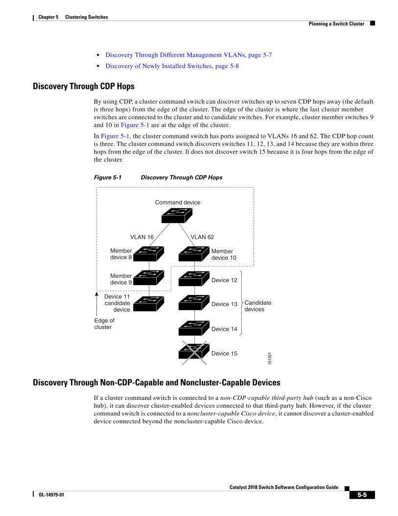
Chapter 5 Clustering SwitchesPlanning a Switch Cluster
• Discovery Through Different Management VLANs, page 5-7
• Discovery of Newly Installed Switches, page 5-8
Discovery Through CDP Hops
By using CDP, a cluster command switch can discover switches up to seven CDP hops away (the default is three hops) from the edge of the cluster. The edge of the cluster is where the last cluster member switches are connected to the cluster and to candidate switches. For example, cluster member switches 9 and 10 in Figure 5-1 are at the edge of the cluster.
In Figure 5-1, the cluster command switch has ports assigned to VLANs 16 and 62. The CDP hop count is three. The cluster command switch discovers switches 11, 12, 13, and 14 because they are within three hops from the edge of the cluster. It does not discover switch 15 because it is four hops from the edge of the cluster.
Figure 5-1 Discovery Through CDP Hops
Command device
Memberdevice 10
Memberdevice 8
Memberdevice 9
VLAN 62
Edge ofcluster
VLAN 16
1013
21
Device 11candidate
deviceCandidatedevices
Device 12
Device 13
Device 14
Device 15
Discovery Through Non-CDP-Capable and Noncluster-Capable Devices
If a cluster command switch is connected to a non-CDP-capable third-party hub (such as a non-Cisco hub), it can discover cluster-enabled devices connected to that third-party hub. However, if the cluster command switch is connected to a noncluster-capable Cisco device, it cannot discover a cluster-enabled device connected beyond the noncluster-capable Cisco device.
5-5Catalyst 2918 Switch Software Configuration Guide
OL-14979-01
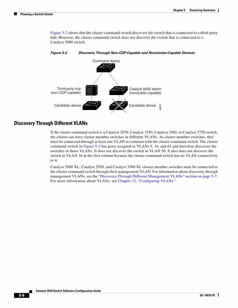
Chapter 5 Clustering SwitchesPlanning a Switch Cluster
Figure 5-2 shows that the cluster command switch discovers the switch that is connected to a third-party hub. However, the cluster command switch does not discover the switch that is connected to a Catalyst 5000 switch.
Figure 5-2 Discovery Through Non-CDP-Capable and Noncluster-Capable Devices
Command device
Catalyst 5000 switch(noncluster-capable)
Third-party hub(non-CDP-capable)
Candidate device Candidate device
8937
7
Discovery Through Different VLANs
If the cluster command switch is a Catalyst 2970, Catalyst 3550, Catalyst 3560, or Catalyst 3750 switch, the cluster can have cluster member switches in different VLANs. As cluster member switches, they must be connected through at least one VLAN in common with the cluster command switch. The cluster command switch in Figure 5-3 has ports assigned to VLANs 9, 16, and 62 and therefore discovers the switches in those VLANs. It does not discover the switch in VLAN 50. It also does not discover the switch in VLAN 16 in the first column because the cluster command switch has no VLAN connectivity to it.
Catalyst 2900 XL, Catalyst 2950, and Catalyst 3500 XL cluster member switches must be connected to the cluster command switch through their management VLAN. For information about discovery through management VLANs, see the “Discovery Through Different Management VLANs” section on page 5-7. For more information about VLANs, see Chapter 12, “Configuring VLANs.”
5-6Catalyst 2918 Switch Software Configuration Guide
OL-14979-01
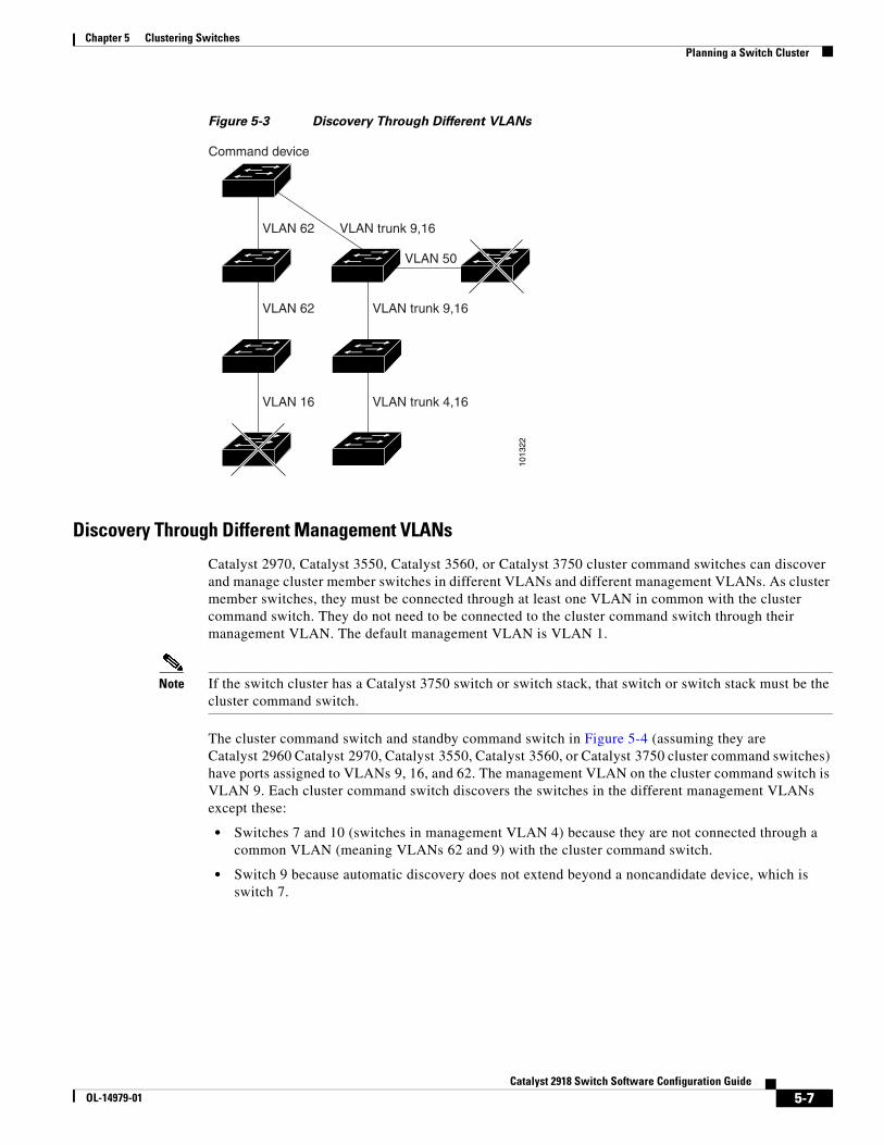
Chapter 5 Clustering SwitchesPlanning a Switch Cluster
Figure 5-3 Discovery Through Different VLANs
VLAN 62
VLAN 62
VLAN 16
VLAN trunk 9,16
Command device
VLAN 50
VLAN trunk 9,16
VLAN trunk 4,16
1013
22Discovery Through Different Management VLANs
Catalyst 2970, Catalyst 3550, Catalyst 3560, or Catalyst 3750 cluster command switches can discover and manage cluster member switches in different VLANs and different management VLANs. As cluster member switches, they must be connected through at least one VLAN in common with the cluster command switch. They do not need to be connected to the cluster command switch through their management VLAN. The default management VLAN is VLAN 1.
Note If the switch cluster has a Catalyst 3750 switch or switch stack, that switch or switch stack must be the cluster command switch.
The cluster command switch and standby command switch in Figure 5-4 (assuming they are Catalyst 2960 Catalyst 2970, Catalyst 3550, Catalyst 3560, or Catalyst 3750 cluster command switches) have ports assigned to VLANs 9, 16, and 62. The management VLAN on the cluster command switch is VLAN 9. Each cluster command switch discovers the switches in the different management VLANs except these:
• Switches 7 and 10 (switches in management VLAN 4) because they are not connected through a common VLAN (meaning VLANs 62 and 9) with the cluster command switch.
• Switch 9 because automatic discovery does not extend beyond a noncandidate device, which is switch 7.
5-7Catalyst 2918 Switch Software Configuration Guide
OL-14979-01
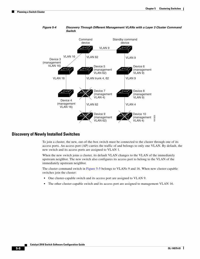
Chapter 5 Clustering SwitchesPlanning a Switch Cluster
Figure 5-4 Discovery Through Different Management VLANs with a Layer 3 Cluster Command
Switch
1013
23
VLAN 62
VLAN trunk 4, 62
VLAN 62
VLAN 16
VLAN 9
VLAN 16 VLAN 9
Standby commanddevice
Commanddevice
VLAN 9
Device 7(managementVLAN 4)
Device 9(managementVLAN 62)
VLAN 4
Device 3(management
VLAN 16)
Device 4(management
VLAN 16)
Device 10(managementVLAN 4)
Device 8(managementVLAN 9)
Device 6(managementVLAN 9)
Device 5(managementVLAN 62)
Discovery of Newly Installed Switches
To join a cluster, the new, out-of-the-box switch must be connected to the cluster through one of its access ports. An access port (AP) carries the traffic of and belongs to only one VLAN. By default, the new switch and its access ports are assigned to VLAN 1.
When the new switch joins a cluster, its default VLAN changes to the VLAN of the immediately upstream neighbor. The new switch also configures its access port to belong to the VLAN of the immediately upstream neighbor.
The cluster command switch in Figure 5-5 belongs to VLANs 9 and 16. When new cluster-capable switches join the cluster:
• One cluster-capable switch and its access port are assigned to VLAN 9.
• The other cluster-capable switch and its access port are assigned to management VLAN 16.
5-8Catalyst 2918 Switch Software Configuration Guide
OL-14979-01
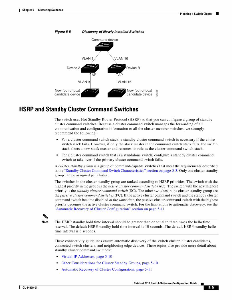
Chapter 5 Clustering SwitchesPlanning a Switch Cluster
Figure 5-5 Discovery of Newly Installed Switches
Command device
New (out-of-box)candidate device
AP
Device A Device B
VLAN 9
VLAN 9
VLAN 16
VLAN 16
New (out-of-box)candidate device
AP
1013
25
HSRP and Standby Cluster Command SwitchesThe switch uses Hot Standby Router Protocol (HSRP) so that you can configure a group of standby cluster command switches. Because a cluster command switch manages the forwarding of all communication and configuration information to all the cluster member switches, we strongly recommend the following:
• For a cluster command switch stack, a standby cluster command switch is necessary if the entire switch stack fails. However, if only the stack master in the command switch stack fails, the switch stack elects a new stack master and resumes its role as the cluster command switch stack.
• For a cluster command switch that is a standalone switch, configure a standby cluster command switch to take over if the primary cluster command switch fails.
A cluster standby group is a group of command-capable switches that meet the requirements described in the “Standby Cluster Command Switch Characteristics” section on page 5-3. Only one cluster standby group can be assigned per cluster.
The switches in the cluster standby group are ranked according to HSRP priorities. The switch with the highest priority in the group is the active cluster command switch (AC). The switch with the next highest priority is the standby cluster command switch (SC). The other switches in the cluster standby group are the passive cluster command switches (PC). If the active cluster command switch and the standby cluster command switch become disabled at the same time, the passive cluster command switch with the highest priority becomes the active cluster command switch. For the limitations to automatic discovery, see the “Automatic Recovery of Cluster Configuration” section on page 5-11.
Note The HSRP standby hold time interval should be greater than or equal to three times the hello time interval. The default HSRP standby hold time interval is 10 seconds. The default HSRP standby hello time interval is 3 seconds.
These connectivity guidelines ensure automatic discovery of the switch cluster, cluster candidates, connected switch clusters, and neighboring edge devices. These topics also provide more detail about standby cluster command switches:
• Virtual IP Addresses, page 5-10
• Other Considerations for Cluster Standby Groups, page 5-10
• Automatic Recovery of Cluster Configuration, page 5-11
5-9Catalyst 2918 Switch Software Configuration Guide
OL-14979-01
Chapter 5 Clustering SwitchesPlanning a Switch Cluster
Virtual IP Addresses
You need to assign a unique virtual IP address and group number and name to the cluster standby group. This information must be configured on a specific VLAN or routed port on the active cluster command switch. The active cluster command switch receives traffic destined for the virtual IP address. To manage the cluster, you must access the active cluster command switch through the virtual IP address, not through the command-switch IP address. This is in case the IP address of the active cluster command switch is different from the virtual IP address of the cluster standby group.
If the active cluster command switch fails, the standby cluster command switch assumes ownership of the virtual IP address and becomes the active cluster command switch. The passive switches in the cluster standby group compare their assigned priorities to decide the new standby cluster command switch. The passive standby switch with the highest priority then becomes the standby cluster command switch. When the previously active cluster command switch becomes active again, it resumes its role as the active cluster command switch, and the current active cluster command switch becomes the standby cluster command switch again. For more information about IP address in switch clusters, see the “IP Addresses” section on page 5-12.
Other Considerations for Cluster Standby Groups
These requirements also apply:
• Standby cluster command switches must be the same type of switches as the cluster command switch. For example, if the cluster command switch is a Catalyst 2918 switch, the standby cluster command switches must also be Catalyst 2918 switches. Refer to the switch configuration guide of other cluster-capable switches for their requirements on standby cluster command switches.
If your switch cluster has a Catalyst 3750 switch, it should be the cluster command switch.
• Only one cluster standby group can be assigned to a cluster. You can have more than one router-redundancy standby group.
• All standby-group members must be members of the cluster.
Note There is no limit to the number of switches that you can assign as standby cluster command switches. However, the total number of switches in the cluster—which would include the active cluster command switch, standby-group members, and cluster member switches—cannot be more than 16.
• Each standby-group member (Figure 5-6) must be connected to the cluster command switch through the same VLAN. In this example, the cluster command switch and standby cluster command switches are Catalyst 2970, Catalyst 3550, Catalyst 3560, or Catalyst 3750 cluster command switches. Each standby-group member must also be redundantly connected to each other through at least one VLAN in common with the switch cluster.
Catalyst 1900, Catalyst 2820, Catalyst 2900 XL, Catalyst 2950, and Catalyst 3500 XL cluster member switches must be connected to the cluster standby group through their management VLANs. For more information about VLANs in switch clusters, see these sections:
– “Discovery Through Different VLANs” section on page 5-6
– “Discovery Through Different Management VLANs” section on page 5-7
5-10Catalyst 2918 Switch Software Configuration Guide
OL-14979-01
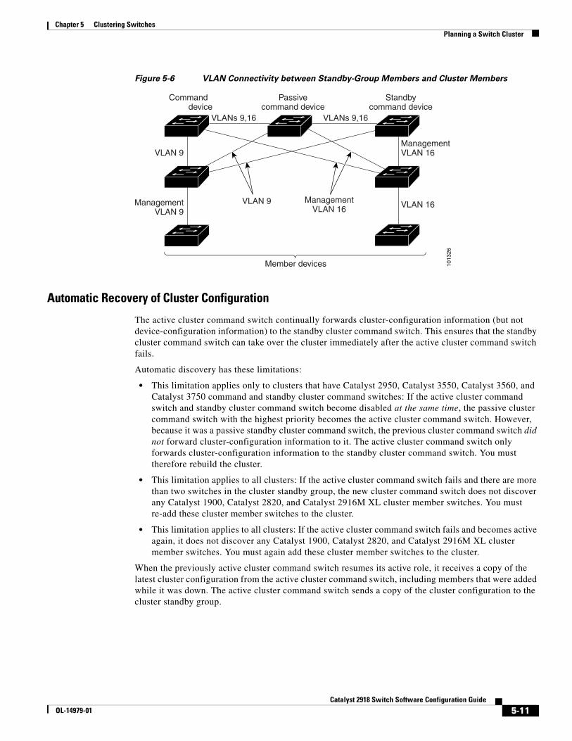
Chapter 5 Clustering SwitchesPlanning a Switch Cluster
Figure 5-6 VLAN Connectivity between Standby-Group Members and Cluster Members
1013
26
ManagementVLAN 16
Standbycommand device
VLAN 16VLAN 9
VLAN 9
Commanddevice
Passivecommand device
Member devices
ManagementVLAN 9
VLANs 9,16 VLANs 9,16
ManagementVLAN 16
Automatic Recovery of Cluster Configuration
The active cluster command switch continually forwards cluster-configuration information (but not device-configuration information) to the standby cluster command switch. This ensures that the standby cluster command switch can take over the cluster immediately after the active cluster command switch fails.
Automatic discovery has these limitations:
• This limitation applies only to clusters that have Catalyst 2950, Catalyst 3550, Catalyst 3560, and Catalyst 3750 command and standby cluster command switches: If the active cluster command switch and standby cluster command switch become disabled at the same time, the passive cluster command switch with the highest priority becomes the active cluster command switch. However, because it was a passive standby cluster command switch, the previous cluster command switch did not forward cluster-configuration information to it. The active cluster command switch only forwards cluster-configuration information to the standby cluster command switch. You must therefore rebuild the cluster.
• This limitation applies to all clusters: If the active cluster command switch fails and there are more than two switches in the cluster standby group, the new cluster command switch does not discover any Catalyst 1900, Catalyst 2820, and Catalyst 2916M XL cluster member switches. You must re-add these cluster member switches to the cluster.
• This limitation applies to all clusters: If the active cluster command switch fails and becomes active again, it does not discover any Catalyst 1900, Catalyst 2820, and Catalyst 2916M XL cluster member switches. You must again add these cluster member switches to the cluster.
When the previously active cluster command switch resumes its active role, it receives a copy of the latest cluster configuration from the active cluster command switch, including members that were added while it was down. The active cluster command switch sends a copy of the cluster configuration to the cluster standby group.
5-11Catalyst 2918 Switch Software Configuration Guide
OL-14979-01
Chapter 5 Clustering SwitchesPlanning a Switch Cluster
IP AddressesYou must assign IP information to a cluster command switch. You can assign more than one IP address to the cluster command switch, and you can access the cluster through any of the command-switch IP addresses. If you configure a cluster standby group, you must use the standby-group virtual IP address to manage the cluster from the active cluster command switch. Using the virtual IP address ensures that you retain connectivity to the cluster if the active cluster command switch fails and that a standby cluster command switch becomes the active cluster command switch.
If the active cluster command switch fails and the standby cluster command switch takes over, you must either use the standby-group virtual IP address or any of the IP addresses available on the new active cluster command switch to access the cluster.
You can assign an IP address to a cluster-capable switch, but it is not necessary. A cluster member switch is managed and communicates with other cluster member switches through the command-switch IP address. If the cluster member switch leaves the cluster and it does not have its own IP address, you must assign an IP address to manage it as a standalone switch.
For more information about IP addresses, see Chapter 3, “Assigning the Switch IP Address and Default Gateway.”
HostnamesYou do not need to assign a host name to either a cluster command switch or an eligible cluster member. However, a hostname assigned to the cluster command switch can help to identify the switch cluster. The default hostname for the switch is Switch.
If a switch joins a cluster and it does not have a hostname, the cluster command switch appends a unique member number to its own hostname and assigns it sequentially as each switch joins the cluster. The number means the order in which the switch was added to the cluster. For example, a cluster command switch named eng-cluster could name the fifth cluster member eng-cluster-5.
If a switch has a hostname, it retains that name when it joins a cluster and when it leaves the cluster.
If a switch received its hostname from the cluster command switch, was removed from a cluster, was then added to a new cluster, and kept the same member number (such as 5), the switch overwrites the old hostname (such as eng-cluster-5) with the hostname of the cluster command switch in the new cluster (such as mkg-cluster-5). If the switch member number changes in the new cluster (such as 3), the switch retains the previous name (eng-cluster-5).
PasswordsYou do not need to assign passwords to an individual switch if it will be a cluster member. When a switch joins a cluster, it inherits the command-switch password and retains it when it leaves the cluster. If no command-switch password is configured, the cluster member switch inherits a null password. Cluster member switches only inherit the command-switch password.
If you change the member-switch password to be different from the command-switch password and save the change, the switch is not manageable by the cluster command switch until you change the member-switch password to match the command-switch password. Rebooting the member switch does not revert the password back to the command-switch password. We recommend that you do not change the member-switch password after it joins a cluster.
For more information about passwords, see the “Preventing Unauthorized Access to Your Switch” section on page 8-1.
5-12Catalyst 2918 Switch Software Configuration Guide
OL-14979-01
Chapter 5 Clustering SwitchesUsing the CLI to Manage Switch Clusters
For password considerations specific to the Catalyst 1900 and Catalyst 2820 switches, refer to the installation and configuration guides for those switches.
SNMP Community StringsA cluster member switch inherits the command-switch first read-only (RO) and read-write (RW) community strings with @esN appended to the community strings:
• command-switch-readonly-community-string@esN, where N is the member-switch number.
• command-switch-readwrite-community-string@esN, where N is the member-switch number.
If the cluster command switch has multiple read-only or read-write community strings, only the first read-only and read-write strings are propagated to the cluster member switch.
The switches support an unlimited number of community strings and string lengths. For more information about SNMP and community strings, see Chapter 26, “Configuring SNMP.”
For SNMP considerations specific to the Catalyst 1900 and Catalyst 2820 switches, refer to the installation and configuration guides specific to those switches.
TACACS+ and RADIUSIf Terminal Access Controller Access Control System Plus (TACACS+) is configured on a cluster member, it must be configured on all cluster members. Similarly, if RADIUS is configured on a cluster member, it must be configured on all cluster members. Further, the same switch cluster cannot have some members configured with TACACS+ and other members configured with RADIUS.
For more information about TACACS+, see the “Controlling Switch Access with TACACS+” section on page 8-10. For more information about RADIUS, see the “Controlling Switch Access with RADIUS” section on page 8-17.
LRE Profiles A configuration conflict occurs if a switch cluster has Long-Reach Ethernet (LRE) switches that use both private and public profiles. If one LRE switch in a cluster is assigned a public profile, all LRE switches in that cluster must have that same public profile. Before you add an LRE switch to a cluster, make sure that you assign it the same public profile used by other LRE switches in the cluster.
A cluster can have a mix of LRE switches that use different private profiles.
Using the CLI to Manage Switch ClustersYou can configure cluster member switches from the CLI by first logging into the cluster command switch. Enter the rcommand user EXEC command and the cluster member switch number to start a Telnet session (through a console or Telnet connection) and to access the cluster member switch CLI. The command mode changes, and the Cisco IOS commands operate as usual. Enter the exit privileged EXEC command on the cluster member switch to return to the command-switch CLI.
This example shows how to log into member-switch 3 from the command-switch CLI:
switch# rcommand 3
5-13Catalyst 2918 Switch Software Configuration Guide
OL-14979-01
Chapter 5 Clustering SwitchesUsing SNMP to Manage Switch Clusters
If you do not know the member-switch number, enter the show cluster members privileged EXEC command on the cluster command switch. For more information about the rcommand command and all other cluster commands, refer to the switch command reference.
The Telnet session accesses the member-switch CLI at the same privilege level as on the cluster command switch. The Cisco IOS commands then operate as usual. For instructions on configuring the switch for a Telnet session, see the “Disabling Password Recovery” section on page 8-5.
Catalyst 1900 and Catalyst 2820 CLI ConsiderationsIf your switch cluster has Catalyst 1900 and Catalyst 2820 switches running standard edition software, the Telnet session accesses the management console (a menu-driven interface) if the cluster command switch is at privilege level 15. If the cluster command switch is at privilege level 1 to 14, you are prompted for the password to access the menu console.
Command-switch privilege levels map to the Catalyst 1900 and Catalyst 2820 cluster member switches running standard and Enterprise Edition Software as follows:
• If the command-switch privilege level is 1 to 14, the cluster member switch is accessed at privilege level 1.
• If the command-switch privilege level is 15, the cluster member switch is accessed at privilege level 15.
Note The Catalyst 1900 and Catalyst 2820 CLI is available only on switches running Enterprise Edition Software.
For more information about the Catalyst 1900 and Catalyst 2820 switches, refer to the installation and configuration guides for those switches.
Using SNMP to Manage Switch ClustersWhen you first power on the switch, SNMP is enabled if you enter the IP information by using the setup program and accept its proposed configuration. If you did not use the setup program to enter the IP information and SNMP was not enabled, you can enable it as described in the “Configuring SNMP” section on page 26-6. On Catalyst 1900 and Catalyst 2820 switches, SNMP is enabled by default.
When you create a cluster, the cluster command switch manages the exchange of messages between cluster member switches and an SNMP application. The cluster software on the cluster command switch appends the cluster member switch number (@esN, where N is the switch number) to the first configured read-write and read-only community strings on the cluster command switch and propagates them to the cluster member switch. The cluster command switch uses this community string to control the forwarding of gets, sets, and get-next messages between the SNMP management station and the cluster member switches.
Note When a cluster standby group is configured, the cluster command switch can change without your knowledge. Use the first read-write and read-only community strings to communicate with the cluster command switch if there is a cluster standby group configured for the cluster.
5-14Catalyst 2918 Switch Software Configuration Guide
OL-14979-01
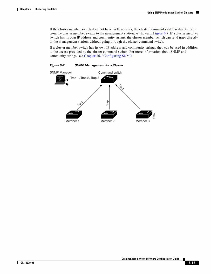
Chapter 5 Clustering SwitchesUsing SNMP to Manage Switch Clusters
If the cluster member switch does not have an IP address, the cluster command switch redirects traps from the cluster member switch to the management station, as shown in Figure 5-7. If a cluster member switch has its own IP address and community strings, the cluster member switch can send traps directly to the management station, without going through the cluster command switch.
If a cluster member switch has its own IP address and community strings, they can be used in addition to the access provided by the cluster command switch. For more information about SNMP and community strings, see Chapter 26, “Configuring SNMP.”
Figure 5-7 SNMP Management for a Cluster
Trap
Trap
Trap
Command switch
Trap 1, Trap 2, Trap 3
Member 1 Member 2 Member 3
3302
0
SNMP Manager
5-15Catalyst 2918 Switch Software Configuration Guide
OL-14979-01

Chapter 5 Clustering SwitchesUsing SNMP to Manage Switch Clusters
5-16Catalyst 2918 Switch Software Configuration Guide
OL-14979-01
OL-14979-01
C H A P T E R 6
Configuring SDM TemplatesThis chapter describes how to configure the Switch Database Management (SDM) templates on the Catalyst 2918 switch.
Note For complete syntax and usage information for the commands used in this chapter, see the command reference for this release.
This chapter consists of these sections:
• Understanding the SDM Templates, page 6-1
• Configuring the Switch SDM Template, page 6-2
• Displaying the SDM Templates, page 6-3
Understanding the SDM TemplatesYou can use SDM templates to configure system resources in the switch to optimize support for specific features, depending on how the switch is used in the network. You can select a template to provide maximum system usage for some functions or use the default template to balance resources.
To allocate ternary content addressable memory (TCAM) resources for different usages, the switch SDM templates prioritize system resources to optimize support for certain features. You can select SDM templates to optimize these features:
• QoS—The QoS template maximizes system resources for quality of service (QoS) access control entries (ACEs).
• Default—The default template gives balance to all functions.
Table 6-1 lists the approximate numbers of each resource supported in each template.
Table 6-1 Approximate Number of Feature Resources Allowed by Each Template
Resource Default QoS
Unicast MAC addresses 8 K 8 K
IPv4 IGMP groups 256 256
IPv4 MAC QoS ACEs 128 384
IPv4 MAC security ACEs 384 128
6-1Catalyst 2918 Switch Software Configuration Guide
Chapter 6 Configuring SDM TemplatesConfiguring the Switch SDM Template
The rows in the tables represent approximate hardware boundaries set when a template is selected. If a section of a hardware resource is full, all processing overflow is sent to the CPU, seriously impacting switch performance.
Configuring the Switch SDM TemplateThese sections contain this configuration information:
• Default SDM Template, page 6-2
• SDM Template Configuration Guidelines, page 6-2
• Setting the SDM Template, page 6-2
Default SDM TemplateThe default template is the default.
SDM Template Configuration GuidelinesWhen you select and configure SDM templates, you must reload the switch for the configuration to take effect.
Setting the SDM TemplateBeginning in privileged EXEC mode, follow these steps to use the SDM template to maximize feature usage:
Command Purpose
Step 1 configure terminal Enter global configuration mode.
Step 2 sdm prefer {default | qos} Specify the SDM template to be used on the switch:
The keywords have these meanings:
• default—Gives balance to all functions.
• qos—Maximizes system resources for QoS ACEs.
Use the no sdm prefer command to set the switch to the default template.
The default template balances the use of system resources.
Step 3 end Return to privileged EXEC mode.
Step 4 reload Reload the operating system.
After the system reboots, you can use the show sdm prefer privileged EXEC command to verify the new template configuration. If you enter the show sdm prefer command before you enter the reload privileged EXEC command, the show sdm prefer command shows the template currently in use and the template that will become active after a reload.
6-2Catalyst 2918 Switch Software Configuration Guide
OL-14979-01

Chapter 6 Configuring SDM TemplatesDisplaying the SDM Templates
Displaying the SDM TemplatesUse the show sdm prefer privileged EXEC command with no parameters to display the active template.
Use the show sdm prefer [default | qos] privileged EXEC command to display the resource numbers supported by the specified template.
6-3Catalyst 2918 Switch Software Configuration Guide
OL-14979-01

Chapter 6 Configuring SDM TemplatesDisplaying the SDM Templates
6-4Catalyst 2918 Switch Software Configuration Guide
OL-14979-01
OL-14979-01
C H A P T E R 7
Administering the SwitchThis chapter describes how to perform one-time operations to administer the Catalyst 2918 switch.
This chapter consists of these sections:
• Managing the System Time and Date, page 7-1
• Configuring a System Name and Prompt, page 7-14
• Creating a Banner, page 7-17
• Managing the MAC Address Table, page 7-19
• Managing the ARP Table, page 7-26
Managing the System Time and DateYou can manage the system time and date on your switch using automatic configuration, such as the Network Time Protocol (NTP), or manual configuration methods.
Note For complete syntax and usage information for the commands used in this section, see the Cisco IOS Configuration Fundamentals Command Reference, Release 12.2.
These sections contain this configuration information:
• Understanding the System Clock, page 7-1
• Understanding Network Time Protocol, page 7-2
• Configuring NTP, page 7-3
• Configuring Time and Date Manually, page 7-11
Understanding the System Clock The heart of the time service is the system clock. This clock runs from the moment the system starts up and keeps track of the date and time.
The system clock can then be set from these sources:
• NTP
• Manual configuration
7-1Catalyst 2918 Switch Software Configuration Guide
Chapter 7 Administering the SwitchManaging the System Time and Date
The system clock can provide time to these services:
• User show commands
• Logging and debugging messages
The system clock keeps track of time internally based on Universal Time Coordinated (UTC), also known as Greenwich Mean Time (GMT). You can configure information about the local time zone and summer time (daylight saving time) so that the time appears correctly for the local time zone.
The system clock keeps track of whether the time is authoritative or not (that is, whether it has been set by a time source considered to be authoritative). If it is not authoritative, the time is available only for display purposes and is not redistributed. For configuration information, see the “Configuring Time and Date Manually” section on page 7-11.
Understanding Network Time ProtocolThe NTP is designed to time-synchronize a network of devices. NTP runs over User Datagram Protocol (UDP), which runs over IP. NTP is documented in RFC 1305.
An NTP network usually gets its time from an authoritative time source, such as a radio clock or an atomic clock attached to a time server. NTP then distributes this time across the network. NTP is extremely efficient; no more than one packet per minute is necessary to synchronize two devices to within a millisecond of one another.
NTP uses the concept of a stratum to describe how many NTP hops away a device is from an authoritative time source. A stratum 1 time server has a radio or atomic clock directly attached, a stratum 2 time server receives its time through NTP from a stratum 1 time server, and so on. A device running NTP automatically chooses as its time source the device with the lowest stratum number with which it communicates through NTP. This strategy effectively builds a self-organizing tree of NTP speakers.
NTP avoids synchronizing to a device whose time might not be accurate by never synchronizing to a device that is not synchronized. NTP also compares the time reported by several devices and does not synchronize to a device whose time is significantly different than the others, even if its stratum is lower.
The communications between devices running NTP (known as associations) are usually statically configured; each device is given the IP address of all devices with which it should form associations. Accurate timekeeping is possible by exchanging NTP messages between each pair of devices with an association. However, in a LAN environment, NTP can be configured to use IP broadcast messages instead. This alternative reduces configuration complexity because each device can simply be configured to send or receive broadcast messages. However, in that case, information flow is one-way only.
The time kept on a device is a critical resource; you should use the security features of NTP to avoid the accidental or malicious setting of an incorrect time. Two mechanisms are available: an access list-based restriction scheme and an encrypted authentication mechanism.
Cisco’s implementation of NTP does not support stratum 1 service; it is not possible to connect to a radio or atomic clock. We recommend that the time service for your network be derived from the public NTP servers available on the IP Internet.
7-2Catalyst 2918 Switch Software Configuration Guide
OL-14979-01
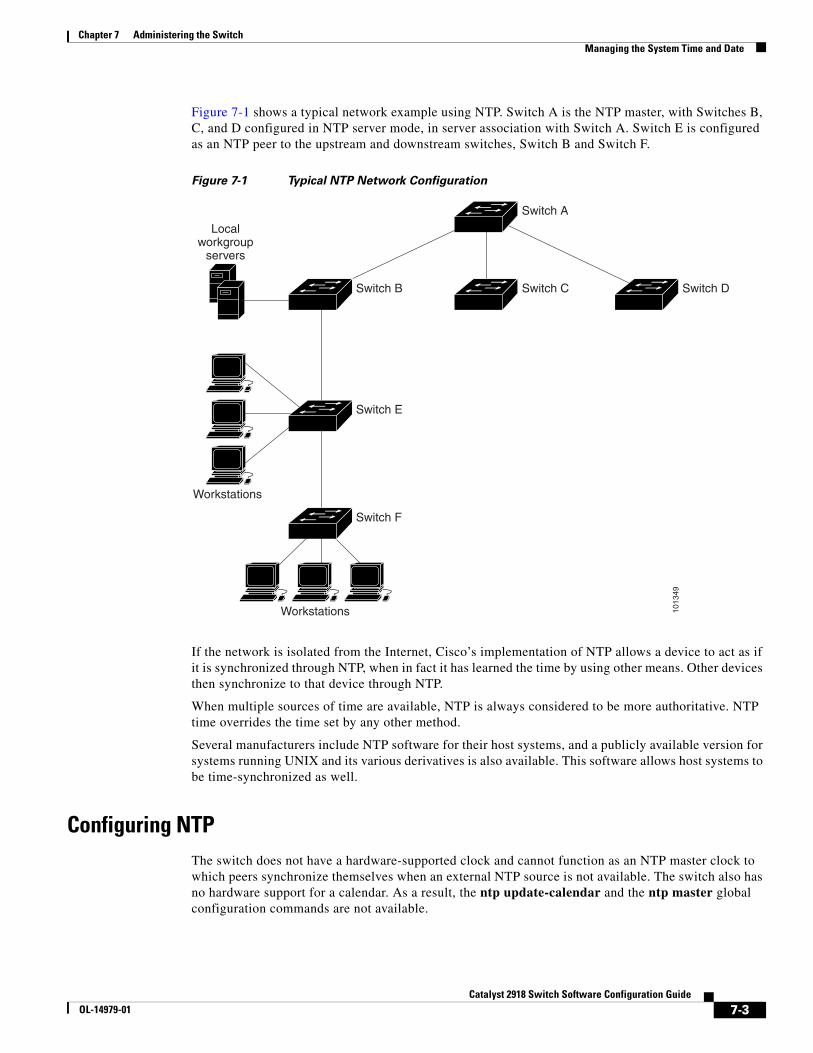
Chapter 7 Administering the SwitchManaging the System Time and Date
Figure 7-1 shows a typical network example using NTP. Switch A is the NTP master, with Switches B, C, and D configured in NTP server mode, in server association with Switch A. Switch E is configured as an NTP peer to the upstream and downstream switches, Switch B and Switch F.
Figure 7-1 Typical NTP Network Configuration
Switch F
Switch A
Workstations
Workstations
Localworkgroup
servers
1013
49
Switch B
Switch E
Switch C Switch D
If the network is isolated from the Internet, Cisco’s implementation of NTP allows a device to act as if it is synchronized through NTP, when in fact it has learned the time by using other means. Other devices then synchronize to that device through NTP.
When multiple sources of time are available, NTP is always considered to be more authoritative. NTP time overrides the time set by any other method.
Several manufacturers include NTP software for their host systems, and a publicly available version for systems running UNIX and its various derivatives is also available. This software allows host systems to be time-synchronized as well.
Configuring NTPThe switch does not have a hardware-supported clock and cannot function as an NTP master clock to which peers synchronize themselves when an external NTP source is not available. The switch also has no hardware support for a calendar. As a result, the ntp update-calendar and the ntp master global configuration commands are not available.
7-3Catalyst 2918 Switch Software Configuration Guide
OL-14979-01
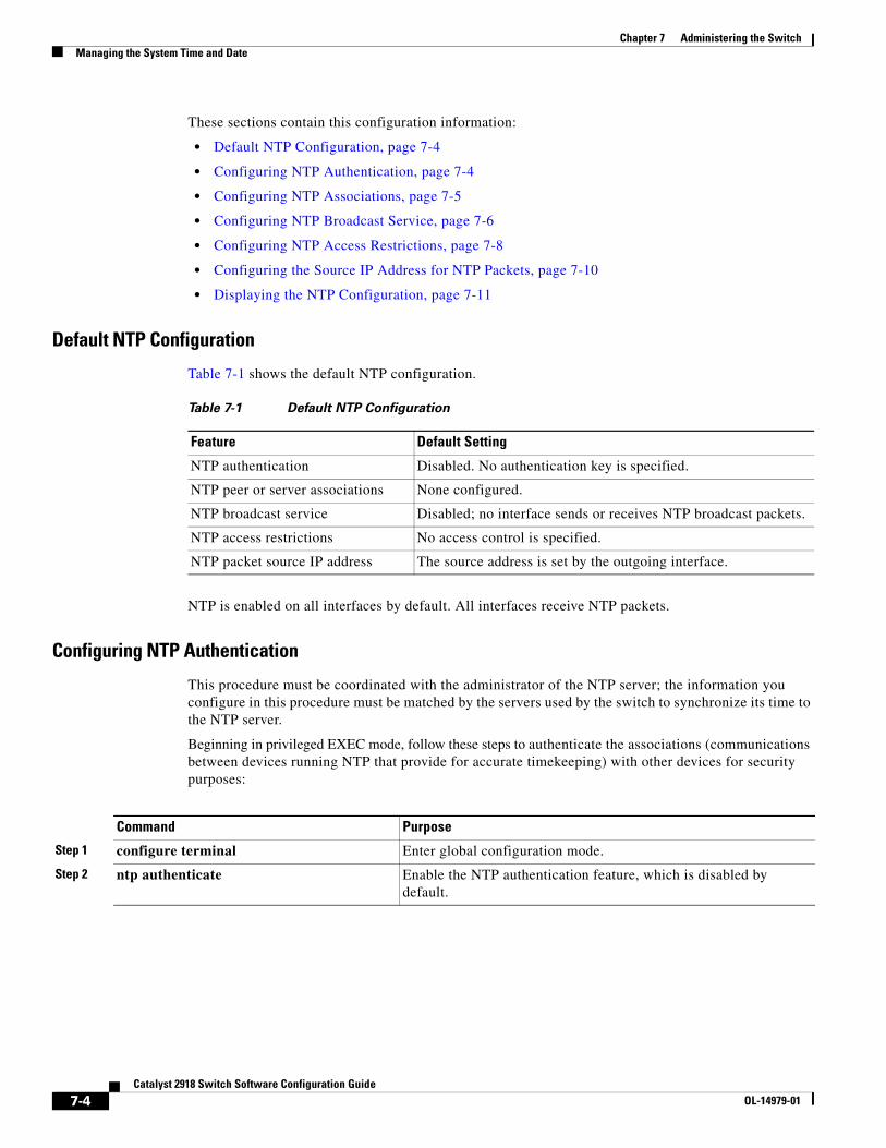
Chapter 7 Administering the SwitchManaging the System Time and Date
These sections contain this configuration information:
• Default NTP Configuration, page 7-4
• Configuring NTP Authentication, page 7-4
• Configuring NTP Associations, page 7-5
• Configuring NTP Broadcast Service, page 7-6
• Configuring NTP Access Restrictions, page 7-8
• Configuring the Source IP Address for NTP Packets, page 7-10
• Displaying the NTP Configuration, page 7-11
Default NTP Configuration
Table 7-1 shows the default NTP configuration.
Table 7-1 Default NTP Configuration
Feature Default Setting
NTP authentication Disabled. No authentication key is specified.
NTP peer or server associations None configured.
NTP broadcast service Disabled; no interface sends or receives NTP broadcast packets.
NTP access restrictions No access control is specified.
NTP packet source IP address The source address is set by the outgoing interface.
NTP is enabled on all interfaces by default. All interfaces receive NTP packets.
Configuring NTP Authentication
This procedure must be coordinated with the administrator of the NTP server; the information you configure in this procedure must be matched by the servers used by the switch to synchronize its time to the NTP server.
Beginning in privileged EXEC mode, follow these steps to authenticate the associations (communications between devices running NTP that provide for accurate timekeeping) with other devices for security purposes:
Command Purpose
Step 1 configure terminal Enter global configuration mode.
Step 2 ntp authenticate Enable the NTP authentication feature, which is disabled by default.
7-4Catalyst 2918 Switch Software Configuration Guide
OL-14979-01
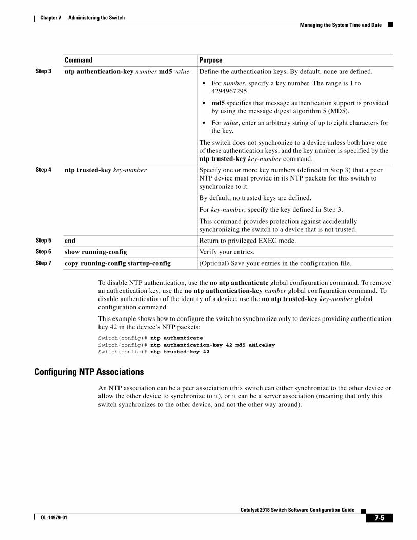
Chapter 7 Administering the SwitchManaging the System Time and Date
To disable NTP authentication, use the no ntp authenticate global configuration command. To remove an authentication key, use the no ntp authentication-key number global configuration command. To disable authentication of the identity of a device, use the no ntp trusted-key key-number global configuration command.
This example shows how to configure the switch to synchronize only to devices providing authentication key 42 in the device’s NTP packets:
Switch(config)# ntp authenticateSwitch(config)# ntp authentication-key 42 md5 aNiceKeySwitch(config)# ntp trusted-key 42
Configuring NTP Associations
An NTP association can be a peer association (this switch can either synchronize to the other device or allow the other device to synchronize to it), or it can be a server association (meaning that only this switch synchronizes to the other device, and not the other way around).
Step 3 ntp authentication-key number md5 value Define the authentication keys. By default, none are defined.
• For number, specify a key number. The range is 1 to 4294967295.
• md5 specifies that message authentication support is provided by using the message digest algorithm 5 (MD5).
• For value, enter an arbitrary string of up to eight characters for the key.
The switch does not synchronize to a device unless both have one of these authentication keys, and the key number is specified by the ntp trusted-key key-number command.
Step 4 ntp trusted-key key-number Specify one or more key numbers (defined in Step 3) that a peer NTP device must provide in its NTP packets for this switch to synchronize to it.
By default, no trusted keys are defined.
For key-number, specify the key defined in Step 3.
This command provides protection against accidentally synchronizing the switch to a device that is not trusted.
Step 5 end Return to privileged EXEC mode.
Step 6 show running-config Verify your entries.
Step 7 copy running-config startup-config (Optional) Save your entries in the configuration file.
Command Purpose
7-5Catalyst 2918 Switch Software Configuration Guide
OL-14979-01
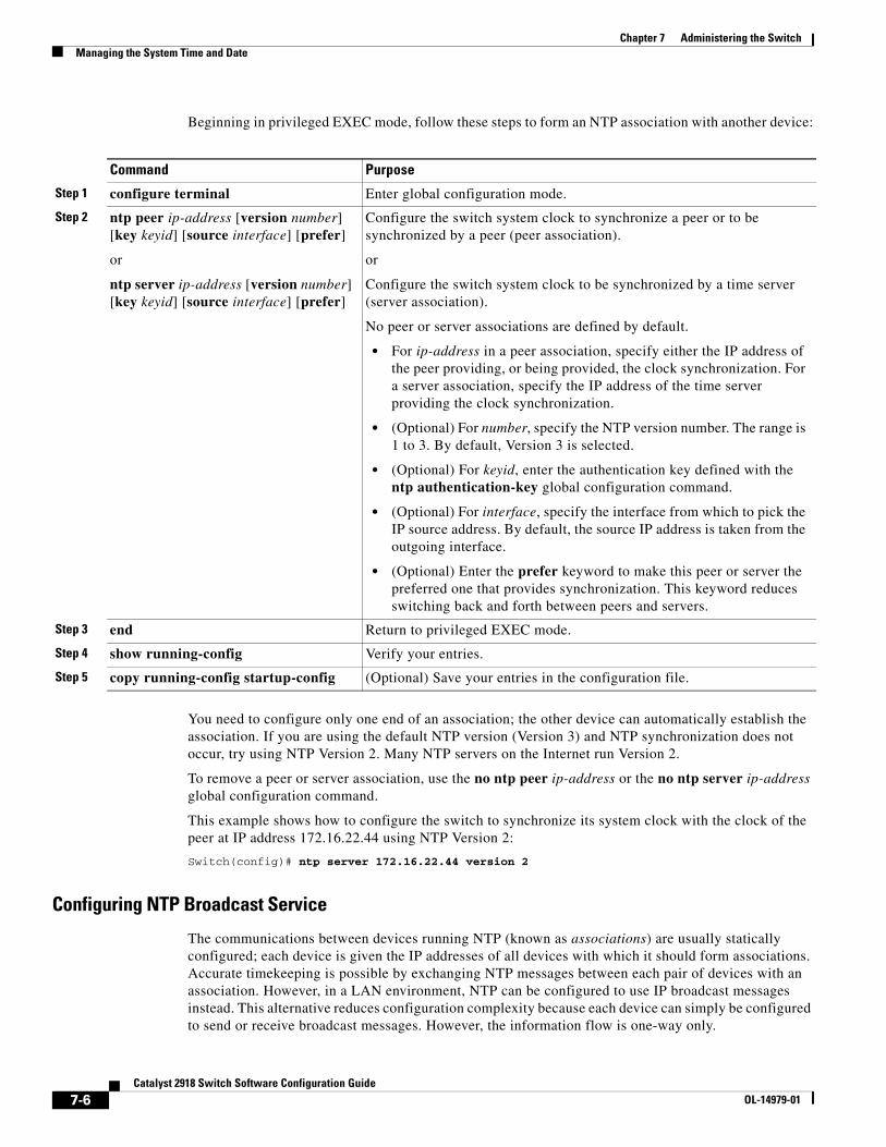
Chapter 7 Administering the SwitchManaging the System Time and Date
Beginning in privileged EXEC mode, follow these steps to form an NTP association with another device:
Command Purpose
Step 1 configure terminal Enter global configuration mode.
Step 2 ntp peer ip-address [version number] [key keyid] [source interface] [prefer]
or
ntp server ip-address [version number] [key keyid] [source interface] [prefer]
Configure the switch system clock to synchronize a peer or to be synchronized by a peer (peer association).
or
Configure the switch system clock to be synchronized by a time server (server association).
No peer or server associations are defined by default.
• For ip-address in a peer association, specify either the IP address of the peer providing, or being provided, the clock synchronization. For a server association, specify the IP address of the time server providing the clock synchronization.
• (Optional) For number, specify the NTP version number. The range is 1 to 3. By default, Version 3 is selected.
• (Optional) For keyid, enter the authentication key defined with the ntp authentication-key global configuration command.
• (Optional) For interface, specify the interface from which to pick the IP source address. By default, the source IP address is taken from the outgoing interface.
• (Optional) Enter the prefer keyword to make this peer or server the preferred one that provides synchronization. This keyword reduces switching back and forth between peers and servers.
Step 3 end Return to privileged EXEC mode.
Step 4 show running-config Verify your entries.
Step 5 copy running-config startup-config (Optional) Save your entries in the configuration file.
You need to configure only one end of an association; the other device can automatically establish the association. If you are using the default NTP version (Version 3) and NTP synchronization does not occur, try using NTP Version 2. Many NTP servers on the Internet run Version 2.
To remove a peer or server association, use the no ntp peer ip-address or the no ntp server ip-address global configuration command.
This example shows how to configure the switch to synchronize its system clock with the clock of the peer at IP address 172.16.22.44 using NTP Version 2:
Switch(config)# ntp server 172.16.22.44 version 2
Configuring NTP Broadcast Service
The communications between devices running NTP (known as associations) are usually statically configured; each device is given the IP addresses of all devices with which it should form associations. Accurate timekeeping is possible by exchanging NTP messages between each pair of devices with an association. However, in a LAN environment, NTP can be configured to use IP broadcast messages instead. This alternative reduces configuration complexity because each device can simply be configured to send or receive broadcast messages. However, the information flow is one-way only.
7-6Catalyst 2918 Switch Software Configuration Guide
OL-14979-01

Chapter 7 Administering the SwitchManaging the System Time and Date
The switch can send or receive NTP broadcast packets on an interface-by-interface basis if there is an NTP broadcast server, such as a router, broadcasting time information on the network. The switch can send NTP broadcast packets to a peer so that the peer can synchronize to it. The switch can also receive NTP broadcast packets to synchronize its own clock. This section provides procedures for both sending and receiving NTP broadcast packets.
Beginning in privileged EXEC mode, follow these steps to configure the switch to send NTP broadcast packets to peers so that they can synchronize their clock to the switch:
Command Purpose
Step 1 configure terminal Enter global configuration mode.
Step 2 interface interface-id Specify the interface to send NTP broadcast packets, and enter interface configuration mode.
Step 3 ntp broadcast [version number] [key keyid] [destination-address]
Enable the interface to send NTP broadcast packets to a peer.
By default, this feature is disabled on all interfaces.
• (Optional) For number, specify the NTP version number. The range is 1 to 3. If you do not specify a version, Version 3 is used.
• (Optional) For keyid, specify the authentication key to use when sending packets to the peer.
• (Optional) For destination-address, specify the IP address of the peer that is synchronizing its clock to this switch.
Step 4 end Return to privileged EXEC mode.
Step 5 show running-config Verify your entries.
Step 6 copy running-config startup-config (Optional) Save your entries in the configuration file.
Step 7 Configure the connected peers to receive NTP broadcast packets as described in the next procedure.
To disable the interface from sending NTP broadcast packets, use the no ntp broadcast interface configuration command.
This example shows how to configure a port to send NTP Version 2 packets:
Switch(config)# interface gigabitethernet0/1Switch(config-if)# ntp broadcast version 2
Beginning in privileged EXEC mode, follow these steps to configure the switch to receive NTP broadcast packets from connected peers:
Command Purpose
Step 1 configure terminal Enter global configuration mode.
Step 2 interface interface-id Specify the interface to receive NTP broadcast packets, and enter interface configuration mode.
Step 3 ntp broadcast client Enable the interface to receive NTP broadcast packets.
By default, no interfaces receive NTP broadcast packets.
Step 4 exit Return to global configuration mode.
7-7Catalyst 2918 Switch Software Configuration Guide
OL-14979-01
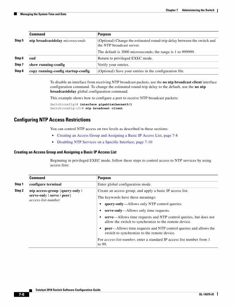
Chapter 7 Administering the SwitchManaging the System Time and Date
To disable an interface from receiving NTP broadcast packets, use the no ntp broadcast client interface configuration command. To change the estimated round-trip delay to the default, use the no ntp broadcastdelay global configuration command.
This example shows how to configure a port to receive NTP broadcast packets:
Switch(config)# interface gigabitethernet0/1Switch(config-if)# ntp broadcast client
Configuring NTP Access Restrictions
You can control NTP access on two levels as described in these sections:
• Creating an Access Group and Assigning a Basic IP Access List, page 7-8
• Disabling NTP Services on a Specific Interface, page 7-10
Creating an Access Group and Assigning a Basic IP Access List
Beginning in privileged EXEC mode, follow these steps to control access to NTP services by using access lists:
Step 5 ntp broadcastdelay microseconds (Optional) Change the estimated round-trip delay between the switch and the NTP broadcast server.
The default is 3000 microseconds; the range is 1 to 999999.
Step 6 end Return to privileged EXEC mode.
Step 7 show running-config Verify your entries.
Step 8 copy running-config startup-config (Optional) Save your entries in the configuration file.
Command Purpose
Command Purpose
Step 1 configure terminal Enter global configuration mode.
Step 2 ntp access-group {query-only | serve-only | serve | peer} access-list-number
Create an access group, and apply a basic IP access list.
The keywords have these meanings:
• query-only—Allows only NTP control queries.
• serve-only—Allows only time requests.
• serve—Allows time requests and NTP control queries, but does not allow the switch to synchronize to the remote device.
• peer—Allows time requests and NTP control queries and allows the switch to synchronize to the remote device.
For access-list-number, enter a standard IP access list number from 1 to 99.
7-8Catalyst 2918 Switch Software Configuration Guide
OL-14979-01
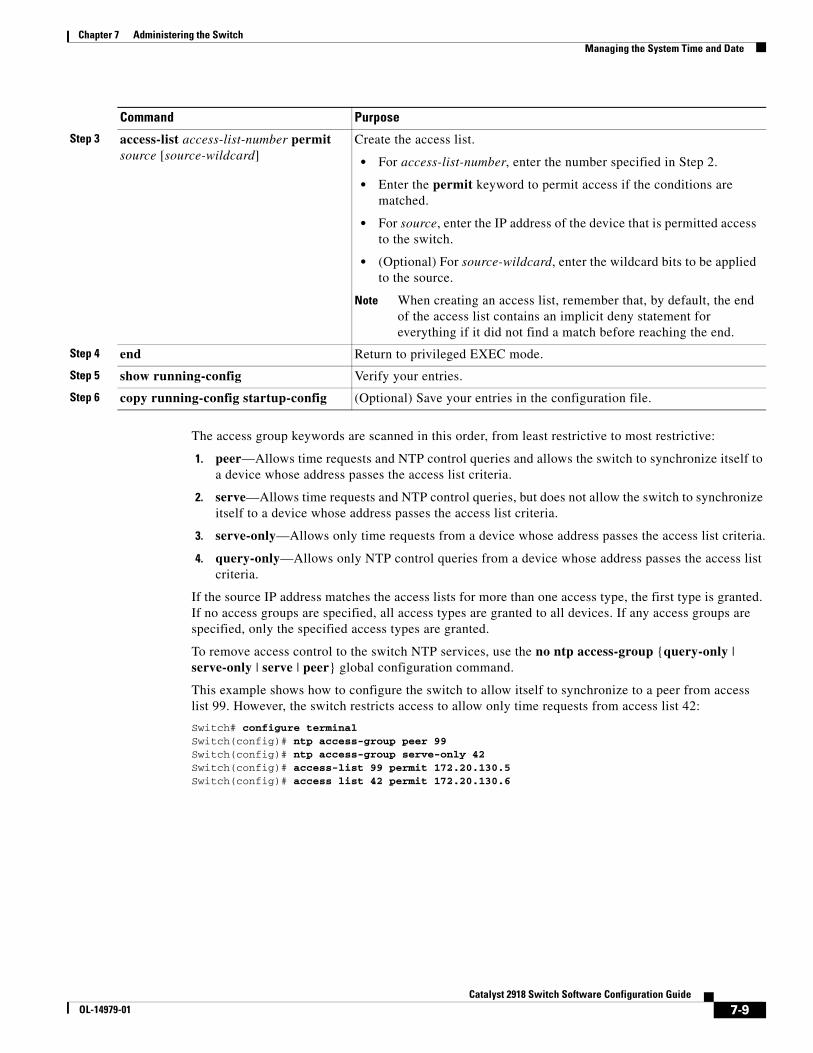
Chapter 7 Administering the SwitchManaging the System Time and Date
The access group keywords are scanned in this order, from least restrictive to most restrictive:
1. peer—Allows time requests and NTP control queries and allows the switch to synchronize itself to a device whose address passes the access list criteria.
2. serve—Allows time requests and NTP control queries, but does not allow the switch to synchronize itself to a device whose address passes the access list criteria.
3. serve-only—Allows only time requests from a device whose address passes the access list criteria.
4. query-only—Allows only NTP control queries from a device whose address passes the access list criteria.
If the source IP address matches the access lists for more than one access type, the first type is granted. If no access groups are specified, all access types are granted to all devices. If any access groups are specified, only the specified access types are granted.
To remove access control to the switch NTP services, use the no ntp access-group {query-only | serve-only | serve | peer} global configuration command.
This example shows how to configure the switch to allow itself to synchronize to a peer from access list 99. However, the switch restricts access to allow only time requests from access list 42:
Switch# configure terminalSwitch(config)# ntp access-group peer 99Switch(config)# ntp access-group serve-only 42Switch(config)# access-list 99 permit 172.20.130.5Switch(config)# access list 42 permit 172.20.130.6
Step 3 access-list access-list-number permit source [source-wildcard]
Create the access list.
• For access-list-number, enter the number specified in Step 2.
• Enter the permit keyword to permit access if the conditions are matched.
• For source, enter the IP address of the device that is permitted access to the switch.
• (Optional) For source-wildcard, enter the wildcard bits to be applied to the source.
Note When creating an access list, remember that, by default, the end of the access list contains an implicit deny statement for everything if it did not find a match before reaching the end.
Step 4 end Return to privileged EXEC mode.
Step 5 show running-config Verify your entries.
Step 6 copy running-config startup-config (Optional) Save your entries in the configuration file.
Command Purpose
7-9Catalyst 2918 Switch Software Configuration Guide
OL-14979-01
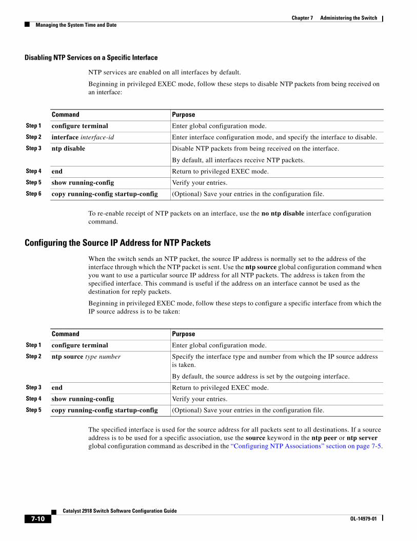
Chapter 7 Administering the SwitchManaging the System Time and Date
Disabling NTP Services on a Specific Interface
NTP services are enabled on all interfaces by default.
Beginning in privileged EXEC mode, follow these steps to disable NTP packets from being received on an interface:
Command Purpose
Step 1 configure terminal Enter global configuration mode.
Step 2 interface interface-id Enter interface configuration mode, and specify the interface to disable.
Step 3 ntp disable Disable NTP packets from being received on the interface.
By default, all interfaces receive NTP packets.
Step 4 end Return to privileged EXEC mode.
Step 5 show running-config Verify your entries.
Step 6 copy running-config startup-config (Optional) Save your entries in the configuration file.
To re-enable receipt of NTP packets on an interface, use the no ntp disable interface configuration command.
Configuring the Source IP Address for NTP Packets
When the switch sends an NTP packet, the source IP address is normally set to the address of the interface through which the NTP packet is sent. Use the ntp source global configuration command when you want to use a particular source IP address for all NTP packets. The address is taken from the specified interface. This command is useful if the address on an interface cannot be used as the destination for reply packets.
Beginning in privileged EXEC mode, follow these steps to configure a specific interface from which the IP source address is to be taken:
Command Purpose
Step 1 configure terminal Enter global configuration mode.
Step 2 ntp source type number Specify the interface type and number from which the IP source address is taken.
By default, the source address is set by the outgoing interface.
Step 3 end Return to privileged EXEC mode.
Step 4 show running-config Verify your entries.
Step 5 copy running-config startup-config (Optional) Save your entries in the configuration file.
The specified interface is used for the source address for all packets sent to all destinations. If a source address is to be used for a specific association, use the source keyword in the ntp peer or ntp server global configuration command as described in the “Configuring NTP Associations” section on page 7-5.
7-10Catalyst 2918 Switch Software Configuration Guide
OL-14979-01
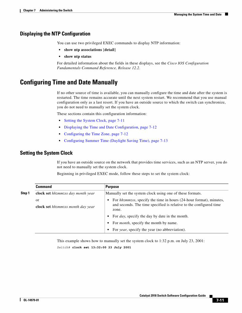
Chapter 7 Administering the SwitchManaging the System Time and Date
Displaying the NTP Configuration
You can use two privileged EXEC commands to display NTP information:
• show ntp associations [detail]
• show ntp status
For detailed information about the fields in these displays, see the Cisco IOS Configuration Fundamentals Command Reference, Release 12.2.
Configuring Time and Date ManuallyIf no other source of time is available, you can manually configure the time and date after the system is restarted. The time remains accurate until the next system restart. We recommend that you use manual configuration only as a last resort. If you have an outside source to which the switch can synchronize, you do not need to manually set the system clock.
These sections contain this configuration information:
• Setting the System Clock, page 7-11
• Displaying the Time and Date Configuration, page 7-12
• Configuring the Time Zone, page 7-12
• Configuring Summer Time (Daylight Saving Time), page 7-13
Setting the System Clock
If you have an outside source on the network that provides time services, such as an NTP server, you do not need to manually set the system clock.
Beginning in privileged EXEC mode, follow these steps to set the system clock:
Command Purpose
Step 1 clock set hh:mm:ss day month year
or
clock set hh:mm:ss month day year
Manually set the system clock using one of these formats.
• For hh:mm:ss, specify the time in hours (24-hour format), minutes, and seconds. The time specified is relative to the configured time zone.
• For day, specify the day by date in the month.
• For month, specify the month by name.
• For year, specify the year (no abbreviation).
This example shows how to manually set the system clock to 1:32 p.m. on July 23, 2001:
Switch# clock set 13:32:00 23 July 2001
7-11Catalyst 2918 Switch Software Configuration Guide
OL-14979-01
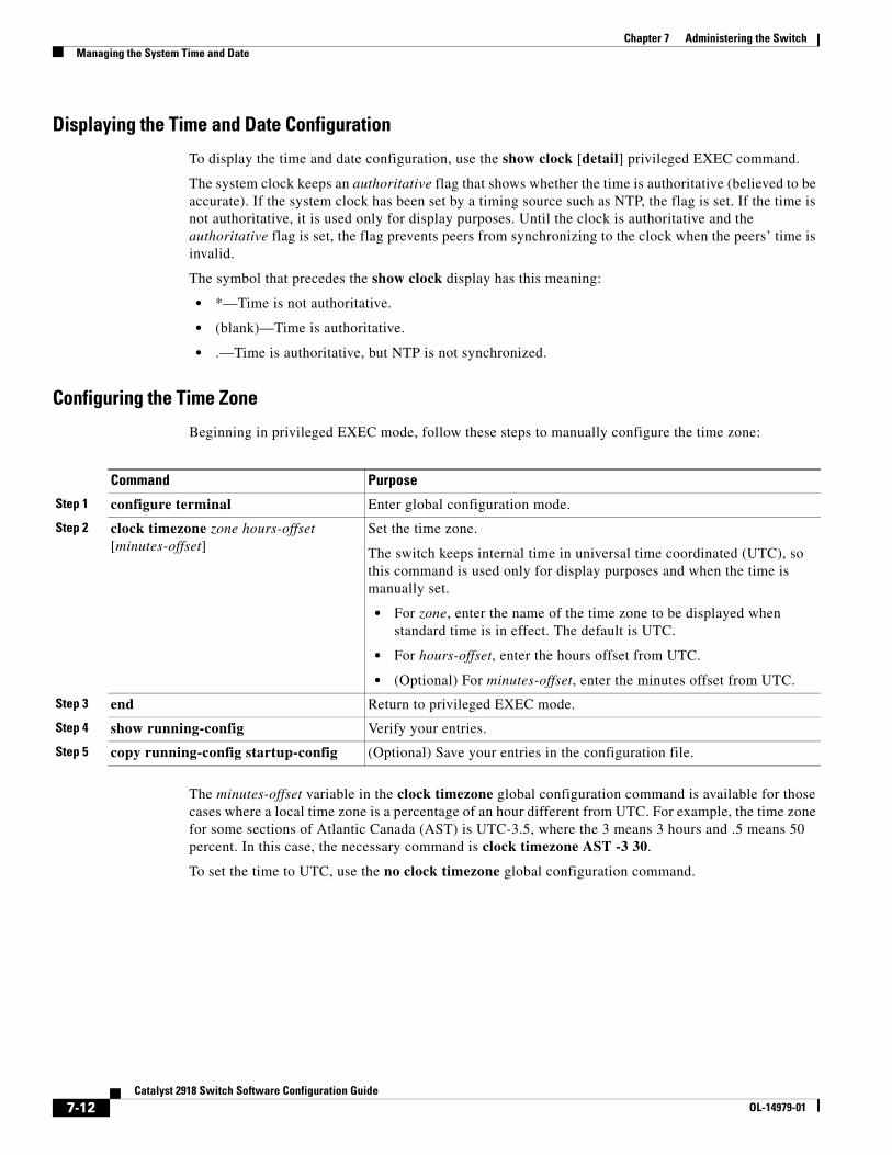
Chapter 7 Administering the SwitchManaging the System Time and Date
Displaying the Time and Date Configuration
To display the time and date configuration, use the show clock [detail] privileged EXEC command.
The system clock keeps an authoritative flag that shows whether the time is authoritative (believed to be accurate). If the system clock has been set by a timing source such as NTP, the flag is set. If the time is not authoritative, it is used only for display purposes. Until the clock is authoritative and the authoritative flag is set, the flag prevents peers from synchronizing to the clock when the peers’ time is invalid.
The symbol that precedes the show clock display has this meaning:
• *—Time is not authoritative.
• (blank)—Time is authoritative.
• .—Time is authoritative, but NTP is not synchronized.
Configuring the Time Zone
Beginning in privileged EXEC mode, follow these steps to manually configure the time zone:
Command Purpose
Step 1 configure terminal Enter global configuration mode.
Step 2 clock timezone zone hours-offset [minutes-offset]
Set the time zone.
The switch keeps internal time in universal time coordinated (UTC), so this command is used only for display purposes and when the time is manually set.
• For zone, enter the name of the time zone to be displayed when standard time is in effect. The default is UTC.
• For hours-offset, enter the hours offset from UTC.
• (Optional) For minutes-offset, enter the minutes offset from UTC.
Step 3 end Return to privileged EXEC mode.
Step 4 show running-config Verify your entries.
Step 5 copy running-config startup-config (Optional) Save your entries in the configuration file.
The minutes-offset variable in the clock timezone global configuration command is available for those cases where a local time zone is a percentage of an hour different from UTC. For example, the time zone for some sections of Atlantic Canada (AST) is UTC-3.5, where the 3 means 3 hours and .5 means 50 percent. In this case, the necessary command is clock timezone AST -3 30.
To set the time to UTC, use the no clock timezone global configuration command.
7-12Catalyst 2918 Switch Software Configuration Guide
OL-14979-01
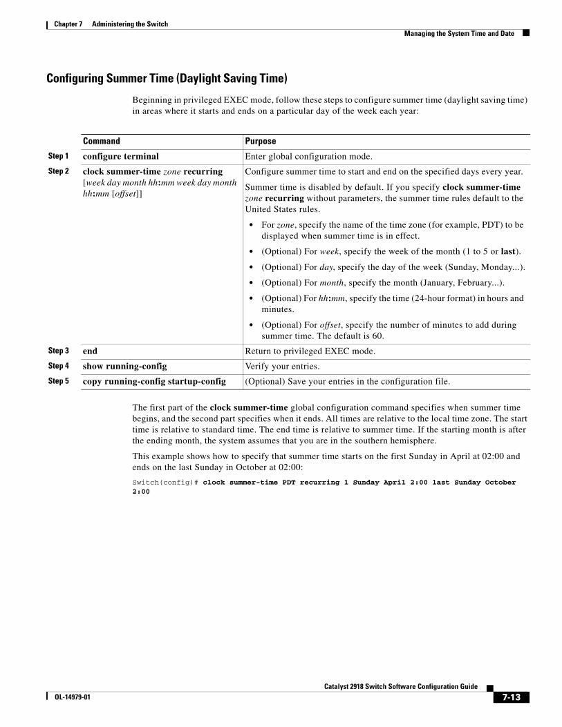
Chapter 7 Administering the SwitchManaging the System Time and Date
Configuring Summer Time (Daylight Saving Time)
Beginning in privileged EXEC mode, follow these steps to configure summer time (daylight saving time) in areas where it starts and ends on a particular day of the week each year:
Command Purpose
Step 1 configure terminal Enter global configuration mode.
Step 2 clock summer-time zone recurring [week day month hh:mm week day month hh:mm [offset]]
Configure summer time to start and end on the specified days every year.
Summer time is disabled by default. If you specify clock summer-time zone recurring without parameters, the summer time rules default to the United States rules.
• For zone, specify the name of the time zone (for example, PDT) to be displayed when summer time is in effect.
• (Optional) For week, specify the week of the month (1 to 5 or last).
• (Optional) For day, specify the day of the week (Sunday, Monday...).
• (Optional) For month, specify the month (January, February...).
• (Optional) For hh:mm, specify the time (24-hour format) in hours and minutes.
• (Optional) For offset, specify the number of minutes to add during summer time. The default is 60.
Step 3 end Return to privileged EXEC mode.
Step 4 show running-config Verify your entries.
Step 5 copy running-config startup-config (Optional) Save your entries in the configuration file.
The first part of the clock summer-time global configuration command specifies when summer time begins, and the second part specifies when it ends. All times are relative to the local time zone. The start time is relative to standard time. The end time is relative to summer time. If the starting month is after the ending month, the system assumes that you are in the southern hemisphere.
This example shows how to specify that summer time starts on the first Sunday in April at 02:00 and ends on the last Sunday in October at 02:00:
Switch(config)# clock summer-time PDT recurring 1 Sunday April 2:00 last Sunday October 2:00
7-13Catalyst 2918 Switch Software Configuration Guide
OL-14979-01
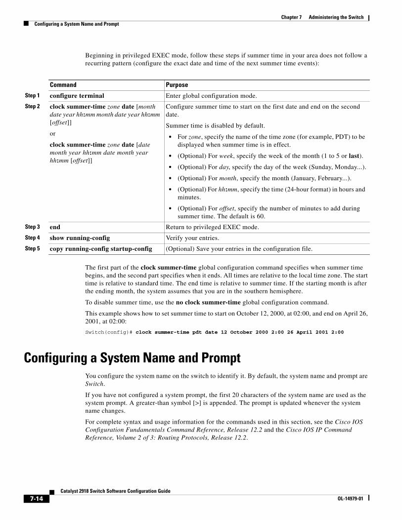
Chapter 7 Administering the SwitchConfiguring a System Name and Prompt
Beginning in privileged EXEC mode, follow these steps if summer time in your area does not follow a recurring pattern (configure the exact date and time of the next summer time events):
Command Purpose
Step 1 configure terminal Enter global configuration mode.
Step 2 clock summer-time zone date [month date year hh:mm month date year hh:mm [offset]]
or
clock summer-time zone date [date month year hh:mm date month year hh:mm [offset]]
Configure summer time to start on the first date and end on the second date.
Summer time is disabled by default.
• For zone, specify the name of the time zone (for example, PDT) to be displayed when summer time is in effect.
• (Optional) For week, specify the week of the month (1 to 5 or last).
• (Optional) For day, specify the day of the week (Sunday, Monday...).
• (Optional) For month, specify the month (January, February...).
• (Optional) For hh:mm, specify the time (24-hour format) in hours and minutes.
• (Optional) For offset, specify the number of minutes to add during summer time. The default is 60.
Step 3 end Return to privileged EXEC mode.
Step 4 show running-config Verify your entries.
Step 5 copy running-config startup-config (Optional) Save your entries in the configuration file.
The first part of the clock summer-time global configuration command specifies when summer time begins, and the second part specifies when it ends. All times are relative to the local time zone. The start time is relative to standard time. The end time is relative to summer time. If the starting month is after the ending month, the system assumes that you are in the southern hemisphere.
To disable summer time, use the no clock summer-time global configuration command.
This example shows how to set summer time to start on October 12, 2000, at 02:00, and end on April 26, 2001, at 02:00:
Switch(config)# clock summer-time pdt date 12 October 2000 2:00 26 April 2001 2:00
Configuring a System Name and PromptYou configure the system name on the switch to identify it. By default, the system name and prompt are Switch.
If you have not configured a system prompt, the first 20 characters of the system name are used as the system prompt. A greater-than symbol [>] is appended. The prompt is updated whenever the system name changes.
For complete syntax and usage information for the commands used in this section, see the Cisco IOS Configuration Fundamentals Command Reference, Release 12.2 and the Cisco IOS IP Command Reference, Volume 2 of 3: Routing Protocols, Release 12.2.
7-14Catalyst 2918 Switch Software Configuration Guide
OL-14979-01
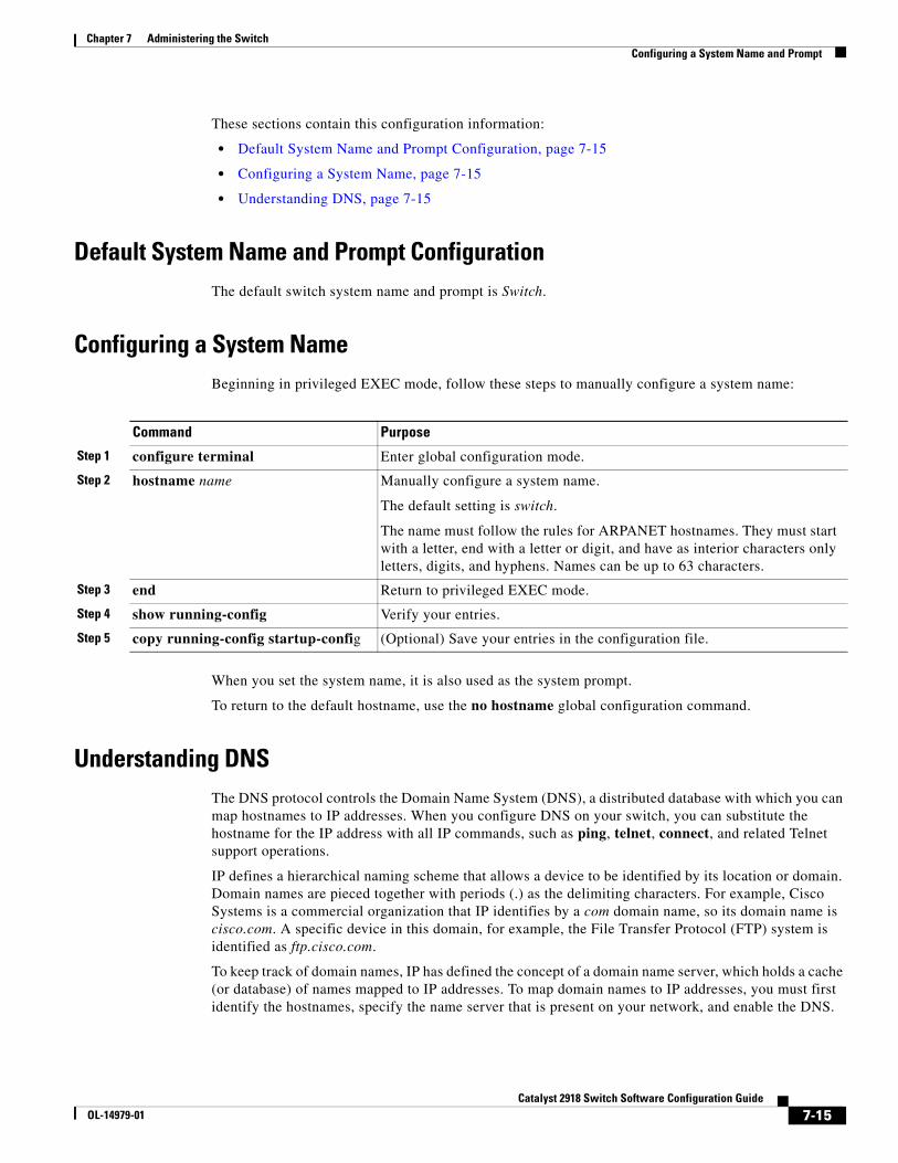
Chapter 7 Administering the SwitchConfiguring a System Name and Prompt
These sections contain this configuration information:
• Default System Name and Prompt Configuration, page 7-15
• Configuring a System Name, page 7-15
• Understanding DNS, page 7-15
Default System Name and Prompt ConfigurationThe default switch system name and prompt is Switch.
Configuring a System NameBeginning in privileged EXEC mode, follow these steps to manually configure a system name:
Command Purpose
Step 1 configure terminal Enter global configuration mode.
Step 2 hostname name Manually configure a system name.
The default setting is switch.
The name must follow the rules for ARPANET hostnames. They must start with a letter, end with a letter or digit, and have as interior characters only letters, digits, and hyphens. Names can be up to 63 characters.
Step 3 end Return to privileged EXEC mode.
Step 4 show running-config Verify your entries.
Step 5 copy running-config startup-config (Optional) Save your entries in the configuration file.
When you set the system name, it is also used as the system prompt.
To return to the default hostname, use the no hostname global configuration command.
Understanding DNSThe DNS protocol controls the Domain Name System (DNS), a distributed database with which you can map hostnames to IP addresses. When you configure DNS on your switch, you can substitute the hostname for the IP address with all IP commands, such as ping, telnet, connect, and related Telnet support operations.
IP defines a hierarchical naming scheme that allows a device to be identified by its location or domain. Domain names are pieced together with periods (.) as the delimiting characters. For example, Cisco Systems is a commercial organization that IP identifies by a com domain name, so its domain name is cisco.com. A specific device in this domain, for example, the File Transfer Protocol (FTP) system is identified as ftp.cisco.com.
To keep track of domain names, IP has defined the concept of a domain name server, which holds a cache (or database) of names mapped to IP addresses. To map domain names to IP addresses, you must first identify the hostnames, specify the name server that is present on your network, and enable the DNS.
7-15Catalyst 2918 Switch Software Configuration Guide
OL-14979-01
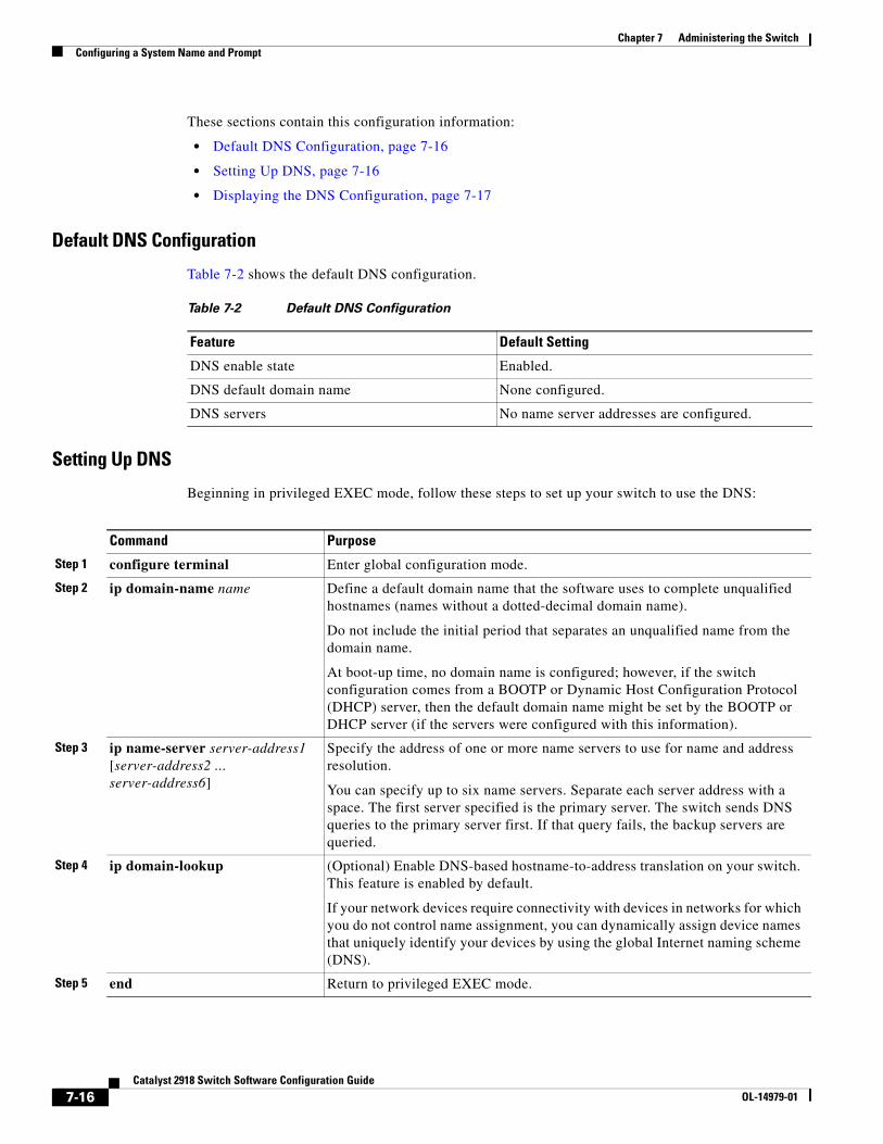
Chapter 7 Administering the SwitchConfiguring a System Name and Prompt
These sections contain this configuration information:
• Default DNS Configuration, page 7-16
• Setting Up DNS, page 7-16
• Displaying the DNS Configuration, page 7-17
Default DNS Configuration
Table 7-2 shows the default DNS configuration.
Table 7-2 Default DNS Configuration
Feature Default Setting
DNS enable state Enabled.
DNS default domain name None configured.
DNS servers No name server addresses are configured.
Setting Up DNS
Beginning in privileged EXEC mode, follow these steps to set up your switch to use the DNS:
Command Purpose
Step 1 configure terminal Enter global configuration mode.
Step 2 ip domain-name name Define a default domain name that the software uses to complete unqualified hostnames (names without a dotted-decimal domain name).
Do not include the initial period that separates an unqualified name from the domain name.
At boot-up time, no domain name is configured; however, if the switch configuration comes from a BOOTP or Dynamic Host Configuration Protocol (DHCP) server, then the default domain name might be set by the BOOTP or DHCP server (if the servers were configured with this information).
Step 3 ip name-server server-address1 [server-address2 ... server-address6]
Specify the address of one or more name servers to use for name and address resolution.
You can specify up to six name servers. Separate each server address with a space. The first server specified is the primary server. The switch sends DNS queries to the primary server first. If that query fails, the backup servers are queried.
Step 4 ip domain-lookup (Optional) Enable DNS-based hostname-to-address translation on your switch. This feature is enabled by default.
If your network devices require connectivity with devices in networks for which you do not control name assignment, you can dynamically assign device names that uniquely identify your devices by using the global Internet naming scheme (DNS).
Step 5 end Return to privileged EXEC mode.
7-16Catalyst 2918 Switch Software Configuration Guide
OL-14979-01
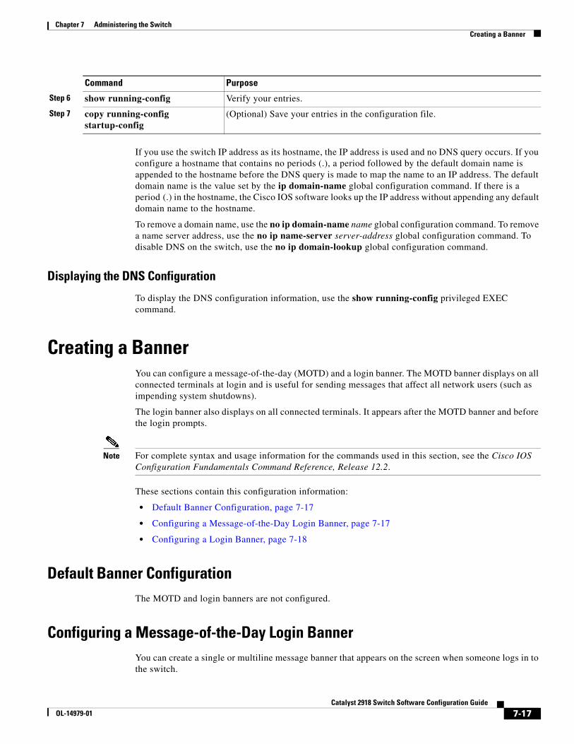
Chapter 7 Administering the SwitchCreating a Banner
If you use the switch IP address as its hostname, the IP address is used and no DNS query occurs. If you configure a hostname that contains no periods (.), a period followed by the default domain name is appended to the hostname before the DNS query is made to map the name to an IP address. The default domain name is the value set by the ip domain-name global configuration command. If there is a period (.) in the hostname, the Cisco IOS software looks up the IP address without appending any default domain name to the hostname.
To remove a domain name, use the no ip domain-name name global configuration command. To remove a name server address, use the no ip name-server server-address global configuration command. To disable DNS on the switch, use the no ip domain-lookup global configuration command.
Displaying the DNS Configuration
To display the DNS configuration information, use the show running-config privileged EXEC command.
Creating a BannerYou can configure a message-of-the-day (MOTD) and a login banner. The MOTD banner displays on all connected terminals at login and is useful for sending messages that affect all network users (such as impending system shutdowns).
The login banner also displays on all connected terminals. It appears after the MOTD banner and before the login prompts.
Note For complete syntax and usage information for the commands used in this section, see the Cisco IOS Configuration Fundamentals Command Reference, Release 12.2.
These sections contain this configuration information:
• Default Banner Configuration, page 7-17
• Configuring a Message-of-the-Day Login Banner, page 7-17
• Configuring a Login Banner, page 7-18
Default Banner ConfigurationThe MOTD and login banners are not configured.
Configuring a Message-of-the-Day Login BannerYou can create a single or multiline message banner that appears on the screen when someone logs in to the switch.
Step 6 show running-config Verify your entries.
Step 7 copy running-config startup-config
(Optional) Save your entries in the configuration file.
Command Purpose
7-17Catalyst 2918 Switch Software Configuration Guide
OL-14979-01
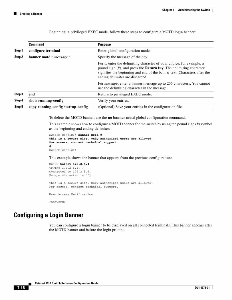
Chapter 7 Administering the SwitchCreating a Banner
Beginning in privileged EXEC mode, follow these steps to configure a MOTD login banner:
Command Purpose
Step 1 configure terminal Enter global configuration mode.
Step 2 banner motd c message c Specify the message of the day.
For c, enter the delimiting character of your choice, for example, a pound sign (#), and press the Return key. The delimiting character signifies the beginning and end of the banner text. Characters after the ending delimiter are discarded.
For message, enter a banner message up to 255 characters. You cannot use the delimiting character in the message.
Step 3 end Return to privileged EXEC mode.
Step 4 show running-config Verify your entries.
Step 5 copy running-config startup-config (Optional) Save your entries in the configuration file.
To delete the MOTD banner, use the no banner motd global configuration command.
This example shows how to configure a MOTD banner for the switch by using the pound sign (#) symbol as the beginning and ending delimiter:
Switch(config)# banner motd #This is a secure site. Only authorized users are allowed.For access, contact technical support.#Switch(config)#
This example shows the banner that appears from the previous configuration:
Unix> telnet 172.2.5.4Trying 172.2.5.4...Connected to 172.2.5.4.Escape character is '^]'.
This is a secure site. Only authorized users are allowed.For access, contact technical support.
User Access Verification
Password:
Configuring a Login BannerYou can configure a login banner to be displayed on all connected terminals. This banner appears after the MOTD banner and before the login prompt.
7-18Catalyst 2918 Switch Software Configuration Guide
OL-14979-01
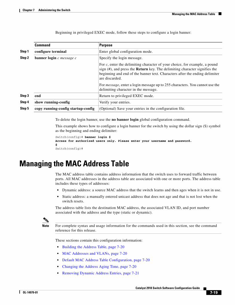
Chapter 7 Administering the SwitchManaging the MAC Address Table
Beginning in privileged EXEC mode, follow these steps to configure a login banner:
Command Purpose
Step 1 configure terminal Enter global configuration mode.
Step 2 banner login c message c Specify the login message.
For c, enter the delimiting character of your choice, for example, a pound sign (#), and press the Return key. The delimiting character signifies the beginning and end of the banner text. Characters after the ending delimiter are discarded.
For message, enter a login message up to 255 characters. You cannot use the delimiting character in the message.
Step 3 end Return to privileged EXEC mode.
Step 4 show running-config Verify your entries.
Step 5 copy running-config startup-config (Optional) Save your entries in the configuration file.
To delete the login banner, use the no banner login global configuration command.
This example shows how to configure a login banner for the switch by using the dollar sign ($) symbol as the beginning and ending delimiter:
Switch(config)# banner login $Access for authorized users only. Please enter your username and password.$Switch(config)#
Managing the MAC Address TableThe MAC address table contains address information that the switch uses to forward traffic between ports. All MAC addresses in the address table are associated with one or more ports. The address table includes these types of addresses:
• Dynamic address: a source MAC address that the switch learns and then ages when it is not in use.
• Static address: a manually entered unicast address that does not age and that is not lost when the switch resets.
The address table lists the destination MAC address, the associated VLAN ID, and port number associated with the address and the type (static or dynamic).
Note For complete syntax and usage information for the commands used in this section, see the command reference for this release.
These sections contain this configuration information:
• Building the Address Table, page 7-20
• MAC Addresses and VLANs, page 7-20
• Default MAC Address Table Configuration, page 7-20
• Changing the Address Aging Time, page 7-20
• Removing Dynamic Address Entries, page 7-21
7-19Catalyst 2918 Switch Software Configuration Guide
OL-14979-01
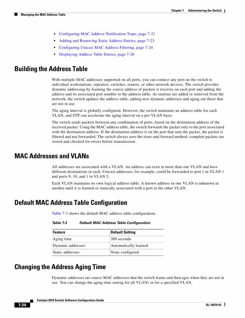
Chapter 7 Administering the SwitchManaging the MAC Address Table
• Configuring MAC Address Notification Traps, page 7-21
• Adding and Removing Static Address Entries, page 7-23
• Configuring Unicast MAC Address Filtering, page 7-24
• Displaying Address Table Entries, page 7-26
Building the Address TableWith multiple MAC addresses supported on all ports, you can connect any port on the switch to individual workstations, repeaters, switches, routers, or other network devices. The switch provides dynamic addressing by learning the source address of packets it receives on each port and adding the address and its associated port number to the address table. As stations are added or removed from the network, the switch updates the address table, adding new dynamic addresses and aging out those that are not in use.
The aging interval is globally configured. However, the switch maintains an address table for each VLAN, and STP can accelerate the aging interval on a per-VLAN basis.
The switch sends packets between any combination of ports, based on the destination address of the received packet. Using the MAC address table, the switch forwards the packet only to the port associated with the destination address. If the destination address is on the port that sent the packet, the packet is filtered and not forwarded. The switch always uses the store-and-forward method: complete packets are stored and checked for errors before transmission.
MAC Addresses and VLANsAll addresses are associated with a VLAN. An address can exist in more than one VLAN and have different destinations in each. Unicast addresses, for example, could be forwarded to port 1 in VLAN 1 and ports 9, 10, and 1 in VLAN 5.
Each VLAN maintains its own logical address table. A known address in one VLAN is unknown in another until it is learned or statically associated with a port in the other VLAN.
Default MAC Address Table ConfigurationTable 7-3 shows the default MAC address table configuration.
Table 7-3 Default MAC Address Table Configuration
Feature Default Setting
Aging time 300 seconds
Dynamic addresses Automatically learned
Static addresses None configured
Changing the Address Aging TimeDynamic addresses are source MAC addresses that the switch learns and then ages when they are not in use. You can change the aging time setting for all VLANs or for a specified VLAN.
7-20Catalyst 2918 Switch Software Configuration Guide
OL-14979-01
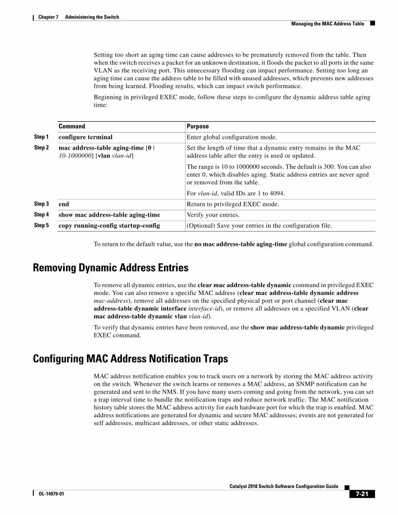
Chapter 7 Administering the SwitchManaging the MAC Address Table
Setting too short an aging time can cause addresses to be prematurely removed from the table. Then when the switch receives a packet for an unknown destination, it floods the packet to all ports in the same VLAN as the receiving port. This unnecessary flooding can impact performance. Setting too long an aging time can cause the address table to be filled with unused addresses, which prevents new addresses from being learned. Flooding results, which can impact switch performance.
Beginning in privileged EXEC mode, follow these steps to configure the dynamic address table aging time:
Command Purpose
Step 1 configure terminal Enter global configuration mode.
Step 2 mac address-table aging-time [0 | 10-1000000] [vlan vlan-id]
Set the length of time that a dynamic entry remains in the MAC address table after the entry is used or updated.
The range is 10 to 1000000 seconds. The default is 300. You can also enter 0, which disables aging. Static address entries are never aged or removed from the table.
For vlan-id, valid IDs are 1 to 4094.
Step 3 end Return to privileged EXEC mode.
Step 4 show mac address-table aging-time Verify your entries.
Step 5 copy running-config startup-config (Optional) Save your entries in the configuration file.
To return to the default value, use the no mac address-table aging-time global configuration command.
Removing Dynamic Address EntriesTo remove all dynamic entries, use the clear mac address-table dynamic command in privileged EXEC mode. You can also remove a specific MAC address (clear mac address-table dynamic address mac-address), remove all addresses on the specified physical port or port channel (clear mac address-table dynamic interface interface-id), or remove all addresses on a specified VLAN (clear mac address-table dynamic vlan vlan-id).
To verify that dynamic entries have been removed, use the show mac address-table dynamic privileged EXEC command.
Configuring MAC Address Notification TrapsMAC address notification enables you to track users on a network by storing the MAC address activity on the switch. Whenever the switch learns or removes a MAC address, an SNMP notification can be generated and sent to the NMS. If you have many users coming and going from the network, you can set a trap interval time to bundle the notification traps and reduce network traffic. The MAC notification history table stores the MAC address activity for each hardware port for which the trap is enabled. MAC address notifications are generated for dynamic and secure MAC addresses; events are not generated for self addresses, multicast addresses, or other static addresses.
7-21Catalyst 2918 Switch Software Configuration Guide
OL-14979-01
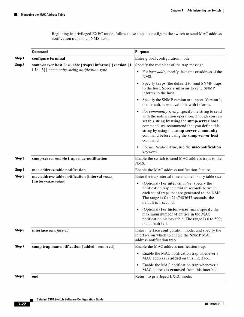
Chapter 7 Administering the SwitchManaging the MAC Address Table
Beginning in privileged EXEC mode, follow these steps to configure the switch to send MAC address notification traps to an NMS host:
Command Purpose
Step 1 configure terminal Enter global configuration mode.
Step 2 snmp-server host host-addr {traps | informs} {version {1 | 2c | 3}} community-string notification-type
Specify the recipient of the trap message.
• For host-addr, specify the name or address of the NMS.
• Specify traps (the default) to send SNMP traps to the host. Specify informs to send SNMP informs to the host.
• Specify the SNMP version to support. Version 1, the default, is not available with informs.
• For community-string, specify the string to send with the notification operation. Though you can set this string by using the snmp-server host command, we recommend that you define this string by using the snmp-server community command before using the snmp-server host command.
• For notification-type, use the mac-notification keyword.
Step 3 snmp-server enable traps mac-notification Enable the switch to send MAC address traps to the NMS.
Step 4 mac address-table notification Enable the MAC address notification feature.
Step 5 mac address-table notification [interval value] | [history-size value]
Enter the trap interval time and the history table size.
• (Optional) For interval value, specify the notification trap interval in seconds between each set of traps that are generated to the NMS. The range is 0 to 2147483647 seconds; the default is 1 second.
• (Optional) For history-size value, specify the maximum number of entries in the MAC notification history table. The range is 0 to 500; the default is 1.
Step 6 interface interface-id Enter interface configuration mode, and specify the interface on which to enable the SNMP MAC address notification trap.
Step 7 snmp trap mac-notification {added | removed} Enable the MAC address notification trap.
• Enable the MAC notification trap whenever a MAC address is added on this interface.
• Enable the MAC notification trap whenever a MAC address is removed from this interface.
Step 8 end Return to privileged EXEC mode.
7-22Catalyst 2918 Switch Software Configuration Guide
OL-14979-01
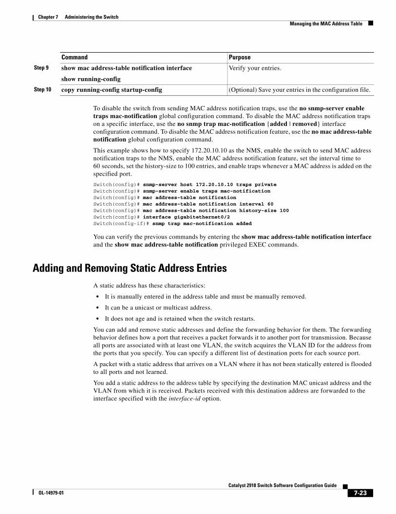
Chapter 7 Administering the SwitchManaging the MAC Address Table
To disable the switch from sending MAC address notification traps, use the no snmp-server enable traps mac-notification global configuration command. To disable the MAC address notification traps on a specific interface, use the no snmp trap mac-notification {added | removed} interface configuration command. To disable the MAC address notification feature, use the no mac address-table notification global configuration command.
This example shows how to specify 172.20.10.10 as the NMS, enable the switch to send MAC address notification traps to the NMS, enable the MAC address notification feature, set the interval time to 60 seconds, set the history-size to 100 entries, and enable traps whenever a MAC address is added on the specified port.
Switch(config)# snmp-server host 172.20.10.10 traps privateSwitch(config)# snmp-server enable traps mac-notificationSwitch(config)# mac address-table notificationSwitch(config)# mac address-table notification interval 60Switch(config)# mac address-table notification history-size 100Switch(config)# interface gigabitethernet0/2Switch(config-if)# snmp trap mac-notification added
You can verify the previous commands by entering the show mac address-table notification interface and the show mac address-table notification privileged EXEC commands.
Adding and Removing Static Address EntriesA static address has these characteristics:
• It is manually entered in the address table and must be manually removed.
• It can be a unicast or multicast address.
• It does not age and is retained when the switch restarts.
You can add and remove static addresses and define the forwarding behavior for them. The forwarding behavior defines how a port that receives a packet forwards it to another port for transmission. Because all ports are associated with at least one VLAN, the switch acquires the VLAN ID for the address from the ports that you specify. You can specify a different list of destination ports for each source port.
A packet with a static address that arrives on a VLAN where it has not been statically entered is flooded to all ports and not learned.
You add a static address to the address table by specifying the destination MAC unicast address and the VLAN from which it is received. Packets received with this destination address are forwarded to the interface specified with the interface-id option.
Step 9 show mac address-table notification interface
show running-config
Verify your entries.
Step 10 copy running-config startup-config (Optional) Save your entries in the configuration file.
Command Purpose
7-23Catalyst 2918 Switch Software Configuration Guide
OL-14979-01
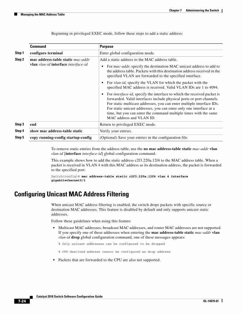
Chapter 7 Administering the SwitchManaging the MAC Address Table
Beginning in privileged EXEC mode, follow these steps to add a static address:
Command Purpose
Step 1 configure terminal Enter global configuration mode.
Step 2 mac address-table static mac-addr vlan vlan-id interface interface-id
Add a static address to the MAC address table.
• For mac-addr, specify the destination MAC unicast address to add to the address table. Packets with this destination address received in the specified VLAN are forwarded to the specified interface.
• For vlan-id, specify the VLAN for which the packet with the specified MAC address is received. Valid VLAN IDs are 1 to 4094.
• For interface-id, specify the interface to which the received packet is forwarded. Valid interfaces include physical ports or port channels. For static multicast addresses, you can enter multiple interface IDs. For static unicast addresses, you can enter only one interface at a time, but you can enter the command multiple times with the same MAC address and VLAN ID.
Step 3 end Return to privileged EXEC mode.
Step 4 show mac address-table static Verify your entries.
Step 5 copy running-config startup-config (Optional) Save your entries in the configuration file.
To remove static entries from the address table, use the no mac address-table static mac-addr vlan vlan-id [interface interface-id] global configuration command.
This example shows how to add the static address c2f3.220a.12f4 to the MAC address table. When a packet is received in VLAN 4 with this MAC address as its destination address, the packet is forwarded to the specified port:
Switch(config)# mac address-table static c2f3.220a.12f4 vlan 4 interface gigabitethernet0/1
Configuring Unicast MAC Address FilteringWhen unicast MAC address filtering is enabled, the switch drops packets with specific source or destination MAC addresses. This feature is disabled by default and only supports unicast static addresses.
Follow these guidelines when using this feature:
• Multicast MAC addresses, broadcast MAC addresses, and router MAC addresses are not supported. If you specify one of these addresses when entering the mac address-table static mac-addr vlan vlan-id drop global configuration command, one of these messages appears:
% Only unicast addresses can be configured to be dropped
% CPU destined address cannot be configured as drop address
• Packets that are forwarded to the CPU are also not supported.
7-24Catalyst 2918 Switch Software Configuration Guide
OL-14979-01
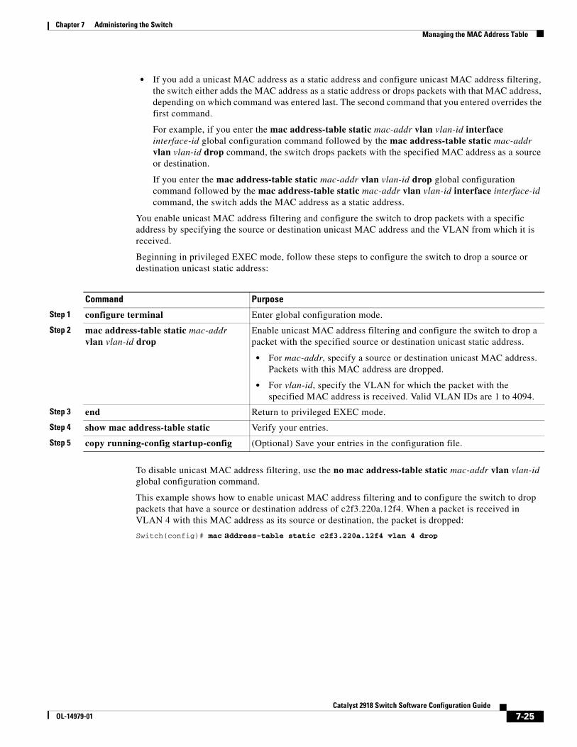
Chapter 7 Administering the SwitchManaging the MAC Address Table
• If you add a unicast MAC address as a static address and configure unicast MAC address filtering, the switch either adds the MAC address as a static address or drops packets with that MAC address, depending on which command was entered last. The second command that you entered overrides the first command.
For example, if you enter the mac address-table static mac-addr vlan vlan-id interface interface-id global configuration command followed by the mac address-table static mac-addr vlan vlan-id drop command, the switch drops packets with the specified MAC address as a source or destination.
If you enter the mac address-table static mac-addr vlan vlan-id drop global configuration command followed by the mac address-table static mac-addr vlan vlan-id interface interface-id command, the switch adds the MAC address as a static address.
You enable unicast MAC address filtering and configure the switch to drop packets with a specific address by specifying the source or destination unicast MAC address and the VLAN from which it is received.
Beginning in privileged EXEC mode, follow these steps to configure the switch to drop a source or destination unicast static address:
Command Purpose
Step 1 configure terminal Enter global configuration mode.
Step 2 mac address-table static mac-addr vlan vlan-id drop
Enable unicast MAC address filtering and configure the switch to drop a packet with the specified source or destination unicast static address.
• For mac-addr, specify a source or destination unicast MAC address. Packets with this MAC address are dropped.
• For vlan-id, specify the VLAN for which the packet with the specified MAC address is received. Valid VLAN IDs are 1 to 4094.
Step 3 end Return to privileged EXEC mode.
Step 4 show mac address-table static Verify your entries.
Step 5 copy running-config startup-config (Optional) Save your entries in the configuration file.
To disable unicast MAC address filtering, use the no mac address-table static mac-addr vlan vlan-id global configuration command.
This example shows how to enable unicast MAC address filtering and to configure the switch to drop packets that have a source or destination address of c2f3.220a.12f4. When a packet is received in VLAN 4 with this MAC address as its source or destination, the packet is dropped:
Switch(config)# mac address-table static c2f3.220a.12f4 vlan 4 drop
7-25Catalyst 2918 Switch Software Configuration Guide
OL-14979-01
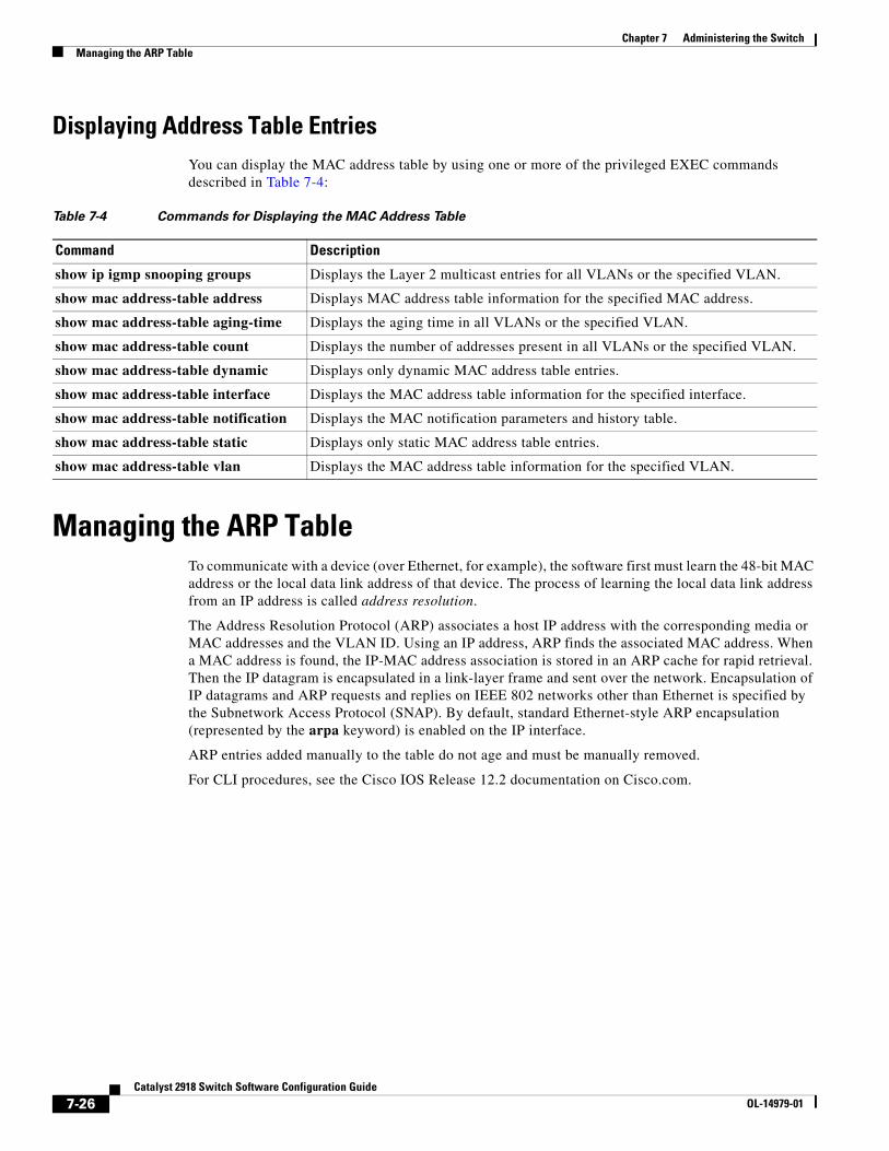
Chapter 7 Administering the SwitchManaging the ARP Table
Displaying Address Table EntriesYou can display the MAC address table by using one or more of the privileged EXEC commands described in Table 7-4:
Table 7-4 Commands for Displaying the MAC Address Table
Command Description
show ip igmp snooping groups Displays the Layer 2 multicast entries for all VLANs or the specified VLAN.
show mac address-table address Displays MAC address table information for the specified MAC address.
show mac address-table aging-time Displays the aging time in all VLANs or the specified VLAN.
show mac address-table count Displays the number of addresses present in all VLANs or the specified VLAN.
show mac address-table dynamic Displays only dynamic MAC address table entries.
show mac address-table interface Displays the MAC address table information for the specified interface.
show mac address-table notification Displays the MAC notification parameters and history table.
show mac address-table static Displays only static MAC address table entries.
show mac address-table vlan Displays the MAC address table information for the specified VLAN.
Managing the ARP TableTo communicate with a device (over Ethernet, for example), the software first must learn the 48-bit MAC address or the local data link address of that device. The process of learning the local data link address from an IP address is called address resolution.
The Address Resolution Protocol (ARP) associates a host IP address with the corresponding media or MAC addresses and the VLAN ID. Using an IP address, ARP finds the associated MAC address. When a MAC address is found, the IP-MAC address association is stored in an ARP cache for rapid retrieval. Then the IP datagram is encapsulated in a link-layer frame and sent over the network. Encapsulation of IP datagrams and ARP requests and replies on IEEE 802 networks other than Ethernet is specified by the Subnetwork Access Protocol (SNAP). By default, standard Ethernet-style ARP encapsulation (represented by the arpa keyword) is enabled on the IP interface.
ARP entries added manually to the table do not age and must be manually removed.
For CLI procedures, see the Cisco IOS Release 12.2 documentation on Cisco.com.
7-26Catalyst 2918 Switch Software Configuration Guide
OL-14979-01
OL-14979-01
C H A P T E R 8
Configuring Switch-Based AuthenticationThis chapter describes how to configure switch-based authentication on the Catalyst 2918 switch. It consists of these sections:
• Preventing Unauthorized Access to Your Switch, page 8-1
• Protecting Access to Privileged EXEC Commands, page 8-2
• Controlling Switch Access with TACACS+, page 8-10
• Controlling Switch Access with RADIUS, page 8-17
• Configuring the Switch for Local Authentication and Authorization, page 8-32
• Configuring the Switch for Secure Shell, page 8-33
• Configuring the Switch for Secure Socket Layer HTTP, page 8-37
• Configuring the Switch for Secure Copy Protocol, page 8-43
Preventing Unauthorized Access to Your SwitchYou can prevent unauthorized users from reconfiguring your switch and viewing configuration information. Typically, you want network administrators to have access to your switch while you restrict access to users who dial from outside the network through an asynchronous port, connect from outside the network through a serial port, or connect through a terminal or workstation from within the local network.
To prevent unauthorized access into your switch, you should configure one or more of these security features:
• At a minimum, you should configure passwords and privileges at each switch port. These passwords are locally stored on the switch. When users attempt to access the switch through a port or line, they must enter the password specified for the port or line before they can access the switch. For more information, see the “Protecting Access to Privileged EXEC Commands” section on page 8-2.
• For an additional layer of security, you can also configure username and password pairs, which are locally stored on the switch. These pairs are assigned to lines or ports and authenticate each user before that user can access the switch. If you have defined privilege levels, you can also assign a specific privilege level (with associated rights and privileges) to each username and password pair. For more information, see the “Configuring Username and Password Pairs” section on page 8-6.
8-1Catalyst 2918 Switch Software Configuration Guide
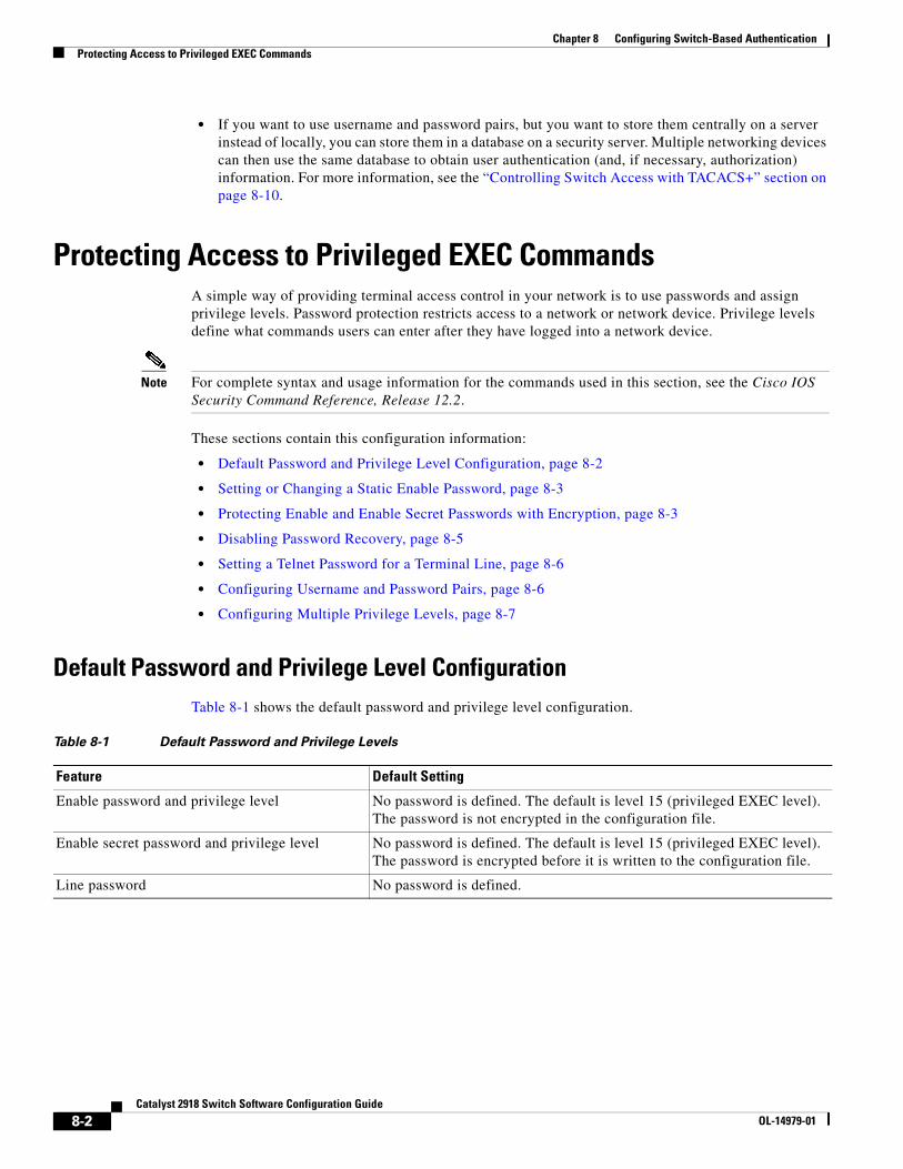
Chapter 8 Configuring Switch-Based AuthenticationProtecting Access to Privileged EXEC Commands
• If you want to use username and password pairs, but you want to store them centrally on a server instead of locally, you can store them in a database on a security server. Multiple networking devices can then use the same database to obtain user authentication (and, if necessary, authorization) information. For more information, see the “Controlling Switch Access with TACACS+” section on page 8-10.
Protecting Access to Privileged EXEC CommandsA simple way of providing terminal access control in your network is to use passwords and assign privilege levels. Password protection restricts access to a network or network device. Privilege levels define what commands users can enter after they have logged into a network device.
Note For complete syntax and usage information for the commands used in this section, see the Cisco IOS Security Command Reference, Release 12.2.
These sections contain this configuration information:
• Default Password and Privilege Level Configuration, page 8-2
• Setting or Changing a Static Enable Password, page 8-3
• Protecting Enable and Enable Secret Passwords with Encryption, page 8-3
• Disabling Password Recovery, page 8-5
• Setting a Telnet Password for a Terminal Line, page 8-6
• Configuring Username and Password Pairs, page 8-6
• Configuring Multiple Privilege Levels, page 8-7
Default Password and Privilege Level ConfigurationTable 8-1 shows the default password and privilege level configuration.
Table 8-1 Default Password and Privilege Levels
Feature Default Setting
Enable password and privilege level No password is defined. The default is level 15 (privileged EXEC level). The password is not encrypted in the configuration file.
Enable secret password and privilege level No password is defined. The default is level 15 (privileged EXEC level). The password is encrypted before it is written to the configuration file.
Line password No password is defined.
8-2Catalyst 2918 Switch Software Configuration Guide
OL-14979-01
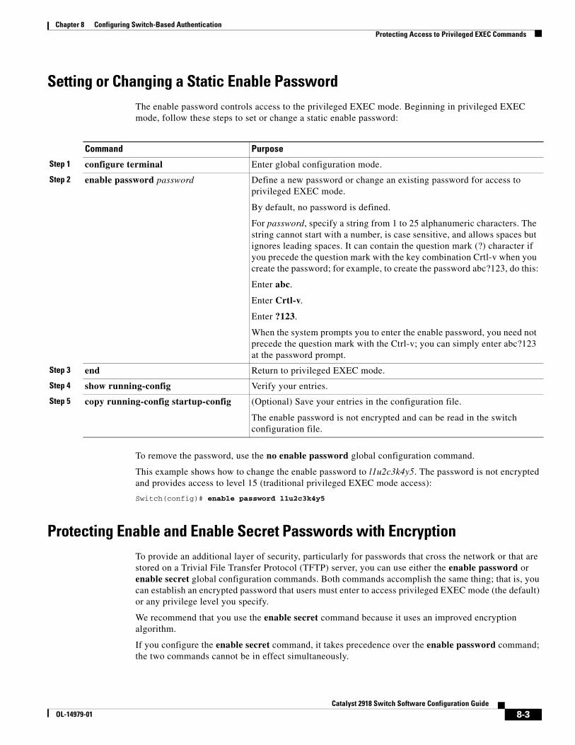
Chapter 8 Configuring Switch-Based AuthenticationProtecting Access to Privileged EXEC Commands
Setting or Changing a Static Enable PasswordThe enable password controls access to the privileged EXEC mode. Beginning in privileged EXEC mode, follow these steps to set or change a static enable password:
Command Purpose
Step 1 configure terminal Enter global configuration mode.
Step 2 enable password password Define a new password or change an existing password for access to privileged EXEC mode.
By default, no password is defined.
For password, specify a string from 1 to 25 alphanumeric characters. The string cannot start with a number, is case sensitive, and allows spaces but ignores leading spaces. It can contain the question mark (?) character if you precede the question mark with the key combination Crtl-v when you create the password; for example, to create the password abc?123, do this:
Enter abc.
Enter Crtl-v.
Enter ?123.
When the system prompts you to enter the enable password, you need not precede the question mark with the Ctrl-v; you can simply enter abc?123 at the password prompt.
Step 3 end Return to privileged EXEC mode.
Step 4 show running-config Verify your entries.
Step 5 copy running-config startup-config (Optional) Save your entries in the configuration file.
The enable password is not encrypted and can be read in the switch configuration file.
To remove the password, use the no enable password global configuration command.
This example shows how to change the enable password to l1u2c3k4y5. The password is not encrypted and provides access to level 15 (traditional privileged EXEC mode access):
Switch(config)# enable password l1u2c3k4y5
Protecting Enable and Enable Secret Passwords with EncryptionTo provide an additional layer of security, particularly for passwords that cross the network or that are stored on a Trivial File Transfer Protocol (TFTP) server, you can use either the enable password or enable secret global configuration commands. Both commands accomplish the same thing; that is, you can establish an encrypted password that users must enter to access privileged EXEC mode (the default) or any privilege level you specify.
We recommend that you use the enable secret command because it uses an improved encryption algorithm.
If you configure the enable secret command, it takes precedence over the enable password command; the two commands cannot be in effect simultaneously.
8-3Catalyst 2918 Switch Software Configuration Guide
OL-14979-01
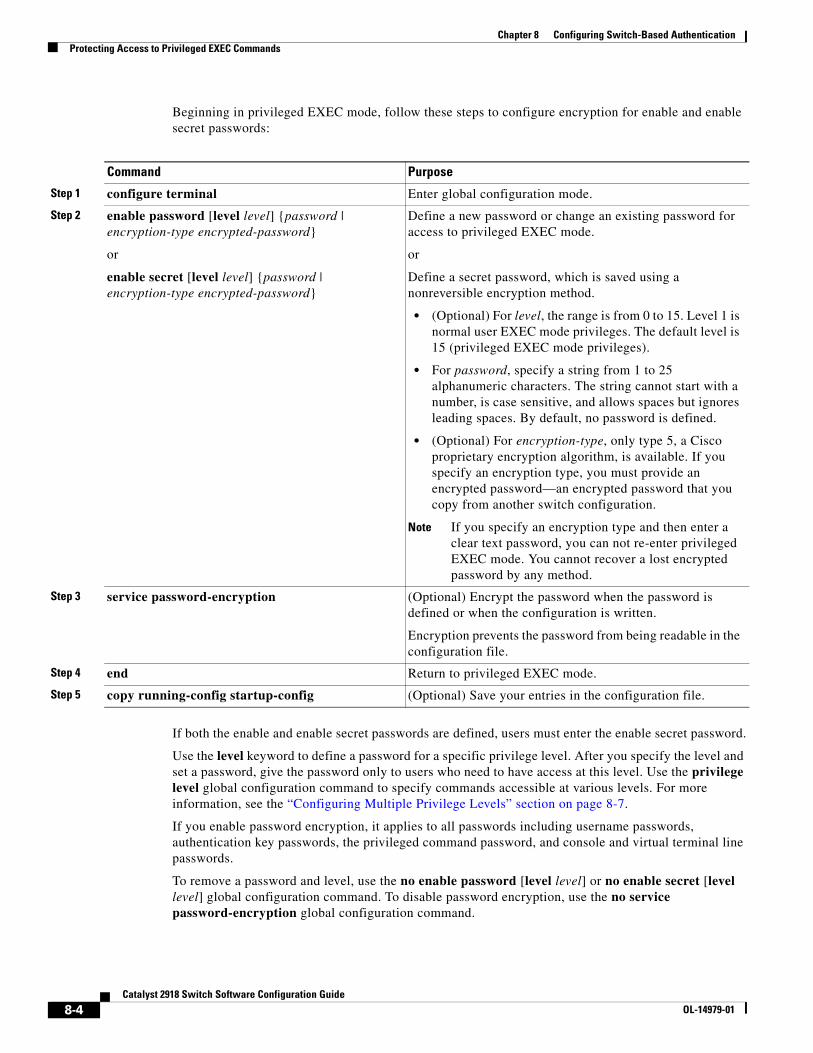
Chapter 8 Configuring Switch-Based AuthenticationProtecting Access to Privileged EXEC Commands
Beginning in privileged EXEC mode, follow these steps to configure encryption for enable and enable secret passwords:
Command Purpose
Step 1 configure terminal Enter global configuration mode.
Step 2 enable password [level level] {password | encryption-type encrypted-password}
or
enable secret [level level] {password | encryption-type encrypted-password}
Define a new password or change an existing password for access to privileged EXEC mode.
or
Define a secret password, which is saved using a nonreversible encryption method.
• (Optional) For level, the range is from 0 to 15. Level 1 is normal user EXEC mode privileges. The default level is 15 (privileged EXEC mode privileges).
• For password, specify a string from 1 to 25 alphanumeric characters. The string cannot start with a number, is case sensitive, and allows spaces but ignores leading spaces. By default, no password is defined.
• (Optional) For encryption-type, only type 5, a Cisco proprietary encryption algorithm, is available. If you specify an encryption type, you must provide an encrypted password—an encrypted password that you copy from another switch configuration.
Note If you specify an encryption type and then enter a clear text password, you can not re-enter privileged EXEC mode. You cannot recover a lost encrypted password by any method.
Step 3 service password-encryption (Optional) Encrypt the password when the password is defined or when the configuration is written.
Encryption prevents the password from being readable in the configuration file.
Step 4 end Return to privileged EXEC mode.
Step 5 copy running-config startup-config (Optional) Save your entries in the configuration file.
If both the enable and enable secret passwords are defined, users must enter the enable secret password.
Use the level keyword to define a password for a specific privilege level. After you specify the level and set a password, give the password only to users who need to have access at this level. Use the privilege level global configuration command to specify commands accessible at various levels. For more information, see the “Configuring Multiple Privilege Levels” section on page 8-7.
If you enable password encryption, it applies to all passwords including username passwords, authentication key passwords, the privileged command password, and console and virtual terminal line passwords.
To remove a password and level, use the no enable password [level level] or no enable secret [level level] global configuration command. To disable password encryption, use the no service password-encryption global configuration command.
8-4Catalyst 2918 Switch Software Configuration Guide
OL-14979-01
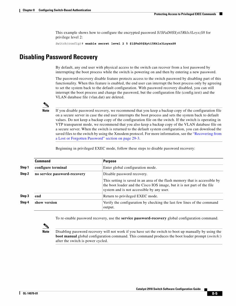
Chapter 8 Configuring Switch-Based AuthenticationProtecting Access to Privileged EXEC Commands
This example shows how to configure the encrypted password $1$FaD0$Xyti5Rkls3LoyxzS8 for privilege level 2:
Switch(config)# enable secret level 2 5 $1$FaD0$Xyti5Rkls3LoyxzS8
Disabling Password RecoveryBy default, any end user with physical access to the switch can recover from a lost password by interrupting the boot process while the switch is powering on and then by entering a new password.
The password-recovery disable feature protects access to the switch password by disabling part of this functionality. When this feature is enabled, the end user can interrupt the boot process only by agreeing to set the system back to the default configuration. With password recovery disabled, you can still interrupt the boot process and change the password, but the configuration file (config.text) and the VLAN database file (vlan.dat) are deleted.
Note If you disable password recovery, we recommend that you keep a backup copy of the configuration file on a secure server in case the end user interrupts the boot process and sets the system back to default values. Do not keep a backup copy of the configuration file on the switch. If the switch is operating in VTP transparent mode, we recommend that you also keep a backup copy of the VLAN database file on a secure server. When the switch is returned to the default system configuration, you can download the saved files to the switch by using the Xmodem protocol. For more information, see the “Recovering from a Lost or Forgotten Password” section on page 29-3.
Beginning in privileged EXEC mode, follow these steps to disable password recovery:
Command Purpose
Step 1 configure terminal Enter global configuration mode.
Step 2 no service password-recovery Disable password recovery.
This setting is saved in an area of the flash memory that is accessible by the boot loader and the Cisco IOS image, but it is not part of the file system and is not accessible by any user.
Step 3 end Return to privileged EXEC mode.
Step 4 show version Verify the configuration by checking the last few lines of the command output.
To re-enable password recovery, use the service password-recovery global configuration command.
Note Disabling password recovery will not work if you have set the switch to boot up manually by using the boot manual global configuration command. This command produces the boot loader prompt (switch:) after the switch is power cycled.
8-5Catalyst 2918 Switch Software Configuration Guide
OL-14979-01
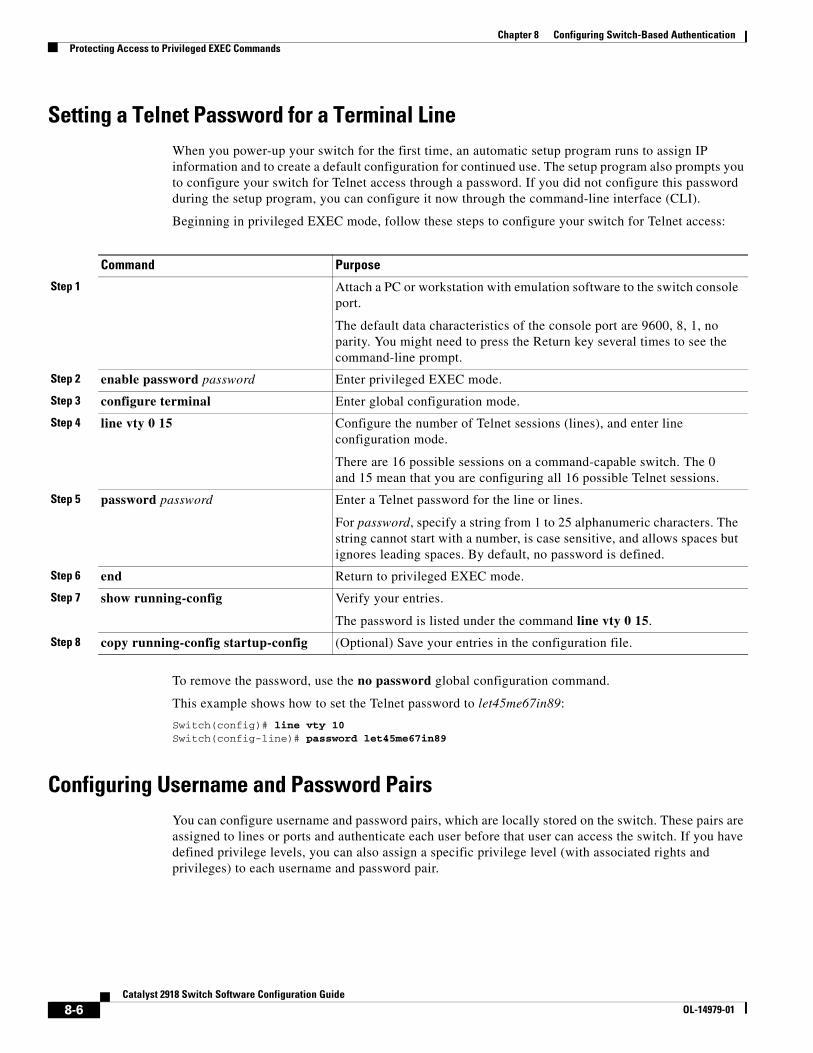
Chapter 8 Configuring Switch-Based AuthenticationProtecting Access to Privileged EXEC Commands
Setting a Telnet Password for a Terminal LineWhen you power-up your switch for the first time, an automatic setup program runs to assign IP information and to create a default configuration for continued use. The setup program also prompts you to configure your switch for Telnet access through a password. If you did not configure this password during the setup program, you can configure it now through the command-line interface (CLI).
Beginning in privileged EXEC mode, follow these steps to configure your switch for Telnet access:
Command Purpose
Step 1 Attach a PC or workstation with emulation software to the switch console port.
The default data characteristics of the console port are 9600, 8, 1, no parity. You might need to press the Return key several times to see the command-line prompt.
Step 2 enable password password Enter privileged EXEC mode.
Step 3 configure terminal Enter global configuration mode.
Step 4 line vty 0 15 Configure the number of Telnet sessions (lines), and enter line configuration mode.
There are 16 possible sessions on a command-capable switch. The 0 and 15 mean that you are configuring all 16 possible Telnet sessions.
Step 5 password password Enter a Telnet password for the line or lines.
For password, specify a string from 1 to 25 alphanumeric characters. The string cannot start with a number, is case sensitive, and allows spaces but ignores leading spaces. By default, no password is defined.
Step 6 end Return to privileged EXEC mode.
Step 7 show running-config Verify your entries.
The password is listed under the command line vty 0 15.
Step 8 copy running-config startup-config (Optional) Save your entries in the configuration file.
To remove the password, use the no password global configuration command.
This example shows how to set the Telnet password to let45me67in89:
Switch(config)# line vty 10Switch(config-line)# password let45me67in89
Configuring Username and Password PairsYou can configure username and password pairs, which are locally stored on the switch. These pairs are assigned to lines or ports and authenticate each user before that user can access the switch. If you have defined privilege levels, you can also assign a specific privilege level (with associated rights and privileges) to each username and password pair.
8-6Catalyst 2918 Switch Software Configuration Guide
OL-14979-01
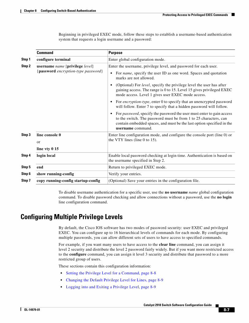
Chapter 8 Configuring Switch-Based AuthenticationProtecting Access to Privileged EXEC Commands
Beginning in privileged EXEC mode, follow these steps to establish a username-based authentication system that requests a login username and a password:
Command Purpose
Step 1 configure terminal Enter global configuration mode.
Step 2 username name [privilege level] {password encryption-type password}
Enter the username, privilege level, and password for each user.
• For name, specify the user ID as one word. Spaces and quotation marks are not allowed.
• (Optional) For level, specify the privilege level the user has after gaining access. The range is 0 to 15. Level 15 gives privileged EXEC mode access. Level 1 gives user EXEC mode access.
• For encryption-type, enter 0 to specify that an unencrypted password will follow. Enter 7 to specify that a hidden password will follow.
• For password, specify the password the user must enter to gain access to the switch. The password must be from 1 to 25 characters, can contain embedded spaces, and must be the last option specified in the username command.
Step 3 line console 0
or
line vty 0 15
Enter line configuration mode, and configure the console port (line 0) or the VTY lines (line 0 to 15).
Step 4 login local Enable local password checking at login time. Authentication is based on the username specified in Step 2.
Step 5 end Return to privileged EXEC mode.
Step 6 show running-config Verify your entries.
Step 7 copy running-config startup-config (Optional) Save your entries in the configuration file.
To disable username authentication for a specific user, use the no username name global configuration command. To disable password checking and allow connections without a password, use the no login line configuration command.
Configuring Multiple Privilege LevelsBy default, the Cisco IOS software has two modes of password security: user EXEC and privileged EXEC. You can configure up to 16 hierarchical levels of commands for each mode. By configuring multiple passwords, you can allow different sets of users to have access to specified commands.
For example, if you want many users to have access to the clear line command, you can assign it level 2 security and distribute the level 2 password fairly widely. But if you want more restricted access to the configure command, you can assign it level 3 security and distribute that password to a more restricted group of users.
These sections contain this configuration information:
• Setting the Privilege Level for a Command, page 8-8
• Changing the Default Privilege Level for Lines, page 8-9
• Logging into and Exiting a Privilege Level, page 8-9
8-7Catalyst 2918 Switch Software Configuration Guide
OL-14979-01
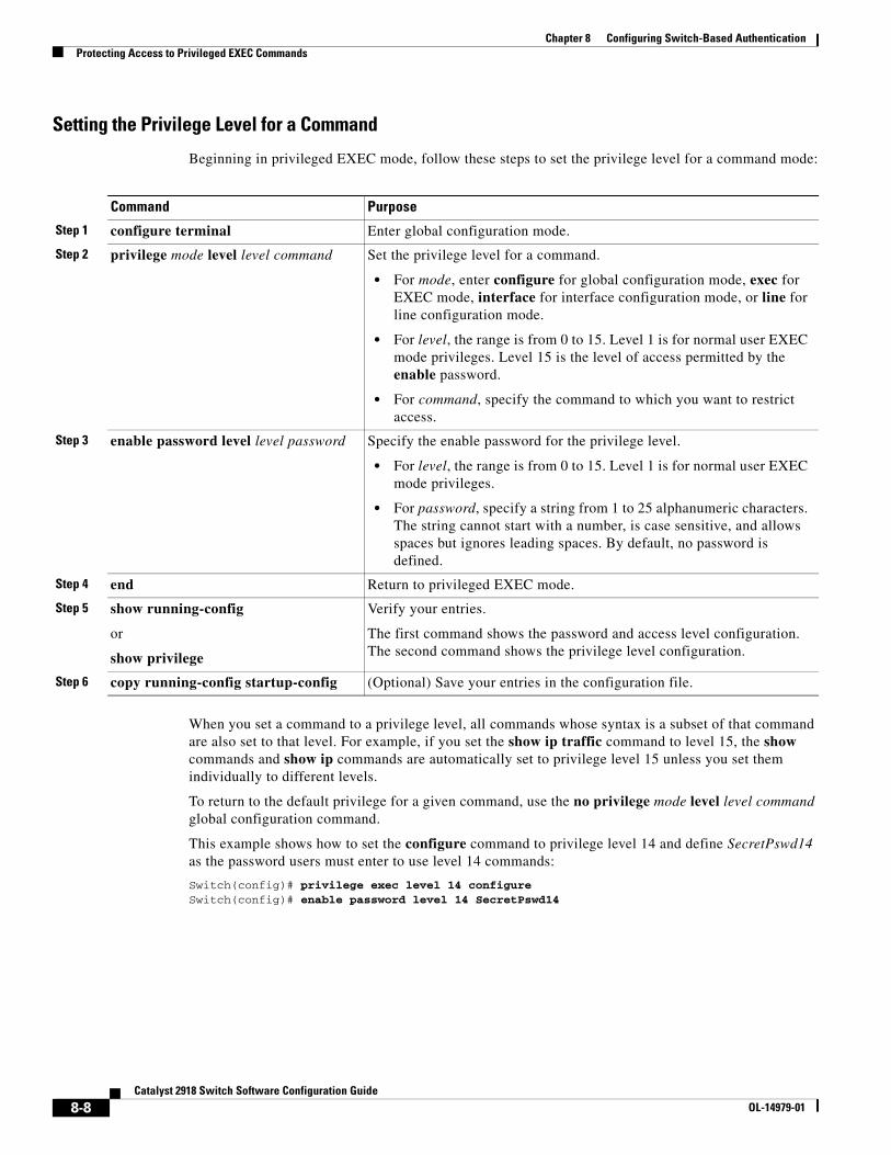
Chapter 8 Configuring Switch-Based AuthenticationProtecting Access to Privileged EXEC Commands
Setting the Privilege Level for a Command
Beginning in privileged EXEC mode, follow these steps to set the privilege level for a command mode:
Command Purpose
Step 1 configure terminal Enter global configuration mode.
Step 2 privilege mode level level command Set the privilege level for a command.
• For mode, enter configure for global configuration mode, exec for EXEC mode, interface for interface configuration mode, or line for line configuration mode.
• For level, the range is from 0 to 15. Level 1 is for normal user EXEC mode privileges. Level 15 is the level of access permitted by the enable password.
• For command, specify the command to which you want to restrict access.
Step 3 enable password level level password Specify the enable password for the privilege level.
• For level, the range is from 0 to 15. Level 1 is for normal user EXEC mode privileges.
• For password, specify a string from 1 to 25 alphanumeric characters. The string cannot start with a number, is case sensitive, and allows spaces but ignores leading spaces. By default, no password is defined.
Step 4 end Return to privileged EXEC mode.
Step 5 show running-config
or
show privilege
Verify your entries.
The first command shows the password and access level configuration. The second command shows the privilege level configuration.
Step 6 copy running-config startup-config (Optional) Save your entries in the configuration file.
When you set a command to a privilege level, all commands whose syntax is a subset of that command are also set to that level. For example, if you set the show ip traffic command to level 15, the show commands and show ip commands are automatically set to privilege level 15 unless you set them individually to different levels.
To return to the default privilege for a given command, use the no privilege mode level level command global configuration command.
This example shows how to set the configure command to privilege level 14 and define SecretPswd14 as the password users must enter to use level 14 commands:
Switch(config)# privilege exec level 14 configureSwitch(config)# enable password level 14 SecretPswd14
8-8Catalyst 2918 Switch Software Configuration Guide
OL-14979-01
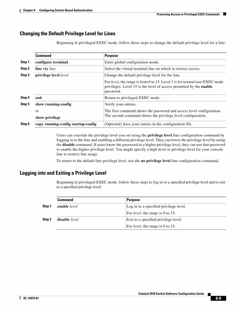
Chapter 8 Configuring Switch-Based AuthenticationProtecting Access to Privileged EXEC Commands
Changing the Default Privilege Level for Lines
Beginning in privileged EXEC mode, follow these steps to change the default privilege level for a line:
Command Purpose
Step 1 configure terminal Enter global configuration mode.
Step 2 line vty line Select the virtual terminal line on which to restrict access.
Step 3 privilege level level Change the default privilege level for the line.
For level, the range is from 0 to 15. Level 1 is for normal user EXEC mode privileges. Level 15 is the level of access permitted by the enable password.
Step 4 end Return to privileged EXEC mode.
Step 5 show running-config
or
show privilege
Verify your entries.
The first command shows the password and access level configuration. The second command shows the privilege level configuration.
Step 6 copy running-config startup-config (Optional) Save your entries in the configuration file.
Users can override the privilege level you set using the privilege level line configuration command by logging in to the line and enabling a different privilege level. They can lower the privilege level by using the disable command. If users know the password to a higher privilege level, they can use that password to enable the higher privilege level. You might specify a high level or privilege level for your console line to restrict line usage.
To return to the default line privilege level, use the no privilege level line configuration command.
Logging into and Exiting a Privilege Level
Beginning in privileged EXEC mode, follow these steps to log in to a specified privilege level and to exit to a specified privilege level:
Command Purpose
Step 1 enable level Log in to a specified privilege level.
For level, the range is 0 to 15.
Step 2 disable level Exit to a specified privilege level.
For level, the range is 0 to 15.
8-9Catalyst 2918 Switch Software Configuration Guide
OL-14979-01
Chapter 8 Configuring Switch-Based AuthenticationControlling Switch Access with TACACS+
Controlling Switch Access with TACACS+ This section describes how to enable and configure Terminal Access Controller Access Control System Plus (TACACS+), which provides detailed accounting information and flexible administrative control over authentication and authorization processes. TACACS+ is facilitated through authentication, authorization, accounting (AAA) and can be enabled only through AAA commands.
Note For complete syntax and usage information for the commands used in this section, see the Cisco IOS Security Command Reference, Release 12.2.
These sections contain this configuration information:
• Understanding TACACS+, page 8-10
• TACACS+ Operation, page 8-12
• Configuring TACACS+, page 8-12
• Displaying the TACACS+ Configuration, page 8-17
Understanding TACACS+TACACS+ is a security application that provides centralized validation of users attempting to gain access to your switch. TACACS+ services are maintained in a database on a TACACS+ daemon typically running on a UNIX or Windows NT workstation. You should have access to and should configure a TACACS+ server before the configuring TACACS+ features on your switch.
TACACS+ provides for separate and modular authentication, authorization, and accounting facilities. TACACS+ allows for a single access control server (the TACACS+ daemon) to provide each service—authentication, authorization, and accounting—independently. Each service can be tied into its own database to take advantage of other services available on that server or on the network, depending on the capabilities of the daemon.
The goal of TACACS+ is to provide a method for managing multiple network access points from a single management service. Your switch can be a network access server along with other Cisco routers and access servers. A network access server provides connections to a single user, to a network or subnetwork, and to interconnected networks as shown in Figure 8-1.
8-10Catalyst 2918 Switch Software Configuration Guide
OL-14979-01
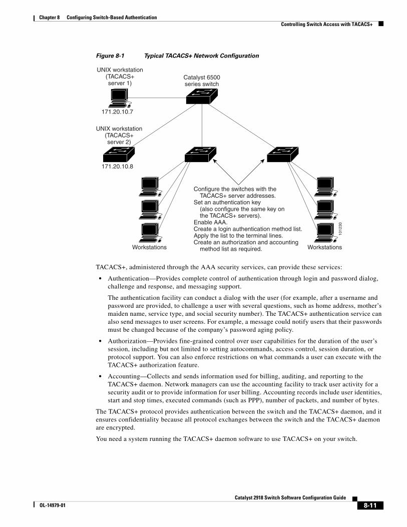
Chapter 8 Configuring Switch-Based AuthenticationControlling Switch Access with TACACS+
Figure 8-1 Typical TACACS+ Network Configuration
1012
30
UNIX workstation(TACACS+server 2)
UNIX workstation(TACACS+server 1)
Configure the switches with theTACACS+ server addresses.
Set an authentication key(also configure the same key onthe TACACS+ servers).
Enable AAA.Create a login authentication method list.Apply the list to the terminal lines.Create an authorization and accounting
method list as required.
Catalyst 6500series switch
Workstations
171.20.10.8
171.20.10.7
Workstations
TACACS+, administered through the AAA security services, can provide these services:
• Authentication—Provides complete control of authentication through login and password dialog, challenge and response, and messaging support.
The authentication facility can conduct a dialog with the user (for example, after a username and password are provided, to challenge a user with several questions, such as home address, mother’s maiden name, service type, and social security number). The TACACS+ authentication service can also send messages to user screens. For example, a message could notify users that their passwords must be changed because of the company’s password aging policy.
• Authorization—Provides fine-grained control over user capabilities for the duration of the user’s session, including but not limited to setting autocommands, access control, session duration, or protocol support. You can also enforce restrictions on what commands a user can execute with the TACACS+ authorization feature.
• Accounting—Collects and sends information used for billing, auditing, and reporting to the TACACS+ daemon. Network managers can use the accounting facility to track user activity for a security audit or to provide information for user billing. Accounting records include user identities, start and stop times, executed commands (such as PPP), number of packets, and number of bytes.
The TACACS+ protocol provides authentication between the switch and the TACACS+ daemon, and it ensures confidentiality because all protocol exchanges between the switch and the TACACS+ daemon are encrypted.
You need a system running the TACACS+ daemon software to use TACACS+ on your switch.
8-11Catalyst 2918 Switch Software Configuration Guide
OL-14979-01
Chapter 8 Configuring Switch-Based AuthenticationControlling Switch Access with TACACS+
TACACS+ OperationWhen a user attempts a simple ASCII login by authenticating to a switch using TACACS+, this process occurs:
1. When the connection is established, the switch contacts the TACACS+ daemon to obtain a username prompt to show to the user. The user enters a username, and the switch then contacts the TACACS+ daemon to obtain a password prompt. The switch displays the password prompt to the user, the user enters a password, and the password is then sent to the TACACS+ daemon.
TACACS+ allows a dialog between the daemon and the user until the daemon receives enough information to authenticate the user. The daemon prompts for a username and password combination, but can include other items, such as the user’s mother’s maiden name.
2. The switch eventually receives one of these responses from the TACACS+ daemon:
• ACCEPT—The user is authenticated and service can begin. If the switch is configured to require authorization, authorization begins at this time.
• REJECT—The user is not authenticated. The user can be denied access or is prompted to retry the login sequence, depending on the TACACS+ daemon.
• ERROR—An error occurred at some time during authentication with the daemon or in the network connection between the daemon and the switch. If an ERROR response is received, the switch typically tries to use an alternative method for authenticating the user.
• CONTINUE—The user is prompted for additional authentication information.
After authentication, the user undergoes an additional authorization phase if authorization has been enabled on the switch. Users must first successfully complete TACACS+ authentication before proceeding to TACACS+ authorization.
3. If TACACS+ authorization is required, the TACACS+ daemon is again contacted, and it returns an ACCEPT or REJECT authorization response. If an ACCEPT response is returned, the response contains data in the form of attributes that direct the EXEC or NETWORK session for that user and the services that the user can access:
• Telnet, Secure Shell (SSH), rlogin, or privileged EXEC services
• Connection parameters, including the host or client IP address, access list, and user timeouts
Configuring TACACS+This section describes how to configure your switch to support TACACS+. At a minimum, you must identify the host or hosts maintaining the TACACS+ daemon and define the method lists for TACACS+ authentication. You can optionally define method lists for TACACS+ authorization and accounting. A method list defines the sequence and methods to be used to authenticate, to authorize, or to keep accounts on a user. You can use method lists to designate one or more security protocols to be used, thus ensuring a backup system if the initial method fails. The software uses the first method listed to authenticate, to authorize, or to keep accounts on users; if that method does not respond, the software selects the next method in the list. This process continues until there is successful communication with a listed method or the method list is exhausted.
8-12Catalyst 2918 Switch Software Configuration Guide
OL-14979-01
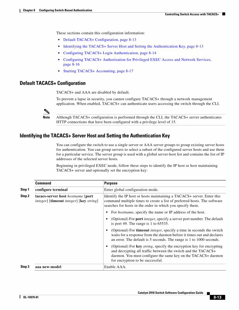
Chapter 8 Configuring Switch-Based AuthenticationControlling Switch Access with TACACS+
These sections contain this configuration information:
• Default TACACS+ Configuration, page 8-13
• Identifying the TACACS+ Server Host and Setting the Authentication Key, page 8-13
• Configuring TACACS+ Login Authentication, page 8-14
• Configuring TACACS+ Authorization for Privileged EXEC Access and Network Services, page 8-16
• Starting TACACS+ Accounting, page 8-17
Default TACACS+ Configuration
TACACS+ and AAA are disabled by default.
To prevent a lapse in security, you cannot configure TACACS+ through a network management application. When enabled, TACACS+ can authenticate users accessing the switch through the CLI.
Note Although TACACS+ configuration is performed through the CLI, the TACACS+ server authenticates HTTP connections that have been configured with a privilege level of 15.
Identifying the TACACS+ Server Host and Setting the Authentication Key
You can configure the switch to use a single server or AAA server groups to group existing server hosts for authentication. You can group servers to select a subset of the configured server hosts and use them for a particular service. The server group is used with a global server-host list and contains the list of IP addresses of the selected server hosts.
Beginning in privileged EXEC mode, follow these steps to identify the IP host or host maintaining TACACS+ server and optionally set the encryption key:
Command Purpose
Step 1 configure terminal Enter global configuration mode.
Step 2 tacacs-server host hostname [port integer] [timeout integer] [key string]
Identify the IP host or hosts maintaining a TACACS+ server. Enter this command multiple times to create a list of preferred hosts. The software searches for hosts in the order in which you specify them.
• For hostname, specify the name or IP address of the host.
• (Optional) For port integer, specify a server port number. The default is port 49. The range is 1 to 65535.
• (Optional) For timeout integer, specify a time in seconds the switch waits for a response from the daemon before it times out and declares an error. The default is 5 seconds. The range is 1 to 1000 seconds.
• (Optional) For key string, specify the encryption key for encrypting and decrypting all traffic between the switch and the TACACS+ daemon. You must configure the same key on the TACACS+ daemon for encryption to be successful.
Step 3 aaa new-model Enable AAA.
8-13Catalyst 2918 Switch Software Configuration Guide
OL-14979-01
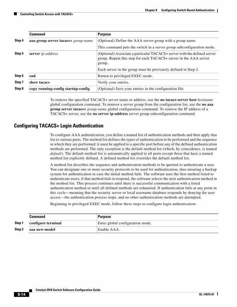
Chapter 8 Configuring Switch-Based AuthenticationControlling Switch Access with TACACS+
To remove the specified TACACS+ server name or address, use the no tacacs-server host hostname global configuration command. To remove a server group from the configuration list, use the no aaa group server tacacs+ group-name global configuration command. To remove the IP address of a TACACS+ server, use the no server ip-address server group subconfiguration command.
Configuring TACACS+ Login Authentication
To configure AAA authentication, you define a named list of authentication methods and then apply that list to various ports. The method list defines the types of authentication to be performed and the sequence in which they are performed; it must be applied to a specific port before any of the defined authentication methods are performed. The only exception is the default method list (which, by coincidence, is named default). The default method list is automatically applied to all ports except those that have a named method list explicitly defined. A defined method list overrides the default method list.
A method list describes the sequence and authentication methods to be queried to authenticate a user. You can designate one or more security protocols to be used for authentication, thus ensuring a backup system for authentication in case the initial method fails. The software uses the first method listed to authenticate users; if that method fails to respond, the software selects the next authentication method in the method list. This process continues until there is successful communication with a listed authentication method or until all defined methods are exhausted. If authentication fails at any point in this cycle—meaning that the security server or local username database responds by denying the user access—the authentication process stops, and no other authentication methods are attempted.
Beginning in privileged EXEC mode, follow these steps to configure login authentication:
Step 4 aaa group server tacacs+ group-name (Optional) Define the AAA server-group with a group name.
This command puts the switch in a server group subconfiguration mode.
Step 5 server ip-address (Optional) Associate a particular TACACS+ server with the defined server group. Repeat this step for each TACACS+ server in the AAA server group.
Each server in the group must be previously defined in Step 2.
Step 6 end Return to privileged EXEC mode.
Step 7 show tacacs Verify your entries.
Step 8 copy running-config startup-config (Optional) Save your entries in the configuration file.
Command Purpose
Command Purpose
Step 1 configure terminal Enter global configuration mode.
Step 2 aaa new-model Enable AAA.
8-14Catalyst 2918 Switch Software Configuration Guide
OL-14979-01
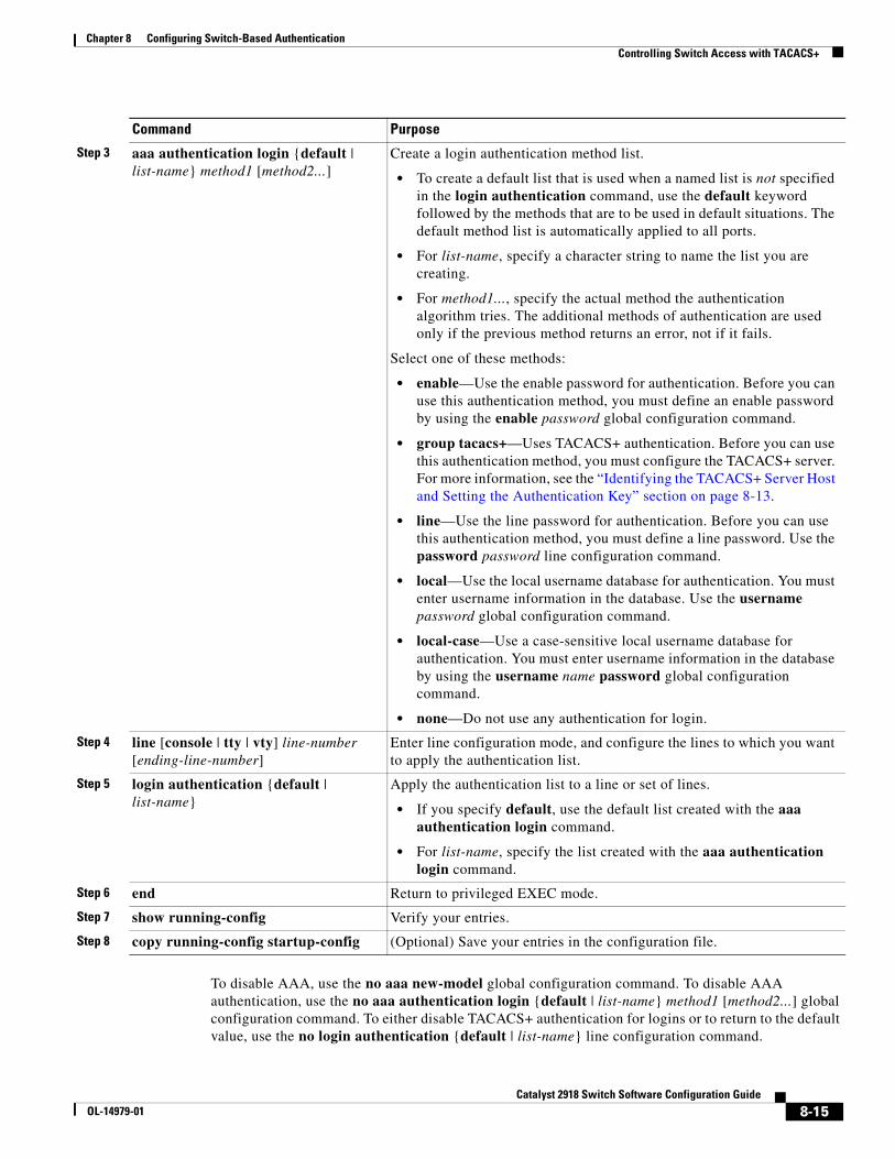
Chapter 8 Configuring Switch-Based AuthenticationControlling Switch Access with TACACS+
To disable AAA, use the no aaa new-model global configuration command. To disable AAA authentication, use the no aaa authentication login {default | list-name} method1 [method2...] global configuration command. To either disable TACACS+ authentication for logins or to return to the default value, use the no login authentication {default | list-name} line configuration command.
Step 3 aaa authentication login {default | list-name} method1 [method2...]
Create a login authentication method list.
• To create a default list that is used when a named list is not specified in the login authentication command, use the default keyword followed by the methods that are to be used in default situations. The default method list is automatically applied to all ports.
• For list-name, specify a character string to name the list you are creating.
• For method1..., specify the actual method the authentication algorithm tries. The additional methods of authentication are used only if the previous method returns an error, not if it fails.
Select one of these methods:
• enable—Use the enable password for authentication. Before you can use this authentication method, you must define an enable password by using the enable password global configuration command.
• group tacacs+—Uses TACACS+ authentication. Before you can use this authentication method, you must configure the TACACS+ server. For more information, see the “Identifying the TACACS+ Server Host and Setting the Authentication Key” section on page 8-13.
• line—Use the line password for authentication. Before you can use this authentication method, you must define a line password. Use the password password line configuration command.
• local—Use the local username database for authentication. You must enter username information in the database. Use the username password global configuration command.
• local-case—Use a case-sensitive local username database for authentication. You must enter username information in the database by using the username name password global configuration command.
• none—Do not use any authentication for login.
Step 4 line [console | tty | vty] line-number [ending-line-number]
Enter line configuration mode, and configure the lines to which you want to apply the authentication list.
Step 5 login authentication {default | list-name}
Apply the authentication list to a line or set of lines.
• If you specify default, use the default list created with the aaa authentication login command.
• For list-name, specify the list created with the aaa authentication login command.
Step 6 end Return to privileged EXEC mode.
Step 7 show running-config Verify your entries.
Step 8 copy running-config startup-config (Optional) Save your entries in the configuration file.
Command Purpose
8-15Catalyst 2918 Switch Software Configuration Guide
OL-14979-01
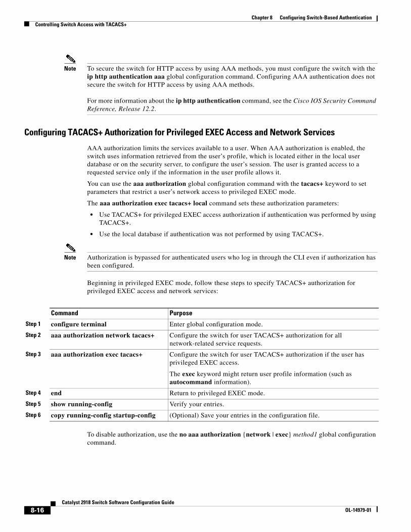
Chapter 8 Configuring Switch-Based AuthenticationControlling Switch Access with TACACS+
Note To secure the switch for HTTP access by using AAA methods, you must configure the switch with the ip http authentication aaa global configuration command. Configuring AAA authentication does not secure the switch for HTTP access by using AAA methods. For more information about the ip http authentication command, see the Cisco IOS Security Command Reference, Release 12.2.
Configuring TACACS+ Authorization for Privileged EXEC Access and Network Services
AAA authorization limits the services available to a user. When AAA authorization is enabled, the switch uses information retrieved from the user’s profile, which is located either in the local user database or on the security server, to configure the user’s session. The user is granted access to a requested service only if the information in the user profile allows it.
You can use the aaa authorization global configuration command with the tacacs+ keyword to set parameters that restrict a user’s network access to privileged EXEC mode.
The aaa authorization exec tacacs+ local command sets these authorization parameters:
• Use TACACS+ for privileged EXEC access authorization if authentication was performed by using TACACS+.
• Use the local database if authentication was not performed by using TACACS+.
Note Authorization is bypassed for authenticated users who log in through the CLI even if authorization has been configured.
Beginning in privileged EXEC mode, follow these steps to specify TACACS+ authorization for privileged EXEC access and network services:
Command Purpose
Step 1 configure terminal Enter global configuration mode.
Step 2 aaa authorization network tacacs+ Configure the switch for user TACACS+ authorization for all network-related service requests.
Step 3 aaa authorization exec tacacs+ Configure the switch for user TACACS+ authorization if the user has privileged EXEC access.
The exec keyword might return user profile information (such as autocommand information).
Step 4 end Return to privileged EXEC mode.
Step 5 show running-config Verify your entries.
Step 6 copy running-config startup-config (Optional) Save your entries in the configuration file.
To disable authorization, use the no aaa authorization {network | exec} method1 global configuration command.
8-16Catalyst 2918 Switch Software Configuration Guide
OL-14979-01
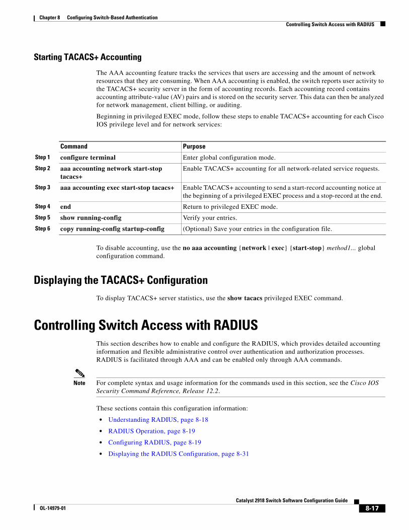
Chapter 8 Configuring Switch-Based AuthenticationControlling Switch Access with RADIUS
Starting TACACS+ Accounting
The AAA accounting feature tracks the services that users are accessing and the amount of network resources that they are consuming. When AAA accounting is enabled, the switch reports user activity to the TACACS+ security server in the form of accounting records. Each accounting record contains accounting attribute-value (AV) pairs and is stored on the security server. This data can then be analyzed for network management, client billing, or auditing.
Beginning in privileged EXEC mode, follow these steps to enable TACACS+ accounting for each Cisco IOS privilege level and for network services:
Command Purpose
Step 1 configure terminal Enter global configuration mode.
Step 2 aaa accounting network start-stop tacacs+
Enable TACACS+ accounting for all network-related service requests.
Step 3 aaa accounting exec start-stop tacacs+ Enable TACACS+ accounting to send a start-record accounting notice at the beginning of a privileged EXEC process and a stop-record at the end.
Step 4 end Return to privileged EXEC mode.
Step 5 show running-config Verify your entries.
Step 6 copy running-config startup-config (Optional) Save your entries in the configuration file.
To disable accounting, use the no aaa accounting {network | exec} {start-stop} method1... global configuration command.
Displaying the TACACS+ ConfigurationTo display TACACS+ server statistics, use the show tacacs privileged EXEC command.
Controlling Switch Access with RADIUS This section describes how to enable and configure the RADIUS, which provides detailed accounting information and flexible administrative control over authentication and authorization processes. RADIUS is facilitated through AAA and can be enabled only through AAA commands.
Note For complete syntax and usage information for the commands used in this section, see the Cisco IOS Security Command Reference, Release 12.2.
These sections contain this configuration information:
• Understanding RADIUS, page 8-18
• RADIUS Operation, page 8-19
• Configuring RADIUS, page 8-19
• Displaying the RADIUS Configuration, page 8-31
8-17Catalyst 2918 Switch Software Configuration Guide
OL-14979-01
Chapter 8 Configuring Switch-Based AuthenticationControlling Switch Access with RADIUS
Understanding RADIUSRADIUS is a distributed client/server system that secures networks against unauthorized access. RADIUS clients run on supported Cisco routers and switches. Clients send authentication requests to a central RADIUS server, which contains all user authentication and network service access information. The RADIUS host is normally a multiuser system running RADIUS server software from Cisco (Cisco Secure Access Control Server Version 3.0), Livingston, Merit, Microsoft, or another software provider. For more information, see the RADIUS server documentation.
Use RADIUS in these network environments that require access security:
• Networks with multiple-vendor access servers, each supporting RADIUS. For example, access servers from several vendors use a single RADIUS server-based security database. In an IP-based network with multiple vendors’ access servers, dial-in users are authenticated through a RADIUS server that has been customized to work with the Kerberos security system.
• Turnkey network security environments in which applications support the RADIUS protocol, such as in an access environment that uses a smart card access control system. In one case, RADIUS has been used with Enigma’s security cards to validates users and to grant access to network resources.
• Networks already using RADIUS. You can add a Cisco switch containing a RADIUS client to the network. This might be the first step when you make a transition to a TACACS+ server. See Figure 8-2 on page 8-19.
• Network in which the user must only access a single service. Using RADIUS, you can control user access to a single host, to a single utility such as Telnet, or to the network through a protocol such as IEEE 802.1x. For more information about this protocol, see Chapter 9, “Configuring IEEE 802.1x Port-Based Authentication.”
• Networks that require resource accounting. You can use RADIUS accounting independently of RADIUS authentication or authorization. The RADIUS accounting functions allow data to be sent at the start and end of services, showing the amount of resources (such as time, packets, bytes, and so forth) used during the session. An Internet service provider might use a freeware-based version of RADIUS access control and accounting software to meet special security and billing needs.
RADIUS is not suitable in these network security situations:
• Multiprotocol access environments. RADIUS does not support AppleTalk Remote Access (ARA), NetBIOS Frame Control Protocol (NBFCP), NetWare Asynchronous Services Interface (NASI), or X.25 PAD connections.
• Switch-to-switch or router-to-router situations. RADIUS does not provide two-way authentication. RADIUS can be used to authenticate from one device to a non-Cisco device if the non-Cisco device requires authentication.
• Networks using a variety of services. RADIUS generally binds a user to one service model.
8-18Catalyst 2918 Switch Software Configuration Guide
OL-14979-01
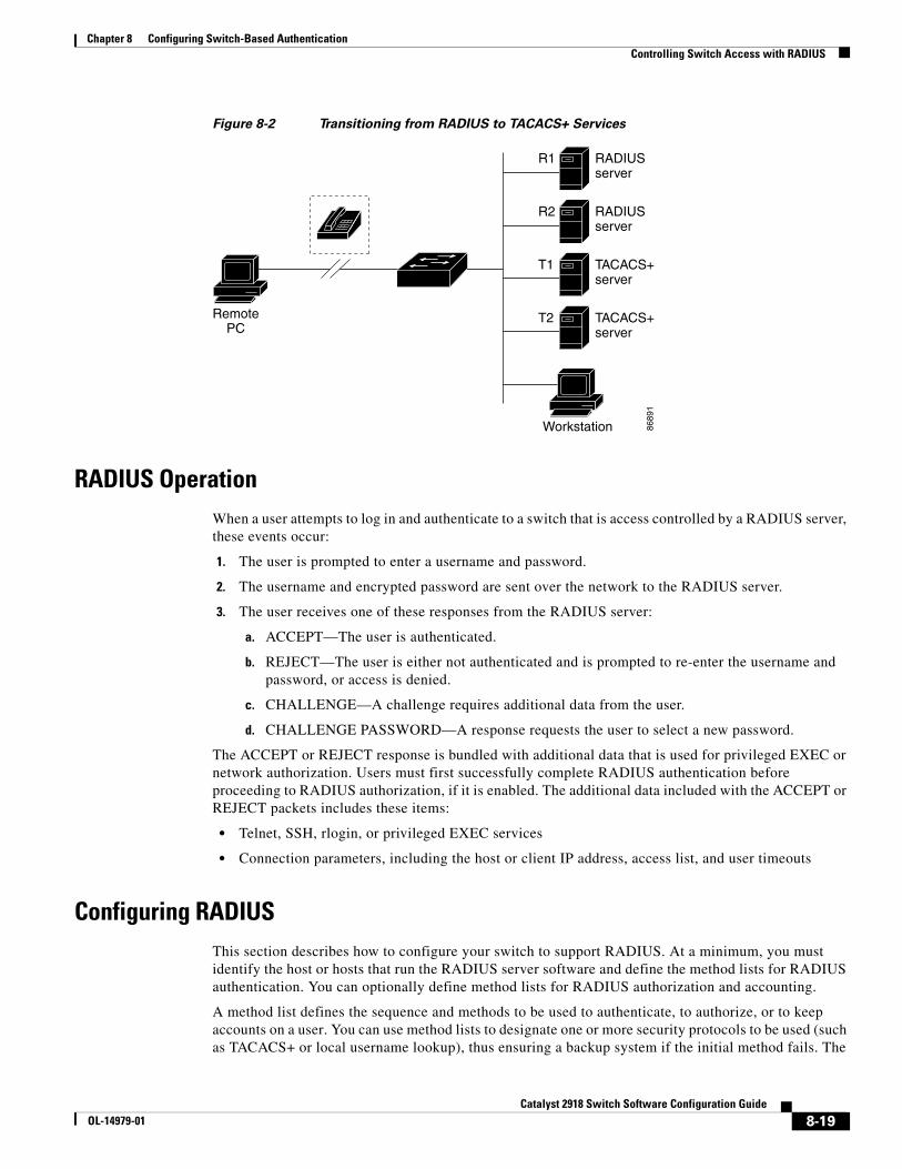
Chapter 8 Configuring Switch-Based AuthenticationControlling Switch Access with RADIUS
Figure 8-2 Transitioning from RADIUS to TACACS+ Services
8689
1
RADIUSserver
RADIUSserver
TACACS+server
TACACS+server
R1
R2
T1
T2RemotePC
Workstation
RADIUS OperationWhen a user attempts to log in and authenticate to a switch that is access controlled by a RADIUS server, these events occur:
1. The user is prompted to enter a username and password.
2. The username and encrypted password are sent over the network to the RADIUS server.
3. The user receives one of these responses from the RADIUS server:
a. ACCEPT—The user is authenticated.
b. REJECT—The user is either not authenticated and is prompted to re-enter the username and password, or access is denied.
c. CHALLENGE—A challenge requires additional data from the user.
d. CHALLENGE PASSWORD—A response requests the user to select a new password.
The ACCEPT or REJECT response is bundled with additional data that is used for privileged EXEC or network authorization. Users must first successfully complete RADIUS authentication before proceeding to RADIUS authorization, if it is enabled. The additional data included with the ACCEPT or REJECT packets includes these items:
• Telnet, SSH, rlogin, or privileged EXEC services
• Connection parameters, including the host or client IP address, access list, and user timeouts
Configuring RADIUSThis section describes how to configure your switch to support RADIUS. At a minimum, you must identify the host or hosts that run the RADIUS server software and define the method lists for RADIUS authentication. You can optionally define method lists for RADIUS authorization and accounting.
A method list defines the sequence and methods to be used to authenticate, to authorize, or to keep accounts on a user. You can use method lists to designate one or more security protocols to be used (such as TACACS+ or local username lookup), thus ensuring a backup system if the initial method fails. The
8-19Catalyst 2918 Switch Software Configuration Guide
OL-14979-01
Chapter 8 Configuring Switch-Based AuthenticationControlling Switch Access with RADIUS
software uses the first method listed to authenticate, to authorize, or to keep accounts on users; if that method does not respond, the software selects the next method in the list. This process continues until there is successful communication with a listed method or the method list is exhausted.
You should have access to and should configure a RADIUS server before configuring RADIUS features on your switch.
These sections contain this configuration information:
• Default RADIUS Configuration, page 8-20
• Identifying the RADIUS Server Host, page 8-20 (required)
• Configuring RADIUS Login Authentication, page 8-23 (required)
• Defining AAA Server Groups, page 8-25 (optional)
• Configuring RADIUS Authorization for User Privileged Access and Network Services, page 8-27 (optional)
• Starting RADIUS Accounting, page 8-28 (optional)
• Configuring Settings for All RADIUS Servers, page 8-29 (optional)
• Configuring the Switch to Use Vendor-Specific RADIUS Attributes, page 8-29 (optional)
• Configuring the Switch for Vendor-Proprietary RADIUS Server Communication, page 8-31 (optional)
Default RADIUS Configuration
RADIUS and AAA are disabled by default.
To prevent a lapse in security, you cannot configure RADIUS through a network management application. When enabled, RADIUS can authenticate users accessing the switch through the CLI.
Identifying the RADIUS Server Host
Switch-to-RADIUS-server communication involves several components:
• Hostname or IP address
• Authentication destination port
• Accounting destination port
• Key string
• Timeout period
• Retransmission value
You identify RADIUS security servers by their hostname or IP address, hostname and specific UDP port numbers, or their IP address and specific UDP port numbers. The combination of the IP address and the UDP port number creates a unique identifier, allowing different ports to be individually defined as RADIUS hosts providing a specific AAA service. This unique identifier enables RADIUS requests to be sent to multiple UDP ports on a server at the same IP address.
If two different host entries on the same RADIUS server are configured for the same service—for example, accounting—the second host entry configured acts as a fail-over backup to the first one. Using this example, if the first host entry fails to provide accounting services, the %RADIUS-4-RADIUS_DEAD message appears, and then the switch tries the second host entry configured on the same device for accounting services. (The RADIUS host entries are tried in the order that they are configured.)
8-20Catalyst 2918 Switch Software Configuration Guide
OL-14979-01
Chapter 8 Configuring Switch-Based AuthenticationControlling Switch Access with RADIUS
A RADIUS server and the switch use a shared secret text string to encrypt passwords and exchange responses. To configure RADIUS to use the AAA security commands, you must specify the host running the RADIUS server daemon and a secret text (key) string that it shares with the switch.
The timeout, retransmission, and encryption key values can be configured globally for all RADIUS servers, on a per-server basis, or in some combination of global and per-server settings. To apply these settings globally to all RADIUS servers communicating with the switch, use the three unique global configuration commands: radius-server timeout, radius-server retransmit, and radius-server key. To apply these values on a specific RADIUS server, use the radius-server host global configuration command.
Note If you configure both global and per-server functions (timeout, retransmission, and key commands) on the switch, the per-server timer, retransmission, and key value commands override global timer, retransmission, and key value commands. For information on configuring these settings on all RADIUS servers, see the “Configuring Settings for All RADIUS Servers” section on page 8-29.
You can configure the switch to use AAA server groups to group existing server hosts for authentication. For more information, see the “Defining AAA Server Groups” section on page 8-25.
8-21Catalyst 2918 Switch Software Configuration Guide
OL-14979-01
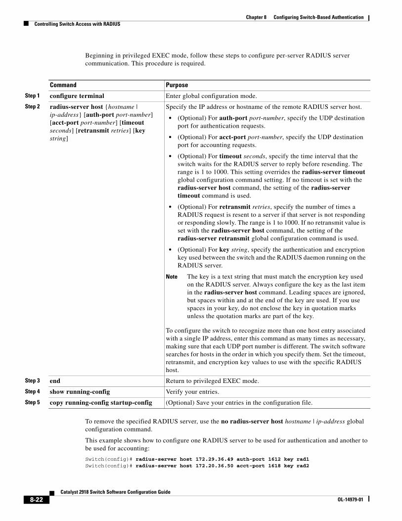
Chapter 8 Configuring Switch-Based AuthenticationControlling Switch Access with RADIUS
Beginning in privileged EXEC mode, follow these steps to configure per-server RADIUS server communication. This procedure is required.
Command Purpose
Step 1 configure terminal Enter global configuration mode.
Step 2 radius-server host {hostname | ip-address} [auth-port port-number] [acct-port port-number] [timeout seconds] [retransmit retries] [key string]
Specify the IP address or hostname of the remote RADIUS server host.
• (Optional) For auth-port port-number, specify the UDP destination port for authentication requests.
• (Optional) For acct-port port-number, specify the UDP destination port for accounting requests.
• (Optional) For timeout seconds, specify the time interval that the switch waits for the RADIUS server to reply before resending. The range is 1 to 1000. This setting overrides the radius-server timeout global configuration command setting. If no timeout is set with the radius-server host command, the setting of the radius-server timeout command is used.
• (Optional) For retransmit retries, specify the number of times a RADIUS request is resent to a server if that server is not responding or responding slowly. The range is 1 to 1000. If no retransmit value is set with the radius-server host command, the setting of the radius-server retransmit global configuration command is used.
• (Optional) For key string, specify the authentication and encryption key used between the switch and the RADIUS daemon running on the RADIUS server.
Note The key is a text string that must match the encryption key used on the RADIUS server. Always configure the key as the last item in the radius-server host command. Leading spaces are ignored, but spaces within and at the end of the key are used. If you use spaces in your key, do not enclose the key in quotation marks unless the quotation marks are part of the key.
To configure the switch to recognize more than one host entry associated with a single IP address, enter this command as many times as necessary, making sure that each UDP port number is different. The switch software searches for hosts in the order in which you specify them. Set the timeout, retransmit, and encryption key values to use with the specific RADIUS host.
Step 3 end Return to privileged EXEC mode.
Step 4 show running-config Verify your entries.
Step 5 copy running-config startup-config (Optional) Save your entries in the configuration file.
To remove the specified RADIUS server, use the no radius-server host hostname | ip-address global configuration command.
This example shows how to configure one RADIUS server to be used for authentication and another to be used for accounting:
Switch(config)# radius-server host 172.29.36.49 auth-port 1612 key rad1Switch(config)# radius-server host 172.20.36.50 acct-port 1618 key rad2
8-22Catalyst 2918 Switch Software Configuration Guide
OL-14979-01
Chapter 8 Configuring Switch-Based AuthenticationControlling Switch Access with RADIUS
This example shows how to configure host1 as the RADIUS server and to use the default ports for both authentication and accounting:
Switch(config)# radius-server host host1
Note You also need to configure some settings on the RADIUS server. These settings include the IP address of the switch and the key string to be shared by both the server and the switch. For more information, see the RADIUS server documentation.
Configuring RADIUS Login Authentication
To configure AAA authentication, you define a named list of authentication methods and then apply that list to various ports. The method list defines the types of authentication to be performed and the sequence in which they are performed; it must be applied to a specific port before any of the defined authentication methods are performed. The only exception is the default method list (which, by coincidence, is named default). The default method list is automatically applied to all ports except those that have a named method list explicitly defined.
A method list describes the sequence and authentication methods to be queried to authenticate a user. You can designate one or more security protocols to be used for authentication, thus ensuring a backup system for authentication in case the initial method fails. The software uses the first method listed to authenticate users; if that method fails to respond, the software selects the next authentication method in the method list. This process continues until there is successful communication with a listed authentication method or until all defined methods are exhausted. If authentication fails at any point in this cycle—meaning that the security server or local username database responds by denying the user access—the authentication process stops, and no other authentication methods are attempted.
Beginning in privileged EXEC mode, follow these steps to configure login authentication. This procedure is required.
Command Purpose
Step 1 configure terminal Enter global configuration mode.
Step 2 aaa new-model Enable AAA.
8-23Catalyst 2918 Switch Software Configuration Guide
OL-14979-01
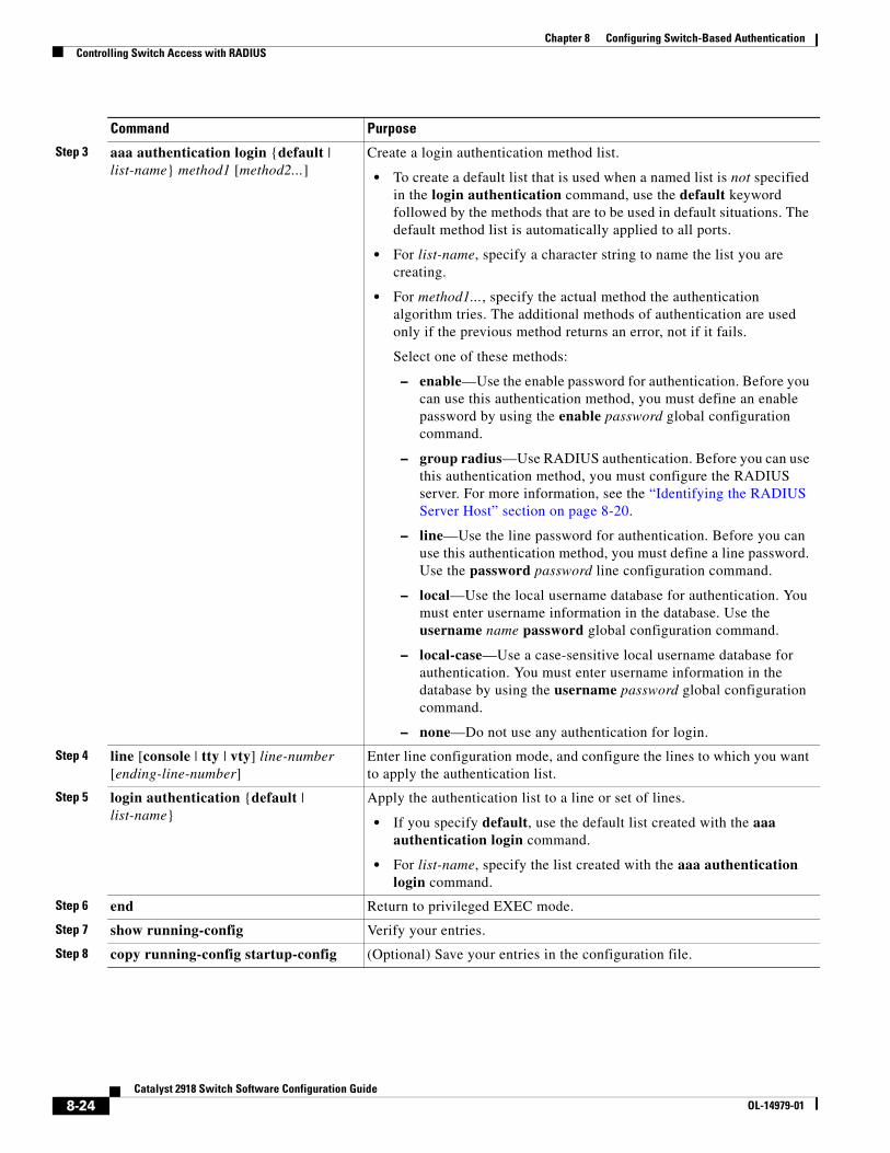
Chapter 8 Configuring Switch-Based AuthenticationControlling Switch Access with RADIUS
Step 3 aaa authentication login {default | list-name} method1 [method2...]
Create a login authentication method list.
• To create a default list that is used when a named list is not specified in the login authentication command, use the default keyword followed by the methods that are to be used in default situations. The default method list is automatically applied to all ports.
• For list-name, specify a character string to name the list you are creating.
• For method1..., specify the actual method the authentication algorithm tries. The additional methods of authentication are used only if the previous method returns an error, not if it fails.
Select one of these methods:
– enable—Use the enable password for authentication. Before you can use this authentication method, you must define an enable password by using the enable password global configuration command.
– group radius—Use RADIUS authentication. Before you can use this authentication method, you must configure the RADIUS server. For more information, see the “Identifying the RADIUS Server Host” section on page 8-20.
– line—Use the line password for authentication. Before you can use this authentication method, you must define a line password. Use the password password line configuration command.
– local—Use the local username database for authentication. You must enter username information in the database. Use the username name password global configuration command.
– local-case—Use a case-sensitive local username database for authentication. You must enter username information in the database by using the username password global configuration command.
– none—Do not use any authentication for login.
Step 4 line [console | tty | vty] line-number [ending-line-number]
Enter line configuration mode, and configure the lines to which you want to apply the authentication list.
Step 5 login authentication {default | list-name}
Apply the authentication list to a line or set of lines.
• If you specify default, use the default list created with the aaa authentication login command.
• For list-name, specify the list created with the aaa authentication login command.
Step 6 end Return to privileged EXEC mode.
Step 7 show running-config Verify your entries.
Step 8 copy running-config startup-config (Optional) Save your entries in the configuration file.
Command Purpose
8-24Catalyst 2918 Switch Software Configuration Guide
OL-14979-01
Chapter 8 Configuring Switch-Based AuthenticationControlling Switch Access with RADIUS
To disable AAA, use the no aaa new-model global configuration command. To disable AAA authentication, use the no aaa authentication login {default | list-name} method1 [method2...] global configuration command. To either disable RADIUS authentication for logins or to return to the default value, use the no login authentication {default | list-name} line configuration command.
Note To secure the switch for HTTP access by using AAA methods, you must configure the switch with the ip http authentication aaa global configuration command. Configuring AAA authentication does not secure the switch for HTTP access by using AAA methods. For more information about the ip http authentication command, see the Cisco IOS Security Command Reference, Release 12.2.
Defining AAA Server Groups
You can configure the switch to use AAA server groups to group existing server hosts for authentication. You select a subset of the configured server hosts and use them for a particular service. The server group is used with a global server-host list, which lists the IP addresses of the selected server hosts.
Server groups also can include multiple host entries for the same server if each entry has a unique identifier (the combination of the IP address and UDP port number), allowing different ports to be individually defined as RADIUS hosts providing a specific AAA service. If you configure two different host entries on the same RADIUS server for the same service, (for example, accounting), the second configured host entry acts as a fail-over backup to the first one.
You use the server group server configuration command to associate a particular server with a defined group server. You can either identify the server by its IP address or identify multiple host instances or entries by using the optional auth-port and acct-port keywords.
8-25Catalyst 2918 Switch Software Configuration Guide
OL-14979-01
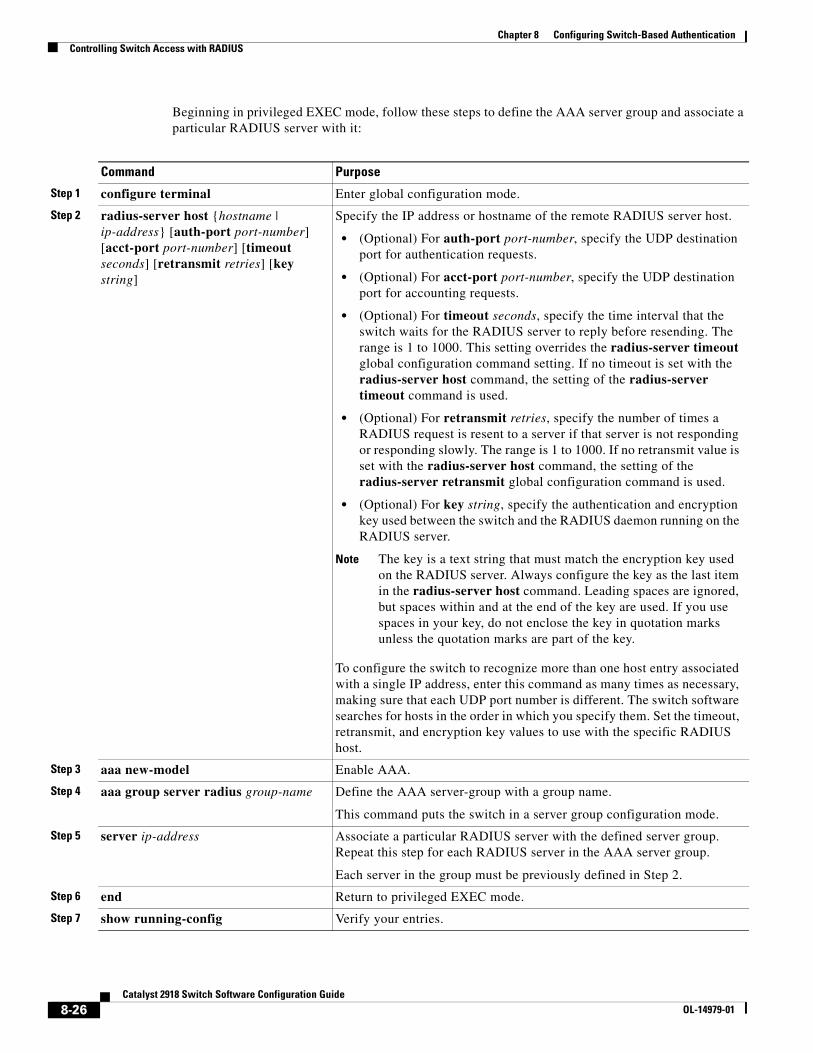
Chapter 8 Configuring Switch-Based AuthenticationControlling Switch Access with RADIUS
Beginning in privileged EXEC mode, follow these steps to define the AAA server group and associate a particular RADIUS server with it:
Command Purpose
Step 1 configure terminal Enter global configuration mode.
Step 2 radius-server host {hostname | ip-address} [auth-port port-number] [acct-port port-number] [timeout seconds] [retransmit retries] [key string]
Specify the IP address or hostname of the remote RADIUS server host.
• (Optional) For auth-port port-number, specify the UDP destination port for authentication requests.
• (Optional) For acct-port port-number, specify the UDP destination port for accounting requests.
• (Optional) For timeout seconds, specify the time interval that the switch waits for the RADIUS server to reply before resending. The range is 1 to 1000. This setting overrides the radius-server timeout global configuration command setting. If no timeout is set with the radius-server host command, the setting of the radius-server timeout command is used.
• (Optional) For retransmit retries, specify the number of times a RADIUS request is resent to a server if that server is not responding or responding slowly. The range is 1 to 1000. If no retransmit value is set with the radius-server host command, the setting of the radius-server retransmit global configuration command is used.
• (Optional) For key string, specify the authentication and encryption key used between the switch and the RADIUS daemon running on the RADIUS server.
Note The key is a text string that must match the encryption key used on the RADIUS server. Always configure the key as the last item in the radius-server host command. Leading spaces are ignored, but spaces within and at the end of the key are used. If you use spaces in your key, do not enclose the key in quotation marks unless the quotation marks are part of the key.
To configure the switch to recognize more than one host entry associated with a single IP address, enter this command as many times as necessary, making sure that each UDP port number is different. The switch software searches for hosts in the order in which you specify them. Set the timeout, retransmit, and encryption key values to use with the specific RADIUS host.
Step 3 aaa new-model Enable AAA.
Step 4 aaa group server radius group-name Define the AAA server-group with a group name.
This command puts the switch in a server group configuration mode.
Step 5 server ip-address Associate a particular RADIUS server with the defined server group. Repeat this step for each RADIUS server in the AAA server group.
Each server in the group must be previously defined in Step 2.
Step 6 end Return to privileged EXEC mode.
Step 7 show running-config Verify your entries.
8-26Catalyst 2918 Switch Software Configuration Guide
OL-14979-01
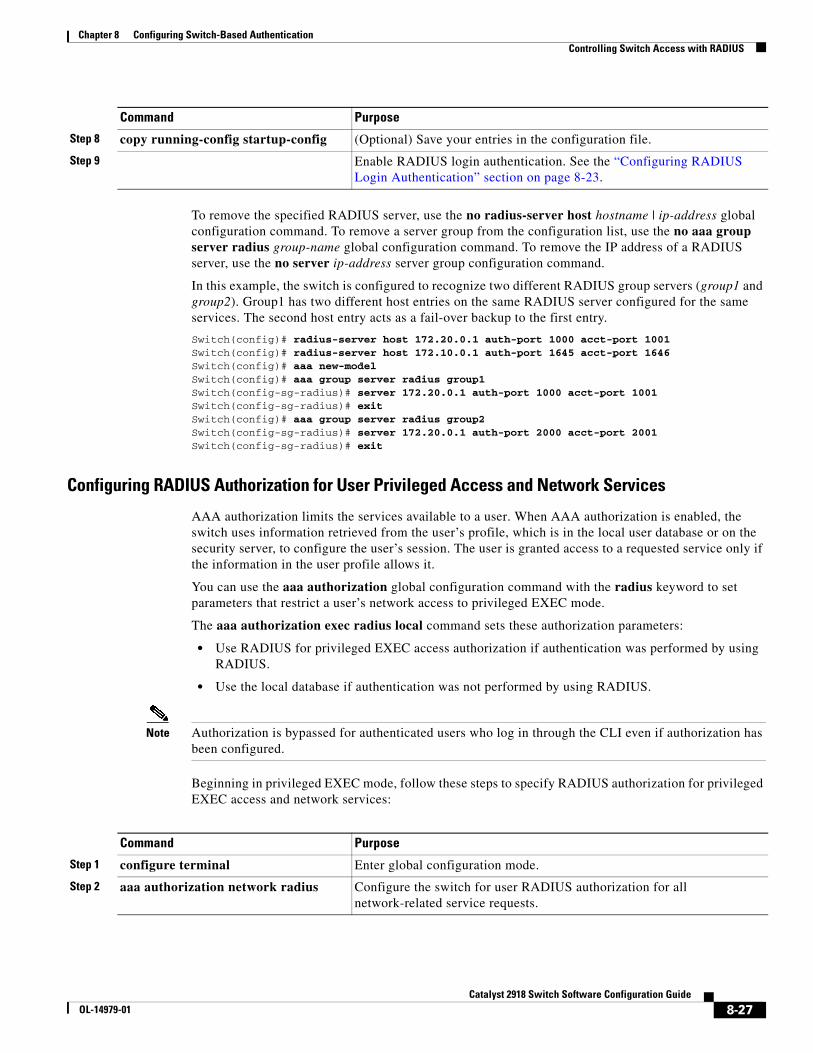
Chapter 8 Configuring Switch-Based AuthenticationControlling Switch Access with RADIUS
To remove the specified RADIUS server, use the no radius-server host hostname | ip-address global configuration command. To remove a server group from the configuration list, use the no aaa group server radius group-name global configuration command. To remove the IP address of a RADIUS server, use the no server ip-address server group configuration command.
In this example, the switch is configured to recognize two different RADIUS group servers (group1 and group2). Group1 has two different host entries on the same RADIUS server configured for the same services. The second host entry acts as a fail-over backup to the first entry.
Switch(config)# radius-server host 172.20.0.1 auth-port 1000 acct-port 1001Switch(config)# radius-server host 172.10.0.1 auth-port 1645 acct-port 1646Switch(config)# aaa new-modelSwitch(config)# aaa group server radius group1Switch(config-sg-radius)# server 172.20.0.1 auth-port 1000 acct-port 1001Switch(config-sg-radius)# exitSwitch(config)# aaa group server radius group2Switch(config-sg-radius)# server 172.20.0.1 auth-port 2000 acct-port 2001Switch(config-sg-radius)# exit
Configuring RADIUS Authorization for User Privileged Access and Network Services
AAA authorization limits the services available to a user. When AAA authorization is enabled, the switch uses information retrieved from the user’s profile, which is in the local user database or on the security server, to configure the user’s session. The user is granted access to a requested service only if the information in the user profile allows it.
You can use the aaa authorization global configuration command with the radius keyword to set parameters that restrict a user’s network access to privileged EXEC mode.
The aaa authorization exec radius local command sets these authorization parameters:
• Use RADIUS for privileged EXEC access authorization if authentication was performed by using RADIUS.
• Use the local database if authentication was not performed by using RADIUS.
Note Authorization is bypassed for authenticated users who log in through the CLI even if authorization has been configured.
Beginning in privileged EXEC mode, follow these steps to specify RADIUS authorization for privileged EXEC access and network services:
Step 8 copy running-config startup-config (Optional) Save your entries in the configuration file.
Step 9 Enable RADIUS login authentication. See the “Configuring RADIUS Login Authentication” section on page 8-23.
Command Purpose
Command Purpose
Step 1 configure terminal Enter global configuration mode.
Step 2 aaa authorization network radius Configure the switch for user RADIUS authorization for all network-related service requests.
8-27Catalyst 2918 Switch Software Configuration Guide
OL-14979-01
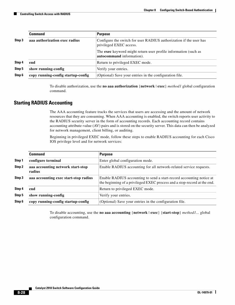
Chapter 8 Configuring Switch-Based AuthenticationControlling Switch Access with RADIUS
To disable authorization, use the no aaa authorization {network | exec} method1 global configuration command.
Starting RADIUS Accounting
The AAA accounting feature tracks the services that users are accessing and the amount of network resources that they are consuming. When AAA accounting is enabled, the switch reports user activity to the RADIUS security server in the form of accounting records. Each accounting record contains accounting attribute-value (AV) pairs and is stored on the security server. This data can then be analyzed for network management, client billing, or auditing.
Beginning in privileged EXEC mode, follow these steps to enable RADIUS accounting for each Cisco IOS privilege level and for network services:
Command Purpose
Step 1 configure terminal Enter global configuration mode.
Step 2 aaa accounting network start-stop radius
Enable RADIUS accounting for all network-related service requests.
Step 3 aaa accounting exec start-stop radius Enable RADIUS accounting to send a start-record accounting notice at the beginning of a privileged EXEC process and a stop-record at the end.
Step 4 end Return to privileged EXEC mode.
Step 5 show running-config Verify your entries.
Step 6 copy running-config startup-config (Optional) Save your entries in the configuration file.
To disable accounting, use the no aaa accounting {network | exec} {start-stop} method1... global configuration command.
Step 3 aaa authorization exec radius Configure the switch for user RADIUS authorization if the user has privileged EXEC access.
The exec keyword might return user profile information (such as autocommand information).
Step 4 end Return to privileged EXEC mode.
Step 5 show running-config Verify your entries.
Step 6 copy running-config startup-config (Optional) Save your entries in the configuration file.
Command Purpose
8-28Catalyst 2918 Switch Software Configuration Guide
OL-14979-01
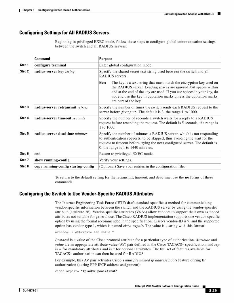
Chapter 8 Configuring Switch-Based AuthenticationControlling Switch Access with RADIUS
Configuring Settings for All RADIUS Servers
Beginning in privileged EXEC mode, follow these steps to configure global communication settings between the switch and all RADIUS servers:
Command Purpose
Step 1 configure terminal Enter global configuration mode.
Step 2 radius-server key string Specify the shared secret text string used between the switch and all RADIUS servers.
Note The key is a text string that must match the encryption key used on the RADIUS server. Leading spaces are ignored, but spaces within and at the end of the key are used. If you use spaces in your key, do not enclose the key in quotation marks unless the quotation marks are part of the key.
Step 3 radius-server retransmit retries Specify the number of times the switch sends each RADIUS request to the server before giving up. The default is 3; the range 1 to 1000.
Step 4 radius-server timeout seconds Specify the number of seconds a switch waits for a reply to a RADIUS request before resending the request. The default is 5 seconds; the range is 1 to 1000.
Step 5 radius-server deadtime minutes Specify the number of minutes a RADIUS server, which is not responding to authentication requests, to be skipped, thus avoiding the wait for the request to timeout before trying the next configured server. The default is 0; the range is 1 to 1440 minutes.
Step 6 end Return to privileged EXEC mode.
Step 7 show running-config Verify your settings.
Step 8 copy running-config startup-config (Optional) Save your entries in the configuration file.
To return to the default setting for the retransmit, timeout, and deadtime, use the no forms of these commands.
Configuring the Switch to Use Vendor-Specific RADIUS Attributes
The Internet Engineering Task Force (IETF) draft standard specifies a method for communicating vendor-specific information between the switch and the RADIUS server by using the vendor-specific attribute (attribute 26). Vendor-specific attributes (VSAs) allow vendors to support their own extended attributes not suitable for general use. The Cisco RADIUS implementation supports one vendor-specific option by using the format recommended in the specification. Cisco’s vendor-ID is 9, and the supported option has vendor-type 1, which is named cisco-avpair. The value is a string with this format:
protocol : attribute sep value *
Protocol is a value of the Cisco protocol attribute for a particular type of authorization. Attribute and value are an appropriate attribute-value (AV) pair defined in the Cisco TACACS+ specification, and sep is = for mandatory attributes and is * for optional attributes. The full set of features available for TACACS+ authorization can then be used for RADIUS.
For example, this AV pair activates Cisco’s multiple named ip address pools feature during IP authorization (during PPP IPCP address assignment):
cisco-avpair= ”ip:addr-pool=first“
8-29Catalyst 2918 Switch Software Configuration Guide
OL-14979-01
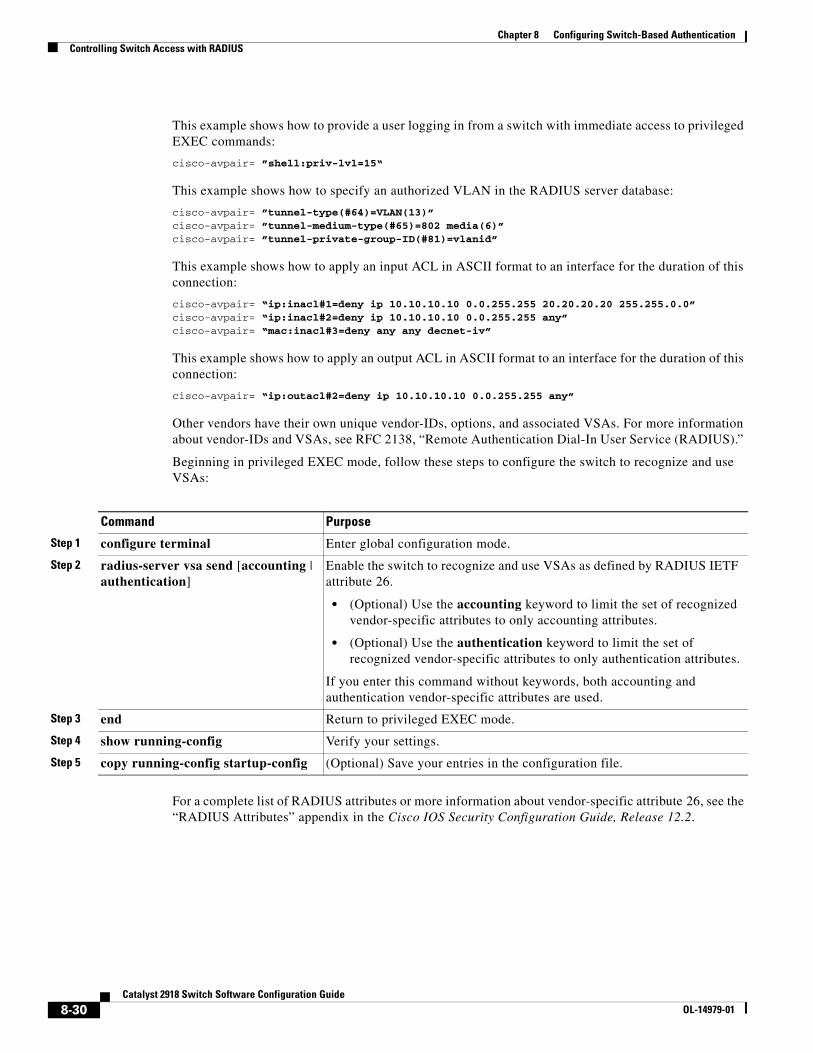
Chapter 8 Configuring Switch-Based AuthenticationControlling Switch Access with RADIUS
This example shows how to provide a user logging in from a switch with immediate access to privileged EXEC commands:
cisco-avpair= ”shell:priv-lvl=15“
This example shows how to specify an authorized VLAN in the RADIUS server database:
cisco-avpair= ”tunnel-type(#64)=VLAN(13)”cisco-avpair= ”tunnel-medium-type(#65)=802 media(6)”cisco-avpair= ”tunnel-private-group-ID(#81)=vlanid”
This example shows how to apply an input ACL in ASCII format to an interface for the duration of this connection:
cisco-avpair= “ip:inacl#1=deny ip 10.10.10.10 0.0.255.255 20.20.20.20 255.255.0.0”cisco-avpair= “ip:inacl#2=deny ip 10.10.10.10 0.0.255.255 any”cisco-avpair= “mac:inacl#3=deny any any decnet-iv”
This example shows how to apply an output ACL in ASCII format to an interface for the duration of this connection:
cisco-avpair= “ip:outacl#2=deny ip 10.10.10.10 0.0.255.255 any”
Other vendors have their own unique vendor-IDs, options, and associated VSAs. For more information about vendor-IDs and VSAs, see RFC 2138, “Remote Authentication Dial-In User Service (RADIUS).”
Beginning in privileged EXEC mode, follow these steps to configure the switch to recognize and use VSAs:
Command Purpose
Step 1 configure terminal Enter global configuration mode.
Step 2 radius-server vsa send [accounting | authentication]
Enable the switch to recognize and use VSAs as defined by RADIUS IETF attribute 26.
• (Optional) Use the accounting keyword to limit the set of recognized vendor-specific attributes to only accounting attributes.
• (Optional) Use the authentication keyword to limit the set of recognized vendor-specific attributes to only authentication attributes.
If you enter this command without keywords, both accounting and authentication vendor-specific attributes are used.
Step 3 end Return to privileged EXEC mode.
Step 4 show running-config Verify your settings.
Step 5 copy running-config startup-config (Optional) Save your entries in the configuration file.
For a complete list of RADIUS attributes or more information about vendor-specific attribute 26, see the “RADIUS Attributes” appendix in the Cisco IOS Security Configuration Guide, Release 12.2.
8-30Catalyst 2918 Switch Software Configuration Guide
OL-14979-01
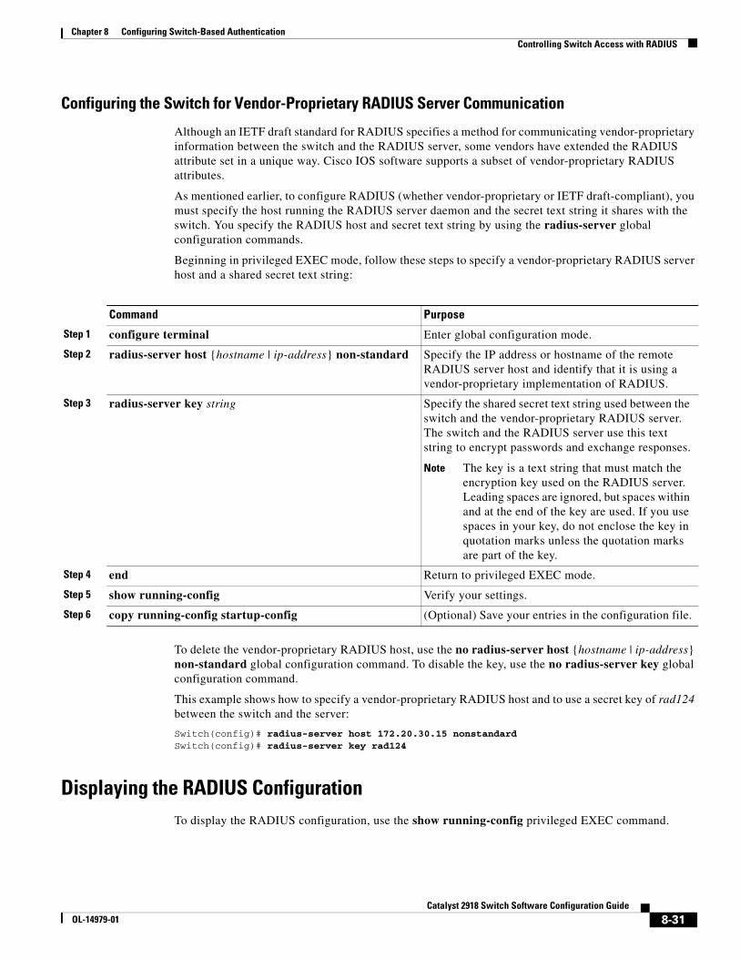
Chapter 8 Configuring Switch-Based AuthenticationControlling Switch Access with RADIUS
Configuring the Switch for Vendor-Proprietary RADIUS Server Communication
Although an IETF draft standard for RADIUS specifies a method for communicating vendor-proprietary information between the switch and the RADIUS server, some vendors have extended the RADIUS attribute set in a unique way. Cisco IOS software supports a subset of vendor-proprietary RADIUS attributes.
As mentioned earlier, to configure RADIUS (whether vendor-proprietary or IETF draft-compliant), you must specify the host running the RADIUS server daemon and the secret text string it shares with the switch. You specify the RADIUS host and secret text string by using the radius-server global configuration commands.
Beginning in privileged EXEC mode, follow these steps to specify a vendor-proprietary RADIUS server host and a shared secret text string:
Command Purpose
Step 1 configure terminal Enter global configuration mode.
Step 2 radius-server host {hostname | ip-address} non-standard Specify the IP address or hostname of the remote RADIUS server host and identify that it is using a vendor-proprietary implementation of RADIUS.
Step 3 radius-server key string Specify the shared secret text string used between the switch and the vendor-proprietary RADIUS server. The switch and the RADIUS server use this text string to encrypt passwords and exchange responses.
Note The key is a text string that must match the encryption key used on the RADIUS server. Leading spaces are ignored, but spaces within and at the end of the key are used. If you use spaces in your key, do not enclose the key in quotation marks unless the quotation marks are part of the key.
Step 4 end Return to privileged EXEC mode.
Step 5 show running-config Verify your settings.
Step 6 copy running-config startup-config (Optional) Save your entries in the configuration file.
To delete the vendor-proprietary RADIUS host, use the no radius-server host {hostname | ip-address} non-standard global configuration command. To disable the key, use the no radius-server key global configuration command.
This example shows how to specify a vendor-proprietary RADIUS host and to use a secret key of rad124 between the switch and the server:
Switch(config)# radius-server host 172.20.30.15 nonstandardSwitch(config)# radius-server key rad124
Displaying the RADIUS ConfigurationTo display the RADIUS configuration, use the show running-config privileged EXEC command.
8-31Catalyst 2918 Switch Software Configuration Guide
OL-14979-01
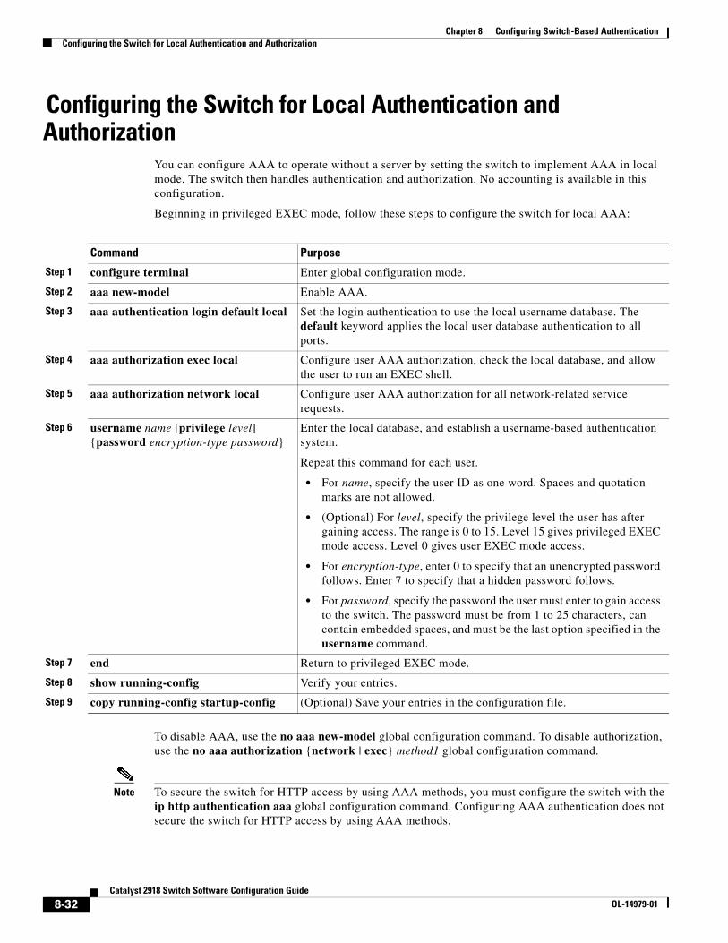
Chapter 8 Configuring Switch-Based AuthenticationConfiguring the Switch for Local Authentication and Authorization
Configuring the Switch for Local Authentication and Authorization
You can configure AAA to operate without a server by setting the switch to implement AAA in local mode. The switch then handles authentication and authorization. No accounting is available in this configuration.
Beginning in privileged EXEC mode, follow these steps to configure the switch for local AAA:
Command Purpose
Step 1 configure terminal Enter global configuration mode.
Step 2 aaa new-model Enable AAA.
Step 3 aaa authentication login default local Set the login authentication to use the local username database. The default keyword applies the local user database authentication to all ports.
Step 4 aaa authorization exec local Configure user AAA authorization, check the local database, and allow the user to run an EXEC shell.
Step 5 aaa authorization network local Configure user AAA authorization for all network-related service requests.
Step 6 username name [privilege level] {password encryption-type password}
Enter the local database, and establish a username-based authentication system.
Repeat this command for each user.
• For name, specify the user ID as one word. Spaces and quotation marks are not allowed.
• (Optional) For level, specify the privilege level the user has after gaining access. The range is 0 to 15. Level 15 gives privileged EXEC mode access. Level 0 gives user EXEC mode access.
• For encryption-type, enter 0 to specify that an unencrypted password follows. Enter 7 to specify that a hidden password follows.
• For password, specify the password the user must enter to gain access to the switch. The password must be from 1 to 25 characters, can contain embedded spaces, and must be the last option specified in the username command.
Step 7 end Return to privileged EXEC mode.
Step 8 show running-config Verify your entries.
Step 9 copy running-config startup-config (Optional) Save your entries in the configuration file.
To disable AAA, use the no aaa new-model global configuration command. To disable authorization, use the no aaa authorization {network | exec} method1 global configuration command.
Note To secure the switch for HTTP access by using AAA methods, you must configure the switch with the ip http authentication aaa global configuration command. Configuring AAA authentication does not secure the switch for HTTP access by using AAA methods.
8-32Catalyst 2918 Switch Software Configuration Guide
OL-14979-01
Chapter 8 Configuring Switch-Based AuthenticationConfiguring the Switch for Secure Shell
For more information about the ip http authentication command, see the Cisco IOS Security Command Reference, Release 12.2.
Configuring the Switch for Secure ShellThis section describes how to configure the Secure Shell (SSH) feature. To use this feature, you must install the cryptographic (encrypted) software image on your switch. You must obtain authorization to use this feature and to download the cryptographic software files from Cisco.com. For more information, see the release notes for this release.
These sections contain this information:
• Understanding SSH, page 8-33
• Configuring SSH, page 8-34
• Displaying the SSH Configuration and Status, page 8-36
For SSH configuration examples, see the “SSH Configuration Examples” section in the “Configuring Secure Shell” chapter of the Cisco IOS Security Configuration Guide, Cisco IOS Release 12.2, at this URL:
http://www.cisco.com/en/US/products/sw/iosswrel/ps1835/products_configuration_guide_chapter09186a00800ca7d5.html
Note For complete syntax and usage information for the commands used in this section, see the command reference for this release and the command reference for Cisco IOS Release 12.2 at this URL: http://www.cisco.com/en/US/products/sw/iosswrel/ps1835/products_command_reference_book09186a0080087e33.html
Understanding SSH SSH is a protocol that provides a secure, remote connection to a device. SSH provides more security for remote connections than Telnet does by providing strong encryption when a device is authenticated. This software release supports SSH Version 1 (SSHv1) and SSH Version 2 (SSHv2).
This section consists of these topics:
• SSH Servers, Integrated Clients, and Supported Versions, page 8-33
• Limitations, page 8-34
SSH Servers, Integrated Clients, and Supported Versions
The SSH feature has an SSH server and an SSH integrated client, which are applications that run on the switch. You can use an SSH client to connect to a switch running the SSH server. The SSH server works with the SSH client supported in this release and with non-Cisco SSH clients. The SSH client also works with the SSH server supported in this release and with non-Cisco SSH servers.
The switch supports an SSHv1 or an SSHv2 server.
The switch supports an SSHv1 client.
8-33Catalyst 2918 Switch Software Configuration Guide
OL-14979-01
Chapter 8 Configuring Switch-Based AuthenticationConfiguring the Switch for Secure Shell
SSH supports the Data Encryption Standard (DES) encryption algorithm, the Triple DES (3DES) encryption algorithm, and password-based user authentication.
SSH also supports these user authentication methods:
• TACACS+ (for more information, see the “Controlling Switch Access with TACACS+” section on page 8-10)
• RADIUS (for more information, see the “Controlling Switch Access with RADIUS” section on page 8-17)
• Local authentication and authorization (for more information, see the “Configuring the Switch for Local Authentication and Authorization” section on page 8-32)
Note This software release does not support IP Security (IPSec).
Limitations
These limitations apply to SSH:
• The switch supports Rivest, Shamir, and Adelman (RSA) authentication.
• SSH supports only the execution-shell application.
• The SSH server and the SSH client are supported only on DES (56-bit) and 3DES (168-bit) data encryption software.
• The switch does not support the Advanced Encryption Standard (AES) symmetric encryption algorithm.
Configuring SSHThis section has this configuration information:
• Configuration Guidelines, page 8-34
• Setting Up the Switch to Run SSH, page 8-35 (required)
• Configuring the SSH Server, page 8-36 (required only if you are configuring the switch as an SSH server)
Configuration Guidelines
Follow these guidelines when configuring the switch as an SSH server or SSH client:
• An RSA key pair generated by a SSHv1 server can be used by an SSHv2 server, and the reverse.
• If you get CLI error messages after entering the crypto key generate rsa global configuration command, an RSA key pair has not been generated. Reconfigure the hostname and domain, and then enter the crypto key generate rsa command. For more information, see the “Setting Up the Switch to Run SSH” section on page 8-35.
• When generating the RSA key pair, the message No host name specified might appear. If it does, you must configure a hostname by using the hostname global configuration command.
• When generating the RSA key pair, the message No domain specified might appear. If it does, you must configure an IP domain name by using the ip domain-name global configuration command.
8-34Catalyst 2918 Switch Software Configuration Guide
OL-14979-01
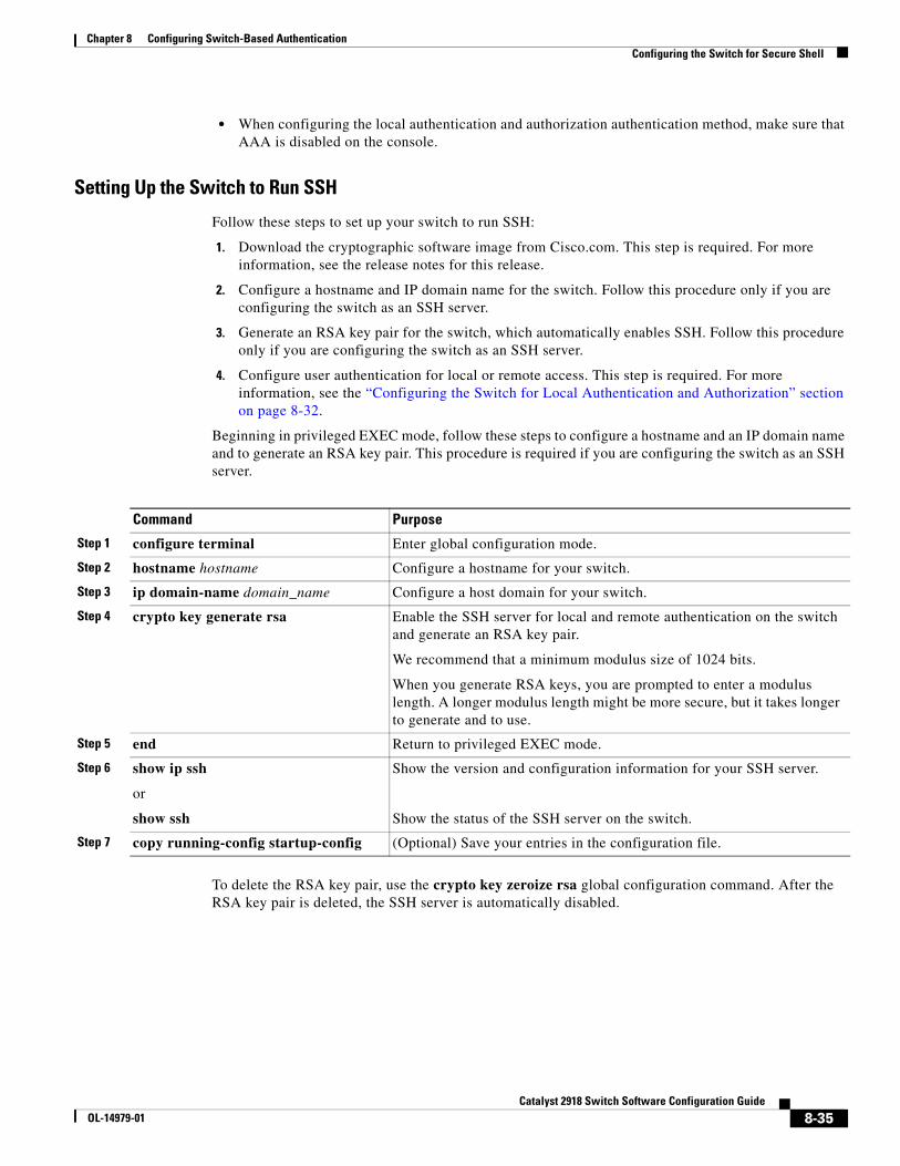
Chapter 8 Configuring Switch-Based AuthenticationConfiguring the Switch for Secure Shell
• When configuring the local authentication and authorization authentication method, make sure that AAA is disabled on the console.
Setting Up the Switch to Run SSH
Follow these steps to set up your switch to run SSH:
1. Download the cryptographic software image from Cisco.com. This step is required. For more information, see the release notes for this release.
2. Configure a hostname and IP domain name for the switch. Follow this procedure only if you are configuring the switch as an SSH server.
3. Generate an RSA key pair for the switch, which automatically enables SSH. Follow this procedure only if you are configuring the switch as an SSH server.
4. Configure user authentication for local or remote access. This step is required. For more information, see the “Configuring the Switch for Local Authentication and Authorization” section on page 8-32.
Beginning in privileged EXEC mode, follow these steps to configure a hostname and an IP domain name and to generate an RSA key pair. This procedure is required if you are configuring the switch as an SSH server.
Command Purpose
Step 1 configure terminal Enter global configuration mode.
Step 2 hostname hostname Configure a hostname for your switch.
Step 3 ip domain-name domain_name Configure a host domain for your switch.
Step 4 crypto key generate rsa Enable the SSH server for local and remote authentication on the switch and generate an RSA key pair.
We recommend that a minimum modulus size of 1024 bits.
When you generate RSA keys, you are prompted to enter a modulus length. A longer modulus length might be more secure, but it takes longer to generate and to use.
Step 5 end Return to privileged EXEC mode.
Step 6 show ip ssh
or
show ssh
Show the version and configuration information for your SSH server.
Show the status of the SSH server on the switch.
Step 7 copy running-config startup-config (Optional) Save your entries in the configuration file.
To delete the RSA key pair, use the crypto key zeroize rsa global configuration command. After the RSA key pair is deleted, the SSH server is automatically disabled.
8-35Catalyst 2918 Switch Software Configuration Guide
OL-14979-01
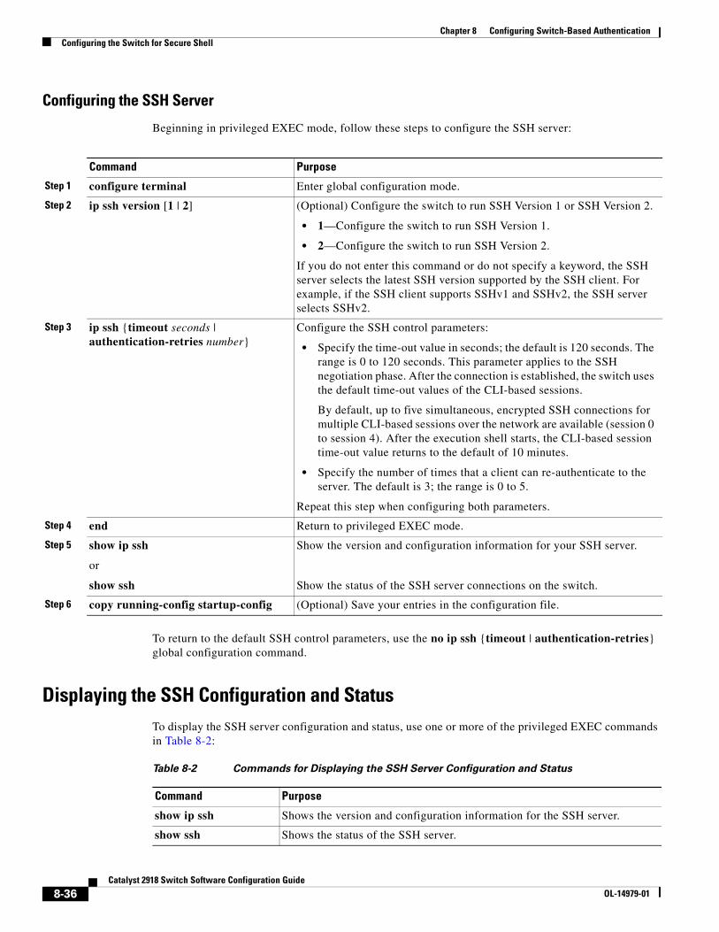
Chapter 8 Configuring Switch-Based AuthenticationConfiguring the Switch for Secure Shell
Configuring the SSH Server
Beginning in privileged EXEC mode, follow these steps to configure the SSH server:
Command Purpose
Step 1 configure terminal Enter global configuration mode.
Step 2 ip ssh version [1 | 2] (Optional) Configure the switch to run SSH Version 1 or SSH Version 2.
• 1—Configure the switch to run SSH Version 1.
• 2—Configure the switch to run SSH Version 2.
If you do not enter this command or do not specify a keyword, the SSH server selects the latest SSH version supported by the SSH client. For example, if the SSH client supports SSHv1 and SSHv2, the SSH server selects SSHv2.
Step 3 ip ssh {timeout seconds | authentication-retries number}
Configure the SSH control parameters:
• Specify the time-out value in seconds; the default is 120 seconds. The range is 0 to 120 seconds. This parameter applies to the SSH negotiation phase. After the connection is established, the switch uses the default time-out values of the CLI-based sessions.
By default, up to five simultaneous, encrypted SSH connections for multiple CLI-based sessions over the network are available (session 0 to session 4). After the execution shell starts, the CLI-based session time-out value returns to the default of 10 minutes.
• Specify the number of times that a client can re-authenticate to the server. The default is 3; the range is 0 to 5.
Repeat this step when configuring both parameters.
Step 4 end Return to privileged EXEC mode.
Step 5 show ip ssh
or
show ssh
Show the version and configuration information for your SSH server.
Show the status of the SSH server connections on the switch.
Step 6 copy running-config startup-config (Optional) Save your entries in the configuration file.
To return to the default SSH control parameters, use the no ip ssh {timeout | authentication-retries} global configuration command.
Displaying the SSH Configuration and StatusTo display the SSH server configuration and status, use one or more of the privileged EXEC commands in Table 8-2:
Table 8-2 Commands for Displaying the SSH Server Configuration and Status
Command Purpose
show ip ssh Shows the version and configuration information for the SSH server.
show ssh Shows the status of the SSH server.
8-36Catalyst 2918 Switch Software Configuration Guide
OL-14979-01
Chapter 8 Configuring Switch-Based AuthenticationConfiguring the Switch for Secure Socket Layer HTTP
For more information about these commands, see the “Secure Shell Commands” section in the “Other Security Features” chapter of the Cisco IOS Security Command Reference, Cisco IOS Release 12.2, at this URL:
http://www.cisco.com/en/US/products/sw/iosswrel/ps1835/products_command_reference_chapter09186a00800ca7cd.html
Configuring the Switch for Secure Socket Layer HTTP This section describes how to configure Secure Socket Layer (SSL) version 3.0 support for the HTTP 1.1 server and client. SSL provides server authentication, encryption, and message integrity, as well as HTTP client authentication, to allow secure HTTP communications.To use this feature, the cryptographic (encrypted) software image must be installed on your switch. You must obtain authorization to use this feature and to download the cryptographic software files from Cisco.com. For more information about the crypto image, see the release notes for this release.
These sections contain this information:
• Understanding Secure HTTP Servers and Clients, page 8-37
• Configuring Secure HTTP Servers and Clients, page 8-39
• Displaying Secure HTTP Server and Client Status, page 8-43
For configuration examples and complete syntax and usage information for the commands used in this section, see the “HTTPS - HTTP Server and Client with SSL 3.0” feature description for Cisco IOS Release 12.2(44)SE at this URL:
http://www.cisco.com/en/US/products/sw/iosswrel/ps1839/products_feature_guide09186a008015a4c6.html
Understanding Secure HTTP Servers and ClientsOn a secure HTTP connection, data to and from an HTTP server is encrypted before being sent over the Internet. HTTP with SSL encryption provides a secure connection to allow such functions as configuring a switch from a Web browser. Cisco's implementation of the secure HTTP server and secure HTTP client uses an implementation of SSL Version 3.0 with application-layer encryption. HTTP over SSL is abbreviated as HTTPS; the URL of a secure connection begins with https:// instead of http://.
The primary role of the HTTP secure server (the switch) is to listen for HTTPS requests on a designated port (the default HTTPS port is 443) and pass the request to the HTTP 1.1 Web server. The HTTP 1.1 server processes requests and passes responses (pages) back to the HTTP secure server, which, in turn, responds to the original request.
The primary role of the HTTP secure client (the web browser) is to respond to Cisco IOS application requests for HTTPS User Agent services, perform HTTPS User Agent services for the application, and pass the response back to the application.
Certificate Authority Trustpoints
Certificate authorities (CAs) manage certificate requests and issue certificates to participating network devices. These services provide centralized security key and certificate management for the participating devices. Specific CA servers are referred to as trustpoints.
8-37Catalyst 2918 Switch Software Configuration Guide
OL-14979-01
Chapter 8 Configuring Switch-Based AuthenticationConfiguring the Switch for Secure Socket Layer HTTP
When a connection attempt is made, the HTTPS server provides a secure connection by issuing a certified X.509v3 certificate, obtained from a specified CA trustpoint, to the client. The client (usually a Web browser), in turn, has a public key that allows it to authenticate the certificate.
For secure HTTP connections, we highly recommend that you configure a CA trustpoint. If a CA trustpoint is not configured for the device running the HTTPS server, the server certifies itself and generates the needed RSA key pair. Because a self-certified (self-signed) certificate does not provide adequate security, the connecting client generates a notification that the certificate is self-certified, and the user has the opportunity to accept or reject the connection. This option is useful for internal network topologies (such as testing).
If you do not configure a CA trustpoint, when you enable a secure HTTP connection, either a temporary or a persistent self-signed certificate for the secure HTTP server (or client) is automatically generated.
• If the switch is not configured with a hostname and a domain name, a temporary self-signed certificate is generated. If the switch reboots, any temporary self-signed certificate is lost, and a new temporary new self-signed certificate is assigned.
• If the switch has been configured with a host and domain name, a persistent self-signed certificate is generated. This certificate remains active if you reboot the switch or if you disable the secure HTTP server so that it will be there the next time you re-enable a secure HTTP connection.
If a self-signed certificate has been generated, this information is included in the output of the show running-config privileged EXEC command. This is a partial sample output from that command displaying a self-signed certificate.
Switch# show running-configBuilding configuration...
<output truncated>
crypto pki trustpoint TP-self-signed-3080755072 enrollment selfsigned subject-name cn=IOS-Self-Signed-Certificate-3080755072 revocation-check none rsakeypair TP-self-signed-3080755072!!crypto ca certificate chain TP-self-signed-3080755072 certificate self-signed 01 3082029F 30820208 A0030201 02020101 300D0609 2A864886 F70D0101 04050030 59312F30 2D060355 04031326 494F532D 53656C66 2D536967 6E65642D 43657274 69666963 6174652D 33303830 37353530 37323126 30240609 2A864886 F70D0109 02161743 45322D33 3535302D 31332E73 756D6D30 342D3335 3530301E 170D3933 30333031 30303030 35395A17 0D323030 31303130 30303030 305A3059 312F302D
<output truncated>
You can remove this self-signed certificate by disabling the secure HTTP server and entering the no crypto pki trustpoint TP-self-signed-30890755072 global configuration command. If you later re-enable a secure HTTP server, a new self-signed certificate is generated.
Note The values that follow TP self-signed depend on the serial number of the device.
You can use an optional command (ip http secure-client-auth) to allow the HTTPS server to request an X.509v3 certificate from the client. Authenticating the client provides more security than server authentication by itself.
For additional information on Certificate Authorities, see the “Configuring Certification Authority Interoperability” chapter in the Cisco IOS Security Configuration Guide, Release 12.2.
8-38Catalyst 2918 Switch Software Configuration Guide
OL-14979-01
Chapter 8 Configuring Switch-Based AuthenticationConfiguring the Switch for Secure Socket Layer HTTP
CipherSuites
A CipherSuite specifies the encryption algorithm and the digest algorithm to use on a SSL connection. When connecting to the HTTPS server, the client Web browser offers a list of supported CipherSuites, and the client and server negotiate the best encryption algorithm to use from those on the list that are supported by both. For example, Netscape Communicator 4.76 supports U.S. security with RSA Public Key Cryptography, MD2, MD5, RC2-CBC, RC4, DES-CBC, and DES-EDE3-CBC.
For the best possible encryption, you should use a client browser that supports 128-bit encryption, such as Microsoft Internet Explorer Version 5.5 (or later) or Netscape Communicator Version 4.76 (or later). The SSL_RSA_WITH_DES_CBC_SHA CipherSuite provides less security than the other CipherSuites, as it does not offer 128-bit encryption.
The more secure and more complex CipherSuites require slightly more processing time. This list defines the CipherSuites supported by the switch and ranks them from fastest to slowest in terms of router processing load (speed):
1. SSL_RSA_WITH_DES_CBC_SHA—RSA key exchange (RSA Public Key Cryptography) with DES-CBC for message encryption and SHA for message digest
2. SSL_RSA_WITH_RC4_128_MD5—RSA key exchange with RC4 128-bit encryption and MD5 for message digest
3. SSL_RSA_WITH_RC4_128_SHA—RSA key exchange with RC4 128-bit encryption and SHA for message digest
4. SSL_RSA_WITH_3DES_EDE_CBC_SHA—RSA key exchange with 3DES and DES-EDE3-CBC for message encryption and SHA for message digest
RSA (in conjunction with the specified encryption and digest algorithm combinations) is used for both key generation and authentication on SSL connections. This usage is independent of whether or not a CA trustpoint is configured.
Configuring Secure HTTP Servers and ClientsThese sections contain this configuration information:
• Default SSL Configuration, page 8-39
• SSL Configuration Guidelines, page 8-40
• Configuring a CA Trustpoint, page 8-40
• Configuring the Secure HTTP Server, page 8-41
• Configuring the Secure HTTP Client, page 8-42
Default SSL Configuration
The standard HTTP server is enabled.
SSL is enabled.
No CA trustpoints are configured.
No self-signed certificates are generated.
8-39Catalyst 2918 Switch Software Configuration Guide
OL-14979-01
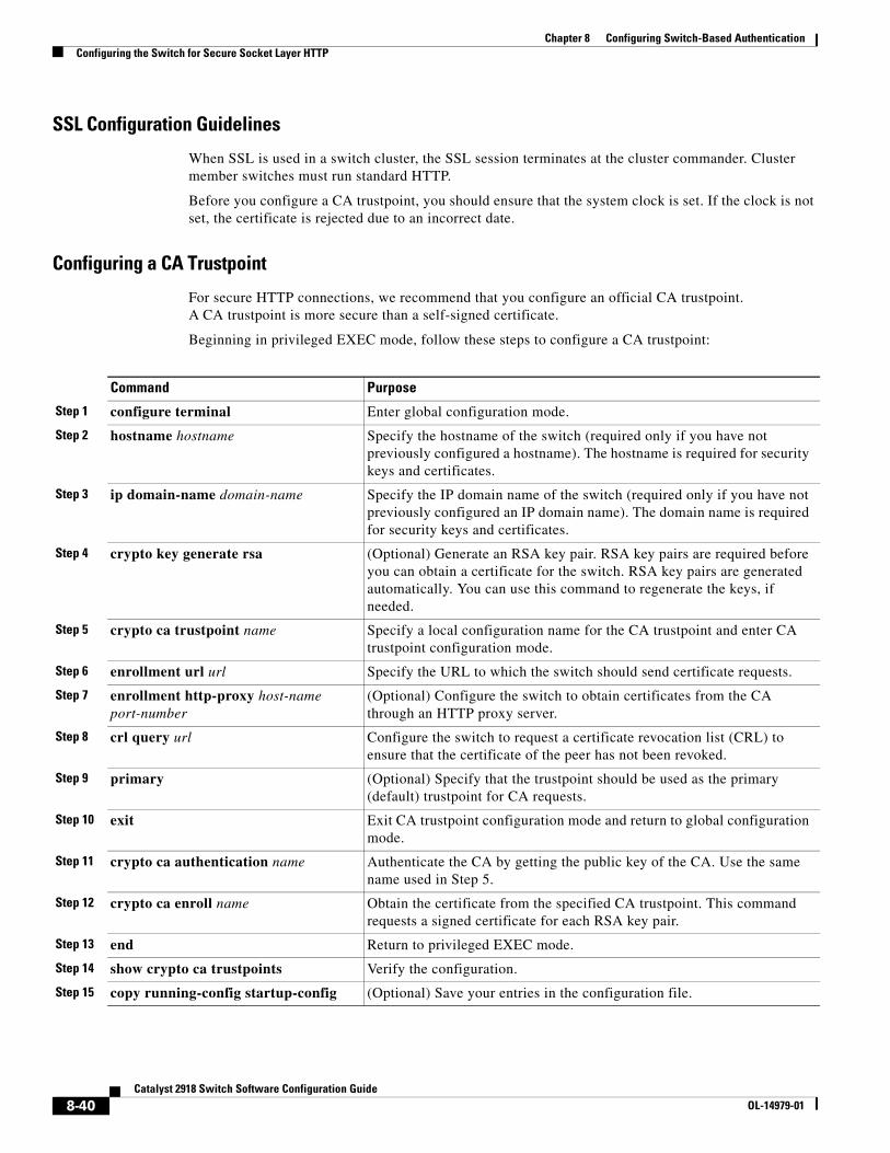
Chapter 8 Configuring Switch-Based AuthenticationConfiguring the Switch for Secure Socket Layer HTTP
SSL Configuration Guidelines
When SSL is used in a switch cluster, the SSL session terminates at the cluster commander. Cluster member switches must run standard HTTP.
Before you configure a CA trustpoint, you should ensure that the system clock is set. If the clock is not set, the certificate is rejected due to an incorrect date.
Configuring a CA Trustpoint
For secure HTTP connections, we recommend that you configure an official CA trustpoint. A CA trustpoint is more secure than a self-signed certificate.
Beginning in privileged EXEC mode, follow these steps to configure a CA trustpoint:
Command Purpose
Step 1 configure terminal Enter global configuration mode.
Step 2 hostname hostname Specify the hostname of the switch (required only if you have not previously configured a hostname). The hostname is required for security keys and certificates.
Step 3 ip domain-name domain-name Specify the IP domain name of the switch (required only if you have not previously configured an IP domain name). The domain name is required for security keys and certificates.
Step 4 crypto key generate rsa (Optional) Generate an RSA key pair. RSA key pairs are required before you can obtain a certificate for the switch. RSA key pairs are generated automatically. You can use this command to regenerate the keys, if needed.
Step 5 crypto ca trustpoint name Specify a local configuration name for the CA trustpoint and enter CA trustpoint configuration mode.
Step 6 enrollment url url Specify the URL to which the switch should send certificate requests.
Step 7 enrollment http-proxy host-name port-number
(Optional) Configure the switch to obtain certificates from the CA through an HTTP proxy server.
Step 8 crl query url Configure the switch to request a certificate revocation list (CRL) to ensure that the certificate of the peer has not been revoked.
Step 9 primary (Optional) Specify that the trustpoint should be used as the primary (default) trustpoint for CA requests.
Step 10 exit Exit CA trustpoint configuration mode and return to global configuration mode.
Step 11 crypto ca authentication name Authenticate the CA by getting the public key of the CA. Use the same name used in Step 5.
Step 12 crypto ca enroll name Obtain the certificate from the specified CA trustpoint. This command requests a signed certificate for each RSA key pair.
Step 13 end Return to privileged EXEC mode.
Step 14 show crypto ca trustpoints Verify the configuration.
Step 15 copy running-config startup-config (Optional) Save your entries in the configuration file.
8-40Catalyst 2918 Switch Software Configuration Guide
OL-14979-01
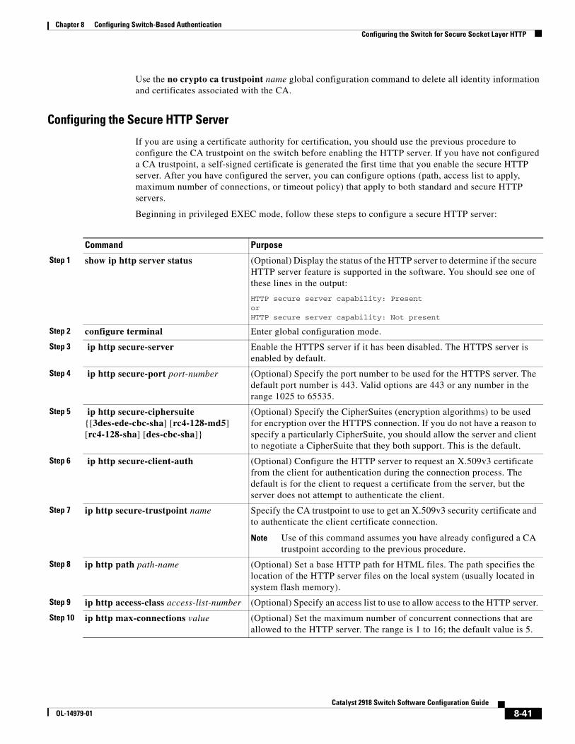
Chapter 8 Configuring Switch-Based AuthenticationConfiguring the Switch for Secure Socket Layer HTTP
Use the no crypto ca trustpoint name global configuration command to delete all identity information and certificates associated with the CA.
Configuring the Secure HTTP Server
If you are using a certificate authority for certification, you should use the previous procedure to configure the CA trustpoint on the switch before enabling the HTTP server. If you have not configured a CA trustpoint, a self-signed certificate is generated the first time that you enable the secure HTTP server. After you have configured the server, you can configure options (path, access list to apply, maximum number of connections, or timeout policy) that apply to both standard and secure HTTP servers.
Beginning in privileged EXEC mode, follow these steps to configure a secure HTTP server:
Command Purpose
Step 1 show ip http server status (Optional) Display the status of the HTTP server to determine if the secure HTTP server feature is supported in the software. You should see one of these lines in the output:
HTTP secure server capability: PresentorHTTP secure server capability: Not present
Step 2 configure terminal Enter global configuration mode.
Step 3 ip http secure-server Enable the HTTPS server if it has been disabled. The HTTPS server is enabled by default.
Step 4 ip http secure-port port-number (Optional) Specify the port number to be used for the HTTPS server. The default port number is 443. Valid options are 443 or any number in the range 1025 to 65535.
Step 5 ip http secure-ciphersuite {[3des-ede-cbc-sha] [rc4-128-md5] [rc4-128-sha] [des-cbc-sha]}
(Optional) Specify the CipherSuites (encryption algorithms) to be used for encryption over the HTTPS connection. If you do not have a reason to specify a particularly CipherSuite, you should allow the server and client to negotiate a CipherSuite that they both support. This is the default.
Step 6 ip http secure-client-auth (Optional) Configure the HTTP server to request an X.509v3 certificate from the client for authentication during the connection process. The default is for the client to request a certificate from the server, but the server does not attempt to authenticate the client.
Step 7 ip http secure-trustpoint name Specify the CA trustpoint to use to get an X.509v3 security certificate and to authenticate the client certificate connection.
Note Use of this command assumes you have already configured a CA trustpoint according to the previous procedure.
Step 8 ip http path path-name (Optional) Set a base HTTP path for HTML files. The path specifies the location of the HTTP server files on the local system (usually located in system flash memory).
Step 9 ip http access-class access-list-number (Optional) Specify an access list to use to allow access to the HTTP server.
Step 10 ip http max-connections value (Optional) Set the maximum number of concurrent connections that are allowed to the HTTP server. The range is 1 to 16; the default value is 5.
8-41Catalyst 2918 Switch Software Configuration Guide
OL-14979-01
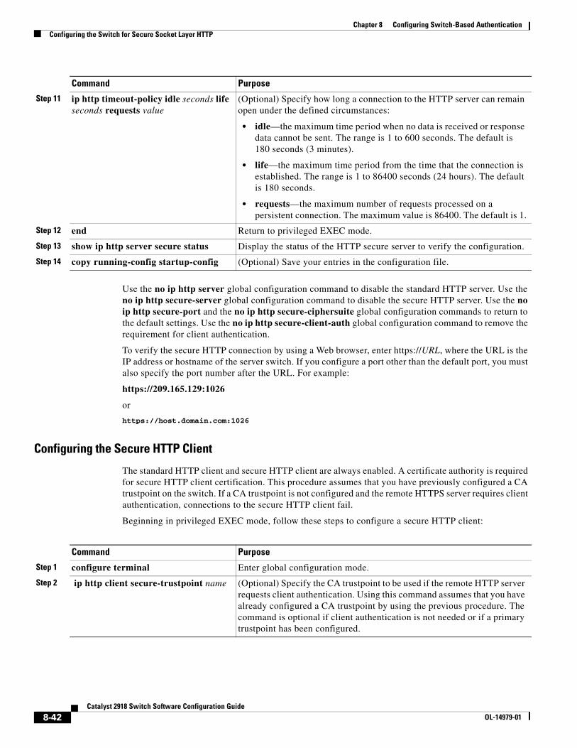
Chapter 8 Configuring Switch-Based AuthenticationConfiguring the Switch for Secure Socket Layer HTTP
Use the no ip http server global configuration command to disable the standard HTTP server. Use the no ip http secure-server global configuration command to disable the secure HTTP server. Use the no ip http secure-port and the no ip http secure-ciphersuite global configuration commands to return to the default settings. Use the no ip http secure-client-auth global configuration command to remove the requirement for client authentication.
To verify the secure HTTP connection by using a Web browser, enter https://URL, where the URL is the IP address or hostname of the server switch. If you configure a port other than the default port, you must also specify the port number after the URL. For example:
https://209.165.129:1026
or
https://host.domain.com:1026
Configuring the Secure HTTP Client
The standard HTTP client and secure HTTP client are always enabled. A certificate authority is required for secure HTTP client certification. This procedure assumes that you have previously configured a CA trustpoint on the switch. If a CA trustpoint is not configured and the remote HTTPS server requires client authentication, connections to the secure HTTP client fail.
Beginning in privileged EXEC mode, follow these steps to configure a secure HTTP client:
Step 11 ip http timeout-policy idle seconds life seconds requests value
(Optional) Specify how long a connection to the HTTP server can remain open under the defined circumstances:
• idle—the maximum time period when no data is received or response data cannot be sent. The range is 1 to 600 seconds. The default is 180 seconds (3 minutes).
• life—the maximum time period from the time that the connection is established. The range is 1 to 86400 seconds (24 hours). The default is 180 seconds.
• requests—the maximum number of requests processed on a persistent connection. The maximum value is 86400. The default is 1.
Step 12 end Return to privileged EXEC mode.
Step 13 show ip http server secure status Display the status of the HTTP secure server to verify the configuration.
Step 14 copy running-config startup-config (Optional) Save your entries in the configuration file.
Command Purpose
Command Purpose
Step 1 configure terminal Enter global configuration mode.
Step 2 ip http client secure-trustpoint name (Optional) Specify the CA trustpoint to be used if the remote HTTP server requests client authentication. Using this command assumes that you have already configured a CA trustpoint by using the previous procedure. The command is optional if client authentication is not needed or if a primary trustpoint has been configured.
8-42Catalyst 2918 Switch Software Configuration Guide
OL-14979-01
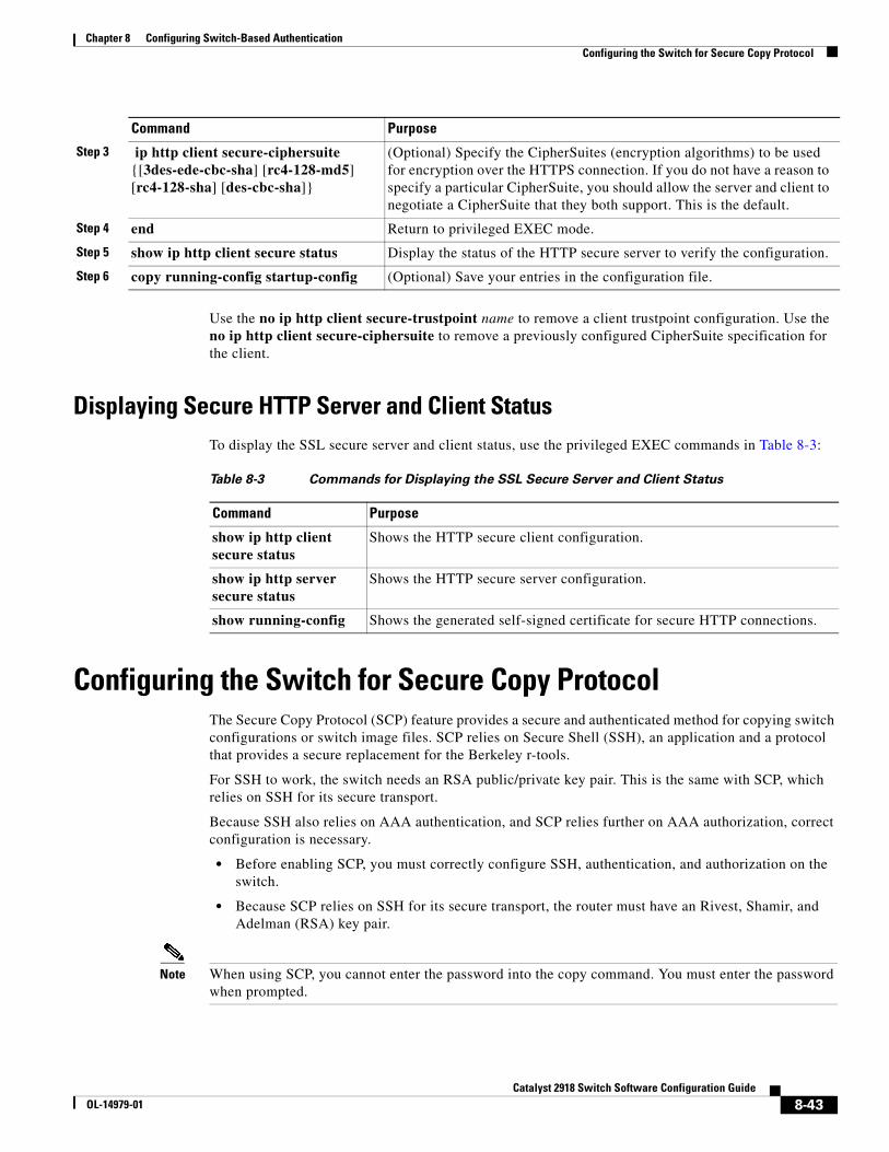
Chapter 8 Configuring Switch-Based AuthenticationConfiguring the Switch for Secure Copy Protocol
Use the no ip http client secure-trustpoint name to remove a client trustpoint configuration. Use the no ip http client secure-ciphersuite to remove a previously configured CipherSuite specification for the client.
Displaying Secure HTTP Server and Client StatusTo display the SSL secure server and client status, use the privileged EXEC commands in Table 8-3:
Table 8-3 Commands for Displaying the SSL Secure Server and Client Status
Command Purpose
show ip http client secure status
Shows the HTTP secure client configuration.
show ip http server secure status
Shows the HTTP secure server configuration.
show running-config Shows the generated self-signed certificate for secure HTTP connections.
Configuring the Switch for Secure Copy ProtocolThe Secure Copy Protocol (SCP) feature provides a secure and authenticated method for copying switch configurations or switch image files. SCP relies on Secure Shell (SSH), an application and a protocol that provides a secure replacement for the Berkeley r-tools.
For SSH to work, the switch needs an RSA public/private key pair. This is the same with SCP, which relies on SSH for its secure transport.
Because SSH also relies on AAA authentication, and SCP relies further on AAA authorization, correct configuration is necessary.
• Before enabling SCP, you must correctly configure SSH, authentication, and authorization on the switch.
• Because SCP relies on SSH for its secure transport, the router must have an Rivest, Shamir, and Adelman (RSA) key pair.
Note When using SCP, you cannot enter the password into the copy command. You must enter the password when prompted.
Step 3 ip http client secure-ciphersuite {[3des-ede-cbc-sha] [rc4-128-md5] [rc4-128-sha] [des-cbc-sha]}
(Optional) Specify the CipherSuites (encryption algorithms) to be used for encryption over the HTTPS connection. If you do not have a reason to specify a particular CipherSuite, you should allow the server and client to negotiate a CipherSuite that they both support. This is the default.
Step 4 end Return to privileged EXEC mode.
Step 5 show ip http client secure status Display the status of the HTTP secure server to verify the configuration.
Step 6 copy running-config startup-config (Optional) Save your entries in the configuration file.
Command Purpose
8-43Catalyst 2918 Switch Software Configuration Guide
OL-14979-01
Chapter 8 Configuring Switch-Based AuthenticationConfiguring the Switch for Secure Copy Protocol
Information About Secure Copy
To configure Secure Copy feature, you should understand these concepts.
The behavior of SCP is similar to that of remote copy (rcp), which comes from the Berkeley r-tools suite, except that SCP relies on SSH for security. SCP also requires that authentication, authorization, and accounting (AAA) authorization be configured so the router can determine whether the user has the correct privilege level.
A user who has appropriate authorization can use SCP to copy any file in the Cisco IOS File System (IFS) to and from a switch by using the copy command. An authorized administrator can also do this from a workstation.
For more information on how to configure and verify SCP, see the “Secure Copy Protocol” chapter of the Cisco IOS New Features, Cisco IOS Release 12.2, at this URL:
http://www.cisco.com/en/US/products/sw/iosswrel/ps1839/products_feature_guide09186a0080087b18.html
8-44Catalyst 2918 Switch Software Configuration Guide
OL-14979-01
OL-14979-01
C H A P T E R 9
Configuring IEEE 802.1x Port-Based AuthenticationThis chapter describes how to configure IEEE 802.1x port-based authentication on the Catalyst 2918 switch. IEEE 802.1x authentication prevents unauthorized devices (clients) from gaining access to the network.
Note For complete syntax and usage information for the commands used in this chapter, see the “RADIUS Commands” section in the Cisco IOS Security Command Reference, Release 12.2 and in the command reference for this release.
This chapter consists of these sections:
• Understanding IEEE 802.1x Port-Based Authentication, page 9-1
• Configuring IEEE 802.1x Authentication, page 9-14
• Displaying IEEE 802.1x Statistics and Status, page 9-28
Understanding IEEE 802.1x Port-Based AuthenticationThe IEEE 802.1x standard defines a client-server-based access control and authentication protocol that prevents clients from connecting to a LAN through publicly accessible ports unless they are authenticated. The authentication server authenticates each client connected to a switch port before making available any services offered by the switch or the LAN.
Until the client is authenticated, IEEE 802.1x access control allows only Extensible Authentication Protocol over LAN (EAPOL), Cisco Discovery Protocol (CDP), and Spanning Tree Protocol (STP) traffic through the port to which the client is connected. After authentication, normal traffic can pass through the port.
These sections describe IEEE 802.1x port-based authentication:
• Device Roles, page 9-2
• Authentication Process, page 9-3
• Authentication Initiation and Message Exchange, page 9-5
• Ports in Authorized and Unauthorized States, page 9-7
• IEEE 802.1x Host Mode, page 9-7
• IEEE 802.1x Accounting, page 9-8
9-1Catalyst 2918 Switch Software Configuration Guide
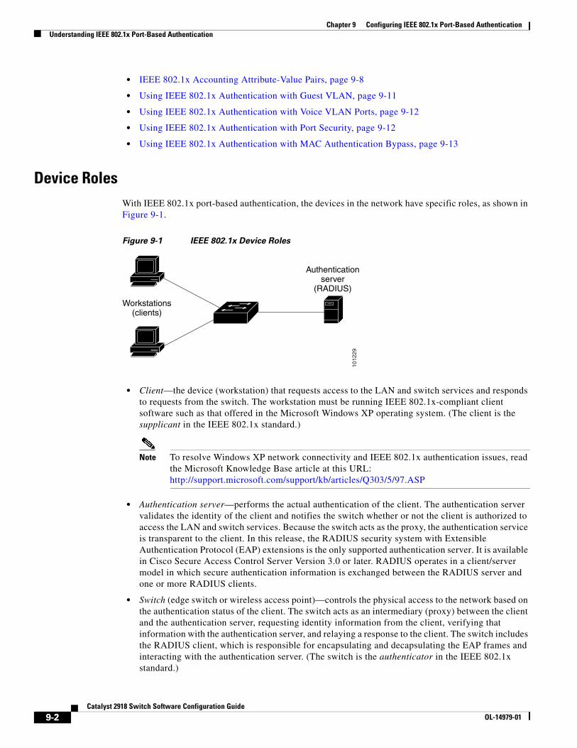
Chapter 9 Configuring IEEE 802.1x Port-Based AuthenticationUnderstanding IEEE 802.1x Port-Based Authentication
• IEEE 802.1x Accounting Attribute-Value Pairs, page 9-8
• Using IEEE 802.1x Authentication with Guest VLAN, page 9-11
• Using IEEE 802.1x Authentication with Voice VLAN Ports, page 9-12
• Using IEEE 802.1x Authentication with Port Security, page 9-12
• Using IEEE 802.1x Authentication with MAC Authentication Bypass, page 9-13
Device RolesWith IEEE 802.1x port-based authentication, the devices in the network have specific roles, as shown in Figure 9-1.
Figure 9-1 IEEE 802.1x Device Roles
1012
29
Workstations(clients)
Authenticationserver
(RADIUS)
• Client—the device (workstation) that requests access to the LAN and switch services and responds to requests from the switch. The workstation must be running IEEE 802.1x-compliant client software such as that offered in the Microsoft Windows XP operating system. (The client is the supplicant in the IEEE 802.1x standard.)
Note To resolve Windows XP network connectivity and IEEE 802.1x authentication issues, read the Microsoft Knowledge Base article at this URL: http://support.microsoft.com/support/kb/articles/Q303/5/97.ASP
• Authentication server—performs the actual authentication of the client. The authentication server validates the identity of the client and notifies the switch whether or not the client is authorized to access the LAN and switch services. Because the switch acts as the proxy, the authentication service is transparent to the client. In this release, the RADIUS security system with Extensible Authentication Protocol (EAP) extensions is the only supported authentication server. It is available in Cisco Secure Access Control Server Version 3.0 or later. RADIUS operates in a client/server model in which secure authentication information is exchanged between the RADIUS server and one or more RADIUS clients.
• Switch (edge switch or wireless access point)—controls the physical access to the network based on the authentication status of the client. The switch acts as an intermediary (proxy) between the client and the authentication server, requesting identity information from the client, verifying that information with the authentication server, and relaying a response to the client. The switch includes the RADIUS client, which is responsible for encapsulating and decapsulating the EAP frames and interacting with the authentication server. (The switch is the authenticator in the IEEE 802.1x standard.)
9-2Catalyst 2918 Switch Software Configuration Guide
OL-14979-01
Chapter 9 Configuring IEEE 802.1x Port-Based AuthenticationUnderstanding IEEE 802.1x Port-Based Authentication
When the switch receives EAPOL frames and relays them to the authentication server, the Ethernet header is stripped, and the remaining EAP frame is re-encapsulated in the RADIUS format. The EAP frames are not modified during encapsulation, and the authentication server must support EAP within the native frame format. When the switch receives frames from the authentication server, the server’s frame header is removed, leaving the EAP frame, which is then encapsulated for Ethernet and sent to the client.
The devices that can act as intermediaries include the Catalyst 3750-E, Catalyst 3560-E, Catalyst 3750, Catalyst 3560, Catalyst 3550, Catalyst 2970, Catalyst 2960, Catalyst 2955, Catalyst 2950, Catalyst 2940 switches, or a wireless access point. These devices must be running software that supports the RADIUS client and IEEE 802.1x authentication.
Authentication ProcessWhen IEEE 802.1x port-based authentication is enabled and the client supports IEEE 802.1x-compliant client software, these events occur:
• If the client identity is valid and the IEEE 802.1x authentication succeeds, the switch grants the client access to the network.
• If IEEE 802.1x authentication times out while waiting for an EAPOL message exchange and MAC authentication bypass is enabled, the switch can use the client MAC address for authorization. If the client MAC address is valid and the authorization succeeds, the switch grants the client access to the network. If the client MAC address is invalid and the authorization fails, the switch assigns the client to a guest VLAN that provides limited services if a guest VLAN is configured.
Figure 9-2 shows the authentication process.
Note Inaccessible authentication bypass, referenced at the bottom of the flow chart, is not supported on the switch.
9-3Catalyst 2918 Switch Software Configuration Guide
OL-14979-01
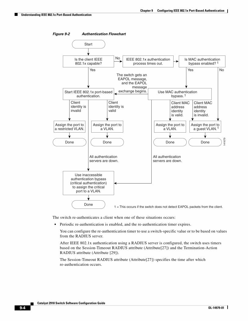
Chapter 9 Configuring IEEE 802.1x Port-Based AuthenticationUnderstanding IEEE 802.1x Port-Based Authentication
Figure 9-2 Authentication Flowchart
1416
79
Yes
No
Clientidentity isinvalid
All authenticationservers are down.
All authenticationservers are down.
Clientidentity isvalid
The switch gets anEAPOL message,
and the EAPOLmessage
exchange begins.
Yes No
1
1
1
1 = This occurs if the switch does not detect EAPOL packets from the client.
Client MAC addressidentity is invalid.
Client MAC addressidentity is valid.
Is the client IEEE802.1x capable?
Start IEEE 802.1x port-basedauthentication.
Use inaccessibleauthentication bypass(critical authentication)
to assign the criticalport to a VLAN.
IEEE 802.1x authenticationprocess times out.
Is MAC authenticationbypass enabled?
Use MAC authenticationbypass.
Assign the port toa guest VLAN.
Start
Done
Assign the port toa VLAN.
Done
Done
Assign the port toa VLAN.
Done
Assign the port toa restricted VLAN.
Done
The switch re-authenticates a client when one of these situations occurs:
• Periodic re-authentication is enabled, and the re-authentication timer expires.
You can configure the re-authentication timer to use a switch-specific value or to be based on values from the RADIUS server.
After IEEE 802.1x authentication using a RADIUS server is configured, the switch uses timers based on the Session-Timeout RADIUS attribute (Attribute[27]) and the Termination-Action RADIUS attribute (Attribute [29]).
The Session-Timeout RADIUS attribute (Attribute[27]) specifies the time after which re-authentication occurs.
9-4Catalyst 2918 Switch Software Configuration Guide
OL-14979-01
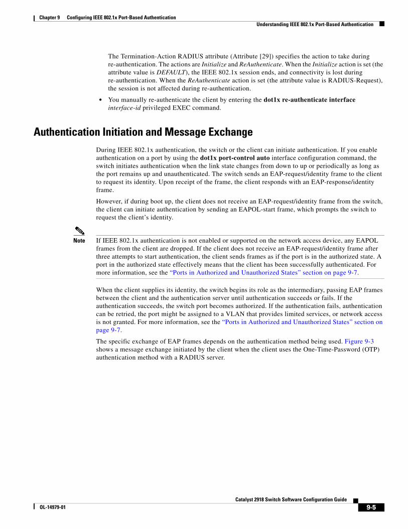
Chapter 9 Configuring IEEE 802.1x Port-Based AuthenticationUnderstanding IEEE 802.1x Port-Based Authentication
The Termination-Action RADIUS attribute (Attribute [29]) specifies the action to take during re-authentication. The actions are Initialize and ReAuthenticate. When the Initialize action is set (the attribute value is DEFAULT), the IEEE 802.1x session ends, and connectivity is lost during re-authentication. When the ReAuthenticate action is set (the attribute value is RADIUS-Request), the session is not affected during re-authentication.
• You manually re-authenticate the client by entering the dot1x re-authenticate interface interface-id privileged EXEC command.
Authentication Initiation and Message ExchangeDuring IEEE 802.1x authentication, the switch or the client can initiate authentication. If you enable authentication on a port by using the dot1x port-control auto interface configuration command, the switch initiates authentication when the link state changes from down to up or periodically as long as the port remains up and unauthenticated. The switch sends an EAP-request/identity frame to the client to request its identity. Upon receipt of the frame, the client responds with an EAP-response/identity frame.
However, if during boot up, the client does not receive an EAP-request/identity frame from the switch, the client can initiate authentication by sending an EAPOL-start frame, which prompts the switch to request the client’s identity.
Note If IEEE 802.1x authentication is not enabled or supported on the network access device, any EAPOL frames from the client are dropped. If the client does not receive an EAP-request/identity frame after three attempts to start authentication, the client sends frames as if the port is in the authorized state. A port in the authorized state effectively means that the client has been successfully authenticated. For more information, see the “Ports in Authorized and Unauthorized States” section on page 9-7.
When the client supplies its identity, the switch begins its role as the intermediary, passing EAP frames between the client and the authentication server until authentication succeeds or fails. If the authentication succeeds, the switch port becomes authorized. If the authentication fails, authentication can be retried, the port might be assigned to a VLAN that provides limited services, or network access is not granted. For more information, see the “Ports in Authorized and Unauthorized States” section on page 9-7.
The specific exchange of EAP frames depends on the authentication method being used. Figure 9-3 shows a message exchange initiated by the client when the client uses the One-Time-Password (OTP) authentication method with a RADIUS server.
9-5Catalyst 2918 Switch Software Configuration Guide
OL-14979-01
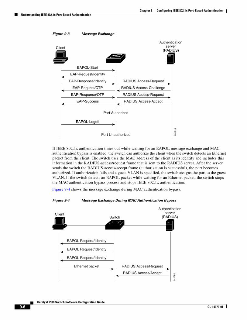
Chapter 9 Configuring IEEE 802.1x Port-Based AuthenticationUnderstanding IEEE 802.1x Port-Based Authentication
Figure 9-3 Message Exchange
1012
28
Client
Port Authorized
Port Unauthorized
EAPOL-Start
EAP-Request/Identity
EAP-Response/Identity
EAP-Request/OTP
EAP-Response/OTP
EAP-Success
RADIUS Access-Request
RADIUS Access-Challenge
RADIUS Access-Request
RADIUS Access-Accept
EAPOL-Logoff
Authenticationserver
(RADIUS)
If IEEE 802.1x authentication times out while waiting for an EAPOL message exchange and MAC authentication bypass is enabled, the switch can authorize the client when the switch detects an Ethernet packet from the client. The switch uses the MAC address of the client as its identity and includes this information in the RADIUS-access/request frame that is sent to the RADIUS server. After the server sends the switch the RADIUS-access/accept frame (authorization is successful), the port becomes authorized. If authorization fails and a guest VLAN is specified, the switch assigns the port to the guest VLAN. If the switch detects an EAPOL packet while waiting for an Ethernet packet, the switch stops the MAC authentication bypass process and stops IEEE 802.1x authentication.
Figure 9-4 shows the message exchange during MAC authentication bypass.
Figure 9-4 Message Exchange During MAC Authentication Bypass
1416
81
ClientSwitch
EAPOL Request/Identity
EAPOL Request/Identity
EAPOL Request/Identity
RADIUS Access/Request
RADIUS Access/Accept
Ethernet packet
Authenticationserver
(RADIUS)
9-6Catalyst 2918 Switch Software Configuration Guide
OL-14979-01
Chapter 9 Configuring IEEE 802.1x Port-Based AuthenticationUnderstanding IEEE 802.1x Port-Based Authentication
Ports in Authorized and Unauthorized StatesDuring IEEE 802.1x authentication, depending on the switch port state, the switch can grant a client access to the network. The port starts in the unauthorized state. While in this state, the port that is not configured as a voice VLAN port disallows all ingress and egress traffic except for IEEE 802.1x authentication, CDP, and STP packets. When a client is successfully authenticated, the port changes to the authorized state, allowing all traffic for the client to flow normally. If the port is configured as a voice VLAN port, the port allows VoIP traffic and IEEE 802.1x protocol packets before the client is successfully authenticated.
If a client that does not support IEEE 802.1x authentication connects to an unauthorized IEEE 802.1x port, the switch requests the client’s identity. In this situation, the client does not respond to the request, the port remains in the unauthorized state, and the client is not granted access to the network.
In contrast, when an IEEE 802.1x-enabled client connects to a port that is not running the IEEE 802.1x standard, the client initiates the authentication process by sending the EAPOL-start frame. When no response is received, the client sends the request for a fixed number of times. Because no response is received, the client begins sending frames as if the port is in the authorized state.
You control the port authorization state by using the dot1x port-control interface configuration command and these keywords:
• force-authorized—disables IEEE 802.1x authentication and causes the port to change to the authorized state without any authentication exchange required. The port sends and receives normal traffic without IEEE 802.1x-based authentication of the client. This is the default setting.
• force-unauthorized—causes the port to remain in the unauthorized state, ignoring all attempts by the client to authenticate. The switch cannot provide authentication services to the client through the port.
• auto—enables IEEE 802.1x authentication and causes the port to begin in the unauthorized state, allowing only EAPOL frames to be sent and received through the port. The authentication process begins when the link state of the port changes from down to up or when an EAPOL-start frame is received. The switch requests the identity of the client and begins relaying authentication messages between the client and the authentication server. Each client attempting to access the network is uniquely identified by the switch by using the client MAC address.
If the client is successfully authenticated (receives an Accept frame from the authentication server), the port state changes to authorized, and all frames from the authenticated client are allowed through the port. If the authentication fails, the port remains in the unauthorized state, but authentication can be retried. If the authentication server cannot be reached, the switch can resend the request. If no response is received from the server after the specified number of attempts, authentication fails, and network access is not granted.
When a client logs off, it sends an EAPOL-logoff message, causing the switch port to change to the unauthorized state.
If the link state of a port changes from up to down, or if an EAPOL-logoff frame is received, the port returns to the unauthorized state.
IEEE 802.1x Host ModeYou can configure an IEEE 802.1x port for single-host or for multiple-hosts mode. In single-host mode (see Figure 9-1 on page 9-2), only one client can be connected to the IEEE 802.1x-enabled switch port. The switch detects the client by sending an EAPOL frame when the port link state changes to the up state. If a client leaves or is replaced with another client, the switch changes the port link state to down, and the port returns to the unauthorized state.
9-7Catalyst 2918 Switch Software Configuration Guide
OL-14979-01
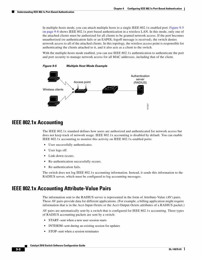
Chapter 9 Configuring IEEE 802.1x Port-Based AuthenticationUnderstanding IEEE 802.1x Port-Based Authentication
In multiple-hosts mode, you can attach multiple hosts to a single IEEE 802.1x-enabled port. Figure 9-5 on page 9-8 shows IEEE 802.1x port-based authentication in a wireless LAN. In this mode, only one of the attached clients must be authorized for all clients to be granted network access. If the port becomes unauthorized (re-authentication fails or an EAPOL-logoff message is received), the switch denies network access to all of the attached clients. In this topology, the wireless access point is responsible for authenticating the clients attached to it, and it also acts as a client to the switch.
With the multiple-hosts mode enabled, you can use IEEE 802.1x authentication to authenticate the port and port security to manage network access for all MAC addresses, including that of the client.
Figure 9-5 Multiple Host Mode Example
1012
27
Wireless clients
Access point
Authenticationserver
(RADIUS)
IEEE 802.1x AccountingThe IEEE 802.1x standard defines how users are authorized and authenticated for network access but does not keep track of network usage. IEEE 802.1x accounting is disabled by default. You can enable IEEE 802.1x accounting to monitor this activity on IEEE 802.1x-enabled ports:
• User successfully authenticates.
• User logs off.
• Link-down occurs.
• Re-authentication successfully occurs.
• Re-authentication fails.
The switch does not log IEEE 802.1x accounting information. Instead, it sends this information to the RADIUS server, which must be configured to log accounting messages.
IEEE 802.1x Accounting Attribute-Value PairsThe information sent to the RADIUS server is represented in the form of Attribute-Value (AV) pairs. These AV pairs provide data for different applications. (For example, a billing application might require information that is in the Acct-Input-Octets or the Acct-Output-Octets attributes of a RADIUS packet.)
AV pairs are automatically sent by a switch that is configured for IEEE 802.1x accounting. Three types of RADIUS accounting packets are sent by a switch:
• START–sent when a new user session starts
• INTERIM–sent during an existing session for updates
• STOP–sent when a session terminates
9-8Catalyst 2918 Switch Software Configuration Guide
OL-14979-01
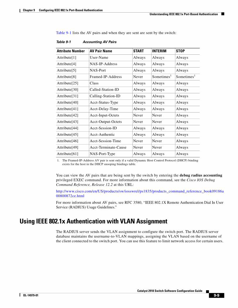
Chapter 9 Configuring IEEE 802.1x Port-Based AuthenticationUnderstanding IEEE 802.1x Port-Based Authentication
Table 9-1 lists the AV pairs and when they are sent are sent by the switch:
Table 9-1 Accounting AV Pairs
Attribute Number AV Pair Name START INTERIM STOP
Attribute[1] User-Name Always Always Always
Attribute[4] NAS-IP-Address Always Always Always
Attribute[5] NAS-Port Always Always Always
Attribute[8] Framed-IP-Address Never Sometimes
1. The Framed-IP-Address AV pair is sent only if a valid Dynamic Host Control Protocol (DHCP) binding exists for the host in the DHCP snooping bindings table.
1 Sometimes1
Attribute[25] Class Always Always Always
Attribute[30] Called-Station-ID Always Always Always
Attribute[31] Calling-Station-ID Always Always Always
Attribute[40] Acct-Status-Type Always Always Always
Attribute[41] Acct-Delay-Time Always Always Always
Attribute[42] Acct-Input-Octets Never Never Always
Attribute[43] Acct-Output-Octets Never Never Always
Attribute[44] Acct-Session-ID Always Always Always
Attribute[45] Acct-Authentic Always Always Always
Attribute[46] Acct-Session-Time Never Never Always
Attribute[49] Acct-Terminate-Cause Never Never Always
Attribute[61] NAS-Port-Type Always Always Always
You can view the AV pairs that are being sent by the switch by entering the debug radius accounting privileged EXEC command. For more information about this command, see the Cisco IOS Debug Command Reference, Release 12.2 at this URL:
http://www.cisco.com/en/US/products/sw/iosswrel/ps1835/products_command_reference_book09186a00800872ce.html
For more information about AV pairs, see RFC 3580, “IEEE 802.1X Remote Authentication Dial In User Service (RADIUS) Usage Guidelines.”
Using IEEE 802.1x Authentication with VLAN AssignmentThe RADIUS server sends the VLAN assignment to configure the switch port. The RADIUS server database maintains the username-to-VLAN mappings, assigning the VLAN based on the username of the client connected to the switch port. You can use this feature to limit network access for certain users.
9-9Catalyst 2918 Switch Software Configuration Guide
OL-14979-01
Chapter 9 Configuring IEEE 802.1x Port-Based AuthenticationUnderstanding IEEE 802.1x Port-Based Authentication
When configured on the switch and the RADIUS server, IEEE 802.1x authentication with VLAN assignment has these characteristics:
• If no VLAN is supplied by the RADIUS server or if IEEE 802.1x authentication is disabled, the port is configured in its access VLAN after successful authentication. Recall that an access VLAN is a VLAN assigned to an access port. All packets sent from or received on this port belong to this VLAN.
• If IEEE 802.1x authentication is enabled but the VLAN information from the RADIUS server is not valid, the port returns to the unauthorized state and remains in the configured access VLAN. This prevents ports from appearing unexpectedly in an inappropriate VLAN because of a configuration error. Configuration errors could include specifying a malformed VLAN ID, a nonexistent VLAN ID, or an attempted assignment to a voice VLAN ID.
• If IEEE 802.1x authentication is enabled and all information from the RADIUS server is valid, the port is placed in the specified VLAN after authentication.
• If the multiple-hosts mode is enabled on an IEEE 802.1x port, all hosts are placed in the same VLAN (specified by the RADIUS server) as the first authenticated host.
• If IEEE 802.1x authentication and port security are enabled on a port, the port is placed in the RADIUS server-assigned VLAN.
• If IEEE 802.1x authentication is disabled on the port, it is returned to the configured access VLAN.
When the port is in the force authorized, force unauthorized, unauthorized, or shutdown state, it is put into the configured access VLAN.
If an IEEE 802.1x port is authenticated and put in the RADIUS server-assigned VLAN, any change to the port access VLAN configuration does not take effect.
The IEEE 802.1x authentication with VLAN assignment feature is not supported on trunk ports, dynamic ports, or with dynamic-access port assignment through a VLAN Membership Policy Server (VMPS).
To configure VLAN assignment you need to perform these tasks:
• Enable AAA authorization by using the network keyword to allow interface configuration from the RADIUS server.
• Enable IEEE 802.1x authentication. (The VLAN assignment feature is automatically enabled when you configure IEEE 802.1x authentication on an access port).
• Assign vendor-specific tunnel attributes in the RADIUS server. The RADIUS server must return these attributes to the switch:
– [64] Tunnel-Type = VLAN
– [65] Tunnel-Medium-Type = 802
– [81] Tunnel-Private-Group-ID = VLAN name or VLAN ID
Attribute [64] must contain the value VLAN (type 13). Attribute [65] must contain the value 802 (type 6). Attribute [81] specifies the VLAN name or VLAN ID assigned to the IEEE 802.1x-authenticated user.
For examples of tunnel attributes, see the “Configuring the Switch to Use Vendor-Specific RADIUS Attributes” section on page 8-29.
9-10Catalyst 2918 Switch Software Configuration Guide
OL-14979-01
Chapter 9 Configuring IEEE 802.1x Port-Based AuthenticationUnderstanding IEEE 802.1x Port-Based Authentication
Using IEEE 802.1x Authentication with Guest VLANYou can configure a guest VLAN for each IEEE 802.1x port on the switch to provide limited services to clients, such as downloading the IEEE 802.1x client. These clients might be upgrading their system for IEEE 802.1x authentication, and some hosts, such as Windows 98 systems, might not be IEEE 802.1x-capable.
When you enable a guest VLAN on an IEEE 802.1x port, the switch assigns clients to a guest VLAN when the switch does not receive a response to its EAP request/identity frame or when EAPOL packets are not sent by the client.
The switch maintains the EAPOL packet history. If an EAPOL packet is detected on the interface during the lifetime of the link, the switch determines that the device connected to that interface is an IEEE 802.1x-capable supplicant, and the interface does not change to the guest VLAN state. EAPOL history is cleared if the interface link status goes down. If no EAPOL packet is detected on the interface, the interface changes to the guest VLAN state.
If the switch is trying to authorize an IEEE 802.1x-capable voice device and the AAA server is unavailable, the authorization attempt fails, but the detection of the EAPOL packet is saved in the EAPOL history. When the AAA server becomes available, the switch authorizes the voice device. However, the switch no longer allows other devices access to the guest VLAN. To prevent this situation, use one of these command sequences:
• Enter the dot1x guest-vlan supplicant global configuration command to allow access to the guest VLAN.
• Enter the shutdown interface configuration command followed by the no shutdown interface configuration command to restart the port.
To allow network access to clients that failed authentication, configure a restricted VLAN by entering the dot1x auth-fail vlan vlan-id interface configuration command.
If devices send EAPOL packets to the switch during the lifetime of the link, the switch no longer allows clients that fail authentication access to the guest VLAN.
Note If an EAPOL packet is detected after the interface has changed to the guest VLAN, the interface reverts to an unauthorized state, and IEEE 802.1x authentication restarts.
Any number of IEEE 802.1x-incapable clients are allowed access when the switch port is moved to the guest VLAN. If an IEEE 802.1x-capable client joins the same port on which the guest VLAN is configured, the port is put into the unauthorized state in the user-configured access VLAN, and authentication is restarted.
Guest VLANs are supported on IEEE 802.1x ports in single-host or multiple-hosts mode.
You can configure any active VLAN except a voice VLAN as an IEEE 802.1x guest VLAN. The guest VLAN feature is not supported on trunk ports; it is supported only on access ports.
The switch supports MAC authentication bypass. When MAC authentication bypass is enabled on an IEEE 802.1x port, the switch can authorize clients based on the client MAC address when IEEE 802.1x authentication times out while waiting for an EAPOL message exchange. After detecting a client on an IEEE 802.1x port, the switch waits for an Ethernet packet from the client. The switch sends the authentication server a RADIUS-access/request frame with a username and password based on the MAC address. If authorization succeeds, the switch grants the client access to the network. If authorization fails, the switch assigns the port to the guest VLAN if one is specified. For more information, see the“Using IEEE 802.1x Authentication with MAC Authentication Bypass” section on page 9-13.
For more information, see the “Configuring a Guest VLAN” section on page 9-25.
9-11Catalyst 2918 Switch Software Configuration Guide
OL-14979-01
Chapter 9 Configuring IEEE 802.1x Port-Based AuthenticationUnderstanding IEEE 802.1x Port-Based Authentication
Using IEEE 802.1x Authentication with Voice VLAN PortsA voice VLAN port is a special access port associated with two VLAN identifiers:
• VVID to carry voice traffic to and from the IP phone. The VVID is used to configure the IP phone connected to the port.
• PVID to carry the data traffic to and from the workstation connected to the switch through the IP phone. The PVID is the native VLAN of the port.
The IP phone uses the VVID for its voice traffic, regardless of the authorization state of the port. This allows the phone to work independently of IEEE 802.1x authentication.
In single-host mode, only the IP phone is allowed on the voice VLAN. In multiple-hosts mode, additional clients can send traffic on the voice VLAN after a supplicant is authenticated on the PVID. When multiple-hosts mode is enabled, the supplicant authentication affects both the PVID and the VVID.
A voice VLAN port becomes active when there is a link, and the device MAC address appears after the first CDP message from the IP phone. Cisco IP phones do not relay CDP messages from other devices. As a result, if several IP phones are connected in series, the switch recognizes only the one directly connected to it. When IEEE 802.1x authentication is enabled on a voice VLAN port, the switch drops packets from unrecognized IP phones more than one hop away.
When IEEE 802.1x authentication is enabled on a port, you cannot configure a port VLAN that is equal to a voice VLAN.
Note If you enable IEEE 802.1x authentication on an access port on which a voice VLAN is configured and to which a Cisco IP Phone is connected, the Cisco IP phone loses connectivity to the switch for up to 30 seconds.
For more information about voice VLANs, see Chapter 14, “Configuring Voice VLAN.”
Using IEEE 802.1x Authentication with Port SecurityYou can configure an IEEE 802.1x port with port security in either single-host or multiple-hosts mode. (You also must configure port security on the port by using the switchport port-security interface configuration command.) When you enable port security and IEEE 802.1x authentication on a port, IEEE 802.1x authentication authenticates the port, and port security manages network access for all MAC addresses, including that of the client. You can then limit the number or group of clients that can access the network through an IEEE 802.1x port.
These are some examples of the interaction between IEEE 802.1x authentication and port security on the switch:
• When a client is authenticated, and the port security table is not full, the client MAC address is added to the port security list of secure hosts. The port then proceeds to come up normally.
When a client is authenticated and manually configured for port security, it is guaranteed an entry in the secure host table (unless port security static aging has been enabled).
A security violation occurs if the client is authenticated, but the port security table is full. This can happen if the maximum number of secure hosts has been statically configured or if the client ages out of the secure host table. If the client address is aged, its place in the secure host table can be taken by another host.
9-12Catalyst 2918 Switch Software Configuration Guide
OL-14979-01
Chapter 9 Configuring IEEE 802.1x Port-Based AuthenticationUnderstanding IEEE 802.1x Port-Based Authentication
If the security violation is caused by the first authenticated host, the port becomes error-disabled and immediately shuts down.
The port security violation modes determine the action for security violations. For more information, see the “Security Violations” section on page 19-10.
• When you manually remove an IEEE 802.1x client address from the port security table by using the no switchport port-security mac-address mac-address interface configuration command, you should re-authenticate the IEEE 802.1x client by using the dot1x re-authenticate interface interface-id privileged EXEC command.
• When an IEEE 802.1x client logs off, the port changes to an unauthenticated state, and all dynamic entries in the secure host table are cleared, including the entry for the client. Normal authentication then takes place.
• If the port is administratively shut down, the port becomes unauthenticated, and all dynamic entries are removed from the secure host table.
• Port security and a voice VLAN can be configured simultaneously on an IEEE 802.1x port that is in either single-host or multiple-hosts mode. Port security applies to both the voice VLAN identifier (VVID) and the port VLAN identifier (PVID).
For more information about enabling port security on your switch, see the “Configuring Port Security” section on page 19-8.
Using IEEE 802.1x Authentication with MAC Authentication BypassYou can configure the switch to authorize clients based on the client MAC address (see Figure 9-2 on page 9-4) by using the MAC authentication bypass feature. For example, you can enable this feature on IEEE 802.1x ports connected to devices such as printers.
If IEEE 802.1x authentication times out while waiting for an EAPOL response from the client, the switch tries to authorize the client by using MAC authentication bypass.
When the MAC authentication bypass feature is enabled on an IEEE 802.1x port, the switch uses the MAC address as the client identity. The authentication server has a database of client MAC addresses that are allowed network access. After detecting a client on an IEEE 802.1x port, the switch waits for an Ethernet packet from the client. The switch sends the authentication server a RADIUS-access/request frame with a username and password based on the MAC address. If authorization succeeds, the switch grants the client access to the network. If authorization fails, the switch assigns the port to the guest VLAN if one is configured.
If an EAPOL packet is detected on the interface during the lifetime of the link, the switch determines that the device connected to that interface is an IEEE 802.1x-capable supplicant and uses IEEE 802.1x authentication (not MAC authentication bypass) to authorize the interface. EAPOL history is cleared if the interface link status goes down.
If the switch already authorized a port by using MAC authentication bypass and detects an IEEE 802.1x supplicant, the switch does not unauthorize the client connected to the port. When re-authentication occurs, the switch uses IEEE 802.1x authentication as the preferred re-authentication process if the previous session ended because the Termination-Action RADIUS attribute value is DEFAULT.
Clients that were authorized with MAC authentication bypass can be re-authenticated. The re-authentication process is the same as that for clients that were authenticated with IEEE 802.1x. During re-authentication, the port remains in the previously assigned VLAN. If re-authentication is successful, the switch keeps the port in the same VLAN. If re-authentication fails, the switch assigns the port to the guest VLAN, if one is configured.
9-13Catalyst 2918 Switch Software Configuration Guide
OL-14979-01
Chapter 9 Configuring IEEE 802.1x Port-Based AuthenticationConfiguring IEEE 802.1x Authentication
If re-authentication is based on the Session-Timeout RADIUS attribute (Attribute[27]) and the Termination-Action RADIUS attribute (Attribute [29]) and if the Termination-Action RADIUS attribute (Attribute [29]) action is Initialize, (the attribute value is DEFAULT), the MAC authentication bypass session ends, and connectivity is lost during re-authentication. If MAC authentication bypass is enabled and the IEEE 802.1x authentication times out, the switch uses the MAC authentication bypass feature to initiate re-authorization. For more information about these AV pairs, see RFC 3580, “IEEE 802.1X Remote Authentication Dial In User Service (RADIUS) Usage Guidelines.”
MAC authentication bypass interacts with the features:
• IEEE 802.1x authentication—You can enable MAC authentication bypass only if IEEE 802.1x authentication is enabled on the port.
• Guest VLAN—If a client has an invalid MAC address identity, the switch assigns the client to a guest VLAN if one is configured.
• Restricted VLAN—This feature is not supported when the client connected to an IEEE 802.lx port is authenticated with MAC authentication bypass.
• Port security—See the “Using IEEE 802.1x Authentication with Port Security” section on page 9-12.
• Voice VLAN—See the “Using IEEE 802.1x Authentication with Voice VLAN Ports” section on page 9-12.
• VLAN Membership Policy Server (VMPS)—IEEE802.1x and VMPS are mutually exclusive.
• Private VLAN—You can assign a client to a private VLAN.
Configuring IEEE 802.1x AuthenticationThese sections contain this configuration information:
• Default IEEE 802.1x Authentication Configuration, page 9-15
• IEEE 802.1x Authentication Configuration Guidelines, page 9-16
• Configuring IEEE 802.1x Authentication, page 9-14 (required)
• Configuring the Switch-to-RADIUS-Server Communication, page 9-19 (required)
• Configuring the Host Mode, page 9-20 (optional)
• Configuring Periodic Re-Authentication, page 9-21 (optional)
• Manually Re-Authenticating a Client Connected to a Port, page 9-21 (optional)
• Changing the Quiet Period, page 9-22 (optional)
• Changing the Switch-to-Client Retransmission Time, page 9-22 (optional)
• Setting the Switch-to-Client Frame-Retransmission Number, page 9-23 (optional)
• Setting the Re-Authentication Number, page 9-24 (optional)
• Configuring IEEE 802.1x Accounting, page 9-24 (optional)
• Configuring a Guest VLAN, page 9-25 (optional)
• Configuring MAC Authentication Bypass, page 9-26 (optional)
• Disabling IEEE 802.1x Authentication on the Port, page 9-27 (optional)
• Resetting the IEEE 802.1x Authentication Configuration to the Default Values, page 9-27 (optional)
9-14Catalyst 2918 Switch Software Configuration Guide
OL-14979-01
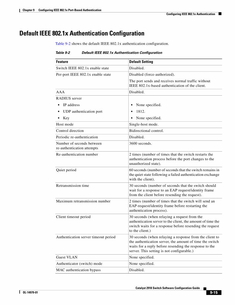
Chapter 9 Configuring IEEE 802.1x Port-Based AuthenticationConfiguring IEEE 802.1x Authentication
Default IEEE 802.1x Authentication ConfigurationTable 9-2 shows the default IEEE 802.1x authentication configuration.
Table 9-2 Default IEEE 802.1x Authentication Configuration
Feature Default Setting
Switch IEEE 802.1x enable state Disabled.
Per-port IEEE 802.1x enable state Disabled (force-authorized).
The port sends and receives normal traffic without IEEE 802.1x-based authentication of the client.
AAA Disabled.
RADIUS server
• IP address
• UDP authentication port
• Key
• None specified.
• 1812.
• None specified.
Host mode Single-host mode.
Control direction Bidirectional control.
Periodic re-authentication Disabled.
Number of seconds between re-authentication attempts
3600 seconds.
Re-authentication number 2 times (number of times that the switch restarts the authentication process before the port changes to the unauthorized state).
Quiet period 60 seconds (number of seconds that the switch remains in the quiet state following a failed authentication exchange with the client).
Retransmission time 30 seconds (number of seconds that the switch should wait for a response to an EAP request/identity frame from the client before resending the request).
Maximum retransmission number 2 times (number of times that the switch will send an EAP-request/identity frame before restarting the authentication process).
Client timeout period 30 seconds (when relaying a request from the authentication server to the client, the amount of time the switch waits for a response before resending the request to the client.)
Authentication server timeout period 30 seconds (when relaying a response from the client to the authentication server, the amount of time the switch waits for a reply before resending the response to the server. This setting is not configurable.)
Guest VLAN None specified.
Authenticator (switch) mode None specified.
MAC authentication bypass Disabled.
9-15Catalyst 2918 Switch Software Configuration Guide
OL-14979-01
Chapter 9 Configuring IEEE 802.1x Port-Based AuthenticationConfiguring IEEE 802.1x Authentication
IEEE 802.1x Authentication Configuration GuidelinesThese section has configuration guidelines for these features:
• IEEE 802.1x Authentication, page 9-16
• VLAN Assignment and Guest VLAN, page 9-17
• MAC Authentication Bypass, page 9-17
IEEE 802.1x Authentication
These are the IEEE 802.1x authentication configuration guidelines:
• When IEEE 802.1x authentication is enabled, ports are authenticated before any other Layer 2 feature is enabled.
• If you try to change the mode of an IEEE 802.1x-enabled port (for example, from access to trunk), an error message appears, and the port mode is not changed.
• If the VLAN to which an IEEE 802.1x-enabled port is assigned changes, this change is transparent and does not affect the switch. For example, this change occurs if a port is assigned to a RADIUS server-assigned VLAN and is then assigned to a different VLAN after re-authentication.
If the VLAN to which an IEEE 802.1x port is assigned to shut down, disabled, or removed, the port becomes unauthorized. For example, the port is unauthorized after the access VLAN to which a port is assigned shuts down or is removed.
• The IEEE 802.1x protocol is supported on Layer 2 static-access ports and voice VLAN ports, but it is not supported on these port types:
– Trunk port—If you try to enable IEEE 802.1x authentication on a trunk port, an error message appears, and IEEE 802.1x authentication is not enabled. If you try to change the mode of an IEEE 802.1x-enabled port to trunk, an error message appears, and the port mode is not changed.
– Dynamic ports—A port in dynamic mode can negotiate with its neighbor to become a trunk port. If you try to enable IEEE 802.1x authentication on a dynamic port, an error message appears, and IEEE 802.1x authentication is not enabled. If you try to change the mode of an IEEE 802.1x-enabled port to dynamic, an error message appears, and the port mode is not changed.
– Dynamic-access ports—If you try to enable IEEE 802.1x authentication on a dynamic-access (VLAN Query Protocol [VQP]) port, an error message appears, and IEEE 802.1x authentication is not enabled. If you try to change an IEEE 802.1x-enabled port to dynamic VLAN assignment, an error message appears, and the VLAN configuration is not changed.
– EtherChannel port—Do not configure a port that is an active or a not-yet-active member of an EtherChannel as an IEEE 802.1x port. If you try to enable IEEE 802.1x authentication on an EtherChannel port, an error message appears, and IEEE 802.1x authentication is not enabled.
– Switched Port Analyzer (SPAN) destination ports—You can enable IEEE 802.1x authentication on a port that is a SPAN destination port. However, IEEE 802.1x authentication is disabled until the port is removed as a SPAN destination port. You can enable IEEE 802.1x authentication on a SPAN source port.
• Before globally enabling IEEE 802.1x authentication on a switch by entering the dot1x system-auth-control global configuration command, remove the EtherChannel configuration from the interfaces on which IEEE 802.1x authentication and EtherChannel are configured.
9-16Catalyst 2918 Switch Software Configuration Guide
OL-14979-01
Chapter 9 Configuring IEEE 802.1x Port-Based AuthenticationConfiguring IEEE 802.1x Authentication
VLAN Assignment and Guest VLAN
These are the configuration guidelines for VLAN assignment, guest VLAN, restricted VLAN, and inaccessible authentication bypass:
• When IEEE 802.1x authentication is enabled on a port, you cannot configure a port VLAN that is equal to a voice VLAN.
• The IEEE 802.1x authentication with VLAN assignment feature is not supported on trunk ports, dynamic ports, or with dynamic-access port assignment through a VMPS.
• You can configure any VLAN except a voice VLAN as an IEEE 802.1x guest VLAN. The guest VLAN feature is not supported on trunk ports; it is supported only on access ports.
• After you configure a guest VLAN for an IEEE 802.1x port to which a DHCP client is connected, you might need to get a host IP address from a DHCP server. You can change the settings for restarting the IEEE 802.1x authentication process on the switch before the DHCP process on the client times out and tries to get a host IP address from the DHCP server. Decrease the settings for the IEEE 802.1x authentication process (dot1x timeout quiet-period and dot1x timeout tx-period interface configuration commands). The amount to decrease the settings depends on the connected IEEE 802.1x client type.
MAC Authentication Bypass
These are the MAC authentication bypass configuration guidelines:
• Unless otherwise stated, the MAC authentication bypass guidelines are the same as the IEEE 802.1x authentication guidelines. For more information, see the “IEEE 802.1x Authentication” section on page 9-16.
• If you disable MAC authentication bypass from a port after the port has been authorized with its MAC address, the port state is not affected.
• If the port is in the unauthorized state and the client MAC address is not the authentication-server database, the port remains in the unauthorized state. However, if the client MAC address is added to the database, the switch can use MAC authentication bypass to re-authorize the port.
• If the port is in the authorized state, the port remains in this state until re-authorization occurs.
Upgrading from a Previous Software ReleaseWhen IEEE 802.1x authentication is enabled, information about Port Fast is no longer added to the configuration and this information appears in the running configuration:
dot1x pae authenticator
Configuring IEEE 802.1x AuthenticationTo configure IEEE 802.1x port-based authentication, you must enable authentication, authorization, and accounting (AAA) and specify the authentication method list. A method list describes the sequence and authentication method to be queried to authenticate a user.
To allow VLAN assignment, you must enable AAA authorization to configure the switch for all network-related service requests.
9-17Catalyst 2918 Switch Software Configuration Guide
OL-14979-01
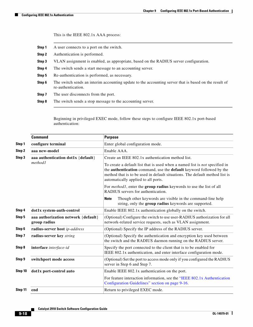
Chapter 9 Configuring IEEE 802.1x Port-Based AuthenticationConfiguring IEEE 802.1x Authentication
This is the IEEE 802.1x AAA process:
Step 1 A user connects to a port on the switch.
Step 2 Authentication is performed.
Step 3 VLAN assignment is enabled, as appropriate, based on the RADIUS server configuration.
Step 4 The switch sends a start message to an accounting server.
Step 5 Re-authentication is performed, as necessary.
Step 6 The switch sends an interim accounting update to the accounting server that is based on the result of re-authentication.
Step 7 The user disconnects from the port.
Step 8 The switch sends a stop message to the accounting server.
Beginning in privileged EXEC mode, follow these steps to configure IEEE 802.1x port-based authentication:
Command Purpose
Step 1 configure terminal Enter global configuration mode.
Step 2 aaa new-model Enable AAA.
Step 3 aaa authentication dot1x {default} method1
Create an IEEE 802.1x authentication method list.
To create a default list that is used when a named list is not specified in the authentication command, use the default keyword followed by the method that is to be used in default situations. The default method list is automatically applied to all ports.
For method1, enter the group radius keywords to use the list of all RADIUS servers for authentication.
Note Though other keywords are visible in the command-line help string, only the group radius keywords are supported.
Step 4 dot1x system-auth-control Enable IEEE 802.1x authentication globally on the switch.
Step 5 aaa authorization network {default} group radius
(Optional) Configure the switch to use user-RADIUS authorization for all network-related service requests, such as VLAN assignment.
Step 6 radius-server host ip-address (Optional) Specify the IP address of the RADIUS server.
Step 7 radius-server key string (Optional) Specify the authentication and encryption key used between the switch and the RADIUS daemon running on the RADIUS server.
Step 8 interface interface-id Specify the port connected to the client that is to be enabled for IEEE 802.1x authentication, and enter interface configuration mode.
Step 9 switchport mode access (Optional) Set the port to access mode only if you configured the RADIUS server in Step 6 and Step 7.
Step 10 dot1x port-control auto Enable IEEE 802.1x authentication on the port.
For feature interaction information, see the “IEEE 802.1x Authentication Configuration Guidelines” section on page 9-16.
Step 11 end Return to privileged EXEC mode.
9-18Catalyst 2918 Switch Software Configuration Guide
OL-14979-01
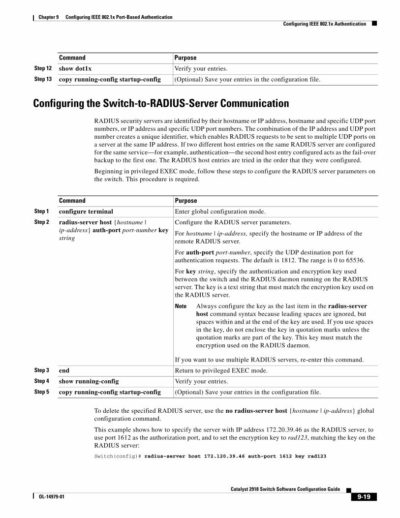
Chapter 9 Configuring IEEE 802.1x Port-Based AuthenticationConfiguring IEEE 802.1x Authentication
Configuring the Switch-to-RADIUS-Server CommunicationRADIUS security servers are identified by their hostname or IP address, hostname and specific UDP port numbers, or IP address and specific UDP port numbers. The combination of the IP address and UDP port number creates a unique identifier, which enables RADIUS requests to be sent to multiple UDP ports on a server at the same IP address. If two different host entries on the same RADIUS server are configured for the same service—for example, authentication—the second host entry configured acts as the fail-over backup to the first one. The RADIUS host entries are tried in the order that they were configured.
Beginning in privileged EXEC mode, follow these steps to configure the RADIUS server parameters on the switch. This procedure is required.
Command Purpose
Step 1 configure terminal Enter global configuration mode.
Step 2 radius-server host {hostname | ip-address} auth-port port-number key string
Configure the RADIUS server parameters.
For hostname | ip-address, specify the hostname or IP address of the remote RADIUS server.
For auth-port port-number, specify the UDP destination port for authentication requests. The default is 1812. The range is 0 to 65536.
For key string, specify the authentication and encryption key used between the switch and the RADIUS daemon running on the RADIUS server. The key is a text string that must match the encryption key used on the RADIUS server.
Note Always configure the key as the last item in the radius-server host command syntax because leading spaces are ignored, but spaces within and at the end of the key are used. If you use spaces in the key, do not enclose the key in quotation marks unless the quotation marks are part of the key. This key must match the encryption used on the RADIUS daemon.
If you want to use multiple RADIUS servers, re-enter this command.
Step 3 end Return to privileged EXEC mode.
Step 4 show running-config Verify your entries.
Step 5 copy running-config startup-config (Optional) Save your entries in the configuration file.
To delete the specified RADIUS server, use the no radius-server host {hostname | ip-address} global configuration command.
This example shows how to specify the server with IP address 172.20.39.46 as the RADIUS server, to use port 1612 as the authorization port, and to set the encryption key to rad123, matching the key on the RADIUS server:
Switch(config)# radius-server host 172.l20.39.46 auth-port 1612 key rad123
Step 12 show dot1x Verify your entries.
Step 13 copy running-config startup-config (Optional) Save your entries in the configuration file.
Command Purpose
9-19Catalyst 2918 Switch Software Configuration Guide
OL-14979-01
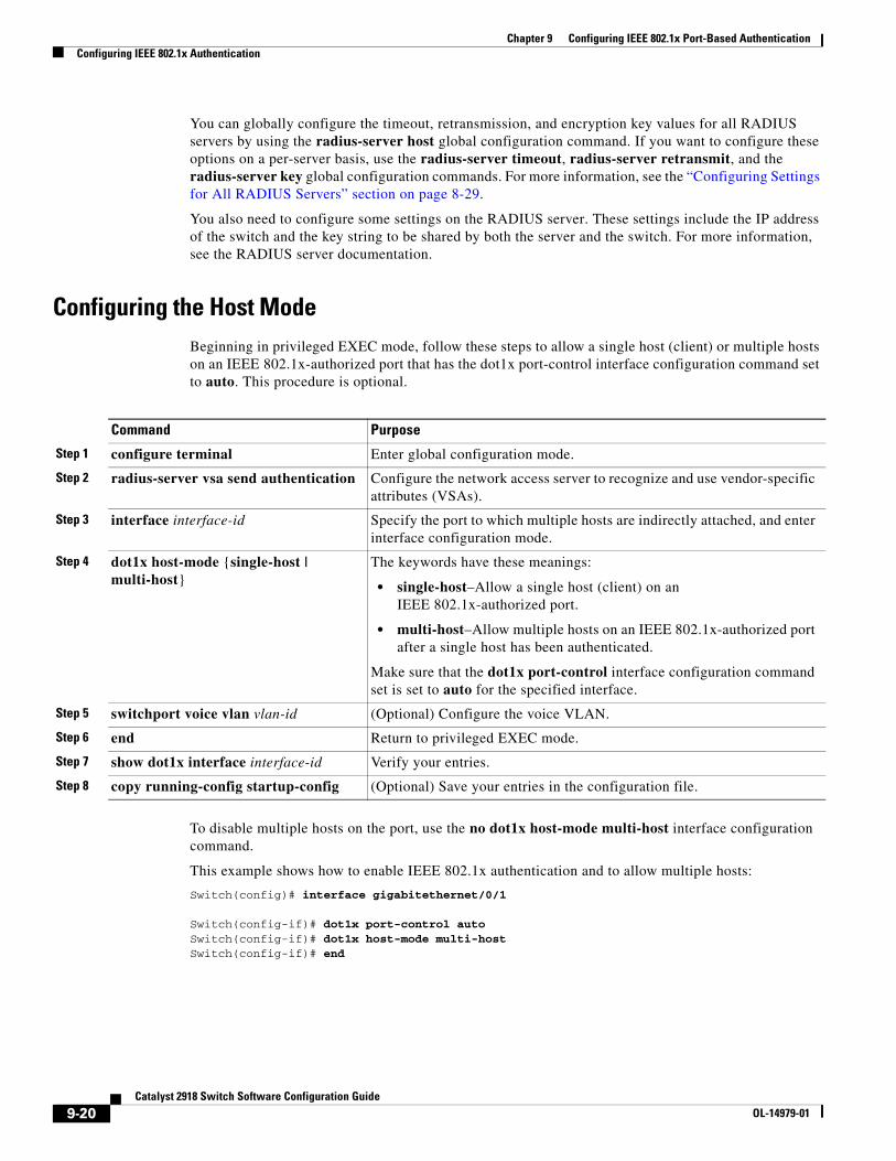
Chapter 9 Configuring IEEE 802.1x Port-Based AuthenticationConfiguring IEEE 802.1x Authentication
You can globally configure the timeout, retransmission, and encryption key values for all RADIUS servers by using the radius-server host global configuration command. If you want to configure these options on a per-server basis, use the radius-server timeout, radius-server retransmit, and the radius-server key global configuration commands. For more information, see the “Configuring Settings for All RADIUS Servers” section on page 8-29.
You also need to configure some settings on the RADIUS server. These settings include the IP address of the switch and the key string to be shared by both the server and the switch. For more information, see the RADIUS server documentation.
Configuring the Host ModeBeginning in privileged EXEC mode, follow these steps to allow a single host (client) or multiple hosts on an IEEE 802.1x-authorized port that has the dot1x port-control interface configuration command set to auto. This procedure is optional.
Command Purpose
Step 1 configure terminal Enter global configuration mode.
Step 2 radius-server vsa send authentication Configure the network access server to recognize and use vendor-specific attributes (VSAs).
Step 3 interface interface-id Specify the port to which multiple hosts are indirectly attached, and enter interface configuration mode.
Step 4 dot1x host-mode {single-host | multi-host}
The keywords have these meanings:
• single-host–Allow a single host (client) on an IEEE 802.1x-authorized port.
• multi-host–Allow multiple hosts on an IEEE 802.1x-authorized port after a single host has been authenticated.
Make sure that the dot1x port-control interface configuration command set is set to auto for the specified interface.
Step 5 switchport voice vlan vlan-id (Optional) Configure the voice VLAN.
Step 6 end Return to privileged EXEC mode.
Step 7 show dot1x interface interface-id Verify your entries.
Step 8 copy running-config startup-config (Optional) Save your entries in the configuration file.
To disable multiple hosts on the port, use the no dot1x host-mode multi-host interface configuration command.
This example shows how to enable IEEE 802.1x authentication and to allow multiple hosts:
Switch(config)# interface gigabitethernet/0/1
Switch(config-if)# dot1x port-control autoSwitch(config-if)# dot1x host-mode multi-hostSwitch(config-if)# end
9-20Catalyst 2918 Switch Software Configuration Guide
OL-14979-01
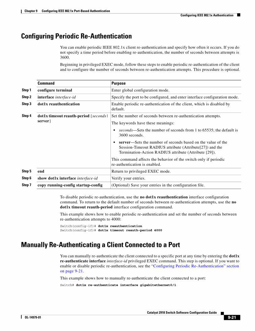
Chapter 9 Configuring IEEE 802.1x Port-Based AuthenticationConfiguring IEEE 802.1x Authentication
Configuring Periodic Re-AuthenticationYou can enable periodic IEEE 802.1x client re-authentication and specify how often it occurs. If you do not specify a time period before enabling re-authentication, the number of seconds between attempts is 3600.
Beginning in privileged EXEC mode, follow these steps to enable periodic re-authentication of the client and to configure the number of seconds between re-authentication attempts. This procedure is optional.
Command Purpose
Step 1 configure terminal Enter global configuration mode.
Step 2 interface interface-id Specify the port to be configured, and enter interface configuration mode.
Step 3 dot1x reauthentication Enable periodic re-authentication of the client, which is disabled by default.
Step 4 dot1x timeout reauth-period {seconds | server}
Set the number of seconds between re-authentication attempts.
The keywords have these meanings:
• seconds—Sets the number of seconds from 1 to 65535; the default is 3600 seconds.
• server—Sets the number of seconds based on the value of the Session-Timeout RADIUS attribute (Attribute[27]) and the Termination-Action RADIUS attribute (Attribute [29]).
This command affects the behavior of the switch only if periodic re-authentication is enabled.
Step 5 end Return to privileged EXEC mode.
Step 6 show dot1x interface interface-id Verify your entries.
Step 7 copy running-config startup-config (Optional) Save your entries in the configuration file.
To disable periodic re-authentication, use the no dot1x reauthentication interface configuration command. To return to the default number of seconds between re-authentication attempts, use the no dot1x timeout reauth-period interface configuration command.
This example shows how to enable periodic re-authentication and set the number of seconds between re-authentication attempts to 4000:
Switch(config-if)# dot1x reauthenticationSwitch(config-if)# dot1x timeout reauth-period 4000
Manually Re-Authenticating a Client Connected to a PortYou can manually re-authenticate the client connected to a specific port at any time by entering the dot1x re-authenticate interface interface-id privileged EXEC command. This step is optional. If you want to enable or disable periodic re-authentication, see the “Configuring Periodic Re-Authentication” section on page 9-21.
This example shows how to manually re-authenticate the client connected to a port:
Switch# dot1x re-authenticate interface gigabitethernet0/1
9-21Catalyst 2918 Switch Software Configuration Guide
OL-14979-01
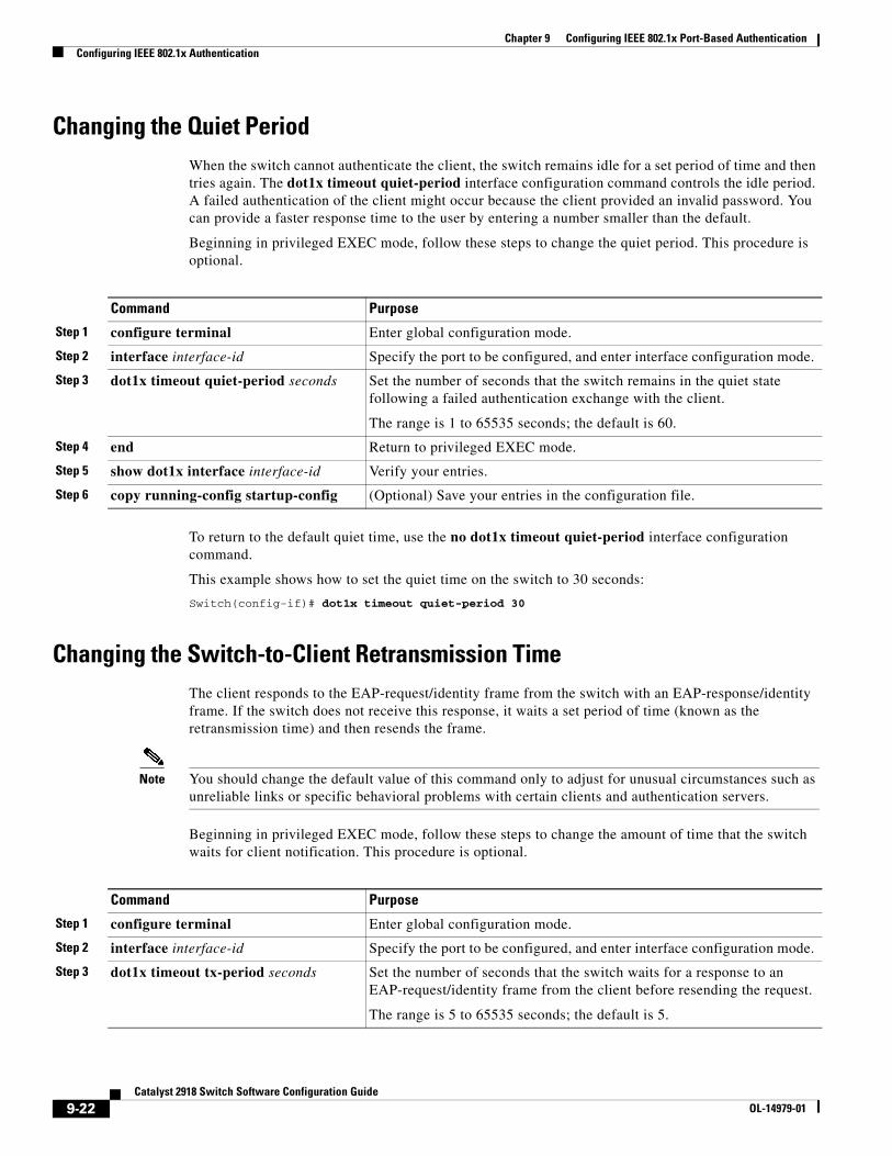
Chapter 9 Configuring IEEE 802.1x Port-Based AuthenticationConfiguring IEEE 802.1x Authentication
Changing the Quiet PeriodWhen the switch cannot authenticate the client, the switch remains idle for a set period of time and then tries again. The dot1x timeout quiet-period interface configuration command controls the idle period. A failed authentication of the client might occur because the client provided an invalid password. You can provide a faster response time to the user by entering a number smaller than the default.
Beginning in privileged EXEC mode, follow these steps to change the quiet period. This procedure is optional.
Command Purpose
Step 1 configure terminal Enter global configuration mode.
Step 2 interface interface-id Specify the port to be configured, and enter interface configuration mode.
Step 3 dot1x timeout quiet-period seconds Set the number of seconds that the switch remains in the quiet state following a failed authentication exchange with the client.
The range is 1 to 65535 seconds; the default is 60.
Step 4 end Return to privileged EXEC mode.
Step 5 show dot1x interface interface-id Verify your entries.
Step 6 copy running-config startup-config (Optional) Save your entries in the configuration file.
To return to the default quiet time, use the no dot1x timeout quiet-period interface configuration command.
This example shows how to set the quiet time on the switch to 30 seconds:
Switch(config-if)# dot1x timeout quiet-period 30
Changing the Switch-to-Client Retransmission TimeThe client responds to the EAP-request/identity frame from the switch with an EAP-response/identity frame. If the switch does not receive this response, it waits a set period of time (known as the retransmission time) and then resends the frame.
Note You should change the default value of this command only to adjust for unusual circumstances such as unreliable links or specific behavioral problems with certain clients and authentication servers.
Beginning in privileged EXEC mode, follow these steps to change the amount of time that the switch waits for client notification. This procedure is optional.
Command Purpose
Step 1 configure terminal Enter global configuration mode.
Step 2 interface interface-id Specify the port to be configured, and enter interface configuration mode.
Step 3 dot1x timeout tx-period seconds Set the number of seconds that the switch waits for a response to an EAP-request/identity frame from the client before resending the request.
The range is 5 to 65535 seconds; the default is 5.
9-22Catalyst 2918 Switch Software Configuration Guide
OL-14979-01
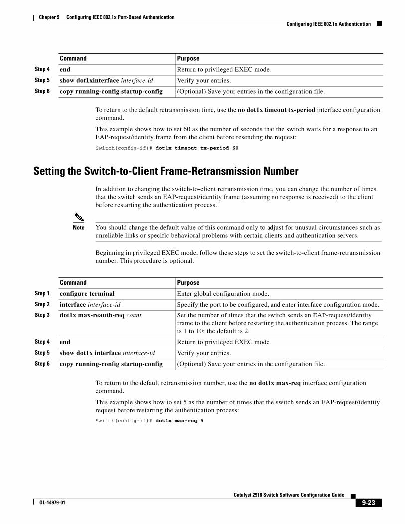
Chapter 9 Configuring IEEE 802.1x Port-Based AuthenticationConfiguring IEEE 802.1x Authentication
To return to the default retransmission time, use the no dot1x timeout tx-period interface configuration command.
This example shows how to set 60 as the number of seconds that the switch waits for a response to an EAP-request/identity frame from the client before resending the request:
Switch(config-if)# dot1x timeout tx-period 60
Setting the Switch-to-Client Frame-Retransmission NumberIn addition to changing the switch-to-client retransmission time, you can change the number of times that the switch sends an EAP-request/identity frame (assuming no response is received) to the client before restarting the authentication process.
Note You should change the default value of this command only to adjust for unusual circumstances such as unreliable links or specific behavioral problems with certain clients and authentication servers.
Beginning in privileged EXEC mode, follow these steps to set the switch-to-client frame-retransmission number. This procedure is optional.
Command Purpose
Step 1 configure terminal Enter global configuration mode.
Step 2 interface interface-id Specify the port to be configured, and enter interface configuration mode.
Step 3 dot1x max-reauth-req count Set the number of times that the switch sends an EAP-request/identity frame to the client before restarting the authentication process. The range is 1 to 10; the default is 2.
Step 4 end Return to privileged EXEC mode.
Step 5 show dot1x interface interface-id Verify your entries.
Step 6 copy running-config startup-config (Optional) Save your entries in the configuration file.
To return to the default retransmission number, use the no dot1x max-req interface configuration command.
This example shows how to set 5 as the number of times that the switch sends an EAP-request/identity request before restarting the authentication process:
Switch(config-if)# dot1x max-req 5
Step 4 end Return to privileged EXEC mode.
Step 5 show dot1xinterface interface-id Verify your entries.
Step 6 copy running-config startup-config (Optional) Save your entries in the configuration file.
Command Purpose
9-23Catalyst 2918 Switch Software Configuration Guide
OL-14979-01
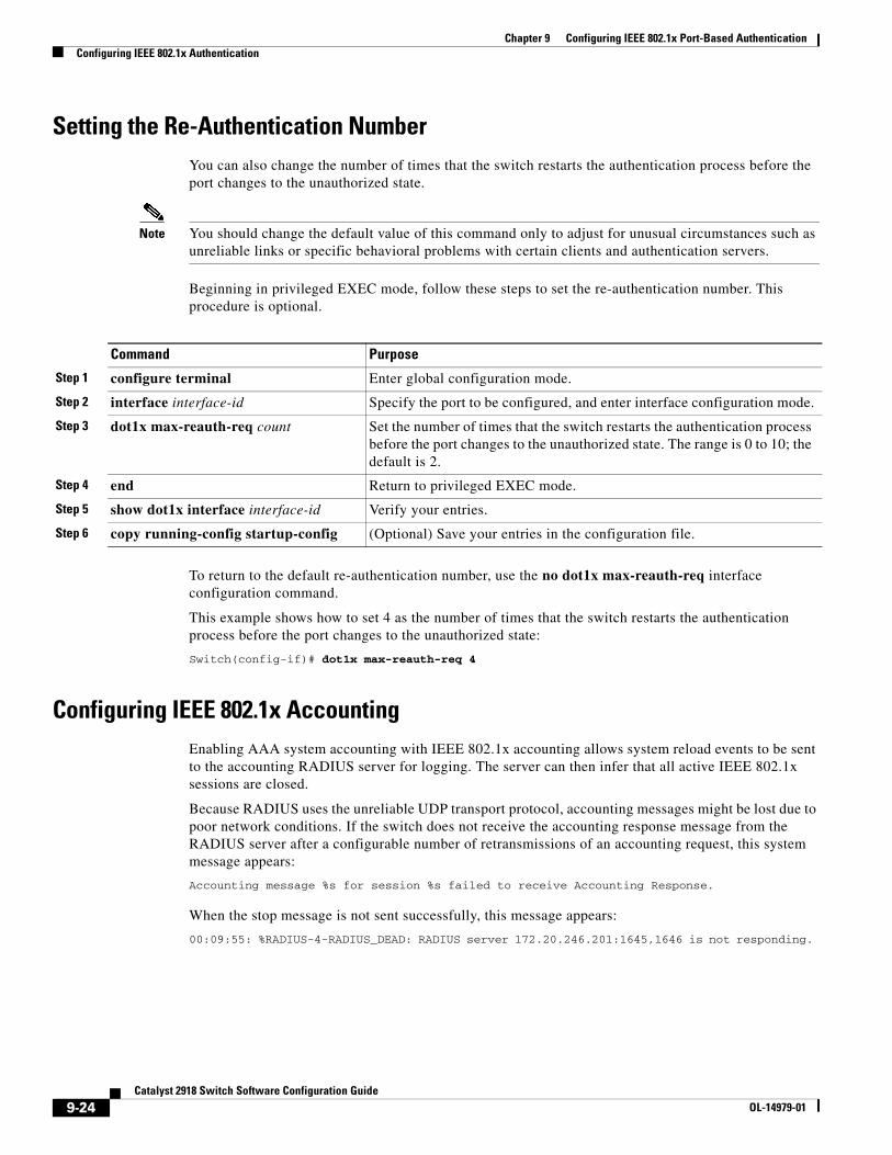
Chapter 9 Configuring IEEE 802.1x Port-Based AuthenticationConfiguring IEEE 802.1x Authentication
Setting the Re-Authentication NumberYou can also change the number of times that the switch restarts the authentication process before the port changes to the unauthorized state.
Note You should change the default value of this command only to adjust for unusual circumstances such as unreliable links or specific behavioral problems with certain clients and authentication servers.
Beginning in privileged EXEC mode, follow these steps to set the re-authentication number. This procedure is optional.
Command Purpose
Step 1 configure terminal Enter global configuration mode.
Step 2 interface interface-id Specify the port to be configured, and enter interface configuration mode.
Step 3 dot1x max-reauth-req count Set the number of times that the switch restarts the authentication process before the port changes to the unauthorized state. The range is 0 to 10; the default is 2.
Step 4 end Return to privileged EXEC mode.
Step 5 show dot1x interface interface-id Verify your entries.
Step 6 copy running-config startup-config (Optional) Save your entries in the configuration file.
To return to the default re-authentication number, use the no dot1x max-reauth-req interface configuration command.
This example shows how to set 4 as the number of times that the switch restarts the authentication process before the port changes to the unauthorized state:
Switch(config-if)# dot1x max-reauth-req 4
Configuring IEEE 802.1x AccountingEnabling AAA system accounting with IEEE 802.1x accounting allows system reload events to be sent to the accounting RADIUS server for logging. The server can then infer that all active IEEE 802.1x sessions are closed.
Because RADIUS uses the unreliable UDP transport protocol, accounting messages might be lost due to poor network conditions. If the switch does not receive the accounting response message from the RADIUS server after a configurable number of retransmissions of an accounting request, this system message appears:
Accounting message %s for session %s failed to receive Accounting Response.
When the stop message is not sent successfully, this message appears:
00:09:55: %RADIUS-4-RADIUS_DEAD: RADIUS server 172.20.246.201:1645,1646 is not responding.
9-24Catalyst 2918 Switch Software Configuration Guide
OL-14979-01
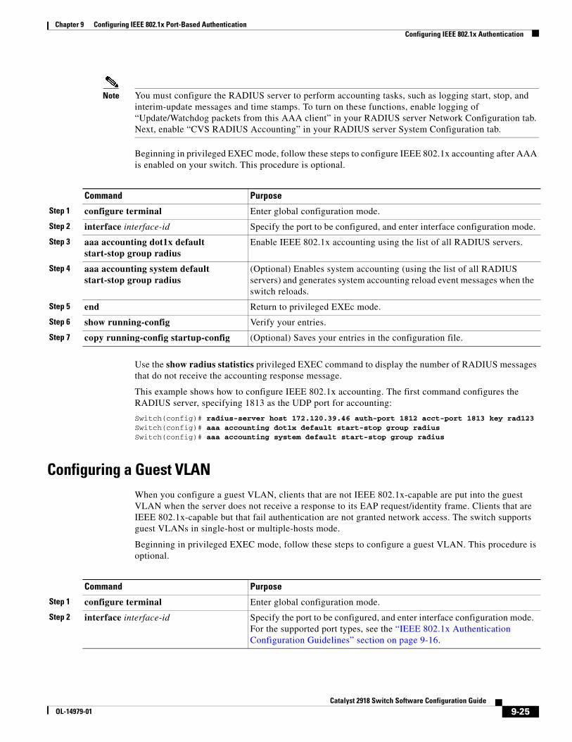
Chapter 9 Configuring IEEE 802.1x Port-Based AuthenticationConfiguring IEEE 802.1x Authentication
Note You must configure the RADIUS server to perform accounting tasks, such as logging start, stop, and interim-update messages and time stamps. To turn on these functions, enable logging of “Update/Watchdog packets from this AAA client” in your RADIUS server Network Configuration tab. Next, enable “CVS RADIUS Accounting” in your RADIUS server System Configuration tab.
Beginning in privileged EXEC mode, follow these steps to configure IEEE 802.1x accounting after AAA is enabled on your switch. This procedure is optional.
Command Purpose
Step 1 configure terminal Enter global configuration mode.
Step 2 interface interface-id Specify the port to be configured, and enter interface configuration mode.
Step 3 aaa accounting dot1x default start-stop group radius
Enable IEEE 802.1x accounting using the list of all RADIUS servers.
Step 4 aaa accounting system default start-stop group radius
(Optional) Enables system accounting (using the list of all RADIUS servers) and generates system accounting reload event messages when the switch reloads.
Step 5 end Return to privileged EXEc mode.
Step 6 show running-config Verify your entries.
Step 7 copy running-config startup-config (Optional) Saves your entries in the configuration file.
Use the show radius statistics privileged EXEC command to display the number of RADIUS messages that do not receive the accounting response message.
This example shows how to configure IEEE 802.1x accounting. The first command configures the RADIUS server, specifying 1813 as the UDP port for accounting:
Switch(config)# radius-server host 172.120.39.46 auth-port 1812 acct-port 1813 key rad123Switch(config)# aaa accounting dot1x default start-stop group radiusSwitch(config)# aaa accounting system default start-stop group radius
Configuring a Guest VLANWhen you configure a guest VLAN, clients that are not IEEE 802.1x-capable are put into the guest VLAN when the server does not receive a response to its EAP request/identity frame. Clients that are IEEE 802.1x-capable but that fail authentication are not granted network access. The switch supports guest VLANs in single-host or multiple-hosts mode.
Beginning in privileged EXEC mode, follow these steps to configure a guest VLAN. This procedure is optional.
Command Purpose
Step 1 configure terminal Enter global configuration mode.
Step 2 interface interface-id Specify the port to be configured, and enter interface configuration mode. For the supported port types, see the “IEEE 802.1x Authentication Configuration Guidelines” section on page 9-16.
9-25Catalyst 2918 Switch Software Configuration Guide
OL-14979-01
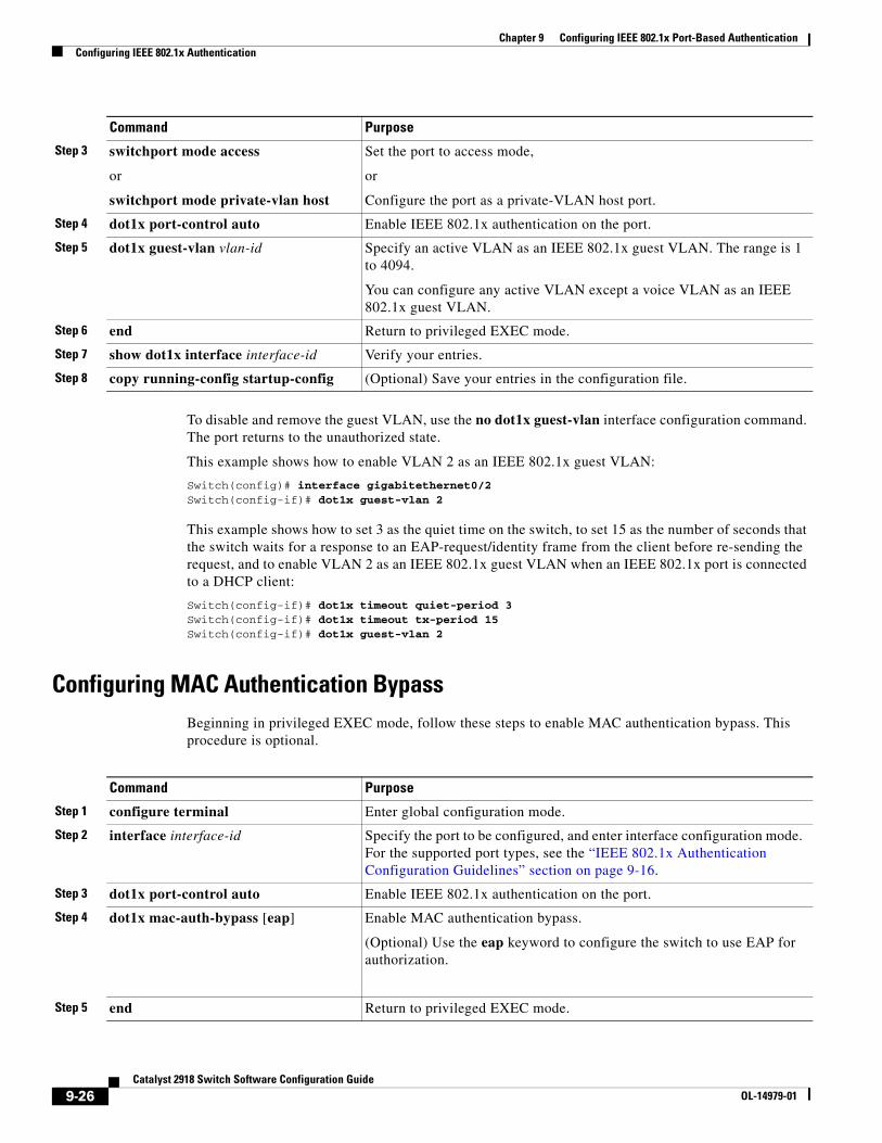
Chapter 9 Configuring IEEE 802.1x Port-Based AuthenticationConfiguring IEEE 802.1x Authentication
To disable and remove the guest VLAN, use the no dot1x guest-vlan interface configuration command. The port returns to the unauthorized state.
This example shows how to enable VLAN 2 as an IEEE 802.1x guest VLAN:
Switch(config)# interface gigabitethernet0/2Switch(config-if)# dot1x guest-vlan 2
This example shows how to set 3 as the quiet time on the switch, to set 15 as the number of seconds that the switch waits for a response to an EAP-request/identity frame from the client before re-sending the request, and to enable VLAN 2 as an IEEE 802.1x guest VLAN when an IEEE 802.1x port is connected to a DHCP client:
Switch(config-if)# dot1x timeout quiet-period 3Switch(config-if)# dot1x timeout tx-period 15Switch(config-if)# dot1x guest-vlan 2
Configuring MAC Authentication BypassBeginning in privileged EXEC mode, follow these steps to enable MAC authentication bypass. This procedure is optional.
Step 3 switchport mode access
or
switchport mode private-vlan host
Set the port to access mode,
or
Configure the port as a private-VLAN host port.
Step 4 dot1x port-control auto Enable IEEE 802.1x authentication on the port.
Step 5 dot1x guest-vlan vlan-id Specify an active VLAN as an IEEE 802.1x guest VLAN. The range is 1 to 4094.
You can configure any active VLAN except a voice VLAN as an IEEE 802.1x guest VLAN.
Step 6 end Return to privileged EXEC mode.
Step 7 show dot1x interface interface-id Verify your entries.
Step 8 copy running-config startup-config (Optional) Save your entries in the configuration file.
Command Purpose
Command Purpose
Step 1 configure terminal Enter global configuration mode.
Step 2 interface interface-id Specify the port to be configured, and enter interface configuration mode. For the supported port types, see the “IEEE 802.1x Authentication Configuration Guidelines” section on page 9-16.
Step 3 dot1x port-control auto Enable IEEE 802.1x authentication on the port.
Step 4 dot1x mac-auth-bypass [eap] Enable MAC authentication bypass.
(Optional) Use the eap keyword to configure the switch to use EAP for authorization.
Step 5 end Return to privileged EXEC mode.
9-26Catalyst 2918 Switch Software Configuration Guide
OL-14979-01
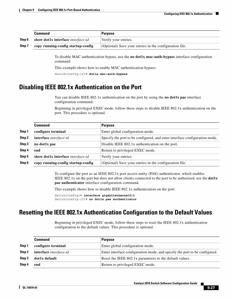
Chapter 9 Configuring IEEE 802.1x Port-Based AuthenticationConfiguring IEEE 802.1x Authentication
To disable MAC authentication bypass, use the no dot1x mac-auth-bypass interface configuration command.
This example shows how to enable MAC authentication bypass:
Switch(config-if)# dot1x mac-auth-bypass
Disabling IEEE 802.1x Authentication on the PortYou can disable IEEE 802.1x authentication on the port by using the no dot1x pae interface configuration command.
Beginning in privileged EXEC mode, follow these steps to disable IEEE 802.1x authentication on the port. This procedure is optional.
Command Purpose
Step 1 configure terminal Enter global configuration mode.
Step 2 interface interface-id Specify the port to be configured, and enter interface configuration mode.
Step 3 no dot1x pae Disable IEEE 802.1x authentication on the port.
Step 4 end Return to privileged EXEC mode.
Step 5 show dot1x interface interface-id Verify your entries.
Step 6 copy running-config startup-config (Optional) Save your entries in the configuration file.
To configure the port as an IEEE 802.1x port access entity (PAE) authenticator, which enables IEEE 802.1x on the port but does not allow clients connected to the port to be authorized, use the dot1x pae authenticator interface configuration command.
This example shows how to disable IEEE 802.1x authentication on the port:
Switch(config)# interface gigabitethernet0/1Switch(config-if)# no dot1x pae authenticator
Resetting the IEEE 802.1x Authentication Configuration to the Default ValuesBeginning in privileged EXEC mode, follow these steps to reset the IEEE 802.1x authentication configuration to the default values. This procedure is optional.
Step 6 show dot1x interface interface-id Verify your entries.
Step 7 copy running-config startup-config (Optional) Save your entries in the configuration file.
Command Purpose
Command Purpose
Step 1 configure terminal Enter global configuration mode.
Step 2 interface interface-id Enter interface configuration mode, and specify the port to be configured.
Step 3 dot1x default Reset the IEEE 802.1x parameters to the default values.
Step 4 end Return to privileged EXEC mode.
9-27Catalyst 2918 Switch Software Configuration Guide
OL-14979-01
Chapter 9 Configuring IEEE 802.1x Port-Based AuthenticationDisplaying IEEE 802.1x Statistics and Status
Displaying IEEE 802.1x Statistics and StatusTo display IEEE 802.1x statistics for all ports, use the show dot1x all statistics privileged EXEC command. To display IEEE 802.1x statistics for a specific port, use the show dot1x statistics interface interface-id privileged EXEC command.
To display the IEEE 802.1x administrative and operational status for the switch, use the show dot1x all [details | statistics | summary] privileged EXEC command. To display the IEEE 802.1x administrative and operational status for a specific port, use the show dot1x interface interface-id privileged EXEC command.
For detailed information about the fields in these displays, see the command reference for this release.
Step 5 show dot1x interface interface-id Verify your entries.
Step 6 copy running-config startup-config (Optional) Save your entries in the configuration file.
Command Purpose
9-28Catalyst 2918 Switch Software Configuration Guide
OL-14979-01
OL-14979-01
C H A P T E R 10
Configuring Interface CharacteristicsThis chapter defines the types of interfaces on the Catalyst 2918 switch and describes how to configure them.
The chapter consists of these sections:
• Understanding Interface Types, page 10-1
• Using Interface Configuration Mode, page 10-4
• Configuring Ethernet Interfaces, page 10-9
• Configuring the System MTU, page 10-16
• Monitoring and Maintaining the Interfaces, page 10-18
Note For complete syntax and usage information for the commands used in this chapter, see the switch command reference for this release and the online Cisco IOS Interface Command Reference, Release 12.2.
Understanding Interface TypesThis section describes the different types of interfaces supported by the switch with references to chapters that contain more detailed information about configuring these interface types. The rest of the chapter describes configuration procedures for physical interface characteristics.
These sections describe the interface types:
• Port-Based VLANs, page 10-2
• Switch Ports, page 10-2
• EtherChannel Port Groups, page 10-3
• Dual-Purpose Uplink Ports, page 10-4
• Connecting Interfaces, page 10-4
10-1Catalyst 2918 Switch Software Configuration Guide
Chapter 10 Configuring Interface CharacteristicsUnderstanding Interface Types
Port-Based VLANsA VLAN is a switched network that is logically segmented by function, team, or application, without regard to the physical location of the users. For more information about VLANs, see Chapter 12, “Configuring VLANs.” Packets received on a port are forwarded only to ports that belong to the same VLAN as the receiving port. Network devices in different VLANs cannot communicate with one another without a Layer 3 device to route traffic between the VLANs.
VLAN partitions provide hard firewalls for traffic in the VLAN, and each VLAN has its own MAC address table. A VLAN comes into existence when a local port is configured to be associated with the VLAN, when the VLAN Trunking Protocol (VTP) learns of its existence from a neighbor on a trunk, or when a user creates a VLAN.
To configure normal-range VLANs (VLAN IDs 1 to 1005), use the vlan vlan-id global configuration command to enter config-vlan mode or the vlan database privileged EXEC command to enter VLAN database configuration mode. The VLAN configurations for VLAN IDs 1 to 1005 are saved in the VLAN database. To configure extended-range VLANs (VLAN IDs 1006 to 4094), you must use config-vlan mode with VTP mode set to transparent. Extended-range VLANs are not added to the VLAN database. When VTP mode is transparent, the VTP and VLAN configuration is saved in the switch running configuration, and you can save it in the switch startup configuration file by entering the copy running-config startup-config privileged EXEC command.
Add ports to a VLAN by using the switchport interface configuration commands:
• Identify the interface.
• For a trunk port, set trunk characteristics, and if desired, define the VLANs to which it can belong.
• For an access port, set and define the VLAN to which it belongs.
Switch PortsSwitch ports are Layer 2-only interfaces associated with a physical port. Switch ports belong to one or more VLANs. A switch port can be an access port or a trunk port. You can configure a port as an access port or trunk port or let the Dynamic Trunking Protocol (DTP) operate on a per-port basis to set the switchport mode by negotiating with the port on the other end of the link. Switch ports are used for managing the physical interface and associated Layer 2 protocols.
Configure switch ports by using the switchport interface configuration commands.
For detailed information about configuring access port and trunk port characteristics, see Chapter 12, “Configuring VLANs.”
Access Ports
An access port belongs to and carries the traffic of only one VLAN (unless it is configured as a voice VLAN port). Traffic is received and sent in native formats with no VLAN tagging. Traffic arriving on an access port is assumed to belong to the VLAN assigned to the port. If an access port receives a tagged packet (IEEE 802.1Q tagged), the packet is dropped, and the source address is not learned.
10-2Catalyst 2918 Switch Software Configuration Guide
OL-14979-01
Chapter 10 Configuring Interface CharacteristicsUnderstanding Interface Types
Two types of access ports are supported:
• Static access ports are manually assigned to a VLAN (or through a RADIUS server for use with IEEE 802.1x. For more information, see the “Using IEEE 802.1x Authentication with VLAN Assignment” section on page 9-9.)
• VLAN membership of dynamic access ports is learned through incoming packets. By default, a dynamic access port is not a member of any VLAN, and forwarding to and from the port is enabled only when the VLAN membership of the port is discovered. Dynamic access ports on the switch are assigned to a VLAN by a VLAN Membership Policy Server (VMPS). The VMPS can be a Catalyst 6500 series switch; the Catalyst 2918 switch cannot be a VMPS server.
You can also configure an access port with an attached Cisco IP Phone to use one VLAN for voice traffic and another VLAN for data traffic from a device attached to the phone. For more information about voice VLAN ports, see Chapter 14, “Configuring Voice VLAN.”
Trunk Ports
A trunk port carries the traffic of multiple VLANs and by default is a member of all VLANs in the VLAN database. Only IEEE 802.1Q trunk ports are supported.
An IEEE 802.1Q trunk port supports simultaneous tagged and untagged traffic. An IEEE 802.1Q trunk port is assigned a default port VLAN ID (PVID), and all untagged traffic travels on the port default PVID. All untagged traffic and tagged traffic with a NULL VLAN ID are assumed to belong to the port default PVID. A packet with a VLAN ID equal to the outgoing port default PVID is sent untagged. All other traffic is sent with a VLAN tag.
Although by default, a trunk port is a member of every VLAN known to the VTP, you can limit VLAN membership by configuring an allowed list of VLANs for each trunk port. The list of allowed VLANs does not affect any other port but the associated trunk port. By default, all possible VLANs (VLAN ID 1 to 4094) are in the allowed list. A trunk port can become a member of a VLAN only if VTP knows of the VLAN and if the VLAN is in the enabled state. If VTP learns of a new, enabled VLAN and the VLAN is in the allowed list for a trunk port, the trunk port automatically becomes a member of that VLAN and traffic is forwarded to and from the trunk port for that VLAN. If VTP learns of a new, enabled VLAN that is not in the allowed list for a trunk port, the port does not become a member of the VLAN, and no traffic for the VLAN is forwarded to or from the port.
For more information about trunk ports, see Chapter 12, “Configuring VLANs.”
EtherChannel Port GroupsEtherChannel port groups treat multiple switch ports as one switch port. These port groups act as a single logical port for high-bandwidth connections between switches or between switches and servers. An EtherChannel balances the traffic load across the links in the channel. If a link within the EtherChannel fails, traffic previously carried over the failed link changes to the remaining links. You can group multiple trunk ports into one logical trunk port or multiple access ports into one logical access port. Most protocols operate over either single ports or aggregated switch ports and do not recognize the physical ports within the port group. Exceptions are the DTP, the Cisco Discovery Protocol (CDP), and the Port Aggregation Protocol (PAgP), which operate only on physical ports.
When you configure an EtherChannel, you create a port-channel logical interface and assign an interface to the EtherChannel. Use the channel-group interface configuration command to dynamically create the port-channel logical interface. This command binds the physical and logical ports together. For more information, see Chapter 28, “Configuring EtherChannels.”
10-3Catalyst 2918 Switch Software Configuration Guide
OL-14979-01
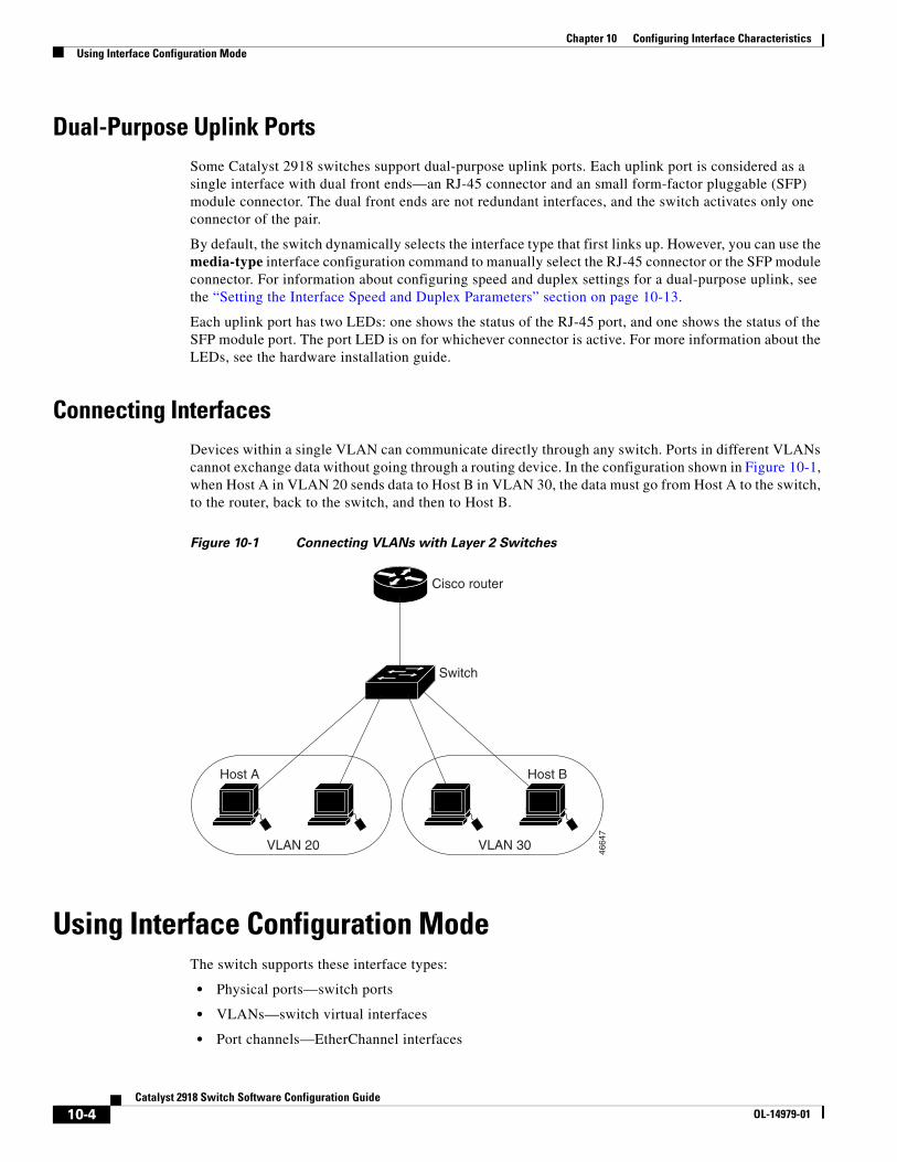
Chapter 10 Configuring Interface CharacteristicsUsing Interface Configuration Mode
Dual-Purpose Uplink PortsSome Catalyst 2918 switches support dual-purpose uplink ports. Each uplink port is considered as a single interface with dual front ends—an RJ-45 connector and an small form-factor pluggable (SFP) module connector. The dual front ends are not redundant interfaces, and the switch activates only one connector of the pair.
By default, the switch dynamically selects the interface type that first links up. However, you can use the media-type interface configuration command to manually select the RJ-45 connector or the SFP module connector. For information about configuring speed and duplex settings for a dual-purpose uplink, see the “Setting the Interface Speed and Duplex Parameters” section on page 10-13.
Each uplink port has two LEDs: one shows the status of the RJ-45 port, and one shows the status of the SFP module port. The port LED is on for whichever connector is active. For more information about the LEDs, see the hardware installation guide.
Connecting InterfacesDevices within a single VLAN can communicate directly through any switch. Ports in different VLANs cannot exchange data without going through a routing device. In the configuration shown in Figure 10-1, when Host A in VLAN 20 sends data to Host B in VLAN 30, the data must go from Host A to the switch, to the router, back to the switch, and then to Host B.
Figure 10-1 Connecting VLANs with Layer 2 Switches
Host A
Switch
Cisco router
VLAN 20
Host B
VLAN 30
4664
7
Using Interface Configuration ModeThe switch supports these interface types:
• Physical ports—switch ports
• VLANs—switch virtual interfaces
• Port channels—EtherChannel interfaces
10-4Catalyst 2918 Switch Software Configuration Guide
OL-14979-01
Chapter 10 Configuring Interface CharacteristicsUsing Interface Configuration Mode
You can also configure a range of interfaces (see the “Configuring a Range of Interfaces” section on page 10-6).
To configure a physical interface (port), specify the interface type, module number, and switch port number, and enter interface configuration mode.
• Type—Fast Ethernet (fastethernet or fa) for 10/100 Mb/s Ethernet, Gigabit Ethernet (gigabitethernet or gi) for 10/100/1000 Mb/s Ethernet ports, or small form-factor pluggable (SFP) module Gigabit Ethernet interfaces.
• Module number—The module or slot number on the switch (always 0 on the Catalyst 2918 switch).
• Port number—The interface number on the switch. The port numbers always begin at 1, starting with the far left port when facing the front of the switch, for example, fastethernet0/1 or gigabitethernet0/1. If there is more than one interface type (for example, 10/100 ports and SFP module ports, the port numbers restart with the second interface type: gigabitethernet0/1. For a switch with 10/100/1000 ports and SFP module ports, SFP module ports are numbered consecutively following the 10/100/1000 ports.
You can identify physical interfaces by physically checking the interface location on the switch. You can also use the show privileged EXEC commands to display information about a specific interface or all the interfaces on the switch. The remainder of this chapter primarily provides physical interface configuration procedures.
Procedures for Configuring InterfacesThese general instructions apply to all interface configuration processes.
Step 1 Enter the configure terminal command at the privileged EXEC prompt:
Switch# configure terminal Enter configuration commands, one per line. End with CNTL/Z.Switch(config)#
Step 2 Enter the interface global configuration command. Identify the interface type and the number of the connector. In this example, Gigabit Ethernet port 1 is selected:
Switch(config)# interface gigabitethernet0/1 Switch(config-if)#
Note You do not need to add a space between the interface type and interface number. For example, in the preceding line, you can specify either gigabitethernet 0/1, gigabitethernet0/1, gi 0/1, or gi0/1.
Step 3 Follow each interface command with the interface configuration commands that the interface requires. The commands that you enter define the protocols and applications that will run on the interface. The commands are collected and applied to the interface when you enter another interface command or enter end to return to privileged EXEC mode.
You can also configure a range of interfaces by using the interface range or interface range macro global configuration commands. Interfaces configured in a range must be the same type and must be configured with the same feature options.
10-5Catalyst 2918 Switch Software Configuration Guide
OL-14979-01
Chapter 10 Configuring Interface CharacteristicsUsing Interface Configuration Mode
Step 4 After you configure an interface, verify its status by using the show privileged EXEC commands listed in the “Monitoring and Maintaining the Interfaces” section on page 10-18.
Enter the show interfaces privileged EXEC command to see a list of all interfaces on or configured for the switch. A report is provided for each interface that the device supports or for the specified interface.
Configuring a Range of InterfacesYou can use the interface range global configuration command to configure multiple interfaces with the same configuration parameters. When you enter the interface-range configuration mode, all command parameters that you enter are attributed to all interfaces within that range until you exit this mode.
Beginning in privileged EXEC mode, follow these steps to configure a range of interfaces with the same parameters:
Command Purpose
Step 1 configure terminal Enter global configuration mode.
Step 2 interface range {port-range | macro macro_name}
Specify the range of interfaces (VLANs or physical ports) to be configured, and enter interface-range configuration mode.
• You can use the interface range command to configure up to five port ranges or a previously defined macro.
• The macro variable is explained in the “Configuring and Using Interface Range Macros” section on page 10-7.
• In a comma-separated port-range, you must enter the interface type for each entry and enter spaces before and after the comma.
• In a hyphen-separated port-range, you do not need to re-enter the interface type, but you must enter a space before the hyphen.
Step 3 Use the normal configuration commands to apply the configuration parameters to all interfaces in the range. Each command is executed as it is entered.
Step 4 end Return to privileged EXEC mode.
Step 5 show interfaces [interface-id] Verify the configuration of the interfaces in the range.
Step 6 copy running-config startup-config (Optional) Save your entries in the configuration file.
When using the interface range global configuration command, note these guidelines:
• Valid entries for port-range:
– vlan vlan-ID, where the VLAN ID is 1 to 4094
Note Although the command-line interface shows options to set multiple VLANs, these options are not supported.
– fastethernet module/{first port} - {last port}, where the module is always 0
– gigabitethernet module/{first port} - {last port}, where the module is always 0
10-6Catalyst 2918 Switch Software Configuration Guide
OL-14979-01
Chapter 10 Configuring Interface CharacteristicsUsing Interface Configuration Mode
– port-channel port-channel-number - port-channel-number, where the port-channel-number is 1 to 6
Note When you use the interface range command with port channels, the first and last port-channel number must be active port channels.
• You must add a space between the first interface number and the hyphen when using the interface range command. For example, the command interface range gigabitethernet0/1 - 4 is a valid range; the command interface range gigabitethernet0/1-4 is not a valid range.
• The interface range command only works with VLAN interfaces that have been configured with the interface vlan command. The show running-config privileged EXEC command displays the configured VLAN interfaces. VLAN interfaces not displayed by the show running-config command cannot be used with the interface range command.
• All interfaces defined in a range must be the same type (all Fast Ethernet ports, all Gigabit Ethernet ports, all EtherChannel ports, or all VLANs), but you can enter multiple ranges in a command.
This example shows how to use the interface range global configuration command to set the speed on ports 1 to 4 to 100 Mb/s:
Switch# configure terminalSwitch(config)# interface range gigabitethernet0/1 - 4Switch(config-if-range)# speed 100
This example shows how to use a comma to add different interface type strings to the range to enable Fast Ethernet ports 1 to 3 and Gigabit Ethernet ports 1 and 2 to receive flow-control pause frames:
Switch# configure terminalSwitch(config)# interface range fastethernet0/1 - 3, gigabitethernet0/1 - 2 Switch(config-if-range)# flowcontrol receive on
If you enter multiple configuration commands while you are in interface-range mode, each command is executed as it is entered. The commands are not batched and executed after you exit interface-range mode. If you exit interface-range configuration mode while the commands are being executed, some commands might not be executed on all interfaces in the range. Wait until the command prompt reappears before exiting interface-range configuration mode.
Configuring and Using Interface Range MacrosYou can create an interface range macro to automatically select a range of interfaces for configuration. Before you can use the macro keyword in the interface range macro global configuration command string, you must use the define interface-range global configuration command to define the macro.
Beginning in privileged EXEC mode, follow these steps to define an interface range macro:
Command Purpose
Step 1 configure terminal Enter global configuration mode.
Step 2 define interface-range macro_name interface-range
Define the interface-range macro, and save it in NVRAM.
• The macro_name is a 32-character maximum character string.
• A macro can contain up to five comma-separated interface ranges.
• Each interface-range must consist of the same port type.
10-7Catalyst 2918 Switch Software Configuration Guide
OL-14979-01
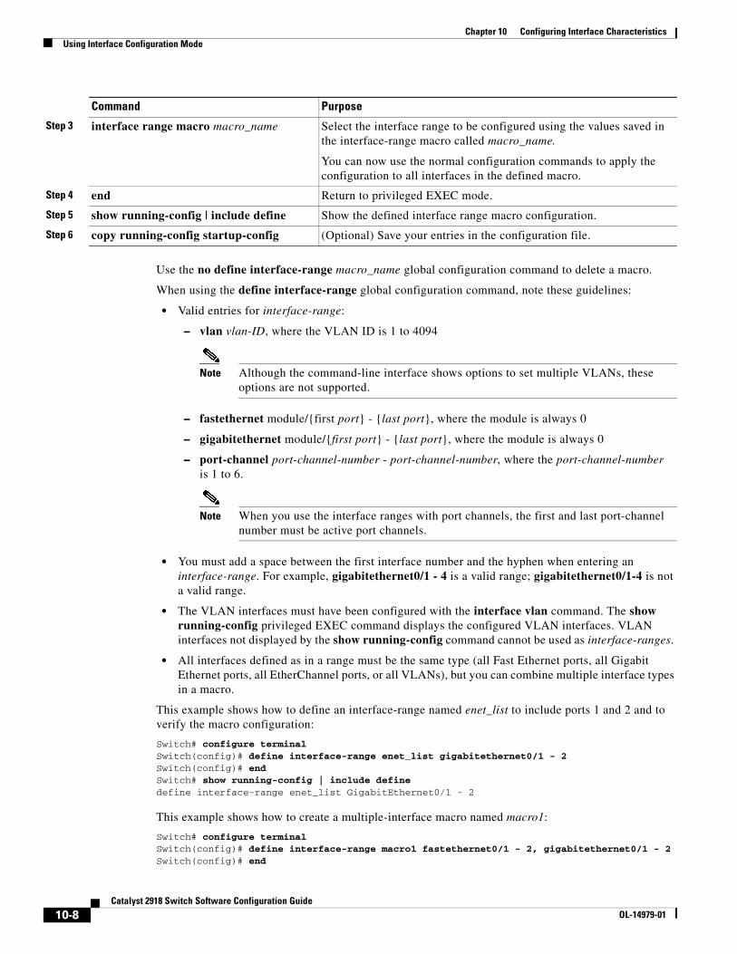
Chapter 10 Configuring Interface CharacteristicsUsing Interface Configuration Mode
Use the no define interface-range macro_name global configuration command to delete a macro.
When using the define interface-range global configuration command, note these guidelines:
• Valid entries for interface-range:
– vlan vlan-ID, where the VLAN ID is 1 to 4094
Note Although the command-line interface shows options to set multiple VLANs, these options are not supported.
– fastethernet module/{first port} - {last port}, where the module is always 0
– gigabitethernet module/{first port} - {last port}, where the module is always 0
– port-channel port-channel-number - port-channel-number, where the port-channel-number is 1 to 6.
Note When you use the interface ranges with port channels, the first and last port-channel number must be active port channels.
• You must add a space between the first interface number and the hyphen when entering an interface-range. For example, gigabitethernet0/1 - 4 is a valid range; gigabitethernet0/1-4 is not a valid range.
• The VLAN interfaces must have been configured with the interface vlan command. The show running-config privileged EXEC command displays the configured VLAN interfaces. VLAN interfaces not displayed by the show running-config command cannot be used as interface-ranges.
• All interfaces defined as in a range must be the same type (all Fast Ethernet ports, all Gigabit Ethernet ports, all EtherChannel ports, or all VLANs), but you can combine multiple interface types in a macro.
This example shows how to define an interface-range named enet_list to include ports 1 and 2 and to verify the macro configuration:
Switch# configure terminalSwitch(config)# define interface-range enet_list gigabitethernet0/1 - 2Switch(config)# endSwitch# show running-config | include define define interface-range enet_list GigabitEthernet0/1 - 2
This example shows how to create a multiple-interface macro named macro1:
Switch# configure terminalSwitch(config)# define interface-range macro1 fastethernet0/1 - 2, gigabitethernet0/1 - 2Switch(config)# end
Step 3 interface range macro macro_name Select the interface range to be configured using the values saved in the interface-range macro called macro_name.
You can now use the normal configuration commands to apply the configuration to all interfaces in the defined macro.
Step 4 end Return to privileged EXEC mode.
Step 5 show running-config | include define Show the defined interface range macro configuration.
Step 6 copy running-config startup-config (Optional) Save your entries in the configuration file.
Command Purpose
10-8Catalyst 2918 Switch Software Configuration Guide
OL-14979-01
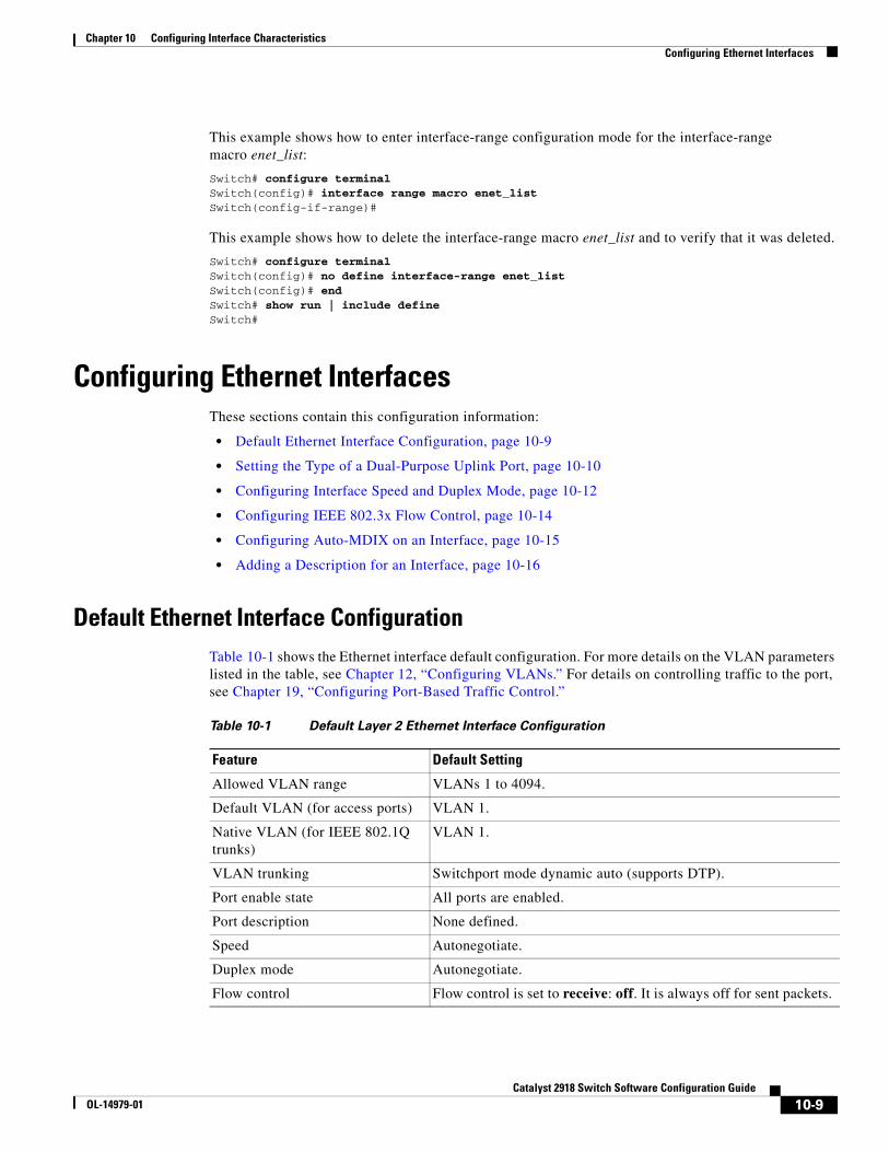
Chapter 10 Configuring Interface CharacteristicsConfiguring Ethernet Interfaces
This example shows how to enter interface-range configuration mode for the interface-range macro enet_list:
Switch# configure terminalSwitch(config)# interface range macro enet_list Switch(config-if-range)#
This example shows how to delete the interface-range macro enet_list and to verify that it was deleted.
Switch# configure terminalSwitch(config)# no define interface-range enet_list Switch(config)# endSwitch# show run | include defineSwitch#
Configuring Ethernet InterfacesThese sections contain this configuration information:
• Default Ethernet Interface Configuration, page 10-9
• Setting the Type of a Dual-Purpose Uplink Port, page 10-10
• Configuring Interface Speed and Duplex Mode, page 10-12
• Configuring IEEE 802.3x Flow Control, page 10-14
• Configuring Auto-MDIX on an Interface, page 10-15
• Adding a Description for an Interface, page 10-16
Default Ethernet Interface ConfigurationTable 10-1 shows the Ethernet interface default configuration. For more details on the VLAN parameters listed in the table, see Chapter 12, “Configuring VLANs.” For details on controlling traffic to the port, see Chapter 19, “Configuring Port-Based Traffic Control.”
Table 10-1 Default Layer 2 Ethernet Interface Configuration
Feature Default Setting
Allowed VLAN range VLANs 1 to 4094.
Default VLAN (for access ports) VLAN 1.
Native VLAN (for IEEE 802.1Q trunks)
VLAN 1.
VLAN trunking Switchport mode dynamic auto (supports DTP).
Port enable state All ports are enabled.
Port description None defined.
Speed Autonegotiate.
Duplex mode Autonegotiate.
Flow control Flow control is set to receive: off. It is always off for sent packets.
10-9Catalyst 2918 Switch Software Configuration Guide
OL-14979-01
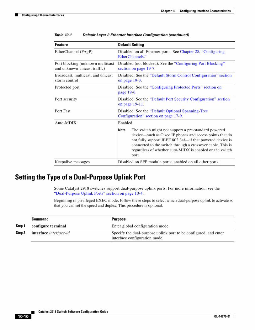
Chapter 10 Configuring Interface CharacteristicsConfiguring Ethernet Interfaces
Setting the Type of a Dual-Purpose Uplink PortSome Catalyst 2918 switches support dual-purpose uplink ports. For more information, see the “Dual-Purpose Uplink Ports” section on page 10-4.
Beginning in privileged EXEC mode, follow these steps to select which dual-purpose uplink to activate so that you can set the speed and duplex. This procedure is optional.
EtherChannel (PAgP) Disabled on all Ethernet ports. See Chapter 28, “Configuring EtherChannels.”
Port blocking (unknown multicast and unknown unicast traffic)
Disabled (not blocked). See the “Configuring Port Blocking” section on page 19-7.
Broadcast, multicast, and unicast storm control
Disabled. See the “Default Storm Control Configuration” section on page 19-3.
Protected port Disabled. See the “Configuring Protected Ports” section on page 19-6.
Port security Disabled. See the “Default Port Security Configuration” section on page 19-11.
Port Fast Disabled. See the “Default Optional Spanning-Tree Configuration” section on page 17-9.
Auto-MDIX Enabled.
Note The switch might not support a pre-standard powered device—such as Cisco IP phones and access points that do not fully support IEEE 802.3af—if that powered device is connected to the switch through a crossover cable. This is regardless of whether auto-MIDX is enabled on the switch port.
Keepalive messages Disabled on SFP module ports; enabled on all other ports.
Table 10-1 Default Layer 2 Ethernet Interface Configuration (continued)
Feature Default Setting
Command Purpose
Step 1 configure terminal Enter global configuration mode.
Step 2 interface interface-id Specify the dual-purpose uplink port to be configured, and enter interface configuration mode.
10-10Catalyst 2918 Switch Software Configuration Guide
OL-14979-01
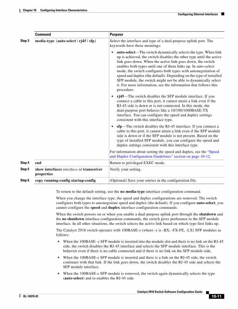
Chapter 10 Configuring Interface CharacteristicsConfiguring Ethernet Interfaces
To return to the default setting, use the no media-type interface configuration command.
When you change the interface type, the speed and duplex configurations are removed. The switch configures both types to autonegotiate speed and duplex (the default). If you configure auto-select, you cannot configure the speed and duplex interface configuration commands.
When the switch powers on or when you enable a dual-purpose uplink port through the shutdown and the no shutdown interface configuration commands, the switch gives preference to the SFP module interface. In all other situations, the switch selects the active link based on which type first links up.
The Catalyst 2918 switch operates with 100BASE-x (where -x is -BX, -FX-FE, -LX) SFP modules as follows:
• When the 100BASE -x SFP module is inserted into the module slot and there is no link on the RJ-45 side, the switch disables the RJ-45 interface and selects the SFP module interface. This is the behavior even if there is no cable connected and if there is no link on the SFP module side.
• When the 100BASE-x SFP module is inserted and there is a link on the RJ-45 side, the switch continues with that link. If the link goes down, the switch disables the RJ-45 side and selects the SFP module interface.
• When the 100BASE-x SFP module is removed, the switch again dynamically selects the type (auto-select) and re-enables the RJ-45 side.
Step 3 media-type {auto-select | rj45 | sfp} Select the interface and type of a dual-purpose uplink port. The keywords have these meanings:
• auto-select—The switch dynamically selects the type. When link up is achieved, the switch disables the other type until the active link goes down. When the active link goes down, the switch enables both types until one of them links up. In auto-select mode, the switch configures both types with autonegotiation of speed and duplex (the default). Depending on the type of installed SFP module, the switch might not be able to dynamically select it. For more information, see the information that follows this procedure.
• rj45—The switch disables the SFP module interface. If you connect a cable to this port, it cannot attain a link even if the RJ-45 side is down or is not connected. In this mode, the dual-purpose port behaves like a 10/100/1000BASE-TX interface. You can configure the speed and duplex settings consistent with this interface type.
• sfp—The switch disables the RJ-45 interface. If you connect a cable to this port, it cannot attain a link even if the SFP module side is down or if the SFP module is not present. Based on the type of installed SFP module, you can configure the speed and duplex settings consistent with this interface type.
For information about setting the speed and duplex, see the “Speed and Duplex Configuration Guidelines” section on page 10-12.
Step 4 end Return to privileged EXEC mode.
Step 5 show interfaces interface-id transceiver properties
Verify your setting.
Step 6 copy running-config startup-config (Optional) Save your entries in the configuration file.
Command Purpose
10-11Catalyst 2918 Switch Software Configuration Guide
OL-14979-01
Chapter 10 Configuring Interface CharacteristicsConfiguring Ethernet Interfaces
The switch does not have this behavior with 100BASE-FX-GE SFP modules.
Configuring Interface Speed and Duplex ModeEthernet interfaces on the switch operate at 10, 100, or 1000 Mb/s and in either full- or half-duplex mode. In full-duplex mode, two stations can send and receive traffic at the same time. Normally, 10-Mb/s ports operate in half-duplex mode, which means that stations can either receive or send traffic.
Switch models include combinations of Fast Ethernet (10/100-Mb/s) ports, Gigabit Ethernet (10/100/1000-Mb/s) ports, and small form-factor pluggable (SFP) module slots supporting SFP modules.
These sections describe how to configure the interface speed and duplex mode:
• Speed and Duplex Configuration Guidelines, page 10-12
• Setting the Interface Speed and Duplex Parameters, page 10-13
Speed and Duplex Configuration Guidelines
When configuring an interface speed and duplex mode, note these guidelines:
• Fast Ethernet (10/100-Mb/s) ports support all speed and duplex options.
• Gigabit Ethernet (10/100/1000-Mb/s) ports support all speed options and all duplex options (auto, half, and full). However, Gigabit Ethernet ports operating at 1000 Mb/s do not support half-duplex mode.
• For SFP module ports, the speed and duplex CLI options change depending on the SFP module type:
– The 1000BASE-x (where -x is -BX, -CWDM, -LX, -SX, and -ZX) SFP module ports support the nonegotiate keyword in the speed interface configuration command. Duplex options are not supported.
– The 1000BASE-T SFP module ports support the same speed and duplex options as the 10/100/1000-Mb/s ports.
– The 100BASE-x (where -x is -BX, -CWDM, -LX, -SX, and -ZX) SFP module ports support only 100 Mb/s. These modules support full- and half- duplex options but do not support autonegotiation.
For information about which SFP modules are supported on your switch, see the product release notes.
• If both ends of the line support autonegotiation, we highly recommend the default setting of auto negotiation.
• If one interface supports autonegotiation and the other end does not, configure duplex and speed on both interfaces; do not use the auto setting on the supported side.
• When STP is enabled and a port is reconfigured, the switch can take up to 30 seconds to check for loops. The port LED is amber while STP reconfigures.
Caution Changing the interface speed and duplex mode configuration might shut down and re-enable the interface during the reconfiguration.
10-12Catalyst 2918 Switch Software Configuration Guide
OL-14979-01
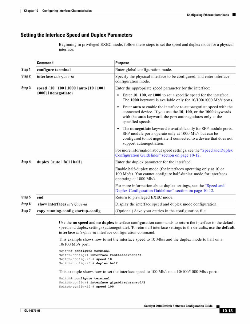
Chapter 10 Configuring Interface CharacteristicsConfiguring Ethernet Interfaces
Setting the Interface Speed and Duplex Parameters
Beginning in privileged EXEC mode, follow these steps to set the speed and duplex mode for a physical interface:
Command Purpose
Step 1 configure terminal Enter global configuration mode.
Step 2 interface interface-id Specify the physical interface to be configured, and enter interface configuration mode.
Step 3 speed {10 | 100 | 1000 | auto [10 | 100 | 1000] | nonegotiate}
Enter the appropriate speed parameter for the interface:
• Enter 10, 100, or 1000 to set a specific speed for the interface. The 1000 keyword is available only for 10/100/1000 Mb/s ports.
• Enter auto to enable the interface to autonegotiate speed with the connected device. If you use the 10, 100, or the 1000 keywords with the auto keyword, the port autonegotiates only at the specified speeds.
• The nonegotiate keyword is available only for SFP module ports. SFP module ports operate only at 1000 Mb/s but can be configured to not negotiate if connected to a device that does not support autonegotiation.
For more information about speed settings, see the “Speed and Duplex Configuration Guidelines” section on page 10-12.
Step 4 duplex {auto | full | half} Enter the duplex parameter for the interface.
Enable half-duplex mode (for interfaces operating only at 10 or 100 Mb/s). You cannot configure half-duplex mode for interfaces operating at 1000 Mb/s.
For more information about duplex settings, see the “Speed and Duplex Configuration Guidelines” section on page 10-12.
Step 5 end Return to privileged EXEC mode.
Step 6 show interfaces interface-id Display the interface speed and duplex mode configuration.
Step 7 copy running-config startup-config (Optional) Save your entries in the configuration file.
Use the no speed and no duplex interface configuration commands to return the interface to the default speed and duplex settings (autonegotiate). To return all interface settings to the defaults, use the default interface interface-id interface configuration command.
This example shows how to set the interface speed to 10 Mb/s and the duplex mode to half on a 10/100 Mb/s port:
Switch# configure terminalSwitch(config)# interface fasttethernet0/3Switch(config-if)# speed 10Switch(config-if)# duplex half
This example shows how to set the interface speed to 100 Mb/s on a 10/100/1000 Mb/s port:
Switch# configure terminalSwitch(config)# interface gigabitethernet0/2Switch(config-if)# speed 100
10-13Catalyst 2918 Switch Software Configuration Guide
OL-14979-01
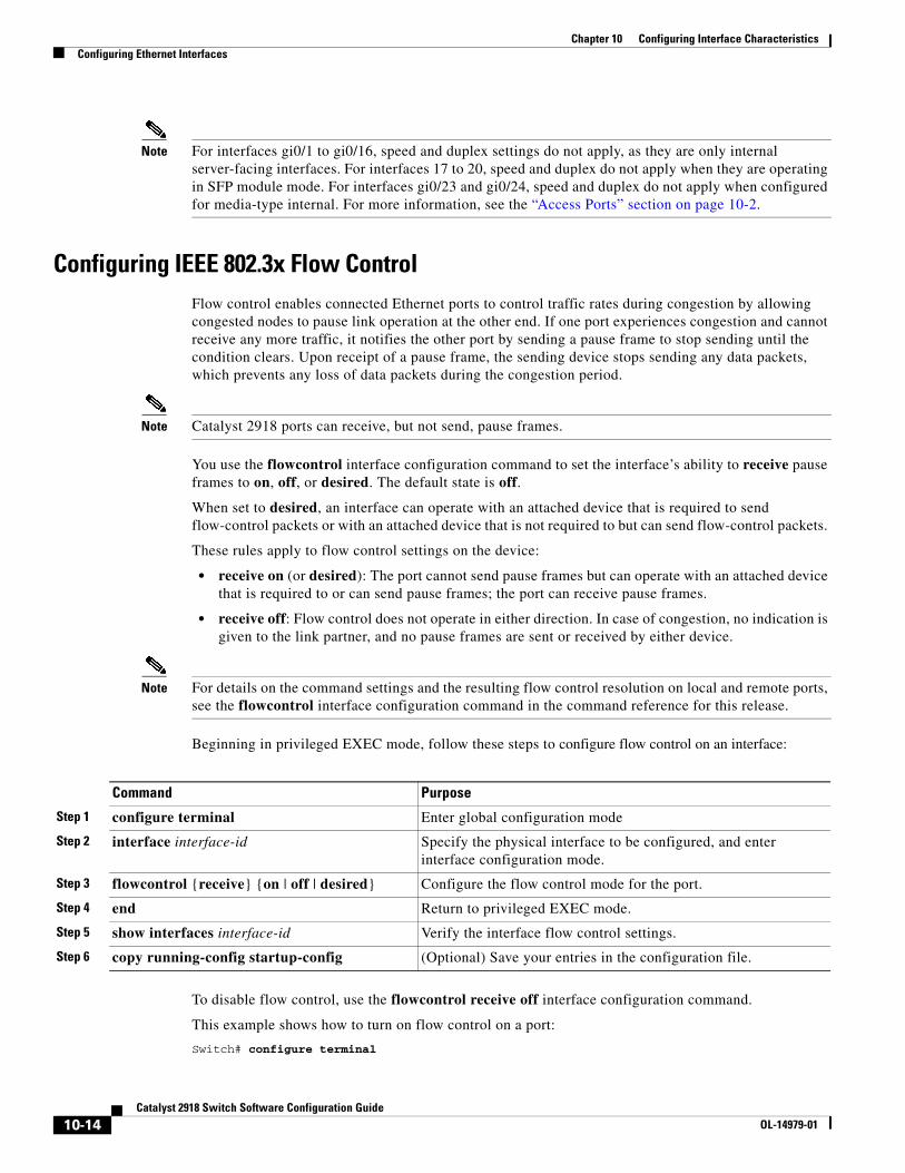
Chapter 10 Configuring Interface CharacteristicsConfiguring Ethernet Interfaces
Note For interfaces gi0/1 to gi0/16, speed and duplex settings do not apply, as they are only internal server-facing interfaces. For interfaces 17 to 20, speed and duplex do not apply when they are operating in SFP module mode. For interfaces gi0/23 and gi0/24, speed and duplex do not apply when configured for media-type internal. For more information, see the “Access Ports” section on page 10-2.
Configuring IEEE 802.3x Flow Control Flow control enables connected Ethernet ports to control traffic rates during congestion by allowing congested nodes to pause link operation at the other end. If one port experiences congestion and cannot receive any more traffic, it notifies the other port by sending a pause frame to stop sending until the condition clears. Upon receipt of a pause frame, the sending device stops sending any data packets, which prevents any loss of data packets during the congestion period.
Note Catalyst 2918 ports can receive, but not send, pause frames.
You use the flowcontrol interface configuration command to set the interface’s ability to receive pause frames to on, off, or desired. The default state is off.
When set to desired, an interface can operate with an attached device that is required to send flow-control packets or with an attached device that is not required to but can send flow-control packets.
These rules apply to flow control settings on the device:
• receive on (or desired): The port cannot send pause frames but can operate with an attached device that is required to or can send pause frames; the port can receive pause frames.
• receive off: Flow control does not operate in either direction. In case of congestion, no indication is given to the link partner, and no pause frames are sent or received by either device.
Note For details on the command settings and the resulting flow control resolution on local and remote ports, see the flowcontrol interface configuration command in the command reference for this release.
Beginning in privileged EXEC mode, follow these steps to configure flow control on an interface:
Command Purpose
Step 1 configure terminal Enter global configuration mode
Step 2 interface interface-id Specify the physical interface to be configured, and enter interface configuration mode.
Step 3 flowcontrol {receive} {on | off | desired} Configure the flow control mode for the port.
Step 4 end Return to privileged EXEC mode.
Step 5 show interfaces interface-id Verify the interface flow control settings.
Step 6 copy running-config startup-config (Optional) Save your entries in the configuration file.
To disable flow control, use the flowcontrol receive off interface configuration command.
This example shows how to turn on flow control on a port:
Switch# configure terminal
10-14Catalyst 2918 Switch Software Configuration Guide
OL-14979-01
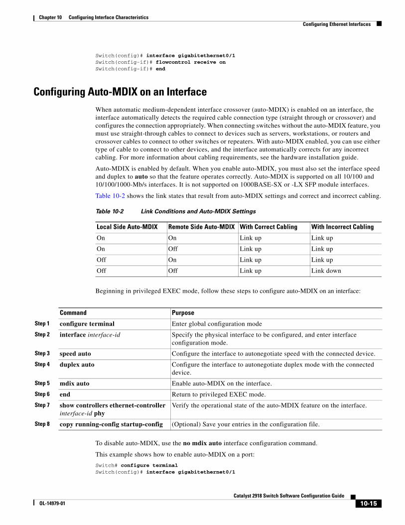
Chapter 10 Configuring Interface CharacteristicsConfiguring Ethernet Interfaces
Switch(config)# interface gigabitethernet0/1Switch(config-if)# flowcontrol receive onSwitch(config-if)# end
Configuring Auto-MDIX on an InterfaceWhen automatic medium-dependent interface crossover (auto-MDIX) is enabled on an interface, the interface automatically detects the required cable connection type (straight through or crossover) and configures the connection appropriately. When connecting switches without the auto-MDIX feature, you must use straight-through cables to connect to devices such as servers, workstations, or routers and crossover cables to connect to other switches or repeaters. With auto-MDIX enabled, you can use either type of cable to connect to other devices, and the interface automatically corrects for any incorrect cabling. For more information about cabling requirements, see the hardware installation guide.
Auto-MDIX is enabled by default. When you enable auto-MDIX, you must also set the interface speed and duplex to auto so that the feature operates correctly. Auto-MDIX is supported on all 10/100 and 10/100/1000-Mb/s interfaces. It is not supported on 1000BASE-SX or -LX SFP module interfaces.
Table 10-2 shows the link states that result from auto-MDIX settings and correct and incorrect cabling.
Table 10-2 Link Conditions and Auto-MDIX Settings
Local Side Auto-MDIX Remote Side Auto-MDIX With Correct Cabling With Incorrect Cabling
On On Link up Link up
On Off Link up Link up
Off On Link up Link up
Off Off Link up Link down
Beginning in privileged EXEC mode, follow these steps to configure auto-MDIX on an interface:
Command Purpose
Step 1 configure terminal Enter global configuration mode
Step 2 interface interface-id Specify the physical interface to be configured, and enter interface configuration mode.
Step 3 speed auto Configure the interface to autonegotiate speed with the connected device.
Step 4 duplex auto Configure the interface to autonegotiate duplex mode with the connected device.
Step 5 mdix auto Enable auto-MDIX on the interface.
Step 6 end Return to privileged EXEC mode.
Step 7 show controllers ethernet-controller interface-id phy
Verify the operational state of the auto-MDIX feature on the interface.
Step 8 copy running-config startup-config (Optional) Save your entries in the configuration file.
To disable auto-MDIX, use the no mdix auto interface configuration command.
This example shows how to enable auto-MDIX on a port:
Switch# configure terminalSwitch(config)# interface gigabitethernet0/1
10-15Catalyst 2918 Switch Software Configuration Guide
OL-14979-01

Chapter 10 Configuring Interface CharacteristicsConfiguring the System MTU
Switch(config-if)# speed autoSwitch(config-if)# duplex autoSwitch(config-if)# mdix autoSwitch(config-if)# end
Adding a Description for an Interface You can add a description about an interface to help you remember its function. The description appears in the output of these privileged EXEC commands: show configuration, show running-config, and show interfaces.
Beginning in privileged EXEC mode, follow these steps to add a description for an interface:
Command Purpose
Step 1 configure terminal Enter global configuration mode.
Step 2 interface interface-id Specify the interface for which you are adding a description, and enter interface configuration mode.
Step 3 description string Add a description (up to 240 characters) for an interface.
Step 4 end Return to privileged EXEC mode.
Step 5 show interfaces interface-id description
or
show running-config
Verify your entry.
Step 6 copy running-config startup-config (Optional) Save your entries in the configuration file.
Use the no description interface configuration command to delete the description.
This example shows how to add a description on a port and how to verify the description:
Switch# config terminalEnter configuration commands, one per line. End with CNTL/Z.Switch(config)# interface gigabitethernet0/2Switch(config-if)# description Connects to MarketingSwitch(config-if)# endSwitch# show interfaces gigabitethernet0/2 descriptionInterface Status Protocol DescriptionGi0/2 admin down down Connects to Marketing
Configuring the System MTUThe default maximum transmission unit (MTU) size for frames received and transmitted on all interfaces on the switch is 1500 bytes. You can increase the MTU size for all interfaces operating at 10 or 100 Mb/s by using the system mtu global configuration command. You can increase the MTU size to support jumbo frames on all Gigabit Ethernet interfaces by using the system mtu jumbo global configuration command.
Gigabit Ethernet ports are not affected by the system mtu command; 10/100 ports are not affected by the system jumbo mtu command. If you do not configure the system mtu jumbo command, the setting of the system mtu command applies to all Gigabit Ethernet interfaces.
10-16Catalyst 2918 Switch Software Configuration Guide
OL-14979-01
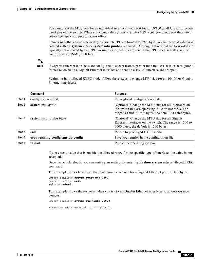
Chapter 10 Configuring Interface CharacteristicsConfiguring the System MTU
You cannot set the MTU size for an individual interface; you set it for all 10/100 or all Gigabit Ethernet interfaces on the switch. When you change the system or jumbo MTU size, you must reset the switch before the new configuration takes effect.
Frames sizes that can be received by the switch CPU are limited to 1998 bytes, no matter what value was entered with the system mtu or system mtu jumbo commands. Although frames that are forwarded are typically not received by the CPU, in some cases packets are sent to the CPU, such as traffic sent to control traffic, SNMP, or Telnet.
Note If Gigabit Ethernet interfaces are configured to accept frames greater than the 10/100 interfaces, jumbo frames received on a Gigabit Ethernet interface and sent on a 10/100 interface are dropped.
Beginning in privileged EXEC mode, follow these steps to change MTU size for all 10/100 or Gigabit Ethernet interfaces:
Command Purpose
Step 1 configure terminal Enter global configuration mode.
Step 2 system mtu bytes (Optional) Change the MTU size for all interfaces on the switch that are operating at 10 or 100 Mb/s. The range is 1500 to 1998 bytes; the default is 1500 bytes.
Step 3 system mtu jumbo bytes (Optional) Change the MTU size for all Gigabit Ethernet interfaces on the switch. The range is 1500 to 9000 bytes; the default is 1500 bytes.
Step 4 end Return to privileged EXEC mode.
Step 5 copy running-config startup-config Save your entries in the configuration file.
Step 6 reload Reload the operating system.
If you enter a value that is outside the allowed range for the specific type of interface, the value is not accepted.
Once the switch reloads, you can verify your settings by entering the show system mtu privileged EXEC command.
This example shows how to set the maximum packet size for a Gigabit Ethernet port to 1800 bytes:
Switch(config)# system jumbo mtu 1800Switch(config)# exitSwitch# reload
This example shows the response when you try to set Gigabit Ethernet interfaces to an out-of-range number:
Switch(config)# system mtu jumbo 25000 ^% Invalid input detected at '^' marker.
10-17Catalyst 2918 Switch Software Configuration Guide
OL-14979-01
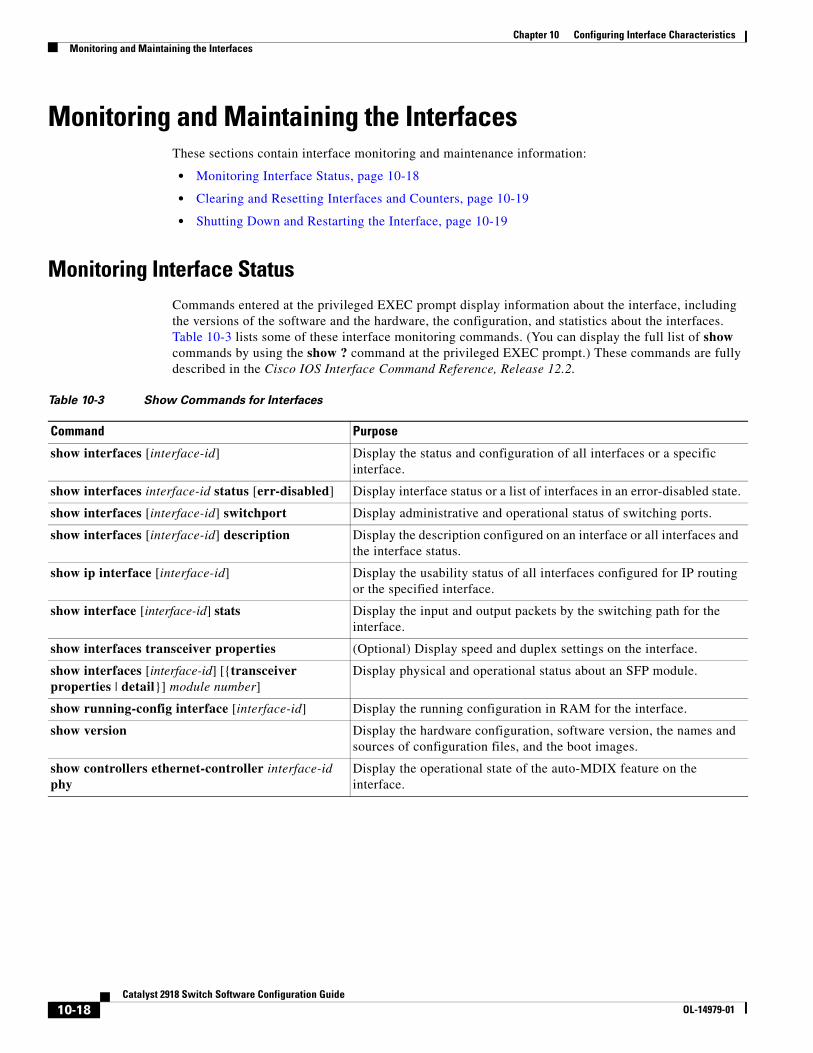
Chapter 10 Configuring Interface CharacteristicsMonitoring and Maintaining the Interfaces
Monitoring and Maintaining the InterfacesThese sections contain interface monitoring and maintenance information:
• Monitoring Interface Status, page 10-18
• Clearing and Resetting Interfaces and Counters, page 10-19
• Shutting Down and Restarting the Interface, page 10-19
Monitoring Interface Status Commands entered at the privileged EXEC prompt display information about the interface, including the versions of the software and the hardware, the configuration, and statistics about the interfaces. Table 10-3 lists some of these interface monitoring commands. (You can display the full list of show commands by using the show ? command at the privileged EXEC prompt.) These commands are fully described in the Cisco IOS Interface Command Reference, Release 12.2.
Table 10-3 Show Commands for Interfaces
Command Purpose
show interfaces [interface-id] Display the status and configuration of all interfaces or a specific interface.
show interfaces interface-id status [err-disabled] Display interface status or a list of interfaces in an error-disabled state.
show interfaces [interface-id] switchport Display administrative and operational status of switching ports.
show interfaces [interface-id] description Display the description configured on an interface or all interfaces and the interface status.
show ip interface [interface-id] Display the usability status of all interfaces configured for IP routing or the specified interface.
show interface [interface-id] stats Display the input and output packets by the switching path for the interface.
show interfaces transceiver properties (Optional) Display speed and duplex settings on the interface.
show interfaces [interface-id] [{transceiver properties | detail}] module number]
Display physical and operational status about an SFP module.
show running-config interface [interface-id] Display the running configuration in RAM for the interface.
show version Display the hardware configuration, software version, the names and sources of configuration files, and the boot images.
show controllers ethernet-controller interface-id phy
Display the operational state of the auto-MDIX feature on the interface.
10-18Catalyst 2918 Switch Software Configuration Guide
OL-14979-01
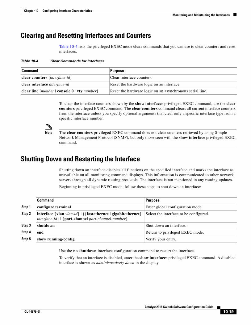
Chapter 10 Configuring Interface CharacteristicsMonitoring and Maintaining the Interfaces
Clearing and Resetting Interfaces and CountersTable 10-4 lists the privileged EXEC mode clear commands that you can use to clear counters and reset interfaces.
Table 10-4 Clear Commands for Interfaces
Command Purpose
clear counters [interface-id] Clear interface counters.
clear interface interface-id Reset the hardware logic on an interface.
clear line [number | console 0 | vty number] Reset the hardware logic on an asynchronous serial line.
To clear the interface counters shown by the show interfaces privileged EXEC command, use the clear counters privileged EXEC command. The clear counters command clears all current interface counters from the interface unless you specify optional arguments that clear only a specific interface type from a specific interface number.
Note The clear counters privileged EXEC command does not clear counters retrieved by using Simple Network Management Protocol (SNMP), but only those seen with the show interface privileged EXEC command.
Shutting Down and Restarting the InterfaceShutting down an interface disables all functions on the specified interface and marks the interface as unavailable on all monitoring command displays. This information is communicated to other network servers through all dynamic routing protocols. The interface is not mentioned in any routing updates.
Beginning in privileged EXEC mode, follow these steps to shut down an interface:
Command Purpose
Step 1 configure terminal Enter global configuration mode.
Step 2 interface {vlan vlan-id} | {{fastethernet | gigabitethernet} interface-id} | {port-channel port-channel-number}
Select the interface to be configured.
Step 3 shutdown Shut down an interface.
Step 4 end Return to privileged EXEC mode.
Step 5 show running-config Verify your entry.
Use the no shutdown interface configuration command to restart the interface.
To verify that an interface is disabled, enter the show interfaces privileged EXEC command. A disabled interface is shown as administratively down in the display.
10-19Catalyst 2918 Switch Software Configuration Guide
OL-14979-01

Chapter 10 Configuring Interface CharacteristicsMonitoring and Maintaining the Interfaces
10-20Catalyst 2918 Switch Software Configuration Guide
OL-14979-01
OL-14979-01
C H A P T E R 11
Configuring Smartports MacrosThis chapter describes how to configure and apply Smartports macros on the Catalyst 2918 switch.
Note For complete syntax and usage information for the commands used in this chapter, see the command reference for this release.
This chapter consists of these sections:
• Understanding Smartports Macros, page 11-1
• Configuring Smartports Macros, page 11-2
• Displaying Smartports Macros, page 11-8
Understanding Smartports MacrosSmartports macros provide a convenient way to save and share common configurations. You can use Smartports macros to enable features and settings based on the location of a switch in the network and for mass configuration deployments across the network.
Each Smartports macro is a set of command-line interface (CLI) commands that you define. Smartports macros do not contain new CLI commands; they are simply a group of existing CLI commands.
When you apply a Smartports macro on an interface, the CLI commands within the macro are configured on the interface. When the macro is applied to an interface, the existing interface configurations are not lost. The new commands are added to the interface and are saved in the running configuration file.
There are Cisco-default Smartports macros embedded in the switch software (see Table 11-1). You can display these macros and the commands they contain by using the show parser macro user EXEC command.
Table 11-1 Cisco-Default Smartports Macros
Macro Name1 Description
cisco-global Use this global configuration macro to enable rapid PVST+, loop guard, and dynamic port error recovery for link state failures.
cisco-desktop Use this interface configuration macro for increased network security and reliability when connecting a desktop device, such as a PC, to a switch port.
11-1Catalyst 2918 Switch Software Configuration Guide
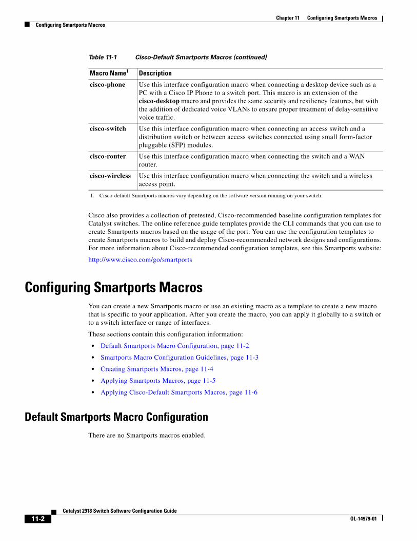
Chapter 11 Configuring Smartports MacrosConfiguring Smartports Macros
Cisco also provides a collection of pretested, Cisco-recommended baseline configuration templates for Catalyst switches. The online reference guide templates provide the CLI commands that you can use to create Smartports macros based on the usage of the port. You can use the configuration templates to create Smartports macros to build and deploy Cisco-recommended network designs and configurations. For more information about Cisco-recommended configuration templates, see this Smartports website:
http://www.cisco.com/go/smartports
Configuring Smartports MacrosYou can create a new Smartports macro or use an existing macro as a template to create a new macro that is specific to your application. After you create the macro, you can apply it globally to a switch or to a switch interface or range of interfaces.
These sections contain this configuration information:
• Default Smartports Macro Configuration, page 11-2
• Smartports Macro Configuration Guidelines, page 11-3
• Creating Smartports Macros, page 11-4
• Applying Smartports Macros, page 11-5
• Applying Cisco-Default Smartports Macros, page 11-6
Default Smartports Macro ConfigurationThere are no Smartports macros enabled.
cisco-phone Use this interface configuration macro when connecting a desktop device such as a PC with a Cisco IP Phone to a switch port. This macro is an extension of the cisco-desktop macro and provides the same security and resiliency features, but with the addition of dedicated voice VLANs to ensure proper treatment of delay-sensitive voice traffic.
cisco-switch Use this interface configuration macro when connecting an access switch and a distribution switch or between access switches connected using small form-factor pluggable (SFP) modules.
cisco-router Use this interface configuration macro when connecting the switch and a WAN router.
cisco-wireless Use this interface configuration macro when connecting the switch and a wireless access point.
1. Cisco-default Smartports macros vary depending on the software version running on your switch.
Table 11-1 Cisco-Default Smartports Macros (continued)
Macro Name1 Description
11-2Catalyst 2918 Switch Software Configuration Guide
OL-14979-01
Chapter 11 Configuring Smartports MacrosConfiguring Smartports Macros
Smartports Macro Configuration GuidelinesFollow these guidelines when configuring macros on your switch:
• When creating a macro, do not use the exit or end commands or change the command mode by using interface interface-id. This could cause commands that follow exit, end, or interface interface-id to execute in a different command mode.
• When creating a macro, all CLI commands should be in the same configuration mode.
• When creating a macro that requires the assignment of unique values, use the parameter value keywords to designate values specific to the interface. Keyword matching is case sensitive. All matching occurrences of the keyword are replaced with the corresponding value. Any full match of a keyword, even if it is part of a larger string, is considered a match and is replaced by the corresponding value.
• Macro names are case sensitive. For example, the commands macro name Sample-Macro and macro name sample-macro will result in two separate macros.
• Some macros might contain keywords that require a parameter value. You can use the macro global apply macro-name ? global configuration command or the macro apply macro-name ? interface configuration command to display a list of any required values in the macro. If you apply a macro without entering the keyword values, the commands are invalid and are not applied.
• When a macro is applied globally to a switch or to a switch interface, all existing configuration on the interface is retained. This is helpful when applying an incremental configuration.
• If you modify a macro definition by adding or deleting commands, the changes are not reflected on the interface where the original macro was applied. You need to reapply the updated macro on the interface to apply the new or changed commands.
• You can use the macro global trace macro-name global configuration command or the macro trace macro-name interface configuration command to apply and debug a macro to find any syntax or configuration errors. If a command fails because of a syntax error or a configuration error, the macro continues to apply the remaining commands.
• Some CLI commands are specific to certain interface types. If a macro is applied to an interface that does not accept the configuration, the macro will fail the syntax check or the configuration check, and the switch will return an error message.
• Applying a macro to an interface range is the same as applying a macro to a single interface. When you use an interface range, the macro is applied sequentially to each interface within the range. If a macro command fails on one interface, it is still applied to the remaining interfaces.
• When you apply a macro to a switch or a switch interface, the macro name is automatically added to the switch or interface. You can display the applied commands and macro names by using the show running-config user EXEC command.
There are Cisco-default Smartports macros embedded in the switch software (see Table 11-1). You can display these macros and the commands they contain by using the show parser macro user EXEC command.
11-3Catalyst 2918 Switch Software Configuration Guide
OL-14979-01
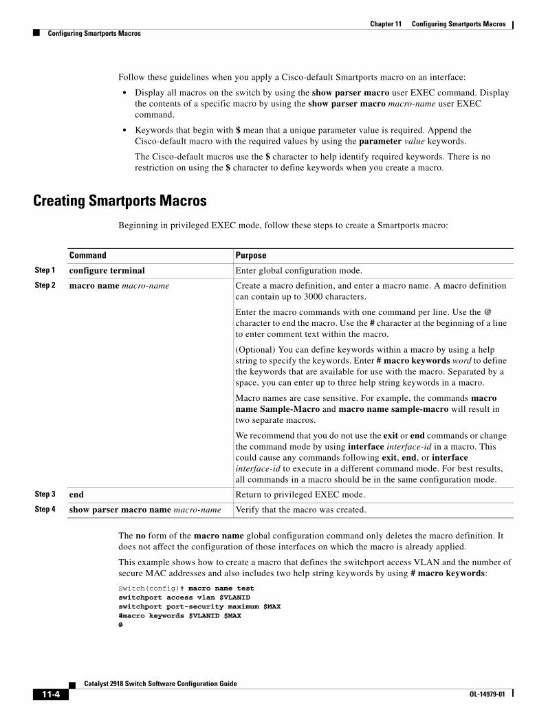
Chapter 11 Configuring Smartports MacrosConfiguring Smartports Macros
Follow these guidelines when you apply a Cisco-default Smartports macro on an interface:
• Display all macros on the switch by using the show parser macro user EXEC command. Display the contents of a specific macro by using the show parser macro macro-name user EXEC command.
• Keywords that begin with $ mean that a unique parameter value is required. Append the Cisco-default macro with the required values by using the parameter value keywords.
The Cisco-default macros use the $ character to help identify required keywords. There is no restriction on using the $ character to define keywords when you create a macro.
Creating Smartports MacrosBeginning in privileged EXEC mode, follow these steps to create a Smartports macro:
Command Purpose
Step 1 configure terminal Enter global configuration mode.
Step 2 macro name macro-name Create a macro definition, and enter a macro name. A macro definition can contain up to 3000 characters.
Enter the macro commands with one command per line. Use the @ character to end the macro. Use the # character at the beginning of a line to enter comment text within the macro.
(Optional) You can define keywords within a macro by using a help string to specify the keywords. Enter # macro keywords word to define the keywords that are available for use with the macro. Separated by a space, you can enter up to three help string keywords in a macro.
Macro names are case sensitive. For example, the commands macro name Sample-Macro and macro name sample-macro will result in two separate macros.
We recommend that you do not use the exit or end commands or change the command mode by using interface interface-id in a macro. This could cause any commands following exit, end, or interface interface-id to execute in a different command mode. For best results, all commands in a macro should be in the same configuration mode.
Step 3 end Return to privileged EXEC mode.
Step 4 show parser macro name macro-name Verify that the macro was created.
The no form of the macro name global configuration command only deletes the macro definition. It does not affect the configuration of those interfaces on which the macro is already applied.
This example shows how to create a macro that defines the switchport access VLAN and the number of secure MAC addresses and also includes two help string keywords by using # macro keywords:
Switch(config)# macro name testswitchport access vlan $VLANIDswitchport port-security maximum $MAX#macro keywords $VLANID $MAX@
11-4Catalyst 2918 Switch Software Configuration Guide
OL-14979-01
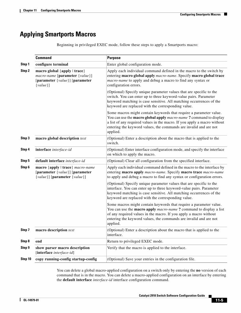
Chapter 11 Configuring Smartports MacrosConfiguring Smartports Macros
Applying Smartports MacrosBeginning in privileged EXEC mode, follow these steps to apply a Smartports macro:
Command Purpose
Step 1 configure terminal Enter global configuration mode.
Step 2 macro global {apply | trace} macro-name [parameter {value}] [parameter {value}] [parameter {value}]
Apply each individual command defined in the macro to the switch by entering macro global apply macro-name. Specify macro global trace macro-name to apply and debug a macro to find any syntax or configuration errors.
(Optional) Specify unique parameter values that are specific to the switch. You can enter up to three keyword-value pairs. Parameter keyword matching is case sensitive. All matching occurrences of the keyword are replaced with the corresponding value.
Some macros might contain keywords that require a parameter value. You can use the macro global apply macro-name ? command to display a list of any required values in the macro. If you apply a macro without entering the keyword values, the commands are invalid and are not applied.
Step 3 macro global description text (Optional) Enter a description about the macro that is applied to the switch.
Step 4 interface interface-id (Optional) Enter interface configuration mode, and specify the interface on which to apply the macro.
Step 5 default interface interface-id (Optional) Clear all configuration from the specified interface.
Step 6 macro {apply | trace} macro-name [parameter {value}] [parameter {value}] [parameter {value}]
Apply each individual command defined in the macro to the interface by entering macro apply macro-name. Specify macro trace macro-name to apply and debug a macro to find any syntax or configuration errors.
(Optional) Specify unique parameter values that are specific to the interface. You can enter up to three keyword-value pairs. Parameter keyword matching is case sensitive. All matching occurrences of the keyword are replaced with the corresponding value.
Some macros might contain keywords that require a parameter value. You can use the macro apply macro-name ? command to display a list of any required values in the macro. If you apply a macro without entering the keyword values, the commands are invalid and are not applied.
Step 7 macro description text (Optional) Enter a description about the macro that is applied to the interface.
Step 8 end Return to privileged EXEC mode.
Step 9 show parser macro description [interface interface-id]
Verify that the macro is applied to the interface.
Step 10 copy running-config startup-config (Optional) Save your entries in the configuration file.
You can delete a global macro-applied configuration on a switch only by entering the no version of each command that is in the macro. You can delete a macro-applied configuration on an interface by entering the default interface interface-id interface configuration command.
11-5Catalyst 2918 Switch Software Configuration Guide
OL-14979-01
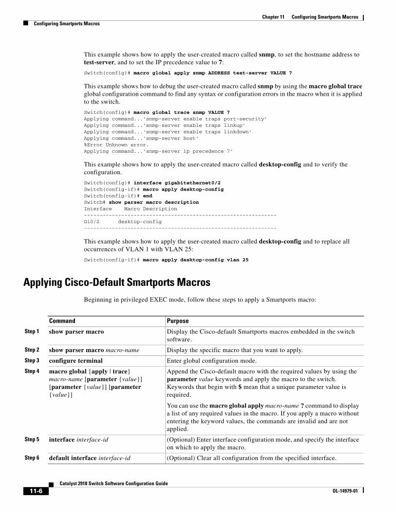
Chapter 11 Configuring Smartports MacrosConfiguring Smartports Macros
This example shows how to apply the user-created macro called snmp, to set the hostname address to test-server, and to set the IP precedence value to 7:
Switch(config)# macro global apply snmp ADDRESS test-server VALUE 7
This example shows how to debug the user-created macro called snmp by using the macro global trace global configuration command to find any syntax or configuration errors in the macro when it is applied to the switch.
Switch(config)# macro global trace snmp VALUE 7Applying command...‘snmp-server enable traps port-security’Applying command...‘snmp-server enable traps linkup’Applying command...‘snmp-server enable traps linkdown’Applying command...‘snmp-server host’%Error Unknown error.Applying command...‘snmp-server ip precedence 7’
This example shows how to apply the user-created macro called desktop-config and to verify the configuration.
Switch(config)# interface gigabitethernet0/2Switch(config-if)# macro apply desktop-configSwitch(config-if)# endSwitch# show parser macro description Interface Macro Description--------------------------------------------------------------Gi0/2 desktop-config--------------------------------------------------------------
This example shows how to apply the user-created macro called desktop-config and to replace all occurrences of VLAN 1 with VLAN 25:
Switch(config-if)# macro apply desktop-config vlan 25
Applying Cisco-Default Smartports MacrosBeginning in privileged EXEC mode, follow these steps to apply a Smartports macro:
Command Purpose
Step 1 show parser macro Display the Cisco-default Smartports macros embedded in the switch software.
Step 2 show parser macro macro-name Display the specific macro that you want to apply.
Step 3 configure terminal Enter global configuration mode.
Step 4 macro global {apply | trace} macro-name [parameter {value}] [parameter {value}] [parameter {value}]
Append the Cisco-default macro with the required values by using the parameter value keywords and apply the macro to the switch. Keywords that begin with $ mean that a unique parameter value is required.
You can use the macro global apply macro-name ? command to display a list of any required values in the macro. If you apply a macro without entering the keyword values, the commands are invalid and are not applied.
Step 5 interface interface-id (Optional) Enter interface configuration mode, and specify the interface on which to apply the macro.
Step 6 default interface interface-id (Optional) Clear all configuration from the specified interface.
11-6Catalyst 2918 Switch Software Configuration Guide
OL-14979-01
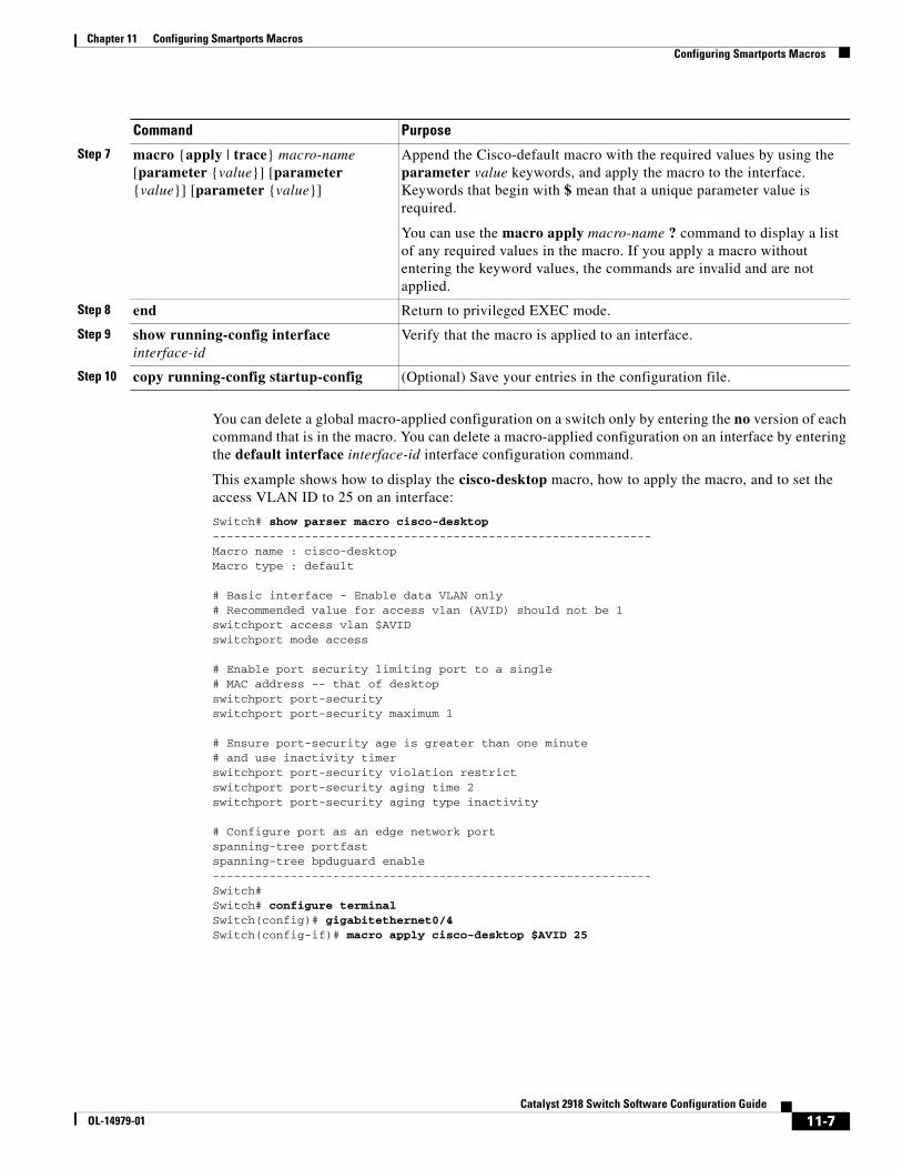
Chapter 11 Configuring Smartports MacrosConfiguring Smartports Macros
You can delete a global macro-applied configuration on a switch only by entering the no version of each command that is in the macro. You can delete a macro-applied configuration on an interface by entering the default interface interface-id interface configuration command.
This example shows how to display the cisco-desktop macro, how to apply the macro, and to set the access VLAN ID to 25 on an interface:
Switch# show parser macro cisco-desktop--------------------------------------------------------------Macro name : cisco-desktopMacro type : default
# Basic interface - Enable data VLAN only# Recommended value for access vlan (AVID) should not be 1switchport access vlan $AVIDswitchport mode access
# Enable port security limiting port to a single# MAC address -- that of desktopswitchport port-securityswitchport port-security maximum 1
# Ensure port-security age is greater than one minute# and use inactivity timerswitchport port-security violation restrictswitchport port-security aging time 2switchport port-security aging type inactivity
# Configure port as an edge network portspanning-tree portfastspanning-tree bpduguard enable--------------------------------------------------------------Switch#Switch# configure terminalSwitch(config)# gigabitethernet0/4Switch(config-if)# macro apply cisco-desktop $AVID 25
Step 7 macro {apply | trace} macro-name [parameter {value}] [parameter {value}] [parameter {value}]
Append the Cisco-default macro with the required values by using the parameter value keywords, and apply the macro to the interface. Keywords that begin with $ mean that a unique parameter value is required.
You can use the macro apply macro-name ? command to display a list of any required values in the macro. If you apply a macro without entering the keyword values, the commands are invalid and are not applied.
Step 8 end Return to privileged EXEC mode.
Step 9 show running-config interface interface-id
Verify that the macro is applied to an interface.
Step 10 copy running-config startup-config (Optional) Save your entries in the configuration file.
Command Purpose
11-7Catalyst 2918 Switch Software Configuration Guide
OL-14979-01
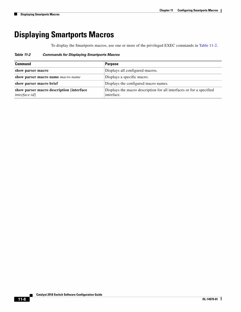
Chapter 11 Configuring Smartports MacrosDisplaying Smartports Macros
Displaying Smartports MacrosTo display the Smartports macros, use one or more of the privileged EXEC commands in Table 11-2.
Table 11-2 Commands for Displaying Smartports Macros
Command Purpose
show parser macro Displays all configured macros.
show parser macro name macro-name Displays a specific macro.
show parser macro brief Displays the configured macro names.
show parser macro description [interface interface-id]
Displays the macro description for all interfaces or for a specified interface.
11-8Catalyst 2918 Switch Software Configuration Guide
OL-14979-01
OL-14979-01
C H A P T E R 12
Configuring VLANsThis chapter describes how to configure normal-range VLANs (VLAN IDs 1 to 1005) and extended-range VLANs (VLAN IDs 1006 to 4094) on the Catalyst 2918 switch. It includes information about VLAN membership modes, VLAN configuration modes, VLAN trunks, and dynamic VLAN assignment from a VLAN Membership Policy Server (VMPS).
Note For complete syntax and usage information for the commands used in this chapter, see the command reference for this release.
The chapter consists of these sections:
• Understanding VLANs, page 12-1
• Configuring Normal-Range VLANs, page 12-4
• Configuring Extended-Range VLANs, page 12-11
• Displaying VLANs, page 12-13
• Configuring VLAN Trunks, page 12-14
• Configuring VMPS, page 12-23
Understanding VLANsA VLAN is a switched network that is logically segmented by function, project team, or application, without regard to the physical locations of the users. VLANs have the same attributes as physical LANs, but you can group end stations even if they are not physically located on the same LAN segment. Any switch port can belong to a VLAN, and unicast, broadcast, and multicast packets are forwarded and flooded only to end stations in the VLAN. Each VLAN is considered a logical network, and packets destined for stations that do not belong to the VLAN must be forwarded through a router or a switch supporting fallback bridging, as shown in Figure 12-1. Because a VLAN is considered a separate logical network, it contains its own bridge Management Information Base (MIB) information and can support its own implementation of spanning tree. See Chapter 15, “Configuring STP.”
Note Before you create VLANs, you must decide whether to use VLAN Trunking Protocol (VTP) to maintain global VLAN configuration for your network. For more information on VTP, see Chapter 13, “Configuring VTP.”
12-1Catalyst 2918 Switch Software Configuration Guide
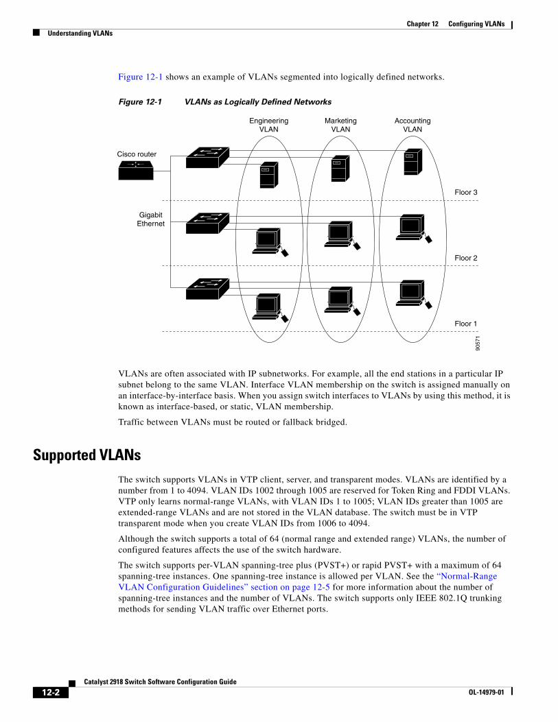
Chapter 12 Configuring VLANsUnderstanding VLANs
Figure 12-1 shows an example of VLANs segmented into logically defined networks.
Figure 12-1 VLANs as Logically Defined Networks
Floor 1
Floor 2
EngineeringVLAN
Cisco router
GigabitEthernet
Floor 3
MarketingVLAN
AccountingVLAN
9057
1
VLANs are often associated with IP subnetworks. For example, all the end stations in a particular IP subnet belong to the same VLAN. Interface VLAN membership on the switch is assigned manually on an interface-by-interface basis. When you assign switch interfaces to VLANs by using this method, it is known as interface-based, or static, VLAN membership.
Traffic between VLANs must be routed or fallback bridged.
Supported VLANsThe switch supports VLANs in VTP client, server, and transparent modes. VLANs are identified by a number from 1 to 4094. VLAN IDs 1002 through 1005 are reserved for Token Ring and FDDI VLANs. VTP only learns normal-range VLANs, with VLAN IDs 1 to 1005; VLAN IDs greater than 1005 are extended-range VLANs and are not stored in the VLAN database. The switch must be in VTP transparent mode when you create VLAN IDs from 1006 to 4094.
Although the switch supports a total of 64 (normal range and extended range) VLANs, the number of configured features affects the use of the switch hardware.
The switch supports per-VLAN spanning-tree plus (PVST+) or rapid PVST+ with a maximum of 64 spanning-tree instances. One spanning-tree instance is allowed per VLAN. See the “Normal-Range VLAN Configuration Guidelines” section on page 12-5 for more information about the number of spanning-tree instances and the number of VLANs. The switch supports only IEEE 802.1Q trunking methods for sending VLAN traffic over Ethernet ports.
12-2Catalyst 2918 Switch Software Configuration Guide
OL-14979-01
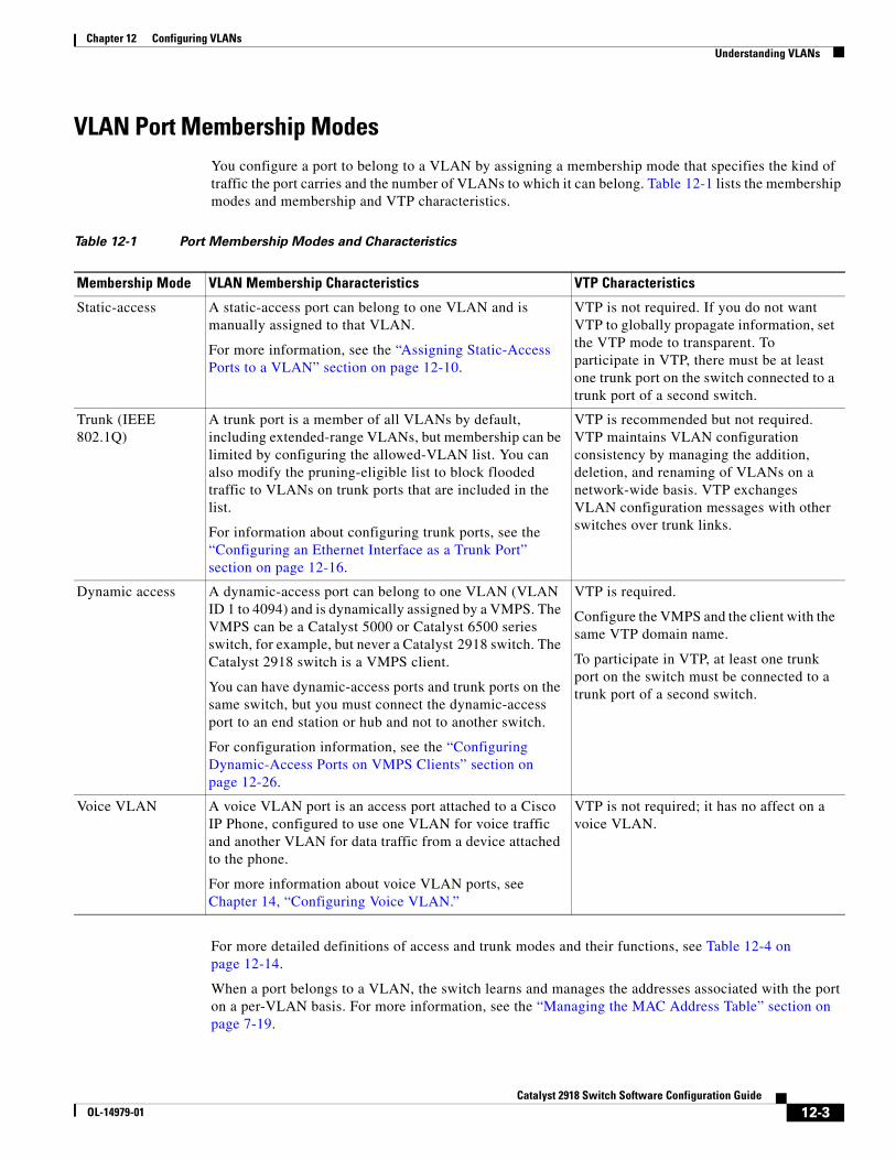
Chapter 12 Configuring VLANsUnderstanding VLANs
VLAN Port Membership ModesYou configure a port to belong to a VLAN by assigning a membership mode that specifies the kind of traffic the port carries and the number of VLANs to which it can belong. Table 12-1 lists the membership modes and membership and VTP characteristics.
Table 12-1 Port Membership Modes and Characteristics
Membership Mode VLAN Membership Characteristics VTP Characteristics
Static-access A static-access port can belong to one VLAN and is manually assigned to that VLAN.
For more information, see the “Assigning Static-Access Ports to a VLAN” section on page 12-10.
VTP is not required. If you do not want VTP to globally propagate information, set the VTP mode to transparent. To participate in VTP, there must be at least one trunk port on the switch connected to a trunk port of a second switch.
Trunk (IEEE 802.1Q)
A trunk port is a member of all VLANs by default, including extended-range VLANs, but membership can be limited by configuring the allowed-VLAN list. You can also modify the pruning-eligible list to block flooded traffic to VLANs on trunk ports that are included in the list.
For information about configuring trunk ports, see the “Configuring an Ethernet Interface as a Trunk Port” section on page 12-16.
VTP is recommended but not required. VTP maintains VLAN configuration consistency by managing the addition, deletion, and renaming of VLANs on a network-wide basis. VTP exchanges VLAN configuration messages with other switches over trunk links.
Dynamic access A dynamic-access port can belong to one VLAN (VLAN ID 1 to 4094) and is dynamically assigned by a VMPS. The VMPS can be a Catalyst 5000 or Catalyst 6500 series switch, for example, but never a Catalyst 2918 switch. The Catalyst 2918 switch is a VMPS client.
You can have dynamic-access ports and trunk ports on the same switch, but you must connect the dynamic-access port to an end station or hub and not to another switch.
For configuration information, see the “Configuring Dynamic-Access Ports on VMPS Clients” section on page 12-26.
VTP is required.
Configure the VMPS and the client with the same VTP domain name.
To participate in VTP, at least one trunk port on the switch must be connected to a trunk port of a second switch.
Voice VLAN A voice VLAN port is an access port attached to a Cisco IP Phone, configured to use one VLAN for voice traffic and another VLAN for data traffic from a device attached to the phone.
For more information about voice VLAN ports, see Chapter 14, “Configuring Voice VLAN.”
VTP is not required; it has no affect on a voice VLAN.
For more detailed definitions of access and trunk modes and their functions, see Table 12-4 on page 12-14.
When a port belongs to a VLAN, the switch learns and manages the addresses associated with the port on a per-VLAN basis. For more information, see the “Managing the MAC Address Table” section on page 7-19.
12-3Catalyst 2918 Switch Software Configuration Guide
OL-14979-01
Chapter 12 Configuring VLANsConfiguring Normal-Range VLANs
Configuring Normal-Range VLANsNormal-range VLANs are VLANs with VLAN IDs 1 to 1005. If the switch is in VTP server or VTP transparent mode, you can add, modify or remove configurations for VLANs 2 to 1001 in the VLAN database. (VLAN IDs 1 and 1002 to 1005 are automatically created and cannot be removed.)
Note When the switch is in VTP transparent mode, you can also create extended-range VLANs (VLANs with IDs from 1006 to 4094), but these VLANs are not saved in the VLAN database. See the “Configuring Extended-Range VLANs” section on page 12-11.
Configurations for VLAN IDs 1 to 1005 are written to the file vlan.dat (VLAN database), and you can display them by entering the show vlan privileged EXEC command. The vlan.dat file is stored in flash memory.
Caution You can cause inconsistency in the VLAN database if you attempt to manually delete the vlan.dat file. If you want to modify the VLAN configuration, use the commands described in these sections and in the command reference for this release. To change the VTP configuration, see Chapter 13, “Configuring VTP.”
You use the interface configuration mode to define the port membership mode and to add and remove ports from VLANs. The results of these commands are written to the running-configuration file, and you can display the file by entering the show running-config privileged EXEC command.
You can set these parameters when you create a new normal-range VLAN or modify an existing VLAN in the VLAN database:
• VLAN ID
• VLAN name
• VLAN type (Ethernet, Fiber Distributed Data Interface [FDDI], FDDI network entity title [NET], TrBRF, or TrCRF, Token Ring, Token Ring-Net)
• VLAN state (active or suspended)
• Maximum transmission unit (MTU) for the VLAN
• Security Association Identifier (SAID)
• Bridge identification number for TrBRF VLANs
• Ring number for FDDI and TrCRF VLANs
• Parent VLAN number for TrCRF VLANs
• Spanning Tree Protocol (STP) type for TrCRF VLANs
• VLAN number to use when translating from one VLAN type to another
Note This section does not provide configuration details for most of these parameters. For complete information on the commands and parameters that control VLAN configuration, see the command reference for this release.
12-4Catalyst 2918 Switch Software Configuration Guide
OL-14979-01
Chapter 12 Configuring VLANsConfiguring Normal-Range VLANs
These sections contain normal-range VLAN configuration information:
• Token Ring VLANs, page 12-5
• Normal-Range VLAN Configuration Guidelines, page 12-5
• VLAN Configuration Mode Options, page 12-6
• Saving VLAN Configuration, page 12-6
• Default Ethernet VLAN Configuration, page 12-7
• Creating or Modifying an Ethernet VLAN, page 12-8
• Deleting a VLAN, page 12-9
• Assigning Static-Access Ports to a VLAN, page 12-10
Token Ring VLANsAlthough the switch does not support Token Ring connections, a remote device such as a Catalyst 5000 series switch with Token Ring connections could be managed from one of the supported switches. Switches running VTP Version 2 advertise information about these Token Ring VLANs:
• Token Ring TrBRF VLANs
• Token Ring TrCRF VLANs
For more information on configuring Token Ring VLANs, see the Catalyst 5000 Series Software Configuration Guide.
Normal-Range VLAN Configuration Guidelines Follow these guidelines when creating and modifying normal-range VLANs in your network:
• The switch supports 64 VLANs in VTP client, server, and transparent modes.
• Normal-range VLANs are identified with a number between 1 and 1001. VLAN numbers 1002 through 1005 are reserved for Token Ring and FDDI VLANs.
• VLAN configuration for VLANs 1 to 1005 are always saved in the VLAN database. If the VTP mode is transparent, VTP and VLAN configuration are also saved in the switch running configuration file.
• The switch also supports VLAN IDs 1006 through 4094 in VTP transparent mode (VTP disabled). These are extended-range VLANs and configuration options are limited. Extended-range VLANs are not saved in the VLAN database. See the “Configuring Extended-Range VLANs” section on page 12-11.
• Before you can create a VLAN, the switch must be in VTP server mode or VTP transparent mode. If the switch is a VTP server, you must define a VTP domain or VTP will not function.
• The switch does not support Token Ring or FDDI media. The switch does not forward FDDI, FDDI-Net, TrCRF, or TrBRF traffic, but it does propagate the VLAN configuration through VTP.
• The switch supports 64 spanning-tree instances. If a switch has more active VLANs than supported spanning-tree instances, spanning tree can be enabled on 128 VLANs and is disabled on the remaining VLANs. If you have already used all available spanning-tree instances on a switch, adding another VLAN anywhere in the VTP domain creates a VLAN on that switch that is not running spanning-tree. If you have the default allowed list on the trunk ports of that switch (which is to allow all VLANs), the new VLAN is carried on all trunk ports. Depending on the topology of the network, this could create a loop in the new VLAN that would not be broken, particularly if there
12-5Catalyst 2918 Switch Software Configuration Guide
OL-14979-01
Chapter 12 Configuring VLANsConfiguring Normal-Range VLANs
are several adjacent switches that all have run out of spanning-tree instances. You can prevent this possibility by setting allowed lists on the trunk ports of switches that have used up their allocation of spanning-tree instances.
If the number of VLANs on the switch exceeds the number of supported spanning-tree instances, we recommend that you configure the IEEE 802.1s Multiple STP (MSTP) on your switch to map multiple VLANs to a single spanning-tree instance. For more information about MSTP, see Chapter 16, “Configuring MSTP.”
VLAN Configuration Mode OptionsYou can configure normal-range VLANs (with VLAN IDs 1 to 1005) by using these two configuration modes:
• VLAN Configuration in config-vlan Mode, page 12-6
You access config-vlan mode by entering the vlan vlan-id global configuration command.
• VLAN Configuration in VLAN Database Configuration Mode, page 12-6
You access VLAN database configuration mode by entering the vlan database privileged EXEC command.
VLAN Configuration in config-vlan Mode
To access config-vlan mode, enter the vlan global configuration command with a VLAN ID. Enter a new VLAN ID to create a VLAN, or enter an existing VLAN ID to modify that VLAN. You can use the default VLAN configuration (Table 12-2) or enter multiple commands to configure the VLAN. For more information about commands available in this mode, see the vlan global configuration command description in the command reference for this release. When you have finished the configuration, you must exit config-vlan mode for the configuration to take effect. To display the VLAN configuration, enter the show vlan privileged EXEC command.
You must use this config-vlan mode when creating extended-range VLANs (VLAN IDs greater than 1005). See the “Configuring Extended-Range VLANs” section on page 12-11.
VLAN Configuration in VLAN Database Configuration Mode
To access VLAN database configuration mode, enter the vlan database privileged EXEC command. Then enter the vlan command with a new VLAN ID to create a VLAN, or enter an existing VLAN ID to modify the VLAN. You can use the default VLAN configuration (Table 12-2) or enter multiple commands to configure the VLAN. For more information about keywords available in this mode, see the vlan VLAN database configuration command description in the command reference for this release. When you have finished the configuration, you must enter apply or exit for the configuration to take effect. When you enter the exit command, it applies all commands and updates the VLAN database. VTP messages are sent to other switches in the VTP domain, and the privileged EXEC mode prompt appears.
Saving VLAN ConfigurationThe configurations of VLAN IDs 1 to 1005 are always saved in the VLAN database (vlan.dat file). If the VTP mode is transparent, they are also saved in the switch running configuration file. You can enter the copy running-config startup-config privileged EXEC command to save the configuration in the startup configuration file. To display the VLAN configuration, enter the show vlan privileged EXEC command.
12-6Catalyst 2918 Switch Software Configuration Guide
OL-14979-01
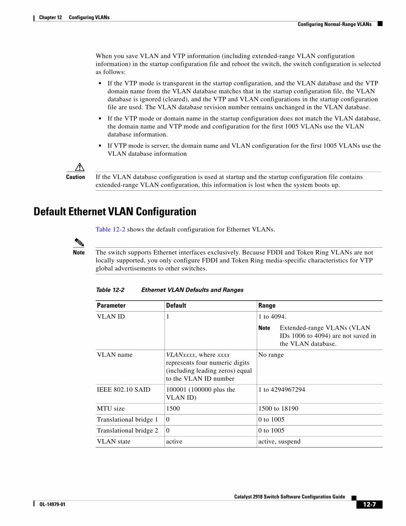
Chapter 12 Configuring VLANsConfiguring Normal-Range VLANs
When you save VLAN and VTP information (including extended-range VLAN configuration information) in the startup configuration file and reboot the switch, the switch configuration is selected as follows:
• If the VTP mode is transparent in the startup configuration, and the VLAN database and the VTP domain name from the VLAN database matches that in the startup configuration file, the VLAN database is ignored (cleared), and the VTP and VLAN configurations in the startup configuration file are used. The VLAN database revision number remains unchanged in the VLAN database.
• If the VTP mode or domain name in the startup configuration does not match the VLAN database, the domain name and VTP mode and configuration for the first 1005 VLANs use the VLAN database information.
• If VTP mode is server, the domain name and VLAN configuration for the first 1005 VLANs use the VLAN database information
Caution If the VLAN database configuration is used at startup and the startup configuration file contains extended-range VLAN configuration, this information is lost when the system boots up.
Default Ethernet VLAN ConfigurationTable 12-2 shows the default configuration for Ethernet VLANs.
Note The switch supports Ethernet interfaces exclusively. Because FDDI and Token Ring VLANs are not locally supported, you only configure FDDI and Token Ring media-specific characteristics for VTP global advertisements to other switches.
Table 12-2 Ethernet VLAN Defaults and Ranges
Parameter Default Range
VLAN ID 1 1 to 4094.
Note Extended-range VLANs (VLAN IDs 1006 to 4094) are not saved in the VLAN database.
VLAN name VLANxxxx, where xxxx represents four numeric digits (including leading zeros) equal to the VLAN ID number
No range
IEEE 802.10 SAID 100001 (100000 plus the VLAN ID)
1 to 4294967294
MTU size 1500 1500 to 18190
Translational bridge 1 0 0 to 1005
Translational bridge 2 0 0 to 1005
VLAN state active active, suspend
12-7Catalyst 2918 Switch Software Configuration Guide
OL-14979-01
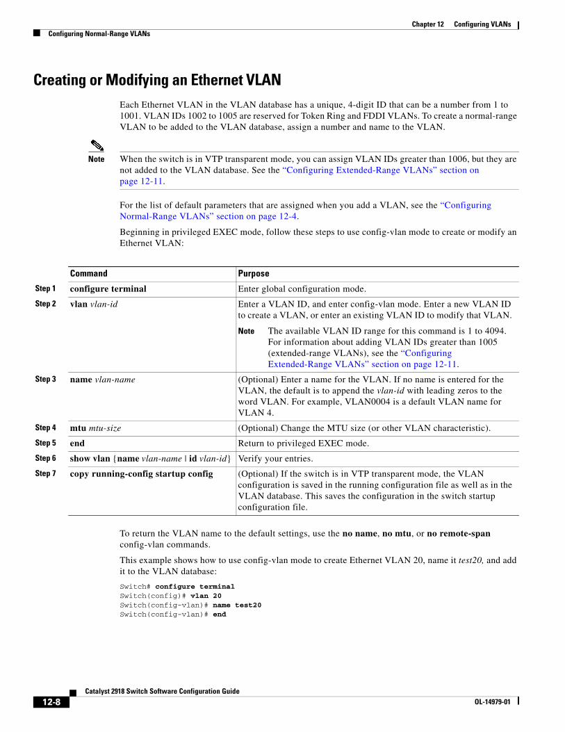
Chapter 12 Configuring VLANsConfiguring Normal-Range VLANs
Creating or Modifying an Ethernet VLANEach Ethernet VLAN in the VLAN database has a unique, 4-digit ID that can be a number from 1 to 1001. VLAN IDs 1002 to 1005 are reserved for Token Ring and FDDI VLANs. To create a normal-range VLAN to be added to the VLAN database, assign a number and name to the VLAN.
Note When the switch is in VTP transparent mode, you can assign VLAN IDs greater than 1006, but they are not added to the VLAN database. See the “Configuring Extended-Range VLANs” section on page 12-11.
For the list of default parameters that are assigned when you add a VLAN, see the “Configuring Normal-Range VLANs” section on page 12-4.
Beginning in privileged EXEC mode, follow these steps to use config-vlan mode to create or modify an Ethernet VLAN:
Command Purpose
Step 1 configure terminal Enter global configuration mode.
Step 2 vlan vlan-id Enter a VLAN ID, and enter config-vlan mode. Enter a new VLAN ID to create a VLAN, or enter an existing VLAN ID to modify that VLAN.
Note The available VLAN ID range for this command is 1 to 4094. For information about adding VLAN IDs greater than 1005 (extended-range VLANs), see the “Configuring Extended-Range VLANs” section on page 12-11.
Step 3 name vlan-name (Optional) Enter a name for the VLAN. If no name is entered for the VLAN, the default is to append the vlan-id with leading zeros to the word VLAN. For example, VLAN0004 is a default VLAN name for VLAN 4.
Step 4 mtu mtu-size (Optional) Change the MTU size (or other VLAN characteristic).
Step 5 end Return to privileged EXEC mode.
Step 6 show vlan {name vlan-name | id vlan-id} Verify your entries.
Step 7 copy running-config startup config (Optional) If the switch is in VTP transparent mode, the VLAN configuration is saved in the running configuration file as well as in the VLAN database. This saves the configuration in the switch startup configuration file.
To return the VLAN name to the default settings, use the no name, no mtu, or no remote-span config-vlan commands.
This example shows how to use config-vlan mode to create Ethernet VLAN 20, name it test20, and add it to the VLAN database:
Switch# configure terminalSwitch(config)# vlan 20Switch(config-vlan)# name test20Switch(config-vlan)# end
12-8Catalyst 2918 Switch Software Configuration Guide
OL-14979-01
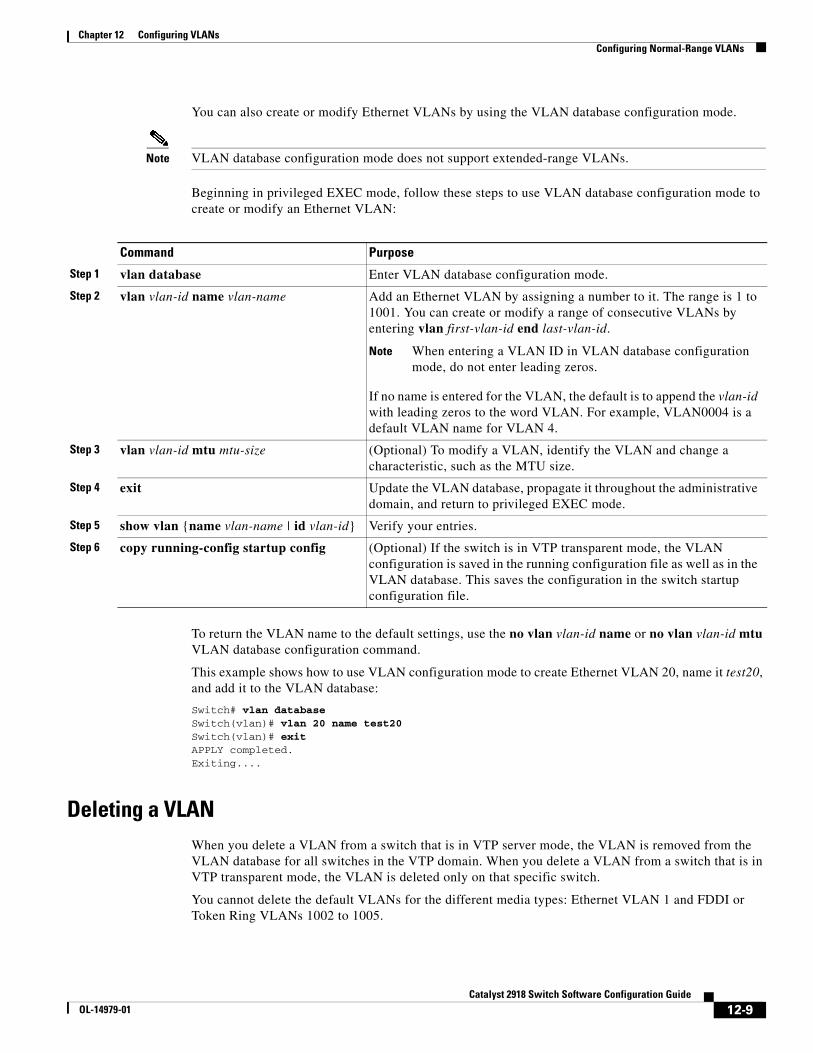
Chapter 12 Configuring VLANsConfiguring Normal-Range VLANs
You can also create or modify Ethernet VLANs by using the VLAN database configuration mode.
Note VLAN database configuration mode does not support extended-range VLANs.
Beginning in privileged EXEC mode, follow these steps to use VLAN database configuration mode to create or modify an Ethernet VLAN:
Command Purpose
Step 1 vlan database Enter VLAN database configuration mode.
Step 2 vlan vlan-id name vlan-name Add an Ethernet VLAN by assigning a number to it. The range is 1 to 1001. You can create or modify a range of consecutive VLANs by entering vlan first-vlan-id end last-vlan-id.
Note When entering a VLAN ID in VLAN database configuration mode, do not enter leading zeros.
If no name is entered for the VLAN, the default is to append the vlan-id with leading zeros to the word VLAN. For example, VLAN0004 is a default VLAN name for VLAN 4.
Step 3 vlan vlan-id mtu mtu-size (Optional) To modify a VLAN, identify the VLAN and change a characteristic, such as the MTU size.
Step 4 exit Update the VLAN database, propagate it throughout the administrative domain, and return to privileged EXEC mode.
Step 5 show vlan {name vlan-name | id vlan-id} Verify your entries.
Step 6 copy running-config startup config (Optional) If the switch is in VTP transparent mode, the VLAN configuration is saved in the running configuration file as well as in the VLAN database. This saves the configuration in the switch startup configuration file.
To return the VLAN name to the default settings, use the no vlan vlan-id name or no vlan vlan-id mtu VLAN database configuration command.
This example shows how to use VLAN configuration mode to create Ethernet VLAN 20, name it test20, and add it to the VLAN database:
Switch# vlan databaseSwitch(vlan)# vlan 20 name test20Switch(vlan)# exitAPPLY completed.Exiting....
Deleting a VLANWhen you delete a VLAN from a switch that is in VTP server mode, the VLAN is removed from the VLAN database for all switches in the VTP domain. When you delete a VLAN from a switch that is in VTP transparent mode, the VLAN is deleted only on that specific switch.
You cannot delete the default VLANs for the different media types: Ethernet VLAN 1 and FDDI or Token Ring VLANs 1002 to 1005.
12-9Catalyst 2918 Switch Software Configuration Guide
OL-14979-01
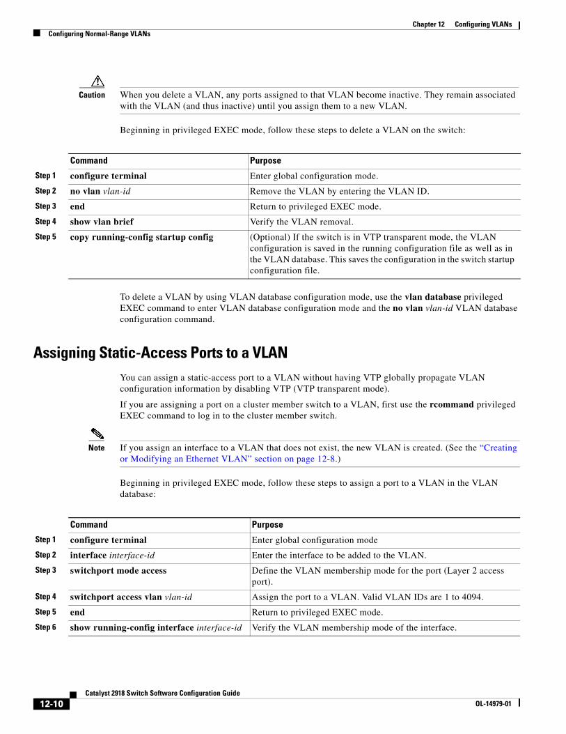
Chapter 12 Configuring VLANsConfiguring Normal-Range VLANs
Caution When you delete a VLAN, any ports assigned to that VLAN become inactive. They remain associated with the VLAN (and thus inactive) until you assign them to a new VLAN.
Beginning in privileged EXEC mode, follow these steps to delete a VLAN on the switch:
Command Purpose
Step 1 configure terminal Enter global configuration mode.
Step 2 no vlan vlan-id Remove the VLAN by entering the VLAN ID.
Step 3 end Return to privileged EXEC mode.
Step 4 show vlan brief Verify the VLAN removal.
Step 5 copy running-config startup config (Optional) If the switch is in VTP transparent mode, the VLAN configuration is saved in the running configuration file as well as in the VLAN database. This saves the configuration in the switch startup configuration file.
To delete a VLAN by using VLAN database configuration mode, use the vlan database privileged EXEC command to enter VLAN database configuration mode and the no vlan vlan-id VLAN database configuration command.
Assigning Static-Access Ports to a VLANYou can assign a static-access port to a VLAN without having VTP globally propagate VLAN configuration information by disabling VTP (VTP transparent mode).
If you are assigning a port on a cluster member switch to a VLAN, first use the rcommand privileged EXEC command to log in to the cluster member switch.
Note If you assign an interface to a VLAN that does not exist, the new VLAN is created. (See the “Creating or Modifying an Ethernet VLAN” section on page 12-8.)
Beginning in privileged EXEC mode, follow these steps to assign a port to a VLAN in the VLAN database:
Command Purpose
Step 1 configure terminal Enter global configuration mode
Step 2 interface interface-id Enter the interface to be added to the VLAN.
Step 3 switchport mode access Define the VLAN membership mode for the port (Layer 2 access port).
Step 4 switchport access vlan vlan-id Assign the port to a VLAN. Valid VLAN IDs are 1 to 4094.
Step 5 end Return to privileged EXEC mode.
Step 6 show running-config interface interface-id Verify the VLAN membership mode of the interface.
12-10Catalyst 2918 Switch Software Configuration Guide
OL-14979-01
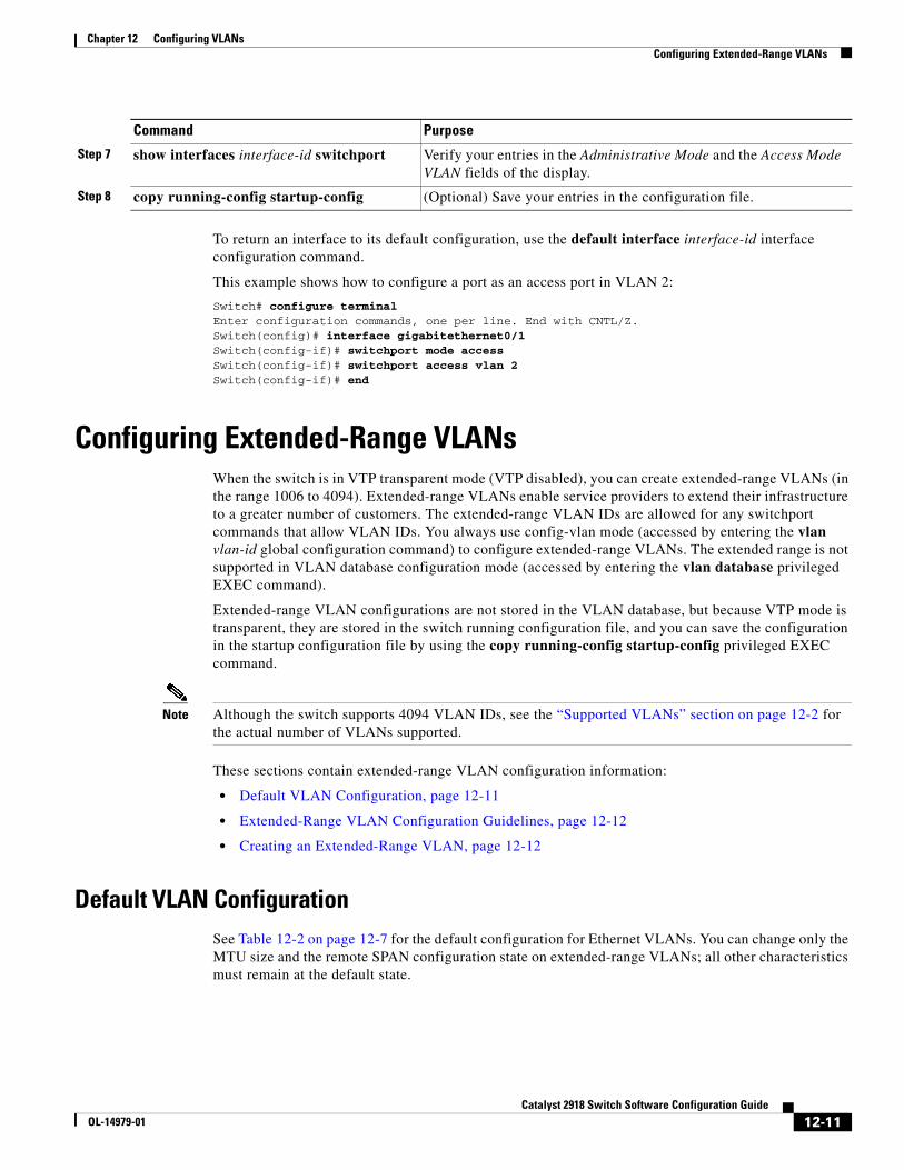
Chapter 12 Configuring VLANsConfiguring Extended-Range VLANs
To return an interface to its default configuration, use the default interface interface-id interface configuration command.
This example shows how to configure a port as an access port in VLAN 2:
Switch# configure terminal Enter configuration commands, one per line. End with CNTL/Z.Switch(config)# interface gigabitethernet0/1 Switch(config-if)# switchport mode access Switch(config-if)# switchport access vlan 2Switch(config-if)# end
Configuring Extended-Range VLANsWhen the switch is in VTP transparent mode (VTP disabled), you can create extended-range VLANs (in the range 1006 to 4094). Extended-range VLANs enable service providers to extend their infrastructure to a greater number of customers. The extended-range VLAN IDs are allowed for any switchport commands that allow VLAN IDs. You always use config-vlan mode (accessed by entering the vlan vlan-id global configuration command) to configure extended-range VLANs. The extended range is not supported in VLAN database configuration mode (accessed by entering the vlan database privileged EXEC command).
Extended-range VLAN configurations are not stored in the VLAN database, but because VTP mode is transparent, they are stored in the switch running configuration file, and you can save the configuration in the startup configuration file by using the copy running-config startup-config privileged EXEC command.
Note Although the switch supports 4094 VLAN IDs, see the “Supported VLANs” section on page 12-2 for the actual number of VLANs supported.
These sections contain extended-range VLAN configuration information:
• Default VLAN Configuration, page 12-11
• Extended-Range VLAN Configuration Guidelines, page 12-12
• Creating an Extended-Range VLAN, page 12-12
Default VLAN ConfigurationSee Table 12-2 on page 12-7 for the default configuration for Ethernet VLANs. You can change only the MTU size and the remote SPAN configuration state on extended-range VLANs; all other characteristics must remain at the default state.
Step 7 show interfaces interface-id switchport Verify your entries in the Administrative Mode and the Access Mode VLAN fields of the display.
Step 8 copy running-config startup-config (Optional) Save your entries in the configuration file.
Command Purpose
12-11Catalyst 2918 Switch Software Configuration Guide
OL-14979-01
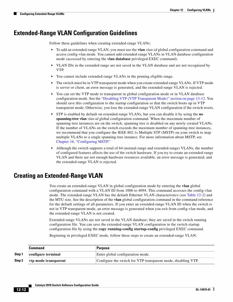
Chapter 12 Configuring VLANsConfiguring Extended-Range VLANs
Extended-Range VLAN Configuration GuidelinesFollow these guidelines when creating extended-range VLANs:
• To add an extended-range VLAN, you must use the vlan vlan-id global configuration command and access config-vlan mode. You cannot add extended-range VLANs in VLAN database configuration mode (accessed by entering the vlan database privileged EXEC command).
• VLAN IDs in the extended range are not saved in the VLAN database and are not recognized by VTP.
• You cannot include extended-range VLANs in the pruning eligible range.
• The switch must be in VTP transparent mode when you create extended-range VLANs. If VTP mode is server or client, an error message is generated, and the extended-range VLAN is rejected.
• You can set the VTP mode to transparent in global configuration mode or in VLAN database configuration mode. See the “Disabling VTP (VTP Transparent Mode)” section on page 13-12. You should save this configuration to the startup configuration so that the switch boots up in VTP transparent mode. Otherwise, you lose the extended-range VLAN configuration if the switch resets.
• STP is enabled by default on extended-range VLANs, but you can disable it by using the no spanning-tree vlan vlan-id global configuration command. When the maximum number of spanning-tree instances are on the switch, spanning tree is disabled on any newly created VLANs. If the number of VLANs on the switch exceeds the maximum number of spanning-tree instances, we recommend that you configure the IEEE 802.1s Multiple STP (MSTP) on your switch to map multiple VLANs to a single spanning-tree instance. For more information about MSTP, see Chapter 16, “Configuring MSTP.”
• Although the switch supports a total of 64 (normal-range and extended-range) VLANs, the number of configured features affects the use of the switch hardware. If you try to create an extended-range VLAN and there are not enough hardware resources available, an error message is generated, and the extended-range VLAN is rejected.
Creating an Extended-Range VLANYou create an extended-range VLAN in global configuration mode by entering the vlan global configuration command with a VLAN ID from 1006 to 4094. This command accesses the config-vlan mode. The extended-range VLAN has the default Ethernet VLAN characteristics (see Table 12-2) and the MTU size. See the description of the vlan global configuration command in the command reference for the default settings of all parameters. If you enter an extended-range VLAN ID when the switch is not in VTP transparent mode, an error message is generated when you exit from config-vlan mode, and the extended-range VLAN is not created.
Extended-range VLANs are not saved in the VLAN database; they are saved in the switch running configuration file. You can save the extended-range VLAN configuration in the switch startup configuration file by using the copy running-config startup-config privileged EXEC command.
Beginning in privileged EXEC mode, follow these steps to create an extended-range VLAN:
Command Purpose
Step 1 configure terminal Enter global configuration mode.
Step 2 vtp mode transparent Configure the switch for VTP transparent mode, disabling VTP.
12-12Catalyst 2918 Switch Software Configuration Guide
OL-14979-01
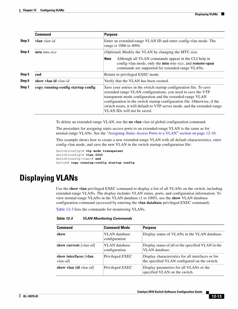
Chapter 12 Configuring VLANsDisplaying VLANs
To delete an extended-range VLAN, use the no vlan vlan-id global configuration command.
The procedure for assigning static-access ports to an extended-range VLAN is the same as for normal-range VLANs. See the “Assigning Static-Access Ports to a VLAN” section on page 12-10.
This example shows how to create a new extended-range VLAN with all default characteristics, enter config-vlan mode, and save the new VLAN in the switch startup configuration file:
Switch(config)# vtp mode transparentSwitch(config)# vlan 2000Switch(config-vlan)# endSwitch# copy running-config startup config
Displaying VLANsUse the show vlan privileged EXEC command to display a list of all VLANs on the switch, including extended-range VLANs. The display includes VLAN status, ports, and configuration information. To view normal-range VLANs in the VLAN database (1 to 1005), use the show VLAN database configuration command (accessed by entering the vlan database privileged EXEC command).
Table 12-3 lists the commands for monitoring VLANs.
Table 12-3 VLAN Monitoring Commands
Command Command Mode Purpose
show VLAN database configuration
Display status of VLANs in the VLAN database.
show current [vlan-id] VLAN database configuration
Display status of all or the specified VLAN in the VLAN database.
show interfaces [vlan vlan-id]
Privileged EXEC Display characteristics for all interfaces or for the specified VLAN configured on the switch.
show vlan [id vlan-id] Privileged EXEC Display parameters for all VLANs or the specified VLAN on the switch.
Step 3 vlan vlan-id Enter an extended-range VLAN ID and enter config-vlan mode. The range is 1006 to 4094.
Step 4 mtu mtu-size (Optional) Modify the VLAN by changing the MTU size.
Note Although all VLAN commands appear in the CLI help in config-vlan mode, only the mtu mtu-size, and remote-span commands are supported for extended-range VLANs.
Step 5 end Return to privileged EXEC mode.
Step 6 show vlan id vlan-id Verify that the VLAN has been created.
Step 7 copy running-config startup config Save your entries in the switch startup configuration file. To save extended-range VLAN configurations, you need to save the VTP transparent mode configuration and the extended-range VLAN configuration in the switch startup configuration file. Otherwise, if the switch resets, it will default to VTP server mode, and the extended-range VLAN IDs will not be saved.
Command Purpose
12-13Catalyst 2918 Switch Software Configuration Guide
OL-14979-01
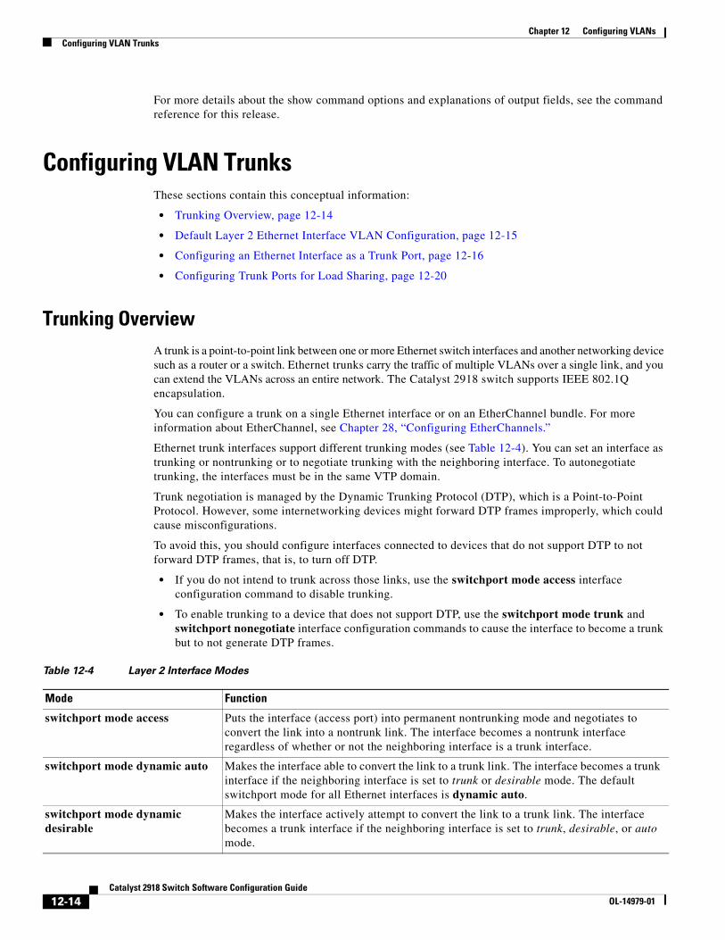
Chapter 12 Configuring VLANsConfiguring VLAN Trunks
For more details about the show command options and explanations of output fields, see the command reference for this release.
Configuring VLAN TrunksThese sections contain this conceptual information:
• Trunking Overview, page 12-14
• Default Layer 2 Ethernet Interface VLAN Configuration, page 12-15
• Configuring an Ethernet Interface as a Trunk Port, page 12-16
• Configuring Trunk Ports for Load Sharing, page 12-20
Trunking OverviewA trunk is a point-to-point link between one or more Ethernet switch interfaces and another networking device such as a router or a switch. Ethernet trunks carry the traffic of multiple VLANs over a single link, and you can extend the VLANs across an entire network. The Catalyst 2918 switch supports IEEE 802.1Q encapsulation.
You can configure a trunk on a single Ethernet interface or on an EtherChannel bundle. For more information about EtherChannel, see Chapter 28, “Configuring EtherChannels.”
Ethernet trunk interfaces support different trunking modes (see Table 12-4). You can set an interface as trunking or nontrunking or to negotiate trunking with the neighboring interface. To autonegotiate trunking, the interfaces must be in the same VTP domain.
Trunk negotiation is managed by the Dynamic Trunking Protocol (DTP), which is a Point-to-Point Protocol. However, some internetworking devices might forward DTP frames improperly, which could cause misconfigurations.
To avoid this, you should configure interfaces connected to devices that do not support DTP to not forward DTP frames, that is, to turn off DTP.
• If you do not intend to trunk across those links, use the switchport mode access interface configuration command to disable trunking.
• To enable trunking to a device that does not support DTP, use the switchport mode trunk and switchport nonegotiate interface configuration commands to cause the interface to become a trunk but to not generate DTP frames.
Table 12-4 Layer 2 Interface Modes
Mode Function
switchport mode access Puts the interface (access port) into permanent nontrunking mode and negotiates to convert the link into a nontrunk link. The interface becomes a nontrunk interface regardless of whether or not the neighboring interface is a trunk interface.
switchport mode dynamic auto Makes the interface able to convert the link to a trunk link. The interface becomes a trunk interface if the neighboring interface is set to trunk or desirable mode. The default switchport mode for all Ethernet interfaces is dynamic auto.
switchport mode dynamic desirable
Makes the interface actively attempt to convert the link to a trunk link. The interface becomes a trunk interface if the neighboring interface is set to trunk, desirable, or auto mode.
12-14Catalyst 2918 Switch Software Configuration Guide
OL-14979-01
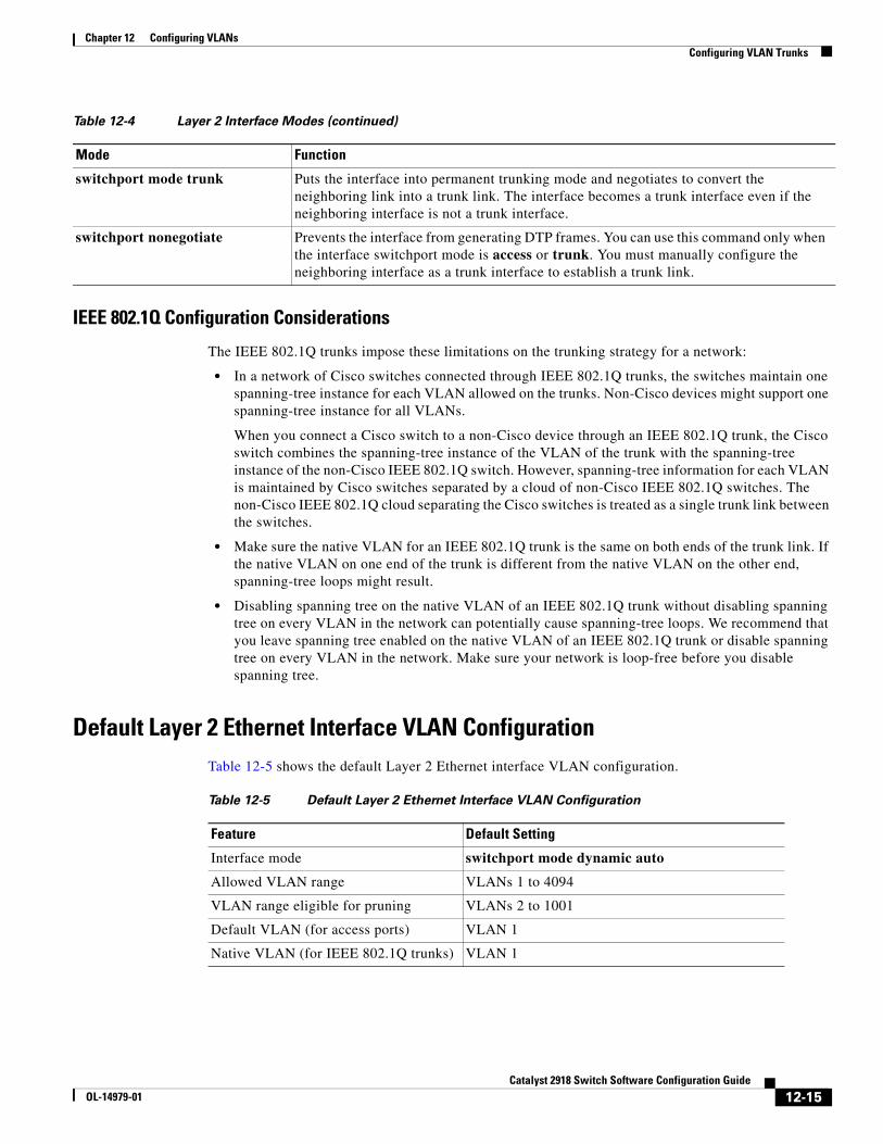
Chapter 12 Configuring VLANsConfiguring VLAN Trunks
IEEE 802.1Q Configuration Considerations
The IEEE 802.1Q trunks impose these limitations on the trunking strategy for a network:
• In a network of Cisco switches connected through IEEE 802.1Q trunks, the switches maintain one spanning-tree instance for each VLAN allowed on the trunks. Non-Cisco devices might support one spanning-tree instance for all VLANs.
When you connect a Cisco switch to a non-Cisco device through an IEEE 802.1Q trunk, the Cisco switch combines the spanning-tree instance of the VLAN of the trunk with the spanning-tree instance of the non-Cisco IEEE 802.1Q switch. However, spanning-tree information for each VLAN is maintained by Cisco switches separated by a cloud of non-Cisco IEEE 802.1Q switches. The non-Cisco IEEE 802.1Q cloud separating the Cisco switches is treated as a single trunk link between the switches.
• Make sure the native VLAN for an IEEE 802.1Q trunk is the same on both ends of the trunk link. If the native VLAN on one end of the trunk is different from the native VLAN on the other end, spanning-tree loops might result.
• Disabling spanning tree on the native VLAN of an IEEE 802.1Q trunk without disabling spanning tree on every VLAN in the network can potentially cause spanning-tree loops. We recommend that you leave spanning tree enabled on the native VLAN of an IEEE 802.1Q trunk or disable spanning tree on every VLAN in the network. Make sure your network is loop-free before you disable spanning tree.
Default Layer 2 Ethernet Interface VLAN ConfigurationTable 12-5 shows the default Layer 2 Ethernet interface VLAN configuration.
Table 12-5 Default Layer 2 Ethernet Interface VLAN Configuration
Feature Default Setting
Interface mode switchport mode dynamic auto
Allowed VLAN range VLANs 1 to 4094
VLAN range eligible for pruning VLANs 2 to 1001
Default VLAN (for access ports) VLAN 1
Native VLAN (for IEEE 802.1Q trunks) VLAN 1
switchport mode trunk Puts the interface into permanent trunking mode and negotiates to convert the neighboring link into a trunk link. The interface becomes a trunk interface even if the neighboring interface is not a trunk interface.
switchport nonegotiate Prevents the interface from generating DTP frames. You can use this command only when the interface switchport mode is access or trunk. You must manually configure the neighboring interface as a trunk interface to establish a trunk link.
Table 12-4 Layer 2 Interface Modes (continued)
Mode Function
12-15Catalyst 2918 Switch Software Configuration Guide
OL-14979-01
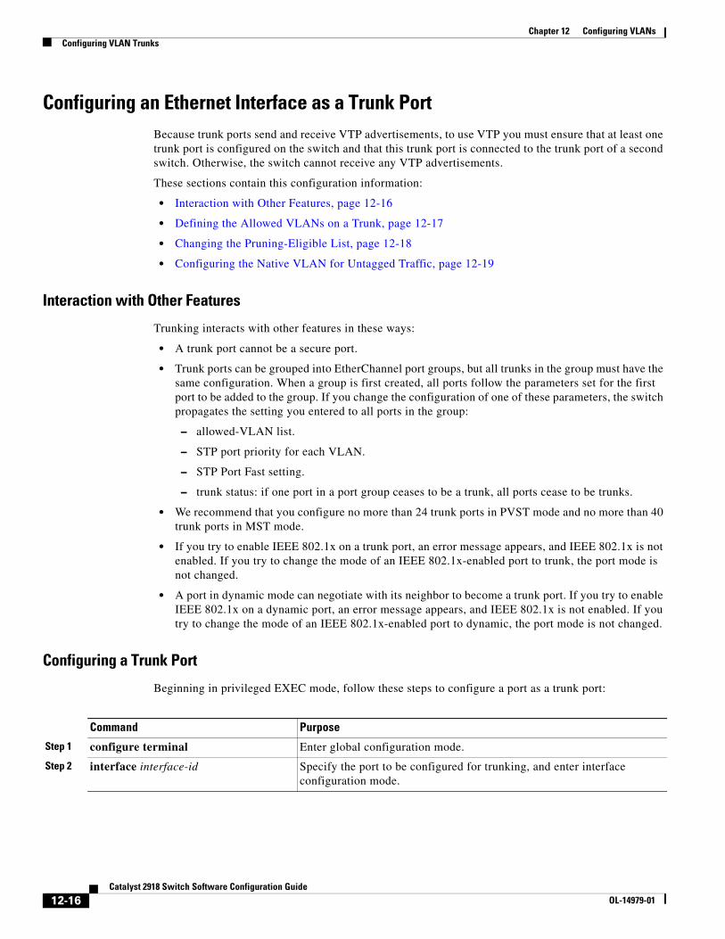
Chapter 12 Configuring VLANsConfiguring VLAN Trunks
Configuring an Ethernet Interface as a Trunk PortBecause trunk ports send and receive VTP advertisements, to use VTP you must ensure that at least one trunk port is configured on the switch and that this trunk port is connected to the trunk port of a second switch. Otherwise, the switch cannot receive any VTP advertisements.
These sections contain this configuration information:
• Interaction with Other Features, page 12-16
• Defining the Allowed VLANs on a Trunk, page 12-17
• Changing the Pruning-Eligible List, page 12-18
• Configuring the Native VLAN for Untagged Traffic, page 12-19
Interaction with Other Features
Trunking interacts with other features in these ways:
• A trunk port cannot be a secure port.
• Trunk ports can be grouped into EtherChannel port groups, but all trunks in the group must have the same configuration. When a group is first created, all ports follow the parameters set for the first port to be added to the group. If you change the configuration of one of these parameters, the switch propagates the setting you entered to all ports in the group:
– allowed-VLAN list.
– STP port priority for each VLAN.
– STP Port Fast setting.
– trunk status: if one port in a port group ceases to be a trunk, all ports cease to be trunks.
• We recommend that you configure no more than 24 trunk ports in PVST mode and no more than 40 trunk ports in MST mode.
• If you try to enable IEEE 802.1x on a trunk port, an error message appears, and IEEE 802.1x is not enabled. If you try to change the mode of an IEEE 802.1x-enabled port to trunk, the port mode is not changed.
• A port in dynamic mode can negotiate with its neighbor to become a trunk port. If you try to enable IEEE 802.1x on a dynamic port, an error message appears, and IEEE 802.1x is not enabled. If you try to change the mode of an IEEE 802.1x-enabled port to dynamic, the port mode is not changed.
Configuring a Trunk Port
Beginning in privileged EXEC mode, follow these steps to configure a port as a trunk port:
Command Purpose
Step 1 configure terminal Enter global configuration mode.
Step 2 interface interface-id Specify the port to be configured for trunking, and enter interface configuration mode.
12-16Catalyst 2918 Switch Software Configuration Guide
OL-14979-01
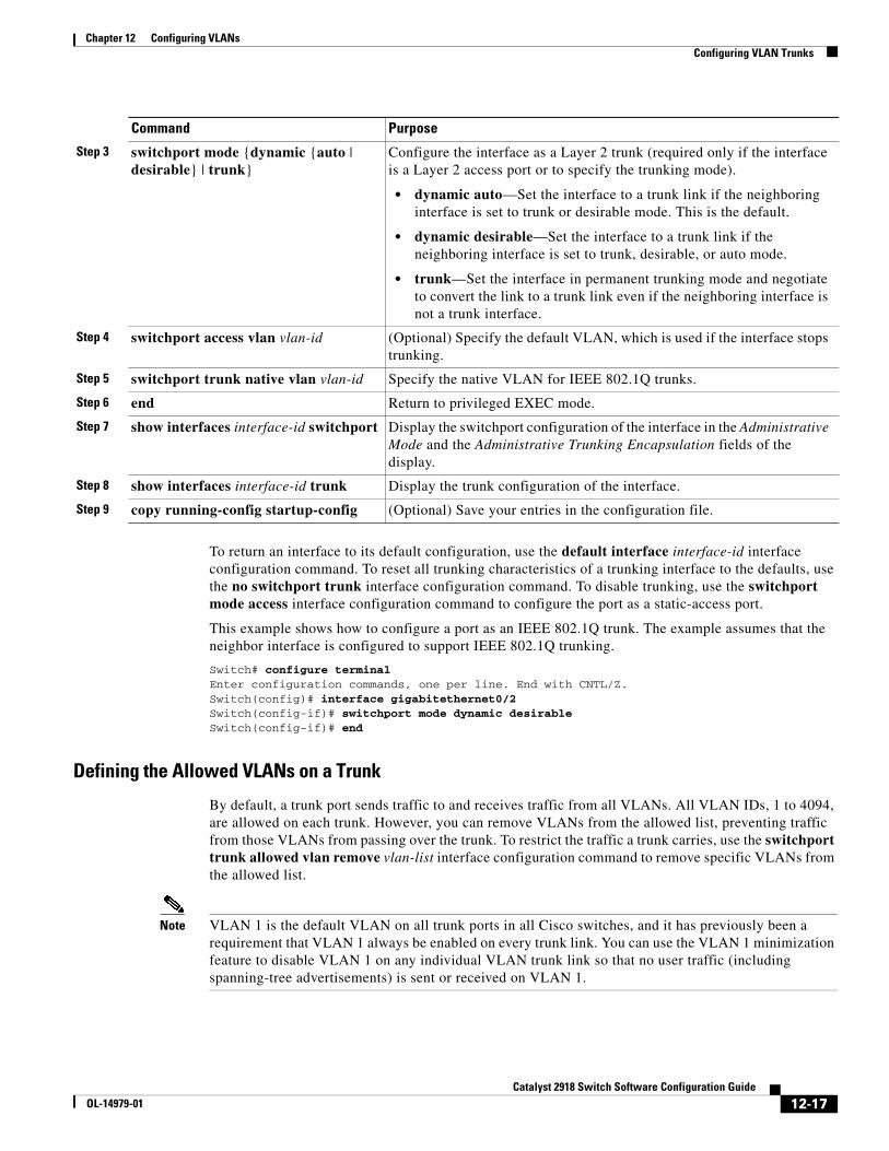
Chapter 12 Configuring VLANsConfiguring VLAN Trunks
To return an interface to its default configuration, use the default interface interface-id interface configuration command. To reset all trunking characteristics of a trunking interface to the defaults, use the no switchport trunk interface configuration command. To disable trunking, use the switchport mode access interface configuration command to configure the port as a static-access port.
This example shows how to configure a port as an IEEE 802.1Q trunk. The example assumes that the neighbor interface is configured to support IEEE 802.1Q trunking.
Switch# configure terminal Enter configuration commands, one per line. End with CNTL/Z.Switch(config)# interface gigabitethernet0/2 Switch(config-if)# switchport mode dynamic desirable Switch(config-if)# end
Defining the Allowed VLANs on a Trunk
By default, a trunk port sends traffic to and receives traffic from all VLANs. All VLAN IDs, 1 to 4094, are allowed on each trunk. However, you can remove VLANs from the allowed list, preventing traffic from those VLANs from passing over the trunk. To restrict the traffic a trunk carries, use the switchport trunk allowed vlan remove vlan-list interface configuration command to remove specific VLANs from the allowed list.
Note VLAN 1 is the default VLAN on all trunk ports in all Cisco switches, and it has previously been a requirement that VLAN 1 always be enabled on every trunk link. You can use the VLAN 1 minimization feature to disable VLAN 1 on any individual VLAN trunk link so that no user traffic (including spanning-tree advertisements) is sent or received on VLAN 1.
Step 3 switchport mode {dynamic {auto | desirable} | trunk}
Configure the interface as a Layer 2 trunk (required only if the interface is a Layer 2 access port or to specify the trunking mode).
• dynamic auto—Set the interface to a trunk link if the neighboring interface is set to trunk or desirable mode. This is the default.
• dynamic desirable—Set the interface to a trunk link if the neighboring interface is set to trunk, desirable, or auto mode.
• trunk—Set the interface in permanent trunking mode and negotiate to convert the link to a trunk link even if the neighboring interface is not a trunk interface.
Step 4 switchport access vlan vlan-id (Optional) Specify the default VLAN, which is used if the interface stops trunking.
Step 5 switchport trunk native vlan vlan-id Specify the native VLAN for IEEE 802.1Q trunks.
Step 6 end Return to privileged EXEC mode.
Step 7 show interfaces interface-id switchport Display the switchport configuration of the interface in the Administrative Mode and the Administrative Trunking Encapsulation fields of the display.
Step 8 show interfaces interface-id trunk Display the trunk configuration of the interface.
Step 9 copy running-config startup-config (Optional) Save your entries in the configuration file.
Command Purpose
12-17Catalyst 2918 Switch Software Configuration Guide
OL-14979-01
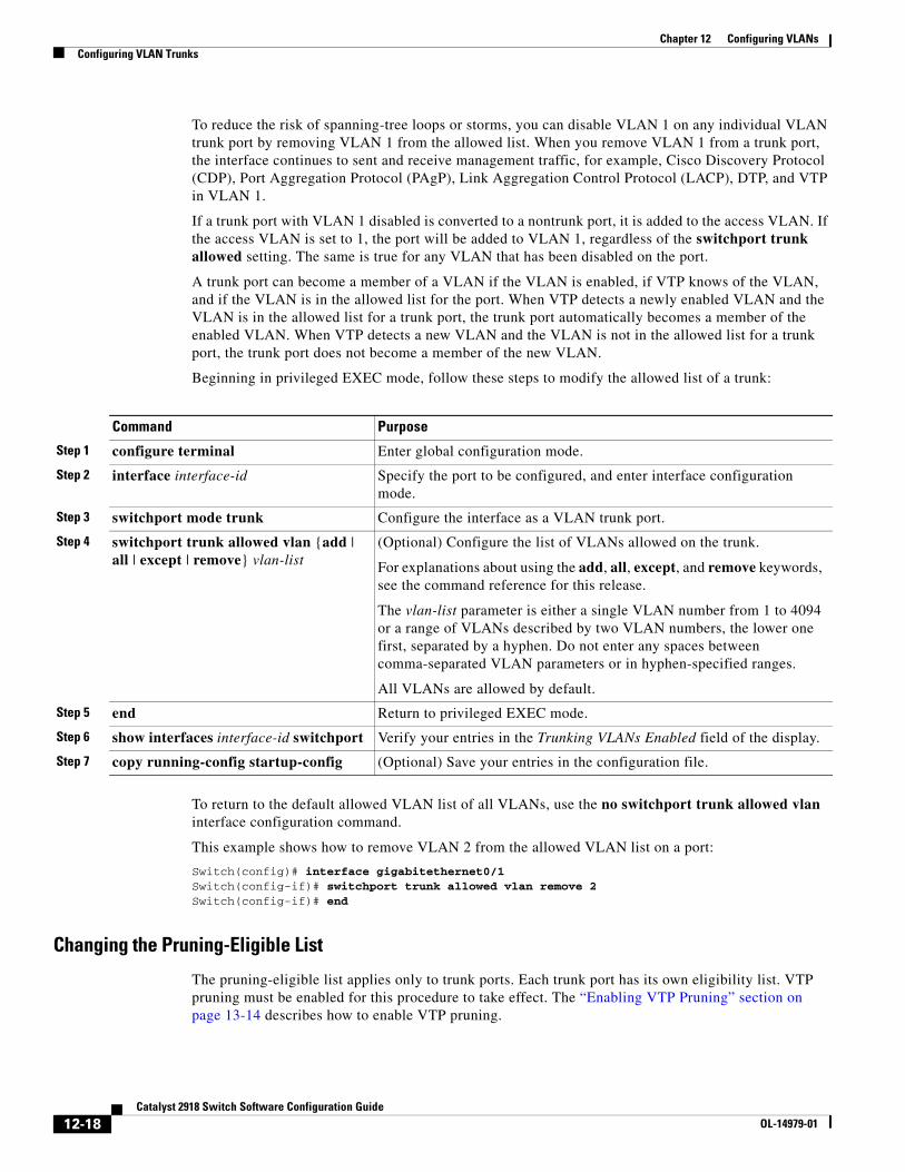
Chapter 12 Configuring VLANsConfiguring VLAN Trunks
To reduce the risk of spanning-tree loops or storms, you can disable VLAN 1 on any individual VLAN trunk port by removing VLAN 1 from the allowed list. When you remove VLAN 1 from a trunk port, the interface continues to sent and receive management traffic, for example, Cisco Discovery Protocol (CDP), Port Aggregation Protocol (PAgP), Link Aggregation Control Protocol (LACP), DTP, and VTP in VLAN 1.
If a trunk port with VLAN 1 disabled is converted to a nontrunk port, it is added to the access VLAN. If the access VLAN is set to 1, the port will be added to VLAN 1, regardless of the switchport trunk allowed setting. The same is true for any VLAN that has been disabled on the port.
A trunk port can become a member of a VLAN if the VLAN is enabled, if VTP knows of the VLAN, and if the VLAN is in the allowed list for the port. When VTP detects a newly enabled VLAN and the VLAN is in the allowed list for a trunk port, the trunk port automatically becomes a member of the enabled VLAN. When VTP detects a new VLAN and the VLAN is not in the allowed list for a trunk port, the trunk port does not become a member of the new VLAN.
Beginning in privileged EXEC mode, follow these steps to modify the allowed list of a trunk:
Command Purpose
Step 1 configure terminal Enter global configuration mode.
Step 2 interface interface-id Specify the port to be configured, and enter interface configuration mode.
Step 3 switchport mode trunk Configure the interface as a VLAN trunk port.
Step 4 switchport trunk allowed vlan {add | all | except | remove} vlan-list
(Optional) Configure the list of VLANs allowed on the trunk.
For explanations about using the add, all, except, and remove keywords, see the command reference for this release.
The vlan-list parameter is either a single VLAN number from 1 to 4094 or a range of VLANs described by two VLAN numbers, the lower one first, separated by a hyphen. Do not enter any spaces between comma-separated VLAN parameters or in hyphen-specified ranges.
All VLANs are allowed by default.
Step 5 end Return to privileged EXEC mode.
Step 6 show interfaces interface-id switchport Verify your entries in the Trunking VLANs Enabled field of the display.
Step 7 copy running-config startup-config (Optional) Save your entries in the configuration file.
To return to the default allowed VLAN list of all VLANs, use the no switchport trunk allowed vlan interface configuration command.
This example shows how to remove VLAN 2 from the allowed VLAN list on a port:
Switch(config)# interface gigabitethernet0/1Switch(config-if)# switchport trunk allowed vlan remove 2Switch(config-if)# end
Changing the Pruning-Eligible List
The pruning-eligible list applies only to trunk ports. Each trunk port has its own eligibility list. VTP pruning must be enabled for this procedure to take effect. The “Enabling VTP Pruning” section on page 13-14 describes how to enable VTP pruning.
12-18Catalyst 2918 Switch Software Configuration Guide
OL-14979-01
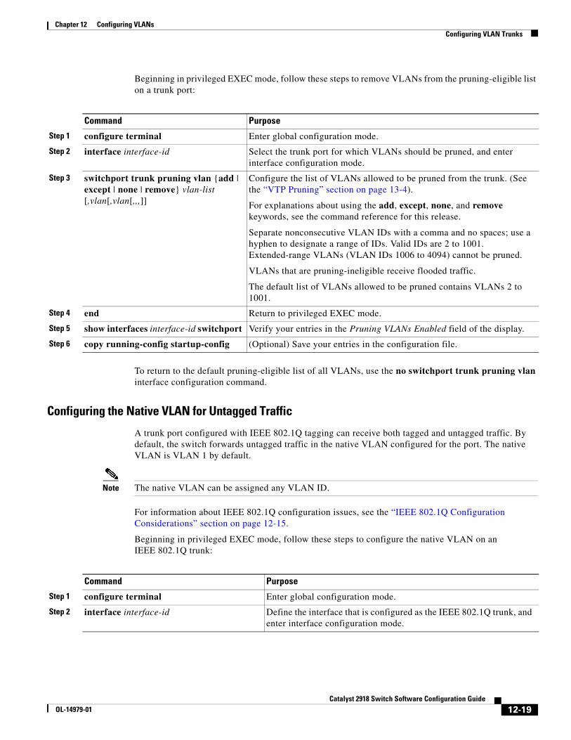
Chapter 12 Configuring VLANsConfiguring VLAN Trunks
Beginning in privileged EXEC mode, follow these steps to remove VLANs from the pruning-eligible list on a trunk port:
Command Purpose
Step 1 configure terminal Enter global configuration mode.
Step 2 interface interface-id Select the trunk port for which VLANs should be pruned, and enter interface configuration mode.
Step 3 switchport trunk pruning vlan {add | except | none | remove} vlan-list [,vlan[,vlan[,,,]]
Configure the list of VLANs allowed to be pruned from the trunk. (See the “VTP Pruning” section on page 13-4).
For explanations about using the add, except, none, and remove keywords, see the command reference for this release.
Separate nonconsecutive VLAN IDs with a comma and no spaces; use a hyphen to designate a range of IDs. Valid IDs are 2 to 1001. Extended-range VLANs (VLAN IDs 1006 to 4094) cannot be pruned.
VLANs that are pruning-ineligible receive flooded traffic.
The default list of VLANs allowed to be pruned contains VLANs 2 to 1001.
Step 4 end Return to privileged EXEC mode.
Step 5 show interfaces interface-id switchport Verify your entries in the Pruning VLANs Enabled field of the display.
Step 6 copy running-config startup-config (Optional) Save your entries in the configuration file.
To return to the default pruning-eligible list of all VLANs, use the no switchport trunk pruning vlan interface configuration command.
Configuring the Native VLAN for Untagged Traffic
A trunk port configured with IEEE 802.1Q tagging can receive both tagged and untagged traffic. By default, the switch forwards untagged traffic in the native VLAN configured for the port. The native VLAN is VLAN 1 by default.
Note The native VLAN can be assigned any VLAN ID.
For information about IEEE 802.1Q configuration issues, see the “IEEE 802.1Q Configuration Considerations” section on page 12-15.
Beginning in privileged EXEC mode, follow these steps to configure the native VLAN on an IEEE 802.1Q trunk:
Command Purpose
Step 1 configure terminal Enter global configuration mode.
Step 2 interface interface-id Define the interface that is configured as the IEEE 802.1Q trunk, and enter interface configuration mode.
12-19Catalyst 2918 Switch Software Configuration Guide
OL-14979-01
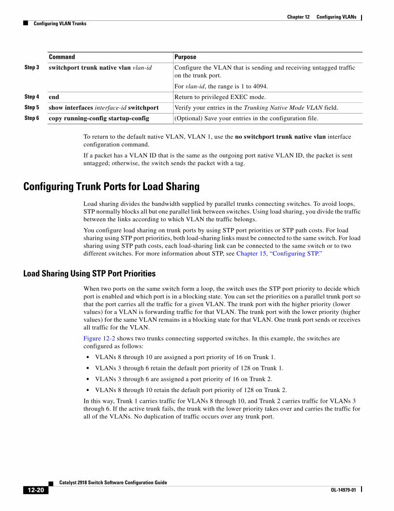
Chapter 12 Configuring VLANsConfiguring VLAN Trunks
To return to the default native VLAN, VLAN 1, use the no switchport trunk native vlan interface configuration command.
If a packet has a VLAN ID that is the same as the outgoing port native VLAN ID, the packet is sent untagged; otherwise, the switch sends the packet with a tag.
Configuring Trunk Ports for Load SharingLoad sharing divides the bandwidth supplied by parallel trunks connecting switches. To avoid loops, STP normally blocks all but one parallel link between switches. Using load sharing, you divide the traffic between the links according to which VLAN the traffic belongs.
You configure load sharing on trunk ports by using STP port priorities or STP path costs. For load sharing using STP port priorities, both load-sharing links must be connected to the same switch. For load sharing using STP path costs, each load-sharing link can be connected to the same switch or to two different switches. For more information about STP, see Chapter 15, “Configuring STP.”
Load Sharing Using STP Port Priorities
When two ports on the same switch form a loop, the switch uses the STP port priority to decide which port is enabled and which port is in a blocking state. You can set the priorities on a parallel trunk port so that the port carries all the traffic for a given VLAN. The trunk port with the higher priority (lower values) for a VLAN is forwarding traffic for that VLAN. The trunk port with the lower priority (higher values) for the same VLAN remains in a blocking state for that VLAN. One trunk port sends or receives all traffic for the VLAN.
Figure 12-2 shows two trunks connecting supported switches. In this example, the switches are configured as follows:
• VLANs 8 through 10 are assigned a port priority of 16 on Trunk 1.
• VLANs 3 through 6 retain the default port priority of 128 on Trunk 1.
• VLANs 3 through 6 are assigned a port priority of 16 on Trunk 2.
• VLANs 8 through 10 retain the default port priority of 128 on Trunk 2.
In this way, Trunk 1 carries traffic for VLANs 8 through 10, and Trunk 2 carries traffic for VLANs 3 through 6. If the active trunk fails, the trunk with the lower priority takes over and carries the traffic for all of the VLANs. No duplication of traffic occurs over any trunk port.
Step 3 switchport trunk native vlan vlan-id Configure the VLAN that is sending and receiving untagged traffic on the trunk port.
For vlan-id, the range is 1 to 4094.
Step 4 end Return to privileged EXEC mode.
Step 5 show interfaces interface-id switchport Verify your entries in the Trunking Native Mode VLAN field.
Step 6 copy running-config startup-config (Optional) Save your entries in the configuration file.
Command Purpose
12-20Catalyst 2918 Switch Software Configuration Guide
OL-14979-01
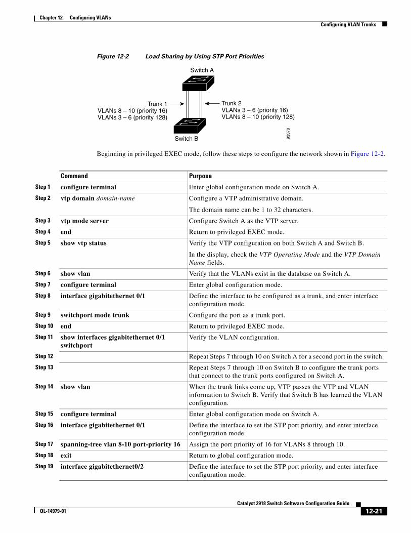
Chapter 12 Configuring VLANsConfiguring VLAN Trunks
Figure 12-2 Load Sharing by Using STP Port Priorities
9337
0
Switch A
Switch B
Trunk 2VLANs 3 – 6 (priority 16)VLANs 8 – 10 (priority 128)
Trunk 1VLANs 8 – 10 (priority 16)VLANs 3 – 6 (priority 128)
Beginning in privileged EXEC mode, follow these steps to configure the network shown in Figure 12-2.
Command Purpose
Step 1 configure terminal Enter global configuration mode on Switch A.
Step 2 vtp domain domain-name Configure a VTP administrative domain.
The domain name can be 1 to 32 characters.
Step 3 vtp mode server Configure Switch A as the VTP server.
Step 4 end Return to privileged EXEC mode.
Step 5 show vtp status Verify the VTP configuration on both Switch A and Switch B.
In the display, check the VTP Operating Mode and the VTP Domain Name fields.
Step 6 show vlan Verify that the VLANs exist in the database on Switch A.
Step 7 configure terminal Enter global configuration mode.
Step 8 interface gigabitethernet 0/1 Define the interface to be configured as a trunk, and enter interface configuration mode.
Step 9 switchport mode trunk Configure the port as a trunk port.
Step 10 end Return to privileged EXEC mode.
Step 11 show interfaces gigabitethernet 0/1 switchport
Verify the VLAN configuration.
Step 12 Repeat Steps 7 through 10 on Switch A for a second port in the switch.
Step 13 Repeat Steps 7 through 10 on Switch B to configure the trunk ports that connect to the trunk ports configured on Switch A.
Step 14 show vlan When the trunk links come up, VTP passes the VTP and VLAN information to Switch B. Verify that Switch B has learned the VLAN configuration.
Step 15 configure terminal Enter global configuration mode on Switch A.
Step 16 interface gigabitethernet 0/1 Define the interface to set the STP port priority, and enter interface configuration mode.
Step 17 spanning-tree vlan 8-10 port-priority 16 Assign the port priority of 16 for VLANs 8 through 10.
Step 18 exit Return to global configuration mode.
Step 19 interface gigabitethernet0/2 Define the interface to set the STP port priority, and enter interface configuration mode.
12-21Catalyst 2918 Switch Software Configuration Guide
OL-14979-01
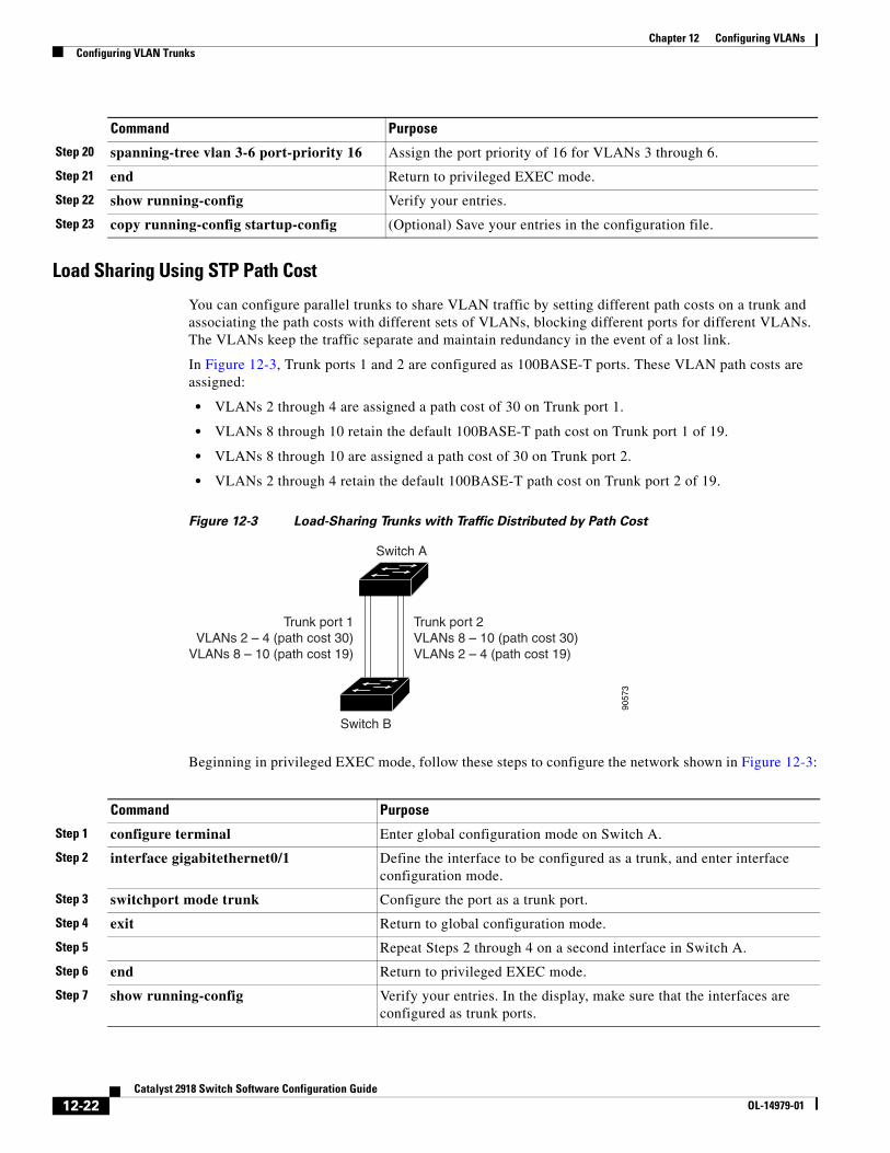
Chapter 12 Configuring VLANsConfiguring VLAN Trunks
Load Sharing Using STP Path Cost
You can configure parallel trunks to share VLAN traffic by setting different path costs on a trunk and associating the path costs with different sets of VLANs, blocking different ports for different VLANs. The VLANs keep the traffic separate and maintain redundancy in the event of a lost link.
In Figure 12-3, Trunk ports 1 and 2 are configured as 100BASE-T ports. These VLAN path costs are assigned:
• VLANs 2 through 4 are assigned a path cost of 30 on Trunk port 1.
• VLANs 8 through 10 retain the default 100BASE-T path cost on Trunk port 1 of 19.
• VLANs 8 through 10 are assigned a path cost of 30 on Trunk port 2.
• VLANs 2 through 4 retain the default 100BASE-T path cost on Trunk port 2 of 19.
Figure 12-3 Load-Sharing Trunks with Traffic Distributed by Path Cost
9057
3
Switch A
Switch B
Trunk port 1VLANs 2 – 4 (path cost 30)
VLANs 8 – 10 (path cost 19)
Trunk port 2VLANs 8 – 10 (path cost 30)VLANs 2 – 4 (path cost 19)
Beginning in privileged EXEC mode, follow these steps to configure the network shown in Figure 12-3:
Step 20 spanning-tree vlan 3-6 port-priority 16 Assign the port priority of 16 for VLANs 3 through 6.
Step 21 end Return to privileged EXEC mode.
Step 22 show running-config Verify your entries.
Step 23 copy running-config startup-config (Optional) Save your entries in the configuration file.
Command Purpose
Command Purpose
Step 1 configure terminal Enter global configuration mode on Switch A.
Step 2 interface gigabitethernet0/1 Define the interface to be configured as a trunk, and enter interface configuration mode.
Step 3 switchport mode trunk Configure the port as a trunk port.
Step 4 exit Return to global configuration mode.
Step 5 Repeat Steps 2 through 4 on a second interface in Switch A.
Step 6 end Return to privileged EXEC mode.
Step 7 show running-config Verify your entries. In the display, make sure that the interfaces are configured as trunk ports.
12-22Catalyst 2918 Switch Software Configuration Guide
OL-14979-01
Chapter 12 Configuring VLANsConfiguring VMPS
Configuring VMPSThe VLAN Query Protocol (VQP) is used to support dynamic-access ports, which are not permanently assigned to a VLAN, but give VLAN assignments based on the MAC source addresses seen on the port. Each time an unknown MAC address is seen, the switch sends a VQP query to a remote VMPS; the query includes the newly seen MAC address and the port on which it was seen. The VMPS responds with a VLAN assignment for the port. The switch cannot be a VMPS server but can act as a client to the VMPS and communicate with it through VQP.
These sections contain this information:
• “Understanding VMPS” section on page 12-23
• “Default VMPS Client Configuration” section on page 12-25
• “VMPS Configuration Guidelines” section on page 12-25
• “Configuring the VMPS Client” section on page 12-25
• “Monitoring the VMPS” section on page 12-28
• “Troubleshooting Dynamic-Access Port VLAN Membership” section on page 12-29
• “VMPS Configuration Example” section on page 12-29
Understanding VMPSEach time the client switch receives the MAC address of a new host, it sends a VQP query to the VMPS. When the VMPS receives this query, it searches its database for a MAC-address-to-VLAN mapping. The server response is based on this mapping and whether or not the server is in open or secure mode. In secure mode, the server shuts down the port when an illegal host is detected. In open mode, the server simply denies the host access to the port.
Step 8 show vlan When the trunk links come up, Switch A receives the VTP information from the other switches. Verify that Switch A has learned the VLAN configuration.
Step 9 configure terminal Enter global configuration mode.
Step 10 interface gigabitethernet0/1 Define the interface on which to set the STP cost, and enter interface configuration mode.
Step 11 spanning-tree vlan 2-4 cost 30 Set the spanning-tree path cost to 30 for VLANs 2 through 4.
Step 12 end Return to global configuration mode.
Step 13 Repeat Steps 9 through 12 on the other configured trunk interface on Switch A, and set the spanning-tree path cost to 30 for VLANs 8, 9, and 10.
Step 14 exit Return to privileged EXEC mode.
Step 15 show running-config Verify your entries. In the display, verify that the path costs are set correctly for both trunk interfaces.
Step 16 copy running-config startup-config (Optional) Save your entries in the configuration file.
Command Purpose
12-23Catalyst 2918 Switch Software Configuration Guide
OL-14979-01
Chapter 12 Configuring VLANsConfiguring VMPS
If the port is currently unassigned (that is, it does not yet have a VLAN assignment), the VMPS provides one of these responses:
• If the host is allowed on the port, the VMPS sends the client a vlan-assignment response containing the assigned VLAN name and allowing access to the host.
• If the host is not allowed on the port and the VMPS is in open mode, the VMPS sends an access-denied response.
• If the VLAN is not allowed on the port and the VMPS is in secure mode, the VMPS sends a port-shutdown response.
If the port already has a VLAN assignment, the VMPS provides one of these responses:
• If the VLAN in the database matches the current VLAN on the port, the VMPS sends an success response, allowing access to the host.
• If the VLAN in the database does not match the current VLAN on the port and active hosts exist on the port, the VMPS sends an access-denied or a port-shutdown response, depending on the secure mode of the VMPS.
If the switch receives an access-denied response from the VMPS, it continues to block traffic to and from the host MAC address. The switch continues to monitor the packets directed to the port and sends a query to the VMPS when it identifies a new host address. If the switch receives a port-shutdown response from the VMPS, it disables the port. The port must be manually re-enabled by using Network Assistant, the CLI, or SNMP.
Dynamic-Access Port VLAN Membership
A dynamic-access port can belong to only one VLAN with an ID from 1 to 4094. When the link comes up, the switch does not forward traffic to or from this port until the VMPS provides the VLAN assignment. The VMPS receives the source MAC address from the first packet of a new host connected to the dynamic-access port and attempts to match the MAC address to a VLAN in the VMPS database.
If there is a match, the VMPS sends the VLAN number for that port. If the client switch was not previously configured, it uses the domain name from the first VTP packet it receives on its trunk port from the VMPS. If the client switch was previously configured, it includes its domain name in the query packet to the VMPS to obtain its VLAN number. The VMPS verifies that the domain name in the packet matches its own domain name before accepting the request and responds to the client with the assigned VLAN number for the client. If there is no match, the VMPS either denies the request or shuts down the port (depending on the VMPS secure mode setting).
Multiple hosts (MAC addresses) can be active on a dynamic-access port if they are all in the same VLAN; however, the VMPS shuts down a dynamic-access port if more than 20 hosts are active on the port.
If the link goes down on a dynamic-access port, the port returns to an isolated state and does not belong to a VLAN. Any hosts that come online through the port are checked again through the VQP with the VMPS before the port is assigned to a VLAN.
Dynamic-access ports can be used for direct host connections, or they can connect to a network. A maximum of 20 MAC addresses are allowed per port on the switch. A dynamic-access port can belong to only one VLAN at a time, but the VLAN can change over time, depending on the MAC addresses seen.
12-24Catalyst 2918 Switch Software Configuration Guide
OL-14979-01
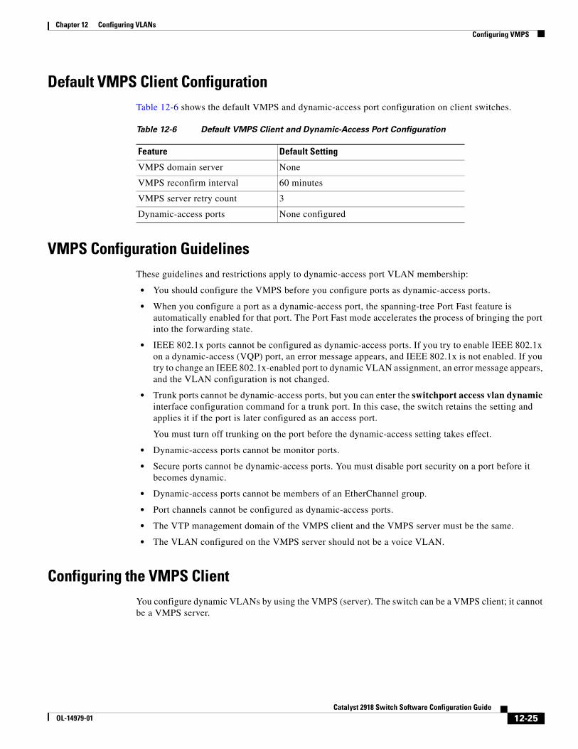
Chapter 12 Configuring VLANsConfiguring VMPS
Default VMPS Client ConfigurationTable 12-6 shows the default VMPS and dynamic-access port configuration on client switches.
Table 12-6 Default VMPS Client and Dynamic-Access Port Configuration
Feature Default Setting
VMPS domain server None
VMPS reconfirm interval 60 minutes
VMPS server retry count 3
Dynamic-access ports None configured
VMPS Configuration GuidelinesThese guidelines and restrictions apply to dynamic-access port VLAN membership:
• You should configure the VMPS before you configure ports as dynamic-access ports.
• When you configure a port as a dynamic-access port, the spanning-tree Port Fast feature is automatically enabled for that port. The Port Fast mode accelerates the process of bringing the port into the forwarding state.
• IEEE 802.1x ports cannot be configured as dynamic-access ports. If you try to enable IEEE 802.1x on a dynamic-access (VQP) port, an error message appears, and IEEE 802.1x is not enabled. If you try to change an IEEE 802.1x-enabled port to dynamic VLAN assignment, an error message appears, and the VLAN configuration is not changed.
• Trunk ports cannot be dynamic-access ports, but you can enter the switchport access vlan dynamic interface configuration command for a trunk port. In this case, the switch retains the setting and applies it if the port is later configured as an access port.
You must turn off trunking on the port before the dynamic-access setting takes effect.
• Dynamic-access ports cannot be monitor ports.
• Secure ports cannot be dynamic-access ports. You must disable port security on a port before it becomes dynamic.
• Dynamic-access ports cannot be members of an EtherChannel group.
• Port channels cannot be configured as dynamic-access ports.
• The VTP management domain of the VMPS client and the VMPS server must be the same.
• The VLAN configured on the VMPS server should not be a voice VLAN.
Configuring the VMPS ClientYou configure dynamic VLANs by using the VMPS (server). The switch can be a VMPS client; it cannot be a VMPS server.
12-25Catalyst 2918 Switch Software Configuration Guide
OL-14979-01
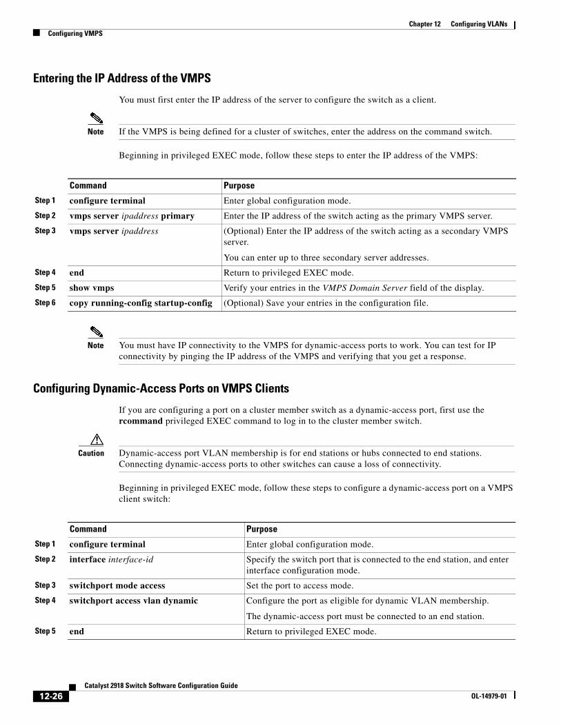
Chapter 12 Configuring VLANsConfiguring VMPS
Entering the IP Address of the VMPS
You must first enter the IP address of the server to configure the switch as a client.
Note If the VMPS is being defined for a cluster of switches, enter the address on the command switch.
Beginning in privileged EXEC mode, follow these steps to enter the IP address of the VMPS:
Command Purpose
Step 1 configure terminal Enter global configuration mode.
Step 2 vmps server ipaddress primary Enter the IP address of the switch acting as the primary VMPS server.
Step 3 vmps server ipaddress (Optional) Enter the IP address of the switch acting as a secondary VMPS server.
You can enter up to three secondary server addresses.
Step 4 end Return to privileged EXEC mode.
Step 5 show vmps Verify your entries in the VMPS Domain Server field of the display.
Step 6 copy running-config startup-config (Optional) Save your entries in the configuration file.
Note You must have IP connectivity to the VMPS for dynamic-access ports to work. You can test for IP connectivity by pinging the IP address of the VMPS and verifying that you get a response.
Configuring Dynamic-Access Ports on VMPS Clients
If you are configuring a port on a cluster member switch as a dynamic-access port, first use the rcommand privileged EXEC command to log in to the cluster member switch.
Caution Dynamic-access port VLAN membership is for end stations or hubs connected to end stations. Connecting dynamic-access ports to other switches can cause a loss of connectivity.
Beginning in privileged EXEC mode, follow these steps to configure a dynamic-access port on a VMPS client switch:
Command Purpose
Step 1 configure terminal Enter global configuration mode.
Step 2 interface interface-id Specify the switch port that is connected to the end station, and enter interface configuration mode.
Step 3 switchport mode access Set the port to access mode.
Step 4 switchport access vlan dynamic Configure the port as eligible for dynamic VLAN membership.
The dynamic-access port must be connected to an end station.
Step 5 end Return to privileged EXEC mode.
12-26Catalyst 2918 Switch Software Configuration Guide
OL-14979-01
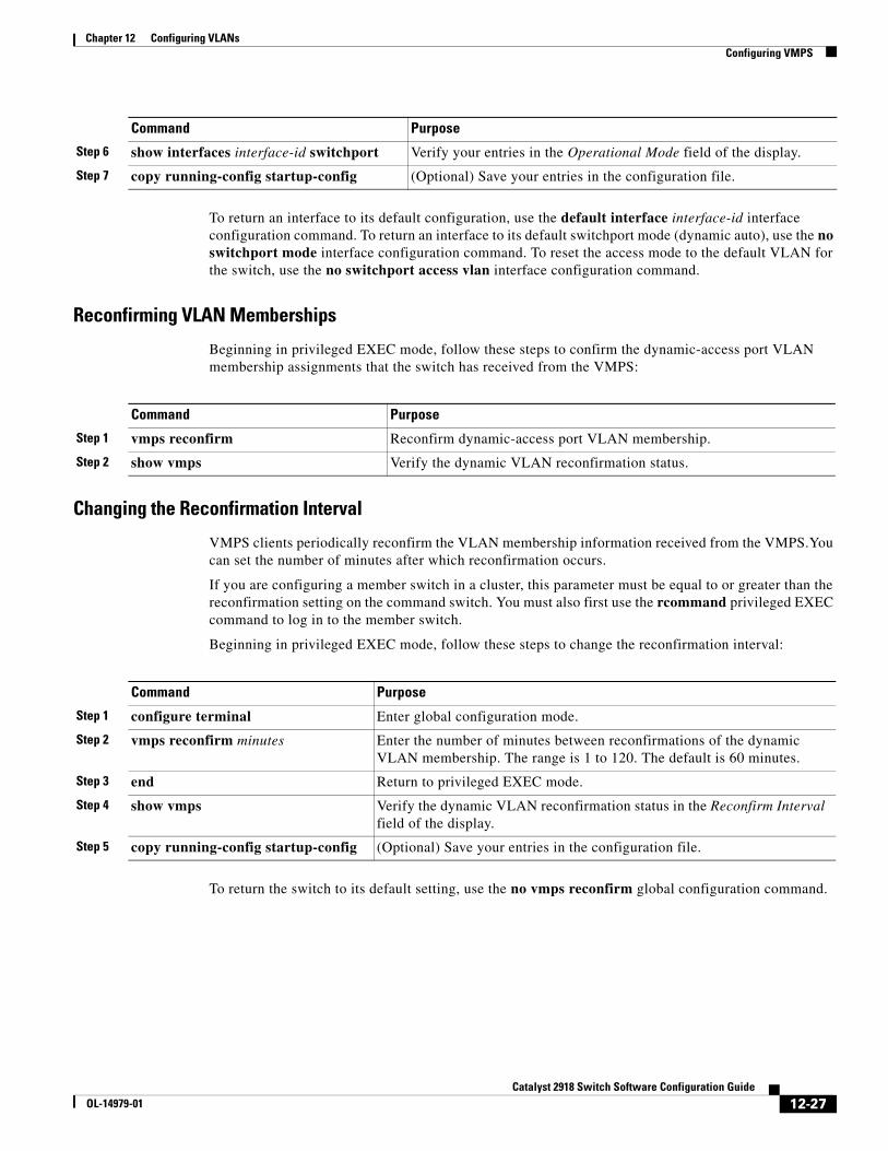
Chapter 12 Configuring VLANsConfiguring VMPS
To return an interface to its default configuration, use the default interface interface-id interface configuration command. To return an interface to its default switchport mode (dynamic auto), use the no switchport mode interface configuration command. To reset the access mode to the default VLAN for the switch, use the no switchport access vlan interface configuration command.
Reconfirming VLAN Memberships
Beginning in privileged EXEC mode, follow these steps to confirm the dynamic-access port VLAN membership assignments that the switch has received from the VMPS:
Command Purpose
Step 1 vmps reconfirm Reconfirm dynamic-access port VLAN membership.
Step 2 show vmps Verify the dynamic VLAN reconfirmation status.
Changing the Reconfirmation Interval
VMPS clients periodically reconfirm the VLAN membership information received from the VMPS.You can set the number of minutes after which reconfirmation occurs.
If you are configuring a member switch in a cluster, this parameter must be equal to or greater than the reconfirmation setting on the command switch. You must also first use the rcommand privileged EXEC command to log in to the member switch.
Beginning in privileged EXEC mode, follow these steps to change the reconfirmation interval:
Command Purpose
Step 1 configure terminal Enter global configuration mode.
Step 2 vmps reconfirm minutes Enter the number of minutes between reconfirmations of the dynamic VLAN membership. The range is 1 to 120. The default is 60 minutes.
Step 3 end Return to privileged EXEC mode.
Step 4 show vmps Verify the dynamic VLAN reconfirmation status in the Reconfirm Interval field of the display.
Step 5 copy running-config startup-config (Optional) Save your entries in the configuration file.
To return the switch to its default setting, use the no vmps reconfirm global configuration command.
Step 6 show interfaces interface-id switchport Verify your entries in the Operational Mode field of the display.
Step 7 copy running-config startup-config (Optional) Save your entries in the configuration file.
Command Purpose
12-27Catalyst 2918 Switch Software Configuration Guide
OL-14979-01
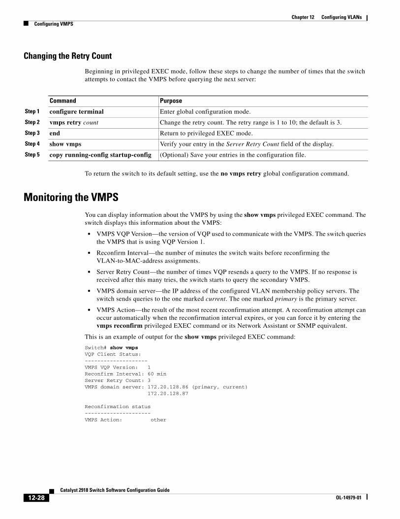
Chapter 12 Configuring VLANsConfiguring VMPS
Changing the Retry Count
Beginning in privileged EXEC mode, follow these steps to change the number of times that the switch attempts to contact the VMPS before querying the next server:
Command Purpose
Step 1 configure terminal Enter global configuration mode.
Step 2 vmps retry count Change the retry count. The retry range is 1 to 10; the default is 3.
Step 3 end Return to privileged EXEC mode.
Step 4 show vmps Verify your entry in the Server Retry Count field of the display.
Step 5 copy running-config startup-config (Optional) Save your entries in the configuration file.
To return the switch to its default setting, use the no vmps retry global configuration command.
Monitoring the VMPSYou can display information about the VMPS by using the show vmps privileged EXEC command. The switch displays this information about the VMPS:
• VMPS VQP Version—the version of VQP used to communicate with the VMPS. The switch queries the VMPS that is using VQP Version 1.
• Reconfirm Interval—the number of minutes the switch waits before reconfirming the VLAN-to-MAC-address assignments.
• Server Retry Count—the number of times VQP resends a query to the VMPS. If no response is received after this many tries, the switch starts to query the secondary VMPS.
• VMPS domain server—the IP address of the configured VLAN membership policy servers. The switch sends queries to the one marked current. The one marked primary is the primary server.
• VMPS Action—the result of the most recent reconfirmation attempt. A reconfirmation attempt can occur automatically when the reconfirmation interval expires, or you can force it by entering the vmps reconfirm privileged EXEC command or its Network Assistant or SNMP equivalent.
This is an example of output for the show vmps privileged EXEC command:
Switch# show vmpsVQP Client Status:--------------------VMPS VQP Version: 1Reconfirm Interval: 60 minServer Retry Count: 3VMPS domain server: 172.20.128.86 (primary, current) 172.20.128.87 Reconfirmation status---------------------VMPS Action: other
12-28Catalyst 2918 Switch Software Configuration Guide
OL-14979-01
Chapter 12 Configuring VLANsConfiguring VMPS
Troubleshooting Dynamic-Access Port VLAN MembershipThe VMPS shuts down a dynamic-access port under these conditions:
• The VMPS is in secure mode, and it does not allow the host to connect to the port. The VMPS shuts down the port to prevent the host from connecting to the network.
• More than 20 active hosts reside on a dynamic-access port.
To re-enable a disabled dynamic-access port, enter the shutdown interface configuration command followed by the no shutdown interface configuration command.
VMPS Configuration ExampleFigure 12-4 shows a network with a VMPS server switch and VMPS client switches with dynamic-access ports. In this example, these assumptions apply:
• The VMPS server and the VMPS client are separate switches.
• The Catalyst 6500 series Switch A is the primary VMPS server.
• The Catalyst 6500 series Switch C and Switch J are secondary VMPS servers.
• End stations are connected to the clients, Switch B and Switch I.
• The database configuration file is stored on the TFTP server with the IP address 172.20.22.7.
12-29Catalyst 2918 Switch Software Configuration Guide
OL-14979-01
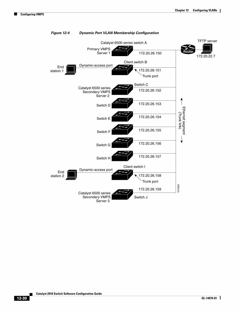
Chapter 12 Configuring VLANsConfiguring VMPS
Figure 12-4 Dynamic Port VLAN Membership Configuration
Primary VMPSServer 1
Catalyst 6500 seriesSecondary VMPS
Server 2
Catalyst 6500 seriesSecondary VMPS
Server 3
172.20.26.150
172.20.26.151
Catalyst 6500 series switch A
172.20.26.152
Switch C
Ethernet segm
ent(Trunk link)
172.20.26.153
172.20.26.154
172.20.26.155
172.20.26.156
172.20.26.157
172.20.26.158
172.20.26.159
Client switch I
Client switch B
Endstation 2
Endstation 1
TFTP server
Dynamic-access port
Dynamic-access port
Switch J
Switch D
Switch E
Switch F
Switch G
Switch H
172.20.22.7
1013
63t
Trunk port
Trunk port
Router
12-30Catalyst 2918 Switch Software Configuration Guide
OL-14979-01
OL-14979-01
C H A P T E R 13
Configuring VTPThis chapter describes how to use the VLAN Trunking Protocol (VTP) and the VLAN database for managing VLANs with the Catalyst 2918 switch.
Note For complete syntax and usage information for the commands used in this chapter, see the command reference for this release.
The chapter consists of these sections:
• Understanding VTP, page 13-1
• Configuring VTP, page 13-6
• Monitoring VTP, page 13-16
Understanding VTPVTP is a Layer 2 messaging protocol that maintains VLAN configuration consistency by managing the addition, deletion, and renaming of VLANs on a network-wide basis. VTP minimizes misconfigurations and configuration inconsistencies that can cause several problems, such as duplicate VLAN names, incorrect VLAN-type specifications, and security violations.
Before you create VLANs, you must decide whether to use VTP in your network. Using VTP, you can make configuration changes centrally on one or more switches and have those changes automatically communicated to all the other switches in the network. Without VTP, you cannot send information about VLANs to other switches.
VTP is designed to work in an environment where updates are made on a single switch and are sent through VTP to other switches in the domain. It does not work well in a situation where multiple updates to the VLAN database occur simultaneously on switches in the same domain, which would result in an inconsistency in the VLAN database.
The switch supports 64 VLANs, but the number of configured features affects the usage of the switch hardware. If the switch is notified by VTP of a new VLAN and the switch is already using the maximum available hardware resources, it sends a message that there are not enough hardware resources available and shuts down the VLAN. The output of the show vlan user EXEC command shows the VLAN in a suspended state.
VTP only learns about normal-range VLANs (VLAN IDs 1 to 1005). Extended-range VLANs (VLAN IDs greater than 1005) are not supported by VTP or stored in the VTP VLAN database.
13-1Catalyst 2918 Switch Software Configuration Guide
Chapter 13 Configuring VTPUnderstanding VTP
These sections contain this conceptual information:
• The VTP Domain, page 13-2
• VTP Modes, page 13-3
• VTP Advertisements, page 13-3
• VTP Version 2, page 13-4
• VTP Pruning, page 13-4
The VTP Domain A VTP domain (also called a VLAN management domain) consists of one switch or several interconnected switches under the same administrative responsibility sharing the same VTP domain name. A switch can be in only one VTP domain. You make global VLAN configuration changes for the domain.
By default, the switch is in the VTP no-management-domain state until it receives an advertisement for a domain over a trunk link (a link that carries the traffic of multiple VLANs) or until you configure a domain name. Until the management domain name is specified or learned, you cannot create or modify VLANs on a VTP server, and VLAN information is not propagated over the network.
If the switch receives a VTP advertisement over a trunk link, it inherits the management domain name and the VTP configuration revision number. The switch then ignores advertisements with a different domain name or an earlier configuration revision number.
Caution Before adding a VTP client switch to a VTP domain, always verify that its VTP configuration revision number is lower than the configuration revision number of the other switches in the VTP domain. Switches in a VTP domain always use the VLAN configuration of the switch with the highest VTP configuration revision number. If you add a switch that has a revision number higher than the revision number in the VTP domain, it can erase all VLAN information from the VTP server and VTP domain. See the “Adding a VTP Client Switch to a VTP Domain” section on page 13-14 for the procedure for verifying and resetting the VTP configuration revision number.
When you make a change to the VLAN configuration on a VTP server, the change is propagated to all switches in the VTP domain. VTP advertisements are sent over all IEEE trunk connections, including IEEE 802.1Q. VTP dynamically maps VLANs with unique names and internal index associates across multiple LAN types. Mapping eliminates excessive device administration required from network administrators.
If you configure a switch for VTP transparent mode, you can create and modify VLANs, but the changes are not sent to other switches in the domain, and they affect only the individual switch. However, configuration changes made when the switch is in this mode are saved in the switch running configuration and can be saved to the switch startup configuration file.
For domain name and password configuration guidelines, see the “VTP Configuration Guidelines” section on page 13-8.
13-2Catalyst 2918 Switch Software Configuration Guide
OL-14979-01
Chapter 13 Configuring VTPUnderstanding VTP
VTP ModesYou can configure a supported switch to be in one of the VTP modes listed in Table 13-1.
Table 13-1 VTP Modes
VTP Mode Description
VTP server In VTP server mode, you can create, modify, and delete VLANs, and specify other configuration parameters (such as the VTP version) for the entire VTP domain. VTP servers advertise their VLAN configurations to other switches in the same VTP domain and synchronize their VLAN configurations with other switches based on advertisements received over trunk links.
In VTP server mode, VLAN configurations are saved in NVRAM. VTP server is the default mode.
VTP client A VTP client behaves like a VTP server and transmits and receives VTP updates on its trunks, but you cannot create, change, or delete VLANs on a VTP client. VLANs are configured on another switch in the domain that is in server mode.
In VTP client mode, VLAN configurations are not saved in NVRAM.
VTP transparent VTP transparent switches do not participate in VTP. A VTP transparent switch does not advertise its VLAN configuration and does not synchronize its VLAN configuration based on received advertisements. However, in VTP Version 2, transparent switches do forward VTP advertisements that they receive from other switches through their trunk interfaces. You can create, modify, and delete VLANs on a switch in VTP transparent mode.
The switch must be in VTP transparent mode when you create extended-range VLANs. See the “Configuring Extended-Range VLANs” section on page 12-11.
When the switch is in VTP transparent mode, the VTP and VLAN configurations are saved in NVRAM, but they are not advertised to other switches. In this mode, VTP mode and domain name are saved in the switch running configuration, and you can save this information in the switch startup configuration file by using the copy running-config startup-config privileged EXEC command.
VTP AdvertisementsEach switch in the VTP domain sends periodic global configuration advertisements from each trunk port to a reserved multicast address. Neighboring switches receive these advertisements and update their VTP and VLAN configurations as necessary.
Note Because trunk ports send and receive VTP advertisements, you must ensure that at least one trunk port is configured on the switch and that this trunk port is connected to the trunk port of another switch. Otherwise, the switch cannot receive any VTP advertisements. For more information on trunk ports, see the “Configuring VLAN Trunks” section on page 12-14.
VTP advertisements distribute this global domain information:
• VTP domain name
• VTP configuration revision number
• Update identity and update timestamp
13-3Catalyst 2918 Switch Software Configuration Guide
OL-14979-01
Chapter 13 Configuring VTPUnderstanding VTP
• MD5 digest VLAN configuration, including maximum transmission unit (MTU) size for each VLAN.
• Frame format
VTP advertisements distribute this VLAN information for each configured VLAN:
• VLAN IDs (IEEE 802.1Q)
• VLAN name
• VLAN type
• VLAN state
• Additional VLAN configuration information specific to the VLAN type
VTP Version 2If you use VTP in your network, you must decide whether to use Version 1 or Version 2. By default, VTP operates in Version 1.
VTP Version 2 supports these features that are not supported in Version 1:
• Token Ring support—VTP Version 2 supports Token Ring Bridge Relay Function (TrBRF) and Token Ring Concentrator Relay Function (TrCRF) VLANs. For more information about Token Ring VLANs, see the “Configuring Normal-Range VLANs” section on page 12-4.
• Unrecognized Type-Length-Value (TLV) support—A VTP server or client propagates configuration changes to its other trunks, even for TLVs it is not able to parse. The unrecognized TLV is saved in NVRAM when the switch is operating in VTP server mode.
• Version-Dependent Transparent Mode—In VTP Version 1, a VTP transparent switch inspects VTP messages for the domain name and version and forwards a message only if the version and domain name match. Because VTP Version 2 supports only one domain, it forwards VTP messages in transparent mode without inspecting the version and domain name.
• Consistency Checks—In VTP Version 2, VLAN consistency checks (such as VLAN names and values) are performed only when you enter new information through the CLI or SNMP. Consistency checks are not performed when new information is obtained from a VTP message or when information is read from NVRAM. If the MD5 digest on a received VTP message is correct, its information is accepted.
VTP PruningVTP pruning increases network available bandwidth by restricting flooded traffic to those trunk links that the traffic must use to reach the destination devices. Without VTP pruning, a switch floods broadcast, multicast, and unknown unicast traffic across all trunk links within a VTP domain even though receiving switches might discard them. VTP pruning is disabled by default.
VTP pruning blocks unneeded flooded traffic to VLANs on trunk ports that are included in the pruning-eligible list. Only VLANs included in the pruning-eligible list can be pruned. By default, VLANs 2 through 1001 are pruning eligible switch trunk ports. If the VLANs are configured as pruning-ineligible, the flooding continues. VTP pruning is supported with VTP Version 1 and Version 2.
13-4Catalyst 2918 Switch Software Configuration Guide
OL-14979-01
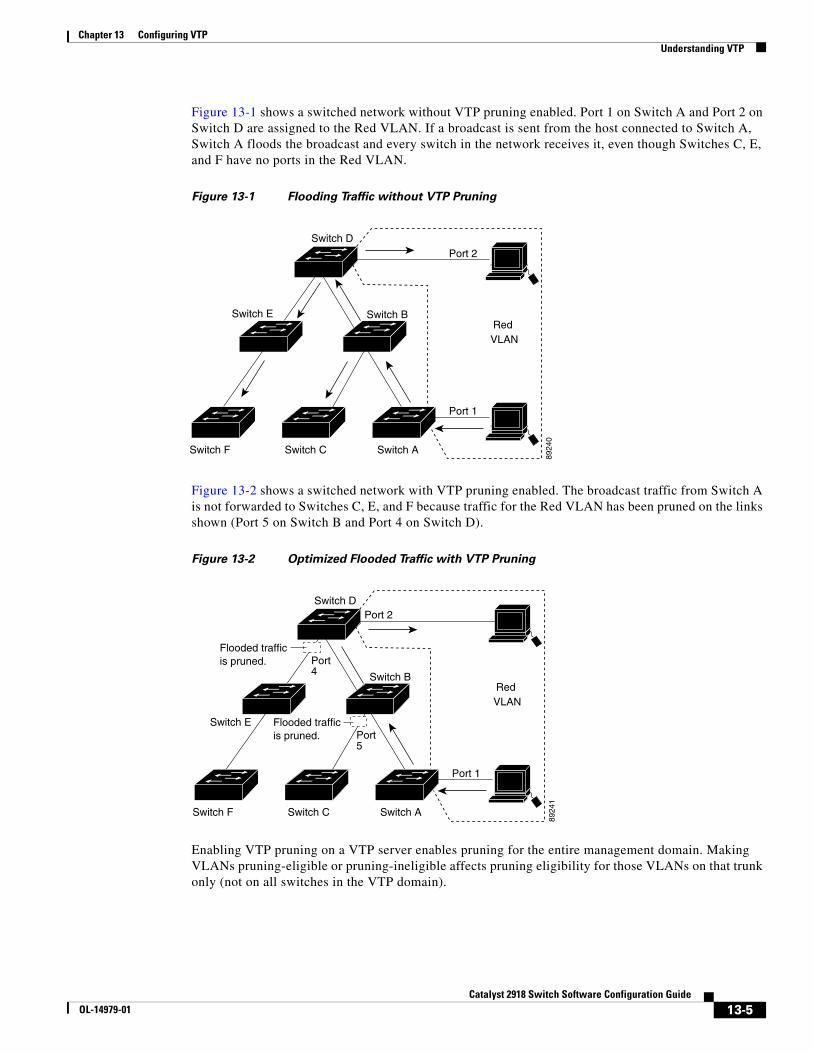
Chapter 13 Configuring VTPUnderstanding VTP
Figure 13-1 shows a switched network without VTP pruning enabled. Port 1 on Switch A and Port 2 on Switch D are assigned to the Red VLAN. If a broadcast is sent from the host connected to Switch A, Switch A floods the broadcast and every switch in the network receives it, even though Switches C, E, and F have no ports in the Red VLAN.
Figure 13-1 Flooding Traffic without VTP Pruning
Switch D
Switch E
Switch CSwitch F Switch A
Switch B
Port 1
Port 2
Red VLAN
8924
0
Figure 13-2 shows a switched network with VTP pruning enabled. The broadcast traffic from Switch A is not forwarded to Switches C, E, and F because traffic for the Red VLAN has been pruned on the links shown (Port 5 on Switch B and Port 4 on Switch D).
Figure 13-2 Optimized Flooded Traffic with VTP Pruning
Switch D
Switch E
Switch CSwitch F Switch A
Switch B
Port 1
Port 2
Red VLAN
8924
1
Port4
Flooded trafficis pruned.
Port5
Flooded trafficis pruned.
Enabling VTP pruning on a VTP server enables pruning for the entire management domain. Making VLANs pruning-eligible or pruning-ineligible affects pruning eligibility for those VLANs on that trunk only (not on all switches in the VTP domain).
13-5Catalyst 2918 Switch Software Configuration Guide
OL-14979-01
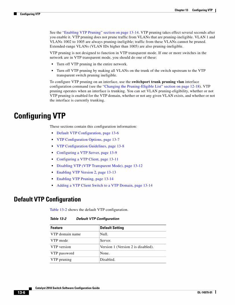
Chapter 13 Configuring VTPConfiguring VTP
See the “Enabling VTP Pruning” section on page 13-14. VTP pruning takes effect several seconds after you enable it. VTP pruning does not prune traffic from VLANs that are pruning-ineligible. VLAN 1 and VLANs 1002 to 1005 are always pruning-ineligible; traffic from these VLANs cannot be pruned. Extended-range VLANs (VLAN IDs higher than 1005) are also pruning-ineligible.
VTP pruning is not designed to function in VTP transparent mode. If one or more switches in the network are in VTP transparent mode, you should do one of these:
• Turn off VTP pruning in the entire network.
• Turn off VTP pruning by making all VLANs on the trunk of the switch upstream to the VTP transparent switch pruning ineligible.
To configure VTP pruning on an interface, use the switchport trunk pruning vlan interface configuration command (see the “Changing the Pruning-Eligible List” section on page 12-18). VTP pruning operates when an interface is trunking. You can set VLAN pruning-eligibility, whether or not VTP pruning is enabled for the VTP domain, whether or not any given VLAN exists, and whether or not the interface is currently trunking.
Configuring VTPThese sections contain this configuration information:
• Default VTP Configuration, page 13-6
• VTP Configuration Options, page 13-7
• VTP Configuration Guidelines, page 13-8
• Configuring a VTP Server, page 13-9
• Configuring a VTP Client, page 13-11
• Disabling VTP (VTP Transparent Mode), page 13-12
• Enabling VTP Version 2, page 13-13
• Enabling VTP Pruning, page 13-14
• Adding a VTP Client Switch to a VTP Domain, page 13-14
Default VTP ConfigurationTable 13-2 shows the default VTP configuration.
Table 13-2 Default VTP Configuration
Feature Default Setting
VTP domain name Null.
VTP mode Server.
VTP version Version 1 (Version 2 is disabled).
VTP password None.
VTP pruning Disabled.
13-6Catalyst 2918 Switch Software Configuration Guide
OL-14979-01
Chapter 13 Configuring VTPConfiguring VTP
VTP Configuration OptionsYou can configure VTP by using these configuration modes.
• VTP Configuration in Global Configuration Mode, page 13-7
• VTP Configuration in VLAN Database Configuration Mode, page 13-7
You access VLAN database configuration mode by entering the vlan database privileged EXEC command.
For detailed information about vtp commands, see the command reference for this release.
VTP Configuration in Global Configuration Mode
You can use the vtp global configuration command to set the VTP password, the version, the VTP file name, the interface providing updated VTP information, the domain name, and the mode, and to disable or enable pruning. For more information about available keywords, see the command descriptions in the command reference for this release. The VTP information is saved in the VTP VLAN database. When VTP mode is transparent, the VTP domain name and mode are also saved in the switch running configuration file, and you can save it in the switch startup configuration file by entering the copy running-config startup-config privileged EXEC command. You must use this command if you want to save VTP mode as transparent, even if the switch resets.
When you save VTP information in the switch startup configuration file and reboot the switch, the switch configuration is selected as follows:
• If the VTP mode is transparent in the startup configuration and the VLAN database and the VTP domain name from the VLAN database matches that in the startup configuration file, the VLAN database is ignored (cleared), and the VTP and VLAN configurations in the startup configuration file are used. The VLAN database revision number remains unchanged in the VLAN database.
• If the VTP mode or domain name in the startup configuration do not match the VLAN database, the domain name and VTP mode and configuration for the first 64 VLANs use the VLAN database information.
VTP Configuration in VLAN Database Configuration Mode
You can configure all VTP parameters in VLAN database configuration mode, which you access by entering the vlan database privileged EXEC command. For more information about available keywords, see the vtp VLAN database configuration command description in the command reference for this release. When you enter the exit command in VLAN database configuration mode, it applies all the commands that you entered and updates the VLAN database. VTP messages are sent to other switches in the VTP domain, and the privileged EXEC mode prompt appears.
If VTP mode is transparent, the domain name and the mode (transparent) are saved in the switch running configuration, and you can save this information in the switch startup configuration file by entering the copy running-config startup-config privileged EXEC command.
13-7Catalyst 2918 Switch Software Configuration Guide
OL-14979-01
Chapter 13 Configuring VTPConfiguring VTP
VTP Configuration GuidelinesThese sections describe guidelines you should follow when implementing VTP in your network.
Domain Names
When configuring VTP for the first time, you must always assign a domain name. You must configure all switches in the VTP domain with the same domain name. Switches in VTP transparent mode do not exchange VTP messages with other switches, and you do not need to configure a VTP domain name for them.
Note If NVRAM and DRAM storage is sufficient, all switches in a VTP domain should be in VTP server mode.
Caution Do not configure a VTP domain if all switches are operating in VTP client mode. If you configure the domain, it is impossible to make changes to the VLAN configuration of that domain. Make sure that you configure at least one switch in the VTP domain for VTP server mode.
Passwords
You can configure a password for the VTP domain, but it is not required. If you do configure a domain password, all domain switches must share the same password and you must configure the password on each switch in the management domain. Switches without a password or with the wrong password reject VTP advertisements.
If you configure a VTP password for a domain, a switch that is booted without a VTP configuration does not accept VTP advertisements until you configure it with the correct password. After the configuration, the switch accepts the next VTP advertisement that uses the same password and domain name in the advertisement.
If you are adding a new switch to an existing network with VTP capability, the new switch learns the domain name only after the applicable password has been configured on it.
Caution When you configure a VTP domain password, the management domain does not function properly if you do not assign a management domain password to each switch in the domain.
VTP Version
Follow these guidelines when deciding which VTP version to implement:
• All switches in a VTP domain must run the same VTP version.
• A VTP Version 2-capable switch can operate in the same VTP domain as a switch running VTP Version 1 if Version 2 is disabled on the Version 2-capable switch (Version 2 is disabled by default).
13-8Catalyst 2918 Switch Software Configuration Guide
OL-14979-01
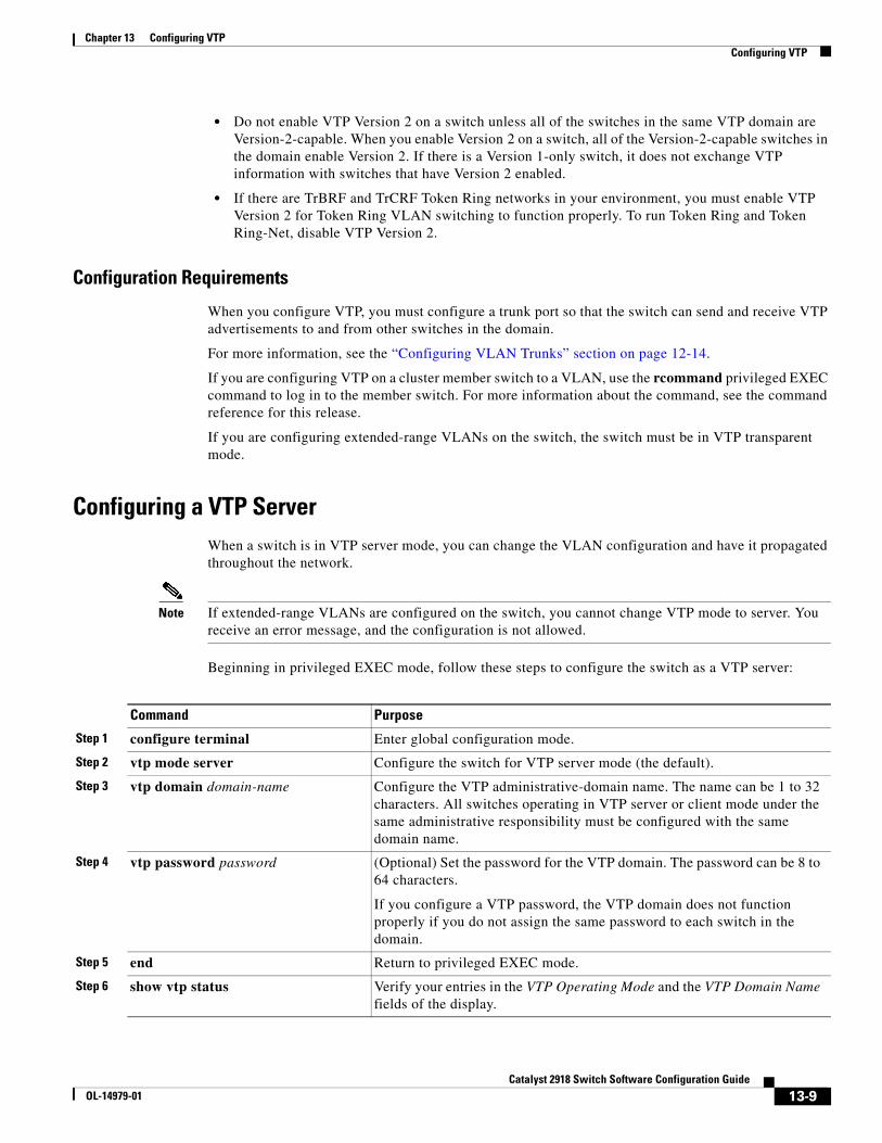
Chapter 13 Configuring VTPConfiguring VTP
• Do not enable VTP Version 2 on a switch unless all of the switches in the same VTP domain are Version-2-capable. When you enable Version 2 on a switch, all of the Version-2-capable switches in the domain enable Version 2. If there is a Version 1-only switch, it does not exchange VTP information with switches that have Version 2 enabled.
• If there are TrBRF and TrCRF Token Ring networks in your environment, you must enable VTP Version 2 for Token Ring VLAN switching to function properly. To run Token Ring and Token Ring-Net, disable VTP Version 2.
Configuration Requirements
When you configure VTP, you must configure a trunk port so that the switch can send and receive VTP advertisements to and from other switches in the domain.
For more information, see the “Configuring VLAN Trunks” section on page 12-14.
If you are configuring VTP on a cluster member switch to a VLAN, use the rcommand privileged EXEC command to log in to the member switch. For more information about the command, see the command reference for this release.
If you are configuring extended-range VLANs on the switch, the switch must be in VTP transparent mode.
Configuring a VTP ServerWhen a switch is in VTP server mode, you can change the VLAN configuration and have it propagated throughout the network.
Note If extended-range VLANs are configured on the switch, you cannot change VTP mode to server. You receive an error message, and the configuration is not allowed.
Beginning in privileged EXEC mode, follow these steps to configure the switch as a VTP server:
Command Purpose
Step 1 configure terminal Enter global configuration mode.
Step 2 vtp mode server Configure the switch for VTP server mode (the default).
Step 3 vtp domain domain-name Configure the VTP administrative-domain name. The name can be 1 to 32 characters. All switches operating in VTP server or client mode under the same administrative responsibility must be configured with the same domain name.
Step 4 vtp password password (Optional) Set the password for the VTP domain. The password can be 8 to 64 characters.
If you configure a VTP password, the VTP domain does not function properly if you do not assign the same password to each switch in the domain.
Step 5 end Return to privileged EXEC mode.
Step 6 show vtp status Verify your entries in the VTP Operating Mode and the VTP Domain Name fields of the display.
13-9Catalyst 2918 Switch Software Configuration Guide
OL-14979-01
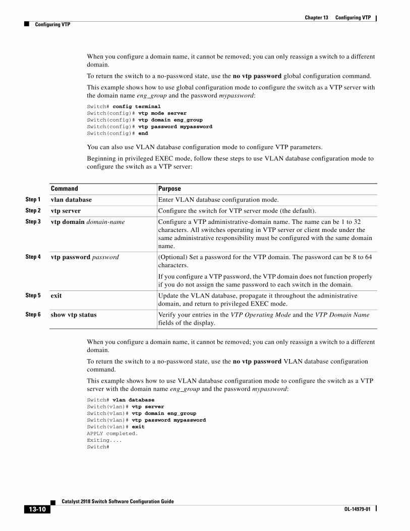
Chapter 13 Configuring VTPConfiguring VTP
When you configure a domain name, it cannot be removed; you can only reassign a switch to a different domain.
To return the switch to a no-password state, use the no vtp password global configuration command.
This example shows how to use global configuration mode to configure the switch as a VTP server with the domain name eng_group and the password mypassword:
Switch# config terminalSwitch(config)# vtp mode serverSwitch(config)# vtp domain eng_groupSwitch(config)# vtp password mypasswordSwitch(config)# end
You can also use VLAN database configuration mode to configure VTP parameters.
Beginning in privileged EXEC mode, follow these steps to use VLAN database configuration mode to configure the switch as a VTP server:
Command Purpose
Step 1 vlan database Enter VLAN database configuration mode.
Step 2 vtp server Configure the switch for VTP server mode (the default).
Step 3 vtp domain domain-name Configure a VTP administrative-domain name. The name can be 1 to 32 characters. All switches operating in VTP server or client mode under the same administrative responsibility must be configured with the same domain name.
Step 4 vtp password password (Optional) Set a password for the VTP domain. The password can be 8 to 64 characters.
If you configure a VTP password, the VTP domain does not function properly if you do not assign the same password to each switch in the domain.
Step 5 exit Update the VLAN database, propagate it throughout the administrative domain, and return to privileged EXEC mode.
Step 6 show vtp status Verify your entries in the VTP Operating Mode and the VTP Domain Name fields of the display.
When you configure a domain name, it cannot be removed; you can only reassign a switch to a different domain.
To return the switch to a no-password state, use the no vtp password VLAN database configuration command.
This example shows how to use VLAN database configuration mode to configure the switch as a VTP server with the domain name eng_group and the password mypassword:
Switch# vlan databaseSwitch(vlan)# vtp serverSwitch(vlan)# vtp domain eng_groupSwitch(vlan)# vtp password mypasswordSwitch(vlan)# exitAPPLY completed.Exiting....Switch#
13-10Catalyst 2918 Switch Software Configuration Guide
OL-14979-01
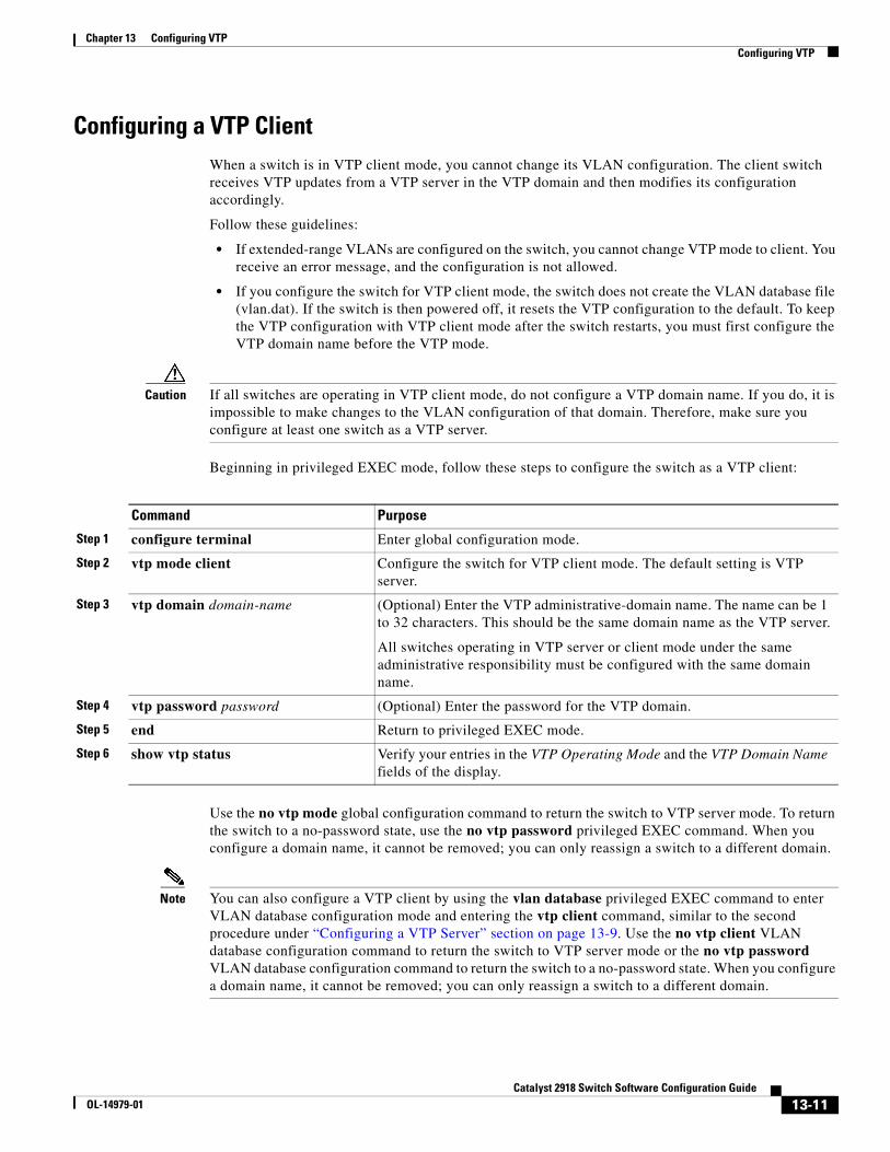
Chapter 13 Configuring VTPConfiguring VTP
Configuring a VTP ClientWhen a switch is in VTP client mode, you cannot change its VLAN configuration. The client switch receives VTP updates from a VTP server in the VTP domain and then modifies its configuration accordingly.
Follow these guidelines:
• If extended-range VLANs are configured on the switch, you cannot change VTP mode to client. You receive an error message, and the configuration is not allowed.
• If you configure the switch for VTP client mode, the switch does not create the VLAN database file (vlan.dat). If the switch is then powered off, it resets the VTP configuration to the default. To keep the VTP configuration with VTP client mode after the switch restarts, you must first configure the VTP domain name before the VTP mode.
Caution If all switches are operating in VTP client mode, do not configure a VTP domain name. If you do, it is impossible to make changes to the VLAN configuration of that domain. Therefore, make sure you configure at least one switch as a VTP server.
Beginning in privileged EXEC mode, follow these steps to configure the switch as a VTP client:
Command Purpose
Step 1 configure terminal Enter global configuration mode.
Step 2 vtp mode client Configure the switch for VTP client mode. The default setting is VTP server.
Step 3 vtp domain domain-name (Optional) Enter the VTP administrative-domain name. The name can be 1 to 32 characters. This should be the same domain name as the VTP server.
All switches operating in VTP server or client mode under the same administrative responsibility must be configured with the same domain name.
Step 4 vtp password password (Optional) Enter the password for the VTP domain.
Step 5 end Return to privileged EXEC mode.
Step 6 show vtp status Verify your entries in the VTP Operating Mode and the VTP Domain Name fields of the display.
Use the no vtp mode global configuration command to return the switch to VTP server mode. To return the switch to a no-password state, use the no vtp password privileged EXEC command. When you configure a domain name, it cannot be removed; you can only reassign a switch to a different domain.
Note You can also configure a VTP client by using the vlan database privileged EXEC command to enter VLAN database configuration mode and entering the vtp client command, similar to the second procedure under “Configuring a VTP Server” section on page 13-9. Use the no vtp client VLAN database configuration command to return the switch to VTP server mode or the no vtp password VLAN database configuration command to return the switch to a no-password state. When you configure a domain name, it cannot be removed; you can only reassign a switch to a different domain.
13-11Catalyst 2918 Switch Software Configuration Guide
OL-14979-01
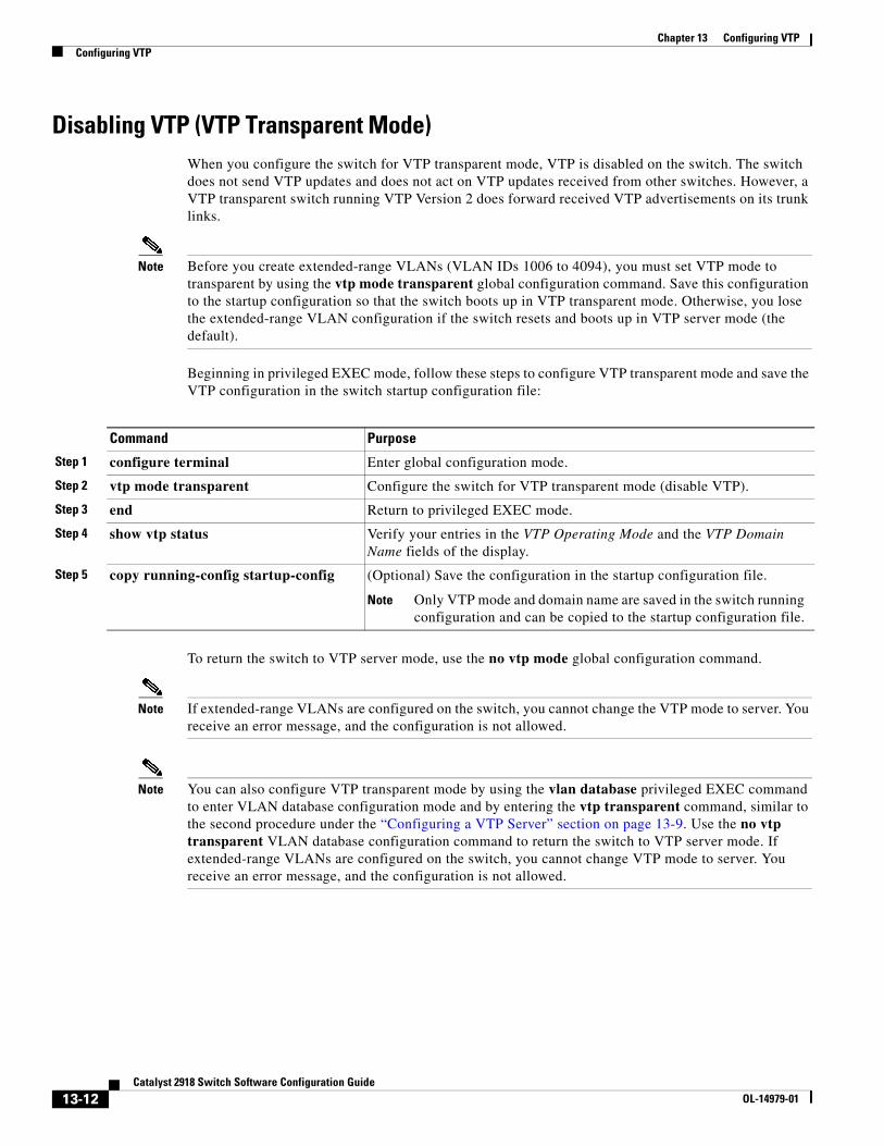
Chapter 13 Configuring VTPConfiguring VTP
Disabling VTP (VTP Transparent Mode)When you configure the switch for VTP transparent mode, VTP is disabled on the switch. The switch does not send VTP updates and does not act on VTP updates received from other switches. However, a VTP transparent switch running VTP Version 2 does forward received VTP advertisements on its trunk links.
Note Before you create extended-range VLANs (VLAN IDs 1006 to 4094), you must set VTP mode to transparent by using the vtp mode transparent global configuration command. Save this configuration to the startup configuration so that the switch boots up in VTP transparent mode. Otherwise, you lose the extended-range VLAN configuration if the switch resets and boots up in VTP server mode (the default).
Beginning in privileged EXEC mode, follow these steps to configure VTP transparent mode and save the VTP configuration in the switch startup configuration file:
Command Purpose
Step 1 configure terminal Enter global configuration mode.
Step 2 vtp mode transparent Configure the switch for VTP transparent mode (disable VTP).
Step 3 end Return to privileged EXEC mode.
Step 4 show vtp status Verify your entries in the VTP Operating Mode and the VTP Domain Name fields of the display.
Step 5 copy running-config startup-config (Optional) Save the configuration in the startup configuration file.
Note Only VTP mode and domain name are saved in the switch running configuration and can be copied to the startup configuration file.
To return the switch to VTP server mode, use the no vtp mode global configuration command.
Note If extended-range VLANs are configured on the switch, you cannot change the VTP mode to server. You receive an error message, and the configuration is not allowed.
Note You can also configure VTP transparent mode by using the vlan database privileged EXEC command to enter VLAN database configuration mode and by entering the vtp transparent command, similar to the second procedure under the “Configuring a VTP Server” section on page 13-9. Use the no vtp transparent VLAN database configuration command to return the switch to VTP server mode. If extended-range VLANs are configured on the switch, you cannot change VTP mode to server. You receive an error message, and the configuration is not allowed.
13-12Catalyst 2918 Switch Software Configuration Guide
OL-14979-01
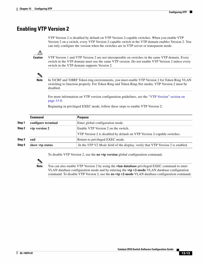
Chapter 13 Configuring VTPConfiguring VTP
Enabling VTP Version 2VTP Version 2 is disabled by default on VTP Version 2-capable switches. When you enable VTP Version 2 on a switch, every VTP Version 2-capable switch in the VTP domain enables Version 2. You can only configure the version when the switches are in VTP server or transparent mode.
Caution VTP Version 1 and VTP Version 2 are not interoperable on switches in the same VTP domain. Every switch in the VTP domain must use the same VTP version. Do not enable VTP Version 2 unless every switch in the VTP domain supports Version 2.
Note In TrCRF and TrBRF Token ring environments, you must enable VTP Version 2 for Token Ring VLAN switching to function properly. For Token Ring and Token Ring-Net media, VTP Version 2 must be disabled.
For more information on VTP version configuration guidelines, see the “VTP Version” section on page 13-8.
Beginning in privileged EXEC mode, follow these steps to enable VTP Version 2:
Command Purpose
Step 1 configure terminal Enter global configuration mode.
Step 2 vtp version 2 Enable VTP Version 2 on the switch.
VTP Version 2 is disabled by default on VTP Version 2-capable switches.
Step 3 end Return to privileged EXEC mode.
Step 4 show vtp status In the VTP V2 Mode field of the display, verify that VTP Version 2 is enabled.
To disable VTP Version 2, use the no vtp version global configuration command.
Note You can also enable VTP Version 2 by using the vlan database privileged EXEC command to enter VLAN database configuration mode and by entering the vtp v2-mode VLAN database configuration command. To disable VTP Version 2, use the no vtp v2-mode VLAN database configuration command.
13-13Catalyst 2918 Switch Software Configuration Guide
OL-14979-01
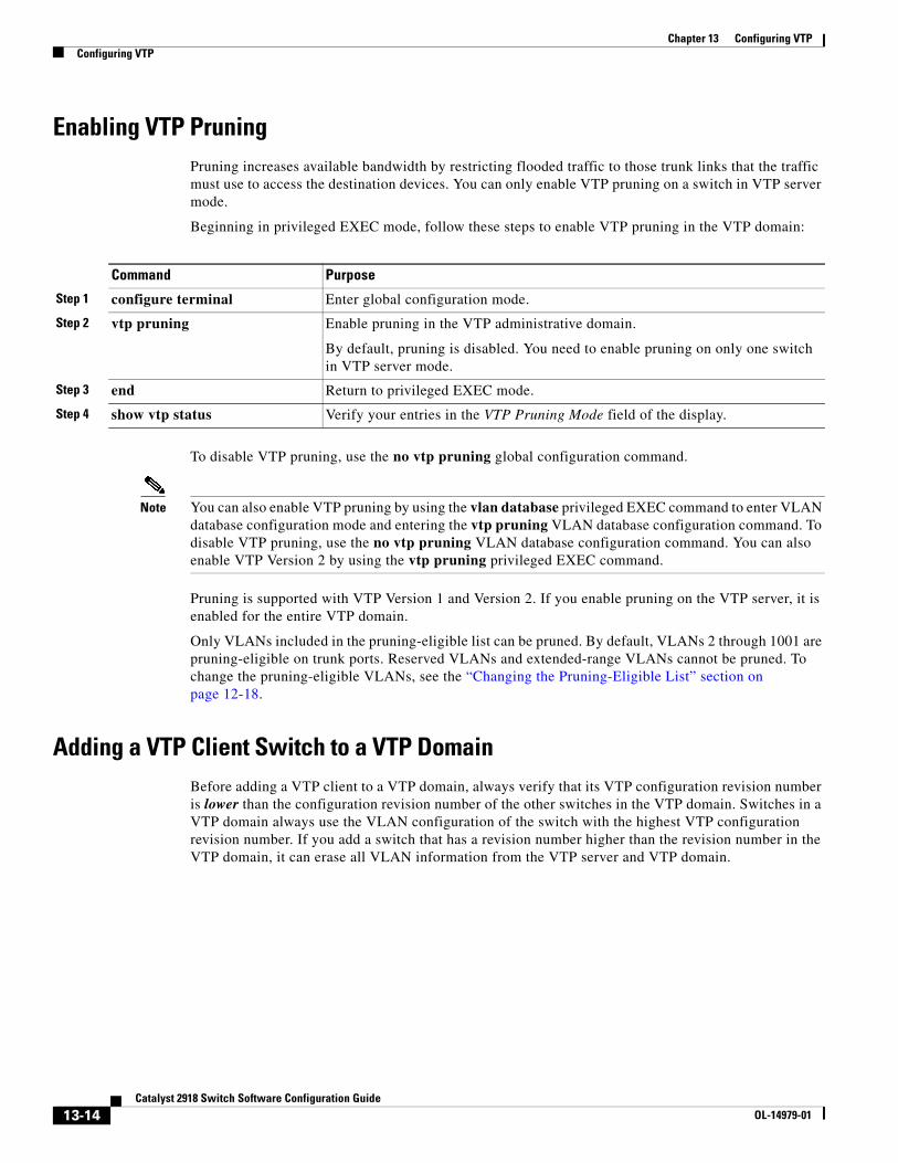
Chapter 13 Configuring VTPConfiguring VTP
Enabling VTP PruningPruning increases available bandwidth by restricting flooded traffic to those trunk links that the traffic must use to access the destination devices. You can only enable VTP pruning on a switch in VTP server mode.
Beginning in privileged EXEC mode, follow these steps to enable VTP pruning in the VTP domain:
Command Purpose
Step 1 configure terminal Enter global configuration mode.
Step 2 vtp pruning Enable pruning in the VTP administrative domain.
By default, pruning is disabled. You need to enable pruning on only one switch in VTP server mode.
Step 3 end Return to privileged EXEC mode.
Step 4 show vtp status Verify your entries in the VTP Pruning Mode field of the display.
To disable VTP pruning, use the no vtp pruning global configuration command.
Note You can also enable VTP pruning by using the vlan database privileged EXEC command to enter VLAN database configuration mode and entering the vtp pruning VLAN database configuration command. To disable VTP pruning, use the no vtp pruning VLAN database configuration command. You can also enable VTP Version 2 by using the vtp pruning privileged EXEC command.
Pruning is supported with VTP Version 1 and Version 2. If you enable pruning on the VTP server, it is enabled for the entire VTP domain.
Only VLANs included in the pruning-eligible list can be pruned. By default, VLANs 2 through 1001 are pruning-eligible on trunk ports. Reserved VLANs and extended-range VLANs cannot be pruned. To change the pruning-eligible VLANs, see the “Changing the Pruning-Eligible List” section on page 12-18.
Adding a VTP Client Switch to a VTP DomainBefore adding a VTP client to a VTP domain, always verify that its VTP configuration revision number is lower than the configuration revision number of the other switches in the VTP domain. Switches in a VTP domain always use the VLAN configuration of the switch with the highest VTP configuration revision number. If you add a switch that has a revision number higher than the revision number in the VTP domain, it can erase all VLAN information from the VTP server and VTP domain.
13-14Catalyst 2918 Switch Software Configuration Guide
OL-14979-01
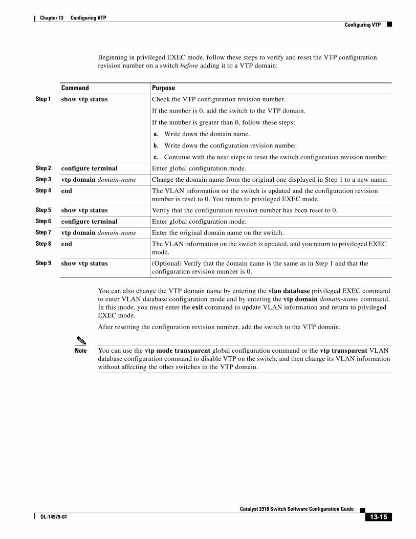
Chapter 13 Configuring VTPConfiguring VTP
Beginning in privileged EXEC mode, follow these steps to verify and reset the VTP configuration revision number on a switch before adding it to a VTP domain:
Command Purpose
Step 1 show vtp status Check the VTP configuration revision number.
If the number is 0, add the switch to the VTP domain.
If the number is greater than 0, follow these steps:
a. Write down the domain name.
b. Write down the configuration revision number.
c. Continue with the next steps to reset the switch configuration revision number.
Step 2 configure terminal Enter global configuration mode.
Step 3 vtp domain domain-name Change the domain name from the original one displayed in Step 1 to a new name.
Step 4 end The VLAN information on the switch is updated and the configuration revision number is reset to 0. You return to privileged EXEC mode.
Step 5 show vtp status Verify that the configuration revision number has been reset to 0.
Step 6 configure terminal Enter global configuration mode.
Step 7 vtp domain domain-name Enter the original domain name on the switch.
Step 8 end The VLAN information on the switch is updated, and you return to privileged EXEC mode.
Step 9 show vtp status (Optional) Verify that the domain name is the same as in Step 1 and that the configuration revision number is 0.
You can also change the VTP domain name by entering the vlan database privileged EXEC command to enter VLAN database configuration mode and by entering the vtp domain domain-name command. In this mode, you must enter the exit command to update VLAN information and return to privileged EXEC mode.
After resetting the configuration revision number, add the switch to the VTP domain.
Note You can use the vtp mode transparent global configuration command or the vtp transparent VLAN database configuration command to disable VTP on the switch, and then change its VLAN information without affecting the other switches in the VTP domain.
13-15Catalyst 2918 Switch Software Configuration Guide
OL-14979-01
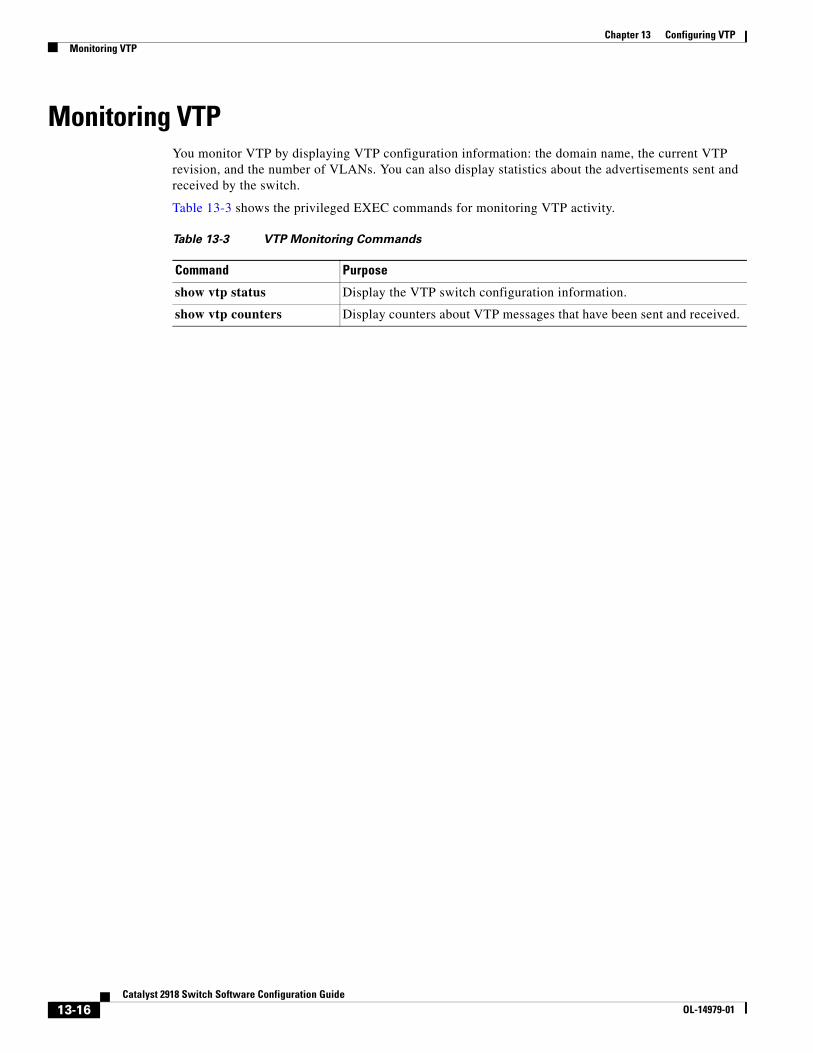
Chapter 13 Configuring VTPMonitoring VTP
Monitoring VTPYou monitor VTP by displaying VTP configuration information: the domain name, the current VTP revision, and the number of VLANs. You can also display statistics about the advertisements sent and received by the switch.
Table 13-3 shows the privileged EXEC commands for monitoring VTP activity.
Table 13-3 VTP Monitoring Commands
Command Purpose
show vtp status Display the VTP switch configuration information.
show vtp counters Display counters about VTP messages that have been sent and received.
13-16Catalyst 2918 Switch Software Configuration Guide
OL-14979-01
OL-14979-01
C H A P T E R 14
Configuring Voice VLANThis chapter describes how to configure the voice VLAN feature on the Catalyst 2918 switch. Voice VLAN is referred to as an auxiliary VLAN in some Catalyst 6500 family switch documentation.
Note For complete syntax and usage information for the commands used in this chapter, see the command reference for this release.
This chapter consists of these sections:
• Understanding Voice VLAN, page 14-1
• Configuring Voice VLAN, page 14-3
• Displaying Voice VLAN, page 14-5
Understanding Voice VLANThe voice VLAN feature enables access ports to carry IP voice traffic from an IP phone. When the switch is connected to a Cisco 7960 IP Phone, the phone sends voice traffic with Layer 3 IP precedence and Layer 2 class of service (CoS) values, which are both set to 5 by default. Because the sound quality of an IP phone call can deteriorate if the data is unevenly sent, the switch supports quality of service (QoS) based on IEEE 802.1p CoS. QoS uses classification and scheduling to send network traffic from the switch in a predictable manner. For more information on QoS, see Chapter 27, “Configuring QoS.”
The Cisco 7960 IP Phone is a configurable device, and you can configure it to forward traffic with an IEEE 802.1p priority. You can configure the switch to trust or override the traffic priority assigned by a Cisco IP Phone.
The Cisco IP Phone contains an integrated three-port 10/100 switch as shown in Figure 14-1. The ports provide dedicated connections to these devices:
• Port 1 connects to the switch or other voice-over-IP (VoIP) device.
• Port 2 is an internal 10/100 interface that carries the IP Phone traffic.
• Port 3 (access port) connects to a PC or other device.
14-1Catalyst 2918 Switch Software Configuration Guide
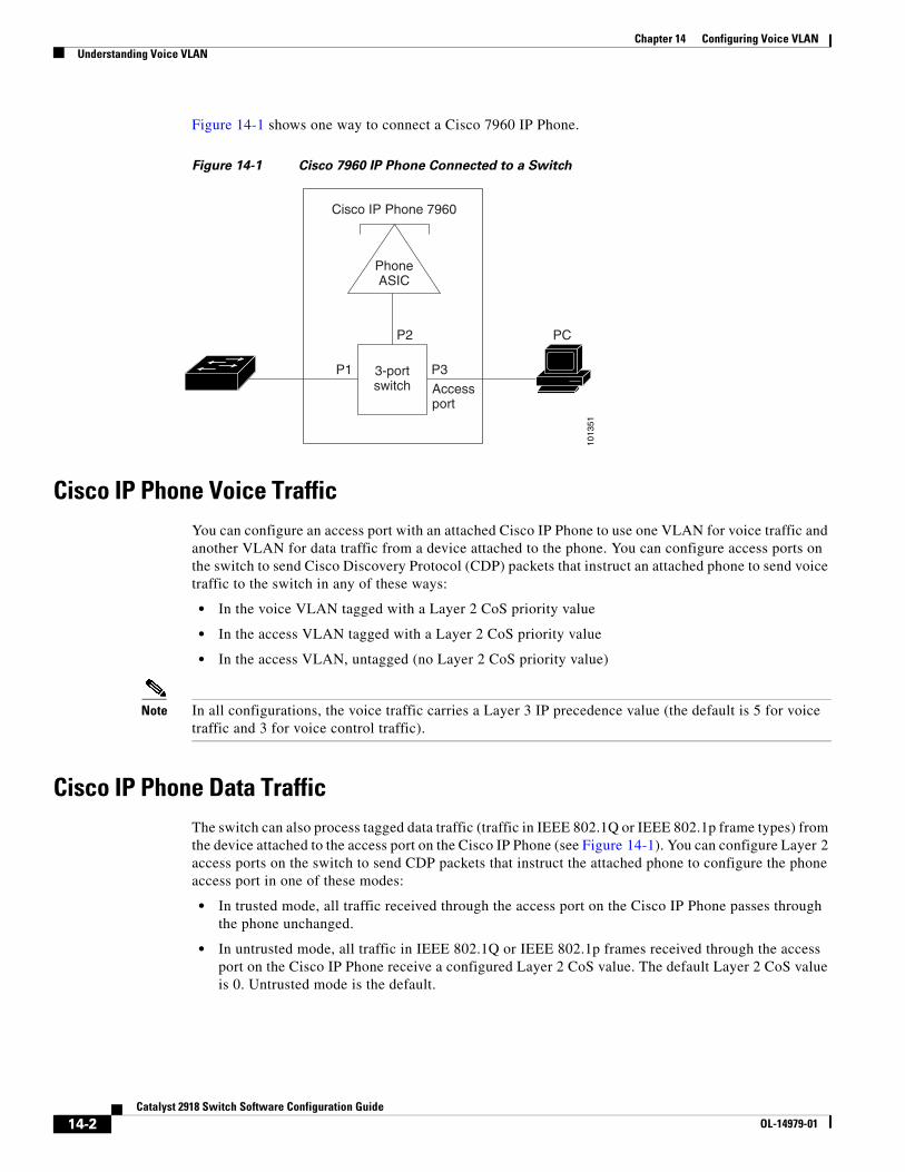
Chapter 14 Configuring Voice VLANUnderstanding Voice VLAN
Figure 14-1 shows one way to connect a Cisco 7960 IP Phone.
Figure 14-1 Cisco 7960 IP Phone Connected to a Switch
3-portswitch
P1 P3
P2
Accessport
Cisco IP Phone 7960
PC
1013
51
PhoneASIC
Cisco IP Phone Voice TrafficYou can configure an access port with an attached Cisco IP Phone to use one VLAN for voice traffic and another VLAN for data traffic from a device attached to the phone. You can configure access ports on the switch to send Cisco Discovery Protocol (CDP) packets that instruct an attached phone to send voice traffic to the switch in any of these ways:
• In the voice VLAN tagged with a Layer 2 CoS priority value
• In the access VLAN tagged with a Layer 2 CoS priority value
• In the access VLAN, untagged (no Layer 2 CoS priority value)
Note In all configurations, the voice traffic carries a Layer 3 IP precedence value (the default is 5 for voice traffic and 3 for voice control traffic).
Cisco IP Phone Data TrafficThe switch can also process tagged data traffic (traffic in IEEE 802.1Q or IEEE 802.1p frame types) from the device attached to the access port on the Cisco IP Phone (see Figure 14-1). You can configure Layer 2 access ports on the switch to send CDP packets that instruct the attached phone to configure the phone access port in one of these modes:
• In trusted mode, all traffic received through the access port on the Cisco IP Phone passes through the phone unchanged.
• In untrusted mode, all traffic in IEEE 802.1Q or IEEE 802.1p frames received through the access port on the Cisco IP Phone receive a configured Layer 2 CoS value. The default Layer 2 CoS value is 0. Untrusted mode is the default.
14-2Catalyst 2918 Switch Software Configuration Guide
OL-14979-01
Chapter 14 Configuring Voice VLANConfiguring Voice VLAN
Note Untagged traffic from the device attached to the Cisco IP Phone passes through the phone unchanged, regardless of the trust state of the access port on the phone.
Configuring Voice VLANThese sections contain this configuration information:
• Default Voice VLAN Configuration, page 14-3
• Voice VLAN Configuration Guidelines, page 14-3
• Configuring a Port Connected to a Cisco 7960 IP Phone, page 14-4
Default Voice VLAN ConfigurationThe voice VLAN feature is disabled by default.
When the voice VLAN feature is enabled, all untagged traffic is sent according to the default CoS priority of the port.
The CoS value is not trusted for IEEE 802.1p or IEEE 802.1Q tagged traffic.
Voice VLAN Configuration GuidelinesThese are the voice VLAN configuration guidelines:
• You should configure voice VLAN on switch access ports; voice VLAN is not supported on trunk ports.
Note Voice VLAN is only supported on access ports and not on trunk ports, even though the configuration is allowed.
• The voice VLAN should be present and active on the switch for the IP phone to correctly communicate on the voice VLAN. Use the show vlan privileged EXEC command to see if the VLAN is present (listed in the display). If the VLAN is not listed, see Chapter 12, “Configuring VLANs,” for information on how to create the voice VLAN.
• Before you enable voice VLAN, we recommend that you enable QoS on the switch by entering the mls qos global configuration command and configure the port trust state to trust by entering the mls qos trust cos interface configuration command. For more information, see Chapter 27, “Configuring QoS.”
• You must enable CDP on the switch port connected to the Cisco IP Phone to send the configuration to the phone. (CDP is globally enabled by default on all switch interfaces.)
• The Port Fast feature is automatically enabled when voice VLAN is configured. When you disable voice VLAN, the Port Fast feature is not automatically disabled.
• If the Cisco IP Phone and a device attached to the phone are in the same VLAN, they must be in the same IP subnet. These conditions indicate that they are in the same VLAN:
– They both use IEEE 802.1p or untagged frames.
14-3Catalyst 2918 Switch Software Configuration Guide
OL-14979-01
Chapter 14 Configuring Voice VLANConfiguring Voice VLAN
– The Cisco IP Phone uses IEEE 802.1p frames, and the device uses untagged frames.
– The Cisco IP Phone uses untagged frames, and the device uses IEEE 802.1p frames.
– The Cisco IP Phone uses IEEE 802.1Q frames, and the voice VLAN is the same as the access VLAN.
• The Cisco IP Phone and a device attached to the phone cannot communicate if they are in the same VLAN and subnet but use different frame types because traffic in the same subnet is not routed (routing would eliminate the frame type difference).
• You cannot configure static secure MAC addresses in the voice VLAN.
• Voice VLAN ports can also be these port types:
– Dynamic access port. See the “Configuring Dynamic-Access Ports on VMPS Clients” section on page 12-26 for more information.
– IEEE 802.1x authenticated port. See the “Configuring IEEE 802.1x Authentication” section on page 9-14 for more information.
Note If you enable IEEE 802.1x on an access port on which a voice VLAN is configured and to which a Cisco IP Phone is connected, the phone loses connectivity to the switch for up to 30 seconds.
– Protected port. See the “Configuring Protected Ports” section on page 19-6 for more information.
– A source or destination port for a SPAN session.
– Secure port. See the “Configuring Port Security” section on page 19-8 for more information.
Note When you enable port security on an interface that is also configured with a voice VLAN, you must set the maximum allowed secure addresses on the port to two plus the maximum number of secure addresses allowed on the access VLAN. When the port is connected to a Cisco IP Phone, the phone requires up to two MAC addresses. The phone address is learned on the voice VLAN and might also be learned on the access VLAN. Connecting a PC to the phone requires additional MAC addresses.
Configuring a Port Connected to a Cisco 7960 IP PhoneBecause a Cisco 7960 IP Phone also supports a connection to a PC or other device, a port connecting the switch to a Cisco IP Phone can carry mixed traffic. You can configure a port to decide how the Cisco IP Phone carries voice traffic and data traffic.
Configuring Cisco IP Phone Voice Traffic
You can configure a port connected to the Cisco IP Phone to send CDP packets to the phone to configure the way in which the phone sends voice traffic. The phone can carry voice traffic in IEEE 802.1Q frames for a specified voice VLAN with a Layer 2 CoS value. It can use IEEE 802.1p priority tagging to give voice traffic a higher priority and forward all voice traffic through the native (access) VLAN. The Cisco IP Phone can also send untagged voice traffic or use its own configuration to send voice traffic in the access VLAN. In all configurations, the voice traffic carries a Layer 3 IP precedence value (the default is 5).
14-4Catalyst 2918 Switch Software Configuration Guide
OL-14979-01
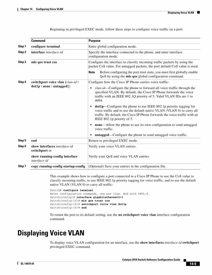
Chapter 14 Configuring Voice VLANDisplaying Voice VLAN
Beginning in privileged EXEC mode, follow these steps to configure voice traffic on a port:
Command Purpose
Step 1 configure terminal Enter global configuration mode.
Step 2 interface interface-id Specify the interface connected to the phone, and enter interface configuration mode.
Step 3 mls qos trust cos Configure the interface to classify incoming traffic packets by using the packet CoS value. For untagged packets, the port default CoS value is used.
Note Before configuring the port trust state, you must first globally enable QoS by using the mls qos global configuration command.
Step 4 switchport voice vlan {vlan-id | dot1p | none | untagged}}
Configure how the Cisco IP Phone carries voice traffic:
• vlan-id—Configure the phone to forward all voice traffic through the specified VLAN. By default, the Cisco IP Phone forwards the voice traffic with an IEEE 802.1Q priority of 5. Valid VLAN IDs are 1 to 4094.
• dot1p—Configure the phone to use IEEE 802.1p priority tagging for voice traffic and to use the default native VLAN (VLAN 0) to carry all traffic. By default, the Cisco IP Phone forwards the voice traffic with an IEEE 802.1p priority of 5.
• none—Allow the phone to use its own configuration to send untagged voice traffic.
• untagged—Configure the phone to send untagged voice traffic.
Step 5 end Return to privileged EXEC mode.
Step 6 show interfaces interface-id switchport or
show running-config interface interface-id
Verify your voice VLAN entries.
Verify your QoS and voice VLAN entries.
Step 7 copy running-config startup-config (Optional) Save your entries in the configuration file.
This example shows how to configure a port connected to a Cisco IP Phone to use the CoS value to classify incoming traffic, to use IEEE 802.1p priority tagging for voice traffic, and to use the default native VLAN (VLAN 0) to carry all traffic:
Switch# configure terminal Enter configuration commands, one per line. End with CNTL/Z.Switch(config)# interface gigabitethernet0/1 Switch(config-if)# mls qos trust cos Switch(config-if)# switchport voice vlan dot1pSwitch(config-if)# end
To return the port to its default setting, use the no switchport voice vlan interface configuration command.
Displaying Voice VLANTo display voice VLAN configuration for an interface, use the show interfaces interface-id switchport privileged EXEC command.
14-5Catalyst 2918 Switch Software Configuration Guide
OL-14979-01

Chapter 14 Configuring Voice VLANDisplaying Voice VLAN
14-6Catalyst 2918 Switch Software Configuration Guide
OL-14979-01
OL-14979-01
C H A P T E R 15
Configuring STPThis chapter describes how to configure the Spanning Tree Protocol (STP) on port-based VLANs on the Catalyst 2918 switch. The switch can use either the per-VLAN spanning-tree plus (PVST+) protocol based on the IEEE 802.1D standard and Cisco proprietary extensions, or the rapid per-VLAN spanning-tree plus (rapid-PVST+) protocol based on the IEEE 802.1w standard.
For information about the Multiple Spanning Tree Protocol (MSTP) and how to map multiple VLANs to the same spanning-tree instance, see Chapter 16, “Configuring MSTP.” For information about other spanning-tree features such as Port Fast, UplinkFast, root guard, and so forth, see Chapter 17, “Configuring Optional Spanning-Tree Features.”
Note For complete syntax and usage information for the commands used in this chapter, see the command reference for this release.
This chapter consists of these sections:
• Understanding Spanning-Tree Features, page 15-1
• Configuring Spanning-Tree Features, page 15-10
• Displaying the Spanning-Tree Status, page 15-22
Understanding Spanning-Tree FeaturesThese sections contain this conceptual information:
• STP Overview, page 15-2
• Spanning-Tree Topology and BPDUs, page 15-3
• Bridge ID, Switch Priority, and Extended System ID, page 15-4
• Spanning-Tree Interface States, page 15-4
• How a Switch or Port Becomes the Root Switch or Root Port, page 15-7
• Spanning Tree and Redundant Connectivity, page 15-8
• Spanning-Tree Address Management, page 15-8
• Accelerated Aging to Retain Connectivity, page 15-8
• Spanning-Tree Modes and Protocols, page 15-9
• Supported Spanning-Tree Instances, page 15-9
15-1Catalyst 2918 Switch Software Configuration Guide
Chapter 15 Configuring STPUnderstanding Spanning-Tree Features
• Spanning-Tree Interoperability and Backward Compatibility, page 15-10
• STP and IEEE 802.1Q Trunks, page 15-10
For configuration information, see the “Configuring Spanning-Tree Features” section on page 15-10.
For information about optional spanning-tree features, see Chapter 17, “Configuring Optional Spanning-Tree Features.”
STP OverviewSTP is a Layer 2 link management protocol that provides path redundancy while preventing loops in the network. For a Layer 2 Ethernet network to function properly, only one active path can exist between any two stations. Multiple active paths among end stations cause loops in the network. If a loop exists in the network, end stations might receive duplicate messages. Switches might also learn end-station MAC addresses on multiple Layer 2 interfaces. These conditions result in an unstable network. Spanning-tree operation is transparent to end stations, which cannot detect whether they are connected to a single LAN segment or a switched LAN of multiple segments.
The STP uses a spanning-tree algorithm to select one switch of a redundantly connected network as the root of the spanning tree. The algorithm calculates the best loop-free path through a switched Layer 2 network by assigning a role to each port based on the role of the port in the active topology:
• Root—A forwarding port elected for the spanning-tree topology
• Designated—A forwarding port elected for every switched LAN segment
• Alternate—A blocked port providing an alternate path to the root bridge in the spanning tree
• Backup—A blocked port in a loopback configuration
The switch that has all of its ports as the designated role or as the backup role is the root switch. The switch that has at least one of its ports in the designated role is called the designated switch.
Spanning tree forces redundant data paths into a standby (blocked) state. If a network segment in the spanning tree fails and a redundant path exists, the spanning-tree algorithm recalculates the spanning-tree topology and activates the standby path. Switches send and receive spanning-tree frames, called bridge protocol data units (BPDUs), at regular intervals. The switches do not forward these frames but use them to construct a loop-free path. BPDUs contain information about the sending switch and its ports, including switch and MAC addresses, switch priority, port priority, and path cost. Spanning tree uses this information to elect the root switch and root port for the switched network and the root port and designated port for each switched segment.
When two ports on a switch are part of a loop, the spanning-tree port priority and path cost settings control which port is put in the forwarding state and which is put in the blocking state. The spanning-tree port priority value represents the location of a port in the network topology and how well it is located to pass traffic. The path cost value represents the media speed.
Note The default is for the switch to send keepalive messages (to ensure the connection is up) only on interfaces that do not have small form-factor pluggable (SFP) modules. You can use the [no] keepalive interface configuration command to change the default for an interface.
15-2Catalyst 2918 Switch Software Configuration Guide
OL-14979-01
Chapter 15 Configuring STPUnderstanding Spanning-Tree Features
Spanning-Tree Topology and BPDUsThe stable, active spanning-tree topology of a switched network is controlled by these elements:
• The unique bridge ID (switch priority and MAC address) associated with each VLAN on each switch.
• The spanning-tree path cost to the root switch.
• The port identifier (port priority and MAC address) associated with each Layer 2 interface.
When the switches in a network are powered up, each functions as the root switch. Each switch sends a configuration BPDU through all of its ports. The BPDUs communicate and compute the spanning-tree topology. Each configuration BPDU contains this information:
• The unique bridge ID of the switch that the sending switch identifies as the root switch
• The spanning-tree path cost to the root
• The bridge ID of the sending switch
• Message age
• The identifier of the sending interface
• Values for the hello, forward delay, and max-age protocol timers
When a switch receives a configuration BPDU that contains superior information (lower bridge ID, lower path cost, and so forth), it stores the information for that port. If this BPDU is received on the root port of the switch, the switch also forwards it with an updated message to all attached LANs for which it is the designated switch.
If a switch receives a configuration BPDU that contains inferior information to that currently stored for that port, it discards the BPDU. If the switch is a designated switch for the LAN from which the inferior BPDU was received, it sends that LAN a BPDU containing the up-to-date information stored for that port. In this way, inferior information is discarded, and superior information is propagated on the network.
A BPDU exchange results in these actions:
• One switch in the network is elected as the root switch (the logical center of the spanning-tree topology in a switched network).
For each VLAN, the switch with the highest switch priority (the lowest numerical priority value) is elected as the root switch. If all switches are configured with the default priority (32768), the switch with the lowest MAC address in the VLAN becomes the root switch. The switch priority value occupies the most significant bits of the bridge ID, as shown in Table 15-1 on page 15-4.
• A root port is selected for each switch (except the root switch). This port provides the best path (lowest cost) when the switch forwards packets to the root switch.
• The shortest distance to the root switch is calculated for each switch based on the path cost.
• A designated switch for each LAN segment is selected. The designated switch incurs the lowest path cost when forwarding packets from that LAN to the root switch. The port through which the designated switch is attached to the LAN is called the designated port.
All paths that are not needed to reach the root switch from anywhere in the switched network are placed in the spanning-tree blocking mode.
15-3Catalyst 2918 Switch Software Configuration Guide
OL-14979-01
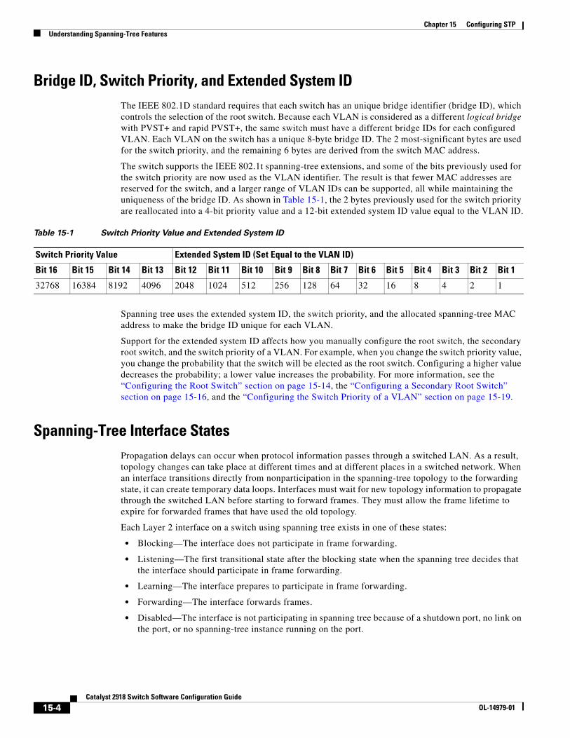
Chapter 15 Configuring STPUnderstanding Spanning-Tree Features
Bridge ID, Switch Priority, and Extended System IDThe IEEE 802.1D standard requires that each switch has an unique bridge identifier (bridge ID), which controls the selection of the root switch. Because each VLAN is considered as a different logical bridge with PVST+ and rapid PVST+, the same switch must have a different bridge IDs for each configured VLAN. Each VLAN on the switch has a unique 8-byte bridge ID. The 2 most-significant bytes are used for the switch priority, and the remaining 6 bytes are derived from the switch MAC address.
The switch supports the IEEE 802.1t spanning-tree extensions, and some of the bits previously used for the switch priority are now used as the VLAN identifier. The result is that fewer MAC addresses are reserved for the switch, and a larger range of VLAN IDs can be supported, all while maintaining the uniqueness of the bridge ID. As shown in Table 15-1, the 2 bytes previously used for the switch priority are reallocated into a 4-bit priority value and a 12-bit extended system ID value equal to the VLAN ID.
Table 15-1 Switch Priority Value and Extended System ID
Switch Priority Value Extended System ID (Set Equal to the VLAN ID)
Bit 16 Bit 15 Bit 14 Bit 13 Bit 12 Bit 11 Bit 10 Bit 9 Bit 8 Bit 7 Bit 6 Bit 5 Bit 4 Bit 3 Bit 2 Bit 1
32768 16384 8192 4096 2048 1024 512 256 128 64 32 16 8 4 2 1
Spanning tree uses the extended system ID, the switch priority, and the allocated spanning-tree MAC address to make the bridge ID unique for each VLAN.
Support for the extended system ID affects how you manually configure the root switch, the secondary root switch, and the switch priority of a VLAN. For example, when you change the switch priority value, you change the probability that the switch will be elected as the root switch. Configuring a higher value decreases the probability; a lower value increases the probability. For more information, see the “Configuring the Root Switch” section on page 15-14, the “Configuring a Secondary Root Switch” section on page 15-16, and the “Configuring the Switch Priority of a VLAN” section on page 15-19.
Spanning-Tree Interface StatesPropagation delays can occur when protocol information passes through a switched LAN. As a result, topology changes can take place at different times and at different places in a switched network. When an interface transitions directly from nonparticipation in the spanning-tree topology to the forwarding state, it can create temporary data loops. Interfaces must wait for new topology information to propagate through the switched LAN before starting to forward frames. They must allow the frame lifetime to expire for forwarded frames that have used the old topology.
Each Layer 2 interface on a switch using spanning tree exists in one of these states:
• Blocking—The interface does not participate in frame forwarding.
• Listening—The first transitional state after the blocking state when the spanning tree decides that the interface should participate in frame forwarding.
• Learning—The interface prepares to participate in frame forwarding.
• Forwarding—The interface forwards frames.
• Disabled—The interface is not participating in spanning tree because of a shutdown port, no link on the port, or no spanning-tree instance running on the port.
15-4Catalyst 2918 Switch Software Configuration Guide
OL-14979-01
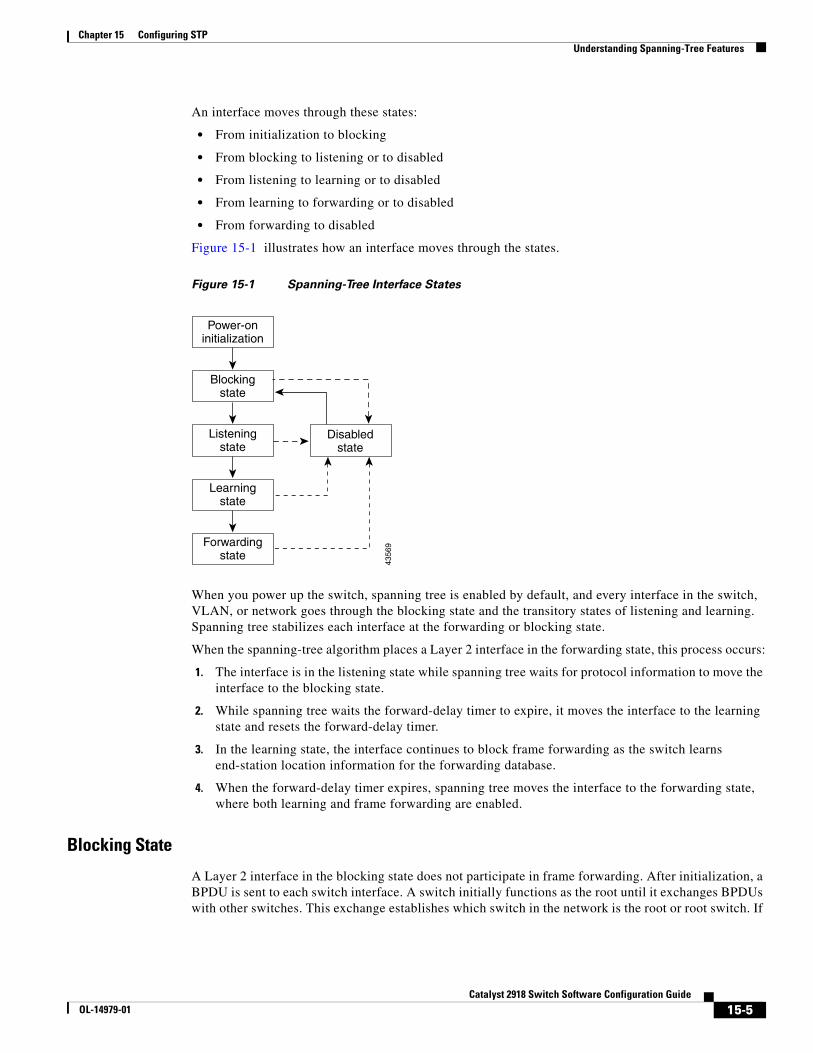
Chapter 15 Configuring STPUnderstanding Spanning-Tree Features
An interface moves through these states:
• From initialization to blocking
• From blocking to listening or to disabled
• From listening to learning or to disabled
• From learning to forwarding or to disabled
• From forwarding to disabled
Figure 15-1 illustrates how an interface moves through the states.
Figure 15-1 Spanning-Tree Interface States
Power-oninitialization
Blockingstate
4356
9
Listeningstate
Disabledstate
Learningstate
Forwardingstate
When you power up the switch, spanning tree is enabled by default, and every interface in the switch, VLAN, or network goes through the blocking state and the transitory states of listening and learning. Spanning tree stabilizes each interface at the forwarding or blocking state.
When the spanning-tree algorithm places a Layer 2 interface in the forwarding state, this process occurs:
1. The interface is in the listening state while spanning tree waits for protocol information to move the interface to the blocking state.
2. While spanning tree waits the forward-delay timer to expire, it moves the interface to the learning state and resets the forward-delay timer.
3. In the learning state, the interface continues to block frame forwarding as the switch learns end-station location information for the forwarding database.
4. When the forward-delay timer expires, spanning tree moves the interface to the forwarding state, where both learning and frame forwarding are enabled.
Blocking State
A Layer 2 interface in the blocking state does not participate in frame forwarding. After initialization, a BPDU is sent to each switch interface. A switch initially functions as the root until it exchanges BPDUs with other switches. This exchange establishes which switch in the network is the root or root switch. If
15-5Catalyst 2918 Switch Software Configuration Guide
OL-14979-01
Chapter 15 Configuring STPUnderstanding Spanning-Tree Features
there is only one switch in the network, no exchange occurs, the forward-delay timer expires, and the interface moves to the listening state. An interface always enters the blocking state after switch initialization.
An interface in the blocking state performs these functions:
• Discards frames received on the interface
• Discards frames switched from another interface for forwarding
• Does not learn addresses
• Receives BPDUs
Listening State
The listening state is the first state a Layer 2 interface enters after the blocking state. The interface enters this state when the spanning tree decides that the interface should participate in frame forwarding.
An interface in the listening state performs these functions:
• Discards frames received on the interface
• Discards frames switched from another interface for forwarding
• Does not learn addresses
• Receives BPDUs
Learning State
A Layer 2 interface in the learning state prepares to participate in frame forwarding. The interface enters the learning state from the listening state.
An interface in the learning state performs these functions:
• Discards frames received on the interface
• Discards frames switched from another interface for forwarding
• Learns addresses
• Receives BPDUs
Forwarding State
A Layer 2 interface in the forwarding state forwards frames. The interface enters the forwarding state from the learning state.
An interface in the forwarding state performs these functions:
• Receives and forwards frames received on the interface
• Forwards frames switched from another interface
• Learns addresses
• Receives BPDUs
15-6Catalyst 2918 Switch Software Configuration Guide
OL-14979-01
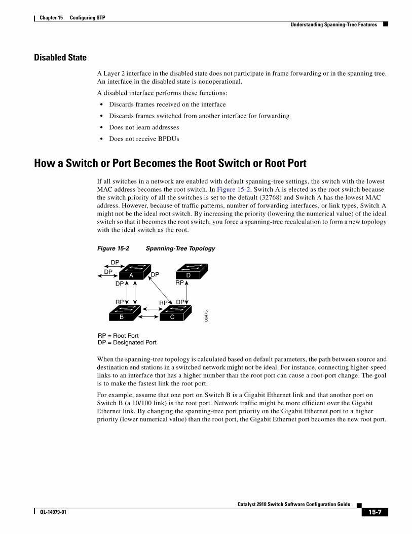
Chapter 15 Configuring STPUnderstanding Spanning-Tree Features
Disabled State
A Layer 2 interface in the disabled state does not participate in frame forwarding or in the spanning tree. An interface in the disabled state is nonoperational.
A disabled interface performs these functions:
• Discards frames received on the interface
• Discards frames switched from another interface for forwarding
• Does not learn addresses
• Does not receive BPDUs
How a Switch or Port Becomes the Root Switch or Root PortIf all switches in a network are enabled with default spanning-tree settings, the switch with the lowest MAC address becomes the root switch. In Figure 15-2, Switch A is elected as the root switch because the switch priority of all the switches is set to the default (32768) and Switch A has the lowest MAC address. However, because of traffic patterns, number of forwarding interfaces, or link types, Switch A might not be the ideal root switch. By increasing the priority (lowering the numerical value) of the ideal switch so that it becomes the root switch, you force a spanning-tree recalculation to form a new topology with the ideal switch as the root.
Figure 15-2 Spanning-Tree Topology
8647
5
DP
DP
RP
DPRP
DP
RP = Root PortDP = Designated Port
DP
RP
DA
CB
When the spanning-tree topology is calculated based on default parameters, the path between source and destination end stations in a switched network might not be ideal. For instance, connecting higher-speed links to an interface that has a higher number than the root port can cause a root-port change. The goal is to make the fastest link the root port.
For example, assume that one port on Switch B is a Gigabit Ethernet link and that another port on Switch B (a 10/100 link) is the root port. Network traffic might be more efficient over the Gigabit Ethernet link. By changing the spanning-tree port priority on the Gigabit Ethernet port to a higher priority (lower numerical value) than the root port, the Gigabit Ethernet port becomes the new root port.
15-7Catalyst 2918 Switch Software Configuration Guide
OL-14979-01
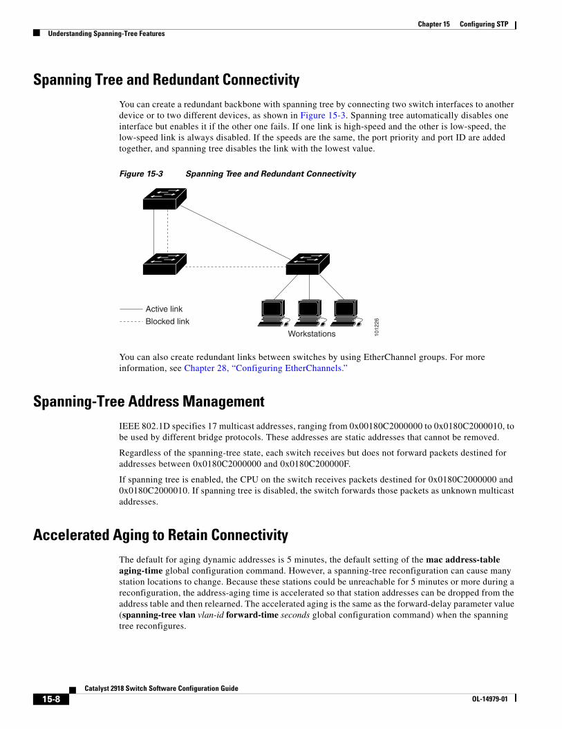
Chapter 15 Configuring STPUnderstanding Spanning-Tree Features
Spanning Tree and Redundant ConnectivityYou can create a redundant backbone with spanning tree by connecting two switch interfaces to another device or to two different devices, as shown in Figure 15-3. Spanning tree automatically disables one interface but enables it if the other one fails. If one link is high-speed and the other is low-speed, the low-speed link is always disabled. If the speeds are the same, the port priority and port ID are added together, and spanning tree disables the link with the lowest value.
Figure 15-3 Spanning Tree and Redundant Connectivity
1012
26
Workstations
Active link
Blocked link
You can also create redundant links between switches by using EtherChannel groups. For more information, see Chapter 28, “Configuring EtherChannels.”
Spanning-Tree Address ManagementIEEE 802.1D specifies 17 multicast addresses, ranging from 0x00180C2000000 to 0x0180C2000010, to be used by different bridge protocols. These addresses are static addresses that cannot be removed.
Regardless of the spanning-tree state, each switch receives but does not forward packets destined for addresses between 0x0180C2000000 and 0x0180C200000F.
If spanning tree is enabled, the CPU on the switch receives packets destined for 0x0180C2000000 and 0x0180C2000010. If spanning tree is disabled, the switch forwards those packets as unknown multicast addresses.
Accelerated Aging to Retain ConnectivityThe default for aging dynamic addresses is 5 minutes, the default setting of the mac address-table aging-time global configuration command. However, a spanning-tree reconfiguration can cause many station locations to change. Because these stations could be unreachable for 5 minutes or more during a reconfiguration, the address-aging time is accelerated so that station addresses can be dropped from the address table and then relearned. The accelerated aging is the same as the forward-delay parameter value (spanning-tree vlan vlan-id forward-time seconds global configuration command) when the spanning tree reconfigures.
15-8Catalyst 2918 Switch Software Configuration Guide
OL-14979-01
Chapter 15 Configuring STPUnderstanding Spanning-Tree Features
Because each VLAN is a separate spanning-tree instance, the switch accelerates aging on a per-VLAN basis. A spanning-tree reconfiguration on one VLAN can cause the dynamic addresses learned on that VLAN to be subject to accelerated aging. Dynamic addresses on other VLANs can be unaffected and remain subject to the aging interval entered for the switch.
Spanning-Tree Modes and ProtocolsThe switch supports these spanning-tree modes and protocols:
• PVST+—This spanning-tree mode is based on the IEEE 802.1D standard and Cisco proprietary extensions. It is the default spanning-tree mode used on all Ethernet port-based VLANs. The PVST+ runs on each VLAN on the switch up to the maximum supported, ensuring that each has a loop-free path through the network.
The PVST+ provides Layer 2 load balancing for the VLAN on which it runs. You can create different logical topologies by using the VLANs on your network to ensure that all of your links are used but that no one link is oversubscribed. Each instance of PVST+ on a VLAN has a single root switch. This root switch propagates the spanning-tree information associated with that VLAN to all other switches in the network. Because each switch has the same information about the network, this process ensures that the network topology is maintained.
• Rapid PVST+—This spanning-tree mode is the same as PVST+ except that is uses a rapid convergence based on the IEEE 802.1w standard. To provide rapid convergence, the rapid PVST+ immediately deletes dynamically learned MAC address entries on a per-port basis upon receiving a topology change. By contrast, PVST+ uses a short aging time for dynamically learned MAC address entries.
The rapid PVST+ uses the same configuration as PVST+ (except where noted), and the switch needs only minimal extra configuration. The benefit of rapid PVST+ is that you can migrate a large PVST+ install base to rapid PVST+ without having to learn the complexities of the MSTP configuration and without having to reprovision your network. In rapid-PVST+ mode, each VLAN runs its own spanning-tree instance up to the maximum supported.
• MSTP—This spanning-tree mode is based on the IEEE 802.1s standard. You can map multiple VLANs to the same spanning-tree instance, which reduces the number of spanning-tree instances required to support a large number of VLANs. The MSTP runs on top of the RSTP (based on IEEE 802.1w), which provides for rapid convergence of the spanning tree by eliminating the forward delay and by quickly transitioning root ports and designated ports to the forwarding state. You cannot run MSTP without RSTP.
The most common initial deployment of MSTP is in the backbone and distribution layers of a Layer 2 switched network. For more information, see Chapter 16, “Configuring MSTP.”
For information about the number of supported spanning-tree instances, see the next section.
Supported Spanning-Tree InstancesIn PVST+ or rapid-PVST+ mode, the switch supports up to 64 spanning-tree instances.
In MSTP mode, the switch supports up to 64 MST instances. The number of VLANs that can be mapped to a particular MST instance is unlimited.
For information about how spanning tree interoperates with the VLAN Trunking Protocol (VTP), see the “Spanning-Tree Configuration Guidelines” section on page 15-12.
15-9Catalyst 2918 Switch Software Configuration Guide
OL-14979-01
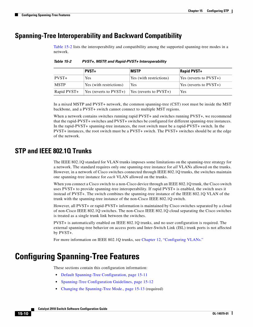
Chapter 15 Configuring STPConfiguring Spanning-Tree Features
Spanning-Tree Interoperability and Backward CompatibilityTable 15-2 lists the interoperability and compatibility among the supported spanning-tree modes in a network.
Table 15-2 PVST+, MSTP, and Rapid-PVST+ Interoperability
PVST+ MSTP Rapid PVST+
PVST+ Yes Yes (with restrictions) Yes (reverts to PVST+)
MSTP Yes (with restrictions) Yes Yes (reverts to PVST+)
Rapid PVST+ Yes (reverts to PVST+) Yes (reverts to PVST+) Yes
In a mixed MSTP and PVST+ network, the common spanning-tree (CST) root must be inside the MST backbone, and a PVST+ switch cannot connect to multiple MST regions.
When a network contains switches running rapid PVST+ and switches running PVST+, we recommend that the rapid-PVST+ switches and PVST+ switches be configured for different spanning-tree instances. In the rapid-PVST+ spanning-tree instances, the root switch must be a rapid-PVST+ switch. In the PVST+ instances, the root switch must be a PVST+ switch. The PVST+ switches should be at the edge of the network.
STP and IEEE 802.1Q TrunksThe IEEE 802.1Q standard for VLAN trunks imposes some limitations on the spanning-tree strategy for a network. The standard requires only one spanning-tree instance for all VLANs allowed on the trunks. However, in a network of Cisco switches connected through IEEE 802.1Q trunks, the switches maintain one spanning-tree instance for each VLAN allowed on the trunks.
When you connect a Cisco switch to a non-Cisco device through an IEEE 802.1Q trunk, the Cisco switch uses PVST+ to provide spanning-tree interoperability. If rapid PVST+ is enabled, the switch uses it instead of PVST+. The switch combines the spanning-tree instance of the IEEE 802.1Q VLAN of the trunk with the spanning-tree instance of the non-Cisco IEEE 802.1Q switch.
However, all PVST+ or rapid-PVST+ information is maintained by Cisco switches separated by a cloud of non-Cisco IEEE 802.1Q switches. The non-Cisco IEEE 802.1Q cloud separating the Cisco switches is treated as a single trunk link between the switches.
PVST+ is automatically enabled on IEEE 802.1Q trunks, and no user configuration is required. The external spanning-tree behavior on access ports and Inter-Switch Link (ISL) trunk ports is not affected by PVST+.
For more information on IEEE 802.1Q trunks, see Chapter 12, “Configuring VLANs.”
Configuring Spanning-Tree FeaturesThese sections contain this configuration information:
• Default Spanning-Tree Configuration, page 15-11
• Spanning-Tree Configuration Guidelines, page 15-12
• Changing the Spanning-Tree Mode., page 15-13 (required)
15-10Catalyst 2918 Switch Software Configuration Guide
OL-14979-01
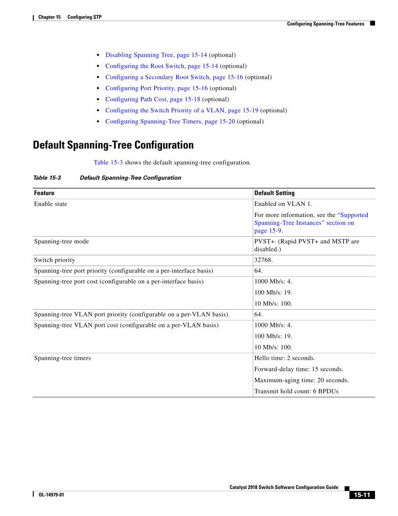
Chapter 15 Configuring STPConfiguring Spanning-Tree Features
• Disabling Spanning Tree, page 15-14 (optional)
• Configuring the Root Switch, page 15-14 (optional)
• Configuring a Secondary Root Switch, page 15-16 (optional)
• Configuring Port Priority, page 15-16 (optional)
• Configuring Path Cost, page 15-18 (optional)
• Configuring the Switch Priority of a VLAN, page 15-19 (optional)
• Configuring Spanning-Tree Timers, page 15-20 (optional)
Default Spanning-Tree ConfigurationTable 15-3 shows the default spanning-tree configuration.
Table 15-3 Default Spanning-Tree Configuration
Feature Default Setting
Enable state Enabled on VLAN 1.
For more information, see the “Supported Spanning-Tree Instances” section on page 15-9.
Spanning-tree mode PVST+. (Rapid PVST+ and MSTP are disabled.)
Switch priority 32768.
Spanning-tree port priority (configurable on a per-interface basis) 64.
Spanning-tree port cost (configurable on a per-interface basis) 1000 Mb/s: 4.
100 Mb/s: 19.
10 Mb/s: 100.
Spanning-tree VLAN port priority (configurable on a per-VLAN basis) 64.
Spanning-tree VLAN port cost (configurable on a per-VLAN basis) 1000 Mb/s: 4.
100 Mb/s: 19.
10 Mb/s: 100.
Spanning-tree timers Hello time: 2 seconds.
Forward-delay time: 15 seconds.
Maximum-aging time: 20 seconds.
Transmit hold count: 6 BPDUs
15-11Catalyst 2918 Switch Software Configuration Guide
OL-14979-01
Chapter 15 Configuring STPConfiguring Spanning-Tree Features
Spanning-Tree Configuration GuidelinesIf more VLANs are defined in the VTP than there are spanning-tree instances, you can enable PVST+ or rapid PVST+ on only 64 VLANs on the switch. The remaining VLANs operate with spanning tree disabled. However, you can map multiple VLANs to the same spanning-tree instances by using MSTP. For more information, see Chapter 16, “Configuring MSTP.”
If 64 instances of spanning tree are already in use, you can disable spanning tree on one of the VLANs and then enable it on the VLAN where you want it to run. Use the no spanning-tree vlan vlan-id global configuration command to disable spanning tree on a specific VLAN, and use the spanning-tree vlan vlan-id global configuration command to enable spanning tree on the desired VLAN.
Caution Switches that are not running spanning tree still forward BPDUs that they receive so that the other switches on the VLAN that have a running spanning-tree instance can break loops. Therefore, spanning tree must be running on enough switches to break all the loops in the network; for example, at least one switch on each loop in the VLAN must be running spanning tree. It is not absolutely necessary to run spanning tree on all switches in the VLAN. However, if you are running spanning tree only on a minimal set of switches, an incautious change to the network that introduces another loop into the VLAN can result in a broadcast storm.
Note If you have already used all available spanning-tree instances on your switch, adding another VLAN anywhere in the VTP domain creates a VLAN that is not running spanning tree on that switch. If you have the default allowed list on the trunk ports of that switch, the new VLAN is carried on all trunk ports. Depending on the topology of the network, this could create a loop in the new VLAN that will not be broken, particularly if there are several adjacent switches that have all run out of spanning-tree instances. You can prevent this possibility by setting up allowed lists on the trunk ports of switches that have used up their allocation of spanning-tree instances. Setting up allowed lists is not necessary in many cases and can make it more labor-intensive to add another VLAN to the network.
Spanning-tree commands control the configuration of VLAN spanning-tree instances. You create a spanning-tree instance when you assign an interface to a VLAN. The spanning-tree instance is removed when the last interface is moved to another VLAN. You can configure switch and port parameters before a spanning-tree instance is created; these parameters are applied when the spanning-tree instance is created.
The switch supports PVST+, rapid PVST+, and MSTP, but only one version can be active at any time. (For example, all VLANs run PVST+, all VLANs run rapid PVST+, or all VLANs run MSTP.) For information about the different spanning-tree modes and how they interoperate, see the “Spanning-Tree Interoperability and Backward Compatibility” section on page 15-10.
For configuration guidelines about UplinkFast and BackboneFast, see the “Optional Spanning-Tree Configuration Guidelines” section on page 17-10.
Caution Loop guard works only on point-to-point links. We recommend that each end of the link has a directly connected device that is running STP.
15-12Catalyst 2918 Switch Software Configuration Guide
OL-14979-01
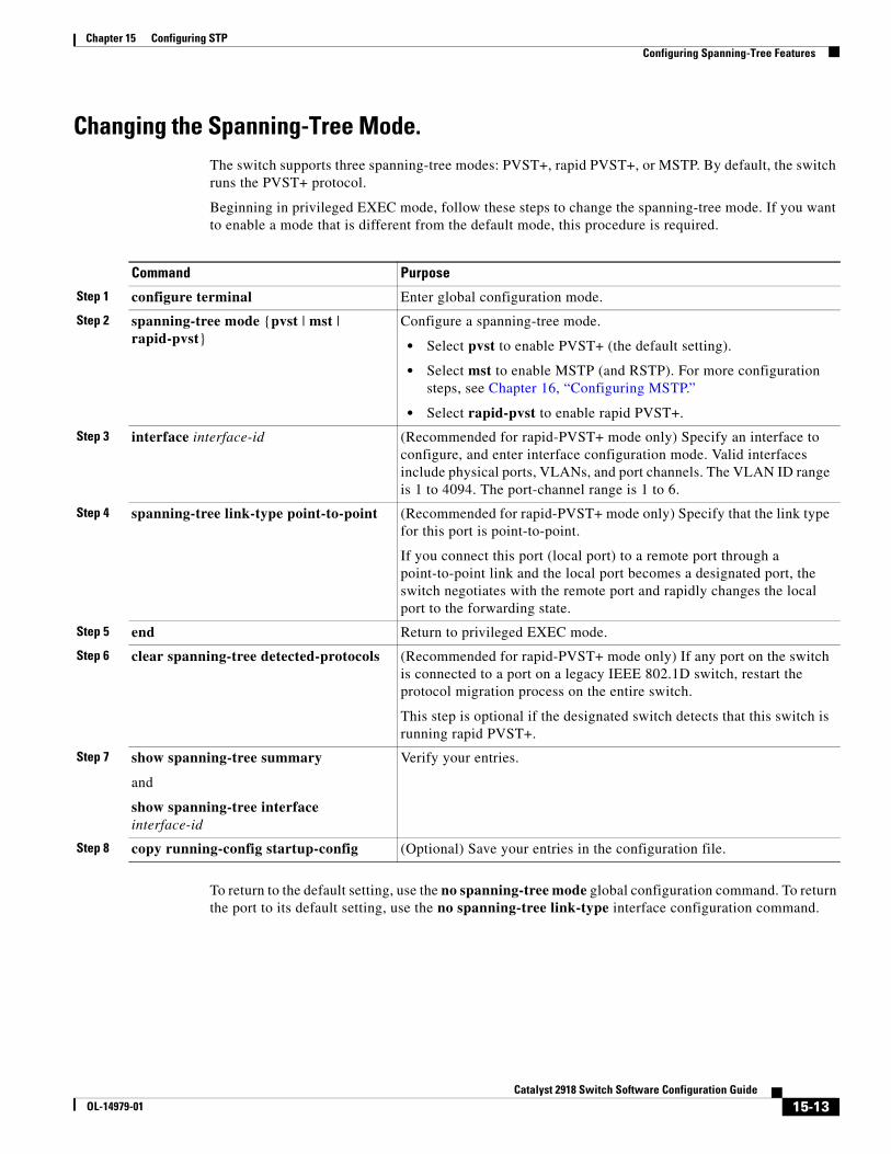
Chapter 15 Configuring STPConfiguring Spanning-Tree Features
Changing the Spanning-Tree Mode.The switch supports three spanning-tree modes: PVST+, rapid PVST+, or MSTP. By default, the switch runs the PVST+ protocol.
Beginning in privileged EXEC mode, follow these steps to change the spanning-tree mode. If you want to enable a mode that is different from the default mode, this procedure is required.
Command Purpose
Step 1 configure terminal Enter global configuration mode.
Step 2 spanning-tree mode {pvst | mst | rapid-pvst}
Configure a spanning-tree mode.
• Select pvst to enable PVST+ (the default setting).
• Select mst to enable MSTP (and RSTP). For more configuration steps, see Chapter 16, “Configuring MSTP.”
• Select rapid-pvst to enable rapid PVST+.
Step 3 interface interface-id (Recommended for rapid-PVST+ mode only) Specify an interface to configure, and enter interface configuration mode. Valid interfaces include physical ports, VLANs, and port channels. The VLAN ID range is 1 to 4094. The port-channel range is 1 to 6.
Step 4 spanning-tree link-type point-to-point (Recommended for rapid-PVST+ mode only) Specify that the link type for this port is point-to-point.
If you connect this port (local port) to a remote port through a point-to-point link and the local port becomes a designated port, the switch negotiates with the remote port and rapidly changes the local port to the forwarding state.
Step 5 end Return to privileged EXEC mode.
Step 6 clear spanning-tree detected-protocols (Recommended for rapid-PVST+ mode only) If any port on the switch is connected to a port on a legacy IEEE 802.1D switch, restart the protocol migration process on the entire switch.
This step is optional if the designated switch detects that this switch is running rapid PVST+.
Step 7 show spanning-tree summary
and
show spanning-tree interface interface-id
Verify your entries.
Step 8 copy running-config startup-config (Optional) Save your entries in the configuration file.
To return to the default setting, use the no spanning-tree mode global configuration command. To return the port to its default setting, use the no spanning-tree link-type interface configuration command.
15-13Catalyst 2918 Switch Software Configuration Guide
OL-14979-01
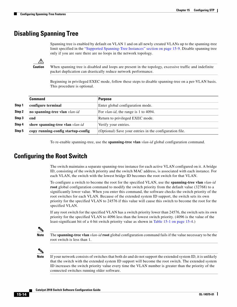
Chapter 15 Configuring STPConfiguring Spanning-Tree Features
Disabling Spanning TreeSpanning tree is enabled by default on VLAN 1 and on all newly created VLANs up to the spanning-tree limit specified in the “Supported Spanning-Tree Instances” section on page 15-9. Disable spanning tree only if you are sure there are no loops in the network topology.
Caution When spanning tree is disabled and loops are present in the topology, excessive traffic and indefinite packet duplication can drastically reduce network performance.
Beginning in privileged EXEC mode, follow these steps to disable spanning-tree on a per-VLAN basis. This procedure is optional.
Command Purpose
Step 1 configure terminal Enter global configuration mode.
Step 2 no spanning-tree vlan vlan-id For vlan-id, the range is 1 to 4094.
Step 3 end Return to privileged EXEC mode.
Step 4 show spanning-tree vlan vlan-id Verify your entries.
Step 5 copy running-config startup-config (Optional) Save your entries in the configuration file.
To re-enable spanning-tree, use the spanning-tree vlan vlan-id global configuration command.
Configuring the Root SwitchThe switch maintains a separate spanning-tree instance for each active VLAN configured on it. A bridge ID, consisting of the switch priority and the switch MAC address, is associated with each instance. For each VLAN, the switch with the lowest bridge ID becomes the root switch for that VLAN.
To configure a switch to become the root for the specified VLAN, use the spanning-tree vlan vlan-id root global configuration command to modify the switch priority from the default value (32768) to a significantly lower value. When you enter this command, the software checks the switch priority of the root switches for each VLAN. Because of the extended system ID support, the switch sets its own priority for the specified VLAN to 24576 if this value will cause this switch to become the root for the specified VLAN.
If any root switch for the specified VLAN has a switch priority lower than 24576, the switch sets its own priority for the specified VLAN to 4096 less than the lowest switch priority. (4096 is the value of the least-significant bit of a 4-bit switch priority value as shown in Table 15-1 on page 15-4.)
Note The spanning-tree vlan vlan-id root global configuration command fails if the value necessary to be the root switch is less than 1.
Note If your network consists of switches that both do and do not support the extended system ID, it is unlikely that the switch with the extended system ID support will become the root switch. The extended system ID increases the switch priority value every time the VLAN number is greater than the priority of the connected switches running older software.
15-14Catalyst 2918 Switch Software Configuration Guide
OL-14979-01
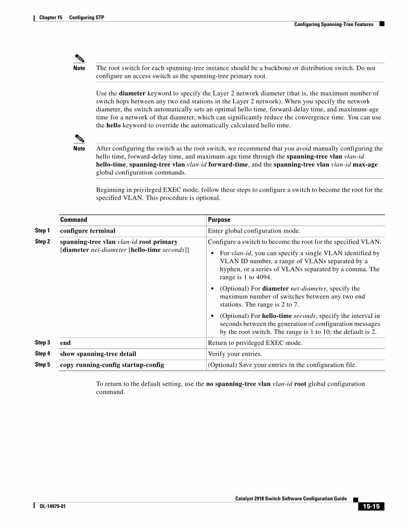
Chapter 15 Configuring STPConfiguring Spanning-Tree Features
Note The root switch for each spanning-tree instance should be a backbone or distribution switch. Do not configure an access switch as the spanning-tree primary root.
Use the diameter keyword to specify the Layer 2 network diameter (that is, the maximum number of switch hops between any two end stations in the Layer 2 network). When you specify the network diameter, the switch automatically sets an optimal hello time, forward-delay time, and maximum-age time for a network of that diameter, which can significantly reduce the convergence time. You can use the hello keyword to override the automatically calculated hello time.
Note After configuring the switch as the root switch, we recommend that you avoid manually configuring the hello time, forward-delay time, and maximum-age time through the spanning-tree vlan vlan-id hello-time, spanning-tree vlan vlan-id forward-time, and the spanning-tree vlan vlan-id max-age global configuration commands.
Beginning in privileged EXEC mode, follow these steps to configure a switch to become the root for the specified VLAN. This procedure is optional.
Command Purpose
Step 1 configure terminal Enter global configuration mode.
Step 2 spanning-tree vlan vlan-id root primary [diameter net-diameter [hello-time seconds]]
Configure a switch to become the root for the specified VLAN.
• For vlan-id, you can specify a single VLAN identified by VLAN ID number, a range of VLANs separated by a hyphen, or a series of VLANs separated by a comma. The range is 1 to 4094.
• (Optional) For diameter net-diameter, specify the maximum number of switches between any two end stations. The range is 2 to 7.
• (Optional) For hello-time seconds, specify the interval in seconds between the generation of configuration messages by the root switch. The range is 1 to 10; the default is 2.
Step 3 end Return to privileged EXEC mode.
Step 4 show spanning-tree detail Verify your entries.
Step 5 copy running-config startup-config (Optional) Save your entries in the configuration file.
To return to the default setting, use the no spanning-tree vlan vlan-id root global configuration command.
15-15Catalyst 2918 Switch Software Configuration Guide
OL-14979-01
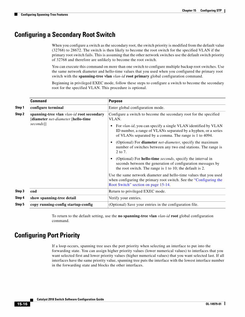
Chapter 15 Configuring STPConfiguring Spanning-Tree Features
Configuring a Secondary Root SwitchWhen you configure a switch as the secondary root, the switch priority is modified from the default value (32768) to 28672. The switch is then likely to become the root switch for the specified VLAN if the primary root switch fails. This is assuming that the other network switches use the default switch priority of 32768 and therefore are unlikely to become the root switch.
You can execute this command on more than one switch to configure multiple backup root switches. Use the same network diameter and hello-time values that you used when you configured the primary root switch with the spanning-tree vlan vlan-id root primary global configuration command.
Beginning in privileged EXEC mode, follow these steps to configure a switch to become the secondary root for the specified VLAN. This procedure is optional.
Command Purpose
Step 1 configure terminal Enter global configuration mode.
Step 2 spanning-tree vlan vlan-id root secondary [diameter net-diameter [hello-time seconds]]
Configure a switch to become the secondary root for the specified VLAN.
• For vlan-id, you can specify a single VLAN identified by VLAN ID number, a range of VLANs separated by a hyphen, or a series of VLANs separated by a comma. The range is 1 to 4094.
• (Optional) For diameter net-diameter, specify the maximum number of switches between any two end stations. The range is 2 to 7.
• (Optional) For hello-time seconds, specify the interval in seconds between the generation of configuration messages by the root switch. The range is 1 to 10; the default is 2.
Use the same network diameter and hello-time values that you used when configuring the primary root switch. See the “Configuring the Root Switch” section on page 15-14.
Step 3 end Return to privileged EXEC mode.
Step 4 show spanning-tree detail Verify your entries.
Step 5 copy running-config startup-config (Optional) Save your entries in the configuration file.
To return to the default setting, use the no spanning-tree vlan vlan-id root global configuration command.
Configuring Port PriorityIf a loop occurs, spanning tree uses the port priority when selecting an interface to put into the forwarding state. You can assign higher priority values (lower numerical values) to interfaces that you want selected first and lower priority values (higher numerical values) that you want selected last. If all interfaces have the same priority value, spanning tree puts the interface with the lowest interface number in the forwarding state and blocks the other interfaces.
15-16Catalyst 2918 Switch Software Configuration Guide
OL-14979-01
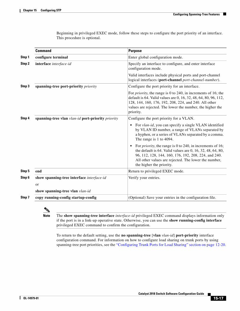
Chapter 15 Configuring STPConfiguring Spanning-Tree Features
Beginning in privileged EXEC mode, follow these steps to configure the port priority of an interface. This procedure is optional.
Command Purpose
Step 1 configure terminal Enter global configuration mode.
Step 2 interface interface-id Specify an interface to configure, and enter interface configuration mode.
Valid interfaces include physical ports and port-channel logical interfaces (port-channel port-channel-number).
Step 3 spanning-tree port-priority priority Configure the port priority for an interface.
For priority, the range is 0 to 240, in increments of 16; the default is 64. Valid values are 0, 16, 32, 48, 64, 80, 96, 112, 128, 144, 160, 176, 192, 208, 224, and 240. All other values are rejected. The lower the number, the higher the priority.
Step 4 spanning-tree vlan vlan-id port-priority priority Configure the port priority for a VLAN.
• For vlan-id, you can specify a single VLAN identified by VLAN ID number, a range of VLANs separated by a hyphen, or a series of VLANs separated by a comma. The range is 1 to 4094.
• For priority, the range is 0 to 240, in increments of 16; the default is 64. Valid values are 0, 16, 32, 48, 64, 80, 96, 112, 128, 144, 160, 176, 192, 208, 224, and 240. All other values are rejected. The lower the number, the higher the priority.
Step 5 end Return to privileged EXEC mode.
Step 6 show spanning-tree interface interface-id
or
show spanning-tree vlan vlan-id
Verify your entries.
Step 7 copy running-config startup-config (Optional) Save your entries in the configuration file.
Note The show spanning-tree interface interface-id privileged EXEC command displays information only if the port is in a link-up operative state. Otherwise, you can use the show running-config interface privileged EXEC command to confirm the configuration.
To return to the default setting, use the no spanning-tree [vlan vlan-id] port-priority interface configuration command. For information on how to configure load sharing on trunk ports by using spanning-tree port priorities, see the “Configuring Trunk Ports for Load Sharing” section on page 12-20.
15-17Catalyst 2918 Switch Software Configuration Guide
OL-14979-01
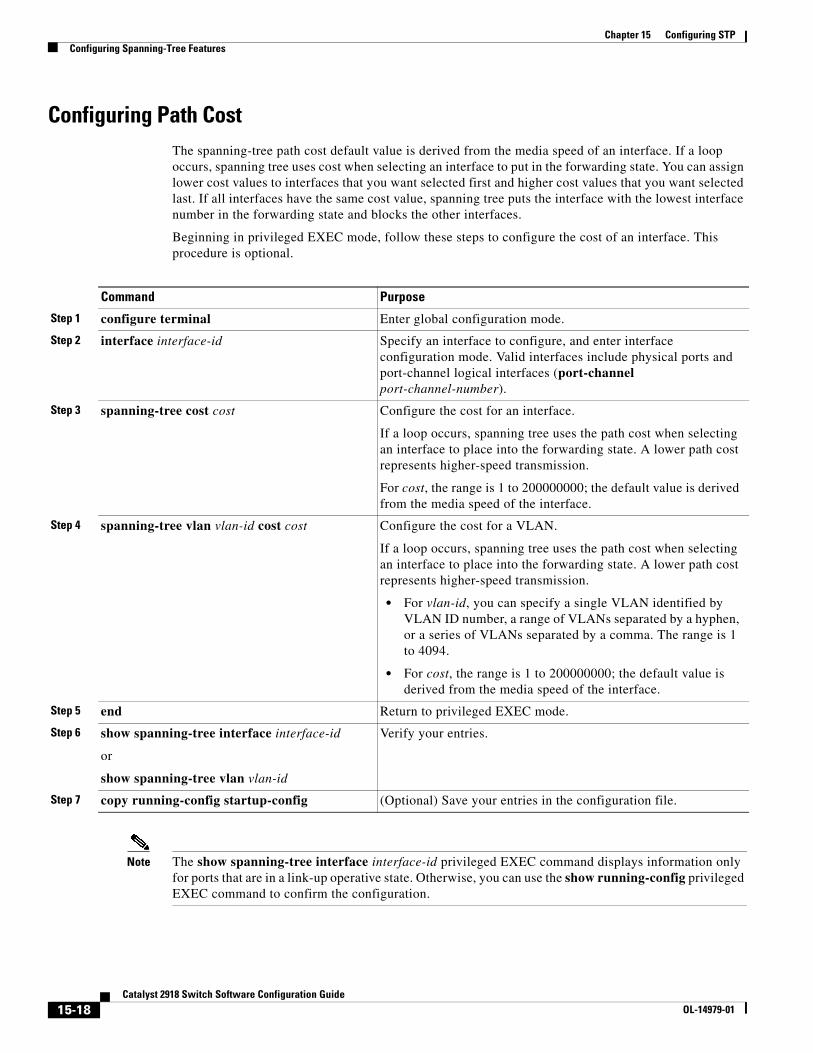
Chapter 15 Configuring STPConfiguring Spanning-Tree Features
Configuring Path CostThe spanning-tree path cost default value is derived from the media speed of an interface. If a loop occurs, spanning tree uses cost when selecting an interface to put in the forwarding state. You can assign lower cost values to interfaces that you want selected first and higher cost values that you want selected last. If all interfaces have the same cost value, spanning tree puts the interface with the lowest interface number in the forwarding state and blocks the other interfaces.
Beginning in privileged EXEC mode, follow these steps to configure the cost of an interface. This procedure is optional.
Command Purpose
Step 1 configure terminal Enter global configuration mode.
Step 2 interface interface-id Specify an interface to configure, and enter interface configuration mode. Valid interfaces include physical ports and port-channel logical interfaces (port-channel port-channel-number).
Step 3 spanning-tree cost cost Configure the cost for an interface.
If a loop occurs, spanning tree uses the path cost when selecting an interface to place into the forwarding state. A lower path cost represents higher-speed transmission.
For cost, the range is 1 to 200000000; the default value is derived from the media speed of the interface.
Step 4 spanning-tree vlan vlan-id cost cost Configure the cost for a VLAN.
If a loop occurs, spanning tree uses the path cost when selecting an interface to place into the forwarding state. A lower path cost represents higher-speed transmission.
• For vlan-id, you can specify a single VLAN identified by VLAN ID number, a range of VLANs separated by a hyphen, or a series of VLANs separated by a comma. The range is 1 to 4094.
• For cost, the range is 1 to 200000000; the default value is derived from the media speed of the interface.
Step 5 end Return to privileged EXEC mode.
Step 6 show spanning-tree interface interface-id
or
show spanning-tree vlan vlan-id
Verify your entries.
Step 7 copy running-config startup-config (Optional) Save your entries in the configuration file.
Note The show spanning-tree interface interface-id privileged EXEC command displays information only for ports that are in a link-up operative state. Otherwise, you can use the show running-config privileged EXEC command to confirm the configuration.
15-18Catalyst 2918 Switch Software Configuration Guide
OL-14979-01
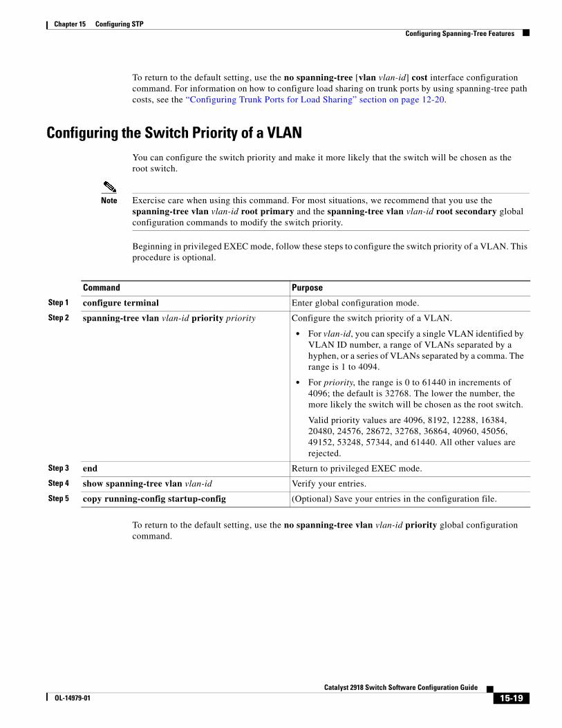
Chapter 15 Configuring STPConfiguring Spanning-Tree Features
To return to the default setting, use the no spanning-tree [vlan vlan-id] cost interface configuration command. For information on how to configure load sharing on trunk ports by using spanning-tree path costs, see the “Configuring Trunk Ports for Load Sharing” section on page 12-20.
Configuring the Switch Priority of a VLANYou can configure the switch priority and make it more likely that the switch will be chosen as the root switch.
Note Exercise care when using this command. For most situations, we recommend that you use the spanning-tree vlan vlan-id root primary and the spanning-tree vlan vlan-id root secondary global configuration commands to modify the switch priority.
Beginning in privileged EXEC mode, follow these steps to configure the switch priority of a VLAN. This procedure is optional.
Command Purpose
Step 1 configure terminal Enter global configuration mode.
Step 2 spanning-tree vlan vlan-id priority priority Configure the switch priority of a VLAN.
• For vlan-id, you can specify a single VLAN identified by VLAN ID number, a range of VLANs separated by a hyphen, or a series of VLANs separated by a comma. The range is 1 to 4094.
• For priority, the range is 0 to 61440 in increments of 4096; the default is 32768. The lower the number, the more likely the switch will be chosen as the root switch.
Valid priority values are 4096, 8192, 12288, 16384, 20480, 24576, 28672, 32768, 36864, 40960, 45056, 49152, 53248, 57344, and 61440. All other values are rejected.
Step 3 end Return to privileged EXEC mode.
Step 4 show spanning-tree vlan vlan-id Verify your entries.
Step 5 copy running-config startup-config (Optional) Save your entries in the configuration file.
To return to the default setting, use the no spanning-tree vlan vlan-id priority global configuration command.
15-19Catalyst 2918 Switch Software Configuration Guide
OL-14979-01
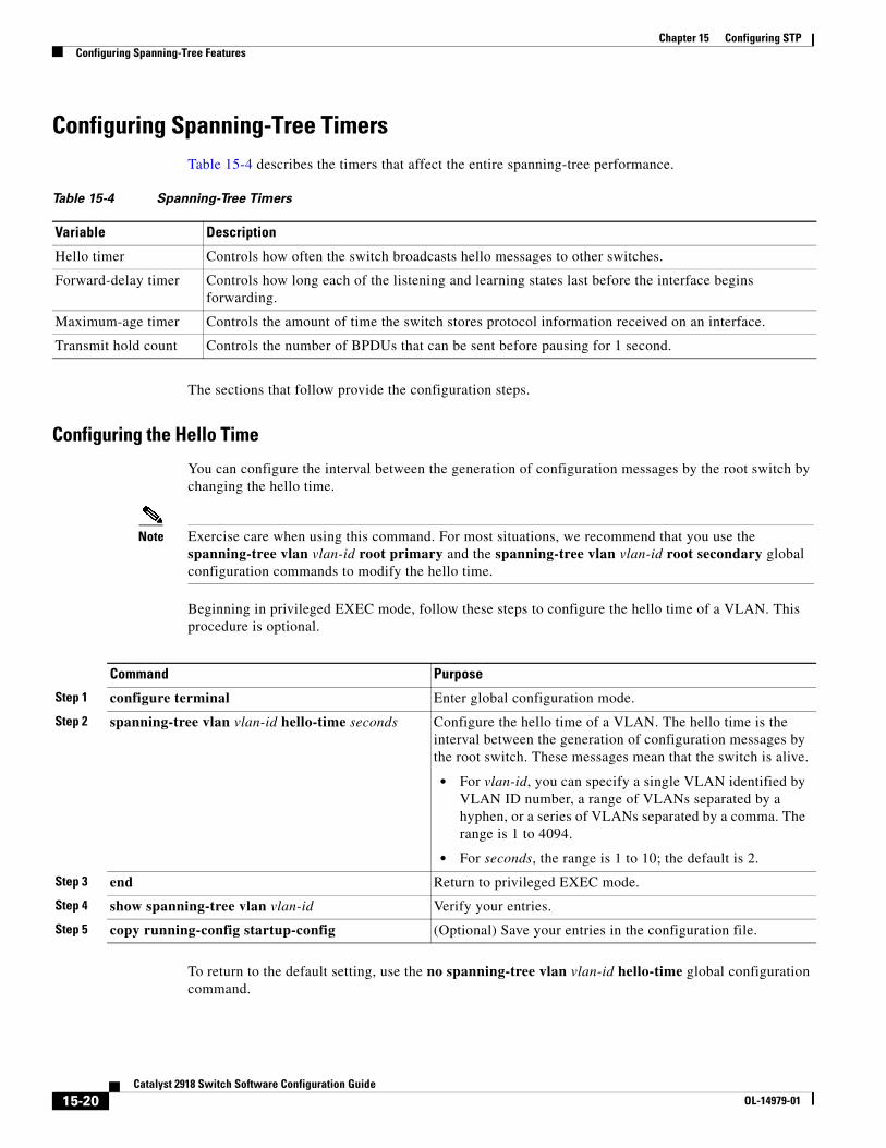
Chapter 15 Configuring STPConfiguring Spanning-Tree Features
Configuring Spanning-Tree TimersTable 15-4 describes the timers that affect the entire spanning-tree performance.
Table 15-4 Spanning-Tree Timers
Variable Description
Hello timer Controls how often the switch broadcasts hello messages to other switches.
Forward-delay timer Controls how long each of the listening and learning states last before the interface begins forwarding.
Maximum-age timer Controls the amount of time the switch stores protocol information received on an interface.
Transmit hold count Controls the number of BPDUs that can be sent before pausing for 1 second.
The sections that follow provide the configuration steps.
Configuring the Hello Time
You can configure the interval between the generation of configuration messages by the root switch by changing the hello time.
Note Exercise care when using this command. For most situations, we recommend that you use the spanning-tree vlan vlan-id root primary and the spanning-tree vlan vlan-id root secondary global configuration commands to modify the hello time.
Beginning in privileged EXEC mode, follow these steps to configure the hello time of a VLAN. This procedure is optional.
Command Purpose
Step 1 configure terminal Enter global configuration mode.
Step 2 spanning-tree vlan vlan-id hello-time seconds Configure the hello time of a VLAN. The hello time is the interval between the generation of configuration messages by the root switch. These messages mean that the switch is alive.
• For vlan-id, you can specify a single VLAN identified by VLAN ID number, a range of VLANs separated by a hyphen, or a series of VLANs separated by a comma. The range is 1 to 4094.
• For seconds, the range is 1 to 10; the default is 2.
Step 3 end Return to privileged EXEC mode.
Step 4 show spanning-tree vlan vlan-id Verify your entries.
Step 5 copy running-config startup-config (Optional) Save your entries in the configuration file.
To return to the default setting, use the no spanning-tree vlan vlan-id hello-time global configuration command.
15-20Catalyst 2918 Switch Software Configuration Guide
OL-14979-01
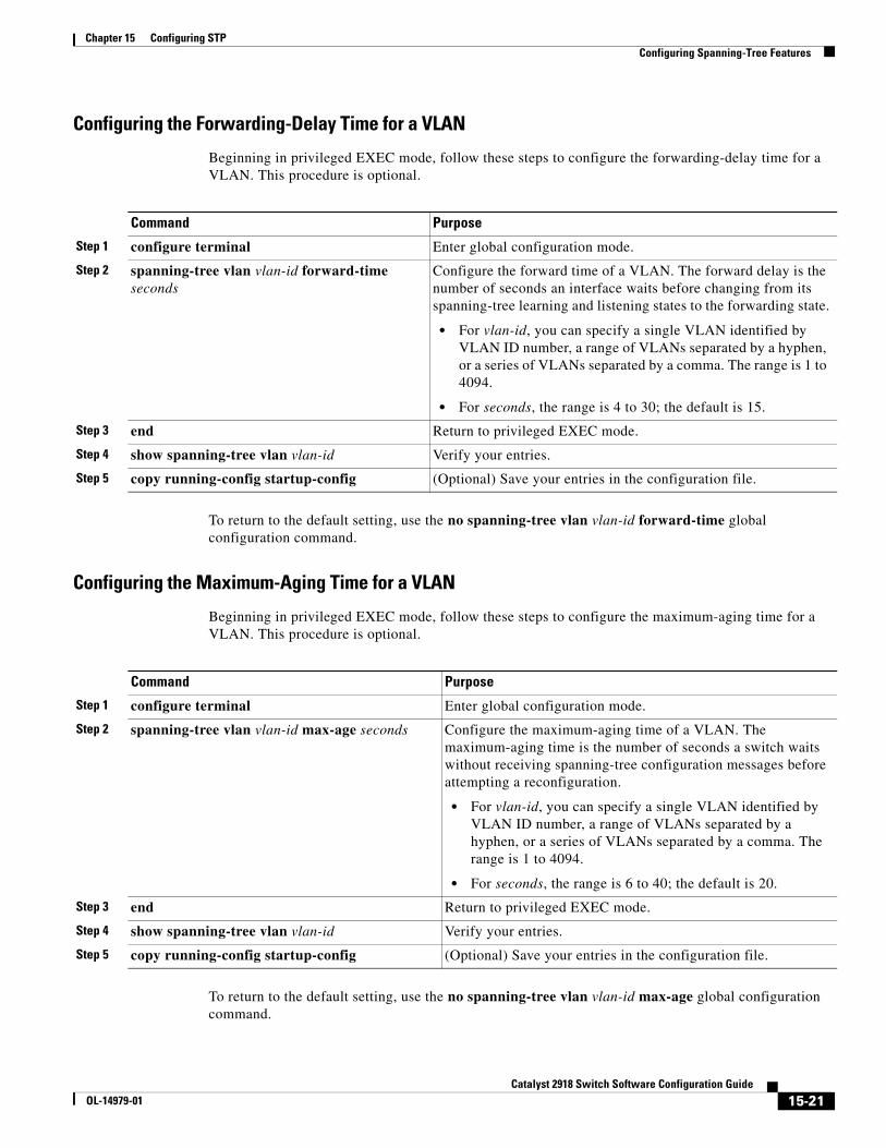
Chapter 15 Configuring STPConfiguring Spanning-Tree Features
Configuring the Forwarding-Delay Time for a VLAN
Beginning in privileged EXEC mode, follow these steps to configure the forwarding-delay time for a VLAN. This procedure is optional.
Command Purpose
Step 1 configure terminal Enter global configuration mode.
Step 2 spanning-tree vlan vlan-id forward-time seconds
Configure the forward time of a VLAN. The forward delay is the number of seconds an interface waits before changing from its spanning-tree learning and listening states to the forwarding state.
• For vlan-id, you can specify a single VLAN identified by VLAN ID number, a range of VLANs separated by a hyphen, or a series of VLANs separated by a comma. The range is 1 to 4094.
• For seconds, the range is 4 to 30; the default is 15.
Step 3 end Return to privileged EXEC mode.
Step 4 show spanning-tree vlan vlan-id Verify your entries.
Step 5 copy running-config startup-config (Optional) Save your entries in the configuration file.
To return to the default setting, use the no spanning-tree vlan vlan-id forward-time global configuration command.
Configuring the Maximum-Aging Time for a VLAN
Beginning in privileged EXEC mode, follow these steps to configure the maximum-aging time for a VLAN. This procedure is optional.
Command Purpose
Step 1 configure terminal Enter global configuration mode.
Step 2 spanning-tree vlan vlan-id max-age seconds Configure the maximum-aging time of a VLAN. The maximum-aging time is the number of seconds a switch waits without receiving spanning-tree configuration messages before attempting a reconfiguration.
• For vlan-id, you can specify a single VLAN identified by VLAN ID number, a range of VLANs separated by a hyphen, or a series of VLANs separated by a comma. The range is 1 to 4094.
• For seconds, the range is 6 to 40; the default is 20.
Step 3 end Return to privileged EXEC mode.
Step 4 show spanning-tree vlan vlan-id Verify your entries.
Step 5 copy running-config startup-config (Optional) Save your entries in the configuration file.
To return to the default setting, use the no spanning-tree vlan vlan-id max-age global configuration command.
15-21Catalyst 2918 Switch Software Configuration Guide
OL-14979-01
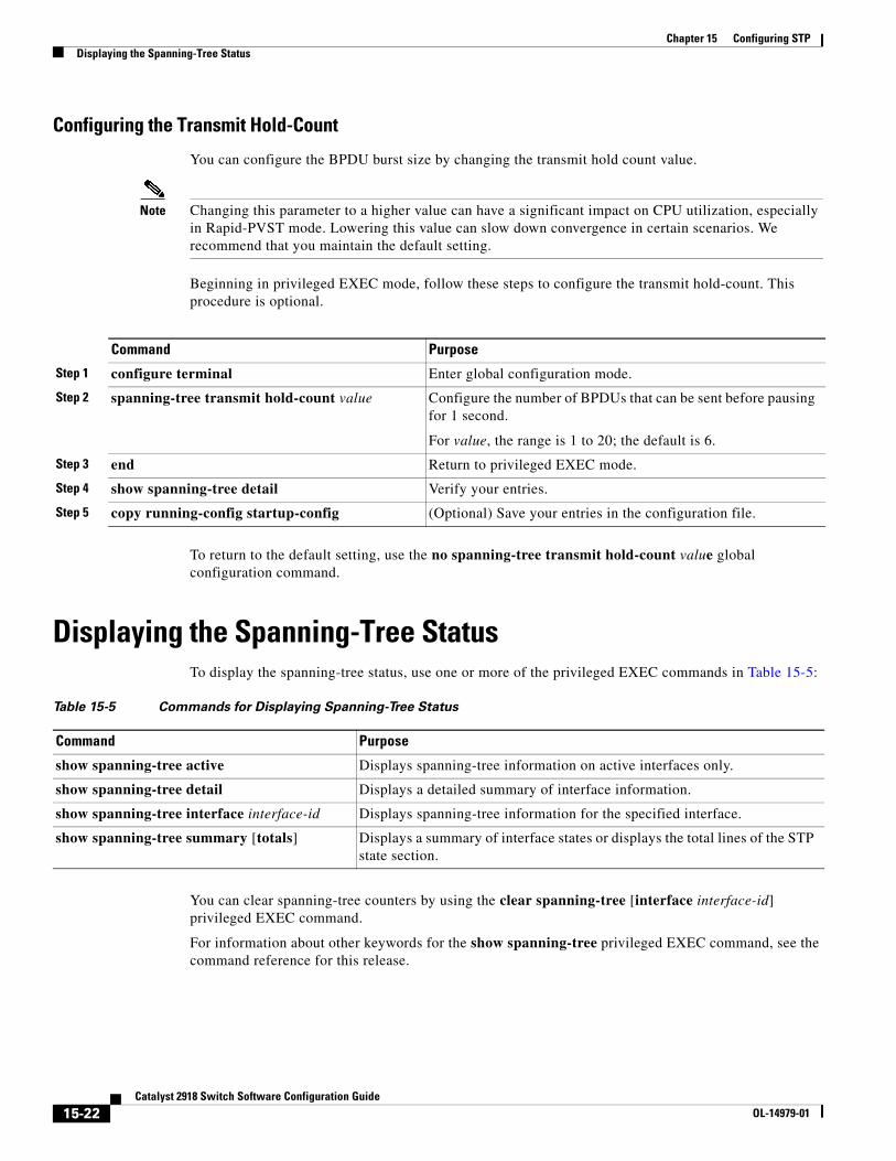
Chapter 15 Configuring STPDisplaying the Spanning-Tree Status
Configuring the Transmit Hold-Count
You can configure the BPDU burst size by changing the transmit hold count value.
Note Changing this parameter to a higher value can have a significant impact on CPU utilization, especially in Rapid-PVST mode. Lowering this value can slow down convergence in certain scenarios. We recommend that you maintain the default setting.
Beginning in privileged EXEC mode, follow these steps to configure the transmit hold-count. This procedure is optional.
Command Purpose
Step 1 configure terminal Enter global configuration mode.
Step 2 spanning-tree transmit hold-count value Configure the number of BPDUs that can be sent before pausing for 1 second.
For value, the range is 1 to 20; the default is 6.
Step 3 end Return to privileged EXEC mode.
Step 4 show spanning-tree detail Verify your entries.
Step 5 copy running-config startup-config (Optional) Save your entries in the configuration file.
To return to the default setting, use the no spanning-tree transmit hold-count value global configuration command.
Displaying the Spanning-Tree StatusTo display the spanning-tree status, use one or more of the privileged EXEC commands in Table 15-5:
Table 15-5 Commands for Displaying Spanning-Tree Status
Command Purpose
show spanning-tree active Displays spanning-tree information on active interfaces only.
show spanning-tree detail Displays a detailed summary of interface information.
show spanning-tree interface interface-id Displays spanning-tree information for the specified interface.
show spanning-tree summary [totals] Displays a summary of interface states or displays the total lines of the STP state section.
You can clear spanning-tree counters by using the clear spanning-tree [interface interface-id] privileged EXEC command.
For information about other keywords for the show spanning-tree privileged EXEC command, see the command reference for this release.
15-22Catalyst 2918 Switch Software Configuration Guide
OL-14979-01
OL-14979-01
C H A P T E R 16
Configuring MSTPThis chapter describes how to configure the Cisco implementation of the IEEE 802.1s Multiple STP (MSTP) on the Catalyst 2918 switch.
Note The multiple spanning-tree (MST) implementation in Cisco IOS Release 12.2(44)SE is based on the IEEE 802.1s standard.
The MSTP enables multiple VLANs to be mapped to the same spanning-tree instance, reducing the number of spanning-tree instances needed to support a large number of VLANs. The MSTP provides for multiple forwarding paths for data traffic and enables load balancing. It improves the fault tolerance of the network because a failure in one instance (forwarding path) does not affect other instances (forwarding paths). The most common initial deployment of MSTP is in the backbone and distribution layers of a Layer 2 switched network. This deployment provides the highly available network required in a service-provider environment.
When the switch is in the MST mode, the Rapid Spanning Tree Protocol (RSTP), which is based on IEEE 802.1w, is automatically enabled. The RSTP provides rapid convergence of the spanning tree through explicit handshaking that eliminates the IEEE 802.1D forwarding delay and quickly transitions root ports and designated ports to the forwarding state.
Both MSTP and RSTP improve the spanning-tree operation and maintain backward compatibility with equipment that is based on the (original) IEEE 802.1D spanning tree, with existing Cisco-proprietary Multiple Instance STP (MISTP), and with existing Cisco per-VLAN spanning-tree plus (PVST+) and rapid per-VLAN spanning-tree plus (rapid PVST+). For information about PVST+ and rapid PVST+, see Chapter 15, “Configuring STP.” For information about other spanning-tree features such as Port Fast, UplinkFast, root guard, and so forth, see Chapter 17, “Configuring Optional Spanning-Tree Features.”
Note For complete syntax and usage information for the commands used in this chapter, see the command reference for this release.
This chapter consists of these sections:
• Understanding MSTP, page 16-2
• Understanding RSTP, page 16-8
• Configuring MSTP Features, page 16-13
• Displaying the MST Configuration and Status, page 16-26
16-1Catalyst 2918 Switch Software Configuration Guide
Chapter 16 Configuring MSTPUnderstanding MSTP
Understanding MSTPMSTP, which uses RSTP for rapid convergence, enables VLANs to be grouped into a spanning-tree instance, with each instance having a spanning-tree topology independent of other spanning-tree instances. This architecture provides multiple forwarding paths for data traffic, enables load balancing, and reduces the number of spanning-tree instances required to support a large number of VLANs.
These sections describe how the MSTP works:
• Multiple Spanning-Tree Regions, page 16-2
• IST, CIST, and CST, page 16-2
• Hop Count, page 16-5
• Boundary Ports, page 16-6
• IEEE 802.1s Implementation, page 16-6
• Interoperability with IEEE 802.1D STP, page 16-8
For configuration information, see the “Configuring MSTP Features” section on page 16-13.
Multiple Spanning-Tree RegionsFor switches to participate in multiple spanning-tree (MST) instances, you must consistently configure the switches with the same MST configuration information. A collection of interconnected switches that have the same MST configuration comprises an MST region as shown in Figure 16-1 on page 16-4.
The MST configuration controls to which MST region each switch belongs. The configuration includes the name of the region, the revision number, and the MST VLAN-to-instance assignment map. You configure the switch for a region by using the spanning-tree mst configuration global configuration command, after which the switch enters the MST configuration mode. From this mode, you can map VLANs to an MST instance by using the instance MST configuration command, specify the region name by using the name MST configuration command, and set the revision number by using the revision MST configuration command.
A region can have one or multiple members with the same MST configuration. Each member must be capable of processing RSTP bridge protocol data units (BPDUs). There is no limit to the number of MST regions in a network, but each region can support up to 65 spanning-tree instances. Instances can be identified by any number in the range from 0 to 4094. You can assign a VLAN to only one spanning-tree instance at a time.
IST, CIST, and CSTUnlike PVST+ and rapid PVST+ in which all the spanning-tree instances are independent, the MSTP establishes and maintains two types of spanning trees:
• An internal spanning tree (IST), which is the spanning tree that runs in an MST region.
Within each MST region, the MSTP maintains multiple spanning-tree instances. Instance 0 is a special instance for a region, known as the internal spanning tree (IST). All other MST instances are numbered from 1 to 4094.
16-2Catalyst 2918 Switch Software Configuration Guide
OL-14979-01
Chapter 16 Configuring MSTPUnderstanding MSTP
The IST is the only spanning-tree instance that sends and receives BPDUs. All of the other spanning-tree instance information is contained in M-records, which are encapsulated within MSTP BPDUs. Because the MSTP BPDU carries information for all instances, the number of BPDUs that need to be processed to support multiple spanning-tree instances is significantly reduced.
All MST instances within the same region share the same protocol timers, but each MST instance has its own topology parameters, such as root switch ID, root path cost, and so forth. By default, all VLANs are assigned to the IST.
An MST instance is local to the region; for example, MST instance 1 in region A is independent of MST instance 1 in region B, even if regions A and B are interconnected.
• A common and internal spanning tree (CIST), which is a collection of the ISTs in each MST region, and the common spanning tree (CST) that interconnects the MST regions and single spanning trees.
The spanning tree computed in a region appears as a subtree in the CST that encompasses the entire switched domain. The CIST is formed by the spanning-tree algorithm running among switches that support the IEEE 802.1w, IEEE 802.1s, and IEEE 802.1D standards. The CIST inside an MST region is the same as the CST outside a region.
For more information, see the “Operations Within an MST Region” section on page 16-3 and the “Operations Between MST Regions” section on page 16-3.
Note The implementation of the IEEE 802.1s standard, changes some of the terminology associated with MST implementations. For a summary of these changes, see Table 15-1 on page 15-4.
Operations Within an MST Region
The IST connects all the MSTP switches in a region. When the IST converges, the root of the IST becomes the CIST regional root (called the IST master before the implementation of the IEEE 802.1s standard) as shown in Figure 16-1 on page 16-4. It is the switch within the region with the lowest switch ID and path cost to the CIST root. The CIST regional root is also the CIST root if there is only one region in the network. If the CIST root is outside the region, one of the MSTP switches at the boundary of the region is selected as the CIST regional root.
When an MSTP switch initializes, it sends BPDUs claiming itself as the root of the CIST and the CIST regional root, with both of the path costs to the CIST root and to the CIST regional root set to zero. The switch also initializes all of its MST instances and claims to be the root for all of them. If the switch receives superior MST root information (lower switch ID, lower path cost, and so forth) than currently stored for the port, it relinquishes its claim as the CIST regional root.
During initialization, a region might have many subregions, each with its own CIST regional root. As switches receive superior IST information, they leave their old subregions and join the new subregion that contains the true CIST regional root. Thus all subregions shrink, except for the one that contains the true CIST regional root.
For correct operation, all switches in the MST region must agree on the same CIST regional root. Therefore, any two switches in the region only synchronize their port roles for an MST instance if they converge to a common CIST regional root.
Operations Between MST Regions
If there are multiple regions or legacy IEEE 802.1D switches within the network, MSTP establishes and maintains the CST, which includes all MST regions and all legacy STP switches in the network. The MST instances combine with the IST at the boundary of the region to become the CST.
16-3Catalyst 2918 Switch Software Configuration Guide
OL-14979-01
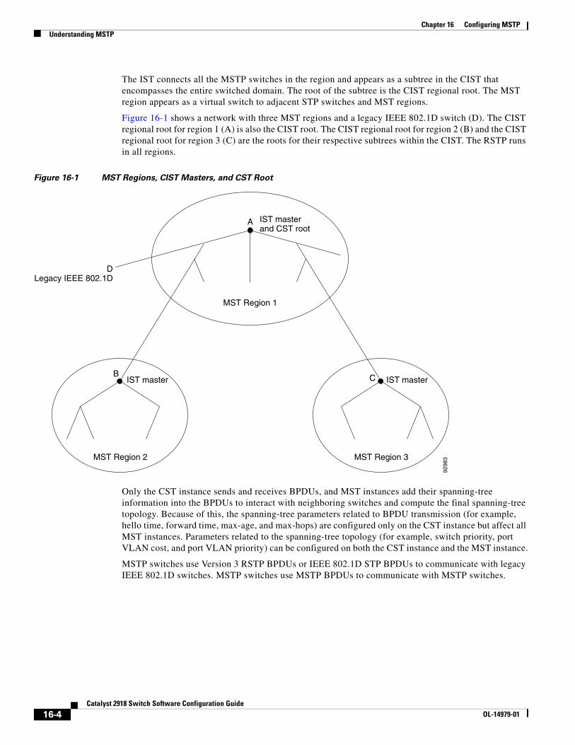
Chapter 16 Configuring MSTPUnderstanding MSTP
The IST connects all the MSTP switches in the region and appears as a subtree in the CIST that encompasses the entire switched domain. The root of the subtree is the CIST regional root. The MST region appears as a virtual switch to adjacent STP switches and MST regions.
Figure 16-1 shows a network with three MST regions and a legacy IEEE 802.1D switch (D). The CIST regional root for region 1 (A) is also the CIST root. The CIST regional root for region 2 (B) and the CIST regional root for region 3 (C) are the roots for their respective subtrees within the CIST. The RSTP runs in all regions.
Figure 16-1 MST Regions, CIST Masters, and CST Root
IST masterand CST root
IST master IST master
A
MST Region 1
DLegacy IEEE 802.1D
B
MST Region 2 MST Region 3
C
9298
3
Only the CST instance sends and receives BPDUs, and MST instances add their spanning-tree information into the BPDUs to interact with neighboring switches and compute the final spanning-tree topology. Because of this, the spanning-tree parameters related to BPDU transmission (for example, hello time, forward time, max-age, and max-hops) are configured only on the CST instance but affect all MST instances. Parameters related to the spanning-tree topology (for example, switch priority, port VLAN cost, and port VLAN priority) can be configured on both the CST instance and the MST instance.
MSTP switches use Version 3 RSTP BPDUs or IEEE 802.1D STP BPDUs to communicate with legacy IEEE 802.1D switches. MSTP switches use MSTP BPDUs to communicate with MSTP switches.
16-4Catalyst 2918 Switch Software Configuration Guide
OL-14979-01
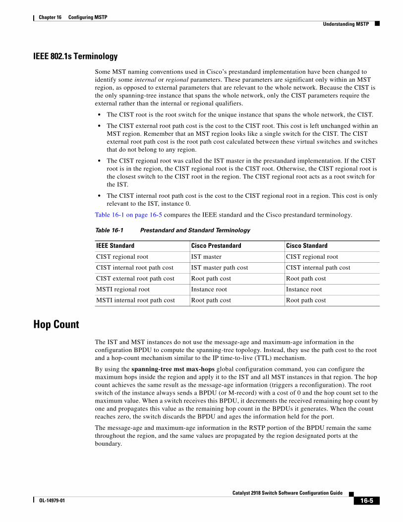
Chapter 16 Configuring MSTPUnderstanding MSTP
IEEE 802.1s Terminology
Some MST naming conventions used in Cisco’s prestandard implementation have been changed to identify some internal or regional parameters. These parameters are significant only within an MST region, as opposed to external parameters that are relevant to the whole network. Because the CIST is the only spanning-tree instance that spans the whole network, only the CIST parameters require the external rather than the internal or regional qualifiers.
• The CIST root is the root switch for the unique instance that spans the whole network, the CIST.
• The CIST external root path cost is the cost to the CIST root. This cost is left unchanged within an MST region. Remember that an MST region looks like a single switch for the CIST. The CIST external root path cost is the root path cost calculated between these virtual switches and switches that do not belong to any region.
• The CIST regional root was called the IST master in the prestandard implementation. If the CIST root is in the region, the CIST regional root is the CIST root. Otherwise, the CIST regional root is the closest switch to the CIST root in the region. The CIST regional root acts as a root switch for the IST.
• The CIST internal root path cost is the cost to the CIST regional root in a region. This cost is only relevant to the IST, instance 0.
Table 16-1 on page 16-5 compares the IEEE standard and the Cisco prestandard terminology.
Table 16-1 Prestandard and Standard Terminology
IEEE Standard Cisco Prestandard Cisco Standard
CIST regional root IST master CIST regional root
CIST internal root path cost IST master path cost CIST internal path cost
CIST external root path cost Root path cost Root path cost
MSTI regional root Instance root Instance root
MSTI internal root path cost Root path cost Root path cost
Hop CountThe IST and MST instances do not use the message-age and maximum-age information in the configuration BPDU to compute the spanning-tree topology. Instead, they use the path cost to the root and a hop-count mechanism similar to the IP time-to-live (TTL) mechanism.
By using the spanning-tree mst max-hops global configuration command, you can configure the maximum hops inside the region and apply it to the IST and all MST instances in that region. The hop count achieves the same result as the message-age information (triggers a reconfiguration). The root switch of the instance always sends a BPDU (or M-record) with a cost of 0 and the hop count set to the maximum value. When a switch receives this BPDU, it decrements the received remaining hop count by one and propagates this value as the remaining hop count in the BPDUs it generates. When the count reaches zero, the switch discards the BPDU and ages the information held for the port.
The message-age and maximum-age information in the RSTP portion of the BPDU remain the same throughout the region, and the same values are propagated by the region designated ports at the boundary.
16-5Catalyst 2918 Switch Software Configuration Guide
OL-14979-01
Chapter 16 Configuring MSTPUnderstanding MSTP
Boundary PortsIn the Cisco prestandard implementation, a boundary port connects an MST region to a single spanning-tree region running RSTP, to a single spanning-tree region running PVST+ or rapid PVST+, or to another MST region with a different MST configuration. A boundary port also connects to a LAN, the designated switch of which is either a single spanning-tree switch or a switch with a different MST configuration.
There is no definition of a boundary port in the IEEE 802.1s standard. The IEEE 802.1Q-2002 standard identifies two kinds of messages that a port can receive: internal (coming from the same region) and external. When a message is external, it is received only by the CIST. If the CIST role is root or alternate, or if the external BPDU is a topology change, it could have an impact on the MST instances. When a message is internal, the CIST part is received by the CIST, and each MST instance receives its respective M-record. The Cisco prestandard implementation treats a port that receives an external message as a boundary port. This means a port cannot receive a mix of internal and external messages.
An MST region includes both switches and LANs. A segment belongs to the region of its designated port. Therefore, a port in a different region than the designated port for a segment is a boundary port. This definition allows two ports internal to a region to share a segment with a port belonging to a different region, creating the possibility of receiving both internal and external messages on a port.
The primary change from the Cisco prestandard implementation is that a designated port is not defined as boundary, unless it is running in an STP-compatible mode.
Note If there is a legacy STP switch on the segment, messages are always considered external.
The other change from the prestandard implementation is that the CIST regional root switch ID field is now inserted where an RSTP or legacy IEEE 802.1Q switch has the sender switch ID. The whole region performs like a single virtual switch by sending a consistent sender switch ID to neighboring switches. In this example, switch C would receive a BPDU with the same consistent sender switch ID of root, whether or not A or B is designated for the segment.
IEEE 802.1s ImplementationThe Cisco implementation of the IEEE MST standard includes features required to meet the standard, as well as some of the desirable prestandard functionality that is not yet incorporated into the published standard.
Port Role Naming Change
The boundary role is no longer in the final MST standard, but this boundary concept is maintained in Cisco’s implementation. However, an MST instance port at a boundary of the region might not follow the state of the corresponding CIST port. Two cases exist now:
• The boundary port is the root port of the CIST regional root—When the CIST instance port is proposed and is in sync, it can send back an agreement and move to the forwarding state only after all the corresponding MSTI ports are in sync (and thus forwarding). The MSTI ports now have a special master role.
16-6Catalyst 2918 Switch Software Configuration Guide
OL-14979-01
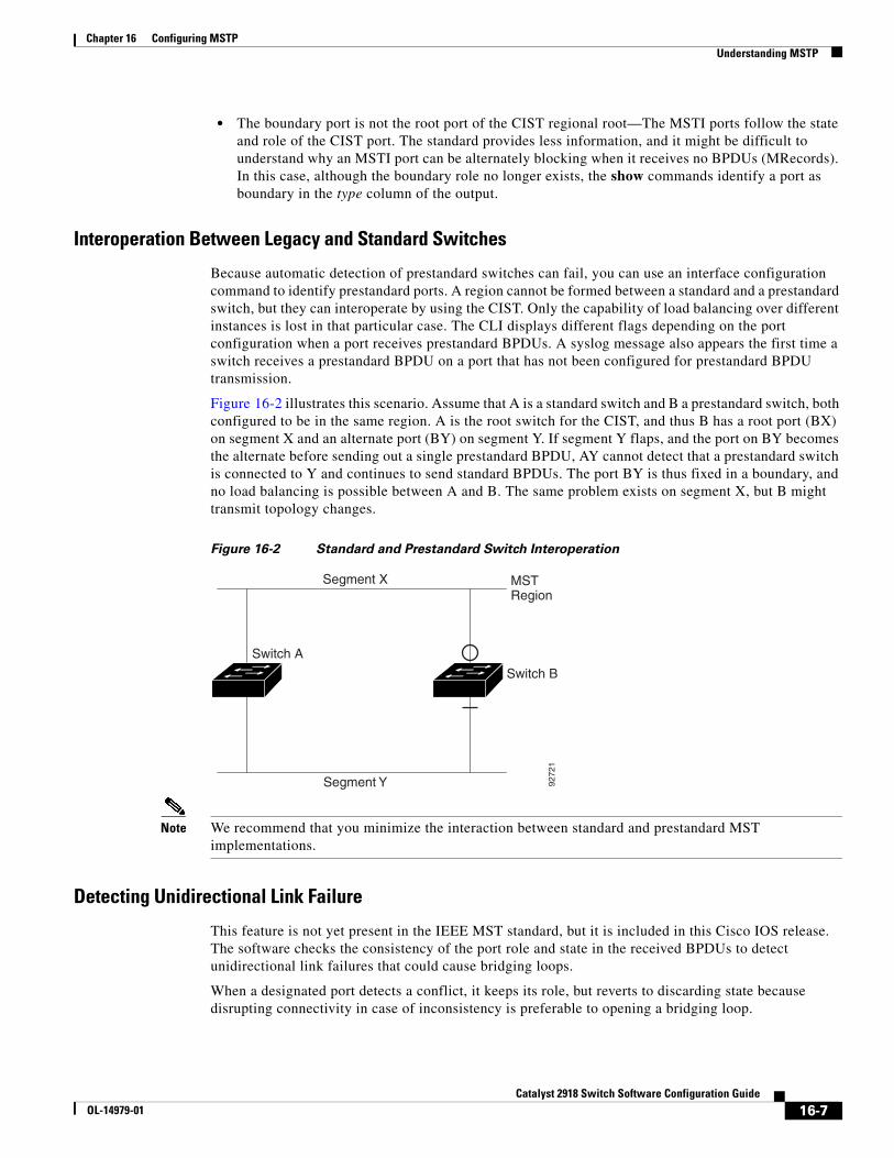
Chapter 16 Configuring MSTPUnderstanding MSTP
• The boundary port is not the root port of the CIST regional root—The MSTI ports follow the state and role of the CIST port. The standard provides less information, and it might be difficult to understand why an MSTI port can be alternately blocking when it receives no BPDUs (MRecords). In this case, although the boundary role no longer exists, the show commands identify a port as boundary in the type column of the output.
Interoperation Between Legacy and Standard Switches
Because automatic detection of prestandard switches can fail, you can use an interface configuration command to identify prestandard ports. A region cannot be formed between a standard and a prestandard switch, but they can interoperate by using the CIST. Only the capability of load balancing over different instances is lost in that particular case. The CLI displays different flags depending on the port configuration when a port receives prestandard BPDUs. A syslog message also appears the first time a switch receives a prestandard BPDU on a port that has not been configured for prestandard BPDU transmission.
Figure 16-2 illustrates this scenario. Assume that A is a standard switch and B a prestandard switch, both configured to be in the same region. A is the root switch for the CIST, and thus B has a root port (BX) on segment X and an alternate port (BY) on segment Y. If segment Y flaps, and the port on BY becomes the alternate before sending out a single prestandard BPDU, AY cannot detect that a prestandard switch is connected to Y and continues to send standard BPDUs. The port BY is thus fixed in a boundary, and no load balancing is possible between A and B. The same problem exists on segment X, but B might transmit topology changes.
Figure 16-2 Standard and Prestandard Switch Interoperation
Segment X MSTRegion
Segment Y 9272
1
Switch A
Switch B
Note We recommend that you minimize the interaction between standard and prestandard MST implementations.
Detecting Unidirectional Link Failure
This feature is not yet present in the IEEE MST standard, but it is included in this Cisco IOS release. The software checks the consistency of the port role and state in the received BPDUs to detect unidirectional link failures that could cause bridging loops.
When a designated port detects a conflict, it keeps its role, but reverts to discarding state because disrupting connectivity in case of inconsistency is preferable to opening a bridging loop.
16-7Catalyst 2918 Switch Software Configuration Guide
OL-14979-01
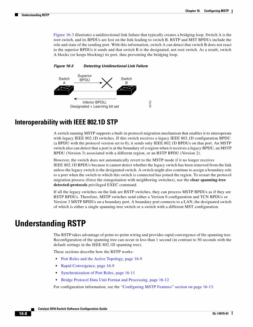
Chapter 16 Configuring MSTPUnderstanding RSTP
Figure 16-3 illustrates a unidirectional link failure that typically creates a bridging loop. Switch A is the root switch, and its BPDUs are lost on the link leading to switch B. RSTP and MST BPDUs include the role and state of the sending port. With this information, switch A can detect that switch B does not react to the superior BPDUs it sends and that switch B is the designated, not root switch. As a result, switch A blocks (or keeps blocking) its port, thus preventing the bridging loop.
Figure 16-3 Detecting Unidirectional Link Failure
Inferior BPDU,Designated + Learning bit set
SuperiorBPDUSwitch
ASwitch
B
9272
2
Interoperability with IEEE 802.1D STPA switch running MSTP supports a built-in protocol migration mechanism that enables it to interoperate with legacy IEEE 802.1D switches. If this switch receives a legacy IEEE 802.1D configuration BPDU (a BPDU with the protocol version set to 0), it sends only IEEE 802.1D BPDUs on that port. An MSTP switch also can detect that a port is at the boundary of a region when it receives a legacy BPDU, an MSTP BPDU (Version 3) associated with a different region, or an RSTP BPDU (Version 2).
However, the switch does not automatically revert to the MSTP mode if it no longer receives IEEE 802.1D BPDUs because it cannot detect whether the legacy switch has been removed from the link unless the legacy switch is the designated switch. A switch might also continue to assign a boundary role to a port when the switch to which this switch is connected has joined the region. To restart the protocol migration process (force the renegotiation with neighboring switches), use the clear spanning-tree detected-protocols privileged EXEC command.
If all the legacy switches on the link are RSTP switches, they can process MSTP BPDUs as if they are RSTP BPDUs. Therefore, MSTP switches send either a Version 0 configuration and TCN BPDUs or Version 3 MSTP BPDUs on a boundary port. A boundary port connects to a LAN, the designated switch of which is either a single spanning-tree switch or a switch with a different MST configuration.
Understanding RSTPThe RSTP takes advantage of point-to-point wiring and provides rapid convergence of the spanning tree. Reconfiguration of the spanning tree can occur in less than 1 second (in contrast to 50 seconds with the default settings in the IEEE 802.1D spanning tree).
These sections describe how the RSTP works:
• Port Roles and the Active Topology, page 16-9
• Rapid Convergence, page 16-9
• Synchronization of Port Roles, page 16-11
• Bridge Protocol Data Unit Format and Processing, page 16-12
For configuration information, see the “Configuring MSTP Features” section on page 16-13.
16-8Catalyst 2918 Switch Software Configuration Guide
OL-14979-01
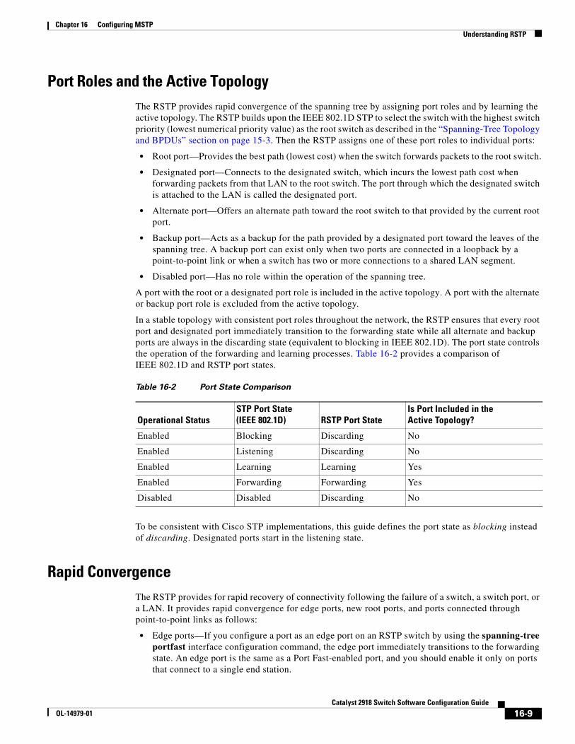
Chapter 16 Configuring MSTPUnderstanding RSTP
Port Roles and the Active TopologyThe RSTP provides rapid convergence of the spanning tree by assigning port roles and by learning the active topology. The RSTP builds upon the IEEE 802.1D STP to select the switch with the highest switch priority (lowest numerical priority value) as the root switch as described in the “Spanning-Tree Topology and BPDUs” section on page 15-3. Then the RSTP assigns one of these port roles to individual ports:
• Root port—Provides the best path (lowest cost) when the switch forwards packets to the root switch.
• Designated port—Connects to the designated switch, which incurs the lowest path cost when forwarding packets from that LAN to the root switch. The port through which the designated switch is attached to the LAN is called the designated port.
• Alternate port—Offers an alternate path toward the root switch to that provided by the current root port.
• Backup port—Acts as a backup for the path provided by a designated port toward the leaves of the spanning tree. A backup port can exist only when two ports are connected in a loopback by a point-to-point link or when a switch has two or more connections to a shared LAN segment.
• Disabled port—Has no role within the operation of the spanning tree.
A port with the root or a designated port role is included in the active topology. A port with the alternate or backup port role is excluded from the active topology.
In a stable topology with consistent port roles throughout the network, the RSTP ensures that every root port and designated port immediately transition to the forwarding state while all alternate and backup ports are always in the discarding state (equivalent to blocking in IEEE 802.1D). The port state controls the operation of the forwarding and learning processes. Table 16-2 provides a comparison of IEEE 802.1D and RSTP port states.
Table 16-2 Port State Comparison
Operational StatusSTP Port State (IEEE 802.1D) RSTP Port State
Is Port Included in the Active Topology?
Enabled Blocking Discarding No
Enabled Listening Discarding No
Enabled Learning Learning Yes
Enabled Forwarding Forwarding Yes
Disabled Disabled Discarding No
To be consistent with Cisco STP implementations, this guide defines the port state as blocking instead of discarding. Designated ports start in the listening state.
Rapid ConvergenceThe RSTP provides for rapid recovery of connectivity following the failure of a switch, a switch port, or a LAN. It provides rapid convergence for edge ports, new root ports, and ports connected through point-to-point links as follows:
• Edge ports—If you configure a port as an edge port on an RSTP switch by using the spanning-tree portfast interface configuration command, the edge port immediately transitions to the forwarding state. An edge port is the same as a Port Fast-enabled port, and you should enable it only on ports that connect to a single end station.
16-9Catalyst 2918 Switch Software Configuration Guide
OL-14979-01
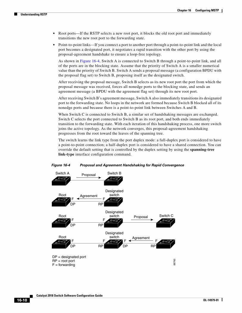
Chapter 16 Configuring MSTPUnderstanding RSTP
• Root ports—If the RSTP selects a new root port, it blocks the old root port and immediately transitions the new root port to the forwarding state.
• Point-to-point links—If you connect a port to another port through a point-to-point link and the local port becomes a designated port, it negotiates a rapid transition with the other port by using the proposal-agreement handshake to ensure a loop-free topology.
As shown in Figure 16-4, Switch A is connected to Switch B through a point-to-point link, and all of the ports are in the blocking state. Assume that the priority of Switch A is a smaller numerical value than the priority of Switch B. Switch A sends a proposal message (a configuration BPDU with the proposal flag set) to Switch B, proposing itself as the designated switch.
After receiving the proposal message, Switch B selects as its new root port the port from which the proposal message was received, forces all nonedge ports to the blocking state, and sends an agreement message (a BPDU with the agreement flag set) through its new root port.
After receiving Switch B’s agreement message, Switch A also immediately transitions its designated port to the forwarding state. No loops in the network are formed because Switch B blocked all of its nonedge ports and because there is a point-to-point link between Switches A and B.
When Switch C is connected to Switch B, a similar set of handshaking messages are exchanged. Switch C selects the port connected to Switch B as its root port, and both ends immediately transition to the forwarding state. With each iteration of this handshaking process, one more switch joins the active topology. As the network converges, this proposal-agreement handshaking progresses from the root toward the leaves of the spanning tree.
The switch learns the link type from the port duplex mode: a full-duplex port is considered to have a point-to-point connection; a half-duplex port is considered to have a shared connection. You can override the default setting that is controlled by the duplex setting by using the spanning-tree link-type interface configuration command.
Figure 16-4 Proposal and Agreement Handshaking for Rapid Convergence
ProposalSwitch A Switch B
FF
RPDP
FF
RPDP
FF
RPDP
FF
RPDP
Switch C
8876
0
AgreementRootDesignated
switch
RootDesignated
switch Proposal
RootDesignated
switch Agreement
DP = designated portRP = root portF = forwarding
16-10Catalyst 2918 Switch Software Configuration Guide
OL-14979-01
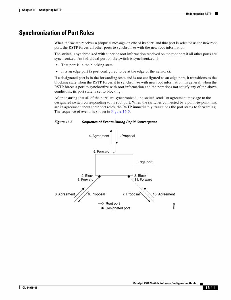
Chapter 16 Configuring MSTPUnderstanding RSTP
Synchronization of Port RolesWhen the switch receives a proposal message on one of its ports and that port is selected as the new root port, the RSTP forces all other ports to synchronize with the new root information.
The switch is synchronized with superior root information received on the root port if all other ports are synchronized. An individual port on the switch is synchronized if
• That port is in the blocking state.
• It is an edge port (a port configured to be at the edge of the network).
If a designated port is in the forwarding state and is not configured as an edge port, it transitions to the blocking state when the RSTP forces it to synchronize with new root information. In general, when the RSTP forces a port to synchronize with root information and the port does not satisfy any of the above conditions, its port state is set to blocking.
After ensuring that all of the ports are synchronized, the switch sends an agreement message to the designated switch corresponding to its root port. When the switches connected by a point-to-point link are in agreement about their port roles, the RSTP immediately transitions the port states to forwarding. The sequence of events is shown in Figure 16-5.
Figure 16-5 Sequence of Events During Rapid Convergence
2. Block9. Forward
1. Proposal4. Agreement
6. Proposal
Root portDesignated port
8. Agreement 10. Agreement
Edge port
7. Proposal
5. Forward
3. Block11. Forward
8876
1
16-11Catalyst 2918 Switch Software Configuration Guide
OL-14979-01
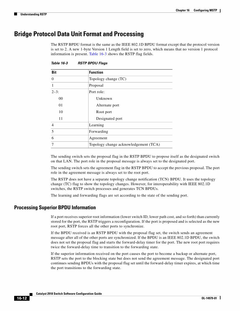
Chapter 16 Configuring MSTPUnderstanding RSTP
Bridge Protocol Data Unit Format and ProcessingThe RSTP BPDU format is the same as the IEEE 802.1D BPDU format except that the protocol version is set to 2. A new 1-byte Version 1 Length field is set to zero, which means that no version 1 protocol information is present. Table 16-3 shows the RSTP flag fields.
Table 16-3 RSTP BPDU Flags
Bit Function
0 Topology change (TC)
1 Proposal
2–3:
00
01
10
11
Port role:
Unknown
Alternate port
Root port
Designated port
4 Learning
5 Forwarding
6 Agreement
7 Topology change acknowledgement (TCA)
The sending switch sets the proposal flag in the RSTP BPDU to propose itself as the designated switch on that LAN. The port role in the proposal message is always set to the designated port.
The sending switch sets the agreement flag in the RSTP BPDU to accept the previous proposal. The port role in the agreement message is always set to the root port.
The RSTP does not have a separate topology change notification (TCN) BPDU. It uses the topology change (TC) flag to show the topology changes. However, for interoperability with IEEE 802.1D switches, the RSTP switch processes and generates TCN BPDUs.
The learning and forwarding flags are set according to the state of the sending port.
Processing Superior BPDU Information
If a port receives superior root information (lower switch ID, lower path cost, and so forth) than currently stored for the port, the RSTP triggers a reconfiguration. If the port is proposed and is selected as the new root port, RSTP forces all the other ports to synchronize.
If the BPDU received is an RSTP BPDU with the proposal flag set, the switch sends an agreement message after all of the other ports are synchronized. If the BPDU is an IEEE 802.1D BPDU, the switch does not set the proposal flag and starts the forward-delay timer for the port. The new root port requires twice the forward-delay time to transition to the forwarding state.
If the superior information received on the port causes the port to become a backup or alternate port, RSTP sets the port to the blocking state but does not send the agreement message. The designated port continues sending BPDUs with the proposal flag set until the forward-delay timer expires, at which time the port transitions to the forwarding state.
16-12Catalyst 2918 Switch Software Configuration Guide
OL-14979-01

Chapter 16 Configuring MSTPConfiguring MSTP Features
Processing Inferior BPDU Information
If a designated port receives an inferior BPDU (higher switch ID, higher path cost, and so forth than currently stored for the port) with a designated port role, it immediately replies with its own information.
Topology ChangesThis section describes the differences between the RSTP and the IEEE 802.1D in handling spanning-tree topology changes.
• Detection—Unlike IEEE 802.1D in which any transition between the blocking and the forwarding state causes a topology change, only transitions from the blocking to the forwarding state cause a topology change with RSTP (only an increase in connectivity is considered a topology change). State changes on an edge port do not cause a topology change. When an RSTP switch detects a topology change, it deletes the learned information on all of its nonedge ports except on those from which it received the TC notification.
• Notification—Unlike IEEE 802.1D, which uses TCN BPDUs, the RSTP does not use them. However, for IEEE 802.1D interoperability, an RSTP switch processes and generates TCN BPDUs.
• Acknowledgement—When an RSTP switch receives a TCN message on a designated port from an IEEE 802.1D switch, it replies with an IEEE 802.1D configuration BPDU with the TCA bit set. However, if the TC-while timer (the same as the topology-change timer in IEEE 802.1D) is active on a root port connected to an IEEE 802.1D switch and a configuration BPDU with the TCA bit set is received, the TC-while timer is reset.
This behavior is only required to support IEEE 802.1D switches. The RSTP BPDUs never have the TCA bit set.
• Propagation—When an RSTP switch receives a TC message from another switch through a designated or root port, it propagates the change to all of its nonedge, designated ports and to the root port (excluding the port on which it is received). The switch starts the TC-while timer for all such ports and flushes the information learned on them.
• Protocol migration—For backward compatibility with IEEE 802.1D switches, RSTP selectively sends IEEE 802.1D configuration BPDUs and TCN BPDUs on a per-port basis.
When a port is initialized, the migrate-delay timer is started (specifies the minimum time during which RSTP BPDUs are sent), and RSTP BPDUs are sent. While this timer is active, the switch processes all BPDUs received on that port and ignores the protocol type.
If the switch receives an IEEE 802.1D BPDU after the port migration-delay timer has expired, it assumes that it is connected to an IEEE 802.1D switch and starts using only IEEE 802.1D BPDUs. However, if the RSTP switch is using IEEE 802.1D BPDUs on a port and receives an RSTP BPDU after the timer has expired, it restarts the timer and starts using RSTP BPDUs on that port.
Configuring MSTP FeaturesThese sections contain this configuration information:
• Default MSTP Configuration, page 16-14
• MSTP Configuration Guidelines, page 16-14
• Specifying the MST Region Configuration and Enabling MSTP, page 16-15 (required)
• Configuring the Root Switch, page 16-17 (optional)
16-13Catalyst 2918 Switch Software Configuration Guide
OL-14979-01
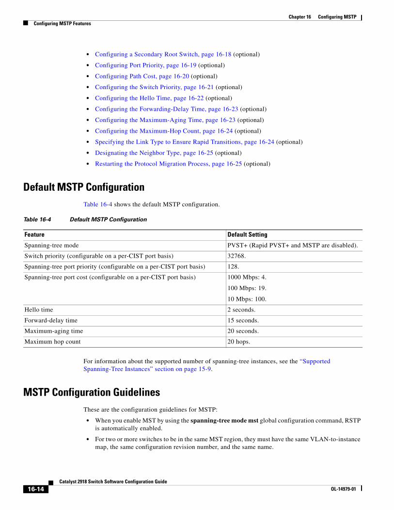
Chapter 16 Configuring MSTPConfiguring MSTP Features
• Configuring a Secondary Root Switch, page 16-18 (optional)
• Configuring Port Priority, page 16-19 (optional)
• Configuring Path Cost, page 16-20 (optional)
• Configuring the Switch Priority, page 16-21 (optional)
• Configuring the Hello Time, page 16-22 (optional)
• Configuring the Forwarding-Delay Time, page 16-23 (optional)
• Configuring the Maximum-Aging Time, page 16-23 (optional)
• Configuring the Maximum-Hop Count, page 16-24 (optional)
• Specifying the Link Type to Ensure Rapid Transitions, page 16-24 (optional)
• Designating the Neighbor Type, page 16-25 (optional)
• Restarting the Protocol Migration Process, page 16-25 (optional)
Default MSTP ConfigurationTable 16-4 shows the default MSTP configuration.
Table 16-4 Default MSTP Configuration
Feature Default Setting
Spanning-tree mode PVST+ (Rapid PVST+ and MSTP are disabled).
Switch priority (configurable on a per-CIST port basis) 32768.
Spanning-tree port priority (configurable on a per-CIST port basis) 128.
Spanning-tree port cost (configurable on a per-CIST port basis) 1000 Mbps: 4.
100 Mbps: 19.
10 Mbps: 100.
Hello time 2 seconds.
Forward-delay time 15 seconds.
Maximum-aging time 20 seconds.
Maximum hop count 20 hops.
For information about the supported number of spanning-tree instances, see the “Supported Spanning-Tree Instances” section on page 15-9.
MSTP Configuration GuidelinesThese are the configuration guidelines for MSTP:
• When you enable MST by using the spanning-tree mode mst global configuration command, RSTP is automatically enabled.
• For two or more switches to be in the same MST region, they must have the same VLAN-to-instance map, the same configuration revision number, and the same name.
16-14Catalyst 2918 Switch Software Configuration Guide
OL-14979-01
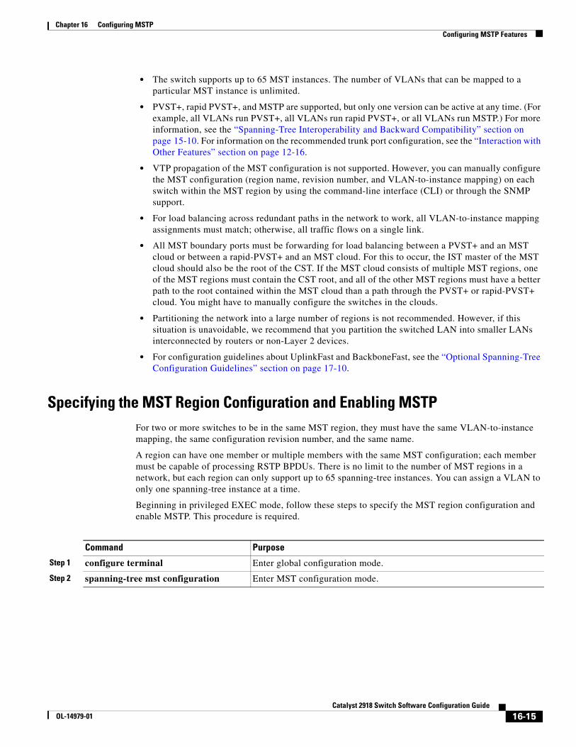
Chapter 16 Configuring MSTPConfiguring MSTP Features
• The switch supports up to 65 MST instances. The number of VLANs that can be mapped to a particular MST instance is unlimited.
• PVST+, rapid PVST+, and MSTP are supported, but only one version can be active at any time. (For example, all VLANs run PVST+, all VLANs run rapid PVST+, or all VLANs run MSTP.) For more information, see the “Spanning-Tree Interoperability and Backward Compatibility” section on page 15-10. For information on the recommended trunk port configuration, see the “Interaction with Other Features” section on page 12-16.
• VTP propagation of the MST configuration is not supported. However, you can manually configure the MST configuration (region name, revision number, and VLAN-to-instance mapping) on each switch within the MST region by using the command-line interface (CLI) or through the SNMP support.
• For load balancing across redundant paths in the network to work, all VLAN-to-instance mapping assignments must match; otherwise, all traffic flows on a single link.
• All MST boundary ports must be forwarding for load balancing between a PVST+ and an MST cloud or between a rapid-PVST+ and an MST cloud. For this to occur, the IST master of the MST cloud should also be the root of the CST. If the MST cloud consists of multiple MST regions, one of the MST regions must contain the CST root, and all of the other MST regions must have a better path to the root contained within the MST cloud than a path through the PVST+ or rapid-PVST+ cloud. You might have to manually configure the switches in the clouds.
• Partitioning the network into a large number of regions is not recommended. However, if this situation is unavoidable, we recommend that you partition the switched LAN into smaller LANs interconnected by routers or non-Layer 2 devices.
• For configuration guidelines about UplinkFast and BackboneFast, see the “Optional Spanning-Tree Configuration Guidelines” section on page 17-10.
Specifying the MST Region Configuration and Enabling MSTPFor two or more switches to be in the same MST region, they must have the same VLAN-to-instance mapping, the same configuration revision number, and the same name.
A region can have one member or multiple members with the same MST configuration; each member must be capable of processing RSTP BPDUs. There is no limit to the number of MST regions in a network, but each region can only support up to 65 spanning-tree instances. You can assign a VLAN to only one spanning-tree instance at a time.
Beginning in privileged EXEC mode, follow these steps to specify the MST region configuration and enable MSTP. This procedure is required.
Command Purpose
Step 1 configure terminal Enter global configuration mode.
Step 2 spanning-tree mst configuration Enter MST configuration mode.
16-15Catalyst 2918 Switch Software Configuration Guide
OL-14979-01
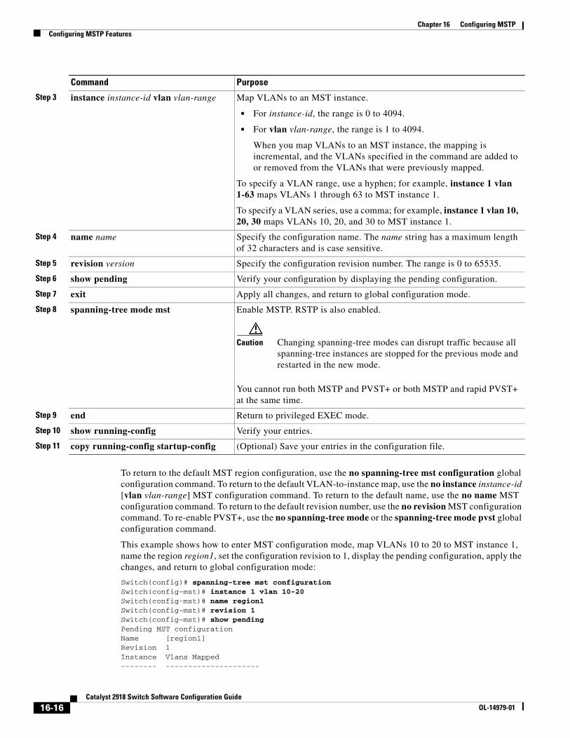
Chapter 16 Configuring MSTPConfiguring MSTP Features
To return to the default MST region configuration, use the no spanning-tree mst configuration global configuration command. To return to the default VLAN-to-instance map, use the no instance instance-id [vlan vlan-range] MST configuration command. To return to the default name, use the no name MST configuration command. To return to the default revision number, use the no revision MST configuration command. To re-enable PVST+, use the no spanning-tree mode or the spanning-tree mode pvst global configuration command.
This example shows how to enter MST configuration mode, map VLANs 10 to 20 to MST instance 1, name the region region1, set the configuration revision to 1, display the pending configuration, apply the changes, and return to global configuration mode:
Switch(config)# spanning-tree mst configurationSwitch(config-mst)# instance 1 vlan 10-20Switch(config-mst)# name region1Switch(config-mst)# revision 1Switch(config-mst)# show pendingPending MST configurationName [region1]Revision 1Instance Vlans Mapped-------- ---------------------
Step 3 instance instance-id vlan vlan-range Map VLANs to an MST instance.
• For instance-id, the range is 0 to 4094.
• For vlan vlan-range, the range is 1 to 4094.
When you map VLANs to an MST instance, the mapping is incremental, and the VLANs specified in the command are added to or removed from the VLANs that were previously mapped.
To specify a VLAN range, use a hyphen; for example, instance 1 vlan 1-63 maps VLANs 1 through 63 to MST instance 1.
To specify a VLAN series, use a comma; for example, instance 1 vlan 10, 20, 30 maps VLANs 10, 20, and 30 to MST instance 1.
Step 4 name name Specify the configuration name. The name string has a maximum length of 32 characters and is case sensitive.
Step 5 revision version Specify the configuration revision number. The range is 0 to 65535.
Step 6 show pending Verify your configuration by displaying the pending configuration.
Step 7 exit Apply all changes, and return to global configuration mode.
Step 8 spanning-tree mode mst Enable MSTP. RSTP is also enabled.
Caution Changing spanning-tree modes can disrupt traffic because all spanning-tree instances are stopped for the previous mode and restarted in the new mode.
You cannot run both MSTP and PVST+ or both MSTP and rapid PVST+ at the same time.
Step 9 end Return to privileged EXEC mode.
Step 10 show running-config Verify your entries.
Step 11 copy running-config startup-config (Optional) Save your entries in the configuration file.
Command Purpose
16-16Catalyst 2918 Switch Software Configuration Guide
OL-14979-01
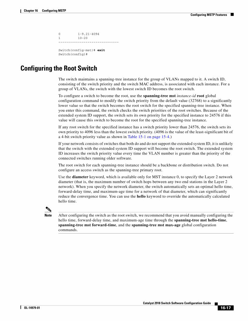
Chapter 16 Configuring MSTPConfiguring MSTP Features
0 1-9,21-40941 10-20-------------------------------
Switch(config-mst)# exitSwitch(config)#
Configuring the Root SwitchThe switch maintains a spanning-tree instance for the group of VLANs mapped to it. A switch ID, consisting of the switch priority and the switch MAC address, is associated with each instance. For a group of VLANs, the switch with the lowest switch ID becomes the root switch.
To configure a switch to become the root, use the spanning-tree mst instance-id root global configuration command to modify the switch priority from the default value (32768) to a significantly lower value so that the switch becomes the root switch for the specified spanning-tree instance. When you enter this command, the switch checks the switch priorities of the root switches. Because of the extended system ID support, the switch sets its own priority for the specified instance to 24576 if this value will cause this switch to become the root for the specified spanning-tree instance.
If any root switch for the specified instance has a switch priority lower than 24576, the switch sets its own priority to 4096 less than the lowest switch priority. (4096 is the value of the least-significant bit of a 4-bit switch priority value as shown in Table 15-1 on page 15-4.)
If your network consists of switches that both do and do not support the extended system ID, it is unlikely that the switch with the extended system ID support will become the root switch. The extended system ID increases the switch priority value every time the VLAN number is greater than the priority of the connected switches running older software.
The root switch for each spanning-tree instance should be a backbone or distribution switch. Do not configure an access switch as the spanning-tree primary root.
Use the diameter keyword, which is available only for MST instance 0, to specify the Layer 2 network diameter (that is, the maximum number of switch hops between any two end stations in the Layer 2 network). When you specify the network diameter, the switch automatically sets an optimal hello time, forward-delay time, and maximum-age time for a network of that diameter, which can significantly reduce the convergence time. You can use the hello keyword to override the automatically calculated hello time.
Note After configuring the switch as the root switch, we recommend that you avoid manually configuring the hello time, forward-delay time, and maximum-age time through the spanning-tree mst hello-time, spanning-tree mst forward-time, and the spanning-tree mst max-age global configuration commands.
16-17Catalyst 2918 Switch Software Configuration Guide
OL-14979-01
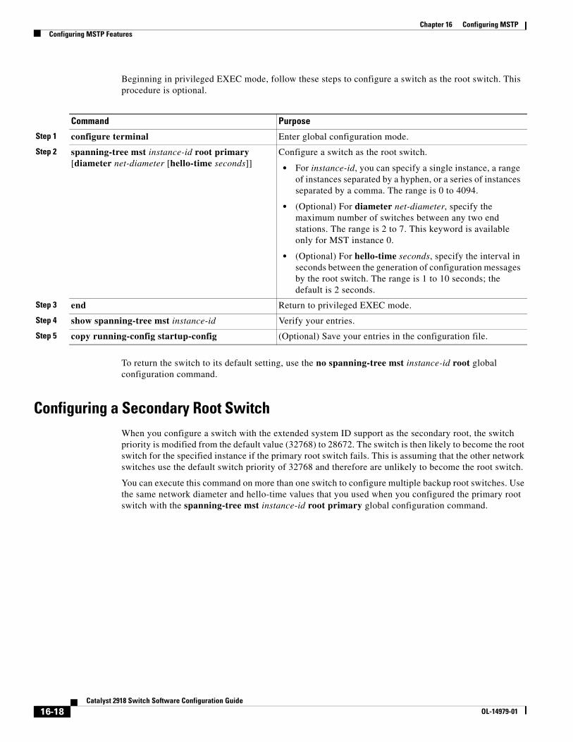
Chapter 16 Configuring MSTPConfiguring MSTP Features
Beginning in privileged EXEC mode, follow these steps to configure a switch as the root switch. This procedure is optional.
Command Purpose
Step 1 configure terminal Enter global configuration mode.
Step 2 spanning-tree mst instance-id root primary [diameter net-diameter [hello-time seconds]]
Configure a switch as the root switch.
• For instance-id, you can specify a single instance, a range of instances separated by a hyphen, or a series of instances separated by a comma. The range is 0 to 4094.
• (Optional) For diameter net-diameter, specify the maximum number of switches between any two end stations. The range is 2 to 7. This keyword is available only for MST instance 0.
• (Optional) For hello-time seconds, specify the interval in seconds between the generation of configuration messages by the root switch. The range is 1 to 10 seconds; the default is 2 seconds.
Step 3 end Return to privileged EXEC mode.
Step 4 show spanning-tree mst instance-id Verify your entries.
Step 5 copy running-config startup-config (Optional) Save your entries in the configuration file.
To return the switch to its default setting, use the no spanning-tree mst instance-id root global configuration command.
Configuring a Secondary Root SwitchWhen you configure a switch with the extended system ID support as the secondary root, the switch priority is modified from the default value (32768) to 28672. The switch is then likely to become the root switch for the specified instance if the primary root switch fails. This is assuming that the other network switches use the default switch priority of 32768 and therefore are unlikely to become the root switch.
You can execute this command on more than one switch to configure multiple backup root switches. Use the same network diameter and hello-time values that you used when you configured the primary root switch with the spanning-tree mst instance-id root primary global configuration command.
16-18Catalyst 2918 Switch Software Configuration Guide
OL-14979-01
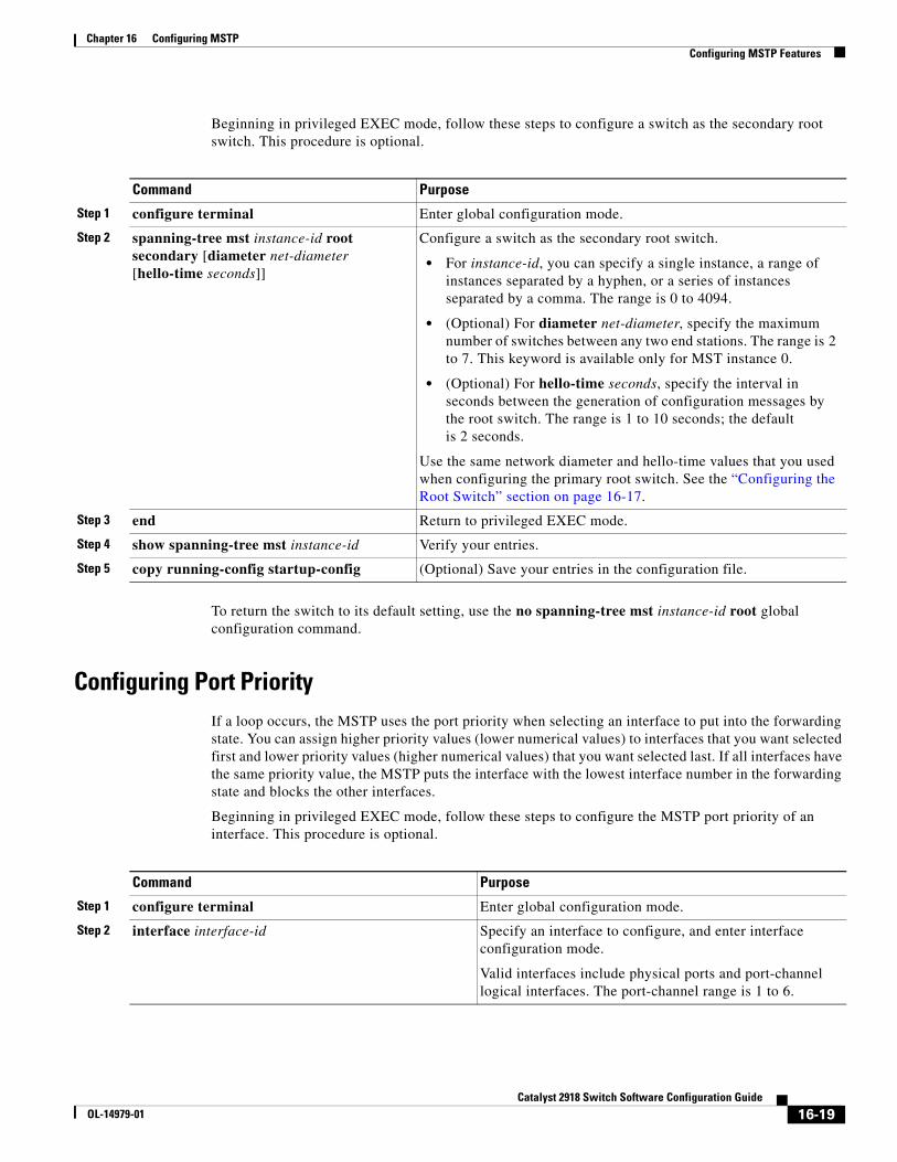
Chapter 16 Configuring MSTPConfiguring MSTP Features
Beginning in privileged EXEC mode, follow these steps to configure a switch as the secondary root switch. This procedure is optional.
Command Purpose
Step 1 configure terminal Enter global configuration mode.
Step 2 spanning-tree mst instance-id root secondary [diameter net-diameter [hello-time seconds]]
Configure a switch as the secondary root switch.
• For instance-id, you can specify a single instance, a range of instances separated by a hyphen, or a series of instances separated by a comma. The range is 0 to 4094.
• (Optional) For diameter net-diameter, specify the maximum number of switches between any two end stations. The range is 2 to 7. This keyword is available only for MST instance 0.
• (Optional) For hello-time seconds, specify the interval in seconds between the generation of configuration messages by the root switch. The range is 1 to 10 seconds; the default is 2 seconds.
Use the same network diameter and hello-time values that you used when configuring the primary root switch. See the “Configuring the Root Switch” section on page 16-17.
Step 3 end Return to privileged EXEC mode.
Step 4 show spanning-tree mst instance-id Verify your entries.
Step 5 copy running-config startup-config (Optional) Save your entries in the configuration file.
To return the switch to its default setting, use the no spanning-tree mst instance-id root global configuration command.
Configuring Port Priority If a loop occurs, the MSTP uses the port priority when selecting an interface to put into the forwarding state. You can assign higher priority values (lower numerical values) to interfaces that you want selected first and lower priority values (higher numerical values) that you want selected last. If all interfaces have the same priority value, the MSTP puts the interface with the lowest interface number in the forwarding state and blocks the other interfaces.
Beginning in privileged EXEC mode, follow these steps to configure the MSTP port priority of an interface. This procedure is optional.
Command Purpose
Step 1 configure terminal Enter global configuration mode.
Step 2 interface interface-id Specify an interface to configure, and enter interface configuration mode.
Valid interfaces include physical ports and port-channel logical interfaces. The port-channel range is 1 to 6.
16-19Catalyst 2918 Switch Software Configuration Guide
OL-14979-01
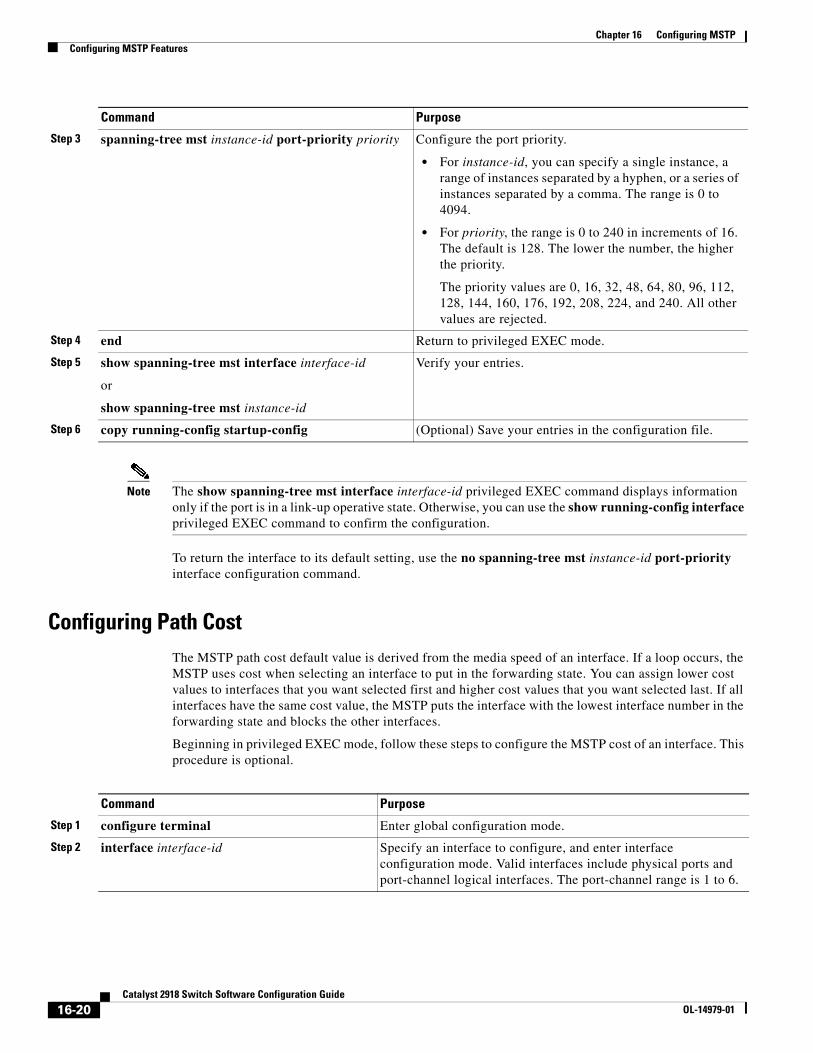
Chapter 16 Configuring MSTPConfiguring MSTP Features
Note The show spanning-tree mst interface interface-id privileged EXEC command displays information only if the port is in a link-up operative state. Otherwise, you can use the show running-config interface privileged EXEC command to confirm the configuration.
To return the interface to its default setting, use the no spanning-tree mst instance-id port-priority interface configuration command.
Configuring Path CostThe MSTP path cost default value is derived from the media speed of an interface. If a loop occurs, the MSTP uses cost when selecting an interface to put in the forwarding state. You can assign lower cost values to interfaces that you want selected first and higher cost values that you want selected last. If all interfaces have the same cost value, the MSTP puts the interface with the lowest interface number in the forwarding state and blocks the other interfaces.
Beginning in privileged EXEC mode, follow these steps to configure the MSTP cost of an interface. This procedure is optional.
Step 3 spanning-tree mst instance-id port-priority priority Configure the port priority.
• For instance-id, you can specify a single instance, a range of instances separated by a hyphen, or a series of instances separated by a comma. The range is 0 to 4094.
• For priority, the range is 0 to 240 in increments of 16. The default is 128. The lower the number, the higher the priority.
The priority values are 0, 16, 32, 48, 64, 80, 96, 112, 128, 144, 160, 176, 192, 208, 224, and 240. All other values are rejected.
Step 4 end Return to privileged EXEC mode.
Step 5 show spanning-tree mst interface interface-id
or
show spanning-tree mst instance-id
Verify your entries.
Step 6 copy running-config startup-config (Optional) Save your entries in the configuration file.
Command Purpose
Command Purpose
Step 1 configure terminal Enter global configuration mode.
Step 2 interface interface-id Specify an interface to configure, and enter interface configuration mode. Valid interfaces include physical ports and port-channel logical interfaces. The port-channel range is 1 to 6.
16-20Catalyst 2918 Switch Software Configuration Guide
OL-14979-01
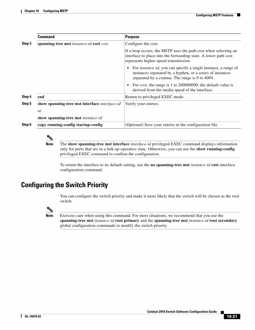
Chapter 16 Configuring MSTPConfiguring MSTP Features
Note The show spanning-tree mst interface interface-id privileged EXEC command displays information only for ports that are in a link-up operative state. Otherwise, you can use the show running-config privileged EXEC command to confirm the configuration.
To return the interface to its default setting, use the no spanning-tree mst instance-id cost interface configuration command.
Configuring the Switch PriorityYou can configure the switch priority and make it more likely that the switch will be chosen as the root switch.
Note Exercise care when using this command. For most situations, we recommend that you use the spanning-tree mst instance-id root primary and the spanning-tree mst instance-id root secondary global configuration commands to modify the switch priority.
Step 3 spanning-tree mst instance-id cost cost Configure the cost.
If a loop occurs, the MSTP uses the path cost when selecting an interface to place into the forwarding state. A lower path cost represents higher-speed transmission.
• For instance-id, you can specify a single instance, a range of instances separated by a hyphen, or a series of instances separated by a comma. The range is 0 to 4094.
• For cost, the range is 1 to 200000000; the default value is derived from the media speed of the interface.
Step 4 end Return to privileged EXEC mode.
Step 5 show spanning-tree mst interface interface-id
or
show spanning-tree mst instance-id
Verify your entries.
Step 6 copy running-config startup-config (Optional) Save your entries in the configuration file.
Command Purpose
16-21Catalyst 2918 Switch Software Configuration Guide
OL-14979-01
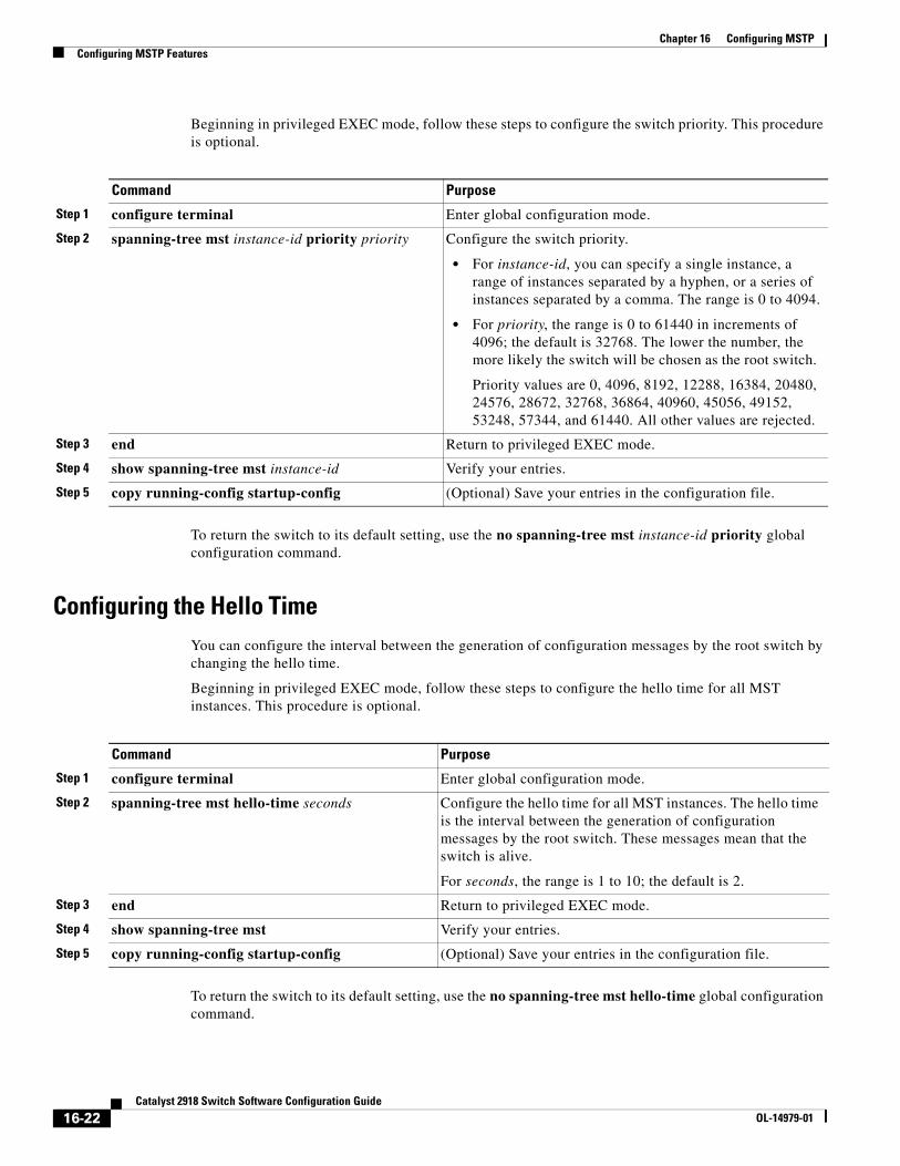
Chapter 16 Configuring MSTPConfiguring MSTP Features
Beginning in privileged EXEC mode, follow these steps to configure the switch priority. This procedure is optional.
Command Purpose
Step 1 configure terminal Enter global configuration mode.
Step 2 spanning-tree mst instance-id priority priority Configure the switch priority.
• For instance-id, you can specify a single instance, a range of instances separated by a hyphen, or a series of instances separated by a comma. The range is 0 to 4094.
• For priority, the range is 0 to 61440 in increments of 4096; the default is 32768. The lower the number, the more likely the switch will be chosen as the root switch.
Priority values are 0, 4096, 8192, 12288, 16384, 20480, 24576, 28672, 32768, 36864, 40960, 45056, 49152, 53248, 57344, and 61440. All other values are rejected.
Step 3 end Return to privileged EXEC mode.
Step 4 show spanning-tree mst instance-id Verify your entries.
Step 5 copy running-config startup-config (Optional) Save your entries in the configuration file.
To return the switch to its default setting, use the no spanning-tree mst instance-id priority global configuration command.
Configuring the Hello TimeYou can configure the interval between the generation of configuration messages by the root switch by changing the hello time.
Beginning in privileged EXEC mode, follow these steps to configure the hello time for all MST instances. This procedure is optional.
Command Purpose
Step 1 configure terminal Enter global configuration mode.
Step 2 spanning-tree mst hello-time seconds Configure the hello time for all MST instances. The hello time is the interval between the generation of configuration messages by the root switch. These messages mean that the switch is alive.
For seconds, the range is 1 to 10; the default is 2.
Step 3 end Return to privileged EXEC mode.
Step 4 show spanning-tree mst Verify your entries.
Step 5 copy running-config startup-config (Optional) Save your entries in the configuration file.
To return the switch to its default setting, use the no spanning-tree mst hello-time global configuration command.
16-22Catalyst 2918 Switch Software Configuration Guide
OL-14979-01
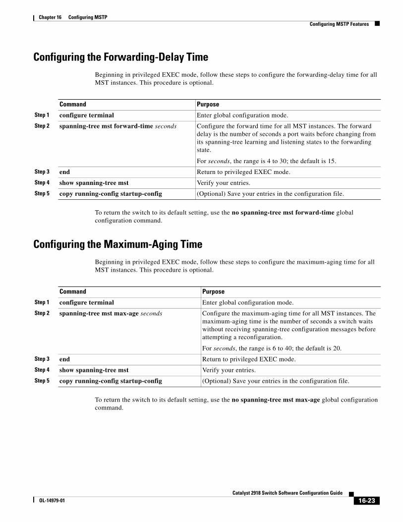
Chapter 16 Configuring MSTPConfiguring MSTP Features
Configuring the Forwarding-Delay TimeBeginning in privileged EXEC mode, follow these steps to configure the forwarding-delay time for all MST instances. This procedure is optional.
Command Purpose
Step 1 configure terminal Enter global configuration mode.
Step 2 spanning-tree mst forward-time seconds Configure the forward time for all MST instances. The forward delay is the number of seconds a port waits before changing from its spanning-tree learning and listening states to the forwarding state.
For seconds, the range is 4 to 30; the default is 15.
Step 3 end Return to privileged EXEC mode.
Step 4 show spanning-tree mst Verify your entries.
Step 5 copy running-config startup-config (Optional) Save your entries in the configuration file.
To return the switch to its default setting, use the no spanning-tree mst forward-time global configuration command.
Configuring the Maximum-Aging TimeBeginning in privileged EXEC mode, follow these steps to configure the maximum-aging time for all MST instances. This procedure is optional.
Command Purpose
Step 1 configure terminal Enter global configuration mode.
Step 2 spanning-tree mst max-age seconds Configure the maximum-aging time for all MST instances. The maximum-aging time is the number of seconds a switch waits without receiving spanning-tree configuration messages before attempting a reconfiguration.
For seconds, the range is 6 to 40; the default is 20.
Step 3 end Return to privileged EXEC mode.
Step 4 show spanning-tree mst Verify your entries.
Step 5 copy running-config startup-config (Optional) Save your entries in the configuration file.
To return the switch to its default setting, use the no spanning-tree mst max-age global configuration command.
16-23Catalyst 2918 Switch Software Configuration Guide
OL-14979-01
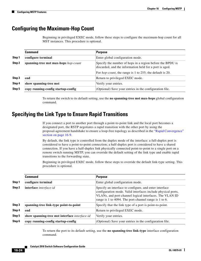
Chapter 16 Configuring MSTPConfiguring MSTP Features
Configuring the Maximum-Hop CountBeginning in privileged EXEC mode, follow these steps to configure the maximum-hop count for all MST instances. This procedure is optional.
Command Purpose
Step 1 configure terminal Enter global configuration mode.
Step 2 spanning-tree mst max-hops hop-count Specify the number of hops in a region before the BPDU is discarded, and the information held for a port is aged.
For hop-count, the range is 1 to 255; the default is 20.
Step 3 end Return to privileged EXEC mode.
Step 4 show spanning-tree mst Verify your entries.
Step 5 copy running-config startup-config (Optional) Save your entries in the configuration file.
To return the switch to its default setting, use the no spanning-tree mst max-hops global configuration command.
Specifying the Link Type to Ensure Rapid TransitionsIf you connect a port to another port through a point-to-point link and the local port becomes a designated port, the RSTP negotiates a rapid transition with the other port by using the proposal-agreement handshake to ensure a loop-free topology as described in the “Rapid Convergence” section on page 16-9.
By default, the link type is controlled from the duplex mode of the interface: a full-duplex port is considered to have a point-to-point connection; a half-duplex port is considered to have a shared connection. If you have a half-duplex link physically connected point-to-point to a single port on a remote switch running MSTP, you can override the default setting of the link type and enable rapid transitions to the forwarding state.
Beginning in privileged EXEC mode, follow these steps to override the default link-type setting. This procedure is optional.
Command Purpose
Step 1 configure terminal Enter global configuration mode.
Step 2 interface interface-id Specify an interface to configure, and enter interface configuration mode. Valid interfaces include physical ports, VLANs, and port-channel logical interfaces. The VLAN ID range is 1 to 4094. The port-channel range is 1 to 6.
Step 3 spanning-tree link-type point-to-point Specify that the link type of a port is point-to-point.
Step 4 end Return to privileged EXEC mode.
Step 5 show spanning-tree mst interface interface-id Verify your entries.
Step 6 copy running-config startup-config (Optional) Save your entries in the configuration file.
To return the port to its default setting, use the no spanning-tree link-type interface configuration command.
16-24Catalyst 2918 Switch Software Configuration Guide
OL-14979-01
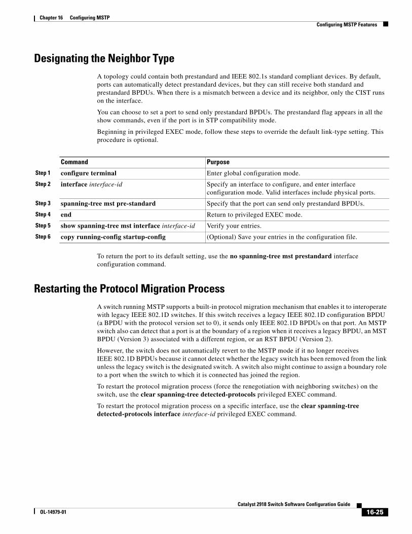
Chapter 16 Configuring MSTPConfiguring MSTP Features
Designating the Neighbor TypeA topology could contain both prestandard and IEEE 802.1s standard compliant devices. By default, ports can automatically detect prestandard devices, but they can still receive both standard and prestandard BPDUs. When there is a mismatch between a device and its neighbor, only the CIST runs on the interface.
You can choose to set a port to send only prestandard BPDUs. The prestandard flag appears in all the show commands, even if the port is in STP compatibility mode.
Beginning in privileged EXEC mode, follow these steps to override the default link-type setting. This procedure is optional.
Command Purpose
Step 1 configure terminal Enter global configuration mode.
Step 2 interface interface-id Specify an interface to configure, and enter interface configuration mode. Valid interfaces include physical ports.
Step 3 spanning-tree mst pre-standard Specify that the port can send only prestandard BPDUs.
Step 4 end Return to privileged EXEC mode.
Step 5 show spanning-tree mst interface interface-id Verify your entries.
Step 6 copy running-config startup-config (Optional) Save your entries in the configuration file.
To return the port to its default setting, use the no spanning-tree mst prestandard interface configuration command.
Restarting the Protocol Migration ProcessA switch running MSTP supports a built-in protocol migration mechanism that enables it to interoperate with legacy IEEE 802.1D switches. If this switch receives a legacy IEEE 802.1D configuration BPDU (a BPDU with the protocol version set to 0), it sends only IEEE 802.1D BPDUs on that port. An MSTP switch also can detect that a port is at the boundary of a region when it receives a legacy BPDU, an MST BPDU (Version 3) associated with a different region, or an RST BPDU (Version 2).
However, the switch does not automatically revert to the MSTP mode if it no longer receives IEEE 802.1D BPDUs because it cannot detect whether the legacy switch has been removed from the link unless the legacy switch is the designated switch. A switch also might continue to assign a boundary role to a port when the switch to which it is connected has joined the region.
To restart the protocol migration process (force the renegotiation with neighboring switches) on the switch, use the clear spanning-tree detected-protocols privileged EXEC command.
To restart the protocol migration process on a specific interface, use the clear spanning-tree detected-protocols interface interface-id privileged EXEC command.
16-25Catalyst 2918 Switch Software Configuration Guide
OL-14979-01
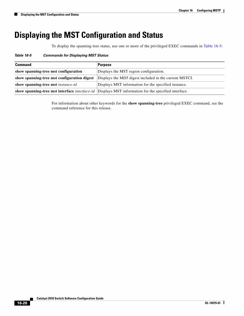
Chapter 16 Configuring MSTPDisplaying the MST Configuration and Status
Displaying the MST Configuration and StatusTo display the spanning-tree status, use one or more of the privileged EXEC commands in Table 16-5:
Table 16-5 Commands for Displaying MST Status
Command Purpose
show spanning-tree mst configuration Displays the MST region configuration.
show spanning-tree mst configuration digest Displays the MD5 digest included in the current MSTCI.
show spanning-tree mst instance-id Displays MST information for the specified instance.
show spanning-tree mst interface interface-id Displays MST information for the specified interface.
For information about other keywords for the show spanning-tree privileged EXEC command, see the command reference for this release.
16-26Catalyst 2918 Switch Software Configuration Guide
OL-14979-01
OL-14979-01
C H A P T E R 17
Configuring Optional Spanning-Tree FeaturesThis chapter describes how to configure optional spanning-tree features on the Catalyst 2918 switch. You can configure all of these features when your switch is running the per-VLAN spanning-tree plus (PVST+). You can configure only the noted features when your switch is running the Multiple Spanning Tree Protocol (MSTP) or the rapid per-VLAN spanning-tree plus (rapid-PVST+) protocol.
For information on configuring the PVST+ and rapid PVST+, see Chapter 15, “Configuring STP.” For information about the Multiple Spanning Tree Protocol (MSTP) and how to map multiple VLANs to the same spanning-tree instance, see Chapter 16, “Configuring MSTP.”
Note For complete syntax and usage information for the commands used in this chapter, see the command reference for this release.
This chapter consists of these sections:
• Understanding Optional Spanning-Tree Features, page 17-1
• Configuring Optional Spanning-Tree Features, page 17-9
• Displaying the Spanning-Tree Status, page 17-16
Understanding Optional Spanning-Tree FeaturesThese sections contain this conceptual information:
• Understanding Port Fast, page 17-2
• Understanding BPDU Guard, page 17-2
• Understanding BPDU Filtering, page 17-3
• Understanding UplinkFast, page 17-3
• Understanding BackboneFast, page 17-5
• Understanding EtherChannel Guard, page 17-7
• Understanding Root Guard, page 17-8
• Understanding Loop Guard, page 17-9
17-1Catalyst 2918 Switch Software Configuration Guide
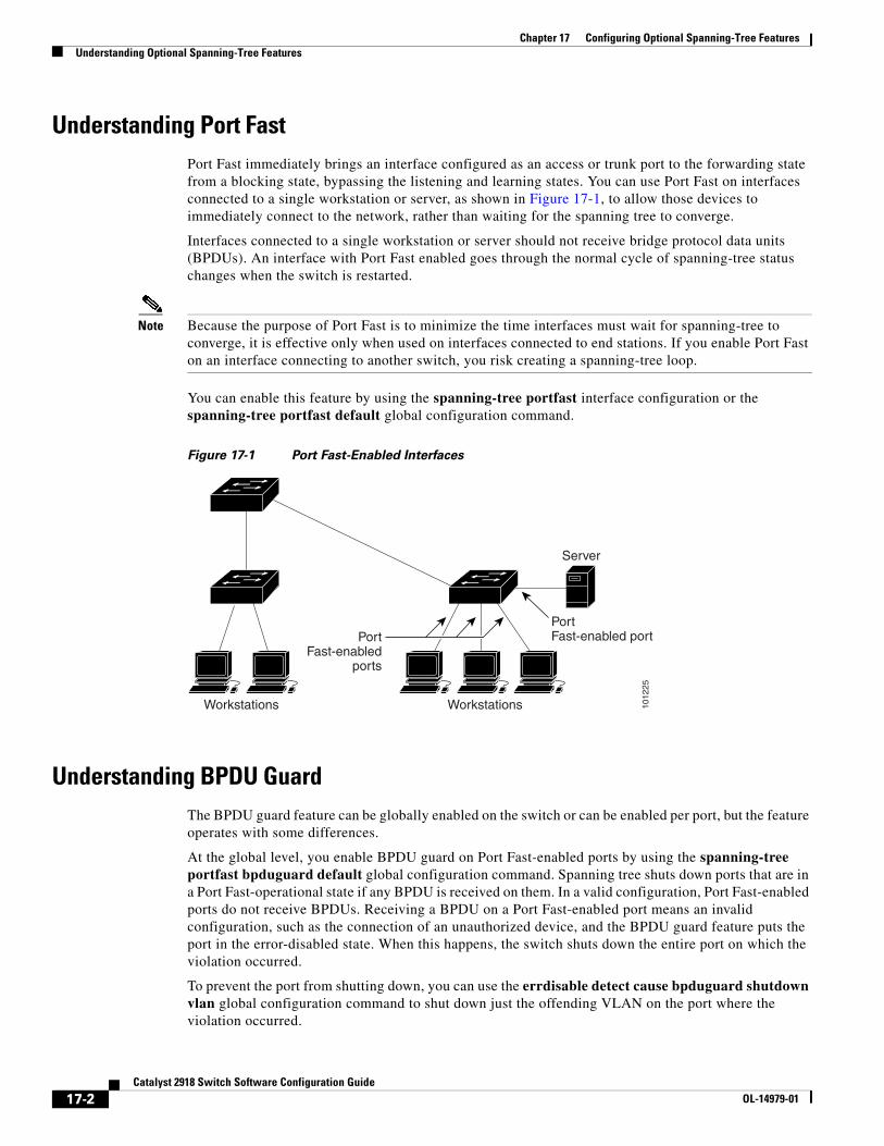
Chapter 17 Configuring Optional Spanning-Tree FeaturesUnderstanding Optional Spanning-Tree Features
Understanding Port FastPort Fast immediately brings an interface configured as an access or trunk port to the forwarding state from a blocking state, bypassing the listening and learning states. You can use Port Fast on interfaces connected to a single workstation or server, as shown in Figure 17-1, to allow those devices to immediately connect to the network, rather than waiting for the spanning tree to converge.
Interfaces connected to a single workstation or server should not receive bridge protocol data units (BPDUs). An interface with Port Fast enabled goes through the normal cycle of spanning-tree status changes when the switch is restarted.
Note Because the purpose of Port Fast is to minimize the time interfaces must wait for spanning-tree to converge, it is effective only when used on interfaces connected to end stations. If you enable Port Fast on an interface connecting to another switch, you risk creating a spanning-tree loop.
You can enable this feature by using the spanning-tree portfast interface configuration or the spanning-tree portfast default global configuration command.
Figure 17-1 Port Fast-Enabled Interfaces
WorkstationsWorkstations
Server
PortFast-enabled portPort
Fast-enabledports
1012
25
Understanding BPDU GuardThe BPDU guard feature can be globally enabled on the switch or can be enabled per port, but the feature operates with some differences.
At the global level, you enable BPDU guard on Port Fast-enabled ports by using the spanning-tree portfast bpduguard default global configuration command. Spanning tree shuts down ports that are in a Port Fast-operational state if any BPDU is received on them. In a valid configuration, Port Fast-enabled ports do not receive BPDUs. Receiving a BPDU on a Port Fast-enabled port means an invalid configuration, such as the connection of an unauthorized device, and the BPDU guard feature puts the port in the error-disabled state. When this happens, the switch shuts down the entire port on which the violation occurred.
To prevent the port from shutting down, you can use the errdisable detect cause bpduguard shutdown vlan global configuration command to shut down just the offending VLAN on the port where the violation occurred.
17-2Catalyst 2918 Switch Software Configuration Guide
OL-14979-01
Chapter 17 Configuring Optional Spanning-Tree FeaturesUnderstanding Optional Spanning-Tree Features
At the interface level, you enable BPDU guard on any port by using the spanning-tree bpduguard enable interface configuration command without also enabling the Port Fast feature. When the port receives a BPDU, it is put in the error-disabled state.
The BPDU guard feature provides a secure response to invalid configurations because you must manually put the interface back in service. Use the BPDU guard feature in a service-provider network to prevent an access port from participating in the spanning tree.
Understanding BPDU FilteringThe BPDU filtering feature can be globally enabled on the switch or can be enabled per interface, but the feature operates with some differences.
At the global level, you can enable BPDU filtering on Port Fast-enabled interfaces by using the spanning-tree portfast bpdufilter default global configuration command. This command prevents interfaces that are in a Port Fast-operational state from sending or receiving BPDUs. The interfaces still send a few BPDUs at link-up before the switch begins to filter outbound BPDUs. You should globally enable BPDU filtering on a switch so that hosts connected to these interfaces do not receive BPDUs. If a BPDU is received on a Port Fast-enabled interface, the interface loses its Port Fast-operational status, and BPDU filtering is disabled.
At the interface level, you can enable BPDU filtering on any interface by using the spanning-tree bpdufilter enable interface configuration command without also enabling the Port Fast feature. This command prevents the interface from sending or receiving BPDUs.
Caution Enabling BPDU filtering on an interface is the same as disabling spanning tree on it and can result in spanning-tree loops.
You can enable the BPDU filtering feature for the entire switch or for an interface.
Understanding UplinkFastSwitches in hierarchical networks can be grouped into backbone switches, distribution switches, and access switches. Figure 17-2 shows a complex network where distribution switches and access switches each have at least one redundant link that spanning tree blocks to prevent loops.
17-3Catalyst 2918 Switch Software Configuration Guide
OL-14979-01
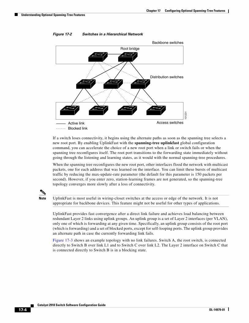
Chapter 17 Configuring Optional Spanning-Tree FeaturesUnderstanding Optional Spanning-Tree Features
Figure 17-2 Switches in a Hierarchical Network
1012
31
Active linkBlocked link
Root bridge
Backbone switches
Distribution switches
Access switches
If a switch loses connectivity, it begins using the alternate paths as soon as the spanning tree selects a new root port. By enabling UplinkFast with the spanning-tree uplinkfast global configuration command, you can accelerate the choice of a new root port when a link or switch fails or when the spanning tree reconfigures itself. The root port transitions to the forwarding state immediately without going through the listening and learning states, as it would with the normal spanning-tree procedures.
When the spanning tree reconfigures the new root port, other interfaces flood the network with multicast packets, one for each address that was learned on the interface. You can limit these bursts of multicast traffic by reducing the max-update-rate parameter (the default for this parameter is 150 packets per second). However, if you enter zero, station-learning frames are not generated, so the spanning-tree topology converges more slowly after a loss of connectivity.
Note UplinkFast is most useful in wiring-closet switches at the access or edge of the network. It is not appropriate for backbone devices. This feature might not be useful for other types of applications.
UplinkFast provides fast convergence after a direct link failure and achieves load balancing between redundant Layer 2 links using uplink groups. An uplink group is a set of Layer 2 interfaces (per VLAN), only one of which is forwarding at any given time. Specifically, an uplink group consists of the root port (which is forwarding) and a set of blocked ports, except for self-looping ports. The uplink group provides an alternate path in case the currently forwarding link fails.
Figure 17-3 shows an example topology with no link failures. Switch A, the root switch, is connected directly to Switch B over link L1 and to Switch C over link L2. The Layer 2 interface on Switch C that is connected directly to Switch B is in a blocking state.
17-4Catalyst 2918 Switch Software Configuration Guide
OL-14979-01
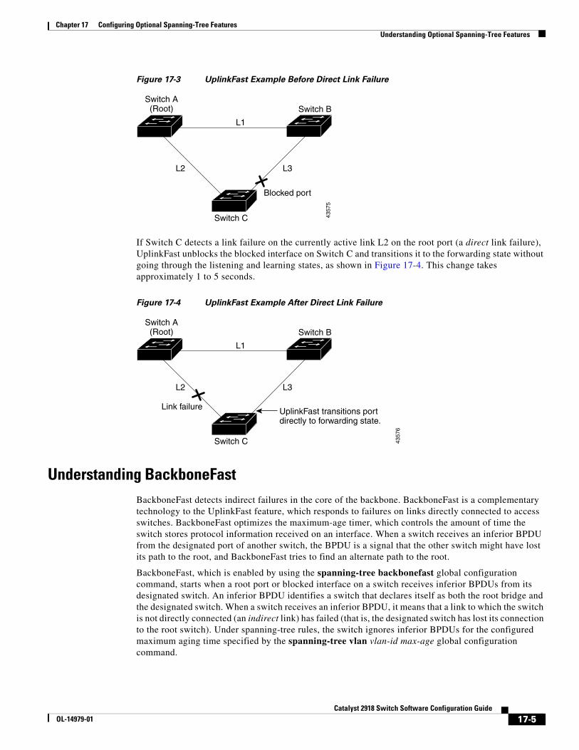
Chapter 17 Configuring Optional Spanning-Tree FeaturesUnderstanding Optional Spanning-Tree Features
Figure 17-3 UplinkFast Example Before Direct Link Failure
L1
L2 L3
Switch C
Switch A(Root) Switch B
Blocked port
4357
5
If Switch C detects a link failure on the currently active link L2 on the root port (a direct link failure), UplinkFast unblocks the blocked interface on Switch C and transitions it to the forwarding state without going through the listening and learning states, as shown in Figure 17-4. This change takes approximately 1 to 5 seconds.
Figure 17-4 UplinkFast Example After Direct Link Failure
L1
L2 L3
Switch C
Switch A(Root) Switch B
UplinkFast transitions portdirectly to forwarding state.
Link failure43
576
Understanding BackboneFastBackboneFast detects indirect failures in the core of the backbone. BackboneFast is a complementary technology to the UplinkFast feature, which responds to failures on links directly connected to access switches. BackboneFast optimizes the maximum-age timer, which controls the amount of time the switch stores protocol information received on an interface. When a switch receives an inferior BPDU from the designated port of another switch, the BPDU is a signal that the other switch might have lost its path to the root, and BackboneFast tries to find an alternate path to the root.
BackboneFast, which is enabled by using the spanning-tree backbonefast global configuration command, starts when a root port or blocked interface on a switch receives inferior BPDUs from its designated switch. An inferior BPDU identifies a switch that declares itself as both the root bridge and the designated switch. When a switch receives an inferior BPDU, it means that a link to which the switch is not directly connected (an indirect link) has failed (that is, the designated switch has lost its connection to the root switch). Under spanning-tree rules, the switch ignores inferior BPDUs for the configured maximum aging time specified by the spanning-tree vlan vlan-id max-age global configuration command.
17-5Catalyst 2918 Switch Software Configuration Guide
OL-14979-01
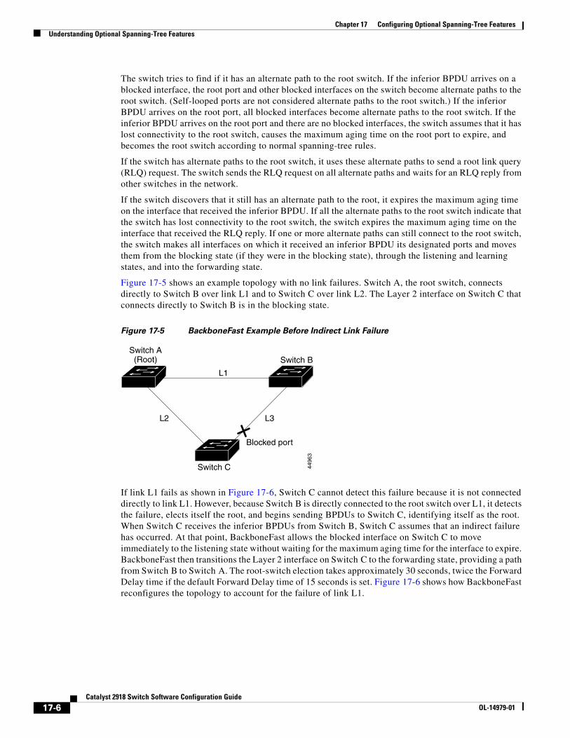
Chapter 17 Configuring Optional Spanning-Tree FeaturesUnderstanding Optional Spanning-Tree Features
The switch tries to find if it has an alternate path to the root switch. If the inferior BPDU arrives on a blocked interface, the root port and other blocked interfaces on the switch become alternate paths to the root switch. (Self-looped ports are not considered alternate paths to the root switch.) If the inferior BPDU arrives on the root port, all blocked interfaces become alternate paths to the root switch. If the inferior BPDU arrives on the root port and there are no blocked interfaces, the switch assumes that it has lost connectivity to the root switch, causes the maximum aging time on the root port to expire, and becomes the root switch according to normal spanning-tree rules.
If the switch has alternate paths to the root switch, it uses these alternate paths to send a root link query (RLQ) request. The switch sends the RLQ request on all alternate paths and waits for an RLQ reply from other switches in the network.
If the switch discovers that it still has an alternate path to the root, it expires the maximum aging time on the interface that received the inferior BPDU. If all the alternate paths to the root switch indicate that the switch has lost connectivity to the root switch, the switch expires the maximum aging time on the interface that received the RLQ reply. If one or more alternate paths can still connect to the root switch, the switch makes all interfaces on which it received an inferior BPDU its designated ports and moves them from the blocking state (if they were in the blocking state), through the listening and learning states, and into the forwarding state.
Figure 17-5 shows an example topology with no link failures. Switch A, the root switch, connects directly to Switch B over link L1 and to Switch C over link L2. The Layer 2 interface on Switch C that connects directly to Switch B is in the blocking state.
Figure 17-5 BackboneFast Example Before Indirect Link Failure
L1
L2 L3
Switch C
Switch A(Root) Switch B
Blocked port
4496
3
If link L1 fails as shown in Figure 17-6, Switch C cannot detect this failure because it is not connected directly to link L1. However, because Switch B is directly connected to the root switch over L1, it detects the failure, elects itself the root, and begins sending BPDUs to Switch C, identifying itself as the root. When Switch C receives the inferior BPDUs from Switch B, Switch C assumes that an indirect failure has occurred. At that point, BackboneFast allows the blocked interface on Switch C to move immediately to the listening state without waiting for the maximum aging time for the interface to expire. BackboneFast then transitions the Layer 2 interface on Switch C to the forwarding state, providing a path from Switch B to Switch A. The root-switch election takes approximately 30 seconds, twice the Forward Delay time if the default Forward Delay time of 15 seconds is set. Figure 17-6 shows how BackboneFast reconfigures the topology to account for the failure of link L1.
17-6Catalyst 2918 Switch Software Configuration Guide
OL-14979-01
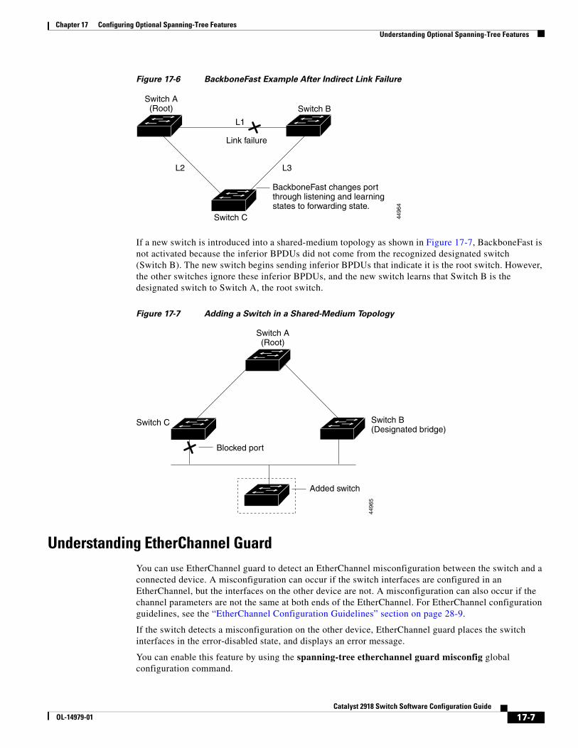
Chapter 17 Configuring Optional Spanning-Tree FeaturesUnderstanding Optional Spanning-Tree Features
Figure 17-6 BackboneFast Example After Indirect Link Failure
L1
L2 L3
Switch C
Switch A(Root) Switch B
Link failure
4496
4
BackboneFast changes portthrough listening and learning states to forwarding state.
If a new switch is introduced into a shared-medium topology as shown in Figure 17-7, BackboneFast is not activated because the inferior BPDUs did not come from the recognized designated switch (Switch B). The new switch begins sending inferior BPDUs that indicate it is the root switch. However, the other switches ignore these inferior BPDUs, and the new switch learns that Switch B is the designated switch to Switch A, the root switch.
Figure 17-7 Adding a Switch in a Shared-Medium Topology
Switch A(Root)
Switch C Switch B(Designated bridge)
Added switch
4496
5
Blocked port
Understanding EtherChannel GuardYou can use EtherChannel guard to detect an EtherChannel misconfiguration between the switch and a connected device. A misconfiguration can occur if the switch interfaces are configured in an EtherChannel, but the interfaces on the other device are not. A misconfiguration can also occur if the channel parameters are not the same at both ends of the EtherChannel. For EtherChannel configuration guidelines, see the “EtherChannel Configuration Guidelines” section on page 28-9.
If the switch detects a misconfiguration on the other device, EtherChannel guard places the switch interfaces in the error-disabled state, and displays an error message.
You can enable this feature by using the spanning-tree etherchannel guard misconfig global configuration command.
17-7Catalyst 2918 Switch Software Configuration Guide
OL-14979-01
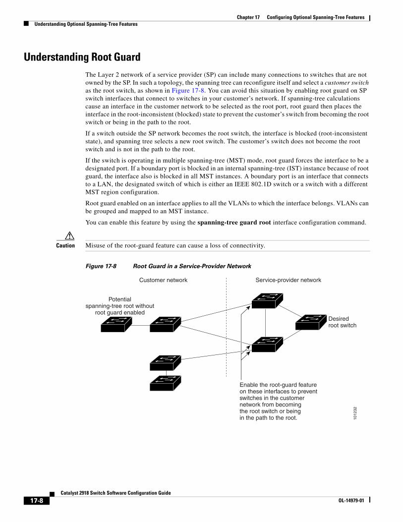
Chapter 17 Configuring Optional Spanning-Tree FeaturesUnderstanding Optional Spanning-Tree Features
Understanding Root GuardThe Layer 2 network of a service provider (SP) can include many connections to switches that are not owned by the SP. In such a topology, the spanning tree can reconfigure itself and select a customer switch as the root switch, as shown in Figure 17-8. You can avoid this situation by enabling root guard on SP switch interfaces that connect to switches in your customer’s network. If spanning-tree calculations cause an interface in the customer network to be selected as the root port, root guard then places the interface in the root-inconsistent (blocked) state to prevent the customer’s switch from becoming the root switch or being in the path to the root.
If a switch outside the SP network becomes the root switch, the interface is blocked (root-inconsistent state), and spanning tree selects a new root switch. The customer’s switch does not become the root switch and is not in the path to the root.
If the switch is operating in multiple spanning-tree (MST) mode, root guard forces the interface to be a designated port. If a boundary port is blocked in an internal spanning-tree (IST) instance because of root guard, the interface also is blocked in all MST instances. A boundary port is an interface that connects to a LAN, the designated switch of which is either an IEEE 802.1D switch or a switch with a different MST region configuration.
Root guard enabled on an interface applies to all the VLANs to which the interface belongs. VLANs can be grouped and mapped to an MST instance.
You can enable this feature by using the spanning-tree guard root interface configuration command.
Caution Misuse of the root-guard feature can cause a loss of connectivity.
Figure 17-8 Root Guard in a Service-Provider Network
1012
32
Desiredroot switch
Customer network
Potentialspanning-tree root without
root guard enabled
Enable the root-guard featureon these interfaces to preventswitches in the customernetwork from becomingthe root switch or beingin the path to the root.
Service-provider network
17-8Catalyst 2918 Switch Software Configuration Guide
OL-14979-01
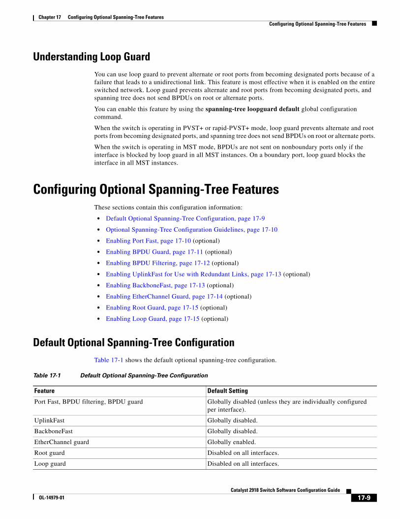
Chapter 17 Configuring Optional Spanning-Tree FeaturesConfiguring Optional Spanning-Tree Features
Understanding Loop GuardYou can use loop guard to prevent alternate or root ports from becoming designated ports because of a failure that leads to a unidirectional link. This feature is most effective when it is enabled on the entire switched network. Loop guard prevents alternate and root ports from becoming designated ports, and spanning tree does not send BPDUs on root or alternate ports.
You can enable this feature by using the spanning-tree loopguard default global configuration command.
When the switch is operating in PVST+ or rapid-PVST+ mode, loop guard prevents alternate and root ports from becoming designated ports, and spanning tree does not send BPDUs on root or alternate ports.
When the switch is operating in MST mode, BPDUs are not sent on nonboundary ports only if the interface is blocked by loop guard in all MST instances. On a boundary port, loop guard blocks the interface in all MST instances.
Configuring Optional Spanning-Tree FeaturesThese sections contain this configuration information:
• Default Optional Spanning-Tree Configuration, page 17-9
• Optional Spanning-Tree Configuration Guidelines, page 17-10
• Enabling Port Fast, page 17-10 (optional)
• Enabling BPDU Guard, page 17-11 (optional)
• Enabling BPDU Filtering, page 17-12 (optional)
• Enabling UplinkFast for Use with Redundant Links, page 17-13 (optional)
• Enabling BackboneFast, page 17-13 (optional)
• Enabling EtherChannel Guard, page 17-14 (optional)
• Enabling Root Guard, page 17-15 (optional)
• Enabling Loop Guard, page 17-15 (optional)
Default Optional Spanning-Tree ConfigurationTable 17-1 shows the default optional spanning-tree configuration.
Table 17-1 Default Optional Spanning-Tree Configuration
Feature Default Setting
Port Fast, BPDU filtering, BPDU guard Globally disabled (unless they are individually configured per interface).
UplinkFast Globally disabled.
BackboneFast Globally disabled.
EtherChannel guard Globally enabled.
Root guard Disabled on all interfaces.
Loop guard Disabled on all interfaces.
17-9Catalyst 2918 Switch Software Configuration Guide
OL-14979-01
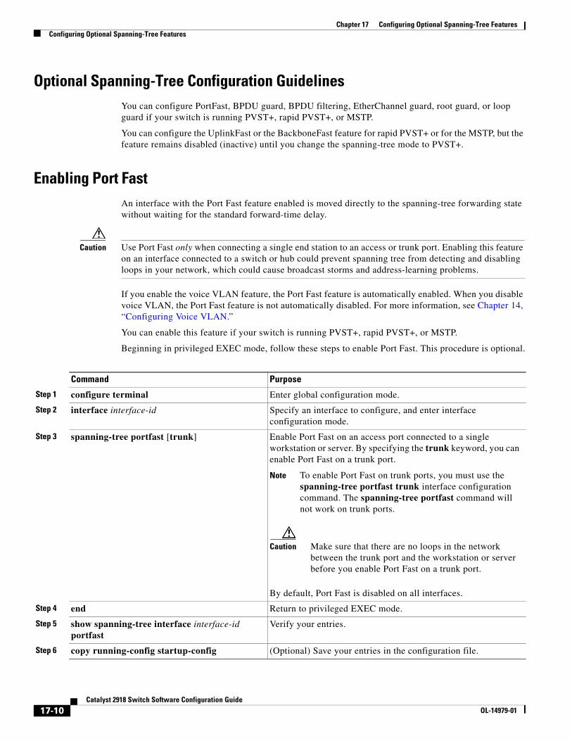
Chapter 17 Configuring Optional Spanning-Tree FeaturesConfiguring Optional Spanning-Tree Features
Optional Spanning-Tree Configuration GuidelinesYou can configure PortFast, BPDU guard, BPDU filtering, EtherChannel guard, root guard, or loop guard if your switch is running PVST+, rapid PVST+, or MSTP.
You can configure the UplinkFast or the BackboneFast feature for rapid PVST+ or for the MSTP, but the feature remains disabled (inactive) until you change the spanning-tree mode to PVST+.
Enabling Port FastAn interface with the Port Fast feature enabled is moved directly to the spanning-tree forwarding state without waiting for the standard forward-time delay.
Caution Use Port Fast only when connecting a single end station to an access or trunk port. Enabling this feature on an interface connected to a switch or hub could prevent spanning tree from detecting and disabling loops in your network, which could cause broadcast storms and address-learning problems.
If you enable the voice VLAN feature, the Port Fast feature is automatically enabled. When you disable voice VLAN, the Port Fast feature is not automatically disabled. For more information, see Chapter 14, “Configuring Voice VLAN.”
You can enable this feature if your switch is running PVST+, rapid PVST+, or MSTP.
Beginning in privileged EXEC mode, follow these steps to enable Port Fast. This procedure is optional.
Command Purpose
Step 1 configure terminal Enter global configuration mode.
Step 2 interface interface-id Specify an interface to configure, and enter interface configuration mode.
Step 3 spanning-tree portfast [trunk] Enable Port Fast on an access port connected to a single workstation or server. By specifying the trunk keyword, you can enable Port Fast on a trunk port.
Note To enable Port Fast on trunk ports, you must use the spanning-tree portfast trunk interface configuration command. The spanning-tree portfast command will not work on trunk ports.
Caution Make sure that there are no loops in the network between the trunk port and the workstation or server before you enable Port Fast on a trunk port.
By default, Port Fast is disabled on all interfaces.
Step 4 end Return to privileged EXEC mode.
Step 5 show spanning-tree interface interface-id portfast
Verify your entries.
Step 6 copy running-config startup-config (Optional) Save your entries in the configuration file.
17-10Catalyst 2918 Switch Software Configuration Guide
OL-14979-01
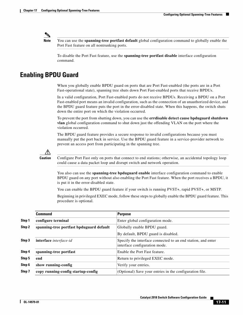
Chapter 17 Configuring Optional Spanning-Tree FeaturesConfiguring Optional Spanning-Tree Features
Note You can use the spanning-tree portfast default global configuration command to globally enable the Port Fast feature on all nontrunking ports.
To disable the Port Fast feature, use the spanning-tree portfast disable interface configuration command.
Enabling BPDU GuardWhen you globally enable BPDU guard on ports that are Port Fast-enabled (the ports are in a Port Fast-operational state), spanning tree shuts down Port Fast-enabled ports that receive BPDUs.
In a valid configuration, Port Fast-enabled ports do not receive BPDUs. Receiving a BPDU on a Port Fast-enabled port means an invalid configuration, such as the connection of an unauthorized device, and the BPDU guard feature puts the port in the error-disabled state. When this happens, the switch shuts down the entire port on which the violation occurred.
To prevent the port from shutting down, you can use the errdisable detect cause bpduguard shutdown vlan global configuration command to shut down just the offending VLAN on the port where the violation occurred.
The BPDU guard feature provides a secure response to invalid configurations because you must manually put the port back in service. Use the BPDU guard feature in a service-provider network to prevent an access port from participating in the spanning tree.
Caution Configure Port Fast only on ports that connect to end stations; otherwise, an accidental topology loop could cause a data packet loop and disrupt switch and network operation.
You also can use the spanning-tree bpduguard enable interface configuration command to enable BPDU guard on any port without also enabling the Port Fast feature. When the port receives a BPDU, it is put it in the error-disabled state.
You can enable the BPDU guard feature if your switch is running PVST+, rapid PVST+, or MSTP.
Beginning in privileged EXEC mode, follow these steps to globally enable the BPDU guard feature. This procedure is optional.
Command Purpose
Step 1 configure terminal Enter global configuration mode.
Step 2 spanning-tree portfast bpduguard default Globally enable BPDU guard.
By default, BPDU guard is disabled.
Step 3 interface interface-id Specify the interface connected to an end station, and enter interface configuration mode.
Step 4 spanning-tree portfast Enable the Port Fast feature.
Step 5 end Return to privileged EXEC mode.
Step 6 show running-config Verify your entries.
Step 7 copy running-config startup-config (Optional) Save your entries in the configuration file.
17-11Catalyst 2918 Switch Software Configuration Guide
OL-14979-01
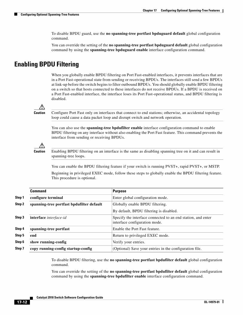
Chapter 17 Configuring Optional Spanning-Tree FeaturesConfiguring Optional Spanning-Tree Features
To disable BPDU guard, use the no spanning-tree portfast bpduguard default global configuration command.
You can override the setting of the no spanning-tree portfast bpduguard default global configuration command by using the spanning-tree bpduguard enable interface configuration command.
Enabling BPDU FilteringWhen you globally enable BPDU filtering on Port Fast-enabled interfaces, it prevents interfaces that are in a Port Fast-operational state from sending or receiving BPDUs. The interfaces still send a few BPDUs at link-up before the switch begins to filter outbound BPDUs. You should globally enable BPDU filtering on a switch so that hosts connected to these interfaces do not receive BPDUs. If a BPDU is received on a Port Fast-enabled interface, the interface loses its Port Fast-operational status, and BPDU filtering is disabled.
Caution Configure Port Fast only on interfaces that connect to end stations; otherwise, an accidental topology loop could cause a data packet loop and disrupt switch and network operation.
You can also use the spanning-tree bpdufilter enable interface configuration command to enable BPDU filtering on any interface without also enabling the Port Fast feature. This command prevents the interface from sending or receiving BPDUs.
Caution Enabling BPDU filtering on an interface is the same as disabling spanning tree on it and can result in spanning-tree loops.
You can enable the BPDU filtering feature if your switch is running PVST+, rapid PVST+, or MSTP.
Beginning in privileged EXEC mode, follow these steps to globally enable the BPDU filtering feature. This procedure is optional.
Command Purpose
Step 1 configure terminal Enter global configuration mode.
Step 2 spanning-tree portfast bpdufilter default Globally enable BPDU filtering.
By default, BPDU filtering is disabled.
Step 3 interface interface-id Specify the interface connected to an end station, and enter interface configuration mode.
Step 4 spanning-tree portfast Enable the Port Fast feature.
Step 5 end Return to privileged EXEC mode.
Step 6 show running-config Verify your entries.
Step 7 copy running-config startup-config (Optional) Save your entries in the configuration file.
To disable BPDU filtering, use the no spanning-tree portfast bpdufilter default global configuration command.
You can override the setting of the no spanning-tree portfast bpdufilter default global configuration command by using the spanning-tree bpdufilter enable interface configuration command.
17-12Catalyst 2918 Switch Software Configuration Guide
OL-14979-01
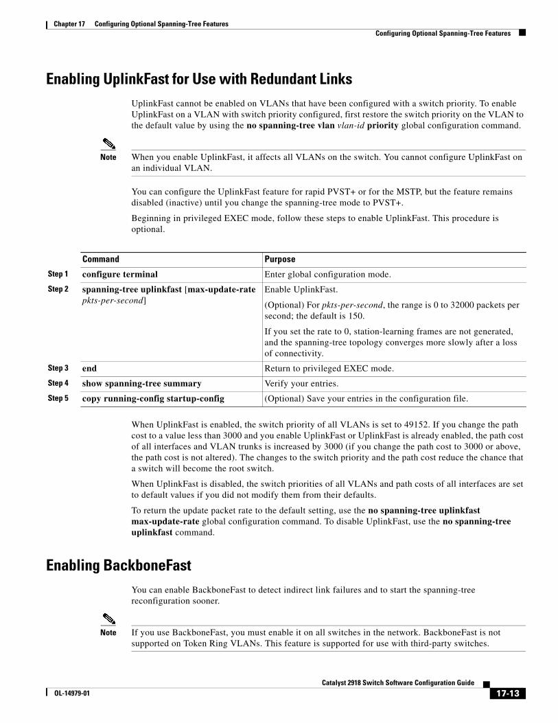
Chapter 17 Configuring Optional Spanning-Tree FeaturesConfiguring Optional Spanning-Tree Features
Enabling UplinkFast for Use with Redundant LinksUplinkFast cannot be enabled on VLANs that have been configured with a switch priority. To enable UplinkFast on a VLAN with switch priority configured, first restore the switch priority on the VLAN to the default value by using the no spanning-tree vlan vlan-id priority global configuration command.
Note When you enable UplinkFast, it affects all VLANs on the switch. You cannot configure UplinkFast on an individual VLAN.
You can configure the UplinkFast feature for rapid PVST+ or for the MSTP, but the feature remains disabled (inactive) until you change the spanning-tree mode to PVST+.
Beginning in privileged EXEC mode, follow these steps to enable UplinkFast. This procedure is optional.
Command Purpose
Step 1 configure terminal Enter global configuration mode.
Step 2 spanning-tree uplinkfast [max-update-rate pkts-per-second]
Enable UplinkFast.
(Optional) For pkts-per-second, the range is 0 to 32000 packets per second; the default is 150.
If you set the rate to 0, station-learning frames are not generated, and the spanning-tree topology converges more slowly after a loss of connectivity.
Step 3 end Return to privileged EXEC mode.
Step 4 show spanning-tree summary Verify your entries.
Step 5 copy running-config startup-config (Optional) Save your entries in the configuration file.
When UplinkFast is enabled, the switch priority of all VLANs is set to 49152. If you change the path cost to a value less than 3000 and you enable UplinkFast or UplinkFast is already enabled, the path cost of all interfaces and VLAN trunks is increased by 3000 (if you change the path cost to 3000 or above, the path cost is not altered). The changes to the switch priority and the path cost reduce the chance that a switch will become the root switch.
When UplinkFast is disabled, the switch priorities of all VLANs and path costs of all interfaces are set to default values if you did not modify them from their defaults.
To return the update packet rate to the default setting, use the no spanning-tree uplinkfast max-update-rate global configuration command. To disable UplinkFast, use the no spanning-tree uplinkfast command.
Enabling BackboneFastYou can enable BackboneFast to detect indirect link failures and to start the spanning-tree reconfiguration sooner.
Note If you use BackboneFast, you must enable it on all switches in the network. BackboneFast is not supported on Token Ring VLANs. This feature is supported for use with third-party switches.
17-13Catalyst 2918 Switch Software Configuration Guide
OL-14979-01
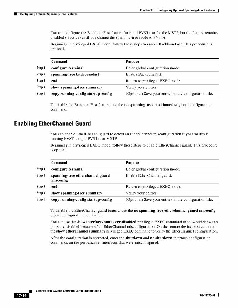
Chapter 17 Configuring Optional Spanning-Tree FeaturesConfiguring Optional Spanning-Tree Features
You can configure the BackboneFast feature for rapid PVST+ or for the MSTP, but the feature remains disabled (inactive) until you change the spanning-tree mode to PVST+.
Beginning in privileged EXEC mode, follow these steps to enable BackboneFast. This procedure is optional.
Command Purpose
Step 1 configure terminal Enter global configuration mode.
Step 2 spanning-tree backbonefast Enable BackboneFast.
Step 3 end Return to privileged EXEC mode.
Step 4 show spanning-tree summary Verify your entries.
Step 5 copy running-config startup-config (Optional) Save your entries in the configuration file.
To disable the BackboneFast feature, use the no spanning-tree backbonefast global configuration command.
Enabling EtherChannel GuardYou can enable EtherChannel guard to detect an EtherChannel misconfiguration if your switch is running PVST+, rapid PVST+, or MSTP.
Beginning in privileged EXEC mode, follow these steps to enable EtherChannel guard. This procedure is optional.
Command Purpose
Step 1 configure terminal Enter global configuration mode.
Step 2 spanning-tree etherchannel guard misconfig
Enable EtherChannel guard.
Step 3 end Return to privileged EXEC mode.
Step 4 show spanning-tree summary Verify your entries.
Step 5 copy running-config startup-config (Optional) Save your entries in the configuration file.
To disable the EtherChannel guard feature, use the no spanning-tree etherchannel guard misconfig global configuration command.
You can use the show interfaces status err-disabled privileged EXEC command to show which switch ports are disabled because of an EtherChannel misconfiguration. On the remote device, you can enter the show etherchannel summary privileged EXEC command to verify the EtherChannel configuration.
After the configuration is corrected, enter the shutdown and no shutdown interface configuration commands on the port-channel interfaces that were misconfigured.
17-14Catalyst 2918 Switch Software Configuration Guide
OL-14979-01
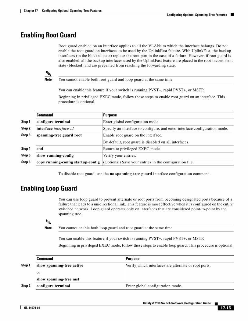
Chapter 17 Configuring Optional Spanning-Tree FeaturesConfiguring Optional Spanning-Tree Features
Enabling Root GuardRoot guard enabled on an interface applies to all the VLANs to which the interface belongs. Do not enable the root guard on interfaces to be used by the UplinkFast feature. With UplinkFast, the backup interfaces (in the blocked state) replace the root port in the case of a failure. However, if root guard is also enabled, all the backup interfaces used by the UplinkFast feature are placed in the root-inconsistent state (blocked) and are prevented from reaching the forwarding state.
Note You cannot enable both root guard and loop guard at the same time.
You can enable this feature if your switch is running PVST+, rapid PVST+, or MSTP.
Beginning in privileged EXEC mode, follow these steps to enable root guard on an interface. This procedure is optional.
Command Purpose
Step 1 configure terminal Enter global configuration mode.
Step 2 interface interface-id Specify an interface to configure, and enter interface configuration mode.
Step 3 spanning-tree guard root Enable root guard on the interface.
By default, root guard is disabled on all interfaces.
Step 4 end Return to privileged EXEC mode.
Step 5 show running-config Verify your entries.
Step 6 copy running-config startup-config (Optional) Save your entries in the configuration file.
To disable root guard, use the no spanning-tree guard interface configuration command.
Enabling Loop GuardYou can use loop guard to prevent alternate or root ports from becoming designated ports because of a failure that leads to a unidirectional link. This feature is most effective when it is configured on the entire switched network. Loop guard operates only on interfaces that are considered point-to-point by the spanning tree.
Note You cannot enable both loop guard and root guard at the same time.
You can enable this feature if your switch is running PVST+, rapid PVST+, or MSTP.
Beginning in privileged EXEC mode, follow these steps to enable loop guard. This procedure is optional.
Command Purpose
Step 1 show spanning-tree active
or
show spanning-tree mst
Verify which interfaces are alternate or root ports.
Step 2 configure terminal Enter global configuration mode.
17-15Catalyst 2918 Switch Software Configuration Guide
OL-14979-01
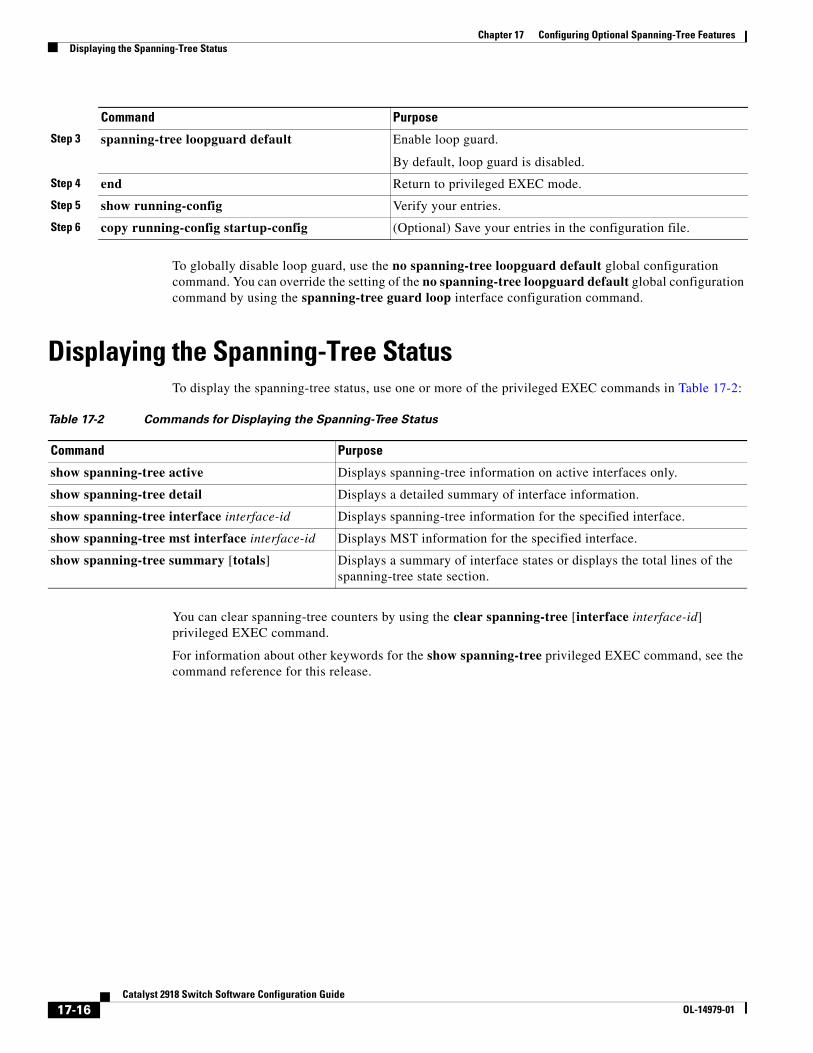
Chapter 17 Configuring Optional Spanning-Tree FeaturesDisplaying the Spanning-Tree Status
To globally disable loop guard, use the no spanning-tree loopguard default global configuration command. You can override the setting of the no spanning-tree loopguard default global configuration command by using the spanning-tree guard loop interface configuration command.
Displaying the Spanning-Tree StatusTo display the spanning-tree status, use one or more of the privileged EXEC commands in Table 17-2:
Table 17-2 Commands for Displaying the Spanning-Tree Status
Command Purpose
show spanning-tree active Displays spanning-tree information on active interfaces only.
show spanning-tree detail Displays a detailed summary of interface information.
show spanning-tree interface interface-id Displays spanning-tree information for the specified interface.
show spanning-tree mst interface interface-id Displays MST information for the specified interface.
show spanning-tree summary [totals] Displays a summary of interface states or displays the total lines of the spanning-tree state section.
You can clear spanning-tree counters by using the clear spanning-tree [interface interface-id] privileged EXEC command.
For information about other keywords for the show spanning-tree privileged EXEC command, see the command reference for this release.
Step 3 spanning-tree loopguard default Enable loop guard.
By default, loop guard is disabled.
Step 4 end Return to privileged EXEC mode.
Step 5 show running-config Verify your entries.
Step 6 copy running-config startup-config (Optional) Save your entries in the configuration file.
Command Purpose
17-16Catalyst 2918 Switch Software Configuration Guide
OL-14979-01
OL-14979-01
C H A P T E R 18
Configuring IGMP SnoopingThis chapter describes how to configure Internet Group Management Protocol (IGMP) snooping on the Catalyst 2918 switch. It also includes procedures for controlling multicast group membership by using IGMP filtering and procedures for configuring the IGMP throttling action.
Note For complete syntax and usage information for the commands used in this chapter, see the switch command reference for this release and the “IP Multicast Routing Commands” section in the Cisco IOS IP Command Reference, Volume 3 of 3:Multicast, Release 12.2.
This chapter consists of these sections:
• Understanding IGMP Snooping, page 18-1
• Configuring IGMP Snooping, page 18-6
• Displaying IGMP Snooping Information, page 18-14
• Configuring IGMP Filtering and Throttling, page 18-16
• Displaying IGMP Filtering and Throttling Configuration, page 18-20
Note You can either manage IP multicast group addresses through features such as IGMP snooping, or you can use static IP addresses.
Understanding IGMP SnoopingLayer 2 switches can use IGMP snooping to constrain the flooding of multicast traffic by dynamically configuring Layer 2 interfaces so that multicast traffic is forwarded to only those interfaces associated with IP multicast devices. As the name implies, IGMP snooping requires the LAN switch to snoop on the IGMP transmissions between the host and the router and to keep track of multicast groups and member ports. When the switch receives an IGMP report from a host for a particular multicast group, the switch adds the host port number to the forwarding table entry; when it receives an IGMP Leave Group message from a host, it removes the host port from the table entry. It also periodically deletes entries if it does not receive IGMP membership reports from the multicast clients.
Note For more information on IP multicast and IGMP, see RFC 1112 and RFC 2236.
18-1Catalyst 2918 Switch Software Configuration Guide
Chapter 18 Configuring IGMP SnoopingUnderstanding IGMP Snooping
The multicast router sends out periodic general queries to all VLANs. All hosts interested in this multicast traffic send join requests and are added to the forwarding table entry. The switch creates one entry per VLAN in the IGMP snooping IP multicast forwarding table for each group from which it receives an IGMP join request.
The switch supports IP multicast group-based bridging, rather than MAC-addressed based groups. With multicast MAC address-based groups, if an IP address being configured translates (aliases) to a previously configured MAC address or to any reserved multicast MAC addresses (in the range 224.0.0.xxx), the command fails. Because the switch uses IP multicast groups, there are no address aliasing issues.
The IP multicast groups learned through IGMP snooping are dynamic. However, you can statically configure multicast groups by using the ip igmp snooping vlan vlan-id static ip_address interface interface-id global configuration command. If you specify group membership for a multicast group address statically, your setting supersedes any automatic manipulation by IGMP snooping. Multicast group membership lists can consist of both user-defined and IGMP snooping-learned settings.
You can configure an IGMP snooping querier to support IGMP snooping in subnets without multicast interfaces because the multicast traffic does not need to be routed. For more information about the IGMP snooping querier, see the “Configuring the IGMP Snooping Querier” section on page 18-13.
If a port spanning-tree, a port group, or a VLAN ID change occurs, the IGMP snooping-learned multicast groups from this port on the VLAN are deleted.
These sections describe IGMP snooping characteristics:
• IGMP Versions, page 18-2
• Joining a Multicast Group, page 18-3
• Leaving a Multicast Group, page 18-4
• Immediate Leave, page 18-5
• IGMP Configurable-Leave Timer, page 18-5
• IGMP Report Suppression, page 18-5
IGMP VersionsThe switch supports IGMP Version 1, IGMP Version 2, and IGMP Version 3. These versions are interoperable on the switch. For example, if IGMP snooping is enabled on an IGMPv2 switch and the switch receives an IGMPv3 report from a host, the switch can forward the IGMPv3 report to the multicast router.
Note The switch supports IGMPv3 snooping based only on the destination multicast MAC address. It does not support snooping based on the source MAC address or on proxy reports.
An IGMPv3 switch supports Basic IGMPv3 Snooping Support (BISS), which includes support for the snooping features on IGMPv1 and IGMPv2 switches and for IGMPv3 membership report messages. BISS constrains the flooding of multicast traffic when your network includes IGMPv3 hosts. It constrains traffic to approximately the same set of ports as the IGMP snooping feature on IGMPv2 or IGMPv1 hosts.
Note IGMPv3 join and leave messages are not supported on switches running IGMP filtering.
18-2Catalyst 2918 Switch Software Configuration Guide
OL-14979-01
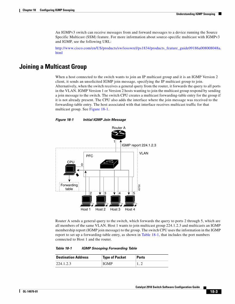
Chapter 18 Configuring IGMP SnoopingUnderstanding IGMP Snooping
An IGMPv3 switch can receive messages from and forward messages to a device running the Source Specific Multicast (SSM) feature. For more information about source-specific multicast with IGMPv3 and IGMP, see the following URL:
http://www.cisco.com/en/US/products/sw/iosswrel/ps1834/products_feature_guide09186a008008048a.html
Joining a Multicast GroupWhen a host connected to the switch wants to join an IP multicast group and it is an IGMP Version 2 client, it sends an unsolicited IGMP join message, specifying the IP multicast group to join. Alternatively, when the switch receives a general query from the router, it forwards the query to all ports in the VLAN. IGMP Version 1 or Version 2 hosts wanting to join the multicast group respond by sending a join message to the switch. The switch CPU creates a multicast forwarding-table entry for the group if it is not already present. The CPU also adds the interface where the join message was received to the forwarding-table entry. The host associated with that interface receives multicast traffic for that multicast group. See Figure 18-1.
Figure 18-1 Initial IGMP Join Message
Forwardingtable
CPU
Host 1 Host 2 Host 3 Host 4
Router A
IGMP report 224.1.2.3
VLANPFC
1
0
2 3 4 5
4575
0
Router A sends a general query to the switch, which forwards the query to ports 2 through 5, which are all members of the same VLAN. Host 1 wants to join multicast group 224.1.2.3 and multicasts an IGMP membership report (IGMP join message) to the group. The switch CPU uses the information in the IGMP report to set up a forwarding-table entry, as shown in Table 18-1, that includes the port numbers connected to Host 1 and the router.
Table 18-1 IGMP Snooping Forwarding Table
Destination Address Type of Packet Ports
224.1.2.3 IGMP 1, 2
18-3Catalyst 2918 Switch Software Configuration Guide
OL-14979-01
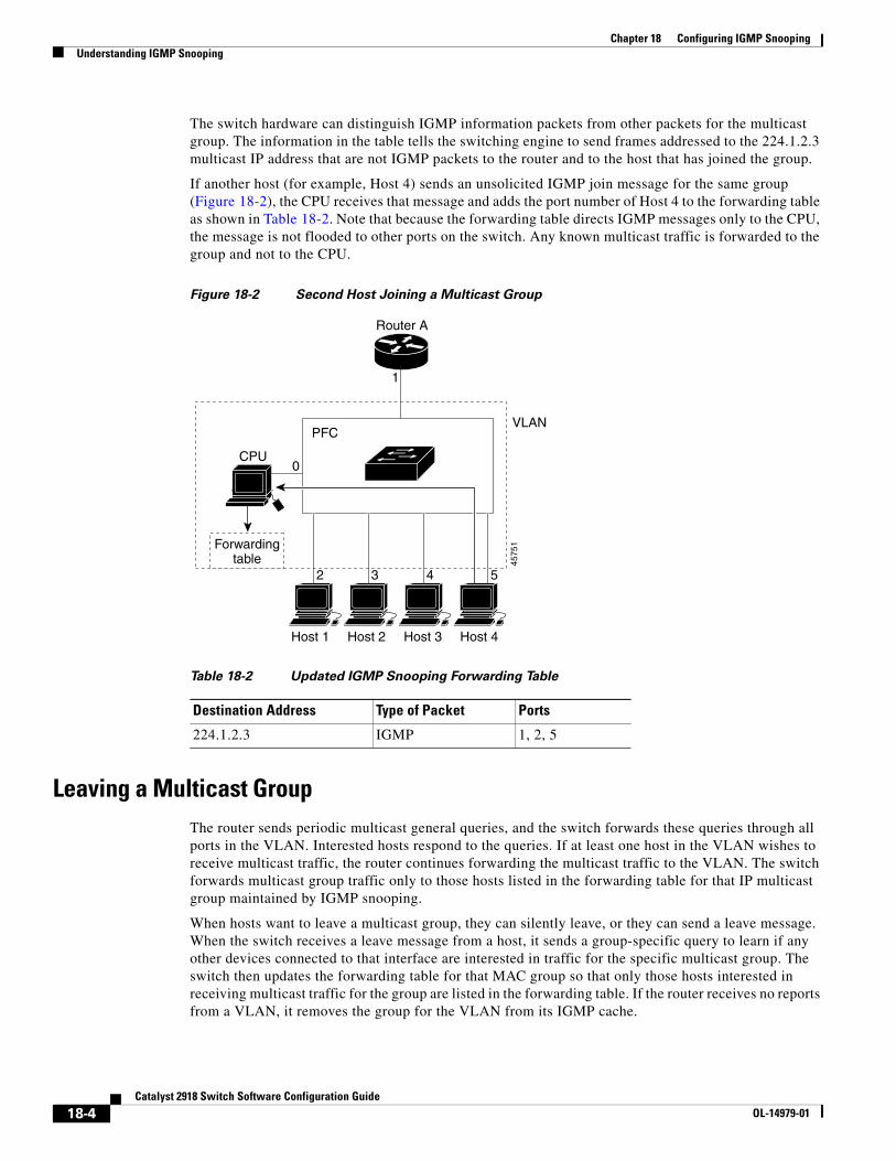
Chapter 18 Configuring IGMP SnoopingUnderstanding IGMP Snooping
The switch hardware can distinguish IGMP information packets from other packets for the multicast group. The information in the table tells the switching engine to send frames addressed to the 224.1.2.3 multicast IP address that are not IGMP packets to the router and to the host that has joined the group.
If another host (for example, Host 4) sends an unsolicited IGMP join message for the same group (Figure 18-2), the CPU receives that message and adds the port number of Host 4 to the forwarding table as shown in Table 18-2. Note that because the forwarding table directs IGMP messages only to the CPU, the message is not flooded to other ports on the switch. Any known multicast traffic is forwarded to the group and not to the CPU.
Figure 18-2 Second Host Joining a Multicast Group
Forwardingtable
CPU
Host 1 Host 2 Host 3 Host 4
Router A
PFCVLAN
1
0
2 3 4 5
4575
1
Table 18-2 Updated IGMP Snooping Forwarding Table
Destination Address Type of Packet Ports
224.1.2.3 IGMP 1, 2, 5
Leaving a Multicast GroupThe router sends periodic multicast general queries, and the switch forwards these queries through all ports in the VLAN. Interested hosts respond to the queries. If at least one host in the VLAN wishes to receive multicast traffic, the router continues forwarding the multicast traffic to the VLAN. The switch forwards multicast group traffic only to those hosts listed in the forwarding table for that IP multicast group maintained by IGMP snooping.
When hosts want to leave a multicast group, they can silently leave, or they can send a leave message. When the switch receives a leave message from a host, it sends a group-specific query to learn if any other devices connected to that interface are interested in traffic for the specific multicast group. The switch then updates the forwarding table for that MAC group so that only those hosts interested in receiving multicast traffic for the group are listed in the forwarding table. If the router receives no reports from a VLAN, it removes the group for the VLAN from its IGMP cache.
18-4Catalyst 2918 Switch Software Configuration Guide
OL-14979-01
Chapter 18 Configuring IGMP SnoopingUnderstanding IGMP Snooping
Immediate Leave Immediate Leave is only supported on IGMP Version 2 hosts.
The switch uses IGMP snooping Immediate Leave to remove from the forwarding table an interface that sends a leave message without the switch sending group-specific queries to the interface. The VLAN interface is pruned from the multicast tree for the multicast group specified in the original leave message. Immediate Leave ensures optimal bandwidth management for all hosts on a switched network, even when multiple multicast groups are simultaneously in use.
Note You should only use the Immediate Leave feature on VLANs where a single host is connected to each port. If Immediate Leave is enabled in VLANs where more than one host is connected to a port, some hosts might inadvertently be dropped.
For configuration steps, see the “Enabling IGMP Immediate Leave” section on page 18-9.
IGMP Configurable-Leave TimerYou can configure the time that the switch waits after sending a group-specific query to determine if hosts are still interested in a specific multicast group. The IGMP leave response time can be configured from 100 to 5000 milliseconds. The timer can be set either globally or on a per-VLAN basis. The VLAN configuration of the leave time overrides the global configuration.
For configuration steps, see the “Configuring the IGMP Leave Timer” section on page 18-10.
IGMP Report Suppression
Note IGMP report suppression is supported only when the multicast query has IGMPv1 and IGMPv2 reports. This feature is not supported when the query includes IGMPv3 reports.
The switch uses IGMP report suppression to forward only one IGMP report per multicast router query to multicast devices. When IGMP router suppression is enabled (the default), the switch sends the first IGMP report from all hosts for a group to all the multicast routers. The switch does not send the remaining IGMP reports for the group to the multicast routers. This feature prevents duplicate reports from being sent to the multicast devices.
If the multicast router query includes requests only for IGMPv1 and IGMPv2 reports, the switch forwards only the first IGMPv1 or IGMPv2 report from all hosts for a group to all the multicast routers.
If the multicast router query also includes requests for IGMPv3 reports, the switch forwards all IGMPv1, IGMPv2, and IGMPv3 reports for a group to the multicast devices.
If you disable IGMP report suppression, all IGMP reports are forwarded to the multicast routers. For configuration steps, see the “Disabling IGMP Report Suppression” section on page 18-14.
18-5Catalyst 2918 Switch Software Configuration Guide
OL-14979-01
Chapter 18 Configuring IGMP SnoopingConfiguring IGMP Snooping
Configuring IGMP SnoopingIGMP snooping allows switches to examine IGMP packets and make forwarding decisions based on their content. These sections contain this configuration information:
• Default IGMP Snooping Configuration, page 18-6
• Enabling or Disabling IGMP Snooping, page 18-6
• Setting the Snooping Method, page 18-7
• Configuring a Multicast Router Port, page 18-8
• Configuring a Host Statically to Join a Group, page 18-9
• Enabling IGMP Immediate Leave, page 18-9
• Configuring the IGMP Leave Timer, page 18-10
• Configuring TCN-Related Commands, page 18-11
• Configuring the IGMP Snooping Querier, page 18-13
• Disabling IGMP Report Suppression, page 18-14
Default IGMP Snooping ConfigurationTable 18-3 shows the default IGMP snooping configuration.
Table 18-3 Default IGMP Snooping Configuration
Feature Default Setting
IGMP snooping Enabled globally and per VLAN
Multicast routers None configured
Multicast router learning (snooping) method PIM-DVMRP
IGMP snooping Immediate Leave Disabled
Static groups None configured
1. TCN = Topology Change Notification
TCN1 flood query count 2
TCN query solicitation Disabled
IGMP snooping querier Disabled
IGMP report suppression Enabled
Enabling or Disabling IGMP SnoopingBy default, IGMP snooping is globally enabled on the switch. When globally enabled or disabled, it is also enabled or disabled in all existing VLAN interfaces. IGMP snooping is by default enabled on all VLANs, but can be enabled and disabled on a per-VLAN basis.
Global IGMP snooping overrides the VLAN IGMP snooping. If global snooping is disabled, you cannot enable VLAN snooping. If global snooping is enabled, you can enable or disable VLAN snooping.
18-6Catalyst 2918 Switch Software Configuration Guide
OL-14979-01
Chapter 18 Configuring IGMP SnoopingConfiguring IGMP Snooping
Beginning in privileged EXEC mode, follow these steps to globally enable IGMP snooping on the switch:
Command Purpose
Step 1 configure terminal Enter global configuration mode.
Step 2 ip igmp snooping Globally enable IGMP snooping in all existing VLAN interfaces.
Step 3 end Return to privileged EXEC mode.
Step 4 copy running-config startup-config (Optional) Save your entries in the configuration file.
To globally disable IGMP snooping on all VLAN interfaces, use the no ip igmp snooping global configuration command.
Beginning in privileged EXEC mode, follow these steps to enable IGMP snooping on a VLAN interface:
Command Purpose
Step 1 configure terminal Enter global configuration mode.
Step 2 ip igmp snooping vlan vlan-id Enable IGMP snooping on the VLAN interface.The VLAN ID range is 1 to 1001 and 1006 to 4094.
Note IGMP snooping must be globally enabled before you can enable VLAN snooping.
Step 3 end Return to privileged EXEC mode.
Step 4 copy running-config startup-config (Optional) Save your entries in the configuration file.
To disable IGMP snooping on a VLAN interface, use the no ip igmp snooping vlan vlan-id global configuration command for the specified VLAN number.
Setting the Snooping MethodMulticast-capable router ports are added to the forwarding table for every Layer 2 multicast entry. The switch learns of such ports through one of these methods:
• Snooping on IGMP queries, Protocol Independent Multicast (PIM) packets, and Distance Vector Multicast Routing Protocol (DVMRP) packets
• Listening to Cisco Group Management Protocol (CGMP) packets from other routers
• Statically connecting to a multicast router port with the ip igmp snooping mrouter global configuration command
You can configure the switch either to snoop on IGMP queries and PIM/DVMRP packets or to listen to CGMP self-join or proxy-join packets. By default, the switch snoops on PIM/DVMRP packets on all VLANs. To learn of multicast router ports through only CGMP packets, use the ip igmp snooping vlan vlan-id mrouter learn cgmp global configuration command. When this command is entered, the router listens to only CGMP self-join and CGMP proxy-join packets and to no other CGMP packets. To learn of multicast router ports through only PIM-DVMRP packets, use the ip igmp snooping vlan vlan-id mrouter learn pim-dvmrp global configuration command.
18-7Catalyst 2918 Switch Software Configuration Guide
OL-14979-01
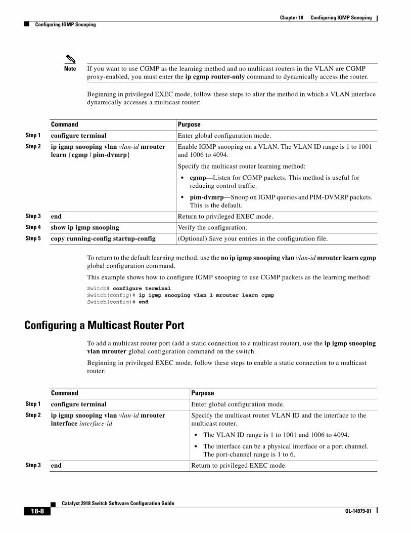
Chapter 18 Configuring IGMP SnoopingConfiguring IGMP Snooping
Note If you want to use CGMP as the learning method and no multicast routers in the VLAN are CGMP proxy-enabled, you must enter the ip cgmp router-only command to dynamically access the router.
Beginning in privileged EXEC mode, follow these steps to alter the method in which a VLAN interface dynamically accesses a multicast router:
Command Purpose
Step 1 configure terminal Enter global configuration mode.
Step 2 ip igmp snooping vlan vlan-id mrouter learn {cgmp | pim-dvmrp}
Enable IGMP snooping on a VLAN. The VLAN ID range is 1 to 1001 and 1006 to 4094.
Specify the multicast router learning method:
• cgmp—Listen for CGMP packets. This method is useful for reducing control traffic.
• pim-dvmrp—Snoop on IGMP queries and PIM-DVMRP packets. This is the default.
Step 3 end Return to privileged EXEC mode.
Step 4 show ip igmp snooping Verify the configuration.
Step 5 copy running-config startup-config (Optional) Save your entries in the configuration file.
To return to the default learning method, use the no ip igmp snooping vlan vlan-id mrouter learn cgmp global configuration command.
This example shows how to configure IGMP snooping to use CGMP packets as the learning method:
Switch# configure terminalSwitch(config)# ip igmp snooping vlan 1 mrouter learn cgmpSwitch(config)# end
Configuring a Multicast Router PortTo add a multicast router port (add a static connection to a multicast router), use the ip igmp snooping vlan mrouter global configuration command on the switch.
Beginning in privileged EXEC mode, follow these steps to enable a static connection to a multicast router:
Command Purpose
Step 1 configure terminal Enter global configuration mode.
Step 2 ip igmp snooping vlan vlan-id mrouter interface interface-id
Specify the multicast router VLAN ID and the interface to the multicast router.
• The VLAN ID range is 1 to 1001 and 1006 to 4094.
• The interface can be a physical interface or a port channel. The port-channel range is 1 to 6.
Step 3 end Return to privileged EXEC mode.
18-8Catalyst 2918 Switch Software Configuration Guide
OL-14979-01
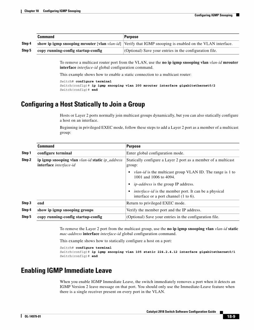
Chapter 18 Configuring IGMP SnoopingConfiguring IGMP Snooping
To remove a multicast router port from the VLAN, use the no ip igmp snooping vlan vlan-id mrouter interface interface-id global configuration command.
This example shows how to enable a static connection to a multicast router:
Switch# configure terminalSwitch(config)# ip igmp snooping vlan 200 mrouter interface gigabitethernet0/2Switch(config)# end
Configuring a Host Statically to Join a GroupHosts or Layer 2 ports normally join multicast groups dynamically, but you can also statically configure a host on an interface.
Beginning in privileged EXEC mode, follow these steps to add a Layer 2 port as a member of a multicast group:
Command Purpose
Step 1 configure terminal Enter global configuration mode.
Step 2 ip igmp snooping vlan vlan-id static ip_address interface interface-id
Statically configure a Layer 2 port as a member of a multicast group:
• vlan-id is the multicast group VLAN ID. The range is 1 to 1001 and 1006 to 4094.
• ip-address is the group IP address.
• interface-id is the member port. It can be a physical interface or a port channel (1 to 6).
Step 3 end Return to privileged EXEC mode.
Step 4 show ip igmp snooping groups Verify the member port and the IP address.
Step 5 copy running-config startup-config (Optional) Save your entries in the configuration file.
To remove the Layer 2 port from the multicast group, use the no ip igmp snooping vlan vlan-id static mac-address interface interface-id global configuration command.
This example shows how to statically configure a host on a port:
Switch# configure terminalSwitch(config)# ip igmp snooping vlan 105 static 224.2.4.12 interface gigabitethernet0/1Switch(config)# end
Enabling IGMP Immediate LeaveWhen you enable IGMP Immediate Leave, the switch immediately removes a port when it detects an IGMP Version 2 leave message on that port. You should only use the Immediate-Leave feature when there is a single receiver present on every port in the VLAN.
Step 4 show ip igmp snooping mrouter [vlan vlan-id] Verify that IGMP snooping is enabled on the VLAN interface.
Step 5 copy running-config startup-config (Optional) Save your entries in the configuration file.
Command Purpose
18-9Catalyst 2918 Switch Software Configuration Guide
OL-14979-01
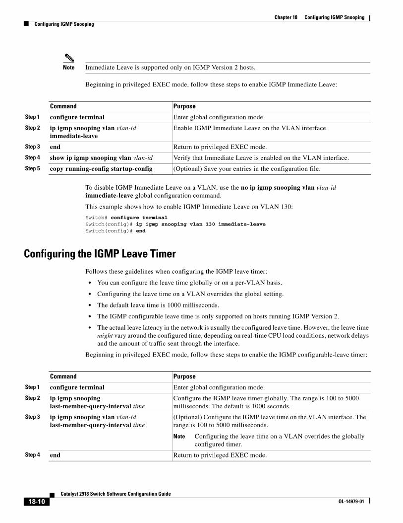
Chapter 18 Configuring IGMP SnoopingConfiguring IGMP Snooping
Note Immediate Leave is supported only on IGMP Version 2 hosts.
Beginning in privileged EXEC mode, follow these steps to enable IGMP Immediate Leave:
Command Purpose
Step 1 configure terminal Enter global configuration mode.
Step 2 ip igmp snooping vlan vlan-id immediate-leave
Enable IGMP Immediate Leave on the VLAN interface.
Step 3 end Return to privileged EXEC mode.
Step 4 show ip igmp snooping vlan vlan-id Verify that Immediate Leave is enabled on the VLAN interface.
Step 5 copy running-config startup-config (Optional) Save your entries in the configuration file.
To disable IGMP Immediate Leave on a VLAN, use the no ip igmp snooping vlan vlan-id immediate-leave global configuration command.
This example shows how to enable IGMP Immediate Leave on VLAN 130:
Switch# configure terminalSwitch(config)# ip igmp snooping vlan 130 immediate-leaveSwitch(config)# end
Configuring the IGMP Leave TimerFollows these guidelines when configuring the IGMP leave timer:
• You can configure the leave time globally or on a per-VLAN basis.
• Configuring the leave time on a VLAN overrides the global setting.
• The default leave time is 1000 milliseconds.
• The IGMP configurable leave time is only supported on hosts running IGMP Version 2.
• The actual leave latency in the network is usually the configured leave time. However, the leave time might vary around the configured time, depending on real-time CPU load conditions, network delays and the amount of traffic sent through the interface.
Beginning in privileged EXEC mode, follow these steps to enable the IGMP configurable-leave timer:
Command Purpose
Step 1 configure terminal Enter global configuration mode.
Step 2 ip igmp snooping last-member-query-interval time
Configure the IGMP leave timer globally. The range is 100 to 5000 milliseconds. The default is 1000 seconds.
Step 3 ip igmp snooping vlan vlan-id last-member-query-interval time
(Optional) Configure the IGMP leave time on the VLAN interface. The range is 100 to 5000 milliseconds.
Note Configuring the leave time on a VLAN overrides the globally configured timer.
Step 4 end Return to privileged EXEC mode.
18-10Catalyst 2918 Switch Software Configuration Guide
OL-14979-01
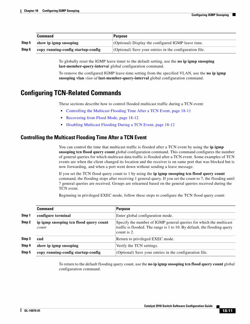
Chapter 18 Configuring IGMP SnoopingConfiguring IGMP Snooping
To globally reset the IGMP leave timer to the default setting, use the no ip igmp snooping last-member-query-interval global configuration command.
To remove the configured IGMP leave-time setting from the specified VLAN, use the no ip igmp snooping vlan vlan-id last-member-query-interval global configuration command.
Configuring TCN-Related CommandsThese sections describe how to control flooded multicast traffic during a TCN event:
• Controlling the Multicast Flooding Time After a TCN Event, page 18-11
• Recovering from Flood Mode, page 18-12
• Disabling Multicast Flooding During a TCN Event, page 18-12
Controlling the Multicast Flooding Time After a TCN Event
You can control the time that multicast traffic is flooded after a TCN event by using the ip igmp snooping tcn flood query count global configuration command. This command configures the number of general queries for which multicast data traffic is flooded after a TCN event. Some examples of TCN events are when the client changed its location and the receiver is on same port that was blocked but is now forwarding, and when a port went down without sending a leave message.
If you set the TCN flood query count to 1 by using the ip igmp snooping tcn flood query count command, the flooding stops after receiving 1 general query. If you set the count to 7, the flooding until 7 general queries are received. Groups are relearned based on the general queries received during the TCN event.
Beginning in privileged EXEC mode, follow these steps to configure the TCN flood query count:
Command Purpose
Step 1 configure terminal Enter global configuration mode.
Step 2 ip igmp snooping tcn flood query count count
Specify the number of IGMP general queries for which the multicast traffic is flooded. The range is 1 to 10. By default, the flooding query count is 2.
Step 3 end Return to privileged EXEC mode.
Step 4 show ip igmp snooping Verify the TCN settings.
Step 5 copy running-config startup-config (Optional) Save your entries in the configuration file.
To return to the default flooding query count, use the no ip igmp snooping tcn flood query count global configuration command.
Step 5 show ip igmp snooping (Optional) Display the configured IGMP leave time.
Step 6 copy running-config startup-config (Optional) Save your entries in the configuration file.
Command Purpose
18-11Catalyst 2918 Switch Software Configuration Guide
OL-14979-01
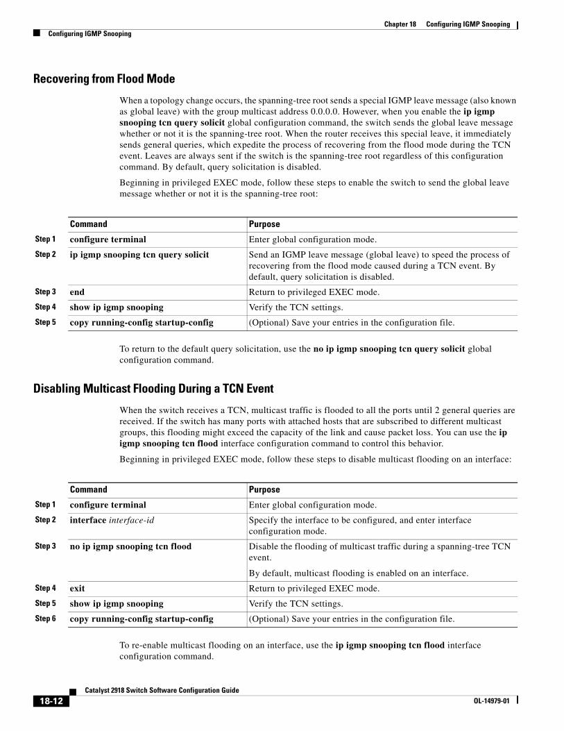
Chapter 18 Configuring IGMP SnoopingConfiguring IGMP Snooping
Recovering from Flood Mode
When a topology change occurs, the spanning-tree root sends a special IGMP leave message (also known as global leave) with the group multicast address 0.0.0.0. However, when you enable the ip igmp snooping tcn query solicit global configuration command, the switch sends the global leave message whether or not it is the spanning-tree root. When the router receives this special leave, it immediately sends general queries, which expedite the process of recovering from the flood mode during the TCN event. Leaves are always sent if the switch is the spanning-tree root regardless of this configuration command. By default, query solicitation is disabled.
Beginning in privileged EXEC mode, follow these steps to enable the switch to send the global leave message whether or not it is the spanning-tree root:
Command Purpose
Step 1 configure terminal Enter global configuration mode.
Step 2 ip igmp snooping tcn query solicit Send an IGMP leave message (global leave) to speed the process of recovering from the flood mode caused during a TCN event. By default, query solicitation is disabled.
Step 3 end Return to privileged EXEC mode.
Step 4 show ip igmp snooping Verify the TCN settings.
Step 5 copy running-config startup-config (Optional) Save your entries in the configuration file.
To return to the default query solicitation, use the no ip igmp snooping tcn query solicit global configuration command.
Disabling Multicast Flooding During a TCN Event
When the switch receives a TCN, multicast traffic is flooded to all the ports until 2 general queries are received. If the switch has many ports with attached hosts that are subscribed to different multicast groups, this flooding might exceed the capacity of the link and cause packet loss. You can use the ip igmp snooping tcn flood interface configuration command to control this behavior.
Beginning in privileged EXEC mode, follow these steps to disable multicast flooding on an interface:
Command Purpose
Step 1 configure terminal Enter global configuration mode.
Step 2 interface interface-id Specify the interface to be configured, and enter interface configuration mode.
Step 3 no ip igmp snooping tcn flood Disable the flooding of multicast traffic during a spanning-tree TCN event.
By default, multicast flooding is enabled on an interface.
Step 4 exit Return to privileged EXEC mode.
Step 5 show ip igmp snooping Verify the TCN settings.
Step 6 copy running-config startup-config (Optional) Save your entries in the configuration file.
To re-enable multicast flooding on an interface, use the ip igmp snooping tcn flood interface configuration command.
18-12Catalyst 2918 Switch Software Configuration Guide
OL-14979-01
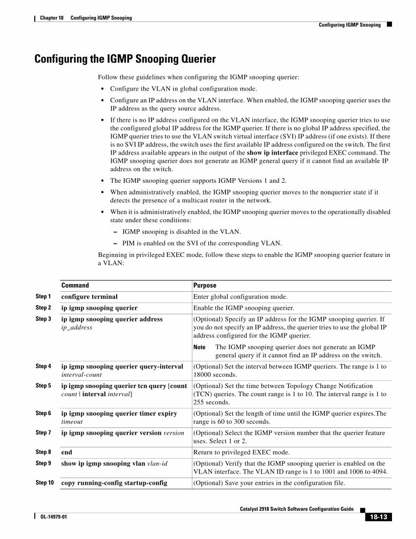
Chapter 18 Configuring IGMP SnoopingConfiguring IGMP Snooping
Configuring the IGMP Snooping QuerierFollow these guidelines when configuring the IGMP snooping querier:
• Configure the VLAN in global configuration mode.
• Configure an IP address on the VLAN interface. When enabled, the IGMP snooping querier uses the IP address as the query source address.
• If there is no IP address configured on the VLAN interface, the IGMP snooping querier tries to use the configured global IP address for the IGMP querier. If there is no global IP address specified, the IGMP querier tries to use the VLAN switch virtual interface (SVI) IP address (if one exists). If there is no SVI IP address, the switch uses the first available IP address configured on the switch. The first IP address available appears in the output of the show ip interface privileged EXEC command. The IGMP snooping querier does not generate an IGMP general query if it cannot find an available IP address on the switch.
• The IGMP snooping querier supports IGMP Versions 1 and 2.
• When administratively enabled, the IGMP snooping querier moves to the nonquerier state if it detects the presence of a multicast router in the network.
• When it is administratively enabled, the IGMP snooping querier moves to the operationally disabled state under these conditions:
– IGMP snooping is disabled in the VLAN.
– PIM is enabled on the SVI of the corresponding VLAN.
Beginning in privileged EXEC mode, follow these steps to enable the IGMP snooping querier feature in a VLAN:
Command Purpose
Step 1 configure terminal Enter global configuration mode.
Step 2 ip igmp snooping querier Enable the IGMP snooping querier.
Step 3 ip igmp snooping querier address ip_address
(Optional) Specify an IP address for the IGMP snooping querier. If you do not specify an IP address, the querier tries to use the global IP address configured for the IGMP querier.
Note The IGMP snooping querier does not generate an IGMP general query if it cannot find an IP address on the switch.
Step 4 ip igmp snooping querier query-interval interval-count
(Optional) Set the interval between IGMP queriers. The range is 1 to 18000 seconds.
Step 5 ip igmp snooping querier tcn query [count count | interval interval]
(Optional) Set the time between Topology Change Notification (TCN) queries. The count range is 1 to 10. The interval range is 1 to 255 seconds.
Step 6 ip igmp snooping querier timer expiry timeout
(Optional) Set the length of time until the IGMP querier expires.The range is 60 to 300 seconds.
Step 7 ip igmp snooping querier version version (Optional) Select the IGMP version number that the querier feature uses. Select 1 or 2.
Step 8 end Return to privileged EXEC mode.
Step 9 show ip igmp snooping vlan vlan-id (Optional) Verify that the IGMP snooping querier is enabled on the VLAN interface. The VLAN ID range is 1 to 1001 and 1006 to 4094.
Step 10 copy running-config startup-config (Optional) Save your entries in the configuration file.
18-13Catalyst 2918 Switch Software Configuration Guide
OL-14979-01
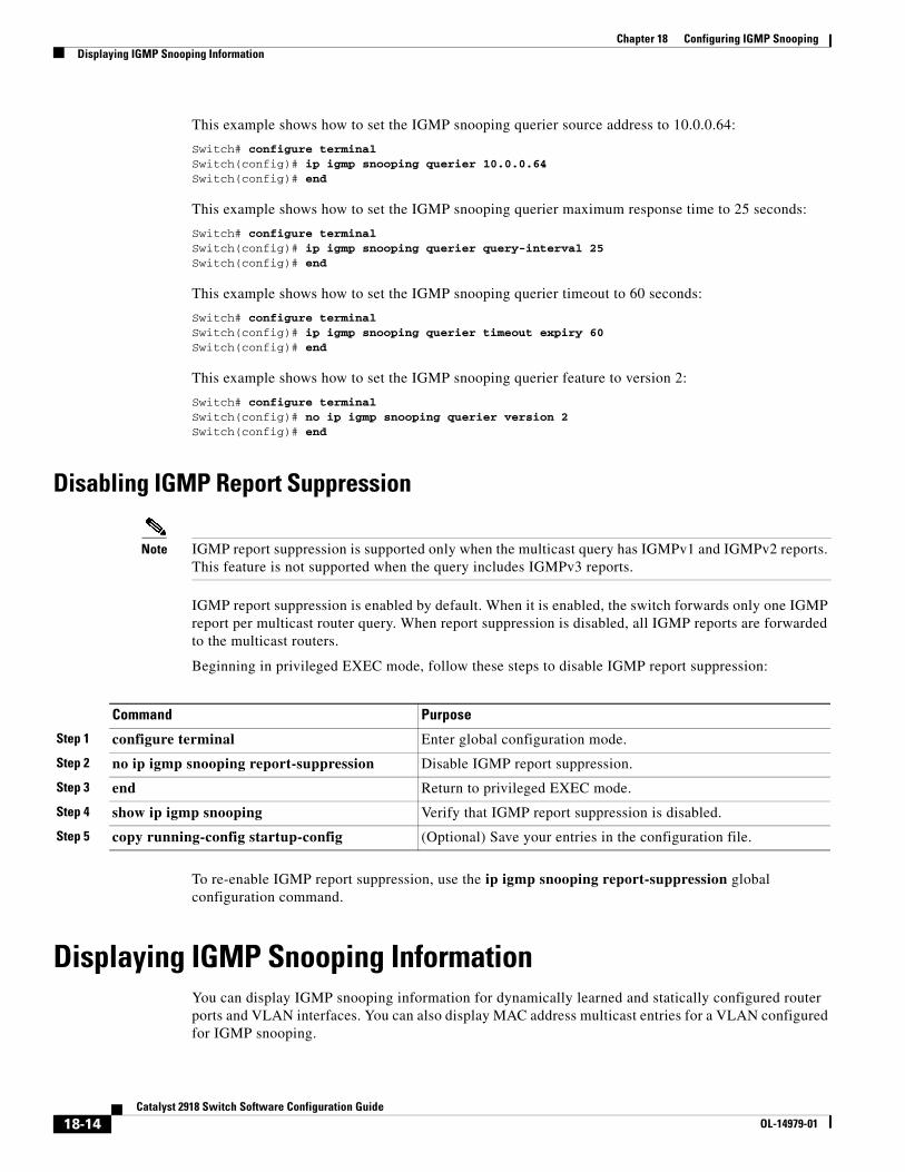
Chapter 18 Configuring IGMP SnoopingDisplaying IGMP Snooping Information
This example shows how to set the IGMP snooping querier source address to 10.0.0.64:
Switch# configure terminalSwitch(config)# ip igmp snooping querier 10.0.0.64Switch(config)# end
This example shows how to set the IGMP snooping querier maximum response time to 25 seconds:
Switch# configure terminalSwitch(config)# ip igmp snooping querier query-interval 25Switch(config)# end
This example shows how to set the IGMP snooping querier timeout to 60 seconds:
Switch# configure terminalSwitch(config)# ip igmp snooping querier timeout expiry 60Switch(config)# end
This example shows how to set the IGMP snooping querier feature to version 2:
Switch# configure terminalSwitch(config)# no ip igmp snooping querier version 2Switch(config)# end
Disabling IGMP Report Suppression
Note IGMP report suppression is supported only when the multicast query has IGMPv1 and IGMPv2 reports. This feature is not supported when the query includes IGMPv3 reports.
IGMP report suppression is enabled by default. When it is enabled, the switch forwards only one IGMP report per multicast router query. When report suppression is disabled, all IGMP reports are forwarded to the multicast routers.
Beginning in privileged EXEC mode, follow these steps to disable IGMP report suppression:
Command Purpose
Step 1 configure terminal Enter global configuration mode.
Step 2 no ip igmp snooping report-suppression Disable IGMP report suppression.
Step 3 end Return to privileged EXEC mode.
Step 4 show ip igmp snooping Verify that IGMP report suppression is disabled.
Step 5 copy running-config startup-config (Optional) Save your entries in the configuration file.
To re-enable IGMP report suppression, use the ip igmp snooping report-suppression global configuration command.
Displaying IGMP Snooping InformationYou can display IGMP snooping information for dynamically learned and statically configured router ports and VLAN interfaces. You can also display MAC address multicast entries for a VLAN configured for IGMP snooping.
18-14Catalyst 2918 Switch Software Configuration Guide
OL-14979-01
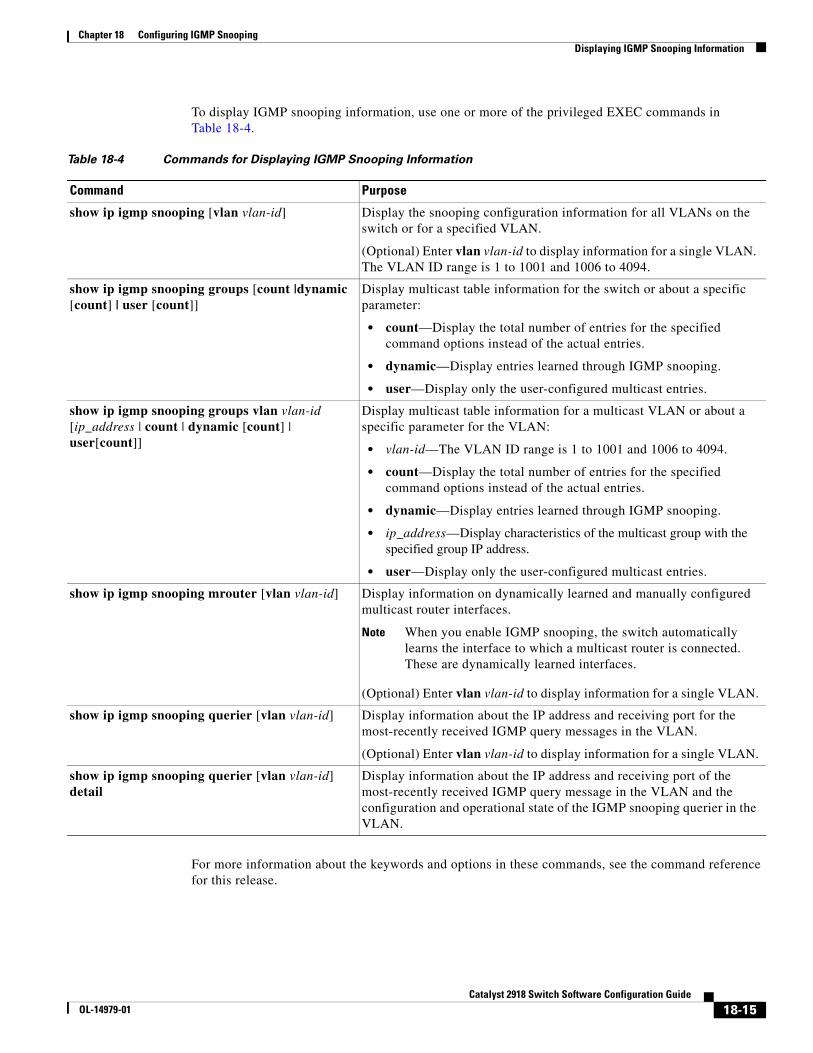
Chapter 18 Configuring IGMP SnoopingDisplaying IGMP Snooping Information
To display IGMP snooping information, use one or more of the privileged EXEC commands in Table 18-4.
Table 18-4 Commands for Displaying IGMP Snooping Information
Command Purpose
show ip igmp snooping [vlan vlan-id] Display the snooping configuration information for all VLANs on the switch or for a specified VLAN.
(Optional) Enter vlan vlan-id to display information for a single VLAN. The VLAN ID range is 1 to 1001 and 1006 to 4094.
show ip igmp snooping groups [count |dynamic [count] | user [count]]
Display multicast table information for the switch or about a specific parameter:
• count—Display the total number of entries for the specified command options instead of the actual entries.
• dynamic—Display entries learned through IGMP snooping.
• user—Display only the user-configured multicast entries.
show ip igmp snooping groups vlan vlan-id [ip_address | count | dynamic [count] | user[count]]
Display multicast table information for a multicast VLAN or about a specific parameter for the VLAN:
• vlan-id—The VLAN ID range is 1 to 1001 and 1006 to 4094.
• count—Display the total number of entries for the specified command options instead of the actual entries.
• dynamic—Display entries learned through IGMP snooping.
• ip_address—Display characteristics of the multicast group with the specified group IP address.
• user—Display only the user-configured multicast entries.
show ip igmp snooping mrouter [vlan vlan-id] Display information on dynamically learned and manually configured multicast router interfaces.
Note When you enable IGMP snooping, the switch automatically learns the interface to which a multicast router is connected. These are dynamically learned interfaces.
(Optional) Enter vlan vlan-id to display information for a single VLAN.
show ip igmp snooping querier [vlan vlan-id] Display information about the IP address and receiving port for the most-recently received IGMP query messages in the VLAN.
(Optional) Enter vlan vlan-id to display information for a single VLAN.
show ip igmp snooping querier [vlan vlan-id] detail
Display information about the IP address and receiving port of the most-recently received IGMP query message in the VLAN and the configuration and operational state of the IGMP snooping querier in the VLAN.
For more information about the keywords and options in these commands, see the command reference for this release.
18-15Catalyst 2918 Switch Software Configuration Guide
OL-14979-01
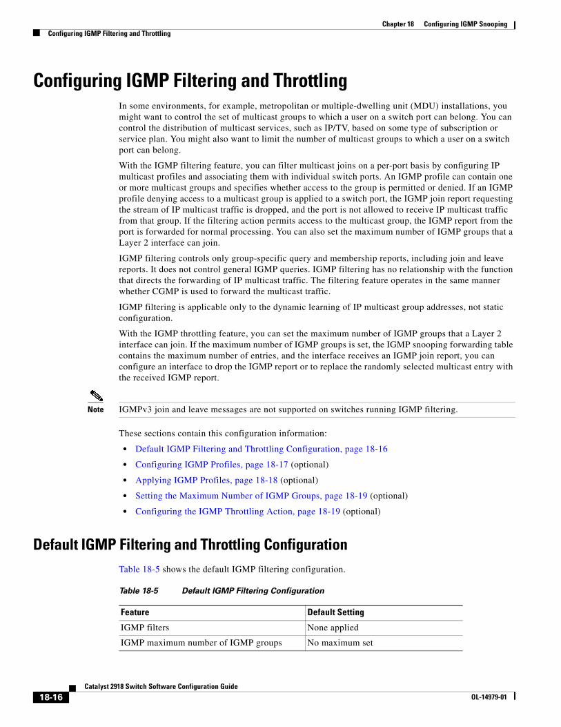
Chapter 18 Configuring IGMP SnoopingConfiguring IGMP Filtering and Throttling
Configuring IGMP Filtering and ThrottlingIn some environments, for example, metropolitan or multiple-dwelling unit (MDU) installations, you might want to control the set of multicast groups to which a user on a switch port can belong. You can control the distribution of multicast services, such as IP/TV, based on some type of subscription or service plan. You might also want to limit the number of multicast groups to which a user on a switch port can belong.
With the IGMP filtering feature, you can filter multicast joins on a per-port basis by configuring IP multicast profiles and associating them with individual switch ports. An IGMP profile can contain one or more multicast groups and specifies whether access to the group is permitted or denied. If an IGMP profile denying access to a multicast group is applied to a switch port, the IGMP join report requesting the stream of IP multicast traffic is dropped, and the port is not allowed to receive IP multicast traffic from that group. If the filtering action permits access to the multicast group, the IGMP report from the port is forwarded for normal processing. You can also set the maximum number of IGMP groups that a Layer 2 interface can join.
IGMP filtering controls only group-specific query and membership reports, including join and leave reports. It does not control general IGMP queries. IGMP filtering has no relationship with the function that directs the forwarding of IP multicast traffic. The filtering feature operates in the same manner whether CGMP is used to forward the multicast traffic.
IGMP filtering is applicable only to the dynamic learning of IP multicast group addresses, not static configuration.
With the IGMP throttling feature, you can set the maximum number of IGMP groups that a Layer 2 interface can join. If the maximum number of IGMP groups is set, the IGMP snooping forwarding table contains the maximum number of entries, and the interface receives an IGMP join report, you can configure an interface to drop the IGMP report or to replace the randomly selected multicast entry with the received IGMP report.
Note IGMPv3 join and leave messages are not supported on switches running IGMP filtering.
These sections contain this configuration information:
• Default IGMP Filtering and Throttling Configuration, page 18-16
• Configuring IGMP Profiles, page 18-17 (optional)
• Applying IGMP Profiles, page 18-18 (optional)
• Setting the Maximum Number of IGMP Groups, page 18-19 (optional)
• Configuring the IGMP Throttling Action, page 18-19 (optional)
Default IGMP Filtering and Throttling ConfigurationTable 18-5 shows the default IGMP filtering configuration.
Table 18-5 Default IGMP Filtering Configuration
Feature Default Setting
IGMP filters None applied
IGMP maximum number of IGMP groups No maximum set
18-16Catalyst 2918 Switch Software Configuration Guide
OL-14979-01
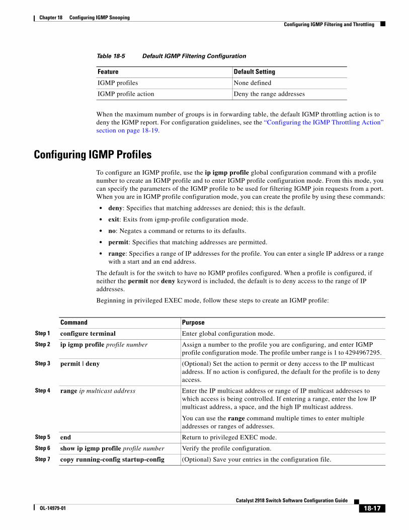
Chapter 18 Configuring IGMP SnoopingConfiguring IGMP Filtering and Throttling
When the maximum number of groups is in forwarding table, the default IGMP throttling action is to deny the IGMP report. For configuration guidelines, see the “Configuring the IGMP Throttling Action” section on page 18-19.
Configuring IGMP ProfilesTo configure an IGMP profile, use the ip igmp profile global configuration command with a profile number to create an IGMP profile and to enter IGMP profile configuration mode. From this mode, you can specify the parameters of the IGMP profile to be used for filtering IGMP join requests from a port. When you are in IGMP profile configuration mode, you can create the profile by using these commands:
• deny: Specifies that matching addresses are denied; this is the default.
• exit: Exits from igmp-profile configuration mode.
• no: Negates a command or returns to its defaults.
• permit: Specifies that matching addresses are permitted.
• range: Specifies a range of IP addresses for the profile. You can enter a single IP address or a range with a start and an end address.
The default is for the switch to have no IGMP profiles configured. When a profile is configured, if neither the permit nor deny keyword is included, the default is to deny access to the range of IP addresses.
Beginning in privileged EXEC mode, follow these steps to create an IGMP profile:
Command Purpose
Step 1 configure terminal Enter global configuration mode.
Step 2 ip igmp profile profile number Assign a number to the profile you are configuring, and enter IGMP profile configuration mode. The profile umber range is 1 to 4294967295.
Step 3 permit | deny (Optional) Set the action to permit or deny access to the IP multicast address. If no action is configured, the default for the profile is to deny access.
Step 4 range ip multicast address Enter the IP multicast address or range of IP multicast addresses to which access is being controlled. If entering a range, enter the low IP multicast address, a space, and the high IP multicast address.
You can use the range command multiple times to enter multiple addresses or ranges of addresses.
Step 5 end Return to privileged EXEC mode.
Step 6 show ip igmp profile profile number Verify the profile configuration.
Step 7 copy running-config startup-config (Optional) Save your entries in the configuration file.
IGMP profiles None defined
IGMP profile action Deny the range addresses
Table 18-5 Default IGMP Filtering Configuration
Feature Default Setting
18-17Catalyst 2918 Switch Software Configuration Guide
OL-14979-01
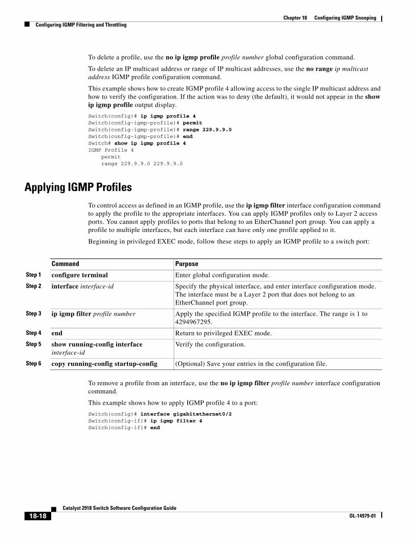
Chapter 18 Configuring IGMP SnoopingConfiguring IGMP Filtering and Throttling
To delete a profile, use the no ip igmp profile profile number global configuration command.
To delete an IP multicast address or range of IP multicast addresses, use the no range ip multicast address IGMP profile configuration command.
This example shows how to create IGMP profile 4 allowing access to the single IP multicast address and how to verify the configuration. If the action was to deny (the default), it would not appear in the show ip igmp profile output display.
Switch(config)# ip igmp profile 4Switch(config-igmp-profile)# permitSwitch(config-igmp-profile)# range 229.9.9.0Switch(config-igmp-profile)# endSwitch# show ip igmp profile 4IGMP Profile 4 permit range 229.9.9.0 229.9.9.0
Applying IGMP ProfilesTo control access as defined in an IGMP profile, use the ip igmp filter interface configuration command to apply the profile to the appropriate interfaces. You can apply IGMP profiles only to Layer 2 access ports. You cannot apply profiles to ports that belong to an EtherChannel port group. You can apply a profile to multiple interfaces, but each interface can have only one profile applied to it.
Beginning in privileged EXEC mode, follow these steps to apply an IGMP profile to a switch port:
Command Purpose
Step 1 configure terminal Enter global configuration mode.
Step 2 interface interface-id Specify the physical interface, and enter interface configuration mode. The interface must be a Layer 2 port that does not belong to an EtherChannel port group.
Step 3 ip igmp filter profile number Apply the specified IGMP profile to the interface. The range is 1 to 4294967295.
Step 4 end Return to privileged EXEC mode.
Step 5 show running-config interface interface-id
Verify the configuration.
Step 6 copy running-config startup-config (Optional) Save your entries in the configuration file.
To remove a profile from an interface, use the no ip igmp filter profile number interface configuration command.
This example shows how to apply IGMP profile 4 to a port:
Switch(config)# interface gigabitethernet0/2Switch(config-if)# ip igmp filter 4Switch(config-if)# end
18-18Catalyst 2918 Switch Software Configuration Guide
OL-14979-01
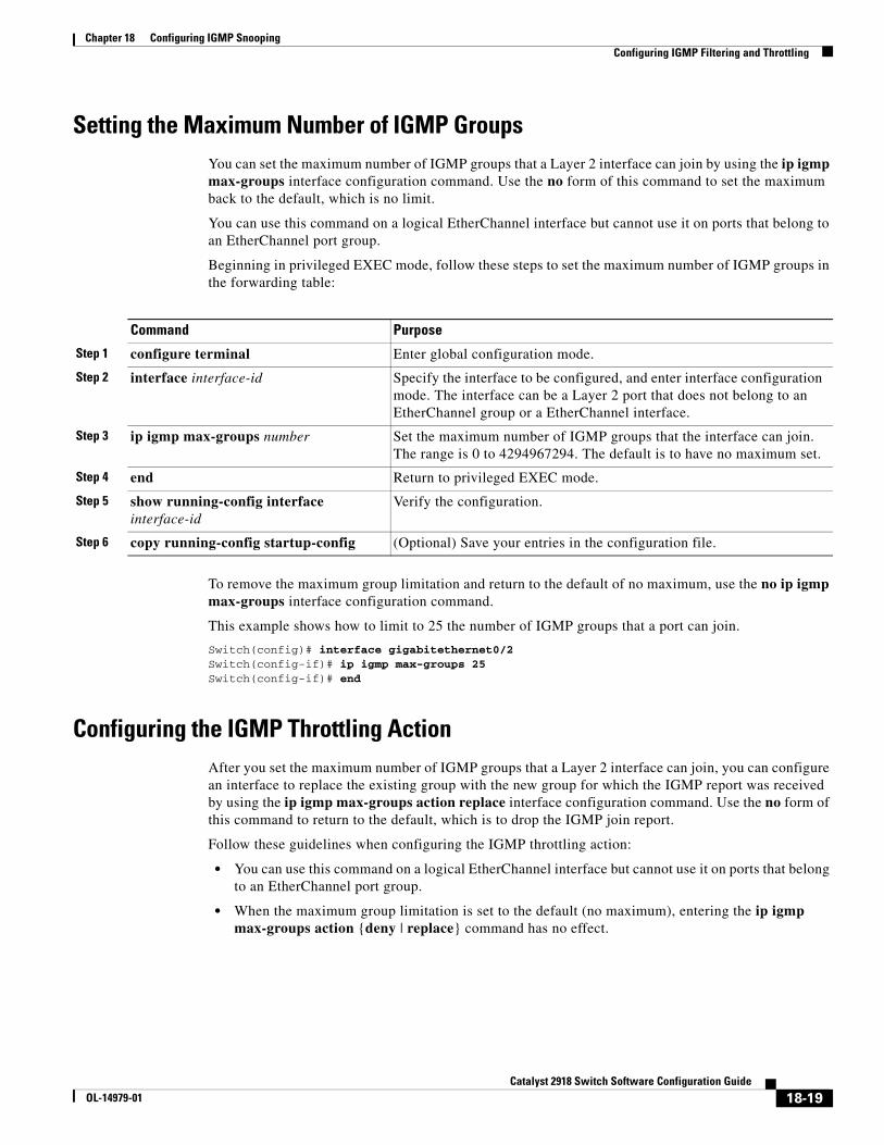
Chapter 18 Configuring IGMP SnoopingConfiguring IGMP Filtering and Throttling
Setting the Maximum Number of IGMP GroupsYou can set the maximum number of IGMP groups that a Layer 2 interface can join by using the ip igmp max-groups interface configuration command. Use the no form of this command to set the maximum back to the default, which is no limit.
You can use this command on a logical EtherChannel interface but cannot use it on ports that belong to an EtherChannel port group.
Beginning in privileged EXEC mode, follow these steps to set the maximum number of IGMP groups in the forwarding table:
Command Purpose
Step 1 configure terminal Enter global configuration mode.
Step 2 interface interface-id Specify the interface to be configured, and enter interface configuration mode. The interface can be a Layer 2 port that does not belong to an EtherChannel group or a EtherChannel interface.
Step 3 ip igmp max-groups number Set the maximum number of IGMP groups that the interface can join. The range is 0 to 4294967294. The default is to have no maximum set.
Step 4 end Return to privileged EXEC mode.
Step 5 show running-config interface interface-id
Verify the configuration.
Step 6 copy running-config startup-config (Optional) Save your entries in the configuration file.
To remove the maximum group limitation and return to the default of no maximum, use the no ip igmp max-groups interface configuration command.
This example shows how to limit to 25 the number of IGMP groups that a port can join.
Switch(config)# interface gigabitethernet0/2Switch(config-if)# ip igmp max-groups 25Switch(config-if)# end
Configuring the IGMP Throttling ActionAfter you set the maximum number of IGMP groups that a Layer 2 interface can join, you can configure an interface to replace the existing group with the new group for which the IGMP report was received by using the ip igmp max-groups action replace interface configuration command. Use the no form of this command to return to the default, which is to drop the IGMP join report.
Follow these guidelines when configuring the IGMP throttling action:
• You can use this command on a logical EtherChannel interface but cannot use it on ports that belong to an EtherChannel port group.
• When the maximum group limitation is set to the default (no maximum), entering the ip igmp max-groups action {deny | replace} command has no effect.
18-19Catalyst 2918 Switch Software Configuration Guide
OL-14979-01

Chapter 18 Configuring IGMP SnoopingDisplaying IGMP Filtering and Throttling Configuration
• If you configure the throttling action and set the maximum group limitation after an interface has added multicast entries to the forwarding table, the forwarding-table entries are either aged out or removed, depending on the throttling action.
– If you configure the throttling action as deny, the entries that were previously in the forwarding table are not removed but are aged out. After these entries are aged out and the maximum number of entries is in the forwarding table, the switch drops the next IGMP report received on the interface.
– If you configure the throttling action as replace, the entries that were previously in the forwarding table are removed. When the maximum number of entries is in the forwarding table, the switch replaces a randomly selected entry with the received IGMP report.
To prevent the switch from removing the forwarding-table entries, you can configure the IGMP throttling action before an interface adds entries to the forwarding table.
Beginning in privileged EXEC mode, follow these steps to configure the throttling action when the maximum number of entries is in the forwarding table:
Command Purpose
Step 1 configure terminal Enter global configuration mode.
Step 2 interface interface-id Specify the physical interface to be configured, and enter interface configuration mode. The interface can be a Layer 2 port that does not belong to an EtherChannel group or an EtherChannel interface. The interface cannot be a trunk port.
Step 3 ip igmp max-groups action {deny | replace}
When an interface receives an IGMP report and the maximum number of entries is in the forwarding table, specify the action that the interface takes:
• deny—Drop the report.
• replace—Replace the existing group with the new group for which the IGMP report was received.
Step 4 end Return to privileged EXEC mode.
Step 5 show running-config interface interface-id
Verify the configuration.
Step 6 copy running-config startup-config (Optional) Save your entries in the configuration file.
To return to the default action of dropping the report, use the no ip igmp max-groups action interface configuration command.
Displaying IGMP Filtering and Throttling ConfigurationYou can display IGMP profile characteristics, and you can display the IGMP profile and maximum group configuration for all interfaces on the switch or for a specified interface. You can also display the IGMP throttling configuration for all interfaces on the switch or for a specified interface.
18-20Catalyst 2918 Switch Software Configuration Guide
OL-14979-01
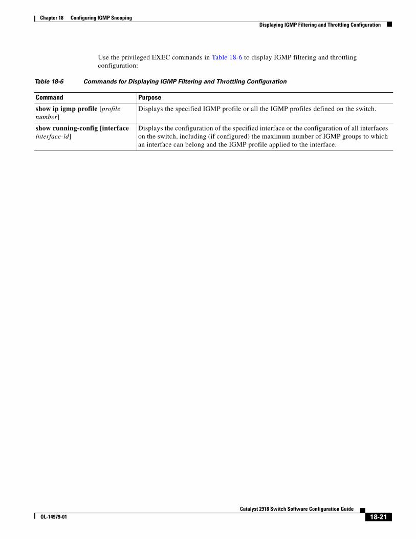
Chapter 18 Configuring IGMP SnoopingDisplaying IGMP Filtering and Throttling Configuration
Use the privileged EXEC commands in Table 18-6 to display IGMP filtering and throttling configuration:
Table 18-6 Commands for Displaying IGMP Filtering and Throttling Configuration
Command Purpose
show ip igmp profile [profile number]
Displays the specified IGMP profile or all the IGMP profiles defined on the switch.
show running-config [interface interface-id]
Displays the configuration of the specified interface or the configuration of all interfaces on the switch, including (if configured) the maximum number of IGMP groups to which an interface can belong and the IGMP profile applied to the interface.
18-21Catalyst 2918 Switch Software Configuration Guide
OL-14979-01

Chapter 18 Configuring IGMP SnoopingDisplaying IGMP Filtering and Throttling Configuration
18-22Catalyst 2918 Switch Software Configuration Guide
OL-14979-01
OL-14979-01
C H A P T E R 19
Configuring Port-Based Traffic ControlThis chapter describes how to configure the port-based traffic control features on the Catalyst 2918 switch.
Note For complete syntax and usage information for the commands used in this chapter, see the command reference for this release.
This chapter consists of these sections:
• Configuring Storm Control, page 19-1
• Configuring Protected Ports, page 19-6
• Configuring Port Blocking, page 19-7
• Configuring Port Security, page 19-8
• Displaying Port-Based Traffic Control Settings, page 19-18
Configuring Storm ControlThese sections contain this conceptual and configuration information:
• Understanding Storm Control, page 19-1
• Default Storm Control Configuration, page 19-3
• Configuring Storm Control and Threshold Levels, page 19-3
• Configuring Small-Frame Arrival Rate, page 19-5
Understanding Storm ControlStorm control prevents traffic on a LAN from being disrupted by a broadcast, multicast, or unicast storm on one of the physical interfaces. A LAN storm occurs when packets flood the LAN, creating excessive traffic and degrading network performance. Errors in the protocol-stack implementation, mistakes in network configurations, or users issuing a denial-of-service attack can cause a storm.
Storm control (or traffic suppression) monitors packets passing from an interface to the switching bus and determines if the packet is unicast, multicast, or broadcast. The switch counts the number of packets of a specified type received within the 1-second time interval and compares the measurement with a predefined suppression-level threshold.
19-1Catalyst 2918 Switch Software Configuration Guide
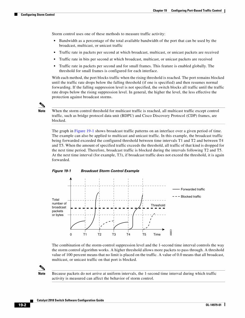
Chapter 19 Configuring Port-Based Traffic ControlConfiguring Storm Control
Storm control uses one of these methods to measure traffic activity:
• Bandwidth as a percentage of the total available bandwidth of the port that can be used by the broadcast, multicast, or unicast traffic
• Traffic rate in packets per second at which broadcast, multicast, or unicast packets are received
• Traffic rate in bits per second at which broadcast, multicast, or unicast packets are received
• Traffic rate in packets per second and for small frames. This feature is enabled globally. The threshold for small frames is configured for each interface.
With each method, the port blocks traffic when the rising threshold is reached. The port remains blocked until the traffic rate drops below the falling threshold (if one is specified) and then resumes normal forwarding. If the falling suppression level is not specified, the switch blocks all traffic until the traffic rate drops below the rising suppression level. In general, the higher the level, the less effective the protection against broadcast storms.
Note When the storm control threshold for multicast traffic is reached, all multicast traffic except control traffic, such as bridge protocol data unit (BDPU) and Cisco Discovery Protocol (CDP) frames, are blocked.
The graph in Figure 19-1 shows broadcast traffic patterns on an interface over a given period of time. The example can also be applied to multicast and unicast traffic. In this example, the broadcast traffic being forwarded exceeded the configured threshold between time intervals T1 and T2 and between T4 and T5. When the amount of specified traffic exceeds the threshold, all traffic of that kind is dropped for the next time period. Therefore, broadcast traffic is blocked during the intervals following T2 and T5. At the next time interval (for example, T3), if broadcast traffic does not exceed the threshold, it is again forwarded.
Figure 19-1 Broadcast Storm Control Example
Totalnumber of broadcastpackets or bytes
Forwarded traffic
0 T1
Threshold
T2 T4 T5 4665
1
T3 Time
Blocked traffic
The combination of the storm-control suppression level and the 1-second time interval controls the way the storm control algorithm works. A higher threshold allows more packets to pass through. A threshold value of 100 percent means that no limit is placed on the traffic. A value of 0.0 means that all broadcast, multicast, or unicast traffic on that port is blocked.
Note Because packets do not arrive at uniform intervals, the 1-second time interval during which traffic activity is measured can affect the behavior of storm control.
19-2Catalyst 2918 Switch Software Configuration Guide
OL-14979-01
Chapter 19 Configuring Port-Based Traffic ControlConfiguring Storm Control
You use the storm-control interface configuration commands to set the threshold value for each traffic type.
Default Storm Control ConfigurationBy default, unicast, broadcast, and multicast storm control are disabled on the switch interfaces; that is, the suppression level is 100 percent.
Configuring Storm Control and Threshold LevelsYou configure storm control on a port and enter the threshold level that you want to be used for a particular type of traffic.
However, because of hardware limitations and the way in which packets of different sizes are counted, threshold percentages are approximations. Depending on the sizes of the packets making up the incoming traffic, the actual enforced threshold might differ from the configured level by several percentage points.
Note Storm control is supported on physical interfaces. You can also configure storm control on an EtherChannel. When storm control is configured on an EtherChannel, the storm control settings propagate to the EtherChannel physical interfaces.
Beginning in privileged EXEC mode, follow these steps to storm control and threshold levels:
Command Purpose
Step 1 configure terminal Enter global configuration mode.
Step 2 interface interface-id Specify the interface to be configured, and enter interface configuration mode.
19-3Catalyst 2918 Switch Software Configuration Guide
OL-14979-01
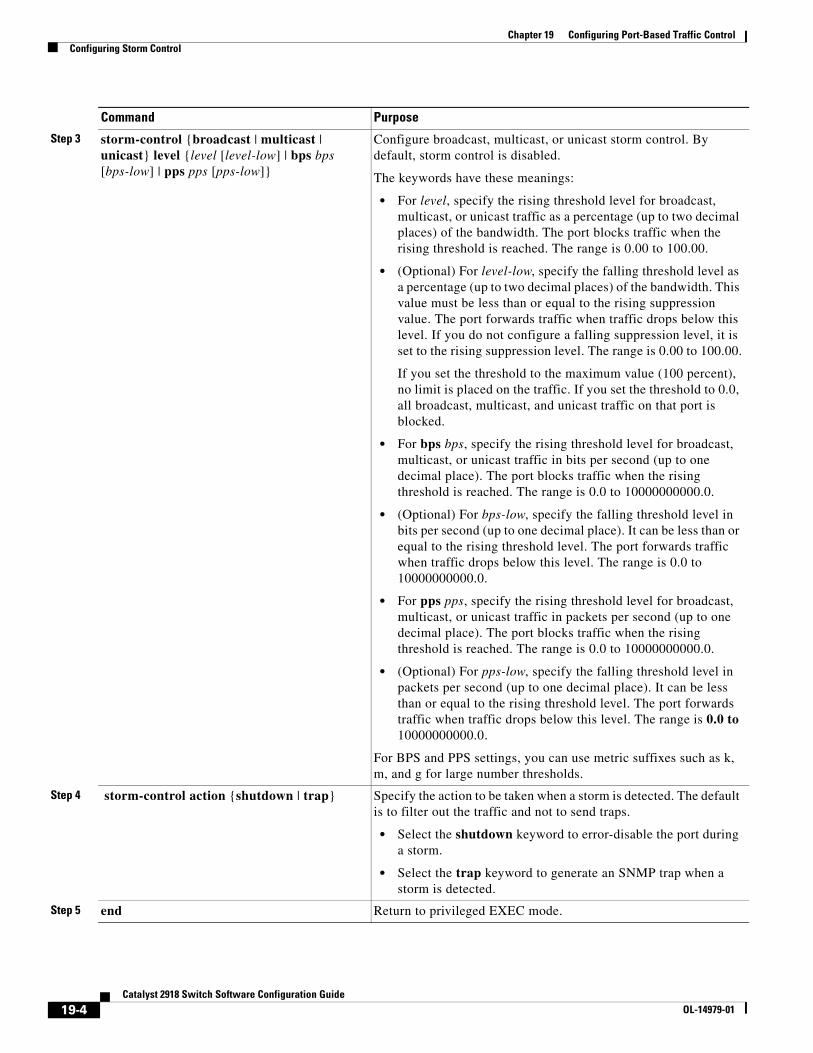
Chapter 19 Configuring Port-Based Traffic ControlConfiguring Storm Control
Step 3 storm-control {broadcast | multicast | unicast} level {level [level-low] | bps bps [bps-low] | pps pps [pps-low]}
Configure broadcast, multicast, or unicast storm control. By default, storm control is disabled.
The keywords have these meanings:
• For level, specify the rising threshold level for broadcast, multicast, or unicast traffic as a percentage (up to two decimal places) of the bandwidth. The port blocks traffic when the rising threshold is reached. The range is 0.00 to 100.00.
• (Optional) For level-low, specify the falling threshold level as a percentage (up to two decimal places) of the bandwidth. This value must be less than or equal to the rising suppression value. The port forwards traffic when traffic drops below this level. If you do not configure a falling suppression level, it is set to the rising suppression level. The range is 0.00 to 100.00.
If you set the threshold to the maximum value (100 percent), no limit is placed on the traffic. If you set the threshold to 0.0, all broadcast, multicast, and unicast traffic on that port is blocked.
• For bps bps, specify the rising threshold level for broadcast, multicast, or unicast traffic in bits per second (up to one decimal place). The port blocks traffic when the rising threshold is reached. The range is 0.0 to 10000000000.0.
• (Optional) For bps-low, specify the falling threshold level in bits per second (up to one decimal place). It can be less than or equal to the rising threshold level. The port forwards traffic when traffic drops below this level. The range is 0.0 to 10000000000.0.
• For pps pps, specify the rising threshold level for broadcast, multicast, or unicast traffic in packets per second (up to one decimal place). The port blocks traffic when the rising threshold is reached. The range is 0.0 to 10000000000.0.
• (Optional) For pps-low, specify the falling threshold level in packets per second (up to one decimal place). It can be less than or equal to the rising threshold level. The port forwards traffic when traffic drops below this level. The range is 0.0 to 10000000000.0.
For BPS and PPS settings, you can use metric suffixes such as k, m, and g for large number thresholds.
Step 4 storm-control action {shutdown | trap} Specify the action to be taken when a storm is detected. The default is to filter out the traffic and not to send traps.
• Select the shutdown keyword to error-disable the port during a storm.
• Select the trap keyword to generate an SNMP trap when a storm is detected.
Step 5 end Return to privileged EXEC mode.
Command Purpose
19-4Catalyst 2918 Switch Software Configuration Guide
OL-14979-01
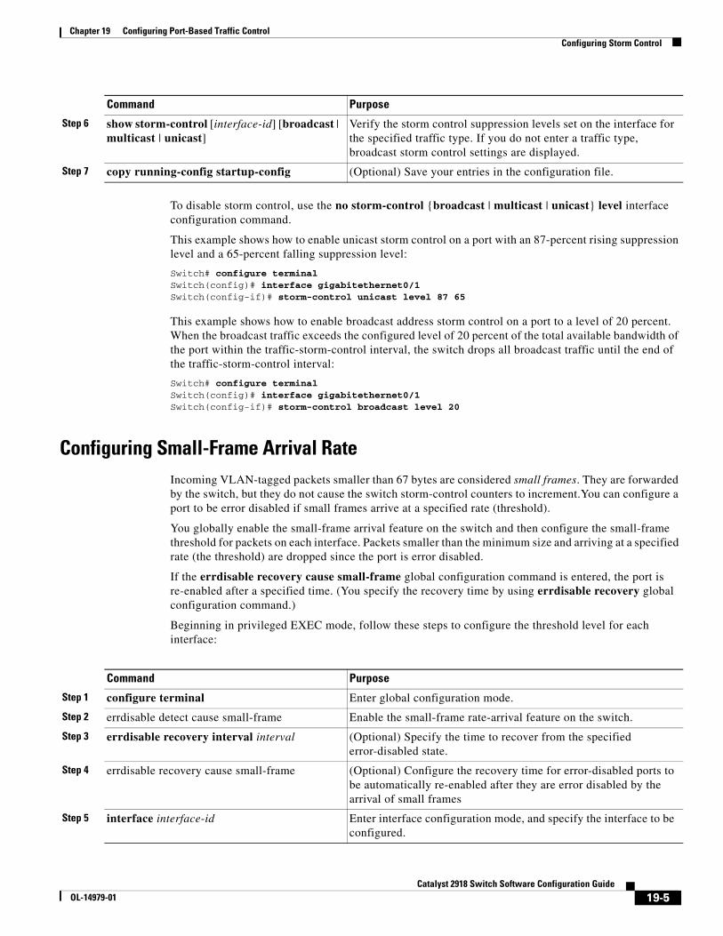
Chapter 19 Configuring Port-Based Traffic ControlConfiguring Storm Control
To disable storm control, use the no storm-control {broadcast | multicast | unicast} level interface configuration command.
This example shows how to enable unicast storm control on a port with an 87-percent rising suppression level and a 65-percent falling suppression level:
Switch# configure terminalSwitch(config)# interface gigabitethernet0/1Switch(config-if)# storm-control unicast level 87 65
This example shows how to enable broadcast address storm control on a port to a level of 20 percent. When the broadcast traffic exceeds the configured level of 20 percent of the total available bandwidth of the port within the traffic-storm-control interval, the switch drops all broadcast traffic until the end of the traffic-storm-control interval:
Switch# configure terminalSwitch(config)# interface gigabitethernet0/1Switch(config-if)# storm-control broadcast level 20
Configuring Small-Frame Arrival RateIncoming VLAN-tagged packets smaller than 67 bytes are considered small frames. They are forwarded by the switch, but they do not cause the switch storm-control counters to increment.You can configure a port to be error disabled if small frames arrive at a specified rate (threshold).
You globally enable the small-frame arrival feature on the switch and then configure the small-frame threshold for packets on each interface. Packets smaller than the minimum size and arriving at a specified rate (the threshold) are dropped since the port is error disabled.
If the errdisable recovery cause small-frame global configuration command is entered, the port is re-enabled after a specified time. (You specify the recovery time by using errdisable recovery global configuration command.)
Beginning in privileged EXEC mode, follow these steps to configure the threshold level for each interface:
Step 6 show storm-control [interface-id] [broadcast | multicast | unicast]
Verify the storm control suppression levels set on the interface for the specified traffic type. If you do not enter a traffic type, broadcast storm control settings are displayed.
Step 7 copy running-config startup-config (Optional) Save your entries in the configuration file.
Command Purpose
Command Purpose
Step 1 configure terminal Enter global configuration mode.
Step 2 errdisable detect cause small-frame Enable the small-frame rate-arrival feature on the switch.
Step 3 errdisable recovery interval interval (Optional) Specify the time to recover from the specified error-disabled state.
Step 4 errdisable recovery cause small-frame (Optional) Configure the recovery time for error-disabled ports to be automatically re-enabled after they are error disabled by the arrival of small frames
Step 5 interface interface-id Enter interface configuration mode, and specify the interface to be configured.
19-5Catalyst 2918 Switch Software Configuration Guide
OL-14979-01
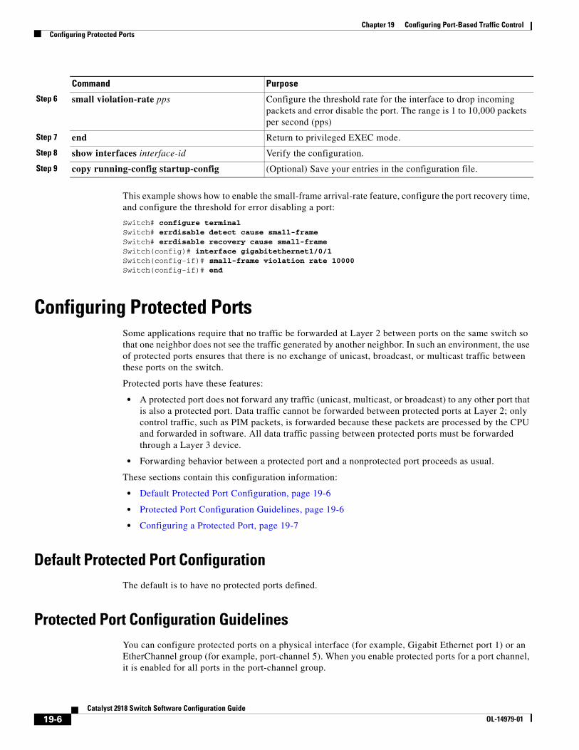
Chapter 19 Configuring Port-Based Traffic ControlConfiguring Protected Ports
This example shows how to enable the small-frame arrival-rate feature, configure the port recovery time, and configure the threshold for error disabling a port:
Switch# configure terminalSwitch# errdisable detect cause small-frameSwitch# errdisable recovery cause small-frameSwitch(config)# interface gigabitethernet1/0/1Switch(config-if)# small-frame violation rate 10000Switch(config-if)# end
Configuring Protected PortsSome applications require that no traffic be forwarded at Layer 2 between ports on the same switch so that one neighbor does not see the traffic generated by another neighbor. In such an environment, the use of protected ports ensures that there is no exchange of unicast, broadcast, or multicast traffic between these ports on the switch.
Protected ports have these features:
• A protected port does not forward any traffic (unicast, multicast, or broadcast) to any other port that is also a protected port. Data traffic cannot be forwarded between protected ports at Layer 2; only control traffic, such as PIM packets, is forwarded because these packets are processed by the CPU and forwarded in software. All data traffic passing between protected ports must be forwarded through a Layer 3 device.
• Forwarding behavior between a protected port and a nonprotected port proceeds as usual.
These sections contain this configuration information:
• Default Protected Port Configuration, page 19-6
• Protected Port Configuration Guidelines, page 19-6
• Configuring a Protected Port, page 19-7
Default Protected Port ConfigurationThe default is to have no protected ports defined.
Protected Port Configuration GuidelinesYou can configure protected ports on a physical interface (for example, Gigabit Ethernet port 1) or an EtherChannel group (for example, port-channel 5). When you enable protected ports for a port channel, it is enabled for all ports in the port-channel group.
Step 6 small violation-rate pps Configure the threshold rate for the interface to drop incoming packets and error disable the port. The range is 1 to 10,000 packets per second (pps)
Step 7 end Return to privileged EXEC mode.
Step 8 show interfaces interface-id Verify the configuration.
Step 9 copy running-config startup-config (Optional) Save your entries in the configuration file.
Command Purpose
19-6Catalyst 2918 Switch Software Configuration Guide
OL-14979-01
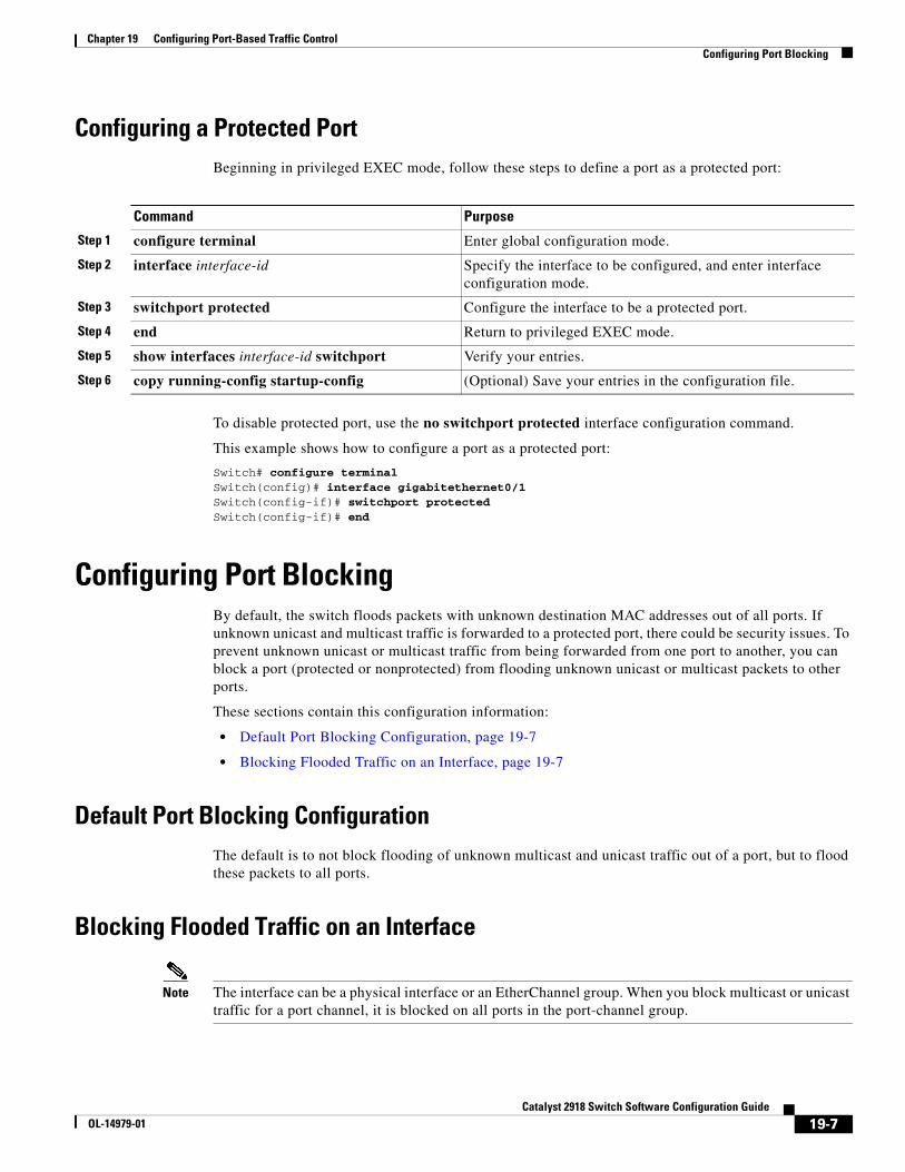
Chapter 19 Configuring Port-Based Traffic ControlConfiguring Port Blocking
Configuring a Protected PortBeginning in privileged EXEC mode, follow these steps to define a port as a protected port:
Command Purpose
Step 1 configure terminal Enter global configuration mode.
Step 2 interface interface-id Specify the interface to be configured, and enter interface configuration mode.
Step 3 switchport protected Configure the interface to be a protected port.
Step 4 end Return to privileged EXEC mode.
Step 5 show interfaces interface-id switchport Verify your entries.
Step 6 copy running-config startup-config (Optional) Save your entries in the configuration file.
To disable protected port, use the no switchport protected interface configuration command.
This example shows how to configure a port as a protected port:
Switch# configure terminalSwitch(config)# interface gigabitethernet0/1Switch(config-if)# switchport protectedSwitch(config-if)# end
Configuring Port BlockingBy default, the switch floods packets with unknown destination MAC addresses out of all ports. If unknown unicast and multicast traffic is forwarded to a protected port, there could be security issues. To prevent unknown unicast or multicast traffic from being forwarded from one port to another, you can block a port (protected or nonprotected) from flooding unknown unicast or multicast packets to other ports.
These sections contain this configuration information:
• Default Port Blocking Configuration, page 19-7
• Blocking Flooded Traffic on an Interface, page 19-7
Default Port Blocking ConfigurationThe default is to not block flooding of unknown multicast and unicast traffic out of a port, but to flood these packets to all ports.
Blocking Flooded Traffic on an Interface
Note The interface can be a physical interface or an EtherChannel group. When you block multicast or unicast traffic for a port channel, it is blocked on all ports in the port-channel group.
19-7Catalyst 2918 Switch Software Configuration Guide
OL-14979-01
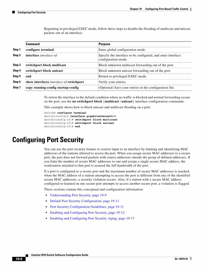
Chapter 19 Configuring Port-Based Traffic ControlConfiguring Port Security
Beginning in privileged EXEC mode, follow these steps to disable the flooding of multicast and unicast packets out of an interface:
Command Purpose
Step 1 configure terminal Enter global configuration mode.
Step 2 interface interface-id Specify the interface to be configured, and enter interface configuration mode.
Step 3 switchport block multicast Block unknown multicast forwarding out of the port.
Step 4 switchport block unicast Block unknown unicast forwarding out of the port.
Step 5 end Return to privileged EXEC mode.
Step 6 show interfaces interface-id switchport Verify your entries.
Step 7 copy running-config startup-config (Optional) Save your entries in the configuration file.
To return the interface to the default condition where no traffic is blocked and normal forwarding occurs on the port, use the no switchport block {multicast | unicast} interface configuration commands.
This example shows how to block unicast and multicast flooding on a port:
Switch# configure terminalSwitch(config)# interface gigabitethernet0/1Switch(config-if)# switchport block multicastSwitch(config-if)# switchport block unicastSwitch(config-if)# end
Configuring Port SecurityYou can use the port security feature to restrict input to an interface by limiting and identifying MAC addresses of the stations allowed to access the port. When you assign secure MAC addresses to a secure port, the port does not forward packets with source addresses outside the group of defined addresses. If you limit the number of secure MAC addresses to one and assign a single secure MAC address, the workstation attached to that port is assured the full bandwidth of the port.
If a port is configured as a secure port and the maximum number of secure MAC addresses is reached, when the MAC address of a station attempting to access the port is different from any of the identified secure MAC addresses, a security violation occurs. Also, if a station with a secure MAC address configured or learned on one secure port attempts to access another secure port, a violation is flagged.
These sections contain this conceptual and configuration information:
• Understanding Port Security, page 19-9
• Default Port Security Configuration, page 19-11
• Port Security Configuration Guidelines, page 19-11
• Enabling and Configuring Port Security, page 19-12
• Enabling and Configuring Port Security Aging, page 19-17
19-8Catalyst 2918 Switch Software Configuration Guide
OL-14979-01
Chapter 19 Configuring Port-Based Traffic ControlConfiguring Port Security
Understanding Port SecurityThese sections contain this conceptual information:
• Secure MAC Addresses, page 19-9
• Security Violations, page 19-10
Secure MAC Addresses
You configure the maximum number of secure addresses allowed on a port by using the switchport port-security maximum value interface configuration command.
Note If you try to set the maximum value to a number less than the number of secure addresses already configured on an interface, the command is rejected.
The switch supports these types of secure MAC addresses:
• Static secure MAC addresses—These are manually configured by using the switchport port-security mac-address mac-address interface configuration command, stored in the address table, and added to the switch running configuration.
• Dynamic secure MAC addresses—These are dynamically configured, stored only in the address table, and removed when the switch restarts.
• Sticky secure MAC addresses—These can be dynamically learned or manually configured, stored in the address table, and added to the running configuration. If these addresses are saved in the configuration file, when the switch restarts, the interface does not need to dynamically reconfigure them.
You can configure an interface to convert the dynamic MAC addresses to sticky secure MAC addresses and to add them to the running configuration by enabling sticky learning. To enable sticky learning, enter the switchport port-security mac-address sticky interface configuration command. When you enter this command, the interface converts all the dynamic secure MAC addresses, including those that were dynamically learned before sticky learning was enabled, to sticky secure MAC addresses. All sticky secure MAC addresses are added to the running configuration.
The sticky secure MAC addresses do not automatically become part of the configuration file, which is the startup configuration used each time the switch restarts. If you save the sticky secure MAC addresses in the configuration file, when the switch restarts, the interface does not need to relearn these addresses. If you do not save the sticky secure addresses, they are lost.
If sticky learning is disabled, the sticky secure MAC addresses are converted to dynamic secure addresses and are removed from the running configuration.
The maximum number of secure MAC addresses that you can configure on a switch is set by the maximum number of available MAC addresses allowed in the system. This number is the total of available MAC addresses, including those used for other Layer 2 functions and any other secure MAC addresses configured on interfaces.
19-9Catalyst 2918 Switch Software Configuration Guide
OL-14979-01
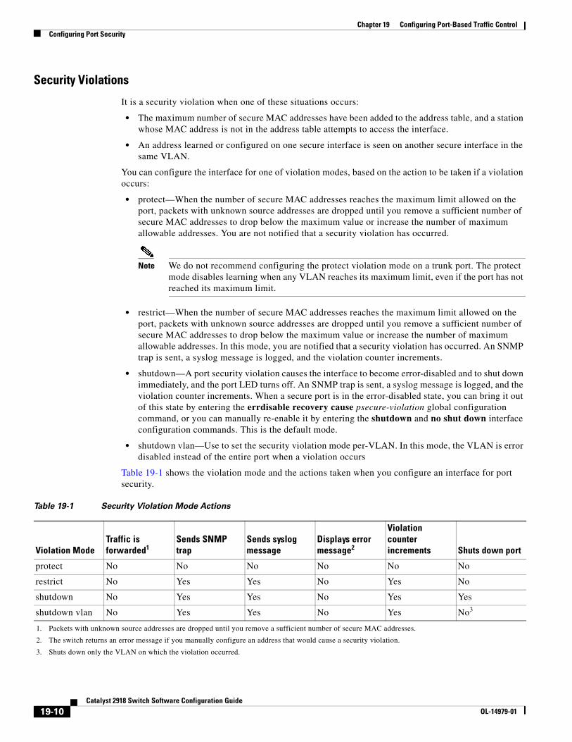
Chapter 19 Configuring Port-Based Traffic ControlConfiguring Port Security
Security Violations
It is a security violation when one of these situations occurs:
• The maximum number of secure MAC addresses have been added to the address table, and a station whose MAC address is not in the address table attempts to access the interface.
• An address learned or configured on one secure interface is seen on another secure interface in the same VLAN.
You can configure the interface for one of violation modes, based on the action to be taken if a violation occurs:
• protect—When the number of secure MAC addresses reaches the maximum limit allowed on the port, packets with unknown source addresses are dropped until you remove a sufficient number of secure MAC addresses to drop below the maximum value or increase the number of maximum allowable addresses. You are not notified that a security violation has occurred.
Note We do not recommend configuring the protect violation mode on a trunk port. The protect mode disables learning when any VLAN reaches its maximum limit, even if the port has not reached its maximum limit.
• restrict—When the number of secure MAC addresses reaches the maximum limit allowed on the port, packets with unknown source addresses are dropped until you remove a sufficient number of secure MAC addresses to drop below the maximum value or increase the number of maximum allowable addresses. In this mode, you are notified that a security violation has occurred. An SNMP trap is sent, a syslog message is logged, and the violation counter increments.
• shutdown—A port security violation causes the interface to become error-disabled and to shut down immediately, and the port LED turns off. An SNMP trap is sent, a syslog message is logged, and the violation counter increments. When a secure port is in the error-disabled state, you can bring it out of this state by entering the errdisable recovery cause psecure-violation global configuration command, or you can manually re-enable it by entering the shutdown and no shut down interface configuration commands. This is the default mode.
• shutdown vlan—Use to set the security violation mode per-VLAN. In this mode, the VLAN is error disabled instead of the entire port when a violation occurs
Table 19-1 shows the violation mode and the actions taken when you configure an interface for port security.
Table 19-1 Security Violation Mode Actions
Violation ModeTraffic is forwarded
1. Packets with unknown source addresses are dropped until you remove a sufficient number of secure MAC addresses.
1
protect No No No No No No
restrict No Yes Yes No Yes No
shutdown No Yes Yes No Yes Yes
shutdown vlan No Yes Yes No Yes
3. Shuts down only the VLAN on which the violation occurred.
No3
Sends SNMP trap
Sends syslog message
Displays error message2
2. The switch returns an error message if you manually configure an address that would cause a security violation.
Violation counter increments Shuts down port
19-10Catalyst 2918 Switch Software Configuration Guide
OL-14979-01
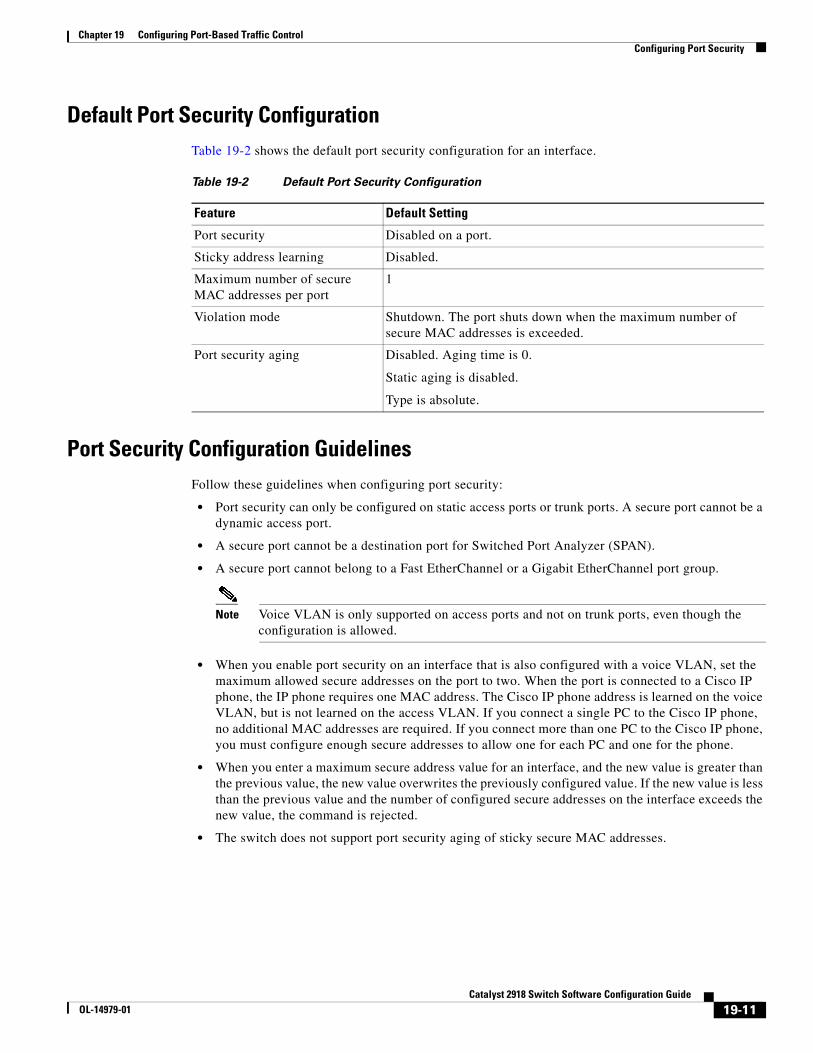
Chapter 19 Configuring Port-Based Traffic ControlConfiguring Port Security
Default Port Security ConfigurationTable 19-2 shows the default port security configuration for an interface.
Table 19-2 Default Port Security Configuration
Feature Default Setting
Port security Disabled on a port.
Sticky address learning Disabled.
Maximum number of secure MAC addresses per port
1
Violation mode Shutdown. The port shuts down when the maximum number of secure MAC addresses is exceeded.
Port security aging Disabled. Aging time is 0.
Static aging is disabled.
Type is absolute.
Port Security Configuration GuidelinesFollow these guidelines when configuring port security:
• Port security can only be configured on static access ports or trunk ports. A secure port cannot be a dynamic access port.
• A secure port cannot be a destination port for Switched Port Analyzer (SPAN).
• A secure port cannot belong to a Fast EtherChannel or a Gigabit EtherChannel port group.
Note Voice VLAN is only supported on access ports and not on trunk ports, even though the configuration is allowed.
• When you enable port security on an interface that is also configured with a voice VLAN, set the maximum allowed secure addresses on the port to two. When the port is connected to a Cisco IP phone, the IP phone requires one MAC address. The Cisco IP phone address is learned on the voice VLAN, but is not learned on the access VLAN. If you connect a single PC to the Cisco IP phone, no additional MAC addresses are required. If you connect more than one PC to the Cisco IP phone, you must configure enough secure addresses to allow one for each PC and one for the phone.
• When you enter a maximum secure address value for an interface, and the new value is greater than the previous value, the new value overwrites the previously configured value. If the new value is less than the previous value and the number of configured secure addresses on the interface exceeds the new value, the command is rejected.
• The switch does not support port security aging of sticky secure MAC addresses.
19-11Catalyst 2918 Switch Software Configuration Guide
OL-14979-01
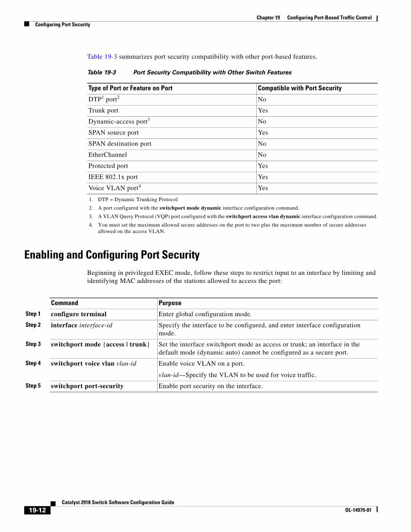
Chapter 19 Configuring Port-Based Traffic ControlConfiguring Port Security
Table 19-3 summarizes port security compatibility with other port-based features.
Table 19-3 Port Security Compatibility with Other Switch Features
Type of Port or Feature on Port Compatible with Port Security
DTP
1. DTP = Dynamic Trunking Protocol
1 port
2. A port configured with the switchport mode dynamic interface configuration command.
2 No
Trunk port Yes
Dynamic-access port
3. A VLAN Query Protocol (VQP) port configured with the switchport access vlan dynamic interface configuration command.
3 No
SPAN source port Yes
SPAN destination port No
EtherChannel No
Protected port Yes
IEEE 802.1x port Yes
Voice VLAN port
4. You must set the maximum allowed secure addresses on the port to two plus the maximum number of secure addresses allowed on the access VLAN.
4 Yes
Enabling and Configuring Port SecurityBeginning in privileged EXEC mode, follow these steps to restrict input to an interface by limiting and identifying MAC addresses of the stations allowed to access the port:
Command Purpose
Step 1 configure terminal Enter global configuration mode.
Step 2 interface interface-id Specify the interface to be configured, and enter interface configuration mode.
Step 3 switchport mode {access | trunk} Set the interface switchport mode as access or trunk; an interface in the default mode (dynamic auto) cannot be configured as a secure port.
Step 4 switchport voice vlan vlan-id Enable voice VLAN on a port.
vlan-id—Specify the VLAN to be used for voice traffic.
Step 5 switchport port-security Enable port security on the interface.
19-12Catalyst 2918 Switch Software Configuration Guide
OL-14979-01
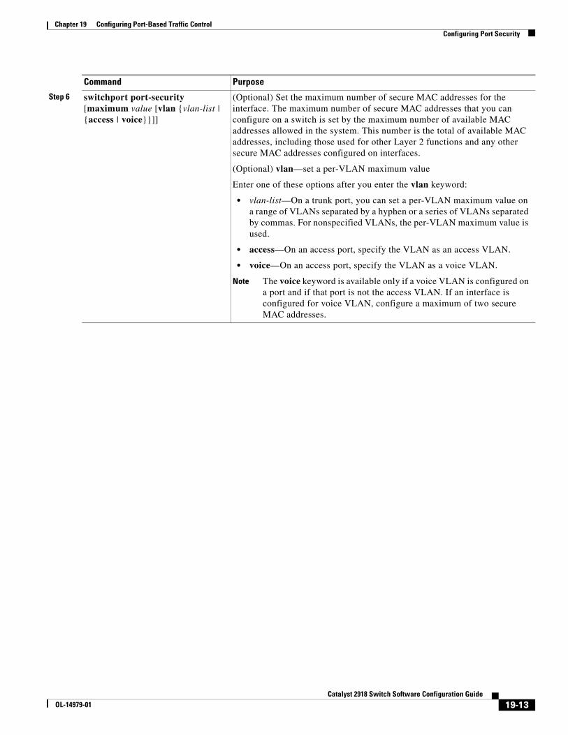
Chapter 19 Configuring Port-Based Traffic ControlConfiguring Port Security
Step 6 switchport port-security [maximum value [vlan {vlan-list | {access | voice}}]]
(Optional) Set the maximum number of secure MAC addresses for the interface. The maximum number of secure MAC addresses that you can configure on a switch is set by the maximum number of available MAC addresses allowed in the system. This number is the total of available MAC addresses, including those used for other Layer 2 functions and any other secure MAC addresses configured on interfaces.
(Optional) vlan—set a per-VLAN maximum value
Enter one of these options after you enter the vlan keyword:
• vlan-list—On a trunk port, you can set a per-VLAN maximum value on a range of VLANs separated by a hyphen or a series of VLANs separated by commas. For nonspecified VLANs, the per-VLAN maximum value is used.
• access—On an access port, specify the VLAN as an access VLAN.
• voice—On an access port, specify the VLAN as a voice VLAN.
Note The voice keyword is available only if a voice VLAN is configured on a port and if that port is not the access VLAN. If an interface is configured for voice VLAN, configure a maximum of two secure MAC addresses.
Command Purpose
19-13Catalyst 2918 Switch Software Configuration Guide
OL-14979-01
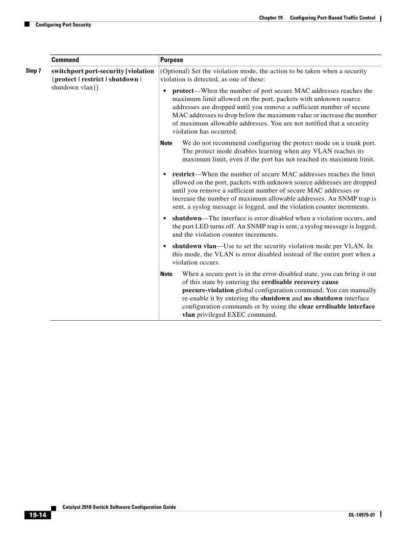
Chapter 19 Configuring Port-Based Traffic ControlConfiguring Port Security
Step 7 switchport port-security [violation {protect | restrict | shutdown | shutdown vlan}]
(Optional) Set the violation mode, the action to be taken when a security violation is detected, as one of these:
• protect—When the number of port secure MAC addresses reaches the maximum limit allowed on the port, packets with unknown source addresses are dropped until you remove a sufficient number of secure MAC addresses to drop below the maximum value or increase the number of maximum allowable addresses. You are not notified that a security violation has occurred.
Note We do not recommend configuring the protect mode on a trunk port. The protect mode disables learning when any VLAN reaches its maximum limit, even if the port has not reached its maximum limit.
• restrict—When the number of secure MAC addresses reaches the limit allowed on the port, packets with unknown source addresses are dropped until you remove a sufficient number of secure MAC addresses or increase the number of maximum allowable addresses. An SNMP trap is sent, a syslog message is logged, and the violation counter increments.
• shutdown—The interface is error disabled when a violation occurs, and the port LED turns off. An SNMP trap is sent, a syslog message is logged, and the violation counter increments.
• shutdown vlan—Use to set the security violation mode per VLAN. In this mode, the VLAN is error disabled instead of the entire port when a violation occurs.
Note When a secure port is in the error-disabled state, you can bring it out of this state by entering the errdisable recovery cause psecure-violation global configuration command. You can manually re-enable it by entering the shutdown and no shutdown interface configuration commands or by using the clear errdisable interface vlan privileged EXEC command.
Command Purpose
19-14Catalyst 2918 Switch Software Configuration Guide
OL-14979-01
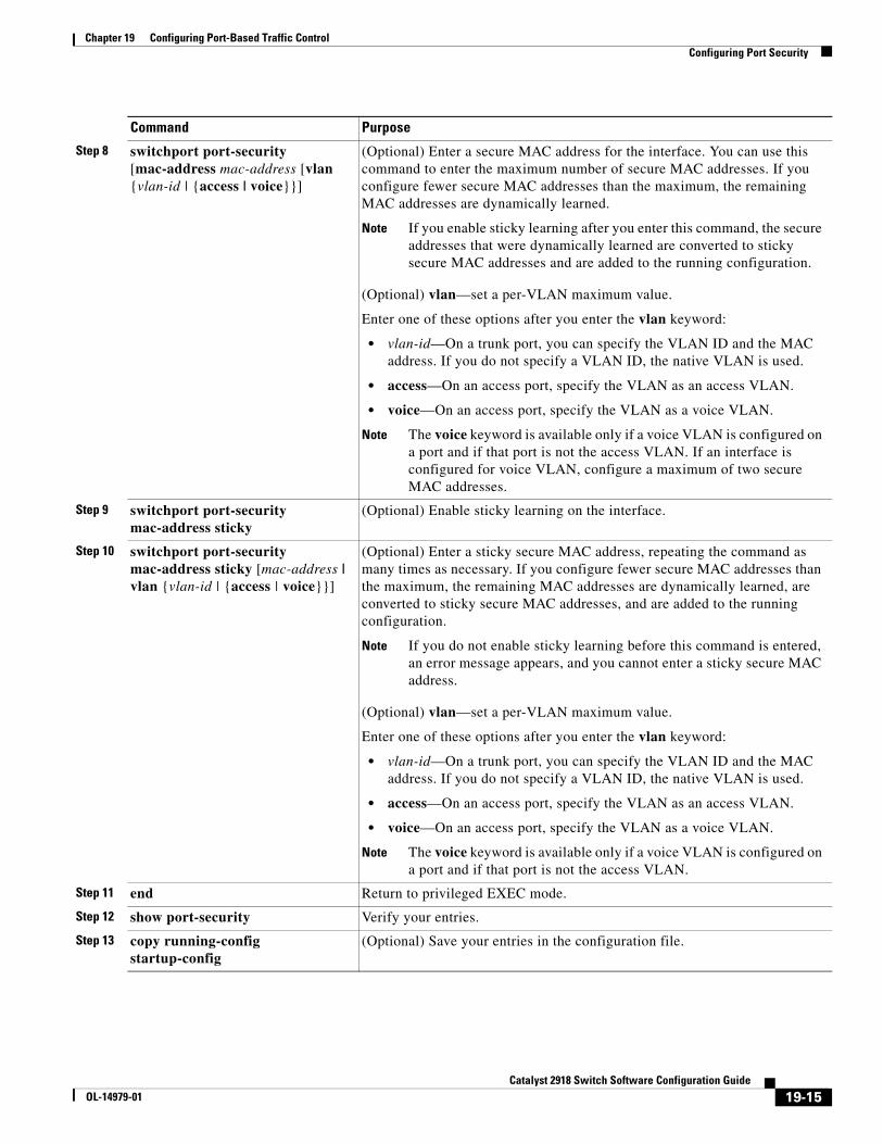
Chapter 19 Configuring Port-Based Traffic ControlConfiguring Port Security
Step 8 switchport port-security [mac-address mac-address [vlan {vlan-id | {access | voice}}]
(Optional) Enter a secure MAC address for the interface. You can use this command to enter the maximum number of secure MAC addresses. If you configure fewer secure MAC addresses than the maximum, the remaining MAC addresses are dynamically learned.
Note If you enable sticky learning after you enter this command, the secure addresses that were dynamically learned are converted to sticky secure MAC addresses and are added to the running configuration.
(Optional) vlan—set a per-VLAN maximum value.
Enter one of these options after you enter the vlan keyword:
• vlan-id—On a trunk port, you can specify the VLAN ID and the MAC address. If you do not specify a VLAN ID, the native VLAN is used.
• access—On an access port, specify the VLAN as an access VLAN.
• voice—On an access port, specify the VLAN as a voice VLAN.
Note The voice keyword is available only if a voice VLAN is configured on a port and if that port is not the access VLAN. If an interface is configured for voice VLAN, configure a maximum of two secure MAC addresses.
Step 9 switchport port-security mac-address sticky
(Optional) Enable sticky learning on the interface.
Step 10 switchport port-security mac-address sticky [mac-address | vlan {vlan-id | {access | voice}}]
(Optional) Enter a sticky secure MAC address, repeating the command as many times as necessary. If you configure fewer secure MAC addresses than the maximum, the remaining MAC addresses are dynamically learned, are converted to sticky secure MAC addresses, and are added to the running configuration.
Note If you do not enable sticky learning before this command is entered, an error message appears, and you cannot enter a sticky secure MAC address.
(Optional) vlan—set a per-VLAN maximum value.
Enter one of these options after you enter the vlan keyword:
• vlan-id—On a trunk port, you can specify the VLAN ID and the MAC address. If you do not specify a VLAN ID, the native VLAN is used.
• access—On an access port, specify the VLAN as an access VLAN.
• voice—On an access port, specify the VLAN as a voice VLAN.
Note The voice keyword is available only if a voice VLAN is configured on a port and if that port is not the access VLAN.
Step 11 end Return to privileged EXEC mode.
Step 12 show port-security Verify your entries.
Step 13 copy running-config startup-config
(Optional) Save your entries in the configuration file.
Command Purpose
19-15Catalyst 2918 Switch Software Configuration Guide
OL-14979-01
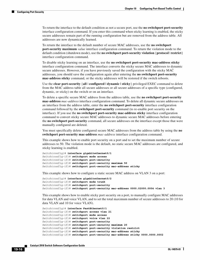
Chapter 19 Configuring Port-Based Traffic ControlConfiguring Port Security
To return the interface to the default condition as not a secure port, use the no switchport port-security interface configuration command. If you enter this command when sticky learning is enabled, the sticky secure addresses remain part of the running configuration but are removed from the address table. All addresses are now dynamically learned.
To return the interface to the default number of secure MAC addresses, use the no switchport port-security maximum value interface configuration command. To return the violation mode to the default condition (shutdown mode), use the no switchport port-security violation {protocol | restrict} interface configuration command.
To disable sticky learning on an interface, use the no switchport port-security mac-address sticky interface configuration command. The interface converts the sticky secure MAC addresses to dynamic secure addresses. However, if you have previously saved the configuration with the sticky MAC addresses, you should save the configuration again after entering the no switchport port-security mac-address sticky command, or the sticky addresses will be restored if the switch reboots.
Use the clear port-security {all | configured | dynamic | sticky} privileged EXEC command to delete from the MAC address table all secure addresses or all secure addresses of a specific type (configured, dynamic, or sticky) on the switch or on an interface.
To delete a specific secure MAC address from the address table, use the no switchport port-security mac-address mac-address interface configuration command. To delete all dynamic secure addresses on an interface from the address table, enter the no switchport port-security interface configuration command followed by the switchport port-security command (to re-enable port security on the interface). If you use the no switchport port-security mac-address sticky interface configuration command to convert sticky secure MAC addresses to dynamic secure MAC addresses before entering the no switchport port-security command, all secure addresses on the interface except those that were manually configured are deleted.
You must specifically delete configured secure MAC addresses from the address table by using the no switchport port-security mac-address mac-address interface configuration command.
This example shows how to enable port security on a port and to set the maximum number of secure addresses to 50. The violation mode is the default, no static secure MAC addresses are configured, and sticky learning is enabled.
Switch(config)# interface gigabitethernet0/1Switch(config-if)# switchport mode accessSwitch(config-if)# switchport port-securitySwitch(config-if)# switchport port-security maximum 50Switch(config-if)# switchport port-security mac-address sticky
This example shows how to configure a static secure MAC address on VLAN 3 on a port:
Switch(config)# interface gigabitethernet0/2Switch(config-if)# switchport mode trunkSwitch(config-if)# switchport port-securitySwitch(config-if)# switchport port-security mac-address 0000.02000.0004 vlan 3
This example shows how to enable sticky port security on a port, to manually configure MAC addresses for data VLAN and voice VLAN, and to set the total maximum number of secure addresses to 20 (10 for data VLAN and 10 for voice VLAN).
Switch(config)# interface FastEthernet0/1Switch(config-if)# switchport access vlan 21Switch(config-if)# switchport mode accessSwitch(config-if)# switchport voice vlan 22Switch(config-if)# switchport port-securitySwitch(config-if)# switchport port-security maximum 20Switch(config-if)# switchport port-security violation restrictSwitch(config-if)# switchport port-security mac-address stickySwitch(config-if)# switchport port-security mac-address sticky 0000.0000.0002
19-16Catalyst 2918 Switch Software Configuration Guide
OL-14979-01
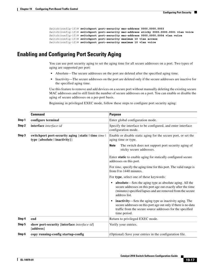
Chapter 19 Configuring Port-Based Traffic ControlConfiguring Port Security
Switch(config-if)# switchport port-security mac-address 0000.0000.0003Switch(config-if)# switchport port-security mac-address sticky 0000.0000.0001 vlan voiceSwitch(config-if)# switchport port-security mac-address 0000.0000.0004 vlan voiceSwitch(config-if)# switchport port-security maximum 10 vlan accessSwitch(config-if)# switchport port-security maximum 10 vlan voice
Enabling and Configuring Port Security AgingYou can use port security aging to set the aging time for all secure addresses on a port. Two types of aging are supported per port:
• Absolute—The secure addresses on the port are deleted after the specified aging time.
• Inactivity—The secure addresses on the port are deleted only if the secure addresses are inactive for the specified aging time.
Use this feature to remove and add devices on a secure port without manually deleting the existing secure MAC addresses and to still limit the number of secure addresses on a port. You can enable or disable the aging of secure addresses on a per-port basis.
Beginning in privileged EXEC mode, follow these steps to configure port security aging:
Command Purpose
Step 1 configure terminal Enter global configuration mode.
Step 2 interface interface-id Specify the interface to be configured, and enter interface configuration mode.
Step 3 switchport port-security aging {static | time time | type {absolute | inactivity}}
Enable or disable static aging for the secure port, or set the aging time or type.
Note The switch does not support port security aging of sticky secure addresses.
Enter static to enable aging for statically configured secure addresses on this port.
For time, specify the aging time for this port. The valid range is from 0 to 1440 minutes.
For type, select one of these keywords:
• absolute—Sets the aging type as absolute aging. All the secure addresses on this port age out exactly after the time (minutes) specified lapses and are removed from the secure address list.
• inactivity—Sets the aging type as inactivity aging. The secure addresses on this port age out only if there is no data traffic from the secure source addresses for the specified time period.
Step 4 end Return to privileged EXEC mode.
Step 5 show port-security [interface interface-id] [address]
Verify your entries.
Step 6 copy running-config startup-config (Optional) Save your entries in the configuration file.
19-17Catalyst 2918 Switch Software Configuration Guide
OL-14979-01
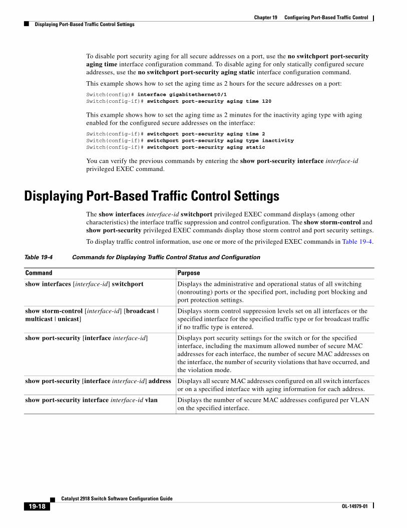
Chapter 19 Configuring Port-Based Traffic ControlDisplaying Port-Based Traffic Control Settings
To disable port security aging for all secure addresses on a port, use the no switchport port-security aging time interface configuration command. To disable aging for only statically configured secure addresses, use the no switchport port-security aging static interface configuration command.
This example shows how to set the aging time as 2 hours for the secure addresses on a port:
Switch(config)# interface gigabitethernet0/1 Switch(config-if)# switchport port-security aging time 120
This example shows how to set the aging time as 2 minutes for the inactivity aging type with aging enabled for the configured secure addresses on the interface:
Switch(config-if)# switchport port-security aging time 2 Switch(config-if)# switchport port-security aging type inactivity Switch(config-if)# switchport port-security aging static
You can verify the previous commands by entering the show port-security interface interface-id privileged EXEC command.
Displaying Port-Based Traffic Control SettingsThe show interfaces interface-id switchport privileged EXEC command displays (among other characteristics) the interface traffic suppression and control configuration. The show storm-control and show port-security privileged EXEC commands display those storm control and port security settings.
To display traffic control information, use one or more of the privileged EXEC commands in Table 19-4.
Table 19-4 Commands for Displaying Traffic Control Status and Configuration
Command Purpose
show interfaces [interface-id] switchport Displays the administrative and operational status of all switching (nonrouting) ports or the specified port, including port blocking and port protection settings.
show storm-control [interface-id] [broadcast | multicast | unicast]
Displays storm control suppression levels set on all interfaces or the specified interface for the specified traffic type or for broadcast traffic if no traffic type is entered.
show port-security [interface interface-id] Displays port security settings for the switch or for the specified interface, including the maximum allowed number of secure MAC addresses for each interface, the number of secure MAC addresses on the interface, the number of security violations that have occurred, and the violation mode.
show port-security [interface interface-id] address Displays all secure MAC addresses configured on all switch interfaces or on a specified interface with aging information for each address.
show port-security interface interface-id vlan Displays the number of secure MAC addresses configured per VLAN on the specified interface.
19-18Catalyst 2918 Switch Software Configuration Guide
OL-14979-01
OL-14979-01
C H A P T E R 20
Configuring CDPThis chapter describes how to configure Cisco Discovery Protocol (CDP) on the Catalyst 2918 switch.
Note For complete syntax and usage information for the commands used in this chapter, see the command reference for this release and the “System Management Commands” section in the Cisco IOS Configuration Fundamentals Command Reference, Release 12.2.
This chapter consists of these sections:
• Understanding CDP, page 20-1
• Configuring CDP, page 20-2
• Monitoring and Maintaining CDP, page 20-4
Understanding CDPCDP is a device discovery protocol that runs over Layer 2 (the data link layer) on all Cisco-manufactured devices (routers, bridges, access servers, and switches) and allows network management applications to discover Cisco devices that are neighbors of already known devices. With CDP, network management applications can learn the device type and the Simple Network Management Protocol (SNMP) agent address of neighboring devices running lower-layer, transparent protocols. This feature enables applications to send SNMP queries to neighboring devices.
CDP runs on all media that support Subnetwork Access Protocol (SNAP). Because CDP runs over the data-link layer only, two systems that support different network-layer protocols can learn about each other.
Each CDP-configured device sends periodic messages to a multicast address, advertising at least one address at which it can receive SNMP messages. The advertisements also contain time-to-live, or holdtime information, which is the length of time a receiving device holds CDP information before discarding it. Each device also listens to the messages sent by other devices to learn about neighboring devices.
On the switch, CDP enables Network Assistant to display a graphical view of the network. The switch uses CDP to find cluster candidates and maintain information about cluster members and other devices up to three cluster-enabled devices away from the command switch by default.
The switch supports CDP Version 2.
20-1Catalyst 2918 Switch Software Configuration Guide
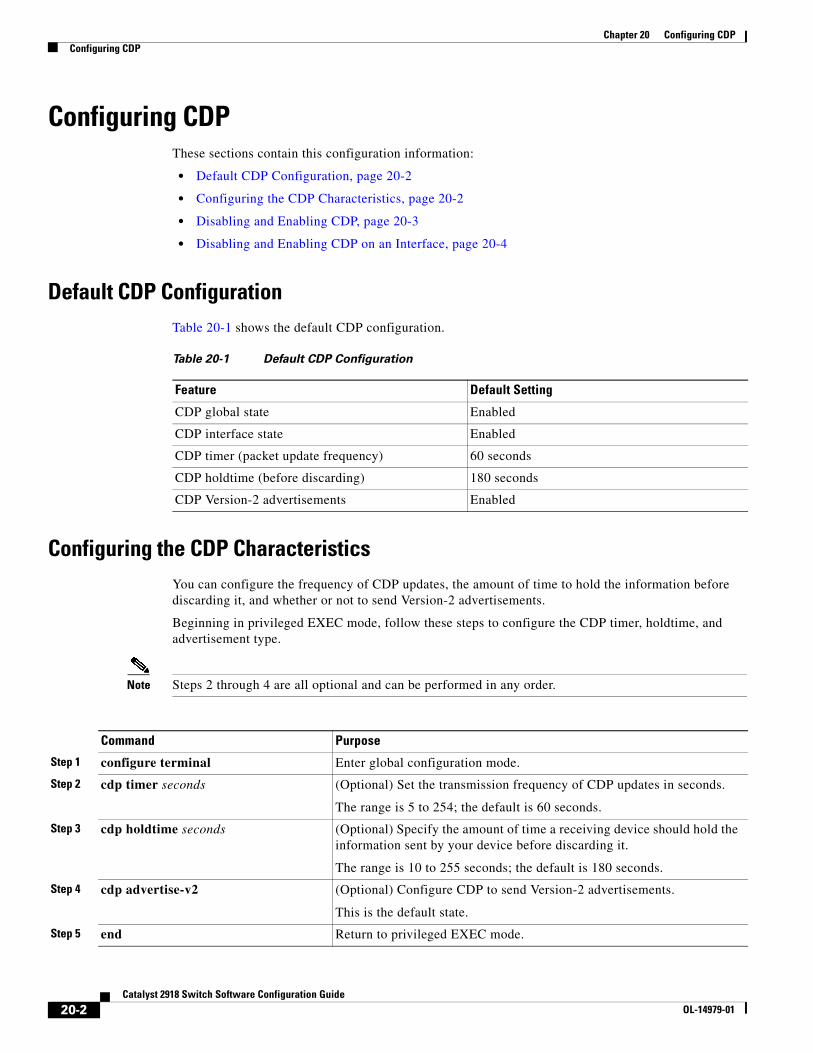
Chapter 20 Configuring CDPConfiguring CDP
Configuring CDPThese sections contain this configuration information:
• Default CDP Configuration, page 20-2
• Configuring the CDP Characteristics, page 20-2
• Disabling and Enabling CDP, page 20-3
• Disabling and Enabling CDP on an Interface, page 20-4
Default CDP ConfigurationTable 20-1 shows the default CDP configuration.
Table 20-1 Default CDP Configuration
Feature Default Setting
CDP global state Enabled
CDP interface state Enabled
CDP timer (packet update frequency) 60 seconds
CDP holdtime (before discarding) 180 seconds
CDP Version-2 advertisements Enabled
Configuring the CDP CharacteristicsYou can configure the frequency of CDP updates, the amount of time to hold the information before discarding it, and whether or not to send Version-2 advertisements.
Beginning in privileged EXEC mode, follow these steps to configure the CDP timer, holdtime, and advertisement type.
Note Steps 2 through 4 are all optional and can be performed in any order.
Command Purpose
Step 1 configure terminal Enter global configuration mode.
Step 2 cdp timer seconds (Optional) Set the transmission frequency of CDP updates in seconds.
The range is 5 to 254; the default is 60 seconds.
Step 3 cdp holdtime seconds (Optional) Specify the amount of time a receiving device should hold the information sent by your device before discarding it.
The range is 10 to 255 seconds; the default is 180 seconds.
Step 4 cdp advertise-v2 (Optional) Configure CDP to send Version-2 advertisements.
This is the default state.
Step 5 end Return to privileged EXEC mode.
20-2Catalyst 2918 Switch Software Configuration Guide
OL-14979-01
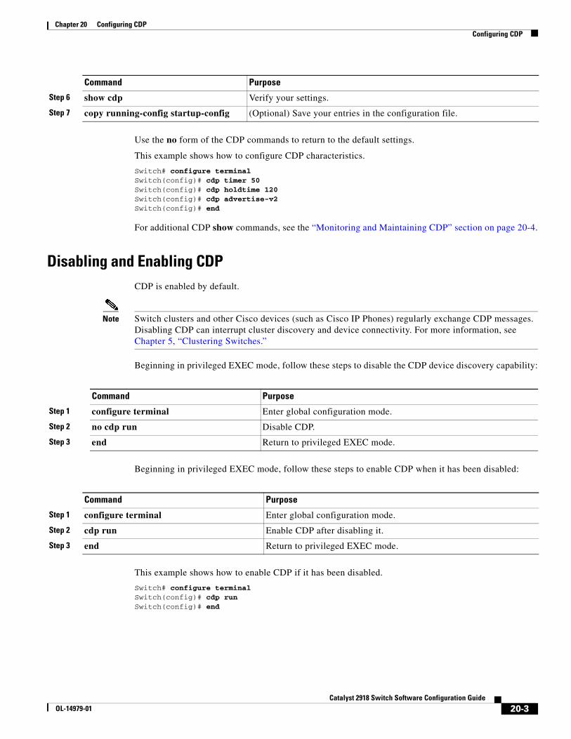
Chapter 20 Configuring CDPConfiguring CDP
Use the no form of the CDP commands to return to the default settings.
This example shows how to configure CDP characteristics.
Switch# configure terminalSwitch(config)# cdp timer 50Switch(config)# cdp holdtime 120Switch(config)# cdp advertise-v2Switch(config)# end
For additional CDP show commands, see the “Monitoring and Maintaining CDP” section on page 20-4.
Disabling and Enabling CDPCDP is enabled by default.
Note Switch clusters and other Cisco devices (such as Cisco IP Phones) regularly exchange CDP messages. Disabling CDP can interrupt cluster discovery and device connectivity. For more information, see Chapter 5, “Clustering Switches.”
Beginning in privileged EXEC mode, follow these steps to disable the CDP device discovery capability:
Command Purpose
Step 1 configure terminal Enter global configuration mode.
Step 2 no cdp run Disable CDP.
Step 3 end Return to privileged EXEC mode.
Beginning in privileged EXEC mode, follow these steps to enable CDP when it has been disabled:
Command Purpose
Step 1 configure terminal Enter global configuration mode.
Step 2 cdp run Enable CDP after disabling it.
Step 3 end Return to privileged EXEC mode.
This example shows how to enable CDP if it has been disabled.
Switch# configure terminalSwitch(config)# cdp runSwitch(config)# end
Step 6 show cdp Verify your settings.
Step 7 copy running-config startup-config (Optional) Save your entries in the configuration file.
Command Purpose
20-3Catalyst 2918 Switch Software Configuration Guide
OL-14979-01
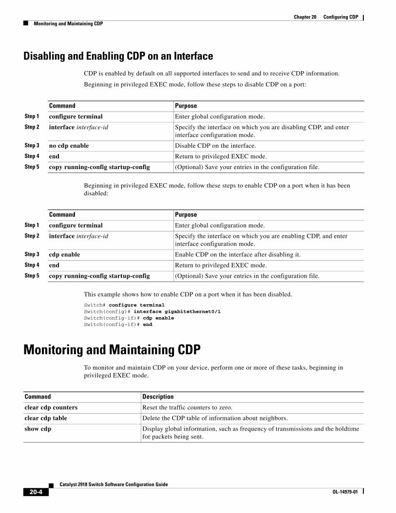
Chapter 20 Configuring CDPMonitoring and Maintaining CDP
Disabling and Enabling CDP on an InterfaceCDP is enabled by default on all supported interfaces to send and to receive CDP information.
Beginning in privileged EXEC mode, follow these steps to disable CDP on a port:
Command Purpose
Step 1 configure terminal Enter global configuration mode.
Step 2 interface interface-id Specify the interface on which you are disabling CDP, and enter interface configuration mode.
Step 3 no cdp enable Disable CDP on the interface.
Step 4 end Return to privileged EXEC mode.
Step 5 copy running-config startup-config (Optional) Save your entries in the configuration file.
Beginning in privileged EXEC mode, follow these steps to enable CDP on a port when it has been disabled:
Command Purpose
Step 1 configure terminal Enter global configuration mode.
Step 2 interface interface-id Specify the interface on which you are enabling CDP, and enter interface configuration mode.
Step 3 cdp enable Enable CDP on the interface after disabling it.
Step 4 end Return to privileged EXEC mode.
Step 5 copy running-config startup-config (Optional) Save your entries in the configuration file.
This example shows how to enable CDP on a port when it has been disabled.
Switch# configure terminalSwitch(config)# interface gigabitethernet0/1Switch(config-if)# cdp enableSwitch(config-if)# end
Monitoring and Maintaining CDPTo monitor and maintain CDP on your device, perform one or more of these tasks, beginning in privileged EXEC mode.
Command Description
clear cdp counters Reset the traffic counters to zero.
clear cdp table Delete the CDP table of information about neighbors.
show cdp Display global information, such as frequency of transmissions and the holdtime for packets being sent.
20-4Catalyst 2918 Switch Software Configuration Guide
OL-14979-01
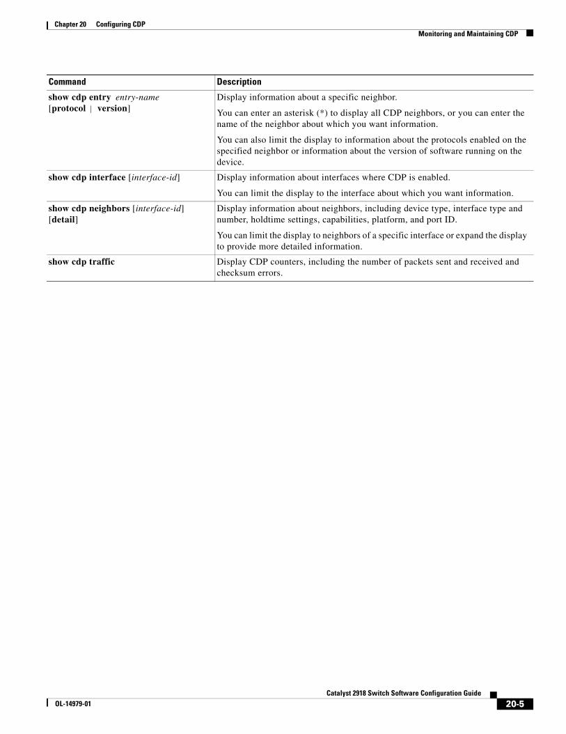
Chapter 20 Configuring CDPMonitoring and Maintaining CDP
show cdp entry entry-name [protocol | version]
Display information about a specific neighbor.
You can enter an asterisk (*) to display all CDP neighbors, or you can enter the name of the neighbor about which you want information.
You can also limit the display to information about the protocols enabled on the specified neighbor or information about the version of software running on the device.
show cdp interface [interface-id] Display information about interfaces where CDP is enabled.
You can limit the display to the interface about which you want information.
show cdp neighbors [interface-id] [detail]
Display information about neighbors, including device type, interface type and number, holdtime settings, capabilities, platform, and port ID.
You can limit the display to neighbors of a specific interface or expand the display to provide more detailed information.
show cdp traffic Display CDP counters, including the number of packets sent and received and checksum errors.
Command Description
20-5Catalyst 2918 Switch Software Configuration Guide
OL-14979-01

Chapter 20 Configuring CDPMonitoring and Maintaining CDP
20-6Catalyst 2918 Switch Software Configuration Guide
OL-14979-01
OL-14979-01
C H A P T E R 21
Configuring LLDPThis chapter describes how to configure the Link Layer Discovery Protocol (LLDP) on the Catalyst 2918 switch.
Note For complete syntax and usage information for the commands used in this chapter, see the command reference for this release and the “System Management Commands” section in the Cisco IOS Configuration Fundamentals Command Reference, Release 12.2.
This chapter consists of these sections:
• Understanding LLDP, page 21-1
• Configuring LLDP, page 21-2
• Monitoring and Maintaining LLDP, page 21-5
Understanding LLDPThe Cisco Discovery Protocol (CDP) is a device discovery protocol that runs over Layer 2 (the data link layer) on all Cisco-manufactured devices (routers, bridges, access servers, and switches). CDP allows network management applications to automatically discover and learn about other Cisco devices connected to the network.
To support non-Cisco devices and to allow for interoperability between other devices, the switch supports the IEEE 802.1AB Link Layer Discovery Protocol (LLDP). LLDP is a neighbor discovery protocol that is used for network devices to advertise information about themselves to other devices on the network. This protocol runs over the data-link layer, which allows two systems running different network layer protocols to learn about each other.
LLDP supports a set of attributes that it uses to discover neighbor devices. These attributes contain type, length, and value descriptions and are referred to as TLVs. LLDP supported devices can use TLVs to receive and send information to their neighbors. Details such as configuration information, device capabilities, and device identity can be advertised using this protocol.
The switch supports these basic management TLVs. These are mandatory LLDP TLVs.
• Port description TLV
• System name TLV
• System description
• System capabilities TLV
21-1Catalyst 2918 Switch Software Configuration Guide
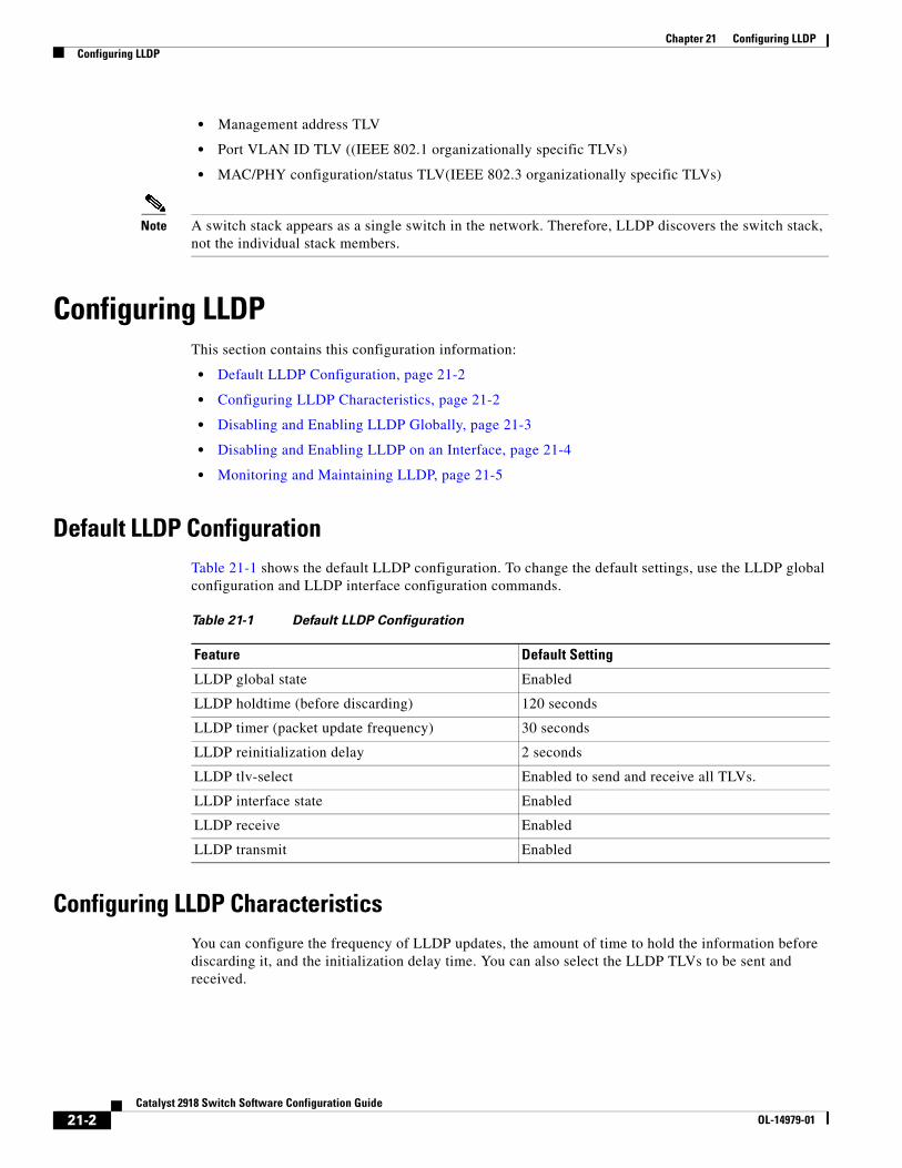
Chapter 21 Configuring LLDPConfiguring LLDP
• Management address TLV
• Port VLAN ID TLV ((IEEE 802.1 organizationally specific TLVs)
• MAC/PHY configuration/status TLV(IEEE 802.3 organizationally specific TLVs)
Note A switch stack appears as a single switch in the network. Therefore, LLDP discovers the switch stack, not the individual stack members.
Configuring LLDPThis section contains this configuration information:
• Default LLDP Configuration, page 21-2
• Configuring LLDP Characteristics, page 21-2
• Disabling and Enabling LLDP Globally, page 21-3
• Disabling and Enabling LLDP on an Interface, page 21-4
• Monitoring and Maintaining LLDP, page 21-5
Default LLDP ConfigurationTable 21-1 shows the default LLDP configuration. To change the default settings, use the LLDP global configuration and LLDP interface configuration commands.
Table 21-1 Default LLDP Configuration
Feature Default Setting
LLDP global state Enabled
LLDP holdtime (before discarding) 120 seconds
LLDP timer (packet update frequency) 30 seconds
LLDP reinitialization delay 2 seconds
LLDP tlv-select Enabled to send and receive all TLVs.
LLDP interface state Enabled
LLDP receive Enabled
LLDP transmit Enabled
Configuring LLDP CharacteristicsYou can configure the frequency of LLDP updates, the amount of time to hold the information before discarding it, and the initialization delay time. You can also select the LLDP TLVs to be sent and received.
21-2Catalyst 2918 Switch Software Configuration Guide
OL-14979-01
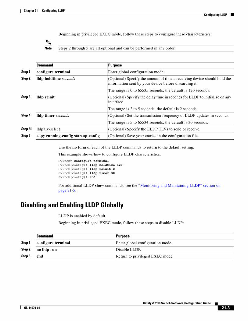
Chapter 21 Configuring LLDPConfiguring LLDP
Beginning in privileged EXEC mode, follow these steps to configure these characteristics:
Note Steps 2 through 5 are all optional and can be performed in any order.
Command Purpose
Step 1 configure terminal Enter global configuration mode.
Step 2 lldp holdtime seconds (Optional) Specify the amount of time a receiving device should hold the information sent by your device before discarding it.
The range is 0 to 65535 seconds; the default is 120 seconds.
Step 3 lldp reinit (Optional) Specify the delay time in seconds for LLDP to initialize on any interface.
The range is 2 to 5 seconds; the default is 2 seconds.
Step 4 lldp timer seconds (Optional) Set the transmission frequency of LLDP updates in seconds.
The range is 5 to 65534 seconds; the default is 30 seconds.
Step 5ll lldp tlv-select (Optional) Specify the LLDP TLVs to send or receive.
Step 6 copy running-config startup-config (Optional) Save your entries in the configuration file.
Use the no form of each of the LLDP commands to return to the default setting.
This example shows how to configure LLDP characteristics.
Switch# configure terminalSwitch(config)# lldp holdtime 120Switch(config)# lldp reinit 2Switch(config)# lldp timer 30Switch(config)# end
For additional LLDP show commands, see the “Monitoring and Maintaining LLDP” section on page 21-5.
Disabling and Enabling LLDP GloballyLLDP is enabled by default.
Beginning in privileged EXEC mode, follow these steps to disable LLDP:
Command Purpose
Step 1 configure terminal Enter global configuration mode.
Step 2 no lldp run Disable LLDP.
Step 3 end Return to privileged EXEC mode.
21-3Catalyst 2918 Switch Software Configuration Guide
OL-14979-01
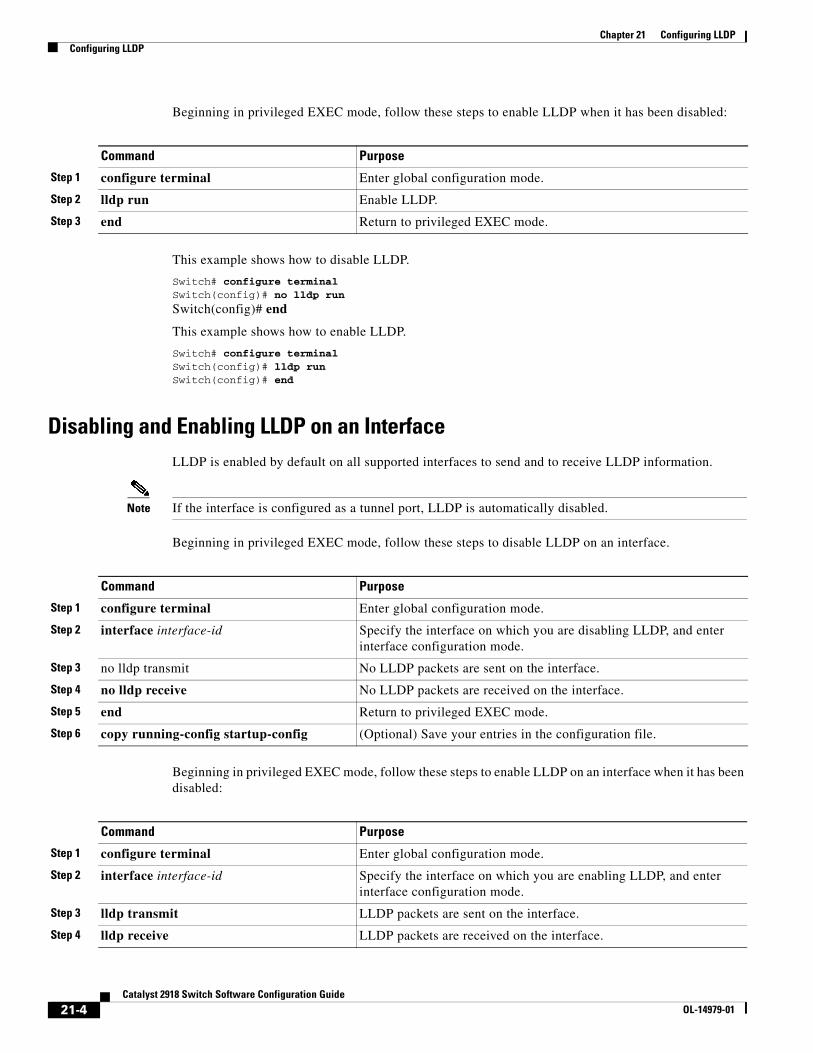
Chapter 21 Configuring LLDPConfiguring LLDP
Beginning in privileged EXEC mode, follow these steps to enable LLDP when it has been disabled:
Command Purpose
Step 1 configure terminal Enter global configuration mode.
Step 2 lldp run Enable LLDP.
Step 3 end Return to privileged EXEC mode.
This example shows how to disable LLDP.
Switch# configure terminalSwitch(config)# no lldp run
Switch(config)# end
This example shows how to enable LLDP.
Switch# configure terminalSwitch(config)# lldp runSwitch(config)# end
Disabling and Enabling LLDP on an InterfaceLLDP is enabled by default on all supported interfaces to send and to receive LLDP information.
Note If the interface is configured as a tunnel port, LLDP is automatically disabled.
Beginning in privileged EXEC mode, follow these steps to disable LLDP on an interface.
Command Purpose
Step 1 configure terminal Enter global configuration mode.
Step 2 interface interface-id Specify the interface on which you are disabling LLDP, and enter interface configuration mode.
Step 3 no lldp transmit No LLDP packets are sent on the interface.
Step 4 no lldp receive No LLDP packets are received on the interface.
Step 5 end Return to privileged EXEC mode.
Step 6 copy running-config startup-config (Optional) Save your entries in the configuration file.
Beginning in privileged EXEC mode, follow these steps to enable LLDP on an interface when it has been disabled:
Command Purpose
Step 1 configure terminal Enter global configuration mode.
Step 2 interface interface-id Specify the interface on which you are enabling LLDP, and enter interface configuration mode.
Step 3 lldp transmit LLDP packets are sent on the interface.
Step 4 lldp receive LLDP packets are received on the interface.
21-4Catalyst 2918 Switch Software Configuration Guide
OL-14979-01
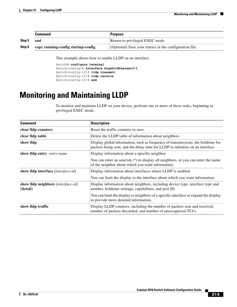
Chapter 21 Configuring LLDPMonitoring and Maintaining LLDP
This example shows how to enable LLDP on an interface.
Switch# configure terminalSwitch(config)# interface GigabitEthernet0/1Switch(config-if)# lldp transmitSwitch(config-if)# lldp receiveSwitch(config-if)# end
Monitoring and Maintaining LLDPTo monitor and maintain LLDP on your device, perform one or more of these tasks, beginning in privileged EXEC mode.
Command Description
clear lldp counters Reset the traffic counters to zero.
clear lldp table Delete the LLDP table of information about neighbors.
show lldp Display global information, such as frequency of transmissions, the holdtime for packets being sent, and the delay time for LLDP to initialize on an interface.
show lldp entry entry-name Display information about a specific neighbor.
You can enter an asterisk (*) to display all neighbors, or you can enter the name of the neighbor about which you want information.
show lldp interface [interface-id] Display information about interfaces where LLDP is enabled.
You can limit the display to the interface about which you want information.
show lldp neighbors [interface-id] [detail]
Display information about neighbors, including device type, interface type and number, holdtime settings, capabilities, and port ID.
You can limit the display to neighbors of a specific interface or expand the display to provide more detailed information.
show lldp traffic Display LLDP counters, including the number of packets sent and received, number of packets discarded, and number of unrecognized TLVs.
Step 5 end Return to privileged EXEC mode.
Step 6 copy running-config startup-config (Optional) Save your entries in the configuration file.
Command Purpose
21-5Catalyst 2918 Switch Software Configuration Guide
OL-14979-01

Chapter 21 Configuring LLDPMonitoring and Maintaining LLDP
21-6Catalyst 2918 Switch Software Configuration Guide
OL-14979-01
OL-14979-01
C H A P T E R 22
Configuring UDLDThis chapter describes how to configure the UniDirectional Link Detection (UDLD) protocol on the Catalyst 2918 switch.
Note For complete syntax and usage information for the commands used in this chapter, see the command reference for this release.
This chapter consists of these sections:
• Understanding UDLD, page 22-1
• Configuring UDLD, page 22-3
• Displaying UDLD Status, page 22-6
Understanding UDLDUDLD is a Layer 2 protocol that enables devices connected through fiber-optic or twisted-pair Ethernet cables to monitor the physical configuration of the cables and detect when a unidirectional link exists. All connected devices must support UDLD for the protocol to successfully identify and disable unidirectional links. When UDLD detects a unidirectional link, it disables the affected port and alerts you. Unidirectional links can cause a variety of problems, including spanning-tree topology loops.
Modes of OperationUDLD supports two modes of operation: normal (the default) and aggressive. In normal mode, UDLD can detect unidirectional links due to misconnected ports on fiber-optic connections. In aggressive mode, UDLD can also detect unidirectional links due to one-way traffic on fiber-optic and twisted-pair links and to misconnected ports on fiber-optic links.
In normal and aggressive modes, UDLD works with the Layer 1 mechanisms to learn the physical status of a link. At Layer 1, autonegotiation takes care of physical signaling and fault detection. UDLD performs tasks that autonegotiation cannot perform, such as detecting the identities of neighbors and shutting down misconnected ports. When you enable both autonegotiation and UDLD, the Layer 1 and Layer 2 detections work together to prevent physical and logical unidirectional connections and the malfunctioning of other protocols.
A unidirectional link occurs whenever traffic sent by a local device is received by its neighbor but traffic from the neighbor is not received by the local device.
22-1Catalyst 2918 Switch Software Configuration Guide
Chapter 22 Configuring UDLDUnderstanding UDLD
In normal mode, UDLD detects a unidirectional link when fiber strands in a fiber-optic port are misconnected and the Layer 1 mechanisms do not detect this misconnection. If the ports are connected correctly but the traffic is one way, UDLD does not detect the unidirectional link because the Layer 1 mechanism, which is supposed to detect this condition, does not do so. In this case, the logical link is considered undetermined, and UDLD does not disable the port.
When UDLD is in normal mode, if one of the fiber strands in a pair is disconnected and autonegotiation is active, the link does not stay up because the Layer 1 mechanisms did not detect a physical problem with the link. In this case, UDLD does not take any action, and the logical link is considered undetermined.
In aggressive mode, UDLD detects a unidirectional link by using the previous detection methods. UDLD in aggressive mode can also detect a unidirectional link on a point-to-point link on which no failure between the two devices is allowed. It can also detect a unidirectional link when one of these problems exists:
• On fiber-optic or twisted-pair links, one of the ports cannot send or receive traffic.
• On fiber-optic or twisted-pair links, one of the ports is down while the other is up.
• One of the fiber strands in the cable is disconnected.
In these cases, UDLD disables the affected port.
In a point-to-point link, UDLD hello packets can be considered as a heart beat whose presence guarantees the health of the link. Conversely, the loss of the heart beat means that the link must be shut down if it is not possible to re-establish a bidirectional link.
If both fiber strands in a cable are working normally from a Layer 1 perspective, UDLD in aggressive mode detects whether those fiber strands are connected correctly and whether traffic is flowing bidirectionally between the correct neighbors. This check cannot be performed by autonegotiation because autonegotiation operates at Layer 1.
Methods to Detect Unidirectional LinksUDLD operates by using two mechanisms:
• Neighbor database maintenance
UDLD learns about other UDLD-capable neighbors by periodically sending a hello packet (also called an advertisement or probe) on every active port to keep each device informed about its neighbors.
When the switch receives a hello message, it caches the information until the age time (hold time or time-to-live) expires. If the switch receives a new hello message before an older cache entry ages, the switch replaces the older entry with the new one.
Whenever a port is disabled and UDLD is running, whenever UDLD is disabled on a port, or whenever the switch is reset, UDLD clears all existing cache entries for the ports affected by the configuration change. UDLD sends at least one message to inform the neighbors to flush the part of their caches affected by the status change. The message is intended to keep the caches synchronized.
• Event-driven detection and echoing
UDLD relies on echoing as its detection mechanism. Whenever a UDLD device learns about a new neighbor or receives a resynchronization request from an out-of-sync neighbor, it restarts the detection window on its side of the connection and sends echo messages in reply. Because this behavior is the same on all UDLD neighbors, the sender of the echoes expects to receive an echo in reply.
22-2Catalyst 2918 Switch Software Configuration Guide
OL-14979-01
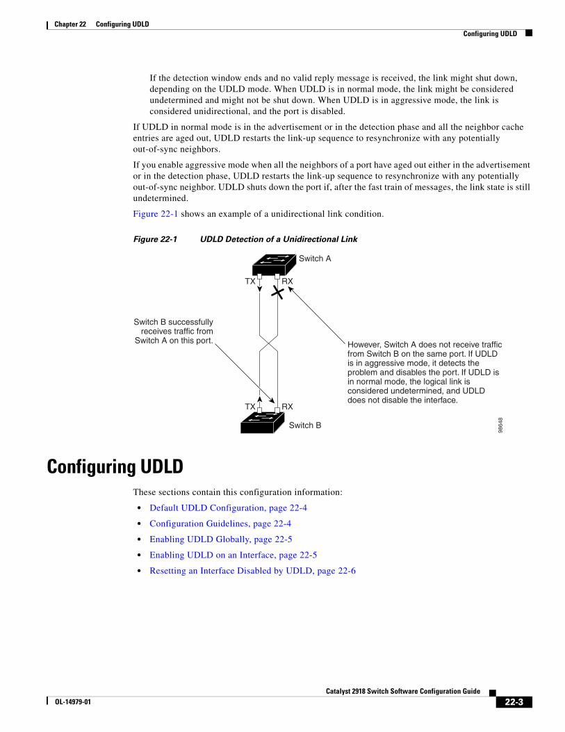
Chapter 22 Configuring UDLDConfiguring UDLD
If the detection window ends and no valid reply message is received, the link might shut down, depending on the UDLD mode. When UDLD is in normal mode, the link might be considered undetermined and might not be shut down. When UDLD is in aggressive mode, the link is considered unidirectional, and the port is disabled.
If UDLD in normal mode is in the advertisement or in the detection phase and all the neighbor cache entries are aged out, UDLD restarts the link-up sequence to resynchronize with any potentially out-of-sync neighbors.
If you enable aggressive mode when all the neighbors of a port have aged out either in the advertisement or in the detection phase, UDLD restarts the link-up sequence to resynchronize with any potentially out-of-sync neighbor. UDLD shuts down the port if, after the fast train of messages, the link state is still undetermined.
Figure 22-1 shows an example of a unidirectional link condition.
Figure 22-1 UDLD Detection of a Unidirectional Link
TX
TX
RX
RX
Switch A
Switch B
Switch B successfullyreceives traffic from
Switch A on this port.
9864
8
However, Switch A does not receive trafficfrom Switch B on the same port. If UDLDis in aggressive mode, it detects the problem and disables the port. If UDLD is in normal mode, the logical link is considered undetermined, and UDLD does not disable the interface.
Configuring UDLDThese sections contain this configuration information:
• Default UDLD Configuration, page 22-4
• Configuration Guidelines, page 22-4
• Enabling UDLD Globally, page 22-5
• Enabling UDLD on an Interface, page 22-5
• Resetting an Interface Disabled by UDLD, page 22-6
22-3Catalyst 2918 Switch Software Configuration Guide
OL-14979-01
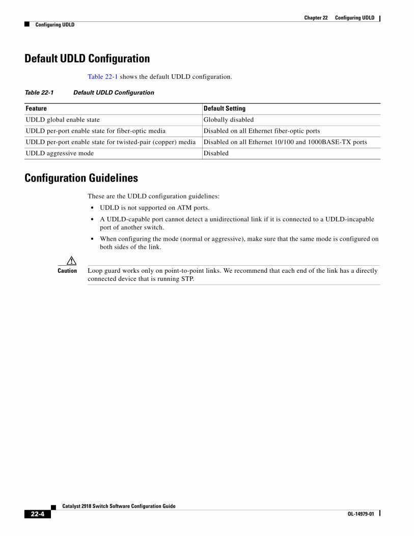
Chapter 22 Configuring UDLDConfiguring UDLD
Default UDLD ConfigurationTable 22-1 shows the default UDLD configuration.
Table 22-1 Default UDLD Configuration
Feature Default Setting
UDLD global enable state Globally disabled
UDLD per-port enable state for fiber-optic media Disabled on all Ethernet fiber-optic ports
UDLD per-port enable state for twisted-pair (copper) media Disabled on all Ethernet 10/100 and 1000BASE-TX ports
UDLD aggressive mode Disabled
Configuration GuidelinesThese are the UDLD configuration guidelines:
• UDLD is not supported on ATM ports.
• A UDLD-capable port cannot detect a unidirectional link if it is connected to a UDLD-incapable port of another switch.
• When configuring the mode (normal or aggressive), make sure that the same mode is configured on both sides of the link.
Caution Loop guard works only on point-to-point links. We recommend that each end of the link has a directly connected device that is running STP.
22-4Catalyst 2918 Switch Software Configuration Guide
OL-14979-01
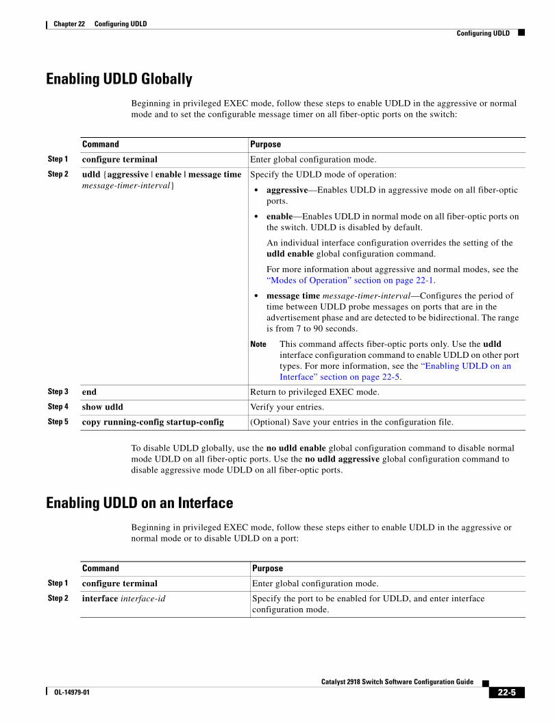
Chapter 22 Configuring UDLDConfiguring UDLD
Enabling UDLD GloballyBeginning in privileged EXEC mode, follow these steps to enable UDLD in the aggressive or normal mode and to set the configurable message timer on all fiber-optic ports on the switch:
Command Purpose
Step 1 configure terminal Enter global configuration mode.
Step 2 udld {aggressive | enable | message time message-timer-interval}
Specify the UDLD mode of operation:
• aggressive—Enables UDLD in aggressive mode on all fiber-optic ports.
• enable—Enables UDLD in normal mode on all fiber-optic ports on the switch. UDLD is disabled by default.
An individual interface configuration overrides the setting of the udld enable global configuration command.
For more information about aggressive and normal modes, see the “Modes of Operation” section on page 22-1.
• message time message-timer-interval—Configures the period of time between UDLD probe messages on ports that are in the advertisement phase and are detected to be bidirectional. The range is from 7 to 90 seconds.
Note This command affects fiber-optic ports only. Use the udld interface configuration command to enable UDLD on other port types. For more information, see the “Enabling UDLD on an Interface” section on page 22-5.
Step 3 end Return to privileged EXEC mode.
Step 4 show udld Verify your entries.
Step 5 copy running-config startup-config (Optional) Save your entries in the configuration file.
To disable UDLD globally, use the no udld enable global configuration command to disable normal mode UDLD on all fiber-optic ports. Use the no udld aggressive global configuration command to disable aggressive mode UDLD on all fiber-optic ports.
Enabling UDLD on an InterfaceBeginning in privileged EXEC mode, follow these steps either to enable UDLD in the aggressive or normal mode or to disable UDLD on a port:
Command Purpose
Step 1 configure terminal Enter global configuration mode.
Step 2 interface interface-id Specify the port to be enabled for UDLD, and enter interface configuration mode.
22-5Catalyst 2918 Switch Software Configuration Guide
OL-14979-01
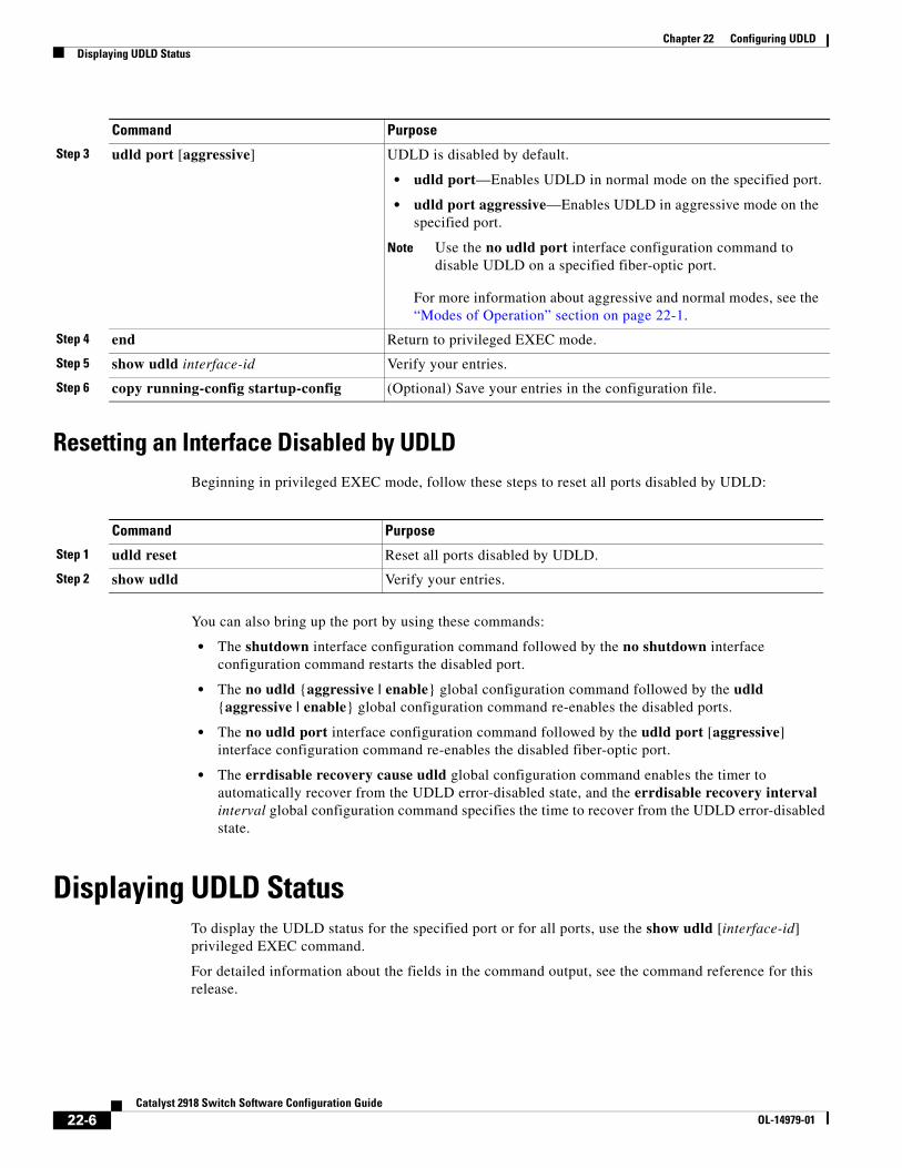
Chapter 22 Configuring UDLDDisplaying UDLD Status
Resetting an Interface Disabled by UDLDBeginning in privileged EXEC mode, follow these steps to reset all ports disabled by UDLD:
Command Purpose
Step 1 udld reset Reset all ports disabled by UDLD.
Step 2 show udld Verify your entries.
You can also bring up the port by using these commands:
• The shutdown interface configuration command followed by the no shutdown interface configuration command restarts the disabled port.
• The no udld {aggressive | enable} global configuration command followed by the udld {aggressive | enable} global configuration command re-enables the disabled ports.
• The no udld port interface configuration command followed by the udld port [aggressive] interface configuration command re-enables the disabled fiber-optic port.
• The errdisable recovery cause udld global configuration command enables the timer to automatically recover from the UDLD error-disabled state, and the errdisable recovery interval interval global configuration command specifies the time to recover from the UDLD error-disabled state.
Displaying UDLD StatusTo display the UDLD status for the specified port or for all ports, use the show udld [interface-id] privileged EXEC command.
For detailed information about the fields in the command output, see the command reference for this release.
Step 3 udld port [aggressive] UDLD is disabled by default.
• udld port—Enables UDLD in normal mode on the specified port.
• udld port aggressive—Enables UDLD in aggressive mode on the specified port.
Note Use the no udld port interface configuration command to disable UDLD on a specified fiber-optic port.
For more information about aggressive and normal modes, see the “Modes of Operation” section on page 22-1.
Step 4 end Return to privileged EXEC mode.
Step 5 show udld interface-id Verify your entries.
Step 6 copy running-config startup-config (Optional) Save your entries in the configuration file.
Command Purpose
22-6Catalyst 2918 Switch Software Configuration Guide
OL-14979-01
OL-14979-01
C H A P T E R 23
Configuring SPANThis chapter describes how to configure Switched Port Analyzer (SPAN) and on the Catalyst 2918 switch.
Note For complete syntax and usage information for the commands used in this chapter, see the command reference for this release.
This chapter consists of these sections:
• Understanding SPAN, page 23-1
• Configuring SPAN, page 23-7
• Displaying SPAN Status, page 23-13
Understanding SPAN You can analyze network traffic passing through ports or VLANs by using SPAN to send a copy of the traffic to another port on the switch or on another switch that has been connected to a network analyzer or other monitoring or security device. SPAN copies (or mirrors) traffic received or sent (or both) on source ports or source VLANs to a destination port for analysis. SPAN does not affect the switching of network traffic on the source ports or VLANs. You must dedicate the destination port for SPAN use. Except for traffic that is required for the SPAN session, destination ports do not receive or forward traffic.
Only traffic that enters or leaves source ports or traffic that enters or leaves source VLANs can be monitored by using SPAN; traffic routed to a source VLAN cannot be monitored. For example, if incoming traffic is being monitored, traffic that gets routed from another VLAN to the source VLAN cannot be monitored; however, traffic that is received on the source VLAN and routed to another VLAN can be monitored.
You can use the SPAN destination port to inject traffic from a network security device. For example, if you connect a Cisco Intrusion Detection System (IDS) sensor appliance to a destination port, the IDS device can send TCP reset packets to close down the TCP session of a suspected attacker.
These sections contain this conceptual information:
• Local SPAN, page 23-2
• SPAN Concepts and Terminology, page 23-2
• SPAN Interaction with Other Features, page 23-6
23-1Catalyst 2918 Switch Software Configuration Guide
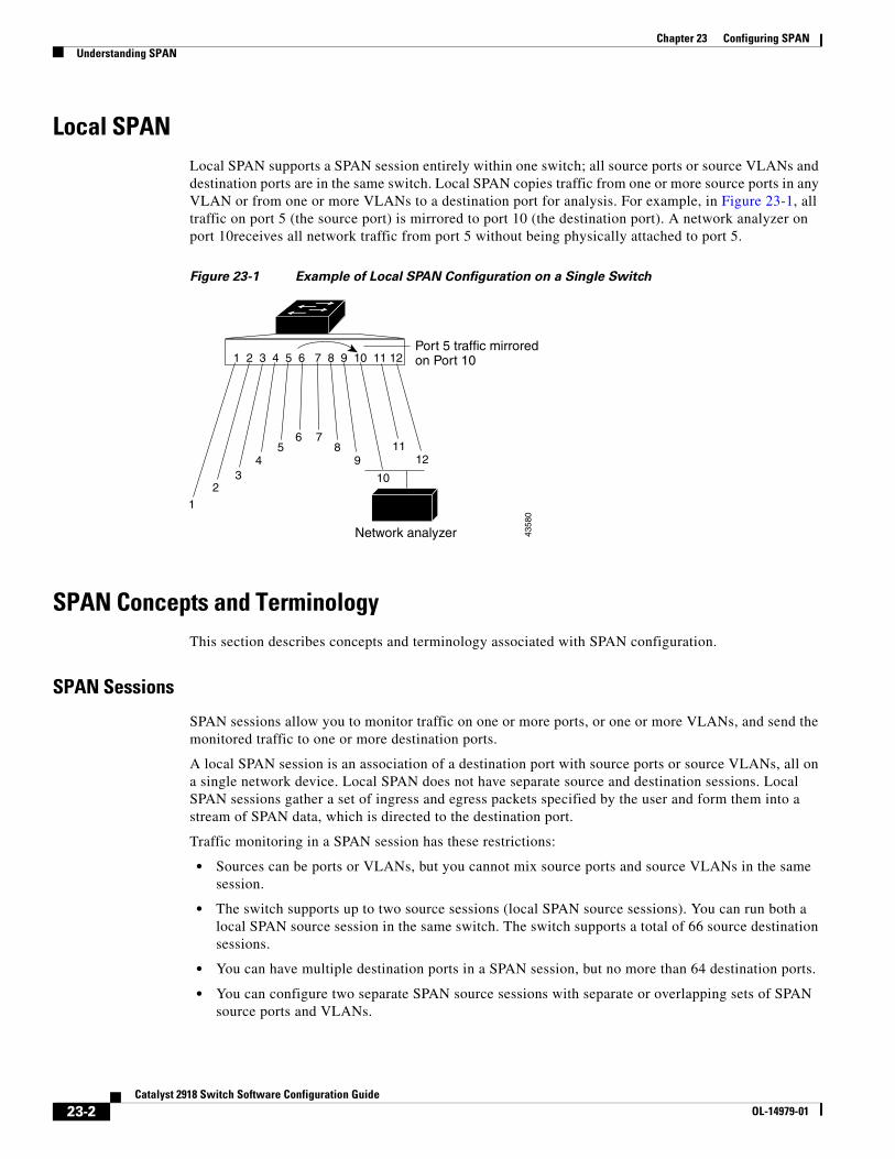
Chapter 23 Configuring SPANUnderstanding SPAN
Local SPANLocal SPAN supports a SPAN session entirely within one switch; all source ports or source VLANs and destination ports are in the same switch. Local SPAN copies traffic from one or more source ports in any VLAN or from one or more VLANs to a destination port for analysis. For example, in Figure 23-1, all traffic on port 5 (the source port) is mirrored to port 10 (the destination port). A network analyzer on port 10receives all network traffic from port 5 without being physically attached to port 5.
Figure 23-1 Example of Local SPAN Configuration on a Single Switch
1 2 3 4 5 6 7 8 9 10 11 12Port 5 traffic mirroredon Port 10
32
1
45
6 78
911
12
10
Network analyzer 4358
0
SPAN Concepts and TerminologyThis section describes concepts and terminology associated with SPAN configuration.
SPAN Sessions
SPAN sessions allow you to monitor traffic on one or more ports, or one or more VLANs, and send the monitored traffic to one or more destination ports.
A local SPAN session is an association of a destination port with source ports or source VLANs, all on a single network device. Local SPAN does not have separate source and destination sessions. Local SPAN sessions gather a set of ingress and egress packets specified by the user and form them into a stream of SPAN data, which is directed to the destination port.
Traffic monitoring in a SPAN session has these restrictions:
• Sources can be ports or VLANs, but you cannot mix source ports and source VLANs in the same session.
• The switch supports up to two source sessions (local SPAN source sessions). You can run both a local SPAN source session in the same switch. The switch supports a total of 66 source destination sessions.
• You can have multiple destination ports in a SPAN session, but no more than 64 destination ports.
• You can configure two separate SPAN source sessions with separate or overlapping sets of SPAN source ports and VLANs.
23-2Catalyst 2918 Switch Software Configuration Guide
OL-14979-01
Chapter 23 Configuring SPANUnderstanding SPAN
• SPAN sessions do not interfere with the normal operation of the switch. However, an oversubscribed SPAN destination, for example, a 10-Mb/s port monitoring a 100-Mb/s port, can result in dropped or lost packets.
• You can configure SPAN sessions on disabled ports; however, a SPAN session does not become active unless you enable the destination port and at least one source port or VLAN for that session.
Monitored Traffic
SPAN sessions can monitor these traffic types:
• Receive (Rx) SPAN—The goal of receive (or ingress) SPAN is to monitor as much as possible all the packets received by the source interface or VLAN before any modification or processing is performed by the switch. A copy of each packet received by the source is sent to the destination port for that SPAN session.
Packets that are modified because of routing or quality of service (QoS)—for example, modified Differentiated Services Code Point (DSCP)—are copied before modification.
Features that can cause a packet to be dropped during receive processing have no effect on ingress SPAN; the destination port receives a copy of the packet even if the actual incoming packet is dropped. These features include IP standard and extended input access control lists (ACLs), ingress QoS policing, and egress QoS policing.
• Transmit (Tx) SPAN—The goal of transmit (or egress) SPAN is to monitor as much as possible all the packets sent by the source interface after all modification and processing is performed by the switch. A copy of each packet sent by the source is sent to the destination port for that SPAN session. The copy is provided after the packet is modified.
Features that can cause a packet to be dropped during transmit processing also affect the duplicated copy for SPAN. These features include IP standard and extended output ACLs and egress QoS policing.
• Both—In a SPAN session, you can also monitor a port or VLAN for both received and sent packets. This is the default.
The default configuration for local SPAN session ports is to send all packets untagged. SPAN also does not normally monitor bridge protocol data unit (BPDU) packets and Layer 2 protocols, such as Cisco Discovery Protocol (CDP), VLAN Trunk Protocol (VTP), Dynamic Trunking Protocol (DTP), Spanning Tree Protocol (STP), and Port Aggregation Protocol (PAgP). However, when you enter the encapsulation replicate keywords when configuring a destination port, these changes occur:
• Packets are sent on the destination port with the same encapsulation—untagged or IEEE 802.1Q—that they had on the source port.
• Packets of all types, including BPDU and Layer 2 protocol packets, are monitored.
Therefore, a local SPAN session with encapsulation replicate enabled can have a mixture of untagged and IEEE 802.1Q tagged packets appear on the destination port.
Switch congestion can cause packets to be dropped at ingress source ports, egress source ports, or SPAN destination ports. In general, these characteristics are independent of one another. For example:
• A packet might be forwarded normally but dropped from monitoring due to an oversubscribed SPAN destination port.
• An ingress packet might be dropped from normal forwarding, but still appear on the SPAN destination port.
• An egress packet dropped because of switch congestion is also dropped from egress SPAN.
23-3Catalyst 2918 Switch Software Configuration Guide
OL-14979-01
Chapter 23 Configuring SPANUnderstanding SPAN
In some SPAN configurations, multiple copies of the same source packet are sent to the SPAN destination port. For example, a bidirectional (both Rx and Tx) SPAN session is configured for the Rx monitor on port A and Tx monitor on port B. If a packet enters the switch through port A and is switched to port B, both incoming and outgoing packets are sent to the destination port. Both packets are the same.
Source Ports
A source port (also called a monitored port) is a switched port that you monitor for network traffic analysis. In a local SPAN session, you can monitor source ports or VLANs for traffic in one or both directions. The switch supports any number of source ports (up to the maximum number of available ports on the switch) and any number of source VLANs (up to the maximum number of VLANs supported). However, the switch supports a maximum of two sessions with source ports or VLANs, and you cannot mix ports and VLANs in a single session.
A source port has these characteristics:
• It can be monitored in multiple SPAN sessions.
• Each source port can be configured with a direction (ingress, egress, or both) to monitor.
• It can be any port type (for example, EtherChannel, Fast Ethernet, Gigabit Ethernet, and so forth).
• For EtherChannel sources, you can monitor traffic for the entire EtherChannel or individually on a physical port as it participates in the port channel.
• It can be an access port, trunk port, or voice VLAN port.
• It cannot be a destination port.
• Source ports can be in the same or different VLANs.
• You can monitor multiple source ports in a single session.
Source VLANs
VLAN-based SPAN (VSPAN) is the monitoring of the network traffic in one or more VLANs. The SPAN source interface in VSPAN is a VLAN ID, and traffic is monitored on all the ports for that VLAN.
VSPAN has these characteristics:
• All active ports in the source VLAN are included as source ports and can be monitored in either or both directions.
• On a given port, only traffic on the monitored VLAN is sent to the destination port.
• If a destination port belongs to a source VLAN, it is excluded from the source list and is not monitored.
• If ports are added to or removed from the source VLANs, the traffic on the source VLAN received by those ports is added to or removed from the sources being monitored.
• You cannot use filter VLANs in the same session with VLAN sources.
• You can monitor only Ethernet VLANs.
23-4Catalyst 2918 Switch Software Configuration Guide
OL-14979-01
Chapter 23 Configuring SPANUnderstanding SPAN
VLAN Filtering
When you monitor a trunk port as a source port, by default, all VLANs active on the trunk are monitored. You can limit SPAN traffic monitoring on trunk source ports to specific VLANs by using VLAN filtering.
• VLAN filtering applies only to trunk ports or to voice VLAN ports.
• VLAN filtering applies only to port-based sessions and is not allowed in sessions with VLAN sources.
• When a VLAN filter list is specified, only those VLANs in the list are monitored on trunk ports or on voice VLAN access ports.
• SPAN traffic coming from other port types is not affected by VLAN filtering; that is, all VLANs are allowed on other ports.
• VLAN filtering affects only traffic forwarded to the destination SPAN port and does not affect the switching of normal traffic.
Destination Port
Each local SPAN session must have a destination port (also called a monitoring port) that receives a copy of traffic from the source ports or VLANs and sends the SPAN packets to the user, usually a network analyzer.
A destination port has these characteristics:
• For a local SPAN session, the destination port must reside on the same switch as the source port.
• When a port is configured as a SPAN destination port, the configuration overwrites the original port configuration. When the SPAN destination configuration is removed, the port reverts to its previous configuration. If a configuration change is made to the port while it is acting as a SPAN destination port, the change does not take effect until the SPAN destination configuration had been removed.
• If the port was in an EtherChannel group, it is removed from the group while it is a destination port.
• It can be any Ethernet physical port.
• It cannot be a secure port.
• It cannot be a source port.
• It cannot be an EtherChannel group or a VLAN.
• It can participate in only one SPAN session at a time (a destination port in one SPAN session cannot be a destination port for a second SPAN session).
• When it is active, incoming traffic is disabled. The port does not transmit any traffic except that required for the SPAN session. Incoming traffic is never learned or forwarded on a destination port.
• If ingress traffic forwarding is enabled for a network security device, the destination port forwards traffic at Layer 2.
• It does not participate in any of the Layer 2 protocols (STP, VTP, CDP, DTP, PagP).
• A destination port that belongs to a source VLAN of any SPAN session is excluded from the source list and is not monitored.
• The maximum number of destination ports in a switch is 64.
23-5Catalyst 2918 Switch Software Configuration Guide
OL-14979-01
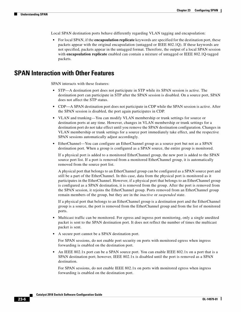
Chapter 23 Configuring SPANUnderstanding SPAN
Local SPAN destination ports behave differently regarding VLAN tagging and encapsulation:
• For local SPAN, if the encapsulation replicate keywords are specified for the destination port, these packets appear with the original encapsulation (untagged or IEEE 802.1Q). If these keywords are not specified, packets appear in the untagged format. Therefore, the output of a local SPAN session with encapsulation replicate enabled can contain a mixture of untagged or IEEE 802.1Q-tagged packets.
SPAN Interaction with Other FeaturesSPAN interacts with these features:
• STP—A destination port does not participate in STP while its SPAN session is active. The destination port can participate in STP after the SPAN session is disabled. On a source port, SPAN does not affect the STP status.
• CDP—A SPAN destination port does not participate in CDP while the SPAN session is active. After the SPAN session is disabled, the port again participates in CDP.
• VLAN and trunking—You can modify VLAN membership or trunk settings for source or destination ports at any time. However, changes in VLAN membership or trunk settings for a destination port do not take effect until you remove the SPAN destination configuration. Changes in VLAN membership or trunk settings for a source port immediately take effect, and the respective SPAN sessions automatically adjust accordingly.
• EtherChannel—You can configure an EtherChannel group as a source port but not as a SPAN destination port. When a group is configured as a SPAN source, the entire group is monitored.
If a physical port is added to a monitored EtherChannel group, the new port is added to the SPAN source port list. If a port is removed from a monitored EtherChannel group, it is automatically removed from the source port list.
A physical port that belongs to an EtherChannel group can be configured as a SPAN source port and still be a part of the EtherChannel. In this case, data from the physical port is monitored as it participates in the EtherChannel. However, if a physical port that belongs to an EtherChannel group is configured as a SPAN destination, it is removed from the group. After the port is removed from the SPAN session, it rejoins the EtherChannel group. Ports removed from an EtherChannel group remain members of the group, but they are in the inactive or suspended state.
If a physical port that belongs to an EtherChannel group is a destination port and the EtherChannel group is a source, the port is removed from the EtherChannel group and from the list of monitored ports.
• Multicast traffic can be monitored. For egress and ingress port monitoring, only a single unedited packet is sent to the SPAN destination port. It does not reflect the number of times the multicast packet is sent.
• A secure port cannot be a SPAN destination port.
For SPAN sessions, do not enable port security on ports with monitored egress when ingress forwarding is enabled on the destination port.
• An IEEE 802.1x port can be a SPAN source port. You can enable IEEE 802.1x on a port that is a SPAN destination port; however, IEEE 802.1x is disabled until the port is removed as a SPAN destination.
For SPAN sessions, do not enable IEEE 802.1x on ports with monitored egress when ingress forwarding is enabled on the destination port.
23-6Catalyst 2918 Switch Software Configuration Guide
OL-14979-01
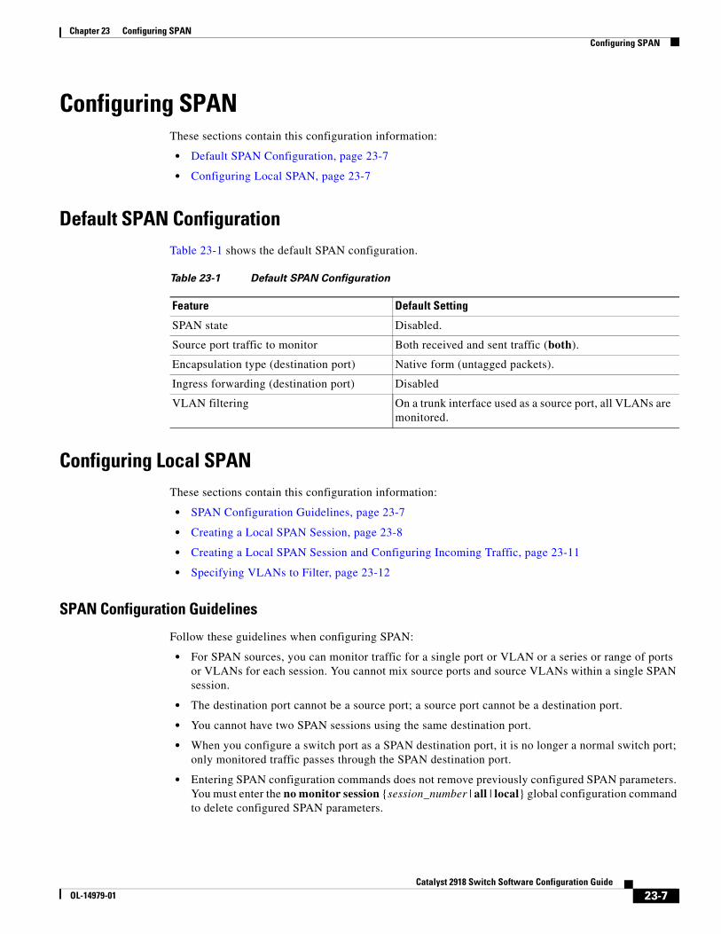
Chapter 23 Configuring SPANConfiguring SPAN
Configuring SPANThese sections contain this configuration information:
• Default SPAN Configuration, page 23-7
• Configuring Local SPAN, page 23-7
Default SPAN ConfigurationTable 23-1 shows the default SPAN configuration.
Table 23-1 Default SPAN Configuration
Feature Default Setting
SPAN state Disabled.
Source port traffic to monitor Both received and sent traffic (both).
Encapsulation type (destination port) Native form (untagged packets).
Ingress forwarding (destination port) Disabled
VLAN filtering On a trunk interface used as a source port, all VLANs are monitored.
Configuring Local SPANThese sections contain this configuration information:
• SPAN Configuration Guidelines, page 23-7
• Creating a Local SPAN Session, page 23-8
• Creating a Local SPAN Session and Configuring Incoming Traffic, page 23-11
• Specifying VLANs to Filter, page 23-12
SPAN Configuration Guidelines
Follow these guidelines when configuring SPAN:
• For SPAN sources, you can monitor traffic for a single port or VLAN or a series or range of ports or VLANs for each session. You cannot mix source ports and source VLANs within a single SPAN session.
• The destination port cannot be a source port; a source port cannot be a destination port.
• You cannot have two SPAN sessions using the same destination port.
• When you configure a switch port as a SPAN destination port, it is no longer a normal switch port; only monitored traffic passes through the SPAN destination port.
• Entering SPAN configuration commands does not remove previously configured SPAN parameters. You must enter the no monitor session {session_number | all | local} global configuration command to delete configured SPAN parameters.
23-7Catalyst 2918 Switch Software Configuration Guide
OL-14979-01
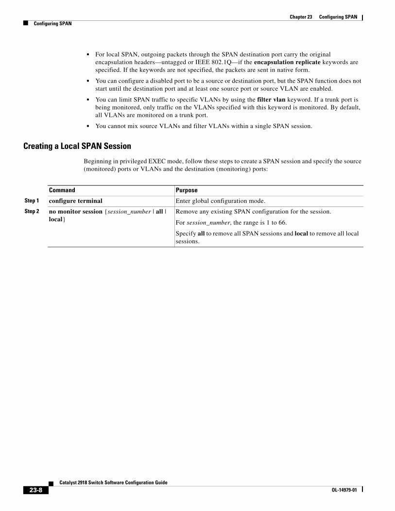
Chapter 23 Configuring SPANConfiguring SPAN
• For local SPAN, outgoing packets through the SPAN destination port carry the original encapsulation headers—untagged or IEEE 802.1Q—if the encapsulation replicate keywords are specified. If the keywords are not specified, the packets are sent in native form.
• You can configure a disabled port to be a source or destination port, but the SPAN function does not start until the destination port and at least one source port or source VLAN are enabled.
• You can limit SPAN traffic to specific VLANs by using the filter vlan keyword. If a trunk port is being monitored, only traffic on the VLANs specified with this keyword is monitored. By default, all VLANs are monitored on a trunk port.
• You cannot mix source VLANs and filter VLANs within a single SPAN session.
Creating a Local SPAN Session
Beginning in privileged EXEC mode, follow these steps to create a SPAN session and specify the source (monitored) ports or VLANs and the destination (monitoring) ports:
Command Purpose
Step 1 configure terminal Enter global configuration mode.
Step 2 no monitor session {session_number | all | local}
Remove any existing SPAN configuration for the session.
For session_number, the range is 1 to 66.
Specify all to remove all SPAN sessions and local to remove all local sessions.
23-8Catalyst 2918 Switch Software Configuration Guide
OL-14979-01
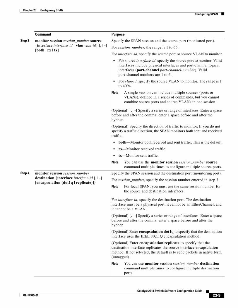
Chapter 23 Configuring SPANConfiguring SPAN
Step 3 monitor session session_number source {interface interface-id | vlan vlan-id} [, | -] [both | rx | tx]
Specify the SPAN session and the source port (monitored port).
For session_number, the range is 1 to 66.
For interface-id, specify the source port or source VLAN to monitor.
• For source interface-id, specify the source port to monitor. Valid interfaces include physical interfaces and port-channel logical interfaces (port-channel port-channel-number). Valid port-channel numbers are 1 to 6.
• For vlan-id, specify the source VLAN to monitor. The range is 1 to 4094.
Note A single session can include multiple sources (ports or VLANs), defined in a series of commands, but you cannot combine source ports and source VLANs in one session.
(Optional) [, | -] Specify a series or range of interfaces. Enter a space before and after the comma; enter a space before and after the hyphen.
(Optional) Specify the direction of traffic to monitor. If you do not specify a traffic direction, the SPAN monitors both sent and received traffic.
• both—Monitor both received and sent traffic. This is the default.
• rx—Monitor received traffic.
• tx—Monitor sent traffic.
Note You can use the monitor session session_number source command multiple times to configure multiple source ports.
Step 4 monitor session session_number destination {interface interface-id [, | -] [encapsulation {dot1q | replicate}]}
Specify the SPAN session and the destination port (monitoring port).
For session_number, specify the session number entered in step 3.
Note For local SPAN, you must use the same session number for the source and destination interfaces.
For interface-id, specify the destination port. The destination interface must be a physical port; it cannot be an EtherChannel, and it cannot be a VLAN.
(Optional) [, | -] Specify a series or range of interfaces. Enter a space before and after the comma; enter a space before and after the hyphen.
(Optional) Enter encapsulation dot1q to specify that the destination interface uses the IEEE 802.1Q encapsulation method.
(Optional) Enter encapsulation replicate to specify that the destination interface replicates the source interface encapsulation method. If not selected, the default is to send packets in native form (untagged).
Note You can use monitor session session_number destination command multiple times to configure multiple destination ports.
Command Purpose
23-9Catalyst 2918 Switch Software Configuration Guide
OL-14979-01
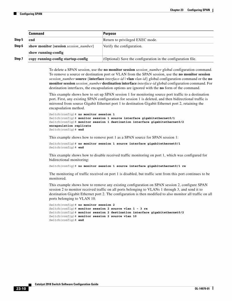
Chapter 23 Configuring SPANConfiguring SPAN
To delete a SPAN session, use the no monitor session session_number global configuration command. To remove a source or destination port or VLAN from the SPAN session, use the no monitor session session_number source {interface interface-id | vlan vlan-id} global configuration command or the no monitor session session_number destination interface interface-id global configuration command. For destination interfaces, the encapsulation options are ignored with the no form of the command.
This example shows how to set up SPAN session 1 for monitoring source port traffic to a destination port. First, any existing SPAN configuration for session 1 is deleted, and then bidirectional traffic is mirrored from source Gigabit Ethernet port 1 to destination Gigabit Ethernet port 2, retaining the encapsulation method.
Switch(config)# no monitor session 1Switch(config)# monitor session 1 source interface gigabitethernet0/1Switch(config)# monitor session 1 destination interface gigabitethernet0/2 encapsulation replicateSwitch(config)# end
This example shows how to remove port 1 as a SPAN source for SPAN session 1:
Switch(config)# no monitor session 1 source interface gigabitethernet0/1Switch(config)# end
This example shows how to disable received traffic monitoring on port 1, which was configured for bidirectional monitoring:
Switch(config)# no monitor session 1 source interface gigabitethernet0/1 rx
The monitoring of traffic received on port 1 is disabled, but traffic sent from this port continues to be monitored.
This example shows how to remove any existing configuration on SPAN session 2, configure SPAN session 2 to monitor received traffic on all ports belonging to VLANs 1 through 3, and send it to destination Gigabit Ethernet port 2. The configuration is then modified to also monitor all traffic on all ports belonging to VLAN 10.
Switch(config)# no monitor session 2Switch(config)# monitor session 2 source vlan 1 - 3 rxSwitch(config)# monitor session 2 destination interface gigabitethernet0/2Switch(config)# monitor session 2 source vlan 10Switch(config)# end
Step 5 end Return to privileged EXEC mode.
Step 6 show monitor [session session_number]
show running-config
Verify the configuration.
Step 7 copy running-config startup-config (Optional) Save the configuration in the configuration file.
Command Purpose
23-10Catalyst 2918 Switch Software Configuration Guide
OL-14979-01
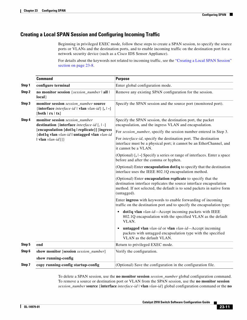
Chapter 23 Configuring SPANConfiguring SPAN
Creating a Local SPAN Session and Configuring Incoming Traffic
Beginning in privileged EXEC mode, follow these steps to create a SPAN session, to specify the source ports or VLANs and the destination ports, and to enable incoming traffic on the destination port for a network security device (such as a Cisco IDS Sensor Appliance).
For details about the keywords not related to incoming traffic, see the “Creating a Local SPAN Session” section on page 23-8.
Command Purpose
Step 1 configure terminal Enter global configuration mode.
Step 2 no monitor session {session_number | all | local}
Remove any existing SPAN configuration for the session.
Step 3 monitor session session_number source {interface interface-id | vlan vlan-id} [, | -] [both | rx | tx]
Specify the SPAN session and the source port (monitored port).
Step 4 monitor session session_number destination {interface interface-id [, | -] [encapsulation {dot1q | replicate}] [ingress {dot1q vlan vlan-id | untagged vlan vlan-id | vlan vlan-id}]}
Specify the SPAN session, the destination port, the packet encapsulation, and the ingress VLAN and encapsulation.
For session_number, specify the session number entered in Step 3.
For interface-id, specify the destination port. The destination interface must be a physical port; it cannot be an EtherChannel, and it cannot be a VLAN.
(Optional) [, | -] Specify a series or range of interfaces. Enter a space before and after the comma or hyphen.
(Optional) Enter encapsulation dot1q to specify that the destination interface uses the IEEE 802.1Q encapsulation method.
(Optional) Enter encapsulation replicate to specify that the destination interface replicates the source interface encapsulation method. If not selected, the default is to send packets in native form (untagged).
Enter ingress with keywords to enable forwarding of incoming traffic on the destination port and to specify the encapsulation type:
• dot1q vlan vlan-id—Accept incoming packets with IEEE 802.1Q encapsulation with the specified VLAN as the default VLAN.
• untagged vlan vlan-id or vlan vlan-id—Accept incoming packets with untagged encapsulation type with the specified VLAN as the default VLAN.
Step 5 end Return to privileged EXEC mode.
Step 6 show monitor [session session_number]
show running-config
Verify the configuration.
Step 7 copy running-config startup-config (Optional) Save the configuration in the configuration file.
To delete a SPAN session, use the no monitor session session_number global configuration command. To remove a source or destination port or VLAN from the SPAN session, use the no monitor session session_number source {interface interface-id | vlan vlan-id} global configuration command or the no
23-11Catalyst 2918 Switch Software Configuration Guide
OL-14979-01
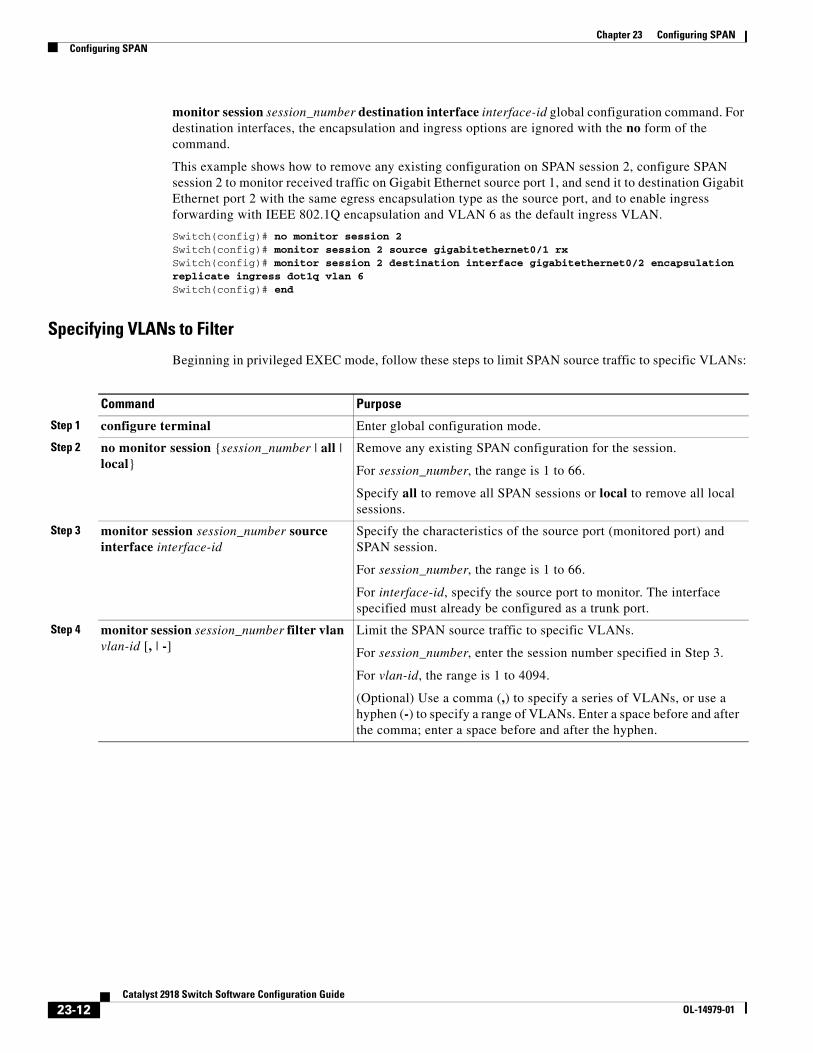
Chapter 23 Configuring SPANConfiguring SPAN
monitor session session_number destination interface interface-id global configuration command. For destination interfaces, the encapsulation and ingress options are ignored with the no form of the command.
This example shows how to remove any existing configuration on SPAN session 2, configure SPAN session 2 to monitor received traffic on Gigabit Ethernet source port 1, and send it to destination Gigabit Ethernet port 2 with the same egress encapsulation type as the source port, and to enable ingress forwarding with IEEE 802.1Q encapsulation and VLAN 6 as the default ingress VLAN.
Switch(config)# no monitor session 2Switch(config)# monitor session 2 source gigabitethernet0/1 rxSwitch(config)# monitor session 2 destination interface gigabitethernet0/2 encapsulation replicate ingress dot1q vlan 6 Switch(config)# end
Specifying VLANs to Filter
Beginning in privileged EXEC mode, follow these steps to limit SPAN source traffic to specific VLANs:
Command Purpose
Step 1 configure terminal Enter global configuration mode.
Step 2 no monitor session {session_number | all | local}
Remove any existing SPAN configuration for the session.
For session_number, the range is 1 to 66.
Specify all to remove all SPAN sessions or local to remove all local sessions.
Step 3 monitor session session_number source interface interface-id
Specify the characteristics of the source port (monitored port) and SPAN session.
For session_number, the range is 1 to 66.
For interface-id, specify the source port to monitor. The interface specified must already be configured as a trunk port.
Step 4 monitor session session_number filter vlan vlan-id [, | -]
Limit the SPAN source traffic to specific VLANs.
For session_number, enter the session number specified in Step 3.
For vlan-id, the range is 1 to 4094.
(Optional) Use a comma (,) to specify a series of VLANs, or use a hyphen (-) to specify a range of VLANs. Enter a space before and after the comma; enter a space before and after the hyphen.
23-12Catalyst 2918 Switch Software Configuration Guide
OL-14979-01
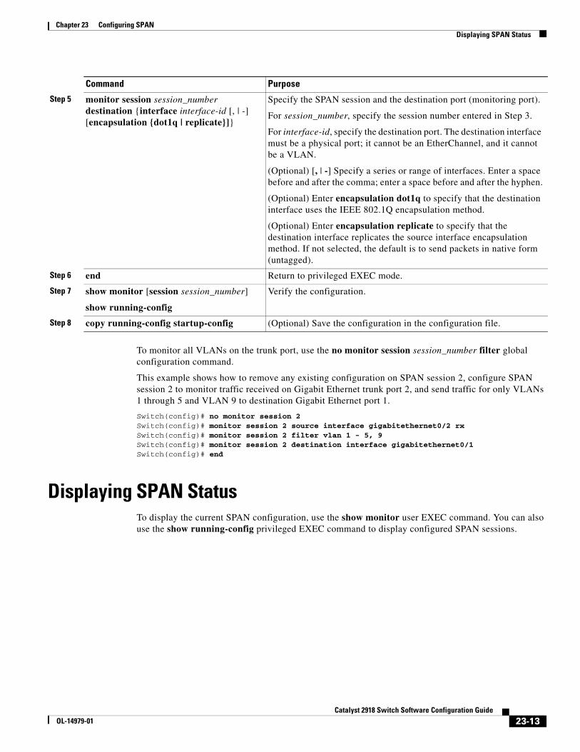
Chapter 23 Configuring SPANDisplaying SPAN Status
To monitor all VLANs on the trunk port, use the no monitor session session_number filter global configuration command.
This example shows how to remove any existing configuration on SPAN session 2, configure SPAN session 2 to monitor traffic received on Gigabit Ethernet trunk port 2, and send traffic for only VLANs 1 through 5 and VLAN 9 to destination Gigabit Ethernet port 1.
Switch(config)# no monitor session 2Switch(config)# monitor session 2 source interface gigabitethernet0/2 rxSwitch(config)# monitor session 2 filter vlan 1 - 5, 9Switch(config)# monitor session 2 destination interface gigabitethernet0/1Switch(config)# end
Displaying SPAN StatusTo display the current SPAN configuration, use the show monitor user EXEC command. You can also use the show running-config privileged EXEC command to display configured SPAN sessions.
Step 5 monitor session session_number destination {interface interface-id [, | -] [encapsulation {dot1q | replicate}]}
Specify the SPAN session and the destination port (monitoring port).
For session_number, specify the session number entered in Step 3.
For interface-id, specify the destination port. The destination interface must be a physical port; it cannot be an EtherChannel, and it cannot be a VLAN.
(Optional) [, | -] Specify a series or range of interfaces. Enter a space before and after the comma; enter a space before and after the hyphen.
(Optional) Enter encapsulation dot1q to specify that the destination interface uses the IEEE 802.1Q encapsulation method.
(Optional) Enter encapsulation replicate to specify that the destination interface replicates the source interface encapsulation method. If not selected, the default is to send packets in native form (untagged).
Step 6 end Return to privileged EXEC mode.
Step 7 show monitor [session session_number]
show running-config
Verify the configuration.
Step 8 copy running-config startup-config (Optional) Save the configuration in the configuration file.
Command Purpose
23-13Catalyst 2918 Switch Software Configuration Guide
OL-14979-01

Chapter 23 Configuring SPANDisplaying SPAN Status
23-14Catalyst 2918 Switch Software Configuration Guide
OL-14979-01
OL-14979-01
C H A P T E R 24
Configuring RMONThis chapter describes how to configure Remote Network Monitoring (RMON) on the Catalyst 2918 switch.
RMON is a standard monitoring specification that defines a set of statistics and functions that can be exchanged between RMON-compliant console systems and network probes. RMON provides you with comprehensive network-fault diagnosis, planning, and performance-tuning information.
Note For complete syntax and usage information for the commands used in this chapter, see the “System Management Commands” section in the Cisco IOS Configuration Fundamentals Command Reference, Release 12.2.
This chapter consists of these sections:
• Understanding RMON, page 24-1
• Configuring RMON, page 24-2
• Displaying RMON Status, page 24-6
Understanding RMONRMON is an Internet Engineering Task Force (IETF) standard monitoring specification that allows various network agents and console systems to exchange network monitoring data. You can use the RMON feature with the Simple Network Management Protocol (SNMP) agent in the switch to monitor all the traffic flowing among switches on all connected LAN segments as shown in Figure 24-1.
24-1Catalyst 2918 Switch Software Configuration Guide
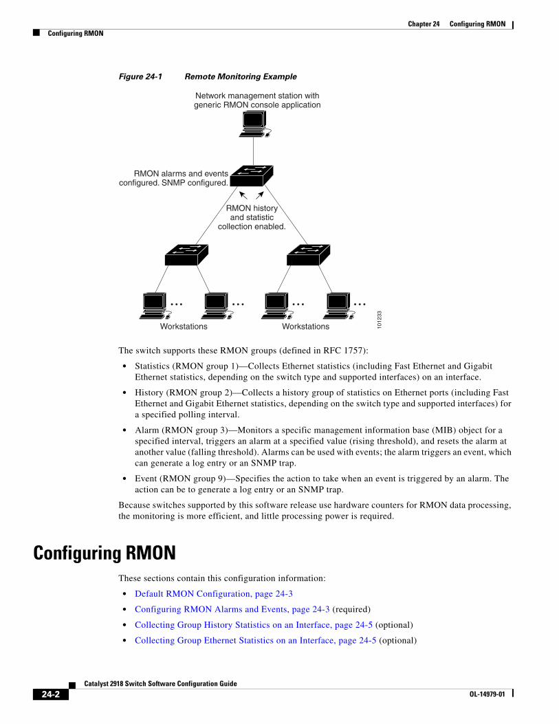
Chapter 24 Configuring RMONConfiguring RMON
Figure 24-1 Remote Monitoring Example
1012
33
RMON alarms and eventsconfigured. SNMP configured.
RMON historyand statistic
collection enabled.
Workstations Workstations
Network management station withgeneric RMON console application
The switch supports these RMON groups (defined in RFC 1757):
• Statistics (RMON group 1)—Collects Ethernet statistics (including Fast Ethernet and Gigabit Ethernet statistics, depending on the switch type and supported interfaces) on an interface.
• History (RMON group 2)—Collects a history group of statistics on Ethernet ports (including Fast Ethernet and Gigabit Ethernet statistics, depending on the switch type and supported interfaces) for a specified polling interval.
• Alarm (RMON group 3)—Monitors a specific management information base (MIB) object for a specified interval, triggers an alarm at a specified value (rising threshold), and resets the alarm at another value (falling threshold). Alarms can be used with events; the alarm triggers an event, which can generate a log entry or an SNMP trap.
• Event (RMON group 9)—Specifies the action to take when an event is triggered by an alarm. The action can be to generate a log entry or an SNMP trap.
Because switches supported by this software release use hardware counters for RMON data processing, the monitoring is more efficient, and little processing power is required.
Configuring RMONThese sections contain this configuration information:
• Default RMON Configuration, page 24-3
• Configuring RMON Alarms and Events, page 24-3 (required)
• Collecting Group History Statistics on an Interface, page 24-5 (optional)
• Collecting Group Ethernet Statistics on an Interface, page 24-5 (optional)
24-2Catalyst 2918 Switch Software Configuration Guide
OL-14979-01
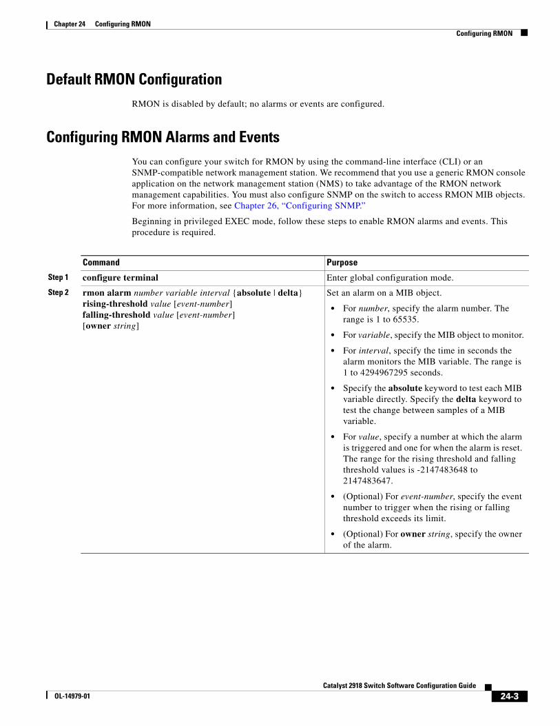
Chapter 24 Configuring RMONConfiguring RMON
Default RMON ConfigurationRMON is disabled by default; no alarms or events are configured.
Configuring RMON Alarms and EventsYou can configure your switch for RMON by using the command-line interface (CLI) or an SNMP-compatible network management station. We recommend that you use a generic RMON console application on the network management station (NMS) to take advantage of the RMON network management capabilities. You must also configure SNMP on the switch to access RMON MIB objects. For more information, see Chapter 26, “Configuring SNMP.”
Beginning in privileged EXEC mode, follow these steps to enable RMON alarms and events. This procedure is required.
Command Purpose
Step 1 configure terminal Enter global configuration mode.
Step 2 rmon alarm number variable interval {absolute | delta} rising-threshold value [event-number] falling-threshold value [event-number] [owner string]
Set an alarm on a MIB object.
• For number, specify the alarm number. The range is 1 to 65535.
• For variable, specify the MIB object to monitor.
• For interval, specify the time in seconds the alarm monitors the MIB variable. The range is 1 to 4294967295 seconds.
• Specify the absolute keyword to test each MIB variable directly. Specify the delta keyword to test the change between samples of a MIB variable.
• For value, specify a number at which the alarm is triggered and one for when the alarm is reset. The range for the rising threshold and falling threshold values is -2147483648 to 2147483647.
• (Optional) For event-number, specify the event number to trigger when the rising or falling threshold exceeds its limit.
• (Optional) For owner string, specify the owner of the alarm.
24-3Catalyst 2918 Switch Software Configuration Guide
OL-14979-01
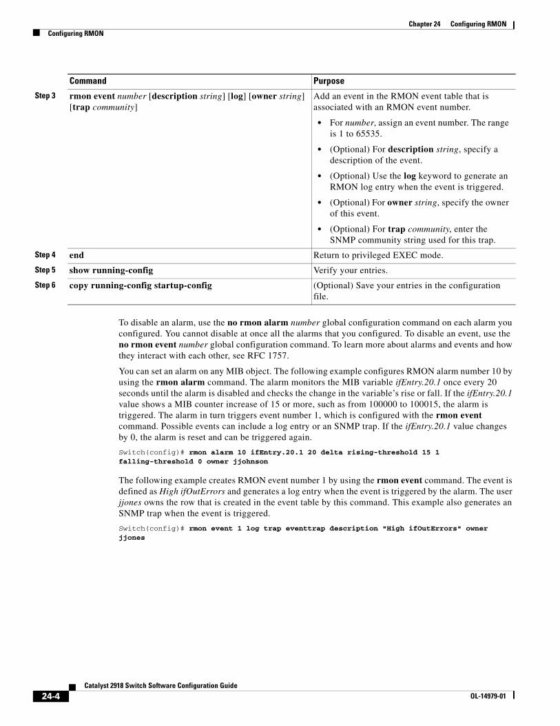
Chapter 24 Configuring RMONConfiguring RMON
To disable an alarm, use the no rmon alarm number global configuration command on each alarm you configured. You cannot disable at once all the alarms that you configured. To disable an event, use the no rmon event number global configuration command. To learn more about alarms and events and how they interact with each other, see RFC 1757.
You can set an alarm on any MIB object. The following example configures RMON alarm number 10 by using the rmon alarm command. The alarm monitors the MIB variable ifEntry.20.1 once every 20 seconds until the alarm is disabled and checks the change in the variable’s rise or fall. If the ifEntry.20.1 value shows a MIB counter increase of 15 or more, such as from 100000 to 100015, the alarm is triggered. The alarm in turn triggers event number 1, which is configured with the rmon event command. Possible events can include a log entry or an SNMP trap. If the ifEntry.20.1 value changes by 0, the alarm is reset and can be triggered again.
Switch(config)# rmon alarm 10 ifEntry.20.1 20 delta rising-threshold 15 1 falling-threshold 0 owner jjohnson
The following example creates RMON event number 1 by using the rmon event command. The event is defined as High ifOutErrors and generates a log entry when the event is triggered by the alarm. The user jjones owns the row that is created in the event table by this command. This example also generates an SNMP trap when the event is triggered.
Switch(config)# rmon event 1 log trap eventtrap description "High ifOutErrors" owner jjones
Step 3 rmon event number [description string] [log] [owner string] [trap community]
Add an event in the RMON event table that is associated with an RMON event number.
• For number, assign an event number. The range is 1 to 65535.
• (Optional) For description string, specify a description of the event.
• (Optional) Use the log keyword to generate an RMON log entry when the event is triggered.
• (Optional) For owner string, specify the owner of this event.
• (Optional) For trap community, enter the SNMP community string used for this trap.
Step 4 end Return to privileged EXEC mode.
Step 5 show running-config Verify your entries.
Step 6 copy running-config startup-config (Optional) Save your entries in the configuration file.
Command Purpose
24-4Catalyst 2918 Switch Software Configuration Guide
OL-14979-01
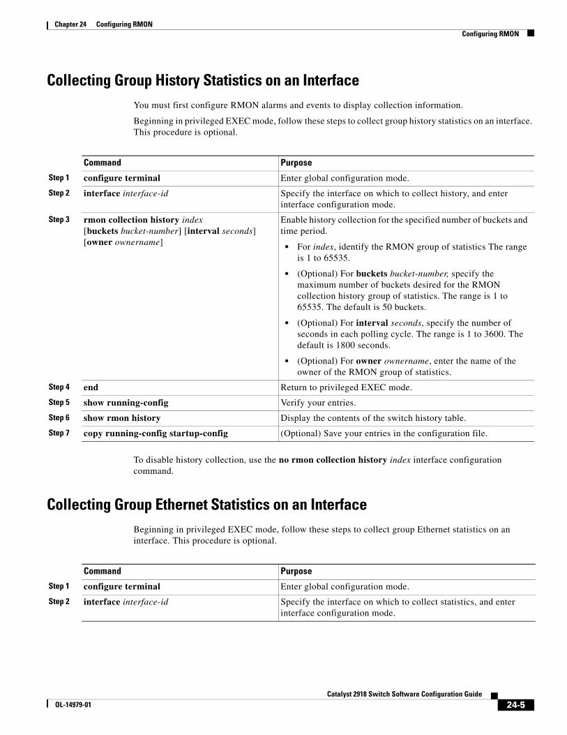
Chapter 24 Configuring RMONConfiguring RMON
Collecting Group History Statistics on an InterfaceYou must first configure RMON alarms and events to display collection information.
Beginning in privileged EXEC mode, follow these steps to collect group history statistics on an interface. This procedure is optional.
Command Purpose
Step 1 configure terminal Enter global configuration mode.
Step 2 interface interface-id Specify the interface on which to collect history, and enter interface configuration mode.
Step 3 rmon collection history index [buckets bucket-number] [interval seconds] [owner ownername]
Enable history collection for the specified number of buckets and time period.
• For index, identify the RMON group of statistics The range is 1 to 65535.
• (Optional) For buckets bucket-number, specify the maximum number of buckets desired for the RMON collection history group of statistics. The range is 1 to 65535. The default is 50 buckets.
• (Optional) For interval seconds, specify the number of seconds in each polling cycle. The range is 1 to 3600. The default is 1800 seconds.
• (Optional) For owner ownername, enter the name of the owner of the RMON group of statistics.
Step 4 end Return to privileged EXEC mode.
Step 5 show running-config Verify your entries.
Step 6 show rmon history Display the contents of the switch history table.
Step 7 copy running-config startup-config (Optional) Save your entries in the configuration file.
To disable history collection, use the no rmon collection history index interface configuration command.
Collecting Group Ethernet Statistics on an InterfaceBeginning in privileged EXEC mode, follow these steps to collect group Ethernet statistics on an interface. This procedure is optional.
Command Purpose
Step 1 configure terminal Enter global configuration mode.
Step 2 interface interface-id Specify the interface on which to collect statistics, and enter interface configuration mode.
24-5Catalyst 2918 Switch Software Configuration Guide
OL-14979-01
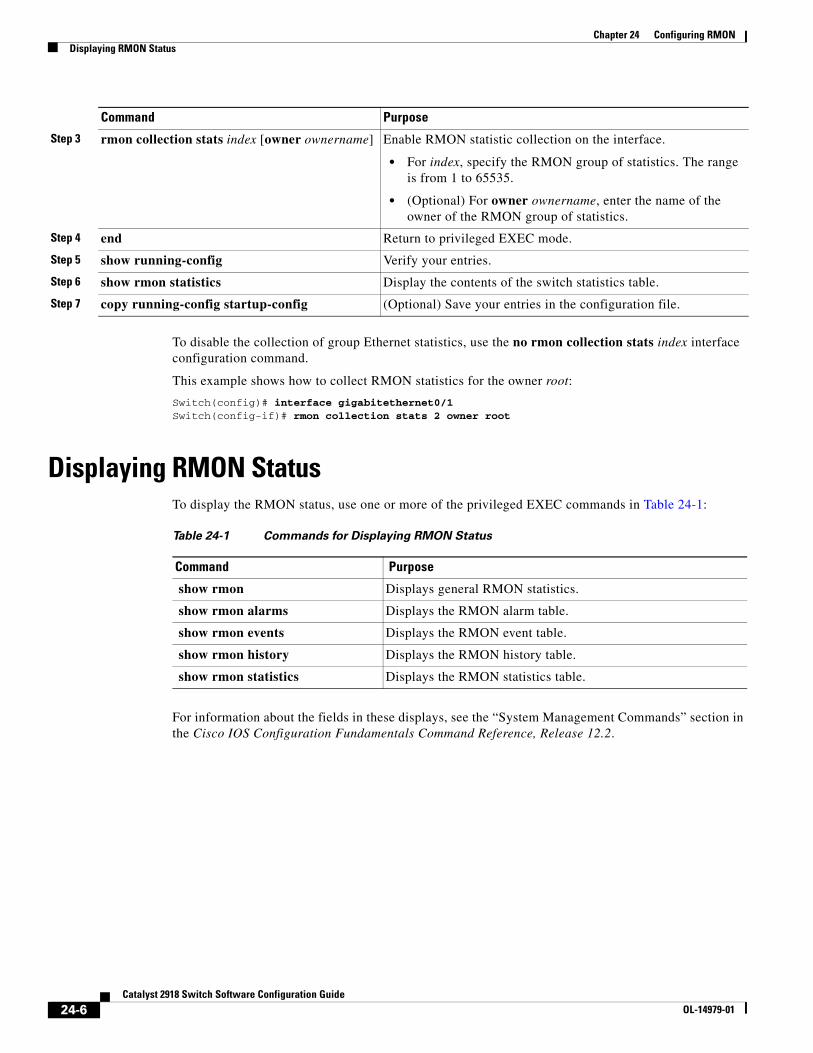
Chapter 24 Configuring RMONDisplaying RMON Status
To disable the collection of group Ethernet statistics, use the no rmon collection stats index interface configuration command.
This example shows how to collect RMON statistics for the owner root:
Switch(config)# interface gigabitethernet0/1Switch(config-if)# rmon collection stats 2 owner root
Displaying RMON StatusTo display the RMON status, use one or more of the privileged EXEC commands in Table 24-1:
Table 24-1 Commands for Displaying RMON Status
Command Purpose
show rmon Displays general RMON statistics.
show rmon alarms Displays the RMON alarm table.
show rmon events Displays the RMON event table.
show rmon history Displays the RMON history table.
show rmon statistics Displays the RMON statistics table.
For information about the fields in these displays, see the “System Management Commands” section in the Cisco IOS Configuration Fundamentals Command Reference, Release 12.2.
Step 3 rmon collection stats index [owner ownername] Enable RMON statistic collection on the interface.
• For index, specify the RMON group of statistics. The range is from 1 to 65535.
• (Optional) For owner ownername, enter the name of the owner of the RMON group of statistics.
Step 4 end Return to privileged EXEC mode.
Step 5 show running-config Verify your entries.
Step 6 show rmon statistics Display the contents of the switch statistics table.
Step 7 copy running-config startup-config (Optional) Save your entries in the configuration file.
Command Purpose
24-6Catalyst 2918 Switch Software Configuration Guide
OL-14979-01
OL-14979-01
C H A P T E R 25
Configuring System Message LoggingThis chapter describes how to configure system message logging on the Catalyst 2918 switch.
Note For complete syntax and usage information for the commands used in this chapter, see the Cisco IOS Configuration Fundamentals Command Reference, Release 12.2.
This chapter consists of these sections:
• Understanding System Message Logging, page 25-1
• Configuring System Message Logging, page 25-2
• Displaying the Logging Configuration, page 25-13
Understanding System Message LoggingBy default, a switch sends the output from system messages and debug privileged EXEC commands to a logging process. The logging process controls the distribution of logging messages to various destinations, such as the logging buffer, terminal lines, or a UNIX syslog server, depending on your configuration. The process also sends messages to the console.
Note The syslog format is compatible with 4.3 BSD UNIX.
When the logging process is disabled, messages are sent only to the console. The messages are sent as they are generated, so message and debug output are interspersed with prompts or output from other commands. Messages appear on the console after the process that generated them has finished.
You can set the severity level of the messages to control the type of messages displayed on the consoles and each of the destinations. You can time-stamp log messages or set the syslog source address to enhance real-time debugging and management. For information on possible messages, see the system message guide for this release.
You can access logged system messages by using the switch command-line interface (CLI) or by saving them to a properly configured syslog server. The switch software saves syslog messages in an internal buffer.
You can remotely monitor system messages by viewing the logs on a syslog server or by accessing the switch through Telnet or through the console port.
25-1Catalyst 2918 Switch Software Configuration Guide
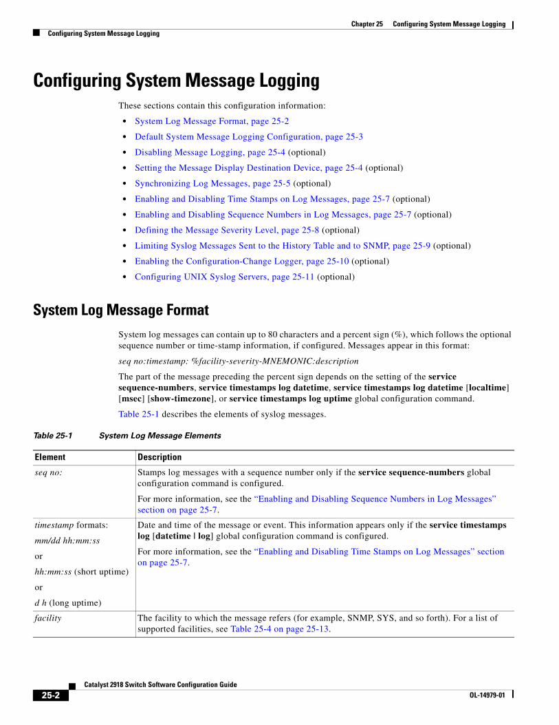
Chapter 25 Configuring System Message LoggingConfiguring System Message Logging
Configuring System Message LoggingThese sections contain this configuration information:
• System Log Message Format, page 25-2
• Default System Message Logging Configuration, page 25-3
• Disabling Message Logging, page 25-4 (optional)
• Setting the Message Display Destination Device, page 25-4 (optional)
• Synchronizing Log Messages, page 25-5 (optional)
• Enabling and Disabling Time Stamps on Log Messages, page 25-7 (optional)
• Enabling and Disabling Sequence Numbers in Log Messages, page 25-7 (optional)
• Defining the Message Severity Level, page 25-8 (optional)
• Limiting Syslog Messages Sent to the History Table and to SNMP, page 25-9 (optional)
• Enabling the Configuration-Change Logger, page 25-10 (optional)
• Configuring UNIX Syslog Servers, page 25-11 (optional)
System Log Message FormatSystem log messages can contain up to 80 characters and a percent sign (%), which follows the optional sequence number or time-stamp information, if configured. Messages appear in this format:
seq no:timestamp: %facility-severity-MNEMONIC:description
The part of the message preceding the percent sign depends on the setting of the service sequence-numbers, service timestamps log datetime, service timestamps log datetime [localtime] [msec] [show-timezone], or service timestamps log uptime global configuration command.
Table 25-1 describes the elements of syslog messages.
Table 25-1 System Log Message Elements
Element Description
seq no: Stamps log messages with a sequence number only if the service sequence-numbers global configuration command is configured.
For more information, see the “Enabling and Disabling Sequence Numbers in Log Messages” section on page 25-7.
timestamp formats:
mm/dd hh:mm:ss
or
hh:mm:ss (short uptime)
or
d h (long uptime)
Date and time of the message or event. This information appears only if the service timestamps log [datetime | log] global configuration command is configured.
For more information, see the “Enabling and Disabling Time Stamps on Log Messages” section on page 25-7.
facility The facility to which the message refers (for example, SNMP, SYS, and so forth). For a list of supported facilities, see Table 25-4 on page 25-13.
25-2Catalyst 2918 Switch Software Configuration Guide
OL-14979-01
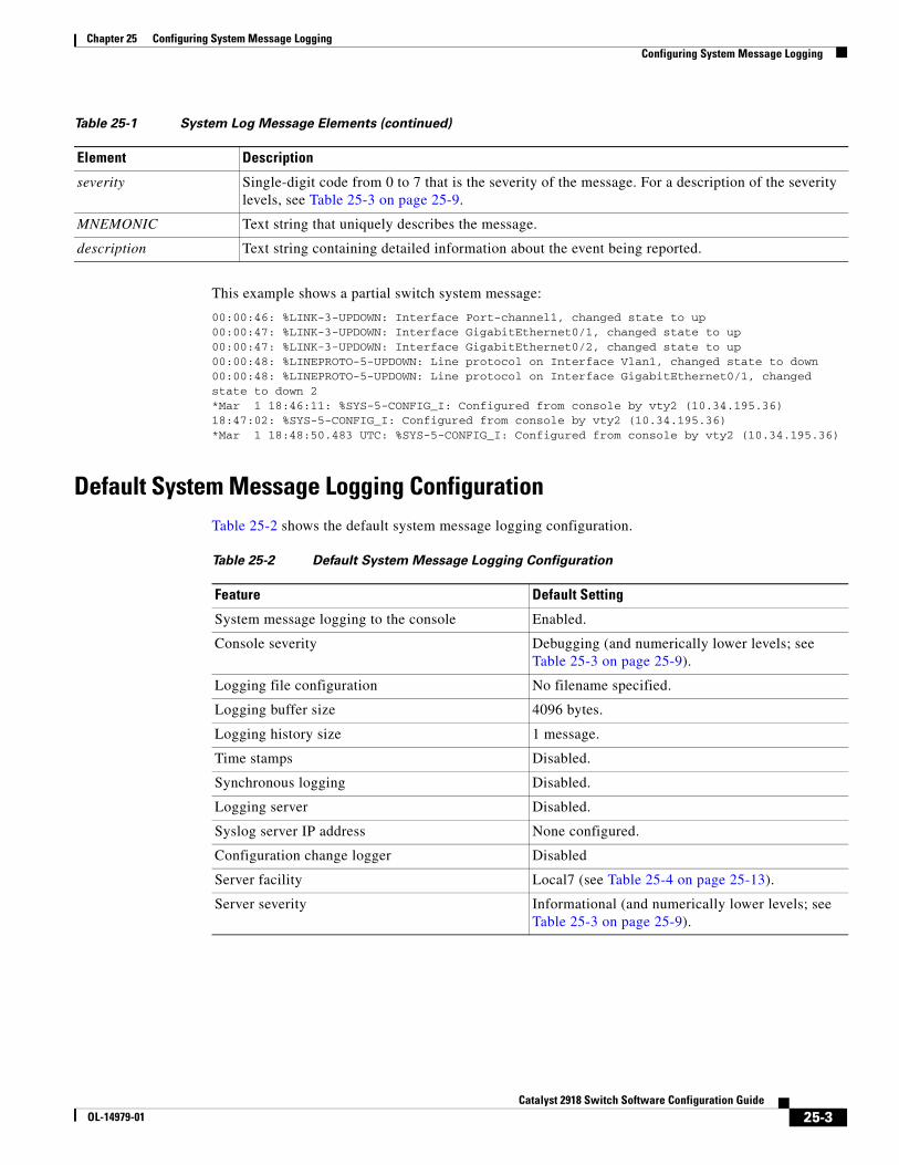
Chapter 25 Configuring System Message LoggingConfiguring System Message Logging
This example shows a partial switch system message:
00:00:46: %LINK-3-UPDOWN: Interface Port-channel1, changed state to up00:00:47: %LINK-3-UPDOWN: Interface GigabitEthernet0/1, changed state to up00:00:47: %LINK-3-UPDOWN: Interface GigabitEthernet0/2, changed state to up00:00:48: %LINEPROTO-5-UPDOWN: Line protocol on Interface Vlan1, changed state to down00:00:48: %LINEPROTO-5-UPDOWN: Line protocol on Interface GigabitEthernet0/1, changed state to down 2*Mar 1 18:46:11: %SYS-5-CONFIG_I: Configured from console by vty2 (10.34.195.36)18:47:02: %SYS-5-CONFIG_I: Configured from console by vty2 (10.34.195.36)*Mar 1 18:48:50.483 UTC: %SYS-5-CONFIG_I: Configured from console by vty2 (10.34.195.36)
Default System Message Logging ConfigurationTable 25-2 shows the default system message logging configuration.
Table 25-2 Default System Message Logging Configuration
Feature Default Setting
System message logging to the console Enabled.
Console severity Debugging (and numerically lower levels; see Table 25-3 on page 25-9).
Logging file configuration No filename specified.
Logging buffer size 4096 bytes.
Logging history size 1 message.
Time stamps Disabled.
Synchronous logging Disabled.
Logging server Disabled.
Syslog server IP address None configured.
Configuration change logger Disabled
Server facility Local7 (see Table 25-4 on page 25-13).
Server severity Informational (and numerically lower levels; see Table 25-3 on page 25-9).
severity Single-digit code from 0 to 7 that is the severity of the message. For a description of the severity levels, see Table 25-3 on page 25-9.
MNEMONIC Text string that uniquely describes the message.
description Text string containing detailed information about the event being reported.
Table 25-1 System Log Message Elements (continued)
Element Description
25-3Catalyst 2918 Switch Software Configuration Guide
OL-14979-01
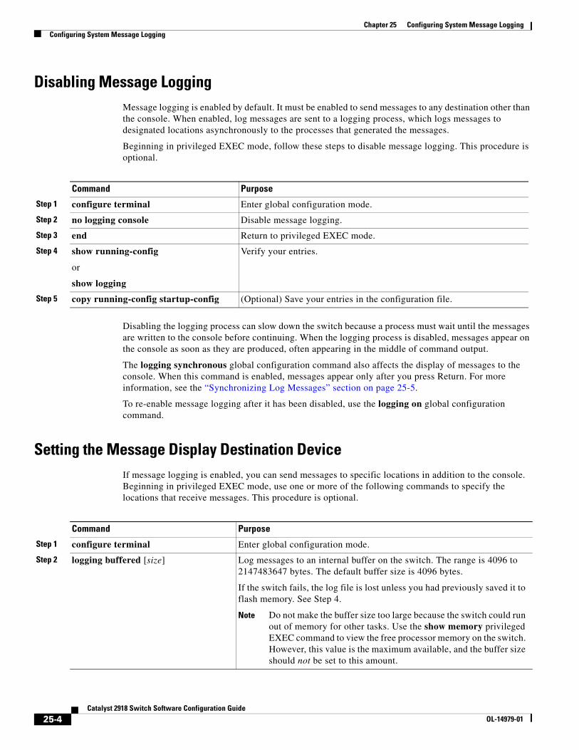
Chapter 25 Configuring System Message LoggingConfiguring System Message Logging
Disabling Message LoggingMessage logging is enabled by default. It must be enabled to send messages to any destination other than the console. When enabled, log messages are sent to a logging process, which logs messages to designated locations asynchronously to the processes that generated the messages.
Beginning in privileged EXEC mode, follow these steps to disable message logging. This procedure is optional.
Command Purpose
Step 1 configure terminal Enter global configuration mode.
Step 2 no logging console Disable message logging.
Step 3 end Return to privileged EXEC mode.
Step 4 show running-config
or
show logging
Verify your entries.
Step 5 copy running-config startup-config (Optional) Save your entries in the configuration file.
Disabling the logging process can slow down the switch because a process must wait until the messages are written to the console before continuing. When the logging process is disabled, messages appear on the console as soon as they are produced, often appearing in the middle of command output.
The logging synchronous global configuration command also affects the display of messages to the console. When this command is enabled, messages appear only after you press Return. For more information, see the “Synchronizing Log Messages” section on page 25-5.
To re-enable message logging after it has been disabled, use the logging on global configuration command.
Setting the Message Display Destination DeviceIf message logging is enabled, you can send messages to specific locations in addition to the console. Beginning in privileged EXEC mode, use one or more of the following commands to specify the locations that receive messages. This procedure is optional.
Command Purpose
Step 1 configure terminal Enter global configuration mode.
Step 2 logging buffered [size] Log messages to an internal buffer on the switch. The range is 4096 to 2147483647 bytes. The default buffer size is 4096 bytes.
If the switch fails, the log file is lost unless you had previously saved it to flash memory. See Step 4.
Note Do not make the buffer size too large because the switch could run out of memory for other tasks. Use the show memory privileged EXEC command to view the free processor memory on the switch. However, this value is the maximum available, and the buffer size should not be set to this amount.
25-4Catalyst 2918 Switch Software Configuration Guide
OL-14979-01
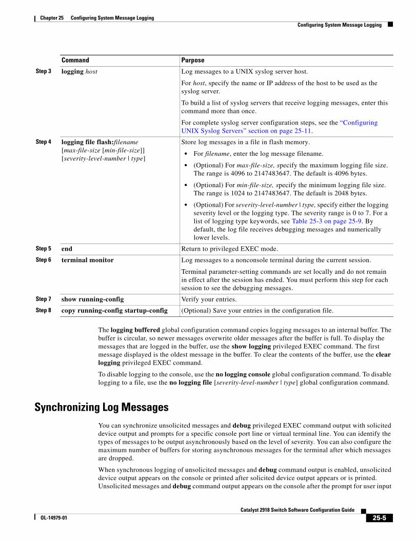
Chapter 25 Configuring System Message LoggingConfiguring System Message Logging
The logging buffered global configuration command copies logging messages to an internal buffer. The buffer is circular, so newer messages overwrite older messages after the buffer is full. To display the messages that are logged in the buffer, use the show logging privileged EXEC command. The first message displayed is the oldest message in the buffer. To clear the contents of the buffer, use the clear logging privileged EXEC command.
To disable logging to the console, use the no logging console global configuration command. To disable logging to a file, use the no logging file [severity-level-number | type] global configuration command.
Synchronizing Log MessagesYou can synchronize unsolicited messages and debug privileged EXEC command output with solicited device output and prompts for a specific console port line or virtual terminal line. You can identify the types of messages to be output asynchronously based on the level of severity. You can also configure the maximum number of buffers for storing asynchronous messages for the terminal after which messages are dropped.
When synchronous logging of unsolicited messages and debug command output is enabled, unsolicited device output appears on the console or printed after solicited device output appears or is printed. Unsolicited messages and debug command output appears on the console after the prompt for user input
Step 3 logging host Log messages to a UNIX syslog server host.
For host, specify the name or IP address of the host to be used as the syslog server.
To build a list of syslog servers that receive logging messages, enter this command more than once.
For complete syslog server configuration steps, see the “Configuring UNIX Syslog Servers” section on page 25-11.
Step 4 logging file flash:filename [max-file-size [min-file-size]] [severity-level-number | type]
Store log messages in a file in flash memory.
• For filename, enter the log message filename.
• (Optional) For max-file-size, specify the maximum logging file size. The range is 4096 to 2147483647. The default is 4096 bytes.
• (Optional) For min-file-size, specify the minimum logging file size. The range is 1024 to 2147483647. The default is 2048 bytes.
• (Optional) For severity-level-number | type, specify either the logging severity level or the logging type. The severity range is 0 to 7. For a list of logging type keywords, see Table 25-3 on page 25-9. By default, the log file receives debugging messages and numerically lower levels.
Step 5 end Return to privileged EXEC mode.
Step 6 terminal monitor Log messages to a nonconsole terminal during the current session.
Terminal parameter-setting commands are set locally and do not remain in effect after the session has ended. You must perform this step for each session to see the debugging messages.
Step 7 show running-config Verify your entries.
Step 8 copy running-config startup-config (Optional) Save your entries in the configuration file.
Command Purpose
25-5Catalyst 2918 Switch Software Configuration Guide
OL-14979-01
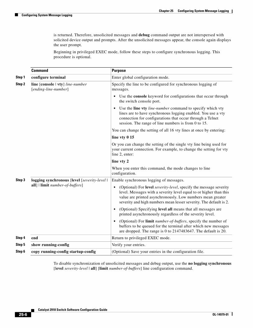
Chapter 25 Configuring System Message LoggingConfiguring System Message Logging
is returned. Therefore, unsolicited messages and debug command output are not interspersed with solicited device output and prompts. After the unsolicited messages appear, the console again displays the user prompt.
Beginning in privileged EXEC mode, follow these steps to configure synchronous logging. This procedure is optional.
Command Purpose
Step 1 configure terminal Enter global configuration mode.
Step 2 line [console | vty] line-number [ending-line-number]
Specify the line to be configured for synchronous logging of messages.
• Use the console keyword for configurations that occur through the switch console port.
• Use the line vty line-number command to specify which vty lines are to have synchronous logging enabled. You use a vty connection for configurations that occur through a Telnet session. The range of line numbers is from 0 to 15.
You can change the setting of all 16 vty lines at once by entering:
line vty 0 15
Or you can change the setting of the single vty line being used for your current connection. For example, to change the setting for vty line 2, enter:
line vty 2
When you enter this command, the mode changes to line configuration.
Step 3 logging synchronous [level [severity-level | all] | limit number-of-buffers]
Enable synchronous logging of messages.
• (Optional) For level severity-level, specify the message severity level. Messages with a severity level equal to or higher than this value are printed asynchronously. Low numbers mean greater severity and high numbers mean lesser severity. The default is 2.
• (Optional) Specifying level all means that all messages are printed asynchronously regardless of the severity level.
• (Optional) For limit number-of-buffers, specify the number of buffers to be queued for the terminal after which new messages are dropped. The range is 0 to 2147483647. The default is 20.
Step 4 end Return to privileged EXEC mode.
Step 5 show running-config Verify your entries.
Step 6 copy running-config startup-config (Optional) Save your entries in the configuration file.
To disable synchronization of unsolicited messages and debug output, use the no logging synchronous [level severity-level | all] [limit number-of-buffers] line configuration command.
25-6Catalyst 2918 Switch Software Configuration Guide
OL-14979-01
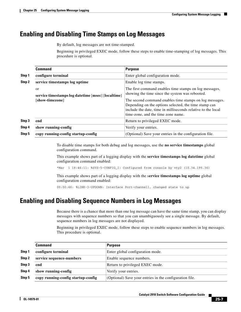
Chapter 25 Configuring System Message LoggingConfiguring System Message Logging
Enabling and Disabling Time Stamps on Log MessagesBy default, log messages are not time-stamped.
Beginning in privileged EXEC mode, follow these steps to enable time-stamping of log messages. This procedure is optional.
Command Purpose
Step 1 configure terminal Enter global configuration mode.
Step 2 service timestamps log uptime
or
service timestamps log datetime [msec] [localtime] [show-timezone]
Enable log time stamps.
The first command enables time stamps on log messages, showing the time since the system was rebooted.
The second command enables time stamps on log messages. Depending on the options selected, the time stamp can include the date, time in milliseconds relative to the local time-zone, and the time zone name.
Step 3 end Return to privileged EXEC mode.
Step 4 show running-config Verify your entries.
Step 5 copy running-config startup-config (Optional) Save your entries in the configuration file.
To disable time stamps for both debug and log messages, use the no service timestamps global configuration command.
This example shows part of a logging display with the service timestamps log datetime global configuration command enabled:
*Mar 1 18:46:11: %SYS-5-CONFIG_I: Configured from console by vty2 (10.34.195.36)
This example shows part of a logging display with the service timestamps log uptime global configuration command enabled:
00:00:46: %LINK-3-UPDOWN: Interface Port-channel1, changed state to up
Enabling and Disabling Sequence Numbers in Log MessagesBecause there is a chance that more than one log message can have the same time stamp, you can display messages with sequence numbers so that you can unambiguously see a single message. By default, sequence numbers in log messages are not displayed.
Beginning in privileged EXEC mode, follow these steps to enable sequence numbers in log messages. This procedure is optional.
Command Purpose
Step 1 configure terminal Enter global configuration mode.
Step 2 service sequence-numbers Enable sequence numbers.
Step 3 end Return to privileged EXEC mode.
Step 4 show running-config Verify your entries.
Step 5 copy running-config startup-config (Optional) Save your entries in the configuration file.
25-7Catalyst 2918 Switch Software Configuration Guide
OL-14979-01
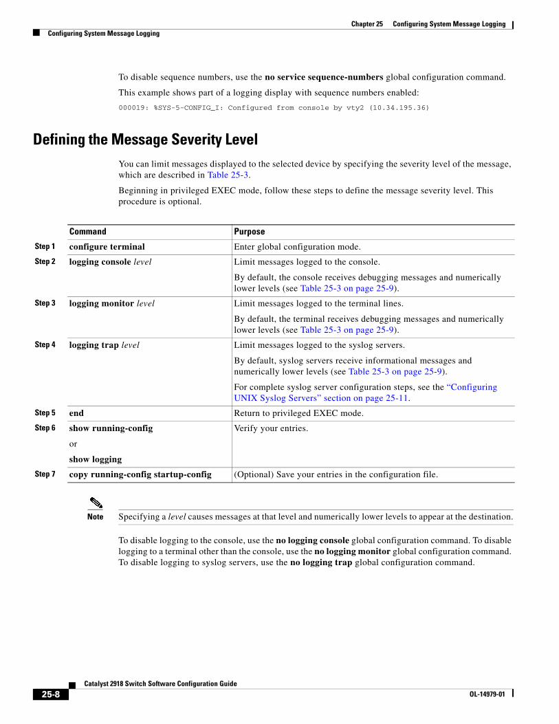
Chapter 25 Configuring System Message LoggingConfiguring System Message Logging
To disable sequence numbers, use the no service sequence-numbers global configuration command.
This example shows part of a logging display with sequence numbers enabled:
000019: %SYS-5-CONFIG_I: Configured from console by vty2 (10.34.195.36)
Defining the Message Severity LevelYou can limit messages displayed to the selected device by specifying the severity level of the message, which are described in Table 25-3.
Beginning in privileged EXEC mode, follow these steps to define the message severity level. This procedure is optional.
Command Purpose
Step 1 configure terminal Enter global configuration mode.
Step 2 logging console level Limit messages logged to the console.
By default, the console receives debugging messages and numerically lower levels (see Table 25-3 on page 25-9).
Step 3 logging monitor level Limit messages logged to the terminal lines.
By default, the terminal receives debugging messages and numerically lower levels (see Table 25-3 on page 25-9).
Step 4 logging trap level Limit messages logged to the syslog servers.
By default, syslog servers receive informational messages and numerically lower levels (see Table 25-3 on page 25-9).
For complete syslog server configuration steps, see the “Configuring UNIX Syslog Servers” section on page 25-11.
Step 5 end Return to privileged EXEC mode.
Step 6 show running-config
or
show logging
Verify your entries.
Step 7 copy running-config startup-config (Optional) Save your entries in the configuration file.
Note Specifying a level causes messages at that level and numerically lower levels to appear at the destination.
To disable logging to the console, use the no logging console global configuration command. To disable logging to a terminal other than the console, use the no logging monitor global configuration command. To disable logging to syslog servers, use the no logging trap global configuration command.
25-8Catalyst 2918 Switch Software Configuration Guide
OL-14979-01
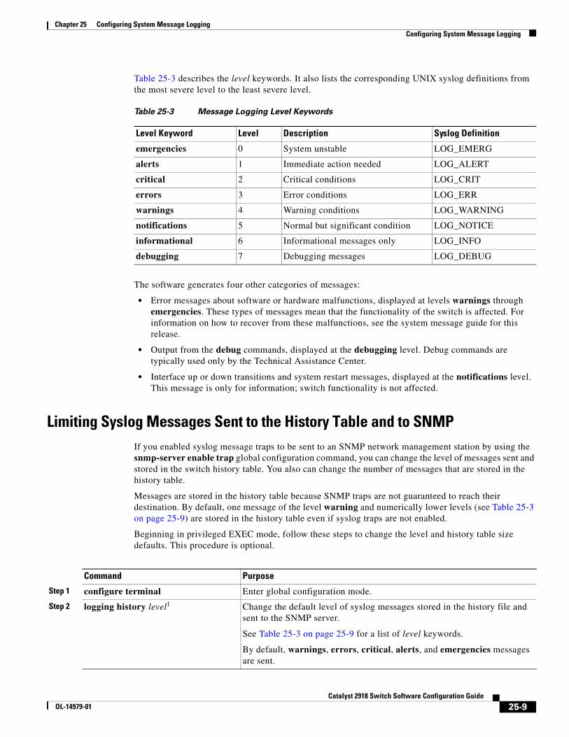
Chapter 25 Configuring System Message LoggingConfiguring System Message Logging
Table 25-3 describes the level keywords. It also lists the corresponding UNIX syslog definitions from the most severe level to the least severe level.
Table 25-3 Message Logging Level Keywords
Level Keyword Level Description Syslog Definition
emergencies 0 System unstable LOG_EMERG
alerts 1 Immediate action needed LOG_ALERT
critical 2 Critical conditions LOG_CRIT
errors 3 Error conditions LOG_ERR
warnings 4 Warning conditions LOG_WARNING
notifications 5 Normal but significant condition LOG_NOTICE
informational 6 Informational messages only LOG_INFO
debugging 7 Debugging messages LOG_DEBUG
The software generates four other categories of messages:
• Error messages about software or hardware malfunctions, displayed at levels warnings through emergencies. These types of messages mean that the functionality of the switch is affected. For information on how to recover from these malfunctions, see the system message guide for this release.
• Output from the debug commands, displayed at the debugging level. Debug commands are typically used only by the Technical Assistance Center.
• Interface up or down transitions and system restart messages, displayed at the notifications level. This message is only for information; switch functionality is not affected.
Limiting Syslog Messages Sent to the History Table and to SNMPIf you enabled syslog message traps to be sent to an SNMP network management station by using the snmp-server enable trap global configuration command, you can change the level of messages sent and stored in the switch history table. You also can change the number of messages that are stored in the history table.
Messages are stored in the history table because SNMP traps are not guaranteed to reach their destination. By default, one message of the level warning and numerically lower levels (see Table 25-3 on page 25-9) are stored in the history table even if syslog traps are not enabled.
Beginning in privileged EXEC mode, follow these steps to change the level and history table size defaults. This procedure is optional.
Command Purpose
Step 1 configure terminal Enter global configuration mode.
Step 2 logging history level1 Change the default level of syslog messages stored in the history file and sent to the SNMP server.
See Table 25-3 on page 25-9 for a list of level keywords.
By default, warnings, errors, critical, alerts, and emergencies messages are sent.
25-9Catalyst 2918 Switch Software Configuration Guide
OL-14979-01
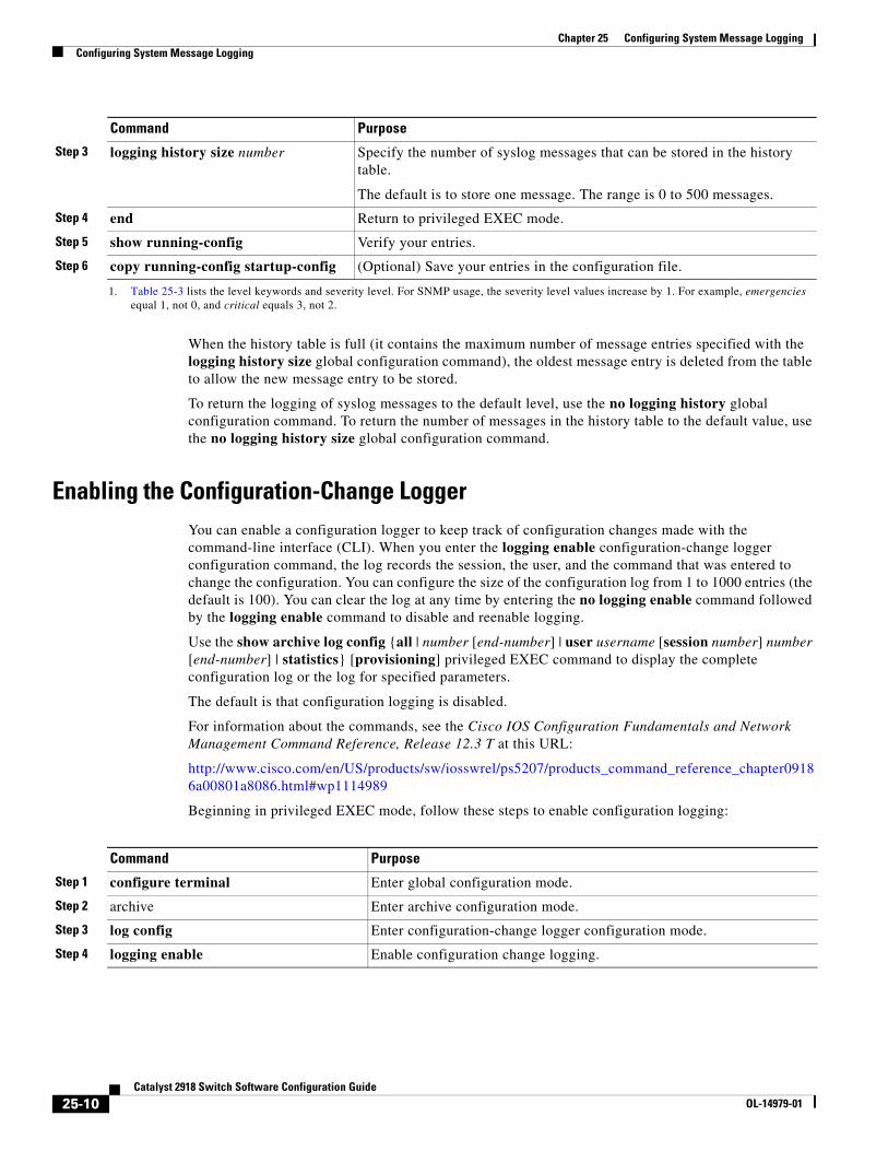
Chapter 25 Configuring System Message LoggingConfiguring System Message Logging
When the history table is full (it contains the maximum number of message entries specified with the logging history size global configuration command), the oldest message entry is deleted from the table to allow the new message entry to be stored.
To return the logging of syslog messages to the default level, use the no logging history global configuration command. To return the number of messages in the history table to the default value, use the no logging history size global configuration command.
Enabling the Configuration-Change LoggerYou can enable a configuration logger to keep track of configuration changes made with the command-line interface (CLI). When you enter the logging enable configuration-change logger configuration command, the log records the session, the user, and the command that was entered to change the configuration. You can configure the size of the configuration log from 1 to 1000 entries (the default is 100). You can clear the log at any time by entering the no logging enable command followed by the logging enable command to disable and reenable logging.
Use the show archive log config {all | number [end-number] | user username [session number] number [end-number] | statistics} [provisioning] privileged EXEC command to display the complete configuration log or the log for specified parameters.
The default is that configuration logging is disabled.
For information about the commands, see the Cisco IOS Configuration Fundamentals and Network Management Command Reference, Release 12.3 T at this URL:
http://www.cisco.com/en/US/products/sw/iosswrel/ps5207/products_command_reference_chapter09186a00801a8086.html#wp1114989
Beginning in privileged EXEC mode, follow these steps to enable configuration logging:
Step 3 logging history size number Specify the number of syslog messages that can be stored in the history table.
The default is to store one message. The range is 0 to 500 messages.
Step 4 end Return to privileged EXEC mode.
Step 5 show running-config Verify your entries.
Step 6 copy running-config startup-config (Optional) Save your entries in the configuration file.
1. Table 25-3 lists the level keywords and severity level. For SNMP usage, the severity level values increase by 1. For example, emergencies equal 1, not 0, and critical equals 3, not 2.
Command Purpose
Command Purpose
Step 1 configure terminal Enter global configuration mode.
Step 2 archive Enter archive configuration mode.
Step 3 log config Enter configuration-change logger configuration mode.
Step 4 logging enable Enable configuration change logging.
25-10Catalyst 2918 Switch Software Configuration Guide
OL-14979-01
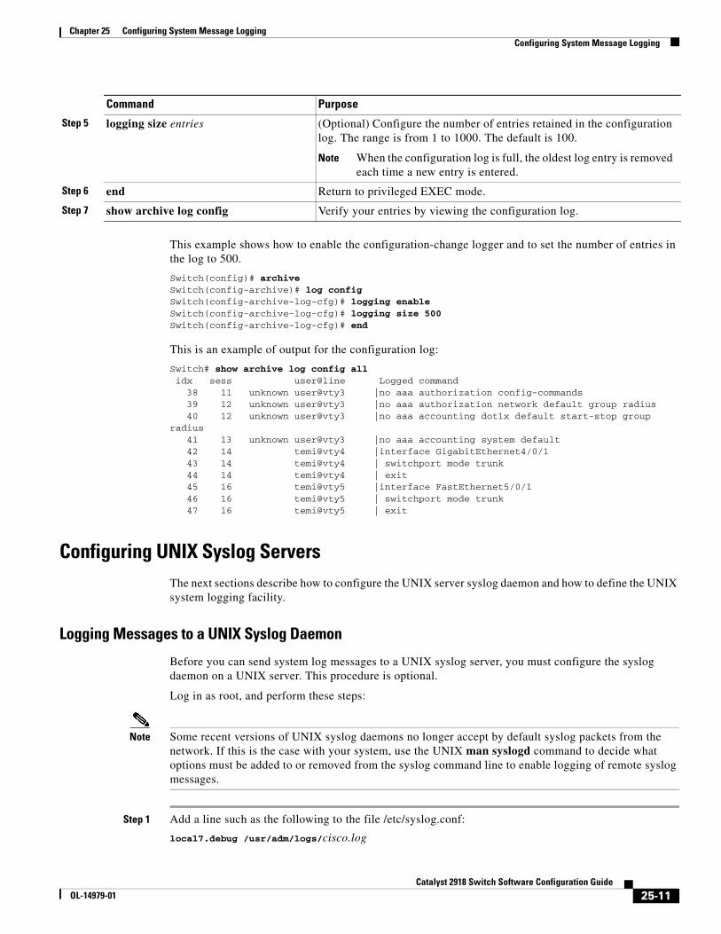
Chapter 25 Configuring System Message LoggingConfiguring System Message Logging
This example shows how to enable the configuration-change logger and to set the number of entries in the log to 500.
Switch(config)# archive Switch(config-archive)# log configSwitch(config-archive-log-cfg)# logging enableSwitch(config-archive-log-cfg)# logging size 500Switch(config-archive-log-cfg)# end
This is an example of output for the configuration log:
Switch# show archive log config all idx sess user@line Logged command 38 11 unknown user@vty3 |no aaa authorization config-commands 39 12 unknown user@vty3 |no aaa authorization network default group radius 40 12 unknown user@vty3 |no aaa accounting dot1x default start-stop group radius 41 13 unknown user@vty3 |no aaa accounting system default 42 14 temi@vty4 |interface GigabitEthernet4/0/1 43 14 temi@vty4 | switchport mode trunk 44 14 temi@vty4 | exit 45 16 temi@vty5 |interface FastEthernet5/0/1 46 16 temi@vty5 | switchport mode trunk 47 16 temi@vty5 | exit
Configuring UNIX Syslog ServersThe next sections describe how to configure the UNIX server syslog daemon and how to define the UNIX system logging facility.
Logging Messages to a UNIX Syslog Daemon
Before you can send system log messages to a UNIX syslog server, you must configure the syslog daemon on a UNIX server. This procedure is optional.
Log in as root, and perform these steps:
Note Some recent versions of UNIX syslog daemons no longer accept by default syslog packets from the network. If this is the case with your system, use the UNIX man syslogd command to decide what options must be added to or removed from the syslog command line to enable logging of remote syslog messages.
Step 1 Add a line such as the following to the file /etc/syslog.conf:
local7.debug /usr/adm/logs/cisco.log
Step 5 logging size entries (Optional) Configure the number of entries retained in the configuration log. The range is from 1 to 1000. The default is 100.
Note When the configuration log is full, the oldest log entry is removed each time a new entry is entered.
Step 6 end Return to privileged EXEC mode.
Step 7 show archive log config Verify your entries by viewing the configuration log.
Command Purpose
25-11Catalyst 2918 Switch Software Configuration Guide
OL-14979-01
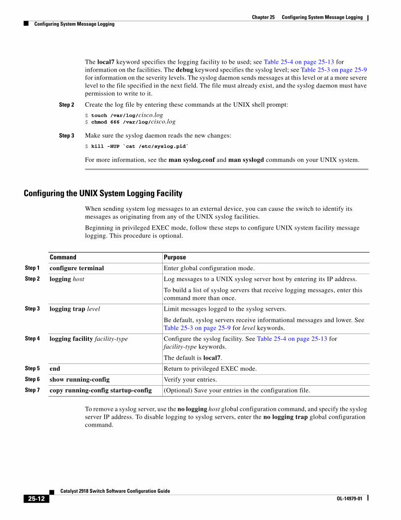
Chapter 25 Configuring System Message LoggingConfiguring System Message Logging
The local7 keyword specifies the logging facility to be used; see Table 25-4 on page 25-13 for information on the facilities. The debug keyword specifies the syslog level; see Table 25-3 on page 25-9 for information on the severity levels. The syslog daemon sends messages at this level or at a more severe level to the file specified in the next field. The file must already exist, and the syslog daemon must have permission to write to it.
Step 2 Create the log file by entering these commands at the UNIX shell prompt:
$ touch /var/log/cisco.log$ chmod 666 /var/log/cisco.log
Step 3 Make sure the syslog daemon reads the new changes:
$ kill -HUP `cat /etc/syslog.pid`
For more information, see the man syslog.conf and man syslogd commands on your UNIX system.
Configuring the UNIX System Logging Facility
When sending system log messages to an external device, you can cause the switch to identify its messages as originating from any of the UNIX syslog facilities.
Beginning in privileged EXEC mode, follow these steps to configure UNIX system facility message logging. This procedure is optional.
Command Purpose
Step 1 configure terminal Enter global configuration mode.
Step 2 logging host Log messages to a UNIX syslog server host by entering its IP address.
To build a list of syslog servers that receive logging messages, enter this command more than once.
Step 3 logging trap level Limit messages logged to the syslog servers.
Be default, syslog servers receive informational messages and lower. See Table 25-3 on page 25-9 for level keywords.
Step 4 logging facility facility-type Configure the syslog facility. See Table 25-4 on page 25-13 for facility-type keywords.
The default is local7.
Step 5 end Return to privileged EXEC mode.
Step 6 show running-config Verify your entries.
Step 7 copy running-config startup-config (Optional) Save your entries in the configuration file.
To remove a syslog server, use the no logging host global configuration command, and specify the syslog server IP address. To disable logging to syslog servers, enter the no logging trap global configuration command.
25-12Catalyst 2918 Switch Software Configuration Guide
OL-14979-01
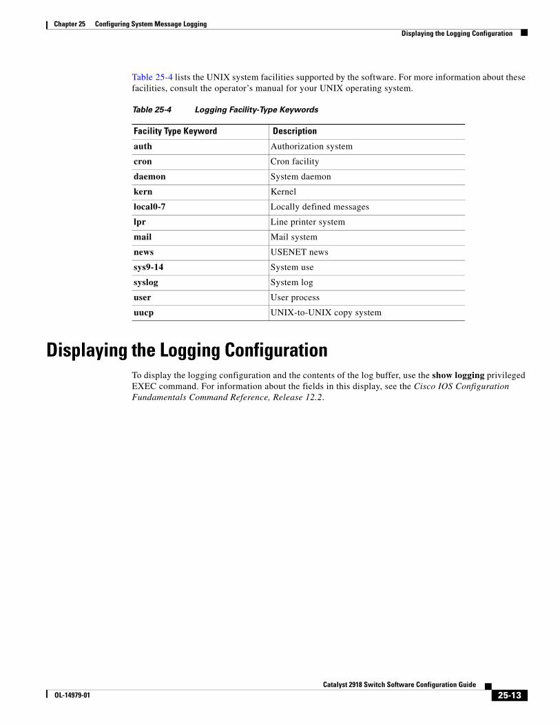
Chapter 25 Configuring System Message LoggingDisplaying the Logging Configuration
Table 25-4 lists the UNIX system facilities supported by the software. For more information about these facilities, consult the operator’s manual for your UNIX operating system.
Table 25-4 Logging Facility-Type Keywords
Facility Type Keyword Description
auth Authorization system
cron Cron facility
daemon System daemon
kern Kernel
local0-7 Locally defined messages
lpr Line printer system
mail Mail system
news USENET news
sys9-14 System use
syslog System log
user User process
uucp UNIX-to-UNIX copy system
Displaying the Logging ConfigurationTo display the logging configuration and the contents of the log buffer, use the show logging privileged EXEC command. For information about the fields in this display, see the Cisco IOS Configuration Fundamentals Command Reference, Release 12.2.
25-13Catalyst 2918 Switch Software Configuration Guide
OL-14979-01

Chapter 25 Configuring System Message LoggingDisplaying the Logging Configuration
25-14Catalyst 2918 Switch Software Configuration Guide
OL-14979-01
OL-14979-01
C H A P T E R 26
Configuring SNMPThis chapter describes how to configure the Simple Network Management Protocol (SNMP) on the Catalyst 2918 switch.
Note For complete syntax and usage information for the commands used in this chapter, see the command reference for this release and the Cisco IOS Configuration Fundamentals Command Reference, Release 12.2.
This chapter consists of these sections:
• Understanding SNMP, page 26-1
• Configuring SNMP, page 26-6
• Displaying SNMP Status, page 26-16
Understanding SNMPSNMP is an application-layer protocol that provides a message format for communication between managers and agents. The SNMP system consists of an SNMP manager, an SNMP agent, and a MIB. The SNMP manager can be part of a network management system (NMS) such as CiscoWorks. The agent and MIB reside on the switch. To configure SNMP on the switch, you define the relationship between the manager and the agent.
The SNMP agent contains MIB variables whose values the SNMP manager can request or change. A manager can get a value from an agent or store a value into the agent. The agent gathers data from the MIB, the repository for information about device parameters and network data. The agent can also respond to a manager’s requests to get or set data.
An agent can send unsolicited traps to the manager. Traps are messages alerting the SNMP manager to a condition on the network. Traps can mean improper user authentication, restarts, link status (up or down), MAC address tracking, closing of a TCP connection, loss of connection to a neighbor, or other significant events.
These sections contain this conceptual information:
• SNMP Versions, page 26-2
• SNMP Manager Functions, page 26-3
• SNMP Agent Functions, page 26-4
• SNMP Community Strings, page 26-4
26-1Catalyst 2918 Switch Software Configuration Guide
Chapter 26 Configuring SNMPUnderstanding SNMP
• Using SNMP to Access MIB Variables, page 26-4
• SNMP Notifications, page 26-5
• SNMP ifIndex MIB Object Values, page 26-5
SNMP VersionsThis software release supports these SNMP versions:
• SNMPv1—The Simple Network Management Protocol, a Full Internet Standard, defined in RFC 1157.
• SNMPv2C replaces the Party-based Administrative and Security Framework of SNMPv2Classic with the community-string-based Administrative Framework of SNMPv2C while retaining the bulk retrieval and improved error handling of SNMPv2Classic. It has these features:
– SNMPv2—Version 2 of the Simple Network Management Protocol, a Draft Internet Standard, defined in RFCs 1902 through 1907.
– SNMPv2C—The community-string-based Administrative Framework for SNMPv2, an Experimental Internet Protocol defined in RFC 1901.
• SNMPv3—Version 3 of the SNMP is an interoperable standards-based protocol defined in RFCs 2273 to 2275. SNMPv3 provides secure access to devices by authenticating and encrypting packets over the network and includes these security features:
– Message integrity—ensuring that a packet was not tampered with in transit
– Authentication—determining that the message is from a valid source
– Encryption—mixing the contents of a package to prevent it from being read by an unauthorized source.
Note To select encryption, enter the priv keyword. This keyword is available only when the cryptographic (encrypted) software image is installed.
Both SNMPv1 and SNMPv2C use a community-based form of security. The community of managers able to access the agent’s MIB is defined by an IP address access control list and password.
SNMPv2C includes a bulk retrieval mechanism and more detailed error message reporting to management stations. The bulk retrieval mechanism retrieves tables and large quantities of information, minimizing the number of round-trips required. The SNMPv2C improved error-handling includes expanded error codes that distinguish different kinds of error conditions; these conditions are reported through a single error code in SNMPv1. Error return codes in SNMPv2C report the error type.
SNMPv3 provides for both security models and security levels. A security model is an authentication strategy set up for a user and the group within which the user resides. A security level is the permitted level of security within a security model. A combination of the security level and the security model determine which security mechanism is used when handling an SNMP packet. Available security models are SNMPv1, SNMPv2C, and SNMPv3.
26-2Catalyst 2918 Switch Software Configuration Guide
OL-14979-01
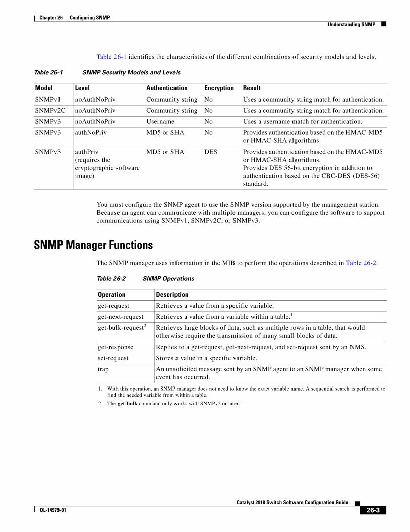
Chapter 26 Configuring SNMPUnderstanding SNMP
Table 26-1 identifies the characteristics of the different combinations of security models and levels.
Table 26-1 SNMP Security Models and Levels
Model Level Authentication Encryption Result
SNMPv1 noAuthNoPriv Community string No Uses a community string match for authentication.
SNMPv2C noAuthNoPriv Community string No Uses a community string match for authentication.
SNMPv3 noAuthNoPriv Username No Uses a username match for authentication.
SNMPv3 authNoPriv MD5 or SHA No Provides authentication based on the HMAC-MD5 or HMAC-SHA algorithms.
SNMPv3 authPriv (requires the cryptographic software image)
MD5 or SHA DES Provides authentication based on the HMAC-MD5 or HMAC-SHA algorithms. Provides DES 56-bit encryption in addition to authentication based on the CBC-DES (DES-56) standard.
You must configure the SNMP agent to use the SNMP version supported by the management station. Because an agent can communicate with multiple managers, you can configure the software to support communications using SNMPv1, SNMPv2C, or SNMPv3.
SNMP Manager FunctionsThe SNMP manager uses information in the MIB to perform the operations described in Table 26-2.
Table 26-2 SNMP Operations
Operation Description
get-request Retrieves a value from a specific variable.
get-next-request Retrieves a value from a variable within a table.
1. With this operation, an SNMP manager does not need to know the exact variable name. A sequential search is performed to find the needed variable from within a table.
1
get-bulk-request
2. The get-bulk command only works with SNMPv2 or later.
2 Retrieves large blocks of data, such as multiple rows in a table, that would otherwise require the transmission of many small blocks of data.
get-response Replies to a get-request, get-next-request, and set-request sent by an NMS.
set-request Stores a value in a specific variable.
trap An unsolicited message sent by an SNMP agent to an SNMP manager when some event has occurred.
26-3Catalyst 2918 Switch Software Configuration Guide
OL-14979-01
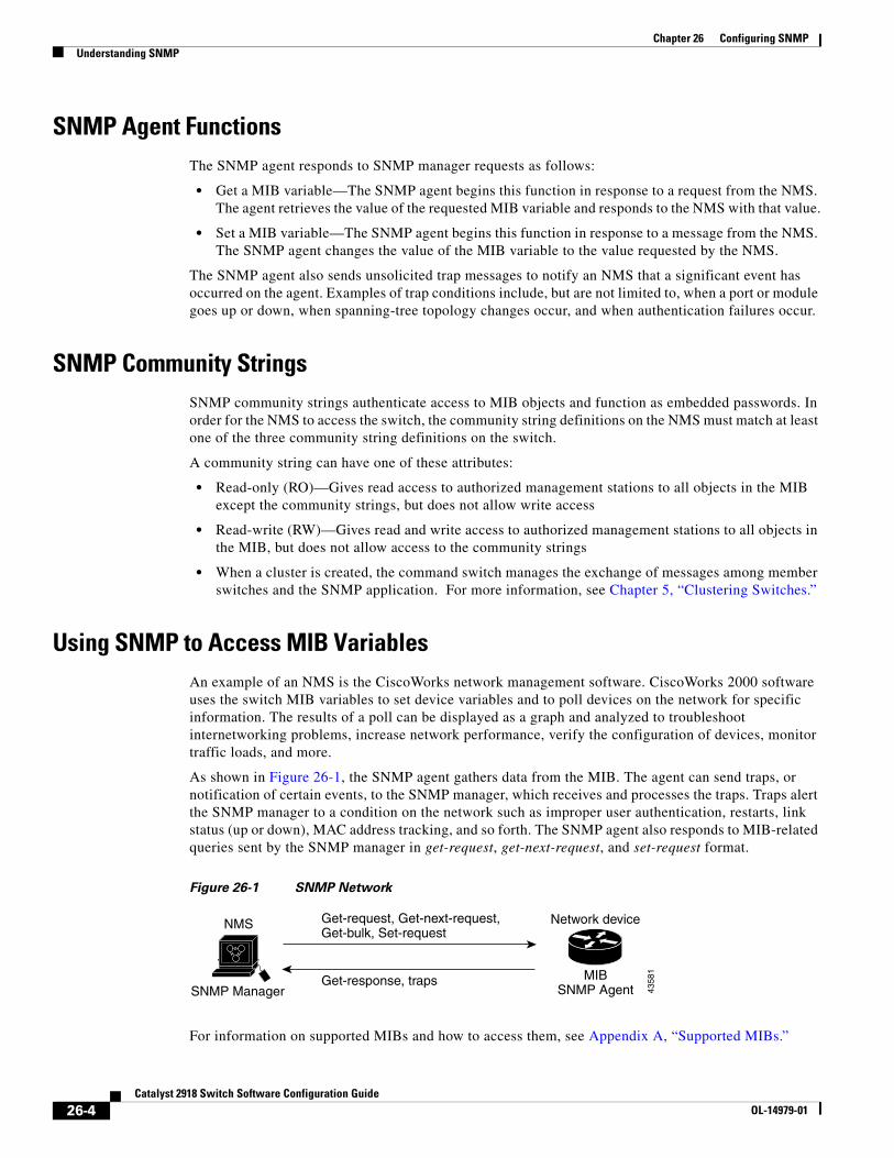
Chapter 26 Configuring SNMPUnderstanding SNMP
SNMP Agent FunctionsThe SNMP agent responds to SNMP manager requests as follows:
• Get a MIB variable—The SNMP agent begins this function in response to a request from the NMS. The agent retrieves the value of the requested MIB variable and responds to the NMS with that value.
• Set a MIB variable—The SNMP agent begins this function in response to a message from the NMS. The SNMP agent changes the value of the MIB variable to the value requested by the NMS.
The SNMP agent also sends unsolicited trap messages to notify an NMS that a significant event has occurred on the agent. Examples of trap conditions include, but are not limited to, when a port or module goes up or down, when spanning-tree topology changes occur, and when authentication failures occur.
SNMP Community StringsSNMP community strings authenticate access to MIB objects and function as embedded passwords. In order for the NMS to access the switch, the community string definitions on the NMS must match at least one of the three community string definitions on the switch.
A community string can have one of these attributes:
• Read-only (RO)—Gives read access to authorized management stations to all objects in the MIB except the community strings, but does not allow write access
• Read-write (RW)—Gives read and write access to authorized management stations to all objects in the MIB, but does not allow access to the community strings
• When a cluster is created, the command switch manages the exchange of messages among member switches and the SNMP application. For more information, see Chapter 5, “Clustering Switches.”
Using SNMP to Access MIB Variables An example of an NMS is the CiscoWorks network management software. CiscoWorks 2000 software uses the switch MIB variables to set device variables and to poll devices on the network for specific information. The results of a poll can be displayed as a graph and analyzed to troubleshoot internetworking problems, increase network performance, verify the configuration of devices, monitor traffic loads, and more.
As shown in Figure 26-1, the SNMP agent gathers data from the MIB. The agent can send traps, or notification of certain events, to the SNMP manager, which receives and processes the traps. Traps alert the SNMP manager to a condition on the network such as improper user authentication, restarts, link status (up or down), MAC address tracking, and so forth. The SNMP agent also responds to MIB-related queries sent by the SNMP manager in get-request, get-next-request, and set-request format.
Figure 26-1 SNMP Network
Get-request, Get-next-request,Get-bulk, Set-request
Network device
Get-response, traps
4358
1
SNMP Manager
NMS
MIBSNMP Agent
For information on supported MIBs and how to access them, see Appendix A, “Supported MIBs.”
26-4Catalyst 2918 Switch Software Configuration Guide
OL-14979-01
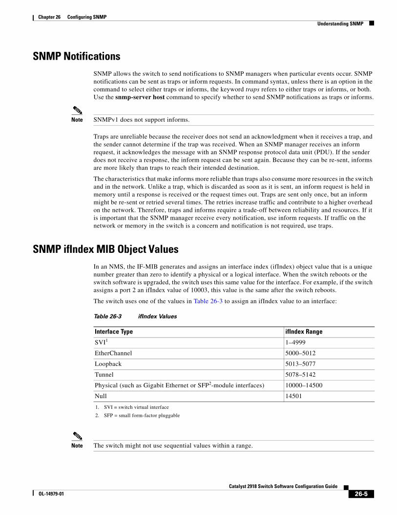
Chapter 26 Configuring SNMPUnderstanding SNMP
SNMP NotificationsSNMP allows the switch to send notifications to SNMP managers when particular events occur. SNMP notifications can be sent as traps or inform requests. In command syntax, unless there is an option in the command to select either traps or informs, the keyword traps refers to either traps or informs, or both. Use the snmp-server host command to specify whether to send SNMP notifications as traps or informs.
Note SNMPv1 does not support informs.
Traps are unreliable because the receiver does not send an acknowledgment when it receives a trap, and the sender cannot determine if the trap was received. When an SNMP manager receives an inform request, it acknowledges the message with an SNMP response protocol data unit (PDU). If the sender does not receive a response, the inform request can be sent again. Because they can be re-sent, informs are more likely than traps to reach their intended destination.
The characteristics that make informs more reliable than traps also consume more resources in the switch and in the network. Unlike a trap, which is discarded as soon as it is sent, an inform request is held in memory until a response is received or the request times out. Traps are sent only once, but an inform might be re-sent or retried several times. The retries increase traffic and contribute to a higher overhead on the network. Therefore, traps and informs require a trade-off between reliability and resources. If it is important that the SNMP manager receive every notification, use inform requests. If traffic on the network or memory in the switch is a concern and notification is not required, use traps.
SNMP ifIndex MIB Object ValuesIn an NMS, the IF-MIB generates and assigns an interface index (ifIndex) object value that is a unique number greater than zero to identify a physical or a logical interface. When the switch reboots or the switch software is upgraded, the switch uses this same value for the interface. For example, if the switch assigns a port 2 an ifIndex value of 10003, this value is the same after the switch reboots.
The switch uses one of the values in Table 26-3 to assign an ifIndex value to an interface:
Table 26-3 ifIndex Values
Interface Type ifIndex Range
1. SVI = switch virtual interface
SVI1 1–4999
EtherChannel 5000–5012
Loopback 5013–5077
Tunnel 5078–5142
Physical (such as Gigabit Ethernet or SFP
2. SFP = small form-factor pluggable
2-module interfaces) 10000–14500
Null 14501
Note The switch might not use sequential values within a range.
26-5Catalyst 2918 Switch Software Configuration Guide
OL-14979-01
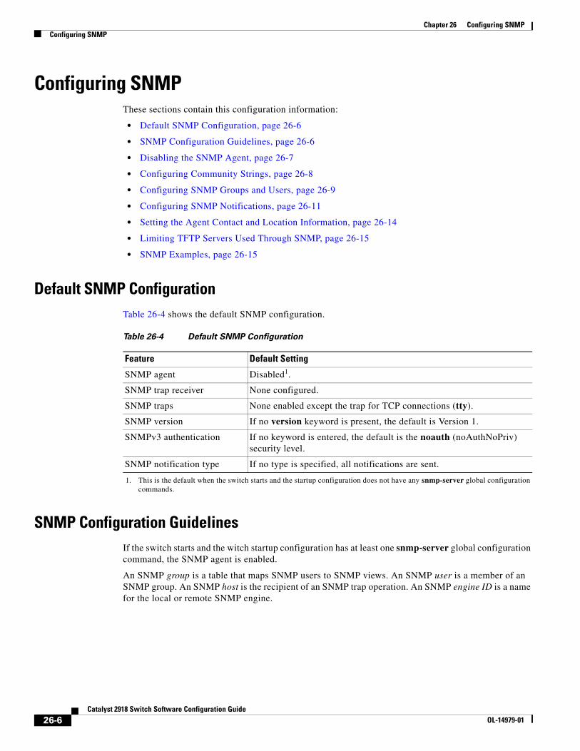
Chapter 26 Configuring SNMPConfiguring SNMP
Configuring SNMPThese sections contain this configuration information:
• Default SNMP Configuration, page 26-6
• SNMP Configuration Guidelines, page 26-6
• Disabling the SNMP Agent, page 26-7
• Configuring Community Strings, page 26-8
• Configuring SNMP Groups and Users, page 26-9
• Configuring SNMP Notifications, page 26-11
• Setting the Agent Contact and Location Information, page 26-14
• Limiting TFTP Servers Used Through SNMP, page 26-15
• SNMP Examples, page 26-15
Default SNMP ConfigurationTable 26-4 shows the default SNMP configuration.
Table 26-4 Default SNMP Configuration
Feature Default Setting
SNMP agent Disabled
1. This is the default when the switch starts and the startup configuration does not have any snmp-server global configuration commands.
1.
SNMP trap receiver None configured.
SNMP traps None enabled except the trap for TCP connections (tty).
SNMP version If no version keyword is present, the default is Version 1.
SNMPv3 authentication If no keyword is entered, the default is the noauth (noAuthNoPriv) security level.
SNMP notification type If no type is specified, all notifications are sent.
SNMP Configuration GuidelinesIf the switch starts and the witch startup configuration has at least one snmp-server global configuration command, the SNMP agent is enabled.
An SNMP group is a table that maps SNMP users to SNMP views. An SNMP user is a member of an SNMP group. An SNMP host is the recipient of an SNMP trap operation. An SNMP engine ID is a name for the local or remote SNMP engine.
26-6Catalyst 2918 Switch Software Configuration Guide
OL-14979-01
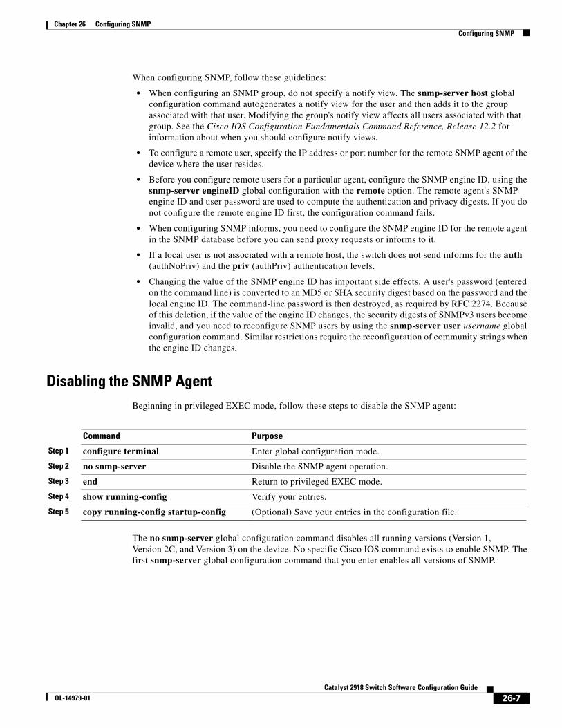
Chapter 26 Configuring SNMPConfiguring SNMP
When configuring SNMP, follow these guidelines:
• When configuring an SNMP group, do not specify a notify view. The snmp-server host global configuration command autogenerates a notify view for the user and then adds it to the group associated with that user. Modifying the group's notify view affects all users associated with that group. See the Cisco IOS Configuration Fundamentals Command Reference, Release 12.2 for information about when you should configure notify views.
• To configure a remote user, specify the IP address or port number for the remote SNMP agent of the device where the user resides.
• Before you configure remote users for a particular agent, configure the SNMP engine ID, using the snmp-server engineID global configuration with the remote option. The remote agent's SNMP engine ID and user password are used to compute the authentication and privacy digests. If you do not configure the remote engine ID first, the configuration command fails.
• When configuring SNMP informs, you need to configure the SNMP engine ID for the remote agent in the SNMP database before you can send proxy requests or informs to it.
• If a local user is not associated with a remote host, the switch does not send informs for the auth (authNoPriv) and the priv (authPriv) authentication levels.
• Changing the value of the SNMP engine ID has important side effects. A user's password (entered on the command line) is converted to an MD5 or SHA security digest based on the password and the local engine ID. The command-line password is then destroyed, as required by RFC 2274. Because of this deletion, if the value of the engine ID changes, the security digests of SNMPv3 users become invalid, and you need to reconfigure SNMP users by using the snmp-server user username global configuration command. Similar restrictions require the reconfiguration of community strings when the engine ID changes.
Disabling the SNMP AgentBeginning in privileged EXEC mode, follow these steps to disable the SNMP agent:
Command Purpose
Step 1 configure terminal Enter global configuration mode.
Step 2 no snmp-server Disable the SNMP agent operation.
Step 3 end Return to privileged EXEC mode.
Step 4 show running-config Verify your entries.
Step 5 copy running-config startup-config (Optional) Save your entries in the configuration file.
The no snmp-server global configuration command disables all running versions (Version 1, Version 2C, and Version 3) on the device. No specific Cisco IOS command exists to enable SNMP. The first snmp-server global configuration command that you enter enables all versions of SNMP.
26-7Catalyst 2918 Switch Software Configuration Guide
OL-14979-01
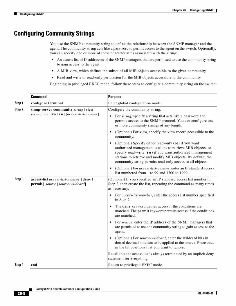
Chapter 26 Configuring SNMPConfiguring SNMP
Configuring Community StringsYou use the SNMP community string to define the relationship between the SNMP manager and the agent. The community string acts like a password to permit access to the agent on the switch. Optionally, you can specify one or more of these characteristics associated with the string:
• An access list of IP addresses of the SNMP managers that are permitted to use the community string to gain access to the agent
• A MIB view, which defines the subset of all MIB objects accessible to the given community
• Read and write or read-only permission for the MIB objects accessible to the community
Beginning in privileged EXEC mode, follow these steps to configure a community string on the switch:
Command Purpose
Step 1 configure terminal Enter global configuration mode.
Step 2 snmp-server community string [view view-name] [ro | rw] [access-list-number]
Configure the community string.
• For string, specify a string that acts like a password and permits access to the SNMP protocol. You can configure one or more community strings of any length.
• (Optional) For view, specify the view record accessible to the community.
• (Optional) Specify either read-only (ro) if you want authorized management stations to retrieve MIB objects, or specify read-write (rw) if you want authorized management stations to retrieve and modify MIB objects. By default, the community string permits read-only access to all objects.
• (Optional) For access-list-number, enter an IP standard access list numbered from 1 to 99 and 1300 to 1999.
Step 3 access-list access-list-number {deny | permit} source [source-wildcard]
(Optional) If you specified an IP standard access list number in Step 2, then create the list, repeating the command as many times as necessary.
• For access-list-number, enter the access list number specified in Step 2.
• The deny keyword denies access if the conditions are matched. The permit keyword permits access if the conditions are matched.
• For source, enter the IP address of the SNMP managers that are permitted to use the community string to gain access to the agent.
• (Optional) For source-wildcard, enter the wildcard bits in dotted decimal notation to be applied to the source. Place ones in the bit positions that you want to ignore.
Recall that the access list is always terminated by an implicit deny statement for everything.
Step 4 end Return to privileged EXEC mode.
26-8Catalyst 2918 Switch Software Configuration Guide
OL-14979-01
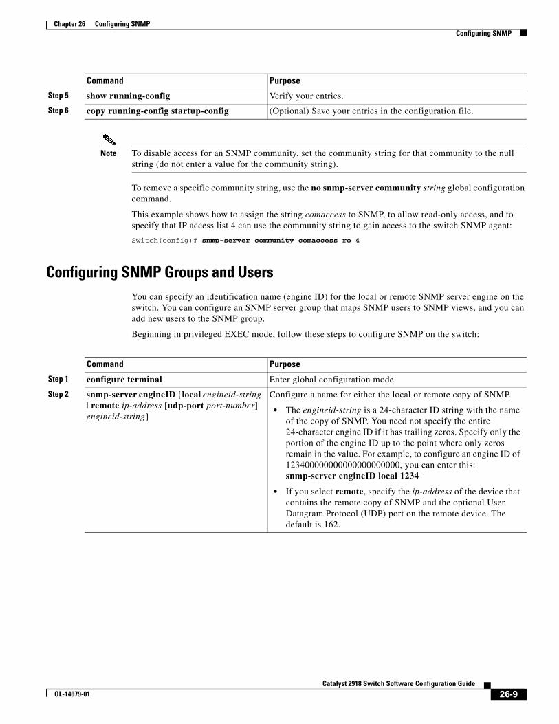
Chapter 26 Configuring SNMPConfiguring SNMP
Note To disable access for an SNMP community, set the community string for that community to the null string (do not enter a value for the community string).
To remove a specific community string, use the no snmp-server community string global configuration command.
This example shows how to assign the string comaccess to SNMP, to allow read-only access, and to specify that IP access list 4 can use the community string to gain access to the switch SNMP agent:
Switch(config)# snmp-server community comaccess ro 4
Configuring SNMP Groups and UsersYou can specify an identification name (engine ID) for the local or remote SNMP server engine on the switch. You can configure an SNMP server group that maps SNMP users to SNMP views, and you can add new users to the SNMP group.
Beginning in privileged EXEC mode, follow these steps to configure SNMP on the switch:
Step 5 show running-config Verify your entries.
Step 6 copy running-config startup-config (Optional) Save your entries in the configuration file.
Command Purpose
Command Purpose
Step 1 configure terminal Enter global configuration mode.
Step 2 snmp-server engineID {local engineid-string | remote ip-address [udp-port port-number] engineid-string}
Configure a name for either the local or remote copy of SNMP.
• The engineid-string is a 24-character ID string with the name of the copy of SNMP. You need not specify the entire 24-character engine ID if it has trailing zeros. Specify only the portion of the engine ID up to the point where only zeros remain in the value. For example, to configure an engine ID of 123400000000000000000000, you can enter this: snmp-server engineID local 1234
• If you select remote, specify the ip-address of the device that contains the remote copy of SNMP and the optional User Datagram Protocol (UDP) port on the remote device. The default is 162.
26-9Catalyst 2918 Switch Software Configuration Guide
OL-14979-01
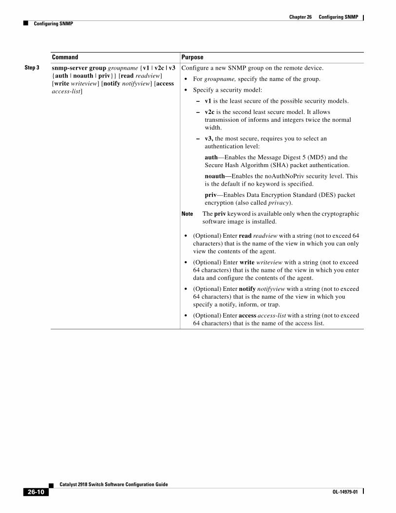
Chapter 26 Configuring SNMPConfiguring SNMP
Step 3 snmp-server group groupname {v1 | v2c | v3 {auth | noauth | priv}} [read readview] [write writeview] [notify notifyview] [access access-list]
Configure a new SNMP group on the remote device.
• For groupname, specify the name of the group.
• Specify a security model:
– v1 is the least secure of the possible security models.
– v2c is the second least secure model. It allows transmission of informs and integers twice the normal width.
– v3, the most secure, requires you to select an authentication level:
auth—Enables the Message Digest 5 (MD5) and the Secure Hash Algorithm (SHA) packet authentication.
noauth—Enables the noAuthNoPriv security level. This is the default if no keyword is specified.
priv—Enables Data Encryption Standard (DES) packet encryption (also called privacy).
Note The priv keyword is available only when the cryptographic software image is installed.
• (Optional) Enter read readview with a string (not to exceed 64 characters) that is the name of the view in which you can only view the contents of the agent.
• (Optional) Enter write writeview with a string (not to exceed 64 characters) that is the name of the view in which you enter data and configure the contents of the agent.
• (Optional) Enter notify notifyview with a string (not to exceed 64 characters) that is the name of the view in which you specify a notify, inform, or trap.
• (Optional) Enter access access-list with a string (not to exceed 64 characters) that is the name of the access list.
Command Purpose
26-10Catalyst 2918 Switch Software Configuration Guide
OL-14979-01
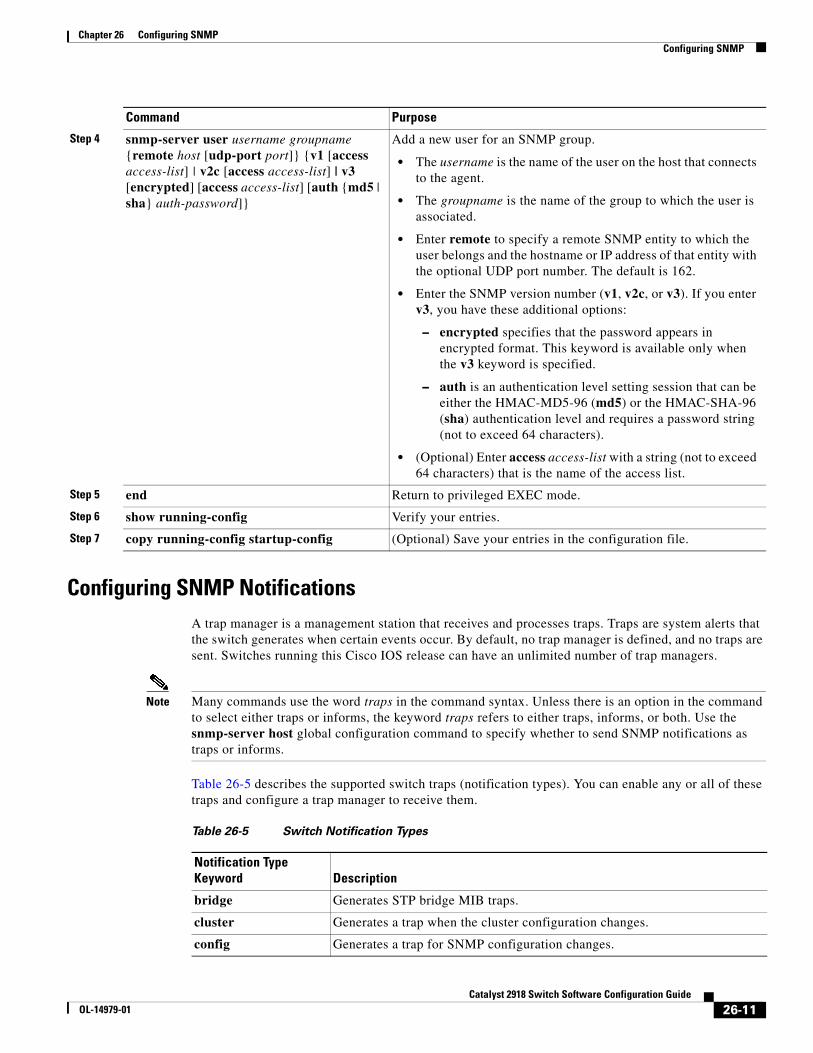
Chapter 26 Configuring SNMPConfiguring SNMP
Configuring SNMP NotificationsA trap manager is a management station that receives and processes traps. Traps are system alerts that the switch generates when certain events occur. By default, no trap manager is defined, and no traps are sent. Switches running this Cisco IOS release can have an unlimited number of trap managers.
Note Many commands use the word traps in the command syntax. Unless there is an option in the command to select either traps or informs, the keyword traps refers to either traps, informs, or both. Use the snmp-server host global configuration command to specify whether to send SNMP notifications as traps or informs.
Table 26-5 describes the supported switch traps (notification types). You can enable any or all of these traps and configure a trap manager to receive them.
Step 4 snmp-server user username groupname {remote host [udp-port port]} {v1 [access access-list] | v2c [access access-list] | v3 [encrypted] [access access-list] [auth {md5 | sha} auth-password]}
Add a new user for an SNMP group.
• The username is the name of the user on the host that connects to the agent.
• The groupname is the name of the group to which the user is associated.
• Enter remote to specify a remote SNMP entity to which the user belongs and the hostname or IP address of that entity with the optional UDP port number. The default is 162.
• Enter the SNMP version number (v1, v2c, or v3). If you enter v3, you have these additional options:
– encrypted specifies that the password appears in encrypted format. This keyword is available only when the v3 keyword is specified.
– auth is an authentication level setting session that can be either the HMAC-MD5-96 (md5) or the HMAC-SHA-96 (sha) authentication level and requires a password string (not to exceed 64 characters).
• (Optional) Enter access access-list with a string (not to exceed 64 characters) that is the name of the access list.
Step 5 end Return to privileged EXEC mode.
Step 6 show running-config Verify your entries.
Step 7 copy running-config startup-config (Optional) Save your entries in the configuration file.
Command Purpose
Table 26-5 Switch Notification Types
Notification Type Keyword Description
bridge Generates STP bridge MIB traps.
cluster Generates a trap when the cluster configuration changes.
config Generates a trap for SNMP configuration changes.
26-11Catalyst 2918 Switch Software Configuration Guide
OL-14979-01
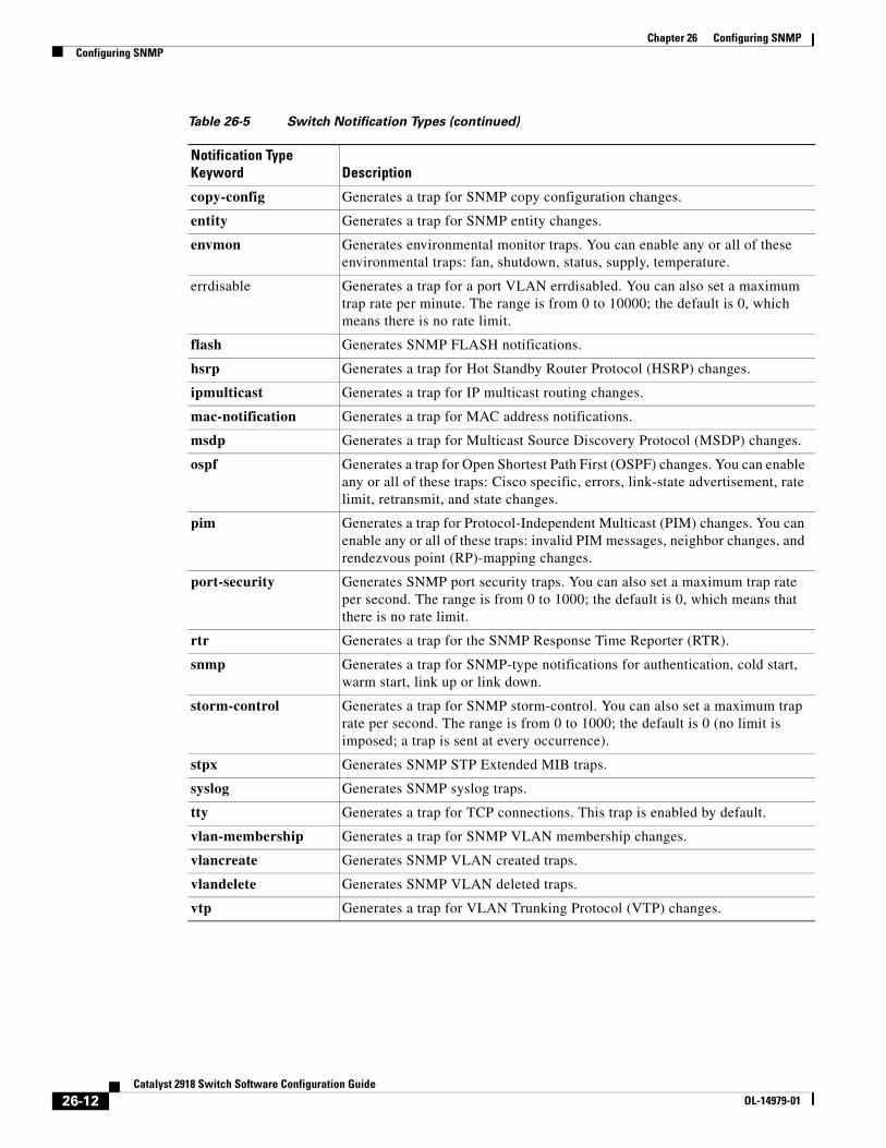
Chapter 26 Configuring SNMPConfiguring SNMP
copy-config Generates a trap for SNMP copy configuration changes.
entity Generates a trap for SNMP entity changes.
envmon Generates environmental monitor traps. You can enable any or all of these environmental traps: fan, shutdown, status, supply, temperature.
errdisable Generates a trap for a port VLAN errdisabled. You can also set a maximum trap rate per minute. The range is from 0 to 10000; the default is 0, which means there is no rate limit.
flash Generates SNMP FLASH notifications.
hsrp Generates a trap for Hot Standby Router Protocol (HSRP) changes.
ipmulticast Generates a trap for IP multicast routing changes.
mac-notification Generates a trap for MAC address notifications.
msdp Generates a trap for Multicast Source Discovery Protocol (MSDP) changes.
ospf Generates a trap for Open Shortest Path First (OSPF) changes. You can enable any or all of these traps: Cisco specific, errors, link-state advertisement, rate limit, retransmit, and state changes.
pim Generates a trap for Protocol-Independent Multicast (PIM) changes. You can enable any or all of these traps: invalid PIM messages, neighbor changes, and rendezvous point (RP)-mapping changes.
port-security Generates SNMP port security traps. You can also set a maximum trap rate per second. The range is from 0 to 1000; the default is 0, which means that there is no rate limit.
rtr Generates a trap for the SNMP Response Time Reporter (RTR).
snmp Generates a trap for SNMP-type notifications for authentication, cold start, warm start, link up or link down.
storm-control Generates a trap for SNMP storm-control. You can also set a maximum trap rate per second. The range is from 0 to 1000; the default is 0 (no limit is imposed; a trap is sent at every occurrence).
stpx Generates SNMP STP Extended MIB traps.
syslog Generates SNMP syslog traps.
tty Generates a trap for TCP connections. This trap is enabled by default.
vlan-membership Generates a trap for SNMP VLAN membership changes.
vlancreate Generates SNMP VLAN created traps.
vlandelete Generates SNMP VLAN deleted traps.
vtp Generates a trap for VLAN Trunking Protocol (VTP) changes.
Table 26-5 Switch Notification Types (continued)
Notification Type Keyword Description
26-12Catalyst 2918 Switch Software Configuration Guide
OL-14979-01
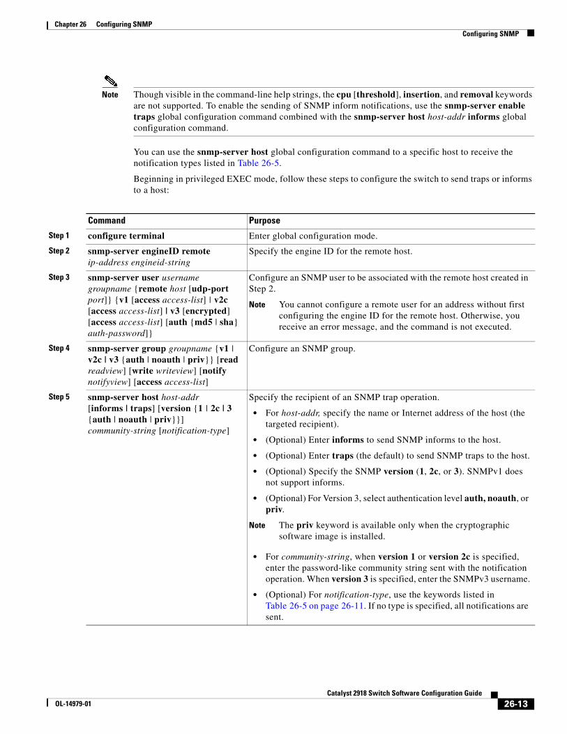
Chapter 26 Configuring SNMPConfiguring SNMP
Note Though visible in the command-line help strings, the cpu [threshold], insertion, and removal keywords are not supported. To enable the sending of SNMP inform notifications, use the snmp-server enable traps global configuration command combined with the snmp-server host host-addr informs global configuration command.
You can use the snmp-server host global configuration command to a specific host to receive the notification types listed in Table 26-5.
Beginning in privileged EXEC mode, follow these steps to configure the switch to send traps or informs to a host:
Command Purpose
Step 1 configure terminal Enter global configuration mode.
Step 2 snmp-server engineID remote ip-address engineid-string
Specify the engine ID for the remote host.
Step 3 snmp-server user username groupname {remote host [udp-port port]} {v1 [access access-list] | v2c [access access-list] | v3 [encrypted] [access access-list] [auth {md5 | sha} auth-password]}
Configure an SNMP user to be associated with the remote host created in Step 2.
Note You cannot configure a remote user for an address without first configuring the engine ID for the remote host. Otherwise, you receive an error message, and the command is not executed.
Step 4 snmp-server group groupname {v1 | v2c | v3 {auth | noauth | priv}} [read readview] [write writeview] [notify notifyview] [access access-list]
Configure an SNMP group.
Step 5 snmp-server host host-addr [informs | traps] [version {1 | 2c | 3 {auth | noauth | priv}}] community-string [notification-type]
Specify the recipient of an SNMP trap operation.
• For host-addr, specify the name or Internet address of the host (the targeted recipient).
• (Optional) Enter informs to send SNMP informs to the host.
• (Optional) Enter traps (the default) to send SNMP traps to the host.
• (Optional) Specify the SNMP version (1, 2c, or 3). SNMPv1 does not support informs.
• (Optional) For Version 3, select authentication level auth, noauth, or priv.
Note The priv keyword is available only when the cryptographic software image is installed.
• For community-string, when version 1 or version 2c is specified, enter the password-like community string sent with the notification operation. When version 3 is specified, enter the SNMPv3 username.
• (Optional) For notification-type, use the keywords listed in Table 26-5 on page 26-11. If no type is specified, all notifications are sent.
26-13Catalyst 2918 Switch Software Configuration Guide
OL-14979-01
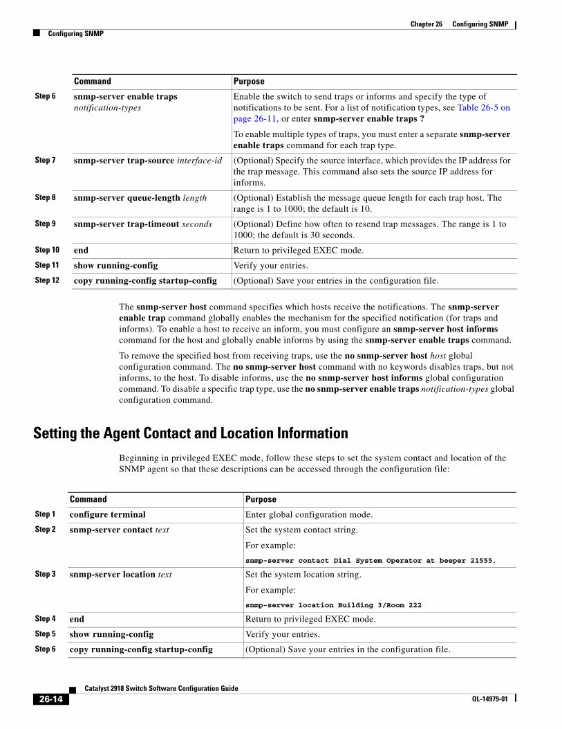
Chapter 26 Configuring SNMPConfiguring SNMP
The snmp-server host command specifies which hosts receive the notifications. The snmp-server enable trap command globally enables the mechanism for the specified notification (for traps and informs). To enable a host to receive an inform, you must configure an snmp-server host informs command for the host and globally enable informs by using the snmp-server enable traps command.
To remove the specified host from receiving traps, use the no snmp-server host host global configuration command. The no snmp-server host command with no keywords disables traps, but not informs, to the host. To disable informs, use the no snmp-server host informs global configuration command. To disable a specific trap type, use the no snmp-server enable traps notification-types global configuration command.
Setting the Agent Contact and Location InformationBeginning in privileged EXEC mode, follow these steps to set the system contact and location of the SNMP agent so that these descriptions can be accessed through the configuration file:
Command Purpose
Step 1 configure terminal Enter global configuration mode.
Step 2 snmp-server contact text Set the system contact string.
For example:
snmp-server contact Dial System Operator at beeper 21555.
Step 3 snmp-server location text Set the system location string.
For example:
snmp-server location Building 3/Room 222
Step 4 end Return to privileged EXEC mode.
Step 5 show running-config Verify your entries.
Step 6 copy running-config startup-config (Optional) Save your entries in the configuration file.
Step 6 snmp-server enable traps notification-types
Enable the switch to send traps or informs and specify the type of notifications to be sent. For a list of notification types, see Table 26-5 on page 26-11, or enter snmp-server enable traps ?
To enable multiple types of traps, you must enter a separate snmp-server enable traps command for each trap type.
Step 7 snmp-server trap-source interface-id (Optional) Specify the source interface, which provides the IP address for the trap message. This command also sets the source IP address for informs.
Step 8 snmp-server queue-length length (Optional) Establish the message queue length for each trap host. The range is 1 to 1000; the default is 10.
Step 9 snmp-server trap-timeout seconds (Optional) Define how often to resend trap messages. The range is 1 to 1000; the default is 30 seconds.
Step 10 end Return to privileged EXEC mode.
Step 11 show running-config Verify your entries.
Step 12 copy running-config startup-config (Optional) Save your entries in the configuration file.
Command Purpose
26-14Catalyst 2918 Switch Software Configuration Guide
OL-14979-01
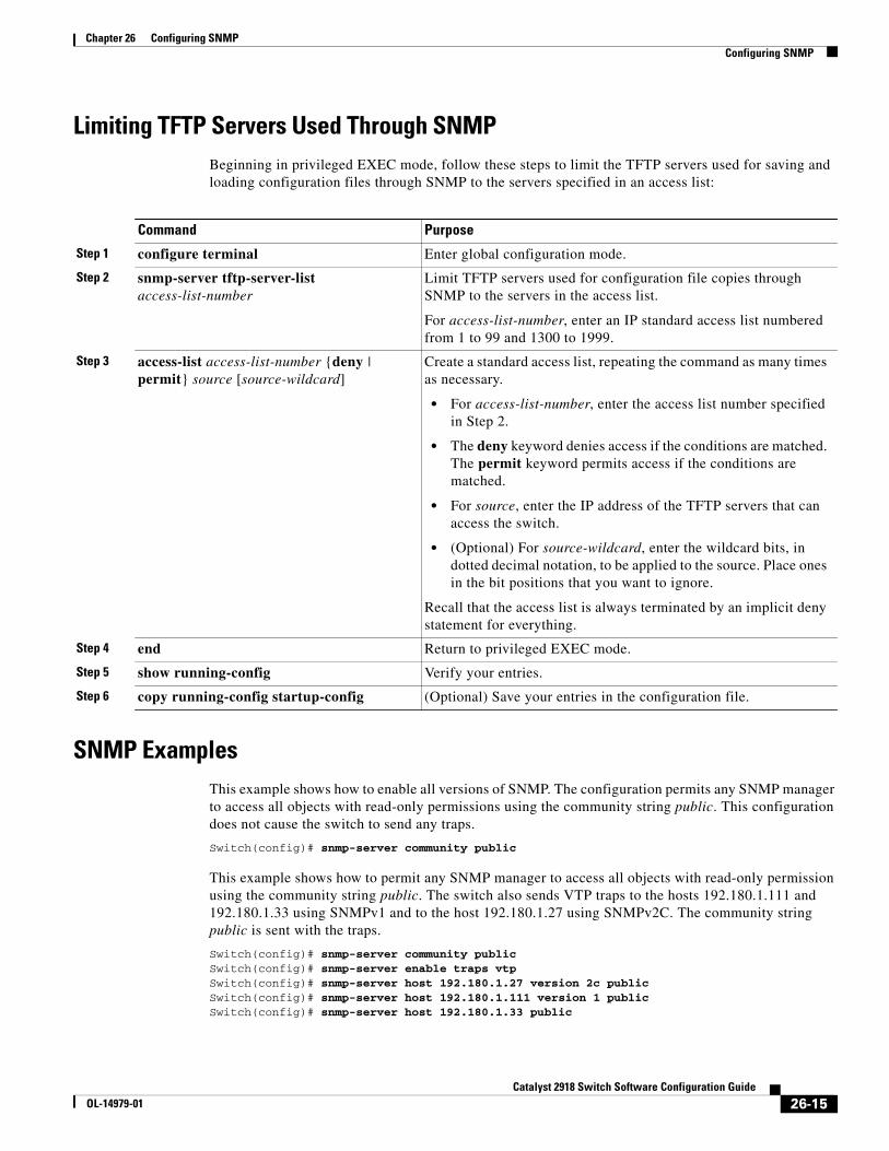
Chapter 26 Configuring SNMPConfiguring SNMP
Limiting TFTP Servers Used Through SNMPBeginning in privileged EXEC mode, follow these steps to limit the TFTP servers used for saving and loading configuration files through SNMP to the servers specified in an access list:
Command Purpose
Step 1 configure terminal Enter global configuration mode.
Step 2 snmp-server tftp-server-list access-list-number
Limit TFTP servers used for configuration file copies through SNMP to the servers in the access list.
For access-list-number, enter an IP standard access list numbered from 1 to 99 and 1300 to 1999.
Step 3 access-list access-list-number {deny | permit} source [source-wildcard]
Create a standard access list, repeating the command as many times as necessary.
• For access-list-number, enter the access list number specified in Step 2.
• The deny keyword denies access if the conditions are matched. The permit keyword permits access if the conditions are matched.
• For source, enter the IP address of the TFTP servers that can access the switch.
• (Optional) For source-wildcard, enter the wildcard bits, in dotted decimal notation, to be applied to the source. Place ones in the bit positions that you want to ignore.
Recall that the access list is always terminated by an implicit deny statement for everything.
Step 4 end Return to privileged EXEC mode.
Step 5 show running-config Verify your entries.
Step 6 copy running-config startup-config (Optional) Save your entries in the configuration file.
SNMP ExamplesThis example shows how to enable all versions of SNMP. The configuration permits any SNMP manager to access all objects with read-only permissions using the community string public. This configuration does not cause the switch to send any traps.
Switch(config)# snmp-server community public
This example shows how to permit any SNMP manager to access all objects with read-only permission using the community string public. The switch also sends VTP traps to the hosts 192.180.1.111 and 192.180.1.33 using SNMPv1 and to the host 192.180.1.27 using SNMPv2C. The community string public is sent with the traps.
Switch(config)# snmp-server community publicSwitch(config)# snmp-server enable traps vtpSwitch(config)# snmp-server host 192.180.1.27 version 2c publicSwitch(config)# snmp-server host 192.180.1.111 version 1 publicSwitch(config)# snmp-server host 192.180.1.33 public
26-15Catalyst 2918 Switch Software Configuration Guide
OL-14979-01
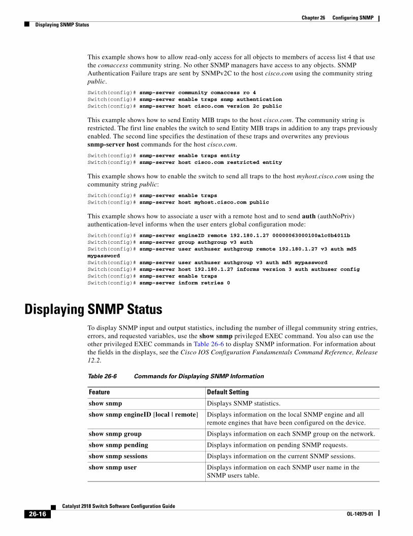
Chapter 26 Configuring SNMPDisplaying SNMP Status
This example shows how to allow read-only access for all objects to members of access list 4 that use the comaccess community string. No other SNMP managers have access to any objects. SNMP Authentication Failure traps are sent by SNMPv2C to the host cisco.com using the community string public.
Switch(config)# snmp-server community comaccess ro 4Switch(config)# snmp-server enable traps snmp authenticationSwitch(config)# snmp-server host cisco.com version 2c public
This example shows how to send Entity MIB traps to the host cisco.com. The community string is restricted. The first line enables the switch to send Entity MIB traps in addition to any traps previously enabled. The second line specifies the destination of these traps and overwrites any previous snmp-server host commands for the host cisco.com.
Switch(config)# snmp-server enable traps entity Switch(config)# snmp-server host cisco.com restricted entity
This example shows how to enable the switch to send all traps to the host myhost.cisco.com using the community string public:
Switch(config)# snmp-server enable trapsSwitch(config)# snmp-server host myhost.cisco.com public
This example shows how to associate a user with a remote host and to send auth (authNoPriv) authentication-level informs when the user enters global configuration mode:
Switch(config)# snmp-server engineID remote 192.180.1.27 00000063000100a1c0b4011bSwitch(config)# snmp-server group authgroup v3 authSwitch(config)# snmp-server user authuser authgroup remote 192.180.1.27 v3 auth md5 mypasswordSwitch(config)# snmp-server user authuser authgroup v3 auth md5 mypasswordSwitch(config)# snmp-server host 192.180.1.27 informs version 3 auth authuser configSwitch(config)# snmp-server enable trapsSwitch(config)# snmp-server inform retries 0
Displaying SNMP StatusTo display SNMP input and output statistics, including the number of illegal community string entries, errors, and requested variables, use the show snmp privileged EXEC command. You also can use the other privileged EXEC commands in Table 26-6 to display SNMP information. For information about the fields in the displays, see the Cisco IOS Configuration Fundamentals Command Reference, Release 12.2.
Table 26-6 Commands for Displaying SNMP Information
Feature Default Setting
show snmp Displays SNMP statistics.
show snmp engineID [local | remote] Displays information on the local SNMP engine and all remote engines that have been configured on the device.
show snmp group Displays information on each SNMP group on the network.
show snmp pending Displays information on pending SNMP requests.
show snmp sessions Displays information on the current SNMP sessions.
show snmp user Displays information on each SNMP user name in the SNMP users table.
26-16Catalyst 2918 Switch Software Configuration Guide
OL-14979-01
OL-14979-01
C H A P T E R 27
Configuring QoSThis chapter describes how to configure quality of service (QoS) by using standard QoS commands on the Catalyst 2918 switch. With QoS, you can provide preferential treatment to certain types of traffic at the expense of others. Without QoS, the switch offers best-effort service to each packet, regardless of the packet contents or size. It sends the packets without any assurance of reliability, delay bounds, or throughput.
You can configure QoS only on physical ports. Configure the QoS settings, such as classification, queueing, and scheduling, and apply a trusted class of service (CoS) or a CoS override setting.
Note For complete syntax and usage information for the commands used in this chapter, see the command reference for this release.
This chapter consists of these sections:
• Understanding QoS, page 27-1
• Configuring Standard QoS, page 27-8
• Displaying Standard QoS Information, page 27-19
The switch supports some of the modular QoS CLI (MQC) commands. For more information about the MQC commands, see the “Modular Quality of Service Command-Line Interface Overview” at this site:
http://www.cisco.com/en/US/products/sw/iosswrel/ps1835/products_configuration_guide_chapter09186a00800bd908.html
Understanding QoSTypically, networks operate on a best-effort delivery basis, which means that all traffic has equal priority and an equal chance of being delivered in a timely manner. When congestion occurs, all traffic has an equal chance of being dropped.
When you configure the QoS feature, you can select specific network traffic, prioritize it according to its relative importance, and use congestion-management and congestion-avoidance techniques to provide preferential treatment. Implementing QoS in your network makes network performance more predictable and bandwidth utilization more effective.
The QoS implementation is based on the Differentiated Services (Diff-Serv) architecture, an emerging standard from the Internet Engineering Task Force (IETF). This architecture specifies that each packet is classified upon entry into the network.
27-1Catalyst 2918 Switch Software Configuration Guide
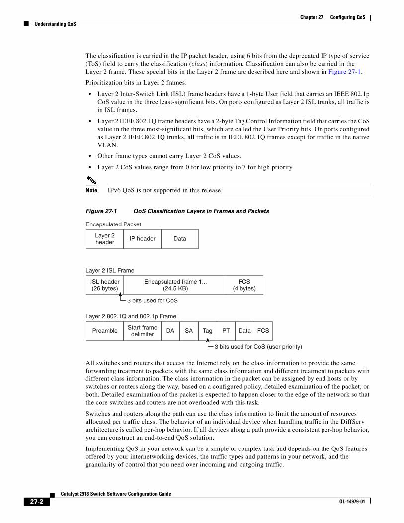
Chapter 27 Configuring QoSUnderstanding QoS
The classification is carried in the IP packet header, using 6 bits from the deprecated IP type of service (ToS) field to carry the classification (class) information. Classification can also be carried in the Layer 2 frame. These special bits in the Layer 2 frame are described here and shown in Figure 27-1.
Prioritization bits in Layer 2 frames:
• Layer 2 Inter-Switch Link (ISL) frame headers have a 1-byte User field that carries an IEEE 802.1p CoS value in the three least-significant bits. On ports configured as Layer 2 ISL trunks, all traffic is in ISL frames.
• Layer 2 IEEE 802.1Q frame headers have a 2-byte Tag Control Information field that carries the CoS value in the three most-significant bits, which are called the User Priority bits. On ports configured as Layer 2 IEEE 802.1Q trunks, all traffic is in IEEE 802.1Q frames except for traffic in the native VLAN.
• Other frame types cannot carry Layer 2 CoS values.
• Layer 2 CoS values range from 0 for low priority to 7 for high priority.
Note IPv6 QoS is not supported in this release.
Figure 27-1 QoS Classification Layers in Frames and Packets
Encapsulated Packet
Layer 2header
IP header
3 bits used for CoS
Data
Layer 2 ISL Frame
ISL header(26 bytes)
Encapsulated frame 1...(24.5 KB)
FCS(4 bytes)
Layer 2 802.1Q and 802.1p Frame
Preamble Start framedelimiter
DA SA Tag PT Data FCS
3 bits used for CoS (user priority)
All switches and routers that access the Internet rely on the class information to provide the same forwarding treatment to packets with the same class information and different treatment to packets with different class information. The class information in the packet can be assigned by end hosts or by switches or routers along the way, based on a configured policy, detailed examination of the packet, or both. Detailed examination of the packet is expected to happen closer to the edge of the network so that the core switches and routers are not overloaded with this task.
Switches and routers along the path can use the class information to limit the amount of resources allocated per traffic class. The behavior of an individual device when handling traffic in the DiffServ architecture is called per-hop behavior. If all devices along a path provide a consistent per-hop behavior, you can construct an end-to-end QoS solution.
Implementing QoS in your network can be a simple or complex task and depends on the QoS features offered by your internetworking devices, the traffic types and patterns in your network, and the granularity of control that you need over incoming and outgoing traffic.
27-2Catalyst 2918 Switch Software Configuration Guide
OL-14979-01
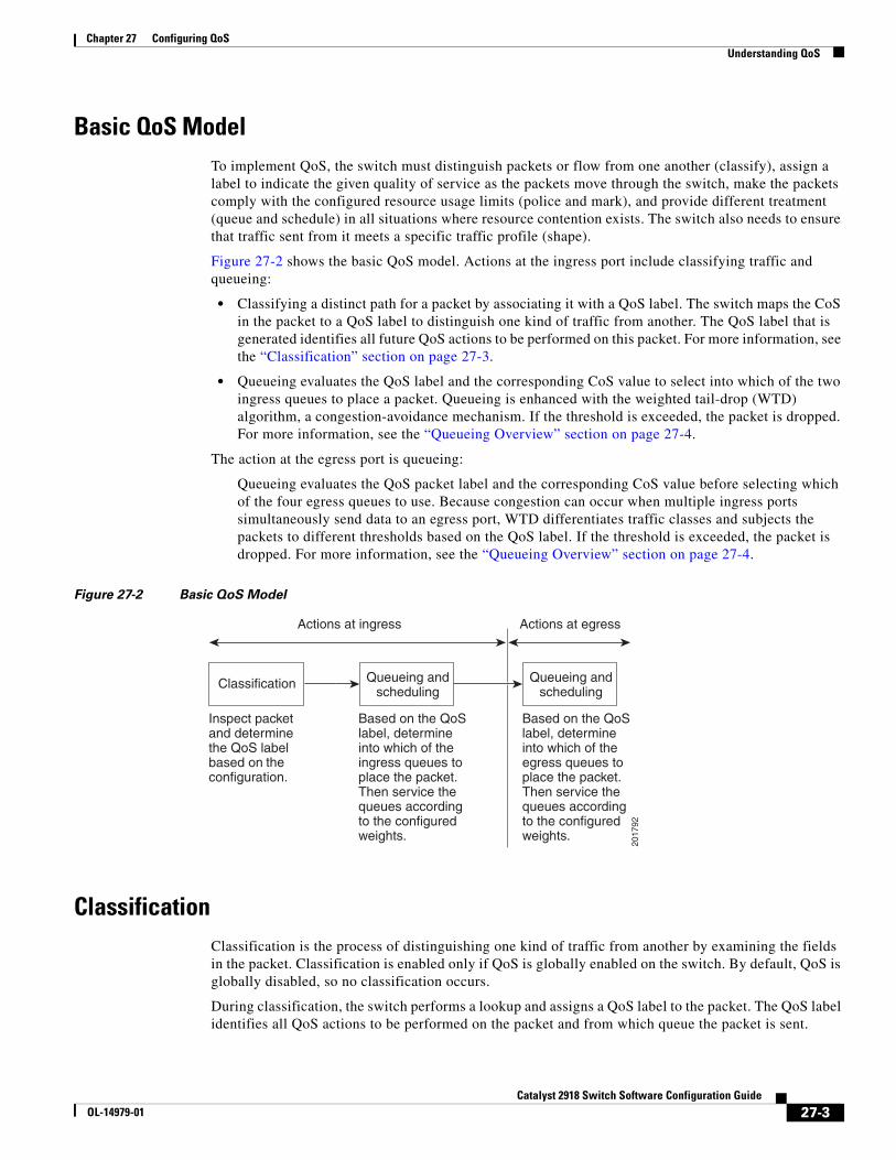
Chapter 27 Configuring QoSUnderstanding QoS
Basic QoS ModelTo implement QoS, the switch must distinguish packets or flow from one another (classify), assign a label to indicate the given quality of service as the packets move through the switch, make the packets comply with the configured resource usage limits (police and mark), and provide different treatment (queue and schedule) in all situations where resource contention exists. The switch also needs to ensure that traffic sent from it meets a specific traffic profile (shape).
Figure 27-2 shows the basic QoS model. Actions at the ingress port include classifying traffic and queueing:
• Classifying a distinct path for a packet by associating it with a QoS label. The switch maps the CoS in the packet to a QoS label to distinguish one kind of traffic from another. The QoS label that is generated identifies all future QoS actions to be performed on this packet. For more information, see the “Classification” section on page 27-3.
• Queueing evaluates the QoS label and the corresponding CoS value to select into which of the two ingress queues to place a packet. Queueing is enhanced with the weighted tail-drop (WTD) algorithm, a congestion-avoidance mechanism. If the threshold is exceeded, the packet is dropped. For more information, see the “Queueing Overview” section on page 27-4.
The action at the egress port is queueing:
Queueing evaluates the QoS packet label and the corresponding CoS value before selecting which of the four egress queues to use. Because congestion can occur when multiple ingress ports simultaneously send data to an egress port, WTD differentiates traffic classes and subjects the packets to different thresholds based on the QoS label. If the threshold is exceeded, the packet is dropped. For more information, see the “Queueing Overview” section on page 27-4.
Figure 27-2 Basic QoS Model
2017
92
ClassificationClassification is the process of distinguishing one kind of traffic from another by examining the fields in the packet. Classification is enabled only if QoS is globally enabled on the switch. By default, QoS is globally disabled, so no classification occurs.
During classification, the switch performs a lookup and assigns a QoS label to the packet. The QoS label identifies all QoS actions to be performed on the packet and from which queue the packet is sent.
27-3Catalyst 2918 Switch Software Configuration Guide
OL-14979-01
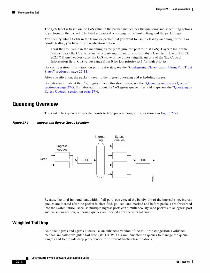
Chapter 27 Configuring QoSUnderstanding QoS
The QoS label is based on the CoS value in the packet and decides the queueing and scheduling actions to perform on the packet. The label is mapped according to the trust setting and the packet type.
You specify which fields in the frame or packet that you want to use to classify incoming traffic. For non-IP traffic, you have this classification option:
Trust the CoS value in the incoming frame (configure the port to trust CoS). Layer 2 ISL frame headers carry the CoS value in the 3 least-significant bits of the 1-byte User field. Layer 2 IEEE 802.1Q frame headers carry the CoS value in the 3 most-significant bits of the Tag Control Information field. CoS values range from 0 for low priority to 7 for high priority.
For configuration information on port trust states, see the “Configuring Classification Using Port Trust States” section on page 27-11.
After classification, the packet is sent to the ingress queueing and scheduling stages.
For information about the CoS ingress queue threshold maps, see the “Queueing on Ingress Queues” section on page 27-5. For information about the CoS egress queue threshold maps, see the “Queueing on Egress Queues” section on page 27-6.
Queueing OverviewThe switch has queues at specific points to help prevent congestion, as shown in Figure 27-3.
Figure 27-3 Ingress and Egress Queue Location
MarkerPolicer
MarkerPolicer
Marker
Ingressqueues
Internalring
EgressqueuesPolicer
MarkerPolicer
fy SRRSRR
9056
3
Traffic
Because the total inbound bandwidth of all ports can exceed the bandwidth of the internal ring, ingress queues are located after the packet is classified, policed, and marked and before packets are forwarded into the switch fabric. Because multiple ingress ports can simultaneously send packets to an egress port and cause congestion, outbound queues are located after the internal ring.
Weighted Tail Drop
Both the ingress and egress queues use an enhanced version of the tail-drop congestion-avoidance mechanism called weighted tail drop (WTD). WTD is implemented on queues to manage the queue lengths and to provide drop precedences for different traffic classifications.
27-4Catalyst 2918 Switch Software Configuration Guide
OL-14979-01
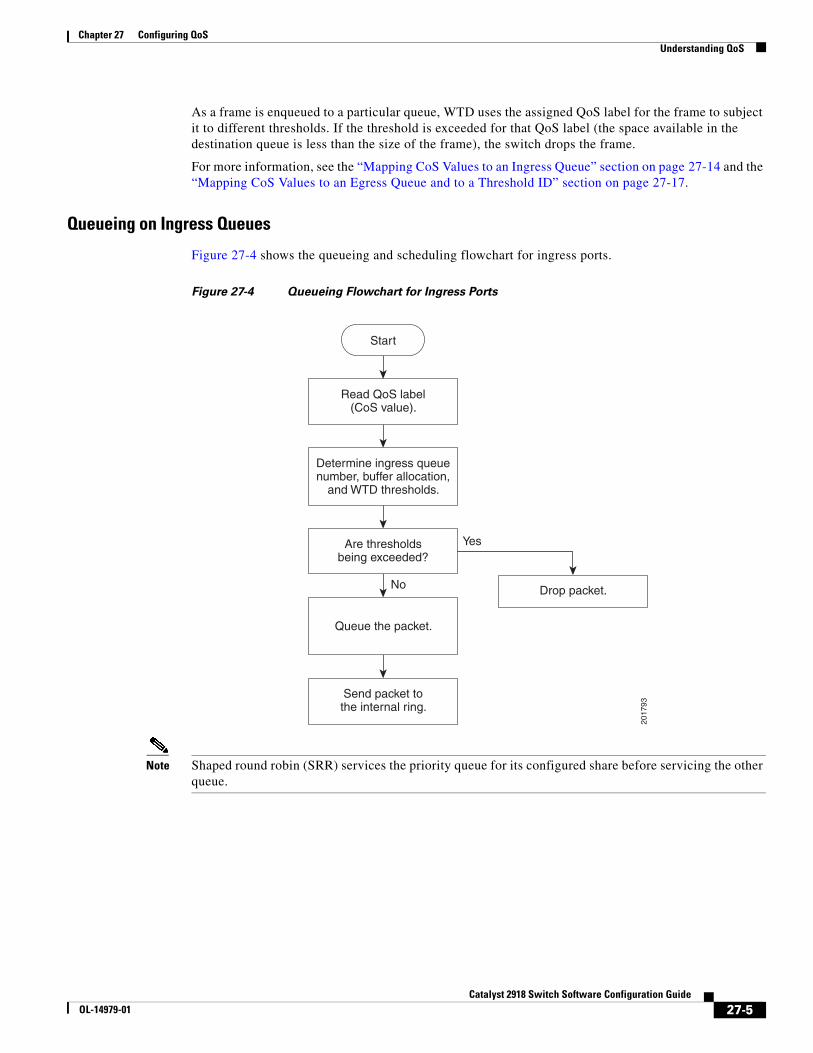
Chapter 27 Configuring QoSUnderstanding QoS
As a frame is enqueued to a particular queue, WTD uses the assigned QoS label for the frame to subject it to different thresholds. If the threshold is exceeded for that QoS label (the space available in the destination queue is less than the size of the frame), the switch drops the frame.
For more information, see the “Mapping CoS Values to an Ingress Queue” section on page 27-14 and the “Mapping CoS Values to an Egress Queue and to a Threshold ID” section on page 27-17.
Queueing on Ingress Queues
Figure 27-4 shows the queueing and scheduling flowchart for ingress ports.
Figure 27-4 Queueing Flowchart for Ingress Ports
2017
93
Read QoS label(CoS value).
Determine ingress queuenumber, buffer allocation,
and WTD thresholds.
Are thresholdsbeing exceeded?
Queue the packet.
Send packet tothe internal ring.
Drop packet.
Start
Yes
No
Note Shaped round robin (SRR) services the priority queue for its configured share before servicing the other queue.
27-5Catalyst 2918 Switch Software Configuration Guide
OL-14979-01
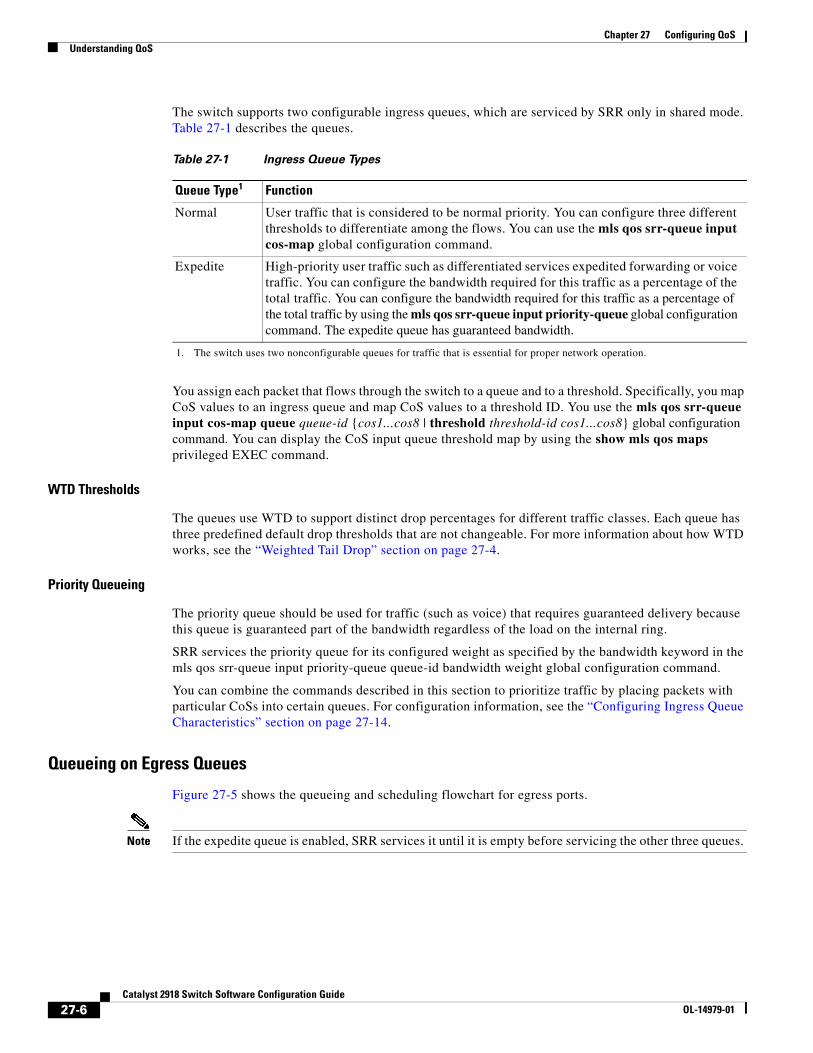
Chapter 27 Configuring QoSUnderstanding QoS
The switch supports two configurable ingress queues, which are serviced by SRR only in shared mode. Table 27-1 describes the queues.
Table 27-1 Ingress Queue Types
Queue Type
1. The switch uses two nonconfigurable queues for traffic that is essential for proper network operation.
1
Normal User traffic that is considered to be normal priority. You can configure three different thresholds to differentiate among the flows. You can use the mls qos srr-queue input cos-map global configuration command.
Expedite High-priority user traffic such as differentiated services expedited forwarding or voice traffic. You can configure the bandwidth required for this traffic as a percentage of the total traffic. You can configure the bandwidth required for this traffic as a percentage of the total traffic by using the mls qos srr-queue input priority-queue global configuration command. The expedite queue has guaranteed bandwidth.
You assign each packet that flows through the switch to a queue and to a threshold. Specifically, you map CoS values to an ingress queue and map CoS values to a threshold ID. You use the mls qos srr-queue input cos-map queue queue-id {cos1...cos8 | threshold threshold-id cos1...cos8} global configuration command. You can display the CoS input queue threshold map by using the show mls qos maps privileged EXEC command.
WTD Thresholds
The queues use WTD to support distinct drop percentages for different traffic classes. Each queue has three predefined default drop thresholds that are not changeable. For more information about how WTD works, see the “Weighted Tail Drop” section on page 27-4.
Priority Queueing
The priority queue should be used for traffic (such as voice) that requires guaranteed delivery because this queue is guaranteed part of the bandwidth regardless of the load on the internal ring.
SRR services the priority queue for its configured weight as specified by the bandwidth keyword in the mls qos srr-queue input priority-queue queue-id bandwidth weight global configuration command.
You can combine the commands described in this section to prioritize traffic by placing packets with particular CoSs into certain queues. For configuration information, see the “Configuring Ingress Queue Characteristics” section on page 27-14.
Queueing on Egress Queues
Figure 27-5 shows the queueing and scheduling flowchart for egress ports.
Note If the expedite queue is enabled, SRR services it until it is empty before servicing the other three queues.
Function
27-6Catalyst 2918 Switch Software Configuration Guide
OL-14979-01
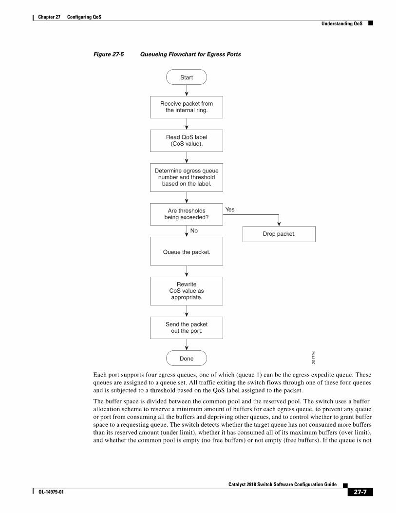
Chapter 27 Configuring QoSUnderstanding QoS
Figure 27-5 Queueing Flowchart for Egress Ports
2017
94
Receive packet fromthe internal ring.
Read QoS label(CoS value).
Determine egress queuenumber and threshold
based on the label.
Are thresholdsbeing exceeded?
Send the packetout the port.
Queue the packet.
Drop packet.
Start
Done
Yes
No
RewriteCoS value asappropriate.
Each port supports four egress queues, one of which (queue 1) can be the egress expedite queue. These queues are assigned to a queue set. All traffic exiting the switch flows through one of these four queues and is subjected to a threshold based on the QoS label assigned to the packet.
The buffer space is divided between the common pool and the reserved pool. The switch uses a buffer allocation scheme to reserve a minimum amount of buffers for each egress queue, to prevent any queue or port from consuming all the buffers and depriving other queues, and to control whether to grant buffer space to a requesting queue. The switch detects whether the target queue has not consumed more buffers than its reserved amount (under limit), whether it has consumed all of its maximum buffers (over limit), and whether the common pool is empty (no free buffers) or not empty (free buffers). If the queue is not
27-7Catalyst 2918 Switch Software Configuration Guide
OL-14979-01
Chapter 27 Configuring QoSConfiguring Standard QoS
over limit, the switch can allocate buffer space from the reserved pool or from the common pool (if it is not empty). If there are no free buffers in the common pool or if the queue is over limit, the switch drops the frame.
WTD Thresholds
You can assign each packet that flows through the switch to a queue and to a threshold. Specifically, you map CoS values to an egress queue and map CoS values to a threshold ID. You use the mls qos srr-queue output cos-map queue queue-id {cos1...cos8 | threshold threshold-id cos1...cos8} global configuration command. You can display the CoS output queue threshold map by using the show mls qos maps privileged EXEC command.
The queues use WTD to support distinct drop percentages for different traffic classes. Each queue has three predefined default drop thresholds that are not changeable. For more information about how WTD works, see the “Weighted Tail Drop” section on page 27-4.
Packet ModificationA packet is classified, policed, and queued to provide QoS. Packet modifications can occur during this process. For IP and non-IP packets, classification involves assigning a QoS label to a packet based on the CoS of the received packet. However, the packet is not modified at this stage; only an indication of the assigned CoS value is carried along.
Configuring Standard QoSBefore configuring standard QoS, you must have a thorough understanding of these items:
• The types of applications used and the traffic patterns on your network.
• Traffic characteristics and needs of your network. Is the traffic bursty? Do you need to reserve bandwidth for voice and video streams?
• Bandwidth requirements and speed of the network.
• Location of congestion points in the network.
These sections contain this configuration information:
• Default Standard QoS Configuration, page 27-8
• Enabling QoS Globally, page 27-10 (required)
• Configuring Classification Using Port Trust States, page 27-11 (required
• Configuring Ingress Queue Characteristics, page 27-14 (optional)
• Configuring Egress Queue Characteristics, page 27-16 (optional)
Default Standard QoS ConfigurationQoS is disabled. There is no concept of trusted or untrusted ports because the packets are not modified (the CoS and IP precedence values in the packet are not changed). Traffic is switched in pass-through mode (packets are switched without any rewrites and classified as best effort without any policing).
27-8Catalyst 2918 Switch Software Configuration Guide
OL-14979-01
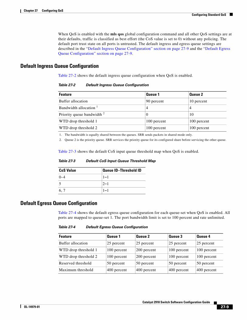
Chapter 27 Configuring QoSConfiguring Standard QoS
When QoS is enabled with the mls qos global configuration command and all other QoS settings are at their defaults, traffic is classified as best effort (the CoS value is set to 0) without any policing. The default port trust state on all ports is untrusted. The default ingress and egress queue settings are described in the “Default Ingress Queue Configuration” section on page 27-9 and the “Default Egress Queue Configuration” section on page 27-9.
Default Ingress Queue Configuration
Table 27-2 shows the default ingress queue configuration when QoS is enabled.
Table 27-2 Default Ingress Queue Configuration
Feature Queue 1 Queue 2
Buffer allocation 90 percent 10 percent
Bandwidth allocation
1. The bandwidth is equally shared between the queues. SRR sends packets in shared mode only.
1 4 4
Priority queue bandwidth
2. Queue 2 is the priority queue. SRR services the priority queue for its configured share before servicing the other queue.
2 0 10
WTD drop threshold 1 100 percent 100 percent
WTD drop threshold 2 100 percent 100 percent
Table 27-3 shows the default CoS input queue threshold map when QoS is enabled.
Table 27-3 Default CoS Input Queue Threshold Map
CoS Value Queue ID–Threshold ID
0–4 1–1
5 2–1
6, 7 1–1
Default Egress Queue Configuration
Table 27-4 shows the default egress queue configuration for each queue-set when QoS is enabled. All ports are mapped to queue-set 1. The port bandwidth limit is set to 100 percent and rate unlimited.
Table 27-4 Default Egress Queue Configuration
Feature Queue 1 Queue 2 Queue 3 Queue 4
Buffer allocation 25 percent 25 percent 25 percent 25 percent
WTD drop threshold 1 100 percent 200 percent 100 percent 100 percent
WTD drop threshold 2 100 percent 200 percent 100 percent 100 percent
Reserved threshold 50 percent 50 percent 50 percent 50 percent
Maximum threshold 400 percent 400 percent 400 percent 400 percent
27-9Catalyst 2918 Switch Software Configuration Guide
OL-14979-01
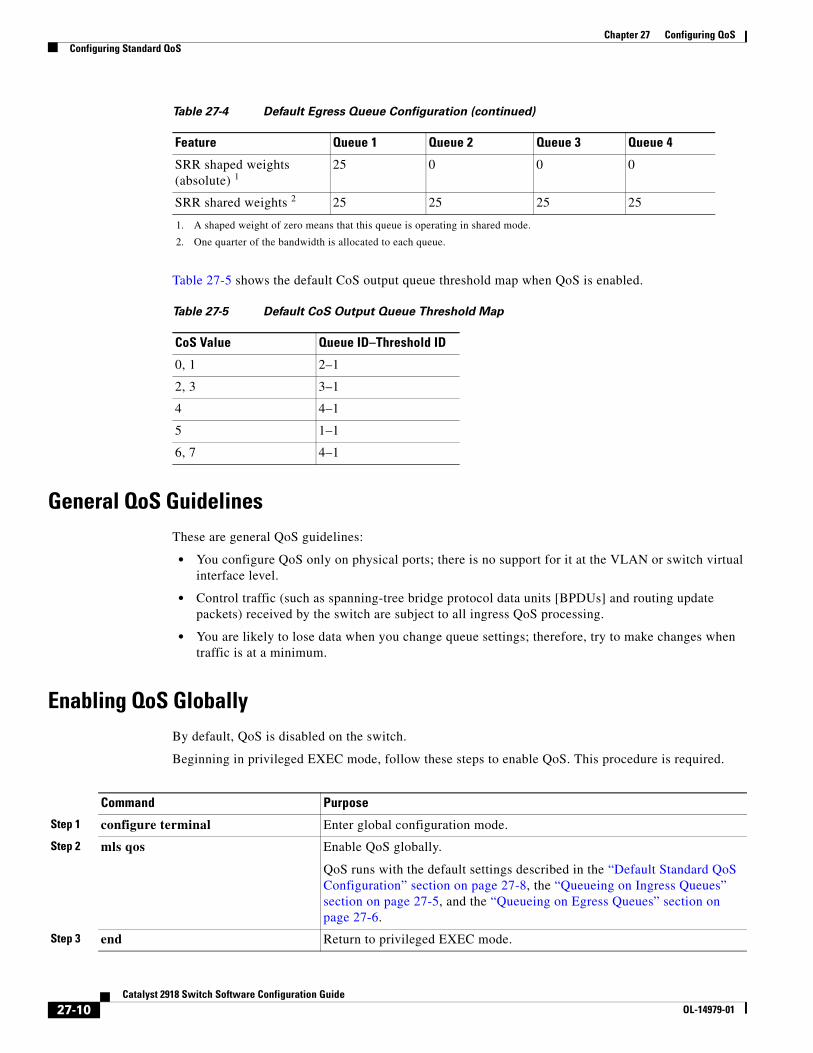
Chapter 27 Configuring QoSConfiguring Standard QoS
Table 27-5 shows the default CoS output queue threshold map when QoS is enabled.
Table 27-5 Default CoS Output Queue Threshold Map
CoS Value Queue ID–Threshold ID
0, 1 2–1
2, 3 3–1
4 4–1
5 1–1
6, 7 4–1
General QoS GuidelinesThese are general QoS guidelines:
• You configure QoS only on physical ports; there is no support for it at the VLAN or switch virtual interface level.
• Control traffic (such as spanning-tree bridge protocol data units [BPDUs] and routing update packets) received by the switch are subject to all ingress QoS processing.
• You are likely to lose data when you change queue settings; therefore, try to make changes when traffic is at a minimum.
Enabling QoS GloballyBy default, QoS is disabled on the switch.
Beginning in privileged EXEC mode, follow these steps to enable QoS. This procedure is required.
SRR shaped weights (absolute) 1
25 0 0 0
SRR shared weights 2 25 25 25 25
1. A shaped weight of zero means that this queue is operating in shared mode.
2. One quarter of the bandwidth is allocated to each queue.
Table 27-4 Default Egress Queue Configuration (continued)
Feature Queue 1 Queue 2 Queue 3 Queue 4
Command Purpose
Step 1 configure terminal Enter global configuration mode.
Step 2 mls qos Enable QoS globally.
QoS runs with the default settings described in the “Default Standard QoS Configuration” section on page 27-8, the “Queueing on Ingress Queues” section on page 27-5, and the “Queueing on Egress Queues” section on page 27-6.
Step 3 end Return to privileged EXEC mode.
27-10Catalyst 2918 Switch Software Configuration Guide
OL-14979-01
Chapter 27 Configuring QoSConfiguring Standard QoS
To disable QoS, use the no mls qos global configuration command.
Configuring Classification Using Port Trust StatesThese sections describe how to classify incoming traffic by using port trust states. Depending on your network configuration, you must perform one or more of these tasks.
• Configuring the Trust State on Ports within the QoS Domain, page 27-11
• Configuring the CoS Value for an Interface, page 27-13
• Enabling DSCP Transparency Mode, page 27-13
Configuring the Trust State on Ports within the QoS Domain
Packets entering a QoS domain are classified at the edge of the QoS domain. When the packets are classified at the edge, the switch port within the QoS domain can be configured to one of the trusted states because there is no need to classify the packets at every switch within the QoS domain. Figure 27-6 shows a sample network topology.
Step 4 show mls qos Verify your entries.
Step 5 copy running-config startup-config (Optional) Save your entries in the configuration file.
Command Purpose
27-11Catalyst 2918 Switch Software Configuration Guide
OL-14979-01
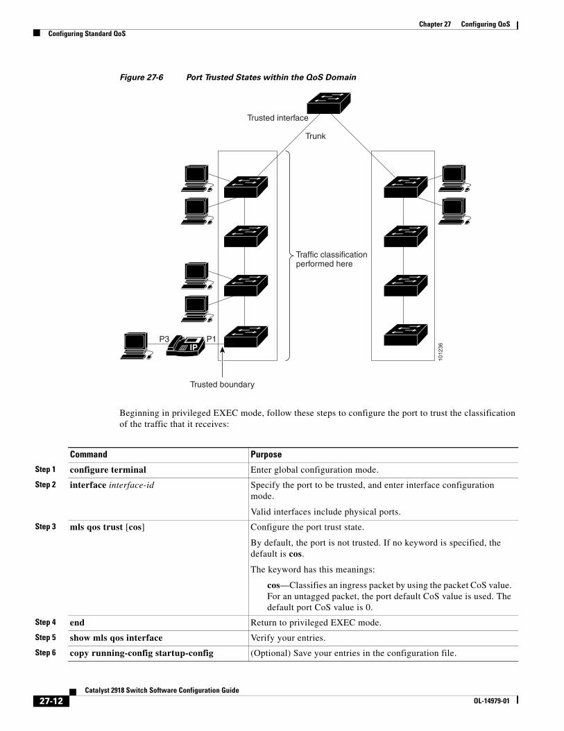
Chapter 27 Configuring QoSConfiguring Standard QoS
Figure 27-6 Port Trusted States within the QoS Domain
1012
36
Trunk
Trusted interface
Traffic classificationperformed here
Trusted boundary
IPP1P3
Beginning in privileged EXEC mode, follow these steps to configure the port to trust the classification of the traffic that it receives:
Command Purpose
Step 1 configure terminal Enter global configuration mode.
Step 2 interface interface-id Specify the port to be trusted, and enter interface configuration mode.
Valid interfaces include physical ports.
Step 3 mls qos trust [cos] Configure the port trust state.
By default, the port is not trusted. If no keyword is specified, the default is cos.
The keyword has this meanings:
cos—Classifies an ingress packet by using the packet CoS value. For an untagged packet, the port default CoS value is used. The default port CoS value is 0.
Step 4 end Return to privileged EXEC mode.
Step 5 show mls qos interface Verify your entries.
Step 6 copy running-config startup-config (Optional) Save your entries in the configuration file.
27-12Catalyst 2918 Switch Software Configuration Guide
OL-14979-01
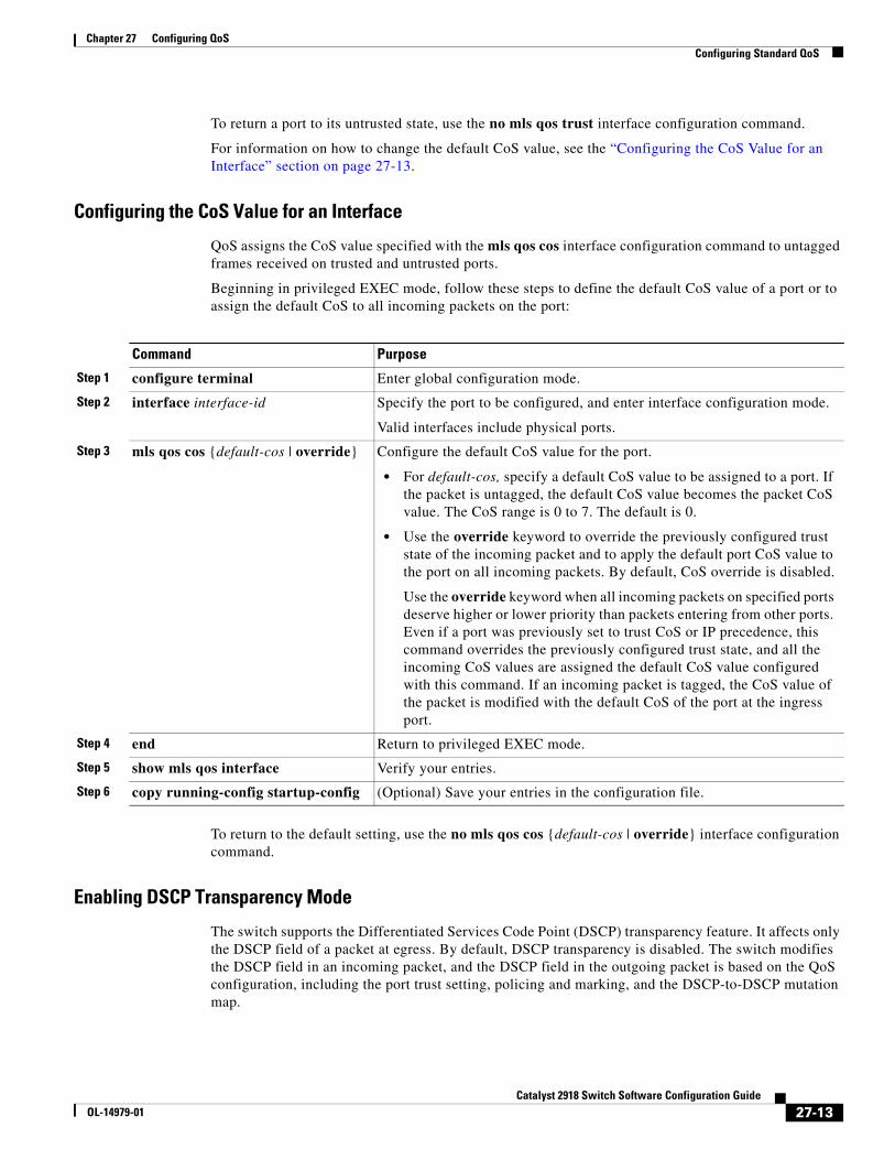
Chapter 27 Configuring QoSConfiguring Standard QoS
To return a port to its untrusted state, use the no mls qos trust interface configuration command.
For information on how to change the default CoS value, see the “Configuring the CoS Value for an Interface” section on page 27-13.
Configuring the CoS Value for an Interface
QoS assigns the CoS value specified with the mls qos cos interface configuration command to untagged frames received on trusted and untrusted ports.
Beginning in privileged EXEC mode, follow these steps to define the default CoS value of a port or to assign the default CoS to all incoming packets on the port:
Command Purpose
Step 1 configure terminal Enter global configuration mode.
Step 2 interface interface-id Specify the port to be configured, and enter interface configuration mode.
Valid interfaces include physical ports.
Step 3 mls qos cos {default-cos | override} Configure the default CoS value for the port.
• For default-cos, specify a default CoS value to be assigned to a port. If the packet is untagged, the default CoS value becomes the packet CoS value. The CoS range is 0 to 7. The default is 0.
• Use the override keyword to override the previously configured trust state of the incoming packet and to apply the default port CoS value to the port on all incoming packets. By default, CoS override is disabled.
Use the override keyword when all incoming packets on specified ports deserve higher or lower priority than packets entering from other ports. Even if a port was previously set to trust CoS or IP precedence, this command overrides the previously configured trust state, and all the incoming CoS values are assigned the default CoS value configured with this command. If an incoming packet is tagged, the CoS value of the packet is modified with the default CoS of the port at the ingress port.
Step 4 end Return to privileged EXEC mode.
Step 5 show mls qos interface Verify your entries.
Step 6 copy running-config startup-config (Optional) Save your entries in the configuration file.
To return to the default setting, use the no mls qos cos {default-cos | override} interface configuration command.
Enabling DSCP Transparency Mode
The switch supports the Differentiated Services Code Point (DSCP) transparency feature. It affects only the DSCP field of a packet at egress. By default, DSCP transparency is disabled. The switch modifies the DSCP field in an incoming packet, and the DSCP field in the outgoing packet is based on the QoS configuration, including the port trust setting, policing and marking, and the DSCP-to-DSCP mutation map.
27-13Catalyst 2918 Switch Software Configuration Guide
OL-14979-01
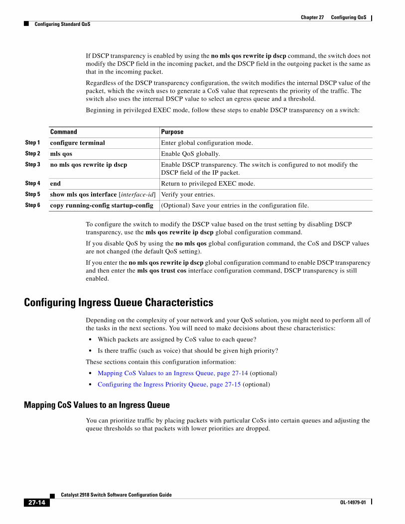
Chapter 27 Configuring QoSConfiguring Standard QoS
If DSCP transparency is enabled by using the no mls qos rewrite ip dscp command, the switch does not modify the DSCP field in the incoming packet, and the DSCP field in the outgoing packet is the same as that in the incoming packet.
Regardless of the DSCP transparency configuration, the switch modifies the internal DSCP value of the packet, which the switch uses to generate a CoS value that represents the priority of the traffic. The switch also uses the internal DSCP value to select an egress queue and a threshold.
Beginning in privileged EXEC mode, follow these steps to enable DSCP transparency on a switch:
Command Purpose
Step 1 configure terminal Enter global configuration mode.
Step 2 mls qos Enable QoS globally.
Step 3 no mls qos rewrite ip dscp Enable DSCP transparency. The switch is configured to not modify the DSCP field of the IP packet.
Step 4 end Return to privileged EXEC mode.
Step 5 show mls qos interface [interface-id] Verify your entries.
Step 6 copy running-config startup-config (Optional) Save your entries in the configuration file.
To configure the switch to modify the DSCP value based on the trust setting by disabling DSCP transparency, use the mls qos rewrite ip dscp global configuration command.
If you disable QoS by using the no mls qos global configuration command, the CoS and DSCP values are not changed (the default QoS setting).
If you enter the no mls qos rewrite ip dscp global configuration command to enable DSCP transparency and then enter the mls qos trust cos interface configuration command, DSCP transparency is still enabled.
Configuring Ingress Queue CharacteristicsDepending on the complexity of your network and your QoS solution, you might need to perform all of the tasks in the next sections. You will need to make decisions about these characteristics:
• Which packets are assigned by CoS value to each queue?
• Is there traffic (such as voice) that should be given high priority?
These sections contain this configuration information:
• Mapping CoS Values to an Ingress Queue, page 27-14 (optional)
• Configuring the Ingress Priority Queue, page 27-15 (optional)
Mapping CoS Values to an Ingress Queue
You can prioritize traffic by placing packets with particular CoSs into certain queues and adjusting the queue thresholds so that packets with lower priorities are dropped.
27-14Catalyst 2918 Switch Software Configuration Guide
OL-14979-01
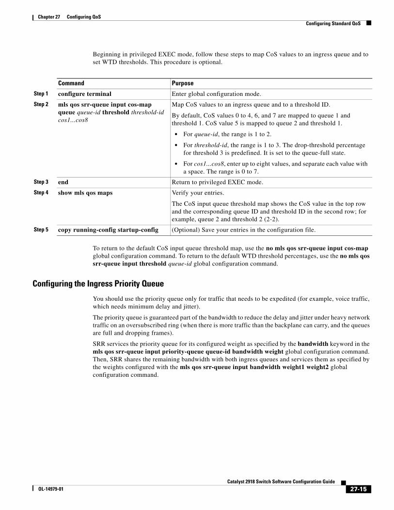
Chapter 27 Configuring QoSConfiguring Standard QoS
Beginning in privileged EXEC mode, follow these steps to map CoS values to an ingress queue and to set WTD thresholds. This procedure is optional.
Command Purpose
Step 1 configure terminal Enter global configuration mode.
Step 2 mls qos srr-queue input cos-map queue queue-id threshold threshold-id cos1...cos8
Map CoS values to an ingress queue and to a threshold ID.
By default, CoS values 0 to 4, 6, and 7 are mapped to queue 1 and threshold 1. CoS value 5 is mapped to queue 2 and threshold 1.
• For queue-id, the range is 1 to 2.
• For threshold-id, the range is 1 to 3. The drop-threshold percentage for threshold 3 is predefined. It is set to the queue-full state.
• For cos1...cos8, enter up to eight values, and separate each value with a space. The range is 0 to 7.
Step 3 end Return to privileged EXEC mode.
Step 4 show mls qos maps Verify your entries.
The CoS input queue threshold map shows the CoS value in the top row and the corresponding queue ID and threshold ID in the second row; for example, queue 2 and threshold 2 (2-2).
Step 5 copy running-config startup-config (Optional) Save your entries in the configuration file.
To return to the default CoS input queue threshold map, use the no mls qos srr-queue input cos-map global configuration command. To return to the default WTD threshold percentages, use the no mls qos srr-queue input threshold queue-id global configuration command.
Configuring the Ingress Priority Queue
You should use the priority queue only for traffic that needs to be expedited (for example, voice traffic, which needs minimum delay and jitter).
The priority queue is guaranteed part of the bandwidth to reduce the delay and jitter under heavy network traffic on an oversubscribed ring (when there is more traffic than the backplane can carry, and the queues are full and dropping frames).
SRR services the priority queue for its configured weight as specified by the bandwidth keyword in the mls qos srr-queue input priority-queue queue-id bandwidth weight global configuration command. Then, SRR shares the remaining bandwidth with both ingress queues and services them as specified by the weights configured with the mls qos srr-queue input bandwidth weight1 weight2 global configuration command.
27-15Catalyst 2918 Switch Software Configuration Guide
OL-14979-01
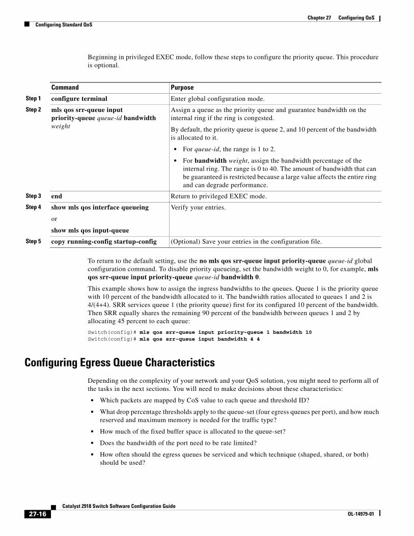
Chapter 27 Configuring QoSConfiguring Standard QoS
Beginning in privileged EXEC mode, follow these steps to configure the priority queue. This procedure is optional.
Command Purpose
Step 1 configure terminal Enter global configuration mode.
Step 2 mls qos srr-queue input priority-queue queue-id bandwidth weight
Assign a queue as the priority queue and guarantee bandwidth on the internal ring if the ring is congested.
By default, the priority queue is queue 2, and 10 percent of the bandwidth is allocated to it.
• For queue-id, the range is 1 to 2.
• For bandwidth weight, assign the bandwidth percentage of the internal ring. The range is 0 to 40. The amount of bandwidth that can be guaranteed is restricted because a large value affects the entire ring and can degrade performance.
Step 3 end Return to privileged EXEC mode.
Step 4 show mls qos interface queueing
or
show mls qos input-queue
Verify your entries.
Step 5 copy running-config startup-config (Optional) Save your entries in the configuration file.
To return to the default setting, use the no mls qos srr-queue input priority-queue queue-id global configuration command. To disable priority queueing, set the bandwidth weight to 0, for example, mls qos srr-queue input priority-queue queue-id bandwidth 0.
This example shows how to assign the ingress bandwidths to the queues. Queue 1 is the priority queue with 10 percent of the bandwidth allocated to it. The bandwidth ratios allocated to queues 1 and 2 is 4/(4+4). SRR services queue 1 (the priority queue) first for its configured 10 percent of the bandwidth. Then SRR equally shares the remaining 90 percent of the bandwidth between queues 1 and 2 by allocating 45 percent to each queue:
Switch(config)# mls qos srr-queue input priority-queue 1 bandwidth 10Switch(config)# mls qos srr-queue input bandwidth 4 4
Configuring Egress Queue CharacteristicsDepending on the complexity of your network and your QoS solution, you might need to perform all of the tasks in the next sections. You will need to make decisions about these characteristics:
• Which packets are mapped by CoS value to each queue and threshold ID?
• What drop percentage thresholds apply to the queue-set (four egress queues per port), and how much reserved and maximum memory is needed for the traffic type?
• How much of the fixed buffer space is allocated to the queue-set?
• Does the bandwidth of the port need to be rate limited?
• How often should the egress queues be serviced and which technique (shaped, shared, or both) should be used?
27-16Catalyst 2918 Switch Software Configuration Guide
OL-14979-01
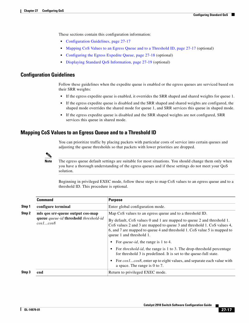
Chapter 27 Configuring QoSConfiguring Standard QoS
These sections contain this configuration information:
• Configuration Guidelines, page 27-17
• Mapping CoS Values to an Egress Queue and to a Threshold ID, page 27-17 (optional)
• Configuring the Egress Expedite Queue, page 27-18 (optional)
• Displaying Standard QoS Information, page 27-19 (optional)
Configuration Guidelines
Follow these guidelines when the expedite queue is enabled or the egress queues are serviced based on their SRR weights:
• If the egress expedite queue is enabled, it overrides the SRR shaped and shared weights for queue 1.
• If the egress expedite queue is disabled and the SRR shaped and shared weights are configured, the shaped mode overrides the shared mode for queue 1, and SRR services this queue in shaped mode.
• If the egress expedite queue is disabled and the SRR shaped weights are not configured, SRR services this queue in shared mode.
Mapping CoS Values to an Egress Queue and to a Threshold ID
You can prioritize traffic by placing packets with particular costs of service into certain queues and adjusting the queue thresholds so that packets with lower priorities are dropped.
Note The egress queue default settings are suitable for most situations. You should change them only when you have a thorough understanding of the egress queues and if these settings do not meet your QoS solution.
Beginning in privileged EXEC mode, follow these steps to map CoS values to an egress queue and to a threshold ID. This procedure is optional.
Command Purpose
Step 1 configure terminal Enter global configuration mode.
Step 2 mls qos srr-queue output cos-map queue queue-id threshold threshold-id cos1...cos8
Map CoS values to an egress queue and to a threshold ID.
By default, CoS values 0 and 1 are mapped to queue 2 and threshold 1. CoS values 2 and 3 are mapped to queue 3 and threshold 1. CoS values 4, 6, and 7 are mapped to queue 4 and threshold 1. CoS value 5 is mapped to queue 1 and threshold 1.
• For queue-id, the range is 1 to 4.
• For threshold-id, the range is 1 to 3. The drop-threshold percentage for threshold 3 is predefined. It is set to the queue-full state.
• For cos1...cos8, enter up to eight values, and separate each value with a space. The range is 0 to 7.
Step 3 end Return to privileged EXEC mode.
27-17Catalyst 2918 Switch Software Configuration Guide
OL-14979-01
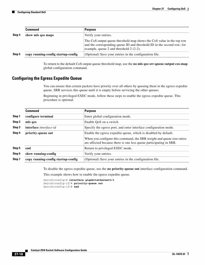
Chapter 27 Configuring QoSConfiguring Standard QoS
To return to the default CoS output queue threshold map, use the no mls qos srr-queue output cos-map global configuration command.
Configuring the Egress Expedite Queue
You can ensure that certain packets have priority over all others by queuing them in the egress expedite queue. SRR services this queue until it is empty before servicing the other queues.
Beginning in privileged EXEC mode, follow these steps to enable the egress expedite queue. This procedure is optional.
Command Purpose
Step 1 configure terminal Enter global configuration mode.
Step 2 mls qos Enable QoS on a switch.
Step 3 interface interface-id Specify the egress port, and enter interface configuration mode.
Step 4 priority-queue out Enable the egress expedite queue, which is disabled by default.
When you configure this command, the SRR weight and queue size ratios are affected because there is one less queue participating in SRR.
Step 5 end Return to privileged EXEC mode.
Step 6 show running-config Verify your entries.
Step 7 copy running-config startup-config (Optional) Save your entries in the configuration file.
To disable the egress expedite queue, use the no priority-queue out interface configuration command.
This example shows how to enable the egress expedite queue.
Switch(config)# interface gigabitethernet0/1Switch(config-if)# priority-queue outSwitch(config-if)# end
Step 4 show mls qos maps Verify your entries.
The CoS output queue threshold map shows the CoS value in the top row and the corresponding queue ID and threshold ID in the second row; for example, queue 2 and threshold 2 (2-2).
Step 5 copy running-config startup-config (Optional) Save your entries in the configuration file.
Command Purpose
27-18Catalyst 2918 Switch Software Configuration Guide
OL-14979-01
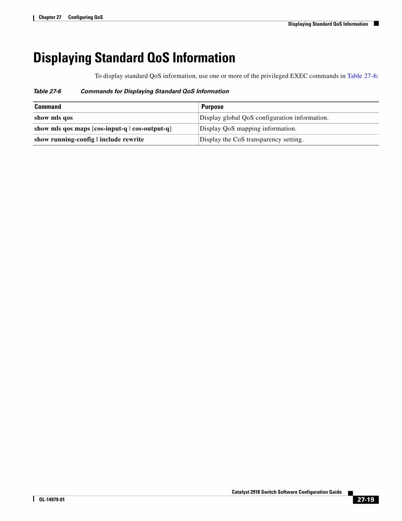
Chapter 27 Configuring QoSDisplaying Standard QoS Information
Displaying Standard QoS InformationTo display standard QoS information, use one or more of the privileged EXEC commands in Table 27-6:
Table 27-6 Commands for Displaying Standard QoS Information
Command Purpose
show mls qos Display global QoS configuration information.
show mls qos maps [cos-input-q | cos-output-q] Display QoS mapping information.
show running-config | include rewrite Display the CoS transparency setting.
27-19Catalyst 2918 Switch Software Configuration Guide
OL-14979-01

Chapter 27 Configuring QoSDisplaying Standard QoS Information
27-20Catalyst 2918 Switch Software Configuration Guide
OL-14979-01
OL-14979-01
C H A P T E R 28
Configuring EtherChannelsThis chapter describes how to configure EtherChannels on Layer 2 ports on the Catalyst 2918 switch. EtherChannel provides fault-tolerant high-speed links between switches, routers, and servers. You can use it to increase the bandwidth between the wiring closets and the data center, and you can deploy it anywhere in the network where bottlenecks are likely to occur. EtherChannel provides automatic recovery for the loss of a link by redistributing the load across the remaining links. If a link fails, EtherChannel redirects traffic from the failed link to the remaining links in the channel without intervention.
Note For complete syntax and usage information for the commands used in this chapter, see the command reference for this release.
This chapter consists of these sections:
• Understanding EtherChannels, page 28-1
• Configuring EtherChannels, page 28-8
• Displaying EtherChannel, PAgP, and LACP Status, page 28-16
Understanding EtherChannelsThese sections describe how EtherChannels work:
• EtherChannel Overview, page 28-2
• Port-Channel Interfaces, page 28-3
• Port Aggregation Protocol, page 28-4
• Link Aggregation Control Protocol, page 28-5
• EtherChannel On Mode, page 28-6
• Load Balancing and Forwarding Methods, page 28-6
28-1Catalyst 2918 Switch Software Configuration Guide
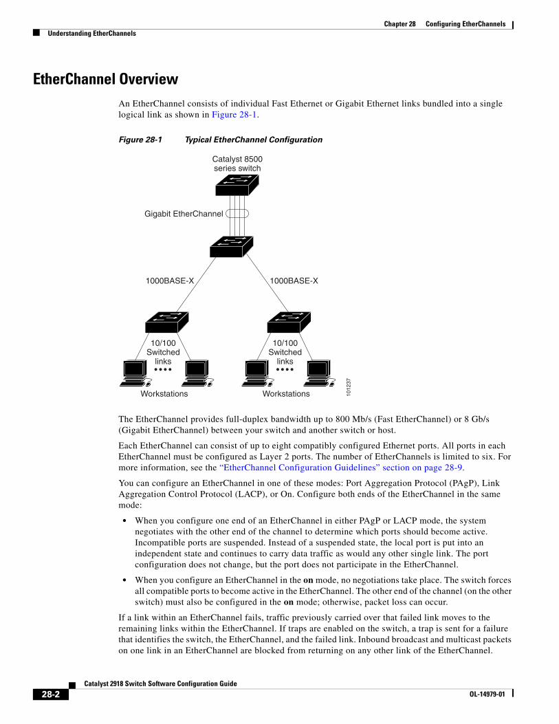
Chapter 28 Configuring EtherChannelsUnderstanding EtherChannels
EtherChannel OverviewAn EtherChannel consists of individual Fast Ethernet or Gigabit Ethernet links bundled into a single logical link as shown in Figure 28-1.
Figure 28-1 Typical EtherChannel Configuration
1012
37
Catalyst 8500series switch
Gigabit EtherChannel
Workstations
10/100Switched
links
Workstations
10/100Switched
links
1000BASE-X 1000BASE-X
The EtherChannel provides full-duplex bandwidth up to 800 Mb/s (Fast EtherChannel) or 8 Gb/s (Gigabit EtherChannel) between your switch and another switch or host.
Each EtherChannel can consist of up to eight compatibly configured Ethernet ports. All ports in each EtherChannel must be configured as Layer 2 ports. The number of EtherChannels is limited to six. For more information, see the “EtherChannel Configuration Guidelines” section on page 28-9.
You can configure an EtherChannel in one of these modes: Port Aggregation Protocol (PAgP), Link Aggregation Control Protocol (LACP), or On. Configure both ends of the EtherChannel in the same mode:
• When you configure one end of an EtherChannel in either PAgP or LACP mode, the system negotiates with the other end of the channel to determine which ports should become active. Incompatible ports are suspended. Instead of a suspended state, the local port is put into an independent state and continues to carry data traffic as would any other single link. The port configuration does not change, but the port does not participate in the EtherChannel.
• When you configure an EtherChannel in the on mode, no negotiations take place. The switch forces all compatible ports to become active in the EtherChannel. The other end of the channel (on the other switch) must also be configured in the on mode; otherwise, packet loss can occur.
If a link within an EtherChannel fails, traffic previously carried over that failed link moves to the remaining links within the EtherChannel. If traps are enabled on the switch, a trap is sent for a failure that identifies the switch, the EtherChannel, and the failed link. Inbound broadcast and multicast packets on one link in an EtherChannel are blocked from returning on any other link of the EtherChannel.
28-2Catalyst 2918 Switch Software Configuration Guide
OL-14979-01
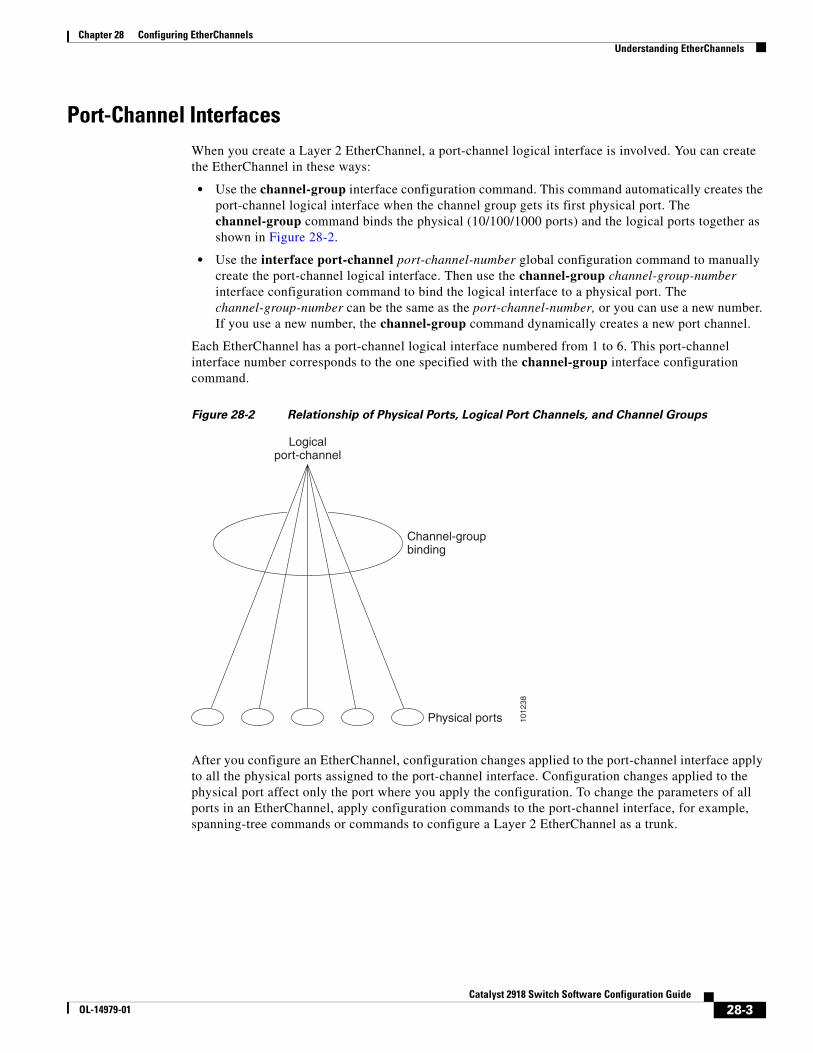
Chapter 28 Configuring EtherChannelsUnderstanding EtherChannels
Port-Channel InterfacesWhen you create a Layer 2 EtherChannel, a port-channel logical interface is involved. You can create the EtherChannel in these ways:
• Use the channel-group interface configuration command. This command automatically creates the port-channel logical interface when the channel group gets its first physical port. The channel-group command binds the physical (10/100/1000 ports) and the logical ports together as shown in Figure 28-2.
• Use the interface port-channel port-channel-number global configuration command to manually create the port-channel logical interface. Then use the channel-group channel-group-number interface configuration command to bind the logical interface to a physical port. The channel-group-number can be the same as the port-channel-number, or you can use a new number. If you use a new number, the channel-group command dynamically creates a new port channel.
Each EtherChannel has a port-channel logical interface numbered from 1 to 6. This port-channel interface number corresponds to the one specified with the channel-group interface configuration command.
Figure 28-2 Relationship of Physical Ports, Logical Port Channels, and Channel Groups
1012
38
Channel-groupbinding
Physical ports
Logicalport-channel
After you configure an EtherChannel, configuration changes applied to the port-channel interface apply to all the physical ports assigned to the port-channel interface. Configuration changes applied to the physical port affect only the port where you apply the configuration. To change the parameters of all ports in an EtherChannel, apply configuration commands to the port-channel interface, for example, spanning-tree commands or commands to configure a Layer 2 EtherChannel as a trunk.
28-3Catalyst 2918 Switch Software Configuration Guide
OL-14979-01
Chapter 28 Configuring EtherChannelsUnderstanding EtherChannels
Port Aggregation ProtocolThe Port Aggregation Protocol (PAgP) is a Cisco-proprietary protocol that can be run only on Cisco switches and on those switches licensed by vendors to support PAgP. PAgP facilitates the automatic creation of EtherChannels by exchanging PAgP packets between Ethernet ports.
By using PAgP, the switch learns the identity of partners capable of supporting PAgP and the capabilities of each port. It then dynamically groups similarly configured ports into a single logical link (channel or aggregate port). Similarly configured ports are grouped based on hardware, administrative, and port parameter constraints. For example, PAgP groups the ports with the same speed, duplex mode, native VLAN, VLAN range, and trunking status and type. After grouping the links into an EtherChannel, PAgP adds the group to the spanning tree as a single switch port.
PAgP Modes
Table 28-1 shows the user-configurable EtherChannel PAgP modes for the channel-group interface configuration command.
Table 28-1 EtherChannel PAgP Modes
Mode Description
auto Places a port into a passive negotiating state, in which the port responds to PAgP packets it receives but does not start PAgP packet negotiation. This setting minimizes the transmission of PAgP packets.
desirable Places a port into an active negotiating state, in which the port starts negotiations with other ports by sending PAgP packets.
Switch ports exchange PAgP packets only with partner ports configured in the auto or desirable modes. Ports configured in the on mode do not exchange PAgP packets.
Both the auto and desirable modes enable ports to negotiate with partner ports to form an EtherChannel based on criteria such as port speed and, for Layer 2 EtherChannels, trunking state and VLAN numbers.
Ports can form an EtherChannel when they are in different PAgP modes as long as the modes are compatible. For example:
• A port in the desirable mode can form an EtherChannel with another port that is in the desirable or auto mode.
• A port in the auto mode can form an EtherChannel with another port in the desirable mode.
A port in the auto mode cannot form an EtherChannel with another port that is also in the auto mode because neither port starts PAgP negotiation.
If your switch is connected to a partner that is PAgP-capable, you can configure the switch port for nonsilent operation by using the non-silent keyword. If you do not specify non-silent with the auto or desirable mode, silent mode is assumed.
Use the silent mode when the switch is connected to a device that is not PAgP-capable and seldom, if ever, sends packets. An example of a silent partner is a file server or a packet analyzer that is not generating traffic. In this case, running PAgP on a physical port connected to a silent partner prevents that switch port from ever becoming operational. However, the silent setting allows PAgP to operate, to attach the port to a channel group, and to use the port for transmission.
28-4Catalyst 2918 Switch Software Configuration Guide
OL-14979-01
Chapter 28 Configuring EtherChannelsUnderstanding EtherChannels
PAgP Interaction with Other Features
The Dynamic Trunking Protocol (DTP) and the Cisco Discovery Protocol (CDP) send and receive packets over the physical ports in the EtherChannel. Trunk ports send and receive PAgP protocol data units (PDUs) on the lowest numbered VLAN.
In Layer 2 EtherChannels, the first port in the channel that comes up provides its MAC address to the EtherChannel. If this port is removed from the bundle, one of the remaining ports in the bundle provides its MAC address to the EtherChannel.
PAgP sends and receives PAgP PDUs only from ports that are up and have PAgP enabled for the auto or desirable mode.
Link Aggregation Control ProtocolThe LACP is defined in IEEE 802.3ad and enables Cisco switches to manage Ethernet channels between switches that conform to the IEEE 802.3ad protocol. LACP facilitates the automatic creation of EtherChannels by exchanging LACP packets between Ethernet ports.
By using LACP, the switch learns the identity of partners capable of supporting LACP and the capabilities of each port. It then dynamically groups similarly configured ports into a single logical link (channel or aggregate port). Similarly configured ports are grouped based on hardware, administrative, and port parameter constraints. For example, LACP groups the ports with the same speed, duplex mode, native VLAN, VLAN range, and trunking status and type. After grouping the links into an EtherChannel, LACP adds the group to the spanning tree as a single switch port.
LACP Modes
Table 28-2 shows the user-configurable EtherChannel LACP modes for the channel-group interface configuration command.
Table 28-2 EtherChannel LACP Modes
Mode Description
active Places a port into an active negotiating state in which the port starts negotiations with other ports by sending LACP packets.
passive Places a port into a passive negotiating state in which the port responds to LACP packets that it receives, but does not start LACP packet negotiation. This setting minimizes the transmission of LACP packets.
Both the active and passive LACP modes enable ports to negotiate with partner ports to an EtherChannel based on criteria such as port speed and, for Layer 2 EtherChannels, trunking state and VLAN numbers.
Ports can form an EtherChannel when they are in different LACP modes as long as the modes are compatible. For example:
• A port in the active mode can form an EtherChannel with another port that is in the active or passive mode.
• A port in the passive mode cannot form an EtherChannel with another port that is also in the passive mode because neither port starts LACP negotiation.
28-5Catalyst 2918 Switch Software Configuration Guide
OL-14979-01
Chapter 28 Configuring EtherChannelsUnderstanding EtherChannels
LACP Interaction with Other Features
The DTP and the CDP send and receive packets over the physical ports in the EtherChannel. Trunk ports send and receive LACP PDUs on the lowest numbered VLAN.
In Layer 2 EtherChannels, the first port in the channel that comes up provides its MAC address to the EtherChannel. If this port is removed from the bundle, one of the remaining ports in the bundle provides its MAC address to the EtherChannel.
LACP sends and receives LACP PDUs only from ports that are up and have LACP enabled for the active or passive mode.
EtherChannel On ModeEtherChannel on mode can be used to manually configure an EtherChannel. The on mode forces a port to join an EtherChannel without negotiations. The on mode can be useful if the remote device does not support PAgP or LACP. In the on mode, a usable EtherChannel exists only when the switches at both ends of the link are configured in the on mode.
Ports that are configured in the on mode in the same channel group must have compatible port characteristics, such as speed and duplex. Ports that are not compatible are suspended, even though they are configured in the on mode.
Caution You should use care when using the on mode. This is a manual configuration, and ports on both ends of the EtherChannel must have the same configuration. If the group is misconfigured, packet loss or spanning-tree loops can occur.
Load Balancing and Forwarding MethodsEtherChannel balances the traffic load across the links in a channel by reducing part of the binary pattern formed from the addresses in the frame to a numerical value that selects one of the links in the channel. EtherChannel load balancing can use MAC addresses or IP addresses, source or destination addresses, or both source and destination addresses. The selected mode applies to all EtherChannels configured on the switch. You configure the load balancing and forwarding method by using the port-channel load-balance global configuration command.
With source-MAC address forwarding, when packets are forwarded to an EtherChannel, they are distributed across the ports in the channel based on the source-MAC address of the incoming packet. Therefore, to provide load balancing, packets from different hosts use different ports in the channel, but packets from the same host use the same port in the channel.
With destination-MAC address forwarding, when packets are forwarded to an EtherChannel, they are distributed across the ports in the channel based on the destination host’s MAC address of the incoming packet. Therefore, packets to the same destination are forwarded over the same port, and packets to a different destination are sent on a different port in the channel.
With source-and-destination MAC address forwarding, when packets are forwarded to an EtherChannel, they are distributed across the ports in the channel based on both the source and destination MAC addresses. This forwarding method, a combination source-MAC and destination-MAC address forwarding methods of load distribution, can be used if it is not clear whether source-MAC or destination-MAC address forwarding is better suited on a particular switch. With source-and-destination MAC-address forwarding, packets sent from host A to host B, host A to host C, and host C to host B could all use different ports in the channel.
28-6Catalyst 2918 Switch Software Configuration Guide
OL-14979-01
Chapter 28 Configuring EtherChannelsUnderstanding EtherChannels
With source-IP address-based forwarding, when packets are forwarded to an EtherChannel, they are distributed across the ports in the EtherChannel based on the source-IP address of the incoming packet. Therefore, to provide load-balancing, packets from different IP addresses use different ports in the channel, but packets from the same IP address use the same port in the channel.
With destination-IP address-based forwarding, when packets are forwarded to an EtherChannel, they are distributed across the ports in the EtherChannel based on the destination-IP address of the incoming packet. Therefore, to provide load-balancing, packets from the same IP source address sent to different IP destination addresses could be sent on different ports in the channel. But packets sent from different source IP addresses to the same destination IP address are always sent on the same port in the channel.
With source-and-destination IP address-based forwarding, packets are sent to an EtherChannel and distributed across the EtherChannel ports, based on both the source and destination IP addresses of the incoming packet. This forwarding method, a combination of source-IP and destination-IP address-based forwarding, can be used if it is not clear whether source-IP or destination-IP address-based forwarding is better suited on a particular switch. In this method, packets sent from the IP address A to IP address B, from IP address A to IP address C, and from IP address C to IP address B could all use different ports in the channel.
Different load-balancing methods have different advantages, and the choice of a particular load-balancing method should be based on the position of the switch in the network and the kind of traffic that needs to be load-distributed. In Figure 28-3, an EtherChannel from a witch that is aggregating data from four workstations communicates with a router. Because the router is a single-MAC-address device, source-based forwarding on the switch EtherChannel ensures that the switch uses all available bandwidth to the router. The router is configured for destination-based forwarding because the large number of workstations ensures that the traffic is evenly distributed from the router EtherChannel.
Use the option that provides the greatest variety in your configuration. For example, if the traffic on a channel is only going to a single MAC address, using the destination-MAC address always chooses the same link in the channel. Using source addresses or IP addresses might result in better load balancing.
28-7Catalyst 2918 Switch Software Configuration Guide
OL-14979-01
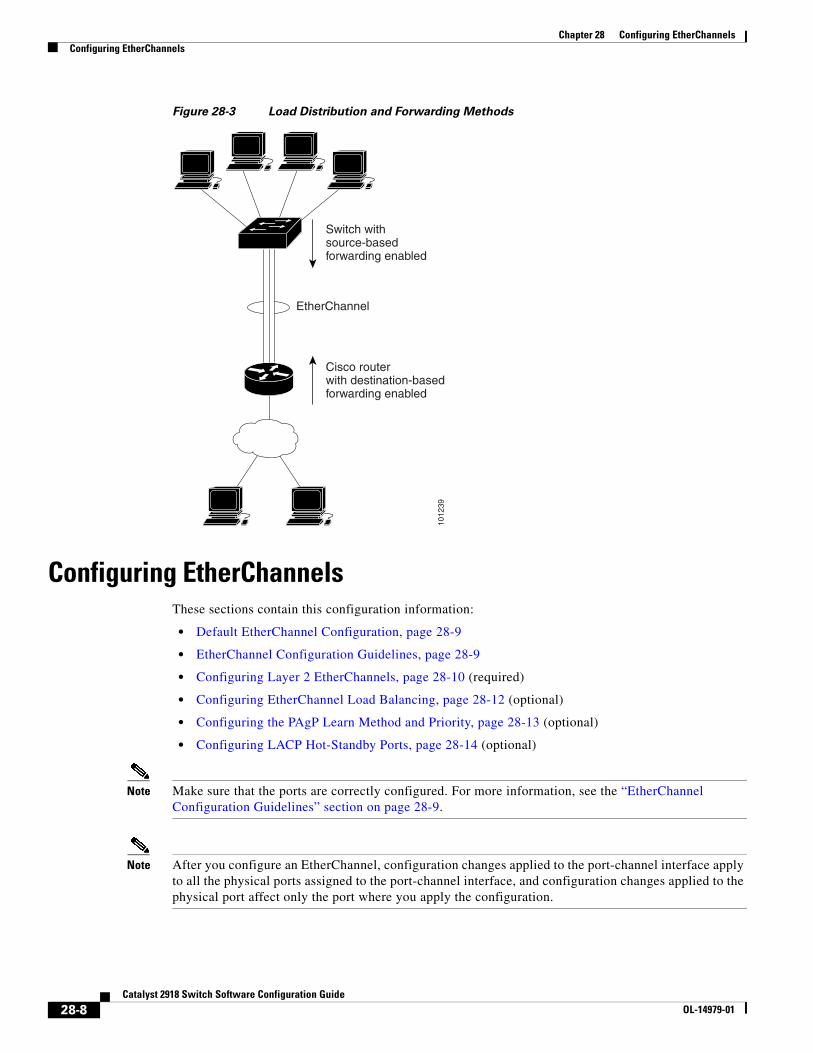
Chapter 28 Configuring EtherChannelsConfiguring EtherChannels
Figure 28-3 Load Distribution and Forwarding Methods
1012
39
Cisco routerwith destination-basedforwarding enabled
EtherChannel
Switch withsource-basedforwarding enabled
Configuring EtherChannelsThese sections contain this configuration information:
• Default EtherChannel Configuration, page 28-9
• EtherChannel Configuration Guidelines, page 28-9
• Configuring Layer 2 EtherChannels, page 28-10 (required)
• Configuring EtherChannel Load Balancing, page 28-12 (optional)
• Configuring the PAgP Learn Method and Priority, page 28-13 (optional)
• Configuring LACP Hot-Standby Ports, page 28-14 (optional)
Note Make sure that the ports are correctly configured. For more information, see the “EtherChannel Configuration Guidelines” section on page 28-9.
Note After you configure an EtherChannel, configuration changes applied to the port-channel interface apply to all the physical ports assigned to the port-channel interface, and configuration changes applied to the physical port affect only the port where you apply the configuration.
28-8Catalyst 2918 Switch Software Configuration Guide
OL-14979-01
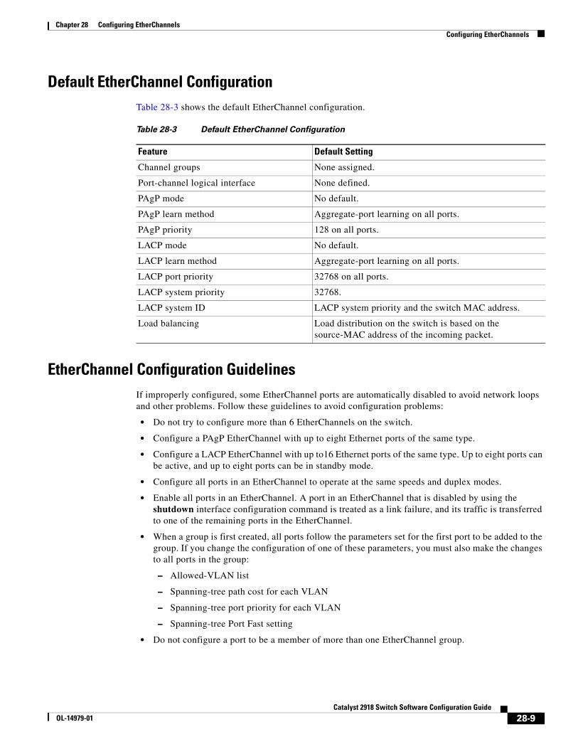
Chapter 28 Configuring EtherChannelsConfiguring EtherChannels
Default EtherChannel ConfigurationTable 28-3 shows the default EtherChannel configuration.
Table 28-3 Default EtherChannel Configuration
Feature Default Setting
Channel groups None assigned.
Port-channel logical interface None defined.
PAgP mode No default.
PAgP learn method Aggregate-port learning on all ports.
PAgP priority 128 on all ports.
LACP mode No default.
LACP learn method Aggregate-port learning on all ports.
LACP port priority 32768 on all ports.
LACP system priority 32768.
LACP system ID LACP system priority and the switch MAC address.
Load balancing Load distribution on the switch is based on the source-MAC address of the incoming packet.
EtherChannel Configuration GuidelinesIf improperly configured, some EtherChannel ports are automatically disabled to avoid network loops and other problems. Follow these guidelines to avoid configuration problems:
• Do not try to configure more than 6 EtherChannels on the switch.
• Configure a PAgP EtherChannel with up to eight Ethernet ports of the same type.
• Configure a LACP EtherChannel with up to16 Ethernet ports of the same type. Up to eight ports can be active, and up to eight ports can be in standby mode.
• Configure all ports in an EtherChannel to operate at the same speeds and duplex modes.
• Enable all ports in an EtherChannel. A port in an EtherChannel that is disabled by using the shutdown interface configuration command is treated as a link failure, and its traffic is transferred to one of the remaining ports in the EtherChannel.
• When a group is first created, all ports follow the parameters set for the first port to be added to the group. If you change the configuration of one of these parameters, you must also make the changes to all ports in the group:
– Allowed-VLAN list
– Spanning-tree path cost for each VLAN
– Spanning-tree port priority for each VLAN
– Spanning-tree Port Fast setting
• Do not configure a port to be a member of more than one EtherChannel group.
28-9Catalyst 2918 Switch Software Configuration Guide
OL-14979-01
Chapter 28 Configuring EtherChannelsConfiguring EtherChannels
• Do not configure an EtherChannel in both the PAgP and LACP modes. EtherChannel groups running PAgP and LACP can coexist on the same switch. Individual EtherChannel groups can run either PAgP or LACP, but they cannot interoperate.
• Do not configure a Switched Port Analyzer (SPAN) destination port as part of an EtherChannel.
• Do not configure a secure port as part of an EtherChannel or the reverse.
• Do not configure a port that is an active or a not-yet-active member of an EtherChannel as an IEEE 802.1x port. If you try to enable IEEE 802.1x on an EtherChannel port, an error message appears, and IEEE 802.1x is not enabled.
• If EtherChannels are configured on switch interfaces, remove the EtherChannel configuration from the interfaces before globally enabling IEEE 802.1x on a switch by using the dot1x system-auth-control global configuration command.
• For Layer 2 EtherChannels:
– Assign all ports in the EtherChannel to the same VLAN, or configure them as trunks. Ports with different native VLANs cannot form an EtherChannel.
– If you configure an EtherChannel from trunk ports, verify that the trunking mode (ISL or IEEE 802.1Q) is the same on all the trunks. Inconsistent trunk modes on EtherChannel ports can have unexpected results.
– An EtherChannel supports the same allowed range of VLANs on all the ports in a trunking Layer 2 EtherChannel. If the allowed range of VLANs is not the same, the ports do not form an EtherChannel even when PAgP is set to the auto or desirable mode.
– Ports with different spanning-tree path costs can form an EtherChannel if they are otherwise compatibly configured. Setting different spanning-tree path costs does not, by itself, make ports incompatible for the formation of an EtherChannel.
Configuring Layer 2 EtherChannels You configure Layer 2 EtherChannels by assigning ports to a channel group with the channel-group interface configuration command. This command automatically creates the port-channel logical interface.
Beginning in privileged EXEC mode, follow these steps to assign a Layer 2 Ethernet port to a Layer 2 EtherChannel. This procedure is required.
Command Purpose
Step 1 configure terminal Enter global configuration mode.
Step 2 interface interface-id Specify a physical port, and enter interface configuration mode.
Valid interfaces include physical ports.
For a PAgP EtherChannel, you can configure up to eight ports of the same type and speed for the same group.
For a LACP EtherChannel, you can configure up to 16 Ethernet ports of the same type. Up to eight ports can be active, and up to eight ports can be in standby mode.
28-10Catalyst 2918 Switch Software Configuration Guide
OL-14979-01
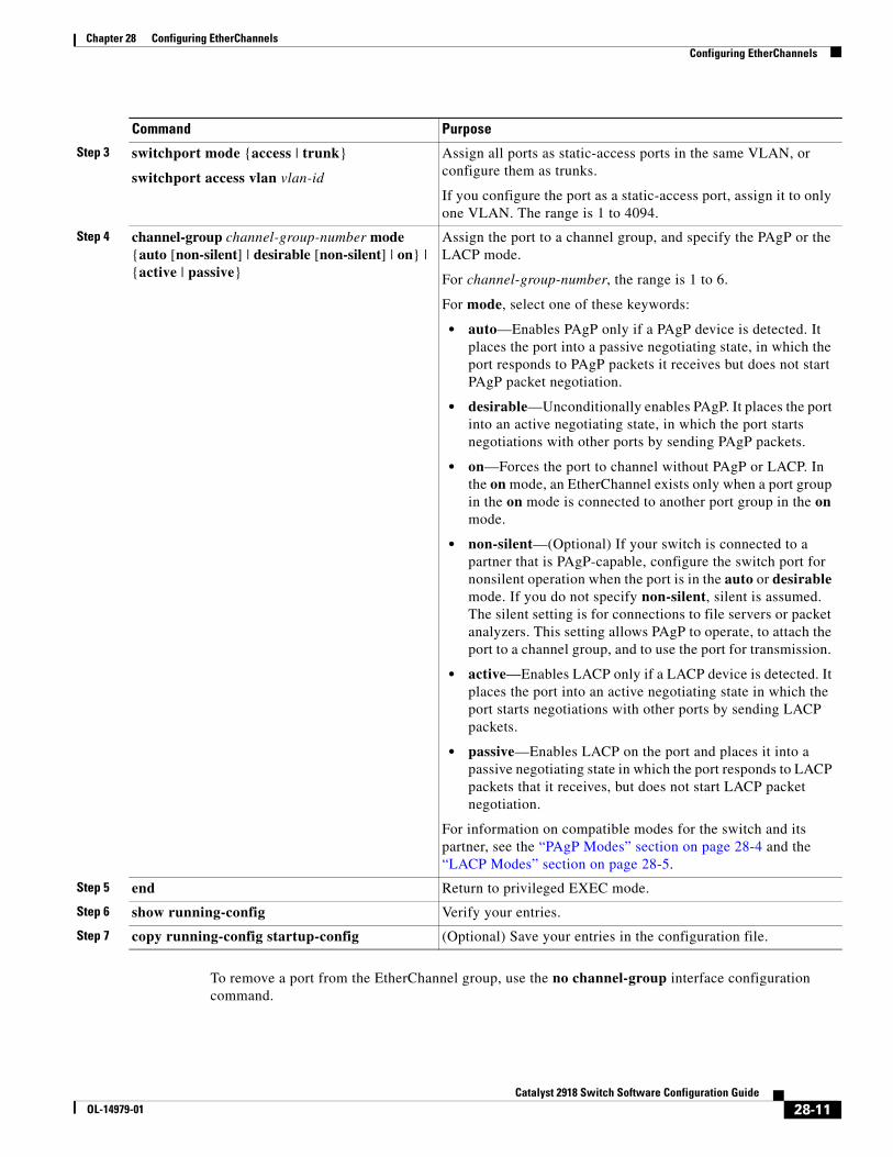
Chapter 28 Configuring EtherChannelsConfiguring EtherChannels
To remove a port from the EtherChannel group, use the no channel-group interface configuration command.
Step 3 switchport mode {access | trunk}
switchport access vlan vlan-id
Assign all ports as static-access ports in the same VLAN, or configure them as trunks.
If you configure the port as a static-access port, assign it to only one VLAN. The range is 1 to 4094.
Step 4 channel-group channel-group-number mode {auto [non-silent] | desirable [non-silent] | on} | {active | passive}
Assign the port to a channel group, and specify the PAgP or the LACP mode.
For channel-group-number, the range is 1 to 6.
For mode, select one of these keywords:
• auto—Enables PAgP only if a PAgP device is detected. It places the port into a passive negotiating state, in which the port responds to PAgP packets it receives but does not start PAgP packet negotiation.
• desirable—Unconditionally enables PAgP. It places the port into an active negotiating state, in which the port starts negotiations with other ports by sending PAgP packets.
• on—Forces the port to channel without PAgP or LACP. In the on mode, an EtherChannel exists only when a port group in the on mode is connected to another port group in the on mode.
• non-silent—(Optional) If your switch is connected to a partner that is PAgP-capable, configure the switch port for nonsilent operation when the port is in the auto or desirable mode. If you do not specify non-silent, silent is assumed. The silent setting is for connections to file servers or packet analyzers. This setting allows PAgP to operate, to attach the port to a channel group, and to use the port for transmission.
• active—Enables LACP only if a LACP device is detected. It places the port into an active negotiating state in which the port starts negotiations with other ports by sending LACP packets.
• passive—Enables LACP on the port and places it into a passive negotiating state in which the port responds to LACP packets that it receives, but does not start LACP packet negotiation.
For information on compatible modes for the switch and its partner, see the “PAgP Modes” section on page 28-4 and the “LACP Modes” section on page 28-5.
Step 5 end Return to privileged EXEC mode.
Step 6 show running-config Verify your entries.
Step 7 copy running-config startup-config (Optional) Save your entries in the configuration file.
Command Purpose
28-11Catalyst 2918 Switch Software Configuration Guide
OL-14979-01
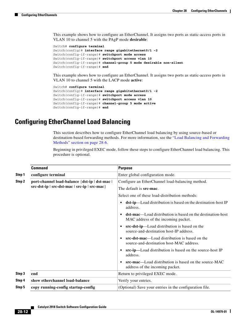
Chapter 28 Configuring EtherChannelsConfiguring EtherChannels
This example shows how to configure an EtherChannel. It assigns two ports as static-access ports in VLAN 10 to channel 5 with the PAgP mode desirable:
Switch# configure terminal Switch(config)# interface range gigabitethernet0/1 -2 Switch(config-if-range)# switchport mode accessSwitch(config-if-range)# switchport access vlan 10Switch(config-if-range)# channel-group 5 mode desirable non-silentSwitch(config-if-range)# end
This example shows how to configure an EtherChannel. It assigns two ports as static-access ports in VLAN 10 to channel 5 with the LACP mode active:
Switch# configure terminal Switch(config)# interface range gigabitethernet0/1 -2 Switch(config-if-range)# switchport mode accessSwitch(config-if-range)# switchport access vlan 10Switch(config-if-range)# channel-group 5 mode activeSwitch(config-if-range)# end
Configuring EtherChannel Load BalancingThis section describes how to configure EtherChannel load balancing by using source-based or destination-based forwarding methods. For more information, see the “Load Balancing and Forwarding Methods” section on page 28-6.
Beginning in privileged EXEC mode, follow these steps to configure EtherChannel load balancing. This procedure is optional.
Command Purpose
Step 1 configure terminal Enter global configuration mode.
Step 2 port-channel load-balance {dst-ip | dst-mac | src-dst-ip | src-dst-mac | src-ip | src-mac}
Configure an EtherChannel load-balancing method.
The default is src-mac.
Select one of these load-distribution methods:
• dst-ip—Load distribution is based on the destination-host IP address.
• dst-mac—Load distribution is based on the destination-host MAC address of the incoming packet.
• src-dst-ip—Load distribution is based on the source-and-destination host-IP address.
• src-dst-mac—Load distribution is based on the source-and-destination host-MAC address.
• src-ip—Load distribution is based on the source-host IP address.
• src-mac—Load distribution is based on the source-MAC address of the incoming packet.
Step 3 end Return to privileged EXEC mode.
Step 4 show etherchannel load-balance Verify your entries.
Step 5 copy running-config startup-config (Optional) Save your entries in the configuration file.
28-12Catalyst 2918 Switch Software Configuration Guide
OL-14979-01
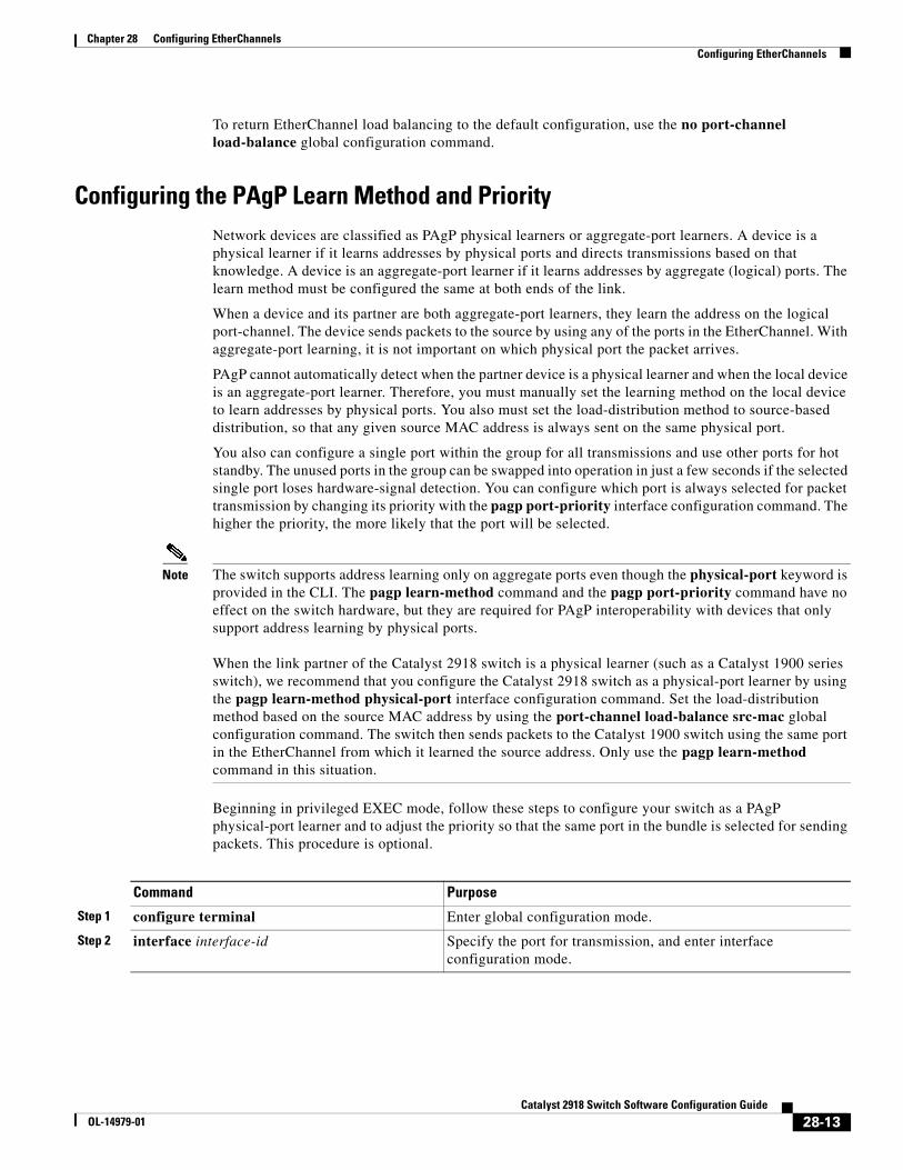
Chapter 28 Configuring EtherChannelsConfiguring EtherChannels
To return EtherChannel load balancing to the default configuration, use the no port-channel load-balance global configuration command.
Configuring the PAgP Learn Method and PriorityNetwork devices are classified as PAgP physical learners or aggregate-port learners. A device is a physical learner if it learns addresses by physical ports and directs transmissions based on that knowledge. A device is an aggregate-port learner if it learns addresses by aggregate (logical) ports. The learn method must be configured the same at both ends of the link.
When a device and its partner are both aggregate-port learners, they learn the address on the logical port-channel. The device sends packets to the source by using any of the ports in the EtherChannel. With aggregate-port learning, it is not important on which physical port the packet arrives.
PAgP cannot automatically detect when the partner device is a physical learner and when the local device is an aggregate-port learner. Therefore, you must manually set the learning method on the local device to learn addresses by physical ports. You also must set the load-distribution method to source-based distribution, so that any given source MAC address is always sent on the same physical port.
You also can configure a single port within the group for all transmissions and use other ports for hot standby. The unused ports in the group can be swapped into operation in just a few seconds if the selected single port loses hardware-signal detection. You can configure which port is always selected for packet transmission by changing its priority with the pagp port-priority interface configuration command. The higher the priority, the more likely that the port will be selected.
Note The switch supports address learning only on aggregate ports even though the physical-port keyword is provided in the CLI. The pagp learn-method command and the pagp port-priority command have no effect on the switch hardware, but they are required for PAgP interoperability with devices that only support address learning by physical ports. When the link partner of the Catalyst 2918 switch is a physical learner (such as a Catalyst 1900 series switch), we recommend that you configure the Catalyst 2918 switch as a physical-port learner by using the pagp learn-method physical-port interface configuration command. Set the load-distribution method based on the source MAC address by using the port-channel load-balance src-mac global configuration command. The switch then sends packets to the Catalyst 1900 switch using the same port in the EtherChannel from which it learned the source address. Only use the pagp learn-method command in this situation.
Beginning in privileged EXEC mode, follow these steps to configure your switch as a PAgP physical-port learner and to adjust the priority so that the same port in the bundle is selected for sending packets. This procedure is optional.
Command Purpose
Step 1 configure terminal Enter global configuration mode.
Step 2 interface interface-id Specify the port for transmission, and enter interface configuration mode.
28-13Catalyst 2918 Switch Software Configuration Guide
OL-14979-01
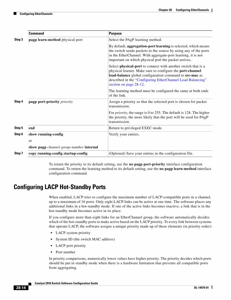
Chapter 28 Configuring EtherChannelsConfiguring EtherChannels
To return the priority to its default setting, use the no pagp port-priority interface configuration command. To return the learning method to its default setting, use the no pagp learn-method interface configuration command.
Configuring LACP Hot-Standby PortsWhen enabled, LACP tries to configure the maximum number of LACP-compatible ports in a channel, up to a maximum of 16 ports. Only eight LACP links can be active at one time. The software places any additional links in a hot-standby mode. If one of the active links becomes inactive, a link that is in the hot-standby mode becomes active in its place.
If you configure more than eight links for an EtherChannel group, the software automatically decides which of the hot-standby ports to make active based on the LACP priority. To every link between systems that operate LACP, the software assigns a unique priority made up of these elements (in priority order):
• LACP system priority
• System ID (the switch MAC address)
• LACP port priority
• Port number
In priority comparisons, numerically lower values have higher priority. The priority decides which ports should be put in standby mode when there is a hardware limitation that prevents all compatible ports from aggregating.
Step 3 pagp learn-method physical-port Select the PAgP learning method.
By default, aggregation-port learning is selected, which means the switch sends packets to the source by using any of the ports in the EtherChannel. With aggregate-port learning, it is not important on which physical port the packet arrives.
Select physical-port to connect with another switch that is a physical learner. Make sure to configure the port-channel load-balance global configuration command to src-mac as described in the “Configuring EtherChannel Load Balancing” section on page 28-12.
The learning method must be configured the same at both ends of the link.
Step 4 pagp port-priority priority Assign a priority so that the selected port is chosen for packet transmission.
For priority, the range is 0 to 255. The default is 128. The higher the priority, the more likely that the port will be used for PAgP transmission.
Step 5 end Return to privileged EXEC mode.
Step 6 show running-config
or
show pagp channel-group-number internal
Verify your entries.
Step 7 copy running-config startup-config (Optional) Save your entries in the configuration file.
Command Purpose
28-14Catalyst 2918 Switch Software Configuration Guide
OL-14979-01
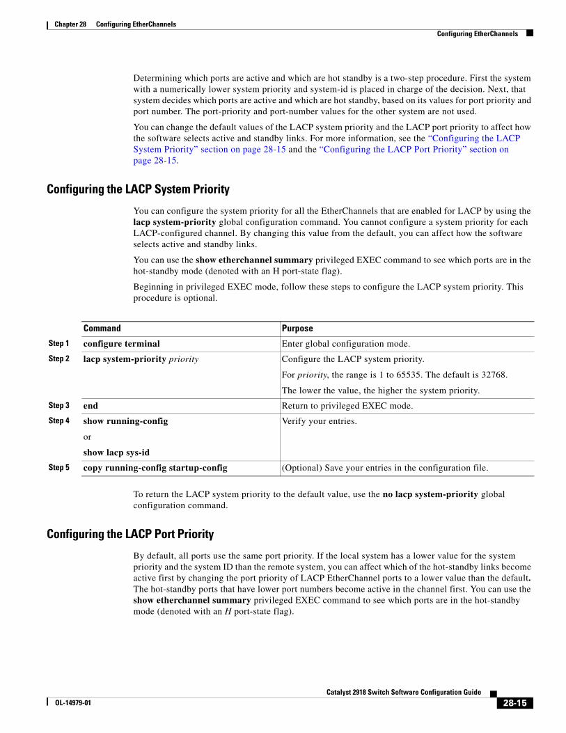
Chapter 28 Configuring EtherChannelsConfiguring EtherChannels
Determining which ports are active and which are hot standby is a two-step procedure. First the system with a numerically lower system priority and system-id is placed in charge of the decision. Next, that system decides which ports are active and which are hot standby, based on its values for port priority and port number. The port-priority and port-number values for the other system are not used.
You can change the default values of the LACP system priority and the LACP port priority to affect how the software selects active and standby links. For more information, see the “Configuring the LACP System Priority” section on page 28-15 and the “Configuring the LACP Port Priority” section on page 28-15.
Configuring the LACP System Priority
You can configure the system priority for all the EtherChannels that are enabled for LACP by using the lacp system-priority global configuration command. You cannot configure a system priority for each LACP-configured channel. By changing this value from the default, you can affect how the software selects active and standby links.
You can use the show etherchannel summary privileged EXEC command to see which ports are in the hot-standby mode (denoted with an H port-state flag).
Beginning in privileged EXEC mode, follow these steps to configure the LACP system priority. This procedure is optional.
Command Purpose
Step 1 configure terminal Enter global configuration mode.
Step 2 lacp system-priority priority Configure the LACP system priority.
For priority, the range is 1 to 65535. The default is 32768.
The lower the value, the higher the system priority.
Step 3 end Return to privileged EXEC mode.
Step 4 show running-config
or
show lacp sys-id
Verify your entries.
Step 5 copy running-config startup-config (Optional) Save your entries in the configuration file.
To return the LACP system priority to the default value, use the no lacp system-priority global configuration command.
Configuring the LACP Port Priority
By default, all ports use the same port priority. If the local system has a lower value for the system priority and the system ID than the remote system, you can affect which of the hot-standby links become active first by changing the port priority of LACP EtherChannel ports to a lower value than the default. The hot-standby ports that have lower port numbers become active in the channel first. You can use the show etherchannel summary privileged EXEC command to see which ports are in the hot-standby mode (denoted with an H port-state flag).
28-15Catalyst 2918 Switch Software Configuration Guide
OL-14979-01
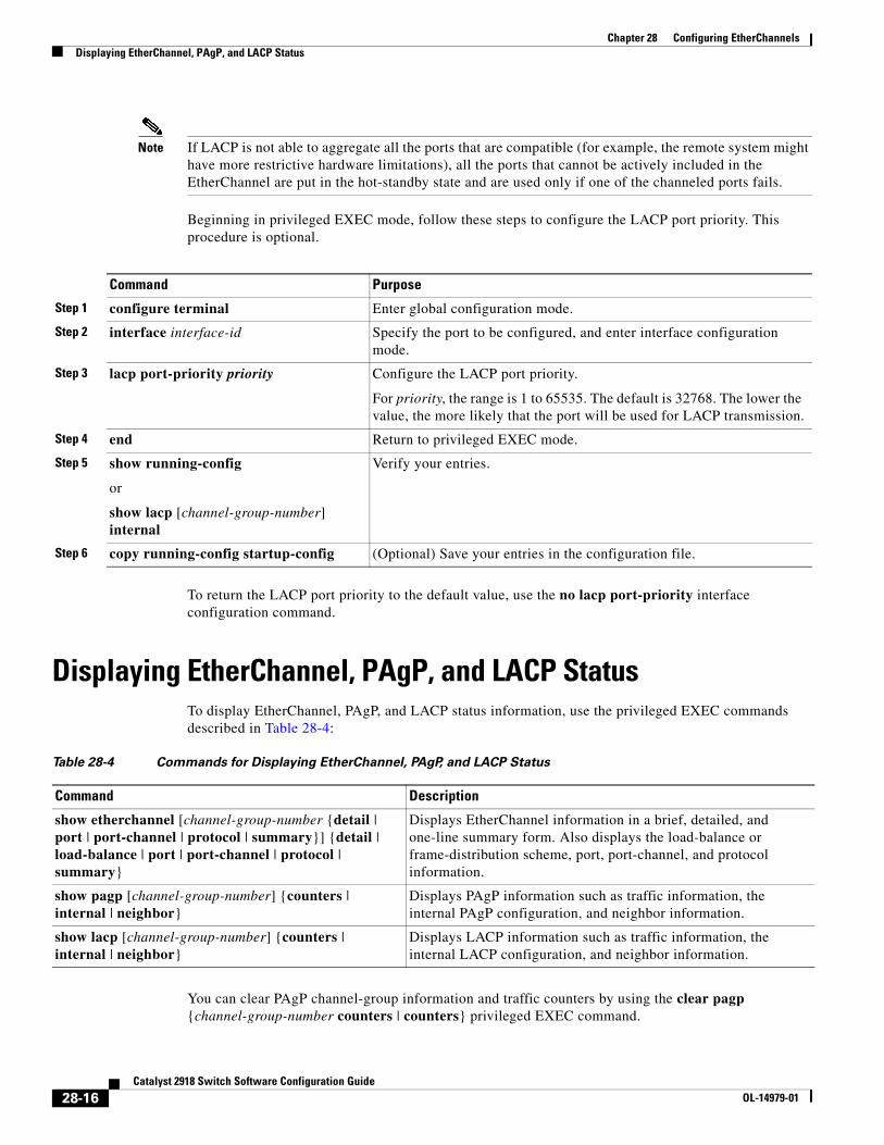
Chapter 28 Configuring EtherChannelsDisplaying EtherChannel, PAgP, and LACP Status
Note If LACP is not able to aggregate all the ports that are compatible (for example, the remote system might have more restrictive hardware limitations), all the ports that cannot be actively included in the EtherChannel are put in the hot-standby state and are used only if one of the channeled ports fails.
Beginning in privileged EXEC mode, follow these steps to configure the LACP port priority. This procedure is optional.
Command Purpose
Step 1 configure terminal Enter global configuration mode.
Step 2 interface interface-id Specify the port to be configured, and enter interface configuration mode.
Step 3 lacp port-priority priority Configure the LACP port priority.
For priority, the range is 1 to 65535. The default is 32768. The lower the value, the more likely that the port will be used for LACP transmission.
Step 4 end Return to privileged EXEC mode.
Step 5 show running-config
or
show lacp [channel-group-number] internal
Verify your entries.
Step 6 copy running-config startup-config (Optional) Save your entries in the configuration file.
To return the LACP port priority to the default value, use the no lacp port-priority interface configuration command.
Displaying EtherChannel, PAgP, and LACP StatusTo display EtherChannel, PAgP, and LACP status information, use the privileged EXEC commands described in Table 28-4:
Table 28-4 Commands for Displaying EtherChannel, PAgP, and LACP Status
Command Description
show etherchannel [channel-group-number {detail | port | port-channel | protocol | summary}] {detail | load-balance | port | port-channel | protocol | summary}
Displays EtherChannel information in a brief, detailed, and one-line summary form. Also displays the load-balance or frame-distribution scheme, port, port-channel, and protocol information.
show pagp [channel-group-number] {counters | internal | neighbor}
Displays PAgP information such as traffic information, the internal PAgP configuration, and neighbor information.
show lacp [channel-group-number] {counters | internal | neighbor}
Displays LACP information such as traffic information, the internal LACP configuration, and neighbor information.
You can clear PAgP channel-group information and traffic counters by using the clear pagp {channel-group-number counters | counters} privileged EXEC command.
28-16Catalyst 2918 Switch Software Configuration Guide
OL-14979-01

Chapter 28 Configuring EtherChannelsDisplaying EtherChannel, PAgP, and LACP Status
You can clear LACP channel-group information and traffic counters by using the clear lacp {channel-group-number counters | counters} privileged EXEC command.
For detailed information about the fields in the displays, see the command reference for this release.
28-17Catalyst 2918 Switch Software Configuration Guide
OL-14979-01

Chapter 28 Configuring EtherChannelsDisplaying EtherChannel, PAgP, and LACP Status
28-18Catalyst 2918 Switch Software Configuration Guide
OL-14979-01
OL-14979-01
C H A P T E R 29
TroubleshootingThis chapter describes how to identify and resolve software problems related to the Cisco IOS software on the Catalyst 2918 switch. Depending on the nature of the problem, you can use the command-line interface (CLI), the device manager, or Network Assistant to identify and solve problems.
Additional troubleshooting information, such as LED descriptions, is provided in the hardware installation guide.
Note For complete syntax and usage information for the commands used in this chapter, see the command reference for this release and the Cisco IOS Command Summary, Release 12.2.
This chapter consists of these sections:
• Recovering from a Software Failure, page 29-2
• Recovering from a Lost or Forgotten Password, page 29-3
• Recovering from a Command Switch Failure, page 29-7
• Recovering from Lost Cluster Member Connectivity, page 29-11
Note Recovery procedures require that you have physical access to the switch.
• Preventing Autonegotiation Mismatches, page 29-11
• SFP Module Security and Identification, page 29-11
• Monitoring SFP Module Status, page 29-12
• Using Ping, page 29-12
• Using Layer 2 Traceroute, page 29-13
• Using IP Traceroute, page 29-15
• Using TDR, page 29-17
• Using Debug Commands, page 29-18
• Using the show platform forward Command, page 29-19
• Using the crashinfo Files, page 29-21
29-1Catalyst 2918 Switch Software Configuration Guide
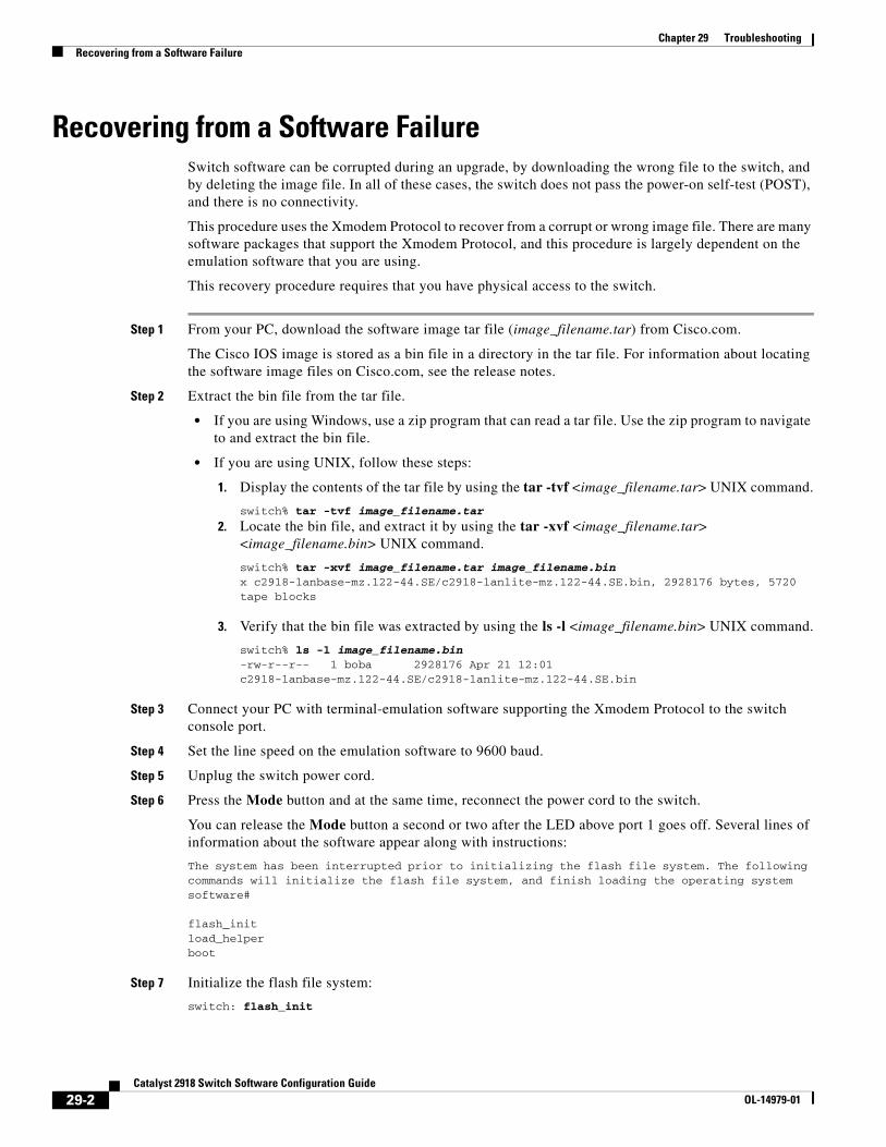
Chapter 29 TroubleshootingRecovering from a Software Failure
Recovering from a Software FailureSwitch software can be corrupted during an upgrade, by downloading the wrong file to the switch, and by deleting the image file. In all of these cases, the switch does not pass the power-on self-test (POST), and there is no connectivity.
This procedure uses the Xmodem Protocol to recover from a corrupt or wrong image file. There are many software packages that support the Xmodem Protocol, and this procedure is largely dependent on the emulation software that you are using.
This recovery procedure requires that you have physical access to the switch.
Step 1 From your PC, download the software image tar file (image_filename.tar) from Cisco.com.
The Cisco IOS image is stored as a bin file in a directory in the tar file. For information about locating the software image files on Cisco.com, see the release notes.
Step 2 Extract the bin file from the tar file.
• If you are using Windows, use a zip program that can read a tar file. Use the zip program to navigate to and extract the bin file.
• If you are using UNIX, follow these steps:
1. Display the contents of the tar file by using the tar -tvf <image_filename.tar> UNIX command.
switch% tar -tvf image_filename.tar
2. Locate the bin file, and extract it by using the tar -xvf <image_filename.tar> <image_filename.bin> UNIX command.
switch% tar -xvf image_filename.tar image_filename.binx c2918-lanbase-mz.122-44.SE/c2918-lanlite-mz.122-44.SE.bin, 2928176 bytes, 5720 tape blocks
3. Verify that the bin file was extracted by using the ls -l <image_filename.bin> UNIX command.
switch% ls -l image_filename.bin-rw-r--r-- 1 boba 2928176 Apr 21 12:01 c2918-lanbase-mz.122-44.SE/c2918-lanlite-mz.122-44.SE.bin
Step 3 Connect your PC with terminal-emulation software supporting the Xmodem Protocol to the switch console port.
Step 4 Set the line speed on the emulation software to 9600 baud.
Step 5 Unplug the switch power cord.
Step 6 Press the Mode button and at the same time, reconnect the power cord to the switch.
You can release the Mode button a second or two after the LED above port 1 goes off. Several lines of information about the software appear along with instructions:
The system has been interrupted prior to initializing the flash file system. The following commands will initialize the flash file system, and finish loading the operating system software#
flash_initload_helperboot
Step 7 Initialize the flash file system:
switch: flash_init
29-2Catalyst 2918 Switch Software Configuration Guide
OL-14979-01
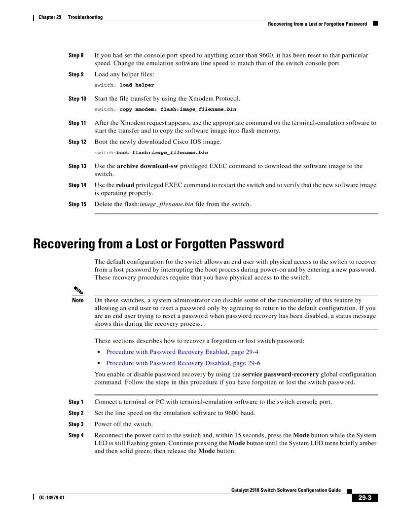
Chapter 29 TroubleshootingRecovering from a Lost or Forgotten Password
Step 8 If you had set the console port speed to anything other than 9600, it has been reset to that particular speed. Change the emulation software line speed to match that of the switch console port.
Step 9 Load any helper files:
switch: load_helper
Step 10 Start the file transfer by using the Xmodem Protocol.
switch: copy xmodem: flash:image_filename.bin
Step 11 After the Xmodem request appears, use the appropriate command on the terminal-emulation software to start the transfer and to copy the software image into flash memory.
Step 12 Boot the newly downloaded Cisco IOS image.
switch:boot flash:image_filename.bin
Step 13 Use the archive download-sw privileged EXEC command to download the software image to the switch.
Step 14 Use the reload privileged EXEC command to restart the switch and to verify that the new software image is operating properly.
Step 15 Delete the flash:image_filename.bin file from the switch.
Recovering from a Lost or Forgotten PasswordThe default configuration for the switch allows an end user with physical access to the switch to recover from a lost password by interrupting the boot process during power-on and by entering a new password. These recovery procedures require that you have physical access to the switch.
Note On these switches, a system administrator can disable some of the functionality of this feature by allowing an end user to reset a password only by agreeing to return to the default configuration. If you are an end user trying to reset a password when password recovery has been disabled, a status message shows this during the recovery process.
These sections describes how to recover a forgotten or lost switch password:
• Procedure with Password Recovery Enabled, page 29-4
• Procedure with Password Recovery Disabled, page 29-6
You enable or disable password recovery by using the service password-recovery global configuration command. Follow the steps in this procedure if you have forgotten or lost the switch password.
Step 1 Connect a terminal or PC with terminal-emulation software to the switch console port.
Step 2 Set the line speed on the emulation software to 9600 baud.
Step 3 Power off the switch.
Step 4 Reconnect the power cord to the switch and, within 15 seconds, press the Mode button while the System LED is still flashing green. Continue pressing the Mode button until the System LED turns briefly amber and then solid green; then release the Mode button.
29-3Catalyst 2918 Switch Software Configuration Guide
OL-14979-01
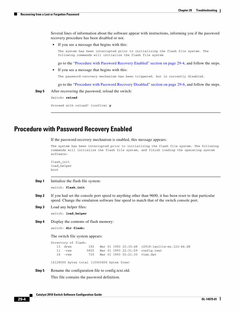
Chapter 29 TroubleshootingRecovering from a Lost or Forgotten Password
Several lines of information about the software appear with instructions, informing you if the password recovery procedure has been disabled or not.
• If you see a message that begins with this:
The system has been interrupted prior to initializing the flash file system. The following commands will initialize the flash file system
go to the “Procedure with Password Recovery Enabled” section on page 29-4, and follow the steps.
• If you see a message that begins with this:
The password-recovery mechanism has been triggered, but is currently disabled.
go to the “Procedure with Password Recovery Disabled” section on page 29-6, and follow the steps.
Step 5 After recovering the password, reload the switch:
Switch> reload
Proceed with reload? [confirm] y
Procedure with Password Recovery EnabledIf the password-recovery mechanism is enabled, this message appears:
The system has been interrupted prior to initializing the flash file system. The following commands will initialize the flash file system, and finish loading the operating system software:
flash_initload_helperboot
Step 1 Initialize the flash file system:
switch: flash_init
Step 2 If you had set the console port speed to anything other than 9600, it has been reset to that particular speed. Change the emulation software line speed to match that of the switch console port.
Step 3 Load any helper files:
switch: load_helper
Step 4 Display the contents of flash memory:
switch: dir flash:
The switch file system appears:
Directory of flash: 13 drwx 192 Mar 01 1993 22:30:48 c2918-lanlite-mz.122-44.SE 11 -rwx 5825 Mar 01 1993 22:31:59 config.text 18 -rwx 720 Mar 01 1993 02:21:30 vlan.dat
16128000 bytes total (10003456 bytes free)
Step 5 Rename the configuration file to config.text.old.
This file contains the password definition.
29-4Catalyst 2918 Switch Software Configuration Guide
OL-14979-01
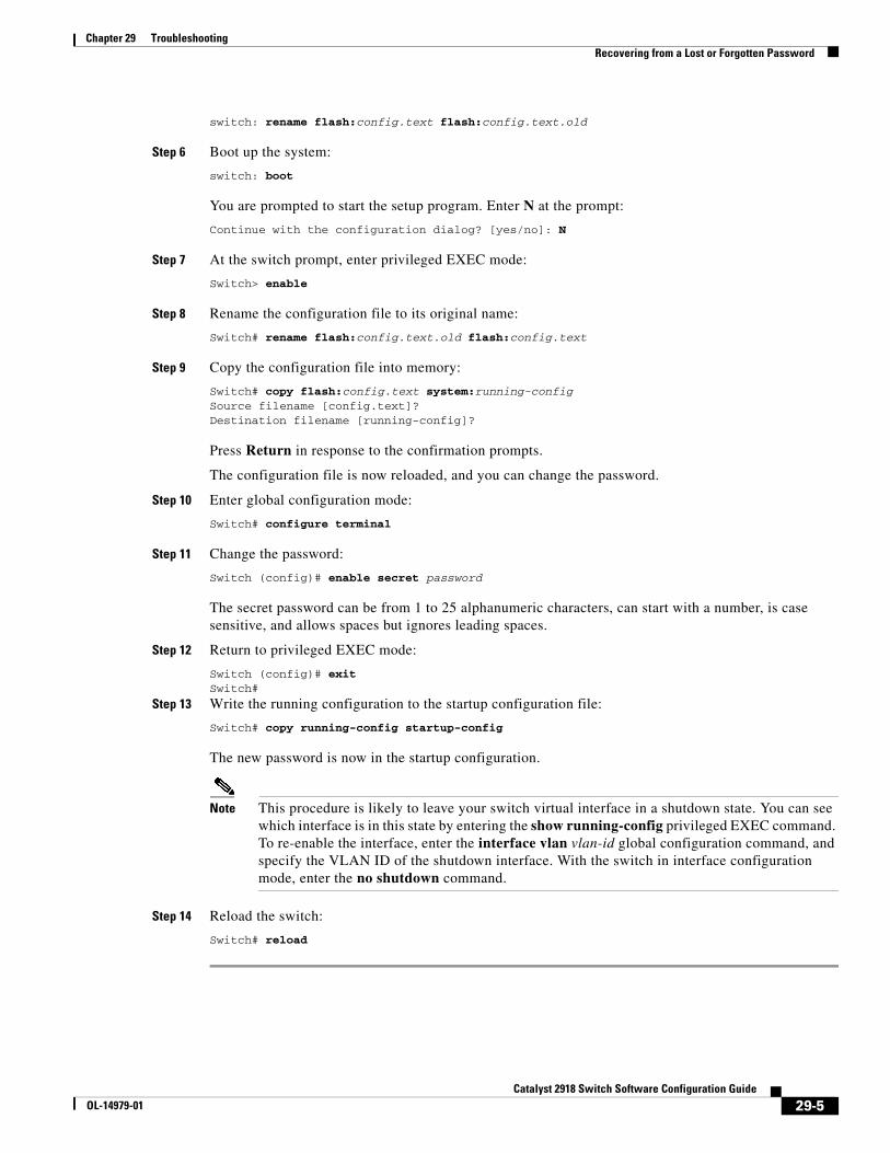
Chapter 29 TroubleshootingRecovering from a Lost or Forgotten Password
switch: rename flash:config.text flash:config.text.old
Step 6 Boot up the system:
switch: boot
You are prompted to start the setup program. Enter N at the prompt:
Continue with the configuration dialog? [yes/no]: N
Step 7 At the switch prompt, enter privileged EXEC mode:
Switch> enable
Step 8 Rename the configuration file to its original name:
Switch# rename flash:config.text.old flash:config.text
Step 9 Copy the configuration file into memory:
Switch# copy flash:config.text system:running-config Source filename [config.text]? Destination filename [running-config]?
Press Return in response to the confirmation prompts.
The configuration file is now reloaded, and you can change the password.
Step 10 Enter global configuration mode:
Switch# configure terminal
Step 11 Change the password:
Switch (config)# enable secret password
The secret password can be from 1 to 25 alphanumeric characters, can start with a number, is case sensitive, and allows spaces but ignores leading spaces.
Step 12 Return to privileged EXEC mode:
Switch (config)# exit Switch#
Step 13 Write the running configuration to the startup configuration file:
Switch# copy running-config startup-config
The new password is now in the startup configuration.
Note This procedure is likely to leave your switch virtual interface in a shutdown state. You can see which interface is in this state by entering the show running-config privileged EXEC command. To re-enable the interface, enter the interface vlan vlan-id global configuration command, and specify the VLAN ID of the shutdown interface. With the switch in interface configuration mode, enter the no shutdown command.
Step 14 Reload the switch:
Switch# reload
29-5Catalyst 2918 Switch Software Configuration Guide
OL-14979-01
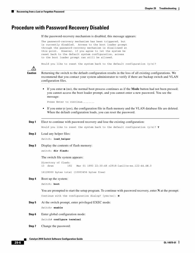
Chapter 29 TroubleshootingRecovering from a Lost or Forgotten Password
Procedure with Password Recovery DisabledIf the password-recovery mechanism is disabled, this message appears:
The password-recovery mechanism has been triggered, butis currently disabled. Access to the boot loader promptthrough the password-recovery mechanism is disallowed atthis point. However, if you agree to let the system bereset back to the default system configuration, accessto the boot loader prompt can still be allowed.
Would you like to reset the system back to the default configuration (y/n)?
Caution Returning the switch to the default configuration results in the loss of all existing configurations. We recommend that you contact your system administrator to verify if there are backup switch and VLAN configuration files.
• If you enter n (no), the normal boot process continues as if the Mode button had not been pressed; you cannot access the boot loader prompt, and you cannot enter a new password. You see the message:
Press Enter to continue........
• If you enter y (yes), the configuration file in flash memory and the VLAN database file are deleted. When the default configuration loads, you can reset the password.
Step 1 Elect to continue with password recovery and lose the existing configuration:
Would you like to reset the system back to the default configuration (y/n)? Y
Step 2 Load any helper files:
Switch: load_helper
Step 3 Display the contents of flash memory:
switch: dir flash:
The switch file system appears:
Directory of flash:13 drwx 192 Mar 01 1993 22:30:48 c2918-lanlite-mz.122-44.SE.0
16128000 bytes total (10003456 bytes free)
Step 4 Boot up the system:
Switch: boot
You are prompted to start the setup program. To continue with password recovery, enter N at the prompt:
Continue with the configuration dialog? [yes/no]: N
Step 5 At the switch prompt, enter privileged EXEC mode:
Switch> enable
Step 6 Enter global configuration mode:
Switch# configure terminal
Step 7 Change the password:
29-6Catalyst 2918 Switch Software Configuration Guide
OL-14979-01
Chapter 29 TroubleshootingRecovering from a Command Switch Failure
Switch (config)# enable secret password
The secret password can be from 1 to 25 alphanumeric characters, can start with a number, is case sensitive, and allows spaces but ignores leading spaces.
Step 8 Return to privileged EXEC mode:
Switch (config)# exit Switch#
Step 9 Write the running configuration to the startup configuration file:
Switch# copy running-config startup-config
The new password is now in the startup configuration.
Note This procedure is likely to leave your switch virtual interface in a shutdown state. You can see which interface is in this state by entering the show running-config privileged EXEC command. To re-enable the interface, enter the interface vlan vlan-id global configuration command, and specify the VLAN ID of the shutdown interface. With the switch in interface configuration mode, enter the no shutdown command.
Step 10 You must now reconfigure the switch. If the system administrator has the backup switch and VLAN configuration files available, you should use those.
Recovering from a Command Switch FailureThis section describes how to recover from a failed command switch. You can configure a redundant command switch group by using the Hot Standby Router Protocol (HSRP). For more information, see Chapter 5, “Clustering Switches.”
Note HSRP is the preferred method for supplying redundancy to a cluster.
If you have not configured a standby command switch, and your command switch loses power or fails in some other way, management contact with the member switches is lost, and you must install a new command switch. However, connectivity between switches that are still connected is not affected, and the member switches forward packets as usual. You can manage the members as standalone switches through the console port, or, if they have IP addresses, through the other management interfaces.
You can prepare for a command switch failure by assigning an IP address to a member switch or another switch that is command-capable, making a note of the command-switch password, and cabling your cluster to provide redundant connectivity between the member switches and the replacement command switch. These sections describe two solutions for replacing a failed command switch:
• Replacing a Failed Command Switch with a Cluster Member, page 29-8
• Replacing a Failed Command Switch with Another Switch, page 29-9
These recovery procedures require that you have physical access to the switch.
For information on command-capable switches, see the release notes.
29-7Catalyst 2918 Switch Software Configuration Guide
OL-14979-01
Chapter 29 TroubleshootingRecovering from a Command Switch Failure
Replacing a Failed Command Switch with a Cluster MemberTo replace a failed command switch with a command-capable member in the same cluster, follow these steps:
Step 1 Disconnect the command switch from the member switches, and physically remove it from the cluster.
Step 2 Insert the member switch in place of the failed command switch, and duplicate its connections to the cluster members.
Step 3 Start a CLI session on the new command switch.
You can access the CLI by using the console port or, if an IP address has been assigned to the switch, by using Telnet. For details about using the console port, see the switch hardware installation guide.
Step 4 At the switch prompt, enter privileged EXEC mode:
Switch> enable Switch#
Step 5 Enter the password of the failed command switch.
Step 6 Enter global configuration mode.
Switch# configure terminal Enter configuration commands, one per line. End with CNTL/Z.
Step 7 Remove the member switch from the cluster.
Switch(config)# no cluster commander-address
Step 8 Return to privileged EXEC mode.
Switch(config)# end Switch#
Step 9 Use the setup program to configure the switch IP information. This program prompts you for IP address information and passwords. From privileged EXEC mode, enter setup, and press Return.
Switch# setup --- System Configuration Dialog ---Continue with configuration dialog? [yes/no]: y
At any point you may enter a question mark '?' for help.Use ctrl-c to abort configuration dialog at any prompt.Default settings are in square brackets '[]'.
Basic management setup configures only enough connectivityfor management of the system, extended setup will ask youto configure each interface on the system
Would you like to enter basic management setup? [yes/no]:
Step 10 Enter Y at the first prompt.
The prompts in the setup program vary depending on the member switch that you selected to be the command switch:
Continue with configuration dialog? [yes/no]: y
or
Configuring global parameters:
29-8Catalyst 2918 Switch Software Configuration Guide
OL-14979-01
Chapter 29 TroubleshootingRecovering from a Command Switch Failure
If this prompt does not appear, enter enable, and press Return. Enter setup, and press Return to start the setup program.
Step 11 Respond to the questions in the setup program.
When prompted for the hostname, recall that on a command switch, the hostname is limited to 28 characters; on a member switch to 31 characters. Do not use -n, where n is a number, as the last characters in a hostname for any switch.
When prompted for the Telnet (virtual terminal) password, recall that it can be from 1 to 25 alphanumeric characters, is case sensitive, allows spaces, but ignores leading spaces.
Step 12 When prompted for the enable secret and enable passwords, enter the passwords of the failed command switch again.
Step 13 When prompted, make sure to enable the switch as the cluster command switch, and press Return.
Step 14 When prompted, assign a name to the cluster, and press Return.
The cluster name can be 1 to 31 alphanumeric characters, dashes, or underscores.
Step 15 After the initial configuration displays, verify that the addresses are correct.
Step 16 If the displayed information is correct, enter Y, and press Return.
If this information is not correct, enter N, press Return, and begin again at Step 9.
Step 17 Start your browser, and enter the IP address of the new command switch.
Step 18 From the Cluster menu, select Add to Cluster to display a list of candidate switches to add to the cluster.
Replacing a Failed Command Switch with Another SwitchTo replace a failed command switch with a switch that is command-capable but not part of the cluster, follow these steps:
Step 1 Insert the new switch in place of the failed command switch, and duplicate its connections to the cluster members.
Step 2 Start a CLI session on the new command switch.
You can access the CLI by using the console port or, if an IP address has been assigned to the switch, by using Telnet. For details about using the console port, see the switch hardware installation guide.
Step 3 At the switch prompt, enter privileged EXEC mode:
Switch> enable Switch#
Step 4 Enter the password of the failed command switch.
Step 5 Use the setup program to configure the switch IP information.
This program prompts you for IP address information and passwords. From privileged EXEC mode, enter setup, and press Return.
Switch# setup --- System Configuration Dialog ---Continue with configuration dialog? [yes/no]: y
At any point you may enter a question mark '?' for help.Use ctrl-c to abort configuration dialog at any prompt.
29-9Catalyst 2918 Switch Software Configuration Guide
OL-14979-01
Chapter 29 TroubleshootingRecovering from a Command Switch Failure
Default settings are in square brackets '[]'.
Basic management setup configures only enough connectivityfor management of the system, extended setup will ask youto configure each interface on the system
Would you like to enter basic management setup? [yes/no]:
Step 6 Enter Y at the first prompt.
The prompts in the setup program vary depending on the switch you selected to be the command switch:
Continue with configuration dialog? [yes/no]: y
or
Configuring global parameters:
If this prompt does not appear, enter enable, and press Return. Enter setup, and press Return to start the setup program.
Step 7 Respond to the questions in the setup program.
When prompted for the hostname, recall that on a command switch, the hostname is limited to 28 characters. Do not use -n, where n is a number, as the last character in a hostname for any switch.
When prompted for the Telnet (virtual terminal) password, recall that it can be from 1 to 25 alphanumeric characters, is case sensitive, allows spaces, but ignores leading spaces.
Step 8 When prompted for the enable secret and enable passwords, enter the passwords of the failed command switch again.
Step 9 When prompted, make sure to enable the switch as the cluster command switch, and press Return.
Step 10 When prompted, assign a name to the cluster, and press Return.
The cluster name can be 1 to 31 alphanumeric characters, dashes, or underscores.
Step 11 When the initial configuration displays, verify that the addresses are correct.
Step 12 If the displayed information is correct, enter Y, and press Return.
If this information is not correct, enter N, press Return, and begin again at Step 9.
Step 13 Start your browser, and enter the IP address of the new command switch.
Step 14 From the Cluster menu, select Add to Cluster to display a list of candidate switches to add to the cluster.
29-10Catalyst 2918 Switch Software Configuration Guide
OL-14979-01
Chapter 29 TroubleshootingRecovering from Lost Cluster Member Connectivity
Recovering from Lost Cluster Member ConnectivitySome configurations can prevent the command switch from maintaining contact with member switches. If you are unable to maintain management contact with a member, and the member switch is forwarding packets normally, check for these conflicts:
• A member switch (Catalyst 3750, Catalyst 3560, Catalyst 3550, Catalyst 3500 XL, Catalyst 2970, Catalyst 2960, Catalyst 2950, Catalyst 2918, Catalyst 2900 XL, Catalyst 2820, and Catalyst 1900 switch) cannot connect to the command switch through a port that is defined as a network port.
• Catalyst 3500 XL, Catalyst 2900 XL, Catalyst 2820, and Catalyst 1900 member switches must connect to the command switch through a port that belongs to the same management VLAN.
• A member switch (Catalyst 3750, Catalyst 3560, Catalyst 3550, Catalyst 2970, Catalyst 2960, Catalyst 2950, Catalyst 2918, Catalyst 3500 XL, Catalyst 2900 XL, Catalyst 2820, and Catalyst 1900 switch) connected to the command switch through a secured port can lose connectivity if the port is disabled because of a security violation.
Preventing Autonegotiation MismatchesThe IEEE 802.3ab autonegotiation protocol manages the switch settings for speed (10 Mb/s, 100 Mb/s, and 1000 Mb/s, excluding SFP module ports) and duplex (half or full). There are situations when this protocol can incorrectly align these settings, reducing performance. A mismatch occurs under these circumstances:
• A manually set speed or duplex parameter is different from the manually set speed or duplex parameter on the connected port.
• A port is set to autonegotiate, and the connected port is set to full duplex with no autonegotiation.
To maximize switch performance and ensure a link, follow one of these guidelines when changing the settings for duplex and speed:
• Let both ports autonegotiate both speed and duplex.
• Manually set the speed and duplex parameters for the ports on both ends of the connection.
Note If a remote device does not autonegotiate, configure the duplex settings on the two ports to match. The speed parameter can adjust itself even if the connected port does not autonegotiate.
SFP Module Security and IdentificationCisco small form-factor pluggable (SFP) modules have a serial EEPROM that contains the module serial number, the vendor name and ID, a unique security code, and cyclic redundancy check (CRC). When an SFP module is inserted in the switch, the switch software reads the EEPROM to verify the serial number, vendor name and vendor ID, and recompute the security code and CRC. If the serial number, the vendor name or vendor ID, the security code, or CRC is invalid, the software generates a security error message and places the interface in an error-disabled state.
29-11Catalyst 2918 Switch Software Configuration Guide
OL-14979-01
Chapter 29 TroubleshootingMonitoring SFP Module Status
Note The security error message references the GBIC_SECURITY facility. The switch supports SFP modules and does not support GBIC modules. Although the error message text refers to GBIC interfaces and modules, the security messages actually refer to the SFP modules and module interfaces. For more information about error messages, see the system message guide for this release.
If you are using a non-Cisco SFP module, remove the SFP module from the switch, and replace it with a Cisco module. After inserting a Cisco SFP module, use the errdisable recovery cause gbic-invalid global configuration command to verify the port status, and enter a time interval for recovering from the error-disabled state. After the elapsed interval, the switch brings the interface out of the error-disabled state and retries the operation. For more information about the errdisable recovery command, see the command reference for this release.
If the module is identified as a Cisco SFP module, but the system is unable to read vendor-data information to verify its accuracy, an SFP module error message is generated. In this case, you should remove and re-insert the SFP module. If it continues to fail, the SFP module might be defective.
Monitoring SFP Module StatusYou can check the physical or operational status of an SFP module by using the show interfaces transceiver privileged EXEC command. This command shows the operational status, such as the temperature and the current for an SFP module on a specific interface and the alarm status. You can also use the command to check the speed and the duplex settings on an SFP module. For more information, see the show interfaces transceiver command in the command reference for this release.
Using PingThese sections contain this information:
• Understanding Ping, page 29-12
• Executing Ping, page 29-13
Understanding Ping The switch supports IP ping, which you can use to test connectivity to remote hosts. Ping sends an echo request packet to an address and waits for a reply. Ping returns one of these responses:
• Normal response—The normal response (hostname is alive) occurs in 1 to 10 seconds, depending on network traffic.
• Destination does not respond—If the host does not respond, a no-answer message is returned.
• Unknown host—If the host does not exist, an unknown host message is returned.
• Destination unreachable—If the default gateway cannot reach the specified network, a destination-unreachable message is returned.
• Network or host unreachable—If there is no entry in the route table for the host or network, a network or host unreachable message is returned.
29-12Catalyst 2918 Switch Software Configuration Guide
OL-14979-01
Chapter 29 TroubleshootingUsing Layer 2 Traceroute
Executing PingBeginning in privileged EXEC mode, use this command to ping another device on the network from the switch:
Command Purpose
ping ip host | address Ping a remote host through IP or by supplying the hostname or network address.
Note Though other protocol keywords are available with the ping command, they are not supported in this release.
This example shows how to ping an IP host:
Switch# ping 172.20.52.3
Type escape sequence to abort.Sending 5, 100-byte ICMP Echoes to 172.20.52.3, timeout is 2 seconds:!!!!!Success rate is 100 percent (5/5), round-trip min/avg/max = 1/2/4 msSwitch#
Table 29-1 describes the possible ping character output.
Table 29-1 Ping Output Display Characters
Character Description
! Each exclamation point means receipt of a reply.
. Each period means the network server timed out while waiting for a reply.
U A destination unreachable error PDU was received.
C A congestion experienced packet was received.
I User interrupted test.
? Unknown packet type.
& Packet lifetime exceeded.
To end a ping session, enter the escape sequence (Ctrl-^ X by default). Simultaneously press and release the Ctrl, Shift, and 6 keys and then press the X key.
Using Layer 2 TracerouteThese sections contain this information:
• Understanding Layer 2 Traceroute, page 29-14
• Usage Guidelines, page 29-14
• Displaying the Physical Path, page 29-15
29-13Catalyst 2918 Switch Software Configuration Guide
OL-14979-01
Chapter 29 TroubleshootingUsing Layer 2 Traceroute
Understanding Layer 2 TracerouteThe Layer 2 traceroute feature allows the switch to identify the physical path that a packet takes from a source device to a destination device. Layer 2 traceroute supports only unicast source and destination MAC addresses. It finds the path by using the MAC address tables of the switches in the path. When the switch detects a device in the path that does not support Layer 2 traceroute, the switch continues to send Layer 2 trace queries and lets them time out.
The switch can only identify the path from the source device to the destination device. It cannot identify the path that a packet takes from source host to the source device or from the destination device to the destination host.
Usage GuidelinesThese are the Layer 2 traceroute usage guidelines:
• Cisco Discovery Protocol (CDP) must be enabled on all the devices in the network. For Layer 2 traceroute to function properly, do not disable CDP.
For a list of switches that support Layer 2 traceroute, see the “Usage Guidelines” section on page 29-14. If any devices in the physical path are transparent to CDP, the switch cannot identify the path through these devices. For more information about enabling CDP, see Chapter 20, “Configuring CDP.”
• A switch is reachable from another switch when you can test connectivity by using the ping privileged EXEC command. All switches in the physical path must be reachable from each other.
• The maximum number of hops identified in the path is ten.
• You can enter the traceroute mac or the traceroute mac ip privileged EXEC command on a switch that is not in the physical path from the source device to the destination device. All switches in the path must be reachable from this switch.
• The traceroute mac command output shows the Layer 2 path only when the specified source and destination MAC addresses belong to the same VLAN. If you specify source and destination MAC addresses that belong to different VLANs, the Layer 2 path is not identified, and an error message appears.
• If you specify a multicast source or destination MAC address, the path is not identified, and an error message appears.
• If the source or destination MAC address belongs to multiple VLANs, you must specify the VLAN to which both the source and destination MAC addresses belong. If the VLAN is not specified, the path is not identified, and an error message appears.
• The traceroute mac ip command output shows the Layer 2 path when the specified source and destination IP addresses belong to the same subnet. When you specify the IP addresses, the switch uses the Address Resolution Protocol (ARP) to associate the IP addresses with the corresponding MAC addresses and the VLAN IDs.
– If an ARP entry exists for the specified IP address, the switch uses the associated MAC address and identifies the physical path.
– If an ARP entry does not exist, the switch sends an ARP query and tries to resolve the IP address. If the IP address is not resolved, the path is not identified, and an error message appears.
29-14Catalyst 2918 Switch Software Configuration Guide
OL-14979-01
Chapter 29 TroubleshootingUsing IP Traceroute
• When multiple devices are attached to one port through hubs (for example, multiple CDP neighbors are detected on a port), the Layer 2 traceroute feature is not supported. When more than one CDP neighbor is detected on a port, the Layer 2 path is not identified, and an error message appears.
• This feature is not supported in Token Ring VLANs.
Displaying the Physical PathYou can display physical path that a packet takes from a source device to a destination device by using one of these privileged EXEC commands:
• tracetroute mac [interface interface-id] {source-mac-address} [interface interface-id] {destination-mac-address} [vlan vlan-id] [detail]
• tracetroute mac ip {source-ip-address | source-hostname}{destination-ip-address | destination-hostname} [detail]
For more information, see the command reference for this release.
Using IP TracerouteThese sections contain this information:
• Understanding IP Traceroute, page 29-15
• Executing IP Traceroute, page 29-16
Understanding IP Traceroute You can use IP traceroute to identify the path that packets take through the network on a hop-by-hop basis. The command output displays all network layer (Layer 3) devices, such as routers, that the traffic passes through on the way to the destination.
Your switches can participate as the source or destination of the traceroute privileged EXEC command and might or might not appear as a hop in the traceroute command output. If the switch is the destination of the traceroute, it is displayed as the final destination in the traceroute output. Intermediate switches do not show up in the traceroute output if they are only bridging the packet from one port to another within the same VLAN. However, if the intermediate switch is a multilayer switch that is routing a particular packet, this switch shows up as a hop in the traceroute output.
The traceroute privileged EXEC command uses the Time To Live (TTL) field in the IP header to cause routers and servers to generate specific return messages. Traceroute starts by sending a User Datagram Protocol (UDP) datagram to the destination host with the TTL field set to 1. If a router finds a TTL value of 1 or 0, it drops the datagram and sends an Internet Control Message Protocol (ICMP) time-to-live-exceeded message to the sender. Traceroute finds the address of the first hop by examining the source address field of the ICMP time-to-live-exceeded message.
To identify the next hop, traceroute sends a UDP packet with a TTL value of 2. The first router decrements the TTL field by 1 and sends the datagram to the next router. The second router sees a TTL value of 1, discards the datagram, and returns the time-to-live-exceeded message to the source. This process continues until the TTL is incremented to a value large enough for the datagram to reach the destination host (or until the maximum TTL is reached).
29-15Catalyst 2918 Switch Software Configuration Guide
OL-14979-01
Chapter 29 TroubleshootingUsing IP Traceroute
To learn when a datagram reaches its destination, traceroute sets the UDP destination port number in the datagram to a very large value that the destination host is unlikely to be using. When a host receives a datagram destined to itself containing a destination port number that is unused locally, it sends an ICMP port-unreachable error to the source. Because all errors except port-unreachable errors come from intermediate hops, the receipt of a port-unreachable error means that this message was sent by the destination port.
Executing IP TracerouteBeginning in privileged EXEC mode, follow this step to trace that the path packets take through the network:
Command Purpose
traceroute ip host Trace the path that packets take through the network.
Note Though other protocol keywords are available with the traceroute privileged EXEC command, they are not supported in this release.
This example shows how to perform a traceroute to an IP host:
Switch# traceroute ip 171.9.15.10
Type escape sequence to abort.Tracing the route to 171.69.115.10
1 172.2.52.1 0 msec 0 msec 4 msec 2 172.2.1.203 12 msec 8 msec 0 msec 3 171.9.16.6 4 msec 0 msec 0 msec 4 171.9.4.5 0 msec 4 msec 0 msec 5 171.9.121.34 0 msec 4 msec 4 msec 6 171.9.15.9 120 msec 132 msec 128 msec 7 171.9.15.10 132 msec 128 msec 128 msecSwitch#
The display shows the hop count, the IP address of the router, and the round-trip time in milliseconds for each of the three probes that are sent.
Table 29-2 Traceroute Output Display Characters
Character Description
* The probe timed out.
? Unknown packet type.
A Administratively unreachable. Usually, this output means that an access list is blocking traffic.
H Host unreachable.
N Network unreachable.
P Protocol unreachable.
29-16Catalyst 2918 Switch Software Configuration Guide
OL-14979-01
Chapter 29 TroubleshootingUsing TDR
To end a trace in progress, enter the escape sequence (Ctrl-^ X by default). Simultaneously press and release the Ctrl, Shift, and 6 keys and then press the X key.
Using TDRThese sections contain this information:
• Understanding TDR, page 29-17
• Running TDR and Displaying the Results, page 29-17
Understanding TDRYou can use the Time Domain Reflector (TDR) feature to diagnose and resolve cabling problems. When running TDR, a local device sends a signal through a cable and compares the reflected signal to the initial signal.
TDR is supported only on 10/100 and 10/100/1000 copper Ethernet ports. It is not supported on SFP module ports.
TDR can detect these cabling problems:
• Open, broken, or cut twisted-pair wires—The wires are not connected to the wires from the remote device.
• Shorted twisted-pair wires—The wires are touching each other or the wires from the remote device. For example, a shorted twisted pair can occur if one wire of the twisted pair is soldered to the other wire.
If one of the twisted-pair wires is open, TDR can find the length at which the wire is open.
Use TDR to diagnose and resolve cabling problems in these situations:
• Replacing a switch
• Setting up a wiring closet
• Troubleshooting a connection between two devices when a link cannot be established or when it is not operating properly
Running TDR and Displaying the ResultsTo run TDR, enter the test cable-diagnostics tdr interface interface-id privileged EXEC command:
To display the results, enter the show cable-diagnostics tdr interface interface-id privileged EXEC command. For a description of the fields in the display, see the command reference for this release.
Q Source quench.
U Port unreachable.
Table 29-2 Traceroute Output Display Characters (continued)
Character Description
29-17Catalyst 2918 Switch Software Configuration Guide
OL-14979-01
Chapter 29 TroubleshootingUsing Debug Commands
Using Debug CommandsThese sections explains how you use debug commands to diagnose and resolve internetworking problems:
• Enabling Debugging on a Specific Feature, page 29-18
• Enabling All-System Diagnostics, page 29-19
• Redirecting Debug and Error Message Output, page 29-19
Caution Because debugging output is assigned high priority in the CPU process, it can render the system unusable. For this reason, use debug commands only to troubleshoot specific problems or during troubleshooting sessions with Cisco technical support staff. It is best to use debug commands during periods of lower network traffic and fewer users. Debugging during these periods decreases the likelihood that increased debug command processing overhead will affect system use.
Note For complete syntax and usage information for specific debug commands, see the command reference for this release.
Enabling Debugging on a Specific FeatureAll debug commands are entered in privileged EXEC mode, and most debug commands take no arguments. For example, beginning in privileged EXEC mode, enter this command to enable the debugging for Switched Port Analyzer (SPAN):
Switch# debug span-session
The switch continues to generate output until you enter the no form of the command.
If you enable a debug command and no output appears, consider these possibilities:
• The switch might not be properly configured to generate the type of traffic you want to monitor. Use the show running-config command to check its configuration.
• Even if the switch is properly configured, it might not generate the type of traffic you want to monitor during the particular period that debugging is enabled. Depending on the feature you are debugging, you can use commands such as the TCP/IP ping command to generate network traffic.
To disable debugging of SPAN, enter this command in privileged EXEC mode:
Switch# no debug span-session
Alternately, in privileged EXEC mode, you can enter the undebug form of the command:
Switch# undebug span-session
To display the state of each debugging option, enter this command in privileged EXEC mode:
Switch# show debugging
29-18Catalyst 2918 Switch Software Configuration Guide
OL-14979-01
Chapter 29 TroubleshootingUsing the show platform forward Command
Enabling All-System DiagnosticsBeginning in privileged EXEC mode, enter this command to enable all-system diagnostics:
Switch# debug all
Caution Because debugging output takes priority over other network traffic, and because the debug all privileged EXEC command generates more output than any other debug command, it can severely diminish switch performance or even render it unusable. In virtually all cases, it is best to use more specific debug commands.
The no debug all privileged EXEC command disables all diagnostic output. Using the no debug all command is a convenient way to ensure that you have not accidentally left any debug commands enabled.
Redirecting Debug and Error Message OutputBy default, the network server sends the output from debug commands and system error messages to the console. If you use this default, you can use a virtual terminal connection to monitor debug output instead of connecting to the console port.
Possible destinations include the console, virtual terminals, internal buffer, and UNIX hosts running a syslog server. The syslog format is compatible with 4.3 Berkeley Standard Distribution (BSD) UNIX and its derivatives.
Note Be aware that the debugging destination you use affects system overhead. Logging messages to the console produces very high overhead, whereas logging messages to a virtual terminal produces less overhead. Logging messages to a syslog server produces even less, and logging to an internal buffer produces the least overhead of any method.
For more information about system message logging, see Chapter 25, “Configuring System Message Logging.”
Using the show platform forward CommandThe output from the show platform forward privileged EXEC command provides some useful information about the forwarding results if a packet entering an interface is sent through the system. Depending upon the parameters entered about the packet, the output provides lookup table results and port maps used to calculate forwarding destinations, bitmaps, and egress information.
Note For more syntax and usage information for the show platform forward command, see the switch command reference for this release.
Most of the information in the output from the command is useful mainly for technical support personnel, who have access to detailed information about the switch application-specific integrated circuits (ASICs). However, packet forwarding information can also be helpful in troubleshooting.
29-19Catalyst 2918 Switch Software Configuration Guide
OL-14979-01
Chapter 29 TroubleshootingUsing the show platform forward Command
This is an example of the output from the show platform forward command on port 1 in VLAN 5 when the packet entering that port is addressed to unknown MAC addresses. The packet should be flooded to all other ports in VLAN 5.
Switch# show platform forward gigabitethernet0/1 vlan 5 1.1.1 2.2.2 ip 13.1.1.1 13.2.2.2 udp 10 20 Global Port Number:24, Asic Number:5Src Real Vlan Id:5, Mapped Vlan Id:5
Ingress: Lookup Key-Used Index-Hit A-DataInptACL 40_0D020202_0D010101-00_40000014_000A0000 01FFA 03000000L2Local 80_00050002_00020002-00_00000000_00000000 00C71 0000002BStation Descriptor:02340000, DestIndex:0239, RewriteIndex:F005
==========================================Egress:Asic 2, switch 1Output Packets:
------------------------------------------Packet 1 Lookup Key-Used Index-Hit A-DataOutptACL 50_0D020202_0D010101-00_40000014_000A0000 01FFE 03000000
Port Vlan SrcMac DstMac Cos DscpvGi0/1 0005 0001.0001.0001 0002.0002.0002
------------------------------------------Packet 2 Lookup Key-Used Index-Hit A-DataOutptACL 50_0D020202_0D010101-00_40000014_000A0000 01FFE 03000000
Port Vlan SrcMac DstMac Cos DscpvGi0/2 0005 0001.0001.0001 0002.0002.0002
------------------------------------------<output truncated>------------------------------------------Packet 10 Lookup Key-Used Index-Hit A-DataOutptACL 50_0D020202_0D010101-00_40000014_000A0000 01FFE 03000000Packet dropped due to failed DEJA_VU Check on Gi0/2
This is an example of the output when the packet coming in on port 1 in VLAN 5 is sent to an address already learned on the VLAN on another port. It should be forwarded from the port on which the address was learned.
Switch# show platform forward gigabitethernet0/1 vlan 5 1.1.1 0009.43a8.0145 ip 13.1.1.1 13.2.2.2 udp 10 20Global Port Number:24, Asic Number:5Src Real Vlan Id:5, Mapped Vlan Id:5
Ingress: Lookup Key-Used Index-Hit A-DataInptACL 40_0D020202_0D010101-00_40000014_000A0000 01FFA 03000000L2Local 80_00050009_43A80145-00_00000000_00000000 00086 02010197Station Descriptor:F0050003, DestIndex:F005, RewriteIndex:0003
==========================================Egress:Asic 3, switch 1Output Packets:
------------------------------------------
29-20Catalyst 2918 Switch Software Configuration Guide
OL-14979-01
Chapter 29 TroubleshootingUsing the crashinfo Files
Packet 1 Lookup Key-Used Index-Hit A-DataOutptACL 50_0D020202_0D010101-00_40000014_000A0000 01FFE 03000000
Port Vlan SrcMac DstMac Cos DscpvGi0/2 0005 0001.0001.0001 0009.43A8.0145
Using the crashinfo FilesThe crashinfo files save information that helps Cisco technical support representatives to debug problems that caused the Cisco IOS image to fail (crash). The switch writes the crash information to the console at the time of the failure. The switch creates two types of crashinfo files:
• Basic crashinfo file—The switch automatically creates this file the next time you boot up the Cisco IOS image after the failure.
• Extended crashinfo file—The switch automatically creates this file when the system is failing.
Basic crashinfo FilesThe information in the basic file includes the Cisco IOS image name and version that failed, a list of the processor registers, and a stack trace. You can provide this information to the Cisco technical support representative by using the show tech-support privileged EXEC command.
Basic crashinfo files are kept in this directory on the flash file system:
flash:/crashinfo/.
The filenames are crashinfo_n where n is a sequence number.
Each new crashinfo file that is created uses a sequence number that is larger than any previously existing sequence number, so the file with the largest sequence number describes the most recent failure. Version numbers are used instead of a timestamp because the switches do not include a real-time clock. You cannot change the name of the file that the system will use when it creates the file. However, after the file is created, you can use the rename privileged EXEC command to rename it, but the contents of the renamed file will not be displayed by the show tech-support privileged EXEC command. You can delete crashinfo files by using the delete privileged EXEC command.
You can display the most recent basic crashinfo file (that is, the file with the highest sequence number at the end of its filename) by entering the show tech-support privileged EXEC command. You also can access the file by using any command that can copy or display files, such as the more or the copy privileged EXEC command.
Extended crashinfo FilesThe switch creates the extended crashinfo file when the system is failing. The information in the extended file includes additional information that can help determine the cause of the switch failure. You provide this information to the Cisco technical support representative by manually accessing the file and using the more or the copy privileged EXEC command.
Extended crashinfo files are kept in this directory on the flash file system:
flash:/crashinfo_ext/.
The filenames are crashinfo_ext_n where n is a sequence number.
29-21Catalyst 2918 Switch Software Configuration Guide
OL-14979-01

Chapter 29 TroubleshootingUsing the crashinfo Files
You can configure the switch to not create the extended crashinfo file by using the no exception crashinfo global configuration command.
29-22Catalyst 2918 Switch Software Configuration Guide
OL-14979-01
CatalyOL-14979-01
A
P P E N D I X A Supported MIBsThis appendix lists the supported management information base (MIBs) for this release on the Catalyst 2918 switch. It contains these sections:
• MIB List, page A-1
• Using FTP to Access the MIB Files, page A-3
MIB List • BRIDGE-MIB
Note The BRIDGE-MIB supports the context of a single VLAN. By default, SNMP messages using the configured community string always provide information for VLAN 1. To obtain the BRIDGE-MIB information for other VLANs, for example VLAN x, use this community string in the SNMP message: configured community string @x.
• CISCO-CABLE-DIAG-MIB
• CISCO-CDP-MIB
• CISCO-CLUSTER-MIB
• CISCO-CONFIG-COPY-MIB
• CISCO-CONFIG-MAN-MIB
• CISCO-ENTITY-VENDORTYPE-OID-MIB
• CISCO-ENVMON-MIB
• CISCO-ERR-DISABLE-MIB
• CISCO-FLASH-MIB (Flash memory on all switches is modeled as removable flash memory.)
• CISCO-FTP-CLIENT-MIB
• CISCO-IGMP-FILTER-MIB
• CISCO-IMAGE-MIB
• CISCO IP-STAT-MIB
• CISCO-LAG-MIB
• CISCO-MAC-NOTIFICATION-MIB
A-1st 2918 Switch Software Configuration Guide
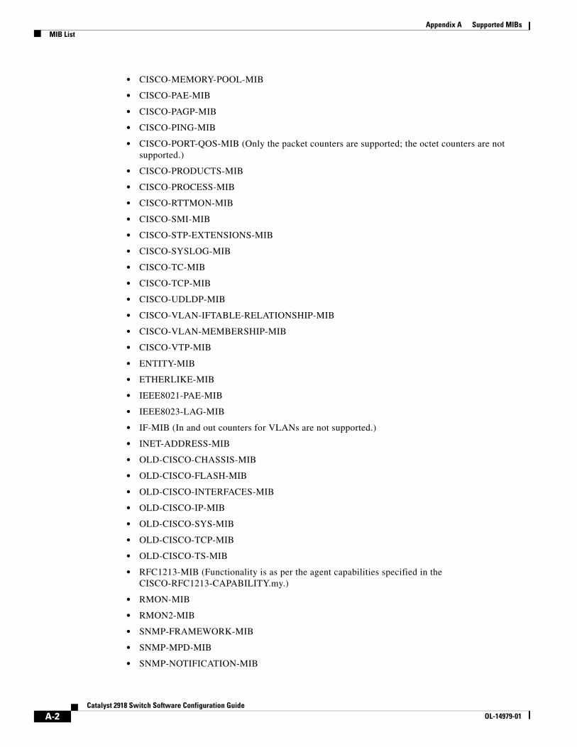
Appendix A Supported MIBsMIB List
• CISCO-MEMORY-POOL-MIB
• CISCO-PAE-MIB
• CISCO-PAGP-MIB
• CISCO-PING-MIB
• CISCO-PORT-QOS-MIB (Only the packet counters are supported; the octet counters are not supported.)
• CISCO-PRODUCTS-MIB
• CISCO-PROCESS-MIB
• CISCO-RTTMON-MIB
• CISCO-SMI-MIB
• CISCO-STP-EXTENSIONS-MIB
• CISCO-SYSLOG-MIB
• CISCO-TC-MIB
• CISCO-TCP-MIB
• CISCO-UDLDP-MIB
• CISCO-VLAN-IFTABLE-RELATIONSHIP-MIB
• CISCO-VLAN-MEMBERSHIP-MIB
• CISCO-VTP-MIB
• ENTITY-MIB
• ETHERLIKE-MIB
• IEEE8021-PAE-MIB
• IEEE8023-LAG-MIB
• IF-MIB (In and out counters for VLANs are not supported.)
• INET-ADDRESS-MIB
• OLD-CISCO-CHASSIS-MIB
• OLD-CISCO-FLASH-MIB
• OLD-CISCO-INTERFACES-MIB
• OLD-CISCO-IP-MIB
• OLD-CISCO-SYS-MIB
• OLD-CISCO-TCP-MIB
• OLD-CISCO-TS-MIB
• RFC1213-MIB (Functionality is as per the agent capabilities specified in the CISCO-RFC1213-CAPABILITY.my.)
• RMON-MIB
• RMON2-MIB
• SNMP-FRAMEWORK-MIB
• SNMP-MPD-MIB
• SNMP-NOTIFICATION-MIB
A-2Catalyst 2918 Switch Software Configuration Guide
OL-14979-01
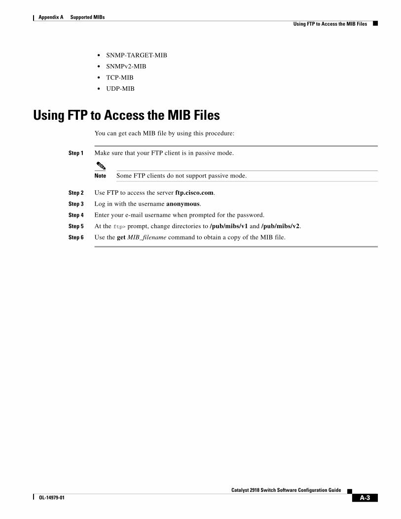
Appendix A Supported MIBsUsing FTP to Access the MIB Files
• SNMP-TARGET-MIB
• SNMPv2-MIB
• TCP-MIB
• UDP-MIB
Using FTP to Access the MIB FilesYou can get each MIB file by using this procedure:
Step 1 Make sure that your FTP client is in passive mode.
Note Some FTP clients do not support passive mode.
Step 2 Use FTP to access the server ftp.cisco.com.
Step 3 Log in with the username anonymous.
Step 4 Enter your e-mail username when prompted for the password.
Step 5 At the ftp> prompt, change directories to /pub/mibs/v1 and /pub/mibs/v2.
Step 6 Use the get MIB_filename command to obtain a copy of the MIB file.
A-3Catalyst 2918 Switch Software Configuration Guide
OL-14979-01

Appendix A Supported MIBsUsing FTP to Access the MIB Files
A-4Catalyst 2918 Switch Software Configuration Guide
OL-14979-01
CatalyOL-14979-01
A
P P E N D I X B Working with the Cisco IOS File System, Configuration Files, and Software ImagesThis appendix describes how to manipulate the Catalyst 2918 switch flash file system, how to copy configuration files, and how to archive (upload and download) software images to a switch.
Note For complete syntax and usage information for the commands used in this chapter, see the switch command reference for this release and the Cisco IOS Configuration Fundamentals Command Reference, Release 12.2.
This appendix consists of these sections:
• Working with the Flash File System, page B-1
• Working with Configuration Files, page B-8
• Working with Software Images, page B-18
Working with the Flash File SystemThe flash file system is a single flash device on which you can store files. It also provides several commands to help you manage software image and configuration files. The default flash file system on the switch is named flash:.
These sections contain this configuration information:
• Displaying Available File Systems, page B-2
• Setting the Default File System, page B-3
• Displaying Information about Files on a File System, page B-3
• Creating and Removing Directories, page B-4
• Copying Files, page B-4
• Deleting Files, page B-5
• Creating, Displaying, and Extracting tar Files, page B-5
• Displaying the Contents of a File, page B-7
B-1st 2918 Switch Software Configuration Guide
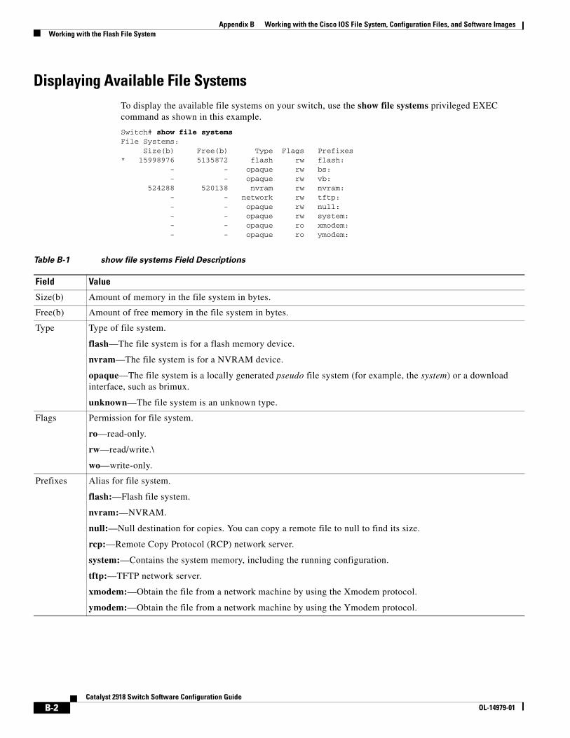
Appendix B Working with the Cisco IOS File System, Configuration Files, and Software ImagesWorking with the Flash File System
Displaying Available File SystemsTo display the available file systems on your switch, use the show file systems privileged EXEC command as shown in this example.
Switch# show file systemsFile Systems: Size(b) Free(b) Type Flags Prefixes* 15998976 5135872 flash rw flash: - - opaque rw bs: - - opaque rw vb: 524288 520138 nvram rw nvram: - - network rw tftp: - - opaque rw null: - - opaque rw system: - - opaque ro xmodem: - - opaque ro ymodem:
Table B-1 show file systems Field Descriptions
Field Value
Size(b) Amount of memory in the file system in bytes.
Free(b) Amount of free memory in the file system in bytes.
Type Type of file system.
flash—The file system is for a flash memory device.
nvram—The file system is for a NVRAM device.
opaque—The file system is a locally generated pseudo file system (for example, the system) or a download interface, such as brimux.
unknown—The file system is an unknown type.
Flags Permission for file system.
ro—read-only.
rw—read/write.\
wo—write-only.
Prefixes Alias for file system.
flash:—Flash file system.
nvram:—NVRAM.
null:—Null destination for copies. You can copy a remote file to null to find its size.
rcp:—Remote Copy Protocol (RCP) network server.
system:—Contains the system memory, including the running configuration.
tftp:—TFTP network server.
xmodem:—Obtain the file from a network machine by using the Xmodem protocol.
ymodem:—Obtain the file from a network machine by using the Ymodem protocol.
B-2Catalyst 2918 Switch Software Configuration Guide
OL-14979-01
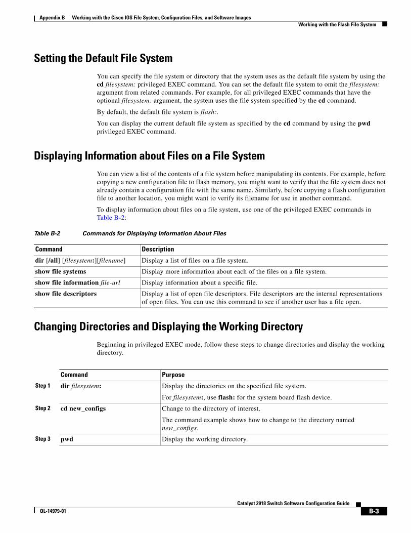
Appendix B Working with the Cisco IOS File System, Configuration Files, and Software ImagesWorking with the Flash File System
Setting the Default File SystemYou can specify the file system or directory that the system uses as the default file system by using the cd filesystem: privileged EXEC command. You can set the default file system to omit the filesystem: argument from related commands. For example, for all privileged EXEC commands that have the optional filesystem: argument, the system uses the file system specified by the cd command.
By default, the default file system is flash:.
You can display the current default file system as specified by the cd command by using the pwd privileged EXEC command.
Displaying Information about Files on a File SystemYou can view a list of the contents of a file system before manipulating its contents. For example, before copying a new configuration file to flash memory, you might want to verify that the file system does not already contain a configuration file with the same name. Similarly, before copying a flash configuration file to another location, you might want to verify its filename for use in another command.
To display information about files on a file system, use one of the privileged EXEC commands in Table B-2:
Table B-2 Commands for Displaying Information About Files
Command Description
dir [/all] [filesystem:][filename] Display a list of files on a file system.
show file systems Display more information about each of the files on a file system.
show file information file-url Display information about a specific file.
show file descriptors Display a list of open file descriptors. File descriptors are the internal representations of open files. You can use this command to see if another user has a file open.
Changing Directories and Displaying the Working DirectoryBeginning in privileged EXEC mode, follow these steps to change directories and display the working directory.
Command Purpose
Step 1 dir filesystem: Display the directories on the specified file system.
For filesystem:, use flash: for the system board flash device.
Step 2 cd new_configs Change to the directory of interest.
The command example shows how to change to the directory named new_configs.
Step 3 pwd Display the working directory.
B-3Catalyst 2918 Switch Software Configuration Guide
OL-14979-01
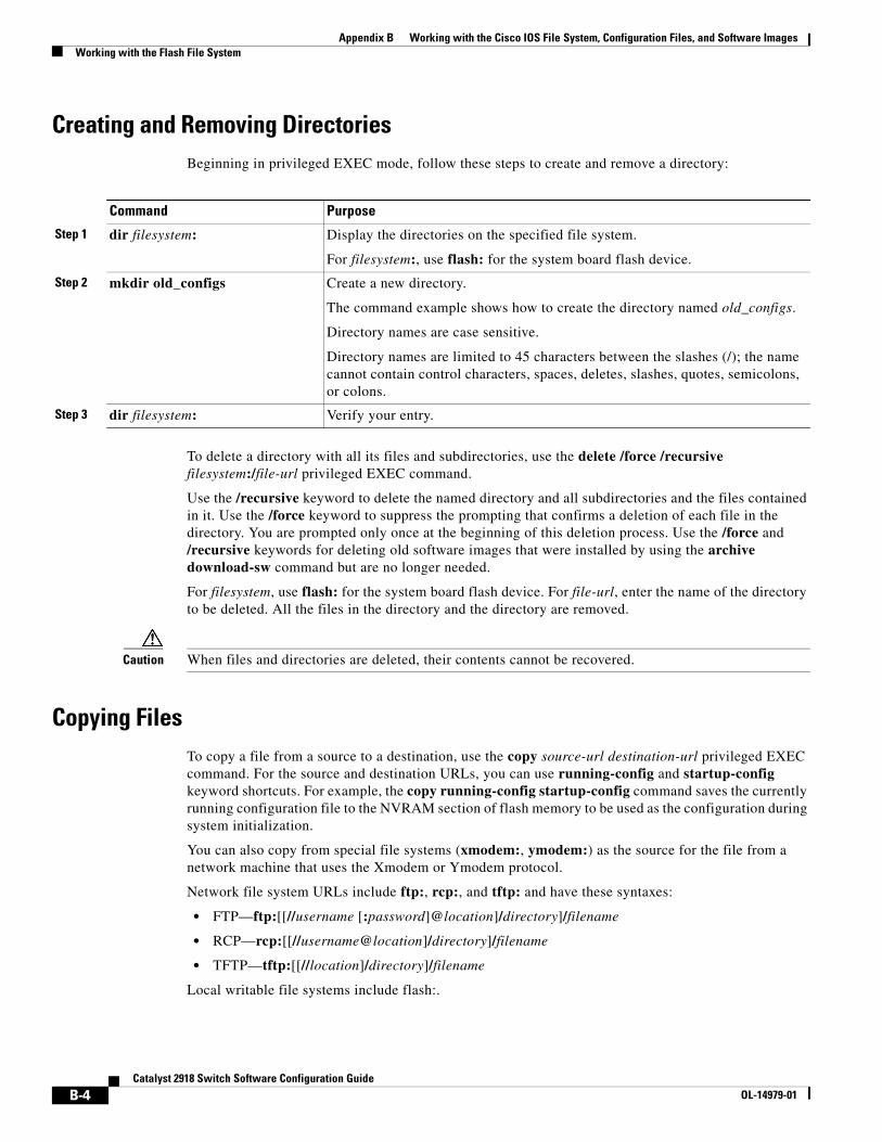
Appendix B Working with the Cisco IOS File System, Configuration Files, and Software ImagesWorking with the Flash File System
Creating and Removing DirectoriesBeginning in privileged EXEC mode, follow these steps to create and remove a directory:
Command Purpose
Step 1 dir filesystem: Display the directories on the specified file system.
For filesystem:, use flash: for the system board flash device.
Step 2 mkdir old_configs Create a new directory.
The command example shows how to create the directory named old_configs.
Directory names are case sensitive.
Directory names are limited to 45 characters between the slashes (/); the name cannot contain control characters, spaces, deletes, slashes, quotes, semicolons, or colons.
Step 3 dir filesystem: Verify your entry.
To delete a directory with all its files and subdirectories, use the delete /force /recursive filesystem:/file-url privileged EXEC command.
Use the /recursive keyword to delete the named directory and all subdirectories and the files contained in it. Use the /force keyword to suppress the prompting that confirms a deletion of each file in the directory. You are prompted only once at the beginning of this deletion process. Use the /force and /recursive keywords for deleting old software images that were installed by using the archive download-sw command but are no longer needed.
For filesystem, use flash: for the system board flash device. For file-url, enter the name of the directory to be deleted. All the files in the directory and the directory are removed.
Caution When files and directories are deleted, their contents cannot be recovered.
Copying FilesTo copy a file from a source to a destination, use the copy source-url destination-url privileged EXEC command. For the source and destination URLs, you can use running-config and startup-config keyword shortcuts. For example, the copy running-config startup-config command saves the currently running configuration file to the NVRAM section of flash memory to be used as the configuration during system initialization.
You can also copy from special file systems (xmodem:, ymodem:) as the source for the file from a network machine that uses the Xmodem or Ymodem protocol.
Network file system URLs include ftp:, rcp:, and tftp: and have these syntaxes:
• FTP—ftp:[[//username [:password]@location]/directory]/filename
• RCP—rcp:[[//username@location]/directory]/filename
• TFTP—tftp:[[//location]/directory]/filename
Local writable file systems include flash:.
B-4Catalyst 2918 Switch Software Configuration Guide
OL-14979-01
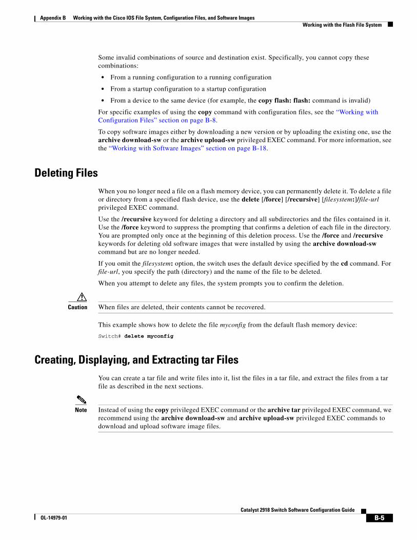
Appendix B Working with the Cisco IOS File System, Configuration Files, and Software ImagesWorking with the Flash File System
Some invalid combinations of source and destination exist. Specifically, you cannot copy these combinations:
• From a running configuration to a running configuration
• From a startup configuration to a startup configuration
• From a device to the same device (for example, the copy flash: flash: command is invalid)
For specific examples of using the copy command with configuration files, see the “Working with Configuration Files” section on page B-8.
To copy software images either by downloading a new version or by uploading the existing one, use the archive download-sw or the archive upload-sw privileged EXEC command. For more information, see the “Working with Software Images” section on page B-18.
Deleting FilesWhen you no longer need a file on a flash memory device, you can permanently delete it. To delete a file or directory from a specified flash device, use the delete [/force] [/recursive] [filesystem:]/file-url privileged EXEC command.
Use the /recursive keyword for deleting a directory and all subdirectories and the files contained in it. Use the /force keyword to suppress the prompting that confirms a deletion of each file in the directory. You are prompted only once at the beginning of this deletion process. Use the /force and /recursive keywords for deleting old software images that were installed by using the archive download-sw command but are no longer needed.
If you omit the filesystem: option, the switch uses the default device specified by the cd command. For file-url, you specify the path (directory) and the name of the file to be deleted.
When you attempt to delete any files, the system prompts you to confirm the deletion.
Caution When files are deleted, their contents cannot be recovered.
This example shows how to delete the file myconfig from the default flash memory device:
Switch# delete myconfig
Creating, Displaying, and Extracting tar FilesYou can create a tar file and write files into it, list the files in a tar file, and extract the files from a tar file as described in the next sections.
Note Instead of using the copy privileged EXEC command or the archive tar privileged EXEC command, we recommend using the archive download-sw and archive upload-sw privileged EXEC commands to download and upload software image files.
B-5Catalyst 2918 Switch Software Configuration Guide
OL-14979-01
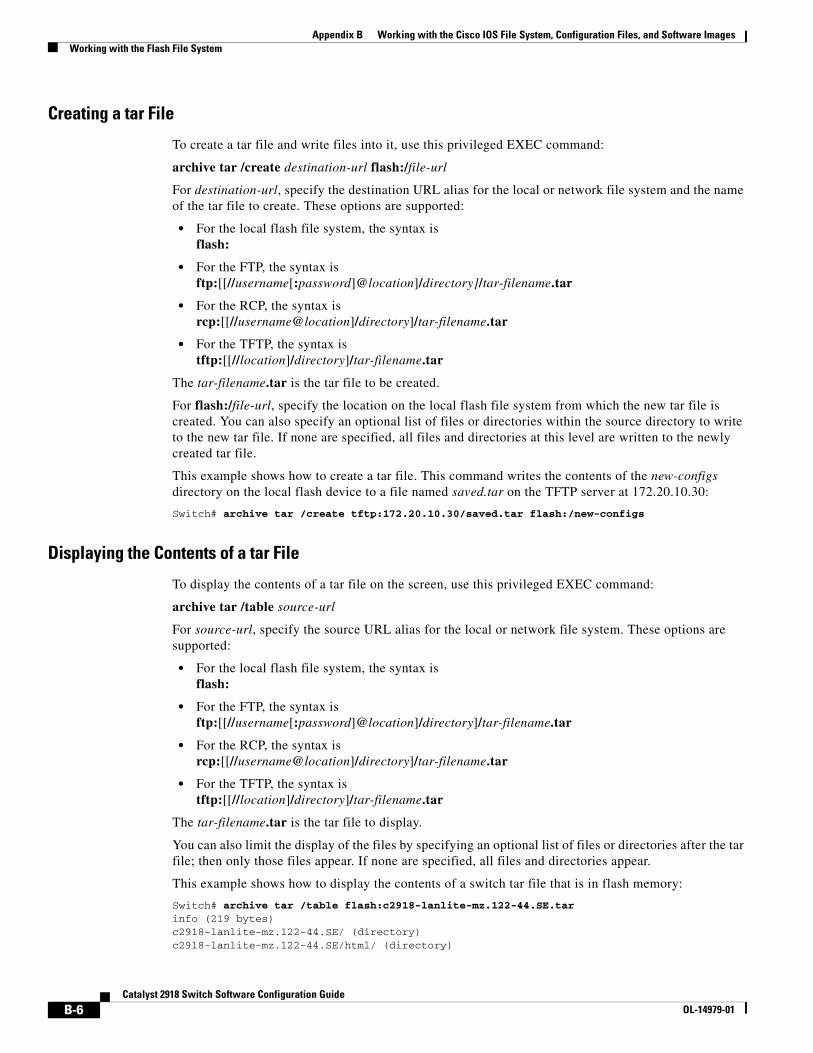
Appendix B Working with the Cisco IOS File System, Configuration Files, and Software ImagesWorking with the Flash File System
Creating a tar File
To create a tar file and write files into it, use this privileged EXEC command:
archive tar /create destination-url flash:/file-url
For destination-url, specify the destination URL alias for the local or network file system and the name of the tar file to create. These options are supported:
• For the local flash file system, the syntax is flash:
• For the FTP, the syntax is ftp:[[//username[:password]@location]/directory]/tar-filename.tar
• For the RCP, the syntax is rcp:[[//username@location]/directory]/tar-filename.tar
• For the TFTP, the syntax is tftp:[[//location]/directory]/tar-filename.tar
The tar-filename.tar is the tar file to be created.
For flash:/file-url, specify the location on the local flash file system from which the new tar file is created. You can also specify an optional list of files or directories within the source directory to write to the new tar file. If none are specified, all files and directories at this level are written to the newly created tar file.
This example shows how to create a tar file. This command writes the contents of the new-configs directory on the local flash device to a file named saved.tar on the TFTP server at 172.20.10.30:
Switch# archive tar /create tftp:172.20.10.30/saved.tar flash:/new-configs
Displaying the Contents of a tar File
To display the contents of a tar file on the screen, use this privileged EXEC command:
archive tar /table source-url
For source-url, specify the source URL alias for the local or network file system. These options are supported:
• For the local flash file system, the syntax is flash:
• For the FTP, the syntax is ftp:[[//username[:password]@location]/directory]/tar-filename.tar
• For the RCP, the syntax is rcp:[[//username@location]/directory]/tar-filename.tar
• For the TFTP, the syntax is tftp:[[//location]/directory]/tar-filename.tar
The tar-filename.tar is the tar file to display.
You can also limit the display of the files by specifying an optional list of files or directories after the tar file; then only those files appear. If none are specified, all files and directories appear.
This example shows how to display the contents of a switch tar file that is in flash memory:
Switch# archive tar /table flash:c2918-lanlite-mz.122-44.SE.tarinfo (219 bytes)c2918-lanlite-mz.122-44.SE/ (directory)c2918-lanlite-mz.122-44.SE/html/ (directory)
B-6Catalyst 2918 Switch Software Configuration Guide
OL-14979-01
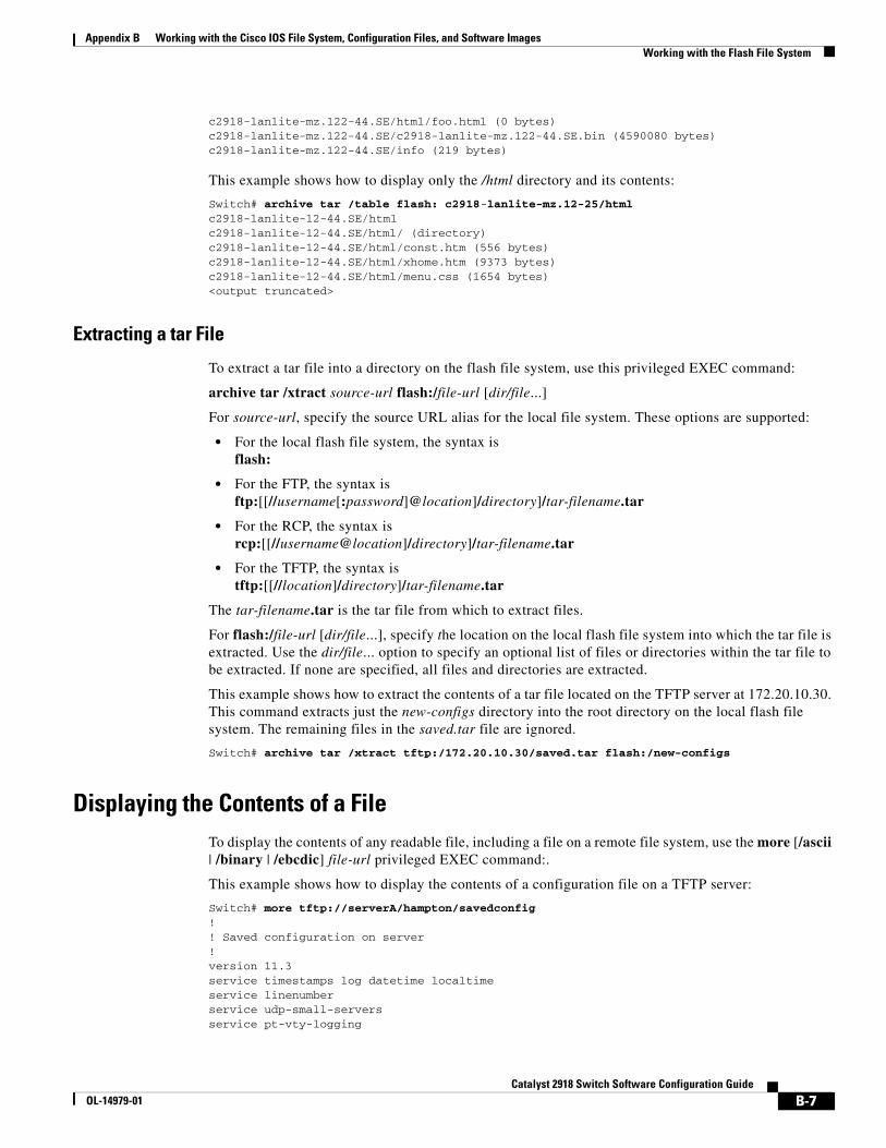
Appendix B Working with the Cisco IOS File System, Configuration Files, and Software ImagesWorking with the Flash File System
c2918-lanlite-mz.122-44.SE/html/foo.html (0 bytes)c2918-lanlite-mz.122-44.SE/c2918-lanlite-mz.122-44.SE.bin (4590080 bytes)c2918-lanlite-mz.122-44.SE/info (219 bytes)
This example shows how to display only the /html directory and its contents:
Switch# archive tar /table flash: c2918-lanlite-mz.12-25/htmlc2918-lanlite-12-44.SE/htmlc2918-lanlite-12-44.SE/html/ (directory)c2918-lanlite-12-44.SE/html/const.htm (556 bytes)c2918-lanlite-12-44.SE/html/xhome.htm (9373 bytes)c2918-lanlite-12-44.SE/html/menu.css (1654 bytes)<output truncated>
Extracting a tar File
To extract a tar file into a directory on the flash file system, use this privileged EXEC command:
archive tar /xtract source-url flash:/file-url [dir/file...]
For source-url, specify the source URL alias for the local file system. These options are supported:
• For the local flash file system, the syntax is flash:
• For the FTP, the syntax is ftp:[[//username[:password]@location]/directory]/tar-filename.tar
• For the RCP, the syntax is rcp:[[//username@location]/directory]/tar-filename.tar
• For the TFTP, the syntax is tftp:[[//location]/directory]/tar-filename.tar
The tar-filename.tar is the tar file from which to extract files.
For flash:/file-url [dir/file...], specify the location on the local flash file system into which the tar file is extracted. Use the dir/file... option to specify an optional list of files or directories within the tar file to be extracted. If none are specified, all files and directories are extracted.
This example shows how to extract the contents of a tar file located on the TFTP server at 172.20.10.30. This command extracts just the new-configs directory into the root directory on the local flash file system. The remaining files in the saved.tar file are ignored.
Switch# archive tar /xtract tftp:/172.20.10.30/saved.tar flash:/new-configs
Displaying the Contents of a FileTo display the contents of any readable file, including a file on a remote file system, use the more [/ascii | /binary | /ebcdic] file-url privileged EXEC command:.
This example shows how to display the contents of a configuration file on a TFTP server:
Switch# more tftp://serverA/hampton/savedconfig !! Saved configuration on server!version 11.3service timestamps log datetime localtimeservice linenumberservice udp-small-serversservice pt-vty-logging
B-7Catalyst 2918 Switch Software Configuration Guide
OL-14979-01
Appendix B Working with the Cisco IOS File System, Configuration Files, and Software ImagesWorking with Configuration Files
!<output truncated>
Working with Configuration FilesThis section describes how to create, load, and maintain configuration files.
Configuration files contain commands entered to customize the function of the Cisco IOS software. A way to create a basic configuration file is to use the setup program or to enter the setup privileged EXEC command. For more information, see Chapter 3, “Assigning the Switch IP Address and Default Gateway.”
You can copy (download) configuration files from a TFTP, FTP, or RCP server to the running configuration or startup configuration of the switch. You might want to perform this for one of these reasons:
• To restore a backed-up configuration file.
• To use the configuration file for another switch. For example, you might add another switch to your network and want it to have a configuration similar to the original switch. By copying the file to the new switch, you can change the relevant parts rather than recreating the whole file.
• To load the same configuration commands on all the switches in your network so that all the switches have similar configurations.
You can copy (upload) configuration files from the switch to a file server by using TFTP, FTP, or RCP. You might perform this task to back up a current configuration file to a server before changing its contents so that you can later restore the original configuration file from the server.
The protocol you use depends on which type of server you are using. The FTP and RCP transport mechanisms provide faster performance and more reliable delivery of data than TFTP. These improvements are possible because FTP and RCP are built on and use the TCP/IP stack, which is connection-oriented.
These sections contain this configuration information:
• Guidelines for Creating and Using Configuration Files, page B-8
• Configuration File Types and Location, page B-9
• Creating a Configuration File By Using a Text Editor, page B-9
• Copying Configuration Files By Using TFTP, page B-10
• Copying Configuration Files By Using FTP, page B-12
• Copying Configuration Files By Using RCP, page B-15
• Clearing Configuration Information, page B-18
Guidelines for Creating and Using Configuration FilesCreating configuration files can aid in your switch configuration. Configuration files can contain some or all of the commands needed to configure one or more switches. For example, you might want to download the same configuration file to several switches that have the same hardware configuration.
B-8Catalyst 2918 Switch Software Configuration Guide
OL-14979-01
Appendix B Working with the Cisco IOS File System, Configuration Files, and Software ImagesWorking with Configuration Files
Use these guidelines when creating a configuration file:
• We recommend that you connect through the console port for the initial configuration of the switch. If you are accessing the switch through a network connection instead of through a direct connection to the console port, keep in mind that some configuration changes (such as changing the switch IP address or disabling ports) can cause a loss of connectivity to the switch.
• If no password has been set on the switch, we recommend that you set one by using the enable secret secret-password global configuration command.
Note The copy {ftp: | rcp: | tftp:} system:running-config privileged EXEC command loads the configuration files on the switch as if you were entering the commands at the command line. The switch does not erase the existing running configuration before adding the commands. If a command in the copied configuration file replaces a command in the existing configuration file, the existing command is erased. For example, if the copied configuration file contains a different IP address in a particular command than the existing configuration, the IP address in the copied configuration is used. However, some commands in the existing configuration might not be replaced or negated. In this case, the resulting configuration file is a mixture of the existing configuration file and the copied configuration file, with the copied configuration file having precedence. To restore a configuration file to an exact copy of a file stored on a server, copy the configuration file directly to the startup configuration (by using the copy {ftp: | rcp: | tftp:} nvram:startup-config privileged EXEC command), and reload the switch.
Configuration File Types and LocationStartup configuration files are used during system startup to configure the software. Running configuration files contain the current configuration of the software. The two configuration files can be different. For example, you might want to change the configuration for a short time period rather than permanently. In this case, you would change the running configuration but not save the configuration by using the copy running-config startup-config privileged EXEC command.
The running configuration is saved in DRAM; the startup configuration is stored in the NVRAM section of flash memory.
Creating a Configuration File By Using a Text EditorWhen creating a configuration file, you must list commands logically so that the system can respond appropriately. This is one method of creating a configuration file:
Step 1 Copy an existing configuration from a switch to a server.
For more information, see the “Downloading the Configuration File By Using TFTP” section on page B-11, the “Downloading a Configuration File By Using FTP” section on page B-13, or the “Downloading a Configuration File By Using RCP” section on page B-16.
Step 2 Open the configuration file in a text editor, such as vi or emacs on UNIX or Notepad on a PC.
Step 3 Extract the portion of the configuration file with the desired commands, and save it in a new file.
Step 4 Copy the configuration file to the appropriate server location. For example, copy the file to the TFTP directory on the workstation (usually /tftpboot on a UNIX workstation).
B-9Catalyst 2918 Switch Software Configuration Guide
OL-14979-01
Appendix B Working with the Cisco IOS File System, Configuration Files, and Software ImagesWorking with Configuration Files
Step 5 Make sure the permissions on the file are set to world-read.
Copying Configuration Files By Using TFTPYou can configure the switch by using configuration files you create, download from another switch, or download from a TFTP server. You can copy (upload) configuration files to a TFTP server for storage.
These sections contain this configuration information:
• Preparing to Download or Upload a Configuration File By Using TFTP, page B-10
• Downloading the Configuration File By Using TFTP, page B-11
• Uploading the Configuration File By Using TFTP, page B-11
Preparing to Download or Upload a Configuration File By Using TFTP
Before you begin downloading or uploading a configuration file by using TFTP, do these tasks:
• Ensure that the workstation acting as the TFTP server is properly configured. On a Sun workstation, make sure that the /etc/inetd.conf file contains this line:
tftp dgram udp wait root /usr/etc/in.tftpd in.tftpd -p -s /tftpboot
Make sure that the /etc/services file contains this line:
tftp 69/udp
Note You must restart the inetd daemon after modifying the /etc/inetd.conf and /etc/services files. To restart the daemon, either stop the inetd process and restart it, or enter a fastboot command (on the SunOS 4.x) or a reboot command (on Solaris 2.x or SunOS 5.x). For more information on the TFTP daemon, see the documentation for your workstation.
• Ensure that the switch has a route to the TFTP server. The switch and the TFTP server must be in the same subnetwork if you do not have a router to route traffic between subnets. Check connectivity to the TFTP server by using the ping command.
• Ensure that the configuration file to be downloaded is in the correct directory on the TFTP server (usually /tftpboot on a UNIX workstation).
• For download operations, ensure that the permissions on the file are set correctly. The permission on the file should be world-read.
• Before uploading the configuration file, you might need to create an empty file on the TFTP server. To create an empty file, enter the touch filename command, where filename is the name of the file you will use when uploading it to the server.
• During upload operations, if you are overwriting an existing file (including an empty file, if you had to create one) on the server, ensure that the permissions on the file are set correctly. Permissions on the file should be world-write.
B-10Catalyst 2918 Switch Software Configuration Guide
OL-14979-01
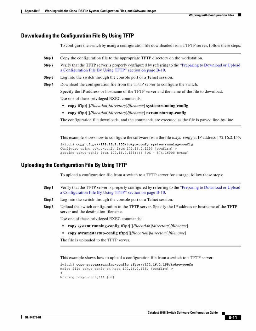
Appendix B Working with the Cisco IOS File System, Configuration Files, and Software ImagesWorking with Configuration Files
Downloading the Configuration File By Using TFTP
To configure the switch by using a configuration file downloaded from a TFTP server, follow these steps:
Step 1 Copy the configuration file to the appropriate TFTP directory on the workstation.
Step 2 Verify that the TFTP server is properly configured by referring to the “Preparing to Download or Upload a Configuration File By Using TFTP” section on page B-10.
Step 3 Log into the switch through the console port or a Telnet session.
Step 4 Download the configuration file from the TFTP server to configure the switch.
Specify the IP address or hostname of the TFTP server and the name of the file to download.
Use one of these privileged EXEC commands:
• copy tftp:[[[//location]/directory]/filename] system:running-config
• copy tftp:[[[//location]/directory]/filename] nvram:startup-config
The configuration file downloads, and the commands are executed as the file is parsed line-by-line.
This example shows how to configure the software from the file tokyo-confg at IP address 172.16.2.155:
Switch# copy tftp://172.16.2.155/tokyo-confg system:running-configConfigure using tokyo-confg from 172.16.2.155? [confirm] yBooting tokyo-confg from 172.16.2.155:!!! [OK - 874/16000 bytes]
Uploading the Configuration File By Using TFTP
To upload a configuration file from a switch to a TFTP server for storage, follow these steps:
Step 1 Verify that the TFTP server is properly configured by referring to the “Preparing to Download or Upload a Configuration File By Using TFTP” section on page B-10.
Step 2 Log into the switch through the console port or a Telnet session.
Step 3 Upload the switch configuration to the TFTP server. Specify the IP address or hostname of the TFTP server and the destination filename.
Use one of these privileged EXEC commands:
• copy system:running-config tftp:[[[//location]/directory]/filename]
• copy nvram:startup-config tftp:[[[//location]/directory]/filename]
The file is uploaded to the TFTP server.
This example shows how to upload a configuration file from a switch to a TFTP server:
Switch# copy system:running-config tftp://172.16.2.155/tokyo-confgWrite file tokyo-confg on host 172.16.2.155? [confirm] y#Writing tokyo-confg!!! [OK]
B-11Catalyst 2918 Switch Software Configuration Guide
OL-14979-01
Appendix B Working with the Cisco IOS File System, Configuration Files, and Software ImagesWorking with Configuration Files
Copying Configuration Files By Using FTPYou can copy configuration files to or from an FTP server.
The FTP protocol requires a client to send a remote username and password on each FTP request to a server. When you copy a configuration file from the switch to a server by using FTP, the Cisco IOS software sends the first valid username in this list:
• The username specified in the copy command if a username is specified.
• The username set by the ip ftp username username global configuration command if the command is configured.
• Anonymous.
The switch sends the first valid password in this list:
• The password specified in the copy command if a password is specified.
• The password set by the ip ftp password password global configuration command if the command is configured.
• The switch forms a password named [email protected]. The variable username is the username associated with the current session, switchname is the configured hostname, and domain is the domain of the switch.
The username and password must be associated with an account on the FTP server. If you are writing to the server, the FTP server must be properly configured to accept your FTP write request.
Use the ip ftp username and ip ftp password commands to specify a username and password for all copies. Include the username in the copy command if you want to specify only a username for that copy operation.
If the server has a directory structure, the configuration file is written to or copied from the directory associated with the username on the server. For example, if the configuration file resides in the home directory of a user on the server, specify that user's name as the remote username.
For more information, see the documentation for your FTP server.
These sections contain this configuration information:
• Preparing to Download or Upload a Configuration File By Using FTP, page B-12
• Downloading a Configuration File By Using FTP, page B-13
• Uploading a Configuration File By Using FTP, page B-14
Preparing to Download or Upload a Configuration File By Using FTP
Before you begin downloading or uploading a configuration file by using FTP, do these tasks:
• Ensure that the switch has a route to the FTP server. The switch and the FTP server must be in the same subnetwork if you do not have a router to route traffic between subnets. Check connectivity to the FTP server by using the ping command.
• If you are accessing the switch through the console or a Telnet session and you do not have a valid username, make sure that the current FTP username is the one that you want to use for the FTP download. You can enter the show users privileged EXEC command to view the valid username. If you do not want to use this username, create a new FTP username by using the ip ftp username username global configuration command during all copy operations. The new username is stored in
B-12Catalyst 2918 Switch Software Configuration Guide
OL-14979-01
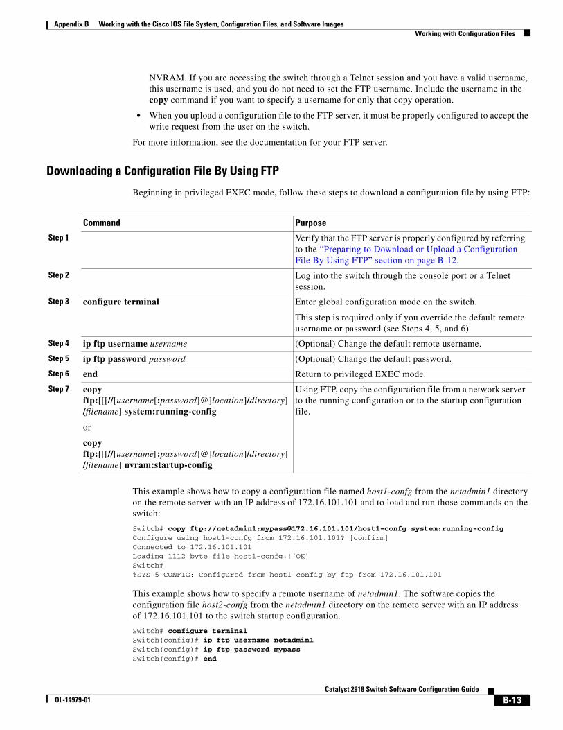
Appendix B Working with the Cisco IOS File System, Configuration Files, and Software ImagesWorking with Configuration Files
NVRAM. If you are accessing the switch through a Telnet session and you have a valid username, this username is used, and you do not need to set the FTP username. Include the username in the copy command if you want to specify a username for only that copy operation.
• When you upload a configuration file to the FTP server, it must be properly configured to accept the write request from the user on the switch.
For more information, see the documentation for your FTP server.
Downloading a Configuration File By Using FTP
Beginning in privileged EXEC mode, follow these steps to download a configuration file by using FTP:
Command Purpose
Step 1 Verify that the FTP server is properly configured by referring to the “Preparing to Download or Upload a Configuration File By Using FTP” section on page B-12.
Step 2 Log into the switch through the console port or a Telnet session.
Step 3 configure terminal Enter global configuration mode on the switch.
This step is required only if you override the default remote username or password (see Steps 4, 5, and 6).
Step 4 ip ftp username username (Optional) Change the default remote username.
Step 5 ip ftp password password (Optional) Change the default password.
Step 6 end Return to privileged EXEC mode.
Step 7 copy ftp:[[[//[username[:password]@]location]/directory]/filename] system:running-config
or
copy ftp:[[[//[username[:password]@]location]/directory]/filename] nvram:startup-config
Using FTP, copy the configuration file from a network server to the running configuration or to the startup configuration file.
This example shows how to copy a configuration file named host1-confg from the netadmin1 directory on the remote server with an IP address of 172.16.101.101 and to load and run those commands on the switch:
Switch# copy ftp://netadmin1:[email protected]/host1-confg system:running-config Configure using host1-confg from 172.16.101.101? [confirm]Connected to 172.16.101.101Loading 1112 byte file host1-confg:![OK]Switch#%SYS-5-CONFIG: Configured from host1-config by ftp from 172.16.101.101
This example shows how to specify a remote username of netadmin1. The software copies the configuration file host2-confg from the netadmin1 directory on the remote server with an IP address of 172.16.101.101 to the switch startup configuration.
Switch# configure terminalSwitch(config)# ip ftp username netadmin1Switch(config)# ip ftp password mypassSwitch(config)# end
B-13Catalyst 2918 Switch Software Configuration Guide
OL-14979-01
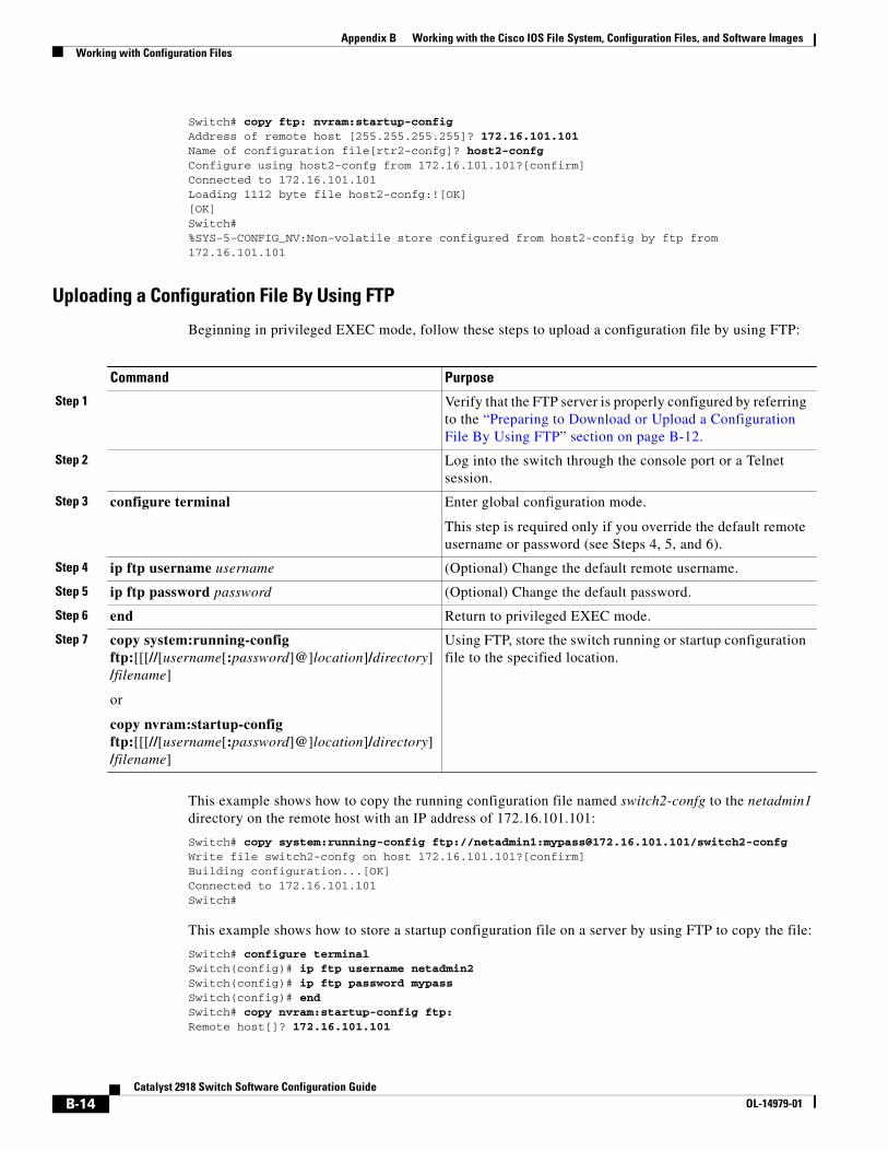
Appendix B Working with the Cisco IOS File System, Configuration Files, and Software ImagesWorking with Configuration Files
Switch# copy ftp: nvram:startup-config Address of remote host [255.255.255.255]? 172.16.101.101Name of configuration file[rtr2-confg]? host2-confgConfigure using host2-confg from 172.16.101.101?[confirm]Connected to 172.16.101.101Loading 1112 byte file host2-confg:![OK][OK]Switch#%SYS-5-CONFIG_NV:Non-volatile store configured from host2-config by ftp from 172.16.101.101
Uploading a Configuration File By Using FTP
Beginning in privileged EXEC mode, follow these steps to upload a configuration file by using FTP:
Command Purpose
Step 1 Verify that the FTP server is properly configured by referring to the “Preparing to Download or Upload a Configuration File By Using FTP” section on page B-12.
Step 2 Log into the switch through the console port or a Telnet session.
Step 3 configure terminal Enter global configuration mode.
This step is required only if you override the default remote username or password (see Steps 4, 5, and 6).
Step 4 ip ftp username username (Optional) Change the default remote username.
Step 5 ip ftp password password (Optional) Change the default password.
Step 6 end Return to privileged EXEC mode.
Step 7 copy system:running-config ftp:[[[//[username[:password]@]location]/directory]/filename]
or
copy nvram:startup-config ftp:[[[//[username[:password]@]location]/directory]/filename]
Using FTP, store the switch running or startup configuration file to the specified location.
This example shows how to copy the running configuration file named switch2-confg to the netadmin1 directory on the remote host with an IP address of 172.16.101.101:
Switch# copy system:running-config ftp://netadmin1:[email protected]/switch2-confgWrite file switch2-confg on host 172.16.101.101?[confirm]Building configuration...[OK]Connected to 172.16.101.101Switch#
This example shows how to store a startup configuration file on a server by using FTP to copy the file:
Switch# configure terminalSwitch(config)# ip ftp username netadmin2Switch(config)# ip ftp password mypassSwitch(config)# endSwitch# copy nvram:startup-config ftp:Remote host[]? 172.16.101.101
B-14Catalyst 2918 Switch Software Configuration Guide
OL-14979-01
Appendix B Working with the Cisco IOS File System, Configuration Files, and Software ImagesWorking with Configuration Files
Name of configuration file to write [switch2-confg]?Write file switch2-confg on host 172.16.101.101?[confirm]![OK]
Copying Configuration Files By Using RCPThe RCP provides another method of downloading, uploading, and copying configuration files between remote hosts and the switch. Unlike TFTP, which uses User Datagram Protocol (UDP), a connectionless protocol, RCP uses TCP, which is connection-oriented.
To use RCP to copy files, the server from or to which you will be copying files must support RCP. The RCP copy commands rely on the rsh server (or daemon) on the remote system. To copy files by using RCP, you do not need to create a server for file distribution as you do with TFTP. You only need to have access to a server that supports the remote shell (rsh). (Most UNIX systems support rsh.) Because you are copying a file from one place to another, you must have read permission on the source file and write permission on the destination file. If the destination file does not exist, RCP creates it for you.
The RCP requires a client to send a remote username with each RCP request to a server. When you copy a configuration file from the switch to a server, the Cisco IOS software sends the first valid username in this list:
• The username specified in the copy command if a username is specified.
• The username set by the ip rcmd remote-username username global configuration command if the command is configured.
• The remote username associated with the current TTY (terminal) process. For example, if the user is connected to the router through Telnet and was authenticated through the username command, the switch software sends the Telnet username as the remote username.
• The switch hostname.
For a successful RCP copy request, you must define an account on the network server for the remote username. If the server has a directory structure, the configuration file is written to or copied from the directory associated with the remote username on the server. For example, if the configuration file is in the home directory of a user on the server, specify that user's name as the remote username.
These sections contain this configuration information:
• Preparing to Download or Upload a Configuration File By Using RCP, page B-15
• Downloading a Configuration File By Using RCP, page B-16
• Uploading a Configuration File By Using RCP, page B-17
Preparing to Download or Upload a Configuration File By Using RCP
Before you begin downloading or uploading a configuration file by using RCP, do these tasks:
• Ensure that the workstation acting as the RCP server supports the remote shell (rsh).
• Ensure that the switch has a route to the RCP server. The switch and the server must be in the same subnetwork if you do not have a router to route traffic between subnets. Check connectivity to the RCP server by using the ping command.
• If you are accessing the switch through the console or a Telnet session and you do not have a valid username, make sure that the current RCP username is the one that you want to use for the RCP download. You can enter the show users privileged EXEC command to view the valid username. If you do not want to use this username, create a new RCP username by using the ip rcmd remote-username username global configuration command to be used during all copy operations.
B-15Catalyst 2918 Switch Software Configuration Guide
OL-14979-01
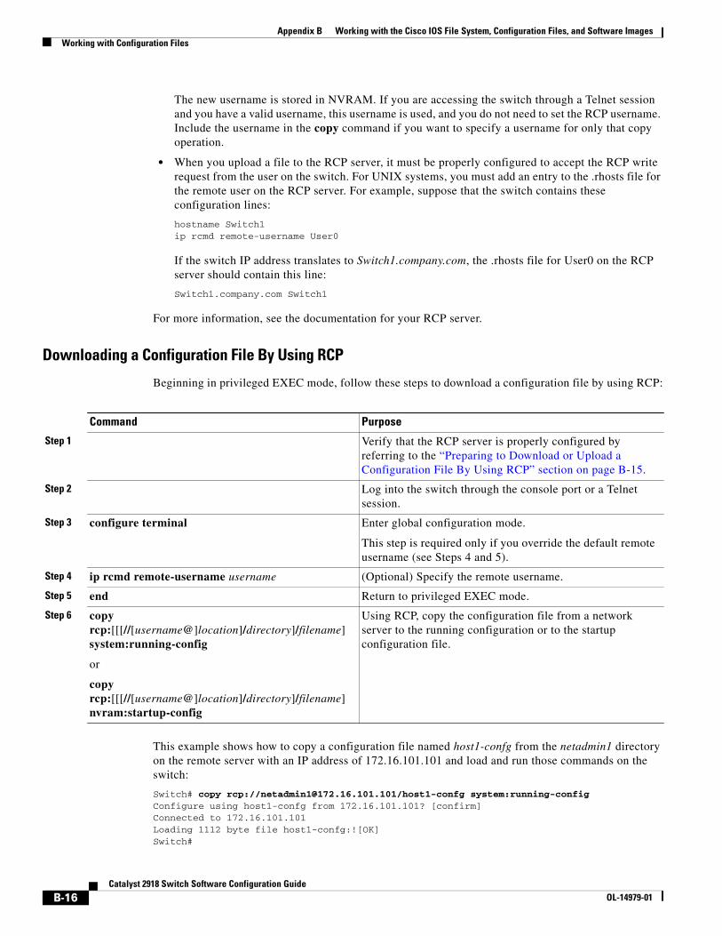
Appendix B Working with the Cisco IOS File System, Configuration Files, and Software ImagesWorking with Configuration Files
The new username is stored in NVRAM. If you are accessing the switch through a Telnet session and you have a valid username, this username is used, and you do not need to set the RCP username. Include the username in the copy command if you want to specify a username for only that copy operation.
• When you upload a file to the RCP server, it must be properly configured to accept the RCP write request from the user on the switch. For UNIX systems, you must add an entry to the .rhosts file for the remote user on the RCP server. For example, suppose that the switch contains these configuration lines:
hostname Switch1ip rcmd remote-username User0
If the switch IP address translates to Switch1.company.com, the .rhosts file for User0 on the RCP server should contain this line:
Switch1.company.com Switch1
For more information, see the documentation for your RCP server.
Downloading a Configuration File By Using RCP
Beginning in privileged EXEC mode, follow these steps to download a configuration file by using RCP:
Command Purpose
Step 1 Verify that the RCP server is properly configured by referring to the “Preparing to Download or Upload a Configuration File By Using RCP” section on page B-15.
Step 2 Log into the switch through the console port or a Telnet session.
Step 3 configure terminal Enter global configuration mode.
This step is required only if you override the default remote username (see Steps 4 and 5).
Step 4 ip rcmd remote-username username (Optional) Specify the remote username.
Step 5 end Return to privileged EXEC mode.
Step 6 copy rcp:[[[//[username@]location]/directory]/filename] system:running-config
or
copy rcp:[[[//[username@]location]/directory]/filename] nvram:startup-config
Using RCP, copy the configuration file from a network server to the running configuration or to the startup configuration file.
This example shows how to copy a configuration file named host1-confg from the netadmin1 directory on the remote server with an IP address of 172.16.101.101 and load and run those commands on the switch:
Switch# copy rcp://[email protected]/host1-confg system:running-config Configure using host1-confg from 172.16.101.101? [confirm]Connected to 172.16.101.101Loading 1112 byte file host1-confg:![OK]Switch#
B-16Catalyst 2918 Switch Software Configuration Guide
OL-14979-01
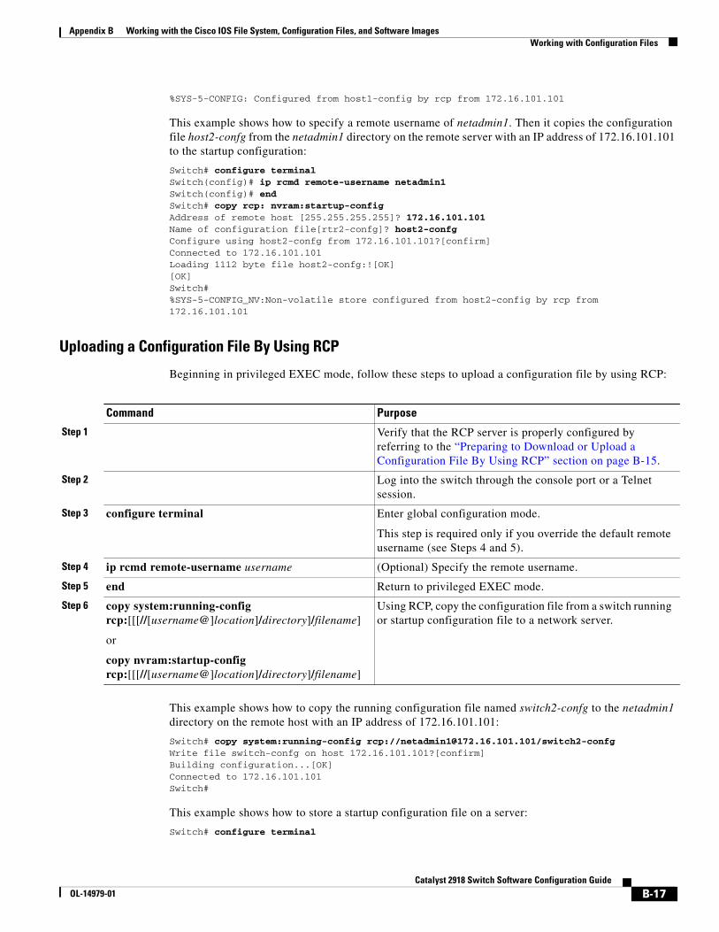
Appendix B Working with the Cisco IOS File System, Configuration Files, and Software ImagesWorking with Configuration Files
%SYS-5-CONFIG: Configured from host1-config by rcp from 172.16.101.101
This example shows how to specify a remote username of netadmin1. Then it copies the configuration file host2-confg from the netadmin1 directory on the remote server with an IP address of 172.16.101.101 to the startup configuration:
Switch# configure terminalSwitch(config)# ip rcmd remote-username netadmin1Switch(config)# endSwitch# copy rcp: nvram:startup-config Address of remote host [255.255.255.255]? 172.16.101.101Name of configuration file[rtr2-confg]? host2-confgConfigure using host2-confg from 172.16.101.101?[confirm]Connected to 172.16.101.101Loading 1112 byte file host2-confg:![OK][OK]Switch#%SYS-5-CONFIG_NV:Non-volatile store configured from host2-config by rcp from 172.16.101.101
Uploading a Configuration File By Using RCP
Beginning in privileged EXEC mode, follow these steps to upload a configuration file by using RCP:
Command Purpose
Step 1 Verify that the RCP server is properly configured by referring to the “Preparing to Download or Upload a Configuration File By Using RCP” section on page B-15.
Step 2 Log into the switch through the console port or a Telnet session.
Step 3 configure terminal Enter global configuration mode.
This step is required only if you override the default remote username (see Steps 4 and 5).
Step 4 ip rcmd remote-username username (Optional) Specify the remote username.
Step 5 end Return to privileged EXEC mode.
Step 6 copy system:running-config rcp:[[[//[username@]location]/directory]/filename]
or
copy nvram:startup-config rcp:[[[//[username@]location]/directory]/filename]
Using RCP, copy the configuration file from a switch running or startup configuration file to a network server.
This example shows how to copy the running configuration file named switch2-confg to the netadmin1 directory on the remote host with an IP address of 172.16.101.101:
Switch# copy system:running-config rcp://[email protected]/switch2-confgWrite file switch-confg on host 172.16.101.101?[confirm]Building configuration...[OK]Connected to 172.16.101.101Switch#
This example shows how to store a startup configuration file on a server:
Switch# configure terminal
B-17Catalyst 2918 Switch Software Configuration Guide
OL-14979-01
Appendix B Working with the Cisco IOS File System, Configuration Files, and Software ImagesWorking with Software Images
Switch(config)# ip rcmd remote-username netadmin2Switch(config)# endSwitch# copy nvram:startup-config rcp:Remote host[]? 172.16.101.101Name of configuration file to write [switch2-confg]?Write file switch2-confg on host 172.16.101.101?[confirm]![OK]
Clearing Configuration InformationYou can clear the configuration information from the startup configuration. If you reboot the switch with no startup configuration, the switch enters the setup program so that you can reconfigure the switch with all new settings.
Clearing the Startup Configuration File
To clear the contents of your startup configuration, use the erase nvram: or the erase startup-config privileged EXEC command.
Caution You cannot restore the startup configuration file after it has been deleted.
Deleting a Stored Configuration File
To delete a saved configuration from flash memory, use the delete flash:filename privileged EXEC command. Depending on the setting of the file prompt global configuration command, you might be prompted for confirmation before you delete a file. By default, the switch prompts for confirmation on destructive file operations. For more information about the file prompt command, see the Cisco IOS Command Reference for Release 12.2.
Caution You cannot restore a file after it has been deleted.
Working with Software ImagesThis section describes how to archive (download and upload) software image files, which contain the system software, the Cisco IOS code, and the embedded device manager software.
Note Instead of using the copy privileged EXEC command or the archive tar privileged EXEC command, we recommend using the archive download-sw and archive upload-sw privileged EXEC commands to download and upload software image files.
You can download a switch image file from a TFTP, FTP, or RCP server to upgrade the switch software. If you do not have access to a TFTP server, you can download a software image file directly to your PC or workstation by using a web browser (HTTP) and then by using the device manager to upgrade your switch. For information about upgrading your switch by using a TFTP server or a web browser (HTTP), see the release notes.
B-18Catalyst 2918 Switch Software Configuration Guide
OL-14979-01
Appendix B Working with the Cisco IOS File System, Configuration Files, and Software ImagesWorking with Software Images
You can replace the current image with the new one or keep the current image in flash memory after a download.
You upload a switch image file to a TFTP, FTP, or RCP server for backup purposes. You can use this uploaded image for future downloads to the same switch or to another of the same type.
The protocol that you use depends on which type of server you are using. The FTP and RCP transport mechanisms provide faster performance and more reliable delivery of data than TFTP. These improvements are possible because FTP and RCP are built on and use the TCP/IP stack, which is connection-oriented.
These sections contain this configuration information:
• Image Location on the Switch, page B-19
• tar File Format of Images on a Server or Cisco.com, page B-19
• Copying Image Files By Using TFTP, page B-20
• Copying Image Files By Using FTP, page B-23
• Copying Image Files By Using RCP, page B-27
Note For a list of software images and the supported upgrade paths, see the release notes.
Image Location on the SwitchThe Cisco IOS image is stored as a .bin file in a directory that shows the version number. A subdirectory contains the files needed for web management. The image is stored on the system board flash memory (flash:).
You can use the show version privileged EXEC command to see the software version that is currently running on your switch. In the display, check the line that begins with System image file is.... It shows the directory name in flash memory where the image is stored.
You can also use the dir filesystem: privileged EXEC command to see the directory names of other software images that might be stored in flash memory.
tar File Format of Images on a Server or Cisco.comSoftware images located on a server or downloaded from Cisco.com are provided in a tar file format, which contains these files:
• An info file, which serves as a table of contents for the tar file
• One or more subdirectories containing other images and files, such as Cisco IOS images and web management files
This example shows some of the information contained in the info file. Table B-3 provides additional details about this information:
system_type:0x00000000:c2918-lanlite-mz.122.44-SE image_family:C2918 stacking_number:1.11 info_end:
version_suffix:lanlite-122-44.SEversion_directory:c2918-lanlite-mz.122.44-SE image_system_type_id:0x00000000
B-19Catalyst 2918 Switch Software Configuration Guide
OL-14979-01
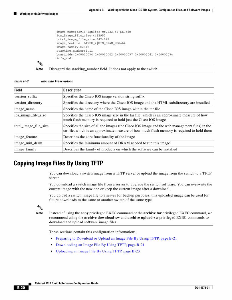
Appendix B Working with the Cisco IOS File System, Configuration Files, and Software ImagesWorking with Software Images
image_name:c2918-lanlite-mz.122.44-SE.bin ios_image_file_size:4413952 total_image_file_size:4424192 image_feature: LAYER_2|MIN_DRAM_MEG=64 image_family:C2918 stacking_number:1.11 board_ids:0x00000034 0x00000042 0x00000037 0x00000041 0x0000003c info_end:
Note Disregard the stacking_number field. It does not apply to the switch.
Table B-3 info File Description
Field Description
version_suffix Specifies the Cisco IOS image version string suffix
version_directory Specifies the directory where the Cisco IOS image and the HTML subdirectory are installed
image_name Specifies the name of the Cisco IOS image within the tar file
ios_image_file_size Specifies the Cisco IOS image size in the tar file, which is an approximate measure of how much flash memory is required to hold just the Cisco IOS image
total_image_file_size Specifies the size of all the images (the Cisco IOS image and the web management files) in the tar file, which is an approximate measure of how much flash memory is required to hold them
image_feature Describes the core functionality of the image
image_min_dram Specifies the minimum amount of DRAM needed to run this image
image_family Describes the family of products on which the software can be installed
Copying Image Files By Using TFTPYou can download a switch image from a TFTP server or upload the image from the switch to a TFTP server.
You download a switch image file from a server to upgrade the switch software. You can overwrite the current image with the new one or keep the current image after a download.
You upload a switch image file to a server for backup purposes; this uploaded image can be used for future downloads to the same or another switch of the same type.
Note Instead of using the copy privileged EXEC command or the archive tar privileged EXEC command, we recommend using the archive download-sw and archive upload-sw privileged EXEC commands to download and upload software image files.
These sections contain this configuration information:
• Preparing to Download or Upload an Image File By Using TFTP, page B-21
• Downloading an Image File By Using TFTP, page B-21
• Uploading an Image File By Using TFTP, page B-23
B-20Catalyst 2918 Switch Software Configuration Guide
OL-14979-01
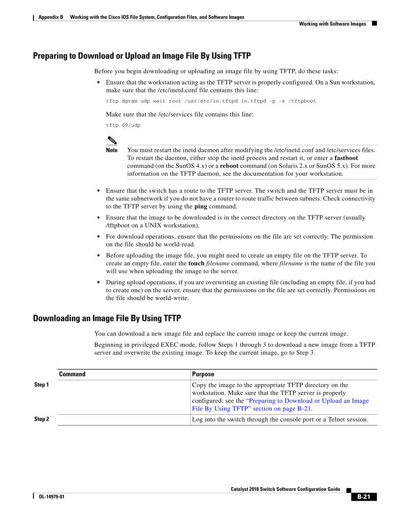
Appendix B Working with the Cisco IOS File System, Configuration Files, and Software ImagesWorking with Software Images
Preparing to Download or Upload an Image File By Using TFTP
Before you begin downloading or uploading an image file by using TFTP, do these tasks:
• Ensure that the workstation acting as the TFTP server is properly configured. On a Sun workstation, make sure that the /etc/inetd.conf file contains this line:
tftp dgram udp wait root /usr/etc/in.tftpd in.tftpd -p -s /tftpboot
Make sure that the /etc/services file contains this line:
tftp 69/udp
Note You must restart the inetd daemon after modifying the /etc/inetd.conf and /etc/services files. To restart the daemon, either stop the inetd process and restart it, or enter a fastboot command (on the SunOS 4.x) or a reboot command (on Solaris 2.x or SunOS 5.x). For more information on the TFTP daemon, see the documentation for your workstation.
• Ensure that the switch has a route to the TFTP server. The switch and the TFTP server must be in the same subnetwork if you do not have a router to route traffic between subnets. Check connectivity to the TFTP server by using the ping command.
• Ensure that the image to be downloaded is in the correct directory on the TFTP server (usually /tftpboot on a UNIX workstation).
• For download operations, ensure that the permissions on the file are set correctly. The permission on the file should be world-read.
• Before uploading the image file, you might need to create an empty file on the TFTP server. To create an empty file, enter the touch filename command, where filename is the name of the file you will use when uploading the image to the server.
• During upload operations, if you are overwriting an existing file (including an empty file, if you had to create one) on the server, ensure that the permissions on the file are set correctly. Permissions on the file should be world-write.
Downloading an Image File By Using TFTP
You can download a new image file and replace the current image or keep the current image.
Beginning in privileged EXEC mode, follow Steps 1 through 3 to download a new image from a TFTP server and overwrite the existing image. To keep the current image, go to Step 3.
Command Purpose
Step 1 Copy the image to the appropriate TFTP directory on the workstation. Make sure that the TFTP server is properly configured; see the “Preparing to Download or Upload an Image File By Using TFTP” section on page B-21.
Step 2 Log into the switch through the console port or a Telnet session.
B-21Catalyst 2918 Switch Software Configuration Guide
OL-14979-01
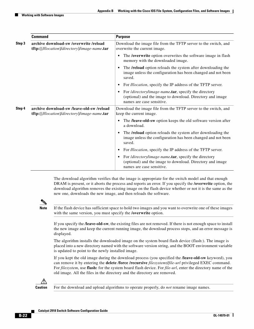
Appendix B Working with the Cisco IOS File System, Configuration Files, and Software ImagesWorking with Software Images
The download algorithm verifies that the image is appropriate for the switch model and that enough DRAM is present, or it aborts the process and reports an error. If you specify the /overwrite option, the download algorithm removes the existing image on the flash device whether or not it is the same as the new one, downloads the new image, and then reloads the software.
Note If the flash device has sufficient space to hold two images and you want to overwrite one of these images with the same version, you must specify the /overwrite option.
If you specify the /leave-old-sw, the existing files are not removed. If there is not enough space to install the new image and keep the current running image, the download process stops, and an error message is displayed.
The algorithm installs the downloaded image on the system board flash device (flash:). The image is placed into a new directory named with the software version string, and the BOOT environment variable is updated to point to the newly installed image.
If you kept the old image during the download process (you specified the /leave-old-sw keyword), you can remove it by entering the delete /force /recursive filesystem:/file-url privileged EXEC command. For filesystem, use flash: for the system board flash device. For file-url, enter the directory name of the old image. All the files in the directory and the directory are removed.
Caution For the download and upload algorithms to operate properly, do not rename image names.
Step 3 archive download-sw /overwrite /reload tftp:[[//location]/directory]/image-name.tar
Download the image file from the TFTP server to the switch, and overwrite the current image.
• The /overwrite option overwrites the software image in flash memory with the downloaded image.
• The /reload option reloads the system after downloading the image unless the configuration has been changed and not been saved.
• For //location, specify the IP address of the TFTP server.
• For /directory/image-name.tar, specify the directory (optional) and the image to download. Directory and image names are case sensitive.
Step 4 archive download-sw /leave-old-sw /reload tftp:[[//location]/directory]/image-name.tar
Download the image file from the TFTP server to the switch, and keep the current image.
• The /leave-old-sw option keeps the old software version after a download.
• The /reload option reloads the system after downloading the image unless the configuration has been changed and not been saved.
• For //location, specify the IP address of the TFTP server.
• For /directory/image-name.tar, specify the directory (optional) and the image to download. Directory and image names are case sensitive.
Command Purpose
B-22Catalyst 2918 Switch Software Configuration Guide
OL-14979-01
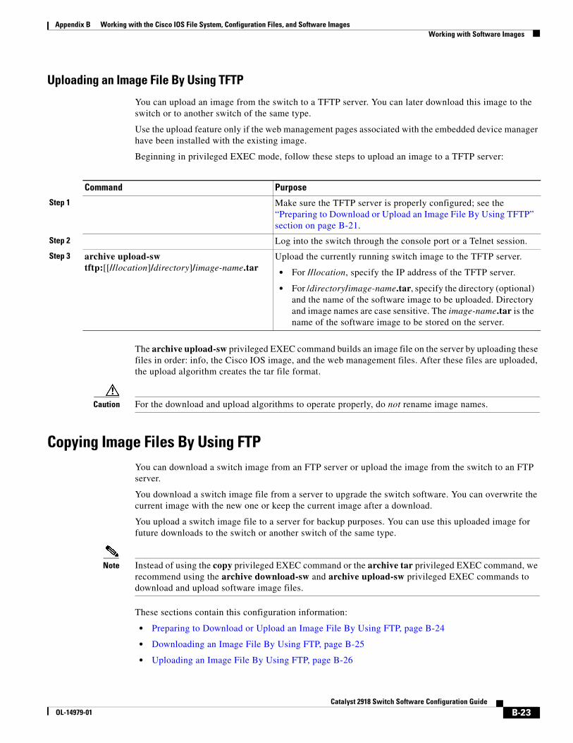
Appendix B Working with the Cisco IOS File System, Configuration Files, and Software ImagesWorking with Software Images
Uploading an Image File By Using TFTP
You can upload an image from the switch to a TFTP server. You can later download this image to the switch or to another switch of the same type.
Use the upload feature only if the web management pages associated with the embedded device manager have been installed with the existing image.
Beginning in privileged EXEC mode, follow these steps to upload an image to a TFTP server:
Command Purpose
Step 1 Make sure the TFTP server is properly configured; see the “Preparing to Download or Upload an Image File By Using TFTP” section on page B-21.
Step 2 Log into the switch through the console port or a Telnet session.
Step 3 archive upload-sw tftp:[[//location]/directory]/image-name.tar
Upload the currently running switch image to the TFTP server.
• For //location, specify the IP address of the TFTP server.
• For /directory/image-name.tar, specify the directory (optional) and the name of the software image to be uploaded. Directory and image names are case sensitive. The image-name.tar is the name of the software image to be stored on the server.
The archive upload-sw privileged EXEC command builds an image file on the server by uploading these files in order: info, the Cisco IOS image, and the web management files. After these files are uploaded, the upload algorithm creates the tar file format.
Caution For the download and upload algorithms to operate properly, do not rename image names.
Copying Image Files By Using FTPYou can download a switch image from an FTP server or upload the image from the switch to an FTP server.
You download a switch image file from a server to upgrade the switch software. You can overwrite the current image with the new one or keep the current image after a download.
You upload a switch image file to a server for backup purposes. You can use this uploaded image for future downloads to the switch or another switch of the same type.
Note Instead of using the copy privileged EXEC command or the archive tar privileged EXEC command, we recommend using the archive download-sw and archive upload-sw privileged EXEC commands to download and upload software image files.
These sections contain this configuration information:
• Preparing to Download or Upload an Image File By Using FTP, page B-24
• Downloading an Image File By Using FTP, page B-25
• Uploading an Image File By Using FTP, page B-26
B-23Catalyst 2918 Switch Software Configuration Guide
OL-14979-01
Appendix B Working with the Cisco IOS File System, Configuration Files, and Software ImagesWorking with Software Images
Preparing to Download or Upload an Image File By Using FTP
You can copy images files to or from an FTP server.
The FTP protocol requires a client to send a remote username and password on each FTP request to a server. When you copy an image file from the switch to a server by using FTP, the Cisco IOS software sends the first valid username in this list:
• The username specified in the archive download-sw or archive upload-sw privileged EXEC command if a username is specified.
• The username set by the ip ftp username username global configuration command if the command is configured.
• Anonymous.
The switch sends the first valid password in this list:
• The password specified in the archive download-sw or archive upload-sw privileged EXEC command if a password is specified.
• The password set by the ip ftp password password global configuration command if the command is configured.
• The switch forms a password named [email protected]. The variable username is the username associated with the current session, switchname is the configured hostname, and domain is the domain of the switch.
The username and password must be associated with an account on the FTP server. If you are writing to the server, the FTP server must be properly configured to accept the FTP write request from you.
Use the ip ftp username and ip ftp password commands to specify a username and password for all copies. Include the username in the archive download-sw or archive upload-sw privileged EXEC command if you want to specify a username only for that operation.
If the server has a directory structure, the image file is written to or copied from the directory associated with the username on the server. For example, if the image file resides in the home directory of a user on the server, specify that user's name as the remote username.
Before you begin downloading or uploading an image file by using FTP, do these tasks:
• Ensure that the switch has a route to the FTP server. The switch and the FTP server must be in the same subnetwork if you do not have a router to route traffic between subnets. Check connectivity to the FTP server by using the ping command.
• If you are accessing the switch through the console or a Telnet session and you do not have a valid username, make sure that the current FTP username is the one that you want to use for the FTP download. You can enter the show users privileged EXEC command to view the valid username. If you do not want to use this username, create a new FTP username by using the ip ftp username username global configuration command. This new name will be used during all archive operations. The new username is stored in NVRAM. If you are accessing the switch through a Telnet session and you have a valid username, this username is used, and you do not need to set the FTP username. Include the username in the archive download-sw or archive upload-sw privileged EXEC command if you want to specify a username for that operation only.
• When you upload an image file to the FTP server, it must be properly configured to accept the write request from the user on the switch.
For more information, see the documentation for your FTP server.
B-24Catalyst 2918 Switch Software Configuration Guide
OL-14979-01
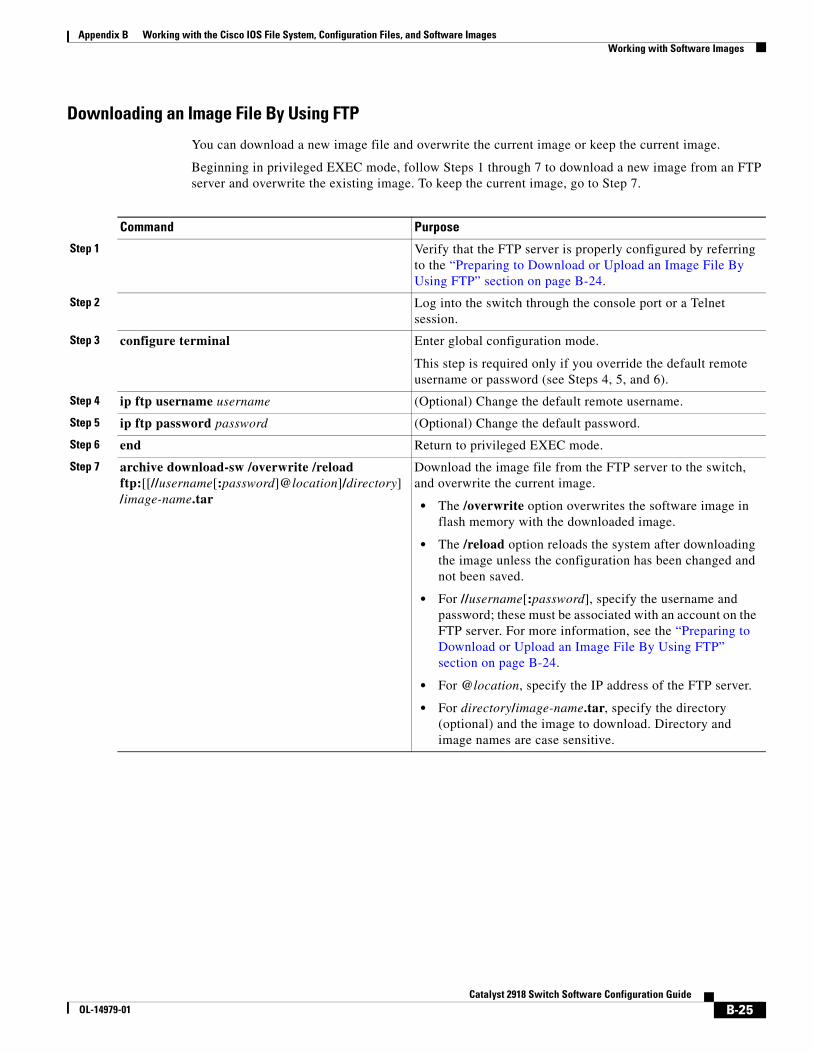
Appendix B Working with the Cisco IOS File System, Configuration Files, and Software ImagesWorking with Software Images
Downloading an Image File By Using FTP
You can download a new image file and overwrite the current image or keep the current image.
Beginning in privileged EXEC mode, follow Steps 1 through 7 to download a new image from an FTP server and overwrite the existing image. To keep the current image, go to Step 7.
Command Purpose
Step 1 Verify that the FTP server is properly configured by referring to the “Preparing to Download or Upload an Image File By Using FTP” section on page B-24.
Step 2 Log into the switch through the console port or a Telnet session.
Step 3 configure terminal Enter global configuration mode.
This step is required only if you override the default remote username or password (see Steps 4, 5, and 6).
Step 4 ip ftp username username (Optional) Change the default remote username.
Step 5 ip ftp password password (Optional) Change the default password.
Step 6 end Return to privileged EXEC mode.
Step 7 archive download-sw /overwrite /reload ftp:[[//username[:password]@location]/directory]/image-name.tar
Download the image file from the FTP server to the switch, and overwrite the current image.
• The /overwrite option overwrites the software image in flash memory with the downloaded image.
• The /reload option reloads the system after downloading the image unless the configuration has been changed and not been saved.
• For //username[:password], specify the username and password; these must be associated with an account on the FTP server. For more information, see the “Preparing to Download or Upload an Image File By Using FTP” section on page B-24.
• For @location, specify the IP address of the FTP server.
• For directory/image-name.tar, specify the directory (optional) and the image to download. Directory and image names are case sensitive.
B-25Catalyst 2918 Switch Software Configuration Guide
OL-14979-01
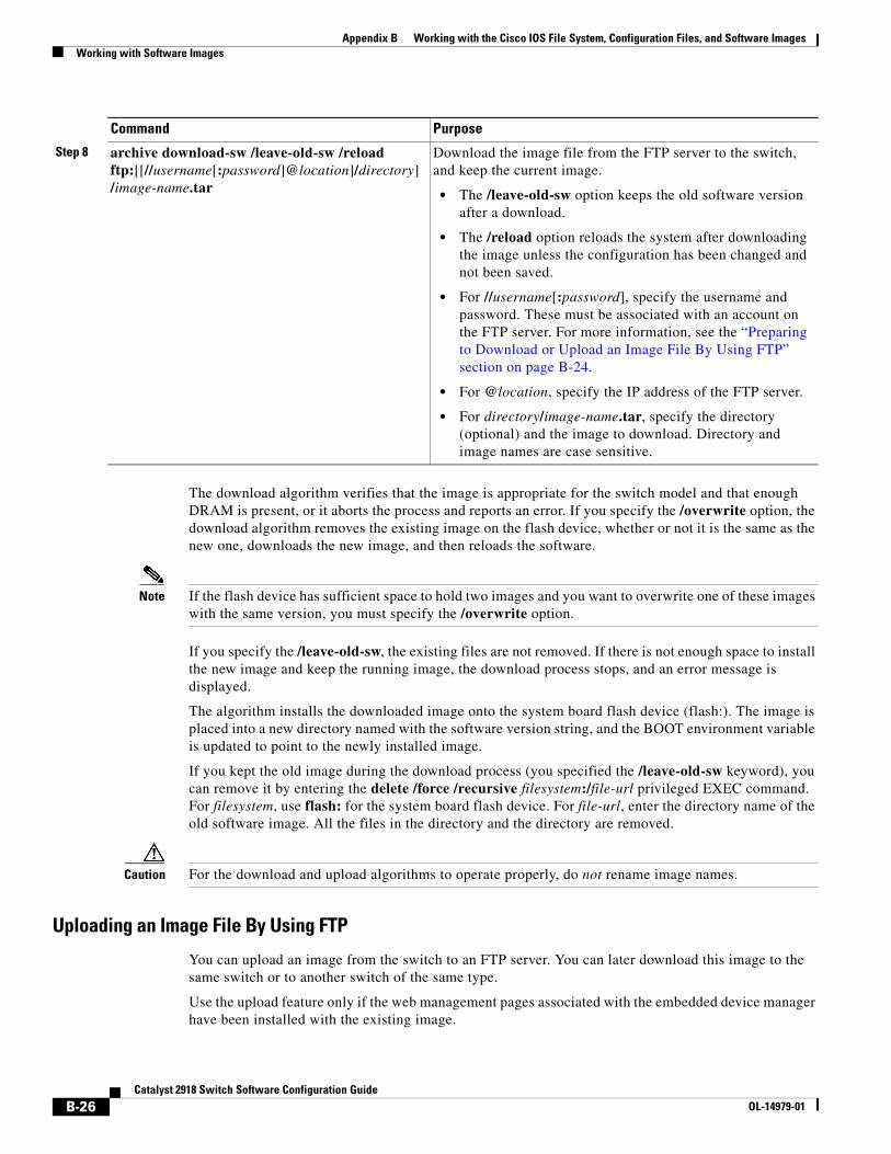
Appendix B Working with the Cisco IOS File System, Configuration Files, and Software ImagesWorking with Software Images
The download algorithm verifies that the image is appropriate for the switch model and that enough DRAM is present, or it aborts the process and reports an error. If you specify the /overwrite option, the download algorithm removes the existing image on the flash device, whether or not it is the same as the new one, downloads the new image, and then reloads the software.
Note If the flash device has sufficient space to hold two images and you want to overwrite one of these images with the same version, you must specify the /overwrite option.
If you specify the /leave-old-sw, the existing files are not removed. If there is not enough space to install the new image and keep the running image, the download process stops, and an error message is displayed.
The algorithm installs the downloaded image onto the system board flash device (flash:). The image is placed into a new directory named with the software version string, and the BOOT environment variable is updated to point to the newly installed image.
If you kept the old image during the download process (you specified the /leave-old-sw keyword), you can remove it by entering the delete /force /recursive filesystem:/file-url privileged EXEC command. For filesystem, use flash: for the system board flash device. For file-url, enter the directory name of the old software image. All the files in the directory and the directory are removed.
Caution For the download and upload algorithms to operate properly, do not rename image names.
Uploading an Image File By Using FTP
You can upload an image from the switch to an FTP server. You can later download this image to the same switch or to another switch of the same type.
Use the upload feature only if the web management pages associated with the embedded device manager have been installed with the existing image.
Step 8 archive download-sw /leave-old-sw /reload ftp:[[//username[:password]@location]/directory]/image-name.tar
Download the image file from the FTP server to the switch, and keep the current image.
• The /leave-old-sw option keeps the old software version after a download.
• The /reload option reloads the system after downloading the image unless the configuration has been changed and not been saved.
• For //username[:password], specify the username and password. These must be associated with an account on the FTP server. For more information, see the “Preparing to Download or Upload an Image File By Using FTP” section on page B-24.
• For @location, specify the IP address of the FTP server.
• For directory/image-name.tar, specify the directory (optional) and the image to download. Directory and image names are case sensitive.
Command Purpose
B-26Catalyst 2918 Switch Software Configuration Guide
OL-14979-01
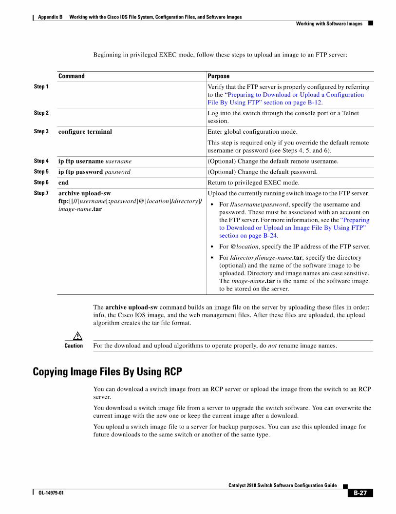
Appendix B Working with the Cisco IOS File System, Configuration Files, and Software ImagesWorking with Software Images
Beginning in privileged EXEC mode, follow these steps to upload an image to an FTP server:
Command Purpose
Step 1 Verify that the FTP server is properly configured by referring to the “Preparing to Download or Upload a Configuration File By Using FTP” section on page B-12.
Step 2 Log into the switch through the console port or a Telnet session.
Step 3 configure terminal Enter global configuration mode.
This step is required only if you override the default remote username or password (see Steps 4, 5, and 6).
Step 4 ip ftp username username (Optional) Change the default remote username.
Step 5 ip ftp password password (Optional) Change the default password.
Step 6 end Return to privileged EXEC mode.
Step 7 archive upload-sw ftp:[[//[username[:password]@]location]/directory]/image-name.tar
Upload the currently running switch image to the FTP server.
• For //username:password, specify the username and password. These must be associated with an account on the FTP server. For more information, see the “Preparing to Download or Upload an Image File By Using FTP” section on page B-24.
• For @location, specify the IP address of the FTP server.
• For /directory/image-name.tar, specify the directory (optional) and the name of the software image to be uploaded. Directory and image names are case sensitive. The image-name.tar is the name of the software image to be stored on the server.
The archive upload-sw command builds an image file on the server by uploading these files in order: info, the Cisco IOS image, and the web management files. After these files are uploaded, the upload algorithm creates the tar file format.
Caution For the download and upload algorithms to operate properly, do not rename image names.
Copying Image Files By Using RCPYou can download a switch image from an RCP server or upload the image from the switch to an RCP server.
You download a switch image file from a server to upgrade the switch software. You can overwrite the current image with the new one or keep the current image after a download.
You upload a switch image file to a server for backup purposes. You can use this uploaded image for future downloads to the same switch or another of the same type.
B-27Catalyst 2918 Switch Software Configuration Guide
OL-14979-01
Appendix B Working with the Cisco IOS File System, Configuration Files, and Software ImagesWorking with Software Images
Note Instead of using the copy privileged EXEC command or the archive tar privileged EXEC command, we recommend using the archive download-sw and archive upload-sw privileged EXEC commands to download and upload software image files.
These sections contain this configuration information:
• Preparing to Download or Upload an Image File By Using RCP, page B-28
• Downloading an Image File By Using RCP, page B-29
• Uploading an Image File By Using RCP, page B-31
Preparing to Download or Upload an Image File By Using RCP
RCP provides another method of downloading and uploading image files between remote hosts and the switch. Unlike TFTP, which uses User Datagram Protocol (UDP), a connectionless protocol, RCP uses TCP, which is connection-oriented.
To use RCP to copy files, the server from or to which you will be copying files must support RCP. The RCP copy commands rely on the rsh server (or daemon) on the remote system. To copy files by using RCP, you do not need to create a server for file distribution as you do with TFTP. You only need to have access to a server that supports the remote shell (rsh). (Most UNIX systems support rsh.) Because you are copying a file from one place to another, you must have read permission on the source file and write permission on the destination file. If the destination file does not exist, RCP creates it for you.
RCP requires a client to send a remote username on each RCP request to a server. When you copy an image from the switch to a server by using RCP, the Cisco IOS software sends the first valid username in this list:
• The username specified in the archive download-sw or archive upload-sw privileged EXEC command if a username is specified.
• The username set by the ip rcmd remote-username username global configuration command if the command is entered.
• The remote username associated with the current TTY (terminal) process. For example, if the user is connected to the router through Telnet and was authenticated through the username command, the switch software sends the Telnet username as the remote username.
• The switch hostname.
For the RCP copy request to execute successfully, an account must be defined on the network server for the remote username. If the server has a directory structure, the image file is written to or copied from the directory associated with the remote username on the server. For example, if the image file resides in the home directory of a user on the server, specify that user’s name as the remote username.
Before you begin downloading or uploading an image file by using RCP, do these tasks:
• Ensure that the workstation acting as the RCP server supports the remote shell (rsh).
• Ensure that the switch has a route to the RCP server. The switch and the server must be in the same subnetwork if you do not have a router to route traffic between subnets. Check connectivity to the RCP server by using the ping command.
• If you are accessing the switch through the console or a Telnet session and you do not have a valid username, make sure that the current RCP username is the one that you want to use for the RCP download. You can enter the show users privileged EXEC command to view the valid username. If you do not want to use this username, create a new RCP username by using the ip rcmd remote-username username global configuration command to be used during all archive
B-28Catalyst 2918 Switch Software Configuration Guide
OL-14979-01
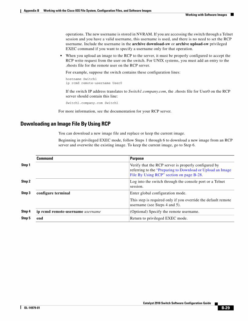
Appendix B Working with the Cisco IOS File System, Configuration Files, and Software ImagesWorking with Software Images
operations. The new username is stored in NVRAM. If you are accessing the switch through a Telnet session and you have a valid username, this username is used, and there is no need to set the RCP username. Include the username in the archive download-sw or archive upload-sw privileged EXEC command if you want to specify a username only for that operation.
• When you upload an image to the RCP to the server, it must be properly configured to accept the RCP write request from the user on the switch. For UNIX systems, you must add an entry to the .rhosts file for the remote user on the RCP server.
For example, suppose the switch contains these configuration lines:
hostname Switch1ip rcmd remote-username User0
If the switch IP address translates to Switch1.company.com, the .rhosts file for User0 on the RCP server should contain this line:
Switch1.company.com Switch1
For more information, see the documentation for your RCP server.
Downloading an Image File By Using RCP
You can download a new image file and replace or keep the current image.
Beginning in privileged EXEC mode, follow Steps 1 through 6 to download a new image from an RCP server and overwrite the existing image. To keep the current image, go to Step 6.
Command Purpose
Step 1 Verify that the RCP server is properly configured by referring to the “Preparing to Download or Upload an Image File By Using RCP” section on page B-28.
Step 2 Log into the switch through the console port or a Telnet session.
Step 3 configure terminal Enter global configuration mode.
This step is required only if you override the default remote username (see Steps 4 and 5).
Step 4 ip rcmd remote-username username (Optional) Specify the remote username.
Step 5 end Return to privileged EXEC mode.
B-29Catalyst 2918 Switch Software Configuration Guide
OL-14979-01
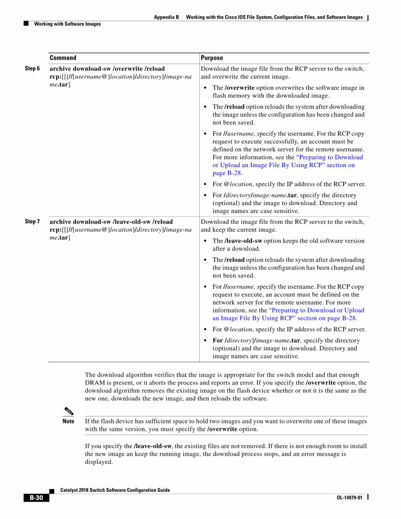
Appendix B Working with the Cisco IOS File System, Configuration Files, and Software ImagesWorking with Software Images
The download algorithm verifies that the image is appropriate for the switch model and that enough DRAM is present, or it aborts the process and reports an error. If you specify the /overwrite option, the download algorithm removes the existing image on the flash device whether or not it is the same as the new one, downloads the new image, and then reloads the software.
Note If the flash device has sufficient space to hold two images and you want to overwrite one of these images with the same version, you must specify the /overwrite option.
If you specify the /leave-old-sw, the existing files are not removed. If there is not enough room to install the new image an keep the running image, the download process stops, and an error message is displayed.
Step 6 archive download-sw /overwrite /reload rcp:[[[//[username@]location]/directory]/image-name.tar]
Download the image file from the RCP server to the switch, and overwrite the current image.
• The /overwrite option overwrites the software image in flash memory with the downloaded image.
• The /reload option reloads the system after downloading the image unless the configuration has been changed and not been saved.
• For //username, specify the username. For the RCP copy request to execute successfully, an account must be defined on the network server for the remote username. For more information, see the “Preparing to Download or Upload an Image File By Using RCP” section on page B-28.
• For @location, specify the IP address of the RCP server.
• For /directory/image-name.tar, specify the directory (optional) and the image to download. Directory and image names are case sensitive.
Step 7 archive download-sw /leave-old-sw /reload rcp:[[[//[username@]location]/directory]/image-name.tar]
Download the image file from the RCP server to the switch, and keep the current image.
• The /leave-old-sw option keeps the old software version after a download.
• The /reload option reloads the system after downloading the image unless the configuration has been changed and not been saved.
• For //username, specify the username. For the RCP copy request to execute, an account must be defined on the network server for the remote username. For more information, see the “Preparing to Download or Upload an Image File By Using RCP” section on page B-28.
• For @location, specify the IP address of the RCP server.
• For /directory]/image-name.tar, specify the directory (optional) and the image to download. Directory and image names are case sensitive.
Command Purpose
B-30Catalyst 2918 Switch Software Configuration Guide
OL-14979-01
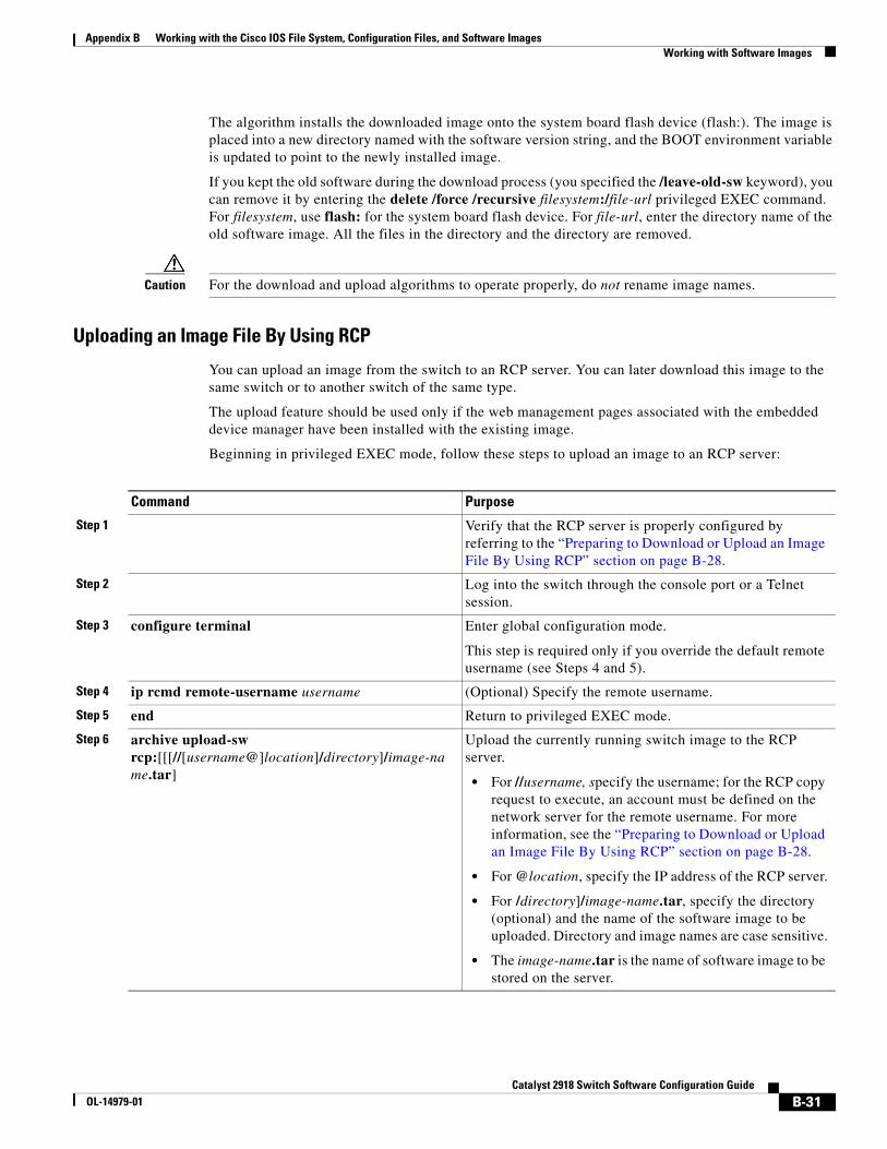
Appendix B Working with the Cisco IOS File System, Configuration Files, and Software ImagesWorking with Software Images
The algorithm installs the downloaded image onto the system board flash device (flash:). The image is placed into a new directory named with the software version string, and the BOOT environment variable is updated to point to the newly installed image.
If you kept the old software during the download process (you specified the /leave-old-sw keyword), you can remove it by entering the delete /force /recursive filesystem:/file-url privileged EXEC command. For filesystem, use flash: for the system board flash device. For file-url, enter the directory name of the old software image. All the files in the directory and the directory are removed.
Caution For the download and upload algorithms to operate properly, do not rename image names.
Uploading an Image File By Using RCP
You can upload an image from the switch to an RCP server. You can later download this image to the same switch or to another switch of the same type.
The upload feature should be used only if the web management pages associated with the embedded device manager have been installed with the existing image.
Beginning in privileged EXEC mode, follow these steps to upload an image to an RCP server:
Command Purpose
Step 1 Verify that the RCP server is properly configured by referring to the “Preparing to Download or Upload an Image File By Using RCP” section on page B-28.
Step 2 Log into the switch through the console port or a Telnet session.
Step 3 configure terminal Enter global configuration mode.
This step is required only if you override the default remote username (see Steps 4 and 5).
Step 4 ip rcmd remote-username username (Optional) Specify the remote username.
Step 5 end Return to privileged EXEC mode.
Step 6 archive upload-sw rcp:[[[//[username@]location]/directory]/image-name.tar]
Upload the currently running switch image to the RCP server.
• For //username, specify the username; for the RCP copy request to execute, an account must be defined on the network server for the remote username. For more information, see the “Preparing to Download or Upload an Image File By Using RCP” section on page B-28.
• For @location, specify the IP address of the RCP server.
• For /directory]/image-name.tar, specify the directory (optional) and the name of the software image to be uploaded. Directory and image names are case sensitive.
• The image-name.tar is the name of software image to be stored on the server.
B-31Catalyst 2918 Switch Software Configuration Guide
OL-14979-01

Appendix B Working with the Cisco IOS File System, Configuration Files, and Software ImagesWorking with Software Images
The archive upload-sw privileged EXEC command builds an image file on the server by uploading these files in order: info, the Cisco IOS image, and the web management files. After these files are uploaded, the upload algorithm creates the tar file format.
Caution For the download and upload algorithms to operate properly, do not rename image names.
B-32Catalyst 2918 Switch Software Configuration Guide
OL-14979-01
CatalyOL-14979-01
A
P P E N D I X C Unsupported Commands in Cisco IOS Release 12.2(44)SEThis appendix lists some of the command-line interface (CLI) commands that appear when you enter the question mark (?) at the Catalyst 2918 switch prompt but are not supported in this release, either because they are not tested or because of Catalyst 2918 switch hardware limitations. This is not a complete list. The unsupported commands are listed by software feature and command mode.
Access Control Lists
Unsupported Privileged EXEC Commandsaccess-enable [host] [timeout minutes]
access-template [access-list-number | name] [dynamic-name] [source] [destination] [timeout minutes]
clear access-template [access-list-number | name] [dynamic-name] [source] [destination].
show access-lists rate-limit [destination]
show accounting
show ip accounting [checkpoint] [output-packets | access violations]
show ip cache [prefix-mask] [type number]
Unsupported Global Configuration Commandsaccess-list rate-limit acl-index {precedence | mask prec-mask}
access-list dynamic extended
Unsupported Interface Configuration Commandsmac access-group name in
C-1st 2918 Switch Software Configuration Guide
Appendix C Unsupported Commands in Cisco IOS Release 12.2(44)SEBoot Loader Commands
Unsupported Route-Map Configuration Commandsmatch ip address prefix-list prefix-list-name [prefix-list-name...]
Boot Loader Commands
Unsupported Global Configuration Commandsboot buffersize
Debug Commands
Unsupported Privileged EXEC Commandsdebug platform cli-redirection main
debug platform configuration
IEEE 802.1x Commands
Unsupported Privileged EXEC Commandshow fallback profile
Unsupported Global Configuration Commandfallback profile profile
IGMP Snooping Commands
Unsupported Global Configuration Commandsip igmp snooping tcn
C-2Catalyst 2918 Switch Software Configuration Guide
OL-14979-01
Appendix C Unsupported Commands in Cisco IOS Release 12.2(44)SEInterface Commands
Interface Commands
Unsupported Privileged EXEC Commandsshow interfaces [interface-id | vlan vlan-id] [crb | fair-queue | irb | mac-accounting | precedence | irb | random-detect | rate-limit | shape]
Unsupported Global Configuration Commandsinterface tunnel
Unsupported Interface Configuration Commandstransmit-interface type number
MAC Address Commands
Unsupported Privileged EXEC Commandsshow mac-address-table
show mac-address-table address
show mac-address-table aging-time
show mac-address-table count
show mac-address-table dynamic
show mac-address-table interface
show mac-address-table multicast
show mac-address-table notification
show mac-address-table static
show mac-address-table vlan
show mac address-table multicast
Note Use the show ip igmp snooping groups privileged EXEC command to display Layer 2 multicast address-table entries for a VLAN.
Unsupported Global Configuration Commandsmac-address-table aging-time
mac-address-table notification
C-3Catalyst 2918 Switch Software Configuration Guide
OL-14979-01
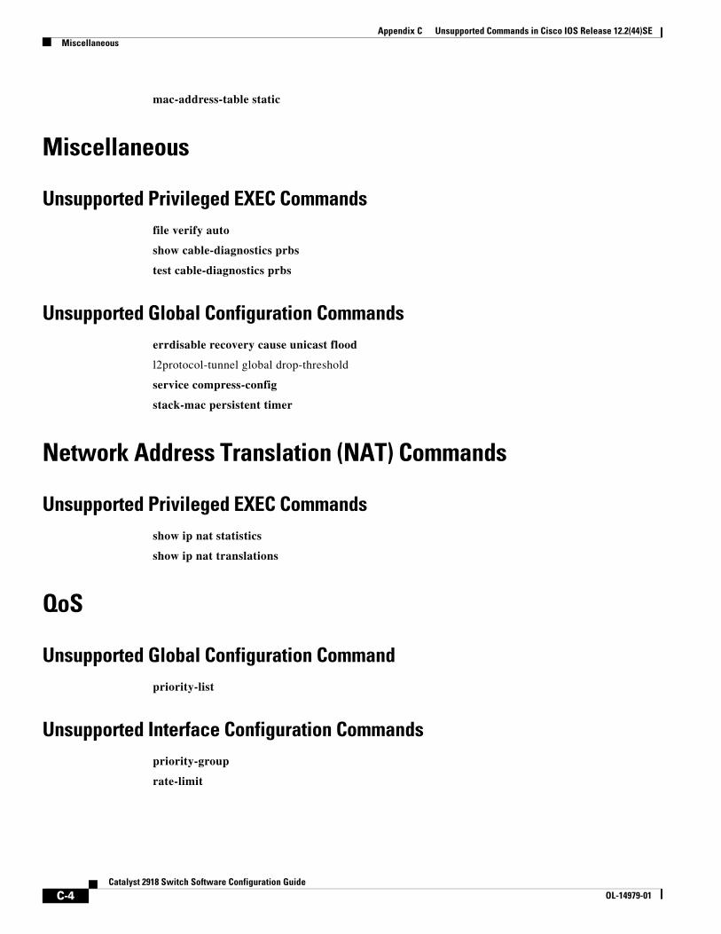
Appendix C Unsupported Commands in Cisco IOS Release 12.2(44)SEMiscellaneous
mac-address-table static
Miscellaneous
Unsupported Privileged EXEC Commandsfile verify auto
show cable-diagnostics prbs
test cable-diagnostics prbs
Unsupported Global Configuration Commandserrdisable recovery cause unicast flood
l2protocol-tunnel global drop-threshold
service compress-config
stack-mac persistent timer
Network Address Translation (NAT) Commands
Unsupported Privileged EXEC Commandsshow ip nat statistics
show ip nat translations
QoS
Unsupported Global Configuration Commandpriority-list
Unsupported Interface Configuration Commandspriority-group
rate-limit
C-4Catalyst 2918 Switch Software Configuration Guide
OL-14979-01
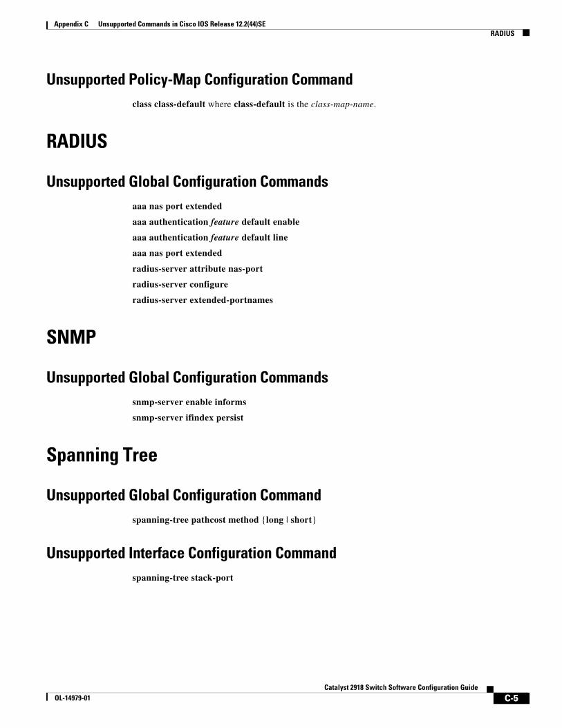
Appendix C Unsupported Commands in Cisco IOS Release 12.2(44)SERADIUS
Unsupported Policy-Map Configuration Commandclass class-default where class-default is the class-map-name.
RADIUS
Unsupported Global Configuration Commandsaaa nas port extended
aaa authentication feature default enable
aaa authentication feature default line
aaa nas port extended
radius-server attribute nas-port
radius-server configure
radius-server extended-portnames
SNMP
Unsupported Global Configuration Commandssnmp-server enable informs
snmp-server ifindex persist
Spanning Tree
Unsupported Global Configuration Commandspanning-tree pathcost method {long | short}
Unsupported Interface Configuration Commandspanning-tree stack-port
C-5Catalyst 2918 Switch Software Configuration Guide
OL-14979-01
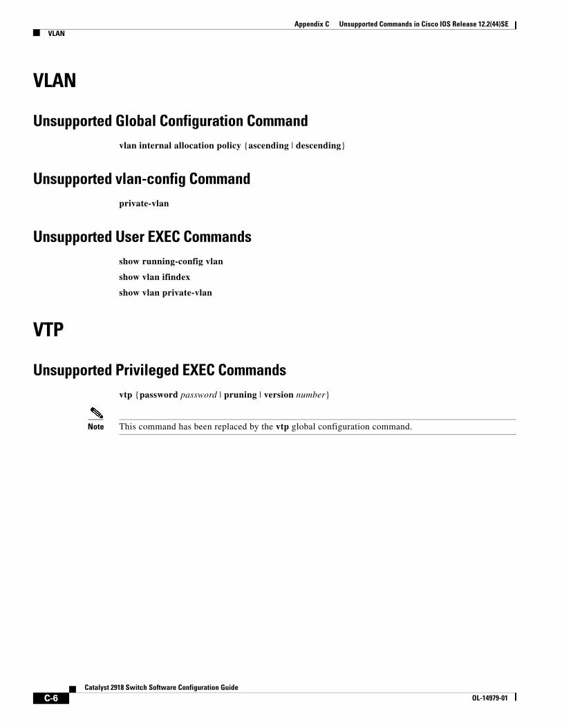
Appendix C Unsupported Commands in Cisco IOS Release 12.2(44)SEVLAN
VLAN
Unsupported Global Configuration Commandvlan internal allocation policy {ascending | descending}
Unsupported vlan-config Commandprivate-vlan
Unsupported User EXEC Commandsshow running-config vlan
show vlan ifindex
show vlan private-vlan
VTP
Unsupported Privileged EXEC Commandsvtp {password password | pruning | version number}
Note This command has been replaced by the vtp global configuration command.
C-6Catalyst 2918 Switch Software Configuration Guide
OL-14979-01
OL-14979-01
I N D E X
A
abbreviating commands 2-4
AC (command switch) 5-9
access-denied response, VMPS 12-24
accessing
clusters, switch 5-12
command switches 5-10
member switches 5-12
switch clusters 5-12
access ports
in switch clusters 5-8
access ports, defined 10-2
accounting
with 802.1x 9-24
with IEEE 802.1x 9-8
with RADIUS 8-28
with TACACS+ 8-11, 8-17
address aliasing 18-2
addresses
displaying the MAC address table 7-26
dynamic
accelerated aging 15-8
changing the aging time 7-20
default aging 15-8
defined 7-19
learning 7-20
removing 7-21
MAC, discovering 7-26
multicast, STP address management 15-8
static
adding and removing 7-23
defined 7-19
address resolution 7-26
Address Resolution Protocol
See ARP
advertisements
CDP 20-1
LLDP 21-1, 21-2
VTP 12-16, 13-3
aggregated ports
See EtherChannel
aging, accelerating 15-8
aging time
accelerated
for MSTP 16-23
for STP 15-8, 15-21
MAC address table 7-20
maximum
for MSTP 16-23, 16-24
for STP 15-21, 15-22
alarms, RMON 24-3
allowed-VLAN list 12-17
ARP
defined 1-4, 7-26
table
address resolution 7-26
managing 7-26
attributes, RADIUS
vendor-proprietary 8-31
vendor-specific 8-29
IN-1Catalyst 2918 Switch Software Configuration Guide
Index
authentication
local mode with AAA 8-32
NTP associations 7-4
RADIUS
key 8-21
login 8-23
TACACS+
defined 8-11
key 8-13
login 8-14
See also port-based authentication
authoritative time source, described 7-2
authorization
with RADIUS 8-27
with TACACS+ 8-11, 8-16
authorized ports with IEEE 802.1x 9-7
autoconfiguration 3-3
automatic discovery
considerations
beyond a noncandidate device 5-7
brand new switches 5-8
connectivity 5-4
different VLANs 5-6
management VLANs 5-7
non-CDP-capable devices 5-5
noncluster-capable devices 5-5
in switch clusters 5-4
See also CDP
automatic recovery, clusters 5-9
See also HSRP
auto-MDIX
configuring 10-15
described 10-15
autonegotiation
duplex mode 1-2
interface configuration guidelines 10-12
mismatches 29-11
IN-2Catalyst 2918 Switch Software Configuration Guide
autosensing, port speed 1-2
auxiliary VLAN
See voice VLAN
availability, features 1-4
B
BackboneFast
described 17-5
disabling 17-14
enabling 17-13
support for 1-5
banners
configuring
login 7-18
message-of-the-day login 7-17
default configuration 7-17
when displayed 7-17
blocking packets 19-7
booting
boot loader, function of 3-2
boot process 3-1
manually 3-17
specific image 3-18
boot loader
accessing 3-18
described 3-2
environment variables 3-18
prompt 3-18
trap-door mechanism 3-2
BPDU
error-disabled state 17-2
filtering 17-3
RSTP format 16-12
BPDU filtering
described 17-3
disabling 17-12
enabling 17-12
support for 1-5
OL-14979-01
Index
BPDU guard
described 17-2
disabling 17-12
enabling 17-11
support for 1-5
bridge protocol data unit
See BPDU
broadcast storm-control command 19-4
broadcast storms 19-1
C
cables, monitoring for unidirectional links 22-1
candidate switch
automatic discovery 5-4
defined 5-3
requirements 5-3
See also command switch, cluster standby group, and member switch
CA trustpoint
configuring 8-40
defined 8-38
CDP
automatic discovery in switch clusters 5-4
configuring 20-2
default configuration 20-2
defined with LLDP 21-1
described 20-1
disabling for routing device 20-3 to 20-4
enabling and disabling
on an interface 20-4
on a switch 20-3
monitoring 20-4
overview 20-1
support for 1-4
transmission timer and holdtime, setting 20-2
updates 20-2
OL-14979-01
CGMP
as IGMP snooping learning method 18-8
joining multicast group 18-3
CipherSuites 8-39
Cisco 7960 IP Phone 14-1
Cisco Discovery Protocol
See CDP
Cisco IOS File System
See IFS
CiscoWorks 2000 1-3, 26-4
CIST regional root
See MSTP
CIST root
See MSTP
class of service
See CoS
clearing interfaces 10-19
CLI
abbreviating commands 2-4
command modes 2-1
configuration logging 2-5
described 1-3
editing features
enabling and disabling 2-7
keystroke editing 2-7
wrapped lines 2-9
error messages 2-5
filtering command output 2-9
getting help 2-3
history
changing the buffer size 2-6
described 2-5
disabling 2-6
recalling commands 2-6
managing clusters 5-13
no and default forms of commands 2-4
client mode, VTP 13-3
IN-3Catalyst 2918 Switch Software Configuration Guide
Index
clock
See system clock
clusters, switch
accessing 5-12
automatic discovery 5-4
automatic recovery 5-9
benefits 1-2
compatibility 5-4
described 5-1
LRE profile considerations 5-13
managing
through CLI 5-13
through SNMP 5-14
planning 5-4
planning considerations
automatic discovery 5-4
automatic recovery 5-9
CLI 5-13
host names 5-12
IP addresses 5-12
LRE profiles 5-13
passwords 5-12
RADIUS 5-13
SNMP 5-13, 5-14
TACACS+ 5-13
See also candidate switch, command switch, cluster standby group, member switch, and standby command switch
cluster standby group
automatic recovery 5-11
considerations 5-10
defined 5-2
requirements 5-3
virtual IP address 5-10
See also HSRP
IN-4Catalyst 2918 Switch Software Configuration Guide
CNS 1-3
Configuration Engine
configID, deviceID, hostname 4-3
configuration service 4-2
described 4-1
event service 4-3
embedded agents
described 4-5
enabling automated configuration 4-6
enabling configuration agent 4-8
enabling event agent 4-7
management functions 1-3
command-line interface
See CLI
command modes 2-1
commands
abbreviating 2-4
no and default 2-4
commands, setting privilege levels 8-8
command switch
accessing 5-10
active (AC) 5-9
configuration conflicts 29-11
defined 5-1
passive (PC) 5-9
password privilege levels 5-14
priority 5-9
recovery
from command-switch failure 5-9, 29-7
from lost member connectivity 29-11
redundant 5-9
replacing
with another switch 29-9
with cluster member 29-8
requirements 5-2
standby (SC) 5-9
See also candidate switch, cluster standby group, member switch, and standby command switch
OL-14979-01
Index
community strings
configuring 5-13, 26-8
in clusters 5-13
overview 26-4
SNMP 5-13
compatibility, feature 19-12
config.text 3-16
configurable leave timer, IGMP 18-5
configuration, initial
defaults 1-8
Express Setup 1-2
configuration changes, logging 25-10
configuration conflicts, recovering from lost member connectivity 29-11
configuration examples, network 1-9
configuration files
clearing the startup configuration B-18
creating using a text editor B-9
default name 3-16
deleting a stored configuration B-18
described B-8
downloading
automatically 3-16
preparing B-10, B-12, B-15
reasons for B-8
using FTP B-13
using RCP B-16
using TFTP B-11
guidelines for creating and using B-8
invalid combinations when copying B-5
limiting TFTP server access 26-15
obtaining with DHCP 3-8
password recovery disable considerations 8-5
specifying the filename 3-16
system contact and location information 26-14
types and location B-9
OL-14979-01
configuration files (continued)
uploading
preparing B-10, B-12, B-15
reasons for B-8
using FTP B-14
using RCP B-17
using TFTP B-11
configuration logger 25-10
configuration logging 2-5
configuration settings, saving 3-14
configure terminal command 10-5
configuring small-frame arrival rate 19-5
config-vlan mode 2-2, 12-6
conflicts, configuration 29-11
connections, secure remote 8-33
connectivity problems 29-12, 29-13, 29-15
consistency checks in VTP Version 2 13-4
console port, connecting to 2-10
corrupted software, recovery steps with Xmodem 29-2
CoS
ingress queues 27-14
in Layer 2 frames 27-2
CoS input queue threshold map for QoS 27-6
CoS output queue threshold map for QoS 27-8
counters, clearing interface 10-19
crashinfo file 29-21
cryptographic software image
SSH 8-33
SSL 8-37
D
daylight saving time 7-13
debugging
enabling all system diagnostics 29-19
enabling for a specific feature 29-18
redirecting error message output 29-19
using commands 29-18
IN-5Catalyst 2918 Switch Software Configuration Guide
Index
default commands 2-4
default configuration
802.1x 9-15
banners 7-17
booting 3-16
CDP 20-2
DNS 7-16
EtherChannel 28-9
Ethernet interfaces 10-9
IGMP filtering 18-16
IGMP snooping 18-6
IGMP throttling 18-17
initial switch information 3-3
Layer 2 interfaces 10-9
LLDP 21-2
MAC address table 7-20
MSTP 16-14
NTP 7-4
optional spanning-tree configuration 17-9
password and privilege level 8-2
RADIUS 8-20
RMON 24-3
RSPAN 23-7
SDM template 6-2
SNMP 26-6
SPAN 23-7
SSL 8-39
standard QoS 27-8
STP 15-11
system message logging 25-3
system name and prompt 7-15
TACACS+ 8-13
UDLD 22-4
VLAN, Layer 2 Ethernet interfaces 12-15
VLANs 12-7
VMPS 12-25
voice VLAN 14-3
VTP 13-6
IN-6Catalyst 2918 Switch Software Configuration Guide
default gateway 3-14
deleting VLANs 12-9
denial-of-service attack 19-1
description command 10-16
designing your network, examples 1-9
destination-IP address-based forwarding, EtherChannel 28-7
destination-MAC address forwarding, EtherChannel 28-6
detecting indirect link failures, STP 17-5
device B-18
device discovery protocol 20-1, 21-1
device manager
benefits 1-2
described 1-2, 1-3
in-band management 1-4
upgrading a switch B-18
DHCP-based autoconfiguration
client request message exchange 3-4
configuring
client side 3-3
DNS 3-7
relay device 3-7
server side 3-6
TFTP server 3-7
example 3-9
lease options
for IP address information 3-6
for receiving the configuration file 3-6
overview 3-3
relationship to BOOTP 3-3
relay support 1-3
support for 1-3
DHCP-based autoconfiguration and image update
configuring 3-11 to 3-13
understanding 3-4 to 3-5
Differentiated Services architecture, QoS 27-1
directed unicast requests 1-4
OL-14979-01
Index
directories
changing B-3
creating and removing B-4
displaying the working B-3
discovery, clusters
See automatic discovery
DNS
and DHCP-based autoconfiguration 3-7
default configuration 7-16
displaying the configuration 7-17
overview 7-15
setting up 7-16
support for 1-3
domain names
DNS 7-15
VTP 13-8
Domain Name System
See DNS
downloading
configuration files
preparing B-10, B-12, B-15
reasons for B-8
using FTP B-13
using RCP B-16
using TFTP B-11
image files
deleting old image B-22
preparing B-21, B-24, B-28
reasons for B-19
using FTP B-25
using HTTP B-18
using RCP B-29
using TFTP B-21
using the device manager or Network Assistant B-18
DSCP transparency 27-13
DTP 1-5, 12-14
OL-14979-01
dual-purpose uplinks
defined 10-4
LEDs 10-4
link selection 10-4
setting the type 10-10
dynamic access ports
characteristics 12-3
configuring 12-26
defined 10-3
dynamic addresses
See addresses
dynamic auto trunking mode 12-14
dynamic desirable trunking mode 12-14
Dynamic Host Configuration Protocol
See DHCP-based autoconfiguration
dynamic port VLAN membership
described 12-24
reconfirming 12-27
troubleshooting 12-29
types of connections 12-26
Dynamic Trunking Protocol
See DTP
E
editing features
enabling and disabling 2-7
keystrokes used 2-7
wrapped lines 2-9
enable password 8-3
enable secret password 8-3
encryption, CipherSuite 8-39
encryption for passwords 8-3
environment variables, function of 3-19
error-disabled state, BPDU 17-2
error messages during command entry 2-5
IN-7Catalyst 2918 Switch Software Configuration Guide
Index
EtherChannel
automatic creation of 28-4, 28-5
channel groups
binding physical and logical interfaces 28-3
numbering of 28-3
configuration guidelines 28-9
configuring Layer 2 interfaces 28-10
default configuration 28-9
described 28-2
displaying status 28-16
forwarding methods 28-6, 28-12
IEEE 802.3ad, described 28-5
interaction
with STP 28-9
with VLANs 28-10
LACP
described 28-5
displaying status 28-16
hot-standby ports 28-14
interaction with other features 28-6
modes 28-5
port priority 28-15
system priority 28-15
load balancing 28-6, 28-12
PAgP
aggregate-port learners 28-13
compatibility with Catalyst 1900 28-13
described 28-4
displaying status 28-16
interaction with other features 28-5
learn method and priority configuration 28-13
modes 28-4
support for 1-2
port-channel interfaces
described 28-3
numbering of 28-3
port groups 10-3
support for 1-2
IN-8Catalyst 2918 Switch Software Configuration Guide
EtherChannel guard
described 17-7
disabling 17-14
enabling 17-14
Ethernet VLANs
adding 12-8
defaults and ranges 12-7
modifying 12-8
events, RMON 24-3
examples
network configuration 1-9
expedite queue for QoS 27-18
Express Setup 1-2
See also getting started guide
extended crashinfo file 29-21
extended-range VLANs
configuration guidelines 12-12
configuring 12-11
creating 12-12
defined 12-1
extended system ID
MSTP 16-17
STP 15-4, 15-14
Extensible Authentication Protocol over LAN 9-1
F
fa0 interface 1-4
features, incompatible 19-12
fiber-optic, detecting unidirectional links 22-1
files
basic crashinfo
description 29-21
location 29-21
copying B-4
crashinfo, description 29-21
deleting B-5
displaying the contents of B-7
OL-14979-01
Index
files (continued)
extended crashinfo
description 29-21
location 29-21
tar
creating B-6
displaying the contents of B-6
extracting B-7
image file format B-19
file system
displaying available file systems B-2
displaying file information B-3
local file system names B-1
network file system names B-4
setting the default B-3
filtering
show and more command output 2-9
filtering show and more command output 2-9
flash device, number of B-1
flooded traffic, blocking 19-8
flowcharts
QoS egress queueing and scheduling 27-7
QoS ingress queueing and scheduling 27-5
flowcontrol
configuring 10-14
described 10-14
forward-delay time
MSTP 16-23
STP 15-21
FTP
accessing MIB files A-3
configuration files
downloading B-13
overview B-12
preparing the server B-12
uploading B-14
OL-14979-01
FTP (continued)
image files
deleting old image B-26
downloading B-25
preparing the server B-24
uploading B-26
G
get-bulk-request operation 26-3
get-next-request operation 26-3, 26-4
get-request operation 26-3, 26-4
get-response operation 26-3
global configuration mode 2-2
global leave, IGMP 18-12
guest VLAN and 802.1x 9-11
GUIs
See device manager and Network Assistant
H
hello time
MSTP 16-22
STP 15-20
help, for the command line 2-3
history
changing the buffer size 2-6
described 2-5
disabling 2-6
recalling commands 2-6
history table, level and number of syslog messages 25-9
host names, in clusters 5-12
hosts, limit on dynamic ports 12-29
HP OpenView 1-3
HSRP
automatic cluster recovery 5-11
cluster standby group considerations 5-10
See also clusters, cluster standby group, and standby command switch
IN-9Catalyst 2918 Switch Software Configuration Guide
Index
HTTP over SSL
see HTTPS
HTTPS 8-37
configuring 8-41
self-signed certificate 8-38
HTTP secure server 8-37
I
ICMP
time-exceeded messages 29-15
traceroute and 29-15
ICMP ping
executing 29-13
overview 29-12
IDS appliances
and ingress SPAN 23-11
IEEE 802.1D
See STP
IEEE 802.1p 14-1
IEEE 802.1Q
and trunk ports 10-3
configuration limitations 12-15
encapsulation 12-14
native VLAN for untagged traffic 12-19
IEEE 802.1s
See MSTP
IEEE 802.1w
See RSTP
IEEE 802.1x
See port-based authentication
IEEE 802.3ad
See EtherChannel
IEEE 802.3x flow control 10-14
ifIndex values, SNMP 26-5
IFS 1-4
IN-10Catalyst 2918 Switch Software Configuration Guide
IGMP
configurable leave timer
described 18-5
enabling 18-10
flooded multicast traffic
controlling the length of time 18-11
disabling on an interface 18-12
global leave 18-12
query solicitation 18-12
recovering from flood mode 18-12
joining multicast group 18-3
join messages 18-3
leave processing, enabling 18-9
leaving multicast group 18-4
queries 18-3
report suppression
described 18-5
disabling 18-14
supported versions 18-2
support for 1-2
IGMP filtering
configuring 18-17
default configuration 18-16
described 18-16
monitoring 18-21
support for 1-3
IGMP groups
configuring filtering 18-19
setting the maximum number 18-19
IGMP Immediate Leave
configuration guidelines 18-10
described 18-5
enabling 18-9
IGMP profile
applying 18-18
configuration mode 18-17
configuring 18-17
OL-14979-01
Index
IGMP snooping
and address aliasing 18-2
configuring 18-6
default configuration 18-6
definition 18-1
enabling and disabling 18-6
global configuration 18-6
Immediate Leave 18-5
method 18-7
monitoring 18-14
querier
configuration guidelines 18-13
configuring 18-13
supported versions 18-2
support for 1-2
VLAN configuration 18-7
IGMP throttling
configuring 18-19
default configuration 18-17
described 18-16
displaying action 18-20
Immediate Leave, IGMP 18-5
initial configuration
defaults 1-8
Express Setup 1-2
interface
number 10-5
range macros 10-7
interface command 10-5
interface configuration mode 2-3
interfaces
auto-MDIX, configuring 10-15
configuration guidelines, duplex and speed 10-12
configuring
procedure 10-5
counters, clearing 10-19
default configuration 10-9
described 10-16
descriptive name, adding 10-16
OL-14979-01
interfaces (continued)
displaying information about 10-18
flow control 10-14
management 1-3
monitoring 10-18
naming 10-16
physical, identifying 10-5
range of 10-6
restarting 10-19
shutting down 10-19
speed and duplex, configuring 10-13
status 10-18
supported 10-4
types of 10-1
interfaces range macro command 10-7
interface types 10-5
Intrusion Detection System
See IDS appliances
IP addresses
candidate or member 5-3, 5-12
cluster access 5-2
command switch 5-2, 5-10, 5-12
discovering 7-26
redundant clusters 5-10
standby command switch 5-10, 5-12
See also IP information
ip igmp profile command 18-17
IP information
assigned
manually 3-14
through DHCP-based autoconfiguration 3-3
default configuration 3-3
IP phones
and QoS 14-1
configuring 14-4
IP traceroute
executing 29-16
overview 29-15
IN-11Catalyst 2918 Switch Software Configuration Guide
Index
J
join messages, IGMP 18-3
L
LACP
See EtherChannel
Layer 2 frames, classification with CoS 27-2
Layer 2 interfaces, default configuration 10-9
Layer 2 traceroute
and ARP 29-14
and CDP 29-14
broadcast traffic 29-14
described 29-14
IP addresses and subnets 29-14
MAC addresses and VLANs 29-14
multicast traffic 29-14
multiple devices on a port 29-15
unicast traffic 29-14
usage guidelines 29-14
LDAP 4-2
LEDs, switch
See hardware installation guide
lightweight directory access protocol
See LDAP
line configuration mode 2-3
Link Aggregation Control Protocol
See EtherChannel
link failure, detecting unidirectional 16-7
Link Layer Discovery Protocol
See CDP
links, unidirectional 22-1
IN-12Catalyst 2918 Switch Software Configuration Guide
LLDP
configuring 21-2
characteristics 21-2
default configuration 21-2
disabling and enabling
globally 21-3
on an interface 21-4
monitoring and maintaining 21-5
overview 21-1
supported TLVs 21-1
switch stack considerations 21-2
transmission timer and holdtime, setting 21-2
local SPAN 23-2
login authentication
with RADIUS 8-23
with TACACS+ 8-14
login banners 7-17
log messages
See system message logging
loop guard
described 17-9
enabling 17-15
support for 1-5
LRE profiles, considerations in switch clusters 5-13
M
MAC addresses
aging time 7-20
and VLAN association 7-20
building the address table 7-20
default configuration 7-20
discovering 7-26
displaying 7-26
OL-14979-01
Index
MAC addresses (continued)
dynamic
learning 7-20
removing 7-21
static
adding 7-24
allowing 7-25
characteristics of 7-23
dropping 7-25
removing 7-24
MAC address notification, support for 1-7
MAC address-to-VLAN mapping 12-23
macros
See Smartports macros
manageability features 1-3
management access
in-band
browser session 1-4
CLI session 1-4
device manager 1-4
SNMP 1-4
out-of-band console port connection 1-4
management options
CLI 2-1
clustering 1-2
CNS 4-1
overview 1-3
management VLAN
considerations in switch clusters 5-7
discovery through different management VLANs 5-7
maximum aging time
MSTP 16-23
STP 15-21
maximum hop count, MSTP 16-24
membership mode, VLAN port 12-3
OL-14979-01
member switch
automatic discovery 5-4
defined 5-1
managing 5-13
passwords 5-12
recovering from lost connectivity 29-11
requirements 5-3
See also candidate switch, cluster standby group, and standby command switch
messages, to users through banners 7-17
MIBs
accessing files with FTP A-3
location of files A-3
overview 26-1
SNMP interaction with 26-4
supported A-1
mirroring traffic for analysis 23-1
mismatches, autonegotiation 29-11
module number 10-5
monitoring
cables for unidirectional links 22-1
CDP 20-4
features 1-7
IGMP
filters 18-21
snooping 18-14
interfaces 10-18
multicast router interfaces 18-15
network traffic for analysis with probe 23-2
port
blocking 19-18
protection 19-18
SFP status 10-18, 29-12
speed and duplex mode 10-13
traffic flowing among switches 24-1
traffic suppression 19-18
VLANs 12-13
VMPS 12-28
VTP 13-16
IN-13Catalyst 2918 Switch Software Configuration Guide
Index
MSTP
boundary ports
configuration guidelines 16-15
described 16-6
BPDU filtering
described 17-3
enabling 17-12
BPDU guard
described 17-2
enabling 17-11
CIST, described 16-3
CIST regional root 16-3
CIST root 16-5
configuration guidelines 16-14, 17-10
configuring
forward-delay time 16-23
hello time 16-22
link type for rapid convergence 16-24
maximum aging time 16-23
maximum hop count 16-24
MST region 16-15
neighbor type 16-25
path cost 16-20
port priority 16-19
root switch 16-17
secondary root switch 16-18
switch priority 16-21
CST
defined 16-3
operations between regions 16-3
default configuration 16-14
default optional feature configuration 17-9
displaying status 16-26
enabling the mode 16-15
EtherChannel guard
described 17-7
enabling 17-14
IN-14Catalyst 2918 Switch Software Configuration Guide
MSTP (continued)
extended system ID
effects on root switch 16-17
effects on secondary root switch 16-18
unexpected behavior 16-17
IEEE 802.1s
implementation 16-6
port role naming change 16-6
terminology 16-5
instances supported 15-9
interface state, blocking to forwarding 17-2
interoperability and compatibility among modes 15-10
interoperability with IEEE 802.1D
described 16-8
restarting migration process 16-25
IST
defined 16-2
master 16-3
operations within a region 16-3
loop guard
described 17-9
enabling 17-15
mapping VLANs to MST instance 16-16
MST region
CIST 16-3
configuring 16-15
described 16-2
hop-count mechanism 16-5
IST 16-2
supported spanning-tree instances 16-2
optional features supported 1-5
overview 16-2
Port Fast
described 17-2
enabling 17-10
preventing root switch selection 17-8
OL-14979-01
Index
MSTP (continued)
root guard
described 17-8
enabling 17-15
root switch
configuring 16-17
effects of extended system ID 16-17
unexpected behavior 16-17
shutdown Port Fast-enabled port 17-2
status, displaying 16-26
multicast groups
Immediate Leave 18-5
joining 18-3
leaving 18-4
static joins 18-9
multicast router interfaces, monitoring 18-15
multicast router ports, adding 18-8
multicast storm 19-1
multicast storm-control command 19-4
N
NameSpace Mapper
See NSM
native VLAN
configuring 12-19
default 12-19
Network Assistant
benefits 1-2
described 1-3
network configuration examples
increasing network performance 1-10
providing network services 1-10
server aggregation and Linux server cluster 1-12
small to medium-sized network 1-13
OL-14979-01
network design
performance 1-10
services 1-10
network management
CDP 20-1
RMON 24-1
SNMP 26-1
Network Time Protocol
See NTP
no commands 2-4
nontrunking mode 12-14
normal-range VLANs 12-4
configuration guidelines 12-5
configuration modes 12-6
configuring 12-4
defined 12-1
NSM 4-3
NTP
associations
authenticating 7-4
defined 7-2
enabling broadcast messages 7-6
peer 7-5
server 7-5
default configuration 7-4
displaying the configuration 7-11
overview 7-2
restricting access
creating an access group 7-8
disabling NTP services per interface 7-10
source IP address, configuring 7-10
stratum 7-2
support for 1-4
synchronizing devices 7-5
time
services 7-2
synchronizing 7-2
IN-15Catalyst 2918 Switch Software Configuration Guide
Index
O
optimizing system resources 6-1
options, management 1-3
P
packet modification, with QoS 27-8
PAgP
See EtherChannel
passwords
default configuration 8-2
disabling recovery of 8-5
encrypting 8-3
for security 1-6
in clusters 5-12
overview 8-1
recovery of 29-3
setting
enable 8-3
enable secret 8-3
Telnet 8-6
with usernames 8-6
VTP domain 13-8
path cost
MSTP 16-20
STP 15-18
PC (passive command switch) 5-9
performance, network design 1-10
performance features 1-2
persistent self-signed certificate 8-38
per-VLAN spanning-tree plus
See PVST+
physical ports 10-2
PIM-DVMRP, as snooping method 18-7
IN-16Catalyst 2918 Switch Software Configuration Guide
ping
character output description 29-13
executing 29-13
overview 29-12
Port Aggregation Protocol
See EtherChannel
port-based authentication
accounting 9-8
authentication server
defined 9-2
RADIUS server 9-2
client, defined 9-2
configuration guidelines 9-16
configuring
802.1x authentication 9-17
guest VLAN 9-25
host mode 9-20
manual re-authentication of a client 9-21
periodic re-authentication 9-21
quiet period 9-22
RADIUS server 9-20
RADIUS server parameters on the switch 9-19
switch-to-client frame-retransmission number 9-23, 9-24
switch-to-client retransmission time 9-22
default configuration 9-15
described 9-1
device roles 9-2
displaying statistics 9-28
EAPOL-start frame 9-5
EAP-request/identity frame 9-5
EAP-response/identity frame 9-5
encapsulation 9-3
guest VLAN
configuration guidelines 9-11
described 9-11
OL-14979-01
Index
port-based authentication (continued)
host mode 9-7
initiation and message exchange 9-5
method lists 9-17
multiple-hosts mode, described 9-8
ports
authorization state and dot1x port-control command 9-7
authorized and unauthorized 9-7
voice VLAN 9-12
port security
and voice VLAN 9-13
described 9-12
interactions 9-12
multiple-hosts mode 9-8
resetting to default values 9-27
statistics, displaying 9-28
switch
as proxy 9-2
RADIUS client 9-2
upgrading from a previous release 9-17
VLAN assignment
AAA authorization 9-17
characteristics 9-10
configuration tasks 9-10
described 9-9
voice VLAN
described 9-12
PVID 9-12
VVID 9-12
port blocking 1-2, 19-7
port-channel
See EtherChannel
Port Fast
described 17-2
enabling 17-10
mode, spanning tree 12-25
support for 1-5
port membership modes, VLAN 12-3
OL-14979-01
port priority
MSTP 16-19
STP 15-16
ports
access 10-2
blocking 19-7
dual-purpose uplink 10-4
dynamic access 12-3
protected 19-6
secure 19-8
static-access 12-3, 12-10
switch 10-2
trunks 12-3, 12-14
VLAN assignments 12-10
port security
aging 19-17
configuring 19-12
default configuration 19-11
described 19-8
displaying 19-18
on trunk ports 19-14
sticky learning 19-9
violations 19-10
with other features 19-11
port-shutdown response, VMPS 12-24
preferential treatment of traffic
See QoS
preventing unauthorized access 8-1
private VLAN edge ports
See protected ports
privileged EXEC mode 2-2
privilege levels
changing the default for lines 8-9
command switch 5-14
exiting 8-9
logging into 8-9
mapping on member switches 5-14
overview 8-2, 8-7
setting a command with 8-8
IN-17Catalyst 2918 Switch Software Configuration Guide
Index
protected ports 1-6, 19-6
pruning, VTP
disabling
in VTP domain 13-14
on a port 12-19
enabling
in VTP domain 13-14
on a port 12-18
examples 13-5
overview 13-4
pruning-eligible list
changing 12-18
for VTP pruning 13-4
VLANs 13-14
PVST+
described 15-9
IEEE 802.1Q trunking interoperability 15-10
instances supported 15-9
Q
QoS
and MQC commands 27-1
basic model 27-3
classification
defined 27-3
DSCP transparency, described 27-13
forwarding treatment 27-2
in frames and packets 27-2
options for non-IP traffic 27-4
trusted CoS, described 27-4
configuring
default port CoS value 27-13
DSCP transparency 27-13
egress queue characteristics 27-16
ingress queue characteristics 27-14
port trust states within the domain 27-11
default standard configuration 27-8
DSCP transparency 27-13
IN-18Catalyst 2918 Switch Software Configuration Guide
QoS (continued)
egress queues
buffer allocation scheme, described 27-7
described 27-3
flowchart 27-7
WTD, described 27-6, 27-8
enabling globally 27-10
flowcharts
egress queueing and scheduling 27-7
ingress queueing and scheduling 27-5
ingress queues
configuring the priority queue 27-15
described 27-3
flowchart 27-5
mapping tables
displaying 27-19
overview 27-1
packet modification 27-8
QoS label, defined 27-3
queues
configuring egress characteristics 27-16
configuring ingress characteristics 27-14
high priority (expedite) 27-18
location of 27-4
WTD, described 27-4
rewrites 27-8
support for 1-6
trust states
described 27-4
within the domain 27-11
quality of service
See QoS
queries, IGMP 18-3
query solicitation, IGMP 18-12
OL-14979-01
Index
R
RADIUS
attributes
vendor-proprietary 8-31
vendor-specific 8-29
configuring
accounting 8-28
authentication 8-23
authorization 8-27
communication, global 8-21, 8-29
communication, per-server 8-20, 8-21
multiple UDP ports 8-20
default configuration 8-20
defining AAA server groups 8-25
displaying the configuration 8-31
identifying the server 8-20
in clusters 5-13
limiting the services to the user 8-27
method list, defined 8-19
operation of 8-19
overview 8-18
suggested network environments 8-18
support for 1-6
tracking services accessed by user 8-28
range
macro 10-7
of interfaces 10-6
rapid convergence 16-9
rapid per-VLAN spanning-tree plus
See rapid PVST+
rapid PVST+
described 15-9
IEEE 802.1Q trunking interoperability 15-10
instances supported 15-9
Rapid Spanning Tree Protocol
See RSTP
rcommand command 5-13
OL-14979-01
RCP
configuration files
downloading B-16
overview B-15
preparing the server B-15
uploading B-17
image files
deleting old image B-31
downloading B-29
preparing the server B-28
uploading B-31
reconfirmation interval, VMPS, changing 12-27
reconfirming dynamic VLAN membership 12-27
recovery procedures 29-1
redundancy
EtherChannel 28-2
STP
backbone 15-8
path cost 12-22
port priority 12-20
redundant links and UplinkFast 17-13
reloading software 3-20
Remote Authentication Dial-In User Service
See RADIUS
Remote Copy Protocol
See RCP
Remote Network Monitoring
See RMON
report suppression, IGMP
described 18-5
disabling 18-14
resetting a UDLD-shutdown interface 22-6
restricting access
NTP services 7-8
overview 8-1
passwords and privilege levels 8-2
RADIUS 8-17
TACACS+ 8-10
retry count, VMPS, changing 12-28
IN-19Catalyst 2918 Switch Software Configuration Guide
Index
RFC
1112, IP multicast and IGMP 18-1
1157, SNMPv1 26-2
1305, NTP 7-2
1757, RMON 24-2
1901, SNMPv2C 26-2
1902 to 1907, SNMPv2 26-2
2236, IP multicast and IGMP 18-1
2273-2275, SNMPv3 26-2
RMON
default configuration 24-3
displaying status 24-6
enabling alarms and events 24-3
groups supported 24-2
overview 24-1
statistics
collecting group Ethernet 24-5
collecting group history 24-5
support for 1-7
root guard
described 17-8
enabling 17-15
support for 1-5
root switch
MSTP 16-17
STP 15-14
RSPAN
default configuration 23-7
destination ports 23-5
displaying status 23-13
interaction with other features 23-6
monitored ports 23-4
monitoring ports 23-5
overview 23-1
received traffic 23-3
sessions
defined 23-2
IN-20Catalyst 2918 Switch Software Configuration Guide
RSPAN (continued)
source ports 23-4
transmitted traffic 23-3
VLAN-based 23-4
RSTP
active topology 16-9
BPDU
format 16-12
processing 16-12
designated port, defined 16-9
designated switch, defined 16-9
interoperability with IEEE 802.1D
described 16-8
restarting migration process 16-25
topology changes 16-13
overview 16-8
port roles
described 16-9
synchronized 16-11
proposal-agreement handshake process 16-10
rapid convergence
described 16-9
edge ports and Port Fast 16-9
point-to-point links 16-10, 16-24
root ports 16-10
root port, defined 16-9
See also MSTP
running configuration, saving 3-14
S
SC (standby command switch) 5-9
scheduled reloads 3-20
SDM
described 6-1
templates
configuring 6-2
number of 6-1
OL-14979-01
Index
SDM template
configuration guidelines 6-2
configuring 6-2
types of 6-1
secure HTTP client
configuring 8-42
displaying 8-43
secure HTTP server
configuring 8-41
displaying 8-43
secure MAC addresses
deleting 19-16
maximum number of 19-9
types of 19-9
secure ports, configuring 19-8
secure remote connections 8-33
Secure Shell
See SSH
Secure Socket Layer
See SSL
security, port 19-8
security features 1-6
sequence numbers in log messages 25-7
server mode, VTP 13-3
service-provider network, MSTP and RSTP 16-1
set-request operation 26-4
setup program
failed command switch replacement 29-9
replacing failed command switch 29-8
severity levels, defining in system messages 25-8
SFPs
monitoring status of 10-18, 29-12
security and identification 29-11
status, displaying 29-12
shaped round robin
See SRR
OL-14979-01
show and more command output, filtering 2-9
show cdp traffic command 20-5
show cluster members command 5-13
show configuration command 10-16
show forward command 29-19
show interfaces command 10-13, 10-16
show lldp traffic command 21-5
show platform forward command 29-19
show running-config command
interface description in 10-16
shutdown command on interfaces 10-19
Simple Network Management Protocol
See SNMP
small-frame arrival rate, configuring 19-5
Smartports macros
applying Cisco-default macros 11-6
applying global parameter values 11-5, 11-6
applying macros 11-5
applying parameter values 11-5, 11-7
configuration guidelines 11-3
creating 11-4
default configuration 11-2
defined 11-1
displaying 11-8
tracing 11-3
website 11-2
SNAP 20-1
SNMP
accessing MIB variables with 26-4
agent
described 26-4
disabling 26-7
authentication level 26-10
community strings
configuring 26-8
overview 26-4
configuration examples 26-15
default configuration 26-6
engine ID 26-7
IN-21Catalyst 2918 Switch Software Configuration Guide
Index
SNMP (continued)
groups 26-6, 26-9
host 26-6
ifIndex values 26-5
in-band management 1-4
in clusters 5-13
informs
and trap keyword 26-11
described 26-5
differences from traps 26-5
disabling 26-14
enabling 26-14
limiting access by TFTP servers 26-15
limiting system log messages to NMS 25-9
manager functions 1-3, 26-3
managing clusters with 5-14
MIBs
location of A-3
supported A-1
notifications 26-5
overview 26-1, 26-4
security levels 26-3
status, displaying 26-16
system contact and location 26-14
trap manager, configuring 26-13
traps
described 26-3, 26-5
differences from informs 26-5
disabling 26-14
enabling 26-11
enabling MAC address notification 7-21
overview 26-1, 26-4
types of 26-11
users 26-6, 26-9
versions supported 26-2
SNMPv1 26-2
SNMPv2C 26-2
SNMPv3 26-2
IN-22Catalyst 2918 Switch Software Configuration Guide
snooping, IGMP 18-1
software images
location in flash B-19
recovery procedures 29-2
scheduling reloads 3-20
tar file format, described B-19
See also downloading and uploading
source-and-destination-IP address based forwarding, EtherChannel 28-7
source-and-destination MAC address forwarding, EtherChannel 28-6
source-IP address based forwarding, EtherChannel 28-7
source-MAC address forwarding, EtherChannel 28-6
SPAN
configuration guidelines 23-7
default configuration 23-7
destination ports 23-5
displaying status 23-13
interaction with other features 23-6
monitored ports 23-4
monitoring ports 23-5
overview 1-7, 23-1
ports, restrictions 19-12
received traffic 23-3
sessions
configuring ingress forwarding 23-12
creating 23-8
defined 23-2
limiting source traffic to specific VLANs 23-12
removing destination (monitoring) ports 23-10
specifying monitored ports 23-8
with ingress traffic enabled 23-11
source ports 23-4
transmitted traffic 23-3
VLAN-based 23-4
spanning tree and native VLANs 12-15
Spanning Tree Protocol
See STP
SPAN traffic 23-3
OL-14979-01
Index
SRR
support for 1-7
SSH
configuring 8-34
cryptographic software image 8-33
described 1-4, 8-33
encryption methods 8-34
user authentication methods, supported 8-34
SSL
configuration guidelines 8-40
configuring a secure HTTP client 8-42
configuring a secure HTTP server 8-41
cryptographic software image 8-37
described 8-37
monitoring 8-43
standby command switch
configuring
considerations 5-10
defined 5-2
priority 5-9
requirements 5-3
virtual IP address 5-10
See also cluster standby group and HSRP
standby group, cluster
See cluster standby group and HSRP
startup configuration
booting
manually 3-17
specific image 3-18
clearing B-18
configuration file
automatically downloading 3-16
specifying the filename 3-16
default boot configuration 3-16
static access ports
assigning to VLAN 12-10
defined 10-3, 12-3
OL-14979-01
static addresses
See addresses
static MAC addressing 1-6
static VLAN membership 12-2
statistics
802.1x 9-28
CDP 20-4
interface 10-18
LLDP 21-5
RMON group Ethernet 24-5
RMON group history 24-5
SNMP input and output 26-16
VTP 13-16
sticky learning 19-9
storm control
configuring 19-3
described 19-1
disabling 19-5
displaying 19-18
support for 1-2
thresholds 19-1
STP
accelerating root port selection 17-4
BackboneFast
described 17-5
disabling 17-14
enabling 17-13
BPDU filtering
described 17-3
disabling 17-12
enabling 17-12
BPDU guard
described 17-2
disabling 17-12
enabling 17-11
BPDU message exchange 15-3
configuration guidelines 15-12, 17-10
IN-23Catalyst 2918 Switch Software Configuration Guide
Index
STP (continued)
configuring
forward-delay time 15-21
hello time 15-20
maximum aging time 15-21
path cost 15-18
port priority 15-16
root switch 15-14
secondary root switch 15-16
spanning-tree mode 15-13
switch priority 15-19
transmit hold-count 15-22
counters, clearing 15-22
default configuration 15-11
default optional feature configuration 17-9
designated port, defined 15-3
designated switch, defined 15-3
detecting indirect link failures 17-5
disabling 15-14
displaying status 15-22
EtherChannel guard
described 17-7
disabling 17-14
enabling 17-14
extended system ID
effects on root switch 15-14
effects on the secondary root switch 15-16
overview 15-4
unexpected behavior 15-14
features supported 1-4
IEEE 802.1D and bridge ID 15-4
IEEE 802.1D and multicast addresses 15-8
IEEE 802.1t and VLAN identifier 15-4
inferior BPDU 15-3
instances supported 15-9
interface state, blocking to forwarding 17-2
IN-24Catalyst 2918 Switch Software Configuration Guide
STP (continued)
interface states
blocking 15-5
disabled 15-7
forwarding 15-5, 15-6
learning 15-6
listening 15-6
overview 15-4
interoperability and compatibility among modes 15-10
limitations with IEEE 802.1Q trunks 15-10
load sharing
overview 12-20
using path costs 12-22
using port priorities 12-20
loop guard
described 17-9
enabling 17-15
modes supported 15-9
multicast addresses, effect of 15-8
optional features supported 1-5
overview 15-2
path costs 12-22
Port Fast
described 17-2
enabling 17-10
port priorities 12-21
preventing root switch selection 17-8
protocols supported 15-9
redundant connectivity 15-8
root guard
described 17-8
enabling 17-15
root port, defined 15-3
root switch
configuring 15-14
effects of extended system ID 15-4, 15-14
election 15-3
unexpected behavior 15-14
OL-14979-01
Index
STP (continued)
shutdown Port Fast-enabled port 17-2
status, displaying 15-22
superior BPDU 15-3
timers, described 15-20
UplinkFast
described 17-3
enabling 17-13
stratum, NTP 7-2
success response, VMPS 12-24
summer time 7-13
SunNet Manager 1-3
switch clustering technology 5-1
See also clusters, switch
switch console port 1-4
Switch Database Management
See SDM
Switched Port Analyzer
See SPAN
switched ports 10-2
switchport block multicast command 19-8
switchport block unicast command 19-8
switchport protected command 19-7
switch priority
MSTP 16-21
STP 15-19
switch software features 1-1
syslog
See system message logging
system clock
configuring
daylight saving time 7-13
manually 7-11
summer time 7-13
time zones 7-12
displaying the time and date 7-12
overview 7-1
See also NTP
OL-14979-01
system message logging
default configuration 25-3
defining error message severity levels 25-8
disabling 25-4
displaying the configuration 25-13
enabling 25-4
facility keywords, described 25-13
level keywords, described 25-9
limiting messages 25-9
message format 25-2
overview 25-1
sequence numbers, enabling and disabling 25-7
setting the display destination device 25-4
synchronizing log messages 25-5
syslog facility 1-7
time stamps, enabling and disabling 25-7
UNIX syslog servers
configuring the daemon 25-11
configuring the logging facility 25-12
facilities supported 25-13
system name
default configuration 7-15
default setting 7-15
manual configuration 7-15
See also DNS
system prompt, default setting 7-14, 7-15
system resources, optimizing 6-1
T
TACACS+
accounting, defined 8-11
authentication, defined 8-11
authorization, defined 8-11
configuring
accounting 8-17
authentication key 8-13
authorization 8-16
login authentication 8-14
IN-25Catalyst 2918 Switch Software Configuration Guide
Index
TACACS+ (continued)
default configuration 8-13
displaying the configuration 8-17
identifying the server 8-13
in clusters 5-13
limiting the services to the user 8-16
operation of 8-12
overview 8-10
support for 1-6
tracking services accessed by user 8-17
tar files
creating B-6
displaying the contents of B-6
extracting B-7
image file format B-19
TDR 1-7
Telnet
accessing management interfaces 2-10
number of connections 1-4
setting a password 8-6
templates, SDM 6-1
temporary self-signed certificate 8-38
Terminal Access Controller Access Control System Plus
See TACACS+
terminal lines, setting a password 8-6
TFTP
configuration files
downloading B-11
preparing the server B-10
uploading B-11
configuration files in base directory 3-7
configuring for autoconfiguration 3-7
image files
deleting B-22
downloading B-21
preparing the server B-21
uploading B-23
limiting access by servers 26-15
IN-26Catalyst 2918 Switch Software Configuration Guide
TFTP server 1-3
threshold, traffic level 19-2
time
See NTP and system clock
Time Domain Reflector
See TDR
time stamps in log messages 25-7
time zones 7-12
TLVs
defined 21-1
LLDP 21-1
Token Ring VLANs
support for 12-5
VTP support 13-4
traceroute, Layer 2
and ARP 29-14
and CDP 29-14
broadcast traffic 29-14
described 29-14
IP addresses and subnets 29-14
MAC addresses and VLANs 29-14
multicast traffic 29-14
multiple devices on a port 29-15
unicast traffic 29-14
usage guidelines 29-14
traceroute command 29-16
See also IP traceroute
traffic
blocking flooded 19-7
traffic suppression 19-1
transmit hold-count
see STP
transparent mode, VTP 13-3, 13-12
trap-door mechanism 3-2
traps
configuring MAC address notification 7-21
configuring managers 26-11
defined 26-3
enabling 7-21, 26-11
OL-14979-01
Index
traps (continued)
notification types 26-11
overview 26-1, 26-4
troubleshooting
connectivity problems 29-12, 29-13, 29-15
detecting unidirectional links 22-1
displaying crash information 29-21
setting packet forwarding 29-19
SFP security and identification 29-11
show forward command 29-19
with CiscoWorks 26-4
with debug commands 29-18
with ping 29-12
with system message logging 25-1
with traceroute 29-15
trunking encapsulation 1-5
trunk ports
configuring 12-16
defined 10-3, 12-3
trunks
allowed-VLAN list 12-17
load sharing
setting STP path costs 12-22
using STP port priorities 12-20, 12-21
native VLAN for untagged traffic 12-19
parallel 12-22
pruning-eligible list 12-18
to non-DTP device 12-14
trusted port states
classification options 27-4
support for 1-6
within a QoS domain 27-11
trustpoints, CA 8-37
twisted-pair Ethernet, detecting unidirectional links 22-1
OL-14979-01
U
UDLD
configuration guidelines 22-4
default configuration 22-4
disabling
globally 22-5
on fiber-optic interfaces 22-5
per interface 22-5
echoing detection mechanism 22-2
enabling
globally 22-5
per interface 22-5
link-detection mechanism 22-1
neighbor database 22-2
overview 22-1
resetting an interface 22-6
status, displaying 22-6
support for 1-4
unauthorized ports with IEEE 802.1x 9-7
unicast MAC address filtering 1-4
and adding static addresses 7-25
and broadcast MAC addresses 7-24
and CPU packets 7-24
and multicast addresses 7-24
and router MAC addresses 7-24
configuration guidelines 7-24
described 7-24
unicast storm 19-1
unicast storm control command 19-4
unicast traffic, blocking 19-8
UniDirectional Link Detection protocol
See UDLD
UNIX syslog servers
daemon configuration 25-11
facilities supported 25-13
message logging configuration 25-12
IN-27Catalyst 2918 Switch Software Configuration Guide
Index
unrecognized Type-Length-Value (TLV) support 13-4
upgrading software images
See downloading
UplinkFast
described 17-3
disabling 17-13
enabling 17-13
support for 1-5
uploading
configuration files
preparing B-10, B-12, B-15
reasons for B-8
using FTP B-14
using RCP B-17
using TFTP B-11
image files
preparing B-21, B-24, B-28
reasons for B-19
using FTP B-26
using RCP B-31
using TFTP B-23
user EXEC mode 2-2
username-based authentication 8-6
V
version-dependent transparent mode 13-4
virtual IP address
cluster standby group 5-10
command switch 5-10
vlan.dat file 12-4
VLAN 1, disabling on a trunk port 12-18
VLAN 1 minimization 12-17
vlan-assignment response, VMPS 12-24
VLAN configuration
at bootup 12-7
saving 12-7
IN-28Catalyst 2918 Switch Software Configuration Guide
VLAN configuration mode 2-2, 12-6
VLAN database
and startup configuration file 12-7
and VTP 13-1
VLAN configuration saved in 12-6
VLANs saved in 12-4
vlan database command 12-6
VLAN filtering and SPAN 23-5
vlan global configuration command 12-6
VLAN ID, discovering 7-26
VLAN management domain 13-2
VLAN Management Policy Server
See VMPS
VLAN membership
confirming 12-27
modes 12-3
VLAN Query Protocol
See VQP
VLANs
adding 12-8
adding to VLAN database 12-8
aging dynamic addresses 15-9
allowed on trunk 12-17
and spanning-tree instances 12-2, 12-6, 12-12
configuration guidelines, extended-range VLANs 12-12
configuration guidelines, normal-range VLANs 12-5
configuration options 12-6
configuring 12-1
configuring IDs 1006 to 4094 12-12
creating in config-vlan mode 12-8
creating in VLAN configuration mode 12-9
default configuration 12-7
deleting 12-9
described 10-2, 12-1
displaying 12-13
extended-range 12-1, 12-11
OL-14979-01
Index
VLANs (continued)
features 1-5
illustrated 12-2
limiting source traffic with SPAN 23-12
modifying 12-8
native, configuring 12-19
normal-range 12-1, 12-4
number supported 1-5
parameters 12-4
port membership modes 12-3
static-access ports 12-10
STP and IEEE 802.1Q trunks 15-10
supported 12-2
Token Ring 12-5
traffic between 12-2
VTP modes 13-3
VLAN Trunking Protocol
See VTP
VLAN trunks 12-14
VMPS
administering 12-28
configuration example 12-29
configuration guidelines 12-25
default configuration 12-25
description 12-23
dynamic port membership
described 12-24
reconfirming 12-27
troubleshooting 12-29
entering server address 12-26
mapping MAC addresses to VLANs 12-23
monitoring 12-28
reconfirmation interval, changing 12-27
reconfirming membership 12-27
retry count, changing 12-28
voice-over-IP 14-1
OL-14979-01
voice VLAN
Cisco 7960 phone, port connections 14-1
configuration guidelines 14-3
configuring ports for voice traffic in
802.1p priority tagged frames 14-5
802.1Q frames 14-4
connecting to an IP phone 14-4
default configuration 14-3
described 14-1
displaying 14-5
IP phone data traffic, described 14-2
IP phone voice traffic, described 14-2
VQP 1-5, 12-23
VTP
adding a client to a domain 13-14
advertisements 12-16, 13-3
and extended-range VLANs 13-1
and normal-range VLANs 13-1
client mode, configuring 13-11
configuration
global configuration mode 13-7
guidelines 13-8
privileged EXEC mode 13-7
requirements 13-9
saving 13-7
VLAN configuration mode 13-7
configuration mode options 13-7
configuration requirements 13-9
configuration revision number
guideline 13-14
resetting 13-15
configuring
client mode 13-11
server mode 13-9
transparent mode 13-12
IN-29Catalyst 2918 Switch Software Configuration Guide
Index
VTP (continued)
consistency checks 13-4
default configuration 13-6
described 13-1
disabling 13-12
domain names 13-8
domains 13-2
modes
client 13-3, 13-11
server 13-3, 13-9
transitions 13-3
transparent 13-3, 13-12
monitoring 13-16
passwords 13-8
pruning
disabling 13-14
enabling 13-14
examples 13-5
overview 13-4
support for 1-5
pruning-eligible list, changing 12-18
server mode, configuring 13-9
statistics 13-16
support for 1-5
Token Ring support 13-4
transparent mode, configuring 13-12
using 13-1
version, guidelines 13-8
Version 1 13-4
Version 2
configuration guidelines 13-8
disabling 13-13
enabling 13-13
overview 13-4
IN-30Catalyst 2918 Switch Software Configuration Guide
W
weighted tail drop
See WTD
WTD
described 27-4
support for 1-7
X
Xmodem protocol 29-2
OL-14979-01
Related Documents