1/26 GEARBOXES FOR COOLING TOWERS 6th edition 07/2006 ZTS Sabinov, a.s. SK-083 30 Sabinov, Hollého 27, SLOVAKIA ID No.: 00590797 registrated in Regional Court Prešov Part: Sa, No.76/P Tel: ++421 51 4561 246, 280 Fax: ++421 51 4561 257, 109 e-mail: [email protected] www.ztssabinov.sk

Welcome message from author
This document is posted to help you gain knowledge. Please leave a comment to let me know what you think about it! Share it to your friends and learn new things together.
Transcript

1/26
GEARBOXES FOR COOLING TOWERS
6 t h e d i t i o n 0 7 / 2 0 0 6
ZTS Sabinov, a.s. SK-083 30 Sabinov, Hollého 27, SLOVAKIA ID No.: 00590797 registrated in Regional Court Prešov Part: Sa, No.76/P Tel: ++421 51 4561 246, 280 Fax: ++421 51 4561 257, 109 e-mail: [email protected] www.ztssabinov.sk

2/26
Dear ladies and gentlemen, this commercial catalogue presented to our clients represents our long-time experience in the field of production and supplying of the drives for cooling towers. The team of our best specialists collected specific requirements and advices of our customers, and the result of this effort is submitted sortiment of the products that we hope you find useful in our present, and also possible future partnership and cooperation. At the beginning please see some basic information about the company: ZTS Sabinov, a.s. is the joint stock company operating in the field of engineering industry. The company has 270 employees Most of its production is formed by gearboxes of following types: Ø bevel Ø spur Ø bevel - spur Ø worm Ø planetary
Gearboxes are produced in types as standard – catalogue – with wide range of possibilities for use in various types of industry. ZTS Sabinov, a.s. produces also the gearboxes for special use that can be devided into following groups:
• gearboxes for truck mounted and stationary concrete mixers • gearboxes for cooling towers • gearboxes – distributors to mobile building machines • gearboxes – winches for lifting the wagon platform in railway transport • other
Big group is also formed by the gearboxes designed and produced on the base of customers´ requirements or based on their technical documentation. Export territories and aplications Our products are supplied to USA, Germany, Czech republic, United Kingdom, Ireland, Netherlands, Poland, Russia, Hungary, Spain, China and also to many other countries. Our products are exported also indirectly – by investment suppliers (technologies) as sugar refineries, steelworks, cement works, ceramics manufacturing, power stations etc. Quality In 1997 we implemented and we use quality system management according to EN ISO 9001. Contact Address: ZTS Sabinov, a.s. Hollého 27, 083 30 Sabinov, Slovakia Tel.: ++421 51 4561 280, 4561 245 E-mail: [email protected] Fax: ++421 51 4561 109, 4561 257 Internet: www.ztssabinov.sk

3/26
1 . C h o o s i n g t h e g e a r b o x
1.1 Specification of gearbox type In standard proposal of cooling tower based on the required technical parameters it is necessary to specify gearbox type. Types of gearboxes for cooling towers: 1.1.1 EP41WT planetary gearbox with el. motor, see fig.No.6, working position: see fig.No.6, with output shaft down, gear ratio range: from i=3,15 to i=8, range of standard gearbox powers: P1=11 to 74kW, when kc=1. 1.1.2 TSA 031 351-06, TSA 031 351-07, TSA 031 351-08 bevel gearbox, fig. No.8, working position see fig. No.10, with output shaft up, gear ratio range: i=2,24 to 5,6, range of standard gearbox powers: P=48 to 450kW, when kc=1. 1.1.3 KCV8, KCV12 bevel-spur gearbox, see fig. No.12, working position see fig. 14, with output shaft up , gear ratio range : i=6,3 to 16, range of standard gearbox powers : P=50 to 870kW, when kc=1. After choosing gearbox type it is necessary to specify required gearbox power.
1.2 Determination of the Gearbox P1N Power Required.
It is possible to achieve the high operating safety and required service life in the given gearbox when taking into consideration all the influences under which is the drive in operation exposed. Calculated necessary output of the gearbox P1N [1] is defined by the formula, as follows: P1N = PV x kc [kW] [1] Catalogue output of the gearbox P1 [2] must be higher than calculated necessary output of the gearbox P1N . P1 > P1N [kW] [2] P1N - calculated necessary output of the gearbox [kW]PV - utilized output of the electric motor [kW] P1 - catalogue output of the gearbox [kW] P2 - output of the electric motor [kW] kc - service factor, in the gearboxes EP41WT, TSA 031 351-06, 07, 08 and KCV, when placing the
gearboxes on the fixed foundation column, it is valid kc = 2. kc- service factor, in the gearboxes TSA 031 351-06, 07, 08 and KCV, when placing elastically the gearboxes, i.e. foundation of the gearbox is connected with load-bearing construction of cooling tower, it is valid kc = 2.2. In the case that P1 < P1N , it is necessary to choose the size of the gearbox which is one grade harder. Example of choosing correct type and size of the gearbox: Driving machine: - electric motor: P2 = 250 kW
- input revolutions of the electric motor: n1 = 1487 rev / min Driven machine: - gearbox for cooling towers
- utilized output: PV = 228 kW, - necessary output revolutions of the gearbox: nvyst = 106 rev / min,
Basic calculation. Required gear: i = n1 / nvyst = 14.02 Chosen nearest gear: i = 14 Required output of the gearbox: P1N = PV x kc = 228 x 2 = 456 kW Chosen type of the gearbox: KCV12 s i = 14 and P1 = 470 kW at 1500 rev / min

4/26
1.3 Determination of the Starting Torque. Maximum starting torque moment of the motor must not exceed 1.7 – multiple of rating moment of the gearbox at input shaft of the gearbox. In the case that the drive does not fulfil this condition, it is possible to achieve it in operation by, for example controlled start of the driving machine ( two-speed motors, frequency converter, and etc. ), and by using the clutch with soft start. It is not recommended to use the drive with squirrel-cage induction motor controlled by direct connection to network ( stator winding is connected into triangle ). In the case that maximum starting moment of the electric motor cannot be observed, it is necessary to choose the size of the gearbox one grade higher. Control of the starting torque moment:
Maximum starting torque moment of the motor must not exceed 1.7 – multiple of rating moment of the gearbox at input shaft of the gearbox:
Mmax = 1.7 x 9550 x P1 / n1 = 1.7 x 9550 x 470 / 1500 = 5086.9 Nm Starting moment of the electric motor from the catalogue of electric motors: Mz = 2.4 x Mn = 2.4 x 9550 x P2 / n1 = 2.4 x 9550 x 250 / 1487 = 3853.3 Nm Mz < Mmax – this datum shows that gearbox is to be chosen correctly. In the case that the drive does not fulfil this condition, it is possible to achieve it in operation by, for
example controlled start of the driving machine ( two-speed motors, frequency converter, and etc. ), and by using the clutch with soft start. 1.4 Checking gearbox for heat output Pt . To reach optimum running conditions, it means maximum oil temperature in gearbox is 85oC, it is necessary to check correctness of choosing gearbox to heat output. Heat output Pt is counted as follows: power of el. motor P2 is multiplied by ambient temperature influence coefficient k5 (tab.No.1), and gearbox location coefficient k6. Such counted values will be compared with maximum thermal output power values Ptmax, tab.No.2, 3 and 4. Pt = P2 x k5 x k6 [kW] [3] when Pt max ≥ Pt [kW] [4] Pt - gearbox heat output [kW] is power transmitted throuhg spreading heat, Pt max - maximum gearbox heat output [kW], is maximum power transmitted through spreading heat Based on this comparison, formula No. 4, we can choose following gearbox versions: Ø Gearbox without fan on input pinion, see Fig. No.6. Ø Gearbox with a fan on input pinion, see Fig.No..11, pos.No.14. Ø Gearbox with external oil cooler – can be in gearboxes KCV only (hot oil from gearbox is sucked to
cooler where it is cooled, cold oil is injected back to the gearbox) -choosing appropriate cooler and its connecting is recommended to be consulted with the producer of the gearbox-ZTS Sabinov a.s..
In case gearbox did not meet checking for heat output Pt, even in the version with using additional cooler on the input pinion, or you do not wish to use cooler, it is necessary to choose one degree stronger gearbox. a/ Ambient temperature influence k5
Table No.1 Ambient temperature influence coefficient k5
Ambient temperature [oC] 30 40 50
Without fan on the input pinion 1,2 1,7 2,2 coefficient k5 With fan on the inut pinion (Fig. No.11) 1,1 1,5 2,0
b/ Cooling tower construction coefficient k6. k6 = 1 - in open construction – free air circulation between gearbox, cooling tower diffuser and the cooling tower construction itself – see fig.No.1. k6 = 1,15 - in closed construction – there is no free air circulation between gearbox, cooling tower diffuser and the cooling tower construction itself – see fig.No.2.

5/26
Fig.No .1 Fig.No.2 1.4.1 Maximum heat output Pt max for gearboxes type EP41WT. Table No.2 Maximum heat output Pt max Gearboxes type EP41WT are not to be checked for heat output as this is considered in the power – see table No. 5 for technical parameters. Construction of planetary gearbox does not alow to use additional cooling of the input pinion. 1.4.2 Maximum heat output Pt max for gearboxes type TSA 031 351-06, TSA 031 351-07, TSA 031 351-08. Table No.3 Maximum heat output Pt max
Pt max [kW] SIZE n1
[min-1] Without fan on input pinion
1500 67 1000 67 TSA 031 351-06 750 50
1500 136 1000 136 TSA 031 351-07 750 100
1500 200 1000 200 TSA 031 351-08 750 165
1.4.3 Maximum heat output Pt max for gearboxes type KCV6, KCV8, KCV10, KCV12. Table No.4 Maximum heat output Pt max
Pt max [kW] SIZE n1
[min-1] With fan on input pinion
1500 280 1000 240 KCV6 750 195
1500 400 1000 320 KCV8 750 240
1500 485 1000 400 KCV10 750 360
1500 540 1000 460 KCV12 750 420
n1 - input revolutions [rev/min] Pt max – maximum heat output [kW]
n1 - input revolutions [rev/min] Pt max - maximum heat output [kW]

6/26
2.EP41WT 2.1 Description One-stage epicyclic gearboxes EP41WT are compact driving aggregates formed by connection of el.motor and driving device with epicyclic gearbox, see Fig. No.3 and 6. Gearbox EP 41 WT:
- is equipped by single-way deaerator that protects the gearbox from moisty ambient air. - is closed tightly and can work in dusty, moisty, chemically non-deffective ambient that does
not lower the sealing ability of the seal rings. Gearboxes are equipped by 2 seal rings from material Viton on the output shaft.
2.2 Technical parameters Table No.5 Technical parameters of gearboxes EP41WT.
ic
( ireal )
n1
[min-1] P1
[kW] noutput [min-1]
Mkoutput
[Nm]
1 500 74 479 1431 1 000 60 319 1742
3.15 (3.13)
750 44 239 1705 1 500 74 384 1785 1 000 60 256 2170 4
(3.9) 750 44 192 2122
1 500 44 300 1358 1 000 37 200 1713 5
(5) 750 30 150 1852
1 500 37 236 1452 1 000 22 157 1297 6.3
(6.33) 750 15 118 1177
1 500 22 189 1078 1 000 15 126 1102
8 (7.93)
750 11 94 1083 iC - total gear ratio ireal - real gear ratio n1 - input revolutions [rev/min] P1 - standard gearbox power [kW] noutput - output revolutions [rev/min] Mkoutput - output torque [Nm] kc - service factor
Fig.No..3
kC=1
Gearboxes EP 41WT in the firm Janikosoda JANIKOWO

7/26
Maximum gearbox noisiness level for standardly produced gearboxes (when measured under 45o from the output shaft axis in 2m distance) is 82dB. It is possible to adjust the gearbox to a smaller electric motors. 2.3 Keys and threads dimensions on output and input shafts. Keys are put at the ends of shafts (see Fig.No.4). For fitting couplings and their securing the shafts are equipped by threads (see Fig. No.5).
Fig.No.4 Fig.No..5 Table No.6 Key and threads dimensions of the output shaft in EP41WT [mm]
Key b d A B Output shaft Key 14x9x70 14h9 50k6 M16 32
b - key width d - output shaft diameter A - thread dimension B - thread lenght

8/26
2.4 Basic dimensions – discharging outlet – oil level checking outlet – pouring outlet – deaerating plug
Fig. No. 6
1
2
3
4
A – total lenght of the gearbox and el. motor (depends on the type of el. motor used) Gearbox EP41WT weight: 95 kg – without el. motor.
9/26
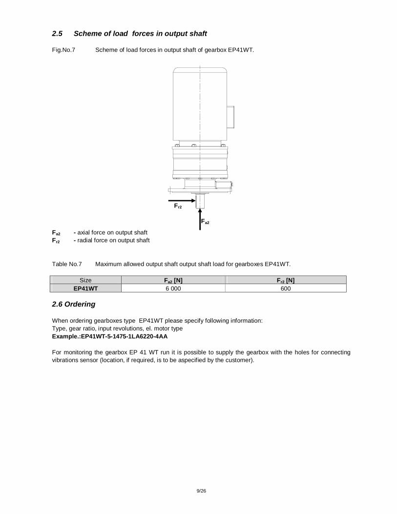
2.5 Scheme of load forces in output shaft Fig.No.7 Scheme of load forces in output shaft of gearbox EP41WT.
Fa2 - axial force on output shaft Fr2 - radial force on output shaft Table No.7 Maximum allowed output shaft output shaft load for gearboxes EP41WT.
Size Fa2 [N] Fr2 [N] EP41WT 6 000 600
2.6 Ordering When ordering gearboxes type EP41WT please specify following information: Type, gear ratio, input revolutions, el. motor type Example.:EP41WT-5-1475-1LA6220-4AA For monitoring the gearbox EP 41 WT run it is possible to supply the gearbox with the holes for connecting vibrations sensor (location, if required, is to be aspecified by the customer).
Fa2
Fr2

10/26
3. TSA 031 351-06, TSA 031 351-07, TSA 031 351-08. 3.1 Description Gearbopxes type TSA 031 351-06, TSA 031 351-07, TSA 031 351-08, Fig. No.8, consist of box –casting, bevel gears type OERLIKON that are specially thermal treated. Vertical output shaft is placed in taper bearings, what allows considerable axial load of the gearbox output. That is precondition for direct catching powers from the fan propeller. Gearboxes are with integrated lubrication system. Gearboxes TSA 031 351-06, TSA 031 351-07, TSA 031 351-08: - are closed tightly and can work in dusty, moisty, chemically non-deffective ambient that does not lower the sealing ability of the seal rings.
- gearboxes are equipped by 2 seal rings from material Viton on the output and input shaft.
Gearboxes TSA 351-08, refinery Gdaňsk, s.a., Poland
Gearboxes TSA 031 351-07, power station Tisová, Czech Republic

11/26
3.2 Technical parameters Table No.8 Technical parameters of gearboxes TSA 031 351-06, TSA 031 351-07, TSA 031 351-08.
SIZE ic iSKUT n1
[min-1] P1
[kW] noutput [min-1]
Mkoutput
[Nm]
1 500 140 669,6 1 966 1 000 134 446,4 2 823 2,24 2,24 750 110 334,8 3 090
1 500 110 476,1 2 172 1 000 101 317,4 2 992 3,15 3,15 750 83 238,1 3 278
1 500 98 333,3 2 765 1 000 75 222,2 3 089 4,5 4,5 750 61 166,6 3 443
1 500 87 300 2 727 1 000 66 200 3 104 5 5 750 55 150 3 448
1 500 78 267,8 2 738 1 000 61 178,5 3 108
TSA
031
351
- 06
5,6 5,6 750 48 133,9 3 371
1 500 250 669,6 3 512 1 000 220 446,4 4 634 2,24 2,24 750 196 334,8 5 506
1 500 230 476,1 4 543 1 000 196 317,4 5 807 3,15 3,15 750 196 238,1 7 742
1 500 190 333,3 5 361 1 000 180 222,2 7 618 4,5 4,5 750 138 166,6 7 787
1 500 159 300 4 985 1 000 151 200 7 054 5 5 750 117 150 7 336
1 500 175 267,8 6 146 1 000 120 178,5 6 321
TSA
031
351
- 07
5,6 5,6 750 94 133,9 6 601
1 500 450 669,6 6 321 1 000 370 446,4 7 795 2,24 2,24 750 320 334,8 8 989
1 500 360 476,1 7 111 1 000 320 317,4 9 481 3,15 3,15 750 300 238,1 11 852
1 500 320 333,3 9 029 1 000 300 222,1 12 698 4,5 4,5 750 210 166,6 11 855
1 500 248 300 7 776 1 000 248 200 11 663 5 5 750 190 150 11 914
1 500 220 267,8 7 725 1 000 220 178,5 11 588
TSA
031
351
- 08
5,6 5,6 750 172 133,9 12 079
iC - total gear ratio ireal - real gear ratio n1 - input revolutions [rev/min] P1 - standard gearbox power [kW] noutput - output revolutions [rev/min] Mkoutput - output torque [Nm] kc - service factor
kC=1
12/26
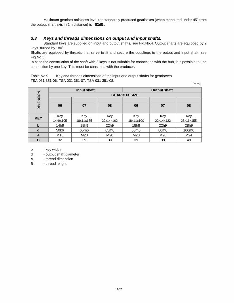
Maximum gearbox noisiness level for standardly produced gearboxes (when measured under 45o from the output shaft axis in 2m distance) is 82dB. 3.3 Keys and threads dimensions on output and input shafts. Standard keys are supplied on input and output shafts, see Fig.No.4. Output shafts are equipped by 2 keys turned by 1800. Shafts are equipped by threads that serve to fit and secure the couplings to the output and input shaft, see Fig.No.5 . In case the construction of the shaft with 2 keys is not suitable for connection with the hub, it is possible to use connection by one key. This must be consulted with the producer. Table No.9 Key and threads dimensions of the input and output shafts for gearboxes TSA 031 351-06, TSA 031 351-07, TSA 031 351-08.
Input shaft Output shaft GEARBOX SIZE
DIM
EN
SIO
N
06 07 08 06 07 08
KEY Key 14x9x105
Key 18x11x135
Key 22x14x162
Key 18x11x100
Key 22x14x122
Key 28x16x155
b 14h9 18h9 22h9 18h9 22h9 28h9 d 50k6 65m6 85m6 60m6 80m6 100m6 A M16 M20 M20 M20 M20 M24 B 32 39 39 39 39 48
b - key width d - output shaft diameter A - thread dimension B - thread lenght
[mm]

13/26
3.4 Basic dimensions Fig.No.8 Gearboxes TSA 031 351-06, TSA 031 351-07, TSA 031 351-08 basic dimensions.
Table No.10 Gearboxes TSA 031 351-06, TSA 031 351-07, TSA 031 351-08 basic dimensions.
Size 06 07 08 H 250 315 400 A 735 958 1143 A1 235 308 373 C 607,5 758 957 D 28 35 35 D1 12 16 16 E 480 620 750 E1 120 150 165 F 480 620 750 F1 240 310 375 F2 110 160 170 G 32 45 50 H1 357,5±1 443,5±1 557±1 H2 252,2 313,5 392 H3 492,5 617,5 780 K 33 45 50 M 390 510 600 d1 50k6 65m6 85m6 d2 60m6 80m6 100m6 l1 110 140 170 l2 105 130 165 j 420 550 670
m 370 490 600 m1 185 245 300
Weight [kg] 275 600 900
Dimension l1 considers also the lenght for fan fixation. In case of using fan the lenght of the hob of coupling must be 30 mm shorter.
[mm]
1 - discharging outle 2 - oil level checking outlet 3 - pouring outlet 4 -deaerating plug

14/26
5. Scheme of load forces in output shaft Fig.No.9 Scheme of load forces in output shaft TSA 031 351-06, TSA 031 351-07, TSA 031 351-08.
Fa1 - axial force on input shaft Fr1 - radial force on input shaft Fa2 - axial force on output shaft Fr2 - radial force on output shaft Table No.11 Maximum allowed load of the gearbox shafts
TSA 031 351-06, TSA 031 351-07, TSA 031 351-08.
Size Fr1 [N] Fa2 [N] Fr2 [N] 06 380 4 100 410 07 970 9 850 985 08 1 070 13 200 1 350
Fa2
Fr2
Fr1
Fa1=0

15/26
3.6 Ordering When ordering gearboxes TSA 031 351-06, TSA 031 351-07, TSA 031 351-08 please specify following: Gearbox marking: Type – size – version x gear ratio x n1
Example: TSA 031 351- 06- 2 x 2,24 x 1000 Fig.No.10 Gearbox versions TSA 031 351-06, TSA 031 351-07, TSA 031 351-08.
1 2
As special accessories the gearboxes TSA 031 351-06, TSA 031 351-07, TSA 031 351-08 can be equipped by:
- device protecting reverse run (blocking device), - cooling gearbox by a fan ( in case checking the gearbox for heat output shows that it is necessary to
use cooling.) To secure monitoring of the gearboxes TSA 031 351-06, TSA 031 351-07, TSA 031 351-08 it is possible to supply the gearbox with the holes for connecting sensors for (location, if required, is to be aspecified by the customer):
- oil flow sensor, - vibrations sensor, - temperature sensor.

16/26
4. KCV6, KCV8, KCV10, KCV12 4.1 Description Gearboxes KCV6, KCV8, KCV10, KCV12 consist of: box-casting, one bevel gear type OERLIKON and one spur gear that are thermally treated. Vertical output shaft is placed in taper bearings, what allows considerable axial load of the gearbox output. That is precondition for direct catching powers from the fan propeller. Gearboxes are with integrated lubrication system. Gearboxes KCV6, KCV8, KCV10, KCV12: - are closed tightly and can work in dusty, moisty, chemically non-deffective ambient
that does not lower the sealing ability of the seal rings. - gearboxes are equipped by 2 seal rings from material Viton on the output and input shaft.
Gearbox KCV 12, power station Nasiríja, Iraq

17/26
Fig.No.11
1 - pouring plug M56x2 2 - deaerating plug - screw M56x2 (pos.1) is adapted for connection of the tube with inner diameter
φ12mm, which will be led out of the cooling tower diffuser and which serves to deaerate the gearbox 3 - discharging plug G 1" 4 - oil gauge 5 - Cover for checking gearings 6 - hole for connecting vibrations sensor 8 - nameplate 9 - pump 10 - filter 11 - oil flow sensor 12 - oil flow sensor – evaluation unit 13 - sucking filter 14 - fan with cover 15 - heating spiral 16 - thermostat 17 - oil temperature sensor 18 - temperature pickup on surface of case (in place of output bearing) User gearboxes for cooling towers must install on gearbox (by installation, operation and maintenance manual for gearboxes) external – outside diffusor cooling tower:
- oil tapping from gearbox, - gearbox venting, - oil level monitoring in gearbox
3
The pointer is marked as per the gearbox version, see F i g . 1 4 .
3
16,17
18

18/26
4.2 Technical parameters Table No.12 Technical parameters of gearboxes types KCV6, KCV8, KCV10, KCV12.
SIZE ic ireal n1
[min-1] P1
[kW] noutput [min-1]
Mkoutput
[Nm] Fa2
[kN] SIZE ic ireal
n1
[min-1] P1
[kW] noutput [min-1]
Mkoutput
[Nm] Fa2
[kN] 1 500 285 239,6 10 904 18 1 500 460 238,1 17 711 23 1 000 190 159,7 10 904 19 1 000 310 158,7 17 903 25 6,3 6,2
750 140 119,8 10 712 21
6,3 6,2
750 231 119,0 17 788 27 1 500 265 214,9 11 305 18 1 500 410 211,2 17 791 23 1 000 180 143,2 11 518 19 1 000 275 140,8 17 899 25 7,1
6.98
750 135 107,4 11 518 21 7,1 7,0
750 208 105,6 18 051 27 1 500 245 182,7 12 293 17 1 500 375 187,5 18 334 24 1 000 170 121,8 12 795 17 1 000 250 125,0 18 334 26 8 8.2
750 130 91,3 13 046 19
8 7.9
750 190 93,7 18 579 27 1 500 210 168,3 11 435 19 1 500 325 166,6 17 876 24 1 000 140 112,2 11 435 20 1 000 220 111,1 18 151 27 9 8.9
750 105 84,1 11 435 21
9 8.9
750 162 83,3 17 820 28 1 500 200 150,6 12 174 17 1 500 300 150 18 334 25 1 000 140 100,4 12 783 18 1 000 200 100 18 334 27 10 9.9
750 105 75,3 12 783 20
10 9.9
750 150 75 18 334 29 1 500 170 135 11 543 19 1 500 250 133,9 17 112 26
1 000 115 90 11 713 21 1 000 170 89,2 17 454 27 11,2 11,1
750 85 67,5 11 543 23
11,2 11,1
750 130 66,9 17 796 22 1 500 145 119,6 11 113 20 1 500 215 120 16 425 28 1 000 100 79,7 11 496 22 1 000 140 80 16 043 30 12,5 12,5 750 75 59,8 11 496 24
12,5 12,4 750 105 60 16 043 32
1 500 135 107,2 11 534 20 1 500 205 107,1 17 540 25 1 000 90 71,5 11 534 22 1 000 140 71,4 17 967 28 14 13.9
750 68 53,6 11 620 25
14 13.8
750 105 53,5 17 967 32 1 500 105 94 10 235 23 1 500 150 93,7 14 667 32 1 000 70 62,6 10 235 26 1 000 100 62,5 14 667 34
KC
V6
16 15.9
750 50 47 9 748 29
KC
V8
16 15.8
750 75 46,88 14 667 38 kc - service factor iC - total gear ratio ireal - real gear ratio n1 - input revolutions [rev/min] P1 - standard gearbox power [kW] noutput - output revolutions [rev/min] Mkoutput - output torque [Nm] Fa2 - axial load of output shaft [kN]
kC=1

19/26
SIZE ic ireal n1
[min-1] P1
[kW] noutput [min-1]
Mkoutput
[Nm] Fa2
[kN] SIZE ic ireal
n1
[min-1] P1
[kW] noutput [min-1]
Mkoutput
[Nm] Fa2
[kN] 1 500 618 247,1 22 926 35 1 500 870 238,1 33 497 55
1 000 450 164,7 25 041 37 1 000 630 158,7 36 385 57 6,3 6,07
750 336 123,5 24 929 41
6,3 6,2
750 470 119,0 36 192 60 1 500 618 217,3 26 061 35 1 500 870 211,2 37 751 52 1 000 420 144,9 26 567 39 1 000 630 140,8 41 005 55 7,1 6,9 750 315 108,6 26 567 40
7,1 7,0 750 470 105,6 40 788 58
1 500 595 190,3 28 655 35 1 500 820 187,5 40 092 49
1 000 400 126,9 28 895 39 1 000 560 125,0 41 069 54 8 7,88
750 302 95,1 29 088 41
8 7.9
750 420 93,7 41 069 57 1 500 495 165,5 27 408 37 1 500 720 166,6 39 603 54 1 000 330 110,3 27 408 40 1 000 490 111,1 40 428 57 9 9,06
750 250 82,7 27 685 43
9 8.9
750 370 83,3 40 702 61
1 500 480 144,7 30 392 37 1 500 670 150 40 947 52
1 000 320 96,5 30 392 40 1 000 450 100 41 252 56 10 10,36
750 240 72,3 30 392 43
10 9.9
750 340 75 41 558 59
1 500 400 134,5 27 258 37 1 500 590 133,9 40 384 55
1 000 270 89,6 27 598 40 1 000 395 89,2 40 556 59 11,2 11,15
750 200 67,2 27 258 43
11,2 11,1
750 295 66,9 40 384 63
1 500 362 122,7 27 035 40 1 500 480 120 36 669 58 1 000 240 81,8 26 886 43 1 000 320 80 36 669 63 12,5 12,22 750 180 61,3 26 886 48
12,5 12,4 750 240 60 36 669 68
1 500 320 103,8 28 240 40 1 500 470 107,1 40 213 57
1 000 214 69,2 28 329 43 1 000 310 71,4 39 785 62 14 14,44
750 160 51,9 28 240 46
14 13.8
750 235 53,5 40 213 66 1 500 245 94,4 23 778 46 1 500 340 93,7 33 247 65 1 000 164 62,9 23 875 50 1 000 225 62,5 33 002 71
KC
V10
16 15,88
750 120 47,2 23 292 54
KC
V12
16 15.8
750 170 46,88 33 247 74
kc - service factor iC - total gear ratio ireal - real gear ratio n1 - input revolutions [rev/min] P1 - standard gearbox power [kW] noutput - output revolutions [rev/min] Mkoutput - output torque [Nm] F a 2 - axial load of output shaft [ k N ]
kC=1
20/26
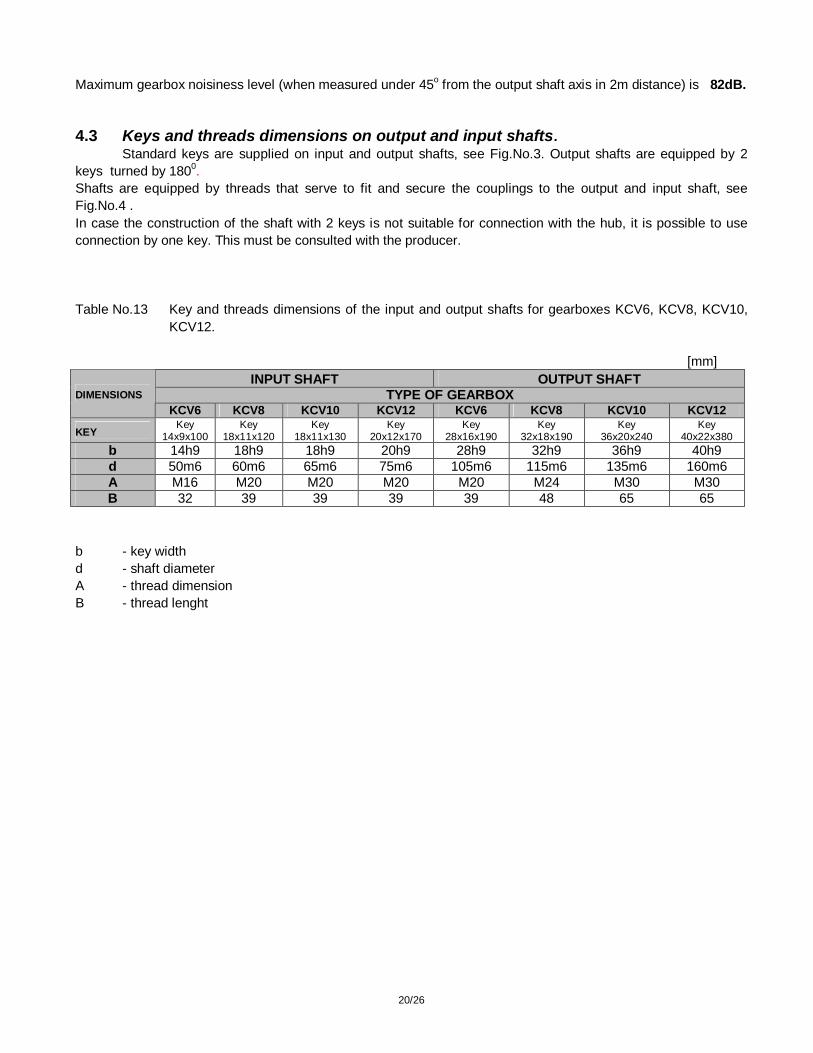
Maximum gearbox noisiness level (when measured under 45o from the output shaft axis in 2m distance) is 82dB. 4.3 Keys and threads dimensions on output and input shafts. Standard keys are supplied on input and output shafts, see Fig.No.3. Output shafts are equipped by 2 keys turned by 1800. Shafts are equipped by threads that serve to fit and secure the couplings to the output and input shaft, see Fig.No.4 . In case the construction of the shaft with 2 keys is not suitable for connection with the hub, it is possible to use connection by one key. This must be consulted with the producer. Table No.13 Key and threads dimensions of the input and output shafts for gearboxes KCV6, KCV8, KCV10,
KCV12.
[mm] INPUT SHAFT OUTPUT SHAFT
TYPE OF GEARBOX DIMENSIONS KCV6 KCV8 KCV10 KCV12 KCV6 KCV8 KCV10 KCV12
KEY Key
14x9x100 Key
18x11x120 Key
18x11x130 Key
20x12x170 Key
28x16x190 Key
32x18x190 Key
36x20x240 Key
40x22x380 b 14h9 18h9 18h9 20h9 28h9 32h9 36h9 40h9 d 50m6 60m6 65m6 75m6 105m6 115m6 135m6 160m6 A M16 M20 M20 M20 M20 M24 M30 M30 B 32 39 39 39 39 48 65 65
b - key width d - shaft diameter A - thread dimension B - thread lenght
21/26
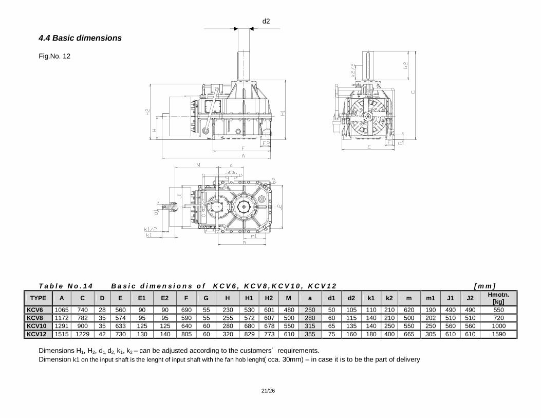
4.4 Basic dimensions Fig.No. 12 T a b l e N o . 1 4 B a s i c d i m e n s i o n s o f K C V 6 , K C V 8 , K C V 1 0 , K C V 1 2 [ m m ]
TYPE A C D E E1 E2 F G H H1 H2 M a d1 d2 k1 k2 m m1 J1 J2 Hmotn. [kg]
KCV6 1065 740 28 560 90 90 690 55 230 530 601 480 250 50 105 110 210 620 190 490 490 550 KCV8 1172 782 35 574 95 95 590 55 255 572 607 500 280 60 115 140 210 500 202 510 510 720 KCV10 1291 900 35 633 125 125 640 60 280 680 678 550 315 65 135 140 250 550 250 560 560 1000 KCV12 1515 1229 42 730 130 140 805 60 320 829 773 610 355 75 160 180 400 665 305 610 610 1590
Dimensions H1, H2, d1, d2, k1, k2 – can be adjusted according to the customers´ requirements. Dimension k1 on the input shaft is the lenght of input shaft with the fan hob lenght( cca. 30mm) – in case it is to be the part of delivery
d2

22/26
4.5 Scheme of load forces in output shaft (see Fig.No.13 and Table No.15)
Fa1 - axial force on input shaft Fr1 - radial force on input shaft Fa2 - axial force on output shaft Fr2 - radial force on output shaft Table No.15 Maximum allowed shafts load for gearboxes KCV6, KCV8, KCV10, KCV12. Maximum radial force acting in the mid of output shaft - Fr2max Fr2max = 0,1 x Fa2 Maximum axial force acting to the input shaft axis - Fa1max Fa1max = 0 Maximum radial force acting in the mid of input shaft - Fr1max Fr1max = 1 kN
Fig.No. 13
Fa1
Fr2
Fr1
Fa2
23/26
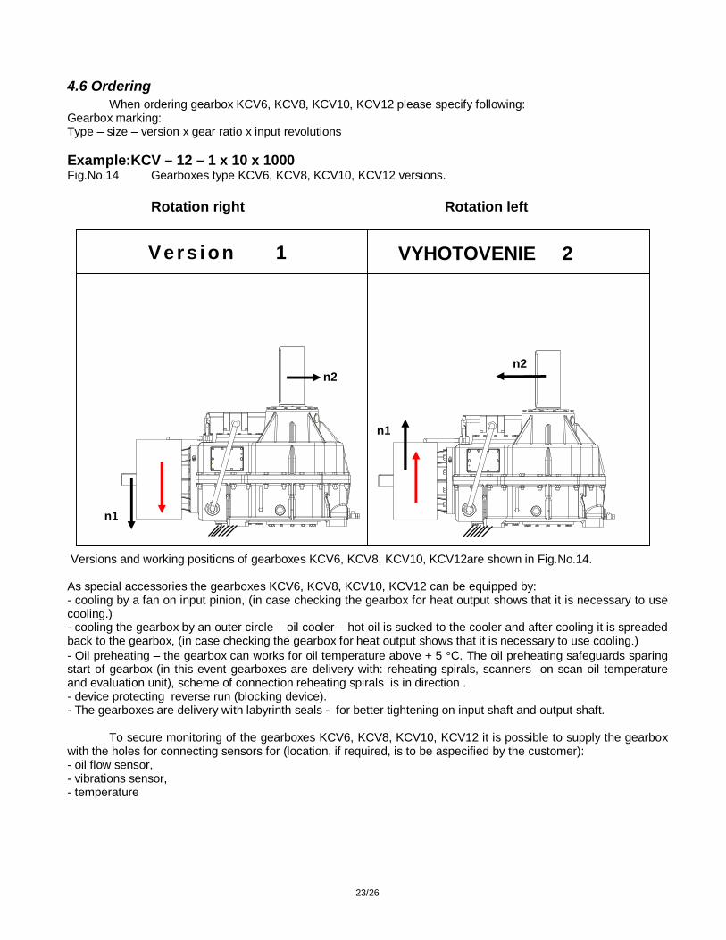
4.6 Ordering When ordering gearbox KCV6, KCV8, KCV10, KCV12 please specify following: Gearbox marking: Type – size – version x gear ratio x input revolutions Example:KCV – 12 – 1 x 10 x 1000 Fig.No.14 Gearboxes type KCV6, KCV8, KCV10, KCV12 versions.
Rotation right Rotation left
Versions and working positions of gearboxes KCV6, KCV8, KCV10, KCV12are shown in Fig.No.14. As special accessories the gearboxes KCV6, KCV8, KCV10, KCV12 can be equipped by: - cooling by a fan on input pinion, (in case checking the gearbox for heat output shows that it is necessary to use cooling.) - cooling the gearbox by an outer circle – oil cooler – hot oil is sucked to the cooler and after cooling it is spreaded back to the gearbox, (in case checking the gearbox for heat output shows that it is necessary to use cooling.) - Oil preheating – the gearbox can works for oil temperature above + 5 °C. The oil preheating safeguards sparing start of gearbox (in this event gearboxes are delivery with: reheating spirals, scanners on scan oil temperature and evaluation unit), scheme of connection reheating spirals is in direction . - device protecting reverse run (blocking device). - The gearboxes are delivery with labyrinth seals - for better tightening on input shaft and output shaft. To secure monitoring of the gearboxes KCV6, KCV8, KCV10, KCV12 it is possible to supply the gearbox with the holes for connecting sensors for (location, if required, is to be aspecified by the customer): - oil flow sensor, - vibrations sensor, - temperature
n1
n1
n2 n2
Vers i on 1 VYHOTOVENIE 2
24/26
5. GENERAL CONDITIONS FOR USING GEARBOXES FOR COOLING TOWERS A, It is recommended to consult the project of locating el. motor, coupling, connecting shaft, gearbox itself and propeller with the gearbox producer.
B, For all types of gearboxes for cooling towers the level of diagnostics (gearbox protection) must be agreed with the gearbox producer.
C, For gearboxes TSA and KCV it is recommended to use oil flow sensors that are connected together electrically so in case there is no oil flow in lubrication system, the el. motor is stopped automatically.
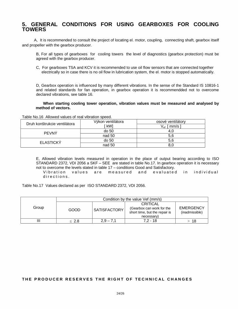
D, Gearbox operation is influenced by many different vibrations. In the sense of the Standard IS 10816-1 and related standards for fan operation, in gearbox operation it is recommendded not to overcome declared vibrations, see table 16.
When starting cooling tower operation, vibration values must be measured and analysed by method of vectors.
Table No.16 Allowed values of real vibration speed.
osové ventilátory Druh konštrukcie ventilátora Výkon ventilátora [ kW] Vef [ mm/s ] do 50 4,0 PEVNÝ nad 50 5,6 do 50 5,6 ELASTICKÝ nad 50 8,0
E, Allowed vibration levels measured in operation in the place of output bearing according to ISO STANDARD 2372, VDI 2056 a SKF – SEE are stated in table No.17. In gearbox operation it is necessary not to overcome the levels stated in table 17 – conditions Good and Satisfactory.
V i b r a t i o n v a l u e s a r e m e a s u r e d a n d e v a l u a t e d i n i n d i v i d u a l d i r e c t i o n s .
Table No.17 Values declared as per ISO STANDARD 2372, VDI 2056.
Condition by the value Vef (mm/s)
Group GOOD SATISFACTORY CRITICAL
(Gearbox can work for the short time, but the repair is
necessary)
EMERGENCY (inadmissible)
III ≤ 2.8 2,9 – 7,1 7,2 - 18 > 18 T H E P R O D U C E R R E S E R V E S T H E R I G H T O F T E C H N I C A L C H A N G E S

25/26
T e c h n i c a l q u e s t i o n a i r e f o r t h e g e a r b o x e s f o r c o o l i n g t o w e r s s p e c i f i c a t i o n . Customer (name of the firm)...................................... Request No.:........................................................ Developed by (name):................................................ Tel.:................................. Fax:............................ Project / country of final use .......................................... Type / Gearbox mounting position:
FAN: FAN φ .............................. mm / No. of blades in screw-propeller...... moment of inertia ..............kg / m2 Gearbox working ambient temperature: min ................ oC max. .................... oC Power of ventilator/ ventilator revolutions : ......................... kW ............................. rev / min Reverse run: yes no Weight of fan:............... kg Weight of hub:..................... kg Total weight of hub and fan:................................. kg ELECTRIC MOTOR: El. motor power ................................ kW El. motor revolutions :....................rev/ min Electric motor type ................................. Relative starting torgue of electric motor....................... Start of el. motor by frequence changer : yes no Start of el. motor by one-speed el. motor: yes no El. motor connection: star / triangle triangle Start of el. motor by two-speed el.motor: yes no Gearbox: Number of pieces: ............... pcs Gear ratioi = ................... Output revolutions allowed deviation: - ................. % + ...................... % Sense of output shaft rotation when looking to the face of the output shaft: right left reverse ( in reverse run please declare main rotation direction ) right left air circulation speed : > 1,0 m/s > 2,0 m/s > 4,0 m/s Action of the forces to the gearbox shafts :
EP41WT TSA 031 351 KCV
Fr2
Fr1 Fa1
Fa2
l1 1/2
l2 1/2 Fa1 = ................... kN Fr1 = ................... kN Fa2 = ................... kN Fr2 = ................... kN
26/26
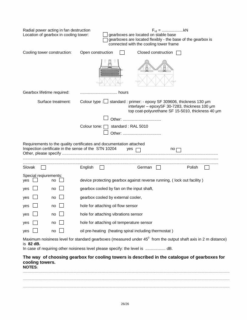
Radial power acting in fan destruction Frd = ...................kN Location of gearbox in cooling tower: gearboxes are located on stable base
gearboxes are located flexibly - the base of the gearbox is connected with the cooling tower frame
Cooling tower construction: Open construction Closed construction
Gearbox lifetime required: ................................. hours
Surface treatment: Colour type : standard : primer: - epoxy SF 309606, thickness 130 μm interlayer – epoxySF 30-7283, thickness 100 μm top coat-polyurethane SF 15-5010, thickness 40 μm Other: ..................................
Colour tone: standard : RAL 5010
Other: .................................. Requirements to the quality certificates and documentation attached Inspection certificate in the sense of the STN 10204 yes no Other, please specify ........................................................................................................................................... .............................................................................................................................................................................. .............................................................................................................................................................................. Slovak English German Polish Special reqiurements: yes no device protecting gearbox against reverse running, ( lock out facility ) yes no gearbox cooled by fan on the input shaft, yes no gearbox cooled by external cooler, yes no hole for attaching oil flow sensor yes no hole for attaching vibrations sensor yes no hole for attaching oil temperature sensor yes no oil pre-heating (heating spiral including thermostat ) Maximum noisiness level for standard gearboxes (measured under 450 from the output shaft axis in 2 m distance) is 82 dB. In case of requiring other noisiness level please specify: the level is .................. dB. The way of choosing gearbox for cooling towers is described in the catalogue of gearboxes for cooling towers. NOTES: ................................................................................................................................................................................................................................... ................................................................................................................................................................................................................................... ...................................................................................................................................................................................................................................

27/26
Related Documents