ETICS Fixings / E.W.I Catalogue

Welcome message from author
This document is posted to help you gain knowledge. Please leave a comment to let me know what you think about it! Share it to your friends and learn new things together.
Transcript

www.fischer.de
ETICS Fixings / E.W.I
Catalogue
00118163 · 05/2020 · V-MKS/CPI · Printed in Germany · Subject to technical alternations without notice
www.fischer.de
Contacts fischerwerke GmbH & Co. KGKlaus-Fischer-Straße 172178 WaldachtalGermany fischer fixings UK Ltd.Whitely RoadOxon OX10 9AT WallingfordGreat Britain fischer Systems Asia Pte. Ltd.4 Kaki Bukit Avenue 1, #01-06 Singapore 417939
Your dealer
Dear partners,
there is a continued need for facades with thermal insulation composite systems (ETICS) in new construction and renovation. They minimise the energy consumption of buildings, thus protecting the environment, reducing operating costs and meeting legislator requirements.
Our company offers a wide range of fixing solutions for the installation of insulation boards. The product range covers different construction materials, thicknesses as well as fire protection and system requirements. System providers and processors of ETICS can find an optimal, easy to use and safe solution for any application within the framework of the European Technical Assessment (ETA).
On the following pages you will find an overview of our extensive product range and our accompanying services. These include impact and screw anchors as well as special anchorages and further solutions for fixing insulating materials. We will also be presenting our spacer mounting systems for the safe and almost thermal-bridge-free installation of attachments to thermal insulation composite systems.
We hope you enjoy discovering our current range of fixing systems. If you require any further support, our experts will be happy to assist you via the technical support hotline or in the field.
Marc-Sven MengisChief Executive Officer for the group of companies fischer
MD_KT_$KT-WDVS-EWI-$KP-KOO-UMSCHLAG_#SEN_#APR_#V1.indd 52-53,2MD_KT_$KT-WDVS-EWI-$KP-KOO-UMSCHLAG_#SEN_#APR_#V1.indd 52-53,2 19.05.2020 10:06:0619.05.2020 10:06:06
www.fischer.de
ETICS Fixings / E.W.I
Catalogue
00118163 · 05/2020 · V-MKS/CPI · Printed in Germany · Subject to technical alternations without notice
www.fischer.de
Contacts fischerwerke GmbH & Co. KGKlaus-Fischer-Straße 172178 WaldachtalGermany fischer fixings UK Ltd.Whitely RoadOxon OX10 9AT WallingfordGreat Britain fischer Systems Asia Pte. Ltd.4 Kaki Bukit Avenue 1, #01-06 Singapore 417939
Your dealer
Dear partners,
there is a continued need for facades with thermal insulation composite systems (ETICS) in new construction and renovation. They minimise the energy consumption of buildings, thus protecting the environment, reducing operating costs and meeting legislator requirements.
Our company offers a wide range of fixing solutions for the installation of insulation boards. The product range covers different construction materials, thicknesses as well as fire protection and system requirements. System providers and processors of ETICS can find an optimal, easy to use and safe solution for any application within the framework of the European Technical Assessment (ETA).
On the following pages you will find an overview of our extensive product range and our accompanying services. These include impact and screw anchors as well as special anchorages and further solutions for fixing insulating materials. We will also be presenting our spacer mounting systems for the safe and almost thermal-bridge-free installation of attachments to thermal insulation composite systems.
We hope you enjoy discovering our current range of fixing systems. If you require any further support, our experts will be happy to assist you via the technical support hotline or in the field.
Marc-Sven MengisChief Executive Officer for the group of companies fischer
MD_KT_$KT-WDVS-EWI-$KP-KOO-UMSCHLAG_#SEN_#APR_#V1.indd 52-53,2MD_KT_$KT-WDVS-EWI-$KP-KOO-UMSCHLAG_#SEN_#APR_#V1.indd 52-53,2 19.05.2020 10:06:0619.05.2020 10:06:06
Fixing selection
3) Depends on the installation situation
The information in this brochure is intended for general guidance only and is given without engagement. Additional information and advice on specific applications is available from our Technical Support Team. For this however, we require a pre-cise description of your particular application. All the data in this brochure concerning work with our fixing elements must be adapted to suit local conditions and the type of materials in use.If no detailed performance specifications are given for certain articles and types, please contact our Technical Service Department for advice.
fischerwerke GmbH & Co. KG72178 WaldachtalGermany
We cannot be responsible for any errors, and we reserve the right to make technical and range modifications without notice.No liability is accepted for printing errors and omissions.
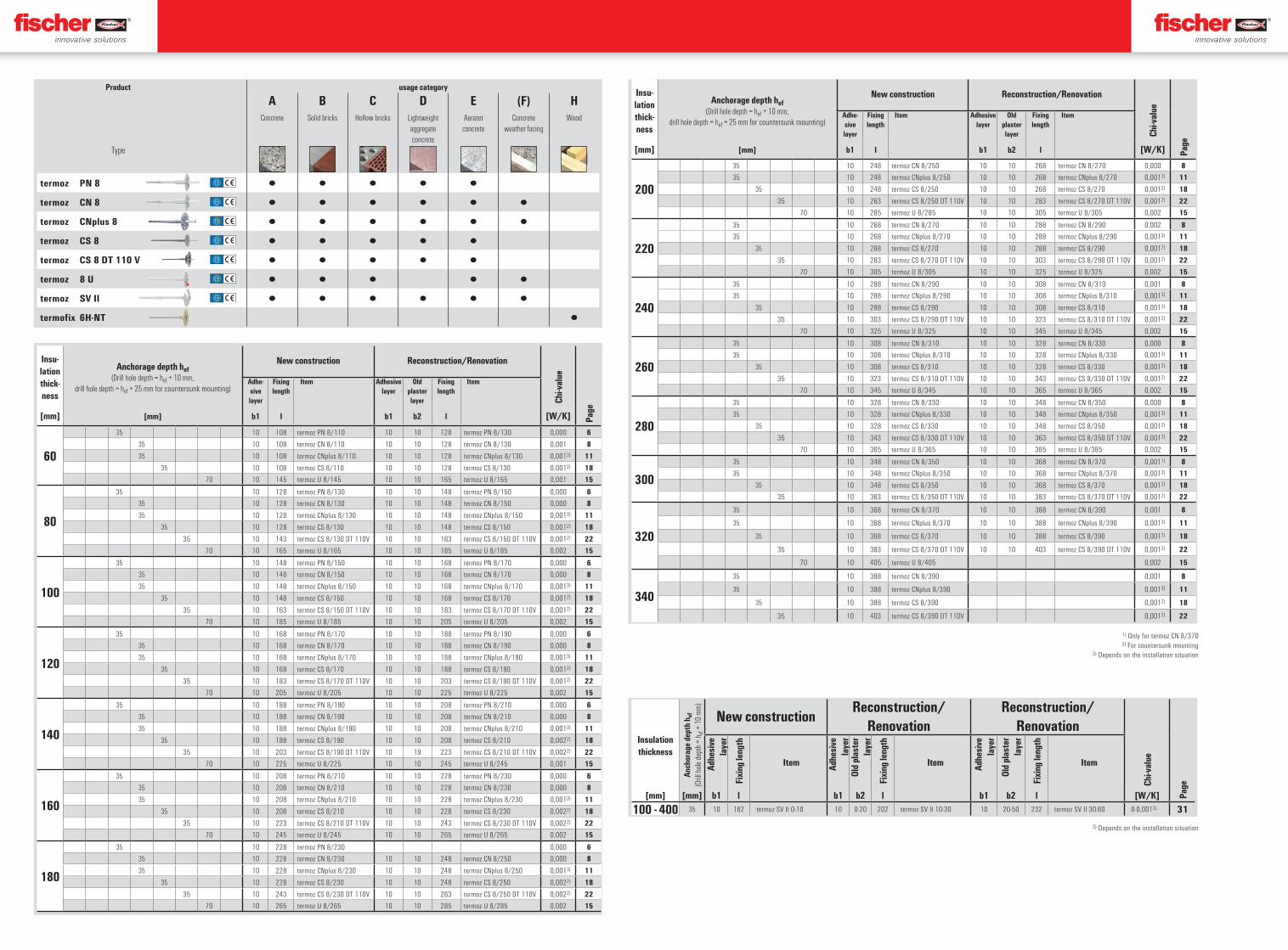
Product usage category
A B C D E (F) HConcrete Solid bricks Hollow bricks Lightweight
aggregate concrete
Aeratet concrete
Concrete weather facing
Wood
Type
termoz PN 8 ▯ ▯ ▯ ▯ ▯
termoz CN 8 ▯ ▯ ▯ ▯ ▯ ▯
termoz CNplus 8 ▯ ▯ ▯ ▯ ▯ ▯
termoz CS 8 ▯ ▯ ▯ ▯ ▯
termoz CS 8 DT 110 V ▯ ▯ ▯ ▯ ▯
termoz 8 U ▯ ▯ ▯ ▯ ▯
termoz SV II ▯ ▯ ▯ ▯ ▯ ▯
termofix 6H-NT ▯
Insulation thickness
Anch
orag
e de
pth
h ef
(Drill
hole
dept
h = h e
f + 1
0 mm
)
New constructionReconstruction/
RenovationReconstruction/
Renovation
Chi-v
alue
Page
Adhe
sive
la
yer
Fixi
ng le
ngth
Item Adhe
sive
la
yer
Old
plas
ter
laye
r
Fixi
ng le
ngth
Item Adhe
sive
la
yer
Old
plas
ter
laye
r
Fixi
ng le
ngth
Item
[mm] [mm] b1 l b1 b2 l b1 b2 l [W/K]
100 - 400 35 10 162 termoz SV II 0-10 10 0-20 202 termoz SV II 10-30 10 20-50 232 termoz SV II 30-60 0-0,0013) 31
Insu-lation thick-ness
Anchorage depth hef(Drill hole depth = hef + 10 mm,
drill hole depth = hef + 25 mm for countersunk mounting)
New construction Reconstruction/Renovation
Chi-v
alue
Page
Adhe-sive layer
Fixing length
Item Adhesive layer
Old plaster layer
Fixing length
Item
[mm] [mm] b1 l b1 b2 l [W/K]
60
35 10 108 termoz PN 8/110 10 10 128 termoz PN 8/130 0,000 6
35 10 108 termoz CN 8/110 10 10 128 termoz CN 8/130 0,001 8
35 10 108 termoz CNplus 8/110 10 10 128 termoz CNplus 8/130 0,0013) 11
35 10 108 termoz CS 8/110 10 10 128 termoz CS 8/130 0,0012) 18
70 10 145 termoz U 8/145 10 10 165 termoz U 8/165 0,001 15
80
35 10 128 termoz PN 8/130 10 10 148 termoz PN 8/150 0,000 6
35 10 128 termoz CN 8/130 10 10 148 termoz CN 8/150 0,000 8
35 10 128 termoz CNplus 8/130 10 10 148 termoz CNplus 8/150 0,0013) 11
35 10 128 termoz CS 8/130 10 10 148 termoz CS 8/150 0,0012) 18
35 10 143 termoz CS 8/130 DT 110V 10 10 163 termoz CS 8/150 DT 110V 0,0012) 22
70 10 165 termoz U 8/165 10 10 185 termoz U 8/185 0,002 15
100
35 10 148 termoz PN 8/150 10 10 168 termoz PN 8/170 0,000 6
35 10 148 termoz CN 8/150 10 10 168 termoz CN 8/170 0,000 8
35 10 148 termoz CNplus 8/150 10 10 168 termoz CNplus 8/170 0,0013) 11
35 10 148 termoz CS 8/150 10 10 168 termoz CS 8/170 0,0012) 18
35 10 163 termoz CS 8/150 DT 110V 10 10 183 termoz CS 8/170 DT 110V 0,0012) 22
70 10 185 termoz U 8/185 10 10 205 termoz U 8/205 0,002 15
120
35 10 168 termoz PN 8/170 10 10 188 termoz PN 8/190 0,000 6
35 10 168 termoz CN 8/170 10 10 188 termoz CN 8/190 0,000 8
35 10 168 termoz CNplus 8/170 10 10 188 termoz CNplus 8/190 0,0013) 11
35 10 168 termoz CS 8/170 10 10 188 termoz CS 8/190 0,0012) 18
35 10 183 termoz CS 8/170 DT 110V 10 10 203 termoz CS 8/190 DT 110V 0,0012) 22
70 10 205 termoz U 8/205 10 10 225 termoz U 8/225 0,002 15
140
35 10 188 termoz PN 8/190 10 10 208 termoz PN 8/210 0,000 6
35 10 188 termoz CN 8/190 10 10 208 termoz CN 8/210 0,000 8
35 10 188 termoz CNplus 8/190 10 10 208 termoz CNplus 8/210 0,0013) 11
35 10 188 termoz CS 8/190 10 10 208 termoz CS 8/210 0,0022) 18
35 10 203 termoz CS 8/190 DT 110V 10 19 223 termoz CS 8/210 DT 110V 0,0022) 22
70 10 225 termoz U 8/225 10 10 245 termoz U 8/245 0,001 15
160
35 10 208 termoz PN 8/210 10 10 228 termoz PN 8/230 0,000 6
35 10 208 termoz CN 8/210 10 10 228 termoz CN 8/230 0,000 8
35 10 208 termoz CNplus 8/210 10 10 228 termoz CNplus 8/230 0,0013) 11
35 10 208 termoz CS 8/210 10 10 228 termoz CS 8/230 0,0022) 18
35 10 223 termoz CS 8/210 DT 110V 10 10 243 termoz CS 8/230 DT 110V 0,0022) 22
70 10 245 termoz U 8/245 10 10 265 termoz U 8/265 0,002 15
180
35 10 228 termoz PN 8/230 0,000 6
35 10 228 termoz CN 8/230 10 10 248 termoz CN 8/250 0,000 8
35 10 228 termoz CNplus 8/230 10 10 248 termoz CNplus 8/250 0,0013) 11
35 10 228 termoz CS 8/230 10 10 248 termoz CS 8/250 0,0022) 18
35 10 243 termoz CS 8/230 DT 110V 10 10 263 termoz CS 8/250 DT 110V 0,0022) 22
70 10 265 termoz U 8/265 10 10 285 termoz U 8/285 0,002 15
Insu-lation thick-ness
Anchorage depth hef(Drill hole depth = hef + 10 mm,
drill hole depth = hef + 25 mm for countersunk mounting)
New construction Reconstruction/Renovation
Chi-v
alue
Page
Adhe-sive layer
Fixing length
Item Adhesive layer
Old plaster layer
Fixing length
Item
[mm] [mm] b1 l b1 b2 l [W/K]
200
35 10 248 termoz CN 8/250 10 10 268 termoz CN 8/270 0,000 8
35 10 248 termoz CNplus 8/250 10 10 268 termoz CNplus 8/270 0,0013) 11
35 10 248 termoz CS 8/250 10 10 268 termoz CS 8/270 0,0012) 18
35 10 263 termoz CS 8/250 DT 110V 10 10 283 termoz CS 8/270 DT 110V 0,0012) 22
70 10 285 termoz U 8/285 10 10 305 termoz U 8/305 0,002 15
220
35 10 268 termoz CN 8/270 10 10 288 termoz CN 8/290 0,002 8
35 10 268 termoz CNplus 8/270 10 10 288 termoz CNplus 8/290 0,0013) 11
35 10 268 termoz CS 8/270 10 10 288 termoz CS 8/290 0,0012) 18
35 10 283 termoz CS 8/270 DT 110V 10 10 303 termoz CS 8/290 DT 110V 0,0012) 22
70 10 305 termoz U 8/305 10 10 325 termoz U 8/325 0,002 15
240
35 10 288 termoz CN 8/290 10 10 308 termoz CN 8/310 0,001 8
35 10 288 termoz CNplus 8/290 10 10 308 termoz CNplus 8/310 0,0013) 11
35 10 288 termoz CS 8/290 10 10 308 termoz CS 8/310 0,0012) 18
35 10 303 termoz CS 8/290 DT 110V 10 10 323 termoz CS 8/310 DT 110V 0,0012) 22
70 10 325 termoz U 8/325 10 10 345 termoz U 8/345 0,002 15
260
35 10 308 termoz CN 8/310 10 10 328 termoz CN 8/330 0,000 8
35 10 308 termoz CNplus 8/310 10 10 328 termoz CNplus 8/330 0,0013) 11
35 10 308 termoz CS 8/310 10 10 328 termoz CS 8/330 0,0012) 18
35 10 323 termoz CS 8/310 DT 110V 10 10 343 termoz CS 8/330 DT 110V 0,0012) 22
70 10 345 termoz U 8/345 10 10 365 termoz U 8/365 0,002 15
280
35 10 328 termoz CN 8/330 10 10 348 termoz CN 8/350 0,000 8
35 10 328 termoz CNplus 8/330 10 10 348 termoz CNplus 8/350 0,0013) 11
35 10 328 termoz CS 8/330 10 10 348 termoz CS 8/350 0,0012) 18
35 10 343 termoz CS 8/330 DT 110V 10 10 363 termoz CS 8/350 DT 110V 0,0012) 22
70 10 365 termoz U 8/365 10 10 385 termoz U 8/385 0,002 15
300
35 10 348 termoz CN 8/350 10 10 368 termoz CN 8/370 0,0011) 8
35 10 348 termoz CNplus 8/350 10 10 368 termoz CNplus 8/370 0,0013) 11
35 10 348 termoz CS 8/350 10 10 368 termoz CS 8/370 0,0012) 18
35 10 363 termoz CS 8/350 DT 110V 10 10 383 termoz CS 8/370 DT 110V 0,0012) 22
320
35 10 368 termoz CN 8/370 10 10 388 termoz CN 8/390 0,001 8
35 10 368 termoz CNplus 8/370 10 10 388 termoz CNplus 8/390 0,0013) 11
35 10 368 termoz CS 8/370 10 10 388 termoz CS 8/390 0,0012) 18
35 10 383 termoz CS 8/370 DT 110V 10 10 403 termoz CS 8/390 DT 110V 0,0012) 22
70 10 405 termoz U 8/405 0,002 15
340
35 10 388 termoz CN 8/390 0,001 8
35 10 388 termoz CNplus 8/390 0,0013) 11
35 10 388 termoz CS 8/390 0,0012) 18
35 10 403 termoz CS 8/390 DT 110V 0,0012) 22
1) Only for termoz CN 8/370 2) For countersunk mounting
3) Depends on the installation situation
MD_KT_$KT-WDVS-EWI-$KP-KOO-UMSCHLAG_#SEN_#APR_#V1.indd 51MD_KT_$KT-WDVS-EWI-$KP-KOO-UMSCHLAG_#SEN_#APR_#V1.indd 51 19.05.2020 10:06:1519.05.2020 10:06:15
11
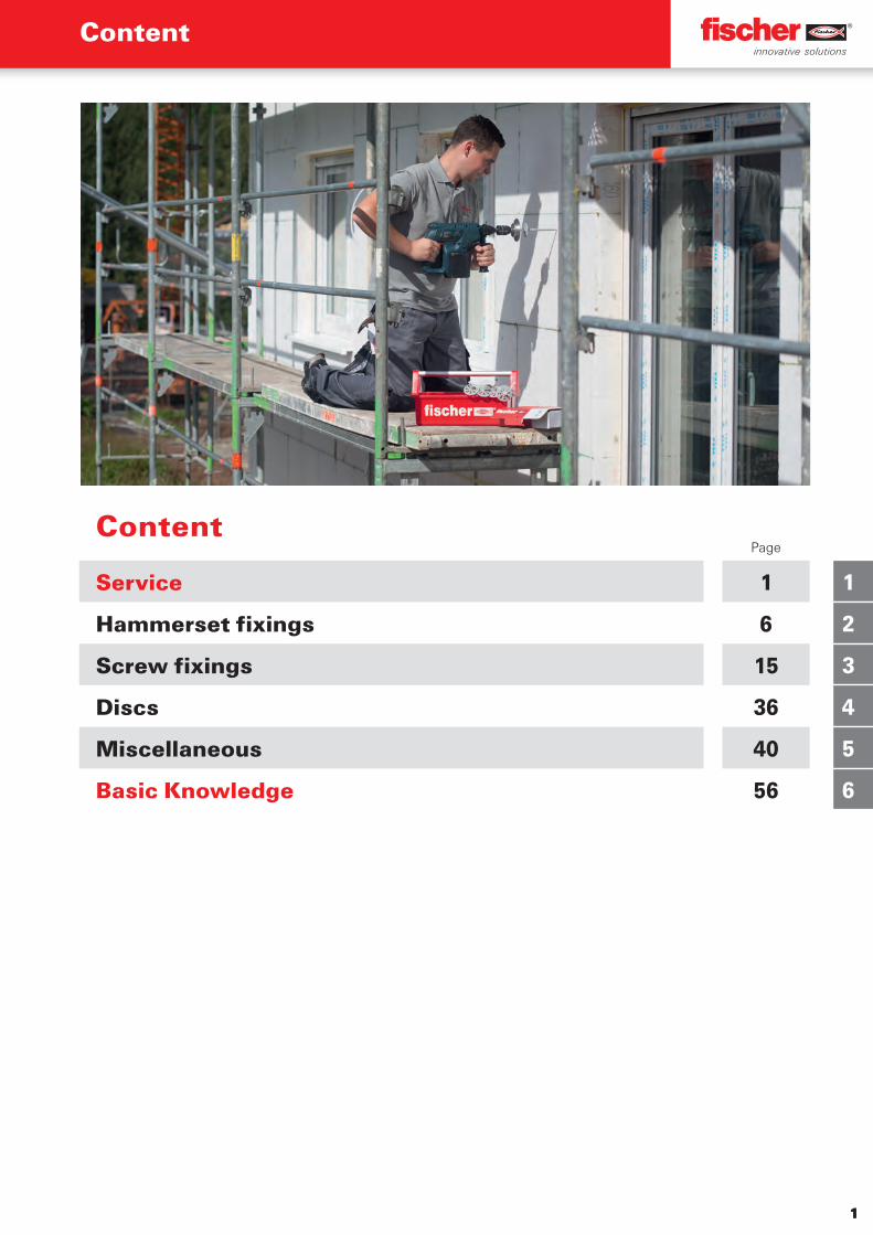
ContentPage
Service 1
Hammerset fixings 6
Screw fixings 15
Discs 36
Miscellaneous 40
Basic Knowledge 56
1
1
2
3
4
5
6
Content
MD_PG_$KT-WDVS-EWI-$KP-K01-SERVICE_#SEN_#APR_#V1.indd 1MD_PG_$KT-WDVS-EWI-$KP-K01-SERVICE_#SEN_#APR_#V1.indd 1 20.05.2020 09:27:5220.05.2020 09:27:52

2
1
A brand and its promise to performS
erv
ice
The fischer brand
� Thegreatestexpertise,safetyandqualityforplastic,steelandchemicalfixingsystems
� Theworld‘sleadingprovideroffixingsystemsandthemarketleaderinmostEuropeancountries
� Atraditionalbrandwiththehighestnamerecognitionwithintheindustry
� Anoutstandingbrandimage.92%ofstructuralengineersandarchitectsrecommendfischer
� Thegreatestsatisfaction.95%ofcustomerswouldrecommendfischer
ETA-98/004ETAG 001- 3
Option 1 für gerissenen Beton
See ICC-ESEvaluation Reportat www.icc-es.org
ESR-1990
Expertise that you can build on
� Over60years‘experienceinfixingtechnology
� High-techproductsolutions
� Thehighestqualitystandards
� Everythingfromonesourcethankstotheon-siteresearch&development,specialmechanicalengineering,productionandgloballogistics
� fischerProcessSystem(fPS)forthecontinuousoptimisationofourprocessesandflexibleadjustmenttomeetcustomerrequirements
Innovative strength
� 9.28patentregistrationsper1,000employeesperannum(industryaverage0.75)
� In-houseresearch&developmentfortheplastics,steelandchemistrysectors
� Rapidimplementationofownresearchresultsandmarkettrends
� Widerangeofproductswithover14,000problemsolutionsinthechemical,steelandplasticsectors
� Standardproducts,project-specificsolutionsandspecialsolutionstosuitcustomerrequirements
Quality you can rely on
� Thegreatestload-bearingcapacities
� Comprehensive,up-to-dateinternationalapprovals,technicaltestmarksandassessments
� Participationintheleadinginternational,standard-settingcommitteesinthefieldoffixingtechnology
� AcertifiedqualitymanagementsysteminaccordancewithDINENISO9001
� fischernylonqualityguarantee
� Involvementinuniversityandinstitutionalresearchwork
MD_PG_$KT-WDVS-EWI-$KP-K01-SERVICE_#SEN_#APR_#V1.indd 2MD_PG_$KT-WDVS-EWI-$KP-K01-SERVICE_#SEN_#APR_#V1.indd 2 20.05.2020 09:28:0020.05.2020 09:28:00
3
1
Se
rvic
e
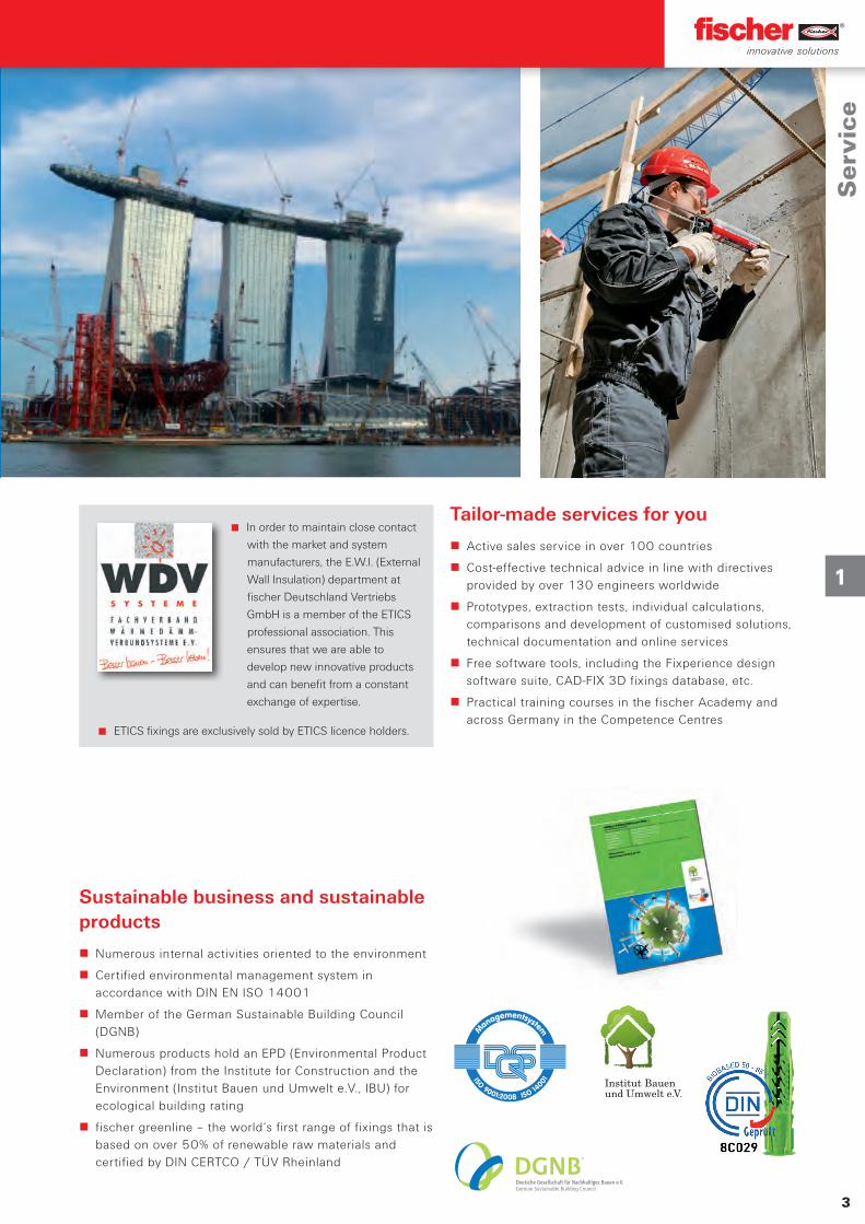
Tailor-made services for you
� Activesalesserviceinover100countries
� Cost-effectivetechnicaladviceinlinewithdirectivesprovidedbyover130engineersworldwide
� Prototypes,extractiontests,individualcalculations,comparisonsanddevelopmentofcustomisedsolutions,technicaldocumentationandonlineservices
� Freesoftwaretools,includingtheFixperiencedesignsoftwaresuite,CAD-FIX3Dfixingsdatabase,etc.
� PracticaltrainingcoursesinthefischerAcademyandacrossGermanyintheCompetenceCentres
Sustainable business and sustainable products
� Numerousinternalactivitiesorientedtotheenvironment
� CertifiedenvironmentalmanagementsysteminaccordancewithDINENISO14001
� MemberoftheGermanSustainableBuildingCouncil(DGNB)
� NumerousproductsholdanEPD(EnvironmentalProductDeclaration)fromtheInstituteforConstructionandtheEnvironment(InstitutBauenundUmwelte.V.,IBU)forecologicalbuildingrating
� fischergreenline–theworld‘sfirstrangeoffixingsthatisbasedonover50%ofrenewablerawmaterialsandcertifiedbyDINCERTCO/TÜVRheinland
Inordertomaintainclosecontactwiththemarketandsystemmanufacturers,theE.W.I.(ExternalWallInsulation)departmentatfischerDeutschlandVertriebsGmbHisamemberoftheETICSprofessionalassociation.Thisensuresthatweareabletodevelopnewinnovativeproductsandcanbenefitfromaconstantexchangeofexpertise.
ETICSfixingsareexclusivelysoldbyETICSlicenceholders.
MD_PG_$KT-WDVS-EWI-$KP-K01-SERVICE_#SEN_#APR_#V1.indd 3MD_PG_$KT-WDVS-EWI-$KP-K01-SERVICE_#SEN_#APR_#V1.indd 3 20.05.2020 09:28:0720.05.2020 09:28:07
Gute Gründe für fischer
4
1
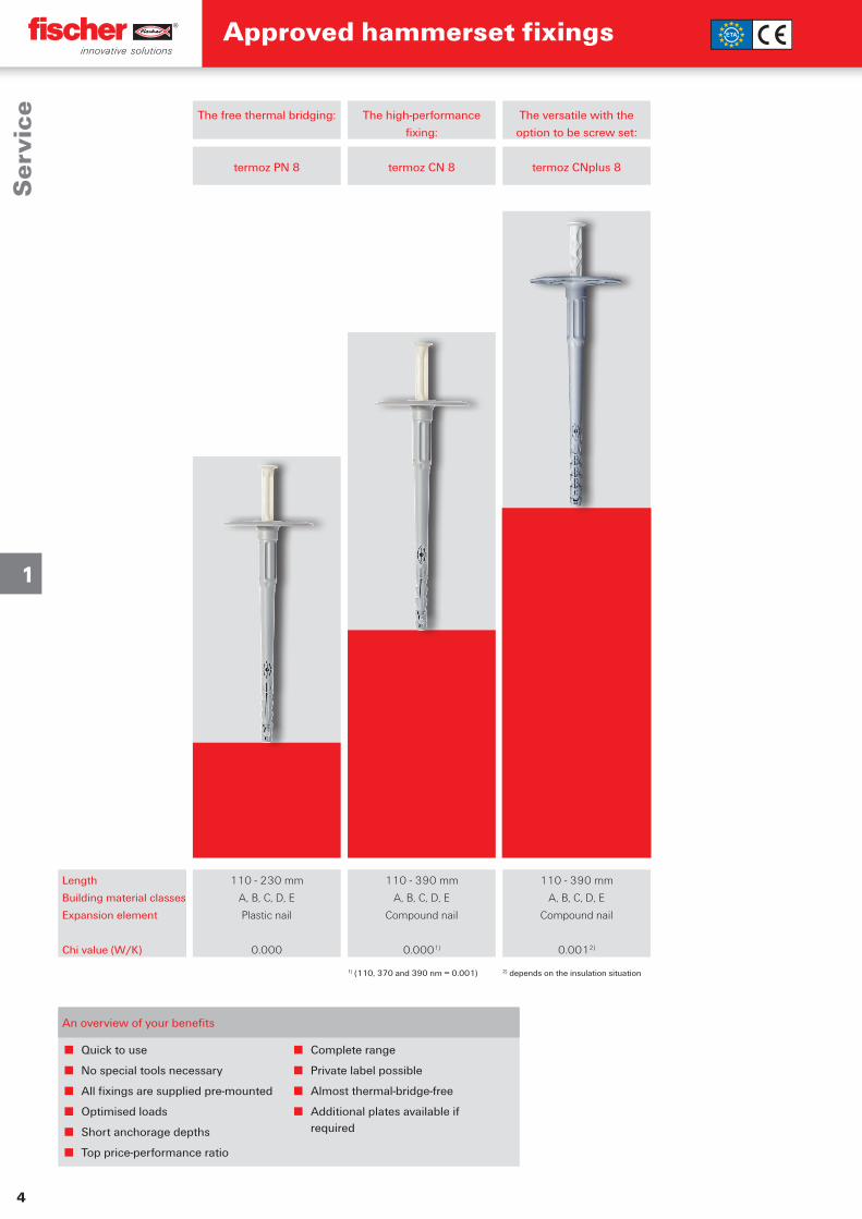
■ Quicktouse
■ Nospecialtoolsnecessary
■ Allfixingsaresuppliedpre-mounted
■ Optimisedloads
■ Shortanchoragedepths
■ Topprice-performanceratio
■ Completerange
■ Privatelabelpossible
■ Almostthermal-bridge-free
■ Additionalplatesavailableifrequired
Length
Buildingmaterialclasses
Expansionelement
Chivalue(W/K)
Thefreethermalbridging:
termozPN8
110-230mm
A,B,C,D,E
Plasticnail
0.000
Thehigh-performancefixing:
termozCN8
110-390mm
A,B,C,D,E
Compoundnail
0.0001)
Theversatilewiththeoptiontobescrewset:
termozCNplus8
110-390mm
A,B,C,D,E
Compoundnail
0.0012)
1)(110,370and390nm=0.001) 2)dependsontheinsulationsituation
Approved hammerset fixingsS
erv
ice
Anoverviewofyourbenefits
MD_PG_$KT-WDVS-EWI-$KP-K01-SERVICE_#SEN_#APR_#V1.indd 4MD_PG_$KT-WDVS-EWI-$KP-K01-SERVICE_#SEN_#APR_#V1.indd 4 20.05.2020 09:28:1620.05.2020 09:28:16
5
1
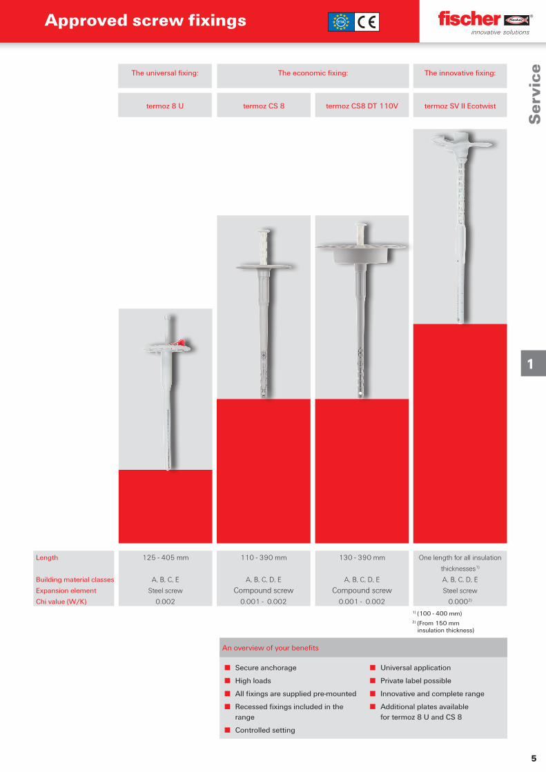
■ Secureanchorage
■ Highloads
■ Allfixingsaresuppliedpre-mounted
■ Recessedfixingsincludedintherange
■ Controlledsetting
■ Universalapplication
■ Privatelabelpossible
■ Innovativeandcompleterange
■ Additionalplatesavailablefortermoz8UandCS8
Approved screw fixings
Anoverviewofyourbenefits
Length
Buildingmaterialclasses
Expansionelement
Chivalue(W/K)
Theeconomicfixing:
termozCS8
Theuniversalfixing:
termoz8U
125-405mm
A,B,C,E
Steelscrew
0.002
termozCS8DT110V
130-390mm
A,B,C,D,E
Compoundscrew0.001-0.002
110-390mm
A,B,C,D,E
Compoundscrew0.001-0.002
Theinnovativefixing:
termozSVIIEcotwist
Onelengthforallinsulation
thicknesses1)
A,B,C,D,E
Steelscrew
0.0002)
Se
rvic
e
1)(100-400mm)2)(From150mm
insulationthickness)
MD_PG_$KT-WDVS-EWI-$KP-K01-SERVICE_#SEN_#APR_#V1.indd 5MD_PG_$KT-WDVS-EWI-$KP-K01-SERVICE_#SEN_#APR_#V1.indd 5 20.05.2020 09:28:2120.05.2020 09:28:21
6
2
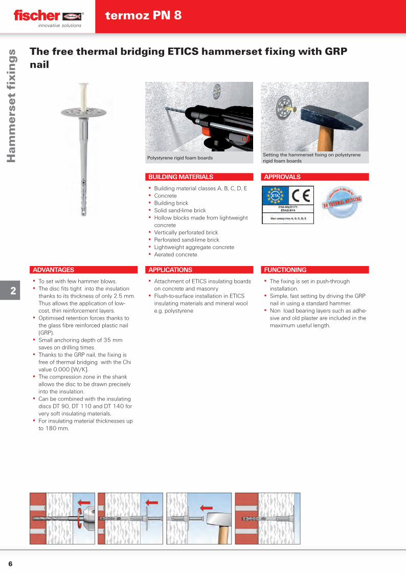
Polystyrene rigid foam boardsSetting the hammerset fi xing on polystyrene rigid foam boards
The free thermal bridging ETICS hammerset fi xing with GRP nail
ADVANTAGES
▪ To set with few hammer blows.▪ The disc fi ts tight into the insulation
thanks to its thickness of only 2.5 mm. Thus allows the application of low-cost, thin reinforcement layers.
▪ Optimised retention forces thanks to the glass fi bre reinforced plastic nail (GRP).
▪ Small anchoring depth of 35 mm saves on drilling times.
▪ Thanks to the GRP nail, the fi xing is free of thermal bridging with the Chi value 0.000 [W/K].
▪ The compression zone in the shank allows the disc to be drawn precisely into the insulation.
▪ Can be combined with the insulating discs DT 90, DT 110 and DT 140 for very soft insulating materials.
▪ For insulating material thicknesses up to 180 mm.
APPLICATIONS
▪ Attachment of ETICS insulating boards on concrete and masonry
▪ Flush-to-surface installation in ETICS insulating materials and mineral wool e.g. polystyrene
FUNCTIONING
▪ The fi xing is set in push-through installation.
▪ Simple, fast setting by driving the GRP nail in using a standard hammer.
▪ Non load bearing layers such as adhe-sive and old plaster are included in the maximum useful length.
BUILDING MATERIALS
▪ Building material classes A, B, C, D, E▪ Concrete▪ Building brick▪ Solid sand-lime brick▪ Hollow blocks made from lightweight
concrete▪ Vertically perforated brick▪ Perforated sand-lime brick▪ Lightweight aggregate concrete▪ Aerated concrete
APPROVALS
Ham
me
rse
t fi
xin
gs
termoz PN 8
7
2
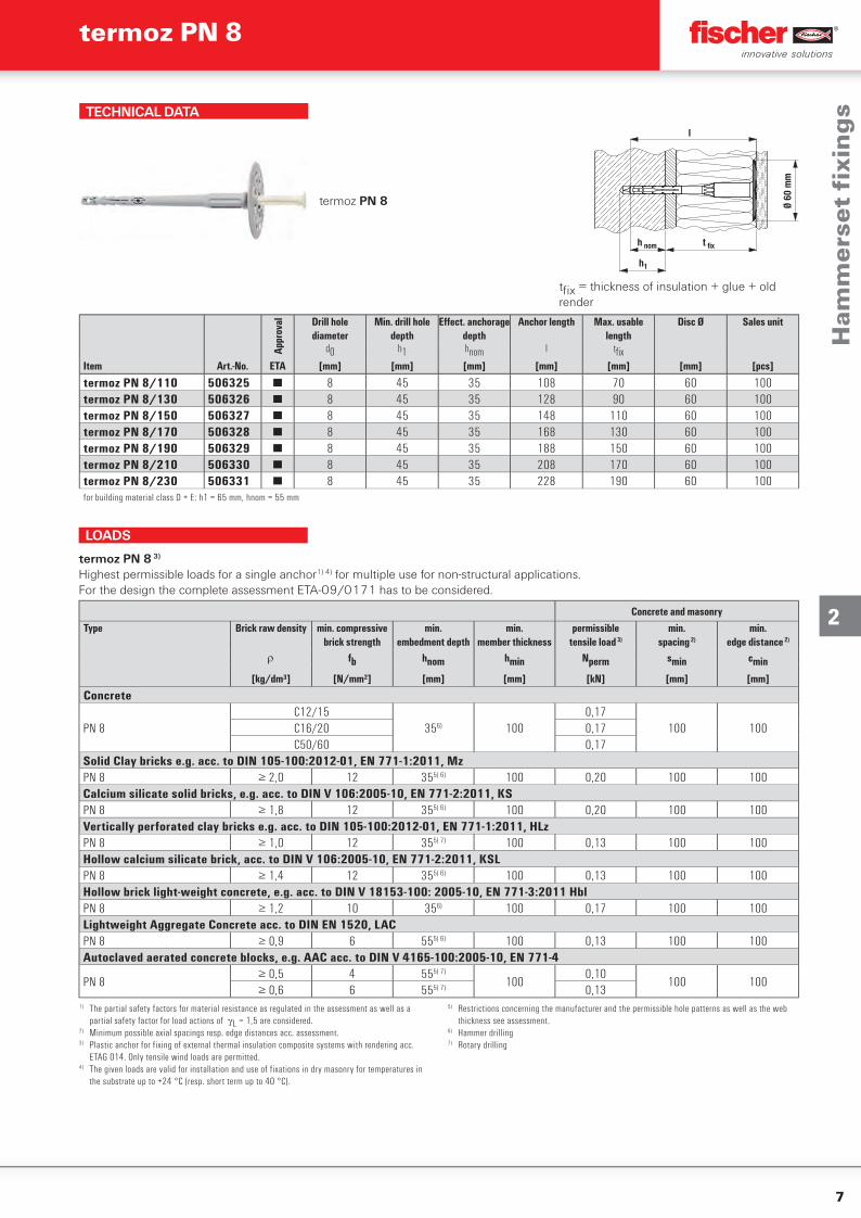
TECHNICAL DATA
termoz PN 8
t fix
h1
Ø 60
mm
h nom
l
tfi x = thickness of insulation + glue + old render
Item
Appr
oval Drill hole
diameterMin. drill hole
depthEff ect. anchorage
depthAnchor length Max. usable
lengthDisc Ø Sales unit
d0 h1 hnom l tfi xArt.-No. ETA [mm] [mm] [mm] [mm] [mm] [mm] [pcs]
termoz PN 8/110 506325 ■ 8 45 35 108 70 60 100termoz PN 8/130 506326 ■ 8 45 35 128 90 60 100termoz PN 8/150 506327 ■ 8 45 35 148 110 60 100termoz PN 8/170 506328 ■ 8 45 35 168 130 60 100termoz PN 8/190 506329 ■ 8 45 35 188 150 60 100termoz PN 8/210 506330 ■ 8 45 35 208 170 60 100termoz PN 8/230 506331 ■ 8 45 35 228 190 60 100for building material class D + E: h1 = 65 mm, hnom = 55 mm
Concrete and masonryType Brick raw density min. compressive
brick strengthmin.
embedment depthmin.
member thicknesspermissible
tensile load 3)
min.spacing 2)
min.edge distance 2)
fb hnom hmin Nperm smin cmin
[kg/dm³] [N/mm²] [mm] [mm] [kN] [mm] [mm]
Concrete
PN 8C12/15
356) 1000,17
100 100C16/20 0,17C50/60 0,17
Solid Clay bricks e.g. acc. to DIN 105-100:2012-01, EN 771-1:2011, MzPN 8 ≥ 2,0 12 355) 6) 100 0,20 100 100Calcium silicate solid bricks, e.g. acc. to DIN V 106:2005-10, EN 771-2:2011, KSPN 8 ≥ 1,8 12 355) 6) 100 0,20 100 100Vertically perforated clay bricks e.g. acc. to DIN 105-100:2012-01, EN 771-1:2011, HLzPN 8 ≥ 1,0 12 355) 7) 100 0,13 100 100Hollow calcium silicate brick, acc. to DIN V 106:2005-10, EN 771-2:2011, KSLPN 8 ≥ 1,4 12 355) 6) 100 0,13 100 100Hollow brick light-weight concrete, e.g. acc. to DIN V 18153-100: 2005-10, EN 771-3:2011 HblPN 8 ≥ 1,2 10 356) 100 0,17 100 100Lightweight Aggregate Concrete acc. to DIN EN 1520, LACPN 8 ≥ 0,9 6 555) 6) 100 0,13 100 100Autoclaved aerated concrete blocks, e.g. AAC acc. to DIN V 4165-100:2005-10, EN 771-4
PN 8≥ 0,5 4 555) 7)
1000,10
100 100≥ 0,6 6 555) 7) 0,13
termoz PN 8 3)
Highest permissible loads for a single anchor1) 4) for multiple use for non-structural applications.For the design the complete assessment ETA-09/0171 has to be considered.
1) The partial safety factors for material resistance as regulated in the assessment as well as a partial safety factor for load actions of L = 1,5 are considered.
2) Minimum possible axial spacings resp. edge distances acc. assessment.3) Plastic anchor for fixing of external thermal insulation composite systems with rendering acc.
ETAG 014. Only tensile wind loads are permitted.4) The given loads are valid for installation and use of fixations in dry masonry for temperatures in
the substrate up to +24 °C (resp. short term up to 40 °C).
5) Restrictions concerning the manufacturer and the permissible hole patterns as well as the web thickness see assessment.
6) Hammer drilling7) Rotary drilling
LOADS
Ham
me
rse
t fi
xin
gs
termoz PN 8
8
2
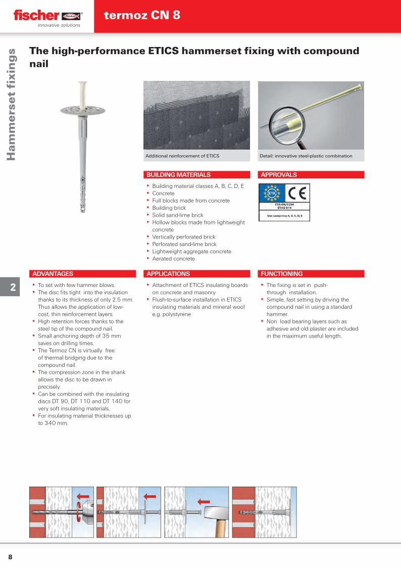
Additional reinforcement of ETICS Detail: innovative steel-plastic combination
The high-performance ETICS hammerset fi xing with compound nail
ADVANTAGES
▪ To set with few hammer blows.▪ The disc fi ts tight into the insulation
thanks to its thickness of only 2.5 mm. Thus allows the application of low-cost, thin reinforcement layers.
▪ High retention forces thanks to the steel tip of the compound nail.
▪ Small anchoring depth of 35 mm saves on drilling times.
▪ The Termoz CN is virtually free of thermal bridging due to the compound nail.
▪ The compression zone in the shank allows the disc to be drawn in precisely.
▪ Can be combined with the insulating discs DT 90, DT 110 and DT 140 for very soft insulating materials.
▪ For insulating material thicknesses up to 340 mm.
APPLICATIONS
▪ Attachment of ETICS insulating boards on concrete and masonry
▪ Flush-to-surface installation in ETICS insulating materials and mineral wool e.g. polystyrene
FUNCTIONING
▪ The fi xing is set in push- through installation.
▪ Simple, fast setting by driving the compound nail in using a standard hammer.
▪ Non load bearing layers such as adhesive and old plaster are included in the maximum useful length.
BUILDING MATERIALS
▪ Building material classes A, B, C, D, E▪ Concrete▪ Full blocks made from concrete▪ Building brick▪ Solid sand-lime brick▪ Hollow blocks made from lightweight
concrete▪ Vertically perforated brick▪ Perforated sand-lime brick▪ Lightweight aggregate concrete▪ Aerated concrete
APPROVALS
Ham
me
rse
t fi
xin
gs
termoz CN 8
9
2
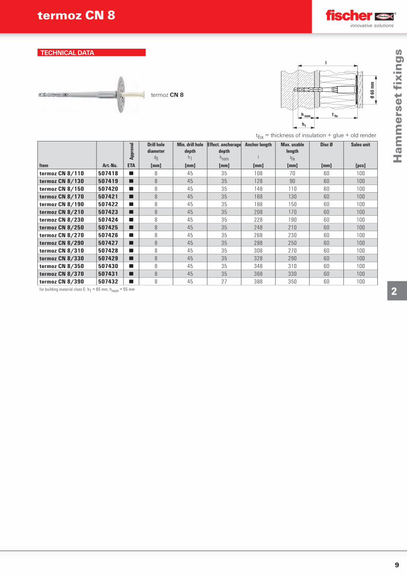
TECHNICAL DATA
termoz CN 8
t fix
h1
Ø 60
mm
h nom
l
tfi x = thickness of insulation + glue + old render
Item
Appr
oval Drill hole
diameterMin. drill hole
depthEff ect. anchorage
depthAnchor length Max. usable
lengthDisc Ø Sales unit
d0 h1 hnom l tfi xArt.-No. ETA [mm] [mm] [mm] [mm] [mm] [mm] [pcs]
termoz CN 8/110 507418 ■ 8 45 35 108 70 60 100termoz CN 8/130 507419 ■ 8 45 35 128 90 60 100termoz CN 8/150 507420 ■ 8 45 35 148 110 60 100termoz CN 8/170 507421 ■ 8 45 35 168 130 60 100termoz CN 8/190 507422 ■ 8 45 35 188 150 60 100termoz CN 8/210 507423 ■ 8 45 35 208 170 60 100termoz CN 8/230 507424 ■ 8 45 35 228 190 60 100termoz CN 8/250 507425 ■ 8 45 35 248 210 60 100termoz CN 8/270 507426 ■ 8 45 35 268 230 60 100termoz CN 8/290 507427 ■ 8 45 35 288 250 60 100termoz CN 8/310 507428 ■ 8 45 35 308 270 60 100termoz CN 8/330 507429 ■ 8 45 35 328 290 60 100termoz CN 8/350 507430 ■ 8 45 35 348 310 60 100termoz CN 8/370 507431 ■ 8 45 35 368 330 60 100termoz CN 8/390 507432 ■ 8 45 27 388 350 60 100for building material class E: h1 = 65 mm, hnom = 55 mm
Ham
me
rse
t fi
xin
gs
termoz CN 8
10
2
LASTEN
1) The partial safety factors for material resistance as regulated in the assessment as well as a partial safety factor for load actions of L = 1,5 are considered.
2) Minimum possible axial spacings resp. edge distances acc. assessment. 3) Plastic anchor for fixing of external thermal insulation composite systems with rendering acc.
ETAG 014. Only tensile wind loads are permitted.
4) The given loads are valid for installation and use of fixations in dry masonry for temperatures in the substrate up to +24 °C (resp. short term up to 40 °C).
5) Restrictions concerning the manufacturer and the permissible hole patterns as well as the web thickness see assessment.
6) Hammer drilling7) Rotary drilling
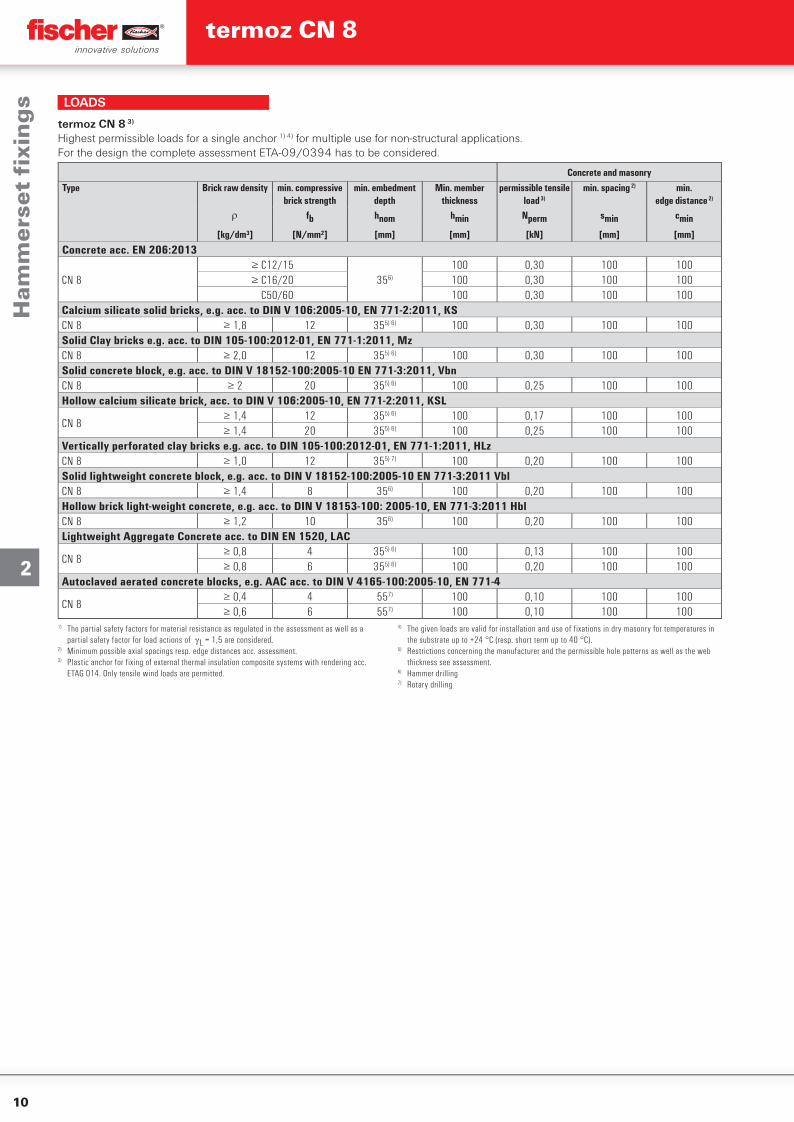
LOADS
Concrete and masonryType Brick raw density min. compressive
brick strengthmin. embedment
depthMin. member
thicknesspermissible tensile
load 3)
min. spacing 2) min.edge distance 2)
fb hnom hmin Nperm smin cmin
[kg/dm³] [N/mm²] [mm] [mm] [kN] [mm] [mm]
Concrete acc. EN 206:2013
CN 8≥ C12/15
356)
100 0,30 100 100≥ C16/20 100 0,30 100 100≤ C50/60 100 0,30 100 100
Calcium silicate solid bricks, e.g. acc. to DIN V 106:2005-10, EN 771-2:2011, KS CN 8 ≥ 1,8 12 355) 6) 100 0,30 100 100Solid Clay bricks e.g. acc. to DIN 105-100:2012-01, EN 771-1:2011, Mz CN 8 ≥ 2,0 12 355) 6) 100 0,30 100 100Solid concrete block, e.g. acc. to DIN V 18152-100:2005-10 EN 771-3:2011, Vbn CN 8 ≥ 2 20 355) 6) 100 0,25 100 100Hollow calcium silicate brick, acc. to DIN V 106:2005-10, EN 771-2:2011, KSL
CN 8≥ 1,4 12 355) 6) 100 0,17 100 100≥ 1,4 20 355) 6) 100 0,25 100 100
Vertically perforated clay bricks e.g. acc. to DIN 105-100:2012-01, EN 771-1:2011, HLz CN 8 ≥ 1,0 12 355) 7) 100 0,20 100 100Solid lightweight concrete block, e.g. acc. to DIN V 18152-100:2005-10 EN 771-3:2011 Vbl CN 8 ≥ 1,4 8 356) 100 0,20 100 100Hollow brick light-weight concrete, e.g. acc. to DIN V 18153-100: 2005-10, EN 771-3:2011 Hbl CN 8 ≥ 1,2 10 356) 100 0,20 100 100Lightweight Aggregate Concrete acc. to DIN EN 1520, LAC
CN 8≥ 0,8 4 355) 6) 100 0,13 100 100≥ 0,8 6 355) 6) 100 0,20 100 100
Autoclaved aerated concrete blocks, e.g. AAC acc. to DIN V 4165-100:2005-10, EN 771-4
CN 8≥ 0,4 4 557) 100 0,10 100 100≥ 0,6 6 557) 100 0,10 100 100
termoz CN 8 3)
Highest permissible loads for a single anchor 1) 4) for multiple use for non-structural applications.For the design the complete assessment ETA-09/0394 has to be considered.
Ham
me
rse
t fi
xin
gs
termoz CN 8
11
2
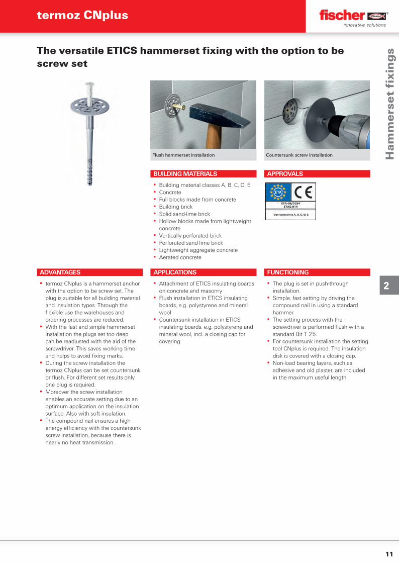
Flush hammerset installation Countersunk screw installation
The versatile ETICS hammerset fi xing with the option to be screw set
ADVANTAGES
▪ termoz CNplus is a hammerset anchor with the option to be screw set. The plug is suitable for all building material and insulation types. Through the fl exible use the warehouses and ordering processes are reduced.
▪ With the fast and simple hammerset installation the plugs set too deep can be readjusted with the aid of the screwdriver. This saves working time and helps to avoid fi xing marks.
▪ During the screw installation the termoz CNplus can be set countersunk or fl ush. For diff erent set results only one plug is required.
▪ Moreover the screw installation enables an accurate setting due to an optimum application on the insulation surface. Also with soft insulation.
▪ The compound nail ensures a high energy effi ciency with the countersunk screw installation, because there is nearly no heat transmission.
APPLICATIONS
▪ Attachment of ETICS insulating boards on concrete and masonry
▪ Flush installation in ETICS insulating boards, e.g. polystyrene and mineral wool
▪ Countersunk installation in ETICS insulating boards, e.g. polystyrene and mineral wool, incl. a closing cap for covering
FUNCTIONING
▪ The plug is set in push-through installation.
▪ Simple, fast setting by driving the compound nail in using a standard hammer.
▪ The setting process with the screwdriver is performed fl ush with a standard Bit T 25.
▪ For countersunk installation the setting tool CNplus is required. The insulation disk is covered with a closing cap.
▪ Non-load bearing layers, such as adhesive and old plaster, are included in the maximum useful length.
BUILDING MATERIALS
▪ Building material classes A, B, C, D, E▪ Concrete▪ Full blocks made from concrete▪ Building brick▪ Solid sand-lime brick▪ Hollow blocks made from lightweight
concrete▪ Vertically perforated brick▪ Perforated sand-lime brick▪ Lightweight aggregate concrete▪ Aerated concrete
APPROVALS
Ham
me
rse
t fi
xin
gs
termoz CNplus
12
2
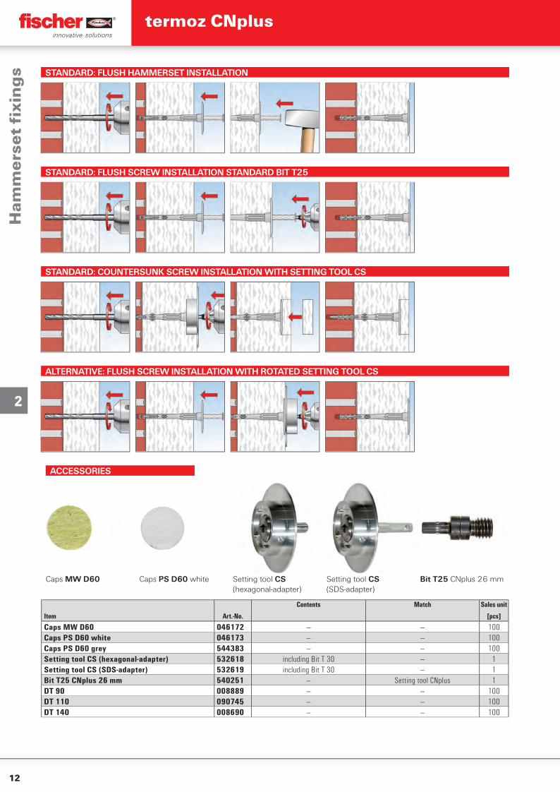
STANDARD: FLUSH HAMMERSET INSTALLATION
STANDARD: FLUSH SCREW INSTALLATION STANDARD BIT T25
STANDARD: COUNTERSUNK SCREW INSTALLATION WITH SETTING TOOL CS
ALTERNATIVE: FLUSH SCREW INSTALLATION WITH ROTATED SETTING TOOL CS
ACCESSORIES
Caps MW D60 Caps PS D60 white Setting tool CS(hexagonal-adapter)
Setting tool CS(SDS-adapter)
Bit T25 CNplus 26 mm
Contents Match Sales unit
Item Art.-No. [pcs]
Caps MW D60 046172 — — 100Caps PS D60 white 046173 — — 100Caps PS D60 grey 544383 — — 100Setting tool CS (hexagonal-adapter) 532618 including Bit T 30 — 1Setting tool CS (SDS-adapter) 532619 including Bit T 30 — 1Bit T25 CNplus 26 mm 540251 — Setting tool CNplus 1DT 90 008889 — — 100DT 110 090745 — — 100DT 140 008690 — — 100
Ham
me
rse
t fi
xin
gs
termoz CNplus
13
2
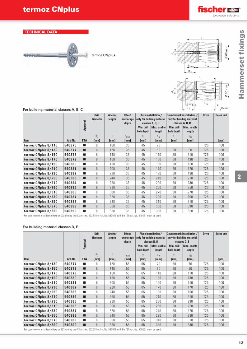
TECHNICAL DATA
termoz CNplus
t fix
h 1
Ø 6
0 m
m
h nom
l
d o
For building material classes A, B, C
Ø 6
0 m
m
t fix
h 1
h nom
l
d o
15 mm
Appr
oval
Drilldiameter
Anchor length
Eff ect. anchorage
depth
Flush installation /only for building material
classes A, B, C
Countersunk installation / only for building material
classes A, B, C
Drive Sales unit
Min. drill hole depth
Max. usable length
Min. drill hole depth
Max. usable length
d0 l hnom h1 tfi x h1 tfi xItem Art.-No. ETA [mm] [mm] [mm] [mm] [mm] [mm] [mm] [pcs]
termoz CNplus 8/110 540376 ■ 8 108 35 45 70 T25 100termoz CNplus 8/130 540377 ■ 8 128 35 45 90 60 90 T25 100termoz CNplus 8/150 540378 ■ 8 148 35 45 110 60 110 T25 100termoz CNplus 8/170 540379 ■ 8 168 35 45 130 60 130 T25 100termoz CNplus 8/190 540380 ■ 8 188 35 45 150 60 150 T25 100termoz CNplus 8/210 540381 ■ 8 208 35 45 170 60 170 T25 100termoz CNplus 8/230 540382 ■ 8 228 35 45 190 60 190 T25 100termoz CNplus 8/250 540383 ■ 8 248 35 45 210 60 210 T25 100termoz CNplus 8/270 540384 ■ 8 268 35 45 230 60 230 T25 100termoz CNplus 8/290 540385 ■ 8 288 35 45 250 60 250 T25 100termoz CNplus 8/310 540386 ■ 8 308 35 45 270 60 270 T25 100termoz CNplus 8/330 540387 ■ 8 328 35 45 290 60 290 T25 100termoz CNplus 8/350 540388 ■ 8 348 35 45 310 60 310 T25 100termoz CNplus 8/370 540389 ■ 8 368 35 45 330 60 330 T25 100termoz CNplus 8/390 540390 ■ 8 388 35 45 350 60 350 T25 100For countersunk installation Hexa or SDS setting tool CS Art.-No. 532618 or Art.-No. 532619 with Bit T25 Art.-No. 540251 must be used.
For building material classes D, E0
Appr
oval
Drilldiameter
Anchor length
Eff ect. anchorage
depth
Flush installation /only for building material
classes D, E
Countersunk installation /only for building material
classes D, E
Drive Sales unit
Min. drill hole depth
Max. usable length
Min. drill hole depth
Max. usable length
d0 l hnom h1 tfi x h1 tfi xItem Art.-No. ETA [mm] [mm] [mm] [mm] [mm] [mm] [mm] [pcs]
termoz CNplus 8/130 540377 ■ 8 128 55 65 70 80 70 T25 100termoz CNplus 8/150 540378 ■ 8 148 55 65 90 80 90 T25 100termoz CNplus 8/170 540379 ■ 8 168 55 65 110 80 110 T25 100termoz CNplus 8/190 540380 ■ 8 188 55 65 130 80 130 T25 100termoz CNplus 8/210 540381 ■ 8 208 55 65 150 80 150 T25 100termoz CNplus 8/230 540382 ■ 8 228 55 65 170 80 170 T25 100termoz CNplus 8/250 540383 ■ 8 248 55 65 190 80 190 T25 100termoz CNplus 8/270 540384 ■ 8 268 55 65 210 80 210 T25 100termoz CNplus 8/290 540385 ■ 8 288 55 65 230 80 230 T25 100termoz CNplus 8/310 540386 ■ 8 308 55 65 250 80 250 T25 100termoz CNplus 8/330 540387 ■ 8 328 55 65 270 80 270 T25 100termoz CNplus 8/350 540388 ■ 8 348 55 65 290 80 290 T25 100termoz CNplus 8/370 540389 ■ 8 368 55 65 310 80 310 T25 100termoz CNplus 8/390 540390 ■ 8 388 55 65 330 80 330 T25 100For countersunk installation Hexa or SDS setting tool CS Art.-No. 532618 or Art.-No. 532619 with Bit T25 Art.-No. 540251 must be used.
Ham
me
rse
t fi
xin
gs
termoz CNplus
14
2
LOADS
1) The partial safety factors for material resistance as regulated in the assessment as well as a partial safety factor for load actions of F = 1,5 are considered.
2) Minimum possible axial spacings resp. edge distances acc. assessment. 3) Plastic anchor for fixing of external thermal insulation composite systems with rendering acc.
ETAG 014. Only tensile wind loads are permitted.
4) The given loads are valid for installation and use of fixations in dry masonry for temperatures in the substrate up to +24 °C (resp. short term up to 40 °C).
5) Restrictions concerning the manufacturer and the permissible hole patterns as well as the web thickness see assessment.
6) Hammer drilling7) Rotary drilling
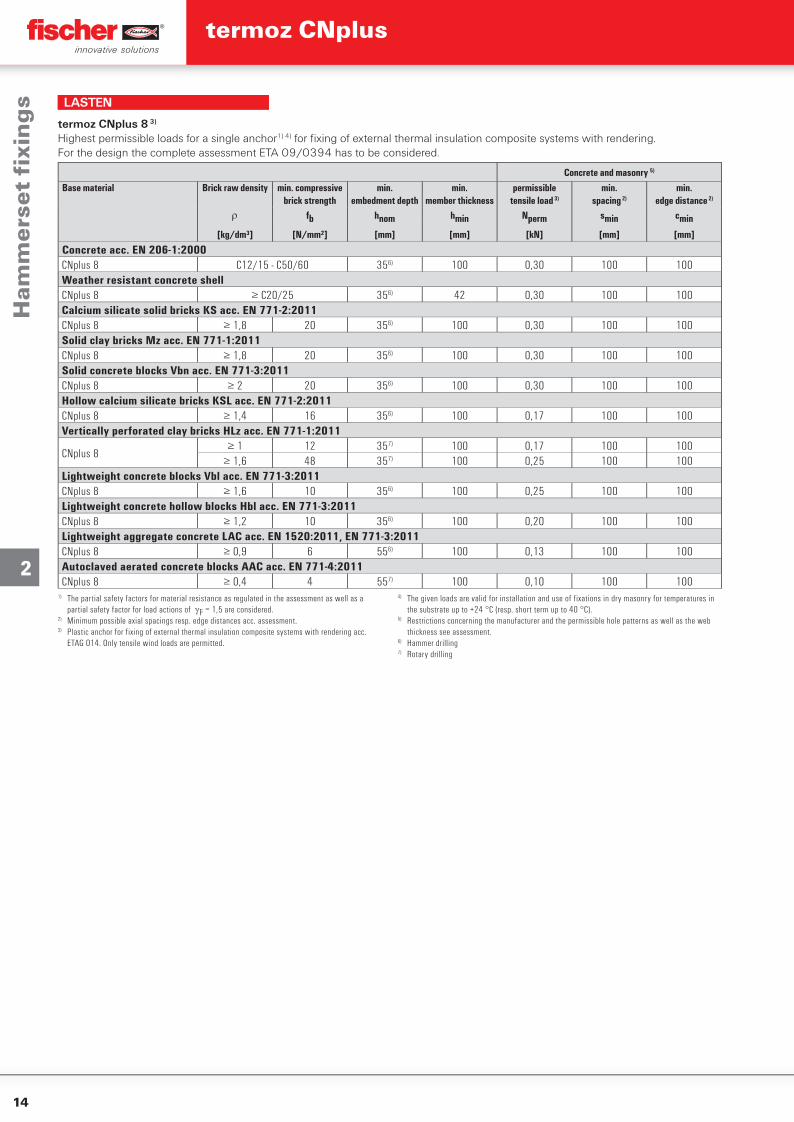
LASTEN
Concrete and masonry 5)
Base material Brick raw density min. compressive brick strength
min.embedment depth
min.member thickness
permissibletensile load 3)
min.spacing 2)
min.edge distance 2)
fb hnom hmin Nperm smin cmin
[kg/dm³] [N/mm²] [mm] [mm] [kN] [mm] [mm]
Concrete acc. EN 206-1:2000CNplus 8 C12/15 - C50/60 356) 100 0,30 100 100Weather resistant concrete shellCNplus 8 ≥ C20/25 356) 42 0,30 100 100Calcium silicate solid bricks KS acc. EN 771-2:2011CNplus 8 ≥ 1,8 20 356) 100 0,30 100 100Solid clay bricks Mz acc. EN 771-1:2011CNplus 8 ≥ 1,8 20 356) 100 0,30 100 100Solid concrete blocks Vbn acc. EN 771-3:2011CNplus 8 ≥ 2 20 356) 100 0,30 100 100Hollow calcium silicate bricks KSL acc. EN 771-2:2011CNplus 8 ≥ 1,4 16 356) 100 0,17 100 100Vertically perforated clay bricks HLz acc. EN 771-1:2011
CNplus 8≥ 1 12 357) 100 0,17 100 100
≥ 1,6 48 357) 100 0,25 100 100Lightweight concrete blocks Vbl acc. EN 771-3:2011CNplus 8 ≥ 1,6 10 356) 100 0,25 100 100Lightweight concrete hollow blocks Hbl acc. EN 771-3:2011CNplus 8 ≥ 1,2 10 356) 100 0,20 100 100Lightweight aggregate concrete LAC acc. EN 1520:2011, EN 771-3:2011CNplus 8 ≥ 0,9 6 556) 100 0,13 100 100Autoclaved aerated concrete blocks AAC acc. EN 771-4:2011CNplus 8 ≥ 0,4 4 557) 100 0,10 100 100
termoz CNplus 8 3)
Highest permissible loads for a single anchor1) 4) for fi xing of external thermal insulation composite systems with rendering.For the design the complete assessment ETA 09/0394 has to be considered.
Ham
me
rse
t fi
xin
gs
termoz CNplus

15
3
Polystyrene rigid foam boards O35 on perforated sand-lime brick
Additional reinforcement of ETICS
The universal ETICS screw fi xing with Delta-Seal coated steel screw
ADVANTAGES
▪ High retention forces thanks to the screwing process and embedment depth of 70 mm.
▪ High level of corrosion protection of the screw thanks to Delta-Seal coating.
▪ An air gap is produced above the screw head due to the sealing ball. This reduces heat transmission losses.
▪ The fl exible head compensates for any heat-related tension and prevents damage.
▪ Can be combined with the insulating discs DT 90, DT 110 and DT 140 for very soft insulating materials.
▪ For insulating material thicknesses up to 320 mm.
APPLICATIONS
▪ Attachment of ETICS insulating boards on concrete and masonry
▪ Flush-to-surface installation in ETICS insulating materials and mineral wool e.g. polystyrene
FUNCTIONING
▪ The fi xing is set in push-through installation.
▪ The setting tool Termoz SWZ TX 30 is required for installation.
▪ Simple, fast setting by screwing the Delta-Seal coated screw in using a standard screwdriver.
▪ Non-load-bearing layers such as adhesive and old plaster are included in the maximum useful length.
BUILDING MATERIALS
▪ Building material classes A, B, C, E▪ Concrete▪ Building brick▪ Solid sand-lime brick▪ Hollow blocks made from lightweight
concrete▪ Vertically perforated brick▪ Perforated sand-lime brick▪ Solid blocks made from lightweight
concrete▪ Aerated concrete
APPROVALS
Scr
ew fi
xin
gs
termoz 8 U

16
3
TECHNICAL DATA
termoz 8U - Pre-assembled with screw T30
h nom
h 1
tfi x = thickness of insulation + glue + old render
Item
Appr
oval Drill hole dia-
meterMin. drill hole
depthEff ect. ancho-
rage depthAnchor length Max. usable
lengthDisc Ø Drive Sales unit
d0 h1 hnom l tfi xArt.-No. ETA [mm] [mm] [mm] [mm] [mm] [mm] [pcs]
termoz 8U/125 003826 ■ 8 85 70 125 55 60 T30 100termoz 8U/145 003827 ■ 8 85 70 145 75 60 T30 100termoz 8U/165 003828 ■ 8 85 70 165 95 60 T30 100termoz 8U/185 003829 ■ 8 85 70 185 115 60 T30 100termoz 8U/205 003830 ■ 8 85 70 205 135 60 T30 100termoz 8U/225 003831 ■ 8 85 70 225 155 60 T30 100termoz 8U/245 003832 ■ 8 85 70 245 175 60 T30 100termoz 8U/265 003833 ■ 8 85 70 265 195 60 T30 100termoz 8U/285 003834 ■ 8 85 70 285 215 60 T30 100termoz 8U/305 003835 ■ 8 85 70 305 235 60 T30 100termoz 8U/325 501447 ■ 8 85 70 325 255 60 T30 100termoz 8U/345 501450 ■ 8 85 70 345 275 60 T30 100termoz 8U/365 501451 ■ 8 85 70 365 295 60 T30 100termoz 8U/385 501452 ■ 8 85 70 385 315 60 T30 100termoz 8U/405 501453 ■ 8 85 70 405 335 60 T30 100
ACCESSORIES
termoz - setting tool
Seat Matching anchor type Sales unitItem Art.-No. [pcs]
SWZ-TX30 008698 T30 termoz 8 U 1
Scr
ew fi
xin
gs
termoz 8 U
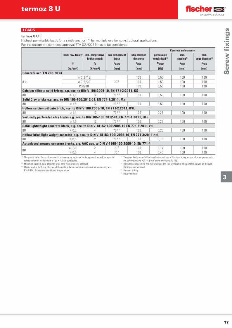
17
3
Concrete and masonryBrick raw density min. compressive
brick strengthmin. embedment
depthMin. member
thicknesspermissible
tensile load 3)
min.spacing 2)
min.edge distance 2)
fb hnom hmin Nperm smin cmin
[kg/dm³] [N/mm²] [mm] [mm] [kN] [mm] [mm]
Concrete acc. EN 206:2013
8 U≥ C12/15
70 6)
100 0,50 100 100≥ C16/20 100 0,50 100 100
C50/60 100 0,50 100 100Calcium silicate solid bricks, e.g. acc. to DIN V 106:2005-10, EN 771-2:2011, KS8U ≥ 1,6 12 70 5) 6) 100 0,50 100 100Solid Clay bricks e.g. acc. to DIN 105-100:2012-01, EN 771-1:2011, Mz8U ≥ 1,6 12 70 5) 6) 100 0,50 100 100Hollow calcium silicate brick, acc. to DIN V 106:2005-10, EN 771-2:2011, KSL8U ≥ 1,4 12 70 5) 6) 100 0,25 100 100Vertically perforated clay bricks e.g. acc. to DIN 105-100:2012-01, EN 771-1:2011, HLz8U ≥ 1,2 12 70 5) 7) 100 0,25 100 100Solid lightweight concrete block, e.g. acc. to DIN V 18152-100:2005-10 EN 771-3:2011 Vbl8U ≥ 0,5 4 70 5) 7) 100 0,20 100 100Hollow brick light-weight concrete, e.g. acc. to DIN V 18153-100: 2005-10, EN 771-3:2011 Hbl8U ≥ 0,5 2 70 5) 7) 100 0,13 100 100Autoclaved aerated concrete blocks, e.g. AAC acc. to DIN V 4165-100:2005-10, EN 771-4
8U≥ 0,35 2 70 7) 100 0,17 100 100≥ 0,5 4 70 7) 100 0,40 100 100
termoz 8 U 3)
Highest permissible loads for a single anchor1) 4) for multiple use for non-structural applications.For the design the complete approval ETA-02/0019 has to be considered.
1) The partial safety factors for material resistance as regulated in the approval as well as a partial safety factor for load actions of F = 1,5 are considered.
2) Minimum possible axial spacings resp. edge distances acc. approval.3) Plastic anchor for fixing of external thermal insulation composite systems with rendering acc.
ETAG 014. Only tensile wind loads are permitted.
4) The given loads are valid for installation and use of fixations in dry masonry for temperatures in the substrate up to +24 °C (resp. short term up to 40 °C).
5) Restrictions concerning the manufacturer and the permissible hole patterns as well as the web thickness see approval.
6) Hammer drilling7) Rotary drilling
LOADS
Scr
ew fi
xin
gs
termoz 8 U
18
3
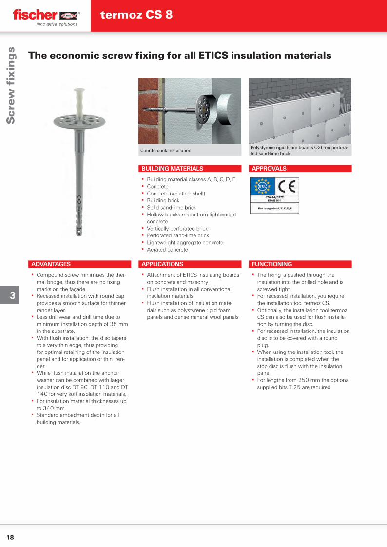
Countersunk installationPolystyrene rigid foam boards O35 on perfora-ted sand-lime brick
The economic screw fi xing for all ETICS insulation materials
ADVANTAGES
▪ Compound screw minimises the ther-mal bridge, thus there are no fi xing marks on the façade.
▪ Recessed installation with round cap provides a smooth surface for thinner render layer.
▪ Less drill wear and drill time due to minimum installation depth of 35 mm in the substrate.
▪ With fl ush installation, the disc tapers to a very thin edge, thus providing for optimal retaining of the insulation panel and for application of thin ren-der.
▪ While fl ush installation the anchor washer can be combined with larger insulation disc DT 90, DT 110 and DT 140 for very soft insolation materials.
▪ For insulation material thicknesses up to 340 mm.
▪ Standard embedment depth for all building materials.
APPLICATIONS
▪ Attachment of ETICS insulating boards on concrete and masonry
▪ Flush installation in all conventional insulation materials
▪ Flush installation of insulation mate-rials such as polystyrene rigid foam panels and dense mineral wool panels
FUNCTIONING
▪ The fi xing is pushed through the insulation into the drilled hole and is screwed tight.
▪ For recessed installation, you require the installation tool termoz CS.
▪ Optionally, the installation tool termoz CS can also be used for fl ush installa-tion by turning the disc.
▪ For recessed installation, the insulation disc is to be covered with a round plug.
▪ When using the installation tool, the installation is completed when the stop disc is fl ush with the insulation panel.
▪ For lengths from 250 mm the optional supplied bits T 25 are required.
BUILDING MATERIALS
▪ Building material classes A, B, C, D, E▪ Concrete▪ Concrete (weather shell)▪ Building brick▪ Solid sand-lime brick▪ Hollow blocks made from lightweight
concrete▪ Vertically perforated brick▪ Perforated sand-lime brick▪ Lightweight aggregate concrete▪ Aerated concrete
APPROVALS
Scr
ew fi
xin
gs
termoz CS 8
19
3
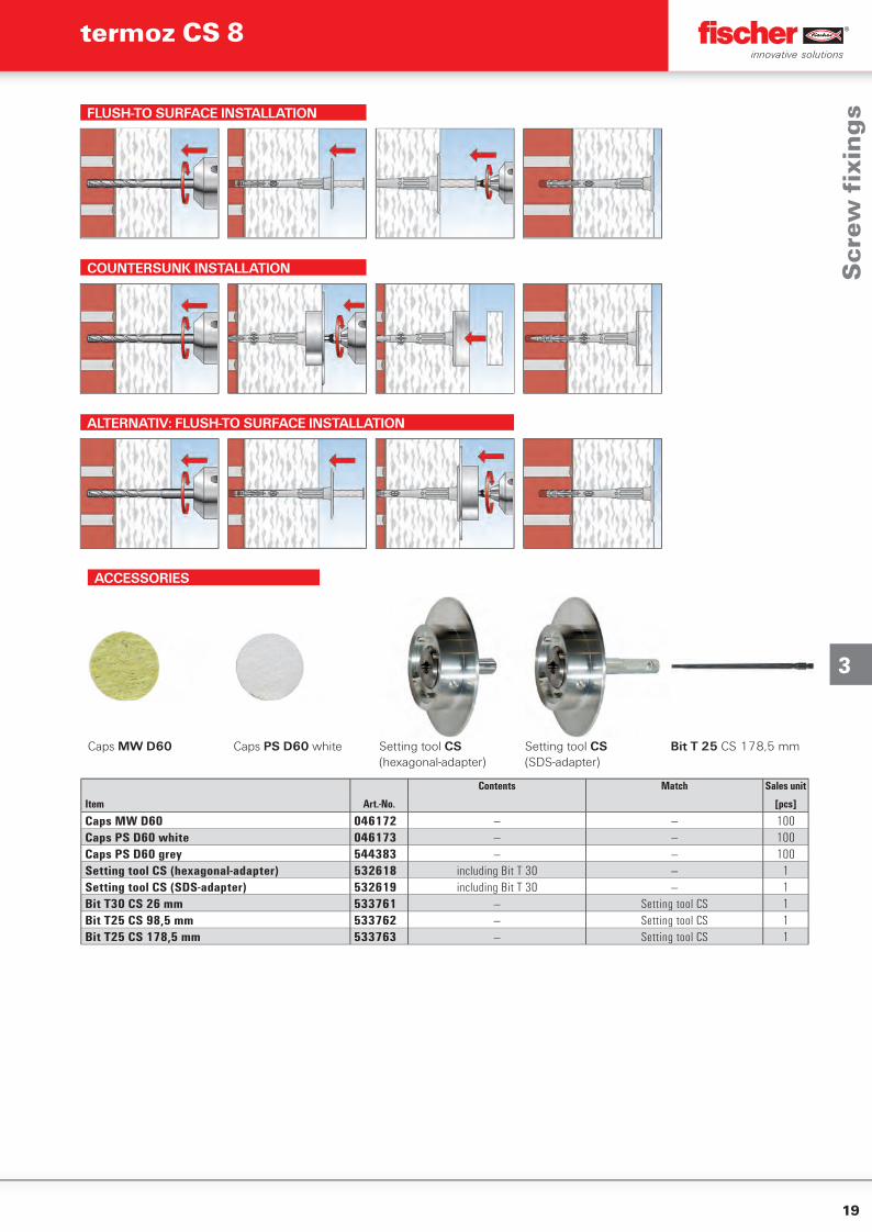
FLUSH-TO SURFACE INSTALLATION
COUNTERSUNK INSTALLATION
ALTERNATIV: FLUSH-TO SURFACE INSTALLATION
ACCESSORIES
Caps MW D60 Caps PS D60 white Setting tool CS(hexagonal-adapter)
Setting tool CS(SDS-adapter)
Bit T 25 CS 178,5 mm
Contents Match Sales unit
Item Art.-No. [pcs]
Caps MW D60 046172 — — 100Caps PS D60 white 046173 — — 100Caps PS D60 grey 544383 — — 100Setting tool CS (hexagonal-adapter) 532618 including Bit T 30 — 1Setting tool CS (SDS-adapter) 532619 including Bit T 30 — 1Bit T30 CS 26 mm 533761 — Setting tool CS 1Bit T25 CS 98,5 mm 533762 — Setting tool CS 1Bit T25 CS 178,5 mm 533763 — Setting tool CS 1
Scr
ew fi
xin
gs
termoz CS 8
20
3
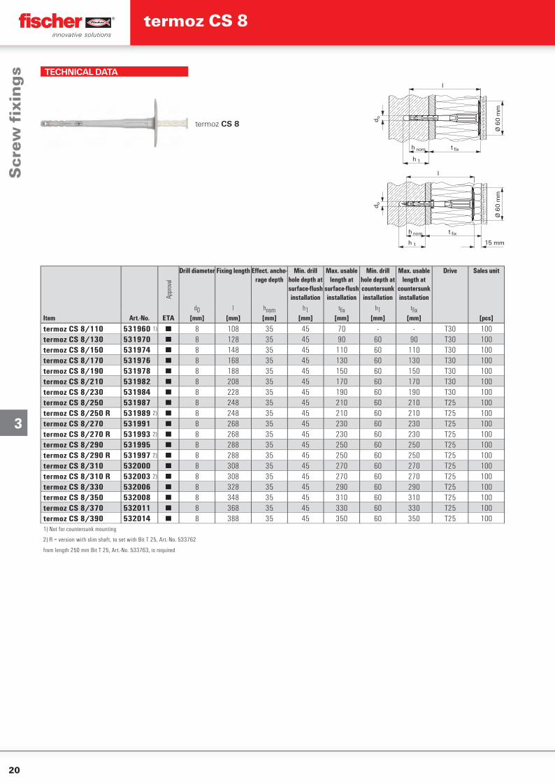
TECHNICAL DATA
termoz CS 8
t fix
h 1
Ø 6
0 m
m
h nom
l
d o
Ø 6
0 m
m
t fix
h 1
h nom
l
d o
15 mm
Appr
oval
Drill diameter Fixing length Eff ect. ancho-rage depth
Min. drill hole depth at surface-fl ush installation
Max. usable length at
surface-fl ush installation
Min. drill hole depth at countersunk installation
Max. usable length at
countersunk installation
Drive Sales unit
d0 l hnom h1 tfi x h1 tfi xItem Art.-No. ETA [mm] [mm] [mm] [mm] [mm] [mm] [mm] [pcs]
termoz CS 8/110 531960 1) ■ 8 108 35 45 70 - - T30 100termoz CS 8/130 531970 ■ 8 128 35 45 90 60 90 T30 100termoz CS 8/150 531974 ■ 8 148 35 45 110 60 110 T30 100termoz CS 8/170 531976 ■ 8 168 35 45 130 60 130 T30 100termoz CS 8/190 531978 ■ 8 188 35 45 150 60 150 T30 100termoz CS 8/210 531982 ■ 8 208 35 45 170 60 170 T30 100termoz CS 8/230 531984 ■ 8 228 35 45 190 60 190 T30 100termoz CS 8/250 531987 ■ 8 248 35 45 210 60 210 T25 100termoz CS 8/250 R 531989 2) ■ 8 248 35 45 210 60 210 T25 100termoz CS 8/270 531991 ■ 8 268 35 45 230 60 230 T25 100termoz CS 8/270 R 531993 2) ■ 8 268 35 45 230 60 230 T25 100termoz CS 8/290 531995 ■ 8 288 35 45 250 60 250 T25 100termoz CS 8/290 R 531997 2) ■ 8 288 35 45 250 60 250 T25 100termoz CS 8/310 532000 ■ 8 308 35 45 270 60 270 T25 100termoz CS 8/310 R 532003 2) ■ 8 308 35 45 270 60 270 T25 100termoz CS 8/330 532006 ■ 8 328 35 45 290 60 290 T25 100termoz CS 8/350 532008 ■ 8 348 35 45 310 60 310 T25 100termoz CS 8/370 532011 ■ 8 368 35 45 330 60 330 T25 100termoz CS 8/390 532014 ■ 8 388 35 45 350 60 350 T25 1001) Not for countersunk mounting
2) R = version with slim shaft, to set with Bit T 25, Art.-No. 533762
from length 250 mm Bit T 25, Art.-No. 533763, is required
Scr
ew fi
xin
gs
termoz CS 8
21
3
Concrete and masonryType Brick raw density min. compressive
brick strengthmin.
embedment depthmin.
member thicknesspermissible
tensile load 3)
min.spacing 2)
min.edge distance 2)
fb hnom hmin Nperm smin cmin
[kg/dm³] [N/mm²] [mm] [mm] [kN] [mm] [mm]
Concrete
CS 8C12/15 - C45/55
356) 1000,40
100 100C50/60 0,50
Weather shell
CS 8C20/25 - C45/55
356) 5) 420,40
100 100C50/60 0,50
Solid Clay bricks e.g. acc. to DIN 105-100:2012-01, EN 771-1:2011, MzCS 8 ≥ 1,8 20 356) 100 0,50 100 100Calcium silicate solid bricks, e.g. acc. to DIN V 106:2005-10, EN 771-2:2011, KS
CS 8 ≥ 1,820
356) 1000,50
100 10012 0,30
Solid lightweight concrete block, e.g. acc. to DIN V 18152-100:2005-10 EN 771-3:2011 VblCS 8 ≥ 1,4 8 356) 100 0,17 100 100Solid concrete block, e.g. acc. to DIN V 18152-100:2005-10 EN 771-3:2011, Vbn
CS 8 ≥ 2,020
356) 1000,40
100 10012 0,25
Vertically perforated clay bricks e.g. acc. to DIN 105-100:2012-01, EN 771-1:2011, HLz
CS 8≥ 1,0 12
357) 8) 1000,20
100 100≥ 1,6 48 0,50
Hollow calcium silicate brick, acc. to DIN V 106:2005-10, EN 771-2:2011, KSL
CS 8 ≥ 1,420
357) 8) 1000,30
100 10012 0,17
Hollow brick light-weight concrete, e.g. acc. to DIN V 18153-100: 2005-10, EN 771-3:2011 HblCS 8 ≥ 0,9 4 356) 8) 100 0,17 100 100Hollow brick concrete, e.g. acc. to DIN V 18153-100: 2005-10, EN 771-3:2011 Hbn
CS 8 ≥ 1,2
10
356) 8) 100
0,40
100 1008 0,306 0,254 0,17
Lightweight Aggregate Concrete acc. to DIN EN 1520, LACCS 8 ≥ 0,9 6 356) 100 0,25 100 100Autoclaved aerated concrete blocks, e.g. AAC acc. to DIN V 4165-100:2005-10, EN 771-4
CS 8 ≥ 0,54 357)
1000,10
100 1004 557) 0,20
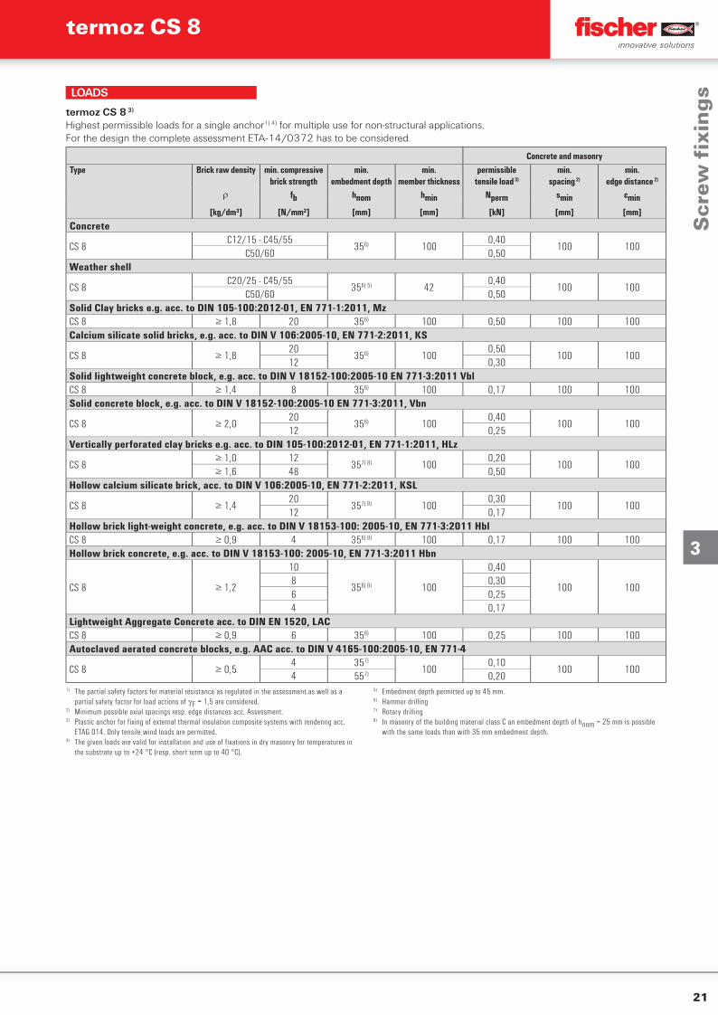
termoz CS 8 3)
Highest permissible loads for a single anchor1) 4) for multiple use for non-structural applications.For the design the complete assessment ETA-14/0372 has to be considered.
1) The partial safety factors for material resistance as regulated in the assessment as well as a partial safety factor for load actions of F = 1,5 are considered.
2) Minimum possible axial spacings resp. edge distances acc. Assessment.3) Plastic anchor for fixing of external thermal insulation composite systems with rendering acc.
ETAG 014. Only tensile wind loads are permitted.4) The given loads are valid for installation and use of fixations in dry masonry for temperatures in
the substrate up to +24 °C (resp. short term up to 40 °C).
5) Embedment depth permitted up to 45 mm.6) Hammer drilling7) Rotary drilling8) In masonry of the building material class C an embedment depth of hnom = 25 mm is possible
with the same loads than with 35 mm embedment depth.
LOADS
Scr
ew fi
xin
gs
termoz CS 8
22
3
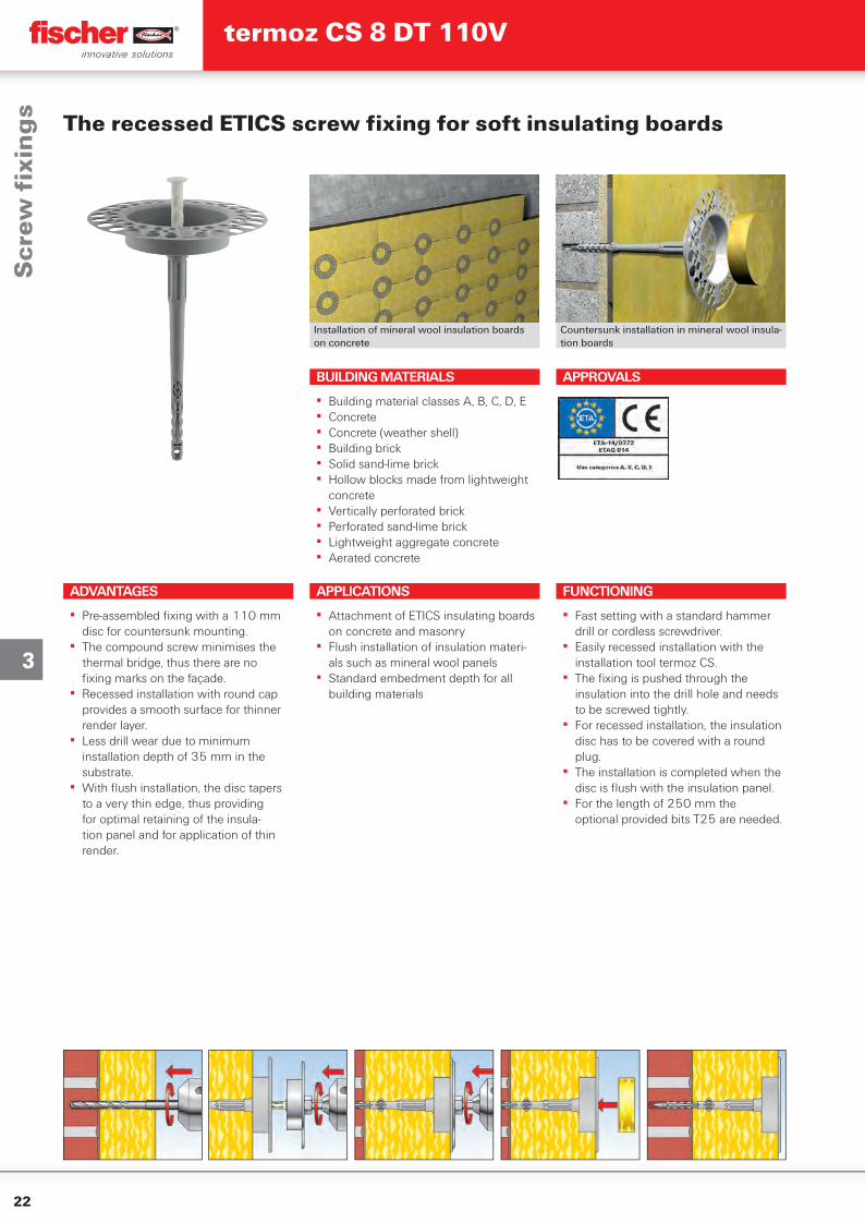
Installation of mineral wool insulation boards on concrete
Countersunk installation in mineral wool insula-tion boards
APPLICATIONS
▪ Attachment of ETICS insulating boards on concrete and masonry
▪ Flush installation of insulation materi-als such as mineral wool panels
▪ Standard embedment depth for all building materials
BUILDING MATERIALS
▪ Building material classes A, B, C, D, E▪ Concrete▪ Concrete (weather shell)▪ Building brick▪ Solid sand-lime brick▪ Hollow blocks made from lightweight
concrete▪ Vertically perforated brick▪ Perforated sand-lime brick▪ Lightweight aggregate concrete▪ Aerated concrete
APPROVALS
The recessed ETICS screw fi xing for soft insulating boards
FUNCTIONING
▪ Fast setting with a standard hammer drill or cordless screwdriver.
▪ Easily recessed installation with the installation tool termoz CS.
▪ The fi xing is pushed through the insulation into the drill hole and needs to be screwed tightly.
▪ For recessed installation, the insulation disc has to be covered with a round plug.
▪ The installation is completed when the disc is fl ush with the insulation panel.
▪ For the length of 250 mm the optional provided bits T25 are needed.
ADVANTAGES
▪ Pre-assembled fi xing with a 110 mm disc for countersunk mounting.
▪ The compound screw minimises the thermal bridge, thus there are no fi xing marks on the façade.
▪ Recessed installation with round cap provides a smooth surface for thinner render layer.
▪ Less drill wear due to minimum installation depth of 35 mm in the substrate.
▪ With fl ush installation, the disc tapers to a very thin edge, thus providing for optimal retaining of the insula-tion panel and for application of thin render.
Scr
ew fi
xin
gs
termoz CS 8 DT 110V
23
3
ACCESSORIES
Caps MW D60 Caps PS D60 white Setting tool CS(hexagonal-adapter)
Setting tool CS(SDS-adapter)
Bit T 25 CS 178,5 mm
Contents Match Sales unit
Item Art.-No. [pcs]
Caps MW D65 525654 — — 100Caps PS D60 white 046173 — — 100Caps PS D60 grey 544383 — — 100Setting tool CS (hexagonal-adapter) 532618 including Bit T 30 — 1Setting tool CS (SDS-adapter) 532619 including Bit T 30 — 1Bit T30 CS 26 mm 533761 — Setting tool CS 1Bit T25 CS 98,5 mm 533762 — Setting tool CS 1Bit T25 CS 178,5 mm 533763 — Setting tool CS 1
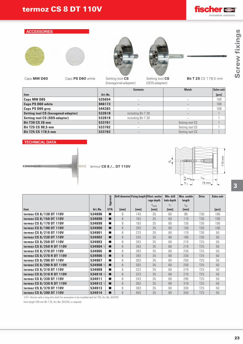
TECHNICAL DATA
termoz CS 8 /... DT 110V 11
0 m
m
h 1
h nom t fix
15 mm
d o
Appr
oval Drill diameter Fixing length Eff ect. ancho-
rage depthMin. drill
hole depthMax. usable
lengthDrive Sales unit
hnom h1 tfi xItem Art.-No. ETA [mm] [mm] [mm] [mm] [mm] [pcs]
termoz CS 8/130 DT 110V 534896 ■ 8 143 35 60 90 T30 100termoz CS 8/150 DT 110V 534898 ■ 8 163 35 60 110 T30 100termoz CS 8/170 DT 110V 534899 ■ 8 183 35 60 130 T30 100termoz CS 8/190 DT 110V 534900 ■ 8 203 35 60 150 T30 100termoz CS 8/210 DT 110V 534901 ■ 8 223 35 60 170 T30 50termoz CS 8/230 DT 110V 534902 ■ 8 243 35 60 190 T30 50termoz CS 8/250 DT 110V 534903 ■ 8 263 35 60 210 T25 50termoz CS 8/250 R DT 110V 534904 1) ■ 8 263 35 60 210 T25 50termoz CS 8/270 DT 110V 534905 ■ 8 283 35 60 230 T25 50termoz CS 8/270 R DT 110V 534906 1) ■ 8 283 35 60 230 T25 50termoz CS 8/290 DT 110V 534907 ■ 8 303 35 60 250 T25 50termoz CS 8/290 R DT 110V 534908 1) ■ 8 303 35 60 250 T25 50termoz CS 8/310 DT 110V 534909 ■ 8 323 35 60 270 T25 50termoz CS 8/310 R DT 110V 534910 1) ■ 8 323 35 60 270 T25 50termoz CS 8/330 DT 110V 534911 ■ 8 343 35 60 290 T25 50termoz CS 8/330 R DT 110V 534912 1) ■ 8 363 35 60 310 T25 50termoz CS 8/370 DT 110V 534913 ■ 8 383 35 60 330 T25 50termoz CS 8/390 DT 110V 534914 ■ 8 403 35 60 350 T25 501) R = Version with a long slim shaft for renovation to be installed with bit T25, Art.-No. 533762
from length 250 mm Bit T 25, Art.-No. 533763, is required
Scr
ew fi
xin
gs
termoz CS 8 DT 110V
24
3
Concrete and masonryType Brick raw density min. compressive
brick strengthmin.
embedment depthmin.
member thicknesspermissible
tensile load 3)
min.spacing 2)
min.edge distance 2)
fb hnom hmin Nperm smin cmin
[kg/dm³] [N/mm²] [mm] [mm] [kN] [mm] [mm]
Concrete
CS 8 DT 110VC12/15 - C45/55
356) 1000,40
100 100C50/60 0,50
Weather shell
CS 8 DT 110VC20/25 - C45/55
356) 5) 420,40
100 100C50/60 0,50
Solid Clay bricks e.g. acc. to DIN 105-100:2012-01, EN 771-1:2011, MzCS 8 DT 110V ≥ 1,8 20 356) 100 0,50 100 100Calcium silicate solid bricks, e.g. acc. to DIN V 106:2005-10, EN 771-2:2011, KS
CS 8 DT 110V ≥ 1,820
356) 1000,50
100 10012 0,30
Solid lightweight concrete block, e.g. acc. to DIN V 18152-100:2005-10 EN 771-3:2011 VblCS 8 DT 110V ≥ 1,4 8 356) 100 0,17 100 100Solid concrete block, e.g. acc. to DIN V 18152-100:2005-10 EN 771-3:2011, Vbn
CS 8 DT 110V ≥ 2,020
356) 1000,40
100 10012 0,25
Vertically perforated clay bricks e.g. acc. to DIN 105-100:2012-01, EN 771-1:2011, HLz
CS 8 DT 110V≥ 1,0 12
357) 8) 1000,20
100 100≥ 1,6 48 0,50
Hollow calcium silicate brick, acc. to DIN V 106:2005-10, EN 771-2:2011, KSL
CS 8 DT 110V ≥ 1,420
357) 8) 1000,30
100 10012 0,17
Hollow brick light-weight concrete, e.g. acc. to DIN V 18153-100: 2005-10, EN 771-3:2011 HblCS 8 DT 110V ≥ 0,9 4 356) 8) 100 0,17 100 100Hollow brick concrete, e.g. acc. to DIN V 18153-100: 2005-10, EN 771-3:2011 Hbn
CS 8 DT 110V ≥ 1,2
10
356) 8) 100
0,40
100 1008 0,306 0,254 0,17
Lightweight Aggregate Concrete acc. to DIN EN 1520, LACCS 8 DT 110V ≥ 0,9 6 356) 100 0,25 100 100Autoclaved aerated concrete blocks, e.g. AAC acc. to DIN V 4165-100:2005-10, EN 771-4
CS 8 DT 110V ≥ 0,54 357)
1000,10
100 1004 557) 0,20
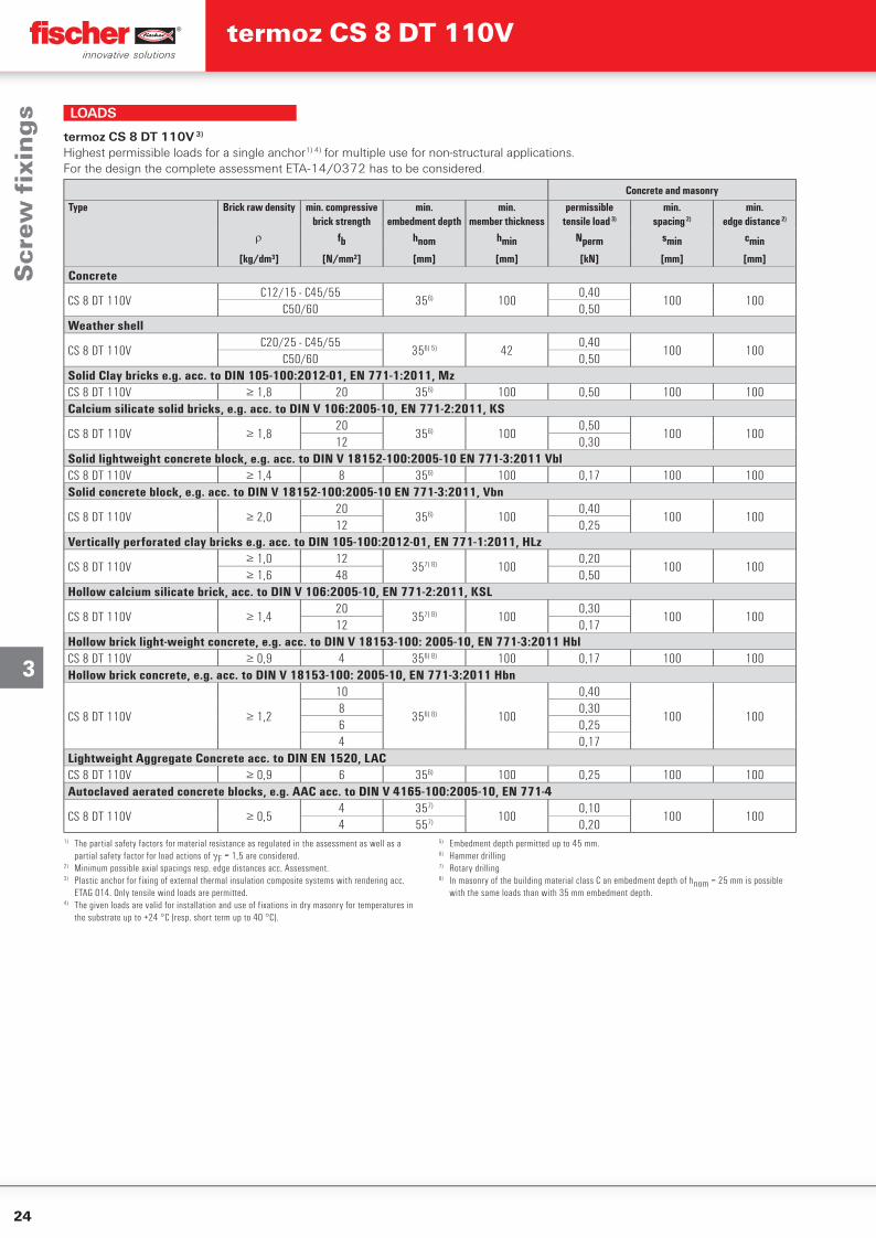
termoz CS 8 DT 110V 3)
Highest permissible loads for a single anchor1) 4) for multiple use for non-structural applications.For the design the complete assessment ETA-14/0372 has to be considered.
1) The partial safety factors for material resistance as regulated in the assessment as well as a partial safety factor for load actions of F = 1,5 are considered.
2) Minimum possible axial spacings resp. edge distances acc. Assessment.3) Plastic anchor for fixing of external thermal insulation composite systems with rendering acc.
ETAG 014. Only tensile wind loads are permitted.4) The given loads are valid for installation and use of fixations in dry masonry for temperatures in
the substrate up to +24 °C (resp. short term up to 40 °C).
5) Embedment depth permitted up to 45 mm.6) Hammer drilling7) Rotary drilling8) In masonry of the building material class C an embedment depth of hnom = 25 mm is possible
with the same loads than with 35 mm embedment depth.
LOADS
Scr
ew fi
xin
gs
termoz CS 8 DT 110V
25
3
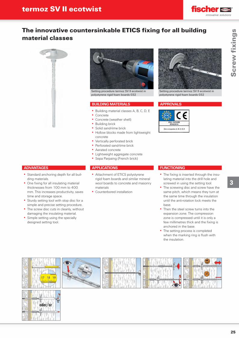
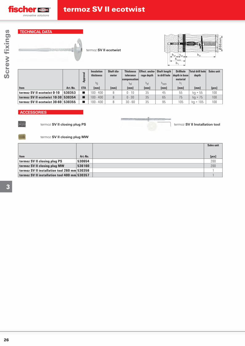
Setting procedure termoz SV II ecotwist in polystyrene rigid foam boards 032
Setting procedure termoz SV II ecotwist in polystyrene rigid foam boards 032
APPROVALS
APPLICATIONS
▪ Attachment of ETICS polystyrene rigid foam boards and similar mineral wool boards to concrete and masonry materials
▪ Counterbored installation
BUILDING MATERIALS
▪ Building material classes A, B, C, D, E▪ Concrete▪ Concrete (weather shell)▪ Building brick▪ Solid sand-lime brick▪ Hollow blocks made from lightweight
concrete▪ Vertically perforated brick▪ Perforated sand-lime brick▪ Aerated concrete▪ Lightweight aggregate concrete▪ Sepa Parpaing (French brick)
FUNCTIONING
▪ The fi xing is inserted through the insu-lating material into the drill hole and screwed in using the setting tool.
▪ The screwing disc and screw have the same pitch, which means they turn at the same time through the insulation until the anti-rotation lock meets the base.
▪ Then the steel screw turns into the expansion zone. The compression zone is compressed until it is only a few millimetres thick and the fi xing is anchored in the base.
▪ The setting process is completed when the marking ring is fl ush with the insulation.
The innovative countersinkable ETICS fi xing for all building material classes
ADVANTAGES
▪ Standard anchoring depth for all buil-ding materials.
▪ One fi xing for all insulating material thicknesses from 100 mm to 400 mm. This increases productivity, saves time and storage space.
▪ Sturdy setting tool with stop disc for a simple and precise setting procedure.
▪ The screw disc cuts in cleanly, without damaging the insulating material.
▪ Simple setting using the specially designed setting tool.
Scr
ew fi
xin
gs
termoz SV II ecotwist
26
3
TECHNICAL DATA
termoz SV II ecotwisth Dt tolh ef
h nom
h 1
Ø 6
6 m
m
ItemAp
prov
al
Insulation thickness
Shaft dia-meter
Thickness tolerance
compensation
Eff ect. ancho-rage depth
Shaft length in drill hole
Drillhole depth in base
material
Total drill hole depth
Sales unit
hD ttol hef hnom h1Art.-No. ETA [mm] [mm] [mm] [mm] [mm] [mm] [mm] [pcs]
termoz SV II ecotwist 0-10 530353 ■ 100 - 400 8 0 - 10 35 45 55 hD + 55 100termoz SV II ecotwist 10-30 530354 ■ 100 - 400 8 0 - 30 35 65 75 hD + 75 100termoz SV II ecotwist 30-60 530355 ■ 100 - 400 8 30 - 60 35 95 105 hD + 105 100
ACCESSORIES
termoz SV II closing plug PS termoz SV II Installation tool
termoz SV II closing plug MW
Sales unit
Item Art.-No. [pcs]
termoz SV II closing plug PS 530654 200termoz SV II closing plug MW 536160 200termoz SV II installation tool 260 mm 530356 1termoz SV II installation tool 400 mm 530357 1
Scr
ew fi
xin
gs
termoz SV II ecotwist
27
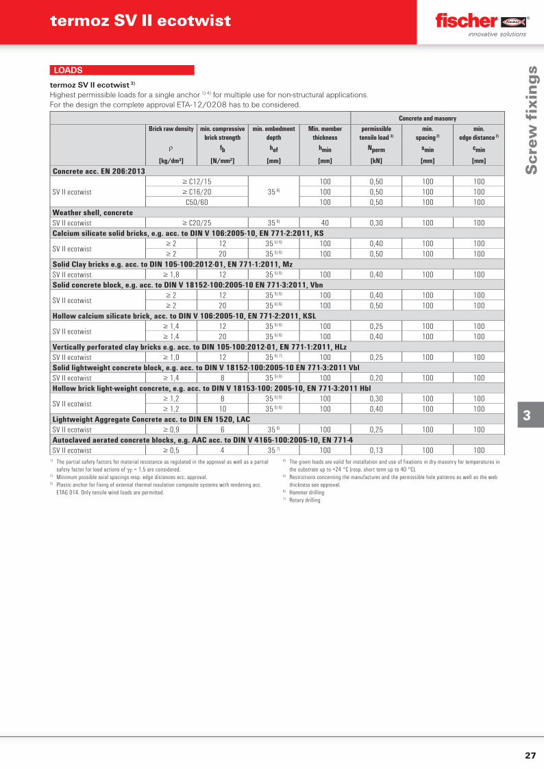
3
Concrete and masonryBrick raw density min. compressive
brick strengthmin. embedment
depthMin. member
thicknesspermissible
tensile load 3)
min.spacing 2)
min.edge distance 2)
fb hef hmin Nperm smin cmin
[kg/dm³] [N/mm²] [mm] [mm] [kN] [mm] [mm]
Concrete acc. EN 206:2013
SV II ecotwist≥ C12/15
35 6)
100 0,50 100 100≥ C16/20 100 0,50 100 100
C50/60 100 0,50 100 100Weather shell, concreteSV II ecotwist ≥ C20/25 35 6) 40 0,30 100 100Calcium silicate solid bricks, e.g. acc. to DIN V 106:2005-10, EN 771-2:2011, KS
SV II ecotwist≥ 2 12 35 5) 6) 100 0,40 100 100≥ 2 20 35 5) 6) 100 0,50 100 100
Solid Clay bricks e.g. acc. to DIN 105-100:2012-01, EN 771-1:2011, MzSV II ecotwist ≥ 1,8 12 35 5) 6) 100 0,40 100 100Solid concrete block, e.g. acc. to DIN V 18152-100:2005-10 EN 771-3:2011, Vbn
SV II ecotwist≥ 2 12 35 5) 6) 100 0,40 100 100≥ 2 20 35 5) 6) 100 0,50 100 100
Hollow calcium silicate brick, acc. to DIN V 106:2005-10, EN 771-2:2011, KSL
SV II ecotwist≥ 1,4 12 35 5) 6) 100 0,25 100 100≥ 1,4 20 35 5) 6) 100 0,40 100 100
Vertically perforated clay bricks e.g. acc. to DIN 105-100:2012-01, EN 771-1:2011, HLzSV II ecotwist ≥ 1,0 12 35 5) 7) 100 0,25 100 100Solid lightweight concrete block, e.g. acc. to DIN V 18152-100:2005-10 EN 771-3:2011 VblSV II ecotwist ≥ 1,4 8 35 5) 6) 100 0,20 100 100Hollow brick light-weight concrete, e.g. acc. to DIN V 18153-100: 2005-10, EN 771-3:2011 Hbl
SV II ecotwist≥ 1,2 8 35 5) 6) 100 0,30 100 100≥ 1,2 10 35 5) 6) 100 0,40 100 100
Lightweight Aggregate Concrete acc. to DIN EN 1520, LACSV II ecotwist ≥ 0,9 6 35 6) 100 0,25 100 100Autoclaved aerated concrete blocks, e.g. AAC acc. to DIN V 4165-100:2005-10, EN 771-4SV II ecotwist ≥ 0,5 4 35 7) 100 0,13 100 100
termoz SV II ecotwist 3)
Highest permissible loads for a single anchor 1) 4) for multiple use for non-structural applications.For the design the complete approval ETA-12/0208 has to be considered.
1) The partial safety factors for material resistance as regulated in the approval as well as a partial safety factor for load actions of F = 1,5 are considered.
2) Minimum possible axial spacings resp. edge distances acc. approval.3) Plastic anchor for fixing of external thermal insulation composite systems with rendering acc.
ETAG 014. Only tensile wind loads are permitted.
4) The given loads are valid for installation and use of fixations in dry masonry for temperatures in the substrate up to +24 °C (resp. short term up to 40 °C).
5) Restrictions concerning the manufacturer and the permissible hole patterns as well as the web thickness see approval.
6) Hammer drilling7) Rotary drilling
LOADS
Scr
ew fi
xin
gs
termoz SV II ecotwist
28
3
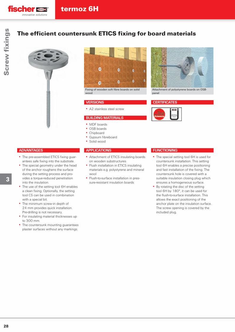
Fixing of wooden soft fi bre boards on solid wood
Attachment of polystyrene boards on OSB-panel
The effi cient countersunk ETICS fi xing for board materials
VERSIONS
▪ A2 stainless steel screw
APPLICATIONS
▪ Attachment of ETICS insulating boards on wooden substructures
▪ Flush installation in ETICS insulating materials e.g. polystyrene and mineral wool
▪ Flush-to-surface installation in pres-sure-resistant insulation boards
FUNCTIONING
▪ The special setting tool 6H is used for countersunk installation. This setting tool 6H enables a precise positioning and fast installation of the fi xing. The countersunk hole is covered with a suitable insulation closing plug which ensures a homogeneous surface.
▪ By rotating the disc of the setting tool 6H by 180°, it can be used for the fl ush-to-surface installation. This allows the exact positioning of the anchor plate on the insulation surface. The screw opening is covered by the included plug.
BUILDING MATERIALS
▪ MDF boards▪ OSB boards▪ Chipboard▪ Gypsum fi breboard▪ Solid wood
CERTIFICATES
Scr
ew fi
xin
gs
ADVANTAGES
▪ The pre-assembled ETICS fi xing guar-antees safe fi xing into the substrate.
▪ The special geometry under the head of the anchor roughens the surface during the setting process and pro-vides a torque-reduced penetration into the insulation.
▪ The use of the setting tool 6H enables a clean fi xing. Optionally, the setting tool CS can be used in combination with a special bit.
▪ The minimum screw-in depth of 24 mm provides quick installation. Pre-drilling is not necessary.
▪ For insulating material thicknesses up to 300 mm.
▪ The countersunk mounting guarantees plaster surfaces without any markings.
termoz 6H
29
3
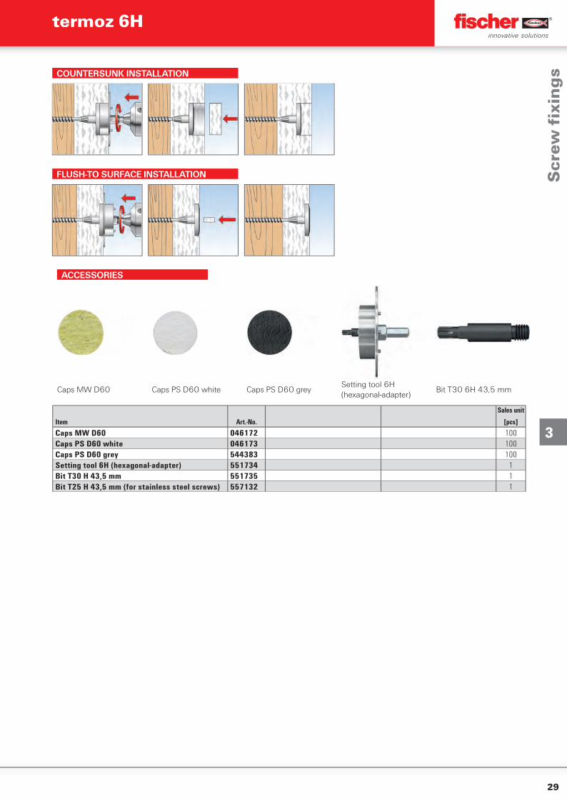
COUNTERSUNK INSTALLATION
FLUSH-TO SURFACE INSTALLATION
ACCESSORIES
Caps MW D60 Caps PS D60 white Caps PS D60 greySetting tool 6H (hexagonal-adapter)
Bit T30 6H 43,5 mm
Sales unit
Item Art.-No. [pcs]
Caps MW D60 046172 100Caps PS D60 white 046173 100Caps PS D60 grey 544383 100Setting tool 6H (hexagonal-adapter) 551734 1Bit T30 H 43,5 mm 551735 1Bit T25 H 43,5 mm (for stainless steel screws) 557132 1
Scr
ew fi
xin
gs
termoz 6H
30
3
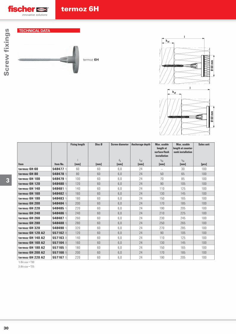
TECHNICAL DATA
termoz 6H
Ø 60
mm
lh ef
lh ef
Ø 60
mm
Fixing length Disc Ø Screw diameter Anchorage depth Max. usable length at
surface-fl ush installation
Max. usable length at counter-sunk installation
Sales unit
l ds hef tfi x tfi xItem Item No. [mm] [mm] [mm] [mm] [mm] [mm] [pcs]
termoz 6H 60 548477 1) 60 60 6,0 24 — 30 100termoz 6H 80 548478 1) 80 60 6,0 24 50 65 100termoz 6H 100 548479 1) 100 60 6,0 24 70 85 100termoz 6H 120 548480 1) 120 60 6,0 24 90 105 100termoz 6H 140 548481 1) 140 60 6,0 24 110 125 100termoz 6H 160 548482 1) 160 60 6,0 24 130 145 100termoz 6H 180 548483 1) 180 60 6,0 24 150 165 100termoz 6H 200 548484 1) 200 60 6,0 24 170 185 100termoz 6H 220 548485 1) 220 60 6,0 24 190 205 100termoz 6H 240 548486 1) 240 60 6,0 24 210 225 100termoz 6H 260 548487 1) 260 60 6,0 24 230 245 100termoz 6H 280 548488 1) 280 60 6,0 24 250 265 100termoz 6H 320 548490 1) 320 60 6,0 24 270 285 100termoz 6H 120 A2 557162 2) 120 60 6,0 24 90 105 100termoz 6H 140 A2 557163 2) 140 60 6,0 24 110 125 100termoz 6H 160 A2 557164 2) 160 60 6,0 24 130 145 100termoz 6H 180 A2 557165 2) 180 60 6,0 24 150 165 100termoz 6H 200 A2 557166 2) 200 60 6,0 24 170 185 100termoz 6H 220 A2 557167 2) 220 60 6,0 24 190 205 1001) Bit size = T30
2) Bit size = T25
Scr
ew fi
xin
gs
termoz 6H
31
3
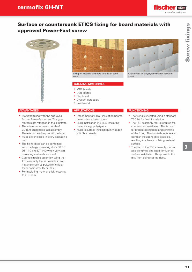
Fixing of wooden soft fi bre boards on solid wood
Attachment of polystyrene boards on OSB-panel
Surface or countersunk ETICS fi xing for board materials with approved Power-Fast screw
ADVANTAGES
▪ Pre-fi tted fi xing with the approved fi scher Power-Fast screw. This gua-rantees safe retention in the substrate.
▪ The minimum screw-in depth of 30 mm guarantees fast assembly. There is no need to pre-drill the hole.
▪ Plugs are enclosed in every packaging unit.
▪ The fi xing discs can be combined with the large insulating discs DT 90, DT 110 and DT 140 when very soft insulating materials are used.
▪ Countersinkable assembly using the TTS assembly tool is possible in soft materials such as polystyrene rigid foam boards PS 15 or PS 20.
▪ For insulating material thicknesses up to 280 mm.
APPLICATIONS
▪ Attachment of ETICS insulating boards on wooden substructures
▪ Flush installation in ETICS insulating materials e.g. polystyrene
▪ Flush-to-surface installation in wooden soft fi bre boards
FUNCTIONING
▪ The fi xing is inserted using a standard T30 bit for fl ush installation.
▪ The TSS assembly tool is required for countersunk installation. This is used for precise positioning and screwing of the fi xing. Thecounterbore is sealed using an insulating disc available, resulting in a level insulating material surface.
▪ The disc of the TSS assembly tool can also be turned and used for fl ush-to-surface installation. This prevents the disc from being set too deep.
BUILDING MATERIALS
▪ MDF boards▪ OSB boards▪ Chipboard▪ Gypsum fi breboard▪ Solid wood
Scr
ew fi
xin
gs
termofi x 6H-NT
32
3
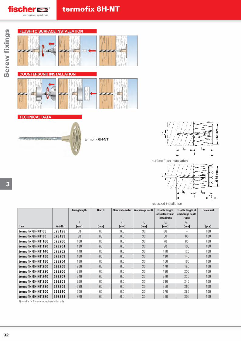
FLUSH-TO SURFACE INSTALLATION
COUNTERSUNK INSTALLATION
TECHNICAL DATA
termofi x 6H-NT
surface-fl ush installation
recessed installation
Fixing length Disc Ø Screw diameter Anchorage depth Usable length at surface-fl ush
installation
Usable length at anchorage depth
70mm
Sales unit
l ds hv tfi x tfi xItem Art.-No. [mm] [mm] [mm] [mm] [mm] [mm] [pcs]
termofix 6H-NT 60 523198 1) 60 60 6,0 30 30 — 100termofix 6H-NT 80 523199 80 60 6,0 30 50 65 100termofix 6H-NT 100 523200 100 60 6,0 30 70 85 100termofix 6H-NT 120 523201 120 60 6,0 30 90 105 100termofix 6H-NT 140 523202 140 60 6,0 30 110 125 100termofix 6H-NT 160 523203 160 60 6,0 30 130 145 100termofix 6H-NT 180 523204 180 60 6,0 30 150 165 100termofix 6H-NT 200 523205 200 60 6,0 30 170 185 100termofix 6H-NT 220 523206 220 60 6,0 30 190 205 100termofix 6H-NT 240 523207 240 60 6,0 30 210 225 100termofix 6H-NT 260 523208 260 60 6,0 30 230 245 100termofix 6H-NT 280 523209 280 60 6,0 30 250 265 100termofix 6H-NT 300 523210 300 60 6,0 30 270 285 100termofix 6H-NT 320 523211 320 60 6,0 30 290 305 1001) suitable for flush-mounting installation only
Scr
ew fi
xin
gs
termofi x 6H-NT
33
3
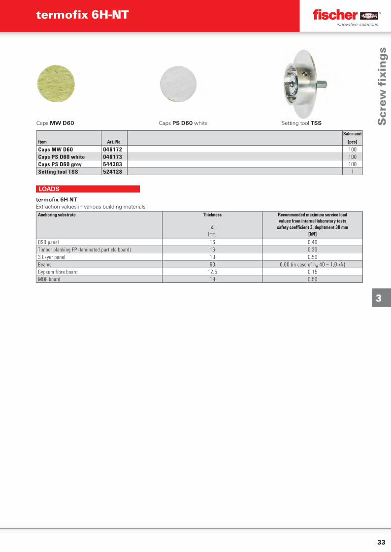
Caps MW D60 Caps PS D60 white Setting tool TSS
Sales unit
Item Art.-No. [pcs]
Caps MW D60 046172 100Caps PS D60 white 046173 100Caps PS D60 grey 544383 100Setting tool TSS 524128 1
Anchoring substrate Thickness
d
Recommended maximum service loadvalues from internal laboratory tests
safety coeffi cient 3, dephtment 30 mm[mm] [kN]
OSB panel 16 0,40Timber planking FP (laminated particle board) 16 0,303 Layer panel 19 0,50Beams 60 0,60 (in case of hv 40 = 1,0 kN)Gypsum fibre board 12,5 0,15MDF board 19 0,50
termofi x 6H-NTExtraction values in various building materials.
LOADS
Scr
ew fi
xin
gs
termofi x 6H-NT
34
3
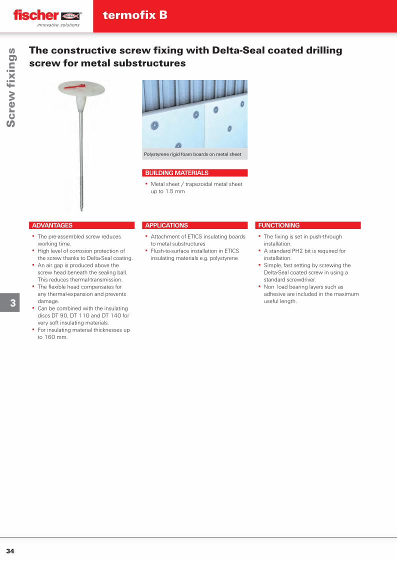
Polystyrene rigid foam boards on metal sheet
The constructive screw fi xing with Delta-Seal coated drilling screw for metal substructures
BUILDING MATERIALS
▪ Metal sheet / trapezoidal metal sheet up to 1.5 mm
APPLICATIONS
▪ Attachment of ETICS insulating boards to metal substructures
▪ Flush-to-surface installation in ETICS insulating materials e.g. polystyrene
FUNCTIONING
▪ The fi xing is set in push-through installation.
▪ A standard PH2 bit is required for installation.
▪ Simple, fast setting by screwing the Delta-Seal coated screw in using a standard screwdriver.
▪ Non load bearing layers such as adhesive are included in the maximum useful length.
ADVANTAGES
▪ The pre-assembled screw reduces working time.
▪ High level of corrosion protection of the screw thanks to Delta-Seal coating.
▪ An air gap is produced above the screw head beneath the sealing ball. This reduces thermal-transmission.
▪ The fl exible head compensates for any thermal-expansion and prevents damage.
▪ Can be combined with the insulating discs DT 90, DT 110 and DT 140 for very soft insulating materials.
▪ For insulating material thicknesses up to 160 mm.
Scr
ew fi
xin
gs
termofi x B
35
3
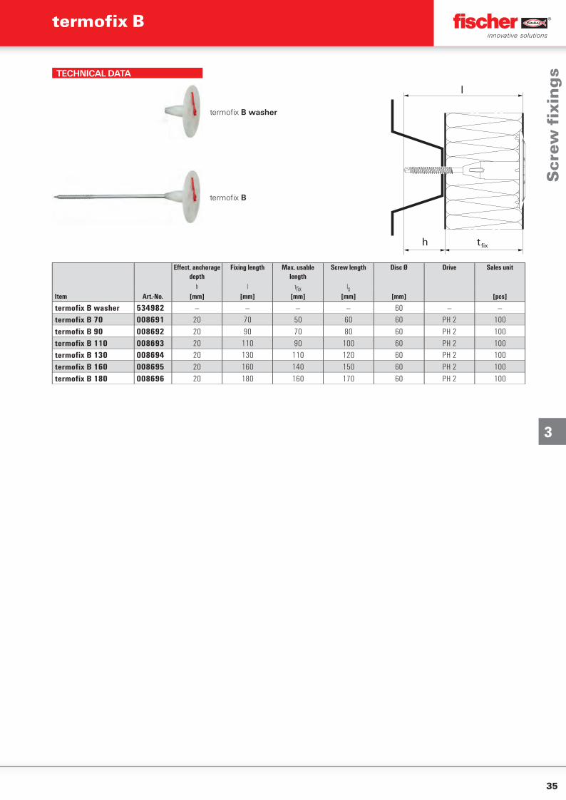
TECHNICAL DATA
termofi x B washer
h t fix
l
termofi x B
Eff ect. anchorage depth
Fixing length Max. usable length
Screw length Disc Ø Drive Sales unit
h l tfi x lsItem Art.-No. [mm] [mm] [mm] [mm] [mm] [pcs]
termofix B washer 534982 — — — — 60 — —termofix B 70 008691 20 70 50 60 60 PH 2 100termofix B 90 008692 20 90 70 80 60 PH 2 100termofix B 110 008693 20 110 90 100 60 PH 2 100termofix B 130 008694 20 130 110 120 60 PH 2 100termofix B 160 008695 20 160 140 150 60 PH 2 100termofix B 180 008696 20 180 160 170 60 PH 2 100
Scr
ew fi
xin
gs
termofi x B
36
4
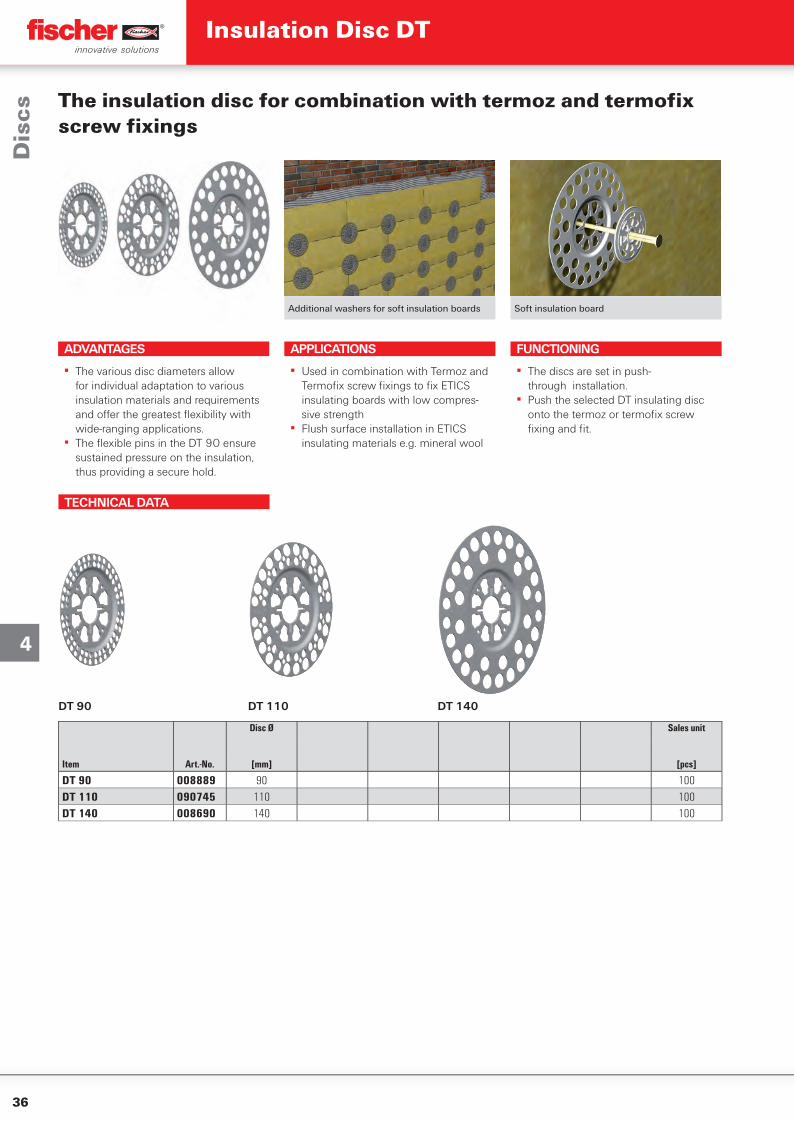
TECHNICAL DATA
DT 90 DT 110 DT 140
Disc Ø Sales unit
Item Art.-No. [mm] [pcs]
DT 90 008889 90 100DT 110 090745 110 100DT 140 008690 140 100
Additional washers for soft insulation boards Soft insulation board
The insulation disc for combination with termoz and termofi x screw fi xings
ADVANTAGES
▪ The various disc diameters allow for individual adaptation to various insulation materials and requirements and off er the greatest fl exibility with wide-ranging applications.
▪ The fl exible pins in the DT 90 ensure sustained pressure on the insulation, thus providing a secure hold.
APPLICATIONS
▪ Used in combination with Termoz and Termofi x screw fi xings to fi x ETICS insulating boards with low compres-sive strength
▪ Flush surface installation in ETICS insulating materials e.g. mineral wool
FUNCTIONING
▪ The discs are set in push-through installation.
▪ Push the selected DT insulating disc onto the termoz or termofi x screw fi xing and fi t.
Dis
csInsulation Disc DT
37
4TECHNICAL DATA
termofi x H 10 termofi x H 50 termofi x H 90 termofi x H 150
Shaft length Disc Ø Disc lock Colour Sales unit
L
Item Art.-No. [mm] [mm] [pcs]
termofix H 10 514288 29 60 PS plug (included) green 200termofix H 50 514289 69 60 Sealing cap (moulded on) green 100termofix H 90 514290 109 60 Sealing cap (moulded on) green 100termofix H 150 514291 169 60 Sealing cap (moulded on) green 100
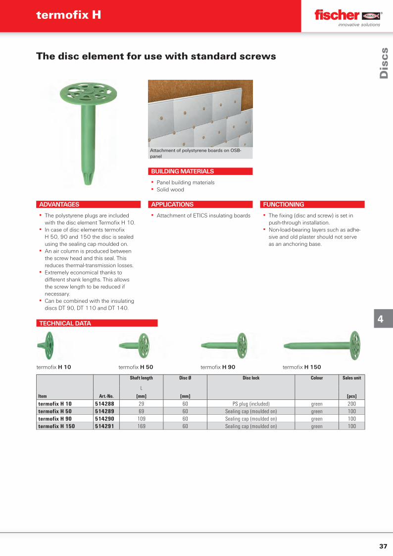
Attachment of polystyrene boards on OSB-panel
The disc element for use with standard screws
ADVANTAGES
▪ The polystyrene plugs are included with the disc element Termofi x H 10.
▪ In case of disc elements termofi x H 50, 90 and 150 the disc is sealed using the sealing cap moulded on.
▪ An air column is produced between the screw head and this seal. This reduces thermal-transmission losses.
▪ Extremely economical thanks to diff erent shank lengths. This allows the screw length to be reduced if necessary.
▪ Can be combined with the insulating discs DT 90, DT 110 and DT 140.
APPLICATIONS
▪ Attachment of ETICS insulating boards
FUNCTIONING
▪ The fi xing (disc and screw) is set in push-through installation.
▪ Non-load-bearing layers such as adhe-sive and old plaster should not serve as an anchoring base.
BUILDING MATERIALS
▪ Panel building materials▪ Solid wood
Dis
cs
termofi x H
38
4
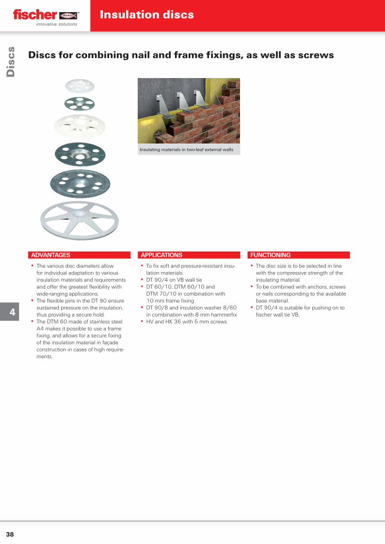
Insulating materials in two-leaf external walls
Discs for combining nail and frame fi xings, as well as screws
ADVANTAGES
▪ The various disc diameters allow for individual adaptation to various insulation materials and requirements and off er the greatest fl exibility with wide-ranging applications.
▪ The fl exible pins in the DT 90 ensure sustained pressure on the insulation, thus providing a secure hold.
▪ The DTM 60 made of stainless steel A4 makes it possible to use a frame fi xing, and allows for a secure fi xing of the insulation material in façade construction in cases of high require-ments.
APPLICATIONS
▪ To fi x soft and pressure-resistant insu-lation materials.
▪ DT 90/4 on VB wall tie▪ DT 60/10, DTM 60/10 and
DTM 70/10 in combination with 10 mm frame fi xing
▪ DT 90/8 and insulation washer 8/60 in combination with 8 mm hammerfi x
▪ HV and HK 36 with 5 mm screws
FUNCTIONING
▪ The disc size is to be selected in line with the compressive strength of the insulating material.
▪ To be combined with anchors, screws or nails corresponding to the available base material.
▪ DT 90/4 is suitable for pushing on to fi scher wall tie VB.
Dis
csInsulation discs
39
4
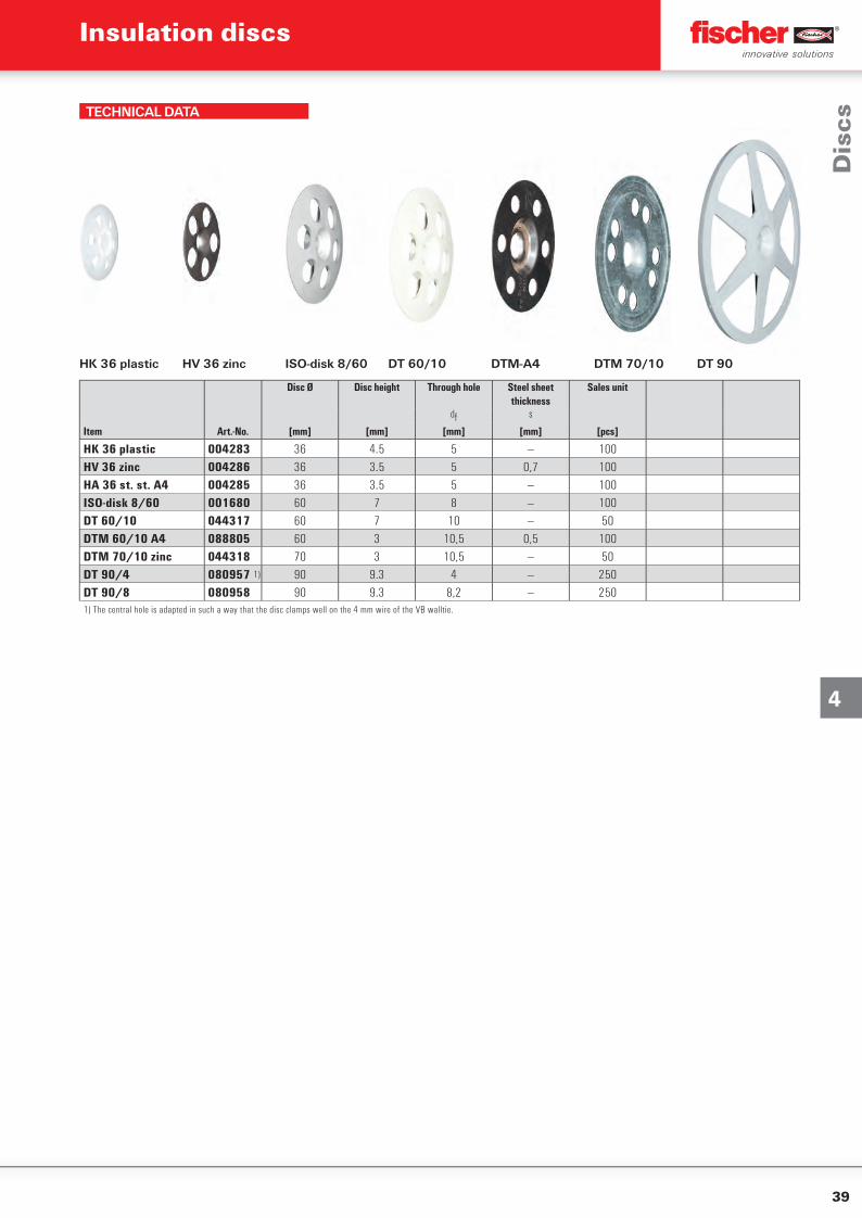
TECHNICAL DATA
HK 36 plastic HV 36 zinc ISO-disk 8/60 DT 60/10 DTM-A4 DTM 70/10 DT 90
Disc Ø Disc height Through hole Steel sheet thickness
Sales unit
df s
Item Art.-No. [mm] [mm] [mm] [mm] [pcs]
HK 36 plastic 004283 36 4.5 5 — 100HV 36 zinc 004286 36 3.5 5 0,7 100HA 36 st. st. A4 004285 36 3.5 5 — 100ISO-disk 8/60 001680 60 7 8 — 100DT 60/10 044317 60 7 10 — 50DTM 60/10 A4 088805 60 3 10,5 0,5 100DTM 70/10 zinc 044318 70 3 10,5 — 50DT 90/4 080957 1) 90 9.3 4 — 250DT 90/8 080958 90 9.3 8,2 — 2501) The central hole is adapted in such a way that the disc clamps well on the 4 mm wire of the VB walltie.
Dis
cs
Insulation discs
40
5
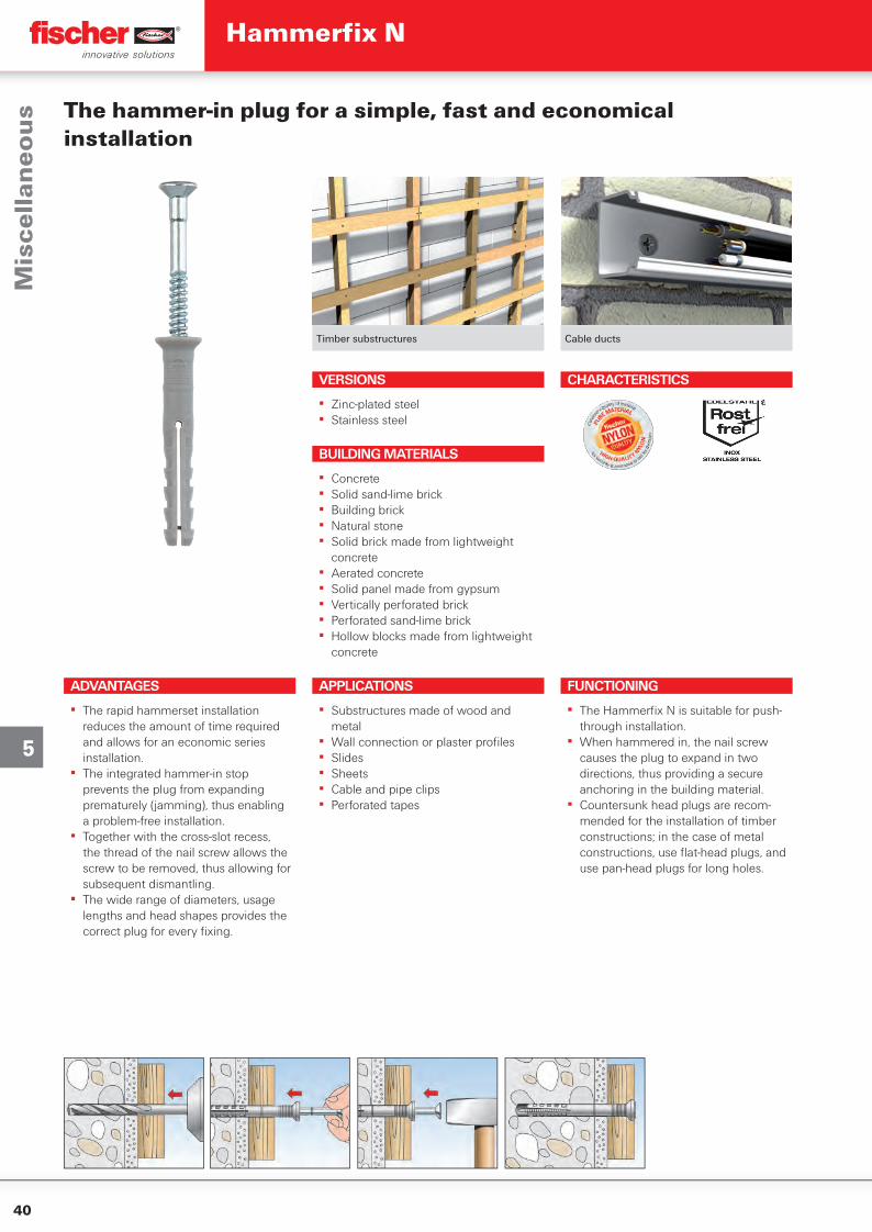
Timber substructures Cable ducts
The hammer-in plug for a simple, fast and economical installation
VERSIONS
▪ Zinc-plated steel▪ Stainless steel
ADVANTAGES
▪ The rapid hammerset installation reduces the amount of time required and allows for an economic series installation.
▪ The integrated hammer-in stop prevents the plug from expanding prematurely (jamming), thus enabling a problem-free installation.
▪ Together with the cross-slot recess, the thread of the nail screw allows the screw to be removed, thus allowing for subsequent dismantling.
▪ The wide range of diameters, usage lengths and head shapes provides the correct plug for every fi xing.
FUNCTIONING
▪ The Hammerfi x N is suitable for push-through installation.
▪ When hammered in, the nail screw causes the plug to expand in two directions, thus providing a secure anchoring in the building material.
▪ Countersunk head plugs are recom-mended for the installation of timber constructions; in the case of metal constructions, use fl at-head plugs, and use pan-head plugs for long holes.
BUILDING MATERIALS
▪ Concrete▪ Solid sand-lime brick▪ Building brick▪ Natural stone▪ Solid brick made from lightweight
concrete▪ Aerated concrete▪ Solid panel made from gypsum▪ Vertically perforated brick▪ Perforated sand-lime brick▪ Hollow blocks made from lightweight
concrete
CHARACTERISTICS
APPLICATIONS
▪ Substructures made of wood and metal
▪ Wall connection or plaster profi les▪ Slides▪ Sheets▪ Cable and pipe clips▪ Perforated tapes
Mis
cell
ane
ou
sHammerfi x N
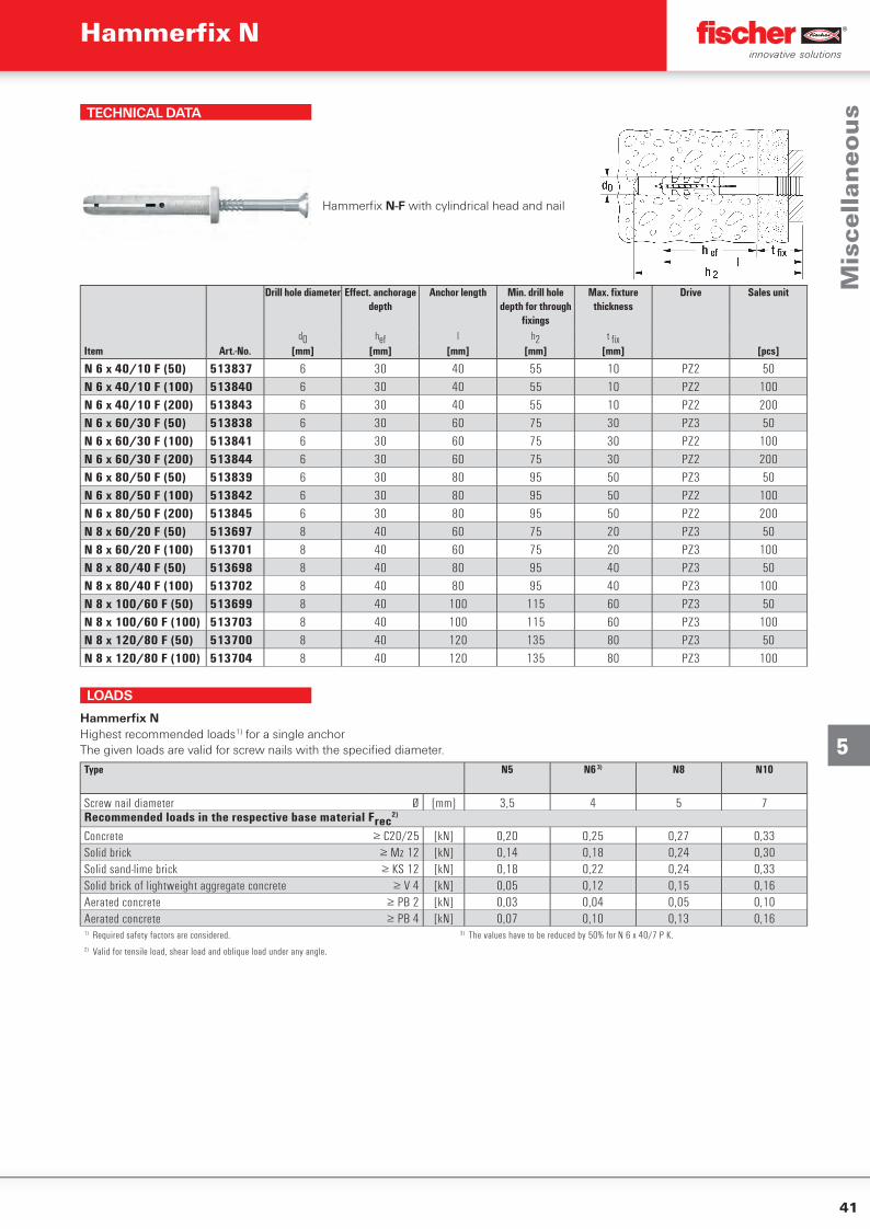
41
5
TECHNICAL DATA
Hammerfi x N-F with cylindrical head and nail
Drill hole diameter Eff ect. anchorage depth
Anchor length Min. drill hole depth for through
fi xings
Max. fi xture thickness
Drive Sales unit
d0 hef l h2 t fi xItem Art.-No. [mm] [mm] [mm] [mm] [mm] [pcs]
N 6 x 40/10 F (50) 513837 6 30 40 55 10 PZ2 50N 6 x 40/10 F (100) 513840 6 30 40 55 10 PZ2 100N 6 x 40/10 F (200) 513843 6 30 40 55 10 PZ2 200N 6 x 60/30 F (50) 513838 6 30 60 75 30 PZ3 50N 6 x 60/30 F (100) 513841 6 30 60 75 30 PZ2 100N 6 x 60/30 F (200) 513844 6 30 60 75 30 PZ2 200N 6 x 80/50 F (50) 513839 6 30 80 95 50 PZ3 50N 6 x 80/50 F (100) 513842 6 30 80 95 50 PZ2 100N 6 x 80/50 F (200) 513845 6 30 80 95 50 PZ2 200N 8 x 60/20 F (50) 513697 8 40 60 75 20 PZ3 50N 8 x 60/20 F (100) 513701 8 40 60 75 20 PZ3 100N 8 x 80/40 F (50) 513698 8 40 80 95 40 PZ3 50N 8 x 80/40 F (100) 513702 8 40 80 95 40 PZ3 100N 8 x 100/60 F (50) 513699 8 40 100 115 60 PZ3 50N 8 x 100/60 F (100) 513703 8 40 100 115 60 PZ3 100N 8 x 120/80 F (50) 513700 8 40 120 135 80 PZ3 50N 8 x 120/80 F (100) 513704 8 40 120 135 80 PZ3 100
LOADS
Hammerfix NHighest recommended loads1) for a single anchorThe given loads are valid for screw nails with the specified diameter.
Type N5 N6 3) N8 N10
Screw nail diameter Ø [mm] 3,5 4 5 7Recommended loads in the respective base material Frec
2)
Concrete ≥ C20/25 [kN] 0,20 0,25 0,27 0,33Solid brick ≥ Mz 12 [kN] 0,14 0,18 0,24 0,30Solid sand-lime brick ≥ KS 12 [kN] 0,18 0,22 0,24 0,33Solid brick of lightweight aggregate concrete ≥ V 4 [kN] 0,05 0,12 0,15 0,16Aerated concrete ≥ PB 2 [kN] 0,03 0,04 0,05 0,10Aerated concrete ≥ PB 4 [kN] 0,07 0,10 0,13 0,161) Required safety factors are considered. 3) The values have to be reduced by 50% for N 6 x 40/7 P K.2) Valid for tensile load, shear load and oblique load under any angle.
Mis
cell
ane
ou
s
Hammerfi x N
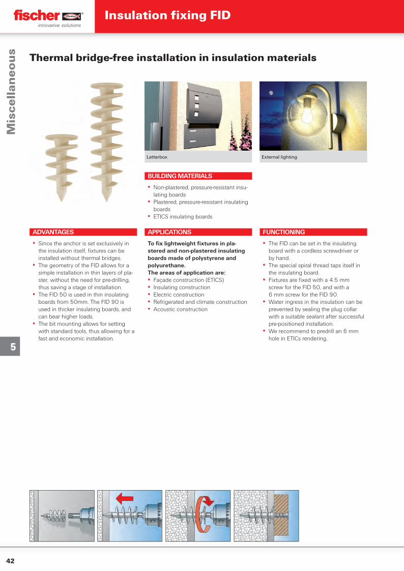
42
5
Letterbox External lighting
APPLICATIONS
To fi x lightweight fi xtures in pla-stered and non-plastered insulating boards made of polystyrene and polyurethane.The areas of application are:▪ Façade construction (ETICS)▪ Insulating construction▪ Electric construction▪ Refrigerated and climate construction▪ Acoustic construction
BUILDING MATERIALS
▪ Non-plastered, pressure-resistant insu-lating boards
▪ Plastered, pressure-resistant insulating boards
▪ ETICS insulating boards
FUNCTIONING
▪ The FID can be set in the insulating board with a cordless screwdriver or by hand.
▪ The special spiral thread taps itself in the insulating board.
▪ Fixtures are fi xed with a 4.5 mm screw for the FID 50, and with a 6 mm screw for the FID 90.
▪ Water ingress in the insulation can be prevented by sealing the plug collar with a suitable sealant after successful pre-positioned installation.
▪ We recommend to predrill an 6 mm hole in ETICs rendering.
Thermal bridge-free installation in insulation materials
ADVANTAGES
▪ Since the anchor is set exclusively in the insulation itself, fi xtures can be installed without thermal bridges.
▪ The geometry of the FID allows for a simple installation in thin layers of pla-ster, without the need for pre-drilling, thus saving a stage of installation.
▪ The FID 50 is used in thin insulating boards from 50mm. The FID 90 is used in thicker insulating boards, and can bear higher loads.
▪ The bit mounting allows for setting with standard tools, thus allowing for a fast and economic installation.
Mis
cell
ane
ou
sInsulation fi xing FID
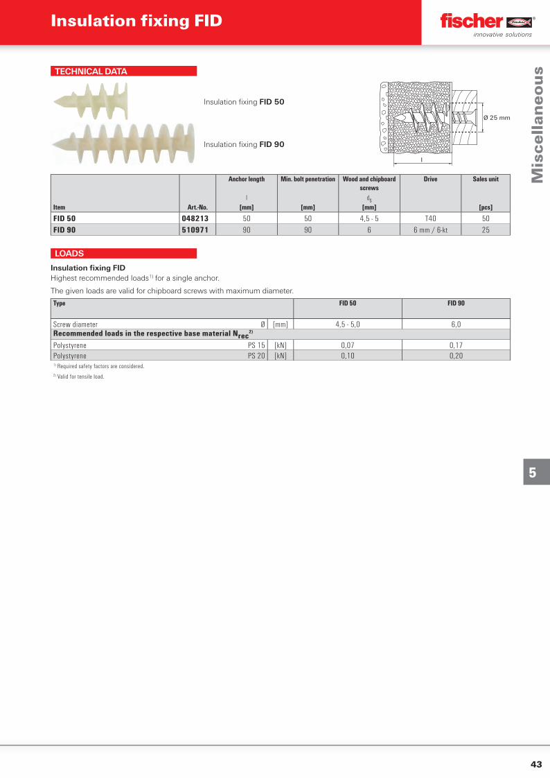
43
5
TECHNICAL DATA
Insulation fi xing FID 50
l
Ø 25 mm
Insulation fi xing FID 90
Anchor length Min. bolt penetration Wood and chipboard screws
Drive Sales unit
l dsItem Art.-No. [mm] [mm] [mm] [pcs]
FID 50 048213 50 50 4,5 - 5 T40 50FID 90 510971 90 90 6 6 mm / 6-kt 25
LOADS
Insulation fixing FIDHighest recommended loads1) for a single anchor.
The given loads are valid for chipboard screws with maximum diameter.
Type FID 50 FID 90
Screw diameter Ø [mm] 4,5 - 5,0 6,0Recommended loads in the respective base material Nrec
2)
Polystyrene PS 15 [kN] 0,07 0,17Polystyrene PS 20 [kN] 0,10 0,201) Required safety factors are considered.2) Valid for tensile load.
Mis
cell
ane
ou
s
Insulation fi xing FID
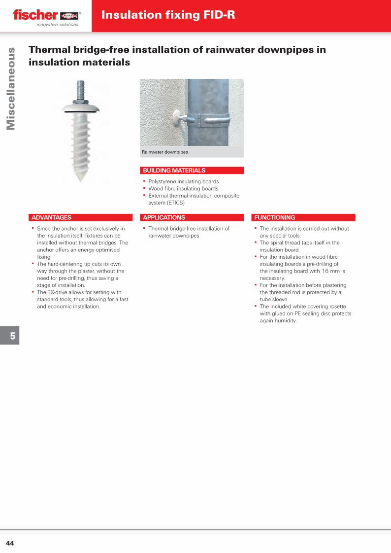
44
5
Rainwater downpipes
Thermal bridge-free installation of rainwater downpipes in insulation materials
ADVANTAGES
▪ Since the anchor is set exclusively in the insulation itself, fi xtures can be installed without thermal bridges. The anchor off ers an energy-optimised fi xing.
▪ The hard-centering tip cuts its own way through the plaster, without the need for pre-drilling, thus saving a stage of installation.
▪ The TX-drive allows for setting with standard tools, thus allowing for a fast and economic installation.
APPLICATIONS
▪ Thermal bridge-free installation of rainwater downpipes
FUNCTIONING
▪ The installation is carried out without any special tools.
▪ The spiral thread taps itself in the insulation board.
▪ For the installation in wood fi bre insulating boards a pre-drilling of the insulating board with 16 mm is necessary.
▪ For the installation before plastering the threaded rod is protected by a tube sleeve.
▪ The included white covering rosette with glued on PE sealing disc protects again humidity.
BUILDING MATERIALS
▪ Polystyrene insulating boards▪ Wood fi bre insulating boards▪ External thermal insulation composite
system (ETICS)
Mis
cell
ane
ou
sInsulation fi xing FID-R
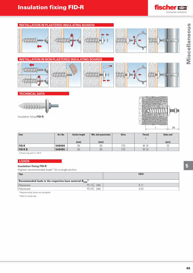
45
5
INSTALLATION IN PLASTERED INSULATING BOARDS
INSTALLATION IN NON-PLASTERED INSULATING BOARDS
TECHNICAL DATA
l 35
Insulation fxing FID-R
Item Art.-No. Anchor length Min. bolt penetration Drive Thread Sales unitl A
[mm] [mm] [pcs]
FID-R 548404 95 95 T25 M 10 25FID-R B 548405 1) 95 95 T25 M 10 11) Plastic bag with 4 x FID R
LOADS
Insulation fixing FID-RHighest recommended loads1) for a single anchor.
Type FID-R
Recommended loads in the respective base material Nrec2)
Polystyrene PS 15 [kN] 0,17Polystyrene PS 20 [kN] 0,201) Required safety factors are considered.2) Valid for tensile load.
Mis
cell
ane
ou
s
Insulation fi xing FID-R
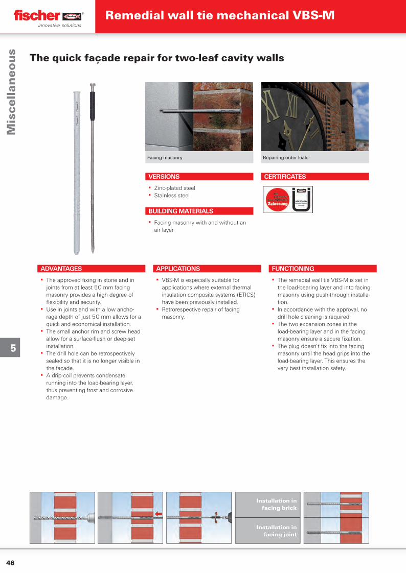
46
5
Facing masonry Repairing outer leafs
The quick façade repair for two-leaf cavity walls
VERSIONS
▪ Zinc-plated steel▪ Stainless steel
ADVANTAGES
▪ The approved fi xing in stone and in joints from at least 50 mm facing masonry provides a high degree of fl exibility and security.
▪ Use in joints and with a low ancho-rage depth of just 50 mm allows for a quick and economical installation.
▪ The small anchor rim and screw head allow for a surface-fl ush or deep-set installation.
▪ The drill hole can be retrospectively sealed so that it is no longer visible in the façade.
▪ A drip coil prevents condensate running into the load-bearing layer, thus preventing frost and corrosive damage.
APPLICATIONS
▪ VBS-M is especially suitable for applications where external thermal insulation composite systems (ETICS) have been previously installed.
▪ Retrorespective repair of facing masonry.
FUNCTIONING
▪ The remedial wall tie VBS-M is set in the load-bearing layer and into facing masonry using push-through installa-tion.
▪ In accordance with the approval, no drill hole cleaning is required.
▪ The two expansion zones in the load-bearing layer and in the facing masonry ensure a secure fi xation.
▪ The plug doesn’t fi x into the facing masonry until the head grips into the load-bearing layer. This ensures the very best installation safety.
BUILDING MATERIALS
▪ Facing masonry with and without an air layer
CERTIFICATES
Mis
cell
ane
ou
sRemedial wall tie mechanical VBS-M
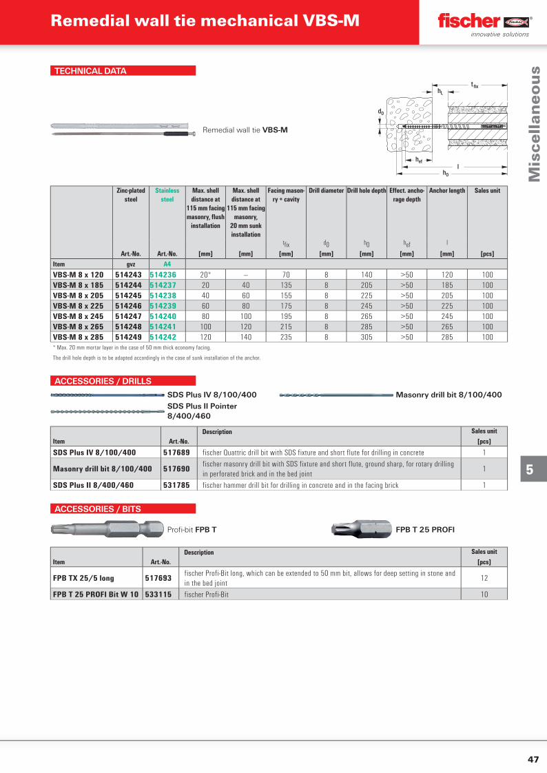
47
5
TECHNICAL DATA
Remedial wall tie VBS-M
hL
d0
lhef
h0
t fix
Zinc-plated steel
Stainless steel
Max. shell distance at
115 mm facing masonry, fl ush
installation
Max. shell distance at
115 mm facing masonry,
20 mm sunk installation
Facing mason-ry + cavity
Drill diameter Drill hole depth Eff ect. ancho-rage depth
Anchor length Sales unit
tfi x d0 h0 hef l
Art.-No. Art.-No. [mm] [mm] [mm] [mm] [mm] [mm] [mm] [pcs]Item gvz A4
VBS-M 8 x 120 514243 514236 20* — 70 8 140 >50 120 100VBS-M 8 x 185 514244 514237 20 40 135 8 205 >50 185 100VBS-M 8 x 205 514245 514238 40 60 155 8 225 >50 205 100VBS-M 8 x 225 514246 514239 60 80 175 8 245 >50 225 100VBS-M 8 x 245 514247 514240 80 100 195 8 265 >50 245 100VBS-M 8 x 265 514248 514241 100 120 215 8 285 >50 265 100VBS-M 8 x 285 514249 514242 120 140 235 8 305 >50 285 100* Max. 20 mm mortar layer in the case of 50 mm thick economy facing.
The drill hole depth is to be adapted accordingly in the case of sunk installation of the anchor.
ACCESSORIES / DRILLS
SDS Plus IV 8/100/400 Masonry drill bit 8/100/400SDS Plus II Pointer 8/400/460
Description Sales unitItem Art.-No. [pcs]
SDS Plus IV 8/100/400 517689 fischer Quattric drill bit with SDS fixture and short flute for drilling in concrete 1
Masonry drill bit 8/100/400 517690fischer masonry drill bit with SDS fixture and short flute, ground sharp, for rotary drilling in perforated brick and in the bed joint
1
SDS Plus II 8/400/460 531785 fischer hammer drill bit for drilling in concrete and in the facing brick 1
ACCESSORIES / BITS
Profi -bit FPB T FPB T 25 PROFI
Description Sales unitItem Art.-No. [pcs]
FPB TX 25/5 long 517693fischer Profi-Bit long, which can be extended to 50 mm bit, allows for deep setting in stone and in the bed joint
12
FPB T 25 PROFI Bit W 10 533115 fischer Profi-Bit 10
Mis
cell
ane
ou
s
Remedial wall tie mechanical VBS-M
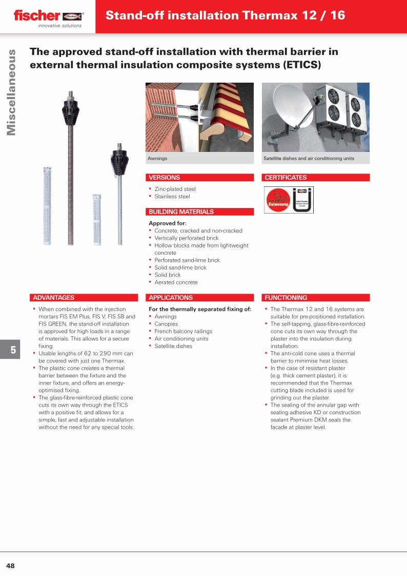
48
5
Awnings Satellite dishes and air conditioning units
The approved stand-off installation with thermal barrier in external thermal insulation composite systems (ETICS)
ADVANTAGES
▪ When combined with the injection mortars FIS EM Plus, FIS V, FIS SB and FIS GREEN, the stand-off installation is approved for high loads in a range of materials. This allows for a secure fi xing.
▪ Usable lengths of 62 to 290 mm can be covered with just one Thermax.
▪ The plastic cone creates a thermal barrier between the fi xture and the inner fi xture, and off ers an energy-optimised fi xing.
▪ The glass-fi bre-reinforced plastic cone cuts its own way through the ETICS with a positive fi t, and allows for a simple, fast and adjustable installation without the need for any special tools.
VERSIONS
▪ Zinc-plated steel▪ Stainless steel
APPLICATIONS
For the thermally separated fi xing of:▪ Awnings▪ Canopies▪ French balcony railings▪ Air conditioning units▪ Satellite dishes
FUNCTIONING
▪ The Thermax 12 and 16 systems are suitable for pre-positioned installation.
▪ The self-tapping, glass-fi bre-reinforced cone cuts its own way through the plaster into the insulation during installation.
▪ The anti-cold cone uses a thermal barrier to minimise heat losses.
▪ In the case of resistant plaster (e.g. thick cement plaster), it is recommended that the Thermax cutting blade included is used for grinding out the plaster.
▪ The sealing of the annular gap with sealing adhesive KD or construction sealant Premium DKM seals the facade at plaster level.
BUILDING MATERIALS
Approved for:▪ Concrete, cracked and non-cracked▪ Vertically perforated brick▪ Hollow blocks made from lightweight
concrete▪ Perforated sand-lime brick▪ Solid sand-lime brick▪ Solid brick▪ Aerated concrete
CERTIFICATES
Mis
cell
ane
ou
sStand-off installation Thermax 12 / 16
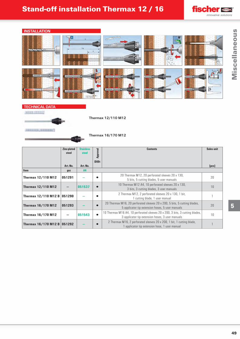
49
5
INSTALLATION
TECHNICAL DATA
Thermax 12/110 M12
Thermax 16/170 M12
Zinc-plated steel
Stainless steel
Appr
oval Contents Sales unit
DIBtArt.-No. Art.-No. [pcs]
Item gvz A4
Thermax 12/110 M12 051291 — ▯20 Thermax M12, 20 perforated sleeves 20 x 130,
5 bits, 5 cutting blades, 5 user manuals20
Thermax 12/110 M12 — 051537 ▯10 Thermax M12 A4, 10 perforated sleeves 20 x 130,
3 bits, 3 cutting blades, 3 user manuals10
Thermax 12/110 M12 B 051290 — ▯2 Thermax M12, 2 perforated sleeves 20 x 130, 1 bit,
1 cutting blade, 1 user manual1
Thermax 16/170 M12 051293 — ▯20 Thermax M16, 20 perforated sleeves 20 x 200, 5 bits, 5 cutting blades,
5 applicator tip extension hoses, 5 user manuals20
Thermax 16/170 M12 — 051543 ▯10 Thermax M16 A4, 10 perforated sleeves 20 x 200, 3 bits, 3 cutting blades,
3 applicator tip extension hoses, 3 user manuals10
Thermax 16/170 M12 B 051292 — ▯2 Thermax M16, 2 perforated sleeves 20 x 200, 1 bit, 1 cutting blade,
1 applicator tip extension hose, 1 user manual1
Mis
cell
ane
ou
s
Stand-off installation Thermax 12 / 16
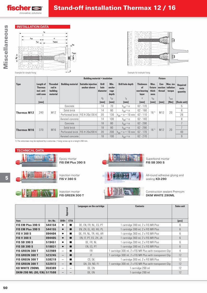
50
5
Example for multiple fixing
Building material + insulation Fixture
Type Length of Thermax incl. anti-cold cone
Threaded rod in
building material
Building material Suitable injection anchor sleeve
Drillhole
diameter
Min. ancho-rage
depth
Drill hole depth Thicknessof
non-bearing layer
Max. fi xture thick-ness
Con-nection thread
Max. ins-tallation torque
Required resin
quantity
l d0 hef td e tfi x Tinst[mm] [mm] [mm] [mm] [mm] [mm] [mm] [Nm] [Scale unit]
Thermax M12 240 M12
Concrete 14 70 hef + e 62 - 170
16 1) M12 20
5Solid brick 14 80 hef + e 62 - 160 6
Perforated brick FIS H 20x130 K 20 130 hef + e + 10 mm 62 - 110 26Aerated concrete 14 100 hef + e 62 - 140 8
Thermax M16 370 M16
Concrete 18 80 hef + e 62 - 290
16 1) M12 20
7Solid brick 18 80 hef + e 62 - 290 7
Perforated brick FIS H 20x200 K 20 200 hef + e + 10 mm 62 - 170 40Aerated concrete 18 100 hef + e 62 - 270 9
1) The setscrews may be replaced by a setscrew / fixing screw up to a length 200 mm.
INSTALLATION DATA
Example for simple fixing
T inst
eh ef
l
t tol t WDVS
d 0
t fix
Ü
t d
TECHNICAL DATA
Epoxy mortar FIS EM Plus 390 S
Superbond mortar FIS SB 390 S
Injection mortar FIS V 360 S
All-round adhesive gluing and sealing KD-290
Injection mortar FIS GREEN 300 T
Construction sealant Premium DKM WHITE 290ML
Appr
oval
Languages on the cartridge Contents Sales unit
Item Art.-No. DIBt ETA [pcs]
FIS EM Plus 390 S 544154 ▯ ■ DE, EN, FR, NL, ES, PT 1 cartridge 390 ml, 2 x FIS MR Plus 6FIS EM Plus 390 S 544155 ▯ ■ EN, ZH, EL, KO, HU, PL 1 cartridge 390 ml, 2 x FIS MR Plus 6FIS V 360 S 094404 ▯ ■ DE, FR, NL, TR, HU, AR 1 cartridge 360 ml, 2 x FIS MR Plus 6FIS V 360 S 094405 ▯ ■ EN, IT, PT, ES, ZH, JA 1 cartridge 360 ml, 2 x FIS MR Plus 6FIS SB 390 S 519451 ▯ ■ DE, FR, NL 1 cartridge 390 ml, 2 x FIS MR Plus 6FIS SB 390 S 518831 ▯ ■ EN, ES, PT 1 cartridge 390 ml, 2 x FIS MR Plus 6FIS GREEN 300 T 522989 — ■ FR 1 cartridge 300 ml, 2 x FIS MR Plus with transparent Clip 4FIS GREEN 300 T 523245 — ■ IT 1 cartridge 300 ml, 2 x FIS MR Plus with transparent Clip 12FIS GREEN 300 T 538219 — ■ CS, SK 1 cartridge 300 ml, 2 x FIS MR Plus 12FIS GREEN 300 T 532972 — ■ DA, SV, NO, FI 1 cartridge 300 ml, 2 x FIS MR Plus with transparent Clip 12KD WHITE 290ML 059389 — — DE, EN 1 cartridge 290 ml 12DKM-290 ML (DE/EN) 517598 — — DE, EN 1 cartridge 290 ml 12
Mis
cell
ane
ou
sStand-off installation Thermax 12 / 16
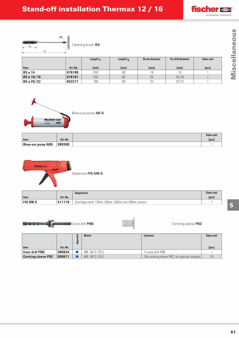
51
5
Cleaning brush BS
Length L1 Length L2 Brush diameter For drill diameter Sales unit
Item Art.-No. [mm] [mm] [mm] [mm] [pcs]
BS ø 14 078180 250 80 16 14 1BS ø 16/18 078181 250 80 20 16/18 1BS ø 20/22 052277 180 80 25 20/22 1
Blow-out pump AB G
Sales unitItem Art.-No. [pcs]
Blow-out pump ABG 089300 1
Dispenser FIS DM S
Adapted for Sales unitItem Art.-No. [pcs]
FIS DM S 511118 Cartridges with 150ml, 300ml, 360ml and 390ml content 1
Cone drill PBB Centring sleeve PBZ
Appr
oval Match Contents Sales unit
Item Art.-No. [pcs]
Cone drill PBB 090634 ■ M8 - M12; FIS E 1x cone drill PBB 1Centring sleeve PBZ 090671 ■ M8 - M12; FIS E 10x centring sleeve PBZ, 5x injection adapter 10
Mis
cell
ane
ou
s
Stand-off installation Thermax 12 / 16
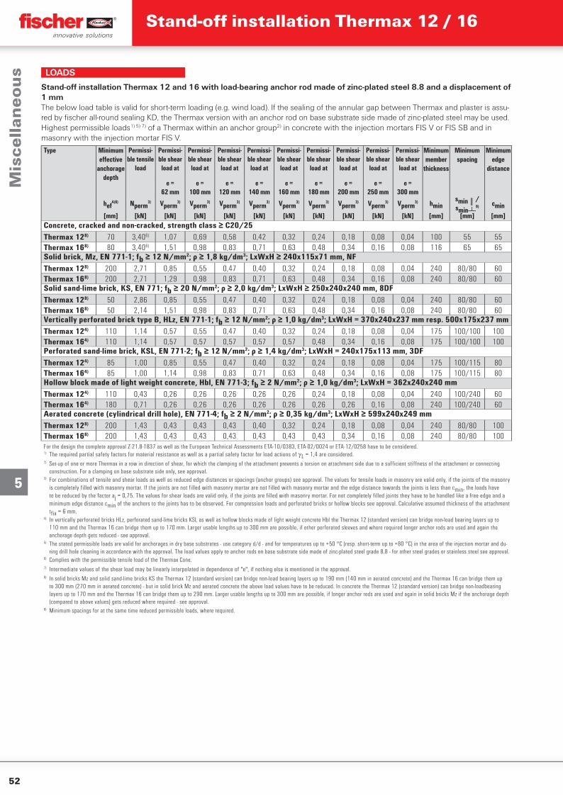
52
5
LOADS
Stand-off installation Thermax 12 and 16 with load-bearing anchor rod made of zinc-plated steel 8.8 and a displacement of 1 mmThe below load table is valid for short-term loading (e.g. wind load). If the sealing of the annular gap between Thermax and plaster is assu-red by fischer all-round sealing KD, the Thermax version with an anchor rod on base substrate side made of zinc-plated steel may be used.Highest permissible loads1) 5) 7) of a Thermax within an anchor group2) in concrete with the injection mortars FIS V or FIS SB and in masonry with the injection mortar FIS V.
Type Minimum effective
anchorage depth
Permissi-ble tensile
load
Permissi-ble shear
load at
Permissi-ble shear
load at
Permissi-ble shear
load at
Permissi-ble shear
load at
Permissi-ble shear
load at
Permissi-ble shear
load at
Permissi-ble shear
load at
Permissi-ble shear
load at
Permissi-ble shear
load at
Minimummember
thickness
Minimumspacing
Minimumedge
distance
e =62 mm
e =100 mm
e =120 mm
e =140 mm
e =160 mm
e =180 mm
e =200 mm
e =250 mm
e =300 mm
hef4)8) Nperm
3) Vperm3) Vperm
3) Vperm3) Vperm
3) Vperm3) Vperm
3) Vperm3) Vperm
3) Vperm3) hmin
smin║/smin┴
9) cmin[mm] [kN] [kN] [kN] [kN] [kN] [kN] [kN] [kN] [kN] [kN] [mm] [mm] [mm]
Concrete, cracked and non-cracked, strength class ≥ C20/25Thermax 128) 70 3,406) 1,07 0,69 0,58 0,42 0,32 0,24 0,18 0,08 0,04 100 55 55Thermax 168) 80 3,406) 1,51 0,98 0,83 0,71 0,63 0,48 0,34 0,16 0,08 116 65 65Solid brick, Mz, EN 771-1; fb ≥ 12 N/mm2; ρ ≥ 1,8 kg/dm3; LxWxH ≥ 240x115x71 mm, NFThermax 128) 200 2,71 0,85 0,55 0,47 0,40 0,32 0,24 0,18 0,08 0,04 240 80/80 60Thermax 168) 200 2,71 1,29 0,98 0,83 0,71 0,63 0,48 0,34 0,16 0,08 240 80/80 60Solid sand-lime brick, KS, EN 771; fb ≥ 20 N/mm2; ρ ≥ 2,0 kg/dm3; LxWxH ≥ 250x240x240 mm, 8DFThermax 128) 50 2,86 0,85 0,55 0,47 0,40 0,32 0,24 0,18 0,08 0,04 240 80/80 60Thermax 168) 50 2,14 1,51 0,98 0,83 0,71 0,63 0,48 0,34 0,16 0,08 240 80/80 60Vertically perforated brick type B, HLz, EN 771-1; fb ≥ 12 N/mm2; ρ ≥ 1,0 kg/dm3; LxWxH = 370x240x237 mm resp. 500x175x237 mmThermax 124) 110 1,14 0,57 0,55 0,47 0,40 0,32 0,24 0,18 0,08 0,04 175 100/100 100Thermax 164) 110 1,14 0,57 0,57 0,57 0,57 0,57 0,48 0,34 0,16 0,08 175 100/100 100Perforated sand-lime brick, KSL, EN 771-2; fb ≥ 12 N/mm2; ρ ≥ 1,4 kg/dm3; LxWxH = 240x175x113 mm, 3DFThermax 124) 85 1,00 0,85 0,55 0,47 0,40 0,32 0,24 0,18 0,08 0,04 175 100/115 80Thermax 164) 85 1,00 1,14 0,98 0,83 0,71 0,63 0,48 0,34 0,16 0,08 175 100/115 80Hollow block made of light weight concrete, Hbl, EN 771-3; fb ≥ 2 N/mm2; ρ ≥ 1,0 kg/dm3; LxWxH = 362x240x240 mmThermax 124) 110 0,43 0,26 0,26 0,26 0,26 0,26 0,24 0,18 0,08 0,04 240 100/240 60Thermax 164) 180 0,71 0,26 0,26 0,26 0,26 0,26 0,26 0,26 0,16 0,08 240 100/240 60Aerated concrete (cylindrical drill hole), EN 771-4; fb ≥ 2 N/mm2; ρ ≥ 0,35 kg/dm3; LxWxH ≥ 599x240x249 mmThermax 128) 200 1,43 0,43 0,43 0,43 0,40 0,32 0,24 0,18 0,08 0,04 240 80/80 100Thermax 168) 200 1,43 0,43 0,43 0,43 0,43 0,43 0,43 0,34 0,16 0,08 240 80/80 100For the design the complete approval Z-21.8-1837 as well as the European Technical Assessments ETA-10/0383, ETA-02/0024 or ETA-12/0258 have to be considered.1) The required partial safety factors for material resistance as well as a partial safety factor for load actions of L = 1,4 are considered.2) Set-up of one or more Thermax in a row in direction of shear, for which the clamping of the attachment prevents a torsion on attachment side due to a sufficient stiffness of the attachment or connecting
construction. For a clamping on base substrate side only, see approval.3) For combinations of tensile and shear loads as well as reduced edge distances or spacings (anchor groups) see approval. The values for tensile loads in masonry are valid only, if the joints of the masonry
is completely filled with masonry mortar. If the joints are not filled with masonry mortar are not filled with masonry mortar and the edge distance towards the joints is less than cmin, the loads have to be reduced by the factor aj = 0,75. The values for shear loads are valid only, if the joints are filled with masonry mortar. For not completely filled joints they have to be handled like a free edge and a minimum edge distance cmin of the anchors to the joints has to be observed. For compression loads and perforated bricks or hollow blocks see approval. Calculative assumed thickness of the attachment tfix = 6 mm.
4) In vertically perforated bricks HLz, perforated sand-lime bricks KSL as well as hollow blocks made of light weight concrete Hbl the Thermax 12 (standard version) can bridge non-load bearing layers up to 110 mm and the Thermax 16 can bridge them up to 170 mm. Larger usable lengths up to 300 mm are possible, if other perforated sleeves and where required longer anchor rods are used and again the anchorage depth gets reduced - see approval.
5) The stated permissible loads are valid for anchorages in dry base substrates - use category d/d - and for temperatures up to +50 °C (resp. short-term up to +80 °C) in the area of the injection mortar and du-ring drill hole cleaning in accordance with the approval. The load values apply to anchor rods on base substrate side made of zinc-plated steel grade 8.8 - for other steel grades or stainless steel see approval.
6) Complies with the permissible tensile load of the Thermax Cone.7) Intermediate values of the shear load may be linearly interpolated in dependence of "e", if nothing else is mentioned in the approval.8) In solid bricks Mz and solid sand-lime bricks KS the Thermax 12 (standard version) can bridge non-load bearing layers up to 190 mm (140 mm in aerated concrete) and the Thermax 16 can bridge them up
to 300 mm (270 mm in aerated concrete) - but in solid brick Mz and aerated concrete the above load values have to be reduced. In concrete the Thermax 12 (standard version) can bridge non-loadbearing layers up to 170 mm and the Thermax 16 can bridge them up to 290 mm. Larger usable lengths up to 300 mm are possible, if longer anchor rods are used and again in solid bricks Mz if the anchorage depth (compared to above values) gets reduced where required - see approval.
9) Minimum spacings for at the same time reduced permissible loads, where required.
Mis
cell
ane
ou
sStand-off installation Thermax 12 / 16
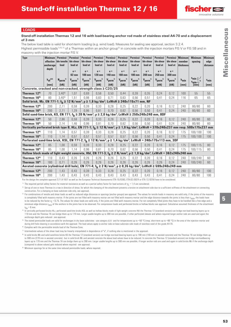
53
5
LOADS
Stand-off installation Thermax 12 and 16 with load-bearing anchor rod made of stainless steel A4-70 and a displacement of 3 mmThe below load table is valid for short-term loading (e.g. wind load). Measures for sealing see approval, section 3.2.4.Highest permissible loads1) 5) 7) of a Thermax within an anchor group2) in concrete with the injection mortars FIS V or FIS SB and in masonry with the injection mortar FIS V.
Type Minimum effective
anchorage depth
Permissi-ble tensile
load
Permissi-ble shear
load at
Permissi-ble shear
load at
Permissi-ble shear
load at
Permissi-ble shear
load at
Permissi-ble shear
load at
Permissi-ble shear
load at
Permissi-ble shear
load at
Permissi-ble shear
load at
Permissi-ble shear
load at
Minimummember
thickness
Minimumspacing
Minimumedge
distance
e =62 mm
e =100 mm
e =120 mm
e =140 mm
e =160 mm
e =180 mm
e =200 mm
e =250 mm
e =300 mm
hef4)8) Nperm
3) Vperm3) Vperm
3) Vperm3) Vperm
3) Vperm3) Vperm
3) Vperm3) Vperm
3) Vperm3) hmin
smin║/smin┴
9) cmin[mm] [kN] [kN] [kN] [kN] [kN] [kN] [kN] [kN] [kN] [kN] [mm] [mm] [mm]
Concrete, cracked and non-cracked, strength class ≥ C20/25Thermax 128) 70 3,406) 1,07 0,69 0,58 0,50 0,44 0,39 0,35 0,24 0,12 100 55 55Thermax 168) 80 3,406) 1,51 0,98 0,83 0,71 0,63 0,56 0,51 0,41 0,24 116 65 65Solid brick, Mz, EN 771-1; fb ≥ 12 N/mm2; ρ ≥ 1,8 kg/dm3; LxWxH ≥ 240x115x71 mm, NFThermax 128) 200 2,71 0,59 0,39 0,33 0,28 0,25 0,22 0,20 0,16 0,12 240 80/80 60Thermax 168) 200 2,71 1,29 0,96 0,81 0,70 0,62 0,56 0,50 0,41 0,24 240 80/80 60Solid sand-lime brick, KS, EN 771; fb ≥ 20 N/mm2; ρ ≥ 2,0 kg/dm3; LxWxH ≥ 250x240x240 mm, 8DFThermax 128) 50 2,86 0,59 0,39 0,33 0,28 0,25 0,22 0,20 0,16 0,12 240 80/80 60Thermax 168) 50 2,14 1,46 0,96 0,81 0,70 0,62 0,56 0,50 0,41 0,24 240 80/80 60Vertically perforated brick type B, HLz, EN 771-1; fb ≥ 12 N/mm2; ρ ≥ 1,0 kg/dm3; LxWxH = 370x240x237 mm resp. 500x175x237 mmThermax 124) 110 1,14 0,57 0,39 0,33 0,28 0,25 0,22 0,20 0,16 0,12 175 100/100 100Thermax 164) 110 1,14 0,57 0,57 0,57 0,57 0,57 0,56 0,50 0,41 0,24 175 100/100 100Perforated sand-lime brick, KSL, EN 771-2; fb ≥ 12 N/mm2; ρ ≥ 1,4 kg/dm3; LxWxH = 240x175x113 mm, 3DFThermax 124) 85 1,00 0,59 0,39 0,33 0,28 0,25 0,22 0,20 0,16 0,12 175 100/115 80Thermax 164) 85 1,00 1,14 0,96 0,81 0,70 0,62 0,56 0,50 0,41 0,24 175 100/115 80Hollow block made of light weight concrete, Hbl, EN 771-3; fb ≥ 2 N/mm2; ρ ≥ 1,0 kg/dm3; LxWxH = 362x240x240 mmThermax 124) 110 0,43 0,26 0,26 0,26 0,26 0,25 0,22 0,20 0,16 0,12 240 100/240 60Thermax 164) 180 0,71 0,26 0,26 0,26 0,26 0,26 0,26 0,26 0,26 0,24 240 100/240 60Aerated concrete (cylindrical drill hole), EN 771-4; fb ≥ 2 N/mm2; ρ ≥ 0,35 kg/dm3; LxWxH ≥ 599x240x249 mmThermax 128) 200 1,43 0,43 0,39 0,33 0,28 0,25 0,22 0,20 0,16 0,12 240 80/80 100Thermax 168) 200 1,43 0,43 0,43 0,43 0,43 0,43 0,43 0,43 0,41 0,24 240 80/80 100For the design the complete approval Z-21.8-1837 as well as the European Technical Assessments ETA-10/0383, ETA-02/0024 or ETA-12/0258 have to be considered.1) The required partial safety factors for material resistance as well as a partial safety factor for load actions of L = 1,4 are considered.2) Set-up of one or more Thermax in a row in direction of shear, for which the clamping of the attachment prevents a torsion on attachment side due to a sufficient stiffness of the attachment or connecting
construction. For a clamping on base substrate side only, see approval.3) For combinations of tensile and shear loads as well as reduced edge distances or spacings (anchor groups) see approval. The values for tensile loads in masonry are valid only, if the joints of the masonry
is completely filled with masonry mortar. If the joints are not filled with masonry mortar are not filled with masonry mortar and the edge distance towards the joints is less than cmin, the loads have to be reduced by the factor aj = 0,75. The values for shear loads are valid only, if the joints are filled with masonry mortar. For not completely filled joints they have to be handled like a free edge and a minimum edge distance cmin of the anchors to the joints has to be observed. For compression loads and perforated bricks or hollow blocks see approval. Calculative assumed thickness of the attachment tfix = 6 mm.
4) In vertically perforated bricks HLz, perforated sand-lime bricks KSL as well as hollow blocks made of light weight concrete Hbl the Thermax 12 (standard version) can bridge non-load bearing layers up to 110 mm and the Thermax 16 can bridge them up to 170 mm. Larger usable lengths up to 300 mm are possible, if other perforated sleeves and where required longer anchor rods are used and again the anchorage depth gets reduced - see approval.
5) The stated permissible loads are valid for anchorages in dry base substrates - use category d/d - and for temperatures up to +50 °C (resp. short-term up to +80 °C) in the area of the injection mortar and during drill hole cleaning in accordance with the approval. The load values apply to anchor rods on base substrate side made of stainless steel of the grade A4-70.
6) Complies with the permissible tensile load of the Thermax Cone.7) Intermediate values of the shear load may be linearly interpolated in dependence of "e", if nothing else is mentioned in the approval.8) In solid bricks Mz and solid sand-lime bricks KS the Thermax 12 (standard version) can bridge non-load bearing layers up to 190 mm (140 mm in aerated concrete) and the Thermax 16 can bridge them up
to 300 mm (270 mm in aerated concrete) - but in solid brick Mz and aerated concrete the above load values have to be reduced. In concrete the Thermax 12 (standard version) can bridge non-loadbearing layers up to 170 mm and the Thermax 16 can bridge them up to 290 mm. Larger usable lengths up to 300 mm are possible, if longer anchor rods are used and again in solid bricks Mz if the anchorage depth (compared to above values) gets reduced where required - see approval.
9) Minimum spacings for at the same time reduced permissible loads, where required.
Mis
cell
ane
ou
s
Stand-off installation Thermax 12 / 16
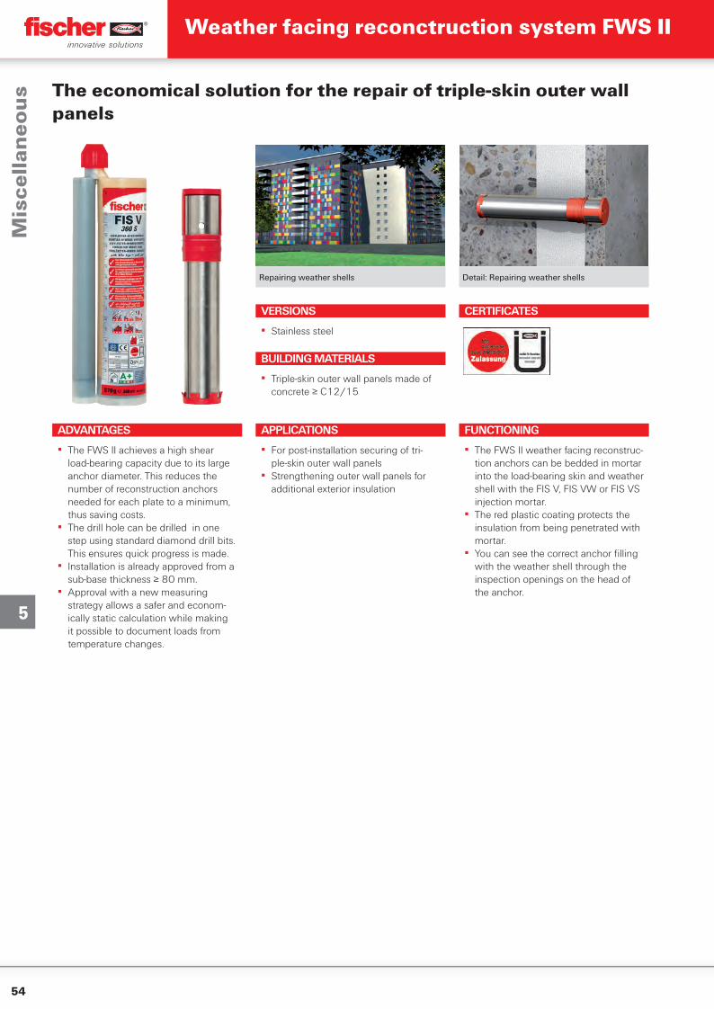
54
5
Repairing weather shells Detail: Repairing weather shells
The economical solution for the repair of triple-skin outer wall panels
ADVANTAGES
▪ The FWS II achieves a high shear load-bearing capacity due to its large anchor diameter. This reduces the number of reconstruction anchors needed for each plate to a minimum, thus saving costs.
▪ The drill hole can be drilled in one step using standard diamond drill bits. This ensures quick progress is made.
▪ Installation is already approved from a sub-base thickness ≥ 80 mm.
▪ Approval with a new measuring strategy allows a safer and econom-ically static calculation while making it possible to document loads from temperature changes.
VERSIONS
▪ Stainless steel
APPLICATIONS
▪ For post-installation securing of tri-ple-skin outer wall panels
▪ Strengthening outer wall panels for additional exterior insulation
FUNCTIONING
▪ The FWS II weather facing reconstruc-tion anchors can be bedded in mortar into the load-bearing skin and weather shell with the FIS V, FIS VW or FIS VS injection mortar.
▪ The red plastic coating protects the insulation from being penetrated with mortar.
▪ You can see the correct anchor fi lling with the weather shell through the inspection openings on the head of the anchor.
BUILDING MATERIALS
▪ Triple-skin outer wall panels made of concrete ≥ C12/15
CERTIFICATES
Mis
cell
ane
ou
sWeather facing reconctruction system FWS II
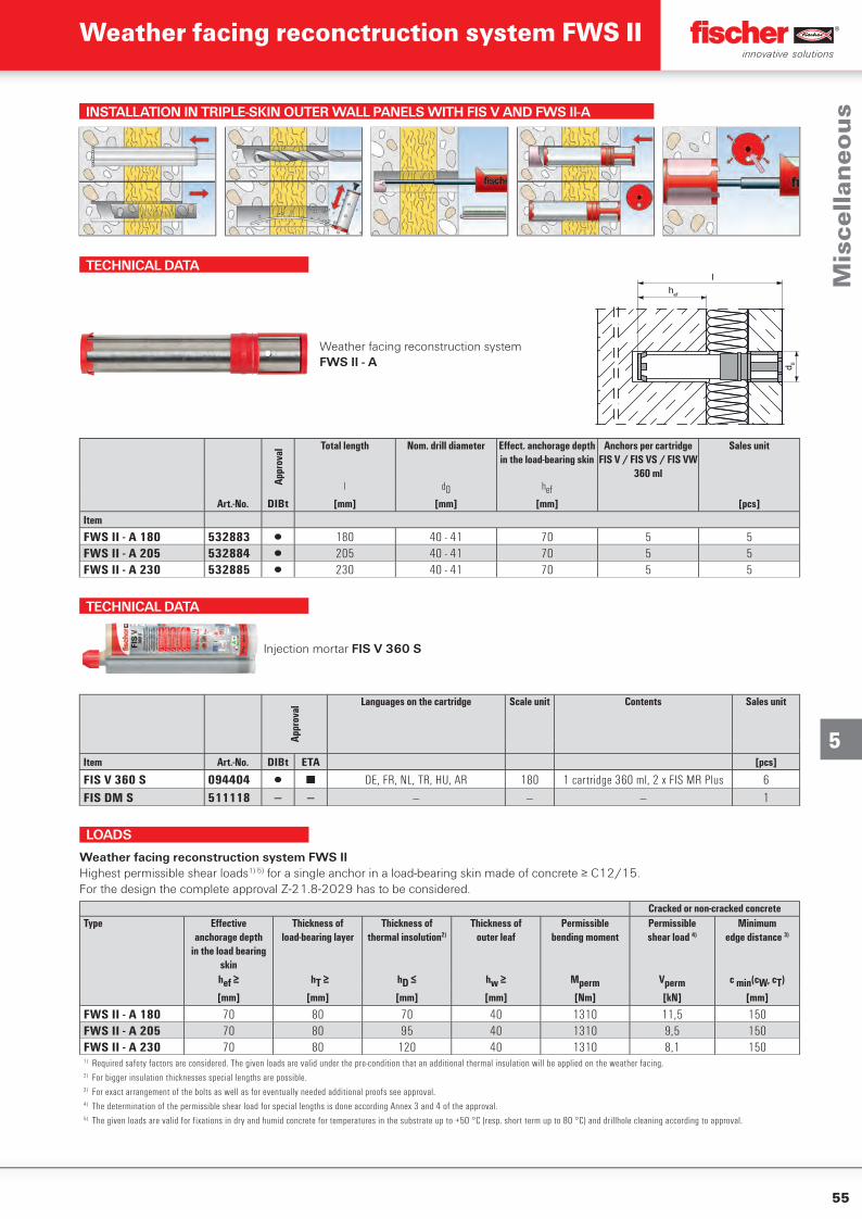
55
5
INSTALLATION IN TRIPLE-SKIN OUTER WALL PANELS WITH FIS V AND FWS II-A
TECHNICAL DATA
Weather facing reconstruction system FWS II - A
hef
d 0
lAp
prov
al
Total length Nom. drill diameter Eff ect. anchorage depth in the load-bearing skin
Anchors per cartridge FIS V / FIS VS / FIS VW
360 ml
Sales unit
l d0 hefArt.-No. DIBt [mm] [mm] [mm] [pcs]
Item
FWS II - A 180 532883 ▯ 180 40 - 41 70 5 5FWS II - A 205 532884 ▯ 205 40 - 41 70 5 5FWS II - A 230 532885 ▯ 230 40 - 41 70 5 5
TECHNICAL DATA
Injection mortar FIS V 360 S
Appr
oval
Languages on the cartridge Scale unit Contents Sales unit
Item Art.-No. DIBt ETA [pcs]
FIS V 360 S 094404 ▯ ■ DE, FR, NL, TR, HU, AR 180 1 cartridge 360 ml, 2 x FIS MR Plus 6FIS DM S 511118 — — — — — 1
LOADS
Weather facing reconstruction system FWS IIHighest permissible shear loads1) 5) for a single anchor in a load-bearing skin made of concrete ≥ C12/15.For the design the complete approval Z-21.8-2029 has to be considered.
Cracked or non-cracked concreteType Effective
anchorage depthin the load bearing
skin
Thickness ofload-bearing layer
Thickness ofthermal insolution2)
Thickness ofouter leaf
Permissiblebending moment
Permissibleshear load 4)
Minimumedge distance 3)
hef ≥ hT ≥ hD ≤ hw ≥ Mperm Vperm c min(cW, cT)
[mm] [mm] [mm] [mm] [Nm] [kN] [mm]
FWS II - A 180 70 80 70 40 1310 11,5 150FWS II - A 205 70 80 95 40 1310 9,5 150FWS II - A 230 70 80 120 40 1310 8,1 1501) Required safety factors are considered. The given loads are valid under the pre-condition that an additional thermal insulation will be applied on the weather facing.2) For bigger insulation thicknesses special lengths are possible.3) For exact arrangement of the bolts as well as for eventually needed additional proofs see approval.4) The determination of the permissible shear load for special lengths is done according Annex 3 and 4 of the approval.5) The given loads are valid for fixations in dry and humid concrete for temperatures in the substrate up to +50 °C (resp. short term up to 80 °C) and drillhole cleaning according to approval.
Mis
cell
ane
ou
s
Weather facing reconctruction system FWS II
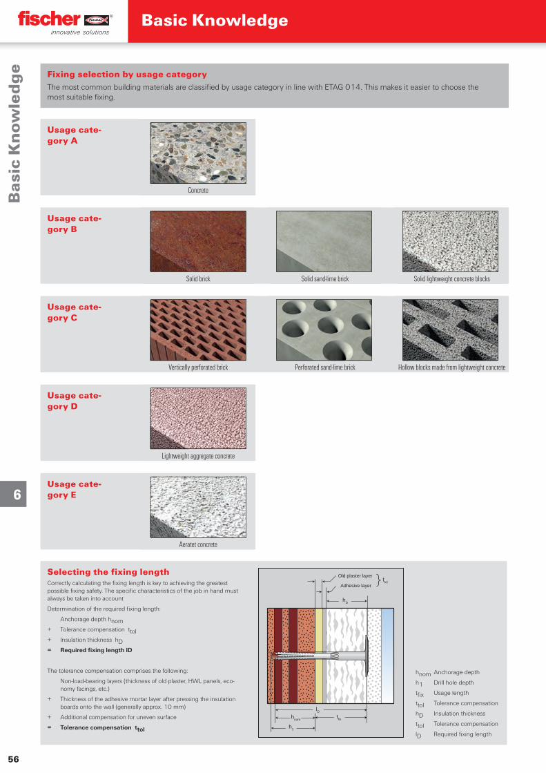
Gute Gründe für fischer
56
6
Bas
ic K
no
wle
dg
eBasic Knowledge
Fixing selection by usage category The most common building materials are classified by usage category in line with ETAG 014. This makes it easier to choose the most suitable fixing.
Selecting the fixing lengthCorrectly calculating the fixing length is key to achieving the greatest possible fixing safety. The specific characteristics of the job in hand must always be taken into account
Determination of the required fixing length:
Anchorage depth hnom+ Tolerance compensation ttol+ Insulation thickness hD= Required fixing length lD
The tolerance compensation comprises the following:
Non-load-bearing layers (thickness of old plaster, HWL panels, eco-nomy facings, etc.)
+ Thickness of the adhesive mortar layer after pressing the insulation boards onto the wall (generally approx. 10 mm)
+ Additional compensation for uneven surface
= Tolerance compensation ttol
Usage cate-gory A
Usage cate-gory B
Usage cate-gory C
Usage cate-gory D
Usage cate-gory E
Concrete
Solid brick Solid sand-lime brick Solid lightweight concrete blocks
Vertically perforated brick Perforated sand-lime brick Hollow blocks made from lightweight concrete
Lightweight aggregate concrete
Aeratet concrete
h1
hnom
Old plaster layer
Adhesive layer
lD
hD
ttol}
tfix
hnom Anchorage depth
h1 Drill hole depth
tfix Usage length
ttol Tolerance compensation
hD Insulation thickness
ttol Tolerance compensation
lD Required fixing length
MD_PG_$KT-WDVS-EWI-$KP-BASISWISSEN_#SEN_#APR_#V1.indd 56MD_PG_$KT-WDVS-EWI-$KP-BASISWISSEN_#SEN_#APR_#V1.indd 56 20.05.2020 08:24:1920.05.2020 08:24:19
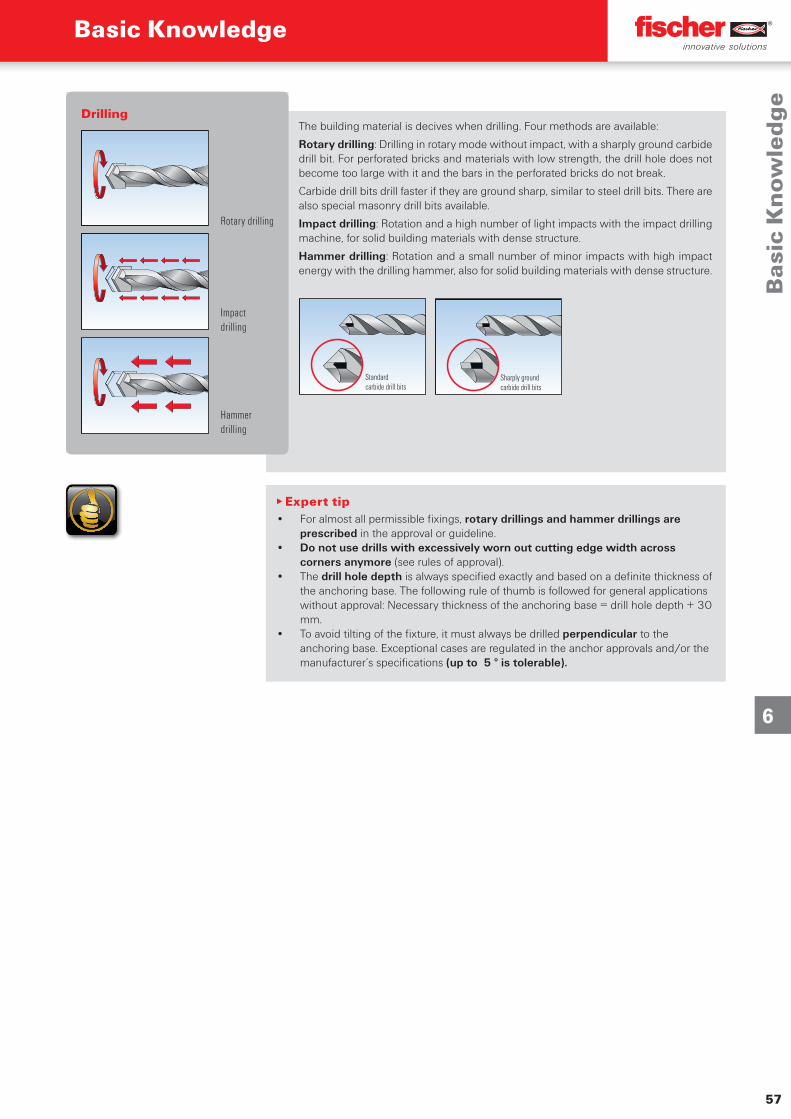
57
6
Bas
ic K
no
wle
dg
e
Basic Knowledge
hnom Anchorage depth
h1 Drill hole depth
tfix Usage length
ttol Tolerance compensation
hD Insulation thickness
ttol Tolerance compensation
lD Required fixing length
▸ Expert tip• For almost all permissible fixings, rotary drillings and hammer drillings are
prescribed in the approval or guideline.• Do not use drills with excessively worn out cutting edge width across
corners anymore (see rules of approval).• The drill hole depth is always specified exactly and based on a definite thickness of
the anchoring base. The following rule of thumb is followed for general applications without approval: Necessary thickness of the anchoring base = drill hole depth + 30 mm.
• To avoid tilting of the fixture, it must always be drilled perpendicular to the anchoring base. Exceptional cases are regulated in the anchor approvals and/or the manufacturer’s specifications (up to 5 ° is tolerable).
The building material is decives when drilling. Four methods are available:
Rotary drilling: Drilling in rotary mode without impact, with a sharply ground carbide drill bit. For perforated bricks and materials with low strength, the drill hole does not become too large with it and the bars in the perforated bricks do not break.
Carbide drill bits drill faster if they are ground sharp, similar to steel drill bits. There are also special masonry drill bits available.
Impact drilling: Rotation and a high number of light impacts with the impact drilling machine, for solid building materials with dense structure.
Hammer drilling: Rotation and a small number of minor impacts with high impact energy with the drilling hammer, also for solid building materials with dense structure.
Standard carbide drill bits
Sharply ground carbide drill bits
Drilling
Rotary drilling
Impact drilling
Hammer drilling
MD_PG_$KT-WDVS-EWI-$KP-BASISWISSEN_#SEN_#APR_#V1.indd 57MD_PG_$KT-WDVS-EWI-$KP-BASISWISSEN_#SEN_#APR_#V1.indd 57 20.05.2020 08:24:2120.05.2020 08:24:21

6
58
Se
rvic
efischer 360°- Service
Global presence with the fischer international sales team
▪ One-on-one assistance from multi lingual staff. ▪ Immediate information and individual solutions regar-
ding the widest range of fixings and fasteners worldwide.
▪ 46 own subsidiaries and distribution to more than 100 countries worldwide.
▪ Visit organization A - Z and training programs.
Qualified technical consulting from the fischer technical team
▪ Support for engineers, consultants and craftsmen. ▪ More than 130 engineers worldwide give legally
compliant technical advice and product recommen-dations.
▪ Services include test installations, pull-out tests, ▪ individual designs and comparative calculations. ▪ Special solutions in the scope of fixing technology.
Our service to you
„ We are a reliable partner, one that will stand at your side and address your individual requirements with advice and action.“
By implementing the fischer process system (fPS) we offer you the quickest and most efficient service.
Please contact: [email protected]
Please contact: [email protected]
MD_PG_$KT-WDVS-EWI-$KP-BASISWISSEN_#SEN_#APR_#V1.indd 58MD_PG_$KT-WDVS-EWI-$KP-BASISWISSEN_#SEN_#APR_#V1.indd 58 20.05.2020 08:24:3920.05.2020 08:24:39
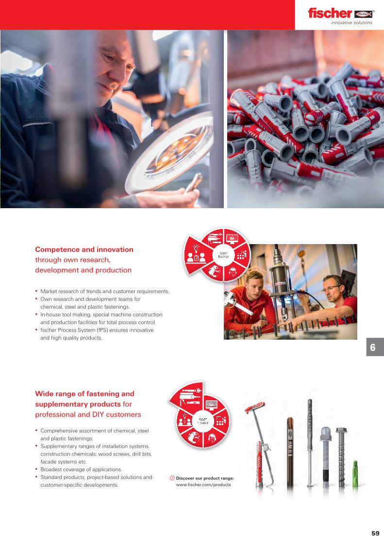
6
59
Se
rvic
e
Wide range of fastening and supplementary products for professional and DIY customers
▪ Comprehensive assortment of chemical, steel and plastic fastenings.
▪ Supplementary ranges of installation systems, construction chemicals, wood screws, drill bits, facade systems etc.
▪ Broadest coverage of applications. ▪ Standard products, project-based solutions and
customer-specific developments.
Competence and innovation through own research, development and production
▪ Market research of trends and customer requirements. ▪ Own research and development teams for
chemical, steel and plastic fastenings. ▪ In-house tool making, special machine construction
and production facilities for total process control. ▪ fischer Process System (fPS) ensures innovative
and high quality products.
Discover our product range:
www.fischer.com/products
MD_PG_$KT-WDVS-EWI-$KP-BASISWISSEN_#SEN_#APR_#V1.indd 59MD_PG_$KT-WDVS-EWI-$KP-BASISWISSEN_#SEN_#APR_#V1.indd 59 20.05.2020 08:24:4320.05.2020 08:24:43
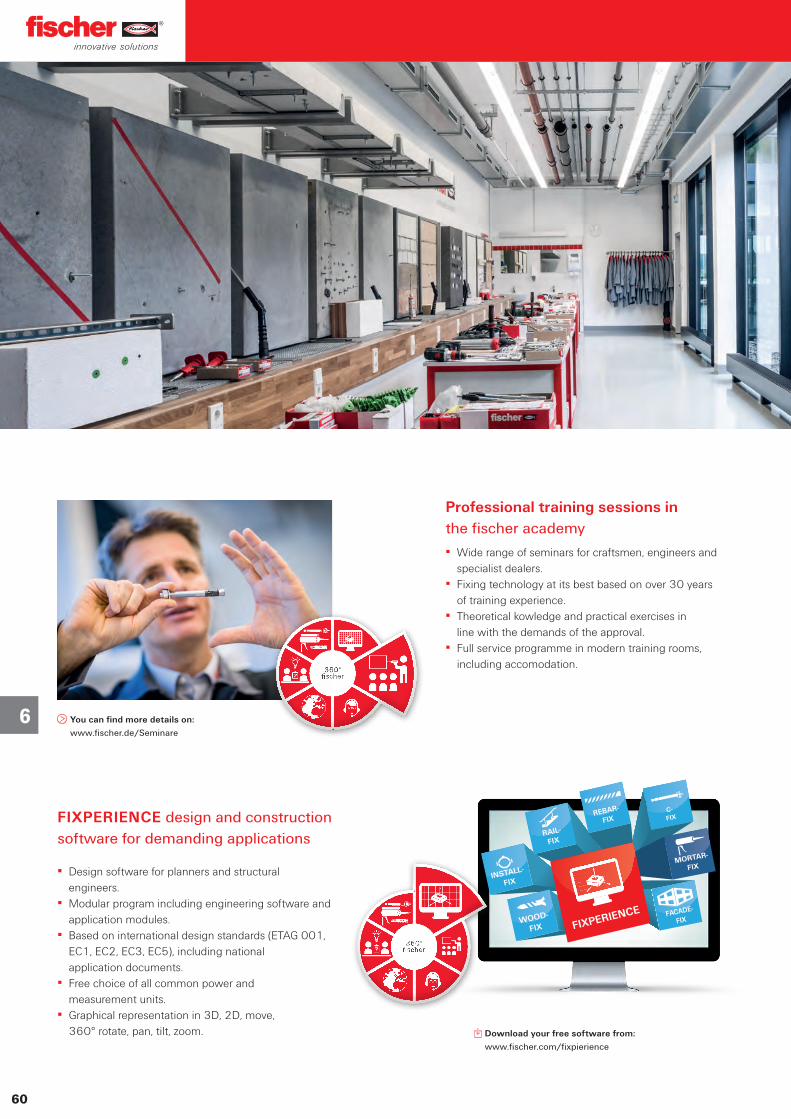
6
60
Se
rvic
e
C- FIX
FACADE-
FIX
INSTALL-
FIX
WOOD-
FIX
REBAR-
FIX
RAIL-
FIX
MORTAR-
FIX
FIXPERIENCE
Download your free software from:
www.fischer.com/fixpierience
You can find more details on:
www.fischer.de/Seminare
Professional training sessions in the fischer academy
▪ Wide range of seminars for craftsmen, engineers and specialist dealers.
▪ Fixing technology at its best based on over 30 years of training experience.
▪ Theoretical kowledge and practical exercises in line with the demands of the approval.
▪ Full service programme in modern training rooms, including accomodation.
FIXPERIENCE design and construction software for demanding applications
▪ Design software for planners and structural engineers.
▪ Modular program including engineering software and application modules.
▪ Based on international design standards (ETAG 001, EC1, EC2, EC3, EC5), including national application documents.
▪ Free choice of all common power and measurement units.
▪ Graphical representation in 3D, 2D, move, 360° rotate, pan, tilt, zoom.
MD_PG_$KT-WDVS-EWI-$KP-BASISWISSEN_#SEN_#APR_#V1.indd 60MD_PG_$KT-WDVS-EWI-$KP-BASISWISSEN_#SEN_#APR_#V1.indd 60 20.05.2020 08:24:5020.05.2020 08:24:50
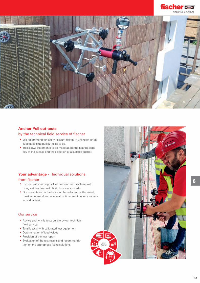
6
61
Se
rvic
e
Anchor Pull-out tests by the technical field service of fischer
▪ We recommend for safety-relevant fixings in unknown or old substrates plug pull-out tests to do.
▪ This allows statements to be made about the bearing capa-city of the subsoil and the selection of a suitable anchor.
Your advantage - Individual solutionsfrom fischer
▪ fischer is at your disposal for questions or problems with fixings at any time with first class service aside.
▪ Our consultation is the basis for the selection of the safest, most economical and above all optimal solution for your very individual task.
Our service
▪ Advice and tensile tests on site by our technical field service
▪ Tensile tests with calibrated test equipment ▪ Determination of load values ▪ Provision of the test report ▪ Evaluation of the test results and recommenda-
tion on the appropriate fixing solutions.
MD_PG_$KT-WDVS-EWI-$KP-BASISWISSEN_#SEN_#APR_#V1.indd 61MD_PG_$KT-WDVS-EWI-$KP-BASISWISSEN_#SEN_#APR_#V1.indd 61 20.05.2020 08:24:5520.05.2020 08:24:55
6
62
Se
rvic
e
MD_PG_$KT-WDVS-EWI-$KP-BASISWISSEN_#SEN_#APR_#V1.indd 62MD_PG_$KT-WDVS-EWI-$KP-BASISWISSEN_#SEN_#APR_#V1.indd 62 20.05.2020 08:24:5520.05.2020 08:24:55
6
63
Se
rvic
e
MD_PG_$KT-WDVS-EWI-$KP-BASISWISSEN_#SEN_#APR_#V1.indd 63MD_PG_$KT-WDVS-EWI-$KP-BASISWISSEN_#SEN_#APR_#V1.indd 63 20.05.2020 08:24:5520.05.2020 08:24:55

6
64
Se
rvic
e
MD_PG_$KT-WDVS-EWI-$KP-BASISWISSEN_#SEN_#APR_#V1.indd 64MD_PG_$KT-WDVS-EWI-$KP-BASISWISSEN_#SEN_#APR_#V1.indd 64 20.05.2020 08:24:5520.05.2020 08:24:55

6
65
Se
rvic
e
MD_PG_$KT-WDVS-EWI-$KP-BASISWISSEN_#SEN_#APR_#V1.indd 65MD_PG_$KT-WDVS-EWI-$KP-BASISWISSEN_#SEN_#APR_#V1.indd 65 20.05.2020 08:24:5520.05.2020 08:24:55

6
66
Se
rvic
e
MD_PG_$KT-WDVS-EWI-$KP-BASISWISSEN_#SEN_#APR_#V1.indd 66MD_PG_$KT-WDVS-EWI-$KP-BASISWISSEN_#SEN_#APR_#V1.indd 66 20.05.2020 08:24:5520.05.2020 08:24:55
Fixing selection
3) Depends on the installation situation
The information in this brochure is intended for general guidance only and is given without engagement. Additional information and advice on specific applications is available from our Technical Support Team. For this however, we require a pre-cise description of your particular application. All the data in this brochure concerning work with our fixing elements must be adapted to suit local conditions and the type of materials in use.If no detailed performance specifications are given for certain articles and types, please contact our Technical Service Department for advice.
fischerwerke GmbH & Co. KG72178 WaldachtalGermany
We cannot be responsible for any errors, and we reserve the right to make technical and range modifications without notice.No liability is accepted for printing errors and omissions.
Product usage category
A B C D E (F) HConcrete Solid bricks Hollow bricks Lightweight
aggregate concrete
Aeratet concrete
Concrete weather facing
Wood
Type
termoz PN 8 ▯ ▯ ▯ ▯ ▯
termoz CN 8 ▯ ▯ ▯ ▯ ▯ ▯
termoz CNplus 8 ▯ ▯ ▯ ▯ ▯ ▯
termoz CS 8 ▯ ▯ ▯ ▯ ▯
termoz CS 8 DT 110 V ▯ ▯ ▯ ▯ ▯
termoz 8 U ▯ ▯ ▯ ▯ ▯
termoz SV II ▯ ▯ ▯ ▯ ▯ ▯
termofix 6H-NT ▯
Insulation thickness
Anch
orag
e de
pth
h ef
(Drill
hole
dept
h = h e
f + 1
0 mm
)
New constructionReconstruction/
RenovationReconstruction/
Renovation
Chi-v
alue
Page
Adhe
sive
la
yer
Fixi
ng le
ngth
Item Adhe
sive
la
yer
Old
plas
ter
laye
r
Fixi
ng le
ngth
Item Adhe
sive
la
yer
Old
plas
ter
laye
r
Fixi
ng le
ngth
Item
[mm] [mm] b1 l b1 b2 l b1 b2 l [W/K]
100 - 400 35 10 162 termoz SV II 0-10 10 0-20 202 termoz SV II 10-30 10 20-50 232 termoz SV II 30-60 0-0,0013) 31
Insu-lation thick-ness
Anchorage depth hef(Drill hole depth = hef + 10 mm,
drill hole depth = hef + 25 mm for countersunk mounting)
New construction Reconstruction/Renovation
Chi-v
alue
Page
Adhe-sive layer
Fixing length
Item Adhesive layer
Old plaster layer
Fixing length
Item
[mm] [mm] b1 l b1 b2 l [W/K]
60
35 10 108 termoz PN 8/110 10 10 128 termoz PN 8/130 0,000 6
35 10 108 termoz CN 8/110 10 10 128 termoz CN 8/130 0,001 8
35 10 108 termoz CNplus 8/110 10 10 128 termoz CNplus 8/130 0,0013) 11
35 10 108 termoz CS 8/110 10 10 128 termoz CS 8/130 0,0012) 18
70 10 145 termoz U 8/145 10 10 165 termoz U 8/165 0,001 15
80
35 10 128 termoz PN 8/130 10 10 148 termoz PN 8/150 0,000 6
35 10 128 termoz CN 8/130 10 10 148 termoz CN 8/150 0,000 8
35 10 128 termoz CNplus 8/130 10 10 148 termoz CNplus 8/150 0,0013) 11
35 10 128 termoz CS 8/130 10 10 148 termoz CS 8/150 0,0012) 18
35 10 143 termoz CS 8/130 DT 110V 10 10 163 termoz CS 8/150 DT 110V 0,0012) 22
70 10 165 termoz U 8/165 10 10 185 termoz U 8/185 0,002 15
100
35 10 148 termoz PN 8/150 10 10 168 termoz PN 8/170 0,000 6
35 10 148 termoz CN 8/150 10 10 168 termoz CN 8/170 0,000 8
35 10 148 termoz CNplus 8/150 10 10 168 termoz CNplus 8/170 0,0013) 11
35 10 148 termoz CS 8/150 10 10 168 termoz CS 8/170 0,0012) 18
35 10 163 termoz CS 8/150 DT 110V 10 10 183 termoz CS 8/170 DT 110V 0,0012) 22
70 10 185 termoz U 8/185 10 10 205 termoz U 8/205 0,002 15
120
35 10 168 termoz PN 8/170 10 10 188 termoz PN 8/190 0,000 6
35 10 168 termoz CN 8/170 10 10 188 termoz CN 8/190 0,000 8
35 10 168 termoz CNplus 8/170 10 10 188 termoz CNplus 8/190 0,0013) 11
35 10 168 termoz CS 8/170 10 10 188 termoz CS 8/190 0,0012) 18
35 10 183 termoz CS 8/170 DT 110V 10 10 203 termoz CS 8/190 DT 110V 0,0012) 22
70 10 205 termoz U 8/205 10 10 225 termoz U 8/225 0,002 15
140
35 10 188 termoz PN 8/190 10 10 208 termoz PN 8/210 0,000 6
35 10 188 termoz CN 8/190 10 10 208 termoz CN 8/210 0,000 8
35 10 188 termoz CNplus 8/190 10 10 208 termoz CNplus 8/210 0,0013) 11
35 10 188 termoz CS 8/190 10 10 208 termoz CS 8/210 0,0022) 18
35 10 203 termoz CS 8/190 DT 110V 10 19 223 termoz CS 8/210 DT 110V 0,0022) 22
70 10 225 termoz U 8/225 10 10 245 termoz U 8/245 0,001 15
160
35 10 208 termoz PN 8/210 10 10 228 termoz PN 8/230 0,000 6
35 10 208 termoz CN 8/210 10 10 228 termoz CN 8/230 0,000 8
35 10 208 termoz CNplus 8/210 10 10 228 termoz CNplus 8/230 0,0013) 11
35 10 208 termoz CS 8/210 10 10 228 termoz CS 8/230 0,0022) 18
35 10 223 termoz CS 8/210 DT 110V 10 10 243 termoz CS 8/230 DT 110V 0,0022) 22
70 10 245 termoz U 8/245 10 10 265 termoz U 8/265 0,002 15
180
35 10 228 termoz PN 8/230 0,000 6
35 10 228 termoz CN 8/230 10 10 248 termoz CN 8/250 0,000 8
35 10 228 termoz CNplus 8/230 10 10 248 termoz CNplus 8/250 0,0013) 11
35 10 228 termoz CS 8/230 10 10 248 termoz CS 8/250 0,0022) 18
35 10 243 termoz CS 8/230 DT 110V 10 10 263 termoz CS 8/250 DT 110V 0,0022) 22
70 10 265 termoz U 8/265 10 10 285 termoz U 8/285 0,002 15
Insu-lation thick-ness
Anchorage depth hef(Drill hole depth = hef + 10 mm,
drill hole depth = hef + 25 mm for countersunk mounting)
New construction Reconstruction/Renovation
Chi-v
alue
Page
Adhe-sive layer
Fixing length
Item Adhesive layer
Old plaster layer
Fixing length
Item
[mm] [mm] b1 l b1 b2 l [W/K]
200
35 10 248 termoz CN 8/250 10 10 268 termoz CN 8/270 0,000 8
35 10 248 termoz CNplus 8/250 10 10 268 termoz CNplus 8/270 0,0013) 11
35 10 248 termoz CS 8/250 10 10 268 termoz CS 8/270 0,0012) 18
35 10 263 termoz CS 8/250 DT 110V 10 10 283 termoz CS 8/270 DT 110V 0,0012) 22
70 10 285 termoz U 8/285 10 10 305 termoz U 8/305 0,002 15
220
35 10 268 termoz CN 8/270 10 10 288 termoz CN 8/290 0,002 8
35 10 268 termoz CNplus 8/270 10 10 288 termoz CNplus 8/290 0,0013) 11
35 10 268 termoz CS 8/270 10 10 288 termoz CS 8/290 0,0012) 18
35 10 283 termoz CS 8/270 DT 110V 10 10 303 termoz CS 8/290 DT 110V 0,0012) 22
70 10 305 termoz U 8/305 10 10 325 termoz U 8/325 0,002 15
240
35 10 288 termoz CN 8/290 10 10 308 termoz CN 8/310 0,001 8
35 10 288 termoz CNplus 8/290 10 10 308 termoz CNplus 8/310 0,0013) 11
35 10 288 termoz CS 8/290 10 10 308 termoz CS 8/310 0,0012) 18
35 10 303 termoz CS 8/290 DT 110V 10 10 323 termoz CS 8/310 DT 110V 0,0012) 22
70 10 325 termoz U 8/325 10 10 345 termoz U 8/345 0,002 15
260
35 10 308 termoz CN 8/310 10 10 328 termoz CN 8/330 0,000 8
35 10 308 termoz CNplus 8/310 10 10 328 termoz CNplus 8/330 0,0013) 11
35 10 308 termoz CS 8/310 10 10 328 termoz CS 8/330 0,0012) 18
35 10 323 termoz CS 8/310 DT 110V 10 10 343 termoz CS 8/330 DT 110V 0,0012) 22
70 10 345 termoz U 8/345 10 10 365 termoz U 8/365 0,002 15
280
35 10 328 termoz CN 8/330 10 10 348 termoz CN 8/350 0,000 8
35 10 328 termoz CNplus 8/330 10 10 348 termoz CNplus 8/350 0,0013) 11
35 10 328 termoz CS 8/330 10 10 348 termoz CS 8/350 0,0012) 18
35 10 343 termoz CS 8/330 DT 110V 10 10 363 termoz CS 8/350 DT 110V 0,0012) 22
70 10 365 termoz U 8/365 10 10 385 termoz U 8/385 0,002 15
300
35 10 348 termoz CN 8/350 10 10 368 termoz CN 8/370 0,0011) 8
35 10 348 termoz CNplus 8/350 10 10 368 termoz CNplus 8/370 0,0013) 11
35 10 348 termoz CS 8/350 10 10 368 termoz CS 8/370 0,0012) 18
35 10 363 termoz CS 8/350 DT 110V 10 10 383 termoz CS 8/370 DT 110V 0,0012) 22
320
35 10 368 termoz CN 8/370 10 10 388 termoz CN 8/390 0,001 8
35 10 368 termoz CNplus 8/370 10 10 388 termoz CNplus 8/390 0,0013) 11
35 10 368 termoz CS 8/370 10 10 388 termoz CS 8/390 0,0012) 18
35 10 383 termoz CS 8/370 DT 110V 10 10 403 termoz CS 8/390 DT 110V 0,0012) 22
70 10 405 termoz U 8/405 0,002 15
340
35 10 388 termoz CN 8/390 0,001 8
35 10 388 termoz CNplus 8/390 0,0013) 11
35 10 388 termoz CS 8/390 0,0012) 18
35 10 403 termoz CS 8/390 DT 110V 0,0012) 22
1) Only for termoz CN 8/370 2) For countersunk mounting
3) Depends on the installation situation
MD_KT_$KT-WDVS-EWI-$KP-KOO-UMSCHLAG_#SEN_#APR_#V1.indd 51MD_KT_$KT-WDVS-EWI-$KP-KOO-UMSCHLAG_#SEN_#APR_#V1.indd 51 19.05.2020 10:06:1519.05.2020 10:06:15
www.fischer.de
ETICS Fixings / E.W.I
Catalogue
00118163 · 05/2020 · V-MKS/CPI · Printed in Germany · Subject to technical alternations without notice
www.fischer.de
Contacts fischerwerke GmbH & Co. KGKlaus-Fischer-Straße 172178 WaldachtalGermany fischer fixings UK Ltd.Whitely RoadOxon OX10 9AT WallingfordGreat Britain fischer Systems Asia Pte. Ltd.4 Kaki Bukit Avenue 1, #01-06 Singapore 417939
Your dealer
Dear partners,
there is a continued need for facades with thermal insulation composite systems (ETICS) in new construction and renovation. They minimise the energy consumption of buildings, thus protecting the environment, reducing operating costs and meeting legislator requirements.
Our company offers a wide range of fixing solutions for the installation of insulation boards. The product range covers different construction materials, thicknesses as well as fire protection and system requirements. System providers and processors of ETICS can find an optimal, easy to use and safe solution for any application within the framework of the European Technical Assessment (ETA).
On the following pages you will find an overview of our extensive product range and our accompanying services. These include impact and screw anchors as well as special anchorages and further solutions for fixing insulating materials. We will also be presenting our spacer mounting systems for the safe and almost thermal-bridge-free installation of attachments to thermal insulation composite systems.
We hope you enjoy discovering our current range of fixing systems. If you require any further support, our experts will be happy to assist you via the technical support hotline or in the field.
Marc-Sven MengisChief Executive Officer for the group of companies fischer
MD_KT_$KT-WDVS-EWI-$KP-KOO-UMSCHLAG_#SEN_#APR_#V1.indd 52-53,2MD_KT_$KT-WDVS-EWI-$KP-KOO-UMSCHLAG_#SEN_#APR_#V1.indd 52-53,2 19.05.2020 10:06:0619.05.2020 10:06:06
Related Documents