Welcome message from author
This document is posted to help you gain knowledge. Please leave a comment to let me know what you think about it! Share it to your friends and learn new things together.
Transcript
8/20/2019 Catalogo Morse MC Clutches y Limitadores
http://slidepdf.com/reader/full/catalogo-morse-mc-clutches-y-limitadores 1/131

8/20/2019 Catalogo Morse MC Clutches y Limitadores
http://slidepdf.com/reader/full/catalogo-morse-mc-clutches-y-limitadores 2/131
The Emerson logo is a trademark and a service mark of Emerson Electric Co. © Emerson Power Transmission Manufacturing, L. P. or affiliates 2006. All rights reserved.
Mechanical Clutches
The industry's broadest line of conveyor backstop, overrunning and indexing
clutches.Morse ® mechanical clutches offer the most completeand versatile selection in the industry. Eleven seriesof clutches perform three basic modes of operation:• Overrunning• Indexing• BackstoppingThese units have set standards of performance,offering:• Higher overrunning speeds• Greater torque capacities• Longer service life
Cam clutches are precision devices that lock theinner and outer races through the wedging action ofcams to transmit torque in one direction of rotationwhile overrunning in the opposite direction ofrotation. These units are often referred to asfreewheels, sprag, overrunning, backstop or one-wayclutches, depending upon their application.
Protect your equipment with Morse and
Browning ® Torque Overload Devices.
Browning and Morse torque overload devices are
designed to protect machinery when an overload or
jam occurs. Utilizing a torque overload device can
help increase production, reduce downtime andprevent costly repairs. Emerson Power Transmission
offers eight different types of torque overloaddevices available in shear pin, ball detent and
friction facing designs. These units are available with
up to 1800 rpm, 21,500 ft/lbs of torque and at best,can maintain trip torque within ±3% accuracy to
meet the needs of the most demanding applications.

8/20/2019 Catalogo Morse MC Clutches y Limitadores
http://slidepdf.com/reader/full/catalogo-morse-mc-clutches-y-limitadores 3/131
1
Pages
I. General Clutch InformationClutch Product Offering .........................................................................................................................4 - 7
Modes of Operation .................................................................................................................................... 8Principles of Operation ........................................................................................................................9 - 10
Design Features ....................................................................................................................................... 11Design Function ................................................................................................................................. 12 - 13Part Number Explanation .................................................................................................................. 12 - 13
II. Mechanical Cam ClutchesM Series ........................................................................................................................................ 14 - 27
MZEU Series ................................................................................................................................28 - 32Conveyor Backstop Clutches ........................................................................................................ 33 - 44
KK ® Series ....................................................................................................................................45 - 51NSS Series ...................................................................................................................................52 - 53
NFS Series ...................................................................................................................................54 - 55B Series ........................................................................................................................................56 - 59PB Series ...................................................................................................................................... 60 - 61
HT Series ...................................................................................................................................... 62 - 63BR Series ...................................................................................................................................... 64 - 71
III. Engineering InformationClutch Lubrication ..................................................................................................................................... 72
Dimensions and Tolerances ...................................................................................................................... 73Bore Sizes and Shaft Tolerances .............................................................................................................. 74
Clutch Selection Procedures .................................................................................................................... 75Clutch Application Data Selection ............................................................................................................ 76
IV. Torque Overload DeviceTorque Overload Device Product Offering ......................................................................................... 80 - 81
Torque Overload Device Design Function ......................................................................................... 82 - 83Browning Shear Pin Hubs and Sprockets ......................................................................................... 84 - 87
Morse Torque Limiters ....................................................................................................................... 88 - 94Morse Torque Limiter Couplings ............................................................................................................... 93Browning Torque Limiters .................................................................................................................. 95 - 96
Browning Torq/Pro ® .......................................................................................................................... 97 - 110Browning Torq/Gard ® ..................................................................................................................... 111 - 116
Browning Axial Gard ......................................................................................................................117 - 121
V. General Information ...................................................................................................................................... 122
VI. Standard Terms and Conditions .................................................................................................................... 128
Table of Contents
8/20/2019 Catalogo Morse MC Clutches y Limitadores
http://slidepdf.com/reader/full/catalogo-morse-mc-clutches-y-limitadores 4/131
2
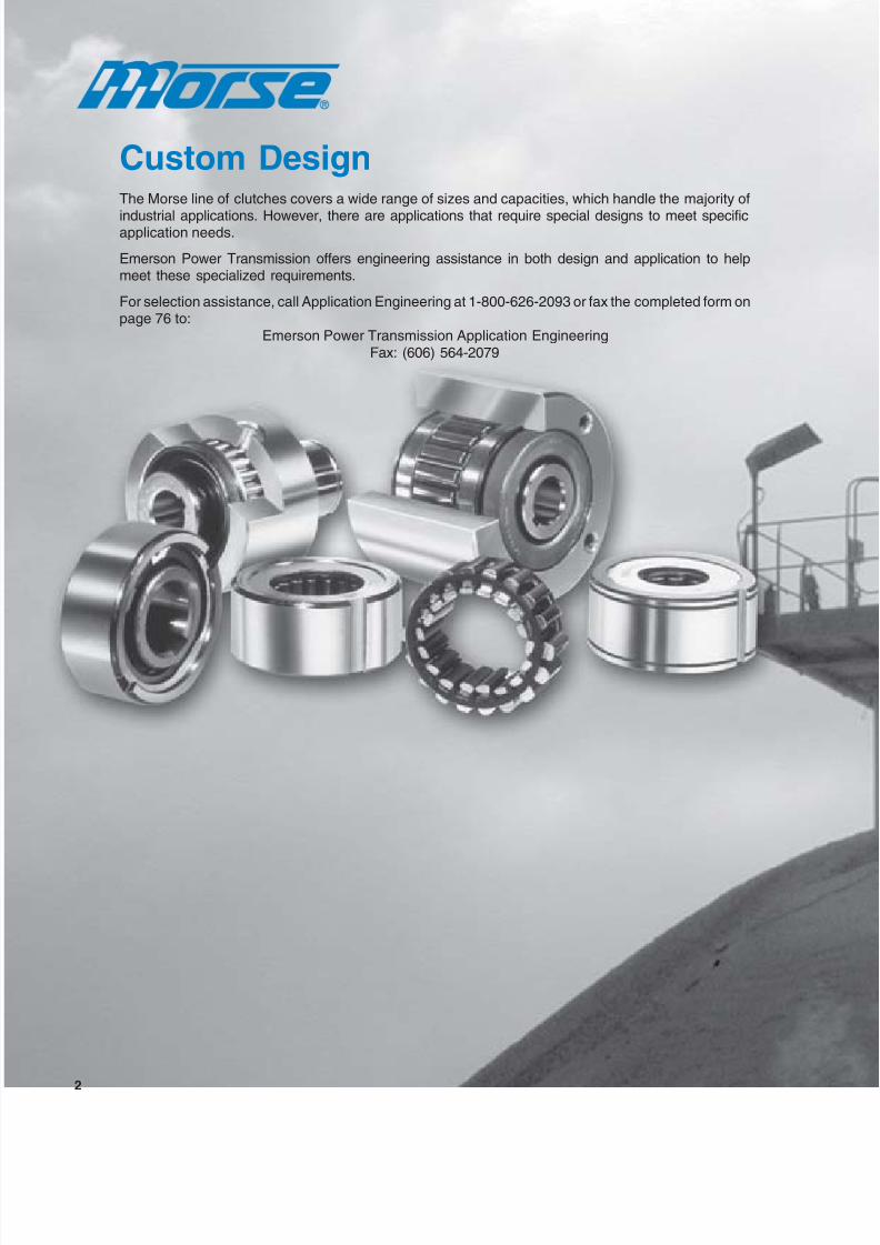
Custom DesignThe Morse line of clutches covers a wide range of sizes and capacities, which handle the majority of
industrial applications. However, there are applications that require special designs to meet specificapplication needs.
Emerson Power Transmission offers engineering assistance in both design and application to helpmeet these specialized requirements.
For selection assistance, call Application Engineering at 1-800-626-2093 or fax the completed form onpage 76 to:
Emerson Power Transmission Application EngineeringFax: (606) 564-2079

8/20/2019 Catalogo Morse MC Clutches y Limitadores
http://slidepdf.com/reader/full/catalogo-morse-mc-clutches-y-limitadores 5/131
3
Morse mechanical cam clutches are precision devicesthat lock the inner and outer races through the wedgingaction of cams to transmit torque in one direction ofrotation while overrunning in the opposite direction ofrotation. These type units are often referred to as
freewheels, sprag, overrunning, backstop or one-wayclutches, depending upon their application.
Clutches are available with a bore range up through17.7" and a torque range up through 500,000 lb. ft. andare the most complete and versatile cam clutchesavailable for a variety of applications – from smallbusiness machines to giant steel slitters.
Eleven series of clutches perform three basicmodes of operation:• Overrunning• Indexing• Backstopping
These units have set standards ofperformance, offering:• Higher overrunning speeds• Greater torque capacities• Longer service life
For selection assistance, call Application Engineering at 1-800-626-2093 or visitwww.emerson-ept.com

8/20/2019 Catalogo Morse MC Clutches y Limitadores
http://slidepdf.com/reader/full/catalogo-morse-mc-clutches-y-limitadores 6/131
4
Features• Self-contained clutches created for high
torque applications where reverse rotation of
a head-shaft must be prevented• Manufactured with large diameter rollers to
provide bearing, clutch support, and
maintain concentricity between inner and
outer races• Torque arm available to help prevent reverse
rotations, plus an external felt seal andinternal lip seal for low maintenance
• Available with an external felt seal andinternal lip seal for low maintenance
• Retaining plate option available to secure
backstop to shaftBore range........... 2.25" – 17.7"
Torque range ....... 6,500 - 500,000 lb–ft.
Conveyor Backstop Clutches(Page 33)
M Series Clutch(Page 14)
Features• Self-contained clutch designed for a wide
variety of applications• Cam cage assembly engineered for optimum
performance and increased capacity
• Two ball bearings included to support radial
load and concentricity between races• Close tolerance outer diameter to mount
sheave, gears, sprockets and torque arms• Positive contact lip or felt seals provided for
grease or oil lubrication• Tapped holes machined on ends of outer race
for mounting auxiliary components
• Metric bore and keyway available• Mounting accessories available
Bore range........... 0.5" – 6.437"Torque range ....... 275 – 25,000 lb-ft.
Features• Full complement of cams
• Two bearings incorporated for concentricitycontrol
• Symmetric, building block components
• Close tolerance outer diameter to mountsheave, gears, sprockets and torque arms
• Tapped holes at both ends of races to mount
accessories• Flange, torque arms and covers available
MZEU Series(Page 28)
Bore range ........... 0.472" – 5.9"
Torque range ........ 44 – 25,000 lb-ft.
Clutch Product Offering

8/20/2019 Catalogo Morse MC Clutches y Limitadores
http://slidepdf.com/reader/full/catalogo-morse-mc-clutches-y-limitadores 7/131
5
KK15 - KK40 Series(Page 45)
Features• Self-contained ball bearing and cam clutch
• Designed with same dimensions asstandard metric light series ball bearing
• Press fit option for shaft and housing
• Available with keyed inner and outer races
• Furnished filled with grease to increasewear life
• Seal options available for contaminatedenvironments
Bore range ........... 0.59" – 1.57" (15mm - 40mm)
Torque range........ 21.4 – 190 lb-ft.
NSS Series(Page 52)
Features• Designed with the same overall
dimensions of a metric 200 light series
ball bearing• Created with an inner race containing a
keyseat and an outer race that press fits inhousing
• Excellent for applications where space is a
consideration
Bore range ........... 0.32" – 2.36" (8mm - 50mm)Torque range ....... 4.94 – 480 lb-ft.
Clutch Product Offering
Value-Added Capabilities• Special bores (splined, dual keyways, extended with setscrews)
• Special width
• Custom seal designs (viton, all rubber, etc)
• Special greases (low-temp, food grade, etc.)
• Dual cages for higher capacity in a wider but small OD package• Gear or sprocket tooth cut into OD of clutch
• Special label needs such as inclusion of OEM part numbers
• Ability to kit products for final assembly
• Assembled to sprocket, coupling, etc.
• Custom engineering designs for OEMs
For selection assistance, call Application Engineering at 1-800-626-2093 or visit
www.emerson-ept.com

8/20/2019 Catalogo Morse MC Clutches y Limitadores
http://slidepdf.com/reader/full/catalogo-morse-mc-clutches-y-limitadores 8/131
6
B Series Clutches
Features• Rugged cam clutch designed for
applications where space and weight arefactors in clutch selection
• Full complement of cams held in the outer
races• Input shaft used as the inner race must be
hardened and ground to size
• Interchangeable with competitors’ products• Bearing support and lubrication required
• Primarily used for backstop applications
B-200A Series(Page 56)
Bore range ........... 0.650" - 2.209"Torque range........ 39 - 575 lb–ft.
B-500A Series(Page 58)
Bore range ........... 0.650" - 2.04"Torque range........ 60 -1,250 lb–ft.
Clutch Product Offering
NFS Series(Page 54)
Features
• Designed with the same overall dimensionsas medium 300 series metric ball bearing
• Manufactured with an inner race containing
a key-seat and an outer race containing keyslots
• Furnished with protective oil
Bore range ........... 0.47" – 3.15" (12mm - 80mm)
Torque range ....... 13.27 – 2,900 lb-ft.
8/20/2019 Catalogo Morse MC Clutches y Limitadores
http://slidepdf.com/reader/full/catalogo-morse-mc-clutches-y-limitadores 9/131
7
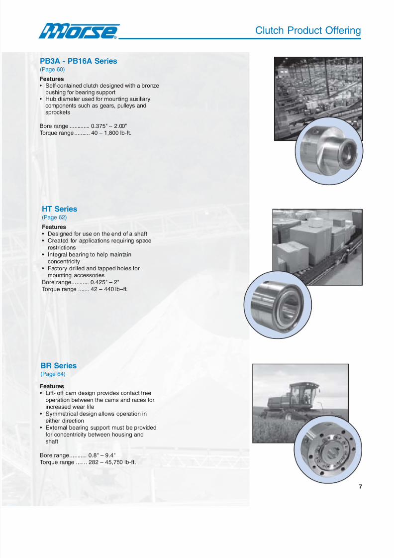
PB3A - PB16A Series(Page 60)
Features• Self-contained clutch designed with a bronze
bushing for bearing support
• Hub diameter used for mounting auxiliarycomponents such as gears, pulleys andsprockets
Bore range ............. 0.375" – 2.00"Torque range.......... 40 – 1,800 lb-ft.
BR Series(Page 64)
Features
• Lift- off cam design provides contact freeoperation between the cams and races forincreased wear life
• Symmetrical design allows operation in
either direction• External bearing support must be provided
for concentricity between housing andshaft
Bore range........... 0.8" – 9.4"Torque range ....... 282 – 45,750 lb-ft.
HT Series(Page 62)
Features• Designed for use on the end of a shaft• Created for applications requiring space
restrictions
• Integral bearing to help maintainconcentricity
• Factory drilled and tapped holes formounting accessories
Bore range........... 0.425" – 2"
Torque range ....... 42 – 440 lb–ft.
Clutch Product Offering

8/20/2019 Catalogo Morse MC Clutches y Limitadores
http://slidepdf.com/reader/full/catalogo-morse-mc-clutches-y-limitadores 10/131
8
Modes of Operation
Fixed outer race
I. General Overrunning
Clutches used in this type of application overrun at either the
inner or outer race and are occasionally called upon to lock upand drive.
A typical application is a standby drive where an electric motor
and a standby diesel engine are connected to a single drivenfan shaft through one-way clutches. The fan can be driven by
the motor or diesel engine. The diesel drive clutch overrunswhen the motor drives the fan. The motor clutch automatically
overruns when the load is transferred to the diesel engine.
Morse cam clutches are precision devices that positively lock to transmit torque in one direction of rotation butoverrun (freewheel) in the opposite direction of rotation. Eleven series of clutches are available, all using the
same principles of operation. Since clutch applications encompass a variety of load and speed characteristics,Morse clutches are manufactured in a range of capacities and styles that are designed to provide the bestfunctional characteristics in performing the three basic modes of operation.
II. Indexing
In this mode of operation, reciprocating motion applied to thedriving race of the clutch is transformed into unidirectional,
intermittent motion at the driven race. For example, on aprinting press application, the clutch is mounted to an inking rolland a pinion is mounted to the driving race of the clutch. A rack
meshing with the pinion provides reciprocating motion to thedriving race. The clutch drives in the forward stroke (index) and
overruns on the return stroke accomplishing intermittentunidirectional motion of the inking roll.
III. Backstopping
In backstop (holdback) applications, the clutches are used to
prevent reverse rotation of drive shafts, which could damagemachinery and other expensive equipment. With the outer race
of the clutch anchored to a stationary member, the inner racecan overrun freely in one direction of rotation; reverse rotation
is prevented by the automatic engagement of the clutch. Typicalbackstop applications occur in conveyor systems and gearreducers.

8/20/2019 Catalogo Morse MC Clutches y Limitadores
http://slidepdf.com/reader/full/catalogo-morse-mc-clutches-y-limitadores 11/131
9
Principle of Operation
B-200A, B-500, PB-A, HT, CB, M, NSS, NFS, MZEU Series
Morse clutches utilize a full complement of cams, which are placedbetween concentric inner and outer races. A light spring helps keepthe cams in contact with the races. Torque is transmitted from one
race to the other by wedging action of the cams between the races.
Morse mechanical clutches provide engagement or disengagement
with minimal backlash.Figure 1 shows the cams in a position to allow the inner race tooverrun counter-clockwise or the outer race to overrun in aclockwise direction.
Figure 2 shows the cams are fully loaded and loads can betransmitted through the cams from a clockwise rotation of the innerrace or a counter-clockwise rotation of the outer race.
KK Series
The KK clutch consists of a standard metric ball bearing combined
with cams. The clutch design is unique, incorporating an
independent cam-cage assembly installed alongside the offset ballcage. The clutch has the same overall dimensions of the metric
bearing. The clutches are entirely self-contained, and do not requireadditional bearing support.
The cam-cage assembly uses an energizing spring to help keep
the entire complement of cams in light contact with the races toprovide rapid engagement when torque transmission occurs. The
wedging action of the full set of cams produces significant torquecapability in a compact, economical package.
Figure 3 shows the cam-cage assembly in the KK clutch in a
position to allow the inner race to overrun clockwise or the outerrace to overrun in a counterclockwise direction.
Figure 4 shows the cam-cage assembly provides a full complementof cams to wedge against inner and outer races allowing torquetransmission through the clutch.
Figure 1
(Overrunning)
Figure 2
(Driving)
Figure 3
Figure 4

8/20/2019 Catalogo Morse MC Clutches y Limitadores
http://slidepdf.com/reader/full/catalogo-morse-mc-clutches-y-limitadores 12/131
10
OverrunHigh Speed
Low SpeedStop
Principle of Operation
The cam of the BR Series clutch is designed to lift off
and have no contact with the inner and outer race whileoverrunning. This is due to centrifugal force and is the
reason this type of cam clutch is known as a lift offtype. These cam clutches are suitable for “overrunning
BR Series
- high speed inner race/low speed engaged outer race”
or “backstopping-high speed inner race overrunning”.There are two types available, an open type installed
directly onto a motor or inside a reducer, or a packagetype that is installed on the outside of the application.
General Overrunning
Backstopping
Indexing
Aircraft arresting gear equipmentCompressorsConveyorsCranes and hoistsDry cleaning machineryDuplicator equipmentFood processing machineryHeat-treat furnaces
Induction draft fansMulti-state conveyorsPackaging machineryPrinting machineryPumpsPunch presses and feedsRailroad crossing gatesShoe machinery
Speed reducersStandby power unitsTextile loomsTwo-speed grindersTwo-speed shiftoversWashing machinesWire winding machinery
Morse mechanical clutches are utilized in many applications such as:
8/20/2019 Catalogo Morse MC Clutches y Limitadores
http://slidepdf.com/reader/full/catalogo-morse-mc-clutches-y-limitadores 13/131
11
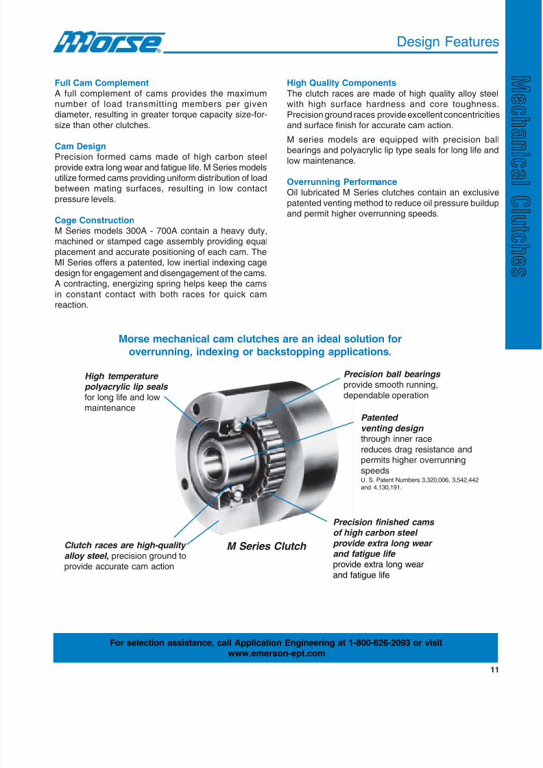
Full Cam ComplementA full complement of cams provides the maximumnumber of load transmitting members per givendiameter, resulting in greater torque capacity size-for-
size than other clutches.
Cam DesignPrecision formed cams made of high carbon steel
provide extra long wear and fatigue life. M Series modelsutilize formed cams providing uniform distribution of loadbetween mating surfaces, resulting in low contact
pressure levels.
Cage ConstructionM Series models 300A - 700A contain a heavy duty,machined or stamped cage assembly providing equal
placement and accurate positioning of each cam. TheMI Series offers a patented, low inertial indexing cage
design for engagement and disengagement of the cams.A contracting, energizing spring helps keep the cams
in constant contact with both races for quick camreaction.
Design Features
High Quality Components
The clutch races are made of high quality alloy steelwith high surface hardness and core toughness.
Precision ground races provide excellent concentricitiesand surface finish for accurate cam action.
M series models are equipped with precision ballbearings and polyacrylic lip type seals for long life and
low maintenance.
Overrunning PerformanceOil lubricated M Series clutches contain an exclusive
patented venting method to reduce oil pressure buildupand permit higher overrunning speeds.
Morse mechanical cam clutches are an ideal solution for
overrunning, indexing or backstopping applications.
High temperature polyacrylic lip seals
for long life and lowmaintenance
Precision ball bearings provide smooth running,
dependable operation
Clutch races are high-quality
alloy steel, precision ground toprovide accurate cam action
Precision finished cams of high carbon steel
provide extra long wear and fatigue life provide extra long wear
and fatigue life
M Series Clutch
Patented
venting design through inner race
reduces drag resistance andpermits higher overrunning
speedsU. S. Patent Numbers 3,320,006, 3,542,442and 4,130,191.
For selection assistance, call Application Engineering at 1-800-626-2093 or visitwww.emerson-ept.com

8/20/2019 Catalogo Morse MC Clutches y Limitadores
http://slidepdf.com/reader/full/catalogo-morse-mc-clutches-y-limitadores 14/131
12
Design Function
noitcnuFdeniatnoC-fleS .oNledoM
egnaReuqroT
gninnurrevO gnixednI gnippotsk caB tf-bl m-N
X X X - A012B-A302B 575-93 087-35
- - X - 315B-A105B 521,2-06 188,2-18
- - X X C005BC-C7BC 000,005-005,6 000,686-318,8X X - X 2E-1E051UEZM-2E-1E21UEZM 000,52-44 008,33-06
- - X X 3E-2E051UEZM-3E-2E21UEZM 000,52-44 008,33-06
- - X X 4E-3E051UEZM-4E-3E21UEZM 000,52-44 008,33-06
- X - X 03TH-01TH 044-24 795-75
X - - X 04KK-51KK 091-02 062-92
X - - X DG2-04KK-DG2-51KK 091-02 062-92
X - - X K1DG2-04KK-K1DG2-51KK 091-02 062-92
X - - X K1-04KK-K1-51KK 091-02 062-92
X - - X K2-04KK-K2-51KK 091-02 062-92
X X X X A007M-A003M 000,5-572 977,6-373
X X X X 0001M-A057M 000,52-000,7 698,33-194,9
X - - - 08SFN-21SFN 009,2-31 429,3-81
X - - - 06SSN-8SSN 084-5 946-7.6
X X X X A61BP-A3BP 008,1-04 144,2-45
- - X - 042RB-02RB 057,54-042 430,26-823
- - X X P-RB 057,54-042 430,26-823
seireShctulC KK SSN SFN A002 005-B A-BP TH M UEZM RB
.oNledoMgolataC x x x x x x x x x xeroB - - - - - x x x - -
)HLroHR(noitatoR - - - - - x x - - -
Clutch Ordering Procedure
Specify the Information Checked (x) in the Table Below
Note: Clutches requiring non-stock bores, tolerances, keyways, lubricants, or other special requirements must be clearly specified on the order.
X = Available.
Part Number Explanation
KK 30-2GD 1K
Keyed inner race
Sealed both sides
Bore size in millimeters
Clutch series
CB - 45 C FB
Specify finished bore diameter
Clutch only*
Torque capacity (ft-lbs. 1000's)
Clutch series (conveyor backstop)
Conveyor Backstop Series
Conveyor backstop clutch built with standard keyway unless requestedotherwise.* Torque arm, to be used with conveyor backstop clutch, should be ordered
separately ex. CB-45TA.
M G 500A - G FB
Specify finished bore diameter
Add - G if grease lubrication required
Model number
General duty lip seal clutch
Clutch series
M Series
NFS - 35
Bore size in millimeters
Clutch series
NFS Series
Examples for M series derivatives: MG (for general duty) ex: MG900 FB, MI(for indexing) ex: MI800 FB, MO (for overrunning) ex: MO600A-G FB and MR(for high-speed outer race overrunning) ex: MR600A FB.
M I 500A - G FB
Specify finished bore diameter
Add - G if grease lubrication required
Model number
Performance indexing
Clutch series
KK 25 2K
Keyed inner and outer race
Bore size in millimeters
Clutch series
KK Series
8/20/2019 Catalogo Morse MC Clutches y Limitadores
http://slidepdf.com/reader/full/catalogo-morse-mc-clutches-y-limitadores 15/131
13
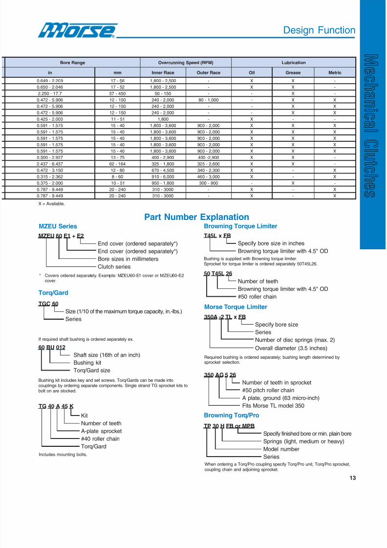
Design Function
egnaReroB )MPR(deepSgninnurrevO noitacirbuL
ni mm ecaRrennI ecaRretuO liO esaerG cirteM
902.2-946.0 65-71 005,2-008,1 - X X -
640.2-056.0 25-71 005,2-008,1 - X X -
7.71-052.2 054-75 051-05 - - X -609.5-274.0 051-21 000,2-042 000,1-08 - X X
609.5-274.0 051-21 000,2-042 - - X X
609.5-274.0 051-21 000,2-042 - - X X
000.2-524.0 15-11 008,1 - X - -
575.1-195.0 04-51 006,3-008,1 000,2-009 X X X
575.1-195.0 04-51 006,3-008,1 000,2-009 X X X
575.1-195.0 04-51 006,3-008,1 000,2-009 X X X
575.1-195.0 04-51 006,3-008,1 000,2-009 X X X
575.1-195.0 04-51 006,3-008,1 000,2-009 X X X
739.2-005.0 57-31 009,2-004 009,2-004 X X -
734.6-734.2 461-26 008,1-523 006,2-523 X X -
051.3-274.0 08-21 005,4-076 003,2-043 X - X
263.2-513.0 06-8 000,6-019 000,3-064 X - X
000.2-573.0 15-01 008,1-059 009-003 - X -
944.9-787.0 042-02 0003-013 - X - X
944.9-787.0 042-02 0003-013 - X - X
X = Available.
MZEU 60 E1 + E2
End cover (ordered separately*)
End cover (ordered separately*)
Bore sizes in millimeters
Clutch series
MZEU Series
* Covers ordered separately. Example: MZEU60-E1 cover or MZEU60-E2cover.
Part Number Explanation
T45L x FB
Specify bore size in inches
Browning torque limiter with 4.5" OD
Browning Torque Limiter
Bushing is supplied with Browning torque limiter.Sprocket for torque limiter is ordered separately 50T45L26.
50 T45L 26
Number of teeth
Browning torque limiter with 4.5" OD#50 roller chain
Morse Torque Limiter
350A -2 TL x FB
Specify bore size
Series
Number of disc springs (max. 2)
Overall diameter (3.5 inches)
Required bushing is ordered separately; bushing length determined bysprocket selection.
350 AG 5 26
Number of teeth in sprocket#50 pitch roller chain
A plate, ground (63 micro-inch)
Fits Morse TL model 350
Browning Torq/Pro
TP 30 H FB or MPB
Specify finished bore or min. plain bore
Springs (light, medium or heavy)
Model number
Series
When ordering a Torq/Pro coupling specify Torq/Pro unit, Torq/Pro sprocket,coupling chain and adjoining sprocket.
Torq/Gard
TGC 60
Size (1/10 of the maximum torque capacity, in.-lbs.)
Series
If required shaft bushing is ordered separately ex.
Bushing kit includes key and set screws. Torq/Gards can be made into
couplings by ordering separate components. Single strand TG sprocket kits tobolt on are stocked.
TG 40 A 45 K
Kit
Number of teeth
A-plate sprocket
#40 roller chain
Torq/Gard
Includes mounting bolts.
60 BU 012
Shaft size (16th of an inch)
Bushing kit
Torq/Gard size
8/20/2019 Catalogo Morse MC Clutches y Limitadores
http://slidepdf.com/reader/full/catalogo-morse-mc-clutches-y-limitadores 16/131
14
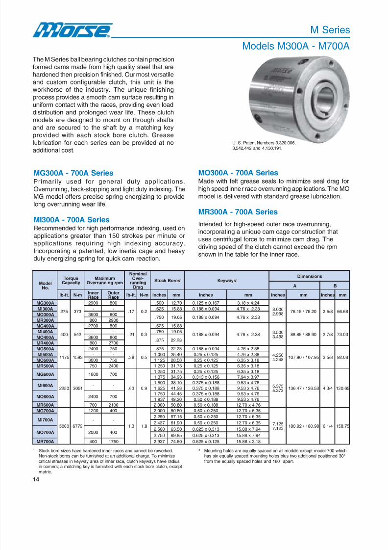
M Series
Models M300A - M700A
The M Series ball bearing clutches contain precisionformed cams made from high quality steel that are
hardened then precision finished. Our most versatileand custom configurable clutch, this unit is theworkhorse of the industry. The unique finishing
process provides a smooth cam surface resulting inuniform contact with the races, providing even load
distribution and prolonged wear life. These clutchmodels are designed to mount on through shafts
and are secured to the shaft by a matching keyprovided with each stock bore clutch. Grease
lubrication for each series can be provided at noadditional cost.
1 Stock bore sizes have hardened inner races and cannot be reworked.Non-stock bores can be furnished at an additional charge. To minimizecritical stresses in keyway area of inner race, clutch keyways have radiusin corners; a matching key is furnished with each stock bore clutch, exceptmetric.
MG300A - 700A SeriesPrimarily used for general duty applications.
Overrunning, back-stopping and light duty indexing. TheMG model offers precise spring energizing to providelong overrunning wear life.
MI300A - 700A SeriesRecommended for high performance indexing, used on
applications greater than 150 strokes per minute orapplications requiring high indexing accuracy.
Incorporating a patented, low inertia cage and heavyduty energizing spring for quick cam reaction.
MO300A - 700A SeriesMade with felt grease seals to minimize seal drag for
high speed inner race overrunning applications. The MOmodel is delivered with standard grease lubrication.
MR300A - 700A Series
Intended for high-speed outer race overrunning,incorporating a unique cam cage construction thatuses centrifugal force to minimize cam drag. The
driving speed of the clutch cannot exceed the rpmshown in the table for the inner race.
2 Mounting holes are equally spaced on all models except model 700 whichhas six equally spaced mounting holes plus two additional positioned 30°from the equally spaced holes and 180° apart.
ledoM
.oN
euqroTyticapaC
mumixaMmprgninnurrevO
lanimoN-revOgninnur
garD
seroBk cotS 1 syawyeK 1snoisnemiD
A B
.tf-bl m-N rennI
ecaRretuO
ecaR .tf-bl m-N sehcnI mm sehcnI mm sehcnI mm sehcnI mm
A003GM
572 373
0092 008
71. 2.0
005. 07.21 761.0x521.0 42.4x81.3
000.3899.2
02.67 / 51.67 8 / 52 86.66A003IM - - 526. 88.51 490.0x881.0 83.2x67.4
A003OM 0063 008057. 50.91 490.0x881.0 83.2x67.4
A003RM 008 0092
A004GM
004 245
0072 008
12. 3.0
526. 88.51
490.0x881.0 83.2x67.4 005.3
894.3 09.88 / 58.88 8 / 72 30.37
A004IM - - 057. 50.91
A004OM 0063 008578. 32.22
A004RM 008 0072
A005GM
5711 3951
0042 057
83. 5.0
578. 32.22 490.0x881.0 83.2x67.4
052.4842.4
59.701 / 09.701 8 / 53 80.29A005IM - - 000.1 04.52 521.0x52.0 83.2x67.4
A005OM 0003 057 521.1 85.82 521.0x52.0 81.3x53.6
A005RM 057 0042 052.1 57.13 521.0x52.0 81.3x53.6
A006GM
0522 1503
0081 007
36. 9.0
052.1 57.13 521.0x52.0 81.3x53.6
573.5373.5
35.631 / 74.631 4 / 34 56.021
573.1 39.43 651.0x313.0 79.3x49.7
A006IM - - 005.1 01.83 881.0x573.0 67.4x35.9
526.1 82.14 881.0x573.0 67.4x35.9
A006OM 0042 007 057.1 54.44 881.0x573.0 67.4x35.9
739.1 02.94 881.0x05.0 67.4x35.9
A006RM 007 0012 000.2 08.05 881.0x05.0 67.4x07.21
A007GM
0005 9776
0021 004
3.1 8.1
000.2 08.05 052.0x05.0 53.6x07.21
521.7321.7
89.081 / 29.081 4 / 16 57.851
A007IM - - 052.2 51.75 052.0x05.0 53.6x07.21
734.2 09.16 052.0x05.0 53.6x07.21
A007OM 0002 004 005.2 05.36 313.0x526.0 49.7x88.51
057.2 58.96 313.0x526.0 49.7x88.51
A007RM 004 0571 739.2 06.47 521.0x526.0 81.3x88.51
U. S. Patent Numbers 3.320.006,3,542,442 and 4,130,191.
8/20/2019 Catalogo Morse MC Clutches y Limitadores
http://slidepdf.com/reader/full/catalogo-morse-mc-clutches-y-limitadores 17/131
15
B
E
A
C
D
F
ledoM
.oN
snoisnemiDfo.oN
).tM(paT
seloH
daerhTeziS
daerhTelbasUhtpeD
ebuLebuL.paC
.zO
thgieW
C D E F
sehcnI mm sehcnI mm sehcnI mm sehcnI mm sehcnI mm sehcnI mm sbl gk
A003GM
573.2 33.06 05.2 5.36 521.1 85.82 53. 9.8 4 82-052.0 117-53.6 005.0 07.21
liO 58.
4 2A003IM liO 52.1
A003OM esaerG 5.
A003RM liO 58.
A004GM
526.2 86.66 57.2 9.96 052.1 57.13 54. 4.11 4 42-313.0 016-49.7 526.0 88.51
liO 1.1
6 3A004IM liO 4.1
A004OM esaerG 5.
A004RM liO 1.1
A005GM
573.3 37.58 05.3 9.88 057.1 54.44 84. 2.21 4 42-313.0 016-49.7 526.0 88.51
liO 8.1
11 5A005IM liO 0.3
A005OM esaerG 0.1
A005RM liO 8.1
A006GM
526.3 80.29 57.3 3.59 057.2 58.96 05. 7.21 6 42-313.0 016-49.7 526.0 88.51
liO8.2
91 9
liO
A006IM
liO
5.4liO
A006OM esaerG
5.1esaerG
A006RM liO 8.2
A007GM
578.4 38.321 00.5 0.721 000.4 06.101 86. 3.71 8 42-573.0 016-35.9 057.0 50.91
liO 6.4
34 02
A007IM liO
9.01liO
A007OM esaerG
9.2esaerG
A007RM liO 6.4
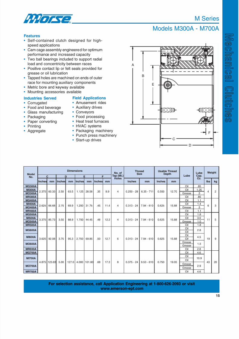
M Series
Models M300A - M700AFeatures• Self-contained clutch designed for high-
speed applications• Cam cage assembly engineered for optimum
performance and increased capacity
• Two ball bearings included to support radialload and concentricity between races
• Positive contact lip or felt seals provided forgrease or oil lubrication
• Tapped holes are machined on ends of outerrace for mounting auxiliary components
• Metric bore and keyway available• Mounting accessories available
Industries Served
• Corrugated• Food and beverage• Glass manufacturing
• Packaging• Paper converting
• Printing• Aggregate
Field Applications
• Amusement rides• Auxiliary drives
• Conveyors
• Food processing• Heat treat furnaces• HVAC systems
• Packaging machinery• Punch press machinery• Start-up drives
For selection assistance, call Application Engineering at 1-800-626-2093 or visit
www.emerson-ept.com
8/20/2019 Catalogo Morse MC Clutches y Limitadores
http://slidepdf.com/reader/full/catalogo-morse-mc-clutches-y-limitadores 18/131
16
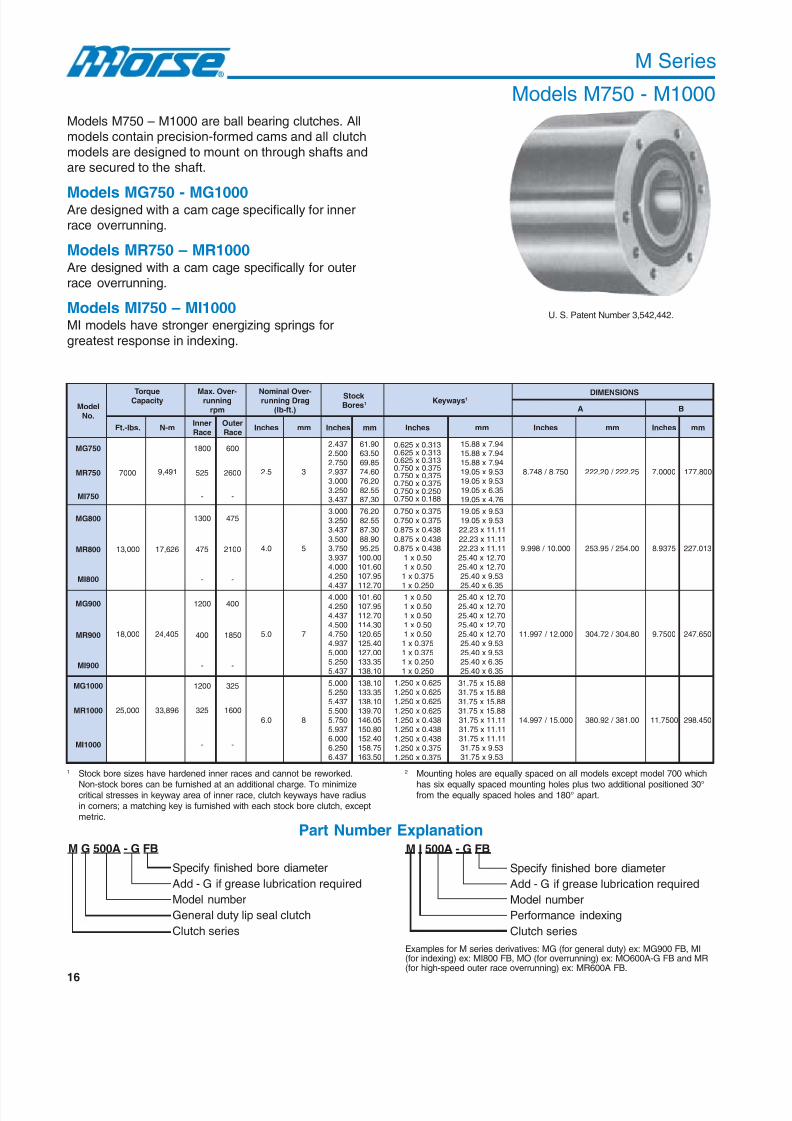
M Series
Models M750 - M1000
U. S. Patent Number 3,542,442.
ledoM.oN
euqroTyticapaC
-revO.xaMgninnur
mpr
-revOlanimoNgarDgninnur
).tf-bl(
k cotSseroB 1 syawyeK 1 SNOISNEMID
A B
.sbl-.tF m-NrennIecaR
retuOecaR
sehcnI mm sehcnI mm sehcnI mm sehcnI mm sehcnI mm
057GM
194,9
0081 006
5.2 3
734.2005.2057.2739.2000.3052.3734.3
09.1605.3658.9606.4702.6755.2803.78
313.0x526.0313.0x526.0313.0x526.0573.0x057.0573.0x057.0573.0x057.0052.0x057.0881.0x057.0
49.7x88.5149.7x88.5149.7x88.5135.9x50.9135.9x50.9153.6x50.9167.4x50.91
057.8 / 847.8 52.222 / 02.222 0000.7 008.771057RM 0007 525 0062
057IM - -
008GM 0031 574
0.4 5
000.3052.3734.3
005.3057.3739.3000.4052.4
734.4
02.6755.2803.78
09.8852.5900.00106.10159.701
07.211
573.0x057.0573.0x057.0834.0x578.0
834.0x578.0834.0x578.0
05.0x105.0x1573.0x1
052.0x1
35.9x50.9135.9x50.9111.11x32.22
11.11x32.2211.11x32.2207.21x04.5207.21x04.52
35.9x04.52
53.6x04.52
000.01 / 899.9 00.452 / 59.352 5739.8 310.722008RM 000,31 626,71 574 0012
008IM - -
009GM
000,81 504,42
0021 004
0.5 7
000.4052.4734.4005.4057.4739.4000.5052.5734.5
06.10159.70107.21103.41156.02104.52100.72153.33101.831
05.0x105.0x105.0x105.0x105.0x1573.0x1573.0x1052.0x1052.0x1
07.21x04.5207.21x04.5207.21x04.5207.21x04.5207.21x04.52
35.9x04.5235.9x04.5253.6x04.5253.6x04.52
000.21 / 799.11 08.403 / 27.403 0057.9 056.742009RM 004 0581
009IM - -
0001GM 0021 523
0.6 8
000.5052.5734.5005.5057.5739.5000.6052.6734.6
01.83153.33101.83107.93150.64108.05104.25157.85105.361
526.0x052.1
526.0x052.1526.0x052.1
526.0x052.1834.0x052.1834.0x052.1
834.0x052.1573.0x052.1
573.0x052.1
88.51x57.1388.51x57.1388.51x57.1388.51x57.1311.11x57.1311.11x57.1311.11x57.13
35.9x57.1335.9x57.13
000.51 / 799.41 00.183 / 29.083 0057.11 054.892
0001RM 000,52 698,33 523 0061
0001IM - -
Models M750 – M1000 are ball bearing clutches. Allmodels contain precision-formed cams and all clutch
models are designed to mount on through shafts andare secured to the shaft.
Models MG750 - MG1000Are designed with a cam cage specifically for innerrace overrunning.
Models MR750 – MR1000Are designed with a cam cage specifically for outerrace overrunning.
Models MI750 – MI1000MI models have stronger energizing springs for
greatest response in indexing.
1 Stock bore sizes have hardened inner races and cannot be reworked.
Non-stock bores can be furnished at an additional charge. To minimizecritical stresses in keyway area of inner race, clutch keyways have radiusin corners; a matching key is furnished with each stock bore clutch, exceptmetric.
2 Mounting holes are equally spaced on all models except model 700 which
has six equally spaced mounting holes plus two additional positioned 30°from the equally spaced holes and 180° apart.
Examples for M series derivatives: MG (for general duty) ex: MG900 FB, MI(for indexing) ex: MI800 FB, MO (for overrunning) ex: MO600A-G FB and MR(for high-speed outer race overrunning) ex: MR600A FB.
Part Number ExplanationM G 500A - G FB
Specify finished bore diameter
Add - G if grease lubrication required
Model number
General duty lip seal clutch
Clutch series
M I 500A - G FB
Specify finished bore diameter
Add - G if grease lubrication required
Model number
Performance indexing
Clutch series

8/20/2019 Catalogo Morse MC Clutches y Limitadores
http://slidepdf.com/reader/full/catalogo-morse-mc-clutches-y-limitadores 19/131
8/20/2019 Catalogo Morse MC Clutches y Limitadores
http://slidepdf.com/reader/full/catalogo-morse-mc-clutches-y-limitadores 20/131
18
10
100
1000
10000
0.1 1 10 100
M A X I M U M
T O R Q U E L O A D ( L B - F T
)
EXAMPLEMG300
MG500
MG400
MG600
MG700
M Series
Load Life Cycle
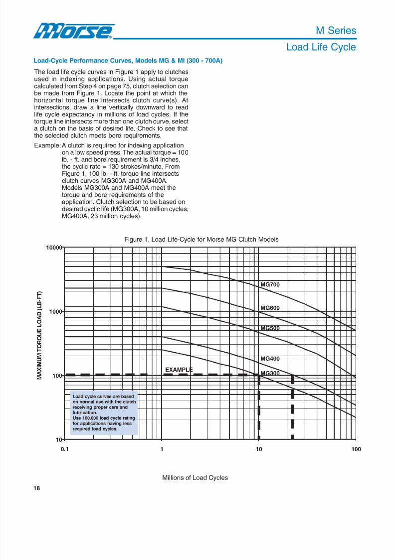
The load life cycle curves in Figure 1 apply to clutchesused in indexing applications. Using actual torquecalculated from Step 4 on page 75, clutch selection canbe made from Figure 1. Locate the point at which thehorizontal torque line intersects clutch curve(s). Atintersections, draw a line vertically downward to readlife cycle expectancy in millions of load cycles. If thetorque line intersects more than one clutch curve, selecta clutch on the basis of desired life. Check to see thatthe selected clutch meets bore requirements.
Example:A clutch is required for indexing applicationon a low speed press. The actual torque = 100lb. - ft. and bore requirement is 3/4 inches,the cyclic rate = 130 strokes/minute. FromFigure 1, 100 lb. - ft. torque line intersectsclutch curves MG300A and MG400A.Models MG300A and MG400A meet the
torque and bore requirements of theapplication. Clutch selection to be based ondesired cyclic life (MG300A, 10 million cycles;MG400A, 23 million cycles).
Load-Cycle Performance Curves, Models MG & MI (300 - 700A)
Figure 1. Load Life-Cycle for Morse MG Clutch Models
Millions of Load Cycles
Load cycle curves are basedon normal use with the clutchreceiving proper care andlubrication.Use 100,000 load cycle ratingfor applications having lessrequired load cycles.

8/20/2019 Catalogo Morse MC Clutches y Limitadores
http://slidepdf.com/reader/full/catalogo-morse-mc-clutches-y-limitadores 21/131
19
M Series
Clutch Wear Life
The wear life curves shown in Figure 2 apply to
clutches used in overrunning or backstoppingapplications. Use inner race overrunning rpm and
clutch size selected in steps 6 and 7 on page 75 todetermine expected wear life.
Example: Assume clutch selected is Model MG500A,which operates at an inner race overrunning
speed of 2000 rpm. From Figure 2, the 2000rpm line is drawn horizontally to point of
intersection with the MG500A curve. Fromthe point of intersection, draw a linevertically downward to read hours of clutch
life (23,000).
Clutch Wear Life Curves, Models MG (300 - 700A)
Figure 2. Clutch Wear Life Model MG (300A - 700A)
Hours of Clutch Life
For selection assistance, call Application Engineering at 1-800-626-2093 or visitwww.emerson-ept.com
0
500
1000
1500
2000
2500
3000
0 5000 10000 15000 20000 25000 30000 35000 40000
I n n e r R a c e O v e r r u n n i n g R
P M
MG300A
MG400A
MG500A
MG600A
MG700A
Example
Wear life curves are based
on normal use with clutchreceiving proper care andlubrication.

8/20/2019 Catalogo Morse MC Clutches y Limitadores
http://slidepdf.com/reader/full/catalogo-morse-mc-clutches-y-limitadores 22/131
8/20/2019 Catalogo Morse MC Clutches y Limitadores
http://slidepdf.com/reader/full/catalogo-morse-mc-clutches-y-limitadores 23/131
21
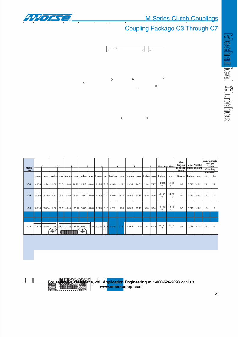
M Series Clutch Couplings
Coupling Package C3 Through C7
C
B
E
HJ
AD G
F
ledoMoN
C D E F G H I J taolFdnE.xaM
.xaMralugnA-ngilasiM
tnem
lellaraP.xaMtnemngilasiM
etamixorppAthgieW
hctulCgnilpuoCylbmessA
sehcnI mm sehcnI mm sehcnI mm sehcnI mm sehcnI mm sehcnI mm sehcnI mm sehcnI mm sehcnI mm eergeD sehcnI mm bl gk
3-C 839.4 14.521 05.2 5.36 000.3 02.67 318.1 40.64 521.0 81.3 964.0 19.11 839.2 16.47 49.2 7.47490.0+
0-83.2+
0-2 / 1 010.0 52.0 8 4
4-C 365.5 92.141 57.2 9.96 005.3 09.88 000.2 08.05 521.0 81.3 604.0 23.01 365.3 94.09 65.3 4.09881.0+
0-67.4+0-
2 / 1 010.0 52.0 21 5
5-C 313.6 43.061 05.3 9.88 052.4 59.701 000.2 08.05 521.0 81.3 573.0 35.9 365.3 94.09 65.3 4.09881.0+
0-67.4+
0-2 / 1 010.0 52.0 91 9
6-C 318.7 44.891 57.3 3.59 573.5 35.631 000.3 02.67 521.0 81.3 839.0 18.32 365.4 98.511 65.4 8.511052.0+
0-53.6+
0-2 / 1 510.0 83.0 43 51
7-C 313.9 45.632 00.5 0.721 521.7 89.081 052.3 55.28 521.0 81.3 839.0 18.32 365.4 98.511 65.4 8.511052.0+
0-
53.6+
0-2 / 1 510.0 83.0 25 42
For selection assistance, call Application Engineering at 1-800-626-2093 or visitwww.emerson-ept.com
8/20/2019 Catalogo Morse MC Clutches y Limitadores
http://slidepdf.com/reader/full/catalogo-morse-mc-clutches-y-limitadores 24/131
22
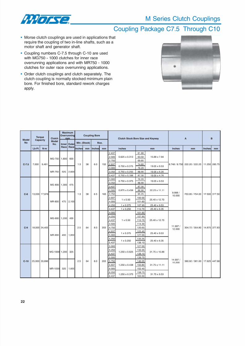
M Series Clutch Couplings
Coupling Package C7.5 Through C10
• Morse clutch couplings are used in applications thatrequire the coupling of two in-line shafts, such as amotor shaft and generator shaft.
• Coupling numbers C-7.5 through C-10 are used
with MG750 - 1000 clutches for inner raceoverrunning applications and with MR750 - 1000clutches for outer race overrunning applications.
• Order clutch couplings and clutch separately. Theclutch coupling is normally stocked minimum plain
bore. For finished bore, standard rework chargesapply.
ledoMoN
euqroTyticapaC
hctulCledoM
.oN
mumixaMgninnurrevO
mpreroBgnilpuoC
yawyeKdnaeziSeroBk cotShctulC A B
rennIecaR
retuOecaR
)k cotS(.niM .xaM
tF-bL m-N sehcnI mm sehcnI mm sehcnI mm sehcnI mm sehcnI mm
5.7-C 000,7 194,9
057-GM 008,1 006
5.1 83 0.6 251
734.2
313.0x526.0
09.16
49.7x88.51
057.8 / 847.8 52.222 / 02.222 052.11 57.582
005.2 05.36
057.2 58.96
739.2573.0x057.0
06.4735.9x50.91
057-RM 525 006,2
000.3 02.67
052.3 052.0x057.0 09.88 53.6x50.91
734.3 881.0x057.0 03.78 67.4x50.91
8-C 000,31 626,71
008-GM 003,1 574
5.1 83 5.6 561
000.3
573.0x057.0
02.67
35.9x50.91
/ 899.9000.01
00.452 / 59.352 005.21 05.713
052.3 09.88
734.3
834.0x578.0
03.78
11.11x32.22005.3 09.88
008-RM 574 001,2
057.3 52.59
739.305.0x1
00.00107.21x04.52
000.4 06.101
052.4 573.0x1 59.701 35.9x04.52
734.4 052.0x1 07.211 53.6x04.52
9-C 000,81 504,42
009-GM 002,1 004
5.2 46 0.8 302
000.4
05.0x1
06.101
07.21x04.52
/ 799.11000.21
08.403 / 27.403 578.41 38.773
052.4 59.701
734.4 07.211
005.4 03.411
009-RM 004 058,1
057.4 56.021
739.4573.0x1
04.52135.9x04.52
000.5 00.721
052.5052.0x1
53.33153.6x04.52
734.5 01.831
01-C 000,52 698,33
0001-GM 002,1 523
5.2 46 0.8 302
000.5
526.0x052.1
00.721
88.51x57.13
/ 799.41000.51
00.183 / 29.083 526.71 86.744
052.5 53.331
734.5 01.831
005.5 07.931
0001-RM 523 006,1
057.5
834.0x052.1
50.641
11.11x57.13739.5 08.051
000.6 04.251
052.6573.0x052.1
57.85135.9x57.13
734.6 05.361
8/20/2019 Catalogo Morse MC Clutches y Limitadores
http://slidepdf.com/reader/full/catalogo-morse-mc-clutches-y-limitadores 25/131
23
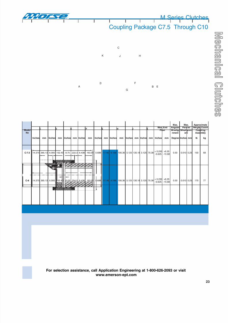
M Series Clutches
Coupling Package C7.5 Through C10
F
B E
G
HJ
C
K
A
D
ledoMoN
C D E F G H J KdnE.xaM
taolF
.xaMralugnA-gilasiM
tnemn
.xaMlellaraP
-mngilasiMtne
etamixorppAhctulCthgieW
gnilpuoCylbmessA
sehcnI mm sehcnI mm sehcnI mm sehcnI mm sehcnI mm sehcnI mm sehcnI mm sehcnI mm sehcnI mm eergeD sehcnI mm bl gk
5.7-C 573.41 31.563 000.6 04.251 57.8 3.222 834.6 15.361 886.0 64.71 881.4 63.601 521.5 81.031 521.3 83.97052.0+526.0-
53.6+88.51-
05.0 010.0 52.0 051 86
8-C 573.41 31.563 000.6 04.251 00.01 0.452 834.6 15.361 886.0 64.71 881.4 63.601 521.5 81.031 521.3 83.97052.0+526.0-
53.6+88.51-
05.0 010.0 52.0 071 77
9-C 839.41 14.973 573.6 39.161 00.21 8.403 526.6 82.861 886.0 64.71 052.4 59.701 573.5 35.631 521.3 83.97052.0+526.0-
53.6+88.51-
05.0 010.0 52.0 052 311
01-C 521.61 85.904 000.7 08.771 00.21 8.403 052.7 51.481 886.0 64.71 839.4 14.521 052.5 53.331 521.3 83.97052.0+526.0-
53.6+88.51-
05.0 010.0 52.0 003 631
For selection assistance, call Application Engineering at 1-800-626-2093 or visitwww.emerson-ept.com
8/20/2019 Catalogo Morse MC Clutches y Limitadores
http://slidepdf.com/reader/full/catalogo-morse-mc-clutches-y-limitadores 26/131
24
M Series
Accessories
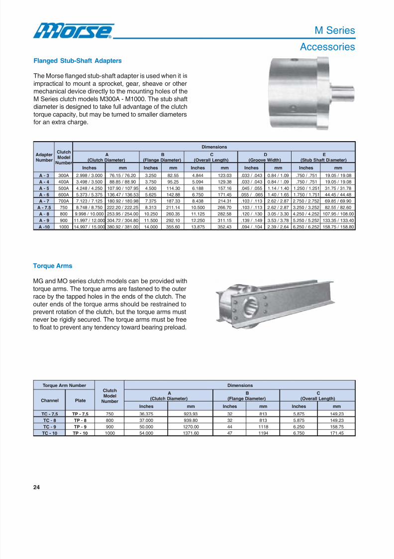
Flanged Stub-Shaft Adapters
The Morse flanged stub-shaft adapter is used when it is
impractical to mount a sprocket, gear, sheave or othermechanical device directly to the mounting holes of the
M Series clutch models M300A - M1000. The stub shaftdiameter is designed to take full advantage of the clutch
torque capacity, but may be turned to smaller diametersfor an extra charge.
Torque Arms
MG and MO series clutch models can be provided with
torque arms. The torque arms are fastened to the outerrace by the tapped holes in the ends of the clutch. The
outer ends of the torque arms should be restrained toprevent rotation of the clutch, but the torque arms mustnever be rigidly secured. The torque arms must be free
to float to prevent any tendency toward bearing preload.
retpadArebmuN
hctulCledoMrebmuN
snoisnemiD
A)retemaiDhctulC(
B)retemaiDegnalF(
C)htgneLllarevO(
D)htdiWevoorG(
E)retemaiDtfahSbutS(
sehcnI mm sehcnI mm sehcnI mm sehcnI mm sehcnI mm
3-A A003 000.3 / 899.2 02.67 / 51.67 052.3 55.28 448.4 30.321 340. / 330. 90.1 / 48.0 157. / 057. 80.91 / 50.91
4-A A004 005.3 / 894.3 09.88 / 58.88 057.3 52.59 490.5 83.921 340. / 330. 90.1 / 48.0 157. / 057. 80.91 / 50.91
5-A A005 052.4 / 842.4 59.701 / 09.701 005.4 03.411 881.6 61.751 550. / 540. 04.1 / 41.1 152.1 / 052.1 87.13 / 57.13
6-A A006 573.5 / 373.5 35.631 / 74.631 526.5 88.241 057.6 54.171 560. / 550. 56.1 / 04.1 157.1 / 057.1 84.44 / 54.447-A A007 521.7 / 321.7 89.081 / 29.081 573.7 33.781 834.8 13.412 311. / 301. 78.2 / 26.2 257.2 / 057.2 09.96 / 58.96
5.7-A 057 057.8 / 847.8 52.222 / 02.222 313.8 41.112 005.01 07.662 311. / 301. 78.2 / 26.2 252.3 / 052.3 06.28 / 55.28
8-A 008 000.01 / 899.9 00.452 / 59.352 052.01 53.062 521.11 85.282 031. / 021. 03.3 / 50.3 252.4 / 052.4 00.801 / 59.701
9-A 009 000.21 / 799.11 08.403 / 27.403 005.11 01.292 052.21 51.113 941. / 931. 87.3 / 35.3 252.5 / 052.5 04.331 / 53.331
01-A 0001 000.51 / 799.41 00.183 / 29.083 000.41 06.553 578.31 34.253 401. / 490. 46.2 / 93.2 252.6 / 052.6 08.851 / 57.851
rebmuNmrAeuqroT
hctulCledoMrebmuN
snoisnemiD
lennahC etalP
A)retemaiDhctulC(
B)retemaiDegnalF(
C)htgneLllarevO(
sehcnI mm sehcnI mm sehcnI mm
5.7-CT 5.7-PT 057 573.63 39.329 23 318 578.5 32.941
8-CT 8-PT 008 000.73 08.939 23 318 578.5 32.941
9-CT 9-PT 009 000.05 00.0721 44 8111 052.6 57.851
01-CT 01-PT 0001 000.45 06.1731 74 4911 057.6 54.171
8/20/2019 Catalogo Morse MC Clutches y Limitadores
http://slidepdf.com/reader/full/catalogo-morse-mc-clutches-y-limitadores 27/131
25
GF D
BE
H
A
C
Keyseat
M Series
Accessories
1/8"
1/8"
B
AC C
DE
retpadArebmuN
snoisnemiD
F)gniRpanSotecaF(
G)dnEtfahSotecaF(
H)dnEtfahSotdnEhctulC(
taesyeK thgieW
sehcnI mm sehcnI mm sehcnI mm sehcnI mm bl gk
3-A 153.1 / 743.1 23.43 / 12.43 05.1 1.83 604.2 21.16 521.x052. 81.3x53.6 4.1 1
4-A 153.1 / 743.1 23.43 / 12.43 05.1 1.83 604.2 21.16 521.x052. 81.3x53.6 6.1 1
5-A 485.1 / 975.1 32.04 / 11.04 57.1 5.44 057.2 58.96 651.x313. 79.3x49.7 2.3 1
6-A 048.1 / 538.1 47.64 / 16.64 00.2 8.05 360.3 97.77 881.x573. 67.4x35.9 8.5 37-A 043.2 / 533.2 44.95 / 13.95 05.2 5.36 005.3 09.88 213.x526. 49.7x88.51 6.21 6
5.7-A 908.2 / 408.2 53.17 / 22.17 00.3 2.67 365.4 98.511 573.x057. 35.9x50.91 8.32 11
8-A 175.3 / 665.3 07.09 / 85.09 57.3 3.59 881.5 67.131 05.x1 07.21x04.52 5.04 81
9-A 123.4 / 613.4 57.901 / 36.901 05.4 3.411 839.5 18.051 526.x052.1 88.51x57.13 8.26 82
01-A 541.5 / 041.5 86.031 / 65.031 05.5 7.931 000.7 08.771 526.x052.1 88.51x57.13 4.301 74
rebmuNmrAeuqroT
hctulC ledoMrebmuN
snoisnemiD
lennahC etalP
D)slennahCowT(htdiW
E)setalPowT(htdiW
eziSlennahC.tf / .blxhtdiW
eziSetalP )mrAhcaE(thgieW
sehcnI mm sehcnI mm sehcnI mm bl gk
5.7-CT 5.7-PT 057 526.9 84.442 573.7 33.781 2.8x6 6x057.0 25 42
8-CT 8-PT 008 573.01 35.362 526.7 86.391 5.11x8 8x578.0 37 33
9-CT 9-PT 009 005.11 01.292 000.8 02.302 3.51x01 21x578.0 921 95
01-CT 01-PT 0001 000.21 08.403 005.8 09.512 3.51x01 21x578.0 831 36
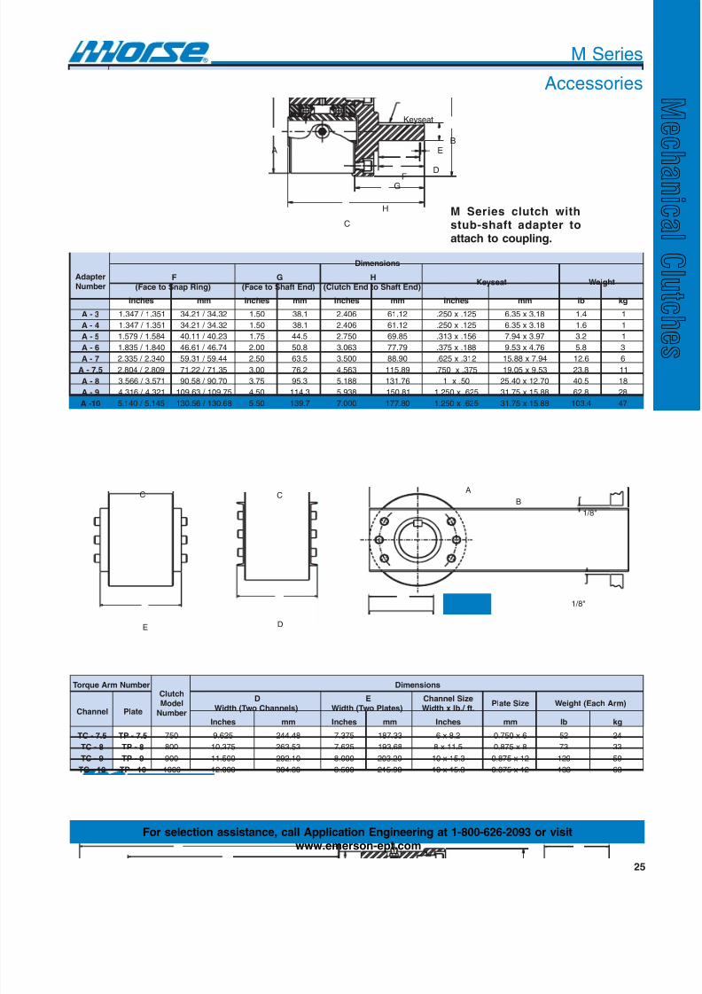
M Series clutch withstub-shaft adapter toattach to coupling.
For selection assistance, call Application Engineering at 1-800-626-2093 or visitwww.emerson-ept.com

8/20/2019 Catalogo Morse MC Clutches y Limitadores
http://slidepdf.com/reader/full/catalogo-morse-mc-clutches-y-limitadores 28/131
26
M Series
Accessories
Oil Reservoirs
An oil reservoir attachment is available for applicationssuch as backstops on the high speed shaft of a reducer,backstops on the head shaft of conveyors and
applications where clutches are relatively inaccessibleor where a minimum of maintenance is required. The
reservoir is designed for direct mounting on any stockMG clutch. Reservoirs can only be used where the clutch
is in backstop service (inner race overrunning).
Since the direction of rotation cannot always be specified,clutches are shipped with oil seals in both ends of the
clutch. When attaching the reservoir to the clutch, theuser should remove the oil seal on the reservoir sideafter determining the proper direction of rotation of the
clutch. This seal should not be reused because it isdamaged by the removal process. The reservoir is an
aluminum casting with cooling fins and has an oil sightgauge.
riovreseRrebmuN
hctulCstiFrebmuNledoM
gninnurrevO.R.ImumixaMmpr
snoisnemiD
)retemaiDhctulC(A
sehcnI mm
3-R A003 0092 000.3 / 899.2 02.67 / 51.67
4-R A004 0072 005.3 / 894.3 09.88 / 58.88
5-R A005 0042 052.4 / 842.4 59.701 / 09.701
6-R A006 0012 573.5 / 373.5 35.631 / 74.631
7-R A007 0051 521.7 / 321.7 89.081 / 29.081
5.7-R 057 0081 057.8 / 847.8 52.222 / 02.222
8-R 008 0031 000.01 / 899.9 00.452 / 59.352
9-R 009 0021 000.21 / 799.11 08.403 / 27.403
01-R 0001 0021 000.51 / 799.41 00.183 / 29.083

8/20/2019 Catalogo Morse MC Clutches y Limitadores
http://slidepdf.com/reader/full/catalogo-morse-mc-clutches-y-limitadores 29/131
27
M Series
Accessories
riovreseRrebmuN
snoisnemiDthgieW
)elcriCtloB(B )htgneLllarevO(C )htgneLriovreseR(D
sehcnI mm sehcnI mm sehcnI mm bl gk
3-R 0526.2 576.66 5265.4 888.511 0521.2 579.35 05.0 2.0
4-R 0578.2 520.37 5218.4 832.221 0521.2 579.35 06.0 3.0
5-R 0526.3 570.29 5260.6 889.351 0526.2 576.66 09.0 4.0
6-R 0057.4 056.021 0005.6 001.561 5218.2 834.17 05.1 7.0
7-R 0052.6 057.851 0521.8 573.602 5781.3 369.08 07.2 2.15.7-R 0000.7 008.771 0000.11 004.972 5260.5 885.821 00.5 3.2
8-R 5739.8 310.722 0005.11 001.292 5265.5 882.141 00.01 5.4
9-R 0057.9 056.742 0052.21 051.113 5739.5 318.051 00.41 4.6
01-R 0057.11 054.892 0000.31 002.033 0521.6 575.551 00.52 3.11
D
C
A
B
For selection assistance, call Application Engineering at 1-800-626-2093 or visit
www.emerson-ept.com
8/20/2019 Catalogo Morse MC Clutches y Limitadores
http://slidepdf.com/reader/full/catalogo-morse-mc-clutches-y-limitadores 30/131
28
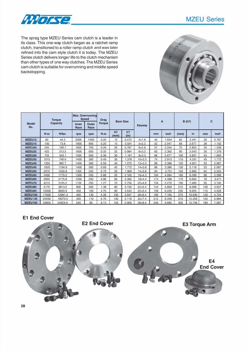
MZEU Series
The sprag type MZEU Series cam clutch is a leader inits class. This one-way clutch began as a ratchet ramp
clutch, transitioned to a roller ramp clutch and was laterrefined into the cam style clutch it is today. The MZEU
Series clutch delivers longer life to the clutch mechanism
than other types of one way clutches. The MZEU Seriescam clutch is suitable for overrunning and middle speed
backstopping.
ledoM.oN
euqroT
yticapaC
gninnurrevO.xaMdeepS garD
euqroT eziSeroB yawyeK A )7h(B CrennIecaR
retuOecaR
m-N .sbl / tf mpr mpr m-N 7H
)mm(7H)ni(
mm hcni )mm( ni mm hcni
21UEZM 06 3.44 0002 0001 02.0 21 274.0 8.1×4 24 456.1 26 144.2 02 787.0
51UEZM 001 8.37 0081 009 02.0 51 195.0 3.2×5 25 740.2 86 776.2 82 201.1
02UEZM 542 7.081 0061 007 92.0 02 787.0 8.2×6 75 442.2 57 359.2 43 933.1
52UEZM 524 5.313 0061 006 33.0 52 489.0 3.3×8 06 263.2 09 345.3 53 873.1
03UEZM 537 1.245 0051 005 93.0 03 181.1 3.3×8 86 776.2 001 739.3 34 396.1
53UEZM 5101 6.847 0041 003 94.0 53 873.1 3.3×01 47 319.2 011 133.4 54 277.1
04UEZM 0531 7.599 0041 003 95.0 04 575.1 3.3×21 68 683.3 521 129.4 35 780.2
54UEZM 0261 9.4911 0041 003 96.0 54 277.1 8.3×41 68 683.3 031 811.5 35 780.2
05UEZM 0702 8.6251 0031 052 97.0 05 969.1 8.3×41 49 107.3 051 609.5 46 025.2
55UEZM 0042 2.0771 0031 052 88.0 55 561.2 3.4×61 401 490.4 061 992.6 66 895.2
06UEZM 0592 8.5712 0021 052 89.0 06 263.2 4.4×81 411 884.4 071 396.6 87 170.3
07UEZM 0124 2.5013 0011 052 72.1 07 657.2 9.4×02 431 672.5 091 084.7 59 047.308UEZM 0715 2.3183 008 002 83.1 08 051.3 4.5×22 441 966.5 012 862.8 001 739.3
09UEZM 00021 9.0588 054 051 07.4 09 345.3 4.5×52 851 022.6 032 550.9 511 825.4
001UEZM 00671 3.18921 004 031 93.5 001 739.3 4.6×82 281 561.7 072 036.01 021 427.4
031UEZM 00542 5.07081 023 011 67.6 031 811.5 4.7×23 212 643.8 013 502.21 251 489.5
051UEZM 00833 9.92942 042 08 31.8 051 609.5 4.8×63 642 586.9 004 847.51 081 780.7
E1 End Cover
E4End Cover
E2 End Cover E3 Torque Arm

8/20/2019 Catalogo Morse MC Clutches y Limitadores
http://slidepdf.com/reader/full/catalogo-morse-mc-clutches-y-limitadores 31/131
29
Features• Sprag type one way clutch
• High torque and longer life than roller rampclutches
• A variety of options, such as torque arm,
flanges, and cover are available accordingto your installation requirements
Industries Served
• Food and beverage• Gearing
• Manufacturing• Textiles
Field Applications
• Conveyors• External gearbox
backstop• General equipment
backstop for drive shaft
ledoM.oN
D E F G
J-H
K L thgieW
mm hcni mm hcni mm hcni mm hcni mm hcni mm hcni gK .bl
21UEZM 15 800.2 24 456.1 02 787.0 72 360.1 5.5Ø-3 - - 5.0 020.0 5.0 1.1
51UEZM 65 502.2 74 058.1 52 489.0 23 062.1 5M-3 8 513.0 8.0 130.0 8.0 8.1
02UEZM 46 025.2 55 561.2 03 181.1 93 535.1 5M-4 8 513.0 8.0 130.0 2.1 6.2
52UEZM 87 170.3 86 776.2 04 575.1 04 575.1 6M-4 01 493.0 0.1 930.0 8.1 0.4
03UEZM 78 524.3 57 359.2 54 277.1 84 098.1 6M-6 01 493.0 0.1 930.0 6.2 7.5
53UEZM 69 087.3 08 051.3 05 969.1 15 800.2 6M-6 21 274.0 0.1 930.0 2.3 1.7
04UEZM 801 252.4 09 345.3 55 561.2 95 323.2 8M-6 41 155.0 5.1 950.0 8.4 6.01
54UEZM 211 904.4 59 047.3 06 263.2 95 323.2 8M-8 41 155.0 5.1 950.0 2.6 7.31
05UEZM 231 791.5 011 133.4 07 657.2 27 538.2 8M-8 41 155.0 5.1 950.0 2.8 1.81
55UEZM 831 334.5 511 825.4 57 359.2 27 538.2 01M-8 61 036.0 0.2 970.0 5.9 9.02
06UEZM 051 609.5 521 129.4 08 051.3 98 405.3 01M-01 61 036.0 0.2 970.0 3.21 1.72
07UEZM 561 694.6 041 215.5 09 345.3 801 252.4 01M-01 61 036.0 5.2 890.0 1.81 9.93
08UEZM 581 382.7 061 992.6 501 431.4 801 252.4 01M-01 61 036.0 5.2 890.0 1.32 9.05
09UEZM 602 011.8 081 780.7 021 427.4 521 129.4 21M-01 02 787.0 0.3 811.0 1.82 9.16
001UEZM 042 944.9 012 862.8 041 215.5 131 751.5 61M-01 42 549.0 0.3 811.0 3.64 1.201
031UEZM 872 549.01 042 944.9 061 992.6 861 416.6 61M-21 42 549.0 0.3 811.0 2.07 8.451
051UEZM 063 371.41 013 502.21 002 478.7 491 836.7 02M-21 23 062.1 0.4 751.0 3.641 5.223
MZEU Series
KH - J
L
D F E B
C
G
A
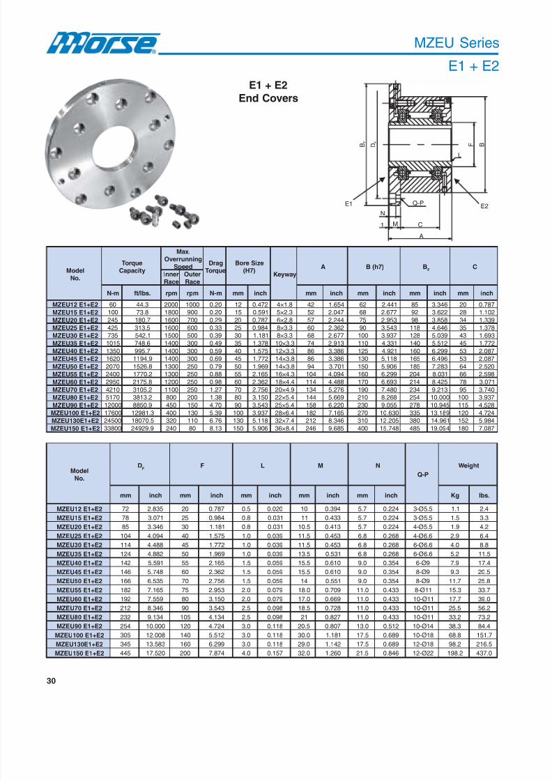
The MZEU series clutches offer various combinationsof covers, which can be assembled to meet a full rangeof applications. These units incorporate two metric ballbearings between the inner and outer races givingexcellent concentricity control.
The outer diameter of the outer race is produced to a
close tolerance and can be used for mounting gears,v-belt sheaves, indexing arms, etc. Tapped holes areprovided at the face of the outer race and are used tosecure the various covers. These tapped holes can alsobe used for attaching specially designed covers oradapter plates to suit special design considerations. Therange of application for these clutches is very extensiveand by using the various combinations of covers, it ispossible to build units for overrunning applications(MZEU with E1-E2), to prevent reverse rotation(backstopping) MZEU E2-E3 or E3-E4 or to convertlinear motion to rotary motion (indexing) MZEU E1-E2with indexing arm bolted to cover E1.
Building Block Principle of Standardization
MZEU 60 E1 + E2
End cover (ordered separately*)
End cover (ordered separately*)
Bore sizes in millimeters
Clutch series
* Covers ordered separately. Example: MZEU60-E1 cover or MZEU60-E2
cover.
Part Number Explanation
8/20/2019 Catalogo Morse MC Clutches y Limitadores
http://slidepdf.com/reader/full/catalogo-morse-mc-clutches-y-limitadores 32/131
30
BF
DF
F B
L
Q-P
C
N
E1 E2
1 M
A
MZEU Series
E1 + E2
ledoM .oN
euqroT
yticapaC
.xaMgninnurrevO
deepS garD
euqroT
eziSeroB
)7H( yawyeK
A )7h(B BF
C
rennIecaR
retuOecaR
m-N .sbl / tf mpr mpr m-N mm hcni mm hcni mm hcni mm hcni mm hcni
2E+1E21UEZM 06 3.44 0002 0001 02.0 21 274.0 8.1×4 24 456.1 26 144.2 58 643.3 02 787.0
2E+1E51UEZM 001 8.37 0081 009 02.0 51 195.0 3.2×5 25 740.2 86 776.2 29 226.3 82 201.1
2E+1E02UEZM 542 7.081 0061 007 92.0 02 787.0 8.2×6 75 442.2 57 359.2 89 858.3 43 933.1
2E+1E52UEZM 524 5.313 0061 006 33.0 52 489.0 3.3×8 06 263.2 09 345.3 811 646.4 53 873.1
2E+1E03UEZM 537 1.245 0051 005 93.0 03 181.1 3.3×8 86 776.2 001 739.3 821 930.5 34 396.1
2E+1E53UEZM 5101 6.847 0041 003 94.0 53 873.1 3.3×01 47 319.2 011 133.4 041 215.5 54 277.1
2E+1E04UEZM 0531 7.599 0041 003 95.0 04 575.1 3.3×21 68 683.3 521 129.4 061 992.6 35 780.2
2E+1E54UEZM 0261 9.4911 0041 003 96.0 54 277.1 8.3×41 68 683.3 031 811.5 561 694.6 35 780.2
2E+1E05UEZM 0702 8.6251 0031 052 97.0 05 969.1 8.3×41 49 107.3 051 609.5 581 382.7 46 025.2
2E+1E55UEZM 0042 2.0771 0031 052 88.0 55 561.2 3.4×61 401 490.4 061 992.6 402 130.8 66 895.2
2E+1E06UEZM 0592 8.5712 0021 052 89.0 06 263.2 4.4×81 411 884.4 071 396.6 412 524.8 87 170.3
2E+1E07UEZM 0124 2.5013 0011 052 72.1 07 657.2 9.4×02 431 672.5 091 084.7 432 312.9 59 047.3
2E+1E08UEZM 0715 2.3183 008 002 83.1 08 051.3 4.5×22 441 966.5 012 862.8 452 000.01 001 739.3
2E+1E09UEZM 00021 9.0588 054 051 07.4 09 345.3 4.5×52 851 022.6 032 550.9 872 549.01 511 825.4
2E+1E001UEZM 00671 3.18921 004 031 93.5 001 739.3 4.6×82 281 561.7 072 036.01 533 981.31 021 427.4
2E+1E031UEZM 00542 5.07081 023 011 67.6 031 811.5 4.7×23 212 643.8 013 502.21 083 169.41 251 489.5
2E+1E051UEZM 00833 9.92942 042 08 31.8 051 609.5 4.8×63 642 586.9 004 847.51 584 490.91 081 780.7
ledoM.oN
DF
F L M N
P-Q
thgieW
mm hcni mm hcni mm hcni mm hcni mm hcni gK .sbl
2E+1E21UEZM 27 538.2 02 787.0 5.0 020.0 01 493.0 7.5 422.0 -3 Ø 5.5 1.1 4.2
2E+1E51UEZM 87 170.3 52 489.0 8.0 130.0 11 334.0 7.5 422.0 -3 Ø 5.5 5.1 3.3
2E+1E02UEZM 58 643.3 03 181.1 8.0 130.0 5.01 314.0 7.5 422.0 -4 Ø 5.5 9.1 2.4
2E+1E52UEZM 401 490.4 04 575.1 0.1 930.0 5.11 354.0 8.6 862.0 -4 Ø 6.6 9.2 4.6
2E+1E03UEZM 411 884.4 54 277.1 0.1 930.0 5.11 354.0 8.6 862.0 -6 Ø 6.6 0.4 8.82E+1E53UEZM 421 288.4 05 969.1 0.1 930.0 5.31 135.0 8.6 862.0 -6 Ø 6.6 2.5 5.11
2E+1E04UEZM 241 195.5 55 561.2 5.1 950.0 5.51 016.0 0.9 453.0 -6 Ø9 9.7 4.71
2E+1E54UEZM 641 847.5 06 263.2 5.1 950.0 5.51 016.0 0.9 453.0 -8 Ø9 3.9 5.02
2E+1E05UEZM 661 535.6 07 657.2 5.1 950.0 41 155.0 0.9 453.0 -8 Ø9 7.11 8.52
2E+1E55UEZM 281 561.7 57 359.2 0.2 970.0 0.81 907.0 0.11 334.0 -8 Ø 11 3.51 7.33
2E+1E06UEZM 291 955.7 08 051.3 0.2 970.0 0.71 966.0 0.11 334.0 -01 Ø 11 7.71 0.93
2E+1E07UEZM 212 643.8 09 345.3 5.2 890.0 5.81 827.0 0.11 334.0 -01 Ø 11 5.52 2.65
2E+1E08UEZM 232 431.9 501 431.4 5.2 890.0 12 728.0 0.11 334.0 -01 Ø 11 2.33 2.37
2E+1E09UEZM 452 000.01 021 427.4 0.3 811.0 5.02 708.0 0.31 215.0 -01 Ø 41 3.83 4.48
2E+1E001UEZM 503 800.21 041 215.5 0.3 811.0 0.03 181.1 5.71 986.0 -01 Ø 81 8.86 7.151
2E+1E031UEZM 543 385.31 061 992.6 0.3 811.0 0.92 241.1 5.71 986.0 -21 Ø 81 2.89 5.612
2E+1E051UEZM 544 025.71 002 478.7 0.4 751.0 0.23 062.1 5.12 648.0 -21 Ø 22 2.891 0.734
E1 + E2
End Covers
8/20/2019 Catalogo Morse MC Clutches y Limitadores
http://slidepdf.com/reader/full/catalogo-morse-mc-clutches-y-limitadores 33/131
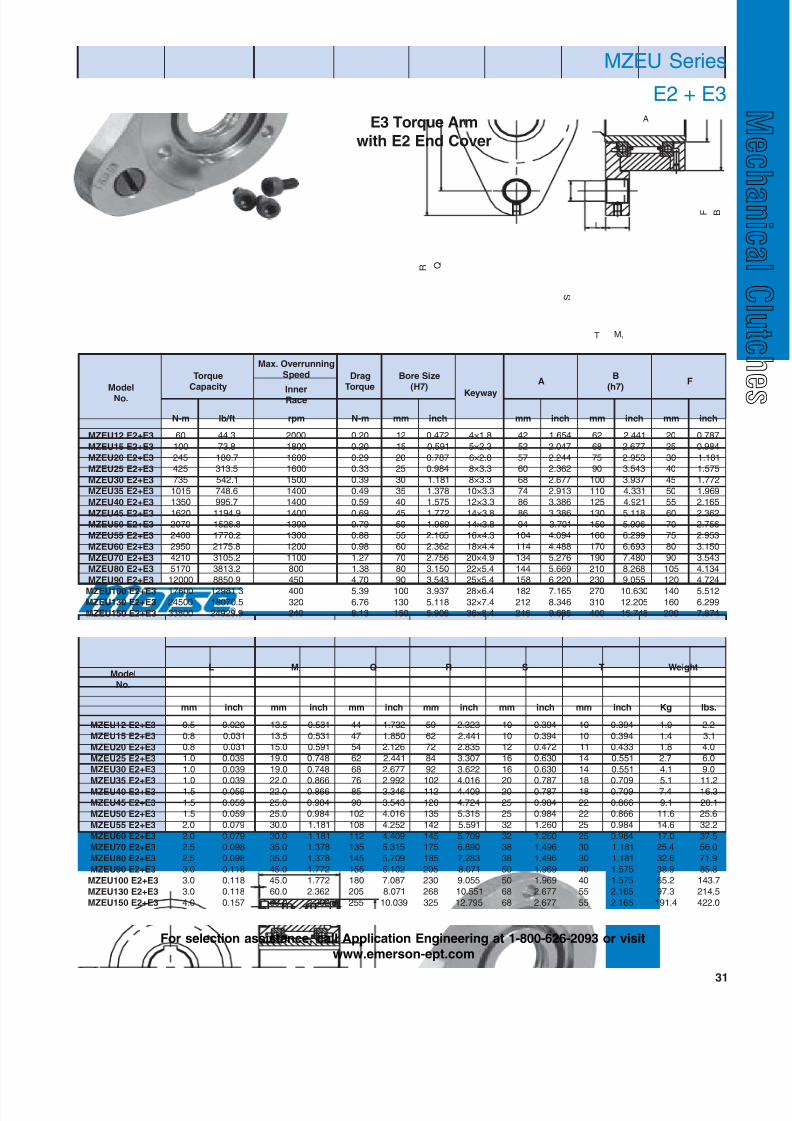
31
MZEU Series
E2 + E3
ledoM.oN
euqroTyticapaC
gninnurrevO.xaMdeepS garD
euqroTeziSeroB
)7H(yawyeK
A B
)7h( F
rennI ecaR
m-N tf / bl mpr m-N mm hcni mm hcni mm hcni mm hcni
3E+2E21UEZM 06 3.44 0002 02.0 21 274.0 8.1×4 24 456.1 26 144.2 02 787.0
3E+2E51UEZM 001 8.37 0081 02.0 51 195.0 3.2×5 25 740.2 86 776.2 52 489.0
3E+2E02UEZM 542 7.081 0061 92.0 02 787.0 8.2×6 75 442.2 57 359.2 03 181.1
3E+2E52UEZM 524 5.313 0061 33.0 52 489.0 3.3×8 06 263.2 09 345.3 04 575.1
3E+2E03UEZM 537 1.245 0051 93.0 03 181.1 3.3×8 86 776.2 001 739.3 54 277.1
3E+2E53UEZM 5101 6.847 0041 94.0 53 873.1 3.3×01 47 319.2 011 133.4 05 969.1
3E+2E04UEZM 0531 7.599 0041 95.0 04 575.1 3.3×21 68 683.3 521 129.4 55 561.2
3E+2E54UEZM 0261 9.4911 0041 96.0 54 277.1 8.3×41 68 683.3 031 811.5 06 263.2
3E+2E05UEZM 0702 8.6251 0031 97.0 05 969.1 8.3×41 49 107.3 051 609.5 07 657.2
3E+2E55UEZM 0042 2.0771 0031 88.0 55 561.2 3.4×61 401 490.4 061 992.6 57 359.2
3E+2E06UEZM 0592 8.5712 0021 89.0 06 263.2 4.4×81 411 884.4 071 396.6 08 051.3
3E+2E07UEZM 0124 2.5013 0011 72.1 07 657.2 9.4×02 431 672.5 091 084.7 09 345.3
3E+2E08UEZM 0715 2.3183 008 83.1 08 051.3 4.5×22 441 966.5 012 862.8 501 431.4
3E+2E09UEZM 00021 9.0588 054 07.4 09 345.3 4.5×52 851 022.6 032 550.9 021 427.4
3E+2E001UEZM 00671 3.18921 004 93.5 001 739.3 4.6×82 281 561.7 072 036.01 041 215.53E+2E031UEZM 00542 5.07081 023 67.6 031 811.5 4.7×23 212 643.8 013 502.21 061 992.6
3E+2E051UEZM 00833 9.92942 042 31.8 051 609.5 4.8×63 642 586.9 004 847.51 002 478.7
ledoM.oN
L M1
Q R S T thgieW
mm hcni mm hcni mm hcni mm hcni mm hcni mm hcni gK .sbl
3E+2E21UEZM 5.0 020.0 5.31 135.0 44 237.1 95 323.2 01 493.0 01 493.0 0.1 2.2
3E+2E51UEZM 8.0 130.0 5.31 135.0 74 058.1 26 144.2 01 493.0 01 493.0 4.1 1.3
3E+2E02UEZM 8.0 130.0 0.51 195.0 45 621.2 27 538.2 21 274.0 11 334.0 8.1 0.4
3E+2E52UEZM 0.1 930.0 0.91 847.0 26 144.2 48 703.3 61 036.0 41 155.0 7.2 0.6
3E+2E03UEZM 0.1 930.0 0.91 847.0 86 776.2 29 226.3 61 036.0 41 155.0 1.4 0.9
3E+2E53UEZM 0.1 930.0 0.22 668.0 67 299.2 201 610.4 02 787.0 81 907.0 1.5 2.11
3E+2E04UEZM 5.1 950.0 0.22 668.0 58 643.3 211 904.4 02 787.0 81 907.0 4.7 3.61
3E+2E54UEZM 5.1 950.0 0.52 489.0 09 345.3 021 427.4 52 489.0 22 668.0 1.9 1.02
3E+2E05UEZM 5.1 950.0 0.52 489.0 201 610.4 531 513.5 52 489.0 22 668.0 6.11 6.52
3E+2E55UEZM 0.2 970.0 0.03 181.1 801 252.4 241 195.5 23 062.1 52 489.0 6.41 2.23
3E+2E06UEZM 0.2 970.0 0.03 181.1 211 904.4 541 907.5 23 062.1 52 489.0 0.71 5.73
3E+2E07UEZM 5.2 890.0 0.53 873.1 531 513.5 571 098.6 83 694.1 03 181.1 4.52 0.65
3E+2E08UEZM 5.2 890.0 0.53 873.1 541 907.5 581 382.7 83 694.1 03 181.1 6.23 9.17
3E+2E09UEZM 0.3 811.0 0.54 277.1 551 201.6 502 170.8 05 969.1 04 575.1 9.83 8.58
3E+2E001UEZM 0.3 811.0 0.54 277.1 081 780.7 032 550.9 05 969.1 04 575.1 2.56 7.341
3E+2E031UEZM 0.3 811.0 0.06 263.2 502 170.8 862 155.01 86 776.2 55 561.2 3.79 5.412
3E+2E051UEZM 0.4 751.0 0.06 263.2 552 930.01 523 597.21 86 776.2 55 561.2 4.191 0.224
A
L
F B
S
R Q
T M1
E3 Torque Arm
with E2 End Cover
For selection assistance, call Application Engineering at 1-800-626-2093 or visit
www.emerson-ept.com

8/20/2019 Catalogo Morse MC Clutches y Limitadores
http://slidepdf.com/reader/full/catalogo-morse-mc-clutches-y-limitadores 34/131
32
AC
A U F
S
R
Q
B
L
M1T
ledoM.oN
euqroT
yticapaC
gninnurrevO.xaMdeepS garD
euqroT
eziSeroB
)7H( yawyeK A AC
B
7h FecaRrennI
m-N .bl / tf mpr m-N mm hcni mm hcni mm hcni mm hcni mm hcni
4E+3E21UEZM 06 3.44 0002 02.0 21 274.0 8.1×4 24 456.1 35 780.2 26 144.2 02 787.0
4E+3E51UEZM 001 8.37 0081 02.0 51 195.0 3.2×5 25 740.2 86 776.2 86 776.2 52 489.0
4E+3E02UEZM 542 7.081 0061 92.0 02 787.0 8.2×6 75 442.2 37 478.2 57 359.2 03 181.1
4E+3E52UEZM 524 5.313 0061 33.0 52 489.0 3.3×8 06 263.2 67 299.2 09 345.3 04 575.1
4E+3E03UEZM 537 1.245 0051 93.0 03 181.1 3.3×8 86 776.2 48 703.3 001 739.3 54 277.1
4E+3E53UEZM 5101 6.847 0041 94.0 53 873.1 3.3×01 47 319.2 29 226.3 011 133.4 05 969.1
4E+3E04UEZM 0531 7.599 0041 95.0 04 575.1 3.3×21 68 683.3 501 431.4 521 129.4 55 561.2
4E+3E54UEZM 0261 9.4911 0041 96.0 54 277.1 8.3×41 68 683.3 801 252.4 031 811.5 06 263.2
4E+3E05UEZM 0702 8.6251 0031 97.0 05 969.1 8.3×41 49 107.3 311 944.4 051 609.5 07 657.2
4E+3E55UEZM 0042 2.0771 0031 88.0 55 561.2 3.4×61 401 490.4 621 169.4 061 992.6 57 359.2
4E+3E06UEZM 0592 8.5712 0021 89.0 06 263.2 4.4×81 411 884.4 731 493.5 071 396.6 08 051.3
4E+3E07UEZM 0124 2.5013 0011 72.1 07 657.2 9.4×02 431 672.5 5.461 674.6 091 084.7 09 345.3
4E+3E08UEZM 0715 2.3183 008 83.1 08 051.3 4.5×22 441 966.5 861 416.6 012 862.8 501 431.44E+3E09UEZM 00021 9.0588 055 67.3 09 345.3 4.5×52 851 022.6 291 955.7 032 550.9 021 427.4
4E+3E001UEZM 00671 3.18921 005 13.4 001 739.3 4.6×82 281 561.7 712 345.8 072 036.01 041 215.5
4E+3E031UEZM 00542 5.07081 004 93.5 031 811.5 4.7×23 212 643.8 052 348.9 013 502.21 061 992.6
4E+3E051UEZM 00833 9.92942 003 74.6 051 609.5 4.8×63 642 586.9 682 062.11 004 847.51 002 478.7
ledoM.oN
L M1
Q R S T U thgieW
mm hcni mm hcni mm hcni mm hcni mm hcni mm hcni mm hcni gK .sbl
4E+3E21UEZM 5.0 020.0 5.31 135.0 44 237.1 95 323.2 01 493.0 01 493.0 0.6 632.0 0.1 2.2
4E+3E51UEZM 8.0 130.0 5.31 135.0 74 058.1 26 144.2 01 493.0 01 493.0 0.01 493.0 5.1 3.3
4E+3E02UEZM 8.0 130.0 0.51 195.0 45 621.2 27 538.2 21 274.0 11 334.0 0.01 493.0 0.2 4.44E+3E52UEZM 0.1 930.0 0.91 847.0 26 144.2 48 703.3 61 036.0 41 155.0 0.01 493.0 9.2 4.6
4E+3E03UEZM 0.1 930.0 0.91 847.0 86 776.2 29 226.3 61 036.0 41 155.0 0.01 493.0 3.4 5.9
4E+3E53UEZM 0.1 930.0 0.22 668.0 67 299.2 201 610.4 02 787.0 81 907.0 0.21 274.0 3.5 7.11
4E+3E04UEZM 5.1 950.0 0.22 668.0 58 643.3 211 904.4 02 787.0 81 907.0 0.21 274.0 8.7 2.71
4E+3E54UEZM 5.1 950.0 0.52 489.0 09 345.3 021 427.4 52 489.0 22 668.0 0.51 195.0 6.9 2.12
4E+3E05UEZM 5.1 950.0 0.52 489.0 201 610.4 531 513.5 52 489.0 22 668.0 0.21 274.0 1.21 7.62
4E+3E55UEZM 0.2 970.0 0.03 181.1 801 252.4 241 195.5 23 062.1 52 489.0 0.51 195.0 2.51 5.33
4E+3E06UEZM 0.2 970.0 0.03 181.1 211 904.4 541 907.5 23 062.1 52 489.0 0.51 195.0 7.71 0.93
4E+3E07UEZM 5.2 890.0 0.53 873.1 531 513.5 571 098.6 83 694.1 03 181.1 5.22 688.0 5.62 4.85
4E+3E08UEZM 5.2 890.0 0.53 873.1 541 907.5 581 382.7 83 694.1 03 181.1 0.61 036.0 6.33 1.47
4E+3E09UEZM 0.3 811.0 0.54 277.1 551 201.6 502 170.8 05 969.1 04 575.1 0.72 360.1 0.93 0.68
4E+3E001UEZM 0.3 811.0 0.54 277.1 081 780.7 032 550.9 05 969.1 04 575.1 0.82 201.1 4.76 6.841
4E+3E031UEZM 0.3 811.0 0.06 263.2 502 170.8 862 155.01 86 776.2 55 561.2 0.03 181.1 2.001 9.022
4E+3E051UEZM 0.4 751.0 0.06 263.2 552 930.01 523 597.21 86 776.2 55 561.2 0.23 062.1 8.491 5.924
MZEU Series
E3 + E4
E3 Torque Armwith E4 End Cover
8/20/2019 Catalogo Morse MC Clutches y Limitadores
http://slidepdf.com/reader/full/catalogo-morse-mc-clutches-y-limitadores 35/131
33
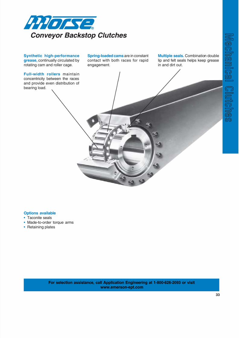
Conveyor Backstop Clutches
Synthetic high-performance
grease, continually circulated byrotating cam and roller cage.
Full-width rollers maintainconcentricity between the racesand provide even distribution ofbearing load.
Spring-loaded cams are in constant
contact with both races for rapidengagement.
Multiple seals. Combination double
lip and felt seals helps keep greasein and dirt out.
Options available• Taconite seals
• Made-to-order torque arms• Retaining plates
For selection assistance, call Application Engineering at 1-800-626-2093 or visitwww.emerson-ept.com
8/20/2019 Catalogo Morse MC Clutches y Limitadores
http://slidepdf.com/reader/full/catalogo-morse-mc-clutches-y-limitadores 36/131
34
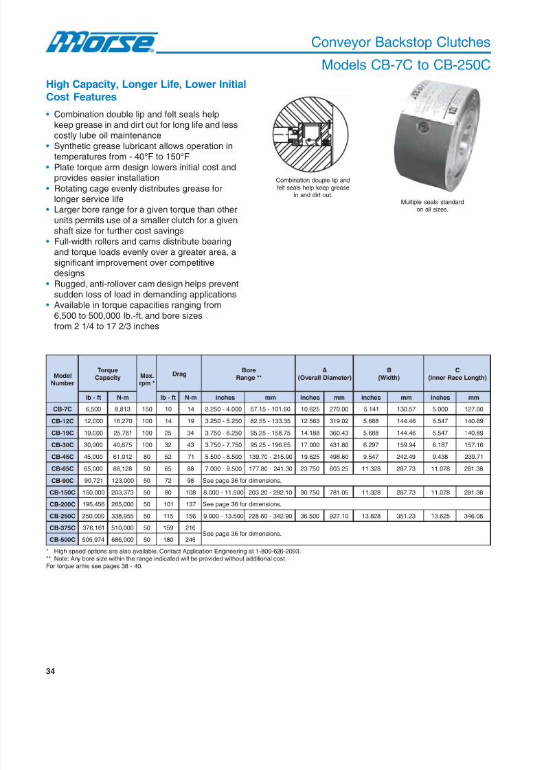
Conveyor Backstop Clutches
Models CB-7C to CB-250C
High Capacity, Longer Life, Lower InitialCost Features
ledoMrebmuN
euqroTyticapaC .xaM
*mpr
garD eroB
**egnaRA
)retemaiDllarevO(B
)htdiW(C
)htgneLecaRrennI(
tf-bl m-N tf-bl m-N sehcni mm sehcni mm sehcni mm sehcni mm
C7-BC 005,6 318,8 051 01 41 000.4-052.2 06.101-51.75 526.01 00.072 141.5 75.031 000.5 00.721
C21-BC 000,21 072,61 001 41 91 052.5-052.3 53.331-55.28 365.21 20.913 886.5 64.441 745.5 98.041
C91-BC 000,91 167,52 001 52 43 052.6-057.3 57.851-52.59 881.41 34.063 886.5 64.441 745.5 98.041
C03-BC 000,03 576,04 001 23 34 057.7-057.3 58.691-52.59 000.71 08.134 792.6 49.951 781.6 61.751
C54-BC 000,54 210,16 08 25 17 005.8-005.5 09.512-07.931 526.91 06.894 745.9 94.242 834.9 17.932
C56-BC 000,56 821,88 05 56 88 005.9-000.7 03.142-08.771 057.32 52.306 823.11 37.782 870.11 83.182
C09-BC 127,09 000,321 05 27 89 .snoisnemidrof63egapeeS
C051-BC 000,051 373,302 05 08 801 005.11-000.8 01.292-02.302 057.03 50.187 823.11 37.782 870.11 83.182
C002-BC 654,591 000,562 05 101 731 .snoisnemidrof63egapeeS
C052-BC 000,052 559,833 05 511 651 005.31-000.9 09.243-06.822 005.63 01.729 828.31 32.153 526.31 80.643
C573-BC 161,673 000,015 05 951 612.snoisnemidrof63egapeeS
C005-BC 479,505 000,686 05 081 542
* High speed options are also available. Contact Application Engineering at 1-800-626-2093.** Note: Any bore size within the range indicated will be provided without additional cost.For torque arms see pages 38 - 40.
Multiple seals standardon all sizes.
Combination douple lip andfelt seals help keep grease
in and dirt out.
• Combination double lip and felt seals helpkeep grease in and dirt out for long life and less
costly lube oil maintenance• Synthetic grease lubricant allows operation in
temperatures from - 40°F to 150°F
• Plate torque arm design lowers initial cost andprovides easier installation
• Rotating cage evenly distributes grease forlonger service life
• Larger bore range for a given torque than other
units permits use of a smaller clutch for a givenshaft size for further cost savings
• Full-width rollers and cams distribute bearingand torque loads evenly over a greater area, a
significant improvement over competitive
designs• Rugged, anti-rollover cam design helps prevent
sudden loss of load in demanding applications• Available in torque capacities ranging from
6,500 to 500,000 lb.-ft. and bore sizesfrom 2 1/4 to 17 2/3 inches

8/20/2019 Catalogo Morse MC Clutches y Limitadores
http://slidepdf.com/reader/full/catalogo-morse-mc-clutches-y-limitadores 37/131
35
A
D
B
CE
Combination douple lip and felt seals keep
grease in and dirt out.
Conveyor Backstop Clutches
Models CB-7C to CB-250C
ledoMrebmuN
DtloBgnitnuoM(
)elcriC
seloHgnitnuoM seloHecaRrennI
tloB daerhT
eziS
htpeDE
rofelcriCtloBetalPgniniateR
fo.oNstloB
daerhTeziS
htpeD etamixorppA
thgieW
sehcni mm sehcni mm sehcni mm sehcni mm bl gk
C7-BC 0.9 922 6 FNU81-526. 578.0 32.22 52.5 4.331 3 FNU42-573. 005.0 07.21 0.08 3.63
C21-BC 0.11 972 8 FNU81-526. 578.0 32.22 05.6 1.561 3 FNU42-573. 005.0 07.21 1.061 6.27
C91-BC 5.21 813 01 CNU01-057. 521.1 85.82 00.8 2.302 3 FNU42-573. 005.0 07.21 1.591 5.88
C03-BC 0.51 183 01 CNU9-578. 573.1 39.43 05.9 3.142 3 FNU02-005. 526.0 88.51 0.033 7.941
C54-BC 5.71 544 61 CNU01-057. 573.1 39.43 00.01 0.452 3 FNU02-005. 526.0 88.51 0.526 5.382
C56-BC 0.12 335 61 CNU8-000.1 526.1 82.14 00.21 8.403 3 FNU02-005. 526.0 88.51 1.0031 6.985
C09-BC .snoisnemidrof73egapeeS
C051-BC 5.72 996 61 CNU7-052.1 521.2 89.35 00.71 8.134 3 CNU11-526. 578.0 32.22 1.0031 5.259
C002-BC .snoisnemidrof73egapeeS
C052-BC 0.23 318 61 CNU7-052.1 578.1 36.74 00.02 0.805 3 CNU01-057. 573.1 39.43 1.0053 6.7851
C573-BC
.snoisnemidrof73egapeeSC005-BC
Industries Served
• Aggregate processing• Agriculture
• Conveyor manufacturing
Field Applications• Belt conveyor
• Bucket elevator• Conveyors• Low rpm head-shafts
• Inclined conveyor
For selection assistance, call Application Engineering at 1-800-626-2093 or visit
www.emerson-ept.com

8/20/2019 Catalogo Morse MC Clutches y Limitadores
http://slidepdf.com/reader/full/catalogo-morse-mc-clutches-y-limitadores 38/131
36
Conveyor Backstop Clutches
Models CB-90C to CB-500C
High Capacity, Longer Life, Lower InitialCost Features
• Combination double lip and felt seals help
keep grease in and dirt out for long life and lesscostly lube oil maintenance
• Synthetic grease lubricant allows operation in
temperatures from - 40°F to 150°F• Plate torque arm design lowers initial cost and
provides easier installation• Rotating cage evenly distributes grease for
longer service life
• Larger bore range for a given torque than otherunits permits use of a smaller clutch for a given
shaft size for further cost savings• Full-width rollers and cams distribute bearing
and torque loads evenly over a greater area, a
significant improvement over competitive designs• Rugged, anti-rollover cam design helps preventsudden loss of load in demanding applications
• Available in torque capacities ranging from
6,500 to 500,000 pound-feet and bore sizesfrom 2 1/4 to 17 2/3 inches
* High speed backstop options are available. Contact Application Engineering at 1-800-626-2093 for further details.** Note: Any bore size within the range indicated will be provided without additional cost.For torque arms see pages 38 - 40.
Multiple seals standardon all sizes.
ledoMrebmuN
yticapaCeuqroT.xaMrennIecaR*mpr).xaM(
garDgninnurrevO eroB
**egnaR
snoisnemiD
A B C
tf-bl m-N tf-bl m-N hcni mm hcni mm hcni mm hcni mm
C54-BC.snoisnemidrof43egapeeS
C56-BC
C09-BC 127,09 000,321 05 27 89 36.01-78.7 072ot002 06.11 592 95.52 056 24.11 092
C051-BC .snoisnemidrof43egapeeS
C002-BC 654,591 000,562 05 101 731 91.31-48.9 533ot052 10.21 503 74.33 058 06.21 023
C052-BC .snoisnemidrof43egapeeS
C573-BC 161,673 000,015 05 951 612 37.61-8.21 524ot523 23.71 044 55.04 0301 27.71 054
C005-BC 479,505 000,686 05 081 542 27.71-87.31 054ot053 27.71 054 19.24 0901 09.81 084

8/20/2019 Catalogo Morse MC Clutches y Limitadores
http://slidepdf.com/reader/full/catalogo-morse-mc-clutches-y-limitadores 39/131
37
Combination single lip and felt seals keepgrease in and dirt out.
Conveyor Backstop Clutches
Models CB-90C to CB-500C
Industries Served
• Aggregate processing• Agriculture• Conveyor manufacturing
Field Applications• Belt conveyor
• Bucket elevator• Conveyors
• Low rpm head-shafts• Inclined conveyor
ledoMrebmuN
snoisnemiD
D E Sfo.oNM-H
seloHdeppaThctiPxeziSx
)mm(
ebuLgnittiF
eloH
esaerGfoytitnauQ o / wthgieW
mrAeuqroT
hcni mm hcni mm hcni mm secnuo smarg bl gk
C54-BC.snoisnemidrof53egapeeS
C56-BC
C09-BC 46.22 575 75.41 073 79.1 05 0.3Px42Mx61 4 / 1TP 89.621 006,3 7631 026
C051-BC .snoisnemidrof53egapeeS
C002-BC 35.92 057 94.91 594 67.2 07 0.4Px63Mx61 4 / 1TP 37.851 008,4 2052 5311
C052-BC .snoisnemidrof53egapeeS
C573-BC 10.73 049 00.52 536 67.2 07 0.4Px63Mx81 LIO LIO LIO 1045 0542
C005-BC 89.83 099 04.52 546 51.3 08 5.4Px24Mx81 LIO LIO LIO 7126 0282
A H - M (both sides)
C
ED B
Lube fitting
S
For selection assistance, call Application Engineering at 1-800-626-2093 or visitwww.emerson-ept.com

8/20/2019 Catalogo Morse MC Clutches y Limitadores
http://slidepdf.com/reader/full/catalogo-morse-mc-clutches-y-limitadores 40/131
38
A
B
E
C
D
K
L
H
F
Conveyor Backstop Clutches
CB-7TA to CB-30TA Torque Arms
For assembly with CB-7C to CB-30C clutches
Single Torque Arm
ledoMrebmuN
snoisnemiD
)htgneLllarevO(A otretneCtfahS(B
)mrAfodnE C )suidaRdnE(D )ssenk cihT(E )eloHdnE(F
hcni mm hcni mm hcni mm hcni mm hcni mm hcni mm
AT7-BC 3.22 765 3.51 783 0.9 922 3.5 531 5.0 31 52.1 13
AT21-BC 4.62 176 6.81 374 0.11 972 3.6 951 5.0 31 52.1 13
AT91-BC 7.13 608 9.22 185 5.21 813 1.7 081 9.0 22 05.1 83
AT03-BC 5.33 158 0.32 485 0.51 183 5.8 512 9.0 22 57.1 44
ledoMrebmuN
snoisnemiDrebmuN
fostloB
seloHgnitnuoM
thgieW)htdiWdnEmrA(H )suidaR(K
ediSthgiartS(L)htgneL daerhT
eziS
htgneL
hcni mm hcni mm hcni mm hcni mm bl gk
AT7-BC 573.4 111 526.5 341 609.2 47 6 FNU81-8 / 5 05.1 1.83 02 9
AT21-BC 057.4 021 057.6 171 365.3 19 8 FNU81-8 / 5 05.1 1.83 03 41
AT91-BC 057.4 021 005.8 612 573.3 68 01 CNU01-4 / 3 57.1 5.44 06 72
AT03-BC 052.5 331 005.01 762 573.3 68 01 CNU9-8 / 7 00.2 8.05 57 43
Made-to-Order Torque Arms
Custom torque arms are available on a made-to-order
basis for your unique requirements.For selection assistance, call Application Engineering at
1-800-626-2093 or fax the information to:Emerson Power Transmission Application Engineering
Fax: (606) 564-2079
CB - 45 C FB
Specify finished bore diameter
Clutch only*
Torque capacity (ft-lbs. 1000's)
Clutch series (conveyor backstop)
Conveyor backstop clutch built with standard keyway unless requestedotherwise.* Torque arm, to be used with conveyor backstop clutch, should be ordered
separately ex. CB-45TA.
Part Number Explanation
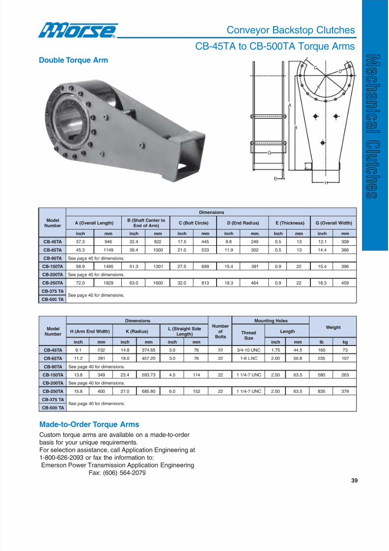
8/20/2019 Catalogo Morse MC Clutches y Limitadores
http://slidepdf.com/reader/full/catalogo-morse-mc-clutches-y-limitadores 41/131
39
Conveyor Backstop Clutches
CB-45TA to CB-500TA Torque Arms
Double Torque Arm
ledoMrebmuN
snoisnemiD
)htgneLllarevO(A otretneCtfahS(B
)mrAfodnE )elcriCtloB(C )suidaRdnE(D )ssenk cihT(E )htdiWllarevO(G
hcni mm hcni mm hcni mm hcni mm hcni mm hcni mm
AT54-BC 3.73 649 4.23 228 5.71 544 8.9 942 5.0 31 1.21 803
AT56-BC 3.54 9411 4.93 0001 0.12 335 9.11 203 5.0 31 4.41 663
AT09-BC .snoisnemidrof04egapeeS
AT051-BC 9.85 5941 3.15 1031 5.72 996 4.51 193 9.0 22 4.51 693
AT002-BC .snoisnemidrof04egapeeS
AT052-BC 0.27 9281 0.36 0061 0.23 318 3.81 464 9.0 22 3.81 954
AT573-BC.snoisnemidrof04egapeeS
AT005-BC
ledoMrebmuN
snoisnemiDrebmuN
fostloB
seloHgnitnuoM
thgieW)htdiWdnEmrA(H )suidaR(K
ediSthgiartS(L)htgneL daerhT
eziS
htgneL
hcni mm hcni mm hcni mm hcni mm bl gk
AT54-BC 1.9 232 8.41 56.473 0.3 67 22 CNU01-4 / 3 57.1 5.44 061 37
AT56-BC 2.11 182 0.81 02.754 0.3 67 22 CNU8-1 00.2 8.05 532 701
AT09-BC .snoisnemidrof04egapeeS
AT051-BC 8.31 943 4.32 37.395 5.4 411 22 CNU7-4 / 11 05.2 5.36 085 362
AT002-BC .snoisnemidrof04egapeeS
AT052-BC 8.51 004 0.72 08.586 0.6 251 22 CNU7-4 / 11 05.2 5.36 538 973
AT573-BC.snoisnemidrof04egapeeS
AT005-BC
Made-to-Order Torque Arms
Custom torque arms are available on a made-to-order
basis for your unique requirements.For selection assistance, call Application Engineering at
1-800-626-2093 or fax the information to:Emerson Power Transmission Application Engineering
Fax: (606) 564-2079
A
G
B
EH
L
K
DC
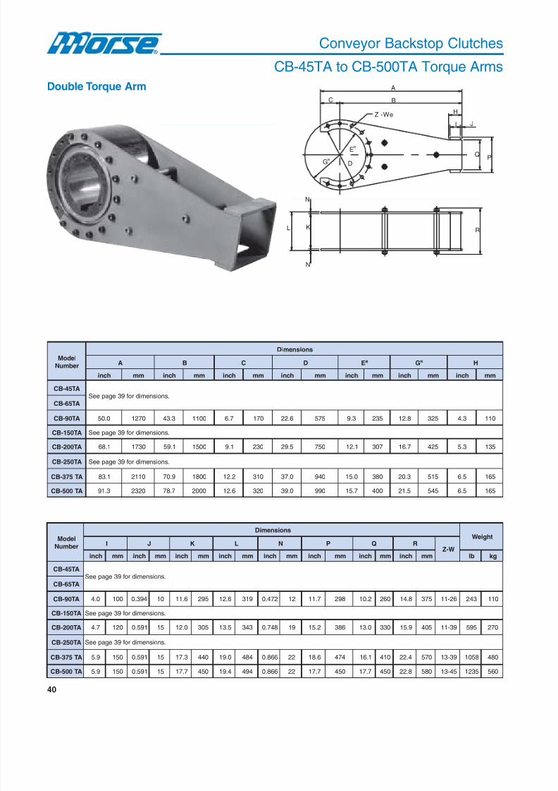
8/20/2019 Catalogo Morse MC Clutches y Limitadores
http://slidepdf.com/reader/full/catalogo-morse-mc-clutches-y-limitadores 42/131
40
Conveyor Backstop Clutches
CB-45TA to CB-500TA Torque Arms
Double Torque Arm
ledoMrebmuN
snoisnemiD
A B C D ER GR H
hcni mm hcni mm hcni mm hcni mm hcni mm hcni mm hcni mm
AT54-BC.snoisnemidrof93egapeeS
AT56-BC
AT09-BC 0.05 0721 3.34 0011 7.6 071 6.22 575 3.9 532 8.21 523 3.4 011
AT051-BC .snoisnemidrof93egapeeS
AT002-BC 1.86 0371 1.95 0051 1.9 032 5.92 057 1.21 703 7.61 524 3.5 531
AT052-BC .snoisnemidrof93egapeeS
AT573-BC 1.38 0112 9.07 0081 2.21 013 0.73 049 0.51 083 3.02 515 5.6 561
AT005-BC 3.19 0232 7.87 0002 6.21 023 0.93 099 7.51 004 5.12 545 5.6 561
ledoMrebmuN
snoisnemiDthgieW
I J K L N P Q RW-Z
hcni mm hcni mm hcni mm hcni mm hcni mm hcni mm hcni mm hcni mm bl gk
AT54-BC.snoisnemidrof93egapeeS
AT56-BC
AT09-BC 0.4 001 493.0 01 6.11 592 6.21 913 274.0 21 7.11 892 2.01 062 8.41 573 62-11 342 011
AT051-BC .snoisnemidrof93egapeeS
AT002-BC 7.4 021 195.0 51 0.21 503 5.31 343 847.0 91 2.51 683 0.31 033 9.51 504 93-11 595 072
AT052-BC .snoisnemidrof93egapeeS
AT573-BC 9.5 051 195.0 51 3.71 044 0.91 484 668.0 22 6.81 474 1.61 014 4.22 075 93-31 8501 084
AT005-BC 9.5 051 195.0 51 7.71 054 4.91 494 668.0 22 7.71 054 7.71 054 8.22 085 54-31 5321 065
A
BC
H
I J
Z -We
N
N
R
QP
D
KL
GR
ER

8/20/2019 Catalogo Morse MC Clutches y Limitadores
http://slidepdf.com/reader/full/catalogo-morse-mc-clutches-y-limitadores 43/131
41
Conveyor Backstop Clutches
Selection Procedure
Backstop Torque Calculation
HP = T x N N= rpm of clutch at headpulley shaft5250 T = (lb-ft.) torque
N = RPM @ headpulley shaft =
Torque CB = SF x HP Total x 5250
N
Bucket Elevator Backstop Selection
Friction resistance is ignored in the selection due to itssmall magnitude relative to the elevator capacity.
HP Total = QH Q = Maximum load, tons per hour
990 H = Vertical height of conveyor (feet)
Same nomenclature as conveyor method.
Torque CB = SF x HP - Motor Nameplate x 5250N
Backstop torque can be calculated using different methods based on conveyor configuration. The methods shownbelow are for basic selections and are based on CEMA (Conveyor Equipment Manufacturing Association) standards.
Motor Breakdown/Locked Rotor Torque Method
Selection is based on the following formula:Depending on motor breakdown torque, apply the
following service factors:1.0 Breakdown torque less than or equal to 175%.
1.2 Breakdown torque greater than 175% to 250%.1.5 Breakdown torque greater than 250% TO 400%.
A backstop is a critical part of theconveyor design. Selection
methods shown above should cover most basic conveyorapplications. When designing a conveyor, it is necessary
that the backstop is selected to handle the maximumload that the conveyor system is designed to handle.
Consult Application Engineering at 1-800-626-2093 forbackstop selection where conveyor design deviates fromthe methods shown.
For selection assistance, call Application Engineering at 1-800-626-2093 or visitwww.emerson-ept.com

8/20/2019 Catalogo Morse MC Clutches y Limitadores
http://slidepdf.com/reader/full/catalogo-morse-mc-clutches-y-limitadores 44/131
42
Conveyor Backstop Installation
Pre-installation
1. Before installation, check the direction of shaft
rotation during operation, often referred to as freeshaft rotation. The backstop clutch overruns in thisdirection and is indicated by stamped rotational
arrows on both ends of the clutch inner race.
2. It is important that the clutch fit the shaft properly.
These clutches are intended to be installed with aslip fit-interference or shrink fits are notrecommended. Bore tolerances and standard
keyway dimensions are shown below.
tfahSlanimoN.aiDeroBdna
ecnareloTeroB dradnatS*htdiWyawyeK
htpeDdnarevO urhT 000.-lanimoN4 / 12 4 / 32 0200.+ 61 / 5x8 / 5
4 / 32 4 / 13 0200.+ 8 / 3x4 / 3
4 / 13 4 / 33 0200.+ 61 / 7x8 / 7
4 / 33 2 / 14 0200.+ 2 / 1x1
2 / 14 2 / 15 5200.+ 8 / 5x4 / 11
2 / 15 2 / 16 5200.+ 4 / 3x2 / 11
2 / 16 2 / 17 0300.+ 4 / 3x4 / 31
2 / 17 9 0300.+ 4 / 3x2
9 11 5300.+ 8 / 7x2 / 12
11 31 0400.+ 1x3
Dimensions - Inches
* Width tolerances are plus .002 minus .000; keyway depth is nominal plus.010 tolerance.
3. Use only parallel keys, do not use tapered keys.The key should be tight along both sides and in
contact with the keyseat. Clearance has beenallowed along the top. The key should not extend
beyond the length of the clutch. Cover plate on shaft
end is recommended for key keep.
Installation
1. The shaft must be clean and free of burrs. Coat
both shaft and key with oil, grease or a similarsubstance to ease installation.
2. Double check shaft rotation and arrow marks on
the end of the clutch inner race to ensure correctrotational direction.
3. Push the backstop clutch on the shaft by applying
pressure only to the end of the inner race. Ifhammering is required, use only a lead or rubber
headed hammer to avoid damage to the inner raceend. Do not hit the clutch outer race or seal support
as internal damage may result. Exercise cautionduring installation to prevent seal damage.
4. Secure backstop clutch in position on the shaft. Use
lock washers, snap rings, lock collars, end plates,adjacent components or similar items to hold clutchin position.
Do not use an inclined key!
Only a parallel key isrecommended.
Fix CB clutch by an end plate toshaft end.
When mounting CB clutch, apply pressure onlyto inner race end.
Do not hit clutch outer race, seal supporter ordust protective cover.
Check direction ofshaft rotation andclutch inner race rotation.
X
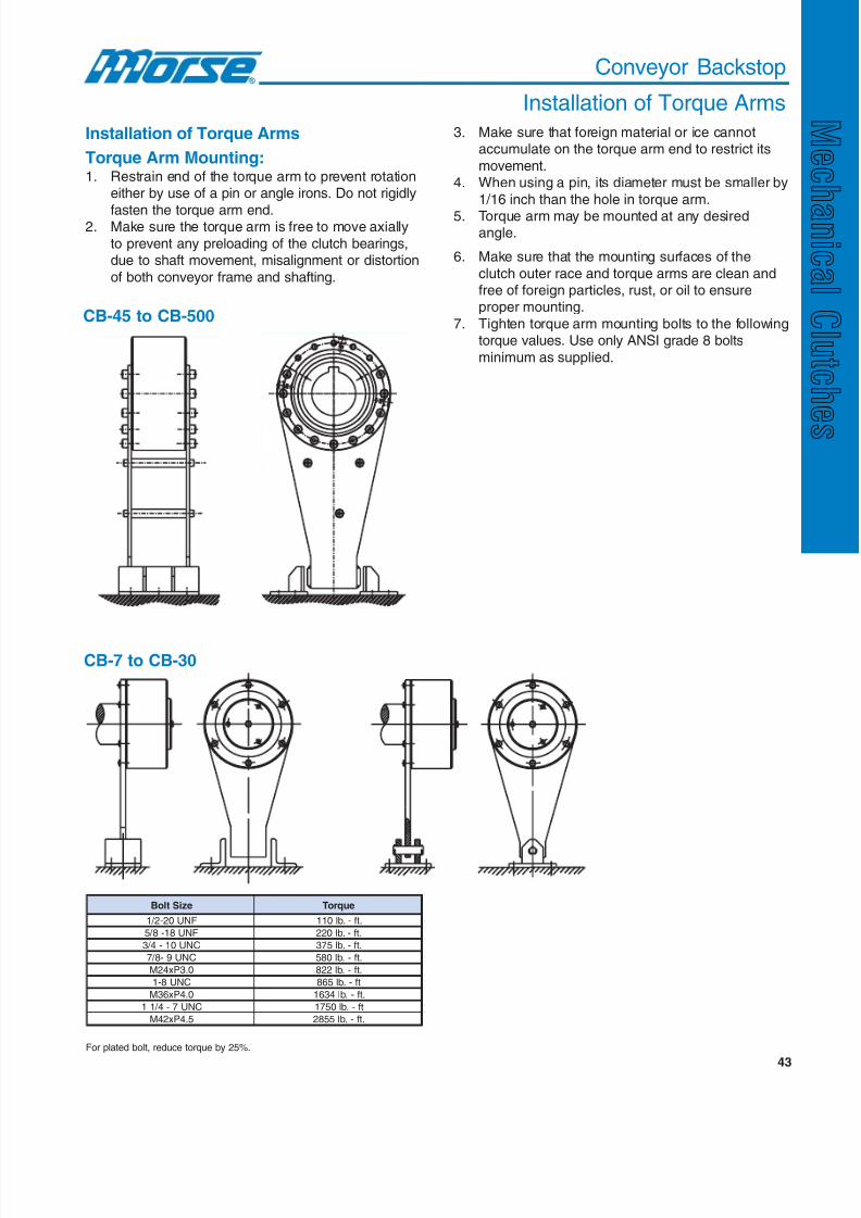
8/20/2019 Catalogo Morse MC Clutches y Limitadores
http://slidepdf.com/reader/full/catalogo-morse-mc-clutches-y-limitadores 45/131
43
Conveyor Backstop
Installation of Torque Arms
Installation of Torque Arms
Torque Arm Mounting:1. Restrain end of the torque arm to prevent rotation
either by use of a pin or angle irons. Do not rigidly
fasten the torque arm end.2. Make sure the torque arm is free to move axially
to prevent any preloading of the clutch bearings,due to shaft movement, misalignment or distortion
of both conveyor frame and shafting.
3. Make sure that foreign material or ice cannotaccumulate on the torque arm end to restrict its
movement.4. When using a pin, its diameter must be smaller by
1/16 inch than the hole in torque arm.
5. Torque arm may be mounted at any desiredangle.
CB-45 to CB-500
CB-7 to CB-30
eziStloB euqroT
FNU02-2 / 1 .tf-.bl011
FNU81-8 / 5 .tf-.bl022
CNU01-4 / 3 .tf-.bl573
CNU9-8 / 7 .bl085 - .tf
0.3Px42M .bl228 - .tf
CNU8-1 .bl568 - tf
0.4Px63M .bl4361 - .tf
CNU7-4 / 11 .bl0571 - tf
5.4Px24M .bl5582 - .tf
For plated bolt, reduce torque by 25%.
6. Make sure that the mounting surfaces of the
clutch outer race and torque arms are clean andfree of foreign particles, rust, or oil to ensureproper mounting.
7. Tighten torque arm mounting bolts to the followingtorque values. Use only ANSI grade 8 bolts
minimum as supplied.
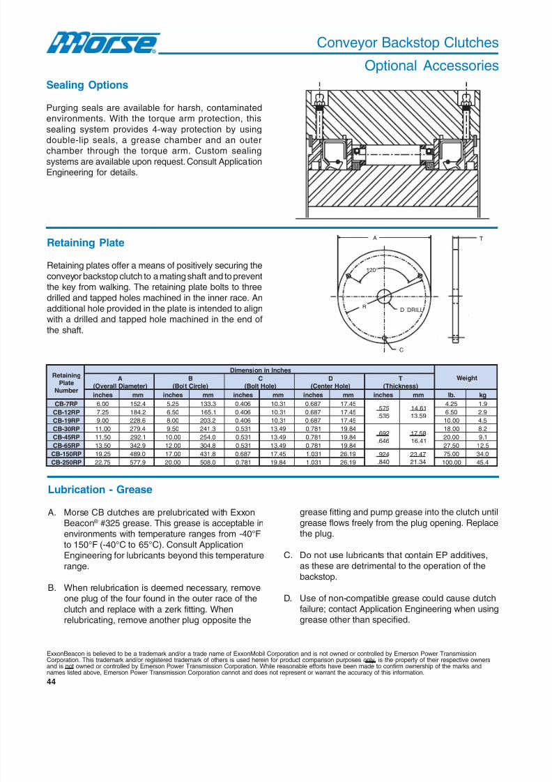
8/20/2019 Catalogo Morse MC Clutches y Limitadores
http://slidepdf.com/reader/full/catalogo-morse-mc-clutches-y-limitadores 46/131
44
Conveyor Backstop Clutches
Optional Accessories
Sealing Options
Purging seals are available for harsh, contaminatedenvironments. With the torque arm protection, this
sealing system provides 4-way protection by using
double-lip seals, a grease chamber and an outerchamber through the torque arm. Custom sealing
systems are available upon request. Consult ApplicationEngineering for details.
Retaining Plate
Retaining plates offer a means of positively securing the
conveyor backstop clutch to a mating shaft and to preventthe key from walking. The retaining plate bolts to three
drilled and tapped holes machined in the inner race. Anadditional hole provided in the plate is intended to alignwith a drilled and tapped hole machined in the end of
the shaft.
Lubrication - Grease
A. Morse CB clutches are prelubricated with ExxonBeacon ® #325 grease. This grease is acceptable inenvironments with temperature ranges from -40°F
to 150°F (-40°C to 65°C). Consult ApplicationEngineering for lubricants beyond this temperature
range.
B. When relubrication is deemed necessary, removeone plug of the four found in the outer race of the
clutch and replace with a zerk fitting. Whenrelubricating, remove another plug opposite the
ExxonBeacon is believed to be a trademark and/or a trade name of ExxonMobil Corporation and is not owned or controlled by Emerson Power TransmissionCorporation. This trademark and/or registered trademark of others is used herein for product comparison purposes only, is the property of their respective ownersand is not owned or controlled by Emerson Power Transmission Corporation. While reasonable efforts have been made to confirm ownership of the marks andnames listed above, Emerson Power Transmission Corporation cannot and does not represent or warrant the accuracy of this information.
grease fitting and pump grease into the clutch until
grease flows freely from the plug opening. Replacethe plug.
C. Do not use lubricants that contain EP additives,as these are detrimental to the operation of the
backstop.
D. Use of non-compatible grease could cause clutchfailure; contact Application Engineering when usinggrease other than specified.
C
A
BD
T
DRILL
120°
gniniateRetalP
rebmuN
sehcnIninoisnemiD
thgieWA)retemaiDllarevO(
B)elcriCtloB(
C)eloHtloB(
D)eloHretneC(
T)ssenk cihT(
sehcni mm sehcni mm sehcni mm sehcni mm sehcni mm .bl gk
PR7-BC 00.6 4.251 52.5 3.331 604.0 13.01 786.0 54.71
575. 535. 16.41 95.31
52.4 9.1
PR21-BC 52.7 2.481 05.6 1.561 604.0 13.01 786.0 54.71 05.6 9.2PR91-BC 00.9 6.822 00.8 2.302 604.0 13.01 786.0 54.71 00.01 5.4
PR03-BC 00.11 4.972 05.9 3.142 135.0 94.31 187.0 48.91296.646.
85.7114.61
00.81 2.8
PR54-BC 05.11 1.292 00.01 0.452 135.0 94.31 187.0 48.91 00.02 1.9
PR56-BC 05.31 9.243 00.21 8.403 135.0 94.31 187.0 48.91 05.72 5.21
PR051-BC 52.91 0.984 00.71 8.134 786.0 54.71 130.1 91.62 429.048.
74.3243.12
00.57 0.43
PR052-BC 57.22 9.775 00.02 0.805 187.0 48.91 130.1 91.62 00.001 4.54
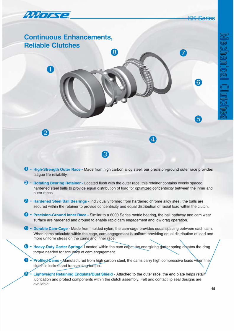
8/20/2019 Catalogo Morse MC Clutches y Limitadores
http://slidepdf.com/reader/full/catalogo-morse-mc-clutches-y-limitadores 47/131
45
- High-Strength Outer Race - Made from high carbon alloy steel, our precision-ground outer race provides
fatigue life reliability.
- Rotating Bearing Retainer - Located flush with the outer race, this retainer contains evenly spaced,
hardened steel balls to provide equal distribution of load for optimized concentricity between the inner and
outer races.
- Hardened Steel Ball Bearings - Individually formed from hardened chrome alloy steel, the balls are
secured within the retainer to provide concentricity and equal distribution of radial load within the clutch.
- Precision-Ground Inner Race - Similar to a 6000 Series metric bearing, the ball pathway and cam wear
surface are hardened and ground to enable rapid cam engagement and low drag operation.
- Durable Cam-Cage - Made from molded nylon, the cam-cage provides equal spacing between each cam.
When cams articulate within the cage, cam engagement is uniform providing equal distribution of load andmore uniform stress on the cams and inner race.
- Heavy-Duty Garter Spring - Located within the cam cage, the energizing garter spring creates the drag
torque needed for accuracy of cam engagement.
- Profiled Cams - Manufactured from high carbon steel, the cams carry high compressive loads when the
clutch is locked and transmitting torque.
- Lightweight Retaining Endplate/Dust Shield - Attached to the outer race, the end plate helps retain
lubrication and protect components within the clutch assembly. Felt and contact lip seal designs areavailable.
KK Series
Continuous Enhancements,
Reliable Clutches

8/20/2019 Catalogo Morse MC Clutches y Limitadores
http://slidepdf.com/reader/full/catalogo-morse-mc-clutches-y-limitadores 48/131
46
Morse brand KK clutches incorporate a compact cam clutchwith built-in bearing support. This unique constructioncombines a cam clutch with a 6200 Series metric ball bearingfor use in applications ranging from exercise equipment to
industrial machinery. This general purpose clutch is intendedfor backstopping, indexing and overrunning applications andcan be utilized with both oil and grease lubrication.
Dimensions and Capacities
eziS
yticapaCeuqroT deepSgninnurrevO.xaM euqroTgarD yticapaCdaoLlaidaR
m-N bl-tF ecaRrennI
MPRecaRretuO
MPR m-N bl-tF
cimanyD citatS
N bl N bl
51 92 4.12 006,3 000,2 010.0 4700.0 059,5 6.7331 032,3 1.627
71 34 7.13 005,3 009,1 010.0 4700.0 000,7 7.3751 007,3 8.138
02 16 0.54 000,3 006,1 410.0 3010.0 005,8 9.0191 009,4 6.1011
52 87 5.75 005,2 004,1 710.0 5210.0 007,01 5.5042 003,6 3.6141
03 041 3.301 000,2 001,1 030.0 1220.0 009,11 2.5762 009,7 0.6771
53 371 6.721 008,1 000,1 430.0 1520.0 005,31 9.4303 007,9 6.0812
04 062 8.191 008,1 009 040.0 5920.0 005,41 7.9523 007,11 3.0362
eziSA B C D r thgieW
mm hcni mm hcni mm hcni mm hcni mm hcni g bl
51 11 334.0 53 873.1 51 195.0 6.23 382.1 6.0 420.0 05 1.0
71 21 274.0 04 575.1 71 966.0 1.63 124.1 6.0 420.0 08 2.0
02 41 155.0 74 058.1 02 787.0 7.14 246.1 0.1 930.0 021 3.0
52 51 195.0 25 740.2 52 489.0 1.74 458.1 0.1 930.0 051 3.0
03 61 036.0 26 144.2 03 181.1 6.65 822.2 0.1 930.0 032 5.0
53 71 966.0 27 538.2 53 873.1 0.46 025.2 1.1 340.0 023 7.0
04 22 668.0 08 051.3 04 575.1 0.17 597.2 1.1 340.0 004 9.0
KK Series

8/20/2019 Catalogo Morse MC Clutches y Limitadores
http://slidepdf.com/reader/full/catalogo-morse-mc-clutches-y-limitadores 49/131
47
Housing Tolerance Inner race Outer race
Cam cage
Ball Shield
Retainer
Shaft Tolerance
eziS retemaiDtfahS
sehcni mm
51 6095.0 9000.0+
5000.0+ 51
320.0+210.0+
71 3966.0 9000.0+
5000.0+ 71
320.0+210.0+
02 4787.0 1100.0+
6000.0+ 02
820.0+510.0+
52 3489.0 1100.0+
6000.0+ 52
820.0+510.0+
03 1181.1 1100.0+
6000.0+ 03
330.0+710.0+
53 0873.1 3100.0+
7000.0+ 53
330.0+710.0+
04 8475.1 3100.0+
7000.0+ 04
330.0+710.0+
eziS retemaiDgnisuoH
sehcni mm
51 9773.1 5000.0-
1100.0- 53
210.0-820.0-
71 8475.1 5000.0-
1100.0- 04
210.0-820.0-
02 4058.1 5000.0-
1100.0- 74
210.0-820.0-
52 2740.2 6000.0-
3100.0- 25
410.0-330.0-
03 9044.2 6000.0-
3100.0- 26
410.0-330.0-
53 6438.2 6000.0-
3100.0- 27
410.0-330.0-
04 6941.3 6000.0-
3100.0- 08
410.0-330.0-
Part Number Explanation
A
r
r
BCD
6 4 2 5 13
KK Series
For selection assistance, call Application Engineering at 1-800-626-2093 or visitwww.emerson-ept.com
KK 25 1K 2GD
Incorporates 2 seals
Keyed inner
Bore size
Series
KK 25 2K 2GD
Incorporates 2 seals
Keyed inner and outer
Bore size
Series

8/20/2019 Catalogo Morse MC Clutches y Limitadores
http://slidepdf.com/reader/full/catalogo-morse-mc-clutches-y-limitadores 50/131
48
eziS
yticapaCeuqroT deepSgninnurrevO.xaM euqroTgarD yticapaCdaoLlaidaR
m-N bl-tF ecaRrennI
nim / recaRretuO
nim / r m-N bl-tF
cimanyD citatS
N bl N bl
51 92 4.12 006,3 000,2 010.0 4700.0 059,5 6.7331 032,3 1.627
71 34 7.13 005,3 009,1 010.0 4700.0 000,7 7.3751 007,3 8.138
02 16 0.54 000,3 006,1 410.0 3010.0 005,8 9.0191 009,4 6.1011
52 87 5.75 005,2 004,1 710.0 5210.0 007,01 5.5042 003,6 3.6141
03 041 3.301 000,2 001,1 030.0 1220.0 009,11 2.5762 009,7 0.6771
53 371 6.721 008,1 000,1 430.0 1520.0 005,31 9.4303 007,9 6.0812
04 062 8.191 008,1 009 040.0 5920.0 005,41 7.9523 007,11 3.0362
Dimensions and Capacities
Note: Model No. marked on the inner race is only K for both 1K and 2K. (I. R. the marked KK17-K for both KK-17-1K and KK-17-2K).
KK Series
Model KK-1K and KK-2KMorse KK clutches incorporate a compact cam clutchwith built-in bearing support. This unique constructioncombines a cam clutch with a 6200 Series metric ball
bearing for use in applications ranging from exerciseequipment to industrial machinery. This general purpose
clutch is intended for backstopping, indexing andoverrunning applications and can be utilized with both
oil and grease lubrication.
Industries Served
• Fitness• Manufacturing
• Printing• Textile
Field Applications
• Electric motor backstops
• Exercise equipment
• Household appliances• Pump backstops
Enhancements
• New sizes added• New sealing and shielding options
• Both inner and outer race keyway options
KK-1K(keyed inner)
KK-2K(keyed inner and
outer)
Part Number Explanation
KK 25 1K 2GD
Incorporates 2 seals
Keyed inner
Bore size
Series
KK 25 2K 2GD
Incorporates 2 seals
Keyed inner and outer
Bore size
Series
For selection assistance, call Application Engineering at 1-800-626-2093 or visit
www.emerson-ept.com
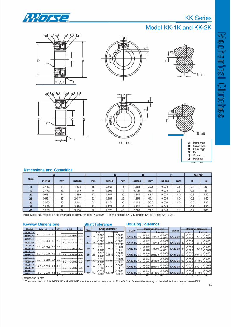
8/20/2019 Catalogo Morse MC Clutches y Limitadores
http://slidepdf.com/reader/full/catalogo-morse-mc-clutches-y-limitadores 51/131
49
r
rA
C BD
b
t2
b
t2
t1
Shaft
46 2 3 5 1
KK Series
Model KK-1K and KK-2K
r
rA
C BD
b
t2
kt
b
t2
t1
Shaft
14 2 3 56
Inner race
Outer race
Cam cage
Ball
Shield
Retainer
ledoM 01sjb 1t *2t 9sjk tK1-51KK
0.5 420.0+ 9.1 2.1- - -
K2-51KK 0.2 5210.0+ 6.0
K1-71KK0.5 420.0+ 9.1 2.1
- - -
K2-71KK 0.2 5210.0+ 0.1
K1-02KK0.6 420.0+ 5.2 6.1
- - -
K2-02KK 0.3 0510.0+ 5.1
K1-52KK0.8 920.0+ 6.3 5.1
- - -
K2-52KK 0.6 0510.0+ 0.2
K1-03KK0.8 920.0+ 1.3 0.2
- - -
K2-03KK 0.6 0510.0+ 0.2
K1-53KK0.01 920.0+ 7.3 4.2
- - -
K2-53KK 0.8 0810.0+ 5.2
K1-04KK0.21 530.0+ 3.3 0.5
- - -
K2-04KK 0.01 0810.0+ 0.3
Keyway Dimensions
Dimensions in mm
Dimensions and Capacities
eziS
A B C D r thgieW
sehcni mm sehcni mm sehcni mm sehcni mm sehcni mm bl g
51 334.0 11 873.1 53 195.0 51 382.1 6.23 420.0 6.0 1.0 05
71 274.0 21 575.1 04 966.0 71 124.1 1.63 420.0 6.0 2.0 08
02 155.0 41 058.1 74 787.0 02 246.1 7.14 930.0 0.1 3.0 021
52 195.0 51 740.2 25 489.0 52 458.1 1.74 930.0 0.1 3.0 051
03 036.0 61 144.2 26 181.1 03 822.2 6.65 930.0 0.1 5.0 032
53 966.0 71 538.2 27 873.1 53 025.2 0.46 340.0 1.1 7.0 023
04 668.0 22 051.3 08 575.1 04 597.2 0.17 340.0 1.1 9.0 004
Note: Model No. marked on the inner race is only K for both 1K and 2K. (I. R. the marked KK17-K for both KK-17-1K and KK-17-2K).
Shaft Tolerance
eziS retemaiDtfahSmm sehcni
51 51 800.0-
820.0- 6095.0
3000.0-
1100.0-
71 71 800.0-
820.0- 3966.0
3000.0-1100.0-
02 02 010.0-
130.0- 4787.0
4000.0-2100.0-
52 52 010.0-
130.0- 3489.0
4000.0-2100.0-
03 03 010.0-
130.0- 1181.1
4000.0-2100.0-
53 53 210.0-
730.0- 0873.1
5000.0-5100.0-
04 04 210.0-
730.0- 8475.1
5000.0-5100.0-
Housing Tolerance
ledoM retemaiDgnisuoH ledoM retemaiDgnisuoHmm sehcni mm sehcni
KK K1-51 53 210.0-
820.0- 9773.1
5000.0-
1100.0- KK K2-51 53
200.0-
810.0- 9773.1
1000.0-
7000.0-
KK K1-71 04 210.0-
820.0- 8475.1
5000.0-
1100.0- KK K2-71 04
200.0-
810.0- 8475.1
1000.0-
7000.0-
KK K1-02 74 210.0-
820.0- 4058.1
5000.0-1100.0-
KK K2-02 74 300.0-
220.0- 4058.1
1000.0-9000.0-
KK K1-52 25 410.0-
330.0- 2740.2
6000.0-3100.0-
KK K2-52 25 300.0-
220.0- 2740.2
1000.0-9000.0-
KK K1-03 26 410.0-
330.0- 9044.2
6000.0-3100.0-
KK K2-03 26 300.0-
220.0- 9044.2
1000.0-9000.0-
KK K1-53 27 410.0-
330.0- 6438.2
6000.0-3100.0-
KK K2-53 27 600.0-
520.0- 6438.2
2000.0-0100.0-
KK K1-04 08 410.0-
330.0- 6941.3
6000.0-
3100.0- KK K2-04 08
600.0-
520.0- 6941.3
2000.0-
0100.0-
* The dimension of t2 for KK25-1K and KK25-2K is 0.5 mm shallow compared to DIN 6885. 3. Process the keyway on the shaft 0.5 mm deeper to use DIN.

8/20/2019 Catalogo Morse MC Clutches y Limitadores
http://slidepdf.com/reader/full/catalogo-morse-mc-clutches-y-limitadores 52/131
50
eziS
yticapaCeuqroT deepSgninnurrevO.xaM euqroTgarD yticapaCdaoLlaidaR
m-N bl-tF ecaRrennI
nim / recaRretuO
nim / r m-N bl-tF
cimanyD citatS
N bl N bl
51 92 4.12 006,3 000,2 040.0 5920.0 059,5 6.7331 032,3 1.627
71 34 7.13 005,3 009,1 050.0 9630.0 000,7 7.3751 007,3 8.138
02 16 0.54 000,3 006,1 550.0 6040.0 005,8 9.0191 009,4 6.1011
52 87 5.75 005,2 004,1 550.0 6040.0 007,01 5.5042 003,6 3.6141
03 041 3.301 000,2 001,1 850.0 8240.0 009,11 2.5762 009,7 0.6771
53 371 6.721 008,1 000,1 060.0 3440.0 005,31 9.4303 007,9 6.0812
04 062 8.191 008,1 009 080.0 0950.0 005,41 7.9523 007,11 3.0362
Dimensions and Capacities
Housing Tolerance Shaft Tolerance
KK Series
Model KK- 2GD and KK-2GD 1K
ledoM retemaiDtfahS
ledoM retemaiDtfahS
sehcni mm sehcni mm
DG2-51KK 6095.0 9000.0+
5000.0+ 51
320.0+210.0+
K1DG2-51KK 6095.0 3000.0-
1100.0- 51
800.0-820.0-
DG2-71KK 3966.0 9000.0+
5000.0+ 71
320.0+
210.0+K1DG2-71KK 3966.0
3000.0-
1100.0- 71
800.0-
820.0-
DG2-02KK 4787.0 1100.0+6000.0+
02 820.0+510.0+
K1DG2-02KK 4787.0 4000.0-2100.0-
02 010.0-130.0-
DG2-52KK 3489.0 1100.0+
6000.0+ 52 820.0+
510.0+K1DG2-52KK 3489.0
4000.0-2100.0-
52 010.0-
130.0-
DG2-03KK 1181.1 1100.0+
6000.0+ 03
330.0+710.0+
K1DG2-03KK 1181.1 4000.0-
2100.0- 03
010.0-130.0-
DG2-53KK 0873.1 3100.0+
7000.0+ 53
330.0+710.0+
K1DG2-53KK 0873.1 5000.0-
5100.0- 53
210.0-730.0-
DG2-04KK 8475.1 3100.0+
7000.0+ 04
330.0+710.0+
K1DG2-04KK 8475.1 5000.0-
5100.0- 04
210.0-730.0-
eziS retemaiDgnisuoH
hcni mm
51 9773.1 5000.0-
1100.0- 53
210.0-820.0-
71 8475.1 5000.0-
1100.0- 04
210.0-820.0-
02 4058.1 5000.0-
1100.0- 74 210.0-
820.0-
52 2740.2 6000.0-
3100.0- 25
410.0-330.0-
03 9044.2 6000.0-
3100.0- 26
410.0-330.0-
53 6438.2 6000.0-
3100.0- 27
410.0-330.0-
04 6941.3 6000.0-
3100.0- 08
410.0-330.0-
KK-2GD 1K
(sealed both sides,
keyed inner)
KK-2GD
(sealed both sides)

8/20/2019 Catalogo Morse MC Clutches y Limitadores
http://slidepdf.com/reader/full/catalogo-morse-mc-clutches-y-limitadores 53/131
51
r
rA
C BD
b
t2b
t2
t1
Shaft
7 4 2 3 6 5 1
* The dimension of t2 for KK25-2GD 1K is0.5 mm shallow compared to DIN 6885. 3.Process the keyway on the shaft 0.5 mmdeeper to use DIN.
r
rA
C BD
7 4 2 3 6 5 1
Inner race
Outer race
Cam cage Ball
Seal
Side plate
Retainer
ledoM 01sjb 1t 2t
K1DG2-51KK 0.5 420.0+ 9.1 2.1
K1DG2-71KK 0.5 420.0+ 9.1 2.1
K1DG2-02KK 0.6 420.0+ 5.2 6.1
K1DG2-52KK 0.8 920.0+ 6.3 5.1
K1DG2-03KK 0.8 920.0+ 1.3 0.2
K1DG2-53KK 0.01 920.0+ 7.3 4.2
K1DG2-04KK 0.21 530.0+ 3.3 0.5
Keyway Dimensions
Dimensions in mm
KK Series
Model KK- 2GD and KK-2GD 1K
Dimensions and Capacities
eziS
A B C D r thgieW
sehcni mm sehcni mm sehcni mm sehcni mm sehcni mm bl g
51 036.0 61 873.1 53 195.0 51 872.1 54.23 420.0 6.0 2.0 07
71 966.0 71 575.1 04 966.0 71 534.1 54.63 420.0 6.0 2.0 001
02 847.0 91 058.1 74 787.0 02 766.1 53.24 930.0 0.1 3.0 051
52 787.0 02 740.2 25 489.0 52 258.1 50.74 930.0 0.1 4.0 002
03 728.0 12 144.2 26 181.1 03 981.2 06.55 930.0 0.1 6.0 082
53 668.0 22 538.2 27 873.1 53 345.2 06.46 340.0 1.1 9.0 014
04 360.1 72 051.3 08 575.1 04 918.2 06.17 340.0 1.1 3.1 006
For selection assistance, call Application Engineering at 1-800-626-2093 or visit
www.emerson-ept.com
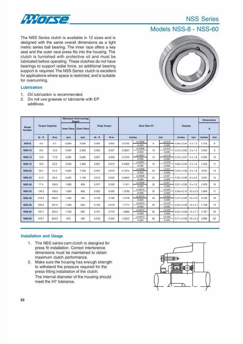
8/20/2019 Catalogo Morse MC Clutches y Limitadores
http://slidepdf.com/reader/full/catalogo-morse-mc-clutches-y-limitadores 54/131
52
NSS Series
Models NSS-8 - NSS-60
The NSS Series clutch is available in 12 sizes and isdesigned with the same overall dimensions as a light
metric series ball bearing. The inner race offers a keyseat and the outer race press fits into the housing. The
clutch is furnished with protective oil and must be
lubricated before operating. These clutches do not havebearings to support radial force, so additional bearing
support is required. The NSS Series clutch is excellentfor applications where space is restricted, and is suitable
for overrunning.
Lubrication
1. Oil lubrication is recommended.2. Do not use greases or lubricants with EP
additives.
ledoMrebmuN
yticapaCeuqroT
gninnurrevOmumixaM
deepS
euqroTgarD 7HeziSeroB yawyeK
snoisnemiD
ecaRrennI ecaRretuO A
tf-bl m-N mpr mpr tf-bl m-N sehcnI mm sehcnI mm sehcnI mm
8-SSN 9.4 7.6 000,6 000,3 400.0 500.0 0513.06000.0+
8510.0+
40.0x80.0 0.1x2 513.0 8000.0- 000.0-
01-SSN 9.8 0.21 005,4 003,2 500.0 700.0 7393.06000.0+
01510.0+
60.0x21.0 4.1x3 453.0 9000.0- 000.0-
21-SSN 5.21 0.71 000,4 000,2 700.0 900.0 4274.07000.0+
21810.0+
70.0x61.0 8.1x4 493.0 01000.0- 000.0-
51-SSN 2.61 0.22 005,3 008,1 700.0 010.0 6095.07000.0+
51810.0+
50.0x02.0 2.1x5 334.0 11000.0- 000.0-
02-SSN 2.03 0.14 006,2 003,1 700.0 010.0 4787.08000.0+
02120.0+
60.0x42.0 6.1x6 155.0 41000.0- 000.0-
52-SSN 3.14 0.65 002,2 001,1 510.0 020.0 3489.08000.0+
52120.0+
80.0x23.0 0.2x8 195.0 51000.0- 000.0-
03-SSN 4.77 0.501 008,1 009 220.0 030.0 1181.18000.0+
03120.0+
80.0x23.0 0.2x8 926.0 61000.0- 000.0-
53-SSN 3.001 0.631 006,1 008 220.0 030.0 0873.10100.0+
53520.0+
01.0x93.0 4.2x01 966.0 71000.0- 000.0-
04-SSN 3.812 0.692 004,1 007 331.0 081.0 8475.10100.0+
04520.0+
90.0x74.0 2.2x21 907.0 81000.0- 000.0-
54-SSN 9.552 0.743 003,1 056 551.0 012.0 7177.10100.0+
54520.0+
80.0x55.0 1.2x41 847.0 91000.0- 000.0-
05-SSN 2.792 0.304 002,1 006 261.0 022.0 5869.10100.0+
05520.0+
80.0x55.0 1.2x41 787.0 02000.0- 000.0-
06-SSN 7.874 0.946 019 064 342.0 033.0 2263.22100.0+
06030.0+
90.0x17.0 3.2x81 668.0 22000.0- 000.0-
Installation and Usage
1. The NSS series cam clutch is designed forpress fit installation. Correct interference
dimensions must be maintained to obtainmaximum clutch performance.
2. Make sure the housing has enough strengthto withstand the pressure required for thepress fitting installation of the clutch.
The internal diameter of the housing shouldmeet the H7 tolerance.
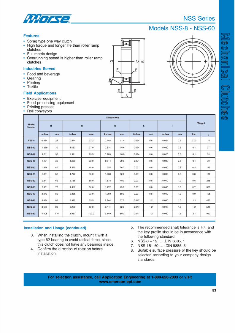
8/20/2019 Catalogo Morse MC Clutches y Limitadores
http://slidepdf.com/reader/full/catalogo-morse-mc-clutches-y-limitadores 55/131
53
NSS Series
Models NSS-8 - NSS-60
ledoMrebmuN
snoisnemiD
thgieWB C D E F
sehcnI mm sehcnI mm sehcnI mm sehcnI mm sehcnI mm .sbl g
8-SSN 449.0 42 478.0 2.22 844.0 4.11 420.0 6.0 420.0 6.0 30.0 41
01-SSN 922.1 03 360.1 0.72 416.0 6.51 420.0 6.0 020.0 6.0 1.0 72
21-SSN 113.1 23 161.1 5.92 907.0 0.81 420.0 6.0 020.0 6.0 1.0 13
51-SSN 434.1 53 062.1 0.23 118.0 6.02 420.0 6.0 020.0 6.0 1.0 93
02-SSN 629.1 74 575.1 0.04 150.1 7.62 130.0 8.0 030.0 8.0 3.0 511
52-SSN 131.2 25 277.1 0.54 062.1 0.23 130.0 8.0 030.0 8.0 3.0 041
03-SSN 145.2 26 561.2 0.55 575.1 0.04 130.0 8.0 040.0 0.1 5.0 512
53-SSN 159.2 27 714.1 0.63 277.1 0.54 130.0 8.0 040.0 0.1 7.0 003
04-SSN 972.3 08 538.2 0.27 969.1 0.05 130.0 8.0 040.0 0.1 9.0 524
54-SSN 484.3 58 279.2 5.57 442.2 0.75 740.0 2.1 040.0 0.1 1.1 594
05-SSN 986.3 09 822.3 0.28 144.2 0.26 740.0 2.1 040.0 0.1 2.1 545
06-SSN 805.4 011 739.3 0.001 941.3 0.08 740.0 2.1 060.0 5.1 1.2 059
D
E E
A
3 0 °
B C
F F
Features
• Sprag type one way clutch• High torque and longer life than roller ramp
clutches• Full metric design
• Overrunning speed is higher than roller rampclutches
Industries Served
• Food and beverage• Gearing• Printing• Textile
Field Applications
• Exercise equipment• Food processing equipment• Printing presses• Roll conveyors
Installation and Usage (continued)
3. When installing the clutch, mount it with atype 62 bearing to avoid radical force, since
this clutch does not have any bearings inside.4. Confirm the direction of rotation before
installation.
5. The recommended shaft tolerance is H7, and
the key profile should be in accordance withthe following standard.
6. NSS-8 – 12……DIN 6885. 17. NSS-15 - 60 …..DIN 6885. 3
8. Suitable surface pressure of the key should beselected according to your company design
standards.
For selection assistance, call Application Engineering at 1-800-626-2093 or visitwww.emerson-ept.com

8/20/2019 Catalogo Morse MC Clutches y Limitadores
http://slidepdf.com/reader/full/catalogo-morse-mc-clutches-y-limitadores 56/131
54
NFS Series
Models NFS-12 - NFS-80The NFS Series clutch is available in 13 sizes and is
designed with the same overall dimensions as amedium metric series ball bearing. The NFS Series
clutch offers approximately twice the torque capacityof the NSS Series clutch. The inner race contains a
key seat and the outer race is designed with Europeankey slots. The clutch is furnished with protective oil
and must be lubricated before installation. In addition,bearing support is required.
Lubrication
1. Oil lubrication is recommended.
2. Do not use greases or lubricants with EPadditives.
ledoM
rebmuN
yticapaCeuqroTmumixaM
deepSgninnurrevOeuqroTgarD 7HeziSeroB yawyeK
snoisnemiD
A
euqroTdetaR yticapaC rennI ecaR retuO ecaR
.sbL-.tF m-N nim / r nim / r tF-bL m-N mm hcnI mm .ni mm .ni
21-SFN 672.31 81 005,4 003,2 030.0 40.0 21810.0+
4274.07000.0+
8.1x4 70.0x61.0 31 215.0000.0- 0000.0-
51-SFN 256.02 82 005,3 008,1 440.0 60.0 51810.0+
6095.07000.0+
2.1x5 50.0x02.0 81 907.0000.0- 0000.0-
71-SFN 978.63 05 002,3 006,1 180.0 11.0 71810.0+
3966.07000.0+
2.1x5 50.0x02.0 91 847.0000.0- 0000.0-
02-SFN 659.16 48 005,2 003,1 331.0 81.0 02120.0+
4787.08000.0+
6.1x6 60.0x42.0 12 728.0000.0- 0000.0-
52-SFN 904.49 821 000,2 000,1 041.0 91.0 52120.0+
3489.08000.0+
0.2x8 80.0x23.0 42 549.0000.0- 0000.0-
03-SFN 415.741 002 006,1 008 551.0 12.0 03120.0+
1181.18000.0+
0.2x8 80.0x23.0 72 360.1000.0- 0000.0-
53-SFN 743.053 574 004,1 007 013.0 24.0 53520.0+
0873.10100.0+
4.2x01 01.0x93.0 13 022.1000.0- 0000.0-
04-SFN 607.744 706 003,1 056 933.0 64.0 04 520.0+ 8475.1 0100.0+ 2.2x21 90.0x74.0 33 992.1000.0- 0000.0-
54-SFN 406.755 657 001,1 055 314.0 65.0 54520.0+
7177.10100.0+
1.2x41 80.0x55.0 63 714.1000.0- 0000.0-
05-SFN 130.928 4211 000,1 005 344.0 06.0 05520.0+
5869.10100.0+
1.2x41 80.0x55.0 04 575.1000.0- 0000.0-
06-SFN 507.6541 5791 048 024 246.0 78.0 06030.0+
2263.22100.0+
3.2x81 90.0x17.0 64 118.1000.0- 0000.0-
07-SFN 652.4581 4152 057 083 176.0 19.0 07030.0+
9557.22100.0+
7.2x02 11.0x97.0 15 800.2000.0- 0000.0-
08-SFN 232.4982 4293 076 043 009.0 22.1 08030.0+
6941.32100.0+
1.3x22 21.0x78.0 85 382.2000.0- 0000.0-
Installation and Usage
1.The outer race of the NFS Series cam clutch is
designed for press fit installation to the housing.Correct interference dimensions of the outer racemust be maintained to obtain maximum clutchperformance. The internal diameter of the housingshould meet the H7 tolerance. Keyways should bemade in the end faces of the clutch for properinstallation.
2.Make sure the housing has enough strength towithstand the pressure required for the press fittinginstallation of the clutch.

8/20/2019 Catalogo Morse MC Clutches y Limitadores
http://slidepdf.com/reader/full/catalogo-morse-mc-clutches-y-limitadores 57/131
55
NFS Series
Models NFS-12 - NFS-80
ledoM
rebmuN
snoisnemiD
thgieWB C D E F G H
mm .ni mm .ni mm .ni mm .ni mm .ni mm .ni mm .ni .g .bl
21-SFN 53 873.1 03 181.1 81 907.0 6.0 420.0 3.0 210.0 4 751.0 4.1 550.0 86 1.0
51-SFN 24 456.1 63 714.1 22 668.0 8.0 130.0 3.0 210.0 5 791.0 8.1 170.0 021 .0
71-SFN 74 058.1 83 694.1 22 668.0 2.1 740.0 8.0 130.0 5 791.0 3.2 190.0 051 3.0
02-SFN 25 740.2 54 277.1 72 360.1 2.1 740.0 8.0 130.0 6 632.0 3.2 190.0 022 5.0
52-SFN 26 144.2 25 740.2 53 873.1 2.1 740.0 8.0 130.0 8 513.0 8.2 011.0 063 8.0
03-SFN 27 538.2 26 144.2 04 575.1 8.1 170.0 0.1 930.0 01 493.0 5.2 890.0 035 2.1
53-SFN 08 051.3 07 657.2 84 098.1 8.1 170.0 0.1 930.0 21 274.0 5.3 831.0 097 7.1
04-SFN 09 345.3 87 170.3 55 641.2 8.1 170.0 0.1 930.0 21 274.0 1.4 161.0 0501 3.2
54-SFN 001 739.3 58 853.3 95 323.2 8.1 170.0 0.1 930.0 41 155.0 6.4 181.0 0731 0.3
05-SFN 011 133.4 29 226.3 56 955.2 8.1 170.0 0.1 930.0 41 155.0 6.5 022.0 0091 2.4
06-SFN 031 811.5 011 133.4 48 703.3 6.2 201.0 5.1 950.0 81 907.0 5.5 712.0 0113 9.6
07-SFN 051 609.5 521 129.4 19 385.3 6.2 201.0 5.1 950.0 02 787.0 9.6 272.0 0934 7.9
08-SFN 071 396.6 041 215.5 001 739.3 6.2 201.0 5.1 950.0 02 787.0 5.7 592.0 0.0446 2.41
Features
• Sprag type one way clutch• High torque and longer life than roller ramp
clutches• Full metric design
• Overrunning speed is higher than rollerramp clutches
Industries Served
• Food and beverage • Gearing• Printing • Textile• European machinery
Field Applications
• Exercise equipment • Printing presses• Roll conveyors • Food processing equipment
D C B G
F F
H
3 0 °
E E
A
Installation and Usage (continued)
3.When installing the clutch, mount it with a type 63
bearing to avoid radial force, since this clutch doesnot have any bearings inside.
4.Mount the clutch on the shaft by rotating it in thedirection marked by the arrow shown on the clutchplate.
5.The recommended shaft tolerance is H7, and thekey profile should be in accordance with the followingstandard.NFS-12 DIN 6885. 1NFS-15 – 80 DIN6885. 3Suitable surface pressure of the key should beselected according to your company design standards.
NFS - 35
Bore size in millimeters
Clutch series
Part Number Explanation
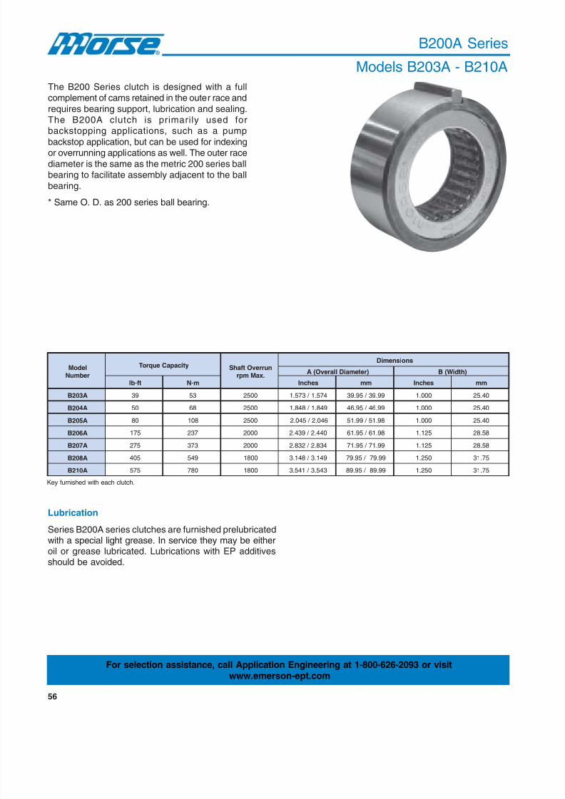
8/20/2019 Catalogo Morse MC Clutches y Limitadores
http://slidepdf.com/reader/full/catalogo-morse-mc-clutches-y-limitadores 58/131
56
B200A Series
Models B203A - B210A
The B200 Series clutch is designed with a fullcomplement of cams retained in the outer race and
requires bearing support, lubrication and sealing.The B200A clutch is primarily used forbackstopping applications, such as a pump
backstop application, but can be used for indexingor overrunning applications as well. The outer race
diameter is the same as the metric 200 series ballbearing to facilitate assembly adjacent to the ball
bearing.
* Same O. D. as 200 series ball bearing.
Key furnished with each clutch.
ledoMrebmuN
yticapaCeuqroT nurrevOtfahS.xaMmpr
snoisnemiD
)retemaiDllarevO(A )htdiW(B
tf-bl m-N sehcnI mm sehcnI mm
A302B 93 35 0052 475.1 / 375.1 99.93 / 59.93 000.1 04.52
A402B 05 86 0052 948.1 / 848.1 99.64 / 59.64 000.1 04.52
A502B 08 801 0052 640.2 / 540.2 89.15 / 99.15 000.1 04.52
A602B 571 732 0002 044.2 / 934.2 89.16 / 59.16 521.1 85.82
A702B 572 373 0002 438.2 / 238.2 99.17 / 59.17 521.1 85.82
A802B 504 945 0081 941.3 / 841.3 99.97 / 59.97 052.1 57.13
A012B 575 087 0081 345.3 / 145.3 99.98 / 59.98 052.1 57.13
Lubrication
Series B200A series clutches are furnished prelubricatedwith a special light grease. In service they may be eitheroil or grease lubricated. Lubrications with EP additives
should be avoided.
For selection assistance, call Application Engineering at 1-800-626-2093 or visit
www.emerson-ept.com
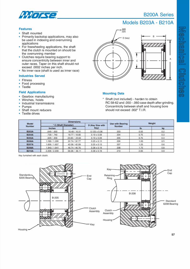
8/20/2019 Catalogo Morse MC Clutches y Limitadores
http://slidepdf.com/reader/full/catalogo-morse-mc-clutches-y-limitadores 59/131
57
B200A Series
Models B203A - B210A
Key furnished with each clutch.
D (key)B
AC
.020
.025R
ledoMrebmuN
snoisnemiDgniraeBhtiwesU
rebmuN
thgieW)retemaiDtfahS(C* htiweziSyeK(D
)yeKsehcnI mm .bl gk
A302B 056. / 946. 15.61 / 84.61 60.0x521.0 302 05.0 2.0
A402B 047. / 937. 08.81 / 77.81 90.0x91.0 402 57.0 3.0
A502B 039. / 929. 26.32 / 06.32 90.0x91.0 502 57.0 3.0
A602B 092.1 / 982.1 77.23 / 47.23 31.0x52.0 602 00.1 5.0A702B 756.1 / 656.1 90.24 / 60.24 31.0x52.0 702 52.1 6.0
A802B 148.1 / 048.1 67.64 / 47.64 91.0x83.0 802 57.1 8.0
A012B 902.2 / 802.2 11.65 / 80.65 91.0x83.0 012 00.2 9.0
Features
• Shaft mounted• Primarily backstop applications, may also
be used in indexing and overrunningapplications
• For freewheeling applications, the shaftthat the clutch is mounted on should bethe overrunning member
• Clutches require bearing support toensure concentricity between inner andouter races. Taper on this shaft should notexceed .0002 inches per inch.
• No inner race (shaft is used as inner race)
Industries Served
• Fitness• Food processing• Textile
Field Applications
• Gearbox manufacturing• Winches, hoists• Industrial transmissions• Pumps• Shaft mount reducers• Textile drives
B-205
ClutchAssembly
Key
Standard6205 Bearing
Housing
EndCap
B-208
EndCap
Housing
Key
RetainingRing
Standard6208 Bearing
ClutchAssembly
Mounting Data* Shaft (not included) - harden to obtain
RC 58-62 and .050 - .060 case depth after grinding.Concentricity between shaft and housing boreshould not exceed .002" T.I.R.
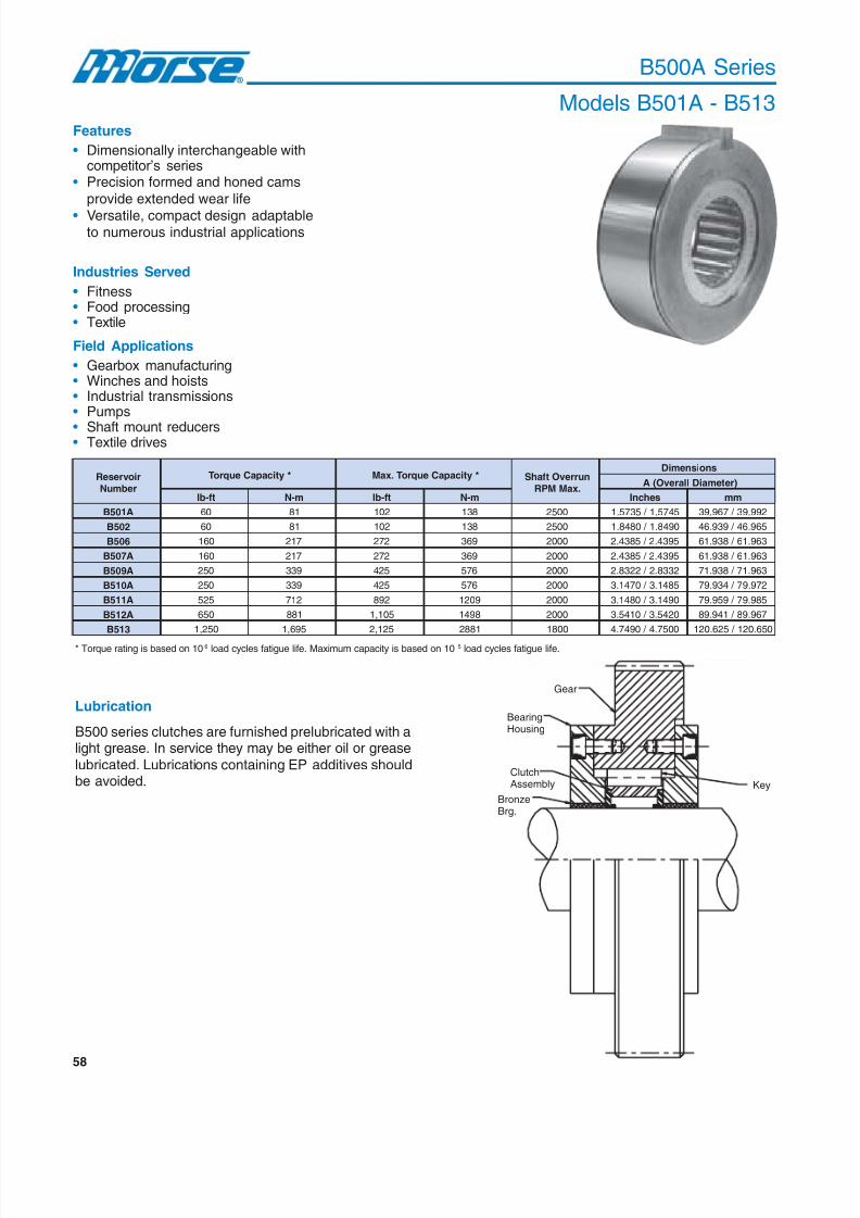
8/20/2019 Catalogo Morse MC Clutches y Limitadores
http://slidepdf.com/reader/full/catalogo-morse-mc-clutches-y-limitadores 60/131

8/20/2019 Catalogo Morse MC Clutches y Limitadores
http://slidepdf.com/reader/full/catalogo-morse-mc-clutches-y-limitadores 61/131
59
B500A Series
Models B501A - B513D
Keyway
CCust. shaft
A
O. D.
B
riovreseRrebmuN
snoisnemiDthgieW
)htdiW(B )retemaiDtfahS(C* )eziSyeK(D
sehcnI mm sehcnI mm sehcnI mm .bl gk
A105B 000.1 04.52 0056. / 5946. 015.61 / 794.61 60.0x521.0 5.1x3.3 05.0 2.0
205B 578.0 32.22 3837. / 8737. 357.81 / 047.81 31.0x52.0 3.3x4.6 57.0 3.0
605B 000.1 04.52 5331.1 / 5231.1 197.82 / 667.82 31.0x52.0 3.3x4.6 57.0 3.0
A705B 521.1 85.82 6079. / 6969. 356.42 / 826.42 31.0x52.0 3.3x4.6 00.1 5.0
A905B 052.1 57.13 5331.1 / 5231.1 197.82 / 667.82 31.0x52.0 3.3x4.6 05.1 7.0
A015B 573.1 39.43 5692.1 / 5592.1 139.23 / 609.23 91.0x573.0 8.4x7.9 57.1 8.0
A115B 526.1 82.14 6773.1 / 0773.1 199.43 / 679.43 91.0x573.0 8.4x7.9 00.2 9.0
A215B 526.1 82.14 0145.1 / 0045.1 141.93 / 611.93 91.0x573.0 8.4x7.9 00.2 9.0
315B 057.1 54.44 7540.2 / 7440.2 169.15 / 539.15 52.0x005.0 4.6x7.21 05.2 1.1
For selection assistance, call Application Engineering at 1-800-626-2093 or visitwww.emerson-ept.com
Mounting Data
* Required shaft diameter - harden to obtainRc58-62 and .050 - .060 case depth after grinding.Grind to 16 microinch finish. Concentricitybetween shaft and housing bore should notexceed .003" T.I.R. Adequate bearing supportmust be provided between the shaft and clutchhousing to maintain proper concentricity andsupport radial loads.
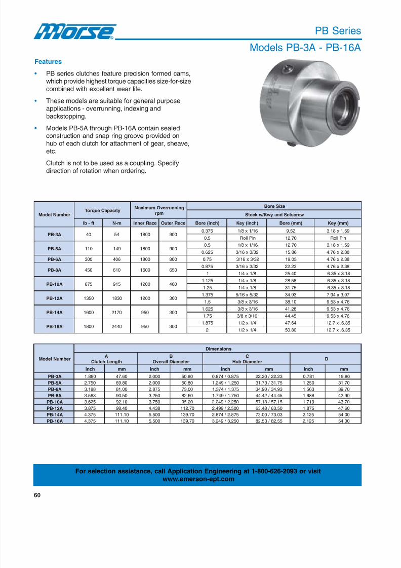
8/20/2019 Catalogo Morse MC Clutches y Limitadores
http://slidepdf.com/reader/full/catalogo-morse-mc-clutches-y-limitadores 62/131
60
PB Series
Models PB-3A - PB-16A
Features
• PB series clutches feature precision formed cams,which provide highest torque capacities size-for-sizecombined with excellent wear life.
• These models are suitable for general purposeapplications - overrunning, indexing andbackstopping.
• Models PB-5A through PB-16A contain sealedconstruction and snap ring groove provided onhub of each clutch for attachment of gear, sheave,etc.
Clutch is not to be used as a coupling. Specifydirection of rotation when ordering.
rebmuNledoMyticapaCeuqroT
gninnurrevOmumixaMmpr
eziSeroB
wercsteSdnaywK / wk cotS
tf-bl m-N ecaRrennI ecaRretuO )hcni(eroB )hcni(yeK )mm(eroB )mm(yeK
A3-BP 04 45 0081 009573.0 61 / 1x8 / 1 25.9 95.1x81.3
5.0 niPlloR 07.21 niPlloR
A5-BP 011 941 0081 0095.0 61 / 1x8 / 1 07.21 95.1x81.3
526.0 23 / 3x61 / 3 68.51 83.2x67.4
A6-BP 003 604 0081 008 57.0 23 / 3x61 / 3 50.91 83.2x67.4
A8-BP 054 016 0061 056578.0 23 / 3x61 / 3 32.22 83.2x67.4
1 8 / 1x4 / 1 04.52 81.3x53.6
A01-BP 576 519 0021 004521.1 8 / 1x4 / 1 85.82 81.3x53.6
52.1 8 / 1x4 / 1 57.13 81.3x53.6
A21-BP 0531 0381 0021 003
573.1 23 / 5x61 / 5 39.43 79.3x49.7
5.1 61 / 3x8 / 3 01.83 67.4x35.9
A41-BP 0061 0712 059 003526.1 61 / 3x8 / 3 82.14 67.4x35.9
57.1 61 / 3x8 / 3 54.44 67.4x35.9
A61-BP 0081 0442 059 003578.1 4 / 1x2 / 1 46.74 53.6.x7.21
2 4 / 1x2 / 1 08.05 53.6.x7.21
rebmuNledoM
snoisnemiD
AhtgneLhctulC
BretemaiDllarevO
CretemaiDbuH
D
hcni mm hcni mm hcni mm hcni mm
A3-BP 088.1 06.74 000.2 08.05 578.0 / 478.0 32.22 / 02.22 187.0 08.91
A5-BP 057.2 08.96 000.2 08.05 052.1 / 942.1 57.13 / 37.13 052.1 07.13
A6-BP 881.3 00.18 578.2 00.37 573.1 / 473.1 39.43 / 09.43 365.1 07.93
A8-BP 365.3 05.09 052.3 06.28 057.1 / 947.1 54.44 / 24.44 886.1 09.24
A01-BP 526.3 01.29 057.3 02.59 052.2 / 942.2 51.75 / 31.75 917.1 07.34
A21-BP 578.3 04.89 834.4 07.211 005.2 / 994.2 05.36 / 84.36 578.1 06.74
A41-BP 573.4 01.111 005.5 07.931 578.2 / 478.2 30.37 / 00.37 521.2 00.45
A61-BP 573.4 01.111 005.5 07.931 052.3 / 942.3 55.28 / 35.28 521.2 00.45
For selection assistance, call Application Engineering at 1-800-626-2093 or visitwww.emerson-ept.com

8/20/2019 Catalogo Morse MC Clutches y Limitadores
http://slidepdf.com/reader/full/catalogo-morse-mc-clutches-y-limitadores 63/131
61
H
K Keyway
B
G
E
M
J
FD
A
BoreC
PB Series
Models PB-3A - PB-16A
** Furnished by customer.
ledoMrebmuN
snoisnemiD
E F
htgneLbuHG
htgneLecaRrennIH
htgneLyawyeKbuHJ
gniRpanSotecaF
hcni mm hcni mm hcni mm hcni mm hcni mm
A3-BP 187.0 04.12 318.0 06.02 839.0 08.32 005.0 07.21 027.0 / 517.0 92.81 / 61.81
A5-BP 000.1 04.52 000.1 04.52 365.1 07.93 886.0 05.71 509.0 / 009.0 99.22 / 68.22
A6-BP 573.1 09.43 313.1 03.33 526.1 03.14 000.1 04.52 022.1 / 512.1 99.03 / 68.03
A8-BP 526.1 03.14 834.1 05.63 057.1 05.44 360.1 00.72 023.1 / 513.1 35.33 / 04.33
A01-BP 000.2 08.05 834.1 05.63 886.1 09.24 360.1 00.72 543.1 / 043.1 61.43 / 40.43
A21-BP 573.2 03.06 834.1 05.63 360.2 04.25 521.1 06.82 123.1 / 113.1 55.33 / 03.33
A41-BP 000.3 02.67 057.1 05.44 000.2 08.05 573.1 09.43 036.1 / 526.1 04.14 / 82.14
A61-BP 052.3 06.28 057.1 05.44 521.2 00.45 834.1 05.63 556.1 / 056.1 40.24 / 19.14
Industries Served
• Packaging• Printing
Field Applications
• Indexing drives• Print processing equipment
LubricationPB series clutches are prelubricated with grease and
are ready for installation. These units can be operatedin ambient temperatures of +20° F to +125° F.
All filler plugs are 1/4-28. All models have three filler
holes at 120° except PB-3A, which has only one.Clutch models PB-5A through PB-16A can be oillubricated by specifying on order.
ledoMrebmuN
snoisnemiD SdednemmoceR
**gniRpanS
thgieWKeziSyeK
L**retemaiDevoorGgniRpanS
M**htdiWevoorGgniRpanS
hcni mm hcni mm hcni mm bl gk
A3-BP 360.0x521.0 95.1x81.3 148.0 / 538.0 63.12 / 12.12 650. / 630. 24.1 / 19.0 78SR 57.0 43.0
A5-BP 490.0x881.0 83.2x67.4 602.1 / 891.1 36.03 / 34.03 860. / 840. 37.1 / 22.1 521SR 57.1 08.0
A6-BP 490.0x881.0 83.2x67.4 723.1 / 913.1 17.33 / 15.33 860. / 840. 37.1 / 22.1 731SR 05.3 06.1
A8-BP 521.0x052.0 81.3x53.6 696.1 / 686.1 80.34 / 28.24 670. / 650. 39.1 / 24.1 571SR 57.3 07.1
A01-BP 651.0x313.0 79.3x49.7 281.2 / 071.2 24.55 / 21.55 670. / 650. 39.1 / 24.1 522SR 00.6 37.2
A21-BP 881.0x573.0 67.4x35.9 193.2 / 973.2 37.06 / 34.06 031. / 021. 03.3 / 50.3 052TSR 05.8 68.3
A41-BP 912.0x834.0 65.5x11.11 787.2 / 577.2 97.07 / 94.07 670. / 650. 39.1 / 24.1 782SR 57.41 96.6
A61-BP 052.0x005.0 53.6x07.21 651.3 / 441.3 61.08 / 68.97 880. / 860. 42.2 / 37.1 523SR 00.51 08.6
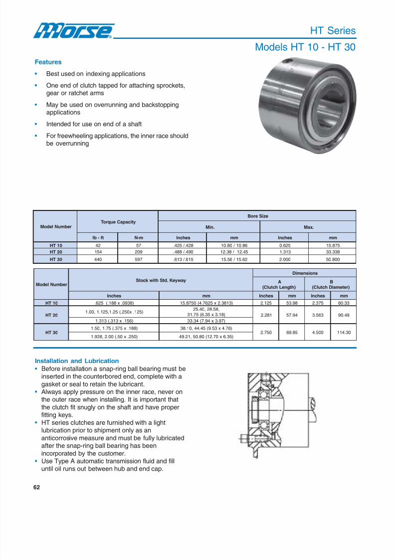
8/20/2019 Catalogo Morse MC Clutches y Limitadores
http://slidepdf.com/reader/full/catalogo-morse-mc-clutches-y-limitadores 64/131
62
Features
• Best used on indexing applications
• One end of clutch tapped for attaching sprockets,gear or ratchet arms
• May be used on overrunning and backstoppingapplications
• Intended for use on end of a shaft
• For freewheeling applications, the inner race shouldbe overrunning
Installation and Lubrication
• Before installation a snap-ring ball bearing must beinserted in the counterbored end, complete with a
gasket or seal to retain the lubricant.
• Always apply pressure on the inner race, never onthe outer race when installing. It is important that
the clutch fit snugly on the shaft and have properfitting keys.
• HT series clutches are furnished with a lightlubrication prior to shipment only as an
anticorrosive measure and must be fully lubricatedafter the snap-ring ball bearing has been
incorporated by the customer.• Use Type A automatic transmission fluid and fill
until oil runs out between hub and end cap.
HT Series
Models HT 10 - HT 30
rebmuNledoMyticapaCeuqroT
eziSeroB
.niM .xaM
tf-bl m-N sehcnI mm sehcnI mm
01TH 24 75 824. / 524. 68.01 / 08.01 526.0 578.51
02TH 451 902 094. / 884. 54.21 / 83.21 313.1 833.33
03TH 044 795 516. / 316. 26.51 / 65.51 000.2 008.05
rebmuNledoMyawyeK.dtShtiwk cotS
snoisnemiD
A)htgneLhctulC(
B)retemaiDhctulC(
sehcnI mm sehcnI mm sehcnI mm
01TH )8390.x881.(526. )3183.2x5267.4(0578.51 521.2 89.35 573.2 33.06
02TH )521.x052.(52.1,521.1,00.1
,85.82,04.52)81.3x53.6(57.13 182.2 49.75 365.3 94.09
)651.x313.(313.1 )79.3x49.7(43.33
03TH)881.x573.(57.1,05.1 )67.4x35.9(54.44,01.83
057.2 58.96 005.4 03.411)052.x05.(00.2,839.1 )53.6x07.21(08.05,12.94

8/20/2019 Catalogo Morse MC Clutches y Limitadores
http://slidepdf.com/reader/full/catalogo-morse-mc-clutches-y-limitadores 65/131
63
A
CB D
E - Number of equallyspaced tapped holes
F - Sizes and numberof threads
GH
HT Series
Models HT 10 - HT 30
ledoMrebmuN
snoisnemiD
C)htgneLecaRrennI(
D)retemaiDgnisuoHgniraeB(
EforebmuN
deppaTseloH
FeloHdeppaT
daerhT
GelcriCtloB
HhtpeDdaerhT
sehcnI mm sehcnI mm sehcnI mm sehcnI mm sehcnI mm
01TH 365.1 96.93 6181.1 / 1181.1 310.03 / 000.03 4 82-0052. 117-053.6 578.1 36.74 573.0 35.9
02TH 886.1 68.24 5740.2 / 0740.2 700.25 / 499.15 4 42-5213. 016-839.7 057.2 58.96 573.0 35.9
03TH 360.2 93.25 0538.2 / 5438.2 900.27 / 699.17 6 42-0573. 016-525.9 057.3 52.59 964.0 19.11
Industries Served
• Equipment rebuild
Field Applications
• Indexing
• Printing press
• Conveyor
• Poly bag machinery
• Plastic bag machinery
** Furnished by customer.
ledoMrebmuN
eroBretnuoCDtiFotgniraeBllaBgniRpanS** thgieWetamixorppA
.oNgniraeB DIgniraeB
)sehcnI(
mm bl gk
01TH 002 7393.0 01 6.2 2.1
02TH 403 / 502 3489. / 4787. 52 / 02 0.5 3.2
03TH 603 / 702 0873.1 / 1181.1 53 / 03 0.11 5
For selection assistance, call Application Engineering at 1-800-626-2093 or visitwww.emerson-ept.com

8/20/2019 Catalogo Morse MC Clutches y Limitadores
http://slidepdf.com/reader/full/catalogo-morse-mc-clutches-y-limitadores 66/131

8/20/2019 Catalogo Morse MC Clutches y Limitadores
http://slidepdf.com/reader/full/catalogo-morse-mc-clutches-y-limitadores 67/131
65
M maxP
JI
L
A
K
G E D C
H
min
F
BR Series
Models BR-20 - BR-70
ledoM
eloHtfahS
ecaRrennIA
ecaRretuOB
C)7h(yawyeK refmahC
mm .ni mm .ni mm .ni mm .ni mm .ni
02-RB 8.2X6 11.0x42.0 5.0 20.0 53 4.1 53 4.1 09 000.0+
3345.3 0000.0+
530.0- 4100.0-
52-RB 3.3X8 31.0x23.0 5.0 20.0 53 4.1 53 4.1 59 000.0+
1047.3 0000.0+
530.0- 4100.0-
03-RB 3.3X8 31.0x23.0 0.1 40.0 53 4.1 53 4.1 001 000.0+
0739.3 0000.0+
530.0- 4100.0-
53-RB 3.3X01 31.0x93.0 0.1 40.0 53 4.1 53 4.1 011 000.0+
7033.4 0000.0+
530.0- 4100.0-
04-RB 3.3X21 31.0x74.0 0.1 40.0 53 4.1 53 4.1 521 000.0+
2129.4 0000.0+
40.0- 6100.0-
54-RB 8.3X41 51.0x55.0 0.1 40.0 53 4.1 53 4.1 031 000.0+
2129.4 0000.0+
40.0- 6100.0-
05-RB 8.3X41 51.0x55.0 0.1 40.0 04 6.1 04 6.1 051 000.0+
5509.5 0000.0+
40.0- 6100.0-
06-RB 4.4X81 71.0x17.0 5.1 60.0 06 4.2 05 0.2 571 000.0+
7988.6 0000.0+
40.0- 6100.0-
07-RB 9.4X02 91.0x97.0 5.1 60.0 06 4.2 05 0.2 091 000.0+
3084.7 0000.0+
640.0- 8100.0-
ledoM
K)ylnOepyTnepO(
L)ylnOepyTnepO(
xamM)ylnOepyTnepO(
PliOfO.oN
sgulP
thgieW laitrenI2DGtnemevoM
m-gk 2
mm .ni mm .ni mm .ni mm .ni .gk .bl
02-RB 0.5 02.0 0.5 02.0 0.4 61.0 5.1 60.0 8 / 1-TPX3 3.1 8.2 4-01X52.2
52-RB 0.5 02.0 0.5 02.0 0.4 61.0 5.1 60.0 8 / 1-TPX3 4.1 0.3 4-01X82.3
03-RB 0.5 02.0 0.5 02.0 0.4 61.0 5.1 60.0 8 / 1-TPX3 5.1 3.3 4-01X44.4
53-RB 0.5 02.0 0.5 02.0 0.4 61.0 5.1 60.0 8 / 1-TPX4 9.1 1.4 4-01X56.5
04-RB 0.5 02.0 0.5 02.0 0.4 61.0 5.1 60.0 8 / 1-TPX4 4.2 2.5 3-01X10.1
54-RB 0.5 02.0 0.5 02.0 0.4 61.0 5.1 60.0 8 / 1-TPX4 6.2 7.5 3-01X22.1
05-RB 5.7 03.0 5.7 03.0 5.6 62.0 0.2 80.0 8 / 1-TPX4 1.4 0.9 3-01X46.2
06-RB 0.7 82.0 0.7 82.0 0.6 42.0 0.2 80.0 8 / 1-TPX4 3.7 0.61 3-01X37.3
07-RB 0.7 82.0 0.7 82.0 0.6 42.0 0.2 80.0 8 / 1-TPX4 1.8 8.71 3-01X56.6
Features
• Lift-off cam design provides
contact free operationbetween the cams and the
races for increased wear-life• Symmetrical design allows
operation in either direction• External bearing support
must be provided forconcentricity between thehousing and shaft
Industries Served
• Gearing• Manufacturing
• Packaging• Textile
Field Applications
• Conveyors• Shaft mount reducers• Vertical shaft backstop

8/20/2019 Catalogo Morse MC Clutches y Limitadores
http://slidepdf.com/reader/full/catalogo-morse-mc-clutches-y-limitadores 68/131
66
BR Series
Models BR-80 - BR-240
ledoMyticapaCeuqroTdetaR maCtampr
ffo-tfiL
fodeepSdednemmoceR)mpr(ecaRrennI
)mm(eziSeroBdradnatS
.sbl-tF m-N .niM .xaM mm hcni
08-RB 7084 7156 091 054 0063 08 030.0+
6941.3 2100.0+
000.0- 0000.0-
09-RB 8826 2658 081 024 0003 09 530.0+
3345.3 4100.0+
000.0- 0000.0-
001-RB 18401 01241 002 064 0072 001 530.0+
739.3 4100.0+
000.0- 0000.0-
031-RB 43051 48302 081 024 0042 031 040.0+
1811.5 6100.0+
000.0- 0000.0-
051-RB 90052 80933 061 073 0031 051 040.0+
5509.5 6100.0+
000.0- 0000.0-
081-RB 90052 80933 061 073 0053 081 640.0+
6680.7 8100.0+
000.0- 0000.0-
091-RB 85303 06114 041 043 0003 091 640.0+
3084.7 8100.0+
000.0- 0000.0-
022-RB 85673 85015 041 033 0003 022 640.0+
4166.8 8100.0+
000.0- 0000.0-
042-RB 45754 43026 031 013 0003 042 640.0+ 8844.9 8100.0+000.0- 0000.0-
ledoM
retemaiDrennIecaRretuOD
)7h(E
FepyTnepO(
)ylnO
seloHgnitnuoM)ylnOepyTnepO(
ffo-lluPseloHnepO(
epyT)ylnO
nimHepyTnepO(
)ylnO
IepyTnepO(
)ylnO
JepyTnepO(
)ylnOelcriCtloBG-retmaiD
fo.oNgnitnuoM
seloH
retemaiDeloHfo
mm .ni mm .ni mm .ni mm .ni T-S mm .ni mm .ni mm .ni
08-RB 061 000.0+
2992.6 0000.0+
0.511 35.4 0.511 35.4 581 4382.7 21 11 01M-2 841 8.5 5 2.0 5 2.0040.0- 6100.0-
09-RB 081 000.0+
6680.7 0000.0+
0.531 13.5 0.531 13.5 602 2011.8 21 5.31 21M-2 071 7.6 5 2.0 5 2.0640.0- 8100.0-
001-RB 012 000.0+
7762.8 0000.0+
0.341 36.5 0.341 36.5 042 8844.9 21 5.71 61M-2 081 1.7 5 2.0 5 2.0640.0- 8100.0-
031-RB 042 000.0+
8844.9 0000.0+
0.371 18.6 0.371 18.6 872 9449.01 21 5.71 61M-2 012 3.8 5 2.0 5 2.0640.0- 8100.0-
051-RB 013 000.0+
7402.21 0000.0+
0.342 75.9 0.342 75.9 063 2371.41 21 5.71 61M-2 082 0.11 5 2.0 5 2.0250.0- 0200.0-
081-RB 013 000.0+
7402.21 0000.0+
0.092 24.11 0.072 36.01 063 3371.41 21 5.71 61M-2 082 0.11 5 2.0 02 8.0250.0- 0200.0-
091-RB 033 000.0+
1299.21 0000.0+
0.013 02.21 0.082 20.11 083 6069.41 61 5.71 61M-2 003 8.11 5 2.0 02 8.0750.0- 2200.0-
022-RB 063 000.0+
2371.41 0000.0+
0.043 93.31 0.023 06.21 014 7141.61 81 5.71 61M-2 033 0.31 5 2.0 02 8.0750.0- 2200.0-
042-RB 093 000.0+
3453.51 0000.0+
0.073 75.41 0.053 87.31 044 8223.71 81 5.71 61M-2 063 2.41 5 2.0 02 8.0750.0- 2200.0-

8/20/2019 Catalogo Morse MC Clutches y Limitadores
http://slidepdf.com/reader/full/catalogo-morse-mc-clutches-y-limitadores 69/131
67
BR Series
Models BR-80 - BR-240
ledoM
eloHtfahS
ecaRrennIA
ecaRretuOB
C)7h(yawyeK refmahC
mm .ni mm .ni mm .ni mm .ni mm .ni
08-RB 4.5X22 12.0x78.0 5.1 60.0 07 8.2 06 4.2 012 000.0+
7762.8 0000.0+
640.0- 8100.0-
09-RB 4.5X52 12.0x89.0 5.1 60.0 08 1.3 07 8.2 032 000.0+
1550.9 0000.0+
640.0- 8100.0-
001-RB 4.6X82 52.0x01.1 5.1 60.0 09 5.3 08 1.3 072 000.0+
9926.01 0000.0+
250.0- 0200.0-
031-RB 4.7X23 92.0x62.1 0.2 80.0 09 5.3 08 1.3 013 000.0+
7402.21 0000.0+
250.0- 0200.0-
051-RB 4.8X63 33.0x24.1 0.2 80.0 09 5.3 08 1.3 004 000.0+
0847.51 0000.0+
750.0- 2200.0-
081-RB 4.01X54 14.0x77.1 0.2 80.0 501 1.4 08 1.3 004 000.0+
0847.51 0000.0+
750.0- 2200.0-
091-RB 4.01X54 14.0x77.1 0.2 80.0 501 1.4 08 1.3 024 000.0+
4535.61 0000.0+
360.0- 5200.0-
022-RB 4.11X05 54.0x79.1 0.2 80.0 501 1.4 08 1.3 064 000.0+
2011.81 0000.0+
360.0- 5200.0-
042-RB 4.21X65 94.0x02.2 0.2 80.0 501 1.4 08 1.3 094 000.0+ 3192.91 0000.0+360.0- 5200.0-
ledoM
K)ylnOepyTnepO(
L)ylnOepyTnepO(
xamM)ylnOepyTnepO(
PliOfO.oN
sgulP
thgieW laitrenI2DGtnemevoM
m-gk 2
mm .ni mm .ni mm .ni mm .ni .gk .bl
08-RB 0.21 74.0 0.21 74.0 0.11 34.0 0.2 80.0 8 / 1-TPX4 0.21 4.62 2-01X77.1
09-RB 0.71 76.0 0.71 76.0 0.61 36.0 0.2 80.0 8 / 1-TPX4 0.61 2.53 2-01X61.3
001-RB 7.31 45.0 7.31 45.0 0.21 74.0 0.2 80.0 4 / 1-TPX4 0.32 7.05 2-01X13.6
031-RB 7.31 45.0 7.31 45.0 0.21 74.0 0.2 80.0 4 / 1-TPX4 0.13 3.86 901.0
051-RB 7.31 45.0 7.31 50.0 0.21 74.0 0.3 21.0 4 / 1-TPX4 0.85 8.721 563.0
081-RB 5.11 54.0 9.51 36.0 0.41 55.0 0.3 21.0 4 / 1-TPX4 0.06 2.231 534.0
091-RB 5.21 94.0 9.8 53.0 5.7 03.0 0.3 21.0 4 / 1-TPX4 0.56 3.341 365.0
022-RB 5.21 94.0 9.01 34.0 0.9 53.0 0.3 21.0 4 / 1-TPX4 0.67 5.761 987.0
042-RB 5.21 94.0 9.01 34.0 0.9 53.0 0.3 21.0 4 / 1-TPX4 0.48 1.581 50.1
M maxP
JI
L
A
K
G E D CH
min
F

8/20/2019 Catalogo Morse MC Clutches y Limitadores
http://slidepdf.com/reader/full/catalogo-morse-mc-clutches-y-limitadores 70/131
68
BR Series
Models BR-20P - BR-70P
ledoMyticapaCeuqroTdetaR maCtampr
ffo-tfiL
fodeepSdednemmoceR)mpr(ecaRrennI )mm(eziSeroBdradnatS
.sbl-tF m-N .niM .xaM mm hcni
P02-RB 522 603 053 088 0063 02 120.0+
9787.0 8000.0+
000.0- 0000.0-
P52-RB 382 483 053 088 0063 52 120.0+
3489.0 8000.0+
000.0- 0000.0-
P03-RB 844 706 053 088 0063 03 120.0+
1181.1 8000.0+
000.0- 0000.0-
P53-RB 605 686 003 047 0063 53 520.0+
0873.1 0100.0+
000.0- 0000.0-
P04-RB 327 089 003 027 0063 04 520.0+
8475.1 0100.0+
000.0- 0000.0-
P54-RB 597 870,1 082 076 0063 54 520.0+
7177.1 0100.0+
000.0- 0000.0-
P05-RB 562,1 517,1 042 016 0063 05 520.0+
5869.1 0100.0+
000.0- 0000.0-
P06-RB 665,2 974,3 002 094 0063 06 030.0+
2263.2 2100.0+
000.0- 0000.0-
P07-RB 294,3 537,4 002 084 0063 07 030.0+
9557.2 2100.0+
000.0- 0000.0-

8/20/2019 Catalogo Morse MC Clutches y Limitadores
http://slidepdf.com/reader/full/catalogo-morse-mc-clutches-y-limitadores 71/131
69
E
F-G B
A
CD
BR Series
Models BR-20P - BR-70P
ledoM
eloHtfahS
ecaRrennI A ecaRretuO B C)7h(
rennIecaRretuO
DretemaiD)7h(
EG-FyawyeK
mm .ni mm .ni mm .ni mm .ni mm .ni mm .ni
P02-RB 8.2X6 11.0x42.0 78 4.3 97 1.3 49 000.0+
8007.3 0000.0+
03 2.1 87 1.3 6M-6530.0- 4100.0-
P52-RB 3.3X8 31.0x23.0 98 5.3 18 2.3 89 000.0+
3858.3 0000.0+
53 4.1 28 2.3 6M-6530.0- 4100.0-
P03-RB 3.3X8 31.0x23.0 49 7.3 58 3.3 301 000.0+
1550.4 0000.0+
54 8.1 78 4.3 6M-6530.0- 4100.0-
P53-RB 3.3X01 31.0x93.0 49 7.3 58 3.3 211 000.0+
4904.4 0000.0+
05 0.2 69 8.3 6M-8530.0- 4100.0-
P04-RB 3.3X21 31.0x74.0 001 9.3 19 6.3 031 000.0+
1811.5 0000.0+
55 2.2 801 3.4 8M-8040.0- 6100.0-
P54-RB 8.3X41 51.0x55.0 001 9.3 19 6.3 531 000.0+
9413.5 0000.0+
06 4.2 211 4.4 8M-8040.0- 6100.0-
P05-RB 8.3X41 51.0x55.0 701 2.4 89 9.3 251 000.0+
2489.5 0000.0+
07 8.2 231 2.5 8M-8040.0- 6100.0-
P06-RB 4.4X81 71.0x17.0 221 8.4 211 4.4 081 000.0+
6680.7 0000.0+
08 1.3 551 1.6 01M-8040.0- 6100.0-
P07-RB 9.4X02 91.0x97.0 821 0.5 021 7.4 091 000.0+
3084.7 0000.0+
09 5.3 561 5.6 01M-21640.0- 8100.0-
For selection assistance, call Application Engineering at 1-800-626-2093 or visit
www.emerson-ept.com

8/20/2019 Catalogo Morse MC Clutches y Limitadores
http://slidepdf.com/reader/full/catalogo-morse-mc-clutches-y-limitadores 72/131
70
BR Series
Models BR-80P - BR-240P
ledoMyticapaCeuqroTdetaR maCtampr
ffo-tfiL
fodeepSdednemmoceR)mpr(ecaRrennI )mm(eziSeroBdradnatS
.sbl-tF m-N .niM .xaM mm hcni
P08-RB 708,4 715,6 091 054 0063 08 030.0+
6941.3 2100.0+
000.0- 0000.0-
P09-RB 882,6 625,8 081 024 0003 09 530.0+
3345.3 4100.0+
000.0- 0000.0-
P001-RB 184,01 012,41 081 064 0052 001 530.0+
739.3 4100.0+
000.0- 0000.0-
P031-RB 430,51 483,02 081 024 0022 031 040.0+
1811.5 6100.0+
000.0- 0000.0-
P051-RB 900,52 809,33 061 073 0031 051 040.0+
5509.5 6100.0+
000.0- 0000.0-
P081-RB 900,52 809,33 061 073 0081 081 040.0+
6680.7 6100.0+
000.0- 0000.0-
P091-RB 853,03 061,14 041 043 0081 091 640.0+
3084.7 8100.0+
000.0- 0000.0-
P022-RB 856,73 850,15 041 033 0081 022 640.0+
4166.8 8100.0+
000.0- 0000.0-
P042-RB 457,54 430,26 031 013 0081 042 640.0+
8844.9 8100.0+
000.0- 0000.0-

8/20/2019 Catalogo Morse MC Clutches y Limitadores
http://slidepdf.com/reader/full/catalogo-morse-mc-clutches-y-limitadores 73/131
71
BR Series
Models BR-80P - BR-240P
ledoM
eloHtfahS
ecaRrennI A ecaRretuO B C)7h(
rennIecaRretuO
DretemaiD)7h(
EG-FyawyeK
mm .ni mm .ni mm .ni mm .ni mm .ni mm .ni
P08-RB 4.5X22 12.0x78.0 841 8.5 431 3.5 012 000.0+
7762.8 0000.0+
011 3.4 581 3.7 01M-21640.0- 8100.0-
P09-RB 4.5X52 12.0x89.0 251 0.6 831 4.5 532 000.0+
9152.9 0000.0+
021 7.4 602 1.8 21M-21640.0- 8100.0-
P001-RB 4.6X82 52.0x01.1 681 3.7 271 8.6 572 000.0+
7628.01 0000.0+
031 1.5 042 4.9 61M-21250.0- 0200.0-
P031-RB 4.7X23 92.0x62.1 802 2.8 881 4.7 413 000.0+
2263.21 0000.0+
061 3.6 872 9.01 61M-21250.0- 0200.0-
P051-RB 4.8X63 33.0x24.1 622 9.8 402 0.8 004 000.0+
8747.51 0000.0+
002 9.7 063 2.41 61M-21360.0- 5200.0-
P081-RB 4.01X54 14.0x77.1 042 4.9 332 2.9 004 000.0+
8747.51 0000.0+
022 7.8 062 2.01 61M-21360.0- 5200.0-
P091-RB 4.01X54 14.0x77.1 052 8.9 242 5.9 024 000.0+
4535.61 0000.0+
042 4.9 083 0.51 61M-61360.0- 5200.0-
P022-RB 4.11X05 54.0x79.1 052 8.9 242 5.9 064 000.0+
2011.81 0000.0+
062 2.01 014 1.61 61M-81360.0- 5200.0-
P042-RB 4.21X65 94.0x12.2 062 2.01 252 9.9 094 000.0+
3192.91 0000.0+
082 0.11 044 3.71 61M-81360.0- 5200.0-
E
F-G B
A
CD
For selection assistance, call Application Engineering at 1-800-626-2093 or visit
www.emerson-ept.com

8/20/2019 Catalogo Morse MC Clutches y Limitadores
http://slidepdf.com/reader/full/catalogo-morse-mc-clutches-y-limitadores 74/131
72
Clutch Lubrication
Grease Lubrication
• Morse recommends an NLGI, Grade 1 or 2 premiumbearing grease, mineral oil based in a lithium soapthickener, non-EP type.
• Synthetic polyurea base fluid greases are alsoacceptable.
• EP greases (having extreme pressurecharacteristics) with slippery additives such as
graphite or molybdenum disulfide must not beused. They can cause the clutch to malfunction.
• Clutches specified as grease are filled at the
factory and are ready-to-use.• Grease is not recommended for low temperatures
or for performance indexing applications.• Generally relubricate every two months and more
often for dirty environments.• For operation in ambient temperatures over
+200°F or below +20°F, consult ApplicationEngineering.
General use: (+20°F to +125°F, NLGI #2)• Texaco Multifak ® AFB 2, Texaco Polystar RB
• Mobilith ® SHC 100• Shell Alvania ® #2
Food grade applications (USDA Grade H-1, up to+300°F):
• Keystone Nevastane ® HT/AW-1 or -2• Mobil ® FM 101,102
• Lubriplate ® FML-1, FML-2
Note: Not all greases are compatible and clutchperformance can be affected.
Oil Lubrication
• Morse standard oil is a multipurpose automatictransmission fluid, good from -20°F to +150°F. Fortemperatures outside this range, use synthetic ATF
oil.• Oils with EP additives must not be used. They cancause the clutch to malfunction.
• Clutches ordered with oil are partially filled andthen drained after factory run-in. Therefore, theclutch must be filled half full with oil before being
operated.• The standard oil lip seal is made from a
polyacrylic compound, which is good to +250°F.• Oil is recommended for indexing applications.
Check the oil level monthly. See the maintenance and
installation sheet provided with each unit.
Mobil and Mobilith are believed to be a trademark and/or a trade name of ExxonMobil Corporation. Shell is believed to be a trademark and/or a trade name ofShell International Limited. Texaco is a believed to be a trademark and/or a trade name of Chevron Products Company. Nevastane is believed to be a trademarkand/or a trade name of Keystone Division of TOTAL Lubricants USA, Inc. Lubriplate is believed to be a trademark and/or a trade name of Fiske Brothers RefiningCompany. These trademarks and/or registered trademarks of others are used herein for product comparison purposes only, are the property of their respectiveowners and are not owned or controlled by Emerson Power Transmission Corporation. While reasonable efforts have been made to confirm ownership of themarks and names listed above, Emerson Power Transmission Corporation cannot and does not represent or warrant the accuracy of this information.
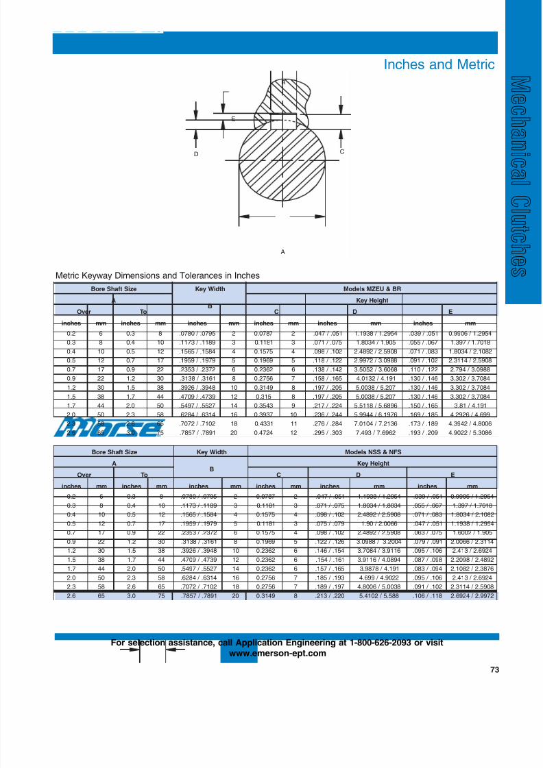
8/20/2019 Catalogo Morse MC Clutches y Limitadores
http://slidepdf.com/reader/full/catalogo-morse-mc-clutches-y-limitadores 75/131
73
Dimensions and Tolerances
Inches and Metric
Metric Keyway Dimensions and Tolerances in Inches
eziStfahSeroB htdiWyeK RB&UEZMsledoM
AB
thgieHyeK
revO oT C D E
sehcni mm sehcni mm sehcni mm sehcni mm sehcni mm sehcni mm
2.0 6 3.0 8 5970. / 0870. 2 7870.0 2 150. / 740. 4592.1 / 8391.1 150. / 930. 4592.1 / 6099.0
3.0 8 4.0 01 9811. / 3711. 3 1811.0 3 570. / 170. 509.1 / 4308.1 760. / 550. 8107.1 / 793.1
4.0 01 5.0 21 4851. / 5651. 4 5751.0 4 201. / 890. 8095.2 / 2984.2 380. / 170. 2801.2 / 4308.1
5.0 21 7.0 71 9791. / 9591. 5 9691.0 5 221. / 811. 8890.3 / 2799.2 201. / 190. 8095.2 / 4113.2
7.0 71 9.0 22 2732. / 3532. 6 2632.0 6 241. / 831. 8606.3 / 2505.3 221. / 011. 8890.3 / 497.2
9.0 22 2.1 03 1613. / 8313. 8 6572.0 7 561. / 851. 191.4 / 2310.4 641. / 031. 4807.3 / 203.3
2.1 03 5.1 83 8493. / 6293. 01 9413.0 8 502. / 791. 702.5 / 8300.5 641. / 031. 4807.3 / 203.3
5.1 83 7.1 44 9374. / 9074. 21 513.0 8 502. / 791. 702.5 / 8300.5 641. / 031. 4807.3 / 203.3
7.1 44 0.2 05 7255. / 7945. 41 3453.0 9 422. / 712. 6986.5 / 8115.5 561. / 051. 191.4 / 18.3
0.2 05 3.2 85 4136. / 4826. 61 7393.0 01 442. / 632. 6791.6 / 4499.5 581. / 961. 996.4 / 6292.4
3.2 85 6.2 56 2017. / 2707. 81 1334.0 11 482. / 672. 6312.7 / 4010.7 981. / 371. 6008.4 / 2493.4
6.2 56 0.3 57 1987. / 7587. 02 4274.0 21 303. / 592. 2696.7 / 394.7 902. / 391. 6803.5 / 2209.4
eziStfahSeroB htdiWyeK SFN&SSNsledoM
AB
thgieHyeK
revO oT C D E
sehcni mm sehcni mm sehcni mm sehcni mm sehcni mm sehcni mm
2.0 6 3.0 8 5970. / 0870. 2 7870.0 2 150. / 740. 4592.1 / 8391.1 150. / 930. 4592.1 / 6099.0
3.0 8 4.0 01 9811. / 3711. 3 1811.0 3 570. / 170. 4308.1 / 4308.1 760. / 550. 8107.1 / 793.1
4.0 01 5.0 21 4851. / 5651. 4 5751.0 4 201. / 890. 8095.2 / 2984.2 380. / 170. 2801.2 / 4308.1
5.0 21 7.0 71 9791. / 9591. 5 1811.0 3 970. / 570. 6600.2 / 09.1 150. / 740. 4592.1 / 8391.1
7.0 71 9.0 22 2732. / 3532. 6 5751.0 4 201. / 890. 8095.2 / 2984.2 570. / 360. 509.1 / 2006.1
9.0 22 2.1 03 1613. / 8313. 8 9691.0 5 621. / 221. 4002.3 / 8890.3 190. / 970. 4113.2 / 6600.2
2.1 03 5.1 83 8493. / 6293. 01 2632.0 6 451. / 641. 6119.3 / 4807.3 601. / 590. 4296.2 / 314.2
5.1 83 7.1 44 9374. / 9074. 21 2632.0 6 161. / 451. 4980.4 / 6119.3 890. / 780. 2984.2 / 8902.2
7.1 44 0.2 05 7255. / 7945. 41 2632.0 6 561. / 751. 191.4 / 8789.3 490. / 380. 6783.2 / 2801.2
0.2 05 3.2 85 4136. / 4826. 61 6572.0 7 391. / 581. 2209.4 / 996.4 601. / 590. 4296.2 / 314.2
3.2 85 6.2 56 2017. / 2707. 81 6572.0 7 791. / 981. 8300.5 / 6008.4 201. / 190. 8095.2 / 4113.2
6.2 56 0.3 57 1987. / 7587. 02 9413.0 8 022. / 312. 885.5 / 2014.5 811. / 601. 2799.2 / 4296.2
C
B
D
E
A
For selection assistance, call Application Engineering at 1-800-626-2093 or visit
www.emerson-ept.com
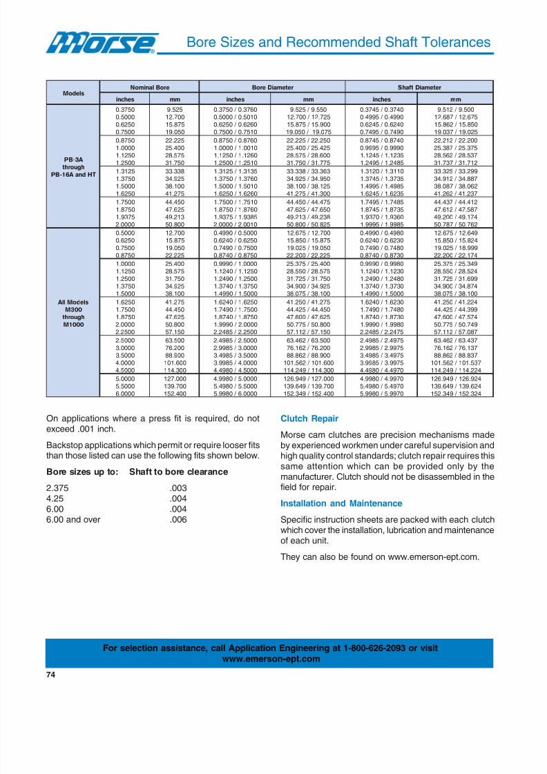
8/20/2019 Catalogo Morse MC Clutches y Limitadores
http://slidepdf.com/reader/full/catalogo-morse-mc-clutches-y-limitadores 76/131
74
Bore Sizes and Recommended Shaft Tolerances
Clutch Repair
Morse cam clutches are precision mechanisms madeby experienced workmen under careful supervision andhigh quality control standards; clutch repair requires thissame attention which can be provided only by themanufacturer. Clutch should not be disassembled in thefield for repair.
Installation and Maintenance
Specific instruction sheets are packed with each clutchwhich cover the installation, lubrication and maintenance
of each unit.
They can also be found on www.emerson-ept.com.
On applications where a press fit is required, do notexceed .001 inch.
Backstop applications which permit or require looser fitsthan those listed can use the following fits shown below.
Bore sizes up to: Shaft to bore clearance
2.375 .0034.25 .0046.00 .0046.00 and over .006
sledoMeroBlanimoN retemaiDeroB retemaiDt f ahS
sehcni mm sehcni mm sehcni mm
A 3-BP
hguorht
THdna A 61-BP
0573.00005.00526.00057.0
525.9007.21578.51050.91
0673.0 / 0573.00105.0 / 0005.00626.0 / 0526.00157.0 / 0057.0
055.9 / 525.9527.21 / 007.21009.51 / 578.51570.91 / 050.91
0473.0 / 5473.00994.0 / 5994.00426.0 / 5426.00947.0 / 5947.0
005.9 / 215.9576.21 / 786.21058.51 / 268.51520.91 / 730.91
0578.00000.10521.10052.1
522.22004.52575.82057.13
0678.0 / 0578.00100.1 / 0000.10621.1 / 0521.10152.1 / 0052.1
052.22 / 522.22524.52 / 004.52006.82 / 575.82577.13 / 057.13
0478.0 / 5478.00999.0 / 5999.05321.1 / 5421.15842.1 / 5942.1
002.22 / 212.22573.52 / 783.52735.82 / 265.82217.13 / 737.13
5213.10573.10005.10526.1
833.33529.43001.83572.14
5313.1 / 5213.10673.1 / 0573.10105.1 / 0005.10626.1 / 0526.1
363.33 / 833.33059.43 / 529.43521.83 / 001.83003.14 / 572.14
0113.1 / 0213.15373.1 / 5473.15894.1 / 5994.15326.1 / 5426.1
992.33 / 523.33788.43 / 219.43260.83 / 780.83732.14 / 262.14
0057.10578.15739.10000.2
054.44526.74312.94008.05
0157.1 / 0057.10678.1 / 0578.15839.1 / 5739.10100.2 / 0000.2
574.44 / 054.44056.74 / 526.74832.94 / 312.94528.05 / 008.05
5847.1 / 5947.15378.1 / 5478.10639.1 / 0739.15899.1 / 5999.1
214.44 / 734.44785.74 / 216.74471.94 / 002.94267.05 / 787.05
sledoMll A
003M
hguorht
0001M
0005.00526.00057.00578.0
007.21578.51050.91522.22
0005.0 / 0994.00526.0 / 0426.00057.0 / 0947.00578.0 / 0478.0
007.21 / 576.21578.51 / 058.51050.91 / 520.91522.22 / 002.22
0894.0 / 0994.00326.0 / 0426.00847.0 / 0947.00378.0 / 0478.0
946.21 / 576.21428.51 / 058.51999.81 / 520.91471.22 / 002.22
0000.1
0521.10052.10573.10005.1
004.52
575.82057.13529.43001.83
0000.1 / 0999.0
0521.1 / 0421.10052.1 / 0942.10573.1 / 0473.10005.1 / 0994.1
004.52 / 573.52
575.82 / 055.82057.13 / 527.13529.43 / 009.43001.83 / 570.83
0899.0 / 0999.0
0321.1 / 0421.10842.1 / 0942.10373.1 / 0473.10005.1 / 0994.1
943.52 / 573.52
425.82 / 055.82996.13 / 527.13478.43 / 009.43001.83 / 570.83
0526.10057.10578.10000.20052.2
572.14054.44526.74008.05051.75
0526.1 / 0426.10057.1 / 0947.10578.1 / 0478.10000.2 / 0999.10052.2 / 5842.2
572.14 / 052.14054.44 / 524.44526.74 / 006.74008.05 / 577.05051.75 / 211.75
0326.1 / 0426.10847.1 / 0947.10378.1 / 0478.10899.1 / 0999.15742.2 / 5842.2
422.14 / 052.14993.44 / 524.44475.74 / 006.74947.05 / 577.05780.75 / 211.75
0005.20000.30005.30000.40005.4
005.36002.67009.88006.101003.411
0005.2 / 5894.20000.3 / 5899.20005.3 / 5894.30000.4 / 5899.30005.4 / 0894.4
005.36 / 264.36002.67 / 261.67009.88 / 268.88
006.101 / 265.101003.411 / 942.411
5794.2 / 5894.25799.2 / 5899.25794.3 / 5894.35799.3 / 5899.30794.4 / 0894.4
734.36 / 264.36731.67 / 261.67738.88 / 268.88
735.101 / 265.101422.411 / 942.411
0000.50005.50000.6
000.721007.931004.251
0000.5 / 0899.40005.5 / 0894.50000.6 / 0899.5
000.721 / 949.621007.931 / 946.931004.251 / 943.251
0799.4 / 0899.40794.5 / 0894.50799.5 / 0899.5
429.621 / 949.621426.931 / 946.931423.251 / 943.251
For selection assistance, call Application Engineering at 1-800-626-2093 or visit
www.emerson-ept.com
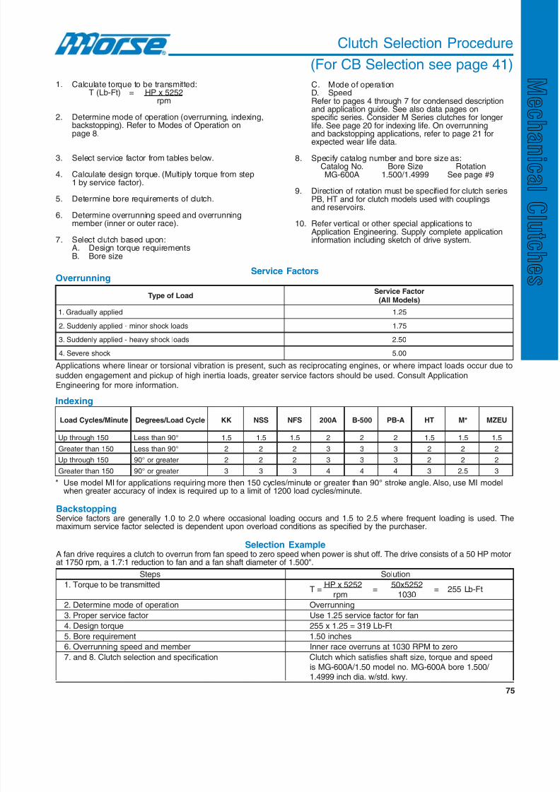
8/20/2019 Catalogo Morse MC Clutches y Limitadores
http://slidepdf.com/reader/full/catalogo-morse-mc-clutches-y-limitadores 77/131
75
Clutch Selection Procedure
(For CB Selection see page 41)
1. Calculate torque to be transmitted:T (Lb-Ft) = HP x 5252
rpm
2. Determine mode of operation (overrunning, indexing,backstopping). Refer to Modes of Operation onpage 8.
3. Select service factor from tables below.
4. Calculate design torque. (Multiply torque from step1 by service factor).
5. Determine bore requirements of clutch.
6. Determine overrunning speed and overrunningmember (inner or outer race).
7. Select clutch based upon:A. Design torque requirementsB. Bore size
C. Mode of operationD. SpeedRefer to pages 4 through 7 for condensed descriptionand application guide. See also data pages onspecific series. Consider M Series clutches for longerlife. See page 20 for indexing life. On overrunningand backstopping applications, refer to page 21 forexpected wear life data.
8. Specify catalog number and bore size as:Catalog No. Bore Size RotationMG-600A 1.500/1.4999 See page #9
9. Direction of rotation must be specified for clutch seriesPB, HT and for clutch models used with couplingsand reservoirs.
10. Refer vertical or other special applications toApplication Engineering. Supply complete applicationinformation including sketch of drive system.
OverrunningService Factors
daoLfoepyTrotcaFecivreS
)sledoMllA(
deilppayllaudarG.1 52.1
sdaolkcohsronim-deilppaylnedduS.2 57.1
sdaolkcohsyvaeh-deilppaylnedduS.3 05.2
kcohsereveS.4 00.5
Indexing
etuniM / selcyCdaoL elcyCdaoL / seergeD KK SSN SFN A002 005-B A-BP TH *M UEZM
051hguorhtpU °09nahtsseL 5.1 5.1 5.1 2 2 2 5.1 5.1 5.1
051nahtretaerG °09nahtsseL 2 2 2 3 3 3 2 2 2
051hguorhtpU retaergro°09 2 2 2 3 3 3 2 2 2
051nahtretaerG retaergro°09 3 3 3 4 4 4 3 5.2 3
BackstoppingService factors are generally 1.0 to 2.0 where occasional loading occurs and 1.5 to 2.5 where frequent loading is used. Themaximum service factor selected is dependent upon overload conditions as specified by the purchaser.
* Use model MI for applications requiring more then 150 cycles/minute or greater than 90° stroke angle. Also, use MI modelwhen greater accuracy of index is required up to a limit of 1200 load cycles/minute.
Selection Example
A fan drive requires a clutch to overrun from fan speed to zero speed when power is shut off. The drive consists of a 50 HP motorat 1750 rpm, a 1.7:1 reduction to fan and a fan shaft diameter of 1.500".
Steps Solution
1. Torque to be transmittedT =
HP x 5252=
50x5252= 255 Lb-Ft
rpm 1030
2. Determine mode of operation Overrunning
3. Proper service factor Use 1.25 service factor for fan
4. Design torque 255 x 1.25 = 319 Lb-Ft
5. Bore requirement 1.50 inches
6. Overrunning speed and member Inner race overruns at 1030 RPM to zero
7. and 8. Clutch selection and specification Clutch which satisfies shaft size, torque and speed
is MG-600A/1.50 model no. MG-600A bore 1.500/ 1.4999 inch dia. w/std. kwy.
Applications where linear or torsional vibration is present, such as reciprocating engines, or where impact loads occur due to
sudden engagement and pickup of high inertia loads, greater service factors should be used. Consult ApplicationEngineering for more information.

8/20/2019 Catalogo Morse MC Clutches y Limitadores
http://slidepdf.com/reader/full/catalogo-morse-mc-clutches-y-limitadores 78/131
76
Clutch Application Data Selection
For selection assistance, call Application Engineering at 1-800-626-2093 or fax the information to:Emerson Power Transmission
P. O. Box 687Maysville, KY 41056
Fax (606) 564-2079
1. Application: State purpose of clutch and equipment clutch will be used on:
2. Main operating mode: Overrunning Backstopping Indexing
3. Power driving clutch: Electric Diesel Gasoline Other
Horsepower Hp, at rpm
4. Torque through clutch: lb-feet, at a Driving rpm on the clutch.
5. Load type/(service factor):Gradual (1.5) Sudden load, minor shock (1.75)
Sudden load, heavy shock (2.5) Severe shock (5.0)
6. Lubrication: Oil Grease Specific type Serviced?
7. Environment: Ambient Temp. (F) Exposed to: Dirt, dust? Moisture?
8. Shaft diameter (inches) Keyway size, if knownClutch Mounting Position: Horizontal Vertical
9. Indexing applications only: Max indexes per minute Degrees per indexHours per day in use Days used per year
10. All other applications: Continuous duty, hours per dayIf intermittent duty cycle; Driving (%) Overrunning (%) Idle (%)
If overrunning; Inner race maximum rpm Outer race max rpm
11. Quantity required: This application Annually
12. Additional comments?
13. Please provide sketch if possible.
Thank you!
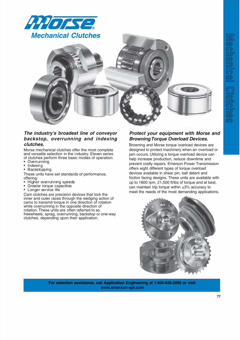
8/20/2019 Catalogo Morse MC Clutches y Limitadores
http://slidepdf.com/reader/full/catalogo-morse-mc-clutches-y-limitadores 79/131
77
Mechanical Clutches
For selection assistance, call Application Engineering at 1-800-626-2093 or visitwww.emerson-ept.com
The industry's broadest line of conveyor backstop, overrunning and indexing clutches.Morse mechanical clutches offer the most completeand versatile selection in the industry. Eleven seriesof clutches perform three basic modes of operation:• Overrunning• Indexing• Backstopping
These units have set standards of performance,
offering:• Higher overrunning speeds• Greater torque capacities• Longer service life
Cam clutches are precision devices that lock theinner and outer races through the wedging action ofcams to transmit torque in one direction of rotationwhile overrunning in the opposite direction ofrotation. These units are often referred to asfreewheels, sprag, overrunning, backstop or one-wayclutches, depending upon their application.
Protect your equipment with Morse and Browning Torque Overload Devices.
Browning and Morse torque overload devices are
designed to protect machinery when an overload or jam occurs. Utilizing a torque overload device canhelp increase production, reduce downtime and
prevent costly repairs. Emerson Power Transmissionoffers eight different types of torque overload
devices available in shear pin, ball detent and
friction facing designs. These units are available withup to 1800 rpm, 21,500 ft/lbs of torque and at best,can maintain trip torque within ±3% accuracy to
meet the needs of the most demanding applications.

8/20/2019 Catalogo Morse MC Clutches y Limitadores
http://slidepdf.com/reader/full/catalogo-morse-mc-clutches-y-limitadores 80/131
78
Emerson Power Transmission offers one of the broadest lines of torque overload devices to help you cost-effectivelyhandle a wide range of applications.
Emerson Power Transmission offers torque overload devices for the protection of equipment and machinery with
eight types of devices for many applications and uses.
By utilizing a torque overload device you can:
• Help protect against the increasing cost and hassle of overload related damage
• Increase production by reducing downtime
Torque Overload Devices
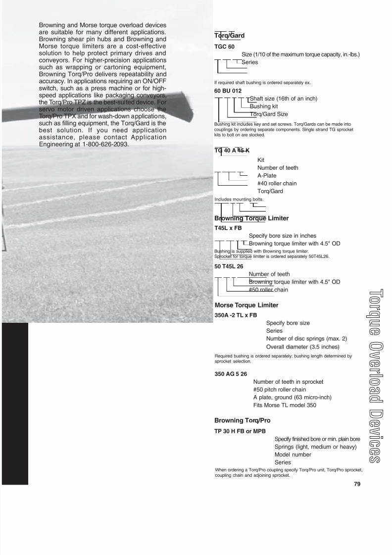
8/20/2019 Catalogo Morse MC Clutches y Limitadores
http://slidepdf.com/reader/full/catalogo-morse-mc-clutches-y-limitadores 81/131
79
q
Browning and Morse torque overload devicesare suitable for many different applications.Browning shear pin hubs and Browning andMorse torque limiters are a cost-effectivesolution to help protect primary drives andconveyors. For higher-precision applicationssuch as wrapping or cartoning equipment,Browning Torq/Pro delivers repeatability andaccuracy. In applications requiring an ON/OFFswitch, such as a press machine or for high-
speed applications like packaging conveyors,the Torq/Pro TPZ is the best-suited device. Forservo motor driven applications choose theTorq/Pro TPX and for wash-down applications,such as filling equipment, the Torq/Gard is thebest solution. If you need applicationassistance, please contact ApplicationEngineering at 1-800-626-2093.
T45L x FB
Specify bore size in inches
Browning torque limiter with 4.5" OD
Browning Torque Limiter
Bushing is supplied with Browning torque limiter.Sprocket for torque limiter is ordered separately 50T45L26.
50 T45L 26
Number of teeth
Browning torque limiter with 4.5" OD
#50 roller chain
Morse Torque Limiter
350A -2 TL x FB
Specify bore size
Series
Number of disc springs (max. 2)
Overall diameter (3.5 inches)
Required bushing is ordered separately; bushing length determined bysprocket selection.
350 AG 5 26
Number of teeth in sprocket
#50 pitch roller chainA plate, ground (63 micro-inch)
Fits Morse TL model 350
Browning Torq/Pro
TP 30 H FB or MPB
Specify finished bore or min. plain bore
Springs (light, medium or heavy)
Model number
Series
When ordering a Torq/Pro coupling specify Torq/Pro unit, Torq/Pro sprocket,coupling chain and adjoining sprocket.
Torq/Gard
TGC 60
Size (1/10 of the maximum torque capacity, in.-lbs.)
Series
If required shaft bushing is ordered separately ex.
Bushing kit includes key and set screws. Torq/Gards can be made intocouplings by ordering separate components. Single strand TG sprocketkits to bolt on are stocked.
TG 40 A 45 K
Kit
Number of teeth
A-Plate
#40 roller chain
Torq/Gard
Includes mounting bolts.
60 BU 012
Shaft size (16th of an inch)Bushing kit
Torq/Gard Size

8/20/2019 Catalogo Morse MC Clutches y Limitadores
http://slidepdf.com/reader/full/catalogo-morse-mc-clutches-y-limitadores 82/131
80
Torque Overload Device Product Offering
Browning Torque Limiters
(Page 95)
Features
• Torque control devices that slip under excessive load• Adjustable spring pressure determines overload setting
and reengages drive when overload condition subsides• Effective overload protection for a wide variety of
applications
Bore range ....................................... 0.5" - 2.5"Torque range .................................... 67 - 733 lb-ft.Precision tripping torque ................. ±25%
Morse Torque Limiters
(Page 88)
Browning Torq/Pro(Page 97)
Features• Overload protection for mechanical drive systems• Adjustable spring pressure determines overload setting
and reengages drive when overload condition subsides• Also available as a torque-limiting couplingBore range ....................................... 0.38" - 4.87"
Torque range .................................... 1 - 6,300 lb-ft.Precision tripping torque ................. ±25%
Features
• Overload protection with increased accuracy• Adjustable spring pressure transmits torque through a
ball-in-detent arrangement• Resets to the same initial position
Bore range ....................................... 0.19" - 5.12"Torque range .................................... 2.6 - 5,270 lb-ft.
Precision tripping torque ................. ±10%
Browning Shear Pin Hubsand Sprockets(Page 84)
Features• Helps prevent damage to machinery due to sudden overloadby shearing a necked pin at a predetermined load, allowing
the sprocket to rotate freely without the hub• New shear pins must be installed to reengage driveBore range ....................................... 0.38" - 5"
Torque range .................................... 0.88 - 21,572 lb-ft.Precision tripping torque .................. ±20%
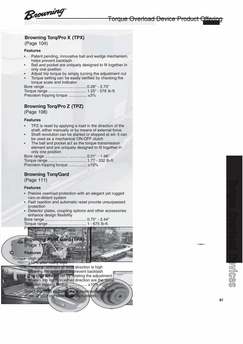
8/20/2019 Catalogo Morse MC Clutches y Limitadores
http://slidepdf.com/reader/full/catalogo-morse-mc-clutches-y-limitadores 83/131
81
q
Browning Torq/Gard
(Page 111)Features
• Precise overload protection with an elegant yet ruggedcam-in-detent system
• Fast reaction and automatic reset provide unsurpassedprotection
• Detector plates, coupling options and other accessoriesenhance design flexibility
Bore range ....................................... 0.75" - 2.44"Torque range .................................... 1 - 675 lb-ft.Precision tripping torque ................. ±5%
Browning Torq/Pro X (TPX)(Page 104)
Features
• Patent pending, innovative ball and wedge mechanism,
helps prevent backlash• Ball and pocket are uniquely designed to fit together in
only one position• Adjust trip torque by simply turning the adjustment nut• Torque setting can be easily verified by checking the
torque scale and indicatorBore range ....................................... 0.28" - 2.75"Torque range .................................... 1.25" - 578 lb-ft.Precision tripping torque ................. ±3%
Browning Torq/Pro Z (TPZ)(Page 108)
Features• TPZ is reset by applying a load in the direction of the
shaft, either manually or by means of external force.• Shaft revolution can be started or stopped at wil- it can
be used as a mechanical ON-OFF clutch• The ball and pocket act as the torque transmission
element and are uniquely designed to fit together inonly one position
Bore range ....................................... 0.31" - 1.96"Torque range .................................... 1.77 - 332 lb-ft.Precision tripping torque ................. ±10%
Torque Overload Device Product Offering
Browning Axial Gard (TPA)(Page 117)
Features
• High accuracy: Trip load doesn’t change over±15% after many trips
• Torsional stiffness of axial direction is highallowing the axial gard to prevent backlash
• Trip load is easily set by rotating the adjustmentscrew - trip loads in either direction are the same
Precision tripping torque ................. ±10%
Select the most suitable torque overload devices tocover all your complex application needs.
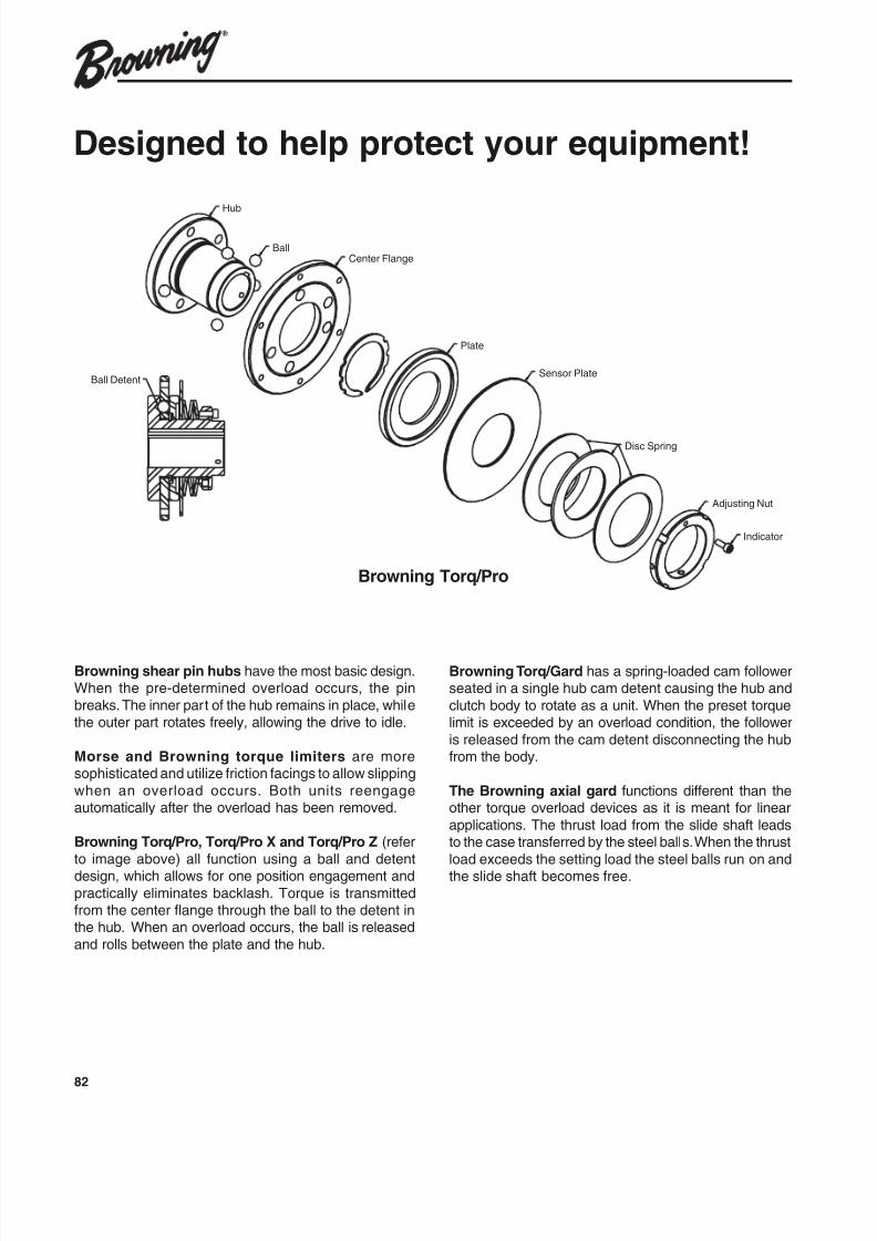
8/20/2019 Catalogo Morse MC Clutches y Limitadores
http://slidepdf.com/reader/full/catalogo-morse-mc-clutches-y-limitadores 84/131
82
Indicator
Adjusting Nut
Disc Spring
Sensor Plate
Plate
Center Flange
Hub
Ball
Ball Detent
Designed to help protect your equipment!
Browning shear pin hubs have the most basic design.When the pre-determined overload occurs, the pin
breaks. The inner part of the hub remains in place, whilethe outer part rotates freely, allowing the drive to idle.
Morse and Browning torque limiters are moresophisticated and utilize friction facings to allow slipping
when an overload occurs. Both units reengageautomatically after the overload has been removed.
Browning Torq/Pro, Torq/Pro X and Torq/Pro Z (refer
to image above) all function using a ball and detentdesign, which allows for one position engagement and
practically eliminates backlash. Torque is transmittedfrom the center flange through the ball to the detent inthe hub. When an overload occurs, the ball is released
and rolls between the plate and the hub.
Browning Torq/Gard has a spring-loaded cam followerseated in a single hub cam detent causing the hub and
clutch body to rotate as a unit. When the preset torquelimit is exceeded by an overload condition, the follower
is released from the cam detent disconnecting the hubfrom the body.
The Browning axial gard functions different than theother torque overload devices as it is meant for linear
applications. The thrust load from the slide shaft leadsto the case transferred by the steel balls. When the thrust
load exceeds the setting load the steel balls run on andthe slide shaft becomes free.
Browning Torq/Pro
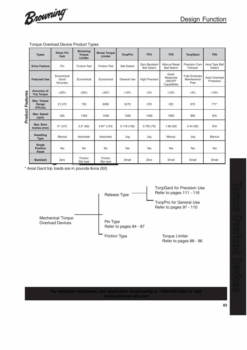
8/20/2019 Catalogo Morse MC Clutches y Limitadores
http://slidepdf.com/reader/full/catalogo-morse-mc-clutches-y-limitadores 85/131
83
q
sepyT niPraehS
buH
gninworBeuqroTretimiL
euqroTesroMretimiL
orP / qroT XPT ZPT draG / qroT APT
erutaeFevirD niP daPnoitcirF daPnoitcirF tneteDllaB hsalkcaBoreZ
tneteDllaBteseRlaunaM
tneteDllaBmaCnoisicerP
rewolloFllaBepyTlaixA
tneteD
esUderutaeF
lacimonocEdooG
ycaruccAlacimonocE lacimonocE esUlareneG noisicerPhgiH
kciuQesnopseR
FFO / NOseitilibapaC
desolcnEylluFecnanetniaM
eerF
daolrevOlaixAnoitcetorP
foycaruccAeuqroTpirT
%02+ %52+ %52+ %01+ %3+ %01+ %5+ %01+
euqroT.xaMegnaR
)sbL / tF(
275,12 337 0036 0725 875 233 576 *177
deepS.xaM)mpr(
005 0041 0041 0021 0041 0081 009 A / N
eroB.xaM)mm(sehcnI )721("5 )36("5.2 )321("78.4 )031(811.5 )07(557.2 )05(69.1 )26(44.2 A / N
gnitteseRepyT
launaM citamotuA citamotuA goJ goJ launaM goJ launaM
elgniSnoitisoP
teseR
seY oN oN seY seY seY seY seY
hsalk caB oreZ noitcirF
epytpilSnoitcirFepytpilS
llamS oreZ llamS llamS llamS
Design Function
Torque Overload Device Product Types
Torq/Gard for Precision Use
Release TypeRefer to pages 111 - 116
Torq/Pro for General Use
Refer to pages 97 - 110
Mechanical Torque
Overload Devices Pin TypeRefer to pages 84 - 87
Friction Type Torque Limiter
Refer to pages 88 - 96
For selection assistance, call Application Engineering at 1-800-626-2093 or visitwww.emerson-ept.com
P
r o d u c t F e a t u r e s
* Axial Gard trip loads are in pounds-force (lbf).
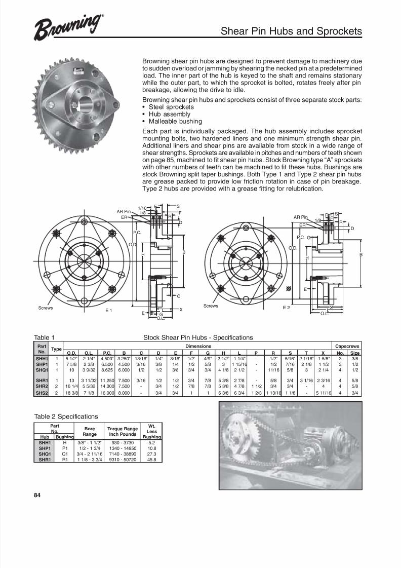
8/20/2019 Catalogo Morse MC Clutches y Limitadores
http://slidepdf.com/reader/full/catalogo-morse-mc-clutches-y-limitadores 86/131
84
Shear Pin Hubs and Sprockets
Browning shear pin hubs are designed to prevent damage to machinery dueto sudden overload or jamming by shearing the necked pin at a predeterminedload. The inner part of the hub is keyed to the shaft and remains stationarywhile the outer part, to which the sprocket is bolted, rotates freely after pinbreakage, allowing the drive to idle.
Browning shear pin hubs and sprockets consist of three separate stock parts:• Steel sprockets• Hub assembly• Malleable bushing
Each part is individually packaged. The hub assembly includes sprocketmounting bolts, two hardened liners and one minimum strength shear pin.Additional liners and shear pins are available from stock in a wide range ofshear strengths. Sprockets are available in pitches and numbers of teeth shownon page 85, machined to fit shear pin hubs. Stock Browning type “A” sprocketswith other numbers of teeth can be machined to fit these hubs. Bushings arestock Browning split taper bushings. Both Type 1 and Type 2 shear pin hubsare grease packed to provide low friction rotation in case of pin breakage.Type 2 hubs are provided with a grease fitting for relubrication.
Table 1 Stock Shear Pin Hubs - Specifications
Table 2 Specifications
traP.oN
epyT snoisnemiD swercspaC
.D.O .L.O .C.P B C D E F G H L P R S T X .oN eziS
1HHS 1 "2 / 15 "4 / 12 "005.4 "052.3 "61 / 31 "4 / 1 "61 / 3 "2 / 1 "9 / 4 "2 / 12 "4 / 11 - "2 / 1 "61 / 5 "61 / 12 "8 / 51 3 8 / 3
1PHS 1 8 / 57 8 / 32 005.6 005.4 61 / 3 8 / 3 4 / 1 2 / 1 8 / 5 3 61 / 511 - 2 / 1 61 / 7 8 / 12 2 / 11 3 2 / 1
1QHS 1 01 23 / 93 526.8 000.6 2 / 1 2 / 1 8 / 3 4 / 3 4 / 3 8 / 14 2 / 12 - 61 / 11 8 / 5 3 4 / 12 4 2 / 1
1RHS 1 31 23 / 113 052.11 005.7 61 / 3 2 / 1 2 / 1 4 / 3 8 / 7 8 / 35 8 / 72 - 8 / 5 4 / 3 61 / 13 61 / 32 4 8 / 5
2RHS 2 4 / 161 23 / 55 000.41 005.7 - 4 / 3 2 / 1 8 / 7 8 / 7 8 / 35 8 / 74 2 / 11 4 / 3 4 / 3 - 4 4 8 / 5
2SHS 2 8 / 381 8 / 17 000.61 000.8 - 4 / 3 4 / 3 1 1 8 / 36 4 / 36 3 / 21 61 / 311 8 / 11 - 61 / 115 4 4 / 3
traP.oN
eroBegnaR
egnaReuqroTsdnuoPhcnI
.tWsseL
gnihsuBbuH gnihsuB
1HHS H "2 / 11-"8 / 3 0373-039 2.5
1PHS 1P 4 / 31-2 / 1 05941-0431 8.01
1QHS 1Q 61 / 112-4 / 3 09883-0417 3.72
1RHS 1R 4 / 33-8 / 11 02705-0139 8.54
E 1Screws
AR Pin
ER
BH
D
GEO.L.
P.C.
R
SF
F1/81/16
L
C
X
O.D.
E 2Screws
AR Pin
ER1/8
FF
S
R
D
BH
XL
O.L.
E
P.C. G
O.D.
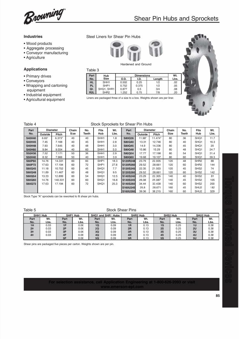
8/20/2019 Catalogo Morse MC Clutches y Limitadores
http://slidepdf.com/reader/full/catalogo-morse-mc-clutches-y-limitadores 87/131
85
q
Shear Pin Hubs and Sprockets
Liners are packaged three of a size to a box. Weights shown are per liner.
Steel Liners for Shear Pin Hubs
Table 3
traP.oN
buHeziS
snoisnemiD .tW.sbL.D.O .D.I htgneL
LH 1HHS 205.0 52.0 2 / 1 20.
LP 1PHS 257.0 573.0 2 / 1 50.
LQ 1RHS,1QHS 778.0 5.0 4 / 3 80.
L2R 2RHS 252.1 57.0 8 / 7 02.
Table 4 Stock Sprockets for Shear Pin Hubs
Table 5 Stock Shear Pins
traP.oN
retemaiD niahCeziS
.oNhteeT
stiFbuH
.tW.sbL
traP.oN
retemaiD niahCeziS
.oNhteeT
stiFbuH
.tW.sbLedistuO hctiP edistuO hctiP
04H04S "56.6 "373.6 04 04 1HHS 8.1 63Q08S "89.11 "474.11 08 63 1QHS 7.11
54H04S 54.7 861.7 04 54 1HHS 8.2 04Q08S 13.31 647.21 08 04 1QHS 3.61
84H04S 39.7 546.7 04 84 1HHS 0.3 54Q08S 9.41 633.41 08 54 1QHS 02
06H04S 48.9 455.9 04 06 1HHS 0.5 84Q08S 68.51 92.51 08 84 1QHS 7.42
63H05S 25.7 171.7 05 63 1HHS 9.2 45Q08S 77.71 891.71 08 45 1QHS 4.13
04H05S 23.8 669.7 05 04 1HHS 9.3 06Q08S 86.91 701.91 08 06 1QHS 3.93
06P06S 67.41 133.41 06 06 1PHS 3.81 842R021S 97.32 539.22 021 84 2RHS 88
27P06S 36.71 491.71 06 27 1PHS 8.72 062R021S 25.92 166.82 021 06 2RHS 441
54Q06S 81.11 257.01 06 54 1QHS 7.7 542S021S 53.22 305.12 021 54 2SHS 47
84Q06S 98.11 764.11 06 84 1QHS 5.9 062S021S 25.92 166.82 021 06 2SHS 241
45Q06S 33.31 998.21 06 45 1QHS 5.21 042S041S 92.32 503.22 041 04 2SHS 18
06Q06S 67.41 133.041 06 06 1QHS 8.61 542S041S 80.62 780.52 041 54 2SHS 501
27Q06S 36.71 491.71 06 27 1QHS 3.52 062S041S 44.43 834.33 041 06 2SHS 002
542U061S 8.92 176.82 061 54 2UHS 281
062U061S 63.93 512.83 061 06 2UHS 923
Stock Type "A" sprockets can be reworked to fit shear pin hubs.
buH1HHS buH1PHS sbuH1RHSdna1QHS buH2RHS buH2SHS buH2UHS
traP.oN
.tW.sbL
traP.oN
.tW.sbL
traP.oN
.tW.sbL
traP.oN
.tW.sbL
traP.oN
.tW.sbL
traP.oN
.tW.sbL
H1 30.0 P1 60.0 Q1 90.0 R1 31.0 S1 52.0 U1 83.0
H2 30.0 P2 60.0 Q2 90.0 R2 31.0 S2 52.0 U2 83.0
H3 30.0 P3 60.0 Q3 90.0 R3 31.0 S3 52.0 U3 83.0
H4 30.0 P4 60.0 Q4 90.0 R4 31.0 S4 52.0 U4 83.0
P5 60.0 Q5 90.0 R5 31.0 S5 52.0 U5 83.0
Shear pins are packaged five pieces per carton. Weights shown are per pin.
Hardened and Ground
Industries
• Wood products• Aggregate processing
• Conveyor manufacturing
• Agriculture
Applications
• Primary drives• Conveyors• Wrapping and cartoning
equipment• Industrial equipment
• Agricultural equipment
For selection assistance, call Application Engineering at 1-800-626-2093 or visitwww.emerson-ept.com
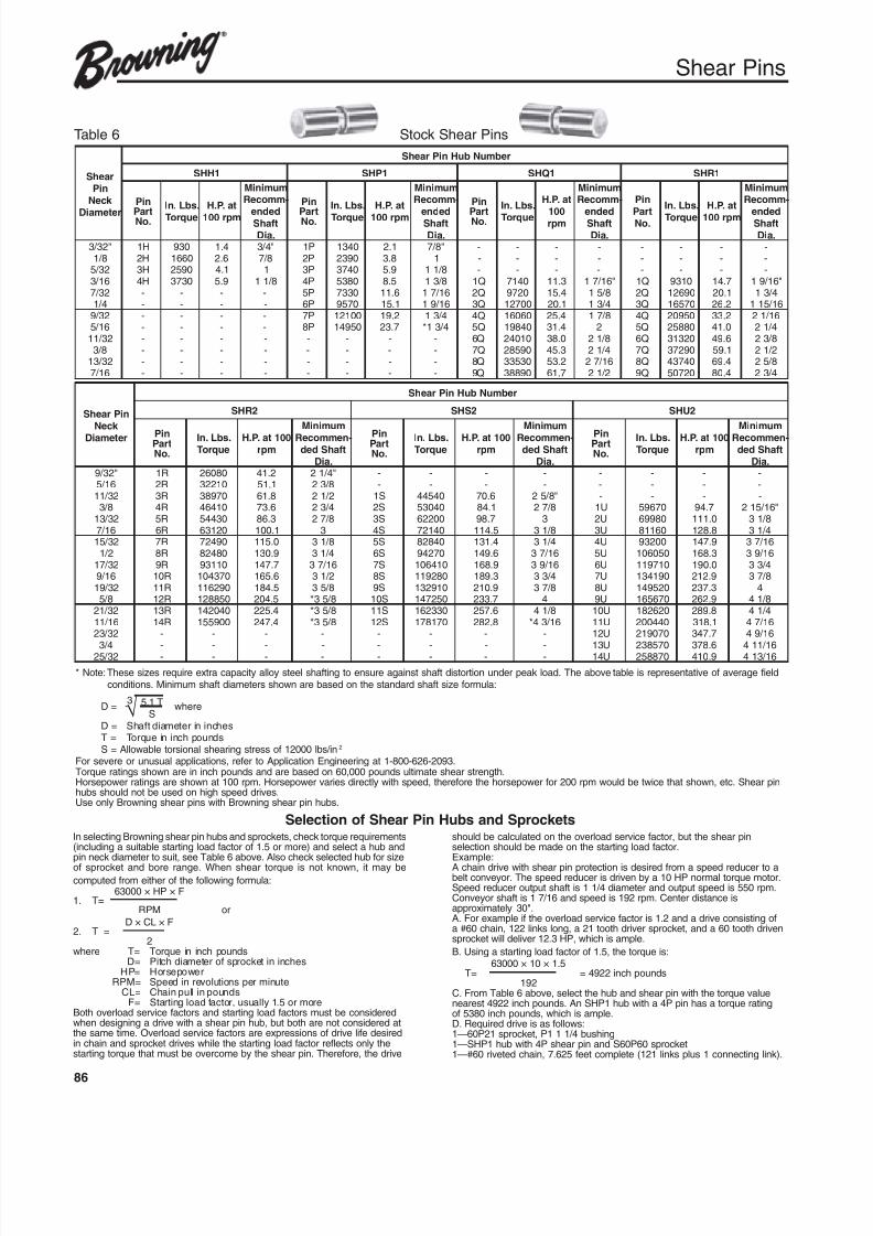
8/20/2019 Catalogo Morse MC Clutches y Limitadores
http://slidepdf.com/reader/full/catalogo-morse-mc-clutches-y-limitadores 88/131
86
Shear Pins
* Note: These sizes require extra capacity alloy steel shafting to ensure against shaft distortion under peak load. The above table is representative of average fieldconditions. Minimum shaft diameters shown are based on the standard shaft size formula:
D = 5.1 T whereS
D = Shaft diameter in inchesT = Torque in inch poundsS = Allowable torsional shearing stress of 12000 lbs/in2
For severe or unusual applications, refer to Application Engineering at 1-800-626-2093.Torque ratings shown are in inch pounds and are based on 60,000 pounds ultimate shear strength.Horsepower ratings are shown at 100 rpm. Horsepower varies directly with speed, therefore the horsepower for 200 rpm would be twice that shown, etc. Shear pinhubs should not be used on high speed drives.Use only Browning shear pins with Browning shear pin hubs.
In selecting Browning shear pin hubs and sprockets, check torque requirements(including a suitable starting load factor of 1.5 or more) and select a hub andpin neck diameter to suit, see Table 6 above. Also check selected hub for size
of sprocket and bore range. When shear torque is not known, it may becomputed from either of the following formula:
63000 × HP × F1. T=
RPM or
D × CL × F2. T =
2where T= Torque in inch pounds
D= Pitch diameter of sprocket in inchesHP= Horsepower
RPM= Speed in revolutions per minuteCL= Chain pull in pounds
F= Starting load factor, usually 1.5 or moreBoth overload service factors and starting load factors must be consideredwhen designing a drive with a shear pin hub, but both are not considered atthe same time. Overload service factors are expressions of drive life desiredin chain and sprocket drives while the starting load factor reflects only thestarting torque that must be overcome by the shear pin. Therefore, the drive
should be calculated on the overload service factor, but the shear pinselection should be made on the starting load factor.Example:
A chain drive with shear pin protection is desired from a speed reducer to abelt conveyor. The speed reducer is driven by a 10 HP normal torque motor.Speed reducer output shaft is 1 1/4 diameter and output speed is 550 rpm.Conveyor shaft is 1 7/16 and speed is 192 rpm. Center distance isapproximately 30".A. For example if the overload service factor is 1.2 and a drive consisting ofa #60 chain, 122 links long, a 21 tooth driver sprocket, and a 60 tooth drivensprocket will deliver 12.3 HP, which is ample.
B. Using a starting load factor of 1.5, the torque is:63000 × 10 × 1.5
T= = 4922 inch pounds192
C. From Table 6 above, select the hub and shear pin with the torque valuenearest 4922 inch pounds. An SHP1 hub with a 4P pin has a torque ratingof 5380 inch pounds, which is ample.D. Required drive is as follows:1—60P21 sprocket, P1 1 1/4 bushing1—SHP1 hub with 4P shear pin and S60P60 sprocket1—#60 riveted chain, 7.625 feet complete (121 links plus 1 connecting link).
raehSniP
k ceN
retemaiD
rebmuNbuHniPraehS
1HHS 1PHS 1QHS 1RHS
niP
traP .oN
.sbL.nI
euqroT
ta.P.H
mpr001
muminiM-mmoceR
dedne tfahS.aiD
niP
traP .oN
.sbL.nI
euqroT
ta.P.H
mpr001
muminiM-mmoceR
dedne tfahS.aiD
niP
traP .oN
.sbL.nI
euqroT
ta.P.H
001 mpr
muminiM-mmoceR
dedne tfahS.aiD
niP
traP .oN
.sbL.nI
euqroT
ta.P.H
mpr001
muminiM-mmoceR
dedne tfahS.aiD
"23 / 3 H1 039 4.1 "4 / 3 P1 0431 1.2 "8 / 7 - - - - - - - -8 / 1 H2 0661 6.2 8 / 7 P2 0932 8.3 1 - - - - - - - -23 / 5 H3 0952 1.4 1 P3 0473 9.5 8 / 11 - - - - - - - -61 / 3 H4 0373 9.5 8 / 11 P4 0835 5.8 8 / 31 Q1 0417 3.11 "61 / 71 Q1 0139 7.41 "61 / 9123 / 7 - - - - P5 0337 6.11 61 / 71 Q2 0279 4.51 8 / 51 Q2 09621 1.02 4 / 314 / 1 - - - - P6 0759 1.51 61 / 91 Q3 00721 1.02 4 / 31 Q3 07561 2.62 61 / 51123 / 9 - - - - P7 00121 2.91 4 / 31 Q4 06061 4.52 8 / 71 Q4 05902 2.33 61 / 1261 / 5 - - - - P8 05941 7.32 4 / 31* Q5 04891 4.13 2 Q5 08852 0.14 4 / 1223 / 11 - - - - - - - - Q6 01042 0.83 8 / 12 Q6 02313 6.94 8 / 32
8 / 3 - - - - - - - - Q7 09582 3.54 4 / 12 Q7 09273 1.95 2 / 1223 / 31 - - - - - - - - Q8 03533 2.35 61 / 72 Q8 04734 4.96 8 / 52
61 / 7 - - - - - - - - Q9 09883 7.16 2 / 12 Q9 02705 4.08 4 / 32
Table 6 Stock Shear Pins
niPraehSk ceN
retemaiD
rebmuNbuHniPraehS
2RHS 2SHS 2UHS
niPtraP.oN
.sbL.nIeuqroT
001ta.P.Hmpr
muminiM-nemmoceR
tfahSded.aiD
niPtraP.oN
.sbL.nIeuqroT
001ta.P.Hmpr
muminiM-nemmoceR
tfahSded.aiD
niPtraP.oN
.sbL.nIeuqroT
001ta.P.Hmpr
muminiM-nemmoceR
tfahSded.aiD
"23 / 9 R1 08062 2.14 "4 / 12 - - - - - - - -61 / 5 R2 01223 1.15 8 / 32 - - - - - - - -23 / 11 R3 07983 8.16 2 / 12 S1 04544 6.07 "8 / 52 - - - -
8 / 3 R4 01464 6.37 4 / 32 S2 04035 1.48 8 / 72 U1 07695 7.49 "61 / 51223 / 31 R5 03445 3.68 8 / 72 S3 00226 7.89 3 U2 08996 0.111 8 / 13
61 / 7 R6 02136 1.001 3 S4 04127 5.411 8 / 13 U3 06118 8.821 4 / 1323 / 51 R7 09427 0.511 8 / 13 S5 04828 4.131 4 / 13 U4 00239 9.741 61 / 73
2 / 1 R8 08428 9.031 4 / 13 S6 07249 6.941 61 / 73 U5 050601 3.861 61 / 9323 / 71 R9 01139 7.741 61 / 73 S7 014601 9.861 61 / 93 U6 017911 0.091 4 / 33
61 / 9 R01 073401 6.561 2 / 13 S8 082911 3.981 4 / 33 U7 091431 9.212 8 / 7323 / 91 R11 092611 5.481 8 / 53 S9 019231 9.012 8 / 73 U8 025941 3.732 4
8 / 5 R21 058821 5.402 8 / 53* S01 052741 7.332 4 U9 076561 9.262 8 / 1423 / 12 R31 040241 4.522 8 / 53* S11 033261 6.752 8 / 14 U01 026281 8.982 4 / 1461 / 11 R41 009551 4.742 8 / 53* S21 071871 8.282 61 / 34* U11 044002 1.813 61 / 7423 / 32 - - - - - - - - U21 070912 7.743 61 / 94
4 / 3 - - - - - - - - U31 075832 6.873 61 / 11423 / 52 - - - - - - - - U41 078852 9.014 61 / 314
√3
Selection of Shear Pin Hubs and Sprockets
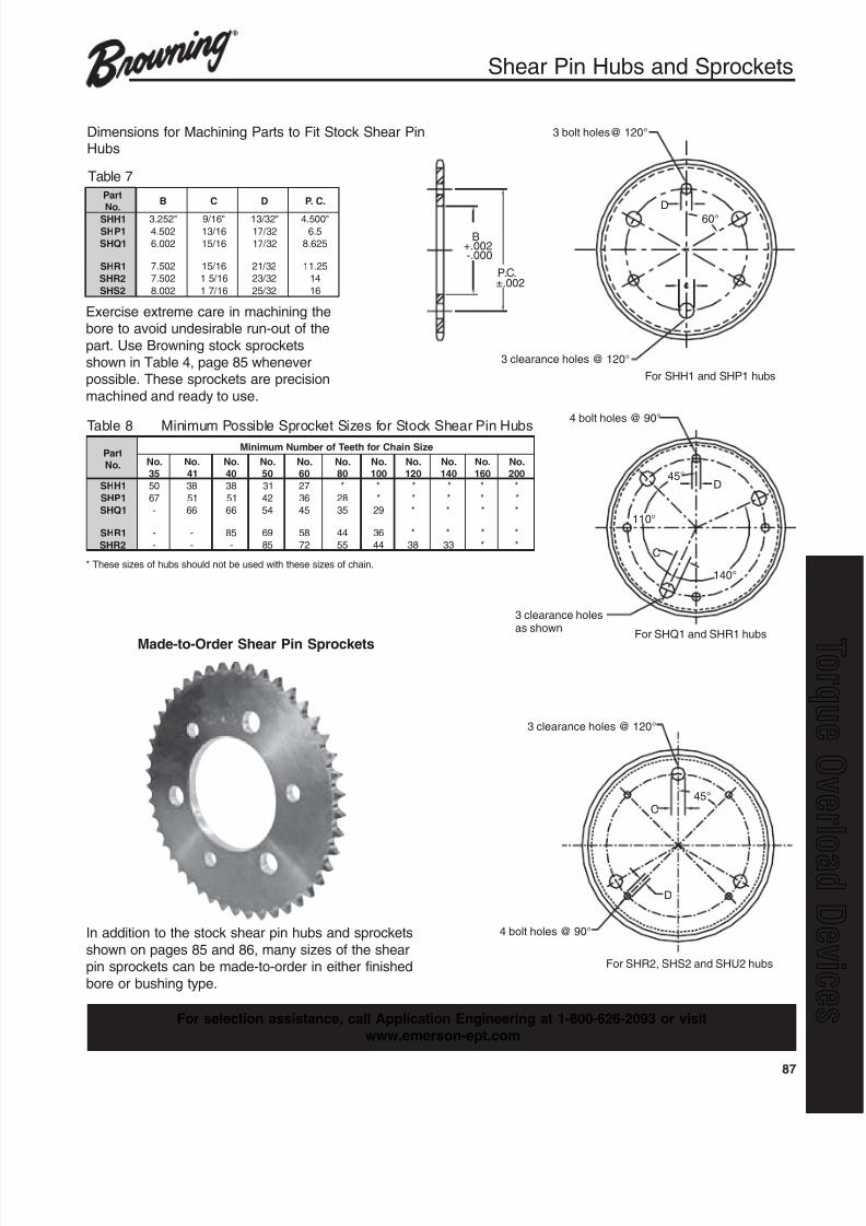
8/20/2019 Catalogo Morse MC Clutches y Limitadores
http://slidepdf.com/reader/full/catalogo-morse-mc-clutches-y-limitadores 89/131
87
q
4 bolt holes @ 90°
3 clearance holesas shown
For SHQ1 and SHR1 hubs
C
45°
110°
140°
D
For SHR2, SHS2 and SHU2 hubs
4 bolt holes @ 90°
45°C
D
3 clearance holes @ 120°
3 clearance holes @ 120°
3 bolt holes@ 120°
60°
D
P.C.±.002
B+.002-.000
For SHH1 and SHP1 hubs
Shear Pin Hubs and Sprockets
Dimensions for Machining Parts to Fit Stock Shear PinHubs
Table 7
Table 8 Minimum Possible Sprocket Sizes for Stock Shear Pin Hubs
* These sizes of hubs should not be used with these sizes of chain.
traP.oN
B C D .C.P
1HHS "252.3 "61 / 9 "23 / 31 "005.4
1PHS 205.4 61 / 31 23 / 71 5.6
1QHS 200.6 61 / 51 23 / 71 526.8
1RHS 205.7 61 / 51 23 / 12 52.11
2RHS 205.7 61 / 51 23 / 32 41
2SHS 200.8 61 / 71 23 / 52 61
traP.oN
eziSniahCrofhteeTforebmuNmuminiM
.oN53
.oN14
.oN04
.oN05
.oN06
.oN08
.oN001
.oN021
.oN041
.oN061
.oN002
1HHS 05 83 83 13 72 * * * * * *
1PHS 76 15 15 24 63 82 * * * * *
1QHS - 66 66 45 54 53 92 * * * *
1RHS - - 58 96 85 44 63 * * * *
2RHS - - - 58 27 55 44 83 33 * *
Exercise extreme care in machining thebore to avoid undesirable run-out of the
part. Use Browning stock sprocketsshown in Table 4, page 85 wheneverpossible. These sprockets are precision
machined and ready to use.
In addition to the stock shear pin hubs and sprockets
shown on pages 85 and 86, many sizes of the shearpin sprockets can be made-to-order in either finished
bore or bushing type.
Made-to-Order Shear Pin Sprockets
For selection assistance, call Application Engineering at 1-800-626-2093 or visit
www.emerson-ept.com
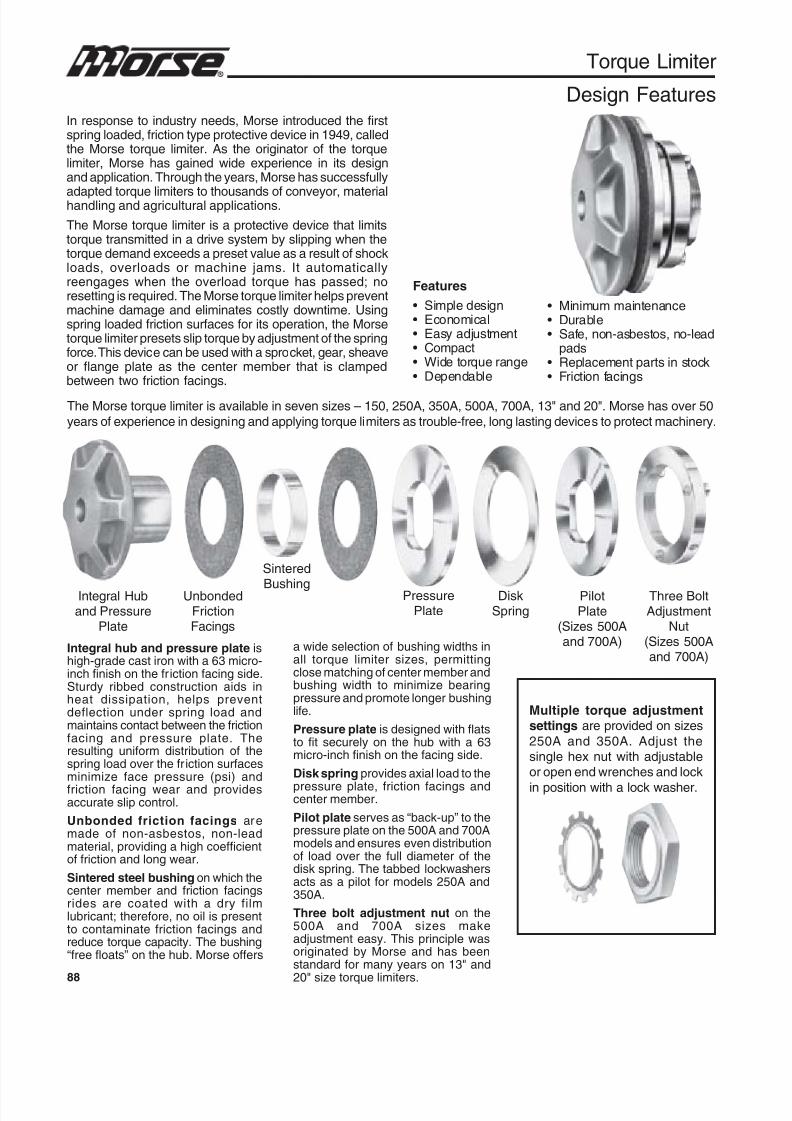
8/20/2019 Catalogo Morse MC Clutches y Limitadores
http://slidepdf.com/reader/full/catalogo-morse-mc-clutches-y-limitadores 90/131
88
Torque Limiter
Design FeaturesIn response to industry needs, Morse introduced the firstspring loaded, friction type protective device in 1949, calledthe Morse torque limiter. As the originator of the torquelimiter, Morse has gained wide experience in its designand application. Through the years, Morse has successfully
adapted torque limiters to thousands of conveyor, materialhandling and agricultural applications.
The Morse torque limiter is a protective device that limitstorque transmitted in a drive system by slipping when thetorque demand exceeds a preset value as a result of shockloads, overloads or machine jams. It automaticallyreengages when the overload torque has passed; noresetting is required. The Morse torque limiter helps preventmachine damage and eliminates costly downtime. Usingspring loaded friction surfaces for its operation, the Morsetorque limiter presets slip torque by adjustment of the springforce. This device can be used with a sprocket, gear, sheaveor flange plate as the center member that is clampedbetween two friction facings.
Features
• Simple design• Economical• Easy adjustment• Compact• Wide torque range• Dependable
Integral Huband Pressure
Plate
UnbondedFrictionFacings
Sintered
Bushing PressurePlate
DiskSpring
PilotPlate
(Sizes 500Aand 700A)
Three BoltAdjustment
Nut(Sizes 500Aand 700A)
Integral hub and pressure plate ishigh-grade cast iron with a 63 micro-inch finish on the friction facing side.Sturdy ribbed construction aids inheat dissipation, helps preventdeflection under spring load andmaintains contact between the frictionfacing and pressure plate. Theresulting uniform distribution of thespring load over the friction surfacesminimize face pressure (psi) andfriction facing wear and providesaccurate slip control.
Unbonded friction facings aremade of non-asbestos, non-leadmaterial, providing a high coefficientof friction and long wear.
Sintered steel bushing on which thecenter member and friction facingsrides are coated with a dry filmlubricant; therefore, no oil is presentto contaminate friction facings andreduce torque capacity. The bushing“free floats” on the hub. Morse offers
a wide selection of bushing widths inall torque limiter sizes, permittingclose matching of center member andbushing width to minimize bearingpressure and promote longer bushinglife.
Pressure plate is designed with flatsto fit securely on the hub with a 63micro-inch finish on the facing side.
Disk spring provides axial load to the
pressure plate, friction facings andcenter member.
Pilot plate serves as “back-up” to thepressure plate on the 500A and 700Amodels and ensures even distributionof load over the full diameter of thedisk spring. The tabbed lockwashersacts as a pilot for models 250A and350A.
Three bolt adjustment nut on the500A and 700A sizes makeadjustment easy. This principle wasoriginated by Morse and has beenstandard for many years on 13" and
20" size torque limiters.
Multiple torque adjustmentsettings are provided on sizes
250A and 350A. Adjust thesingle hex nut with adjustableor open end wrenches and lock
in position with a lock washer.
• Minimum maintenance• Durable• Safe, non-asbestos, no-lead
pads• Replacement parts in stock• Friction facings
The Morse torque limiter is available in seven sizes – 150, 250A, 350A, 500A, 700A, 13" and 20". Morse has over 50
years of experience in designing and applying torque limiters as trouble-free, long lasting devices to protect machinery.
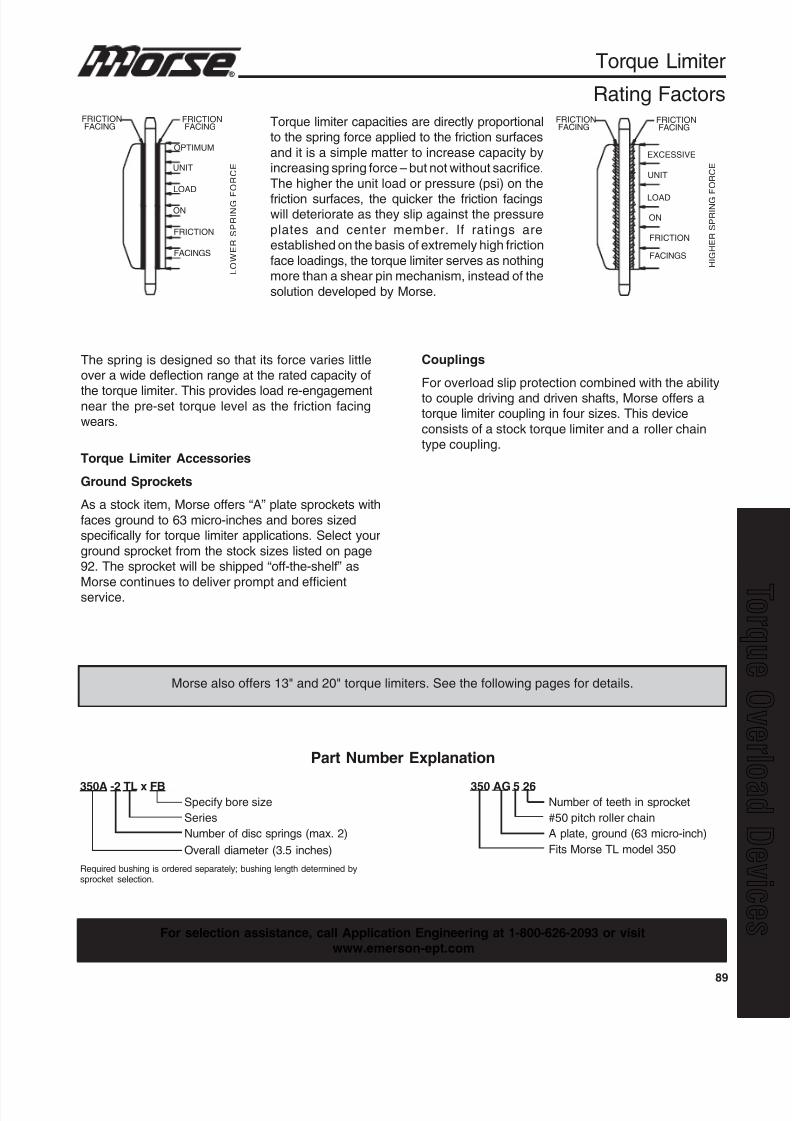
8/20/2019 Catalogo Morse MC Clutches y Limitadores
http://slidepdf.com/reader/full/catalogo-morse-mc-clutches-y-limitadores 91/131
89
q
FRICTIONFACING
FRICTIONFACING
FRICTIONFACING
FRICTIONFACING
OPTIMUM
UNIT
LOAD
ON
FRICTION
FACINGS
L O W E R S P R I N G F
O R C E
EXCESSIVE
UNIT
LOAD
ON
FRICTION
FACINGS H I G H E R S P R I N G
F O R C E
Torque Limiter
Rating Factors
The spring is designed so that its force varies littleover a wide deflection range at the rated capacity of
the torque limiter. This provides load re-engagementnear the pre-set torque level as the friction facingwears.
Torque limiter capacities are directly proportionalto the spring force applied to the friction surfaces
and it is a simple matter to increase capacity byincreasing spring force – but not without sacrifice.
The higher the unit load or pressure (psi) on the
friction surfaces, the quicker the friction facingswill deteriorate as they slip against the pressure
plates and center member. If ratings areestablished on the basis of extremely high friction
face loadings, the torque limiter serves as nothingmore than a shear pin mechanism, instead of the
solution developed by Morse.
Torque Limiter Accessories
Ground Sprockets
As a stock item, Morse offers “A” plate sprockets with
faces ground to 63 micro-inches and bores sizedspecifically for torque limiter applications. Select your
ground sprocket from the stock sizes listed on page92. The sprocket will be shipped “off-the-shelf” as
Morse continues to deliver prompt and efficientservice.
Couplings
For overload slip protection combined with the abilityto couple driving and driven shafts, Morse offers atorque limiter coupling in four sizes. This device
consists of a stock torque limiter and a roller chaintype coupling.
Morse also offers 13" and 20" torque limiters. See the following pages for details.
For selection assistance, call Application Engineering at 1-800-626-2093 or visitwww.emerson-ept.com
Part Number Explanation
350A -2 TL x FBSpecify bore size
Series
Number of disc springs (max. 2)
Overall diameter (3.5 inches)
Required bushing is ordered separately; bushing length determined bysprocket selection.
350 AG 5 26Number of teeth in sprocket
#50 pitch roller chain
A plate, ground (63 micro-inch)
Fits Morse TL model 350
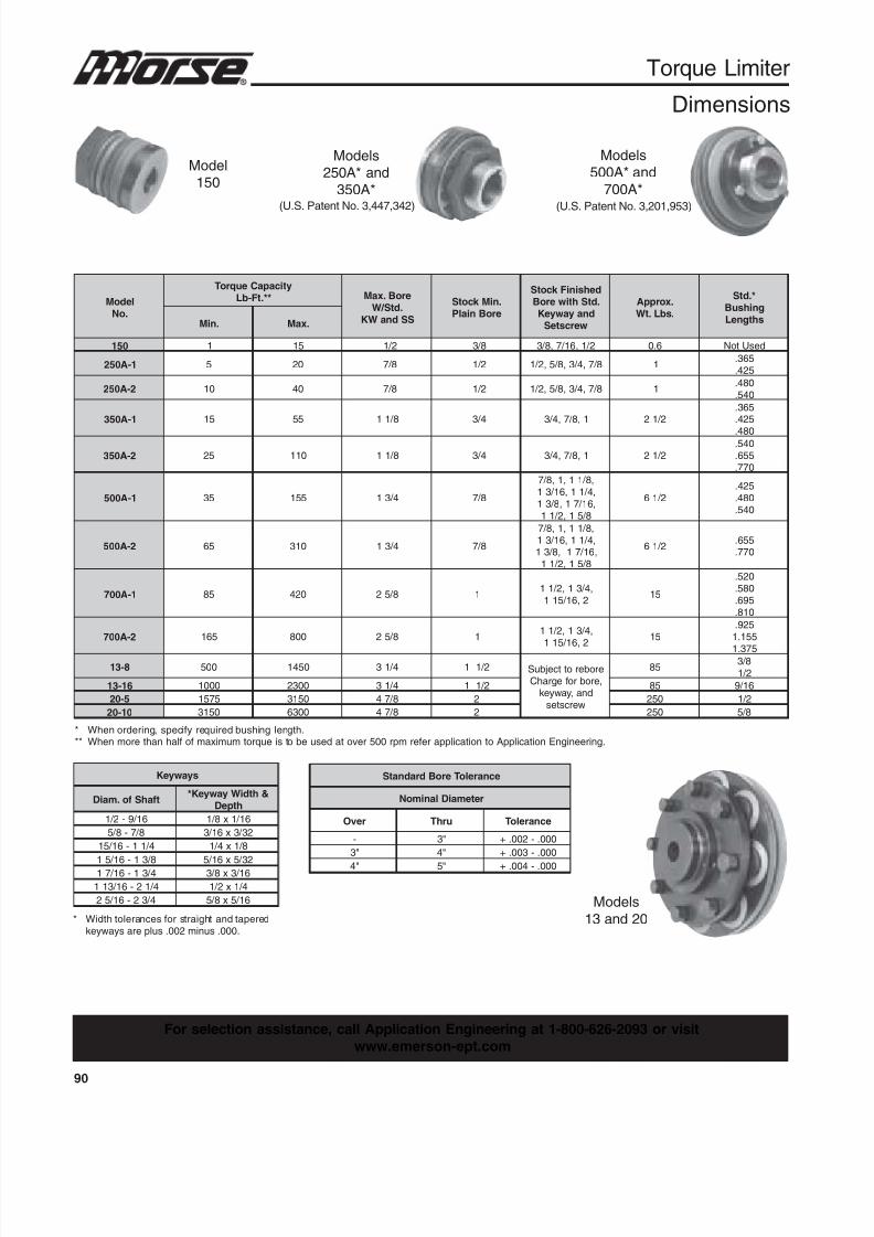
8/20/2019 Catalogo Morse MC Clutches y Limitadores
http://slidepdf.com/reader/full/catalogo-morse-mc-clutches-y-limitadores 92/131
90
Torque Limiter
Dimensions
Model150
Models250A* and
350A*
Models500A* and
700A*
Models
13 and 20
* When ordering, specify required bushing length.** When more than half of maximum torque is to be used at over 500 rpm refer application to Application Engineering.
* Width tolerances for straight and taperedkeyways are plus .002 minus .000.
(U.S. Patent No. 3,201,953)(U.S. Patent No. 3,447,342)
ledoM.oN
yticapaCeuqroT**.tF-bL eroB.xaM
.dtS / WSSdnaWK
.niMk cotSeroBnialP
dehsiniFk cotS.dtShtiweroB
dnayawyeKwercsteS
.xorppA
.sbL.tW
*.dtSgnihsuBshtgneL.niM .xaM
051 1 51 2 / 1 8 / 3 2 / 1,61 / 7,8 / 3 6.0 desUtoN
1-A052 5 02 8 / 7 2 / 1 8 / 7,4 / 3,8 / 5,2 / 1 1 563.
524.
2-A052 01 04 8 / 7 2 / 1 8 / 7,4 / 3,8 / 5,2 / 1 1 084.
045.
1-A053 51 55 8 / 11 4 / 3 1,8 / 7,4 / 3 2 / 12563.524.
084.
2-A053 52 011 8 / 11 4 / 3 1,8 / 7,4 / 3 2 / 12045.556.077.
1-A005 53 551 4 / 31 8 / 7
,8 / 11,1,8 / 7,4 / 11,61 / 31,61 / 71,8 / 31
8 / 51,2 / 11
2 / 16524.084.045.
2-A005 56 013 4 / 31 8 / 7
,8 / 11,1,8 / 7,4 / 11,61 / 31,61 / 71,8 / 31
8 / 51,2 / 11
2 / 16 556.
077.
1-A007 58 024 8 / 52 1 ,4 / 31,2 / 11
2,61 / 511 51
025.085.596.018.
2-A007 561 008 8 / 52 1 ,4 / 31,2 / 11
2,61 / 511 51
529.551.1
573.1
8-31 005 0541 4 / 13 2 / 11 eroberottce jbuS,erobrofegrahC
dna,yawyekwercstes
58 8 / 3
2 / 1
61-31 0001 0032 4 / 13 2 / 11 58 61 / 9
5-02 5751 0513 8 / 74 2 052 2 / 1
01-02 0513 0036 8 / 74 2 052 8 / 5
syawyeK
tfahSfo.maiD &htdiWyawyeK*
htpeD
61 / 9-2 / 1 61 / 1x8 / 1
8 / 7-8 / 5 23 / 3x61 / 3
4 / 11-61 / 51 8 / 1x4 / 1
8 / 31-61 / 51 23 / 5x61 / 5
4 / 31-61 / 71 61 / 3x8 / 3
4 / 12-61 / 311 4 / 1x2 / 1
4 / 32-61 / 52 61 / 5x8 / 5
ecnareloTeroBdradnatS
retemaiDlanimoN
revO urhT ecnareloT
- "3 000.-200.+
"3 "4 000.-300.+
"4 "5 000.-400.+
For selection assistance, call Application Engineering at 1-800-626-2093 or visit
www.emerson-ept.com
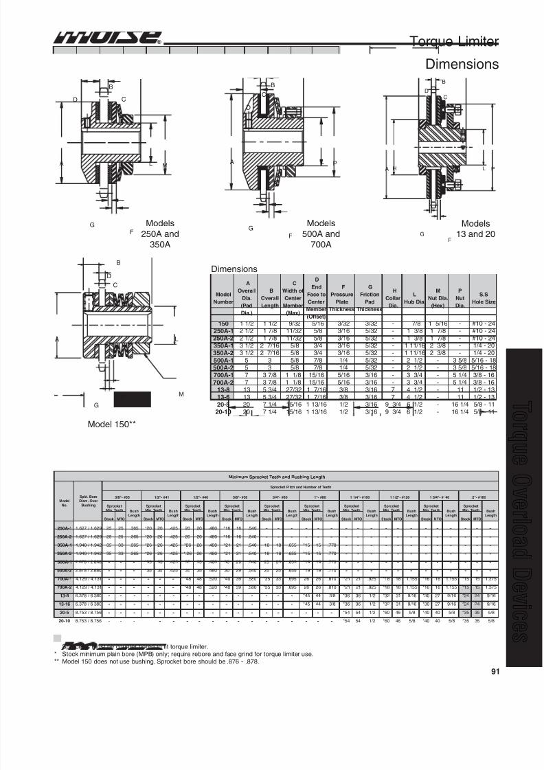
8/20/2019 Catalogo Morse MC Clutches y Limitadores
http://slidepdf.com/reader/full/catalogo-morse-mc-clutches-y-limitadores 93/131
91
q
A L M
GF
B
D C
Torque Limiter
Dimensions
Models
250A and350A
Models
500A and700A
Models13 and 20
Model 150**
B
C
A L
F
G
M
D
PA H L
B
DC
GF
L PA
F
G
D
C
B
Sprockets must be counter bored to fit torque limiter.* Stock minimum plain bore (MPB) only; require rebore and face grind for torque limiter use.** Model 150 does not use bushing. Sprocket bore should be .876 - .878.
ledoM
rebmuN
A
llarevO
.aiD
daP(
).aiD
B
llarevO
htgneL
C
fohtdiW
retneC
rebmeM
)xaM(
D
dnE
otecaF
retneC
rebmeM
)tesffO(
F
erusserP
etalP
ssenk cihT
G
noitcirF
daP
ssenk cihT
H
ralloC
.aiD
L
.aiDbuH
M
.aiDtuN
)xeH(
P
tuN
.aiD
S.S
eziSeloH
051 2 / 11 2 / 11 23 / 9 61 / 5 23 / 3 23 / 3 - 8 / 7 61 / 51 - 42-01#
1-A052 2 / 12 8 / 71 23 / 11 8 / 5 61 / 3 23 / 5 - 8 / 31 8 / 71 - 42-01#
2-A052 2 / 12 8 / 71 23 / 11 8 / 5 61 / 3 23 / 5 - 8 / 31 8 / 71 - 42-01#
1-A053 2 / 13 61 / 72 8 / 5 4 / 3 61 / 3 23 / 5 - 61 / 111 8 / 32 - 02-4 / 1
2-A053 2 / 13 61 / 72 8 / 5 4 / 3 61 / 3 23 / 5 - 61 / 111 8 / 32 - 02-4 / 1
1-A005 5 3 8 / 5 8 / 7 4 / 1 23 / 5 - 2 / 12 - 8 / 53 81-61 / 5
2-A005 5 3 8 / 5 8 / 7 4 / 1 23 / 5 - 2 / 12 - 8 / 53 81-61 / 5
1-A007 7 8 / 73 8 / 11 61 / 51 61 / 5 61 / 3 - 4 / 33 - 4 / 15 61-8 / 3
2-A007 7 8 / 73 8 / 11 61 / 51 61 / 5 61 / 3 - 4 / 33 - 4 / 15 61-8 / 3
8-31 31 4 / 35 23 / 72 61 / 71 8 / 3 61 / 3 7 2 / 14 - 11 31-2 / 1
6-31 31 4 / 35 23 / 72 61 / 71 8 / 3 61 / 3 7 2 / 14 - 11 31-2 / 1
5-02 02 4 / 17 61 / 51 61 / 311 2 / 1 61 / 3 4 / 39 2 / 16 - 4 / 161 11-8 / 501-02 02 4 / 17 61 / 51 61 / 311 2 / 1 61 / 3 4 / 39 2 / 16 - 4 / 161 11-8 / 5
Dimensions
htgneLgnihsuBdnahteeTtek corpSmuminiM
ledoM.oN
eroB.tk pSrevO.maiD
gnihsuB
hteeTforebmuNdnahctiPtek corpS
53#-"8 / 3 14#-"2 / 1 04#-"2 / 1 05#-"8 / 5 06#-"4 / 3 08#-"1 001#-"4 / 11 021#-"2 / 11 041#-"4 / 31 061#-"2
tek corpShteeT.niM hsuB
htgneL
tek corpShteeT.niM hsuB
htgneL
tek corpShteeT.niM hsuB
htgneL
tek corpShteeT.niM hsuB
htgneL
tek corpShteeT.niM hsuB
htgneL
tek corpShteeT.niM hsuB
htgneL
tek corpShteeT.niM hsuB
htgneL
tek corpShteeT.niM hsuB
htgneL
tek corpShteeT.niM hsuB
htgneL
tek corpShteeT.niM hsuB
htgneLk cotS OTM k cotS OTM k cotS OTM k cotS OTM k cotS OTM k cotS OTM k cotS OTM k cotS OTM k cotS OTM k cotS OTM
1-A052 926.1 / 726.1 52 52 563. 02* 02 524. 02 02 084. 61* 61 045. - - - - - - - - - - - - - - - - - -
2-A052 926.1 / 726.1 52 52 563. 02* 02 524. 02 02 084. 61* 61 045.
- - - - - - - - - - - - - - - - - -1-A053 249.1 / 049.1 53 33 563. 62* 62 524. 62* 62 084. 12* 12 045. 81 81 556. 51* 51 077. - - - - - - - - - - - -
2-A053 249.1 / 049.1 53 33 563. 62* 62 524. 62.* 62 084. 12* 12 045. 81 81 556. 51* 51 077. - - - - - - - - - - - -
1-A005 088.2 / 878.2 - - - 53* 53 524. 53 53 084. 03 92 045. 52 52 556. 91* 91 077. - - - - - - - - - - - -
2-A005 088.2 / 878.2 - - - 53* 53 524. 53 53 084. 03 92 045. 52 52 556. 91* 91 077. - - - - - - - - - - - -
1-A007 131.4 / 921.4 - - - - - - 84* 84 025. 04* 93 085. 53* 33 596. 62 62 018. 12* 12 529. 81* 81 551.1 61* 61 551.1 51* 51 573.1
2-A007 131.4 / 921.4 - - - - - - 84* 84 025. 04* 93 085. 53* 33 596. 62 62 018. 12* 12 529. 81* 81 551.1 61* 61 551.1 51* 51 573.1
8-31 083.6 / 873.6 - - - - - - - - - - - - - - - 54* 44 8 / 3 63* 63 2 / 1 23* 13 61 / 9 03* 72 61 / 9 42* 42 61 / 9
61-31 083.6 / 873.6 - - - - - - - - - - - - - - - 54* 44 8 / 3 63* 63 2 / 1 23* 13 61 / 9 03* 72 61 / 9 42* 42 61 / 9
5-02 657.8 / 357.8 - - - - - - - - - - - - - - - - - - 45* 45 2 / 1 06* 64 8 / 5 04* 04 8 / 5 53* 53 8 / 5
01-02 657.8 / 357.8 - - - - - - - - - - - - - - - - - 45* 45 2 / 1 06* 64 8 / 5 04* 04 8 / 5 53* 53 8 / 5
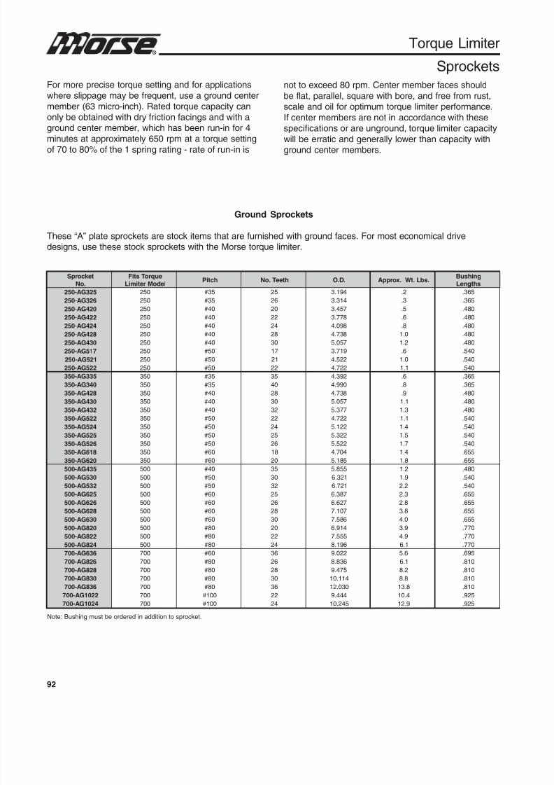
8/20/2019 Catalogo Morse MC Clutches y Limitadores
http://slidepdf.com/reader/full/catalogo-morse-mc-clutches-y-limitadores 94/131
92
Torque Limiter
Sprockets
Ground Sprockets
These “A” plate sprockets are stock items that are furnished with ground faces. For most economical drivedesigns, use these stock sprockets with the Morse torque limiter.
For more precise torque setting and for applicationswhere slippage may be frequent, use a ground center
member (63 micro-inch). Rated torque capacity canonly be obtained with dry friction facings and with aground center member, which has been run-in for 4
minutes at approximately 650 rpm at a torque settingof 70 to 80% of the 1 spring rating - rate of run-in is
not to exceed 80 rpm. Center member faces should
be flat, parallel, square with bore, and free from rust,scale and oil for optimum torque limiter performance.
If center members are not in accordance with thesespecifications or are unground, torque limiter capacity
will be erratic and generally lower than capacity withground center members.
Note: Bushing must be ordered in addition to sprocket.
tek corpS.oN
euqroTstiFledoMretimiL
hctiP hteeT.oN .D.O .sbL.tW.xorppA gnihsuBshtgneL
523GA-052 052 53# 52 491.3 2. 563.
623GA-052 052 53# 62 413.3 3. 563.
024GA-052 052 04# 02 754.3 5. 084.
224GA-052 052 04# 22 877.3 6. 084.
424GA-052 052 04# 42 890.4 8. 084.
824GA-052 052 04# 82 837.4 0.1 084.
034GA-052 052 04# 03 750.5 2.1 084.
715GA-052 052 05# 71 917.3 6. 045.
125GA-052 052 05# 12 225.4 0.1 045.
225GA-052 052 05# 22 227.4 1.1 045.
533GA-053 053 53# 53 293.4 6. 563.
043GA-053 053 53# 04 099.4 8. 563.
824GA-053 053 04# 82 837.4 9. 084.
034GA-053 053 04# 03 750.5 1.1 084.
234GA-053 053 04# 23 773.5 3.1 084.225GA-053 053 05# 22 227.4 1.1 045.
425GA-053 053 05# 42 221.5 4.1 045.
525GA-053 053 05# 52 223.5 5.1 045.
625GA-053 053 05# 62 225.5 7.1 045.
816GA-053 053 06# 81 407.4 4.1 556.
026GA-053 053 06# 02 581.5 8.1 556.
534GA-005 005 04# 53 558.5 2.1 084.
035GA-005 005 05# 03 123.6 9.1 045.
235GA-005 005 05# 23 127.6 2.2 045.
526GA-005 005 06# 52 783.6 3.2 556.
626GA-005 005 06# 62 726.6 8.2 556.
826GA-005 005 06# 82 701.7 8.3 556.
036GA-005 005 06# 03 685.7 0.4 556.
028GA-005 005 08# 02 419.6 9.3 077.
228GA-005 005 08# 22 555.7 9.4 077.
428GA-005 005 08# 42 691.8 1.6 077.
636GA-007 007 06# 63 220.9 6.5 596.
628GA-007 007 08# 62 638.8 1.6 018.
828GA-007 007 08# 82 574.9 2.8 018.
038GA-007 007 08# 03 411.01 8.8 018.
638GA-007 007 08# 63 030.21 8.31 018.
2201GA-007 007 001# 22 444.9 4.01 529.
4201GA-007 007 001# 42 542.01 9.21 529.

8/20/2019 Catalogo Morse MC Clutches y Limitadores
http://slidepdf.com/reader/full/catalogo-morse-mc-clutches-y-limitadores 95/131
93
q
Torque Limiter
Couplings
The torque limiter couplingcombines overload slip protectionwith the ability to couple driving
and driven shafts. Some angularand parallel misalignment can beaccommodated by the double
roller chain design.
C
A
B
EDF
* Coupling sprocket minimum plain bore.** Torque limiter only, includes one (1) setscrew.
Note: Coupling assembly includes “A” plate sprocket, “B” sprocket, bushing and double strand roller chain.
The torque limiter must be ordered separately.
gnilpuoCledoMrebmuN
ngilasiM
euqroTyticapaC.tF.sbL
eroB.xaM
.tk pSeziS
snoisnemiD)sehcnI(
.xorppA.tW.sbLxaM
lellaraPxaM
ralugnAeuqroTretimiL
.glpC
.tk pS
AllarevO
htdiW
BllarevOretemaiD
CbuH
retemaiD
DhtgneL
eroBurhtgnilpuoCtek corpS
EhtgneL
eroBurhteuqroTretimiL
FecnaraelC
PC052 010. °2 / 1 04 8 / 7 4 / 11 224 3 4 2 1 8 / 71 8 / 1 2 / 14
PC053 210. °2 / 1 011 8 / 11 4 / 31 425 61 / 14 8 / 35 4 / 32 2 / 11 61 / 72 8 / 1 2 / 111
PC005 510. °2 / 1 013 4 / 31 2 / 12 826 4 / 34 8 / 37 4 8 / 51 3 8 / 1 72
PC007 020. °2 / 1 008 8 / 52 2 / 13 828 8 / 56 8 / 79 6 8 / 52 8 / 73 8 / 1 96
ecnareloTeroBdradnatS
retemaiDlanimoN
revO urhT ecnareloT
- "3 000.-200.+
"3 "4 000.-300.+
"4 "5 000.-400.+
For selection assistance, call Application Engineering at 1-800-626-2093 or visitwww.emerson-ept.com

8/20/2019 Catalogo Morse MC Clutches y Limitadores
http://slidepdf.com/reader/full/catalogo-morse-mc-clutches-y-limitadores 96/131
94
0
5
10
15
20
25
30
35
40
0 200 400 600 800 1000 1200
RPM
10sec.
20sec.30sec.
1 min.2 min.4 min.
Torque
Lb.Ft.
1400
Torque Limiter
Selection
0
20
40
60
80
100
0 200 400 600 800 1000 1200 1400
RPM
10sec.
20sec.30sec.
1 min.2 min.4 min.
Torque
Lb.Ft.
0
40
80
120
160
200
240
280
0 200 400 600 800 1000 1200 1400
RPM
310
20 sec.
30 sec.
1 min.
2 min.
4 min.
10 sec.
Torque
Lb.F
t.
0
100
200
300
400
500
600
700
800
0 200 400 600 800 1000 1200 1400
RPM
1 min.
10 sec.
20 sec.
30 sec.
2 min.
4 min.
Torque
Lb.
Ft.
250A Torque Limiter 350A Torque Limiter
700A Torque Limiter500A Torque Limiter
1. Select a torque limiter size with a torquecapacity that slightly exceeds the required sliptorque for the application.
2. Confirm the required torque limiter hub bore isavailable. Stock finished bores are shown in this
catalog.3. Check “minimum sprocket teeth and bushinglength” table to determine that the specificsprocket to be assembled in the torque limiteris compatible.
4. If a slip condition is expected to persist for morethan a few seconds, refer to the maximumduration chart. Torque limiters subjected toextended slipping beyond the recommendedtime limit may be damaged and may
malfunction.Note: Because of widely varied applications, nomaximum speed is specified, however, the effects ofsprocket run-out on a specific application should beconsidered.For longest wear life, mount torque limiter on the “low-speed” shaft of a drive.
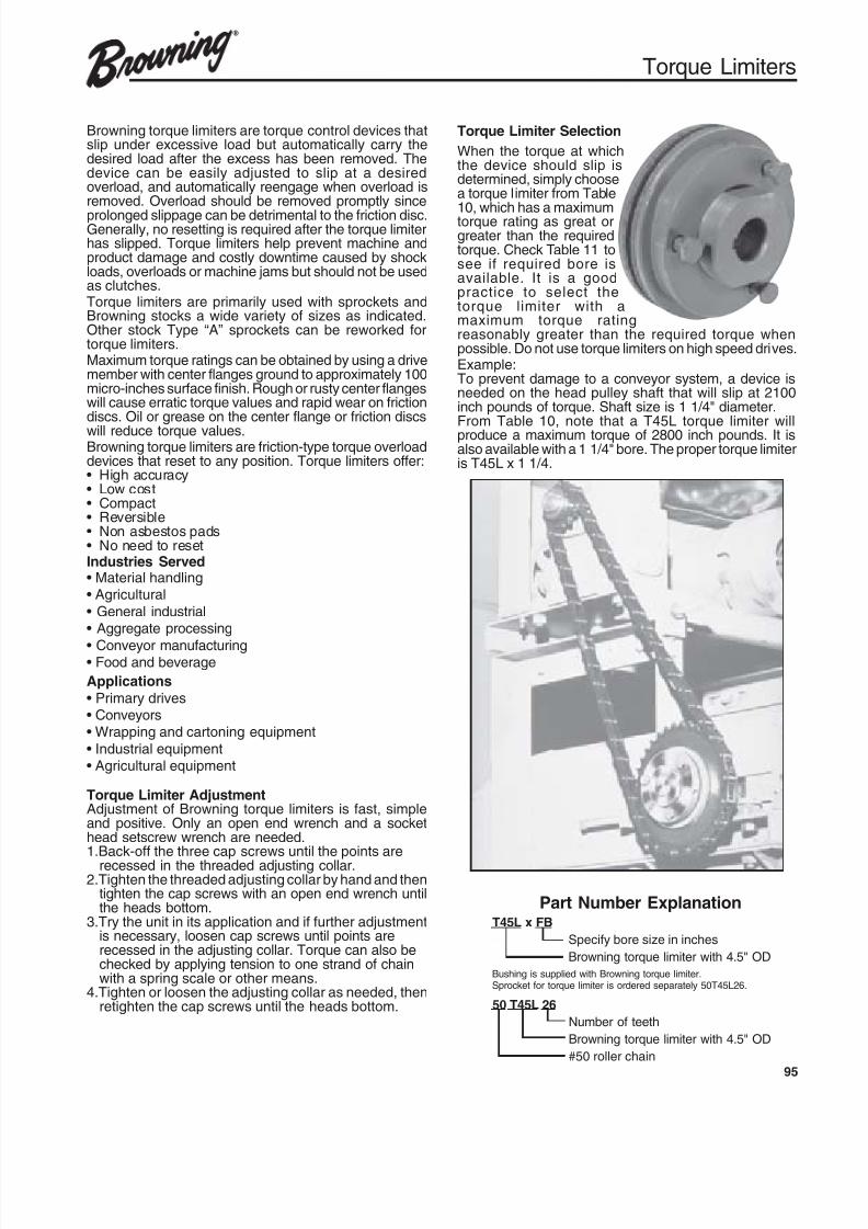
8/20/2019 Catalogo Morse MC Clutches y Limitadores
http://slidepdf.com/reader/full/catalogo-morse-mc-clutches-y-limitadores 97/131
95
Torque Limiters
Browning torque limiters are torque control devices thatslip under excessive load but automatically carry thedesired load after the excess has been removed. Thedevice can be easily adjusted to slip at a desiredoverload, and automatically reengage when overload isremoved. Overload should be removed promptly since
prolonged slippage can be detrimental to the friction disc.Generally, no resetting is required after the torque limiterhas slipped. Torque limiters help prevent machine andproduct damage and costly downtime caused by shockloads, overloads or machine jams but should not be usedas clutches.Torque limiters are primarily used with sprockets andBrowning stocks a wide variety of sizes as indicated.Other stock Type “A” sprockets can be reworked fortorque limiters.Maximum torque ratings can be obtained by using a drivemember with center flanges ground to approximately 100micro-inches surface finish. Rough or rusty center flangeswill cause erratic torque values and rapid wear on frictiondiscs. Oil or grease on the center flange or friction discs
will reduce torque values.Browning torque limiters are friction-type torque overloaddevices that reset to any position. Torque limiters offer:• High accuracy• Low cost• Compact• Reversible• Non asbestos pads• No need to resetIndustries Served• Material handling• Agricultural
• General industrial• Aggregate processing
• Conveyor manufacturing• Food and beverage
Applications
• Primary drives• Conveyors• Wrapping and cartoning equipment
• Industrial equipment• Agricultural equipment
Torque Limiter AdjustmentAdjustment of Browning torque limiters is fast, simpleand positive. Only an open end wrench and a sockethead setscrew wrench are needed.1.Back-off the three cap screws until the points are
recessed in the threaded adjusting collar.2.Tighten the threaded adjusting collar by hand and then
tighten the cap screws with an open end wrench untilthe heads bottom.
3.Try the unit in its application and if further adjustmentis necessary, loosen cap screws until points arerecessed in the adjusting collar. Torque can also bechecked by applying tension to one strand of chainwith a spring scale or other means.
4.Tighten or loosen the adjusting collar as needed, thenretighten the cap screws until the heads bottom.
Torque Limiter Selection
When the torque at whichthe device should slip isdetermined, simply choosea torque limiter from Table
10, which has a maximumtorque rating as great orgreater than the requiredtorque. Check Table 11 tosee if required bore isavailable. It is a goodpractice to select thetorque limiter with amaximum torque ratingreasonably greater than the required torque whenpossible. Do not use torque limiters on high speed drives.Example:To prevent damage to a conveyor system, a device isneeded on the head pulley shaft that will slip at 2100inch pounds of torque. Shaft size is 1 1/4" diameter.From Table 10, note that a T45L torque limiter willproduce a maximum torque of 2800 inch pounds. It isalso available with a 1 1/4" bore. The proper torque limiteris T45L x 1 1/4.
T45L x FB
Specify bore size in inches
Browning torque limiter with 4.5" OD
Bushing is supplied with Browning torque limiter.Sprocket for torque limiter is ordered separately 50T45L26.
50 T45L 26
Number of teeth
Browning torque limiter with 4.5" OD
#50 roller chain
Part Number Explanation
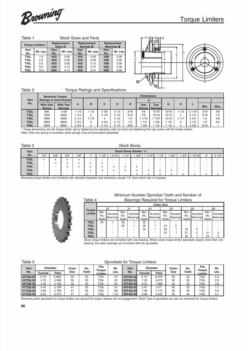
8/20/2019 Catalogo Morse MC Clutches y Limitadores
http://slidepdf.com/reader/full/catalogo-morse-mc-clutches-y-limitadores 98/131
96
Torque Limiters
Table 1 Stock Sizes and Parts
Table 2 Torque Ratings and Specifications
* These dimensions are the torque limiter set by tightening the adjusting collar by hand and tightening the cap screw until the heads bottom.Note: Only one spring is furnished; extra springs must be purchased separately.
sretimiLeuqroT tnemecalpeR
scsiD
tnemecalpeRsgnirpS
tnemecalpeRsgniraeB
traP.oN
.sbL.tW traP
.oN .sbL.tW
traP.oN
.sbL.tW traP
.oN .sbL.tW
L52T 3.1 D52 60.0 S52 60.0 B52 60.0
L53T 9.2 D53 60.0 S53 60.0 B53 60.0L54T 6.5 D54 60.0 S54 31.0 B54 60.0
L55T 6.9 D55 31.0 S55 52.0 B55 60.0
L56T 8.51 D56 31.0 S56 13.0 B56 60.0
traP.oN
euqroTmumixaMsdnuoP-hcnInisgnitaR
snoisnemiD
A B C D E*F
G H LT
enOhtiWgnirpS
owThtiWsgnirpS
enOgnirpS
owTsgnirpS
.niM .xaM
L52T 008 0011 4 / 11 2 / 11 8 / 32 2 / 12 61 / 3 8 / 7 61 / 51 61 / 31 2 / 11 61 / 12 61 / 3 8 / 3
L53T 0081 0003 4 / 31 2 8 / 13 2 / 13 61 / 3 8 / 7 61 / 51 61 / 31 2 4 / 12 61 / 3 2 / 1
L54T 0082 0094 4 / 12 2 / 12 4 2 / 14 4 / 1 61 / 11 23 / 71 61 / 51 2 / 12 4 / 32 4 / 1 8 / 5
L55T 0083 0086 4 / 32 3 4 / 34 2 / 15 4 / 1 4 / 11 8 / 31 8 / 11 3 4 / 13 4 / 1 4 / 3L56T 0084 0088 4 / 33 4 2 / 15 2 / 16 23 / 9 8 / 31 2 / 11 8 / 11 4 8 / 53 61 / 5 1
Table 3 Stock Bores
traP.oN
"x"dek raMseroBk cotS
"2 / 1 "8 / 5 "4 / 3 "8 / 7 "1 "8 / 11 "61 / 31 "4 / 11 "8 / 31 "61 / 71 "2 / 11 "8 / 51 "4 / 31 "61 / 511 "2 "2 / 12
L52T x x x x - - - - - - - - - - - -
L53T - x x x x x - - - - - - - - - -
L54T - - x x x x x x x - - - - - - -
L55T - - - - x x x x x x x x - - - -
L56T - - - - - - - - x x x x x x x x
Minimum Number Sprocket Teeth and Number of
Table 4 Bearings Required for Torque Limiters
euqroTretimiL
eziSniahC
53 14 04 05 06 08
.niM.oNhteeT
rebmuNsgniraeB
.niM.oNhteeT
rebmuNsgniraeB
.niM.oNhteeT
rebmuNsgniraeB
.niM.oNhteeT
rebmuNsgniraeB
.niM.oNhteeT
rebmuNsgniraeB
.niM.oNhteeT
rebmuNsgniraeB
L52T 52 1 02 1 02 1 - - - - - -
L53T - - 62 1 62 1 12 2 - - - -
L54T - - - - 23 1 62 1 22 2 - -
L55T - - - - - - 23 1 72 2 12 2
L56T - - - - - - - - 23 1 42 2
Browning torque limiters are furnished with standard keyseats and setscrews, except 1/2" bore which has no keyseat.
Table 5 Sprockets for Torque Limiters
traP.oN
retemaiD niahCeziS
.oNhteeT
stiFeuqroTretimiL
.tW.sbL
traP.oN
retemaiD niahCeziS
.oNhteeT
stiFeuqroTretimiL
.tW.sbLedistuO hctiP edistuO hctiP
52L52T53 "91.3 "299.2 53 52 L52T 16. 23L55T05 "27.6 "673.6 05 23 L55T 0.2
03L52T53 97.3 885.3 53 03 L52T 16. 53L55T05 23.7 279.6 05 53 L55T 6.2
53L53T53 93.4 381.4 53 53 L52T 36. 04L55T05 23.8 669.7 05 04 L55T 8.3
02L52T14 54.3 691.3 14 02 L52T 16. 22L54T06 76.5 72.5 06 22 L54T 7.1
03L52T14 60.5 387.4 14 03 L52T 86. 03L54T06 95.7 571.7 06 03 L54T 0.4
04L52T14 56.6 373.6 14 04 L52T 76.1 04L54T06 89.9 955.9 06 04 L54T 1.8
Browning stock sprockets for torque limiters are ground for proper release and re-engagement. Stock Type A sprockets can also be reworked for torque limiters.
Stock torque limiters are furnished with one bearing. Where stock torque limiter sprockets require more than onebearing, the extra bearings are furnished with the sprockets.
D
F G E
BH A
C
L
T
2
1
3

8/20/2019 Catalogo Morse MC Clutches y Limitadores
http://slidepdf.com/reader/full/catalogo-morse-mc-clutches-y-limitadores 99/131
97
q
Indicator
Torquemeter
Adjusting nut
Disc spring
Sensor platePlate
Centerflange
Hub
Torq/Pro
Design Features
Production Protection
There is a strong push toward automating manufacturingfacilities and equipment. Depending on material flow,
various machines are systematically coordinated toachieve high efficiency, productivity and performance in
the total production layout. In this situation, however,small mishaps can occasionally add to total systemdowntime and subsequent losses. Browning Torq/Pro is
based on a design concept to not only help protectmachines from overload but also minimize downtime,which may be caused by the problems of just one of the
interacting machines.
Browning Torq/Pro is a release-type ball-detenttorque overload device with a single position reset
configuration and offers:• Improved accuracy
• Simple design• Reversible
• Torque set scale• Switch detector plate
Features• One position type: the non-symmetric
arrangement of balls and pockets allows only
one engagement position.• Automatic resetting: once the overload is
removed, it reengages automatically by rotatinga driving member.
• Accuracy of trip torque within ±10%: evenwith repeated tripping the precision remainswithin ±10 %.
• Easy torque setting and adjusting: by tighteningor loosening the adjusting nuts (bolts), the
desired torque can be easily set• Visual torquemeter: the indicator and the
torquemeter can confirm the setting torque.
Structure
1. Torque is transmitted by the balls and pockets.The irregular arrangement of the balls andpockets results in only one positionengagement.
2. During normal machine operation torque willbe transmitted from the center flange throughthe balls to the pockets with the hub. If
overloaded the balls are released from thepockets and roll between the plate and thehub. On tripping, the needle bearing providessmooth and light rotation.
3. On tripping, the center flange will move in thedirection 2-3 mm, then the sensor platecatches the overload.
4. Adjust torque by tightening the adjusting nuts(bolts). The indicator and torquemeter showset tripping torques.
Part Number Explanation
TP 30 H FB or MPB
Specify finished bore or min. plain bore
Springs (light, medium or heavy)
Model number
Series
When ordering a Torq/Pro coupling specify Torq/Pro unit, Torq/Pro sprocket,coupling chain and adjoining sprocket.
8/20/2019 Catalogo Morse MC Clutches y Limitadores
http://slidepdf.com/reader/full/catalogo-morse-mc-clutches-y-limitadores 100/131
98
Torq/Pro
SelectionSelecting Torq/Pro
Like other overload protection devices, position the Torq/ Pro at the nearest place to the driving part where overloadwill occur.
1. Decide the trip limit torque from the maximum
torque limit, strength of the driving part and theexpected overload.2. Confirm the bore size and rpm.3. Select a suitable size from the ratings table.
Like other overload devices, it is best to position the Torq/ Pro nearest the driven equipment where the overload ismost likely to occur.Tripping torque should be 25% greater than the operatingtorque to compensate for motor starting torque andintermittent, shock and reversing loads.
Tripping Torque=Operating Torque × SF
Horsepower × 63025Torque (In. Lbs.)=
rpmTorque (In. Lbs) × rpm
Horsepower = 630251. Determine the tripping torque by either the HP or
torque formula shown.2. Select the correct Torq/Pro based on this rating.3. Check for max. rpm and confirm stock bore size.
Installation
1. The torque of the Torq/Pro is set at the minimum valuewhen shipped. Please check to ensure that theindicator is pointing to zero on the torque scale.
2. Loosen the fit-drive setscrew of the adjustment nutand remove the lock plug.
3. Look at the tightening graph to determine the angle to
which the adjustment nut must be tightened toproduce the trip torque determined above. The torquescale is divided into increments of 60°. First turn theadjustment nut to an angle 60° before the angledetermined from the graph, install the Torq/Pro ontothe machine, and do a trip test. Then gradually tightenthe nut until the required torque is reached.
4. After the torque is set, insert the lock plug and tightenthe screw with hole so that it holds loosely.
5. Do not turn the adjustment nut beyond the largest valueon the torque scale. If this is done, the springwill not have sufficient flexible leeway and the devicewill lock when tripping occurs.
Torque SettingTP-08, 12, 16
1. Torque is set with adjustment nut.2. Tighten the adjustment nut at the tightening angle
which is equivalent to the trip torque per tightening
angle – trip torque diagram.3. At first, tighten the adjustment nut at 60 degrees
smaller than the required value and test. Thengradually increase the tripping torque to the best value.
Do not turn the adjustment nut over themaximum value of the torque indicator.
Otherwise there is no margin of coil springwhen tripping.
TP-20, 30, 50
1. Torque setting is adjusted by tightening orloosening the adjustment nut. Make sure thatthe setscrew in the nut is loosened to preventhub thread damage. Note: There is a brasslock plug under setscrew.
2. Refer to catalog torque to determineapproximate rotation of adjustment nut to obtaindesired torque. It is suggested that the nut isfirst tightened to a value less than desired (60degrees) and final adjusted on the shaft aftermaking a test run.
3. Adjust to final torque by gradually tightening
adjustment nut.4. After setting torque, tighten setscrew to prevent
loosening.
5. Note: Do not tighten the adjustment nut beyondmaximum limit of scale because the TP unitmay not trip even under overloading conditions.
TP-70, 90, 110 and 130
1. Torque adjustment is accomplished by thethree adjustment bolts. First, loosen the locknuts on the adjustment bolts and remove thelock plugs (TP 70 and 90 do not have lock plugs). Then, check that the match mark ofthe hub and adjustment plate line up and the
setscrew is tight.2. Refer to catalog torque to determineapproximate rotation of the adjustment bolt toobtain desired torque. It is suggested thatinitially the bolt is tightened to a value less thandesired (60 degrees) and final adjusted on theshaft after making a test run.
3. Adjust to final torque by gradually tighteningthe three adjusting bolts evenly.
4. Tighten the lock nuts to prevent the adjustmentbolts from loosening.
5. Note: Do not tighten the adjusting bolts beyondthe maximum limit of the scale because the TPunit may not trip even under overloading
conditions.Resetting
a. When TP trips, stop the drive and removethe source of the overload.
b. Reset by either rotating at 50 rpm or lessor by jogging the motor.
c. When resetting, an audible sound will beheard as the ball snaps into the detent.

8/20/2019 Catalogo Morse MC Clutches y Limitadores
http://slidepdf.com/reader/full/catalogo-morse-mc-clutches-y-limitadores 101/131
99
q
0
240
480
720
960
1200
1440
1680
0 60 120 180 240 300 360 420 480
H
L
0 1 5432 76 8
TP70
T r i p
T o r q u e
( I n .
L b s . )
Adjusting Nut (Degrees) / Torquemeter
Torq/Pro
Torque Settings
600
1200
1800
2400
3000
3600
4200
4800
0 60 120 180 240 300 360 420 480
|___________|____________|____________|___________|____________|___________|___________
0 1 2 3 4 5 6 7 8
L
M
H
T r i p
T o r q
u e
( I n .
L b s . )
Adjusting Nut (Degrees) / Torquemeter
1200
2400
3600
4800
6000
7200
8400
9600
0 120 240 360 480 600 720 840 960
|___________|____________|____________|___________|____________|___________|___________
0 1 2
T r i p
T o r q u e
( I n .
L b s . )
Adjusting Nut (Degrees) / Torquemeter
0
5000
10000
15000
20000
25000
30000
0 360 720 1080 1440 1800
H
L
1 32 4
TP90
T r i p
T o r q u e
( I n .
L b s . )
Adjusting Nut (Degrees) / Torquemeter
0
5000
10000
15000
20000
25000
30000
35000
40000
45000
50000
0 180 360 540 720 900 1080 1260 1440
1 32 40
L
H
T r i p
T o r q u e
( I n .
L b s . )
Adjusting Nut (Degrees) / Torquemeter
TP110
0
10000
20000
30000
40000
50000
60000
70000
0 180 360 540 720 900
H
L
1 2
T r i p
T o r q u e
( I n .
L b s . )
Adjusting Nut (Degrees) / Torquemeter
TP130
0
5
10
15
20
25
30
0 120 240 360 480 600 720 840 960 1080 1200
H
1 32
M
L
TP08
T r i p
T o r q u e
( I n .
L b s . )
Adjusting Nut (Degrees) / Torquemeter
TP12
T r i p
T o r q u e
( I n .
L b s . )
Adjusting Nut (Degrees) / Torquemeter
0
10
20
30
40
50
60
0 360 720 1080 1440 1800
H
M
1 32 4
L
TP16
T r i p
T o r q u e
( I n .
L b s . )
Adjusting Nut (Degrees) / Torquemeter
0
20
40
60
80
100
120
0 360 720 1080 1440
H
L
M
1 32
TP20
T r i p
T o r q u e
( I n .
L b s . )
Adjusting Nut (Degrees) / Torquemeter
0
60
120
180
240
300
360
420
0 60 120 180 240 300 360 420 480
0 1 5432 76 8
TP30
TP50
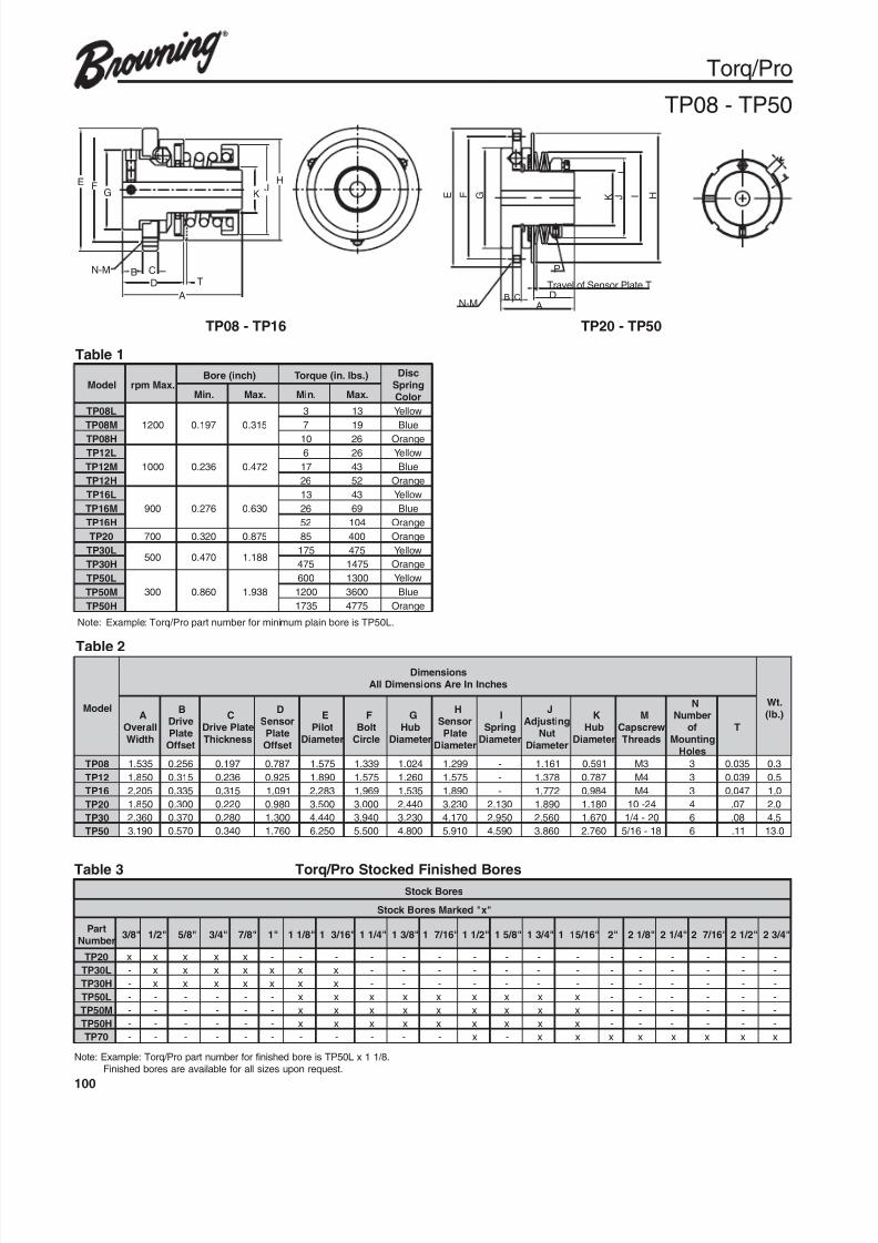
8/20/2019 Catalogo Morse MC Clutches y Limitadores
http://slidepdf.com/reader/full/catalogo-morse-mc-clutches-y-limitadores 102/131
100
E F
L
K J I HG
P
N-M B C
A
Travel of Sensor Plate TD
Torq/Pro
TP08 - TP50
Note: Example: Torq/Pro part number for minimum plain bore is TP50L.
ledoM .xaMmpr)hcni(eroB ).sbl.ni(euqroT csiD
gnirpSroloC.niM .xaM .niM .xaM
L80PT
0021 791.0 513.0
3 31 wolleY
M80PT 7 91 eulB
H80PT 01 62 egnarO
L21PT
0001 632.0 274.0
6 62 wolleY
M21PT 71 34 eulB
H21PT 62 25 egnarO
L61PT
009 672.0 036.0
31 34 wolleY
M61PT 62 96 eulB
H61PT 25 401 egnarO
02PT 007 023.0 578.0 58 004 egnarO
L03PT005 074.0 881.1
571 574 wolleY
H03PT 574 5741 egnarO
L05PT
003 068.0 839.1
006 0031 wolleY
M05PT 0021 0063 eulB
H05PT 5371 5774 egnarO
Table 1
ledoM
snoisnemiDsehcnInIerAsnoisnemiDllA
.tW).bl(A
llarevOhtdiW
BevirDetalP
tesffO
CetalPevirD
ssenk cihT
DrosneS
etalPtesffO
EtoliP
retemaiD
FtloBelcriC
GbuH
retemaiD
HrosneS
etalPretemaiD
IgnirpS
retemaiD
JgnitsujdA
tuNretemaiD
KbuH
retemaiD
MwercspaC
sdaerhT
NrebmuN
fognitnuoM
seloH
T
80PT 535.1 652.0 791.0 787.0 575.1 933.1 420.1 992.1 - 161.1 195.0 3M 3 530.0 3.0
21PT 058.1 513.0 632.0 529.0 098.1 575.1 062.1 575.1 - 873.1 787.0 4M 3 930.0 5.0
61PT 502.2 533.0 513.0 190.1 382.2 969.1 535.1 098.1 - 277.1 489.0 4M 3 740.0 0.1
02PT 058.1 003.0 022.0 089.0 005.3 000.3 044.2 032.3 031.2 098.1 081.1 42-01 4 70. 0.2
03PT 063.2 073.0 082.0 003.1 044.4 049.3 032.3 071.4 059.2 065.2 076.1 02-4 / 1 6 80. 5.4
05PT 091.3 075.0 043.0 067.1 052.6 005.5 008.4 019.5 095.4 068.3 067.2 81-61 / 5 6 11. 0.31
Table 2
Note: Example: Torq/Pro part number for finished bore is TP50L x 1 1/8.Finished bores are available for all sizes upon request.
Table 3 Torq/Pro Stocked Finished Bores
HJ
KG
N-M B C
D T
A
FE
TP08 - TP16 TP20 - TP50
seroBk cotS
"x"dek raMseroBk cotS
traPrebmuN
"8 / 3 "2 / 1 "8 / 5 "4 / 3 "8 / 7 "1 "8 / 11 "61 / 31 "4 / 11 "8 / 31 "61 / 71 "2 / 11 "8 / 51 "4 / 31 "61 / 511 "2 "8 / 12 "4 / 12 "61 / 72 "2 / 12 "4 / 32
02PT x x x x x - - - - - - - - - - - - - - - -
L03PT - x x x x x x x - - - - - - - - - - - - -
H03PT - x x x x x x x - - - - - - - - - - - - -
L05PT - - - - - - x x x x x x x x x - - - - - -
M05PT - - - - - - x x x x x x x x x - - - - - -
H05PT - - - - - - x x x x x x x x x - - - - - -
07PT - - - - - - - - - - - x - x x x x x x x x

8/20/2019 Catalogo Morse MC Clutches y Limitadores
http://slidepdf.com/reader/full/catalogo-morse-mc-clutches-y-limitadores 103/131
101
q
E F G K J I
H
N-M B C
A
D
P
Travel of Sensor Plate T
Torq/Pro
TP70 - TP130
ledoM
snoisnemiDsehcnInIerAsnoisnemiDllA
).bl(.tWA
llarevOhtdiW
BevirDetalP
tesffO
CevirDetalP
ssenk cihT
DrosneS
etalPtesffO
EtoliP
retemaiD
FtloBelcriC
GbuH
retemaiD
HrosneS
etalPretemaiD
IgnirpS
retemaiD
JgnitsujdA
tuNretemaiD
KbuH
retemaiD
MwercspaC
sdaerhT
NforebmuN
gnitnuoMseloH
T
07PT 033.4 075.0 074.0 007.2 036.8 088.7 096.6 070.8 045.6 081.6 071.4 61-8 / 3 6 31. 0.73
09PT 181.6 489.0 668.0 884.3 416.11 334.01 192.9 714.11 683.8 299.7 811.5 21M 8 12.0 7.28
011PT 776.7 181.1 489.0 431.4 679.31 597.21 992.11 385.31 549.01 274.01 992.6 61M 6 42.0 4.351
031PT 550.9 873.1 360.1 811.5 847.51 371.41 955.21 453.51 144.21 969.11 084.7 61M 8 62.0 9.422
ledoM .xaMmpr)hcni(eroB ).sbl.ni(euqroT csiD
gnirpSroloC.niM .xaM .niM .xaM
07PT 061 062.1 557.2 0062 0559 wolleY
L09PT021 456.1 345.3
3093 01711 wolleY
H09PT 0428 65772 egnarO
L011PT001 740.2 133.4
2706 74371 wolleY
H011PT 87831 30154 egnarO
L031PT08 263.2 811.5
80401 98862 wolleY
H031PT 91432 81336 egnarO
Table 4
Table 5
E
F
G
N-MB C
A
DTravel of Sensor PlateT
K
JI
H
TP70 - TP90 TP110 - TP130
For selection assistance, call Application Engineering at 1-800-626-2093 or visitwww.emerson-ept.com
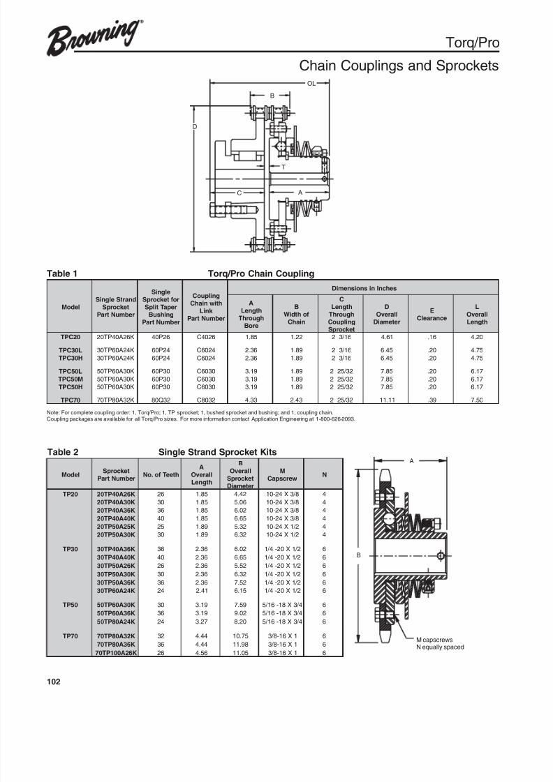
8/20/2019 Catalogo Morse MC Clutches y Limitadores
http://slidepdf.com/reader/full/catalogo-morse-mc-clutches-y-limitadores 104/131
102
Torq/Pro
Chain Couplings and Sprockets
D
B
OL
T
C A
B
M capscrewsN equally spaced
A
Table 1 Torq/Pro Chain Coupling
Note: For complete coupling order: 1, Torq/Pro; 1, TP sprocket; 1, bushed sprocket and bushing; and 1, coupling chain.Coupling packages are available for all Torq/Pro sizes. For more information contact Application Engineering at 1-800-626-2093.
ledoMdnartSelgniS
tek corpSrebmuNtraP
elgniSroftek corpS
repaTtilpSgnihsuB
rebmuNtraP
gnilpuoChtiwniahC
k niLrebmuNtraP
sehcnInisnoisnemiD
AhtgneLhguorhT
eroB
BfohtdiW
niahC
ChtgneLhguorhTgnilpuoCtek corpS
DllarevOretemaiD
EecnaraelC
LllarevO
htgneL
02CPT K62A04PT02 62P04 6204C 58.1 22.1 61 / 32 16.4 61. 02.4
L03CPT K42A06PT03 42P06 4206C 63.2 98.1 61 / 32 54.6 02. 57.4
H03CPT K42A06PT03 42P06 4206C 63.2 98.1 61 / 32 54.6 02. 57.4
L05CPT K03A06PT05 03P06 0306C 91.3 98.1 23 / 522 58.7 02. 71.6
M05CPT K03A06PT05 03P06 0306C 91.3 98.1 23 / 522 58.7 02. 71.6
H05CPT K03A06PT05 03P06 0306C 91.3 98.1 23 / 522 58.7 02. 71.6
07CPT K23A08PT07 23Q08 2308C 33.4 34.2 23 / 522 11.11 93. 05.7
Table 2 Single Strand Sprocket Kits
ledoM tek corpS
rebmuNtraP hteeTfo.oN
AllarevO
htgneL
BllarevOtek corpSretemaiD
MwercspaC
N
02PT K62A04PT02 62 58.1 24.4 8 / 3X42-01 4
K03A04PT02 03 58.1 60.5 8 / 3X42-01 4
K63A04PT02 63 58.1 20.6 8 / 3X42-01 4
K04A04PT02 04 58.1 56.6 8 / 3X42-01 4
K52A05PT02 52 98.1 23.5 2 / 1X42-01 4
K03A05PT02 03 98.1 23.6 2 / 1X42-01 4
03PT K63A04PT03 63 63.2 20.6 2 / 1X02-4 / 1 6K04A04PT03 04 63.2 56.6 2 / 1X02-4 / 1 6
K62A05PT03 62 63.2 25.5 2 / 1X02-4 / 1 6
K03A05PT03 03 63.2 23.6 2 / 1X02-4 / 1 6
K63A05PT03 63 63.2 25.7 2 / 1X02-4 / 1 6
K42A06PT03 42 14.2 51.6 2 / 1X02-4 / 1 6
05PT K03A06PT05 03 91.3 95.7 4 / 3X81-61 / 5 6
K63A06PT05 63 91.3 20.9 4 / 3X81-61 / 5 6
K42A08PT05 42 72.3 02.8 4 / 3X81-61 / 5 6
07PT K23A08PT07 23 44.4 57.01 1X61-8 / 3 6
K63A08PT07 63 44.4 89.11 1X61-8 / 3 6
K62A001PT07 62 65.4 50.11 1X61-8 / 3 6
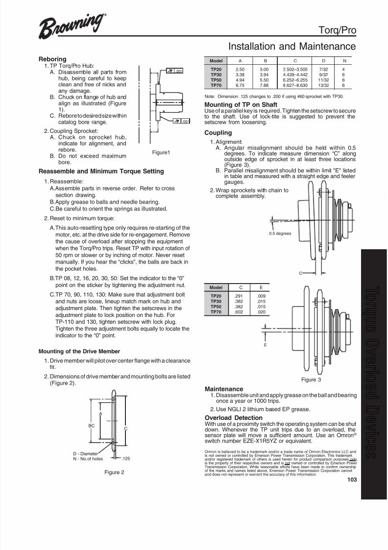
8/20/2019 Catalogo Morse MC Clutches y Limitadores
http://slidepdf.com/reader/full/catalogo-morse-mc-clutches-y-limitadores 105/131
103
q
E
C
0.5 degrees
BC
A
C
.125D - DiameterN - No.of holes
Torq/Pro
Installation and Maintenance
Mounting of TP on ShaftUse of a parallel key is required. Tighten the setscrew to secureto the shaft. Use of lock-tite is suggested to prevent thesetscrew from loosening.
Model A B C D N
TP20 2.50 3.00 3.502–3.505 7/32 4
TP30 3.38 3.94 4.439–4.442 9/32 6
TP50 4.94 5.50 6.252–6.255 11/32 6
TP70 6.75 7.88 8.627–8.630 13/32 6
Note: Dimension .125 changes to .200 if using #60 sprocket with TP30.
Reboring1. TP Torq/Pro Hub:
A. Disassemble all parts fromhub, being careful to keepclean and free of nicks andany damage.
B. Chuck on flange of hub andalign as illustrated (Figure1).
C. Rebore to desired size withincatalog bore range.
2. Coupling Sprocket:A. Chuck on sprocket hub,
indicate for alignment, andrebore.
B. Do not exceed maximumbore.
Model C ETP20 .291 .009
TP30 .382 .015
TP50 .382 .015
TP70 .602 .020
Figure 2
Maintenance1. Disassemble unit and apply grease on the ball and bearing
once a year or 1000 trips.
2. Use NGLI 2 lithium based EP grease.
Overload DetectionWith use of a proximity switch the operating system can be shutdown. Whenever the TP unit trips due to an overload, thesensor plate will move a sufficient amount. Use an Omron ®
switch number EZE-X1R5YZ or equivalent.
Figure 3
.001
.001
Figure1
Reassemble and Minimum Torque Setting
1. Reassemble:
A.Assemble parts in reverse order. Refer to crosssection drawing.
B.Apply grease to balls and needle bearing.
C.Be careful to orient the springs as illustrated.
2. Reset to minimum torque:
A.This auto-resetting type only requires re-starting of the
motor, etc. at the drive side for re-engagement. Removethe cause of overload after stopping the equipment
when the Torq/Pro trips. Reset TP with input rotation of
50 rpm or slower or by inching of motor. Never resetmanually. If you hear the “clicks”, the balls are back in
the pocket holes.
B.TP 08, 12, 16, 20, 30, 50: Set the indicator to the “0”
point on the sticker by tightening the adjustment nut.
C.TP 70, 90, 110, 130: Make sure that adjustment boltand nuts are loose, lineup match mark on hub and
adjustment plate. Then tighten the setscrews in the
adjustment plate to lock position on the hub. ForTP-110 and 130, tighten setscrew with lock plug.
Tighten the three adjustment bolts equally to locate theindicator to the “0” point.
Mounting of the Drive Member
1. Drive member will pilot over center flange with a clearancefit.
2. Dimensions of drive member and mounting bolts are listed
(Figure 2).
Omron is believed to be a trademark and/or a trade name of Omron Electronics LLC andis not owned or controlled by Emerson Power Transmission Corporation. This trademarkand/or registered trademark of others is used herein for product comparison purposes only,is the property of their respective owners and is not owned or controlled by Emerson PowerTransmission Corporation. While reasonable efforts have been made to confirm ownershipof the marks and names listed above, Emerson Power Transmission Corporation cannotand does not represent or warrant the accuracy of this information.
Coupling
1. Alignment:A. Angular misalignment should be held within 0.5
degrees. To indicate measure dimension “C” alongoutside edge of sprocket in at least three locations(Figure 3).
B. Parallel misalignment should be within limit "E" listedin table and measured with a straight edge and feelergauges.
2. Wrap sprockets with chain tocomplete assembly.
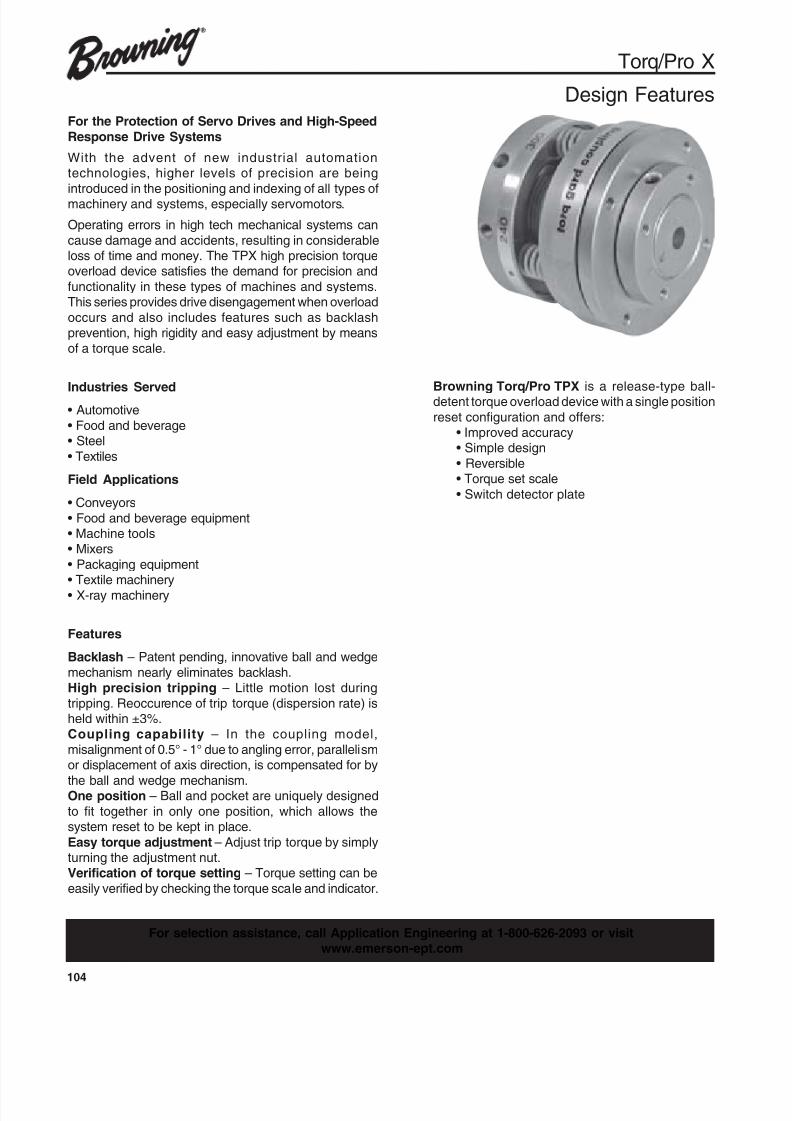
8/20/2019 Catalogo Morse MC Clutches y Limitadores
http://slidepdf.com/reader/full/catalogo-morse-mc-clutches-y-limitadores 106/131
104
For the Protection of Servo Drives and High-Speed
Response Drive Systems
With the advent of new industrial automationtechnologies, higher levels of precision are being
introduced in the positioning and indexing of all types ofmachinery and systems, especially servomotors.
Operating errors in high tech mechanical systems can
cause damage and accidents, resulting in considerableloss of time and money. The TPX high precision torqueoverload device satisfies the demand for precision and
functionality in these types of machines and systems.This series provides drive disengagement when overload
occurs and also includes features such as backlashprevention, high rigidity and easy adjustment by means
of a torque scale.
Industries Served• Automotive
• Food and beverage• Steel
• Textiles
Field Applications
• Conveyors
• Food and beverage equipment• Machine tools• Mixers
• Packaging equipment• Textile machinery
• X-ray machinery
Features
Backlash – Patent pending, innovative ball and wedge
mechanism nearly eliminates backlash.High precision tripping – Little motion lost during
tripping. Reoccurence of trip torque (dispersion rate) isheld within ±3%.Coupling capability – In the coupling model,
misalignment of 0.5° - 1° due to angling error, parallelismor displacement of axis direction, is compensated for by
the ball and wedge mechanism.One position – Ball and pocket are uniquely designed
to fit together in only one position, which allows thesystem reset to be kept in place.
Easy torque adjustment – Adjust trip torque by simplyturning the adjustment nut.Verification of torque setting – Torque setting can be
easily verified by checking the torque scale and indicator.
Browning Torq/Pro TPX is a release-type ball-detent torque overload device with a single position
reset configuration and offers:• Improved accuracy• Simple design
• Reversible• Torque set scale
• Switch detector plate
Torq/Pro X
Design Features
For selection assistance, call Application Engineering at 1-800-626-2093 or visitwww.emerson-ept.com
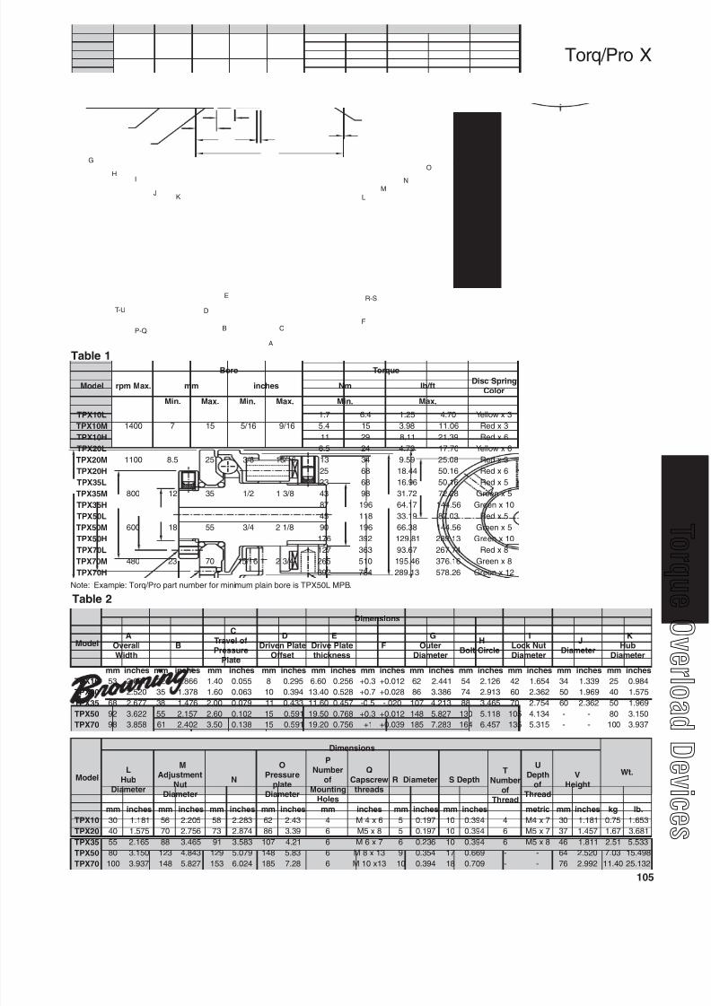
8/20/2019 Catalogo Morse MC Clutches y Limitadores
http://slidepdf.com/reader/full/catalogo-morse-mc-clutches-y-limitadores 107/131
105
q
K
I
G
J
H
L
M
N
O
V
A
B C
D
E
F
R-S
T-U
P-Q
Torq/Pro X
Note: Example: Torq/Pro part number for minimum plain bore is TPX50L MPB.
Table 1
Table 2
ledoM
snoisnemiD
AllarevO
htdiWB
CfolevarTerusserP
etalP
DetalPnevirD
tesffO
EetalPevirD
ssenk cihtF
GretuO
retemaiD
HelcriCtloB
ItuNk coLretemaiD
JretemaiD
KbuH
retemaiD
mm sehcni mm sehcni mm sehcni mm sehcni mm sehcni mm sehcni mm sehcni mm sehcni mm sehcni mm sehcni mm sehcni
01XPT 35 780.2 22 668.0 04.1 550.0 8 592.0 06.6 652.0 3.0+ 210.0+ 26 144.2 45 621.2 24 456.1 43 933.1 52 489.0
02XPT 46 025.2 53 873.1 06.1 360.0 01 493.0 04.31 825.0 7.0+ 820.0+ 68 683.3 47 319.2 06 263.2 05 969.1 04 575.1
53XPT 86 776.2 83 674.1 00.2 970.0 11 334.0 06.11 754.0 5.0- 020.- 701 312.4 88 564.3 07 457.2 06 263.2 05 969.105XPT 29 226.3 55 751.2 06.2 201.0 51 195.0 05.91 867.0 3.0+ 210.0+ 841 728.5 031 811.5 501 431.4 - - 08 051.3
07XPT 89 858.3 16 204.2 05.3 831.0 51 195.0 02.91 657.0 1+ 930.0+ 581 382.7 461 754.6 531 513.5 - - 001 739.3
ledoM
snoisnemiD
.tWLbuH
retemaiD
MtnemtsujdA
tuNretemaiD
N
OerusserP
etalpretemaiD
PrebmuN
fognitnuoM
seloH
QwercspaC
sdaerhtretemaiDR htpeDS
TrebmuN
fodaerhT
UhtpeD
fodaerhT
VthgieH
mm sehcni mm sehcni mm sehcni mm sehcni mm sehcni mm sehcni mm sehcni cirtem mm sehcni gk .bl
01XPT 03 181.1 65 502.2 85 382.2 26 34.2 4 6x4M 5 791.0 01 493.0 4 7x4M 03 181.1 57.0 356.1
02XPT 04 575.1 07 657.2 37 478.2 68 93.3 6 8x5M 5 791.0 01 493.0 6 7x5M 73 754.1 76.1 186.3
53XPT 55 561.2 88 564.3 19 385.3 701 12.4 6 7x6M 6 632.0 01 493.0 6 8x5M 64 118.1 15.2 335.5
05XPT 08 051.3 321 348.4 921 970.5 841 38.5 6 31x8M 9 453.0 71 966.0 - - 46 025.2 30.7 894.51
07XPT 001 739.3 841 728.5 351 420.6 581 82.7 6 31x01M 01 493.0 81 907.0 - - 67 299.2 04.11 231.52
ledoM .xaMmpr
eroB euqroT
gnirpScsiDroloC
mm sehcni mN tf / bl
.niM .xaM .niM .xaM .niM .xaM
L01XPT
0041 7 51 61 / 5 61 / 9
7.1 4.6 52.1 07.4 3xwolleY
M01XPT 4.5 51 89.3 60.11 3xdeR
H01XPT 11 92 11.8 93.12 6xdeR
L02XPT
0011 5.8 52 8 / 3 61 / 51
5.6 42 97.4 07.71 6xwolleY
M02XPT 31 43 95.9 80.52 3xdeR
H02XPT 52 86 44.81 61.05 6xdeR
L53XPT
008 21 53 2 / 1 8 / 31
32 86 69.61 61.05 5xdeR
M53XPT 34 89 27.13 82.27 5xneerG
H53XPT 78 691 71.46 65.441 01xneerG
L05XPT
006 81 55 4 / 3 8 / 12
54 811 91.33 30.78 5xdeR
M05XPT 09 691 83.66 65.441 5xneerGH05XPT 671 293 18.921 31.982 01xneerG
L07XPT
084 32 07 61 / 51 4 / 32
721 363 76.39 47.762 8xdeR
M07XPT 562 015 64.591 61.673 8xneerG
H07XPT 293 487 31.982 62.875 21xneerG
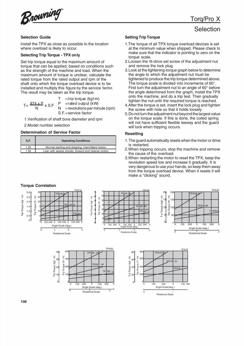
8/20/2019 Catalogo Morse MC Clutches y Limitadores
http://slidepdf.com/reader/full/catalogo-morse-mc-clutches-y-limitadores 108/131
106
Torq/Pro X
SelectionSelection Guide
Install the TPX as close as possible to the locationwhere overload is likely to occur.
Selecting Trip Torque - TPX only
Set trip torque equal to the maximum amount oftorque that can be applied, based on conditions suchas the strength of the machine and load. When themaximum amount of torque is unclear, calculate therated torque from the rated output and rpm of theshaft onto which the torque overload device is to beinstalled and multiply this figure by the service factor.The result may be taken as the trip torque.
T =trip torque (kgf-m)
T=974 x P
x S.FP =rated output (kW)
N N =revolutions per minute (rpm)S.F.=service factor
1.Verification of shaft bore diameter and rpm2.Model number selection
Determination of Service Factor
Setting Trip Torque
1.The torque of all TPX torque overload devices is setat the minimum value when shipped. Please check tomake sure that the indicator is pointing to zero on thetorque scale.
2.Loosen the fit-drive set screw of the adjustment nutand remove the lock plug.
3.Look at the tightening-torque graph below to determinethe angle to which the adjustment nut must betightened to produce the trip torque determined above.The torque scale is divided into increments of 60°.First turn the adjustment nut to an angle of 60° beforethe angle determined from the graph, install the TPXonto the machine, and do a trip test. Then graduallytighten the nut until the required torque is reached.
4.After the torque is set, insert the lock plug and tightenthe screw with hole so that it holds loosely.
5.Do not turn the adjustment nut beyond the largest valueon the torque scale. If this is done, the coiled springwill not have sufficient flexible leeway and the guardwill lock when tripping occurs.
Resetting
1.The guard automatically resets when the motor or driveis restarted.
2.When tripping occurs, stop the machine and removethe cause of the overload.
3.When restarting the motor to reset the TPX, keep therevolution speed low and increase it gradually. It isvery dangerous to use your hands, so keep them awayfrom the torque overload device. When it resets it willmake a “clicking” sound.
.F.S snoitidnoCgnitarepO
52.1 noitomtnettimretni,gnippotsdnagnitratslamroN
05.1 noitomesreverdnadrawrof,skcohsereveshtiwdaoL
TPX10
T 10-HPX
TPX10-M
TPX10-L
00
50.5
51.5
252.5
303.0
101.0
202.0
0000 240240240 120120120
Angle Scale (deg.)
Rotational Scale
0 2 31
TripTorque(N
-m)
TripTorque(kgf-m)
TPX20
TPX20 - H
TPX20 - M
TPX20 - L
707
505
404
303
202
101
000
0
0 0 0
321
120 120 120240 240 240
606
TripTorque(N
-m)
TripTorque(kgf-m)
Angle Scale (deg.)
Rotational Scale
Torque CorrelationTPX35
TripTorque(N
-m)
TripTorque(kgf-m)
0 21
Angle Scale (deg.)
Rotational Scale
0 0 0120 120240 240
20020
10010
505
00
15015
TPX35-L
TPX35-M
TPX35-H
TripTorque(N
-m)
TripTorque(kgf-m)
40
20020
10010
00
30030
400
0 21
Angle Scale (deg.)
Rotational Scale
0 0 0120 120240 240
TPX50
TPX50 - H
TPX50 - M
TPX50 - L
TPX70
TPX70 - H
TPX70 - M
TripTorque(N-m)
TripTorque(kgf-m)
80
40040
20020
00
60060
800
0 1
Angle Scale(deg.)
Rotational Scale
0 0120 120240 180
TPX70 - L
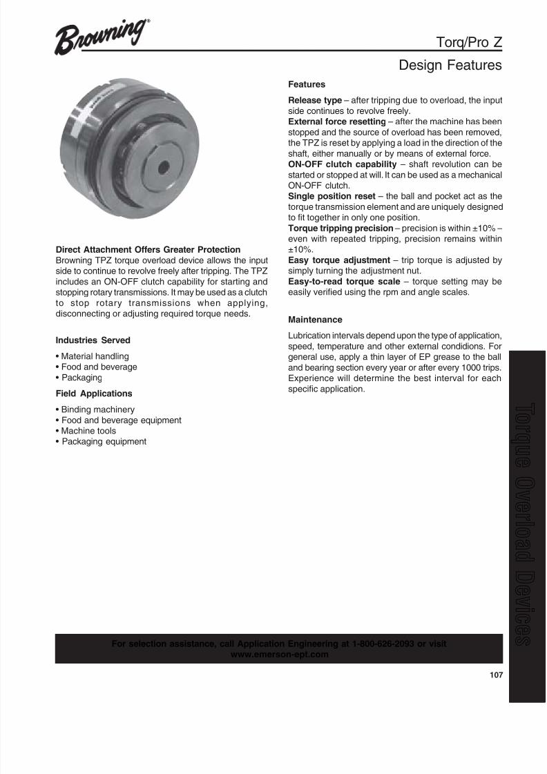
8/20/2019 Catalogo Morse MC Clutches y Limitadores
http://slidepdf.com/reader/full/catalogo-morse-mc-clutches-y-limitadores 109/131
107
q
Torq/Pro Z
Design Features
Direct Attachment Offers Greater Protection
Browning TPZ torque overload device allows the input
side to continue to revolve freely after tripping. The TPZincludes an ON-OFF clutch capability for starting andstopping rotary transmissions. It may be used as a clutch
to stop rotary transmissions when applying,disconnecting or adjusting required torque needs.
Industries Served
• Material handling• Food and beverage
• Packaging
Field Applications
• Binding machinery• Food and beverage equipment• Machine tools• Packaging equipment
Maintenance
Lubrication intervals depend upon the type of application,
speed, temperature and other external condidions. Forgeneral use, apply a thin layer of EP grease to the ball
and bearing section every year or after every 1000 trips.Experience will determine the best interval for each
specific application.
Features
Release type – after tripping due to overload, the input
side continues to revolve freely.External force resetting – after the machine has been
stopped and the source of overload has been removed,the TPZ is reset by applying a load in the direction of the
shaft, either manually or by means of external force.ON-OFF clutch capability – shaft revolution can be
started or stopped at will. It can be used as a mechanicalON-OFF clutch.Single position reset – the ball and pocket act as the
torque transmission element and are uniquely designedto fit together in only one position.
Torque tripping precision – precision is within ±10% –even with repeated tripping, precision remains within±10%.
Easy torque adjustment – trip torque is adjusted by
simply turning the adjustment nut.Easy-to-read torque scale – torque setting may beeasily verified using the rpm and angle scales.
For selection assistance, call Application Engineering at 1-800-626-2093 or visitwww.emerson-ept.com

8/20/2019 Catalogo Morse MC Clutches y Limitadores
http://slidepdf.com/reader/full/catalogo-morse-mc-clutches-y-limitadores 110/131
108
Torq/Pro Z
Note: Example: Torq/Pro part number for minimum plain bore is TPZ50L.
Table 1
Table 2
ledoM
snoisnemiD
AllarevO
htdiWB C
DerusserP
etalPevoorG
EerusserP
etalPssenk cihT
F G H
IfolevarTerusserP
etalP
JretemaiD
KelcriCtloB
mm sehcni mm sehcni mm sehcni mm sehcni mm sehcni mm sehcni mm sehcni mm sehcni mm sehcni mm sehcni mm sehcni
02ZPT 47 319.2 37 478.2 0.1 930.0 8 513.0 6 632.0 5.31 135.0 08.0 130.0 00.11 334.0 01.4 161.0 69 187.3 68 683.3
03ZPT 5.38 782.3 28 822.3 5.1 950.0 8 513.0 6 632.0 5.41 175.0 01.1 340.0 05.11 354.0 07.4 581.0 811 646.4 601 371.4
04ZPT 101 679.3 001 739.3 0.1 930.0 9 453.0 8 513.0 02 787.0 01.1 340.0 00.41 155.0 09.5 232.0 251 489.5 931 274.5
05ZPT 5.411 805.4 211 904.4 5.2 890.0 01 493.0 9 453.0 2.02 597.0 02.1 740.0 00.61 036.0 00.7 672.0 871 800.7 261 873.6
ledoM .xaMmpr
eroB euqroT
gnirpScsiDroloC
mm sehcni mN tf / bl
.niM .xaM .niM .xaM .niM .xaM .niM .xaML02ZPT
0081 8 02 8 / 3 4 / 3
4.2 3.8 77.1 21.6 3xwolleY
M02ZPT 1.4 61 20.3 08.11 3xeulB
H02ZPT 2.8 13 50.6 78.22 6xeulB
L03ZPT
0081 21 03 2 / 1 8 / 11
9.5 12 53.4 94.51 4xwolleY
M03ZPT 02 24 57.41 89.03 4xdeR
H03ZPT 93 801 77.82 66.97 8xdeR
L04ZPT
0081 71 04 61 / 11 61 / 91
52 39 44.81 95.86 5xeulB
M04ZPT 44 721 54.23 26.39 5xdeR
H04ZPT 88 542 19.46 17.081 01xdeR
L05ZPT
0081 22 05 8 / 7 61 / 511
36 751 74.64 08.511 5xdeR
M05ZPT 721 403 76.39 22.422 01xdeR
H05ZPT 542 154 17.081 56.233 01xneerG
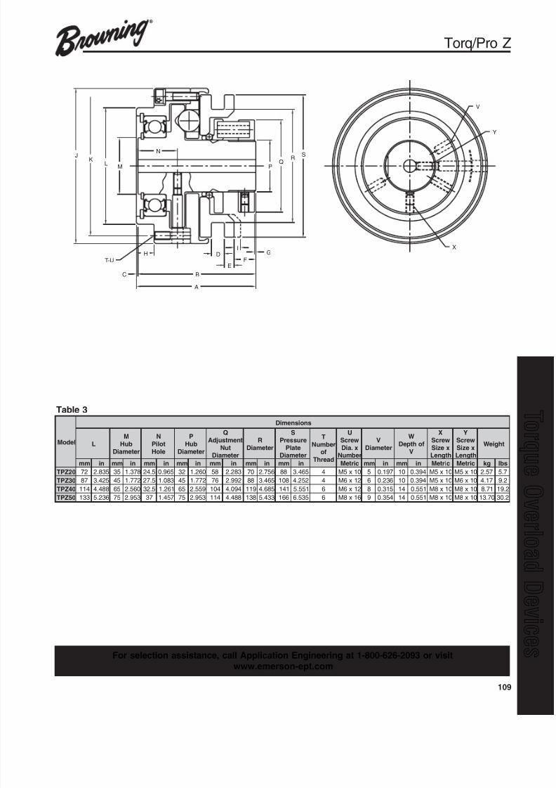
8/20/2019 Catalogo Morse MC Clutches y Limitadores
http://slidepdf.com/reader/full/catalogo-morse-mc-clutches-y-limitadores 111/131
109
q
ledoM
snoisnemiD
LM
buHretemaiD
NtoliP
eloH
PbuH
retemaiD
QtnemtsujdA
tuNretemaiD
RretemaiD
SerusserP
etalPretemaiD
TrebmuN
fodaerhT
UwercSx.aiD
rebmuN
VretemaiD
WfohtpeD
V
XwercSxeziShtgneL
YwercSxeziShtgneL
thgieW
mm ni mm ni mm ni mm ni mm ni mm ni mm ni cirteM mm ni mm ni cirteM cirteM gk sbl
02ZPT 27 538.2 53 873.1 5.42 569.0 23 062.1 85 382.2 07 657.2 88 564.3 4 01x5M 5 791.0 01 493.0 01x5M 01x5M 75.2 7.5
03ZPT 78 524.3 54 277.1 5.72 380.1 54 277.1 67 299.2 88 564.3 801 252.4 4 21x6M 6 632.0 01 493.0 01x5M 01x6M 71.4 2.9
04ZPT 411 884.4 56 065.2 5.23 162.1 56 955.2 401 490.4 911 586.4 141 155.5 6 21x6M 8 513.0 41 155.0 01x8M 01x8M 17.8 2.91
05ZPT 331 632.5 57 359.2 73 754.1 57 359.2 411 884.4 831 334.5 661 535.6 6 61x8M 9 453.0 41 155.0 01x8M 01x8M 07.31 2.03
SR
QPM
LK
J N
H
C B
A
FE
DI
G
T-U
V
Y
X
Torq/Pro Z
Table 3
For selection assistance, call Application Engineering at 1-800-626-2093 or visit
www.emerson-ept.com

8/20/2019 Catalogo Morse MC Clutches y Limitadores
http://slidepdf.com/reader/full/catalogo-morse-mc-clutches-y-limitadores 112/131
110
Torq/Pro Z
SelectionSelection Guide
Install the TPZ as close as possible to the location inwhich overload is likely to occur.
Selecting the Trip Torque
1.Set the trip torque equal to the maximum amount oftorque that can be applied, based on conditionssuch as the strength of the machine and load.When the maximum amount of torque is unclear,calculate the rated torque from the rated output andrpm of the shaft onto which the torque overloaddevice is to be installed and multiply this figure bythe service factor. The result may be taken as thetrip torque.
T =trip torque (kgf-m)
T=974 x P
x S.FP =rated output (kW)
N N =revolutions per minute (rpm)S.F.=service factor
2.Verification of shaft bore diameter and rpm.
3.Model number selection.Determination of Service Factor
Shaft Bore Machining
1.Before machining – the torque of each TPZ torqueoverload device is set to the minimum value whenshipped. Please verify that the rpm and angle scalesboth read zero.
2.Disassembly – loosen the setscrew and remove thecoiled spring. Disassemble the coiled spring, plate andball, etc. Remove the stop ring and take out thebearings and driven flange. Take care at this time thatno dust or dirt accumulates.
3.Chucking – secure the exterior diameter of the hubflange in a chuck and center at the boss.
4.Machining – machine the keyway directly under thesetscrew tap on the hub flange.
5.Assembly – when reassembling the parts aftermachining the shaft bore, grease balls A and B, thepockets and V groove.
Setting Trip Torque
1.The torque of all TPZ torque overload devices is setat the minimum value when shipped. Check to make
sure that the indicator is pointing to zero on the torquescale.
2.Loosen the fit-drive set screw of the adjustment nutand remove the lock plug.
3.Look at the tightening-torque graph below to determinethe angle to which the adjustment nut must betightened to produce the trip torque determined above.The torque scale is divided into increments of 60°.First turn the adjustment nut to an angle of 60° beforethe angle determined from the graph. Install the TPXonto the machine and do a trip test. Then graduallytighten the nut until reaching the required torque.
4.After the torque is set, insert the lock plug andtighten the screw with hole so that it holds loosely.
5.Do not turn the adjustment nut beyond the largest valueon the torque scale. If this is done, the coiled springwill not have sufficient flexible leeway and the guardwill lock when tripping occurs.
.F.S snoitidnoCgnitarepO
52.1 noitomtnettimretni,gnippotsdnagnitratslamroN
05.1 noitomesreverdnadrawrof,skcohsereveshtiwdaoL
TripTorque
(N
-m)
TripTorque(kgf-m)
252.5
202.0151.5
101.0
50.5
00
303.0
353.5
0
0 0 0
1 2 3
Angle Scale (deg.)
Rotational Scale
TPZ20
TPZ20-M
TPZ20-H
0 240 240 240120 120 120
TPZ20-L
0
0 0 0
1 2 3
Angle Scale (deg.)
Rotational Scale
0 240 240 240120 120 120
TripTorque(N
-m)
TripTorq
ue(kgf-m)
808
606
404
202
00
10010
12012TPZ30
TPZ30-H
TPZ30-L
TPZ30-M
TripTorque(N
-m)
TripTorque(kgf-m)
150
100
50
15
10
5
00
2002.0
2502.5
0 1
Angle Scale (deg.)
Rotational Scale
TPZ40Torque Correlation
TPZ40-H
TPZ40-M
TPZ40-L
0 0 0 0
32
240 240 240120 120 120
TripTorque(N
-m)
TripTorque(kgf-m)
50
40 400
30 300
20 200
10 100
0 0
500
Angle Scale (deg.)
Rotational Scale
TPZ50Torque Correlation
TPZ50-H
TPZ50-M
TPZ50-L
0 0 0
0 1 2
240 240120 120
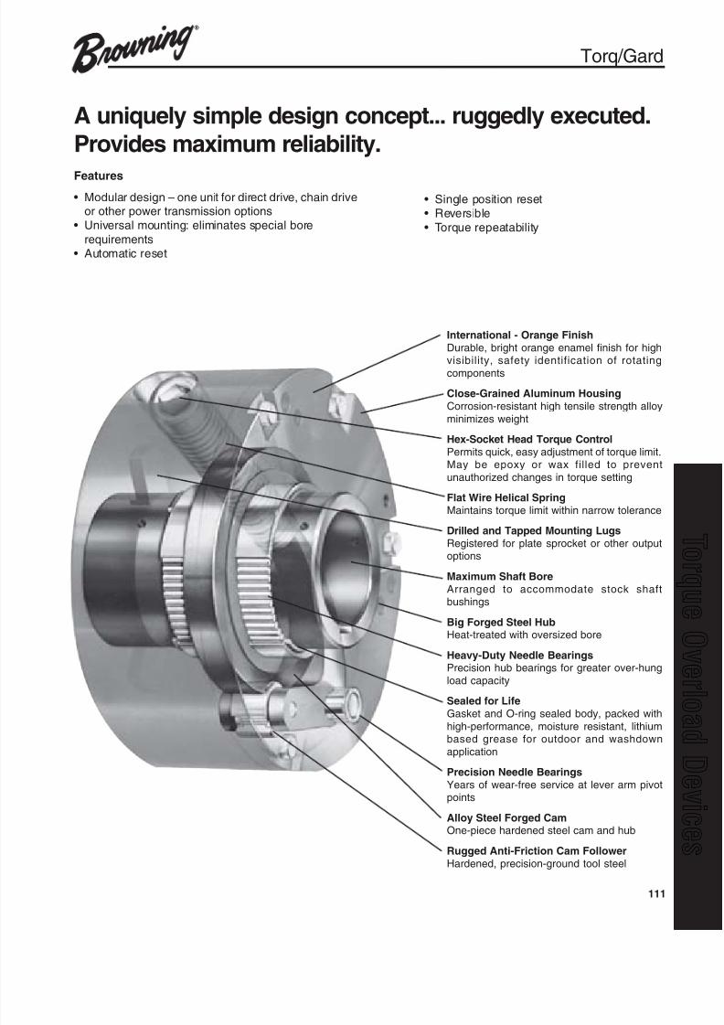
8/20/2019 Catalogo Morse MC Clutches y Limitadores
http://slidepdf.com/reader/full/catalogo-morse-mc-clutches-y-limitadores 113/131
111
q
Torq/Gard
A uniquely simple design concept... ruggedly executed.
Provides maximum reliability.
Features• Modular design – one unit for direct drive, chain drive
or other power transmission options• Universal mounting: eliminates special bore
requirements• Automatic reset
International - Orange Finish
Durable, bright orange enamel finish for high
visibility, safety identification of rotatingcomponents
Close-Grained Aluminum Housing
Corrosion-resistant high tensile strength alloy
minimizes weight
Hex-Socket Head Torque Control
Permits quick, easy adjustment of torque limit.May be epoxy or wax filled to prevent
unauthorized changes in torque setting
Flat Wire Helical Spring
Maintains torque limit within narrow tolerance
Drilled and Tapped Mounting Lugs
Registered for plate sprocket or other outputoptions
Maximum Shaft Bore
Arranged to accommodate stock shaftbushings
Big Forged Steel HubHeat-treated with oversized bore
Heavy-Duty Needle BearingsPrecision hub bearings for greater over-hung
load capacity
Sealed for Life
Gasket and O-ring sealed body, packed withhigh-performance, moisture resistant, lithiumbased grease for outdoor and washdown
application
Precision Needle Bearings
Years of wear-free service at lever arm pivotpoints
Alloy Steel Forged CamOne-piece hardened steel cam and hub
Rugged Anti-Friction Cam Follower
Hardened, precision-ground tool steel
• Single position reset• Reversible
• Torque repeatability
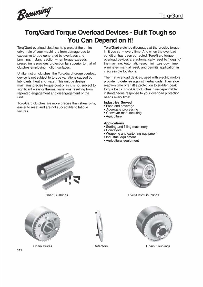
8/20/2019 Catalogo Morse MC Clutches y Limitadores
http://slidepdf.com/reader/full/catalogo-morse-mc-clutches-y-limitadores 114/131
112
Torq/Gard
Torq/Gard Torque Overload Devices - Built Tough so
You Can Depend on It!Torq/Gard overload clutches help protect the entiredrive train of your machinery from damage due to
excessive torque generated by overloads and jamming. Instant reaction when torque exceedspreset limits provides protection far superior to that of
clutches employing friction surfaces.
Unlike friction clutches, the Torq/Gard torque overload
device is not subject to torque variations caused bylubricants, heat and water. This unique designmaintains precise torque control as it is not subject to
significant wear or thermal variations resulting fromrepeated engagement and disengagement of the
unit.
Torq/Gard clutches are more precise than shear pins,
easier to reset and are not succeptible to fatiguefailures.
Torq/Gard clutches disengage at the precise torque
limit you set – every time. And when the overloadcondition has been corrected, Torq/Gard torque
overload devices are automatically reset by “jogging”the machine. Automatic reset minimizes downtime,
eliminates manual reset, and permits application ininaccessible locations.
Thermal overload devices, used with electric motors,
provide no defense against inertia loads. Their slowreaction time offer little protection to sudden peak
torque loads. Torq/Gard clutches give dependableinstantaneous response to your overload protectionneeds every time!
Shaft Bushings Ever-Flex ® Couplings
Chain Drives Detectors Chain Couplings
Industries Served• Food and beverage• Aggregate processing• Conveyor manufacturing• Agriculture
Applications• Sorting and filling machinery• Conveyors• Wrapping and cartoning equipment• Industrial equipment• Agricultural equipment

8/20/2019 Catalogo Morse MC Clutches y Limitadores
http://slidepdf.com/reader/full/catalogo-morse-mc-clutches-y-limitadores 115/131
113
q
Single-Position and ReversibleA spring-loaded cam follower seated in a
single hub cam detent causes hub andclutch body to rotate together: thus theclutch always resets in the same positionif tripped. Since the cam detent profile isthe same in both positions, all Torq/Gardclutches are fully reversible.
Automatic ResetThe Torq/Gard clutch is quickly reset aftera jam is cleared by simply jogging themachine until the cam follower reengagesthe hub cam detent. This avoids potentiallydangerous manual resetting and requiresno tools.
Bushings Permit a Wide Range of Shaft
SizesTo allow you to use an off-the-shelf Torq/ Gard clutch on shafts of various sizes, theclutch was designed with a larger thanusual hub bore. Shafts smaller than themaximum diameter are accommodatedwith standard Browning bushing kits.
Registered Mounting LugsAll Torq/Gard clutches are designed withtapped mounting lugs to accommodateBrowning single strand chain sprockets orgearbelt pulleys - without modification.
Only Torq/Gard Has All These Standard Features.
Chain Coupling Drive OptionsBrowning chain coupling kits mount directly
on the Torq/Gard clutch. Hubs with splittaper bushings simplify drive applications.
Universal Adapter PlateA universal adapter plate is available fordirect mounting of Browning Ever-Flexcouplings to the Torq/Gard. The plate mayalso be modified for special transmissionoptions.
Detector Plate AssemblyThe detector mechanism actuates a limitswitch, which disconnects the motor fromthe power source when the Torq/Gard isdisengaged. To reset the clutch, simply jogthe machine by pressing the motor “start”
button. A typical wiring diagram is providedwith each Torq/Gard clutch. Detector platesare standard on all sizes. Limit switches arenot supplied.
Infinitely Adjustable Within Load RangeTurning a single, hex-socket head controladjusts the Torq/Gard clutch precisely toany setting within its load range. Indexmarks on the clutch body give approximatesettings to facilitate adjustment.
Torq/Gard
Direct drive application withthe Torq/Gard mounted onthe low speed output shaft
of the reducer. The Torq/ Gard is shown with aBrowning Ever-Flex halfcoupling, which mounts onthe clutch adapter withoutmodification. Browningchain coupling kits are alsoavailable for the Torq/Gardwhen greater misalignmentcapabilities are required.Either side of the Torq/Gardcan be used as the input.
The Torq/Gard should notbe used on the high-speedinput side of the reducer.
Clutch sensitivity becomesa function of the reducer’sgear ratio. As an example,when used with a 100 to 1reducer, a 100 inch-poundtorque variation on theoutput side will reflect onlya 1 inch-pound change onthe input side. Do notexceed the maximum rpmshown in the Torq/Gardselection table.
Mounting the clutch on theoutput of the gear motoror reducer provides themost economical clutchassembly. The Torq/Gardis designed to protect theweakest link in the drivesystem.
One basic design fits most installations.
The Torq/Gard is mountedon the driven machine andis powered through a chainand sprocket drive.Mounting the clutch in thisposition tends to absorbpeak starting torques.

8/20/2019 Catalogo Morse MC Clutches y Limitadores
http://slidepdf.com/reader/full/catalogo-morse-mc-clutches-y-limitadores 116/131
114
A
B
D
E
X
ØF
J
G H
K
L P
Y3PL’s
45°
W
S
U
45°
37.5°
C
Torq/Gard
Table No. 1 Mini Torq/Gard Overload Clutches
ledoM .xaM
eroB A B C D E F G H I J K L P S U W X Y
3CGT 005. 63.2 42.2 80. 98.1 21. 51.3 78.0 781.1 79.1 61. 575.1 23. 23-461. 55. 46. 521. 61. 23-461.
6CGT 005. 63.2 42.2 80. 98.1 21. 51.3 78.0 781.1 79.1 61. 575.1 23. 23-461. 55. 46. 521. 61. 23-461.
02CGT 057. 67.2 06.2 21. 42.2 21. 49.3 81.1 365.1 63.2 61. 669.1 93. 42-091. 57. 68. 78.1 61. 42-091.
Table No. 2 Torq/Gard Overload ClutchesledoM
.xaMeroB
buHtaesyeK A C D E G H I J K L M O
06CGT 052.1 8 / 1x4 / 1 05.3 52. 76.2 43. 13. 578.1 573.2 83.3 52.5 65. "61 / 9XCN02-4 / 1 578.2
002CGT 839.1 8 / 1x2 / 1 13.4 52. 63.3 93. 65. 057.2 052.3 00.5 00.7 57. 4 / 3XCN61-8 / 3 005.4
004CGT 834.2 61 / 3x8 / 5 91.6 13. 71.5 24. 26. 005.3 005.4 05.7 57.01 21.1 8 / 11XCN31-2 / 1 005.6
008CGT 834.2 613x8 / 5 91.6 13. 71.5 24. 26. 005.3 005.4 05.7 57.01 21.1 8 / 11XCN31-2 / 1 005.6
AC
D E
J
I
G
K
H
.500 - 13UNC - 28 1.12 deep3 holes eql. spaced ona Ø6.500 bolt circle.
L
3, M holes equallyspaced on 0 B.C.
7.50°F
For selection assistance, call Application Engineering at 1-800-626-2093 or visitwww.emerson-ept.com

8/20/2019 Catalogo Morse MC Clutches y Limitadores
http://slidepdf.com/reader/full/catalogo-morse-mc-clutches-y-limitadores 117/131
115
q
P
Q
Torque adjustmentscrew 4000-8000"/lbs
Adaptor plate
Ever-Flex orchain coupling
S
R
Torq/Gard
*Order both springs.
Table 1 Single Strand SprocketsANSI Standard Roller Chain
ledoM tek corpS
oNtraPfo.oN
hteeT P Q
hctiP8 / 3,53.oNroF
3CGT K03A53GT 03 04.2 97.3& K63A53GT 63 04.2 15.4
6CGT K54A53GT 54 04.2 95.5
hctiP2 / 1,04.oNroF
K62A06GT 54 83.4 81.11
K62A06GT 06 83.4 37.41
K62A06GT 27 83.4 6.71
hctiP1,08.oNroF
004CGT K82A08GT 82 53.6 84.9
K63A08GT 63 53.6 30.21
K54A08GT 54 53.6 9.41
K06A08GT 06 53.6 46.91
K27A08GT 27 53.6 64.32
hctiP4 / 11,001.oNroF
008CGT K82A001GT 82 64.6 48.11
K63A001GT 63 64.6 40.51K54A001GT 54 64.6 36.81
K06A001GT 06 64.6 55.42
K27A001GT 27 64.6 33.92
Table 3 Torq/Gard Ever-Flex Couplings
ledoMgnilpuoC
flaH.oNtraP
retpadAetalP
.oNtraP
tilpSrepaT
gnihsuBR S
06CGT H5RFCHC 5PAC006 H 19.5 52.5
002CGT P8RFCHC 8PAC002 1P 60.7 88.7
004CGT Q9RFCHC 9PAC004 1Q 22.9 57.01
008CGT Q01RFCHC 01PAC008 1Q 35.9 57.01
Table 4 Torq/Gard Chain Couplings
ledoM
elgniSdnartS
tek corpS.oNtraP
elgniStek corpS
tilpSrofrepaT
gnihsuB.oNtraP
gnilpuoCniahCk niL / w
.oNtraP
R S
06CGT K62A04GT 62P04 niahC62P04 79.6 24.4
002CGT K62A06GT 62P06 niahC62P06 51.7 36.6
004CGT K82A08GT 82Q08 niahC8208C 50.01 84.9
008CGT K82A08GT 82Q08 niahC8208C 50.01 84.9
Table 2Torq/Gard Bushing Kits
ledoM tfahS
retemaiDtiKgnihsuB
.oN
3CGT
& 8 / 3 600UB60
6CGT
02CGT 2 / 1 800UB02
8 / 5 010UB02
002CGT
4 / 3 210UB06
8 / 7 410UB06
61 / 51 510UB06
1 001UB06
8 / 11 201UB002
61 / 31 301UB002
4 / 11 401UB002
61 / 51 501UB002
8 / 31 601UB002
61 / 71 701UB002
2 / 11 801UB002
8 / 51 011UB002
61 / 111 111UB002
4 / 31 211UB00261 / 511 enoN
MM42 MM42UB002
MM52 MM52UB002
MM82 MM82UB002
MM03 MM03UB002
MM23 MM23UB002
MM53 MM53UB002
MM04 MM04UB002
MM24 MM24UB002
MM54 MM54UB002
004CGT&
008CGT
4 / 11 401UB008
8 / 31 601UB008
61 / 71 701UB008
2 / 11 801UB008
8 / 51 011UB008
61 / 111 111UB0084 / 31 211UB008
8 / 71 411UB008
61 / 511 511UB008
2 002UB008
8 / 12 202UB008
61 / 32 302UB008
4 / 12 402UB008
61 / 72 enoN
MM53 MM53UB008
MM83 MM83UB008
MM04 MM04UB008
MM24 MM24UB008
MM54 MM54UB008
MM84 MM84UB008
MM05 MM05UB008
MM55 MM55UB008
Table 5 Torq/Gard Repair Parts
ledoM rotceteD
etalProtceteD
maC
rotceteDetalPgnirpS
euqroTgnitsujdA
gnirpS
06CGT 65071B 55071B 95071A 13751A
002CGT 72961C 62961B 98961A 23731A
004CGT 67071C 77071C 88771A ,128661A
*228661A
008CGT 67071C 77071C 88771A ,183571A
*283571A

8/20/2019 Catalogo Morse MC Clutches y Limitadores
http://slidepdf.com/reader/full/catalogo-morse-mc-clutches-y-limitadores 118/131
116
1. Torq/Gard clutches may be sized by the speed/ torque chart.
Tripping torque should be at least 25% greater thanthe operating torque to compensate for motor starting
torque, intermittent loads, shock loads and reversingloads.
The speed/torque chart incorporates this 25% servicefactor (S.F.). On shock load or reversing load
applications service factor greater than 25% may berequired.
2. The Torq/Gard may also be sized by applying one ofthe following formulas.
Horsepower (HP) × 63025Torque (in.-lbs) =
rpm
Torque (in.-lbs.) × rpmHorsepower =
63025
Tripping Torque = Operating Torque × S.F.
3. Select the desired Torq/Gard from the rating chart.
The Torq/Gard will successfully operate from 0 speed
to the maximum rpm listed.
Torq/Gard
Selecting the Right Torq/Gard Clutch - Easy as 1 - 2 - 3
eziS.oN
).sbl.ni(euqroTPH
.xaMmpr
.xaMthgieW
).sbl(aitrenI
k W 2
eroB
.aiD.xaM
)sehcni(.niM .xaM
3 31 23 5.1 0081 5.1 4.1 2 / 1
6 32 65 5.2 0081 5.1 4.1 2 / 1
02 65 302 0.4 0081 5.2 7.5 4 / 3
06 002 006 5.8 009 5.5 01 4 / 11
002 006 0002 5.12 086 21 64 61 / 511
004 0002 0004 2.22 053 83 554 61 / 72
008 0004 0008 4.44 053 83 554 61 / 72
Torq/Gard Ratings
800
900
1000
12001400
1600
1800 TG3 TG6
TG20
80
100
200
300
400
500
600
700
rpm
20
.007 .013 .050 .090 .15 .25 .50 1.00 2.00 3.00 5.00.027
40
60
Horsepower
1 /4 1 /2 3 /4 1 1 .5 2 3 5 7.5 1 0 1 5 2 0 3 0 35
20
40
60
80TG200
TG400
TG800
TG60
100
200
300
400
500
600
700
800
900
40
Horsepower
rpm
For selection assistance, call Application Engineering at 1-800-626-2093 or visitwww.emerson-ept.com
Part Number ExplanationTGC 60
Size (1/10 of the maximum torque capacity, in.-lbs.)
Series
If required shaft bushing is ordered separately ex.
Bushing kit includes key and setscrews. Torq/Gards can be made intocouplings by ordering separate components. Single strand TG sprocket kits tobolt on are stocked.
TG 40 A 45 K
Kit
Number of teeth
A-plate sprocket
#40 roller chain
Torq/Gard
Includes mounting bolts.
60 BU 012
Shaft size (16th of an inch)
Bushing kit
Torq/Gard size

8/20/2019 Catalogo Morse MC Clutches y Limitadores
http://slidepdf.com/reader/full/catalogo-morse-mc-clutches-y-limitadores 119/131
117
q
Setscrew
Adjusting Screw
Disk Spring
Plate
Steel Ball
Washer
Case
Slide Shaft Rotating Scale
Angle Scale
Axial Gard
Design FunctionBrowning Axial Gard TPA
The Browning Axial Gard is suitable for overload ofaxial direction such as pusher or crank motion and isdirectly mounted to the shaft to protect the machine
from damage due to unexpected stopping. TheBrowning Axial Gard is designed for easy trip setting
and will always reset.
Principle
A. Thrust load from case (slide shaft) leads toslide shaft (case) through steel ball.
Field Applications
• Automatic machinery• Machine tools
• Medical treatment machinery• Packaging equipment
• Special purpose machinery• Testing machinery
Steel Ball Case
Slide Shaft
Slot
Normal
B. When thrust load exceeds the setting load,
steel ball pops out of grove and slide shaftbecomes free.
Trip
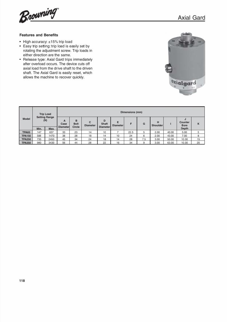
8/20/2019 Catalogo Morse MC Clutches y Limitadores
http://slidepdf.com/reader/full/catalogo-morse-mc-clutches-y-limitadores 120/131
118
Axial Gard
Features and Benefits
• High accuracy: ±15% trip load• Easy trip setting: trip load is easily set by
rotating the adjustment screw. Trip loads in
either direction are the same.• Release type: Axial Gard trips immediatelyafter overload occurs. The device cuts off
axial load from the drive shaft to the drivenshaft. The Axial Gard is easily reset, whichallows the machine to recover quickly.
ledoM
daoLpirTegnaRgnitteS
)N(
)mm(snoisnemiD
AesaC
retemaiD
BtloBelcriC
CretemaiD
DtfahS
retemaiD
EretemaiD F G
HredluohS I
JretnuoC
eroBhtpeD
K
.niM .xaM
56APT 741 736 33 32 41 01 7 5.22 5 00.2 00.04 00.5 5
051APT 885 0741 83 82 81 41 01 42 6 00.2 00.34 00.7 8
052APT 537 0542 54 43 42 81 41 82 5.7 00.3 00.05 00.01 51
053APT 089 0343 65 44 82 22 61 43 9 00.3 00.36 00.01 02
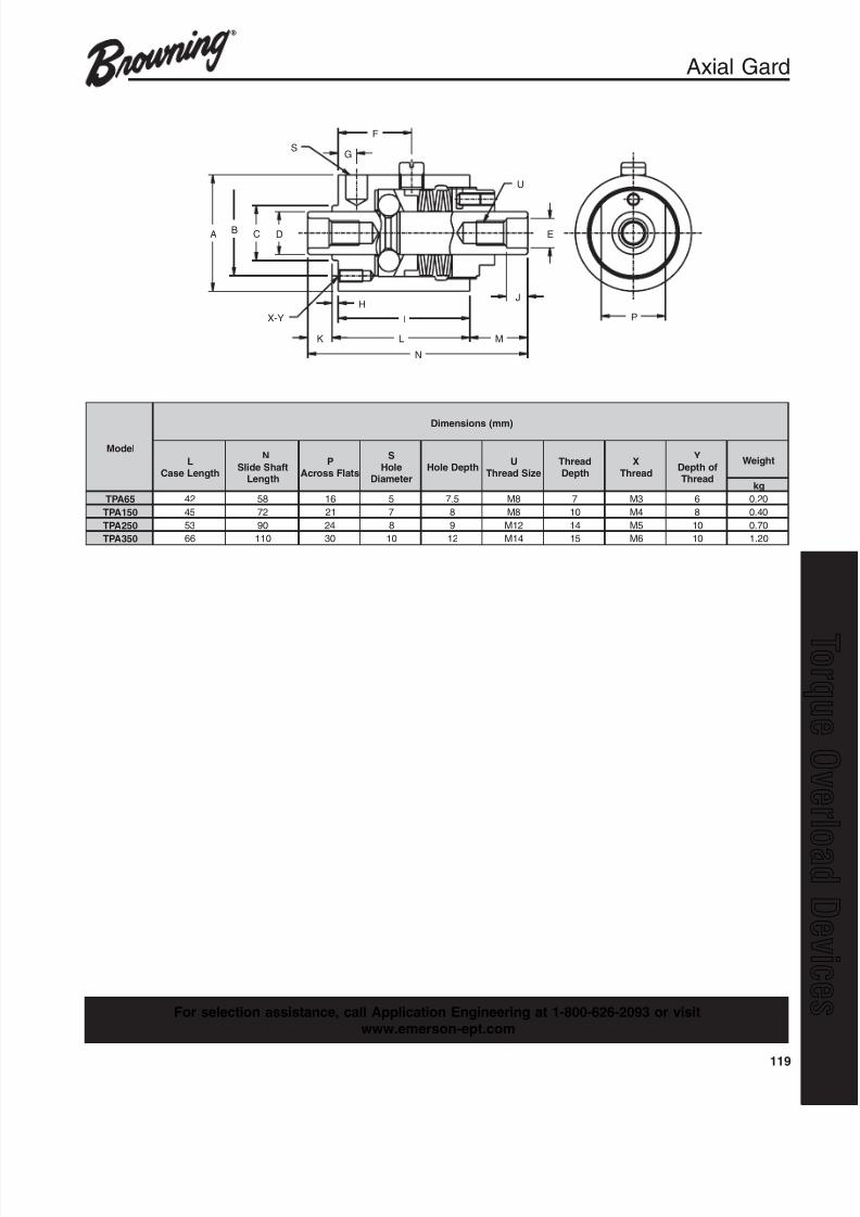
8/20/2019 Catalogo Morse MC Clutches y Limitadores
http://slidepdf.com/reader/full/catalogo-morse-mc-clutches-y-limitadores 121/131
119
q
P
EDCBA
G
F
S
U
K L M
N
H
I
J
X-Y
Axial Gard
ledoM
)mm(snoisnemiD
LhtgneLesaC
NtfahSedilS
htgneL
PstalFssorcA
SeloH
retemaiDhtpeDeloH U
eziSdaerhTdaerhT
htpeDX
daerhT
YfohtpeD
daerhT
thgieW
gk
56APT 24 85 61 5 5.7 8M 7 3M 6 02.0
051APT 54 27 12 7 8 8M 01 4M 8 04.0
052APT 35 09 42 8 9 21M 41 5M 01 07.0
053APT 66 011 03 01 21 41M 51 6M 01 02.1
For selection assistance, call Application Engineering at 1-800-626-2093 or visitwww.emerson-ept.com

8/20/2019 Catalogo Morse MC Clutches y Limitadores
http://slidepdf.com/reader/full/catalogo-morse-mc-clutches-y-limitadores 122/131
120
Axial Gard
SelectionAxial Gard Selection Guide
1. Install Axial Gard at the nearest place where
overload may occur.2. To decide setting load, set maximum setting
load after you consider normal necessaryload or machine strength. If maximum settingload is unknown, set lower load at first and
increase setting load gradually.
How to set setting load
3. Axial Gard is setting at min point (minimumload) when shipped.
4. Loosen setscrew for adjustment screw.
5. Fasten adjustment screw at 60 degreesbefore the target position according to load
correlation graph.6. Fasten adjustment screw gradually after
testing trip.7. Fasten setscrew for adjustment screw.8. Don’t fasten adjustment screw over maximum
load shown in correlation graph.
Resetting
9. Remove the cause of overload after stoppingmachine.
10. Axial Gard will be reset automatically whenyou slowly give it opposite load.
11. Check to ensure Axial Gard was reset bychecking dimension A.
ledoM daoLgnitteseR
)N(A
mm
56APT N38 11
051APT N691 91
052APT N343 22
053APT N094 42
At maximum load
Installation
1. Before installing into the machine, clean the
tap holes on the “case” and “slide shaft” andremove dust caps or tips.
2 Adhesive for metal is applied to the screws of“slide shaft” and “case” for preventing
looseness.
3. Be careful to align the center of the “case”and “slide shaft”.
4. Axial Gard is shipped after applying thegrease but apply grease once a year or every
100 times tripping.
See page 121 for load correlation graph.
A
Slide Shaft
Setscrew foradjustment

8/20/2019 Catalogo Morse MC Clutches y Limitadores
http://slidepdf.com/reader/full/catalogo-morse-mc-clutches-y-limitadores 123/131
121
q
TGA3503500
3000
2500
2000
1500
1000
500
00
0 1 2 3 4
350
300
250
200
150
100
50
0
TrippingLoad(kgf)
TrippingLoad(n)
120
Adjustment Screw Angle (deg.)
Load Scale
240 2400 0120 120240 2400 0120
TGA2502500
2000
1500
1000
500
00 0
0 1
250
200
150
100
50
0
Tripping
Load(kgf)
Tripping
Load(n)
60 60Adjustment Screw Angle (deg.)
Load Scale
120 120180 240 300
Axial Gard
Load Correlation Graphs
TGA65
TrippingLoad(k
gf)
TrippingLo
ad(n)
Adjustment Screw Angle (deg.)
Load Scale
800 80
700 70
600 60
50050
400 40
300 30
200 20
100 10
0 00
0
120 240 0 0 0
321
120 120240 240
TGA1501500 1500
1250 1250
1000 1000
750 750
500 500
250 250
00
0
60 120 180 240 300 0
1
0
TrippingLoad(kgf)
TrippingLoad(n)
Adjustment Screw Angle (deg.)
Load Scale
For selection assistance, call Application Engineering at 1-800-626-2093 or visitwww.emerson-ept.com
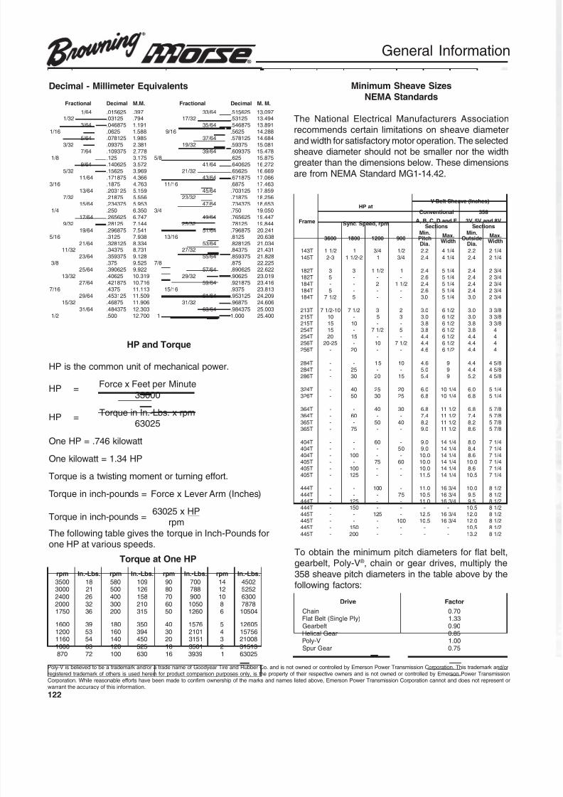
8/20/2019 Catalogo Morse MC Clutches y Limitadores
http://slidepdf.com/reader/full/catalogo-morse-mc-clutches-y-limitadores 124/131
122
lanoitcarF lamiceD .M.M lanoitcarF lamiceD .M.M
46 / 1 526510. 793. 46 / 33 526515. 790.3123 / 1 52130. 497. 23 / 71 52135. 494.31
46 / 3 578640. 191.1 46 / 53 578645. 198.3161 / 1 5260. 885.1 61 / 9 5265. 882.41
46 / 5 521870. 589.1 46 / 73 521875. 486.4123 / 3 57390. 183.2 23 / 91 57395. 180.51
46 / 7 573901. 877.2 46 / 93 573906. 874.518 / 1 521. 571.3 8 / 5 526. 578.51
46 / 9 526041. 275.3 46 / 14 526046. 272.6123 / 5 52651. 969.3 23 / 12 52656. 966.61
46 / 11 578171. 663.4 46 / 34 578176. 660.7161 / 3 5781. 367.4 61 / 11 5786. 364.71
46 / 31 521302. 951.5 46 / 54 521307. 958.7123 / 7 57812. 655.5 23 / 32 57817. 652.81
46 / 51 573432. 359.5 46 / 74 573437. 356.814 / 1 052. 053.6 4 / 3 057. 050.91
46 / 71 526562. 747.6 46 / 94 526567. 744.9123 / 9 52182. 441.7 23 / 52 52187. 448.91
46 / 91 578692. 145.7 46 / 15 578697. 142.0261 / 5 5213. 839.7 61 / 31 5218. 836.02
46 / 12 521823. 433.8 46 / 35 521828. 430.1223 / 11 57343. 137.8 23 / 72 57348. 134.12
46 / 32 573953. 821.9 46 / 55 573958. 828.128 / 3 573. 525.9 8 / 7 578. 522.22
46 / 52 526093. 229.9 46 / 75 526098. 226.2223 / 31 52604. 913.01 23 / 92 52609. 910.32
46 / 72 578124. 617.01 46 / 95 578129. 614.3261 / 7 5734. 311.11 61 / 51 5739. 318.32
46 / 92 521354. 905.11 46 / 16 521359. 902.4223 / 51 57864. 609.11 23 / 13 57869. 606.42
46 / 13 573484. 303.21 46 / 36 573489. 300.522 / 1 005. 007.21 1 000.1 004.52
Decimal - Millimeter Equivalents
HP and Torque
HP is the common unit of mechanical power.
HP =Force x Feet per Minute
33000
HP =Torque in In.-Lbs. x rpm
63025
One HP = .746 kilowatt
One kilowatt = 1.34 HP
Torque is a twisting moment or turning effort.
Torque in inch-pounds = Force x Lever Arm (Inches)
Torque in inch-pounds =63025 x HP
rpm
The following table gives the torque in Inch-Pounds forone HP at various speeds.
Torque at One HPmpr .sbL-.nI mpr .sbL-.nI mpr .sbL-.nI mpr .sbL-.nI
0053 81 085 901 09 007 41 20540003 12 005 621 08 887 21 25250042 62 004 851 07 009 01 00360002 23 003 012 06 0501 8 87870571 63 002 513 05 0621 6 40501
0061 93 081 053 04 6751 5 506210021 35 061 493 03 1012 4 657510611 45 041 054 02 1513 3 800120001 36 021 525 81 1053 2 31513
078 27 001 036 61 9393 1 52036
Minimum Sheave Sizes
NEMA Standards
The National Electrical Manufacturers Associationrecommends certain limitations on sheave diameter
and width for satisfactory motor operation. The selectedsheave diameter should not be smaller nor the widthgreater than the dimensions below. These dimensions
are from NEMA Standard MG1-14.42.
To obtain the minimum pitch diameters for flat belt,gearbelt, Poly-V ® , chain or gear drives, multiply the
358 sheave pitch diameters in the table above by thefollowing factors:
emarF
taPH)sehcnI(evaehStleB-V
lanoitnevnoC 853
mpr,deepS.cnySEdnaD,C,B,A
snoitceSV8dnaV5,V3
snoitceS
0063 0081 0021 009.niMhctiP.aiD
.xaMhtdiW
.niMedistuO
.aiD
.xaMhtdiW
T341 2 / 11 1 4 / 3 2 / 1 2.2 4 / 14 2.2 4 / 12
T541 3-2 2-2 / 11 1 4 / 3 4.2 4 / 14 4.2 4 / 12
T281 3 3 2 / 11 1 4.2 4 / 15 4.2 4 / 32
T281 5 - - - 6.2 4 / 15 4.2 4 / 32T481 - - 2 2 / 11 4.2 4 / 15 4.2 4 / 32T481 5 - - - 6.2 4 / 15 4.2 4 / 32T481 2 / 17 5 - - 0.3 4 / 15 0.3 4 / 32
T312 01-2 / 17 2 / 17 3 2 0.3 2 / 16 0.3 8 / 33T512 01 - 5 3 0.3 2 / 16 0.3 8 / 33T512 51 01 - - 8.3 2 / 16 8.3 8 / 33T452 51 - 2 / 17 5 8.3 2 / 16 8.3 4T452 02 51 - - 4.4 2 / 16 4.4 4T652 52-02 - 01 2 / 17 4.4 2 / 16 4.4 4T652 - 02 - - 6.4 2 / 16 4.4 4
T482 - - 51 01 6.4 9 4.4 8 / 54T482 - 52 - - 0.5 9 4.4 8 / 54T682 - 03 02 51 4.5 9 2.5 8 / 54
T423 - 04 52 02 0.6 4 / 101 0.6 4 / 15T623 - 05 03 52 8.6 4 / 101 8.6 4 / 15
T463 - - 04 03 8.6 2 / 111 8.6 8 / 75T463 - 06 - - 4.7 2 / 111 4.7 8 / 75
T563 - - 05 04 2.8 2 / 111 2.8 8 / 75T563 - 57 - - 0.9 2 / 111 6.8 8 / 75
T404 - - 06 - 0.9 4 / 141 0.8 4 / 17T404 - - - 05 0.9 4 / 141 4.8 4 / 17T404 - 001 - - 0.01 4 / 141 6.8 4 / 17T504 - - 57 06 0.01 4 / 141 0.01 4 / 17T504 - 001 - - 0.01 4 / 141 6.8 4 / 17T504 - 521 - - 5.11 4 / 141 5.01 4 / 17
T444 - - 001 - 0.11 4 / 361 0.01 2 / 18T444 - - - 57 5.01 4 / 361 5.9 2 / 18T444 - 521 - - 0.11 4 / 361 5.9 2 / 18T444 - 051 - - - - 5.01 2 / 18T544 - - 521 - 5.21 4 / 361 0.21 2 / 18T544 - - - 001 5.01 4 / 361 0.21 2 / 18T544 - 051 - - - - 5.01 2 / 18
T544 - 002 - - - - 2.31 2 / 18
evirD rotcaF
niahC 07.0)ylPelgniS(tleBtalF 33.1
tlebraeG 09.0raeGlacileH 58.0
V-yloP 00.1raeGrupS 57.0
General Information
Poly-V is believed to be a trademark and/or a trade name of Goodyear Tire and Rubber Co. and is not owned or controlled by Emerson Power Transmission Corporation. This trademark and/orregistered trademark of others is used herein for product comparison purposes only, is the property of their respective owners and is not owned or controlled by Emerson Power TransmissionCorporation. While reasonable efforts have been made to confirm ownership of the marks and names listed above, Emerson Power Transmission Corporation cannot and does not represent orwarrant the accuracy of this information.
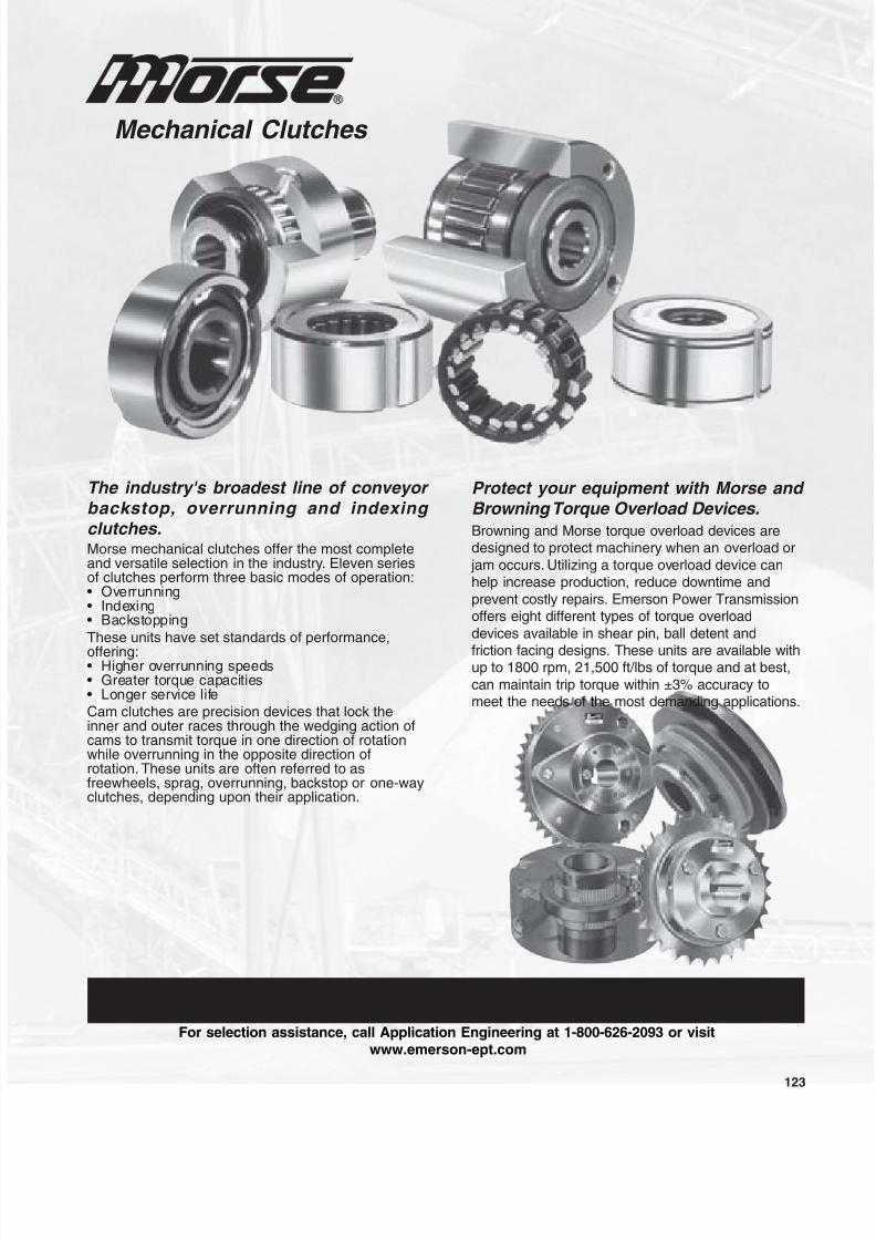
8/20/2019 Catalogo Morse MC Clutches y Limitadores
http://slidepdf.com/reader/full/catalogo-morse-mc-clutches-y-limitadores 125/131
123
Mechanical Clutches
For selection assistance, call Application Engineering at 1-800-626-2093 or visit
www.emerson-ept.com
The industry's broadest line of conveyor backstop, overrunning and indexing clutches.Morse mechanical clutches offer the most completeand versatile selection in the industry. Eleven seriesof clutches perform three basic modes of operation:• Overrunning• Indexing• Backstopping
These units have set standards of performance,
offering:• Higher overrunning speeds• Greater torque capacities• Longer service life
Cam clutches are precision devices that lock theinner and outer races through the wedging action ofcams to transmit torque in one direction of rotationwhile overrunning in the opposite direction ofrotation. These units are often referred to asfreewheels, sprag, overrunning, backstop or one-wayclutches, depending upon their application.
Protect your equipment with Morse and Browning Torque Overload Devices.
Browning and Morse torque overload devices aredesigned to protect machinery when an overload or
jam occurs. Utilizing a torque overload device canhelp increase production, reduce downtime and
prevent costly repairs. Emerson Power Transmissionoffers eight different types of torque overload
devices available in shear pin, ball detent and
friction facing designs. These units are available withup to 1800 rpm, 21,500 ft/lbs of torque and at best,
can maintain trip torque within ±3% accuracy tomeet the needs of the most demanding applications.

8/20/2019 Catalogo Morse MC Clutches y Limitadores
http://slidepdf.com/reader/full/catalogo-morse-mc-clutches-y-limitadores 126/131
124

8/20/2019 Catalogo Morse MC Clutches y Limitadores
http://slidepdf.com/reader/full/catalogo-morse-mc-clutches-y-limitadores 127/131
125
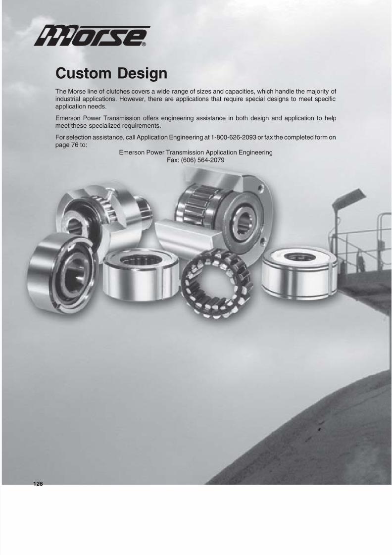
8/20/2019 Catalogo Morse MC Clutches y Limitadores
http://slidepdf.com/reader/full/catalogo-morse-mc-clutches-y-limitadores 128/131
126
Custom DesignThe Morse line of clutches covers a wide range of sizes and capacities, which handle the majority of
industrial applications. However, there are applications that require special designs to meet specificapplication needs.
Emerson Power Transmission offers engineering assistance in both design and application to helpmeet these specialized requirements.
For selection assistance, call Application Engineering at 1-800-626-2093 or fax the completed form onpage 76 to:
Emerson Power Transmission Application EngineeringFax: (606) 564-2079
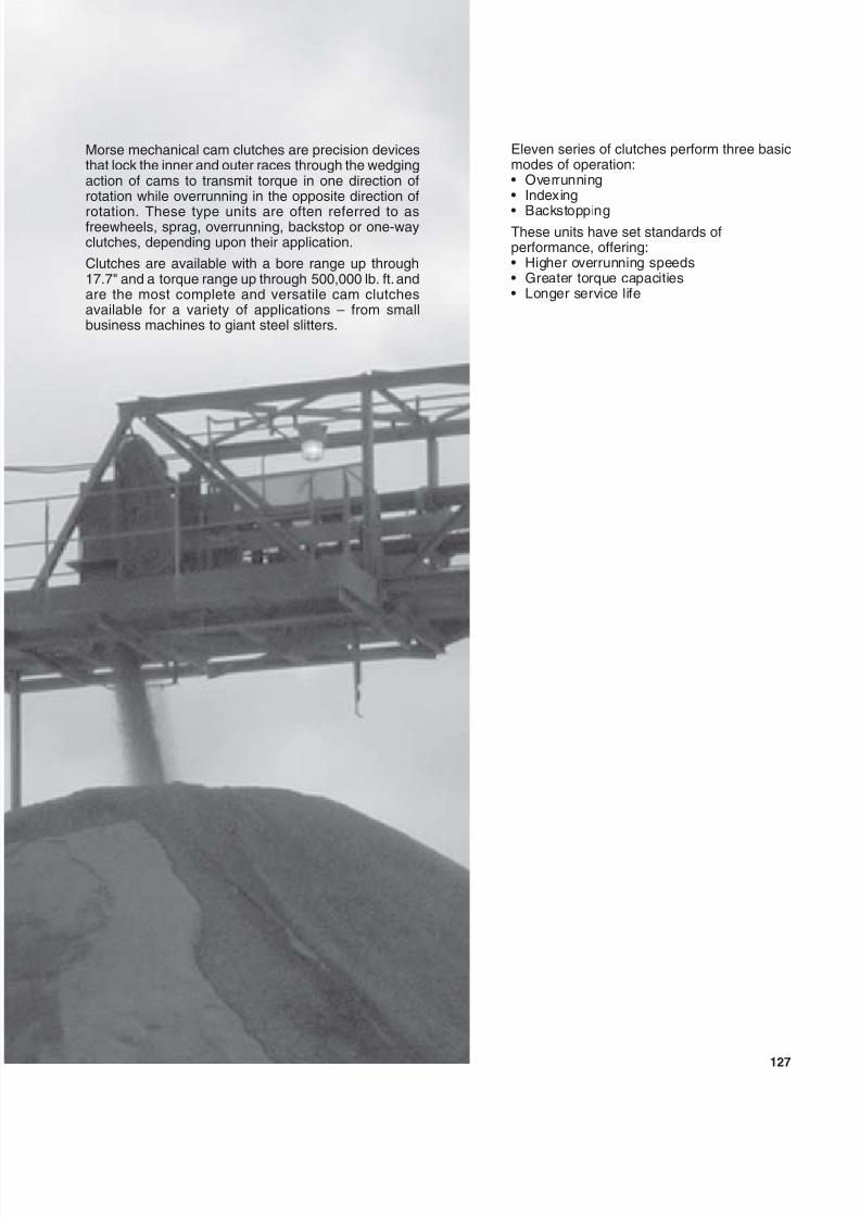
8/20/2019 Catalogo Morse MC Clutches y Limitadores
http://slidepdf.com/reader/full/catalogo-morse-mc-clutches-y-limitadores 129/131
127
Morse mechanical cam clutches are precision devicesthat lock the inner and outer races through the wedgingaction of cams to transmit torque in one direction ofrotation while overrunning in the opposite direction of
rotation. These type units are often referred to asfreewheels, sprag, overrunning, backstop or one-wayclutches, depending upon their application.
Clutches are available with a bore range up through17.7" and a torque range up through 500,000 lb. ft. andare the most complete and versatile cam clutchesavailable for a variety of applications – from smallbusiness machines to giant steel slitters.
Eleven series of clutches perform three basicmodes of operation:• Overrunning• Indexing
• BackstoppingThese units have set standards ofperformance, offering:• Higher overrunning speeds• Greater torque capacities• Longer service life

8/20/2019 Catalogo Morse MC Clutches y Limitadores
http://slidepdf.com/reader/full/catalogo-morse-mc-clutches-y-limitadores 130/131
128
1. PRICES: Unless otherwise specified in writing by Seller, Seller’s price for the goodsshall remain in effect for thirty (30) days after the date of Seller’s quotation or acknowl-edgment of Buyer’s order for the Goods, whichever occurs first, provided an uncondi-tional, complete authorization for the immediate shipment of the Goods is received andaccepted by Seller within such time period. If such authorization is not received bySeller within such thirty (30) day period, Seller shall have the right to change the pricefor the Good to Seller’s price for the Goods at the time of shipment.
2. TAXES: Any tax or governmental charge or increase in same hereafter becomingeffective increasing the cost to Seller of producing, selling or delivering the Goods or ofprocuring material used therein, and any tax now in effect or increase in same payableby the Seller because of the manufacture, sale or delivery of the Goods, may at Seller’soption, be added to the price.
3. TERMS OF PAYMENT: Subject to the approval of Seller’s Credit Department, termsare net thirty (30) days from date of Seller’s invoice in U.S. currency. If any paymentowed to Seller is not paid when due, it shall bear interest, at a rate to be determined bySeller, which shall not exceed the maximum rate permitted by law, from the date onwhich it is due until it is paid. Seller shall have the right, among other remedies, eitherto terminate the Agreement or to suspend further performance under this and/or otheragreements with Buyer in the event Buyer fails to make any payment when due. Buyershall be liable for all expenses, including attorneys’ fees, relating to the collection ofpast due amounts.
4. SHIPMENT AND DELIVERY: Shipments are made F.O.B. Seller’s shipping point.Any claims for shortages or damages suffered in transit shall be submitted by the Buyerdirectly to the carrier. While Seller will use all reasonable commercial efforts to maintainthe delivery date acknowledged or quoted by Seller, all shipping dates are approxi-
mate. Seller reserves the right to make partial shipments and to segregate “specials”and made-to-order Goods from normal stock Goods. Seller shall not be bound to ten-der delivery of any Goods for which Buyer has not provided shipping instructions.
5. QUANTITY: Buyer agrees to accept overruns of up to ten percent (10%) of the orderon “made-to-order” Goods, including parts. Any such additional items shall be priced atthe price per item charged for the specific quantity ordered.
6. LIMITED WARRANTY: Subject to the limitations of Section 7, Sel ler warrants that theGoods will be free from defects in material and workmanship under normal use, ser-vice and maintenance for a period of one year (unless otherwise specified by Seller inwriting) from the date of shipment of the Goods by Seller. THIS IS THE SOLE ANDEXCLUSIVE WARRANTY GIVEN BY SELLER WITH RESPECT TO THE GOODSAND IS IN LIEU OF AND EXCLUDES ALL OTHER WARRANTIES, EXPRESS ORIMPLIED, ARISING BY OPERATION OF LAW OR OTHERWISE, INCLUDING WITH-OUT LIMITATION, MERCHANTABILITY OR FITNESS FOR A PARTICULAR PUR-POSE WHETHER OR NOT THE PURPOSE OR USE HAS BEEN DISCLOSED TOSELLER IN SPECIFICATIONS, DRAWINGS OR OTHERWISE, AND WHETHER ORNOT SELLER’S PRODUCTS ARE SPECIFICALLY DESIGNED AND/OR MANUFAC-TURED BY SELLER FOR BUYER’S USE OR PURPOSE.This warranty does not extend to any losses or damages due to misuse, accident,
abuse, neglect, normal wear and tear, unauthorized modification or alteration, use be-yond rated capacity, or improper installation, maintenance or application. To the extentthat Buyer or its agents has supplied specifications, information, representation of op-erating conditions or other data to Seller in the selection or design of the Goods and thepreparation of Seller’s quotation, and in the event that actual operating conditions orother conditions differ from those represented by Buyer, any warranties or other provi-sions contained herein which are affected by such conditions shall be null and void. Ifwithin thirty (30) days after Buyer’s discovery of any warranty defects within the war-ranty period, Buyer notifies Seller thereof in writing, Seller shall, at its option, repair orreplace F.O.B. point of manufacture, or refund the purchase price for, that por tion of thegoods found by Seller to be defective. Failure by Buyer to give such written notice withinthe applicable time period shall be deemed an absolute and unconditional waiver ofBuyer’s claim for such defects. Goods repaired or replaced during the warranty periodshall be covered by the foregoing warranty for the remainder of the original warrantyperiod or ninety (90) days, whichever is longer. Buyer assumes all other responsibilityfor any loss, damage, or injury to persons or property arising out of, connected with, orresulting from the use of Goods, either alone or in combination with other products/ components.
SECTIONS 6 AND 7 APPLY TO ANY ENTITY OR PERSON WHO MAY BUY, AC-QUIRE OR USE SELLER’S GOODS, INCLUDING ANY ENTITY OR PERSON WHO
BUYS THE GOODS FROM SELLER’S DISTRIBUTOR AND SUCH ENTITY OR PER-SON SHALL BE BOUND BY THE LIMITATIONS THEREIN.
7. LIMITATION OF REMEDY AND LIABILITY: THE SOLE AND EXCLUSIVE REMEDYFOR BREACH OF ANY WARRANTY HEREUNDER (OTHER THAN THE WARRANTYPROVIDED UNDER SECTION 13) SHALL BE LIMITED TO REPAIR, REPLACEMENTOR REFUND OF THE PURCHASE PRICE UNDER SECTION 6. SELLER SHALLNOT BE LIABLE FOR DAMAGES CAUSED BY DELAY IN PERFORMANCE AND INNO EVENT, REGARDLESS OF THE FORM OF THE CLAIM OR CAUSE OF ACTION(WHETHER BASED IN CONTRACT, INFRINGEMENT, NEGLIGENCE, STRICT LI-ABILITY, OTHER TORT OR OTHERWISE), SHALL SELLER’S LIABILITY TO BUYERAND/OR ITS CUSTOMERS EXCEED THE PRICE TO BUYER OF THE SPECIFICGOODS PROVIDED BY SELLER GIVING RISE TO THE CLAIM OR CAUSE OF AC-TION. BUYER AGREES THAT IN NO EVENT SHALL SELLER’S LIABILITY TOBUYER AND/OR ITS CUSTOMERS EXTEND TO INCLUDE INCIDENTAL, CONSE-QUENTIAL OR PUNITIVE DAMAGES. THE TERM “CONSEQUENTIAL DAMAGES”SHALL INCLUDE, BUT NOT BE LIMITED TO, LOSS OF ANTICIPATED PROFITS,LOSS OF USE, LOSS OF REVENUE, COST OF CAPITAL AND DAMAGE OR LOSSOF OTHER PROPERTY OR EQUIPMENT.
It is expressly understood that any technical advice furnished by Seller with respect tothe use of the Goods is given without charge, and Seller assumes no obligation orliability for the advice given, or results obtained, all such advice being given and ac-cepted at Buyer’s risk.
GOODS AND/OR SERVICES SOLD HEREUNDER ARE NOT FOR USE IN ANY
NUCLEAR AND RELATED APPLICATIONS. Buyer accepts goods and/or serviceswith the foregoing understanding, agrees to communicate the same in writing to anysubsequent purchaser or users and to defend, indemnify and hold harmless Seller from
any claims, losses, suits, judgments and damages, including incidental and consequen-
tial damages, arising from such use, whether the cause of action be based in tort,
contract or otherwise, including allegations that the Seller's liability is based onnegligence or strict liability.
8. EXCUSE OF PERFORMANCE: Seller shall not be liable for delays in performanceor for non-performance due to acts of God, acts of Buyer, war, riot, fire, flood, othersevere weather, sabotage, or epidemics; strikes or labor disturbances; governmentalrequests, restrictions, laws, regulations, orders or actions; unavailability of or delays intransportation; default of suppliers; or unforeseen circumstances or any events or causesbeyond Seller’s reasonable control. Deliveries may be suspended for an appropriateperiod of time as a result of the foregoing. If Seller determines that its ability to supplythe total demand for the Goods, or to obtain material used directly or indirectly in themanufacture of the Goods, is hindered, limited or made impracticable due to causesaddressed in this Section 8, Seller may allocate its available supply of the Goods orsuch material (without obligation to acquire other supplies of any such Goods or mate-rial) among itself and its purchasers on such basis as Seller determines to be equitablewithout liability for any failure of performance which may result therefrom. Deliveriessuspended or not made by reason of this section may be canceled by Seller uponnotice to Buyer without liability, but the balance of the agreement shall otherwise re-main unaffected.
9. CANCELLATION: The Buyer may cancel orders only upon written notice and uponpayment to Seller of cancellation charges which include, among other things, all costsand expenses incurred and commitments made by the Seller and a reasonable profitthereon.
10. CHANGES: Buyer may request changes or additions to the Goods consistent withSeller’s specifications and criteria. In the event such changes or additions are acceptedby Seller, Seller may revise the price and delivery schedule. Seller reserves the right tochange designs and specifications for the Goods without prior notice to Buyer, exceptwith respect to Goods being made-to-order for Buyer.
11. TOOLING: Tool, die, and pattern charges, if any, are in addition to the price of theGoods and are due and payable upon completion of the tooling. All such tools, dies andpatterns shall be and remain the property of Seller. Charges for tools, dies, and pat-terns do not convey to Buyer, title, ownership interests in, or rights to possession orremoval, nor prevent their use by Seller for other purchasers, except as otherwise ex-pressly provided by Seller and Buyer in writing with reference to this provision.
12. ASSIGNMENT: Buyer shall not assign its rights or delegate its duties hereunder orany interest therein or any rights hereunder without the prior written consent of theSeller, and any such assignment, without such consent, shall be void.
13. PATENTS AND COPYRIGHTS: Subject to Section 7, Seller warrants that the Goodssold, except as are made specifically for Buyer according to Buyer’s specifications, donot infringe any valid U.S. patent or copyright in existence as of the date of delivery. Thiswarranty is given upon the condition that Buyer promptly notify Seller of any claim orsuit involving Buyer in which such infringement is alleged, and, that Buyer cooperatefully with Seller and permit Seller to control completely the defense or compromise ofany such allegation of infringement. Seller’s warranty as to use only applies to infringe-ments arising solely out of the inherent operation (i) of such Goods, or (ii) of any com-bination of Goods in a system designed by Seller. In the event such Goods, singularlyor in combination, are held to infringe a U.S. patent or copyright in such suit, and theuse of such Goods is enjoined, or in the case of a compromise by Seller, Seller shallhave the right, at its option and expense, to procure for Buyer the right to continueusing such Goods, or replace them with non-infringing Goods; or modify same to be-come non-infringing; or grant Buyer a credit for the depreciated value of such Goodsand accept return of them.
14. MISCELLANEOUS: These terms and conditions set forth the entire understandingand agreement between Seller and Buyer, and supersede all other communications,negotiations and prior oral or written statements regarding the subject matter of theseterms and conditions. No change, modification, rescission, discharge, abandonment,or waiver of these terms and conditions of Sale shal l be binding upon the Seller unlessmade in writing and signed on its behalf by an officer of the Seller. No conditions, usageor trade, course of dealing or performance, understanding or agreement purporting tomodify, vary, explain, or supplement these Terms and Conditions shall be binding un-less hereafter made in writing and signed by the party to be bound, and no modificationshall be affected by the acceptance of purchase orders or shipping instruction formscontaining terms at variance with or in addition to those set forth herein. Any suchmodifications or additional terms are specifically rejected by Seller. No waiver by Sellerwith respect to any breach or default or any right or remedy and no course of dealing,shall be deemed to constitute a continuing waiver of any other breach or default or ofany other right or remedy, unless such waiver be expressed in writing and signed bythe party to be bound. Seller is not responsible for typographical or clerical errors madein any quotation, orders or publications. All such errors are subject to correction. Thevalidity, performance, and all other matters relating to the interpretation and effect ofthis contract shall be governed by the law of the state of New York. The United NationsConvention on the International Sale of Goods shall not apply to any transaction here-under.
All sales are made on our STANDARD TERMS AND CONDITIONS OF SALE in effect at the time a customer’s order is accepted. The current Terms and Conditions are set forth below:
STANDARD TERMS AND CONDITIONS OF SALE (August 15, 2001)
These Terms and Conditions, the attendant quotation or acknowledgment and all documents incorporated by specific reference therein, wil l be the complete and exclusive statement
of the terms of the agreement governing the sale of goods (“Goods”) by Emerson Power Transmission Corporation and its divisions and subsidiaries (“Seller”) to Customer
(“Buyer”). Buyer’s acceptance of the Goods will manifest Buyer’s assent to these Terms and Conditions. If these Terms and Conditions differ in any way from the terms and conditions
of Buyer’s order, or other documentation, this document will be construed as a counteroffer and will not be deemed an acceptance of Buyer’s terms and conditions which conflict
herewith.

8/20/2019 Catalogo Morse MC Clutches y Limitadores
http://slidepdf.com/reader/full/catalogo-morse-mc-clutches-y-limitadores 131/131
Related Documents