SIMATIC Products for Totally Integrated Automation siemens.com/tia Catalog News ST 70 N Edition 2016 © Siemens AG 2016

Welcome message from author
This document is posted to help you gain knowledge. Please leave a comment to let me know what you think about it! Share it to your friends and learn new things together.
Transcript

SIMATIC
Products for TotallyIntegrated Automation
siemens.com/tia
Catalog NewsST 70 N
Edition2016
© Siemens AG 2016

Related catalogs
SIMATIC ST 70Products forTotally Integrated Automation
E86060-K4670-A101-B5-7600
SIMATIC HMI / ST 80/ST PCPC-based Automation Human Machine Interface SystemsPC-based Automation
E86060-K4680-A101-C3-7600
Industrial Communication IK PISIMATIC NET
E86060-K6710-A101-B8-7600
SIMATIC ST PCS 7SIMATIC PCS 7Process Control SystemSystem components
E86060-K4678-A111-C3-7600
SITOP KT 10.1Power supplySITOP
E86060-K2410-A101-B1-7600
SIMATIC Ident ID 10Industrial Identification Systems
E86060-K8310-A101-B1-7600
Motion Control PM 21SIMOTION, SINAMICS S120 & SIMOTICSEquipment for Production Machines
E86060-K4921-A101-A3-7600
SITRAIN ITCTraining for Industry
Only available in GermanE86060-K6850-A101-C5
Products for Automation and Drives CA 01Interactive Catalog, DVD
E86060-D4001-A510-D6-7600
Industry Mall Information and Ordering Platformin the Internet:
www.siemens.com/industrymall
Response E-mailPlease send your comments and suggestions for improvement to
[email protected] (include the catalog name in the subject field)
© Siemens AG 2016

Introduction 1
LOGO! logic module 2
SIMATIC S7-1200 basic controller 3
SIMATIC S7-1500 advanced controller 4
SIMATIC S7-300 advanced controller 5
SIMATIC S7-400 advanced controller 6
Distributed controllers 7
Software controllers 8
I/O systems 9
SIMATIC control systems 10
Software for SIMATIC controllers 11
SIMATIC programming devices 12
Products for specific requirements 13
Overviews 14
Supplementary components 15
Appendix 16
Products for Totally Integrated Automation
SIMATIC
Catalog News ST 70 N · 2016
Refer to the Industry Mall for current updates of this catalog:www.siemens.com/industrymall
The products contained in this catalog can also be found in the Interactive Catalog CA 01.Article No.: E86060-D4001-A510-D6-7600
Please contact your local Siemens branch.
© Siemens AG 2016
Printed on paper from sustainably managed forests and controlled sources.www.pefc.org
The products and systems described in this catalog are manufactured/distributed under application of a certified quality management system in accordance with DIN EN ISO 9001 (Certified Registration No. 1323QM-08). The certificate is recognized by all IQNet countries.
© Siemens AG 2016

2 Siemens ST 70 N · 2016
© Siemens AG 2016
Siemens ST 70 N · 2016
2
Brochures
For brochures serving as selection guides for SIMATIC products refer to:
www.siemens.com/simatic/printmaterial
2/2 LOGO! modular2/2 SIPLUS LOGO! modular basic variants2/6 SIPLUS LOGO! modular pure variants2/9 SIPLUS LOGO! modular expansion
modules
2/14 LOGO! modular communication modules2/14 LOGO! CMK2000 communication module
LOGO! logic module
© Siemens AG 2016
2/2 Siemens ST 70 N · 2016
2
LOGO! logic moduleLOGO! modular
SIPLUS LOGO! modular basic variants
■ Overview
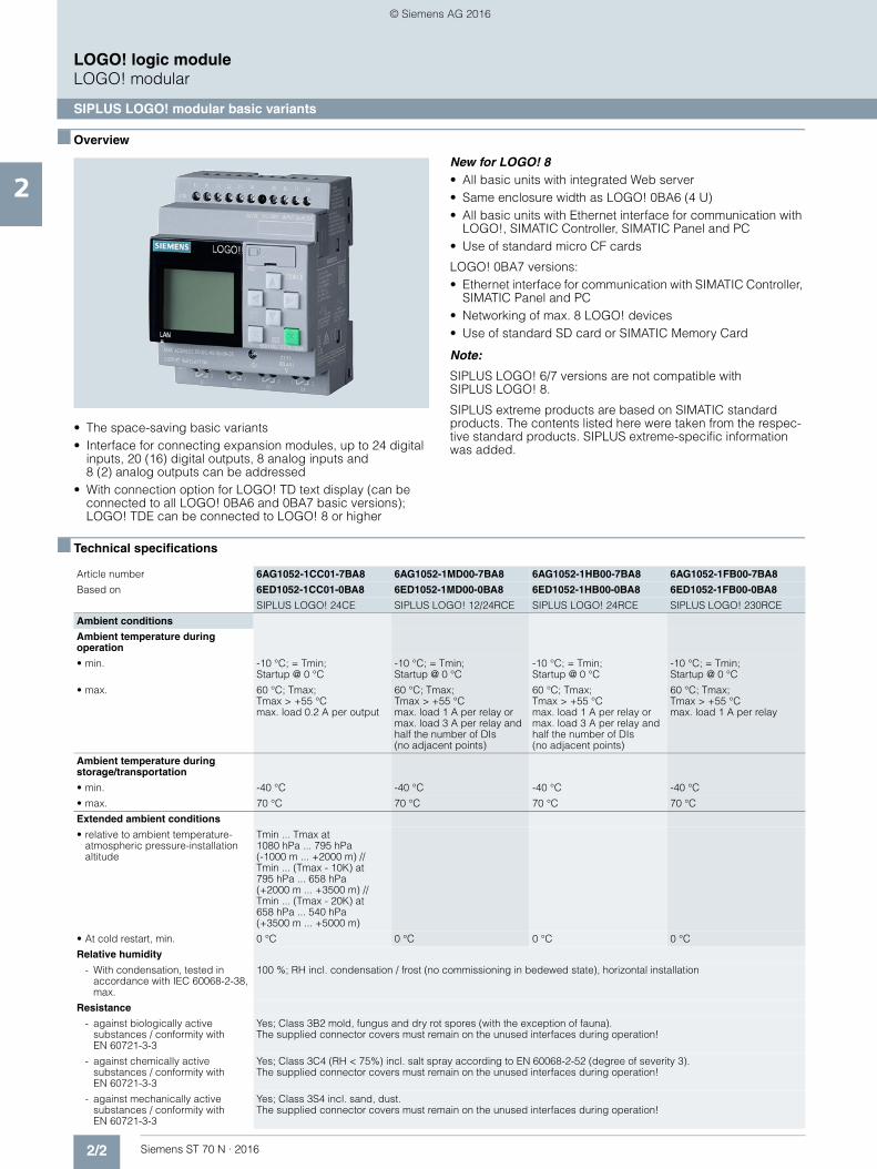
• The space-saving basic variants• Interface for connecting expansion modules, up to 24 digital
inputs, 20 (16) digital outputs, 8 analog inputs and 8 (2) analog outputs can be addressed
• With connection option for LOGO! TD text display (can be connected to all LOGO! 0BA6 and 0BA7 basic versions); LOGO! TDE can be connected to LOGO! 8 or higher
New for LOGO! 8• All basic units with integrated Web server• Same enclosure width as LOGO! 0BA6 (4 U)• All basic units with Ethernet interface for communication with
LOGO!, SIMATIC Controller, SIMATIC Panel and PC• Use of standard micro CF cards
LOGO! 0BA7 versions:• Ethernet interface for communication with SIMATIC Controller,
SIMATIC Panel and PC• Networking of max. 8 LOGO! devices• Use of standard SD card or SIMATIC Memory Card
Note:
SIPLUS LOGO! 6/7 versions are not compatible with SIPLUS LOGO! 8.
SIPLUS extreme products are based on SIMATIC standard products. The contents listed here were taken from the respec-tive standard products. SIPLUS extreme-specific information was added.
■ Technical specifications
Article number 6AG1052-1CC01-7BA8 6AG1052-1MD00-7BA8 6AG1052-1HB00-7BA8 6AG1052-1FB00-7BA8
Based on 6ED1052-1CC01-0BA8 6ED1052-1MD00-0BA8 6ED1052-1HB00-0BA8 6ED1052-1FB00-0BA8
SIPLUS LOGO! 24CE SIPLUS LOGO! 12/24RCE SIPLUS LOGO! 24RCE SIPLUS LOGO! 230RCE
Ambient conditions
Ambient temperature during operation
• min. -10 °C; = Tmin; Startup @ 0 °C
-10 °C; = Tmin; Startup @ 0 °C
-10 °C; = Tmin; Startup @ 0 °C
-10 °C; = Tmin; Startup @ 0 °C
• max. 60 °C; Tmax; Tmax > +55 °C max. load 0.2 A per output
60 °C; Tmax; Tmax > +55 °C max. load 1 A per relay or max. load 3 A per relay and half the number of DIs (no adjacent points)
60 °C; Tmax; Tmax > +55 °C max. load 1 A per relay or max. load 3 A per relay and half the number of DIs (no adjacent points)
60 °C; Tmax; Tmax > +55 °C max. load 1 A per relay
Ambient temperature during storage/transportation
• min. -40 °C -40 °C -40 °C -40 °C
• max. 70 °C 70 °C 70 °C 70 °C
Extended ambient conditions
• relative to ambient temperature-atmospheric pressure-installation altitude
Tmin ... Tmax at 1080 hPa ... 795 hPa (-1000 m ... +2000 m) // Tmin ... (Tmax - 10K) at 795 hPa ... 658 hPa (+2000 m ... +3500 m) // Tmin ... (Tmax - 20K) at 658 hPa ... 540 hPa (+3500 m ... +5000 m)
• At cold restart, min. 0 °C 0 °C 0 °C 0 °C
Relative humidity
- With condensation, tested in accordance with IEC 60068-2-38, max.
100 %; RH incl. condensation / frost (no commissioning in bedewed state), horizontal installation
Resistance
- against biologically active substances / conformity with EN 60721-3-3
Yes; Class 3B2 mold, fungus and dry rot spores (with the exception of fauna). The supplied connector covers must remain on the unused interfaces during operation!
- against chemically active substances / conformity with EN 60721-3-3
Yes; Class 3C4 (RH < 75%) incl. salt spray according to EN 60068-2-52 (degree of severity 3). The supplied connector covers must remain on the unused interfaces during operation!
- against mechanically active substances / conformity with EN 60721-3-3
Yes; Class 3S4 incl. sand, dust. The supplied connector covers must remain on the unused interfaces during operation!
© Siemens AG 2016
2/3Siemens ST 70 N · 2016
2
■ Technical specifications (continued)
LOGO! logic moduleLOGO! modular
SIPLUS LOGO! modular basic variants
Article number 6AG1052-1MD00-2BA7 6AG1052-1FB00-2BA7
Based on 6ED1052-1MD00-0BA7 6ED1052-1FB00-0BA7
SIPLUS LOGO!12/24RCE SIPLUS LOGO! 230RCE
Ambient conditions
Ambient temperature during operation
• min. -25 °C; = Tmin -25 °C; = Tmin
• max. 70 °C; = Tmax 70 °C; = Tmax
Extended ambient conditions
• relative to ambient temperature-atmospheric pressure-installation altitude
Tmin ... Tmax at 1080 hPa ... 795 hPa (-1000 m ... +2000 m) // Tmin ... (Tmax - 10K) at 795 hPa ... 658 hPa (+2000 m ... +3500 m) // Tmin ... (Tmax - 20K) at 658 hPa ... 540 hPa (+3500 m ... +5000 m)
Tmin ... Tmax at 1080 hPa ... 795 hPa (-1000 m ... +2000 m)
Relative humidity
- With condensation, tested in accordance with IEC 60068-2-38, max.
100 %; Relative humidity, incl. condensation / frost permitted (no commissioning under condensation conditions)
Resistance
- against biologically active substances / conformity with EN 60721-3-3
Yes; Class 3B2 mold, fungus and dry rot spores (with the exception of fauna). The supplied connector covers must remain on the unused interfaces during operation!
- against chemically active substances / conformity with EN 60721-3-3
Yes; Class 3C4 incl. salt spray according to EN 60068-2-52 (degree of severity 3). The supplied connector covers must remain on the unused interfaces during operation!
- against mechanically active substances / conformity with EN 60721-3-3
Yes; Class 3S4 incl. sand, dust. The supplied connector covers must remain on the unused interfaces during operation!
Article number 6AG1052-1CC01-2BA6 6AG1052-1MD00-2BA6 6AG1052-1HB00-2BA6 6AG1052-1FB00-2BA6
Based on 6ED1052-1CC01-0BA6 6ED1052-1MD00-0BA6 6ED1052-1HB00-0BA6 6AED1052-1FB00-0BA6
SIPLUS LOGO! 24C SIPLUS LOGO! 12/24RC SIPLUS LOGO! 24RC SIPLUS LOGO! 230RC
Ambient conditions
Ambient temperature during operation
• min. -25 °C; = Tmin -25 °C; = Tmin -25 °C; = Tmin -25 °C; = Tmin
• max. 70 °C; = Tmax; 55 °C @ UL/cUL use
70 °C; = Tmax; 55 °C @ UL/cUL use
70 °C; = Tmax; 55 °C @ UL/cUL use
70 °C; = Tmax; 55 °C @ UL/cUL use
Extended ambient conditions
• relative to ambient temperature-atmospheric pressure-installation altitude
Tmin ... Tmax at 1080 hPa ... 795 hPa (-1000 m ... +2000 m) // Tmin ... (Tmax - 10K) at 795 hPa ... 658 hPa (+2000 m ... +3500 m) // Tmin ... (Tmax - 20K) at 658 hPa ... 540 hPa (+3500 m ... +5000 m)
Tmin ... Tmax at 1080 hPa ... 795 hPa (-1000 m ... +2000 m) // Tmin ... (Tmax - 10K) at 795 hPa ... 658 hPa (+2000 m ... +3500 m) // Tmin ... (Tmax - 20K) at 658 hPa ... 540 hPa (+3500 m ... +5000 m)
Tmin ... Tmax at 1080 hPa ... 795 hPa (-1000 m ... +2000 m) // Tmin ... (Tmax - 10K) at 795 hPa ... 658 hPa (+2000 m ... +3500 m) // Tmin ... (Tmax - 20K) at 658 hPa ... 540 hPa (+3500 m ... +5000 m)
Tmin ... Tmax at 1080 hPa ... 795 hPa (-1000 m ... +2000 m)
Relative humidity
- With condensation, tested in accordance with IEC 60068-2-38, max.
100 %; Relative humidity, incl. condensation / frost permitted (no commissioning under condensation conditions)
Resistance
- against biologically active substances / conformity with EN 60721-3-3
Yes; Class 3B2 mold, fungus and dry rot spores (with the exception of fauna). The supplied connector covers must remain on the unused interfaces during operation!
- against chemically active substances / conformity with EN 60721-3-3
Yes; Class 3C4 incl. salt spray. The supplied connector covers must remain on the unused interfaces during operation!
- against mechanically active substances / conformity with EN 60721-3-3
Yes; Class 3S4 incl. sand, dust. The supplied connector covers must remain on the unused interfaces during operation!
© Siemens AG 2016

2/4 Siemens ST 70 N · 2016
2
LOGO! logic moduleLOGO! modular
SIPLUS LOGO! modular basic variants
■ Ordering data Article No. Article No.
SIPLUS LOGO! 8 logic module
SIPLUS LOGO! 24CE
Supply voltage 24 V DC, 8 digital inputs 24 V DC, of which 4 can be used in analog mode (0 to 10 V), 4 digital outputs 24 V DC, 0.3 A, integrated time switch, Ethernet interface; 400 function blocks can be interlinked, modular expansion capability
Extended temperature range and exposure to media
6AG1052-1CC01-7BA8
SIPLUS LOGO! 12/24RCE
Supply voltage 12...24 V DC, 8 digital inputs 12/24 V DC, of which 4 can be used in analog mode (0 to 10 V),4 relay outputs 10 A, integral time switch, Ethernet interface; 400 function blocks can be interlinked, modular expansion capability
Extended temperature range and exposure to media
6AG1052-1MD00-7BA8
SIPLUS LOGO! 24RCE
Supply voltage 24 V AC/DC, 8 digital inputs 24 V AC/DC, 4 relay outputs 10 A, integral time switch, Ethernet interface; 400 function blocks can be interlinked, modular expansion capability
Extended temperature range and exposure to media
6AG1052-1HB00-7BA8
SIPLUS LOGO! 230RCE
Supply voltage 115...230 V AC/DC, 8 digital inputs 115...230 V AC/DC, 4 relay outputs 10 A, integral time switch, Ethernet interface; 400 function blocks can be interlinked, modular expansion capability
Extended temperature range and exposure to media
6AG1052-1FB00-7BA8
SIPLUS LOGO! 7 logic module
SIPLUS LOGO! 12/24RCE
12/24 V DC supply voltage, 8 digital inputs 12/24 V DC, of which 4 can be used in analog mode (0 to 10 V),4 relay outputs 10 A, integral time switch; 400 function blocks can be interlinked,Ethernet interface,modular expansion capability
Extended temperature range and exposure to media
6AG1052-1MD00-2BA7
SIPLUS LOGO! 230RCE
115/230 V AC/DC supply voltage, 8 digital inputs 115/230 V AC/DC, 4 relay outputs 10 A, integral time switch; 400 function blocks can be interlinked, Ethernet interface, modular expansion capability
Extended temperature range and exposure to media
6AG1052-1FB00-2BA7
SIPLUS LOGO! 6 logic module
SIPLUS LOGO! 24
24 V DC supply voltage, 8 digital inputs 24 V DC, of which 4 can be used in analog mode (0 to 10 V), 4 digital outputs 24 V DC, 0.3 A, integrated time switch; 200 function blocks can be interlinked,modular expansion capability
Extended temperature range and exposure to media
6AG1052-1CC01-2BA6
SIPLUS LOGO! 12/24RC
12/24 V DC power supply, 8x 12/24 V DC digital inputs, of which 4 can be used in analog mode (0 to 10 V)4x 10 A relay outputs, integral time switch; 200 function blocks can be interlinked,modular expansion capability
Extended temperature range and exposure to media
6AG1052-1MD00-2BA6
SIPLUS LOGO! 24RC
24 V AC/DC supply voltage, 8 digital inputs 24 V AC/DC, 4 relay outputs 10 A, integral time switch; 200 function blocks can be interlinked,modular expansion capability
Extended temperature range and exposure to media
6AG1052-1HB00-2BA6
SIPLUS LOGO! 230RC
Control supply voltage 115/230 V AC/DC, 8 digital inputs 115/230 V AC/DC, 4 relay outputs 10 A, integrated time switch;200 function blocks can be interlinked, modular expansion capability
Extended temperature range and exposure to media
6AG1052-1FB00-2BA6
SIPLUS LOGO! 6, 7, 8 accessories
LOGO! PROM 6AG1057-1AA01-0BA6
Programming device used to simultaneously reproduce program module contents on up to 8 program modules
LOGO!Soft Comfort V8 6ED1058-0BA08-0YA1
For programming on the PC in LAD/FBD; executes on Windows 8, 7, XP, Linux and Mac OSX; on DVD
LOGO!Soft Comfort V8 Upgrade 6ED1058-0CA08-0YE1
Upgrade from V1.0 to V8, on DVD
Front panel mounting set
Width 4 U 6AG1057-1AA00-0AA0
Width 8 U 6AG1057-1AA00-0AA1
Width 8 U, with keys 6AG1057-1AA00-0AA2
© Siemens AG 2016
2/5Siemens ST 70 N · 2016
2
■ Ordering data Article No. Article No.
LOGO! logic moduleLOGO! modular
SIPLUS LOGO! modular basic variants
SIPLUS LOGO! 6, 7 accessories
SIPLUS LOGO! TD text display 6AG1055-4MH00-2BA0
(Extended temperature range -10 ... +60 °C and medial loading)
4-line text display, can be connected to all LOGO! basic and pure variants as of -0BA6, including connecting cable
LOGO! memory card 6ED1056-1DA00-0BA0
Program module for copying, with know-how protection
LOGO! battery card 6ED1056-6XA00-0BA0
Battery module for backing up integral real-time clock (not LOGO! 24)
LOGO! memory/battery card 6ED1056-7DA00-0BA0
Combined program and battery module, with know-how protection and for backing up the integral real-time clock (not LOGO! 24)
SIPLUS LOGO! 6 accessories
LOGO! PC cable 6ED1057-1AA00-0BA0
For program transfer between LOGO! and PC
LOGO! USB PC cable 6ED1057-1AA01-0BA0
For program transfer between LOGO! and PC, including driver on CD-ROM
© Siemens AG 2016

2/6 Siemens ST 70 N · 2016
2
LOGO! logic moduleLOGO! modular
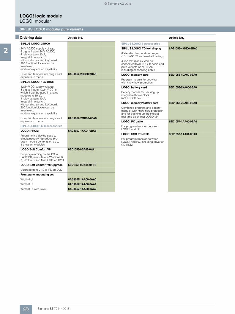
SIPLUS LOGO! modular pure variants
■ Overview
• Basic variants optimized for costs• Interface for connecting expansion modules, up to 24 digital
inputs, 16 (20) digital outputs, 8 analog inputs and 2 (8) analog outputs can be addressed
• With connection option for LOGO! TD text display (can be connected to all LOGO! 0BA6 basic variants)
New for SIPLUS LOGO! 8• All basic units with integrated Web server • Same enclosure width as LOGO! 0BA6 (4 U) • All basic units with Ethernet interface for communication with
LOGO!, SIMATIC Controller, SIMATIC Panel and PC • Use of standard micro CF cards
Note:
SIPLUS LOGO! 6 versions are not compatible with SIPLUS LOGO! 8.
SIPLUS extreme products are based on SIMATIC standard products. The contents listed here were adopted from the respective standard products. SIPLUS extreme specific information was added.
■ Technical specifications
Article number 6AG1052-2CC01-7BA8 6AG1052-2MD00-7BA8 6AG1052-2HB00-7BA8 6AG1052-2FB00-7BA8
Based on 6ED1052-2CC01-0BA8 6ED1052-2MD00-0BA8 6ED1052-2HB00-0BA8 6ED1052-2FB00-0BA8
SIPLUS LOGO! 24CEO SIPLUS LOGO! 12/24RCEO SIPLUS LOGO! 24RCEO (AC)
SIPLUS LOGO! 230RCEO
Ambient conditions
Ambient temperature during operation
• min. -40 °C; = Tmin; Startup @ -25 °C
-40 °C; = Tmin; Startup @ -25 °C
-40 °C; = Tmin; Startup @ -25 °C
-40 °C; = Tmin; Startup @ -25 °C
• max. 70 °C; Tmax; Tmax > +55 °C max. load 0.2 A per output
70 °C; Tmax; Tmax > +55 °C max. load 1 A per relay or max. load 3 A per relay and half the number of DIs (no adjacent points)
70 °C; Tmax; Tmax > +55 °C max. load 1 A per relay or max. load 3 A per relay and half the number of DIs (no adjacent points)
70 °C; Tmax; Tmax > +55 °C max. load 1 A per relay
Ambient temperature during storage/transportation
• min. -40 °C -40 °C -40 °C -40 °C
• max. 70 °C 70 °C 70 °C 70 °C
Extended ambient conditions
• relative to ambient temperature-atmospheric pressure-installation altitude
Tmin ... Tmax at 1080 hPa ... 795 hPa (-1000 m ... +2000 m) // Tmin ... (Tmax - 10K) at 795 hPa ... 658 hPa (+2000 m ... +3500 m) // Tmin ... (Tmax - 20K) at 658 hPa ... 540 hPa (+3500 m ... +5000 m)
• At cold restart, min. 0 °C 0 °C 0 °C 0 °C
Relative humidity
- With condensation, tested in accordance with IEC 60068-2-38, max.
100 %; RH incl. condensation / frost (no commissioning in bedewed state), horizontal installation
Resistance
- against biologically active substances / conformity with EN 60721-3-3
Yes; Class 3B2 mold, fungus and dry rot spores (with the exception of fauna). The supplied connector covers must remain on the unused interfaces during operation!
- against chemically active substances / conformity with EN 60721-3-3
Yes; Class 3C4 (RH < 75%) incl. salt spray according to EN 60068-2-52 (degree of severity 3). The supplied connector covers must remain on the unused interfaces during operation!
- against mechanically active substances / conformity with EN 60721-3-3
Yes; Class 3S4 incl. sand, dust. The supplied connector covers must remain on the unused interfaces during operation!
© Siemens AG 2016

2/7Siemens ST 70 N · 2016
2
■ Technical specifications (continued)
LOGO! logic moduleLOGO! modular
SIPLUS LOGO! modular pure variants
■ Ordering data Article No. Article No.
Article number 6AG1052-2CC01-2BA6 6AG1052-2MD00-2BA6 6AG1052-2HB00-2BA6 6AG1052-2FB00-2BA6
Based on 6ED1052-2CC01-0BA6 6ED1052-2MD00-0BA6 6ED1052-2HB00-0BA6 6ED1052-2FB00-0BA6
SIPLUS LOGO! 24CO SIPLUS LOGO! 12/24RCO SIPLUS LOGO! 24RCO SIPLUS LOGO! 230RCO
Ambient conditions
Ambient temperature during operation
• min. -40 °C; = Tmin -40 °C; = Tmin -40 °C; = Tmin -40 °C; = Tmin
• max. 70 °C; = Tmax; 55 °C @ UL/cUL use
70 °C; = Tmax; 55 °C @ UL/cUL use
70 °C; = Tmax; 55 °C @ UL/cUL use
70 °C; = Tmax; 55 °C @ UL/cUL use
Extended ambient conditions
• relative to ambient temperature-atmospheric pressure-installation altitude
Tmin ... Tmax at 1080 hPa ... 795 hPa (-1000 m ... +2000 m) // Tmin ... (Tmax - 10K) at 795 hPa ... 658 hPa (+2000 m ... +3500 m) // Tmin ... (Tmax - 20K) at 658 hPa ... 540 hPa (+3500 m ... +5000 m)
Tmin ... Tmax at 1080 hPa ... 795 hPa (-1000 m ... +2000 m) // Tmin ... (Tmax - 10K) at 795 hPa ... 658 hPa (+2000 m ... +3500 m) // Tmin ... (Tmax - 20K) at 658 hPa ... 540 hPa (+3500 m ... +5000 m)
Tmin ... Tmax at 1080 hPa ... 795 hPa (-1000 m ... +2000 m) // Tmin ... (Tmax - 10K) at 795 hPa ... 658 hPa (+2000 m ... +3500 m) // Tmin ... (Tmax - 20K) at 658 hPa ... 540 hPa (+3500 m ... +5000 m)
Tmin ... Tmax at 1080 hPa ... 795 hPa (-1000 m ... +2000 m)
Relative humidity
- With condensation, tested in accordance with IEC 60068-2-38, max.
100 %; Relative humidity, incl. condensation / frost permitted (no commissioning under condensation conditions)
Resistance
- against biologically active substances / conformity with EN 60721-3-3
Yes; Class 3B2 mold, fungus and dry rot spores (with the exception of fauna). The supplied connector covers must remain on the unused interfaces during operation!
- against chemically active substances / conformity with EN 60721-3-3
Yes; Class 3C4 incl. salt spray. The supplied connector covers must remain on the unused interfaces during operation!
- against mechanically active substances / conformity with EN 60721-3-3
Yes; Class 3S4 incl. sand, dust. The supplied connector covers must remain on the unused interfaces during operation!
SIPLUS LOGO! 8 logic module
SIPLUS LOGO! 24CEo
24 V DC supply voltage, 8 digital inputs 24 V DC, of which 4 can be used in analog mode (0 to 10 V), 4 digital outputs 24 V DC, 0.3 A, integral time switch, Ethernet interface; without display and keyboard; 400 function blocks can be interlinked, modular expansion capability
Extended temperature range and exposure to media
6AG1052-2CC01-7BA8
SIPLUS LOGO! 230RCEo
115...230 V AC/DC supply voltage, 8 digital inputs 115...230 V AC/DC, 4 relay outputs 10 A, integral time switch, Ethernet interface; without display or keyboard; 400 function blocks can be interlinked, modular expansion capability
Extended temperature range and exposure to media
6AG1052-2FB00-7BA8
SIPLUS LOGO! 24RCEo
24 V AC/DC supply voltage, 8 digital inputs 24 V AC/DC, 4 relay outputs 10 A, integral time switch, Ethernet interface; without display or keyboard; 400 function blocks can be interlinked, modular expansion capability
Extended temperature range and exposure to media
6AG1052-2HB00-7BA8
SIPLUS LOGO! 12/24RCEo
12...24 V DC supply voltage, 8 digital inputs 12...24 V DC, of which 4 can be used in analog mode (0 to 10 V), 4 relay outputs 10 A, integral time switch, Ethernet interface; without display or keyboard; 400 function blocks can be interlinked, modular expansion capability
Extended temperature range and exposure to media
6AG1052-2MD00-7BA8
SIPLUS LOGO! 6 logic module
SIPLUS LOGO! 24o
24 V DC supply voltage, 8 digital inputs 24 V DC, of which 4 can be used in analog mode (0 to 10 V), 4 digital outputs 24 V DC, 0.3 A, integrated time switch; without display and keyboard; 200 function blocks can be interlinked, modular expansion capability
Extended temperature range and exposure to media
6AG1052-2CC01-2BA6
SIPLUS LOGO! 230RCo
115/230 V AC/DC supply voltage, 8 digital inputs 115/230 V AC/DC, 4 relay outputs 10 A, integral time switch; without display and keyboard; 200 function blocks can be interlinked, modular expansion capability
Extended temperature range and exposure to media
6AG1052-2FB00-2BA6
© Siemens AG 2016
2/8 Siemens ST 70 N · 2016
2
■ Ordering data Article No. Article No.
LOGO! logic moduleLOGO! modular
SIPLUS LOGO! modular pure variants
SIPLUS LOGO! 24RCo
24 V AC/DC supply voltage, 8 digital inputs 24 V AC/DC, 4 relay outputs 10 A, integral time switch; without display and keyboard; 200 function blocks can be interlinked,modular expansion capability
Extended temperature range and exposure to media
6AG1052-2HB00-2BA6
SIPLUS LOGO! 12/24RCo
12/24 V DC supply voltage, 8 digital inputs 12/24 V DC, of which 4 can be used in analog mode (0 to 10 V), 4 relay outputs 10 A, integral time switch; without display and keyboard; 200 function blocks can be interlinked,modular expansion capability
Extended temperature range and exposure to media
6AG1052-2MD00-2BA6
SIPLUS LOGO! 6, 8 accessories
LOGO! PROM 6AG1057-1AA01-0BA6
Programming device used to simultaneously reproduce pro-gram module contents on up to 8 program modules
LOGO!Soft Comfort V8 6ED1058-0BA08-0YA1
For programming on the PC in LAD/FBD; executes on Windows 8, 7, XP, Linux and Mac OSX; on DVD
LOGO!Soft Comfort V8 Upgrade 6ED1058-0CA08-0YE1
Upgrade from V1.0 to V8, on DVD
Front panel mounting set
Width 4 U 6AG1057-1AA00-0AA0
Width 8 U 6AG1057-1AA00-0AA1
Width 8 U, with keys 6AG1057-1AA00-0AA2
SIPLUS LOGO! 6 accessories
SIPLUS LOGO! TD text display 6AG1055-4MH00-2BA0
(Extended temperature range -10 ... +60 °C and medial loading)
4-line text display, can be connected to all LOGO! basic and pure variants as of -0BA6, including connecting cable
LOGO! memory card 6ED1056-1DA00-0BA0
Program module for copying, with know-how protection
LOGO! battery card 6ED1056-6XA00-0BA0
Battery module for backing up integral real-time clock (not LOGO! 24)
LOGO! memory/battery card 6ED1056-7DA00-0BA0
Combined program and battery module, with know-how protection and for backing up the integral real-time clock (not LOGO! 24)
LOGO! PC cable 6ED1057-1AA00-0BA0
For program transfer between LOGO! and PC
LOGO! USB PC cable 6ED1057-1AA01-0BA0
For program transfer between LOGO! and PC, including driver on CD-ROM
© Siemens AG 2016
2/9Siemens ST 70 N · 2016
2
LOGO! logic moduleLOGO! modular
SIPLUS LOGO! modular expansion modules
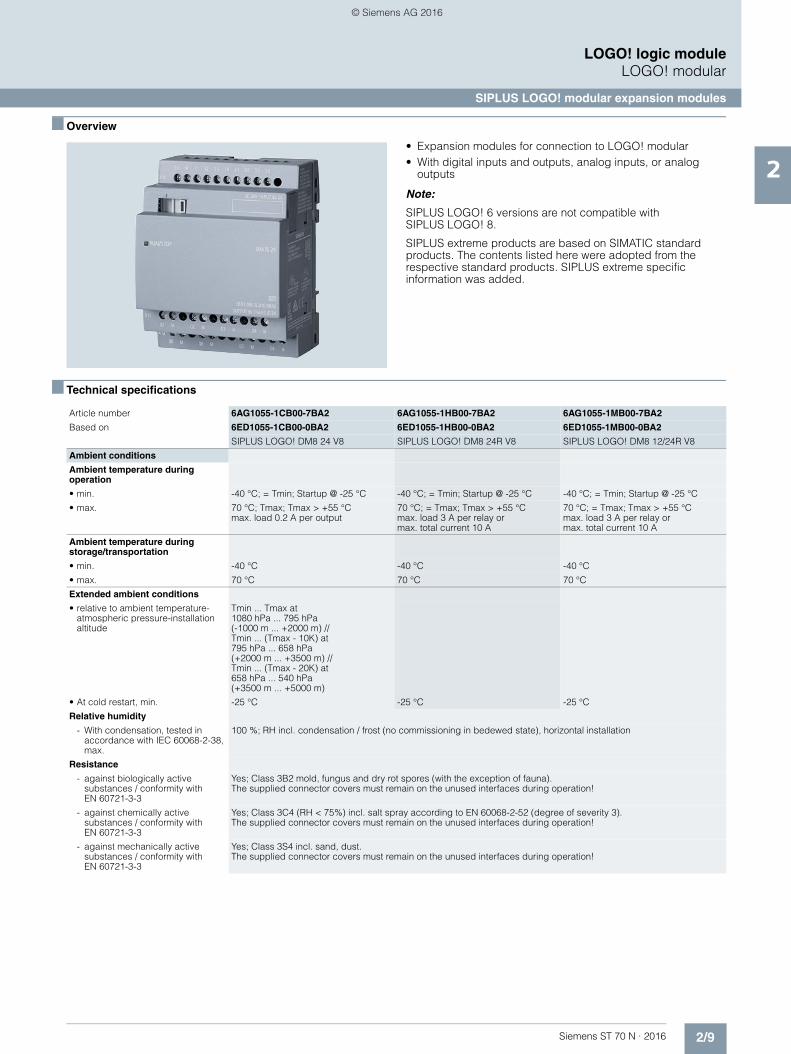
■ Overview
• Expansion modules for connection to LOGO! modular• With digital inputs and outputs, analog inputs, or analog
outputs
Note:
SIPLUS LOGO! 6 versions are not compatible with SIPLUS LOGO! 8.
SIPLUS extreme products are based on SIMATIC standard products. The contents listed here were adopted from the respective standard products. SIPLUS extreme specific information was added.
■ Technical specifications
Article number 6AG1055-1CB00-7BA2 6AG1055-1HB00-7BA2 6AG1055-1MB00-7BA2
Based on 6ED1055-1CB00-0BA2 6ED1055-1HB00-0BA2 6ED1055-1MB00-0BA2
SIPLUS LOGO! DM8 24 V8 SIPLUS LOGO! DM8 24R V8 SIPLUS LOGO! DM8 12/24R V8
Ambient conditions
Ambient temperature during operation
• min. -40 °C; = Tmin; Startup @ -25 °C -40 °C; = Tmin; Startup @ -25 °C -40 °C; = Tmin; Startup @ -25 °C
• max. 70 °C; Tmax; Tmax > +55 °C max. load 0.2 A per output
70 °C; = Tmax; Tmax > +55 °C max. load 3 A per relay or max. total current 10 A
70 °C; = Tmax; Tmax > +55 °C max. load 3 A per relay or max. total current 10 A
Ambient temperature during storage/transportation
• min. -40 °C -40 °C -40 °C
• max. 70 °C 70 °C 70 °C
Extended ambient conditions
• relative to ambient temperature-atmospheric pressure-installation altitude
Tmin ... Tmax at 1080 hPa ... 795 hPa (-1000 m ... +2000 m) // Tmin ... (Tmax - 10K) at 795 hPa ... 658 hPa (+2000 m ... +3500 m) // Tmin ... (Tmax - 20K) at 658 hPa ... 540 hPa (+3500 m ... +5000 m)
• At cold restart, min. -25 °C -25 °C -25 °C
Relative humidity
- With condensation, tested in accordance with IEC 60068-2-38, max.
100 %; RH incl. condensation / frost (no commissioning in bedewed state), horizontal installation
Resistance
- against biologically active substances / conformity with EN 60721-3-3
Yes; Class 3B2 mold, fungus and dry rot spores (with the exception of fauna). The supplied connector covers must remain on the unused interfaces during operation!
- against chemically active substances / conformity with EN 60721-3-3
Yes; Class 3C4 (RH < 75%) incl. salt spray according to EN 60068-2-52 (degree of severity 3). The supplied connector covers must remain on the unused interfaces during operation!
- against mechanically active substances / conformity with EN 60721-3-3
Yes; Class 3S4 incl. sand, dust. The supplied connector covers must remain on the unused interfaces during operation!
© Siemens AG 2016
2/10 Siemens ST 70 N · 2016
2
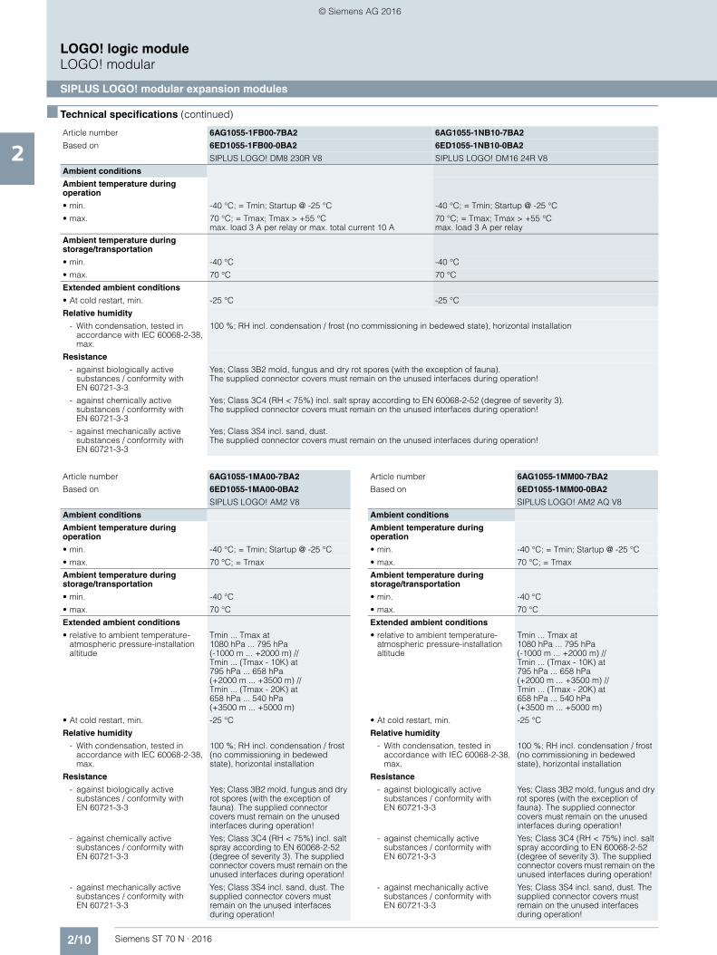
■ Technical specifications (continued)
LOGO! logic moduleLOGO! modular
SIPLUS LOGO! modular expansion modules
Article number 6AG1055-1FB00-7BA2 6AG1055-1NB10-7BA2
Based on 6ED1055-1FB00-0BA2 6ED1055-1NB10-0BA2
SIPLUS LOGO! DM8 230R V8 SIPLUS LOGO! DM16 24R V8
Ambient conditions
Ambient temperature during operation
• min. -40 °C; = Tmin; Startup @ -25 °C -40 °C; = Tmin; Startup @ -25 °C
• max. 70 °C; = Tmax; Tmax > +55 °C max. load 3 A per relay or max. total current 10 A
70 °C; = Tmax; Tmax > +55 °C max. load 3 A per relay
Ambient temperature during storage/transportation
• min. -40 °C -40 °C
• max. 70 °C 70 °C
Extended ambient conditions
• At cold restart, min. -25 °C -25 °C
Relative humidity
- With condensation, tested in accordance with IEC 60068-2-38, max.
100 %; RH incl. condensation / frost (no commissioning in bedewed state), horizontal installation
Resistance
- against biologically active substances / conformity with EN 60721-3-3
Yes; Class 3B2 mold, fungus and dry rot spores (with the exception of fauna). The supplied connector covers must remain on the unused interfaces during operation!
- against chemically active substances / conformity with EN 60721-3-3
Yes; Class 3C4 (RH < 75%) incl. salt spray according to EN 60068-2-52 (degree of severity 3). The supplied connector covers must remain on the unused interfaces during operation!
- against mechanically active substances / conformity with EN 60721-3-3
Yes; Class 3S4 incl. sand, dust. The supplied connector covers must remain on the unused interfaces during operation!
Article number 6AG1055-1MA00-7BA2
Based on 6ED1055-1MA00-0BA2
SIPLUS LOGO! AM2 V8
Ambient conditions
Ambient temperature during operation
• min. -40 °C; = Tmin; Startup @ -25 °C
• max. 70 °C; = Tmax
Ambient temperature during storage/transportation
• min. -40 °C
• max. 70 °C
Extended ambient conditions
• relative to ambient temperature-atmospheric pressure-installation altitude
Tmin ... Tmax at 1080 hPa ... 795 hPa (-1000 m ... +2000 m) // Tmin ... (Tmax - 10K) at 795 hPa ... 658 hPa (+2000 m ... +3500 m) // Tmin ... (Tmax - 20K) at 658 hPa ... 540 hPa (+3500 m ... +5000 m)
• At cold restart, min. -25 °C
Relative humidity
- With condensation, tested in accordance with IEC 60068-2-38, max.
100 %; RH incl. condensation / frost (no commissioning in bedewed state), horizontal installation
Resistance
- against biologically active substances / conformity with EN 60721-3-3
Yes; Class 3B2 mold, fungus and dry rot spores (with the exception of fauna). The supplied connector covers must remain on the unused interfaces during operation!
- against chemically active substances / conformity with EN 60721-3-3
Yes; Class 3C4 (RH < 75%) incl. salt spray according to EN 60068-2-52 (degree of severity 3). The supplied connector covers must remain on the unused interfaces during operation!
- against mechanically active substances / conformity with EN 60721-3-3
Yes; Class 3S4 incl. sand, dust. The supplied connector covers must remain on the unused interfaces during operation!
Article number 6AG1055-1MM00-7BA2
Based on 6ED1055-1MM00-0BA2
SIPLUS LOGO! AM2 AQ V8
Ambient conditions
Ambient temperature during operation
• min. -40 °C; = Tmin; Startup @ -25 °C
• max. 70 °C; = Tmax
Ambient temperature during storage/transportation
• min. -40 °C
• max. 70 °C
Extended ambient conditions
• relative to ambient temperature-atmospheric pressure-installation altitude
Tmin ... Tmax at 1080 hPa ... 795 hPa (-1000 m ... +2000 m) // Tmin ... (Tmax - 10K) at 795 hPa ... 658 hPa (+2000 m ... +3500 m) // Tmin ... (Tmax - 20K) at 658 hPa ... 540 hPa (+3500 m ... +5000 m)
• At cold restart, min. -25 °C
Relative humidity
- With condensation, tested in accordance with IEC 60068-2-38, max.
100 %; RH incl. condensation / frost (no commissioning in bedewed state), horizontal installation
Resistance
- against biologically active substances / conformity with EN 60721-3-3
Yes; Class 3B2 mold, fungus and dry rot spores (with the exception of fauna). The supplied connector covers must remain on the unused interfaces during operation!
- against chemically active substances / conformity with EN 60721-3-3
Yes; Class 3C4 (RH < 75%) incl. salt spray according to EN 60068-2-52 (degree of severity 3). The supplied connector covers must remain on the unused interfaces during operation!
- against mechanically active substances / conformity with EN 60721-3-3
Yes; Class 3S4 incl. sand, dust. The supplied connector covers must remain on the unused interfaces during operation!
© Siemens AG 2016
2/11Siemens ST 70 N · 2016
2
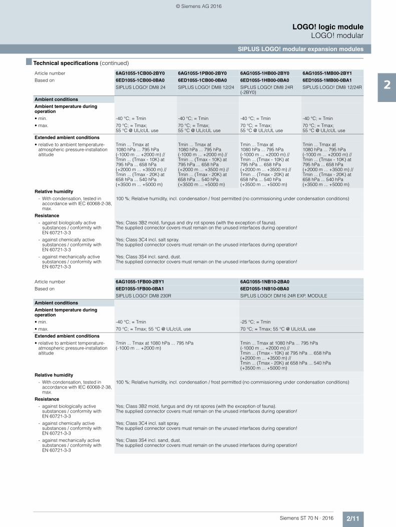
■ Technical specifications (continued)
LOGO! logic moduleLOGO! modular
SIPLUS LOGO! modular expansion modules
Article number 6AG1055-1CB00-2BY0 6AG1055-1PB00-2BY0 6AG1055-1HB00-2BY0 6AG1055-1MB00-2BY1
Based on 6ED1055-1CB00-0BA0 6ED1055-1CB00-0BA0 6ED1055-1HB00-0BA0 6ED1055-1MB00-0BA1
SIPLUS LOGO! DM8 24 SIPLUS LOGO! DM8 12/24 SIPLUS LOGO! DM8 24R (-2BY0)
SIPLUS LOGO! DM8 12/24R
Ambient conditions
Ambient temperature during operation
• min. -40 °C; = Tmin -40 °C; = Tmin -40 °C; = Tmin -40 °C; = Tmin
• max. 70 °C; = Tmax; 55 °C @ UL/cUL use
70 °C; = Tmax; 55 °C @ UL/cUL use
70 °C; = Tmax; 55 °C @ UL/cUL use
70 °C; = Tmax; 55 °C @ UL/cUL use
Extended ambient conditions
• relative to ambient temperature-atmospheric pressure-installation altitude
Tmin ... Tmax at 1080 hPa ... 795 hPa (-1000 m ... +2000 m) // Tmin ... (Tmax - 10K) at 795 hPa ... 658 hPa (+2000 m ... +3500 m) // Tmin ... (Tmax - 20K) at 658 hPa ... 540 hPa (+3500 m ... +5000 m)
Tmin ... Tmax at 1080 hPa ... 795 hPa (-1000 m ... +2000 m) // Tmin ... (Tmax - 10K) at 795 hPa ... 658 hPa (+2000 m ... +3500 m) // Tmin ... (Tmax - 20K) at 658 hPa ... 540 hPa (+3500 m ... +5000 m)
Tmin ... Tmax at 1080 hPa ... 795 hPa (-1000 m ... +2000 m) // Tmin ... (Tmax - 10K) at 795 hPa ... 658 hPa (+2000 m ... +3500 m) // Tmin ... (Tmax - 20K) at 658 hPa ... 540 hPa (+3500 m ... +5000 m)
Tmin ... Tmax at 1080 hPa ... 795 hPa (-1000 m ... +2000 m) // Tmin ... (Tmax - 10K) at 795 hPa ... 658 hPa (+2000 m ... +3500 m) // Tmin ... (Tmax - 20K) at 658 hPa ... 540 hPa (+3500 m ... +5000 m)
Relative humidity
- With condensation, tested in accordance with IEC 60068-2-38, max.
100 %; Relative humidity, incl. condensation / frost permitted (no commissioning under condensation conditions)
Resistance
- against biologically active substances / conformity with EN 60721-3-3
Yes; Class 3B2 mold, fungus and dry rot spores (with the exception of fauna). The supplied connector covers must remain on the unused interfaces during operation!
- against chemically active substances / conformity with EN 60721-3-3
Yes; Class 3C4 incl. salt spray. The supplied connector covers must remain on the unused interfaces during operation!
- against mechanically active substances / conformity with EN 60721-3-3
Yes; Class 3S4 incl. sand, dust. The supplied connector covers must remain on the unused interfaces during operation!
Article number 6AG1055-1FB00-2BY1 6AG1055-1NB10-2BA0
Based on 6ED1055-1FB00-0BA1 6ED1055-1NB10-0BA0
SIPLUS LOGO! DM8 230R SIPLUS LOGO! DM16 24R EXP. MODULE
Ambient conditions
Ambient temperature during operation
• min. -40 °C; = Tmin -25 °C; = Tmin
• max. 70 °C; = Tmax; 55 °C @ UL/cUL use 70 °C; = Tmax; 55 °C @ UL/cUL use
Extended ambient conditions
• relative to ambient temperature-atmospheric pressure-installation altitude
Tmin ... Tmax at 1080 hPa ... 795 hPa (-1000 m ... +2000 m)
Tmin ... Tmax at 1080 hPa ... 795 hPa (-1000 m ... +2000 m) // Tmin ... (Tmax - 10K) at 795 hPa ... 658 hPa (+2000 m ... +3500 m) // Tmin ... (Tmax - 20K) at 658 hPa ... 540 hPa (+3500 m ... +5000 m)
Relative humidity
- With condensation, tested in accordance with IEC 60068-2-38, max.
100 %; Relative humidity, incl. condensation / frost permitted (no commissioning under condensation conditions)
Resistance
- against biologically active substances / conformity with EN 60721-3-3
Yes; Class 3B2 mold, fungus and dry rot spores (with the exception of fauna). The supplied connector covers must remain on the unused interfaces during operation!
- against chemically active substances / conformity with EN 60721-3-3
Yes; Class 3C4 incl. salt spray. The supplied connector covers must remain on the unused interfaces during operation!
- against mechanically active substances / conformity with EN 60721-3-3
Yes; Class 3S4 incl. sand, dust. The supplied connector covers must remain on the unused interfaces during operation!
© Siemens AG 2016

2/12 Siemens ST 70 N · 2016
2
■ Technical specifications (continued)
LOGO! logic moduleLOGO! modular
SIPLUS LOGO! modular expansion modules
■ Ordering data Article No. Article No.
Article number 6AG1055-1MA00-2BY0
Based on 6ED1055-1MA00-0BA0
SIPLUS LOGO! AM2
Ambient conditions
Ambient temperature during operation
• min. -40 °C; = Tmin
• max. 70 °C; = Tmax; 55 °C @ UL/cUL use
Extended ambient conditions
• relative to ambient temperature-atmospheric pressure-installation altitude
Tmin ... Tmax at 1080 hPa ... 795 hPa (-1000 m ... +2000 m) // Tmin ... (Tmax - 10K) at 795 hPa ... 658 hPa (+2000 m ... +3500 m) // Tmin ... (Tmax - 20K) at 658 hPa ... 540 hPa (+3500 m ... +5000 m)
Relative humidity
- With condensation, tested in accordance with IEC 60068-2-38, max.
100 %; Relative humidity, incl. condensation / frost permitted (no commissioning under condensation conditions)
Resistance
- against biologically active substances / conformity with EN 60721-3-3
Yes; Class 3B2 mold, fungus and dry rot spores (with the exception of fauna). The supplied connector covers must remain on the unused interfaces during operation!
- against chemically active substances / conformity with EN 60721-3-3
Yes; Class 3C4 incl. salt spray. The supplied connector covers must remain on the unused interfaces during operation!
- against mechanically active substances / conformity with EN 60721-3-3
Yes; Class 3S4 incl. sand, dust. The supplied connector covers must remain on the unused interfaces during operation!
Article number 6AG1055-1MM00-2BY1
Based on 6ED1055-1MM00-0BA1
SIPLUS_LOGO!_AM2_AQ
Ambient conditions
Ambient temperature during operation
• min. -40 °C; = Tmin
• max. 70 °C; = Tmax; 55 °C @ UL/cUL use
Extended ambient conditions
• relative to ambient temperature-atmospheric pressure-installation altitude
Tmin ... Tmax at 1080 hPa ... 795 hPa (-1000 m ... +2000 m) // Tmin ... (Tmax - 10K) at 795 hPa ... 658 hPa (+2000 m ... +3500 m) // Tmin ... (Tmax - 20K) at 658 hPa ... 540 hPa (+3500 m ... +5000 m)
Relative humidity
- With condensation, tested in accordance with IEC 60068-2-38, max.
100 %; Relative humidity, incl. condensation / frost permitted (no commissioning under condensation conditions)
Resistance
- against biologically active substances / conformity with EN 60721-3-3
Yes; Class 3B2 mold, fungus and dry rot spores (with the exception of fauna). The supplied connector covers must remain on the unused interfaces during operation!
- against chemically active substances / conformity with EN 60721-3-3
Yes; Class 3C4 incl. salt spray. The supplied connector covers must remain on the unused interfaces during operation!
- against mechanically active substances / conformity with EN 60721-3-3
Yes; Class 3S4 incl. sand, dust. The supplied connector covers must remain on the unused interfaces during operation!
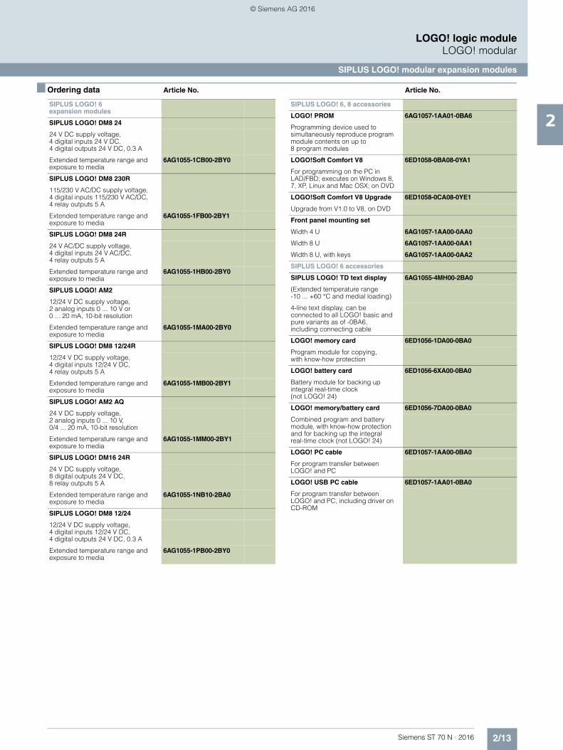
SIPLUS LOGO! 8 expansion modules
SIPLUS LOGO! DM8 24
Supply voltage 24 V DC, 4 digital inputs 24 V DC, 4 digital outputs 24 V DC, 0.3 A
Extended temperature range and exposure to media
6AG1055-1CB00-7BA2
SIPLUS LOGO! DM8 230R
115...230 V AC/DC supply voltage, 4 digital inputs 115...230 V AC/DC, 4 relay outputs 5 A
Extended temperature range and exposure to media
6AG1055-1FB00-7BA2
SIPLUS LOGO! DM8 24R
Supply voltage 24 V AC/DC, 4 digital inputs 24 V AC/DC, 4 relay outputs 5 A
Extended temperature range and exposure to media
6AG1055-1HB00-7BA2
SIPLUS LOGO! AM2
12...24 V DC supply voltage, 2 analog inputs 0 to 10 V or 0 to 20 mA, resolution 10 bit
Extended temperature range and exposure to media
6AG1055-1MA00-7BA2
SIPLUS LOGO! DM8 12/24R
12...24 V DC supply voltage, 4 digital inputs 12...24 V DC, 4 relay outputs 5 A
Extended temperature range and exposure to media
6AG1055-1MB00-7BA2
SIPLUS LOGO! AM2 AQ
Supply voltage 24 V DC, 2 analog outputs 0 to 10 V, 0/4 to 20 mA
Extended temperature range and exposure to media
6AG1055-1MM00-7BA2
SIPLUS LOGO! DM16 24R
Supply voltage 24 V DC, 8 digital inputs 24 V DC, 8 relay outputs 5 A
Extended temperature range and exposure to media
6AG1055-1NB10-7BA2
© Siemens AG 2016
2/13Siemens ST 70 N · 2016
2
■ Ordering data Article No. Article No.
LOGO! logic moduleLOGO! modular
SIPLUS LOGO! modular expansion modules
SIPLUS LOGO! 6 expansion modules
SIPLUS LOGO! DM8 24
24 V DC supply voltage, 4 digital inputs 24 V DC, 4 digital outputs 24 V DC, 0.3 A
Extended temperature range and exposure to media
6AG1055-1CB00-2BY0
SIPLUS LOGO! DM8 230R
115/230 V AC/DC supply voltage, 4 digital inputs 115/230 V AC/DC, 4 relay outputs 5 A
Extended temperature range and exposure to media
6AG1055-1FB00-2BY1
SIPLUS LOGO! DM8 24R
24 V AC/DC supply voltage, 4 digital inputs 24 V AC/DC, 4 relay outputs 5 A
Extended temperature range and exposure to media
6AG1055-1HB00-2BY0
SIPLUS LOGO! AM2
12/24 V DC supply voltage, 2 analog inputs 0 ... 10 V or 0 ... 20 mA, 10-bit resolution
Extended temperature range and exposure to media
6AG1055-1MA00-2BY0
SIPLUS LOGO! DM8 12/24R
12/24 V DC supply voltage, 4 digital inputs 12/24 V DC, 4 relay outputs 5 A
Extended temperature range and exposure to media
6AG1055-1MB00-2BY1
SIPLUS LOGO! AM2 AQ
24 V DC supply voltage, 2 analog inputs 0 ... 10 V, 0/4 ... 20 mA, 10-bit resolution
Extended temperature range and exposure to media
6AG1055-1MM00-2BY1
SIPLUS LOGO! DM16 24R
24 V DC supply voltage, 8 digital outputs 24 V DC, 8 relay outputs 5 A
Extended temperature range and exposure to media
6AG1055-1NB10-2BA0
SIPLUS LOGO! DM8 12/24
12/24 V DC supply voltage, 4 digital inputs 12/24 V DC, 4 digital outputs 24 V DC, 0.3 A
Extended temperature range and exposure to media
6AG1055-1PB00-2BY0
SIPLUS LOGO! 6, 8 accessories
LOGO! PROM 6AG1057-1AA01-0BA6
Programming device used to simultaneously reproduce program module contents on up to 8 program modules
LOGO!Soft Comfort V8 6ED1058-0BA08-0YA1
For programming on the PC in LAD/FBD; executes on Windows 8, 7, XP, Linux and Mac OSX; on DVD
LOGO!Soft Comfort V8 Upgrade 6ED1058-0CA08-0YE1
Upgrade from V1.0 to V8, on DVD
Front panel mounting set
Width 4 U 6AG1057-1AA00-0AA0
Width 8 U 6AG1057-1AA00-0AA1
Width 8 U, with keys 6AG1057-1AA00-0AA2
SIPLUS LOGO! 6 accessories
SIPLUS LOGO! TD text display 6AG1055-4MH00-2BA0
(Extended temperature range -10 ... +60 °C and medial loading)
4-line text display, can be connected to all LOGO! basic and pure variants as of -0BA6, including connecting cable
LOGO! memory card 6ED1056-1DA00-0BA0
Program module for copying, with know-how protection
LOGO! battery card 6ED1056-6XA00-0BA0
Battery module for backing up integral real-time clock (not LOGO! 24)
LOGO! memory/battery card 6ED1056-7DA00-0BA0
Combined program and battery module, with know-how protection and for backing up the integral real-time clock (not LOGO! 24)
LOGO! PC cable 6ED1057-1AA00-0BA0
For program transfer between LOGO! and PC
LOGO! USB PC cable 6ED1057-1AA01-0BA0
For program transfer between LOGO! and PC, including driver on CD-ROM
© Siemens AG 2016

2/14 Siemens ST 70 N · 2016
2
LOGO! logic moduleLOGO! modular communication modules
LOGO! CMK2000 communication module
■ Overview
• Expansion module for LOGO! 8 basic versions• For integrating LOGO! 8 in KNX installations• With 24 digital inputs, 20 digital outputs as well as 8 analog
inputs and outputs for processing process signals via KNX.
■ Technical specifications
■ Ordering data Article No.
Article number 6BK1700-0BA20-0AA0
LOGO! CMK2000
General information
Firmware version
• FW update possible Yes
Installation type/mounting
Mounting on 35 mm DIN rail, 4 spacing units wide
Supply voltage
Rated value (DC) 24 V
• 12 V DC No
• 24 V DC Yes
permissible range, lower limit (DC) 19.2 V
permissible range, upper limit (DC) 28.8 V
Rated value (AC)
• 24 V AC No
Input current
Current consumption, max. 0.04 A
Power loss
Power loss, max. 1.1 W
Memory
Flash Yes
Time of day
Clock synchronization
• supported Yes
Interfaces
Transmission rate, max. 100 Mbit/s over Ethernet, 9 600 bit/s over KNX
Protocols
EIB/KNX Yes
Web server
• supported Yes
Interrupts/diagnostics/status information
Diagnostics indication LED
• RUN/STOP LED Yes
EMC
Emission of radio interference acc. to EN 55 011
• Limit class B, for use in residential areas
Yes; In accordance with EN 61000-6-3
Degree and class of protection
Degree of protection acc. to EN 60529
• IP20 Yes
Standards, approvals, certificates
CE mark Yes
CSA approval Yes
UL approval Yes
cULus Yes
FM approval No
RCM (formerly C-TICK) No
KC approval Yes
EAC (formerly Gost-R) Yes
according to VDE 0631 No
Marine approval
• Marine approval No
Ambient conditions
Ambient temperature during operation
• min. 0 °C
• max. 55 °C
Ambient temperature during storage/transportation
• min. -40 °C
• max. 70 °C
Relative humidity
• Operation, max. 95 %
Connection method
Bus connector KNX terminal 0.6 mm² - 1.0 mm²
Power supply 2 screw-type terminals: L+, M 0.5 mm² - 2.5 mm² Screw-type terminal: FE 0.5 mm² … 6.0 mm²
Dimensions
Width 71.5 mm; 4 WU
Height 90 mm
Depth 58.5 mm
Weights
Weight, approx. 0.14 kg
LOGO! CMK2000 communication module
6BK1700-0BA20-0AA0
For integrating LOGO! 8 in the KNX building system bus, max. 50 communication objects can be configured; RJ45 port for Ethernet; supply voltage 24 V DC/40 mA
Article number 6BK1700-0BA20-0AA0
LOGO! CMK2000
© Siemens AG 2016
Siemens ST 70 N · 2016
3
Brochures
For brochures serving as selectionguides for SIMATIC products refer to:
www.siemens.com/simatic/printmaterial
3/2 Central processing units3/2 SIPLUS standard CPUs3/2 SIPLUS CPU 1212C3/6 SIPLUS CPU 1214C3/10 SIPLUS CPU 1215C
3/14 I/O modules3/14 SIPLUS analog modules3/14 SIPLUS RTD SM 1231 signal module 3/16 Special modules3/16 SIPLUS CMS1200 SM 1281
Condition Monitoring3/17 SIWAREX WP2513/19 SIPLUS communication3/19 SIPLUS CM 1241 communication module
3/21 Operator control and monitoring3/21 SIPLUS Basic Panels (2nd Generation)
SIMATIC S7-1200 basic controller
© Siemens AG 2016
3/2 Siemens ST 70 N · 2016
3
SIMATIC S7-1200 basic controllerCentral processing unitsSIPLUS standard CPUs
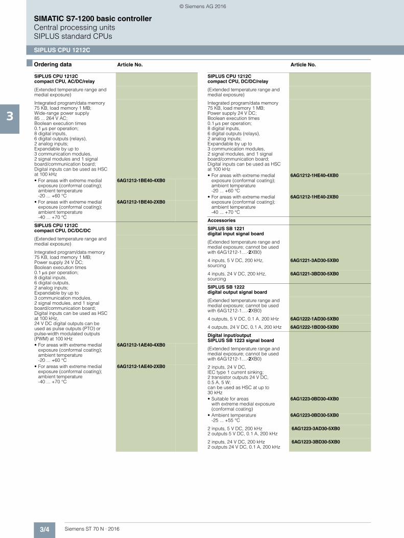
SIPLUS CPU 1212C
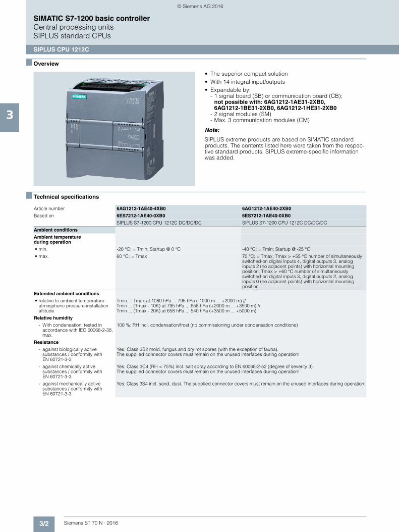
■ Overview
• The superior compact solution• With 14 integral input/outputs• Expandable by:
- 1 signal board (SB) or communication board (CB); not possible with: 6AG1212-1AE31-2XB0,6AG1212-1BE31-2XB0, 6AG1212-1HE31-2XB0
- 2 signal modules (SM)- Max. 3 communication modules (CM)
Note:
SIPLUS extreme products are based on SIMATIC standard products. The contents listed here were taken from the respec-tive standard products. SIPLUS extreme-specific information was added.
■ Technical specifications
Article number 6AG1212-1AE40-4XB0 6AG1212-1AE40-2XB0
Based on 6ES7212-1AE40-0XB0 6ES7212-1AE40-0XB0
SIPLUS S7-1200 CPU 1212C DC/DC/DC SIPLUS S7-1200 CPU 1212C DC/DC/DC
Ambient conditions
Ambient temperatureduring operation
• min. -20 °C; = Tmin; Startup @ 0 °C -40 °C; = Tmin; Startup @ -25 °C
• max. 60 °C; = Tmax 70 °C; = Tmax; Tmax > +55 °C number of simultaneously switched-on digital inputs 4, digital outputs 3, analog inputs 2 (no adjacent points) with horizontal mounting position; Tmax > +60 °C number of simultaneously switched-on digital inputs 3, digital outputs 2, analog inputs 0 (no adjacent points) with horizontal mounting position
Extended ambient conditions
• relative to ambient temperature-atmospheric pressure-installation altitude
Tmin ... Tmax at 1080 hPa ... 795 hPa (-1000 m ... +2000 m) // Tmin ... (Tmax - 10K) at 795 hPa ... 658 hPa (+2000 m ... +3500 m) // Tmin ... (Tmax - 20K) at 658 hPa ... 540 hPa (+3500 m ... +5000 m)
Relative humidity
- With condensation, tested in accordance with IEC 60068-2-38, max.
100 %; RH incl. condensation/frost (no commissioning under condensation conditions)
Resistance
- against biologically active substances / conformity with EN 60721-3-3
Yes; Class 3B2 mold, fungus and dry rot spores (with the exception of fauna). The supplied connector covers must remain on the unused interfaces during operation!
- against chemically active substances / conformity with EN 60721-3-3
Yes; Class 3C4 (RH < 75%) incl. salt spray according to EN 60068-2-52 (degree of severity 3).The supplied connector covers must remain on the unused interfaces during operation!
- against mechanically active substances / conformity with EN 60721-3-3
Yes; Class 3S4 incl. sand, dust. The supplied connector covers must remain on the unused interfaces during operation!
© Siemens AG 2016
3/3Siemens ST 70 N · 2016
3
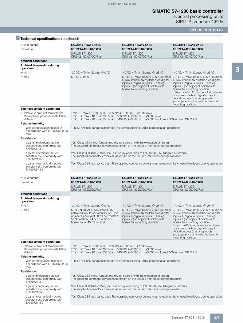
■ Technical specifications (continued)
SIMATIC S7-1200 basic controllerCentral processing units SIPLUS standard CPUs
SIPLUS CPU 1212C
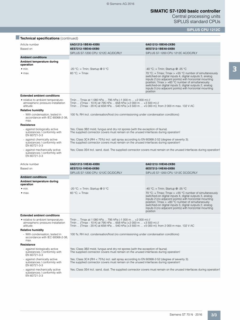
Article number 6AG1212-1BE40-4XB0 6AG1212-1BE40-2XB0
Based on 6ES7212-1BE40-0XB0 6ES7212-1BE40-0XB0
SIPLUS S7-1200 CPU 1212C AC/DC/RLY SIPLUS S7-1200 CPU 1212C AC/DC/RLY
Ambient conditions
Ambient temperature during operation
• min. -20 °C; = Tmin; Startup @ 0 °C -40 °C; = Tmin; Startup @ -25 °C
• max. 60 °C; = Tmax 70 °C; = Tmax; Tmax > +55 °C number of simultaneously switched-on digital inputs 4, digital outputs 3, analog inputs 2 (no adjacent points) with horizontal mounting position; Tmax > +60 °C number of simultaneously switched-on digital inputs 3, digital outputs 2, analog inputs 0 (no adjacent points) with horizontal mounting position
Extended ambient conditions
• relative to ambient temperature-atmospheric pressure-installation altitude
Tmin ... Tmax at 1 080 hPa ... 795 hPa (-1 000 m ... +2 000 m) //Tmin ... (Tmax - 10 K) at 795 hPa ... 658 hPa (+2 000 m ... +3 500 m) //Tmin ... (Tmax - 20 K) at 658 hPa ... 540 hPa (+3 500 m ... +5 000 m); from 2 000 m max. 132 V AC
Relative humidity
- With condensation, tested in accordance with IEC 60068-2-38, max.
100 %; RH incl. condensation/frost (no commissioning under condensation conditions)
Resistance
- against biologically active substances / conformity with EN 60721-3-3
Yes; Class 3B2 mold, fungus and dry rot spores (with the exception of fauna). The supplied connector covers must remain on the unused interfaces during operation!
- against chemically active substances / conformity with EN 60721-3-3
Yes; Class 3C4 (RH < 75%) incl. salt spray according to EN 60068-2-52 (degree of severity 3). The supplied connector covers must remain on the unused interfaces during operation!
- against mechanically active substances / conformity with EN 60721-3-3
Yes; Class 3S4 incl. sand, dust. The supplied connector covers must remain on the unused interfaces during operation!
Article number 6AG1212-1HE40-4XB0 6AG1212-1HE40-2XB0
Based on 6ES7212-1HE40-0XB0 6ES7212-1HE40-0XB0
SIPLUS S7-1200 CPU 1212C DC/DC/RLY SIPLUS S7-1200 CPU 1212C DC/DC/RLY
Ambient conditions
Ambient temperature during operation
• min. -20 °C; = Tmin; Startup @ 0 °C -40 °C; = Tmin; Startup @ -25 °C
• max. 60 °C; = Tmax 70 °C; = Tmax; Tmax > +55 °C number of simultaneously switched-on digital inputs 4, digital outputs 3, analog inputs 2 (no adjacent points) with horizontal mounting position; Tmax > +60 °C number of simultaneously switched-on digital inputs 3, digital outputs 2, analog inputs 0 (no adjacent points) with horizontal mounting position
Extended ambient conditions
• relative to ambient temperature-atmospheric pressure-installation altitude
Tmin ... Tmax at 1 080 hPa ... 795 hPa (-1 000 m ... +2 000 m) // Tmin ... (Tmax - 10 K) at 795 hPa ... 658 hPa (+2 000 m ... +3 500 m) // Tmin ... (Tmax - 20 K) at 658 hPa ... 540 hPa (+3 500 m ... +5 000 m); from 2 000 m max. 132 V AC
Relative humidity
- With condensation, tested in accordance with IEC 60068-2-38, max.
100 %; RH incl. condensation/frost (no commissioning under condensation conditions)
Resistance
- against biologically active substances / conformity with EN 60721-3-3
Yes; Class 3B2 mold, fungus and dry rot spores (with the exception of fauna).The supplied connector covers must remain on the unused interfaces during operation!
- against chemically active substances / conformity with EN 60721-3-3
Yes; Class 3C4 (RH < 75%) incl. salt spray according to EN 60068-2-52 (degree of severity 3). The supplied connector covers must remain on the unused interfaces during operation!
- against mechanically active substances / conformity with EN 60721-3-3
Yes; Class 3S4 incl. sand, dust. The supplied connector covers must remain on the unused interfaces during operation!
© Siemens AG 2016
3/4 Siemens ST 70 N · 2016
3
SIMATIC S7-1200 basic controllerCentral processing unitsSIPLUS standard CPUs
SIPLUS CPU 1212C
■ Ordering data Article No. Article No.
SIPLUS CPU 1212Ccompact CPU, AC/DC/relay
(Extended temperature range and medial exposure)
Integrated program/data memory 75 KB, load memory 1 MB; Wide-range power supply 85 ... 264 V AC; Boolean execution times 0.1 s per operation; 8 digital inputs, 6 digital outputs (relays), 2 analog inputs; Expandable by up to 3 communication modules, 2 signal modules and 1 signal board/communication board; Digital inputs can be used as HSC at 100 kHz• For areas with extreme medial
exposure (conformal coating);ambient temperature-20 ... +60 °C
6AG1212-1BE40-4XB0
• For areas with extreme medial exposure (conformal coating);ambient temperature-40 ... +70 °C
6AG1212-1BE40-2XB0
SIPLUS CPU 1212C compact CPU, DC/DC/DC
(Extended temperature range and medial exposure)
Integrated program/data memory 75 KB, load memory 1 MB; Power supply 24 V DC; Boolean execution times 0.1 s per operation; 8 digital inputs,6 digital outputs, 2 analog inputs; Expandable by up to 3 communication modules, 2 signal modules, and 1 signal board/communication board; Digital inputs can be used as HSC at 100 kHz, 24 V DC digital outputs can be used as pulse outputs (PTO) or pulse-width modulated outputs (PWM) at 100 kHz• For areas with extreme medial
exposure (conformal coating);ambient temperature-20 ... +60 °C
6AG1212-1AE40-4XB0
• For areas with extreme medialexposure (conformal coating);ambient temperature-40 ... +70 °C
6AG1212-1AE40-2XB0
SIPLUS CPU 1212Ccompact CPU, DC/DC/relay
(Extended temperature range and medial exposure)
Integrated program/data memory 75 KB, load memory 1 MB; Power supply 24 V DC; Boolean execution times 0.1 s per operation; 8 digital inputs, 6 digital outputs (relays), 2 analog inputs; Expandable by up to 3 communication modules, 2 signal modules, and 1 signal board/communication board; Digital inputs can be used as HSC at 100 kHz• For areas with extreme medial
exposure (conformal coating);ambient temperature-20 ... +60 °C
6AG1212-1HE40-4XB0
• For areas with extreme medial exposure (conformal coating);ambient temperature-40 ... +70 °C
6AG1212-1HE40-2XB0
Accessories
SIPLUS SB 1221digital input signal board
(Extended temperature range and medial exposure; cannot be used with 6AG1212-1....-2XB0)
4 inputs, 5 V DC, 200 kHz, sourcing
6AG1221-3AD30-5XB0
4 inputs, 24 V DC, 200 kHz, sourcing
6AG1221-3BD30-5XB0
SIPLUS SB 1222digital output signal board
(Extended temperature range and medial exposure; cannot be used with 6AG1212-1....-2XB0)
4 outputs, 5 V DC, 0.1 A, 200 kHz 6AG1222-1AD30-5XB0
4 outputs, 24 V DC, 0.1 A, 200 kHz 6AG1222-1BD30-5XB0
Digital input/output SIPLUS SB 1223 signal board
(Extended temperature range and medial exposure; cannot be used with 6AG1212-1....-2XB0)
2 inputs, 24 V DC,IEC type 1 current sinking; 2 transistor outputs 24 V DC,0.5 A, 5 W; can be used as HSC at up to 30 kHz• Suitable for areas
with extreme medial exposure (conformal coating)
6AG1223-0BD30-4XB0
• Ambient temperature-25 ... +55 °C
6AG1223-0BD30-5XB0
2 inputs, 5 V DC, 200 kHz2 outputs 5 V DC, 0.1 A, 200 kHz
6AG1223-3AD30-5XB0
2 inputs, 24 V DC, 200 kHz2 outputs 24 V DC, 0.1 A, 200 kHz
6AG1223-3BD30-5XB0
© Siemens AG 2016
3/5Siemens ST 70 N · 2016
3
■ Ordering data Article No. Article No.
SIMATIC S7-1200 basic controllerCentral processing units SIPLUS standard CPUs
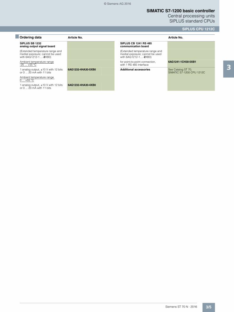
SIPLUS CPU 1212C
SIPLUS SB 1232 analog output signal board
(Extended temperature range and medial exposure; cannot be used with 6AG1212-1....-2XB0)
Ambient temperature range-25 ... +55 °C
1 analog output, ±10 V with 12 bits or 0 ... 20 mA with 11 bits
6AG1232-4HA30-5XB0
Ambient temperature range 0 ... +55 °C
1 analog output, ±10 V with 12 bits or 0 ... 20 mA with 11 bits
6AG1232-4HA30-4XB0
SIPLUS CB 1241 RS 485 communication board
(Extended temperature range and medial exposure; cannot be used with 6AG1212-1....-2XB0)
for point-to-point connection, with 1 RS 485 interface
6AG1241-1CH30-5XB1
Additional accessories See Catalog ST 70,SIMATIC S7-1200 CPU 1212C
© Siemens AG 2016

3/6 Siemens ST 70 N · 2016
3
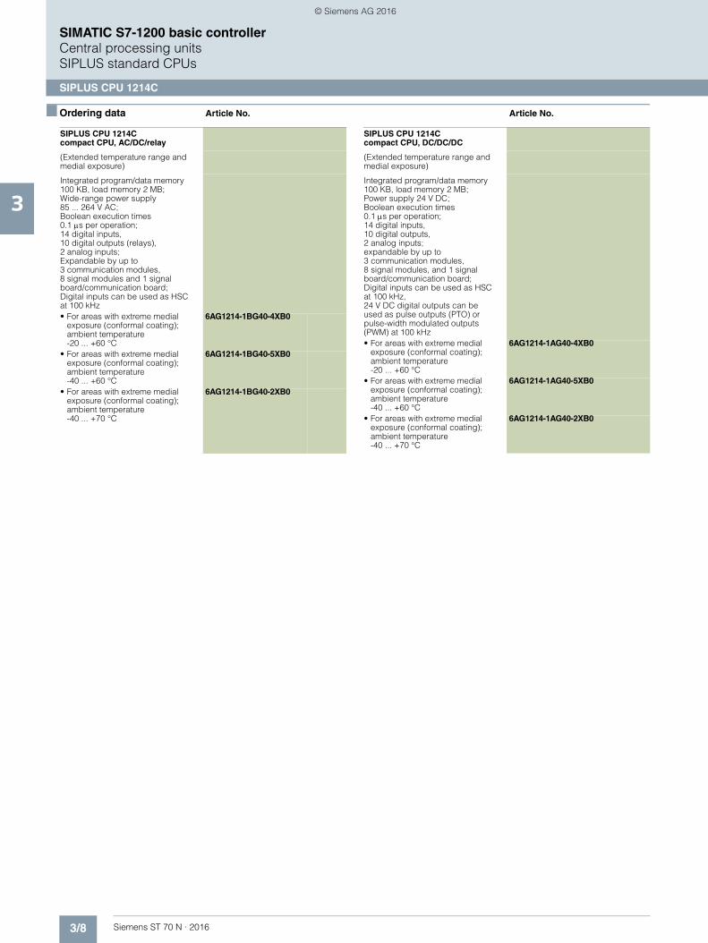
SIMATIC S7-1200 basic controllerCentral processing unitsSIPLUS standard CPUs
SIPLUS CPU 1214C
■ Overview
• The compact high-performance CPU• With 24 integrated I/Os• Expandable with:
- 1 signal board (SB) or communication board (CB); not possible with: 6AG1214-1AG40-2XB0, 6AG1214-1BG40-2XB0, 6AG1214-1HG40-2XB0
- 8 signal modules (SM)- Max. 3 communication modules (CM)
Note:
SIPLUS extreme products are based on SIMATIC standard products. The contents listed here were taken from the respec-tive standard products. SIPLUS extreme-specific information was added.
■ Technical specifications
Article number 6AG1214-1AG40-4XB0 6AG1214-1AG40-5XB0 6AG1214-1AG40-2XB0
Based on 6ES7214-1AG40-0XB0 6ES7214-1AG40-0XB0 6ES7214-1AG40-0XB0
SIPLUS S7-1200CPU 1214C DC/DC/DC
SIPLUS S7-1200 CPU 1214C DC/DC/DC
SIPLUS S7-1200 CPU 1214C DC/DC/DC
Ambient conditions
Ambient temperature during operation
• min. -20 °C; = Tmin; Startup @ 0 °C -40 °C; = Tmin; Startup @ -25 °C -40 °C; = Tmin; Startup @ -25 °C
• max. 60 °C; = Tmax; Tmax > +55 °C number of simultaneously switched-on digital inputs 7, digital outputs 5, analog inputs 2 (no adjacent points) with horizontal mounting position
60 °C; = Tmax; Tmax > +55 °C number of simultaneously switched-on digital inputs 7, digital outputs 5, analog inputs 2 (no adjacent points) with horizontal mounting position
70 °C; = Tmax; Tmax > +55 °C number of simultaneously switched-on digital inputs 7, digital outputs 5, analog inputs 2 (no adjacent points) with horizontal mounting position; Tmax > +60 °C number of simultane-ously switched-on digital inputs 7, digital outputs 5, analog inputs 1(no adjacent points) with horizontal mounting position
Extended ambient conditions
• relative to ambient temperature-atmospheric pressure-installation altitude
Tmin ... Tmax at 1080 hPa ... 795 hPa (-1000 m ... +2000 m) //Tmin ... (Tmax - 10K) at 795 hPa ... 658 hPa (+2000 m ... +3500 m) //Tmin ... (Tmax - 20K) at 658 hPa ... 540 hPa (+3500 m ... +5000 m)
Relative humidity
- With condensation, tested in accordance with IEC 60068-2-38, max.
100 %; RH incl. condensation/frost (no commissioning under condensation conditions)
Resistance
- against biologically active substances / conformity with EN 60721-3-3
Yes; Class 3B2 mold, fungus and dry rot spores (with the exception of fauna).The supplied connector covers must remain on the unused interfaces during operation!
- against chemically active substances / conformity with EN 60721-3-3
Yes; Class 3C4 (RH < 75%) incl. salt spray according to EN 60068-2-52 (degree of severity 3). The supplied connector covers must remain on the unused interfaces during operation!
- against mechanically active substances / conformity with EN 60721-3-3
Yes; Class 3S4 incl. sand, dust. The supplied connector covers must remain on the unused interfaces during operation!
© Siemens AG 2016
3/7Siemens ST 70 N · 2016
3
■ Technical specifications (continued)
SIMATIC S7-1200 basic controllerCentral processing units SIPLUS standard CPUs
SIPLUS CPU 1214C
Article number 6AG1214-1BG40-4XB0 6AG1214-1BG40-5XB0 6AG1214-1BG40-2XB0
Based on 6ES7214-1BG40-0XB0 6ES7214-1BG40-0XB0 6ES7214-1BG40-0XB0
SIPLUS S7-1200 CPU 1214C AC/DC/RLY
SIPLUS S7-1200CPU 1214C AC/DC/RLY
SIPLUS S7-1200CPU 1214C AC/DC/RLY
Ambient conditions
Ambient temperature during operation
• min. -20 °C; = Tmin; Startup @ 0 °C -40 °C; = Tmin; Startup @ -25 °C -40 °C; = Tmin; Startup @ -25 °C
• max. 60 °C; = Tmax 60 °C; = Tmax; Tmax > +55 °C number of simultaneously switched-on digital inputs 7, digital outputs 5, analog inputs 2 (no adjacent points) with horizontal mounting position
70 °C; = Tmax; Tmax > +55 °C number of simultaneously switched-on digital inputs 7, digital outputs 5, analog inputs 2 (no adjacent points) with horizontal mounting position; Tmax > +60 °C number of simultane-ously switched-on digital inputs 7, digital outputs 5, analog inputs 1(no adjacent points) with horizontal mounting position
Extended ambient conditions
• relative to ambient temperature-atmospheric pressure-installation altitude
Tmin ... Tmax at 1 080 hPa ... 795 hPa (-1 000 m ... +2 000 m) // Tmin ... (Tmax - 10 K) at 795 hPa ... 658 hPa (+2 000 m ... +3 500 m) //Tmin ... (Tmax - 20 K) at 658 hPa ... 540 hPa (+3 500 m ... +5 000 m); from 2 000 m max. 132 V AC
Relative humidity
- With condensation, tested in accordance with IEC 60068-2-38, max.
100 %; RH incl. condensation/frost (no commissioning under condensation conditions)
Resistance
- against biologically active substances / conformity with EN 60721-3-3
Yes; Class 3B2 mold, fungus and dry rot spores (with the exception of fauna). The supplied connector covers must remain on the unused interfaces during operation!
- against chemically active substances / conformity with EN 60721-3-3
Yes; Class 3C4 (RH < 75%) incl. salt spray according to EN 60068-2-52 (degree of severity 3). The supplied connector covers must remain on the unused interfaces during operation!
- against mechanically active substances / conformity with EN 60721-3-3
Yes; Class 3S4 incl. sand, dust. The supplied connector covers must remain on the unused interfaces during operation!
Article number 6AG1214-1HG40-4XB0 6AG1214-1HG40-5XB0 6AG1214-1HG40-2XB0
Based on 6ES7214-1HG40-0XB0 6ES7214-1HG40-0XB0 6ES7214-1HG40-0XB0
SIPLUS S7-1200 CPU 1214C DC/DC/RLY
SIPLUS S7-1200 CPU 1214C DC/DC/RLY
SIPLUS S7-1200CPU 1214C DC/DC/RLY
Ambient conditions
Ambient temperature during operation
• min. -20 °C; = Tmin; Startup @ 0 °C -40 °C; = Tmin; Startup @ -25 °C -40 °C; = Tmin; Startup @ -25 °C
• max. 60 °C; Number of simultaneously activated inputs or outputs 7 or 5 (no adjacent points) at 60 °C horizontal or 50 °C vertical, 14 or 10 at 55 °C horizontal or 45 °C vertical
60 °C; = Tmax; Tmax > +55 °C number of simultaneously switched-on digital inputs 7, digital outputs 5, analog inputs 2 (no adjacent points) with horizontal mounting position
70 °C; = Tmax; Tmax > +55 °C number of simultaneously switched-on digital inputs 7, digital outputs 5, analog inputs 2 (no adjacent points) with horizontal mounting position;Tmax > +60 °C number of simultane-ously switched-on digital inputs 7, digital outputs 5, analog inputs 1 (no adjacent points) with horizontal mounting position
Extended ambient conditions
• relative to ambient temperature-atmospheric pressure-installation altitude
Tmin ... Tmax at 1 080 hPa ... 795 hPa (-1 000 m ... +2 000 m) //Tmin ... (Tmax - 10 K) at 795 hPa ... 658 hPa (+2 000 m ... +3 500 m) // Tmin ... (Tmax - 20 K) at 658 hPa ... 540 hPa (+3 500 m ... +5 000 m); from 2 000 m max. 132 V AC
Relative humidity
- With condensation, tested in accordance with IEC 60068-2-38, max.
100 %; RH incl. condensation/frost (no commissioning under condensation conditions)
Resistance
- against biologically active substances / conformity with EN 60721-3-3
Yes; Class 3B2 mold, fungus and dry rot spores (with the exception of fauna).The supplied connector covers must remain on the unused interfaces during operation!
- against chemically active substances / conformity with EN 60721-3-3
Yes; Class 3C4 (RH < 75%) incl. salt spray according to EN 60068-2-52 (degree of severity 3). The supplied connector covers must remain on the unused interfaces during operation!
- against mechanically active substances / conformity with EN 60721-3-3
Yes; Class 3S4 incl. sand, dust. The supplied connector covers must remain on the unused interfaces during operation!
© Siemens AG 2016
3/8 Siemens ST 70 N · 2016
3
SIMATIC S7-1200 basic controllerCentral processing unitsSIPLUS standard CPUs
SIPLUS CPU 1214C
■ Ordering data Article No. Article No.
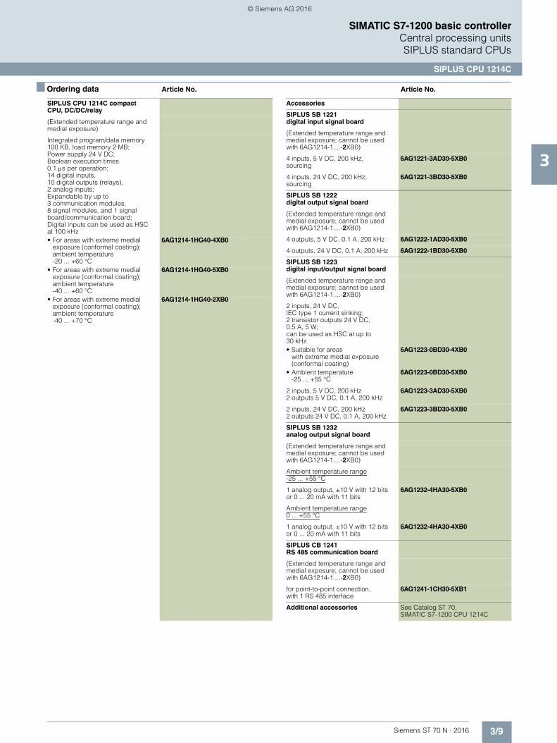
SIPLUS CPU 1214C compact CPU, AC/DC/relay
(Extended temperature range and medial exposure)
Integrated program/data memory 100 KB, load memory 2 MB; Wide-range power supply85 ... 264 V AC; Boolean execution times0.1 s per operation; 14 digital inputs, 10 digital outputs (relays), 2 analog inputs; Expandable by up to 3 communication modules, 8 signal modules and 1 signal board/communication board; Digital inputs can be used as HSC at 100 kHz• For areas with extreme medial
exposure (conformal coating);ambient temperature-20 ... +60 °C
6AG1214-1BG40-4XB0
• For areas with extreme medialexposure (conformal coating);ambient temperature-40 ... +60 °C
6AG1214-1BG40-5XB0
• For areas with extreme medial exposure (conformal coating);ambient temperature -40 ... +70 °C
6AG1214-1BG40-2XB0
SIPLUS CPU 1214Ccompact CPU, DC/DC/DC
(Extended temperature range and medial exposure)
Integrated program/data memory 100 KB, load memory 2 MB; Power supply 24 V DC; Boolean execution times0.1 s per operation; 14 digital inputs, 10 digital outputs,2 analog inputs; expandable by up to 3 communication modules, 8 signal modules, and 1 signal board/communication board; Digital inputs can be used as HSC at 100 kHz, 24 V DC digital outputs can be used as pulse outputs (PTO) or pulse-width modulated outputs (PWM) at 100 kHz• For areas with extreme medial
exposure (conformal coating);ambient temperature-20 ... +60 °C
6AG1214-1AG40-4XB0
• For areas with extreme medial exposure (conformal coating);ambient temperature-40 ... +60 °C
6AG1214-1AG40-5XB0
• For areas with extreme medial exposure (conformal coating);ambient temperature -40 ... +70 °C
6AG1214-1AG40-2XB0
© Siemens AG 2016
3/9Siemens ST 70 N · 2016
3
■ Ordering data Article No. Article No.
SIMATIC S7-1200 basic controllerCentral processing units SIPLUS standard CPUs
SIPLUS CPU 1214C
SIPLUS CPU 1214C compact CPU, DC/DC/relay
(Extended temperature range and medial exposure)
Integrated program/data memory 100 KB, load memory 2 MB; Power supply 24 V DC; Boolean execution times0.1 s per operation; 14 digital inputs, 10 digital outputs (relays), 2 analog inputs; Expandable by up to 3 communication modules,8 signal modules, and 1 signal board/communication board; Digital inputs can be used as HSC at 100 kHz• For areas with extreme medial
exposure (conformal coating);ambient temperature-20 ... +60 °C
6AG1214-1HG40-4XB0
• For areas with extreme medial exposure (conformal coating);ambient temperature-40 ... +60 °C
6AG1214-1HG40-5XB0
• For areas with extreme medial exposure (conformal coating);ambient temperature-40 ... +70 °C
6AG1214-1HG40-2XB0
Accessories
SIPLUS SB 1221digital input signal board
(Extended temperature range and medial exposure; cannot be used with 6AG1214-1....-2XB0)
4 inputs, 5 V DC, 200 kHz, sourcing
6AG1221-3AD30-5XB0
4 inputs, 24 V DC, 200 kHz,sourcing
6AG1221-3BD30-5XB0
SIPLUS SB 1222 digital output signal board
(Extended temperature range and medial exposure; cannot be used with 6AG1214-1....-2XB0)
4 outputs, 5 V DC, 0.1 A, 200 kHz 6AG1222-1AD30-5XB0
4 outputs, 24 V DC, 0.1 A, 200 kHz 6AG1222-1BD30-5XB0
SIPLUS SB 1223 digital input/output signal board
(Extended temperature range and medial exposure; cannot be used with 6AG1214-1....-2XB0)
2 inputs, 24 V DC, IEC type 1 current sinking; 2 transistor outputs 24 V DC, 0.5 A, 5 W; can be used as HSC at up to 30 kHz• Suitable for areas
with extreme medial exposure (conformal coating)
6AG1223-0BD30-4XB0
• Ambient temperature -25 ... +55 °C
6AG1223-0BD30-5XB0
2 inputs, 5 V DC, 200 kHz2 outputs 5 V DC, 0.1 A, 200 kHz
6AG1223-3AD30-5XB0
2 inputs, 24 V DC, 200 kHz2 outputs 24 V DC, 0.1 A, 200 kHz
6AG1223-3BD30-5XB0
SIPLUS SB 1232 analog output signal board
(Extended temperature range and medial exposure; cannot be used with 6AG1214-1....-2XB0)
Ambient temperature range-25 ... +55 °C
1 analog output, ±10 V with 12 bits or 0 ... 20 mA with 11 bits
6AG1232-4HA30-5XB0
Ambient temperature range0 ... +55 °C
1 analog output, ±10 V with 12 bits or 0 ... 20 mA with 11 bits
6AG1232-4HA30-4XB0
SIPLUS CB 1241 RS 485 communication board
(Extended temperature range and medial exposure; cannot be used with 6AG1214-1....-2XB0)
for point-to-point connection, with 1 RS 485 interface
6AG1241-1CH30-5XB1
Additional accessories See Catalog ST 70, SIMATIC S7-1200 CPU 1214C
© Siemens AG 2016

3/10 Siemens ST 70 N · 2016
3
SIMATIC S7-1200 basic controllerCentral processing unitsSIPLUS standard CPUs
SIPLUS CPU 1215C
■ Overview
• The compact high-performance CPU• With 24 integrated I/Os• Expandable with:
- 1 signal board (SB) or communication board (CB); not possible with: 6AG1215-1AG40-2XB0, 6AG1215-1BG40-2XB0, 6AG1215-1HG40-2XB0
- 8 signal modules (SM) - Max. 3 communication modules (CM)
Note:
SIPLUS extreme products are based on SIMATIC standard products. The contents listed here were taken from the respec-tive standard products. SIPLUS extreme-specific information was added.
■ Technical specifications
Article number 6AG1215-1AG40-4XB0 6AG1215-1AG40-5XB0 6AG1215-1AG40-2XB0
Based on 6ES7215-1AG40-0XB0 6ES7215-1AG40-0XB0 6ES7215-1AG40-0XB0
SIPLUS S7-1200CPU 1215C DC/DC/DC
SIPLUS S7-1200CPU 1215C DC/DC/DC
SIPLUS S7-1200 CPU 1215C DC/DC/DC
Ambient conditions
Ambient temperature during operation
• min. -20 °C; = Tmin; Startup @ 0 °C -40 °C; = Tmin; Startup @ -25 °C -40 °C; = Tmin; Startup @ -25 °C
• max. 60 °C; Number of simultaneously activated inputs or outputs 7 or 5(no adjacent points) at 60 °C horizontal or 50 °C vertical, 14 or 10 at 55 °C horizontal or 45 °C vertical
60 °C; = Tmax; Tmax > +55 °C number of simultaneously switched-on digital inputs 7, digital outputs 5, analog inputs 2, analog outputs 2 (no adjacent points) with horizontal mounting position
70 °C; = Tmax; Tmax > +55 °C number of simultaneously switched-on digital inputs 7, digital outputs 5, analog inputs 2, analog outputs 2 (no adjacent points) with horizontal mounting position; Tmax > +60 °C number of simultaneously switched-on digital inputs 7, digital outputs 5, analog inputs 1, analog outputs 1 (no adjacent points) with horizontal mounting position
Extended ambient conditions
• relative to ambient temperature-atmospheric pressure-installation altitude
Tmin ... Tmax at 1080 hPa ... 795 hPa (-1000 m ... +2000 m) // Tmin ... (Tmax - 10K) at 795 hPa ... 658 hPa (+2000 m ... +3500 m) //Tmin ... (Tmax - 20K) at 658 hPa ... 540 hPa (+3500 m ... +5000 m)
Relative humidity
- With condensation, tested in accordance with IEC 60068-2-38, max.
100 %; RH incl. condensation/frost (no commissioning under condensation conditions)
Resistance
- against biologically active substances / conformity with EN 60721-3-3
Yes; Class 3B2 mold, fungus and dry rot spores (with the exception of fauna).The supplied connector covers must remain on the unused interfaces during operation!
- against chemically active substances / conformity with EN 60721-3-3
Yes; Class 3C4 (RH < 75%) incl. salt spray according to EN 60068-2-52 (degree of severity 3).The supplied connector covers must remain on the unused interfaces during operation!
- against mechanically active substances / conformity with EN 60721-3-3
Yes; Class 3S4 incl. sand, dust. The supplied connector covers must remain on the unused interfaces during operation!
© Siemens AG 2016
3/11Siemens ST 70 N · 2016
3
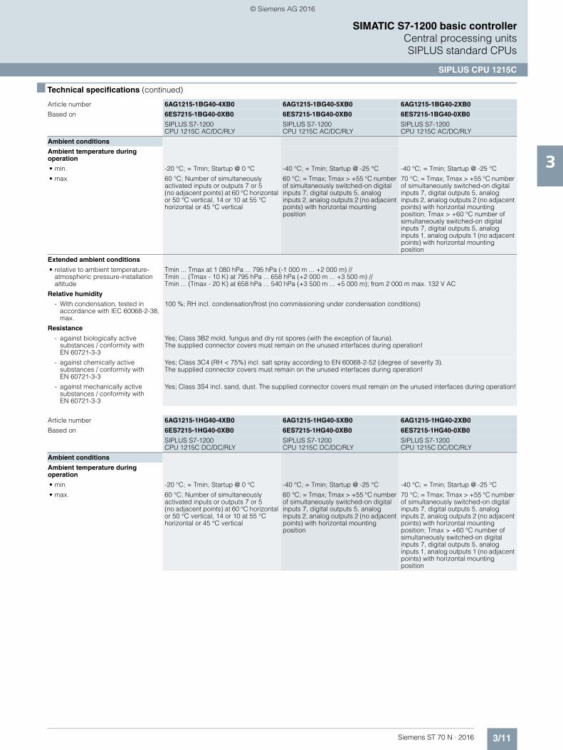
■ Technical specifications (continued)
SIMATIC S7-1200 basic controllerCentral processing units SIPLUS standard CPUs
SIPLUS CPU 1215C
Article number 6AG1215-1BG40-4XB0 6AG1215-1BG40-5XB0 6AG1215-1BG40-2XB0
Based on 6ES7215-1BG40-0XB0 6ES7215-1BG40-0XB0 6ES7215-1BG40-0XB0
SIPLUS S7-1200 CPU 1215C AC/DC/RLY
SIPLUS S7-1200 CPU 1215C AC/DC/RLY
SIPLUS S7-1200CPU 1215C AC/DC/RLY
Ambient conditions
Ambient temperature during operation
• min. -20 °C; = Tmin; Startup @ 0 °C -40 °C; = Tmin; Startup @ -25 °C -40 °C; = Tmin; Startup @ -25 °C
• max. 60 °C; Number of simultaneously activated inputs or outputs 7 or 5(no adjacent points) at 60 °C horizontal or 50 °C vertical, 14 or 10 at 55 °C horizontal or 45 °C vertical
60 °C; = Tmax; Tmax > +55 °C number of simultaneously switched-on digital inputs 7, digital outputs 5, analog inputs 2, analog outputs 2 (no adjacent points) with horizontal mounting position
70 °C; = Tmax; Tmax > +55 °C number of simultaneously switched-on digital inputs 7, digital outputs 5, analog inputs 2, analog outputs 2 (no adjacent points) with horizontal mounting position; Tmax > +60 °C number of simultaneously switched-on digital inputs 7, digital outputs 5, analog inputs 1, analog outputs 1 (no adjacent points) with horizontal mounting position
Extended ambient conditions
• relative to ambient temperature-atmospheric pressure-installation altitude
Tmin ... Tmax at 1 080 hPa ... 795 hPa (-1 000 m ... +2 000 m) // Tmin ... (Tmax - 10 K) at 795 hPa ... 658 hPa (+2 000 m ... +3 500 m) // Tmin ... (Tmax - 20 K) at 658 hPa ... 540 hPa (+3 500 m ... +5 000 m); from 2 000 m max. 132 V AC
Relative humidity
- With condensation, tested in accordance with IEC 60068-2-38, max.
100 %; RH incl. condensation/frost (no commissioning under condensation conditions)
Resistance
- against biologically active substances / conformity with EN 60721-3-3
Yes; Class 3B2 mold, fungus and dry rot spores (with the exception of fauna). The supplied connector covers must remain on the unused interfaces during operation!
- against chemically active substances / conformity with EN 60721-3-3
Yes; Class 3C4 (RH < 75%) incl. salt spray according to EN 60068-2-52 (degree of severity 3).The supplied connector covers must remain on the unused interfaces during operation!
- against mechanically active substances / conformity with EN 60721-3-3
Yes; Class 3S4 incl. sand, dust. The supplied connector covers must remain on the unused interfaces during operation!
Article number 6AG1215-1HG40-4XB0 6AG1215-1HG40-5XB0 6AG1215-1HG40-2XB0
Based on 6ES7215-1HG40-0XB0 6ES7215-1HG40-0XB0 6ES7215-1HG40-0XB0
SIPLUS S7-1200 CPU 1215C DC/DC/RLY
SIPLUS S7-1200 CPU 1215C DC/DC/RLY
SIPLUS S7-1200 CPU 1215C DC/DC/RLY
Ambient conditions
Ambient temperature during operation
• min. -20 °C; = Tmin; Startup @ 0 °C -40 °C; = Tmin; Startup @ -25 °C -40 °C; = Tmin; Startup @ -25 °C
• max. 60 °C; Number of simultaneously activated inputs or outputs 7 or 5 (no adjacent points) at 60 °C horizontal or 50 °C vertical, 14 or 10 at 55 °C horizontal or 45 °C vertical
60 °C; = Tmax; Tmax > +55 °C number of simultaneously switched-on digital inputs 7, digital outputs 5, analog inputs 2, analog outputs 2 (no adjacent points) with horizontal mounting position
70 °C; = Tmax; Tmax > +55 °C number of simultaneously switched-on digital inputs 7, digital outputs 5, analog inputs 2, analog outputs 2 (no adjacent points) with horizontal mounting position; Tmax > +60 °C number of simultaneously switched-on digital inputs 7, digital outputs 5, analog inputs 1, analog outputs 1 (no adjacent points) with horizontal mounting position
© Siemens AG 2016
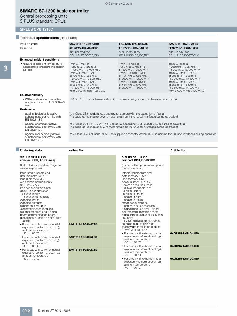
3/12 Siemens ST 70 N · 2016
3
■ Technical specifications (continued)
SIMATIC S7-1200 basic controllerCentral processing unitsSIPLUS standard CPUs
SIPLUS CPU 1215C
■ Ordering data Article No. Article No.
Extended ambient conditions
• relative to ambient temperature-atmospheric pressure-installation altitude
Tmin ... Tmax at 1 080 hPa ... 795 hPa(-1 000 m ... +2 000 m) //Tmin ... (Tmax - 10 K) at 795 hPa ... 658 hPa(+2 000 m ... +3 500 m) //Tmin ... (Tmax - 20 K)at 658 hPa ... 540 hPa(+3 500 m ... +5 000 m); from 2 000 m max. 132 V AC
Tmin ... Tmax at 1080 hPa ... 795 hPa(-1000 m ... +2000 m) //Tmin ... (Tmax - 10K)at 795 hPa ... 658 hPa (+2000 m ... +3500 m) //Tmin ... (Tmax - 20K) at 658 hPa ... 540 hPa(+3500 m ... +5000 m)
Tmin ... Tmax at1 080 hPa ... 795 hPa (-1 000 m ... +2 000 m) //Tmin ... (Tmax - 10 K) at 795 hPa ... 658 hPa(+2 000 m ... +3 500 m) //Tmin ... (Tmax - 20 K) at 658 hPa ... 540 hPa(+3 500 m ... +5 000 m);from 2 000 m max. 132 V AC
Relative humidity
- With condensation, tested in accordance with IEC 60068-2-38, max.
100 %; RH incl. condensation/frost (no commissioning under condensation conditions)
Resistance
- against biologically active substances / conformity with EN 60721-3-3
Yes; Class 3B2 mold, fungus and dry rot spores (with the exception of fauna). The supplied connector covers must remain on the unused interfaces during operation!
- against chemically active substances / conformity with EN 60721-3-3
Yes; Class 3C4 (RH < 75%) incl. salt spray according to EN 60068-2-52 (degree of severity 3). The supplied connector covers must remain on the unused interfaces during operation!
- against mechanically active substances / conformity with EN 60721-3-3
Yes; Class 3S4 incl. sand, dust. The supplied connector covers must remain on the unused interfaces during operation!
Article number 6AG1215-1HG40-4XB0 6AG1215-1HG40-5XB0 6AG1215-1HG40-2XB0
Based on 6ES7215-1HG40-0XB0 6ES7215-1HG40-0XB0 6ES7215-1HG40-0XB0
SIPLUS S7-1200 CPU 1215C DC/DC/RLY
SIPLUS S7-1200 CPU 1215C DC/DC/RLY
SIPLUS S7-1200 CPU 1215C DC/DC/RLY
SIPLUS CPU 1215Ccompact CPU, AC/DC/relay
(Extended temperature range and medial exposure)
Integrated program and data memory 125 KB,load memory 4 MB; wide-range power supply 85 ... 264 V AC; Boolean execution times0.085 s per operation; 14 digital inputs, 10 digital outputs (relay), 2 analog inputs, 2 analog outputs; expandable by up to 3 communication modules, 8 signal modules and 1 signal board/communication board; digital inputs usable as HSC with 100 kHz• For areas with extreme medial
exposure (conformal coating);ambient temperature-20 ... +60 °C
6AG1215-1BG40-4XB0
• For areas with extreme medialexposure (conformal coating);ambient temperature-40 ... +60 °C
6AG1215-1BG40-5XB0
• For areas with extreme medial exposure (conformal coating);ambient temperature-40 ... +70 °C
6AG1215-1BG40-2XB0
SIPLUS CPU 1215C compact CPU, DC/DC/DC
(Extended temperature range and medial exposure)
Integrated program anddata memory 125 KB,load memory 4 MB; power supply 24 V DC; Boolean execution times 0.085 s per operation; 14 digital inputs, 10 digital outputs,2 analog inputs, 2 analog outputs; expandable by up to 3 communication modules, 8 signal modules and 1 signal board/communication board; digital inputs usable as HSC with 100 kHz; 24 V DC digital outputs usable as pulse outputs (PTO) or pulse-width-modulated outputs (PWM) with 100 kHz• For areas with extreme medial
exposure (conformal coating);ambient temperature-20 ... +60 °C
6AG1215-1AG40-4XB0
• For areas with extreme medial exposure (conformal coating);ambient temperature-40 ... +60 °C
6AG1215-1AG40-5XB0
• For areas with extreme medial exposure (conformal coating);ambient temperature-40 ... +70 °C
6AG1215-1AG40-2XB0
© Siemens AG 2016

3/13Siemens ST 70 N · 2016
3
■ Ordering data Article No. Article No.
SIMATIC S7-1200 basic controllerCentral processing units SIPLUS standard CPUs
SIPLUS CPU 1215C
SIPLUS CPU 1215C compact CPU, DC/DC/relay
(Extended temperature range and medial exposure)
Integrated program and data memory 125 KB,load memory 4 MB; power supply 24 V DC; Boolean execution times 0.085 s per operation; 14 digital inputs, 10 digital outputs (relay), 2 analog inputs, 2 analog outputs; expandable by up to 3 communication modules, 8 signal modules and 1 signal board/communication board; digital inputs usable as HSC with 100 kHz• For areas with extreme medial
exposure (conformal coating);ambient temperature-20 ... +60 °C
6AG1215-1HG40-4XB0
• For areas with extreme medial exposure (conformal coating);ambient temperature-40 ... +60 °C
6AG1215-1HG40-5XB0
• For areas with extreme medial exposure (conformal coating);ambient temperature-40 ... +70 °C
6AG1215-1HG40-2XB0
Accessories
SIPLUS SB 1221digital input signal board
(Extended temperature range and medial exposure; cannot be used with 6AG1215-1....-2XB0)
4 inputs, 5 V DC, 200 kHz, sourcing
6AG1221-3AD30-5XB0
4 inputs, 24 V DC, 200 kHz,
sourcing
6AG1221-3BD30-5XB0
SIPLUS SB 1222 digital output signal board
(Extended temperature range and medial exposure; cannot be used with 6AG1215-1....-2XB0)
4 outputs, 5 V DC, 0.1 A, 200 kHz 6AG1222-1AD30-5XB0
4 outputs, 24 V DC, 0.1 A, 200 kHz 6AG1222-1BD30-5XB0
Digital input/output SIPLUS signal board SB 1223
(Extended temperature range and medial exposure; cannot be used with 6AG1215-1....-2XB0)
2 inputs, 24 V DC, IEC type 1 current sinking; 2 transistor outputs 24 V DC, 0.5 A, 5 W; can be used as HSC at up to 30 kHz• Suitable for areas
with extreme medial exposure (conformal coating)
6AG1223-0BD30-4XB0
• Ambient temperature-25 ... +55 °C
6AG1223-0BD30-5XB0
2 inputs, 5 V DC, 200 kHz2 outputs 5 V DC, 0.1 A, 200 kHz
6AG1223-3AD30-5XB0
2 inputs, 24 V DC, 200 kHz2 outputs 24 V DC, 0.1 A, 200 kHz
6AG1223-3BD30-5XB0
SIPLUS SB 1232 analog output signal board
(Extended temperature range and medial exposure; cannot be used with 6AG1215-1....-2XB0)
Ambient temperature range-25 ... +55 °C
1 analog output, ±10 V with 12 bits or 0 ... 20 mA with 11 bits
6AG1232-4HA30-5XB0
Ambient temperature range0 ... +55 °C
1 analog output, ±10 V with 12 bits or 0 ... 20 mA with 11 bits
6AG1232-4HA30-4XB0
SIPLUS CB 1241RS 485 communication board
(Extended temperature range and medial exposure; cannot be used with 6AG1215-1....-2XB0)
For point-to-point connection, with 1 RS 485 interface
6AG1241-1CH30-5XB1
Additional accessories See Catalog ST 70, SIMATIC S7-1200 CPU 1215C
© Siemens AG 2016

3/14 Siemens ST 70 N · 2016
3
SIMATIC S7-1200 basic controllerI/O modulesSIPLUS analog modules
SIPLUS RTD SM 1231 signal module
■ Overview
• For the convenient recording of temperatures with great accuracy
• 4 inputs• Most popular resistance temperature detectors can be used• Can easily be retrofitted to existing plant
Note:
SIPLUS extreme products are based on SIMATIC standard products. The contents listed here were taken from the respec-tive standard products. SIPLUS extreme specific information was added.
■ Technical specifications
Article number 6AG1231-5PD32-4XB0 6AG1231-5PD32-2XB0 6AG1231-5PF32-4XB0 6AG1231-5PF32-2XB0
Based on 6ES7231-5PD32-0XB0 6ES7231-5PD32-0XB0 6ES7231-5PF32-0XB0 6ES7231-5PF32-0XB0
SIPLUS S7-1200 SM 1231 4AI RTD 16BIT
SIPLUS S7-1200SM 1231 4AI RTD 16BIT
SIPLUS S7-1200 SM 1231 8AI RTD 16BIT
SIPLUS S7-1200 SM 1231 8AI RTD 16BIT
Ambient conditions
Free fall
• Fall height, max. 0.3 m; five times, in product package
Ambient temperature during operation
• min. -20 °C; = Tmin;Startup @ 0 °C
-40 °C; = Tmin;Startup @ -25 °C
-20 °C; = Tmin; Startup @ 0 °C
-40 °C; = Tmin; Startup @ -25 °C
• max. 60 °C; = Tmax 70 °C; = Tmax 60 °C; = Tmax 70 °C; = Tmax
Ambient temperature during storage/transportation
• min. -40 °C
• max. 70 °C
Air pressure acc. to IEC 60068-2-13
• Storage/transport, min. 660 hPa
• Storage/transport, max. 1 080 hPa
Relative humidity
• permissible range (without condensation) at 25 °C
95 %
Extended ambient conditions
• relative to ambient temperature-atmospheric pressure-installation altitude
Tmin ... Tmax at 1080 hPa ... 795 hPa (-1000 m ... +2000 m) //Tmin ... (Tmax - 10K) at 795 hPa ... 658 hPa (+2000 m ... +3500 m) // Tmin ... (Tmax - 20K) at 658 hPa ... 540 hPa (+3500 m ... +5000 m)
Relative humidity
- With condensation, tested in accordance with IEC 60068-2-38, max.
100 %; RH incl. condensation/frost (no commissioning under condensation conditions)
Resistance
- against biologically active substances / conformity with EN 60721-3-3
Yes; Class 3B2 mold, fungus and dry rot spores (with the exception of fauna). The supplied connector covers must remain on the unused interfaces during operation!
- against chemically active substances / conformity with EN 60721-3-3
Yes; Class 3C4 (RH < 75%) incl. salt spray according to EN 60068-2-52 (degree of severity 3). The supplied connector covers must remain on the unused interfaces during operation!
- against mechanically active substances / conformity with EN 60721-3-3
Yes; Class 3S4 incl. sand, dust. The supplied connector covers must remain on the unused interfaces during operation!
© Siemens AG 2016
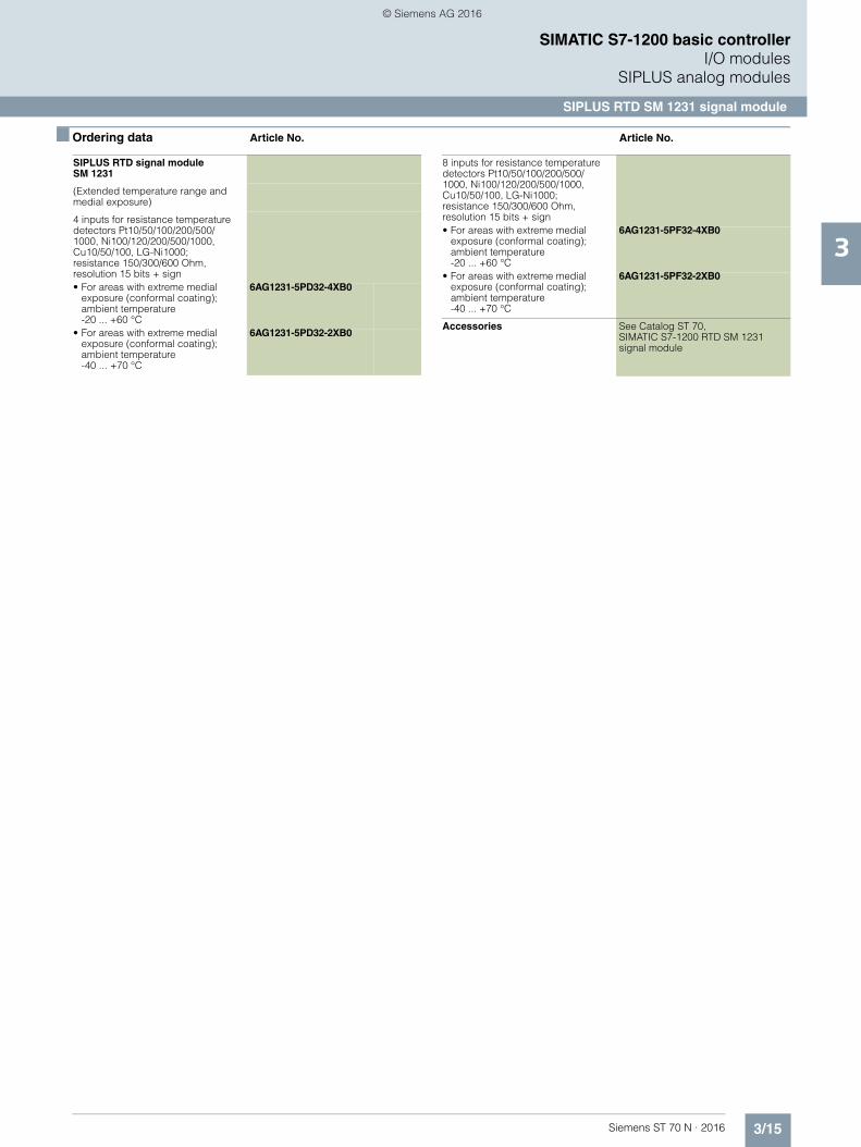
3/15Siemens ST 70 N · 2016
3
SIMATIC S7-1200 basic controllerI/O modules
SIPLUS analog modules
SIPLUS RTD SM 1231 signal module
■ Ordering data Article No. Article No.
SIPLUS RTD signal module SM 1231
(Extended temperature range and medial exposure)
4 inputs for resistance temperature detectors Pt10/50/100/200/500/1000, Ni100/120/200/500/1000, Cu10/50/100, LG-Ni1000; resistance 150/300/600 Ohm,resolution 15 bits + sign• For areas with extreme medial
exposure (conformal coating);ambient temperature-20 ... +60 °C
6AG1231-5PD32-4XB0
• For areas with extreme medial exposure (conformal coating);ambient temperature-40 ... +70 °C
6AG1231-5PD32-2XB0
8 inputs for resistance temperature detectors Pt10/50/100/200/500/1000, Ni100/120/200/500/1000, Cu10/50/100, LG-Ni1000;resistance 150/300/600 Ohm,resolution 15 bits + sign• For areas with extreme medial
exposure (conformal coating);ambient temperature-20 ... +60 °C
6AG1231-5PF32-4XB0
• For areas with extreme medial exposure (conformal coating);ambient temperature-40 ... +70 °C
6AG1231-5PF32-2XB0
Accessories See Catalog ST 70, SIMATIC S7-1200 RTD SM 1231signal module
© Siemens AG 2016

3/16 Siemens ST 70 N · 2016
3
SIMATIC S7-1200 basic controllerI/O modulesSpecial modules
SM 1281 Condition Monitoring
■ Overview
SIPLUS CMS1200 SM 1281 Condition Monitoring forms part of SIMATIC S7-1200 and is used for the:• Monitoring of motors, generators, pumps, fans, or other
mechanical components• Recording and analysis of vibrations• Expansion capability of up to 7 modules
■ Technical specifications
■ Ordering data Article No.
Article number 6AT8007-1AA10-0AA0
product brand name SIPLUS
Product designation CMS1200 SM 1281 Condition Monitoring
General technical data:
Protection class IP IP20
Browser software required Web browser Mozilla Firefox (ESR31) or Microsoft Internet Explorer (10/11)
Storage capacity total Gbyte 1
Scanning frequency maximum
Hz 46 875
Material of the enclosure Plastic: polycarbonate:abbreviation: PC- GF 10 FR
Hardware configuration Modular, up to 7 modules per CPU
Vibration frequency mea-suring range
• initial value Hz 0.05
• Full-scale value Hz 10 000
Power loss [W] total typi-cal
W 6
Equipment marking acc. to DIN EN 81346-2
P
Weight g 260
Supply voltage:
Supply voltage 1at DC rated value
V 24
Type of voltage of the supply voltage
DC
Supply voltage at DC rated value
• minimum V 20.4
• maximum V 28.8
Installation/ mounting/ dimensions:
Mounting position vertical, horizontal
Mounting position recommended
horizontal
Mounting type Rail or wall mounting
Width mm 70
Height mm 112
Depth mm 75
Inputs/ Outputs:
Number of sensor inputs for IEPE sensors
4
Number of speed inputs 1
Product function Bus communication
Yes
Product function monitor-ing of sensor inputs
Yes
Input voltage at speed input DC 24 V digital
Yes
Display:
Display version for diagnostic function: status display digital input LED green
No
Communication:
Type of data transmission Exporting of raw data as WAV file for further analyses(e.g. using SIPLUS CMS X-Tools) can be downloaded via browser
Design of the interface Ethernet interface
Yes
Service as web server HTTP
Yes
Ambient conditions:
Ambient temperature
• during operation -20 ... +55
• during storage -25 ... +85
• during transport -25 ... +85
Air pressure during stor-age and transport
660 ... 1 080
Height of fall maximum m 0.3
Options:
Alert function Diagnostics alarm
Yes
Type of electricalconnection
screw-type terminals
SIPLUS CMS1200 SM 1281 Condition Monitoring
Module for SIMATIC S7-1200for monitoring vibrations in mechanical components based on characteristic valuesand frequency-selective analysis functions.
6AT8007-1AA10-0AA0
Article number 6AT8007-1AA10-0AA0
© Siemens AG 2016
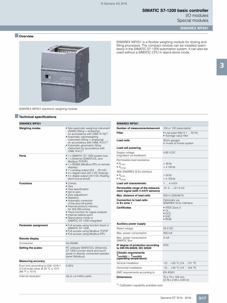
3/17Siemens ST 70 N · 2016
3
SIMATIC S7-1200 basic controllerI/O modules
Special modules
SIWAREX WP251
■ Overview
SIWAREX WP251 electronic weighing module
SIWAREX WP251 is a flexible weighing module for dosing and filling processes. The compact module can be installed seam-lessly in the SIMATIC S7-1200 automation system. It can also be used without a SIMATIC CPU in stand-alone mode.
■ Technical specifications
1) Calibration capability available soon
SIWAREX WP251
Weighing modes • Non-automatic weighing instrument (NAWI) (filling + emptying)(in accordance with OIML R-76)1)
• Automatic catchweighing instrument (filling + emptying) (in accordance with OIML R-51)1)
• Automatic gravimetric filling instrument (in accordance with OIML R-61)1)
Ports • 1 x SIMATIC S7-1200 system bus• 1 x Ethernet (SIWATOOL and
Modbus TCP/IP)• 1 x RS485 (Modbus RTU or remote
display)• 1 x analog output (0/4 ... 20 mA)• 4 x digital input (24 V DC floating)• 4 x digital output (24 V DC floating,
short-circuit proof)
Functions • 3 limits• Tare• Tare specification• Set to zero• Zero adjustment• Statistics• Automatic correction
of the shut-off points• Internal protocol memory
for 550 000 entries• Trace function for signal analysis • Internal restore point• Stand-alone mode or
SIMATIC S7-1200 integrated
Parameter assignment • Full access using function block in SIMATIC S7-1200
• Full access using Modbus TCP/IP• Full access using Modbus RTU
Remote display
Connection Via RS485
Setting the scales PC software SIWATOOL (Ethernet), S7-1200 function block and touch panel or directly connected operator panel (Modbus)
Measuring accuracy
Error limit according to DIN 1319-1of full-scale value at 20 °C ± 10 K(68 °F ± 10 K)
0.05%
Internal resolution Up to ±4 million parts
Number of measurements/second 100 or 120 (selectable)
Filter • Low-pass filter 0.1 ... 50 Hz• Average value filter
Load cells Strain gaugesin 4-wire or 6-wire system
Load cell powering
Supply voltage(regulated via feedback)
4.85 V DC
Permissible load resistance• RLmin > 40 • RLmax < 4 100
With SIWAREX IS Ex interface• RLmin > 50 • RLmax < 4 100
Load cell characteristic 1 … 4 mV/V
Permissible range of the measure-ment signal (with 4 mV/V sensors)
-21.3 ... +21.3 mV
Max. distance of load cells 500 m (229.66 ft)
Connection to load cellsin Ex zone 1
Optionally viaSIWAREX IS Ex interface
Certificates • ATEX Zone 2• UL• KCC• EAC• RCM
Auxiliary power supply
Rated voltage 24 V DC
Max. power consumption 200 mA
Max. power consumption SIMATIC Bus
3 mA
IP degree of protection according to DIN EN 60529; IEC 60529
IP20
Climatic requirements Tmin(IND) ... Tmax(IND)(operating temperature)
Vertical installation -10 ... +55 °C (14 ... 131 °F)
Horizontal installation -10 ... +40 °C (14 ... 104 °F)
EMC requirements according to EN 45501
Dimensions 70 x 75 x 100 mm(2.76 x 2.95 x 3.94 in)
SIWAREX WP251
© Siemens AG 2016
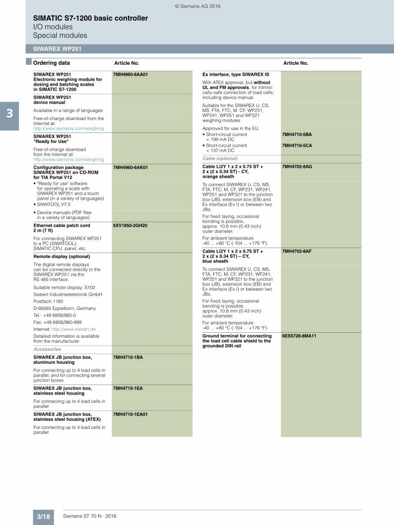
3/18 Siemens ST 70 N · 2016
3
SIMATIC S7-1200 basic controllerI/O modulesSpecial modules
SIWAREX WP251
■ Ordering data Article No. Article No.
SIWAREX WP251Electronic weighing module for dosing and batching scales in SIMATIC S7-1200
7MH4960-6AA01
SIWAREX WP251device manual
Available in a range of languages
Free-of-charge download from the Internet at: http://www.siemens.com/weighing
SIWAREX WP251"Ready for Use"
Free-of-charge downloadfrom the Internet at:http://www.siemens.com/weighing
Configuration package SIWAREX WP251 on CD-ROMfor TIA Portal V12
7MH4960-6AK01
• "Ready for use" software for operating a scale with SIWAREX WP251 and a touch panel (in a variety of languages)
• SIWATOOL V7.0
• Device manuals (PDF filesin a variety of languages)
Ethernet cable patch cord2 m (7 ft)
6XV1850-2GH20
For connecting SIWAREX WP251 to a PC (SIWATOOL),SIMATIC CPU, panel, etc.
Remote display (optional)
The digital remote displays can be connected directly to the SIWAREX WP251 via theRS 485 interface.
Suitable remote display: S102
Siebert Industrieelektronik GmbH
Postfach 1180
D-66565 Eppelborn, Germany
Tel.: +49 6806/980-0
Fax: +49 6806/980-999
Internet: http://www.siebert.de
Detailed information is available from the manufacturer.
Accessories
SIWAREX JB junction box, aluminum housing
7MH4710-1BA
For connecting up to 4 load cells in parallel, and for connecting several junction boxes
SIWAREX JB junction box, stainless steel housing
7MH4710-1EA
For connecting up to 4 load cells in parallel
SIWAREX JB junction box, stainless steel housing (ATEX)
7MH4710-1EA01
For connecting up to 4 load cells in parallel
Ex interface, type SIWAREX IS
With ATEX approval, but without UL and FM approvals, for intrinsi-cally-safe connection of load cells, including device manual
Suitable for the SIWAREX U, CS, MS, FTA, FTC, M, CF, WP231, WP241, WP251 and WP321 weighing modules
Approved for use in the EU• Short-circuit current
< 199 mA DC7MH4710-5BA
• Short-circuit current < 137 mA DC
7MH4710-5CA
Cable (optional)
Cable Li2Y 1 x 2 x 0.75 ST + 2 x (2 x 0.34 ST) - CY, orange sheath
7MH4702-8AG
To connect SIWAREX U, CS, MS, FTA, FTC, M, CF, WP231, WP241, WP251 and WP321 to the junction box (JB), extension box (EB) and Ex interface (Ex I) or between two JBs.
For fixed laying, occasional bending is possible,approx. 10.8 mm (0.43 inch)outer diameter.
For ambient temperature-40 ... +80 °C (-104 ... +176 °F).
Cable Li2Y 1 x 2 x 0.75 ST + 2 x (2 x 0.34 ST) – CY, blue sheath
7MH4702-8AF
To connect SIWAREX U, CS, MS, FTA, FTC, M, CF, WP231, WP241, WP251 and WP321 to the junction box (JB), extension box (EB) and Ex interface (Ex I) or between two JBs.
For fixed laying, occasional bending is possible, approx. 10.8 mm (0.43 inch) outer diameter.
For ambient temperature-40 ... +80 °C (-104 ... +176 °F).
Ground terminal for connecting the load cell cable shield to the grounded DIN rail
6ES5728-8MA11
© Siemens AG 2016

3/19Siemens ST 70 N · 2016
3
SIMATIC S7-1200 basic controllerI/O modules
SIPLUS communication
SIPLUS CM 1241 communication module
■ Overview
• For fast, high-performance serial data exchangevia point-to-point coupling
• Implemented protocols: ASCII, USS drive protocol, Modbus RTU
• Additional protocols can also be loaded • Simple parameterization with STEP 7 Basic
Note:
SIPLUS extreme products are based on SIMATIC standard products. The contents listed here were taken from the respec-tive standard products. SIPLUS extreme-specific information was added.
■ Technical specifications
Article number 6AG1241-1AH32-4XB0 6AG1241-1AH32-2XB0 6AG1241-1CH32-4XB0 6AG1241-1CH32-2XB0
Based on 6ES7241-1AH32-0XB0 6ES7241-1AH32-0XB0 6ES7241-1CH32-0XB0 6ES7241-1CH32-0XB0
SIPLUS S7-1200 CM 1241 RS232
SIPLUS S7-1200 CM1241 RS232
SIPLUS S7-1200 CM 1241 RS422/485
SIPLUS S7-1200 CM 1241 RS422/485
Ambient conditions
Free fall
• Fall height, max. 0.3 m; five times, in product package
Ambient temperature during operation
• min. -20 °C; = Tmin; Startup @ 0 °C
-40 °C; = Tmin; Startup @ -25 °C
-20 °C; = Tmin; Startup @ 0 °C
-40 °C; = Tmin; Startup @ -25 °C
• max. 60 °C 70 °C; = Tmax 60 °C; = Tmax 70 °C; Tmax > 60 °C, derating: Max. one module may be configured; this module must be the last module on the CM bus; minimum clearance on the left side of at least 45 mm
Ambient temperature during storage/transportation
• min. -40 °C
• max. 70 °C
Air pressure acc. to IEC 60068-2-13
• Operation, min. 795 hPa
• Operation, max. 1 080 hPa
• Storage/transport, min. 660 hPa 660 hPa
• Storage/transport, max. 1 080 hPa 1 080 hPa
Relative humidity
• permissible range(without condensation) at 25 °C
95 % 95 %
Extended ambient conditions
• relative to ambient temperature-atmospheric pressure-installation altitude
Tmin ... Tmax at 1080 hPa ... 795 hPa (-1000 m ... +2000 m) // Tmin ... (Tmax - 10K) at 795 hPa ... 658 hPa (+2000 m ... +3500 m) //Tmin ... (Tmax - 20K) at 658 hPa ... 540 hPa (+3500 m ... +5000 m)
Relative humidity
- With condensation, tested in accordance with IEC 60068-2-38, max.
100 %; RH incl. condensation/frost (no commissioning under condensation conditions)
Resistance
- against biologically active substances / conformity with EN 60721-3-3
Yes; Class 3B2 mold, fungus and dry rot spores (with the exception of fauna).The supplied connector covers must remain on the unused interfaces during operation!
- against chemically active substances / conformity with EN 60721-3-3
Yes; Class 3C4 (RH < 75%) incl. salt spray according to EN 60068-2-52 (degree of severity 3).The supplied connector covers must remain on the unused interfaces during operation!
- against mechanically active substances / conformity with EN 60721-3-3
Yes; Class 3S4 incl. sand, dust. The supplied connector covers must remain on the unused interfaces during operation!
© Siemens AG 2016
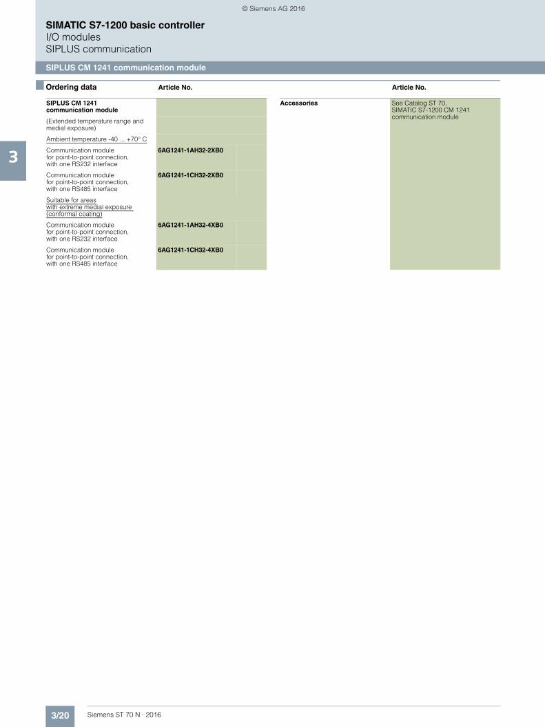
3/20 Siemens ST 70 N · 2016
3
SIMATIC S7-1200 basic controllerI/O modulesSIPLUS communication
SIPLUS CM 1241 communication module
■ Ordering data Article No. Article No.
SIPLUS CM 1241communication module
(Extended temperature range and medial exposure)
Ambient temperature -40 ... +70° C
Communication modulefor point-to-point connection,with one RS232 interface
6AG1241-1AH32-2XB0
Communication modulefor point-to-point connection, with one RS485 interface
6AG1241-1CH32-2XB0
Suitable for areaswith extreme medial exposure (conformal coating)
Communication module for point-to-point connection, with one RS232 interface
6AG1241-1AH32-4XB0
Communication module for point-to-point connection, with one RS485 interface
6AG1241-1CH32-4XB0
Accessories See Catalog ST 70, SIMATIC S7-1200 CM 1241 communication module
© Siemens AG 2016

3/21Siemens ST 70 N · 2016
3
SIMATIC S7-1200 basic controllerOperator control and monitoring
SIPLUS Basic Panels (2nd Generation)
■ Overview
With their fully developed HMI basic functions, 2nd generation SIPLUS Basic Panels are the ideal entry level series for simple HMI applications.
The device family offers panels with 4", 7", 9" and 12" displays, as well as combined key and touch operation.
The innovative high-resolution widescreen displays with64 000 colors are also suitable for upright installation, and they can be dimmed down to 100 %. The innovative operator inter-face with improved usability opens up a diverse range of options thanks to new controls and graphics. The new USB interface en-ables the connection of keyboard, mouse or barcode scanner, and supports the simple archiving of data on a USB stick.
The integrated Ethernet or RS 485/422 interface (version-specific) enables simple connection to the controller.
Note
SIPLUS extreme products are based on SIMATIC standard products. The contents listed here were taken from the respec-tive standard products. SIPLUS extreme specific information was added.
Technical documentation on SIPLUS can be found here:http://www.siemens.com/siplus-extreme
■ Technical specifications
Article number 6AG1123-2DB03-2AX0 6AG1123-2GB03-2AX0 6AG1123-2GA03-2AX0
Based on 6AV2123-2DB03-0AX0 6AV2123-2GB03-0AX0 6AV2123-2GA03-0AX0
SIPLUS HMI KTP400 BASIC SIPLUS HMI KTP700 BASIC SIPLUS HMI KTP700 BASIC DP
Ambient conditions
Ambient temperature during operation
• Operation (vertical installation)
- For vertical installation, min. -20 °C -20 °C -20 °C; = Tmin
- For vertical installation, max. 50 °C 50 °C 50 °C
Extended ambient conditions
• relative to ambient temperature-atmospheric pressure-installation altitude
Tmin ... Tmax at 1080 hPa ... 795 hPa (-1000 m ... +2000 m) // Tmin ... (Tmax - 10K) at 795 hPa ... 658 hPa (+2000 m ... +3500 m) //Tmin ... (Tmax - 20K) at 658 hPa ... 540 hPa (+3500 m ... +5000 m)
Relative humidity
- With condensation, tested in accordance with IEC 60068-2-38, max.
100 %; RH incl. condensation/frost (no commissioning under conden-sation conditions)
100 %; RH incl. condensation/frost (no commissioning under conden-sation conditions)
100 %; RH incl. condensation/frost (no commissioning when condensation present), vertical mounting position
Resistance
- against biologically active substances / conformity with EN 60721-3-3
Yes; Class 3B2 mold, fungus and dry rot spores (with the exception of fauna).The supplied connector covers must remain on the unused interfaces during operation!
- against chemically active substances / conformity with EN 60721-3-3
Yes; Class 3C4 (RH < 75%) incl. salt spray according to EN 60068-2-52 (degree of severity 3). The supplied connector covers must remain on the unused interfaces during operation!
- against mechanically active substances / conformity with EN 60721-3-3
Yes; Class 3S4 incl. sand, dust. The supplied connector covers must remain on the unused interfaces during operation!
© Siemens AG 2016

3/22 Siemens ST 70 N · 2016
3
■ Technical specifications (continued)
SIMATIC S7-1200 basic controllerOperator control and monitoring
SIPLUS Basic Panels (2nd Generation)
■ Ordering data Article No. Article No.
Article number 6AG1123-2JB03-2AX0 6AG1123-2MB03-2AX0 6AG1123-2MA03-2AX0
Based on 6AV2123-2JB03-0AX0 6AV2123-2MB03-0AX0 6AV2123-2MA03-0AX0
SIPLUS HMI KTP900 BASIC SIPLUS HMI KTP1200 BASIC SIPLUS HMI KTP1200 BASIC DP
Ambient conditions
Ambient temperature during operation
• Operation (vertical installation)
- For vertical installation, min. -20 °C -10 °C; = Tmin -10 °C; = Tmin
- For vertical installation, max. 50 °C 50 °C 50 °C
Extended ambient conditions
• relative to ambient temperature-atmospheric pressure-installation altitude
Tmin ... Tmax at 1080 hPa ... 795 hPa (-1000 m ... +2000 m) //Tmin ... (Tmax - 10K) at 795 hPa ... 658 hPa (+2000 m ... +3500 m) // Tmin ... (Tmax - 20K) at 658 hPa ... 540 hPa (+3500 m ... +5000 m)
Relative humidity
- With condensation, tested in accordance with IEC 60068-2-38, max.
100 %; RH incl. condensation/frost (no commissioning under conden-sation conditions)
100 %; RH incl. condensation / frost (no commissioning in bedewed state), horizontal installation
100 %; RH incl. condensation/frost(no commissioning when condensation present), vertical mounting position
Resistance
- against biologically active substances / conformity with EN 60721-3-3
Yes; Class 3B2 mold, fungus and dry rot spores (with the exception of fauna). The supplied connector covers must remain on the unused interfaces during operation!
- against chemically active substances / conformity with EN 60721-3-3
Yes; Class 3C4 (RH < 75%) incl. salt spray according to EN 60068-2-52 (degree of severity 3). The supplied connector covers must remain on the unused interfaces during operation!
- against mechanically active substances / conformity with EN 60721-3-3
Yes; Class 3S4 incl. sand, dust. The supplied connector covers must remain on the unused interfaces during operation!
SIPLUS HMI Basic Panels, Key and Touch
SIPLUS HMI KTP400 Basic 6AG1123-2DB03-2AX0
For areas with extreme medial exposure (conformal coating); ambient temperature-20 ... +50 °C
SIPLUS HMI KTP700 Basic 6AG1123-2GB03-2AX0
For areas with extreme medial exposure (conformal coating); ambient temperature-20 ... +50 °C
SIPLUS HMI KTP700 Basic DP 6AG1123-2GA03-2AX0
For areas with extreme medial exposure (conformal coating); ambient temperature-20 ... +50 °C
SIPLUS HMI KTP900 Basic 6AG1123-2JB03-2AX0
For areas with extreme medial exposure (conformal coating); ambient temperature-20 ... +50 °C
SIPLUS HMI KTP1200 Basic 6AG1123-2MB03-2AX0
For areas with extreme medial exposure (conformal coating); ambient temperature-10 ... +50 °C
SIPLUS HMI KTP1200 Basic DP 6AG1123-2MA03-2AX0
For areas with extreme medial exposure (conformal coating); ambient temperature-10 ... +50 °C
Accessories See Catalog ST 80, SIMATIC Basic Panels 2nd Generation
© Siemens AG 2016
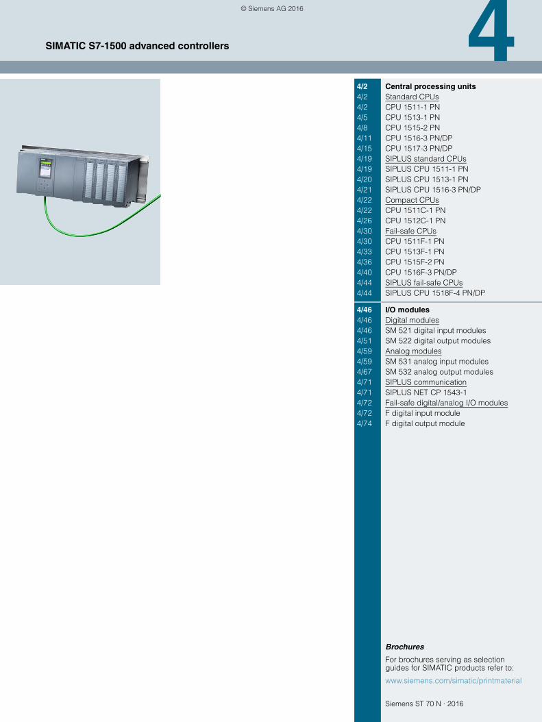
Siemens ST 70 N · 2016
4
Brochures
For brochures serving as selection guides for SIMATIC products refer to:
www.siemens.com/simatic/printmaterial
4/2 Central processing units4/2 Standard CPUs4/2 CPU 1511-1 PN4/5 CPU 1513-1 PN4/8 CPU 1515-2 PN4/11 CPU 1516-3 PN/DP4/15 CPU 1517-3 PN/DP4/19 SIPLUS standard CPUs4/19 SIPLUS CPU 1511-1 PN4/20 SIPLUS CPU 1513-1 PN4/21 SIPLUS CPU 1516-3 PN/DP4/22 Compact CPUs4/22 CPU 1511C-1 PN4/26 CPU 1512C-1 PN4/30 Fail-safe CPUs4/30 CPU 1511F-1 PN4/33 CPU 1513F-1 PN4/36 CPU 1515F-2 PN4/40 CPU 1516F-3 PN/DP4/44 SIPLUS fail-safe CPUs4/44 SIPLUS CPU 1518F-4 PN/DP
4/46 I/O modules4/46 Digital modules4/46 SM 521 digital input modules4/51 SM 522 digital output modules4/59 Analog modules4/59 SM 531 analog input modules4/67 SM 532 analog output modules4/71 SIPLUS communication4/71 SIPLUS NET CP 1543-14/72 Fail-safe digital/analog I/O modules4/72 F digital input module4/74 F digital output module
SIMATIC S7-1500 advanced controllers
© Siemens AG 2016
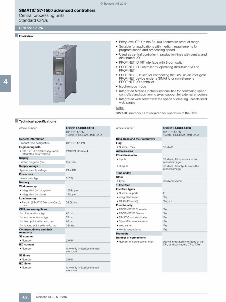
4/2 Siemens ST 70 N · 2016
4
SIMATIC S7-1500 advanced controllersCentral processing unitsStandard CPUs
CPU 1511-1 PN
■ Overview
• Entry-level CPU in the S7-1500 controller product range• Suitable for applications with medium requirements for
program scope and processing speed• Used as central controller in production lines with central and
distributed I/O• PROFINET IO IRT interface with 2-port switch• PROFINET IO Controller for operating distributed I/O on
PROFINET• PROFINET I-Device for connecting the CPU as an intelligent
PROFINET device under a SIMATIC or non-Siemens PROFINET I/O controller
• Isochronous mode• Integrated Motion Control functionalities for controlling speed-
controlled and positioning axes, support for external encoders• Integrated web server with the option of creating user-defined
web pages
Note:
SIMATIC memory card required for operation of the CPU
■ Technical specifications
Article number 6ES7511-1AK01-0AB0
CPU 1511-1PN, 150KB PROGRAM, 1MB DATA
General information
Product type designation CPU 1511-1 PN
Engineering with
• STEP 7 TIA Portal configurable/integrated as of version
V13 SP1 Update 4
Display
Screen diagonal (cm) 3.45 cm
Supply voltage
Type of supply voltage 24 V DC
Power loss
Power loss, typ. 5.7 W
Memory
Work memory
• integrated (for program) 150 kbyte
• integrated (for data) 1 Mbyte
Load memory
• Plug-in (SIMATIC Memory Card), max.
32 Gbyte
CPU processing times
for bit operations, typ. 60 ns
for word operations, typ. 72 ns
for fixed point arithmetic, typ. 96 ns
for floating point arithmetic, typ. 384 ns
Counters, timers and their retentivity
S7 counter
• Number 2 048
IEC counter
• Number Any (only limited by the main memory)
S7 times
• Number 2 048
IEC timer
• Number Any (only limited by the main memory)
Data areas and their retentivity
Flag
• Number, max. 16 kbyte
Address area
I/O address area
• Inputs 32 kbyte; All inputs are in the process image
• Outputs 32 kbyte; All outputs are in the process image
Time of day
Clock
• Type Hardware clock
1. Interface
Interface types
• Number of ports 2
• integrated switch Yes
• RJ 45 (Ethernet) Yes; X1
Functionality
• PROFINET IO Controller Yes
• PROFINET IO Device Yes
• SIMATIC communication Yes
• Open IE communication Yes
• Web server Yes
• Media redundancy Yes
Protocols
Number of connections
• Number of connections, max. 96; via integrated interfaces of the CPU and connected CPs / CMs
Article number 6ES7511-1AK01-0AB0
CPU 1511-1PN, 150KB PROGRAM, 1MB DATA
© Siemens AG 2016
4/3Siemens ST 70 N · 2016
4
■ Technical specifications (continued)
SIMATIC S7-1500 advanced controllersCentral processing units
Standard CPUs
CPU 1511-1 PN
■ Ordering data Article No. Article No.
PROFINET IO Controller
Services
- Number of connectable IO Devices, max.
128; In total, up to 256 distributed I/O devices can be connected via PROFIBUS or PROFINET
- Of which IO devices with IRT, max. 64
- Number of connectableIO Devices for RT, max.
128
Isochronous mode
Isochronous operation (application synchronized up to terminal)
Yes; With minimum OB 6x cycle of 625 µs
Supported technology objects
Motion Control Yes
• Speed-controlled axis
- Number of speed-controlled axes, max.
6; Requirement: There must be no other motion technology objects created; note: The number of axes affects the cycle time of the PLC program; selection guide via the TIA Selection Tool
• Positioning axis
- Number of positioning axes, max. 6; Requirement: There must be no other motion technology objects created; note: The number of axes affects the cycle time of the PLC program; selection guide via the TIA Selection Tool
• Synchronized axes (relative gear synchronization)
- Number of axes, max. 3; Requirement: There must be no other motion technology objects created; note: The number of axes affects the cycle time of the PLC program; selection guide via the TIA Selection Tool
• External encoders
- Number of external encoders, max.
6; Requirement: There must be no other motion technology objects created; note: The number of axes affects the cycle time of the PLC program; selection guide via the TIA Selection Tool
Article number 6ES7511-1AK01-0AB0
CPU 1511-1PN, 150KB PROGRAM, 1MB DATA
Controller
• PID_Compact Yes; Universal PID controller with integrated optimization
• PID_3Step Yes; PID controller with integrated optimization for valves
• PID-Temp Yes; PID controller with integrated optimization for temperature
Counting and measuring
• High-speed counter Yes
Ambient conditions
Ambient temperature during operation
• horizontal installation, min. 0 °C
• horizontal installation, max. 60 °C; Display: 50 °C, at an operating temperature of typically50 °C, the display is switched off
• vertical installation, min. 0 °C
• vertical installation, max. 40 °C; Display: 40 °C, at an operating temperature of typically 40 °C, the display is switched off
Configuration
Programming
Programming language
- LAD Yes
- FBD Yes
- STL Yes
- SCL Yes
- GRAPH Yes
Know-how protection
• User program protection Yes
• Copy protection Yes
• Block protection Yes
Access protection
• Password for display Yes
• Protection level: Write protection Yes
• Protection level: Read/write protection
Yes
• Protection level: Complete protection
Yes
Dimensions
Width 35 mm
Height 147 mm
Depth 129 mm
Weights
Weight, approx. 430 g
Article number 6ES7511-1AK01-0AB0
CPU 1511-1PN, 150KB PROGRAM, 1MB DATA
CPU 1511-1 PN 6ES7511-1AK01-0AB0
Work memory 150 KB for program, 1 MB for data, PROFINET IO IRT interface, SIMATIC Memory Card required
Accessories
SIMATIC Memory Card
4 MB 6ES7954-8LC02-0AA0
12 MB 6ES7954-8LE02-0AA0
24 MB 6ES7954-8LF02-0AA0
256 MB 6ES7954-8LL02-0AA0
2 GB 6ES7954-8LP02-0AA0
32 GB 6ES7954-8LT02-0AA0
SIMATIC S7-1500 DIN rail
Fixed lengths,with grounding elements• 160 mm 6ES7590-1AB60-0AA0• 245 mm 6ES7590-1AC40-0AA0• 482 mm 6ES7590-1AE80-0AA0• 530 mm 6ES7590-1AF30-0AA0• 830 mm 6ES7590-1AJ30-0AA0
For cutting to length by customer, without drill holes; grounding ele-ments must be ordered separately• 2000 mm 6ES7590-1BC00-0AA0
PE connection element for DIN rail 2000 mm
6ES7590-5AA00-0AA0
20 units
© Siemens AG 2016
4/4 Siemens ST 70 N · 2016
4
■ Ordering data Article No. Article No.
SIMATIC S7-1500 advanced controllersCentral processing unitsStandard CPUs
CPU 1511-1 PN
1) For up-to-date information and download availability, see:http://www.siemens.com/tia-online-software-delivery
Power supply
For supplying the backplane bus of the S7-1500
24 V DC input voltage, power 25 W 6ES7505-0KA00-0AB0
24/48/60 V DC input voltage, power 60 W
6ES7505-0RA00-0AB0
120/230 V AC input voltage, power 60 W
6ES7507-0RA00-0AB0
Power connector 6ES7590-8AA00-0AA0
With coding element for power supply module; spare part, 10 units
Load power supply
24 V DC/3A 6EP1332-4BA00
24 V DC/8A 6EP1333-4BA00
Power supply connector
Spare part; for connecting the 24 V DC supply voltage• with push-in terminals 6ES7193-4JB00-0AA0
IE FC RJ45 plugs
RJ45 plug connector for Industrial Ethernet with a rugged metal enclo-sure and integrated insulation dis-placement contacts for connecting Industrial Ethernet FC installation cables
IE FC RJ45 Plug 180
180° cable outlet
1 unit 6GK1901-1BB10-2AA0
10 units 6GK1901-1BB10-2AB0
50 units 6GK1901-1BB10-2AE0
IE FC TP standard cable GP 2x2 6XV1840-2AH10
4-core, shielded TP installation cable for connection toIE FC Outlet RJ45/ IE FC RJ45 Plug; PROFINET-compatible; with UL approval;sold by the meter; max. delivery unit 1000 m, minimum order quantity 20 m
IE FC TP Trailing Cable 2 x 2 (Type C)
6XV1840-3AH10
4-core, shielded TP installation cable for connection toIE FC Outlet RJ45/ IE FC RJ45 Plug 180/90 for use as trailing cable; PROFINET-compatible; with UL approval; sold by the meter; max. delivery unit 1000 m,minimum order quantity 20 m
IE FC TP Marine Cable 2 x 2 (Type B)
6XV1840-4AH10
4-core, shielded TP installation cable for connection toIE FC Outlet RJ45/ IE FC RJ45 Plug 180/90 with marine approval, sold by the meter; max. delivery unit 1000 m, minimum order quantity 20 m
IE FC stripping tool 6GK1901-1GA00
Preadjusted stripping tool for fast stripping of Industrial Ethernet FC cables
Display 6ES7591-1AA01-0AA0
for CPU 1511-1 PN and CPU 1513-1 PN; spare part
SIMATIC S7-1500 Starter Kit 6ES7511-1AK02-4YB5
Comprising:CPU 1511-1 PN, SIMATIC Memory Card 4 MB, digital input DI 16 x 24 V DC HF, digital output DO 16 x 24 V DC/0.5 A ST, 160 mm DIN rail, front connector, STEP 7 Professional V13 SP1, 365-day license, power supply PM 70, 120/230 V AC,Ethernet cable, documentation
STEP 7 Professional V13 SP1
Target system:SIMATIC S7-1200, S7-1500, S7-300, S7-400, WinACRequirement:Windows 7 Professional SP1(64-bit), Windows 7 Enterprise SP1 (64-bit), Windows 7 Ultimate SP1 (64-bit), Windows 8.1 (64-bit), Windows 8.1 Professional (64-bit),Windows 8.1 Enterprise (64-bit), Windows Server 2008 R2 StdE(full installation), Windows Server 2012 StdE(full installation)Available in:German, English, Chinese, Italian, French, Spanish
STEP 7 Professional V13 SP1,floating license
6ES7822-1AA03-0YA5
STEP 7 Professional V13 SP1,floating license, software download incl. license key 1)
Email address required for delivery
6ES7822-1AE03-0YA5
SIMATIC Manual Collection 6ES7998-8XC01-8YE0
Electronic manuals on DVD, multi-language: LOGO!, SIMADYN, SIMATIC bus components, SIMATIC C7, SIMATIC distributed I/O, SIMATIC HMI, SIMATIC Sensors, SIMATIC NET, SIMATIC PC Based Automation, SIMATIC PCS 7, SIMATIC PG/PC, SIMATIC S7, SIMATIC Software, SIMATIC TDC
SIMATIC Manual Collection update service for 1 year
6ES7998-8XC01-8YE2
Current "Manual Collection" DVD and the three subsequent updates
© Siemens AG 2016
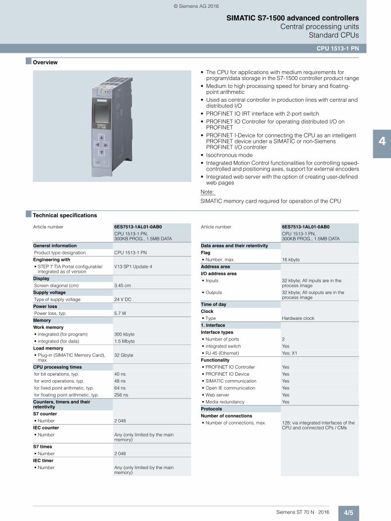
4/5Siemens ST 70 N · 2016
4
SIMATIC S7-1500 advanced controllersCentral processing units
Standard CPUs
CPU 1513-1 PN
■ Overview
• The CPU for applications with medium requirements for program/data storage in the S7-1500 controller product range
• Medium to high processing speed for binary and floating-point arithmetic
• Used as central controller in production lines with central and distributed I/O
• PROFINET IO IRT interface with 2-port switch• PROFINET IO Controller for operating distributed I/O on
PROFINET• PROFINET I-Device for connecting the CPU as an intelligent
PROFINET device under a SIMATIC or non-Siemens PROFINET I/O controller
• Isochronous mode• Integrated Motion Control functionalities for controlling speed-
controlled and positioning axes, support for external encoders• Integrated web server with the option of creating user-defined
web pages
Note:
SIMATIC memory card required for operation of the CPU
■ Technical specifications
Article number 6ES7513-1AL01-0AB0
CPU 1513-1 PN, 300KB PROG., 1.5MB DATA
General information
Product type designation CPU 1513-1 PN
Engineering with
• STEP 7 TIA Portal configurable/integrated as of version
V13 SP1 Update 4
Display
Screen diagonal (cm) 3.45 cm
Supply voltage
Type of supply voltage 24 V DC
Power loss
Power loss, typ. 5.7 W
Memory
Work memory
• integrated (for program) 300 kbyte
• integrated (for data) 1.5 Mbyte
Load memory
• Plug-in (SIMATIC Memory Card), max.
32 Gbyte
CPU processing times
for bit operations, typ. 40 ns
for word operations, typ. 48 ns
for fixed point arithmetic, typ. 64 ns
for floating point arithmetic, typ. 256 ns
Counters, timers and their retentivity
S7 counter
• Number 2 048
IEC counter
• Number Any (only limited by the main memory)
S7 times
• Number 2 048
IEC timer
• Number Any (only limited by the main memory)
Data areas and their retentivity
Flag
• Number, max. 16 kbyte
Address area
I/O address area
• Inputs 32 kbyte; All inputs are in the process image
• Outputs 32 kbyte; All outputs are in the process image
Time of day
Clock
• Type Hardware clock
1. Interface
Interface types
• Number of ports 2
• integrated switch Yes
• RJ 45 (Ethernet) Yes; X1
Functionality
• PROFINET IO Controller Yes
• PROFINET IO Device Yes
• SIMATIC communication Yes
• Open IE communication Yes
• Web server Yes
• Media redundancy Yes
Protocols
Number of connections
• Number of connections, max. 128; via integrated interfaces of the CPU and connected CPs / CMs
Article number 6ES7513-1AL01-0AB0
CPU 1513-1 PN, 300KB PROG., 1.5MB DATA
© Siemens AG 2016
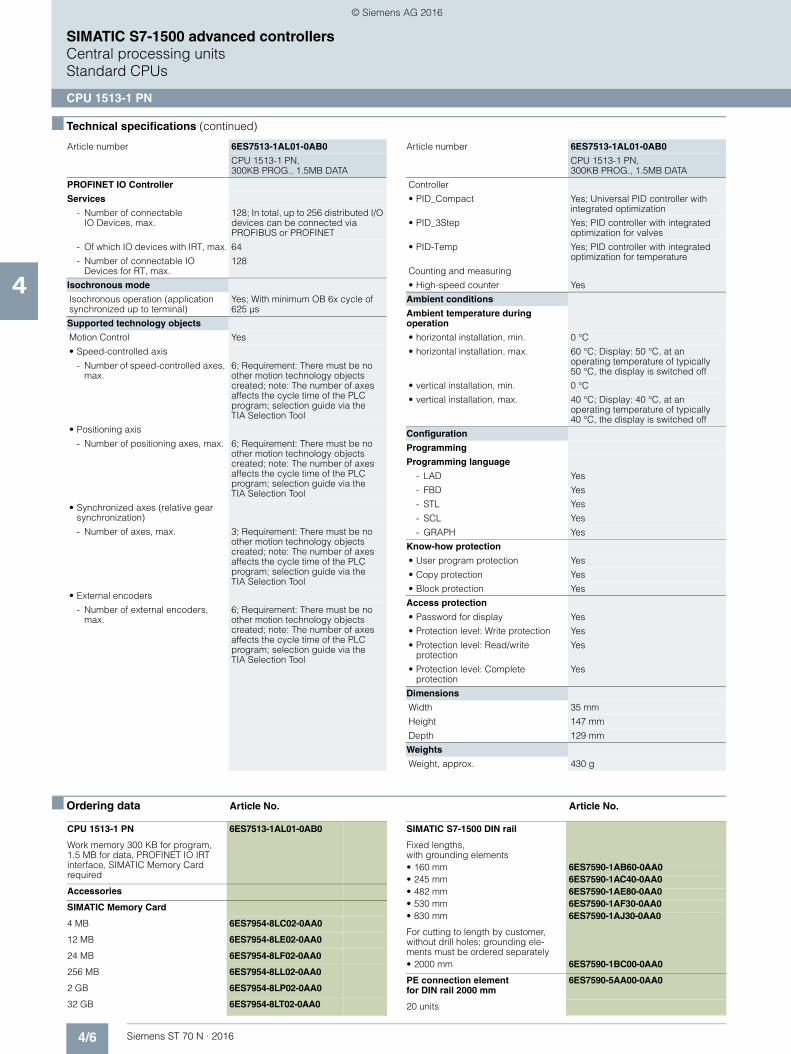
4/6 Siemens ST 70 N · 2016
4
■ Technical specifications (continued)
SIMATIC S7-1500 advanced controllersCentral processing unitsStandard CPUs
CPU 1513-1 PN
■ Ordering data Article No. Article No.
PROFINET IO Controller
Services
- Number of connectableIO Devices, max.
128; In total, up to 256 distributed I/O devices can be connected via PROFIBUS or PROFINET
- Of which IO devices with IRT, max. 64
- Number of connectable IO Devices for RT, max.
128
Isochronous mode
Isochronous operation (application synchronized up to terminal)
Yes; With minimum OB 6x cycle of 625 µs
Supported technology objects
Motion Control Yes
• Speed-controlled axis
- Number of speed-controlled axes, max.
6; Requirement: There must be no other motion technology objects created; note: The number of axes affects the cycle time of the PLC program; selection guide via the TIA Selection Tool
• Positioning axis
- Number of positioning axes, max. 6; Requirement: There must be no other motion technology objects created; note: The number of axes affects the cycle time of the PLC program; selection guide via the TIA Selection Tool
• Synchronized axes (relative gear synchronization)
- Number of axes, max. 3; Requirement: There must be no other motion technology objects created; note: The number of axes affects the cycle time of the PLC program; selection guide via theTIA Selection Tool
• External encoders
- Number of external encoders, max.
6; Requirement: There must be no other motion technology objects created; note: The number of axes affects the cycle time of the PLC program; selection guide via the TIA Selection Tool
Article number 6ES7513-1AL01-0AB0
CPU 1513-1 PN, 300KB PROG., 1.5MB DATA
Controller
• PID_Compact Yes; Universal PID controller with integrated optimization
• PID_3Step Yes; PID controller with integrated optimization for valves
• PID-Temp Yes; PID controller with integrated optimization for temperature
Counting and measuring
• High-speed counter Yes
Ambient conditions
Ambient temperature during operation
• horizontal installation, min. 0 °C
• horizontal installation, max. 60 °C; Display: 50 °C, at an operating temperature of typically50 °C, the display is switched off
• vertical installation, min. 0 °C
• vertical installation, max. 40 °C; Display: 40 °C, at an operating temperature of typically40 °C, the display is switched off
Configuration
Programming
Programming language
- LAD Yes
- FBD Yes
- STL Yes
- SCL Yes
- GRAPH Yes
Know-how protection
• User program protection Yes
• Copy protection Yes
• Block protection Yes
Access protection
• Password for display Yes
• Protection level: Write protection Yes
• Protection level: Read/write protection
Yes
• Protection level: Complete protection
Yes
Dimensions
Width 35 mm
Height 147 mm
Depth 129 mm
Weights
Weight, approx. 430 g
Article number 6ES7513-1AL01-0AB0
CPU 1513-1 PN, 300KB PROG., 1.5MB DATA
CPU 1513-1 PN 6ES7513-1AL01-0AB0
Work memory 300 KB for program, 1.5 MB for data, PROFINET IO IRT interface, SIMATIC Memory Card required
Accessories
SIMATIC Memory Card
4 MB 6ES7954-8LC02-0AA0
12 MB 6ES7954-8LE02-0AA0
24 MB 6ES7954-8LF02-0AA0
256 MB 6ES7954-8LL02-0AA0
2 GB 6ES7954-8LP02-0AA0
32 GB 6ES7954-8LT02-0AA0
SIMATIC S7-1500 DIN rail
Fixed lengths,with grounding elements• 160 mm 6ES7590-1AB60-0AA0• 245 mm 6ES7590-1AC40-0AA0• 482 mm 6ES7590-1AE80-0AA0• 530 mm 6ES7590-1AF30-0AA0• 830 mm 6ES7590-1AJ30-0AA0
For cutting to length by customer, without drill holes; grounding ele-ments must be ordered separately• 2000 mm 6ES7590-1BC00-0AA0
PE connection element for DIN rail 2000 mm
6ES7590-5AA00-0AA0
20 units
© Siemens AG 2016
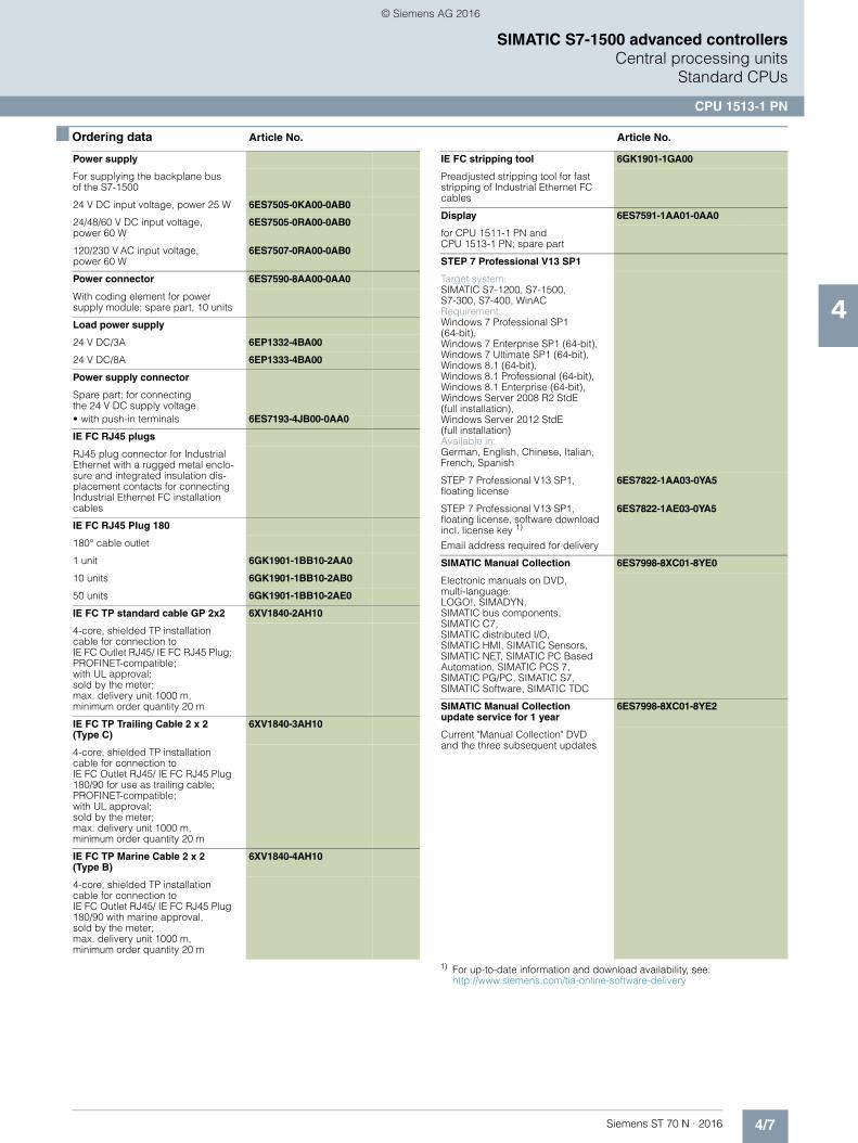
4/7Siemens ST 70 N · 2016
4
■ Ordering data Article No. Article No.
SIMATIC S7-1500 advanced controllersCentral processing units
Standard CPUs
CPU 1513-1 PN
1) For up-to-date information and download availability, see:http://www.siemens.com/tia-online-software-delivery
Power supply
For supplying the backplane bus of the S7-1500
24 V DC input voltage, power 25 W 6ES7505-0KA00-0AB0
24/48/60 V DC input voltage, power 60 W
6ES7505-0RA00-0AB0
120/230 V AC input voltage, power 60 W
6ES7507-0RA00-0AB0
Power connector 6ES7590-8AA00-0AA0
With coding element for powersupply module; spare part, 10 units
Load power supply
24 V DC/3A 6EP1332-4BA00
24 V DC/8A 6EP1333-4BA00
Power supply connector
Spare part; for connectingthe 24 V DC supply voltage• with push-in terminals 6ES7193-4JB00-0AA0
IE FC RJ45 plugs
RJ45 plug connector for Industrial Ethernet with a rugged metal enclo-sure and integrated insulation dis-placement contacts for connecting Industrial Ethernet FC installation cables
IE FC RJ45 Plug 180
180° cable outlet
1 unit 6GK1901-1BB10-2AA0
10 units 6GK1901-1BB10-2AB0
50 units 6GK1901-1BB10-2AE0
IE FC TP standard cable GP 2x2 6XV1840-2AH10
4-core, shielded TP installation cable for connection to IE FC Outlet RJ45/ IE FC RJ45 Plug; PROFINET-compatible; with UL approval;sold by the meter;max. delivery unit 1000 m, minimum order quantity 20 m
IE FC TP Trailing Cable 2 x 2 (Type C)
6XV1840-3AH10
4-core, shielded TP installation cable for connection toIE FC Outlet RJ45/ IE FC RJ45 Plug 180/90 for use as trailing cable; PROFINET-compatible; with UL approval; sold by the meter; max. delivery unit 1000 m, minimum order quantity 20 m
IE FC TP Marine Cable 2 x 2 (Type B)
6XV1840-4AH10
4-core, shielded TP installation cable for connection toIE FC Outlet RJ45/ IE FC RJ45 Plug 180/90 with marine approval, sold by the meter;max. delivery unit 1000 m, minimum order quantity 20 m
IE FC stripping tool 6GK1901-1GA00
Preadjusted stripping tool for fast stripping of Industrial Ethernet FC cables
Display 6ES7591-1AA01-0AA0
for CPU 1511-1 PN and CPU 1513-1 PN; spare part
STEP 7 Professional V13 SP1
Target system:SIMATIC S7-1200, S7-1500, S7-300, S7-400, WinACRequirement:Windows 7 Professional SP1 (64-bit), Windows 7 Enterprise SP1 (64-bit), Windows 7 Ultimate SP1 (64-bit), Windows 8.1 (64-bit), Windows 8.1 Professional (64-bit),Windows 8.1 Enterprise (64-bit), Windows Server 2008 R2 StdE (full installation), Windows Server 2012 StdE (full installation)Available in:German, English, Chinese, Italian, French, Spanish
STEP 7 Professional V13 SP1, floating license
6ES7822-1AA03-0YA5
STEP 7 Professional V13 SP1, floating license, software download incl. license key 1)
Email address required for delivery
6ES7822-1AE03-0YA5
SIMATIC Manual Collection 6ES7998-8XC01-8YE0
Electronic manuals on DVD, multi-language: LOGO!, SIMADYN, SIMATIC bus components, SIMATIC C7,SIMATIC distributed I/O, SIMATIC HMI, SIMATIC Sensors, SIMATIC NET, SIMATIC PC Based Automation, SIMATIC PCS 7, SIMATIC PG/PC, SIMATIC S7, SIMATIC Software, SIMATIC TDC
SIMATIC Manual Collection update service for 1 year
6ES7998-8XC01-8YE2
Current "Manual Collection" DVD and the three subsequent updates
© Siemens AG 2016

4/8 Siemens ST 70 N · 2016
4
SIMATIC S7-1500 advanced controllersCentral processing unitsStandard CPUs
CPU 1515-2 PN
■ Overview
• The CPU for applications with medium to high requirements for program/data storage in the S7-1500 controller product range
• Medium to high processing speed for binary and floating-point arithmetic
• Used as central controller in production lines with central and distributed I/O
• PROFINET IO IRT interface with 2-port switch• Additional PROFINET interface with separate IP address • PROFINET IO Controller for operating distributed I/O on
PROFINET• PROFINET I-Device for connecting the CPU as an intelligent
PROFINET device under a SIMATIC or non-Siemens PROFINET I/O controller
• Isochronous mode• Integrated Motion Control functionalities for controlling speed-
controlled and positioning axes, support for external encoders• Integrated web server with the option of creating user-defined
web pages
Note:
SIMATIC memory card required for operation of the CPU
■ Technical specifications
Article number 6ES7515-2AM01-0AB0
CPU 1515-2 PN, 500KB PROG., 3MB DATA
General information
Product type designation CPU 1515-2 PN
Engineering with
• STEP 7 TIA Portal configurable/integrated as of version
V13 SP1 Update 4
Display
Screen diagonal (cm) 6.1 cm
Supply voltage
Type of supply voltage 24 V DC
Power loss
Power loss, typ. 6.3 W
Memory
Work memory
• integrated (for program) 500 kbyte
• integrated (for data) 3 Mbyte
Load memory
• Plug-in (SIMATIC Memory Card), max.
32 Gbyte
CPU processing times
for bit operations, typ. 30 ns
for word operations, typ. 36 ns
for fixed point arithmetic, typ. 48 ns
for floating point arithmetic, typ. 192 ns
Counters, timers and their retentivity
S7 counter
• Number 2 048
IEC counter
• Number Any (only limited by the main memory)
S7 times
• Number 2 048
IEC timer
• Number Any (only limited by the main memory)
Data areas and their retentivity
Flag
• Number, max. 16 kbyte
Address area
I/O address area
• Inputs 32 kbyte; All inputs are in the process image
• Outputs 32 kbyte; All outputs are in the process image
Time of day
Clock
• Type Hardware clock
1. Interface
Interface types
• Number of ports 2
• integrated switch Yes
• RJ 45 (Ethernet) Yes; X1
Functionality
• PROFINET IO Controller Yes
• PROFINET IO Device Yes
• SIMATIC communication Yes
• Open IE communication Yes
• Web server Yes
• Media redundancy Yes
2. Interface
Interface types
• Number of ports 1
• integrated switch No
• RJ 45 (Ethernet) Yes; X2
Article number 6ES7515-2AM01-0AB0
CPU 1515-2 PN, 500KB PROG., 3MB DATA
© Siemens AG 2016

4/9Siemens ST 70 N · 2016
4
■ Technical specifications (continued)
SIMATIC S7-1500 advanced controllersCentral processing units
Standard CPUs
CPU 1515-2 PN
■ Ordering data Article No. Article No.
Functionality
• PROFINET IO Controller No
• PROFINET IO Device No
• SIMATIC communication Yes
• Open IE communication Yes
• Web server Yes
Protocols
Number of connections
• Number of connections, max. 192; via integrated interfaces of the CPU and connected CPs / CMs
PROFINET IO Controller
Services
- Number of connectableIO Devices, max.
256; In total, up to 512 distributed I/O devices can be connected via PROFIBUS or PROFINET
- Of which IO devices with IRT, max. 64
- Number of connectableIO Devices for RT, max.
256
Isochronous mode
Isochronous operation (application synchronized up to terminal)
Yes; With minimum OB 6x cycle of 500 µs
Supported technology objects
Motion Control Yes
• Speed-controlled axis
- Number of speed-controlled axes, max.
30; Requirement: There must be no other motion technology objects created; note: The number of axes affects the cycle time of the PLC program; selection guide via the TIA Selection Tool
• Positioning axis
- Number of positioning axes, max. 30; Requirement: There must be no other motion technology objects created; note: The number of axes affects the cycle time of the PLC program; selection guide via theTIA Selection Tool
• Synchronized axes (relative gear synchronization)
- Number of axes, max. 15; Requirement: There must be no other motion technology objects created; note: The number of axes affects the cycle time of the PLC program; selection guide via the TIA Selection Tool
Article number 6ES7515-2AM01-0AB0
CPU 1515-2 PN, 500KB PROG., 3MB DATA
• External encoders
- Number of external encoders, max.
30; Requirement: There must be no other motion technology objects created; note: The number of axes affects the cycle time of the PLC program; selection guide via the TIA Selection Tool
Controller
• PID_Compact Yes; Universal PID controller with integrated optimization
• PID_3Step Yes; PID controller with integrated optimization for valves
• PID-Temp Yes; PID controller with integrated optimization for temperature
Counting and measuring
• High-speed counter Yes
Ambient conditions
Ambient temperature during operation
• horizontal installation, min. 0 °C
• horizontal installation, max. 60 °C; Display: 50 °C, at an operating temperature of typically50 °C, the display is switched off
• vertical installation, min. 0 °C
• vertical installation, max. 40 °C; Display: 40 °C, at an operating temperature of typically 40 °C, the display is switched off
Configuration
Programming
Programming language
- LAD Yes
- FBD Yes
- STL Yes
- SCL Yes
- GRAPH Yes
Know-how protection
• User program protection Yes
• Copy protection Yes
• Block protection Yes
Access protection
• Password for display Yes
• Protection level: Write protection Yes
• Protection level: Read/write protection Yes
• Protection level: Complete protection Yes
Dimensions
Width 70 mm
Height 147 mm
Depth 129 mm
Weights
Weight, approx. 830 g
Article number 6ES7515-2AM01-0AB0
CPU 1515-2 PN, 500KB PROG., 3MB DATA
CPU 1515-2 PN 6ES7515-2AM01-0AB0
500 KB work memory for program, 3 MB for data, PROFINET IO IRT interface, PROFINET interface; SIMATIC Memory Card required
Accessories
SIMATIC Memory Card
4 MB 6ES7954-8LC02-0AA0
12 MB 6ES7954-8LE02-0AA0
24 MB 6ES7954-8LF02-0AA0
256 MB 6ES7954-8LL02-0AA0
2 GB 6ES7954-8LP02-0AA0
32 GB 6ES7954-8LT02-0AA0
© Siemens AG 2016

4/10 Siemens ST 70 N · 2016
4
■ Ordering data Article No. Article No.
SIMATIC S7-1500 advanced controllersCentral processing unitsStandard CPUs
CPU 1515-2 PN
1) For up-to-date information and download availability, see:http://www.siemens.com/tia-online-software-delivery
SIMATIC S7-1500 DIN rail
Fixed lengths, with grounding elements• 160 mm 6ES7590-1AB60-0AA0• 245 mm 6ES7590-1AC40-0AA0• 482 mm 6ES7590-1AE80-0AA0• 530 mm 6ES7590-1AF30-0AA0• 830 mm 6ES7590-1AJ30-0AA0
For cutting to length by customer, without drill holes; grounding ele-ments must be ordered separately• 2000 mm 6ES7590-1BC00-0AA0
PE connection elementfor DIN rail 2000 mm
6ES7590-5AA00-0AA0
20 units
Power supply
For supplying the backplane bus of the S7-1500
24 V DC input voltage, power 25 W 6ES7505-0KA00-0AB0
24/48/60 V DC input voltage,power 60 W
6ES7505-0RA00-0AB0
120/230 V AC input voltage, power 60 W
6ES7507-0RA00-0AB0
Power connector 6ES7590-8AA00-0AA0
With coding element for power supply module; spare part, 10 units
Load power supply
24 V DC/3A 6EP1332-4BA00
24 V DC/8A 6EP1333-4BA00
Power supply connector
Spare part; for connecting the 24 V DC supply voltage• with push-in terminals 6ES7193-4JB00-0AA0
IE FC RJ45 plugs
RJ45 plug connector for Industrial Ethernet with a rugged metal enclo-sure and integrated insulation dis-placement contacts for connecting Industrial Ethernet FC installation cables
IE FC RJ45 Plug 180
180° cable outlet
1 unit 6GK1901-1BB10-2AA0
10 units 6GK1901-1BB10-2AB0
50 units 6GK1901-1BB10-2AE0
IE FC TP standard cable GP 2x2 6XV1840-2AH10
4-core, shielded TP installation cable for connection toIE FC Outlet RJ45/ IE FC RJ45 Plug; PROFINET-compatible;with UL approval;sold by the meter;max. delivery unit 1000 m, minimum order quantity 20 m
IE FC TP Trailing Cable 2 x 2 (Type C)
6XV1840-3AH10
4-core, shielded TP installation cable for connection toIE FC Outlet RJ45/ IE FC RJ45 Plug 180/90 for use as trailing cable; PROFINET-compatible; with UL approval; sold by the meter; max. delivery unit 1000 m,minimum order quantity 20 m
IE FC TP Marine Cable 2 x 2 (Type B)
6XV1840-4AH10
4-core, shielded TP installation cable for connection toIE FC Outlet RJ45/ IE FC RJ45 Plug 180/90 with marine approval, sold by the meter; max. delivery unit 1000 m, minimum order quantity 20 m
IE FC stripping tool 6GK1901-1GA00
Preadjusted stripping tool for fast stripping of Industrial Ethernet FC cables
Display 6ES7591-1BA01-0AA0
For CPU 1515-2 PN, CPU 1516-3 PN/DP, CPU 1517-3PN/DP and CPU 1518-4 PN/DP; spare part
STEP 7 Professional V13 SP1
Target system:SIMATIC S7-1200, S7-1500,S7-300, S7-400, WinACRequirement:Windows 7 Professional SP1(64-bit), Windows 7 Enterprise SP1 (64-bit), Windows 7 Ultimate SP1 (64-bit), Windows 8.1 (64-bit), Windows 8.1 Professional (64-bit),Windows 8.1 Enterprise (64-bit), Windows Server 2008 R2 StdE (full installation), Windows Server 2012 StdE(full installation)Available in:German, English, Chinese, Italian, French, Spanish
STEP 7 Professional V13 SP1,floating license
6ES7822-1AA03-0YA5
STEP 7 Professional V13 SP1,floating license, software download incl. license key 1)
Email address required for delivery
6ES7822-1AE03-0YA5
SIMATIC Manual Collection 6ES7998-8XC01-8YE0
Electronic manuals on DVD, multi-language: LOGO!, SIMADYN, SIMATIC bus components,SIMATIC C7,SIMATIC distributed I/O, SIMATIC HMI, SIMATIC Sensors, SIMATIC NET, SIMATIC PC Based Automation, SIMATIC PCS 7, SIMATIC PG/PC, SIMATIC S7, SIMATIC Software, SIMATIC TDC
SIMATIC Manual Collection update service for 1 year
6ES7998-8XC01-8YE2
Current "Manual Collection" DVD and the three subsequent updates
© Siemens AG 2016

4/11Siemens ST 70 N · 2016
4
SIMATIC S7-1500 advanced controllersCentral processing units
Standard CPUs
CPU 1516-3 PN/DP
■ Overview
• The CPU with a large program and data memory in the S7-1500 controller product range for applications with high requirements regarding program scope and networking
• High processing speed for binary and floating-point arithmetic• Used as central controller in production lines with central and
distributed I/O• PROFINET IO IRT interface with 2-port switch• Additional PROFINET interface with separate IP address• PROFINET IO controller for operating distributed I/O on
PROFINET.• PROFINET I-Device for connecting the CPU as an intelligent
PROFINET device under a SIMATIC or non-Siemens PROFINET IO controller.
• PROFIBUS DP master interface • Isochronous mode on PROFIBUS and PROFINET• Integrated Motion Control functionalities for controlling speed-
controlled and positioning axes, support for external encoders• Integrated web server with the option of creating user-defined
web pages
Note:
SIMATIC memory card required for operation of the CPU
■ Technical specifications
Article number 6ES7516-3AN01-0AB0
CPU 1516-3 PN/DP,1MB PROG., 5MB DATA
General information
Product type designation CPU 1516-3 PN/DP
Engineering with
• STEP 7 TIA Portal configurable/integrated as of version
V13 SP1 Update 4
Display
Screen diagonal (cm) 6.1 cm
Supply voltage
Type of supply voltage 24 V DC
Power loss
Power loss, typ. 7 W
Memory
Work memory
• integrated (for program) 1 Mbyte
• integrated (for data) 5 Mbyte
Load memory
• Plug-in (SIMATIC Memory Card), max.
32 Gbyte
CPU processing times
for bit operations, typ. 10 ns
for word operations, typ. 12 ns
for fixed point arithmetic, typ. 16 ns
for floating point arithmetic, typ. 64 ns
Counters, timers and their retentivity
S7 counter
• Number 2 048
IEC counter
• Number Any (only limited by the main memory)
S7 times
• Number 2 048
IEC timer
• Number Any (only limited by the main memory)
Data areas and their retentivity
Flag
• Number, max. 16 kbyte
Address area
I/O address area
• Inputs 32 kbyte; All inputs are in the process image
• Outputs 32 kbyte; All outputs are in the process image
Time of day
Clock
• Type Hardware clock
1. Interface
Interface types
• Number of ports 2
• integrated switch Yes
• RJ 45 (Ethernet) Yes; X1
Functionality
• PROFINET IO Controller Yes
• PROFINET IO Device Yes
• SIMATIC communication Yes
• Open IE communication Yes
• Web server Yes
• Media redundancy Yes
2. Interface
Interface types
• Number of ports 1
• integrated switch No
• RJ 45 (Ethernet) Yes; X2
Functionality
• PROFINET IO Controller No
• PROFINET IO Device No
• SIMATIC communication Yes
• Open IE communication Yes
• Web server Yes
Article number 6ES7516-3AN01-0AB0
CPU 1516-3 PN/DP,1MB PROG., 5MB DATA
© Siemens AG 2016
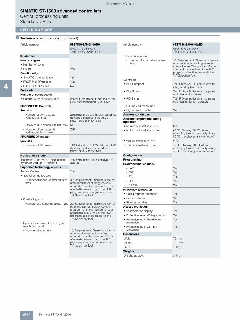
4/12 Siemens ST 70 N · 2016
4
■ Technical specifications (continued)
SIMATIC S7-1500 advanced controllersCentral processing unitsStandard CPUs
CPU 1516-3 PN/DP
3. Interface
Interface types
• Number of ports 1
• RS 485 Yes
Functionality
• SIMATIC communication Yes
• PROFIBUS DP master Yes
• PROFIBUS DP slave No
Protocols
Number of connections
• Number of connections, max. 256; via integrated interfaces of the CPU and connected CPs / CMs
PROFINET IO Controller
Services
- Number of connectableIO Devices, max.
256; In total, up to 768 distributed I/O devices can be connected via PROFIBUS or PROFINET
- Of which IO devices with IRT, max. 64
- Number of connectableIO Devices for RT, max.
256
PROFIBUS DP master
Services
- Number of DP slaves 125; In total, up to 768 distributed I/O devices can be connected via PROFIBUS or PROFINET
Isochronous mode
Isochronous operation (application synchronized up to terminal)
Yes; With minimum OB 6x cycle of 375 µs
Supported technology objects
Motion Control Yes
• Speed-controlled axis
- Number of speed-controlled axes, max.
30; Requirement: There must be no other motion technology objects created; note: The number of axes affects the cycle time of the PLC program; selection guide via the TIA Selection Tool
• Positioning axis
- Number of positioning axes, max. 30; Requirement: There must be no other motion technology objects created; note: The number of axes affects the cycle time of the PLC program; selection guide via the TIA Selection Tool
• Synchronized axes (relative gear synchronization)
- Number of axes, max. 15; Requirement: There must be no other motion technology objects created; note: The number of axes affects the cycle time of the PLC program; selection guide via theTIA Selection Tool
Article number 6ES7516-3AN01-0AB0
CPU 1516-3 PN/DP,1MB PROG., 5MB DATA
• External encoders
- Number of external encoders, max.
30; Requirement: There must be no other motion technology objects created; note: The number of axes affects the cycle time of the PLC program; selection guide via theTIA Selection Tool
Controller
• PID_Compact Yes; Universal PID controller with integrated optimization
• PID_3Step Yes; PID controller with integrated optimization for valves
• PID-Temp Yes; PID controller with integrated optimization for temperature
Counting and measuring
• High-speed counter Yes
Ambient conditions
Ambient temperature during operation
• horizontal installation, min. 0 °C
• horizontal installation, max. 60 °C; Display: 50 °C, at an operating temperature of typically 50 °C, the display is switched off
• vertical installation, min. 0 °C
• vertical installation, max. 40 °C; Display: 40 °C, at an operating temperature of typically 40 °C, the display is switched off
Configuration
Programming
Programming language
- LAD Yes
- FBD Yes
- STL Yes
- SCL Yes
- GRAPH Yes
Know-how protection
• User program protection Yes
• Copy protection Yes
• Block protection Yes
Access protection
• Password for display Yes
• Protection level: Write protection Yes
• Protection level: Read/write protection
Yes
• Protection level: Complete protection
Yes
Dimensions
Width 70 mm
Height 147 mm
Depth 129 mm
Weights
Weight, approx. 845 g
Article number 6ES7516-3AN01-0AB0
CPU 1516-3 PN/DP,1MB PROG., 5MB DATA
© Siemens AG 2016

4/13Siemens ST 70 N · 2016
4
SIMATIC S7-1500 advanced controllersCentral processing units
Standard CPUs
CPU 1516-3 PN/DP
■ Ordering data Article No. Article No.
CPU 1516-3 PN/DP 6ES7516-3AN01-0AB0
1 MB work memory for program, 5 MB for data, PROFINET IO IRT interface, PROFINET/PROFIBUS interface; SIMATIC Memory Card required
Accessories
SIMATIC Memory Card
4 MB 6ES7954-8LC02-0AA0
12 MB 6ES7954-8LE02-0AA0
24 MB 6ES7954-8LF02-0AA0
256 MB 6ES7954-8LL02-0AA0
2 GB 6ES7954-8LP02-0AA0
32 GB 6ES7954-8LT02-0AA0
SIMATIC S7-1500 DIN rail
Fixed lengths, with grounding elements• 160 mm 6ES7590-1AB60-0AA0• 245 mm 6ES7590-1AC40-0AA0• 482 mm 6ES7590-1AE80-0AA0• 530 mm 6ES7590-1AF30-0AA0• 830 mm 6ES7590-1AJ30-0AA0
For cutting to length by customer, without drill holes; grounding ele-ments must be ordered separately• 2000 mm 6ES7590-1BC00-0AA0
PE connection elementfor DIN rail 2000 mm
6ES7590-5AA00-0AA0
20 units
Power supply
For supplying the backplane bus of the S7-1500
24 V DC input voltage, power 25 W 6ES7505-0KA00-0AB0
24/48/60 V DC input voltage, power 60 W
6ES7505-0RA00-0AB0
120/230 V AC input voltage, power 60 W
6ES7507-0RA00-0AB0
Power connector 6ES7590-8AA00-0AA0
With coding element for power supply module; spare part, 10 units
Load power supply
24 V DC/3A 6EP1332-4BA00
24 V DC/8A 6EP1333-4BA00
Power supply connector
Spare part; for connecting the24 V DC supply voltage• with push-in terminals 6ES7193-4JB00-0AA0
PROFIBUS FastConnect RS 485 bus connector with 90° cable outlet
with insulation displacement, max. transmission rate 12 Mbit/s
without PG interface, groundingvia control cabinet contact surface; 1 unit
6ES7972-0BA70-0XA0
with PG interface, groundingvia control cabinet contact surface; 1 unit
6ES7972-0BB70-0XA0
PROFIBUS FC standard cable GP 6XV1830-0EH10
Standard type with special design for fast mounting, 2-core, shielded;sold by the meter; max. delivery unit 1000 m, minimum order quantity 20 m
PROFIBUS FC Robust Cable 6XV1830-0JH10
2-wire, shielded;sold by the meter; max. delivery unit 1000 m, minimum order quantity 20 m
PROFIBUS FC Flexible Cable 6XV1831-2K
2-wire, shielded;sold by the meter;max. delivery unit 1000 m,minimum order quantity 20 m
PROFIBUS FC Trailing Cable
2-wire, shielded;sold by the meter; max. delivery unit 1000 m, minimum order quantity 20 m
Sheath color: Petrol 6XV1830-3EH10
Sheath color: Violet 6XV1831-2L
PROFIBUS FC Food Cable 6XV1830-0GH10
2-wire, shielded;sold by the meter; max. delivery unit 1000 m, minimum order quantity 20 m
PROFIBUS FC Ground Cable 6XV1830-3FH10
2-wire, shielded;sold by the meter; max. delivery unit 1000 m, minimum order quantity 20 m
PROFIBUS FC FRNC Cable GP 6XV1830-0LH10
2-wire, shielded, flame-retardant, with copolymer outer sheath FRNC; sold by the meter; max. delivery unit 1000 m,minimum order quantity 20 m
PROFIBUS FastConnect Stripping Tool
6GK1905-6AA00
Preadjusted stripping toolfor fast stripping of PROFIBUS FastConnect bus cables
IE FC RJ45 plugs
RJ45 plug connector for Industrial Ethernet with a rugged metal enclo-sure and integrated insulation dis-placement contacts for connecting Industrial Ethernet FC installation cables
IE FC RJ45 Plug 180
180° cable outlet
1 unit 6GK1901-1BB10-2AA0
10 units 6GK1901-1BB10-2AB0
50 units 6GK1901-1BB10-2AE0
© Siemens AG 2016

4/14 Siemens ST 70 N · 2016
4
■ Ordering data Article No. Article No.
SIMATIC S7-1500 advanced controllersCentral processing unitsStandard CPUs
CPU 1516-3 PN/DP
1) For up-to-date information and download availability, see:http://www.siemens.com/tia-online-software-delivery
IE FC TP standard cable GP 2x2 6XV1840-2AH10
4-core, shielded TP installation cable for connection to IE FC Outlet RJ45/ IE FC RJ45 Plug; PROFINET-compatible; with UL approval;sold by the meter; max. delivery unit 1000 m, minimum order quantity 20 m
IE FC TP Trailing Cable 2 x 2 (Type C)
6XV1840-3AH10
4-core, shielded TP installation cable for connection toIE FC Outlet RJ45/ IE FC RJ45 Plug 180/90 for use as trailing cable; PROFINET-compatible; with UL approval; sold by the meter; max. delivery unit 1000 m, minimum order quantity 20 m
IE FC TP Marine Cable 2 x 2 (Type B)
6XV1840-4AH10
4-core, shielded TP installation cable for connection toIE FC Outlet RJ45/ IE FC RJ45 Plug 180/90 with marine approval, sold by the meter; max. delivery unit 1000 m,minimum order quantity 20 m
IE FC stripping tool 6GK1901-1GA00
Preadjusted stripping toolfor fast stripping ofIndustrial Ethernet FC cables
Display 6ES7591-1BA01-0AA0
for CPU 1515-2 PN, CPU 1516-3 PN/DP, CPU 1517-3 PN/DP and CPU 1518-4 PN/DP; spare part
STEP 7 Professional V13 SP1
Target system:SIMATIC S7-1200, S7-1500, S7-300, S7-400, WinACRequirement:Windows 7 Professional SP1 (64-bit), Windows 7 Enterprise SP1 (64-bit), Windows 7 Ultimate SP1 (64-bit), Windows 8.1 (64-bit), Windows 8.1 Professional (64-bit),Windows 8.1 Enterprise (64-bit), Windows Server 2008 R2 StdE(full installation), Windows Server 2012 StdE(full installation)Available in:German, English, Chinese, Italian, French, Spanish
STEP 7 Professional V13 SP1, floating license
6ES7822-1AA03-0YA5
STEP 7 Professional V13 SP1, floating license, software download incl. license key 1)
Email address required for delivery
6ES7822-1AE03-0YA5
SIMATIC Manual Collection 6ES7998-8XC01-8YE0
Electronic manuals on DVD, multi-language: LOGO!, SIMADYN, SIMATIC bus components,SIMATIC C7,SIMATIC distributed I/O, SIMATIC HMI, SIMATIC Sensors, SIMATIC NET, SIMATIC PC Based Automation, SIMATIC PCS 7, SIMATIC PG/PC, SIMATIC S7, SIMATIC Software, SIMATIC TDC
SIMATIC Manual Collection update service for 1 year
6ES7998-8XC01-8YE2
Current "Manual Collection" DVD and the three subsequent updates
© Siemens AG 2016
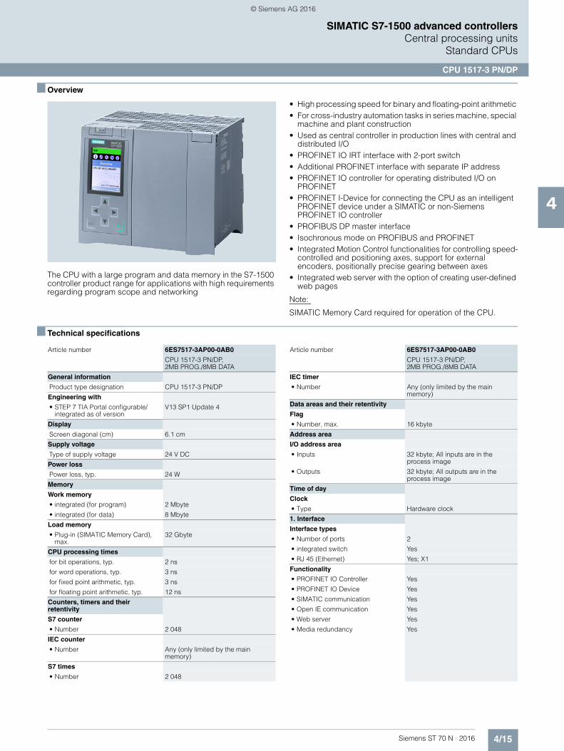
4/15Siemens ST 70 N · 2016
4
SIMATIC S7-1500 advanced controllersCentral processing units
Standard CPUs
CPU 1517-3 PN/DP
■ Overview
The CPU with a large program and data memory in the S7-1500 controller product range for applications with high requirements regarding program scope and networking
• High processing speed for binary and floating-point arithmetic • For cross-industry automation tasks in series machine, special
machine and plant construction • Used as central controller in production lines with central and
distributed I/O • PROFINET IO IRT interface with 2-port switch • Additional PROFINET interface with separate IP address • PROFINET IO controller for operating distributed I/O on
PROFINET • PROFINET I-Device for connecting the CPU as an intelligent
PROFINET device under a SIMATIC or non-Siemens PROFINET IO controller
• PROFIBUS DP master interface • Isochronous mode on PROFIBUS and PROFINET • Integrated Motion Control functionalities for controlling speed-
controlled and positioning axes, support for external encoders, positionally precise gearing between axes
• Integrated web server with the option of creating user-defined web pages
Note:
SIMATIC Memory Card required for operation of the CPU.
■ Technical specifications
Article number 6ES7517-3AP00-0AB0
CPU 1517-3 PN/DP, 2MB PROG./8MB DATA
General information
Product type designation CPU 1517-3 PN/DP
Engineering with
• STEP 7 TIA Portal configurable/integrated as of version
V13 SP1 Update 4
Display
Screen diagonal (cm) 6.1 cm
Supply voltage
Type of supply voltage 24 V DC
Power loss
Power loss, typ. 24 W
Memory
Work memory
• integrated (for program) 2 Mbyte
• integrated (for data) 8 Mbyte
Load memory
• Plug-in (SIMATIC Memory Card), max.
32 Gbyte
CPU processing times
for bit operations, typ. 2 ns
for word operations, typ. 3 ns
for fixed point arithmetic, typ. 3 ns
for floating point arithmetic, typ. 12 ns
Counters, timers and their retentivity
S7 counter
• Number 2 048
IEC counter
• Number Any (only limited by the main memory)
S7 times
• Number 2 048
IEC timer
• Number Any (only limited by the main memory)
Data areas and their retentivity
Flag
• Number, max. 16 kbyte
Address area
I/O address area
• Inputs 32 kbyte; All inputs are in the process image
• Outputs 32 kbyte; All outputs are in the process image
Time of day
Clock
• Type Hardware clock
1. Interface
Interface types
• Number of ports 2
• integrated switch Yes
• RJ 45 (Ethernet) Yes; X1
Functionality
• PROFINET IO Controller Yes
• PROFINET IO Device Yes
• SIMATIC communication Yes
• Open IE communication Yes
• Web server Yes
• Media redundancy Yes
Article number 6ES7517-3AP00-0AB0
CPU 1517-3 PN/DP, 2MB PROG./8MB DATA
© Siemens AG 2016

4/16 Siemens ST 70 N · 2016
4
■ Technical specifications (continued)
SIMATIC S7-1500 advanced controllersCentral processing unitsStandard CPUs
CPU 1517-3 PN/DP
2. Interface
Interface types
• Number of ports 1
• integrated switch No
• RJ 45 (Ethernet) Yes; X2
Functionality
• PROFINET IO Controller No
• PROFINET IO Device No
• SIMATIC communication Yes
• Open IE communication Yes
• Web server Yes
3. Interface
Interface types
• Number of ports 1
• RS 485 Yes
Functionality
• SIMATIC communication Yes
• PROFIBUS DP master Yes
• PROFIBUS DP slave No
Protocols
Number of connections
• Number of connections, max. 320; via integrated interfaces of the CPU and connected CPs / CMs
PROFINET IO Controller
Services
- Number of connectableIO Devices, max.
512; In total, up to 1000 distributedI/O devices can be connected via PROFIBUS or PROFINET
- Of which IO devices with IRT, max. 64
- Number of connectable IO Devices for RT, max.
512
PROFIBUS DP master
Services
- Number of DP slaves 125; In total, up to 1000 distributedI/O devices can be connected via PROFIBUS or PROFINET
Isochronous mode
Isochronous operation (application synchronized up to terminal)
Yes; With minimum OB 6x cycle of 375 µs
Supported technology objects
Motion Control Yes
• Speed-controlled axis
- Number of speed-controlled axes, max.
96; Requirement: There must be no other motion technology objects created; note: The number of axes affects the cycle time of the PLC program; selection guide via theTIA Selection Tool
• Positioning axis
- Number of positioning axes, max. 96; Requirement: There must be no other motion technology objects created; note: The number of axes affects the cycle time of the PLC program; selection guide via theTIA Selection Tool
Article number 6ES7517-3AP00-0AB0
CPU 1517-3 PN/DP, 2MB PROG./8MB DATA
• Synchronized axes(relative gear synchronization)
- Number of axes, max. 48; Requirement: There must be no other motion technology objects created; note: The number of axes affects the cycle time of the PLC program; selection guide via theTIA Selection Tool
• External encoders
- Number of external encoders, max.
96; Requirement: There must be no other motion technology objects created; note: The number of axes affects the cycle time of the PLC program; selection guide via theTIA Selection Tool
Controller
• PID_Compact Yes; Universal PID controller with integrated optimization
• PID_3Step Yes; PID controller with integrated optimization for valves
• PID-Temp Yes; PID controller with integrated optimization for temperature
Counting and measuring
• High-speed counter Yes
Ambient conditions
Ambient temperature during operation
• horizontal installation, min. 0 °C
• horizontal installation, max. 60 °C; Display: 50 °C, at an operating temperature of typically 50 °C, the display is switched off
• vertical installation, min. 0 °C
• vertical installation, max. 40 °C; Display: 40 °C, at an operating temperature of typically 40 °C, the display is switched off
Configuration
Programming
Programming language
- LAD Yes
- FBD Yes
- STL Yes
- SCL Yes
- GRAPH Yes
Know-how protection
• User program protection Yes
• Copy protection Yes
• Block protection Yes
Access protection
• Password for display Yes
• Protection level: Write protection Yes
• Protection level: Read/write protection
Yes
• Protection level: Complete protection
Yes
Dimensions
Width 175 mm
Height 147 mm
Depth 129 mm
Weights
Weight, approx. 1 978 g
Article number 6ES7517-3AP00-0AB0
CPU 1517-3 PN/DP, 2MB PROG./8MB DATA
© Siemens AG 2016
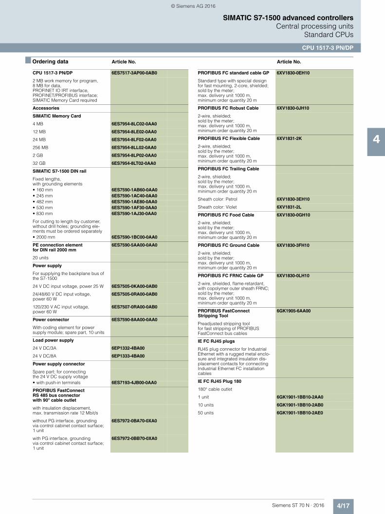
4/17Siemens ST 70 N · 2016
4
SIMATIC S7-1500 advanced controllersCentral processing units
Standard CPUs
CPU 1517-3 PN/DP
■ Ordering data Article No. Article No.
CPU 1517-3 PN/DP 6ES7517-3AP00-0AB0
2 MB work memory for program, 8 MB for data, PROFINET IO IRT interface, PROFINET/PROFIBUS interface; SIMATIC Memory Card required
Accessories
SIMATIC Memory Card
4 MB 6ES7954-8LC02-0AA0
12 MB 6ES7954-8LE02-0AA0
24 MB 6ES7954-8LF02-0AA0
256 MB 6ES7954-8LL02-0AA0
2 GB 6ES7954-8LP02-0AA0
32 GB 6ES7954-8LT02-0AA0
SIMATIC S7-1500 DIN rail
Fixed lengths, with grounding elements• 160 mm 6ES7590-1AB60-0AA0• 245 mm 6ES7590-1AC40-0AA0• 482 mm 6ES7590-1AE80-0AA0• 530 mm 6ES7590-1AF30-0AA0• 830 mm 6ES7590-1AJ30-0AA0
For cutting to length by customer, without drill holes; grounding ele-ments must be ordered separately• 2000 mm 6ES7590-1BC00-0AA0
PE connection element for DIN rail 2000 mm
6ES7590-5AA00-0AA0
20 units
Power supply
For supplying the backplane bus of the S7-1500
24 V DC input voltage, power 25 W 6ES7505-0KA00-0AB0
24/48/60 V DC input voltage,power 60 W
6ES7505-0RA00-0AB0
120/230 V AC input voltage, power 60 W
6ES7507-0RA00-0AB0
Power connector 6ES7590-8AA00-0AA0
With coding element for power supply module; spare part, 10 units
Load power supply
24 V DC/3A 6EP1332-4BA00
24 V DC/8A 6EP1333-4BA00
Power supply connector
Spare part; for connectingthe 24 V DC supply voltage• with push-in terminals 6ES7193-4JB00-0AA0
PROFIBUS FastConnectRS 485 bus connectorwith 90° cable outlet
with insulation displacement,max. transmission rate 12 Mbit/s
without PG interface, groundingvia control cabinet contact surface; 1 unit
6ES7972-0BA70-0XA0
with PG interface, grounding via control cabinet contact surface; 1 unit
6ES7972-0BB70-0XA0
PROFIBUS FC standard cable GP 6XV1830-0EH10
Standard type with special design for fast mounting, 2-core, shielded;sold by the meter; max. delivery unit 1000 m, minimum order quantity 20 m
PROFIBUS FC Robust Cable 6XV1830-0JH10
2-wire, shielded;sold by the meter; max. delivery unit 1000 m, minimum order quantity 20 m
PROFIBUS FC Flexible Cable 6XV1831-2K
2-wire, shielded;sold by the meter; max. delivery unit 1000 m, minimum order quantity 20 m
PROFIBUS FC Trailing Cable
2-wire, shielded;sold by the meter; max. delivery unit 1000 m, minimum order quantity 20 m
Sheath color: Petrol 6XV1830-3EH10
Sheath color: Violet 6XV1831-2L
PROFIBUS FC Food Cable 6XV1830-0GH10
2-wire, shielded;sold by the meter; max. delivery unit 1000 m, minimum order quantity 20 m
PROFIBUS FC Ground Cable 6XV1830-3FH10
2-wire, shielded;sold by the meter; max. delivery unit 1000 m,minimum order quantity 20 m
PROFIBUS FC FRNC Cable GP 6XV1830-0LH10
2-wire, shielded, flame-retardant, with copolymer outer sheath FRNC; sold by the meter; max. delivery unit 1000 m, minimum order quantity 20 m
PROFIBUS FastConnect Stripping Tool
6GK1905-6AA00
Preadjusted stripping tool for fast stripping of PROFIBUSFastConnect bus cables
IE FC RJ45 plugs
RJ45 plug connector for Industrial Ethernet with a rugged metal enclo-sure and integrated insulation dis-placement contacts for connecting Industrial Ethernet FC installation cables
IE FC RJ45 Plug 180
180° cable outlet
1 unit 6GK1901-1BB10-2AA0
10 units 6GK1901-1BB10-2AB0
50 units 6GK1901-1BB10-2AE0
© Siemens AG 2016
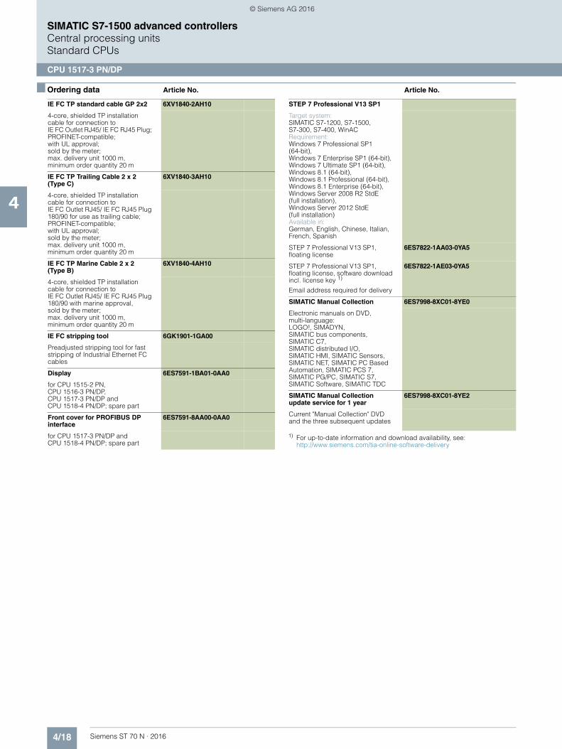
4/18 Siemens ST 70 N · 2016
4
■ Ordering data Article No. Article No.
SIMATIC S7-1500 advanced controllersCentral processing unitsStandard CPUs
CPU 1517-3 PN/DP
1) For up-to-date information and download availability, see:http://www.siemens.com/tia-online-software-delivery
IE FC TP standard cable GP 2x2 6XV1840-2AH10
4-core, shielded TP installation cable for connection to IE FC Outlet RJ45/ IE FC RJ45 Plug; PROFINET-compatible; with UL approval;sold by the meter;max. delivery unit 1000 m, minimum order quantity 20 m
IE FC TP Trailing Cable 2 x 2 (Type C)
6XV1840-3AH10
4-core, shielded TP installation cable for connection toIE FC Outlet RJ45/ IE FC RJ45 Plug 180/90 for use as trailing cable; PROFINET-compatible; with UL approval; sold by the meter; max. delivery unit 1000 m, minimum order quantity 20 m
IE FC TP Marine Cable 2 x 2 (Type B)
6XV1840-4AH10
4-core, shielded TP installation cable for connection to IE FC Outlet RJ45/ IE FC RJ45 Plug 180/90 with marine approval, sold by the meter; max. delivery unit 1000 m,minimum order quantity 20 m
IE FC stripping tool 6GK1901-1GA00
Preadjusted stripping tool for fast stripping of Industrial Ethernet FC cables
Display 6ES7591-1BA01-0AA0
for CPU 1515-2 PN, CPU 1516-3 PN/DP, CPU 1517-3 PN/DP and CPU 1518-4 PN/DP; spare part
Front cover for PROFIBUS DP interface
6ES7591-8AA00-0AA0
for CPU 1517-3 PN/DP and CPU 1518-4 PN/DP; spare part
STEP 7 Professional V13 SP1
Target system:SIMATIC S7-1200, S7-1500, S7-300, S7-400, WinACRequirement:Windows 7 Professional SP1(64-bit), Windows 7 Enterprise SP1 (64-bit), Windows 7 Ultimate SP1 (64-bit), Windows 8.1 (64-bit), Windows 8.1 Professional (64-bit),Windows 8.1 Enterprise (64-bit), Windows Server 2008 R2 StdE(full installation), Windows Server 2012 StdE(full installation)Available in:German, English, Chinese, Italian, French, Spanish
STEP 7 Professional V13 SP1, floating license
6ES7822-1AA03-0YA5
STEP 7 Professional V13 SP1,floating license, software download incl. license key 1)
Email address required for delivery
6ES7822-1AE03-0YA5
SIMATIC Manual Collection 6ES7998-8XC01-8YE0
Electronic manuals on DVD, multi-language: LOGO!, SIMADYN, SIMATIC bus components, SIMATIC C7, SIMATIC distributed I/O, SIMATIC HMI, SIMATIC Sensors, SIMATIC NET, SIMATIC PC Based Automation, SIMATIC PCS 7, SIMATIC PG/PC, SIMATIC S7, SIMATIC Software, SIMATIC TDC
SIMATIC Manual Collection update service for 1 year
6ES7998-8XC01-8YE2
Current "Manual Collection" DVD and the three subsequent updates
© Siemens AG 2016

4/19Siemens ST 70 N · 2016
4
SIMATIC S7-1500 advanced controllersCentral processing units SIPLUS standard CPUs
SIPLUS CPU 1511-1 PN
■ Overview
• Entry-level CPU in the S7-1500 controller product range• Suitable for applications with medium requirements for
program scope and processing speed• Used as central controller in production lines with central and
distributed I/O• PROFINET IO IRT interface with 2-port switch• PROFINET IO Controller for operating distributed I/O on
PROFINET• PROFINET I-Device for connecting the CPU as an intelligent
PROFINET device under a SIMATIC or non-Siemens PROFINET I/O controller
• Isochronous mode• SIMATIC memory card required for operation of the CPU
Please note:
SIPLUS extreme products are based on SIMATIC standard pro-ducts. The contents listed here were taken from the respective standard products. SIPLUS extreme-specific information was added.
■ Technical specifications
■ Ordering data Article No.
Article number 6AG1511-1AK01-2AB0 6AG1511-1AK01-7AB0
Based on 6ES7511-1AK01-0AB0 6ES7511-1AK01-0AB0
SIPLUS S7-1500CPU 1511-1 PN
SIPLUS S7-1500CPU 1511-1 PN
Ambient conditions
Ambient temperature during operation
• horizontal installation, min.
-40 °C; = Tmin;Startup @ -20 °C
-40 °C; = Tmin; Startup @ -20 °C
• horizontal installation, max.
60 °C; Display: 50 °C, at an operating temperature of typically 50 °C, the display is switched off
70 °C; Display: 50 °C, at an operating temperature of typically 50 °C, the display is switched off
• vertical installation, min. -40 °C; = Tmin; Startup @ -20 °C
-40 °C; = Tmin; Startup @ -20 °C
• vertical installation, max. 40 °C; Display: 40 °C, at an operating temperature of typically 40 °C, the display is switched off
40 °C; Display: 40 °C, at an operating temperature of typically 40 °C, the display is switched off
Extended ambient condi-tions
• relative to ambient temperature-atmospheric pressure-installation altitude
Tmin ... Tmax at 1080 hPa ... 795 hPa (-1000 m ... +2000 m) //Tmin ... (Tmax - 10K) at 795 hPa ... 658 hPa (+2000 m ... +3500 m) // Tmin ... (Tmax - 20K) at 658 hPa ... 540 hPa (+3500 m ... +5000 m)
Relative humidity
- With condensation, tested in accordance with IEC 60068-2-38, max.
100 %; RH incl. condensation / frost (no commissioning in bedewed state), horizontal installation
Resistance
- against biologically active substances / conformity with EN 60721-3-3
Yes; Class 3B2 mold, fungus and dry rot spores (with the exception of fauna). The supplied connector covers must remain on the unused interfaces during operation!
- against chemically active substances / conformity with EN 60721-3-3
Yes; Class 3C4 (RH < 75%) incl. salt spray according to EN 60068-2-52 (degree of severity 3). The supplied connector covers must remain on the unused interfaces during operation!
Yes; Class 3C4 incl. salt spray. The supplied connector covers must remain on the unused interfaces during operation!
- against mechanically active substances / conformity with EN 60721-3-3
Yes; Class 3S4 incl. sand, dust. The supplied connector covers must remain on the unused interfaces during operation!
Yes; Class 3S4 incl. sand, dust. The supplied connector covers must remain on the unused interfaces during operation in corrosive atmospheres!
SIPLUS CPU 1511-1 PN
(extended temperature range and medial exposure)
Work memory 150 KB for program, 1 MB for data, PROFINET IO IRT interface; SIMATIC memory card required
Temperature range -40 ... +60 °C (startup -20 °C)
6AG1511-1AK01-2AB0
Temperature range -40 ... +70 °C (startup -20 °C)
6AG1511-1AK01-7AB0
Power supply
(extended temperature range and medial exposure)
24 V DC input voltage, power 25 W 6AG1505-0KA00-7AB0
24/48/60 V DC input voltage,power 60 W
6AG1505-0RA00-7AB0
120/230 V AC input voltage, power 60 W
6AG1507-0RA00-7AB0
Load power supply
(extended temperature range and medial exposure)
24 V DC/3A 6AG1332-4BA00-7AA0
24 V DC/8A 6AG1333-4BA00-7AA0
Display 6AG1591-1AA01-2AA0
(extended temperature range and medial exposure)
for SIPLUS CPU 1511-1 PN and CPU 1513-1 PN; spare part
Further accessories See SIMATIC S7-1500, CPU 1511-1 PN, page 4/3
Article number 6AG1511-1AK01-2AB0 6AG1511-1AK01-7AB0
Based on 6ES7511-1AK01-0AB0 6ES7511-1AK01-0AB0
SIPLUS S7-1500CPU 1511-1 PN
SIPLUS S7-1500CPU 1511-1 PN
© Siemens AG 2016
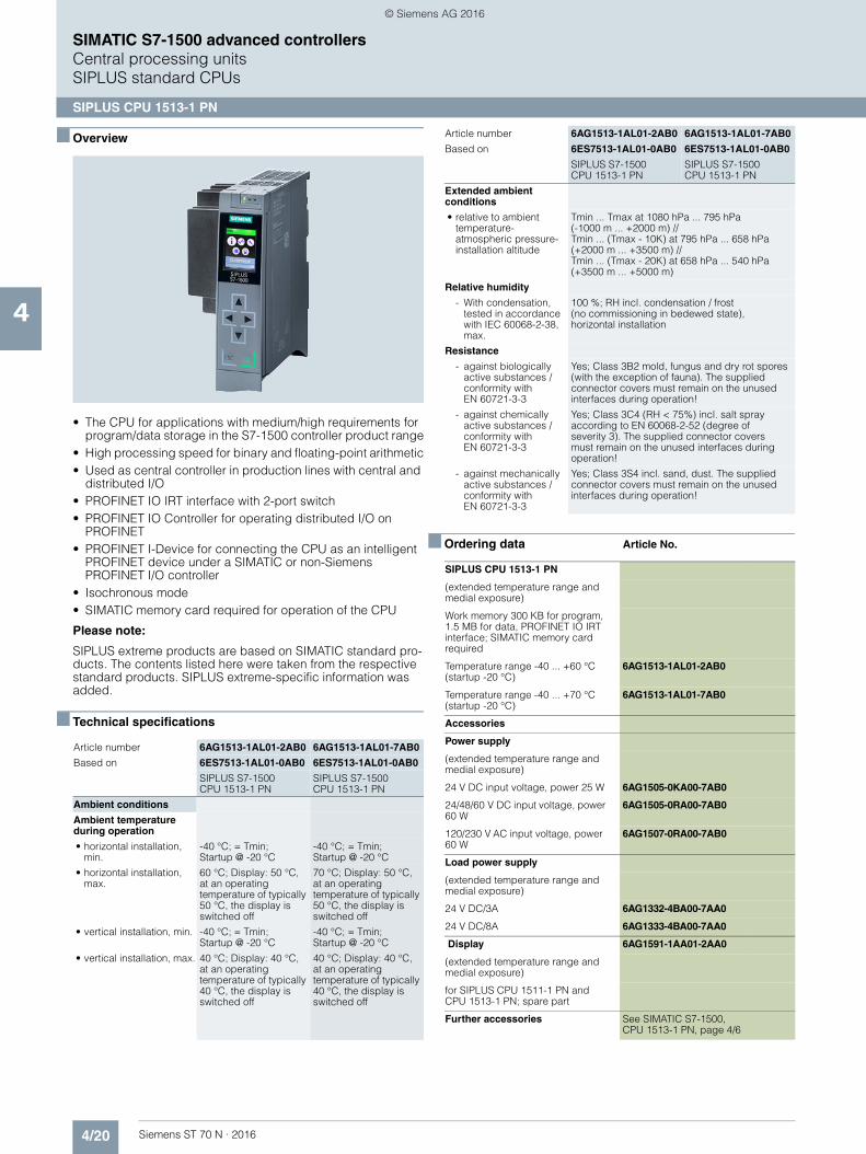
4/20 Siemens ST 70 N · 2016
4
SIMATIC S7-1500 advanced controllersCentral processing unitsSIPLUS standard CPUs
SIPLUS CPU 1513-1 PN
■ Overview
• The CPU for applications with medium/high requirements for program/data storage in the S7-1500 controller product range
• High processing speed for binary and floating-point arithmetic• Used as central controller in production lines with central and
distributed I/O• PROFINET IO IRT interface with 2-port switch• PROFINET IO Controller for operating distributed I/O on
PROFINET• PROFINET I-Device for connecting the CPU as an intelligent
PROFINET device under a SIMATIC or non-Siemens PROFINET I/O controller
• Isochronous mode• SIMATIC memory card required for operation of the CPU
Please note:
SIPLUS extreme products are based on SIMATIC standard pro-ducts. The contents listed here were taken from the respective standard products. SIPLUS extreme-specific information was added.
■ Technical specifications
■ Ordering data Article No.
Article number 6AG1513-1AL01-2AB0 6AG1513-1AL01-7AB0
Based on 6ES7513-1AL01-0AB0 6ES7513-1AL01-0AB0
SIPLUS S7-1500 CPU 1513-1 PN
SIPLUS S7-1500CPU 1513-1 PN
Ambient conditions
Ambient temperature during operation
• horizontal installation, min.
-40 °C; = Tmin; Startup @ -20 °C
-40 °C; = Tmin; Startup @ -20 °C
• horizontal installation, max.
60 °C; Display: 50 °C, at an operating temperature of typically 50 °C, the display is switched off
70 °C; Display: 50 °C, at an operating temperature of typically 50 °C, the display is switched off
• vertical installation, min. -40 °C; = Tmin;Startup @ -20 °C
-40 °C; = Tmin; Startup @ -20 °C
• vertical installation, max. 40 °C; Display: 40 °C, at an operating temperature of typically 40 °C, the display is switched off
40 °C; Display: 40 °C, at an operating temperature of typically 40 °C, the display is switched off
Extended ambient conditions
• relative to ambient temperature-atmospheric pressure-installation altitude
Tmin ... Tmax at 1080 hPa ... 795 hPa(-1000 m ... +2000 m) // Tmin ... (Tmax - 10K) at 795 hPa ... 658 hPa (+2000 m ... +3500 m) // Tmin ... (Tmax - 20K) at 658 hPa ... 540 hPa (+3500 m ... +5000 m)
Relative humidity
- With condensation, tested in accordance with IEC 60068-2-38, max.
100 %; RH incl. condensation / frost (no commissioning in bedewed state), horizontal installation
Resistance
- against biologically active substances / conformity with EN 60721-3-3
Yes; Class 3B2 mold, fungus and dry rot spores (with the exception of fauna). The supplied connector covers must remain on the unused interfaces during operation!
- against chemically active substances / conformity with EN 60721-3-3
Yes; Class 3C4 (RH < 75%) incl. salt spray according to EN 60068-2-52 (degree of severity 3). The supplied connector covers must remain on the unused interfaces during operation!
- against mechanically active substances / conformity with EN 60721-3-3
Yes; Class 3S4 incl. sand, dust. The supplied connector covers must remain on the unused interfaces during operation!
SIPLUS CPU 1513-1 PN
(extended temperature range and medial exposure)
Work memory 300 KB for program, 1.5 MB for data, PROFINET IO IRT interface; SIMATIC memory card required
Temperature range -40 ... +60 °C (startup -20 °C)
6AG1513-1AL01-2AB0
Temperature range -40 ... +70 °C (startup -20 °C)
6AG1513-1AL01-7AB0
Accessories
Power supply
(extended temperature range and medial exposure)
24 V DC input voltage, power 25 W 6AG1505-0KA00-7AB0
24/48/60 V DC input voltage, power 60 W
6AG1505-0RA00-7AB0
120/230 V AC input voltage, power 60 W
6AG1507-0RA00-7AB0
Load power supply
(extended temperature range and medial exposure)
24 V DC/3A 6AG1332-4BA00-7AA0
24 V DC/8A 6AG1333-4BA00-7AA0
Display 6AG1591-1AA01-2AA0
(extended temperature range and medial exposure)
for SIPLUS CPU 1511-1 PN and CPU 1513-1 PN; spare part
Further accessories See SIMATIC S7-1500, CPU 1513-1 PN, page 4/6
Article number 6AG1513-1AL01-2AB0 6AG1513-1AL01-7AB0
Based on 6ES7513-1AL01-0AB0 6ES7513-1AL01-0AB0
SIPLUS S7-1500 CPU 1513-1 PN
SIPLUS S7-1500CPU 1513-1 PN
© Siemens AG 2016
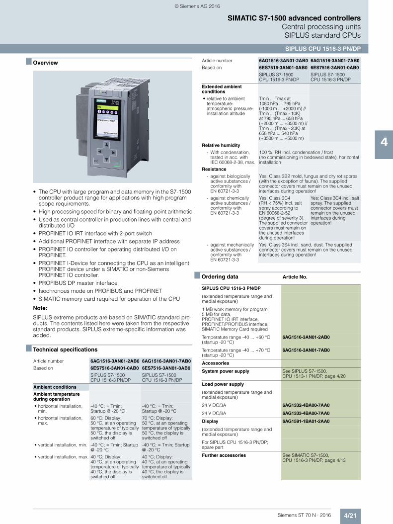
4/21Siemens ST 70 N · 2016
4
SIMATIC S7-1500 advanced controllersCentral processing units SIPLUS standard CPUs
SIPLUS CPU 1516-3 PN/DP
■ Overview
• The CPU with large program and data memory in the S7-1500 controller product range for applications with high program scope requirements.
• High processing speed for binary and floating-point arithmetic• Used as central controller in production lines with central and
distributed I/O• PROFINET IO IRT interface with 2-port switch• Additional PROFINET interface with separate IP address• PROFINET IO controller for operating distributed I/O on
PROFINET.• PROFINET I-Device for connecting the CPU as an intelligent
PROFINET device under a SIMATIC or non-Siemens PROFINET IO controller.
• PROFIBUS DP master interface • Isochronous mode on PROFIBUS and PROFINET• SIMATIC memory card required for operation of the CPU
Note:
SIPLUS extreme products are based on SIMATIC standard pro-ducts. The contents listed here were taken from the respective standard products. SIPLUS extreme-specific information was added.
■ Technical specifications
■ Ordering data Article No.
Article number 6AG1516-3AN01-2AB0 6AG1516-3AN01-7AB0
Based on 6ES7516-3AN01-0AB0 6ES7516-3AN01-0AB0
SIPLUS S7-1500 CPU 1516-3 PN/DP
SIPLUS S7-1500CPU 1516-3 PN/DP
Ambient conditions
Ambient temperature during operation
• horizontal installation, min.
-40 °C; = Tmin; Startup @ -20 °C
-40 °C; = Tmin; Startup @ -20 °C
• horizontal installation, max.
60 °C; Display: 50 °C, at an operating temperature of typically 50 °C, the display is switched off
70 °C; Display: 50 °C, at an operating temperature of typically 50 °C, the display is switched off
• vertical installation, min. -40 °C; = Tmin; Startup @ -20 °C
-40 °C; = Tmin; Startup @ -20 °C
• vertical installation, max. 40 °C; Display: 40 °C, at an operating temperature of typically 40 °C, the display is switched off
40 °C; Display: 40 °C, at an operating temperature of typically 40 °C, the display is switched off
Extended ambient conditions
• relative to ambient temperature-atmospheric pressure-installation altitude
Tmin ... Tmax at1080 hPa ... 795 hPa (-1000 m ... +2000 m) // Tmin ... (Tmax - 10K) at 795 hPa ... 658 hPa (+2000 m ... +3500 m) // Tmin ... (Tmax - 20K) at 658 hPa ... 540 hPa (+3500 m ... +5000 m)
Relative humidity
- With condensation, tested in acc. with IEC 60068-2-38, max.
100 %; RH incl. condensation / frost (no commissioning in bedewed state), horizontal installation
Resistance
- against biologically active substances / conformity with EN 60721-3-3
Yes; Class 3B2 mold, fungus and dry rot spores (with the exception of fauna). The supplied connector covers must remain on the unused interfaces during operation!
- against chemically active substances / conformity with EN 60721-3-3
Yes; Class 3C4(RH < 75%) incl. salt spray according to EN 60068-2-52 (degree of severity 3). The supplied connector covers must remain on the unused interfaces during operation!
Yes; Class 3C4 incl. salt spray. The supplied connector covers must remain on the unused interfaces during operation!
- against mechanically active substances / conformity with EN 60721-3-3
Yes; Class 3S4 incl. sand, dust. The supplied connector covers must remain on the unused interfaces during operation!
SIPLUS CPU 1516-3 PN/DP
(extended temperature range and medial exposure)
1 MB work memory for program, 5 MB for data, PROFINET IO IRT interface, PROFINET/PROFIBUS interface; SIMATIC Memory Card required
Temperature range -40 ... +60 °C (startup -20 °C)
6AG1516-3AN01-2AB0
Temperature range -40 ... +70 °C (startup -20 °C)
6AG1516-3AN01-7AB0
Accessories
System power supply See SIPLUS S7-1500,CPU 1513-1 PN/DP, page 4/20
Load power supply
(extended temperature range and medial exposure)
24 V DC/3A 6AG1332-4BA00-7AA0
24 V DC/8A 6AG1333-4BA00-7AA0
Display 6AG1591-1BA01-2AA0
(extended temperature range and medial exposure)
For SIPLUS CPU 1516-3 PN/DP; spare part
Further accessories See SIMATIC S7-1500, CPU 1516-3 PN/DP, page 4/13
Article number 6AG1516-3AN01-2AB0 6AG1516-3AN01-7AB0
Based on 6ES7516-3AN01-0AB0 6ES7516-3AN01-0AB0
SIPLUS S7-1500 CPU 1516-3 PN/DP
SIPLUS S7-1500CPU 1516-3 PN/DP
© Siemens AG 2016

4/22 Siemens ST 70 N · 2016
4
SIMATIC S7-1500 advanced controllersCentral processing unitsCompact CPUs
CPU 1511C-1 PN
■ Overview
• The compact CPU with integral digital and analog inputs and outputs in the product spectrum of the S7-1500 Controllers
• With integrated technological functions• Suitable for applications with medium requirements for
program scope and processing speed• Used as central controller in production lines with central and
distributed I/O• PROFINET IO IRT interface with 2-port switch• PROFINET IO Controller for operating distributed I/O on
PROFINET• PROFINET I-Device for connecting the CPU as an intelligent
PROFINET device under a SIMATIC or non-Siemens PROFINET IO Controller
• Isochronous mode• Integrated Motion Control functionalities for controlling speed-
controlled and positioning axes, support for external encoders• Integrated web server with the option of creating user-defined
Web pages
Note
SIMATIC Memory Card required for operation of the CPU.
■ Technical specifications
Article number 6ES7511-1CK00-0AB0
CPU 1511C-1 PN, 175 KB PROG, 1 MB DATA
General information
Product type designation CPU 1511C-1 PN
Engineering with
• STEP 7 TIA Portal configurable/integrated as of version
V13 SP1 Update 4
Display
Screen diagonal (cm) 3.45 cm
Supply voltage
Type of supply voltage 24 V DC
Input current
Digital inputs
• from load voltage L+ (without load), max.
20 mA; per group
Digital outputs
• from load voltage L+, max. 30 mA; Per group, without load
Power loss
Power loss, typ. 11.8 W
Memory
Work memory
• integrated (for program) 175 kbyte
• integrated (for data) 1 Mbyte
Load memory
• Plug-in (SIMATIC Memory Card), max.
32 Gbyte
CPU processing times
for bit operations, typ. 60 ns
for word operations, typ. 72 ns
for fixed point arithmetic, typ. 96 ns
for floating point arithmetic, typ. 384 ns
Counters, timers and their retentivity
S7 counter
• Number 2 048
IEC counter
• Number Any (only limited by the main memory)
S7 times
• Number 2 048
IEC timer
• Number Any (only limited by the main memory)
Data areas and their retentivity
Flag
• Number, max. 16 kbyte
Address area
I/O address area
• Inputs 32 kbyte; All inputs are in the process image
• Outputs 32 kbyte; All outputs are in the process image
Time of day
Clock
• Type Hardware clock
Digital inputs
integrated channels (DI) 16
Digital outputs
integrated channels (DO) 16
Short-circuit protection Yes; electronic/thermal
Analog outputs
integrated channels (AO) 2
Article number 6ES7511-1CK00-0AB0
CPU 1511C-1 PN, 175 KB PROG, 1 MB DATA
© Siemens AG 2016

4/23Siemens ST 70 N · 2016
4
■ Technical specifications (continued)
SIMATIC S7-1500 advanced controllersCentral processing units
Compact CPUs
CPU 1511C-1 PN
1. Interface
Interface types
• Number of ports 2
• integrated switch Yes
• RJ 45 (Ethernet) Yes; X1
Functionality
• PROFINET IO Controller Yes
• PROFINET IO Device Yes
• SIMATIC communication Yes
• Open IE communication Yes
• Web server Yes
• Media redundancy Yes
Protocols
Number of connections
• Number of connections, max. 96; via integrated interfaces of the CPU and connected CPs / CMs
PROFINET IO Controller
Services
- Number of connectable IO Devices, max.
128; In total, up to 256 distributed I/O devices can be connected via PROFIBUS or PROFINET
- Of which IO devices with IRT, max. 64
- Number of connectable IO Devices for RT, max.
128
Isochronous mode
Isochronous operation (application synchronized up to terminal)
Yes; With minimum OB 6x cycle of 625 µs
Supported technology objects
Motion Control Yes
• Speed-controlled axis
- Number of speed-controlled axes, max.
6; Requirement: There must be no other motion technology objects created; note: The number of axes affects the cycle time of the PLC program; selection guide via theTIA Selection Tool
• Positioning axis
- Number of positioning axes, max. 6; Requirement: There must be no other motion technology objects created; note: The number of axes affects the cycle time of the PLC program; selection guide via theTIA Selection Tool
• Synchronized axes(relative gear synchronization)
- Number of axes, max. 3; Requirement: There must be no other motion technology objects created; note: The number of axes affects the cycle time of the PLC program; selection guide via the TIA Selection Tool
Article number 6ES7511-1CK00-0AB0
CPU 1511C-1 PN, 175 KB PROG, 1 MB DATA
• External encoders
- Number of external encoders, max.
6; Requirement: There must be no other motion technology objects created; note: The number of axes affects the cycle time of the PLC program; selection guide via theTIA Selection Tool
Controller
• PID_Compact Yes; Universal PID controller with integrated optimization
• PID_3Step Yes; PID controller with integrated optimization for valves
• PID-Temp Yes; PID controller with integrated optimization for temperature
Counting and measuring
• High-speed counter Yes
Ambient conditions
Ambient temperature during operation
• horizontal installation, min. 0 °C
• horizontal installation, max. 60 °C; Note derating data for onboard I/O in the manual. Dsplay: 50 °C, at an operating temperature of typically 50 °C, the display is switched off
• vertical installation, min. 0 °C
• vertical installation, max. 40 °C; Note derating data for onboard I/O in the manual. Dsplay: 40 °C, at an operating temperature of typically 40 °C, the display is switched off
Configuration
Programming
Programming language
- LAD Yes
- FBD Yes
- STL Yes
- SCL Yes
- GRAPH Yes
Know-how protection
• User program protection Yes
• Copy protection Yes
• Block protection Yes
Access protection
• Password for display Yes
• Protection level: Write protection Yes
• Protection level: Read/write protection
Yes
• Protection level: Complete protection
Yes
Dimensions
Width 85 mm
Height 147 mm
Depth 129 mm
Weights
Weight, approx. 1 050 g
Article number 6ES7511-1CK00-0AB0
CPU 1511C-1 PN, 175 KB PROG, 1 MB DATA
© Siemens AG 2016
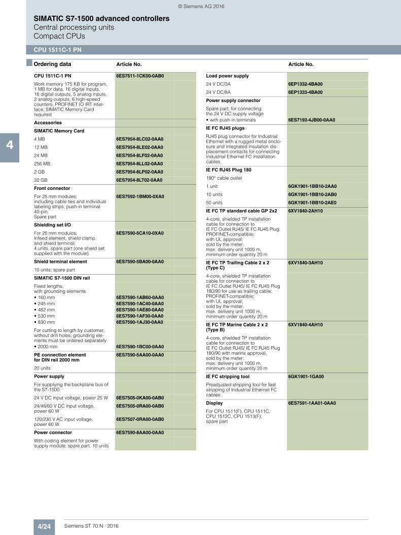
4/24 Siemens ST 70 N · 2016
4
SIMATIC S7-1500 advanced controllersCentral processing unitsCompact CPUs
CPU 1511C-1 PN
■ Ordering data Article No. Article No.
CPU 1511C-1 PN 6ES7511-1CK00-0AB0
Work memory 175 KB for program, 1 MB for data, 16 digital inputs, 16 digital outputs, 5 analog inputs, 2 analog outputs, 6 high-speed counters, PROFINET IO IRT inter-face, SIMATIC Memory Card required
Accessories
SIMATIC Memory Card
4 MB 6ES7954-8LC02-0AA0
12 MB 6ES7954-8LE02-0AA0
24 MB 6ES7954-8LF02-0AA0
256 MB 6ES7954-8LL02-0AA0
2 GB 6ES7954-8LP02-0AA0
32 GB 6ES7954-8LT02-0AA0
Front connector
For 25 mm modules; including cable ties and individual labeling strips; push-in terminal40-pin; Spare part
6ES7592-1BM00-0XA0
Shielding set I/O
For 25 mm modules; Infeed element, shield clamp, and shield terminal; 4 units, spare part (one shield set supplied with the module).
6ES7590-5CA10-0XA0
Shield terminal element 6ES7590-5BA00-0AA0
10 units; spare part
SIMATIC S7-1500 DIN rail
Fixed lengths, with grounding elements• 160 mm 6ES7590-1AB60-0AA0• 245 mm 6ES7590-1AC40-0AA0• 482 mm 6ES7590-1AE80-0AA0• 530 mm 6ES7590-1AF30-0AA0• 830 mm 6ES7590-1AJ30-0AA0
For cutting to length by customer, without drill holes; grounding ele-ments must be ordered separately• 2000 mm 6ES7590-1BC00-0AA0
PE connection elementfor DIN rail 2000 mm
6ES7590-5AA00-0AA0
20 units
Power supply
For supplying the backplane bus of the S7-1500
24 V DC input voltage, power 25 W 6ES7505-0KA00-0AB0
24/48/60 V DC input voltage, power 60 W
6ES7505-0RA00-0AB0
120/230 V AC input voltage,power 60 W
6ES7507-0RA00-0AB0
Power connector 6ES7590-8AA00-0AA0
With coding element for power supply module; spare part, 10 units
Load power supply
24 V DC/3A 6EP1332-4BA00
24 V DC/8A 6EP1333-4BA00
Power supply connector
Spare part; for connectingthe 24 V DC supply voltage• with push-in terminals 6ES7193-4JB00-0AA0
IE FC RJ45 plugs
RJ45 plug connector for Industrial Ethernet with a rugged metal enclo-sure and integrated insulation dis-placement contacts for connecting Industrial Ethernet FC installation cables
IE FC RJ45 Plug 180
180° cable outlet
1 unit 6GK1901-1BB10-2AA0
10 units 6GK1901-1BB10-2AB0
50 units 6GK1901-1BB10-2AE0
IE FC TP standard cable GP 2x2 6XV1840-2AH10
4-core, shielded TP installation cable for connection toIE FC Outlet RJ45/ IE FC RJ45 Plug; PROFINET-compatible;with UL approval;sold by the meter; max. delivery unit 1000 m,minimum order quantity 20 m
IE FC TP Trailing Cable 2 x 2 (Type C)
6XV1840-3AH10
4-core, shielded TP installation cable for connection toIE FC Outlet RJ45/ IE FC RJ45 Plug 180/90 for use as trailing cable; PROFINET-compatible;with UL approval; sold by the meter; max. delivery unit 1000 m,minimum order quantity 20 m
IE FC TP Marine Cable 2 x 2 (Type B)
6XV1840-4AH10
4-core, shielded TP installation cable for connection to IE FC Outlet RJ45/ IE FC RJ45 Plug 180/90 with marine approval, sold by the meter;max. delivery unit 1000 m,minimum order quantity 20 m
IE FC stripping tool 6GK1901-1GA00
Preadjusted stripping tool for fast stripping of Industrial Ethernet FC cables
Display 6ES7591-1AA01-0AA0
For CPU 1511(F), CPU 1511C,CPU 1512C, CPU 1513(F); spare part
© Siemens AG 2016
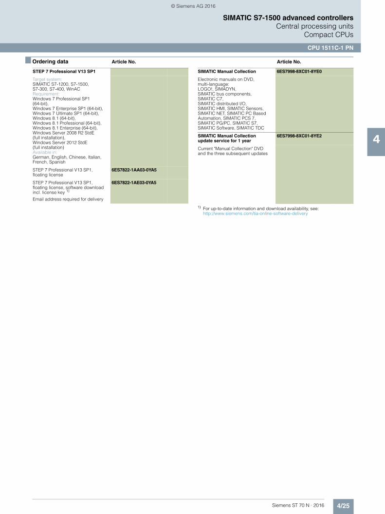
4/25Siemens ST 70 N · 2016
4
■ Ordering data Article No. Article No.
SIMATIC S7-1500 advanced controllersCentral processing units
Compact CPUs
CPU 1511C-1 PN
1) For up-to-date information and download availability, see:http://www.siemens.com/tia-online-software-delivery
STEP 7 Professional V13 SP1
Target system:SIMATIC S7-1200, S7-1500, S7-300, S7-400, WinACRequirement:Windows 7 Professional SP1(64-bit), Windows 7 Enterprise SP1 (64-bit), Windows 7 Ultimate SP1 (64-bit), Windows 8.1 (64-bit), Windows 8.1 Professional (64-bit),Windows 8.1 Enterprise (64-bit), Windows Server 2008 R2 StdE (full installation), Windows Server 2012 StdE (full installation)Available in:German, English, Chinese, Italian, French, Spanish
STEP 7 Professional V13 SP1,floating license
6ES7822-1AA03-0YA5
STEP 7 Professional V13 SP1, floating license, software download incl. license key 1)
Email address required for delivery
6ES7822-1AE03-0YA5
SIMATIC Manual Collection 6ES7998-8XC01-8YE0
Electronic manuals on DVD, multi-language:LOGO!, SIMADYN,SIMATIC bus components,SIMATIC C7, SIMATIC distributed I/O, SIMATIC HMI, SIMATIC Sensors, SIMATIC NET, SIMATIC PC Based Automation, SIMATIC PCS 7, SIMATIC PG/PC, SIMATIC S7, SIMATIC Software, SIMATIC TDC
SIMATIC Manual Collection update service for 1 year
6ES7998-8XC01-8YE2
Current "Manual Collection" DVD and the three subsequent updates
© Siemens AG 2016
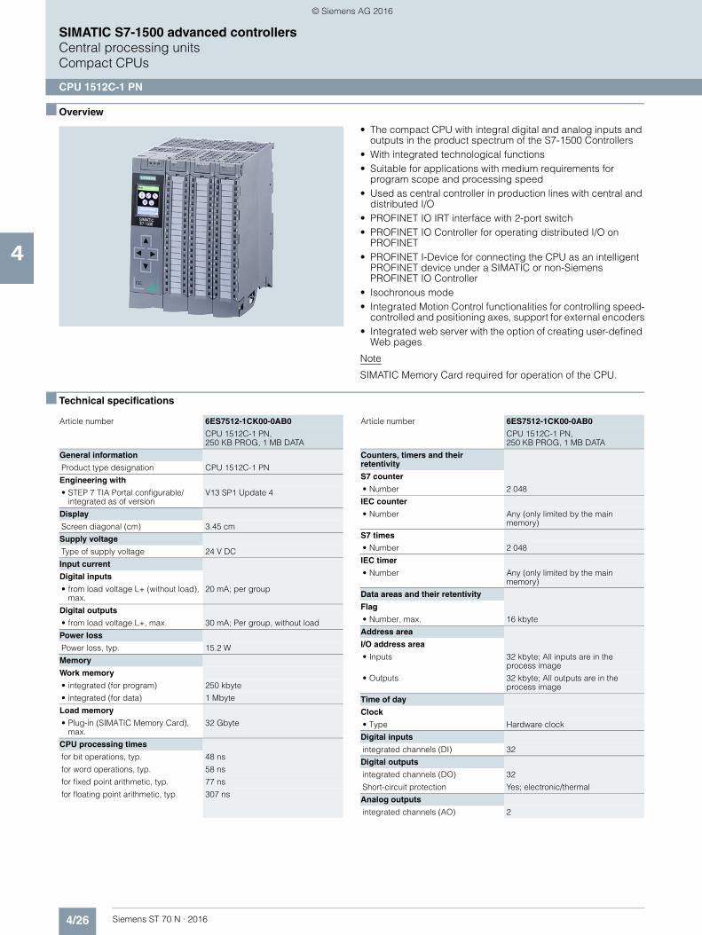
4/26 Siemens ST 70 N · 2016
4
SIMATIC S7-1500 advanced controllersCentral processing unitsCompact CPUs
CPU 1512C-1 PN
■ Overview
• The compact CPU with integral digital and analog inputs and outputs in the product spectrum of the S7-1500 Controllers
• With integrated technological functions• Suitable for applications with medium requirements for
program scope and processing speed• Used as central controller in production lines with central and
distributed I/O• PROFINET IO IRT interface with 2-port switch• PROFINET IO Controller for operating distributed I/O on
PROFINET• PROFINET I-Device for connecting the CPU as an intelligent
PROFINET device under a SIMATIC or non-Siemens PROFINET IO Controller
• Isochronous mode• Integrated Motion Control functionalities for controlling speed-
controlled and positioning axes, support for external encoders• Integrated web server with the option of creating user-defined
Web pages
Note
SIMATIC Memory Card required for operation of the CPU.
■ Technical specifications
Article number 6ES7512-1CK00-0AB0
CPU 1512C-1 PN, 250 KB PROG, 1 MB DATA
General information
Product type designation CPU 1512C-1 PN
Engineering with
• STEP 7 TIA Portal configurable/integrated as of version
V13 SP1 Update 4
Display
Screen diagonal (cm) 3.45 cm
Supply voltage
Type of supply voltage 24 V DC
Input current
Digital inputs
• from load voltage L+ (without load), max.
20 mA; per group
Digital outputs
• from load voltage L+, max. 30 mA; Per group, without load
Power loss
Power loss, typ. 15.2 W
Memory
Work memory
• integrated (for program) 250 kbyte
• integrated (for data) 1 Mbyte
Load memory
• Plug-in (SIMATIC Memory Card), max.
32 Gbyte
CPU processing times
for bit operations, typ. 48 ns
for word operations, typ. 58 ns
for fixed point arithmetic, typ. 77 ns
for floating point arithmetic, typ. 307 ns
Counters, timers and their retentivity
S7 counter
• Number 2 048
IEC counter
• Number Any (only limited by the main memory)
S7 times
• Number 2 048
IEC timer
• Number Any (only limited by the main memory)
Data areas and their retentivity
Flag
• Number, max. 16 kbyte
Address area
I/O address area
• Inputs 32 kbyte; All inputs are in the process image
• Outputs 32 kbyte; All outputs are in the process image
Time of day
Clock
• Type Hardware clock
Digital inputs
integrated channels (DI) 32
Digital outputs
integrated channels (DO) 32
Short-circuit protection Yes; electronic/thermal
Analog outputs
integrated channels (AO) 2
Article number 6ES7512-1CK00-0AB0
CPU 1512C-1 PN, 250 KB PROG, 1 MB DATA
© Siemens AG 2016
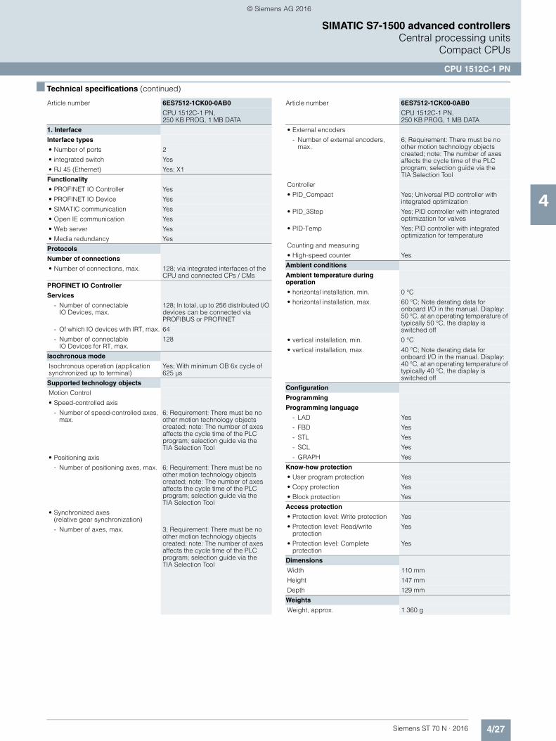
4/27Siemens ST 70 N · 2016
4
■ Technical specifications (continued)
SIMATIC S7-1500 advanced controllersCentral processing units
Compact CPUs
CPU 1512C-1 PN
1. Interface
Interface types
• Number of ports 2
• integrated switch Yes
• RJ 45 (Ethernet) Yes; X1
Functionality
• PROFINET IO Controller Yes
• PROFINET IO Device Yes
• SIMATIC communication Yes
• Open IE communication Yes
• Web server Yes
• Media redundancy Yes
Protocols
Number of connections
• Number of connections, max. 128; via integrated interfaces of the CPU and connected CPs / CMs
PROFINET IO Controller
Services
- Number of connectableIO Devices, max.
128; In total, up to 256 distributed I/O devices can be connected via PROFIBUS or PROFINET
- Of which IO devices with IRT, max. 64
- Number of connectableIO Devices for RT, max.
128
Isochronous mode
Isochronous operation (application synchronized up to terminal)
Yes; With minimum OB 6x cycle of 625 µs
Supported technology objects
Motion Control
• Speed-controlled axis
- Number of speed-controlled axes, max.
6; Requirement: There must be no other motion technology objects created; note: The number of axes affects the cycle time of the PLC program; selection guide via the TIA Selection Tool
• Positioning axis
- Number of positioning axes, max. 6; Requirement: There must be no other motion technology objects created; note: The number of axes affects the cycle time of the PLC program; selection guide via the TIA Selection Tool
• Synchronized axes (relative gear synchronization)
- Number of axes, max. 3; Requirement: There must be no other motion technology objects created; note: The number of axes affects the cycle time of the PLC program; selection guide via the TIA Selection Tool
Article number 6ES7512-1CK00-0AB0
CPU 1512C-1 PN, 250 KB PROG, 1 MB DATA
• External encoders
- Number of external encoders, max.
6; Requirement: There must be no other motion technology objects created; note: The number of axes affects the cycle time of the PLC program; selection guide via theTIA Selection Tool
Controller
• PID_Compact Yes; Universal PID controller with integrated optimization
• PID_3Step Yes; PID controller with integrated optimization for valves
• PID-Temp Yes; PID controller with integrated optimization for temperature
Counting and measuring
• High-speed counter Yes
Ambient conditions
Ambient temperature during operation
• horizontal installation, min. 0 °C
• horizontal installation, max. 60 °C; Note derating data for onboard I/O in the manual. Display: 50 °C, at an operating temperature of typically 50 °C, the display is switched off
• vertical installation, min. 0 °C
• vertical installation, max. 40 °C; Note derating data for onboard I/O in the manual. Display: 40 °C, at an operating temperature of typically 40 °C, the display is switched off
Configuration
Programming
Programming language
- LAD Yes
- FBD Yes
- STL Yes
- SCL Yes
- GRAPH Yes
Know-how protection
• User program protection Yes
• Copy protection Yes
• Block protection Yes
Access protection
• Protection level: Write protection Yes
• Protection level: Read/write protection
Yes
• Protection level: Complete protection
Yes
Dimensions
Width 110 mm
Height 147 mm
Depth 129 mm
Weights
Weight, approx. 1 360 g
Article number 6ES7512-1CK00-0AB0
CPU 1512C-1 PN, 250 KB PROG, 1 MB DATA
© Siemens AG 2016

4/28 Siemens ST 70 N · 2016
4
SIMATIC S7-1500 advanced controllersCentral processing unitsCompact CPUs
CPU 1512C-1 PN
■ Ordering data Article No. Article No.
CPU 1512C-1 PN 6ES7512-1CK00-0AB0
Work memory 250 KB for program, 1 MB for data, 32 digital inputs, 32 digital outputs, 5 analog inputs, 2 analog outputs, 6 high-speed counters, PROFINET IO IRT inter-face; SIMATIC Memory Card required
Accessories
SIMATIC Memory Card
4 MB 6ES7954-8LC02-0AA0
12 MB 6ES7954-8LE02-0AA0
24 MB 6ES7954-8LF02-0AA0
256 MB 6ES7954-8LL02-0AA0
2 GB 6ES7954-8LP02-0AA0
32 GB 6ES7954-8LT02-0AA0
Front connector
For 25 mm modules; including cable ties and individual labeling strips; push-in terminal 40-pin; Spare part
6ES7592-1BM00-0XA0
Shielding set I/O
For 25 mm modules; Infeed element, shield clamp, and shield terminal; 4 units, spare part (one shield set supplied with the module).
6ES7590-5CA10-0XA0
Shield terminal element 6ES7590-5BA00-0AA0
10 units; spare part
SIMATIC S7-1500 DIN rail
Fixed lengths, with grounding elements• 160 mm 6ES7590-1AB60-0AA0• 245 mm 6ES7590-1AC40-0AA0• 482 mm 6ES7590-1AE80-0AA0• 530 mm 6ES7590-1AF30-0AA0• 830 mm 6ES7590-1AJ30-0AA0
For cutting to length by customer, without drill holes; grounding ele-ments must be ordered separately• 2000 mm 6ES7590-1BC00-0AA0
PE connection element for DIN rail 2000 mm
6ES7590-5AA00-0AA0
20 units
Power supply
For supplying the backplane bus of the S7-1500
24 V DC input voltage, power 25 W 6ES7505-0KA00-0AB0
24/48/60 V DC input voltage, power 60 W
6ES7505-0RA00-0AB0
120/230 V AC input voltage,power 60 W
6ES7507-0RA00-0AB0
Power connector 6ES7590-8AA00-0AA0
With coding element for power supply module; spare part, 10 units
Load power supply
24 V DC/3A 6EP1332-4BA00
24 V DC/8A 6EP1333-4BA00
Power supply connector
Spare part; for connectingthe 24 V DC supply voltage• with push-in terminals 6ES7193-4JB00-0AA0
IE FC RJ45 plugs
RJ45 plug connector for Industrial Ethernet with a rugged metal enclo-sure and integrated insulation dis-placement contacts for connecting Industrial Ethernet FC installation cables
IE FC RJ45 Plug 180
180° cable outlet
1 unit 6GK1901-1BB10-2AA0
10 units 6GK1901-1BB10-2AB0
50 units 6GK1901-1BB10-2AE0
IE FC TP standard cable GP 2x2 6XV1840-2AH10
4-core, shielded TP installation cable for connection to IE FC Outlet RJ45/ IE FC RJ45 Plug; PROFINET-compatible; with UL approval;sold by the meter; max. delivery unit 1000 m,minimum order quantity 20 m
IE FC TP Trailing Cable 2 x 2 (Type C)
6XV1840-3AH10
4-core, shielded TP installation cable for connection to IE FC Outlet RJ45/ IE FC RJ45 Plug 180/90 for use as trailing cable; PROFINET-compatible; with UL approval; sold by the meter; max. delivery unit 1000 m, minimum order quantity 20 m
IE FC TP Marine Cable 2 x 2 (Type B)
6XV1840-4AH10
4-core, shielded TP installation cable for connection to IE FC Outlet RJ45/ IE FC RJ45 Plug 180/90 with marine approval, sold by the meter; max. delivery unit 1000 m, minimum order quantity 20 m
IE FC stripping tool 6GK1901-1GA00
Preadjusted stripping tool for fast stripping of Industrial Ethernet FC cables
Display 6ES7591-1AA01-0AA0
for CPU 1511(F), CPU 1511C, CPU 1512C, CPU 1513(F); spare part
© Siemens AG 2016
4/29Siemens ST 70 N · 2016
4
■ Ordering data Article No. Article No.
SIMATIC S7-1500 advanced controllersCentral processing units
Compact CPUs
CPU 1512C-1 PN
1) For up-to-date information and download availability, see:http://www.siemens.com/tia-online-software-delivery
STEP 7 Professional V13 SP1
Target system:SIMATIC S7-1200, S7-1500, S7-300, S7-400, WinACRequirement:Windows 7 Professional SP1 (64-bit), Windows 7 Enterprise SP1 (64-bit), Windows 7 Ultimate SP1 (64-bit), Windows 8.1 (64-bit), Windows 8.1 Professional (64-bit),Windows 8.1 Enterprise (64-bit), Windows Server 2008 R2 StdE (full installation), Windows Server 2012 StdE (full installation)Available in:German, English, Chinese, Italian, French, Spanish
STEP 7 Professional V13 SP1, floating license
6ES7822-1AA03-0YA5
STEP 7 Professional V13 SP1, floating license, software download incl. license key 1)
Email address required for delivery
6ES7822-1AE03-0YA5
SIMATIC Manual Collection 6ES7998-8XC01-8YE0
Electronic manuals on DVD, multi-language: LOGO!, SIMADYN, SIMATIC bus components,SIMATIC C7, SIMATIC distributed I/O, SIMATIC HMI, SIMATIC Sensors, SIMATIC NET, SIMATIC PC Based Automation, SIMATIC PCS 7, SIMATIC PG/PC, SIMATIC S7, SIMATIC Software, SIMATIC TDC
SIMATIC Manual Collection update service for 1 year
6ES7998-8XC01-8YE2
© Siemens AG 2016
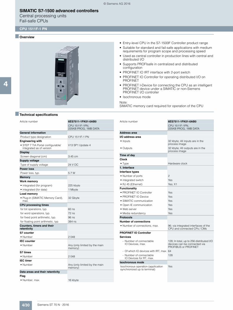
4/30 Siemens ST 70 N · 2016
4
SIMATIC S7-1500 advanced controllersCentral processing unitsFail-safe CPUs
CPU 1511F-1 PN
■ Overview
• Entry-level CPU in the S7-1500F Controller product range • Suitable for standard and fail-safe applications with medium
requirements for program scope and processing speed • Used as central controller in production lines with central and
distributed I/O • Supports PROFIsafe in centralized and distributed
configuration • PROFINET IO IRT interface with 2-port switch • PROFINET IO Controller for operating distributed I/O on
PROFINET • PROFINET I-Device for connecting the CPU as an intelligent
PROFINET device under a SIMATIC or non-Siemens PROFINET I/O controller
• Isochronous mode
Note:SIMATIC memory card required for operation of the CPU
■ Technical specifications
Article number 6ES7511-1FK01-0AB0
CPU 1511F-1PN,225KB PROG, 1MB DATA
General information
Product type designation CPU 1511F-1 PN
Engineering with
• STEP 7 TIA Portal configurable/integrated as of version
V13 SP1 Update 4
Display
Screen diagonal (cm) 3.45 cm
Supply voltage
Type of supply voltage 24 V DC
Power loss
Power loss, typ. 5.7 W
Memory
Work memory
• integrated (for program) 225 kbyte
• integrated (for data) 1 Mbyte
Load memory
• Plug-in (SIMATIC Memory Card), max.
32 Gbyte
CPU processing times
for bit operations, typ. 60 ns
for word operations, typ. 72 ns
for fixed point arithmetic, typ. 96 ns
for floating point arithmetic, typ. 384 ns
Counters, timers and their retentivity
S7 counter
• Number 2 048
IEC counter
• Number Any (only limited by the main memory)
S7 times
• Number 2 048
IEC timer
• Number Any (only limited by the main memory)
Data areas and their retentivity
Flag
• Number, max. 16 kbyte
Address area
I/O address area
• Inputs 32 kbyte; All inputs are in the process image
• Outputs 32 kbyte; All outputs are in the process image
Time of day
Clock
• Type Hardware clock
1. Interface
Interface types
• Number of ports 2
• integrated switch Yes
• RJ 45 (Ethernet) Yes; X1
Functionality
• PROFINET IO Controller Yes
• PROFINET IO Device Yes
• SIMATIC communication Yes
• Open IE communication Yes
• Web server Yes
• Media redundancy Yes
Protocols
Number of connections
• Number of connections, max. 96; via integrated interfaces of the CPU and connected CPs / CMs
PROFINET IO Controller
Services
- Number of connectableIO Devices, max.
128; In total, up to 256 distributed I/O devices can be connected via PROFIBUS or PROFINET
- Of which IO devices with IRT, max. 64
- Number of connectableIO Devices for RT, max.
128
Isochronous mode
Isochronous operation (application synchronized up to terminal)
Yes
Article number 6ES7511-1FK01-0AB0
CPU 1511F-1PN,225KB PROG, 1MB DATA
© Siemens AG 2016

4/31Siemens ST 70 N · 2016
4
■ Technical specifications (continued)
SIMATIC S7-1500 advanced controllersCentral processing units
Fail-safe CPUs
CPU 1511F-1 PN
■ Ordering data Article No. Article No.
Supported technology objects
Motion Control Yes
• Speed-controlled axis
- Number of speed-controlled axes, max.
6; Max. number of speed-controlled axes (requirement: there must be no other motion technology objects created)
• Positioning axis
- Number of positioning axes, max. 6; Max. number of positioning axes (requirement: there must be no other motion technology objects created)
• Synchronized axes (relative gear synchronization)
- Number of axes, max. 3; Max. number of synchronous axes (requirement: there must be no other motion technology objects created)
• External encoders
- Number of external encoders, max.
6; Max. number of external encoders (requirement: there must be no other motion technology objects created)
Controller
• PID_Compact Yes; Universal PID controller with integrated optimization
• PID_3Step Yes; PID controller with integrated optimization for valves
Counting and measuring
• High-speed counter Yes
Article number 6ES7511-1FK01-0AB0
CPU 1511F-1PN,225KB PROG, 1MB DATA
Ambient conditions
Ambient temperature during operation
• horizontal installation, min. 0 °C
• horizontal installation, max. 60 °C; Display: 50 °C, at an operating temperature of typically 50 °C, the display is switched off
• vertical installation, min. 0 °C
• vertical installation, max. 40 °C; Display: 40 °C, at an operating temperature of typically40 °C, the display is switched off
Configuration
Programming
Programming language
- LAD Yes; incl. failsafe
- FBD Yes; incl. failsafe
- STL Yes
- SCL Yes
- GRAPH Yes
Know-how protection
• User program protection Yes
• Copy protection Yes
• Block protection Yes
Access protection
• Password for display Yes
• Protection level: Write protection Yes
• Protection level: Read/write protection
Yes
• Protection level: Complete protection
Yes
Dimensions
Width 35 mm
Height 147 mm
Depth 129 mm
Weights
Weight, approx. 430 g
Article number 6ES7511-1FK01-0AB0
CPU 1511F-1PN,225KB PROG, 1MB DATA
CPU 1511F-1 PN 6ES7511-1FK01-0AB0
Failsafe CPU, 230 KB work memoryfor program, 1 MB for data, PROFINET IO IRT interface; SIMATIC Memory Card required
Accessories
SIMATIC Memory Card
4 MB 6ES7954-8LC02-0AA0
12 MB 6ES7954-8LE02-0AA0
24 MB 6ES7954-8LF02-0AA0
256 MB 6ES7954-8LL02-0AA0
2 GB 6ES7954-8LP02-0AA0
32 GB 6ES7954-8LT02-0AA0
SIMATIC S7-1500 DIN rail
Fixed lengths, with grounding elements• 160 mm 6ES7590-1AB60-0AA0• 245 mm 6ES7590-1AC40-0AA0• 482 mm 6ES7590-1AE80-0AA0• 530 mm 6ES7590-1AF30-0AA0• 830 mm 6ES7590-1AJ30-0AA0
For cutting to length by customer, without drill holes; grounding ele-ments must be ordered separately• 2000 mm 6ES7590-1BC00-0AA0
PE connection elementfor DIN rail 2000 mm
6ES7590-5AA00-0AA0
20 units
© Siemens AG 2016

4/32 Siemens ST 70 N · 2016
4
■ Ordering data Article No. Article No.
SIMATIC S7-1500 advanced controllersCentral processing unitsFail-safe CPUs
CPU 1511F-1 PN
1) For up-to-date information and download availability, see:http://www.siemens.com/tia-online-software-delivery
Power supply
For supplying the backplanebus of the S7-1500
24 V DC input voltage, power 25 W 6ES7505-0KA00-0AB0
24/48/60 V DC input voltage, power 60 W
6ES7505-0RA00-0AB0
120/230 V AC input voltage, power 60 W
6ES7507-0RA00-0AB0
Power connector 6ES7590-8AA00-0AA0
With coding element for power supply module; spare part, 10 units
Load power supply
24 V DC/3A 6EP1332-4BA00
24 V DC/8A 6EP1333-4BA00
Power supply connector
Spare part; for connecting the 24 V DC supply voltage• with push-in terminals 6ES7193-4JB00-0AA0
IE FC RJ45 plugs
RJ45 plug connector for Industrial Ethernet with a rugged metal enclo-sure and integrated insulation dis-placement contacts for connecting Industrial Ethernet FC installation cables
IE FC RJ45 Plug 180
180° cable outlet
1 unit 6GK1901-1BB10-2AA0
10 units 6GK1901-1BB10-2AB0
50 units 6GK1901-1BB10-2AE0
IE FC TP standard cable GP 2x2 6XV1840-2AH10
4-core, shielded TP installation cable for connection toIE FC Outlet RJ45/ IE FC RJ45 Plug; PROFINET-compatible; with UL approval;sold by the meter; max. delivery unit 1000 m, minimum order quantity 20 m
IE FC TP Trailing Cable 2 x 2 (Type C)
6XV1840-3AH10
4-core, shielded TP installation cable for connection toIE FC Outlet RJ45/ IE FC RJ45 Plug 180/90 for use as trailing cable; PROFINET-compatible; with UL approval; sold by the meter; max. delivery unit 1000 m, minimum order quantity 20 m
IE FC TP Marine Cable 2 x 2(Type B)
6XV1840-4AH10
4-core, shielded TP installation cable for connection toIE FC Outlet RJ45/ IE FC RJ45 Plug 180/90 with marine approval, sold by the meter;max. delivery unit 1000 m, minimum order quantity 20 m
IE FC stripping tool 6GK1901-1GA00
Preadjusted stripping tool for fast stripping of Industrial Ethernet FC cables
Display 6ES7591-1AA01-0AA0
for CPU 1511-1 PN and CPU 1513-1 PN; spare part
STEP 7 Professional V13 SP1
Target system:SIMATIC S7-1200, S7-1500,S7-300, S7-400, WinACRequirement: Windows 7 Professional SP1 (64-bit), Windows 7 Enterprise SP1 (64-bit), Windows 7 Ultimate SP1 (64-bit), Windows 8.1 (64-bit), Windows 8.1 Professional (64-bit),Windows 8.1 Enterprise (64-bit), Windows Server 2008 R2 StdE(full installation), Windows Server 2012 StdE(full installation)Available in:German, English, Chinese, Italian, French, Spanish
STEP 7 Professional V13 SP1,floating license
6ES7822-1AA03-0YA5
STEP 7 Professional V13 SP1,floating license, software download incl. license key 1)
Email address required for delivery
6ES7822-1AE03-0YA5
STEP 7 Safety Advanced V13 SP1
Task:Engineering tool for configuring failsafe user programs forSIMATIC S7-1200 FC, S7-1500F, S7-300F, S7-400F, WinAC RTX F, ET 200SP F controller, ET 200SP, ET 200S, ET 200M, ET 200iSP, ET 200pro, ET 200ecoRequirement:STEP 7 Professional V13 SP1
Floating license for 1 user 6ES7833-1FA13-0YA5
Floating license for 1 user, license key download without software or documentation1)
Email address required for delivery
6ES7833-1FA13-0YH5
SIMATIC Manual Collection 6ES7998-8XC01-8YE0
Electronic manuals on DVD, multi-language: LOGO!, SIMADYN, SIMATIC bus components, SIMATIC C7, SIMATIC distributed I/O, SIMATIC HMI, SIMATIC Sensors, SIMATIC NET, SIMATIC PC Based Automation, SIMATIC PCS 7, SIMATIC PG/PC, SIMATIC S7, SIMATIC Software, SIMATIC TDC
SIMATIC Manual Collection update service for 1 year
6ES7998-8XC01-8YE2
Current "Manual Collection" DVD and the three subsequent updates
© Siemens AG 2016

4/33Siemens ST 70 N · 2016
4
SIMATIC S7-1500 advanced controllersCentral processing units
Fail-safe CPUs
CPU 1513F-1 PN
■ Overview
• The CPU for standard and fail-safe applications with medium/high requirements for program/data storage in the S7-1500 controller product range
• High processing speed for binary and floating-point arithmetic• Used as central controller in production lines with central and
distributed I/O • Supports PROFIsafe in centralized and distributed
configuration • PROFINET IO IRT interface with 2-port switch • PROFINET IO Controller for operating distributed I/O on
PROFINET • PROFINET I-Device for connecting the CPU as an intelligent
PROFINET device under a SIMATIC or non-Siemens PROFINET I/O controller
• Isochronous mode
Note: SIMATIC memory card required for operation of the CPU
■ Technical specifications
Article number 6ES7513-1FL01-0AB0
CPU 1513F-1 PN, 450KB PROG, 1,5MB DATA
General information
Product type designation CPU 1513F-1 PN
Engineering with
• STEP 7 TIA Portal configurable/integrated as of version
V13 SP1 Update 4
Display
Screen diagonal (cm) 3.45 cm
Supply voltage
Type of supply voltage 24 V DC
Power loss
Power loss, typ. 5.7 W
Memory
Work memory
• integrated (for program) 450 kbyte
• integrated (for data) 1.5 Mbyte
Load memory
• Plug-in (SIMATIC Memory Card), max.
32 Gbyte
CPU processing times
for bit operations, typ. 40 ns
for word operations, typ. 48 ns
for fixed point arithmetic, typ. 64 ns
for floating point arithmetic, typ. 256 ns
Counters, timers and their retentivity
S7 counter
• Number 2 048
IEC counter
• Number Any (only limited by the main memory)
S7 times
• Number 2 048
IEC timer
• Number Any (only limited by the main memory)
Data areas and their retentivity
Flag
• Number, max. 16 kbyte
Address area
I/O address area
• Inputs 32 kbyte; All inputs are in the process image
• Outputs 32 kbyte; All outputs are in the process image
Time of day
Clock
• Type Hardware clock
1. Interface
Interface types
• Number of ports 2
• integrated switch Yes
• RJ 45 (Ethernet) Yes; X1
Functionality
• PROFINET IO Controller Yes
• PROFINET IO Device Yes
• SIMATIC communication Yes
• Open IE communication Yes
• Web server Yes
• Media redundancy Yes
Protocols
Number of connections
• Number of connections, max. 128; via integrated interfaces of the CPU and connected CPs / CMs
PROFINET IO Controller
Services
- Number of connectable IO Devices, max.
128; In total, up to 256 distributed I/O devices can be connected via PROFIBUS or PROFINET
- Of which IO devices with IRT, max. 64
- Number of connectable IO Devices for RT, max.
128
Article number 6ES7513-1FL01-0AB0
CPU 1513F-1 PN, 450KB PROG, 1,5MB DATA
© Siemens AG 2016

4/34 Siemens ST 70 N · 2016
4
■ Technical specifications (continued)
SIMATIC S7-1500 advanced controllersCentral processing unitsFail-safe CPUs
CPU 1513F-1 PN
■ Ordering data Article No. Article No.
Isochronous mode
Isochronous operation (application synchronized up to terminal)
Yes; With minimum OB 6x cycle of 500 µs
Supported technology objects
Motion Control Yes
• Speed-controlled axis
- Number of speed-controlled axes, max.
6; Requirement: There must be no other motion technology objects created
• Positioning axis
- Number of positioning axes, max. 6; Requirement: There must be no other motion technology objects created
• Synchronized axes(relative gear synchronization)
- Number of axes, max. 3; Requirement: There must be no other motion technology objects created
• External encoders
- Number of external encoders, max.
6; Requirement: There must be no other motion technology objects created
Controller
• PID_Compact Yes; Universal PID controller with integrated optimization
• PID_3Step Yes; PID controller with integrated optimization for valves
• PID-Temp Yes; PID controller with integrated optimization for temperature
Article number 6ES7513-1FL01-0AB0
CPU 1513F-1 PN, 450KB PROG, 1,5MB DATA
Counting and measuring
• High-speed counter Yes
Ambient conditions
Ambient temperature during operation
• horizontal installation, min. 0 °C
• horizontal installation, max. 60 °C; Display: 50 °C, at an operating temperature of typically50 °C, the display is switched off
• vertical installation, min. 0 °C
• vertical installation, max. 40 °C; Display: 40 °C, at an operating temperature of typically 40 °C, the display is switched off
Configuration
Programming
Programming language
- LAD Yes; incl. failsafe
- FBD Yes; incl. failsafe
- STL Yes
- SCL Yes
- GRAPH Yes
Know-how protection
• User program protection Yes
• Copy protection Yes
• Block protection Yes
Access protection
• Password for display Yes
• Protection level: Write protection Yes; Specific write protection both for Standard and for Failsafe
• Protection level: Read/write protection
Yes
• Protection level: Complete protection
Yes
Dimensions
Width 35 mm
Height 147 mm
Depth 129 mm
Weights
Weight, approx. 430 g
Article number 6ES7513-1FL01-0AB0
CPU 1513F-1 PN, 450KB PROG, 1,5MB DATA
CPU 1513F-1 PN 6ES7513-1FL01-0AB0
Failsafe CPU, 450 KB work memory for program, 1.5 MB for data, PROFINET IO IRT interface; SIMATIC Memory Card required
Accessories
SIMATIC Memory Card
4 MB 6ES7954-8LC02-0AA0
12 MB 6ES7954-8LE02-0AA0
24 MB 6ES7954-8LF02-0AA0
256 MB 6ES7954-8LL02-0AA0
2 GB 6ES7954-8LP02-0AA0
32 GB 6ES7954-8LT02-0AA0
SIMATIC S7-1500 DIN rail
Fixed lengths, with grounding elements• 160 mm 6ES7590-1AB60-0AA0• 245 mm 6ES7590-1AC40-0AA0• 482 mm 6ES7590-1AE80-0AA0• 530 mm 6ES7590-1AF30-0AA0• 830 mm 6ES7590-1AJ30-0AA0
For cutting to length by customer, without drill holes; grounding ele-ments must be ordered separately• 2000 mm 6ES7590-1BC00-0AA0
PE connection elementfor DIN rail 2000 mm
6ES7590-5AA00-0AA0
20 units
© Siemens AG 2016
4/35Siemens ST 70 N · 2016
4
■ Ordering data Article No. Article No.
SIMATIC S7-1500 advanced controllersCentral processing units
Fail-safe CPUs
CPU 1513F-1 PN
1) For up-to-date information and download availability, see:http://www.siemens.com/tia-online-software-delivery
Power supply
For supplying the backplane bus of the S7-1500
24 V DC input voltage, power 25 W 6ES7505-0KA00-0AB0
24/48/60 V DC input voltage,power 60 W
6ES7505-0RA00-0AB0
120/230 V AC input voltage, power 60 W
6ES7507-0RA00-0AB0
Power connector 6ES7590-8AA00-0AA0
With coding element for power supply module; spare part, 10 units
Load power supply
24 V DC/3A 6EP1332-4BA00
24 V DC/8A 6EP1333-4BA00
Power supply connector
Spare part; for connecting the24 V DC supply voltage• with push-in terminals 6ES7193-4JB00-0AA0
IE FC RJ45 plugs
RJ45 plug connector for Industrial Ethernet with a rugged metal enclo-sure and integrated insulation dis-placement contacts for connecting Industrial Ethernet FC installation cables
IE FC RJ45 Plug 180
180° cable outlet
1 unit 6GK1901-1BB10-2AA0
10 units 6GK1901-1BB10-2AB0
50 units 6GK1901-1BB10-2AE0
IE FC TP standard cable GP 2x2 6XV1840-2AH10
4-core, shielded TP installation cable for connection to IE FC Outlet RJ45/ IE FC RJ45 Plug; PROFINET-compatible; with UL approval;sold by the meter; max. delivery unit 1000 m, minimum order quantity 20 m
IE FC TP Trailing Cable 2 x 2 (Type C)
6XV1840-3AH10
4-core, shielded TP installation cable for connection toIE FC Outlet RJ45/ IE FC RJ45 Plug 180/90 for use as trailing cable; PROFINET-compatible; with UL approval; sold by the meter; max. delivery unit 1000 m, minimum order quantity 20 m
IE FC TP Marine Cable 2 x 2(Type B)
6XV1840-4AH10
4-core, shielded TP installation cable for connection to IE FC Outlet RJ45/ IE FC RJ45 Plug 180/90 with marine approval, sold by the meter; max. delivery unit 1000 m, minimum order quantity 20 m
IE FC stripping tool 6GK1901-1GA00
Preadjusted stripping tool for fast stripping of Industrial Ethernet FC cables
Display 6ES7591-1AA01-0AA0
For CPU 1511-1 PN andCPU 1513-1 PN; spare part
STEP 7 Professional V13 SP1
Target system:SIMATIC S7-1200, S7-1500,S7-300, S7-400, WinACRequirement: Windows 7 Professional SP1 (64-bit), Windows 7 Enterprise SP1 (64-bit), Windows 7 Ultimate SP1 (64-bit), Windows 8.1 (64-bit), Windows 8.1 Professional (64-bit),Windows 8.1 Enterprise (64-bit), Windows Server 2008 R2 StdE(full installation), Windows Server 2012 StdE (full installation)Available in:German, English, Chinese, Italian, French, Spanish
STEP 7 Professional V13 SP1, floating license
6ES7822-1AA03-0YA5
STEP 7 Professional V13 SP1, floating license, software download incl. license key 1)
Email address required for delivery
6ES7822-1AE03-0YA5
STEP 7 Safety Advanced V13 SP1
Task:Engineering tool for configuringfailsafe user programs for SIMATIC S7-1200 FC, S7-1500F, S7-300F, S7-400F, WinAC RTX F, ET 200SP F controller, ET 200SP, ET 200S, ET 200M, ET 200iSP, ET 200pro, ET 200ecoRequirement:STEP 7 Professional V13 SP1
Floating license for 1 user 6ES7833-1FA13-0YA5
Floating license for 1 user, license key download without software or documentation1)
Email address required for delivery
6ES7833-1FA13-0YH5
SIMATIC Manual Collection 6ES7998-8XC01-8YE0
Electronic manuals on DVD, multi-language: LOGO!, SIMADYN, SIMATIC bus components, SIMATIC C7,SIMATIC distributed I/O, SIMATIC HMI, SIMATIC Sensors, SIMATIC NET, SIMATIC PC Based Automation, SIMATIC PCS 7, SIMATIC PG/PC, SIMATIC S7, SIMATIC Software, SIMATIC TDC
SIMATIC Manual Collection update service for 1 year
6ES7998-8XC01-8YE2
Current "Manual Collection" DVD and the three subsequent updates
© Siemens AG 2016
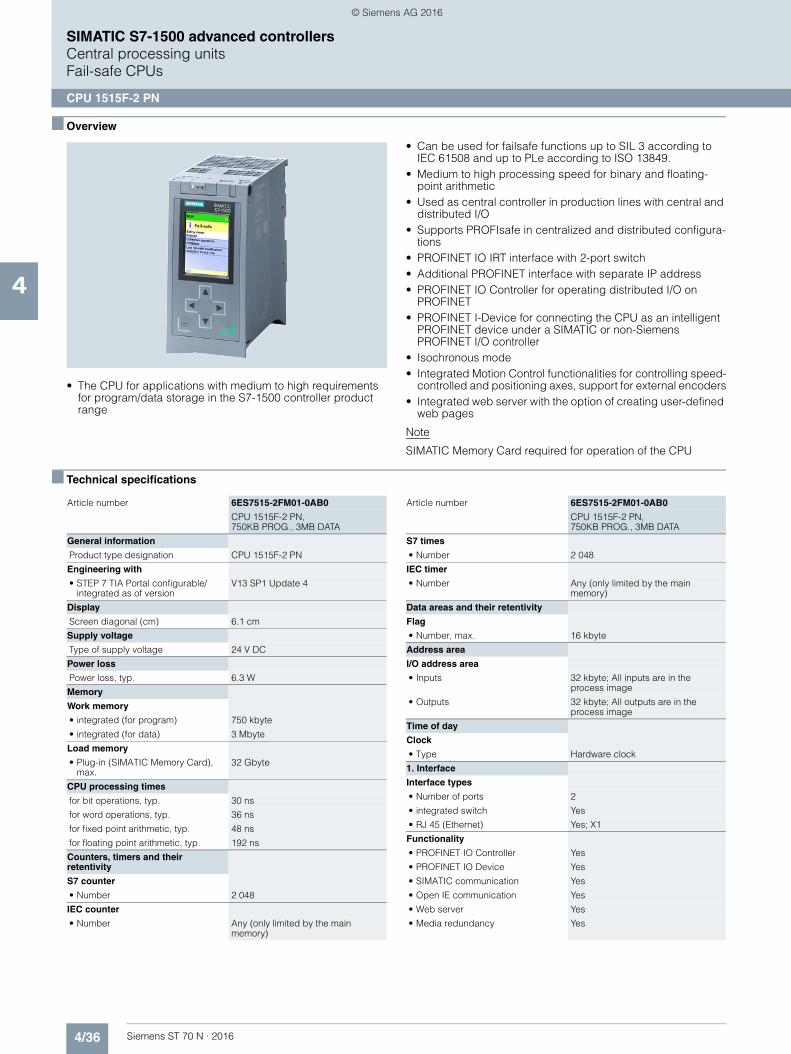
4/36 Siemens ST 70 N · 2016
4
SIMATIC S7-1500 advanced controllersCentral processing unitsFail-safe CPUs
CPU 1515F-2 PN
■ Overview
• The CPU for applications with medium to high requirements for program/data storage in the S7-1500 controller product range
• Can be used for failsafe functions up to SIL 3 according to IEC 61508 and up to PLe according to ISO 13849.
• Medium to high processing speed for binary and floating-point arithmetic
• Used as central controller in production lines with central and distributed I/O
• Supports PROFIsafe in centralized and distributed configura-tions
• PROFINET IO IRT interface with 2-port switch• Additional PROFINET interface with separate IP address• PROFINET IO Controller for operating distributed I/O on
PROFINET• PROFINET I-Device for connecting the CPU as an intelligent
PROFINET device under a SIMATIC or non-Siemens PROFINET I/O controller
• Isochronous mode• Integrated Motion Control functionalities for controlling speed-
controlled and positioning axes, support for external encoders• Integrated web server with the option of creating user-defined
web pages
Note
SIMATIC Memory Card required for operation of the CPU
■ Technical specifications
Article number 6ES7515-2FM01-0AB0
CPU 1515F-2 PN, 750KB PROG., 3MB DATA
General information
Product type designation CPU 1515F-2 PN
Engineering with
• STEP 7 TIA Portal configurable/integrated as of version
V13 SP1 Update 4
Display
Screen diagonal (cm) 6.1 cm
Supply voltage
Type of supply voltage 24 V DC
Power loss
Power loss, typ. 6.3 W
Memory
Work memory
• integrated (for program) 750 kbyte
• integrated (for data) 3 Mbyte
Load memory
• Plug-in (SIMATIC Memory Card), max.
32 Gbyte
CPU processing times
for bit operations, typ. 30 ns
for word operations, typ. 36 ns
for fixed point arithmetic, typ. 48 ns
for floating point arithmetic, typ. 192 ns
Counters, timers and their retentivity
S7 counter
• Number 2 048
IEC counter
• Number Any (only limited by the main memory)
S7 times
• Number 2 048
IEC timer
• Number Any (only limited by the main memory)
Data areas and their retentivity
Flag
• Number, max. 16 kbyte
Address area
I/O address area
• Inputs 32 kbyte; All inputs are in the process image
• Outputs 32 kbyte; All outputs are in the process image
Time of day
Clock
• Type Hardware clock
1. Interface
Interface types
• Number of ports 2
• integrated switch Yes
• RJ 45 (Ethernet) Yes; X1
Functionality
• PROFINET IO Controller Yes
• PROFINET IO Device Yes
• SIMATIC communication Yes
• Open IE communication Yes
• Web server Yes
• Media redundancy Yes
Article number 6ES7515-2FM01-0AB0
CPU 1515F-2 PN, 750KB PROG., 3MB DATA
© Siemens AG 2016
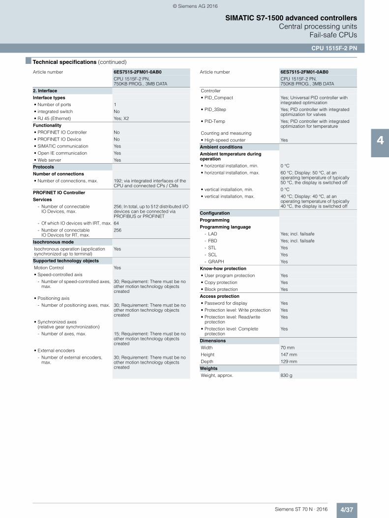
4/37Siemens ST 70 N · 2016
4
■ Technical specifications (continued)
SIMATIC S7-1500 advanced controllersCentral processing units
Fail-safe CPUs
CPU 1515F-2 PN
2. Interface
Interface types
• Number of ports 1
• integrated switch No
• RJ 45 (Ethernet) Yes; X2
Functionality
• PROFINET IO Controller No
• PROFINET IO Device No
• SIMATIC communication Yes
• Open IE communication Yes
• Web server Yes
Protocols
Number of connections
• Number of connections, max. 192; via integrated interfaces of the CPU and connected CPs / CMs
PROFINET IO Controller
Services
- Number of connectableIO Devices, max.
256; In total, up to 512 distributed I/O devices can be connected via PROFIBUS or PROFINET
- Of which IO devices with IRT, max. 64
- Number of connectableIO Devices for RT, max.
256
Isochronous mode
Isochronous operation (application synchronized up to terminal)
Yes
Supported technology objects
Motion Control Yes
• Speed-controlled axis
- Number of speed-controlled axes, max.
30; Requirement: There must be no other motion technology objects created
• Positioning axis
- Number of positioning axes, max. 30; Requirement: There must be no other motion technology objects created
• Synchronized axes (relative gear synchronization)
- Number of axes, max. 15; Requirement: There must be no other motion technology objects created
• External encoders
- Number of external encoders, max.
30; Requirement: There must be no other motion technology objects created
Article number 6ES7515-2FM01-0AB0
CPU 1515F-2 PN, 750KB PROG., 3MB DATA
Controller
• PID_Compact Yes; Universal PID controller with integrated optimization
• PID_3Step Yes; PID controller with integrated optimization for valves
• PID-Temp Yes; PID controller with integrated optimization for temperature
Counting and measuring
• High-speed counter Yes
Ambient conditions
Ambient temperature during operation
• horizontal installation, min. 0 °C
• horizontal installation, max. 60 °C; Display: 50 °C, at an operating temperature of typically 50 °C, the display is switched off
• vertical installation, min. 0 °C
• vertical installation, max. 40 °C; Display: 40 °C, at an operating temperature of typically 40 °C, the display is switched off
Configuration
Programming
Programming language
- LAD Yes; incl. failsafe
- FBD Yes; incl. failsafe
- STL Yes
- SCL Yes
- GRAPH Yes
Know-how protection
• User program protection Yes
• Copy protection Yes
• Block protection Yes
Access protection
• Password for display Yes
• Protection level: Write protection Yes
• Protection level: Read/write protection
Yes
• Protection level: Complete protection
Yes
Dimensions
Width 70 mm
Height 147 mm
Depth 129 mm
Weights
Weight, approx. 830 g
Article number 6ES7515-2FM01-0AB0
CPU 1515F-2 PN, 750KB PROG., 3MB DATA
© Siemens AG 2016

4/38 Siemens ST 70 N · 2016
4
SIMATIC S7-1500 advanced controllersCentral processing unitsFail-safe CPUs
CPU 1515F-2 PN
■ Ordering data Article No. Article No.
CPU 1515F-2 PN 6ES7515-2FM01-0AB0
Failsafe CPU, 750 KB work memory for program, 3 MB for data,PROFINET IO IRT interface, PROFINET interface;SIMATIC Memory Card required
Accessories
SIMATIC Memory Card
4 MB 6ES7954-8LC02-0AA0
12 MB 6ES7954-8LE02-0AA0
24 MB 6ES7954-8LF02-0AA0
256 MB 6ES7954-8LL02-0AA0
2 GB 6ES7954-8LP02-0AA0
32 GB 6ES7954-8LT02-0AA0
SIMATIC S7-1500 DIN rail
Fixed lengths, with grounding elements• 160 mm 6ES7590-1AB60-0AA0• 245 mm 6ES7590-1AC40-0AA0• 482 mm 6ES7590-1AE80-0AA0• 530 mm 6ES7590-1AF30-0AA0• 830 mm 6ES7590-1AJ30-0AA0
For cutting to length by customer, without drill holes; grounding ele-ments must be ordered separately• 2000 mm 6ES7590-1BC00-0AA0
PE connection elementfor DIN rail 2000 mm
6ES7590-5AA00-0AA0
20 units
Power supply
For supplying the backplane bus of the S7-1500
24 V DC input voltage, power 25 W 6ES7505-0KA00-0AB0
24/48/60 V DC input voltage,power 60 W
6ES7505-0RA00-0AB0
120/230 V AC input voltage, power 60 W
6ES7507-0RA00-0AB0
Power connector 6ES7590-8AA00-0AA0
With coding element for power supply module; spare part, 10 units
Load power supply
24 V DC/3A 6EP1332-4BA00
24 V DC/8A 6EP1333-4BA00
Power supply connector
Spare part; for connecting the24 V DC supply voltage• with push-in terminals 6ES7193-4JB00-0AA0
IE FC RJ45 plugs
RJ45 plug connector for Industrial Ethernet with a rugged metal enclo-sure and integrated insulation dis-placement contacts for connecting Industrial Ethernet FC installation cables
IE FC RJ45 Plug 180
180° cable outlet
1 unit 6GK1901-1BB10-2AA0
10 units 6GK1901-1BB10-2AB0
50 units 6GK1901-1BB10-2AE0
IE FC TP standard cable GP 2x2 6XV1840-2AH10
4-core, shielded TP installation cable for connection toIE FC Outlet RJ45/ IE FC RJ45 Plug; PROFINET-compatible; with UL approval;sold by the meter; max. delivery unit 1000 m,minimum order quantity 20 m
IE FC TP Trailing Cable 2 x 2 (Type C)
6XV1840-3AH10
4-core, shielded TP installation cable for connection toIE FC Outlet RJ45/ IE FC RJ45 Plug 180/90 for use as trailing cable; PROFINET-compatible; with UL approval; sold by the meter;max. delivery unit 1000 m, minimum order quantity 20 m
IE FC TP Marine Cable 2 x 2(Type B)
6XV1840-4AH10
4-core, shielded TP installation cable for connection to IE FC Outlet RJ45/ IE FC RJ45 Plug 180/90 with marine approval, sold by the meter; max. delivery unit 1000 m, minimum order quantity 20 m
IE FC stripping tool 6GK1901-1GA00
Preadjusted stripping tool for fast stripping of Industrial Ethernet FC cables
Display 6ES7591-1BA01-0AA0
For CPU 1515-2 PN, CPU 1515F-2 PN, CPU 1516-3 PN/DP, CPU 1516F-3 PN/DP, CPU 1517-3 PN/DP, CPU 1517F-3 PN/DP, CPU 1518-4 PN/DP and CPU 1518F-4 PN/DP; spare part
© Siemens AG 2016
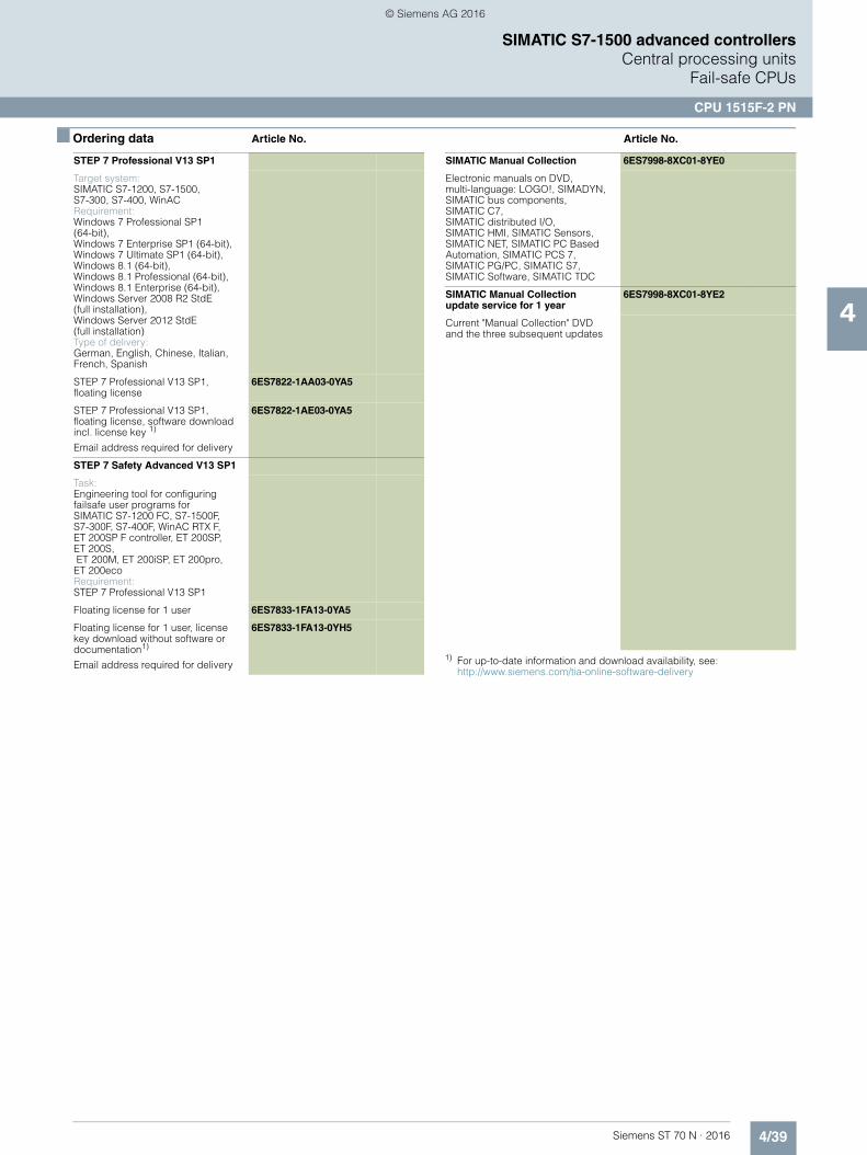
4/39Siemens ST 70 N · 2016
4
■ Ordering data Article No. Article No.
SIMATIC S7-1500 advanced controllersCentral processing units
Fail-safe CPUs
CPU 1515F-2 PN
1) For up-to-date information and download availability, see:http://www.siemens.com/tia-online-software-delivery
STEP 7 Professional V13 SP1
Target system: SIMATIC S7-1200, S7-1500, S7-300, S7-400, WinACRequirement:Windows 7 Professional SP1 (64-bit), Windows 7 Enterprise SP1 (64-bit), Windows 7 Ultimate SP1 (64-bit), Windows 8.1 (64-bit), Windows 8.1 Professional (64-bit),Windows 8.1 Enterprise (64-bit), Windows Server 2008 R2 StdE (full installation), Windows Server 2012 StdE(full installation) Type of delivery:German, English, Chinese, Italian, French, Spanish
STEP 7 Professional V13 SP1, floating license
6ES7822-1AA03-0YA5
STEP 7 Professional V13 SP1, floating license, software download incl. license key 1)
Email address required for delivery
6ES7822-1AE03-0YA5
STEP 7 Safety Advanced V13 SP1
Task:Engineering tool for configuring failsafe user programs for SIMATIC S7-1200 FC, S7-1500F, S7-300F, S7-400F, WinAC RTX F, ET 200SP F controller, ET 200SP,ET 200S, ET 200M, ET 200iSP, ET 200pro, ET 200ecoRequirement:STEP 7 Professional V13 SP1
Floating license for 1 user 6ES7833-1FA13-0YA5
Floating license for 1 user, license key download without software or documentation1)
Email address required for delivery
6ES7833-1FA13-0YH5
SIMATIC Manual Collection 6ES7998-8XC01-8YE0
Electronic manuals on DVD, multi-language: LOGO!, SIMADYN, SIMATIC bus components, SIMATIC C7, SIMATIC distributed I/O, SIMATIC HMI, SIMATIC Sensors, SIMATIC NET, SIMATIC PC Based Automation, SIMATIC PCS 7, SIMATIC PG/PC, SIMATIC S7, SIMATIC Software, SIMATIC TDC
SIMATIC Manual Collection update service for 1 year
6ES7998-8XC01-8YE2
Current "Manual Collection" DVD and the three subsequent updates
© Siemens AG 2016
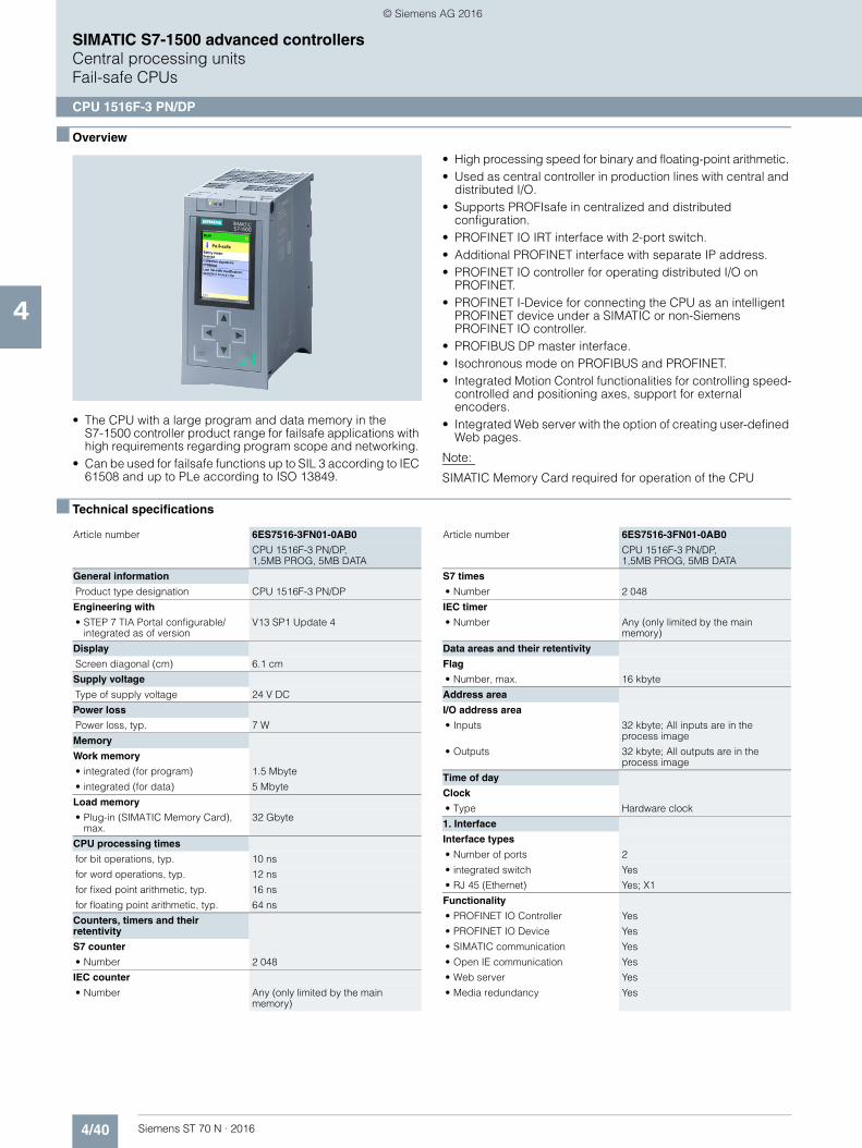
4/40 Siemens ST 70 N · 2016
4
SIMATIC S7-1500 advanced controllersCentral processing unitsFail-safe CPUs
CPU 1516F-3 PN/DP
■ Overview
• The CPU with a large program and data memory in the S7-1500 controller product range for failsafe applications with high requirements regarding program scope and networking.
• Can be used for failsafe functions up to SIL 3 according to IEC 61508 and up to PLe according to ISO 13849.
• High processing speed for binary and floating-point arithmetic. • Used as central controller in production lines with central and
distributed I/O. • Supports PROFIsafe in centralized and distributed
configuration. • PROFINET IO IRT interface with 2-port switch. • Additional PROFINET interface with separate IP address. • PROFINET IO controller for operating distributed I/O on
PROFINET. • PROFINET I-Device for connecting the CPU as an intelligent
PROFINET device under a SIMATIC or non-Siemens PROFINET IO controller.
• PROFIBUS DP master interface. • Isochronous mode on PROFIBUS and PROFINET.• Integrated Motion Control functionalities for controlling speed-
controlled and positioning axes, support for external encoders.
• Integrated Web server with the option of creating user-defined Web pages.
Note:
SIMATIC Memory Card required for operation of the CPU
■ Technical specifications
Article number 6ES7516-3FN01-0AB0
CPU 1516F-3 PN/DP, 1,5MB PROG, 5MB DATA
General information
Product type designation CPU 1516F-3 PN/DP
Engineering with
• STEP 7 TIA Portal configurable/integrated as of version
V13 SP1 Update 4
Display
Screen diagonal (cm) 6.1 cm
Supply voltage
Type of supply voltage 24 V DC
Power loss
Power loss, typ. 7 W
Memory
Work memory
• integrated (for program) 1.5 Mbyte
• integrated (for data) 5 Mbyte
Load memory
• Plug-in (SIMATIC Memory Card), max.
32 Gbyte
CPU processing times
for bit operations, typ. 10 ns
for word operations, typ. 12 ns
for fixed point arithmetic, typ. 16 ns
for floating point arithmetic, typ. 64 ns
Counters, timers and their retentivity
S7 counter
• Number 2 048
IEC counter
• Number Any (only limited by the main memory)
S7 times
• Number 2 048
IEC timer
• Number Any (only limited by the main memory)
Data areas and their retentivity
Flag
• Number, max. 16 kbyte
Address area
I/O address area
• Inputs 32 kbyte; All inputs are in the process image
• Outputs 32 kbyte; All outputs are in the process image
Time of day
Clock
• Type Hardware clock
1. Interface
Interface types
• Number of ports 2
• integrated switch Yes
• RJ 45 (Ethernet) Yes; X1
Functionality
• PROFINET IO Controller Yes
• PROFINET IO Device Yes
• SIMATIC communication Yes
• Open IE communication Yes
• Web server Yes
• Media redundancy Yes
Article number 6ES7516-3FN01-0AB0
CPU 1516F-3 PN/DP, 1,5MB PROG, 5MB DATA
© Siemens AG 2016
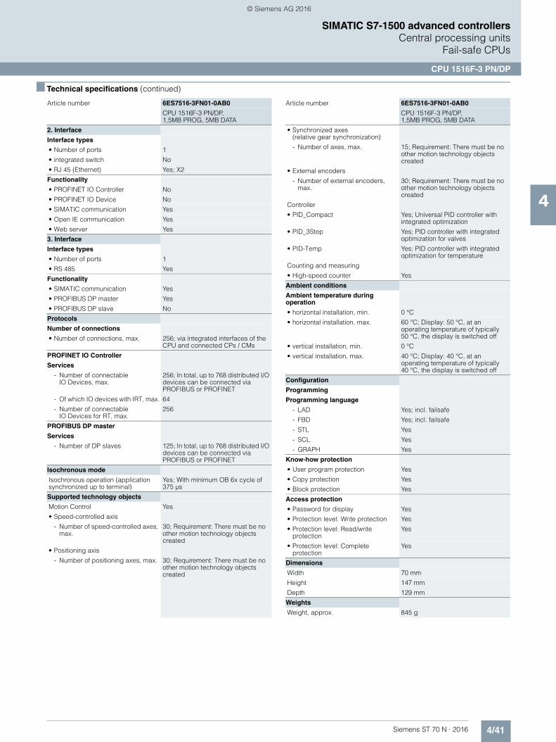
4/41Siemens ST 70 N · 2016
4
■ Technical specifications (continued)
SIMATIC S7-1500 advanced controllersCentral processing units
Fail-safe CPUs
CPU 1516F-3 PN/DP
2. Interface
Interface types
• Number of ports 1
• integrated switch No
• RJ 45 (Ethernet) Yes; X2
Functionality
• PROFINET IO Controller No
• PROFINET IO Device No
• SIMATIC communication Yes
• Open IE communication Yes
• Web server Yes
3. Interface
Interface types
• Number of ports 1
• RS 485 Yes
Functionality
• SIMATIC communication Yes
• PROFIBUS DP master Yes
• PROFIBUS DP slave No
Protocols
Number of connections
• Number of connections, max. 256; via integrated interfaces of the CPU and connected CPs / CMs
PROFINET IO Controller
Services
- Number of connectable IO Devices, max.
256; In total, up to 768 distributed I/O devices can be connected via PROFIBUS or PROFINET
- Of which IO devices with IRT, max. 64
- Number of connectableIO Devices for RT, max.
256
PROFIBUS DP master
Services
- Number of DP slaves 125; In total, up to 768 distributed I/O devices can be connected via PROFIBUS or PROFINET
Isochronous mode
Isochronous operation (application synchronized up to terminal)
Yes; With minimum OB 6x cycle of 375 µs
Supported technology objects
Motion Control Yes
• Speed-controlled axis
- Number of speed-controlled axes, max.
30; Requirement: There must be no other motion technology objects created
• Positioning axis
- Number of positioning axes, max. 30; Requirement: There must be no other motion technology objects created
Article number 6ES7516-3FN01-0AB0
CPU 1516F-3 PN/DP, 1,5MB PROG, 5MB DATA
• Synchronized axes(relative gear synchronization)
- Number of axes, max. 15; Requirement: There must be no other motion technology objects created
• External encoders
- Number of external encoders, max.
30; Requirement: There must be no other motion technology objects created
Controller
• PID_Compact Yes; Universal PID controller with integrated optimization
• PID_3Step Yes; PID controller with integrated optimization for valves
• PID-Temp Yes; PID controller with integrated optimization for temperature
Counting and measuring
• High-speed counter Yes
Ambient conditions
Ambient temperature during operation
• horizontal installation, min. 0 °C
• horizontal installation, max. 60 °C; Display: 50 °C, at an operating temperature of typically50 °C, the display is switched off
• vertical installation, min. 0 °C
• vertical installation, max. 40 °C; Display: 40 °C, at an operating temperature of typically 40 °C, the display is switched off
Configuration
Programming
Programming language
- LAD Yes; incl. failsafe
- FBD Yes; incl. failsafe
- STL Yes
- SCL Yes
- GRAPH Yes
Know-how protection
• User program protection Yes
• Copy protection Yes
• Block protection Yes
Access protection
• Password for display Yes
• Protection level: Write protection Yes
• Protection level: Read/write protection
Yes
• Protection level: Complete protection
Yes
Dimensions
Width 70 mm
Height 147 mm
Depth 129 mm
Weights
Weight, approx. 845 g
Article number 6ES7516-3FN01-0AB0
CPU 1516F-3 PN/DP, 1,5MB PROG, 5MB DATA
© Siemens AG 2016
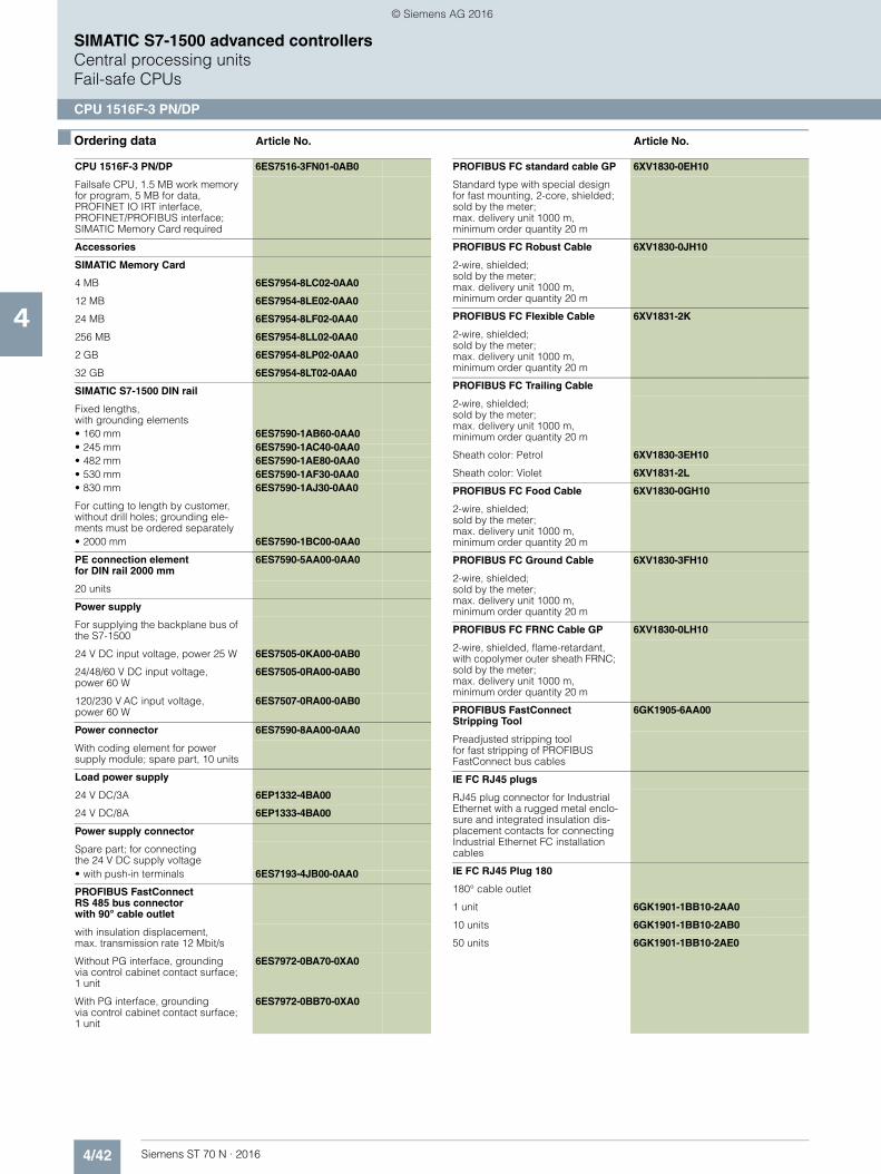
4/42 Siemens ST 70 N · 2016
4
SIMATIC S7-1500 advanced controllersCentral processing unitsFail-safe CPUs
CPU 1516F-3 PN/DP
■ Ordering data Article No. Article No.
CPU 1516F-3 PN/DP 6ES7516-3FN01-0AB0
Failsafe CPU, 1.5 MB work memoryfor program, 5 MB for data,PROFINET IO IRT interface, PROFINET/PROFIBUS interface; SIMATIC Memory Card required
Accessories
SIMATIC Memory Card
4 MB 6ES7954-8LC02-0AA0
12 MB 6ES7954-8LE02-0AA0
24 MB 6ES7954-8LF02-0AA0
256 MB 6ES7954-8LL02-0AA0
2 GB 6ES7954-8LP02-0AA0
32 GB 6ES7954-8LT02-0AA0
SIMATIC S7-1500 DIN rail
Fixed lengths, with grounding elements• 160 mm 6ES7590-1AB60-0AA0• 245 mm 6ES7590-1AC40-0AA0• 482 mm 6ES7590-1AE80-0AA0• 530 mm 6ES7590-1AF30-0AA0• 830 mm 6ES7590-1AJ30-0AA0
For cutting to length by customer, without drill holes; grounding ele-ments must be ordered separately• 2000 mm 6ES7590-1BC00-0AA0
PE connection elementfor DIN rail 2000 mm
6ES7590-5AA00-0AA0
20 units
Power supply
For supplying the backplane bus of the S7-1500
24 V DC input voltage, power 25 W 6ES7505-0KA00-0AB0
24/48/60 V DC input voltage, power 60 W
6ES7505-0RA00-0AB0
120/230 V AC input voltage,power 60 W
6ES7507-0RA00-0AB0
Power connector 6ES7590-8AA00-0AA0
With coding element for power supply module; spare part, 10 units
Load power supply
24 V DC/3A 6EP1332-4BA00
24 V DC/8A 6EP1333-4BA00
Power supply connector
Spare part; for connectingthe 24 V DC supply voltage• with push-in terminals 6ES7193-4JB00-0AA0
PROFIBUS FastConnect RS 485 bus connector with 90° cable outlet
with insulation displacement, max. transmission rate 12 Mbit/s
Without PG interface, groundingvia control cabinet contact surface; 1 unit
6ES7972-0BA70-0XA0
With PG interface, groundingvia control cabinet contact surface; 1 unit
6ES7972-0BB70-0XA0
PROFIBUS FC standard cable GP 6XV1830-0EH10
Standard type with special design for fast mounting, 2-core, shielded;sold by the meter; max. delivery unit 1000 m, minimum order quantity 20 m
PROFIBUS FC Robust Cable 6XV1830-0JH10
2-wire, shielded;sold by the meter; max. delivery unit 1000 m, minimum order quantity 20 m
PROFIBUS FC Flexible Cable 6XV1831-2K
2-wire, shielded;sold by the meter; max. delivery unit 1000 m, minimum order quantity 20 m
PROFIBUS FC Trailing Cable
2-wire, shielded;sold by the meter; max. delivery unit 1000 m,minimum order quantity 20 m
Sheath color: Petrol 6XV1830-3EH10
Sheath color: Violet 6XV1831-2L
PROFIBUS FC Food Cable 6XV1830-0GH10
2-wire, shielded;sold by the meter; max. delivery unit 1000 m,minimum order quantity 20 m
PROFIBUS FC Ground Cable 6XV1830-3FH10
2-wire, shielded;sold by the meter; max. delivery unit 1000 m, minimum order quantity 20 m
PROFIBUS FC FRNC Cable GP 6XV1830-0LH10
2-wire, shielded, flame-retardant, with copolymer outer sheath FRNC; sold by the meter; max. delivery unit 1000 m, minimum order quantity 20 m
PROFIBUS FastConnectStripping Tool
6GK1905-6AA00
Preadjusted stripping tool for fast stripping of PROFIBUS FastConnect bus cables
IE FC RJ45 plugs
RJ45 plug connector for Industrial Ethernet with a rugged metal enclo-sure and integrated insulation dis-placement contacts for connecting Industrial Ethernet FC installation cables
IE FC RJ45 Plug 180
180° cable outlet
1 unit 6GK1901-1BB10-2AA0
10 units 6GK1901-1BB10-2AB0
50 units 6GK1901-1BB10-2AE0
© Siemens AG 2016

4/43Siemens ST 70 N · 2016
4
■ Ordering data Article No. Article No.
SIMATIC S7-1500 advanced controllersCentral processing units
Fail-safe CPUs
CPU 1516F-3 PN/DP
1) For up-to-date information and download availability, see: http://www.siemens.com/tia-online-software-delivery
IE FC TP standard cable GP 2x2 6XV1840-2AH10
4-core, shielded TP installation cable for connection to IE FC Outlet RJ45/ IE FC RJ45 Plug; PROFINET-compatible; with UL approval;sold by the meter; max. delivery unit 1000 m, minimum order quantity 20 m
IE FC TP Trailing Cable 2 x 2 (Type C)
6XV1840-3AH10
4-core, shielded TP installation cable for connection toIE FC Outlet RJ45/ IE FC RJ45 Plug 180/90 for use as trailing cable; PROFINET-compatible; with UL approval; sold by the meter; max. delivery unit 1000 m,minimum order quantity 20 m
IE FC TP Marine Cable 2 x 2(Type B)
6XV1840-4AH10
4-core, shielded TP installation cable for connection to IE FC Outlet RJ45/ IE FC RJ45 Plug 180/90 with marine approval, sold by the meter; max. delivery unit 1000 m, minimum order quantity 20 m
IE FC stripping tool 6GK1901-1GA00
Preadjusted stripping tool for fast stripping of Industrial Ethernet FC cables
Display 6ES7591-1BA01-0AA0
For CPU 1516-3 PN/DP; spare part
STEP 7 Professional V13 SP1
Target system:SIMATIC S7-1200, S7-1500, S7-300, S7-400, WinACRequirement:Windows 7 Professional SP1(64-bit), Windows 7 Enterprise SP1 (64-bit), Windows 7 Ultimate SP1 (64-bit), Windows 8.1 (64-bit), Windows 8.1 Professional (64-bit),Windows 8.1 Enterprise (64-bit), Windows Server 2008 R2 StdE(full installation), Windows Server 2012 StdE (full installation)Available in:German, English, Chinese, Italian, French, Spanish
STEP 7 Professional V13 SP1,floating license
6ES7822-1AA03-0YA5
STEP 7 Professional V13 SP1, floating license, software download incl. license key 1)
Email address required for delivery
6ES7822-1AE03-0YA5
STEP 7 Safety Advanced V13 SP1
Task:Engineering tool for configuring failsafe user programs for SIMATIC S7-1200 FC, S7-1500F,S7-300F, S7-400F, WinAC RTX F, ET 200SP F controller, ET 200SP, ET 200S, ET 200M, ET 200iSP, ET 200pro, ET 200ecoRequirement:STEP 7 Professional V13 SP1
Floating license for 1 user 6ES7833-1FA13-0YA5
Floating license for 1 user, license key download without software or documentation1); email address required for delivery
6ES7833-1FA13-0YH5
SIMATIC Manual Collection 6ES7998-8XC01-8YE0
Electronic manuals on DVD, multi-language: LOGO!, SIMADYN, SIMATIC bus components, SIMATIC C7, SIMATIC distributed I/O, SIMATIC HMI, SIMATIC Sensors, SIMATIC NET, SIMATIC PC Based Automation, SIMATIC PCS 7, SIMATIC PG/PC, SIMATIC S7, SIMATIC Software, SIMATIC TDC
SIMATIC Manual Collection update service for 1 year
6ES7998-8XC01-8YE2
Current "Manual Collection" DVD and the three subsequent updates
© Siemens AG 2016
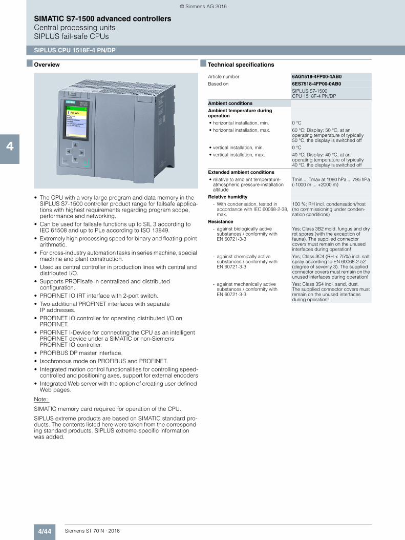
4/44 Siemens ST 70 N · 2016
4
SIMATIC S7-1500 advanced controllersCentral processing unitsSIPLUS fail-safe CPUs
SIPLUS CPU 1518F-4 PN/DP
■ Overview
• The CPU with a very large program and data memory in the SIPLUS S7-1500 controller product range for failsafe applica-tions with highest requirements regarding program scope, performance and networking.
• Can be used for failsafe functions up to SIL 3 according to IEC 61508 and up to PLe according to ISO 13849.
• Extremely high processing speed for binary and floating-point arithmetic.
• For cross-industry automation tasks in series machine, special machine and plant construction.
• Used as central controller in production lines with central and distributed I/O.
• Supports PROFIsafe in centralized and distributed configuration.
• PROFINET IO IRT interface with 2-port switch. • Two additional PROFINET interfaces with separate
IP addresses. • PROFINET IO controller for operating distributed I/O on
PROFINET.• PROFINET I-Device for connecting the CPU as an intelligent
PROFINET device under a SIMATIC or non-Siemens PROFINET IO controller.
• PROFIBUS DP master interface. • Isochronous mode on PROFIBUS and PROFINET. • Integrated motion control functionalities for controlling speed-
controlled and positioning axes, support for external encoders• Integrated Web server with the option of creating user-defined
Web pages.
Note:
SIMATIC memory card required for operation of the CPU.
SIPLUS extreme products are based on SIMATIC standard pro-ducts. The contents listed here were taken from the correspond-ing standard products. SIPLUS extreme-specific information was added.
■ Technical specifications
Article number 6AG1518-4FP00-4AB0
Based on 6ES7518-4FP00-0AB0
SIPLUS S7-1500CPU 1518F-4 PN/DP
Ambient conditions
Ambient temperature during operation
• horizontal installation, min. 0 °C
• horizontal installation, max. 60 °C; Display: 50 °C, at an operating temperature of typically50 °C, the display is switched off
• vertical installation, min. 0 °C
• vertical installation, max. 40 °C; Display: 40 °C, at an operating temperature of typically40 °C, the display is switched off
Extended ambient conditions
• relative to ambient temperature-atmospheric pressure-installation altitude
Tmin ... Tmax at 1080 hPa ... 795 hPa (-1000 m ... +2000 m)
Relative humidity
- With condensation, tested in accordance with IEC 60068-2-38, max.
100 %; RH incl. condensation/frost (no commissioning under conden-sation conditions)
Resistance
- against biologically active substances / conformity with EN 60721-3-3
Yes; Class 3B2 mold, fungus and dry rot spores (with the exception of fauna). The supplied connector covers must remain on the unused interfaces during operation!
- against chemically active substances / conformity with EN 60721-3-3
Yes; Class 3C4 (RH < 75%) incl. salt spray according to EN 60068-2-52 (degree of severity 3). The supplied connector covers must remain on the unused interfaces during operation!
- against mechanically active substances / conformity with EN 60721-3-3
Yes; Class 3S4 incl. sand, dust. The supplied connector covers must remain on the unused interfaces during operation!
© Siemens AG 2016

4/45Siemens ST 70 N · 2016
4
SIMATIC S7-1500 advanced controllersCentral processing units
SIPLUS fail-safe CPUs
SIPLUS CPU 1518F-4 PN/DP
■ Ordering data Article No.
CPU 1518F-4 PN/DP 6AG1518-4FP00-4AB0
(environmental stress)
Fail-safe CPU, work memory 6 MB for program, 20 MB for data, PROFINET IO IRT interface, 2 PROFINET interfaces, PROFIBUS interface; SIMATIC memory card required
Accessories
Power supply
(Extended temperature rangeand environmental stress)
For supplying the backplane bus of the S7-1500
24 VDC input voltage, power 25 W 6AG1505-0KA00-7AB0
24/48/60 VDC input voltage,power 60 W
6AG1505-0RA00-7AB0
120/230 VAC input voltage, power 60 W
6AG1507-0RA00-7AB0
Load power supply
(Extended temperature range and environmental stress)
24 VDC/3A 6AG1332-4BA00-7AA0
24 VDC/8A 6AG1333-4BA00-7AA0
Display 6AG1591-1BA00-2AA0
(Extended temperature range and environmental stress)
for CPU 1518-4F PN/DP; spare part
Other accessories See Catalog ST 70, SIMATIC S7-1500, CPU 1518F-4 PN/DP
© Siemens AG 2016

4/46 Siemens ST 70 N · 2016
4
SIMATIC S7-1500 advanced controllersI/O modulesDigital modules
SM 521 digital input modules
■ Overview
• 16 and 32-channel digital input modules• For flexible adaptation of the controller to the corresponding
task• For subsequent expansion of the system with additional inputs• 35 mm wide modules with parameters and diagnostic
functions• 25 mm wide modules for use in tight spaces:
particularly economical, without parameters or diagnostic functions
■ Technical specifications
Article number 6ES7521-1BH00-0AB0
6ES7521-1BL00-0AB0
6ES7521-1BH50-0AA0
6ES7521-1FH00-0AA0
6ES7521-7EH00-0AB0
S7-1500, DI 16X24VDC HF
S7-1500, DI 32X24VDC HF
S7-1500, DI 16X24VDC SRC BA
S7-1500, DI 16X230VAC BA
S7-1500, DI 16 X 24...125V UC HF
General information
Product type designation DI 16x24 V DC HF DI 32x24 V DC HF DI 16x24 V DC SRC BA
DI 16x230 V AC BA DI 16x24 ... 125VUC HF
Product function
• I&M data Yes; I&M0 to I&M3 Yes; I&M0 to I&M3 Yes; I&M0 to I&M3 Yes; I&M0 to I&M3 Yes; I&M0 to I&M3
Engineering with
• STEP 7 TIA Portal configurable/integrated as of version
V13 SP1 / - V13 SP1 / - V12 / V12 V12 / V12 V13 SP1 / -
• STEP 7 configurable/integrated as of version
V5.5 SP3 / - V5.5 SP3 / - V5.5 SP3 / - V5.5 SP3 / - V5.5 SP3 / -
• PROFIBUS as of GSD version/GSD revision
V1.0 / V5.1 V1.0 / V5.1 V1.0 / V5.1 V1.0 / V5.1 V1.0 / V5.1
• PROFINET as of GSD version/GSD revision
V2.3 / - V2.3 / - V2.3 / - V2.3 / - V2.3 / -
Operating mode
• DI Yes Yes Yes Yes Yes
• Counter Yes Yes No No No
• Oversampling No
• MSI Yes Yes Yes Yes Yes
Supply voltage
Type of supply voltage DC DC
Rated value (DC) 24 V 24 V
Reverse polarity protection Yes Yes
Digital inputs
Number of digital inputs 16 32 16 16 16
Digital inputs, parameterizable Yes Yes No No Yes
m/p-reading p-reading p-reading m-reading p-reading p-reading
Input characteristic curve in accordance with IEC 61131, type 1
Yes
Input characteristic curve inaccordance with IEC 61131, type 3
Yes Yes Yes Yes; at 24 V DC
Digital input functions, parameterizable
• Gate start/stop Yes Yes
• Freely usable digital input Yes Yes
• Counter
- Number, max. 2 2
- Counting frequency, max. 1 kHz 1 kHz
- Counting width 32 bit 32 bit
- Counting direction up/down Up Up
© Siemens AG 2016

4/47Siemens ST 70 N · 2016
4
■ Technical specifications (continued)
SIMATIC S7-1500 advanced controllersI/O modules
Digital modules
SM 521 digital input modules
Input voltage
• Type of input voltage DC DC DC AC AC/DC
• Rated value (DC) 24 V 24 V 24 V 24 V; 48 V, 125 V
• Rated value (AC) 230 V; 120/230V AC, 50/60 Hz
24 V; 48 V, 125 V (50 - 60 Hz)
• for signal "0" -30 to +5V -30 to +5V -5 to +30V 0V AC to 40V AC -5 ... +5 V
• for signal "1" +11 to +30V +11 to +30V -11 to -30V 79V AC to 264V AC +11 V DC to +146 V DC
Input current
• for signal "1", typ. 2.5 mA 2.5 mA 4.5 mA 11 mA; At 230 V AC and5.5 mA at 120 V AC
3 mA; at 24 V DC
Input delay (for rated value of input voltage)
for standard inputs
- parameterizable Yes; 0.05 / 0.1 / 0.4 / 1.6 / 3.2 / 12.8 / 20 ms
Yes; 0.05 / 0.1 / 0.4 / 1.6 / 3.2 / 12.8 / 20 ms
No No Yes; 0.05 / 0.1 / 0.4 / 1.6 / 3.2 / 12.8 / 20 ms parameterizable with DC, 20 ms fixed with AC
for interrupt inputs
- parameterizable Yes Yes No No Yes
for counter/technological functions
- parameterizable Yes Yes No No No
Cable length
• shielded, max. 1 000 m 1 000 m 1 000 m 1 000 m 1 000 m
• unshielded, max. 600 m 600 m 600 m 600 m 600 m
Encoder
Connectable encoders
• 2-wire sensor Yes Yes Yes Yes Yes
- permissible quiescent current (2-wire sensor), max.
1.5 mA 1.5 mA 1.5 mA 2 mA 1.5 mA
Isochronous mode
Isochronous operation (application synchronized up to terminal)
Yes Yes No No No
Filtering and processing time (TCI), min.
80 µs; At 50 s filter time
80 µs; At 50 s filter time
Bus cycle time (TDP), min. 250 µs 250 µs
Interrupts/diagnostics/status information
Diagnostics Yes Yes No No Yes
Alarms
• Diagnostic alarm Yes Yes No No Yes
• Hardware interrupt Yes Yes No No Yes
Diagnostic messages
• Monitoring the supply voltage Yes Yes No No No
• Wire-break Yes; to I < 350 µA Yes; to I < 350 µA No No Yes; To I < 550 µA
• Short-circuit No No No No No
Diagnostics indication LED
• RUN LED Yes; Green LED Yes; Green LED Yes; Green LED Yes; Green LED Yes; Green LED
• ERROR LED Yes; Red LED Yes; Red LED Yes; Red LED Yes; Red LED Yes; Red LED
• Monitoring of the supply voltage (PWR-LED)
Yes; Green LED Yes; Green LED No No No
• Channel status display Yes; Green LED Yes; Green LED Yes; Green LED Yes; Green LED Yes; Green LED
• for channel diagnostics Yes; Red LED Yes; Red LED No No Yes; Red LED
• for module diagnostics Yes; Red LED Yes; Red LED No Yes; Red LED Yes; Red LED
Article number 6ES7521-1BH00-0AB0
6ES7521-1BL00-0AB0
6ES7521-1BH50-0AA0
6ES7521-1FH00-0AA0
6ES7521-7EH00-0AB0
S7-1500, DI 16X24VDC HF
S7-1500, DI 32X24VDC HF
S7-1500, DI 16X24VDC SRC BA
S7-1500, DI 16X230VAC BA
S7-1500, DI 16 X 24...125V UC HF
© Siemens AG 2016

4/48 Siemens ST 70 N · 2016
4
■ Technical specifications (continued)
SIMATIC S7-1500 advanced controllersI/O modulesDigital modules
SM 521 digital input modules
Potential separation
Potential separation channels
• between the channels and backplane bus
Yes Yes Yes Yes Yes
Isolation
Isolation tested with 707 V DC (type test) 707 V DC (type test) 707 V DC (type test) 2500 V DC 1 200 V DC
Ambient conditions
Ambient temperature during operation
• horizontal installation, min. 0 °C 0 °C 0 °C 0 °C 0 °C
• horizontal installation, max. 60 °C 60 °C 60 °C 60 °C 60 °C
• vertical installation, min. 0 °C 0 °C 0 °C 0 °C 0 °C
• vertical installation, max. 40 °C 40 °C 40 °C 40 °C 40 °C
Decentralized operation
Prioritized startup Yes Yes Yes Yes Yes
Dimensions
Width 35 mm 35 mm 35 mm 35 mm 35 mm
Height 147 mm 147 mm 147 mm 147 mm 147 mm
Depth 129 mm 129 mm 129 mm 129 mm 129 mm
Weights
Weight, approx. 240 g 260 g 230 g 300 g 240 g
Article number 6ES7521-1BH10-0AA0 6ES7521-1BL10-0AA0
S7-1500, DI 16X24VDC BA S7-1500, DI 32X24VDC BA
General information
Product type designation DI 16 x 24 V DC BA DI 32 x 24 V DC BA
Product function
• I&M data Yes; I&M0 to I&M3 Yes; I&M0 to I&M3
Engineering with
• STEP 7 TIA Portal configurable/integrated as of version
V13 / V13 V13 / V13
• STEP 7 configurable/integrated as of version
V5.5 SP3 / - V5.5 SP3 / -
• PROFIBUS as of GSD version/GSD revision
V1.0 / V5.1 V1.0 / V5.1
• PROFINET as of GSD version/GSD revision
V2.3 / - V2.3 / -
Operating mode
• DI Yes Yes
• Counter No No
• MSI Yes Yes
Supply voltage
Type of supply voltage DC DC
Rated value (DC) 24 V 24 V
Digital inputs
Number of digital inputs 16 32
Digital inputs, parameterizable No No
m/p-reading p-reading p-reading
Input characteristic curve in accordance with IEC 61131, type 3
Yes Yes
Input voltage
• Type of input voltage DC DC
• Rated value (DC) 24 V 24 V
• for signal "0" -30 to +5V -30 to +5V
• for signal "1" +11 to +30V +11 to +30V
Input current
• for signal "1", typ. 2.7 mA 2.7 mA
Article number 6ES7521-1BH00-0AB0
6ES7521-1BL00-0AB0
6ES7521-1BH50-0AA0
6ES7521-1FH00-0AA0
6ES7521-7EH00-0AB0
S7-1500, DI 16X24VDC HF
S7-1500, DI 32X24VDC HF
S7-1500, DI 16X24VDC SRC BA
S7-1500, DI 16X230VAC BA
S7-1500, DI 16 X 24...125V UC HF
© Siemens AG 2016
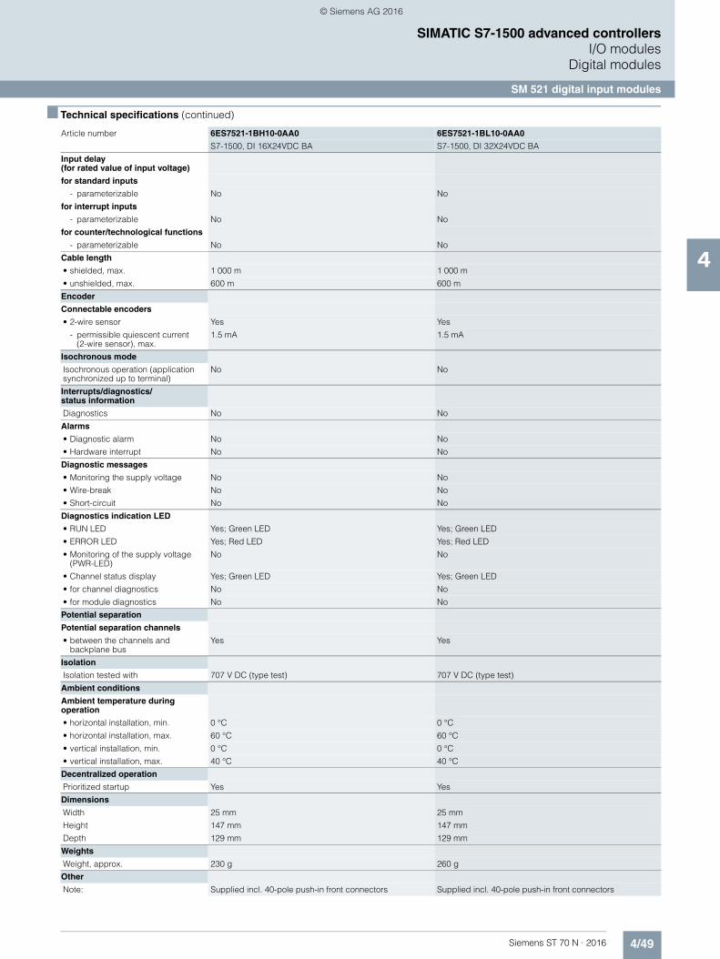
4/49Siemens ST 70 N · 2016
4
■ Technical specifications (continued)
SIMATIC S7-1500 advanced controllersI/O modules
Digital modules
SM 521 digital input modules
Input delay (for rated value of input voltage)
for standard inputs
- parameterizable No No
for interrupt inputs
- parameterizable No No
for counter/technological functions
- parameterizable No No
Cable length
• shielded, max. 1 000 m 1 000 m
• unshielded, max. 600 m 600 m
Encoder
Connectable encoders
• 2-wire sensor Yes Yes
- permissible quiescent current (2-wire sensor), max.
1.5 mA 1.5 mA
Isochronous mode
Isochronous operation (application synchronized up to terminal)
No No
Interrupts/diagnostics/status information
Diagnostics No No
Alarms
• Diagnostic alarm No No
• Hardware interrupt No No
Diagnostic messages
• Monitoring the supply voltage No No
• Wire-break No No
• Short-circuit No No
Diagnostics indication LED
• RUN LED Yes; Green LED Yes; Green LED
• ERROR LED Yes; Red LED Yes; Red LED
• Monitoring of the supply voltage (PWR-LED)
No No
• Channel status display Yes; Green LED Yes; Green LED
• for channel diagnostics No No
• for module diagnostics No No
Potential separation
Potential separation channels
• between the channels and backplane bus
Yes Yes
Isolation
Isolation tested with 707 V DC (type test) 707 V DC (type test)
Ambient conditions
Ambient temperature during operation
• horizontal installation, min. 0 °C 0 °C
• horizontal installation, max. 60 °C 60 °C
• vertical installation, min. 0 °C 0 °C
• vertical installation, max. 40 °C 40 °C
Decentralized operation
Prioritized startup Yes Yes
Dimensions
Width 25 mm 25 mm
Height 147 mm 147 mm
Depth 129 mm 129 mm
Weights
Weight, approx. 230 g 260 g
Other
Note: Supplied incl. 40-pole push-in front connectors Supplied incl. 40-pole push-in front connectors
Article number 6ES7521-1BH10-0AA0 6ES7521-1BL10-0AA0
S7-1500, DI 16X24VDC BA S7-1500, DI 32X24VDC BA
© Siemens AG 2016
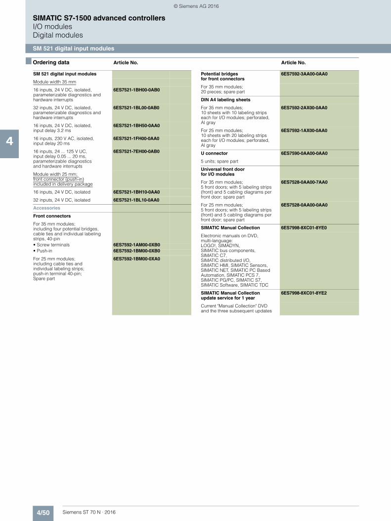
4/50 Siemens ST 70 N · 2016
4
SIMATIC S7-1500 advanced controllersI/O modulesDigital modules
SM 521 digital input modules
■ Ordering data Article No. Article No.
SM 521 digital input modules
Module width 35 mm
16 inputs, 24 V DC, isolated, parameterizable diagnostics and hardware interrupts
6ES7521-1BH00-0AB0
32 inputs, 24 V DC, isolated, parameterizable diagnostics and hardware interrupts
6ES7521-1BL00-0AB0
16 inputs, 24 V DC, isolated,input delay 3.2 ms
6ES7521-1BH50-0AA0
16 inputs, 230 V AC, isolated, input delay 20 ms
6ES7521-1FH00-0AA0
16 inputs, 24 ... 125 V UC,input delay 0.05 ... 20 ms, parameterizable diagnosticsand hardware interrupts
6ES7521-7EH00-0AB0
Module width 25 mm; front connector (push-in)included in delivery package
16 inputs, 24 V DC, isolated 6ES7521-1BH10-0AA0
32 inputs, 24 V DC, isolated 6ES7521-1BL10-0AA0
Accessories
Front connectors
For 35 mm modules; including four potential bridges, cable ties and individual labeling strips, 40-pin• Screw terminals 6ES7592-1AM00-0XB0• Push-in 6ES7592-1BM00-0XB0
For 25 mm modules; including cable ties andindividual labeling strips;push-in terminal 40-pin; Spare part
6ES7592-1BM00-0XA0
Potential bridgesfor front connectors
6ES7592-3AA00-0AA0
For 35 mm modules; 20 pieces; spare part
DIN A4 labeling sheets
For 35 mm modules; 10 sheets with 10 labeling strips each for I/O modules; perforated,Al gray
6ES7592-2AX00-0AA0
For 25 mm modules; 10 sheets with 20 labeling strips each for I/O modules; perforated,Al gray
6ES7592-1AX00-0AA0
U connector 6ES7590-0AA00-0AA0
5 units; spare part
Universal front door for I/O modules
For 35 mm modules; 5 front doors; with 5 labeling strips (front) and 5 cabling diagrams per front door; spare part
6ES7528-0AA00-7AA0
For 25 mm modules; 5 front doors; with 5 labeling strips (front) and 5 cabling diagrams per front door; spare part
6ES7528-0AA00-0AA0
SIMATIC Manual Collection 6ES7998-8XC01-8YE0
Electronic manuals on DVD, multi-language: LOGO!, SIMADYN, SIMATIC bus components,SIMATIC C7, SIMATIC distributed I/O, SIMATIC HMI, SIMATIC Sensors, SIMATIC NET, SIMATIC PC Based Automation, SIMATIC PCS 7, SIMATIC PG/PC, SIMATIC S7, SIMATIC Software, SIMATIC TDC
SIMATIC Manual Collection update service for 1 year
6ES7998-8XC01-8YE2
Current "Manual Collection" DVD and the three subsequent updates
© Siemens AG 2016

4/51Siemens ST 70 N · 2016
4
SIMATIC S7-1500 advanced controllersI/O modules
Digital modules
SM 522 digital output modules
■ Overview
• 8, 16 and 32-channel digital output modules• For flexible adaptation of the controller to the corresponding
task• For subsequent expansion of the system with additional
outputs• 35 mm wide modules with parameters and diagnostic
functions• 25 mm wide modules for use in tight spaces: particularly
economical, without parameters or diagnostic functions
■ Technical specifications
Article number 6ES7522-1BH01-0AB0 6ES7522-1BL01-0AB0 6ES7522-1BF00-0AB0 6ES7522-5EH00-0AB0
S7-1500, DQ 16X24V DC/0.5A HF
S7-1500, DQ 32X24VDC/0.5A HF
S7-1500,DQ 8X24VDC/2A HF
S7-1500, DQ 16X24...48VUC/125VDC/0.5A ST
General information
Product type designation DQ 16x24VDC/0.5A HF DQ 32x24VDC/0.5A HF DQ 8x24VDC/2A HF DQ 16x24 ... 48VUC/125VDC/0.5A ST
Product function
• I&M data Yes; I&M0 to I&M3 Yes; I&M0 to I&M3 Yes; I&M0 to I&M3 Yes; I&M0 to I&M3
Engineering with
• STEP 7 TIA Portal configurable/integrated as of version
V13 SP1 / - V13 SP1 / - V13 SP1 / - V13 SP1 / -
• STEP 7 configurable/integrated as of version
V5.5 SP3 / - V5.5 SP3 / -
• PROFIBUS as of GSD version/GSD revision
V1.0 / V5.1 V1.0 / V5.1 V1.0 / V5.1 V1.0 / V5.1
• PROFINET as of GSD version/GSD revision
V2.3 / - V2.3 / - V2.3 / - V2.3 / -
Operating mode
• DQ Yes Yes Yes Yes
• DQ with energy-saving function No No Yes; with an application No
• PWM No No Yes No
• Oversampling No No No No
• MSO Yes Yes Yes Yes
Supply voltage
Type of supply voltage DC DC DC
Rated value (DC) 24 V 24 V 24 V
Reverse polarity protection Yes; through internal protection with 7 A per group
Yes; through internal protection with 7 A per group
Yes; through internal protection with 10 A per group
Digital outputs
Type of digital output Transistor Transistor Transistor Transistor
Number of digital outputs 16 32 8 16
Current-sinking Yes
Current-sourcing Yes Yes Yes Yes
Digital outputs, parameterizable Yes Yes Yes Yes
Short-circuit protection Yes; Clocked electronically Yes; Clocked electronically Yes
Limitation of inductive shutdown voltage to
L+ (-53 V) L+ (-53 V) -17 V 200 V (suppressor diode)
Controlling a digital input Yes Yes Yes Yes
© Siemens AG 2016

4/52 Siemens ST 70 N · 2016
4
■ Technical specifications (continued)
SIMATIC S7-1500 advanced controllersI/O modulesDigital modules
SM 522 digital output modules
Digital output functions, parameterizable
• Freely usable digital output Yes
• PWM output Yes
- Number, max. 2
- Cycle duration, parameterizable Yes; 2 ... 100 ms continuous
Switching capacity of the outputs
• with resistive load, max. 0.5 A 0.5 A 0.5 A
• on lamp load, max. 5 W 5 W 10 W 40 W; At 125 V DC, 10 W at 48 V UC, 5 W at 24 V UC
Load resistance range
• lower limit 48 48 12 • upper limit 12 k 12 k 4 kOutput voltage
• Type of output voltage DC DC DC UC
• for signal "1", min. L+ (-0.8 V) L+ (-0.8 V) L+ (-0.8 V) L+ (-1.0 V)
Output current
• for signal "1" rated value 0.5 A 0.5 A 2 A 0.5 A
• for signal "0" residual current, max. 0.5 mA 0.5 mA 0.5 mA
Output delay with resistive load
• "0" to "1", typ. 80 µs
• "0" to "1", max. 100 µs 100 µs 100 µs 5 ms
• "1" to "0", typ. 300 µs
• "1" to "0", max. 500 µs 500 µs 500 µs 5 ms
Parallel switching of two outputs
• for logic links Yes Yes Yes Yes
• for uprating No No No No
• for redundant control of a load Yes Yes Yes Yes
Switching frequency
• with resistive load, max. 100 Hz 100 Hz 100 Hz; With PWM operation: 500 Hz
25 Hz
• with inductive load, max. 0.5 Hz; According to IEC 60947-5-1, DC-13
0.5 Hz; According to IEC 60947-5-1, DC-13
0.5 Hz; According to IEC 60947-5-1, DC-13; max. 500 Hz with PWM operation only with external circuit; see additional description in the manual
0.5 Hz
• on lamp load, max. 10 Hz 10 Hz 10 Hz 10 Hz
Total current of the outputs
• Current per channel, max. 0.5 A; see additional description in the manual
0.5 A; see additional description in the manual
2 A; see additional description in the manual
0.5 A
• Current per group, max. 4 A; see additional description in the manual
4 A; see additional description in the manual
8 A; see additional description in the manual
0.5 A
• Current per module, max. 8 A; see additional description in the manual
16 A; see additional description in the manual
16 A; see additional description in the manual
8 A
Cable length
• shielded, max. 1 000 m 1 000 m 1 000 m 1 000 m
• unshielded, max. 600 m 600 m 600 m 600 m
Isochronous mode
Isochronous operation (application synchronized up to terminal)
Yes Yes No No
Execution and activation time (TCO), min.
70 µs 70 µs
Bus cycle time (TDP), min. 250 µs 250 µs
Article number 6ES7522-1BH01-0AB0 6ES7522-1BL01-0AB0 6ES7522-1BF00-0AB0 6ES7522-5EH00-0AB0
S7-1500, DQ 16X24V DC/0.5A HF
S7-1500, DQ 32X24VDC/0.5A HF
S7-1500,DQ 8X24VDC/2A HF
S7-1500, DQ 16X24...48VUC/125VDC/0.5A ST
© Siemens AG 2016
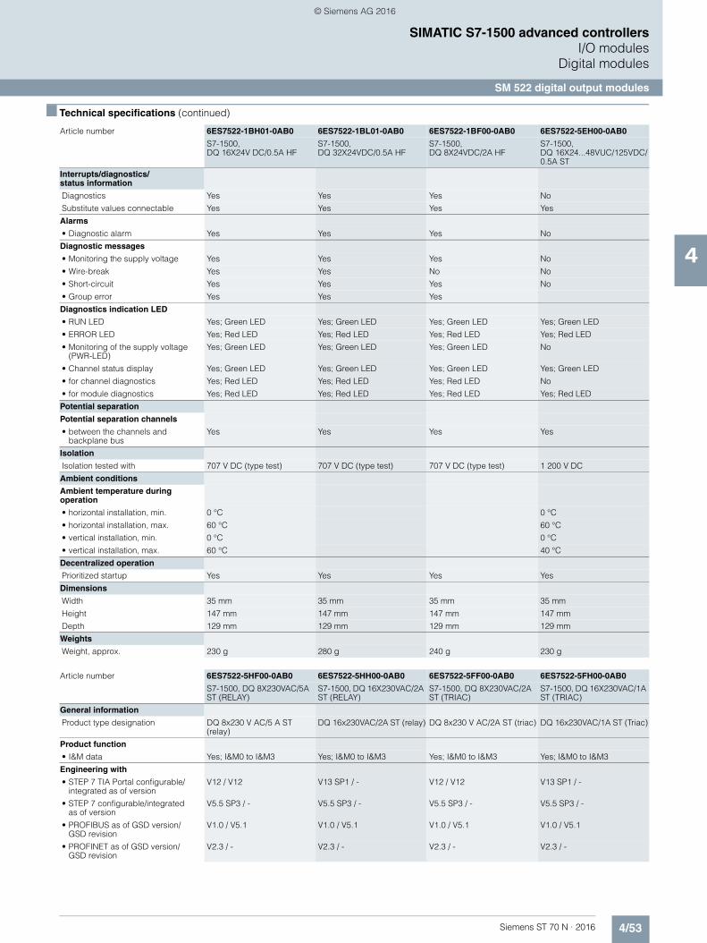
4/53Siemens ST 70 N · 2016
4
■ Technical specifications (continued)
SIMATIC S7-1500 advanced controllersI/O modules
Digital modules
SM 522 digital output modules
Interrupts/diagnostics/status information
Diagnostics Yes Yes Yes No
Substitute values connectable Yes Yes Yes Yes
Alarms
• Diagnostic alarm Yes Yes Yes No
Diagnostic messages
• Monitoring the supply voltage Yes Yes Yes No
• Wire-break Yes Yes No No
• Short-circuit Yes Yes Yes No
• Group error Yes Yes Yes
Diagnostics indication LED
• RUN LED Yes; Green LED Yes; Green LED Yes; Green LED Yes; Green LED
• ERROR LED Yes; Red LED Yes; Red LED Yes; Red LED Yes; Red LED
• Monitoring of the supply voltage (PWR-LED)
Yes; Green LED Yes; Green LED Yes; Green LED No
• Channel status display Yes; Green LED Yes; Green LED Yes; Green LED Yes; Green LED
• for channel diagnostics Yes; Red LED Yes; Red LED Yes; Red LED No
• for module diagnostics Yes; Red LED Yes; Red LED Yes; Red LED Yes; Red LED
Potential separation
Potential separation channels
• between the channels and backplane bus
Yes Yes Yes Yes
Isolation
Isolation tested with 707 V DC (type test) 707 V DC (type test) 707 V DC (type test) 1 200 V DC
Ambient conditions
Ambient temperature during operation
• horizontal installation, min. 0 °C 0 °C
• horizontal installation, max. 60 °C 60 °C
• vertical installation, min. 0 °C 0 °C
• vertical installation, max. 60 °C 40 °C
Decentralized operation
Prioritized startup Yes Yes Yes Yes
Dimensions
Width 35 mm 35 mm 35 mm 35 mm
Height 147 mm 147 mm 147 mm 147 mm
Depth 129 mm 129 mm 129 mm 129 mm
Weights
Weight, approx. 230 g 280 g 240 g 230 g
Article number 6ES7522-5HF00-0AB0 6ES7522-5HH00-0AB0 6ES7522-5FF00-0AB0 6ES7522-5FH00-0AB0
S7-1500, DQ 8X230VAC/5A ST (RELAY)
S7-1500, DQ 16X230VAC/2A ST (RELAY)
S7-1500, DQ 8X230VAC/2A ST (TRIAC)
S7-1500, DQ 16X230VAC/1A ST (TRIAC)
General information
Product type designation DQ 8x230 V AC/5 A ST (relay)
DQ 16x230VAC/2A ST (relay) DQ 8x230 V AC/2A ST (triac) DQ 16x230VAC/1A ST (Triac)
Product function
• I&M data Yes; I&M0 to I&M3 Yes; I&M0 to I&M3 Yes; I&M0 to I&M3 Yes; I&M0 to I&M3
Engineering with
• STEP 7 TIA Portal configurable/integrated as of version
V12 / V12 V13 SP1 / - V12 / V12 V13 SP1 / -
• STEP 7 configurable/integrated as of version
V5.5 SP3 / - V5.5 SP3 / - V5.5 SP3 / - V5.5 SP3 / -
• PROFIBUS as of GSD version/GSD revision
V1.0 / V5.1 V1.0 / V5.1 V1.0 / V5.1 V1.0 / V5.1
• PROFINET as of GSD version/GSD revision
V2.3 / - V2.3 / - V2.3 / - V2.3 / -
Article number 6ES7522-1BH01-0AB0 6ES7522-1BL01-0AB0 6ES7522-1BF00-0AB0 6ES7522-5EH00-0AB0
S7-1500, DQ 16X24V DC/0.5A HF
S7-1500, DQ 32X24VDC/0.5A HF
S7-1500,DQ 8X24VDC/2A HF
S7-1500, DQ 16X24...48VUC/125VDC/0.5A ST
© Siemens AG 2016
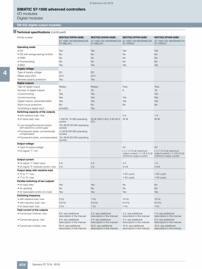
4/54 Siemens ST 70 N · 2016
4
■ Technical specifications (continued)
SIMATIC S7-1500 advanced controllersI/O modulesDigital modules
SM 522 digital output modules
Operating mode
• DQ Yes Yes Yes Yes
• DQ with energy-saving function No No No No
• PWM No No No No
• Oversampling No No No No
• MSO Yes Yes Yes Yes
Supply voltage
Type of supply voltage DC DC
Rated value (DC) 24 V 24 V
Reverse polarity protection Yes Yes
Digital outputs
Type of digital output Relays Relays Triac Triac
Number of digital outputs 8 16 8 16
Current-sinking Yes Yes Yes
Current-sourcing Yes Yes Yes Yes
Digital outputs, parameterizable Yes Yes Yes Yes
Short-circuit protection No No No No
Controlling a digital input possible Yes
Switching capacity of the outputs
• with resistive load, max. 2 A 1 A
• on lamp load, max. 1 500 W; 10 000 operating cycles
50 W (230 V AC), 5 W (24 V DC)
50 W 50 W
• Low energy/fluorescent lampswith electronic control gear
10x 58 W (25 000 operating cycles)
• Fluorescent tubes, conventionally compensated
1x 58 W (25 000 operating cycles)
• Fluorescent tubes, uncompensated 10x 58 W (25 000 operating cycles)
Output voltage
• Type of output voltage AC AC
• for signal "1", min. L1 (-1.5 V) at maximum output current; L1 (-8.5 V) at minimum output current
L1 (-1.5 V) at maximum output current; L1 (-8.5 V) at minimum output current
Output current
• for signal "1" rated value 5 A 2 A 2 A 1 A
• for signal "0" residual current, max. 0 A 0 A 2 mA 2 mA
Output delay with resistive load
• "0" to "1", max. 1 AC cycle 1 AC cycle
• "1" to "0", max. 1 AC cycle 1 AC cycle
Parallel switching of two outputs
• for logic links Yes Yes No No
• for uprating No No No No
• for redundant control of a load Yes Yes Yes Yes
Switching frequency
• with resistive load, max. 2 Hz 1 Hz 10 Hz 10 Hz
• with inductive load, max. 0.5 Hz 0.5 Hz 0.5 Hz 0.5 Hz
• on lamp load, max. 2 Hz 1 Hz 1 Hz 1 Hz
Total current of the outputs
• Current per channel, max. 8 A; see additional description in the manual
2 A; see additional description in the manual
2 A; see additional description in the manual
1 A; see additional description in the manual
• Current per group, max. 8 A; see additional description in the manual
2 A; see additional description in the manual
2 A; see additional description in the manual
2 A; see additional description in the manual
• Current per module, max. 64 A; see additional description in the manual
32 A; see additional description in the manual
10 A; see additional description in the manual
10 A; see additional description in the manual
Article number 6ES7522-5HF00-0AB0 6ES7522-5HH00-0AB0 6ES7522-5FF00-0AB0 6ES7522-5FH00-0AB0
S7-1500, DQ 8X230VAC/5A ST (RELAY)
S7-1500, DQ 16X230VAC/2A ST (RELAY)
S7-1500, DQ 8X230VAC/2A ST (TRIAC)
S7-1500, DQ 16X230VAC/1A ST (TRIAC)
© Siemens AG 2016
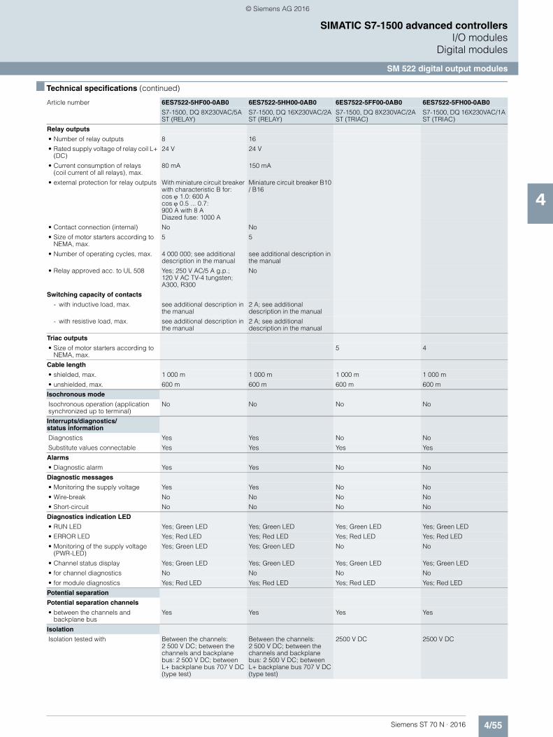
4/55Siemens ST 70 N · 2016
4
■ Technical specifications (continued)
SIMATIC S7-1500 advanced controllersI/O modules
Digital modules
SM 522 digital output modules
Relay outputs
• Number of relay outputs 8 16
• Rated supply voltage of relay coil L+ (DC)
24 V 24 V
• Current consumption of relays (coil current of all relays), max.
80 mA 150 mA
• external protection for relay outputs With miniature circuit breaker with characteristic B for:cos 1.0: 600 A cos 0.5 ... 0.7: 900 A with 8 A Diazed fuse: 1000 A
Miniature circuit breaker B10 / B16
• Contact connection (internal) No No
• Size of motor starters according to NEMA, max.
5 5
• Number of operating cycles, max. 4 000 000; see additional description in the manual
see additional description in the manual
• Relay approved acc. to UL 508 Yes; 250 V AC/5 A g.p.; 120 V AC TV-4 tungsten; A300, R300
No
Switching capacity of contacts
- with inductive load, max. see additional description in the manual
2 A; see additional description in the manual
- with resistive load, max. see additional description in the manual
2 A; see additional description in the manual
Triac outputs
• Size of motor starters according to NEMA, max.
5 4
Cable length
• shielded, max. 1 000 m 1 000 m 1 000 m 1 000 m
• unshielded, max. 600 m 600 m 600 m 600 m
Isochronous mode
Isochronous operation (application synchronized up to terminal)
No No No No
Interrupts/diagnostics/status information
Diagnostics Yes Yes No No
Substitute values connectable Yes Yes Yes Yes
Alarms
• Diagnostic alarm Yes Yes No No
Diagnostic messages
• Monitoring the supply voltage Yes Yes No No
• Wire-break No No No No
• Short-circuit No No No No
Diagnostics indication LED
• RUN LED Yes; Green LED Yes; Green LED Yes; Green LED Yes; Green LED
• ERROR LED Yes; Red LED Yes; Red LED Yes; Red LED Yes; Red LED
• Monitoring of the supply voltage (PWR-LED)
Yes; Green LED Yes; Green LED No No
• Channel status display Yes; Green LED Yes; Green LED Yes; Green LED Yes; Green LED
• for channel diagnostics No No No No
• for module diagnostics Yes; Red LED Yes; Red LED Yes; Red LED Yes; Red LED
Potential separation
Potential separation channels
• between the channels and backplane bus
Yes Yes Yes Yes
Isolation
Isolation tested with Between the channels: 2 500 V DC; between the channels and backplane bus: 2 500 V DC; between L+ backplane bus 707 V DC (type test)
Between the channels: 2 500 V DC; between the channels and backplane bus: 2 500 V DC; between L+ backplane bus 707 V DC (type test)
2500 V DC 2500 V DC
Article number 6ES7522-5HF00-0AB0 6ES7522-5HH00-0AB0 6ES7522-5FF00-0AB0 6ES7522-5FH00-0AB0
S7-1500, DQ 8X230VAC/5A ST (RELAY)
S7-1500, DQ 16X230VAC/2A ST (RELAY)
S7-1500, DQ 8X230VAC/2A ST (TRIAC)
S7-1500, DQ 16X230VAC/1A ST (TRIAC)
© Siemens AG 2016
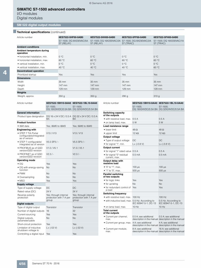
4/56 Siemens ST 70 N · 2016
4
■ Technical specifications (continued)
SIMATIC S7-1500 advanced controllersI/O modulesDigital modules
SM 522 digital output modules
Ambient conditions
Ambient temperature during operation
• horizontal installation, min. 0 °C 0 °C 0 °C 0 °C
• horizontal installation, max. 60 °C 60 °C 60 °C 60 °C
• vertical installation, min. 0 °C 0 °C 0 °C 0 °C
• vertical installation, max. 40 °C 40 °C 40 °C 60 °C
Decentralized operation
Prioritized startup Yes Yes Yes Yes
Dimensions
Width 35 mm 35 mm 35 mm 35 mm
Height 147 mm 147 mm 147 mm 147 mm
Depth 129 mm 129 mm 129 mm 129 mm
Weights
Weight, approx. 350 g 350 g 290 g 310 g
Article number 6ES7522-5HF00-0AB0 6ES7522-5HH00-0AB0 6ES7522-5FF00-0AB0 6ES7522-5FH00-0AB0
S7-1500, DQ 8X230VAC/5A ST (RELAY)
S7-1500, DQ 16X230VAC/2A ST (RELAY)
S7-1500, DQ 8X230VAC/2A ST (TRIAC)
S7-1500, DQ 16X230VAC/1A ST (TRIAC)
Article number 6ES7522-1BH10-0AA0 6ES7522-1BL10-0AA0
S7-1500, DQ 16X24VDC/0.5A BA
S7-1500, DQ 32X24VDC/0.5A BA
General information
Product type designation DQ 16 x 24 V DC / 0.5 A BA
DQ 32 x 24 V DC / 0.5 A BA
Product function
• I&M data Yes; I&M0 to I&M3 Yes; I&M0 to I&M3
Engineering with
• STEP 7 TIA Portal configurable/integrated as of version
V13 / V13 V13 / V13
• STEP 7 configurable/integrated as of version
V5.5 SP3 / - V5.5 SP3 / -
• PROFIBUS as of GSD version/GSD revision
V1.0 / V5.1 V1.0 / V5.1
• PROFINET as of GSD version/GSD revision
V2.3 / - V2.3 / -
Operating mode
• DQ Yes Yes
• DQ with energy-saving function
No No
• PWM No No
• Oversampling No No
• MSO Yes Yes
Supply voltage
Type of supply voltage DC DC
Rated value (DC) 24 V 24 V
Reverse polarity protection
Yes; through internal protection with 7 A per group
Yes; through internal protection with 7 A per group
Digital outputs
Type of digital output Transistor Transistor
Number of digital outputs 16 32
Current-sourcing Yes Yes
Digital outputs, parameterizable
No No
Short-circuit protection Yes Yes
Limitation of inductive shutdown voltage to
L+ (-53 V) L+ (-53 V)
Controlling a digital input Yes Yes
Switching capacityof the outputs
• with resistive load, max. 0.5 A 0.5 A
• on lamp load, max. 5 W 5 W
Load resistance range
• lower limit 48 48 • upper limit 12 k 12 kOutput voltage
• Type of output voltage DC DC
• for signal "1", min. L+ (-0.8 V) L+ (-0.8 V)
Output current
• for signal "1" rated value 0.5 A 0.5 A
• for signal "0" residual current, max.
0.5 mA 0.5 mA
Output delay with resistive load
• "0" to "1", max. 100 µs 100 µs
• "1" to "0", max. 500 µs 500 µs
Parallel switchingof two outputs
• for logic links Yes Yes
• for uprating No No
• for redundant control of a load
Yes Yes
Switching frequency
• with resistive load, max. 100 Hz 100 Hz
• with inductive load, max. 0.5 Hz; According to IEC 60947-5-1, DC-13
0.5 Hz; According to IEC 60947-5-1, DC-13
• on lamp load, max. 10 Hz 10 Hz
Total currentof the outputs
• Current per channel, max.
0.5 A; see additional description in the manual
0.5 A; see additional description in the manual
• Current per group, max. 4 A; see additional description in the manual
4 A; see additional description in the manual
• Current per module, max.
8 A; see additional description in the manual
16 A; see additional description in the manual
Article number 6ES7522-1BH10-0AA0 6ES7522-1BL10-0AA0
S7-1500, DQ 16X24VDC/0.5A BA
S7-1500, DQ 32X24VDC/0.5A BA
© Siemens AG 2016

4/57Siemens ST 70 N · 2016
4
■ Technical specifications (continued)
SIMATIC S7-1500 advanced controllersI/O modules
Digital modules
SM 522 digital output modules
■ Ordering data Article No. Article No.
Cable length
• shielded, max. 1 000 m 1 000 m
• unshielded, max. 600 m 600 m
Isochronous mode
Isochronous operation (application synchro-nized up to terminal)
No No
Interrupts/diagnostics/status information
Diagnostics No No
Substitute values connectable
No No
Alarms
• Diagnostic alarm No No
Diagnostic messages
• Monitoring the supply voltage
No No
• Wire-break No No
• Short-circuit No No
• Group error No No
Article number 6ES7522-1BH10-0AA0 6ES7522-1BL10-0AA0
S7-1500, DQ 16X24VDC/0.5A BA
S7-1500, DQ 32X24VDC/0.5A BA
Diagnostics indication LED
• RUN LED Yes; Green LED Yes; Green LED
• ERROR LED Yes; Red LED Yes; Red LED
• Monitoring of the supply voltage (PWR-LED)
Yes; Green LED Yes; Green LED
• Channel status display Yes; Green LED Yes; Green LED
• for channel diagnostics No No
• for module diagnostics No No
Potential separation
Potential separation channels
• between the channels and backplane bus
Yes Yes
Isolation
Isolation tested with 707 V DC (type test) 707 V DC (type test)
Decentralized operation
Prioritized startup Yes Yes
Dimensions
Width 25 mm 25 mm
Height 147 mm 147 mm
Depth 129 mm 129 mm
Weights
Weight, approx. 230 g 280 g
Other
Note: Supplied incl. 40-pole push-in front connectors
Supplied incl.40-pole push-in front connectors
Article number 6ES7522-1BH10-0AA0 6ES7522-1BL10-0AA0
S7-1500, DQ 16X24VDC/0.5A BA
S7-1500, DQ 32X24VDC/0.5A BA
SM 522 digital output modules
Module width 35 mm
8 outputs, 24 V DC; 2 A, isolated 6ES7522-1BF00-0AB0
16 outputs, 24 V DC; 0.5 A, isolated 6ES7522-1BH01-0AB0
32 outputs, 24 V DC; 0.5 A, isolated 6ES7522-1BL01-0AB0
8 relay outputs, 230 V AC, 5 A 6ES7522-5HF00-0AB0
16 relay outputs, 230 V AC, 2 A 6ES7522-5HH00-0AB0
8 outputs (triac), 230 V AC, 2 A 6ES7522-5FF00-0AB0
16 outputs (triac), 230 V AC, 1 A 6ES7522-5FH00-0AB0
16 outputs, 24 ... 48 V UC, 125 V DC, 0.5 A, isolated
6ES7522-5EH00-0AB0
Module width 25 mm;front connector (push-in)included in delivery package
16 outputs, 24 V DC; 0.5 A, isolated 6ES7 522-1BH10-0AA0
32 outputs, 24 V DC; 0.5 A, isolated 6ES7 522-1BL10-0AA0
Accessories
Front connectors
For 35 mm modules; including four potential bridges, cable ties and individual labeling strips, 40-pin• Screw terminals 6ES7592-1AM00-0XB0• Push-in 6ES7592-1BM00-0XB0
For 25 mm modules; including cable ties and individual labeling strips; push-in terminal 40-pin; Spare part
6ES7592-1BM00-0XA0
Potential bridgesfor front connectors
6ES7592-3AA00-0AA0
For 35 mm modules; 20 pieces; spare part
DIN A4 labeling sheets
For 35 mm modules; 10 sheets with 10 labeling strips each for I/O modules; perforated, Al gray
6ES7592-2AX00-0AA0
For 25 mm modules; 10 sheets with 20 labeling strips each for I/O modules; perforated,Al gray
6ES7592-1AX00-0AA0
© Siemens AG 2016
4/58 Siemens ST 70 N · 2016
4
■ Ordering data Article No. Article No.
SIMATIC S7-1500 advanced controllersI/O modulesDigital modules
SM 522 digital output modules
U connector 6ES7590-0AA00-0AA0
5 units; spare part
Universal front doorfor I/O modules
For 35 mm modules; 5 front doors; with 5 labeling strips (front) and 5 cabling diagrams per front door; spare part
6ES7528-0AA00-7AA0
For 25 mm modules; 5 front doors; with 5 labeling strips (front) and 5 cabling diagrams per front door; spare part
6ES7528-0AA00-0AA0
SIMATIC Manual Collection 6ES7998-8XC01-8YE0
Electronic manuals on DVD, multi-language: LOGO!, SIMADYN, SIMATIC bus components, SIMATIC C7, SIMATIC distributed I/O, SIMATIC HMI, SIMATIC Sensors, SIMATIC NET, SIMATIC PC Based Automation, SIMATIC PCS 7, SIMATIC PG/PC, SIMATIC S7, SIMATIC Software, SIMATIC TDC
SIMATIC Manual Collection update service for 1 year
6ES7998-8XC01-8YE2
Current "Manual Collection" DVD and the three subsequent updates
© Siemens AG 2016
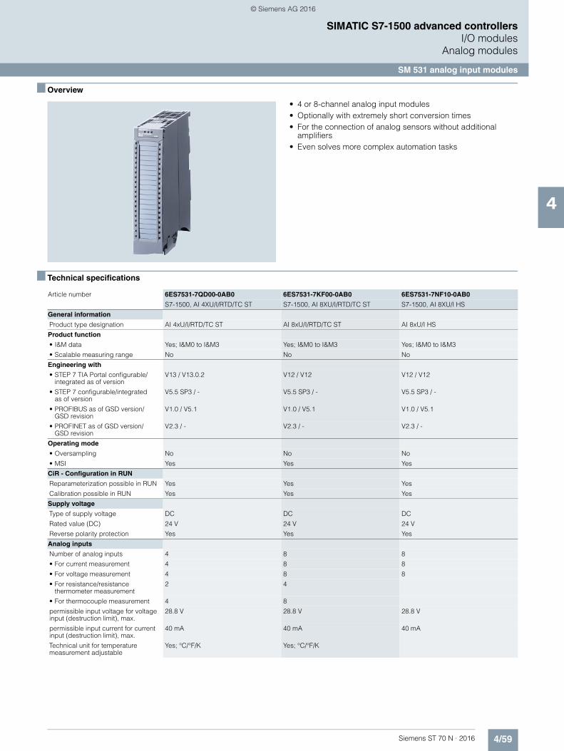
4/59Siemens ST 70 N · 2016
4
SIMATIC S7-1500 advanced controllersI/O modules
Analog modules
SM 531 analog input modules
■ Overview
• 4 or 8-channel analog input modules• Optionally with extremely short conversion times• For the connection of analog sensors without additional
amplifiers• Even solves more complex automation tasks
■ Technical specifications
Article number 6ES7531-7QD00-0AB0 6ES7531-7KF00-0AB0 6ES7531-7NF10-0AB0
S7-1500, AI 4XU/I/RTD/TC ST S7-1500, AI 8XU/I/RTD/TC ST S7-1500, AI 8XU/I HS
General information
Product type designation AI 4xU/I/RTD/TC ST AI 8xU/I/RTD/TC ST AI 8xU/I HS
Product function
• I&M data Yes; I&M0 to I&M3 Yes; I&M0 to I&M3 Yes; I&M0 to I&M3
• Scalable measuring range No No No
Engineering with
• STEP 7 TIA Portal configurable/integrated as of version
V13 / V13.0.2 V12 / V12 V12 / V12
• STEP 7 configurable/integratedas of version
V5.5 SP3 / - V5.5 SP3 / - V5.5 SP3 / -
• PROFIBUS as of GSD version/GSD revision
V1.0 / V5.1 V1.0 / V5.1 V1.0 / V5.1
• PROFINET as of GSD version/GSD revision
V2.3 / - V2.3 / - V2.3 / -
Operating mode
• Oversampling No No No
• MSI Yes Yes Yes
CiR - Configuration in RUN
Reparameterization possible in RUN Yes Yes Yes
Calibration possible in RUN Yes Yes Yes
Supply voltage
Type of supply voltage DC DC DC
Rated value (DC) 24 V 24 V 24 V
Reverse polarity protection Yes Yes Yes
Analog inputs
Number of analog inputs 4 8 8
• For current measurement 4 8 8
• For voltage measurement 4 8 8
• For resistance/resistance thermometer measurement
2 4
• For thermocouple measurement 4 8
permissible input voltage for voltage input (destruction limit), max.
28.8 V 28.8 V 28.8 V
permissible input current for current input (destruction limit), max.
40 mA 40 mA 40 mA
Technical unit for temperature measurement adjustable
Yes; °C/°F/K Yes; °C/°F/K
© Siemens AG 2016

4/60 Siemens ST 70 N · 2016
4
■ Technical specifications (continued)
SIMATIC S7-1500 advanced controllersI/O modulesAnalog modules
SM 531 analog input modules
Input ranges (rated values), voltages
• 1 V to 5 V Yes Yes Yes
• -1 V to +1 V Yes Yes
• -10 V to +10 V Yes Yes Yes
• -2.5 V to +2.5 V Yes Yes
• -250 mV to +250 mV Yes Yes
• -5 V to +5 V Yes Yes Yes
• -50 mV to +50 mV Yes Yes
• -500 mV to +500 mV Yes Yes
• -80 mV to +80 mV Yes Yes
Input ranges (rated values), currents
• 0 to 20 mA Yes Yes Yes
• -20 mA to +20 mA Yes Yes Yes
• 4 mA to 20 mA Yes Yes Yes
Input ranges (rated values), thermocouples
• Type B Yes Yes
• Type E Yes Yes
• Type J Yes Yes
• Type K Yes Yes
• Type N Yes Yes
• Type R Yes Yes
• Type S Yes Yes
• Type T Yes Yes
Input ranges (rated values), resistance thermometer
• Ni 100 Yes; Standard/climate Yes; Standard/climate
• Ni 1000 Yes; Standard/climate Yes; Standard/climate
• LG-Ni 1000 Yes; Standard/climate Yes; Standard/climate
• Pt 100 Yes; Standard/climate Yes; Standard/climate
• Pt 1000 Yes; Standard/climate Yes; Standard/climate
• Pt 200 Yes; Standard/climate Yes; Standard/climate
• Pt 500 Yes; Standard/climate Yes; Standard/climate
Input ranges (rated values), resistors
• 0 to 150 ohms Yes Yes
• 0 to 300 ohms Yes Yes
• 0 to 600 ohms Yes Yes
• 0 to 6000 ohms Yes Yes
• PTC Yes Yes
Thermocouple (TC)
Temperature compensation
- parameterizable Yes Yes
Cable length
• shielded, max. 800 m; for U/I, 200 m for R/RTD, 50 m for TC
800 m; for U/I, 200 m for R/RTD, 50 m for TC
800 m
Analog value generation for the inputs
Integration and conversion time/resolution per channel
• Resolution with overrange (bit including sign), max.
16 bit 16 bit 16 bit
• Integration time, parameterizable Yes Yes
• Integration time (ms) 2,5 / 16,67 / 20 / 100 ms 2,5 / 16,67 / 20 / 100 ms
Article number 6ES7531-7QD00-0AB0 6ES7531-7KF00-0AB0 6ES7531-7NF10-0AB0
S7-1500, AI 4XU/I/RTD/TC ST S7-1500, AI 8XU/I/RTD/TC ST S7-1500, AI 8XU/I HS
© Siemens AG 2016
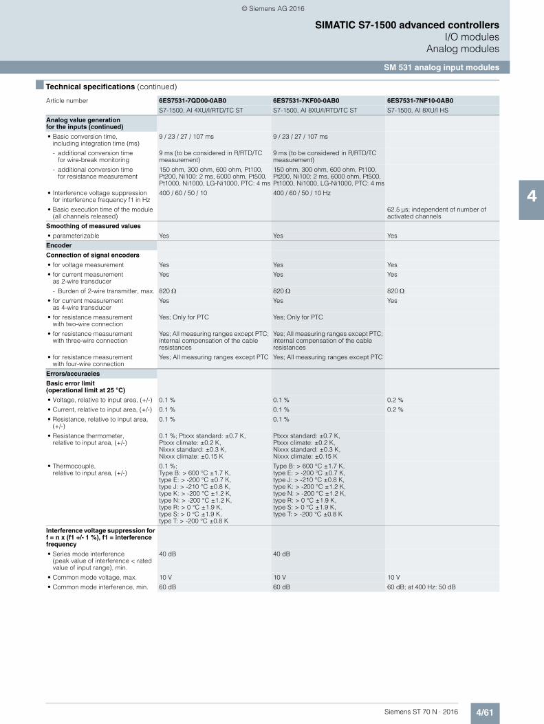
4/61Siemens ST 70 N · 2016
4
■ Technical specifications (continued)
SIMATIC S7-1500 advanced controllersI/O modules
Analog modules
SM 531 analog input modules
Analog value generation for the inputs (continued)
• Basic conversion time, including integration time (ms)
9 / 23 / 27 / 107 ms 9 / 23 / 27 / 107 ms
- additional conversion time for wire-break monitoring
9 ms (to be considered in R/RTD/TC measurement)
9 ms (to be considered in R/RTD/TC measurement)
- additional conversion timefor resistance measurement
150 ohm, 300 ohm, 600 ohm, Pt100, Pt200, Ni100: 2 ms, 6000 ohm, Pt500, Pt1000, Ni1000, LG-Ni1000, PTC: 4 ms
150 ohm, 300 ohm, 600 ohm, Pt100, Pt200, Ni100: 2 ms, 6000 ohm, Pt500, Pt1000, Ni1000, LG-Ni1000, PTC: 4 ms
• Interference voltage suppressionfor interference frequency f1 in Hz
400 / 60 / 50 / 10 400 / 60 / 50 / 10 Hz
• Basic execution time of the module (all channels released)
62.5 µs; independent of number of activated channels
Smoothing of measured values
• parameterizable Yes Yes Yes
Encoder
Connection of signal encoders
• for voltage measurement Yes Yes Yes
• for current measurement as 2-wire transducer
Yes Yes Yes
- Burden of 2-wire transmitter, max. 820 820 820 • for current measurement
as 4-wire transducerYes Yes Yes
• for resistance measurement with two-wire connection
Yes; Only for PTC Yes; Only for PTC
• for resistance measurement with three-wire connection
Yes; All measuring ranges except PTC; internal compensation of the cable resistances
Yes; All measuring ranges except PTC; internal compensation of the cable resistances
• for resistance measurement with four-wire connection
Yes; All measuring ranges except PTC Yes; All measuring ranges except PTC
Errors/accuracies
Basic error limit(operational limit at 25 °C)
• Voltage, relative to input area, (+/-) 0.1 % 0.1 % 0.2 %
• Current, relative to input area, (+/-) 0.1 % 0.1 % 0.2 %
• Resistance, relative to input area, (+/-)
0.1 % 0.1 %
• Resistance thermometer, relative to input area, (+/-)
0.1 %; Ptxxx standard: ±0.7 K, Ptxxx climate: ±0.2 K, Nixxx standard: ±0.3 K, Nixxx climate: ±0.15 K
Ptxxx standard: ±0.7 K, Ptxxx climate: ±0.2 K, Nixxx standard: ±0.3 K, Nixxx climate: ±0.15 K
• Thermocouple,relative to input area, (+/-)
0.1 %;Type B: > 600 °C ±1.7 K, type E: > -200 °C ±0.7 K, type J: > -210 °C ±0.8 K, type K: > -200 °C ±1.2 K,type N: > -200 °C ±1.2 K, type R: > 0 °C ±1.9 K,type S: > 0 °C ±1.9 K,type T: > -200 °C ±0.8 K
Type B: > 600 °C ±1.7 K, type E: > -200 °C ±0.7 K,type J: > -210 °C ±0.8 K, type K: > -200 °C ±1.2 K, type N: > -200 °C ±1.2 K,type R: > 0 °C ±1.9 K,type S: > 0 °C ±1.9 K, type T: > -200 °C ±0.8 K
Interference voltage suppression for f = n x (f1 +/- 1 %), f1 = interference frequency
• Series mode interference (peak value of interference < rated value of input range), min.
40 dB 40 dB
• Common mode voltage, max. 10 V 10 V 10 V
• Common mode interference, min. 60 dB 60 dB 60 dB; at 400 Hz: 50 dB
Article number 6ES7531-7QD00-0AB0 6ES7531-7KF00-0AB0 6ES7531-7NF10-0AB0
S7-1500, AI 4XU/I/RTD/TC ST S7-1500, AI 8XU/I/RTD/TC ST S7-1500, AI 8XU/I HS
© Siemens AG 2016
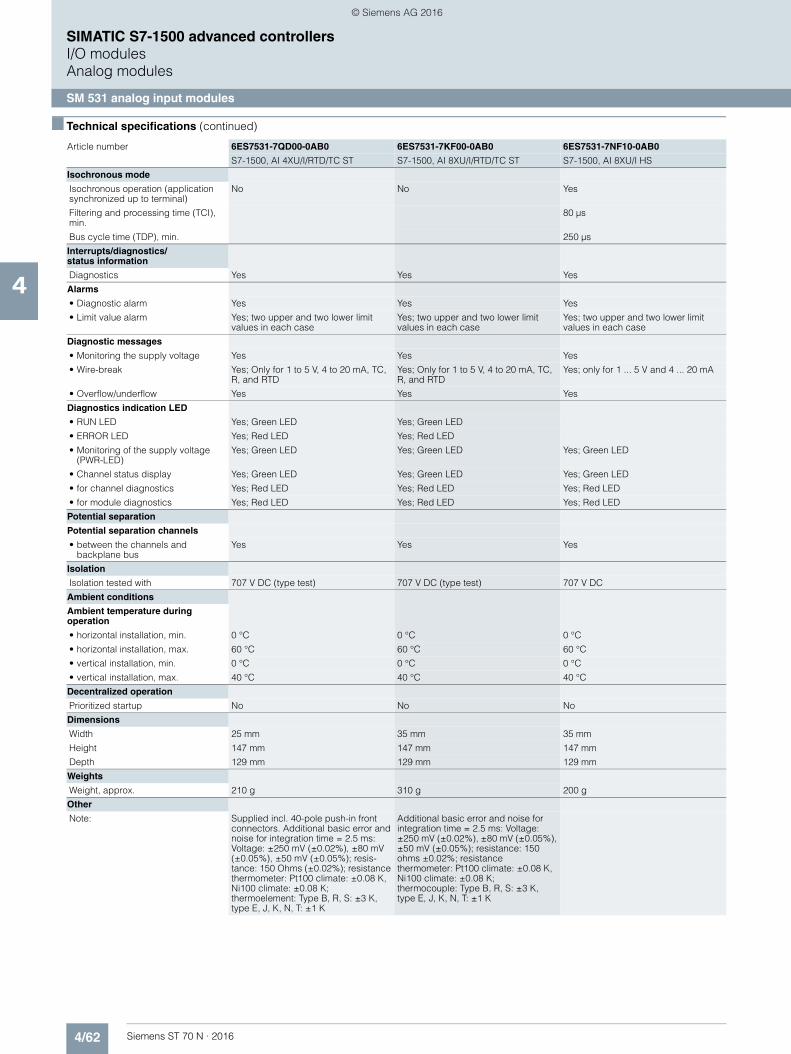
4/62 Siemens ST 70 N · 2016
4
■ Technical specifications (continued)
SIMATIC S7-1500 advanced controllersI/O modulesAnalog modules
SM 531 analog input modules
Isochronous mode
Isochronous operation (application synchronized up to terminal)
No No Yes
Filtering and processing time (TCI), min.
80 µs
Bus cycle time (TDP), min. 250 µs
Interrupts/diagnostics/status information
Diagnostics Yes Yes Yes
Alarms
• Diagnostic alarm Yes Yes Yes
• Limit value alarm Yes; two upper and two lower limit values in each case
Yes; two upper and two lower limit values in each case
Yes; two upper and two lower limit values in each case
Diagnostic messages
• Monitoring the supply voltage Yes Yes Yes
• Wire-break Yes; Only for 1 to 5 V, 4 to 20 mA, TC, R, and RTD
Yes; Only for 1 to 5 V, 4 to 20 mA, TC, R, and RTD
Yes; only for 1 ... 5 V and 4 ... 20 mA
• Overflow/underflow Yes Yes Yes
Diagnostics indication LED
• RUN LED Yes; Green LED Yes; Green LED
• ERROR LED Yes; Red LED Yes; Red LED
• Monitoring of the supply voltage (PWR-LED)
Yes; Green LED Yes; Green LED Yes; Green LED
• Channel status display Yes; Green LED Yes; Green LED Yes; Green LED
• for channel diagnostics Yes; Red LED Yes; Red LED Yes; Red LED
• for module diagnostics Yes; Red LED Yes; Red LED Yes; Red LED
Potential separation
Potential separation channels
• between the channels and backplane bus
Yes Yes Yes
Isolation
Isolation tested with 707 V DC (type test) 707 V DC (type test) 707 V DC
Ambient conditions
Ambient temperature during operation
• horizontal installation, min. 0 °C 0 °C 0 °C
• horizontal installation, max. 60 °C 60 °C 60 °C
• vertical installation, min. 0 °C 0 °C 0 °C
• vertical installation, max. 40 °C 40 °C 40 °C
Decentralized operation
Prioritized startup No No No
Dimensions
Width 25 mm 35 mm 35 mm
Height 147 mm 147 mm 147 mm
Depth 129 mm 129 mm 129 mm
Weights
Weight, approx. 210 g 310 g 200 g
Other
Note: Supplied incl. 40-pole push-in front connectors. Additional basic error and noise for integration time = 2.5 ms: Voltage: ±250 mV (±0.02%), ±80 mV (±0.05%), ±50 mV (±0.05%); resis-tance: 150 Ohms (±0.02%); resistance thermometer: Pt100 climate: ±0.08 K, Ni100 climate: ±0.08 K; thermoelement: Type B, R, S: ±3 K, type E, J, K, N, T: ±1 K
Additional basic error and noise for integration time = 2.5 ms: Voltage: ±250 mV (±0.02%), ±80 mV (±0.05%), ±50 mV (±0.05%); resistance: 150 ohms ±0.02%; resistance thermometer: Pt100 climate: ±0.08 K, Ni100 climate: ±0.08 K;thermocouple: Type B, R, S: ±3 K,type E, J, K, N, T: ±1 K
Article number 6ES7531-7QD00-0AB0 6ES7531-7KF00-0AB0 6ES7531-7NF10-0AB0
S7-1500, AI 4XU/I/RTD/TC ST S7-1500, AI 8XU/I/RTD/TC ST S7-1500, AI 8XU/I HS
© Siemens AG 2016

4/63Siemens ST 70 N · 2016
4
■ Technical specifications (continued)
SIMATIC S7-1500 advanced controllersI/O modules
Analog modules
SM 531 analog input modules
Article number 6ES7531-7NF00-0AB0
General information
Product type designation AI 8xU/I HF
Product function
• I&M data Yes; I&M0 to I&M3
• Scalable measuring range No
Engineering with
• STEP 7 TIA Portal configurable/integrated as of version
V13 SP1 / V14
• STEP 7 configurable/integrated as of version
V5.5 SP3 / V5.5 SP4
• PROFIBUS as of GSD version/GSD revision
V1.0 / V5.1
• PROFINET as of GSD version/GSD revision
V2.3 / -
Operating mode
• Oversampling No
• MSI Yes
CiR - Configuration in RUN
Reparameterization possible in RUN Yes
Calibration possible in RUN No
Supply voltage
Type of supply voltage DC
Rated value (DC) 24 V
Reverse polarity protection Yes
Analog inputs
Number of analog inputs 8
• For current measurement 8
• For voltage measurement 8
permissible input voltage for voltage input (destruction limit), max.
28.8 V
permissible input current for current input (destruction limit), max.
40 mA
Input ranges (rated values), voltages
• 1 V to 5 V Yes
• -10 V to +10 V Yes
• -2.5 V to +2.5 V Yes
• -5 V to +5 V Yes
Input ranges (rated values), currents
• 0 to 20 mA Yes
• -20 mA to +20 mA Yes
• 4 mA to 20 mA Yes
Cable length
• shielded, max. 800 m
Analog value generationfor the inputs
Integration and conversion time/resolution per channel
• Resolution with overrange (bit including sign), max.
16 bit
• Integration time, parameterizable Yes
• Integration time (ms) Fast mode: 2.5 / 16.67 / 20 / 100 ms, standard mode: 7.5 / 50 / 60 / 300 ms
• Basic conversion time,including integration time (ms)
Fast mode: 4 / 18 / 22 / 102 ms; Standard mode: 9 / 52 / 62 / 302 ms
• Interference voltage suppression for interference frequency f1 in Hz
400 / 60 / 50 / 10 Hz
• Basic execution time of the module (all channels released)
Corresponds to the channel with the highest basic conversion time
Smoothing of measured values
• parameterizable Yes
Encoder
Connection of signal encoders
• for voltage measurement Yes
• for current measurementas 2-wire transducer
Yes; with external transmitter supply
• for current measurement as 4-wire transducer
Yes
Errors/accuracies
Basic error limit(operational limit at 25 °C)
• Voltage, relative to input area, (+/-) 0.05 %
• Current, relative to input area, (+/-) 0.05 %
Interference voltage suppression for f = n x (f1 +/- 1 %), f1 = interference frequency
• Series mode interference (peak value of interference < rated value of input range), min.
80 dB; in the Standard operating mode, 40 dB in the Fast operating mode
• Common mode voltage, max. 60 V DC/30 V AC
• Common mode interference, min. 80 dB
Isochronous mode
Isochronous operation (application synchronized up to terminal)
No
Interrupts/diagnostics/status information
Diagnostics Yes
Alarms
• Diagnostic alarm Yes
• Limit value alarm Yes; two upper and two lower limit values in each case
Diagnostic messages
• Monitoring the supply voltage Yes
• Wire-break Yes; only for 1 ... 5 V and 4 ... 20 mA
• Overflow/underflow Yes
Diagnostics indication LED
• RUN LED Yes; Green LED
• ERROR LED Yes; Red LED
• Monitoring of the supply voltage (PWR-LED)
Yes; Green LED
• Channel status display Yes; Green LED
• for channel diagnostics Yes; Red LED
• for module diagnostics Yes; Red LED
Potential separation
Potential separation channels
• between the channels and backplane bus
Yes
Isolation
Isolation tested with 2 000 V DC between the channels and the supply voltage L+; 2 000 V DC between the channels and the backplane bus; 2 000 V DC between the channels; 707 V DC (type test) between the supply voltage L+ and the backplane bus
Article number 6ES7531-7NF00-0AB0
© Siemens AG 2016
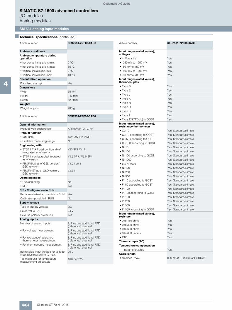
4/64 Siemens ST 70 N · 2016
4
■ Technical specifications (continued)
SIMATIC S7-1500 advanced controllersI/O modulesAnalog modules
SM 531 analog input modules
Ambient conditions
Ambient temperature during operation
• horizontal installation, min. 0 °C
• horizontal installation, max. 60 °C
• vertical installation, min. 0 °C
• vertical installation, max. 40 °C
Decentralized operation
Prioritized startup Yes
Dimensions
Width 35 mm
Height 147 mm
Depth 129 mm
Weights
Weight, approx. 280 g
Article number 6ES7531-7PF00-0AB0
General information
Product type designation AI 8xU/R/RTD/TC HF
Product function
• I&M data Yes; I&M0 to I&M3
• Scalable measuring range No
Engineering with
• STEP 7 TIA Portal configurable/integrated as of version
V13 SP1 / V14
• STEP 7 configurable/integrated as of version
V5.5 SP3 / V5.5 SP4
• PROFIBUS as of GSD version/GSD revision
V1.0 / V5.1
• PROFINET as of GSD version/GSD revision
V2.3 / -
Operating mode
• Oversampling No
• MSI Yes
CiR - Configuration in RUN
Reparameterization possible in RUN Yes
Calibration possible in RUN No
Supply voltage
Type of supply voltage DC
Rated value (DC) 24 V
Reverse polarity protection Yes
Analog inputs
Number of analog inputs 8; Plus one additional RTD (reference) channel
• For voltage measurement 8; Plus one additional RTD (reference) channel
• For resistance/resistance thermometer measurement
8; Plus one additional RTD (reference) channel
• For thermocouple measurement 8; Plus one additional RTD (reference) channel
permissible input voltage for voltage input (destruction limit), max.
20 V
Technical unit for temperature measurement adjustable
Yes; °C/°F/K
Article number 6ES7531-7NF00-0AB0
Input ranges (rated values), voltages
• -1 V to +1 V Yes
• -250 mV to +250 mV Yes
• -50 mV to +50 mV Yes
• -500 mV to +500 mV Yes
• -80 mV to +80 mV Yes
Input ranges (rated values), thermocouples
• Type B Yes
• Type E Yes
• Type J Yes
• Type K Yes
• Type N Yes
• Type R Yes
• Type S Yes
• Type T Yes
• Type TXK/TXK(L) to GOST Yes
Input ranges (rated values), resistance thermometer
• Cu 10 Yes; Standard/climate
• Cu 10 according to GOST Yes; Standard/climate
• Cu 50 according to GOST Yes; Standard/climate
• Cu 100 according to GOST Yes; Standard/climate
• Ni 10 Yes; Standard/climate
• Ni 100 Yes; Standard/climate
• Ni 100 according to GOST Yes; Standard/climate
• Ni 1000 Yes; Standard/climate
• LG-Ni 1000 Yes; Standard/climate
• Ni 120 Yes; Standard/climate
• Ni 200 Yes; Standard/climate
• Ni 500 Yes; Standard/climate
• Pt 10 according to GOST Yes; Standard/climate
• Pt 50 according to GOST Yes; Standard/climate
• Pt 100 Yes; Standard/climate
• Pt 100 according to GOST Yes; Standard/climate
• Pt 1000 Yes; Standard/climate
• Pt 200 Yes; Standard/climate
• Pt 500 Yes; Standard/climate
• Pt 500 according to GOST Yes; Standard/climate
Input ranges (rated values), resistors
• 0 to 150 ohms Yes
• 0 to 300 ohms Yes
• 0 to 600 ohms Yes
• 0 to 6000 ohms Yes
• PTC Yes
Thermocouple (TC)
Temperature compensation
- parameterizable Yes
Cable length
• shielded, max. 800 m; at U; 200 m at R/RTD/TC
Article number 6ES7531-7PF00-0AB0
© Siemens AG 2016

4/65Siemens ST 70 N · 2016
4
■ Technical specifications (continued)
SIMATIC S7-1500 advanced controllersI/O modules
Analog modules
SM 531 analog input modules
Analog value generationfor the inputs
Integration and conversion time/resolution per channel
• Resolution with overrange(bit including sign), max.
16 bit
• Integration time, parameterizable Yes
• Integration time (ms) Fast mode: 2.5 / 16.67 / 20 / 100 ms, standard mode: 7.5 / 50 / 60 / 300 ms
• Basic conversion time, including integration time (ms)
Fast mode: 4 / 18 / 22 / 102 ms; Standard mode: 9 / 52 / 62 / 302 ms
- additional conversion time forwire-break monitoring
Thermocouples, 150 Ohm, 300 Ohm, 600 Ohm, Cu10, Cu50, Cu100, Ni10, Ni50, Ni100, Ni120, Ni200, Pt10, Pt50, Pt100, Pt200: 4 ms; 6 kOhm, Ni500, Ni1000, LG-Ni1000, Pt500, Pt1000: 13 ms
- additional conversion time for resistance measurement
Only for three-wire: 150 Ohm, 300 Ohm, 600 Ohm, Cu10, Cu50, Cu100, Ni10, Ni50, Ni100, Ni120, Ni200, Pt10, Pt50, Pt100, Pt200: 2 ms; 6 kOhm, Ni500, Ni1000,LG-Ni1000, Pt500, Pt1000: 8 ms
• Interference voltage suppressionfor interference frequency f1 in Hz
400 / 60 / 50 / 10 Hz
• Basic execution time of the module (all channels released)
Corresponds to the channel with the highest basic conversion time
Smoothing of measured values
• parameterizable Yes
Encoder
Connection of signal encoders
• for voltage measurement Yes
• for resistance measurement with two-wire connection
Yes
• for resistance measurement with three-wire connection
Yes; All measuring ranges except PTC; internal compensation of the cable resistances
• for resistance measurement with four-wire connection
Yes; All measuring ranges except PTC
Errors/accuracies
Basic error limit(operational limit at 25 °C)
• Voltage, relative to input area, (+/-) 0.05 %
• Resistance, relative to input area,(+/-)
0.05 %
• Resistance thermometer,relative to input area, (+/-)
Cuxxx Standard: ±0.3 K,Cuxxx Klima: ±0.2 K, Ptxxx Standard: ±0.5 K, Ptxxx Klima: ±0.2 K, Nixxx Standard: ±0.3 K, Nixxx Klima: ±0.15 K
• Thermocouple, relative to input area, (+/-)
Type B: > 600 °C ±1 K, Type E: > -200 °C ±0.5 K,Type J: > -210 °C ±0.5 K, Type K: > -200 °C ±1 K,Type N: > -200 °C ±1 K, Type R: > 0 °C ±1 K,Type S: > 0 °C ±1 K,Type T: > -200 °C ±0.5 K, Type TXK/TXK(L): ±0.5 K
Interference voltage suppression for f = n x (f1 +/- 1 %), f1 = interference frequency
• Series mode interference(peak value of interference < rated value of input range), min.
80 dB; in the Standard operating mode, 40 dB in the Fast operating mode
• Common mode voltage, max. 60 V DC/30 V AC
• Common mode interference, min. 80 dB
Article number 6ES7531-7PF00-0AB0
Isochronous mode
Isochronous operation (application synchronized up to terminal)
No
Interrupts/diagnostics/status information
Diagnostics Yes
Alarms
• Diagnostic alarm Yes
• Limit value alarm Yes; two upper and two lower limit values in each case
Diagnostic messages
• Monitoring the supply voltage Yes
• Wire-break Yes; Only with TC, R, RTD
• Overflow/underflow Yes
Diagnostics indication LED
• RUN LED Yes; Green LED
• ERROR LED Yes; Red LED
• Monitoring of the supply voltage (PWR-LED)
Yes; Green LED
• Channel status display Yes; Green LED
• for channel diagnostics Yes; Red LED
• for module diagnostics Yes; Red LED
Potential separation
Potential separation analog inputs
• between the channels and backplane bus
Yes
Isolation
Isolation tested with 2 000 V DC between the channels and the supply voltage L+; 2 000 V DC between the channels and the backplane bus; 2 000 V DC between the channels; 707 V DC (type test) between the supply voltage L+ and the backplane bus
Ambient conditions
Ambient temperature during operation
• horizontal installation, min. 0 °C
• horizontal installation, max. 60 °C
• vertical installation, min. 0 °C
• vertical installation, max. 40 °C
Decentralized operation
Prioritized startup Yes
Dimensions
Width 35 mm
Height 147 mm
Depth 129 mm
Weights
Weight, approx. 290 g
Article number 6ES7531-7PF00-0AB0
© Siemens AG 2016
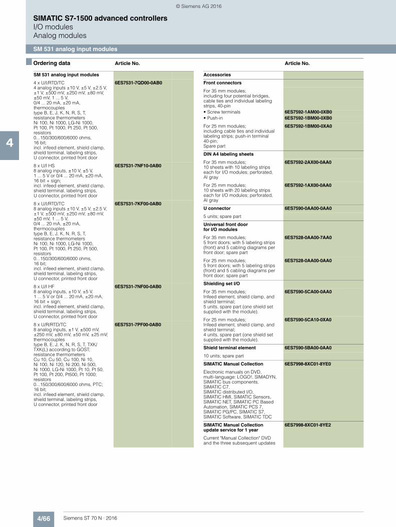
4/66 Siemens ST 70 N · 2016
4
SIMATIC S7-1500 advanced controllersI/O modulesAnalog modules
SM 531 analog input modules
■ Ordering data Article No. Article No.
SM 531 analog input modules
4 x U/I/RTD/TC4 analog inputs ±10 V, ±5 V, ±2.5 V, ±1 V, ±500 mV, ±250 mV, ±80 mV, ±50 mV, 1 ... 5 V, 0/4 ... 20 mA, ±20 mA, thermocouplestype B, E, J, K, N, R, S, T, resistance thermometers Ni 100, Ni 1000, LG-Ni 1000, Pt 100, Pt 1000, Pt 250, Pt 500, resistors 0...150/300/600/6000 ohms, 16 bit; incl. infeed element, shield clamp, shield terminal, labeling strips, U connector, printed front door
6ES7531-7QD00-0AB0
8 x U/I HS8 analog inputs, ±10 V, ±5 V, 1 ... 5 V or 0/4 ... 20 mA, ±20 mA, 16 bit + sign; incl. infeed element, shield clamp, shield terminal, labeling strips,U connector, printed front door
6ES7531-7NF10-0AB0
8 x U/I/RTD/TC8 analog inputs ±10 V, ±5 V, ±2.5 V, ±1 V, ±500 mV, ±250 mV, ±80 mV, ±50 mV, 1 ... 5 V, 0/4 ... 20 mA, ±20 mA, thermocouples type B, E, J, K, N, R, S, T, resistance thermometers Ni 100, Ni 1000, LG-Ni 1000, Pt 100, Pt 1000, Pt 250, Pt 500, resistors 0...150/300/600/6000 ohms, 16 bit; incl. infeed element, shield clamp, shield terminal, labeling strips, U connector, printed front door
6ES7531-7KF00-0AB0
8 x U/I HF8 analog inputs, ±10 V, ±5 V,1 ... 5 V or 0/4 ... 20 mA, ±20 mA, 16 bit + sign; incl. infeed element, shield clamp, shield terminal, labeling strips,U connector, printed front door
6ES7531-7NF00-0AB0
8 x U/R/RTD/TC8 analog inputs, ±1 V, ±500 mV, ±250 mV, ±80 mV, ±50 mV, ±25 mV;thermocouplestype B, E, J, K, N, R, S, T, TXK/TXK(L) according to GOST; resistance thermometersCu 10, Cu 50, Cu 100, Ni 10, Ni 100, Ni 120, Ni 200, Ni 500, Ni 1000, LG-Ni 1000, Pt 10, Pt 50, Pt 100, Pt 200, Pt500, Pt 1000; resistors 0...150/300/600/6000 ohms, PTC;16 bit; incl. infeed element, shield clamp, shield terminal, labeling strips, U connector, printed front door
6ES7531-7PF00-0AB0
Accessories
Front connectors
For 35 mm modules; including four potential bridges, cable ties and individual labeling strips, 40-pin• Screw terminals 6ES7592-1AM00-0XB0• Push-in 6ES7592-1BM00-0XB0
For 25 mm modules; including cable ties and individual labeling strips; push-in terminal 40-pin; Spare part
6ES7592-1BM00-0XA0
DIN A4 labeling sheets
For 35 mm modules; 10 sheets with 10 labeling strips each for I/O modules; perforated, Al gray
6ES7592-2AX00-0AA0
For 25 mm modules; 10 sheets with 20 labeling strips each for I/O modules; perforated,Al gray
6ES7592-1AX00-0AA0
U connector 6ES7590-0AA00-0AA0
5 units; spare part
Universal front doorfor I/O modules
For 35 mm modules; 5 front doors; with 5 labeling strips (front) and 5 cabling diagrams per front door; spare part
6ES7528-0AA00-7AA0
For 25 mm modules; 5 front doors; with 5 labeling strips (front) and 5 cabling diagrams per front door; spare part
6ES7528-0AA00-0AA0
Shielding set I/O
For 35 mm modules; Infeed element, shield clamp, and shield terminal; 5 units, spare part (one shield set supplied with the module).
6ES7590-5CA00-0AA0
For 25 mm modules; Infeed element, shield clamp, and shield terminal; 4 units, spare part (one shield set supplied with the module).
6ES7590-5CA10-0XA0
Shield terminal element 6ES7590-5BA00-0AA0
10 units; spare part
SIMATIC Manual Collection 6ES7998-8XC01-8YE0
Electronic manuals on DVD, multi-language: LOGO!, SIMADYN, SIMATIC bus components, SIMATIC C7, SIMATIC distributed I/O, SIMATIC HMI, SIMATIC Sensors, SIMATIC NET, SIMATIC PC Based Automation, SIMATIC PCS 7, SIMATIC PG/PC, SIMATIC S7, SIMATIC Software, SIMATIC TDC
SIMATIC Manual Collection update service for 1 year
6ES7998-8XC01-8YE2
Current "Manual Collection" DVD and the three subsequent updates
© Siemens AG 2016

4/67Siemens ST 70 N · 2016
4
SIMATIC S7-1500 advanced controllersI/O modules
Analog modules
SM 532 analog output modules
■ Overview
• 2, 4 and 8-channel analog output modules• Optionally with extremely short conversion times• For connecting analog actuators without additional amplifiers• Even solves more complex automation tasks
■ Technical specifications
Article number 6ES7532-5NB00-0AB0 6ES7532-5HD00-0AB0 6ES7532-5HF00-0AB0
S7-1500, AQ 2XU/I ST S7-1500, AQ 4XU/I ST S7-1500, AQ 8XU/I HS
General information
Product type designation AQ 2xU/I ST AQ 4xU/I ST AQ 8xU/I HS
Product function
• I&M data Yes; I&M0 to I&M3 Yes; I&M0 to I&M3 Yes; I&M0 to I&M3
• Scalable output range No No No
Engineering with
• STEP 7 TIA Portal configurable/integrated as of version
V13 / V13.0.2 V12 / V12 V12 / V12
• STEP 7 configurable/integrated as of version
V5.5 SP3 / - V5.5 SP3 / - V5.5 SP3 / -
• PROFIBUS as of GSD version/GSD revision
V1.0 / V5.1 V1.0 / V5.1 V1.0 / V5.1
• PROFINET as of GSD version/GSD revision
V2.3 / - V2.3 / - V2.3 / -
Operating mode
• Oversampling No No No
• MSO Yes Yes Yes
CiR - Configuration in RUN
Reparameterization possible in RUN Yes Yes Yes
Calibration possible in RUN Yes Yes Yes
Supply voltage
Type of supply voltage DC DC DC
Rated value (DC) 24 V 24 V 24 V
Reverse polarity protection Yes Yes Yes
Analog outputs
Number of analog outputs 2 4 8
Cycle time (all channels), min. 3.2 ms; independent of number of activated channels
3.2 ms; independent of number of activated channels
125 µs; independent of number of activated channels
Output ranges, voltage
• 0 to 10 V Yes Yes Yes
• 1 V to 5 V Yes Yes Yes
• -10 V to +10 V Yes Yes Yes
Output ranges, current
• 0 to 20 mA Yes Yes Yes
• -20 mA to +20 mA Yes Yes Yes
• 4 mA to 20 mA Yes Yes Yes
© Siemens AG 2016
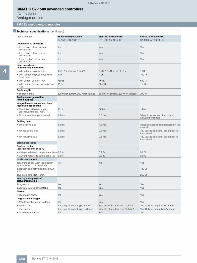
4/68 Siemens ST 70 N · 2016
4
■ Technical specifications (continued)
SIMATIC S7-1500 advanced controllersI/O modulesAnalog modules
SM 532 analog output modules
Connection of actuators
• for voltage output two-wire connection
Yes Yes Yes
• for voltage output four-wire connection
Yes Yes Yes
• for current output two-wire connection
Yes Yes Yes
Load impedance(in rated range of output)
• with voltage outputs, min. 1 k; 0.5 kOhm at 1 to 5 V 1 k; 0.5 kOhm at 1 to 5 V 1 k• with voltage outputs, capacitive
load, max.1 µF 1 µF 100 nF
• with current outputs, max. 750 750 500 • with current outputs, inductive load,
max.10 mH 10 mH 1 mH
Cable length
• shielded, max. 800 m; for current, 200 m for voltage 800 m; for current, 200 m for voltage 200 m
Analog value generationfor the outputs
Integration and conversion time/resolution per channel
• Resolution with overrange(bit including sign), max.
16 bit 16 bit 16 bit
• Conversion time (per channel) 0.5 ms 0.5 ms 50 µs; independent of number of activated channels
Settling time
• for resistive load 1.5 ms 1.5 ms 30 µs; see additional description in the manual
• for capacitive load 2.5 ms 2.5 ms 100 µs; see additional description in the manual
• for inductive load 2.5 ms 2.5 ms 100 µs; see additional description in the manual
Errors/accuracies
Basic error limit(operational limit at 25 °C)
• Voltage, relative to output area, (+/-) 0.2 % 0.2 % 0.2 %
• Current, relative to output area, (+/-) 0.2 % 0.2 % 0.2 %
Isochronous mode
Isochronous operation (application synchronized up to terminal)
No No Yes
Execution and activation time (TCO), min.
100 µs
Bus cycle time (TDP), min. 250 µs
Interrupts/diagnostics/status information
Diagnostics Yes Yes Yes
Substitute values connectable Yes Yes Yes
Alarms
• Diagnostic alarm Yes Yes Yes
Diagnostic messages
• Monitoring the supply voltage Yes Yes Yes
• Wire-break Yes; Only for output type "current" Yes; Only for output type "current" Yes; Only for output type "current"
• Short-circuit Yes; Only for output type "voltage" Yes; Only for output type "voltage" Yes; Only for output type "voltage"
• Overflow/underflow Yes Yes Yes
Article number 6ES7532-5NB00-0AB0 6ES7532-5HD00-0AB0 6ES7532-5HF00-0AB0
S7-1500, AQ 2XU/I ST S7-1500, AQ 4XU/I ST S7-1500, AQ 8XU/I HS
© Siemens AG 2016
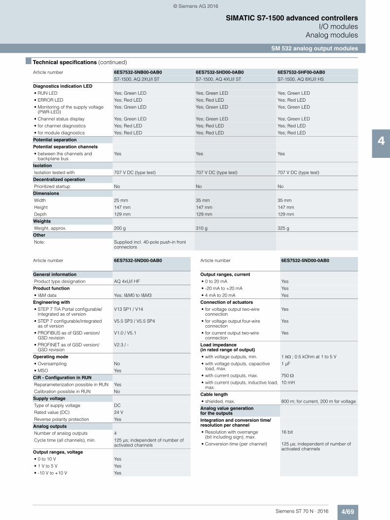
4/69Siemens ST 70 N · 2016
4
■ Technical specifications (continued)
SIMATIC S7-1500 advanced controllersI/O modules
Analog modules
SM 532 analog output modules
Diagnostics indication LED
• RUN LED Yes; Green LED Yes; Green LED Yes; Green LED
• ERROR LED Yes; Red LED Yes; Red LED Yes; Red LED
• Monitoring of the supply voltage (PWR-LED)
Yes; Green LED Yes; Green LED Yes; Green LED
• Channel status display Yes; Green LED Yes; Green LED Yes; Green LED
• for channel diagnostics Yes; Red LED Yes; Red LED Yes; Red LED
• for module diagnostics Yes; Red LED Yes; Red LED Yes; Red LED
Potential separation
Potential separation channels
• between the channels and backplane bus
Yes Yes Yes
Isolation
Isolation tested with 707 V DC (type test) 707 V DC (type test) 707 V DC (type test)
Decentralized operation
Prioritized startup No No No
Dimensions
Width 25 mm 35 mm 35 mm
Height 147 mm 147 mm 147 mm
Depth 129 mm 129 mm 129 mm
Weights
Weight, approx. 200 g 310 g 325 g
Other
Note: Supplied incl. 40-pole push-in front connectors
Article number 6ES7532-5NB00-0AB0 6ES7532-5HD00-0AB0 6ES7532-5HF00-0AB0
S7-1500, AQ 2XU/I ST S7-1500, AQ 4XU/I ST S7-1500, AQ 8XU/I HS
Article number 6ES7532-5ND00-0AB0
General information
Product type designation AQ 4xU/I HF
Product function
• I&M data Yes; I&M0 to I&M3
Engineering with
• STEP 7 TIA Portal configurable/integrated as of version
V13 SP1 / V14
• STEP 7 configurable/integrated as of version
V5.5 SP3 / V5.5 SP4
• PROFIBUS as of GSD version/GSD revision
V1.0 / V5.1
• PROFINET as of GSD version/GSD revision
V2.3 / -
Operating mode
• Oversampling No
• MSO Yes
CiR - Configuration in RUN
Reparameterization possible in RUN Yes
Calibration possible in RUN No
Supply voltage
Type of supply voltage DC
Rated value (DC) 24 V
Reverse polarity protection Yes
Analog outputs
Number of analog outputs 4
Cycle time (all channels), min. 125 µs; independent of number of activated channels
Output ranges, voltage
• 0 to 10 V Yes
• 1 V to 5 V Yes
• -10 V to +10 V Yes
Output ranges, current
• 0 to 20 mA Yes
• -20 mA to +20 mA Yes
• 4 mA to 20 mA Yes
Connection of actuators
• for voltage output two-wire connection
Yes
• for voltage output four-wire connection
Yes
• for current output two-wire connection
Yes
Load impedance(in rated range of output)
• with voltage outputs, min. 1 k; 0.5 kOhm at 1 to 5 V
• with voltage outputs, capacitive load, max.
1 µF
• with current outputs, max. 750 • with current outputs, inductive load,
max.10 mH
Cable length
• shielded, max. 800 m; for current, 200 m for voltage
Analog value generationfor the outputs
Integration and conversion time/resolution per channel
• Resolution with overrange (bit including sign), max.
16 bit
• Conversion time (per channel) 125 µs; independent of number of activated channels
Article number 6ES7532-5ND00-0AB0
© Siemens AG 2016
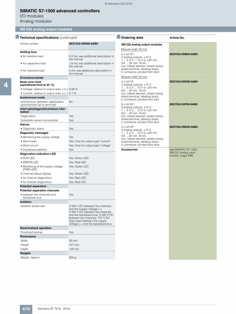
4/70 Siemens ST 70 N · 2016
4
■ Technical specifications (continued)
SIMATIC S7-1500 advanced controllersI/O modulesAnalog modules
SM 532 analog output modules
Settling time
• for resistive load 0.2 ms; see additional description in the manual
• for capacitive load 1.8 ms; see additional description in the manual
• for inductive load 2 ms; see additional description in the manual
Errors/accuracies
Basic error limit(operational limit at 25 °C)
• Voltage, relative to output area, (+/-) 0.06 %
• Current, relative to output area, (+/-) 0.1 %
Isochronous mode
Isochronous operation (application synchronized up to terminal)
No
Interrupts/diagnostics/status infor-mation
Diagnostics Yes
Substitute values connectable Yes
Alarms
• Diagnostic alarm Yes
Diagnostic messages
• Monitoring the supply voltage Yes
• Wire-break Yes; Only for output type "current"
• Short-circuit Yes; Only for output type "voltage"
• Overflow/underflow Yes
Diagnostics indication LED
• RUN LED Yes; Green LED
• ERROR LED Yes; Red LED
• Monitoring of the supply voltage (PWR-LED)
Yes; Green LED
• Channel status display Yes; Green LED
• for channel diagnostics Yes; Red LED
• for module diagnostics Yes; Red LED
Potential separation
Potential separation channels
• between the channels and backplane bus
Yes
Isolation
Isolation tested with 2 000 V DC between the channels and the supply voltage L+; 2 000 V DC between the channels and the backplane bus; 2 000 V DC between the channels; 707 V DC (type test) between the supply voltage L+ and the backplane bus
Decentralized operation
Prioritized startup Yes
Dimensions
Width 35 mm
Height 147 mm
Depth 129 mm
Weights
Weight, approx. 300 g
Article number 6ES7532-5ND00-0AB0
■ Ordering data Article No.
SM 532 analog output modules
Module width 25 mm
2 x U/I ST; 2 analog outputs, ±10 V,1 ... 5 V, 0 ... 10 V or ±20 mA,0/4 ... 20 mA, 16 bit; incl. infeed element, shield clamp, shield terminal, labeling strips, U connector, printed front door
6ES7532-5NB00-0AB0
Module width 35 mm
4 x U/I ST; 4 analog outputs, ±10 V,1 ... 5 V, 0 ... 10 V or ±20 mA, 0/4 ... 20 mA, 16 bit; incl. infeed element, shield clamp, shield terminal, labeling strips, U connector, printed front door
6ES7532-5HD00-0AB0
8 x U/I HF;8 analog outputs, ±10 V, 1 ... 5 V, 0 ... 10 V or ±20 mA, 0/4 ... 20 mA, 16 bit; incl. infeed element, shield clamp, shield terminal, labeling strips, U connector, printed front door
6ES7532-5HF00-0AB0
4 x U/I HF; 4 analog outputs, ±10 V,1 ... 5 V, 0 ... 10 V or ±20 mA, 0/4 ... 20 mA, 16 bit; incl. infeed element, shield clamp, shield terminal, labeling strips, U connector, printed front door
6ES7532-5ND00-0AB0
Accessories see SIMATIC S7-1500,SM 531 analog input module, page 4/66
© Siemens AG 2016

4/71Siemens ST 70 N · 2016
4
SIMATIC S7-1500 advanced controllersI/O modules
SIPLUS communication
SIPLUS NET CP 1543-1
■ Overview
The SIMATIC CP 1543-1 communications processor securely connects the new SIMATIC S7-1500 controller to Industrial Ethernet networks. By combining a variety of security features such as an SPI (Stateful Packet Inspection) firewall, VPN and data encryption protocols such as FTPS and SNMPv3, the communications processor protects individual S7-1500 stations or even entire automation cells against unauthorized access.
The CP can also be used for linking the S7-1500 station into an IPv6-based network. All functions are configured by means of STEP 7 Professional V12 (TIA Portal) or higher.
The CP 1543-1 supports the following communications services:• PG/OP communication• S7 communication• Open communication (SEND/RECEIVE, FETCH/WRITE)• IT communication
- FTP functions (File Transfer Protocol FTP/FTPS) for file management and access to data blocks in the CPU(client and server function)
- Sending e-mails via SMTP or ESMTP with "SMTP-Auth"for authentication on an e-mail server (also with IPv6)
• Security functions- Stateful Packet Inspection (layers 3 and 4) firewall- Secure communication via VPN (IPsec)- Secure access to the Web server of the CPU via the
HTTPS protocol- Secure file transfer using FTPS- Secure transfer of the time of day (NTP)- SNMPv3 for tap-proof transfer of network analysis infor-
mation• Integration of the S7-1500 into IPv6-based networks;
An IPv6-compliant IP address can be used for the following communication services:- FETCH/WRITE access (CP as server)- FTP server mode- FTP client mode with addressing by program block- E-mail transfer with addressing by program block
Note
SIPLUS extreme products are based on SIMATIC standard pro-ducts. The contents listed here were taken from the respective standard products. SIPLUS extreme specific information was added.
■ Ordering data Article No.
G_I
K10
_XX
_103
53S7/S5PG/OPIP-RITMRPPNTCP/
UDPISO
SIPLUS CP 1543-1 Communications processor
6AG1543-1AX00-2XE0
(Extended temperature range and medial exposure)
for connection of SIMATIC S7-1500 to Industrial Ethernet via TCP/IP, ISO and UDP and Security functions; 1 x RJ45 interface with 10/100/1000 Mbit/s;electronic manual on DVD
Accessories see Catalog ST 70,SIMATIC S7-1500, CP 1543-1communications processor
© Siemens AG 2016

4/72 Siemens ST 70 N · 2016
4
SIMATIC S7-1500 advanced controllersI/O modulesFail-safe digital/analog I/O modules
F digital input module
■ Overview
Failsafe digital input module:F-DI 16x24VDC PROFISAFE
Important properties:• 16-channel failsafe digital input module for
ET 200MP/S7-1500• For failsafe reading of sensor information (1 or 2 channels) • Provides integral discrepancy evaluation for 2-out-of-2 signals • 4 internal sensor supplies (incl. test function) onboard • Certified up to SIL 3 (IEC 61508), PL e (ISO 13849) • LED display for error, operation, supply voltage and status• Clear module labeling
- Plain text identification of the module type - Complete Article No. - 2D matrix code (article and serial number) - Connection diagram - Hardware and firmware version
• Optional labeling accessories- Labeling sheets, yellow
• The modules support PROFIsafe in both PROFIBUS and PROFINET configurations. Can be used with all failsafe SIMATIC S7-1500 F-CPUs in the central configuration, as well as ET 200MP distributed I/O with all other SIMATIC S7 F-CPUs.
■ Technical specifications
Article number 6ES7526-1BH00-0AB0
ET 200MP, F-DI 16X24VDC
General information
Product type designation F-DI 16x24VDC
Product function
• I&M data Yes; I&M0 to I&M3
Engineering with
• STEP 7 TIA Portal configurable/integrated as of version
V13 SP1 with HSP0086
Operating mode
• DI Yes
Supply voltage
Type of supply voltage 24 V DC
Rated value (DC) 24 V
Reverse polarity protection Yes
Encoder supply
Number of outputs 4
Short-circuit protection Yes; Electronic (response threshold 0.7 A to 1.8 A)
24 V encoder supply
• 24 V Yes; min. L+ (-1.5 V)
• Short-circuit protection Yes
• Output current, max. 300 mA; Max. 100 mA when mounted vertically
Digital inputs
Number of digital inputs 16
m/p-reading Yes; p-reading
Input characteristic curve in accordance with IEC 61131, type 1
Yes
Input voltage
• Rated value (DC) 24 V
• for signal "0" -30 to +5V
• for signal "1" +15 to +30V
Input current
• for signal "1", typ. 3.7 mA
Input delay (for rated value of input voltage)
for standard inputs
- parameterizable Yes
Cable length
• shielded, max. 1 000 m
• unshielded, max. 500 m
Interrupts/diagnostics/status information
Diagnostics Yes
Alarms
• Diagnostic alarm Yes
• Hardware interrupt No
Diagnostic messages
• Monitoring the supply voltage Yes
• Wire-break No
• Short-circuit Yes
• Group error Yes
Diagnostics indication LED
• RUN LED Yes; Green LED
• ERROR LED Yes; Red LED
• Channel status display Yes; Green LED
• for channel diagnostics Yes; Red LED
• for module diagnostics Yes; Red LED
© Siemens AG 2016
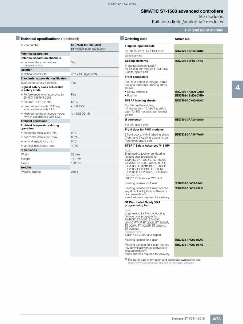
4/73Siemens ST 70 N · 2016
4
■ Technical specifications (continued)
SIMATIC S7-1500 advanced controllersI/O modules
Fail-safe digital/analog I/O modules
F digital input module
Potential separation
Potential separation channels
• between the channels and backplane bus
Yes
Isolation
Isolation tested with 707 V DC (type test)
Standards, approvals, certificates
Suitable for safety functions Yes
Highest safety class achievable in safety mode
• Performance level according to EN ISO 13849-1:2008
PLe
• SIL acc. to IEC 61508 SIL 3
• Low demand mode: PFDavg in accordance with SIL3
< 5.00E-05
• High demand/continuous mode: PFH in accordance with SIL3
< 1.00E-09 1/h
Ambient conditions
Ambient temperature during operation
• horizontal installation, min. 0 °C
• horizontal installation, max. 60 °C
• vertical installation, min. 0 °C
• vertical installation, max. 40 °C
Dimensions
Width 35 mm
Height 147 mm
Depth 129 mm
Weights
Weight, approx. 280 g
Article number 6ES7526-1BH00-0AB0
ET 200MP, F-DI 16X24VDC
■ Ordering data Article No.
1) For up-to-date information and download availability, see:http://www.siemens.com/tia-online-software-delivery
F digital input module
16 inputs, 24 V DC, PROFISAFE 6ES7526-1BH00-0AB0
Accessories
Coding elements 6ES7592-6EF00-1AA0
E-coding element type Ffor ET 200 MP-module F-DI/F-DQ;5 units, spare part
Front connectors
Incl. four potential bridges, cable ties and individual labeling strips, 40-pin• Screw terminals 6ES7592-1AM00-0XB0• Push-in 6ES7592-1BM00-0XB0
DIN A4 labeling sheets 6ES7592-2CX00-0AA0
For 35-mm F-modules; 10 sheets with 10 labeling strips each for I/O modules; perforated, yellow
U connector 6ES7590-0AA00-0AA0
5 units; spare part
Front door for F-I/O modules
5 front doors; with 5 labeling strips (front) and 5 cabling diagrams per front door; spare part
6ES7528-0AA10-7AA0
STEP 7 Safety Advanced V13 SP1
Task:Engineering tool for configuringfailsafe user programs for SIMATIC S7-1200 FC, S7-1500F, S7-300F, S7-400F, WinAC RTX F, ET 200SP F controller, ET 200SP, ET 200S, ET 200MP, ET 200M, ET 200iSP, ET 200pro, ET 200ecoRequirement:STEP 7 Professional V13 SP1
Floating license for 1 user 6ES7833-1FA13-0YA5
Floating license for 1 user, license key download without software or documentation1); email address required for delivery
6ES7833-1FA13-0YH5
S7 Distributed Safety V5.4 programming tool
Task:Engineering tool for configuringfailsafe user programs for SIMATIC S7-300F, S7-400F, WinAC RTX F, ET 200S, ET 200MP, ET 200M, ET 200iSP, ET 200pro, ET 200ecoRequirement: STEP 7 V5.3 SP3 and higher
Floating license for 1 user 6ES7833-1FC02-0YA5
Floating License for 1 user, license key download without software or documentation2); email address required for delivery
6ES7833-1FC02-0YH5
© Siemens AG 2016
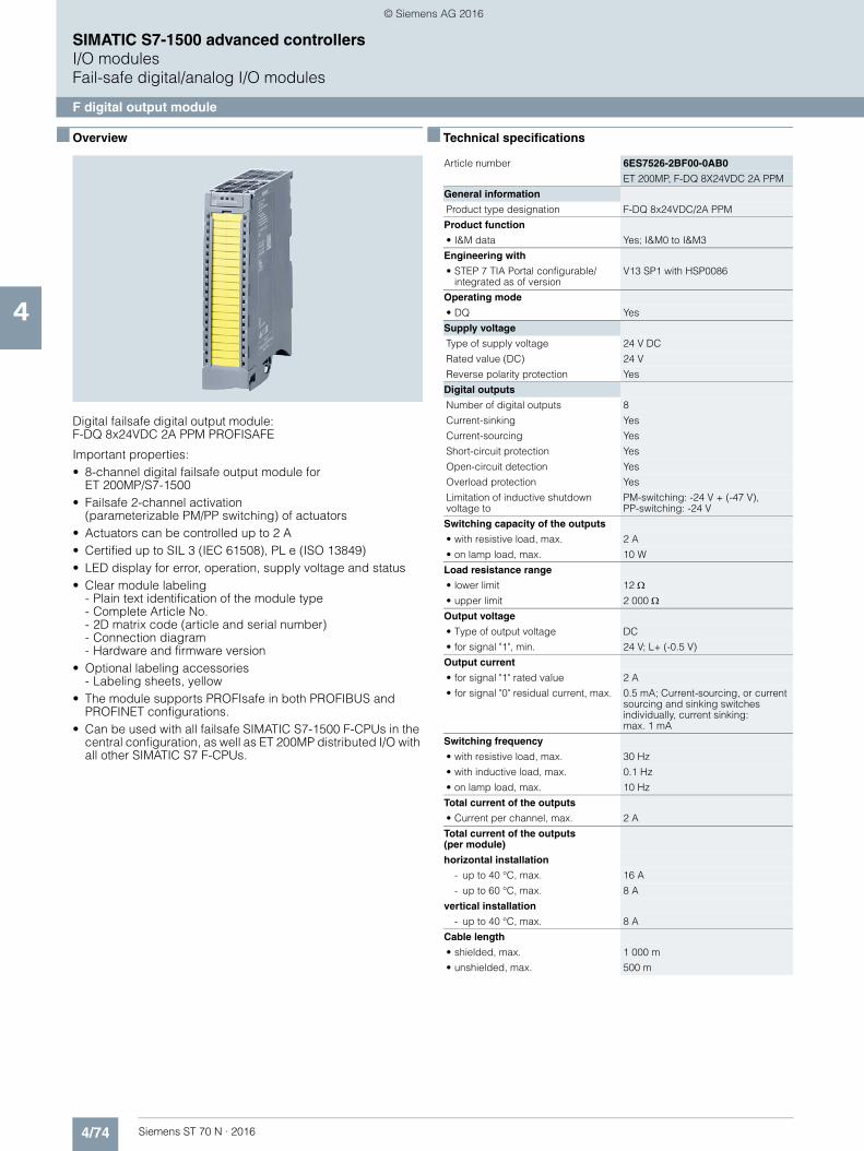
4/74 Siemens ST 70 N · 2016
4
SIMATIC S7-1500 advanced controllersI/O modulesFail-safe digital/analog I/O modules
F digital output module
■ Overview
Digital failsafe digital output module: F-DQ 8x24VDC 2A PPM PROFISAFE
Important properties:• 8-channel digital failsafe output module for
ET 200MP/S7-1500 • Failsafe 2-channel activation
(parameterizable PM/PP switching) of actuators• Actuators can be controlled up to 2 A • Certified up to SIL 3 (IEC 61508), PL e (ISO 13849)• LED display for error, operation, supply voltage and status• Clear module labeling
- Plain text identification of the module type - Complete Article No. - 2D matrix code (article and serial number) - Connection diagram - Hardware and firmware version
• Optional labeling accessories- Labeling sheets, yellow
• The module supports PROFIsafe in both PROFIBUS and PROFINET configurations.
• Can be used with all failsafe SIMATIC S7-1500 F-CPUs in the central configuration, as well as ET 200MP distributed I/O with all other SIMATIC S7 F-CPUs.
■ Technical specifications
Article number 6ES7526-2BF00-0AB0
ET 200MP, F-DQ 8X24VDC 2A PPM
General information
Product type designation F-DQ 8x24VDC/2A PPM
Product function
• I&M data Yes; I&M0 to I&M3
Engineering with
• STEP 7 TIA Portal configurable/integrated as of version
V13 SP1 with HSP0086
Operating mode
• DQ Yes
Supply voltage
Type of supply voltage 24 V DC
Rated value (DC) 24 V
Reverse polarity protection Yes
Digital outputs
Number of digital outputs 8
Current-sinking Yes
Current-sourcing Yes
Short-circuit protection Yes
Open-circuit detection Yes
Overload protection Yes
Limitation of inductive shutdown voltage to
PM-switching: -24 V + (-47 V),PP-switching: -24 V
Switching capacity of the outputs
• with resistive load, max. 2 A
• on lamp load, max. 10 W
Load resistance range
• lower limit 12 • upper limit 2 000 Output voltage
• Type of output voltage DC
• for signal "1", min. 24 V; L+ (-0.5 V)
Output current
• for signal "1" rated value 2 A
• for signal "0" residual current, max. 0.5 mA; Current-sourcing, or current sourcing and sinking switches individually, current sinking: max. 1 mA
Switching frequency
• with resistive load, max. 30 Hz
• with inductive load, max. 0.1 Hz
• on lamp load, max. 10 Hz
Total current of the outputs
• Current per channel, max. 2 A
Total current of the outputs(per module)
horizontal installation
- up to 40 °C, max. 16 A
- up to 60 °C, max. 8 A
vertical installation
- up to 40 °C, max. 8 A
Cable length
• shielded, max. 1 000 m
• unshielded, max. 500 m
© Siemens AG 2016
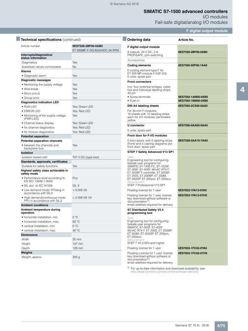
4/75Siemens ST 70 N · 2016
4
■ Technical specifications (continued)
SIMATIC S7-1500 advanced controllersI/O modules
Fail-safe digital/analog I/O modules
F digital output module
Interrupts/diagnostics/status information
Diagnostics Yes
Substitute values connectable No
Alarms
• Diagnostic alarm Yes
Diagnostic messages
• Monitoring the supply voltage Yes
• Wire-break Yes
• Short-circuit Yes
• Group error Yes
Diagnostics indication LED
• RUN LED Yes; Green LED
• ERROR LED Yes; Red LED
• Monitoring of the supply voltage (PWR-LED)
Yes
• Channel status display Yes; Green LED
• for channel diagnostics Yes; Red LED
• for module diagnostics Yes; Red LED
Potential separation
Potential separation channels
• between the channels and backplane bus
Yes
Isolation
Isolation tested with 707 V DC (type test)
Standards, approvals, certificates
Suitable for safety functions Yes
Highest safety class achievable in safety mode
• Performance level according to EN ISO 13849-1:2008
PLe
• SIL acc. to IEC 61508 SIL 3
• Low demand mode: PFDavg in accordance with SIL3
< 6.00E-05
• High demand/continuous mode: PFH in accordance with SIL3
< 2.00E-09 1/h
Ambient conditions
Ambient temperature during operation
• horizontal installation, min. 0 °C
• horizontal installation, max. 60 °C
• vertical installation, min. 0 °C
• vertical installation, max. 40 °C
Dimensions
Width 35 mm
Height 147 mm
Depth 129 mm
Weights
Weight, approx. 300 g
Article number 6ES7526-2BF00-0AB0
ET 200MP, F-DQ 8X24VDC 2A PPM
■ Ordering data Article No.
1) For up-to-date information and download availability, see:http://www.siemens.com/tia-online-software-delivery
F digital output module
8 outputs, 24 V DC, 2 A, PROFISAFE, p/m-switching
6ES7526-2BF00-0AB0
Accessories
Coding elements 6ES7592-6EF00-1AA0
E-coding element type F forET 200 MP-module F-DI/F-DQ; 5 units, spare part
Front connectors
Incl. four potential bridges, cable ties and individual labeling strips, 40-pin• Screw terminals 6ES7592-1AM00-0XB0• Push-in 6ES7592-1BM00-0XB0
DIN A4 labeling sheets 6ES7592-2CX00-0AA0
For 35-mm F-modules; 10 sheets with 10 labeling strips each for I/O modules; perforated, yellow
U connector 6ES7590-0AA00-0AA0
5 units; spare part
Front door for F-I/O modules
5 front doors; with 5 labeling strips (front) and 5 cabling diagrams per front door; spare part
6ES7528-0AA10-7AA0
STEP 7 Safety Advanced V13 SP1
Task:Engineering tool for configuring failsafe user programs for SIMATIC S7-1200 FC, S7-1500F, S7-300F, S7-400F, WinAC RTX F, ET 200SP F controller, ET 200SP, ET 200S, ET 200MP, ET 200M, ET 200iSP, ET 200pro, ET 200ecoRequirement:STEP 7 Professional V13 SP1
Floating license for 1 user 6ES7833-1FA13-0YA5
Floating license for 1 user, license key download without software or documentation1); email address required for delivery
6ES7833-1FA13-0YH5
S7 Distributed Safety V5.4 programming tool
Task:Engineering tool for configuringfailsafe user programs for SIMATIC S7-300F, S7-400F, WinAC RTX F, ET 200S, ET 200MP, ET 200M, ET 200iSP, ET 200pro, ET 200ecoRequirement: STEP 7 V5.3 SP3 and higher
Floating license for 1 user 6ES7833-1FC02-0YA5
Floating License for 1 user, license key download without software or documentation2); email address required for delivery
6ES7833-1FC02-0YH5
© Siemens AG 2016
4/76 Siemens ST 70 N · 2016
4
SIMATIC S7-1500 advanced controllers
Notes
© Siemens AG 2016
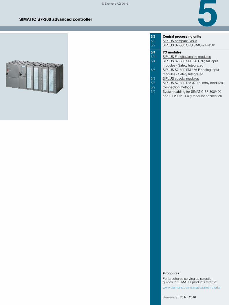
Siemens ST 70 N · 2016
5
Brochures
For brochures serving as selection guides for SIMATIC products refer to:
www.siemens.com/simatic/printmaterial
5/2 Central processing units5/2 SIPLUS compact CPUs5/2 SIPLUS S7-300 CPU 314C-2 PN/DP
5/4 I/O modules5/4 SIPLUS F digital/analog modules5/4 SIPLUS S7-300 SM 326 F digital input
modules - Safety Integrated5/6 SIPLUS S7-300 SM 336 F analog input
modules - Safety Integrated5/8 SIPLUS special modules5/8 SIPLUS S7-300 DM 370 dummy modules5/9 Connection methods5/9 System cabling for SIMATIC S7-300/400
and ET 200M - Fully modular connection
SIMATIC S7-300 advanced controller
© Siemens AG 2016
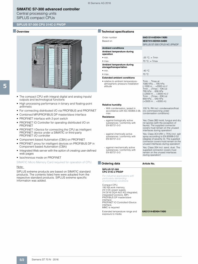
5/2 Siemens ST 70 N · 2016
5
SIMATIC S7-300 advanced controllerCentral processing unitsSIPLUS compact CPUs
SIPLUS S7-300 CPU 314C-2 PN/DP
■ Overview
• The compact CPU with integral digital and analog inputs/outputs and technological functions
• High processing performance in binary and floating-point arithmetic
• For connecting distributed I/O via PROFIBUS and PROFINET• Combined MPI/PROFIBUS DP master/slave interface• PROFINET interface with 2-port switch • PROFINET IO Controller for operating distributed I/O on
PROFINET • PROFINET I-Device for connecting the CPU as intelligent
PROFINET device under a SIMATIC or third-party PROFINET I/O controller
• Component based Automation (CBA) on PROFINET• PROFINET proxy for intelligent devices on PROFIBUS DP in
Component based Automation (CBA)• Integrated Web server with the option of creating user-defined
web pages• Isochronous mode on PROFINET
SIMATIC Micro Memory Card required for operation of CPU.
Note:
SIPLUS extreme products are based on SIMATIC standard products. The contents listed here were adopted from the respective standard products. SIPLUS extreme specific information was added.
■ Technical specifications
■ Ordering data Article No.
Order number 6AG1314-6EH04-7AB0
Based on 6ES7314-6EH04-0AB0
SIPLUS S7-300 CPU314C-2PN/DP
Ambient conditions
Ambient temperature during operation
• min. -25 °C; = Tmin
• max. 70 °C; = Tmax
Ambient temperature during storage/transportation
• min. -40 °C
• max. 70 °C
Extended ambient conditions
• relative to ambient temperature-atmospheric pressure-installation altitude
Tmin ... Tmax at 1080 hPa ... 795 hPa (-1000 m ... +2000 m) // Tmin ... (Tmax - 10K) at 795 hPa ... 658 hPa (+2000 m ... +3500 m) // Tmin ... (Tmax - 20K) at 658 hPa ... 540 hPa (+3500 m ... +5000 m)
Relative humidity
- With condensation, tested in accordance with IEC 60068-2-38, max.
100 %; RH incl. condensation/frost (no commissioning under condensation conditions)
Resistance
- against biologically active substances / conformity with EN 60721-3-3
Yes; Class 3B2 mold, fungus and dry rot spores (with the exception of fauna). The supplied connector covers must remain on the unused interfaces during operation!
- against chemically active substances / conformity with EN 60721-3-3
Yes; Class 3C4 (RH < 75%) incl. salt spray according to EN 60068-2-52 (degree of severity 3). The supplied connector covers must remain on the unused interfaces during operation!
- against mechanically active substances / conformity with EN 60721-3-3
Yes; Class 3S4 incl. sand, dust. The supplied connector covers must remain on the unused interfaces during operation!
SIPLUS S7-300 CPU 314C-2 PN/DP
For industrial applications with particularly demanding environmental conditions
Compact CPU, 192 KB work memory, 24 V DC power supply, 24 DI/16 DQ/4 AI/2 AQ integrated, integrated functions, MPI; PROFIBUS DP master/slave interface; PROFINET IO Controller/I-Device interface, MMC is required
Extended temperature range and exposure to media
6AG1314-6EH04-7AB0
© Siemens AG 2016

5/3Siemens ST 70 N · 2016
5
■ Ordering data Article No. Article No.
SIMATIC S7-300 advanced controllerCentral processing units SIPLUS compact CPUs
SIPLUS S7-300 CPU 314C-2 PN/DP
Accessories
Mandatory
SIMATIC Micro Memory Card
64 KB 6ES7953-8LF30-0AA0
128 KB 6ES7953-8LG30-0AA0
512 KB 6ES7953-8LJ30-0AA0
2 MB 6ES7953-8LL31-0AA0
4 MB 6ES7953-8LM31-0AA0
8 MB 6ES7953-8LP31-0AA0
Front connector (1 unit)
For compact CPUs
40-pin, with spring-loaded contacts• 1 unit 6ES7392-1BM01-0AA0• 100 units 6ES7392-1BM01-1AB0
For communication within the application
PROFIBUS DP bus connector RS 485
(extended temperature range and exposure to media)
With 90° cable outlet, max. transfer rate 12 Mbit/s• Without PG interface 6AG1972-0BA12-2XA0• With PG interface 6AG1972-0BB12-2XA0
With angled cable outlet, max. transfer rate 12 Mbit/s• Without PG interface 6AG1972-0BA42-7XA0• With PG interface 6AG1972-0BB42-7XA0
(extended temperature range)
With axial cable outlet for SIMATIC OP, for connecting to PPI, MPI, PROFIBUS
6AG1500-0EA02-2AA0
IE FC RJ45 Plug 180
(extended temperature range and exposure to media)
180° cable outlet• 1 unit 6AG1901-1BB10-7AA0
SIPLUS SCALANCE X-200 Industrial Ethernet switches
Industrial Ethernet switches with integral SNMP access, online diagnostics, copper cable diagnostics and PROFINET diagnostics for configuring line, star and ring topologies; with integrated redundancy manager (exception: SCALANCE X208PRO); incl. operating instructions, Industrial Ethernet network manual and configuration software on CD-ROM• With electrical and optical ports
for glass multimode FOC up to 3 km
• Extended temperature range and exposure to media
• SIPLUS SCALANCE X204-2 With four 10/100 Mbit/s RJ45 ports and two fiber-optic ports
6AG1204-2BB10-4AA3
PROFIBUS FastConnect bus cable
6XV1830-0EH10
Standard type with special design for quick mounting, 2-core, shielded, sold by the meter; max. length 1000 m, minimum ordering quantity 20 m
IE FC TP Standard Cable GP 2x2 6XV1840-2AH10
4-core, shielded TP installation cable for connection to IE FC Outlet RJ45/ IE FC RJ45 Plug; PROFINET-compatible; with UL approval;Sold by the meter; max. length 1 000 m minimum order quantity 20 m
FO Standard Cable GP (50/125) 6XV1873-2A
Standard cable, splittable, UL approval, sold by the meter:max. length 1 000 m minimum order quantity 20 m
RS 485 repeater for PROFIBUS 6AG1972-0AA02-7XA0
(extended temperature range and exposure to media)
Transmission rate up to 12 Mbit/s; 24 V DC; IP20 enclosure
For commissioning
MPI cable 6ES7901-0BF00-0AA0
For connection of SIMATIC S7 and PG via MPI; length 5 m
USB A2 PC adapter 6GK1571-0BA00-0AA0
For connecting a PG/PC or Notebook to PROFIBUS or MPI; USB cable included in scope of delivery
Consumables
Front door, elevated design 6ES7328-7AA20-0AA0
For compact CPUs; for connecting 1.3 mm2/16 AWG wires; wiring diagram and labels in petrol
Power supply connector 6ES7391-1AA00-0AA0
10 units, spare part
Slot number plates 6ES7912-0AA00-0AA0
Labeling strips 6ES7392-2XX00-0AA0
10 units, spare part
Label cover 6ES7392-2XY00-0AA0
10 units, spare part
Labeling sheets for machine inscription
For modules with 40-pin front connector, DIN A4, for printing with laser printer; 10 units
Petrol 6ES7392-2AX10-0AA0
Light beige 6ES7392-2BX10-0AA0
Yellow 6ES7392-2CX10-0AA0
Red 6ES7392-2DX10-0AA0
Documentation
SIMATIC Manual Collection 6ES7998-8XC01-8YE0
Electronic manuals on DVD, multilingual
SIMATIC Manual Collection update service for 1 year
6ES7998-8XC01-8YE2
Current "Manual Collection" DVD and the three subsequent updates
© Siemens AG 2016
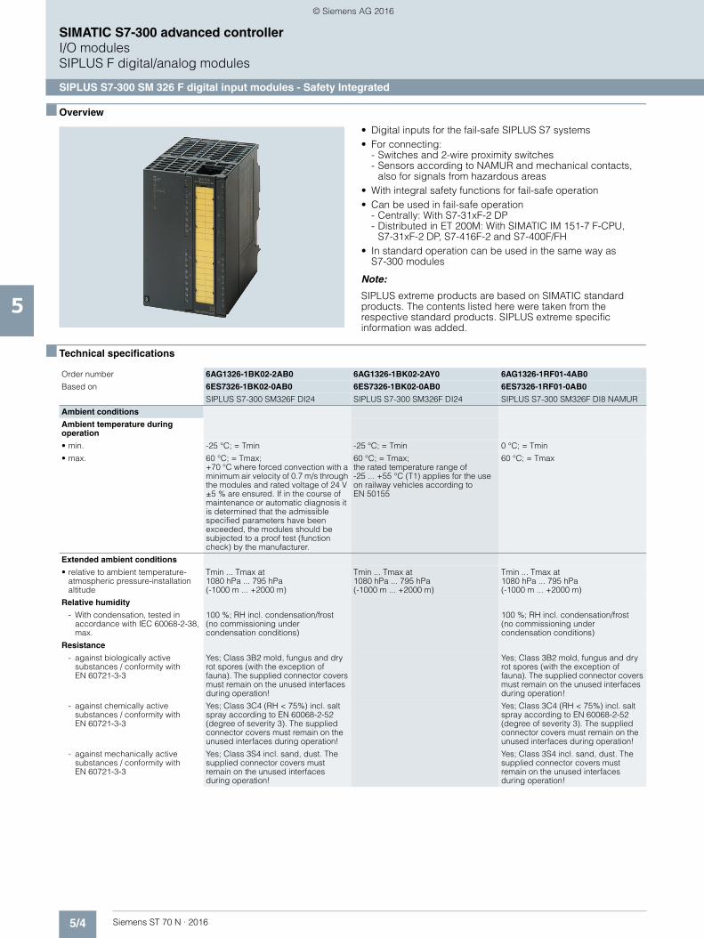
5/4 Siemens ST 70 N · 2016
5
SIMATIC S7-300 advanced controllerI/O modulesSIPLUS F digital/analog modules
SIPLUS S7-300 SM 326 F digital input modules - Safety Integrated
■ Overview
• Digital inputs for the fail-safe SIPLUS S7 systems• For connecting:
- Switches and 2-wire proximity switches- Sensors according to NAMUR and mechanical contacts,
also for signals from hazardous areas• With integral safety functions for fail-safe operation• Can be used in fail-safe operation
- Centrally: With S7-31xF-2 DP- Distributed in ET 200M: With SIMATIC IM 151-7 F-CPU,
S7-31xF-2 DP, S7-416F-2 and S7-400F/FH• In standard operation can be used in the same way as
S7-300 modules
Note:
SIPLUS extreme products are based on SIMATIC standard products. The contents listed here were taken from the respective standard products. SIPLUS extreme specific information was added.
■ Technical specifications
Order number 6AG1326-1BK02-2AB0 6AG1326-1BK02-2AY0 6AG1326-1RF01-4AB0
Based on 6ES7326-1BK02-0AB0 6ES7326-1BK02-0AB0 6ES7326-1RF01-0AB0
SIPLUS S7-300 SM326F DI24 SIPLUS S7-300 SM326F DI24 SIPLUS S7-300 SM326F DI8 NAMUR
Ambient conditions
Ambient temperature during operation
• min. -25 °C; = Tmin -25 °C; = Tmin 0 °C; = Tmin
• max. 60 °C; = Tmax; +70 °C where forced convection with a minimum air velocity of 0.7 m/s through the modules and rated voltage of 24 V ±5 % are ensured. If in the course of maintenance or automatic diagnosis it is determined that the admissible specified parameters have been exceeded, the modules should be subjected to a proof test (function check) by the manufacturer.
60 °C; = Tmax; the rated temperature range of -25 ... +55 °C (T1) applies for the use on railway vehicles according to EN 50155
60 °C; = Tmax
Extended ambient conditions
• relative to ambient temperature-atmospheric pressure-installation altitude
Tmin ... Tmax at 1080 hPa ... 795 hPa (-1000 m ... +2000 m)
Tmin ... Tmax at 1080 hPa ... 795 hPa (-1000 m ... +2000 m)
Tmin ... Tmax at 1080 hPa ... 795 hPa (-1000 m ... +2000 m)
Relative humidity
- With condensation, tested in accordance with IEC 60068-2-38, max.
100 %; RH incl. condensation/frost (no commissioning under condensation conditions)
100 %; RH incl. condensation/frost (no commissioning under condensation conditions)
Resistance
- against biologically active substances / conformity with EN 60721-3-3
Yes; Class 3B2 mold, fungus and dry rot spores (with the exception of fauna). The supplied connector covers must remain on the unused interfaces during operation!
Yes; Class 3B2 mold, fungus and dry rot spores (with the exception of fauna). The supplied connector covers must remain on the unused interfaces during operation!
- against chemically active substances / conformity with EN 60721-3-3
Yes; Class 3C4 (RH < 75%) incl. salt spray according to EN 60068-2-52 (degree of severity 3). The supplied connector covers must remain on the unused interfaces during operation!
Yes; Class 3C4 (RH < 75%) incl. salt spray according to EN 60068-2-52 (degree of severity 3). The supplied connector covers must remain on the unused interfaces during operation!
- against mechanically active substances / conformity with EN 60721-3-3
Yes; Class 3S4 incl. sand, dust. The supplied connector covers must remain on the unused interfaces during operation!
Yes; Class 3S4 incl. sand, dust. The supplied connector covers must remain on the unused interfaces during operation!
© Siemens AG 2016

5/5Siemens ST 70 N · 2016
5
SIMATIC S7-300 advanced controllerI/O modules
SIPLUS F digital/analog modules
SIPLUS S7-300 SM 326 F digital input modules - Safety Integrated
■ Ordering data Article No. Article No.
1) For up-to-date information and download availability, see:http://www.siemens.com/tia-online-software-delivery
SIPLUS S7-300 SM 326 F digital input
For industrial applications with extended ambient conditions
Extended temperature range and exposure to media
24 inputs, 24 V DC, failsafe, with diagnostics interrupt
6AG1326-1BK02-2AB0
8 inputs, 24 V DC, NAMUR, failsafe 6AG1326-1RF01-4AB0
For rolling stock railway applications
Conforms to EN 50155
24 inputs, 24 V DC, failsafe, with diagnostics interrupt
6AG1326-1BK02-2AY0
Accessories
Mandatory
Front connector
40-pin, with spring-loaded contacts• 1 unit 6ES7392-1BM01-0AA0• 100 units 6ES7392-1BM01-1AB0
Accessories for hot swapping function
Active bus module
BM 1 x 80 for 1 module, 80 mm wide
6AG1195-7HC00-2XA0
Consumables
DIN rail for active bus modules
For max. 5 active bus modules for hot swapping function• Length 483 mm (19") 6ES7195-1GA00-0XA0• Length 530 mm 6ES7195-1GF30-0XA0• Length 620 mm 6ES7195-1GG30-0XA0• Length 2000 mm 6ES7195-1GC00-0XA0
Front door, elevated design, for F-modules
6ES7328-7AA10-0AA0
For F-modules; for connecting 1.3 mm2/16 AWG wires; wiring diagram and labels in yellow
Labeling strips 6ES7392-2XX20-0AA0
For fail-safe modules (spare part); 10 units
Label cover 6ES7392-2XY20-0AA0
For fail-safe modules (spare part); 10 units
LK 393 cable guide 6ES7393-4AA10-0AA0
For F-modules; L+ and M connections; 5 units
Programming tools and documentation
S7 Distributed Safety programming tool V5.4
Task: Configuration software for configuring fail-safe user programs for SIMATIC S7-300F, S7-400F, WinAC RTX F, ET 200S, ET 200M, ET 200iSP, ET 200pro, ET 200ecoRequirement: STEP 7 V5.3 SP3 and higher
Floating license 6ES7833-1FC02-0YA5
Floating license for 1 user, license key download without software or documentation1); email address required for delivery
6ES7833-1FC02-0YH5
S7 Distributed Safety upgrade
From V5.x to V5.4; floating license for 1 user
6ES7833-1FC02-0YE5
STEP 7 Safety Advanced V13 SP1
Task:Engineering tool for configuring fail-safe user programs for SIMATIC S7-1200 FC, S7-1500F, S7-300F, S7-400F, WinAC RTX F, ET 200SP F Controller, ET 200SP, ET 200S, ET 200M, ET 200iSP, ET 200pro, ET 200ecoRequirement:STEP 7 Professional V13 SP1
Floating license for 1 user 6ES7833-1FA13-0YA5
Floating license for 1 user, license key download without software or documentation1); email address required for delivery
6ES7833-1FA13-0YH5
SIMATIC Manual Collection 6ES7998-8XC01-8YE0
Electronic manuals on DVD, multi-language: LOGO!, SIMADYN, SIMATIC bus components, SIMATIC C7, SIMATIC distributed I/O, SIMATIC HMI, SIMATIC Sensors, SIMATIC NET, SIMATIC PC Based Automation, SIMATIC PCS 7, SIMATIC PG/PC, SIMATIC S7, SIMATIC Software, SIMATIC TDC
SIMATIC Manual Collection update service for 1 year
6ES7998-8XC01-8YE2
Current "Manual Collection" DVD and the three subsequent updates
© Siemens AG 2016
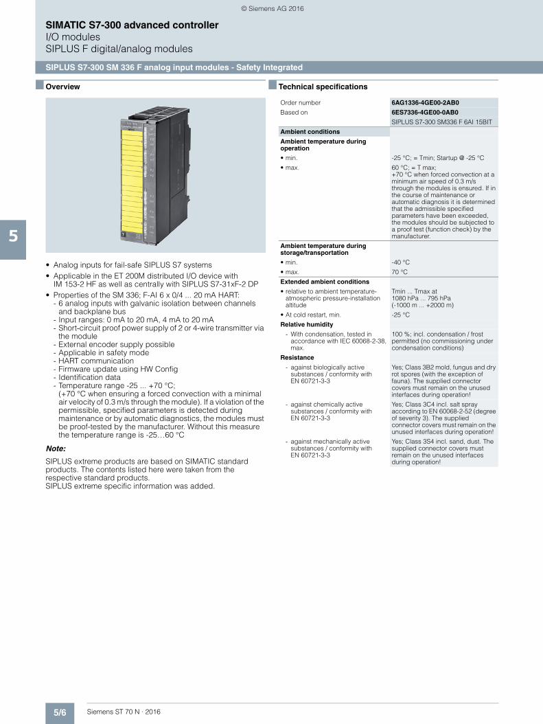
5/6 Siemens ST 70 N · 2016
5
SIMATIC S7-300 advanced controllerI/O modulesSIPLUS F digital/analog modules
SIPLUS S7-300 SM 336 F analog input modules - Safety Integrated
■ Overview
• Analog inputs for fail-safe SIPLUS S7 systems • Applicable in the ET 200M distributed I/O device with
IM 153-2 HF as well as centrally with SIPLUS S7-31xF-2 DP • Properties of the SM 336; F-AI 6 x 0/4 ... 20 mA HART:
- 6 analog inputs with galvanic isolation between channels and backplane bus
- Input ranges: 0 mA to 20 mA, 4 mA to 20 mA - Short-circuit proof power supply of 2 or 4-wire transmitter via
the module - External encoder supply possible - Applicable in safety mode - HART communication - Firmware update using HW Config - Identification data - Temperature range -25 ... +70 °C;
(+70 °C when ensuring a forced convection with a minimal air velocity of 0.3 m/s through the module). If a violation of the permissible, specified parameters is detected during maintenance or by automatic diagnostics, the modules must be proof-tested by the manufacturer. Without this measure the temperature range is -25…60 °C
Note:
SIPLUS extreme products are based on SIMATIC standard products. The contents listed here were taken from the respective standard products. SIPLUS extreme specific information was added.
■ Technical specifications
Order number 6AG1336-4GE00-2AB0
Based on 6ES7336-4GE00-0AB0
SIPLUS S7-300 SM336 F 6AI 15BIT
Ambient conditions
Ambient temperature during operation
• min. -25 °C; = Tmin; Startup @ -25 °C
• max. 60 °C; = T max; +70 °C when forced convection at a minimum air speed of 0.3 m/s through the modules is ensured. If in the course of maintenance or automatic diagnosis it is determined that the admissible specified parameters have been exceeded, the modules should be subjected to a proof test (function check) by the manufacturer.
Ambient temperature during storage/transportation
• min. -40 °C
• max. 70 °C
Extended ambient conditions
• relative to ambient temperature-atmospheric pressure-installation altitude
Tmin ... Tmax at 1080 hPa ... 795 hPa (-1000 m ... +2000 m)
• At cold restart, min. -25 °C
Relative humidity
- With condensation, tested in accordance with IEC 60068-2-38, max.
100 %; incl. condensation / frost permitted (no commissioning under condensation conditions)
Resistance
- against biologically active substances / conformity with EN 60721-3-3
Yes; Class 3B2 mold, fungus and dry rot spores (with the exception of fauna). The supplied connector covers must remain on the unused interfaces during operation!
- against chemically active substances / conformity with EN 60721-3-3
Yes; Class 3C4 incl. salt spray according to EN 60068-2-52 (degree of severity 3). The supplied connector covers must remain on the unused interfaces during operation!
- against mechanically active substances / conformity with EN 60721-3-3
Yes; Class 3S4 incl. sand, dust. The supplied connector covers must remain on the unused interfaces during operation!
© Siemens AG 2016
5/7Siemens ST 70 N · 2016
5
SIMATIC S7-300 advanced controllerI/O modules
SIPLUS F digital/analog modules
SIPLUS S7-300 SM 336 F analog input modules - Safety Integrated
■ Ordering data Article No. Article No.
1) For up-to-date information and download availability, see:http://www.siemens.com/tia-online-software-delivery
F analog input module SIPLUS S7-300 SM 336
For industrial applications with extended ambient conditions
Extended temperature range and exposure to environmental substances
6 inputs, 15 bit, 0/4 - 20 mA HART 6AG1336-4GE00-2AB0
Accessories
Mandatory
Front connector
20-pin, with spring-loaded contacts• 1 unit 6ES7392-1BJ00-0AA0• 100 units 6ES7392-1BJ00-1AB0
Accessories for hot swapping function
Active bus module
BM 2 x 40 for accepting 2 IO modules, each 40 mm wide
6AG1195-7HB00-7XA0
Consumables
DIN rail for active bus modules
For max. 5 active bus modules for hot swapping function• Length 483 mm (19") 6ES7195-1GA00-0XA0• Length 530 mm 6ES7195-1GF30-0XA0• Length 620 mm 6ES7195-1GG30-0XA0• Length 2000 mm 6ES7195-1GC00-0XA0
Front door, elevated design, for F-modules
6ES7328-7AA10-0AA0
For F-modules; for connecting 1.3 mm2/16 AWG wires; wiring iagram and labels in yellow
Labeling strips 6ES7392-2XX20-0AA0
For fail-safe modules (spare part); 10 units
Label cover 6ES7392-2XY20-0AA0
For fail-safe modules (spare part); 10 units
LK 393 cable guide 6ES7393-4AA10-0AA0
For F-modules; L+ and M connections; 5 units
Programming tools and documentation
S7 Distributed Safety programming tool V5.4
Task: Configuration software for configuring fail-safe user programs for SIMATIC S7-300F, S7-400F, WinAC RTX F, ET 200S, ET 200M, ET 200iSP, ET 200pro, ET 200ecoRequirement: STEP 7 V5.3 SP3 and higher
Floating license 6ES7833-1FC02-0YA5
Floating license for 1 user, license key download without software or documentation1); email address required for delivery
6ES7833-1FC02-0YH5
S7 Distributed Safety upgrade
From V5.x to V5.4; floating license for 1 user
6ES7833-1FC02-0YE5
STEP 7 Safety Advanced V13 SP1
Task:Configuration software for configuring fail-safe user programs for SIMATIC S7-1200 FC, S7-1500F, S7-300F, S7-400F, WinAC RTX F, ET 200SP F Controller, ET 200SP, ET 200S, ET 200M, ET 200iSP, ET 200pro, ET 200ecoRequirement:STEP 7 Professional V13 SP1
Floating license for 1 user 6ES7833-1FA13-0YA5
Floating license for 1 user, license key download without software or documentation1); email address required for delivery
6ES7833-1FA13-0YH5
SIMATIC Manual Collection 6ES7998-8XC01-8YE0
Electronic manuals on DVD, multi-language: LOGO!, SIMADYN, SIMATIC bus components, SIMATIC C7, SIMATIC distributed I/O, SIMATIC HMI, SIMATIC Sensors, SIMATIC NET, SIMATIC PC Based Automation, SIMATIC PCS 7, SIMATIC PG/PC, SIMATIC S7, SIMATIC Software, SIMATIC TDC
SIMATIC Manual Collection update service for 1 year
6ES7998-8XC01-8YE2
Current "Manual Collection" DVD and the three subsequent updates
© Siemens AG 2016
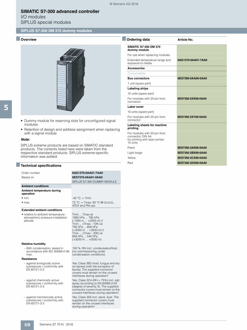
5/8 Siemens ST 70 N · 2016
5
SIMATIC S7-300 advanced controllerI/O modulesSIPLUS special modules
SIPLUS S7-300 DM 370 dummy modules
■ Overview
• Dummy module for reserving slots for unconfigured signal modules
• Retention of design and address assignment when replacing with a signal module
Note:
SIPLUS extreme products are based on SIMATIC standard products. The contents listed here were taken from the respective standard products. SIPLUS extreme-specific information was added.
■ Technical specifications
■ Ordering data Article No.
Order number 6AG1370-0AA01-7AA0
Based on 6ES7370-0AA01-0AA0
SIPLUS S7-300 DUMMY MODULE
Ambient conditions
Ambient temperature during operation
• min. -40 °C; = Tmin
• max. 70 °C; = Tmax; 60 °C @ UL/cUL, ATEX and FM use
Extended ambient conditions
• relative to ambient temperature-atmospheric pressure-installation altitude
Tmin ... Tmax at 1080 hPa ... 795 hPa (-1000 m ... +2000 m) // Tmin ... (Tmax - 10K) at 795 hPa ... 658 hPa (+2000 m ... +3500 m) // Tmin ... (Tmax - 20K) at 658 hPa ... 540 hPa (+3500 m ... +5000 m)
Relative humidity
- With condensation, tested in accordance with IEC 60068-2-38, max.
100 %; RH incl. condensation/frost (no commissioning under condensation conditions)
Resistance
- against biologically active substances / conformity with EN 60721-3-3
Yes; Class 3B2 mold, fungus and dry rot spores (with the exception of fauna). The supplied connector covers must remain on the unused interfaces during operation!
- against chemically active substances / conformity with EN 60721-3-3
Yes; Class 3C4 (RH < 75%) incl. salt spray according to EN 60068-2-52 (degree of severity 3). The supplied connector covers must remain on the unused interfaces during operation!
- against mechanically active substances / conformity with EN 60721-3-3
Yes; Class 3S4 incl. sand, dust. The supplied connector covers must remain on the unused interfaces during operation!
SIMATIC S7-300 DM 370 dummy module
For use when replacing modules
Extended temperature range and exposure to media
6AG1370-0AA01-7AA0
Accessories
Consumables
Bus connectors 6ES7390-0AA00-0AA0
1 unit (spare part)
Labeling strips
10 units (spare part)
For modules with 20-pin front connector
6ES7392-2XX00-0AA0
Label cover
10 units (spare part)
For modules with 20-pin front connector
6ES7392-2XY00-0AA0
Labeling sheets for machine printing
For modules with 20-pin front connector, DIN A4, for printing with laser printer; 10 units
Petrol 6ES7392-2AX00-0AA0
Light beige 6ES7392-2BX00-0AA0
Yellow 6ES7392-2CX00-0AA0
Red 6ES7392-2DX00-0AA0
© Siemens AG 2016

5/9Siemens ST 70 N · 2016
5
SIMATIC S7-300 advanced controllerI/O modules
Connection methods
System cabling for SIMATIC S7-300/400 and ET 200M - Fully modular connection
■ Overview
Wiring of SIMATIC S7 I/O modules with the sensors/actuators is a significant factor with respect to time/cost overhead, configuring, control cabinet installation, procurement and ease of service.
With SIMATIC TOP connect system cabling, it is simple and quick to establish a reliable connection for your SIMATIC S7-300 or ET 200M.
The fully modular connection is the standard connection for the SIMATIC S7-300/ET 200 M and allows the sensors and actuators from the field to be conveniently and quickly connected to the SIMATIC S7-300/ET 200 M without errors.
With the TIA Selection Tool, a mouse click is all that is required to configure the connection from the SIMATIC S7 module to the I/O. The program automatically checks for plausibility and gen-erates a parts list for the selected connection components that can then be ordered in the Industry Mall.
Further information can be found on the Internet at
http://www.siemens.com/tia-selection-tool
■ Benefits
• Easy plugging in of front connector module, connecting cable and connection module
• Fast and low-cost wiring• Supply voltage connectable to front connector module or
connection module for digital and analog signals• Reduction in wiring errors, clear control cabinet wiring• Distribution of digital signals by byte or by double-byte• Each component can be replaced individually.• Every cable length can be configured without cutting, or pre-
assembled cables can be used
■ Design
Fully modular connection
Each component is individually inserted.
The system consists of:• Front connector module• Connecting cable• Terminal modules in the following versions:
Basic module, signal module and function module
Connection errors are thus practically excluded and installation overhead is minimized. Systematic connection of the SIMATIC system. The assembly overhead for the connecting cables is drastically reduced thanks to the use of pre-assembled or easily assembled cables sold by the meter.
Front connector module
Modified front connectors, called front connector modules, are available for connecting to the module. These are plugged into the module to be wired instead of the front connector. The front connector modules are available in many different digital and analog versions. The connecting cables are plugged into these front connector modules.
Connecting cable
The connecting cable is available in two different versions.
As a pre-assembled 16-pin round cable (shielded or unshielded) up to a length of 10 m, or as a 16-pin round-sheath ribbon cable (with or without shield), which can be easily assembled by the user; or as 2 x 16-pin round-sheath ribbon cable (without shield).
When assembled, there are one or two insulation displacement connectors (female ribbon connectors) at both ends of the cable.
The round-sheath ribbon cable is assembled by the user with the aid of pliers (can be ordered separately). The cable transmits 8 or 2 x 8 channels over a distance of up to 30 m.
The connecting cable connects the front connector module with the terminal module.
Terminal module
The system has digital and analog terminal modules for connecting the I/O signals. These are snapped onto the DIN rail.
Terminal modules are available for two different connection methods: with spring-loaded or screw-type terminals
Basic module:
Terminal modules with basic functionality for getting the signal from the field to the module or from the module to the field quickly and easily. For digital or analog signals.
Signal module:
Expands the digital basic module with LEDs for signaling the active high signal. This makes commissioning easier for you, and you always have an overview of the signal states of your I/O. One LED signals the availability of the supply voltage.
© Siemens AG 2016

5/10 Siemens ST 70 N · 2016
5
■ Design (continued)
SIMATIC S7-300 advanced controllerI/O modulesConnection methods
System cabling for SIMATIC S7-300/400 and ET 200M - Fully modular connection
Function module:
Digital terminal modules that are fitted with relays or optocouplers.
If other voltage or power levels are required in the field, the terminal module for TPRo or TPOo output signals is used. For the TPRo terminal module, relays are used for the implementation. For the TPOo terminal module, optocouplers are used for the implementation. This converts the 24 V DC output signal simply and reliably to another voltage or power level. If 230 V AC input signals have to be transmitted to the controller in the field, a connection module with relay TPRi is available that simply converts the 230 V AC signal to 24 V DC. This means that there is always the same voltage level on the module side.
Use with optocouplers for the TPRo relay modules
If higher switching frequencies of the relay terminal module are required for the output signals, the relay can simply be replaced with an optocoupler (note technical specifications) in order to increase the switching frequency.
Shield plate
The shield plate is latched onto the connection module for 3-core initiators or optionally onto the connection module for analog signals and then snapped onto the DIN rail with the connection module. With the terminal elements, optimal shield connection is achieved between the shielded round-sheath ribbon cable or the shielded field cables and the grounded DIN rail.
SIMATIC TOP connect for S7-300/ ET200 M, fully modular connection
■ Technical specifications Front connector module
Wiring rules for the front connector modules
Sensors andactuators inthe field
Connectablecables(pre-assembledwith a length of0.5 m to 10 m)
Front connector modulefor DI/DO modules withup to 4 sockets, forconnectable cables
Connection module withsocket for connectablecables
SIMATICS7-300/ET 200M
G_K
T01_
XX
_007
59
Technical data of front connector module
Rated operating voltage 24 VDC
Max. permissible operating voltage 60 V DC
Max. permissible continuous current• per connector pin
1 A
Max. permissible summation current 4 A/byte
Permissible ambient temperature 0 to + 60°C
Test voltage 0.5 kV, 50 Hz, 60 sec.
Air gaps and creepage distances IEC 664 (1980), IEC 664 A (1981),in accordance with DIN VDE 0110 (01.89), overvoltage class II, pollution degree 2
Technical data of front connector module
Front connector module SIMATIC TOP connect, connection for potential infeed
Spring connection Screw connection
Modules up to 4 connections
Connectable cable cross-sections
• solid cables No• flexible cables with/without wire end
ferrule0,25 to 1.5 mm2
Number of wires per connection 1 or a combination of 2 conductors up to 1.5 mm2 (total) in a common wire end ferrule
Max. diameter of the cable insulation 3.1 mm
Stripping length of the cables
• without insulating collar 6 mm• with insulating collar -
Wire-end ferrules in acc. with DIN 46228
• without insulating collar Form A; 5 to 7 mm long• with insulating collar 0.25 to 1.0
mm2-
• with insulating collar 1.5 mm2 -
Blade width of the screwdriver 3.5 mm (cylindrical shape)
Tightening torque for connecting the cables
- 0.4 to 0.7 Nm
Front connector module SIMATIC TOP connect, connection for potential infeed
Spring connection Screw connection
Modules up to 8 connections
Connectable cable cross-sections
• solid cables No• flexible cables with/without wire end
ferrule0.25 to 0.75 mm2
Number of cables per connection 1 or a combination of 2 wires up to 0.75 mm2 (total) in a common wire end ferrule
Max. diameter of the cable insulation 2.0 mm
Stripping length of the cables
• without insulating collar 6 mm• with insulating collar -
Wire-end ferrules in acc. with DIN 46228
• without insulating collar Form A; 5 to 7 mm long• with insulating collar
0.25 to 1.0 mm2-
• with insulating collar 1.5 mm2 -
Blade width of the screwdriver 3.5 mm (cylindrical shape)
Tightening torque for connecting the cables
- 0.4 to 0.7 Nm
© Siemens AG 2016

5/11Siemens ST 70 N · 2016
5
SIMATIC S7-300 advanced controllerI/O modules
Connection methods
System cabling for SIMATIC S7-300/400 and ET 200M - Fully modular connection
■ Technical specifications Connecting cable
■ Ordering data Article No. Article No.
Front connector modules Connecting cable
Technical specifications of connecting cable from SIMATIC S7 to connection module
Operating voltage 60 V DC
Continuous current per signal conductor
1 A
Max. aggregate current 4 A/byte
Operating temperature 0 to +60 °C
Outer diameter of pre-assembled round cable in mm unshielded/shielded (16-pole)
Approx. 6.5/7.0
Outer diameter of round-sheath ribbon cable in mm 16-pole/2 x 16-pole
approx. 9.5/11.5
Technical specifications of connecting cable from SIMATIC S7 to connection module
Front connector module (compact CPU 312C)
Power supply via• Screw terminals 6ES7921-3AK20-0AA0
Front connector module (compact CPU 313C/314C-2PtP/314C-2DP), slot X1
Power supply via• Screw terminals 6ES7921-3AM20-0AA0
Front connector module (digital 2 x 8 I/O)
Power supply via• Spring-loaded terminals 6ES7921-3AA00-0AA0• Screw terminals 6ES7921-3AB00-0AA0
Front connector module (digital 4 x 8 I/O)
Power supply via• Spring-loaded terminals 6ES7921-3AA20-0AA0• Screw terminals 6ES7921-3AB20-0AA0
Front connector module (1 x 8 outputs) for 2 ampere digital outputs
Power supply via• Spring-loaded terminals 6ES7921-3AC00-0AA0• Screw terminals 6ES7921-3AD00-0AA0
Front connector module 20-pin (analog)
Power supply via• Spring-loaded terminals 6ES7921-3AF00-0AA0• Screw terminals 6ES7921-3AG00-0AA0
Front connector module 40-pin (analog)
Power supply via• Spring-loaded terminals 6ES7921-3AF20-0AA0• Screw terminals 6ES7921-3AG20-0AA0
Connecting cables for SIMATIC S7-300/S7-1500
Pre-assembled round cable
16-pin, 0.14 mm2
unshielded• 0.5 m 6ES7923-0BA50-0CB0• 1.0 m 6ES7923-0BB00-0CB0• 1.5 m 6ES7923-0BB50-0CB0• 2.0 m 6ES7923-0BC00-0CB0• 2.5 m 6ES7923-0BC50-0CB0• 3.0 m 6ES7923-0BD00-0CB0• 4.0 m 6ES7923-0BE00-0CB0• 5.0 m 6ES7923-0BF00-0CB0• 6.5 m 6ES7923-0BG50-0CB0• 8.0 m 6ES7923-0BJ00-0CB0• 10.0 m 6ES7923-0CB00-0CB0
shielded• 1.0 m 6ES7923-0BB00-0DB0• 2.0 m 6ES7923-0BC00-0DB0• 2.5 m 6ES7923-0BC50-0DB0• 3.0 m 6ES7923-0BD00-0DB0• 4.0 m 6ES7923-0BE00-0DB0• 5.0 m 6ES7923-0BF00-0DB0• 6.5 m 6ES7923-0BG50-0DB0• 8.0 m 6ES7923-0BJ00-0DB0• 10.0 m 6ES7923-0CB00-0DB0
Version 4 x 16 to 1 x 50-pin, 0.14 mm2
Unshielded• 0.5 m 6ES7923-5BA50-0EB0• 1.0 m 6ES7923-5BB00-0EB0• 1.5 m 6ES7923-5BB50-0EB0• 2.0 m 6ES7923-5BC00-0EB0• 2.5 m 6ES7923-5BC50-0EB0• 3.0 m 6ES7923-5BD00-0EB0• 4.0 m 6ES7923-5BE00-0EB0• 5.0 m 6ES7923-5BF00-0EB0• 6.5 m 6ES7923-5BG50-0EB0• 8.0 m 6ES7923-5BJ00-0EB0• 10.0 m 6ES7923-5CB00-0EB0
Round-sheath ribbon cable
16-pin, 0.14 mm2
Unshielded• 30 m 6ES7923-0CD00-0AA0• 60 m 6ES7923-0CG00-0AA0
Shielded• 30 m 6ES7923-0CD00-0BA0• 60 m 6ES7923-0CG00-0BA0
© Siemens AG 2016
5/12 Siemens ST 70 N · 2016
5
■ Ordering data Article No. Article No.
SIMATIC S7-300 advanced controllerI/O modulesConnection methods
System cabling for SIMATIC S7-300/400 and ET 200M - Fully modular connection
Terminal modules
Round-sheath ribbon cable
2 x 16-pin, 0.14 mm2
Unshielded• 30 m 6ES7923-2CD00-0AA0• 60 m 6ES7923-2CG00-0AA0
Connector (female ribbon connector)
6ES7921-3BE10-0AA0
16-pin, insulation displacement system, with strain relief devices;packing unit: 8 connectors and 8 cable grips
Accessories
Manual pliers 6ES7928-0AA00-0AA0
For preparing the connectors (female ribbon connector)
Terminal module TP1
For 1-wire connection, for 16-pin connecting cables
• Push-in terminals without LEDs 6ES7924-0AA20-0AC0• Screw-type terminals without
LEDs6ES7924-0AA20-0AA0
• Push-in terminals with LEDs 6ES7924-0AA20-0BC0• Screw-type terminals with LEDs 6ES7924-0AA20-0BA0
For 1-wire connection, for 50-pin connecting cables• Push-in terminals without LEDs 6ES7924-2AA20-0AC0• Push-in terminals with LEDs 6ES7924-2AA20-0BC0• Screw-type terminals with LEDs 6ES7924-2AA20-0BA0
Terminal module TP3
For 3-wire connection, for 16-pin connecting cables
• Push-in terminals without LEDs 6ES7924-0CA20-0AC0• Screw-type terminals without
LEDs6ES7924-0CA20-0AA0
• Push-in terminals with LEDs 6ES7924-0CA20-0BC0• Screw-type terminals with LEDs 6ES7924-0CA20-0BA0• Push-in terminals with LEDs and
one isolating terminal per channel6ES7924-0CH20-0BC0
• Screw-type terminals with LEDs and one isolating terminal per channel
6ES7924-0CH20-0BA0
• Push-in terminals with LED and fuse per channel
6ES7924-0CL20-0BC0
• Push-in terminals with LED and fuse per channel
6ES7924-0CL20-0BA0
For 3-wire connection, for 50-pin connecting cables• Push-in terminals without LEDs 6ES7924-2CA20-0AC0• Screw-type terminals without
LEDs6ES7924-2CA20-0AA0
• Push-in terminals with LEDs 6ES7924-2CA20-0BC0• Screw-type terminals with LEDs 6ES7924-2CA20-0BA0
Terminal module TPRo
Relay module for 8 outputs, relay as normally open contact• Push-in terminals with LEDs 6ES7924-0BD20-0BC0• Screw-type terminals with LEDs 6ES7924-0BD20-0BA0
Terminal module TPRi
Relay module for 8 outputs (110 V AC), relay as normally open contact• Push-in terminals with LEDs 6ES7924-0BG20-0BC0• Screw-type terminals with LEDs 6ES7924-0BG20-0BA0
Terminal module TPRi
Relay module for 8 outputs (230 V AC), relay as normally open contact• Push-in terminals with LEDs 6ES7924-0BE20-0BC0• Screw-type terminals with LEDs 6ES7924-0BE20-0BA0
Terminal module TPOo
Optocoupler module for 8 outputs (max. 24 V DC/4 A)• Push-in terminals with LEDs 6ES7924-0BF20-0BC0• Screw-type terminals with LEDs 6ES7924-0BF20-0BA0
Terminal module for digital output modules 2 A
Terminal module TP2 • Push-in terminals without LEDs 6ES7924-0BB20-0AC0• Screw-type terminals without
LEDs6ES7924-0BB20-0AA0
Terminal module for analog modules (for S7-300 only)
Terminal module TPA• Push-in terminals without LEDs 6ES7924-0CC21-0AC0• Screw-type terminals without
LEDs6ES7924-0CC21-0AA0
Accessories
Shield for analog terminal module
PU = 4 units (for connection of 16-pin connecting cable)
6ES7928-1AA20-4AA0
Shield connection clamp
For shield plate at SIMATIC end, PU = 10 units
6ES7590-5BA00-0AA0
For shield plate at field end, 2 x 2 ... 6 mm
6ES7390-5AB00-0AA0
For shield plate at field end, 3 ... 8 mm
6ES7390-5BA00-0AA0
For shield plate at field end, 4 ... 13 mm
6ES7390-5CA00-0AA0
© Siemens AG 2016

Siemens ST 70 N · 2016
6
Brochures
For brochures serving as selectionguides for SIMATIC products refer to:
www.siemens.com/simatic/printmaterial
6/2 Central processing units6/2 Standard CPUs6/2 CPU 4126/6 CPU 4146/11 CPU 4166/16 CPU 4176/19 Fail-safe CPUs6/19 CPU 414F6/23 CPU 416F6/27 High-availability CPUs6/27 Y-link for S7-400H6/29 SIPLUS high-availability CPUs6/29 SIPLUS Y-Link for S7-400H
6/31 Function modules6/31 FM 458-1 DP application module6/31 D7-SYS
SIMATIC S7-400 advanced controller
© Siemens AG 2016

6/2 Siemens ST 70 N · 2016
6
SIMATIC S7-400 advanced controllerCentral processing unitsStandard CPUs
CPU 412
■ Overview
• The low-cost starter solution for the medium performance range
• Can be used in small and medium-sized systems with requirements of the medium performance range
■ Technical specifications
Article number 6ES7412-1XJ07-0AB0 6ES7412-2XK07-0AB0 6ES7412-2EK07-0AB0
CPU412-1, MPI/DP, 512 KB CPU412-2, MPI/DP, 1 MB CPU412-2 PN, 1 MB, 2 INTERFACES
General information
Product type designation CPU 412-1 CPU 412-2 CPU 412-2 PN
Engineering with
• Programming package STEP 7 V5.4 or higher with HSP 261 STEP 7 V5.4 or higher with HSP 261 STEP 7 V5.5 or higher with HSP 262
Supply voltage
Rated value (DC)
• 24 V DC No; Power supply via system power supply
No; Power supply via system power supply
No; Power supply via system power supply
Power loss
Power loss, typ. 3.5 W 4.5 W 5.5 W
Memory
Work memory
• integrated 512 kbyte 1 Mbyte 1 Mbyte
• integrated (for program) 256 kbyte 512 kbyte 512 kbyte
• integrated (for data) 256 kbyte 512 kbyte 512 kbyte
Load memory
• expandable FEPROM, max. 64 Mbyte 64 Mbyte 64 Mbyte
• integrated RAM, max. 512 kbyte 512 kbyte 512 kbyte
• expandable RAM, max. 64 Mbyte 64 Mbyte 64 Mbyte
CPU processing times
for bit operations, typ. 31.25 ns 31.25 ns 31.25 ns
for word operations, typ. 31.25 ns 31.25 ns 31.25 ns
for fixed point arithmetic, typ. 31.25 ns 31.25 ns 31.25 ns
for floating point arithmetic, typ. 62.5 ns 62.5 ns 62.5 ns
Counters, timers and their retentivity
S7 counter
• Number 2 048 2 048 2 048
IEC counter
• present Yes Yes Yes
S7 times
• Number 2 048 2 048 2 048
IEC timer
• present Yes Yes Yes
Data areas and their retentivity
Flag
• Number, max. 4 kbyte; Size of bit memory address area
4 kbyte; Size of bit memory address area
4 kbyte; Size of bit memory address area
© Siemens AG 2016
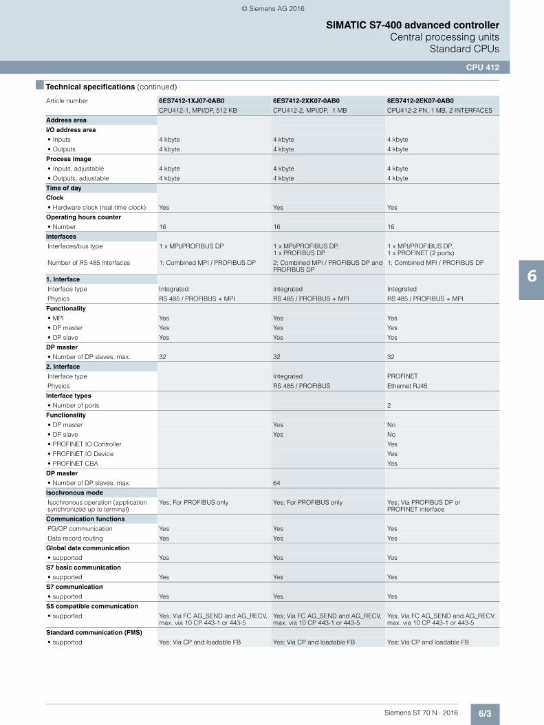
6/3Siemens ST 70 N · 2016
6
■ Technical specifications (continued)
SIMATIC S7-400 advanced controllerCentral processing units
Standard CPUs
CPU 412
Address area
I/O address area
• Inputs 4 kbyte 4 kbyte 4 kbyte
• Outputs 4 kbyte 4 kbyte 4 kbyte
Process image
• Inputs, adjustable 4 kbyte 4 kbyte 4 kbyte
• Outputs, adjustable 4 kbyte 4 kbyte 4 kbyte
Time of day
Clock
• Hardware clock (real-time clock) Yes Yes Yes
Operating hours counter
• Number 16 16 16
Interfaces
Interfaces/bus type 1 x MPI/PROFIBUS DP 1 x MPI/PROFIBUS DP, 1 x PROFIBUS DP
1 x MPI/PROFIBUS DP, 1 x PROFINET (2 ports)
Number of RS 485 interfaces 1; Combined MPI / PROFIBUS DP 2; Combined MPI / PROFIBUS DP and PROFIBUS DP
1; Combined MPI / PROFIBUS DP
1. Interface
Interface type Integrated Integrated Integrated
Physics RS 485 / PROFIBUS + MPI RS 485 / PROFIBUS + MPI RS 485 / PROFIBUS + MPI
Functionality
• MPI Yes Yes Yes
• DP master Yes Yes Yes
• DP slave Yes Yes Yes
DP master
• Number of DP slaves, max. 32 32 32
2. Interface
Interface type Integrated PROFINET
Physics RS 485 / PROFIBUS Ethernet RJ45
Interface types
• Number of ports 2
Functionality
• DP master Yes No
• DP slave Yes No
• PROFINET IO Controller Yes
• PROFINET IO Device Yes
• PROFINET CBA Yes
DP master
• Number of DP slaves, max. 64
Isochronous mode
Isochronous operation (application synchronized up to terminal)
Yes; For PROFIBUS only Yes; For PROFIBUS only Yes; Via PROFIBUS DP or PROFINET interface
Communication functions
PG/OP communication Yes Yes Yes
Data record routing Yes Yes Yes
Global data communication
• supported Yes Yes Yes
S7 basic communication
• supported Yes Yes Yes
S7 communication
• supported Yes Yes Yes
S5 compatible communication
• supported Yes; Via FC AG_SEND and AG_RECV, max. via 10 CP 443-1 or 443-5
Yes; Via FC AG_SEND and AG_RECV, max. via 10 CP 443-1 or 443-5
Yes; Via FC AG_SEND and AG_RECV, max. via 10 CP 443-1 or 443-5
Standard communication (FMS)
• supported Yes; Via CP and loadable FB Yes; Via CP and loadable FB Yes; Via CP and loadable FB
Article number 6ES7412-1XJ07-0AB0 6ES7412-2XK07-0AB0 6ES7412-2EK07-0AB0
CPU412-1, MPI/DP, 512 KB CPU412-2, MPI/DP, 1 MB CPU412-2 PN, 1 MB, 2 INTERFACES
© Siemens AG 2016
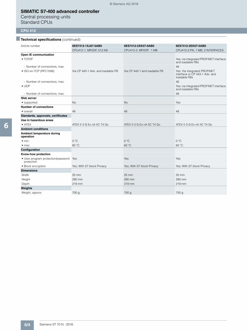
6/4 Siemens ST 70 N · 2016
6
■ Technical specifications (continued)
SIMATIC S7-400 advanced controllerCentral processing unitsStandard CPUs
CPU 412
Open IE communication
• TCP/IP Yes; via integrated PROFINET interface and loadable FBs
- Number of connections, max. 46
• ISO-on-TCP (RFC1006) Via CP 443-1 Adv. and loadable FB Via CP 443-1 and loadable FB Yes; Via integrated PROFINET interface or CP 443-1 Adv. and loadable FBs
- Number of connections, max. 46
• UDP Yes; via integrated PROFINET interface and loadable FBs
- Number of connections, max. 46
Web server
• supported No No Yes
Number of connections
• overall 48 48 48
Standards, approvals, certificates
Use in hazardous areas
• ATEX ATEX II 3 G Ex nA IIC T4 Gc ATEX II 3 G Ex nA IIC T4 Gc ATEX II 3 G Ex nA IIC T4 Gc
Ambient conditions
Ambient temperature during operation
• min. 0 °C 0 °C 0 °C
• max. 60 °C 60 °C 60 °C
Configuration
Know-how protection
• User program protection/password protection
Yes Yes Yes
• Block encryption Yes; With S7 block Privacy Yes; With S7 block Privacy Yes; With S7 block Privacy
Dimensions
Width 25 mm 25 mm 25 mm
Height 290 mm 290 mm 290 mm
Depth 219 mm 219 mm 219 mm
Weights
Weight, approx. 700 g 700 g 750 g
Article number 6ES7412-1XJ07-0AB0 6ES7412-2XK07-0AB0 6ES7412-2EK07-0AB0
CPU412-1, MPI/DP, 512 KB CPU412-2, MPI/DP, 1 MB CPU412-2 PN, 1 MB, 2 INTERFACES
© Siemens AG 2016
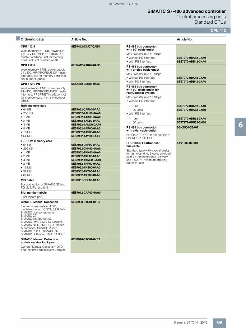
6/5Siemens ST 70 N · 2016
6
SIMATIC S7-400 advanced controllerCentral processing units
Standard CPUs
CPU 412
■ Ordering data Article No. Article No.
CPU 412-1
Work memory 512 KB, power sup-ply 24 V DC, MPI/PROFIBUS DP master interface, slot for memory card, incl. slot number labels
6ES7412-1XJ07-0AB0
CPU 412-2
Work memory 1 MB, power supply 24 V DC, MPI/PROFIBUS DP master interface, slot for memory card, incl. slot number labels
6ES7412-2XK07-0AB0
CPU 412-2 PN
Work memory 1 MB, power supply 24 V DC, MPI/PROFIBUS DP master interface, PROFINET interface, slot for memory card, incl. slot number labels
6ES7412-2EK07-0AB0
RAM memory card• 64 KB 6ES7952-0AF00-0AA0• 256 KB 6ES7952-1AH00-0AA0• 1 MB 6ES7952-1AK00-0AA0• 2 MB 6ES7952-1AL00-0AA0• 4 MB 6ES7952-1AM00-0AA0• 8 MB 6ES7952-1AP00-0AA0• 16 MB 6ES7952-1AS00-0AA0• 64 MB 6ES7952-1AY00-0AA0
FEPROM memory card• 64 KB 6ES7952-0KF00-0AA0• 256 KB 6ES7952-0KH00-0AA0• 1 MB 6ES7952-1KK00-0AA0• 2 MB 6ES7952-1KL00-0AA0• 4 MB 6ES7952-1KM00-0AA0• 8 MB 6ES7952-1KP00-0AA0• 16 MB 6ES7952-1KS00-0AA0• 32 MB 6ES7952-1KT00-0AA0• 64 MB 6ES7952-1KY00-0AA0
MPI cable
For connection of SIMATIC S7 and PG via MPI; length: 5 m
6ES7901-0BF00-0AA0
Slot number labels
1 set (spare part)
6ES7912-0AA00-0AA0
SIMATIC Manual Collection
Electronic manuals on DVD, multi-language: LOGO!, SIMADYN, SIMATIC bus components,SIMATIC C7, SIMATIC distributed I/O, SIMATIC HMI, SIMATIC Sensors, SIMATIC NET, SIMATIC PC-based Automation, SIMATIC PCS 7, SIMATIC PG/PC, SIMATIC S7, SIMATIC Software, SIMATIC TDC
6ES7998-8XC01-8YE0
SIMATIC Manual Collection update service for 1 year
Current "Manual Collection" DVD and the three subsequent updates
6ES7998-8XC01-8YE2
RS 485 bus connectorwith 90° cable outlet
Max. transfer rate 12 Mbps• Without PG interface 6ES7972-0BA12-0XA0• With PG interface 6ES7972-0BB12-0XA0
RS 485 bus connector with angled cable outlet
Max. transfer rate 12 Mbps• Without PG interface 6ES7972-0BA42-0XA0• With PG interface 6ES7972-0BB42-0XA0
RS 485 bus connector with 90° cable outlet forFastConnect system
Max. transfer rate 12 Mbps• Without PG interface
- 1 unit 6ES7972-0BA52-0XA0- 100 units 6ES7972-0BA52-0XB0
• With PG interface
- 1 unit 6ES7972-0BB52-0XA0- 100 units 6ES7972-0BB52-0XB0
RS 485 bus connector with axial cable outlet
For SIMATIC OP, for connection to PPI, MPI, PROFIBUS
6GK1500-0EA02
PROFIBUS FastConnect bus cable
Standard type with special design for fast mounting, 2-core, shielded, sold by the meter; max. delivery unit 1 000 m, minimum ordering quantity 20 m
6XV1830-0EH10
© Siemens AG 2016
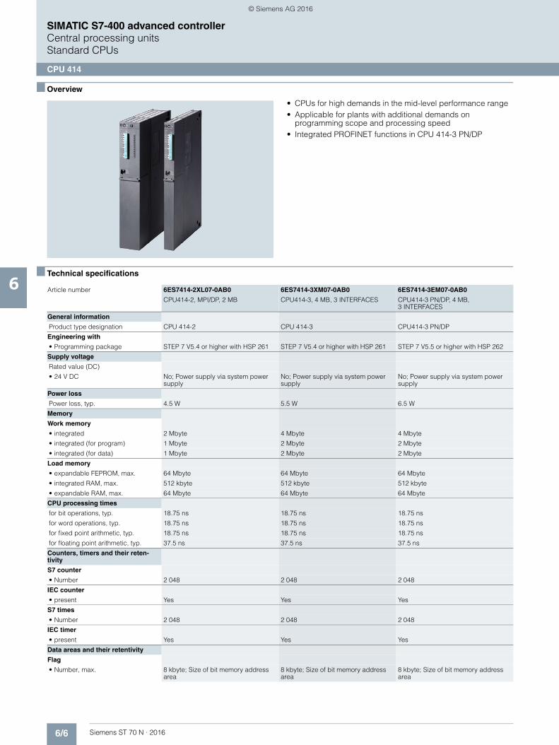
6/6 Siemens ST 70 N · 2016
6
SIMATIC S7-400 advanced controllerCentral processing unitsStandard CPUs
CPU 414
■ Overview
• CPUs for high demands in the mid-level performance range• Applicable for plants with additional demands on
programming scope and processing speed• Integrated PROFINET functions in CPU 414-3 PN/DP
■ Technical specifications
Article number 6ES7414-2XL07-0AB0 6ES7414-3XM07-0AB0 6ES7414-3EM07-0AB0
CPU414-2, MPI/DP, 2 MB CPU414-3, 4 MB, 3 INTERFACES CPU414-3 PN/DP, 4 MB, 3 INTERFACES
General information
Product type designation CPU 414-2 CPU 414-3 CPU414-3 PN/DP
Engineering with
• Programming package STEP 7 V5.4 or higher with HSP 261 STEP 7 V5.4 or higher with HSP 261 STEP 7 V5.5 or higher with HSP 262
Supply voltage
Rated value (DC)
• 24 V DC No; Power supply via system power supply
No; Power supply via system power supply
No; Power supply via system power supply
Power loss
Power loss, typ. 4.5 W 5.5 W 6.5 W
Memory
Work memory
• integrated 2 Mbyte 4 Mbyte 4 Mbyte
• integrated (for program) 1 Mbyte 2 Mbyte 2 Mbyte
• integrated (for data) 1 Mbyte 2 Mbyte 2 Mbyte
Load memory
• expandable FEPROM, max. 64 Mbyte 64 Mbyte 64 Mbyte
• integrated RAM, max. 512 kbyte 512 kbyte 512 kbyte
• expandable RAM, max. 64 Mbyte 64 Mbyte 64 Mbyte
CPU processing times
for bit operations, typ. 18.75 ns 18.75 ns 18.75 ns
for word operations, typ. 18.75 ns 18.75 ns 18.75 ns
for fixed point arithmetic, typ. 18.75 ns 18.75 ns 18.75 ns
for floating point arithmetic, typ. 37.5 ns 37.5 ns 37.5 ns
Counters, timers and their reten-tivity
S7 counter
• Number 2 048 2 048 2 048
IEC counter
• present Yes Yes Yes
S7 times
• Number 2 048 2 048 2 048
IEC timer
• present Yes Yes Yes
Data areas and their retentivity
Flag
• Number, max. 8 kbyte; Size of bit memory address area
8 kbyte; Size of bit memory address area
8 kbyte; Size of bit memory address area
© Siemens AG 2016

6/7Siemens ST 70 N · 2016
6
■ Technical specifications (continued)
SIMATIC S7-400 advanced controllerCentral processing units
Standard CPUs
CPU 414
Address area
I/O address area
• Inputs 8 kbyte 8 kbyte 8 kbyte
• Outputs 8 kbyte 8 kbyte 8 kbyte
Process image
• Inputs, adjustable 8 kbyte 8 kbyte 8 kbyte
• Outputs, adjustable 8 kbyte 8 kbyte 8 kbyte
Time of day
Clock
• Hardware clock (real-time clock) Yes Yes Yes
Operating hours counter
• Number 16 16 16
Interfaces
Interfaces/bus type 1 x MPI/PROFIBUS DP, 1 x PROFIBUS DP
1 x MPI/PROFIBUS DP, 1 x PROFIBUS DP, 1 x PROFIBUS DP(optionally pluggable)
1 x MPI/PROFIBUS DP, 1 x PROFINET (2 ports), 1 x PROFIBUS DP (optionally pluggable)
Number of RS 485 interfaces 2; Combined MPI / PROFIBUS DP and PROFIBUS DP
2; Combined MPI / PROFIBUS DP and PROFIBUS DP
1; Combined MPI / PROFIBUS DP
Number of other interfaces 1; PROFIBUS DP with IF 964-DP (plug-in option; MLFB: 6ES7964-2AA04-0AB0)
1; PROFIBUS DP withIF 964-DP (plug-in option; MLFB: 6ES7964-2AA04-0AB0)
1. Interface
Interface type Integrated Integrated Integrated
Physics RS 485 / PROFIBUS + MPI RS 485 / PROFIBUS + MPI RS 485 / PROFIBUS + MPI
Functionality
• MPI Yes Yes Yes
• DP master Yes Yes Yes
• DP slave Yes Yes Yes
DP master
• Number of DP slaves, max. 32 32 32
2. Interface
Interface type Integrated Integrated PROFINET
Physics RS 485 / PROFIBUS RS 485 / PROFIBUS Ethernet RJ45
Interface types
• Number of ports 2
Functionality
• DP master Yes Yes No
• DP slave Yes Yes No
• PROFINET IO Controller Yes
• PROFINET IO Device Yes
• PROFINET CBA Yes
DP master
• Number of DP slaves, max. 96 96
3. Interface
Interface type Pluggable interface module (IF), technical data as for 2nd interface
Pluggable interface module (IF)
Plug-in interface modules IF 964-DP(MLFB: 6ES7964-2AA04-0AB0)
IF 964-DP(MLFB: 6ES7964-2AA04-0AB0)
Physics RS 485 / PROFIBUS RS 485 / PROFIBUS
Functionality
• MPI No No
• DP master Yes Yes
• DP slave Yes Yes
DP master
• Number of DP slaves, max. 96 96
Article number 6ES7414-2XL07-0AB0 6ES7414-3XM07-0AB0 6ES7414-3EM07-0AB0
CPU414-2, MPI/DP, 2 MB CPU414-3, 4 MB, 3 INTERFACES CPU414-3 PN/DP, 4 MB, 3 INTERFACES
© Siemens AG 2016
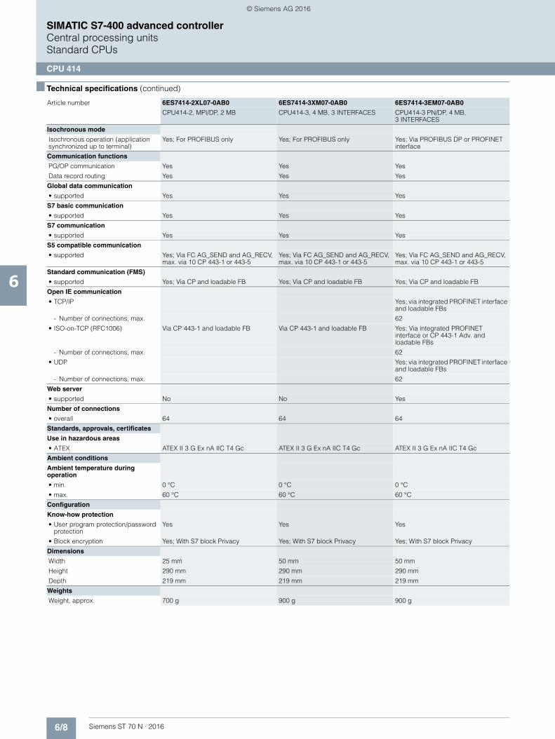
6/8 Siemens ST 70 N · 2016
6
■ Technical specifications (continued)
SIMATIC S7-400 advanced controllerCentral processing unitsStandard CPUs
CPU 414
Isochronous mode
Isochronous operation (application synchronized up to terminal)
Yes; For PROFIBUS only Yes; For PROFIBUS only Yes; Via PROFIBUS DP or PROFINET interface
Communication functions
PG/OP communication Yes Yes Yes
Data record routing Yes Yes Yes
Global data communication
• supported Yes Yes Yes
S7 basic communication
• supported Yes Yes Yes
S7 communication
• supported Yes Yes Yes
S5 compatible communication
• supported Yes; Via FC AG_SEND and AG_RECV, max. via 10 CP 443-1 or 443-5
Yes; Via FC AG_SEND and AG_RECV, max. via 10 CP 443-1 or 443-5
Yes; Via FC AG_SEND and AG_RECV, max. via 10 CP 443-1 or 443-5
Standard communication (FMS)
• supported Yes; Via CP and loadable FB Yes; Via CP and loadable FB Yes; Via CP and loadable FB
Open IE communication
• TCP/IP Yes; via integrated PROFINET interface and loadable FBs
- Number of connections, max. 62
• ISO-on-TCP (RFC1006) Via CP 443-1 and loadable FB Via CP 443-1 and loadable FB Yes; Via integrated PROFINET interface or CP 443-1 Adv. and loadable FBs
- Number of connections, max. 62
• UDP Yes; via integrated PROFINET interface and loadable FBs
- Number of connections, max. 62
Web server
• supported No No Yes
Number of connections
• overall 64 64 64
Standards, approvals, certificates
Use in hazardous areas
• ATEX ATEX II 3 G Ex nA IIC T4 Gc ATEX II 3 G Ex nA IIC T4 Gc ATEX II 3 G Ex nA IIC T4 Gc
Ambient conditions
Ambient temperature during operation
• min. 0 °C 0 °C 0 °C
• max. 60 °C 60 °C 60 °C
Configuration
Know-how protection
• User program protection/password protection
Yes Yes Yes
• Block encryption Yes; With S7 block Privacy Yes; With S7 block Privacy Yes; With S7 block Privacy
Dimensions
Width 25 mm 50 mm 50 mm
Height 290 mm 290 mm 290 mm
Depth 219 mm 219 mm 219 mm
Weights
Weight, approx. 700 g 900 g 900 g
Article number 6ES7414-2XL07-0AB0 6ES7414-3XM07-0AB0 6ES7414-3EM07-0AB0
CPU414-2, MPI/DP, 2 MB CPU414-3, 4 MB, 3 INTERFACES CPU414-3 PN/DP, 4 MB, 3 INTERFACES
© Siemens AG 2016

6/9Siemens ST 70 N · 2016
6
SIMATIC S7-400 advanced controllerCentral processing units
Standard CPUs
CPU 414
■ Ordering data Article No. Article No.
CPU 414-2
Work memory 2 MB, power supply 24 V DC, MPI/PROFIBUS DP master interface, slot for memory card, incl. slot number labels
6ES7414-2XL07-0AB0
CPU 414-3
Work memory 4 MB, power supply 24 V DC, MPI/PROFIBUS DP master interface, PROFIBUS DP master interface, slot for memory card, module slots for 1 IF module, incl. slot number labels
6ES7414-3XM07-0AB0
CPU 414-3 PN/DP
Work memory 4 MB, power supply 24 V DC, MPI/PROFIBUS DP master interface, PROFINET interface, slot for memory card, module slot for 1 IF module, incl. slot number labels
6ES7414-3EM07-0AB0
RAM memory card• 64 KB 6ES7952-0AF00-0AA0• 256 KB 6ES7952-1AH00-0AA0• 1 MB 6ES7952-1AK00-0AA0• 2 MB 6ES7952-1AL00-0AA0• 4 MB 6ES7952-1AM00-0AA0• 8 MB 6ES7952-1AP00-0AA0• 16 MB 6ES7952-1AS00-0AA0• 64 MB 6ES7952-1AY00-0AA0
FEPROM memory card• 64 KB 6ES7952-0KF00-0AA0• 256 KB 6ES7952-0KH00-0AA0• 1 MB 6ES7952-1KK00-0AA0• 2 MB 6ES7952-1KL00-0AA0• 4 MB 6ES7952-1KM00-0AA0• 8 MB 6ES7952-1KP00-0AA0• 16 MB 6ES7952-1KS00-0AA0• 32 MB 6ES7952-1KT00-0AA0• 64 MB 6ES7952-1KY00-0AA0
MPI cable
for connection of SIMATIC S7 and PG via MPI; length: 5 m
6ES7901-0BF00-0AA0
IF 964-DP interface module
For connecting an additional DP line; for CPU 414-3, CPU 414-3 PN/DP, CPU 416-3, CPU 416-3 PN/DP, CPU 417-4
6ES7964-2AA04-0AB0
Slot number labels
1 set (spare part)
6ES7912-0AA00-0AA0
SIMATIC Manual Collection
Electronic manuals on DVD, multi-language: LOGO!, SIMADYN, SIMATIC bus components, SIMATIC C7, SIMATIC distributed I/O, SIMATIC HMI, SIMATIC Sensors, SIMATIC NET, SIMATIC PC-based Automation, SIMATIC PCS 7, SIMATIC PG/PC, SIMATIC S7, SIMATIC Software, SIMATIC TDC
6ES7998-8XC01-8YE0
SIMATIC Manual Collection update service for 1 year
Current "Manual Collection" DVD and the three subsequent updates
6ES7998-8XC01-8YE2
PROFIBUS bus components
RS 485 bus connectorwith 90° cable outlet
Max. transfer rate 12 Mbps• Without PG interface 6ES7972-0BA12-0XA0• With PG interface 6ES7972-0BB12-0XA0
RS 485 bus connector with angled cable outlet
Max. transfer rate 12 Mbps• Without PG interface 6ES7972-0BA42-0XA0• With PG interface 6ES7972-0BB42-0XA0
RS 485 bus connector with 90° cable outlet forFastConnect connection system
Max. transfer rate 12 Mbps• Without PG interface
- 1 unit 6ES7972-0BA52-0XA0- 100 units 6ES7972-0BA52-0XB0
• With PG interface
- 1 unit 6ES7972-0BB52-0XA0- 100 units 6ES7972-0BB52-0XB0
RS 485 bus connector with axial cable outlet
For SIMATIC OP, for connection to PPI, MPI, PROFIBUS
6GK1500-0EA02
PROFIBUS FastConnect bus cable
Standard type with special design for fast mounting, 2-core, shielded, sold by the meter; max. delivery unit 1 000 m, minimum ordering quantity 20 m
6XV1830-0EH10
© Siemens AG 2016
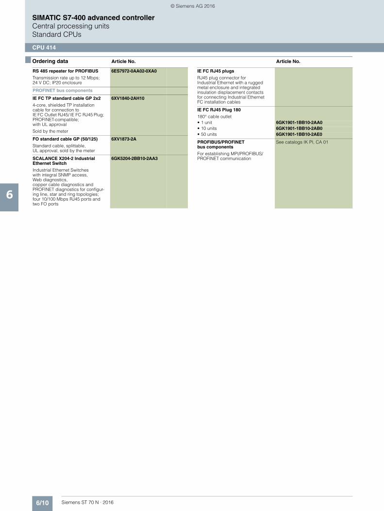
6/10 Siemens ST 70 N · 2016
6
■ Ordering data Article No. Article No.
SIMATIC S7-400 advanced controllerCentral processing unitsStandard CPUs
CPU 414
RS 485 repeater for PROFIBUS
Transmission rate up to 12 Mbps; 24 V DC; IP20 enclosure
6ES7972-0AA02-0XA0
PROFINET bus components
IE FC TP standard cable GP 2x2
4-core, shielded TP installation cable for connection toIE FC Outlet RJ45/ IE FC RJ45 Plug; PROFINET-compatible; with UL approval
Sold by the meter
6XV1840-2AH10
FO standard cable GP (50/125)
Standard cable, splittable,UL approval, sold by the meter
6XV1873-2A
SCALANCE X204-2 Industrial Ethernet Switch
Industrial Ethernet Switches with integral SNMP access, Web diagnostics, copper cable diagnostics and PROFINET diagnostics for configur-ing line, star and ring topologies; four 10/100 Mbps RJ45 ports and two FO ports
6GK5204-2BB10-2AA3
IE FC RJ45 plugs
RJ45 plug connector forIndustrial Ethernet with a rugged metal enclosure and integrated insulation displacement contacts for connecting Industrial Ethernet FC installation cables
IE FC RJ45 Plug 180
180° cable outlet• 1 unit 6GK1901-1BB10-2AA0• 10 units 6GK1901-1BB10-2AB0• 50 units 6GK1901-1BB10-2AE0
PROFIBUS/PROFINET bus components
For establishing MPI/PROFIBUS/PROFINET communication
See catalogs IK PI, CA 01
© Siemens AG 2016

6/11Siemens ST 70 N · 2016
6
SIMATIC S7-400 advanced controllerCentral processing units
Standard CPUs
CPU 416
■ Overview
• High-performance CPUs in the high-end performance range• Applicable for plants with high requirements in the high-end
performance range• Integrated PROFINET functions in CPU 416-3 PN/DP
■ Technical specifications
Article number 6ES7416-2XP07-0AB0 6ES7416-3XS07-0AB0 6ES7416-3ES07-0AB0
CPU 416-2, MPI, PROFIBUS, 8 MB CPU 416-3, 16 MB, 3 INTERFACES CPU416-3 PN/DP, 16 MB, 3 INTERFACES
General information
Product type designation CPU 416-2 CPU 416-3 CPU416-3 PN/DP
Engineering with
• Programming package STEP 7 V5.4 or higher with HSP 261 STEP 7 V5.4 or higher with HSP 261 STEP 7 V5.5 or higher with HSP 262
Supply voltage
Rated value (DC)
• 24 V DC No; Power supply via system power supply
No; Power supply via system power supply
No; Power supply via system power supply
Power loss
Power loss, typ. 4.5 W 5.5 W 6.5 W
Memory
Work memory
• integrated 8 Mbyte 16 Mbyte 16 Mbyte
• integrated (for program) 4 Mbyte 8 Mbyte 8 Mbyte
• integrated (for data) 4 Mbyte 8 Mbyte 8 Mbyte
Load memory
• expandable FEPROM, max. 64 Mbyte 64 Mbyte 64 Mbyte
• integrated RAM, max. 1 Mbyte 1 Mbyte 1 Mbyte
• expandable RAM, max. 64 Mbyte 64 Mbyte 64 Mbyte
CPU processing times
for bit operations, typ. 12.5 ns 12.5 ns 12.5 ns
for word operations, typ. 12.5 ns 12.5 ns 12.5 ns
for fixed point arithmetic, typ. 12.5 ns 12.5 ns 12.5 ns
for floating point arithmetic, typ. 25 ns 25 ns 25 ns
Counters, timers and their retentivity
S7 counter
• Number 2 048 2 048 2 048
IEC counter
• present Yes Yes Yes
S7 times
• Number 2 048 2 048 2 048
IEC timer
• present Yes Yes Yes
Data areas and their retentivity
Flag
• Number, max. 16 kbyte; Size of bit memory address area
16 kbyte; Size of bit memory address area
16 kbyte; Size of bit memory address area
© Siemens AG 2016

6/12 Siemens ST 70 N · 2016
6
■ Technical specifications (continued)
SIMATIC S7-400 advanced controllerCentral processing unitsStandard CPUs
CPU 416
Address area
I/O address area
• Inputs 16 kbyte 16 kbyte 16 kbyte
• Outputs 16 kbyte 16 kbyte 16 kbyte
Process image
• Inputs, adjustable 16 kbyte 16 kbyte 16 kbyte
• Outputs, adjustable 16 kbyte 16 kbyte 16 kbyte
Time of day
Clock
• Hardware clock (real-time clock) Yes Yes Yes
Operating hours counter
• Number 16 16 16
Interfaces
Interfaces/bus type 1 x MPI/PROFIBUS DP, 1 x PROFIBUS DP
1 x MPI/PROFIBUS DP, 1 x PROFIBUS DP, 1 x PROFIBUS DP (optionally pluggable)
1 x MPI/PROFIBUS DP, 1 x PROFINET (2 ports), 1 x PROFIBUS DP(optionally pluggable)
Number of RS 485 interfaces 2; Combined MPI / PROFIBUS DP and PROFIBUS DP
2; Combined MPI / PROFIBUS DP and PROFIBUS DP
1; Combined MPI / PROFIBUS DP
Number of other interfaces 1; PROFIBUS DP with IF 964-DP (plug-in option;MLFB: 6ES7964-2AA04-0AB0)
1; PROFIBUS DP with IF 964-DP (plug-in option; MLFB: 6ES7964-2AA04-0AB0)
1. Interface
Interface type Integrated Integrated Integrated
Physics RS 485 / PROFIBUS + MPI RS 485 / PROFIBUS + MPI RS 485 / PROFIBUS + MPI
Functionality
• MPI Yes Yes Yes
• DP master Yes Yes Yes
• DP slave Yes Yes Yes
DP master
• Number of DP slaves, max. 32 32 32
2. Interface
Interface type Integrated Integrated PROFINET
Physics RS 485 / PROFIBUS RS 485 / PROFIBUS Ethernet RJ45
Interface types
• Number of ports 2
Functionality
• DP master Yes Yes No
• DP slave Yes Yes No
• PROFINET IO Controller Yes
• PROFINET IO Device Yes
• PROFINET CBA Yes
DP master
• Number of DP slaves, max. 125 125
3. Interface
Interface type Pluggable interface module (IF), technical data as for 2nd interface
Pluggable interface module (IF)
Plug-in interface modules IF 964-DP (MLFB: 6ES7964-2AA04-0AB0)
IF 964-DP(MLFB: 6ES7964-2AA04-0AB0)
Physics RS 485 / PROFIBUS RS 485 / PROFIBUS
Functionality
• MPI No No
• DP master Yes Yes
• DP slave Yes Yes
DP master
• Number of DP slaves, max. 125 125
Article number 6ES7416-2XP07-0AB0 6ES7416-3XS07-0AB0 6ES7416-3ES07-0AB0
CPU 416-2, MPI, PROFIBUS, 8 MB CPU 416-3, 16 MB, 3 INTERFACES CPU416-3 PN/DP, 16 MB, 3 INTERFACES
© Siemens AG 2016

6/13Siemens ST 70 N · 2016
6
■ Technical specifications (continued)
SIMATIC S7-400 advanced controllerCentral processing units
Standard CPUs
CPU 416
Isochronous mode
Isochronous operation (application synchronized up to terminal)
Yes; For PROFIBUS only Yes; For PROFIBUS only Yes; Via PROFIBUS DP or PROFINET interface
Communication functions
PG/OP communication Yes Yes Yes
Data record routing Yes Yes Yes
Global data communication
• supported Yes Yes Yes
S7 basic communication
• supported Yes Yes Yes
S7 communication
• supported Yes Yes Yes
S5 compatible communication
• supported Yes; Via FC AG_SEND and AG_RECV, max. via 10 CP 443-1 or 443-5
Yes; Via FC AG_SEND and AG_RECV, max. via 10 CP 443-1 or 443-5
Yes; Via FC AG_SEND and AG_RECV, max. via 10 CP 443-1 or 443-5
Standard communication (FMS)
• supported Yes; Via CP and loadable FB Yes; Via CP and loadable FB Yes; Via CP and loadable FB
Open IE communication
• TCP/IP Yes; via integrated PROFINET interface and loadable FBs
- Number of connections, max. 94
• ISO-on-TCP (RFC1006) Via CP 443-1 and loadable FB Via CP 443-1 and loadable FB Yes; Via integrated PROFINET interface or CP 443-1 and loadable FBs
- Number of connections, max. 94
• UDP Yes; via integrated PROFINET interface and loadable FBs
- Number of connections, max. 94
Web server
• supported No No Yes
Number of connections
• overall 96 96 96
Standards, approvals, certificates
Use in hazardous areas
• ATEX ATEX II 3 G Ex nA IIC T4 Gc ATEX II 3 G Ex nA IIC T4 Gc ATEX II 3 G Ex nA IIC T4 Gc
Ambient conditions
Ambient temperature during operation
• min. 0 °C 0 °C 0 °C
• max. 60 °C 60 °C 60 °C
Configuration
Know-how protection
• User program protection/password protection
Yes Yes Yes
• Block encryption Yes; With S7 block Privacy Yes; With S7 block Privacy Yes; With S7 block Privacy
Dimensions
Width 25 mm 50 mm 50 mm
Height 290 mm 290 mm 290 mm
Depth 219 mm 219 mm 219 mm
Weights
Weight, approx. 700 g 900 g 900 g
Article number 6ES7416-2XP07-0AB0 6ES7416-3XS07-0AB0 6ES7416-3ES07-0AB0
CPU 416-2, MPI, PROFIBUS, 8 MB CPU 416-3, 16 MB, 3 INTERFACES CPU416-3 PN/DP, 16 MB, 3 INTERFACES
© Siemens AG 2016
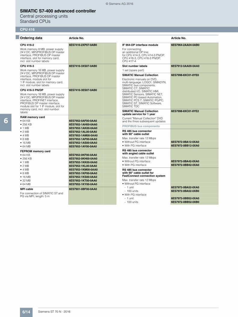
6/14 Siemens ST 70 N · 2016
6
SIMATIC S7-400 advanced controllerCentral processing unitsStandard CPUs
CPU 416
■ Ordering data Article No. Article No.
CPU 416-2
Work memory 8 MB, power supply 24 V DC, MPI/PROFIBUS DP master interface, PROFIBUS DP master interface, slot for memory card, incl. slot number labels
6ES7416-2XP07-0AB0
CPU 416-3
Work memory 16 MB, power supply 24 V DC, MPI/PROFIBUS DP master interface, PROFIBUS DP master interface, module slot for 1 IF module, slot for memory card, incl. slot number labels
6ES7416-3XS07-0AB0
CPU 416-3 PN/DP
Work memory 16 MB, power supply 24 V DC, MPI/PROFIBUS DP master interface, PROFINET interface, PROFIBUS DP master interface, module slot for 1 IF module, slot for memory card, incl. slot number labels
6ES7416-3ES07-0AB0
RAM memory card• 64 KB 6ES7952-0AF00-0AA0• 256 KB 6ES7952-1AH00-0AA0• 1 MB 6ES7952-1AK00-0AA0• 2 MB 6ES7952-1AL00-0AA0• 4 MB 6ES7952-1AM00-0AA0• 8 MB 6ES7952-1AP00-0AA0• 16 MB 6ES7952-1AS00-0AA0• 64 MB 6ES7952-1AY00-0AA0
FEPROM memory card• 64 KB 6ES7952-0KF00-0AA0• 256 KB 6ES7952-0KH00-0AA0• 1 MB 6ES7952-1KK00-0AA0• 2 MB 6ES7952-1KL00-0AA0• 4 MB 6ES7952-1KM00-0AA0• 8 MB 6ES7952-1KP00-0AA0• 16 MB 6ES7952-1KS00-0AA0• 32 MB 6ES7952-1KT00-0AA0• 64 MB 6ES7952-1KY00-0AA0
MPI cable
For connection of SIMATIC S7 and PG via MPI; length: 5 m
6ES7901-0BF00-0AA0
IF 964-DP interface module
For connecting an additional DP line; for CPU 414-3, CPU 414-3 PN/DP, CPU 416-3, CPU 416-3 PN/DP, CPU 417-4
6ES7964-2AA04-0AB0
Slot number labels
1 set (spare part)
6ES7912-0AA00-0AA0
SIMATIC Manual Collection
Electronic manuals on DVD, multi-language: LOGO!, SIMADYN, SIMATIC bus components, SIMATIC C7, SIMATIC distributed I/O, SIMATIC HMI, SIMATIC Sensors, SIMATIC NET, SIMATIC PC-based Automation, SIMATIC PCS 7, SIMATIC PG/PC, SIMATIC S7, SIMATIC Software, SIMATIC TDC
6ES7998-8XC01-8YE0
SIMATIC Manual Collection update service for 1 year
Current "Manual Collection" DVD and the three subsequent updates
6ES7998-8XC01-8YE2
PROFIBUS bus components
RS 485 bus connector with 90° cable outlet
Max. transfer rate 12 Mbps• Without PG interface 6ES7972-0BA12-0XA0• With PG interface 6ES7972-0BB12-0XA0
RS 485 bus connector with angled cable outlet
Max. transfer rate 12 Mbps• Without PG interface 6ES7972-0BA42-0XA0• With PG interface 6ES7972-0BB42-0XA0
RS 485 bus connector with 90° cable outlet for FastConnect connection system
Max. transfer rate 12 Mbps• Without PG interface
- 1 unit 6ES7972-0BA52-0XA0- 100 units 6ES7972-0BA52-0XB0
• With PG interface- 1 unit 6ES7972-0BB52-0XA0- 100 units 6ES7972-0BB52-0XB0
© Siemens AG 2016

6/15Siemens ST 70 N · 2016
6
■ Ordering data Article No. Article No.
SIMATIC S7-400 advanced controllerCentral processing units
Standard CPUs
CPU 416
RS 485 bus connectorwith axial cable outlet
For SIMATIC OP, for connectionto PPI, MPI, PROFIBUS
6GK1500-0EA02
PROFIBUS FastConnect bus cableStandard type with special design for fast mounting, 2-core, shielded, sold by the meter; max. delivery unit 1 000 m, minimum ordering quantity 20 m
6XV1830-0EH10
RS 485 repeater for PROFIBUS
Transmission rate up to 12 Mbps; 24 V DC; IP20 enclosure
6ES7972-0AA02-0XA0
PROFINET bus components
IE FC TP standard cable GP 2x2
4-core, shielded TP installation cable for connection to IE FC Outlet RJ45/ IE FC RJ45 Plug; PROFINET-compatible; with UL approval
Sold by the meter
6XV1840-2AH10
FO standard cable GP (50/125)
Standard cable, splittable, UL approval, sold by the meter
6XV1873-2A
SCALANCE X204-2Industrial Ethernet Switch
Industrial Ethernet Switches with integral SNMP access, Web diagnostics, copper cable diagnostics and PROFINET diag-nostics for configuring line, star and ring topologies; four 10/100 Mbps RJ45 ports and two FO ports
6GK5204-2BB10-2AA3
IE FC RJ45 plugs
RJ45 plug connector for Industrial Ethernet with a rugged metal enclosure and integrated insulation displacement contacts for connecting Industrial Ethernet FC installation cables
IE FC RJ45 Plug 180
180° cable outlet• 1 unit 6GK1901-1BB10-2AA0• 10 units 6GK1901-1BB10-2AB0• 50 units 6GK1901-1BB10-2AE0
PROFIBUS/PROFINET bus components
For establishing MPI/PROFIBUS/PROFINET communication
See catalogs IK PI, CA 01
© Siemens AG 2016

6/16 Siemens ST 70 N · 2016
6
SIMATIC S7-400 advanced controllerCentral processing unitsStandard CPUs
CPU 417
■ Overview
• The most powerful SIMATIC S7-400 CPU• Can be used in the most sophisticated installations in the
upper performance range• With two slots for IF modules
■ Technical specifications
Article number 6ES7417-4XT07-0AB0
CPU 417-4, 32 MB, 4 INTERFACES
General information
Product type designation CPU 417-4
Engineering with
• Programming package STEP 7 V5.4 or higher with HSP 261
Supply voltage
Rated value (DC)
• 24 V DC No; Power supply via system power supply
Power loss
Power loss, typ. 6.5 W
Memory
Work memory
• integrated 32 Mbyte
• integrated (for program) 16 Mbyte
• integrated (for data) 16 Mbyte
Load memory
• expandable FEPROM, max. 64 Mbyte
• integrated RAM, max. 1 Mbyte
• expandable RAM, max. 64 Mbyte
CPU processing times
for bit operations, typ. 7.5 ns
for word operations, typ. 7.5 ns
for fixed point arithmetic, typ. 7.5 ns
for floating point arithmetic, typ. 15 ns
Counters, timers and their reten-tivity
S7 counter
• Number 2 048
IEC counter
• present Yes
S7 times
• Number 2 048
IEC timer
• present Yes
Data areas and their retentivity
Flag
• Number, max. 16 kbyte; Size of bit memory address area
Address area
I/O address area
• Inputs 16 kbyte
• Outputs 16 kbyte
Process image
• Inputs, adjustable 16 kbyte
• Outputs, adjustable 16 kbyte
Time of day
Clock
• Hardware clock (real-time clock) Yes
Operating hours counter
• Number 16
Interfaces
Interfaces/bus type 1 x MPI/PROFIBUS DP, 1 x PROFIBUS DP, 2 x PROFIBUS DP (optionally pluggable)
Number of RS 485 interfaces 2; Combined MPI / PROFIBUS DP and PROFIBUS DP
Number of other interfaces 2; PROFIBUS DP with IF 964-DP (plug-in option; MLFB: 6ES7964-2AA04-0AB0)
1. Interface
Interface type Integrated
Physics RS 485 / PROFIBUS + MPI
Functionality
• MPI Yes
• DP master Yes
• DP slave Yes
DP master
• Number of DP slaves, max. 32
2. Interface
Interface type Integrated
Physics RS 485 / PROFIBUS
Article number 6ES7417-4XT07-0AB0
CPU 417-4, 32 MB, 4 INTERFACES
© Siemens AG 2016

6/17Siemens ST 70 N · 2016
6
■ Technical specifications (continued)
SIMATIC S7-400 advanced controllerCentral processing units
Standard CPUs
CPU 417
■ Ordering data Article No. Article No.
Functionality
• DP master Yes
• DP slave Yes
DP master
• Number of DP slaves, max. 125
3. Interface
Interface type Pluggable interface module (IF), technical data as for 2nd interface
Plug-in interface modules IF 964-DP(MLFB: 6ES7964-2AA04-0AB0)
Physics RS 485 / PROFIBUS
Functionality
• MPI No
• DP master Yes
• DP slave Yes
DP master
• Number of DP slaves, max. 125
4. Interface
Interface type Pluggable interface module (IF), technical data as for 2nd interface
Plug-in interface modules IF 964-DP(MLFB: 6ES7964-2AA04-0AB0)
Isochronous mode
Isochronous operation (application synchronized up to terminal)
Yes; For PROFIBUS only
Communication functions
PG/OP communication Yes
Data record routing Yes
Global data communication
• supported Yes
S7 basic communication
• supported Yes
S7 communication
• supported Yes
Article number 6ES7417-4XT07-0AB0
CPU 417-4, 32 MB, 4 INTERFACES
S5 compatible communication
• supported Yes; Via FC AG_SEND and AG_RECV, max. via 10 CP 443-1 or 443-5
Standard communication (FMS)
• supported Yes; Via CP and loadable FB
Open IE communication
• ISO-on-TCP (RFC1006) Via CP 443-1 and loadable FB
Web server
• supported No
Number of connections
• overall 120
Standards, approvals, certificates
Use in hazardous areas
• ATEX ATEX II 3 G Ex nA IIC T4 Gc
Ambient conditions
Ambient temperature during operation
• min. 0 °C
• max. 60 °C
Configuration
Know-how protection
• User program protection/password protection
Yes
• Block encryption Yes; With S7 block Privacy
Dimensions
Width 50 mm
Height 290 mm
Depth 219 mm
Weights
Weight, approx. 900 g
Article number 6ES7417-4XT07-0AB0
CPU 417-4, 32 MB, 4 INTERFACES
CPU 417-4
Work memory 30 MB, power supply 24 V DC, MPI/PROFIBUS DP master interface, PROFIBUS DP master interface, module slots for up to 2 additional IF modules, slot for memory card, incl. slot number labels
6ES7417-4XT07-0AB0
RAM memory card• 64 KB 6ES7952-0AF00-0AA0• 256 KB 6ES7952-1AH00-0AA0• 1 MB 6ES7952-1AK00-0AA0• 2 MB 6ES7952-1AL00-0AA0• 4 MB 6ES7952-1AM00-0AA0• 8 MB 6ES7952-1AP00-0AA0• 16 MB 6ES7952-1AS00-0AA0• 64 MB 6ES7952-1AY00-0AA0
FEPROM memory card• 64 KB 6ES7952-0KF00-0AA0• 256 KB 6ES7952-0KH00-0AA0• 1 MB 6ES7952-1KK00-0AA0• 2 MB 6ES7952-1KL00-0AA0• 4 MB 6ES7952-1KM00-0AA0• 8 MB 6ES7952-1KP00-0AA0• 16 MB 6ES7952-1KS00-0AA0• 32 MB 6ES7952-1KT00-0AA0• 64 MB 6ES7952-1KY00-0AA0
MPI cable
For connection of SIMATIC S7 and PG via MPI; length: 5 m
6ES7901-0BF00-0AA0
© Siemens AG 2016
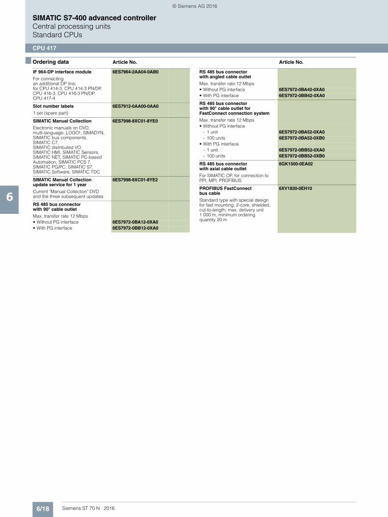
6/18 Siemens ST 70 N · 2016
6
■ Ordering data Article No. Article No.
SIMATIC S7-400 advanced controllerCentral processing unitsStandard CPUs
CPU 417
IF 964-DP interface module
For connectingan additional DP line; for CPU 414-3, CPU 414-3 PN/DP, CPU 416-3, CPU 416-3 PN/DP, CPU 417-4
6ES7964-2AA04-0AB0
Slot number labels
1 set (spare part)
6ES7912-0AA00-0AA0
SIMATIC Manual Collection
Electronic manuals on DVD,multi-language: LOGO!, SIMADYN, SIMATIC bus components,SIMATIC C7, SIMATIC distributed I/O, SIMATIC HMI, SIMATIC Sensors, SIMATIC NET, SIMATIC PC-based Automation, SIMATIC PCS 7, SIMATIC PG/PC, SIMATIC S7, SIMATIC Software, SIMATIC TDC
6ES7998-8XC01-8YE0
SIMATIC Manual Collection update service for 1 year
Current "Manual Collection" DVD and the three subsequent updates
6ES7998-8XC01-8YE2
RS 485 bus connectorwith 90° cable outlet
Max. transfer rate 12 Mbps• Without PG interface 6ES7972-0BA12-0XA0• With PG interface 6ES7972-0BB12-0XA0
RS 485 bus connectorwith angled cable outlet
Max. transfer rate 12 Mbps• Without PG interface 6ES7972-0BA42-0XA0• With PG interface 6ES7972-0BB42-0XA0
RS 485 bus connector with 90° cable outlet for FastConnect connection system
Max. transfer rate 12 Mbps• Without PG interface
- 1 unit 6ES7972-0BA52-0XA0- 100 units 6ES7972-0BA52-0XB0
• With PG interface- 1 unit 6ES7972-0BB52-0XA0- 100 units 6ES7972-0BB52-0XB0
RS 485 bus connectorwith axial cable outlet
For SIMATIC OP, for connection to PPI, MPI, PROFIBUS
6GK1500-0EA02
PROFIBUS FastConnect bus cable
Standard type with special design for fast mounting, 2-core, shielded, cut-to-length; max. delivery unit 1 000 m, minimum ordering quantity 20 m
6XV1830-0EH10
© Siemens AG 2016

6/19Siemens ST 70 N · 2016
6
SIMATIC S7-400 advanced controllerCentral processing units
Fail-safe CPUs
CPU 414F
■ Overview
• For constructing a fail-safe automation system for plants with increased safety requirements
• CPUs for high demands in the mid-level performance range• Applicable for plants with additional demands on
programming scope and processing speed • Complies with safety requirements to SIL 3 acc. to IEC 61508
and PL e acc. to ISO 13849.1• Standard and safety-related tasks can be performed
with a single CPU• Integrated PROFINET functions with CPU 414F-3 PN/DP• Multi-processor mode is possible• Safety-related communication with distributed I/O devices
over PROFIBUS DP or PROFINET IO with PROFIsafe profile• Fail-safe I/O modules can be connected in a distributed
manner via the integrated interfaces (DP and PN with CPU 414F-3 PN/DP) and/or through communication modules (CP 443-5 Extended and CP 443-1 Advanced)
• Central and distributed use of standard modules for non-safety-oriented applications
■ Technical specifications
Article number 6ES7414-3FM07-0AB0
CPU414F-3 PN/DP, 4 MB, 3 INTERFACES
General information
Product type designation CPU414F-3 PN/DP
Engineering with
• Programming package STEP 7 V5.5 or higher with HSP 262
Supply voltage
Rated value (DC)
• 24 V DC No; Power supply via system power supply
Power loss
Power loss, typ. 6.5 W
Memory
Work memory
• integrated 4 Mbyte
• integrated (for program) 2 Mbyte
• integrated (for data) 2 Mbyte
Load memory
• expandable FEPROM, max. 64 Mbyte
• integrated RAM, max. 512 kbyte
• expandable RAM, max. 64 Mbyte
CPU processing times
for bit operations, typ. 18.75 ns
for word operations, typ. 18.75 ns
for fixed point arithmetic, typ. 18.75 ns
for floating point arithmetic, typ. 37.5 ns
Counters, timers and theirretentivity
S7 counter
• Number 2 048
IEC counter
• present Yes
S7 times
• Number 2 048
IEC timer
• present Yes
Data areas and their retentivity
Flag
• Number, max. 8 kbyte; Size of bit memory address area
Address area
I/O address area
• Inputs 8 kbyte
• Outputs 8 kbyte
Process image
• Inputs, adjustable 8 kbyte
• Outputs, adjustable 8 kbyte
Time of day
Clock
• Hardware clock (real-time clock) Yes
Operating hours counter
• Number 16
Interfaces
Interfaces/bus type 1 x MPI/PROFIBUS DP, 1 x PROFINET (2 ports), 1 x PROFIBUS DP(optionally pluggable)
Number of RS 485 interfaces 1; Combined MPI / PROFIBUS DP
Number of other interfaces 1; PROFIBUS DP withIF 964-DP (plug-in option; MLFB: 6ES7964-2AA04-0AB0)
1. Interface
Interface type Integrated
Physics RS 485 / PROFIBUS + MPI
Article number 6ES7414-3FM07-0AB0
CPU414F-3 PN/DP, 4 MB, 3 INTERFACES
© Siemens AG 2016
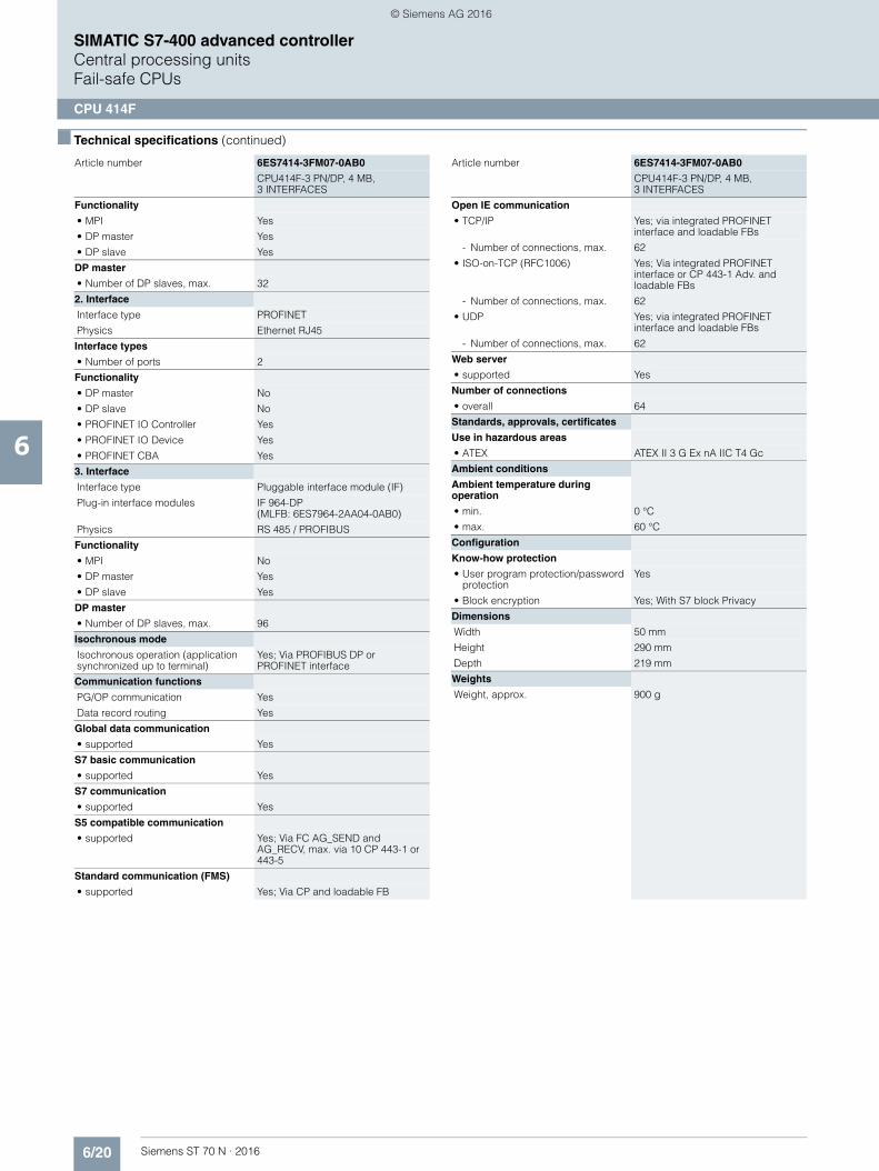
6/20 Siemens ST 70 N · 2016
6
■ Technical specifications (continued)
SIMATIC S7-400 advanced controllerCentral processing unitsFail-safe CPUs
CPU 414F
Functionality
• MPI Yes
• DP master Yes
• DP slave Yes
DP master
• Number of DP slaves, max. 32
2. Interface
Interface type PROFINET
Physics Ethernet RJ45
Interface types
• Number of ports 2
Functionality
• DP master No
• DP slave No
• PROFINET IO Controller Yes
• PROFINET IO Device Yes
• PROFINET CBA Yes
3. Interface
Interface type Pluggable interface module (IF)
Plug-in interface modules IF 964-DP(MLFB: 6ES7964-2AA04-0AB0)
Physics RS 485 / PROFIBUS
Functionality
• MPI No
• DP master Yes
• DP slave Yes
DP master
• Number of DP slaves, max. 96
Isochronous mode
Isochronous operation (application synchronized up to terminal)
Yes; Via PROFIBUS DP or PROFINET interface
Communication functions
PG/OP communication Yes
Data record routing Yes
Global data communication
• supported Yes
S7 basic communication
• supported Yes
S7 communication
• supported Yes
S5 compatible communication
• supported Yes; Via FC AG_SEND and AG_RECV, max. via 10 CP 443-1 or 443-5
Standard communication (FMS)
• supported Yes; Via CP and loadable FB
Article number 6ES7414-3FM07-0AB0
CPU414F-3 PN/DP, 4 MB, 3 INTERFACES
Open IE communication
• TCP/IP Yes; via integrated PROFINET interface and loadable FBs
- Number of connections, max. 62
• ISO-on-TCP (RFC1006) Yes; Via integrated PROFINET interface or CP 443-1 Adv. and loadable FBs
- Number of connections, max. 62
• UDP Yes; via integrated PROFINET interface and loadable FBs
- Number of connections, max. 62
Web server
• supported Yes
Number of connections
• overall 64
Standards, approvals, certificates
Use in hazardous areas
• ATEX ATEX II 3 G Ex nA IIC T4 Gc
Ambient conditions
Ambient temperature during operation
• min. 0 °C
• max. 60 °C
Configuration
Know-how protection
• User program protection/password protection
Yes
• Block encryption Yes; With S7 block Privacy
Dimensions
Width 50 mm
Height 290 mm
Depth 219 mm
Weights
Weight, approx. 900 g
Article number 6ES7414-3FM07-0AB0
CPU414F-3 PN/DP, 4 MB, 3 INTERFACES
© Siemens AG 2016
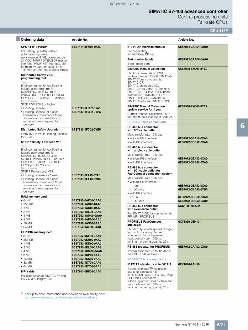
6/21Siemens ST 70 N · 2016
6
SIMATIC S7-400 advanced controllerCentral processing units
Fail-safe CPUs
CPU 414F
■ Ordering data Article No. Article No.
CPU 414F-3 PN/DP
For setting up safety-related automation systems;work memory 4 MB, power supply 24 V DC, MPI/PROFIBUS DP master interface, PROFINET interface, slot for memory card, module slot for1 IF module, incl. slot number labels
6ES7414-3FM07-0AB0
Distributed Safety V5.4programming tool
Task:Engineering tool for configuringfailsafe user programs for SIMATIC S7-300F, S7-400F, WinAC RTX F, ET 200S, ET 200M, ET 200iSP, ET 200pro, ET 200eco Requirement: STEP 7 V5.3 SP3 or higher• Floating License 6ES7833-1FC02-0YA5• Floating License for 1 user,
license key download without software or documentation1); e-mail address required for delivery
6ES7833-1FC02-0YH5
Distributed Safety Upgrade
From V5.x to V5.4; Floating License for 1 user
6ES7833-1FC02-0YE5
STEP 7 Safety Advanced V13
Task:Engineering tool for configuringfailsafe user programs for SIMATIC S7-1500F, S7-300F, S7-400F, WinAC RTX F, ET200SP, ET 200S, ET 200M, ET 200iSP, ET 200pro, ET 200ecoRequirement:STEP 7 Professional V13• Floating License for 1 user 6ES7833-1FA13-0YA5• Floating License for 1 user,
license key download without software or documentation1); e-mail address required fordelivery
6ES7833-1FA13-0YH5
RAM memory card• 64 KB 6ES7952-0AF00-0AA0• 256 KB 6ES7952-1AH00-0AA0• 1 MB 6ES7952-1AK00-0AA0• 2 MB 6ES7952-1AL00-0AA0• 4 MB 6ES7952-1AM00-0AA0• 8 MB 6ES7952-1AP00-0AA0• 16 MB 6ES7952-1AS00-0AA0• 64 MB 6ES7952-1AY00-0AA0
FEPROM memory card• 64 KB 6ES7952-0KF00-0AA0• 256 KB 6ES7952-0KH00-0AA0• 1 MB 6ES7952-1KK00-0AA0• 2 MB 6ES7952-1KL00-0AA0• 4 MB 6ES7952-1KM00-0AA0• 8 MB 6ES7952-1KP00-0AA0• 16 MB 6ES7952-1KS00-0AA0• 32 MB 6ES7952-1KT00-0AA0• 64 MB 6ES7952-1KY00-0AA0
MPI cable
For connection of SIMATIC S7 and PG via MPI; length: 5 m
6ES7901-0BF00-0AA0
1) For up-to-date information and download availability, see:http://www.siemens.com/tia-online-software-delivery
IF 964-DP interface module
For connecting an additional DP line
6ES7964-2AA04-0AB0
Slot number labels
1 set (spare part)
6ES7912-0AA00-0AA0
SIMATIC Manual Collection
Electronic manuals on DVD, multi-language: LOGO!, SIMADYN, SIMATIC bus components, SIMATIC C7, SIMATIC distributed I/O, SIMATIC HMI, SIMATIC Sensors, SIMATIC NET, SIMATIC PC-based Automation, SIMATIC PCS 7, SIMATIC PG/PC, SIMATIC S7, SIMATIC Software, SIMATIC TDC
6ES7998-8XC01-8YE0
SIMATIC Manual Collection update service for 1 year
Current "Manual Collection" DVD and the three subsequent updates
6ES7998-8XC01-8YE2
PROFIBUS bus components
RS 485 bus connector with 90° cable outlet
Max. transfer rate 12 Mbps• Without PG interface 6ES7972-0BA12-0XA0• With PG interface 6ES7972-0BB12-0XA0
RS 485 bus connectorwith angled cable outlet
Max. transfer rate 12 Mbps• Without PG interface 6ES7972-0BA42-0XA0• With PG interface 6ES7972-0BB42-0XA0
RS 485 bus connector with 90° cable outlet for FastConnect connection system
Max. transfer rate 12 Mbps• Without PG interface
- 1 unit 6ES7972-0BA52-0XA0- 100 units 6ES7972-0BA52-0XB0
• With PG interface- 1 unit 6ES7972-0BB52-0XA0- 100 units 6ES7972-0BB52-0XB0
RS 485 bus connector with axial cable outlet
For SIMATIC OP, for connection to PPI, MPI, PROFIBUS
6GK1500-0EA02
PROFIBUS FastConnect bus cable
Standard type with special design for quick mounting, 2-core, shielded, sold by the meter; max. delivery unit 1000 m, minimum ordering quantity 20 m
6XV1830-0EH10
RS 485 repeater for PROFIBUS
Transmission rate up to 12 Mbps; 24 V DC; IP20 enclosure
6ES7972-0AA02-0XA0
PROFINET bus components
IE FC TP standard cable GP 2x2
4-core, shielded TP installation cable for connection to IE FC Outlet RJ45/ IE FC RJ45 Plug; PROFINET-compatible; with UL approval; sold by the meter; max. delivery unit 1000 m, minimum ordering quantity 20 m
6XV1840-2AH10
© Siemens AG 2016

6/22 Siemens ST 70 N · 2016
6
■ Ordering data Article No. Article No.
SIMATIC S7-400 advanced controllerCentral processing unitsFail-safe CPUs
CPU 414F
FO standard cable GP (50/125)
Standard cable, splittable, UL approval, sold by the meter:max. delivery unit 1 000 m, minimum ordering quantity 20 m
6XV1873-2A
SCALANCE X204-2 Industrial Ethernet Switch
Industrial Ethernet Switches with integral SNMP access, Web diagnostics, copper cable diagnostics and PROFINET diagnostics for configuring line,star and ring topologies;four 10/100 Mbps RJ45 ports and two FO ports
6GK5204-2BB10-2AA3
IE FC RJ45 plugs
RJ45 plug connector forIndustrial Ethernet with a rugged metal enclosure and integrated insulation displacement contacts for connecting Industrial Ethernet FC installation cables
IE FC RJ45 Plug 180
180° cable outlet• 1 unit 6GK1901-1BB10-2AA0• 10 units 6GK1901-1BB10-2AB0• 50 units 6GK1901-1BB10-2AE0
PROFIBUS/PROFINET bus components
For establishing MPI/PROFIBUS/PROFINET communication
See catalogs IK PI, CA 01
© Siemens AG 2016

6/23Siemens ST 70 N · 2016
6
SIMATIC S7-400 advanced controllerCentral processing units
Fail-safe CPUs
CPU 416F
■ Overview
• For constructing a fail-safe automation system for plants with increased safety requirements
• High-performance CPU in the top-end performance range • Complies with safety requirements to SIL 3 acc. to IEC 61508
and PL e acc. to ISO 13849.1• Standard and safety-related tasks can be performed
with a single CPU• Multi-processor mode is possible• Safety-related communication with distributed I/O devices
over PROFIBUS DP with the PROFIsafe profile• Fail-safe I/O modules can be connected decentralized over
the integrated interfaces (DP and PN with CPU416F-3 PN/DP) and/or through communication modules (CP443-5 Ext. and CP443-1 Adv.)
• Standard modules for non-safety-related applications can be operated centrally and decentralized
■ Technical specifications
Article number 6ES7416-2FP07-0AB0 6ES7416-3FS07-0AB0
CPU 416F-2, MPI, PROFIBUS, 8 MB
CPU416F-3 PN/DP, 16 MB, 3 INTERFACES
General information
Product type designation CPU 416F-2 CPU416F-3 PN/DP
Engineering with
• Programming package STEP 7 V5.4 or higher with HSP 261
STEP 7 V5.5 or higher with HSP 262
Supply voltage
Rated value (DC)
• 24 V DC No; Power supply via system power supply
No; Power supply via system power supply
Power loss
Power loss, typ. 4.5 W 6.5 W
Memory
Work memory
• integrated 8 Mbyte 16 Mbyte
• integrated (for program) 4 Mbyte 8 Mbyte
• integrated (for data) 4 Mbyte 8 Mbyte
Load memory
• expandable FEPROM, max.
64 Mbyte 64 Mbyte
• integrated RAM, max. 1 Mbyte 1 Mbyte
• expandable RAM, max. 64 Mbyte 64 Mbyte
CPU processing times
for bit operations, typ. 12.5 ns 12.5 ns
for word operations, typ. 12.5 ns 12.5 ns
for fixed point arithmetic, typ.
12.5 ns 12.5 ns
for floating point arithmetic, typ.
25 ns 25 ns
Counters, timers and their retentivity
S7 counter
• Number 2 048 2 048
IEC counter
• present Yes Yes
S7 times
• Number 2 048 2 048
IEC timer
• present Yes Yes
Data areas and their retentivity
Flag
• Number, max. 16 kbyte; Size of bit memory address area
16 kbyte; Size of bit memory address area
Address area
I/O address area
• Inputs 16 kbyte 16 kbyte
• Outputs 16 kbyte 16 kbyte
Process image
• Inputs, adjustable 16 kbyte 16 kbyte
• Outputs, adjustable 16 kbyte 16 kbyte
Time of day
Clock
• Hardware clock (real-time clock)
Yes Yes
Operating hours counter
• Number 16 16
Interfaces
Interfaces/bus type 1 x MPI/PROFIBUS DP, 1 x PROFIBUS DP
1 x MPI/PROFIBUS DP, 1 x PROFINET (2 ports), 1 x PROFIBUS DP (optionally pluggable)
Number of RS 485 inter-faces
2; Combined MPI / PROFIBUS DP and PROFIBUS DP
1; Combined MPI / PROFIBUS DP
Number of other interfaces 1; PROFIBUS DP with IF 964-DP(plug-in option; MLFB: 6ES7964-2AA04-0AB0)
1. Interface
Interface type Integrated Integrated
Physics RS 485 / PROFIBUS + MPI
RS 485 / PROFIBUS + MPI
Functionality
• MPI Yes Yes
• DP master Yes Yes
• DP slave Yes Yes
• PROFIBUS DP master Yes Yes
• PROFIBUS DP slave Yes Yes
DP master
• Number of DP slaves, max.
32 32
Article number 6ES7416-2FP07-0AB0 6ES7416-3FS07-0AB0
CPU 416F-2, MPI, PROFIBUS, 8 MB
CPU416F-3 PN/DP, 16 MB, 3 INTERFACES
© Siemens AG 2016
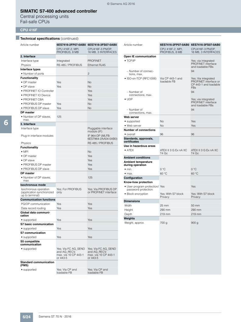
6/24 Siemens ST 70 N · 2016
6
■ Technical specifications (continued)
SIMATIC S7-400 advanced controllerCentral processing unitsFail-safe CPUs
CPU 416F
2. Interface
Interface type Integrated PROFINET
Physics RS 485 / PROFIBUS Ethernet RJ45
Interface types
• Number of ports 2
Functionality
• DP master Yes No
• DP slave Yes No
• PROFINET IO Controller Yes
• PROFINET IO Device Yes
• PROFINET CBA Yes
• PROFIBUS DP master Yes No
• PROFIBUS DP slave Yes No
DP master
• Number of DP slaves, max.
125
3. Interface
Interface type Pluggable interface module (IF)
Plug-in interface modules IF 964-DP (MLFB: 6ES7964-2AA04-0AB0)
Physics RS 485 / PROFIBUS
Functionality
• MPI No
• DP master Yes
• DP slave Yes
• PROFIBUS DP master Yes
• PROFIBUS DP slave Yes
DP master
• Number of DP slaves, max.
125
Isochronous mode
Isochronous operation (application synchronized up to terminal)
Yes; For PROFIBUS only
Yes; Via PROFIBUS DP or PROFINET interface
Communication functions
PG/OP communication Yes Yes
Data record routing Yes Yes
Global data communi-cation
• supported Yes Yes
S7 basic communication
• supported Yes Yes
S7 communication
• supported Yes Yes
S5 compatible communication
• supported Yes; Via FC AG_SEND and AG_RECV, max. via 10 CP 443-1 or 443-5
Yes; Via FC AG_SEND and AG_RECV, max. via 10 CP 443-1 or 443-5
Standard communication (FMS)
• supported Yes; Via CP and loadable FB
Yes; Via CP and loadable FB
Article number 6ES7416-2FP07-0AB0 6ES7416-3FS07-0AB0
CPU 416F-2, MPI, PROFIBUS, 8 MB
CPU416F-3 PN/DP, 16 MB, 3 INTERFACES
Open IE communication
• TCP/IP Yes; via integrated PROFINET interface and loadable FBs
- Number of connec-tions, max.
94
• ISO-on-TCP (RFC1006) Via CP 443-1 and loadable FB
Yes; Via integrated PROFINET interface or CP 443-1 and loadable FBs
- Number of connections, max.
94
• UDP Yes; via integrated PROFINET interface and loadable FBs
- Number ofconnections, max.
94
Web server
• supported No Yes
• Web server No Yes
Number of connections
• overall 96 96
Standards, approvals, certificates
Use in hazardous areas
• ATEX ATEX II 3 G Ex nA IIC T4 Gc
ATEX II 3 G Ex nA IIC T4 Gc
Ambient conditions
Ambient temperature during operation
• min. 0 °C 0 °C
• max. 60 °C 60 °C
Configuration
Know-how protection
• User program protection/password protection
Yes Yes
• Block encryption Yes; With S7 block Privacy
Yes; With S7 block Privacy
Dimensions
Width 25 mm 50 mm
Height 290 mm 290 mm
Depth 219 mm 219 mm
Weights
Weight, approx. 700 g 900 g
Article number 6ES7416-2FP07-0AB0 6ES7416-3FS07-0AB0
CPU 416F-2, MPI, PROFIBUS, 8 MB
CPU416F-3 PN/DP, 16 MB, 3 INTERFACES
© Siemens AG 2016
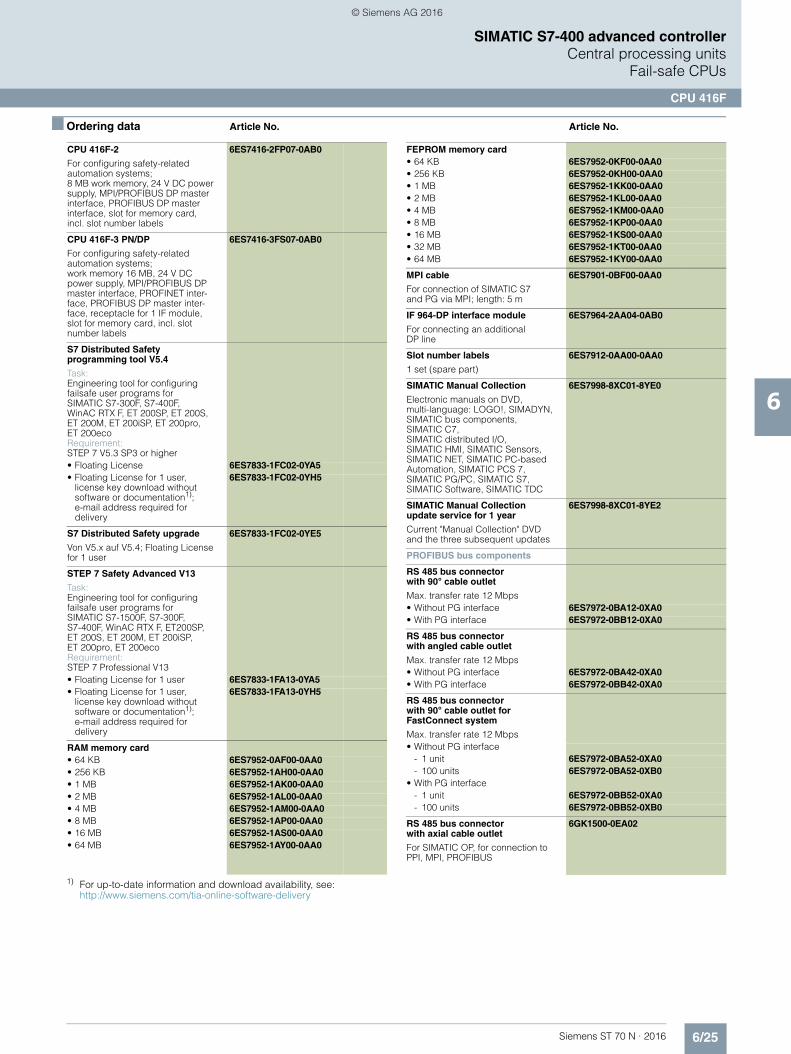
6/25Siemens ST 70 N · 2016
6
SIMATIC S7-400 advanced controllerCentral processing units
Fail-safe CPUs
CPU 416F
■ Ordering data Article No. Article No.
CPU 416F-2
For configuring safety-relatedautomation systems;8 MB work memory, 24 V DC power supply, MPI/PROFIBUS DP master interface, PROFIBUS DP master interface, slot for memory card,incl. slot number labels
6ES7416-2FP07-0AB0
CPU 416F-3 PN/DP
For configuring safety-related automation systems;work memory 16 MB, 24 V DC power supply, MPI/PROFIBUS DP master interface, PROFINET inter-face, PROFIBUS DP master inter-face, receptacle for 1 IF module, slot for memory card, incl. slot number labels
6ES7416-3FS07-0AB0
S7 Distributed Safety programming tool V5.4
Task:Engineering tool for configuringfailsafe user programs for SIMATIC S7-300F, S7-400F, WinAC RTX F, ET 200SP, ET 200S, ET 200M, ET 200iSP, ET 200pro, ET 200eco Requirement:STEP 7 V5.3 SP3 or higher• Floating License 6ES7833-1FC02-0YA5• Floating License for 1 user,
license key download without software or documentation1); e-mail address required for delivery
6ES7833-1FC02-0YH5
S7 Distributed Safety upgrade
Von V5.x auf V5.4; Floating License for 1 user
6ES7833-1FC02-0YE5
STEP 7 Safety Advanced V13
Task:Engineering tool for configuringfailsafe user programs for SIMATIC S7-1500F, S7-300F, S7-400F, WinAC RTX F, ET200SP, ET 200S, ET 200M, ET 200iSP, ET 200pro, ET 200ecoRequirement:STEP 7 Professional V13• Floating License for 1 user 6ES7833-1FA13-0YA5• Floating License for 1 user,
license key download without software or documentation1); e-mail address required for delivery
6ES7833-1FA13-0YH5
RAM memory card• 64 KB 6ES7952-0AF00-0AA0• 256 KB 6ES7952-1AH00-0AA0• 1 MB 6ES7952-1AK00-0AA0• 2 MB 6ES7952-1AL00-0AA0• 4 MB 6ES7952-1AM00-0AA0• 8 MB 6ES7952-1AP00-0AA0• 16 MB 6ES7952-1AS00-0AA0• 64 MB 6ES7952-1AY00-0AA0
1) For up-to-date information and download availability, see:http://www.siemens.com/tia-online-software-delivery
FEPROM memory card• 64 KB 6ES7952-0KF00-0AA0• 256 KB 6ES7952-0KH00-0AA0• 1 MB 6ES7952-1KK00-0AA0• 2 MB 6ES7952-1KL00-0AA0• 4 MB 6ES7952-1KM00-0AA0• 8 MB 6ES7952-1KP00-0AA0• 16 MB 6ES7952-1KS00-0AA0• 32 MB 6ES7952-1KT00-0AA0• 64 MB 6ES7952-1KY00-0AA0
MPI cable
For connection of SIMATIC S7 and PG via MPI; length: 5 m
6ES7901-0BF00-0AA0
IF 964-DP interface module
For connecting an additionalDP line
6ES7964-2AA04-0AB0
Slot number labels
1 set (spare part)
6ES7912-0AA00-0AA0
SIMATIC Manual Collection
Electronic manuals on DVD, multi-language: LOGO!, SIMADYN, SIMATIC bus components,SIMATIC C7, SIMATIC distributed I/O, SIMATIC HMI, SIMATIC Sensors, SIMATIC NET, SIMATIC PC-based Automation, SIMATIC PCS 7, SIMATIC PG/PC, SIMATIC S7, SIMATIC Software, SIMATIC TDC
6ES7998-8XC01-8YE0
SIMATIC Manual Collection update service for 1 year
Current "Manual Collection" DVD and the three subsequent updates
6ES7998-8XC01-8YE2
PROFIBUS bus components
RS 485 bus connectorwith 90° cable outlet
Max. transfer rate 12 Mbps• Without PG interface 6ES7972-0BA12-0XA0• With PG interface 6ES7972-0BB12-0XA0
RS 485 bus connector with angled cable outlet
Max. transfer rate 12 Mbps• Without PG interface 6ES7972-0BA42-0XA0• With PG interface 6ES7972-0BB42-0XA0
RS 485 bus connector with 90° cable outlet for FastConnect system
Max. transfer rate 12 Mbps• Without PG interface
- 1 unit 6ES7972-0BA52-0XA0- 100 units 6ES7972-0BA52-0XB0
• With PG interface- 1 unit 6ES7972-0BB52-0XA0- 100 units 6ES7972-0BB52-0XB0
RS 485 bus connector with axial cable outlet
For SIMATIC OP, for connection to PPI, MPI, PROFIBUS
6GK1500-0EA02
© Siemens AG 2016
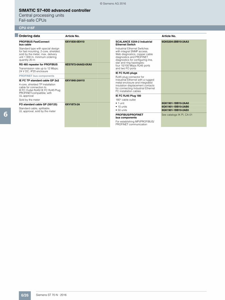
6/26 Siemens ST 70 N · 2016
6
■ Ordering data Article No. Article No.
SIMATIC S7-400 advanced controllerCentral processing unitsFail-safe CPUs
CPU 416F
PROFIBUS FastConnect bus cable
Standard type with special design for fast mounting, 2-core, shielded, sold by the meter; max. delivery unit 1 000 m, minimum ordering quantity 20 m
6XV1830-0EH10
RS 485 repeater for PROFIBUS
Transmission rate up to 12 Mbps; 24 V DC; IP20 enclosure
6ES7972-0AA02-0XA0
PROFINET bus components
IE FC TP standard cable GP 2x2
4-core, shielded TP installation cable for connection toIE FC Outlet RJ45/ IE FC RJ45 Plug; PROFINET-compatible; withUL approval
Sold by the meter
6XV1840-2AH10
FO standard cable GP (50/125)
Standard cable, splittable, UL approval, sold by the meter
6XV1873-2A
SCALANCE X204-2 Industrial Ethernet Switch
Industrial Ethernet Switches with integral SNMP access,Web diagnostics, copper cable diagnostics and PROFINET diagnostics for configuring line, star and ring topologies;four 10/100 Mbps RJ45 ports and two FO ports
6GK5204-2BB10-2AA3
IE FC RJ45 plugs
RJ45 plug connector for Industrial Ethernet with a rugged metal enclosure and integrated insulation displacement contacts for connecting Industrial Ethernet FC installation cables
IE FC RJ45 Plug 180
180° cable outlet• 1 unit 6GK1901-1BB10-2AA0• 10 units 6GK1901-1BB10-2AB0• 50 units 6GK1901-1BB10-2AE0
PROFIBUS/PROFINET bus components
For establishing MPI/PROFIBUS/PROFINET communication
See catalogs IK PI, CA 01
© Siemens AG 2016
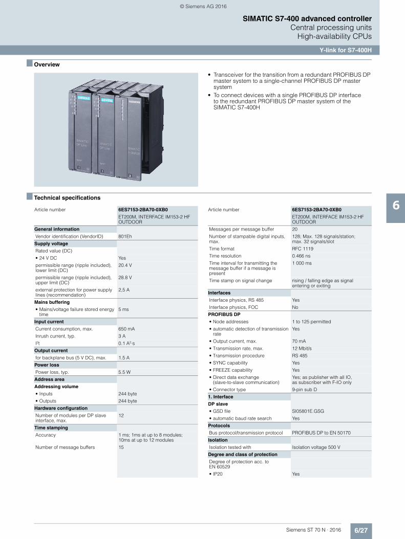
6/27Siemens ST 70 N · 2016
6
SIMATIC S7-400 advanced controllerCentral processing units
High-availability CPUs
Y-link for S7-400H
■ Overview
• Transceiver for the transition from a redundant PROFIBUS DP master system to a single-channel PROFIBUS DP master system
• To connect devices with a single PROFIBUS DP interface to the redundant PROFIBUS DP master system of the SIMATIC S7-400H
■ Technical specifications
Article number 6ES7153-2BA70-0XB0
ET200M, INTERFACE IM153-2 HF OUTDOOR
General information
Vendor identification (VendorID) 801Eh
Supply voltage
Rated value (DC)
• 24 V DC Yes
permissible range (ripple included), lower limit (DC)
20.4 V
permissible range (ripple included), upper limit (DC)
28.8 V
external protection for power supply lines (recommendation)
2,5 A
Mains buffering
• Mains/voltage failure stored energy time
5 ms
Input current
Current consumption, max. 650 mA
Inrush current, typ. 3 A
I²t 0.1 A²·s
Output current
for backplane bus (5 V DC), max. 1.5 A
Power loss
Power loss, typ. 5.5 W
Address area
Addressing volume
• Inputs 244 byte
• Outputs 244 byte
Hardware configuration
Number of modules per DP slave interface, max.
12
Time stamping
Accuracy 1 ms; 1ms at up to 8 modules; 10ms at up to 12 modules
Number of message buffers 15
Messages per message buffer 20
Number of stampable digital inputs, max.
128; Max. 128 signals/station; max. 32 signals/slot
Time format RFC 1119
Time resolution 0.466 ns
Time interval for transmitting the message buffer if a message is present
1 000 ms
Time stamp on signal change rising / falling edge as signal entering or exiting
Interfaces
Interface physics, RS 485 Yes
Interface physics, FOC No
PROFIBUS DP
• Node addresses 1 to 125 permitted
• automatic detection of transmission rate
Yes
• Output current, max. 70 mA
• Transmission rate, max. 12 Mbit/s
• Transmission procedure RS 485
• SYNC capability Yes
• FREEZE capability Yes
• Direct data exchange(slave-to-slave communication)
Yes; as publisher with all IO, as subscriber with F-IO only
• Connector type 9-pin sub D
1. Interface
DP slave
• GSD file SI05801E.GSG
• automatic baud rate search Yes
Protocols
Bus protocol/transmission protocol PROFIBUS DP to EN 50170
Isolation
Isolation tested with Isolation voltage 500 V
Degree and class of protection
Degree of protection acc. to EN 60529
• IP20 Yes
Article number 6ES7153-2BA70-0XB0
ET200M, INTERFACE IM153-2 HF OUTDOOR
© Siemens AG 2016
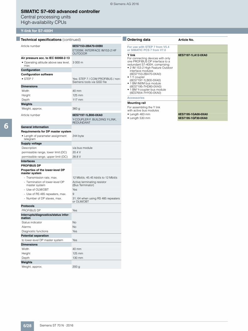
6/28 Siemens ST 70 N · 2016
6
■ Technical specifications (continued)
SIMATIC S7-400 advanced controllerCentral processing unitsHigh-availability CPUs
Y-link for S7-400H
Air pressure acc. to IEC 60068-2-13
• Operating altitude above sea level, max.
3 000 m
Configuration
Configuration software
• STEP 7 Yes; STEP 7 / COM PROFIBUS / non-Siemens tools via GSD file
Dimensions
Width 40 mm
Height 125 mm
Depth 117 mm
Weights
Weight, approx. 360 g
Article number 6ES7197-1LB00-0XA0
Y-COUPLER F. BUILDING Y-LINK, REDUNDANT
General information
Requirements for DP master system
• Length of parameter assignment telegram
244 byte
Supply voltage
Description via bus module
permissible range, lower limit (DC) 20.4 V
permissible range, upper limit (DC) 28.8 V
Interfaces
PROFIBUS DP
Properties of the lower-level DP master system
- Transmission rate, max. 12 Mbit/s; 45.45 kbit/s to 12 Mbit/s
- Termination of lower-level DP master system
Active terminating resistor(Bus Terminator)
- Use of OLM/OBT Yes
- Use of RS 485 repeaters, max. 9
- Number of DP slaves, max. 31; 64 when using RS 485 repeaters or OLM/OBT
Protocols
PROFIBUS DP Yes
Interrupts/diagnostics/status infor-mation
Status indicator No
Alarms No
Diagnostic functions Yes
Potential separation
to lower-level DP master system Yes
Dimensions
Width 40 mm
Height 125 mm
Depth 130 mm
Weights
Weight, approx. 200 g
Article number 6ES7153-2BA70-0XB0
ET200M, INTERFACE IM153-2 HF OUTDOOR
■ Ordering data Article No.
For use with STEP 7 from V5.4 or SIMATIC PCS 7 from V7.0
Y linkFor connecting devices with only one PROFIBUS DP interface to a redundant S7-400H, comprising:• 2 IM 153-2 High Feature Outdoor
interface modules(6ES7153-2BA70-0XA0)
• 1 Y coupler (6ES7197-1LB00-0XA0)
• 1 BM IM/IM bus module (6ES7195-7HD80-0XA0)
• 1 BM Y-coupler bus module (6ES7654-7HY00-0XA0)
6ES7197-1LA12-0XA0
Accessories
Mounting rail
For assembling the Y link with active bus modules• Length 483 mm 6ES7195-1GA00-0XA0• Length 530 mm 6ES7195-1GF30-0XA0
© Siemens AG 2016

6/29Siemens ST 70 N · 2016
6
SIMATIC S7-400 advanced controllerCentral processing units
SIPLUS high-availability CPUs
SIPLUS Y-Link for S7-400H
■ Overview
• Bus coupler for transition from a redundant PROFIBUS DP master system to a single-channel PROFIBUS DP master system
• For connection of devices with only one PROFIBUS DP interface to the redundant PROFIBUS DP master system of the SIMATIC S7-400H
Note:
SIPLUS extreme products are based on SIMATIC standard products. The contents listed here were taken from the respec-tive standard products. SIPLUS extreme specific information was added.
Technical documentation on SIPLUS can be found here:http://www.siemens.com/siplus-extreme
■ Technical specifications
Article number 6AG1153-2BA10-7XB0
Based on 6ES7153-2BA10-0XB0
SIPLUS ET200M IM153-2 HF
Ambient conditions
Ambient temperature during operation
• min. -40 °C; = Tmin; Startup @ -25 °C
• max. 70 °C; = Tmax
Ambient temperature during storage/transportation
• min. -40 °C
• max. 70 °C
Extended ambient conditions
• relative to ambient temperature-atmospheric pressure-installation altitude
Tmin ... Tmax at 1080 hPa ... 795 hPa(-1000 m ... +2000 m) //Tmin ... (Tmax - 10K) at 795 hPa ... 658 hPa (+2000 m ... +3500 m) // Tmin ... (Tmax - 20K) at 658 hPa ... 540 hPa (+3500 m ... +5000 m)
• At cold restart, min. -25 °C
Relative humidity
- With condensation, tested in accordance with IEC 60068-2-38, max.
100 %; RH incl. condensation/frost (no commissioning under conden-sation conditions)
Resistance
- against biologically active substances / conformity with EN 60721-3-3
Yes; Class 3B2 mold, fungus and dry rot spores (with the exception of fauna). The supplied connector covers must remain on the unused interfaces during operation!
- against chemically active substances / conformity with EN 60721-3-3
Yes; Class 3C4 (RH < 75%) incl. salt spray according to EN 60068-2-52 (degree of severity 3). The supplied connector covers must remain on the unused interfaces during operation!
- against mechanically active substances / conformity with EN 60721-3-3
Yes; Class 3S4 incl. sand, dust.The supplied connector covers must remain on the unused interfaces during operation!
Article number 6AG1197-1LB00-4XA0
Based on 6ES7197-1LB00-0XA0
SIPLUS S7 Y COUPLER
Ambient conditions
Ambient temperature during operation
• min. 0 °C; = Tmin
• max. 60 °C; = Tmax
Ambient temperature during storage/transportation
• min. -40 °C
• max. 70 °C
Extended ambient conditions
• relative to ambient temperature-atmospheric pressure-installation altitude
Tmin ... Tmax at 1080 hPa ... 795 hPa(-1000 m ... +2000 m) // Tmin ... (Tmax - 10K) at 795 hPa ... 658 hPa (+2000 m ... +3500 m) //Tmin ... (Tmax - 20K) at 658 hPa ... 540 hPa (+3500 m ... +5000 m)
Relative humidity
- With condensation, tested in accordance with IEC 60068-2-38, max.
100 %; RH incl. condensation/frost (no commissioning under conden-sation conditions)
Resistance
- against biologically active substances / conformity with EN 60721-3-3
Yes; Class 3B2 mold, fungus and dry rot spores (with the exception of fauna). The supplied connector covers must remain on the unused interfaces during operation!
- against chemically active substances / conformity with EN 60721-3-3
Yes; Class 3C4 (RH < 75%) incl. salt spray according to EN 60068-2-52 (degree of severity 3). The supplied connector covers must remain on the unused interfaces during operation!
- against mechanically active substances / conformity with EN 60721-3-3
Yes; Class 3S4 incl. sand, dust. The supplied connector covers must remain on the unused interfaces during operation!
© Siemens AG 2016

6/30 Siemens ST 70 N · 2016
6
■ Technical specifications (continued)
SIMATIC S7-400 advanced controllerCentral processing unitsSIPLUS high-availability CPUs
SIPLUS Y-Link for S7-400H
Article number 6AG1195-7HD10-2XA0
Based on 6ES7195-7HD10-0XA0
SIPLUS ET200M DP BUS MODULE
Ambient conditions
Ambient temperature during operation
• min. -40 °C; = Tmin
• max. 70 °C; = Tmax; 60 °C @ UL/cUL, ATEX and FM use
Ambient temperature during storage/transportation
• min. -40 °C
• max. 70 °C
Extended ambient conditions
• relative to ambient temperature-atmospheric pressure-installation altitude
Tmin ... Tmax at 1080 hPa ... 795 hPa (-1000 m ... +2000 m) //Tmin ... (Tmax - 10K) at 795 hPa ... 658 hPa (+2000 m ... +3500 m) // Tmin ... (Tmax - 20K) at 658 hPa ... 540 hPa (+3500 m ... +5000 m)
Relative humidity
- With condensation, tested in accordance with IEC 60068-2-38, max.
100 %; RH incl. condensation/frost (no commissioning under conden-sation conditions)
Resistance
- against biologically active substances / conformity with EN 60721-3-3
Yes; Class 3B2 mold, fungus and dry rot spores (with the exception of fauna). The supplied connector covers must remain on the unused interfaces during operation!
- against chemically active substances / conformity with EN 60721-3-3
Yes; Class 3C4 (RH < 75%) incl. salt spray according to EN 60068-2-52 (degree of severity 3). The supplied connector covers must remain on the unused interfaces during operation!
- against mechanically active substances / conformity with EN 60721-3-3
Yes; Class 3S4 incl. sand, dust. The supplied connector covers must remain on the unused interfaces during operation!
■ Ordering data Article No.
SIPLUS ET 200M IM 153-2High Feature (2 units required)
Slave interface for connecting an ET 200M to PROFIBUS DP for a maximum of 12 S7-300 modules; also for use in redundant systems• Extended temperature range and
exposure to media6AG1153-2BA10-7XB0
Y coupler
For establishing a Y-link for redundant controllers• Exposure to media 6AG1197-1LB00-4XA0
Bus module for SIPLUS ET 200M
Bus module for accommodating two IM-153 modules for the hot-swapping function; for setting up redundant systems• Extended temperature range
and exposure to media6AG1195-7HD10-2XA0
SIPLUS S7 bus module BM Y-coupler
to accommodate a Y-coupler incl. bus module cover• Extended temperature range
and exposure to media6AG1654-7HY00-7XA0
Accessories
Consumables
Mounting rail
For assembling the Y-link with active bus modules• Length 483 mm 6ES7195-1GA00-0XA0• Length 530 mm 6ES7195-1GF30-0XA0
© Siemens AG 2016

6/31Siemens ST 70 N · 2016
6
SIMATIC S7-400 advanced controllerFunction modules
FM 458-1 DP application module
D7-SYS
■ Overview
• Optional package for STEP 7 V5.5 for configuring closed-loop control and automation tasks with SIMATIC TDC, FM 458-1 DP and T400
• Extensive block library• Generation of user libraries in ANSI C with D7-FB-GEN
function block generator
■ Ordering data Article No.
1) For more information on the software update service, see chapter 11, page 11/2.
SIMATIC D7-SYS V8.1
Reference hardware:SIMATIC TDC, FM 458-1 DP, T400 Requirement:MS Windows 7 Professional/Enterprise/Ultimate + SP1(32/64-bit); MS Windows XP Professional SP3 (32-bit); MS Windows Server 2003 R2 SP2 (32-bit) / 2008 R2 SP1 (64-bit); STEP 7 V5.5 SP4 or higher Type of delivery:on DVD, German, English, with electronic documentation
Floating license 6ES7852-0CC04-0YA5
Upgrade License V7.x and higher 6ES7852-0CC04-0YE5
Software Update Service1) 6ES7852-0CC01-0YL5
SIMATIC Manual Collection 6ES7998-8XC01-8YE0
Electronic manuals on DVD, multilingual: LOGO!, SIMADYN, SIMATIC bus components,SIMATIC C7,SIMATIC distributed I/O, SIMATIC HMI, SIMATIC Sensors, SIMATIC NET, SIMATIC PC Based Automation, SIMATIC PCS 7, SIMATIC PG/PC, SIMATIC S7, SIMATIC Software, SIMATIC TDC
SIMATIC Manual Collection update service for 1 year
6ES7998-8XC01-8YE2
Current "Manual Collection" DVD and the three subsequent updates
© Siemens AG 2016

6/32 Siemens ST 70 N · 2016
6
SIMATIC S7-400 advanced controller
Notes
© Siemens AG 2016
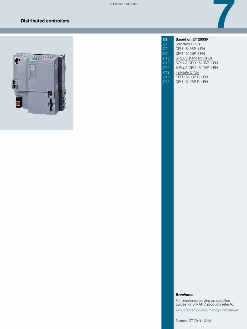
Siemens ST 70 N · 2016
7
Brochures
For brochures serving as selection guides for SIMATIC products refer to:
www.siemens.com/simatic/printmaterial
7/2 Based on ET 200SP7/2 Standard CPUs7/2 CPU 1510SP-1 PN7/6 CPU 1512SP-1 PN7/10 SIPLUS standard CPUs7/10 SIPLUS CPU 1510SP-1 PN7/11 SIPLUS CPU 1512SP-1 PN7/12 Fail-safe CPUs7/12 CPU 1510SP F-1 PN7/16 CPU 1512SP F-1 PN
Distributed controllers
© Siemens AG 2016

7/2 Siemens ST 70 N · 2016
7
Distributed controllersBased on ET 200SPStandard CPUs
CPU 1510SP-1 PN
■ Overview
• CPU 1510SP-1 PN for SIMATIC ET 200SP based on S7-1500 CPU 1511-1 PN
• For high-performance control solutions using ET 200SP• Increase in availability of systems and machines • PROFINET IO Controller for up to 64 IO devices
• PROFINET I-Device for connecting the CPU as anintelligent PROFINET device with a SIMATIC or third-party PROFINET I/O Controller
• PROFINET shared I-Device for 4 controllers• PROFINET IO IRT interface with integrated 3-port switch • Isochronous mode on PROFINET • With multiple communication options:
PG/OP communication, PROFINET IO, open IE communi-cation (TCP, ISO-on-TCP and UDP), Web server and S7 communication (with loadable FBs)
• Optional PROFIBUS DP master for 125 PROFIBUS DP slaves (with CM DP module 6ES7545-5DA00-0AB0)
• Optional PROFIBUS DP-slave (with CM DP module 6ES7545-5DA00-0AB0)
• Configuration control (option handling)• Integrated Motion Control functionalities for controlling speed-
controlled and positioning axes, support for external encoders
Note
SIMATIC Memory Card required for operation of the CPU.The bus adapter is not included in scope of delivery and is to be ordered separately.
■ Technical specifications
Article number 6ES7510-1DJ01-0AB0
CPU 1510SP-1 PN,100KB PROG./750KB DATA
General information
Product type designation CPU 1510SP-1 PN
Engineering with
• STEP 7 TIA Portal configurable/integrated as of version
V13 SP1 Update 4
Supply voltage
Type of supply voltage 24 V DC
Power loss
Power loss, typ. 5.6 W
Memory
Work memory
• integrated (for program) 100 kbyte
• integrated (for data) 750 kbyte
Load memory
• Plug-in (SIMATIC Memory Card), max.
32 Gbyte
CPU processing times
for bit operations, typ. 72 ns
for word operations, typ. 86 ns
for fixed point arithmetic, typ. 115 ns
for floating point arithmetic, typ. 461 ns
Counters, timers and their retentivity
S7 counter
• Number 2 048
IEC counter
• Number Any (only limited by the main memory)
S7 times
• Number 2 048
IEC timer
• Number Any (only limited by the main memory)
Data areas and their retentivity
Flag
• Number, max. 16 kbyte
Address area
I/O address area
• Inputs 32 kbyte; All inputs are in the process image
• Outputs 32 kbyte; All outputs are in the process image
Address space per module
• Address space per module, max. 32 byte; For input and output data respectively
Address space per station
• Address space per station, max. 1 280 byte; for central inputs and outputs; depending on configuration
Time of day
Clock
• Type Hardware clock
1st interface
Interface types
• Number of ports 3; 1. integr. + 2. via BusAdapter
• integrated switch Yes
• RJ 45 (Ethernet) Yes; X1
• Bus adapter (PROFINET) Yes; Applicable BusAdapters:BA 2x RJ45, BA 2x FC
Functionality
• PROFINET IO Controller Yes
• PROFINET IO Device Yes
• SIMATIC communication Yes
• Open IE communication Yes
• Web server Yes
• Media redundancy Yes
Article number 6ES7510-1DJ01-0AB0
CPU 1510SP-1 PN,100KB PROG./750KB DATA
© Siemens AG 2016

7/3Siemens ST 70 N · 2016
7
■ Technical specifications (continued)
Distributed controllersBased on ET 200SP
Standard CPUs
CPU 1510SP-1 PN
2nd interface
Interface types
• Number of ports 1
• RS 485 Yes; Via CM DP module
Functionality
• SIMATIC communication Yes
• PROFIBUS DP master Yes
• PROFIBUS DP slave Yes
Protocols
Number of connections
• Number of connections, max. 64
PROFINET IO Controller
Services
- Number of connectableIO Devices, max.
64; In total, up to 189 distributed I/O devices can be connected via PROFIBUS or PROFINET
- Of which IO devices with IRT, max. 64
- Number of connectable IO Devices for RT, max.
64
PROFIBUS DP master
Services
- Number of DP slaves 125
Isochronous mode
Isochronous operation (application synchronized up to terminal)
Yes; Only with PROFINET; with minimum OB 6x cycle of 625 µs
Supported technology objects
Motion Control Yes
• Speed-controlled axis
- Number of speed-controlled axes, max.
6; Requirement: There must be no other motion technology objects created; note: The number of axes affects the cycle time of the PLC program; selection guide via theTIA Selection Tool
• Positioning axis
- Number of positioning axes, max. 6; Requirement: There must be no other motion technology objects created; note: The number of axes affects the cycle time of the PLC program; selection guide via the TIA Selection Tool
• Synchronized axes (relative gear synchronization)
- Number of axes, max. 3; Requirement: There must be no other motion technology objects created; note: The number of axes affects the cycle time of the PLC program; selection guide via the TIA Selection Tool
• External encoders
- Number of external encoders, max.
6; Requirement: There must be no other motion technology objects created; note: The number of axes affects the cycle time of the PLC program; selection guide via theTIA Selection Tool
Article number 6ES7510-1DJ01-0AB0
CPU 1510SP-1 PN,100KB PROG./750KB DATA
Controller
• PID_Compact Yes; Universal PID controller with integrated optimization
• PID_3Step Yes; PID controller with integrated optimization for valves
• PID-Temp Yes; PID controller with integrated optimization for temperature
Counting and measuring
• High-speed counter Yes
Ambient conditions
Ambient temperature during operation
• horizontal installation, min. 0 °C
• horizontal installation, max. 60 °C
• vertical installation, min. 0 °C
• vertical installation, max. 50 °C
Configuration
Programming
Programming language
- LAD Yes
- FBD Yes
- STL Yes
- SCL Yes
- GRAPH Yes
Know-how protection
• User program protection Yes
• Copy protection Yes
• Block protection Yes
Access protection
• Protection level: Write protection Yes
• Protection level: Read/write protection
Yes
• Protection level: Complete protection
Yes
Dimensions
Width 100 mm
Height 117 mm
Depth 75 mm
Weights
Weight, approx. 310 g
Article number 6ES7510-1DJ01-0AB0
CPU 1510SP-1 PN,100KB PROG./750KB DATA
© Siemens AG 2016

7/4 Siemens ST 70 N · 2016
7
Distributed controllersBased on ET 200SPStandard CPUs
CPU 1510SP-1 PN
■ Ordering data Article No. Article No.
CPU 1510SP-1 PN 6ES7510-1DJ01-0AB0
Work memory 100 KB for program, 750 KB for data, PROFINET IO IRT interface; SIMATIC Memory Card required
Accessories
CM DP for ET 200SP CPU 6ES7545-5DA00-0AB0
PROFIBUS DP master/slave with electrical interface for connecting the ET 200SP CPUs to PROFIBUS at up to 12 Mbit/s
SIMATIC Memory Card
4 MB 6ES7954-8LC02-0AA0
12 MB 6ES7954-8LE02-0AA0
24 MB 6ES7954-8LF02-0AA0
256 MB 6ES7954-8LL02-0AA0
2 GB 6ES7954-8LP02-0AA0
32 GB 6ES7954-8LT02-0AA0
DIN rail 35 mm • Length: 483 mm
for 19" cabinets6ES5710-8MA11
• Length: 530 mm for 600 mm cabinets
6ES5710-8MA21
• Length: 830 mmfor 900 mm cabinets
6ES5710-8MA31
• Length: 2 m 6ES5710-8MA41
PE connection element for DIN rail 2000 mm
6ES7590-5AA00-0AA0
BusAdapter BA 2xRJ45 6ES7193-6AR00-0AA0
BusAdapter BA 2xFCfor increased vibrationand EMC loads
6ES7193-6AF00-0AA0
BusAdapter BA 2xSCRJ 6ES7193-6AP00-0AA0
BusAdapter BA SCRJ/RJ45 6ES7193-6AP20-0AA0
BusAdapter BA SCRJ/FC 6ES7193-6AP40-0AA0
Reference identification label 6ES7193-6LF30-0AW0
10 sheets of 16 labels
Labeling strips
500 labeling strips on roll, light gray, for inscription with thermal transfer roll printer
6ES7193-6LR10-0AA0
500 labeling strips on roll, yellow, for inscription with thermal transfer roll printer
6ES7193-6LR10-0AG0
1000 labeling strips DIN A4, light gray, card, for inscription with laser printer
6ES7193-6LA10-0AA0
1000 labeling strips DIN A4, yellow, card, for inscription with laser printer
6ES7193-6LA10-0AG0
IE FC RJ45 plugs
RJ45 plug connector for Industrial Ethernet with a rugged metal enclo-sure and integrated insulation dis-placement contacts for connecting Industrial Ethernet FC installation cables
IE FC RJ45 Plug 90
90° cable outlet
1 unit 6GK1901-1BB20-2AA0
10 units 6GK1901-1BB20-2AB0
50 units 6GK1901-1BB20-2AE0
IE FC RJ45 Plug 180
180° cable outlet
1 unit 6GK1901-1BB10-2AA0
10 units 6GK1901-1BB10-2AB0
50 units 6GK1901-1BB10-2AE0
IE FC TP standard cable GP 2x2 6XV1840-2AH10
4-core, shielded TP installation cable for connection toIE FC Outlet RJ45/ IE FC RJ45 Plug; PROFINET-compatible; with UL approval;sold by the meter; max. delivery unit 1000 m,minimum order quantity 20 m
IE FC TP Trailing Cable 2 x 2 (Type C)
6XV1840-3AH10
4-core, shielded TP installation cable for connection toIE FC Outlet RJ45/ IE FC RJ45 Plug 180/90 for use as trailing cable; PROFINET-compatible; with UL approval; sold by the meter; max. delivery unit 1000 m, minimum order quantity 20 m
IE FC TP Marine Cable 2 x 2 (Type B)
6XV1840-4AH10
4-core, shielded TP installation cable for connection to IE FC Outlet RJ45/ IE FC RJ45 Plug 180/90 with marine approval, sold by the meter; max. delivery unit 1000 m, minimum order quantity 20 m
IE FC stripping tool 6GK1901-1GA00
Preadjusted stripping tool for fast stripping of Industrial Ethernet FC cables
Manuals for ET 200SPdistributed I/O system
ET 200SP library: ET 200SP Manual Collection,comprising system manual, product information, and device manuals
Manuals can be downloaded from the Internet as PDF files:
http://www.siemens.com/simatic-docu
© Siemens AG 2016

7/5Siemens ST 70 N · 2016
7
■ Ordering data Article No. Article No.
Distributed controllersBased on ET 200SP
Standard CPUs
CPU 1510SP-1 PN
1) For up-to-date information and download availability, see:http://www.siemens.com/tia-online-software-delivery
SIMATIC Manual Collection 6ES7998-8XC01-8YE0
Electronic manuals on DVD, multi-language: LOGO!, SIMADYN, SIMATIC bus components, SIMATIC C7,SIMATIC distributed I/O, SIMATIC HMI, SIMATIC Sensors, SIMATIC NET, SIMATIC PC Based Automation, SIMATIC PCS 7, SIMATIC PG/PC, SIMATIC S7, SIMATIC Software, SIMATIC TDC
SIMATIC Manual Collection update service for 1 year
6ES7998-8XC01-8YE2
Current "Manual Collection" DVD and the three subsequent updates
STEP 7 Professional V13 SP1
Target system:SIMATIC S7-1200, S7-1500, S7-300, S7-400, WinACRequirement:Windows 7 Professional SP1(64-bit), Windows 7 Enterprise SP1 (64-bit), Windows 7 Ultimate SP1 (64-bit), Windows 8.1 (64-bit), Windows 8.1 Professional (64-bit),Windows 8.1 Enterprise (64-bit), Windows Server 2008 R2 StdE (full installation), Windows Server 2012 StdE (full installation)Available in:German, English, Chinese, Italian, French, Spanish
STEP 7 Professional V13 SP1, floating license
6ES7822-1AA03-0YA5
STEP 7 Professional V13 SP1,floating license, software download incl. license key 1)
Email address required for delivery
6ES7822-1AE03-0YA5
Spare parts
Power supply connector 6ES7193-4JB00-0AA0
Spare part; for connecting the 24 V DC supply voltage• With push-in terminals; 10 units
Cover for bus adapter interface 6ES7591-3AA00-0AA0
5 units
Server module 6ES7193-6PA00-0AA0
© Siemens AG 2016
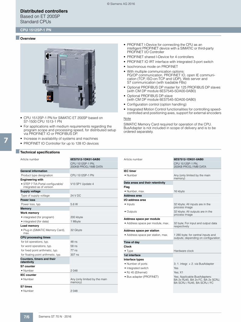
7/6 Siemens ST 70 N · 2016
7
Distributed controllersBased on ET 200SPStandard CPUs
CPU 1512SP-1 PN
■ Overview
• CPU 1512SP-1 PN for SIMATIC ET 200SP based onS7-1500 CPU 1513-1 PN
• For applications with medium requirements regarding the program scope and processing speed, for distributed setup via PROFINET IO or PROFIBUS DP.
• Increase in availability of systems and machines • PROFINET IO Controller for up to 128 IO devices
• PROFINET I-Device for connecting the CPU as anintelligent PROFINET device with a SIMATIC or third-party PROFINET I/O Controller
• PROFINET shared I-Device for 4 controllers• PROFINET IO IRT interface with integrated 3-port switch • Isochronous mode on PROFINET • With multiple communication options:
PG/OP communication, PROFINET IO, open IE communi-cation (TCP, ISO-on-TCP and UDP), Web server and S7 communication (with loadable FBs)
• Optional PROFIBUS DP master for 125 PROFIBUS DP slaves (with CM DP module 6ES7545-5DA00-0AB0)
• Optional PROFIBUS DP-slave(with CM DP module 6ES7545-5DA00-0AB0)
• Configuration control (option handling)• Integrated Motion Control functionalities for controlling speed-
controlled and positioning axes, support for external encoders
Note
SIMATIC Memory Card required for operation of the CPU.BusAdapter is not included in scope of delivery and is to be ordered separately.
■ Technical specifications
Article number 6ES7512-1DK01-0AB0
CPU 1512SP-1 PN, 200KB PROG./1MB DATA
General information
Product type designation CPU 1512SP-1 PN
Engineering with
• STEP 7 TIA Portal configurable/integrated as of version
V13 SP1 Update 4
Supply voltage
Type of supply voltage 24 V DC
Power loss
Power loss, typ. 5.6 W
Memory
Work memory
• integrated (for program) 200 kbyte
• integrated (for data) 1 Mbyte
Load memory
• Plug-in (SIMATIC Memory Card), max.
32 Gbyte
CPU processing times
for bit operations, typ. 48 ns
for word operations, typ. 58 ns
for fixed point arithmetic, typ. 77 ns
for floating point arithmetic, typ. 307 ns
Counters, timers and their retentivity
S7 counter
• Number 2 048
IEC counter
• Number Any (only limited by the main memory)
S7 times
• Number 2 048
IEC timer
• Number Any (only limited by the main memory)
Data areas and their retentivity
Flag
• Number, max. 16 kbyte
Address area
I/O address area
• Inputs 32 kbyte; All inputs are in the process image
• Outputs 32 kbyte; All outputs are in the process image
Address space per module
• Address space per module, max. 32 byte; For input and output data respectively
Address space per station
• Address space per station, max. 1 280 byte; for central inputs and outputs; depending on configuration
Time of day
Clock
• Type Hardware clock
1st interface
Interface types
• Number of ports 3; 1. integr. + 2. via BusAdapter
• integrated switch Yes
• RJ 45 (Ethernet) Yes; X1
• Bus adapter (PROFINET) Yes; Applicable BusAdapters: BA 2x RJ45, BA 2x FC, BA 2x SCRJ, BA SCRJ / RJ45, BA SCRJ / FC
Article number 6ES7512-1DK01-0AB0
CPU 1512SP-1 PN, 200KB PROG./1MB DATA
© Siemens AG 2016
7/7Siemens ST 70 N · 2016
7
■ Technical specifications (continued)
Distributed controllersBased on ET 200SP
Standard CPUs
CPU 1512SP-1 PN
Functionality
• PROFINET IO Controller Yes
• PROFINET IO Device Yes
• SIMATIC communication Yes
• Open IE communication Yes
• Web server Yes
• Media redundancy Yes
2nd interface
Interface types
• Number of ports 1
• RS 485 Yes; Via CM DP module
Functionality
• SIMATIC communication Yes
• PROFIBUS DP master Yes
• PROFIBUS DP slave Yes
Protocols
Number of connections
• Number of connections, max. 88
PROFINET IO Controller
Services
- Number of connectable IO Devices, max.
128; In total, up to 253 distributed I/O devices can be connected via PROFIBUS or PROFINET
- Of which IO devices with IRT, max. 64
- Number of connectable IO Devices for RT, max.
128
PROFIBUS DP master
Services
- Number of DP slaves 125
Isochronous mode
Isochronous operation (application synchronized up to terminal)
Yes; Only with PROFINET; with minimum OB 6x cycle of 625 µs
Supported technology objects
Motion Control Yes
• Speed-controlled axis
- Number of speed-controlled axes, max.
6; Requirement: There must be no other motion technology objects created; note: The number of axes affects the cycle time of the PLC program; selection guide via the TIA Selection Tool
• Positioning axis
- Number of positioning axes, max. 6; Requirement: There must be no other motion technology objects created; note: The number of axes affects the cycle time of the PLC program; selection guide via the TIA Selection Tool
• Synchronized axes(relative gear synchronization)
- Number of axes, max. 3; Requirement: There must be no other motion technology objects created; note: The number of axes affects the cycle time of the PLC program; selection guide via the TIA Selection Tool
Article number 6ES7512-1DK01-0AB0
CPU 1512SP-1 PN, 200KB PROG./1MB DATA
• External encoders
- Number of external encoders, max.
6; Requirement: There must be no other motion technology objects created; note: The number of axes affects the cycle time of the PLC program; selection guide via theTIA Selection Tool
Controller
• PID_Compact Yes; Universal PID controller with integrated optimization
• PID_3Step Yes; PID controller with integrated optimization for valves
• PID-Temp Yes; PID controller with integrated optimization for temperature
Counting and measuring
• High-speed counter Yes
Ambient conditions
Ambient temperature during operation
• horizontal installation, min. 0 °C
• horizontal installation, max. 60 °C
• vertical installation, min. 0 °C
• vertical installation, max. 50 °C
Configuration
Programming
Programming language
- LAD Yes
- FBD Yes
- STL Yes
- SCL Yes
- GRAPH Yes
Know-how protection
• User program protection Yes
• Copy protection Yes
• Block protection Yes
Access protection
• Protection level: Write protection Yes
• Protection level: Read/write protection
Yes
• Protection level: Complete protection
Yes
Dimensions
Width 100 mm
Height 117 mm
Depth 75 mm
Weights
Weight, approx. 310 g
Article number 6ES7512-1DK01-0AB0
CPU 1512SP-1 PN, 200KB PROG./1MB DATA
© Siemens AG 2016

7/8 Siemens ST 70 N · 2016
7
Distributed controllersBased on ET 200SPStandard CPUs
CPU 1512SP-1 PN
■ Ordering data Article No. Article No.
CPU 1512SP-1 PN 6ES7512-1DK01-0AB0
Work memory 200 KB for program, 1 MB for data, PROFINET IO IRT interface; SIMATIC Memory Card required
Accessories
CM DP for ET 200SP CPU 6ES7545-5DA00-0AB0
PROFIBUS DP master/slave with electrical interface for connecting the ET 200SP CPUs to PROFIBUS at up to 12 Mbit/s
SIMATIC Memory Card
4 MB 6ES7954-8LC02-0AA0
12 MB 6ES7954-8LE02-0AA0
24 MB 6ES7954-8LF02-0AA0
256 MB 6ES7954-8LL02-0AA0
2 GB 6ES7954-8LP02-0AA0
32 GB 6ES7954-8LT02-0AA0
DIN rail 35 mm • Length: 483 mm
for 19" cabinets6ES5710-8MA11
• Length: 530 mmfor 600 mm cabinets
6ES5710-8MA21
• Length: 830 mmfor 900 mm cabinets
6ES5710-8MA31
• Length: 2 m 6ES5710-8MA41
PE connection element for DIN rail 2000 mm
6ES7590-5AA00-0AA0
BusAdapter BA 2xRJ45 6ES7193-6AR00-0AA0
BusAdapter BA 2xFC for increased vibrationand EMC loads
6ES7193-6AF00-0AA0
BusAdapter BA 2xSCRJ 6ES7193-6AP00-0AA0
BusAdapter BA SCRJ/RJ45 6ES7193-6AP20-0AA0
BusAdapter BA SCRJ/FC 6ES7193-6AP40-0AA0
Reference identification label 6ES7193-6LF30-0AW0
10 sheets of 16 labels
Labeling strips
500 labeling strips on roll, light gray, for inscription with thermal transfer roll printer
6ES7193-6LR10-0AA0
500 labeling strips on roll, yellow, for inscription with thermal transfer roll printer
6ES7193-6LR10-0AG0
1000 labeling strips DIN A4, light gray, card, for inscription with laser printer
6ES7193-6LA10-0AA0
1000 labeling strips DIN A4, yellow, card, for inscription with laser printer
6ES7193-6LA10-0AG0
IE FC RJ45 plugs
RJ45 plug connector for Industrial Ethernet with a rugged metal enclo-sure and integrated insulation dis-placement contacts for connecting Industrial Ethernet FC installation cables
IE FC RJ45 Plug 90
90° cable outlet
1 unit 6GK1901-1BB20-2AA0
10 units 6GK1901-1BB20-2AB0
50 units 6GK1901-1BB20-2AE0
IE FC RJ45 Plug 180
180° cable outlet
1 unit 6GK1901-1BB10-2AA0
10 units 6GK1901-1BB10-2AB0
50 units 6GK1901-1BB10-2AE0
IE FC TP standard cable GP 2x2 6XV1840-2AH10
4-core, shielded TP installation cable for connection toIE FC Outlet RJ45/ IE FC RJ45 Plug; PROFINET-compatible; with UL approval;sold by the meter; max. delivery unit 1000 m, minimum order quantity 20 m
IE FC TP Trailing Cable 2 x 2 (Type C)
6XV1840-3AH10
4-core, shielded TP installation cable for connection toIE FC Outlet RJ45/ IE FC RJ45 Plug 180/90 for use as trailing cable; PROFINET-compatible;with UL approval; sold by the meter;max. delivery unit 1000 m, minimum order quantity 20 m
IE FC TP Marine Cable 2 x 2 (Type B)
6XV1840-4AH10
4-core, shielded TP installation cable for connection to IE FC Outlet RJ45/ IE FC RJ45 Plug 180/90 with marine approval, sold by the meter; max. delivery unit 1000 m, minimum order quantity 20 m
IE FC stripping tool 6GK1901-1GA00
Preadjusted stripping tool for fast stripping of Industrial Ethernet FC cables
Manuals for ET 200SP distributed I/O system
ET 200SP library: ET 200SP Manual Collection,comprising system manual, product information, and device manuals
Manuals can be downloaded from the Internet as PDF files:
http://www.siemens.com/simatic-docu
© Siemens AG 2016
7/9Siemens ST 70 N · 2016
7
■ Ordering data Article No. Article No.
Distributed controllersBased on ET 200SP
Standard CPUs
CPU 1512SP-1 PN
1) For up-to-date information and download availability, see:http://www.siemens.com/tia-online-software-delivery
SIMATIC Manual Collection 6ES7998-8XC01-8YE0
Electronic manuals on DVD, multi-language: LOGO!, SIMADYN, SIMATIC bus components, SIMATIC C7, SIMATIC distributed I/O, SIMATIC HMI, SIMATIC Sensors, SIMATIC NET, SIMATIC PC Based Automation, SIMATIC PCS 7, SIMATIC PG/PC, SIMATIC S7, SIMATIC Software, SIMATIC TDC
SIMATIC Manual Collection update service for 1 year
6ES7998-8XC01-8YE2
Current "Manual Collection" DVD and the three subsequent updates
STEP 7 Professional V13 SP1
Target system:SIMATIC S7-1200, S7-1500, S7-300, S7-400, WinACRequirement:Windows 7 Professional SP1 (64-bit), Windows 7 Enterprise SP1 (64-bit), Windows 7 Ultimate SP1 (64-bit), Windows 8.1 (64-bit), Windows 8.1 Professional (64-bit),Windows 8.1 Enterprise (64-bit), Windows Server 2008 R2 StdE (full installation), Windows Server 2012 StdE (full installation)Available in:German, English, Chinese, Italian, French, Spanish
STEP 7 Professional V13 SP1, floating license
6ES7822-1AA03-0YA5
STEP 7 Professional V13 SP1, floating license, software download incl. license key 1)
Email address required for delivery
6ES7822-1AE03-0YA5
Spare parts
Power supply connector 6ES7193-4JB00-0AA0
Spare part; for connecting the 24 V DC supply voltage• With push-in terminals; 10 units
Cover for bus adapter interface 6ES7591-3AA00-0AA0
5 units
Server module 6ES7193-6PA00-0AA0
© Siemens AG 2016
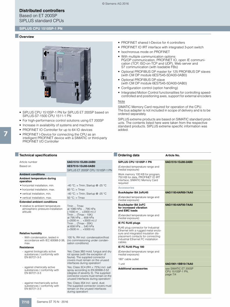
7/10 Siemens ST 70 N · 2016
7
Distributed controllersBased on ET 200SPSIPLUS standard CPUs
SIPLUS CPU 1510SP-1 PN
■ Overview
• SIPLUS CPU 1510SP-1 PN for SIPLUS ET 200SP based on SIPLUS-S7-1500 CPU 1511-1 PN
• For high-performance control solutions using ET 200SP• Increase in availability of systems and machines • PROFINET IO Controller for up to 64 IO devices • PROFINET I-Device for connecting the CPU as an
intelligent PROFINET device with a SIMATIC or third-party PROFINET I/O Controller
• PROFINET shared I-Device for 4 controllers• PROFINET IO IRT interface with integrated 3-port switch • Isochronous mode on PROFINET • With multiple communication options:
PG/OP communication, PROFINET IO, open IE communi-cation (TCP, ISO-on-TCP and UDP), Web server and S7 communication (with loadable FBs)
• Optional PROFIBUS DP master for 125 PROFIBUS DP slaves (with CM DP module 6ES7545-5DA00-0AB0)
• Optional PROFIBUS DP-slave(with CM DP module 6ES7545-5DA00-0AB0)
• Configuration control (option handling)• Integrated Motion Control functionalities for controlling speed-
controlled and positioning axes, support for external encoders
Note
SIMATIC Memory Card required for operation of the CPU.The bus adapter is not included in scope of delivery and is to be ordered separately.
SIPLUS extreme products are based on SIMATIC standard prod-ucts. The contents listed here were taken from the respective standard products. SIPLUS extreme specific information was added.
■ Technical specifications ■ Ordering data Article No.
Article number 6AG1510-1DJ00-2AB0
Based on 6ES7510-1DJ00-0AB0
SIPLUS ET 200SP CPU 1510SP-1 PN
Ambient conditions
Ambient temperature during operation
• horizontal installation, min. -40 °C; = Tmin; Startup @ -25 °C
• horizontal installation, max. 60 °C; = Tmax
• vertical installation, min. -40 °C; = Tmin; Startup @ -25 °C
• vertical installation, max. 50 °C; = Tmax
Extended ambient conditions
• relative to ambient temperature-atmospheric pressure-installation altitude
Tmin ... Tmaxat 1080 hPa ... 795 hPa (-1000 m ... +2000 m) //Tmin ... (Tmax - 10K) at 795 hPa ... 658 hPa (+2000 m ... +3500 m) // Tmin ... (Tmax - 20K) at 658 hPa ... 540 hPa(+3500 m ... +5000 m)
Relative humidity
- With condensation, tested in accordance with IEC 60068-2-38, max.
100 %; RH incl. condensation/frost (no commissioning under conden-sation conditions)
Resistance
- against biologically active substances / conformity with EN 60721-3-3
Yes; Class 3B2 mold, fungus and dry rot spores (with the exception of fauna). The supplied connector covers must remain on the unused interfaces during operation!
- against chemically active substances / conformity with EN 60721-3-3
Yes; Class 3C4 (RH < 75%) incl. salt spray according to EN 60068-2-52 (degree of severity 3). The supplied connector covers must remain on the unused interfaces during operation!
- against mechanically active substances / conformity with EN 60721-3-3
Yes; Class 3S4 incl. sand, dust. The supplied connector covers must remain on the unused interfaces during operation!
SIPLUS CPU 1510SP-1 PN 6AG1510-1DJ00-2AB0
(Extended temperature range and medial exposure)
Work memory 100 KB for program, 750 KB for data, PROFINET IO IRT interface; SIMATIC Memory Card required
Accessories
BusAdapter BA 2xRJ45 6AG1193-6AR00-7AA0
(Extended temperature range and medial exposure)
BusAdapter BA 2xFCfor increased vibrationand EMC loads
6AG1193-6AF00-7AA0
(Extended temperature range and medial exposure)
IE FC RJ45 plugs
RJ45 plug connector for Industrial Ethernet with a rugged metal enclo-sure and integrated insulation dis-placement contacts for connecting Industrial Ethernet FC installation cables
IE FC RJ45 Plug 180
(Extended temperature range and medial exposure)
180° cable outlet
1 unit 6AG1901-1BB10-7AA0
Additional accessories see SIMATIC ET 200SP CPU 1510SP-1 PN, page 7/4
© Siemens AG 2016

7/11Siemens ST 70 N · 2016
7
Distributed controllersBased on ET 200SP
SIPLUS standard CPUs
SIPLUS CPU 1512SP-1 PN
■ Overview
• SIPLUS CPU 1512SP-1 PN for SIPLUS ET 200SP based on SIPLUS-S7-1500 CPU 1513-1 PN
• For applications with medium requirements regarding the program scope and processing speed, for distributed setup via PROFINET IO or PROFIBUS DP.
• Increase in availability of systems and machines • PROFINET IO Controller for up to 128 IO devices
• PROFINET I-Device for connecting the CPU as anintelligent PROFINET device with a SIMATIC or third-party PROFINET I/O Controller
• PROFINET shared I-Device for 4 controllers• PROFINET IO IRT interface with integrated 3-port switch • Isochronous mode on PROFINET • With multiple communication options:
PG/OP communication, PROFINET IO, open IE communi-cation (TCP, ISO-on-TCP and UDP), Web server andS7 communication (with loadable FBs)
• Optional PROFIBUS DP master for 125 PROFIBUS DP slaves (with CM DP module 6ES7545-5DA00-0AB0)
• Optional PROFIBUS DP-slave(with CM DP module 6ES7545-5DA00-0AB0)
• Configuration control (option handling)• Integrated Motion Control functionalities for controlling speed-
controlled and positioning axes, support for external encoders
Note
SIMATIC Memory Card required for operation of the CPU.BusAdapter is not included in scope of delivery and is to be ordered separately.
SIPLUS extreme products are based on SIMATIC standard prod-ucts. The contents listed here were taken from the respective standard products. SIPLUS extreme specific information was added.
■ Technical specifications ■ Ordering data Article No.
Article number 6AG1512-1DK00-2AB0
Based on 6ES7512-1DK00-0AB0
SIPLUS ET 200SP CPU 1512SP-1 PN
Ambient conditions
Ambient temperature during operation
• horizontal installation, min. -40 °C; = Tmin; Startup @ -25 °C
• horizontal installation, max. 60 °C; = Tmax
• vertical installation, min. -40 °C; = Tmin; Startup @ -25 °C
• vertical installation, max. 50 °C; = Tmax
Extended ambient conditions
• relative to ambient temperature-atmospheric pressure-installation altitude
Tmin ... Tmax at 1080 hPa ... 795 hPa (-1000 m ... +2000 m) // Tmin ... (Tmax - 10K)at 795 hPa ... 658 hPa (+2000 m ... +3500 m) //Tmin ... (Tmax - 20K) at 658 hPa ... 540 hPa (+3500 m ... +5000 m)
Relative humidity
- With condensation, tested in accordance with IEC 60068-2-38, max.
100 %; RH incl. condensation/frost (no commissioning under conden-sation conditions)
Resistance
- against biologically active substances / conformity with EN 60721-3-3
Yes; Class 3B2 mold, fungus and dry rot spores (with the exception of fauna). The supplied connector covers must remain on the unused interfaces during operation!
- against chemically active substances / conformity with EN 60721-3-3
Yes; Class 3C4 (RH < 75%) incl. salt spray according to EN 60068-2-52 (degree of severity 3). The supplied connector covers must remain on the unused interfaces during operation!
- against mechanically active substances / conformity with EN 60721-3-3
Yes; Class 3S4 incl. sand, dust.The supplied connector covers must remain on the unused interfaces during operation!
SIPLUS CPU 1512SP-1 PN 6AG1512-1DK00-2AB0
(Extended temperature range and medial exposure)
Work memory 200 KB for program, 1 MB for data, PROFINET IO IRT interface; SIMATIC Memory Card required
Accessories
BusAdapter BA 2xRJ45 6AG1193-6AR00-7AA0
(Extended temperature range and medial exposure)
BusAdapter BA 2xFC for increased vibration and EMC loads
6AG1193-6AF00-7AA0
(Extended temperature range and medial exposure)
IE FC RJ45 plugs
RJ45 plug connector for Industrial Ethernet with a rugged metal enclo-sure and integrated insulation dis-placement contacts for connecting Industrial Ethernet FC installation cables
IE FC RJ45 Plug 180
180° cable outlet
1 unit 6AG1901-1BB10-7AA0
Additional accessories see SIMATIC ET 200SP, CPU 1512SP-1 PN, page 7/8
© Siemens AG 2016

7/12 Siemens ST 70 N · 2016
7
Distributed controllersBased on ET 200SPFail-safe CPUs
CPU 1510SP F-1 PN
■ Overview
• CPU 1510SP F-1 PN for SIMATIC ET 200SP based on S7-1500 CPU 1511F-1 PN
• For high-performance control solutions using ET 200SP• Increase in availability of systems and machines • Supports PROFIsafe in centralized and distributed
configurations
• PROFINET IO controller for up to 64 IO devices• PROFINET I-Device for connecting the CPU as an
intelligent PROFINET device with a SIMATIC or third-party PROFINET I/O controller
• PROFINET Shared I-Device for 4 controllers• PROFINET IO IRT interface with integrated 3-port switch • Isochronous mode on PROFINET • With multiple communication options:
PG/OP communication, PROFINET IO, open IE communi-cation (TCP, ISO-on-TCP and UDP), Web server andS7 communication (with loadable FBs)
• Optional PROFIBUS master for 125 PROFIBUS DP slaves (with CM DP module 6ES7545-5DA00-0AB0)
• Configuration control (option handling)• Integrated Motion Control functionalities for controlling speed-
controlled and positioning axes, support for external encoders
Note
SIMATIC Memory Card required for operation of the CPU.
The bus adapter is not included in the scope of supply and must be ordered separately.
■ Technical specifications
Article number 6ES7510-1SJ01-0AB0
CPU1510SP F-1 PN, 150KB PROG./750KB DATA
General information
Product type designation CPU 1510SP F-1 PN
Engineering with
• STEP 7 TIA Portal configurable/integrated as of version
V13 SP1 Update 4
Supply voltage
Type of supply voltage 24 V DC
Power loss
Power loss, typ. 5.6 W
Memory
Work memory
• integrated (for program) 150 kbyte
• integrated (for data) 750 kbyte
Load memory
• Plug-in (SIMATIC Memory Card), max.
32 Gbyte
CPU processing times
for bit operations, typ. 72 ns
for word operations, typ. 86 ns
for fixed point arithmetic, typ. 115 ns
for floating point arithmetic, typ. 461 ns
Counters, timers and their retentivity
S7 counter
• Number 2 048
IEC counter
• Number Any (only limited by the main memory)
S7 times
• Number 2 048
IEC timer
• Number Any (only limited by the main memory)
Data areas and their retentivity
Flag
• Number, max. 16 kbyte
Address area
I/O address area
• Inputs 32 kbyte; All inputs are in the process image
• Outputs 32 kbyte; All outputs are in the process image
Address space per module
• Address space per module, max. 32 byte; For input and output data respectively
Address space per station
• Address space per station, max. 1 280 byte; for central inputs and outputs; depending on configuration
Time of day
Clock
• Type Hardware clock
1st interface
Interface types
• Number of ports 3
• integrated switch Yes
• RJ 45 (Ethernet) 1. integr. + 2. via Bus AdapterBA 2x RJ45
Functionality
• PROFINET IO Controller Yes
• PROFINET IO Device Yes
• SIMATIC communication Yes
• Open IE communication Yes
• Web server Yes
• Media redundancy Yes
Article number 6ES7510-1SJ01-0AB0
CPU1510SP F-1 PN, 150KB PROG./750KB DATA
© Siemens AG 2016

7/13Siemens ST 70 N · 2016
7
■ Technical specifications (continued)
Distributed controllersBased on ET 200SP
Fail-safe CPUs
CPU 1510SP F-1 PN
2nd interface
Interface types
• Number of ports 1
• RS 485 Via CM DP module
Functionality
• SIMATIC communication Yes
• PROFIBUS DP master Yes
• PROFIBUS DP slave Yes
Protocols
Number of connections
• Number of connections, max. 64
PROFINET IO Controller
Services
- Number of connectableIO Devices, max.
64; In total, up to 189 distributed I/O devices can be connected via PROFIBUS or PROFINET
- Of which IO devices with IRT, max. 64
- Number of connectableIO Devices for RT, max.
64
PROFIBUS DP master
Services
- Number of DP slaves 125
Isochronous mode
Isochronous operation (application synchronized up to terminal)
Yes; For PROFINET only
Supported technology objects
Motion Control Yes
• Speed-controlled axis
- Number of speed-controlled axes, max.
6; Max. number of speed-controlled axes (requirement: there must be no other motion technology objects created)
• Positioning axis
- Number of positioning axes, max. 6; Max. number of positioning axes (requirement: there must be no other motion technology objects created)
• Synchronized axes (relative gear synchronization)
- Number of axes, max. 3; Max. number of synchronous axes (requirement: there must be no other motion technology objects created)
• External encoders
- Number of external encoders, max.
6; Max. number of external encoders (requirement: there must be no other motion technology objects created)
Article number 6ES7510-1SJ01-0AB0
CPU1510SP F-1 PN, 150KB PROG./750KB DATA
Controller
• PID_Compact Yes; Universal PID controller with integrated optimization
• PID_3Step Yes; PID controller with integrated optimization for valves
• PID-Temp Yes; PID controller with integrated optimization for temperature
Counting and measuring
• High-speed counter Yes
Ambient conditions
Ambient temperature during operation
• horizontal installation, min. 0 °C
• horizontal installation, max. 60 °C
• vertical installation, min. 0 °C
• vertical installation, max. 50 °C
Configuration
Programming
Programming language
- LAD Yes; incl. failsafe
- FBD Yes; incl. failsafe
- STL Yes
- SCL Yes
- GRAPH Yes
Know-how protection
• User program protection Yes
• Copy protection Yes
• Block protection Yes
Access protection
• Protection level: Write protection Yes
• Protection level: Read/write protection
Yes
• Protection level: Complete protection
Yes
Dimensions
Width 100 mm
Height 117 mm
Depth 75 mm
Weights
Weight, approx. 310 g
Article number 6ES7510-1SJ01-0AB0
CPU1510SP F-1 PN, 150KB PROG./750KB DATA
© Siemens AG 2016

7/14 Siemens ST 70 N · 2016
7
Distributed controllersBased on ET 200SPFail-safe CPUs
CPU 1510SP F-1 PN
■ Ordering data Article No. Article No.
CPU 1510SP F-1 PN 6ES7510-1SJ01-0AB0
Work memory 150 KB for program, 750 KB for data, PROFINET IO IRT interface; SIMATIC Memory Card required
Accessories
CM DP for ET 200SP CPU 6ES7545-5DA00-0AB0
PROFIBUS DP master/slave with electrical interface for connecting the ET 200SP CPUs to PROFIBUS at up to 12 Mbit/s
SIMATIC Memory Card
4 MB 6ES7954-8LC02-0AA0
12 MB 6ES7954-8LE02-0AA0
24 MB 6ES7954-8LF02-0AA0
256 MB 6ES7954-8LL02-0AA0
2 GB 6ES7954-8LP02-0AA0
32 GB 6ES7954-8LT02-0AA0
DIN rail 35 mm • Length: 483 mm
for 19" cabinets6ES5710-8MA11
• Length: 530 mmfor 600 mm cabinets
6ES5710-8MA21
• Length: 830 mmfor 900 mm cabinets
6ES5710-8MA31
• Length: 2 m 6ES5710-8MA41
PE connection elementfor DIN rail 2000 mm
6ES7590-5AA00-0AA0
BusAdapter BA 2xRJ45 6ES7193-6AR00-0AA0
BusAdapter BA 2xFCfor increased vibration and EMC loads
6ES7193-6AF00-0AA0
BusAdapter BA 2xSCRJ 6ES7193-6AP00-0AA0
BusAdapter BA SCRJ/RJ45 6ES7193-6AP20-0AA0
BusAdapter BA SCRJ/FC 6ES7193-6AP40-0AA0
Reference identification label 6ES7193-6LF30-0AW0
10 sheets of 16 labels
Labeling strips
500 labeling strips on roll, light gray, for inscription with thermal transfer roll printer
6ES7193-6LR10-0AA0
500 labeling strips on roll, yellow, for inscription with thermal transfer roll printer
6ES7193-6LR10-0AG0
1000 labeling strips DIN A4, light gray, card, for inscription with laser printer
6ES7193-6LA10-0AA0
1000 labeling strips DIN A4, yellow, card, for inscription with laser printer
6ES7193-6LA10-0AG0
IE FC RJ45 plugs
RJ45 plug connector for Industrial Ethernet with a rugged metal enclo-sure and integrated insulation dis-placement contacts for connecting Industrial Ethernet FC installation cables
IE FC RJ45 Plug 90
90° cable outlet
1 unit 6GK1901-1BB20-2AA0
10 units 6GK1901-1BB20-2AB0
50 units 6GK1901-1BB20-2AE0
IE FC RJ45 Plug 180
180° cable outlet
1 unit 6GK1901-1BB10-2AA0
10 units 6GK1901-1BB10-2AB0
50 units 6GK1901-1BB10-2AE0
IE FC TP Standard Cable GP 2x2 6XV1840-2AH10
4-core, shielded TP installation cable for connection toIE FC Outlet RJ45/ IE FC RJ45 Plug; PROFINET-compatible; with UL approval;sold by the meter; max. delivery unit 1000 m, minimum order quantity 20 m
IE FC TP Trailing Cable 2 x 2 (Type C)
6XV1840-3AH10
4-core, shielded TP installation cable for connection toIE FC Outlet RJ45/ IE FC RJ45 Plug 180/90 for use as trailing cable; PROFINET-compatible; with UL approval; sold by the meter; max. delivery unit 1000 m, minimum order quantity 20 m
IE FC TP Marine Cable 2 x 2(Type B)
6XV1840-4AH10
4-core, shielded TP installation cable for connection to IE FC Outlet RJ45/ IE FC RJ45 Plug 180/90 with marine approval, sold by the meter;max. delivery unit 1000 m, minimum order quantity 20 m
IE FC stripping tool 6GK1901-1GA00
Preadjusted stripping tool for fast stripping of Industrial Ethernet FC cables
Manuals for ET 200SP distributed I/O system
ET 200SP library: ET 200SP Manual Collection,comprising system manual, product information, and device manuals
Manuals can be downloaded fromthe Internet as PDF files:
http://www.siemens.com/simatic-docu
© Siemens AG 2016

7/15Siemens ST 70 N · 2016
7
■ Ordering data Article No. Article No.
Distributed controllersBased on ET 200SP
Fail-safe CPUs
CPU 1510SP F-1 PN
1) For up-to-date information and download availability, see:http://www.siemens.com/tia-online-software-delivery
SIMATIC Manual Collection 6ES7998-8XC01-8YE0
Electronic manuals on DVD, multi-language: LOGO!, SIMADYN, SIMATIC bus components, SIMATIC C7, SIMATIC distributed I/O, SIMATIC HMI, SIMATIC Sensors, SIMATIC NET, SIMATIC PC Based Automation, SIMATIC PCS 7, SIMATIC PG/PC, SIMATIC S7, SIMATIC Software, SIMATIC TDC
SIMATIC Manual Collection update service for 1 year
6ES7998-8XC01-8YE2
Current "Manual Collection" DVD and the three subsequent updates
STEP 7 Professional V13 SP1
Target system:SIMATIC S7-1200, S7-1500,S7-300, S7-400, WinACRequirement:Windows 7 Professional SP1 (64-bit), Windows 7 Enterprise SP1 (64-bit), Windows 7 Ultimate SP1 (64-bit), Windows 8.1 (64-bit), Windows 8.1 Professional (64-bit),Windows 8.1 Enterprise (64-bit), Windows Server 2008 R2 StdE (full installation), Windows Server 2012 StdE (full installation)Available in:German, English, Chinese, Italian, French, Spanish
STEP 7 Professional V13 SP1,floating license
6ES7822-1AA03-0YA5
STEP 7 Professional V13 SP1, floating license, software download incl. license key 1)
Email address required for delivery
6ES7822-1AE03-0YA5
STEP 7 Safety Advanced V13 SP1
Task:Engineering tool for configuringfailsafe user programs for SIMATIC S7-1200 FC, S7-1500F, S7-300F, S7-400F, WinAC RTX F, ET 200SP F Controller, ET 200SP, ET 200S, ET 200M, ET 200iSP, ET 200pro, ET 200eco Requirement: STEP 7 Professional V13 SP1
Floating license for 1 user 6ES7833-1FA13-0YA5
Floating license for 1 user, license key download without software or documentation1)
Email address required for delivery
6ES7833-1FA13-0YH5
Spare parts
Power supply connector 6ES7193-4JB00-0AA0
Spare part; for connecting the 24 V DC supply voltage• With push-in terminals; 10 units
Cover for bus adapter interface 6ES7591-3AA00-0AA0
5 units
Server module 6ES7193-6PA00-0AA0
© Siemens AG 2016

7/16 Siemens ST 70 N · 2016
7
Distributed controllersBased on ET 200SPFail-safe CPUs
CPU 1512SP F-1 PN
■ Overview
• CPU 1512SP F-1 PN for SIMATIC ET 200SP based on S7-1500 CPU 1513F-1 PN
• For applications with medium requirements in terms of program scope and processing speed, for distributed configurations via PROFINET IO or PROFIBUS DP.
• Increase in availability of systems and machines • Supports PROFIsafe in centralized and distributed
configurations
• PROFINET IO controller for up to 128 IO devices• PROFINET I-Device for connecting the CPU as an
intelligent PROFINET device with a SIMATIC or third-party PROFINET I/O controller
• PROFINET Shared I-Device for 4 controllers• PROFINET IO IRT interface with integrated 3-port switch • Isochronous mode on PROFINET • With multiple communication options:
PG/OP communication, PROFINET IO, open IE communi-cation (TCP, ISO-on-TCP and UDP), Web server and S7 communication (with loadable FBs)
• Optional PROFIBUS master for 125 PROFIBUS DP slaves (with CM DP module 6ES7545-5DA00-0AB0)
• Configuration control (option handling)• Integrated Motion Control functionalities for controlling speed-
controlled and positioning axes, support for external encoders
Note
SIMATIC Memory Card required for operation of the CPU.
The bus adapter is not included in the scope of supply and must be ordered separately.
■ Technical specifications
Article number 6ES7512-1SK01-0AB0
CPU 1512SP F-1 PN,300KB PROG./1MB DATA
General information
Product type designation CPU 1512SP F-1 PN
Engineering with
• STEP 7 TIA Portal configurable/integrated as of version
V13 SP1 Update 4
Supply voltage
Type of supply voltage 24 V DC
Power loss
Power loss, typ. 5.6 W
Memory
Work memory
• integrated (for program) 300 kbyte
• integrated (for data) 1 Mbyte
Load memory
• Plug-in (SIMATIC Memory Card), max.
32 Gbyte
CPU processing times
for bit operations, typ. 48 ns
for word operations, typ. 58 ns
for fixed point arithmetic, typ. 77 ns
for floating point arithmetic, typ. 307 ns
Counters, timers and their retentivity
S7 counter
• Number 2 048
IEC counter
• Number Any (only limited by the main memory)
S7 times
• Number 2 048
IEC timer
• Number Any (only limited by the main memory)
Data areas and their retentivity
Flag
• Number, max. 16 kbyte
Address area
I/O address area
• Inputs 32 kbyte; All inputs are in the process image
• Outputs 32 kbyte; All outputs are in the process image
Address space per module
• Address space per module, max. 32 byte; For input and output data respectively
Address space per station
• Address space per station, max. 1 280 byte; for central inputs and outputs; depending on configuration
Time of day
Clock
• Type Hardware clock
1st interface
Interface types
• Number of ports 3; 1. integr. + 2. via BusAdapter
• integrated switch Yes
• RJ 45 (Ethernet) Yes; X1
• Bus adapter (PROFINET) Yes; Applicable BusAdapters: BA 2x RJ45, BA 2x FC
Article number 6ES7512-1SK01-0AB0
CPU 1512SP F-1 PN,300KB PROG./1MB DATA
© Siemens AG 2016
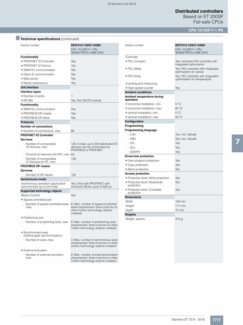
7/17Siemens ST 70 N · 2016
7
■ Technical specifications (continued)
Distributed controllersBased on ET 200SP
Fail-safe CPUs
CPU 1512SP F-1 PN
Functionality
• PROFINET IO Controller Yes
• PROFINET IO Device Yes
• SIMATIC communication Yes
• Open IE communication Yes
• Web server Yes
• Media redundancy Yes
2nd interface
Interface types
• Number of ports 1
• RS 485 Yes; Via CM DP module
Functionality
• SIMATIC communication Yes
• PROFIBUS DP master Yes
• PROFIBUS DP slave Yes
Protocols
Number of connections
• Number of connections, max. 88
PROFINET IO Controller
Services
- Number of connectableIO Devices, max.
128; In total, up to 253 distributed I/O devices can be connected via PROFIBUS or PROFINET
- Of which IO devices with IRT, max. 64
- Number of connectableIO Devices for RT, max.
128
PROFIBUS DP master
Services
- Number of DP slaves 125
Isochronous mode
Isochronous operation (application synchronized up to terminal)
Yes; Only with PROFINET; with minimum OB 6x cycle of 625 µs
Supported technology objects
Motion Control Yes
• Speed-controlled axis
- Number of speed-controlled axes, max.
6; Max. number of speed-controlled axes (requirement: there must be no other motion technology objects created)
• Positioning axis
- Number of positioning axes, max. 6; Max. number of positioning axes (requirement: there must be no other motion technology objects created)
• Synchronized axes(relative gear synchronization)
- Number of axes, max. 3; Max. number of synchronous axes (requirement: there must be no other motion technology objects created)
• External encoders
- Number of external encoders, max.
6; Max. number of external encoders (requirement: there must be no other motion technology objects created)
Article number 6ES7512-1SK01-0AB0
CPU 1512SP F-1 PN,300KB PROG./1MB DATA
Controller
• PID_Compact Yes; Universal PID controller with integrated optimization
• PID_3Step Yes; PID controller with integrated optimization for valves
• PID-Temp Yes; PID controller with integrated optimization for temperature
Counting and measuring
• High-speed counter Yes
Ambient conditions
Ambient temperature during operation
• horizontal installation, min. 0 °C
• horizontal installation, max. 60 °C
• vertical installation, min. 0 °C
• vertical installation, max. 50 °C
Configuration
Programming
Programming language
- LAD Yes; incl. failsafe
- FBD Yes; incl. failsafe
- STL Yes
- SCL Yes
- GRAPH Yes
Know-how protection
• User program protection Yes
• Copy protection Yes
• Block protection Yes
Access protection
• Protection level: Write protection Yes
• Protection level: Read/write protection
Yes
• Protection level: Complete protection
Yes
Dimensions
Width 100 mm
Height 117 mm
Depth 75 mm
Weights
Weight, approx. 310 g
Article number 6ES7512-1SK01-0AB0
CPU 1512SP F-1 PN,300KB PROG./1MB DATA
© Siemens AG 2016

7/18 Siemens ST 70 N · 2016
7
Distributed controllersBased on ET 200SPFail-safe CPUs
CPU 1512SP F-1 PN
■ Ordering data Article No. Article No.
CPU 1512SP F-1 PN 6ES7512-1SK01-0AB0
Work memory 300 KB for program, 1 MB for data, PROFINET IO IRT interface, SIMATIC Memory Card required
Accessories
CM DP for ET 200SP CPU 6ES7545-5DA00-0AB0
PROFIBUS DP master/slave with electrical interface for connecting the ET 200SP CPUs to PROFIBUS at up to 12 Mbit/s
SIMATIC Memory Card
4 MB 6ES7954-8LC02-0AA0
12 MB 6ES7954-8LE02-0AA0
24 MB 6ES7954-8LF02-0AA0
256 MB 6ES7954-8LL02-0AA0
2 GB 6ES7954-8LP02-0AA0
32 GB 6ES7954-8LT02-0AA0
DIN rail 35 mm • Length: 483 mm
for 19" cabinets6ES5710-8MA11
• Length: 530 mm for 600 mm cabinets
6ES5710-8MA21
• Length: 830 mm for 900 mm cabinets
6ES5710-8MA31
• Length: 2 m 6ES5710-8MA41
PE connection elementfor DIN rail 2000 mm
6ES7590-5AA00-0AA0
BusAdapter BA 2xRJ45 6ES7193-6AR00-0AA0
BusAdapter BA 2xFCfor increased vibration and EMC loads
6ES7193-6AF00-0AA0
BusAdapter BA 2xSCRJ 6ES7193-6AP00-0AA0
BusAdapter BA SCRJ/RJ45 6ES7193-6AP20-0AA0
BusAdapter BA SCRJ/FC 6ES7193-6AP40-0AA0
Reference identification label 6ES7193-6LF30-0AW0
10 sheets of 16 labels
Labeling strips
500 labeling strips on roll, light gray, for inscription with thermal transfer roll printer
6ES7193-6LR10-0AA0
500 labeling strips on roll, yellow, for inscription with thermal transfer roll printer
6ES7193-6LR10-0AG0
1000 labeling strips DIN A4, light gray, card, for inscription with laser printer
6ES7193-6LA10-0AA0
1000 labeling strips DIN A4, yellow, card, for inscription with laser printer
6ES7193-6LA10-0AG0
IE FC RJ45 plugs
RJ45 plug connector for Industrial Ethernet with a rugged metal enclo-sure and integrated insulation dis-placement contacts for connecting Industrial Ethernet FC installation cables
IE FC RJ45 Plug 90
90° cable outlet
1 unit 6GK1901-1BB20-2AA0
10 units 6GK1901-1BB20-2AB0
50 units 6GK1901-1BB20-2AE0
IE FC RJ45 Plug 180
180° cable outlet
1 unit 6GK1901-1BB10-2AA0
10 units 6GK1901-1BB10-2AB0
50 units 6GK1901-1BB10-2AE0
IE FC TP standard cable GP 2x2 6XV1840-2AH10
4-core, shielded TP installation cable for connection toIE FC Outlet RJ45/ IE FC RJ45 Plug; PROFINET-compatible; with UL approval;sold by the meter; max. delivery unit 1000 m,minimum order quantity 20 m
IE FC TP Trailing Cable 2 x 2 (Type C)
6XV1840-3AH10
4-core, shielded TP installation cable for connection toIE FC Outlet RJ45/ IE FC RJ45 Plug 180/90 for use as trailing cable; PROFINET-compatible;with UL approval; sold by the meter; max. delivery unit 1000 m,minimum order quantity 20 m
IE FC TP Marine Cable 2 x 2(Type B)
6XV1840-4AH10
4-core, shielded TP installation cable for connection toIE FC Outlet RJ45/ IE FC RJ45 Plug 180/90 with marine approval, sold by the meter; max. delivery unit 1000 m,minimum order quantity 20 m
IE FC stripping tool 6GK1901-1GA00
Preadjusted stripping tool for fast stripping of Industrial Ethernet FC cables
Manuals for ET 200SP distributed I/O system
ET 200SP library: ET 200SP Manual Collection,comprising system manual, product information, and device manuals
Manuals can be downloaded fromthe Internet as PDF files:
http://www.siemens.com/simatic-docu
© Siemens AG 2016
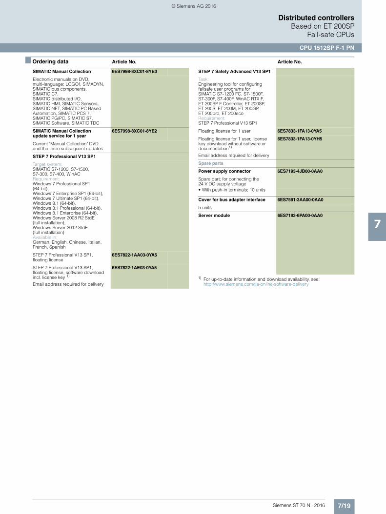
7/19Siemens ST 70 N · 2016
7
■ Ordering data Article No. Article No.
Distributed controllersBased on ET 200SP
Fail-safe CPUs
CPU 1512SP F-1 PN
1) For up-to-date information and download availability, see:http://www.siemens.com/tia-online-software-delivery
SIMATIC Manual Collection 6ES7998-8XC01-8YE0
Electronic manuals on DVD, multi-language: LOGO!, SIMADYN, SIMATIC bus components, SIMATIC C7,SIMATIC distributed I/O, SIMATIC HMI, SIMATIC Sensors, SIMATIC NET, SIMATIC PC Based Automation, SIMATIC PCS 7, SIMATIC PG/PC, SIMATIC S7, SIMATIC Software, SIMATIC TDC
SIMATIC Manual Collection update service for 1 year
6ES7998-8XC01-8YE2
Current "Manual Collection" DVD and the three subsequent updates
STEP 7 Professional V13 SP1
Target system:SIMATIC S7-1200, S7-1500, S7-300, S7-400, WinACRequirement:Windows 7 Professional SP1 (64-bit), Windows 7 Enterprise SP1 (64-bit), Windows 7 Ultimate SP1 (64-bit), Windows 8.1 (64-bit), Windows 8.1 Professional (64-bit),Windows 8.1 Enterprise (64-bit), Windows Server 2008 R2 StdE (full installation), Windows Server 2012 StdE(full installation)Available in:German, English, Chinese, Italian, French, Spanish
STEP 7 Professional V13 SP1, floating license
6ES7822-1AA03-0YA5
STEP 7 Professional V13 SP1,floating license, software download incl. license key 1)
Email address required for delivery
6ES7822-1AE03-0YA5
STEP 7 Safety Advanced V13 SP1
Task: Engineering tool for configuringfailsafe user programs forSIMATIC S7-1200 FC, S7-1500F, S7-300F, S7-400F, WinAC RTX F, ET 200SP F Controller, ET 200SP,ET 200S, ET 200M, ET 200iSP, ET 200pro, ET 200eco Requirement: STEP 7 Professional V13 SP1
Floating license for 1 user 6ES7833-1FA13-0YA5
Floating license for 1 user, license key download without software or documentation1)
Email address required for delivery
6ES7833-1FA13-0YH5
Spare parts
Power supply connector 6ES7193-4JB00-0AA0
Spare part; for connecting the24 V DC supply voltage• With push-in terminals; 10 units
Cover for bus adapter interface 6ES7591-3AA00-0AA0
5 units
Server module 6ES7193-6PA00-0AA0
© Siemens AG 2016
7/20 Siemens ST 70 N · 2016
7
Distributed controllers
Notes
© Siemens AG 2016
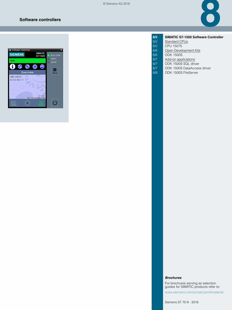
Siemens ST 70 N · 2016
8
Brochures
For brochures serving as selection guides for SIMATIC products refer to:
www.siemens.com/simatic/printmaterial
8/2 SIMATIC S7-1500 Software Controller8/2 Standard CPUs8/2 CPU 1507S8/6 Open Development Kits8/6 ODK 1500S8/7 Add-on applications8/7 ODK 1500S SQL driver8/7 ODK 1500S DataAccess driver8/8 ODK 1500S FileServer
Software controllers
© Siemens AG 2016
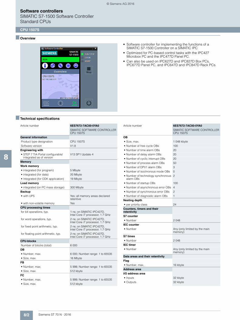
8/2 Siemens ST 70 N · 2016
8
Software controllersSIMATIC S7-1500 Software ControllerStandard CPUs
CPU 1507S
■ Overview
• Software controller for implementing the functions of a SIMATIC S7-1500 Controller on a SIMATIC IPC
• Optimized for PC-based control tasks with the IPC427 Microbox PC and the IPC477D Panel PC.
• Can also be used on IPC627D and IPC827D Box PCs, IPC677D Panel PC, and IPC647D and IPC847D Rack PCs.
■ Technical specifications
Article number 6ES7672-7AC00-0YA0
SIMATIC SOFTWARE CONTROLLER CPU 1507S
General information
Product type designation CPU 1507S
Software version V1.8
Engineering with
• STEP 7 TIA Portal configurable/integrated as of version
V13 SP1 Update 4
Memory
Work memory
• integrated (for program) 5 Mbyte
• integrated (for data) 20 Mbyte
• Integrated (for ODK application) 19 Mbyte
Load memory
• integrated (on PC mass storage) 300 Mbyte
Backup
• with UPS Yes; all memory areas declared retentive
• with non-volatile memory Yes
CPU processing times
for bit operations, typ. 1 ns; on SIMATIC IPC427D,Intel Core i7 processor, 1.7 GHz
for word operations, typ. 2 ns; on SIMATIC IPC427D, Intel Core i7 processor, 1.7 GHz
for fixed point arithmetic, typ. 2 ns; on SIMATIC IPC427D, Intel Core i7 processor, 1.7 GHz
for floating point arithmetic, typ. 2 ns; on SIMATIC IPC427D,Intel Core i7 processor, 1.7 GHz
CPU-blocks
Number of blocks (total) 6 000
DB
• Number, max. 6 000; Number range: 1 to 65535
• Size, max. 16 Mbyte
FB
• Number, max. 5 998; Number range: 1 to 65535
• Size, max. 512 kbyte
FC
• Number, max. 5 999; Number range: 1 to 65535
• Size, max. 512 kbyte
OB
• Size, max. 1 048 kbyte
• Number of free cycle OBs 100
• Number of time alarm OBs 20
• Number of delay alarm OBs 20
• Number of cyclic interrupt OBs 20
• Number of process alarm OBs 50
• Number of DPV1 alarm OBs 3
• Number of isochronous mode OBs 0
• Number of technology synchronous alarm OBs
2
• Number of startup OBs 100
• Number of asynchronous error OBs 4
• Number of synchronous error OBs 2
• Number of diagnostic alarm OBs 1
Nesting depth
• per priority class 24
Counters, timers and their retentivity
S7 counter
• Number 2 048
IEC counter
• Number Any (only limited by the main memory)
S7 times
• Number 2 048
IEC timer
• Number Any (only limited by the main memory)
Data areas and their retentivity
Flag
• Number, max. 16 kbyte
Address area
I/O address area
• Inputs 32 kbyte
• Outputs 32 kbyte
Article number 6ES7672-7AC00-0YA0
SIMATIC SOFTWARE CONTROLLER CPU 1507S
© Siemens AG 2016

8/3Siemens ST 70 N · 2016
8
■ Technical specifications (continued)
Software controllersSIMATIC S7-1500 Software Controller
Standard CPUs
CPU 1507S
Time of day
Clock
• Type Software clock, synchronizable, no battery backup
Interfaces
Number of interfaces 3
1. Interface
Interface type Onboard PROFINET / IE interface X2 of the SIMATIC IPC, Intel Springville i210T
Interface types
• Number of ports 1
• RJ 45 (Ethernet) Yes
- Transmission rate, max. 100 Mbit/s
- Industrial Ethernet status LED Yes
Functionality
• Number of connections via this interface
128
• PROFINET IO Controller Yes
• PROFINET IO Device Yes
• SIMATIC communication Yes
• Open IE communication Yes
• Web server Yes
PROFINET IO Controller
Services
- Isochronous mode No
- IRT No
- MRP No
- Prioritized startup Yes; Max. 32 PROFINET devices;if you want to use the "Prioritized startup" functionality in STEP 7 forthe PROFINET interface of the CPU, the CPU and the device must be separated by means of a switch (e.g. SCALANCE X205)
- Number of connectableIO Devices, max.
128
- Number of connectable IO Devices for RT, max.
128
- of which in line, max. 128
- Number of IO Devices that can be simultaneously activated/deacti-vated, max.
8
- IO Devices changing during operation (partner ports), supported
Yes
- Number of IO Devices per tool, max.
8
- Updating times The minimum value of the update time also depends on communi-cation share set for PROFINET IO, on the number of IO devices, and on the quantity of configured user data
Update time for RT
- for send cycle of 1 ms 1 ms to 512 ms
Article number 6ES7672-7AC00-0YA0
SIMATIC SOFTWARE CONTROLLER CPU 1507S
PROFINET IO Device
Services
- Isochronous mode No
- IRT No
- MRP No
- Prioritized startup Yes; If you want to use the"Prioritized startup" functionality in STEP 7 for the PROFINET interface of the CPU, the CPU and the device must be separated by means of a switch (e.g. SCALANCE X205)
- Shared device Yes
- Number of IO Controllers with shared device, max.
2
2. Interface
Interface type PROFIBUS with CP 5622, CP 5622 onboard
Interface types
• RS 485 Yes
Functionality
• Number of connections via this interface
44
• SIMATIC communication Yes; no PG/STEP 7 connection possible
• PROFIBUS DP master Yes
• PROFIBUS DP slave No
DP master
Services
- Equidistance No
- Isochronous mode No
- Number of connectable DP slaves, max.
64
3. Interface
Interface type PROFIBUS with CP 5623
Functionality
• Number of connections via this interface
44
• SIMATIC communication Yes; no PG/STEP 7 connection possible
DP master
Services
- Equidistance No
- Isochronous mode No
- Number of connectable DP slaves, max.
125
Protocols
Number of connections
• Number of connections, max. 128
SIMATIC communication
• PG/OP communication Yes
• S7 routing Yes
• S7 communication, as server Yes
• S7 communication, as client Yes
• User data per job, max. 64 kbyte; BSEND/BRCV: 64 KB;PUT/GET: 960 bytes
Article number 6ES7672-7AC00-0YA0
SIMATIC SOFTWARE CONTROLLER CPU 1507S
© Siemens AG 2016
8/4 Siemens ST 70 N · 2016
8
■ Technical specifications (continued)
Software controllersSIMATIC S7-1500 Software ControllerStandard CPUs
CPU 1507S
Open IE communication
• TCP/IP Yes
- Data length, max. 64 kbyte
• ISO-on-TCP (RFC1006) Yes
- Data length, max. 64 kbyte
• UDP Yes
- Data length, max. 1 472 byte
• DHCP No
• SNMP Yes
• DCP Yes
• LLDP Yes
Web server
• HTTP Yes; Standard and user-defined pages
• HTTPS Yes; Standard and user-defined pages
Supported technology objects
Motion Control Yes
• Speed-controlled axis
- Number of speed-controlled axes, max.
60; configurable, up to 60 axes in total (speed-controlled, positioning axis, external encoders) are supported
• Positioning axis
- Number of positioning axes, max. 60; configurable, up to 60 axes in total (speed-controlled, positioning axis, external encoders) are supported
• Synchronized axes (relative gear synchronization)
- Number of axes, max. 30; Max. number of synchronous axes (requirement: there must be no other motion technology objects created)
• External encoders
- Number of external encoders, max.
60; configurable, up to 60 axes in total (speed-controlled, positioning axis, external encoders) are supported
Controller
• PID_Compact Yes; Universal PID controller with integrated optimization
• PID_3Step Yes; PID controller with integrated optimization for valves
Counting and measuring
• High-speed counter Yes
Article number 6ES7672-7AC00-0YA0
SIMATIC SOFTWARE CONTROLLER CPU 1507S
Hardware requirements
Hardware required SIMATIC IPC4x7D, IPC6x7D, IPC8x7D
free hard disk memory for installation, min.
100 Mbyte
free hard disk memory at runtime, min.
400 Mbyte
Work memory, min. 4 Gbyte
Processor
• Single-core processor No
• Single-core processor with hyper-threading
No
• Multi-core processor Yes
• Multi-core processor with hyper-threading
Yes
• occupied cores 1; For multicore processors with activated Hyper-Threading, one complete physical core is reserved for the CPU 1507S
Operating systems
pre-installed operating system
• Windows XP No
• Windows 7 Yes; Professional, Enterprise, Ultimate (32 bits and 64 bits)
• Windows Embedded Standard 7 Yes; With the delivery image of the SIMATIC PC
• Windows 8 No
• Windows Embedded Standard 8 No
Configuration
Programming
Programming language
- LAD Yes
- FBD Yes
- STL Yes
- SCL Yes
- CFC No
- GRAPH Yes
Know-how protection
• User program protection Yes
• Copy protection Yes
• Block protection Yes
Access protection
• Protection level: Write protection Yes
• Protection level: Read/write protection
Yes
• Protection level: Complete protection
Yes
Open Development interfaces
• Size of ODK SO file, max. 1 Mbyte
Dimensions
Width 18.2 cm; Packaging
Height 26.5 cm
Depth 3 cm
Weights
Weight, approx. 200 g
Article number 6ES7672-7AC00-0YA0
SIMATIC SOFTWARE CONTROLLER CPU 1507S
© Siemens AG 2016

8/5Siemens ST 70 N · 2016
8
Software controllersSIMATIC S7-1500 Software Controller
Standard CPUs
CPU 1507S
■ Ordering data Article No. Article No.
1) For up-to-date information and download availability, see: http://www.siemens.com/tia-online-software-delivery
SIMATIC S7-1500 Software Controller CPU 1507S
For implementing the function of an S7-1500 Controller on SIMATIC IPCTarget system:Optimized for IPC427 Microbox PCIPC477D Panel PC; can also be used with IPC677D Panel PCIPC627D Box PCIPC827D Box PCIPC647D Rack PCIPC847D Rack PCRequirement: Windows 7Available in:German, English, Chinese, Italian, French, Spanish• Single license for one installation;
software and documentation on DVD, license key on USB flash drive
6ES7672-7AC00-0YA0
• Single license for one installation; software download including license key 1)
6ES7672-7AC00-0YG0
Accessories
SIMATIC IPC• SIMATIC IPC427D Microbox PC 6AG4140-.....-....• SIMATIC IPC477D Panel PC 6AV7240-.....-....• SIMATIC IPC677D Panel PC 6AV7260-.....-....• SIMATIC IPC627D Box PC 6AG4131-2....-....• SIMATIC IPC827D Box PC 6AG4132-2....-....• SIMATIC IPC647D Rack PC 6AG4112-2....-....• SIMATIC IPC847D Rack PC 6AG4114-2....-....
For further information,see Catalog ST 80 / ST PC
CP 5622 communications processor
6GK1562-2AA00
PCI Express x1 card (32 bit) for connection of a programming device or PC to PROFIBUS
CP 5623 communications processor
6GK1562-3AA00
PCI Express x1 card (32 bit) for connection to PROFIBUSincl. DP-Base software withNCM PC; DP-RAM interface forDP master or DP slave, incl. PG and FDL protocols; single license for 1 installation, runtime software, software and electronic manual on CD-ROM, Class A, for operating system supportsee SIMATIC NET software;German/English
© Siemens AG 2016
8/6 Siemens ST 70 N · 2016
8
Software controllersSIMATIC S7-1500 Software ControllerOpen Development Kits
ODK 1500S
■ Overview
• For developing dynamically loadable function librariesfor S7-1500 Software Controllers:- Implementation of function libraries by means of high-level
programming with C/C++.- Execution of the library functions under Windows or in the
real-time context of the software controller.- Calling the functions directly from the PLC program.
• Development environment for real-time library functions included in the scope of delivery.
• Development of Windows library functions with MS Visual Studio.
• Automatic creation of function blocks for calling the library functions.
• Simple integration of the function blocks into STEP 7 by importing.
• Simple use of the library functions in the controller without specific high-level language know-how.
■ Technical specifications
System requirements
The SIMATIC ODK 1500S can be used on PC platforms with the following requirements:• Windows 7, Windows 8 operating systems• Min. 150 MB hard drive memory• Min. 4 GB work memory• Mouse, keyboard, screen
■ Ordering data Article No.
SIMATIC ODK 1500S 6ES7 806-2CD00-0YA0
Open Development Kit for support in developing Windows and real-time library functions for S7-1500 software controllers
© Siemens AG 2016

8/7Siemens ST 70 N · 2016
8
Software controllersSIMATIC S7-1500 Software Controller
Add-on applications
ODK 1500S SQL driver
■ Overview
Note
This catalog entry contains non-binding information on a supple-mentary application software for the SIMATIC S7-1500 Software Controller and the SIMATIC ET 200SP Open Controller.
Overview
The ODK 1500S SQL driver enables direct access to an SQL database from the PLC program. In this case the database can be installed on the same computer as the S7- 1500 Software Controller or in the network.• Direct data exchange with SQL-based database by means of
SQL commands from the PCL program• Connection to SQL-based database on the same PC or to
database servers in the network
■ Application
Generally the ODK1500S SQL driver can be used in all applica-tion scenarios in which an SQL database is required. Typical fields of application are warehouse management, message memory management or recipe management
■ Technical specifications
■ More information
If you are interested, please contact your sales representative:http://www.automation.siemens.com/partner/
You can find Service and Support at:https://support.industry.siemens.com/cs/ww/en/view/109479140
■ Overview
Note
This catalog entry contains non-binding information on a supple-mentary application software for the SIMATIC S7-1500 Software Controller and the SIMATIC ET 200SP Open Controller.
Overview
With the function blocks of the ODK 1500S XML Data Access driver it is possible to access specific information in XML files in the Windows file system from the PLC program.
XPath expressions are used for accessing XML file elements since they provide the highest possible flexibility for processing XML data. This means that extremely large XML files can be edited, too.
The driver offers the following functionality:• XML data can be read into and processed in the PLC.• XML data can be modified and written back to the XML file.
■ Application
• Reading in of parameters or recipes that have been made available as XML files by the control system.
• Return of production data which need to be made available in the form of an XML file.
■ Technical specifications
■ More information
If you are interested, please contact your sales representative:http://www.automation.siemens.com/partner/
You can find Service and Support at:https://support.industry.siemens.com/cs/ww/en/view/109479496
Supported SQL commands • SELECT
• INSERT
• UPDATE
• DELETE
Supported data types All standard SQL data types
System requirements• Runtime PC SIMATIC IPC with S7-1500 Software
Controller or SIMATIC ET 200SP Open Controller
• Engineering STEP 7 in the TIA Portal V13 SP1
System requirements• Runtime PC SIMATIC IPC with S7-1500 software
controller or SIMATIC ET 200SP open controller
• Engineering STEP 7 in the TIA Portal V13 SP1
ODK 1500S XML DataAccess driver
© Siemens AG 2016
8/8 Siemens ST 70 N · 2016
8
Software controllersSIMATIC S7-1500 Software ControllerAdd-on applications
ODK 1500S FileServer
■ Overview
Note
This catalog entry contains non-binding information on a supple-mentary application software for the SIMATIC S7-1500 software controller and the SIMATIC ET 200SP open controller.
Overview
The ODK 1500S FileServer enhances the file functions of the SIMATIC S7-1500 software controller with an option enabling direct access to the Windows file system of the PC from the STEP 7 program.
The driver enables reading and writing of data blocks in/from files in structured form. Various file formats are supported.
There are also FBs available for handling(e.g. renaming, deleting) files.
■ Application
Driver blocks enable file operations to be directly integrated in automation solutions, e.g.:• Writing of measured values to CSV• Writing of quality data to CSV• Reading of parameters from INI file• Reading of recipes from XML file
■ Technical specifications
1) The XML format is predefined. A DB can be saved and read in as anXML file. It is not possible to parse any particular XML file.
■ More information
If you are interested, please contact your sales representative:http://www.automation.siemens.com/partner/
You can find Service and Support at:https://support.industry.siemens.com/cs/ww/en/view/109479497
Supported file formats • CSV
• ASCII
• Windows-INI
• XML1)
• Binary
System requirements• Runtime PC SIMATIC IPC with S7-1500 software
controller or SIMATIC ET 200SP open controller
• Engineering STEP 7 in the TIA Portal V13 SP1
© Siemens AG 2016
Siemens ST 70 N · 2016
9
Brochures
For brochures serving as selectionguides for SIMATIC products refer to:
www.siemens.com/simatic/printmaterial
9/2 ET 200 systems for the control cabinet9/2 ET 200SP – interface modules9/2 SIPLUS interface modules9/3 ET 200SP – I/O modules9/3 Digital output modules9/13 SIPLUS digital output modules9/15 Analog input modules9/27 Analog output modules9/32 SIPLUS analog input modules9/35 SIPLUS analog output modules9/37 ET 200SP – I/O modules –
Technology modules9/37 Pulse output module TM Pulse 2x24V9/40 ET 200SP – I/O modules –
Communication9/40 SIPLUS CM DP for ET 200SP CPU9/41 ET 200SP – I/O modules –
Fail-safe I/O modules9/41 SIPLUS digital F input modules9/43 SIPLUS digital F output modules9/45 SIPLUS fail-safe customized modules9/46 ET 200SP – I/O modules9/46 ET 200SP motor starters9/52 ET 200SP – BaseUnits9/55 ET 200SP – SIPLUS BaseUnits9/58 ET 200SP – BusAdapters9/61 ET 200SP – SIPLUS BusAdapter9/63 ET 200SP – Accessories9/64 SIMATIC ET 200S9/65 ET 200M – Interface modules9/65 IM 153-1/153-29/68 SIPLUS IM 153-1/153-2
9/70 ET 200 systems without control cabinet9/70 ET 200pro9/70 ET 200pro FC-2 Frequency Converter9/73 SIMATIC ET 200AL – I/O modules9/73 Digital I/O modules9/80 SIMATIC ET 200AL – Accessories9/80 Cables and connectors
9/92 Heating control systems9/92 SIPLUS HCS3200 heating control system9/94 SIPLUS HCS4200 heating control system9/94 Rack9/95 Central Interface Module (CIM)9/97 Power Output Module (POM)9/99 SIPLUS HCS4300 heating control system9/99 Central Interface Module (CIM)9/101 Power Output Module (POM)
9/104 PROFINET components9/104 PROFINET Driver
I/O systems
© Siemens AG 2016

9/2 Siemens ST 70 N · 2016
9
I/O systemsET 200 systems for the control cabinetET 200SP – interface modules
SIPLUS interface modules
■ Overview
• Interface module for linking the I/O modules to a higher level controller with PROFINET or PROFIBUS
• Server module included in the scope of supply • Station expansion with IP67 I/O system ET 200AL via
ET-connection to BU-Send / BA-Send • PROFINET bus connection
- 2 ports for line configuration - PN connection selected via BusAdapter (ST, HF) - Two integrated RJ45 sockets (BA)
• PROFIBUS bus connection- 9-pole D-sub socket - PROFIBUS connector included in scope of delivery - Hot swapping (module replacement during operation) - Startup and operation with gaps - Dynamic re-parameterization in RUN mode - Configuration control (option handling) - Pluggable 24 V DC supply connector - Electronically readable rating plate (I&M data)
Note:
SIPLUS extreme products are based on SIMATIC standard pro-ducts. The contents listed here were taken from the respective standard products. SIPLUS extreme specific information was added.
■ Technical specifications
■ Ordering data Article No. Article No.
Article number 6AG1155-6AA00-7BN0 6AG1155-6AU00-4CN0 6AG1155-6BA00-7CN0
Based on 6ES7155-6AA00-0BN0 6ES7155-6AU00-0CN0 6ES7155-6BA00-0CN0
SIPLUS ET 200SP IM155-6PN ST SIPLUS ET 200SP IM155-6PN HF SIPLUS ET 200SP IM155-6DP HF
Ambient conditions
Ambient temperature during operation
• horizontal installation, min. -40 °C; = Tmin; Startup @ -25 °C 0 °C -40 °C; = Tmin; Startup @ -25 °C
• horizontal installation, max. 70 °C; = Tmax 60 °C 70 °C; = Tmax
• vertical installation, min. -40 °C; = Tmin; Startup @ -25 °C 0 °C -40 °C; = Tmin; Startup @ -25 °C
• vertical installation, max. 50 °C; = Tmax 50 °C 50 °C; = Tmax
Extended ambient conditions
• relative to ambient temperature-atmospheric pressure-installation altitude
Tmin ... Tmax at 1080 hPa ... 795 hPa (-1000 m ... +2000 m) // Tmin ... (Tmax - 10K) at 795 hPa ... 658 hPa (+2000 m ... +3500 m) //Tmin ... (Tmax - 20K) at 658 hPa ... 540 hPa (+3500 m ... +5000 m)
Relative humidity
- With condensation, tested in acc. with IEC 60068-2-38, max.
100 %; RH incl. condensation/frost (no commissioning under condensation conditions)
Resistance
- against biologically active substances / conformity with EN 60721-3-3
Yes; Class 3B2 mold, fungus and dry rot spores (with the exception of fauna). The supplied connector covers must remain on the unused interfaces during operation!
- against chemically active substances / conformity with EN 60721-3-3
Yes; Class 3C4 (RH < 75%) incl. salt spray according to EN 60068-2-52 (degree of severity 3). The supplied connector covers must remain on the unused interfaces during operation!
- against mechanically active substances / conformity with EN 60721-3-3
Yes; Class 3S4 incl. sand, dust. The supplied connector covers must remain on the unused interfaces during operation!
SIPLUS interface moduleStandard
(Extended temperature range and medial exposure)• IM 155-6PN ST,
with server module andinstalled BusAdapter BA 2xRJ45
6AG1155-6AA00-7BN0
SIPLUS interface moduleHigh Feature
(Extended temperature range and medial exposure)• IM 155-6DP HF, with server
module, with multi-hot-swap, incl. PROFIBUS connector
6AG1155-6BA00-7CN0
(medial exposure)• IM 155-6PN HF, incl. server
module, without BusAdapter6AG1155-6AU00-4CN0
Accessories see catalog ST 70,SIMATIC ET 200SP, IM 155-6 interface module
© Siemens AG 2016
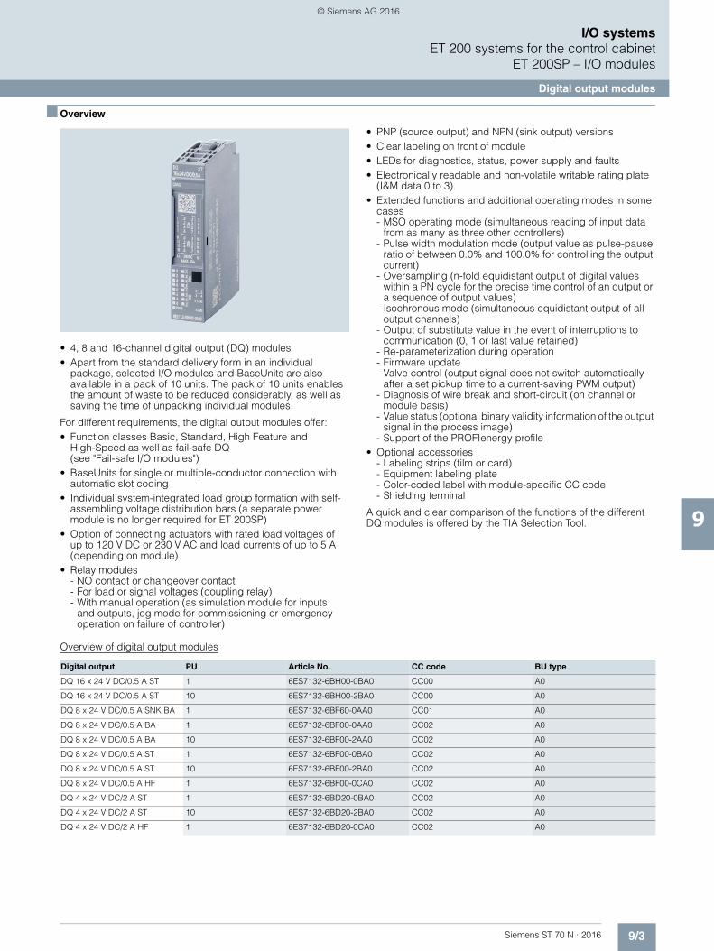
9/3Siemens ST 70 N · 2016
9
I/O systemsET 200 systems for the control cabinet
ET 200SP – I/O modules
Digital output modules
■ Overview
• 4, 8 and 16-channel digital output (DQ) modules• Apart from the standard delivery form in an individual
package, selected I/O modules and BaseUnits are also available in a pack of 10 units. The pack of 10 units enables the amount of waste to be reduced considerably, as well as saving the time of unpacking individual modules.
For different requirements, the digital output modules offer:• Function classes Basic, Standard, High Feature and
High-Speed as well as fail-safe DQ(see "Fail-safe I/O modules")
• BaseUnits for single or multiple-conductor connection with automatic slot coding
• Individual system-integrated load group formation with self-assembling voltage distribution bars (a separate power module is no longer required for ET 200SP)
• Option of connecting actuators with rated load voltages of up to 120 V DC or 230 V AC and load currents of up to 5 A (depending on module)
• Relay modules- NO contact or changeover contact- For load or signal voltages (coupling relay)- With manual operation (as simulation module for inputs
and outputs, jog mode for commissioning or emergency operation on failure of controller)
• PNP (source output) and NPN (sink output) versions• Clear labeling on front of module• LEDs for diagnostics, status, power supply and faults• Electronically readable and non-volatile writable rating plate
(I&M data 0 to 3)• Extended functions and additional operating modes in some
cases- MSO operating mode (simultaneous reading of input data
from as many as three other controllers)- Pulse width modulation mode (output value as pulse-pause
ratio of between 0.0% and 100.0% for controlling the output current)
- Oversampling (n-fold equidistant output of digital values within a PN cycle for the precise time control of an output or a sequence of output values)
- Isochronous mode (simultaneous equidistant output of all output channels)
- Output of substitute value in the event of interruptions to communication (0, 1 or last value retained)
- Re-parameterization during operation- Firmware update- Valve control (output signal does not switch automatically
after a set pickup time to a current-saving PWM output)- Diagnosis of wire break and short-circuit (on channel or
module basis)- Value status (optional binary validity information of the output
signal in the process image)- Support of the PROFIenergy profile
• Optional accessories- Labeling strips (film or card)- Equipment labeling plate- Color-coded label with module-specific CC code- Shielding terminal
A quick and clear comparison of the functions of the different DQ modules is offered by the TIA Selection Tool.
Overview of digital output modules
Digital output PU Article No. CC code BU type
DQ 16 x 24 V DC/0.5 A ST 1 6ES7132-6BH00-0BA0 CC00 A0
DQ 16 x 24 V DC/0.5 A ST 10 6ES7132-6BH00-2BA0 CC00 A0
DQ 8 x 24 V DC/0.5 A SNK BA 1 6ES7132-6BF60-0AA0 CC01 A0
DQ 8 x 24 V DC/0.5 A BA 1 6ES7132-6BF00-0AA0 CC02 A0
DQ 8 x 24 V DC/0.5 A BA 10 6ES7132-6BF00-2AA0 CC02 A0
DQ 8 x 24 V DC/0.5 A ST 1 6ES7132-6BF00-0BA0 CC02 A0
DQ 8 x 24 V DC/0.5 A ST 10 6ES7132-6BF00-2BA0 CC02 A0
DQ 8 x 24 V DC/0.5 A HF 1 6ES7132-6BF00-0CA0 CC02 A0
DQ 4 x 24 V DC/2 A ST 1 6ES7132-6BD20-0BA0 CC02 A0
DQ 4 x 24 V DC/2 A ST 10 6ES7132-6BD20-2BA0 CC02 A0
DQ 4 x 24 V DC/2 A HF 1 6ES7132-6BD20-0CA0 CC02 A0
© Siemens AG 2016
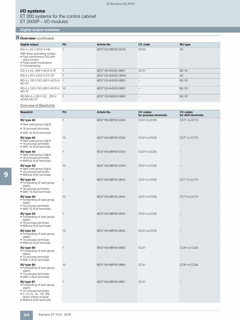
9/4 Siemens ST 70 N · 2016
9
■ Overview (continued)
I/O systemsET 200 systems for the control cabinetET 200SP – I/O modules
Digital output modules
Overview of BaseUnits
DQ 4 x 24 V DC/2 A HS
With three operating modes:• Fast isochronous DQ with
valve control• Pulse width modulation• Oversampling
1 6ES7132-6BD20-0DA0 CC02 A0
DQ 4 x 24...230 V AC/2 A ST 1 6ES7132-6FD00-0BB1 CC41 B0, B1
RQ 4 x 24 V UC/2 A CO ST 1 6ES7132-6GD50-0BA0 -- A0
RQ 4 x 120 V DC-230 V AC/5 A NO ST
1 6ES7132-6HD00-0BB1 -- B0, B1
RQ 4 x 120 V DC-230 V AC/5 A NO ST
10 6ES7132-6HD00-0BB1 -- B0, B1
RQ MA 4 x 120 V DC...230 V AC/5A NO ST
1 6ES7132-6MD00-0BB1 -- B0, B1
Digital output PU Article No. CC code BU type
BaseUnit PU Article No. CC codes for process terminals
CC codes for AUX terminals
BU type A0
• New load group (light)
• 16 process terminals
• With 10 AUX terminals
1 6ES7193-6BP20-0DA0 CC01 to CC05 CC71 to CC73
BU type A0 • New load group (light) • 16 process terminals • With 10 AUX terminals
10 6ES7193-6BP20-2DA0 CC01 to CC05 CC71 to CC73
BU type A0 • New load group (light) • 16 process terminals • Without AUX terminals
1 6ES7193-6BP00-0DA0 CC01 to CC05 --
BU type A0 • New load group (light) • 16 process terminals • Without AUX terminals
10 6ES7193-6BP00-2DA0 CC01 to CC05 --
BU type A0 • Forwarding of load group
(dark) • 16 process terminals • With 10 AUX terminals
1 6ES7193-6BP20-0BA0 CC01 to CC05 CC71 to CC73
BU type A0 • Forwarding of load group
(dark) • 16 process terminals • With 10 AUX terminals
10 6ES7193-6BP20-2BA0 CC01 to CC05 CC71 to CC73
BU type A0 • Forwarding of load group
(dark) • 16 process terminals • Without AUX terminals
1 6ES7193-6BP00-0BA0 CC01 to CC05 --
BU type A0 • Forwarding of load group
(dark) • 16 process terminals • Without AUX terminals
10 6ES7193-6BP00-2BA0 CC01 to CC05 --
BU type B0• Forwarding of load group
(dark) • 12 process terminals• With 4 AUX terminals
1 6ES7193-6BP20-0BB0 CC41 CC81 to CC83
BU type B0• Forwarding of load group
(dark) • 12 process terminals• With 4 AUX terminals
10 6ES7193-6BP20-0BB0 CC41 CC81 to CC83
BU type B1 • Forwarding of load group
(dark) • 12 process terminals • 2 x 2 (1L, 2L, 1N, 2N)
direct infeed module • Without AUX terminals
1 6ES7193-6BP20-0BB1 CC41 --
© Siemens AG 2016

9/5Siemens ST 70 N · 2016
9
I/O systemsET 200 systems for the control cabinet
ET 200SP – I/O modules
Digital output modules
■ Technical specifications
Article number 6ES7132-6BH00-0BA0
6ES7132-6BF60-0AA0
6ES7132-6BF00-0AA0
6ES7132-6BF00-0BA0
6ES7132-6BF00-0CA0
ET 200SP, DQ 16X24VDC/0.5A ST
ET 200SP, DQ 8X24VDC/0.5A SINK BASIC
ET 200SP, DQ 8X24VDC/0.5A BASIC, PU 1
ET 200SP, DQ 8X24VDC/0.5A ST
ET 200SP, DQ 8X24VDC/0.5A HF
General information
Product type designation ET 200SP, DQ 16x24VDC/0.5A ST, PU 1
DQ 8x24VDC/0.5A SNK BA
ET 200SP, DQ 8x24VDC/0.5A BA, PU 1
ET 200SP, DQ 8x24VDC/0.5A ST, PU 1
DQ 8x24VDC/0.5A HF
Product function
• I&M data Yes; I&M0 to I&M3 Yes; I&M0 to I&M3 Yes; I&M0 to I&M3 Yes; I&M0 to I&M3 Yes; I&M0 to I&M3
Engineering with
• STEP 7 TIA Portal configurable/integrated as of version
V11 SP2 / V13 V13 / V13 V13 SP1 / - V11 SP2 / V13 V13 / V13
• STEP 7 configurable/integratedas of version
V5.5 SP3 / - V5.5 SP3 / - V5.5 SP3 / - V5.5 SP3 / - V5.5 SP3 / -
• PCS 7 configurable/integrated as of version
V8.1 SP1 V8.1 SP1 V8.1 SP1
• PROFIBUS as of GSD version/GSD revision
GSD Revision 5 GSD Revision 5 GSD Revision 5 GSD Revision 5 GSD Revision 5
• PROFINET as of GSD version/GSD revision
GSDML V2.3 GSDML V2.3 GSDML V2.3 GSDML V2.3 GSDML V2.3
Operating mode
• DQ Yes Yes Yes Yes Yes
• DQ with energy-saving function No No No No No
• PWM No No No No No
• Oversampling No No No No No
• MSO No No No No Yes
Supply voltage
Type of supply voltage DC 24 V DC DC DC DC
Rated value (DC) 24 V 24 V 24 V 24 V 24 V
Reverse polarity protection Yes Yes Yes Yes
Digital outputs
Number of digital outputs 16 8 8 8 8
Current-sinking No Yes No No No
Current-sourcing Yes No Yes Yes Yes
Digital outputs, parameterizable Yes Yes Yes Yes Yes
Short-circuit protection Yes Yes Yes; per channel, electronic
Open-circuit detection No
Limitation of inductive shutdown voltage to
Typ. L+ (-50 V) Typ. 47 V Typ. L+ (-53 V) Typ. L+ (-50 V)
Controlling a digital input Yes Yes Yes Yes
Switching capacity of the outputs
• with resistive load, max. 0.5 A 0.5 A 0.5 A 0.5 A 0.5 A
• on lamp load, max. 5 W 5 W 5 W 5 W 5 W
Load resistance range
• lower limit 48 48 48 48 48 • upper limit 12 k 3 400 12 k 12 k 12 kOutput current
• for signal "1" rated value 0.5 A 0.5 A 0.5 A 0.5 A 0.5 A
• for signal "0" residual current, max. 0.1 mA 5 µA 1 mA 0.1 mA 0.1 mA
Output delay with resistive load
• "0" to "1", typ. 50 µs 50 µs
• "0" to "1", max. 300 µs 100 µs; at rated load 50 µs; at rated load
• "1" to "0", typ. 100 µs 100 µs
• "1" to "0", max. 600 µs 150 µs; at rated load 100 µs; at rated load
Parallel switching of two outputs
• for uprating No No No No
• for redundant control of a load Yes Yes Yes; per module Yes Yes
© Siemens AG 2016

9/6 Siemens ST 70 N · 2016
9
■ Technical specifications (continued)
I/O systemsET 200 systems for the control cabinetET 200SP – I/O modules
Digital output modules
Switching frequency
• with resistive load, max. 100 Hz 100 Hz 100 Hz 100 Hz 100 Hz
• with inductive load, max. 2 Hz 0.5 Hz 2 Hz 2 Hz 2 Hz
• on lamp load, max. 10 Hz 10 Hz 10 Hz 10 Hz 10 Hz
Total current of the outputs
• Current per channel, max. 0.5 A 0.5 A 0.5 A 0.5 A 0.5 A
• Current per module, max. 8 A 4 A 4 A 4 A 4 A
Total current of the outputs(per module)
horizontal installation
- up to 30 °C, max. 8 A
- up to 40 °C, max. 8 A
- up to 50 °C, max. 6 A
- up to 60 °C, max. 4 A 4 A 4 A 4 A 4 A
vertical installation
- up to 30 °C, max. 8 A
- up to 40 °C, max. 6 A
- up to 50 °C, max. 4 A 4 A
- up to 60 °C, max. 4 A 4 A 4 A 4 A
Cable length
• shielded, max. 1 000 m 1 000 m 1 000 m 1 000 m 1 000 m
• unshielded, max. 600 m 600 m 600 m 600 m 600 m
Isochronous mode
Isochronous operation (application synchronized up to terminal)
No No No No Yes
Execution and activation time (TCO), min.
48 µs
Bus cycle time (TDP), min. 500 µs
Interrupts/diagnostics/status information
Diagnostics Yes Yes Yes Yes Yes
Substitute values connectable Yes No Yes Yes Yes
Alarms
• Diagnostic alarm Yes Yes Yes Yes Yes
Diagnostic messages
• Monitoring the supply voltage Yes Yes Yes Yes Yes
• Wire-break Yes; Module-wise No No Yes; Module-wise Yes; channel by channel
• Short-circuit Yes; Module-wise No No Yes; Module-wise Yes; channel by channel
• Group error Yes Yes Yes Yes Yes
Diagnostics indication LED
• Monitoring of the supply voltage (PWR-LED)
Yes; green PWR LED Yes; green PWR LED Yes; green PWR LED Yes; green PWR LED Yes; green PWR LED
• Channel status display Yes; Green LED Yes; Green LED Yes; Green LED Yes; Green LED Yes; Green LED
• for channel diagnostics No No No No Yes; Red LED
• for module diagnostics Yes; green/red DIAG LED
Yes; green/redDIAG LED
Yes; green/red DIAG LED
Yes; green/red DIAG LED
Yes; green/red DIAG LED
Potential separation
Potential separation channels
• between the channels and backplane bus
Yes Yes Yes Yes Yes
Isolation
Isolation tested with 707 V DC (type test) 707 V DC (type test) 707 V DC (type test) 707 V DC (type test) 707 V DC (type test)
Dimensions
Width 15 mm 15 mm 15 mm 15 mm 15 mm
Weights
Weight, approx. 28 g 30 g 28 g 28 g 30 g
Article number 6ES7132-6BH00-0BA0
6ES7132-6BF60-0AA0
6ES7132-6BF00-0AA0
6ES7132-6BF00-0BA0
6ES7132-6BF00-0CA0
ET 200SP, DQ 16X24VDC/0.5A ST
ET 200SP, DQ 8X24VDC/0.5A SINK BASIC
ET 200SP, DQ 8X24VDC/0.5A BASIC, PU 1
ET 200SP, DQ 8X24VDC/0.5A ST
ET 200SP, DQ 8X24VDC/0.5A HF
© Siemens AG 2016

9/7Siemens ST 70 N · 2016
9
■ Technical specifications (continued)
I/O systemsET 200 systems for the control cabinet
ET 200SP – I/O modules
Digital output modules
Article number 6ES7132-6BD20-0BA0
6ES7132-6BD20-0CA0
6ES7132-6BD20-0DA0
6ES7132-6FD00-0BB1
6ES7132-6GD50-0BA0
ET 200SP, DQ 4X24VDC/2A ST
ET 200SP, DQ 4X24VDC/2A HF
ET 200SP, DQ 4X24VDC/2A HIGH SPEED, PU 1
ET 200SP, DQ 4X24..230VAC/2A ST
ET 200SP, RQ 4X24VDC/2A CO ST
General information
Product type designation ET 200SP, DQ 4x24VDC/2A ST, PU 1
ET 200SP, DQ 4x24VDC/2A HF, PU 1
ET 200SP, DQ 4x24VDC/2A High Speed, PU 1
ET 200SP, DQ 4x24 ...230VAC/2A ST, PU 1
RQ 4x24VUC/2A CO ST
Product function
• I&M data Yes; I&M0 to I&M3 Yes; I&M0 to I&M3 Yes; I&M0 to I&M3 Yes; I&M0 to I&M3 Yes; I&M0 to I&M3
Engineering with
• STEP 7 TIA Portal configurable/integrated as of version
V11 SP2 / V13 V13 / V13 V13 SP1 V13 / V13 V13 / V13
• STEP 7 configurable/integratedas of version
V5.5 SP3 / - V5.5 SP3 / - V5.5 SP3 / - V5.5 SP3 / - V5.5 SP3 / -
• PCS 7 configurable/integrated as of version
V8.1 SP1
• PROFIBUS as of GSD version/GSD revision
GSD Revision 5 GSD Revision 5 GSD Revision 5 GSD Revision 5 GSD Revision 5
• PROFINET as of GSD version/GSD revision
GSDML V2.3 GSDML V2.3 GSDML V2.3 GSDML V2.3 GSDML V2.3
Operating mode
• DQ Yes Yes Yes Yes Yes
• DQ with energy-saving function No No Yes; Valve control No No
• PWM No No Yes No No
• Oversampling No No Yes No No
• MSO No Yes No No No
Supply voltage
Type of supply voltage DC DC DC 24V AC to 230V AC DC
Rated value (DC) 24 V 24 V 24 V 24 V
Rated value (AC) 230 V
Reverse polarity protection Yes Yes Yes
Digital outputs
Type of digital output Triac with zero point detection
Relays
Number of digital outputs 4 4 4 4 4
Current-sinking No No No No
Current-sourcing Yes Yes Yes; Push-pull output Yes
Digital outputs, parameterizable Yes Yes Yes No
Short-circuit protection Yes Yes Yes No; when using BU type B1, a fuse with10 A tripping current must be provided
No
Limitation of inductive shutdown voltage to
Typ. L+ (-50 V) L+ -(37 to 41V) M (-1 V)
Controlling a digital input Yes Yes; Minimum current consumption 7 mA
No Yes
Digital output functions, parameterizable
• PWM output Yes
- Number, max. 4
- Cycle duration, parameterizable Yes; 0 ms, 0.2 ms, 0.4 ms, 0.93 ms, 1.33 ms, 4.27 ms, 10.67 ms, 21.33 ms, 34.13 ms, 59.73 ms
• Digital output with oversampling Yes
- Number, max. 4
- Values per cycle, max. 32
- Resolution, min. 100 µs
Switching capacity of the outputs
• with resistive load, max. 2 A 2 A 2 A 2 A
• on lamp load, max. 10 W 10 W 10 W 100 W
© Siemens AG 2016

9/8 Siemens ST 70 N · 2016
9
■ Technical specifications (continued)
I/O systemsET 200 systems for the control cabinetET 200SP – I/O modules
Digital output modules
Load resistance range
• lower limit 12 12 12 • upper limit 3 400 3 400 3 400 Output voltage
• Type of output voltage 24V AC to 230V AC
• for signal "1", min. 20.4 V
• permissible voltage at output, min. 20.4 V
• permissible voltage at output, max. 264 V
Output current
• for signal "1" rated value 2 A 2 A 2 A 2 A
• for signal "0" residual current, max. 0.1 mA 0.1 mA 0.1 mA 460 µA
Output delay with resistive load
• "0" to "1", typ. 50 µs 50 µs
• "0" to "1", max. 50 µs 1 µs 10 ms
• "1" to "0", typ. 100 µs 100 µs
• "1" to "0", max. 100 µs 1 µs 10 ms
Parallel switching of two outputs
• for logic links No
• for uprating No No No No
• for redundant control of a load Yes Yes
Switching frequency
• with resistive load, max. 100 Hz 100 Hz 5 kHz 10 Hz 2 Hz
• with inductive load, max. 2 Hz 2 Hz 5 kHz 0.5 Hz
• on lamp load, max. 10 Hz 10 Hz 5 kHz 1 Hz
Total current of the outputs
• Current per channel, max. 2 A 2 A 2 A 2 A 2 A
• Current per module, max. 8 A 8 A 8 A 8 A 8 A
Total current of the outputs(per module)
horizontal installation
- up to 30 °C, max. 8 A 8 A 8 A; DQ mode
- up to 40 °C, max. 8 A 8 A 6.9 A; DQ mode 8 A
- up to 50 °C, max. 6 A 6 A 4.7 A; DQ mode 6 A
- up to 60 °C, max. 4 A 4 A 2.5 A; DQ mode 4 A 8 A
vertical installation
- up to 30 °C, max. 8 A 8 A 7.2 A; DQ mode 8 A
- up to 40 °C, max. 6 A 6 A 5.6 A; DQ mode 6 A
- up to 50 °C, max. 4 A 4 A 4 A; DQ mode 4 A
- up to 60 °C, max. 4 A 4 A 4 A; DQ mode 8 A
Relay outputs
• Number of relay outputs 4
• Rated supply voltage of relay coil L+ (DC)
24 V
• Current consumption of relays(coil current of all relays), max.
40 mA
Switching capacity of contacts
- with resistive load, max. 2 A
- Thermal continuous current, max. 2 A
- Switching current, min. 1 mA; 5 V DC
- Rated switching voltage (DC) 24 V
- Rated switching voltage (AC) 24 V
Article number 6ES7132-6BD20-0BA0
6ES7132-6BD20-0CA0
6ES7132-6BD20-0DA0
6ES7132-6FD00-0BB1
6ES7132-6GD50-0BA0
ET 200SP, DQ 4X24VDC/2A ST
ET 200SP, DQ 4X24VDC/2A HF
ET 200SP, DQ 4X24VDC/2A HIGH SPEED, PU 1
ET 200SP, DQ 4X24..230VAC/2A ST
ET 200SP, RQ 4X24VDC/2A CO ST
© Siemens AG 2016
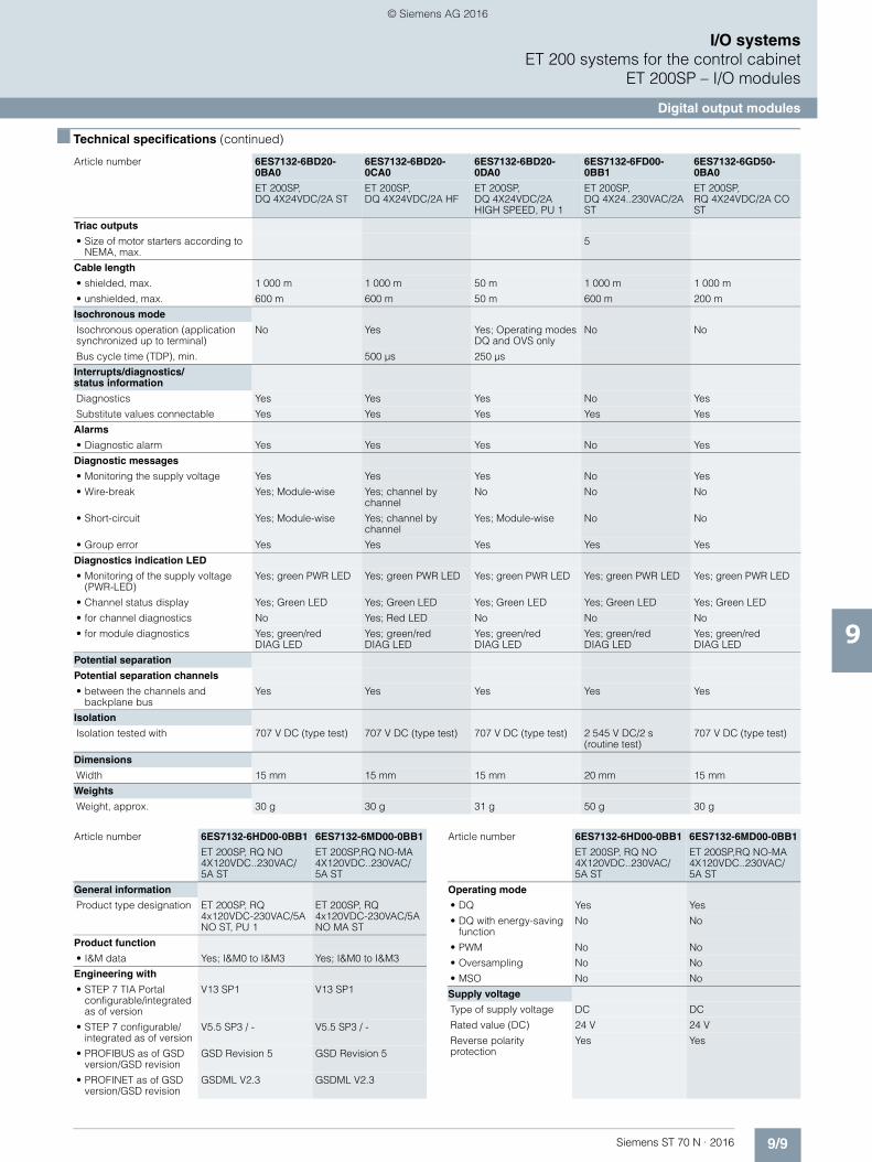
9/9Siemens ST 70 N · 2016
9
■ Technical specifications (continued)
I/O systemsET 200 systems for the control cabinet
ET 200SP – I/O modules
Digital output modules
Triac outputs
• Size of motor starters according to NEMA, max.
5
Cable length
• shielded, max. 1 000 m 1 000 m 50 m 1 000 m 1 000 m
• unshielded, max. 600 m 600 m 50 m 600 m 200 m
Isochronous mode
Isochronous operation (application synchronized up to terminal)
No Yes Yes; Operating modes DQ and OVS only
No No
Bus cycle time (TDP), min. 500 µs 250 µs
Interrupts/diagnostics/status information
Diagnostics Yes Yes Yes No Yes
Substitute values connectable Yes Yes Yes Yes Yes
Alarms
• Diagnostic alarm Yes Yes Yes No Yes
Diagnostic messages
• Monitoring the supply voltage Yes Yes Yes No Yes
• Wire-break Yes; Module-wise Yes; channel by channel
No No No
• Short-circuit Yes; Module-wise Yes; channel by channel
Yes; Module-wise No No
• Group error Yes Yes Yes Yes Yes
Diagnostics indication LED
• Monitoring of the supply voltage (PWR-LED)
Yes; green PWR LED Yes; green PWR LED Yes; green PWR LED Yes; green PWR LED Yes; green PWR LED
• Channel status display Yes; Green LED Yes; Green LED Yes; Green LED Yes; Green LED Yes; Green LED
• for channel diagnostics No Yes; Red LED No No No
• for module diagnostics Yes; green/red DIAG LED
Yes; green/red DIAG LED
Yes; green/red DIAG LED
Yes; green/red DIAG LED
Yes; green/red DIAG LED
Potential separation
Potential separation channels
• between the channels and backplane bus
Yes Yes Yes Yes Yes
Isolation
Isolation tested with 707 V DC (type test) 707 V DC (type test) 707 V DC (type test) 2 545 V DC/2 s (routine test)
707 V DC (type test)
Dimensions
Width 15 mm 15 mm 15 mm 20 mm 15 mm
Weights
Weight, approx. 30 g 30 g 31 g 50 g 30 g
Article number 6ES7132-6BD20-0BA0
6ES7132-6BD20-0CA0
6ES7132-6BD20-0DA0
6ES7132-6FD00-0BB1
6ES7132-6GD50-0BA0
ET 200SP, DQ 4X24VDC/2A ST
ET 200SP, DQ 4X24VDC/2A HF
ET 200SP, DQ 4X24VDC/2A HIGH SPEED, PU 1
ET 200SP, DQ 4X24..230VAC/2A ST
ET 200SP, RQ 4X24VDC/2A CO ST
Article number 6ES7132-6HD00-0BB1 6ES7132-6MD00-0BB1
ET 200SP, RQ NO 4X120VDC..230VAC/5A ST
ET 200SP,RQ NO-MA 4X120VDC..230VAC/5A ST
General information
Product type designation ET 200SP, RQ 4x120VDC-230VAC/5A NO ST, PU 1
ET 200SP, RQ 4x120VDC-230VAC/5A NO MA ST
Product function
• I&M data Yes; I&M0 to I&M3 Yes; I&M0 to I&M3
Engineering with
• STEP 7 TIA Portal configurable/integrated as of version
V13 SP1 V13 SP1
• STEP 7 configurable/integrated as of version
V5.5 SP3 / - V5.5 SP3 / -
• PROFIBUS as of GSD version/GSD revision
GSD Revision 5 GSD Revision 5
• PROFINET as of GSD version/GSD revision
GSDML V2.3 GSDML V2.3
Operating mode
• DQ Yes Yes
• DQ with energy-saving function
No No
• PWM No No
• Oversampling No No
• MSO No No
Supply voltage
Type of supply voltage DC DC
Rated value (DC) 24 V 24 V
Reverse polarity protection
Yes Yes
Article number 6ES7132-6HD00-0BB1 6ES7132-6MD00-0BB1
ET 200SP, RQ NO 4X120VDC..230VAC/5A ST
ET 200SP,RQ NO-MA 4X120VDC..230VAC/5A ST
© Siemens AG 2016
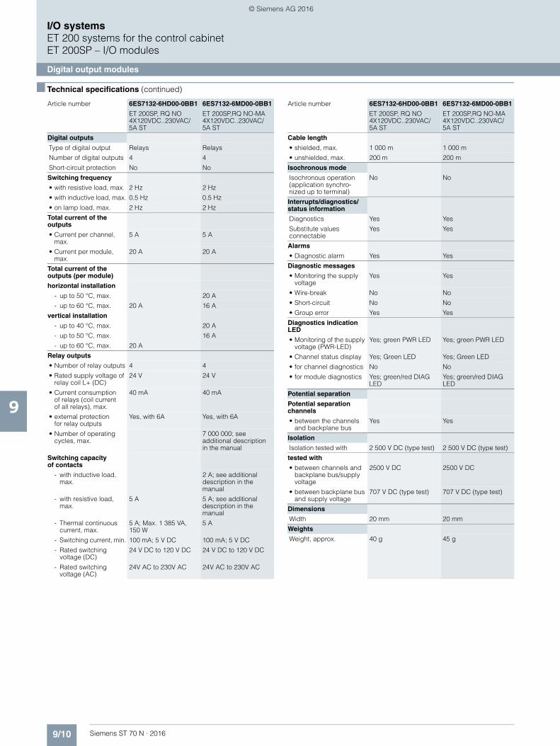
9/10 Siemens ST 70 N · 2016
9
■ Technical specifications (continued)
I/O systemsET 200 systems for the control cabinetET 200SP – I/O modules
Digital output modules
Digital outputs
Type of digital output Relays Relays
Number of digital outputs 4 4
Short-circuit protection No No
Switching frequency
• with resistive load, max. 2 Hz 2 Hz
• with inductive load, max. 0.5 Hz 0.5 Hz
• on lamp load, max. 2 Hz 2 Hz
Total current of the outputs
• Current per channel, max.
5 A 5 A
• Current per module, max.
20 A 20 A
Total current of the outputs (per module)
horizontal installation
- up to 50 °C, max. 20 A
- up to 60 °C, max. 20 A 16 A
vertical installation
- up to 40 °C, max. 20 A
- up to 50 °C, max. 16 A
- up to 60 °C, max. 20 A
Relay outputs
• Number of relay outputs 4 4
• Rated supply voltage of relay coil L+ (DC)
24 V 24 V
• Current consumption of relays (coil currentof all relays), max.
40 mA 40 mA
• external protectionfor relay outputs
Yes, with 6A Yes, with 6A
• Number of operating cycles, max.
7 000 000; see additional descriptionin the manual
Switching capacity of contacts
- with inductive load, max.
2 A; see additional description in the manual
- with resistive load, max.
5 A 5 A; see additional description in the manual
- Thermal continuous current, max.
5 A; Max. 1 385 VA, 150 W
5 A
- Switching current, min. 100 mA; 5 V DC 100 mA; 5 V DC
- Rated switching voltage (DC)
24 V DC to 120 V DC 24 V DC to 120 V DC
- Rated switching voltage (AC)
24V AC to 230V AC 24V AC to 230V AC
Article number 6ES7132-6HD00-0BB1 6ES7132-6MD00-0BB1
ET 200SP, RQ NO 4X120VDC..230VAC/5A ST
ET 200SP,RQ NO-MA 4X120VDC..230VAC/5A ST
Cable length
• shielded, max. 1 000 m 1 000 m
• unshielded, max. 200 m 200 m
Isochronous mode
Isochronous operation (application synchro-nized up to terminal)
No No
Interrupts/diagnostics/status information
Diagnostics Yes Yes
Substitute values connectable
Yes Yes
Alarms
• Diagnostic alarm Yes Yes
Diagnostic messages
• Monitoring the supply voltage
Yes Yes
• Wire-break No No
• Short-circuit No No
• Group error Yes Yes
Diagnostics indication LED
• Monitoring of the supply voltage (PWR-LED)
Yes; green PWR LED Yes; green PWR LED
• Channel status display Yes; Green LED Yes; Green LED
• for channel diagnostics No No
• for module diagnostics Yes; green/red DIAG LED
Yes; green/red DIAG LED
Potential separation
Potential separation channels
• between the channels and backplane bus
Yes Yes
Isolation
Isolation tested with 2 500 V DC (type test) 2 500 V DC (type test)
tested with
• between channels and backplane bus/supply voltage
2500 V DC 2500 V DC
• between backplane bus and supply voltage
707 V DC (type test) 707 V DC (type test)
Dimensions
Width 20 mm 20 mm
Weights
Weight, approx. 40 g 45 g
Article number 6ES7132-6HD00-0BB1 6ES7132-6MD00-0BB1
ET 200SP, RQ NO 4X120VDC..230VAC/5A ST
ET 200SP,RQ NO-MA 4X120VDC..230VAC/5A ST
© Siemens AG 2016
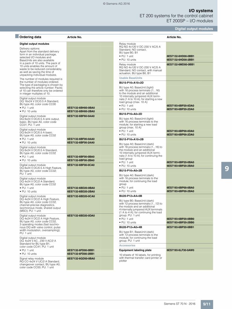
9/11Siemens ST 70 N · 2016
9
I/O systemsET 200 systems for the control cabinet
ET 200SP – I/O modules
Digital output modules
■ Ordering data Article No. Article No.
Digital output modules
Delivery options: Apart from the standard delivery form in an individual package, selected I/O modules and BaseUnits are also availablein a pack of 10 units. The pack of 10 units enables the amount of waste to be reduced considerably, as well as saving the time of unpacking individual modules.
The number of modules required is the number of modules ordered. The type of packaging is chosen by selecting the article number. Packs of 10 can therefore only be ordered in integer multiples of 10.
Digital output module DQ 16x24 V DC/0.5 A Standard, BU type A0, color code CC00• PU: 1 unit 6ES7132-6BH00-0BA0• PU: 10 units 6ES7132-6BH00-2BA0
Digital output module DQ 8x24 V DC/0.5 A sink output, basic, BU type A0, color code CC01; PU: 1 unit
6ES7132-6BF60-0AA0
Digital output module DQ 8x24 V DC/0.5 A basic, BU type A0, color code CC02• PU: 1 unit 6ES7132-6BF00-0AA0• PU: 10 units 6ES7132-6BF00-2AA0
Digital output module DQ 8x24 V DC/0.5 A Standard, BU type A0, color code CC02• PU: 1 unit 6ES7132-6BF00-0BA0• PU: 10 units 6ES7132-6BF00-2BA0
Digital output module DQ 8x24 V DC/0.5 A High Feature, BU type A0, color code CC02; PU: 1 unit
6ES7132-6BF00-0CA0
Digital output module DQ 4x24 V DC/2 A Standard, BU type A0, color code CC02• PU: 1 unit 6ES7132-6BD20-0BA0• PU: 10 units 6ES7132-6BD20-2BA0
Digital output module DQ 4x24 V DC/2 A High Feature, BU type A0, color code CC02, channel-precise diagnostics, isochronous mode, shared output (MSO); PU: 1 unit
6ES7132-6BD20-0CA0
Digital output module DQ 4x24 V DC/2 A High Feature, BU type A0, color code CC02,3 operating modes (fast isochro-nous DQ with valve control, pulse width modulation, oversampling); PU: 1 unit
6ES7132-6BD20-0DA0
Digital output moduleDQ 4x24 V AC...230 V AC/2 AStandard for BU type B1, color code CC41; PU: 1 unit• PU: 1 unit 6ES7132-6FD00-0BB1• PU: 10 units 6ES7132-6FD00-2BB1
Signal relay module RQ CO 4x24 V UC/2 A Standard, changeover contact, BU type A0, color code CC00; PU: 1 unit
6ES7132-6GD50-0BA0
Relay module RQ NO 4x120 V DC-230 V AC/5 A Standard, NO contact, BU type B0, B1• PU: 1 unit 6ES7132-6HD00-0BB1• PU: 10 units 6ES7132-6HD00-2BB1
Relay moduleRQ NO 4x120 V DC-230 V AC/5 A Standard, NO contact, with manual actuation, BU type B0, B1
6ES7132-6MD00-0BB1
Usable BaseUnits
BU15-P16+A10+2D
BU type A0; BaseUnit (light) with 16 process terminals (1...16)to the module and an additional 10 internally jumpered AUX termi-nals (1 A to 10 A); for starting a new load group (max. 10 A)• PU: 1 unit 6ES7193-6BP20-0DA0• PU: 10 units 6ES7193-6BP20-2DA0
BU15-P16+A0+2D
BU type A0; BaseUnit (light) with 16 process terminals to the module; for starting a new load group (max. 10 A)• PU: 1 unit 6ES7193-6BP00-0DA0• PU: 10 units 6ES7193-6BP00-2DA0
BU15-P16+A10+2B
BU type A0; BaseUnit (dark) with 16 process terminals (1...16) to the module and an additional10 internally jumpered AUX termi-nals (1 A to 10 A); for continuing the load group• PU: 1 unit 6ES7193-6BP20-0BA0• PU: 10 units 6ES7193-6BP20-2BA0
BU15-P16+A0+2B
BU type A0; BaseUnit (dark)with 16 process terminals to the module; for continuing the load group• PU: 1 unit 6ES7193-6BP00-0BA0• PU: 10 units 6ES7193-6BP00-2BA0
BU20-P12+A4+0B
BU type B0; BaseUnit (dark) with 12 process terminals (1...12) to the module and an additional 4 internally jumpered AUX terminals (1 A to 4 A); for continuing the load group; PU: 1 unit• PU: 1 unit 6ES7193-6BP20-0BB0• PU: 10 units 6ES7193-6BP20-2BB0
BU20-P12+A0+4B 6ES7193-6BP20-0BB1
BU type B1; BaseUnit (dark)with 12 process terminals to the module; for continuing the load group; PU: 1 unit
Accessories
Equipment labeling plate 6ES7193-6LF30-0AW0
10 sheets of 16 labels, for printing with thermal transfer card printer or plotter
© Siemens AG 2016

9/12 Siemens ST 70 N · 2016
9
■ Ordering data Article No. Article No.
I/O systemsET 200 systems for the control cabinetET 200SP – I/O modules
Digital output modules
Labeling strips
500 labeling strips on roll, light gray, for inscription with thermal transfer roll printer
6ES7193-6LR10-0AA0
500 labeling strips on roll, yellow, for inscription with thermal transfer roll printer
6ES7193-6LR10-0AG0
1000 labeling strips DIN A4, light gray, card, perforated,for inscription with laser printer
6ES7193-6LA10-0AA0
1000 labeling strips DIN A4, yellow, card, perforated, for inscription with laser printer
6ES7193-6LA10-0AG0
BU cover
for covering empty slots (gaps); 5 units• 15 mm wide 6ES7133-6CV15-1AM0• 20 mm wide 6ES7133-6CV20-1AM0
Shield connection 6ES7193-6SC00-1AM0
5 shield supports and 5 shieldterminals
Color-coded labelsfor 15 mm wide BaseUnits
Color code CC00, for 16 process terminals, for BU type A0, A1, gray (terminals 1 to 8), red (terminals 9 to 16); 10 units
6ES7193-6CP00-2MA0
Color code CC01,for 16 process terminals, for BU type A0, A1, gray (terminals 1 to 8),red (terminals 9 to 16); 10 units
6ES7193-6CP01-2MA0
Color code CC02, for 16 process terminals,for BU type A0, A1,gray (terminals 1 to 8), blue (terminals 9 to 16); 10 units
6ES7193-6CP02-2MA0
Color code CC71, for 10 AUX terminals, BU type A0, yellow/green (terminals 1 A to 10 A); 10 units
6ES7193-6CP71-2AA0
Color code CC72, for 10 AUX terminals, BU type A0, red (terminals 1 A to 10 A); 10 units
6ES7193-6CP72-2AA0
Color code CC73, for 10 AUX terminals, BU type A0, blue (terminals 1 A to 10 A); 10 units
6ES7193-6CP73-2AA0
Color-coded labels for 20 mm wide BaseUnits
Color code CC41,for 16 push-in terminals;for BU type B1, gray (terminals 1 to 4), red (terminals 5 to 8), blue (terminals 9 to 12); 10 units
6ES7193-6CP41-2MB0
Color code CC81, for 4 AUX terminals, BU type B0, yellow/green (terminals 1 A to 4 A); 10 units
6ES7193-6CP81-2AB0
Color code CC82, for 4 AUX terminals, BU type B0, red (terminals 1 A to 4 A); 10 units
6ES7193-6CP82-2AB0
Color code CC83, for 4 AUX terminals, BU type B0, blue (terminals 1 A to 4 A); 10 units
6ES7193-6CP83-2AB0
© Siemens AG 2016
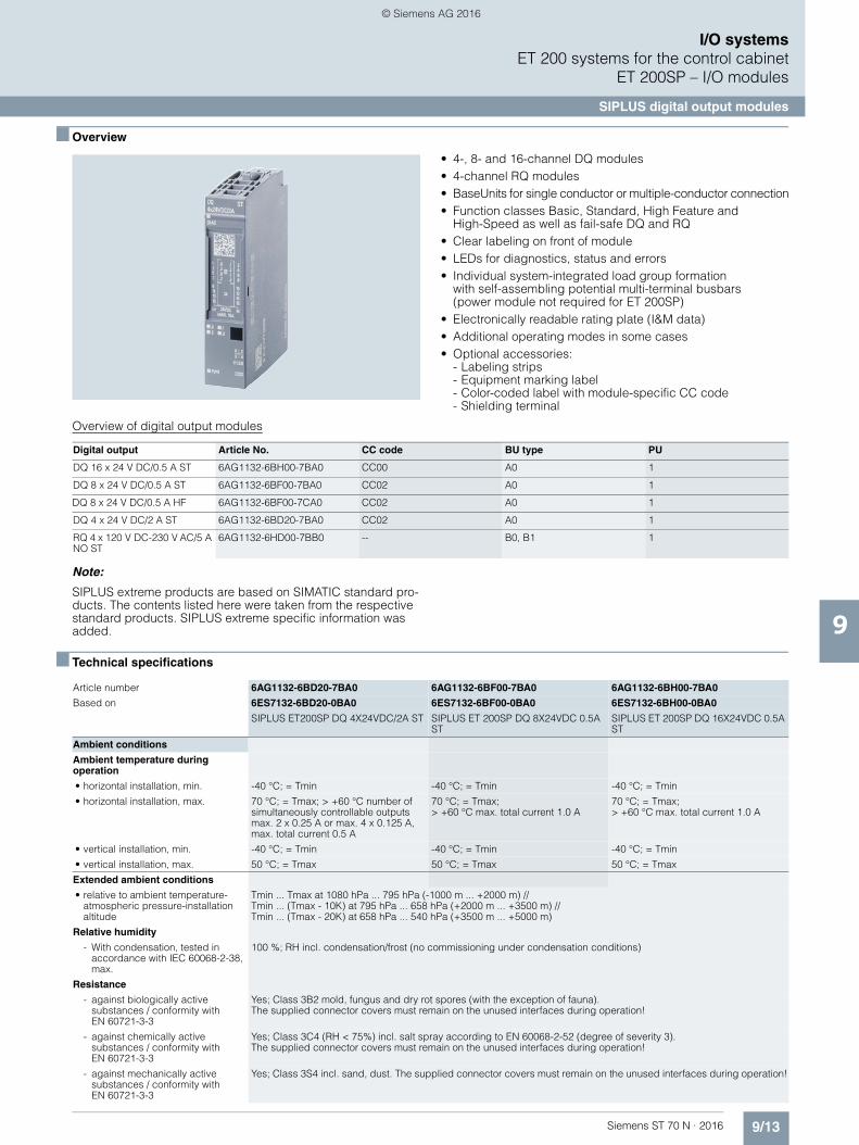
9/13Siemens ST 70 N · 2016
9
I/O systemsET 200 systems for the control cabinet
ET 200SP – I/O modules
SIPLUS digital output modules
■ Overview
• 4-, 8- and 16-channel DQ modules • 4-channel RQ modules • BaseUnits for single conductor or multiple-conductor connection• Function classes Basic, Standard, High Feature and
High-Speed as well as fail-safe DQ and RQ • Clear labeling on front of module • LEDs for diagnostics, status and errors • Individual system-integrated load group formation
with self-assembling potential multi-terminal busbars(power module not required for ET 200SP)
• Electronically readable rating plate (I&M data) • Additional operating modes in some cases • Optional accessories:
- Labeling strips - Equipment marking label- Color-coded label with module-specific CC code - Shielding terminal
Overview of digital output modules
Note:
SIPLUS extreme products are based on SIMATIC standard pro-ducts. The contents listed here were taken from the respective standard products. SIPLUS extreme specific information was added.
■ Technical specifications
Digital output Article No. CC code BU type PU
DQ 16 x 24 V DC/0.5 A ST 6AG1132-6BH00-7BA0 CC00 A0 1
DQ 8 x 24 V DC/0.5 A ST 6AG1132-6BF00-7BA0 CC02 A0 1
DQ 8 x 24 V DC/0.5 A HF 6AG1132-6BF00-7CA0 CC02 A0 1
DQ 4 x 24 V DC/2 A ST 6AG1132-6BD20-7BA0 CC02 A0 1
RQ 4 x 120 V DC-230 V AC/5 A NO ST
6AG1132-6HD00-7BB0 -- B0, B1 1
Article number 6AG1132-6BD20-7BA0 6AG1132-6BF00-7BA0 6AG1132-6BH00-7BA0
Based on 6ES7132-6BD20-0BA0 6ES7132-6BF00-0BA0 6ES7132-6BH00-0BA0
SIPLUS ET200SP DQ 4X24VDC/2A ST SIPLUS ET 200SP DQ 8X24VDC 0.5A ST
SIPLUS ET 200SP DQ 16X24VDC 0.5A ST
Ambient conditions
Ambient temperature during operation
• horizontal installation, min. -40 °C; = Tmin -40 °C; = Tmin -40 °C; = Tmin
• horizontal installation, max. 70 °C; = Tmax; > +60 °C number of simultaneously controllable outputs max. 2 x 0.25 A or max. 4 x 0.125 A, max. total current 0.5 A
70 °C; = Tmax; > +60 °C max. total current 1.0 A
70 °C; = Tmax; > +60 °C max. total current 1.0 A
• vertical installation, min. -40 °C; = Tmin -40 °C; = Tmin -40 °C; = Tmin
• vertical installation, max. 50 °C; = Tmax 50 °C; = Tmax 50 °C; = Tmax
Extended ambient conditions
• relative to ambient temperature-atmospheric pressure-installation altitude
Tmin ... Tmax at 1080 hPa ... 795 hPa (-1000 m ... +2000 m) // Tmin ... (Tmax - 10K) at 795 hPa ... 658 hPa (+2000 m ... +3500 m) //Tmin ... (Tmax - 20K) at 658 hPa ... 540 hPa (+3500 m ... +5000 m)
Relative humidity
- With condensation, tested in accordance with IEC 60068-2-38, max.
100 %; RH incl. condensation/frost (no commissioning under condensation conditions)
Resistance
- against biologically active substances / conformity with EN 60721-3-3
Yes; Class 3B2 mold, fungus and dry rot spores (with the exception of fauna). The supplied connector covers must remain on the unused interfaces during operation!
- against chemically active substances / conformity with EN 60721-3-3
Yes; Class 3C4 (RH < 75%) incl. salt spray according to EN 60068-2-52 (degree of severity 3).The supplied connector covers must remain on the unused interfaces during operation!
- against mechanically active substances / conformity with EN 60721-3-3
Yes; Class 3S4 incl. sand, dust. The supplied connector covers must remain on the unused interfaces during operation!
© Siemens AG 2016

9/14 Siemens ST 70 N · 2016
9
■ Technical specifications (continued)
I/O systemsET 200 systems for the control cabinetET 200SP – I/O modules
SIPLUS digital output modules
■ Ordering data Article No. Article No.
Article number 6AG1132-6BF00-7CA0 6AG1132-6HD00-7BB0
Based on 6ES7132-6BF00-0CA0 6ES7132-6HD00-0BB0
SIPLUS ET 200SP DQ 8X24VDC/0.5A HF SIPLUS ET 200SP RQ 4X120VDC/230VAC/5A
Ambient conditions
Ambient temperature during operation
• horizontal installation, min. -40 °C; = Tmin; Startup @ -25 °C -40 °C; = Tmin
• horizontal installation, max. 70 °C; = Tmax; > +60 °C max. total current 1.0 A 70 °C; = Tmax; > +60 °C max. continuous current per relay 3 A, max. total current module 12 A
• vertical installation, min. -40 °C
• vertical installation, max. 50 °C
Extended ambient conditions
• relative to ambient temperature-atmospheric pressure-installation altitude
Tmin ... Tmax at 1080 hPa ... 795 hPa (-1000 m ... +2000 m) //Tmin ... (Tmax - 10K) at 795 hPa ... 658 hPa(+2000 m ... +3500 m) //Tmin ... (Tmax - 20K) at 658 hPa ... 540 hPa (+3500 m ... +5000 m)
Tmin ... Tmax at 1080 hPa ... 795 hPa (-1000 m ... +2000 m)
Relative humidity
- With condensation, tested in accordance with IEC 60068-2-38, max.
100 %; RH incl. condensation/frost (no commissioning under condensation conditions)
Resistance
- against biologically active substances / conformity with EN 60721-3-3
Yes; Class 3B2 mold, fungus and dry rot spores (with the exception of fauna).The supplied connector covers must remain on the unused interfaces during operation!
- against chemically active substances / conformity with EN 60721-3-3
Yes; Class 3C4 (RH < 75%) incl. salt spray according to EN 60068-2-52 (degree of severity 3). The supplied connector covers must remain on the unused interfaces during operation!
- against mechanically active substances / conformity with EN 60721-3-3
Yes; Class 3S4 incl. sand, dust. The supplied connector covers must remain on the unused interfaces during operation!
SIPLUS digital output modules
(Extended temperature range and medial exposure)
Digital output module DQ 4x24 V DC/2 A Standard,BU type A0, color code CC02
6AG1132-6BD20-7BA0
Digital output module DQ 8x24 V DC/0.5 A Standard, BU type A0, color code CC02
6AG1132-6BF00-7BA0
Digital output module DQ 8x24 V DC/0.5 A High Feature, BU type A0, color code CC02
6AG1132-6BF00-7CA0
Digital output module DQ 16x24 V DC/0.5 A Standard, BU type A0, color code CC00
6AG1132-6BH00-7BA0
Relay module RQ NO 4x120 V DC - 230 V AC/5 A Standard, normally-open, BU type B0, color code CC00; 1 unit
6AG1132-6HD00-7BB0
Usable SIPLUS BaseUnits
BU15-P16+A0+2D 6AG1193-6BP00-7DA0
(Extended temperature range and medial exposure)
BU type A0; BaseUnit (light) with 16 process terminals to the module, for starting a new load group (max. 10 A)
BU15-P16+A0+2B 6AG1193-6BP00-7BA0
(Extended temperature range and medial exposure)
BU type A0; BaseUnit (dark) with 16 process terminals to the module; for continuing the load group
BU15-P16+A10+2D 6AG1193-6BP20-7DA0
(Extended temperature range and medial exposure)
BU type A0; BaseUnit (light)with 16 process terminals (1...16) to the module and an additional10 internally jumpered AUX terminals (1 A to 10 A);for starting a new load group(max. 10 A)
BU15-P16+A10+2B 6AG1193-6BP20-7BA0
(Extended temperature range and medial exposure)
BU type A0; BaseUnit (dark) with 16 process terminals (1...16) to the module and an additional 10 internally jumpered AUX terminals (1 A to 10 A); for continuing the load group
BU20-P12+A4+0B 6AG1193-6BP20-7BB0
(extended temperature range and exposure to media)
BU type B0; BaseUnit (dark) with 12 process terminals (1...12) to the module and an additional 4 internally jumpered AUX terminals (1 A to 4 A); for continuing the load group; 1 unit
Accessories See SIMATIC ET 200SP, digital output modules, page 9/11
© Siemens AG 2016
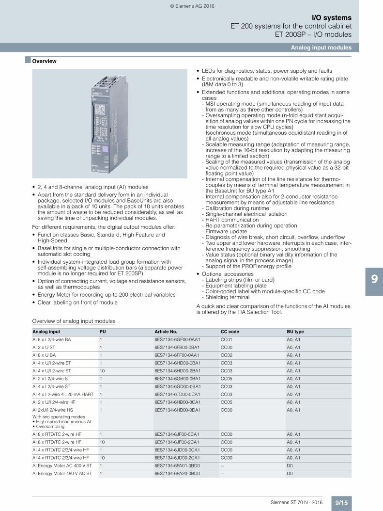
9/15Siemens ST 70 N · 2016
9
I/O systemsET 200 systems for the control cabinet
ET 200SP – I/O modules
Analog input modules
■ Overview
• 2, 4 and 8-channel analog input (AI) modules• Apart from the standard delivery form in an individual
package, selected I/O modules and BaseUnits are also available in a pack of 10 units. The pack of 10 units enables the amount of waste to be reduced considerably, as well as saving the time of unpacking individual modules.
For different requirements, the digital output modules offer:• Function classes Basic, Standard, High Feature and
High-Speed• BaseUnits for single or multiple-conductor connection with
automatic slot coding• Individual system-integrated load group formation with
self-assembling voltage distribution bars (a separate power module is no longer required for ET 200SP)
• Option of connecting current, voltage and resistance sensors, as well as thermocouples
• Energy Meter for recording up to 200 electrical variables• Clear labeling on front of module
• LEDs for diagnostics, status, power supply and faults• Electronically readable and non-volatile writable rating plate
(I&M data 0 to 3)• Extended functions and additional operating modes in some
cases- MSI operating mode (simultaneous reading of input data
from as many as three other controllers)- Oversampling operating mode (n-fold equidistant acqui-
sition of analog values within one PN cycle for increasing the time resolution for slow CPU cycles)
- Isochronous mode (simultaneous equidistant reading in of all analog values)
- Scalable measuring range (adaptation of measuring range, increase of the 16-bit resolution by adapting the measuring range to a limited section)
- Scaling of the measured values (transmission of the analog value normalized to the required physical value as a 32-bit floating point value)
- Internal compensation of the line resistance for thermo-couples by means of terminal temperature measurement in the BaseUnit for BU type A1
- Internal compensation also for 2-conductor resistance measurement by means of adjustable line resistance
- Calibration during runtime- Single-channel electrical isolation- HART communication- Re-parameterization during operation- Firmware update- Diagnosis of wire break, short circuit, overflow, underflow- Two upper and lower hardware interrupts in each case, inter-
ference frequency suppression, smoothing- Value status (optional binary validity information of the
analog signal in the process image)- Support of the PROFIenergy profile
• Optional accessories- Labeling strips (film or card)- Equipment labeling plate- Color-coded label with module-specific CC code- Shielding terminal
A quick and clear comparison of the functions of the AI modules is offered by the TIA Selection Tool.
Overview of analog input modules
Analog input PU Article No. CC code BU type
AI 8 x I 2/4-wire BA 1 6ES7134-6GF00-0AA1 CC01 A0, A1
AI 2 x U ST 1 6ES7134-6FB00-0BA1 CC00 A0, A1
AI 8 x U BA 1 6ES7134-6FF00-0AA1 CC02 A0, A1
AI 4 x U/I 2-wire ST 1 6ES7134-6HD00-0BA1 CC03 A0, A1
AI 4 x U/I 2-wire ST 10 6ES7134-6HD00-2BA1 CC03 A0, A1
AI 2 x I 2/4-wire ST 1 6ES7134-6GB00-0BA1 CC05 A0, A1
AI 4 x I 2/4-wire ST 1 6ES7134-6GD00-0BA1 CC03 A0, A1
AI 4 x I 2-wire 4...20 mA HART 1 6ES7134-6TD00-0CA1 CC03 A0, A1
AI 2 x U/I 2/4-wire HF 1 6ES7134-6HB00-0CA1 CC05 A0, A1
AI 2xU/I 2/4-wire HS
With two operating modes• High-speed isochronous AI• Oversampling
1 6ES7134-6HB00-0DA1 CC00 A0, A1
AI 8 x RTD/TC 2-wire HF 1 6ES7134-6JF00-0CA1 CC00 A0, A1
AI 8 x RTD/TC 2-wire HF 10 6ES7134-6JF00-2CA1 CC00 A0, A1
AI 4 x RTD/TC 2/3/4-wire HF 1 6ES7134-6JD00-0CA1 CC00 A0, A1
AI 4 x RTD/TC 2/3/4-wire HF 10 6ES7134-6JD00-2CA1 CC00 A0, A1
AI Energy Meter AC 400 V ST 1 6ES7134-6PA01-0BD0 -- D0
AI Energy Meter 480 V AC ST 1 6ES7134-6PA20-0BD0 -- D0
© Siemens AG 2016
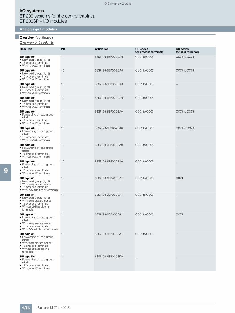
9/16 Siemens ST 70 N · 2016
9
■ Overview (continued)
I/O systemsET 200 systems for the control cabinetET 200SP – I/O modules
Analog input modules
Overview of BaseUnits
BaseUnit PU Article No. CC codes for process terminals
CC codesfor AUX terminals
BU type A0• New load group (light)• 16 process terminals • With 10 AUX terminals
1 6ES7193-6BP20-0DA0 CC01 to CC05 CC71 to CC73
BU type A0• New load group (light)• 16 process terminals • With 10 AUX terminals
10 6ES7193-6BP20-2DA0 CC01 to CC05 CC71 to CC73
BU type A0• New load group (light)• 16 process terminals • Without AUX terminals
1 6ES7193-6BP00-0DA0 CC01 to CC05 --
BU type A0• New load group (light)• 16 process terminals • Without AUX terminals
10 6ES7193-6BP00-2DA0 CC01 to CC05 --
BU type A0• Forwarding of load group
(dark)• 16 process terminals • With 10 AUX terminals
1 6ES7193-6BP20-0BA0 CC01 to CC05 CC71 to CC73
BU type A0• Forwarding of load group
(dark)• 16 process terminals • With 10 AUX terminals
10 6ES7193-6BP20-2BA0 CC01 to CC05 CC71 to CC73
BU type A0• Forwarding of load group
(dark)• 16 process terminals • Without AUX terminals
1 6ES7193-6BP00-0BA0 CC01 to CC05 --
BU type A0• Forwarding of load group
(dark)• 16 process terminals • Without AUX terminals
10 6ES7193-6BP00-2BA0 CC01 to CC05 --
BU type A1• New load group (light)• With temperature sensor• 16 process terminals• With 2x5 additional terminals
1 6ES7193-6BP40-0DA1 CC01 to CC05 CC74
BU type A1• New load group (light)• With temperature sensor• 16 process terminals• Without 2x5 additional
terminals
1 6ES7193-6BP00-0DA1 CC01 to CC05 --
BU type A1• Forwarding of load group
(dark)• With temperature sensor• 16 process terminals• With 2x5 additional terminals
1 6ES7193-6BP40-0BA1 CC01 to CC05 CC74
BU type A1• Forwarding of load group
(dark)• With temperature sensor• 16 process terminals• Without 2x5 additional
terminals
1 6ES7193-6BP00-0BA1 CC01 to CC05 --
BU type D0• Forwarding of load group
(dark)• 12 process terminals• Without AUX terminals
1 6ES7193-6BP00-0BD0 -- --
© Siemens AG 2016
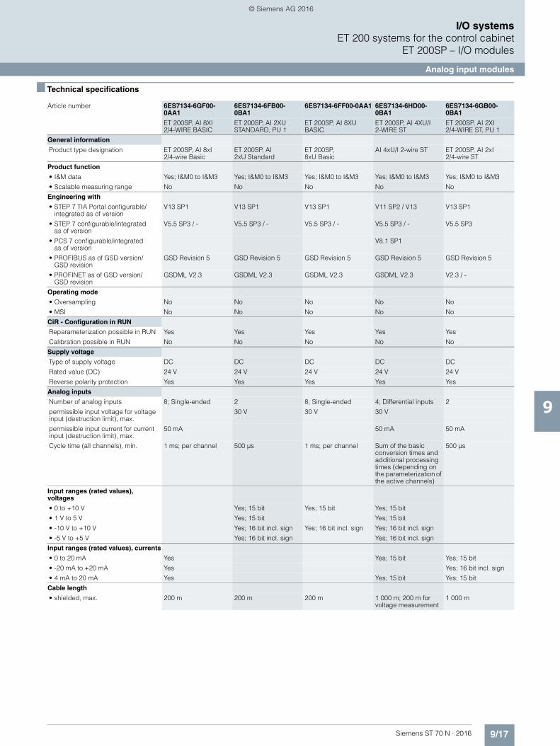
9/17Siemens ST 70 N · 2016
9
I/O systemsET 200 systems for the control cabinet
ET 200SP – I/O modules
Analog input modules
■ Technical specifications
Article number 6ES7134-6GF00-0AA1
6ES7134-6FB00-0BA1
6ES7134-6FF00-0AA1 6ES7134-6HD00-0BA1
6ES7134-6GB00-0BA1
ET 200SP, AI 8XI2/4-WIRE BASIC
ET 200SP, AI 2XU STANDARD, PU 1
ET 200SP, AI 8XUBASIC
ET 200SP, AI 4XU/I 2-WIRE ST
ET 200SP, AI 2XI 2/4-WIRE ST, PU 1
General information
Product type designation ET 200SP, AI 8xI2/4-wire Basic
ET 200SP, AI2xU Standard
ET 200SP, 8xU Basic
AI 4xU/I 2-wire ST ET 200SP, AI 2xI 2/4-wire ST
Product function
• I&M data Yes; I&M0 to I&M3 Yes; I&M0 to I&M3 Yes; I&M0 to I&M3 Yes; I&M0 to I&M3 Yes; I&M0 to I&M3
• Scalable measuring range No No No No No
Engineering with
• STEP 7 TIA Portal configurable/integrated as of version
V13 SP1 V13 SP1 V13 SP1 V11 SP2 / V13 V13 SP1
• STEP 7 configurable/integrated as of version
V5.5 SP3 / - V5.5 SP3 / - V5.5 SP3 / - V5.5 SP3 / - V5.5 SP3
• PCS 7 configurable/integrated as of version
V8.1 SP1
• PROFIBUS as of GSD version/GSD revision
GSD Revision 5 GSD Revision 5 GSD Revision 5 GSD Revision 5 GSD Revision 5
• PROFINET as of GSD version/GSD revision
GSDML V2.3 GSDML V2.3 GSDML V2.3 GSDML V2.3 V2.3 / -
Operating mode
• Oversampling No No No No No
• MSI No No No No No
CiR - Configuration in RUN
Reparameterization possible in RUN Yes Yes Yes Yes Yes
Calibration possible in RUN No No No No No
Supply voltage
Type of supply voltage DC DC DC DC DC
Rated value (DC) 24 V 24 V 24 V 24 V 24 V
Reverse polarity protection Yes Yes Yes Yes Yes
Analog inputs
Number of analog inputs 8; Single-ended 2 8; Single-ended 4; Differential inputs 2
permissible input voltage for voltage input (destruction limit), max.
30 V 30 V 30 V
permissible input current for current input (destruction limit), max.
50 mA 50 mA 50 mA
Cycle time (all channels), min. 1 ms; per channel 500 µs 1 ms; per channel Sum of the basic conversion times and additional processing times (depending on the parameterization of the active channels)
500 µs
Input ranges (rated values), voltages
• 0 to +10 V Yes; 15 bit Yes; 15 bit Yes; 15 bit
• 1 V to 5 V Yes; 15 bit Yes; 15 bit
• -10 V to +10 V Yes; 16 bit incl. sign Yes; 16 bit incl. sign Yes; 16 bit incl. sign
• -5 V to +5 V Yes; 16 bit incl. sign Yes; 16 bit incl. sign
Input ranges (rated values), currents
• 0 to 20 mA Yes Yes; 15 bit Yes; 15 bit
• -20 mA to +20 mA Yes Yes; 16 bit incl. sign
• 4 mA to 20 mA Yes Yes; 15 bit Yes; 15 bit
Cable length
• shielded, max. 200 m 200 m 200 m 1 000 m; 200 m for voltage measurement
1 000 m
© Siemens AG 2016
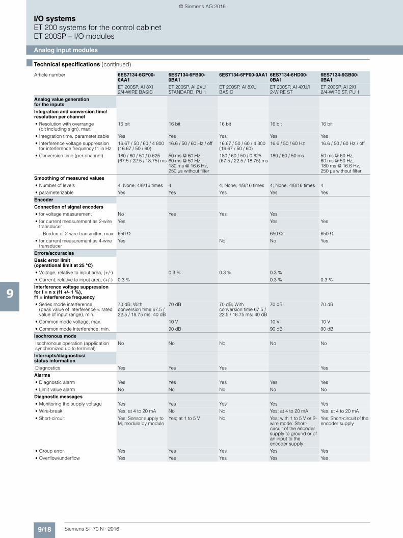
9/18 Siemens ST 70 N · 2016
9
■ Technical specifications (continued)
I/O systemsET 200 systems for the control cabinetET 200SP – I/O modules
Analog input modules
Analog value generationfor the inputs
Integration and conversion time/resolution per channel
• Resolution with overrange (bit including sign), max.
16 bit 16 bit 16 bit 16 bit 16 bit
• Integration time, parameterizable Yes Yes Yes Yes Yes
• Interference voltage suppression for interference frequency f1 in Hz
16.67 / 50 / 60 / 4 800 (16.67 / 50 / 60)
16.6 / 50 / 60 Hz / off 16.67 / 50 / 60 / 4 800 (16.67 / 50 / 60)
16.6 / 50 / 60 Hz 16.6 / 50 / 60 Hz / off
• Conversion time (per channel) 180 / 60 / 50 / 0.625 (67.5 / 22.5 / 18.75) ms
50 ms @ 60 Hz, 60 ms @ 50 Hz, 180 ms @ 16.6 Hz, 250 µs without filter
180 / 60 / 50 / 0.625 (67.5 / 22.5 / 18.75) ms
180 / 60 / 50 ms 50 ms @ 60 Hz, 60 ms @ 50 Hz, 180 ms @ 16.6 Hz,250 µs without filter
Smoothing of measured values
• Number of levels 4; None; 4/8/16 times 4 4; None; 4/8/16 times 4; None; 4/8/16 times 4
• parameterizable Yes Yes Yes Yes Yes
Encoder
Connection of signal encoders
• for voltage measurement No Yes Yes Yes
• for current measurement as 2-wire transducer
Yes Yes Yes
- Burden of 2-wire transmitter, max. 650 650 650 • for current measurement as 4-wire
transducerYes No No Yes
Errors/accuracies
Basic error limit (operational limit at 25 °C)
• Voltage, relative to input area, (+/-) 0.3 % 0.3 % 0.3 %
• Current, relative to input area, (+/-) 0.3 % 0.3 % 0.3 %
Interference voltage suppressionfor f = n x (f1 +/- 1 %),f1 = interference frequency
• Series mode interference(peak value of interference < rated value of input range), min.
70 dB; With conversion time 67.5 / 22.5 / 18.75 ms: 40 dB
70 dB 70 dB; With conversion time 67.5 / 22.5 / 18.75 ms: 40 dB
70 dB 70 dB
• Common mode voltage, max. 10 V 10 V 10 V
• Common mode interference, min. 90 dB 90 dB 90 dB
Isochronous mode
Isochronous operation (application synchronized up to terminal)
No No No No No
Interrupts/diagnostics/status information
Diagnostics Yes Yes Yes Yes
Alarms
• Diagnostic alarm Yes Yes Yes Yes Yes
• Limit value alarm No No No No No
Diagnostic messages
• Monitoring the supply voltage Yes Yes Yes Yes Yes
• Wire-break Yes; at 4 to 20 mA No No Yes; at 4 to 20 mA Yes; at 4 to 20 mA
• Short-circuit Yes; Sensor supply to M; module by module
Yes; at 1 to 5 V No Yes; with 1 to 5 V or 2-wire mode: Short-circuit of the encoder supply to ground or of an input to the encoder supply
Yes; Short-circuit of the encoder supply
• Group error Yes Yes Yes Yes Yes
• Overflow/underflow Yes Yes Yes Yes Yes
Article number 6ES7134-6GF00-0AA1
6ES7134-6FB00-0BA1
6ES7134-6FF00-0AA1 6ES7134-6HD00-0BA1
6ES7134-6GB00-0BA1
ET 200SP, AI 8XI2/4-WIRE BASIC
ET 200SP, AI 2XU STANDARD, PU 1
ET 200SP, AI 8XUBASIC
ET 200SP, AI 4XU/I 2-WIRE ST
ET 200SP, AI 2XI 2/4-WIRE ST, PU 1
© Siemens AG 2016
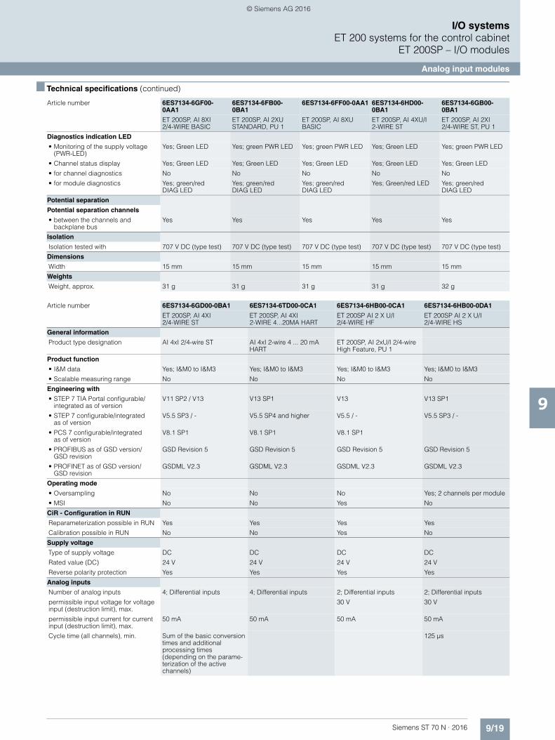
9/19Siemens ST 70 N · 2016
9
■ Technical specifications (continued)
I/O systemsET 200 systems for the control cabinet
ET 200SP – I/O modules
Analog input modules
Diagnostics indication LED
• Monitoring of the supply voltage (PWR-LED)
Yes; Green LED Yes; green PWR LED Yes; green PWR LED Yes; Green LED Yes; green PWR LED
• Channel status display Yes; Green LED Yes; Green LED Yes; Green LED Yes; Green LED Yes; Green LED
• for channel diagnostics No No No No No
• for module diagnostics Yes; green/red DIAG LED
Yes; green/red DIAG LED
Yes; green/red DIAG LED
Yes; Green/red LED Yes; green/red DIAG LED
Potential separation
Potential separation channels
• between the channels and backplane bus
Yes Yes Yes Yes Yes
Isolation
Isolation tested with 707 V DC (type test) 707 V DC (type test) 707 V DC (type test) 707 V DC (type test) 707 V DC (type test)
Dimensions
Width 15 mm 15 mm 15 mm 15 mm 15 mm
Weights
Weight, approx. 31 g 31 g 31 g 31 g 32 g
Article number 6ES7134-6GD00-0BA1 6ES7134-6TD00-0CA1 6ES7134-6HB00-0CA1 6ES7134-6HB00-0DA1
ET 200SP, AI 4XI 2/4-WIRE ST
ET 200SP, AI 4XI 2-WIRE 4...20MA HART
ET 200SP AI 2 X U/I 2/4-WIRE HF
ET 200SP AI 2 X U/I 2/4-WIRE HS
General information
Product type designation AI 4xI 2/4-wire ST AI 4xI 2-wire 4 ... 20 mA HART
ET 200SP, AI 2xU/I 2/4-wire High Feature, PU 1
Product function
• I&M data Yes; I&M0 to I&M3 Yes; I&M0 to I&M3 Yes; I&M0 to I&M3 Yes; I&M0 to I&M3
• Scalable measuring range No No No No
Engineering with
• STEP 7 TIA Portal configurable/integrated as of version
V11 SP2 / V13 V13 SP1 V13 V13 SP1
• STEP 7 configurable/integratedas of version
V5.5 SP3 / - V5.5 SP4 and higher V5.5 / - V5.5 SP3 / -
• PCS 7 configurable/integrated as of version
V8.1 SP1 V8.1 SP1 V8.1 SP1
• PROFIBUS as of GSD version/GSD revision
GSD Revision 5 GSD Revision 5 GSD Revision 5 GSD Revision 5
• PROFINET as of GSD version/GSD revision
GSDML V2.3 GSDML V2.3 GSDML V2.3 GSDML V2.3
Operating mode
• Oversampling No No No Yes; 2 channels per module
• MSI No No Yes No
CiR - Configuration in RUN
Reparameterization possible in RUN Yes Yes Yes Yes
Calibration possible in RUN No No Yes No
Supply voltage
Type of supply voltage DC DC DC DC
Rated value (DC) 24 V 24 V 24 V 24 V
Reverse polarity protection Yes Yes Yes Yes
Analog inputs
Number of analog inputs 4; Differential inputs 4; Differential inputs 2; Differential inputs 2; Differential inputs
permissible input voltage for voltage input (destruction limit), max.
30 V 30 V
permissible input current for current input (destruction limit), max.
50 mA 50 mA 50 mA 50 mA
Cycle time (all channels), min. Sum of the basic conversion times and additional processing times (depending on the parame-terization of the active channels)
125 µs
Article number 6ES7134-6GF00-0AA1
6ES7134-6FB00-0BA1
6ES7134-6FF00-0AA1 6ES7134-6HD00-0BA1
6ES7134-6GB00-0BA1
ET 200SP, AI 8XI2/4-WIRE BASIC
ET 200SP, AI 2XU STANDARD, PU 1
ET 200SP, AI 8XUBASIC
ET 200SP, AI 4XU/I 2-WIRE ST
ET 200SP, AI 2XI 2/4-WIRE ST, PU 1
© Siemens AG 2016
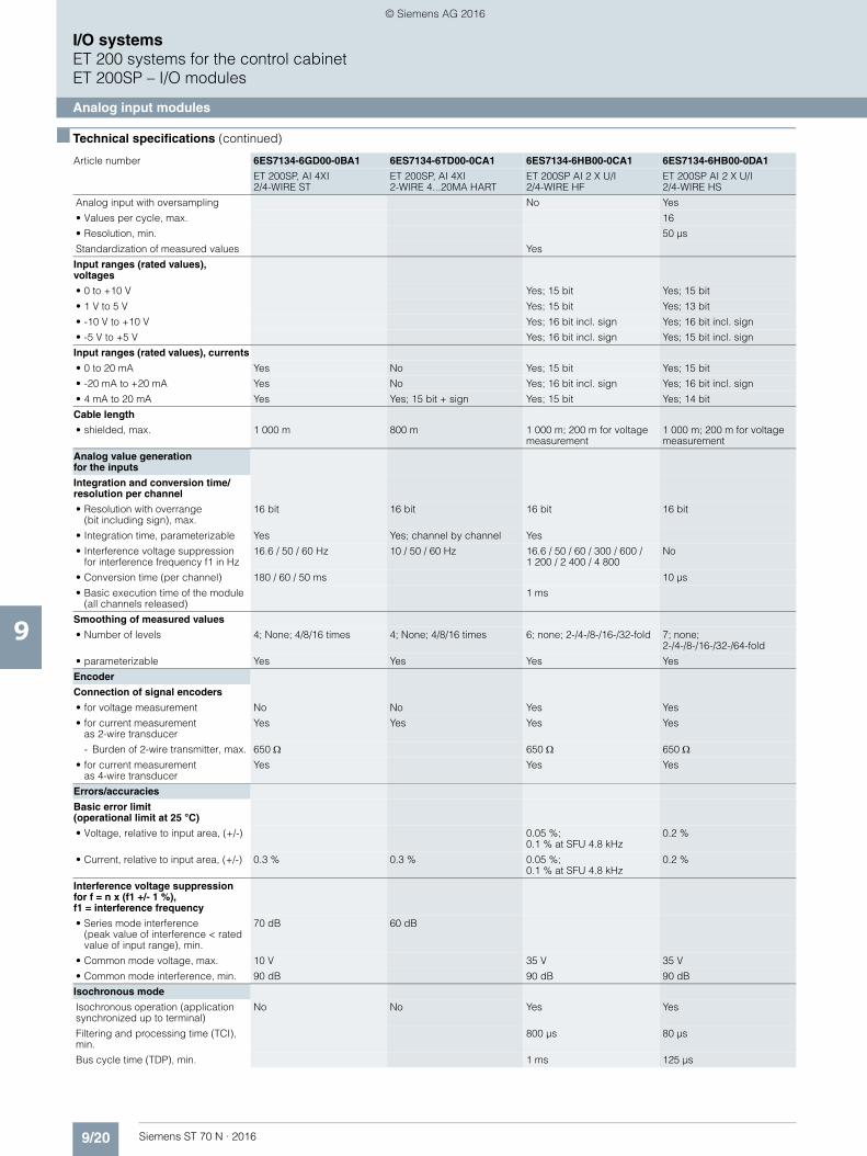
9/20 Siemens ST 70 N · 2016
9
■ Technical specifications (continued)
I/O systemsET 200 systems for the control cabinetET 200SP – I/O modules
Analog input modules
Analog input with oversampling No Yes
• Values per cycle, max. 16
• Resolution, min. 50 µs
Standardization of measured values Yes
Input ranges (rated values), voltages
• 0 to +10 V Yes; 15 bit Yes; 15 bit
• 1 V to 5 V Yes; 15 bit Yes; 13 bit
• -10 V to +10 V Yes; 16 bit incl. sign Yes; 16 bit incl. sign
• -5 V to +5 V Yes; 16 bit incl. sign Yes; 15 bit incl. sign
Input ranges (rated values), currents
• 0 to 20 mA Yes No Yes; 15 bit Yes; 15 bit
• -20 mA to +20 mA Yes No Yes; 16 bit incl. sign Yes; 16 bit incl. sign
• 4 mA to 20 mA Yes Yes; 15 bit + sign Yes; 15 bit Yes; 14 bit
Cable length
• shielded, max. 1 000 m 800 m 1 000 m; 200 m for voltage measurement
1 000 m; 200 m for voltage measurement
Analog value generation for the inputs
Integration and conversion time/resolution per channel
• Resolution with overrange (bit including sign), max.
16 bit 16 bit 16 bit 16 bit
• Integration time, parameterizable Yes Yes; channel by channel Yes
• Interference voltage suppressionfor interference frequency f1 in Hz
16.6 / 50 / 60 Hz 10 / 50 / 60 Hz 16.6 / 50 / 60 / 300 / 600 / 1 200 / 2 400 / 4 800
No
• Conversion time (per channel) 180 / 60 / 50 ms 10 µs
• Basic execution time of the module (all channels released)
1 ms
Smoothing of measured values
• Number of levels 4; None; 4/8/16 times 4; None; 4/8/16 times 6; none; 2-/4-/8-/16-/32-fold 7; none; 2-/4-/8-/16-/32-/64-fold
• parameterizable Yes Yes Yes Yes
Encoder
Connection of signal encoders
• for voltage measurement No No Yes Yes
• for current measurement as 2-wire transducer
Yes Yes Yes Yes
- Burden of 2-wire transmitter, max. 650 650 650 • for current measurement
as 4-wire transducerYes Yes Yes
Errors/accuracies
Basic error limit(operational limit at 25 °C)
• Voltage, relative to input area, (+/-) 0.05 %; 0.1 % at SFU 4.8 kHz
0.2 %
• Current, relative to input area, (+/-) 0.3 % 0.3 % 0.05 %; 0.1 % at SFU 4.8 kHz
0.2 %
Interference voltage suppression for f = n x (f1 +/- 1 %),f1 = interference frequency
• Series mode interference (peak value of interference < rated value of input range), min.
70 dB 60 dB
• Common mode voltage, max. 10 V 35 V 35 V
• Common mode interference, min. 90 dB 90 dB 90 dB
Isochronous mode
Isochronous operation (application synchronized up to terminal)
No No Yes Yes
Filtering and processing time (TCI), min.
800 µs 80 µs
Bus cycle time (TDP), min. 1 ms 125 µs
Article number 6ES7134-6GD00-0BA1 6ES7134-6TD00-0CA1 6ES7134-6HB00-0CA1 6ES7134-6HB00-0DA1
ET 200SP, AI 4XI 2/4-WIRE ST
ET 200SP, AI 4XI 2-WIRE 4...20MA HART
ET 200SP AI 2 X U/I 2/4-WIRE HF
ET 200SP AI 2 X U/I 2/4-WIRE HS
© Siemens AG 2016
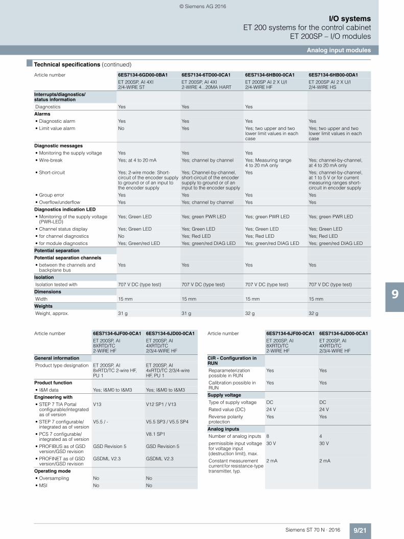
9/21Siemens ST 70 N · 2016
9
■ Technical specifications (continued)
I/O systemsET 200 systems for the control cabinet
ET 200SP – I/O modules
Analog input modules
Interrupts/diagnostics/status information
Diagnostics Yes Yes Yes
Alarms
• Diagnostic alarm Yes Yes Yes Yes
• Limit value alarm No Yes Yes; two upper and two lower limit values in each case
Yes; two upper and two lower limit values in each case
Diagnostic messages
• Monitoring the supply voltage Yes Yes Yes
• Wire-break Yes; at 4 to 20 mA Yes; channel by channel Yes; Measuring range 4 to 20 mA only
Yes; channel-by-channel,at 4 to 20 mA only
• Short-circuit Yes; 2-wire mode: Short-circuit of the encoder supply to ground or of an input to the encoder supply
Yes; Channel-by-channel, short-circuit of the encoder supply to ground or of an input to the encoder supply
Yes Yes; channel-by-channel,at 1 to 5 V or for current measuring ranges short-circuit in encoder supply
• Group error Yes Yes Yes Yes
• Overflow/underflow Yes Yes; channel by channel Yes Yes
Diagnostics indication LED
• Monitoring of the supply voltage (PWR-LED)
Yes; Green LED Yes; green PWR LED Yes; green PWR LED Yes; green PWR LED
• Channel status display Yes; Green LED Yes; Green LED Yes; Green LED Yes; Green LED
• for channel diagnostics No Yes; Red LED Yes; Red LED Yes; Red LED
• for module diagnostics Yes; Green/red LED Yes; green/red DIAG LED Yes; green/red DIAG LED Yes; green/red DIAG LED
Potential separation
Potential separation channels
• between the channels and backplane bus
Yes Yes Yes Yes
Isolation
Isolation tested with 707 V DC (type test) 707 V DC (type test) 707 V DC (type test) 707 V DC (type test)
Dimensions
Width 15 mm 15 mm 15 mm 15 mm
Weights
Weight, approx. 31 g 31 g 32 g 32 g
Article number 6ES7134-6GD00-0BA1 6ES7134-6TD00-0CA1 6ES7134-6HB00-0CA1 6ES7134-6HB00-0DA1
ET 200SP, AI 4XI 2/4-WIRE ST
ET 200SP, AI 4XI 2-WIRE 4...20MA HART
ET 200SP AI 2 X U/I 2/4-WIRE HF
ET 200SP AI 2 X U/I 2/4-WIRE HS
Article number 6ES7134-6JF00-0CA1 6ES7134-6JD00-0CA1
ET 200SP, AI 8XRTD/TC 2-WIRE HF
ET 200SP, AI 4XRTD/TC 2/3/4-WIRE HF
General information
Product type designation ET 200SP, AI 8xRTD/TC 2-wire HF, PU 1
ET 200SP, AI4xRTD/TC 2/3/4-wire HF, PU 1
Product function
• I&M data Yes; I&M0 to I&M3 Yes; I&M0 to I&M3
Engineering with
• STEP 7 TIA Portal configurable/integrated as of version
V13 V12 SP1 / V13
• STEP 7 configurable/integrated as of version
V5.5 / - V5.5 SP3 / V5.5 SP4
• PCS 7 configurable/integrated as of version
V8.1 SP1
• PROFIBUS as of GSD version/GSD revision
GSD Revision 5 GSD Revision 5
• PROFINET as of GSD version/GSD revision
GSDML V2.3 GSDML V2.3
Operating mode
• Oversampling No No
• MSI No No
CiR - Configuration in RUN
Reparameterization possible in RUN
Yes Yes
Calibration possible in RUN
Yes Yes
Supply voltage
Type of supply voltage DC DC
Rated value (DC) 24 V 24 V
Reverse polarity protection
Yes Yes
Analog inputs
Number of analog inputs 8 4
permissible input voltage for voltage input (destruction limit), max.
30 V 30 V
Constant measurement current for resistance-type transmitter, typ.
2 mA 2 mA
Article number 6ES7134-6JF00-0CA1 6ES7134-6JD00-0CA1
ET 200SP, AI 8XRTD/TC 2-WIRE HF
ET 200SP, AI 4XRTD/TC 2/3/4-WIRE HF
© Siemens AG 2016
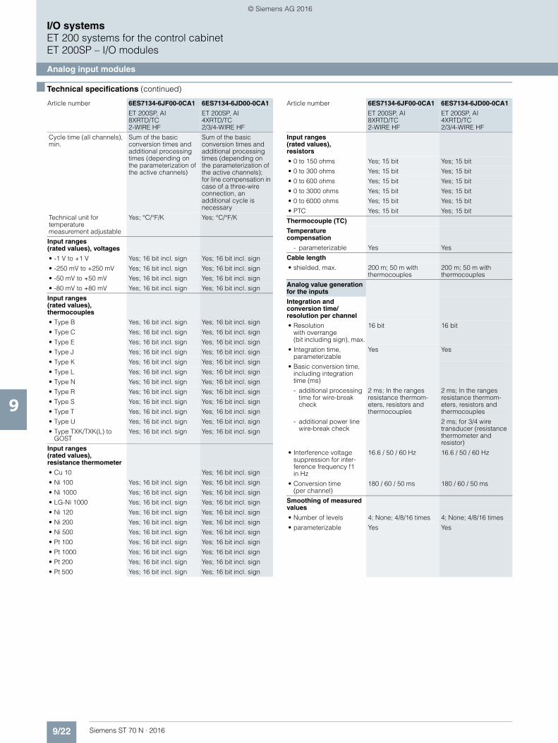
9/22 Siemens ST 70 N · 2016
9
■ Technical specifications (continued)
I/O systemsET 200 systems for the control cabinetET 200SP – I/O modules
Analog input modules
Cycle time (all channels), min.
Sum of the basic conversion times and additional processing times (depending on the parameterization of the active channels)
Sum of the basic conversion times and additional processing times (depending on the parameterization of the active channels);for line compensation in case of a three-wire connection, an additional cycle is necessary
Technical unit for temperature measurement adjustable
Yes; °C/°F/K Yes; °C/°F/K
Input ranges(rated values), voltages
• -1 V to +1 V Yes; 16 bit incl. sign Yes; 16 bit incl. sign
• -250 mV to +250 mV Yes; 16 bit incl. sign Yes; 16 bit incl. sign
• -50 mV to +50 mV Yes; 16 bit incl. sign Yes; 16 bit incl. sign
• -80 mV to +80 mV Yes; 16 bit incl. sign Yes; 16 bit incl. sign
Input ranges(rated values), thermocouples
• Type B Yes; 16 bit incl. sign Yes; 16 bit incl. sign
• Type C Yes; 16 bit incl. sign Yes; 16 bit incl. sign
• Type E Yes; 16 bit incl. sign Yes; 16 bit incl. sign
• Type J Yes; 16 bit incl. sign Yes; 16 bit incl. sign
• Type K Yes; 16 bit incl. sign Yes; 16 bit incl. sign
• Type L Yes; 16 bit incl. sign Yes; 16 bit incl. sign
• Type N Yes; 16 bit incl. sign Yes; 16 bit incl. sign
• Type R Yes; 16 bit incl. sign Yes; 16 bit incl. sign
• Type S Yes; 16 bit incl. sign Yes; 16 bit incl. sign
• Type T Yes; 16 bit incl. sign Yes; 16 bit incl. sign
• Type U Yes; 16 bit incl. sign Yes; 16 bit incl. sign
• Type TXK/TXK(L) to GOST
Yes; 16 bit incl. sign Yes; 16 bit incl. sign
Input ranges (rated values),resistance thermometer
• Cu 10 Yes; 16 bit incl. sign
• Ni 100 Yes; 16 bit incl. sign Yes; 16 bit incl. sign
• Ni 1000 Yes; 16 bit incl. sign Yes; 16 bit incl. sign
• LG-Ni 1000 Yes; 16 bit incl. sign Yes; 16 bit incl. sign
• Ni 120 Yes; 16 bit incl. sign Yes; 16 bit incl. sign
• Ni 200 Yes; 16 bit incl. sign Yes; 16 bit incl. sign
• Ni 500 Yes; 16 bit incl. sign Yes; 16 bit incl. sign
• Pt 100 Yes; 16 bit incl. sign Yes; 16 bit incl. sign
• Pt 1000 Yes; 16 bit incl. sign Yes; 16 bit incl. sign
• Pt 200 Yes; 16 bit incl. sign Yes; 16 bit incl. sign
• Pt 500 Yes; 16 bit incl. sign Yes; 16 bit incl. sign
Article number 6ES7134-6JF00-0CA1 6ES7134-6JD00-0CA1
ET 200SP, AI 8XRTD/TC 2-WIRE HF
ET 200SP, AI 4XRTD/TC 2/3/4-WIRE HF
Input ranges(rated values), resistors
• 0 to 150 ohms Yes; 15 bit Yes; 15 bit
• 0 to 300 ohms Yes; 15 bit Yes; 15 bit
• 0 to 600 ohms Yes; 15 bit Yes; 15 bit
• 0 to 3000 ohms Yes; 15 bit Yes; 15 bit
• 0 to 6000 ohms Yes; 15 bit Yes; 15 bit
• PTC Yes; 15 bit Yes; 15 bit
Thermocouple (TC)
Temperature compensation
- parameterizable Yes Yes
Cable length
• shielded, max. 200 m; 50 m with thermocouples
200 m; 50 m with thermocouples
Analog value generation for the inputs
Integration and conversion time/resolution per channel
• Resolutionwith overrange (bit including sign), max.
16 bit 16 bit
• Integration time, parameterizable
Yes Yes
• Basic conversion time, including integration time (ms)
- additional processing time for wire-break check
2 ms; In the ranges resistance thermom-eters, resistors and thermocouples
2 ms; In the ranges resistance thermom-eters, resistors and thermocouples
- additional power line wire-break check
2 ms; for 3/4 wire transducer (resistance thermometer and resistor)
• Interference voltage suppression for inter-ference frequency f1in Hz
16.6 / 50 / 60 Hz 16.6 / 50 / 60 Hz
• Conversion time(per channel)
180 / 60 / 50 ms 180 / 60 / 50 ms
Smoothing of measured values
• Number of levels 4; None; 4/8/16 times 4; None; 4/8/16 times
• parameterizable Yes Yes
Article number 6ES7134-6JF00-0CA1 6ES7134-6JD00-0CA1
ET 200SP, AI 8XRTD/TC 2-WIRE HF
ET 200SP, AI 4XRTD/TC 2/3/4-WIRE HF
© Siemens AG 2016
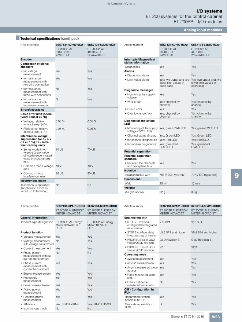
9/23Siemens ST 70 N · 2016
9
■ Technical specifications (continued)
I/O systemsET 200 systems for the control cabinet
ET 200SP – I/O modules
Analog input modules
Encoder
Connection of signal encoders
• for voltage measurement
Yes Yes
• for resistance measurement with two-wire connection
Yes Yes
• for resistance measurement with three-wire connection
No Yes
• for resistance measurement with four-wire connection
No Yes
Errors/accuracies
Basic error limit (opera-tional limit at 25 °C)
• Voltage, relative to input area, (+/-)
0.05 % 0.05 %
• Resistance, relativeto input area, (+/-)
0.05 % 0.05 %
Interference voltage suppression for f = n x (f1 +/- 1 %), f1 = inter-ference frequency
• Series mode inter-ference (peak value of interference < rated value of input range), min.
70 dB 70 dB
• Common mode voltage, max.
10 V 10 V
• Common mode interference, min.
90 dB 90 dB
Isochronous mode
Isochronous operation (application synchro-nized up to terminal)
No No
Article number 6ES7134-6JF00-0CA1 6ES7134-6JD00-0CA1
ET 200SP, AI 8XRTD/TC 2-WIRE HF
ET 200SP, AI 4XRTD/TC 2/3/4-WIRE HF
Interrupts/diagnostics/status information
Diagnostics Yes Yes
Alarms
• Diagnostic alarm Yes Yes
• Limit value alarm Yes; two upper and two lower limit values in each case
Yes; two upper and two lower limit values in each case
Diagnostic messages
• Monitoring the supply voltage
Yes Yes
• Wire-break Yes; channel by channel
Yes; channel by channel
• Group error Yes Yes
• Overflow/underflow Yes; channel by channel
Yes; channel by channel
Diagnostics indication LED
• Monitoring of the supply voltage (PWR-LED)
Yes; green PWR LED Yes; green PWR LED
• Channel status display Yes; Green LED Yes; Green LED
• for channel diagnostics Yes; Red LED Yes; Red LED
• for module diagnostics Yes; green/red DIAG LED
Yes; green/red DIAG LED
Potential separation
Potential separation channels
• between the channels and backplane bus
Yes Yes
Isolation
Isolation tested with 707 V DC (type test) 707 V DC (type test)
Dimensions
Width 15 mm 15 mm
Weights
Weight, approx. 32 g 30 g
Article number 6ES7134-6JF00-0CA1 6ES7134-6JD00-0CA1
ET 200SP, AI 8XRTD/TC 2-WIRE HF
ET 200SP, AI 4XRTD/TC 2/3/4-WIRE HF
Article number 6ES7134-6PA01-0BD0 6ES7134-6PA20-0BD0
ET 200SP AI ENERGY METER 400VAC ST
ET 200SP AI ENERGY METER 480VAC ST
General information
Product type designation ET 200SP, AI Energy Meter 400VAC ST, PU 1
ET 200SP, AI Energy Meter 480VAC ST, PU 1
Product function
• Voltage measurement Yes Yes
• Voltage measurement with voltage transformers
No Yes
• Current measurement Yes Yes
• Phase current measurement without current transformers
No No
• Phase current measurement with current transformers
Yes Yes
• Energy measurement Yes Yes
• Frequency measurement
Yes Yes
• Power measurement Yes Yes
• Active power measurement
Yes Yes
• Reactive power measurement
Yes Yes
• I&M data Yes; I&M0 to I&M3 Yes; I&M0 to I&M3
• Isochronous mode No No
Engineering with
• STEP 7 TIA Portal configurable/integrated as of version
V13 SP1 V13 SP1
• STEP 7 configurable/integrated as of version
V5.5 SP4 and higher V5.5 SP4 and higher
• PROFIBUS as of GSD version/GSD revision
GSD Revision 5 GSD Revision 5
• PROFINET as of GSD version/GSD revision
V2.3 V2.3
Operating mode
• cyclic measurement Yes Yes
• acyclic measurement Yes Yes
• Acyclic measured value access
Yes Yes
• Fixed measured value sets
Yes Yes
• Freely definable measured value sets
No Yes
CiR - Configuration in RUN
Reparameterization possible in RUN
Yes Yes
Calibration possible in RUN
No Yes
Article number 6ES7134-6PA01-0BD0 6ES7134-6PA20-0BD0
ET 200SP AI ENERGY METER 400VAC ST
ET 200SP AI ENERGY METER 480VAC ST
© Siemens AG 2016
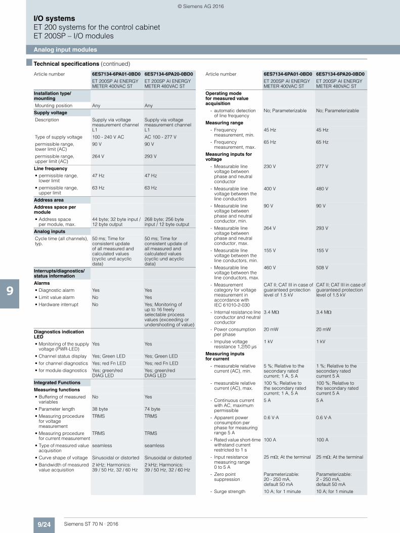
9/24 Siemens ST 70 N · 2016
9
■ Technical specifications (continued)
I/O systemsET 200 systems for the control cabinetET 200SP – I/O modules
Analog input modules
Installation type/mounting
Mounting position Any Any
Supply voltage
Description Supply via voltage measurement channel L1
Supply via voltage measurement channel L1
Type of supply voltage 100 - 240 V AC AC 100 - 277 V
permissible range,lower limit (AC)
90 V 90 V
permissible range, upper limit (AC)
264 V 293 V
Line frequency
• permissible range, lower limit
47 Hz 47 Hz
• permissible range, upper limit
63 Hz 63 Hz
Address area
Address space per module
• Address spaceper module, max.
44 byte; 32 byte input / 12 byte output
268 byte; 256 byte input / 12 byte output
Analog inputs
Cycle time (all channels), typ.
50 ms; Time for consistent update of all measured and calculated values (cyclic und acyclic data)
50 ms; Time for consistent update of all measured and calculated values (cyclic und acyclic data)
Interrupts/diagnostics/status information
Alarms
• Diagnostic alarm Yes Yes
• Limit value alarm No Yes
• Hardware interrupt No Yes; Monitoring ofup to 16 freely selectable process values (exceeding or undershooting of value)
Diagnostics indication LED
• Monitoring of the supply voltage (PWR-LED)
Yes Yes
• Channel status display Yes; Green LED Yes; Green LED
• for channel diagnostics Yes; red Fn LED Yes; red Fn LED
• for module diagnostics Yes; green/red DIAG LED
Yes; green/red DIAG LED
Integrated Functions
Measuring functions
• Buffering of measured variables
No Yes
• Parameter length 38 byte 74 byte
• Measuring procedure for voltage measurement
TRMS TRMS
• Measuring procedure for current measurement
TRMS TRMS
• Type of measured value acquisition
seamless seamless
• Curve shape of voltage Sinusoidal or distorted Sinusoidal or distorted
• Bandwidth of measured value acquisition
2 kHz; Harmonics: 39 / 50 Hz, 32 / 60 Hz
2 kHz; Harmonics: 39 / 50 Hz, 32 / 60 Hz
Article number 6ES7134-6PA01-0BD0 6ES7134-6PA20-0BD0
ET 200SP AI ENERGY METER 400VAC ST
ET 200SP AI ENERGY METER 480VAC ST
Operating modefor measured value acquisition
- automatic detection of line frequency
No; Parameterizable No; Parameterizable
Measuring range
- Frequency measurement, min.
45 Hz 45 Hz
- Frequency measurement, max.
65 Hz 65 Hz
Measuring inputs for voltage
- Measurable line voltage between phase and neutral conductor
230 V 277 V
- Measurable line voltage between the line conductors
400 V 480 V
- Measurable line voltage between phase and neutral conductor, min.
90 V 90 V
- Measurable line voltage between phase and neutral conductor, max.
264 V 293 V
- Measurable line voltage between the line conductors, min.
155 V 155 V
- Measurable line voltage between the line conductors, max.
460 V 508 V
- Measurement category for voltage measurement in accordance with IEC 61010-2-030
CAT II; CAT III in case of guaranteed protection level of 1.5 kV
CAT II; CAT III in case of guaranteed protection level of 1.5 kV
- Internal resistance line conductor and neutral conductor
3.4 M 3.4 M
- Power consumption per phase
20 mW 20 mW
- Impulse voltage resistance 1,2/50 µs
1 kV 1 kV
Measuring inputsfor current
- measurable relative current (AC), min.
5 %; Relative to the secondary rated current; 1 A, 5 A
1 %; Relative to the secondary rated current 5 A
- measurable relative current (AC), max.
100 %; Relative tothe secondary rated current; 1 A, 5 A
100 %; Relative tothe secondary rated current 5 A
- Continuous current with AC, maximum permissible
5 A 5 A
- Apparent power consumption per phase for measuring range 5 A
0.6 V·A 0.6 V·A
- Rated value short-time withstand current restricted to 1 s
100 A 100 A
- Input resistance measuring range 0 to 5 A
25 m; At the terminal 25 m; At the terminal
- Zero point suppression
Parameterizable:20 - 250 mA, default 50 mA
Parameterizable: 2 - 250 mA,default 50 mA
- Surge strength 10 A; for 1 minute 10 A; for 1 minute
Article number 6ES7134-6PA01-0BD0 6ES7134-6PA20-0BD0
ET 200SP AI ENERGY METER 400VAC ST
ET 200SP AI ENERGY METER 480VAC ST
© Siemens AG 2016

9/25Siemens ST 70 N · 2016
9
■ Technical specifications (continued)
I/O systemsET 200 systems for the control cabinet
ET 200SP – I/O modules
Analog input modules
Accuracy class according toIEC 61557-12
- Measured variable voltage
0.5 0,2
- Measured variable current
0.5 0,2
- Measured variable apparent power
1 0.5
- Measured variable active power
1 0.5
- Measured variable reactive power
1 1
- Measured variable power factor
0.5 0.5
- Measured variable active energy
1 0.5
- Measured variable reactive energy
2 1
- Measured variable neutral current
0.5; calculated
- Measured variable ±1 °; not covered by IEC 61577-12
±1 °; not covered by IEC 61577-12
- Measured variable frequency
0.05 0.05
Potential separation
Potential separation channels
• between the channels and backplane bus
Yes; 3 700 V AC (type test) CAT III
Yes; 3 700 V AC(type test) CAT III
Isolation
Isolation tested with 2 300V AC for 1 min. (type test)
2 300V AC for 1 min. (type test)
Ambient conditions
Ambient temperature during operation
• horizontal installation, min.
0 °C 0 °C
• horizontal installation, max.
60 °C 60 °C
• vertical installation, min. 0 °C 0 °C
• vertical installation, max. 50 °C 50 °C
Dimensions
Width 20 mm 20 mm
Weights
Weight (without packaging)
45 g 45 g
Data for selecting a current transformer
• Burden power current transformer x/1A, min.
As a function of cable length and cross section, see device manual
As a function of cable length and cross section, see device manual
• Burden power current transformer x/5A, min.
As a function of cable length and cross section, see device manual
As a function of cable length and cross section, see device manual
Article number 6ES7134-6PA01-0BD0 6ES7134-6PA20-0BD0
ET 200SP AI ENERGY METER 400VAC ST
ET 200SP AI ENERGY METER 480VAC ST
■ Ordering data Article No.
Analog input modules
Delivery options: Apart from the standard delivery form in an individual package, selected I/O modules and BaseUnits are also available in a pack of 10 units. The pack of 10 units enables the amount of waste to be reduced considerably, as well as saving the time of unpacking individual modules.
The number of modules required is the number of modules ordered. The type of packaging is chosen by selecting the article number. Packs of 10 can therefore only be ordered in integer multiples of 10.
Analog input moduleAI 8xI 2/4-wire BA, BU type A0 or A1, color code CC01
6ES7 134-6GF00-0AA1
Analog input module AI 2xU ST, BU type A0 or A1, color code CC00
6ES7134-6FB00-0BA1
Analog input module AI 8xU BA,BU type A0 or A1, color code CC02
6ES7 134-6FF00-0AA1
Analog input module AI 4xU/I 2-wire Standard, BU type A0 or A1, color code CC03, 16 bit, ± 0.3%• 1 unit 6ES7134-6HD00-0BA1• 10 units 6ES7134-6HD00-2BA1
Analog input module AI 2xI 2/4-wire Standard, BU type A0 or A1, color code CC05, 16 bit
6ES7134-6GB00-0BA1
Analog input module AI 4xI 2-/4-wire Standard, BU type A0or A1, color code CC03, 16 bit, ± 0.3%
6ES7134-6GD00-0BA1
Analog input module AI 4xI 2-wire 4...20 mA HART, BU type A0 or A1, color code CC03
6ES7134-6TD00-0CA1
Analog input module AI 2xU/I 2/4-wire High Feature, BU type A0 or A1, color code CC05, 16 bit, ± 0.1%, independent channel isola-tion, isochronous mode above 1 ms
6ES7134-6HB00-0CA1
Analog input module AI 2xU/I 2-/4-wire High Speed, BU type A0 or A1, color code CC00, 16 bit, ± 0.3%, isochronous mode above 250 µs, oversampling above 50 µs
6ES7134-6HB00-0DA1
Analog input module AI 8xRTD/TC 2-wire High Feature, BU type A0or A1, color code CC00, 16 bit, ± 0.1%, scalable measuring range• 1 unit 6ES7134-6JF00-0CA1 • 10 units 6ES7134-6JF00-2CA1
Analog input module AI 4xRTD/TC 2, 3, 4-wire High Feature, BU type A0 or A1, color code CC00, 16 bit, ± 0.1%, scalable measuring range• 1 unit 6ES7134-6JD00-0CA1• 10 units 6ES7134-6JD00-2CA1
Analog input module AI Energy Meter Standard, 400 V AC, BU type D0
6ES7134-6PA01-0BD0
Analog input module AI Energy Meter Standard, 480 V AC, BU type D0
6ES7134-6PA20-0BD0
© Siemens AG 2016

9/26 Siemens ST 70 N · 2016
9
■ Ordering data Article No. Article No.
I/O systemsET 200 systems for the control cabinetET 200SP – I/O modules
Analog input modules
Usable type A0 BaseUnits
BU15-P16+A10+2D
BU type A0; BaseUnit (light) with16 process terminals (1...16) to the module and an additional 10 inter-nally jumpered AUX terminals(1 A to 10 A); for starting a newload group (max. 10 A)• 1 unit 6ES7193-6BP20-0DA0• 10 units 6ES7193-6BP20-2DA0
BU15-P16+A0+2D
BU type A0; BaseUnit (light) with 16 process terminals to the module; for starting a new load group (max. 10 A)• 1 unit 6ES7193-6BP00-0DA0• 10 units 6ES7193-6BP00-2DA0
BU15-P16+A10+2B
BU type A0; BaseUnit (dark) with 16 process terminals (1...16) to the module and an additional 10 internally jumpered AUX termi-nals (1 A to 10 A); for continuing the load group• 1 unit 6ES7193-6BP20-0BA0• 10 units 6ES7193-6BP20-2BA0
BU15-P16+A0+2B
BU type A0; BaseUnit (dark) with16 process terminals to the module; for continuing the load group• 1 unit 6ES7193-6BP00-0BA0• 10 units 6ES7193-6BP00-2BA0
Usable type A1 BaseUnits (temperature detection)
BU15-P16+A0+12D/T 6ES7193-6BP40-0DA1
BU type A1; BaseUnit (light) with16 process terminals (1...16) to the module and an additional 2x5 inter-nally jumpered additional terminals (1 B to 5 B and 1 C to 5 C); for start-ing a new load group (max. 10 A)
BU15-P16+A0+2D/T 6ES7193-6BP00-0DA1
BU type A1; BaseUnit (light) with 16 process terminals to the module; for starting a new load group(max. 10 A)
BU15-P16+A0+12B/T 6ES7193-6BP40-0BA1
BU type A1; BaseUnit (dark) with 16 process terminals (1...16) to the module and an additional 2x5 inter-nally jumpered additional terminals (1 B to 5 B and 1 C to 5 C); for con-tinuing the load group
BU15-P16+A0+2B/T 6ES7193-6BP00-0BA1
BU type A1; BaseUnit (dark) with16 process terminals to the module; for continuing the load group
Usable type D0 BaseUnits
BU20-P12+A0+0B 6ES7193-6BP00-0BD0
BU type D0; BaseUnit with 12 push-in terminals, without AUX terminals, bridged to the left
Accessories
Equipment labeling plate 6ES7193-6LF30-0AW0
10 sheets of 16 labels, for printing with thermal transfer card printer or plotter
Labeling strips
500 labeling strips on roll, light gray, for inscription with thermal transfer roll printer
6ES7193-6LR10-0AA0
500 labeling strips on roll, yellow, for inscription with thermal transfer roll printer
6ES7193-6LR10-0AG0
1000 labeling strips DIN A4, light gray, card, perforated, for inscrip-tion with laser printer
6ES7193-6LA10-0AA0
1000 labeling strips DIN A4, yellow, card, perforated, for inscription with laser printer
6ES7193-6LA10-0AG0
BU cover
for covering empty slots (gaps); 5 units• 15 mm wide 6ES7133-6CV15-1AM0• 20 mm wide 6ES7133-6CV20-1AM0
Shield connection 6ES7193-6SC00-1AM0
5 shield supports and 5 shield terminals
Color-coded labels
Color code CC00, for 16 process terminals, for BU type A0, A1, gray (terminals 1 to 8), red (terminals 9 to 16); 10 units
6ES7193-6CP00-2MA0
Color code CC01, for 16 process terminals, for BU type A0, A1,gray (terminals 1 to 8), red (terminals 9 to 16); 10 units
6ES7193-6CP01-2MA0
Color code CC02, for 16 process terminals, for BU type A0, A1, gray (terminals 1 to 8), blue (terminals 9 to 16); 10 units
6ES7193-6CP02-2MA0
Color code CC03, for 16 push-in terminals, for BU type A0, A1gray (terminals 1 to 8), red (terminals 9 to 12), gray (terminals 13 to 16); 10 units
6ES7193-6CP03-2MA0
Color code CC05, for 16 push-in terminals, for BU type A0, A1, gray (terminals 1 to 12), red (terminals 13 to 14), blue (terminals 15 to 16); 10 units
6ES7193-6CP05-2MA0
Color code CC71, for 10 AUX terminals, BU type A0, yellow/green (terminals 1 A to 10 A); 10 units
6ES7193-6CP71-2AA0
Color code CC72,for 10 AUX terminals, BU type A0, red (terminals 1 A to 10 A); 10 units
6ES7193-6CP72-2AA0
Color code CC73, for 10 AUX terminals, BU type A0, blue (terminals 1 A to 10 A); 10 units
6ES7193-6CP73-2AA0
Color code CC74, for 2x5 additional terminals, BU type A1,red (terminals 1B to 5B), blue (terminals 1C to 5C); 10 units
6ES7193-6CP74-2AA0
© Siemens AG 2016
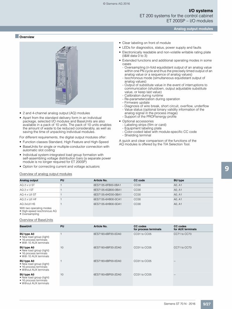
9/27Siemens ST 70 N · 2016
9
I/O systemsET 200 systems for the control cabinet
ET 200SP – I/O modules
Analog output modules
■ Overview
• 2 and 4-channel analog output (AQ) modules• Apart from the standard delivery form in an individual
package, selected I/O modules and BaseUnits are also available in a pack of 10 units. The pack of 10 units enables the amount of waste to be reduced considerably, as well as saving the time of unpacking individual modules.
For different requirements, the digital output modules offer:• Function classes Standard, High Feature and High-Speed• BaseUnits for single or multiple-conductor connection with
automatic slot coding• Individual system-integrated load group formation with
self-assembling voltage distribution bars (a separate power module is no longer required for ET 200SP)
• Option for connecting current and voltage actuators
• Clear labeling on front of module• LEDs for diagnostics, status, power supply and faults• Electronically readable and non-volatile writable rating plate
(I&M data 0 to 3)• Extended functions and additional operating modes in some
cases- Oversampling (n-fold equidistant output of an analog value
within one PN cycle and thus the precisely timed output of an analog value or a sequence of analog values)
- Isochronous mode (simultaneous equidistant output of analog values)
- Output of substitute value in the event of interruptions to communication (shutdown, output adjustable substitute value, or keep last value)
- Calibration during runtime- Re-parameterization during operation- Firmware update- Diagnosis of wire break, short circuit, overflow, underflow- Value status (optional binary validity information of the
analog signal in the process image)- Support of the PROFIenergy profile
• Optional accessories- Labeling strips (film or card)- Equipment labeling plate- Color-coded label with module-specific CC code- Shielding terminal
A quick and clear comparison of the functions of the AQ modules is offered by the TIA Selection Tool.
Overview of analog output modules
Overview of BaseUnits
Analog output PU Article No. CC code BU type
AQ 2 x U ST 1 6ES7135-6FB00-0BA1 CC00 A0, A1
AQ 2 x I ST 1 6ES7135-6GB00-0BA1 CC00 A0, A1
AQ 4 x U/I ST 1 6ES7135-6HD00-0BA1 CC00 A0, A1
AQ 2 x U/I HF 1 6ES7135-6HB00-0CA1 CC00 A0, A1
AQ 2xU/I HS
With two operating modes• High-speed isochronous AQ• Oversampling
1 6ES7135-6HB00-0DA1 CC00 A0, A1
BaseUnit PU Article No. CC codesfor process terminals
CC codes for AUX terminals
BU type A0• New load group (light)• 16 process terminals • With 10 AUX terminals
1 6ES7193-6BP20-0DA0 CC01 to CC05 CC71 to CC73
BU type A0• New load group (light)• 16 process terminals • With 10 AUX terminals
10 6ES7193-6BP20-2DA0 CC01 to CC05 CC71 to CC73
BU type A0• New load group (light)• 16 process terminals • Without AUX terminals
1 6ES7193-6BP00-0DA0 CC01 to CC05 --
BU type A0• New load group (light)• 16 process terminals • Without AUX terminals
10 6ES7193-6BP00-2DA0 CC01 to CC05 --
© Siemens AG 2016

9/28 Siemens ST 70 N · 2016
9
■ Overview (continued)
I/O systemsET 200 systems for the control cabinetET 200SP – I/O modules
Analog output modules
■ Technical specifications
BU type A0• Forwarding of load group
(dark)• 16 process terminals • With 10 AUX terminals
1 6ES7193-6BP20-0BA0 CC01 to CC05 CC71 to CC73
BU type A0• Forwarding of load group
(dark)• 16 process terminals • With 10 AUX terminals
10 6ES7193-6BP20-2BA0 CC01 to CC05 CC71 to CC73
BU type A0• Forwarding of load group
(dark)• 16 process terminals • Without AUX terminals
1 6ES7193-6BP00-0BA0 CC01 to CC05 --
BU type A0• Forwarding of load group
(dark)• 16 process terminals • Without AUX terminals
10 6ES7193-6BP00-2BA0 CC01 to CC05 --
BU type A1• New load group (light)• With temperature sensor• 16 process terminals• With 2x5 additional terminals
1 6ES7193-6BP40-0DA1 CC01 to CC05 CC74
BU type A1• New load group (light)• With temperature sensor• 16 process terminals• Without 2x5 additional
terminals
1 6ES7193-6BP00-0DA1 CC01 to CC05 --
BU type A1• Forwarding of load group
(dark)• With temperature sensor• 16 process terminals• With 2x5 additional terminals
1 6ES7193-6BP40-0BA1 CC01 to CC05 CC74
BU type A1• Forwarding of load group
(dark)• With temperature sensor• 16 process terminals• Without 2x5 additional
terminals
1 6ES7193-6BP00-0BA1 CC01 to CC05 --
BaseUnit PU Article No. CC codesfor process terminals
CC codes for AUX terminals
Article number 6ES7135-6FB00-0BA1
6ES7135-6GB00-0BA1
6ES7135-6HD00-0BA1
6ES7135-6HB00-0DA1
6ES7135-6HB00-0CA1
ET 200SP, AQ 2XU STANDARD, PU 1
ET 200SP, AQ 2XI STANDARD, PU 1
ET 200SP, AQ 4XU/I ST ET 200SP, AQ 2 X U/I HIGH SPEED
ET 200SP, AQ 2 X U/I HIGH FEATURE
General information
Product type designation ET 200SP, AQ 2xU Standard
ET 200SP, AQ 2xI Standard
ET 200SP, AQ 4xU/I Standard
ET 200SP, AQ 2xU/I High Speed
AQ 2xU/I HF
Product function
• I&M data Yes; I&M0 to I&M3 Yes; I&M0 to I&M3 Yes; I&M0 to I&M3 Yes; I&M0 to I&M3 Yes; I&M0 to I&M3
• Scalable output range No No No
Engineering with
• STEP 7 TIA Portal configurable/integrated as of version
V13 SP1 / - V13 SP1 / - V11 SP2 / V13 V13 SP1 V13 / V13
• STEP 7 configurable/integrated as of version
V5.5 SP3 / - V5.5 SP3 / - V5.5 SP3 / - V5.5 SP3 / - V5.5 SP3 / -
• PCS 7 configurable/integrated as of version
V8.1 SP1 V8.1 SP1
• PROFIBUS as of GSD version/GSD revision
GSD Revision 5 GSD Revision 5 GSD Revision 5 GSD Revision 5 GSD Revision 5
• PROFINET as of GSD version/GSD revision
GSDML V2.3 GSDML V2.3 GSDML V2.3 GSDML V2.3 GSDML V2.3
© Siemens AG 2016

9/29Siemens ST 70 N · 2016
9
■ Technical specifications (continued)
I/O systemsET 200 systems for the control cabinet
ET 200SP – I/O modules
Analog output modules
Operating mode
• Oversampling No No No Yes; 2 channels per module
No
• MSO No No No No No
CiR - Configuration in RUN
Reparameterization possible in RUN Yes Yes Yes Yes Yes
Calibration possible in RUN No No No Yes Yes
Supply voltage
Type of supply voltage DC DC DC DC DC
Rated value (DC) 24 V 24 V 24 V 24 V 24 V
Reverse polarity protection Yes Yes Yes Yes Yes
Analog outputs
Number of analog outputs 2 2 4 2 2
Cycle time (all channels), min. 1 ms 1 ms 5 ms 125 µs 750 µs
Analog output with oversampling No No No Yes
• Values per cycle, max. 16
• Resolution, min. 45 µs; (2 channels), 35 µs (1 channel)
Output ranges, voltage
• 0 to 10 V Yes; 15 bit Yes; 15 bit Yes; 15 bit Yes; 15 bit
• 1 V to 5 V Yes; 13 bit Yes; 13 bit Yes; 13 bit Yes; 13 bit
• -5 V to +5 V Yes; 15 bit incl. sign Yes; 15 bit incl. sign Yes; 15 bit incl. sign Yes; 15 bit incl. sign
• -10 V to +10 V Yes; 16 bit incl. sign Yes; 16 bit incl. sign Yes; 16 bit incl. sign Yes; 16 bit incl. sign
Output ranges, current
• 0 to 20 mA Yes; 15 bit Yes; 15 bit Yes; 15 bit Yes; 15 bit
• -20 mA to +20 mA Yes; 16 bit incl. sign Yes; 16 bit incl. sign Yes; 16 bit incl. sign Yes; 16 bit incl. sign
• 4 mA to 20 mA Yes; 14 bit Yes; 14 bit Yes; 14 bit Yes; 14 bit
Connection of actuators
• for voltage output two-wire connection
Yes Yes Yes Yes
• for voltage output four-wire connection
No Yes Yes Yes
• for current output two-wire connection
Yes Yes Yes Yes
Load impedance(in rated range of output)
• with voltage outputs, min. 2 k 2 k 2 k 2 k• with voltage outputs,
capacitive load, max.1 µF 1 µF 1 µF 1 µF
• with current outputs, max. 500 500 500 500 • with current outputs, inductive load,
max.1 mH 1 mH 1 mH 1 mH
Cable length
• shielded, max. 200 m 1 000 m 1 000 m; 200 m for voltage output
1 000 m; 200 m for voltage output
1 000 m; 200 m for voltage output
Settling time
• for resistive load 0.1 ms 0.1 ms; Typical value 0.1 ms 0.05 ms 0.05 ms
• for capacitive load 1 ms 1 ms 0.05 ms; Max. 47 nF and 20 m cable length
0.05 ms; Max. 47 nF and 20 m cable length
• for inductive load 0.5 ms 0.5 ms 0.05 ms 0.05 ms
Errors/accuracies
Basic error limit(operational limit at 25 °C)
• Voltage, relative to output area, (+/-) 0.3 % 0.3 % 0.3 % 0.1 % 0.1 %
• Current, relative to output area, (+/-) 0.3 % 0.3 % 0.3 % 0.1 % 0.1 %
Article number 6ES7135-6FB00-0BA1
6ES7135-6GB00-0BA1
6ES7135-6HD00-0BA1
6ES7135-6HB00-0DA1
6ES7135-6HB00-0CA1
ET 200SP, AQ 2XU STANDARD, PU 1
ET 200SP, AQ 2XI STANDARD, PU 1
ET 200SP, AQ 4XU/I ST ET 200SP, AQ 2 X U/I HIGH SPEED
ET 200SP, AQ 2 X U/I HIGH FEATURE
© Siemens AG 2016

9/30 Siemens ST 70 N · 2016
9
■ Technical specifications (continued)
I/O systemsET 200 systems for the control cabinetET 200SP – I/O modules
Analog output modules
■ Ordering data Article No. Article No.
Isochronous mode
Isochronous operation (application synchronized up to terminal)
No No No Yes Yes
Execution and activation time (TCO), min.
70 µs 500 µs
Bus cycle time (TDP), min. 125 µs 750 µs
Interrupts/diagnostics/status information
Diagnostics Yes Yes Yes Yes Yes
Substitute values connectable Yes Yes Yes Yes Yes
Alarms
• Diagnostic alarm Yes Yes Yes Yes Yes
Diagnostic messages
• Monitoring the supply voltage Yes Yes Yes Yes Yes
• Wire-break Yes Yes Yes; channel-by-channel, only for output type "current"
Yes; channel-by-channel, only for output type "current"
• Short-circuit Yes Yes Yes; channel-by-channel, only for output type "voltage"
Yes; channel-by-channel, only for output type "voltage"
• Group error Yes Yes Yes Yes Yes
• Overflow/underflow Yes Yes Yes Yes Yes
Diagnostics indication LED
• Monitoring of the supply voltage (PWR-LED)
Yes; green PWR LED Yes; green PWR LED Yes; green PWR LED Yes; green PWR LED Yes; green PWR LED
• Channel status display Yes; Green LED Yes; Green LED Yes; Green LED Yes; Green LED Yes; Green LED
• for channel diagnostics No No No Yes; Red LED Yes; Red LED
• for module diagnostics Yes; green/red DIAG LED
Yes; green/red DIAG LED
Yes; green/red DIAG LED
Yes; green/red DIAG LED
Yes; green/redDIAG LED
Potential separation
Potential separation channels
• between the channels and backplane bus
Yes Yes Yes Yes Yes
Isolation
Isolation tested with 707 V DC (type test) 707 V DC (type test) 707 V DC (type test) 707 V DC (type test) 707 V DC (type test)
Ambient conditions
Ambient temperature during operation
• horizontal installation, min. 0 °C 0 °C 0 °C 0 °C 0 °C
• horizontal installation, max. 60 °C 60 °C 60 °C; Observe derating
60 °C 60 °C
• vertical installation, min. 0 °C 0 °C 0 °C 0 °C 0 °C
• vertical installation, max. 50 °C 50 °C 50 °C; Observe derating
50 °C 50 °C
Dimensions
Width 15 mm 15 mm 15 mm 15 mm 15 mm
Weights
Weight, approx. 31 g 31 g 31 g 31 g 31 g
Article number 6ES7135-6FB00-0BA1
6ES7135-6GB00-0BA1
6ES7135-6HD00-0BA1
6ES7135-6HB00-0DA1
6ES7135-6HB00-0CA1
ET 200SP, AQ 2XU STANDARD, PU 1
ET 200SP, AQ 2XI STANDARD, PU 1
ET 200SP, AQ 4XU/I ST ET 200SP, AQ 2 X U/I HIGH SPEED
ET 200SP, AQ 2 X U/I HIGH FEATURE
Analog output modules
Analog output module AQ 2xU Standard,BU type A0 or A1, color code CC00, 16 bit
6ES7135-6FB00-0BA1
Analog output module AQ 2xI Standard, BU type A0 or A1, color code CC00, 16 bit
6ES7135-6GB00-0BA1
Analog output moduleAQ 4xU/I Standard, BU type A0 or A1, color code CC00, 16 bit, ± 0.3%
6ES7135-6HD00-0BA1
Analog output module AQ 2xU/I High Feature, BU type A0 or A1, color code CC00, 16 bit, ± 0.1%
6ES7135-6HB00-0CA1
Analog output module AQ 2xU/I High Speed,BU type A0 or A1, color code CC00, 16 bit, ± 0.3%
6ES7135-6HB00-0DA1
© Siemens AG 2016
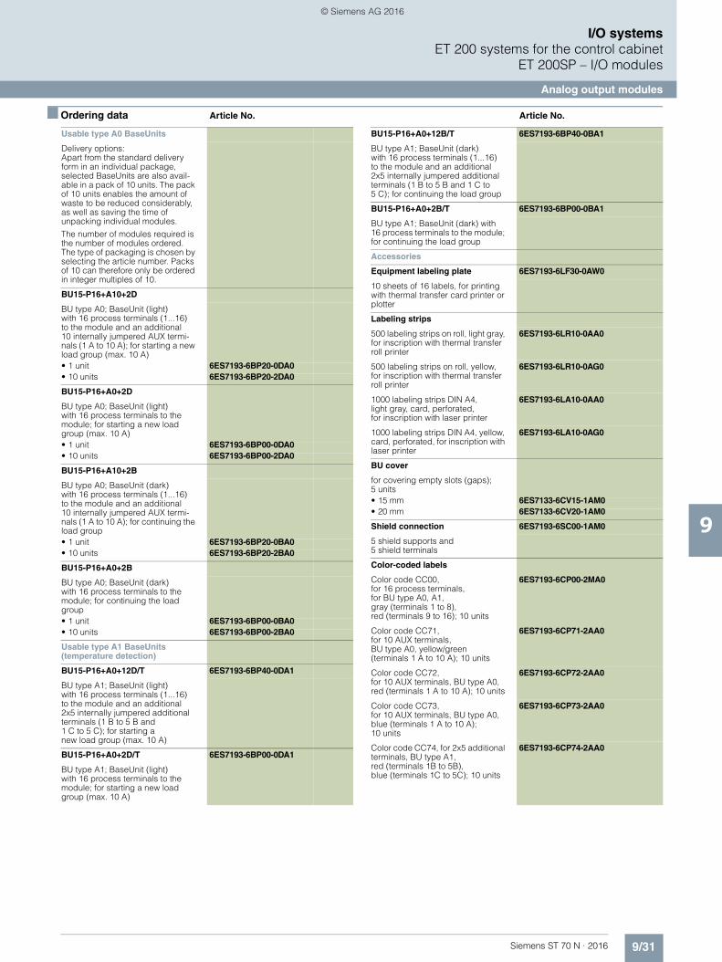
9/31Siemens ST 70 N · 2016
9
■ Ordering data Article No. Article No.
I/O systemsET 200 systems for the control cabinet
ET 200SP – I/O modules
Analog output modules
Usable type A0 BaseUnits
Delivery options: Apart from the standard delivery form in an individual package, selected BaseUnits are also avail-able in a pack of 10 units. The pack of 10 units enables the amount of waste to be reduced considerably, as well as saving the time of unpacking individual modules.
The number of modules required is the number of modules ordered. The type of packaging is chosen by selecting the article number. Packs of 10 can therefore only be ordered in integer multiples of 10.
BU15-P16+A10+2D
BU type A0; BaseUnit (light) with 16 process terminals (1...16) to the module and an additional 10 internally jumpered AUX termi-nals (1 A to 10 A); for starting a new load group (max. 10 A)• 1 unit 6ES7193-6BP20-0DA0• 10 units 6ES7193-6BP20-2DA0
BU15-P16+A0+2D
BU type A0; BaseUnit (light) with 16 process terminals to the module; for starting a new load group (max. 10 A)• 1 unit 6ES7193-6BP00-0DA0• 10 units 6ES7193-6BP00-2DA0
BU15-P16+A10+2B
BU type A0; BaseUnit (dark) with 16 process terminals (1...16)to the module and an additional 10 internally jumpered AUX termi-nals (1 A to 10 A); for continuing the load group• 1 unit 6ES7193-6BP20-0BA0• 10 units 6ES7193-6BP20-2BA0
BU15-P16+A0+2B
BU type A0; BaseUnit (dark) with 16 process terminals to the module; for continuing the load group• 1 unit 6ES7193-6BP00-0BA0• 10 units 6ES7193-6BP00-2BA0
Usable type A1 BaseUnits(temperature detection)
BU15-P16+A0+12D/T 6ES7193-6BP40-0DA1
BU type A1; BaseUnit (light) with 16 process terminals (1...16)to the module and an additional 2x5 internally jumpered additional terminals (1 B to 5 B and1 C to 5 C); for starting a new load group (max. 10 A)
BU15-P16+A0+2D/T 6ES7193-6BP00-0DA1
BU type A1; BaseUnit (light) with 16 process terminals to the module; for starting a new load group (max. 10 A)
BU15-P16+A0+12B/T 6ES7193-6BP40-0BA1
BU type A1; BaseUnit (dark) with 16 process terminals (1...16)to the module and an additional2x5 internally jumpered additional terminals (1 B to 5 B and 1 C to 5 C); for continuing the load group
BU15-P16+A0+2B/T 6ES7193-6BP00-0BA1
BU type A1; BaseUnit (dark) with 16 process terminals to the module; for continuing the load group
Accessories
Equipment labeling plate 6ES7193-6LF30-0AW0
10 sheets of 16 labels, for printing with thermal transfer card printer or plotter
Labeling strips
500 labeling strips on roll, light gray, for inscription with thermal transfer roll printer
6ES7193-6LR10-0AA0
500 labeling strips on roll, yellow, for inscription with thermal transfer roll printer
6ES7193-6LR10-0AG0
1000 labeling strips DIN A4, light gray, card, perforated, for inscription with laser printer
6ES7193-6LA10-0AA0
1000 labeling strips DIN A4, yellow, card, perforated, for inscription with laser printer
6ES7193-6LA10-0AG0
BU cover
for covering empty slots (gaps);5 units• 15 mm 6ES7133-6CV15-1AM0• 20 mm 6ES7133-6CV20-1AM0
Shield connection 6ES7193-6SC00-1AM0
5 shield supports and 5 shield terminals
Color-coded labels
Color code CC00, for 16 process terminals,for BU type A0, A1, gray (terminals 1 to 8), red (terminals 9 to 16); 10 units
6ES7193-6CP00-2MA0
Color code CC71,for 10 AUX terminals, BU type A0, yellow/green (terminals 1 A to 10 A); 10 units
6ES7193-6CP71-2AA0
Color code CC72, for 10 AUX terminals, BU type A0, red (terminals 1 A to 10 A); 10 units
6ES7193-6CP72-2AA0
Color code CC73, for 10 AUX terminals, BU type A0, blue (terminals 1 A to 10 A); 10 units
6ES7193-6CP73-2AA0
Color code CC74, for 2x5 additional terminals, BU type A1,red (terminals 1B to 5B), blue (terminals 1C to 5C); 10 units
6ES7193-6CP74-2AA0
© Siemens AG 2016

9/32 Siemens ST 70 N · 2016
9
I/O systemsET 200 systems for the control cabinetET 200SP – I/O modules
SIPLUS analog input modules
■ Overview
• 2-, 4- and 8-channel AI modules • Measuring ranges for current, voltage, thermocouples,
resistance thermometer, resistor and PTC • BaseUnits for 2-, 3- and 4-conductor connection • Function classes Basic, Standard, High Feature and
High Speed • Clear labeling on front of module • LEDs for diagnostics, status and errors • Individual system-integrated load group formation with self-
assembling potential multi-terminal busbars (power module not required for ET 200SP)
• Electronically readable rating plate (I&M data)• Additional operating modes in some cases • Optional accessories:
- Labeling strips - Equipment marking label - Color-coded label with module-specific CC code - Shielding terminal
Overview of SIPLUS analog input modules
Note:
SIPLUS extreme products are based on SIMATIC standard pro-ducts. The contents listed here were taken from the respective standard products. SIPLUS extreme specific information was added.
■ Technical specifications
Analog input Article No. CC code BU type PU
AI 4 x U/I 2-wire ST 6AG1134-6HD00-7BA1 CC03 A0, A1 1
AI 4 x I 2-/4-wire ST 6AG1134-6GD00-7BA1 CC03 A0, A1 1
AI 4 x I 2-wire 4...20 mA HART 6AG1134-6TD00-2CA1 CC03 A0, A1 1
AI 2xU/I 2/4-wire HS
With two operating modes• High-speed isochronous AI• Oversampling
6AG1134-6HB00-2DA1 CC00 A0, A1 1
AI 8 x RTD/TC 2-wire HF 6AG1134-6JF00-2CA1 CC00 A0, A1 1
AI 4 x RTD/TC 2-/3-/4-wire HF 6AG1134-6JD00-2CA1 CC00 A0, A1 1
AI 4 x RTD/TC 2-/3-/4-wire HF 6AG1134-6JD00-2CA1 CC00 A0, A1 1
AI Energy Meter AC 400 V ST 6AG1134-6PA00-7BD0 -- D0 1
Article number 6AG1134-6HD00-7BA1 6AG1134-6GD00-7BA1 6AG1134-6TD00-2CA1
Based on 6ES7134-6HD00-0BA1 6ES7134-6GD00-0BA1 6ES7134-6TD00-0CA1
SIPLUS ET 200SP AI 4XU/I 2-WIRE ST SIPLUS ET 200SP AI 4XI 2-/4-WIRE ST SIPLUS ET 200SP AI 4XI 2-WIRE 4...20MA H
Ambient conditions
Ambient temperature during operation
• horizontal installation, min. -40 °C; = Tmin -40 °C; = Tmin -40 °C; = Tmin; Startup @ -25 °C
• horizontal installation, max. 70 °C; = Tmax; > 60 °C max.1x +/- 20 mA or 4x +/- 10 V permissible
70 °C; = Tmax; > 60 °C max.1x +/- 20 mA permissible
60 °C
• vertical installation, min. -40 °C; = Tmin -40 °C; = Tmin -40 °C; = Tmin; Startup @ -25 °C
• vertical installation, max. 50 °C; = Tmax 50 °C; = Tmax 50 °C
Extended ambient conditions
• relative to ambient temperature-atmospheric pressure-installation altitude
Tmin ... Tmax at1080 hPa ... 795 hPa (-1000 m ... +2000 m) //Tmin ... (Tmax - 10K) at 795 hPa ... 658 hPa(+2000 m ... +3500 m) // Tmin ... (Tmax - 20K) at 658 hPa ... 540 hPa (+3500 m ... +5000 m)
© Siemens AG 2016

9/33Siemens ST 70 N · 2016
9
■ Technical specifications (continued)
I/O systemsET 200 systems for the control cabinet
ET 200SP – I/O modules
SIPLUS analog input modules
Relative humidity
- With condensation, testedin acc. with IEC 60068-2-38, max.
100 %; RH incl. condensation/frost (no commissioning under condensation conditions)
Resistance
- against biologically active substances / conformity with EN 60721-3-3
Yes; Class 3B2 mold, fungus and dry rot spores (with the exception of fauna). The supplied connector covers must remain on the unused interfaces during operation!
- against chemically active substances / conformity with EN 60721-3-3
Yes; Class 3C4 (RH < 75%) incl. salt spray according to EN 60068-2-52 (degree of severity 3). The supplied connector covers must remain on the unused interfaces during operation!
- against mechanically active substances / conformity with EN 60721-3-3
Yes; Class 3S4 incl. sand, dust. The supplied connector covers must remain on the unused interfaces during operation!
Article number 6AG1134-6HB00-2DA1 6AG1134-6JF00-2CA1 6AG1134-6JD00-2CA1
Based on 6ES7134-6HB00-0DA1 6ES7134-6JF00-0CA1 6ES7134-6JD00-0CA1
SIPLUS ET 200SP AI 2 X U/I 2-/4-WIRE HS
SIPLUS ET 200SP AI 8XRTD/TC 2-WIRE HF
SIPLUS ET 200SP AI 4XRTD/TC HF
Ambient conditions
Ambient temperature during operation
• horizontal installation, min. -40 °C; = Tmin; Startup @ -25 °C -40 °C; = Tmin; Startup @ -25 °C -40 °C; = Tmin
• horizontal installation, max. 60 °C; = Tmax 60 °C 60 °C; = Tmax
• vertical installation, min. -40 °C; = Tmin; Startup @ -25 °C -40 °C; = Tmin
• vertical installation, max. 50 °C 50 °C; = Tmax
Extended ambient conditions
• relative to ambient temperature-atmospheric pressure-installation altitude
Tmin ... Tmax at 1080 hPa ... 795 hPa (-1000 m ... +2000 m) // Tmin ... (Tmax - 10K) at 795 hPa ... 658 hPa (+2000 m ... +3500 m) // Tmin ... (Tmax - 20K) at 658 hPa ... 540 hPa (+3500 m ... +5000 m)
Tmin ... Tmax at 1080 hPa ... 795 hPa(-1000 m ... +2000 m) //Tmin ... (Tmax - 10K) at 795 hPa ... 658 hPa (+2000 m ... +3500 m) //Tmin ... (Tmax - 20K) at 658 hPa ... 540 hPa (+3500 m ... +5000 m)
Relative humidity
- With condensation, tested in accordance with IEC 60068-2-38, max.
100 %; RH incl. condensation / frost (no commissioning in bedewed state), horizontal installation
Resistance
- against biologically active substances / conformity with EN 60721-3-3
Yes; Class 3B2 mold, fungus and dry rot spores (with the exception of fauna). The supplied connector covers must remain on the unused interfaces during operation!
- against chemically active substances / conformity with EN 60721-3-3
Yes; Class 3C4 (RH < 75%) incl. salt spray according to EN 60068-2-52 (degree of severity 3). The supplied connector covers must remain on the unused interfaces during operation!
- against mechanically active substances / conformity with EN 60721-3-3
Yes; Class 3S4 incl. sand, dust. The supplied connector covers must remain on the unused interfaces during operation!
Article number 6AG1134-6HD00-7BA1 6AG1134-6GD00-7BA1 6AG1134-6TD00-2CA1
Based on 6ES7134-6HD00-0BA1 6ES7134-6GD00-0BA1 6ES7134-6TD00-0CA1
SIPLUS ET 200SP AI 4XU/I 2-WIRE ST SIPLUS ET 200SP AI 4XI 2-/4-WIRE ST SIPLUS ET 200SP AI 4XI 2-WIRE 4...20MA H
Article number 6AG1134-6PA00-7BD0
Based on 6ES7134-6PA00-0BD0
SIPLUS ET 200SP AI ENERGY METER
Ambient conditions
Ambient temperature during operation
• horizontal installation, min. -40 °C; = Tmin
• horizontal installation, max. 70 °C; = Tmax; > +60 °C max. permissible current 1 A per phase
Extended ambient conditions
• relative to ambient temperature-atmospheric pressure-installation altitude
Tmin ... Tmax at1080 hPa ... 795 hPa (-1000 m ... +2000 m)
Relative humidity
- With condensation, tested in accordance with IEC 60068-2-38, max.
100 %; RH incl. condensation/frost (no commissioning under conden-sation conditions)
Resistance
- against biologically active substances / conformity with EN 60721-3-3
Yes; Class 3B2 mold, fungus and dry rot spores (with the exception of fauna). The supplied connector covers must remain on the unused interfaces during operation!
- against chemically active substances / conformity with EN 60721-3-3
Yes; Class 3C4 (RH < 75%) incl. salt spray according to EN 60068-2-52 (degree of severity 3). The supplied connector covers must remain on the unused interfaces during operation!
- against mechanically active substances / conformity with EN 60721-3-3
Yes; Class 3S4 incl. sand, dust. The supplied connector covers must remain on the unused interfaces during operation!
Article number 6AG1134-6PA00-7BD0
Based on 6ES7134-6PA00-0BD0
SIPLUS ET 200SP AI ENERGY METER
© Siemens AG 2016

9/34 Siemens ST 70 N · 2016
9
I/O systemsET 200 systems for the control cabinetET 200SP – I/O modules
SIPLUS analog input modules
■ Ordering data Article No. Article No.
SIPLUS analog input modules
(Extended temperature range and medial exposure)
Analog input moduleAI 4xU/I 2-wire Standard,BU type A0 or A1, color code CC03, 16 bit, ± 0.3%
6AG1134-6HD00-7BA1
Analog input moduleAI 4xI 2-/4-wire Standard, BU type A0 or A1, color code CC03, 16 bit, ± 0.3%
6AG1134-6GD00-7BA1
Analog input module AI 4xRTD/TC 2-, 3-, 4-wire High Feature, BU type A0 or A1, color code CC00, 16 bit, ± 0.1%, scalable measuring range
6AG1134-6JD00-2CA1
Analog input moduleAI 4xI 2-wire 4...20 mA HART, BU type A0 or A1, color code CC03
6AG1134-6TD00-2CA1
Analog input module AI 2xU/I 2-/4-wire High Speed, BU type A0 or A1, color code CC00, 16 bit, ± 0.3%, isochronous mode above 250 µs, oversampling above 50 µs
6AG1134-6HB00-2DA1
Analog input moduleAI 8xRTD/TC 2-wire High Feature, BU type A0 or A1, color code CC00, 16 bit, ± 0.1%, scalable measuring range
6AG1134-6JF00-2CA1
Analog input module AI 4xRTD/TC 2-, 3-, 4-wire High Feature, BU type A0 or A1, color code CC00, 16 bit, ± 0.1%, scalable measuring range
6AG1134-6JD00-2CA1
Analog input module AI Energy Meter Standard, BU type D0
6AG1134-6PA00-7BD0
Usable SIPLUS BaseUnits type A0
BU15-P16+A0+2D 6AG1193-6BP00-7DA0
(Extended temperature range and medial exposure)
BU type A0; BaseUnit (light) with 16 process terminals to the module, for starting a new load group (max. 10 A)
BU15-P16+A0+2B 6AG1193-6BP00-7BA0
(Extended temperature range and medial exposure)
BU type A0; BaseUnit (dark)with 16 process terminals to the module; for continuing the load group
BU15-P16+A10+2D 6AG1193-6BP20-7DA0
(Extended temperature range and medial exposure)
BU type A0; BaseUnit (light) with 16 process terminals (1...16) to the module and an additional 10 internally jumpered AUX terminals (1 A to 10 A); for starting a new load group (max. 10 A)
BU15-P16+A10+2B 6AG1193-6BP20-7BA0
(Extended temperature range and medial exposure)
BU type A0; BaseUnit (dark) with 16 process terminals (1...16) to the module and an additional 10 internally jumpered AUX terminals (1 A to 10 A); for continuing the load group
Usable SIPLUS BaseUnitstype A1 (temperature detection)
BU15-P16+A0+2D/T 6AG1193-6BP00-7DA1
(Extended temperature range and medial exposure)
BU type A1; BaseUnit (light) with 16 process terminals to the module, for starting a new load group (max. 10 A)
BU15-P16+A0+2B/T 6AG1193-6BP00-7BA1
(Extended temperature range and medial exposure)
BU type A1; BaseUnit (dark) with 16 process terminals to the module; for continuing the load group
BU15-P16+A0+12D/T 6AG1193-6BP40-7DA1
(Extended temperature range and medial exposure)
BU type A1; BaseUnit (light) with 16 process terminals (1...16) to the module and an additional2x5 internally jumpered AUX termi-nals (1 B to 5 B and 1 C to 5 C); for starting a new load group (max. 10 A)
BU15-P16+A0+12B/T 6AG1193-6BP40-7BA1
(Extended temperature range and medial exposure)
BU type A1; BaseUnit (dark) with 16 process terminals (1...16) to the module and an additional2x5 internally jumpered AUX termi-nals (1 B to 5 B and 1 C to 5 C);for continuing the load group
Usable SIPLUS BaseUnits type D0
BU20-P12+A0+0B 6AG1193-6BP00-7BD0
(Extended temperature range and medial exposure)
BU type D0; BaseUnit with 12 push-in terminals, without AUX terminals, bridged to the left
Accessories See SIMATIC ET 200SP, analog input modules, page 9/26
© Siemens AG 2016

9/35Siemens ST 70 N · 2016
9
I/O systemsET 200 systems for the control cabinet
ET 200SP – I/O modules
SIPLUS analog output modules
■ Overview
• 2 and 4-channel AQ modules• Output ranges for current, voltage• BaseUnits for 2-, 3- and 4-conductor connection• Function classes Standard and High Speed• Clear labeling on front of module• LEDs for diagnostics, status and errors• Individual system-integrated load group formation
with self-assembling potential multi-terminal busbars(power module not required for ET 200SP)
• Electronically readable rating plate (I&M data)• Additional operating modes in some cases• Optional accessories
- Labeling strips- Reference identification label- Color-coded label with module-specific CC code- Shielding terminal
Overview of analog output modules
Note:
SIPLUS extreme products are based on SIMATIC standard pro-ducts. The contents listed here were taken from the respective standard products. SIPLUS extreme specific information was added.
■ Technical specifications
Analog output Article No. CC code BU type PU
AQ 4 x U/I ST 6AG1135-6HD00-7BA1 CC00 A0, A1 1
AQ 2xU/I HS
With two operating modes• High-speed isochronous AQ• Oversampling
6AG1135-6HB00-2DA1 CC00 A0, A1 1
Article number 6AG1135-6HD00-7BA1 6AG1135-6HB00-2DA1
Based on 6ES7135-6HD00-0BA1 6ES7135-6HB00-0DA1
SIPLUS ET 200SP AQ 4XU/I ST SIPLUS ET 200SP AQ 2 X U/I HIGH SPEED
Ambient conditions
Ambient temperature during operation
• horizontal installation, min. -40 °C; = Tmin -40 °C; = Tmin; Startup @ -25 °C
• horizontal installation, max. 70 °C; = Tmax; > +60 °C max. 2x +/- 10 V permissible 60 °C; = Tmax
• vertical installation, min. -40 °C; = Tmin
• vertical installation, max. 50 °C; = Tmax
Extended ambient conditions
• relative to ambient temperature-atmospheric pressure-installation altitude
Tmin ... Tmax at 1080 hPa ... 795 hPa (-1000 m ... +2000 m) // Tmin ... (Tmax - 10K) at 795 hPa ... 658 hPa (+2000 m ... +3500 m) //Tmin ... (Tmax - 20K) at 658 hPa ... 540 hPa (+3500 m ... +5000 m)
Relative humidity
- With condensation, tested in accordance with IEC 60068-2-38, max.
100 %; RH incl. condensation/frost (no commissioning under condensation conditions)
Resistance
- against biologically active substances / conformity with EN 60721-3-3
Yes; Class 3B2 mold, fungus and dry rot spores (with the exception of fauna).The supplied connector covers must remain on the unused interfaces during operation!
- against chemically active substances / conformity with EN 60721-3-3
Yes; Class 3C4 (RH < 75%) incl. salt spray according to EN 60068-2-52 (degree of severity 3). The supplied connector covers must remain on the unused interfaces during operation!
- against mechanically active substances / conformity with EN 60721-3-3
Yes; Class 3S4 incl. sand, dust. The supplied connector covers must remain on the unused interfaces during operation!
© Siemens AG 2016

9/36 Siemens ST 70 N · 2016
9
I/O systemsET 200 systems for the control cabinetET 200SP – I/O modules
SIPLUS analog output modules
■ Ordering data Article No. Article No.
SIPLUS analog output modules
(Extended temperature range and medial exposure)
AQ 4XU/I Standard, BU type A0 or A1, color code CC03
6AG1135-6HD00-7BA1
Analog output module AQ 2xU/I High Speed,BU type A0 or A1, color code CC00, 16 bit, ± 0.3%
6AG1135-6HB00-2DA1
Usable SIPLUS BaseUnits type A0
BU15-P16+A0+2D 6AG1193-6BP00-7DA0
(Extended temperature range and medial exposure)
BU type A0; BaseUnit (light) with 16 process terminals to the module, for starting a new load group (max. 10 A)
BU15-P16+A0+2B 6AG1193-6BP00-7BA0
(Extended temperature range and medial exposure)
BU type A0; BaseUnit (dark)with 16 process terminals to the module; for continuing the load group
BU15-P16+A10+2D 6AG1193-6BP20-7DA0
(Extended temperature range and medial exposure)
BU type A0; BaseUnit (light) with 16 process terminals (1...16)to the module and an additional10 internally jumpered AUX termi-nals (1 A to 10 A); for starting a new load group (max. 10 A)
BU15-P16+A10+2B 6AG1193-6BP20-7BA0
(Extended temperature range and medial exposure)
BU type A0; BaseUnit (dark) with 16 process terminals (1...16)to the module and an additional 10 internally jumpered AUX termi-nals (1 A to 10 A); for continuing the load group
Usable SIPLUS BaseUnitstype A1 (temperature detection)
BU15-P16+A0+2D/T 6AG1193-6BP00-7DA1
(Extended temperature range and medial exposure)
BU type A1; BaseUnit (light) with 16 process terminals to the module, for starting a new load group (max. 10 A)
BU15-P16+A0+2B/T 6AG1193-6BP00-7BA1
(Extended temperature range and medial exposure)
BU type A1; BaseUnit (dark) with 16 process terminals to the module; for continuing the load group
BU15-P16+A0+12D/T 6AG1193-6BP40-7DA1
(Extended temperature range and medial exposure)
BU type A1; BaseUnit (light) with 16 process terminals (1...16) to the module and an additional2x5 internally jumpered AUX termi-nals (1 B to 5 B and 1 C to 5 C);for starting a new load group(max. 10 A)
BU15-P16+A0+12B/T 6AG1193-6BP40-7BA1
(Extended temperature range and medial exposure)
BU type A1; BaseUnit (dark) with 16 process terminals (1...16) to the module and an additional2x5 internally jumpered AUX termi-nals (1 B to 5 B and 1 C to 5 C);for continuing the load group
Accessories See SIMATIC ET 200SP, analog output modules, page 9/31
© Siemens AG 2016
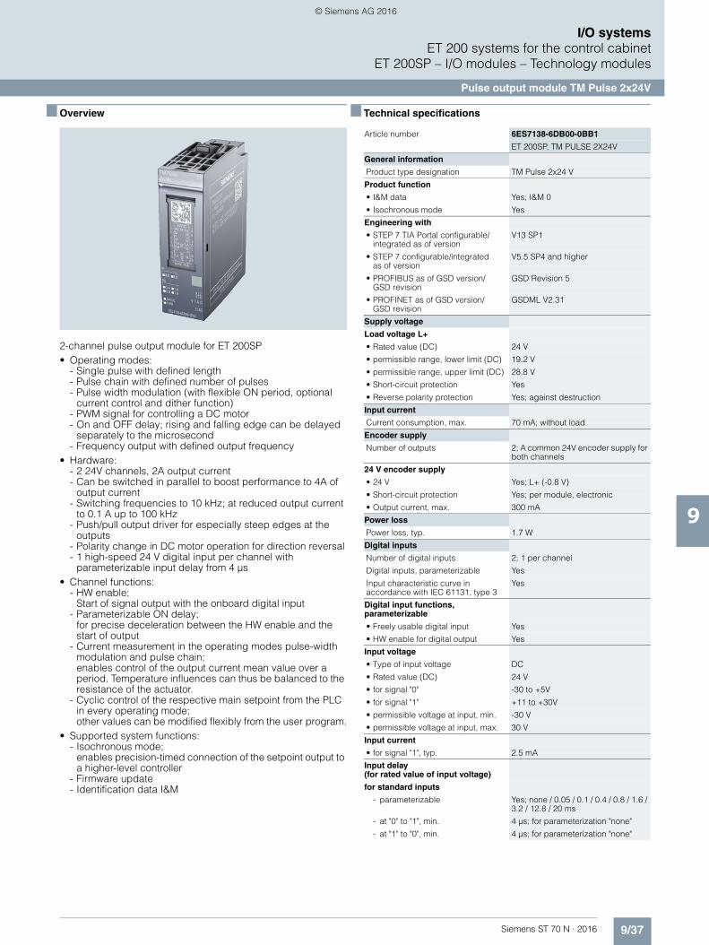
9/37Siemens ST 70 N · 2016
9
I/O systemsET 200 systems for the control cabinet
ET 200SP – I/O modules – Technology modules
Pulse output module TM Pulse 2x24V
■ Overview
2-channel pulse output module for ET 200SP• Operating modes:
- Single pulse with defined length- Pulse chain with defined number of pulses- Pulse width modulation (with flexible ON period, optional
current control and dither function)- PWM signal for controlling a DC motor- On and OFF delay; rising and falling edge can be delayed
separately to the microsecond- Frequency output with defined output frequency
• Hardware:- 2 24V channels, 2A output current - Can be switched in parallel to boost performance to 4A of
output current- Switching frequencies to 10 kHz; at reduced output current
to 0.1 A up to 100 kHz- Push/pull output driver for especially steep edges at the
outputs- Polarity change in DC motor operation for direction reversal- 1 high-speed 24 V digital input per channel with
parameterizable input delay from 4 µs• Channel functions:
- HW enable; Start of signal output with the onboard digital input
- Parameterizable ON delay; for precise deceleration between the HW enable and the start of output
- Current measurement in the operating modes pulse-width modulation and pulse chain; enables control of the output current mean value over a period. Temperature influences can thus be balanced to the resistance of the actuator.
- Cyclic control of the respective main setpoint from the PLC in every operating mode; other values can be modified flexibly from the user program.
• Supported system functions:- Isochronous mode;
enables precision-timed connection of the setpoint output to a higher-level controller
- Firmware update- Identification data I&M
■ Technical specifications
Article number 6ES7138-6DB00-0BB1
ET 200SP, TM PULSE 2X24V
General information
Product type designation TM Pulse 2x24 V
Product function
• I&M data Yes; I&M 0
• Isochronous mode Yes
Engineering with
• STEP 7 TIA Portal configurable/integrated as of version
V13 SP1
• STEP 7 configurable/integratedas of version
V5.5 SP4 and higher
• PROFIBUS as of GSD version/GSD revision
GSD Revision 5
• PROFINET as of GSD version/GSD revision
GSDML V2.31
Supply voltage
Load voltage L+
• Rated value (DC) 24 V
• permissible range, lower limit (DC) 19.2 V
• permissible range, upper limit (DC) 28.8 V
• Short-circuit protection Yes
• Reverse polarity protection Yes; against destruction
Input current
Current consumption, max. 70 mA; without load
Encoder supply
Number of outputs 2; A common 24V encoder supply for both channels
24 V encoder supply
• 24 V Yes; L+ (-0.8 V)
• Short-circuit protection Yes; per module, electronic
• Output current, max. 300 mA
Power loss
Power loss, typ. 1.7 W
Digital inputs
Number of digital inputs 2; 1 per channel
Digital inputs, parameterizable Yes
Input characteristic curve in accordance with IEC 61131, type 3
Yes
Digital input functions, parameterizable
• Freely usable digital input Yes
• HW enable for digital output Yes
Input voltage
• Type of input voltage DC
• Rated value (DC) 24 V
• for signal "0" -30 to +5V
• for signal "1" +11 to +30V
• permissible voltage at input, min. -30 V
• permissible voltage at input, max. 30 V
Input current
• for signal "1", typ. 2.5 mA
Input delay (for rated value of input voltage)
for standard inputs
- parameterizable Yes; none / 0.05 / 0.1 / 0.4 / 0.8 / 1.6 / 3.2 / 12.8 / 20 ms
- at "0" to "1", min. 4 µs; for parameterization "none"
- at "1" to "0", min. 4 µs; for parameterization "none"
© Siemens AG 2016
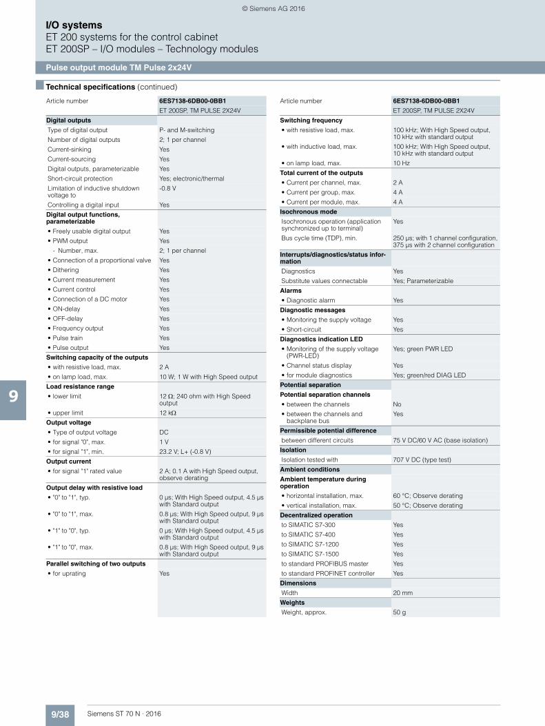
9/38 Siemens ST 70 N · 2016
9
■ Technical specifications (continued)
I/O systemsET 200 systems for the control cabinetET 200SP – I/O modules – Technology modules
Pulse output module TM Pulse 2x24V
Digital outputs
Type of digital output P- and M-switching
Number of digital outputs 2; 1 per channel
Current-sinking Yes
Current-sourcing Yes
Digital outputs, parameterizable Yes
Short-circuit protection Yes; electronic/thermal
Limitation of inductive shutdown voltage to
-0.8 V
Controlling a digital input Yes
Digital output functions,parameterizable
• Freely usable digital output Yes
• PWM output Yes
- Number, max. 2; 1 per channel
• Connection of a proportional valve Yes
• Dithering Yes
• Current measurement Yes
• Current control Yes
• Connection of a DC motor Yes
• ON-delay Yes
• OFF-delay Yes
• Frequency output Yes
• Pulse train Yes
• Pulse output Yes
Switching capacity of the outputs
• with resistive load, max. 2 A
• on lamp load, max. 10 W; 1 W with High Speed output
Load resistance range
• lower limit 12 ; 240 ohm with High Speed output
• upper limit 12 kOutput voltage
• Type of output voltage DC
• for signal "0", max. 1 V
• for signal "1", min. 23.2 V; L+ (-0.8 V)
Output current
• for signal "1" rated value 2 A; 0.1 A with High Speed output, observe derating
Output delay with resistive load
• "0" to "1", typ. 0 µs; With High Speed output, 4.5 µs with Standard output
• "0" to "1", max. 0.8 µs; With High Speed output, 9 µs with Standard output
• "1" to "0", typ. 0 µs; With High Speed output, 4.5 µs with Standard output
• "1" to "0", max. 0.8 µs; With High Speed output, 9 µs with Standard output
Parallel switching of two outputs
• for uprating Yes
Article number 6ES7138-6DB00-0BB1
ET 200SP, TM PULSE 2X24V
Switching frequency
• with resistive load, max. 100 kHz; With High Speed output, 10 kHz with standard output
• with inductive load, max. 100 kHz; With High Speed output,10 kHz with standard output
• on lamp load, max. 10 Hz
Total current of the outputs
• Current per channel, max. 2 A
• Current per group, max. 4 A
• Current per module, max. 4 A
Isochronous mode
Isochronous operation (application synchronized up to terminal)
Yes
Bus cycle time (TDP), min. 250 µs; with 1 channel configuration, 375 µs with 2 channel configuration
Interrupts/diagnostics/status infor-mation
Diagnostics Yes
Substitute values connectable Yes; Parameterizable
Alarms
• Diagnostic alarm Yes
Diagnostic messages
• Monitoring the supply voltage Yes
• Short-circuit Yes
Diagnostics indication LED
• Monitoring of the supply voltage (PWR-LED)
Yes; green PWR LED
• Channel status display Yes
• for module diagnostics Yes; green/red DIAG LED
Potential separation
Potential separation channels
• between the channels No
• between the channels and backplane bus
Yes
Permissible potential difference
between different circuits 75 V DC/60 V AC (base isolation)
Isolation
Isolation tested with 707 V DC (type test)
Ambient conditions
Ambient temperature during operation
• horizontal installation, max. 60 °C; Observe derating
• vertical installation, max. 50 °C; Observe derating
Decentralized operation
to SIMATIC S7-300 Yes
to SIMATIC S7-400 Yes
to SIMATIC S7-1200 Yes
to SIMATIC S7-1500 Yes
to standard PROFIBUS master Yes
to standard PROFINET controller Yes
Dimensions
Width 20 mm
Weights
Weight, approx. 50 g
Article number 6ES7138-6DB00-0BB1
ET 200SP, TM PULSE 2X24V
© Siemens AG 2016

9/39Siemens ST 70 N · 2016
9
I/O systemsET 200 systems for the control cabinet
ET 200SP – I/O modules – Technology modules
Pulse output module TM Pulse 2x24V
■ Ordering data Article No. Article No.
Pulse output module TM Pulse 2x24V
PWM and pulse output, 2 channels of 2 A for proportional valves and DC motors
6ES7138-6DB00-0BB1
Usable BaseUnits
BU20-P12+A0+4B 6ES7193-6BP20-0BB1
BU type B1; BaseUnit (dark); without AUX terminals; for continuing the load group
Accessories
Reference identification label 6ES7193-6LF30-0AW0
10 sheets of 16 labels
Labeling strips
500 labeling strips on roll, light gray, for inscription with thermal transfer roll printer
6ES7193-6LR10-0AA0
500 labeling strips on roll, yellow, for inscription with thermal transfer roll printer
6ES7193-6LR10-0AG0
1000 labeling strips DIN A4, light gray, card, for inscription with laser printer
6ES7193-6LA10-0AA0
1000 labeling strips DIN A4, yellow, card, for inscription with laser printer
6ES7193-6LA10-0AG0
BU cover
for covering empty slots (gaps);5 units• 15 mm wide 6ES7133-6CV15-1AM0• 20 mm wide 6ES7133-6CV20-1AM0
© Siemens AG 2016
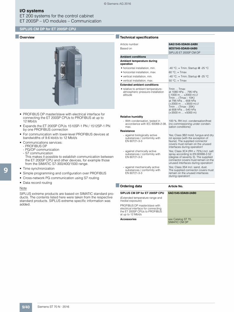
9/40 Siemens ST 70 N · 2016
9
I/O systemsET 200 systems for the control cabinetET 200SP – I/O modules – Communication
SIPLUS CM DP for ET 200SP CPU
■ Overview
• PROFIBUS DP master/slave with electrical interface for connecting the ET 200SP CPUs to PROFIBUS at up to 12 Mbit/s
• Expands the ET 200SP CPUs 1510SP-1 PN / 1512SP-1 PN by one PROFIBUS connection
• For communication with lower-level PROFIBUS devices at bandwidths of 9.6 kbit/s to 12 Mbit/s
• Communications services: - PROFIBUS DP - PG/OP communication - S7 communication
This makes it possible to establish communication between the ET 200SP CPU and other devices, for example those from the SIMATIC S7-300/400/1500 range.
• Time synchronization • Simple programming and configuration over PROFIBUS • Cross-network PG communication using S7 routing • Data record routing
Note
SIPLUS extreme products are based on SIMATIC standard pro-ducts. The contents listed here were taken from the respective standard products. SIPLUS extreme specific information was added.
■ Technical specifications
■ Ordering data Article No.
Article number 6AG1545-5DA00-2AB0
Based on 6ES7545-5DA00-0AB0
SIPLUS ET 200SP CM DP
Ambient conditions
Ambient temperature during operation
• horizontal installation, min. -40 °C; = Tmin; Startup @ -25 °C
• horizontal installation, max. 60 °C; = Tmax
• vertical installation, min. -40 °C; = Tmin; Startup @ -25 °C
• vertical installation, max. 50 °C; = Tmax
Extended ambient conditions
• relative to ambient temperature-atmospheric pressure-installation altitude
Tmin ... Tmax at 1080 hPa ... 795 hPa(-1000 m ... +2000 m) // Tmin ... (Tmax - 10K)at 795 hPa ... 658 hPa (+2000 m ... +3500 m) //Tmin ... (Tmax - 20K) at 658 hPa ... 540 hPa(+3500 m ... +5000 m)
Relative humidity
- With condensation, tested in accordance with IEC 60068-2-38, max.
100 %; RH incl. condensation/frost (no commissioning under conden-sation conditions)
Resistance
- against biologically active substances / conformity with EN 60721-3-3
Yes; Class 3B2 mold, fungus and dry rot spores (with the exception of fauna). The supplied connector covers must remain on the unused interfaces during operation!
- against chemically active substances / conformity with EN 60721-3-3
Yes; Class 3C4 (RH < 75%) incl. salt spray according to EN 60068-2-52 (degree of severity 3). The supplied connector covers must remain on the unused interfaces during operation!
- against mechanically active substances / conformity with EN 60721-3-3
Yes; Class 3S4 incl. sand, dust.The supplied connector covers must remain on the unused interfaces during operation!
SIPLUS CM DP for ET 200SP CPU 6AG1545-5DA00-2AB0
(Extended temperature range and medial exposure)
PROFIBUS DP master/slave with electrical interface for connecting the ET 200SP CPUs to PROFIBUS at up to 12 Mbit/s
Accessories see Catalog ST 70, SIMATIC CM DP
© Siemens AG 2016

9/41Siemens ST 70 N · 2016
9
I/O systemsET 200 systems for the control cabinet
ET 200SP – Fail-safe I/O modules
SIPLUS digital F input modules
■ Overview
Digital fail-safe input module: F-DI 8x24 V DC High Feature for BU type A0, color code CC01
Important features:• 8-channel digital fail-safe input module for the ET 200SP• For fail-safe reading of sensor information (1 or 2 channels) • Provides integral discrepancy evaluation for 2-out-of-2 signals • 8 internal sensor supplies (incl. test function) onboard • Certified up to SIL 3 (IEC 61508), PL e (ISO 13849) • Can be plugged into type A0 BaseUnits (BU) with automatic
coding• LED display for error, operation, supply voltage and status• Clear labeling on front of module
- Plain text identification of the module type and function class - 2D matrix code (order and serial number) - Connection diagram - Color coding of the module type DI: White - Hardware and firmware version - Color code CC for module-specific color coding of the
potentials at the terminals of the BU - Complete article No.
• Optional labeling accessories- Labeling strips - Reference identification label
• Optional module-specific color identification of the terminals according to the color code CC
• Optional system-integrated shield connection• The modules support PROFIsafe, both in PROFIBUS, and in
PROFINET configurations. They can be used with all fail-safe SIMATIC S7 CPUs.
Note:
SIPLUS extreme products are based on SIMATIC standard pro-ducts. The contents listed here were adopted from the respec-tive standard products. SIPLUS extreme specific information was added.
■ Technical specifications
Article number 6AG1136-6BA00-2CA0
Based on 6ES7136-6BA00-0CA0
SIPLUS ET 200SP F-DI 4/8X24VDC HF
Ambient conditions
Ambient temperature during operation
• horizontal installation, min. -25 °C
• horizontal installation, max. 60 °C
• vertical installation, min. -25 °C
• vertical installation, max. 50 °C
Extended ambient conditions
• relative to ambient temperature-atmospheric pressure-installation altitude
Tmin ... Tmax at 1080 hPa ... 795 hPa (-1000 m ... +2000 m)
Relative humidity
- With condensation, tested in accordance with IEC 60068-2-38, max.
100 %; RH incl. condensation/frost (no commissioning under conden-sation conditions)
Resistance
- against biologically active substances / conformity with EN 60721-3-3
Yes; Class 3B2 mold, fungus and dry rot spores (with the exception of fauna). The supplied connector covers must remain on the unused interfaces during operation!
- against chemically active substances / conformity with EN 60721-3-3
Yes; Class 3C4 (RH < 75%) incl. salt spray according to EN 60068-2-52 (degree of severity 3). The supplied connector covers must remain on the unused interfaces during operation!
- against mechanically active substances / conformity with EN 60721-3-3
Yes; Class 3S4 incl. sand, dust. The supplied connector covers must remain on the unused interfaces during operation!
© Siemens AG 2016
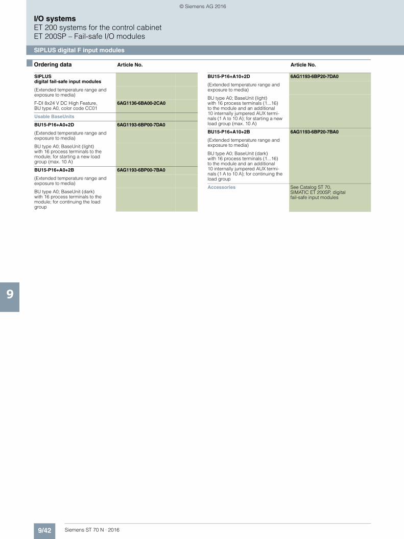
9/42 Siemens ST 70 N · 2016
9
I/O systemsET 200 systems for the control cabinetET 200SP – Fail-safe I/O modules
SIPLUS digital F input modules
■ Ordering data Article No. Article No.
SIPLUS digital fail-safe input modules
(Extended temperature range and exposure to media)
F-DI 8x24 V DC High Feature, BU type A0, color code CC01
6AG1136-6BA00-2CA0
Usable BaseUnits
BU15-P16+A0+2D 6AG1193-6BP00-7DA0
(Extended temperature range and exposure to media)
BU type A0; BaseUnit (light) with 16 process terminals to the module; for starting a new load group (max. 10 A)
BU15-P16+A0+2B 6AG1193-6BP00-7BA0
(Extended temperature range and exposure to media)
BU type A0; BaseUnit (dark)with 16 process terminals to the module; for continuing the load group
BU15-P16+A10+2D 6AG1193-6BP20-7DA0
(Extended temperature range and exposure to media)
BU type A0; BaseUnit (light)with 16 process terminals (1...16) to the module and an additional 10 internally jumpered AUX termi-nals (1 A to 10 A); for starting a new load group (max. 10 A)
BU15-P16+A10+2B 6AG1193-6BP20-7BA0
(Extended temperature range and exposure to media)
BU type A0; BaseUnit (dark) with 16 process terminals (1...16)to the module and an additional 10 internally jumpered AUX termi-nals (1 A to 10 A); for continuing the load group
Accessories See Catalog ST 70, SIMATIC ET 200SP, digital fail-safe input modules
© Siemens AG 2016
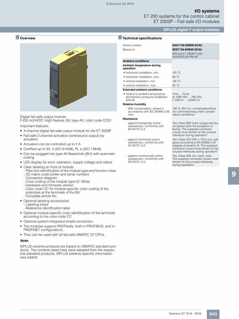
9/43Siemens ST 70 N · 2016
9
I/O systemsET 200 systems for the control cabinet
ET 200SP – Fail-safe I/O modules
SIPLUS digital F output modules
■ Overview
Digital fail-safe output module: F-DQ 4x24VDC High Feature, BU type A0, color code CC01
Important features:• 4-channel digital fail-safe output module for the ET 200SP• Fail-safe 2-channel activation (sink/source output) by
actuators• Actuators can be controlled up to 2 A• Certified up to SIL 3 (IEC 61508), PL e (ISO 13849) • Can be plugged into type A0 BaseUnits (BU) with automatic
coding• LED display for error, operation, supply voltage and status• Clear labeling on front of module
- Plain text identification of the module type and function class - 2D matrix code (order and serial number) - Connection diagram - Color coding of the module type DI: White - Hardware and firmware version - Color code CC for module-specific color coding of the
potentials at the terminals of the BU - Complete article No.
• Optional labeling accessories- Labeling strips - Reference identification label
• Optional module-specific color identification of the terminals according to the color code CC
• Optional system-integrated shield connection• The modules support PROFIsafe, both in PROFIBUS, and in
PROFINET configurations. • They can be used with all fail-safe SIMATIC S7 CPUs.
Note:
SIPLUS extreme products are based on SIMATIC standard pro-ducts. The contents listed here were adopted from the respec-tive standard products. SIPLUS extreme specific information was added.
■ Technical specifications
Article number 6AG1136-6DB00-2CA0
Based on 6ES7136-6DB00-0CA0
SIPLUS ET 200SP F-DQ 4X24VDC/2A PM HF
Ambient conditions
Ambient temperature during operation
• horizontal installation, min. -25 °C
• horizontal installation, max. 60 °C
• vertical installation, min. -25 °C
• vertical installation, max. 50 °C
Extended ambient conditions
• relative to ambient temperature-atmospheric pressure-installation altitude
Tmin ... Tmax at 1080 hPa ... 795 hPa(-1000 m ... +2000 m)
Relative humidity
- With condensation, tested in accordance with IEC 60068-2-38, max.
100 %; RH incl. condensation/frost (no commissioning under conden-sation conditions)
Resistance
- against biologically active substances / conformity with EN 60721-3-3
Yes; Class 3B2 mold, fungus and dry rot spores (with the exception of fauna). The supplied connector covers must remain on the unused interfaces during operation!
- against chemically active substances / conformity with EN 60721-3-3
Yes; Class 3C4 (RH < 75%) incl. salt spray according to EN 60068-2-52 (degree of severity 3). The supplied connector covers must remain on the unused interfaces during operation!
- against mechanically active substances / conformity with EN 60721-3-3
Yes; Class 3S4 incl. sand, dust.The supplied connector covers must remain on the unused interfaces during operation!
© Siemens AG 2016

9/44 Siemens ST 70 N · 2016
9
I/O systemsET 200 systems for the control cabinetET 200SP – Fail-safe I/O modules
SIPLUS digital F output modules
■ Ordering data Article No. Article No.
SIPLUS digital fail-safe output modules
(extended temperature range and exposure to media)
F-DQ 4x24VDC High Feature,BU type A0, color code CC01
6AG1136-6DB00-2CA0
Usable BaseUnits
BU15-P16+A0+2D 6AG1193-6BP00-7DA0
(extended temperature range and exposure to media)
BU type A0; BaseUnit (light)with 16 process terminals to themodule; for starting a new load group (max. 10 A)
BU15-P16+A0+2B 6AG1193-6BP00-7BA0
(extended temperature range and exposure to media)
BU type A0; BaseUnit (dark)with 16 process terminals to the module; for continuing the load group
BU15-P16+A10+2D 6AG1193-6BP20-7DA0
(extended temperature range and exposure to media)
BU type A0; BaseUnit (light) with 16 process terminals (1...16) to the module and an additional10 internally jumpered AUX termi-nals (1 A to 10 A); for starting a new load group (max. 10 A)
BU15-P16+A10+2B 6AG1193-6BP20-7BA0
(extended temperature range and exposure to media)
BU type A0; BaseUnit (dark) with 16 process terminals (1...16)to the module and an additional 10 internally jumpered AUX termi-nals (1 A to 10 A); for continuing the load group
BU20-P12+A4+0B 6AG1193-6BP20-7BB0
(extended temperature range and exposure to media)
BU type B0; BaseUnit (dark) with 12 process terminals (1...12)to the module and an additional4 internally jumpered AUX terminals (1 A to 4 A); for continuing the load group; 1 unit
Accessories see Catalog ST 70, SIMATIC ET 200SP, digital F-output modules
© Siemens AG 2016

9/45Siemens ST 70 N · 2016
9
I/O systemsET 200 systems for the control cabinet
ET 200SP – Fail-safe I/O modules
SIPLUS fail-safe customized modules
■ Overview
Digital fail-safe power module:·F-PM-E PPM 24VDC/8A for BU type C0, color code CC52
Important features:• Certified up to SIL 3 (IEC 61508), PL e (ISO 13849) • Safety-related shutdown of output modules within the potential
group of the F-PM-E• Two fail-safe digital inputs, for reading of sensor information
(1 or 2 channels)• One fail-safe digital output onboard (ppm switching, up to 2 A,
up to SIL 3/PL e)• Fail-safe digital output and potential supply pp or pm
switching can be parameterized• Parameterizable onboard evaluation of the fail-safe inputs for
control of the fail-safe digital outputs and of the potential group• Digital standard output modules can be shut down up to
PL d (ISO 13849) and SIL 2 (IEC61508) (up to 8 A).• Can be plugged into type C0 BaseUnits (BU) with automatic
coding• LED display for error, operation, supply voltage and status• Clear labeling on front of module
- Plain text identification of the module type and function class- 2D matrix code (order and serial number) - Connection diagram - Color coding of the module type DI: White - Hardware and firmware version - Color code CC for module-specific color coding of the
potentials at the terminals of the BU - Complete article No.
• Optional labeling accessories- Labeling strips - Reference identification label
• Optional module-specific color identification of the terminals according to the color code CC
• Optional system-integrated shield connection• The modules support PROFIsafe in both PROFIBUS and
PROFINET configurations. They can be used with all fail-safe SIMATIC S7 CPUs.
Note:
SIPLUS extreme products are based on SIMATIC standard pro-ducts. The contents listed here were adopted from the respec-tive standard products. SIPLUS extreme specific information was added.
■ Technical specifications
■ Ordering data Article No.
Article number 6AG1136-6PA00-2BC0
Based on 6ES7136-6PA00-0BC0
SIPLUS ET 200SP F-PM-E 24VDC/8A PPM
Ambient conditions
Ambient temperature during operation
• horizontal installation, min. -25 °C
• horizontal installation, max. 60 °C
• vertical installation, min. -25 °C
• vertical installation, max. 50 °C
Extended ambient conditions
• relative to ambient temperature-atmospheric pressure-installation altitude
Tmin ... Tmax at 1080 hPa ... 795 hPa (-1000 m ... +2000 m)
Relative humidity
- With condensation, tested in accordance with IEC 60068-2-38, max.
100 %; RH incl. condensation/frost (no commissioning under conden-sation conditions)
Resistance
- against biologically active substances / conformity with EN 60721-3-3
Yes; Class 3B2 mold, fungus and dry rot spores (with the exception of fauna). The supplied connector covers must remain on the unused interfaces during operation!
- against chemically active substances / conformity with EN 60721-3-3
Yes; Class 3C4 (RH < 75%) incl. salt spray according to EN 60068-2-52 (degree of severity 3). The supplied connector covers must remain on the unused interfaces during operation!
- against mechanically active substances / conformity with EN 60721-3-3
Yes; Class 3S4 incl. sand, dust. The supplied connector covers must remain on the unused interfaces during operation!
SIPLUS digital F power module F-PM-E 24VDC/8 A PPMStandard
6AG1136-6PA00-2BC0
(extended temperature range and exposure to media)
BU type C0, color code CC52.2 inputs, 1 output, SIL3/Cat.4/PLe
Type C0 BaseUnits
BU20-P6+A2+4D 6AG1193-6BP20-7DC0
(extended temperature range and exposure to media)
BU type C0; BaseUnit (light) with 6 push-in terminals (1...6) to the module and an additional 2 AUX terminals; new load group
Accessories see Catalog ST 70, SIMATIC ET 200SP,fail-safe special modules
© Siemens AG 2016
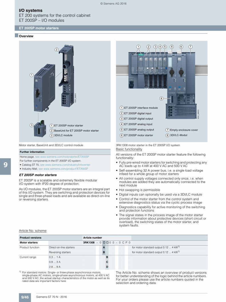
9/46 Siemens ST 70 N · 2016
I/O systemsET 200 systems for the control cabinetET 200SP – I/O modules
ET 200SP motor starters
9
■ Overview
Motor starter, BaseUnit and 3DI/LC control module 3RK1308 motor starter in the ET 200SP I/O system
ET 200SP motor starters
ET 200SP is a scalable and extremely flexible modular I/O system with IP20 degree of protection.
As I/O modules, the ET 200SP motor starters are an integral part of this I/O system. They are switching and protection devices for single and three-phase loads and are available as direct-on-line or reversing starters.
Basic functionality
All versions of the ET 200SP motor starter feature the following functionality:• Fully pre-wired motor starters for switching and protecting any
AC loads up to 4 kW at 400 V AC and 500 V AC• Self-assembling 32 A power bus, i.e. a single load voltage
infeed for a whole group of motor starters• All control supply voltages connected only once, i.e. when
modules are added they are automatically connected to the next module
• Hot swapping is permissible• Digital inputs can optionally be used via a 3DI/LC module• Control of the motor starter from the control system and
extensive diagnostics status via the cyclic process image• Diagnostics capability for active monitoring of the switching
and protection functions• The signal states in the process image of the motor starter
provide information about protective devices (short circuit or overload), the switching states of the motor starter, and system faults.
Article No. scheme
1) For standard motors: Single- or three-phase asynchronous motors, single-phase AC motors, single-phase asynchronous motors, at 400 V AC and 500 V AC; the actual startup characteristics of the motor as well as its rated data are important factors here.
The Article No. scheme shows an overview of product versions for better understanding of the logic behind the article numbers. For your orders please use the article numbers quoted in the selection and ordering data.
2
3
1
2
1
3
ET 200SP motor starter
BaseUnit for ET 200SP motor starter
3DI/LC module
IC01
_006
12
8
1 3 4 65 6 72
7
6 8 3DI/LC-Modul
4
3
5
1
2
Empty enclosure cover
ET 200SP motor starter
ET 200SP digital output
ET 200SP analog input
ET 200SP analog output
ET 200SP interface module
ET 200SP digital input
IC01
_006
13
Further information
Home page, see www.siemens.com/motorstarter/ET200SP
For further components in the ET 200SP I/O system:
• Catalog ST 70, see www.siemens.com/industry/infocenter
• Industry Mall, see www.siemens.com/product?ET200SP
Product versions Article number
Motor starters 3RK1308 – 0 @ @ 0 0 – 0 C P 0
Product function Direct-on-line starters A for motor standard output 0.12 ... 4 kW1)
Reversing starters B for motor standard output 0.12 ... 4 kW1)
Current range 0.3 ... 1 A B
0.9 ... 3 A C
2.8 ... 9 A D
© Siemens AG 2016
9/47Siemens ST 70 N · 2016
I/O systemsET 200 systems for the control cabinet
ET 200SP – I/O modules
ET 200SP motor starters
9
■ Overview (continued)
BaseUnits for motor starters
BaseUnits are components for accommodating the ET 200SP I/O modules. The self-assembling voltage buses integrated into the terminal modules reduce wiring outlay to the single infeed (both of auxiliary and load voltage).
All modules following on the right are automatically supplied upon plugging the BaseUnits together, if BaseUnits are inserted with routing. The rugged design and keyed connection technology enables use in harsh industrial conditions.
The BaseUnits are available with various infeeds for the motor starters.
Article No. scheme
The Article No. scheme shows an overview of product versions for better understanding of the logic behind the article numbers.
For your orders please use the article numbers quoted in the selection and ordering data.
3DI/LC control module
This is a digital input module with three inputs for local motor starter functions such as "manual local control", implementation of fast inputs or "end position disconnection". For a list of all functions permitted by the 3DI/LC module, see Manual "ET 200SP Motor Starters", "Function overview" sectionhttps://support.industry.siemens.com/cs/ww/en/view/109479973.
The module is plugged into the front of the motor starter, from which it receives its 24 V DC operating voltage.
■ Benefits
Product advantages
The ET 200SP motor starters offer a number of advantages:• Fully integrated into the ET 200SP I/O system (including
TIA Selection Tool and TIA Portal)• Simple, integrated current value transmission• Extensive parameterization by means of TIA Portal• Increase of plant availability through fast replacement of units
(easy mounting and plug-in technology)• Greater endurance and reduced heat losses thanks to hybrid
technology• Less space required in the control cabinet (20 to 80 %)
as a result of greater functional density (direct-on-line and reversing starters in same width)
• Extensive diagnostics and information for preventive maintenance
• Parameterizable inputs via 3DI/LC control module
• Less wiring and testing required as a result of integrating several functions into a single device
• Lower costs for stock keeping and configuration as a result of the wide setting range of the electronic overload release (up to 1:3)
• Technology-reduced inherent power loss as speed-controlled drive systems, thereby reducing cooling effort required (and enabling a more compact design)
The ET 200SP motor starters can be used with highly energy-efficient IE3/IE4 motors.
For further information on IE3/IE4, see Catalog IC 10 N, page 5.
Standards and approvals• IEC/EN 60947-4-2• UL 508• CCC approval for China
■ Application
The ET 200SP motor starters are suitable for the following applications:• Switching and monitoring of
- 3-phase motors with overload and short-circuit protection(e.g. 400 V asynchronous motors for secondary drives in conveyor systems)
- 1-phase motors with overload and short-circuit protection(e.g. 250 V motors for pump applications)
- Resistive loads by means of current value and diagnosis via the maintenance function (e.g. for heaters)
• Plant monitoring and energy management in conveyor systemsBy means of the phase asymmetry and zero current detection, for example, it is possible to monitor drive belts and blocking.
• Track switching and lifting table control in conveyor systemsTrack switches can be implemented by means of the quick stop function and lifting table controls by means of the "immediate end position disconnection" function without any laborious programming.
• Safe isolation of drive from main power supplyThe isolating functions in accordance with IEC 60947-1 offer protection against inadvertent activation during plant maintenance.
Product versions Article number
BaseUnit 3RK1908 – 0 A P 0 0 – 0 @ P 0
BU infeed 24 V and 500 V A
500 V B
24 V C
None D
© Siemens AG 2016
9/48 Siemens ST 70 N · 2016
I/O systemsET 200 systems for the control cabinetET 200SP – I/O modules
ET 200SP motor starters
9
■ Technical specifications
ET 200SP motor starters
Further information
Industry Mall, see www.siemens.com/product?3RK1308
Manual, see https://support.industry.siemens.com/cs/ww/en/view/109479973
FAQs, see https://support.industry.siemens.com/cs/products?dtp=Faq&pnid=21800&lc=en-WW
Article number 3RK1308-0.B00-0CP0 3RK1308-0.C00-0CP0 3RK1308-0.D00-0CP0
General technical specifications:
Width x Height x Depth mm 30 × 142 × 150
Design of the switch contact Hybrid
Design of the motor protection Electronic
Installation altitude at height above sea level maximum m 2 000
Mounting position Vertical, horizontal, flat
Type of mounting Can be plugged into BaseUnit
Ambient temperature • During operation °C -25 ... +60• During transport °C -40 ... +70• During storage °C -40 ... +70
Relative humidity during operation % 10 ... 95
Vibration resistance 15 mm up to 6 Hz; 2 g up to 500 Hz
Shock resistance 6 g / 11 ms
IP degree of protection IP20
Type of coordination 1
Electrical data:
Operating frequency Hz 50 ... 60
Ultimate short-circuit current breaking capacity (Icu) • at 400 V rated value kA 55• at 500 V rated value kA 55
Adjustable current response value of the inverse-time delayed overload release
A 0.3 ... 1 0.9 ... 3 2.8 ... 9
Maximum permissible voltage for protective separation • between main and auxiliary circuit V 500• between control and auxiliary circuit V 75
Insulation voltage, rated value V 500
Trip class CLASS 5 and 10 adjustable
W
H
D
© Siemens AG 2016

9/49Siemens ST 70 N · 2016
I/O systemsET 200 systems for the control cabinet
ET 200SP – I/O modules
ET 200SP motor starters
9
■ Technical specifications (continued)
BaseUnits for motor starters
Article number 3RK1908-0AP00-0.P0
General technical specifications:
Width x Height x Depth mm 30 × 217 × 75
Ambient temperature • During operation °C -25 ... +60• During transport °C -40 ... +70• During storage °C -40 ... +70
IP degree of protection IP20
Touch protection against electric shock Finger-safe
Connections / terminals:
Connectable conductor cross-section for main contacts
• Solid or stranded mm² 1 ... 6• Finely stranded with end sleeve mm² 1 ... 6 • Finely stranded without end sleeve mm² 1 ... 6
Connectable conductor cross-section at DC input
• Solid or stranded mm² 0.5 ... 2.5• Finely stranded with end sleeve mm² 0.5 ... 2.5 • Finely stranded without end sleeve mm² 0.5 ... 2.5
AWG number as coded connectable conductor cross-section • For main contacts 24 ... 10• At DC input 20 ... 12
Type of electrical connection for auxiliary and control circuits Spring-type terminals (push-in)
Miscellaneous:
Type of screwdriver tip Slotted
Size of screwdriver tip Standard screwdriver 0.6 mm x 3.5 mm
W
H
D
© Siemens AG 2016
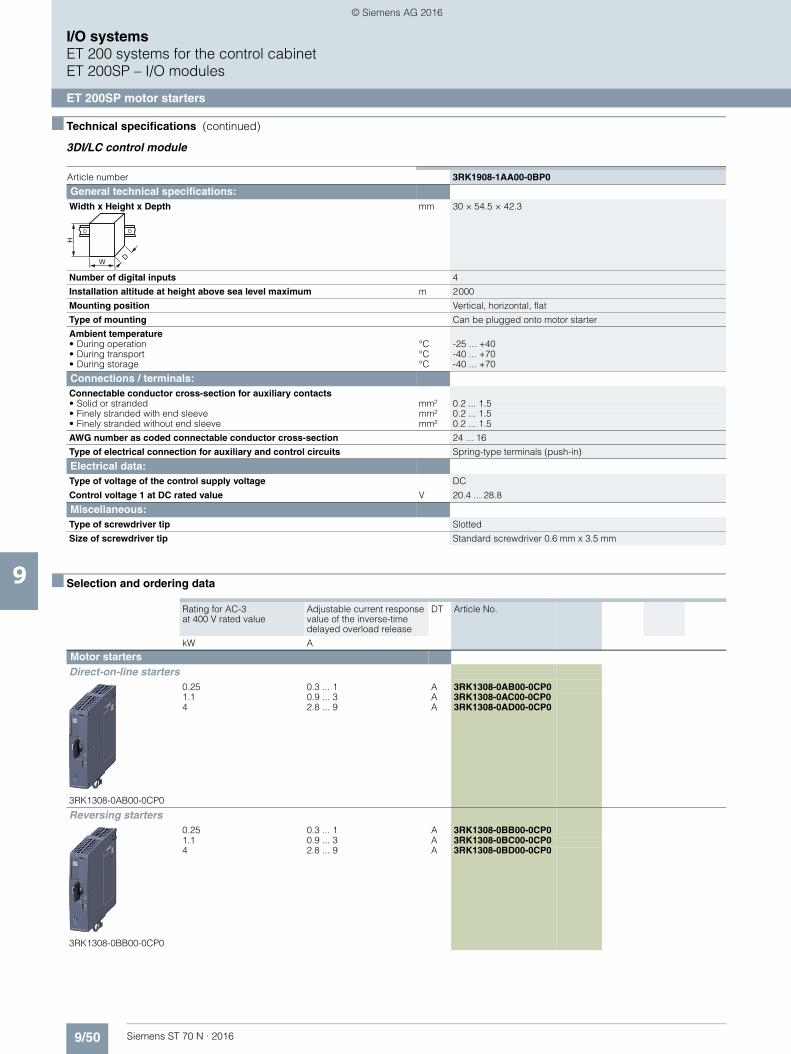
9/50 Siemens ST 70 N · 2016
I/O systemsET 200 systems for the control cabinetET 200SP – I/O modules
ET 200SP motor starters
9
■ Technical specifications (continued)
3DI/LC control module
■ Selection and ordering data
Article number 3RK1908-1AA00-0BP0
General technical specifications:
Width x Height x Depth mm 30 × 54.5 × 42.3
Number of digital inputs 4
Installation altitude at height above sea level maximum m 2 000
Mounting position Vertical, horizontal, flat
Type of mounting Can be plugged onto motor starter
Ambient temperature • During operation °C -25 ... +40• During transport °C -40 ... +70• During storage °C -40 ... +70
Connections / terminals:
Connectable conductor cross-section for auxiliary contacts • Solid or stranded mm² 0.2 ... 1.5• Finely stranded with end sleeve mm² 0.2 ... 1.5• Finely stranded without end sleeve mm² 0.2 ... 1.5
AWG number as coded connectable conductor cross-section 24 ... 16
Type of electrical connection for auxiliary and control circuits Spring-type terminals (push-in)
Electrical data:
Type of voltage of the control supply voltage DC
Control voltage 1 at DC rated value V 20.4 ... 28.8
Miscellaneous:
Type of screwdriver tip Slotted
Size of screwdriver tip Standard screwdriver 0.6 mm x 3.5 mm
Rating for AC-3 at 400 V rated value
Adjustable current response value of the inverse-time delayed overload release
DT Article No.
kW A
Motor starters
Direct-on-line starters
3RK1308-0AB00-0CP0
0.25 0.3 ... 1 A 3RK1308-0AB00-0CP01.1 0.9 ... 3 A 3RK1308-0AC00-0CP04 2.8 ... 9 A 3RK1308-0AD00-0CP0
Reversing starters
3RK1308-0BB00-0CP0
0.25 0.3 ... 1 A 3RK1308-0BB00-0CP01.1 0.9 ... 3 A 3RK1308-0BC00-0CP04 2.8 ... 9 A 3RK1308-0BD00-0CP0
W
H
D
© Siemens AG 2016
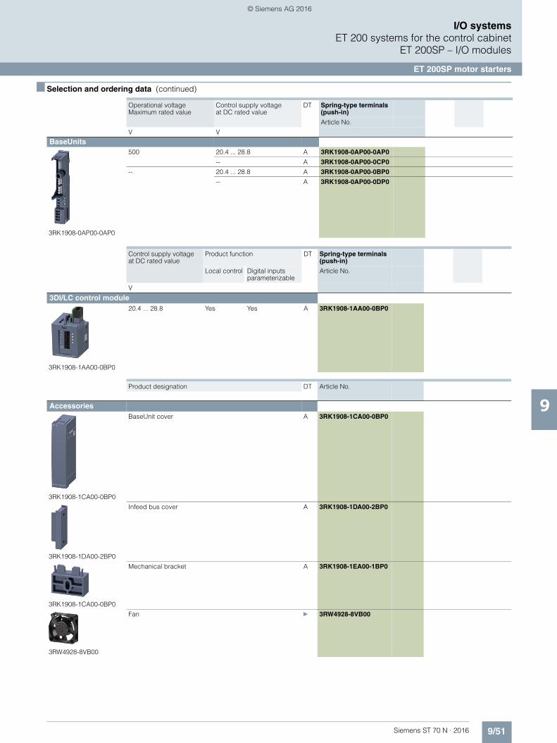
9/51Siemens ST 70 N · 2016
I/O systemsET 200 systems for the control cabinet
ET 200SP – I/O modules
ET 200SP motor starters
9
■ Selection and ordering data (continued)
Operational voltage Maximum rated value
Control supply voltage at DC rated value
DT Spring-type terminals (push-in)
Article No.
V V
BaseUnits
3RK1908-0AP00-0AP0
500 20.4 ... 28.8 A 3RK1908-0AP00-0AP0
-- A 3RK1908-0AP00-0CP0
-- 20.4 ... 28.8 A 3RK1908-0AP00-0BP0
-- A 3RK1908-0AP00-0DP0
Control supply voltage at DC rated value
Product function DT Spring-type terminals (push-in)
Local control Digital inputs parameterizable
Article No.
V
3DI/LC control module
3RK1908-1AA00-0BP0
20.4 ... 28.8 Yes Yes A 3RK1908-1AA00-0BP0
Product designation DT Article No.
Accessories
3RK1908-1CA00-0BP0
BaseUnit cover A 3RK1908-1CA00-0BP0
3RK1908-1DA00-2BP0
Infeed bus cover A 3RK1908-1DA00-2BP0
3RK1908-1CA00-0BP0
Mechanical bracket A 3RK1908-1EA00-1BP0
3RW4928-8VB00
Fan } 3RW4928-8VB00
© Siemens AG 2016
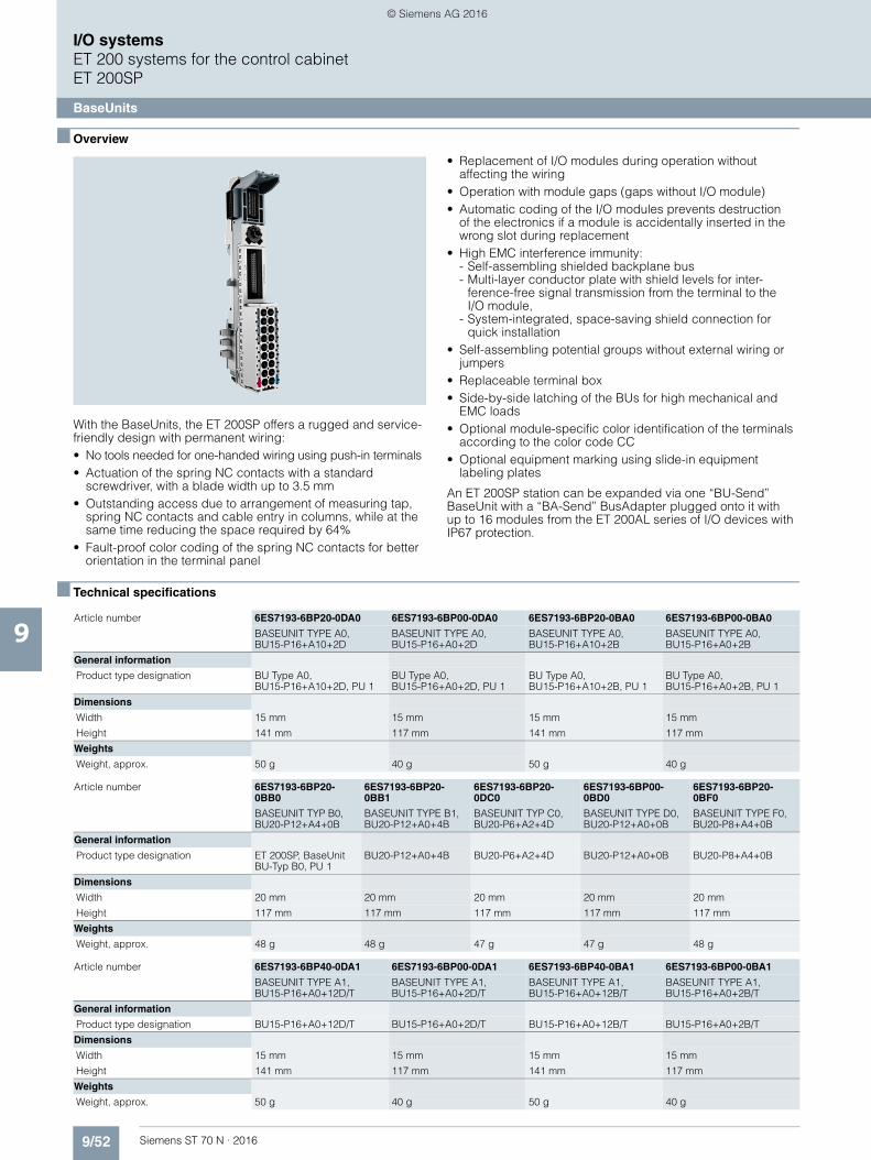
9/52 Siemens ST 70 N · 2016
9
I/O systemsET 200 systems for the control cabinetET 200SP
BaseUnits
■ Overview
With the BaseUnits, the ET 200SP offers a rugged and service-friendly design with permanent wiring:• No tools needed for one-handed wiring using push-in terminals• Actuation of the spring NC contacts with a standard
screwdriver, with a blade width up to 3.5 mm• Outstanding access due to arrangement of measuring tap,
spring NC contacts and cable entry in columns, while at the same time reducing the space required by 64%
• Fault-proof color coding of the spring NC contacts for better orientation in the terminal panel
• Replacement of I/O modules during operation without affecting the wiring
• Operation with module gaps (gaps without I/O module)• Automatic coding of the I/O modules prevents destruction
of the electronics if a module is accidentally inserted in the wrong slot during replacement
• High EMC interference immunity:- Self-assembling shielded backplane bus- Multi-layer conductor plate with shield levels for inter-
ference-free signal transmission from the terminal to theI/O module,
- System-integrated, space-saving shield connection for quick installation
• Self-assembling potential groups without external wiring or jumpers
• Replaceable terminal box• Side-by-side latching of the BUs for high mechanical and
EMC loads• Optional module-specific color identification of the terminals
according to the color code CC• Optional equipment marking using slide-in equipment
labeling plates
An ET 200SP station can be expanded via one “BU-Send” BaseUnit with a “BA-Send” BusAdapter plugged onto it withup to 16 modules from the ET 200AL series of I/O devices with IP67 protection.
■ Technical specifications
Article number 6ES7193-6BP20-0DA0 6ES7193-6BP00-0DA0 6ES7193-6BP20-0BA0 6ES7193-6BP00-0BA0
BASEUNIT TYPE A0, BU15-P16+A10+2D
BASEUNIT TYPE A0, BU15-P16+A0+2D
BASEUNIT TYPE A0, BU15-P16+A10+2B
BASEUNIT TYPE A0, BU15-P16+A0+2B
General information
Product type designation BU Type A0,BU15-P16+A10+2D, PU 1
BU Type A0,BU15-P16+A0+2D, PU 1
BU Type A0, BU15-P16+A10+2B, PU 1
BU Type A0,BU15-P16+A0+2B, PU 1
Dimensions
Width 15 mm 15 mm 15 mm 15 mm
Height 141 mm 117 mm 141 mm 117 mm
Weights
Weight, approx. 50 g 40 g 50 g 40 g
Article number 6ES7193-6BP20-0BB0
6ES7193-6BP20-0BB1
6ES7193-6BP20-0DC0
6ES7193-6BP00-0BD0
6ES7193-6BP20-0BF0
BASEUNIT TYP B0, BU20-P12+A4+0B
BASEUNIT TYPE B1, BU20-P12+A0+4B
BASEUNIT TYP C0, BU20-P6+A2+4D
BASEUNIT TYPE D0, BU20-P12+A0+0B
BASEUNIT TYPE F0, BU20-P8+A4+0B
General information
Product type designation ET 200SP, BaseUnit BU-Typ B0, PU 1
BU20-P12+A0+4B BU20-P6+A2+4D BU20-P12+A0+0B BU20-P8+A4+0B
Dimensions
Width 20 mm 20 mm 20 mm 20 mm 20 mm
Height 117 mm 117 mm 117 mm 117 mm 117 mm
Weights
Weight, approx. 48 g 48 g 47 g 47 g 48 g
Article number 6ES7193-6BP40-0DA1 6ES7193-6BP00-0DA1 6ES7193-6BP40-0BA1 6ES7193-6BP00-0BA1
BASEUNIT TYPE A1, BU15-P16+A0+12D/T
BASEUNIT TYPE A1, BU15-P16+A0+2D/T
BASEUNIT TYPE A1, BU15-P16+A0+12B/T
BASEUNIT TYPE A1, BU15-P16+A0+2B/T
General information
Product type designation BU15-P16+A0+12D/T BU15-P16+A0+2D/T BU15-P16+A0+12B/T BU15-P16+A0+2B/T
Dimensions
Width 15 mm 15 mm 15 mm 15 mm
Height 141 mm 117 mm 141 mm 117 mm
Weights
Weight, approx. 50 g 40 g 50 g 40 g
© Siemens AG 2016

9/53Siemens ST 70 N · 2016
9
■ Technical specifications (continued)
I/O systemsET 200 systems for the control cabinet
ET 200SP
BaseUnits
■ Ordering data Article No. Article No.
Article number 6ES7193-6BN00-0NE0
ET 200SP, BASEUNIT BU-SEND
General information
Product type designation BaseUnit BU-Send
Dimensions
Width 20 mm
Height 117 mm
Weights
Weight, approx. 30 g
Type A0 BaseUnits
BU15-P16+A10+2D
BU type A0; BaseUnit (light) with 16 process terminals (1...16)to the module and an additional 10 internally jumpered AUX termi-nals (1 A to 10 A); for starting a new load group (max. 10 A)• 1 unit 6ES7193-6BP20-0DA0• 10 units 6ES7193-6BP20-2DA0
BU15-P16+A0+2D
BU type A0; BaseUnit (light)with 16 process terminals to the module; for starting a new load group (max. 10 A)• 1 unit 6ES7193-6BP00-0DA0• 10 units 6ES7193-6BP00-2DA0
BU15-P16+A10+2B
BU type A0; BaseUnit (dark)with 16 process terminals (1...16) to the module and an additional 10 internally jumpered AUX termi-nals (1 A to 10 A); for continuing the load group• 1 unit 6ES7193-6BP20-0BA0• 10 units 6ES7193-6BP20-2BA0
BU15-P16+A0+2B
BU type A0; BaseUnit (dark) with 16 process terminals to the module; for continuing the load group• 1 unit 6ES7193-6BP00-0BA0• 10 units 6ES7193-6BP00-2BA0
Type B0 BaseUnits
BU20-P12+A4+0B
BU type B0; BaseUnit (dark) with 12 process terminals (1...12) to the module and an additional 4 internally jumpered AUX terminals (1 A to 4 A); for continuing the load group; 1 unit• 1 unit 6ES7193-6BP20-0BB0• 10 units 6ES7193-6BP20-2BB0
Type B1 BaseUnits
BU20-P12+A0+4B 6ES7193-6BP20-0BB1
BU type B1; BaseUnit (dark)with 12 process terminals to the module; for continuing the load group; 1 unit
Type C0 BaseUnits
BU20-P6+A2+4D 6ES7193-6BP20-0DC0
BU type C0; BaseUnit (light) with 6 push-in terminals (1...6)to the module and an additional2 AUX terminals; new load group
Type D0 BaseUnits
BU20-P12+A0+0B 6ES7193-6BP00-0BD0
BU type D0; BaseUnit (dark) with 12 push-in terminals, without AUX terminals, bridged to the left
Type A1 BaseUnits (with temperature detection)
BU15-P16+A0+12D/T 6ES7193-6BP40-0DA1
BU type A1; BaseUnit (light) with 16 process terminals (1...16)to the module and an additional 2x5 internally jumpered additional terminals (1 B to 5 B and 1 C to5 C); for starting a new load group (max. 10 A)
BU15-P16+A0+2D/T 6ES7193-6BP00-0DA1
BU type A1; BaseUnit (light) with 16 process terminals to the module; for starting a new load group (max. 10 A)
BU15-P16+A0+12B/T 6ES7193-6BP40-0BA1
BU type A1; BaseUnit (dark) with 16 process terminals (1...16) to the module and an additional 2x5 internally jumpered additional terminals (1 B to 5 B and 1 C to5 C); for continuing the load group
BU15-P16+A0+2B/T 6ES7193-6BP00-0BA1
BU type A1; BaseUnit (dark) with 16 process terminals to the module; for continuing the load group
Type F0 BaseUnits
BU20-P8+A4+0B 6ES7193-6BP20-0BF0
BU type F0; BaseUnit (dark) with8 process terminals to the module and an additional 4 internally jum-pered AUX terminals (1 A to 4 A); for continuing the load group
© Siemens AG 2016
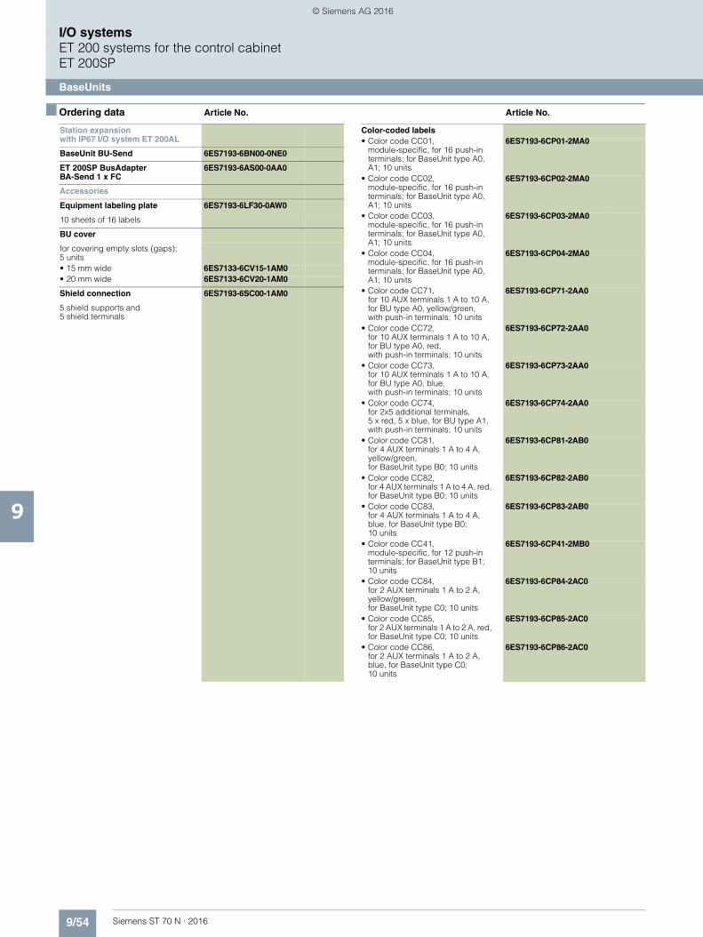
9/54 Siemens ST 70 N · 2016
9
■ Ordering data Article No. Article No.
I/O systemsET 200 systems for the control cabinetET 200SP
BaseUnits
Station expansionwith IP67 I/O system ET 200AL
BaseUnit BU-Send 6ES7193-6BN00-0NE0
ET 200SP BusAdapter BA-Send 1 x FC
6ES7193-6AS00-0AA0
Accessories
Equipment labeling plate 6ES7193-6LF30-0AW0
10 sheets of 16 labels
BU cover
for covering empty slots (gaps); 5 units• 15 mm wide 6ES7133-6CV15-1AM0• 20 mm wide 6ES7133-6CV20-1AM0
Shield connection 6ES7193-6SC00-1AM0
5 shield supports and5 shield terminals
Color-coded labels• Color code CC01,
module-specific, for 16 push-in terminals; for BaseUnit type A0, A1; 10 units
6ES7193-6CP01-2MA0
• Color code CC02, module-specific, for 16 push-in terminals; for BaseUnit type A0, A1; 10 units
6ES7193-6CP02-2MA0
• Color code CC03, module-specific, for 16 push-in terminals; for BaseUnit type A0, A1; 10 units
6ES7193-6CP03-2MA0
• Color code CC04, module-specific, for 16 push-in terminals; for BaseUnit type A0, A1; 10 units
6ES7193-6CP04-2MA0
• Color code CC71, for 10 AUX terminals 1 A to 10 A, for BU type A0, yellow/green,with push-in terminals; 10 units
6ES7193-6CP71-2AA0
• Color code CC72, for 10 AUX terminals 1 A to 10 A, for BU type A0, red,with push-in terminals; 10 units
6ES7193-6CP72-2AA0
• Color code CC73, for 10 AUX terminals 1 A to 10 A, for BU type A0, blue,with push-in terminals; 10 units
6ES7193-6CP73-2AA0
• Color code CC74, for 2x5 additional terminals, 5 x red, 5 x blue, for BU type A1, with push-in terminals; 10 units
6ES7193-6CP74-2AA0
• Color code CC81,for 4 AUX terminals 1 A to 4 A,yellow/green, for BaseUnit type B0; 10 units
6ES7193-6CP81-2AB0
• Color code CC82, for 4 AUX terminals 1 A to 4 A, red, for BaseUnit type B0; 10 units
6ES7193-6CP82-2AB0
• Color code CC83, for 4 AUX terminals 1 A to 4 A, blue, for BaseUnit type B0; 10 units
6ES7193-6CP83-2AB0
• Color code CC41, module-specific, for 12 push-in terminals; for BaseUnit type B1;10 units
6ES7193-6CP41-2MB0
• Color code CC84,for 2 AUX terminals 1 A to 2 A, yellow/green,for BaseUnit type C0; 10 units
6ES7193-6CP84-2AC0
• Color code CC85,for 2 AUX terminals 1 A to 2 A, red, for BaseUnit type C0; 10 units
6ES7193-6CP85-2AC0
• Color code CC86, for 2 AUX terminals 1 A to 2 A, blue, for BaseUnit type C0; 10 units
6ES7193-6CP86-2AC0
© Siemens AG 2016
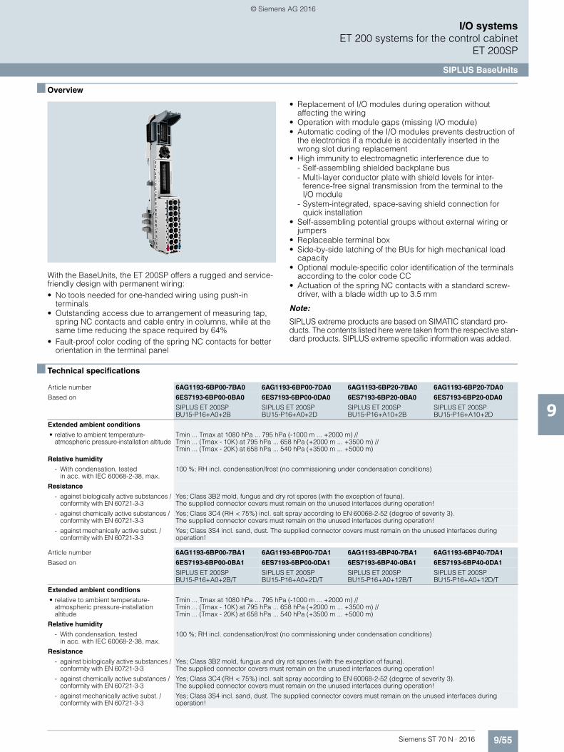
9/55Siemens ST 70 N · 2016
9
I/O systemsET 200 systems for the control cabinet
ET 200SP
SIPLUS BaseUnits
■ Overview
With the BaseUnits, the ET 200SP offers a rugged and service-friendly design with permanent wiring:• No tools needed for one-handed wiring using push-in
terminals• Outstanding access due to arrangement of measuring tap,
spring NC contacts and cable entry in columns, while at the same time reducing the space required by 64%
• Fault-proof color coding of the spring NC contacts for better orientation in the terminal panel
• Replacement of I/O modules during operation without affecting the wiring
• Operation with module gaps (missing I/O module)• Automatic coding of the I/O modules prevents destruction of
the electronics if a module is accidentally inserted in the wrong slot during replacement
• High immunity to electromagnetic interference due to- Self-assembling shielded backplane bus- Multi-layer conductor plate with shield levels for inter-
ference-free signal transmission from the terminal to theI/O module
- System-integrated, space-saving shield connection for quick installation
• Self-assembling potential groups without external wiring or jumpers
• Replaceable terminal box• Side-by-side latching of the BUs for high mechanical load
capacity• Optional module-specific color identification of the terminals
according to the color code CC• Actuation of the spring NC contacts with a standard screw-
driver, with a blade width up to 3.5 mm
Note:
SIPLUS extreme products are based on SIMATIC standard pro-ducts. The contents listed here were taken from the respective stan-dard products. SIPLUS extreme specific information was added.
■ Technical specifications
Article number 6AG1193-6BP00-7BA0 6AG1193-6BP00-7DA0 6AG1193-6BP20-7BA0 6AG1193-6BP20-7DA0
Based on 6ES7193-6BP00-0BA0 6ES7193-6BP00-0DA0 6ES7193-6BP20-0BA0 6ES7193-6BP20-0DA0
SIPLUS ET 200SPBU15-P16+A0+2B
SIPLUS ET 200SP BU15-P16+A0+2D
SIPLUS ET 200SP BU15-P16+A10+2B
SIPLUS ET 200SP BU15-P16+A10+2D
Extended ambient conditions
• relative to ambient temperature-atmospheric pressure-installation altitude
Tmin ... Tmax at 1080 hPa ... 795 hPa (-1000 m ... +2000 m) // Tmin ... (Tmax - 10K) at 795 hPa ... 658 hPa (+2000 m ... +3500 m) // Tmin ... (Tmax - 20K) at 658 hPa ... 540 hPa (+3500 m ... +5000 m)
Relative humidity
- With condensation, testedin acc. with IEC 60068-2-38, max.
100 %; RH incl. condensation/frost (no commissioning under condensation conditions)
Resistance
- against biologically active substances / conformity with EN 60721-3-3
Yes; Class 3B2 mold, fungus and dry rot spores (with the exception of fauna). The supplied connector covers must remain on the unused interfaces during operation!
- against chemically active substances / conformity with EN 60721-3-3
Yes; Class 3C4 (RH < 75%) incl. salt spray according to EN 60068-2-52 (degree of severity 3). The supplied connector covers must remain on the unused interfaces during operation!
- against mechanically active subst. / conformity with EN 60721-3-3
Yes; Class 3S4 incl. sand, dust. The supplied connector covers must remain on the unused interfaces during operation!
Article number 6AG1193-6BP00-7BA1 6AG1193-6BP00-7DA1 6AG1193-6BP40-7BA1 6AG1193-6BP40-7DA1
Based on 6ES7193-6BP00-0BA1 6ES7193-6BP00-0DA1 6ES7193-6BP40-0BA1 6ES7193-6BP40-0DA1
SIPLUS ET 200SPBU15-P16+A0+2B/T
SIPLUS ET 200SP BU15-P16+A0+2D/T
SIPLUS ET 200SP BU15-P16+A0+12B/T
SIPLUS ET 200SP BU15-P16+A0+12D/T
Extended ambient conditions
• relative to ambient temperature-atmospheric pressure-installation altitude
Tmin ... Tmax at 1080 hPa ... 795 hPa (-1000 m ... +2000 m) // Tmin ... (Tmax - 10K) at 795 hPa ... 658 hPa (+2000 m ... +3500 m) //Tmin ... (Tmax - 20K) at 658 hPa ... 540 hPa (+3500 m ... +5000 m)
Relative humidity
- With condensation, testedin acc. with IEC 60068-2-38, max.
100 %; RH incl. condensation/frost (no commissioning under condensation conditions)
Resistance
- against biologically active substances / conformity with EN 60721-3-3
Yes; Class 3B2 mold, fungus and dry rot spores (with the exception of fauna). The supplied connector covers must remain on the unused interfaces during operation!
- against chemically active substances / conformity with EN 60721-3-3
Yes; Class 3C4 (RH < 75%) incl. salt spray according to EN 60068-2-52 (degree of severity 3).The supplied connector covers must remain on the unused interfaces during operation!
- against mechanically active subst. / conformity with EN 60721-3-3
Yes; Class 3S4 incl. sand, dust. The supplied connector covers must remain on the unused interfaces during operation!
© Siemens AG 2016

9/56 Siemens ST 70 N · 2016
9
■ Technical specifications (continued)
I/O systemsET 200 systems for the control cabinetET 200SP
SIPLUS BaseUnits
■ Ordering data Article No. Article No.
Article number 6AG1193-6BP20-7BB0 6AG1193-6BP20-7DC0 6AG1193-6BP00-7BD0
Based on 6ES7193-6BP20-0BB0 6ES7193-6BP20-0DC0 6ES7193-6BP00-0BD0
SIPLUS ET 200SP BU20-P12+A4+0B SIPLUS ET 200SP BU20-P6+A2+4D SIPLUS ET 200SP BU20-P12+A0+0B
Ambient conditions
Ambient temperature during operation
• horizontal installation, min. -40 °C; = Tmin -25 °C; = Tmin -40 °C; = Tmin
• horizontal installation, max. 70 °C; = Tmax 60 °C; = Tmax 70 °C; = Tmax
• vertical installation, min. -40 °C -25 °C -40 °C
• vertical installation, max. 50 °C 50 °C 50 °C
Extended ambient conditions
• relative to ambient temperature-atmospheric pressure-installation altitude
Tmin ... Tmax at 1080 hPa ... 795 hPa(-1000 m ... +2000 m) // Tmin ... (Tmax - 10K) at 795 hPa ... 658 hPa(+2000 m ... +3500 m) //Tmin ... (Tmax - 20K) at 658 hPa ... 540 hPa(+3500 m ... +5000 m)
Tmin ... Tmax at1080 hPa ... 795 hPa(-1000 m ... +2000 m)
Tmin ... Tmax at 1080 hPa ... 795 hPa (-1000 m ... +2000 m) // Tmin ... (Tmax - 10K) at 795 hPa ... 658 hPa (+2000 m ... +3500 m) // Tmin ... (Tmax - 20K) at 658 hPa ... 540 hPa (+3500 m ... +5000 m)
Relative humidity
- With condensation, tested in accordance with IEC 60068-2-38, max.
100 %; RH incl. condensation/frost (no commissioning under condensation conditions)
Resistance
- against biologically active substances / conformity with EN 60721-3-3
Yes; Class 3B2 mold, fungus and dry rot spores (with the exception of fauna).The supplied connector covers must remain on the unused interfaces during operation!
- against chemically active substances / conformity with EN 60721-3-3
Yes; Class 3C4 (RH < 75%) incl. salt spray according to EN 60068-2-52 (degree of severity 3). The supplied connector covers must remain on the unused interfaces during operation!
- against mechanically active substances / conformity with EN 60721-3-3
Yes; Class 3S4 incl. sand, dust. The supplied connector covers must remain on the unused interfaces during operation!
SIPLUS BaseUnits type A0
BU15-P16+A0+2D 6AG1193-6BP00-7DA0
(Extended temperature range and medial exposure)
BU type A0; BaseUnit (light)with 16 process terminals to the module, for starting a new load group (max. 10 A)
BU15-P16+A0+2B 6AG1193-6BP00-7BA0
(Extended temperature range and medial exposure)
BU type A0; BaseUnit (dark) with 16 process terminals to the module; for continuing the load group
BU15-P16+A10+2D 6AG1193-6BP20-7DA0
(Extended temperature range and medial exposure)
BU type A0; BaseUnit (light) with 16 process terminals (1...16)to the module and an additional 10 internally jumpered AUX termi-nals (1A to 10A); for starting a new load group (max. 10 A)
BU15-P16+A10+2B 6AG1193-6BP20-7BA0
(Extended temperature range and medial exposure)
BU type A0; BaseUnit (dark) with 16 process terminals (1...16)to the module and an additional 10 internally jumpered AUX termi-nals (1A to 10A); for continuing the load group
SIPLUS BaseUnits type A1(with temperature detection)
BU15-P16+A0+2D/T 6AG1193-6BP00-7DA1
(Extended temperature range and medial exposure)
BU type A1; BaseUnit (light) with 16 process terminals to the module, for starting a new load group (max. 10 A)
BU15-P16+A0+2B/T 6AG1193-6BP00-7BA1
(Extended temperature range and medial exposure)
BU type A1; BaseUnit (dark) with16 process terminals to the module; for continuing the load group
BU15-P16+A0+12D/T 6AG1193-6BP40-7DA1
(Extended temperature range and medial exposure)
BU type A1; BaseUnit (light) with 16 process terminals (1...16) to the module and an additional 2x5 inter-nally jumpered AUX terminals(1 B to 5 B and 1 C to 5 C); for start-ing a new load group (max. 10 A)
BU15-P16+A0+12B/T 6AG1193-6BP40-7BA1
(Extended temperature range and medial exposure)
BU type A1; BaseUnit (dark) with 16 process terminals (1...16) to the module and an additional 2x5 inter-nally jumpered AUX terminals (1 B to 5 B and 1 C to 5 C); for continuing the load group
© Siemens AG 2016

9/57Siemens ST 70 N · 2016
9
■ Ordering data Article No. Article No.
I/O systemsET 200 systems for the control cabinet
ET 200SP
SIPLUS BaseUnits
SIPLUS BaseUnits type B0
BU20-P12+A4+0B 6AG1193-6BP20-7BB0
(Extended temperature range and exposure to media)
BU type B0; BaseUnit (dark) with12 process terminals (1...12) to the module and an additional 4 inter-nally jumpered AUX terminals(1 A to 4 A); for continuing the load group; 1 unit
SIPLUS BaseUnits type C0 6AG1193-6BP20-7DC0
BU20-P6+A2+4D
(Extended temperature range and exposure to media)
BU type C0; BaseUnit (light) with6 push-in terminals (1...6) to the module and an additional 2 AUX terminals; new load group
SIPLUS BaseUnits type D0
BU20-P12+A0+0B 6AG1193-6BP00-7BD0
(Extended temperature range and exposure to media)
BU type D0; BaseUnit (dark) with 12 push-in terminals, without AUX terminals, bridged to the left
Accessories see SIMATIC ET 200SP BaseUnits, page 9/54
© Siemens AG 2016
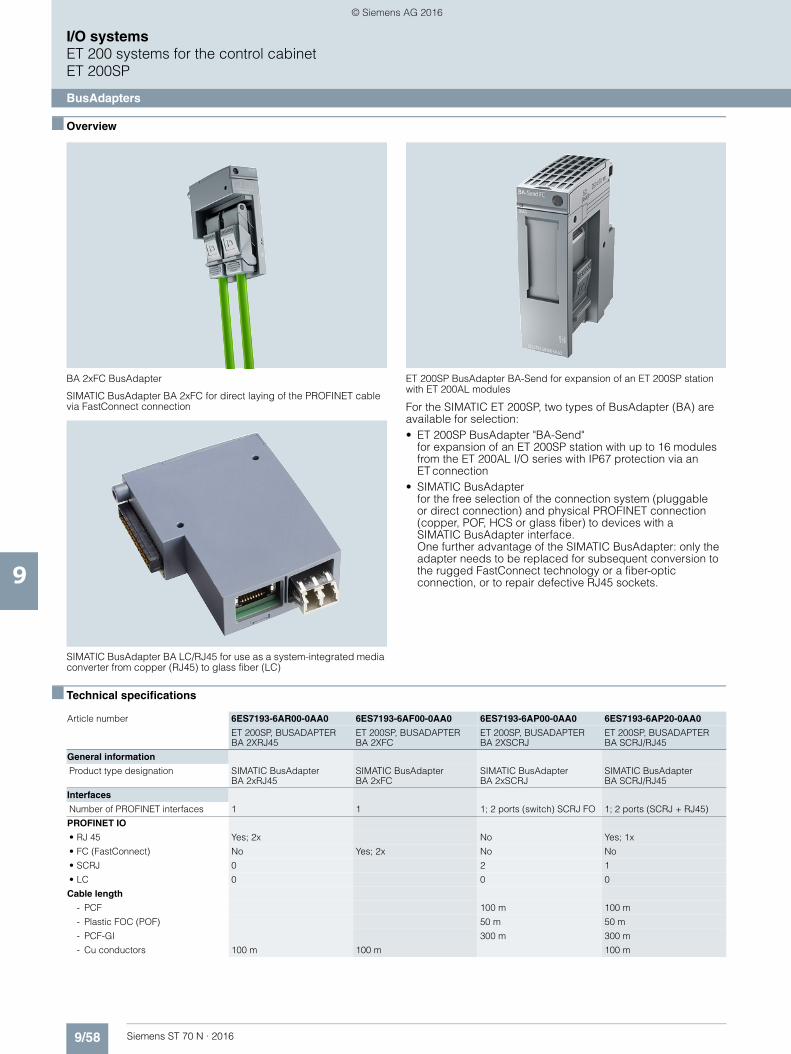
9/58 Siemens ST 70 N · 2016
9
I/O systemsET 200 systems for the control cabinetET 200SP
BusAdapters
■ Overview
BA 2xFC BusAdapter
SIMATIC BusAdapter BA 2xFC for direct laying of the PROFINET cable via FastConnect connection
SIMATIC BusAdapter BA LC/RJ45 for use as a system-integrated media converter from copper (RJ45) to glass fiber (LC)
ET 200SP BusAdapter BA-Send for expansion of an ET 200SP station with ET 200AL modules
For the SIMATIC ET 200SP, two types of BusAdapter (BA) are available for selection:• ET 200SP BusAdapter "BA-Send"
for expansion of an ET 200SP station with up to 16 modules from the ET 200AL I/O series with IP67 protection via an ET connection
• SIMATIC BusAdapterfor the free selection of the connection system (pluggable or direct connection) and physical PROFINET connection (copper, POF, HCS or glass fiber) to devices with a SIMATIC BusAdapter interface. One further advantage of the SIMATIC BusAdapter: only the adapter needs to be replaced for subsequent conversion to the rugged FastConnect technology or a fiber-optic connection, or to repair defective RJ45 sockets.
■ Technical specifications
Article number 6ES7193-6AR00-0AA0 6ES7193-6AF00-0AA0 6ES7193-6AP00-0AA0 6ES7193-6AP20-0AA0
ET 200SP, BUSADAPTERBA 2XRJ45
ET 200SP, BUSADAPTER BA 2XFC
ET 200SP, BUSADAPTER BA 2XSCRJ
ET 200SP, BUSADAPTER BA SCRJ/RJ45
General information
Product type designation SIMATIC BusAdapterBA 2xRJ45
SIMATIC BusAdapterBA 2xFC
SIMATIC BusAdapterBA 2xSCRJ
SIMATIC BusAdapter BA SCRJ/RJ45
Interfaces
Number of PROFINET interfaces 1 1 1; 2 ports (switch) SCRJ FO 1; 2 ports (SCRJ + RJ45)
PROFINET IO
• RJ 45 Yes; 2x No Yes; 1x
• FC (FastConnect) No Yes; 2x No No
• SCRJ 0 2 1
• LC 0 0 0
Cable length
- PCF 100 m 100 m
- Plastic FOC (POF) 50 m 50 m
- PCF-GI 300 m 300 m
- Cu conductors 100 m 100 m 100 m
© Siemens AG 2016
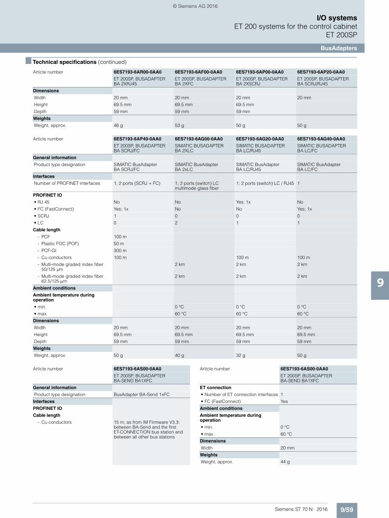
9/59Siemens ST 70 N · 2016
9
■ Technical specifications (continued)
I/O systemsET 200 systems for the control cabinet
ET 200SP
BusAdapters
Dimensions
Width 20 mm 20 mm 20 mm 20 mm
Height 69.5 mm 69.5 mm 69.5 mm
Depth 59 mm 59 mm 59 mm
Weights
Weight, approx. 46 g 53 g 50 g 50 g
Article number 6ES7193-6AP40-0AA0 6ES7193-6AG00-0AA0 6ES7193-6AG20-0AA0 6ES7193-6AG40-0AA0
ET 200SP, BUSADAPTER BA SCRJ/FC
SIMATIC BUSADAPTER BA 2XLC
SIMATIC BUSADAPTER BA LC/RJ45
SIMATIC BUSADAPTERBA LC/FC
General information
Product type designation SIMATIC BusAdapterBA SCRJ/FC
SIMATIC BusAdapter BA 2xLC
SIMATIC BusAdapter BA LC/RJ45
SIMATIC BusAdapter BA LC/FC
Interfaces
Number of PROFINET interfaces 1; 2 ports (SCRJ + FC) 1; 2 ports (switch) LC multimode glass fiber
1; 2 ports (switch) LC / RJ45 1
PROFINET IO
• RJ 45 No No Yes; 1x No
• FC (FastConnect) Yes; 1x No No Yes; 1x
• SCRJ 1 0 0 0
• LC 0 2 1 1
Cable length
- PCF 100 m
- Plastic FOC (POF) 50 m
- PCF-GI 300 m
- Cu conductors 100 m 100 m 100 m
- Multi-mode graded index fiber50/125 µm
2 km 2 km 2 km
- Multi-mode graded index fiber 62.5/125 m
2 km 2 km 2 km
Ambient conditions
Ambient temperature during operation
• min. 0 °C 0 °C 0 °C
• max. 60 °C 60 °C 60 °C
Dimensions
Width 20 mm 20 mm 20 mm 20 mm
Height 69.5 mm 69.5 mm 69.5 mm 69.5 mm
Depth 59 mm 59 mm 59 mm 59 mm
Weights
Weight, approx. 50 g 40 g 32 g 50 g
Article number 6ES7193-6AR00-0AA0 6ES7193-6AF00-0AA0 6ES7193-6AP00-0AA0 6ES7193-6AP20-0AA0
ET 200SP, BUSADAPTERBA 2XRJ45
ET 200SP, BUSADAPTER BA 2XFC
ET 200SP, BUSADAPTER BA 2XSCRJ
ET 200SP, BUSADAPTER BA SCRJ/RJ45
Article number 6ES7193-6AS00-0AA0
ET 200SP, BUSADAPTER BA-SEND BA1XFC
General information
Product type designation BusAdapter BA-Send 1xFC
Interfaces
PROFINET IO
Cable length
- Cu conductors 15 m; as from IM Firmware V3.3: between BA-Send and the first ET-CONNECTION bus station and between all other bus stations
ET connection
• Number of ET connection interfaces 1
• FC (FastConnect) Yes
Ambient conditions
Ambient temperature during operation
• min. 0 °C
• max. 60 °C
Dimensions
Width 20 mm
Weights
Weight, approx. 44 g
Article number 6ES7193-6AS00-0AA0
ET 200SP, BUSADAPTER BA-SEND BA1XFC
© Siemens AG 2016
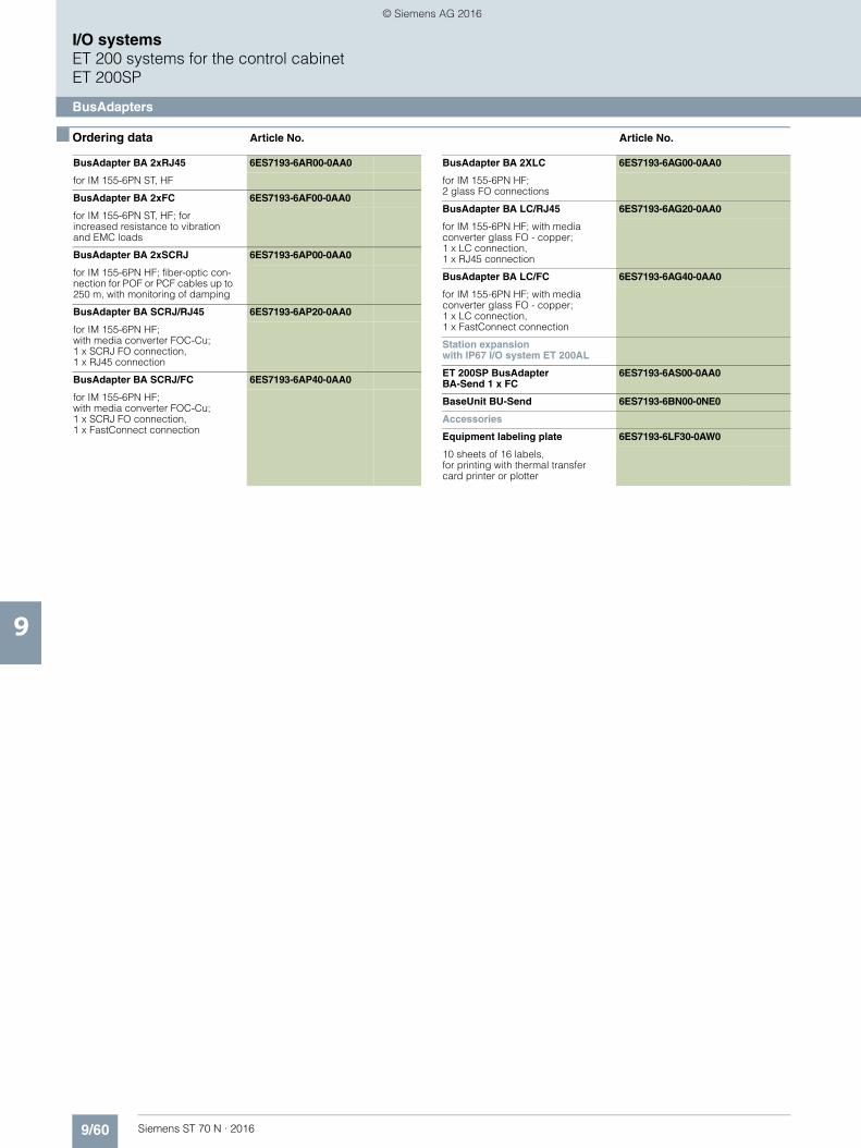
9/60 Siemens ST 70 N · 2016
9
I/O systemsET 200 systems for the control cabinetET 200SP
BusAdapters
■ Ordering data Article No. Article No.
BusAdapter BA 2xRJ45 6ES7193-6AR00-0AA0
for IM 155-6PN ST, HF
BusAdapter BA 2xFC 6ES7193-6AF00-0AA0
for IM 155-6PN ST, HF; for increased resistance to vibration and EMC loads
BusAdapter BA 2xSCRJ 6ES7193-6AP00-0AA0
for IM 155-6PN HF; fiber-optic con-nection for POF or PCF cables up to 250 m, with monitoring of damping
BusAdapter BA SCRJ/RJ45 6ES7193-6AP20-0AA0
for IM 155-6PN HF;with media converter FOC-Cu; 1 x SCRJ FO connection, 1 x RJ45 connection
BusAdapter BA SCRJ/FC 6ES7193-6AP40-0AA0
for IM 155-6PN HF; with media converter FOC-Cu; 1 x SCRJ FO connection, 1 x FastConnect connection
BusAdapter BA 2XLC 6ES7193-6AG00-0AA0
for IM 155-6PN HF; 2 glass FO connections
BusAdapter BA LC/RJ45 6ES7193-6AG20-0AA0
for IM 155-6PN HF; with mediaconverter glass FO - copper; 1 x LC connection, 1 x RJ45 connection
BusAdapter BA LC/FC 6ES7193-6AG40-0AA0
for IM 155-6PN HF; with media converter glass FO - copper; 1 x LC connection, 1 x FastConnect connection
Station expansionwith IP67 I/O system ET 200AL
ET 200SP BusAdapter BA-Send 1 x FC
6ES7193-6AS00-0AA0
BaseUnit BU-Send 6ES7193-6BN00-0NE0
Accessories
Equipment labeling plate 6ES7193-6LF30-0AW0
10 sheets of 16 labels,for printing with thermal transfer card printer or plotter
© Siemens AG 2016

9/61Siemens ST 70 N · 2016
9
I/O systemsET 200 systems for the control cabinet
ET 200SP
SIPLUS BusAdapter
■ Overview
ET 200SP BusAdapter (RJ45)
BusAdapter BA 2xFC
Some interface modules of the SIPLUS ET 200SP have a universal PROFINET interface for BusAdapters. With the appro-priate bus adapter, the type of connection can be adapted to the requirements of the respective application:• For standard applications with a moderate mechanical and
EMC load, the BusAdapter BA 2xRJ45 is used. It offers two sockets for standard RJ45 plugs.
• For machines and systems in which higher mechanical and/or EMC loads act on the devices, the BusAdapter BA 2xFC is recommended. In this case, the bus cables are connected directly by means of FastConnect terminals – similar to the PROFIBUS connector, proven in millions of applications.The technology is extremely quick to assemble and achieves 5 times better vibration resistance and also 5 times greater resistance to electromagnetic interference, when compared to RJ45 plug-in connectors.
• BusAdapters with connections for fiber-optic cables can be used to cover high potential differences between two stations and/or high EMC loads.
Another advantage of the BusAdapters: In order to repair defec-tive RJ45 sockets or for subsequent conversion to the rugged FastConnect technology or a fiber-optic connection, only the adapter needs to be replaced.
The following interface modules offer a PROFINET connection via BusAdapter:• SIPLUS IM 155-6PN Standard• SIPLUS IM 155-6PN High Feature
Note
SIPLUS extreme products are based on SIMATIC standard pro-ducts. The contents listed here were taken from the respective standard products. SIPLUS extreme specific information was added.
© Siemens AG 2016

9/62 Siemens ST 70 N · 2016
9
I/O systemsET 200 systems for the control cabinetET 200SP
SIPLUS BusAdapter
■ Technical specifications
■ Ordering data Article No. Article No.
Article number 6AG1193-6AR00-7AA0 6AG1193-6AF00-7AA0 6AG1193-6AP00-2AA0
Based on 6ES7193-6AR00-0AA0 6ES7193-6AF00-0AA0 6ES7193-6AP00-0AA0
SIPLUS ET 200SP BA 2XRJ45 SIPLUS ET 200SP BA 2XFC PN SIPLUS ET 200SP BA 2XSCRJ PN
Ambient conditions
Ambient temperature during operation
• min. -40 °C; = Tmin; Startup @ -25 °C -40 °C; = Tmin; Startup @ -25 °C -40 °C; = Tmin; Startup @ -25 °C
• max. 70 °C; = Tmax 70 °C; = Tmax 60 °C; = Tmax
Extended ambient conditions
• relative to ambient temperature-atmospheric pressure-installation altitude
Tmin ... Tmax at 1080 hPa ... 795 hPa (-1000 m ... +2000 m) // Tmin ... (Tmax - 10K) at 795 hPa ... 658 hPa (+2000 m ... +3500 m) // Tmin ... (Tmax - 20K) at 658 hPa ... 540 hPa (+3500 m ... +5000 m)
Relative humidity
- With condensation, tested in accordance with IEC 60068-2-38, max.
100 %; RH incl. condensation/frost (no commissioning under condensation conditions)
Resistance
- against biologically active substances / conformity with EN 60721-3-3
Yes; Class 3B2 mold, fungus and dry rot spores (with the exception of fauna). The supplied connector covers must remain on the unused interfaces during operation!
- against chemically active substances / conformity with EN 60721-3-3
Yes; Class 3C4 (RH < 75%) incl. salt spray according to EN 60068-2-52 (degree of severity 3). The supplied connector covers must remain on the unused interfaces during operation!
- against mechanically active substances / conformity with EN 60721-3-3
Yes; Class 3S4 incl. sand, dust. The supplied connector covers must remain on the unused interfaces during operation!
SIPLUS BA 2xRJ45 BusAdapter 6AG1193-6AR00-7AA0
(Extended temperature range and medial exposure)
For IM 155-6PN ST, HF
SIPLUS BA 2xFC BusAdapter 6AG1193-6AF00-7AA0
(Extended temperature range and medial exposure)
For IM 155-6PN ST, HF;for increased resistance tovibration and EMC loads
SIPLUS BA 2xSCRJ BusAdapter 6AG1193-6AP00-2AA0
(Extended temperature range and medial exposure)
For IM 155-6PN HF; fiber-optic con-nection for POF or PCF cables up to 250 m, with monitoring of damping
Reference identification label 6ES7193-6LF30-0AW0
10 sheets of 16 labels,for printing with thermal transfer card printer or plotter
© Siemens AG 2016

9/63Siemens ST 70 N · 2016
9
I/O systemsET 200SP
Accessories – Color-coded labels
■ Overview
The I/O modules that are plugged onto the BaseUnits determine the potentials connected at the process terminals.
The +/- potentials can optionally be identified using module-specific color-coded labels. The potentials of the AUX and add-on terminals can also be marked using color-coded labels.
Advantages of the color-coded labels: • Quick installation (one label for marking 16 terminals) • Printed terminal numbers • Avoidance of wiring errors • Simple detection of potentials during servicing
■ Ordering data Article No. Article No.
Module-specific color-coded labels
(pack containing 10 labels)
Color code CC00, for 16 process terminals, for BU type A0, A1, gray (terminals 1 to 8), red (terminals 9 to 16)
6ES7193-6CP00-2MA0
Color code CC01, for 16 process terminals, for BU type A0, A1, gray (terminals 1 to 8), red (terminals 9 to 16)
6ES7193-6CP01-2MA0
Color code CC02, for 16 process terminals, for BU type A0, A1, gray (terminals 1 to 8), blue (terminals 9 to 16)
6ES7193-6CP02-2MA0
Color code CC03, for 16 push-in terminals, for BU type A0, A1gray (terminals 1 to 8), red (terminals 9 to 12), gray (terminals 13 to 16)
6ES7193-6CP03-2MA0
Color code CC04, for 16 push-in terminals, BU type A0, A1, gray (terminals 1 to 8), red (terminals 9 to 12), blue (terminals 13 to 16)
6ES7193-6CP04-2MA0
Color code CC05, for 16 push-in terminals, for BU type A0, A1, gray (terminals 1 to 12), red (terminals 13 to 14),blue (terminals 15 to 16)
6ES7193-6CP05-2MA0
Color code CC41, for 16 push-in terminals; for BU type B1, gray (terminals 1 to 4), red (terminals 5 to 8), blue (terminals 9 to 12)
6ES7193-6CP41-2MB0
Color code CC42, for 12 push-in terminals, BU type F0, gray (terminals 1 to 8), red (terminals 9 to 10), blue (terminals 11 to 12)
6ES7193-6CP42-2MB0
Color code CC51, for 6 process terminals, for BU type C0, C1, gray (terminals 1 to 4), red (terminal 5), blue (terminal 6)
6ES7193-6CP51-2MC0
Color code CC51, for 6 process terminals, for BU type C0, gray (terminals 1, 2 and 5),red (terminals 3 and 4), blue (terminal 6)
6ES7193-6CP52-2MC0
Color-coded labelsfor additional terminals
(pack containing 10 labels)
Color code CC71,for 10 AUX terminals, BU type A0, yellow/green (terminals 1 A to 10 A)
6ES7193-6CP71-2AA0
Color code CC72, for 10 AUX terminals, BU type A0, red (terminals 1 A to 10 A)
6ES7193-6CP72-2AA0
Color code CC73,for 10 AUX terminals, BU type A0, blue (terminals 1 A to 10 A)
6ES7193-6CP73-2AA0
Color code CC74,for 2x5 additional terminals,BU type A1, red (terminals 1B to 5B), blue (terminals 1C to 5C)
6ES7193-6CP74-2AA0
Color code CC81, for 4 AUX terminals, BU type B0, yellow/green (terminals 1 A to 4 A)
6ES7193-6CP81-2AB0
Color code CC82, for 4 AUX terminals, BU type B0, red (terminals 1 A to 4 A)
6ES7193-6CP82-2AB0
Color code CC83,for 4 AUX terminals, BU type B0, blue (terminals 1 A to 4 A)
6ES7193-6CP83-2AB0
Color code CC84,for 2 AUX terminals 1 A to 2 A, yellow/green,for BaseUnit type C0, C1
6ES7193-6CP84-2AC0
Color code CC85, for 2 AUX terminals 1 A to 2 A, red, for BaseUnit type C0, C1
6ES7193-6CP85-2AC0
Color code CC86,for 2 AUX terminals 1 A to 2 A, blue, for BaseUnit type C0, C1
6ES7193-6CP86-2AC0
© Siemens AG 2016
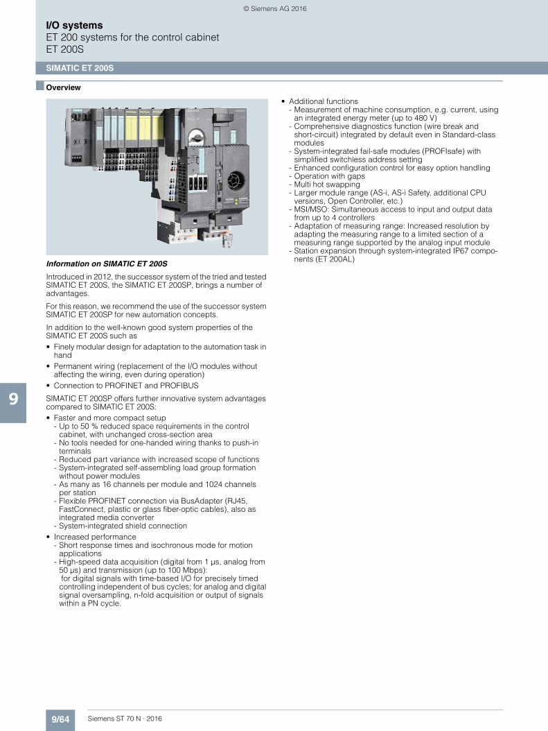
9/64 Siemens ST 70 N · 2016
9
I/O systemsET 200 systems for the control cabinetET 200S
SIMATIC ET 200S
■ Overview
Information on SIMATIC ET 200S
Introduced in 2012, the successor system of the tried and tested SIMATIC ET 200S, the SIMATIC ET 200SP, brings a number of advantages.
For this reason, we recommend the use of the successor system SIMATIC ET 200SP for new automation concepts.
In addition to the well-known good system properties of the SIMATIC ET 200S such as• Finely modular design for adaptation to the automation task in
hand• Permanent wiring (replacement of the I/O modules without
affecting the wiring, even during operation)• Connection to PROFINET and PROFIBUS
SIMATIC ET 200SP offers further innovative system advantages compared to SIMATIC ET 200S:• Faster and more compact setup
- Up to 50 % reduced space requirements in the control cabinet, with unchanged cross-section area
- No tools needed for one-handed wiring thanks to push-in terminals
- Reduced part variance with increased scope of functions- System-integrated self-assembling load group formation
without power modules- As many as 16 channels per module and 1024 channels
per station- Flexible PROFINET connection via BusAdapter (RJ45,
FastConnect, plastic or glass fiber-optic cables), also as integrated media converter
- System-integrated shield connection• Increased performance
- Short response times and isochronous mode for motion applications
- High-speed data acquisition (digital from 1 µs, analog from 50 µs) and transmission (up to 100 Mbps): for digital signals with time-based I/O for precisely timed controlling independent of bus cycles; for analog and digital signal oversampling, n-fold acquisition or output of signals within a PN cycle.
• Additional functions- Measurement of machine consumption, e.g. current, using
an integrated energy meter (up to 480 V)- Comprehensive diagnostics function (wire break and
short-circuit) integrated by default even in Standard-class modules
- System-integrated fail-safe modules (PROFIsafe) with simplified switchless address setting
- Enhanced configuration control for easy option handling- Operation with gaps- Multi hot swapping- Larger module range (AS-i, AS-i Safety, additional CPU
versions, Open Controller, etc.)- MSI/MSO: Simultaneous access to input and output data
from up to 4 controllers- Adaptation of measuring range: Increased resolution by
adapting the measuring range to a limited section of a measuring range supported by the analog input module
- Station expansion through system-integrated IP67 compo-nents (ET 200AL)
© Siemens AG 2016
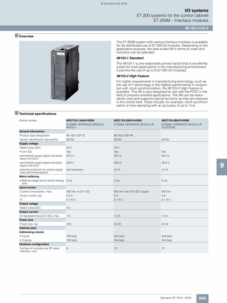
9/65Siemens ST 70 N · 2016
9
I/O systemsET 200 systems for the control cabinet
ET 200M – Interface modules
IM 153-1/153-2
■ Overview
The ET 200M system with various interface modules is available for the distributed use of S7-300 I/O modules. Depending on the application purpose, the best suited IM in terms of costs and functions can be selected:
IM153-1 Standard
The IM153-1 is one reasonably priced variant that is excellently suited for most applications in the manufacturing environment.It permits the use of up to 8 S7-300 I/O modules.
IM153-2 High Feature
For higher requirements in manufacturing technology, such as the use of F-technology or the highest performance in conjunc-tion with clock synchronization, the IM153-2 High Feature is available. This IM is also designed for use with the PCS7 in the field of process-oriented applications. This IM can be redun-dantly used and supports typical functions as they are required in the control field. These include, for example, clock synchroni-zation or time stamping with an accuracy of up to 1ms.
■ Technical specifications
Article number 6ES7153-1AA03-0XB0 6ES7153-2BA10-0XB0 6ES7153-2BA70-0XB0
ET200M, INTERFACE MODULEIM153-1
ET200M, INTERFACE IM153-2 HF ET200M, INTERFACE IM153-2 HF OUTDOOR
General information
Product type designation IM 153-1 DP ST IM 153-2 DP HF
Vendor identification (VendorID) 801Dh 801Eh 801Eh
Supply voltage
Rated value (DC) 24 V 24 V
• 24 V DC Yes Yes Yes
permissible range (ripple included), lower limit (DC)
20.4 V 20.4 V 20.4 V
permissible range (ripple included), upper limit (DC)
28.8 V 28.8 V 28.8 V
external protection for power supply lines (recommendation)
not necessary 2.5 A 2.5 A
Mains buffering
• Mains/voltage failure stored energy time
5 ms 5 ms 5 ms
Input current
Current consumption, max. 350 mA; at 24 V DC 650 mA; with 24 V DC supply 650 mA
Inrush current, typ. 2.5 A 3 A 3 A
I²t 0.1 A²·s 0.1 A²·s 0.1 A²·s
Output voltage
Rated value (DC) 5 V
Output current
for backplane bus (5 V DC), max. 1 A 1.5 A 1.5 A
Power loss
Power loss, typ. 3 W 5.5 W 5.5 W
Address area
Addressing volume
• Inputs 128 byte 244 byte 244 byte
• Outputs 128 byte 244 byte 244 byte
Hardware configuration
Number of modules per DP slave interface, max.
8 12 12
© Siemens AG 2016
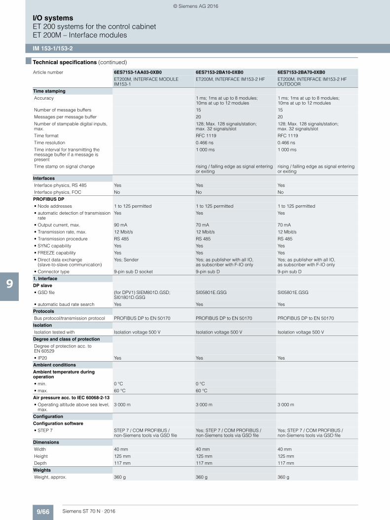
9/66 Siemens ST 70 N · 2016
9
■ Technical specifications (continued)
I/O systemsET 200 systems for the control cabinetET 200M – Interface modules
IM 153-1/153-2
Time stamping
Accuracy 1 ms; 1ms at up to 8 modules;10ms at up to 12 modules
1 ms; 1ms at up to 8 modules; 10ms at up to 12 modules
Number of message buffers 15 15
Messages per message buffer 20 20
Number of stampable digital inputs, max.
128; Max. 128 signals/station; max. 32 signals/slot
128; Max. 128 signals/station; max. 32 signals/slot
Time format RFC 1119 RFC 1119
Time resolution 0.466 ns 0.466 ns
Time interval for transmitting the message buffer if a message is present
1 000 ms 1 000 ms
Time stamp on signal change rising / falling edge as signal entering or exiting
rising / falling edge as signal entering or exiting
Interfaces
Interface physics, RS 485 Yes Yes Yes
Interface physics, FOC No No No
PROFIBUS DP
• Node addresses 1 to 125 permitted 1 to 125 permitted 1 to 125 permitted
• automatic detection of transmission rate
Yes Yes Yes
• Output current, max. 90 mA 70 mA 70 mA
• Transmission rate, max. 12 Mbit/s 12 Mbit/s 12 Mbit/s
• Transmission procedure RS 485 RS 485 RS 485
• SYNC capability Yes Yes Yes
• FREEZE capability Yes Yes Yes
• Direct data exchange(slave-to-slave communication)
Yes; Sender Yes; as publisher with all IO, as subscriber with F-IO only
Yes; as publisher with all IO, as subscriber with F-IO only
• Connector type 9-pin sub D socket 9-pin sub D 9-pin sub D
1. Interface
DP slave
• GSD file (for DPV1) SIEM801D.GSD; SI01801D.GSG
SI05801E.GSG SI05801E.GSG
• automatic baud rate search Yes Yes Yes
Protocols
Bus protocol/transmission protocol PROFIBUS DP to EN 50170 PROFIBUS DP to EN 50170 PROFIBUS DP to EN 50170
Isolation
Isolation tested with Isolation voltage 500 V Isolation voltage 500 V Isolation voltage 500 V
Degree and class of protection
Degree of protection acc. to EN 60529
• IP20 Yes Yes Yes
Ambient conditions
Ambient temperature during operation
• min. 0 °C 0 °C
• max. 60 °C 60 °C
Air pressure acc. to IEC 60068-2-13
• Operating altitude above sea level, max.
3 000 m 3 000 m 3 000 m
Configuration
Configuration software
• STEP 7 STEP 7 / COM PROFIBUS / non-Siemens tools via GSD file
Yes; STEP 7 / COM PROFIBUS / non-Siemens tools via GSD file
Yes; STEP 7 / COM PROFIBUS / non-Siemens tools via GSD file
Dimensions
Width 40 mm 40 mm 40 mm
Height 125 mm 125 mm 125 mm
Depth 117 mm 117 mm 117 mm
Weights
Weight, approx. 360 g 360 g 360 g
Article number 6ES7153-1AA03-0XB0 6ES7153-2BA10-0XB0 6ES7153-2BA70-0XB0
ET200M, INTERFACE MODULEIM153-1
ET200M, INTERFACE IM153-2 HF ET200M, INTERFACE IM153-2 HF OUTDOOR
© Siemens AG 2016

9/67Siemens ST 70 N · 2016
9
■ Technical specifications (continued)
I/O systemsET 200 systems for the control cabinet
ET 200M – Interface modules
IM 153-1/153-2
■ Ordering data Article No. Article No.
Article number 6ES7195-7HD10-0XA0 6ES7195-7HA00-0XA0 6ES7195-7HB00-0XA0 6ES7195-7HC00-0XA0
ET200M, BUS MODULEF. 2 IM 153-2 RED.
ET200M, BUS MODULE F. PS AND IM 153
ET200M, BUS MODULE F. 2 40MM I/O MODULES
ET200M, BUS MODULE F. 1 80MM I/O MODULE
Accessories
belongs to product ET 200M ET 200M ET 200M ET 200M
Dimensions
Width 97 mm 97 mm 97 mm 97 mm
Height 92 mm 92 mm 92 mm 92 mm
Depth 30 mm 30 mm 30 mm 30 mm
Weights
Weight, approx. 133 g 111 g 140 g 127 g
IM 153-1 interface module
Slave interface for connecting an ET 200M to PROFIBUS DP• Standard temperature range 6ES7153-1AA03-0XB0
IM 153-2 interface module
Slave interface for connecting an ET 200M to PROFIBUS DP; also for use in redundant systems• High Feature 6ES7153-2BA10-0XB0• High Feature with extended
temperature range6ES7153-2BA70-0XB0
Active IM 153/IM 153 bus module 6ES7195-7HD10-0XA0
For two IM 153-2 High Feature modules for designing redundant systems
Bus module for ET 200M• For accommodating a power
supply and an IM 153 module for the hot-swapping function during RUN, incl. bus module cover
6ES7195-7HA00-0XA0
• To accommodate two 40-mm wide I/O modules for the hot-swapping function
6ES7195-7HB00-0XA0
• To accommodate one 80-mm wide I/O module for the hot-swapping function
6ES7195-7HC00-0XA0
ET 200M redundancy bundle 6ES7153-2AR04-0XA0
Comprising two IM 153-2 High Feature modules and one IM 153/IM 153 bus module
Accessories
PROFIBUS bus connector
90° outgoing cable, terminating resistor with disconnecting function, up to 12 Mbps, FastConnect
Without PG interface• 1 unit 6ES7972-0BA52-0XA0• 100 units 6ES7972-0BA52-0XB0
With PG interface• 1 unit 6ES7972-0BB52-0XA0• 100 units 6ES7972-0BB52-0XB0
SIMATIC DP DIN rail for ET 200M
Accommodates up to 5 bus modules;for hot-swapping function • Length: 483 mm (19“) 6ES7195-1GA00-0XA0• Length: 530 mm 6ES7195-1GF30-0XA0• Length: 620 mm 6ES7195-1GG30-0XA0• Length: 2000 mm 6ES7195-1GC00-0XA0
SIMATIC S7-300 DIN rail• Length: 160 mm 6ES7390-1AB60-0AA0• Length: 480 mm (19“) 6ES7390-1AE80-0AA0• Length: 530 mm 6ES7390-1AF30-0AA0• Length: 830 mm 6ES7390-1AJ30-0AA0• Length: 2000 mm 6ES7390-1BC00-0AA0
S7 Manual Collection 6ES7998-8XC01-8YE0
Electronic manuals on DVD, multi-language:LOGO!, SIMADYN, SIMATIC bus components, SIMATIC C7, SIMATIC distributed I/O, SIMATIC HMI, SIMATIC Sensors, SIMATIC NET, SIMATIC PC-Based Automation, SIMATIC PCS 7, SIMATIC PG/PC, SIMATIC S7, SIMATIC Software, SIMATIC TDC
S7 Manual Collection, update service for 1 year
6ES7998-8XC01-8YE2
Scope of delivery: Current DVD "S7 Manual Collection" and the three subsequent updates
© Siemens AG 2016

9/68 Siemens ST 70 N · 2016
9
I/O systemsET 200 systems for the control cabinetET 200M – Interface modules
SIPLUS IM 153-1/153-2
■ Overview
Note:
SIPLUS extreme products are based on SIMATIC standard pro-ducts. The contents listed here were taken from the respective standard products. SIPLUS extreme specific information was added.
For technical documentation on SIPLUS, see:
http://www.siemens.com/siplus-extreme
■ Technical specifications
Article number 6AG1153-1AA03-2XB0 6AG1153-2BA02-2XY0 6AG1153-2BA10-7XB0
Based on 6ES7153-1AA03-0XB0 6ES7153-2BA02-0XB0 6ES7153-2BA10-0XB0
SIPLUS IM153-1 SIPLUS ET200M IM153-2 EN50155 SIPLUS ET200M IM153-2 HF
Ambient conditions
Ambient temperature during operation
• min. -40 °C; = Tmin -25 °C; = Tmin -40 °C; = Tmin; Startup @ -25 °C
• max. 70 °C; = Tmax; 60 °C @ UL/cUL, ATEX and FM use
60 °C; = Tmax; the rated temperature range of -25 ... +55 °C (T1) applies for the use on railway vehicles according to EN50155
70 °C; = Tmax
Ambient temperature during storage/transportation
• min. -40 °C -40 °C
• max. 70 °C 70 °C
Extended ambient conditions
• relative to ambient temperature-atmospheric pressure-installation altitude
Tmin ... Tmax at 1080 hPa ... 795 hPa (-1000 m ... +2000 m) //Tmin ... (Tmax - 10K) at 795 hPa ... 658 hPa (+2000 m ... +3500 m) //Tmin ... (Tmax - 20K) at658 hPa ... 540 hPa(+3500 m ... +5000 m)
Tmin ... Tmax at 1080 hPa ... 795 hPa (-1000 m ... +2000 m) // Tmin ... (Tmax - 10K) at795 hPa ... 658 hPa (+2000 m ... +3500 m) //Tmin ... (Tmax - 20K) at 658 hPa ... 540 hPa (+3500 m ... +5000 m)
Tmin ... Tmax at 1080 hPa ... 795 hPa(-1000 m ... +2000 m) //Tmin ... (Tmax - 10K) at795 hPa ... 658 hPa (+2000 m ... +3500 m) // Tmin ... (Tmax - 20K) at 658 hPa ... 540 hPa(+3500 m ... +5000 m)
• At cold restart, min. -25 °C -25 °C
Relative humidity
- With condensation, tested in accordance with IEC 60068-2-38, max.
100 %; RH incl. condensation/frost (no commissioning under conden-sation conditions)
100 %; RH incl. condensation/frost (no commissioning under conden-sation conditions)
100 %; RH incl. condensation/frost(no commissioning under conden-sation conditions)
Resistance
- against biologically active substances / conformity with EN 60721-3-3
Yes; Class 3B2 mold, fungus and dry rot spores (with the exception of fauna). The supplied connector covers must remain on the unused interfaces during operation!
Yes; Class 3B2 mold, fungus and dry rot spores (with the exception of fauna). The supplied connector covers must remain on the unused interfaces during operation!
Yes; Class 3B2 mold, fungus and dry rot spores (with the exception of fauna). The supplied connector covers must remain on the unused interfaces during operation!
- against chemically active substances / conformity with EN 60721-3-3
Yes; Class 3C4 incl. salt spray according to EN 60068-2-52 (degree of severity 3). The supplied connector covers must remain on the unused interfaces during operation!
Yes; Class 3C4 (RH < 75%) incl. salt spray according to EN 60068-2-52 (degree of severity 3). The supplied connector covers must remain on the unused interfaces during operation!
Yes; Class 3C4 (RH < 75%) incl. salt spray according to EN 60068-2-52 (degree of severity 3). The supplied connector covers must remain on the unused interfaces during operation!
- against mechanically active substances / conformity with EN 60721-3-3
Yes; Class 3S4 incl. sand, dust.The supplied connector covers must remain on the unused interfaces during operation!
Yes; Class 3S4 incl. sand, dust. The supplied connector covers must remain on the unused interfaces during operation!
Yes; Class 3S4 incl. sand, dust. The supplied connector covers must remain on the unused interfaces during operation!
© Siemens AG 2016
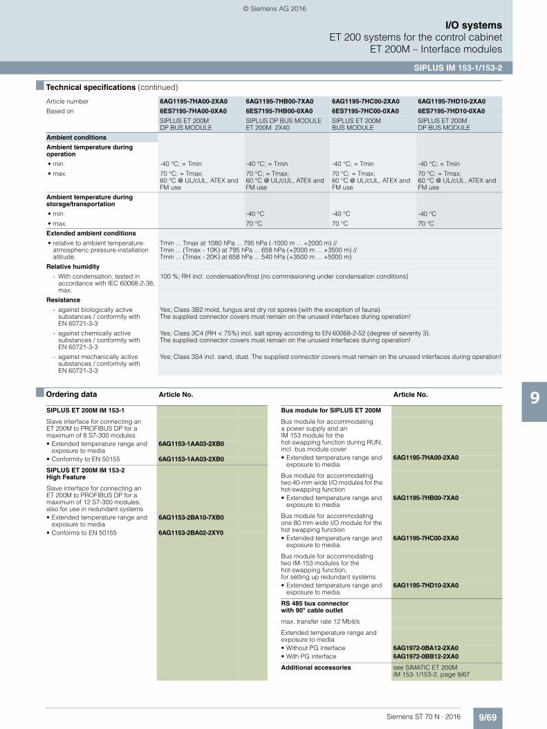
9/69Siemens ST 70 N · 2016
9
■ Technical specifications (continued)
I/O systemsET 200 systems for the control cabinet
ET 200M – Interface modules
SIPLUS IM 153-1/153-2
■ Ordering data Article No. Article No.
Article number 6AG1195-7HA00-2XA0 6AG1195-7HB00-7XA0 6AG1195-7HC00-2XA0 6AG1195-7HD10-2XA0
Based on 6ES7195-7HA00-0XA0 6ES7195-7HB00-0XA0 6ES7195-7HC00-0XA0 6ES7195-7HD10-0XA0
SIPLUS ET 200M DP BUS MODULE
SIPLUS DP BUS MODULE ET 200M 2X40
SIPLUS ET 200M BUS MODULE
SIPLUS ET 200M DP BUS MODULE
Ambient conditions
Ambient temperature during operation
• min. -40 °C; = Tmin -40 °C; = Tmin -40 °C; = Tmin -40 °C; = Tmin
• max. 70 °C; = Tmax; 60 °C @ UL/cUL, ATEX and FM use
70 °C; = Tmax; 60 °C @ UL/cUL, ATEX and FM use
70 °C; = Tmax;60 °C @ UL/cUL, ATEX and FM use
70 °C; = Tmax; 60 °C @ UL/cUL, ATEX and FM use
Ambient temperature during storage/transportation
• min. -40 °C -40 °C -40 °C
• max. 70 °C 70 °C 70 °C
Extended ambient conditions
• relative to ambient temperature-atmospheric pressure-installation altitude
Tmin ... Tmax at 1080 hPa ... 795 hPa (-1000 m ... +2000 m) //Tmin ... (Tmax - 10K) at 795 hPa ... 658 hPa (+2000 m ... +3500 m) //Tmin ... (Tmax - 20K) at 658 hPa ... 540 hPa (+3500 m ... +5000 m)
Relative humidity
- With condensation, tested in accordance with IEC 60068-2-38, max.
100 %; RH incl. condensation/frost (no commissioning under condensation conditions)
Resistance
- against biologically active substances / conformity with EN 60721-3-3
Yes; Class 3B2 mold, fungus and dry rot spores (with the exception of fauna). The supplied connector covers must remain on the unused interfaces during operation!
- against chemically active substances / conformity with EN 60721-3-3
Yes; Class 3C4 (RH < 75%) incl. salt spray according to EN 60068-2-52 (degree of severity 3). The supplied connector covers must remain on the unused interfaces during operation!
- against mechanically active substances / conformity with EN 60721-3-3
Yes; Class 3S4 incl. sand, dust. The supplied connector covers must remain on the unused interfaces during operation!
SIPLUS ET 200M IM 153-1
Slave interface for connecting an ET 200M to PROFIBUS DP for a maximum of 8 S7-300 modules• Extended temperature range and
exposure to media6AG1153-1AA03-2XB0
• Conformity to EN 50155 6AG1153-1AA03-2XB0
SIPLUS ET 200M IM 153-2 High Feature
Slave interface for connecting an ET 200M to PROFIBUS DP for a maximum of 12 S7-300 modules; also for use in redundant systems• Extended temperature range and
exposure to media6AG1153-2BA10-7XB0
• Conforms to EN 50155 6AG1153-2BA02-2XY0
Bus module for SIPLUS ET 200M
Bus module for accommodating a power supply and anIM 153 module for thehot-swapping function during RUN, incl. bus module cover• Extended temperature range and
exposure to media6AG1195-7HA00-2XA0
Bus module for accommodating two 40-mm wide I/O modules for the hot-swapping function• Extended temperature range and
exposure to media6AG1195-7HB00-7XA0
Bus module for accommodating one 80 mm wide I/O module for the hot swapping function• Extended temperature range and
exposure to media6AG1195-7HC00-2XA0
Bus module for accommodating two IM-153 modules for thehot-swapping function; for setting up redundant systems• Extended temperature range and
exposure to media6AG1195-7HD10-2XA0
RS 485 bus connector with 90° cable outlet
max. transfer rate 12 Mbit/s
Extended temperature range and exposure to media• Without PG interface 6AG1972-0BA12-2XA0• With PG interface 6AG1972-0BB12-2XA0
Additional accessories see SIMATIC ET 200M IM 153-1/153-2, page 9/67
© Siemens AG 2016
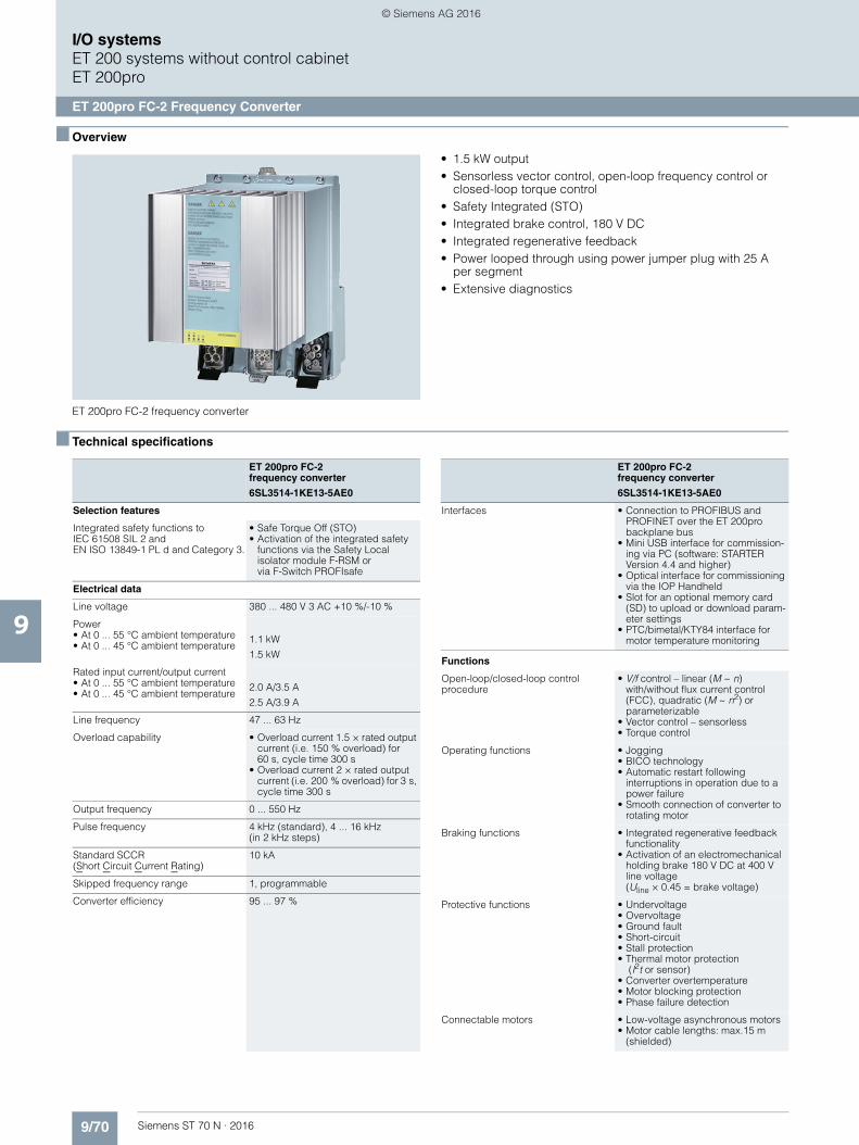
9/70 Siemens ST 70 N · 2016
9
I/O systemsET 200 systems without control cabinetET 200pro
ET 200pro FC-2 Frequency Converter
■ Overview
ET 200pro FC-2 frequency converter
• 1.5 kW output• Sensorless vector control, open-loop frequency control or
closed-loop torque control• Safety Integrated (STO)• Integrated brake control, 180 V DC• Integrated regenerative feedback• Power looped through using power jumper plug with 25 A
per segment• Extensive diagnostics
■ Technical specifications
ET 200pro FC-2 frequency converter
6SL3514-1KE13-5AE0
Selection features
Integrated safety functions to IEC 61508 SIL 2 and EN ISO 13849-1 PL d and Category 3.
• Safe Torque Off (STO)• Activation of the integrated safety
functions via the Safety Localisolator module F-RSM orvia F-Switch PROFIsafe
Electrical data
Line voltage 380 ... 480 V 3 AC +10 %/-10 %
Power• At 0 ... 55 °C ambient temperature• At 0 ... 45 °C ambient temperature
1.1 kW
1.5 kW
Rated input current/output current• At 0 ... 55 °C ambient temperature• At 0 ... 45 °C ambient temperature
2.0 A/3.5 A
2.5 A/3.9 A
Line frequency 47 ... 63 Hz
Overload capability • Overload current 1.5 × rated output current (i.e. 150 % overload) for 60 s, cycle time 300 s
• Overload current 2 × rated output current (i.e. 200 % overload) for 3 s, cycle time 300 s
Output frequency 0 ... 550 Hz
Pulse frequency 4 kHz (standard), 4 ... 16 kHz(in 2 kHz steps)
Standard SCCR (Short Circuit Current Rating)
10 kA
Skipped frequency range 1, programmable
Converter efficiency 95 ... 97 %
Interfaces • Connection to PROFIBUS and PROFINET over the ET 200pro backplane bus
• Mini USB interface for commission-ing via PC (software: STARTER Version 4.4 and higher)
• Optical interface for commissioning via the IOP Handheld
• Slot for an optional memory card (SD) to upload or download param-eter settings
• PTC/bimetal/KTY84 interface for motor temperature monitoring
Functions
Open-loop/closed-loop controlprocedure
• V/f control – linear (M ~ n) with/without flux current control (FCC), quadratic (M ~ n2) orparameterizable
• Vector control – sensorless• Torque control
Operating functions • Jogging• BICO technology• Automatic restart following
interruptions in operation due to a power failure
• Smooth connection of converter to rotating motor
Braking functions • Integrated regenerative feedback functionality
• Activation of an electromechanical holding brake 180 V DC at 400 V line voltage (Uline × 0.45 = brake voltage)
Protective functions • Undervoltage• Overvoltage• Ground fault• Short-circuit• Stall protection• Thermal motor protection
(I2t or sensor)• Converter overtemperature• Motor blocking protection• Phase failure detection
Connectable motors • Low-voltage asynchronous motors• Motor cable lengths: max.15 m
(shielded)
ET 200pro FC-2 frequency converter
6SL3514-1KE13-5AE0
© Siemens AG 2016

9/71Siemens ST 70 N · 2016
9
■ Technical specifications (continued)
I/O systemsET 200 systems without control cabinet
ET 200pro
ET 200pro FC-2 Frequency Converter
Derating data
Pulse frequency
■ Ordering data Article No. Article No.
Mechanical data
Degree of protection IP65
Operating temperature 0 ... 55 °C
Mounting position Vertical wall mounting (verticalalignment of the cooling fins)
Dimensions (W × H × D) in mm
155 × 246 × 248
Weight, approx. 4.0 kg
ET 200pro FC-2 frequency converter
6SL3514-1KE13-5AE0
Standards
Approvals, according to UL508C, cUL, CE, low-voltagedirective 2006/95/EC, EMC directive EN 61800-3 (corresponds to Class A acc. to EN 55011)
ET 200pro FC-2 frequency converter
6SL3514-1KE13-5AE0
Ambient temperature °C Rated output current in A at a pulse frequency of
4 kHz 6 kHz 8 kHz 10 kHz 12 kHz 14 kHz 16 kHz
0 ... 55 (1.1 kW) 3.5 2.8 2.2 1.6 1.1 0.5 0.0
0 ... 45 (1.5 kW) 3.9 3.9 3.9 3.6 3.3 2.7 2.2
ET 200pro FC-2frequency converterwith integral safety function
380 ... 480 V 3 AC +10 %/-10 %47 ... 63 Hz
Overload:150 %, 60 s;200 % 3 s
Output:1.1 kW (0 … 55 °C)1.5 kW (0 … 45 °C)
6SL3514-1KE13-5AE0
Backplane bus module to hold the frequency converter
(Essential for operationof the converter)
6SL3260-2TA00-0AA0
Accessories
Connector set
For energy supply, HAN Q4/2
• 2.5 mm² 3RK1911-2BE50
• 4.0 mm² 3RK1911-2BE10
• 6.0 mm² 3RK1911-2BE30
Motor cables
Motor cables pre-assembled at one end
For motors with brake and tempera-ture sensor with HAN Q8 connector, shielded
(HTG: supplied by Harting)(ZKT: supplied by KnorrTec)
Cross-section 1.5 mm2
• Length 1.5 m ZKT: 70020501000150HTG: 61 88 201 0288
• Length 3 m ZKT: 70020501000300HTG: 61 88 201 0289
• Length 5 m ZKT: 70020501000500HTG: 61 88 201 0290
• Length 10 m ZKT: 70020501001000HTG: 61 88 201 0299
Further selected accessories are available from Siemens Solution Partners. Select "Distributed Field Installation System" as technology in the "Solution Partner Finder".
http://www.siemens.com/automation/partnerfinder
© Siemens AG 2016
9/72 Siemens ST 70 N · 2016
9
■ Ordering data Article No. Article No.
I/O systemsET 200 systems without control cabinetET 200pro
ET 200pro FC-2 Frequency Converter
1) RS 232 connecting cable with optical interface(Article no.: 3RK1922-2BP00) required for use with SINAMICS G110D, SINAMICS G120D, SINAMICS G110M or SIMATIC ET 200pro FC-2. The cable must be ordered separately.
2) The STARTER commissioning tool is available on the Internet at http://www.siemens.com/starter
Frequency converter connector (HTG: supplied by Harting)(ZKT: supplied by KnorrTec)
For motor cable, shielded, HAN Q8
ZKT: 10032001HTG: 61 83 401 0131
Power jumper plug
For 400 V power transmissionto following 400 V modules
3RK1922-2BQ00
IOP Handheld
For use with SINAMICS G120, SINAMICS G120C, SINAMICS G120P,SINAMICS G110D, SINAMICS G120D, SINAMICS G110M,SINAMICS S110 or SIMATIC ET 200pro FC-2
Included in the scope of delivery:• IOP (6SL3255-0AA00-4JA1)• Handheld housing• Rechargeable batteries (4 × AA)• Charging unit (international)• RS 232 connecting cable
(length 3 m, can only be used for SINAMICS G120, SINAMICS G120C, SINAMICS G120P and SINAMICS S110 1))
• USB cable (length 1 m)
6SL3255-0AA00-4HA0
RS 232 interface cable
With optical interface to connect the ET 200pro FC-2 frequency converter to the IOP Handheld(length 2.5 m) 1)
3RK1922-2BP00
PC converter connection kit 2 (mini USB interface cable for communication with a PC)
For controlling and commissioning a converter directly from a PC via a point-to-point connection if the appro-priate software has been installed (STARTER commissioning tool 2)V4.3 or higher); including USB cable (length 3 m)
6SL3255-0AA00-2CA0
Memory card (SD)
For the parameter settings of the ET 200pro FC-2 If required, the complete parameter settings of the frequency converter can be saved on the memory card. When servicing, the plant is immedi-ately ready for use again after replac-ing the frequency converter and inserting the memory card.
6SL3054-4AG00-2AA0
© Siemens AG 2016
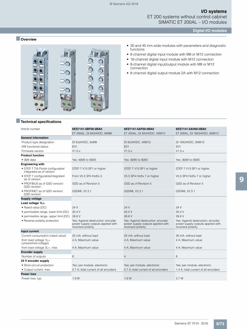
9/73Siemens ST 70 N · 2016
9
I/O systemsET 200 systems without control cabinet
SIMATIC ET 200AL – I/O modules
Digital I/O modules
■ Overview
• 30 and 45 mm wide modules with parameters and diagnostic functions
• 8-channel digital input module with M8 or M12 connection• 16-channel digital input module with M12 connection • 8-channel digital input/output module with M8 or M12
connection• 8-channel digital output module 2A with M12 connection
■ Technical specifications
Article number 6ES7141-5BF00-0BA0 6ES7141-5AF00-0BA0 6ES7141-5AH00-0BA0
ET 200AL, DI 8X24VDC, 8XM8 ET 200AL, DI 8X24VDC, 4XM12 ET 200AL, DI 16X24VDC, 8XM12
General information
Product type designation DI 8x24VDC, 8xM8 DI 8x24VDC, 4XM12 DI 16X24VDC, 8XM12
HW functional status E01 E01 E01
Firmware version V1.0.x V1.0.x V1.0.x
Product function
• I&M data Yes; I&M0 to I&M3 Yes; I&M0 to I&M3 Yes; I&M0 to I&M3
Engineering with
• STEP 7 TIA Portal configurable/integrated as of version
STEP 7 V13 SP1 or higher STEP 7 V13 SP1 or higher STEP 7 V13 SP1 or higher
• STEP 7 configurable/integrated as of version
From V5.5 SP4 Hotfix 3 V5.5 SP4 Hotfix 7 or higher V5.5 SP4 Hotfix 7 or higher
• PROFIBUS as of GSD version/GSD revision
GSD as of Revision 5 GSD as of Revision 5 GSD as of Revision 5
• PROFINET as of GSD version/GSD revision
GSDML V2.3.1 GSDML V2.3.1 GSDML V2.3.1
Supply voltage
Load voltage 1L+
• Rated value (DC) 24 V 24 V 24 V
• permissible range, lower limit (DC) 20.4 V 20.4 V 20.4 V
• permissible range, upper limit (DC) 28.8 V 28.8 V 28.8 V
• Reverse polarity protection Yes; Against destruction; encoder power supply outputs applied with reversed polarity
Yes; Against destruction; encoder power supply outputs applied with reversed polarity
Yes; Against destruction; encoder power supply outputs applied with reversed polarity
Input current
Current consumption (rated value) 25 mA; without load 25 mA; without load 30 mA; without load
from load voltage 1L+ (unswitched voltage)
4 A; Maximum value 4 A; Maximum value 4 A; Maximum value
from load voltage 2L+, max. 4 A; Maximum value 4 A; Maximum value 4 A; Maximum value
Encoder supply
Number of outputs 8 4 8
24 V encoder supply
• Short-circuit protection Yes; per module, electronic Yes; per module, electronic Yes; per module, electronic
• Output current, max. 0.7 A; total current of all encoders 0.7 A; total current of all encoders 1.4 A; total current of all encoders
Power loss
Power loss, typ. 1.9 W 1.9 W 2.7 W
© Siemens AG 2016
9/74 Siemens ST 70 N · 2016
9
■ Technical specifications (continued)
I/O systemsET 200 systems without control cabinetSIMATIC ET 200AL – I/O modules
Digital I/O modules
Digital inputs
Number of digital inputs 8 8 16
Input characteristic curve in accordance with IEC 61131, type 3
Yes Yes Yes
Number of simultaneously controllable inputs
all mounting positions
- up to 55 °C, max. 8 8 16
Input voltage
• Type of input voltage DC DC DC
• Rated value (DC) 24 V 24 V 24 V
• for signal "0" -30 to +5V -30 to +5V -30 to +5V
• for signal "1" +11 to +30V +11 to +30V +11 to +30V
Input current
• for signal "1", typ. 3.2 mA 3.2 mA 3.2 mA
Input delay (for rated value of input voltage)
for standard inputs
- at "0" to "1", min. 1.2 ms 1.2 ms 1.2 ms
- at "0" to "1", max. 4.8 ms 4.8 ms 4.8 ms
- at "1" to "0", min. 1.2 ms 1.2 ms 1.2 ms
- at "1" to "0", max. 4.8 ms 4.8 ms 4.8 ms
Cable length
• unshielded, max. 30 m 30 m 30 m
Encoder
Connectable encoders
• 2-wire sensor Yes Yes Yes
- permissible quiescent current(2-wire sensor), max.
1.5 mA 1.5 mA 1.5 mA
Interrupts/diagnostics/status information
Alarms
• Diagnostic alarm Yes; Parameterizable Yes; Parameterizable Yes; Parameterizable
Diagnostic messages
• Short-circuit Yes; Sensor supply to M; module by module
Yes; Sensor supply to M; module by module
Yes; Sensor supply to M; module by module
Diagnostics indication LED
• Channel status display Yes; Green LED Yes; Green LED Yes; Green LED
• for module diagnostics Yes; Green/red LED Yes; Green/red LED Yes; Green/red LED
Potential separation
between the load voltages Yes Yes Yes
Potential separation channels
• between the channels No No No
• between the channels and backplane bus
Yes Yes Yes
• between the channels and the power supply of the electronics
No No No
Isolation
Isolation tested with 707 V DC (type test) 707 V DC (type test) 707 V DC (type test)
Degree and class of protection
Degree of protection acc. to EN 60529
• IP65 Yes Yes Yes
• IP67 Yes Yes Yes
Ambient conditions
Ambient temperature during operation
• min. -25 °C -25 °C -25 °C
• max. 55 °C 55 °C 55 °C
Article number 6ES7141-5BF00-0BA0 6ES7141-5AF00-0BA0 6ES7141-5AH00-0BA0
ET 200AL, DI 8X24VDC, 8XM8 ET 200AL, DI 8X24VDC, 4XM12 ET 200AL, DI 16X24VDC, 8XM12
© Siemens AG 2016
9/75Siemens ST 70 N · 2016
9
■ Technical specifications (continued)
I/O systemsET 200 systems without control cabinet
SIMATIC ET 200AL – I/O modules
Digital I/O modules
Connection method
Inputs/outputs M8, 3-pole M12, 5-pole M12, 5-pole
Power supply M8, 4-pole M8, 4-pole M8, 4-pole
ET-Connection
• ET-Connection M8, 4-pin, shielded M8, 4-pin, shielded M8, 4-pin, shielded
Dimensions
Width 30 mm 30 mm 45 mm
Height 159 mm 159 mm 159 mm
Depth 40 mm 40 mm 40 mm
Weights
Weight, approx. 145 g 145 g 184 g
Article number 6ES7141-5BF00-0BA0 6ES7141-5AF00-0BA0 6ES7141-5AH00-0BA0
ET 200AL, DI 8X24VDC, 8XM8 ET 200AL, DI 8X24VDC, 4XM12 ET 200AL, DI 16X24VDC, 8XM12
Article number 6ES7142-5AF00-0BA0
ET 200AL, DQ 8X24VDC/2A, 8XM12
General information
Product type designation DQ 8X24VDC/2A, 8XM12
HW functional status E01
Firmware version V1.0.x
Product function
• I&M data Yes; I&M0 to I&M3
Engineering with
• STEP 7 TIA Portal configurable/integrated as of version
STEP 7 V13 SP1 or higher
• STEP 7 configurable/integrated as of version
V5.5 SP4 Hotfix 7 or higher
• PROFIBUS as of GSD version/GSD revision
GSD as of Revision 5
• PROFINET as of GSD version/GSD revision
GSDML V2.3.1
Supply voltage
Load voltage 1L+
• Rated value (DC) 24 V
• permissible range, lower limit (DC) 20.4 V
• permissible range, upper limit (DC) 28.8 V
• Reverse polarity protection Yes; against destruction; load increasing
Load voltage 2L+
• Rated value (DC) 24 V
• permissible range, lower limit (DC) 20.4 V
• permissible range, upper limit (DC) 28.8 V
• Reverse polarity protection Yes; against destruction;load increasing
Input current
Current consumption (rated value) 40 mA; without load
from load voltage 1L+(unswitched voltage)
4 A; Maximum value
from load voltage 2L+, max. 4 A; Maximum value
Power loss
Power loss, typ. 4 W
Digital outputs
Number of digital outputs 8
• in groups of 4; 2 load groups for 4 outputs each
Short-circuit protection Yes; per channel, electronic
• Response threshold, typ. 2,8 A
Limitation of inductive shutdown voltage to
2L+ (-47 V)
Switching capacity of the outputs
• on lamp load, max. 10 W
Load resistance range
• lower limit 12 • upper limit 4 kOutput voltage
• for signal "1", min. L+ (-0.8 V)
Output current
• for signal "1" rated value 2 A
• for signal "1" permissible range, max.
2 A; with inductive load to IEC 60947-5-1, DC-13 / AC-15
• for signal "0" residual current, max. 0.5 mA
Switching frequency
• with resistive load, max. 100 Hz
• with inductive load, max. 0.1 Hz; 0.25 Hz at 25 °C
• on lamp load, max. 1 Hz
Total current of the outputs
• Current per group, max. 4 A; For inductive load max. 2 channels per group
Cable length
• unshielded, max. 30 m
Interrupts/diagnostics/status information
Substitute values connectable Yes; channel by channel, parameterizable
Alarms
• Diagnostic alarm Yes; Parameterizable
Diagnostic messages
• Short-circuit Yes; Outputs to ground; module by module
Diagnostics indication LED
• Channel status display Yes; Green LED
• for module diagnostics Yes; Green/red LED
• For load voltage monitoring Yes; Green LED
Potential separation
between the load voltages Yes
Potential separation channels
• between the channels, in groups of 4
• between the channels and backplane bus
Yes
• between the channels and the power supply of the electronics
No; 4 channels are non-isolated and 4 channels are isolated from supply voltage 1L+
Article number 6ES7142-5AF00-0BA0
ET 200AL, DQ 8X24VDC/2A, 8XM12
© Siemens AG 2016
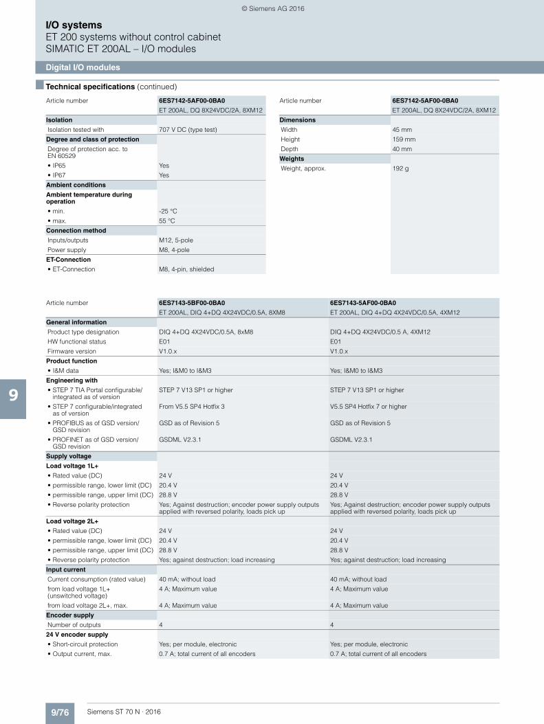
9/76 Siemens ST 70 N · 2016
9
■ Technical specifications (continued)
I/O systemsET 200 systems without control cabinetSIMATIC ET 200AL – I/O modules
Digital I/O modules
Isolation
Isolation tested with 707 V DC (type test)
Degree and class of protection
Degree of protection acc. to EN 60529
• IP65 Yes
• IP67 Yes
Ambient conditions
Ambient temperature during operation
• min. -25 °C
• max. 55 °C
Connection method
Inputs/outputs M12, 5-pole
Power supply M8, 4-pole
ET-Connection
• ET-Connection M8, 4-pin, shielded
Article number 6ES7142-5AF00-0BA0
ET 200AL, DQ 8X24VDC/2A, 8XM12
Dimensions
Width 45 mm
Height 159 mm
Depth 40 mm
Weights
Weight, approx. 192 g
Article number 6ES7142-5AF00-0BA0
ET 200AL, DQ 8X24VDC/2A, 8XM12
Article number 6ES7143-5BF00-0BA0 6ES7143-5AF00-0BA0
ET 200AL, DIQ 4+DQ 4X24VDC/0.5A, 8XM8 ET 200AL, DIQ 4+DQ 4X24VDC/0.5A, 4XM12
General information
Product type designation DIQ 4+DQ 4X24VDC/0.5A, 8xM8 DIQ 4+DQ 4X24VDC/0.5 A, 4XM12
HW functional status E01 E01
Firmware version V1.0.x V1.0.x
Product function
• I&M data Yes; I&M0 to I&M3 Yes; I&M0 to I&M3
Engineering with
• STEP 7 TIA Portal configurable/integrated as of version
STEP 7 V13 SP1 or higher STEP 7 V13 SP1 or higher
• STEP 7 configurable/integrated as of version
From V5.5 SP4 Hotfix 3 V5.5 SP4 Hotfix 7 or higher
• PROFIBUS as of GSD version/GSD revision
GSD as of Revision 5 GSD as of Revision 5
• PROFINET as of GSD version/GSD revision
GSDML V2.3.1 GSDML V2.3.1
Supply voltage
Load voltage 1L+
• Rated value (DC) 24 V 24 V
• permissible range, lower limit (DC) 20.4 V 20.4 V
• permissible range, upper limit (DC) 28.8 V 28.8 V
• Reverse polarity protection Yes; Against destruction; encoder power supply outputs applied with reversed polarity, loads pick up
Yes; Against destruction; encoder power supply outputs applied with reversed polarity, loads pick up
Load voltage 2L+
• Rated value (DC) 24 V 24 V
• permissible range, lower limit (DC) 20.4 V 20.4 V
• permissible range, upper limit (DC) 28.8 V 28.8 V
• Reverse polarity protection Yes; against destruction; load increasing Yes; against destruction; load increasing
Input current
Current consumption (rated value) 40 mA; without load 40 mA; without load
from load voltage 1L+ (unswitched voltage)
4 A; Maximum value 4 A; Maximum value
from load voltage 2L+, max. 4 A; Maximum value 4 A; Maximum value
Encoder supply
Number of outputs 4 4
24 V encoder supply
• Short-circuit protection Yes; per module, electronic Yes; per module, electronic
• Output current, max. 0.7 A; total current of all encoders 0.7 A; total current of all encoders
© Siemens AG 2016

9/77Siemens ST 70 N · 2016
9
■ Technical specifications (continued)
I/O systemsET 200 systems without control cabinet
SIMATIC ET 200AL – I/O modules
Digital I/O modules
Power loss
Power loss, typ. 2.5 W 2.5 W
Digital inputs
Number of digital inputs 4; Parameterizable as DIQ 4; Parameterizable as DIQ
Input characteristic curve in accordance with IEC 61131, type 3
Yes Yes
Number of simultaneously controllable inputs
all mounting positions
- up to 55 °C, max. 4 4
Input voltage
• Type of input voltage DC DC
• Rated value (DC) 24 V 24 V
• for signal "0" -3 to +5V -3 to +5V
• for signal "1" +11 to +30V +11 to +30V
Input current
• for signal "1", typ. 3.2 mA 3.2 mA
Input delay (for rated value of input voltage)
for standard inputs
- at "0" to "1", min. 1.2 ms 1.2 ms
- at "0" to "1", max. 4.8 ms 4.8 ms
- at "1" to "0", min. 1.2 ms 1.2 ms
- at "1" to "0", max. 4.8 ms 4.8 ms
Cable length
• unshielded, max. 30 m 30 m
Digital outputs
Number of digital outputs 8; 4 DQ fixed, 4 DIQ parameterizable 8; 4 DQ fixed, 4 DIQ parameterizable
• in groups of 4; 2 load groups for 4 outputs each 4; 2 load groups for 4 outputs each
Short-circuit protection Yes; per channel, electronic Yes; per channel, electronic
• Response threshold, typ. 0.7 A 0.7 A
Limitation of inductive shutdown voltage to
2L+ (-47 V) 2L+ (-47 V)
Switching capacity of the outputs
• on lamp load, max. 5 W 5 W
Load resistance range
• lower limit 48 48 • upper limit 4 k 4 kOutput voltage
• for signal "1", min. L+ (-0.8 V) L+ (-0.8 V)
Output current
• for signal "1" rated value 0.5 A 0.5 A
• for signal "0" residual current, max. 0.5 mA 0.5 mA
Switching frequency
• with resistive load, max. 100 Hz 100 Hz
• with inductive load, max. 0.5 Hz 0.5 Hz
• on lamp load, max. 1 Hz 1 Hz
Total current of the outputs
• Current per group, max. 2 A 2 A
Cable length
• unshielded, max. 30 m 30 m
Encoder
Connectable encoders
• 2-wire sensor Yes Yes
- permissible quiescent current (2-wire sensor), max.
1.5 mA 1.5 mA
Article number 6ES7143-5BF00-0BA0 6ES7143-5AF00-0BA0
ET 200AL, DIQ 4+DQ 4X24VDC/0.5A, 8XM8 ET 200AL, DIQ 4+DQ 4X24VDC/0.5A, 4XM12
© Siemens AG 2016

9/78 Siemens ST 70 N · 2016
9
■ Technical specifications (continued)
I/O systemsET 200 systems without control cabinetSIMATIC ET 200AL – I/O modules
Digital I/O modules
Interrupts/diagnostics/status information
Substitute values connectable Yes; channel by channel, parameterizable Yes; channel by channel, parameterizable
Alarms
• Diagnostic alarm Yes; Parameterizable Yes; Parameterizable
Diagnostic messages
• Short-circuit Yes; Outputs to M; encoder supply to M; module by module Yes; Outputs to M; encoder supply to M; module by module
Diagnostics indication LED
• Channel status display Yes; Green LED Yes; Green LED
• for module diagnostics Yes; Green/red LED Yes; Green/red LED
• For load voltage monitoring Yes; Green LED Yes; Green LED
Potential separation
between the load voltages Yes Yes
Potential separation channels
• between the channels, in groups of 4; DIQ channels are isolated from DQ channels 4; DIQ channels are isolated from DQ channels
• between the channels and backplane bus
Yes Yes
• between the channels and the power supply of the electronics
No; DIQ channels are non-isolated and DQ channels are isolated from supply voltage 1L+
No; DIQ channels are non-isolated and DQ channels are isolated from supply voltage 1L+
Isolation
Isolation tested with 707 V DC (type test) 707 V DC (type test)
Degree and class of protection
Degree of protection acc. to EN 60529
• IP65 Yes Yes
• IP67 Yes Yes
Ambient conditions
Ambient temperature during operation
• min. -25 °C -25 °C
• max. 55 °C 55 °C
Connection method
Inputs/outputs M8, 3-pole M12, 5-pole
Power supply M8, 4-pole M8, 4-pole
ET-Connection
• ET-Connection M8, 4-pin, shielded M8, 4-pin, shielded
Dimensions
Width 30 mm 30 mm
Height 159 mm 159 mm
Depth 40 mm 40 mm
Weights
Weight, approx. 145 g 145 g
Article number 6ES7143-5BF00-0BA0 6ES7143-5AF00-0BA0
ET 200AL, DIQ 4+DQ 4X24VDC/0.5A, 8XM8 ET 200AL, DIQ 4+DQ 4X24VDC/0.5A, 4XM12
© Siemens AG 2016

9/79Siemens ST 70 N · 2016
9
I/O systemsET 200 systems without control cabinet
SIMATIC ET 200AL – I/O modules
Digital I/O modules
■ Ordering data Article No. Article No.
Digital input modules
DI 8X24VDC, 8XM8 6ES7141-5BF00-0BA0
DI 8X24VDC, 4XM12 6ES7141-5AF00-0BA0
DI 16X24VDC, 8XM12 6ES7141-5AH00-0BA0
Digital output modules
DQ 8X24VDC/2A, 8XM12 6ES7142-5AF00-0BA0
Digital input/output modules
4 DIO / 4 DO, 24 V DC, 0.5 A 6ES7143-5BF00-0BA0
DIQ 4+DQ 4X24VDC/0.5A, 4XM12 6ES7143-5AF00-0BA0
Accessories
Bus cable for backplane bus(ET connection)
4-pin, shielded
Pre-assembled at both ends, 2 M8 connectors
0.19 m 6ES7194-2LH02-0AA0
0.3 m 6ES7194-2LH03-0AA0
1 m 6ES7194-2LH10-0AA0
2 m 6ES7194-2LH20-0AA0
5 m 6ES7194-2LH50-0AA0
10 m 6ES7194-2LN10-0AA0
15 m 6ES7194-2LN15-0AA0
Pre-assembled at both ends,two M8 connectors, angled
0.3 m 6ES7194-2LH03-0AB0
1 m 6ES7194-2LH10-0AB0
2 m 6ES7194-2LH20-0AB0
5 m 6ES7194-2LH50-0AB0
10 m 6ES7194-2LN10-0AB0
15 m 6ES7194-2LN15-0AB0
Pre-assembled at one end,one M8 connector
2 m 6ES7194-2LH20-0AC0
5 m 6ES7194-2LH50-0AC0
10 m 6ES7194-2LN10-0AC0
15 m 6ES7194-2LN15-0AC0
Power cable M8
4-pin
Pre-assembled at both ends,M8 connector and M8 socket
0.19 m 6ES7194-2LH02-1AA0
0.3 m 6ES7194-2LH03-1AA0
1 m 6ES7194-2LH10-1AA0
2 m 6ES7194-2LH20-1AA0
5 m 6ES7194-2LH50-1AA0
10 m 6ES7194-2LN10-1AA0
15 m 6ES7194-2LN15-1AA0
Pre-assembled at both ends, angled M8 connector and angled M8 socket
0.3 m 6ES7194-2LH03-1AB0
1 m 6ES7194-2LH10-1AB0
2 m 6ES7194-2LH20-1AB0
5 m 6ES7194-2LH50-1AB0
10 m 6ES7194-2LN10-1AB0
15 m 6ES7194-2LN15-1AB0
Pre-assembled at one end,M8 socket
2 m 6ES7194-2LH20-1AC0
5 m 6ES7194-2LH50-1AC0
10 m 6ES7194-2LN10-1AC0
15 m 6ES7194-2LN15-1AC0
M8 connector for ET connection 6ES7194-2AB00-0AA0
4-pin, shielded
M8 power connector
Male contact insert, 4-pin 6ES7194-2AA00-0AA0
Female contact insert, 4-pin 6ES7194-2AC00-0AA0
ET connection FastConnect stripping tool
6ES7194-2KA00-0AA0
Stripping tool for stripping theET connection bus cable
Labels 6ES7194-2BA00-0AA0
10 x 5 mm, RAL 9016; 5 frames with 40 labels each
© Siemens AG 2016
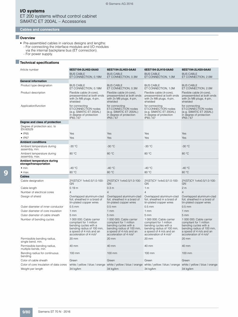
9/80 Siemens ST 70 N · 2016
9
I/O systemsET 200 systems without control cabinetSIMATIC ET 200AL – Accessories
Cables and connectors
■ Overview
• Pre-assembled cables in various designs and lengths:- For connecting the interface modules and I/O modules
via the internal backplane bus (ET connection).- For power supply.
■ Technical specifications
Article number 6ES7194-2LH02-0AA0 6ES7194-2LH03-0AA0 6ES7194-2LH10-0AA0 6ES7194-2LH20-0AA0
BUS CABLE ET CONNECTION, 0.19M
BUS CABLEET CONNECTION, 0.3M
BUS CABLEET CONNECTION, 1.0M
BUS CABLEET CONNECTION, 2.0M
General information
Product type designation BUS CABLE ET CONNECTION, 0.19M
BUS CABLE ET CONNECTION, 0.3M
BUS CABLE ET CONNECTION, 1.0M
BUS CABLE ET CONNECTION, 2.0M
Product description Flexible cable (4-core), preassembled at both ends with 2x M8 plugs, 4-pin, shielded
Flexible cable (4-core), preassembled at both ends with 2x M8 plugs, 4-pin, shielded
Flexible cable (4-core), preassembled at both ends with 2x M8 plugs, 4-pin, shielded
Flexible cable (4-core), preassembled at both ends with 2x M8 plugs, 4-pin, shielded
Application/function for connecting ET-CONNECTION nodes (e.g. SIMATIC ET 200AL)in degree of protectionIP65 / 67
for connecting ET-CONNECTION nodes (e.g. SIMATIC ET 200AL)in degree of protectionIP65 / 67
for connecting ET-CONNECTION nodes(e.g. SIMATIC ET 200AL)in degree of protectionIP65 / 67
for connecting ET-CONNECTION nodes(e.g. SIMATIC ET 200AL)in degree of protectionIP65 / 67
Degree and class of protection
Degree of protection acc. to EN 60529
• IP65 Yes Yes Yes Yes
• IP67 Yes Yes Yes Yes
Ambient conditions
Ambient temperature during assembly, min.
-30 °C -30 °C -30 °C -30 °C
Ambient temperature during assembly, max.
80 °C 80 °C 80 °C 80 °C
Ambient temperature during storage/transportation
• min. -40 °C -40 °C -40 °C -40 °C
• max. 80 °C 80 °C 80 °C 80 °C
Cables
Cable designation 2Y(ST)CY 1x4x0.5/1.0-100-GN
2Y(ST)CY 1x4x0.5/1.0-100-GN
2Y(ST)CY 1x4x0.5/1.0-100-GN
2Y(ST)CY 1x4x0.5/1.0-100-GN
Cable length 0.19 m 0.3 m 1 m 2 m
Number of electrical cores 4 4 4 4
Design of shield Overlapped aluminum-clad foil, sheathed in a braid of tin-plated copper wires
Overlapped aluminum-clad foil, sheathed in a braid of tin-plated copper wires
Overlapped aluminum-clad foil, sheathed in a braid of tin-plated copper wires
Overlapped aluminum-clad foil, sheathed in a braid of tin-plated copper wires
Outer diameter of inner conductor 0.5 mm 0.5 mm 0.5 mm 0.5 mm
Outer diameter of core insulation 1 mm 1 mm 1 mm 1 mm
Outer diameter of cable sheath 5 mm 5 mm 5 mm 5 mm
Number of bending cycles 1 000 000; Cable carrier compliant for 1 million bending cycles with a bending radius of 100 mm, a speed of 4 m/s and an acceleration of 4 m/s²
1 000 000; Cable carrier compliant for 1 million bending cycles with a bending radius of 100 mm, a speed of 4 m/s and an acceleration of 4 m/s²
1 000 000; Cable carrier compliant for 1 million bending cycles with a bending radius of 100 mm, a speed of 4 m/s and an acceleration of 4 m/s²
1 000 000; Cable carrier compliant for 1 million bending cycles with a bending radius of 100 mm, a speed of 4 m/s and an acceleration of 4 m/s²
Permissible bending radius, single bend, min.
20 mm 20 mm 20 mm 20 mm
Permissible bending radius, multiple bends, min.
40 mm 40 mm 40 mm 40 mm
Bending radius for continuous bending
100 mm 100 mm 100 mm 100 mm
Color of cable sheath Green Green Green Green
Color of core insulation of data cores white / yellow / blue / orange white / yellow / blue / orange white / yellow / blue / orange white / yellow / blue / orange
Weight per length 34 kg/km 34 kg/km 34 kg/km 34 kg/km
© Siemens AG 2016

9/81Siemens ST 70 N · 2016
9
■ Technical specifications (continued)
I/O systemsET 200 systems without control cabinet
SIMATIC ET 200AL – Accessories
Cables and connectors
Mechanics/material
Type of cable outlet 180 degree cable outlet 180 degree cable outlet 180 degree cable outlet 180 degree cable outlet
Material of housing metal metal metal metal
Material of core insulation PE PE PE PE
Material of cable sheath PVC PVC PVC PVC
Material property halogen-free No No No No
Material property silicone-free Yes Yes Yes Yes
Article number 6ES7194-2LH50-0AA0 6ES7194-2LN10-0AA0 6ES7194-2LN15-0AA0
BUS CABLE ET CONNECTION, 5.0M
BUS CABLEET CONNECTION, 10M
BUS CABLE ET CONNECTION, 15M
General information
Product type designation BUS CABLE ET-CONNECTION, 5.0M BUS CABLE ET-CONNECTION, 10M BUS CABLE ET CONNECTION, 15M
Product description Flexible cable (4-core), preassembled at both ends with 2x M8 plugs, 4-pin, shielded
Flexible cable (4-core), preassembled at both ends with 2x M8 plugs, 4-pin, shielded
Flexible cable (4-core), preassembled at both ends with 2x M8 plugs, 4-pin, shielded
Application/function for connecting ET-CONNECTION nodes (e.g. SIMATIC ET 200AL)in degree of protection IP65 / 67
for connecting ET-CONNECTION nodes (e.g. SIMATIC ET 200AL)in degree of protection IP65 / 67
for connecting ET-CONNECTION nodes (e.g. SIMATIC ET 200AL)in degree of protection IP65 / 67
Degree and class of protection
Degree of protection acc. to EN 60529
• IP65 Yes Yes Yes
• IP67 Yes Yes Yes
Ambient conditions
Ambient temperature during assembly, min.
-30 °C -30 °C -30 °C
Ambient temperature during assembly, max.
80 °C 80 °C 80 °C
Ambient temperature during storage/transportation
• min. -40 °C -40 °C -40 °C
• max. 80 °C 80 °C 80 °C
Cables
Cable designation 2Y(ST)CY 1x4x0.5/1.0-100-GN 2Y(ST)CY 1x4x0.5/1.0-100-GN 2Y(ST)CY 1x4x0.5/1.0-100-GN
Cable length 5 m 10 m 15 m
Number of electrical cores 4 4 4
Design of shield Overlapped aluminum-clad foil, sheathed in a braid of tin-plated copper wires
Overlapped aluminum-clad foil, sheathed in a braid of tin-plated copper wires
Overlapped aluminum-clad foil, sheathed in a braid of tin-plated copper wires
Outer diameter of inner conductor 0.5 mm 0.5 mm 0.5 mm
Outer diameter of core insulation 1 mm 1 mm 1 mm
Outer diameter of cable sheath 5 mm 5 mm 5 mm
Number of bending cycles 1 000 000; Cable carrier compliant for 1 million bending cycles with a bending radius of 100 mm, a speedof 4 m/s and an acceleration of 4 m/s²
1 000 000; Cable carrier compliantfor 1 million bending cycles with a bending radius of 100 mm, a speedof 4 m/s and an acceleration of 4 m/s²
Permissible bending radius, single bend, min.
20 mm 20 mm 20 mm
Permissible bending radius, multiple bends, min.
40 mm 40 mm 40 mm
Bending radius for continuous bending
100 mm 100 mm 100 mm
Color of cable sheath Green Green Green
Color of core insulation of data cores white / yellow / blue / orange white / yellow / blue / orange white / yellow / blue / orange
Weight per length 34 kg/km 34 kg/km 34 kg/km
Mechanics/material
Type of cable outlet 180 degree cable outlet 180 degree cable outlet 180 degree cable outlet
Material of housing metal metal metal
Material of core insulation PE PE PE
Material of cable sheath PVC PVC PVC
Material property halogen-free No No No
Material property silicone-free Yes Yes Yes
Article number 6ES7194-2LH02-0AA0 6ES7194-2LH03-0AA0 6ES7194-2LH10-0AA0 6ES7194-2LH20-0AA0
BUS CABLE ET CONNECTION, 0.19M
BUS CABLEET CONNECTION, 0.3M
BUS CABLEET CONNECTION, 1.0M
BUS CABLEET CONNECTION, 2.0M
© Siemens AG 2016
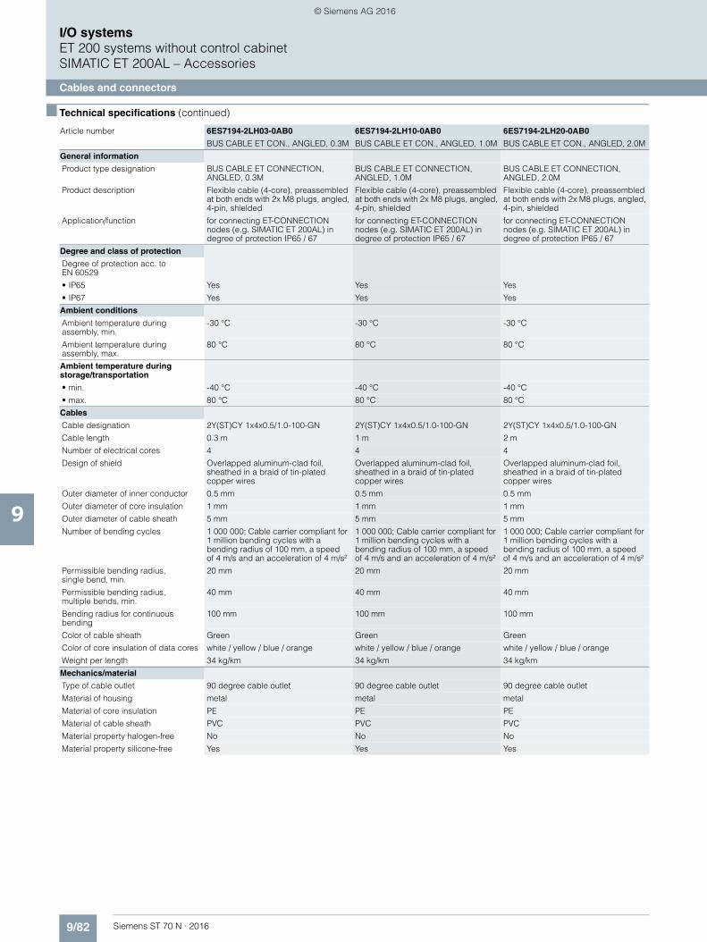
9/82 Siemens ST 70 N · 2016
9
■ Technical specifications (continued)
I/O systemsET 200 systems without control cabinetSIMATIC ET 200AL – Accessories
Cables and connectors
Article number 6ES7194-2LH03-0AB0 6ES7194-2LH10-0AB0 6ES7194-2LH20-0AB0
BUS CABLE ET CON., ANGLED, 0.3M BUS CABLE ET CON., ANGLED, 1.0M BUS CABLE ET CON., ANGLED, 2.0M
General information
Product type designation BUS CABLE ET CONNECTION, ANGLED, 0.3M
BUS CABLE ET CONNECTION, ANGLED, 1.0M
BUS CABLE ET CONNECTION, ANGLED, 2.0M
Product description Flexible cable (4-core), preassembled at both ends with 2x M8 plugs, angled, 4-pin, shielded
Flexible cable (4-core), preassembled at both ends with 2x M8 plugs, angled, 4-pin, shielded
Flexible cable (4-core), preassembled at both ends with 2x M8 plugs, angled, 4-pin, shielded
Application/function for connecting ET-CONNECTION nodes (e.g. SIMATIC ET 200AL) in degree of protection IP65 / 67
for connecting ET-CONNECTION nodes (e.g. SIMATIC ET 200AL) in degree of protection IP65 / 67
for connecting ET-CONNECTION nodes (e.g. SIMATIC ET 200AL) in degree of protection IP65 / 67
Degree and class of protection
Degree of protection acc. to EN 60529
• IP65 Yes Yes Yes
• IP67 Yes Yes Yes
Ambient conditions
Ambient temperature during assembly, min.
-30 °C -30 °C -30 °C
Ambient temperature during assembly, max.
80 °C 80 °C 80 °C
Ambient temperature during storage/transportation
• min. -40 °C -40 °C -40 °C
• max. 80 °C 80 °C 80 °C
Cables
Cable designation 2Y(ST)CY 1x4x0.5/1.0-100-GN 2Y(ST)CY 1x4x0.5/1.0-100-GN 2Y(ST)CY 1x4x0.5/1.0-100-GN
Cable length 0.3 m 1 m 2 m
Number of electrical cores 4 4 4
Design of shield Overlapped aluminum-clad foil, sheathed in a braid of tin-plated copper wires
Overlapped aluminum-clad foil, sheathed in a braid of tin-plated copper wires
Overlapped aluminum-clad foil, sheathed in a braid of tin-plated copper wires
Outer diameter of inner conductor 0.5 mm 0.5 mm 0.5 mm
Outer diameter of core insulation 1 mm 1 mm 1 mm
Outer diameter of cable sheath 5 mm 5 mm 5 mm
Number of bending cycles 1 000 000; Cable carrier compliant for 1 million bending cycles with a bending radius of 100 mm, a speedof 4 m/s and an acceleration of 4 m/s²
1 000 000; Cable carrier compliant for 1 million bending cycles with a bending radius of 100 mm, a speedof 4 m/s and an acceleration of 4 m/s²
1 000 000; Cable carrier compliant for 1 million bending cycles with a bending radius of 100 mm, a speed of 4 m/s and an acceleration of 4 m/s²
Permissible bending radius, single bend, min.
20 mm 20 mm 20 mm
Permissible bending radius, multiple bends, min.
40 mm 40 mm 40 mm
Bending radius for continuous bending
100 mm 100 mm 100 mm
Color of cable sheath Green Green Green
Color of core insulation of data cores white / yellow / blue / orange white / yellow / blue / orange white / yellow / blue / orange
Weight per length 34 kg/km 34 kg/km 34 kg/km
Mechanics/material
Type of cable outlet 90 degree cable outlet 90 degree cable outlet 90 degree cable outlet
Material of housing metal metal metal
Material of core insulation PE PE PE
Material of cable sheath PVC PVC PVC
Material property halogen-free No No No
Material property silicone-free Yes Yes Yes
© Siemens AG 2016

9/83Siemens ST 70 N · 2016
9
■ Technical specifications (continued)
I/O systemsET 200 systems without control cabinet
SIMATIC ET 200AL – Accessories
Cables and connectors
Article number 6ES7194-2LH50-0AB0 6ES7194-2LN10-0AB0 6ES7194-2LN15-0AB0
BUS CABLE ET CON., ANGLED, 5.0M BUS CABLE ET CONNECTION, ANGLED, 10M
BUS CABLE ET CONNECTION, ANGLED, 15M
General information
Product type designation BUS CABLE ET CONNECTION, ANGLED, 5.0M
BUS CABLE ET CONNECTION, ANGLED, 10M
BUS CABLE ET CONNECTION, ANGLED, 15M
Product description Flexible cable (4-core), preassembled at both ends with 2x M8 plugs, angled, 4-pin, shielded
Flexible cable (4-core), preassembled at both ends with 2x M8 plugs, angled, 4-pin, shielded
Flexible cable (4-core), preassembled at both ends with 2x M8 plugs, angled, 4-pin, shielded
Application/function for connecting ET-CONNECTION nodes (e.g. SIMATIC ET 200AL) in degree of protection IP65 / 67
for connecting ET-CONNECTION nodes (e.g. SIMATIC ET 200AL) in degree of protection IP65 / 67
for connecting ET-CONNECTION nodes (e.g. SIMATIC ET 200AL) in degree of protection IP65 / 67
Degree and class of protection
Degree of protection acc. to EN 60529
• IP65 Yes Yes Yes
• IP67 Yes Yes Yes
Ambient conditions
Ambient temperature during assembly, min.
-30 °C -30 °C -30 °C
Ambient temperature during assembly, max.
80 °C 80 °C 80 °C
Ambient temperature during storage/transportation
• min. -40 °C -40 °C -40 °C
• max. 80 °C 80 °C 80 °C
Cables
Cable designation 2Y(ST)CY 1x4x0.5/1.0-100-GN 2Y(ST)CY 1x4x0.5/1.0-100-GN 2Y(ST)CY 1x4x0.5/1.0-100-GN
Cable length 5 m 10 m 15 m
Number of electrical cores 4 4 4
Design of shield Overlapped aluminum-clad foil, sheathed in a braid of tin-plated copper wires
Overlapped aluminum-clad foil, sheathed in a braid of tin-plated copper wires
Overlapped aluminum-clad foil, sheathed in a braid of tin-plated copper wires
Outer diameter of inner conductor 0.5 mm 0.5 mm 0.5 mm
Outer diameter of core insulation 1 mm 1 mm 1 mm
Outer diameter of cable sheath 5 mm 5 mm 5 mm
Number of bending cycles 1 000 000; Cable carrier compliant for 1 million bending cycles with a bending radius of 100 mm, a speed of 4 m/s and an acceleration of 4 m/s²
1 000 000; Cable carrier compliant for 1 million bending cycles with a bending radius of 100 mm, a speedof 4 m/s and an acceleration of 4 m/s²
Permissible bending radius,single bend, min.
20 mm 20 mm 20 mm
Permissible bending radius,multiple bends, min.
40 mm 40 mm 40 mm
Bending radius for continuous bending
100 mm 100 mm 100 mm
Color of cable sheath Green Green Green
Color of core insulation of data cores white / yellow / blue / orange white / yellow / blue / orange white / yellow / blue / orange
Weight per length 34 kg/km 34 kg/km 34 kg/km
Mechanics/material
Type of cable outlet 90 degree cable outlet 90 degree cable outlet 90 degree cable outlet
Material of housing metal metal metal
Material of core insulation PE PE PE
Material of cable sheath PVC PVC PVC
Material property halogen-free No No No
Material property silicone-free Yes Yes Yes
© Siemens AG 2016
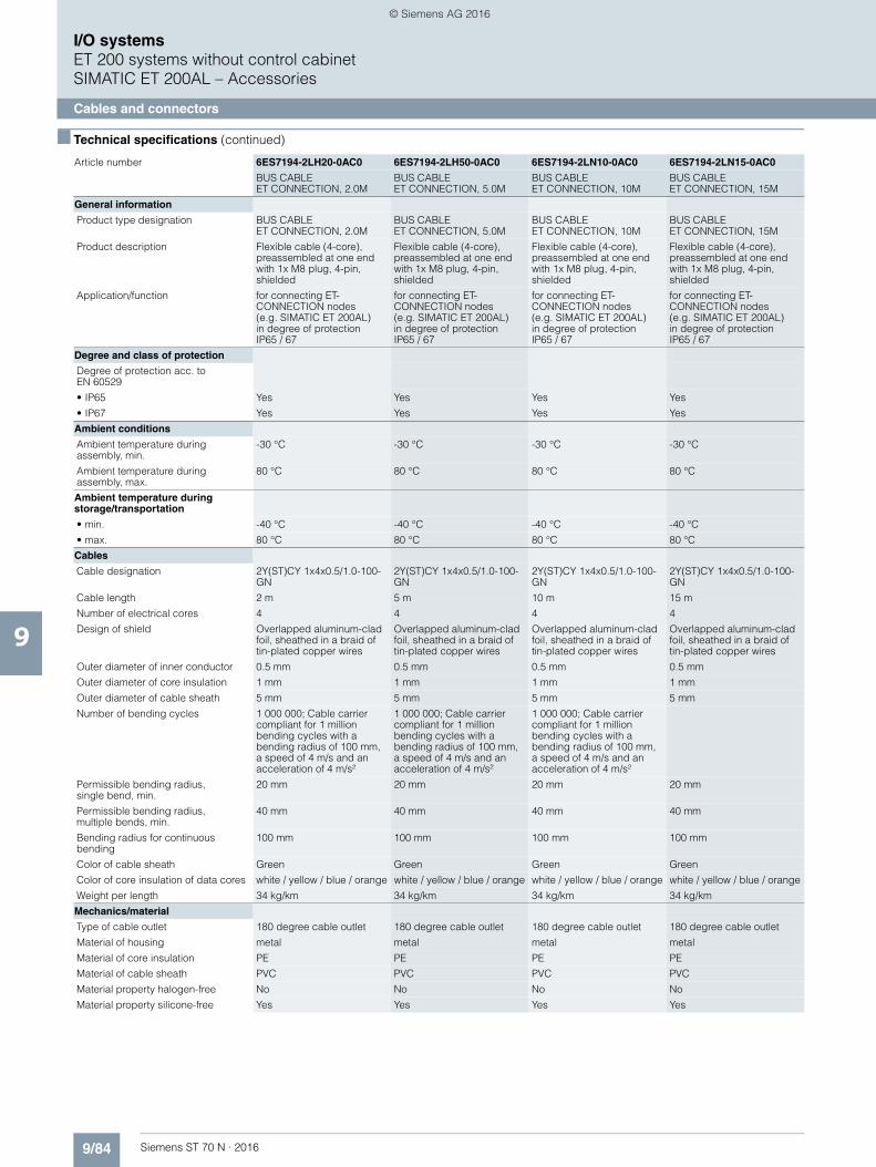
9/84 Siemens ST 70 N · 2016
9
■ Technical specifications (continued)
I/O systemsET 200 systems without control cabinetSIMATIC ET 200AL – Accessories
Cables and connectors
Article number 6ES7194-2LH20-0AC0 6ES7194-2LH50-0AC0 6ES7194-2LN10-0AC0 6ES7194-2LN15-0AC0
BUS CABLE ET CONNECTION, 2.0M
BUS CABLE ET CONNECTION, 5.0M
BUS CABLEET CONNECTION, 10M
BUS CABLE ET CONNECTION, 15M
General information
Product type designation BUS CABLE ET CONNECTION, 2.0M
BUS CABLE ET CONNECTION, 5.0M
BUS CABLE ET CONNECTION, 10M
BUS CABLE ET CONNECTION, 15M
Product description Flexible cable (4-core), preassembled at one end with 1x M8 plug, 4-pin, shielded
Flexible cable (4-core), preassembled at one end with 1x M8 plug, 4-pin, shielded
Flexible cable (4-core), preassembled at one end with 1x M8 plug, 4-pin, shielded
Flexible cable (4-core), preassembled at one end with 1x M8 plug, 4-pin, shielded
Application/function for connecting ET-CONNECTION nodes (e.g. SIMATIC ET 200AL)in degree of protectionIP65 / 67
for connecting ET-CONNECTION nodes (e.g. SIMATIC ET 200AL)in degree of protectionIP65 / 67
for connecting ET-CONNECTION nodes(e.g. SIMATIC ET 200AL)in degree of protectionIP65 / 67
for connecting ET-CONNECTION nodes (e.g. SIMATIC ET 200AL)in degree of protectionIP65 / 67
Degree and class of protection
Degree of protection acc. to EN 60529
• IP65 Yes Yes Yes Yes
• IP67 Yes Yes Yes Yes
Ambient conditions
Ambient temperature during assembly, min.
-30 °C -30 °C -30 °C -30 °C
Ambient temperature during assembly, max.
80 °C 80 °C 80 °C 80 °C
Ambient temperature during storage/transportation
• min. -40 °C -40 °C -40 °C -40 °C
• max. 80 °C 80 °C 80 °C 80 °C
Cables
Cable designation 2Y(ST)CY 1x4x0.5/1.0-100-GN
2Y(ST)CY 1x4x0.5/1.0-100-GN
2Y(ST)CY 1x4x0.5/1.0-100-GN
2Y(ST)CY 1x4x0.5/1.0-100-GN
Cable length 2 m 5 m 10 m 15 m
Number of electrical cores 4 4 4 4
Design of shield Overlapped aluminum-clad foil, sheathed in a braid of tin-plated copper wires
Overlapped aluminum-clad foil, sheathed in a braid of tin-plated copper wires
Overlapped aluminum-clad foil, sheathed in a braid of tin-plated copper wires
Overlapped aluminum-clad foil, sheathed in a braid of tin-plated copper wires
Outer diameter of inner conductor 0.5 mm 0.5 mm 0.5 mm 0.5 mm
Outer diameter of core insulation 1 mm 1 mm 1 mm 1 mm
Outer diameter of cable sheath 5 mm 5 mm 5 mm 5 mm
Number of bending cycles 1 000 000; Cable carrier compliant for 1 million bending cycles with a bending radius of 100 mm, a speed of 4 m/s and an acceleration of 4 m/s²
1 000 000; Cable carrier compliant for 1 million bending cycles with a bending radius of 100 mm, a speed of 4 m/s and an acceleration of 4 m/s²
1 000 000; Cable carrier compliant for 1 million bending cycles with a bending radius of 100 mm, a speed of 4 m/s and an acceleration of 4 m/s²
Permissible bending radius, single bend, min.
20 mm 20 mm 20 mm 20 mm
Permissible bending radius, multiple bends, min.
40 mm 40 mm 40 mm 40 mm
Bending radius for continuous bending
100 mm 100 mm 100 mm 100 mm
Color of cable sheath Green Green Green Green
Color of core insulation of data cores white / yellow / blue / orange white / yellow / blue / orange white / yellow / blue / orange white / yellow / blue / orange
Weight per length 34 kg/km 34 kg/km 34 kg/km 34 kg/km
Mechanics/material
Type of cable outlet 180 degree cable outlet 180 degree cable outlet 180 degree cable outlet 180 degree cable outlet
Material of housing metal metal metal metal
Material of core insulation PE PE PE PE
Material of cable sheath PVC PVC PVC PVC
Material property halogen-free No No No No
Material property silicone-free Yes Yes Yes Yes
© Siemens AG 2016
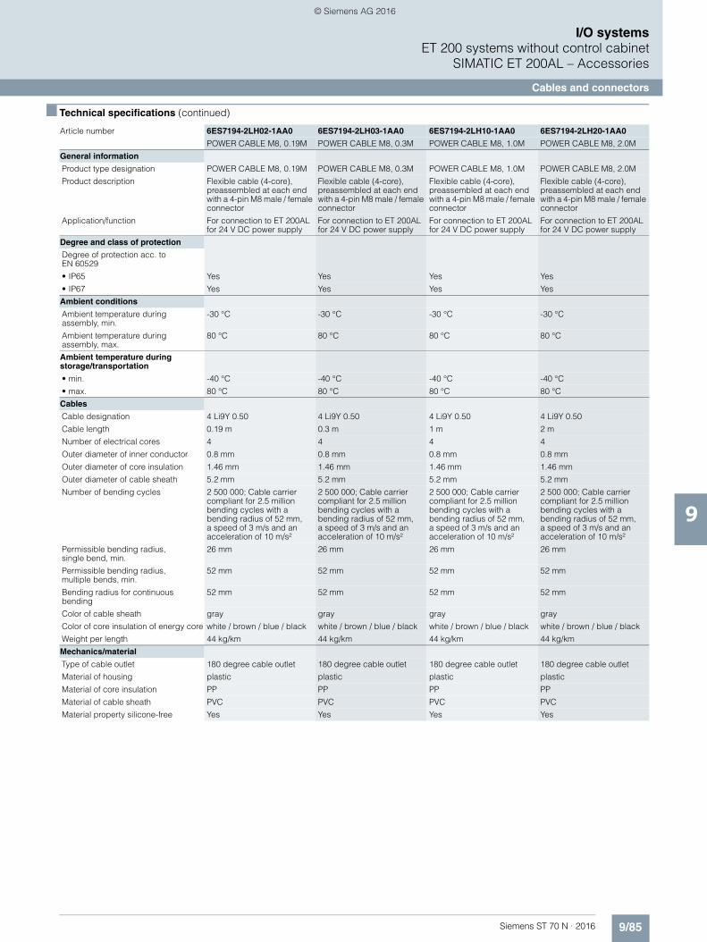
9/85Siemens ST 70 N · 2016
9
■ Technical specifications (continued)
I/O systemsET 200 systems without control cabinet
SIMATIC ET 200AL – Accessories
Cables and connectors
Article number 6ES7194-2LH02-1AA0 6ES7194-2LH03-1AA0 6ES7194-2LH10-1AA0 6ES7194-2LH20-1AA0
POWER CABLE M8, 0.19M POWER CABLE M8, 0.3M POWER CABLE M8, 1.0M POWER CABLE M8, 2.0M
General information
Product type designation POWER CABLE M8, 0.19M POWER CABLE M8, 0.3M POWER CABLE M8, 1.0M POWER CABLE M8, 2.0M
Product description Flexible cable (4-core), preassembled at each end with a 4-pin M8 male / female connector
Flexible cable (4-core), preassembled at each end with a 4-pin M8 male / female connector
Flexible cable (4-core), preassembled at each end with a 4-pin M8 male / female connector
Flexible cable (4-core), preassembled at each end with a 4-pin M8 male / female connector
Application/function For connection to ET 200AL for 24 V DC power supply
For connection to ET 200AL for 24 V DC power supply
For connection to ET 200AL for 24 V DC power supply
For connection to ET 200AL for 24 V DC power supply
Degree and class of protection
Degree of protection acc. to EN 60529
• IP65 Yes Yes Yes Yes
• IP67 Yes Yes Yes Yes
Ambient conditions
Ambient temperature during assembly, min.
-30 °C -30 °C -30 °C -30 °C
Ambient temperature during assembly, max.
80 °C 80 °C 80 °C 80 °C
Ambient temperature during storage/transportation
• min. -40 °C -40 °C -40 °C -40 °C
• max. 80 °C 80 °C 80 °C 80 °C
Cables
Cable designation 4 Li9Y 0.50 4 Li9Y 0.50 4 Li9Y 0.50 4 Li9Y 0.50
Cable length 0.19 m 0.3 m 1 m 2 m
Number of electrical cores 4 4 4 4
Outer diameter of inner conductor 0.8 mm 0.8 mm 0.8 mm 0.8 mm
Outer diameter of core insulation 1.46 mm 1.46 mm 1.46 mm 1.46 mm
Outer diameter of cable sheath 5.2 mm 5.2 mm 5.2 mm 5.2 mm
Number of bending cycles 2 500 000; Cable carrier compliant for 2.5 million bending cycles with a bending radius of 52 mm, a speed of 3 m/s and an acceleration of 10 m/s²
2 500 000; Cable carrier compliant for 2.5 million bending cycles with a bending radius of 52 mm,a speed of 3 m/s and an acceleration of 10 m/s²
2 500 000; Cable carrier compliant for 2.5 million bending cycles with a bending radius of 52 mm, a speed of 3 m/s and an acceleration of 10 m/s²
2 500 000; Cable carrier compliant for 2.5 million bending cycles with a bending radius of 52 mm, a speed of 3 m/s and an acceleration of 10 m/s²
Permissible bending radius,single bend, min.
26 mm 26 mm 26 mm 26 mm
Permissible bending radius, multiple bends, min.
52 mm 52 mm 52 mm 52 mm
Bending radius for continuous bending
52 mm 52 mm 52 mm 52 mm
Color of cable sheath gray gray gray gray
Color of core insulation of energy core white / brown / blue / black white / brown / blue / black white / brown / blue / black white / brown / blue / black
Weight per length 44 kg/km 44 kg/km 44 kg/km 44 kg/km
Mechanics/material
Type of cable outlet 180 degree cable outlet 180 degree cable outlet 180 degree cable outlet 180 degree cable outlet
Material of housing plastic plastic plastic plastic
Material of core insulation PP PP PP PP
Material of cable sheath PVC PVC PVC PVC
Material property silicone-free Yes Yes Yes Yes
© Siemens AG 2016

9/86 Siemens ST 70 N · 2016
9
■ Technical specifications (continued)
I/O systemsET 200 systems without control cabinetSIMATIC ET 200AL – Accessories
Cables and connectors
Article number 6ES7194-2LH50-1AA0 6ES7194-2LN10-1AA0 6ES7194-2LN15-1AA0
POWER CABLE M8, 5.0M POWER CABLE M8, 10M POWER CABLE M8, 15M
General information
Product type designation POWER CABLE M8, 5.0M POWER CABLE M8, 10M POWER CABLE M8, 15M
Product description Flexible cable (4-core), preassembled at each end with a 4-pin M8 male / female connector
Flexible cable (4-core), preassembled at each end with a 4-pin M8 male / female connector
Flexible cable (4-core), preassembled at each end with a 4-pin M8 male / female connector
Application/function For connection to ET 200ALfor 24 V DC power supply
For connection to ET 200AL for 24 V DC power supply
For connection to ET 200ALfor 24 V DC power supply
Degree and class of protection
Degree of protection acc. to EN 60529
• IP65 Yes Yes Yes
• IP67 Yes Yes Yes
Ambient conditions
Ambient temperature during assembly, min.
-30 °C -30 °C -30 °C
Ambient temperature during assembly, max.
80 °C 80 °C 80 °C
Ambient temperature during storage/transportation
• min. -40 °C -40 °C -40 °C
• max. 80 °C 80 °C 80 °C
Cables
Cable designation 4 Li9Y 0.50 4 Li9Y 0.50 4 Li9Y 0.50
Cable length 5 m 10 m 15 m
Number of electrical cores 4 4 4
Outer diameter of inner conductor 0.8 mm 0.8 mm 0.8 mm
Outer diameter of core insulation 1.46 mm 1.46 mm 1.46 mm
Outer diameter of cable sheath 5.2 mm 5.2 mm 5.2 mm
Number of bending cycles 2 500 000; Cable carrier compliant for 2.5 million bending cycles with a bending radius of 52 mm, a speed of 3 m/s and an acceleration of 10 m/s²
2 500 000; Cable carrier compliant for 2.5 million bending cycles with a bending radius of 52 mm, a speed of3 m/s and an acceleration of 10 m/s²
2 500 000; Cable carrier compliant for 2.5 million bending cycles with a bending radius of 52 mm, a speed of 3 m/s and an acceleration of 10 m/s²
Permissible bending radius, single bend, min.
26 mm 26 mm 26 mm
Permissible bending radius, multiple bends, min.
52 mm 52 mm 52 mm
Bending radius for continuous bending
52 mm 52 mm 52 mm
Color of cable sheath gray gray gray
Color of core insulation of energy core white / brown / blue / black white / brown / blue / black white / brown / blue / black
Weight per length 44 kg/km 44 kg/km 44 kg/km
Mechanics/material
Type of cable outlet 180 degree cable outlet 180 degree cable outlet 180 degree cable outlet
Material of housing plastic plastic plastic
Material of core insulation PP PP PP
Material of cable sheath PVC PVC PVC
Material property silicone-free Yes Yes Yes
© Siemens AG 2016
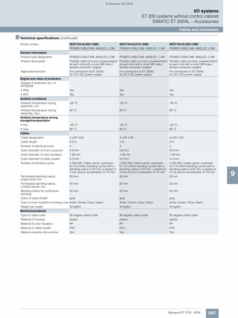
9/87Siemens ST 70 N · 2016
9
■ Technical specifications (continued)
I/O systemsET 200 systems without control cabinet
SIMATIC ET 200AL – Accessories
Cables and connectors
Article number 6ES7194-2LH03-1AB0 6ES7194-2LH10-1AB0 6ES7194-2LH20-1AB0
POWER CABLE M8, ANGLED, 0.3M POWER CABLE M8, ANGLED, 1.0M POWER CABLE M8, ANGLED, 2.0M
General information
Product type designation POWER CABLE M8, ANGLED, 0.3M POWER CABLE M8, ANGLED, 1.0M POWER CABLE M8, ANGLED, 2.0M
Product description Flexible cable (4-core), preassembled at each end with a 4-pin M8 male / female connector, angled
Flexible cable (4-core), preassembled at each end with a 4-pin M8 male / female connector, angled
Flexible cable (4-core), preassembled at each end with a 4-pin M8 male / female connector, angled
Application/function For connection to ET 200ALfor 24 V DC power supply
For connection to ET 200ALfor 24 V DC power supply
For connection to ET 200AL for 24 V DC power supply
Degree and class of protection
Degree of protection acc. to EN 60529
• IP65 Yes Yes Yes
• IP67 Yes Yes Yes
Ambient conditions
Ambient temperature during assembly, min.
-30 °C -30 °C -30 °C
Ambient temperature during assembly, max.
80 °C 80 °C 80 °C
Ambient temperature during storage/transportation
• min. -40 °C -40 °C -40 °C
• max. 80 °C 80 °C 80 °C
Cables
Cable designation 4 Li9Y 0.50 4 Li9Y 0.50 4 Li9Y 0.50
Cable length 0.3 m 1 m 2 m
Number of electrical cores 4 4 4
Outer diameter of inner conductor 0.8 mm 0.8 mm 0.8 mm
Outer diameter of core insulation 1.46 mm 1.46 mm 1.46 mm
Outer diameter of cable sheath 5.2 mm 5.2 mm 5.2 mm
Number of bending cycles 2 500 000; Cable carrier compliant for 2.5 million bending cycles with a bending radius of 52 mm, a speed of3 m/s and an acceleration of 10 m/s²
2 500 000; Cable carrier compliantfor 2.5 million bending cycles with a bending radius of 52 mm, a speed of3 m/s and an acceleration of 10 m/s²
2 500 000; Cable carrier compliantfor 2.5 million bending cycles with a bending radius of 52 mm, a speed of3 m/s and an acceleration of 10 m/s²
Permissible bending radius, single bend, min.
26 mm 26 mm 26 mm
Permissible bending radius, multiple bends, min.
52 mm 52 mm 52 mm
Bending radius for continuous bending
52 mm 52 mm 52 mm
Color of cable sheath gray gray gray
Color of core insulation of energy core white / brown / blue / black white / brown / blue / black white / brown / blue / black
Weight per length 44 kg/km 44 kg/km 44 kg/km
Mechanics/material
Type of cable outlet 90 degree cable outlet 90 degree cable outlet 90 degree cable outlet
Material of housing plastic plastic plastic
Material of core insulation PP PP PP
Material of cable sheath PVC PVC PVC
Material property silicone-free Yes Yes Yes
© Siemens AG 2016
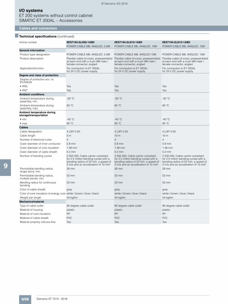
9/88 Siemens ST 70 N · 2016
9
■ Technical specifications (continued)
I/O systemsET 200 systems without control cabinetSIMATIC ET 200AL – Accessories
Cables and connectors
Article number 6ES7194-2LH50-1AB0 6ES7194-2LN10-1AB0 6ES7194-2LN15-1AB0
POWER CABLE M8, ANGLED, 5.0M POWER CABLE M8, ANGLED, 10M POWER CABLE M8, ANGLED, 15M
General information
Product type designation POWER CABLE M8, ANGLED, 5.0M POWER CABLE M8, ANGLED 10M POWER CABLE M8, ANGLED, 15M
Product description Flexible cable (4-core), preassembled at each end with a 4-pin M8 male / female connector, angled
Flexible cable (4-core), preassembled at each end with a 4-pin M8 male / female connector, angled
Flexible cable (4-core), preassembled at each end with a 4-pin M8 male / female connector, angled
Application/function For connection to ET 200ALfor 24 V DC power supply
For connection to ET 200ALfor 24 V DC power supply
For connection to ET 200ALfor 24 V DC power supply
Degree and class of protection
Degree of protection acc. to EN 60529
• IP65 Yes Yes Yes
• IP67 Yes Yes Yes
Ambient conditions
Ambient temperature during assembly, min.
-30 °C -30 °C -30 °C
Ambient temperature during assembly, max.
80 °C 80 °C 80 °C
Ambient temperature during storage/transportation
• min. -40 °C -40 °C -40 °C
• max. 80 °C 80 °C 80 °C
Cables
Cable designation 4 Li9Y 0.50 4 Li9Y 0.50 4 Li9Y 0.50
Cable length 5 m 10 m 15 m
Number of electrical cores 4 4 4
Outer diameter of inner conductor 0.8 mm 0.8 mm 0.8 mm
Outer diameter of core insulation 1.46 mm 1.46 mm 1.46 mm
Outer diameter of cable sheath 5.2 mm 5.2 mm 5.2 mm
Number of bending cycles 2 500 000; Cable carrier compliant for 2.5 million bending cycles with a bending radius of 52 mm, a speed of3 m/s and an acceleration of 10 m/s²
2 500 000; Cable carrier compliant for 2.5 million bending cycles with a bending radius of 52 mm, a speed of3 m/s and an acceleration of 10 m/s²
2 500 000; Cable carrier compliant for 2.5 million bending cycles with a bending radius of 52 mm, a speed of 3 m/s and an acceleration of 10 m/s²
Permissible bending radius,single bend, min.
26 mm 26 mm 26 mm
Permissible bending radius, multiple bends, min.
52 mm 52 mm 52 mm
Bending radius for continuous bending
52 mm 52 mm 52 mm
Color of cable sheath gray gray gray
Color of core insulation of energy core white / brown / blue / black white / brown / blue / black white / brown / blue / black
Weight per length 44 kg/km 44 kg/km 44 kg/km
Mechanics/material
Type of cable outlet 90 degree cable outlet 90 degree cable outlet 90 degree cable outlet
Material of housing plastic plastic plastic
Material of core insulation PP PP PP
Material of cable sheath PVC PVC PVC
Material property silicone-free Yes Yes Yes
© Siemens AG 2016

9/89Siemens ST 70 N · 2016
9
■ Technical specifications (continued)
I/O systemsET 200 systems without control cabinet
SIMATIC ET 200AL – Accessories
Cables and connectors
Article number 6ES7194-2LH20-1AC0 6ES7194-2LH50-1AC0 6ES7194-2LN10-1AC0 6ES7194-2LN15-1AC0
POWER CABLE M8, 2.0M POWER CABLE M8, 5.0M POWER CABLE M8, 10M POWER CABLE M8, 15M
General information
Product type designation POWER CABLE M8, 2.0M POWER CABLE M8, 5.0M POWER CABLE M8, 10M POWER CABLE M8, 15M
Product description Flexible cable (4-core), preassembled at one end with 1x M8 female connector
Flexible cable (4-core), preassembled at one end with 1x M8 female connector
Flexible cable (4-core), preassembled at one end with 1x M8 plug, 4-pin, shielded
Flexible cable (4-core), preassembled at one end with 1x M8 plug, 4-pin, shielded
Application/function For connection to ET 200AL for 24 V DC power supply
For connection to ET 200AL for 24 V DC power supply
For connection to ET 200AL for 24 V DC power supply
For connection to ET 200AL for 24 V DC power supply
Degree and class of protection
Degree of protection acc. to EN 60529
• IP65 Yes Yes Yes Yes
• IP67 Yes Yes Yes Yes
Ambient conditions
Ambient temperature during assembly, min.
-30 °C -30 °C -30 °C -30 °C
Ambient temperature during assembly, max.
80 °C 80 °C 80 °C 80 °C
Ambient temperature during storage/transportation
• min. -40 °C -40 °C -40 °C -40 °C
• max. 80 °C 80 °C 80 °C 80 °C
Cables
Cable designation 4 Li9Y 0.50 4 Li9Y 0.50 4 Li9Y 0.50 4 Li9Y 0.50
Cable length 2 m 5 m 10 m 15 m
Number of electrical cores 4 4 4 4
Outer diameter of inner conductor 0.8 mm 0.8 mm 0.8 mm 0.8 mm
Outer diameter of core insulation 1.46 mm 1.46 mm 1.46 mm 1.46 mm
Outer diameter of cable sheath 5.2 mm 5.2 mm 5.2 mm 5.2 mm
Number of bending cycles 2 500 000; Cable carrier compliant for 2.5 million bending cycles with a bending radius of 52 mm, a speed of 3 m/s and an acceleration of 10 m/s²
2 500 000; Cable carrier compliant for 2.5 million bending cycles with a bending radius of 52 mm, a speed of 3 m/s and an acceleration of 10 m/s²
2 500 000; Cable carrier compliant for 2.5 million bending cycles with a bending radius of 52 mm, a speed of 3 m/s and an acceleration of 10 m/s²
2 500 000; Cable carrier compliant for 2.5 million bending cycles with a bending radius of 52 mm, a speed of 3 m/s and an acceleration of 10 m/s²
Permissible bending radius, single bend, min.
26 mm 26 mm 26 mm 26 mm
Permissible bending radius, multiple bends, min.
52 mm 52 mm 52 mm 52 mm
Bending radius for continuous bending
52 mm 52 mm 52 mm 52 mm
Color of cable sheath gray gray gray gray
Color of core insulation of energy core white / brown / blue / black white / brown / blue / black white / brown / blue / black white / brown / blue / black
Weight per length 44 kg/km 44 kg/km 44 kg/km 44 kg/km
Mechanics/material
Type of cable outlet 180 degree cable outlet 180 degree cable outlet 180 degree cable outlet 180 degree cable outlet
Material of housing plastic plastic plastic plastic
Material of core insulation PP PP PP PP
Material of cable sheath PVC PVC PVC PVC
Material property silicone-free Yes Yes Yes Yes
© Siemens AG 2016

9/90 Siemens ST 70 N · 2016
9
■ Technical specifications (continued)
I/O systemsET 200 systems without control cabinetSIMATIC ET 200AL – Accessories
Cables and connectors
Article number 6ES7194-2AA00-0AA0 6ES7194-2AC00-0AA0
M8 POWER CONNECTOR M8 POWER CONNECTOR, SOCKET
General information
Product type designation M8 POWER CONNECTOR POWER CONNECTOR M8, SOCKET
Product description M8 plug connector with high degree of protection, 4-pin, plastic version
M8 plug connector with high degree of protection, socket insert, 4-pin, plastic version
Application/function For connection to ET 200AL for 24 V DC power supply For connection to ET 200AL for 24 V DC power supply
Degree and class of protection
Degree of protection acc. to EN 60529
• IP65 Yes Yes
• IP67 Yes Yes
Ambient conditions
Ambient temperature during assembly, min.
-30 °C -30 °C
Ambient temperature during assembly, max.
85 °C 85 °C
Ambient temperature during storage/transportation
• min. -40 °C -40 °C
• max. 85 °C 85 °C
Mechanics/material
Type of cable outlet 180 degree cable outlet 180 degree cable outlet
Material of housing plastic plastic
Dimensions
Width 14 mm 14 mm
Depth 47 mm 47 mm
Article number 6ES7194-2AB00-0AA0
M8 CONNECTOR ET-CONNECTION
General information
Product type designation M8 PLUG ET-CONNECTION
Product description M8 plug connector with high degree of protection, 4-pin, metal version
Application/function for connecting ET-CONNECTION nodes (e.g. SIMATIC ET 200AL) in degree of protection IP65 / 67
Degree and class of protection
Degree of protection acc. to EN 60529
• IP65 Yes
• IP67 Yes
Ambient conditions
Ambient temperature during assembly, min.
-30 °C
Ambient temperature during assembly, max.
80 °C
Ambient temperature during storage/transportation
• min. -40 °C
• max. 80 °C
Mechanics/material
Type of cable outlet 180 degree cable outlet
Material of housing metal
Dimensions
Width 14 mm
Depth 47 mm
© Siemens AG 2016
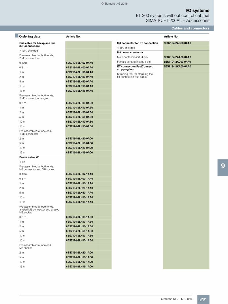
9/91Siemens ST 70 N · 2016
9
I/O systemsET 200 systems without control cabinet
SIMATIC ET 200AL – Accessories
Cables and connectors
■ Ordering data Article No. Article No.
Bus cable for backplane bus (ET connection)
4-pin, shielded
Pre-assembled at both ends, 2 M8 connectors
0.19 m 6ES7194-2LH02-0AA0
0.3 m 6ES7194-2LH03-0AA0
1 m 6ES7194-2LH10-0AA0
2 m 6ES7194-2LH20-0AA0
5 m 6ES7194-2LH50-0AA0
10 m 6ES7194-2LN10-0AA0
15 m 6ES7194-2LN15-0AA0
Pre-assembled at both ends, 2 M8 connectors, angled
0.3 m 6ES7194-2LH03-0AB0
1 m 6ES7194-2LH10-0AB0
2 m 6ES7194-2LH20-0AB0
5 m 6ES7194-2LH50-0AB0
10 m 6ES7194-2LN10-0AB0
15 m 6ES7194-2LN15-0AB0
Pre-assembled at one end, 1 M8 connector
2 m 6ES7194-2LH20-0AC0
5 m 6ES7194-2LH50-0AC0
10 m 6ES7194-2LN10-0AC0
15 m 6ES7194-2LN15-0AC0
Power cable M8
4-pin
Pre-assembled at both ends,M8 connector and M8 socket
0.19 m 6ES7194-2LH02-1AA0
0.3 m 6ES7194-2LH03-1AA0
1 m 6ES7194-2LH10-1AA0
2 m 6ES7194-2LH20-1AA0
5 m 6ES7194-2LH50-1AA0
10 m 6ES7194-2LN10-1AA0
15 m 6ES7194-2LN15-1AA0
Pre-assembled at both ends, angled M8 connector and angled M8 socket
0.3 m 6ES7194-2LH03-1AB0
1 m 6ES7194-2LH10-1AB0
2 m 6ES7194-2LH20-1AB0
5 m 6ES7194-2LH50-1AB0
10 m 6ES7194-2LN10-1AB0
15 m 6ES7194-2LN15-1AB0
Pre-assembled at one end, M8 socket
2 m 6ES7194-2LH20-1AC0
5 m 6ES7194-2LH50-1AC0
10 m 6ES7194-2LN10-1AC0
15 m 6ES7194-2LN15-1AC0
M8 connector for ET connection 6ES7194-2AB00-0AA0
4-pin, shielded
M8 power connector
Male contact insert, 4-pin 6ES7194-2AA00-0AA0
Female contact insert, 4-pin 6ES7194-2AC00-0AA0
ET connection FastConnect stripping tool
6ES7194-2KA00-0AA0
Stripping tool for stripping the ET connection bus cable
© Siemens AG 2016
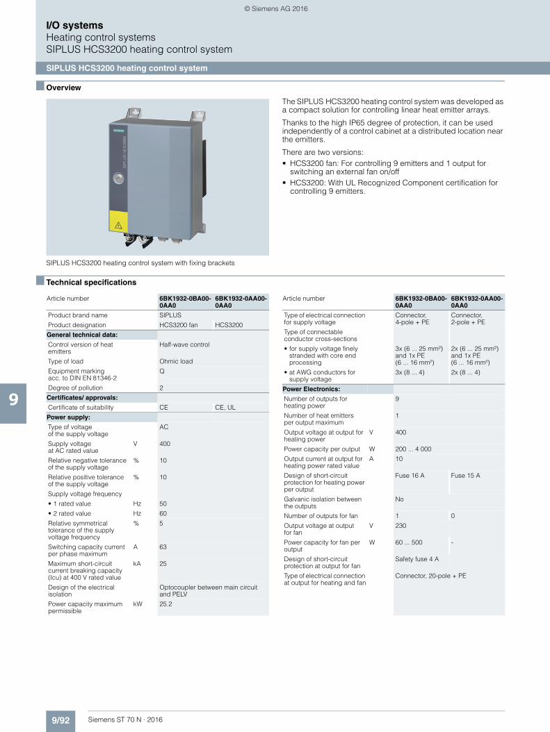
9/92 Siemens ST 70 N · 2016
9
I/O systemsHeating control systemsSIPLUS HCS3200 heating control system
SIPLUS HCS3200 heating control system
■ Overview
SIPLUS HCS3200 heating control system with fixing brackets
The SIPLUS HCS3200 heating control system was developed as a compact solution for controlling linear heat emitter arrays.
Thanks to the high IP65 degree of protection, it can be usedindependently of a control cabinet at a distributed location near the emitters.
There are two versions:• HCS3200 fan: For controlling 9 emitters and 1 output for
switching an external fan on/off• HCS3200: With UL Recognized Component certification for
controlling 9 emitters.
■ Technical specifications
Article number 6BK1932-0BA00-0AA0
6BK1932-0AA00-0AA0
Product brand name SIPLUS
Product designation HCS3200 fan HCS3200
General technical data:
Control version of heat emitters
Half-wave control
Type of load Ohmic load
Equipment markingacc. to DIN EN 81346-2
Q
Degree of pollution 2
Certificates/ approvals:
Certificate of suitability CE CE, UL
Power supply:
Type of voltage of the supply voltage
AC
Supply voltageat AC rated value
V 400
Relative negative tolerance of the supply voltage
% 10
Relative positive tolerance of the supply voltage
% 10
Supply voltage frequency
• 1 rated value Hz 50
• 2 rated value Hz 60
Relative symmetrical tolerance of the supply voltage frequency
% 5
Switching capacity current per phase maximum
A 63
Maximum short-circuit current breaking capacity (Icu) at 400 V rated value
kA 25
Design of the electrical isolation
Optocoupler between main circuit and PELV
Power capacity maximum permissible
kW 25.2
Type of electrical connection for supply voltage
Connector,4-pole + PE
Connector, 2-pole + PE
Type of connectable conductor cross-sections
• for supply voltage finely stranded with core end processing
3x (6 ... 25 mm²) and 1x PE(6 ... 16 mm²)
2x (6 ... 25 mm²) and 1x PE(6 ... 16 mm²)
• at AWG conductors for supply voltage
3x (8 ... 4) 2x (8 ... 4)
Power Electronics:
Number of outputs for heating power
9
Number of heat emitters per output maximum
1
Output voltage at output for heating power
V 400
Power capacity per output W 200 ... 4 000
Output current at output for heating power rated value
A 10
Design of short-circuit protection for heating power per output
Fuse 16 A Fuse 15 A
Galvanic isolation between the outputs
No
Number of outputs for fan 1 0
Output voltage at output for fan
V 230
Power capacity for fan per output
W 60 ... 500 -
Design of short-circuit protection at output for fan
Safety fuse 4 A
Type of electrical connection at output for heating and fan
Connector, 20-pole + PE
Article number 6BK1932-0BA00-0AA0
6BK1932-0AA00-0AA0
© Siemens AG 2016
9/93Siemens ST 70 N · 2016
9
■ Technical specifications (continued)
I/O systemsHeating control systems
SIPLUS HCS3200 heating control system
SIPLUS HCS3200 heating control system
■ Ordering data Article No. Article No.
Type of connectable conductor cross-sections
• for heating and fan finely stranded with core end processing
20x(1.5 ... 4 mm²), 1x PE(1.5 ... 16 mm²)
18x (1.5 ... 4 mm²),1x PE(1.5 ... 16 mm²)
• at AWG conductors stranded
20x (18 ... 12) 18x (18 ... 12)
Product function voltage detection
Yes
Communication:
Protocol is supported PROFIBUS DP protocol
Yes
Design of the interface PROFIBUS DP
Transfer rate withPROFIBUS DP maximum
Mbit/s 12
Type of electrical connection of the PROFIBUS interface
ECOFAST
Power supply:
Design of the power supply External
Type of voltage DC
Supply voltage for electronics
V 24
Relative symmetrical tolerance of the input voltage
% 20
Consumed current for electronics maximum
A 0.25
Protective and monitoring functions:
Number of status displays 2
Display version as status display by LED
LED green = status indicator, LED red = fault indicator
Product function Temperature monitoring
Yes
Type of the temperature monitoring
NTC thermistor
Diagnostics functionTripped fuse
Yes
Diagnostics functionCable break
Yes
Diagnostics function Heat emitter failure
Yes
Mechanical data:
Mounting position vertical
Mounting type screw fixing
Type of ventilation Self-ventilation
Shock resistance
• acc. to IEC 60068-2-27 15g / 11 ms / 3 shocks / axis
• acc. to IEC 60068-2-29 25 g / 6 ms / 1000 shocks / axis
Article number 6BK1932-0BA00-0AA0
6BK1932-0AA00-0AA0
Vibration resistance
• during operation acc. to IEC 60068-2-6
10 ... 58 Hz / 0.15 mm,58 ... 150 Hz / 1g
• during storage acc. to IEC 60068-2-6
5 ... 9 Hz / 3.5 mm, 9 ... 500 Hz / 1g
Protection class IP IP65
Width mm 300
Height mm 380
Depth mm 200
Electromagnetic compatibility:
Conducted interference due to burst acc. to IEC 61000-4-4
2 kV power supply lines / 1 kV signal lines
Conducted interference due to surge acc. toIEC 61000-4-5
On supply lines: 1 kV symmetrical,2 kV asymmetrical, (24 V DC supply only with external protective measure) for PROFIBUS cable : asymmetrical 1 kV
Conducted interference due to high-frequency radiation acc. to IEC 61000-4-6
10 V (0.15 ... 80 MHz)
Electrostatic discharge acc. to IEC 61000-4-2
4 kV contact discharge / 8 kV air discharge
Field-bound parasitic coupling acc. toIEC 61000-4-3
10 V/m (80 ... 1000 MHz),3 V/m (1.4 ... 2.0 GHz), 1 V/m (2.0 ... 2.7 GHz)
EMC emitted interference in accordance withIEC 61000-6-4:2007 + A1:2011
Overvoltage category III
Ambient conditions:
Ambient temperature
• during operation °C 0 ... 50
• during storage °C -40 ... +70
• during transport °C -40 ... +70
Air pressure
• during operation hPa 860 ... 1 080
• during storage hPa 660 ... 1 080
Installation altitude at height above sea level maximum
m 2 000
Relative humidity
• at 25 °C maximum % 95
• at 50 °C during operation maximum
% 50
Article number 6BK1932-0BA00-0AA0
6BK1932-0AA00-0AA0
SIPLUS HCS3200 heating control system
SIPLUS HCS3200 fan 6BK1932-0BA00-0AA0
SIPLUS HCS3200 UL-certified 6BK1932-0AA00-0AA0
Accessories
SIPLUS HCS3200 fanas spare part
6BK1932-6AA00-0AA0
Installation kit for wall mounting 6BK1932-6BA00-0AA0
© Siemens AG 2016

9/94 Siemens ST 70 N · 2016
9
I/O systemsHeating control systemsSIPLUS HCS4200 heating control system
Rack
■ Overview
SIPLUS HCS4200 heating control system
The rack constitutes the basic mechanical structure of SIPLUS HCS4200
■ Technical specifications
■ Ordering data Article No.
Product brand name SIPLUS
Product designation RACK4200 for 4 POM
RACK4200for 12 POM
General technical data:
Equipment markingacc. to DIN EN 81346-2
K
Number of slots 4 12
Type of power output connectable
POM4220
Supply voltage:
Power capacity
• without fan per rack maximum
29 kW 88 kW
• with fan per rack maximum 64 kW 193 kW
Communication:
Design of the interface system interface
Mechanical data:
Mounting position horizontal
Mounting type Control cabinet backplane
Type of ventilation Self ventilation or forced ventilation
Protection class IP IP20
Depth 293 mm
Height 285 mm
Width 204 mm 488 mm
Electromagnetic compatibility:
EMC emitted interference Limit value in accordance with IEC 61000-6-4:2007 + A1:2011
Field-bound parasitic coupling acc. to IEC 61000-4-3
10 V/m (80 ... 1000 MHz), 3 V/m (1.4 ... 2.0 GHz), 1 V/m (2.0 ... 2.7 GHz)
Electrostatic discharge acc. to IEC 61000-4-2
4 kV contact discharge / 8 kV air discharge
Ambient conditions:
Ambient temperature
• during operation 0 ... 55 °C
• during storage -25 ... +70 °C
• during transport -25 ... +70 °C
Air pressure
• during operation 860 ... 1 080 hPa
• during storage 660 ... 1 080 hPa
Degree of pollution 2
Installation altitude at height above sea level maximum
2 000 m
Relative humidity
• at 25 °C during operation maximum
95 %
• at 50 °C during operation maximum
50 %
• at 50 °C during operation maximum Note
95% at 25 °C, decreasing linearly to 50% at 50 °C
Certificates/ approvals:
Certificate of suitability CE
SIPLUS HCS4200 Rackfor 12 POM
6BK1942-0AA00-0AA0
Rack for accommodating up to 12 POM4320 power output modules
SIPLUS HCS4200 Rackfor 4 POM
6BK1942-0BA00-0AA0
Rack for accommodating up to 4 POM4320 power output modules
Accessories
SIPLUS HCS4200 Fan Module 6BK1942-4AA00-0AA0
Is attached to the top of the rackfor accommodating up to 4 power output modules
Blanking cover (10 items) 6BK1942-6DA00-0AA0
For covering unoccupied slots in the rack
Product brand name SIPLUS
Product designation RACK4200 for 4 POM
RACK4200for 12 POM
© Siemens AG 2016
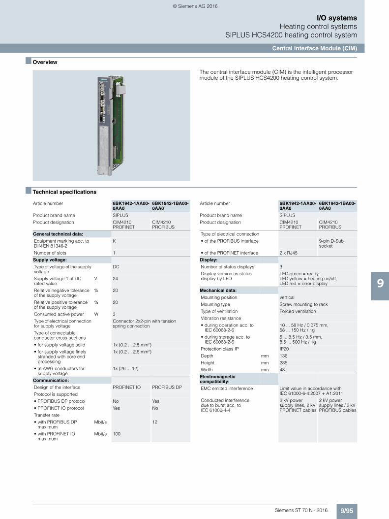
9/95Siemens ST 70 N · 2016
9
I/O systemsHeating control systems
SIPLUS HCS4200 heating control system
Central Interface Module (CIM)
■ Overview
The central interface module (CIM) is the intelligent processor module of the SIPLUS HCS4200 heating control system.
■ Technical specifications
Article number 6BK1942-1AA00-0AA0
6BK1942-1BA00-0AA0
Product brand name SIPLUS
Product designation CIM4210 PROFINET
CIM4210 PROFIBUS
General technical data:
Equipment marking acc. to DIN EN 81346-2
K
Number of slots 1
Supply voltage:
Type of voltage of the supply voltage
DC
Supply voltage 1 at DC rated value
V 24
Relative negative tolerance of the supply voltage
% 20
Relative positive tolerance of the supply voltage
% 20
Consumed active power W 3
Type of electrical connection for supply voltage
Connector 2x2-pin with tension spring connection
Type of connectable conductor cross-sections
• for supply voltage solid 1x (0.2 ... 2.5 mm²)
• for supply voltage finely stranded with core end processing
1x (0.2 ... 2.5 mm²)
• at AWG conductors for supply voltage
1x (26 ... 12)
Communication:
Design of the interface PROFINET IO PROFIBUS DP
Protocol is supported
• PROFIBUS DP protocol No Yes
• PROFINET IO protocol Yes No
Transfer rate
• with PROFIBUS DP maximum
Mbit/s 12
• with PROFINET IO maximum
Mbit/s 100
Type of electrical connection
• of the PROFIBUS interface 9-pin D-Sub socket
• of the PROFINET interface 2 x RJ45
Display:
Number of status displays 3
Display version as status display by LED
LED green = ready, LED yellow = heating on/off, LED red = error display
Mechanical data:
Mounting position vertical
Mounting type Screw mounting to rack
Type of ventilation Forced ventilation
Vibration resistance
• during operation acc. to IEC 60068-2-6
10 ... 58 Hz / 0.075 mm, 58 ... 150 Hz / 1g
• during storage acc. toIEC 60068-2-6
5 ... 8.5 Hz / 3.5 mm, 8.5 ... 500 Hz / 1g
Protection class IP IP20
Depth mm 136
Height mm 285
Width mm 43
Electromagnetic compatibility:
EMC emitted interference Limit value in accordance with IEC 61000-6-4:2007 + A1:2011
Conducted interference due to burst acc. toIEC 61000-4-4
2 kV power supply lines, 2 kV PROFINET cables
2 kV power supply lines / 2 kV PROFIBUS cables
Article number 6BK1942-1AA00-0AA0
6BK1942-1BA00-0AA0
Product brand name SIPLUS
Product designation CIM4210 PROFINET
CIM4210 PROFIBUS
© Siemens AG 2016
9/96 Siemens ST 70 N · 2016
9
■ Technical specifications (continued)
I/O systemsHeating control systemsSIPLUS HCS4200 heating control system
Central Interface Module (CIM)
Conducted interferencedue to surge acc. toIEC 61000-4-5
DC supply lines: 0.5 kV symmetric and unsymmetric PROFINET cables: 1 kV unsymmetric
DC supply lines: 0.5 kV symmet-rical and asymmetrical, PROFIBUS lines: 1 kV asymmetrical
Conducted interference due to high-frequency radiation acc. to IEC 61000-4-6
10 V (0.15 ... 80 MHz)
Field-bound parasitic coupling acc. toIEC 61000-4-3
10 V/m (80 ... 1000 MHz), 3 V/m (1.4 ... 2.0 GHz), 1 V/m (2.0 ... 2.7 GHz)
Electrostatic dischargeacc. to IEC 61000-4-2
4 kV contact discharging, 8 kV air discharging
Overvoltage category III
Ambient conditions:
Ambient temperature
• during operation °C 0 ... 55
• during storage °C -25 ... +70
• during transport °C -25 ... +70
Air pressure
• during operation hPa 860 ... 1 080
• during storage hPa 660 ... 1 080
Degree of pollution 2
Installation altitude at height above sea level maximum
m 2 000
Relative humidity
• at 25 °C during operation maximum
% 95
• at 50 °C during operation maximum
% 50
• at 50 °C during operation maximum Note
95% at 25 °C, decreasing linearly to 50% at 50 °C
Article number 6BK1942-1AA00-0AA0
6BK1942-1BA00-0AA0
Product brand name SIPLUS
Product designation CIM4210 PROFINET
CIM4210 PROFIBUS
■ Ordering data Article No.
SIPLUS HCS4200 CIM4210 PROFINET
6BK1942-1AA00-0AA0
Central interface module with PROFINET communication
SIPLUS HCS4200 CIM4210 PROFIBUS
6BK1942-1BA00-0AA0
Central interface module with PROFIBUS communication
Accessories
SIPLUS HCS4200 connector set 6BK1942-6FA00-0AA0
consisting of 20 x 2-pole connectors (24 V DC power supply)
SIPLUS HCS4000I/O module temperature
6BK1900-0AA00-0AA0
For recording temperaturesusing temperature sensors, thermocouples and pyrometers
SIPLUS HCS4000I/O module DI/DO
6BK1900-0BA00-0AA0
With 8 digital outputsand 8 configurable inputs/outputs
SIPLUS HCS4000I/O module U/I
6BK1900-0CA00-0AA0
For current and voltage measure-ment (line voltage compensation)
© Siemens AG 2016
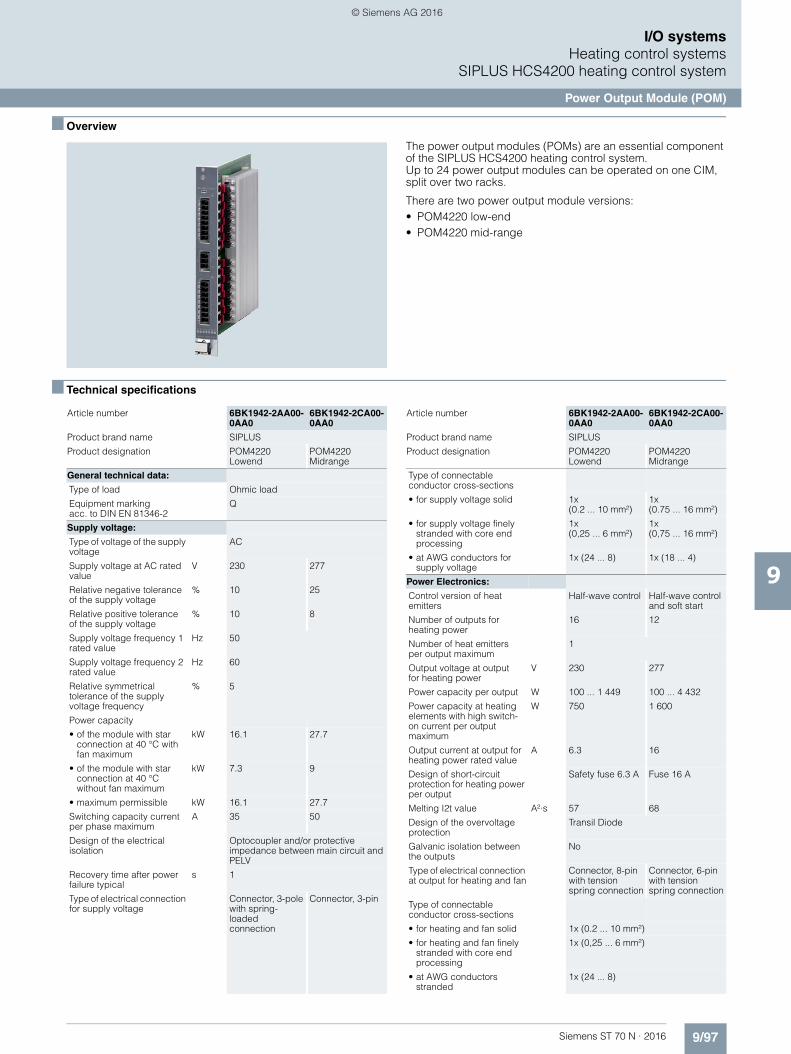
9/97Siemens ST 70 N · 2016
9
I/O systemsHeating control systems
SIPLUS HCS4200 heating control system
Power Output Module (POM)
■ Overview
The power output modules (POMs) are an essential component of the SIPLUS HCS4200 heating control system. Up to 24 power output modules can be operated on one CIM, split over two racks.
There are two power output module versions:• POM4220 low-end• POM4220 mid-range
■ Technical specifications
Article number 6BK1942-2AA00-0AA0
6BK1942-2CA00-0AA0
Product brand name SIPLUS
Product designation POM4220 Lowend
POM4220 Midrange
General technical data:
Type of load Ohmic load
Equipment markingacc. to DIN EN 81346-2
Q
Supply voltage:
Type of voltage of the supply voltage
AC
Supply voltage at AC rated value
V 230 277
Relative negative tolerance of the supply voltage
% 10 25
Relative positive tolerance of the supply voltage
% 10 8
Supply voltage frequency 1 rated value
Hz 50
Supply voltage frequency 2 rated value
Hz 60
Relative symmetrical tolerance of the supply voltage frequency
% 5
Power capacity
• of the module with star connection at 40 °C with fan maximum
kW 16.1 27.7
• of the module with star connection at 40 °C without fan maximum
kW 7.3 9
• maximum permissible kW 16.1 27.7
Switching capacity current per phase maximum
A 35 50
Design of the electrical isolation
Optocoupler and/or protective impedance between main circuit and PELV
Recovery time after power failure typical
s 1
Type of electrical connection for supply voltage
Connector, 3-pole with spring-loaded connection
Connector, 3-pin
Type of connectable conductor cross-sections
• for supply voltage solid 1x (0.2 ... 10 mm²)
1x (0.75 ... 16 mm²)
• for supply voltage finely stranded with core end processing
1x (0,25 ... 6 mm²)
1x (0,75 ... 16 mm²)
• at AWG conductors for supply voltage
1x (24 ... 8) 1x (18 ... 4)
Power Electronics:
Control version of heat emitters
Half-wave control Half-wave control and soft start
Number of outputs for heating power
16 12
Number of heat emitters per output maximum
1
Output voltage at outputfor heating power
V 230 277
Power capacity per output W 100 ... 1 449 100 ... 4 432
Power capacity at heating elements with high switch-on current per output maximum
W 750 1 600
Output current at output for heating power rated value
A 6.3 16
Design of short-circuit protection for heating power per output
Safety fuse 6.3 A Fuse 16 A
Melting I2t value A²·s 57 68
Design of the overvoltage protection
Transil Diode
Galvanic isolation between the outputs
No
Type of electrical connection at output for heating and fan
Connector, 8-pin with tension spring connection
Connector, 6-pin with tension spring connection
Type of connectable conductor cross-sections
• for heating and fan solid 1x (0.2 ... 10 mm²)
• for heating and fan finely stranded with core end processing
1x (0,25 ... 6 mm²)
• at AWG conductors stranded
1x (24 ... 8)
Article number 6BK1942-2AA00-0AA0
6BK1942-2CA00-0AA0
Product brand name SIPLUS
Product designation POM4220 Lowend
POM4220 Midrange
© Siemens AG 2016

9/98 Siemens ST 70 N · 2016
9
■ Technical specifications (continued)
I/O systemsHeating control systemsSIPLUS HCS4200 heating control system
Power Output Module (POM)
■ Ordering data Article No. Article No.
Communication:
Design of the interface system interface
Display:
Number of status displays 19 15
Display version as status display by LED
LED green = ready, LED yellow = heating on/off, LED red = error display, LED red = error for each channel
Auxiliary circuit:
Design of the power supply Power supply via rack
Consumed active power maximum
W 1
Protective and monitoring functions:
Product function Temperature monitoring
Yes
Type of the temperature monitoring
NTC thermistor
Diagnostics function Voltage diagnostics
• Tripped fuse Yes
• Cable break Yes
• Heat emitter failure Yes
Mechanical data:
Mounting position vertical
Mounting type Screw mounting to rack
Type of ventilation Self ventilation or forced ventilation
Vibration resistance
• during operation acc. to IEC 60068-2-6
10 ... 58 Hz / 0.075 mm, 58 ... 150 Hz / 1g
• during storage acc. toIEC 60068-2-6
5 ... 8.5 Hz / 3.5 mm,8.5 ... 500 Hz / 1g
Protection class IP IP20
Article number 6BK1942-2AA00-0AA0
6BK1942-2CA00-0AA0
Product brand name SIPLUS
Product designation POM4220 Lowend
POM4220 Midrange
Depth mm 281
Height mm 285
Width mm 36
Electromagnetic compatibility:
EMC emitted interference Limit value in accordance with IEC 61000-6-4:2007 + A1:2011
Conducted interference due to burst acc. to IEC 61000-4-4
2 kV power supply lines,2 kV load lines
Conducted interference due to high-frequency radiation acc. to IEC 61000-4-6
10 V (0.15 ... 80 MHz)
Field-bound parasitic coupling acc. to IEC 61000-4-3
10 V/m (80 ... 1000 MHz),3 V/m (1.4 ... 2.0 GHz), 1 V/m (2.0 ... 2.7 GHz)
Electrostatic discharge acc. to IEC 61000-4-2
4 kV contact discharge / 8 kV air discharge
Overvoltage category III
Ambient conditions:
Ambient temperature
• during operation °C 0 ... 55
• during storage °C -25 ... +70
• during transport °C -25 ... +70
Air pressure
• during operation hPa 860 ... 1 080
• during storage hPa 660 ... 1 080
Degree of pollution 2
Installation altitude at height above sea level maximum
m 2 000
Relative humidity
• at 25 °C during operation maximum
% 95
• at 50 °C during operation maximum
% 50
• at 50 °C during operation maximum Note
95% at 25 °C, decreasing linearly to 50% at 50 °C
Article number 6BK1942-2AA00-0AA0
6BK1942-2CA00-0AA0
Product brand name SIPLUS
Product designation POM4220 Lowend
POM4220 Midrange
SIPLUS HCS4200 POM4220 Low-End
6BK1942-2AA00-0AA0
SIPLUS HCS4200 POM4220 Midrange
6BK1942-2CA00-0AA0
Power output module with 16 out-puts for connecting resistive loads
Accessories
Spare fuse, 6.3 A/250 V,for POM4220 Low-end
6BK1942-6AA00-0AA0
Spare fuse, 16 A/500 V,for the POM4320 Mid-range
6BK1942-6BA00-0AA0
SIPLUS HCS4200 connector set as accessory
6BK1943-6AA00-0AA0
comprising 10 connectors, 3-pin, for incoming supply, POM4220 Low-end
SIPLUS HCS4200 connector set as accessory
6BK1942-6CA00-0AA0
comprising 5 connectors, 8-pin, for power outputs, POM4220 Low-end
SIPLUS HCS4200 connector set as accessory
6BK1942-6GA00-0AA0
comprising 6 connectors, 3-pin, for incoming supply, POM4220 Mid-range
SIPLUS HCS4200 connector set as accessory
6BK1942-6EA00-0AA0
comprising 5 connectors, 6-pin, for power outputs, POM4220 Mid-range
© Siemens AG 2016
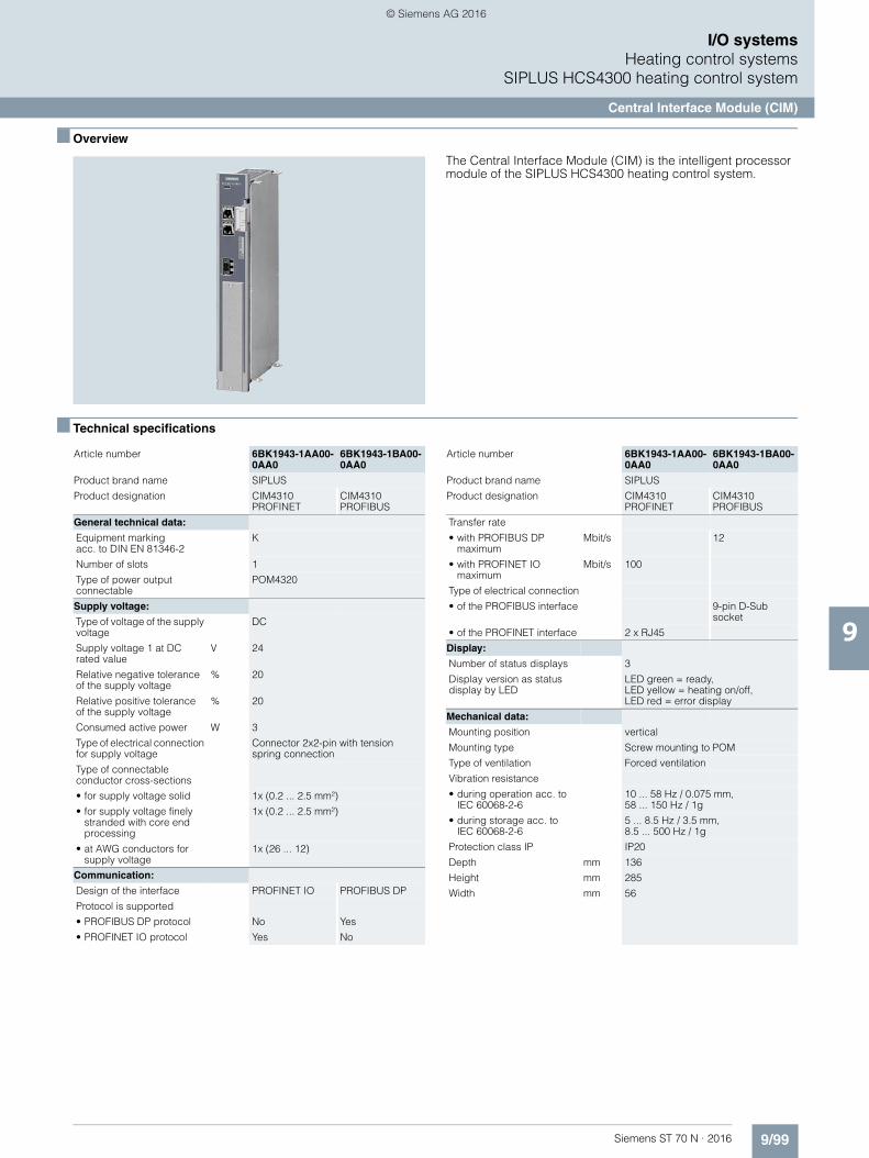
9/99Siemens ST 70 N · 2016
9
I/O systemsHeating control systems
SIPLUS HCS4300 heating control system
Central Interface Module (CIM)
■ Overview
The Central Interface Module (CIM) is the intelligent processor module of the SIPLUS HCS4300 heating control system.
■ Technical specifications
Article number 6BK1943-1AA00-0AA0
6BK1943-1BA00-0AA0
Product brand name SIPLUS
Product designation CIM4310 PROFINET
CIM4310 PROFIBUS
General technical data:
Equipment marking acc. to DIN EN 81346-2
K
Number of slots 1
Type of power output connectable
POM4320
Supply voltage:
Type of voltage of the supply voltage
DC
Supply voltage 1 at DC rated value
V 24
Relative negative tolerance of the supply voltage
% 20
Relative positive tolerance of the supply voltage
% 20
Consumed active power W 3
Type of electrical connection for supply voltage
Connector 2x2-pin with tension spring connection
Type of connectable conductor cross-sections
• for supply voltage solid 1x (0.2 ... 2.5 mm²)
• for supply voltage finely stranded with core end processing
1x (0.2 ... 2.5 mm²)
• at AWG conductors for supply voltage
1x (26 ... 12)
Communication:
Design of the interface PROFINET IO PROFIBUS DP
Protocol is supported
• PROFIBUS DP protocol No Yes
• PROFINET IO protocol Yes No
Transfer rate
• with PROFIBUS DP maximum
Mbit/s 12
• with PROFINET IO maximum
Mbit/s 100
Type of electrical connection
• of the PROFIBUS interface 9-pin D-Sub socket
• of the PROFINET interface 2 x RJ45
Display:
Number of status displays 3
Display version as status display by LED
LED green = ready, LED yellow = heating on/off,LED red = error display
Mechanical data:
Mounting position vertical
Mounting type Screw mounting to POM
Type of ventilation Forced ventilation
Vibration resistance
• during operation acc. to IEC 60068-2-6
10 ... 58 Hz / 0.075 mm,58 ... 150 Hz / 1g
• during storage acc. toIEC 60068-2-6
5 ... 8.5 Hz / 3.5 mm,8.5 ... 500 Hz / 1g
Protection class IP IP20
Depth mm 136
Height mm 285
Width mm 56
Article number 6BK1943-1AA00-0AA0
6BK1943-1BA00-0AA0
Product brand name SIPLUS
Product designation CIM4310 PROFINET
CIM4310 PROFIBUS
© Siemens AG 2016

9/100 Siemens ST 70 N · 2016
9
■ Technical specifications (continued)
I/O systemsHeating control systemsSIPLUS HCS4300 heating control system
Central Interface Module (CIM)
Electromagneticcompatibility:
EMC emitted interference Limit value in accordance withIEC 61000-6-4:2007 + A1:2011
Conducted interference due to burst acc. toIEC 61000-4-4
2 kV power supply lines, 2 kV PROFINET cables
2 kV power supply lines / 2 kV PROFIBUS cables
Conducted interferencedue to surge acc. to IEC 61000-4-5
DC supply lines: 0.5 kV symmetric and unsymmetric PROFINET cables: 1 kV unsymmetric
DC supply lines: 0.5 kV symmet-rical and asymmetrical, PROFIBUS lines: 1 kV asymmetrical
Conducted interference due to high-frequency radiation acc. to IEC 61000-4-6
10 V (0.15 ... 80 MHz)
Field-bound parasitic coupling acc. to IEC 61000-4-3
10 V/m (80 ... 1000 MHz), 3 V/m (1.4 ... 2.0 GHz), 1 V/m (2.0 ... 2.7 GHz)
Electrostatic dischargeacc. to IEC 61000-4-2
4 kV contact discharge / 8 kV air discharge
Overvoltage category III
Ambient conditions:
Ambient temperature
• during operation °C 0 ... 55
• during storage °C -25 ... +70
• during transport °C -25 ... +70
Air pressure
• during operation hPa 860 ... 1 080
• during storage hPa 660 ... 1 080
Degree of pollution 2
Installation altitude at height above sea level maximum
m 2 000
Relative humidity
• at 25 °C during operation maximum
% 95
• at 50 °C during operation maximum
% 50
• at 50 °C during operation maximum Note
95% at 25 °C, decreasing linearly to 50% at 50 °C
Article number 6BK1943-1AA00-0AA0
6BK1943-1BA00-0AA0
Product brand name SIPLUS
Product designation CIM4310 PROFINET
CIM4310 PROFIBUS
■ Ordering data Article No.
SIPLUS HCS4300 CIM 4310
Central interface module with PROFINET communication
6BK1943-1AA00-0AA0
Central interface module with PROFBUS communication
6BK1943-1BA00-0AA0
Accessories
SIPLUS HCS4300 EM 4315 6BK1943-1AA50-0AA0
Expansion module for SIPLUS HCS4300, extends the configurationwith 8 power output modules
SIPLUS HCS4000I/O module temperature
6BK1900-0AA00-0AA0
For recording temperaturesusing temperature sensors,thermocouples and pyrometers
SIPLUS HCS4000 I/O module DI/DO
6BK1900-0BA00-0AA0
With 8 digital outputsand 8 configurable inputs/outputs
SIPLUS HCS4000I/O module U/I
6BK1900-0CA00-0AA0
For current and voltage measure-ment (line voltage compensation)
© Siemens AG 2016

9/101Siemens ST 70 N · 2016
9
I/O systemsHeating control systems
SIPLUS HCS4300 heating control system
Power Output Module (POM)
■ Overview
■ Technical specifications
Article number 6BK1943-2AA00-0AA0 6BK1943-2BA00-0AA0 6BK1943-2CA00-0AA0 6BK1943-2DA00-0AA0
Product brand name SIPLUS
Product designation POM4320 BUSBAR MOUNTING (IEC)
POM4320 BUSBAR MOUNTING (UL)
POM4320 rear panel mounting (IEC)
POM4320 rear panel mounting (UL)
General technical data:
Type of load Ohmic load
Equipment marking acc. to DIN EN 81346-2
Q
Supply voltage:
Type of voltage of the supply voltage AC
Supply voltage at AC rated value V 400
Relative negative tolerance of the supply voltage
% 10
Relative positive tolerance of the supply voltage
% 30
Supply voltage frequency 1 rated value
Hz 50
Supply voltage frequency 2 rated value
Hz 60
Relative symmetrical tolerance of the supply voltage frequency
% 5
Power capacity
• of the module with delta connection at 40 °C with fan maximum
kW 69.1 64.8 69.1 64.8
• maximum permissible kW 69.1 64.8 69.1 64.8
Switching capacity current per phase maximum
A 83 80 83 80
Short-time withstand current (SCCR) acc. to UL 508A
kA 50 50
Design of the electrical isolation Optocoupler and/or protective impedance between main circuit and PELV
Recovery time after power failure typical
s 1
Type of electrical connection for supply voltage
Busbar adapter, 3-pole + PE Terminal, 3-pin
Type of connectable conductor cross-sections
• for supply voltage solid 1x (1.5 ... 50 mm²)
• for supply voltage finely stranded with core end processing
1x (1,5 ... 35 mm²)
• at AWG conductors for supply voltage
1x (16 ... 1)
© Siemens AG 2016

9/102 Siemens ST 70 N · 2016
9
■ Technical specifications (continued)
I/O systemsHeating control systemsSIPLUS HCS4300 heating control system
Power Output Module (POM)
Power Electronics:
Number of outputs for heating power 9
Number of heat emittersper output maximum
1
Output voltage at outputfor heating power
V 400
Power capacity per output W 200 ... 7 680 200 ... 7 200 200 ... 7 680 200 ... 7 200
Power capacity at heating elements with high switch-on current per output maximum
W 4 000 3 000 4 000 3 000
Output current at output for heating power rated value
A 16 15 16 15
Peak current A 150 135 150 135
Design of short-circuit protection for heating power per output
Fuse 16 A Fuse 15 A Fuse 16 A Fuse 15 A
Melting I2t value A²·s 250 225 250 225
Design of the overvoltage protection Transil Diode
Galvanic isolation between the outputs
No
Type of electrical connection at output for heating and fan
Connector, 3-pole with spring-loaded connection
Type of connectable conductor cross-sections
• for heating and fan solid 1x (0.2 ... 10 mm²)
• for heating and fan finely stranded with core end processing
1x (0,25 ... 6 mm²)
• at AWG conductors stranded 1x (24 ... 8)
Product function voltage detection Yes
Communication:
Design of the interface system interface
Display:
Number of status displays 12
Display version as status display by LED
LED green = ready, LED yellow = heating on/off, LED red = error display, LED red = error for each channel
Auxiliary circuit:
Design of the power supply Power supply via CIM
Consumed active power maximum W 8
Protective and monitoring functions:
Product function Temperature monitoring
Yes
Type of the temperature monitoring NTC thermistor
Diagnostics function Voltage diagnostics
• Tripped fuse Yes
• Cable break Yes
• Heat emitter failure Yes
Mechanical data:
Mounting position vertical
Mounting type Busbar mounting Backplane mounting
Type of ventilation Self-ventilation
Vibration resistance
• during operation acc. to IEC 60068-2-6
10 ... 58 Hz / 0.075 mm, 58 ... 150 Hz / 1g
• during storage acc. to IEC 60068-2-6
5 ... 8.5 Hz / 3.5 mm, 8.5 ... 500 Hz / 1g
Protection class IP IP20
Depth mm 250 217
Height mm 340 344
Width mm 104
Article number 6BK1943-2AA00-0AA0 6BK1943-2BA00-0AA0 6BK1943-2CA00-0AA0 6BK1943-2DA00-0AA0
Product brand name SIPLUS
Product designation POM4320 BUSBAR MOUNTING (IEC)
POM4320 BUSBAR MOUNTING (UL)
POM4320 rear panel mounting (IEC)
POM4320 rear panel mounting (UL)
© Siemens AG 2016

9/103Siemens ST 70 N · 2016
9
■ Technical specifications (continued)
I/O systemsHeating control systems
SIPLUS HCS4300 heating control system
Power Output Module (POM)
■ Ordering data Article No. Article No.
Electromagnetic compatibility:
EMC emitted interference Limit value in accordance with IEC 61000-6-4:2007 + A1:2011
Conducted interference due to burst acc. to IEC 61000-4-4
2 kV power supply lines, 2 kV load lines
Conducted interferencedue to surge acc. to IEC 61000-4-5
on supply and load lines: 1 kV symmetric, 2 kV unsymmetric
Conducted interference due to high-frequency radiationacc. to IEC 61000-4-6
10 V (0.15 ... 80 MHz)
Field-bound parasitic coupling acc. to IEC 61000-4-3
10 V/m (80 ... 1000 MHz), 3 V/m (1.4 ... 2.0 GHz), 1 V/m (2.0 ... 2.7 GHz)
Electrostatic discharge acc. to IEC 61000-4-2
4 kV contact discharge / 8 kV air discharge
Overvoltage category III
Ambient conditions:
Ambient temperature
• during operation °C 0 ... 55
• during storage °C -25 ... +70
• during transport °C -25 ... +70
Air pressure
• during operation hPa 860 ... 1 080
• during storage hPa 660 ... 1 080
Degree of pollution 2
Installation altitude at height above sea level maximum
m 2 000
Relative humidity
• at 25 °C during operation maximum % 95
• at 50 °C during operation maximum % 50
• at 50 °C during operation maximum Note
95% at 25 °C, decreasing linearly to 50% at 50 °C
Certificates/ approvals:
Certificate of suitability CE CE / UL CE CE / UL
Article number 6BK1943-2AA00-0AA0 6BK1943-2BA00-0AA0 6BK1943-2CA00-0AA0 6BK1943-2DA00-0AA0
Product brand name SIPLUS
Product designation POM4320 BUSBAR MOUNTING (IEC)
POM4320 BUSBAR MOUNTING (UL)
POM4320 rear panel mounting (IEC)
POM4320 rear panel mounting (UL)
SIPLUS HCS4300 POM4320
Power Output Module with 9 out-puts for connecting resistive loads
Busbar mounting (IEC) 6BK1943-2AA00-0AA0
Busbar mounting (UL) 6BK1943-2BA00-0AA0
Rear panel mounting (IEC) 6BK1943-2CA00-0AA0
Rear panel mounting (UL) 6BK1943-2DA00-0AA0
Accessories
SIPLUS HCS4300 connecting cable from POM to POM
consisting of 10 items, 10 cm long 6BK1943-5AA00-0AA0
consisting of 10 items, 25 cm long 6BK1943-5BA00-0AA0
SIPLUS HCS4300 connector set 6BK1943-6AA00-0AA0
consisting of 10 x 3-pole connectors
Spare fuse, 16 A/500 V,for POM4320
6BK1943-6BA00-0AA0
Fan as spare part 6BK1700-2GA00-0AA0
© Siemens AG 2016
9/104 Siemens ST 70 N · 2016
9
I/O systemsPROFINET components
PROFINET Driver
■ Overview
• For connecting distributed I/O and drives to user-specific control applications via PROFINET
• Operation of the control software on a standard PC using the standard Ethernet interface of the PC
• Supplied as portable source code and can therefore be used with any operating system
• Sample application for Windows included in the scope of delivery; uses SIMATIC IPCs as example hardware
■ Ordering data Article No.
1) You are provided with the source code of the PN driver V1.1, as well as the source code of the application examples. These codes are to be used for modifying and editing in conjunction with SIMATIC only. You are not permitted to use PN driver source codes or the application examples without SIMATIC, nor are you permitted to pass them on to third parties. The application examples are not binding and do not claim to be complete regarding the circuits shown, equipping and any eventuality. The appli-cation examples do not represent customer-specific solutions. They are only intended to provide support for typical tasks. You are responsible for ensuring that the described products are used correctly. These application examples do not relieve you of your responsibility to use safe practices in application, installation, operation and maintenance processes. By using these application examples, you agree that we cannot be held liable for any damages/claims beyond the liability clause described. We reserve the right to make changes to these application examples at any time without prior notice. If there are any deviations between the recommendations provided in these application examples and other Siemens publications – e.g. Catalogs – the contents of the other documents have priority. We do not accept any liability for the information contained in this document. Any claims against us – based on whatever legal reason – resulting from the use of the examples, information, programs, engineering and perfor-mance data etc., described in this Application Example shall be excluded. Such an exclusion shall not apply in the case of mandatory liability, e.g. under the German Product Liability Act (“Produkthaftungsgesetz”), in case of intent, gross negligence, or injury of life, body or health, guarantee for the quality of a product, fraudulent concealment of a deficiency or breach of a condition which goes to the root of the contract (“wesentliche Vertrags-pflichten”). The damages for a breach of a substantial contractual obligation are, however, limited to the foreseeable damage, typical for the type of contract, except in the event of intent or gross negligence or injury to life, body or health. The above provisions do not imply a change of the burden of proof to your detriment. Any form of duplication of these appli-cation examples or excerpts thereof is not permitted without the express consent of Siemens AG.
PROFINET Driver
For connecting distributed I/Oand drives to user-specific control applications via PROFINET
Development license1) 6ES7195-3AA00-0YA0
Runtime licenses• 1 unit 6ES7195-3AA05-0XA0• 10 units 6ES7195-3AA10-0XA0• 50 units 6ES7195-3AA20-0XA0• 200 units 6ES7195-3AA30-0XA0• 500 units 6ES7195-3AA40-0XA0
© Siemens AG 2016

Siemens ST 70 N · 2016
10
Brochures
For brochures serving as selection guides for SIMATIC products refer to:
www.siemens.com/simatic/printmaterial
10/2 SIMATIC TDC multiprocessor control system
10/2 UR6021 rack10/2 CPU555 processor module
SIMATIC control systems
© Siemens AG 2016
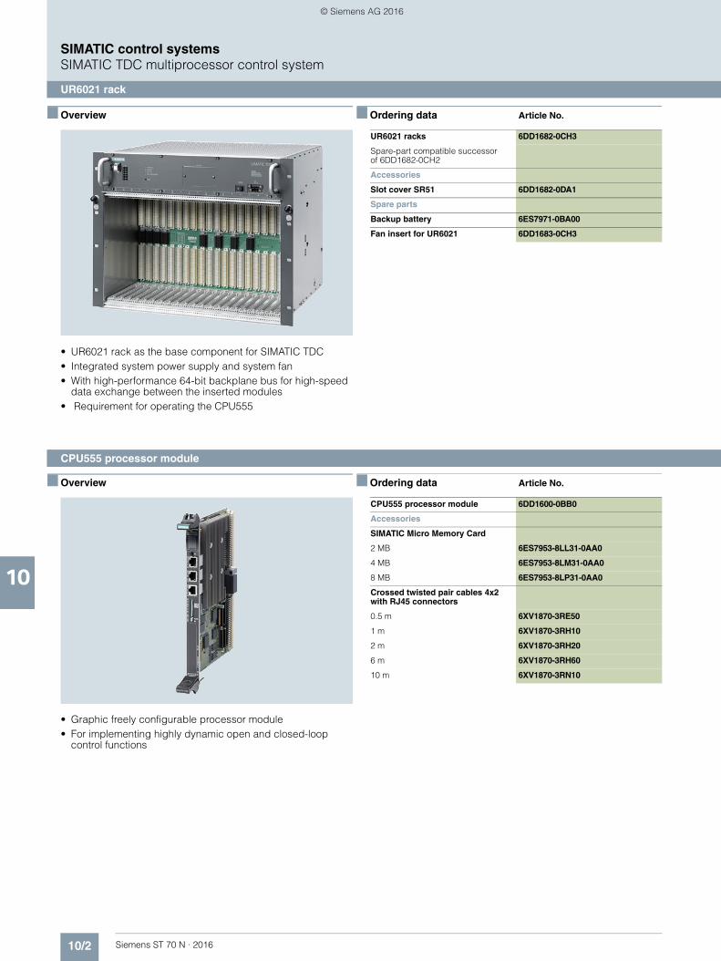
10/2 Siemens ST 70 N · 2016
10
SIMATIC control systemsSIMATIC TDC multiprocessor control system
UR6021 rack
■ Overview
• UR6021 rack as the base component for SIMATIC TDC• Integrated system power supply and system fan• With high-performance 64-bit backplane bus for high-speed
data exchange between the inserted modules• Requirement for operating the CPU555
■ Ordering data Article No.
■ Overview
• Graphic freely configurable processor module• For implementing highly dynamic open and closed-loop
control functions
■ Ordering data Article No.
UR6021 racks 6DD1682-0CH3
Spare-part compatible successor of 6DD1682-0CH2
Accessories
Slot cover SR51 6DD1682-0DA1
Spare parts
Backup battery 6ES7971-0BA00
Fan insert for UR6021 6DD1683-0CH3
CPU555 processor module 6DD1600-0BB0
Accessories
SIMATIC Micro Memory Card
2 MB 6ES7953-8LL31-0AA0
4 MB 6ES7953-8LM31-0AA0
8 MB 6ES7953-8LP31-0AA0
Crossed twisted pair cables 4x2 with RJ45 connectors
0.5 m 6XV1870-3RE50
1 m 6XV1870-3RH10
2 m 6XV1870-3RH20
6 m 6XV1870-3RH60
10 m 6XV1870-3RN10
CPU555 processor module
© Siemens AG 2016
Siemens ST 70 N · 2016
11
Brochures
For brochures serving as selection guides for SIMATIC products refer to:
www.siemens.com/simatic/printmaterial
11/2 Introduction11/2 Information on software licensing11/2 Software Update Service
11/3 Controller software in the TIA Portal11/3 STEP 7 (TIA Portal)11/6 STEP 7 Safety (TIA Portal)
11/8 Options for engineering and drive technology
11/8 D7-SYS11/9 Drive ES engineering software
11/10 Software for joint tasks in the maintenance sector
11/10 SIMATIC PDM
Software for SIMATIC controllers
© Siemens AG 2016

11/2 Siemens ST 70 N · 2016
11
Software for SIMATIC controllersIntroduction
Information on software licensing, Software Update Service
■ Overview Licensing
Siemens Digital Factory offers various types of licensesfor software.
For further information, see chapter 16, page 16/16.
■ Overview Software Update Service
• Service for automatic dispatch of all new software versions during contract lifetime
• Reduced logistics effort thanks to automatic contract extension
• Reduced costs as updates are provided free of charge
Ordering• The Software Update Service is ordered in the same way as
any other product. The corresponding order number is given in the ordering information of the software product in question.
• You must own the current version of the software.• One Software Update Service is ordered for each software
license installed.• The Software Update Service runs for 1 year from date of
order.• It is extended automatically by a further year in each case,
as long as it is not canceled 3 months before it expires.• An annual lump sum is invoiced per license.
■ Application
SIMATIC software is continuously enhanced and improved. The Software Update Service is the easiest way to regularly take advantage of these improvements. This service automati-cally sends new software updates when they are released so you always have the latest version.
The Software Update Service • Saves time and effort:
Once it is ordered, the Software Update Service is automati-cally renewed every year.
• Lowers costs: The service pays for itself after the first update as it costs less than an individually ordered update.
• Makes budgeting easier: Software expenditures can be accounted for early in the budgeting process and they are easier to write off.
■ Design
Scope of delivery• All software versions released after ordering the Software
Update Service (usually several consignments per year).• SIMATIC Customer Support Knowledge Base CD-ROM with
FAQs, tips & tricks and downloads (several issues per year).
© Siemens AG 2016

11/3Siemens ST 70 N · 2016
11
Software for SIMATIC controllersController software in the TIA Portal
STEP 7 (TIA Portal)
■ Overview
STEP 7 V13 SP1 (TIA Portal), portal view
STEP 7 V13 SP1 (TIA Portal), device view: configuring and parameterizing in photographically realistic representation
Intuitive, efficient and future-oriented - the engineering software for programming the SIMATIC controllers
SIMATIC STEP 7 Professional V13 SP1 is the engineering system for the SIMATIC controllers S7-1200, S7-1500, S7-300, S7-400, WinAC and software controllers.
SIMATIC STEP 7 Basic V13 SP1 is the engineering system for the S7-1200.
STEP 7 V13 is based on the central engineering framework Totally Integrated Automation Portal (TIA Portal), which offers the user a uniform, efficient and intuitive solution to all automation tasks.
New with V13 SP1• Supports the new SIMATIC Open controllers• Systematic further development of language elements for
programming• Functional enhancements for team engineering• Scalable online security options• "Undo" is activated in online mode• Simulation for S7-1200 V4.0 and higher• API engineering of STEP 7 and WinCC• Multiple usability expansions for efficient engineering
■ Technical specifications
Compatibility with other SIMATIC products
STEP 7 Professional / Basic V13 SP1 (incl. WinCC Basic V13 SP1) can be installed on a PC in parallel with other versions of STEP 7 V12, V5.4 or V5.5, STEP 7 Micro/WIN, WinCC flexible (from 2008), S7-PCT (from V3.3) and WinCC (from V7.0 SP2).
STEP 7 Professional / Basic V13 SP1 (TIA Portal)
Type of license Floating license
Software class A
Current version V13 SP1
Target system SIMATIC S7-1200, S7-1500, S7-300, S7-400, WinAC, software controllers
Operating system Windows 7 (64-bit)• Windows 7 Professional SP1• Windows 7 Enterprise SP1• Windows 7 Ultimate SP1
Windows 8.1 (64-bit)• Windows 8.1• Windows 8.1 Professional• Windows 8.1 Enterprise
Windows Server (64-bit)• Windows Server 2008 R2 StdE SP1
(full installation)• Windows Server 2012 R2 StdE
(full installation)
Computer SIMATIC Field PG M4 PREMIUM or higher (or comparable PC)
Processor Intel Core i5-3320M 3.3GHz or higher
RAM min. 8 GB
Hard disk 300 GB SSD
Screen 15.6" widescreen display(1920 x 1080)
Note Includes the IEC programminglanguages SCL, LAD, FBD, STL and GRAPH
© Siemens AG 2016

11/4 Siemens ST 70 N · 2016
11
Software for SIMATIC controllersController software in the TIA Portal
STEP 7 (TIA Portal)
■ Ordering data Article No. Article No.
STEP 7 Professional / Basic V13 SP1
Target system:SIMATIC S7-1200, S7-1500, S7-300, S7-400, WinACRequirement:Windows 7 Professional SP1(64 bit), Windows 7 Enterprise SP1 (64 bit), Windows 7 Ultimate SP1 (64 bit), Windows 8.1 (64 bit), Windows 8.1 Professional (64 bit),Windows 8.1 Enterprise (64 bit), Windows Server 2008 R2 StdE(full installation), Windows Server 2012 StdE(full installation)Form of delivery:German, English, Chinese, Italian, French, Spanish
STEP 7 Professional V13 SP1, Floating License
6ES7822-1AA03-0YA5
STEP 7 Professional V13 SP1, Floating License, software downloadincl. license key 1)
Email address required for delivery
6ES7822-1AE03-0YA5
STEP 7 Professional V13 SP1, Trial License
6ES7822-1AA03-0YA7
STEP 7 Professional 2010/V13 SP1, Floating Combo License; on DVD
6ES7810-5CC11-0YA5
STEP 7 Professional 2010/V13 SP1, Floating Combo License, license key download1)
6ES7810-5CE11-0YB5
without software and documenta-tion; email address required for delivery
Conversion package STEP 7 Professional V13 SP1
Only valid if ordered together with a Software Update Service6ES7 810-5CC04-0YE2 (STEP 7 Professional and STEP 7 Professional in TIA Portal).• Powerpack & upgrade from
STEP 7 V5.5 to STEP 7 Professional 2010/V13 SP1, Floating License.Prerequisite is an existing STEP 7 Software Update Service.
6ES7822-1AA03-0XC2
• Powerpack & upgrade from STEP 7 V5.5 to STEP 7 Professional 2010/V13 SP1, floating license.Prerequisite is an existing STEP 7 Software Update Service.Software downloadincl. license key 1)Email address requiredfor delivery
6ES7822-1AE03-0XC2
Upgrade STEP 7 Professional V12 to STEP 7 Professional V13 SP1, Floating License
6ES7822-1AA03-0YE5
Upgrade from STEP 7 Prof. V12 to STEP 7 Professional V13 SP1, Floating License, software downloadincl. license key1)
Email address required for delivery
6ES7822-1AE03-0YE5
Upgrade from STEP 7 Prof. 2006/2010 to STEP 7 Professional 2010/V13 SP1, Floating License
6ES7822-1AA03-0XE5
Upgrade from STEP 7 Prof. 2006/2010 to STEP 7 Professional 2010/V13 SP1, Floating License, software downloadincl. license key1)
Email address required for delivery
6ES7822-1AE03-0XE5
PowerPack STEP 7 Prof. V13 Trial 365 to STEP 7 Prof. V13 SP1, Floating License.
Only valid if ordered together with Software Update Service 6ES7 822-1AE00-0YY0(STEP 7 Professional V1x) Prerequisite is a STEP 7 V13 Trial 365 license. License key download 1) Email address required for delivery
6ES7822-1BE03-0YC5
Powerpack & upgrade from STEP 7 V5.4/V5.5 to STEP 7 Professional 2010/V13 SP1, Floating License.
6ES7822-1AA03-0XC5
Powerpack & upgradefrom STEP 7 V5.4/V5.5 to STEP 7 Professional 2010/V13 SP1, Floating License, software download incl. license key 1)
Email address required for delivery
6ES7822-1AE03-0XC5
Powerpack STEP 7 Basic V13 SP1 to STEP 7 Professional V13 SP1, Floating License
6ES7822-1AA03-0YC5
Powerpack STEP 7 Basic V13 SP1 to STEP 7 Professional V13 SP1, Floating License, software downloadincl. license key 1)
Email address required for delivery
6ES7822-1AE03-0YC5
STEP 7 Basic V13 SP1,Floating License
6ES7822-0AA03-0YA5
STEP 7 Basic V13 SP1, Floating License, software downloadincl. license key1)
Email address required for delivery
6ES7822-0AE03-0YA5
STEP 7 Basic V13 SP1, Trial License
6ES7822-0AA03-0YA7
Upgrade STEP 7 Basic V12 to STEP 7 Basic V13 SP1, Floating License
6ES7822-0AA03-0YE5
1) For up-to-date information and download availability, see:http://www.siemens.com/tia-online-software-delivery
© Siemens AG 2016
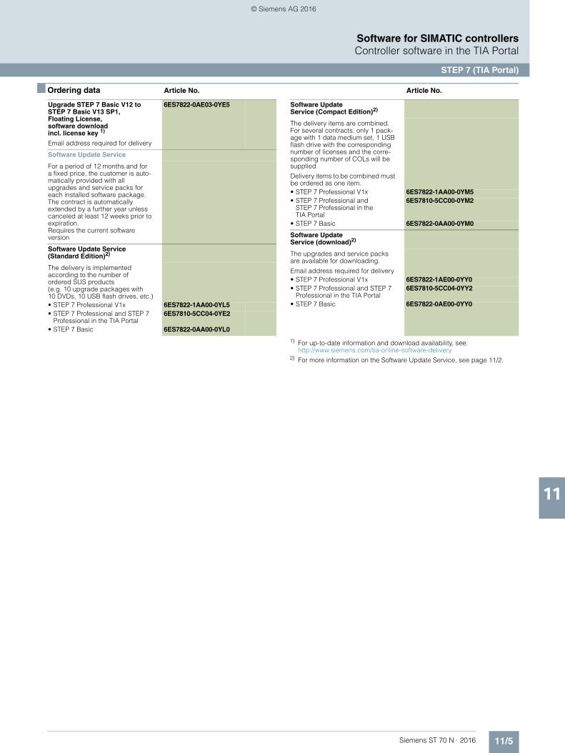
11/5Siemens ST 70 N · 2016
11
■ Ordering data Article No. Article No.
Software for SIMATIC controllersController software in the TIA Portal
STEP 7 (TIA Portal)
1) For up-to-date information and download availability, see:http://www.siemens.com/tia-online-software-delivery
2) For more information on the Software Update Service, see page 11/2.
Upgrade STEP 7 Basic V12 to STEP 7 Basic V13 SP1, Floating License, software downloadincl. license key 1)
Email address required for delivery
6ES7822-0AE03-0YE5
Software Update Service
For a period of 12 months and for a fixed price, the customer is auto-matically provided with all upgrades and service packs for each installed software package. The contract is automatically extended by a further year unless canceled at least 12 weeks prior to expiration. Requires the current software version
Software Update Service(Standard Edition)2)
The delivery is implemented according to the number of ordered SUS products (e.g. 10 upgrade packages with 10 DVDs, 10 USB flash drives, etc.)• STEP 7 Professional V1x 6ES7822-1AA00-0YL5• STEP 7 Professional and STEP 7
Professional in the TIA Portal6ES7810-5CC04-0YE2
• STEP 7 Basic 6ES7822-0AA00-0YL0
Software Update Service (Compact Edition)2)
The delivery items are combined. For several contracts, only 1 pack-age with 1 data medium set, 1 USB flash drive with the corresponding number of licenses and the corre-sponding number of COLs will be supplied.
Delivery items to be combined must be ordered as one item.• STEP 7 Professional V1x 6ES7822-1AA00-0YM5• STEP 7 Professional and
STEP 7 Professional in theTIA Portal
6ES7810-5CC00-0YM2
• STEP 7 Basic 6ES7822-0AA00-0YM0
Software Update Service (download)2)
The upgrades and service packs are available for downloading.
Email address required for delivery• STEP 7 Professional V1x 6ES7822-1AE00-0YY0• STEP 7 Professional and STEP 7
Professional in the TIA Portal6ES7810-5CC04-0YY2
• STEP 7 Basic 6ES7822-0AE00-0YY0
© Siemens AG 2016

11/6 Siemens ST 70 N · 2016
11
Software for SIMATIC controllersController software in the TIA Portal
STEP 7 Safety (TIA Portal)
■ Overview
• For creating safety-related programs on the STEP 7 operator interface
• For seamless and easy to use integration of safety-related functions into the standard automation
• All the required configuration and programming tools are integrated into the STEP 7 operator interface and utilize a common project structure
• STEP 7 Safety Basic option package for parameter assignment and programming of the fail-safe S7-1200
• STEP 7 Safety Advanced option package for all fail-safeTIA SIMATIC controller classes (S7-1500, S7-1200, S7-300, S7-400, WinAC)
■ Ordering data Article No. Article No.
STEP 7 Safety Advanced V13 SP1
Task:Engineering tool for configuringfail-safe user programs forSIMATIC S7-1200 FC, S7-1500F, S7-300F, S7-400F, WinAC RTX F,ET 200SP F controllers, ET 200SP, ET 200S, ET 200M, ET 200iSP, ET 200pro, ET 200ecoRequirement:STEP 7 Professional V13 SP1
Floating License for 1 user, software and documentation on DVD, license key on USB stick
6ES7833-1FA13-0YA5
Floating License for 1 user,software, documentation and license key for download2); e-mail address required for delivery
6ES7833-1FA13-0YH5
Software Update Service(Standard Edition)1)
6ES7833-1FC00-0YX2
The delivery is implemented according to the number of ordered SUS products (e.g. 10 upgrade packages with 10 DVDs,10 USB flash drives, etc.) Requires the current softwareversion.
Software Update Service(Compact Edition)1)
6ES7833-1FC00-0YM2
The delivery items are combined. For several contracts, only 1package with 1 data medium set, 1 USB flash drive with the corresponding number of licenses and the corresponding number of COLs will be supplied. The deliveries that are to be grouped together must be ordered as one item.Requires the current software version.
Minimum order quantity: 5 units
Software Update Service(Download)1)
6ES7833-1FC00-0YY0
Requires the current software version.
E-mail address required for delivery.
STEP 7 Safety Advanced Upgrade
Upgrade from Distributed Safety V5.4 SP5 to STEP 7 Safety Advanced V13 SP1 for paralleluse of both versions; software and documentation on DVD,license key on USB stick; Combo License
6ES7833-1FA13-0YF5
Upgrade from Distributed Safety V5.4 SP5 to STEP 7 Safety Advanced V13 SP1 for parallel use of both versions; software, license key and documentation fordownload2);Combo License; e-mail address required for delivery
6ES7833-1FA13-0YY5
Upgrade from STEP 7 Safety Advanced V11/V12 to STEP 7 Advanced Safety V13 SP1 for parallel use of both versions; software and documentationon DVD, license key on USB stick; Upgrade License
6ES7833-1FA13-0YE5
Upgrade from STEP 7 Safety Advanced V11/V12 to STEP 7 Advanced Safety V13 SP1 for parallel use of both versions; Upgrade License; software, license key anddocumentation for download2); e-mail address required for delivery
6ES7833-1FA13-0YK5
STEP 7 Safety AdvancedPowerPack
Powerpack STEP 7 Safety Basic V13 SP1 to STEP 7 Safety Advanced V13 SP1; license key on USB stick; Floating License for 1 user
6ES7833-1FA13-0YC5
Powerpack STEP 7 Safety Basic V13 SP1 to STEP 7 Safety Advanced V13 SP1;license key for download2); Floating License for 1 user;e-mail address required for delivery
6ES7833-1FA13-0YJ5
1) For more information on the software update service, see page 11/2.2) For up-to-date information and download availability, see:
http://www.siemens.com/tia-online-software-delivery
© Siemens AG 2016
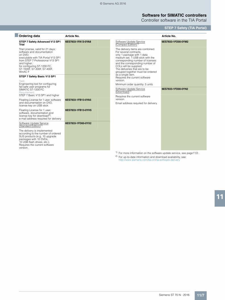
11/7Siemens ST 70 N · 2016
11
■ Ordering data Article No. Article No.
Software for SIMATIC controllersController software in the TIA Portal
STEP 7 Safety (TIA Portal)
1) For more information on the software update service, see page11/2.2) For up-to-date information and download availability, see:
http://www.siemens.com/tia-online-software-delivery
STEP 7 Safety Advanced V13 SP1 Trial
6ES7833-1FA13-0YA8
Trial License, valid for 21 days;software and documentationon DVD; executable with TIA Portal V13 SP1 from STEP 7 Professional V13 SP1 and higher; for configuring S7-1200 FC, S7-1500F, S7-300F, S7-400F,WinAC F
STEP 7 Safety Basic V13 SP1
Task:Engineering tool for configuringfail-safe user programs for SIMATIC S7-1200 FCRequirement:STEP 7 Basic V13 SP1 and higher
Floating License for 1 user, software and documentation on DVD, license key on USB stick
6ES7833-1FB13-0YA5
Floating License for 1 user, software, documentation and license key for download2); e-mail address required for delivery
6ES7833-1FB13-0YH5
Software Update Service(Standard Edition)1)
6ES7833-1FD00-0YX2
The delivery is implemented according to the number of ordered SUS products (e.g. 10 upgrade packages with 10 DVDs, 10 USB flash drives, etc.). Requires the current software version.
Software Update Service(Compact Edition)1)
6ES7833-1FD00-0YM2
The delivery items are combined. For several contracts,only 1 package with 1 data medium set, 1 USB stick with the corresponding number of licenses and the corresponding number of COLs will be supplied. The deliveries that are to be grouped together must be ordered as a single item.Requires the current software version.
Minimum order quantity: 5 units
Software Update Service(Download)1)
6ES7833-1FD00-0YN2
Requires the current software version.
Email address required for delivery.
© Siemens AG 2016

11/8 Siemens ST 70 N · 2016
11
Software for SIMATIC controllersOptions for engineering and drive technology
D7-SYS
■ Overview
• Optional package for STEP 7 V5.5 for configuring closed-loop control and automation tasks with SIMATIC TDC, FM 458-1 DP and T400
• Extensive block library• Generation of user libraries in ANSI C with D7-FB-GEN
function block generator
■ Ordering data Article No.
1) For more information on the software update service, page 11/2.
SIMATIC D7-SYS V8.1
Reference hardware:SIMATIC TDC, FM 458-1 DP, T400 Requirement:MS Windows 7 Professional/Enterprise/Ultimate + SP1 (32/64-bit); MS Windows XP Professional SP3 (32-bit); MS Windows Server 2003 R2 SP2 (32-bit) / 2008 R2 SP1 (64-bit); STEP 7 V5.5 SP4 or higher Type of delivery:on DVD, German, English, with electronic documentation
Floating license 6ES7852-0CC04-0YA5
Upgrade License V7.x and higher 6ES7852-0CC04-0YE5
Software Update Service1) 6ES7852-0CC01-0YL5
SIMATIC Manual Collection 6ES7998-8XC01-8YE0
Electronic manuals on DVD, multilingual: LOGO!, SIMADYN, SIMATIC bus components, SIMATIC C7, SIMATIC distributed I/O, SIMATIC HMI, SIMATIC Sensors, SIMATIC NET, SIMATIC PC Based Automation, SIMATIC PCS 7, SIMATIC PG/PC, SIMATIC S7, SIMATIC Software, SIMATIC TDC
SIMATIC Manual Collection update service for 1 year
6ES7998-8XC01-8YE2
Current "Manual Collection" DVD and the three subsequent updates
© Siemens AG 2016
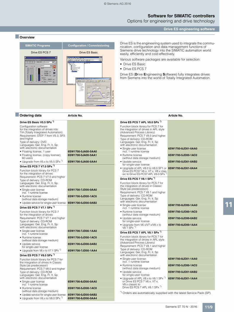
11/9Siemens ST 70 N · 2016
11
Software for SIMATIC controllersOptions for engineering and drive technology
Drive ES engineering software
■ Overview
Drive ES is the engineering system used to integrate the commu-nication, configuration and data management functions of Siemens drive technology into the SIMATIC automation world easily, efficiently and cost-effectively.
Various software packages are available for selection:• Drive ES Basic• Drive ES PCS 7
Drive ES (Drive Engineering Software) fully integrates drives from Siemens into the world of Totally Integrated Automation.
■ Ordering data Article No. Article No.
*) Orders are automatically supplied with the latest Service Pack (SP).
Configuration / CommissioningSIMATIC Programs
G_D
211_
EN
_002
75b
Drive ES BasicDrive ES PCS 7
Drive ES Basic V5.5 SPx *)
Configuration softwarefor the integration of drives intoTIA (Totally Integrated Automation)Requirement: STEP 7 from V5.3, SP3 and higherType of delivery: DVDLanguages: Ger, Eng, Fr, It, Spwith electronic documentation
• Floating license, 1 user 6SW1700-5JA00-5AA0• Floating license, (copy license),
60 users6SW1700-5JA00-5AA1
• Upgrade from V5.x to V5.5 SPx *) 6SW1700-5JA00-5AA4
Drive ES PCS 7 V7.0 SPx *)
Function block library for PCS 7for the integration of drivesRequirement: PCS 7 V7.0 and higherType of delivery: CD-ROM Languages: Ger, Eng, Fr, It, Spwith electronic documentation
• Single-user licenseincl. 1 runtime license
6SW1700-7JD00-0AA0
• Runtime license (without data storage medium)
6SW1700-5JD00-1AC0
• Update service for single-user license 6SW1700-0JD00-0AB2
Drive ES PCS 7 V7.1 SPx *)
Function block library for PCS 7for the integration of drivesRequirement: PCS 7 V7.1 and higherType of delivery: CD-ROM Languages: Ger, Eng, Fr, It, Spwith electronic documentation
• Single-user licenseincl. 1 runtime license
6SW1700-7JD00-1AA0
• Runtime license(without data storage medium)
6SW1700-5JD00-1AC0
• Update servicefor single-user license
6SW1700-0JD00-0AB2
• Upgrade from V6.x to V7.1 SPx *) 6SW1700-7JD00-1AA4
Drive ES PCS 7 V8.0 SPx *)
Function block library for PCS 7 for the integration of drives in Classic Style (as predecessor)Requirement: PCS 7 V8.0 and higherType of delivery: CD-ROM Languages: Ger, Eng, Fr, It, Spwith electronic documentation
• Single-user licenseincl. 1 runtime license
6SW1700-8JD00-0AA0
• Runtime license(without data storage medium)
6SW1700-5JD00-1AC0
• Update service for single-user license 6SW1700-0JD00-0AB2• Upgrade from V6.x to V8.0 SPx *) 6SW1700-8JD00-0AA4
Drive ES PCS 7 APL V8.0 SPx *)
Function block library for PCS 7 for the integration of drives in APL style (Advanced Process Library)Requirement: PCS 7 V8.0 and higherType of delivery: CD-ROM Languages: Ger, Eng, Fr, It, Spwith electronic documentation
• Single-user licenseincl. 1 runtime license
6SW1700-8JD01-0AA0
• Runtime license(without data storage medium)
6SW1700-5JD00-1AC0
• Update servicefor single-user license
6SW1700-0JD01-0AB2
• Upgrade of APL V8.0 to V8.0 SP1 or Drive ES PCS7 V6.x, V7.x, V8.x clas-sic to Drive ES PCS7 APL V8.0 SPx *)
6SW1700-8JD01-0AA4
Drive ES PCS 7 V8.1 SPx *)
Function block library for PCS 7 for the integration of drives in Classic Style (as predecessor)Requirement: PCS 7 V8.1 and higherType of delivery: CD-ROM Languages: Ger, Eng, Fr, It, Spwith electronic documentation
• Single-user licenseincl. 1 runtime license
6SW1700-8JD00-1AA0
• Runtime license(without data storage medium)
6SW1700-5JD00-1AC0
• Update service for single-user license
6SW1700-0JD00-0AB2
• Upgrade from V6.x/V7.x/V8.x to V8.1 SPx *)
6SW1700-8JD00-1AA4
Drive ES PCS 7 APL V8.1 SPx *)
Function block library for PCS 7 for the integration of drives in APL style (Advanced Process Library)Requirement: PCS 7 V8.1 and higherType of delivery: CD-ROM Languages: Ger, Eng, Fr, It, Spwith electronic documentation
• Single-user licenseincl. 1 runtime license
6SW1700-8JD01-1AA0
• Runtime license(without data storage medium)
6SW1700-5JD00-1AC0
• Update servicefor single-user license
6SW1700-0JD01-0AB2
• Upgrade of APL V8.x to V8.1 SPx *) or Drive ES PCS 7 V6.x, V7.x, V8.x classic to Drive ES PCS 7 APL V8.1 SPx *)
6SW1700-8JD01-1AA4
© Siemens AG 2016

11/10 Siemens ST 70 N · 2016
11
Software for SIMATIC controllersSoftware for joint tasks in the maintenance sector
SIMATIC PDM
■ Overview
Configuration options with SIMATIC PDM
SIMATIC PDM (Process Device Manager) is a universal, vendor-independent tool for the configuration, parameter assignment, commissioning, diagnostics and servicing of intelligent fielddevices (sensors and actuators) and field components (remote I/Os, multiplexers, control-room devices, compact controllers), which in the following sections will be referred to simply as de-vices.
With one software product, SIMATIC PDM enables users to work with over 3 500 devices and device variants of Siemens and over 200 other manufacturers worldwide on a single homoge-neous user interface.
The user interface satisfies the requirements of the VDI/VDE GMA 2187 and IEC 65/349/CD directives. Parameters and functions for all supported devices are displayed in a con-sistent and uniform fashion independent of their communica-tions interface. Even complex devices with several hundred parameters can be represented clearly and processed quickly. Using SIMATIC PDM it is very easy to navigate in highly complex stations such as remote I/Os and even connected field devices.
From the viewpoint of device integration, SIMATIC PDM is the most powerful open process device manager on the global mar-ket. Devices which previously were not supported can be inte-grated in SIMATIC PDM by importing their device descriptions (EDD). This provides security for your investment and saves you investment costs, training expenses and follow-up costs.
SIMATIC PDM supports the operative system management in particular through:• Uniform presentation and operation of devices• Uniform representation of diagnostics information• Indicators for preventive maintenance and servicing• Detection of changes in the project and device• Increasing the operational reliability• Reducing the investment, operating and maintenance costs
Maintenance personnel can assign field device parameters using Microsoft Internet Explorer at mobile and stationary workstations with SIMATIC PDM. Practically every workstation integrated in the production plant can be used for configuration. Service personnel are thus able to work directly at the location of the field device, while data is stored centrally in the engineering station or maintenance station. This leads to a significant short-ening of maintenance and travel times.
When a maintenance station is configured in the SIMATIC PCS 7 process control system, SIMATIC PDM is integrated in it and transmits parameter data and diagnostic information. You can switch directly to the SIMATIC PDM views from the diagnostics faceplates in the maintenance station.
A SIMATIC PDM user administration system based onSIMATIC Logon is used to assign various roles with defined function privileges to users. These function privileges refer to SIMATIC PDM system functions, e.g. writing to the device.
For all devices described per Electronic Device Description (EDD), SIMATIC PDM delivers a range of information for display and further processing on the maintenance station, e.g.:• Device type information (electronic rating plate)• Detailed diagnostics information (manufacturer information,
information on error diagnostics and troubleshooting, further documentation)
• Results of internal condition monitoring functions• Status information (e.g. local configuration changes)• Information on changes (audit trail report)• Parameter information
SIMATIC PCS 7 engineering stationwith SIMATIC PDM
Central service station
SIMATIC PCS 7 maintenance station client
Connection point forlocal service station
HARTmultiplexer
Device onthe workbench
HART protocol
Field devices
PROFIBUS PA FF H1
SIMOCODE
SIMOCODE
ET 200iSP
S7-400S7-400
HA
RT
HA
RT
G_P
CS
7_X
X_0
0386
RS 232/RS 485
PROFIBUS DP
Industrial Ethernet
PROFINET
PROFIBUS PA
ET 200M
ET 200M
IE/PB Link PN IO
PA Link CompactFF Link
© Siemens AG 2016
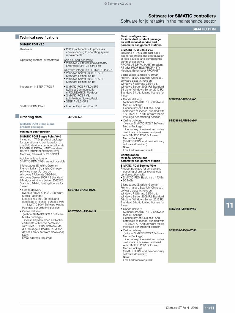
11/11Siemens ST 70 N · 2016
11
Software for SIMATIC controllersSoftware for joint tasks in the maintenance sector
SIMATIC PDM
■ Technical specifications
■ Ordering data Article No.
SIMATIC PDM V9.0
Hardware • PG/PC/notebook with processor corresponding to operating systemrequirements
Operating system (alternatives) Can be used generally:• Windows 7 Professional/Ultimate/
Enterprise SP1, 32-bit/64-bit
Only with integration in SIMATIC PCS 7:• Windows Server 2008 R2 SP1
Standard Edition, 64-bit• Windows Server 2012 R2 SP1
Standard Edition, 64-bit
Integration in STEP 7/PCS 7 • SIMATIC PCS 7 V8.0+SP2(without Communication FOUNDATION Fieldbus)
• SIMATIC PCS 7 V8.1(with/without ServicePack)
• STEP 7 V5.5+SP4
SIMATIC PDM Client • Internet Explorer 10 or 11
SIMATIC PDM Stand aloneproduct packages
Minimum configuration
SIMATIC PDM Single Point V9.0including 1 TAG; product packagefor operation and configuration of one field device; communication via PROFIBUS DP/PA, HART (modem, RS 232, PROFIBUS/PROFINET), Modbus, Ethernet or PROFINET
Additional functions or SIMATIC PDM TAGs are not possible
6 languages (English, German, French, Italian, Spanish, Chinese), software class A, runs on Windows 7 Ultimate 32/64-bit, Windows Server 2008 R2 Standard 64-bit, or Windows Server 2012 R2 Standard 64-bit, floating license for 1 user• Goods delivery
(without SIMATIC PCS 7 Software Media Package)License key on USB stick and certificate of license, bundled with 1 × SIMATIC PDM Software Media Package per ordering position
6ES7658-3HA58-0YA5
• Online delivery (without SIMATIC PCS 7 Software Media Package) License Key download and online certificate of license combined with SIMATIC PDM Software Me-dia Package (SIMATIC PDM and device library software download)Note: Email address required!
6ES7658-3HA58-0YH5
Basic configurationfor individual product package as well as local service and parameter assignment stations
SIMATIC PDM Basic V9.0including 4 TAGs; product pack-age for operation and configuration of field devices and components; communication via PROFIBUS DP/PA, HART (modem, RS 232, PROFIBUS/PROFINET), Modbus, Ethernet or PROFINET
6 languages (English, German, French, Italian, Spanish, Chinese), software class A, runs on Windows 7 Ultimate 32/64-bit, Windows Server 2008 R2 Standard 64-bit, or Windows Server 2012 R2 Standard 64-bit, floating license for 1 user• Goods delivery
(without SIMATIC PCS 7 Software Media Package)License key on USB stick andcertificate of license, bundled with 1 × SIMATIC PDM Software Media Package per ordering position
6ES7658-3AB58-0YA5
• Online delivery (without SIMATIC PCS 7 Software Media Package) License key download and online certificate of license combined with SIMATIC PDM Software Media Package(SIMATIC PDM and device library software download)Note: Email address required!
6ES7658-3AB58-0YH5
Configurationfor local service and parameter assignment station
SIMATIC PDM Service V9.0Product package for service and measuring circuit tests on a local service station, with• SIMATIC PDM Basic incl. 4 TAGs• 50 TAGs
6 languages (English, German, French, Italian, Spanish, Chinese), software class A, runs on Windows 7 Ultimate 32/64-bit,Windows Server 2008 R2 Standard 64-bit, or Windows Server 2012 R2 Standard 64-bit, floating license for 1 user• Goods delivery
(without SIMATIC PCS 7 Software Media Package)License key on USB stick and certificate of license, bundled with 1 × SIMATIC PDM Software Media Package per ordering position
6ES7658-3JD58-0YA5
• Online delivery (without SIMATIC PCS 7 Software Media Package) License key download and online certificate of license combined with SIMATIC PDM Software Media Package(SIMATIC PDM and device library software download)Note: Email address required!
6ES7658-3JD58-0YH5
© Siemens AG 2016
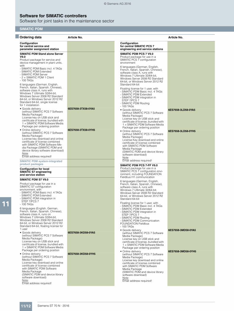
11/12 Siemens ST 70 N · 2016
11
■ Ordering data Article No. Article No.
Software for SIMATIC controllersSoftware for joint tasks in the maintenance sector
SIMATIC PDM
Configuration for central service andparameter assignment station
SIMATIC PDM Stand alone Server V9.0Product package for service and device management in plant units, with- SIMATIC PDM Basic incl. 4 TAGs- SIMATIC PDM Extended- SIMATIC PDM Server- 2 × SIMATIC PDM 1 Client- 100 TAGs
6 languages (German, English, French, Italian, Spanish, Chinese), software class A, runs with Windows 7 Ultimate 32/64-bit, Windows Server 2008 R2 Standard 64-bit, or Windows Server 2012 R2 Standard 64-bit, single licensefor 1 installation• Goods delivery
(without SIMATIC PCS 7 Software Media Package)License key on USB stick and certificate of license, bundled with 1 × SIMATIC PDM Software Media Package per ordering position
6ES7658-3TX58-0YA5
• Online delivery(without SIMATIC PCS 7 Software Media Package)License key download and online certificate of license combined with SIMATIC PDM Software Me-dia Package (SIMATIC PDM and device library software download)Note: Email address required!
6ES7658-3TX58-0YH5
SIMATIC PDM system-integrated product packages
Configuration for localSIMATIC S7 engineeringand service station
SIMATIC PDM S7 V9.0
Product package for use in a SIMATIC S7 configuration environment, with- SIMATIC PDM Basic incl. 4 TAGs- SIMATIC PDM Extended- SIMATIC PDM integration in
STEP 7/PCS 7- 100 TAGs
6 languages (English, German, French, Italian, Spanish, Chinese), software class A, runs on Windows 7 Ultimate 32/64-bit, Windows Server 2008 R2 Standard 64-bit, or Windows Server 2012 R2 Standard 64-bit, floating license for 1 user• Goods delivery
(without SIMATIC PCS 7 Software Media Package)License key on USB stick andcertificate of license, bundled with 1 × SIMATIC PDM Software Media Package per ordering position
6ES7658-3KD58-0YA5
• Online delivery(without SIMATIC PCS 7 Software Media Package)License key download and online certificate of license combined with SIMATIC PDM Software Media Package(SIMATIC PDM and device library software download)Note: Email address required!
6ES7658-3KD58-0YH5
Configurationfor central SIMATIC PCS 7 engineering and service stations
SIMATIC PDM PCS 7 V9.0Product package for use in a SIMATIC PCS 7 configurationenvironment
6 languages (German, English, French, Italian, Spanish, Chinese), software class A, runs with Windows 7 Ultimate 32/64-bit, Windows Server 2008 R2 Standard 64-bit, or Windows Server 2012 R2 Standard 64-bit
Floating license for 1 user, with- SIMATIC PDM Basic incl. 4 TAGs- SIMATIC PDM Extended- SIMATIC PDM integration in
STEP 7/PCS 7- SIMATIC PDM Routing- 100 TAGs• Goods delivery
(without SIMATIC PCS 7 Software Media Package)License key on USB stick and certificate of license, bundled with 1 × SIMATIC PDM Software Media Package per ordering position
6ES7658-3LD58-0YA5
• Online delivery(without SIMATIC PCS 7 Software Media Package)License Key download and online certificate of license combined with SIMATIC PDM SoftwareMedia Package (SIMATIC PDM and device library software download)Note: Email address required!
6ES7658-3LD58-0YH5
SIMATIC PDM PCS 7-FF V9.0Product package for use in a SIMATIC PCS 7 configuration envi-ronment, including FOUNDATION Fieldbus H1 communication
6 languages (German, English, French, Italian, Spanish, Chinese), software class A, runs with Windows 7 Ultimate 32/64-bit, Windows Server 2008 R2 Standard 64-bit, or Windows Server 2012 R2 Standard 64-bit
Floating license for 1 user, with- SIMATIC PDM Basic incl. 4 TAGs- SIMATIC PDM Extended- SIMATIC PDM integration in
STEP 7/PCS 7- SIMATIC PDM Routing- SIMATIC PDM Communication FOUNDATION Fieldbus- 100 TAGs• Goods delivery
(without SIMATIC PCS 7 Software Media Package)License key on USB stick and certificate of license, bundled with 1 × SIMATIC PDM Software Media Package per ordering position
6ES7658-3MD58-0YA5
• Online delivery(without SIMATIC PCS 7 Software Media Package)License key download and online certificate of license combined with SIMATIC PDM Software Media Package (SIMATIC PDM and device library software download)Note: Email address required!
6ES7658-3MD58-0YH5
© Siemens AG 2016
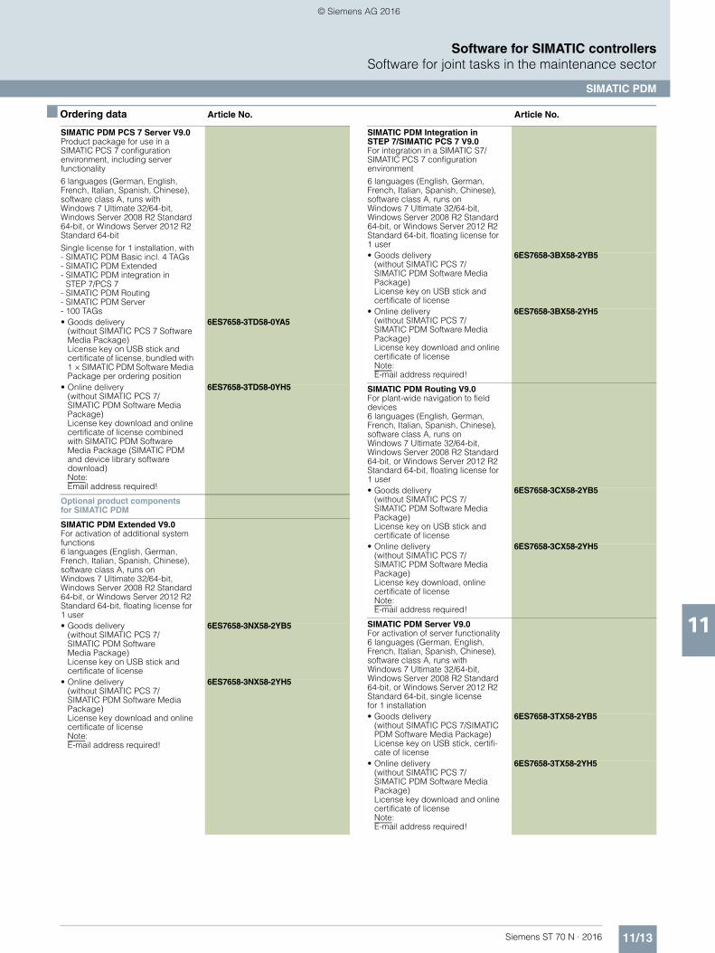
11/13Siemens ST 70 N · 2016
11
■ Ordering data Article No. Article No.
Software for SIMATIC controllersSoftware for joint tasks in the maintenance sector
SIMATIC PDM
SIMATIC PDM PCS 7 Server V9.0Product package for use in a SIMATIC PCS 7 configuration environment, including server functionality
6 languages (German, English, French, Italian, Spanish, Chinese), software class A, runs with Windows 7 Ultimate 32/64-bit, Windows Server 2008 R2 Standard 64-bit, or Windows Server 2012 R2 Standard 64-bit
Single license for 1 installation, with- SIMATIC PDM Basic incl. 4 TAGs- SIMATIC PDM Extended- SIMATIC PDM integration in
STEP 7/PCS 7- SIMATIC PDM Routing- SIMATIC PDM Server- 100 TAGs• Goods delivery
(without SIMATIC PCS 7 Software Media Package)License key on USB stick andcertificate of license, bundled with 1 × SIMATIC PDM Software Media Package per ordering position
6ES7658-3TD58-0YA5
• Online delivery(without SIMATIC PCS 7/SIMATIC PDM Software Media Package)License key download and online certificate of license combined with SIMATIC PDM Software Media Package (SIMATIC PDM and device library software download)Note: Email address required!
6ES7658-3TD58-0YH5
Optional product componentsfor SIMATIC PDM
SIMATIC PDM Extended V9.0For activation of additional system functions6 languages (English, German, French, Italian, Spanish, Chinese), software class A, runs on Windows 7 Ultimate 32/64-bit, Windows Server 2008 R2 Standard 64-bit, or Windows Server 2012 R2 Standard 64-bit, floating license for 1 user• Goods delivery
(without SIMATIC PCS 7/SIMATIC PDM Software Media Package)License key on USB stick andcertificate of license
6ES7658-3NX58-2YB5
• Online delivery(without SIMATIC PCS 7/SIMATIC PDM Software Media Package)License key download and online certificate of licenseNote: E-mail address required!
6ES7658-3NX58-2YH5
SIMATIC PDM Integration in STEP 7/SIMATIC PCS 7 V9.0For integration in a SIMATIC S7/SIMATIC PCS 7 configurationenvironment
6 languages (English, German, French, Italian, Spanish, Chinese), software class A, runs on Windows 7 Ultimate 32/64-bit,Windows Server 2008 R2 Standard 64-bit, or Windows Server 2012 R2 Standard 64-bit, floating license for 1 user• Goods delivery
(without SIMATIC PCS 7/SIMATIC PDM Software Media Package)License key on USB stick and certificate of license
6ES7658-3BX58-2YB5
• Online delivery(without SIMATIC PCS 7/SIMATIC PDM Software Media Package)License key download and online certificate of licenseNote: E-mail address required!
6ES7658-3BX58-2YH5
SIMATIC PDM Routing V9.0For plant-wide navigation to field devices6 languages (English, German, French, Italian, Spanish, Chinese), software class A, runs on Windows 7 Ultimate 32/64-bit, Windows Server 2008 R2 Standard 64-bit, or Windows Server 2012 R2 Standard 64-bit, floating license for 1 user• Goods delivery
(without SIMATIC PCS 7/SIMATIC PDM Software Media Package)License key on USB stick and certificate of license
6ES7658-3CX58-2YB5
• Online delivery(without SIMATIC PCS 7/SIMATIC PDM Software Media Package)License key download, online certificate of licenseNote: E-mail address required!
6ES7658-3CX58-2YH5
SIMATIC PDM Server V9.0For activation of server functionality6 languages (German, English, French, Italian, Spanish, Chinese), software class A, runs with Windows 7 Ultimate 32/64-bit, Windows Server 2008 R2 Standard 64-bit, or Windows Server 2012 R2 Standard 64-bit, single licensefor 1 installation• Goods delivery
(without SIMATIC PCS 7/SIMATIC PDM Software Media Package)License key on USB stick, certifi-cate of license
6ES7658-3TX58-2YB5
• Online delivery(without SIMATIC PCS 7/SIMATIC PDM Software Media Package)License key download and online certificate of licenseNote: E-mail address required!
6ES7658-3TX58-2YH5
© Siemens AG 2016
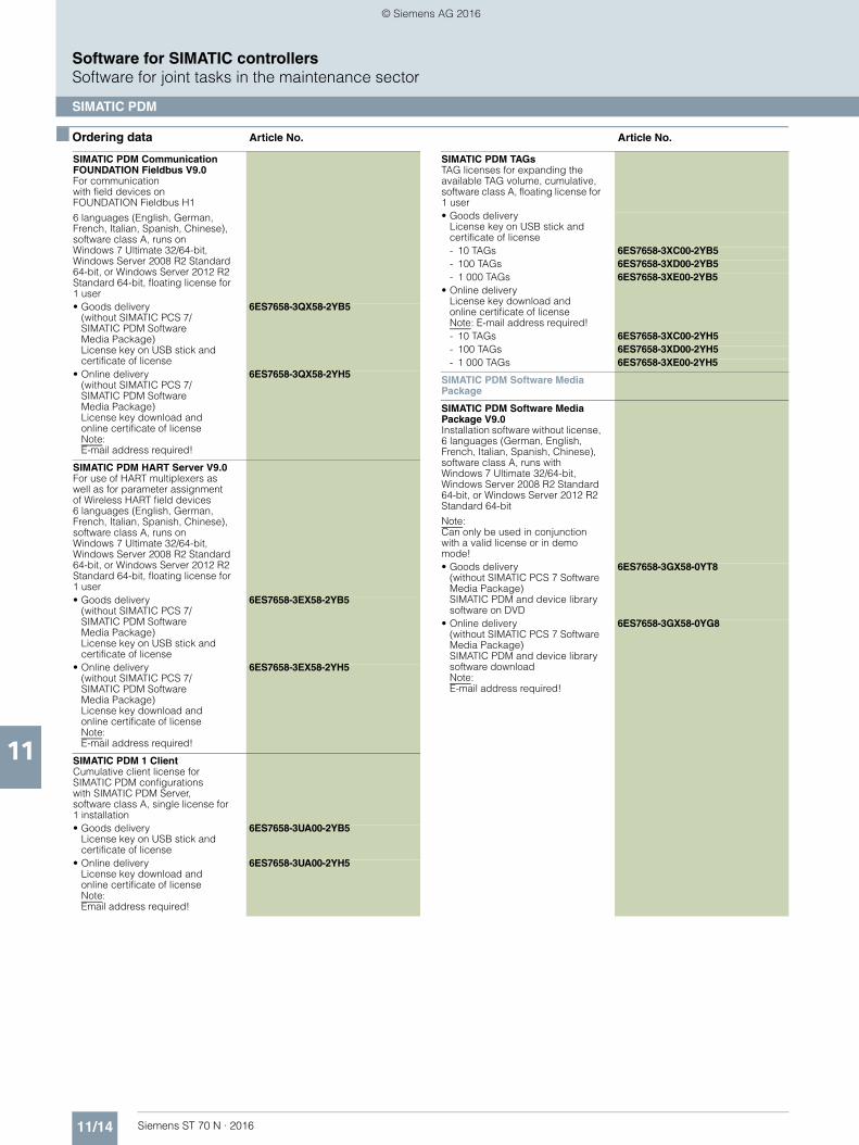
11/14 Siemens ST 70 N · 2016
11
■ Ordering data Article No. Article No.
Software for SIMATIC controllersSoftware for joint tasks in the maintenance sector
SIMATIC PDM
SIMATIC PDM Communication FOUNDATION Fieldbus V9.0For communication with field devices on FOUNDATION Fieldbus H1
6 languages (English, German, French, Italian, Spanish, Chinese), software class A, runs on Windows 7 Ultimate 32/64-bit, Windows Server 2008 R2 Standard 64-bit, or Windows Server 2012 R2 Standard 64-bit, floating license for 1 user• Goods delivery
(without SIMATIC PCS 7/SIMATIC PDM Software Media Package)License key on USB stick and certificate of license
6ES7658-3QX58-2YB5
• Online delivery(without SIMATIC PCS 7/SIMATIC PDM SoftwareMedia Package)License key download and online certificate of licenseNote: E-mail address required!
6ES7658-3QX58-2YH5
SIMATIC PDM HART Server V9.0For use of HART multiplexers as well as for parameter assignment of Wireless HART field devices 6 languages (English, German, French, Italian, Spanish, Chinese), software class A, runs on Windows 7 Ultimate 32/64-bit, Windows Server 2008 R2 Standard 64-bit, or Windows Server 2012 R2 Standard 64-bit, floating license for 1 user• Goods delivery
(without SIMATIC PCS 7/SIMATIC PDM SoftwareMedia Package)License key on USB stick andcertificate of license
6ES7658-3EX58-2YB5
• Online delivery(without SIMATIC PCS 7/SIMATIC PDM SoftwareMedia Package)License key download andonline certificate of licenseNote: E-mail address required!
6ES7658-3EX58-2YH5
SIMATIC PDM 1 ClientCumulative client license for SIMATIC PDM configurations with SIMATIC PDM Server, software class A, single license for 1 installation• Goods delivery
License key on USB stick andcertificate of license
6ES7658-3UA00-2YB5
• Online deliveryLicense key download and online certificate of licenseNote: Email address required!
6ES7658-3UA00-2YH5
SIMATIC PDM TAGsTAG licenses for expanding the available TAG volume, cumulative, software class A, floating license for 1 user• Goods delivery
License key on USB stick and certificate of license- 10 TAGs 6ES7658-3XC00-2YB5- 100 TAGs 6ES7658-3XD00-2YB5- 1 000 TAGs 6ES7658-3XE00-2YB5
• Online deliveryLicense key download and online certificate of licenseNote: E-mail address required!- 10 TAGs 6ES7658-3XC00-2YH5- 100 TAGs 6ES7658-3XD00-2YH5- 1 000 TAGs 6ES7658-3XE00-2YH5
SIMATIC PDM Software Media Package
SIMATIC PDM Software Media Package V9.0Installation software without license, 6 languages (German, English, French, Italian, Spanish, Chinese), software class A, runs with Windows 7 Ultimate 32/64-bit, Windows Server 2008 R2 Standard 64-bit, or Windows Server 2012 R2 Standard 64-bit
Note:Can only be used in conjunction with a valid license or in demo mode!• Goods delivery
(without SIMATIC PCS 7 Software Media Package)SIMATIC PDM and device library software on DVD
6ES7658-3GX58-0YT8
• Online delivery(without SIMATIC PCS 7 Software Media Package)SIMATIC PDM and device library software downloadNote: E-mail address required!
6ES7658-3GX58-0YG8
© Siemens AG 2016
Siemens ST 70 N · 2016
13
Brochures
For brochures serving as selection guides for SIMATIC products refer to:
www.siemens.com/simatic/printmaterial
13/2 Telecontrol systems for comprehensive applications
13/2 SIPLUS RIC substations for IEC protocol13/2 SIPLUS RIC libraries for ET 200SP13/3 SIPLUS RIC libraries for SIMATIC S7-1500
13/4 Automatic door controls13/4 for industry applications13/4 Geared motors13/6 Accessories13/9 for railway applications – Controllers13/9 SIDOOR ATE530S
platform screen door drive
13/11 Condition monitoring systems13/11 SIPLUS CMS1200
condition monitoring system13/11 Introduction13/11 SIPLUS CMS1200
SM 1281 Condition Monitoring13/13 Accessories
Products for specific requirements
© Siemens AG 2016

13/2 Siemens ST 70 N · 2016
13
Products for specific requirementsTelecontrol systems for comprehensive applicationsSIPLUS RIC substations for IEC protocol
SIPLUS RIC libraries for ET 200SP
■ Overview
If a SIMATIC ET 200SP-based system is to communicate with a Siemens control center, e.g. SIMATIC PCS 7 TeleControl, WinCC TeleControl, WinCC OA, or a control center of a third-party supplier using the IEC 60870-5 telecontrol standard, the IEC 60870-5-101 (serial), -103 (protection) or -104 (TCP/IP) telecontrol protocols can be used in the SIMATIC automation systems.
SIPLUS RIC libraries offer an integrated, scalable system based on SIMATIC ET 200SP functions, for the following data volumes:• 200 information points, for use with CPU 1510• 800 information points, for use with CPU 1512
The work memory for data is used for buffering the message frames. Longer communication failure times can thus be bridged should a connection fail. The SIPLUS RIC software libraries are based on the standard TIA Portal and can be used on various, mutually compatible types of SIMATIC S7 devices, thus saving hardware costs and programming overhead.
The libraries are on a CD and are supplied together with a SIMATIC memory card which can be used on all CPUs. Five versions with different storage capacities are available.
With SIPLUS Extreme hardware, telecontrol devices for an extended ambient temperature range (-25 ... +70 °C) and exceptional exposure to media (conformal coating) can be implemented with the telecontrol protocols.
A certificate of license enabling all IEC 60870-5-101 (serial), -103 (protection) or -104 (TCP/IP) telecontrol protocols is supplied for the SIMATIC memory card included in delivery.
■ Ordering data Article No.
SIPLUS RIC libraries for SIMATIC ET 200SP
Runtime license; CD with software anddocumentation
with SIMATIC memory card; 12 MB
6AG6003-8CF00-0LE0
© Siemens AG 2016
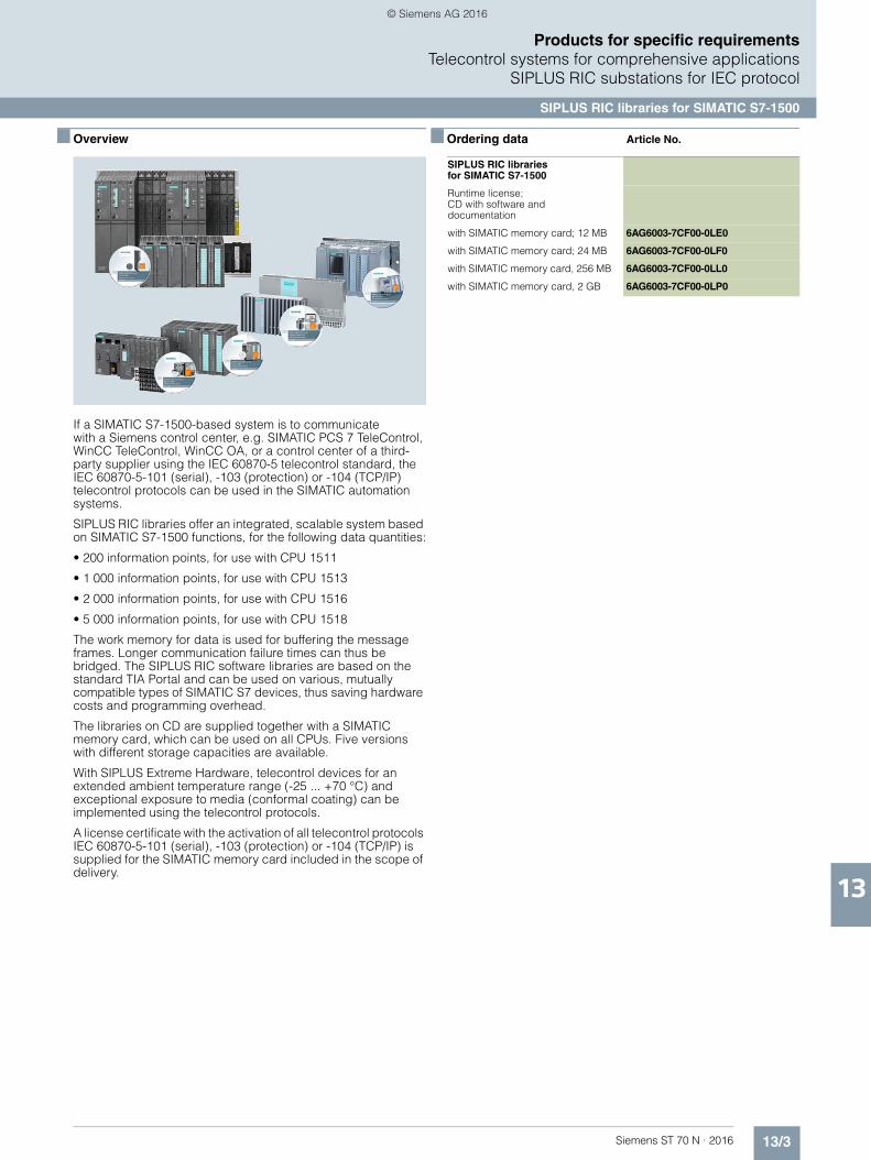
13/3Siemens ST 70 N · 2016
13
Products for specific requirementsTelecontrol systems for comprehensive applications
SIPLUS RIC substations for IEC protocol
SIPLUS RIC libraries for SIMATIC S7-1500
■ Overview
If a SIMATIC S7-1500-based system is to communicate with a Siemens control center, e.g. SIMATIC PCS 7 TeleControl, WinCC TeleControl, WinCC OA, or a control center of a third-party supplier using the IEC 60870-5 telecontrol standard, the IEC 60870-5-101 (serial), -103 (protection) or -104 (TCP/IP) telecontrol protocols can be used in the SIMATIC automation systems.
SIPLUS RIC libraries offer an integrated, scalable system based on SIMATIC S7-1500 functions, for the following data quantities:
• 200 information points, for use with CPU 1511
• 1 000 information points, for use with CPU 1513
• 2 000 information points, for use with CPU 1516
• 5 000 information points, for use with CPU 1518
The work memory for data is used for buffering the message frames. Longer communication failure times can thus be bridged. The SIPLUS RIC software libraries are based on the standard TIA Portal and can be used on various, mutually compatible types of SIMATIC S7 devices, thus saving hardware costs and programming overhead.
The libraries on CD are supplied together with a SIMATIC memory card, which can be used on all CPUs. Five versionswith different storage capacities are available.
With SIPLUS Extreme Hardware, telecontrol devices for an extended ambient temperature range (-25 ... +70 °C) and exceptional exposure to media (conformal coating) can be implemented using the telecontrol protocols.
A license certificate with the activation of all telecontrol protocols IEC 60870-5-101 (serial), -103 (protection) or -104 (TCP/IP) is supplied for the SIMATIC memory card included in the scope of delivery.
■ Ordering data Article No.
SIPLUS RIC librariesfor SIMATIC S7-1500
Runtime license; CD with software and documentation
with SIMATIC memory card; 12 MB 6AG6003-7CF00-0LE0
with SIMATIC memory card; 24 MB 6AG6003-7CF00-0LF0
with SIMATIC memory card, 256 MB 6AG6003-7CF00-0LL0
with SIMATIC memory card, 2 GB 6AG6003-7CF00-0LP0
© Siemens AG 2016
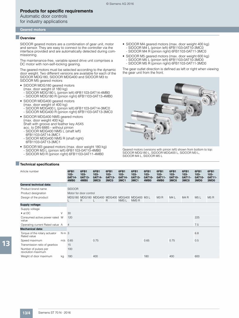
13/4 Siemens ST 70 N · 2016
13
Products for specific requirementsAutomatic door controlsfor industry applications
Geared motors
■ Overview
SIDOOR geared motors are a combination of gear unit, motor and sensor. They are easy to connect to the controller via the interface provided and are automatically detected during com-missioning.
The maintenance-free, variable speed drive unit comprises aDC motor with non-self-locking gearing.
The geared motors must be selected according to the dynamic door weight. Two different versions are available for each of the SIDOOR MDG180, SIDOOR MDG400 and SIDOOR M3 to SIDOOR M5 geared motors:• SIDOOR MDG180 geared motors
(max. door weight of 180 kg)- SIDOOR MDG180 L (pinion left) 6FB1103-0AT14-4MB0- SIDOOR MDG180 R (pinion right) 6FB1103-0AT13-4MB0
• SIDOOR MDG400 geared motors(max. door weight of 400 kg)- SIDOOR MDG400 L (pinion left) 6FB1103-0AT14-3MC0- SIDOOR MDG400 R (pinion right) 6FB1103-0AT13-3MC0
• SIDOOR MDG400 NMS geared motors(max. door weight 400 kg)Shaft with groove and feather key A5X5 acc. to DIN 6885 - without pinion- SIDOOR MDG400 NMS L (shaft left)
6FB1103-0AT14-3MC1- SIDOOR MDG400 NMS R (shaft right)
6FB1103-0AT13-3MC1• SIDOOR M3 geared motors (max. door weight 180 kg)
- SIDOOR M3 L (pinion left) 6FB1103-0AT10-4MB0- SIDOOR M3 R (pinion right) 6FB1103-0AT11-4MB0
• SIDOOR M4 geared motors (max. door weight 400 kg)- SIDOOR M4 L (pinion left) 6FB1103-0AT10-3MC0- SIDOOR M4 R (pinion right) 6FB1103-0AT11-3MC0
• SIDOOR M5 geared motors (max. door weight 600 kg)- SIDOOR M5 L (pinion left) 6FB1103-0AT10-3MD0- SIDOOR M5 R (pinion right) 6FB1103-0AT11-3MD0
The gear outlet direction is defined as left or right when viewing the gear unit from the front.
Geared motors (versions with pinion left) shown from bottom to top: SIDOOR MDG180 L, SIDOOR MDG400 L, SIDOOR M3 L, SIDOOR M4 L, SIDOOR M5 L
■ Technical specifications
Article number 6FB1103-0AT14-4MB0
6FB1103-0AT13-4MB0
6FB1103-0AT14-3MC0
6FB1103-0AT13-3MC0
6FB1103-0AT14-3MC1
6FB1103-0AT13-3MC1
6FB1103-0AT10-4MB0
6FB1103-0AT11-4MB0
6FB1103-0AT10-3MC0
6FB1103-0AT11-3MC0
6FB1103-0AT10-3MD0
6FB1103-0AT11-3MD0
General technical data:
Product brand name SIDOOR
Product designation Motor for door control
Design of the product MDG180 L
MDG180 R
MDG400 L
MDG400 R
MDG400NMS L
MDG400 NMS R
M3 L M3 R M4 L M4 R M5 L M5 R
Supply voltage:
Supply voltage
• at DC V 30
Consumed active power rated value
W 120 225
Operating current Rated value A 4 7.5
Mechanical data:
Torque of the rotary actuator Rated value
N·m 3 6.8
Speed maximum m/s 0.65 0.75 0.65 0.75 0.5
Transmission ratio of gearbox 15
Number of pulses per revolution maximum
100
Weight of door maximum kg 180 400 180 400 600
© Siemens AG 2016
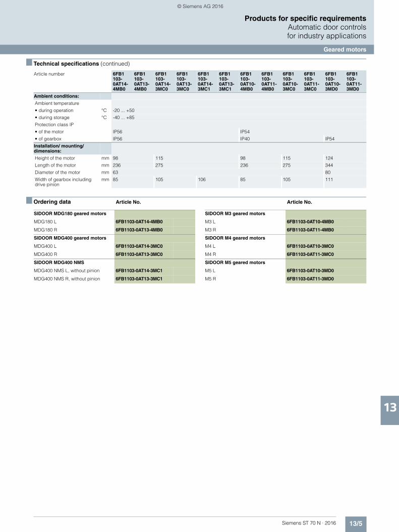
13/5Siemens ST 70 N · 2016
13
■ Technical specifications (continued)
Products for specific requirementsAutomatic door controlsfor industry applications
Geared motors
■ Ordering data Article No. Article No.
Ambient conditions:
Ambient temperature
• during operation °C -20 ... +50
• during storage °C -40 ... +85
Protection class IP
• of the motor IP56 IP54
• of gearbox IP56 IP40 IP54
Installation/ mounting/ dimensions:
Height of the motor mm 98 115 98 115 124
Length of the motor mm 236 275 236 275 344
Diameter of the motor mm 63 80
Width of gearbox including drive pinion
mm 85 105 106 85 105 111
Article number 6FB1103-0AT14-4MB0
6FB1103-0AT13-4MB0
6FB1103-0AT14-3MC0
6FB1103-0AT13-3MC0
6FB1103-0AT14-3MC1
6FB1103-0AT13-3MC1
6FB1103-0AT10-4MB0
6FB1103-0AT11-4MB0
6FB1103-0AT10-3MC0
6FB1103-0AT11-3MC0
6FB1103-0AT10-3MD0
6FB1103-0AT11-3MD0
SIDOOR MDG180 geared motors
MDG180 L 6FB1103-0AT14-4MB0
MDG180 R 6FB1103-0AT13-4MB0
SIDOOR MDG400 geared motors
MDG400 L 6FB1103-0AT14-3MC0
MDG400 R 6FB1103-0AT13-3MC0
SIDOOR MDG400 NMS
MDG400 NMS L, without pinion 6FB1103-0AT14-3MC1
MDG400 NMS R, without pinion 6FB1103-0AT13-3MC1
SIDOOR M3 geared motors
M3 L 6FB1103-0AT10-4MB0
M3 R 6FB1103-0AT11-4MB0
SIDOOR M4 geared motors
M4 L 6FB1103-0AT10-3MC0
M4 R 6FB1103-0AT11-3MC0
SIDOOR M5 geared motors
M5 L 6FB1103-0AT10-3MD0
M5 R 6FB1103-0AT11-3MD0
© Siemens AG 2016
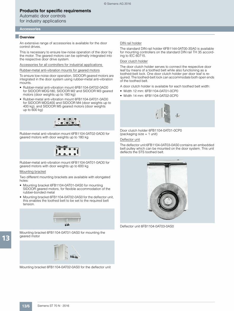
13/6 Siemens ST 70 N · 2016
13
Products for specific requirementsAutomatic door controlsfor industry applications
Accessories
■ Overview
An extensive range of accessories is available for the door control drives.
This is necessary to ensure low-noise operation of the door by the motor. The geared motors can be optimally integrated into the respective door drive system.
Accessories for all controllers for industrial applications
Rubber-metal anti-vibration mounts for geared motors
To ensure low-noise door operation, SIDOOR geared motors are integrated in the door system using rubber-metal anti-vibration mounts.• Rubber-metal anti-vibration mount 6FB1104-0AT02-0AD0
for SIDOOR MDG180, SIDOOR M2 and SIDOOR M3 geared motors (door weights up to 180 kg)
• Rubber-metal anti-vibration mount 6FB1104-0AT01-0AD0for SIDOOR MDG400 and SIDOOR M4 (door weights up to 400 kg), and SIDOOR M5 geared motors (door weights up to 600 kg)
Rubber-metal anti-vibration mount 6FB1104-0AT02-0AD0 for geared motors with door weights up to 180 kg
Rubber-metal anti-vibration mount 6FB1104-0AT01-0AD0 for geared motors with door weights up to 600 kg
Mounting bracket
Two different mounting brackets are available with elongated holes: • Mounting bracket 6FB1104-0AT01-0AS0 for mounting
SIDOOR geared motors, for flexible accommodation of the rubber-bonded metal
• Mounting bracket 6FB1104-0AT02-0AS0 for the deflector unit, this enables the toothed belt to be set to the required belt tension.
Mounting bracket 6FB1104-0AT01-0AS0 for mounting the geared motor
Mounting bracket 6FB1104-0AT02-0AS0 for the deflector unit
DIN rail holder
The standard DIN rail holder 6FB1144-0AT00-3SA0 is available for mounting controllers on the standard DIN rail TH 35 accord-ing to IEC 60715.
Door clutch holder
The door clutch holder serves to connect the respective door leaf by means of a toothed belt while also functioning as a toothed-belt lock. One door clutch holder per door leaf is re-quired. The toothed-belt lock can accommodate both open ends of the toothed belt.
A door clutch holder is available for each toothed belt width:• Width 12 mm: 6FB1104-0AT01-0CP0• Width 14 mm: 6FB1104-0AT02-0CP0
Door clutch holder 6FB1104-0AT01-0CP0 (packaging size = 1 unit)
Deflector unit
The deflector unit 6FB1104-0AT03-0AS0 contains an embedded belt pulley which can be mounted on the door system. This unit deflects the STS toothed belt.
Deflector unit 6FB1104-0AT03-0AS0
© Siemens AG 2016
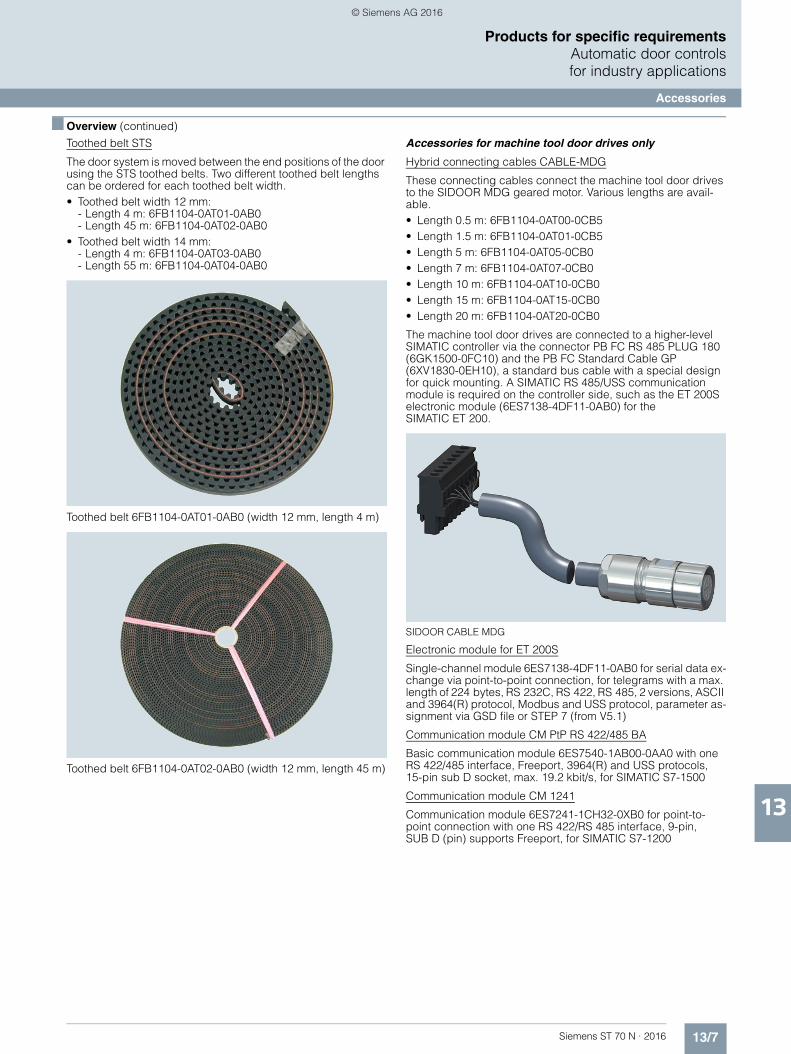
13/7Siemens ST 70 N · 2016
13
■ Overview (continued)
Products for specific requirementsAutomatic door controlsfor industry applications
Accessories
Toothed belt STS
The door system is moved between the end positions of the door using the STS toothed belts. Two different toothed belt lengths can be ordered for each toothed belt width.• Toothed belt width 12 mm:
- Length 4 m: 6FB1104-0AT01-0AB0- Length 45 m: 6FB1104-0AT02-0AB0
• Toothed belt width 14 mm: - Length 4 m: 6FB1104-0AT03-0AB0- Length 55 m: 6FB1104-0AT04-0AB0
Toothed belt 6FB1104-0AT01-0AB0 (width 12 mm, length 4 m)
Toothed belt 6FB1104-0AT02-0AB0 (width 12 mm, length 45 m)
Accessories for machine tool door drives only
Hybrid connecting cables CABLE-MDG
These connecting cables connect the machine tool door drives to the SIDOOR MDG geared motor. Various lengths are avail-able.• Length 0.5 m: 6FB1104-0AT00-0CB5• Length 1.5 m: 6FB1104-0AT01-0CB5• Length 5 m: 6FB1104-0AT05-0CB0• Length 7 m: 6FB1104-0AT07-0CB0• Length 10 m: 6FB1104-0AT10-0CB0• Length 15 m: 6FB1104-0AT15-0CB0• Length 20 m: 6FB1104-0AT20-0CB0
The machine tool door drives are connected to a higher-level SIMATIC controller via the connector PB FC RS 485 PLUG 180 (6GK1500-0FC10) and the PB FC Standard Cable GP (6XV1830-0EH10), a standard bus cable with a special design for quick mounting. A SIMATIC RS 485/USS communication module is required on the controller side, such as the ET 200S electronic module (6ES7138-4DF11-0AB0) for the SIMATIC ET 200.
SIDOOR CABLE MDG
Electronic module for ET 200S
Single-channel module 6ES7138-4DF11-0AB0 for serial data ex-change via point-to-point connection, for telegrams with a max. length of 224 bytes, RS 232C, RS 422, RS 485, 2 versions, ASCII and 3964(R) protocol, Modbus and USS protocol, parameter as-signment via GSD file or STEP 7 (from V5.1)
Communication module CM PtP RS 422/485 BA
Basic communication module 6ES7540-1AB00-0AA0 with one RS 422/485 interface, Freeport, 3964(R) and USS protocols,15-pin sub D socket, max. 19.2 kbit/s, for SIMATIC S7-1500
Communication module CM 1241
Communication module 6ES7241-1CH32-0XB0 for point-to-point connection with one RS 422/RS 485 interface, 9-pin,SUB D (pin) supports Freeport, for SIMATIC S7-1200
© Siemens AG 2016
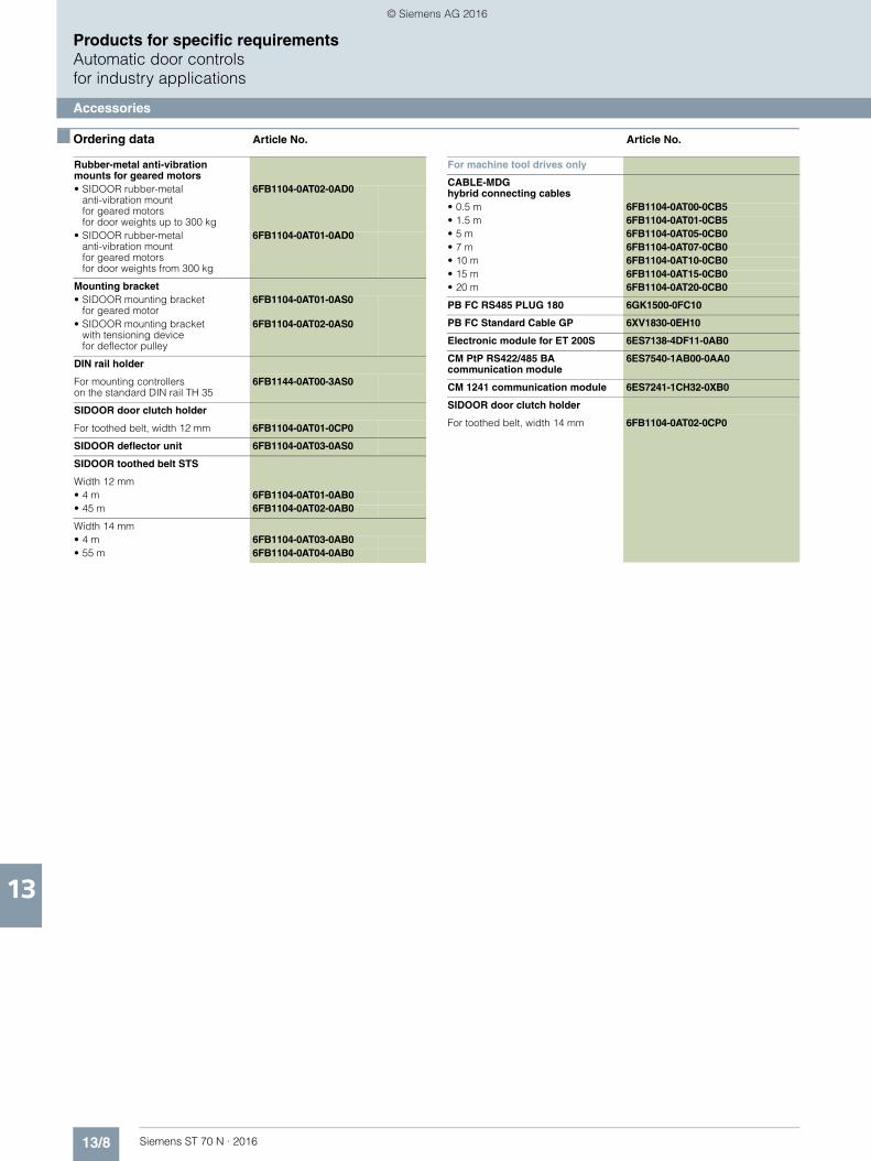
13/8 Siemens ST 70 N · 2016
13
Products for specific requirementsAutomatic door controlsfor industry applications
Accessories
■ Ordering data Article No. Article No.
Rubber-metal anti-vibration mounts for geared motors• SIDOOR rubber-metal
anti-vibration mount for geared motorsfor door weights up to 300 kg
6FB1104-0AT02-0AD0
• SIDOOR rubber-metal anti-vibration mount for geared motors for door weights from 300 kg
6FB1104-0AT01-0AD0
Mounting bracket• SIDOOR mounting bracket
for geared motor6FB1104-0AT01-0AS0
• SIDOOR mounting bracket with tensioning devicefor deflector pulley
6FB1104-0AT02-0AS0
DIN rail holder
For mounting controllers on the standard DIN rail TH 35
6FB1144-0AT00-3AS0
SIDOOR door clutch holder
For toothed belt, width 12 mm 6FB1104-0AT01-0CP0
SIDOOR deflector unit 6FB1104-0AT03-0AS0
SIDOOR toothed belt STS
Width 12 mm• 4 m 6FB1104-0AT01-0AB0• 45 m 6FB1104-0AT02-0AB0
Width 14 mm• 4 m 6FB1104-0AT03-0AB0• 55 m 6FB1104-0AT04-0AB0
For machine tool drives only
CABLE-MDGhybrid connecting cables• 0.5 m 6FB1104-0AT00-0CB5• 1.5 m 6FB1104-0AT01-0CB5• 5 m 6FB1104-0AT05-0CB0• 7 m 6FB1104-0AT07-0CB0• 10 m 6FB1104-0AT10-0CB0• 15 m 6FB1104-0AT15-0CB0• 20 m 6FB1104-0AT20-0CB0
PB FC RS485 PLUG 180 6GK1500-0FC10
PB FC Standard Cable GP 6XV1830-0EH10
Electronic module for ET 200S 6ES7138-4DF11-0AB0
CM PtP RS422/485 BA communication module
6ES7540-1AB00-0AA0
CM 1241 communication module 6ES7241-1CH32-0XB0
SIDOOR door clutch holder
For toothed belt, width 14 mm 6FB1104-0AT02-0CP0
© Siemens AG 2016
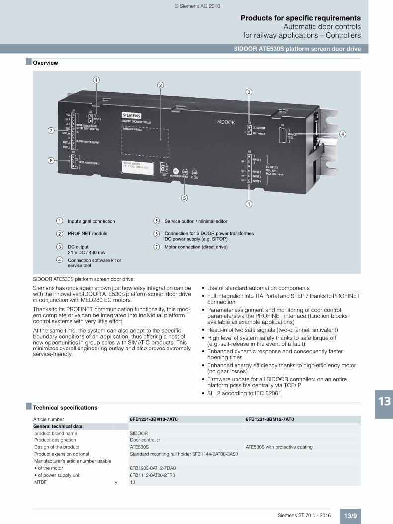
13/9Siemens ST 70 N · 2016
13
Products for specific requirementsAutomatic door controls
for railway applications – Controllers
SIDOOR ATE530S platform screen door drive
■ Overview
SIDOOR ATE530S platform screen door drive
Siemens has once again shown just how easy integration can be with the innovative SIDOOR ATE530S platform screen door drive in conjunction with MED280 EC motors.
Thanks to its PROFINET communication functionality, this mod-ern complete drive can be integrated into individual platform control systems with very little effort.
At the same time, the system can also adapt to the specific boundary conditions of an application, thus offering a host of new opportunities in group sales with SIMATIC products. This minimizes overall engineering outlay and also proves extremely service-friendly.
• Use of standard automation components• Full integration into TIA Portal and STEP 7 thanks to PROFINET
connection• Parameter assignment and monitoring of door control
parameters via the PROFINET interface (function blocks available as example applications)
• Read-in of two safe signals (two-channel, antivalent)• High level of system safety thanks to safe torque off
(e.g. self-release in the event of a fault)• Enhanced dynamic response and consequently faster
opening times• Enhanced energy efficiency thanks to high-efficiency motor
(no gear losses)• Firmware update for all SIDOOR controllers on an entire
platform possible centrally via TCP/IP• SIL 2 according to IEC 62061
■ Technical specifications
1
3
1
1
2
3
5
6
7
4
5
4
6
7
2
Input signal connection
PROFINET module
DC output24 V DC / 400 mA
Service button / minimal editor
Connection for SIDOOR power transformer/DC power supply (e.g. SITOP)
Motor connection (direct drive)
Connection software kit or service tool
Article number 6FB1231-3BM10-7AT0 6FB1231-3BM12-7AT0
General technical data:
product brand name SIDOOR
Product designation Door controller
Design of the product ATE530S ATE530S with protective coating
Product extension optional Standard mounting rail holder 6FB1144-0AT00-3AS0
Manufacturer's article number usable
• of the motor 6FB1203-0AT12-7DA0
• of power supply unit 6FB1112-0AT20-2TR0
MTBF y 13
© Siemens AG 2016
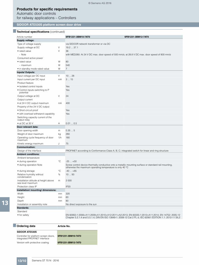
13/10 Siemens ST 70 N · 2016
13
■ Technical specifications (continued)
Products for specific requirementsAutomatic door controlsfor railway applications – Controllers
SIDOOR ATE530S platform screen door drive
■ Ordering data Article No.
Supply voltage:
Type of voltage supply via SIDOOR network transformer or via DC
Supply voltage at DC V 19.2 ... 37.1
• rated value V 36
- Note with MED280: At 24 V DC max. door speed of 500 mm/s; at 28.8 V DC max. door speed of 800 mm/s
Consumed active power
• rated value W 80
- maximum W 540
• in standby mode rated value W 7
Inputs/ Outputs:
Input voltage per DC input V 10 ... 28
Input current per DC input mA 3 ... 15
Product feature
• Isolated control inputs Yes
• Control inputs switching to P potential
Yes
Output voltage at DC V 24
Output current
• at 24 V DC output maximum mA 400
Property of the 24 V DC output
• Short-circuit proof Yes
• with overload withstand capability Yes
Switching capacity current of the output relay
• at DC at 30 V A 0.01 ... 0.5
Door-relevant data:
Door opening width m 0.35 ... 5
Weight of door maximum kg 280
Operating cycle frequency of door maximum
1/h 180
Kinetic energy maximum J 75
Communication:
Design of the interface PROFINET according to Conformance Class A, B, C; integrated switch for linear and ring structure
Ambient conditions:
Ambient temperature
• during operation °C -25 ... +50
• during operation Note Screw control device thermally conductive onto a metallic mounting surface or standard rail mounting,otherwise the maximum operating temperature is only 40 °C
• during storage °C -40 ... +85
Relative humidity without condensation
% 10 ... 93
Installation altitude at height above sea level maximum
m 2 000
Protection class IP IP20
Installation/ mounting/ dimensions:
Width mm 320
Height mm 60
Depth mm 80
Installation or assembly note No direct exposure to the sun
Standards:
Standard
• for safety EN 60950-1:2006+A11:2009+A1:2010+A12:2011+A2:2013, EN 60335-1:2012+A11:2014, EN 14752: 2005-12 Chapter 5.2.1.4 and 5.5.1.4, DIN EN ISO 13849-1: 2008-12 Cat 2 PL d, IEC 62061 EDITION 1.1: 2012-11 SIL2
Article number 6FB1231-3BM10-7AT0 6FB1231-3BM12-7AT0
SIDOOR ATE530S
Controller for platform screen doors,integrated PROFINET interface
6FB1231-3BM10-7AT0
Version with protective coating 6FB1231-3BM12-7AT0
© Siemens AG 2016
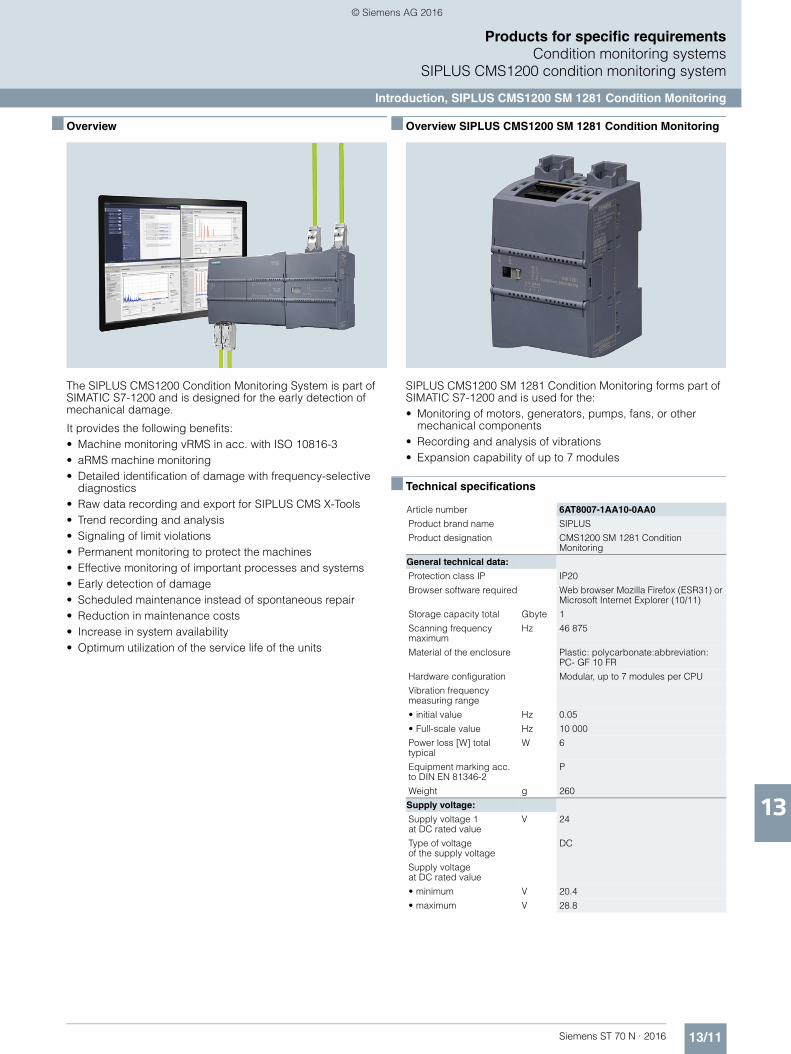
13/11Siemens ST 70 N · 2016
13
Products for specific requirementsCondition monitoring systems
SIPLUS CMS1200 condition monitoring system
Introduction, SIPLUS CMS1200 SM 1281 Condition Monitoring
■ Overview
The SIPLUS CMS1200 Condition Monitoring System is part of SIMATIC S7-1200 and is designed for the early detection of mechanical damage.
It provides the following benefits:• Machine monitoring vRMS in acc. with ISO 10816-3• aRMS machine monitoring • Detailed identification of damage with frequency-selective
diagnostics• Raw data recording and export for SIPLUS CMS X-Tools• Trend recording and analysis• Signaling of limit violations• Permanent monitoring to protect the machines• Effective monitoring of important processes and systems• Early detection of damage• Scheduled maintenance instead of spontaneous repair• Reduction in maintenance costs• Increase in system availability• Optimum utilization of the service life of the units
■ Overview SIPLUS CMS1200 SM 1281 Condition Monitoring
SIPLUS CMS1200 SM 1281 Condition Monitoring forms part of SIMATIC S7-1200 and is used for the:• Monitoring of motors, generators, pumps, fans, or other
mechanical components• Recording and analysis of vibrations• Expansion capability of up to 7 modules
■ Technical specifications
Article number 6AT8007-1AA10-0AA0
Product brand name SIPLUS
Product designation CMS1200 SM 1281 Condition Monitoring
General technical data:
Protection class IP IP20
Browser software required Web browser Mozilla Firefox (ESR31) or Microsoft Internet Explorer (10/11)
Storage capacity total Gbyte 1
Scanning frequency maximum
Hz 46 875
Material of the enclosure Plastic: polycarbonate:abbreviation: PC- GF 10 FR
Hardware configuration Modular, up to 7 modules per CPU
Vibration frequency measuring range
• initial value Hz 0.05
• Full-scale value Hz 10 000
Power loss [W] total typical
W 6
Equipment marking acc. to DIN EN 81346-2
P
Weight g 260
Supply voltage:
Supply voltage 1 at DC rated value
V 24
Type of voltage of the supply voltage
DC
Supply voltage at DC rated value
• minimum V 20.4
• maximum V 28.8
© Siemens AG 2016

13/12 Siemens ST 70 N · 2016
13
■ Technical specifications (continued)
Products for specific requirementsCondition monitoring systemsSIPLUS CMS1200 condition monitoring system
SIPLUS CMS1200 SM 1281 Condition Monitoring
Installation/ mounting/ dimensions:
Mounting position vertical, horizontal
Mounting positionrecommended
horizontal
Mounting type Rail or wall mounting
Width mm 70
Height mm 112
Depth mm 75
Inputs/ Outputs:
Number of sensor inputs for IEPE sensors
4
Number of speed inputs 1
Product function Bus communication
Yes
Product function monitoring of sensor inputs
Yes
Input voltage at speed input DC 24 V digital
Yes
Display:
Display version for diagnostic function: status display digital input LED green
No
Communication:
Type of data transmission Exporting of raw data as WAV file for further analyses (e.g. using SIPLUS CMS X-Tools) can be downloaded via browser
Design of the interface Ethernet interface
Yes
Service as web server HTTP
Yes
Ambient conditions:
Ambient temperature
• during operation -20 ... +55
• during storage -25 ... +85
• during transport -25 ... +85
Air pressure during storage and transport
660 ... 1 080
Height of fall maximum m 0.3
Options:
Alert function Diagnostics alarm
Yes
Type of electrical connection
screw-type terminals
Article number 6AT8007-1AA10-0AA0
■ Ordering data Article No.
SIPLUS CMS1200 SM 1281 Condition Monitoring
Module for SIMATIC S7-1200for monitoring vibrations in mechanical components based on characteristic valuesand frequency-selective analysis functions.
6AT8007-1AA10-0AA0
© Siemens AG 2016
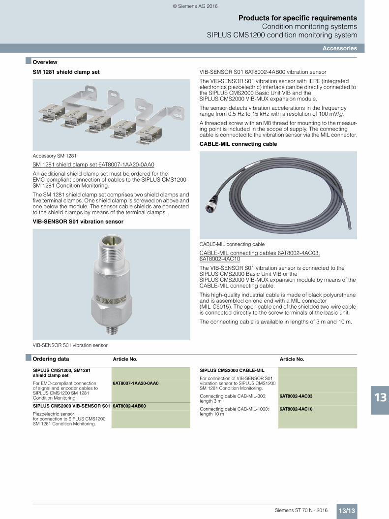
13/13Siemens ST 70 N · 2016
13
Products for specific requirementsCondition monitoring systems
SIPLUS CMS1200 condition monitoring system
Accessories
■ Overview
SM 1281 shield clamp set
Accessory SM 1281
SM 1281 shield clamp set 6AT8007-1AA20-0AA0
An additional shield clamp set must be ordered for the EMC-compliant connection of cables to the SIPLUS CMS1200 SM 1281 Condition Monitoring.
The SM 1281 shield clamp set comprises two shield clamps and five terminal clamps. One shield clamp is screwed on above and one below the module. The sensor cable shields are connected to the shield clamps by means of the terminal clamps.
VIB-SENSOR S01 vibration sensor
VIB-SENSOR S01 vibration sensor
VIB-SENSOR S01 6AT8002-4AB00 vibration sensor
The VIB-SENSOR S01 vibration sensor with IEPE (integrated electronics piezoelectric) interface can be directly connected to the SIPLUS CMS2000 Basic Unit VIB and the SIPLUS CMS2000 VIB-MUX expansion module.
The sensor detects vibration accelerations in the frequency range from 0.5 Hz to 15 kHz with a resolution of 100 mV/g.
A threaded screw with an M8 thread for mounting to the measur-ing point is included in the scope of supply. The connecting cable is connected to the vibration sensor via the MIL connector.
CABLE-MIL connecting cable
CABLE-MIL connecting cable
CABLE-MIL connecting cables 6AT8002-4AC03,6AT8002-4AC10
The VIB-SENSOR S01 vibration sensor is connected to the SIPLUS CMS2000 Basic Unit VIB or the SIPLUS CMS2000 VIB-MUX expansion module by means of the CABLE-MIL connecting cable.
This high-quality industrial cable is made of black polyurethane and is assembled on one end with a MIL connector (MIL-C5015). The open cable end of the shielded two-wire cable is connected directly to the screw terminals of the basic unit.
The connecting cable is available in lengths of 3 m and 10 m.
■ Ordering data Article No. Article No.
SIPLUS CMS1200, SM1281 shield clamp set
For EMC-compliant connectionof signal and encoder cables to SIPLUS CMS1200 SM 1281Condition Monitoring.
6AT8007-1AA20-0AA0
SIPLUS CMS2000 VIB-SENSOR S01 6AT8002-4AB00
Piezoelectric sensor for connection to SIPLUS CMS1200 SM 1281 Condition Monitoring.
SIPLUS CMS2000 CABLE-MIL
For connection of VIB-SENSOR S01 vibration sensor to SIPLUS CMS1200 SM 1281 Condition Monitoring.
Connecting cable CAB-MIL-300; length 3 m
6AT8002-4AC03
Connecting cable CAB-MIL-1000; length 10 m
6AT8002-4AC10
© Siemens AG 2016
13/14 Siemens ST 70 N · 2016
13
Products for specific requirements
Notes
© Siemens AG 2016

Siemens ST 70 N · 2016
1616/2 SITRAIN – Training for Industry
16/3 Additional documentation16/3 SIMATIC Manual Collection
16/4 Standards and approbations16/4 CE marking16/5 Certificates
16/5 Quality management
16/6 Partner at Siemens16/6 Contacts worldwide16/7 Siemens Partner Program
16/8 Siemens Automation Cooperateswith Education
16/8 Simplify your education in automation
16/10 Online Services16/10 Information and Ordering Options
on the Internet and DVD16/11 Information and Download Center,
Social Media, Mobile Media
16/12 Industry Services16/13 Portfolio overview16/15 Online Support
16/16 Software Licenses
16/18 Index
16/20 Article No. index
16/24 Conditions of sale and delivery
Appendix
© Siemens AG 2016

16/2 Siemens ST 70 N · 2016
AppendixSITRAIN – Training for Industry
16
■ Introduction
Your benefit from practical training directly from the manufacturer
SITRAIN – Training for Industry – provides you with compre-hensive support in solving your tasks.
Training directly from the manufacturer enables you to make correct decisions with confidence.
Increased profits and lower costs:• Shorter times for commissioning, maintenance and servicing• Optimized production operations• Reliable configuration and startup• Shorten commissioning times, reduce downtimes, and faster
troubleshooting• Exclude expensive faulty planning right from the start• Flexible plant adaptation to market requirements• Compliance with quality standards in production• Increased employee satisfaction and motivation • Shorter familiarization times following changes in technology
and staff
Your benefits with SITRAIN – Training for Industry
Certified top trainers
Our trainers are skilled specialists with practical experience. Course developers have close contact with product devel-opment, and pass on their knowledge to the trainers and then to you.
Practical application with practice
Practice, practice, practice! We have designed the trainings with an emphasis on practical exercises. They take up to half of the course time in our trainings. You can therefore implement your new knowledge in practice even faster.
300 courses in more than 60 countries
We offer a total of about 300 classroom-based courses. You can find us at more than 50 locations in Germany, and in 62 countries worldwide. You can find which course is offered at which location at:
www.siemens.com/sitrain
Skills development
Do you want to develop skills and fill in gaps in your knowledge? Our solution: We will provide a program tailored exactly to your personal requirements. After an individual requirements analysis, we will train you in our training centers near you or directly at your offices. You will practice on the most modern training equipment with special exercise units. The individual training courses are optimally matched to each other and help with the continuous development of knowledge and skills. After finishing a training module, the follow-up measures make success certain, as well as the refreshment and deepening of the knowledge gained.
Contact
Visit our site on the Internet at:
www.siemens.com/sitrain
or let us advise you personally. You can request our latest training catalog from:
SITRAIN – Training for Industry SITRAIN Customer Support Germany:
Tel.: +49 911 895-7575
Fax: +49 911 895-7576
Email: [email protected]
© Siemens AG 2016

16/3Siemens ST 70 N · 2016
AppendixAdditional documentation
SIMATIC Manual Collection
16
■ Overview
The SIMATIC manual collection brings together the manuals of Totally Integrated Automation in the smallest possible package. It is eminently suitable for startup and service, replaces the space-consuming paper version in the office and provides fast access to the information.
The manual collection contains manuals in 5 languages for • LOGO!• SIMADYN• SIMATIC bus components• SIMATIC C7• SIMATIC Distributed I/O• SIMATIC HMI• SIMATIC Sensors• SIMATIC NET• SIMATIC PC Based Automation• SIMATIC PCS 7• SIMATIC PG/PC• SIMATIC S7• SIMATIC Software• SIMATIC TDC
Manuals that are not yet available in all 5 languages will at least be included in English and German.
There is an update contract for the SIMATIC Manual Collection that encompasses supply of the up-to-date collection and three subsequent updates which is valid for one year. If the update contract is not cancelled, it is automatically extended and the list price will be charged to the customer.
■ Ordering data Article No.
SIMATIC Manual Collection 6ES7998-8XC01-8YE0
Electronic manuals on DVD, multilingual: LOGO!, SIMADYN,SIMATIC bus components, SIMATIC C7, SIMATIC Distributed IO, SIMATIC HMI, SIMATIC Sensors, SIMATIC NET, SIMATIC PC Based Automation, SIMATIC PCS 7, SIMATIC PG/PC, SIMATIC S7, SIMATIC Software, SIMATIC TDC
SIMATIC Manual Collection update service for 1 year
6ES7998-8XC01-8YE2
Current "Manual Collection" DVD and the three subsequent updates
© Siemens AG 2016

16/4 Siemens ST 70 N · 2016
AppendixStandards and approbations
CE marking
16
■ Overview
The electronic products described in this catalog comply with the requirements and protection objectives of the following ECdirectives insofar as they relate to the product concerned. They also comply with the corresponding harmonized European standards (EN) published for these products in the Official Journals of the European Community.• Directive 2004/108/EC of the European Parliament andCouncil
on the approximation of the laws of the Member States relating to electromagnetic compatibility (EMC Directive)
• Directive 2006/95/EC of the European Parliament and of the Council on the harmonization of the laws of Member States relating to electrical equipment designed for use within certain voltage limits (Low Voltage Directive)
• Directive 94/9/EC of the European Parliament and the Council on approximation of the laws of the Member States concerning equipment and protective systems intended for use in potentially explosive atmospheres (ATEX Directive).
• Directive 1999/5/EC of the European Parliament and of the Council on radio equipment and telecommunications terminal equipment and the mutual recognition of their conformity (RTTE Directive)
The originals of the declarations of conformity are kept available by us for the responsible supervisory authorities.
Note on the EMC Directive:
In terms of their interference emissions, SIMATIC products are designed for industrial applications.
If individual products deviate from this specification, it is noted in the catalog with the products.
The installation instructions in the manuals must be adhered to when installing and operating the products described in this catalog. These contain, for example, important information on installation in cabinets and on the use of shielded cables.
■ Notes for machine manufacturers
The SIMATIC automation system is not a machine within the context of the EU machine guidelines. Therefore a declaration of conformity with regard to the EU machine directive 89/392/EEC or 2006/42/EU (new edition, applicable from end of 2009) may not be provided for SIMATIC.
The EU machine directive regulates the requirements placed on a machine or a part thereof. A machine is understood for the purposes of this guideline to be a combination of interconnected parts or mechanisms (see also EN 292-1, Paragraph 3.1).
SIMATIC is part of the electrical equipment of a machine, and must therefore be integrated into the evaluation of the complete machine by the machine manufacturer.
As electrical equipment, SIMATIC is subject to the low-voltage directive which, as a "total safety directive", covers all dangers just like the machine directive.
The EN 60204-1 standard (safety of machines, general require-ments for the electrical equipment of machines) is applicable to the electrical equipment of machines.
The following table will help you in the provision of your decla-ration of conformity, and shows which criteria according to EN 60204-1 (2006-06) apply to SIMATIC. You can obtain further information from the enclosed declaration of conformity according to the low-voltage and EMC directives (with list of included standards).
EN 60204-1 Topic/criterion Notes
Paragraph 4 General requirements
The requirements are met when the equipment is assembled/ installed in accordance with the installation guidelines.Please note the relevant information in the manuals.
Paragraph 11.2 Digital input/output interfaces
The requirements are met
Paragraph 12.3 Programmable equipment
The requirements are met when the equipment is installed in lockable cabinets to protect against alteration of the memory contents by unautho-rized persons
Paragraph 20.4 Voltage tests The requirements are met
© Siemens AG 2016
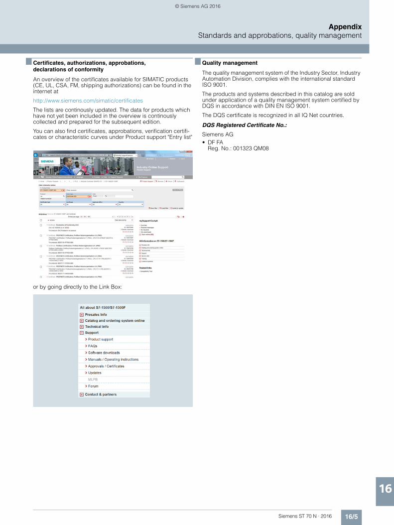
16/5Siemens ST 70 N · 2016
AppendixStandards and approbations, quality management
16
■ Certificates, authorizations, approbations,declarations of conformity
An overview of the certificates available for SIMATIC products (CE, UL, CSA, FM, shipping authorizations) can be found in the internet at
http://www.siemens.com/simatic/certificates
The lists are continously updated. The data for products which have not yet been included in the overview is continously collected and prepared for the subsequent edition.
You can also find certificates, approbations, verification certifi-cates or characteristic curves under Product support "Entry list"
or by going directly to the Link Box:
■ Quality management
The quality management system of the Industry Sector, Industry Automation Division, complies with the international standard ISO 9001.
The products and systems described in this catalog are sold under application of a quality management system certified by DQS in accordance with DIN EN ISO 9001.
The DQS certificate is recognized in all IQ Net countries.
DQS Registered Certificate No.:
Siemens AG • DF FA
Reg. No.: 001323 QM08
© Siemens AG 2016

16/6 Siemens ST 70 N · 2016
AppendixPartner at Siemens
Contacts worldwide
16
■ Overview
At Siemens we are resolutely pursuing the same goal: long-term improvement of your competitive ability. We are committed to this goal. Thanks to our commitment, we continue to set new standards in automation and drive technology. In all industries – worldwide.
At your service locally, around the globe for consulting, sales, training, service, support, spare parts ... on the entire Industry Automation and Drive Technologies range.
Your personal contact can be found in our Contacts Database at:www.siemens.com/automation/partner
You start by selecting • the required competence, • products and branches, • a country, • a city
or by a• location search or• person search.
© Siemens AG 2016
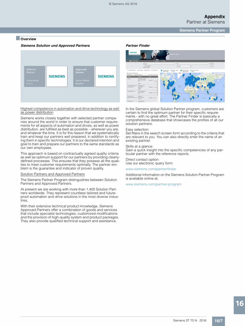
16/7Siemens ST 70 N · 2016
AppendixPartner at Siemens
Siemens Partner Program
16
■ Overview
Siemens Solution und Approved Partners
Highest competence in automation and drive technology as well as power distribution
Siemens works closely together with selected partner compa-nies around the world in order to ensure that customer require-ments for all aspects of automation and drives, as well as power distribution, are fulfilled as best as possible – wherever you are, and whatever the time. It is for this reason that we systematically train and keep our partners well prepared, in addition to certify-ing them in specific technologies. It is our declared intention and goal to train and prepare our partners to the same standards as our own employees.
This approach is based on contractually agreed quality criteria as well as optimum support for our partners by providing clearly-defined processes. This ensures that they possess all the quali-ties to meet customer requirements optimally. The partner em-blem is the guarantee and indicator of proven quality.
Solution Partners and Approved Partners
The Siemens Partner Program distinguishes between Solution Partners and Approved Partners.
At present we are working with more than 1,400 Solution Part-ners worldwide. They represent countless tailored and future-proof automation and drive solutions in the most diverse indus-tries.
With their extensive technical product knowledge, Siemens Approved Partners offer a combination of goods and services that include specialist technologies, customized modifications and the provision of high-quality system and product packages. They also provide qualified technical support and assistance.
Partner Finder
In the Siemens global Solution Partner program, customers are certain to find the optimum partner for their specific require-ments - with no great effort. The Partner Finder is basically a comprehensive database that showcases the profiles of all our solution partners.
Easy selection: Set filters in the search screen form according to the criteria that are relevant to you. You can also directly enter the name of an existing partner.
Skills at a glance: Gain a quick insight into the specific competencies of any par-ticular partner with the reference reports.
Direct contact option: Use our electronic query form:
www.siemens.com/partnerfinder
Additional information on the Siemens Solution Partner Program is available online at:
www.siemens.com/partner-program
© Siemens AG 2016
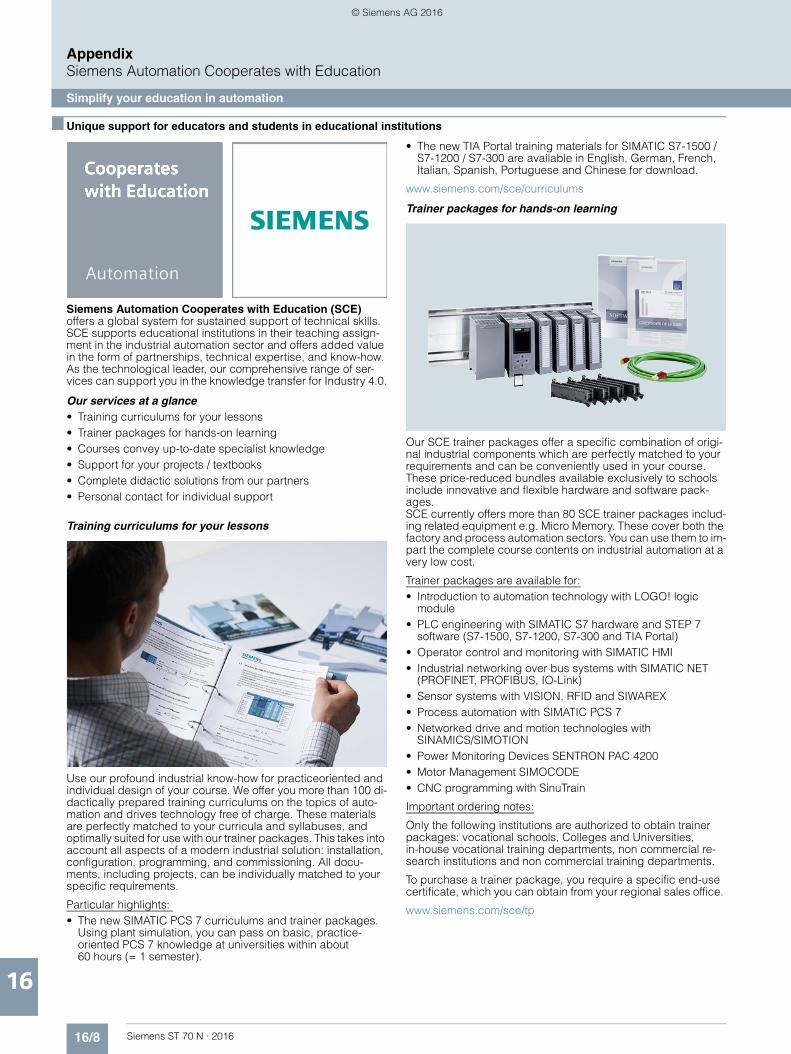
16/8 Siemens ST 70 N · 2016
AppendixSiemens Automation Cooperates with Education
Simplify your education in automation
16
■ Unique support for educators and students in educational institutions
Siemens Automation Cooperates with Education (SCE) offers a global system for sustained support of technical skills. SCE supports educational institutions in their teaching assign-ment in the industrial automation sector and offers added value in the form of partnerships, technical expertise, and know-how. As the technological leader, our comprehensive range of ser-vices can support you in the knowledge transfer for Industry 4.0.
Our services at a glance• Training curriculums for your lessons• Trainer packages for hands-on learning• Courses convey up-to-date specialist knowledge• Support for your projects / textbooks• Complete didactic solutions from our partners• Personal contact for individual support
Training curriculums for your lessons
Use our profound industrial know-how for practiceoriented and individual design of your course. We offer you more than 100 di-dactically prepared training curriculums on the topics of auto-mation and drives technology free of charge. These materials are perfectly matched to your curricula and syllabuses, and optimally suited for use with our trainer packages. This takes into account all aspects of a modern industrial solution: installation, configuration, programming, and commissioning. All docu-ments, including projects, can be individually matched to your specific requirements.
Particular highlights: • The new SIMATIC PCS 7 curriculums and trainer packages.
Using plant simulation, you can pass on basic, practice-oriented PCS 7 knowledge at universities within about 60 hours (= 1 semester).
• The new TIA Portal training materials for SIMATIC S7-1500 / S7-1200 / S7-300 are available in English, German, French, Italian, Spanish, Portuguese and Chinese for download.
www.siemens.com/sce/curriculums
Trainer packages for hands-on learning
Our SCE trainer packages offer a specific combination of origi-nal industrial components which are perfectly matched to your requirements and can be conveniently used in your course. These price-reduced bundles available exclusively to schools include innovative and flexible hardware and software pack-ages. SCE currently offers more than 80 SCE trainer packages includ-ing related equipment e.g. Micro Memory. These cover both the factory and process automation sectors. You can use them to im-part the complete course contents on industrial automation at a very low cost.
Trainer packages are available for:• Introduction to automation technology with LOGO! logic
module• PLC engineering with SIMATIC S7 hardware and STEP 7
software (S7-1500, S7-1200, S7-300 and TIA Portal)• Operator control and monitoring with SIMATIC HMI• Industrial networking over bus systems with SIMATIC NET
(PROFINET, PROFIBUS, IO-Link)• Sensor systems with VISION, RFID and SIWAREX• Process automation with SIMATIC PCS 7• Networked drive and motion technologies with
SINAMICS/SIMOTION• Power Monitoring Devices SENTRON PAC 4200• Motor Management SIMOCODE• CNC programming with SinuTrain
Important ordering notes:
Only the following institutions are authorized to obtain trainer packages: vocational schools, Colleges and Universities, in-house vocational training departments, non commercial re-search institutions and non commercial training departments.
To purchase a trainer package, you require a specific end-use certificate, which you can obtain from your regional sales office.
www.siemens.com/sce/tp
© Siemens AG 2016
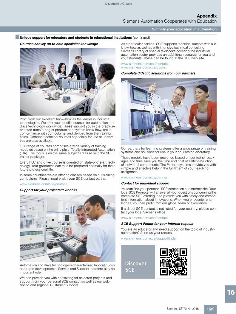
16/9Siemens ST 70 N · 2016
AppendixSiemens Automation Cooperates with Education
Simplify your education in automation
16
■ Unique support for educators and students in educational institutions (continued)
Courses convey up-to-date specialist knowledge
Profit from our excellent know-how as the leader in industrial technologies. We offer you specific courses for automation and drive technology worldwide. These support you in the practice-oriented transferring of product and system know-how, are in conformance with curriculums, and derived from the training fields. Compact technical courses especially for use at universi-ties are also available.
Our range of courses comprises a wide variety of training modules based on the principle of Totally Integrated Automation (TIA). The focus is on the same subject areas as with the SCE trainer packages.
Every PLC and drive course is oriented on state-of-the-art tech-nology. Your graduates can thus be prepared optimally for their future professional life.
In some countries we are offering classes based on our training curriculums. Please inquire with your SCE contact partner.
www.siemens.com/sce/courses
Support for your projects/textbooks
Automation and drive technology is characterized by continuous and rapid developments. Service and Support therefore play an important role.
We can provide you with consulting for selected projects and support from your personal SCE contact as well as our web-based and regional Customer Support.
As a particular service, SCE supports technical authors with our know-how as well as with intensive technical consulting. Siemens library of special textbooks covering the industrial automation sector provides an additional resource for you and your students. These can be found at the SCE web site.
www.siemens.com/sce/contact www.siemens.com/sce/books
Complete didactic solutions from our partners
Our partners for learning systems offer a wide range of training systems and solutions for use in your courses or laboratory.
These models have been designed based on our trainer pack-ages and thus save you the time and cost of selfconstruction of individual components. The Partner systems provide you with simple and effective help in the fulfillment of your teaching assignment.
www.siemens.com/sce/partner
Contact for individual support
You can find your personal SCE contact on our Internet site. Your local SCE Promoter will answer all your questions concerning the complete SCE offering, and provide you with timely and compe-tent information about innovations. When you encounter chal-lenges, you can profit from our global team of excellence.
If a direct SCE contact is not listed for your country, please con-tact your local Siemens office.
www.siemens.com/sce/contact
SCE Support Finder for your Internet request
You are an educator and need support on the topic of industry automation? Send us your request:
www.siemens.com/sce/supportfinder
© Siemens AG 2016
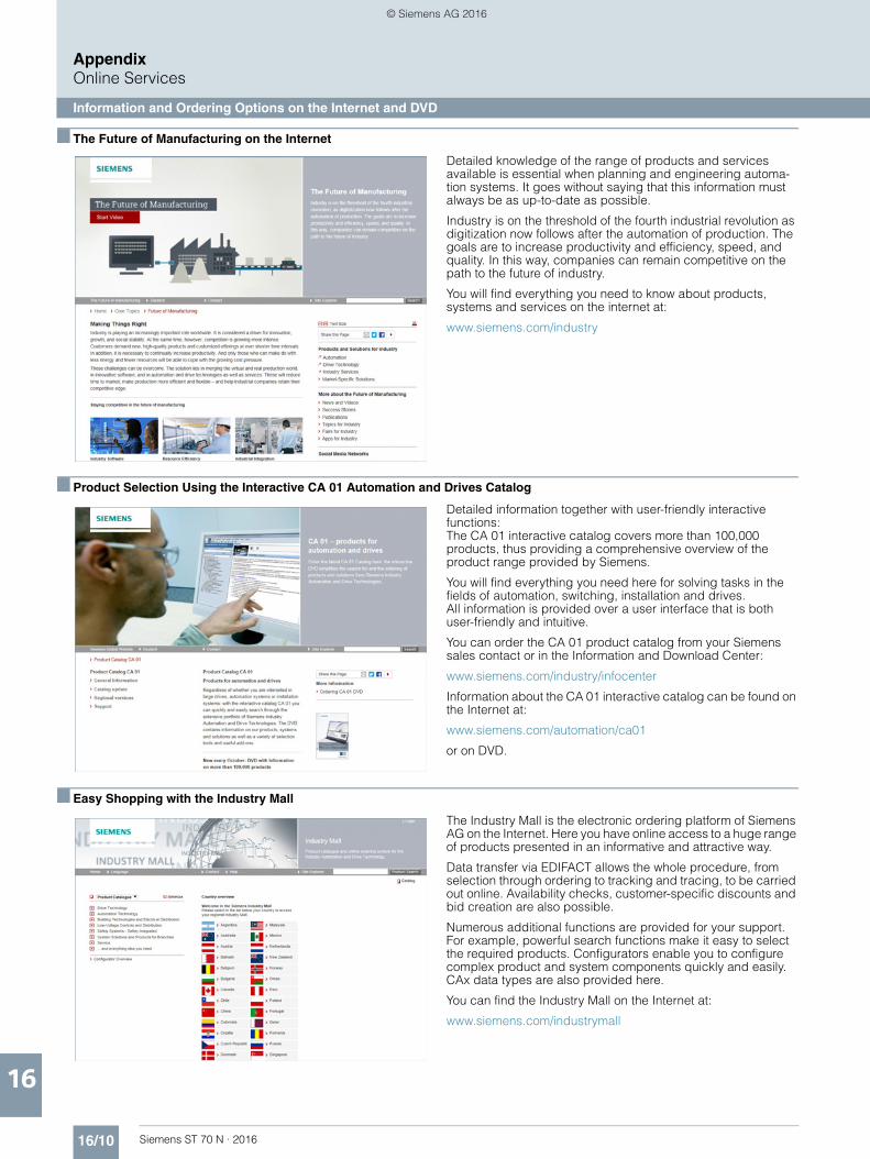
16/10 Siemens ST 70 N · 2016
AppendixOnline Services
Information and Ordering Options on the Internet and DVD
16
■ The Future of Manufacturing on the Internet
Detailed knowledge of the range of products and services available is essential when planning and engineering automa-tion systems. It goes without saying that this information must always be as up-to-date as possible.
Industry is on the threshold of the fourth industrial revolution as digitization now follows after the automation of production. The goals are to increase productivity and efficiency, speed, and quality. In this way, companies can remain competitive on the path to the future of industry.
You will find everything you need to know about products, systems and services on the internet at:
www.siemens.com/industry
■ Product Selection Using the Interactive CA 01 Automation and Drives Catalog
Detailed information together with user-friendly interactive functions: The CA 01 interactive catalog covers more than 100,000 products, thus providing a comprehensive overview of the product range provided by Siemens.
You will find everything you need here for solving tasks in the fields of automation, switching, installation and drives. All information is provided over a user interface that is both user-friendly and intuitive.
You can order the CA 01 product catalog from your Siemens sales contact or in the Information and Download Center:
www.siemens.com/industry/infocenter
Information about the CA 01 interactive catalog can be found on the Internet at:
www.siemens.com/automation/ca01
or on DVD.
■ Easy Shopping with the Industry Mall
The Industry Mall is the electronic ordering platform of Siemens AG on the Internet. Here you have online access to a huge range of products presented in an informative and attractive way.
Data transfer via EDIFACT allows the whole procedure, from selection through ordering to tracking and tracing, to be carried out online. Availability checks, customer-specific discounts and bid creation are also possible.
Numerous additional functions are provided for your support. For example, powerful search functions make it easy to select the required products. Configurators enable you to configure complex product and system components quickly and easily. CAx data types are also provided here.
You can find the Industry Mall on the Internet at:
www.siemens.com/industrymall
© Siemens AG 2016
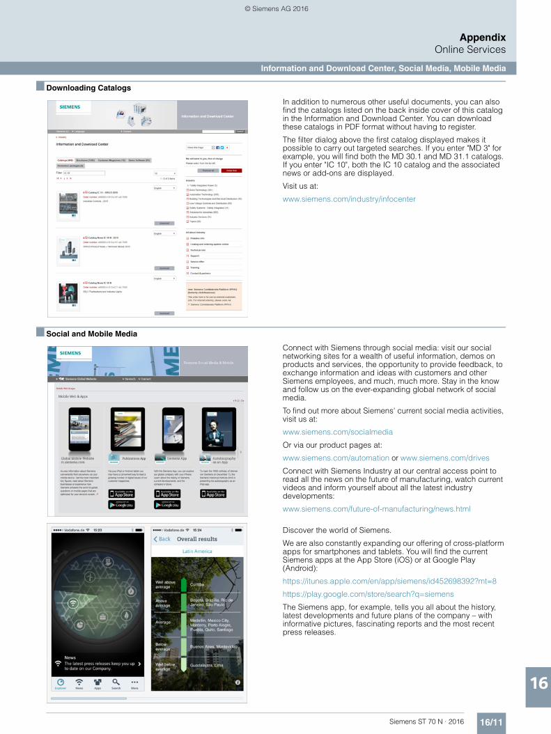
16/11Siemens ST 70 N · 2016
AppendixOnline Services
Information and Download Center, Social Media, Mobile Media
16
■ Downloading Catalogs
In addition to numerous other useful documents, you can also find the catalogs listed on the back inside cover of this catalog in the Information and Download Center. You can download these catalogs in PDF format without having to register.
The filter dialog above the first catalog displayed makes it possible to carry out targeted searches. If you enter "MD 3" for example, you will find both the MD 30.1 and MD 31.1 catalogs. If you enter "IC 10", both the IC 10 catalog and the associated news or add-ons are displayed.
Visit us at:
www.siemens.com/industry/infocenter
■ Social and Mobile Media
Connect with Siemens through social media: visit our social networking sites for a wealth of useful information, demos on products and services, the opportunity to provide feedback, to exchange information and ideas with customers and other Siemens employees, and much, much more. Stay in the know and follow us on the ever-expanding global network of social media.
To find out more about Siemens' current social media activities, visit us at:
www.siemens.com/socialmedia
Or via our product pages at:
www.siemens.com/automation or www.siemens.com/drives
Connect with Siemens Industry at our central access point to read all the news on the future of manufacturing, watch current videos and inform yourself about all the latest industry developments:
www.siemens.com/future-of-manufacturing/news.html
Discover the world of Siemens.
We are also constantly expanding our offering of cross-platform apps for smartphones and tablets. You will find the current Siemens apps at the App Store (iOS) or at Google Play (Android):
https://itunes.apple.com/en/app/siemens/id452698392?mt=8
https://play.google.com/store/search?q=siemens
The Siemens app, for example, tells you all about the history, latest developments and future plans of the company – with informative pictures, fascinating reports and the most recent press releases.
© Siemens AG 2016

16/12 Siemens ST 70 N · 2016
AppendixIndustry Services
16
■ Overview
Unleash potential – with services from Siemens
Increase your performance – with Industry Services
Optimizing the productivity of your equipment and operations can be a challenge, especially with constantly changing market conditions. Working with our service experts makes it easier. We understand your industry’s unique processes and provide the services needed so that you can better achieve your business goals.
You can count on us to maximize your uptime and minimize your downtime, increasing your operations’ productivity and reliabil-ity. When your operations have to be changed quickly to meet a new demand or business opportunity, our services give you the flexibility to adapt. Of course, we take care that your production is protected against cyber threats. We assist in keeping your operations as energy and resource efficient as possible and re-ducing your total cost of ownership. As a trendsetter, we ensure that you can capitalize on the opportunities of digitalization and by applying data analytics to enhance decision making: You can be sure that your plant reaches its full potential and retains this over the longer lifespan.
You can rely on our highly dedicated team of engineers, techni-cians and specialists to deliver the services you need – safely, professionally and in compliance with all regulations. We are there for you, where you need us, when you need us.
TrainingServices
ServicePrograms andAgreements
Retrofit andModernizationServices
G_DA65_XX_00272RepairServices
Field andMaintenanceServices
Spare PartsServices
Plant DataServices
Support andConsultingServices
© Siemens AG 2016

16/13Siemens ST 70 N · 2016
AppendixIndustry Services
Industry Services – Portfolio overview
16
■ Overview
Make your industrial processes transparent to gain improve-ments in productivity, asset availability, and energy efficiency.
Production data is generated, filtered and translated with intelli-gent analytics to enhance decision-making.
This is done whilst taking data security into consideration and with continuous protection against cyber attack threats.
www.industry.siemens.com/services/global/en/portfolio/plant-data-services/Pages/index.aspx
From the basics and advanced to specialist skills, SITRAIN courses provide expertise right from the manufacturer – and encompass the entire spectrum of Siemens products and systems for the industry.
Worldwide, SITRAIN courses are available wherever you need a training course in more than 170 locations in over 60 countries.
www.industry.siemens.com/services/global/en/portfolio/training/Pages/index.aspx
Industry Online Support site for comprehensive information, application examples, FAQs and support requests.
Technical and Engineering Support for advice and answers for all inquiries about functionality, handling, and fault clearance.
Information & Consulting Services, e.g. SIMATIC System Audit; clarity about the state and service capability of your auto-mation system or Lifecycle Information Services; transparency on the lifecycle of the products in your plants.
www.industry.siemens.com/services/global/en/portfolio/support-consulting/Pages/index.aspx
Are available worldwide for smooth and fast supply of spare parts – and thus optimal plant availability. Genuine spare parts are available for up to ten years. Logistic experts take care of procurement, transport, custom clearance, storage and order management. Reliable logistics processes ensure that compo-nents reach their destination as needed.
Asset optimization services help you design a strategy for parts supply where your investment and carrying costs are reduced and the risk of obsolescence is avoided.
www.industry.siemens.com/services/global/en/portfolio/spare_parts/Pages/index.aspx
Plant DataServices
TrainingServices
Support andConsultingServices
Spare PartsServices
© Siemens AG 2016
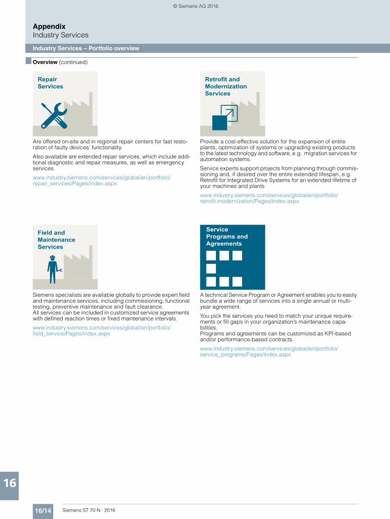
16/14 Siemens ST 70 N · 2016
AppendixIndustry Services
Industry Services – Portfolio overview
16
■ Overview (continued)
Are offered on-site and in regional repair centers for fast resto-ration of faulty devices’ functionality.
Also available are extended repair services, which include addi-tional diagnostic and repair measures, as well as emergency services.
www.industry.siemens.com/services/global/en/portfolio/repair_services/Pages/index.aspx
Siemens specialists are available globally to provide expert field and maintenance services, including commissioning, functional testing, preventive maintenance and fault clearance. All services can be included in customized service agreements with defined reaction times or fixed maintenance intervals.
www.industry.siemens.com/services/global/en/portfolio/field_service/Pages/index.aspx
Provide a cost-effective solution for the expansion of entire plants, optimization of systems or upgrading existing products to the latest technology and software, e.g. migration services for automation systems.
Service experts support projects from planning through commis-sioning and, if desired over the entire extended lifespan, e.g. Retrofit for Integrated Drive Systems for an extended lifetime of your machines and plants
www.industry.siemens.com/services/global/en/portfolio/retrofit-modernization/Pages/index.aspx
A technical Service Program or Agreement enables you to easily bundle a wide range of services into a single annual or multi-year agreement.
You pick the services you need to match your unique require-ments or fill gaps in your organization’s maintenance capa-bilities. Programs and agreements can be customized as KPI-based and/or performance-based contracts.
www.industry.siemens.com/services/global/en/portfolio/service_programs/Pages/index.aspx
RepairServices
Field andMaintenanceServices
Retrofit andModernizationServices
ServicePrograms andAgreements
© Siemens AG 2016
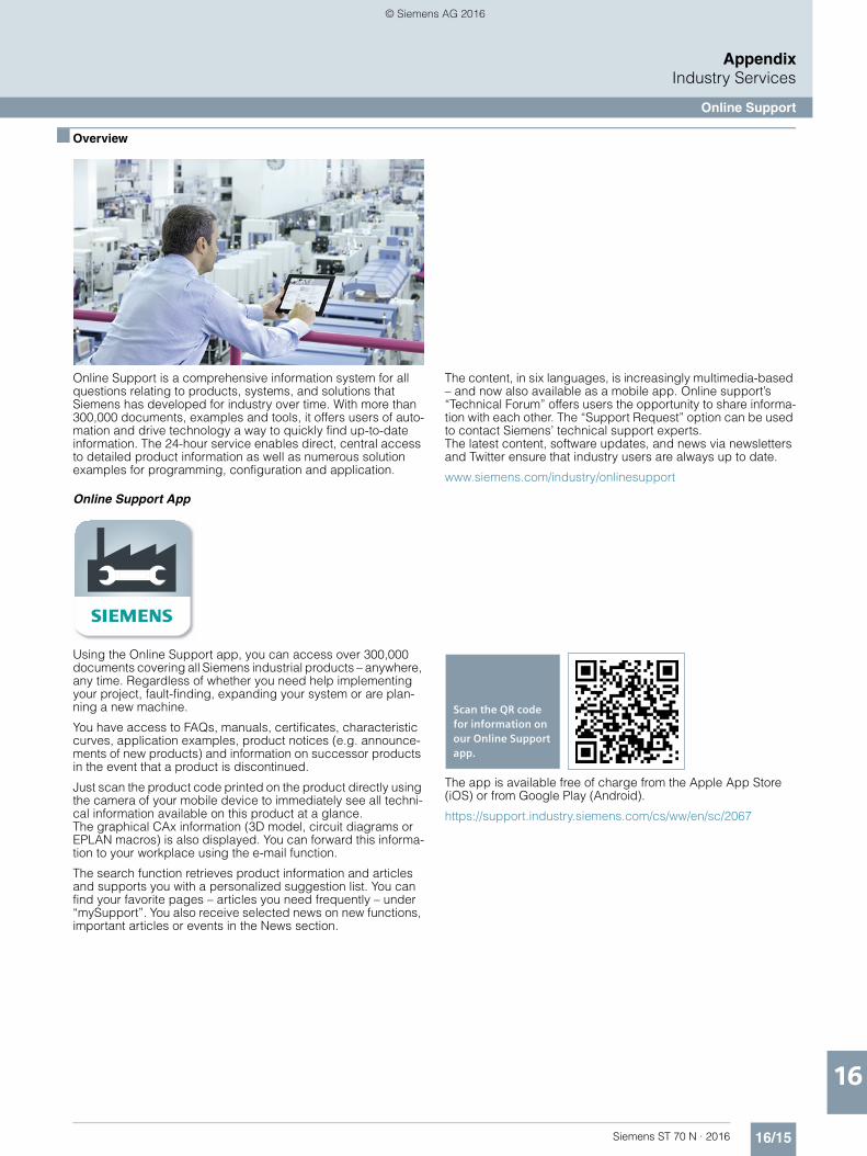
16/15Siemens ST 70 N · 2016
AppendixIndustry Services
Online Support
16
■ Overview
Online Support is a comprehensive information system for all questions relating to products, systems, and solutions that Siemens has developed for industry over time. With more than 300,000 documents, examples and tools, it offers users of auto-mation and drive technology a way to quickly find up-to-date information. The 24-hour service enables direct, central access to detailed product information as well as numerous solution examples for programming, configuration and application.
The content, in six languages, is increasingly multimedia-based – and now also available as a mobile app. Online support’s “Technical Forum” offers users the opportunity to share informa-tion with each other. The “Support Request” option can be used to contact Siemens’ technical support experts. The latest content, software updates, and news via newsletters and Twitter ensure that industry users are always up to date.
www.siemens.com/industry/onlinesupport
Online Support App
Using the Online Support app, you can access over 300,000 documents covering all Siemens industrial products – anywhere, any time. Regardless of whether you need help implementing your project, fault-finding, expanding your system or are plan-ning a new machine.
You have access to FAQs, manuals, certificates, characteristic curves, application examples, product notices (e.g. announce-ments of new products) and information on successor products in the event that a product is discontinued.
Just scan the product code printed on the product directly using the camera of your mobile device to immediately see all techni-cal information available on this product at a glance. The graphical CAx information (3D model, circuit diagrams or EPLAN macros) is also displayed. You can forward this informa-tion to your workplace using the e-mail function.
The search function retrieves product information and articles and supports you with a personalized suggestion list. You can find your favorite pages – articles you need frequently – under “mySupport”. You also receive selected news on new functions, important articles or events in the News section.
The app is available free of charge from the Apple App Store (iOS) or from Google Play (Android).
https://support.industry.siemens.com/cs/ww/en/sc/2067
s
Scan the QR code for information on our Online Support app.
© Siemens AG 2016
16/16 Siemens ST 70 N · 2016
AppendixSoftware Licenses
16
■ Overview
Software typesSoftware requiring a license is categorized into types.The following software types have been defined:• Engineering software• Runtime software
Engineering softwareThis includes all software products for creating (engineering) user software, e.g. for configuring, programming, parameteriz-ing, testing, commissioning or servicing. Data generated with engineering software and executable programs can be duplicated for your own use or for use by third-parties free-of-charge.
Runtime softwareThis includes all software products required for plant/machine operation, e.g. operating system, basic system, system expan-sions, drivers, etc.The duplication of the runtime software and executable pro-grams created with the runtime software for your own use or for use by third-parties is subject to a charge. You can find information about license fees according to use in the ordering data (e.g. in the catalog). Examples of categories of use include per CPU, per installation, per channel, per instance, per axis, per control loop, per variable, etc.Information about extended rights of use for parameteriza-tion/configuration tools supplied as integral components of the scope of delivery can be found in the readme file supplied with the relevant product(s).
License typesSiemens Industry Automation & Drive Technologies offers vari-ous types of software license:• Floating license• Single license• Rental license• Rental floating license• Trial license• Demo license• Demo floating license
Floating licenseThe software may be installed for internal use on any number of devices by the licensee. Only the concurrent user is licensed. The concurrent user is the person using the program. Use begins when the software is started. A license is required for each concurrent user.
Single licenseUnlike the floating license, a single license permits only one installation of the software per license. The type of use licensed is specified in the ordering data and in the Certificate of License (CoL). Types of use include for example per instance, per axis, per channel, etc. One single license is required for each type of use defined.
Rental licenseA rental license supports the "sporadic use" of engineering software. Once the license key has been installed, the software can be used for a specific period of time (the operating hours do not have to be consecutive). One license is required for each installation of the software.
Rental floating licenseThe rental floating license corresponds to the rental license, except that a license is not required for each installation of the software. Rather, one license is required per object (for example, user or device).
Trial licenseA trial license supports "short-term use" of the software in a non-productive context, e.g. for testing and evaluation purposes. It can be transferred to another license.
Demo licenseThe demo license support the "sporadic use" of engineering soft-ware in a non-productive context, for example, use for testing and evaluation purposes. It can be transferred to another license. After the installation of the license key, the software can be operated for a specific period of time, whereby usage can be interrupted as often as required.One license is required per installation of the software.
Demo floating licenseThe demo floating license corresponds to the demo license, except that a license is not required for each installation of the software. Rather, one license is required per object (for example, user or device).
Certificate of license (CoL)The CoL is the licensee's proof that the use of the software has been licensed by Siemens. A CoL is required for every type of use and must be kept in a safe place.
DowngradingThe licensee is permitted to use the software or an earlier ver-sion/release of the software, provided that the licensee owns such a version/release and its use is technically feasible.
Delivery versionsSoftware is constantly being updated.The following delivery versions• PowerPack• Upgradecan be used to access updates.Existing bug fixes are supplied with the ServicePack version.
PowerPackPowerPacks can be used to upgrade to more powerful software.The licensee receives a new license agreement and CoL (Certificate of License) with the PowerPack. This CoL, together with the CoL for the original product, proves that the new soft-ware is licensed. A separate PowerPack must be purchased for each original license of the software to be replaced.
UpgradeAn upgrade permits the use of a new version of the software on the condition that a license for a previous version of the product is already held.The licensee receives a new license agreement and CoL with the upgrade. This CoL, together with the CoL for the previous product, proves that the new version is licensed.A separate upgrade must be purchased for each original license of the software to be upgraded.
© Siemens AG 2016

16/17Siemens ST 70 N · 2016
AppendixSoftware Licenses
16
■ Overview
ServicePackServicePacks are used to debug existing products. ServicePacks may be duplicated for use as prescribed accord-ing to the number of existing original licenses.
License keySiemens Industry Automation & Drive Technologies supplies software products with and without license keys.The license key serves as an electronic license stamp and is also the "switch" for activating the software (floating license, rental license, etc.).The complete installation of software products requiring license keys includes the program to be licensed (the software) and the license key (which represents the license).
Software Update Service (SUS)As part of the SUS contract, all software updates for the respec-tive product are made available to you free of charge for a period of one year from the invoice date. The contract will automatically be extended for one year if it is not canceled three months before it expires.The possession of the current version of the respective software is a basic condition for entering into an SUS contract.
You can download explanations concerning license conditions fromwww.siemens.com/automation/salesmaterial-as/catalog/en/terms_of_trade_en.pdf
© Siemens AG 2016
16/18 Siemens ST 70 N · 2016
AppendixIndex
16
A
Accessories ..................................... 13/6, 13/13Additional documentation........................... 16/3Analog input modules................................. 9/15Analog input modules SM 531 ................... 4/59Analog output modules............................... 9/27Analog output modules SM 532 ................. 4/67Application module FM 458-1 DP............... 6/31Approbations .............................................. 16/4Automatic door controls.............................. 13/4
B
BaseUnits.................................................... 9/52BusAdapters ............................................... 9/58
C
Cables and connectors .............................. 9/80CE marking ................................................. 16/4Central Interface Module (CIM) ......... 9/95, 9/99Central processing units.......... 3/2, 4/2, 5/2, 6/2Certificates.................................................. 16/5CMK2000 .................................................... 2/14Color-coded labels ..................................... 9/63Compact CPUs ........................................... 4/22Communication module LOGO! CMK2000 ....................................... 2/14Communication modules LOGO! modular ......................................... 2/14Condition monitoring systems .................. 13/11Conditions of sale and delivery ................ 16/22Contacts worldwide .................................... 16/6Controller Software inside TIA Portal . 11/3, 11/6CPU 1507S ................................................... 8/2CPU 1510SP F-1 PN ................................... 7/12CPU 1510SP-1 PN ........................................ 7/2CPU 1511-1 PN............................................. 4/2CPU 1511C-1 PN ........................................ 4/22CPU 1511F-1 PN......................................... 4/30CPU 1512C-1 PN ........................................ 4/26CPU 1512SP F-1 PN ................................... 7/16CPU 1512SP-1 PN ........................................ 7/6CPU 1513-1 PN............................................. 4/5CPU 1513F-1 PN......................................... 4/33CPU 1515-2 PN............................................. 4/8CPU 1515F-2 PN......................................... 4/36CPU 1516-3 PN/DP..................................... 4/11CPU 1516F-3 PN/DP................................... 4/40CPU 1517-3 PN/DP..................................... 4/15CPU 412........................................................ 6/2CPU 414........................................................ 6/6CPU 414F.................................................... 6/19CPU 416...................................................... 6/11CPU 416F.................................................... 6/23CPU 417...................................................... 6/16CPU555....................................................... 10/2
D
D7-SYS............................................... 6/31, 11/8Digital F input modules ............................... 9/72Digital F output modules............................. 9/74Digital input modules SM 521..................... 4/46Digital I/O modules ..................................... 9/73Digital output modules SM 522................... 4/51Digital output modules.................................. 9/3Distributed controllersbased on ET 200SP .................................... 7/12Drive ES engineering software ................... 11/9
E
ET 200M ...................................................... 9/65ET 200pro.................................................... 9/70ET 200S ....................................................... 9/64ET 200SP....................................................... 9/2ET 200 systems for the control cabinet ......... 9/2ET 200 systems without control cabinet...... 9/70
F
F digital input module.................................. 4/72F digital output module ............................... 4/74Fail-safe CPUs........................... 4/30, 6/19, 7/12Fail-safe I/O modules .................................. 9/41Frequency Converter ET 200pro FC-2 ....... 9/70Function modules........................................ 6/31
G
Geared motors ............................................ 13/4
H
Heating control systems.............................. 9/92Heating control systems SIPLUS HCS3200 ....................................... 9/92Heating control systems SIPLUS HCS4200 ....................................... 9/94Heating control systems SIPLUS HCS4300........................................ 9/99High-availability CPUs................................. 6/27
I
IM 153-1/153-2 ............................................ 9/65Industry Services....................................... 16/12Information and Download Center ............ 16/11Information and Ordering Options on the Internet and DVD............................ 16/10Information on software licensing ............... 11/2Interface modules ................................ 9/2, 9/65I/O modules.......................... 3/14, 4/46, 5/4, 9/3
L
LOGO! communication moduleCMK2000 .................................................... 2/14LOGO! modular............................................. 2/2LOGO! modular communication modules .. 2/14
M
Mobile Media............................................. 16/11Motor starters ET 200SP.............................. 9/46Multiprocessor control systemSIMATIC TDC ............................................. 10/2
O
ODK 1500S ................................................... 8/6ODK 1500S FileServer .................................. 8/8ODK 1500S SQL driver ................................. 8/7ODK 1500S XML DataAccess driver ............ 8/7Online Services ......................................... 16/10Online Support .......................................... 16/15Operator control and monitoring................. 3/21Options for engineeringand drive technology .................................. 11/8
P
Partner at Siemens ..................................... 16/6Platform screen door driveSIDOOR ATE530S....................................... 13/9Power Output Module (POM)........... 9/97, 9/101Processor module CPU555 ....................... 10/2PROFINET components............................ 9/104PROFINET Driver ...................................... 9/104Pulse output module TM Pulse 2x24V ........ 9/37
Q
Quality management .................................. 16/5
R
Rack............................................................ 9/94Rack UR6021.............................................. 10/2
S
Siemens Automation Cooperateswith Education ............................................ 16/8Siemens Partner Program........................... 16/7SIMATIC ET 200AL ..................................... 9/73SIMATIC ET 200S........................................ 9/64SIMATIC Manual Collection ........................ 16/3SIMATIC PDM ........................................... 11/10SIMATIC S7-1500 Software Controller ....................................... 8/2SIMATIC TDC multiprocessor control system............................................. 10/2Simplify your education in automation........ 16/8SIPLUS analog input modules .................... 9/32SIPLUS analog output modules.................. 9/35SIPLUS BaseUnits ...................................... 9/55SIPLUS Basic Panels (2nd Generation)...... 3/21SIPLUS BusAdapter.................................... 9/61SIPLUS CM 1241 communication module.. 3/19SIPLUS CM DP for ET 200SP CPU ............. 9/40SIPLUS CMS1200 condition monitoring system..................... 13/11SIPLUS CMS1200 SM 1281Condition Monitoring................................... 3/16SIPLUS compact CPUs ................................ 5/2SIPLUS CPU 1212C...................................... 3/2SIPLUS CPU 1214C...................................... 3/6SIPLUS CPU 1215C.................................... 3/10SIPLUS CPU 1510SP-1 PN......................... 7/10SIPLUS CPU 1511-1 PN ............................. 4/19SIPLUS CPU 1512SP-1 PN......................... 7/11SIPLUS CPU 1513-1 PN ............................. 4/20SIPLUS CPU 1516-3 PN/DP........................ 4/21SIPLUS CPU 1518F-4 PN/DP...................... 4/44SIPLUS digital F input modules .................. 9/41SIPLUS digital F output modules ................ 9/43SIPLUS digital output modules ................... 9/13SIPLUS fail-safe CPUs................................ 4/44SIPLUS fail-safe customized modules........ 9/45SIPLUS high-availability CPUs.................... 6/29SIPLUS IM 153-1/153-2 .............................. 9/68SIPLUS interface modules............................ 9/2SIPLUS LOGO! modular basic variants ............................................... 2/2SIPLUS LOGO! modular expansion modules ...................................... 2/9SIPLUS LOGO! modular pure variants ................................................. 2/6SIPLUS NET CP 1543-1.............................. 4/71SIPLUS RIC libraries for ET200SP .............. 13/2SIPLUS RIC Librariesfor SIMATIC S7-1500 .................................. 13/3SIPLUS RIC substations for IEC protocol ... 13/2
© Siemens AG 2016

16/19Siemens ST 70 N · 2016
AppendixIndex
16
SIPLUS RTD SM 1231 signal module ......... 3/14SIPLUS S7-300 CPU 314C-2 PN/DP............. 5/2SIPLUS S7-300 DM 370 dummy modules .... 5/8SIPLUS S7-300 SM 326 F digital input modules - Safety Integrated... 5/4SIPLUS S7-300 SM 336 F analog input modules - Safety Integrated . 5/6SIPLUS standard CPUs .............. 3/2, 4/19, 7/10SIPLUS Y-Link for S7-400H ......................... 6/29SITRAIN – Training for Industry................... 16/2SIWAREX WP251 ........................................ 3/17SM 1281 Condition Monitoring ................... 3/16SM 521 digital input modules ..................... 4/46SM 522 digital output modules ................... 4/51Social Media ............................................. 16/11Software for joint tasksin the maintenance sector ........................ 11/10Software Licenses..................................... 16/16Software Update Service ............................ 11/2Standard CPUs ............................... 4/2, 6/2, 7/2Standards ................................................... 16/4STEP 7 (TIA Portal) ..................................... 11/3STEP 7 Safety (TIA Portal) .......................... 11/6System cabling for SIMATIC S7-300/400 and ET 200M - Fully modular connection.............................. 5/9
T
Telecontrol systemsfor comprehensive applications.................. 13/2TM Pulse 2x24V pulse output module ........ 9/37
Y
Y-link for S7-400H........................................ 6/27
© Siemens AG 2016
16/20 Siemens ST 70 N · 2016
AppendixArticle No. index
16
3
3RK1308- .................................................... 9/503RK1908- .................................................... 9/513RK1911- .................................................... 9/713RK1922- .................................................... 9/723RW4928- ................................................... 9/51
6AG
6AG1052- ........................................ 2/4, 2/7, 2/86AG1055- ............................. 2/5, 2/8, 2/12, 2/136AG1057- ...................................... 2/4, 2/8, 2/136AG1123- .................................................... 3/226AG1132- .................................................... 9/146AG1134- .................................................... 9/346AG1135- .................................................... 9/366AG1136- .................................. 9/42, 9/44, 9/456AG1153- ........................................... 6/30, 9/696AG1155- ...................................................... 9/26AG1193- ............... 7/10, 7/12, 9/14, 9/34, 9/36,........................ 9/42, 9/44, 9/45, 9/56, 9/57, 9/626AG1195- ............................. 5/5, 5/7, 6/30, 9/696AG1197- .................................................... 6/306AG1204- ...................................................... 5/36AG1212- ...................................................... 3/46AG1214- ............................................... 3/8, 3/96AG1215- ........................................... 3/12, 3/136AG1221- ...................................... 3/4, 3/9, 3/136AG1222- ...................................... 3/4, 3/9, 3/136AG1223- ...................................... 3/4, 3/9, 3/136AG1231- .................................................... 3/156AG1232- ...................................... 3/5, 3/9, 3/136AG1241- ............................. 3/5, 3/9, 3/13, 3/206AG1314- ...................................................... 5/26AG1326- ...................................................... 5/56AG1332- ......................... 4/19, 4/20, 4/21, 4/456AG1333- ........................................... 4/20, 4/456AG1336- ...................................................... 5/76AG1370- ...................................................... 5/86AG1500- ...................................................... 5/36AG1505- .................................. 4/19, 4/20, 4/456AG1507- .................................. 4/19, 4/20, 4/456AG1510- .................................................... 7/106AG1511- .................................................... 4/196AG1512- .................................................... 7/126AG1513- .................................................... 4/206AG1516- .................................................... 4/216AG1518- .................................................... 4/456AG1543- .................................................... 4/716AG1545- .................................................... 9/406AG1591- ......................... 4/19, 4/20, 4/21, 4/456AG1654- .................................................... 6/306AG1901- .................................... 5/3, 7/10, 7/126AG1972- ............................................. 5/3, 9/696AG41..- ........................................................ 8/56AG6003- ........................................... 13/2, 13/3
6AT, 6AV
6AT8002- ................................................... 13/136AT8007- ............................... 3/16, 13/12, 13/136AV72..- ........................................................ 8/5
6B, 6D
6BK1700- .................................................. 9/1036BK1700-0 .................................................. 2/146BK1900- ......................................... 9/96, 9/1006BK1932- .................................................... 9/936BK1942- .................................. 9/94, 9/96, 9/986BK1943- .............................. 9/98, 9/100, 9/1036DD1600- .................................................... 10/26DD1682- .................................................... 10/26DD1683- .................................................... 10/2
6ED, 6EP
6ED1056- ...............................................2/5, 2/86ED1056-1 ..................................................2/136ED1057- ......................................2/5, 2/8, 2/136ED1058- ......................................2/4, 2/8, 2/136EP1332- ...........4/4, 4/7, 4/10, 4/13, 4/17, 4/24,.................................4/28, 4/32, 4/35, 4/38, 4/426EP1333- ...........4/4, 4/7, 4/10, 4/13, 4/17, 4/24,.................................4/28, 4/32, 4/35, 4/38, 4/42
6ES
6ES5710- ..............................7/4, 7/8, 7/14, 7/186ES5728- .....................................................3/186ES5734- .....................................................12/56ES7132- .....................................................9/116ES7133- .................9/12, 9/26, 9/31, 9/39, 9/546ES7134- .....................................................9/256ES7135- .....................................................9/306ES7138- ............................................9/39, 13/86ES7141- .....................................................9/796ES7142- .....................................................9/796ES7143- .....................................................9/796ES7153- .....................................................9/676ES7193- ...........4/4, 4/7, 4/10, 4/13, 4/17, 4/24,...........4/28, 4/32, 4/35, 4/38, 4/42, 7/4, 7/5, 7/8,.......7/9, 7/14, 7/15, 7/18, 7/19, 9/11, 9/12, 9/26,...............9/31, 9/39, 9/53, 9/54, 9/60, 9/62, 9/636ES7194- ............................................9/79, 9/916ES7195- ........................6/28, 6/30, 9/67, 9/1046ES7197- .....................................................6/286ES7241- .....................................................13/86ES7328- .........................................5/3, 5/5, 5/76ES7390- .....................................5/8, 5/12, 9/676ES7391- .......................................................5/36ES7392- ..................................5/3, 5/5, 5/7, 5/86ES7393- ................................................5/5, 5/76ES7412- .......................................................6/56ES7414- ..............................................6/9, 6/216ES7416- ............................................6/14, 6/256ES7417- .....................................................6/176ES7505- ...........4/4, 4/7, 4/10, 4/13, 4/17, 4/24,.................................4/28, 4/32, 4/35, 4/38, 4/426ES7507- ...........4/4, 4/7, 4/10, 4/13, 4/17, 4/24,.................................4/28, 4/32, 4/35, 4/38, 4/426ES7510- ..............................................7/4, 7/156ES7511- ..............................4/3, 4/4, 4/24, 4/316ES7512- .....................................4/28, 7/8, 7/186ES7513- ..............................................4/6, 4/346ES7515- ..............................................4/9, 4/386ES7516- ............................................4/13, 4/426ES7517- .....................................................4/176ES7521- .....................................................4/506ES7522- .....................................................4/576ES7526- ............................................4/73, 4/756ES7528- .................4/50, 4/58, 4/66, 4/73, 4/756ES7531- .....................................................4/666ES7532- .....................................................4/706ES7540- .....................................................13/86ES7545- ..............................7/4, 7/8, 7/14, 7/186ES7590- ......4/3, 4/4, 4/6, 4/7, 4/10, 4/13, 4/17,.....4/24, 4/28, 4/31, 4/32, 4/34, 4/35, 4/38, 4/42,.........4/50, 4/58, 4/66, 4/73, 4/75, 5/12, 7/4, 7/8,............................................................7/14, 7/186ES7591- ...........4/4, 4/7, 4/10, 4/14, 4/18, 4/24,.........................4/28, 4/32, 4/35, 4/38, 4/43, 7/5,.....................................................7/9, 7/15, 7/196ES7592- .........................4/24, 4/28, 4/50, 4/57,...................................................4/66, 4/73, 4/756ES7658- ..................11/11, 11/12, 11/13, 11/146ES7672- .......................................................8/56ES7806- .......................................................8/66ES7810- ............................................11/4, 11/5
6ES7822- .......... 4/4, 4/7, 4/10, 4/14, 4/18, 4/25,......... 4/29, 4/32, 4/35, 4/39, 4/43, 7/5, 7/9, 7/15,................................................... 7/20, 11/4, 11/56ES7833- ...... 4/32, 4/35, 4/39, 4/43, 4/73, 4/75,................. 5/7, 6/21, 6/25, 7/15, 7/19, 11/6, 11/76ES7833-1 .................................................... 5/56ES7852- ........................................... 6/31, 11/86ES7901- ..................... 5/3, 6/5, 6/9, 6/14, 6/17,............................................................ 6/21, 6/256ES7912- .............................. 5/3, 6/5, 6/9, 6/14,................................................... 6/18, 6/21, 6/256ES7921- ........................................... 5/11, 5/126ES7923- ........................................... 5/11, 5/126ES7924- .................................................... 5/126ES7928- .................................................... 5/126ES7952- ........... 6/5, 6/9, 6/14, 6/17, 6/21, 6/256ES7953- ............................................. 5/3, 10/26ES7954- ... 4/3, 4/6, 4/9, 4/13, 4/17, 4/24, 4/28,.......................................... 4/31, 4/34, 4/38, 4/426ES7964- .................. 6/9, 6/14, 6/18, 6/21, 6/256ES7971- .................................................... 10/26ES7972- .......... 4/13, 4/17, 4/42, 6/5, 6/9, 6/10,............... 6/14, 6/15, 6/18, 6/21, 6/25, 6/26, 9/676ES7998- .......... 4/4, 4/7, 4/10, 4/14, 4/18, 4/25,..... 4/29, 4/32, 4/35, 4/39, 4/43, 4/50, 4/58, 4/66,...... 5/3, 5/5, 5/7, 6/5, 6/9, 6/14, 6/18, 6/21, 6/25,.......... 6/31, 7/5, 7/9, 7/15, 7/19, 9/67, 11/8, 16/3
6F, 6G, 6S, 6X, 6Z
6FB1103- .................................................... 13/56FB1104- .................................................... 13/86FB1144- .................................................... 13/86FB1231- .................................................. 13/106GK1500- ........................... 6/5, 6/9, 6/15, 6/18,................................................... 6/21, 6/25, 13/86GK1562- ..................................................... 8/56GK1571- ..................................................... 5/36GK1901 ..................................................... 4/356GK1901- ......... 4/4, 4/7, 4/10, 4/13, 4/14, 4/17,.............. 4/18, 4/24, 4/28, 4/32, 4/35, 4/38, 4/42,......................... 4/43, 6/10, 6/15, 6/22, 6/26, 7/4,..................................................... 7/8, 7/14, 7/186GK1905- ................................. 4/13, 4/17, 4/426GK5204- ........................ 6/10, 6/15, 6/22, 6/266SL3054- .................................................... 9/726SL3255- .................................................... 9/726SL3260- .................................................... 9/716SL3514- .................................................... 9/716SW1700- ................................................... 11/96XV1830- ............ 4/13, 4/17, 4/42, 5/3, 6/5, 6/9,................................. 6/15, 6/18, 6/21, 6/26, 13/86XV1831- .................................. 4/13, 4/17, 4/426XV1840- .......... 4/4, 4/7, 4/10, 4/14, 4/18, 4/24,................ 4/28, 4/32, 4/35, 4/38, 4/43, 5/3, 6/10,................... 6/15, 6/21, 6/26, 7/4, 7/8, 7/14, 7/186XV1850- .................................................... 3/186XV1870- .................................................... 10/26XV1873- .................. 5/3, 6/10, 6/15, 6/22, 6/26
7
7MH4702- ................................................... 3/187MH4710- ................................................... 3/187MH4960- ................................................... 3/18
H
HTG: .................................................. 9/71, 9/72
Z
ZKT: .................................................... 9/71, 9/72
© Siemens AG 2016

16/21Siemens ST 70 N · 2016
AppendixNotes
16
© Siemens AG 2016

16/22 Siemens ST 70 N · 2016
AppendixNotes
16
© Siemens AG 2016

16/23Siemens ST 70 N · 2016
AppendixNotes
16
© Siemens AG 2016
16/24 Siemens ST 70 N · 2016
AppendixConditions of sale and delivery
16
■ 1. General Provisions
By using this catalog you can acquire hardware and software products described therein from Siemens AG subject to the following Terms and Conditions of Sale and Delivery (hereinafter referred to as "T&C"). Please note that the scope, the quality and the conditions for supplies and services, including software products, by any Siemens entity having a registered office outside Germany, shall be subject exclusively to the General Terms and Conditions of the respective Siemens entity. The following T&C apply exclusively for orders placed with Siemens Aktiengesellschaft, Germany.
1.1 For customers with a seat or registered office in GermanyFor customers with a seat or registered office in Germany, the following applies subordinate to the T&C:• the "General Terms of Payment"1) and,• for software products, the "General License Conditions for
Software Products for Automation and Drives for Customers with a Seat or Registered Office in Germany"1) and,
• for other supplies and services, the "General Conditions for the Supply of Products and Services of the Electrical and Electronics Industry"1).
1.2 For customers with a seat or registered office outside GermanyFor customers with a seat or registered office outside Germany, the following applies subordinate to the T&C:• the "General Terms of Payment"1) and,• for software products, the "General License Conditions for
Software Products for Automation and Drives for Customers with a Seat or Registered Office outside of Germany"1) and
• for other supplies and/or services, the "General Conditions for Supplies of Siemens Industry for Customers with a Seat or Registered Office outside of Germany"1).
■ 2. Prices
The prices are in € (Euro) ex point of delivery, exclusive of packaging.The sales tax (value added tax) is not included in the prices. It shall be charged separately at the respective rate according to the applicable statutory legal regulations.Prices are subject to change without prior notice. We will charget the prices valid at the time of delivery.To compensate for variations in the price of raw materials (e.g. silver, copper, aluminum, lead, gold, dysprosium and neodym), surcharges are calculated on a daily basis using the so-called metal factor for products containing these raw materials. A surcharge for the respective raw material is calculated as a supplement to the price of a product if the basic official price of the raw material in question is exceeded.The metal factor of a product indicates the basic official price (for those raw materials concerned) as of which the surcharges on the price of the product are applied, and with what method of calculation. An exact explanation of the metal factor can be downloaded at:www.siemens.com/automation/salesmaterial-as/catalog/en/ terms_of_trade_en.pdfTo calculate the surcharge (except in the cases of dysprosium and neodym), the official price from the day prior to that on which the order was received or the release order was effected is used.To calculate the surcharge applicable to dysprosium and neodym ("rare earths"), the corresponding three-month basic average price in the quarter prior to that in which the order was received or the release order was effected is used with a one-month buffer (details on the calculation can be found in the explanation of the metal factor).
■ 3. Additional Terms and Conditions
The dimensions are in mm. In Germany, according to the German law on units in measuring technology, data in inches apply only to devices for export.Illustrations are not binding.Insofar as there are no remarks on the individual pages of this catalog - especially with regard to data, dimensions and weights given - these are subject to change without prior notice.
■ 4. Export regulations
We shall not be obligated to fulfill any agreement if such fulfillment is prevented by any impediments arising out of national or international foreign trade or customs requirements or any embargoes and/or other sanctions.Export of goods listed in this catalog may be subject to licensing requirements. We will indicate in the delivery details whether licenses are required under German, European and US export lists. Goods labeled with "AL" not equal to "N" are subject to European or German export authorization when being exported out of the EU. Goods labeled with "ECCN" not equal to "N" are subject to US re-export authorization. The export indications can be viewed in advance in the description of the respective goods on the Industry Mall, our online catalog system. Only the export labels "AL" and "ECCN" indicated on order confirmations, delivery notes and invoices are authoritative.Even without a label, or with label "AL:N" or "ECCN:N", authori-zation may be required i .a. due to the final disposition and intended use of goods.If you transfer goods (hardware and/or software and/or technology as well as corresponding documentation, regardless of the mode of provision) delivered by us or works and services (including all kinds of technical support) performed by us to a third party worldwide, you must comply with all applicable national and international (re-)export control regulations.If required for the purpose of conducting export control checks, you (upon request by us) shall promptly provide us with all infor-mation pertaining to the particular end customer, final dispo-sition and intended use of goods delivered by us respectively works and services provided by us, as well as to any export control restrictions existing in this relation.The products listed in this catalog may be subject to European/German and/or US export regulations. Any export requiring approval is therefore subject to authorization by the relevant authorities.Errors excepted and subject to change without prior notice.
1) The text of the Terms and Conditions of Siemens AG can be downloaded atwww.siemens.com/automation/salesmaterial-as/catalog/en/ terms_of_trade_en.pdf
© Siemens AG 2016

CatalogsDigital Factory, Process Industries and Drives and Energy Management
Further information can be obtained from our branch offices listed at www.siemens.com/automation/partner
Interactive Catalog on DVD CatalogProducts for Automation and Drives CA 01
Building ControlGAMMA Building Control ET G1
Drive SystemsSINAMICS G130 Drive Converter Chassis Units SINAMICS G150 Drive Converter Cabinet Units
D 11
SINAMICS GM150, SINAMICS SM150 Medium-Voltage Converters
D 12
SINAMICS PERFECT HARMONY GH180 Medium-Voltage Air-Cooled Drives Germany Edition
D 15.1
SINAMICS G180 Converters – Compact Units, Cabinet Systems, Cabinet Units Air-Cooled and Liquid-Cooled
D 18.1
SINAMICS S120 Chassis Format Units and Cabinet Modules SINAMICS S150 Converter Cabinet Units
D 21.3
SINAMICS DCM DC Converter, Control Module D 23.1SINAMICS DCM Cabinet D 23.2SINAMICS Inverters for Single-Axis Drives and SIMOTICS Motors
D 31
SINAMICS G120P and SINAMICS G120P Cabinet pump, fan, compressor converters
D 35
LOHER VARIO High Voltage Motors Flameproof, Type Series 1PS4, 1PS5, 1MV4 and 1MV5Frame Size 355 to 1000, Power Range 80 to 7100 kW
D 83.2
Three-Phase Induction Motors SIMOTICS HV, SIMOTICS TN• Series H-compact• Series H-compact PLUS
D 84.1
High Voltage Three-phase Induction Motors SIMOTICS HV Series A-compact PLUS
D 84.9
Three-Phase Induction Motors SIMOTICS HV, Series H-compact
D 86.1
Synchronous Motors with Permanent-Magnet Technology, HT-direct
D 86.2
DC Motors DA 12SIMOREG DC MASTER 6RA70 Digital Chassis Converters
DA 21.1
SIMOREG K 6RA22 Analog Chassis Converters DA 21.2Digital: SIMOREG DC MASTER 6RM70 Digital
Converter Cabinet UnitsDA 22
SIMOVERT PM Modular Converter Systems DA 45SIEMOSYN Motors DA 48MICROMASTER 420/430/440 Inverters DA 51.2MICROMASTER 411/COMBIMASTER 411 DA 51.3
Low-Voltage Three-Phase-MotorsSIMOTICS Low-Voltage Motors D 81.1SIMOTICS FD Low-Voltage Motors D 81.8LOHER Low-Voltage Motors D 83.1MOTOX Geared Motors D 87.1SIMOGEAR Geared Motors MD 50.1SIMOGEAR Gearboxes with adapter MD 50.11
Mechanical Driving MachinesFLENDER Standard Couplings MD 10.1FLENDER High Performance Couplings MD 10.2FLENDER Backlash-free Couplings MD 10.3FLENDER SIP Standard industrial planetary gear units MD 31.1
Process Instrumentation and AnalyticsDigital: Field Instruments for Process Automation FI 01Digital: SIPART Controllers and Software MP 31Products for Weighing Technology WT 10Digital: Process Analytical Instruments AP 01Digital: Process Analytics, Components for Continuous
Emission MonitoringAP 11
Low-Voltage Power Distribution and Electrical Installation Technology
Catalog
SENTRON · SIVACON · ALPHA Protection, Switching, Measuring and Monitoring Devices, Switchboards and Distribution Systems
LV 10
Standards-Compliant Components for Photovoltaic Plants
LV 11
Electrical Components for the Railway Industry LV 12TÜV-certified Power Monitoring System LV 14Components for Industrial Control Panels according to UL Standards
LV 16
3WT Air Circuit Breakers up to 4000 A LV 353VT Molded Case Circuit Breakers up to 1600 A LV 36Digital: SIVACON System Cubicles, System Lighting
and System Air-ConditioningLV 50
Digital: ALPHA Distribution Systems LV 51ALPHA FIX Terminal Blocks LV 52SIVACON S4 Power Distribution Boards LV 56SIVACON 8PS Busbar Trunking Systems LV 70Digital: DELTA Switches and Socket Outlets ET D1
Motion ControlSINUMERIK 840Equipment for Machine Tools
NC 62
SINUMERIK 808 Equipment for Machine Tools
NC 81.1
SINUMERIK 828 Equipment for Machine Tools
NC 82
SIMOTION, SINAMICS S120 & SIMOTICS Equipment for Production Machines
PM 21
Digital: Drive and Control Components for Cranes CR 1
Power SupplySITOP Power supply KT 10.1
Safety IntegratedSafety Technology for Factory Automation SI 10
SIMATIC HMI / PC-based AutomationHuman Machine Interface Systems/PC-based Automation
ST 80/ ST PC
SIMATIC IdentIndustrial Identification Systems ID 10
SIMATIC Industrial Automation SystemsProducts for Totally Integrated Automation ST 70SIMATIC PCS 7 Process Control System System components
ST PCS 7
SIMATIC PCS 7 Process Control System Technology components
ST PCS 7 T
Add-ons for the SIMATIC PCS 7 Process Control System
ST PCS 7 AO
SIMATIC NETIndustrial Communication IK PI
SIRIUS Industrial Controls Digital: SIRIUS Industrial Controls IC 10
Digital: These catalogs are only available as a PDF.
Information and Download Center
Digital versions of the catalogs are available on the Internet at:www.siemens.com/industry/infocenter There you’ll find additional catalogs in other languages.
Please note the section “Downloading catalogs” on page “Online services” in the appendix of this catalog.
© Siemens AG 2016
The information provided in this brochure contains merely general descriptions or characteristics of performance which in case of actual use do not always apply as described or which may change as a result of further development of the products. An obligation to provide the respective characteristics shall only exist if expressly agreed in the terms of contract. Availability and technical specifications are subject to change without notice.All product designations may be trademarks or product names of Siemens AG or supplier companies whose use by third parties for their own purposes could violate the rights of the owners.
Siemens AGDigital Factory DivisionPostfach 48 4890026 NÜRNBERGGERMANY
Subject to change without prior noticeArticle No. E86060-K4670-A151-A8-7600W-FPN6Z-DF-FAK10 KG 0516 1.5 AUM 344 EnPrinted in Germany © Siemens AG 2016
www.siemens.com/automation
Security information
Siemens provides products and solutions with industrial security functions that support the secure operation of plants, solutions, machines, equipment and/or networks. They are important components in a holistic industrial security concept. With this in mind, Siemens’ products and solutions undergo continuous development. Siemens recommends strongly that you regularly check for product updates.
For the secure operation of Siemens products and solutions, it is necessary to take suitable preventive action (e.g. cell protection concept) and integrate each component into a holistic, state-of-the-art industrial security concept. Third-party products that may be in use should also be considered. For more information about industrial security, visit http://www.siemens.com/industrialsecurity.
To stay informed about product updates as they occur, sign up for a product-specific newsletter. For more information, visit http://support.automation.siemens.com.
© Siemens AG 2016
Related Documents