Edition dated March 2016 Product Warranty Within eighteen months of completion inspection or within twelve months of the start of usage, whichever is shortest, Hitachi Valve will repair or replace products or the faulty components of products free of charge in the event of failure under normal usage attributable to inadequate design or manufacturing on the part of Hitachi Valve. However, repairs or replacements will be charged in any of the following cases. Also note that if a separate agreement is in effect, that agreement shall take precedence. (1) When the product has been used in an incorrect manner which deviates from the catalog or instruction manual; (2) When the product failure is due to careless handling such as jamming with foreign substances or the sticking of excessive water stains; (3) When the product has been disassembled, repaired or altered by a third party other than Hitachi Valve; (4) When the product has been subject to causes beyond the control of Hitachi Valve including natural disasters such as wind or flood damage, earthquakes and electrical storms, fire, pollution (special environments), salt damage, war or acts of terror; (5) When a failure is due to any other factor not deemed to be the responsibility of Hitachi Valve. Damage caused by use, failure, defect, etc. of the product are excluded from the scope of warranty by Hitachi Valve. ESG2016①1 • The product specifications, performance values and prices listed in this catalog are based on general conditions of use and are intended as guidelines for selecting models. Please confirm product specifications and conditions including fluids, temperatures and pressures before selecting a product. • The products listed in this catalog are not designed or manufactured for applications that require a special quality level, such as medical equipment, nuclear generation facilities or airplanes. • The products listed in this catalog are designed to be used within Japan. When exporting the products, the exporter will need to obtain an export license from the Ministry of Economy, Trade and Industry based on the provisions of the Export Control Order under the Foreign Exchange and Foreign Trade Act. • Please note that to improve this catalog, the contents may be changed or revised without prior notice. Please be aware that product catalogs published prior to such revisions are not valid. • The contents of this catalog are copyright of Hitachi Valve, Ltd. Duplication without permission is strictly prohibited. For inquiries, please contact your nearest Hitachi Valve sales office. • When using a product listed in this catalog, please follow the precautions listed in its instruction manual and use it properly. Agent http://www.hitachi-metals.co.jp/e Headquarters ☎+81-3-6774-3520 FAX+81-3-6774-4348 Niigata Sales Office ☎+81-25-241-5421 FAX+81-25-243-2558 Kita Nihon branch ☎+81-22-267-0216 FAX+81-22-266-7891 Hokkaido Sales Office ☎+81-11-806-1786 FAX+81-11-806-1792 Naka Nihon branch ☎+81-52-551-4138 FAX+81-52-551-4139 Shizuoka Sales Office ☎+81-54-202-1580 FAX+81-54-202-1588 Nishi Nihon branch ☎+81-6-7669-3763 FAX+81-6-7669-3736 Chugoku branch ☎+81-82-535-1710 FAX+81-82-535-1713 Kyushu branch ☎+81-92-687-5268 FAX+81-92-687-5266 Segment Ball Valves Eccentric ball valves • Manual • Electric • Air cylinder Catalog GOURD BRAND

Welcome message from author
This document is posted to help you gain knowledge. Please leave a comment to let me know what you think about it! Share it to your friends and learn new things together.
Transcript
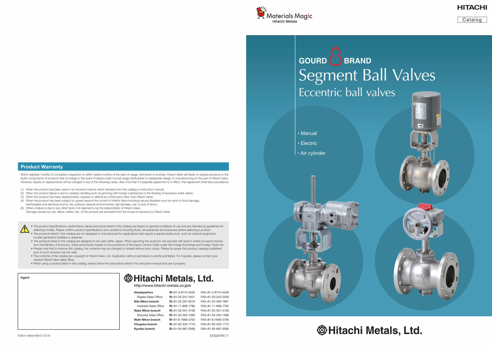
Segment Ball ValvesEccentric ball valves
• Manual
• Electric
• Air cylinder
Edition dated March 2016
Product WarrantyWithin eighteen months of completion inspection or within twelve months of the start of usage, whichever is shortest, Hitachi Valve will repair or replace products or the faulty components of products free of charge in the event of failure under normal usage attributable to inadequate design or manufacturing on the part of Hitachi Valve. However, repairs or replacements will be charged in any of the following cases. Also note that if a separate agreement is in effect, that agreement shall take precedence.
(1) When the product has been used in an incorrect manner which deviates from the catalog or instruction manual;(2) When the product failure is due to careless handling such as jamming with foreign substances or the sticking of excessive water stains;(3) When the product has been disassembled, repaired or altered by a third party other than Hitachi Valve;(4) When the product has been subject to causes beyond the control of Hitachi Valve including natural disasters such as wind or flood damage, earthquakes and electrical storms, fire, pollution (special environments), salt damage, war or acts of terror;(5) When a failure is due to any other factor not deemed to be the responsibility of Hitachi Valve. Damage caused by use, failure, defect, etc. of the product are excluded from the scope of warranty by Hitachi Valve.
ESG2016①1
• The product specifications, performance values and prices listed in this catalog are based on general conditions of use and are intended as guidelines for selecting models. Please confirm product specifications and conditions including fluids, temperatures and pressures before selecting a product.• The products listed in this catalog are not designed or manufactured for applications that require a special quality level, such as medical equipment, nuclear generation facilities or airplanes.• The products listed in this catalog are designed to be used within Japan. When exporting the products, the exporter will need to obtain an export license from the Ministry of Economy, Trade and Industry based on the provisions of the Export Control Order under the Foreign Exchange and Foreign Trade Act.• Please note that to improve this catalog, the contents may be changed or revised without prior notice. Please be aware that product catalogs published prior to such revisions are not valid.• The contents of this catalog are copyright of Hitachi Valve, Ltd. Duplication without permission is strictly prohibited. For inquiries, please contact your nearest Hitachi Valve sales office.• When using a product listed in this catalog, please follow the precautions listed in its instruction manual and use it properly.
Agent
Catalog
GOURD BRAND
http://www.hitachi-metals.co.jp/e
Headquarters ☎+81-3-6774-3520 FAX+81-3-6774-4348
Niigata Sales Office ☎+81-25-241-5421 FAX+81-25-243-2558
Kita Nihon branch ☎+81-22-267-0216 FAX+81-22-266-7891
Hokkaido Sales Office ☎+81-11-806-1786 FAX+81-11-806-1792
Naka Nihon branch ☎+81-52-551-4138 FAX+81-52-551-4139
Shizuoka Sales Office ☎+81-54-202-1580 FAX+81-54-202-1588
Nishi Nihon branch ☎+81-6-7669-3763 FAX+81-6-7669-3736
Chugoku branch ☎+81-82-535-1710 FAX+81-82-535-1713
Kyushu branch ☎+81-92-687-5268 FAX+81-92-687-5266
Fullyclosed
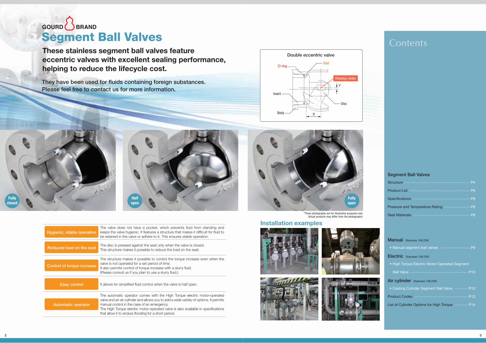
These stainless segment ball valves featureeccentric valves with excellent sealing performance,helping to reduce the lifecycle cost.
Segment Ball Valves
Installation examples
They have been used for fluids containing foreign substances.Please feel free to contact us for more information.
Segment Ball Valves
Structure
Product List
Specifications
Pressure and Temperature Rating
Seat Materials
Manual Stainless 10K/20K
• Manual segment ball valves
Electric Stainless 10K/20K
• High Torque Electric Motor-Operated Segment
Ball Valve
Air cylinder Stainless 10K/20K
• Casting Cylinder Segment Ball Valve
Product Codes
List of Cylinder Options for High Torque
................................................................ P4
........................................................... P6
........................................................ P8
......................... P8
....................................................... P8
............................. P9
........................................................ P10
............. P12
.................................................... P13
............. P14
*These photographs are for illustrative purposes only.Actual products may differ from the photographs.
Hygienic, stable operationThe valve does not have a pocket, which prevents fluid from standing and keeps the valve hygienic. It features a structure that makes it difficult for fluid to be retained in the valve or adhere to it. This ensures stable operation.
The disc is pressed against the seat only when the valve is closed.This structure makes it possible to reduce the load on the seat.
The structure makes it possible to control the torque increase even when the valve is not operated for a set period of time.It also permits control of torque increase with a slurry fluid.(Please consult us if you plan to use a slurry fluid.)
The automatic operator comes with the High Torque electric motor-operated valve and an air cylinder and allows you to add a wide variety of options. It permits manual control in the case of an emergency.The High Torque electric motor-operated valve is also available in specifications that allow it to endure flooding for a short period.
It allows for simplified fluid control when the valve is half open.
Reduced load on the seat
Control of torque increase
Easy control
Automatic operator
Halfopen
Fullyopen
O-ring
Insert
X
Y
Seat
Disc
Double eccentric valve
Body
Rotating center
GOURD BRAND
Fullyclosed
These stainless segment ball valves featureeccentric valves with excellent sealing performance,helping to reduce the lifecycle cost.
Segment Ball Valves
Installation examples
They have been used for fluids containing foreign substances.Please feel free to contact us for more information.
Segment Ball Valves
Structure
Product List
Specifications
Pressure and Temperature Rating
Seat Materials
Manual Stainless 10K/20K
• Manual segment ball valves
Electric Stainless 10K/20K
• High Torque Electric Motor-Operated Segment
Ball Valve
Air cylinder Stainless 10K/20K
• Casting Cylinder Segment Ball Valve
Product Codes
List of Cylinder Options for High Torque
................................................................ P4
........................................................... P6
........................................................ P8
......................... P8
....................................................... P8
............................. P9
........................................................ P10
............. P12
.................................................... P13
............. P14
*These photographs are for illustrative purposes only.Actual products may differ from the photographs.
Hygienic, stable operationThe valve does not have a pocket, which prevents fluid from standing and keeps the valve hygienic. It features a structure that makes it difficult for fluid to be retained in the valve or adhere to it. This ensures stable operation.
The disc is pressed against the seat only when the valve is closed.This structure makes it possible to reduce the load on the seat.
The structure makes it possible to control the torque increase even when the valve is not operated for a set period of time.It also permits control of torque increase with a slurry fluid.(Please consult us if you plan to use a slurry fluid.)
The automatic operator comes with the High Torque electric motor-operated valve and an air cylinder and allows you to add a wide variety of options. It permits manual control in the case of an emergency.The High Torque electric motor-operated valve is also available in specifications that allow it to endure flooding for a short period.
It allows for simplified fluid control when the valve is half open.
Reduced load on the seat
Control of torque increase
Easy control
Automatic operator
Halfopen
Fullyopen
O-ring
Insert
X
Y
Seat
Disc
Double eccentric valve
Body
Rotating center
GOURD BRAND
3
セグメントボールCS6(E)_1601.indd 3 16/03/17 11:23
Fullyclosed
These stainless segment ball valves featureeccentric valves with excellent sealing performance,helping to reduce the lifecycle cost.
Segment Ball Valves
Installation examples
They have been used for fluids containing foreign substances.Please feel free to contact us for more information.
Segment Ball Valves
Structure
Product List
Specifications
Pressure and Temperature Rating
Seat Materials
Manual Stainless 10K/20K
• Manual segment ball valves
Electric Stainless 10K/20K
• High Torque Electric Motor-Operated Segment
Ball Valve
Air cylinder Stainless 10K/20K
• Casting Cylinder Segment Ball Valve
Product Codes
List of Cylinder Options for High Torque
................................................................ P4
........................................................... P6
........................................................ P8
......................... P8
....................................................... P8
............................. P9
........................................................ P10
............. P12
.................................................... P13
............. P14
*These photographs are for illustrative purposes only.Actual products may differ from the photographs.
Hygienic, stable operationThe valve does not have a pocket, which prevents fluid from standing and keeps the valve hygienic. It features a structure that makes it difficult for fluid to be retained in the valve or adhere to it. This ensures stable operation.
The disc is pressed against the seat only when the valve is closed.This structure makes it possible to reduce the load on the seat.
The structure makes it possible to control the torque increase even when the valve is not operated for a set period of time.It also permits control of torque increase with a slurry fluid.(Please consult us if you plan to use a slurry fluid.)
The automatic operator comes with the High Torque electric motor-operated valve and an air cylinder and allows you to add a wide variety of options. It permits manual control in the case of an emergency.The High Torque electric motor-operated valve is also available in specifications that allow it to endure flooding for a short period.
It allows for simplified fluid control when the valve is half open.
Reduced load on the seat
Control of torque increase
Easy control
Automatic operator
Halfopen
Fullyopen
O-ring
Insert
X
Y
Seat
Disc
Double eccentric valve
Body
Rotating center
GOURD BRAND
2
セグメントボールCS6(E)_1601.indd 2 16/03/17 11:23
5
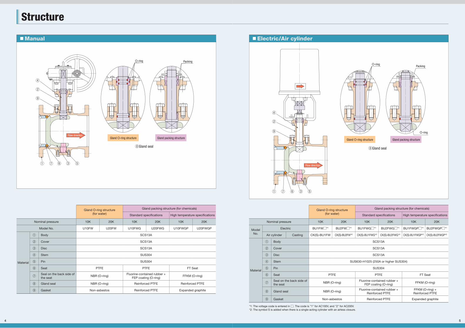
■ Electric/Air cylinder
⑧Gland seal
④
②
⑨
⑤③⑥⑦①
Gland O-ring structure Gland packing structure
Flow direction
PackingO-ring
O-ring
Gland O-ring structure(for water)
Gland packing structure (for chemicals)
Standard specifications High temperature specifications
Nominal pressure 10K 20K 10K 20K 10K 20K
Model No.
Electric BU1FW□*1 BU2FW□*1 BU1FWG□*1 BU2FWG□*1 BU1FWGP□*1 BU2FWGP□*1
Air cylinder Casting CK(S)-BU1FW CK(S)-BU2FW*2 CK(S)-BU1FWG*2 CK(S)-BU2FWG*2 CK(S)-BU1FWGP*2 CK(S)-BU2FWGP*2
Material
① Body SCS13A
② Cover SCS13A
③ Disc SCS13A
④ Stem SUS630-H1025 (250A or higher SUS304)
⑤ Pin SUS304
⑥ Seat PTFE PTFE FT Seat
⑦ Seal on the back side of the seat
NBR (O-ring)Fluorine-contained rubber +
FEP coating (O-ring)FFKM (O-ring)
⑧ Gland seal NBR (O-ring)Fluorine-contained rubber +
Reinforced PTFEFFKM (O-ring) +Reinforced PTFE
⑨ Gasket Non-asbestos Reinforced PTFE Expanded graphite
*1: The voltage code is entered in □. The code is "1" for AC100V, and "2" for AC200V.*2: The symbol S is added when there is a single-acting cylinder with an airless closure.
セグメントボールCS6(E)_1601.indd 5 16/03/17 11:23
4
Structure
■ Manual
④
②
⑨
① ⑦ ⑥ ③ ⑤
Flow direction
PackingO-ring
Gland O-ring structure Gland packing structure
⑧Gland seal
Gland O-ring structure(for water)
Gland packing structure (for chemicals)
Standard specifications High temperature specifications
Nominal pressure 10K 20K 10K 20K 10K 20K
Model No. U10FW U20FW U10FWG U20FWG U10FWGP U20FWGP
Material
① Body SCS13A
② Cover SCS13A
③ Disc SCS13A
④ Stem SUS304
⑤ Pin SUS304
⑥ Seat PTFE PTFE FT Seat
⑦ Seal on the back side of the seat
NBR (O-ring)Fluorine-contained rubber +
FEP coating (O-ring)FFKM (O-ring)
⑧ Gland seal NBR (O-ring) Reinforced PTFE Reinforced PTFE
⑨ Gasket Non-asbestos Reinforced PTFE Expanded graphite
セグメントボールCS6(E)_1601.indd 4 16/03/17 11:23
7
Gland structure Specifi cations Nominal
pressure
Maximum operating
temperatureConnection Product Code
Production rangeRating
15(A) 20(A) 25(A) 32(A) 40(A) 50(A) 65(A) 80(A) 100(A) 125(A) 150(A) 200(A) 250(A) 300(A)
Manual(gear)
O-ring Standard10K
80˚CFlanged (F.F.) U10FW Gear-operated R-01
20K Flanged (R.F.) U20FW Gear-operated R-01
Packing
Standard10K
120˚CFlanged (R.F.) U10FWG Lever handle Gear-operated R-02
20K Flanged (R.F.) U20FWG Gear-operated R-02
High temperature
10K183˚C
Flanged (R.F.) U10FWGP Lever handle Gear-operated R-03
20K Flanged (R.F.) U20FWGP *1
Electric
O-ring
Low differential pressure
10K80˚C
Flanged (F.F.) BU1FW□*4 M3B M5B M10B M11B *3 R-01
High differential pressure Flanged (F.F.) BU1FWH□*4 M3B M5B M10B M11B *2 *3 R-01
Standard 20K Flanged (R.F.) BU2FW□*4 M10B M11B R-01
Packing
Standard10K
120˚CFlanged (R.F.) BU1FWG□*4 M3B M5B M10B M11B R-02
20K Flanged (R.F.) BU2FWG□*4 M10B M11B R-02
High temperature
10K183˚C
Flanged (R.F.) BU1FWGP□*4 M3B M5B M10B M11B R-03
20K Flanged (R.F.) BU2FWGP□*4 *1
Cylinder
Double-acting
cylinder
O-ring
Low differential pressure
10K80˚C
Flanged (F.F.) CK-BU1FW H1C H2C H3C H4 H5 *1 R-01
High differential pressure Flanged (F.F.) CK-BU1FWH H2C H3C H4 H5 *1 R-01
Standard 20K Flanged (R.F.) CK-BU2FW H4 H5 R-01
Packing
Standard10K
120˚CFlanged (R.F.) CK-BU1FWG H1C H2C H3C H4 R-02
20K Flanged (R.F.) CK-BU2FWG H4 H5 R-02
High temperature
10K183˚C
Flanged (R.F.) CK-BU1FWGP H1C H2C H3C H4 R-03
20K Flanged (R.F.) CK-BU2FWGP *1
Single-acting
cylinder
O-ring
Low differential pressure
10K80˚C
Flanged (F.F.) CKS-BU1FW H1SC H2SC H3SC H4S H5S *1 R-01
High differential pressure Flanged (F.F.) CKS-BU1FWH H2SC H3SC H4S H5S *1 R-01
Standard 20K Flanged (R.F.) CKS-BU2FW H4S H5S R-01
Packing
Standard10K
120˚CFlanged (R.F.) CKS-BU1FWG H1SC H2SC H3SC H4S H5S R-02
20K Flanged (R.F.) CKS-BU2FWG H4S H5S R-02
High temperature
10K183˚C
Flanged (R.F.) CKS-BU1FWGP H1SC H2C H3SC H4S H5S R-03
20K Flanged (R.F.) CKS-BU2FWGP *1
セグメントボールCS6(E)_1601.indd 7 16/03/17 11:23
6
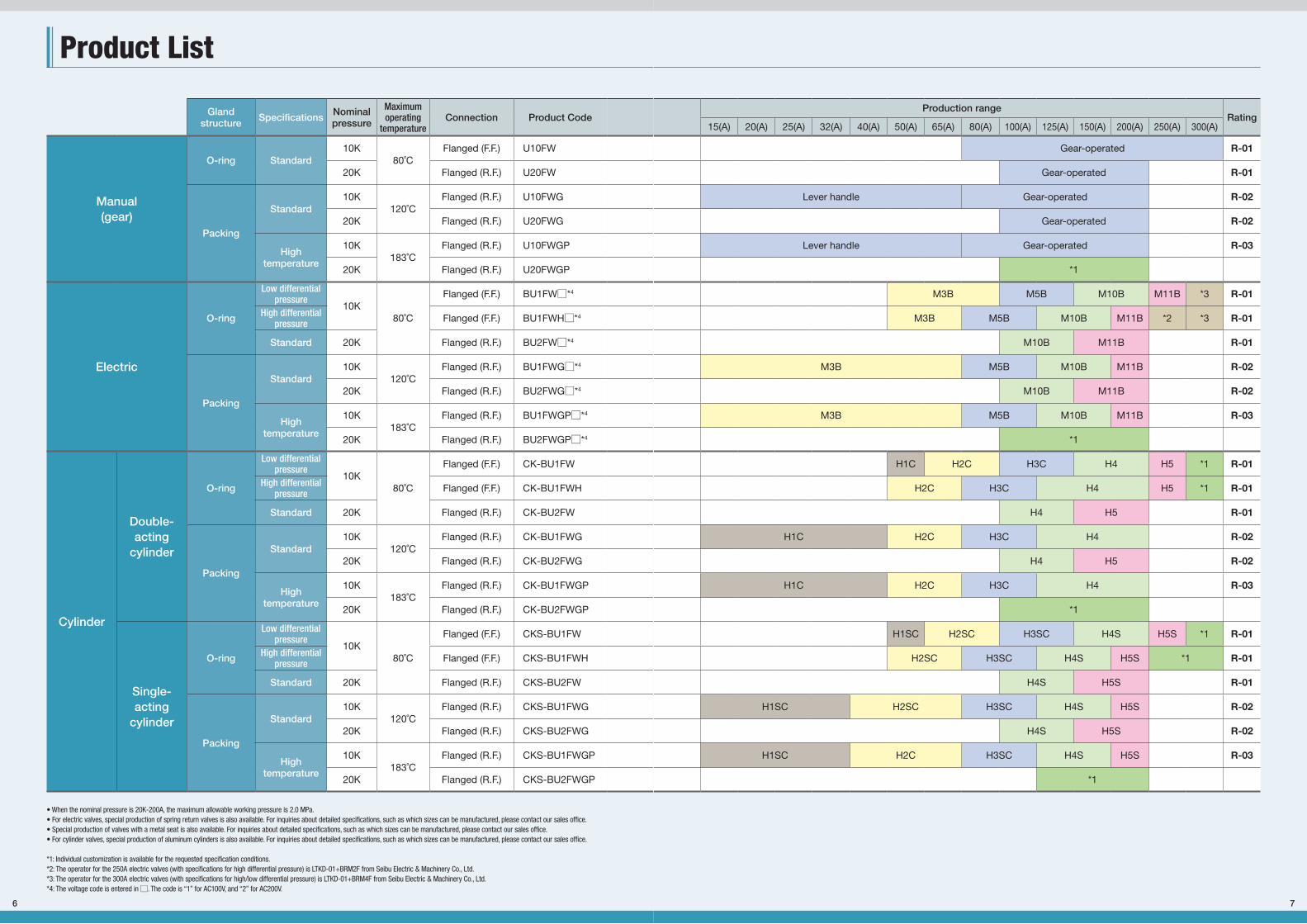
Product List
• When the nominal pressure is 20K-200A, the maximum allowable working pressure is 2.0 MPa.• For electric valves, special production of spring return valves is also available. For inquiries about detailed specifications, such as which sizes can be manufactured, please contact our sales office.• Special production of valves with a metal seat is also available. For inquiries about detailed specifications, such as which sizes can be manufactured, please contact our sales office.• For cylinder valves, special production of aluminum cylinders is also available. For inquiries about detailed specifications, such as which sizes can be manufactured, please contact our sales office.
*1: Individual customization is available for the requested specification conditions.*2: The operator for the 250A electric valves (with specifications for high differential pressure) is LTKD-01+BRM2F from Seibu Electric & Machinery Co., Ltd.*3: The operator for the 300A electric valves (with specifications for high/low differential pressure) is LTKD-01+BRM4F from Seibu Electric & Machinery Co., Ltd.*4: The voltage code is entered in □. The code is “1” for AC100V, and “2” for AC200V.
Gland structure Specifi cations Nominal
pressure
Maximum operating
temperatureConnection Product Code
Production rangeRating
15(A) 20(A) 25(A) 32(A) 40(A) 50(A) 65(A) 80(A) 100(A) 125(A) 150(A) 200(A) 250(A) 300(A)
Manual(gear)
O-ring Standard10K
80˚CFlanged (F.F.) U10FW Gear-operated R-01
20K Flanged (R.F.) U20FW Gear-operated R-01
Packing
Standard10K
120˚CFlanged (R.F.) U10FWG Lever handle Gear-operated R-02
20K Flanged (R.F.) U20FWG Gear-operated R-02
High temperature
10K183˚C
Flanged (R.F.) U10FWGP Lever handle Gear-operated R-03
20K Flanged (R.F.) U20FWGP *1
Electric
O-ring
Low differential pressure
10K80˚C
Flanged (F.F.) BU1FW□*4 M3B M5B M10B M11B *3 R-01
High differential pressure Flanged (F.F.) BU1FWH□*4 M3B M5B M10B M11B *2 *3 R-01
Standard 20K Flanged (R.F.) BU2FW□*4 M10B M11B R-01
Packing
Standard10K
120˚CFlanged (R.F.) BU1FWG□*4 M3B M5B M10B M11B R-02
20K Flanged (R.F.) BU2FWG□*4 M10B M11B R-02
High temperature
10K183˚C
Flanged (R.F.) BU1FWGP□*4 M3B M5B M10B M11B R-03
20K Flanged (R.F.) BU2FWGP□*4 *1
Cylinder
Double-acting
cylinder
O-ring
Low differential pressure
10K80˚C
Flanged (F.F.) CK-BU1FW H1C H2C H3C H4 H5 *1 R-01
High differential pressure Flanged (F.F.) CK-BU1FWH H2C H3C H4 H5 *1 R-01
Standard 20K Flanged (R.F.) CK-BU2FW H4 H5 R-01
Packing
Standard10K
120˚CFlanged (R.F.) CK-BU1FWG H1C H2C H3C H4 R-02
20K Flanged (R.F.) CK-BU2FWG H4 H5 R-02
High temperature
10K183˚C
Flanged (R.F.) CK-BU1FWGP H1C H2C H3C H4 R-03
20K Flanged (R.F.) CK-BU2FWGP *1
Single-acting
cylinder
O-ring
Low differential pressure
10K80˚C
Flanged (F.F.) CKS-BU1FW H1SC H2SC H3SC H4S H5S *1 R-01
High differential pressure Flanged (F.F.) CKS-BU1FWH H2SC H3SC H4S H5S *1 R-01
Standard 20K Flanged (R.F.) CKS-BU2FW H4S H5S R-01
Packing
Standard10K
120˚CFlanged (R.F.) CKS-BU1FWG H1SC H2SC H3SC H4S H5S R-02
20K Flanged (R.F.) CKS-BU2FWG H4S H5S R-02
High temperature
10K183˚C
Flanged (R.F.) CKS-BU1FWGP H1SC H2C H3SC H4S H5S R-03
20K Flanged (R.F.) CKS-BU2FWGP *1
セグメントボールCS6(E)_1601.indd 6 16/03/17 11:23

Manual
Electric
Air cylind
er
9
ManualM
anualE
lectricA
ir cylinder
Stainless 10K/20K
Manual segment ball valves
U10FW/U20FW U10FWG/U20FWGProduct Code Product Code
Flowdirection
Flowdirection Flow
direction
Structural drawing Structural drawing
Main dimensions
LL
Lt t
t
φD
φD
φD
H
H
H
φd
φd
φd
Features • Lever handle (for valves with nominal diameter of up to 65A) and gear operator (for valves with nominal diameter of 80A or above) allow for smooth opening and closing operations.
• The valve can be kept half open, allowing for simplified fluid control.
• The main body material can be used to manufacture SCS14A as well.
• A wide range of options are available, including chain-operated gear operator and product with a limit switch.Please place your order with our sales office.
Gland O-ring structure (Segment ball valve for water) Gland packing structure (Segment ball valve for chemicals)
Nominal pressure 10K 20K
Nominal diameter (A) 15 20 25 32 40 50 65 80 100 125 150 200 250 300 100 125 150 200
L (End-to-end dimensions) 108 117 127 140 165 178 190 203 229 254 267 292 330 356 229 254 267 292
D (Flange outer diameter) 95 100 125 135 140 155 175 185 210 250 280 330 400 445 225 270 305 350
t (Flange thickness) 12 14 14 16 16 16 18 18 18 20 22 22 24 24 24 26 28 30
d (Port diameter) 14.5 19 24 32 38 48 63 72 92 114 138 184 225 265 92 114 138 184
Gland O-ring structure(for water)
Connection - - - - - JIS B 2220 10K F.F. JIS B 2220 20K R.F.
Pressure - - - - - Max: 1.4 MPa (Differential pressure Max: 1.4 MPa)Max: 2.5 MPa
(Differential pressure Max: 2.5 MPa)*1
Model - - - - - Gear operator Gear operator
H: Total height - - - - - - - 237 265 277 311 370 442 483 287 299 343 370
Gland packing structure(for chemicals)
Connection JIS B 2220 10K R.F. - - JIS B 2220 20K R.F.
Pressure Max: 1.4 MPa (Differential pressure Max: 1.4 MPa)Max: 2.5 MPa
(Differential pressure Max: 2.5 MPa)*1
Model Lever handle Gear operator - - Gear operator
H: Total height 153 156 170 174 193 199 217 237 265 277 316 384 - - 292 304 357 384
Cv value (applies when the valve is fully open) 20 35 55 90 130 210 365 510 800 1200 1850 3200 4700 6700 800 1200 1850 3200
*1: Max: 2.0 MPa (Max. differential pressure: 2.0 MPa) with a nominal pressure of 20K-200A
セグメントボールCS6(E)_1601.indd 9 16/03/17 11:23
8
Specifi cations
Pressure and Temperature Rating
Seat MaterialsIn addition to seats with standard specifications and those with specifications for high temperatures,we also manufacture seats from the following special materials. Please consult our sales office if you have any questions.
Seat Materials Color Features
PTFEMilky white
Used for seats with standard specificationsUnfilled PTFE seats with superior chemical resistance and sealing performance
FT seat(Modified PTFE seat)
Milky white
Used for seats with specifications for high temperaturesA modified PTFE seat featuring improved PTFE high-temperature creep resistanceSame level of high sealing performance and chemical resistance as a PTFE seat
PTFE with glass fiber WhiteReinforced PTFE containing glass fiberHigher abrasion resistance than PTFE
PTFE with carbon fiber BlackReinforced PTFE containing carbon fiberHigher abrasion resistance than PTFE containing glass fiberHigher heat resistance than PTFE
P seat BlackCarbon-reinforced materialHigher abrasion resistance than PTFEHigher heat resistance than PTFE
Metal seatMetallic
color
Optimal for fluids that require higher abrasion resistance and higher seat-surface strength than resin seatsTo be used with a surface-hardened disc
0.0
0.5
1.0
1.5
2.0
2.5
3.0
0 5 20 40 60 80 100
1.4
U20FW-100~150A
0.0
0.5
1.0
1.5
2.0
2.5
3.0
0 20 40 60 80 100 120 1400.0
0.2
0.4
0.6
0.8
1.0
1.2
1.4
1.6
0 20 40 60 80 100 120 140 160 180 200
U20FW-200A U20FWG-200A
U10FW-80~300A U10FWG-15~200A
Pre
ssur
e (M
Pa)
Pre
ssur
e (M
Pa)
Pre
ssur
e (M
Pa)
Temperature (˚C) Temperature (˚C) Temperature (˚C)
U20FWG-100~150AU10FWGP-15~200A
1.4
183
Standard specifications (R-01) Standard specifications (R-02) High temperature specifications (R-03)
■ Gland O-ring structure (for water)
■ Gland packing structure (for chemicals)
Gland O-ring structure(for water)
Gland packing structure(for chemicals)
Standard specifications High temperature specifications
Nominal pressure 10K 20K 10K 20K 10K 20K
Model No.
Manual U10FW U20FW U10FWG U20FWG U10FWGP U20FWGP
Electric BU1FW□*1 BU2FW□*1 BU1FWG□*1 BU2FWG□*1 BU1FWGP□*1 BU2FWGP□*1
Air-cylinder valve (casting) CK(S)-BU1FW CK(S)-BU2FW CK(S)-BU1FWG CK(S)-BU2FWG CK(S)-BU1FWGP CK(S)-BU2FWGP
Conditions
Fluid temperature 5〜80˚C0〜120˚C 0〜183˚C
*2(No freezing) (No freezing)
Flow rate Max:3m/s (When the valve is fully open)
Flow direction Limited (See the arrows in the illustrations.)
Rating R-01 R-02 R-03 *2
*1: A code for voltage is entered in □. The code is "1" for AC100V, and "2" for AC200V.*2: Individual customization is available for the requested specification conditions.
セグメントボールCS6(E)_1601.indd 8 16/03/17 11:23
11
Manual
Electric
Air cylind
er
ProductCode
*1: The maximum allowable working pressure (differential pressure) is 1.2 MPa.
* M3B and M5B are coated with a special sealant.
Specifications
Item Specifications
Operator
Model name High Torque (with specifications that enable it to endure flooding for a short period)
External connection wiring Lead cable (standard length: 10 m)Structure Endures flood for a short periodOther specifications Same as standard High Torque
①②
③⑧ ⑤ ④
①
②
③⑧ ⑤ ④ ⑥ ⑦
Structural drawing
Structural drawing
Precautions
Commodity number Product Name
1 Cover O-ring*2 Cable end seal3 Waterproof connector4 Output shaft O-ring5 Special ventilator6 Manual operation shaft7 Manual/automatic clutch8 Cable (10m)
M3B.M5B M10B.M11B
Product Name Material
Body SCS13A
Valve element SCS13A
Seat PTFE
Cover SCS13A
Stem SUS630-H1025
Gland O-ring NBR*
Nominal pressure 10K 20KNominal diameter (A) 125 150 200 250 100 125 150L (End-to-end dimensions) 254 267 292 330 229 254 267d (Port diameter) 114 138 184 225 92 114 138H: Total height 595 624 663 685 588 600 624
ModelLow differential pressure M10-BL M11-BLHigh differential pressure M10-BL M11-BL*1 - M10-BL M11-BL
Flowdirection
Clutch shaft
Position forautomaticoperation
Position formanual
operation
Main dimensions
L
H
φd
Actuator specifications
Model of the operator M3B M5B M10B M11BLTKD-01
BRM2F BRM4FRated output torque (N.m) 49 177 559 1078 1862 3038Opening and closing time (seconds)
50Hz 18 24 26 38 43 6960Hz 14 20 22 32 37 58
Current(A)
AC100/110VRated 0.37 0.61 1.6 2.2
Differs according to the voltage and frequency. Please contact us for details.
Peak 0.73 1.5 4.6 5.8
AC200/220VRated 0.19 0.31 0.85 1.15Peak 0.37 0.75 2.4 2.8
Power consumption (W) 27 +5 40+5 145+10 210+10
Rated output (W) 6 23 60 80 400 400Time rating 30 minutes 15 minutesSafety protection Thermal protector Torque switchUsage environment (type of protection) Indoor and outdoor (IP54 equivalent) Indoor and outdoor (IP55)Frequency of opening and closing One opening and closing or less/2 minutes -Type of motor Capacitor-run reversible motor -Thermal class E BSpace heater YesOpening/closing control signal Yes (with voltage) Yes (without voltage)Permissible ambient temperature --10~50˚CAmbient environment 0.5 G vibration, non-explosion-proof atmosphere
Connection terminal Compatible wire: 2mm2 or below(No need to use crimping terminal) -
Service entrance for electric wire 1-G½ 1-G¾ 2-G1,1-G¾
Manual operation
Hook an adjustable wrench on the socket portion of the output shaft under the operator, and then open/close it by pushing down the adjustable wrench.
Insert a screw driver into the hole of the output shaft under the operator, push it down, and then hook an adjustable wrench on the manual operation shaft to open and close the valve.
Press down the lever to the position for manual operation, and then turn the handle.
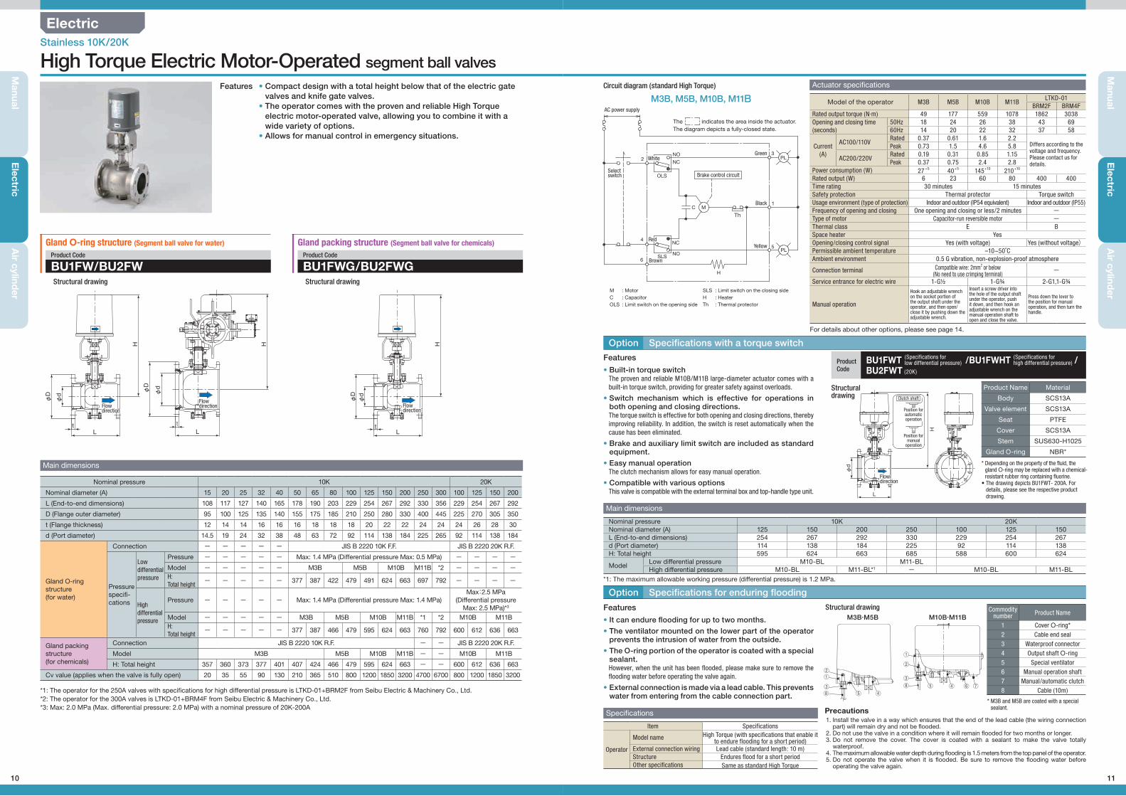
For details about other options, please see page 14.
* Depending on the property of the fluid, the gland O-ring may be replaced with a chemical-resistant rubber ring containing fluorine.
• The drawing depicts BU1FWT- 200A. For details, please see the respective product drawing.
1. Install the valve in a way which ensures that the end of the lead cable (the wiring connection part) will remain dry and not be flooded.
2. Do not use the valve in a condition where it will remain flooded for two months or longer.3. Do not remove the cover. The cover is coated with a sealant to make the valve totally
waterproof.4. The maximum allowable water depth during flooding is 1.5 meters from the top panel of the operator.5. Do not operate the valve when it is flooded. Be sure to remove the flooding water before
operating the valve again.
Option Specifications with a torque switch
Option Specifications for enduring flooding
C
PL
PL
Th
H
NC
NO
NC
NOSLS
OLS
3
1
5
2
4
6
M
M : MotorC : CapacitorOLS : Limit switch on the opening side
SLS : Limit switch on the closing sideH : HeaterTh : Thermal protector
AC power supply
Selectswitch
WhiteGreen
Black
Yellow
Brake control circuit
Red
Brown
The indicates the area inside the actuator.The diagram depicts a fully-closed state.
M3B, M5B, M10B, M11B
Features
Features
• Built-in torque switchThe proven and reliable M10B/M11B large-diameter actuator comes with a built-in torque switch, providing for greater safety against overloads.
• Switch mechanism which is effective for operations in both opening and closing directions.The torque switch is effective for both opening and closing directions, thereby improving reliability. In addition, the switch is reset automatically when the cause has been eliminated.
• Brake and auxiliary limit switch are included as standard equipment.
• Easy manual operationThe clutch mechanism allows for easy manual operation.
• Compatible with various optionsThis valve is compatible with the external terminal box and top-handle type unit.
• It can endure flooding for up to two months.
• The ventilator mounted on the lower part of the operator prevents the intrusion of water from the outside.
• The O-ring portion of the operator is coated with a special sealant.However, when the unit has been flooded, please make sure to remove the flooding water before operating the valve again.
• External connection is made via a lead cable. This prevents water from entering from the cable connection part.
Circuit diagram (standard High Torque)
BU1FWT /BU1FWHT /BU2FWT (20K)
(Specifications forlow differential pressure)
(Specifications forhigh differential pressure)
セグメントボールCS6(E)_1601.indd 11 16/03/17 11:23
10
Electric
Manual
Electric
Air cylind
er
Stainless 10K/20K
High Torque Electric Motor-Operated segment ball valves
BU1FW/BU2FW BU1FWG/BU2FWGProduct Code Product Code
Main dimensions
Gland O-ring structure (Segment ball valve for water) Gland packing structure (Segment ball valve for chemicals)
Nominal pressure 10K 20K
Nominal diameter (A) 15 20 25 32 40 50 65 80 100 125 150 200 250 300 100 125 150 200
L (End-to-end dimensions) 108 117 127 140 165 178 190 203 229 254 267 292 330 356 229 254 267 292
D (Flange outer diameter) 95 100 125 135 140 155 175 185 210 250 280 330 400 445 225 270 305 350
t (Flange thickness) 12 14 14 16 16 16 18 18 18 20 22 22 24 24 24 26 28 30
d (Port diameter) 14.5 19 24 32 38 48 63 72 92 114 138 184 225 265 92 114 138 184
Gland O-ring structure(for water)
Connection - - - - - JIS B 2220 10K F.F. JIS B 2220 20K R.F.
Pressure specifi-cations
Low differential pressure
Pressure - - - - - Max: 1.4 MPa (Differential pressure Max: 0.5 MPa) - - - -Model - - - - - M3B M5B M10B M11B *2 - - - -H:Total height
- - - - - 377 387 422 479 491 624 663 697 792 - - - -
High differential pressure
Pressure - - - - - Max: 1.4 MPa (Differential pressure Max: 1.4 MPa)Max:2.5 MPa
(Differential pressure Max: 2.5 MPa)*3
Model - - - - - M3B M5B M10B M11B *1 *2 M10B M11BH:Total height
- - - - - 377 387 466 479 595 624 663 760 792 600 612 636 663
Gland packing structure(for chemicals)
Connection JIS B 2220 10K R.F. - - JIS B 2220 20K R.F.
Model M3B M5B M10B M11B - - M10B M11B
H: Total height 357 360 373 377 401 407 424 466 479 595 624 663 - - 600 612 636 663
Cv value (applies when the valve is fully open) 20 35 55 90 130 210 365 510 800 1200 1850 3200 4700 6700 800 1200 1850 3200
Flowdirection
Flowdirection Flow
direction
L LLt tt
φD
φDφ
D
H HH
φd
φdφ
d
*1: The operator for the 250A valves with specifications for high differential pressure is LTKD-01+BRM2F from Seibu Electric & Machinery Co., Ltd.*2: The operator for the 300A valves is LTKD-01+BRM4F from Seibu Electric & Machinery Co., Ltd.*3: Max: 2.0 MPa (Max. differential pressure: 2.0 MPa) with a nominal pressure of 20K-200A
Features • Compact design with a total height below that of the electric gate valves and knife gate valves.
• The operator comes with the proven and reliable High Torque
electric motor-operated valve, allowing you to combine it with a wide variety of options.
• Allows for manual control in emergency situations.
Structural drawing Structural drawing
セグメントボールCS6(E)_1601.indd 10 16/03/17 11:23
13
Manual
Electric
Air cylind
er
Specifications of the cylinder operator
■Casting cylinder ModelSpecifications
H1CH1SC
H2CH2SC
H3CH3SC
H4H4S
H5H5S
Operating fluid Compressed air*1
Standard operating pressure 0.39 MPaOperating pressure range in which it may be used 0.39〜0.69 MPaCylinder pressure resistance 0.98 MPaAngle of rotation 90 degreesAir inlet Rc1/4 Rc3/8Operating temperature range*2 -10˚C〜+60˚CPlace of use*3 Indoor/Outdoor
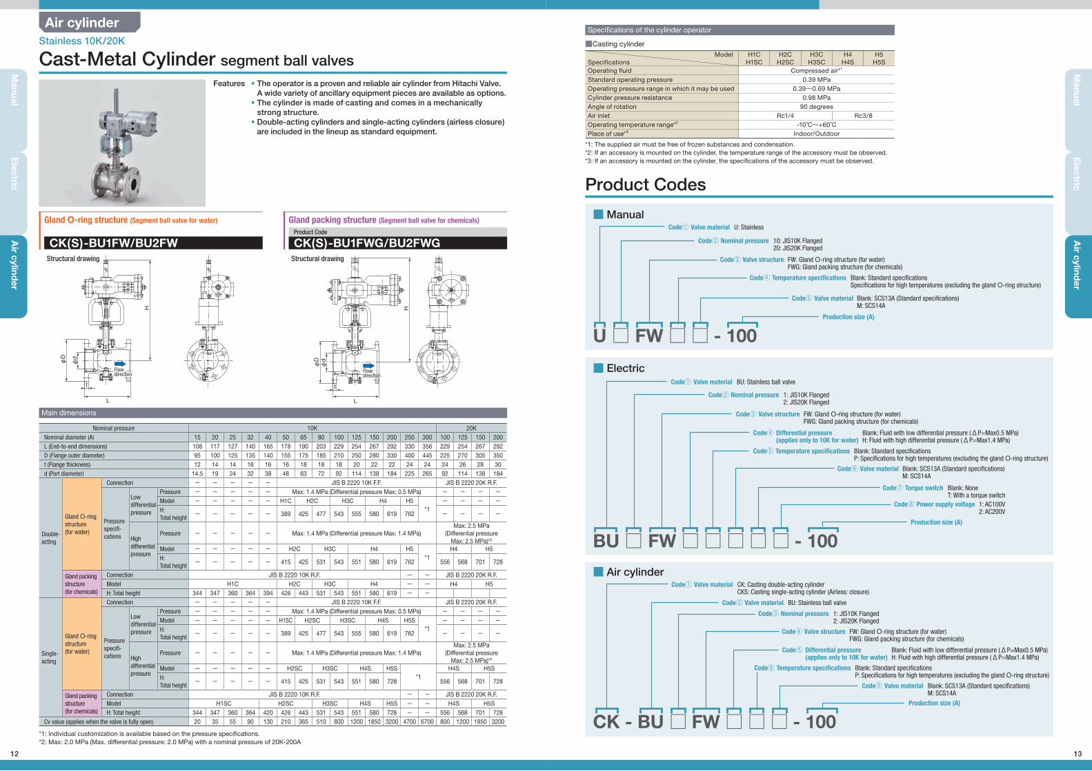
Product Codes
■ Electric
BU □ FW □ □ □ □ □ - 100
■ Air cylinder
CK - BU □ FW □ □ □ - 100
■Manual
U □ FW □ □ - 100
U: Stainless
BU: Stainless ball valve
CK: Casting double-acting cylinderCKS: Casting single-acting cylinder (Airless: closure)
Blank: SCS13A (Standard specifications)M: SCS14A
BU: Stainless ball valve
Code① Valve material
Code① Valve material
Code① Valve material
Code⑤ Valve material
Code② Valve material
10: JIS10K Flanged20: JIS20K Flanged
1: JIS10K Flanged2: JIS20K Flanged
1: JIS10K Flanged2: JIS20K Flanged
Code② Nominal pressure
Code② Nominal pressure
Code③ Nominal pressure
FW: Gland O-ring structure (for water)FWG: Gland packing structure (for chemicals)
FW: Gland O-ring structure (for water)FWG: Gland packing structure (for chemicals)
FW: Gland O-ring structure (for water)FWG: Gland packing structure (for chemicals)
Code③ Valve structure
Code③ Valve structure
Code④ Valve structure
Blank: Standard specificationsSpecifications for high temperatures (excluding the gland O-ring structure)
Blank: Standard specificationsP: Specifications for high temperatures (excluding the gland O-ring structure)
Blank: Standard specificationsP: Specifications for high temperatures (excluding the gland O-ring structure)
Blank: Fluid with low differential pressure (ΔP=Max0.5 MPa)H: Fluid with high differential pressure (ΔP=Max1.4 MPa)
Blank: Fluid with low differential pressure (ΔP=Max0.5 MPa)H: Fluid with high differential pressure (ΔP=Max1.4 MPa)
Blank: SCS13A (Standard specifications)M: SCS14A
Blank: SCS13A (Standard specifications)M: SCS14A
Blank: NoneT: With a torque switch
1: AC100V2: AC200V
Code④ Temperature specifications
Code⑤ Temperature specifications
Code⑥ Temperature specifications
Code④ Differential pressure (applies only to 10K for water)
Code⑤ Differential pressure (applies only to 10K for water)
Code⑤ Valve material
Code⑥ Valve material
Code⑦ Torque switch
Code⑧ Power supply voltage
Production size (A)
Production size (A)
Production size (A)
*1: The supplied air must be free of frozen substances and condensation.*2: If an accessory is mounted on the cylinder, the temperature range of the accessory must be observed.*3: If an accessory is mounted on the cylinder, the specifications of the accessory must be observed.
セグメントボールCS6(E)_1601.indd 13 16/03/17 11:23
12
Air cylinder
Manual
Electric
Air cylind
er
CK(S)-BU1FW/BU2FW CK(S)-BU1FWG/BU2FWGProduct Code
Main dimensions
Gland O-ring structure (Segment ball valve for water) Gland packing structure (Segment ball valve for chemicals)
Flowdirection
Flowdirection
L L
t t
φD
φD
H H
φd
φd
Nominal pressure 10K 20KNominal diameter (A) 15 20 25 32 40 50 65 80 100 125 150 200 250 300 100 125 150 200L (End-to-end dimensions) 108 117 127 140 165 178 190 203 229 254 267 292 330 356 229 254 267 292D (Flange outer diameter) 95 100 125 135 140 155 175 185 210 250 280 330 400 445 225 270 305 350t (Flange thickness) 12 14 14 16 16 16 18 18 18 20 22 22 24 24 24 26 28 30d (Port diameter) 14.5 19 24 32 38 48 63 72 92 114 138 184 225 265 92 114 138 184
Double-acting
Gland O-ring structure(for water)
Connection - - - - - JIS B 2220 10K F.F. JIS B 2220 20K R.F.
Pressure specifi-cations
Low differential pressure
Pressure - - - - - Max: 1.4 MPa (Differential pressure Max: 0.5 MPa) - - - -Model - - - - - H1C H2C H3C H4 H5
*1- - - -
H:Total height
- - - - - 389 425 477 543 555 580 619 762 - - - -
High differential pressure
Pressure - - - - - Max: 1.4 MPa (Differential pressure Max: 1.4 MPa)Max: 2.5 MPa
(Differential pressureMax: 2.5 MPa)*2
Model - - - - - H2C H3C H4 H5*1
H4 H5H:Total height
- - - - - 415 425 531 543 551 580 619 762 556 568 701 728
Gland packing structure(for chemicals)
Connection JIS B 2220 10K R.F. - - JIS B 2220 20K R.F.Model H1C H2C H3C H4 - - H4 H5H: Total height 344 347 360 364 394 426 443 531 543 551 580 619 - -
Single-acting
Gland O-ring structure(for water)
Connection - - - - - JIS B 2220 10K F.F. JIS B 2220 20K R.F.
Pressure specifi-cations
Low differential pressure
Pressure - - - - - Max: 1.4 MPa (Differential pressure Max: 0.5 MPa) - - - -Model - - - - - H1SC H2SC H3SC H4S H5S
*1- - - -
H:Total height
- - - - - 389 425 477 543 555 580 619 762 - - - -
High differential pressure
Pressure - - - - - Max: 1.4 MPa (Differential pressure Max: 1.4 MPa)Max: 2.5 MPa
(Differential pressureMax: 2.5 MPa)*2
Model - - - - - H2SC H3SC H4S H5S*1
H4S H5SH:Total height
- - - - - 415 425 531 543 551 580 728 556 568 701 728
Gland packing structure(for chemicals)
Connection JIS B 2220 10K R.F. - - JIS B 2220 20K R.F.Model H1SC H2SC H3SC H4S H5S - - H4S H5SH: Total height 344 347 360 364 420 426 443 531 543 551 580 728 - - 556 568 701 728
Cv value (applies when the valve is fully open) 20 35 55 90 130 210 365 510 800 1200 1850 3200 4700 6700 800 1200 1850 3200
Stainless 10K/20K
Cast-Metal Cylinder segment ball valvesFeatures • The operator is a proven and reliable air cylinder from Hitachi Valve.
A wide variety of ancillary equipment pieces are available as options.• The cylinder is made of casting and comes in a mechanically
strong structure.• Double-acting cylinders and single-acting cylinders (airless closure)
are included in the lineup as standard equipment.
Structural drawing Structural drawing
*1: Individual customization is available based on the pressure specifications.*2: Max: 2.0 MPa (Max. differential pressure: 2.0 MPa) with a nominal pressure of 20K-200A
セグメントボールCS6(E)_1601.indd 12 16/03/17 11:23
MEMO
セグメントボールCS6(E)_1601.indd 15 16/03/17 11:23
14
Manual
Electric
Air cylind
er
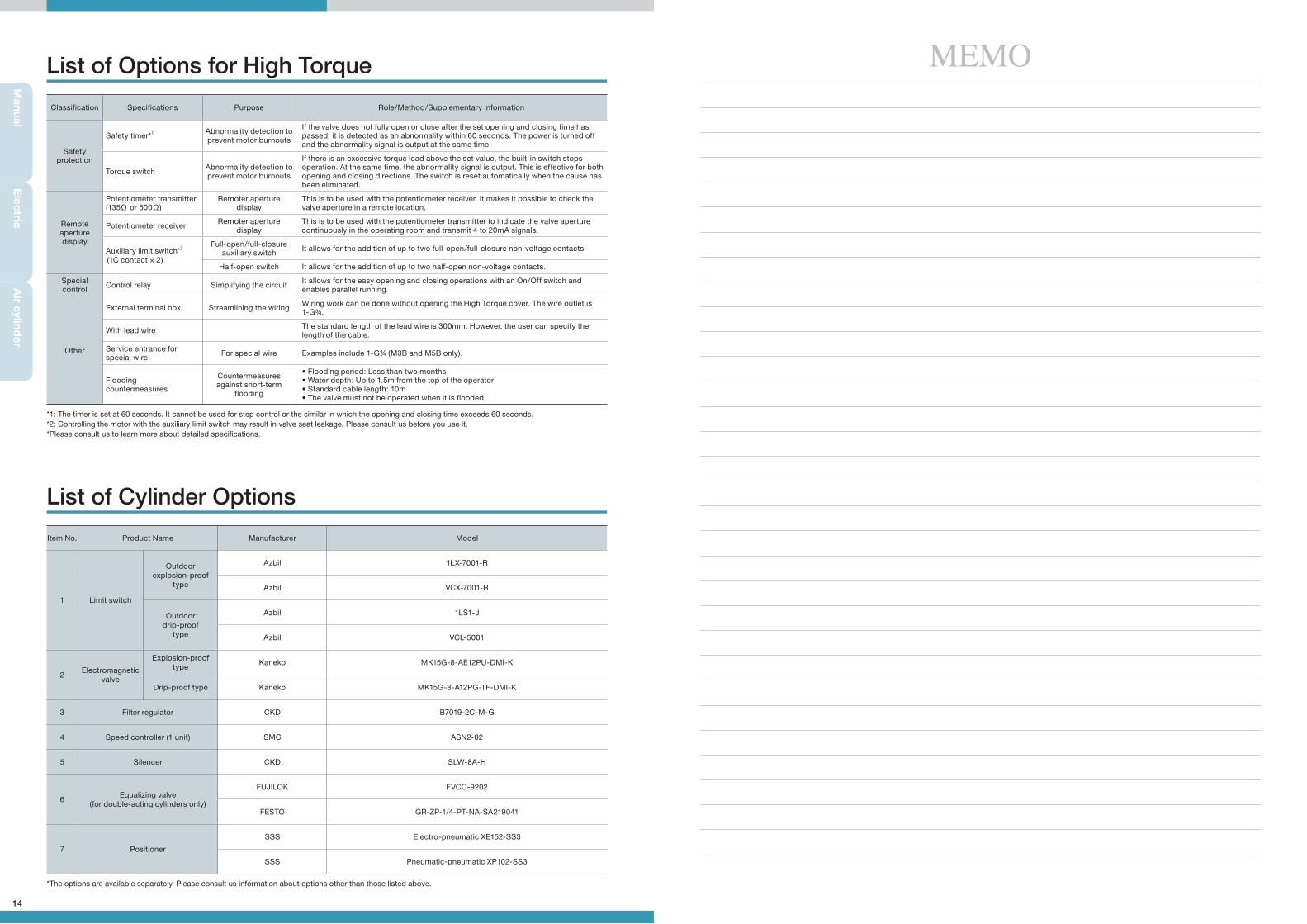
Classification Specifications Purpose Role/Method/Supplementary information
Safety protection
Safety timer*1 Abnormality detection to prevent motor burnouts
If the valve does not fully open or close after the set opening and closing time has passed, it is detected as an abnormality within 60 seconds. The power is turned off and the abnormality signal is output at the same time.
Torque switch Abnormality detection to prevent motor burnouts
If there is an excessive torque load above the set value, the built-in switch stops operation. At the same time, the abnormality signal is output. This is effective for both opening and closing directions. The switch is reset automatically when the cause has been eliminated.
Remote aperture display
Potentiometer transmitter (135Ω or 500Ω)
Remoter aperture display
This is to be used with the potentiometer receiver. It makes it possible to check the valve aperture in a remote location.
Potentiometer receiver Remoter aperture display
This is to be used with the potentiometer transmitter to indicate the valve aperture continuously in the operating room and transmit 4 to 20mA signals.
Auxiliary limit switch*2
(1C contact × 2)
Full-open/full-closure auxiliary switch It allows for the addition of up to two full-open/full-closure non-voltage contacts.
Half-open switch It allows for the addition of up to two half-open non-voltage contacts.
Special control Control relay Simplifying the circuit It allows for the easy opening and closing operations with an On/Off switch and
enables parallel running.
Other
External terminal box Streamlining the wiring Wiring work can be done without opening the High Torque cover. The wire outlet is 1-G¾.
With lead wire The standard length of the lead wire is 300mm. However, the user can specify the length of the cable.
Service entrance for special wire For special wire Examples include 1-G¾ (M3B and M5B only).
Flooding countermeasures
Countermeasures against short-term
flooding
• Flooding period: Less than two months• Water depth: Up to 1.5m from the top of the operator• Standard cable length: 10m• The valve must not be operated when it is flooded.
Item No. Product Name Manufacturer Model
1 Limit switch
Outdoorexplosion-proof
type
Azbil 1LX-7001-R
Azbil VCX-7001-R
Outdoordrip-proof
type
Azbil 1LS1-J
Azbil VCL-5001
2Electromagnetic
valve
Explosion-proof type
Kaneko MK15G-8-AE12PU-DMI-K
Drip-proof type Kaneko MK15G-8-A12PG-TF-DMI-K
3 Filter regulator CKD B7019-2C-M-G
4 Speed controller (1 unit) SMC ASN2-02
5 Silencer CKD SLW-8A-H
6Equalizing valve
(for double-acting cylinders only)
FUJILOK FVCC-9202
FESTO GR-ZP-1/4-PT-NA-SA219041
7 Positioner
SSS Electro-pneumatic XE152-SS3
SSS Pneumatic-pneumatic XP102-SS3
List of Options for High Torque
List of Cylinder Options
*1: The timer is set at 60 seconds. It cannot be used for step control or the similar in which the opening and closing time exceeds 60 seconds.*2: Controlling the motor with the auxiliary limit switch may result in valve seat leakage. Please consult us before you use it.*Please consult us to learn more about detailed specifications.
*The options are available separately. Please consult us information about options other than those listed above.
セグメントボールCS6(E)_1601.indd 14 16/03/17 11:23
Related Documents