cAT. N272 Electro- Pneu matic Valve NVEPA|VEFseies Output Pressure or Flow is Controlled ByAn Electrical Input Signal Amplifier Supply Voltage is 1 1SVAC or 24yDC Operating Pressure Up To 150 psig 114" lo 314" Port Sizes Base Mount or Body Ported Built-ln PID Controller is Optional

Welcome message from author
This document is posted to help you gain knowledge. Please leave a comment to let me know what you think about it! Share it to your friends and learn new things together.
Transcript
cAT. N272
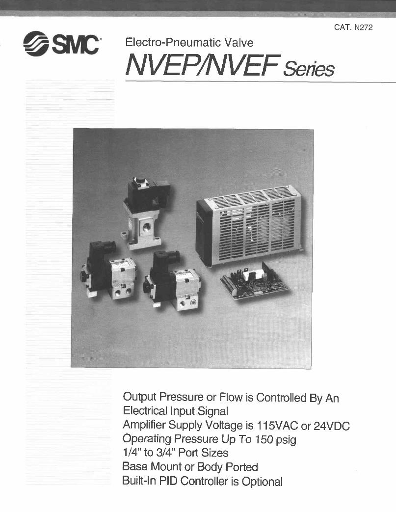
Electro- Pneu matic Valve
NVEPA|VEFseies
Output Pressure or Flow is Controlled By AnElectrical Input SignalAmplifier Supply Voltage is 1 1SVAC or 24yDCOperating Pressure Up To 150 psig114" lo 314" Port SizesBase Mount or Body PortedBuilt-ln PID Controller is Optional
NVE NVEP
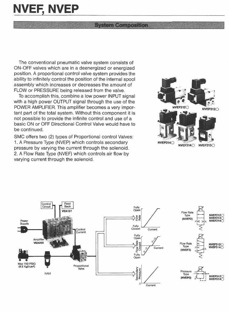
The conventional pneumatic valve syslem consists ofON-OFF valves which are in a deenergized or energizedposition. A proportional conlrol valve system provides theability to infinitely control the position of the internal spoolassembly which increases or decreases the amount ofFLOW or PRESSURE being released from the valve.
To accomplish this, combine a low power INPUT signalwith a high power OUTPUT signal through the use of thePOWER AMPLIFIER. This amplifier becomes a very impor-tant part of the total system. Without this component it isnot possible to provide the infinite control and use of abasic ON or OFF Directional Control Valve would have tobe continued.SMC offers two (2) types of Proportional control Valves:1. A Pressure Type (NVEP) which controls secondarypressure by varying the current through the solenoid.2. A Flow Rate Type (NVEfl which controls air flow byvarying current through the solenoid.
,qFfi l F lEKf:-Jr r ltr-t
€
Flow Rate
(NVEF:I) B
fi#fr$.E#E
NVEF2l2c)vEF2isO
a t{YEF2l4O
Reasureryp€
(l{vEP3t
-P{
d | | vEP3r20F'---r-. .l t EBrrO
Index2. 3 Port Electro-Pneumatic Proportional Valve
NVEF, NVEPSpecifications P OH o w t o O r d e r . . . . . . . . P OFlow Characteristics/Operating Principles P O, OConstruction Detai l . . PODimensions P OInstallation PO
Power Amp.: Series VEAM o d e l / S p e c i f i c a t i o n s . . . . . . . . . . . P OH o w t o O r d e r . . . . . . . . . P @Dimensions/ Handling Instruct ions . . . . . P@, @, @External Connections P@, @Features and Functions P@Sample Applications . . . PO

2. 3 Port Electro-Pneumatic Proportional Valve
NVEE NVEP
STANDARD SPECIFICATIONS
Characteristlcs
Flow PresgureNVEF2t20NVEF3t20
(Baso Mount)NVEFzl30 NVEF2140
NVEF3I40NVEP3120
(Base Mount) NVEP3l /t0
Port Slzg 1/4", 3/8" NPTF 114" 318" 1lz',NPTF 1/2", 3/4" NPTF 1/4",3/8" NPTF 1/2",3/4" NPTF
Medla Air *
Oper. Prassuro 1s0 PSIG (9.9 Kgflcm )Prool Pr333ure 225 PSIG (15 Kgr cm )
Ambl€nl Temp. 40 - 120"F (5 - 50"C)
Responsg Tlme 30 ms Max. 50 ms Max. 30 ms Max. 50 ms Max,
Hysteresls 3% F.S.
Repeatablllty 3/.
Sensitivity o.5/.Llnearlty 3%
Lubrlcatlon Recommend ISO Specilication VG32 (Turbine Oil #1)
Wolght Lbs. 1 .98 2.20 3.09 1 0 4 3.09* Lub.icated or oil free and any non-llammable, non-toxic, non-corrosive gases, except oxygen.
SOLENOID SPECIFICATIONSAdder Number 0 1Required Amplifier VEA1 30, VEA131 vEA 250, 251 ,252Control Range 0-750mA 0 - 1 ACoil Resistance 26]2 (68"F (20"C) ) 1312 (68"F (20 'C))
PorYer Consumotion 15W Max. Current(68"F (20"C) )
13W Max. Current(68"F (20 'C))
Insulation Class HMax. TempeEture Rise 284'F (140"C) at Full CurrentElec-trical Connection DIN Connector (h" PF)
NVEF. NVEP
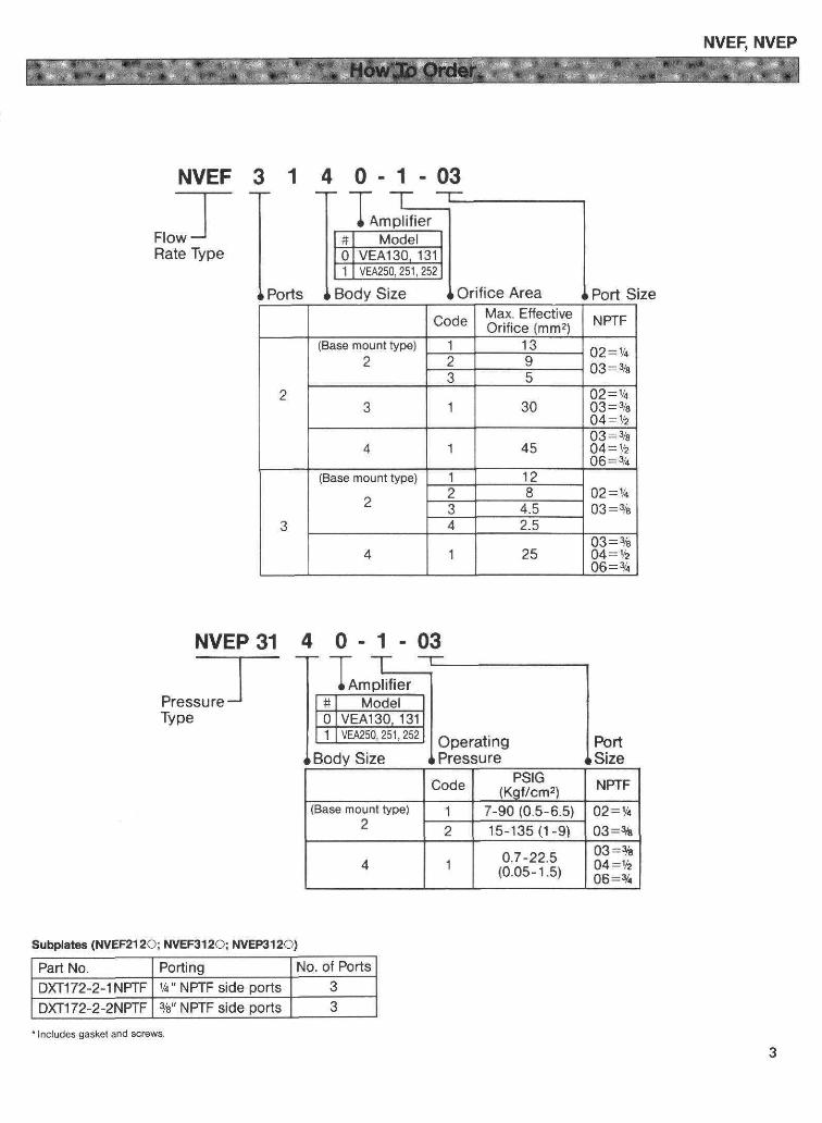
- 1 - 0 34 0
T ItffiIFTCI B"dt
NVEF 3 1- r Tnowj IRate rype
II Ports Port Size
NVEP 31 4
Code Max. EtfectiveOrifice (mm2) NPTF
(Base mount type) 1 1 3 02=1h03 = 3/sI
.t 1 30Q2=1/t03=9eO4=1/z
1 4503 =3/804=1/z06=aa
(Base mount type) 1 202=lL03 = 3/s
84.5
4 ?.5
1 l 3= %=V2
0 - 1 - 0 3
Size I Pressure SizeCode PSIG
(Kg7cm2) NPTF(Base mount type)
21 7-90 (0.s-5.5)O2=t/c
03=%2 15-135 (1 -9 )
4 1 o.7 -22.5(0.05- 1.s)
03=%O4=th06 =Vr
Subplates (NVEF2120; NVEFII20; NVERI I20)
Part No. Porting No. of PortsDXT172-2-1 NPTF Y4" NPTF side ports
DXfi72-2-2NPTF%" NPTF side Dorts 3'lnclud6s gas*et and screws
SERIES NVEFFLOW RATE TYPEFLOW CHARACTERISTICS
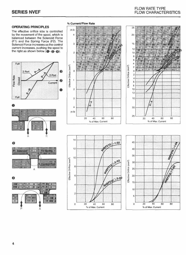
% CurrcnvFlow RateOPERATING PBINCIPLESThe effective orifice size is controlledby lhe movement of the spool, which isbalanced between the Solenoid Force(F1) and the Spring Force (F2). TheSolenoid Force increasesas the controlcurrent increases, pushing the spool tothe right as shown below (O-O-€t).
SERIES NVEPPRESSURE TYPEFLOW CHARACTERISNCS
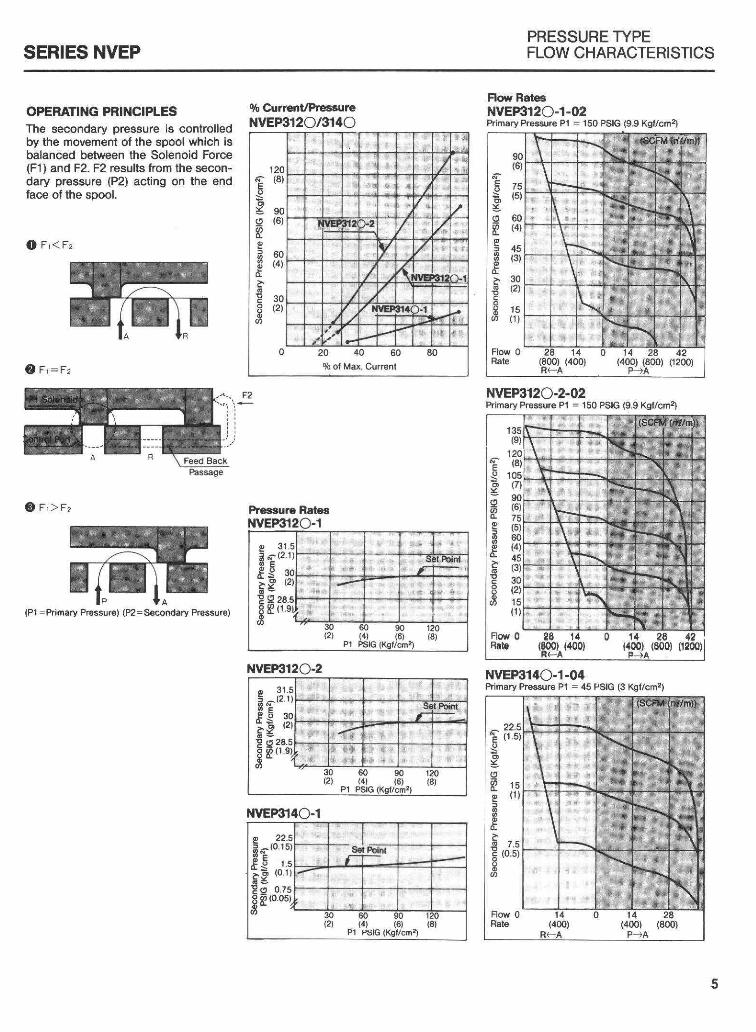
OPERATING PRINCIPLESThe secondary pressure is controlledby the movement of the spool which isbalanced belween the Solenoid Force(F1) and F2. F2 results lrom the secon-dary pressure (P2) acting on the endface of the spool.
O F , < F ,
Q r ' = r ,
@ r , > r ,
(P1 =Primary Pressure) (P2=Secondary Pressure)
iYo Curr€nyPressureNVEP3120/3140
Flqv RategNvERtl2O-1-02ftimary Pressure P1 : 150 PSIG {9.9 Kg/crn2}
NVEP314O-'r -04Primary Pressure P1 = 45 PSIG (3 KSI/cmr)
Pressure Raies
NVEP3l2O-2
t2I{
28( r .
E
t r SF gt o
NVEHtl4O-1
Et ^*t6 SF 5
(0.15)
t . 5( 0 1 )
(0.05)
E
a
EaEa
o
( 1 )
(0.s)

NVEE NVEP CONSTRUCTION DETAIL
Flow Raie'lvpo: VEF212O (2 Pdts)NVEF:112O (3 Porb)
Pressuro llrp€: NVEP3I2O (3 Porb)
l lP-Supply R-Exhaust
Flow Rtr Type: NVEFZI3O (2 Poits) Flow Rate Bpe: NVEF214O (2 Porb)NVEF{}14O (3 Ports)
Preasurc Type: NVEP314O G Porb)

NVEE NVEP DIMENSIONS
Fforv Rate !pe: NVEF212O, NVEF312OtoessureType: ItlVEP3lzO
AO.27 " -0.45" I d 6.8 -1 1.smm')
Flor Rate T!pe: NVEF213O Florir Rate Typei NVEF214O, NVEF314OPrassurc Type: NVEP814O
Supply
Exhaust t!UJ
I
2-Forled \bBion
DIMENSIONSA B c o E F G H J K M P R s T
1.57(40)
2.52(64)
2.20(56)
1.77(45)
4.80(1221
1.97{50}
0.98(25)
1 . 1 0(28)
0.51(13)
4.45(113)
? otr(101 )
0.83(211
5.08(129)
3.74(9s)
2.56(65)
2.01(51)
U v w x Y z AA BB cc DD EE FF GG HH JJ KK1.38(35)
2.52(64)
0.35(9)
1.42(36)
o-u6(154.5|
4.7 4020.s)
2.09(53)
3.23t82l
2.28(58)
3.19(81)
o.47(121
4.O2(102)
1 .97(50)
4.35(110.5)
z.ud(s2) 2.60
(66)Millimele|s in psrentheses

NVEF, NVEP PROPORTIONAL VALVE
Valve Installation Wiring Procedure for DIN
1. Remove DIN top from solenoidassemblY.
2. Connect cable to co ect terminals.3. Use compression grommets for
strain relief
CAUTION:lf using ground terminal, remove spnngwasher. When removing DIN connec-tor lift perpendicular to valve body.
1-2 = Solenoid Connection3 = Ground
FILTRATION
To insure that proper operation is maintained it isverv important that the air is properly filtered withCO-ALESCED tvpe filter, SMC ofiers a SERIES NAMcoalescing f lteihnd with the help of a SERIES NAFstandard airline f lter, which would be used to pre-flter the supply pressure, will provide you with a deanair supply.
LUBRICATION
This valve mav be op€rated with or without lubrica-tion. When lu6ricati6n is used it is very importantthat a hiqh orade of oil be used. An oil with a speci-fication df ISO VG 32 is recommended (Turlcine Oil#1) EXCESSIVE LUBRICATION CAN CAUSETHEVALVE TO OPERATE ERRATICALLY
MOUNTING
It is verv imDortant to mount the valve so that thesoool is on a horizontal plane. lt is recommendedthat a rubber vibration pad be placed undernealhthe valve to reduce the amount of noise created bythe solenoid during operalion.
PLUMBING
Be surethatthe supply lines are thoroughly deanedout before connecting to the valve. Any metal chipsor other types of contamination should be removedbefore ooeralion.
MANUAL OPIRATION
This valve may be manually operated. However, aoreat deal of force will be needed to manually op-6ration this valve in order to over@methe mechani-cal spring as well as the air pressure assisting thespring.
o
Cord Relainer
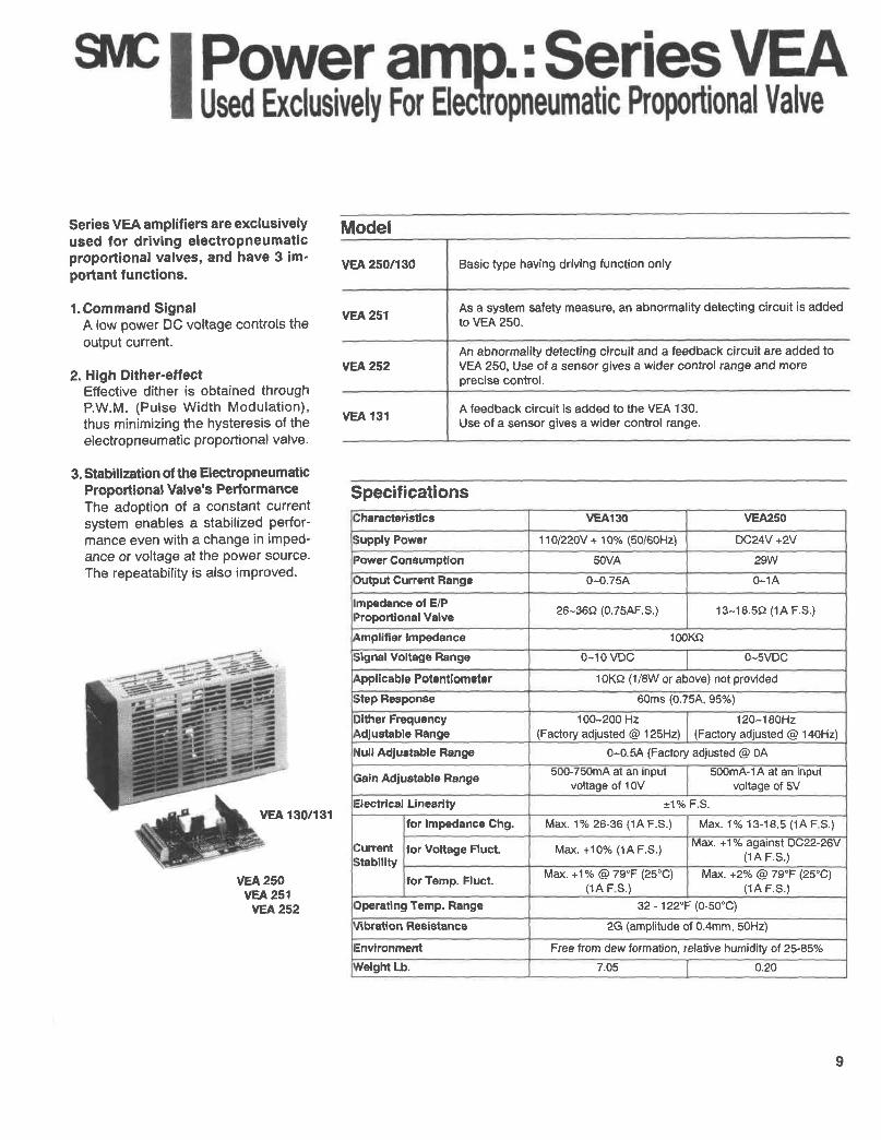
vEA 250/130 Basic type having driving function only
vEA 251 As a system safety measure, an abnormality detecting circuit is addedto vEA 250.
vEA252
vEA 131 A feedback circuit is added to the VEA 'l30.
Use of a sensor gives a wider control range.
Specifications)haracterislica vEA130 VEA250
iupply Power 1 10/220V + 10% (50/60H2) DC24V +2Vtower Consumption sOVA 29W)utput Current Range 0-0.75A 0-1A
mpedance ol E/Prroportional Valve 26-36s2 (0.75AF.S.) 13-18.5() (1A F-S.)
Amplifier lmpedance 100Ko3ignal Voltage Range 0-1 0 vDc 0-svDcqppllcable Polentiometer 1OKA (1/8W or above) not provided
itep Besponse 60ms (0.75A,95'/d
)lther FrequencyAdlustable Range
100-200 Hz(Factory adjusted @ 125H2)
12Q-19QHz(Factory adiusted @ 140H2)
{ull Adjustable Range 0-0.5A (Factory adjusted @ 0A
Sain Adlustable Range 5UU-/5UmA aI an InpUIvoltage of 10V
500mA-14 at an inputvoltage of 5V
=lectrlcal Linearity *17o F.S.
:urrentitabllity
for lmpedance Chg. Max. 1% 26-36 (1A F.S.) Mat<. 1o/o 13-18.5 (1A F S.)
lor Voltage Fluct. Max. +1 0olo (1A F.S.) Max. +1% against DC22-26V(1A F .S. )
tor Temp. Fluct. Max. +1% @ 79'F (25'C)(1A F S. )
Mat<. +2Vo @ 79'F (25"C)(1A F .S. )
)perating Temp. Range 32 - 122'F (0-s0'C)y'ibratlon Resistance 2G (amplitude of 0.4mm, 50Hz)
Environment Free trom dew formation, relalive humidity ot 25-85%
rveight Lb. 7.05 0.20
ModelSeries VEA amplifiers are exclusivelyused for driving electropneumaticproportional valves, and have 3 im-portant tunctions.
l .Command SignalA low power DC voltage controls theoutput current.
2. High Dither-eftectEffective dither is obtained throughP.W.M. (Pulse Width Modulat ion),thus minimizing the hysteresis of theelectropneumatic proportional valve.
3. Stabilization of the ElectropneumaticProportional Valve's PerformanceThe adoPtion of a constant currentsystem enables a stabilized perfor-mance even with a change in imped-ance or voltage at the power source.The repeatability is also improved.
vEA 130/131
vEA 250vEA 251vEA252
An abnormality detecting circuit and a feedback circuit are added toVEA 250, Use of a sensor gives a wider control range and moreprecise control.
I

SERfES VEA 250, 251,130
S.pecif ication of Abnormality llectection Circuit/VEA251 (Main features asVEA2SO)Detection caoabi:itiesOutput system / Typ€P.o$/er source requkedfor detection circuit
Broken output cable, broken power source cableOpen collector output / Off when dlsconnected
24VDC, 1&rrA
.26 1.12].
Specification of Feedback Circuit/VEA252 (Main features as VEA25O, 251)S€nsor tesdback voltqts Recommend range 0-5V (oETECT AMP GA|N xO.1- x lO)Input im!€dance loOkO or morePre Amp. giain Fixed atxlOOht9gral action time
O-20s
Derivativ€ action time
.29 (.13)
Specification of Feedback Circuit/VEAl3l(Main featurcs as VEA130)S€nsor f€edback voltage 0-1V (Det€ct Amp Gain X1 -X20)Input impedance 100KoPre Amp. gain
Integral action time(DELAY AD.J)
7.05 (3.2)
HowTo Order
Feedback Circuitw/o Feedback Sensor
1 w/Feedbacli Sensor
'Speciaj order o,ly
Function0 w/O Feedback or Detection1 Wrth Detection Circuit
Wilh Detection and Feedback Circult
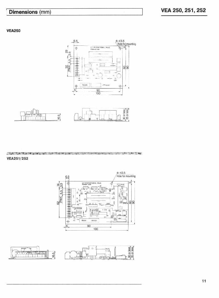
Dimensions (mm vEA250,251,252
O vEA2so
I=iL I **"
vEA25'l/252
E F Bs$P-, -"" s L-
lFiii l l-r- i,l lr

vEA250,251,252
0 Connect lead wire after twisting andsoldering.
O Connect to 24VDC, outBJt, sitnal, sensorand detect terminals. Shielded wires arerecommended for connections to siqnaland sensor terminals.
NOTE: The 24VDC and the G5\,DC sig-nal voltage must have separate isolatedgrounds.
O Keep the AC line remote from the DCline when mounting together with otherapparatus within a control box. (Noisecan cause damage to circuit elements.)Twisting the wire of the AC line is aneffective counter measure against noise.
O lf noise (ripple) trom the power sourceis high, then noise protection measuressuch as a linefilter, are necessary.
Linefilter ; 250VAC, 3-5A ratingZ lap ; 39-47VDC
O Some of the elements will generate h€atwhen operating, therefore care should betaken with respect to radiant heat.
Mounting Amplifier
Single mounting
Ho.izontally
Q r A
Multiple mounting
+ -f -t] + -tin n n h nt t t l t t l t I i
u ! L l ! L l+ + + + +V€rlical mounting aids heai
F
vertica,,y
radialon duo to im-
Feedback circuit
trEN-So-Fll
VGND
t24vpc 1
mrRJiElectropneumaticproportionalvalve
12

vEA 130.131 DIMENSIONS
vEA130/131
Dimensions
Mounting AmplifierThe VEA 130/131 Amplilier includes \ltwo (2) mounting Srackets $rhich may \lL rbe moved to fit any of the tollowing + + :l Imounting configurarions. zffi SF----'--'..-
TerminalLocation
|:::=::=:
Model A B c D E F G H J K
vEAl30n31 10.04(255)
9.72(2471
9.33(237].
9.61(2441
8.90(2261
5.35(136)
5.08(129)
2.36(60)
1.57(40) (145)

vEA 250, 251,252 EXTERNAL CONNECTIONS
External Connections Specification 0l Circuit With Abnormality Detection FunctionBasic Type: VEA250NOTE) The 24VDC powersource and the 0-5V signalvoltage must have separateisolated grounds.
}:':L::..!:!.:i.!::*:jqr:..t?aa::.3-'.:,1.',:.::|:r5:{.:ir:.:.:,'} r!-1.,r:ir:ti-
With Abnormality Detecting Circuit :vEA25r
Example of a Safety Circuit
When the electropneumatic proportional valve malfunctions due tocable disconnection or breakage, a safety circuit for the entiresystem can be obtained by the use of a relay or sequence controller.
}t .t :r.r*.gl,ra:r.a.,i..,1iii;:r.t .r't},'i.'.1*r.r:a:::t...,:,.,.r.,:'*, -i:
Example ot Short-circuit Protection
lf a short-circuit occurs on the current output terminal side, thepower source is cul immediately, preventing damage to thepower amp. oulput clrcuit.Starting and restarting is achieved by a manually controlledreset-on switch.
24VDC power s!pOly conneclion
Eecnopneum;1ic p,oport,onat vave
Potent ometer conn6tion
Comm€nd Signal :0-sVDCor (10lKOl lbw polentiometer
sam€asvEA25r {
14

vEA 130, 131 EXTERNAL CONNECTIONS
Basic Type: VEA130
Wlth Feedback Circult: VEA131
Command Signal
NOfE: The command signal can be 0 -1OVDC or a(10 [KOI 1tW) potentiometer.
Power Supply +--:-
-- .----
--Potentiometer Connection
Command Signal
to vatve- - _ 1 3 '
To Ammeter &(Remove Jumper) L-:i
SERIES VEA AMPLIFIER FEATUBES / FUNCTIONS
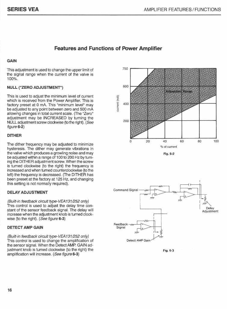
Features and Functions of Fower Amplifier
GAIN
This adjustrnent is used to change the upper limit ofthe signal range when the current of the valve is1O0P/o.
NULL CZERO AINUSTMENT)
This is used to adiust the minimum level ot currentwhich is received fom the Power A.nolifier. This isfactory preset at O mA. This "minimum level" maybe adjusted to any point between zero and 500 mAallowing changes in total c nent scale. Ohe "Zero"adjustment may be INCREASED by turning theNULL ad.iustnent screw docl$ise (to the riglrt). (Seefigure 6-2)
DITHER
The dither frequency may be adiusted to minimizehysteresis. The dither may generate vibrations infe valve which produces a growling noise and maybe ad.iusted within a range of 100 to 2m Hz by lum-ing the DITHER adiustment screw. When the screwis turned clockwise (to the right) the frequency isincreased and when tumed counterdoclaryise {to theleft) the frequency is decreased. ohe DITHER hasbeen preset at the factory at 125 Hz, and changinglhis setting is not normally required).
DEIAYADJUSTI'ENT
(Buift-in feedback circuit type-VEAl 31 252 only)This control is used to adjust the delay time con-stant of the sensor feedback signal. The delay willincrease when lhe adjusiment knob isturned clock-wise (to the righD. (See tigure 6€)
DETECTAMP GAIN
(Built-in teedback circuit type-VEAl 31 252 onvThis control is us€d to change the amplitcation ofhe sensor signal. When the DetectAMP. GAIN ad-juslment knob is turned cloclevise (to the right) theamplification will increase. (See ligure S3)
Command Signal
FeedbackSignal
DelayAdjustment
Fig. 6-3
16
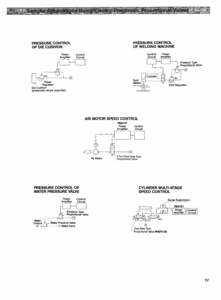
PRE$SURE CONIROLOF DIE CUSHION
Fo|Fr ContrclArnplifl€. Cl.cui!
De Cu3hlon(9n€rmetic thock abco$€r)
PRESSURE OOI'IIROL OFWAIER PRESSURE VATYE
Prg$urg Typ€ProDoalional \hlt e
Spotlltsld€r
AIR HOTIOR SPEED @NTROLrErtStfuYroa Confol
Arndn€r Ck uit
a
CYLINDER IIULTI€TAGESPEED CONTROL
17

World Wide QS\E Support...North American Branch Offices For a branch office near you call: 1-800-SMC-SMC1 (762-7621)SMC Pneumatics Inc. (Atlanta)1440 Lakes Parkway, Suite 600Lawrenceville, GA 30043Tel: (770) 624-1940FAX: (770) 624-1943
SMC Pneumatics lnc. (Austin)2324-D Ridgepoint DriveAustin, TX 78754Tel: (512) 926-2646FAX: (512) 926-7055
SMC Pneumatics Inc. (Boston)Zero Centennial DrivePeabody, MA01960Tel: (978) 326-3600Fax: (978) 326-3700
SMC Pneumatics lnc. (Charlotte)5029-8 West W.T. Hanis Blvd.Charlotte, NC 28269Tel: (704) 597-9292FAX: (704) 596-9561
SMC Pneumatics Inc. (Chicago)27725 Diehl RoadWarrenville, lL 60555Tel: (630) 393-0080FAX: (630) 393-0084
SMC Pneumatics Inc. (Cincinnati)4598 Olympic Blvd.Erlanger, KY 41018Tel: (606) 647-5600FAX: (606) 647-5609
SMC Pneumatics Inc. (Cleveland)2305 East Aurora Rd., Unit A-3Twinsburg, OH 44087Tel: (330) 963-2727FAX: (330) 963-2730
SMC Pneumatics lnc. (Columbus)3687 Corporate DriveColumbus, OH 43231Tel: (614) 895-9765FAX: (614) 895-9780
SMC Pneumatics Inc. (Dallas)12801 N. Stemmons Frutry, Ste.815Dallas, TX 75234rel: (972\ 406-0082FAX: (972) 406-9904
SMC Pneumatics lnc. (Detroit)2990 Technology DriveRochester Hills, Ml 48309Tel: (248) 299-O2O2FAX: (2a8) 293-3333
SMC Pneumatics Inc. (Houston)9001 Jameel, Suite 180Houston, TX77O4OTel: (713) 460-0762FAX: (713) 460-1510
SMC Pneumatics Inc. (L.A.)14191 Myford RoadTustin. CA 92780Tel: (714\ 669-1 701FAX: (714) 669-1715
16850 W. Victor RoadNew Berl in. Wl 53151Tel: (414) 827-0080FAX: (414) 827-OO92
SMC Pneumatics Inc. (Mnpls.)990 Lone Oak Road, Suite 162Eagan, MN 55121Tel: (651) 688-3490FAX: (651) 688-9013
SMC Pneumatics Inc. (Nashville)5000 Linbar Drive, Suite 297Nashvi l le, TN 37211Tel: (615) 331-0020FAX: (615) 331-9950
SMC Pneumatics lnc. (Newark)3434 US Hwy.22 West, Ste. 110Somerville, NJ 08876Tel: (908) 253-3241FAX: (908) 253-3452
SMC Pneumatics Inc. (Phoenix)2001 W. Melinda LanePhoenix, AZ85027Tel: (623) 492-0908FAX: (623) 492-9493
SMC Pneumatics Inc. (Portland)14107 N.E. Airport WayPortland, OR 97230Tel: (503) 252-9299FAX: (503) 252-9253
5377 Glen Alden DriveRichmond, VA 23231Tel: (804) 222-2762FAX: (80a) 222-5221
SMC Pneumatics Inc. (Rochester)245 Summit Point DriveHenrietta, NY 14467Tel: (716) 321-1300FAX: (716) 321-1865
SMC Pneumatics lnc. (S.F.)85 Nicholson LaneSan Jose, CA 95134Tel: (408) 943-9600FAX: (408) 943-9111
SMC Pneumatics Inc. (St. Louis)4130 Rider Trail NorthEarth City, MO 63045Tel: (314) 209-0080FAX: (314) 209-0085
SMC Pneumatics Inc. (Tampa)8507-H Benjamin RoadTampa, FL 33634Tel: (813) 243-8350FAX: (813) 243-8621
SMG Pneumatics Inc. (Tulsa)10203 A East 61st StreetTulsa. OK 74146Tel: (918) 2s2-782OFAX: (918) 252-9511
SMC Pneumatics lnc. (Milwaukee) SMC Pneumatics lnc. (Richmond)
EuropeENGLANDSMC Pneumatics (U.K.) Ltd.GERMANYSMC Pneumatik GmbHITALYSMC ltalia SpAFRANCESMC Pneumatique SAHOLLANDSMC Controls BvSWEDENSMC Pneumatics Sweden ABSWITZERLANDSMC Pneumatik AGAUSTRIASMC Pneumatik GmbHSPAINSMC Espafra, S.A.IRETANDSMC Pneumatics (lreland) Ltd.AsiaJAPAN
SMC CorporationKOBEASMC Pneumatics Korea Co., Ltd.CHINASMC (China) Co., Ltd.HONG KONGSMC Pneumatics (Hong Kong) Ltd.SINGAPORESMC Pneumatics (S.E.A.) Pte. Ltd.PHILIPPINESSMC Pneumatics (Philippines), Inc.MALAYSIASMC Pneumatics (S.E.A.) Sdn. Bhd.TAIWANSMG Pneumatics (Taiwan) Co., Ltd.THAILANDSMC Thailand Ltd.INDIASMC Pneumatics (lndia) Pvt., Ltd.North AmericaCANADASMC Pneumatics (Canada) Ltd.MEXICOSMC Pneumatics (Mexico) S.A. de C.V.
South AmericaAFGENTINASMC Argentina S.A.CHILESMC Pneumatics (Chile) Ltda.
OceaniaAUSTRALIASMC Pneumatics (Australia) Pty. Ltd.NEW ZEALANDSMC Pneumatics (N.2.) Ltd.
SMC offers the same quality and engineering expertise in many other pneumatic componentsValvesDirectional Control ValvesManual ValvesMufflersExhaust CleanersQuick Exhaust Valves
ValvesProoortional ValvesMechanical ValvesMiniature ValvesFluid Valves
Cylinders/ActuatorsCompact CylindersMiniature CylindersRodless CylindersRotary ActuatorsPneumatic Grippers
VacuumVacuum EjectorsVacuum AccessoriesInstrumentationPneumatic PositionersPneumatic Transducers
Air Preparation EquipmentFilters-Regulators-LubricatorsCoalescing FiltersMicro Mist SeDaratorsFittingsAir Fiftings
SMC Pneumatics Inc.P.O. Box 26640, Indianapolis, lN 46226
Tel: (317) 899-4440. FAX: (317) 899-3102O 1978-1999 SMC Pneumatics, Inc. All Rights Reserved.Revised October 1999
Related Documents