CAT 2000 Automated Controller OWNER'S MANUAL INSTALLATION OPERATION MAINTENANCE SPECIFICATIONS

Welcome message from author
This document is posted to help you gain knowledge. Please leave a comment to let me know what you think about it! Share it to your friends and learn new things together.
Transcript

CAT 2000 Automated Controller
OWNER'S MANUAL
INSTALLATION
OPERATION
MAINTENANCE
SPECIFICATIONS
FOREWORD
Congratulations on your wise investment. The product you have selected from the CAT 2000 line of automated pool & spa controllers should provide you with substantially reduced chemical maintenance, improved compliance with Health Department operating standards, chemical cost savings, and many years of reliable operation. All CAT controllers incorporate state of the art microprocessor-based design technology to provide sophisticated control functions at an affordable price. Although CAT controllers are relatively simple to install, please take the time to read this entire manual, compare package contents with the parts list, and gather all tools required before beginning installation. Improper installation may void the warranty and create unnecessary hazards. Properly preparing for installation will also reduce facility down-time. For the purposes of this manual, it is presupposed that the installer is familiar with the physical characteristics of the pool or spa to be automated. As is the case when installing any filtration system component, all recirculating pumps, heaters, etc. need to be turned off prior to installation of the controller. If the filtration system is located below water level, additionally adjust all valves required to eliminate pressure from the system. Physically, installation of a CAT controller is no more challenging than installation of a chemical feeder. Any swimming pool contractor or maintenance engineer should have the tools and knowledge to perform the installation. Our technical support line can also be used to answer any questions pertaining to controller installation. Congratulations on your purchase and welcome to the world of chemical automation. Please complete and return your warranty registration card today.
TABLE OF CONTENTS Chemical Automation with the CAT 2000 . . . . . . . . . . . 1. Important Safety Information . . . . . . . . . . . . . . . . . . 3. Packaging Contents . . . . . . . . . . . . . . . . . . . . . . 4. Standard Installation . . . . . . . . . . . . . . . . . . . . . . 5. Installation Utilizing Bypass Line . . . . . . . . . . . . . . . 8. Preparing Pool or Spa Water Chemistry . . . . . . . . . . . 11. Setting and Operating the Cat 2000 . . . . . . . . . . . . . 12. Display Functions . . . . . . . . . . . . . . . . . . . . . . 19. Maintenance . . . . . . . . . . . . . . . . . . . . . . . . 23. Troubleshooting . . . . . . . . . . . . . . . . . . . . . . . 25. Chemical Notes . . . . . . . . . . . . . . . . . . . . . . . 27. Specifications . . . . . . . . . . . . . . . . . . . . . . . . 28. Warranty . . . . . . . . . . . . . . . . . . . . . . . . . . . 29.
Page 2.
SECTION 1. CHEMICAL AUTOMATION WITH THE CAT 2000
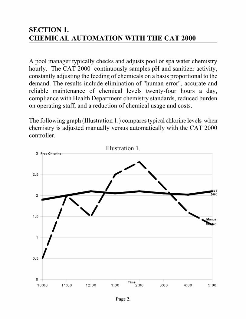
A pool manager typically checks and adjusts pool or spa water chemistry hourly. The CAT 2000 continuously samples pH and sanitizer activity, constantly adjusting the feeding of chemicals on a basis proportional to the demand. The results include elimination of "human error", accurate and reliable maintenance of chemical levels twenty-four hours a day, compliance with Health Department chemistry standards, reduced burden on operating staff, and a reduction of chemical usage and costs. The following graph (Illustration 1.) compares typical chlorine levels when chemistry is adjusted manually versus automatically with the CAT 2000 controller.
Illustration 1.
Free Chlorine
CAT 2000
Manual Control
Time
Page 3.
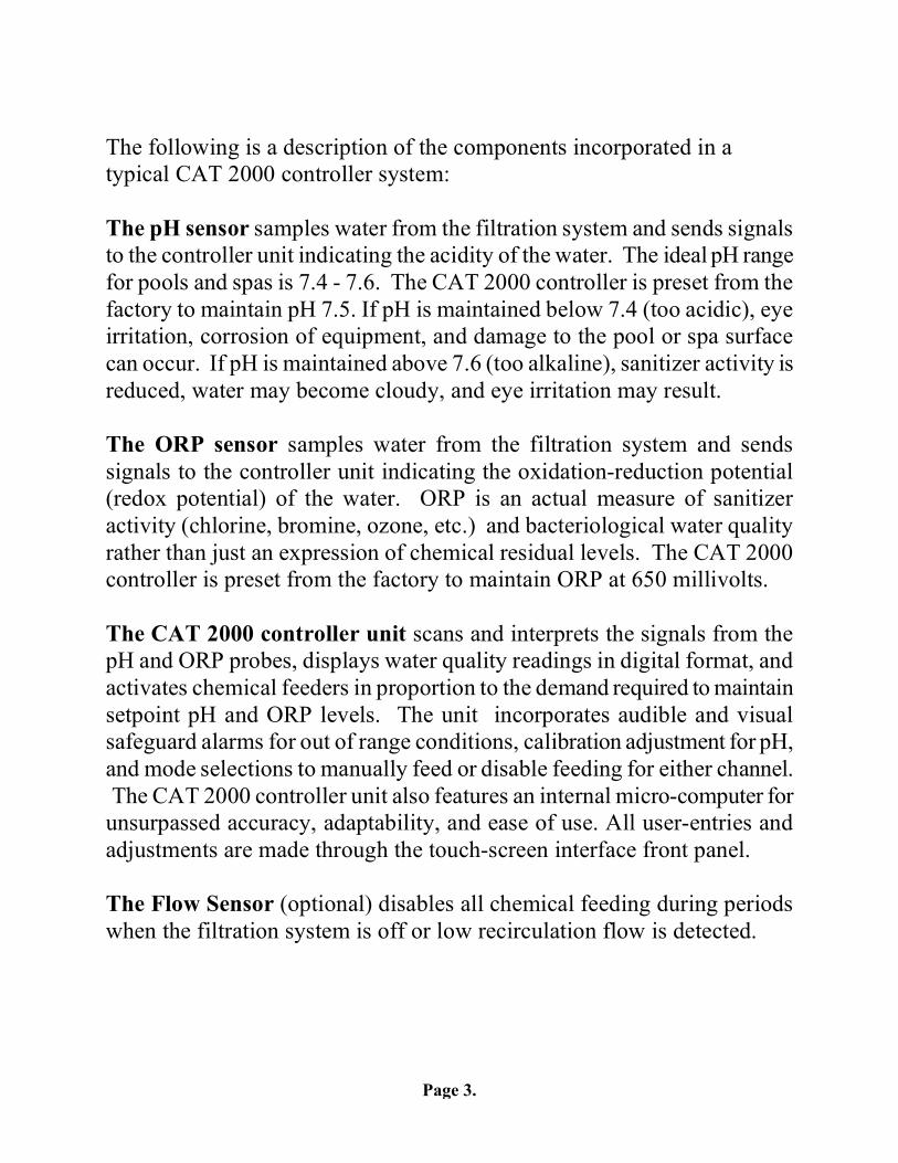
The following is a description of the components incorporated in a typical CAT 2000 controller system: The pH sensor samples water from the filtration system and sends signals to the controller unit indicating the acidity of the water. The ideal pH range for pools and spas is 7.4 - 7.6. The CAT 2000 controller is preset from the factory to maintain pH 7.5. If pH is maintained below 7.4 (too acidic), eye irritation, corrosion of equipment, and damage to the pool or spa surface can occur. If pH is maintained above 7.6 (too alkaline), sanitizer activity is reduced, water may become cloudy, and eye irritation may result. The ORP sensor samples water from the filtration system and sends signals to the controller unit indicating the oxidation-reduction potential (redox potential) of the water. ORP is an actual measure of sanitizer activity (chlorine, bromine, ozone, etc.) and bacteriological water quality rather than just an expression of chemical residual levels. The CAT 2000 controller is preset from the factory to maintain ORP at 650 millivolts. The CAT 2000 controller unit scans and interprets the signals from the pH and ORP probes, displays water quality readings in digital format, and activates chemical feeders in proportion to the demand required to maintain setpoint pH and ORP levels. The unit incorporates audible and visual safeguard alarms for out of range conditions, calibration adjustment for pH, and mode selections to manually feed or disable feeding for either channel. The CAT 2000 controller unit also features an internal micro-computer for unsurpassed accuracy, adaptability, and ease of use. All user-entries and adjustments are made through the touch-screen interface front panel. The Flow Sensor (optional) disables all chemical feeding during periods when the filtration system is off or low recirculation flow is detected.
Page 4.
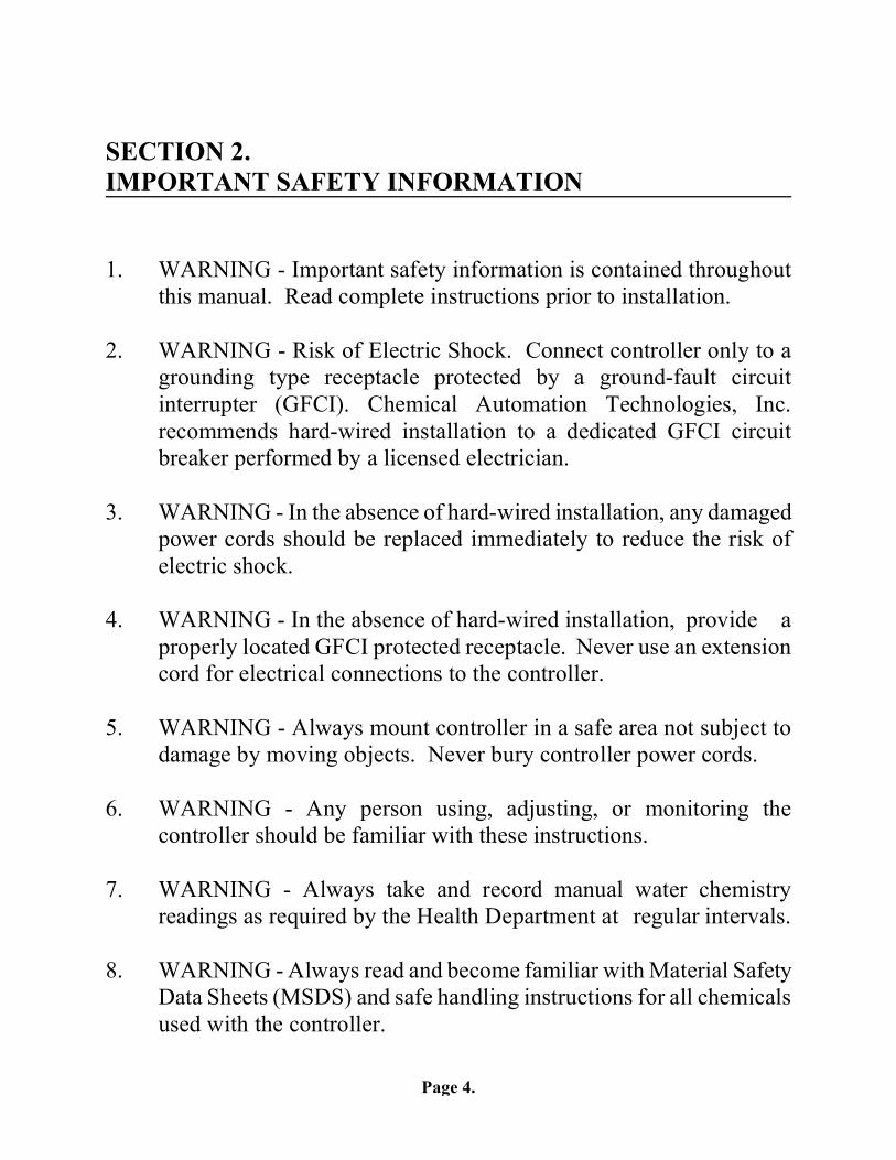
SECTION 2. IMPORTANT SAFETY INFORMATION
1. WARNING - Important safety information is contained throughout this manual. Read complete instructions prior to installation. 2. WARNING - Risk of Electric Shock. Connect controller only to a
grounding type receptacle protected by a ground-fault circuit interrupter (GFCI). Chemical Automation Technologies, Inc. recommends hard-wired installation to a dedicated GFCI circuit breaker performed by a licensed electrician.
3. WARNING - In the absence of hard-wired installation, any damaged power cords should be replaced immediately to reduce the risk of electric shock. 4. WARNING - In the absence of hard-wired installation, provide a properly located GFCI protected receptacle. Never use an extension cord for electrical connections to the controller. 5. WARNING - Always mount controller in a safe area not subject to damage by moving objects. Never bury controller power cords. 6. WARNING - Any person using, adjusting, or monitoring the controller should be familiar with these instructions. 7. WARNING - Always take and record manual water chemistry readings as required by the Health Department at regular intervals. 8. WARNING - Always read and become familiar with Material Safety Data Sheets (MSDS) and safe handling instructions for all chemicals used with the controller.
Page 5.
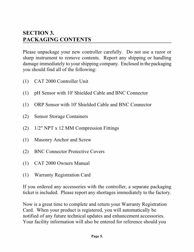
SECTION 3. PACKAGING CONTENTS Please unpackage your new controller carefully. Do not use a razor or sharp instrument to remove contents. Report any shipping or handling damage immediately to your shipping company. Enclosed in the packaging you should find all of the following: (1) CAT 2000 Controller Unit (1) pH Sensor with 10' Shielded Cable and BNC Connector (1) ORP Sensor with 10' Shielded Cable and BNC Connector (2) Sensor Storage Containers (2) 1/2" NPT x 12 MM Compression Fittings (1) Masonry Anchor and Screw (2) BNC Connector Protective Covers (1) CAT 2000 Owners Manual (1) Warranty Registration Card If you ordered any accessories with the controller, a separate packaging ticket is included. Please report any shortages immediately to the factory. Now is a great time to complete and return your Warranty Registration Card. When your product is registered, you will automatically be notified of any future technical updates and enhancement accessories. Your facility information will also be entered for reference should you
Page 6.
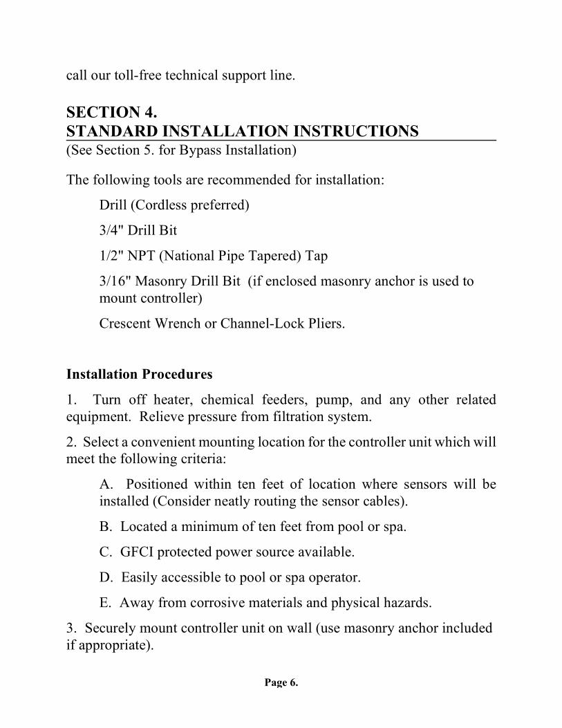
call our toll-free technical support line. SECTION 4. STANDARD INSTALLATION INSTRUCTIONS (See Section 5. for Bypass Installation) The following tools are recommended for installation:
Drill (Cordless preferred)
3/4" Drill Bit
1/2" NPT (National Pipe Tapered) Tap
3/16" Masonry Drill Bit (if enclosed masonry anchor is used to mount controller)
Crescent Wrench or Channel-Lock Pliers. Installation Procedures
1. Turn off heater, chemical feeders, pump, and any other related equipment. Relieve pressure from filtration system.
2. Select a convenient mounting location for the controller unit which will meet the following criteria:
A. Positioned within ten feet of location where sensors will be installed (Consider neatly routing the sensor cables).
B. Located a minimum of ten feet from pool or spa.
C. GFCI protected power source available.
D. Easily accessible to pool or spa operator.
E. Away from corrosive materials and physical hazards.
3. Securely mount controller unit on wall (use masonry anchor included if appropriate).
Page 7.
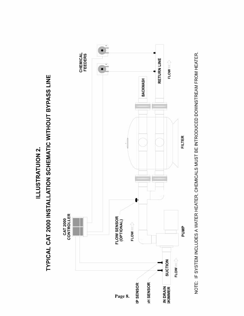
4. Drill two 3/4" holes in the incoming filtration line positioned as shown in illustration 2 . Thread with 1/2" NPT tap. Apply Teflon tape to the two 1/2" NPT x 12 MM compression fittings provided and securely tighten into place. NOTE: The pH and ORP sensors must be mounted upstream from chemical feeders. 5. Remove pH and ORP sensors from the plastic storage bottles and save bottles and storage fluid for future use. 6. Remove BNC protective covers from left side of controller unit and store for future use. NOTE: These covers protect the controller unit from electro-static discharge (ESD) and should be used whenever handling or transporting the controller unit. 7. Insert the pH and ORP sensors into the two compression fittings and tighten retaining nuts. 8. Carefully route sensor cables to the controller unit, and connect the sensor cables to the controller unit as labeled. Neatly coil and secure any excess cable beside controller unit. Plastic cable-ties are excellent for securing sensor cables. NOTE: Sensor cables are constructed from a specialized coaxial material - never cut or splice sensor cables. 9. If additional or new chemical feeders are to be used with the controller, install according to manufacturers instructions. 10. Connect chemical feeders to the controller unit as labeled. 11. If optional flow sensor is to be installed, a 1/8" NPT port must be drilled and tapped immediately upstream of the filter as shown inillustration 2. CAT flow sensors are "normally closed" type. 12. Resume operation of the filtration system and check all new connections for leaks.
Page 8.
Page 9.
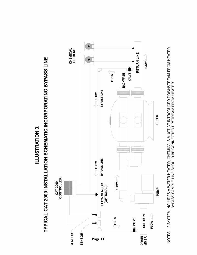
SECTION 5. INSTALLATION UTILIZING BYPASS LINE For large commercial applications it may be preferable to install the controller using a filtration system bypass line rather than mounting the sensors directly in the incoming suction line. Bypass line installation affords the following advantages over conventional installation: Controller unit may be mounted more than ten feet from incoming filtration plumbing. Sensors may be removed for cleaning or replacement without disrupting filtration system operation. Sensor life is extended due to reduced flow in bypass line. An in-line filter may be added to bypass line, protecting sensors from waterborne debris and contaminates. Construction of a bypass line requires familiarity with the procedures for plumbing with PVC as well as the material used in the existing filtration system. Any knowledgeable swimming pool contractor or maintenance engineer should have the knowledge required to accomplish the installation. Refer to Illustration 3. for bypass schematic. 1. Complete steps 1 through 3 in the previous section, "Standard Installation". 2. Install one "reducing tee" or "saddle tee" fitting each on the incoming suction line to the pump and the return line upstream from heater as shown in Illustration 3.
Page 10.
3. Install ball or gate valves on bypass inlet and effluent immediately adjacent to tee fittings. 4. Install in-line filter (optional) immediately downstream from bypass 5. Install flow meter (optional) immediately downstream from in-line filter (if applicable) or bypass inlet valve. 6. Install two tee fittings to accommodate 1/2" NPT pH & ORP sensor compression fittings. Install reducer tee to accommodate 1/8" NPT flow sensor (optional). Please refer to Illustration 3. 7. Remove pH and ORP sensors from the plastic storage bottles and save bottles and storage fluid for future use. 8. Remove BNC protective covers from left side of controller unit and store for future use. NOTE: These covers protect the controller unit from electro-static discharge (ESD) and should be used whenever handling or transporting the controller unit. 9. Insert the pH and ORP sensors into the two compression fittings and tighten retaining nuts. 10. Carefully route sensor cables to the controller unit, and connect the sensor cables to the controller unit as labeled. Neatly coil and secure any excess cable beside controller unit. Plastic cable-ties are excellent for securing sensor cables. NOTE: Sensor cables are constructed from a specialized coaxial material - never cut or splice sensor cables. 11. Label and provide support for all new piping. If additional or new chemical feeders are to be used with the controller, install according to instructionsprovided by the manufacturer. 12. Connect chemical feeders to the controller unit as labeled. 13. Resume operation of the filtration system and check for leaks.
Page 11.
Page 12.
SECTION 6. PREPARING POOL OR SPA WATER CHEMISTRY
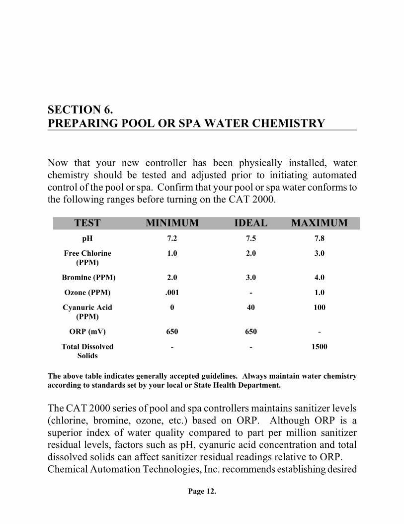
Now that your new controller has been physically installed, water chemistry should be tested and adjusted prior to initiating automated control of the pool or spa. Confirm that your pool or spa water conforms to the following ranges before turning on the CAT 2000. TEST MINIMUM IDEAL MAXIMUM
pH
7.2
7.5
7.8
Free Chlorine (PPM)
1.0
2.0
3.0
Bromine (PPM)
2.0
3.0
4.0
Ozone (PPM)
.001
-
1.0
Cyanuric Acid
(PPM)
0
40
100
ORP (mV)
650
650
-
Total Dissolved
Solids
-
-
1500
The above table indicates generally accepted guidelines. Always maintain water chemistry according to standards set by your local or State Health Department. The CAT 2000 series of pool and spa controllers maintains sanitizer levels (chlorine, bromine, ozone, etc.) based on ORP. Although ORP is a superior index of water quality compared to part per million sanitizer residual levels, factors such as pH, cyanuric acid concentration and total dissolved solids can affect sanitizer residual readings relative to ORP. Chemical Automation Technologies, Inc. recommends establishing desired
Page 13.
pH and cyanuric acid levels prior to initiating automatedcontrol of the pool or spa. The ORP setpoint will need to be changed periodically as described later in this section if the goal is to provide consistent sanitizer residual levels rather than consistent control of ORP. SECTION 7. SETTING AND OPERATING THE CAT 2000
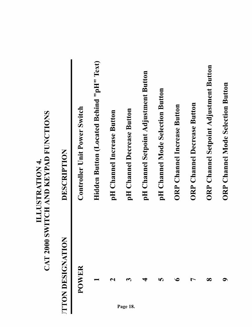
Once desired start up chemistry parameters have been established, you are ready to set the CAT 2000 to automatically maintain pH and sanitizer levels. Please refer to Illustration 4 for controller unit button designations. Button designations appear in bold type.
Selecting Acid or Base Feed The CAT 2000 is preset from the factory to operate in the acid feed mode (when pH exceeds the setpoint, the pH chemical feeder is activated). If the sanitizer used at your facility causes the pH to decrease you must select base feed mode. To switch the controller between acid feed and base feed modes, perform the following steps.
1. Turn the controller unit off using POWER switch. 2. Press and hold the Hidden Button (#1) while turning the unit on
by pressing the POWER switch.
As the unit powers on, the digital pH readout will display an "A" or "B" indicating whether acid feed or base feed mode has been activated. Repeating the above procedure toggles the unit between the two modes. Calibrating pH Readings from the CAT 2000 are far more accurate than those obtained from most liquid test standards. To match manual water testing results or compensate for a depleted or unclean pH sensor, the pH channel of the controller may be calibrated as follows:
1. Press the pH Setpoint Adjustment Button (#4) twice, illuminating the green "CALIBRATE" LED.
2. Press the arrow-shaped pH Channel Increase Button (#2) or pH Channel Decrease Button (#3) until the digital
Page 14.
display matches your manual pH test reading. 3. The controller will automatically return to the normal
operating mode after twenty seconds, storing any changes.Changing the pH Setpoint The CAT 2000 is preset from the factory to maintain pH at 7.5. Chemical Automation Technologies, Inc. considers this setting to be ideal for pool and spa applications. To set pH control at a different level, perform the following:
1. Press the pH Setpoint Adjustment Button (#4) until the green "SET" LED is illuminated.
2. Press the arrow-shaped pH Channel Increase Button (#2) or pH Channel Decrease Button (#3) until the digital display matches your desired pH control level.
3. The controller will automatically return to the normal operating mode after twenty seconds, storing any changes. Changing the ORP Setpoint The CAT 2000 is preset from the factory to maintain ORP at 650 mV. This is the generally accepted world standard for safe drinking water. In order to meet Health Department standards for a particular pool or spa, the ORP setpoint may be changed to maintain a desired sanitizer level by performing the following:
1. Manually test pool or spa to confirm that the current sanitizer reading (chlorine, bromine, etc.) is the level you wish to maintain.
2. Note the ORP reading displayed by the controller. 3. Press the ORP Setpoint Adjustment Button (#8) until the
green "SET" LED is illuminated. 2. Press the arrow-shaped ORP Channel Increase Button (#6) or
ORP Channel Decrease Button (#7) until the digital display matches the ORP reading previously noted.
3. The controller will automatically return to the normal operating mode after twenty seconds, storing any changes.
Page 15.
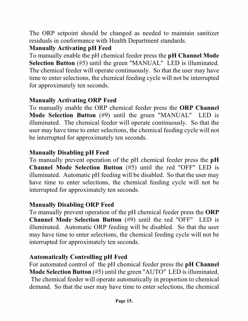
The ORP setpoint should be changed as needed to maintain sanitizer residuals in conformance with Health Department standards. Manually Activating pH Feed To manually enable the pH chemical feeder press the pH Channel Mode Selection Button (#5) until the green "MANUAL" LED is illuminated. The chemical feeder will operate continuously. So that the user may have time to enter selections, the chemical feeding cycle will not be interrupted for approximately ten seconds. Manually Activating ORP Feed To manually enable the ORP chemical feeder press the ORP Channel Mode Selection Button (#9) until the green "MANUAL" LED is illuminated. The chemical feeder will operate continuously. So that the user may have time to enter selections, the chemical feeding cycle will not be interrupted for approximately ten seconds. Manually Disabling pH Feed To manually prevent operation of the pH chemical feeder press the pH Channel Mode Selection Button (#5) until the red "OFF" LED is illuminated. Automatic pH feeding will be disabled. So that the user may have time to enter selections, the chemical feeding cycle will not be interrupted for approximately ten seconds. Manually Disabling ORP Feed To manually prevent operation of the pH chemical feeder press the ORP Channel Mode Selection Button (#9) until the red "OFF" LED is illuminated. Automatic ORP feeding will be disabled. So that the user may have time to enter selections, the chemical feeding cycle will not be interrupted for approximately ten seconds. Automatically Controlling pH Feed For automated control of the pH chemical feeder press the pH Channel Mode Selection Button (#5) until the green "AUTO" LED is illuminated. The chemical feeder will operate automatically in proportion to chemical demand. So that the user may have time to enter selections, the chemical
Page 16.
feeding cycle will not be interrupted for approximately ten seconds. Automatically Controlling ORP Feed For automated control of the ORP chemical feeder press the ORP Channel Mode Selection Button (#9) until the green "AUTO" LED is illuminated. The chemical feeder will operate automatically in proportion to chemical demand. So that the user may have time to enter selections, the chemical feeding cycle will not be interrupted for approximately ten seconds.
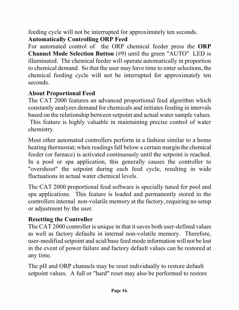
About Proportional Feed The CAT 2000 features an advanced proportional feed algorithm which constantly analyzes demand for chemicals and initiates feeding in intervals based on the relationship between setpoint and actual water sample values. This feature is highly valuable in maintaining precise control of water chemistry.
Most other automated controllers perform in a fashion similar to a home heating thermostat; when readings fall below a certain margin the chemical feeder (or furnace) is activated continuously until the setpoint is reached. In a pool or spa application, this generally causes the controller to "overshoot" the setpoint during each feed cycle, resulting in wide fluctuations in actual water chemical levels.
The CAT 2000 proportional feed software is specially tuned for pool and spa applications. This feature is loaded and permanently stored in the controllers internal non-volatile memory at the factory, requiring no setup or adjustment by the user.
Resetting the Controller The CAT 2000 controller is unique in that it saves both user-defined values as well as factory defaults in internal non-volatile memory. Therefore, user-modified setpoint and acid/base feed mode information will not be lost in the event of power failure and factory default values can be restored at any time.
The pH and ORP channels may be reset individually to restore default setpoint values. A full or "hard" reset may also be performed to restore
Page 17.
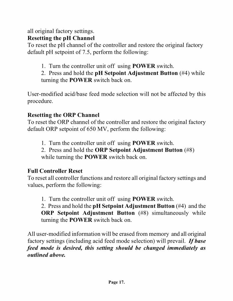
all original factory settings. Resetting the pH Channel To reset the pH channel of the controller and restore the original factory default pH setpoint of 7.5, perform the following:
1. Turn the controller unit off using POWER switch. 2. Press and hold the pH Setpoint Adjustment Button (#4) while
turning the POWER switch back on. User-modified acid/base feed mode selection will not be affected by this procedure. Resetting the ORP Channel To reset the ORP channel of the controller and restore the original factory default ORP setpoint of 650 MV, perform the following:
1. Turn the controller unit off using POWER switch. 2. Press and hold the ORP Setpoint Adjustment Button (#8)
while turning the POWER switch back on. Full Controller Reset To reset all controller functions and restore all original factory settings and values, perform the following:
1. Turn the controller unit off using POWER switch. 2. Press and hold the pH Setpoint Adjustment Button (#4) and the
ORP Setpoint Adjustment Button (#8) simultaneously while turning the POWER switch back on. All user-modified information will be erased from memory and all original factory settings (including acid feed mode selection) will prevail. If base feed mode is desired, this setting should be changed immediately as outlined above.
Page 18.
Page 19.
Page 20.
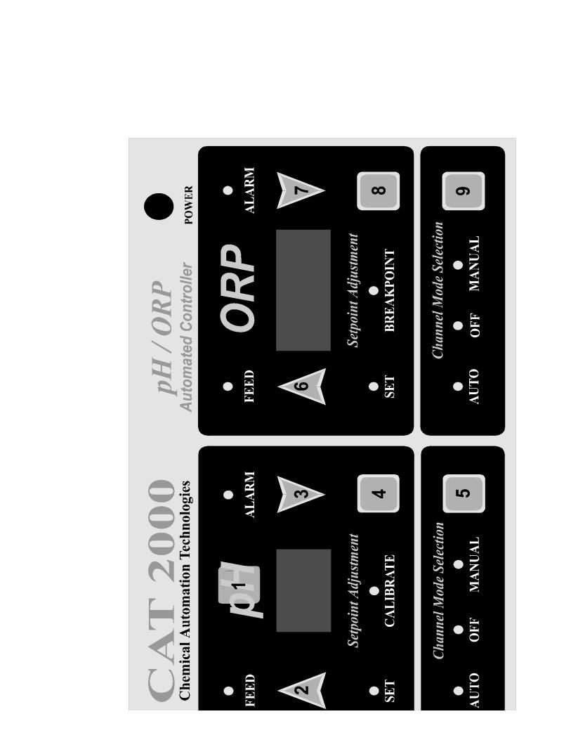
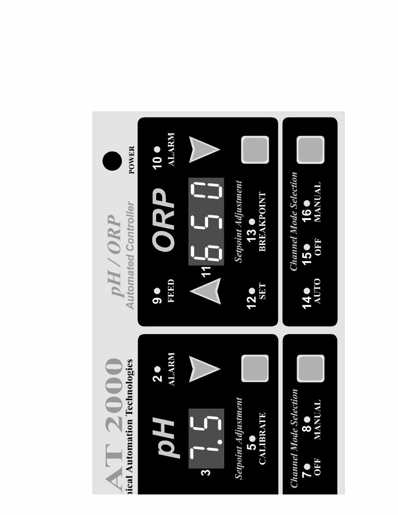
SECTION 8 DISPLAY FUNCTIONS
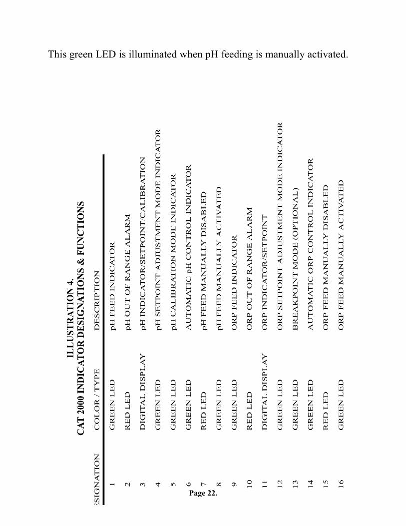
Please refer to Illustration 5 with reference to designations of the various LED indicator lights on the front panel. Please note that for enhanced viewing the CAT 2000 features a "dead-front" display panel, so only illuminated indicators will be visible to the user. All lights and indicators are activated during power-on.
pH Feed Indicator (#1) This green LED is illuminated whenever the pH chemical feeder is automatically or manually activated.
pH Alarm Indicator (#2) Illumination of this red indicator is accompanied by an audible alarm and indicates that pH is outside of the safe operating range (7.2 - 7.8). Check that the pH chemical feeder is functioning properly and that an adequate supply chemical is available.
pH Digital Display (#3) The red digital numeric display of the pH channel of the controller normally indicates the current pH of the pool or spa water (as calibrated) passing through the filtration system. Pressing the pH Setpoint Adjustment Button until the red "SET" LED is illuminated causes the pH setpoint to be displayed.
pH Setpoint Adjustment Mode Indicator (#4) This green LED is illuminated whenever the controller is in the pH setpoint adjustment mode. Setpoint adjustment is allowed only when this LED is illuminated.
pH Calibration Mode Indicator (#5) This green LED is illuminated whenever the controller is in the pH
Page 21.
calibration mode. Calibration of the pH display is allowed only when this LED is illuminated. pH Automatic Control Indicator (#6) This green LED is illuminated when pH is under automated control. pH Manual Off Indicator (#7) This red LED is illuminated when pH feeding is manually disabled.
pH Manual On Indicator (#8) This green LED is illuminated when pH feeding is manually activated.
ORP Feed Indicator (#9) This green LED is illuminated whenever the ORP chemical feeder is automatically or manually activated.
ORP Alarm Indicator (#10) Illumination of this red indicator is accompanied by an audible alarm and indicates that ORP is outside of the safe operating range. Check that the ORP chemical feeder is functioning properly and that an adequate supply sanitizer is available.
ORP Digital Display (#11) The red digital numeric display of the ORP channel of the controller normally indicates the current ORP (oxidation-reduction potential) of the pool or spa water passing through the filtration system. Pressing the ORP Setpoint Adjustment Button until the red "SET" LED is illuminated causes the ORP setpoint to be displayed.
ORP Setpoint Adjustment Mode Indicator (#12) This green LED is illuminated whenever the controller is in the ORP setpoint adjustment mode.
ORP Breakpoint Mode Indicator (#13) This LED is only active with optional breakpoint feature.
ORP Automatic Control Indicator (#14) This green LED is illuminated when ORP is under automated control.
ORP Manual Off Indicator (#15) This red LED is illuminated when ORP feeding is manually disabled.
ORP Manual On Indicator (#16)
Page 22.
This green LED is illuminated when pH feeding is manually activated.
Page 23.
Page 24.
SECTION 9 MAINTENANCE
The CAT 2000 controller unit is virtually maintenance free. Cleaning of the enclosure and front panel can be performed using a clean, soft cloth moistened with mild soap and water solution or glass cleaner. Use of abrasives or harsh chemicals may damage the controller
Water Maintenance Always test and record water chemistry readings in compliance with Health Department requirements using a quality manual test kit. Calibrate pH periodically as described earlier in this manual.
It is important to note that changes in pH, cyanuric acid concentration, total dissolved solids, and use of additional or alternative sanitizers will all impact the primary sanitizer residual level in comparison to ORP. To maintain a consistent sanitizer residual in parts-per-million (ppm), periodically adjust the ORP setpoint.
Precision Calibration The CAT 2000 controller provides instrument-grade accuracy which exceeds that of most liquid-standard water testing kits. Therefore, it may be preferable to calibrate pH using commercially available reference solutions.
Sensor Maintenance The sensors must be clean and free from chemical deposits and contamination to function properly. After saturation in pool or spa water, the sensors may need to be cleaned on a weekly or monthly basis depending on water quality and other facility-specific characteristics. Slow response and inconsistent readings are indications that the sensors are in need of cleaning.
Page 25.
To clean the sensors, carefully remove them from the compression fittings. Unscrew the plastic tip protectors and clean sensors with a mild liquid detergent (Joy, etc.) solution. Rinse with fresh water and soak sensors in a mild acid solution for five minutes. Rinse with fresh water, reinstall plastic tip protectors, and reinstall sensors. Sensor Replacement Chemical Automation Technologies, Inc. recommends replacement of the sensors on an annual basis, or as the electrolyte rings visible in the sensors have dissolved and performance diminishes. For optimum controller performance, always use genuine CAT replacement sensors.
Sensor Storage Extended exposure to atmospheric conditions will cause the sensor tips to dry out. Always remove and properly store sensors if the pool or spa is to be winterized or inactive for thirty days or longer.
Store sensors in the storage containers provided, making sure that each container is filled with the original storage solution or clean water. If the storage containers have been misplaced, store sensors individually in small glass or plastic containers with clean water covering sensor tips.
Controller Storage The controller unit is subject to damage by electro-static discharge (ESD) when the sensor cables are disconnected. Always reinstall the BNC protective covers prior to storing or transporting the controller unit.
Winterization The sensors should be prepared for storage as outlined above and protected from freezing temperatures. Although the CAT 2000 controller unit is designed to withstand a broad temperature range, winter storage in a secure location may be desirable.
Page 26.
SECTION 10 TROUBLESHOOTING
Each CAT 2000 controller is manufactured to the highest quality standards and then thoroughly tested before leaving the factory. State of the art design and fabrication technology ensure years of trouble free operation. Most apparent malfunctions can be solved through the following actions:
No lights are illuminated when controller is powered on. 1. Check circuit breaker and/or receptacle for proper operation.
Connect to functional grounding-type GFCI protected power source. 2. Check for damaged power connector.
Alarm light(s) and tone are observed. 1. Ensure that filtration system is functioning properly, flow is
adequate, and water chemistry is in balance. 2. Ensure that sensor and power cables are properly connected to their
respective connectors on the controller unit. 3. Check chemical feeders for proper operation. 4. Ensure that (optional) flow sensor is properly installed.
Both pH and ORP digital readouts display illogical values. 1. Sensor cable connections may be reversed. Ensure that sensor
cables are properly connected to their respective BNC connectors on the controller unit.
2. Ensure that filtration system is functioning properly, flow is adequate, and water chemistry is in balance.
ORP chemical feeder is not activated as expected. 1. Make sure "auto" ORP feed mode is selected. 2. Check ORP setpoint.
pH chemical feeder is not activated as expected.
Page 27.
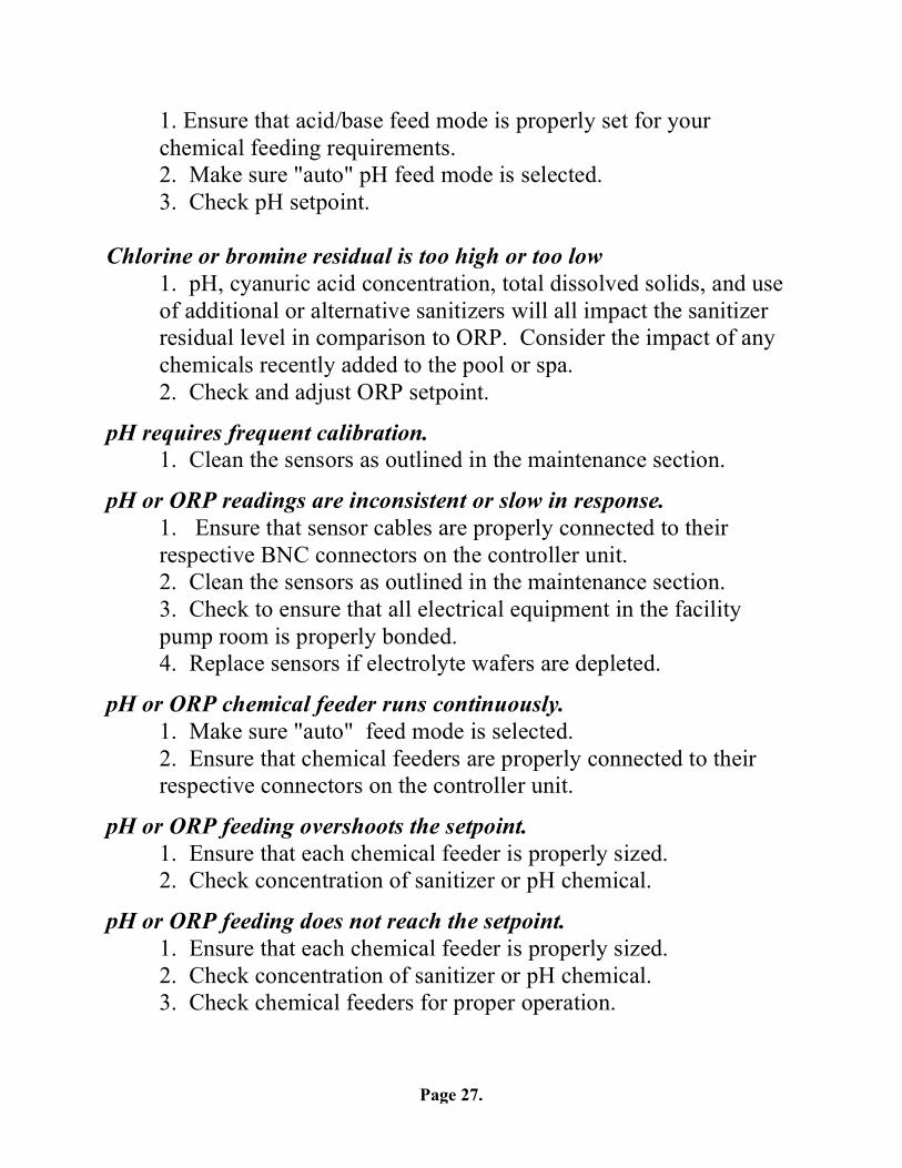
1. Ensure that acid/base feed mode is properly set for your chemical feeding requirements.
2. Make sure "auto" pH feed mode is selected. 3. Check pH setpoint.
Chlorine or bromine residual is too high or too low
1. pH, cyanuric acid concentration, total dissolved solids, and use of additional or alternative sanitizers will all impact the sanitizer residual level in comparison to ORP. Consider the impact of any chemicals recently added to the pool or spa.
2. Check and adjust ORP setpoint.
pH requires frequent calibration. 1. Clean the sensors as outlined in the maintenance section.
pH or ORP readings are inconsistent or slow in response. 1. Ensure that sensor cables are properly connected to their
respective BNC connectors on the controller unit. 2. Clean the sensors as outlined in the maintenance section. 3. Check to ensure that all electrical equipment in the facility
pump room is properly bonded. 4. Replace sensors if electrolyte wafers are depleted.
pH or ORP chemical feeder runs continuously. 1. Make sure "auto" feed mode is selected. 2. Ensure that chemical feeders are properly connected to their
respective connectors on the controller unit.
pH or ORP feeding overshoots the setpoint. 1. Ensure that each chemical feeder is properly sized. 2. Check concentration of sanitizer or pH chemical.
pH or ORP feeding does not reach the setpoint. 1. Ensure that each chemical feeder is properly sized. 2. Check concentration of sanitizer or pH chemical. 3. Check chemical feeders for proper operation.
Page 28.
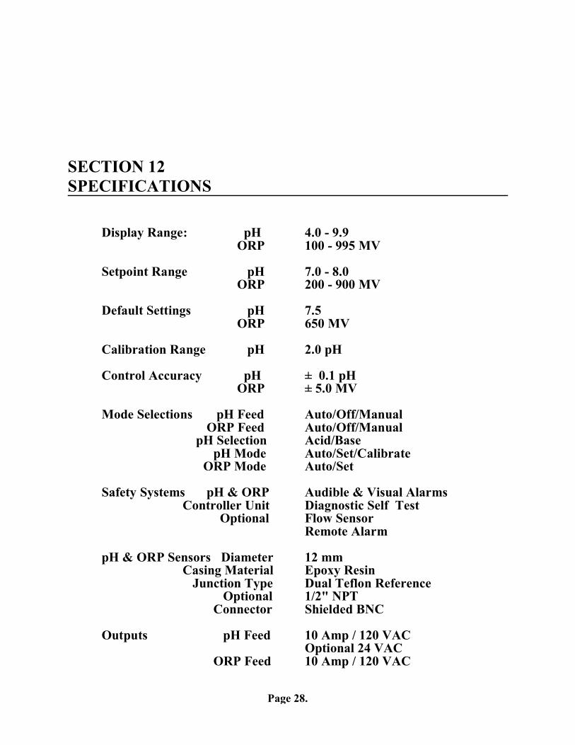
SECTION 12 SPECIFICATIONS
Display Range: pH 4.0 - 9.9 ORP 100 - 995 MV
Setpoint Range pH 7.0 - 8.0
ORP 200 - 900 MV Default Settings pH 7.5
ORP 650 MV
Calibration Range pH 2.0 pH
Control Accuracy pH ± 0.1 pH ORP ± 5.0 MV
Mode Selections pH Feed Auto/Off/Manual
ORP Feed Auto/Off/Manual pH Selection Acid/Base
pH Mode Auto/Set/Calibrate ORP Mode Auto/Set
Safety Systems pH & ORP Audible & Visual Alarms
Controller Unit Diagnostic Self Test Optional Flow Sensor
Remote Alarm pH & ORP Sensors Diameter 12 mm
Casing Material Epoxy Resin Junction Type Dual Teflon Reference
Optional 1/2" NPT Connector Shielded BNC
Outputs pH Feed 10 Amp / 120 VAC
Optional 24 VAC ORP Feed 10 Amp / 120 VAC
Page 29.
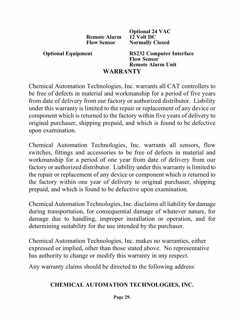
Optional 24 VAC Remote Alarm 12 Volt DC Flow Sensor Normally Closed
Optional Equipment RS232 Computer Interface
Flow Sensor Remote Alarm Unit
WARRANTY Chemical Automation Technologies, Inc. warrants all CAT controllers to be free of defects in material and workmanship for a period of five years from date of delivery from our factory or authorized distributor. Liability under this warranty is limited to the repair or replacement of any device or component which is returned to the factory within five years of delivery to original purchaser, shipping prepaid, and which is found to be defective upon examination. Chemical Automation Technologies, Inc. warrants all sensors, flow switches, fittings and accessories to be free of defects in material and workmanship for a period of one year from date of delivery from our factory or authorized distributor. Liability under this warranty is limited to the repair or replacement of any device or component which is returned to the factory within one year of delivery to original purchaser, shipping prepaid, and which is found to be defective upon examination. Chemical Automation Technologies, Inc. disclaims all liability for damage during transportation, for consequential damage of whatever nature, for damage due to handling, improper installation or operation, and for determining suitability for the use intended by the purchaser. Chemical Automation Technologies, Inc. makes no warranties, either expressed or implied, other than those stated above. No representative has authority to change or modify this warranty in any respect.
Any warranty claims should be directed to the following address:
CHEMICAL AUTOMATION TECHNOLOGIES, INC.
Page 30.
202 Perry Parkway #7 Gaithersburg, Maryland 20877 800-657-2287
Related Documents