THE HIGH TEMP RESPONSE CASTABLE LINING

Welcome message from author
This document is posted to help you gain knowledge. Please leave a comment to let me know what you think about it! Share it to your friends and learn new things together.
Transcript

THE HIGH TEMP RESPONSE
CASTABLE LINING

THE HIGH TEMP RESPONSE
CA
STA
BLE
LIN
ING
3
CA
STA
BLE
LIN
ING
TABLE OF CONTENTS
SINGLE LAYER LINING - HAND WELDING
V RANGE ..........................................................................................P. 7
CH RANGE .......................................................................................P. 10
UV RANGE .......................................................................................P. 15
UBL RANGE .....................................................................................P. 16
SINGLE LAYER LINING - GUN WELDING
CV RANGE .......................................................................................P. 21
MULTI LAYER LINING
TWIN PIN RANGE - HAND WELDING .............................................P. 30
TWIN PIN RANGE - GUN WELDING ...............................................P. 33
TW RANGE ......................................................................................P. 36
BULLHORN RANGE ........................................................................P. 40
L RANGE
ON DR STUD RANGE ......................................................................P. 46
L RANGE ..........................................................................................P. 48
VS RANGE .......................................................................................P. 49
DR RANGE .......................................................................................P. 50
FLAT ANCHORS RANGE .........................................................................P. 55
CA
STA
BLE
LIN
ING
THE HIGH TEMP RESPONSE
SINGLE LAYER LINING HAND WELDING

THE HIGH TEMP RESPONSE
CA
STA
BLE
LIN
ING
7
CA
STA
BLE
LIN
ING
V RANGE - HAND WELDING
IRIS manufactures anchors from cold drawn wires, with a specific tensile strength, using a «soft bending technique». This «in house» developed technology, reduces mechanical stress in the steel structure and avoids the formation of micro cracks, through which corrosion can accelerate and damage the anchors.
V1 V4
Steel casingWelding
Caps*
V1 Refractory castable
V4
Welding
with CNC bending machin
FOR HAND WELDING

THE HIGH TEMP RESPONSE
CA
STA
BLE
LIN
ING
9
THE HIGH TEMP RESPONSE
8
CA
STA
BLE
LIN
ING
V RANGE - HAND WELDING
DESIGNATION
V1.6(60) - 040 - 304
Anchor type
Diameter D
Angle Lenght L(L1/L2)
Alloy
STANDARD OPTIONS
Option CAPSCaps on top
Option LENGTH (L1/L2)for unequal legs
V1
OPTIONS
Notes :Most frequent angles : 45° - 60° - 90°any angle on request.
Sketch not contractual
CAPS
L2
L1
ØD
45° - 60° - 90°
L
ON : on nutStandard nut :M8_AISI 310
OB : on bossWelded on bossStandard boss :M8_AISI 310
ANCHOR NAME _ ON + SIZE + ALLOY ANCHOR NAME _ OB + SIZE + ALLOY
WB : with an omega BSP : with a base plateAlloy and lenght
IN.BSP.040.040.8(10) - 304
BL : Bent LegsWith the top of legs bent
ANCHOR NAME _ BL + LENGTH
45°
25
OS : on studWelded on threaded studstandard stud :M8 - 310
ANCHOR NAME _ OS + SIZE + ALLOY
Welding-304 WB . 8 . R12 / 25 . 310 R12
ØD
L
ANCHOR TYPE øDRADIUS R
LENGTH LALLOY
L
DESIGNATION
Length L(L1/L2)
Alloy
STANDARD OPTIONS
Option CAPSCaps on top
Option LENGTH (L1/L2)for unequal legs
CAPS
L1
L2
Notes :Most frequent angles : 45° - 60° - 90°any angle on request.
ØD
45° 60° 90°
L
ON : on nutStandard nut :M8_AISI 310
OB : on bossWelded on bossStandard boss :M8_AISI 310
OS : on studWelded on threaded studstandard stud :M8 - 310
WB: with an omega BSP : with a base plateAlloy and lenght
ANCHOR NAME _ BL + LENGTH ANCHOR NAME _ ON + SIZE + ALLOY ANCHOR NAME _ OB + SIZE + ALLOY
ANCHOR NAME _ OS + SIZE + ALLOY IN.BSP.040.040.8(10) - 304
BL : Bent LegsWith the top of legs bent
45°
25
Welding
V RANGE - HAND WELDING
V4.6 (60) - 060 - 304
V4
OPTIONSSketch not contractual
Anchor type
Diameter D
Angle
WB . 8 . R12 / 25 . 310 R12
ØD
L
ANCHOR TYPE øDRADIUS R
LENGTH LALLOY
L

THE HIGH TEMP RESPONSE
CA
STA
BLE
LIN
ING
11
THE HIGH TEMP RESPONSE
10
CA
STA
BLE
LIN
ING
CH RANGE
CH 1 CH 2 CH 4
Steel casing
WeldingWelding
CH4 CH2
Welding
Caps
Refractory castableCH1
IRIS manufactures anchors from cold drawn wires, with a specific tensile strength, using a «soft bending technique». This «in house» developed technology, reduces mechanical stress in the steel structure and avoids the formation of micro cracks, through which corrosion can accelerate and damage the anchors.
CH RANGE - HAND WELDING
DESIGNATION
CH1. 6 (60) - 035 - 304
AnchorAlloyAnchor type
Diameter D
AngleLength L
STANDARD OPTIONS
Option CAPSCaps on top
Option LENGTH (L1/L2)for unequal legs
CAPS
L1
L2
BL : Bent LegsWith the top of legs bent
ON : on nutStandard nut :M8_AISI 310
OB : on bossWelded on bossStandard boss :M8_AISI 310
OS : on studWelded on threaded studstandard stud : M8 - 310
WB : with an omega BSP : with a base plateAlloy and lenght
ANCHOR NAME _ BL + LENGTH ANCHOR NAME _ ON + SIZE + ALLOY ANCHOR NAME _ OB + SIZE + ALLOY
ANCHOR NAME _ OS + SIZE + ALLOYIN.BSP.040.040.8(10) - 304
45°
25
WELD
CH1
OPTIONSSketch not contractual
20
L
ØD
45° - 60° - 90°
Notes : Most frequent angles : 45° - 60° - 90°any angle on request.
WB . 8 . R12 / 25 . 310 R12
ØD
L
ANCHOR TYPE øDRADIUS R
LENGTH LALLOY
L
THE HIGH TEMP RESPONSE
CA
STA
BLE
LIN
ING
13
THE HIGH TEMP RESPONSE
12
CA
STA
BLE
LIN
ING
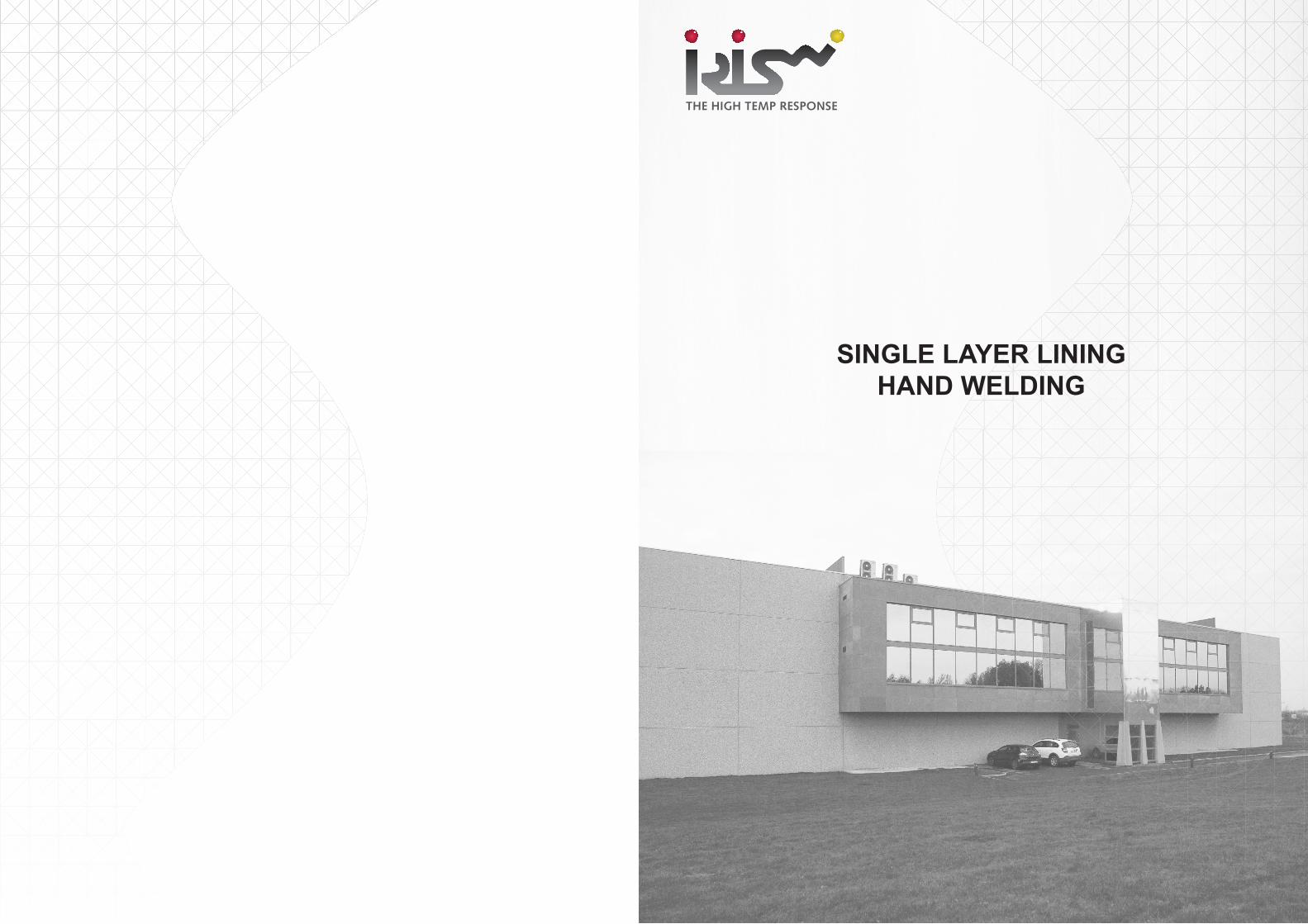
CH RANGE - HAND WELDING
DESIGNATION
CH1 . RL . 4(60) - 025 - 050 - 020 - 304
Length BAlloyAnchor type
Diameter D
AngleLength A(L1/L2)
Length L
STANDARD OPTIONS
Option CAPSCaps on top
Option LENGTH (L1/L2)for unequal legs
CAPS
L1
L2
CH1.RL
OPTIONS
B
B
A
BL : Bent LegsWith the top of legs bent
ON : on nutStandard nut :M8_AISI 310
OB : on bossWelded on bossStandard boss :M8_AISI 310
OS : on studWelded on threaded studstandard stud :M8 - 310
WB: with an omega BSP : with a base plateAlloy and lenght
ANCHOR NAME _ BL + LENGTH ANCHOR NAME _ ON + SIZE + ALLOY ANCHOR NAME _ OB + SIZE + ALLOY
ANCHOR NAME _ OS + SIZE + ALLOYIN.BSP.040.040.8(10) - 304
45°
25
A
15
L
ØD
60°
WELD
Sketch not contractual
L
WB . 8 . R12 / 25 . 310 R12
ØD
L
ANCHOR TYPE øDRADIUS R
LENGTH LALLOY
L
DESIGNATION
CH2.8(60) - 130 - 304
Length L(L1/L2)
Anchor Alloy
STANDARD OPTIONS
Option CAPSCaps on top
Option LENGTH (L1/L2)for unequal legs
CAPS
L1
L2
CH2
OPTIONSBL : Bent LegsWith the top of legs bent
ON : on nutStandard nut :M8_AISI 310
OB : on bossWelded on bossStandard boss :M8_AISI 310
OS : on studWelded on threaded studstandard stud : M8 - 310
WB: with an omega BSP : with a base plateAlloy and length
ANCHOR NAME _ BL + LENGTH ANCHOR NAME _ ON + SIZE + ALLOY ANCHOR NAME _ OB + SIZE + ALLOY
ANCHOR NAME _ OS + SIZE + ALLOY IN.BSP.040.040.8(10) - 304
45°25
Anchor type
Diameter D
Angle
CH RANGE - HAND WELDING
ØD
20 for Ø 6-8-10
Angle
L
WELD
WELD
WELD
Sketch not contractual
WB . 8 . R12 / 25 . 310 R12
ØD
L
ANCHOR TYPE øDRADIUS R
LENGTH LALLOY
L

THE HIGH TEMP RESPONSE
CA
STA
BLE
LIN
ING
15
THE HIGH TEMP RESPONSE
14
CA
STA
BLE
LIN
ING
CH RANGE - HAND WELDING
DESIGNATION STANDARD OPTIONS
Option CAPSCaps on top
Option LENGTH (L1/L2)for unequal legs
CH4
OPTIONS
Notes : Most frequent angles : 45° - 60° - 90°any angle on request.
CH4.6(60) - 150 - 253
Anchor type
Diameter D
Angle Length L(L1/L2)
Alloy
BL : Bent LegsWith the top of legs bent
ON : on nutStandard nut :M8_AISI 310
OB : on bossWelded on bossStandard boss :M8_AISI 310
OS : on studWelded on threaded studstandard stud : M8 - 310
WB: with an omega BSP : with a base plateAlloy and length
ANCHOR NAME _ BL + LENGTH ANCHOR NAME _ ON + SIZE + ALLOY ANCHOR NAME _ OB + SIZE + ALLOY
ANCHOR NAME _ OS + SIZE + ALLOY IN.BSP.040.040.8(10) - 304
45°25
WELD
WELD
ØD
45° - 60° - 90°
2020 for Ø 6-8-10
L
CAPS
L2L1
WELD
Sketch not contractual
L
WB . 8 . R12 / 25 . 310 R12
ØD
L
ANCHOR TYPE øDRADIUS R
LENGTH LALLOY
L
DESIGNATION STANDARD OPTIONS
Option CAPSCaps on top
Option LENGTH (L1/L2)for unequal legs
CAPS
L1
L2
BL : Bent LegsWith the top of legs bent
ON : on nutStandard nut :M8_AISI 310
OB : on bossWelded on bossStandard boss :M8_AISI 310
OS : on studWelded on threaded studstandard stud : M8 - 310
WB: with an omega BSP : with a base plateAlloy and length
ANCHOR NAME _ BL + LENGHT ANCHOR NAME _ ON + SIZE + ALLOY ANCHOR NAME _ OB + SIZE + ALLOY
ANCHOR NAME _ OS + SIZE + ALLOY IN.BSP.040.040.8(10) - 304
45°25
UV.6(80/90) - 050/040 - 309
Length L(L1/L2)
Anchor Alloy
Anchor type
Diameter D
Angle A/B
UV RANGE - HAND WELDING
WELD
WELD
90°- B
12 45°
45°
L1L2
80°- A
15
Steel casing Welding
Caps (option)UV Anchor
WELD
UV
OPTIONSSketch not contractual
WB . 8 . R12 / 25 . 310 R12
ØD
L
ANCHOR TYPE øDRADIUS R
LENGTH LALLOY
L

THE HIGH TEMP RESPONSE
CA
STA
BLE
LIN
ING
17
THE HIGH TEMP RESPONSE
16
CA
STA
BLE
LIN
ING
UBL RANGE
EX : TUBULAR WALL OF BOILER
IRIS manufactures anchors from cold drawn wires, with a specific tensile strength, using a «soft bending technique». This «in house» developed technology, reduces mechanical stress in the steel structure and avoids the formation of micro cracks, through which corrosion can accelerate and damage the anchors.
DESIGNATION STANDARD OPTIONS
Option CAPSCaps on top
Option LENGTH (L1/L2)for unequal legs
CAPS
L1
L2
UBL
OPTIONSBL : Bent LegsWith the top of legs bent
ON : on nutStandard nut :M8_AISI 310
OB : on bossWelded on bossStandard boss :M8_AISI 310
OS : on studWelded on threaded studstandard stud : M8 - 310
WB : with an omega BSP : with a base plateAlloy and length
ANCHOR NAME _ BL + LENGTH ANCHOR NAME _ ON + SIZE + ALLOY ANCHOR NAME _ OB + SIZE + ALLOY
ANCHOR NAME _ OS + SIZE + ALLOY IN.BSP.040.040.8(10) - 304
45°25
UBL RANGE - HAND WELDING
U.BL.6(90/90) - 55(25) - 310
Length SLength S
Alloy typewerkstoff
Anchor typeAnker Typ
Diameter DDurchmesser D
Angle ßAngle ß
Length LLength L(L1/L2)
Angle ɑAngle ɑ
ɑ
30
S
L
Ø6
ß
WELD
Sketch not contractual
WB . 8 . R12 / 25 . 310 R12
ØD
L
ANCHOR TYPE øDRADIUS R
LENGTH LALLOY
L

CA
STA
BLE
LIN
ING
THE HIGH TEMP RESPONSE
SINGLE LAYER LINING GUN WELDING
THE HIGH TEMP RESPONSE
CA
STA
BLE
LIN
ING
21
CA
STA
BLE
LIN
ING
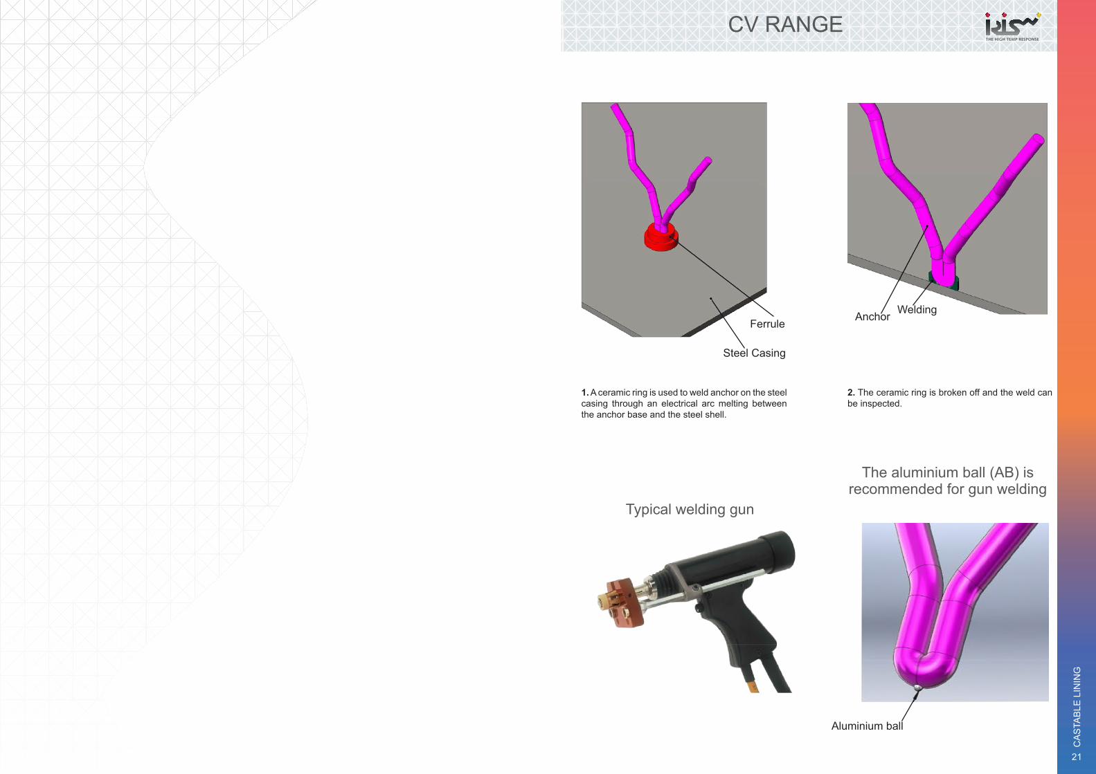
CV RANGE
Ferrule
Steel Casing
Anchor Welding
1. A ceramic ring is used to weld anchor on the steel casing through an electrical arc melting between the anchor base and the steel shell.
2. The ceramic ring is broken off and the weld can be inspected.
Typical welding gun
The aluminium ball (AB) is recommended for gun welding
Aluminium ball

THE HIGH TEMP RESPONSE
CA
STA
BLE
LIN
ING
23
THE HIGH TEMP RESPONSE
22
CA
STA
BLE
LIN
ING
CV RANGE
CV 1 CV 2 CV 4
THESE ANCHORS CAN BE GUNWELDED TO THE STEEL CASING
Refractory castable
Caps
CV1
CV2CV4
Steel casing
Ferrule for welding
IRIS manufactures anchors from cold drawn wires, with a specific tensile strength, using a «soft bending technique». This «in house» developed technology, reduces mechanical stress in the steel structure and avoids the formation of micro cracks, through which corrosion can accelerate and damage the anchors.
DESIGNATION STANDARD OPTIONS
Option CAPSCaps on top
Option LENGTH (L1/L2)for unequal legs
CV RANGE - GUN WELDING
CV1.6(60) - 125 - 304
Length L(L1/L2)
AlloyAnchor type
Diameter D
Angle
L1
L2
Ferrule :
60°
22 m
ini
L
The aluminium ball (AB) is recommended for gun welding.
Aluminium ball
Ferrule FER-126-000 for Ø6mm FER-128-000 for Ø8mm Aluminium ball optional (AB), on
request makes gun welding easierAluminium ball
FER-105-000 for Ø5mmFER-126-000 for Ø6mmFER-168-000 for Ø8mm
CV1
OPTIONSSketch not contractual

THE HIGH TEMP RESPONSE
CA
STA
BLE
LIN
ING
25
THE HIGH TEMP RESPONSE
24
CA
STA
BLE
LIN
ING
CV RANGE - GUN WELDING
DESIGNATION
CV2.6(80) - 125 - 310
Anchor type
Diameter D
Angle Length L(L1/L2)
Alloy
STANDARD OPTIONS
Option LENGTH (L1/L2)for unequal legs
22 m
ini
90°
Ferrule FER-105-000 for Ø5mm FER-126-000 for Ø6mm FER-168-000 for Ø8mm
L
L1
L2
CAPS
Option CAPSCaps on top
CV2
OPTIONSSketch not contractual
Aluminium ball
Ferrule FER-126-000 for Ø6mm FER-128-000 for Ø8mm Aluminium ball optional (AB), on
request makes gun welding easierAluminium ball
DESIGNATION STANDARD OPTIONS
Option CAPSCaps on top
Option LENGTH (L1/L2)for unequal legs
CV RANGE - GUN WELDING
CV4.6(60) - 150 - 304
Length L(L1/L2)
AlloyAnchor type
Diameter D
Angle
L1
L2
Ferrule :
60°
22
min
i
L
Caps
FER-105-000 for Ø5mmFER-126-000 for Ø6mmFER-168-000 for Ø8mm
OPTIONSSketch not contractual
CV4
Aluminium ball
Ferrule FER-126-000 for Ø6mm FER-128-000 for Ø8mm Aluminium ball optional (AB), on
request makes gun welding easierAluminium ball

THE HIGH TEMP RESPONSE
26
CA
STA
BLE
LIN
ING
FERRULES FOR STUD WELDING
TYPICAL DESIGNS ANS SIZES CAN BE CHANGED WITHOUT NOTICE OTHER MODELS ON REQUEST.
6,5
Ø26
11,8
Ø30,511
,3
8,5
Ø25,3
12,1
Ø28,2
1212
Ø28,2
13
6,5
5,5
6,5
2013
ORDER CODE
TO BE USED WITH
FER - 126
FER - 168
FER - 126S
FER - 105F
FER - 126F
CV Ø6STP Ø6CTP Ø6
CV Ø8STP Ø8CTP Ø8
CV Ø6STP Ø6CTP Ø6
CV Ø5STP Ø5CTP Ø5
CV Ø6STP Ø6CTP Ø6
CA
STA
BLE
LIN
ING
THE HIGH TEMP RESPONSE
MULTI LAYER LINING

THE HIGH TEMP RESPONSE
CA
STA
BLE
LIN
ING
31
THE HIGH TEMP RESPONSE
30
CA
STA
BLE
LIN
ING
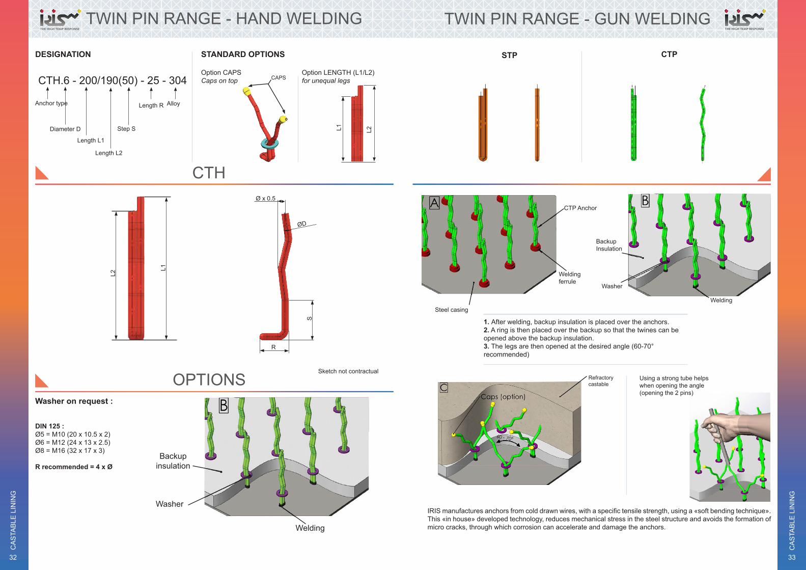
TWIN PIN RANGE - HAND WELDING
STH CTH
Steel casing
CTH Anchor
Welding
BackupInsulation
Washer
Refractorycastable
Using a strong tube helps when opening the angle (opening the 2 pins)
1. After welding, backup insulation is placed over the anchors.2. A ring is then placed over the backup so that the twines can be opened above the backup insulation. 3. The legs are then opened at the desired angle (60-70° recommended)
IRIS manufactures anchors from cold drawn wires, with a specific tensile strength, using a «soft bending technique». This «in house» developed technology, reduces mechanical stress in the steel structure and avoids the formationof micro cracks, through which corrosion can accelerate and damage the anchors.
DESIGNATION STANDARD OPTIONS
Option CAPSCaps on top
Option LENGTH (L1/L2)for unequal legs
TWIN PIN RANGE - HAND WELDING
L1 L2
STH.6 - 060/055 - 25 - 310
Length R AlloyDiameter D
Length L1
Length L2Anchor type
CAPS
Washer on request :
Backup insulation
Washer
Welding
DIN 125 : Ø5 = M10 (20 x 10.5 x 2)Ø6 = M12 (24 x 13x 2.5)Ø8 = M16 (32 x 17 x 3)
R recommended = 4 x Ø
L1 L2
ØD
R
OPTIONSSketch not contractual
STH
THE HIGH TEMP RESPONSE
CA
STA
BLE
LIN
ING
33
THE HIGH TEMP RESPONSE
32
CA
STA
BLE
LIN
ING
DESIGNATION STANDARD OPTIONS
Option CAPSCaps on top
Option LENGTH (L1/L2)for unequal legs
TWIN PIN RANGE - HAND WELDING
L1 L2
CAPS
Washer on request :
Backup insulation
Washer
Welding
DIN 125 : Ø5 = M10 (20 x 10.5 x 2)Ø6 = M12 (24 x 13 x 2.5)Ø8 = M16 (32 x 17 x 3)
R recommended = 4 x Ø
CTH.6 - 200/190(50) - 25 - 304
Length R Alloy
Length L1
Length L2
Step SDiameter D
Anchor typeL2
L1
ØD
Ø x 0.5
R
S
CTH
OPTIONSSketch not contractual
TWIN PIN RANGE - GUN WELDING
STP CTP
Steel casing
CTP Anchor
Weldingferrule
BackupInsulation
Washer
Refractorycastable
Welding
IRIS manufactures anchors from cold drawn wires, with a specific tensile strength, using a «soft bending technique». This «in house» developed technology, reduces mechanical stress in the steel structure and avoids the formation of micro cracks, through which corrosion can accelerate and damage the anchors.
1. After welding, backup insulation is placed over the anchors.2. A ring is then placed over the backup so that the twines can be opened above the backup insulation. 3. The legs are then opened at the desired angle (60-70° recommended)
Using a strong tube helps when opening the angle (opening the 2 pins)
THE HIGH TEMP RESPONSE
CA
STA
BLE
LIN
ING
35
THE HIGH TEMP RESPONSE
34
CA
STA
BLE
LIN
ING
DESIGNATION STANDARD OPTIONS
Option CAPSCaps on top
Option LENGTH (L1/L2)for unequal legs
L1 L2
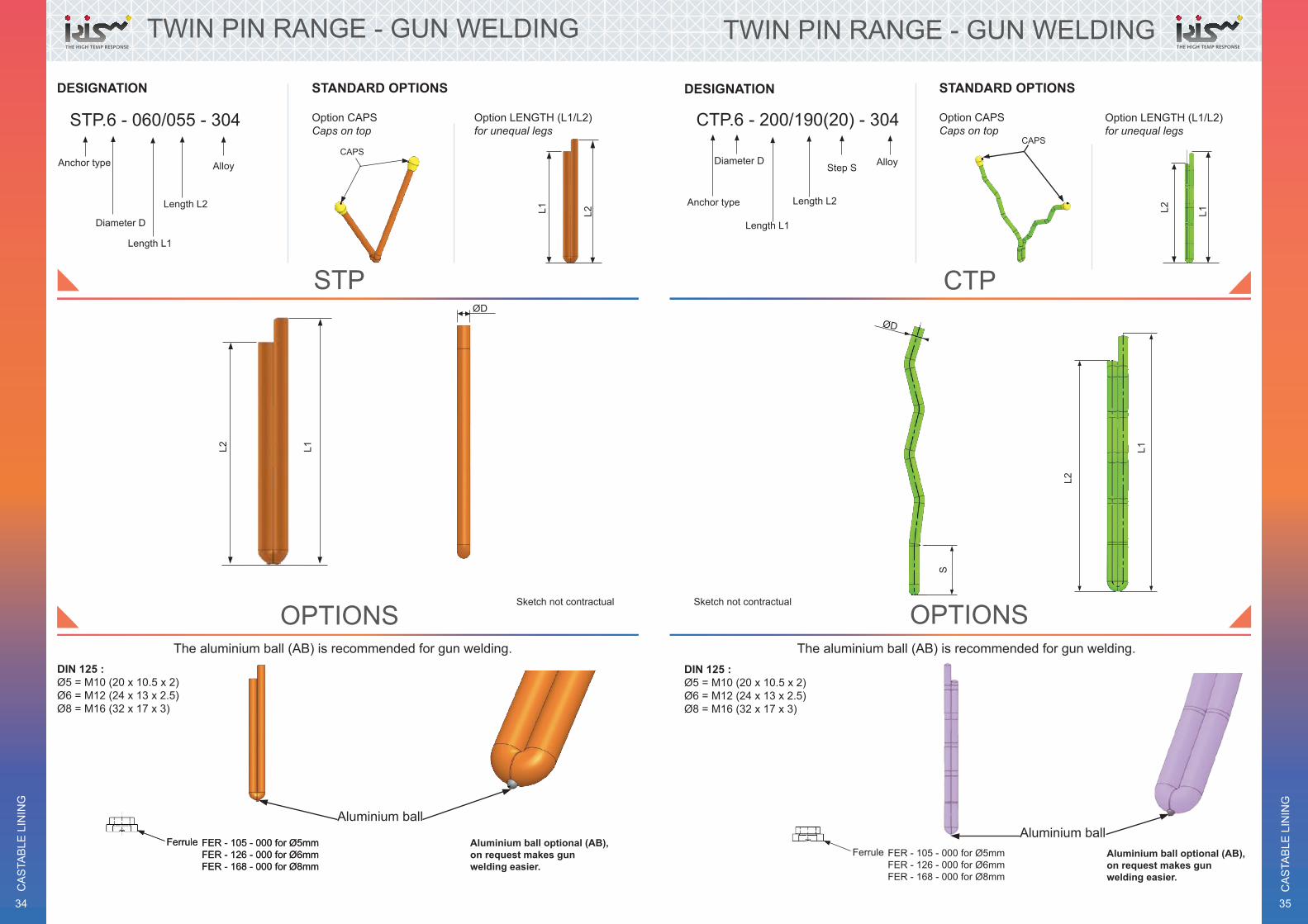
TWIN PIN RANGE - GUN WELDING
DIN 125 : Ø5 = M10 (20 x 10.5 x 2)Ø6 = M12 (24 x 13 x 2.5)Ø8 = M16 (32 x 17 x 3)
L2 L1
CAPS
ØD
FER - 105 - 000 for Ø5mmFER - 126 - 000 for Ø6mmFER - 168 - 000 for Ø8mm
Ferrule
Aluminium ball
Aluminium ball optional (AB), on request makes gun welding easier.
FER - 105 - 000 for Ø5mmFER - 126 - 000 for Ø6mmFER - 168 - 000 for Ø8mm
Ferrule
STP.6 - 060/055 - 304
Alloy
Diameter D
Length L1
Length L2
Anchor type
STP
OPTIONSSketch not contractual
The aluminium ball (AB) is recommended for gun welding.
DESIGNATION STANDARD OPTIONS
Option CAPSCaps on top
Option LENGTH (L1/L2)for unequal legs
TWIN PIN RANGE - GUN WELDING
CTP.6 - 200/190(20) - 304
Step S AlloyDiameter D
Length L1
Length L2Anchor type
CAPS
DIN 125 : Ø5 = M10 (20 x 10.5 x 2)Ø6 = M12 (24 x 13 x 2.5)Ø8 = M16 (32 x 17 x 3)
L2 L1
ØD
L2
L1
S
OPTIONSSketch not contractual
CTP
The aluminium ball (AB) is recommended for gun welding.
FER - 105 - 000 for Ø5mmFER - 126 - 000 for Ø6mmFER - 168 - 000 for Ø8mm
Ferrule
Aluminium ballAluminium ball optional (AB), on request makes gun welding easier.

THE HIGH TEMP RESPONSE
CA
STA
BLE
LIN
ING
37
THE HIGH TEMP RESPONSE
36
CA
STA
BLE
LIN
ING
TW RANGE
TWA TWS TWSS
Refractory castable
Caps (option)
TWA Anchor
Welding
Steel casing
The TW anchors can be either hand welded with electrode or bolted on to the steel casing (M10 recommended or M12).
EX : TWA
EX : TWS With Stud
TWS Anchor
Washer
Nut
Threaded Stud Welded on steelcasing
IRIS manufactures anchors from cold drawn wires, with a specific tensile strength, using a «soft bending technique». This «in house» developed technology, reduces mechanical stress in the steel structure and avoids the formation of micro cracks, through which corrosion can accelerate and damage the anchors.
STANDARD OPTIONS
Option CAPSCaps on top
Option LENGTH (L1/L2)for unequal legs
TW RANGE - HAND WELDING
Ø5 T = 13Ø6 T = 13Ø8 T = 15
R recommended = 4 x Ø
DESIGNATION
TWA.8(60) - 200(100) - 25 - 310
Length R AlloyAngle α
Length L(L1/L2)
Step SDiametre D
Anchor type
L1 L2
αØD
T
S
L
R
TWA
Sketch not contractual
OPTIONS
Exemple withTWS Anchor
Nut
Threaded Stud Welded on steel casing
TW : with stud
Washer

THE HIGH TEMP RESPONSE
CA
STA
BLE
LIN
ING
39
THE HIGH TEMP RESPONSE
38
CA
STA
BLE
LIN
ING
STANDARD OPTIONS
Option CAPSCaps on top
Option LENGTH (L1/L2)for unequal legs
TW RANGE - HAND WELDING
Ø6 T = 13Ø8 T = 13Ø10 T = 15
R recommended = 4 x Ø α
T
S
ØD
LR
L1
ØD
L2
TWS
OPTIONSSketch not contractual
DESIGNATION
TWS.8(60) - 200(100) - 25 - 310
Length R AlloyAngle α
Length L(L1/L2)
Step SDiametre D
Anchor type
Exemple withTWS Anchor
Nut
Threaded Stud Welded on steel casing
TW : with stud
Washer
Exemple withTWS Anchor
Nut
Threaded Stud Welded on steel casing
DESIGNATION
Length R Alloy
STANDARD OPTIONS
Option CAPSCaps on top
Option LENGTH (L1/L2)for unequal legs
Length L2
Step S1
Step S
TW RANGE - GUN WELDING
Diametre D
R recommended = 4 x ØS = 25 mm as minimumS1 = 75 mm as minimum
Ø6 T = 13Ø8 T = 13Ø10 T = 15
TW : with stud
Washer
Length L1Anchor type
L1
ØD
L2
T
ØD
S1
L1
60 °
L2
25
S
R
TWSS.8 - 275/265 (125 - 50) - 25 - 253
TWSS
Sketch not contractual
OPTIONS

THE HIGH TEMP RESPONSE
CA
STA
BLE
LIN
ING
41
THE HIGH TEMP RESPONSE
40
CA
STA
BLE
LIN
ING
BULLHORN RANGE
CBH CBH.SG
Heavy and dense refractory concrete
CBH Anchor
Welding
Steel casingLight refractory
concrete
Caps (option)
IRIS manufactures anchors from cold drawn wires, with a specific tensile strength, using a «soft bending technique». This «in house» developed technology, reduces mechanical stress in the steel structure and avoids the formation of micro cracks, through which corrosion can accelerate and damage the anchors.
DESIGNATION
CBH.8 (15/60) - 250 - 253
Length L(L1/L2)
Alloy
STANDARD OPTIONS
Option CAPSCaps on top
Option LENGTH (L1/L2)for unequal legs
Diametre D
Angle α
Angle β
BULLHORN RANGE - HAND WELDING
Anchor type
Ø10 B = 34 mmØ12 B = 40 mmØ16 B = 50 mm
L min = 80 mm L max = 400 mm
ØD
L1
Caps
α
B
β
L
ON : on nutStandard nut :M8_AISI 310
ANCHOR NAME _ ON + SIZE + ALLOY
BL : Bent LegsWith the top of legs bent
ANCHOR NAME _ BL + LENGTH
45°
L1
L2
CBH
Sketch not contractual
OPTIONS

THE HIGH TEMP RESPONSE
42
CA
STA
BLE
LIN
ING
DESIGNATION STANDARD OPTIONS
Option CAPSCaps on top
Option LENGTH (L1/L2)for unequal legs
BULLHORN RANGE - HAND WELDING
L min = 80mmL max = 400mm
R = 4 x Ø
L2L1
CAPS
β
ØD
αL1 L
R
BL : Bent LegsWith the top of legs bent
ANCHOR NAME _ BL + LENGTH
45°
Nut
Threaded Stud Welded on steel casing
Washer
CBH.SG.8 (15/55) - 350 - 30 - 330
Alloy
Angle α
Angle ß
Length L(L1/L2)
Diameter D Length R
Anchor type
Washer
CBH.SG
Sketch not contractual
OPTIONS

CA
STA
BLE
LIN
ING
THE HIGH TEMP RESPONSE
L RANGE

THE HIGH TEMP RESPONSE
CA
STA
BLE
LIN
ING
47
THE HIGH TEMP RESPONSE
46
CA
STA
BLE
LIN
ING
RANGE ON DR STUD
Hot face layer
Caps *
Insulating back up
DRS or DRH
Steel casing
VS Anchor welded on Nut (VS.ON)
OTHER EXAMPLE
SS OHN
DRH
VS or SS Ø6 or Ø8 Anchor
Weld
IRIS manufactures anchors from cold drawn wires, with a specific tensile strength, using a «soft bending technique». This «in house» developed technology, reduces mechanical stress in the steel structure and avoids the formation of micro cracks, through which corrosion can accelerate and damage the anchors.
RANGE ON DR STUD
«CH» & «V» anchors welded on Nut or Boss for multi layer linings.
1. Studs are welded on to the casing. 2. After covering the threaded ends with a plastic cap the backup insulating layer may be applied.
Insulating layer
Plastic cap
DRS or DRP or DRHSteel casing
Hot face layer
CH Anchor welded on nut or boss
Insulating back up
3. «CH» anchors welded on nut or on boss can be screwed on after removal of the plastic caps.

THE HIGH TEMP RESPONSE
CA
STA
BLE
LIN
ING
49
THE HIGH TEMP RESPONSE
48
CA
STA
BLE
LIN
ING
DESIGNATION STANDARD OPTIONS
Option CAPSCaps on top
Option LENGTH (L1/L2)for unequal legs
L RANGE
Sketch not contractual
L1
L2
Caps
L.10 - 130/30(015) - 304 - C
Alloy Caps
Length LLength R
Length XDiameter D
Anchor type
+ VS/SS.6(60) - 125 - 310+ CH4.6(60) - 125 - 310 - OB - M10 - 310
Caps
CH4 OB
CAP
With plastic cap to be removed after gunning back-up layers and before screwing CH4 anchor.Th
read
ed
20 m
m
L
R Ø8, Ø10, Ø12 are typical
VS or SS Ø6 or Ø8
ØDX
Available M8, M10, M12
L
BL : Bent LegsWith the top of legs bent
ON : on nutStandard nut :M8_AISI 310
OB : on bossWelded on bossStandard boss :M8_AISI 310
OS : on studWelded on threaded studstandard stud :M8 - 310
WB : with an omega BSP : with a base plateAlloy and length
ANCHOR NAME _ BL + LENGTH ANCHOR NAME _ ON + SIZE + ALLOY ANCHOR NAME _ OB + SIZE + ALLOY
ANCHOR NAME _ OS + SIZE + ALLOY IN.BSP.040.040.8(10) - 304
45° 25
DESIGNATION STANDARD OPTIONS
Option CAPSCaps on top
Option LENGTH (L1/L2)for unequal legs
VS RANGE
L1
L2
CapsVS.6(60) - 125 - 304
Alloy
Diameter DAngle
Length L(L1/L2)
Anchor type
M8Welding 15
Ø12
Welding
13
ØD
60° L
25
VS
Sketch not contractual
OPTIONS
WB . 8 . R12 / 25 . 310 R12
ØD
L
ANCHOR TYPE øDRADIUS R
LENGTH LALLOY
L

THE HIGH TEMP RESPONSE
CA
STA
BLE
LIN
ING
51
THE HIGH TEMP RESPONSE
50
CA
STA
BLE
LIN
ING
DESIGNATION STANDARD ALLOYS
STD DRS RANGE
«L» ≤ 50 mm I = 20 mm«L» = 51-≤100 mm I = 25 mm«L» ≥ 101 mm I = 50 mm
DRS - or .6 - 125 - 310RT
CT
AlloyLength L (L1/L2)
Diameter D
Anchor type
NOTE :
RT = Rolled thread
M6 D = ± 5.35mmM8 D = ± 7.18mmM10 D = ± 9.02mmM12 D = ± 10.86mm
NOTE :
CT = Cut Thread
M6 D = 6mmM8 D = 8mmM10 D = 10 mmM12 D = 12 mm
Alu Ball (option « AB ») requested from M8 and more. Makes gun welding easier
Alu Ball (option « AB ») requested from M8 and more. Makes gun welding easier
Aluminium ball
Sketch not contractual
ØD
L
I
M6M8M10 or M12 thread
Ceramic ferrule for stud welding
DRS - RT
Ceramic ferrule for stud welding
M6M8M10 or M12 thread
ØD
L
I
M6M8M10 or M12 thread
DRS - CT
DRS
DESIGNATION STANDARD ALLOYS
STUD DRS RANGE
«L» ≤ 50 mm I = 20 mm«L» = 51-≤ 100 mm I = 25 mm«L» ≥ 101 mm I = 50 mm
DRH - or .6 - 125 - 310RTCT
AlloyLength L (L1/L2)
Diameter D
Anchor type
NOTE :
RT = Rolled thread
M6 D = ± 5.35mmM8 D = ± 7.18mmM10 D = ± 9.02mmM12 D = ± 10.86mm
NOTE :
CT = Cut Thread
M6 D = 6mmM8 D = 8mmM10 D = 10 mmM12 D = 12 mm
ØD
20L
I
M6M8M10 or M12 thread
DRH - RT
ØD
20
L
I
M6M8M10 or M12 thread
DRH CT
Sketch not contractual
DRH

THE HIGH TEMP RESPONSE
FLAT ANCHORS RANGE

THE HIGH TEMP RESPONSE
CA
STA
BLE
LIN
ING
55
THE «Y» RANGE SYSTEM
1. The anchors can either be welded by hand welding or gun welding.
2.This allows an optional back up layer to be applied over the anchor.
3. Most of the time, the two wings are bent / opened after welding.
Steel casingYHB anchor
Back up layer
Refractory castable
Welding
YRA
IRIS manufactures anchors from cold drawn wires, with a specific tensile strength, using a «soft bending technique». This «in house» developed technology, reduces mechanical stress in the steel structure and avoids the formation of micro cracks, through which corrosion can accelerate and damage the anchors.
YRB YHA YHB

THE HIGH TEMP RESPONSE
CA
STA
BLE
LIN
ING
57
THE HIGH TEMP RESPONSE
56
CA
STA
BLE
LIN
ING
FLAT RANGE
DESIGNATION
YRA - 30/3 - 200(125) - 310
AlloyStep S
Length LSection WxT
Anchor type
YRA - 30/3(60) - 200(125) - 310
Opening if delivered open(ex: 60°)
L
YRA - 30/3(60) - 200(125) - 310
Aluminim ball optional (AB), in request makes gun welding easier.
Aluminium ball option is possible from the 4mm thick
Welding ferrule
Ferrule FER - 163 - 000
W
16
S
L
T
YRA
Sketch not contractual
OPTIONS
FLAT RANGE
DESIGNATION
YRB - 30/3 - 200(125) - 310
AlloyStep S
Length LSection WxT
Anchor type
YRB - 30/3(60) - 200(125) - 310
W
L
YRB - 30/3(60) - 200(125) - 310 - AB
Welding ferrule
Ferrule FER - 163 - 000 16
S
L
T
YRB
Sketch not contractual
OPTIONS
Opening if delivered open(ex: 60°)
Aluminim ball optional (AB), in request makes gun welding easier.
Aluminium ball option is possible from the 4mm thick

THE HIGH TEMP RESPONSE
CA
STA
BLE
LIN
ING
59
THE HIGH TEMP RESPONSE
58
CA
STA
BLE
LIN
ING
FLAT RANGE
DESIGNATION EXAMPLE
YHA - 30/4 - 125(075) - 310
AlloyStep S
Length LSection WxT
Anchor type
YHA - 30/4(60) - 125(075) - 310
W
S
L
T
Opening if delivered open(ex: 60°)L
Sketch not contractual
OPTIONS
YHA
Sketch not contractual
FLAT RANGE
DESIGNATION
YHB - 30/4 - 125(075) - 310
AlloyStep S
Length LSection WxT
Anchor type
YRB - 30/3(60) - 200(125) - 310
W
S
L
T
L
YHB
OPTIONS
Opening if delivered open(ex: 60°)

THE HIGH TEMP RESPONSE
CA
STA
BLE
LIN
ING
61
THE HIGH TEMP RESPONSE
60
CA
STA
BLE
LIN
ING
TOLERANCES :
Our anchors are submitted to normal manufacturing tolerances. In general, dimensional tolerance average is :
1. +/- 5° on angles2. +/- 2 mm for height ≤ 200 mm3. +/- 5 mm for height > 200 mm
, please contact us.
SPECIFIC REQUEST :
REMARKS :
THE HIGH TEMP RESPONSE
62
CA
STA
BLE
LIN
ING
NOTES
THE HIGH TEMP RESPONSE
63
CA
STA
BLE
LIN
ING
NOTES
THE HIGH TEMP RESPONSE
Parc d’activités de l’Aérodrome Ouest. RouvigniesRue Louis Duvant, 59328 VALENCIENNES Cedex.
Tél : 03 27 21 52 80Fax : 03 27 21 52 99
Related Documents