Case Study: Comparison between the Acoustic Performance of a Mixed Building Technology Building and a Conventional Building Luís Bragança* and Jorge Patrício + *Department of Civil Engineering; University of Minho, Campus de Azurém, 4800-058 Guimarães, Portugal [email protected] + National Laboratory for Civil Engineering; Avenida do Brasil 101, 1700-066 Lisboa, Portugal [email protected] (Received 22 July 2003 and accepted in revised form 21 October 2003) ABSTRACT The objective of this work is to compare the acoustical performance of MBT (Mixed Building Technology) constructions and conventional buildings. The sound insulation performance of a MBT construction was assessed by tests done in situ. The results were compared with similar data from earlier measurements undertaken by the Building Physics Laboratory of the University of Minho in Portugal, and from simplified prediction methods. The building where this comparison was done is a 3-storey building. The first 2 storeys were refurbished using conventional construction methods, but the 3rd storey was built using MBT methods, characterised by using lightweight materials, with high thermal insulation, and large fenestration areas. Based on the work undertaken, some conclusions and proposals for further work are presented. 1. INTRODUCTION Developments in new construction technology can yield improvements in overall of building quality, and comfort for occupants. The acoustic performance is an important aspect in this [1, 2]. Mixed Building Technology (MBT) is one of these new technologies, which can offer original and important improvements in aesthetic, functional and economical terms. The improvements are a result of the favourable relationship between weight/thickness and insulation of the materials used in MBT construction. Generally, MBT external and internal walls are thicker than those for than conventional buildings and use high absorption materials in the cavity of lightweight sandwich partitions. Conventional building solutions only involve small thicknesses of mineral wool in the cavity of double leaf hollow brick walls. BUILDING ACOUSTICS · Volume 11 · Number 1 · 2004 Pages 79 – 90 79

Welcome message from author
This document is posted to help you gain knowledge. Please leave a comment to let me know what you think about it! Share it to your friends and learn new things together.
Transcript
Case Study: Comparison between the AcousticPerformance of a Mixed Building Technology
Building and a Conventional Building
Luís Bragança* and Jorge Patrício+
*Department of Civil Engineering; University of Minho, Campus de Azurém, 4800-058 Guimarães, Portugal
+National Laboratory for Civil Engineering; Avenida do Brasil 101, 1700-066 Lisboa, Portugal
(Received 22 July 2003 and accepted in revised form 21 October 2003)
ABSTRACTThe objective of this work is to compare the acoustical performance of MBT (Mixed BuildingTechnology) constructions and conventional buildings. The sound insulation performance of aMBT construction was assessed by tests done in situ. The results were compared with similar datafrom earlier measurements undertaken by the Building Physics Laboratory of the University ofMinho in Portugal, and from simplified prediction methods.
The building where this comparison was done is a 3-storey building. The first 2 storeys wererefurbished using conventional construction methods, but the 3rd storey was built using MBT methods,characterised by using lightweight materials, with high thermal insulation, and large fenestration areas.Based on the work undertaken, some conclusions and proposals for further work are presented.
1. INTRODUCTIONDevelopments in new construction technology can yield improvements in overall ofbuilding quality, and comfort for occupants. The acoustic performance is an importantaspect in this [1, 2].
Mixed Building Technology (MBT) is one of these new technologies, which canoffer original and important improvements in aesthetic, functional and economicalterms. The improvements are a result of the favourable relationship betweenweight/thickness and insulation of the materials used in MBT construction.
Generally, MBT external and internal walls are thicker than those for thanconventional buildings and use high absorption materials in the cavity of lightweightsandwich partitions. Conventional building solutions only involve small thicknesses ofmineral wool in the cavity of double leaf hollow brick walls.
BUILDING ACOUSTICS · Volume 11 · Number 1 · 2004 Pages 79 – 90 79
Mixed Building Technology (MBT) is a new construction concept that aims tointegrate different construction methods in a single building. This concept is underdevelopment all over the world (and especially in Europe) as a result of recentrecognition that there is a special need for higher quality in urban buildings. Thisrequires the development of new and suitable strategies for architects, sociologists,urban planners, local authorities and engineers.
Important work has already been undertaken, under the auspices of the EuropeanCommunity, by way of COST projects, for example the COST Action C12 “Improvingbuildings’ structural quality by new technologies” programme. The main objective ofCOST Action C12 is to develop, combine and disseminate new engineeringtechnologies, to improve the quality of urban buildings, and to propose new technicalsolutions to architects and planners, to reduce the disturbances of the constructionprocess in urban areas and to improve the eventual quality of living in the urban habitat.
Implementation of new technologies requires that construction should be undertakenin such a way that the building’s overall cost (construction, maintenance and use)should not be increased and, if possible, reduced
Subjectively, the evaluation of the acoustic performance of buildings depends oneach person’s requirements, which in turn are based on their individual socio-economicand cultural heritage. Quantitative assessment can be based on measurable physicalcriteria, described in the specialized literature and in international standards.
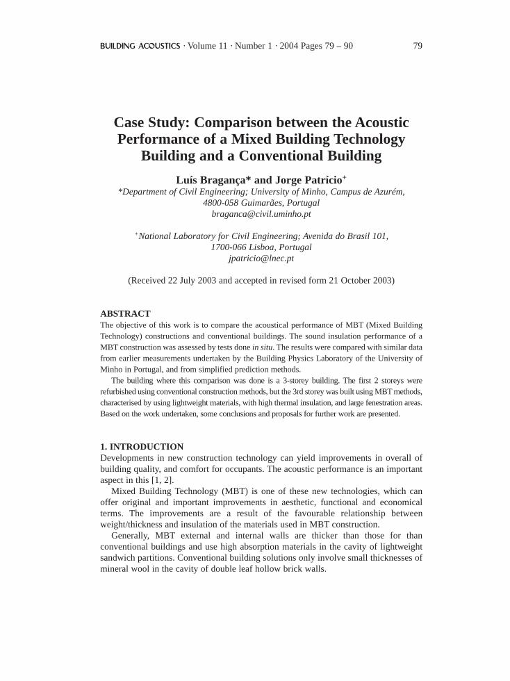
2. CONSTRUCTIVE ASPECTS OF THE BUILDINGSFor the purpose of this work to evaluate the acoustic performance of MBT buildings,an office building in Coimbra, Portugal, whose top floor was enlarged using MBTmethods, was selected (Figure 1). The whole South façade of the MBT top floor has aglass curtain wall. The floor and roof slabs are 12 cm thick lightweight reinforcedconcrete, whereas the conventional construction lower floors are heavier, and typical ofbuildings in Portugal, with 25 cm thick beam and pot floor.
Figure 1. General view of the building where the MBT construction wasimplemented
80 Acoustic Performance of MTB Buildings
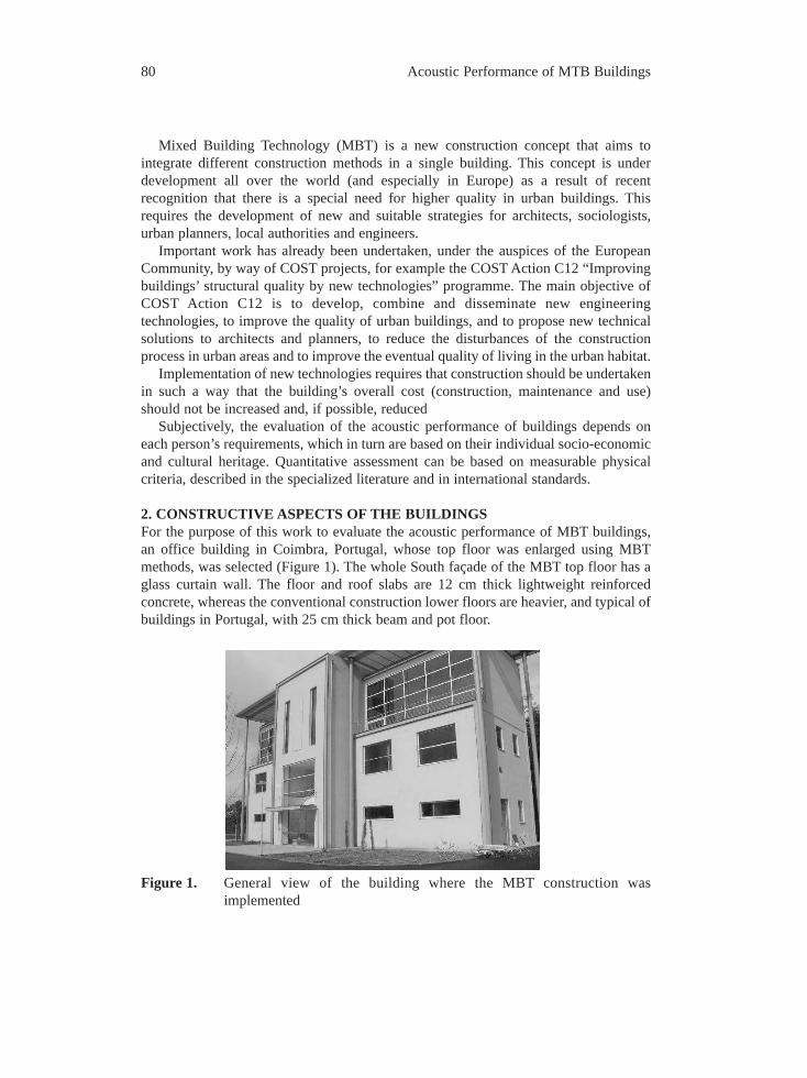
The MBT structure is defined by a skeleton of steel, supporting the walls, theintermediate floors and the roof. The floor finishing is of plywood square plates withlinoleum coating. This covering is located 10 cm above the slab to allow insertion ofelectric and PC cables. Under the slab there is a 13 mm thick plasterboard suspendedceiling (see Figure 2 and Table 1).
The floors and roof of the conventional part of the building are 25 cm thick beam andpot slabs. The floor finishing is wood and the ceiling plaster (see Figure 2 and Table 1).
MBT construction Conventional construction Figure 2. Vertical cross-section of the MBT and of conventional floors
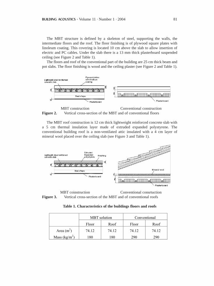
The MBT roof construction is 12 cm thick lightweight reinforced concrete slab witha 5 cm thermal insulation layer made of extruded expanded polystyrene. Theconventional building roof is a non-ventilated attic insulated with a 4 cm layer ofmineral wool placed over the ceiling slab (see Figure 3 and Table 1).
MBT coinstruction Conventional consrtuctionFigure 3. Vertical cross-section of the MBT and of conventional roofs
Table 1. Characteristics of the buildings floors and roofs
MBT solution Conventional
Floor Roof Floor Roof
Area (m2) 74.12 74.12 74.12 74.12
Mass (kg/m2) 180 180 290 290
BUILDING ACOUSTICS · Volume 11 · Number 1 · 2004 81
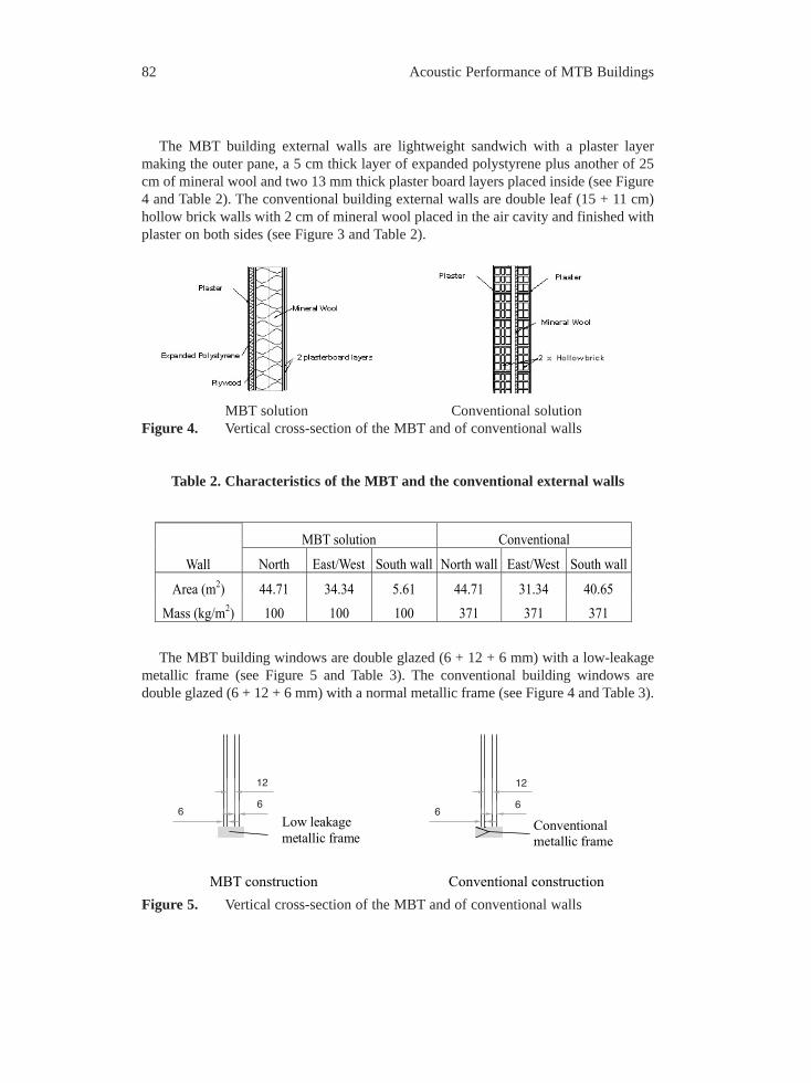
The MBT building external walls are lightweight sandwich with a plaster layermaking the outer pane, a 5 cm thick layer of expanded polystyrene plus another of 25cm of mineral wool and two 13 mm thick plaster board layers placed inside (see Figure4 and Table 2). The conventional building external walls are double leaf (15 + 11 cm)hollow brick walls with 2 cm of mineral wool placed in the air cavity and finished withplaster on both sides (see Figure 3 and Table 2).
MBT solution Conventional solutionFigure 4. Vertical cross-section of the MBT and of conventional walls
Table 2. Characteristics of the MBT and the conventional external walls
The MBT building windows are double glazed (6 + 12 + 6 mm) with a low-leakagemetallic frame (see Figure 5 and Table 3). The conventional building windows aredouble glazed (6 + 12 + 6 mm) with a normal metallic frame (see Figure 4 and Table 3).
Figure 5. Vertical cross-section of the MBT and of conventional walls
Conventional metallic frame
Conventional construction
6
12
6
Low leakage metallic frame
MBT construction
12
66
MBT solution Conventional
Wall North East/West South wall North wall East/West South wall
Area (m2) 44.71 34.34 5.61 44.71 31.34 40.65
Mass (kg/m2) 100 100 100 371 371 371
82 Acoustic Performance of MTB Buildings
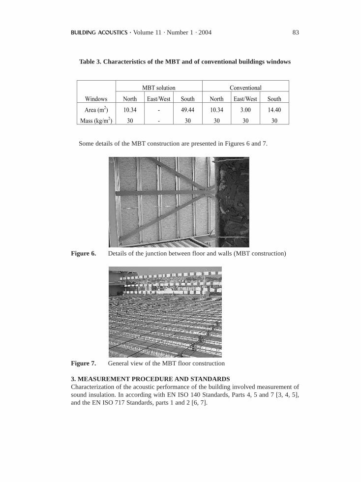
Table 3. Characteristics of the MBT and of conventional buildings windows
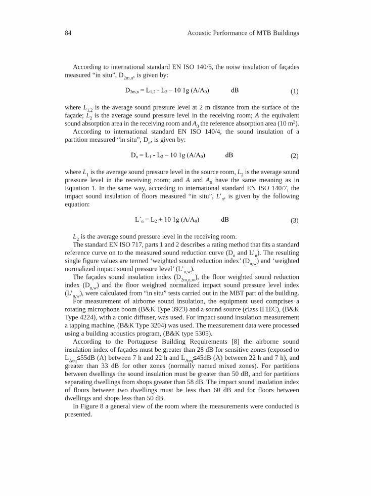
Some details of the MBT construction are presented in Figures 6 and 7.
Figure 6. Details of the junction between floor and walls (MBT construction)
Figure 7. General view of the MBT floor construction
3. MEASUREMENT PROCEDURE AND STANDARDSCharacterization of the acoustic performance of the building involved measurement ofsound insulation. In according with EN ISO 140 Standards, Parts 4, 5 and 7 [3, 4, 5],and the EN ISO 717 Standards, parts 1 and 2 [6, 7].
MBT solution Conventional
Windows North East/West South North East/West South
Area (m2) 10.34 - 49.44 10.34 3.00 14.40
Mass (kg/m2) 30 - 30 30 30 30
BUILDING ACOUSTICS · Volume 11 · Number 1 · 2004 83
According to international standard EN ISO 140/5, the noise insulation of façadesmeasured “in situ”, D2m,n, is given by:
(1)
where L1,2 is the average sound pressure level at 2 m distance from the surface of thefaçade; L2 is the average sound pressure level in the receiving room; A the equivalentsound absorption area in the receiving room and A0 the reference absorption area (10 m2).
According to international standard EN ISO 140/4, the sound insulation of apartition measured “in situ”, Dn, is given by:
(2)
where L1 is the average sound pressure level in the source room, L2 is the average soundpressure level in the receiving room; and A and A0 have the same meaning as inEquation 1. In the same way, according to international standard EN ISO 140/7, theimpact sound insulation of floors measured “in situ”, L′n, is given by the followingequation:
(3)
L2 is the average sound pressure level in the receiving room.The standard EN ISO 717, parts 1 and 2 describes a rating method that fits a standard
reference curve on to the measured sound reduction curve (Dn and L’n). The resultingsingle figure values are termed ‘weighted sound reduction index’ (Dn,w) and ‘weightednormalized impact sound pressure level’ (L’n,w).
The façades sound insulation index (D2m,n,w), the floor weighted sound reductionindex (Dn,w) and the floor weighted normalized impact sound pressure level index(L’n,w), were calculated from “in situ” tests carried out in the MBT part of the building.
For measurement of airborne sound insulation, the equipment used comprises arotating microphone boom (B&K Type 3923) and a sound source (class II IEC), (B&KType 4224), with a conic diffuser, was used. For impact sound insulation measurementa tapping machine, (B&K Type 3204) was used. The measurement data were processedusing a building acoustics program, (B&K type 5305).
According to the Portuguese Building Requirements [8] the airborne soundinsulation index of façades must be greater than 28 dB for sensitive zones (exposed toLAeq≤55dB (A) between 7 h and 22 h and LAeq≤45dB (A) between 22 h and 7 h), andgreater than 33 dB for other zones (normally named mixed zones). For partitionsbetween dwellings the sound insulation must be greater than 50 dB, and for partitionsseparating dwellings from shops greater than 58 dB. The impact sound insulation indexof floors between two dwellings must be less than 60 dB and for floors betweendwellings and shops less than 50 dB.
In Figure 8 a general view of the room where the measurements were conducted ispresented.
L«n = L2 + 10 1g (A/A0) dB
Dn = L1 - L2 Ð 10 1g (A/A0) dB
D2m,n = L1,2 - L2 Ð 10 1g (A/A0) dB
84 Acoustic Performance of MTB Buildings
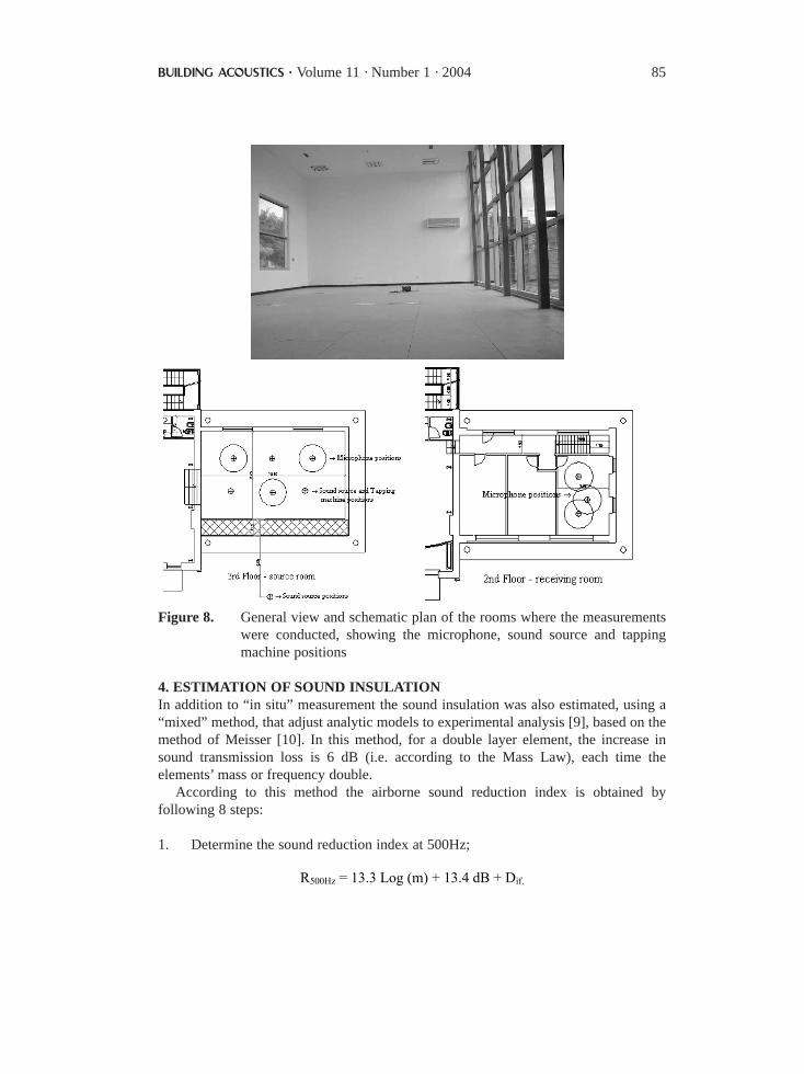
Figure 8. General view and schematic plan of the rooms where the measurementswere conducted, showing the microphone, sound source and tappingmachine positions
4. ESTIMATION OF SOUND INSULATIONIn addition to “in situ” measurement the sound insulation was also estimated, using a“mixed” method, that adjust analytic models to experimental analysis [9], based on themethod of Meisser [10]. In this method, for a double layer element, the increase insound transmission loss is 6 dB (i.e. according to the Mass Law), each time theelements’ mass or frequency double.
According to this method the airborne sound reduction index is obtained byfollowing 8 steps:
1. Determine the sound reduction index at 500Hz;
R500Hz = 13.3 Log (m) + 13.4 dB + Dif.
BUILDING ACOUSTICS · Volume 11 · Number 1 · 2004 85
where: Dif. = 0 dB to single-leaf walls; Dif. = 2 dB for lightweight panels with smallair cavities; Dif. = 4 dB for heavyweight panels with 2 to 4 cm air cavities; Dif. = 6 dBfor heavyweight panels with more than 4 cm air cavities; and Dif. = 9 dB forheavyweight panels with 5 to 10 cm air cavities filled with absorbent material.
2. Sketch the predicted mass law curve of sound reduction index versus frequencyfor the two-leaf partition (6 dB/oct.).
3. Calculate of first eigenfrequency relating to transverse vibration by bending, andredesign the curve, with the correspondent loss of insulation (negligible if f < 100 Hz,and reaching 6 to 8 dB for thin lightweight panels)
4. Calculate the resonance frequency of the panels for the double partition, andsuperimpose on the mass law curve showing the corresponding loss of insulation(negligible if f < 100 Hz, reaching 6 to 8 dB for windows)
(4)
where c is velocity of sound in air (m/s); mi the mass per unit area of the panel(kg/m2}; ρ the density of the material (kg/m3) (ρar = 1,18 kg/m3); and d the aircavity width, in m.
5. Calculate the critical frequencies, and superpose on the mass law curve (a loss ofinsulation of 4 dB for cork, 5 dB for expanded polystyrene, 6 dB for wood, 7dBfor plasterboard, 8 dB for concrete, 9 dB for brick and 10 dB for glass, steel andaluminium)
(5)
where h is thickness of the element; and E the Young modulus.
6. Calculate the resonance frequency of the air cavity, for double walls, and redesignthe mass law curve with the correspondent loss of insulation (it can reach 3 to 4dB for windows)
(6)
where d is the air cavity width, in m.
7. Delineate the curve corresponding to the theoretical frequency law (8 dB/oct. forfrequencies above the resonance frequency of the mass-air cavity), outside thezones where there may be insulation loss.
d2
ckf,...,
d2
c2f,
d2
cf k21 ===
E8,1
2 ρh
cfc =
+π
ρ=
2m1
1m1
d1
2
c.f
2
ress
86 Acoustic Performance of MTB Buildings
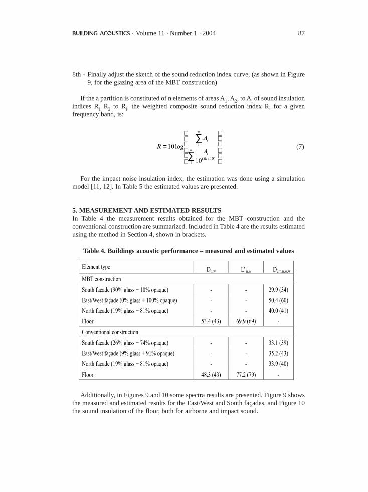
8th - Finally adjust the sketch of the sound reduction index curve, (as shown in Figure9, for the glazing area of the MBT construction)
If the a partition is constituted of n elements of areas A1, A2, to Ai of sound insulationindices R1 R2 to Ri, the weighted composite sound reduction index R, for a givenfrequency band, is:
(7)
For the impact noise insulation index, the estimation was done using a simulationmodel [11, 12]. In Table 5 the estimated values are presented.
5. MEASUREMENT AND ESTIMATED RESULTS In Table 4 the measurement results obtained for the MBT construction and theconventional construction are summarized. Included in Table 4 are the results estimatedusing the method in Section 4, shown in brackets.
Table 4. Buildings acoustic performance – measured and estimated values
Additionally, in Figures 9 and 10 some spectra results are presented. Figure 9 showsthe measured and estimated results for the East/West and South façades, and Figure 10the sound insulation of the floor, both for airborne and impact sound.
Element type Dn,w LÕn,w D2m,n,w,w
MBT construction
South fa�ade (90% glass + 10% opaque) - - 29.9 (34)
East/West fa�ade (0% glass + 100% opaque) - - 50.4 (60)
North fa�ade (19% glass + 81% opaque) - - 40.0 (41)
Floor 53.4 (43) 69.9 (69) -
Conventional construction
South fa�ade (26% glass + 74% opaque) - - 33.1 (39)
East/West fa�ade (9% glass + 91% opaque) - - 35.2 (43)
North fa�ade (19% glass + 81% opaque) - - 33.9 (40)
Floor 48.3 (43) 77.2 (79) -
=∑
∑n
Rii
n
i
A
AR
1)10/(
1
10
log10
BUILDING ACOUSTICS · Volume 11 · Number 1 · 2004 87
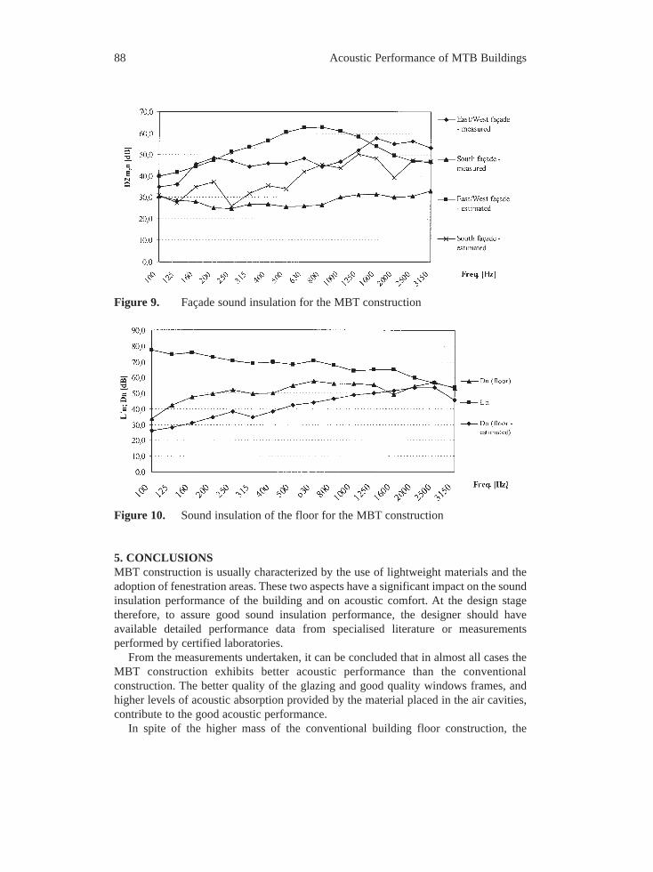
Figure 9. Façade sound insulation for the MBT construction
Figure 10. Sound insulation of the floor for the MBT construction
5. CONCLUSIONSMBT construction is usually characterized by the use of lightweight materials and theadoption of fenestration areas. These two aspects have a significant impact on the soundinsulation performance of the building and on acoustic comfort. At the design stagetherefore, to assure good sound insulation performance, the designer should haveavailable detailed performance data from specialised literature or measurementsperformed by certified laboratories.
From the measurements undertaken, it can be concluded that in almost all cases theMBT construction exhibits better acoustic performance than the conventionalconstruction. The better quality of the glazing and good quality windows frames, andhigher levels of acoustic absorption provided by the material placed in the air cavities,contribute to the good acoustic performance.
In spite of the higher mass of the conventional building floor construction, the
88 Acoustic Performance of MTB Buildings
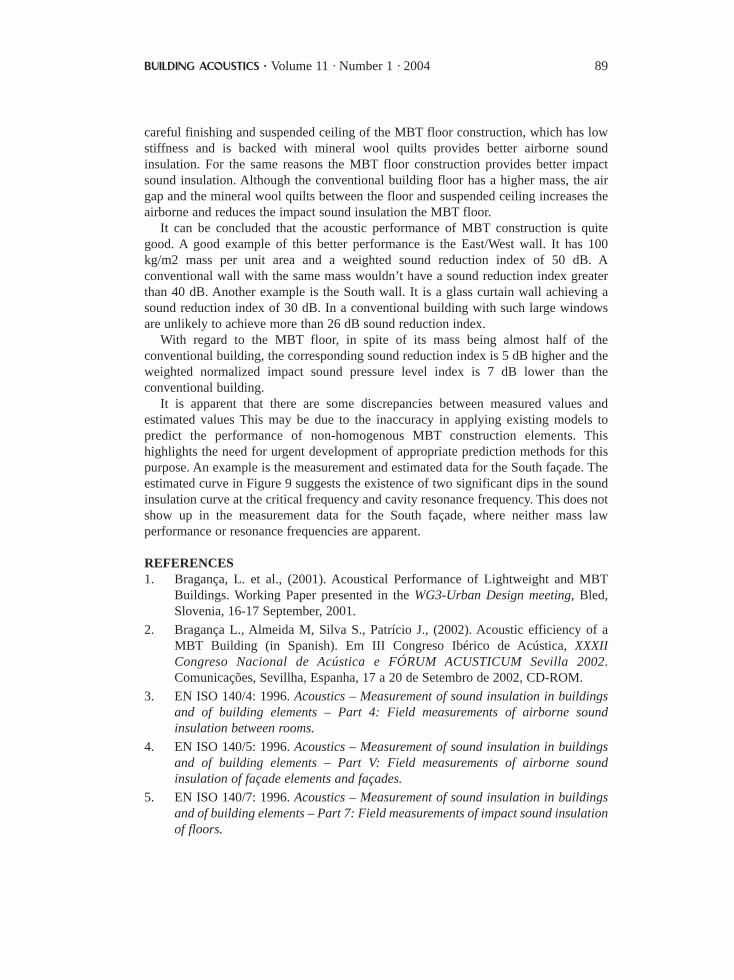
careful finishing and suspended ceiling of the MBT floor construction, which has lowstiffness and is backed with mineral wool quilts provides better airborne soundinsulation. For the same reasons the MBT floor construction provides better impactsound insulation. Although the conventional building floor has a higher mass, the airgap and the mineral wool quilts between the floor and suspended ceiling increases theairborne and reduces the impact sound insulation the MBT floor.
It can be concluded that the acoustic performance of MBT construction is quitegood. A good example of this better performance is the East/West wall. It has 100kg/m2 mass per unit area and a weighted sound reduction index of 50 dB. Aconventional wall with the same mass wouldn’t have a sound reduction index greaterthan 40 dB. Another example is the South wall. It is a glass curtain wall achieving asound reduction index of 30 dB. In a conventional building with such large windowsare unlikely to achieve more than 26 dB sound reduction index.
With regard to the MBT floor, in spite of its mass being almost half of theconventional building, the corresponding sound reduction index is 5 dB higher and theweighted normalized impact sound pressure level index is 7 dB lower than theconventional building.
It is apparent that there are some discrepancies between measured values andestimated values This may be due to the inaccuracy in applying existing models topredict the performance of non-homogenous MBT construction elements. Thishighlights the need for urgent development of appropriate prediction methods for thispurpose. An example is the measurement and estimated data for the South façade. Theestimated curve in Figure 9 suggests the existence of two significant dips in the soundinsulation curve at the critical frequency and cavity resonance frequency. This does notshow up in the measurement data for the South façade, where neither mass lawperformance or resonance frequencies are apparent.
REFERENCES1. Bragança, L. et al., (2001). Acoustical Performance of Lightweight and MBT
Buildings. Working Paper presented in the WG3-Urban Design meeting, Bled,Slovenia, 16-17 September, 2001.
2. Bragança L., Almeida M, Silva S., Patrício J., (2002). Acoustic efficiency of aMBT Building (in Spanish). Em III Congreso Ibérico de Acústica, XXXIICongreso Nacional de Acústica e FÓRUM ACUSTICUM Sevilla 2002.Comunicações, Sevillha, Espanha, 17 a 20 de Setembro de 2002, CD-ROM.
3. EN ISO 140/4: 1996. Acoustics – Measurement of sound insulation in buildingsand of building elements – Part 4: Field measurements of airborne soundinsulation between rooms.
4. EN ISO 140/5: 1996. Acoustics – Measurement of sound insulation in buildingsand of building elements – Part V: Field measurements of airborne soundinsulation of façade elements and façades.
5. EN ISO 140/7: 1996. Acoustics – Measurement of sound insulation in buildingsand of building elements – Part 7: Field measurements of impact sound insulationof floors.
BUILDING ACOUSTICS · Volume 11 · Number 1 · 2004 89
6. EN ISO 717/1:1996. Acoustics – Rating of sound insulation in buildings and ofbuilding elements – Part 1: Airborne sound insulation.
7. EN ISO 717/2: 1996. Acoustics – Rating of sound insulation in buildings and ofbuilding elements – Part 2: Impact sound insulation.
8. PORTUGAL, Ministério do Ambiente e do Ordenamento do Território –Portuguese noise regulations (In Portuguese). Decree-Law no. 292/2000,November 14th, Lisbon, 2000.
9. Mateus D., Tadeu A., (1999). Acoustic performance of buildings (in Portuguese).Faculdade de Ciências e Tecnologia da Universidade de Coimbra.
10. Meisser, M., (1978). The practice of acoustics in buildings (La Pratique deL’acoustique dans les Bâtiments). Éditions Eyrolles, Paris.
11. Patrício, J. V., (1998). Acoustic performance of non-homogeneous floorsregarding impact sound sound in buildings: simulation model. “Ph. D. Thesis” (InPortuguese). Instituto Superior Técnico, Lisbon.
12. Patrício, J., Acoustics in buildings (in Portuguese). Author´s Edition, Lisbon 2003.
90 Acoustic Performance of MTB Buildings
Related Documents


