NASA TECHNICAL NOTE O ¢p, ! Z I--- ,,,¢ ,,,¢ Z NASA TN D-6970 CASE FILE COPY \ RANDo'M RE_gpO SE OF RECTANGULAR TO THE PRESSURE FIELD BENEATH A "TURBULENT BOUNDARY LAYER PANELS z IN SUBSONIC FLOWS by IVei J. Chyu and M. K. Au-Yang Ames Research Center Moffett Field, Calif. 94035 NATIONAL AERONAUTICS AND SPACE ADMINISTRATION • WASHINGTON, D. C. • OCTOBER 1972 https://ntrs.nasa.gov/search.jsp?R=19730004207 2018-06-17T15:07:14+00:00Z

Welcome message from author
This document is posted to help you gain knowledge. Please leave a comment to let me know what you think about it! Share it to your friends and learn new things together.
Transcript
NASA TECHNICAL NOTE
O
¢p,
!
ZI---
,,,¢
,,,¢Z
NASA TN D-6970
CASE FILECOPY
\
RANDo'M RE_gpO SE OF RECTANGULAR
TO THE PRESSURE FIELD BENEATH
A "TURBULENT BOUNDARY LAYER
PANELS
z
IN SUBSONIC FLOWS
by IVei J. Chyu and M. K. Au-Yang
Ames Research Center
Moffett Field, Calif. 94035
NATIONAL AERONAUTICS AND SPACE ADMINISTRATION • WASHINGTON, D. C. • OCTOBER1972
https://ntrs.nasa.gov/search.jsp?R=19730004207 2018-06-17T15:07:14+00:00Z

t_ 2
Z
F_

1. Report No. 2. Government Accession No. 3. Recipient's Catalog No.
NASA TN D-6970.. .,.
4. Title and Subtitle " 5. Report DateOctober 1972
RANDOM RESPONSE OF RECTANGULAR PANELS TO
THE PRESSURE FIELD BENEATH A TURBULENT
BOUNDARY LAYER IN SUBSONIC FLOWS
7. Author(s)
Wei J. Chyu and M. K. Au-Yang
9. Performing Organization Name and Address
NASA Ames Research Center
Moffett Field, Calif. 94035
12. Sponsoring Agency Name and Address
National Aeronautics and Space Administration
Washington, D.C. 20546
15. Supplementary Notes
6. Performing Organization Code
8. Performing Organization Report No.
A--4382
10. Work Unit No.
134-14-07-05-00-21
11. Contract or Grant No.
13. Type of Report and Period Covered
Technical Note
14. Sponsoring Agency Code
16. Abstract
The response of a rectangular panel under the excitation of a turbulent boundary layer with a zero longitudinal mean
pressure gradient in a subsonic flow was studied in detail. The method of normal mode was used together with the tech-
nique of spectral analysis. Both simply supported and clamped edge conditions of a panel were considered, and the
displacement power spectral density of the panel response was computed. The results for the clamped edge panel com-
pare favorably with existing data. Charts of structural acceptance, which provide a framework for estimating the response
of other rectangular panels, are presented, and the physical significances of structural acceptances discussed.
17. Key Words (Suggested by Author(s}}
Random vibration
Turbulent boundary-layer excitation
Normal mode analysis
lB. DistributionStatement
Unclassified - Unlimited
19. Security Classif. (of this report) 20. Security Classif, (of this page) 21. No. of Pages
Unclassified Unclassified 101
22. Price"
$3.00
"For sale by the National Technical Information Service, Springfield, Virginia 22151


TABLE OF CONTENTS
Page
SYMBOLS .................................................................. vSUMMARY ................................................................. l
INTRODUCTION ............................................................ l
METHOD OF ANALYSIS ..................................................... 2
Formulation of Displacement Power Spectral Density (DPSD) ...................... 2
Separation Into Real and Imaginary Parts and Factorization of Acceptance ............ 7
Two-Parameter Formulation of Acceptance .................................... 9
RESULTS .................................................................. 10
DISCUSSION ............................................................... 11
Structural Acceptances .................................................... 11
Coincidence of structural and pressure waves ................................ I I
Structural acaeptances as transition amplitudes .............................. 12
Acceptance as a function of F and/x* ...................................... 12Structural Response ....................................................... 13
Displacement PSD as function of frequency ................................ 13Displacement PSD distribution on a panel ................................. 13
CONCLUSIONS ............................................................. 14APPENDIX A - RANDOM EXCITATION BY SURFACE PRESSURE
FLUCTUATIONS ........................................................ 16APPENDIX B - ACCEPTANCE AS TRANSITION AMPLITUDES BETWEEN TWO
NORMAL MODES OF VIBRATION AND ITS SIGNIFICANCE IN PANEL
VIBRATION ............................................................ 18APPENDIX C - APPLICATION OF ACCEPTANCE CHARTS IN DISPLACEMENT
PSD COMPUTATION ..................................................... 21REFERENCES .............................................................. 22
TABLE .................................................................... 23
FIGURES .................................................................. 25
Ul


SYMBOLS
a
A
Am
b
c
C_e
D
E
f
fa(t)
Uc
F1
Fa
G_,co )
G(x__',x", co)
h
Ha(co)
Jail(co )
Jmr(co )
.w
Ins(co)
Ja¢(co )
transition amplitude from the 3 mode to the a mode of vibration
surface area of the panel
normalization factor for _m
co
Uc
damping coefficient
equivalent damping coefficient for the a mode
Eh 312(1 0 2) , bending stiffness
Young's modulus
frequency
generalized force
Strouhal number
4f_ 1 4f_ 2Uc ' F2 = UC
Fourier transform of fa
2S(x_,co) one-sided power spectral density function
2S(_x._',x",co) one-sided cross spectral density function
thickness of panel
frequency response function
real part of acceptance
real part of longitudinal acceptance
transversal acceptance
acceptance
k_(_o )
kmr( _o)
_2
ms
Mo_
Osp__',x__",,o)
p x(_,t)
q_
qa(t)
Qa(_o)
R_;x_",_)
$_',x_"_)
S_,_o)
t
T
u=
Uc09
w(x_,t)
XI
X2
x__(xl,x2)
Yl
vi
negative of imaginary part of acceptance
negative of imaginary part of longitudinal acceptance
panel length in x_ direction
panel length in x2 direction
generalized mass for the a mode
free-stream Mach number
operator corresponding to the pressure disturbance Sp(.X__',x",_o)
pressure fluctuation acting on the panel
dynamic pressure
generalized coordinates
Fourier transform of qa
cross correlation function
two-sided cross spectral density function
two-sided power spectral density function
time
averaging time
free-stream velocity
narrow-band convection velocity
displacement normal to the panel surface
Fourier transform of w
location on the panel in the longitudinal (or streamwise) direction
location on the panel in the lateral direction
coordinate referring to location on the panel
Xl

.]22
£(Y l ,Y_ )
7m
A*
_4
z/2
__(_ ,n_)
#
POt
ff
P
7
_)
_)
GO
X2
_2
normalized coordinates referring to location on the panel
roots of the transcendental equations (4) and (5)
boundary-layer thickness
displacement boundary-layer thickness
Kronecker delta
6"
C_4 C_2 G_2 O_4
_X I 4 _ 2 _xl 2 ax2 2 de. _X2 4
x' - x" coordinate referring to the separation distance of two points on the
panel
Y[ ' - Yl "
,_ ?FY2 - Y2
y' _y"
mass per unit area of the panel
loss factor for the a mode
Poisson ratio
correlation coefficient
delay time
mode shape function of the panel
mode shape function of a panel with unit dimensions
angular frequency
natural frequency of the a mode
vii

a = (m,n)
= (r,s)
P
d
Subscripts
mode index
mode index
quantity evaluated at the free stream
streamwise direction
lateral direction
quantities related to the excitation field
quantities related to panel displacement
viii
RANDOM RESPONSE OF RECTANGULAR PANELS TO
THE PRESSURE FIELD BENEATH A TURBULENT
BOUNDARY LAYER IN SUBSONIC FLOWS
Wei J. Chyu and M. K. Au-Yang
Ames Research Center
SUMMARY
The response of a rectangular panel under the excitation of a turbulent boundary layerwith a zero longitudinal mean pressure gradient in a subsonic flow was studied in detail. The
method of normal mode was used together with the technique of spectral analysis. Simply
supported and clamped edge boundary conditions of a panel were assumed. The response ofthe panel has been expressed in terms of displacement power spectral density. The mode number
and frequency in the response computation were extended to 7 and 3000 Hz, respectively.
The results of response computation assuming a clamped edge condition compare favorably
with existing experimental data with a clamped edge condition. The simply supported edge
condition, however, overestimates the response. The effect of flow velocity on the response is
to increase the higher frequency components of the power spectral density per unit excitation.
Charts of structural acceptances, which provide a framework for estimating the response of
other rectangular panels, are presented as functions of dimensionless frequency and boundary-layer displacement thickness. Physical signiflcances of the structural acceptances are also discussed,
as regards the coincidence of the pressure and flexural waves and the probability of mode transition.
INTRODUCTION
The pressure fluctuations in regions of turbulent attached and separated boundary layers
and shock waves adjacent to the surface of aerospace vehicles cause structural vibrations throughout
atmospheric flight. The study of these vibrations is important in determining stress, fatigue, life
of structures, and noise transmission into the interior of the vehicle. Unfortunately, the analysisof this type of vibration is complicated by the inherent random characteristics of the excitation
pressure fields, and the difficulty of analytically describing the vibration of a realistic structure.
For these reasons, early investigators of this problem considered only a hypothetical flow fieldand made the simplifying assumption that the structure, almost invariably either a beam or a
rectangular panel, was infinitely large (refs. 1, 2, and 3). This assumption leads to a solution in
terms of the mean square displacement of the panel as a whole, but not as a function of locationon the panel.

In recentinvestigationsthe responseof finite-sizerectangularpanelsto the excitationof anattachedturbulentboundarylayerhasbeenconsidered,but the panelswereassumedto besimplysupported(refs.4 to 6). This assumptionsimplifiesthe algebratremendously,permittingsolutionsto be expressedin closedforms.Although thesetheoreticalresultsagreebetterwith experimentthan thoseobtainedwith the infinite panelassumption,they tend to overestimatethe responseof a realisticpanel.Previousanalysisalsofails to predict thewavematchingaccuratelybetweenthe flexuraI waveof a paneland the pressurewave.The estimationof this wavematchingisimportant, particularly when the matchingoccursat one of the resonantfrequenciesof thestructure,andcausesa largestructuralresponse.With theadventof modernhighspeedcomputers,a theoreticalanalysisof a finite rectangularpanelwith clampededgesunderthe excitation of aturbulent boundary layer is now feasible. Analytical integration in closed forms is not necessary,
since numerical integration can be carried out with no algebraic simplification of the integrand.
This digital computer oriented approach has the following additional advantages over an analytical
approach: (1) The transparency of the problem is preserved, as often the physics of the problemis lost among a great length of closed-form mathematical formulas; (2) future developments aresimplified, as the basic computer program can be modified to describe different flow fields and/ordifferent structures.
A research program has therefore been undertaken to improve the analytical capability, andto develop practical computer programs for computing the displacement, velocity and stresses atdifferent locations on realistic panel structures in different flow fields, including attached andseparated flows at subsonic, transonic, and supersonic speeds. The first step in this process,discussed in this report, has been to consider the response of a clamped edge panel to the excitation
of a subsonic attached turbulent boundary layer. The subsonic case was chosen because of the
availability of corresponding excitation data (ref. 7) and response measurements (ref. 6). A similar
analysis pertaining to attached and separated supersonic flow is in progress along with tests to
obtain corresponding structural response data. For this reason, a computer program has been
developed that is in modular form so that additions can be made to the program to accommodate
different flow and structural conditions without affecting the rest of the program. The computer
program pertaining to the analysis will be published separately.
METHOD OF ANALYSIS
Formulation of Displacement Power Spectral Density (DPSD)
The displacement w_,t) of a vibrating panel (fig. 1) is assumed to obey the classical thinplate equation:
law + C_V + DV4w = p(.x., t) (1)
In the present analysis a uniform plate is considered. Hence/a and D are constants and independentof _x. The above equation with c and p set equal to zero is the equation of free vibration of the
plate, of which the solutions _ba_) are called the natural normal modes of the plate. In the
subsequent analysis, it will be assumed that the damping is so small that the natural normal modes
and frequencies are not significantly changed. It is assumed further that w(_,t) can be expanded
in terms of _ka(x) as follows:
2
w(x, t) = _ qa(t) ¢JaQ-) (2)
Here qJa is assumed to be properly normalized:
Furthermore, it will be assumed that ffa(x) can be obtained by separation of coordinates:
Ca(x) = _m(X_ )qJn(X_ )
The term q_a(_) will be properly normalized if _Om(X_) and _n(X2 ) are normalized:
o _km(X l )_kn(x l )dx l = _ mn
35
o _m(X2)qJn(x2)dx2 = 6mn
It can be shown that, for a panel with simply supported edges
_ m_rxiqJm(Xi) = sin _i i-- 1, 2 (3)
For a panel with clamped edges, _m takes on different forms according to whether m is evenor odd:
(a) Ifm is odd,
_ m(Xi) - l [cos Tm(_-l) + km cosh Tm(_-½)lAmq_
where 3'm are the roots of the equation
tan _ + tanh _-_= 0
and
(4)
Tm
sin _-km =_
7msinh _--

(b) If m is even,
-1------_ [sin "rm(_-I) + km sinh 3'mt_- 1)] (5)¢_m(Xi) Am_-_
where "rm are the roots of the equation
7m _.mtanT -tanh =0
The orthogonality condition of the mode shape function can be used to find the normalization
factors A m.
Am= Zm
where
Zm = 7m + sin 7m + km 2 (sinh 7m + "rm) if m is odd
= 7m - sin "rm + km 2 (sinh 7m - _'m)
The numerical values of Am and _'m are:
Note that
and
m A m 7 m
1 0.7133 4.730040
2 .7068 7.853202
3 .7071 10.995608
4 .7071 14.137164
5 .7071 17.278758
6 .7071 20.420352
A m _- 0.7071 form>t 3
_'m-_76 +(m-6)_r form_, 7
The generalized coordinate qa(t) satisfies the Lagrange equation
mai_a(t) + Cadla(t) + Kaqa(t) = fa(t)
if m is even
!
where the generalized mass
rn_ = v f ¢j2 (x)d__x= U
in view of the orthonormality condition of ffa(_x).
Similarly,
Ca = c
Ke_ = ma_a 2
and
£
fa(t) = J p(x_,t)_a(y_)dx_ (6)
The above Lagrange equation is valid only for viscous damping. With structural damping thecorresponding Lagrange equation (ref. 6) takes the form:
m_i_a(t) + Ko_(l + iva')qa(t) = fa(t)
where va' is the loss factor corresponding to structural damping. For harmonic solution the above
equation can be cast into viscous damping form because q = (1/i_)(l. Therefore
maqa(t) + C'aeqa(t) + K_qa(t) = fa(t)
where C'_e = (Kava'/co) is the equivalent viscous damping coefficient. In practice, both viscousand structural damping are present, and the Lagrange equation takes the final form
m_i_a(t) + C_eqa(t ) + Kaqa(t) = fa(t) (7)
where
_e = _e +
is the equivalent damping coefficient that takes into account the effect of both viscous and
structural damping. The viscous loss factor 6a' is usually defined by the following relation:
Hence,
Cae = Kava_..'+¢..o
2Ko_8o_'
coot

If the combined damping is small, so that the PSD curve is sharply peaked at the natural fre-
quencies, only the frequencies around the neighborhood of the natural frequencies are of interest.Therefore
and
¢o _-_ 60ot
Cote = Kol (280/ + rot')60
Kotvot
Ca.)
where
Vt_ = POt' + 2_ot'
is the combined loss factor for both structural and viscous damping. 1 It is this combined loss
factor pot that is measured experimentally. The natural frequency 60a will be computed by the
method of Hearman (ref. 8).
The Fourier transform of the Lagrange equation (7) takes the form:
Oa(60 ) = Ha(60 )Fot(60 ) (8)
wherO
1 (9)Hot(60) = mot [(60ot2 _ 602) + ivot60a= ]
Equations (2) and (8) together give
W(x,60) = Y_. Hot(60)Fot (60)qJot(x)
The displacement power spectral density is related to WT(g,60) by
SdfZ,60 ) = T-+"_ 71im,r WT,(X_,60)WT(X,60 )
(lO)
(II)
1The loss factor va takes into account the effect of hysteretic damping as well as viscous damping. Thelatter includes the interaction of panel motion on the flow field within and outside the boundary layer, andthe effect of acoustical radiation into the interior of the structure (cavity), and into the exterior flow field.The present state of art requires that rot be measured experimentally. Development of analytical and experi-mental methods for the determination of loss factor are in progress.
2One can alternatively write Cae _"2Ko_Sr,/60awhere 28ct = 26a' + rot'. This will give H(60) = 1/mot[(60a2 - 602)
+ 2iSot60ot60]instead of equation (9). The two expressions are equal at 60= 60ot.
:!i

where W T is the truncated Fourier transform of w. Equations (7), (8), (10), and (11) together give
Sd(X_,¢o ) = 2_ Y]Ha(co)H/3*(co)_a(_x)_0/7(_x)
T-+_ T 41r -T -Ta(x_ ')q; #(_")p(x', t')p(x", t" )e -iw(t''-t')
• dt' dt" dx' dx"
The excitation cross correlation function Rp_',x__",t) and the cross spectral density Sp(x_',x_", co)are defined by:
T
1 fTRp(x_',x_",r) = lim -_ p(_',t')p_",t' + r)dt'--_ O0
(12)
S,,(x,x,,o) I fZ .... ,,or_' _" = R p(S_ ,x_ ,r )e dr (13)
Equations (12) and (13) can be used to derive the following expression for Sd:
S d(X_,¢o) = ASp(cO) y] qJa2 (x)lHc_(co)12Jcm(o)Ol
+ 2ASp(_) _ Sa(x)C,#(x)Ha((.,.,)Hs*((.,.,)Ja/3(_) (14)
a,l_ counted once
where
Jail (¢'°) - ASp(w) Oa_')¢ _")Sp(x',x",_ )dx' dx"(15)
is the familiar structural acceptance first introduced by Powell (ref. 9). Note that it is dimensionless.
An empirical formula for Sp(x',x",w) is given in appendix A, and in appendix B the structural
acceptance JaB is shown to be equal to the transition amplitude per unit area per unit excitationbetween the a and _ mode of vibration.
Separation Into Real and Imaginary Parts and Factorization of Acceptance
Since Sp(x',x_.",_) is a complex function (see appendix A), the structural acceptance isgenerally complex. Therefore it can be written as
7
,J_ = j_[_ - ik_ (16)
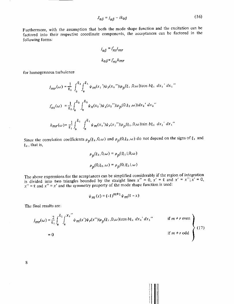
Furthermore, with the assumption that both the mode shape function and the excitation can befactored into their respective coordinate components, the acceptances can be factored in the
following forms:
for homogeneous turbulence
• r °
ja_ = Inslmr
°p
ka_ = Ins kmr
�mr(W) =-_ fo fo $m(Xl')$r(X_")[PP(_l'O'_)[c°sb_x dx_' dx_"
., 1 :Q2 fo_2lns(_O) =-_2Jo ¢n(X2')¢s(X2")top(O$2,w)ldx2' dx2"
1 -_1 roostkrrtr(_O) = _T Jo d/m(X,')$r(xl ")lpp(_l,O, co)lsin b_, dxx' dxt"
Since the correlation coefficients pp(_ 2,0,w) and pp(O._2,eo) do not depend on the signs of _ and_2, that is,
Op(_t ,0,_o) = pp(l_a 1,0,¢o)
ap(O,_2,_o) = 0p(0,[_2 [,w)
The above expressions for the acceptances can be simplified considerably if the region of integrationis divided into two triangles bounded by the straight lines x" = 0, x' = _ and x' = x";x' = 0,x" = _ and x" = x' and the symmetry property of the mode shape function is used:
The final results are:
__2 f_,fx,"i (.rnr._O)[,Jo Jo
=0
_Om (x) = (-1) m+l _Om(_ -x)
_ m(X')_ r(X")lp p(_ l ,0,w)lcos b_l dx _' dx _" if m + r even
if m + r odd (17)
_2 X.
=0
fokmr( _O) = -_1
n(X2 ')_ s(X2 ")lo p(O,_2 ,_ )ldx2' dx2"
i (Xl "
J qJm(X_")_r(Xl ")lpp(_l ,O,_o)lsin b_l dx_' dx_"0
if n + s even I
if n + s odd
if rn + r odd
= 0 if m + r even
(18)
(19)
A physical argument leading to the second identity of the above equations will be given in
appendix B.
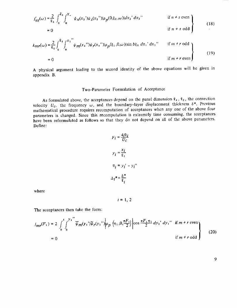
Two-Parameter Formulation of Acceptance
As formulated above, the acceptances depend on the panel dimension _, 92, the convection
velocity Uc, the frequency w, and the boundary-layer displacement thickness 6*. Previous
mathematical procedure requires recomputation of acceptances when any one of the above four
parameters is changed. Since this recomputation is extremely time consuming, the acceptances
have been reformulated as follows so that they do not depend on all of the above parameters.Define:
_f = Yi' - Yi"
where
i=1,2
The acceptances then take the form:
I Yl
Jmr (F')=2 f f0 0
=0
t?
'-' 2 / cos dYl' dYlif m + r even /
/if m + r odd ]
(20)
9

#t
0 1-# _ , ?rSns(F2 2 n(Y2 )_ks(Y2 ,rh, 2' dy2 if n + s even
0 0
= 0 if n 4- s odd
#t
mr,l ,,=2i'fy'0 0
(21)
- '-- " (r/ _rFl • IrFli71 dy I , dYl #,_m(Yl )_r(Y, )Op ,,0,---_)lsin-----T--if m + r odd )
(22)
= 0 if m + r even]/
Here ffm(Y) are the normalized mode shape functions (eqs. (4) and (5)) with _ replaced by unity;
the pressure correlation coefficients Ion(_l, 0, lrF1/2)l, 10p(0, rh, 7rF2/2)1 are as defined inappendix A. In equations (20) to (22),the acceptances now depend on only two parameters,Fi and _i*. As long as Ai* remains constant, the same acceptance curves can be used to computethe displacement power spectral density of different rectangular panels at different free-streamvelocities.
In terms of these new acceptances, the displacement power spectral density takes the form:
SdO',D = SpO0 Y] "_a_02)Ilia(2"m') 12/ram(F,)/'nn(F_)a
+ 2Sp(f) E "_a_)_k'--_)i'ns(F2 )[gajmr(F1 ) + ha[3kmr(F' )]av_-[3 mam_(g_ + h_t_)
(23)
where
ga# = (was - _2 ) (wO2 _ _o_ ) + VaV_COa2coO2 (24)
hal3 = _'a_a 2 (_(_2 _ co2 ) _ v#_ 2 (_a2 - _2 ) (25)
Acceptance charts based on equations (20) to (22) have been developed for the case of arectangular panel under excitation of a turbulent boundary layer in a subsonic flow with a zero-
longitudinal mean pressure gradient. The application of these charts in displacement PSD compu-tation is described in appendix C.
RESULTS
The first part of the results from the present analysis includes the response of a clamped edgepanel to turbulent flow excitation applied on one side of the panel. The panel properties and flowparameters used for an illustrative computation are given in table 1. The results are shown in
figures 2 to 9 along with some results of an identical panel with simply supported edges. Fig-
ures 2 to 6 show the structural acceptances for a boundary layer with ti*/_ = 0.04468 and
10

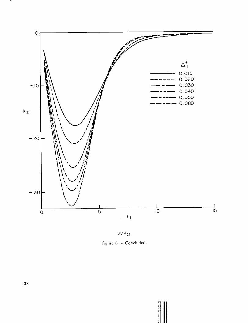
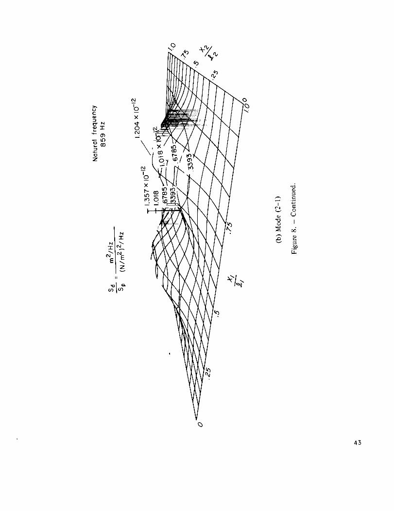
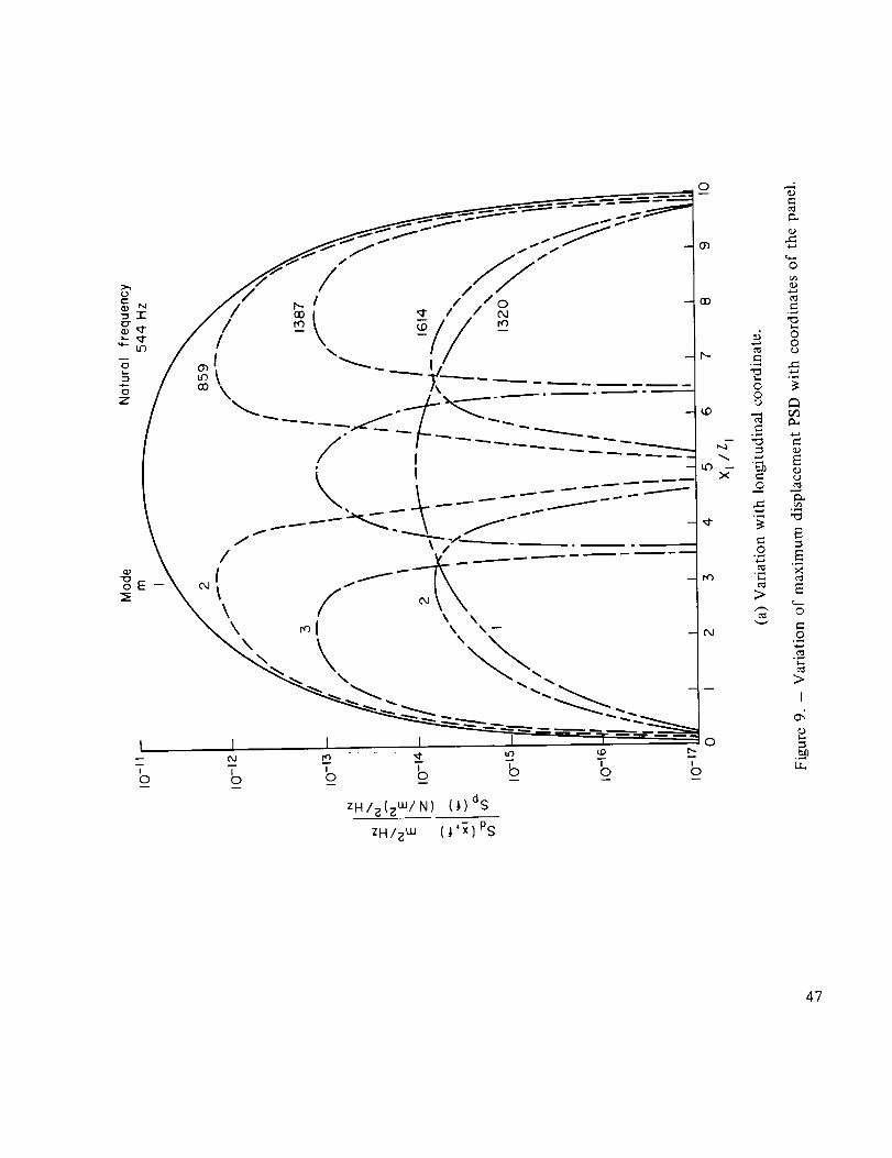
6"/_2 = 0.06499, for which the corresponding response data are available from Wilby's experi-ment (ref. 6). Figure 6 shows the variation of acceptance with boundary-layer displacementthickness. Figure 7 shows the calculated DPSD at the quarter- and midpoints of the panel,together with the corresponding experimental results. Figure 8 depicts the perspective view ofthe distribution of displacement PSD components at each mode on the panel. Figure 9(a) showsthe variation of the displacement PSD with longitudinal distance x_/_, evaluated at the lateral
position x2/_2 for which the PSD is a maximum for a given mode shown in figure 8. Similarly,
figure 9(b) shows the variation of the displacement PSD with lateral distance x2/£2 evaluated at
the longitudinal position x_/_ for which the PSD is a maximum. PSD results are obtained by
truncating the series in equation (23) after the seventh mode. It is found that decreasing the
mode number to five, or increasing the mode number to nine, has a negligible effect on the results.
The second part of the results (figs. 10 to 12) are charts of acceptances plotted against the
frequency parameter Fi for various Ai*. These charts, together with equation (23), enable thedisplacement PSD of the response of a clamped edge panel to be computed for attached turbulent
boundary-layer excitations in subsonic flow.
DISCUSSION
Structural Acceptances
Coincidence of structural and pressure waves- The response of a panel to a spatial-temporal
correlated random pressure fluctuation caused by a turbulent boundary layer is characterized by
wave-length matchings between the pressure wave and the flexural waves of the panel; a condition
often referred to as "coincidence." It is this peak coincidence that gives rise to large response if it
occurs at one of the resonant frequencies of the structure. Coincidence frequencies are identified
by peaks of the longitudinal joint acceptance curves (fig. 2). They occur at F (or 4f_/Uc) =_ 2m
for both simply supported and clamped edge panels.
Figure 2 shows that the degree,of wavelength matching is highest in the first mode, and
decreases with increase of mode number for both boundary conditions. A simply supported panel
exhibits a higher degree of matching than a clamped edge panel. Since the joint terms (the first
sum on the right-hand side of eq. (23)) involving the joint acceptances account for almost all of
the Sd(ff, co) , it follows that a simply supported panel will undergo a larger mean square displace-ment than a clamped edge panel.
In the case of a simply supported panel, the peaks occur at F < 2m because of the finiteness
of the panel. This means that the flexural wavelength of the panel is shorter than the matching
wavelength of the pressure wave. As the mode number is increased, the peaks approach F = 2m,
the matching condition of an infinite panel, because the panel appears to be infinite whencompared with the small wavelengths of the pressure waves at higher mode numbers.
When the panel edges are clamped, the panel boundary has two effects, one due to the
finiteness of the panel as stated above, and the other due to the rigidity of the clamped boundary,
For a nonresponsive region of a clamped-edge panel the effect appears to be small when compared
11

with the long pressure waves at the lower modes, and large when compared with the short pres-
sure waves at higher modes. Thus, the effect of the clamped edges is negligible at lower modematchings. The acceptance curves (fig. 2) show that the peaks at lower mode numbers occur at
F < 2m, because finiteness of the panel dominates. At higher mode numbers the opposite effectof the nonresponsive part of the panel edges begins to dominate and the peaks shift to F > 2m.
It is significant that the peaks shift a half wavelength larger than 2m. Thus, the generally accepted
assumption that wave matching always occurs at F = 2m is not true for a finite panel.
Structural acceptances as transition amplitudes- Suppose an arbitrary external force is
applied on a structure initially vibrating in the _ normal mode. The structure will generallytransit into another mode (the a mode) of vibration, which can be a normal mode or a linear
superposition of normal modes of vibration. The probability of this transition is called thetransition amplitude between the # normal mode, and the a mode when the structure is excited
by the specific force in question. It is shown in appendix B that the structural acceptance J0_j3(c_)is equal to the transition amplitude per unit area per unit excitation from the _ to the a mode of
vibration when the panel is excited by randomly fluctuating pressure forces.
In the case of two-dimensional panel vibration the transition amplitude is regarded as a
product of longitudinal and lateral acceptances. The longitudinal acceptance/mr - ikmr correspondsto the transition amplitude between the ruth and the rth mode of vibration of a one--dimensional
structure (a beam) under the excitation of the longitudinally correlated component of the pressureforce or It)(_l, 0, co)le -ic° _1/Uc in equation (A 1). The in-phase part of this longitudinal component
of the pressure force gives rise to the real part/mr of the longitudinal acceptance and the out-of-
phase part to the imaginary part kmr. The lateral transition amplitude/_Ts corresponds to thetransition amplitude of another one-dimensional structure under the excitation of the laterallycorrelated component of the pressure force or Ip(0,_ ,co)t.
Several interesting characteristics of the transition amplitudes are disclosed by the acceptances
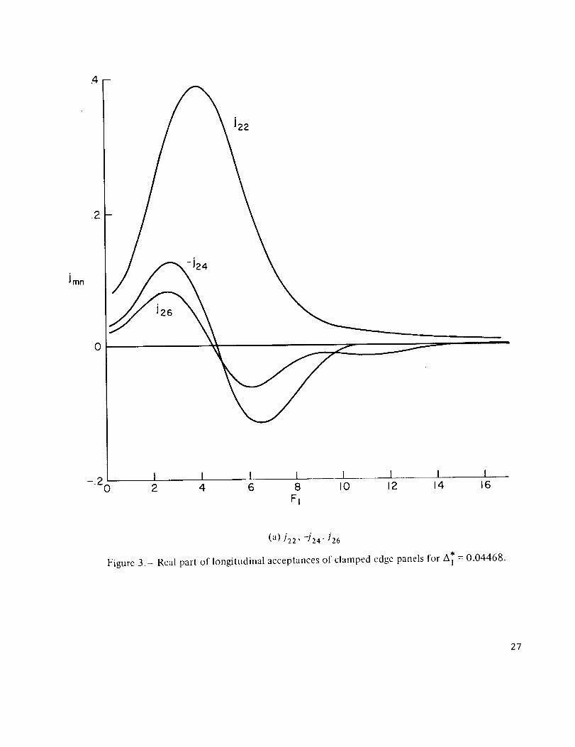
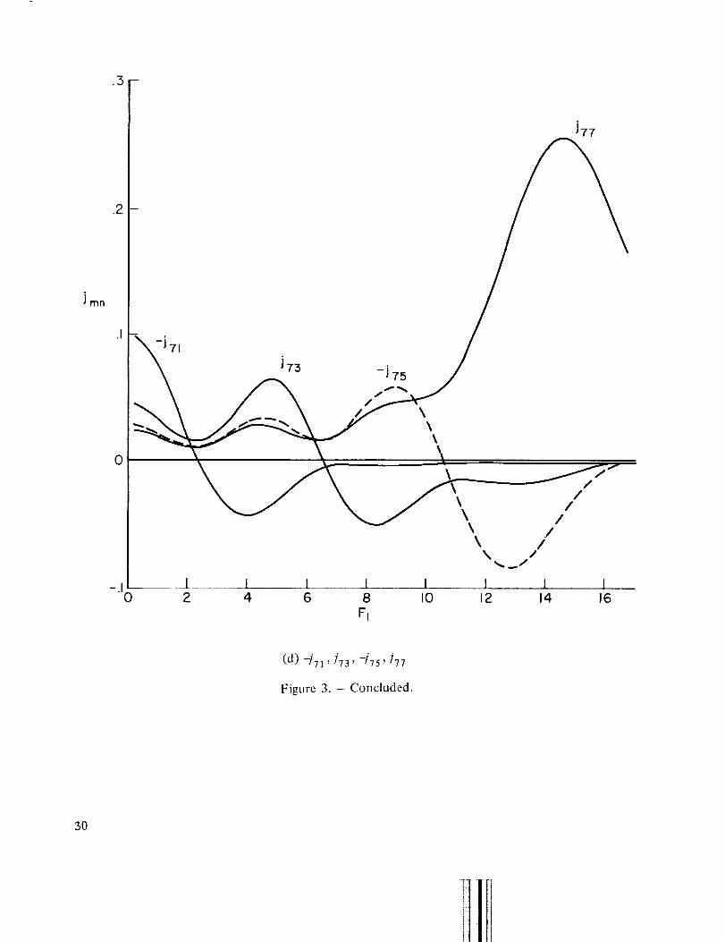
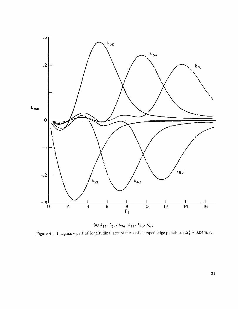
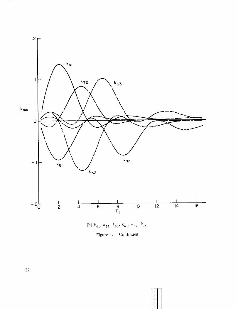
in figures 3, 4, and 5. Figures 3 and 4 show that longitudinal transition amplitudes/ran and kmnare typically maximum when m = n. In case m 4: n the magnitude decreases with increasing orderof the sum of m and n. This implies that the probability of the initial mode remaining in the same
mode is the highest and that there is less probability of transition to other modes. The figures alsoshow that the acceptances have maxima at F-_twice the lower mode number of m or n, indicating
that the maximum transitions occur also at coincidence frequencies of the lower mode numbersof m or n.
.t
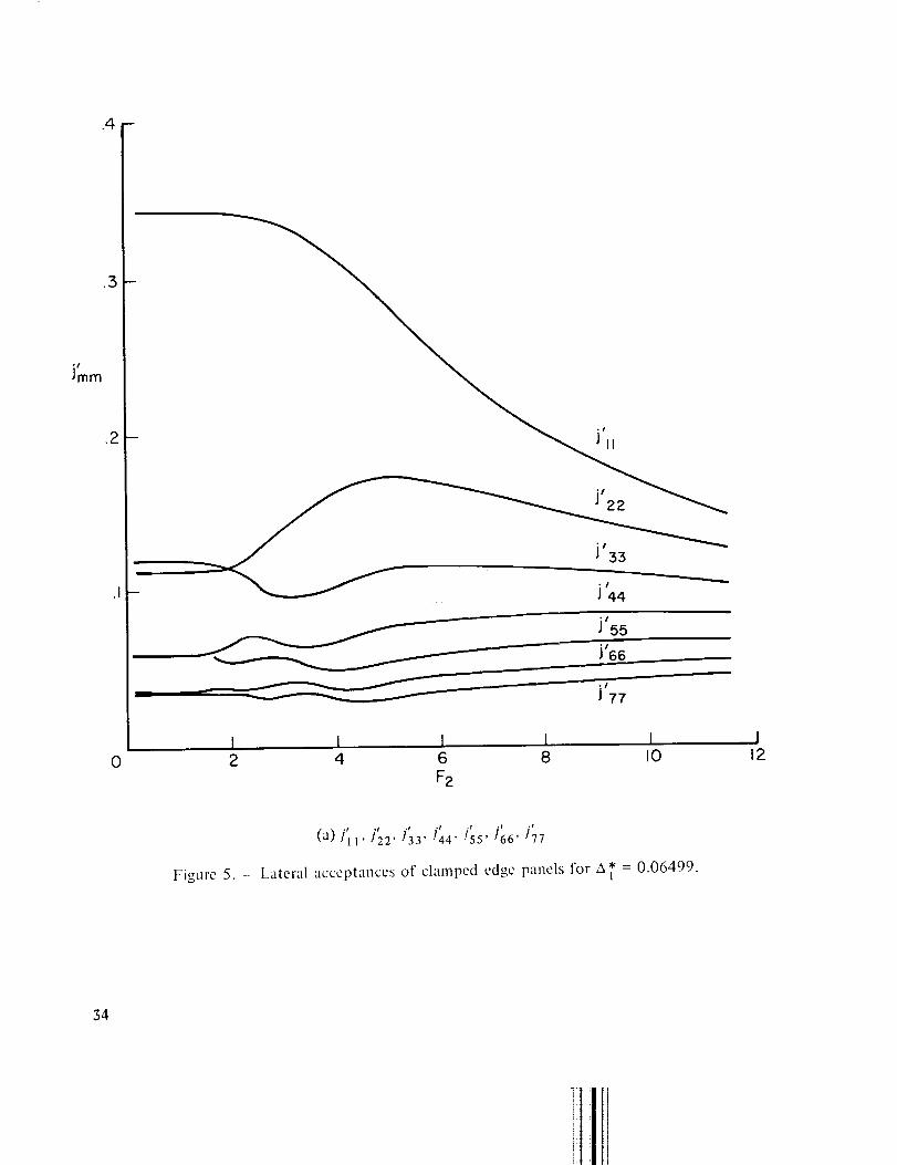
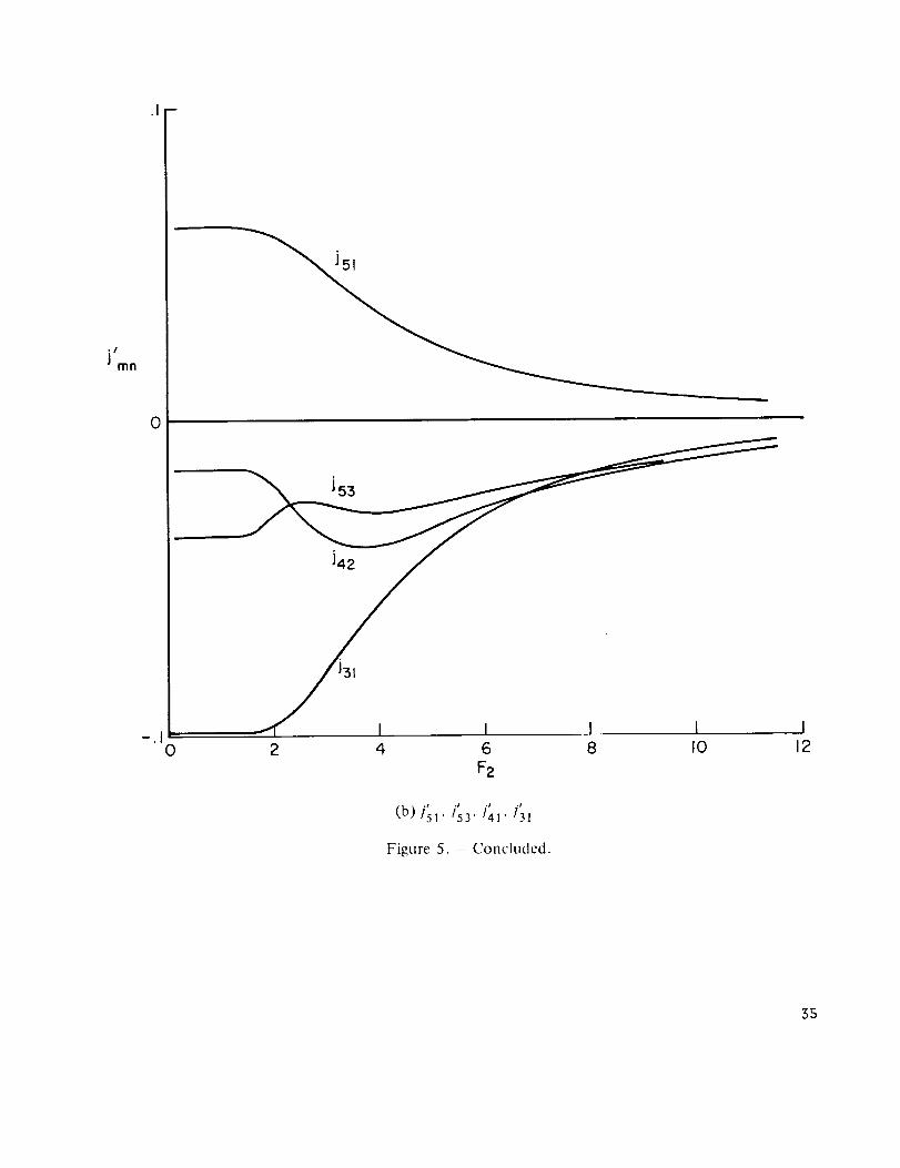
Figure 5 shows that the lateral acceptances in s are small compared with the longitudinalacceptances in figures 3 and 4, particularly at high mode numbers. Since the pressure field is
less correlated in the lateral direction, it follows that the lateral acceptances should contribute
less to the panel response than longitudinal acceptances (see eq. (23)). The appearance of wave
matching in the lateral acceptances is not possible because of the lack of convection velocity inthe lateral direction.
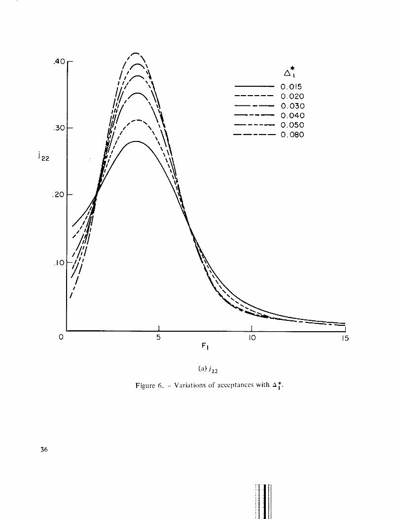
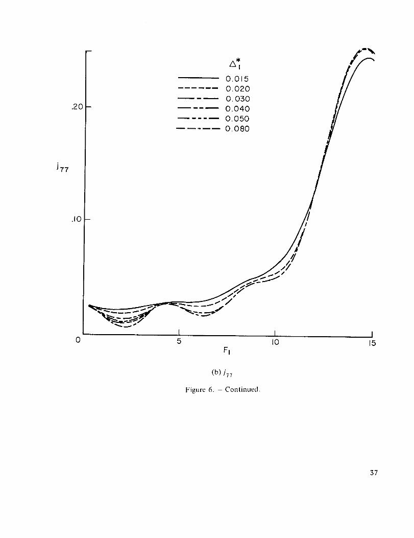
Acceptance as a function of F and ix*- Typical acceptances as shown in figure 6 vary signi-ficantly with A ] * at low Strouhal number F_, and their dependence on A 1* gradually disappears
as F_ increases. The reduction in dependency on A_* occurs because high values of Ft correspond
to high frequencies and short pressure wavelengths, and the boundary layer therefore appears tobe infinitely thick in comparison with the short pressure waves. This factor was also taken into
account when the empirical formulas for the correlation coefficients were derived as shown in
12

appendixA, where the correlation coefficients are independent of A l* at high frequencies. This
same variation of wavelength with F1 relative to A l* causes the acceptances for lower modes to
vary more significantly with A a* than those involving higher modes. This variation can be seen
by comparing typical acceptance J22 with JT_ in figures 6(a) and 6(b), respectively.
Structural Response
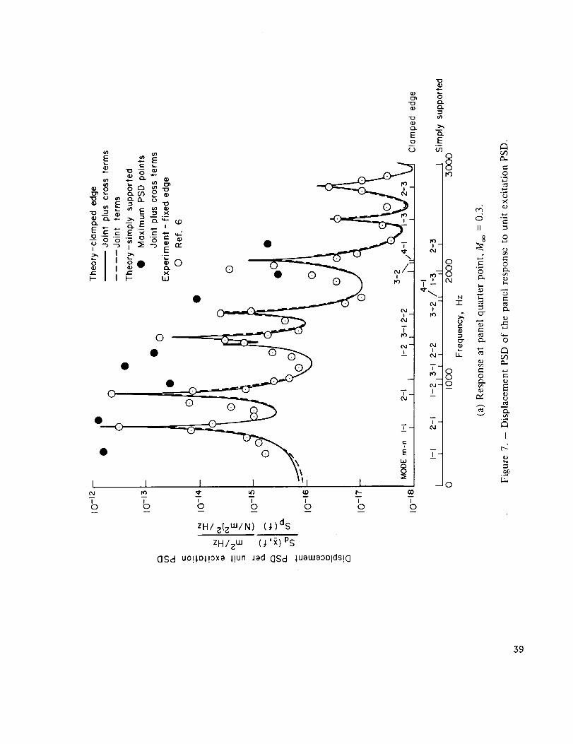
Displacement PSD as function of frequency- Figures 7(a) and 7(b) show the results of the
computed displacement power spectral density (DPSD) at the quarter point of the panel at
Mo_ = 0.3 and 0.5, and' their comparisons with Wilby's measurements (ref. 6). Results are shownfor both clamped edge and simply supported panels. The dimensions and material properties of
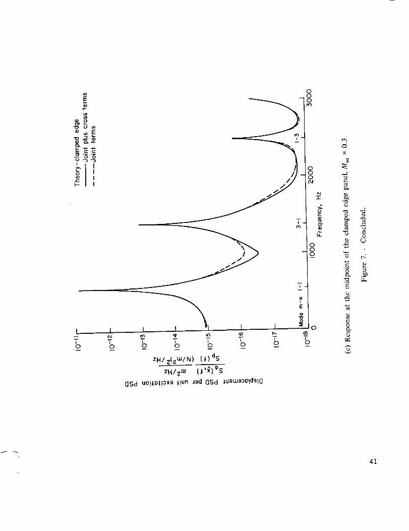
the panel are listed in table 1. Figure 7(c) shows the results of the calculated panel response at the
midpoint of the panel, where no experimental data are available for comparison.
The study of figure 7 discloses that the peaks of the response curve always occur at, or verynear, the natural frequencies. The envelope of the peaks in the spectra decays rapidly with fre-
quency to justify the normal mode approach used in the present analysis. The response compu-
tation based on the cIamped edge boundary condition (figs. 7(a) and 7(b)) agrees better with
Wilby's measurements (ref. 6) than with the computations based on the simply,supported boundary
condition. The results also show that the joint terms (the first sum of eq. (23)) account for almostalJ of the contribution to DPSD at the peaks. The contribution of the cross terms (the second
sum of eq. (23)) to DPSD is completely negligible except at some valleys of the DPSD curve.Powell (ref. 9) showed that because of the orthogonality condition of the mode shape functions,
the cross-term contribution to a uniformly loaded surface will be zero when averaged over the
entire surface. However, he also pointed out that the cross terms cannot be neglected if damping
is appreciable or if the force is applied to a localized area.
When the Mach number is changed from 0.3 to 0.5 (figs. 7(a) and 7(b), the overall shape of
the DPSD curve does not change, but the displacement per unit excitation increases at higherfrequencies. The corresponding rms displacement per unit pressure input increases by about
11 percent at the quarter point and 17 percent at the midpoint of the panel. This increase in
response is attributed to the increase in the spatial correlation of the pressure field at high fre-
quencies as the Mach number is increased. Since pressure excitation also increased with velocity
(,v/'p-_- _" 0.006 qoo), the rms displacement of the panel will increase, as a result of both the increase
in pressure excitation Sp(f) and the increase in DPSD per unit pressure excitation, Sd(Y,f)/Sp(f).
The computed DPSD at the midpoint of the panel (fig. 7(c)) does not have peaks at naturalfrequencies, which correspond to antisymmetric modes, because the panel midpoint is a node
point for the antisymmetric modes.
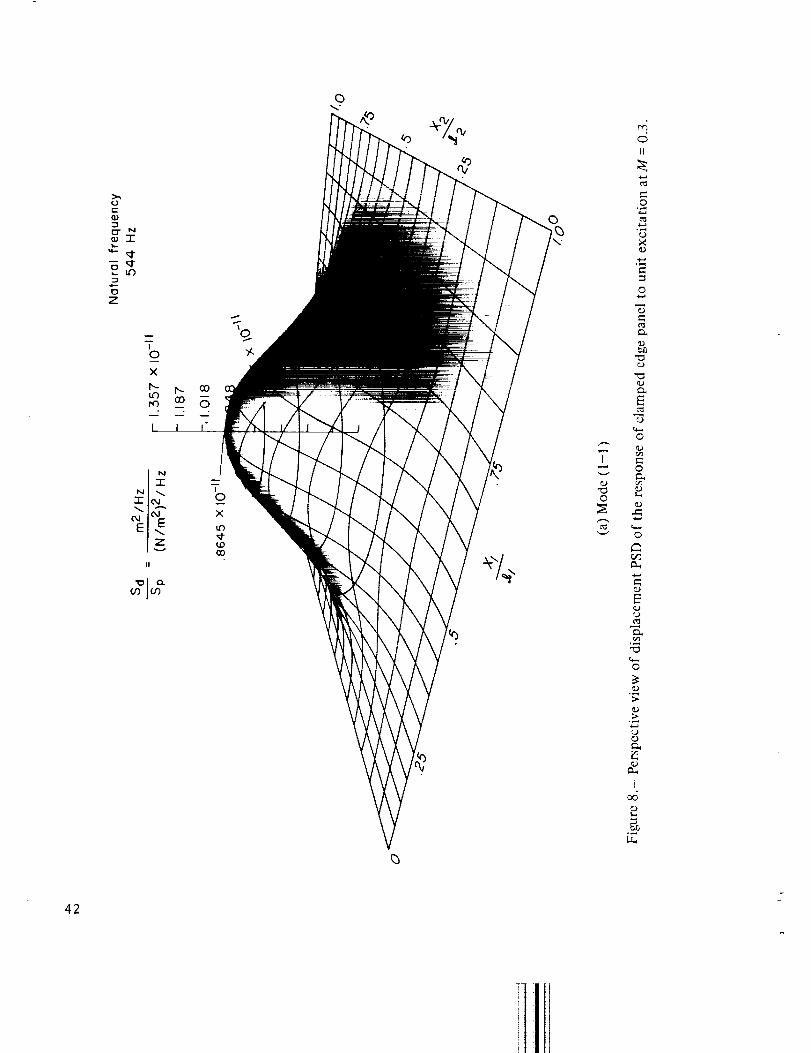
Displacement PSD distribution on a panel- Computer programs capable of displaying theperspective view of displacement PSD on a panel were also developed. The displacement PSD on
a panel is necessary information for the assessment of the distribution of stress. Typical results
given in figure 8 show the distribution of PSD components on a clamped edge panel at naturalfrequencies corresponding to modes (1-1), (2-1), (1-2), (3-1), and (2-2). Figure 9 shows thevariation of maximum displacement PSD with longitudinal and lateral coordinates. Note thatwhen mode m or n > 1, the peaks of the PSD next to the panel edge do not occur at exactly
13

_/2m from the edge,asthey would in the caseof a simply supportedpanel.The fact that thepeaks of the PSD occur at distances greater than _/2m from the edge is due to the rigidity of thepanel at the clamped edge. Note also that when mode m or n > 1 and the mode number is odd
(for instance m = 3 in fig. 9(a)), the PSD in the middle region of the panel is symmetric, but thePSD next to the panel edge is asymmetric about the respective peaks.
CONCLUSIONS
The study on the response of a rectangular panel under the excitation of a turbulent boundarylayer discloses the following:
1. The matching between the pressure wave and the flexural wave of a panel does notoccur exactly at even integer values of the reduced frequency F = 4f_/Uc, as it would when the
panel is infinite for two reasons; (a) the finiteness of the panel significantly affects the low fre-
quency matchings, and (b) the rigidity of the clamped boundary significantly affects the highfrequency matchings.
2. The structural acceptance Jo_ is equal to the probability of transition, or transitionamplitude, from the _ mode to a mode of vibration, per unit excitation power spectral densityper unit area of the panel, when the panel is excited by the random pressure. The longitudinaltransition amplitudes (/mn and kmn) exhibit a general behavior, being maximal when m = n.When m 4: n, the magnitude decreases with increasing order of the sum of m and n. This decrease
implies that the probability of preserving the same mode is higher than the probability of transitingto different modes.
3. An expression that depends only on the dimensionless frequency Fi and boundarylayer thickness Ai* can be derived for the structural acceptance. Corresponding acceptancecharts were therefore prepared which make possible a quick estimation of the response of anyrectangular panel to excitation of a turbulent boundary layer in subsonic flow with a zero
longitudinal mean gradient.
4. The lateral acceptances are small compared with the longitudinal acceptances. Since
pressure field is less correlated in the lateral direction, the lateral acceptances contribute less tothe panel response than longitudinal acceptances.
5. The response computation based on the clamped edge boundary condition of a panel
is in better agreement with the measurements than previous results obtained by investigators whoused a simply supported boundary condition in the acceptance calculation.
6. As the Mach number is increased within the subsonic range, the response of a panel isalso increased in its high frequency components of vibration. The increase is attributed to two
factors: the increase in the spatial correlation of the pressure field at high frequencies; and theincrease of the magnitude of pressure excitations.
14

7. The variationof boundary-layerthicknessaffectsonly the low frequencycomponentof the responsethrough the structural acceptances,which vary significantlynearthe low fre-quency,particularlywherethe wavematchingoccurs.
AmesResearchCenterNationalAeronauticsandSpaceAdministration
Moffett Field,Calif.94035,July7, 1972
15
APPENDIX A
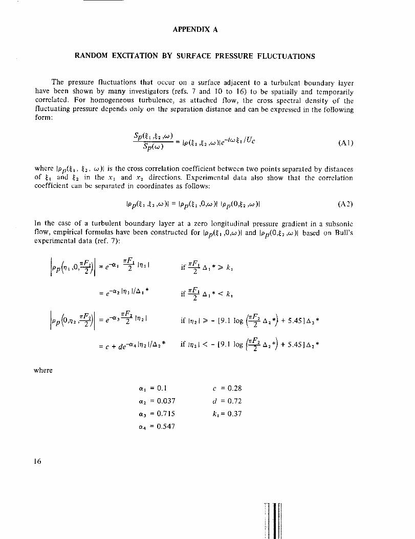
RANDOM EXCITATION BY SURFACE PRESSURE FLUCTUATIONS
The pressure fluctuations that occur on a surface adjacent to a turbulent boundary layer
have been shown by many investigators (refs. 7 and 10 to 16) to be spatially and temporarilycorrelated. For homogeneous turbulence, as attached flow, the cross spectral density of the
fluctuating pressure depends only on the separation distance and can be expressed in the followingform:
Sp(_ I ,_2 ,_o)
Sp(oo) = Ip(_l ,_2 ,co)le -i_'/Uc (A1)
where lpp(_, _, _o)1 is the cross correlation coefficient between two points separated by distancesof _ and _2 in the xl and x2 directions. Experimental data also show that the correlation
coefficient can be separated in coordinates as follows:
IPp(_l ,_2,eo)J = Ipp(_, ,0,eo)[ Ipp(O,_2 ,co)l (A2)
In the case of a turbulent boundary layer at a zero longitudinal pressure gradient in a subsonic
flow, empirical formulas have been constructed for Ipp(_l ,0,_o)[ and Ipp(0,_2 ,_)J based on Bull'sexperimental data (ref. 7):
Pp t,Of F' =e --_1 2 if--TA1
= e "-°ts Ir/_ [/Al* lI--'_'"7rFz al * < kl
lop (0,rls ,_-_ 9 = e-'a 3n-'_--'_=F=[r/s I if In=t >- [9.1 log ('-@_a=*) + 5.45]A=*
= c + de "-a4 Irts l/As *\
Insl < - [9.1 log 1rr-2 As*) + 5.45]A=*if(2
where
al = 0.1
as = 0.037
a3 = 0.715
a4 = 0.547
c = 0.28
d = 0.72
kl = 0.37
16

The convection velocity, Uc, in this mathematical model is given by,
Uc = (_, + K,:,e-°lsW6*/U'_')U_ (A3)
where
K, = 0.59
_2 = 0.30
as = 0.89
17

APPENDIX B
ACCEPTANCE AS TRANSITION AMPLITUDES BETWEEN TWO NORMAL MODES
OF VIBRATION AND ITS SIGNIFICANCE IN PANEL VIBRATION
In view of the importance of acceptances in predicting structural response to random forces,
a physical meaning of acceptances is derived below. Suppose a structure is vibrating initially inthe _ normal mode. If an arbitrary external force is applied, the structure will in general transit
into another mode of vibration which can be a linear superposition of normal modes or a purenormal mode. The probability of this transition is called the transition amplitude between the
normal mode and the final mode when the structure is excited by the specific force in question.
Since the final mode is, in general, a linear superposition of the normal modes, it can be expressedas_] aa{3qJa, where aaB is the transition amplitude between the a and/3 normal mode.
ot
To show the relationship between the transition amplitude and the acceptance, a mathematicalformulation of the above discussion is necessary. In the language of linear algebra, the method of
normal mode analysis assumes that the normalized mode shape functions _a form an orthonormal
basis in a linear space, S, which is the space of all possible vibration modes of the structure. Any
mode of vibration is a vector in S and therefore can be expressed as a linear sum of _a" Theorthonormal condition of qJa can be expressed mathematically as:
(BI)
where the integration is over the entire structure, or in the present case, the area of the rectangularpanel. This suggests that the scalar product between two vectors A, B in S can be defined as:
(A tB) = Af A (£)B(x)d_x (B2)
In this linear space, a disturbance such as Sp(y.',x",_o )is described mathematically by a linear
operator OSp(:y.',x",_o ) in S with the property that if-A is a vector in S,
OSp(Y" "x'"w )A - -fA dx" Sp(x',x",_o )A(x") (B3)
in accordance with the definition of scalar product in equation (B2). By definition of 0 S , OsjDA• . Pis also m S. In particular, when A = ff_3(x), Or_ 42j3 is also in S. Therefore it can be expandedasfollows: up
OSp(:Y.',x",co)¢_3(x") = _]a_,#ff 3,(x')
18
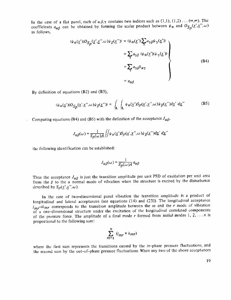
In the case of a flat panel, each of a,#,'r contains two indices such as (1,1), (1,2)... (oo,oo). The
coefficients aa# can be obtained by forming the scalar product between _a and OSp(X',X",w)as folIows,
ffsa(x')lOSp(X'.X",_)¢O(x")> = <_,_(x')l_a_,#qJ_t(x')>
a.r# <_o,(x')l _.t(x'))
= _ a"tt36_3'
(B4)
By definition of equations (B2) and (B3),
(tka_ )lOSp(£ ,x__,co)tp[j(x" )) = _ba(x )Sp(x ,x ,co)_kfl(x )dx dx"(B5)
Comparing equations (B4) and (B5) with the definition of the acceptance Ja#,
Ja#(co )= _ f/d/ a(x_')Sp(x',x. ",co )_b#_")dx' dx"
the following identification can be established'
1
Ja# (c° ) = Sp(co )A a°_#
Thus the acceptance Ja# is just the transition amplitude per unit PSD of excitation per unit areafrom the # to the a normal mode of vibration when the structure is excited by the disturbance
described by Sp(x',x",o).
In the case of two--dimensional panel vibration the transition amplitude is a product of
longitudinal and lateral acceptances (see e.quations (14) and (23)). The longitudinal acceptance
/mr--ikmr corresponds to the transition amplitude between the m and the r mode of vibrationof a one-dimensional structure under the excitation of the longitudinal correlated components
of the pressure force. The amplitude of a final mode r formed from initial modes 1, 2 .... n is
proportional to the following sum:
1l
_._ (Jmr + kmr)m=l
where the first sum represents the transitions caused by the in-phase pressure fluctuations, and
the second sum by the out-of-phase pressure fluctuations. When any two of the above acceptances
19

havethe samesign at a givenfrequency,the transition is suchthat they reinforceeachother,givingrise to constructiveinterference.If they haveoppositesigns,they canceleachother,givingriseto destructiveinterference.
During a transition, the parity of the modemust be conservedif the excitationhasevenparity or symmetryin space,and must changeif theexcitationhasodd parity or antisymmetryin space.Since/mr is proportionalto transitionamplitudecausedby the in-phasepressureforce,which is symmetricin space(it cc_ntainsa cosinetermin eq.(20)),/mr mustbezeroif m + r isodd. On the other hand, since kmr is proportional to the transition amplitude caused by the
out-of-phase pressure force, which is antisymmetric in space (it contains a sine term in eq. (22)),.t
kmr must be zero if m + r is even. For the same reason lmr must be zero if m + r is odd. Thephysical significance of equations (20) to (22) is thus shown in terms of the parity of modaltransition.
20
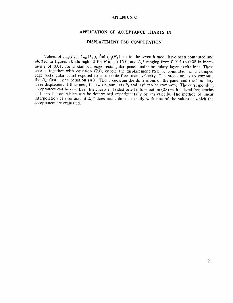
APPENDIXC
APPLICATIONOF ACCEPTANCE CHARTS IN
DISPLACEMENT PSD COMPUTATION
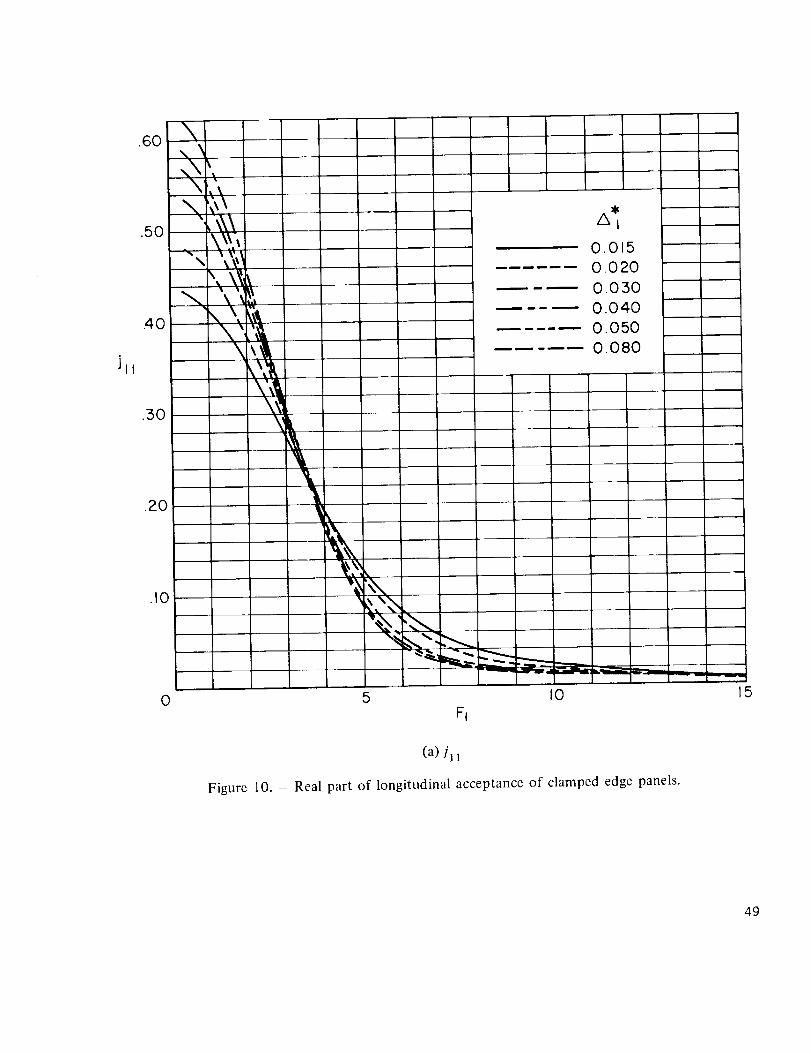
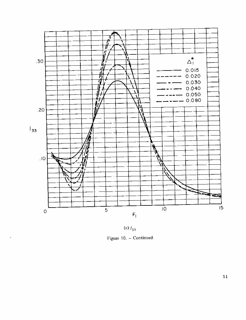
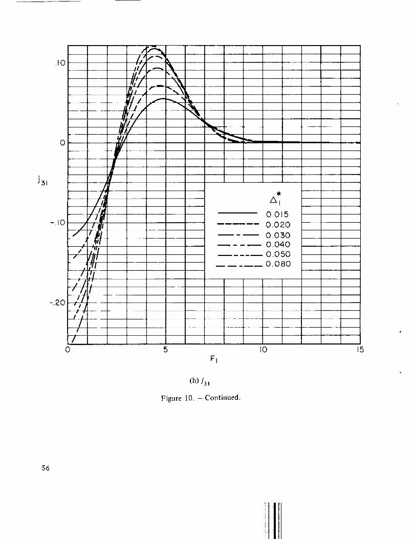
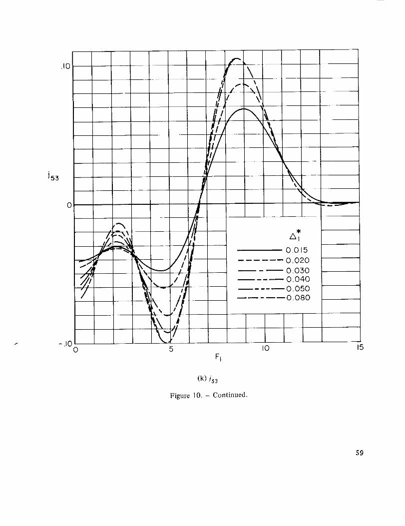
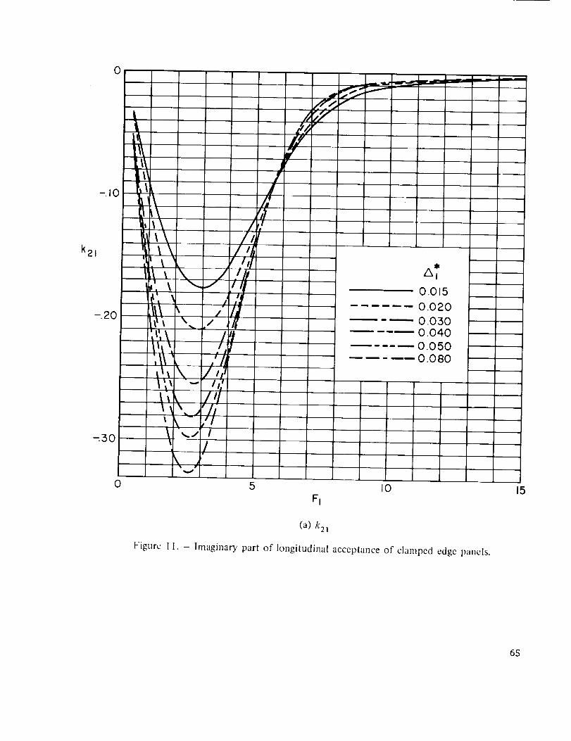
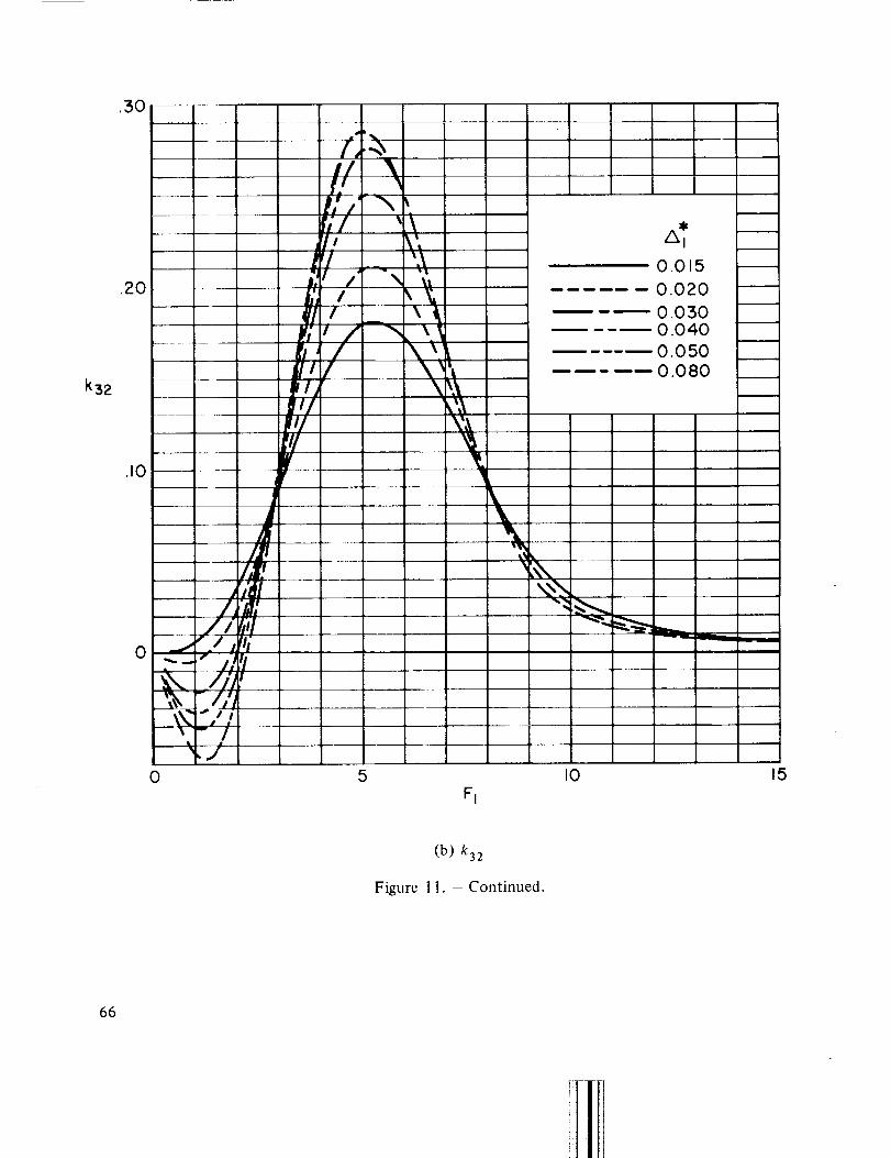
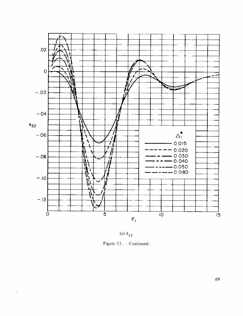
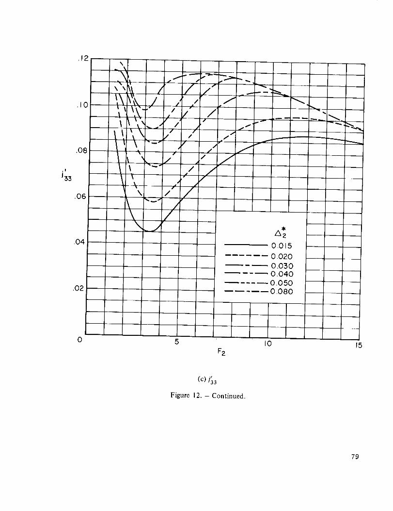
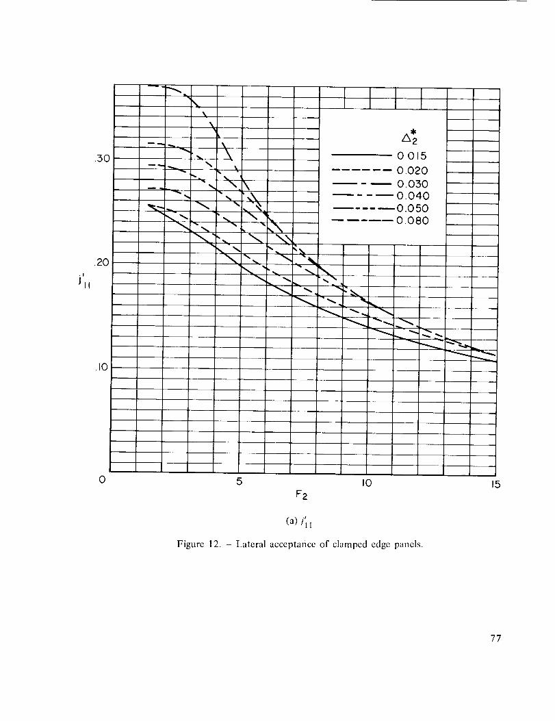
Values of Jmr(F_ ), kmr(F_ ), dnd/'ns(Fz ) up to the seventh mode have been computed andplotted in figures 10 through 12 for F up to 15.0, and Ai* ranging from 0.015 to 0.08 in incre-
ments of 0.01, for a clamped edge rectangular panel under boundary layer excitations. Thesecharts, together with equation (23), enable the displacement PSD be computed for a clampededge rectangular panel exposed to a subsonic freestream velocity. The procedure is to computethe Uc first, using equation (A3). Then, knowing the dimensions of the panel and the boundarylayer displacement thickness, the two parameters Fi and Ai* can be computed. The correspondingacceptances can be read from the charts and substituted into equation (23) with natural frequenciesand loss factors which can be determined experimentally or analytically. The method of linearinterpolation can be used if /xi* does not coincide exactly with one of the values at which theacceptances are evaluated.
21
REFERENCES
1. Corcos, G. M,; and Liepmann, H. W.: On the Contribution of Turbulent Boundary Layers to the NoiseInside a Fuselage. NACA TM 1420, 1950.
2. Ribner, H. S.: Boundary-Layer-Induced Noise in the Interior of Aircra_, University of Toronto. U.T.I.A.Rep. 37,1956.
3. Kraichnan, R. H.: Noise Transmission From Boundary Layer Pressure Fluctuations. J. Acoust. Soc. Amer.,vol. 29, no. 1, Jan. 1957, pp. 65-80.
4. Strawdermann, Wayne A._ Turbulent-Induced Plate Vibrations: An Evaluation of Finite and Infinite-PlaceModels, J. Acoust. Soc. Amer., vol. 46, no. 5, pt. 2, 1969, pp. 1294-1307.
5. Bozich, Daniel J.: Spatial Correlation in Acoustic-Structural Coupling. J. Acoust. Soc. Amer., vol. 36,no. 1, Jan. 1964, pp. 52-58.
6. Wilby, John F.: The Response of Simple Panels to Turbulent Boundary Layer Excitation. AFFDL-TR-67-70Oct. 1967.
7. Bull, M. K.: Wall-Pressure Fluctuations Associated with Subsonic Turbulent Boundary Layer Flow. J. FluidMech., vol. 28, pt. 4, 22 June 1967, pp. 719-754.
8. Hearman, R. F. S.: The Frequency of Flexural Vibration of Rectangular Orthotropic Plates with Clampedor Supported Edges, J. Appl. Mech. vol. 26, Ser. E, no. 4, Dec. 1959, pp. 537-540.
9. Powell, Alan: On the Fatigue Failure of Structures Due to Vibrations Excited by Random Pressure Fields,J. Acoust. Soc. Amer., vol. 30, no. 12, Dec. 1958, pp. 1130-I135.
10. Harrison, Mark: Pressure Fluctuations on the Wall Adjacent to a Turbulent Boundary Layer. David TaylorModel Basic Rep. 1260, Dec. 1958.
I 1. Serafini, John S.: Wall-Pressure Fluctuations and Pressure-Velocity Correlations in a Turbulent BoundaryLayer. NASA TR R-165, 1963.
12. Witlmarth, W. W.; and Wooldridge, C. E.: Measurements of the Fluctuating Pressure at the Wall Beneath aThick Turbulent Boundary Layer. J. Fluid Mech., vol. 14, pt. 2, Oct. 1962, pp. 187-210.
13. Kistler, A. L.; and Chen W. S.: The Fluctuating Pressure Field in a Supersonic Turbulent Boundary Layer.J. Fluid Mech. vol. 16, pt. 1, May 1963, pp. 41-64.
14. Speaker, W. V.; and Ailman, C. M.: Spectra and Space-Time Correlations of the Fluctuating Pressures at aWall Beneath a Supersonic Turbulent Boundary Layer Perturbed by Steps and Shock Waves. NASACR--486, 1966.
15. Coe, Charles F.: Surface-Pressure Fluctuations Associated with Aerodynamic Noise. NASA SP-207, 1969,pp. 409-424.
16. Chyu, Wei J.; and Hanly Richard D.: Power- and Cross-Spectra and Space-Time Correlations of SurfaceFluctuating Pressures at Mach Numbers Between 1.6 and 2.5. NASA TN D-5440, 1969.
22

TABLE1.- PANELPROPERTIESANDFLOWPARAMETERS
[Ref.6]
Mildsteelpanel
_1 0.1016 m (4 in.)
_2 0.06985 m (2.75 in.)
h 0.000381 m (0.015 in.)
E 0.2323×10¹² N/m2 ( 33.7)<106 lb/in'2)
o 0.3
v 0.009
Density
7473 kg/m 3 (0.27 lb/in?)
Flow parameters
M_ 0.3 and 0.5
fi* 0.00454 m (0.179 in.)
23

EE
--j
.6
¢.JC
¢_ .413.
13¢..3
13
E°--
0
13¢-
'- ,20
_J
\
\\ Jil- \
\
\
Boundary condition
Clamped edge
Simply supported
J44
/ \z-x j 55
\ J66
\ J77
\
\\
\
1 I 10 2 4 6 8 I0 12 14 16
Fi
Figure 2.- Longitudinal joint acceptances of clamped and simply supportcd panel for A 1 = 0.04468.
26
.4
Jmtl
.2
0
J26
-Jz4
-.2 0I I I 1 I I I I2 4 6 8 I0 12 14 16
FI
(a) /22' "-J24' /26
Figure 3.-Real part oflongitudinal acceptances of clamped edge panels for A l = 0.04468.
27

.6-
J 113[1
.4
.2
0
ill
1 I I 12 4 6 8
FI
II0
I12
I14
I16
(b)/11 ' -/13' iis' -/17
Figure 3. - Continued.
28

mn
0
J37
-J35X\
\\
I
4
I I I I I
12 14 168 I0
Fi
(C) d31, ]'33' -']35' ]37
Figure 3. - Continued.
29
.5
J77
Jmn
0
I I"10 2 4
1
J73
I I6 8
Ft
\\\
1I0
\
\\
\\ /
\ /_..J
1 112 14
//
/I
I!
16
(d) "-/71'/73' -t75' ]77
Figure 3. - Concluded.
3O
kmn
\
k54
/ \ /X
/ / \,I / \
\
2
k76\
\\
\\
\\
\\
\ //\ ,,/ ..._/
_ II iit_ki5
/k2l , //k43/ __..I I I I 1 I I4 6 8 I0 12 14 16
FI
(a) k32, k54, k76, k21, k43, k65
Figure 4.- Imaginary part oflongitudinal acceptances of clamped edge panels for A T = 0.04468.
31
.2-
kmll
.I
0
-.I
-.2 0
- / \ L_ i'-\\ _o_
y.,/ \
\ \/ ,",, /\\1 I'-"
/ \--1-- k61 k J k74
"'-- k5 2
I I I I I I I I2 4 6 8 I0 12 14 16
Fr
(b) k41, k72, k63, k61, k52, k74
Figure 4. -- Continued.
32

.3
k21
.2
klTink25
.I
0
f"-_/ \
/ \/ \
/ \\
\
-.I0
I I I2 4 6 8
Ft
II0
I12
I14
I16
(C) k21,-k23, k25, k27
Figure 4. - Concluded.
33
.4-
.3
*/
Jmm
.2
0
i'll
J_55
J'66
J_77
I I I 1 I2 4 6 8 I0
F2
I12
• F .¢ .t .r .f .# .r
(;|) ]11 ' ]22' 133' ]44' 155' ]66' ]77
Figurc 5. -- Lateral acceptances of clamped cdgc panels for _ = 0.06499.
34
J'mn
J42
I I I
2 4 6
F2
.t .t -I ,t
(b)151,153,141,131
Figure 5. Concluded.
I I
8 I0 12
35
J22
/I
/
,,I0.015
0.020
0.0:.'50
0.040
O. 050
O. 080
0I 1 I5 I0 15
FI
(a)/22
Figure 6. Variations of acceptances with A*--- I "
36
It
J77
,20
.10
0
0.015
0.020
0.030
0.040
0.050
0.080
El
(b) j77
Figure 6. - Continued.
II0
!15
37
0
A_0015
0.020
O. 050
0.040
..... 0.050
O. 080
0 5
FI
1I0
,J15
(c) k2!
Figure 6. - Concluded.
38
i
Q
0
Q Q
0
IOJ
T0
I I II'--TOi
Q
T(M
E
ILl
CI
co
I
O
rdc_II
8
oc_
I-,C)
N "C-r ._
Cr
o %LL
O
¢J
c_
o
;,<
o
_Oc_r"
o
(1.)
,.{=
O
r_
¢JC.)
Ir-:
LT.
39

©
0 0
I I I I I_1 r¢_ _ _ _ I_T T T --/ T --i0 0 0 0 0 0
ZHl _(zUJIN) (t)dS
ZHli_Uu (J'_)P$
0Sd U0!ID|!OXal!unJed OSd luewa001ds!o
"O
"O
O.
E
(.)
roI
oJ
I
T
/-
I
I
T
!
"T-
r- N!
E
"10 !
O
i!i
0O
b
"O
3
(2.
E00 O
8K)
OfO
I . II
8o :_
to-- OJ 0
-_. _.
, g
"r- %
_ 0
e,I ,'_
I -
-- 0
oL)
I
L_
4O
I
(/)
E
..i-.
0
.o__
E_-- 0 0
l I
¢...
l
I
o
I
I
o
dSd UO!J,O4!Oxe J'!unJed C]Sd luauJaoolds!G
II
8
C_
_D
E
"d _-0
°,._0 _
E
N
0
41
C_
^
v-.,-q
I
0
...,..J
_F.j
H
©.j..a
,1.--r
o
c_
O
o
C_
o
CL_
Es3
o
i
42
¢Jt.-,0,)
O- N_'T"
o_co
Z
N"I-
E
U')
N"1-
%Zv
o.C/')
It",l
Q
,,D
O
r_
I
._,,qLI.
_5
45

Uc-
v,-C)
.,IDO
Z
j_
II
©
f-g
L.T.
44

,4--i_--- COp_
0
Z
_-%
I!
I0
%
I
"oo
o
J
(5
45

UC
D
zI
_1%
f!
%
_,,II
0
"-d
0
46
_5
!
0
I
% I0
0 "
i!. _T % % o_
ZHl_W I_'_)Ps
47

X
o0
I-G
o
"IZ
>
izl
0
I
48
ill
.60
.50
4O
.5O
.2O
.10
\\\
\
\
i
xk\\xx.,
\\,
_k
%kX_x'x.
-_X?,.-,,.
0.05
0.020
0.030
0.040
0.050
0.080
[11,.h __
0 5 I0 15
F_
(a) Jl I
Figure 10. - Real part of longitudinal acceptance of clamped edge panels.
49

J22
.40 t' /'_ _,_t I
\'I.
ir/_/ \,!//'t ,
.20 /_
_7• ,57
In
/,;,
• I
/I
0
',,,_.
%
5
Fi
(b) ]'22
Figure 10. - Continued.
0.0 5
0,020
0.030
0,040
0.050
0.080
I0 15
5O
J 33
.30
.2O
.10//
"._ J
_,\ /,:
_J
I
/_!vfi
!
i_il/ __¢1
I1.1/ \\!ill /-',, \ _
I!,', \
_)'iI \',\I,'/1t
AI
0.05
0.020
0.050
0.040
0,050
0.080
0 5FI
I0 15
(C) J3
Figure 10. - Continued.
51

J44
.30
2O
.10
I I tlAi
0.015O.O20
0.030
0.0400.050
0 080
11
,---.,;/
I; %
il i \Xr i _.%i i _ '_
!
]/r/j//7
l \/
_X\X
\_k
0 5
Fi
(d) ]44
Fisure 10. - Continued.
I0 15
$2

J 55
.3o
.20
.10
J
A_0.0150.020
0.0300.040
0.0500.080
f_
/ \
It
,/," \// ,:\"
i/ \1I////Ill,i/
//,'/
/I I'
_.._11___,'"/rjs
\\\
\
0
Figure
El
(e) Jss
10. - Continued.
I0 15
53

J66
.20
.10
0
/k t
0.0150.020
0.0300.040
0.0 50
0.080
Sj f/?.
5FI
/!
/l/
t!I/
//f
JI.
/21I r
tl
I
I0
\I
\\
15
(0 ]'66
Figure 10. - Continued.
54
11

J77
.2O
.10
0
I
A_
0.015
0.020
-- -_ 0.0:30
0.040
0.050
0.080
,7
5 10
t
I/
15
(g)/77
Figure lO. - Continued.
$5
J31
.10
0
-I0
-.20
//
//
J
/i .
/ !/ /j
'_]T
----t--'l-
0
.p
flJ
ii"lh
filliil
:.
1
/
p
*#w % •II_ Ji
'1,'/,.- .AL'I I _ _'_ "__fl . r l
.... f
,, !
i
1
i
i
, 15
i
l !
/k I
0015
0.020
0.050
0.040
0.0500.080
Ig.... l ....
FI
15
(h) J31
Figure 10. - Continued.
S6
t

J42
.I0
0
-.I0
\'L
0
/ J._ J, !
_,',,, j• I I
h!_: rll
! _J _-
" !%
b
5
Fi
II
I
I
I
I
I
I
i0.015
0.020
0.0500.0400.0500.080
I0
i
L
i
,q
I
I
15
(i) J4 2
Figure 10. - Continued.
$7

.10
JsI
0
\I
,\
\
\
lI
t
\ f
_,',._/jf
/X I
0.0 5
0.020
0.0300.040
0.050
0.080u
I0
FI
15
(i)/51
Figure 10. - Continued.
58
J53
.10
ol
- .10
F\I A %
17/ \\
U�/"_II' r
Y
0
,,/
/
'_ _p
, /]
5
\
I0
Fi
\
A l
0.0 5
0.020
0.030
0.040
0.050
0.080
15
(k) Js3
Figure 10. - Continued.
59

.O8
.O6
.04
J62
.02
0
- .02
- .04
0 5
FI
(I) J62
Figure 10. - Continued.
I0 15
6O

.O8
.O6
.04
A_
0.015
...... O.O2O
- 0.0500,040
0.050-- 0.080
.02
J64
0
.k
-o_.%_,,,..._. '-_ b.
-.04 '__J
-.06
0 5
il!
,//Z
/,7II
J IIIh
/' '1
_"-/_-",/I'A ,/
\\.,q
FI
i ,'_
/,i' _
!11II/
fr,ol,!
I0
%\
%
\.\
15
(m)/64
Figure 10. - Continued.
61

.O4
.02
0 -- --
-.02
J71
-.04
- .06
- .08
-.10
0
!
/:
/.(J
! ,,,
T mi
-/, Iml p
i#
"iJ# •
r •
/
;if _-L-
JJ /it/ N
I,
. . J J
i_/ ," /
_Jwe
5
I
Aj
0.015
0.020
0.0300.040
.0.050-- 0.0 8 0
I
' I
iIt
: I
FI
i
' ' lIO
!
l
i
15
(n) ]71
Figure 10. - Continued.
62
T1
1I

.06
.04
0
-.02
-.04
0
\\%
'l _s I
,_/• \ 'll
\
5
Figure
\\_, /_
\ /\ /
FI
(o)/73
10. - Continued.
I0
A I
0.015
0 020
0.0300.040
0.0500.0t30
J
15
63

J75
.O8
.06
.04
A I
0.0 5
0,020
0.030
0.040
0,050
--0.080
.02
0
-.02
J/
-.060
/ ,,v
\_ i'I\ \ I/
I
\, /"f I
I0
FI
5
(P) Jvs
Figure 10. - Concluded.
/ \I _L \/--_\
il \,I/
!!;II!
I
3
\
15
64
0
k21
-.I0
-.20
i
i
%%
|
--.50
IIii
I_4
11"
I
It ,9i_\ /q
,x /,'t,'t\
:'\ 7i_ _ i
i'.tt\'t , i;
:l,,\ /#
\ - /I
\ _.,1 I/
\,
A I
0.015
...... 0.020
0.0300.040
..... 0.050-- 0.080
0 5 I0 15
FI
(a) k21
Figure 1 1. - Imaginary part of longitudinal acceptance of clamped edge panels.
6S
k32
.30
.2O
.10
0
A _ _
fil _ \
rl '\
r, / s_,ill/ _ ',i_
I:/ \// \
#11_U
f .
'L
J \
J
0
A/,
//
//J
' s,/I
- I
/,/,_'/l I,'!_
'liY
5.... i
FI
%,
I0
A I
0.0 5
0.020
0 0300.040
0.0500.080
15
(b) k32
Figure 11. - Continued.
66
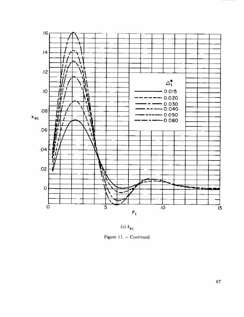
k41
.16
.14
.12
.10
.08
.06
.04
.02
/\
, \i nl _ 1
L I
ilJ., \__! \',I _/ \,.
ill _ ,
II \' i',II / ,_l
I 'l I _ \ItI'i _1
I1: /-_ '.ll_ljf / \ \I
r: i _',I,i \
I';il \l",I! \7rl; / \'_!_;/ \',i
_,'/'//
0
0
t_
_\"\I _ "_
_:, "%_ -
5
0.0 5
0.020
0.0300.040
-- 0.0500.080
Y
I0
FI
15
(C) k 4 !
Figure 1 I. - Continued.
67
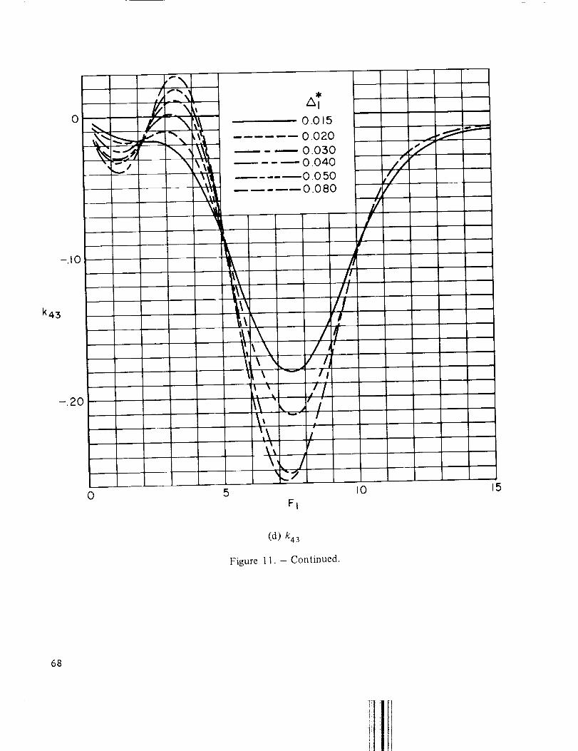
k43
-.20
o .'-. ___T. \,,__
L _\'1
0
/k I
0.015
0.020
0 0800.040
0.050
0.080
5
I/J,
I "_ i/
- I
FI
/,//
/lI
qI
//f
I0
J
//
/
15
(d) k43
Figure 11. - Continued.
68
.O2
0
- .02
-.04
k52
-.06
-.08
-.10_
-.12
/I,,','/,,,"y,,.1¢"
If_
"'x'%_,\
-'\\\
\
\_.\\ /
il'_ ;i!'.\ II
It, , ,e_-__/,]'_,\ j-I\ _. _lj
I
[
f
v,,/
7'
At
0.015
0.020-- 0.030
..... 0.0400.0500.080
_ i_,, .w "-j
fw
0 5 I0 15Fi
(e) k52
Figure 11. - Continued.
69
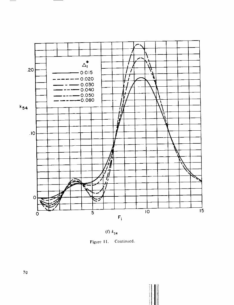
.2O
k54
m m
Imm
m m
_m_
m
0.015
0.020
0.0300.0400.0500.080
.i0
0
0
P,
Ii,n.//il
_I \_.-.',,
",_=>'15
i,!Ii�I#
i!,'1/"_/!_fl#
II/IllI'./'1I,It
F I
%
I
\
I0
t\k_
'tI
\\"k
XX\\
"N
15
(f) k54
Figure l 1. - Continued.
7O

0
-.02
-.04
k61
- .06
-.08
-.10
0
it I v lm
I__! " .'x 1,1
i!i _ /'el_ I Jn
il
I\ /Il
I _,,I I
\ /
p_//- _'%'.--
Y
_v
0.0 5
0.020
0.0300.040
0.0500.080
5
FI
I0 15
(g) k61
Figure 1 1. - Continued.
71
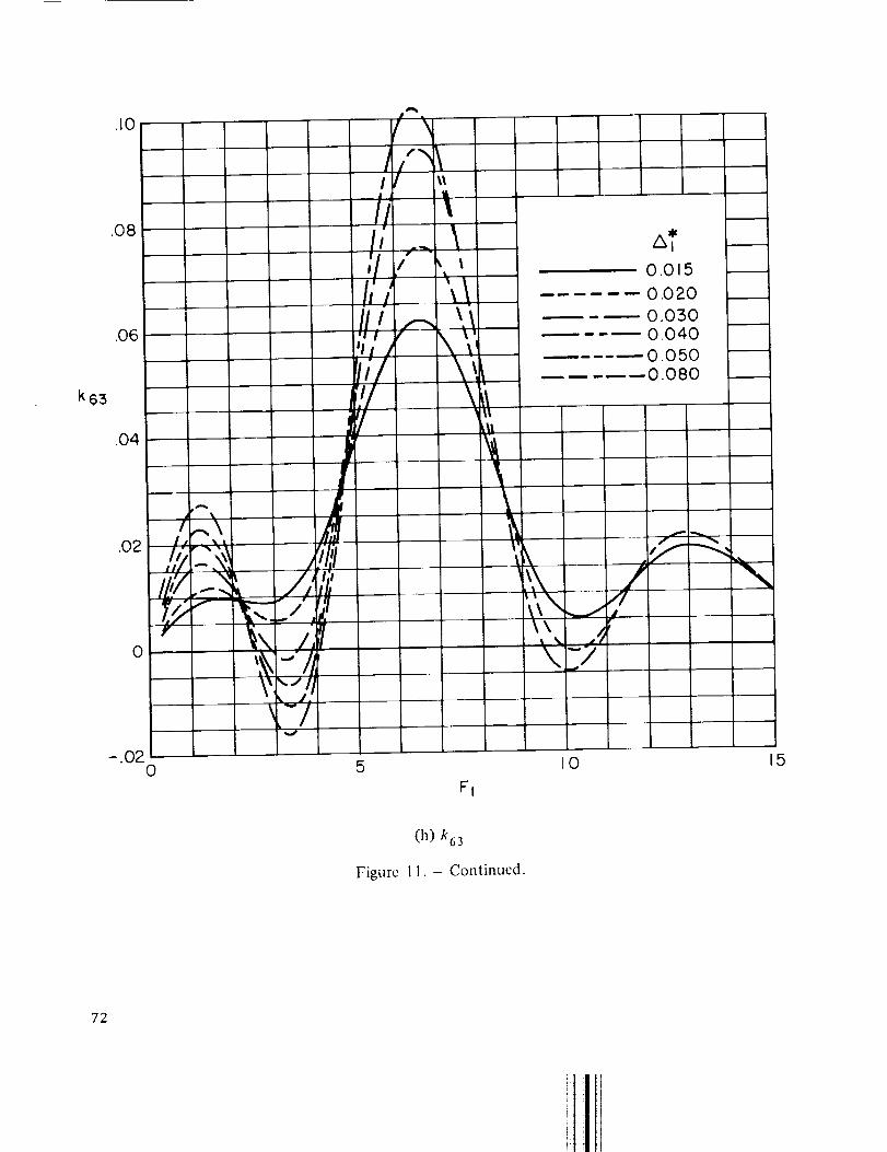
k63
.10
.08
.O6
.O4
.O2
0
- .020
t"- ,,jj
I,, i
=/,'2::_! J_////I.,.'/,--_'_ V,' l_'__ _-<.:,,",'_
_.]#\'-/
r \
I I _
/l!
!i-j"
t !I
!1!
!////
5
FI
II_ll
\
At0,0 5
0,020
0.0300.040
--- O.050..... 0.080
_._._ ///I
I0
\
15
(h) k63
Figure 1 I. - Continued.
72
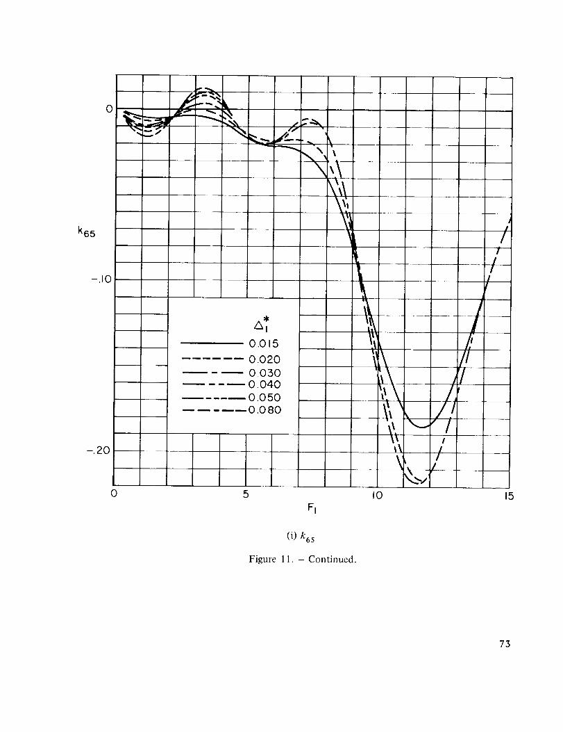
k65
-.10
-.20
0
0
4/ -
i i
At
0.015
0.020
0.0300.040
0.0500.0 80
5
Fi
t
i
\
I0
/I
I!
I!
/;/I
J'l/
/./,!
!
i!
!
15
(i) k65
Figure 11. - Continued.
73

k 72
.08
.06
.O4
J.02 • A
I/,z.//LJ'
0 _ _,_ff!
k:?;.-.o2 \/
I'
//j-,,'_
ill _ill I ;'_/ !,,/11 ',\\
i I _,,
Jr,!/ \,,_"Lr \i¢
0.015
--. 0.020
---.-'---_ 0.030
-'-"-- 0.040
---'-- 0.050
..... 0.080
\_k
"XX,,.I
Jf
0 5
El
IO 15
(J) k72
Figure 11. - Continued.
74

- .02
k 74
-.04
-.06
-.08
o _ ; \i
0
/\
1'
,! 1X IIX ,_1,,',\ /_,l_ _ /I_/k I
0.015
0.020
0.0 300.040
0.050
0.080
15
|
11 I
i "" /|
I..... /
\JI0
FI
15
(k) k74
Figure 1 1. - Continued.
75
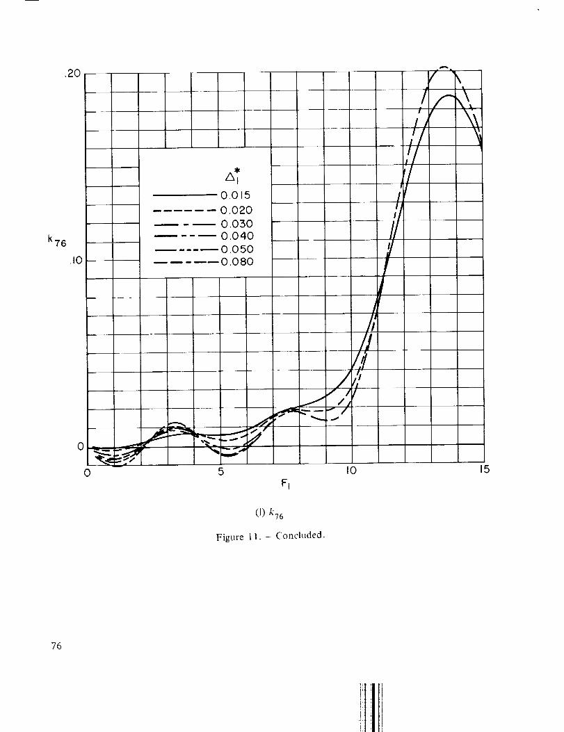
.20
k76
01015
0.020
0.0500.040
..... 0.0 50
0.080
o_._#.,_ "_=._0 5
I
,,/
I
/,,/ //
I0
Fi
//
15
(1) k76
Figure 11. - Concluded.
76
°1
J33
.12
.10
.08
.O6
.O4
.O2
\,\._ /_,\\'_ / ,
"__',",\ " ,'1
\_ \ "-" .,/ " "
\ /
._J
///
I
,, //
JI
I
/
//
J
/
A
f
JI
./f
/
- //-
,,w ,d_,,-
A z
0015
0.020
0.030.... 0.040
0.050-----0 080
0 5
F2
IO 15
.F
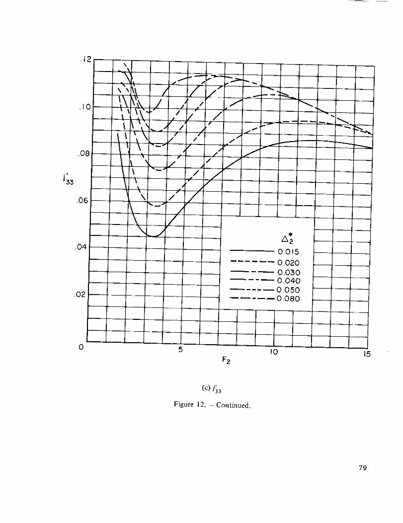
(C) 13 3
Figure 12. - Continued.
79
,I
Jtl
.3O
.2O
._0
\\
\
[ ! I
/k z
0015
0.0200.0300.040
--0.050..... 0.080
0 5 I0 15
F2
(a) ]1 1
Figure 12. - Lateral acceptance of clamped edge panels.
77
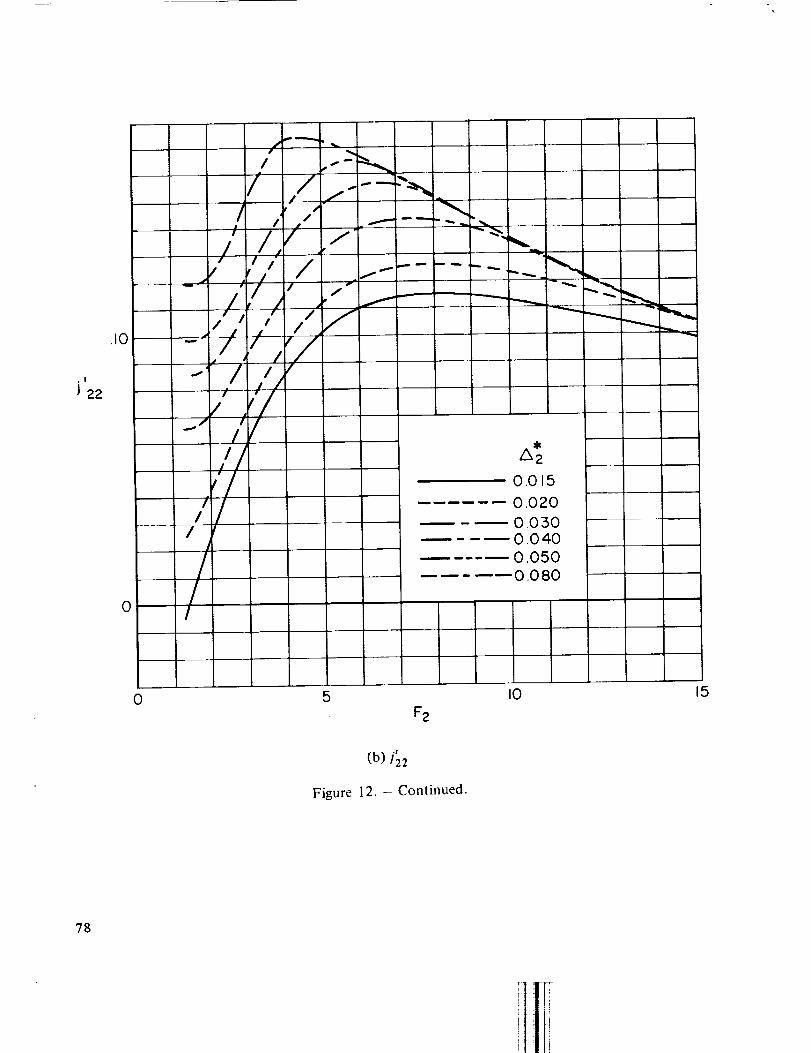
,I
J 22
.10 -- "
f
/!/
/!
o /
/I
//
/
//
/ //
//
/
/I
// /
,'//
/
/
/
p S_
l f
r J-f n_
A2
0015
0.020
0,0500.040
0.050
0.080
/
/ '//
,//'
,'/!
0
F2
I0 15
.r
(b) 122
Figure 12. - Continued.
78
.I
J33
.12
.10
.08
.06
.O4
.O2
\
t\?',,, i ,,
_(It',\ /"
\ /
\---/
///
/
i /f
i/
i
//
/
/._w _ _ _
f/
t/
/"/
I
/
uj _r
_w
Az
O0 5
0.020
0.0300.040
0.050---- ---..-- 0.0_]0
L
0 5
F2
I0 15
.l
(C) /33
Figure 12. - Continued.
79
.I
J 44
,08
.O6
.04
.O2
J J/ I/ //
. ._,=,, / / / / ./!
' ]_ _ I /,,I / /'
• _ /" /
.>I; / /
f
J
/
Az
0.0 5
...... 0.020
0.030
0.040
0.050
..... 0.080
J
f-I
0 5
F2
I0 15
.f
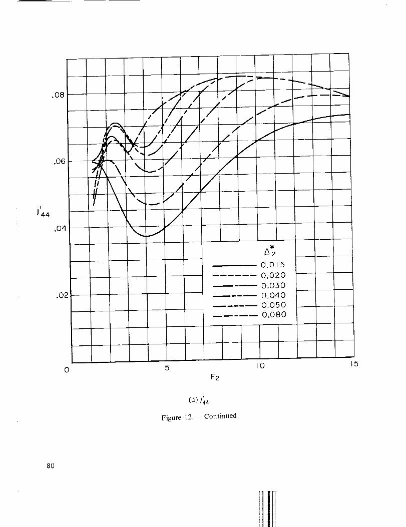
(d) ]44
Figure 12. - Continued.
8O

, I
J 55
.O7O
.060
.O5O
.040
.030
.020
.010
k
i /
' \ \
,I/ ¢
" / J
/ /"l
/I/"
=
/
,//
//
/J /
• f
/
//
f
_ J
/f
J/
J
f
J
v 7
/-
/
i i I I i
0.0 5
0.020
0.030
0.040
0.0500.080
0 5
F 2
I0 15
(e) 155
Figure 12. - Continued.
81
.O6
ol
J66
.O5
.O4
.O3
.O2
.01
i, #" __
,i [/,.,#1
/,
_,Lt,_ /i ,' /f
'_.jI_ \.. .t
,J
_r
/ // ,"
J/
/ //# /"
/ tJ J
//"
/
J
A*2
0.015
0.020
0.030
0.040 :,
0.050
0.080
J
/-t
f
0 5
F 2
I0 15
,r
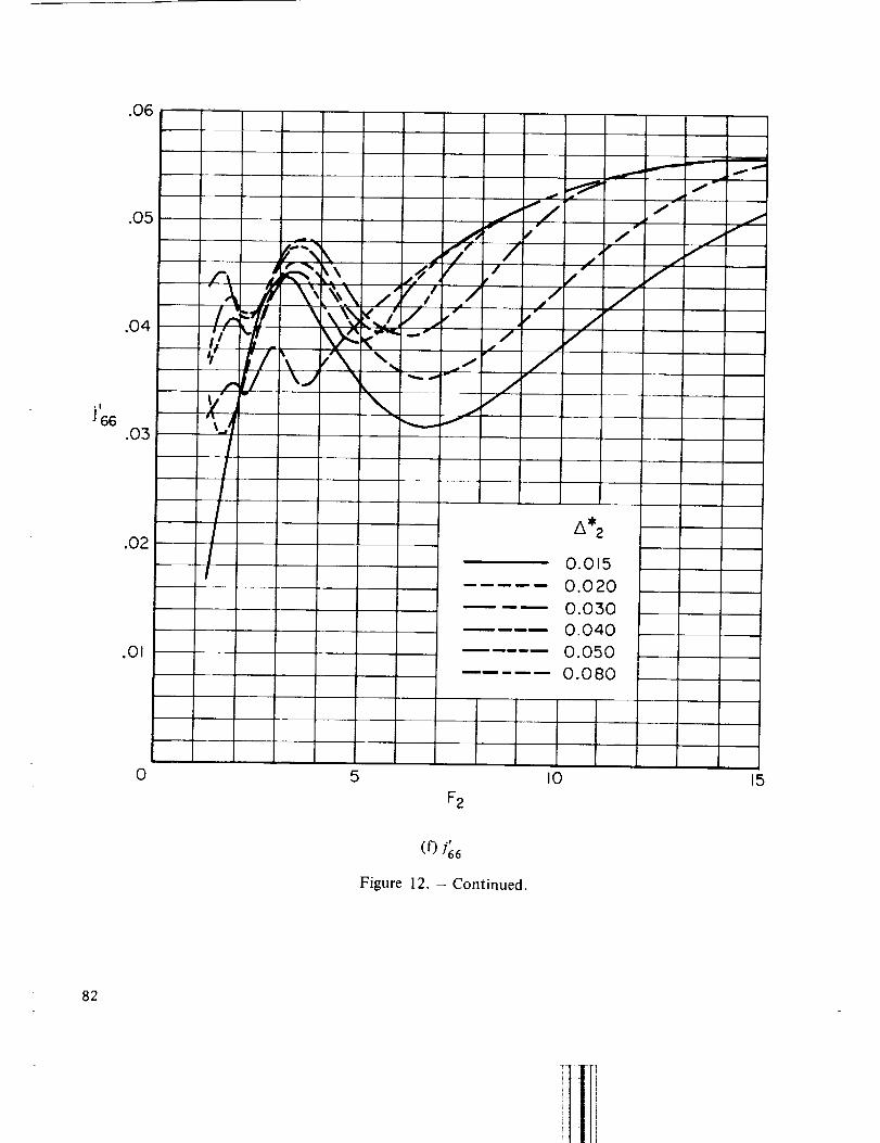
(0 s66
Figure 12. - Continued.
82
0
-.005
-.010
,!
J75
--.015
_020
- .0250 5
F2
I0 15
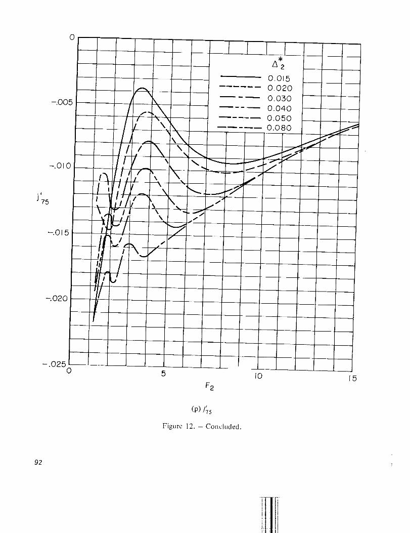
(P) l'Ts
Figure 12. - Concluded.
92
, I
J 77
.O5O
.040
.030
.020
.010
Az
0.015
...... 0.020
0.030
.... 0.040
m 0.050
..... 0.080
0 5
F2
I0 15
,I
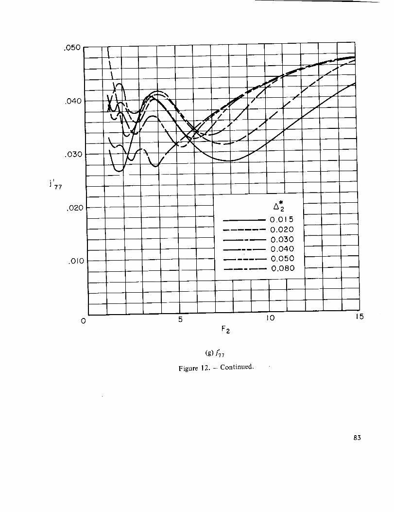
(g) 177
Figure 12. - Continued.
83
0
-.02
-.04
,!
J31
-.06
-.08
-.10
-.12
i
// i /
t
I!"#l
_/"
1!
l,
A 2
0.0 5
0.020
0.040
0.080
,,_ II
0 5
F2
.I
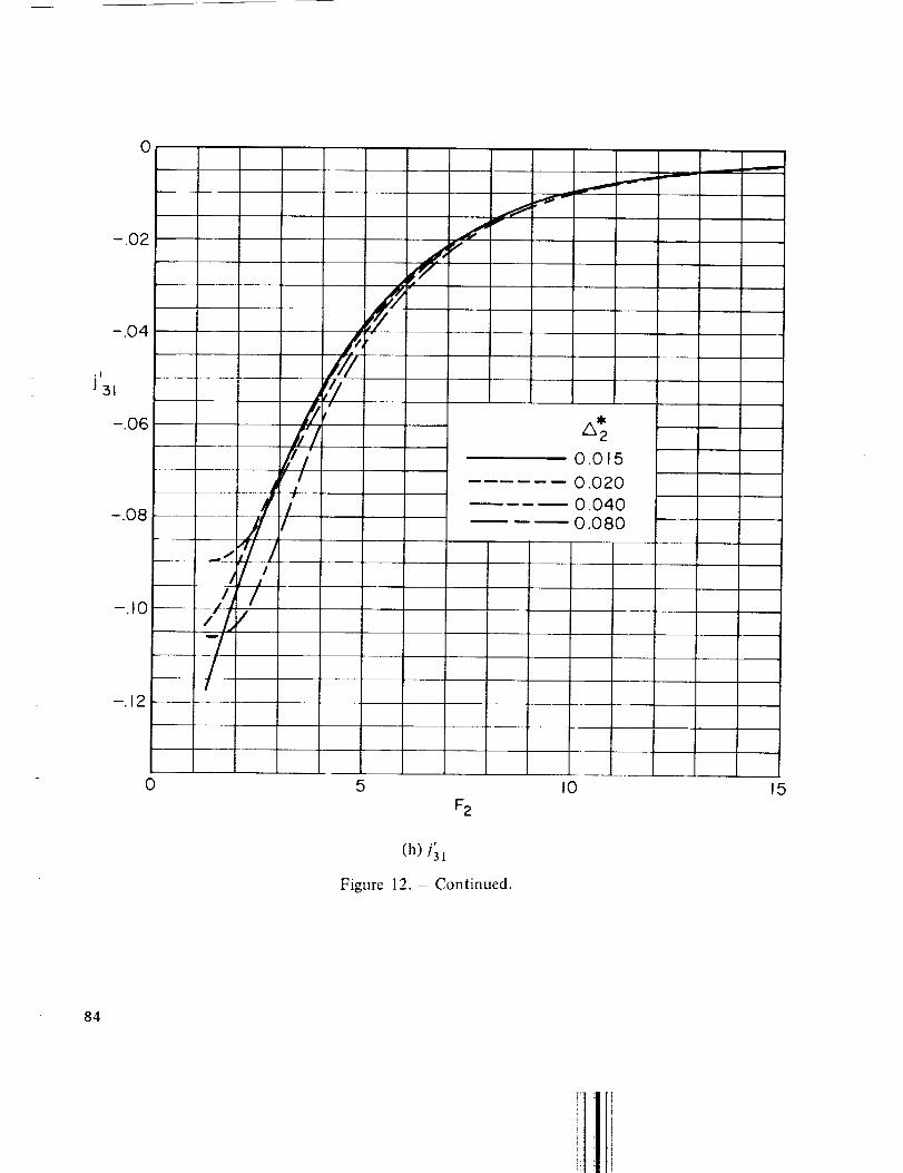
(h) 131
Figure 12. - Continued.
I0 15
84
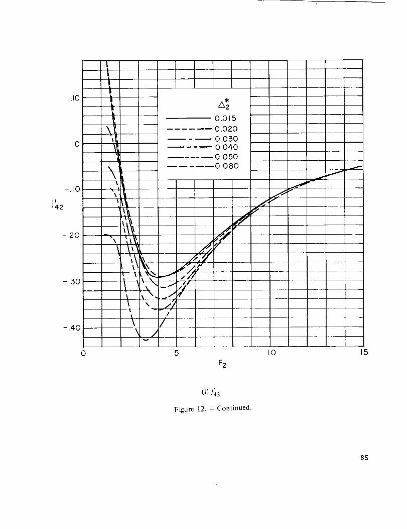
1
.10
0
-.10
"I
J42
-.20
-.30
- ,40
0
't\_
L
\
\ |
',_,\_',\
\. 1
\
\
..J
/
//
v
i
.,f'z;"
5
40.0 5
0.020
0.0300.040
0.0500.080
_J
F2
I0
ilr,v
J
f
15
.!
(i) ]42
Figure 12. - Continued.
85
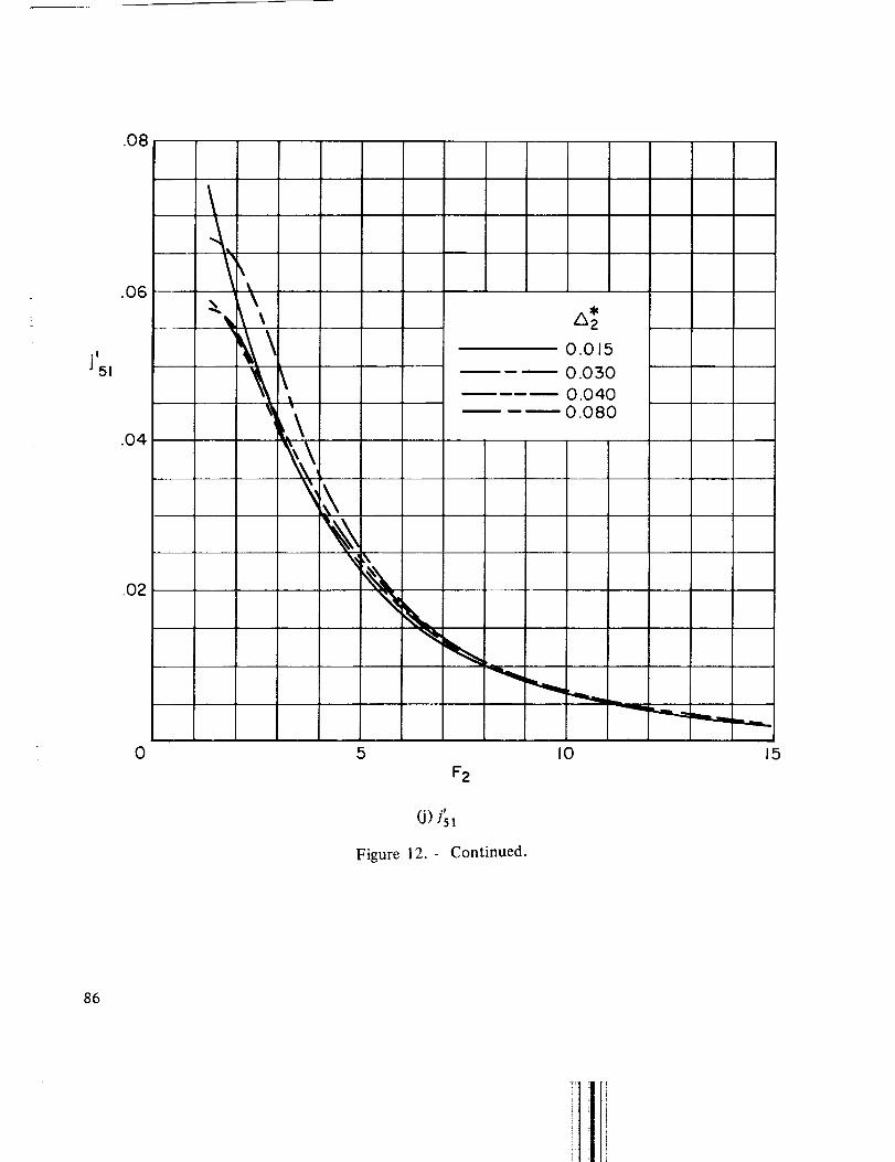
.O8
,!
J51
.O6
.O4
.O2
''i
\,
% \
\%i
0.015
0.030
O.040
--_ 0 080
0 5 I0
F2
.r
(J) zs
Figure 12. - Continued.
15
86

0
-.10
,!
J 5:5
-.20
-.30
-,400
I .--,X
I / \\ .4.- _"I t '_ _,.'_'.,7.4
,, ,jiii \,ltJ
ii/F\
7/I
//I
i
5
F2
_t0.015
0.020
0.0300.040
..... 0.050
..... 0.080
I0
J
15
.r
(k) Is 3
Figure 12. - Continued.
87

,/
J62
.2O
.10
/ \t .., ...,.. \I / _/ i -_t_I / " _./ 1/, /i/-'_-
// /f-
_ il,'/I/,o" i!l/
--" ',7171
k7//i
I
/[1
-,&
.%
0
0
,'illl
'/I.
/5
\',N
A2
0.015
0,0500.040
- 0.050--0.080
F2
I0 15
.I
(1) s62
Figure 12. - Continued.
88

.010
,I
J 64
0
-.010
0
-.020
0.0 5
0.020
0.030
0.040
0.050
0.080
I0
F2
15
,i
(m) ]64
Figure 12. - Continued.
89

, !
J71
0
-.10
-20
-30
-.40
-.50
/,
hYP
IIII I /
i
II
7/
I
¢,/i
./f __
7
/k z
0015
0.040
0.0l_0
-.600 5 I0 15
.f
(n) 171
Figure 12. - Continued.
9O
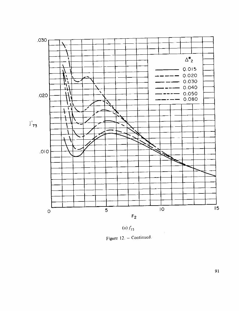
°1
J 73
.030
.020
.010
\\
I
,I
,L
;\\
I
I \ /
_. _ _-"
_ //
A* 2
\
S _,--
0.015
• -- 0.020
0.050
0.040
0.050
0.080
'__
0 5
F2
(O) 173
Figure 12. - Continued.
IO 15
91

0
.I
J 75
5
F2
I0 15
(P) t75
Figure 12. - Concluded.
92
Related Documents