IOSR Journal of Electrical and Electronics Engineering (IOSR-JEEE) e-ISSN: 2278-1676,p-ISSN: 2320-3331, Volume 6, Issue 1 (May. - Jun. 2013), PP 76-86 www.iosrjournals.org www.iosrjournals.org 76 | Page Cascaded Multilevel Inverter Based Active Power Filters: A Survey of Controls K. Damodara Reddy 1 , K.Venkateswarlu 2 , N.Srinivas 3 , G.Sandeep 4 1, 2, 3, 4 (Department of EEE, Vardhaman College of Engineering, India) Abstract: This paper presents the most important control theories for cascaded multilevel inverter based active power filters like, p-q theory with PI controller, average power method with carrier phase shifted pwm, instantaneous real-power theory with triangular-sampling current modulator, p-q theory with space vector modulation strategies for generating the switching signals for the operation. This paper also presents performance assessment among these control strategies. Keywords-Active Power Filters, Cascaded multilevel inverter, Harmonic compensation I. Introduction In recent years power electronic converters are widely used in industrial as well as domestic applications for thecontrol of power flow for automation and energy efficiency. Most of the time these converters draw harmonic current and reactive power from AC source and causes the power quality problems [19]. Active power filters are most effective for harmonic compensation. Different types, such as shunt and series active power filters are used effectively [2]. Multilevel inverters are increasingly used in high voltage powersystems due to advantages of high power quality waveforms, low electromagnetic compatibility and low switching losses. In addition, with the increase of voltage levels, the inverter output contains fewer harmonic and eventually approaching to desired sinusoidal waveform [3] [4]. The cascaded H-bridge multilevel VSI has been applied for active filter applications due to increased number of voltage levels, low switching losses and higher order of harmonic compensation. The cascade M- level inverter consists of (M-1/2) H-bridges and each bridge has its own separate dc source. Cascade multilevel inverter based APF eliminates need of high cost transformer with APF in high voltage systems. Fig.1 shows the three phase cascaded multilevel inverter used for active power filter application. In this, I s is the AC source current, I L is nonlinear load current where three phase diode rectifier with R-L load is used as nonlinear load, I c is the compensated current from APF then I S =I L -I C (1) In operation of APF, the harmonic component of load current is derived through harmonic detection circuit and reverses it as the reference compensating current. Then switching signal for multilevel inverter is generated suchthat AC side output current of APF correctly trace reference current and provides the harmonic current of theload so that source current will be free from harmonic and approaches towards pure sinusoidal. Fig.1 Five-level cascaded H-bridge inverter topology The p-q theory is used to generate referencecurrent. But this method will introduce error in the referencecurrent when source voltages are distorted and the performance of APF will be degraded. In second scheme a PLL based unit vector template is conferred to find fundamentalsupply voltage and by sensing load currents, average power iscalculated and then reference currents are generated. Thismethod gives accurate

Welcome message from author
This document is posted to help you gain knowledge. Please leave a comment to let me know what you think about it! Share it to your friends and learn new things together.
Transcript
IOSR Journal of Electrical and Electronics Engineering (IOSR-JEEE)
e-ISSN: 2278-1676,p-ISSN: 2320-3331, Volume 6, Issue 1 (May. - Jun. 2013), PP 76-86 www.iosrjournals.org
www.iosrjournals.org 76 | Page
Cascaded Multilevel Inverter Based Active Power Filters:
A Survey of Controls
K. Damodara Reddy1, K.Venkateswarlu
2, N.Srinivas
3, G.Sandeep
4
1, 2, 3, 4(Department of EEE, Vardhaman College of Engineering, India)
Abstract: This paper presents the most important control theories for cascaded multilevel inverter based active
power filters like, p-q theory with PI controller, average power method with carrier phase shifted pwm,
instantaneous real-power theory with triangular-sampling current modulator, p-q theory with space vector
modulation strategies for generating the switching signals for the operation. This paper also presents
performance assessment among these control strategies.
Keywords-Active Power Filters, Cascaded multilevel inverter, Harmonic compensation
I. Introduction In recent years power electronic converters are widely used in industrial as well as domestic
applications for thecontrol of power flow for automation and energy efficiency. Most of the time these converters draw harmonic current and reactive power from AC source and causes the power quality problems
[19]. Active power filters are most effective for harmonic compensation. Different types, such as shunt and
series active power filters are used effectively [2].
Multilevel inverters are increasingly used in high voltage powersystems due to advantages of high
power quality waveforms, low electromagnetic compatibility and low switching losses. In addition, with the
increase of voltage levels, the inverter output contains fewer harmonic and eventually approaching to desired
sinusoidal waveform [3] [4].
The cascaded H-bridge multilevel VSI has been applied for active filter applications due to increased
number of voltage levels, low switching losses and higher order of harmonic compensation. The cascade M-
level inverter consists of (M-1/2) H-bridges and each bridge has its own separate dc source. Cascade multilevel
inverter based APF eliminates need of high cost transformer with APF in high voltage systems. Fig.1 shows the
three phase cascaded multilevel inverter used for active power filter application. In this, Isis the AC source current, IL is nonlinear load current where three phase diode rectifier with R-L load is used as nonlinear load, Ic
is the compensated current from APF then
IS=IL-IC (1)
In operation of APF, the harmonic component of load current is derived through harmonic detection
circuit and reverses it as the reference compensating current. Then switching signal for multilevel inverter is
generated suchthat AC side output current of APF correctly trace reference current and provides the harmonic
current of theload so that source current will be free from harmonic and approaches towards pure sinusoidal.
Fig.1 Five-level cascaded H-bridge inverter topology
The p-q theory is used to generate referencecurrent. But this method will introduce error in the
referencecurrent when source voltages are distorted and the performance of APF will be degraded. In second
scheme a PLL based unit vector template is conferred to find fundamentalsupply voltage and by sensing load
currents, average power iscalculated and then reference currents are generated. Thismethod gives accurate
Cascaded Multilevel Inverter Based Active Power Filters: A Survey Of Controls
www.iosrjournals.org 77 | Page
reference current even the supplyvoltages are distorted. CPS-PWM modulation method is usedto generate gating
signals with lower individual deviceswitching frequency [5].
The instantaneous real-power theory [6] provides good compensation characteristics in steady state as
well as transient states. The instantaneous real-power theory generates the reference currents required to
compensate the distorted line current harmonics and reactive power. It also tries to maintain the dc-bus voltage
across the capacitor constant. Another important characteristic of this real-power theory is the simplicity of the calculations, which involves only algebraic calculation.
Among all the switching algorithms for multilevel converters, SVPWM is potential candidate, as it
offers a great flexibility in optimizing switching pattern and it is suitable for digital implementation. Various
SVPWM algorithms are used for multilevel inverters to get high quality output voltage for AC drives in the
literature [9]. The algorithm doesn't need any lookup tables and requires memory space lesser than other
available algorithms due to use of MATLAB s-functions for generation of the switching states. In this method
the location of tip of reference vector is identified by triangle number[13]. The switching sequences are
generated with respect to the triangle number, such that there will be one switching per state. The on-times of
M-level inverters are calculated based on on-time calculation for two-level SVPWM, irrespective of triangle
number, such that complex calculations and lookup tables are not required.In this paper cascade type multilevel
inverter based active power filter for different control methods are discussed.
II. Reference Current Control Strategies Estimation of compensating signal is the important part of the active filter control. It has great impact
on compensation objectives, rating of active filter and its transient as well as steady state performance.This
section confers various control strategies for cascaded multilevel inverter based APF.
1. p-q theory with PI controller:
The p-q theory calculatesinstantaneous real and imaginary reactive power components.This theory is
based on the α-β transformation whichtransforms three phase voltages and currents into the α-βstationary reference frame. The three phase voltages and currents are transformed into α-β orthogonal coordinates.
(2)
and
(3)
The instantaneous active and reactive power in α-β coordinates are calculated by following expressions
(4)
The fundamental active power component is extracted byusing low pass filter. APF loss component obtained
bycontrolling DC capacitor voltages are added to fundamentalactive power. The compensating currents in α-β
plane are derived by (4).
(5) Then three phase currents are obtained by following two phase to three phase transformation
(6)
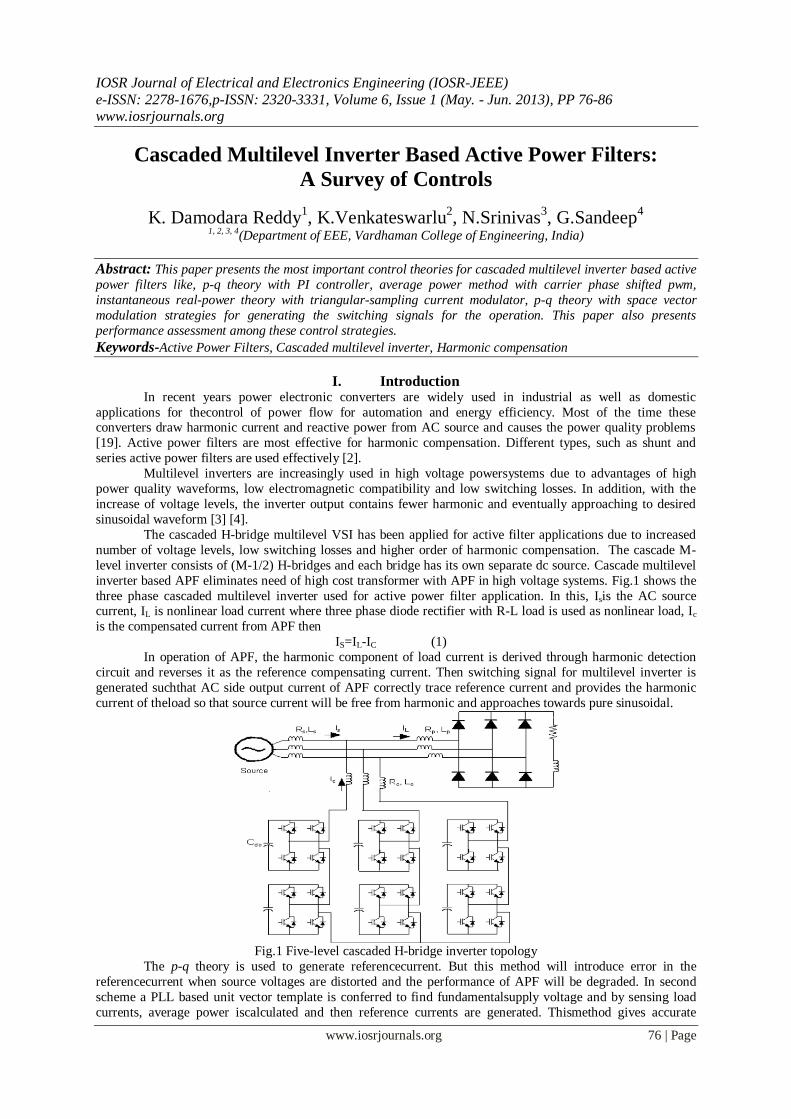
The block diagram of the control scheme of shunt active power filter using p-q theory is shown in
Fig.2. The advantage of p-q theory is that real and reactive powers associated with fundamental components are
Cascaded Multilevel Inverter Based Active Power Filters: A Survey Of Controls
www.iosrjournals.org 78 | Page
dc quantities. These quantities can be extracted with low pass filter. Since the signal to be extracted is dc
filtering α-β reference frame is insensitive to any phase shift errors introduced by low pass filter, improving
compensation characteristics of the active power filter. The limitation of this theory is the requirement of pure
sinusoidal supply voltages. In most industrial power system mains voltages are often unbalanced and distorted.
In such case p-q theory generate errors in reference currents and limits the compensation of harmonics even the
PLL is used.
Fig.2 Control system to generate gating pulses for active power filter
2. Average power method-CPS PWM:
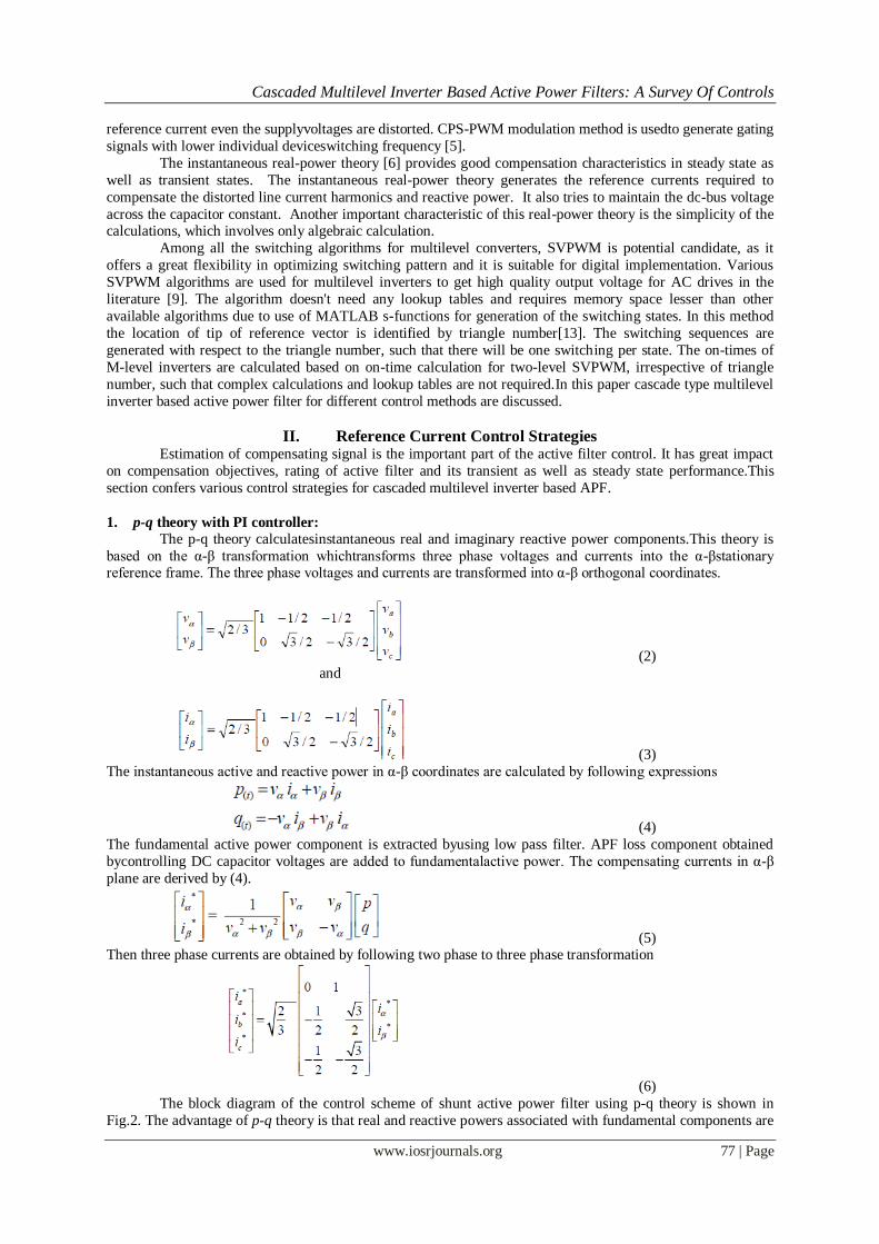
The average power method gives accurate results even thesupply voltage is distorted. A PLL based unit
vector templateis used to obtain fundamental component of mains voltage.The block diagram of extraction of
unit vector template isshown in Fig.3. The mains voltage contains fundamental anddistorted component. To get
unit vector templates of voltage,the input voltage is sensed and multiplied by gain equal to1/ Vpk where Vpk is
peak amplitude of fundamental supplyvoltage. These unit vectors are then passed through a PLL for synchronization of signals. Three phase fundamentalfrequency components are multiplied by Vpk to get
fundamental mains voltage.
Fig.3 Extraction of Unit Vector Template
The reference value of the current component to the loadI*smpis computed using the sensed average load power
Pave.The sensed load currents (iLa ,iLb, iLc)and bus voltages(va , vb , vc) through PLL are used to derive the
instantaneouspowerPLas given by
(7)
The average power Paveis calculated by averaginginstantaneous power over one sixth of period of supplyfrequency. The peak current component of load current I*
smpis calculated using following relation
(8)
The desired references of the APF currents are computed by taking the difference between the three
phaseinstantaneous reference source currentsandactual source currents as below
ica*= isa* - isa (9)
icb* = isb* - isb (10)
icc* = isc* - isc (11)
Cascaded Multilevel Inverter Based Active Power Filters: A Survey Of Controls
www.iosrjournals.org 79 | Page
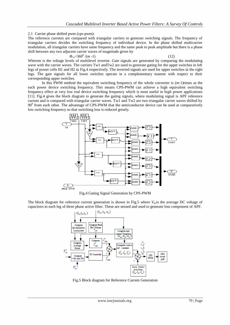
2.1 Carrier phase shifted pwm (cps-pwm):
The reference currents are compared with triangular carriers to generate switching signals. The frequency of
triangular carriers decides the switching frequency of individual device. In the phase shifted multicarrier
modulation, all triangular carriers have same frequency and the same peak to peak amplitude but there is a phase
shift between any two adjacent carrier waves of magnitude given by
cr=3600 /(m -1) (12) Wherem is the voltage levels of multilevel inverter. Gate signals are generated by comparing the modulating wave with the carrier waves. The carriers Tw1 andTw2 are used to generate gating for the upper switches in left
legs of power cells H1 and H2 in Fig.4 respectively. The inverted signals are used for upper switches in the right
legs. The gate signals for all lower switches operate in a complementary manner with respect to their
corresponding upper switches.
In this PWM method the equivalent switching frequency of the whole converter is (m-1)times as the
each power device switching frequency. This means CPS-PWM can achieve a high equivalent switching
frequency effect at very low real device switching frequency which is most useful in high power applications
[11]. Fig.4 gives the block diagram to generate the gating signals, where modulating signal is APF reference
current and is compared with triangular carrier waves. Tw1 and Tw2 are two triangular carrier waves shifted by
900 from each other. The advantage of CPS-PWM that the semiconductor device can be used at comparatively
low switching frequency so that switching loss is reduced greatly.
Fig.4 Gating Signal Generation by CPS-PWM
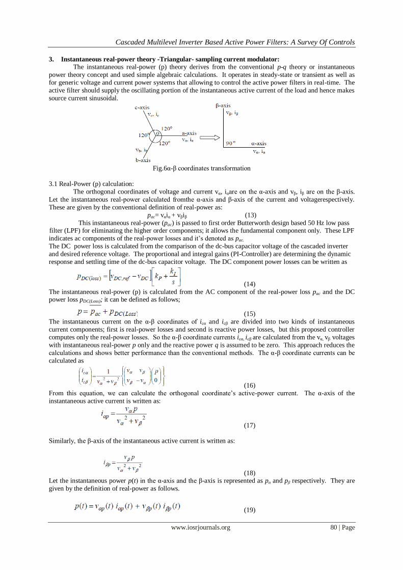
The block diagram for reference current generation is shown in Fig.5 where Vdcis the average DC voltage of
capacitors in each leg of three phase active filter. These are sensed and used to generate loss component of APF.
Fig.5 Block diagram for Reference Current Generation
Cascaded Multilevel Inverter Based Active Power Filters: A Survey Of Controls
www.iosrjournals.org 80 | Page
3. Instantaneous real-power theory -Triangular- sampling current modulator:
The instantaneous real-power (p) theory derives from the conventional p-q theory or instantaneous
power theory concept and used simple algebraic calculations. It operates in steady-state or transient as well as
for generic voltage and current power systems that allowing to control the active power filters in real-time. The
active filter should supply the oscillating portion of the instantaneous active current of the load and hence makes
source current sinusoidal.
Fig.6α-β coordinates transformation
3.1 Real-Power (p) calculation:
The orthogonal coordinates of voltage and current vα, iαare on the α-axis and vβ, iβ are on the β-axis.
Let the instantaneous real-power calculated fromthe α-axis and β-axis of the current and voltagerespectively.
These are given by the conventional definition of real-power as:
pac= vαiα + vβiβ (13)
This instantaneous real-power (pac) is passed to first order Butterworth design based 50 Hz low pass filter (LPF) for eliminating the higher order components; it allows the fundamental component only. These LPF
indicates ac components of the real-power losses and it’s denoted as pac.
The DC power loss is calculated from the comparison of the dc-bus capacitor voltage of the cascaded inverter
and desired reference voltage. The proportional and integral gains (PI-Controller) are determining the dynamic
response and settling time of the dc-bus capacitor voltage. The DC component power losses can be written as
(14)
The instantaneous real-power (p) is calculated from the AC component of the real-power loss pac and the DC power loss pDC(Loss); it can be defined as follows;
(15)
The instantaneous current on the α-β coordinates of icα and icβ are divided into two kinds of instantaneous
current components; first is real-power losses and second is reactive power losses, but this proposed controller
computes only the real-power losses. So the α-β coordinate currents icα, icβ are calculated from the vα, vβ voltages
with instantaneous real-power p only and the reactive power q is assumed to be zero. This approach reduces the
calculations and shows better performance than the conventional methods. The α-β coordinate currents can be
calculated as
(16)
From this equation, we can calculate the orthogonal coordinate’s active-power current. The α-axis of the
instantaneous active current is written as:
(17)
Similarly, the β-axis of the instantaneous active current is written as:
(18) Let the instantaneous power p(t) in the α-axis and the β-axis is represented as pα and pβ respectively. They are
given by the definition of real-power as follows.
(19)
Cascaded Multilevel Inverter Based Active Power Filters: A Survey Of Controls
www.iosrjournals.org 81 | Page
From this equation (19), substitute the orthogonal coordinates α-axis active power (17) and β-axis active power
(18); we can calculate the real-power p(t) as follows
(20)
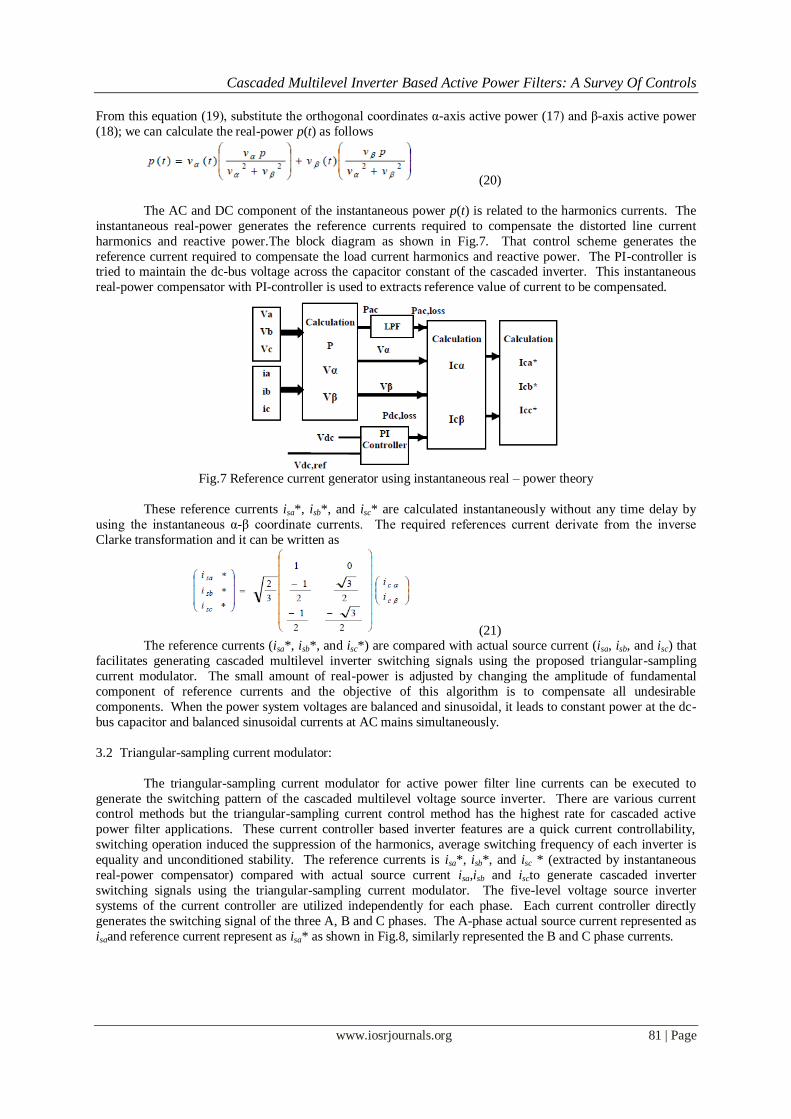
The AC and DC component of the instantaneous power p(t) is related to the harmonics currents. The
instantaneous real-power generates the reference currents required to compensate the distorted line current
harmonics and reactive power.The block diagram as shown in Fig.7. That control scheme generates the
reference current required to compensate the load current harmonics and reactive power. The PI-controller is tried to maintain the dc-bus voltage across the capacitor constant of the cascaded inverter. This instantaneous
real-power compensator with PI-controller is used to extracts reference value of current to be compensated.
Fig.7 Reference current generator using instantaneous real – power theory
These reference currents isa*, isb*, and isc* are calculated instantaneously without any time delay by
using the instantaneous α-β coordinate currents. The required references current derivate from the inverse
Clarke transformation and it can be written as
(21) The reference currents (isa*, isb*, and isc*) are compared with actual source current (isa, isb, and isc) that
facilitates generating cascaded multilevel inverter switching signals using the proposed triangular-sampling
current modulator. The small amount of real-power is adjusted by changing the amplitude of fundamental
component of reference currents and the objective of this algorithm is to compensate all undesirable
components. When the power system voltages are balanced and sinusoidal, it leads to constant power at the dc-
bus capacitor and balanced sinusoidal currents at AC mains simultaneously.
3.2 Triangular-sampling current modulator:
The triangular-sampling current modulator for active power filter line currents can be executed to
generate the switching pattern of the cascaded multilevel voltage source inverter. There are various current control methods but the triangular-sampling current control method has the highest rate for cascaded active
power filter applications. These current controller based inverter features are a quick current controllability,
switching operation induced the suppression of the harmonics, average switching frequency of each inverter is
equality and unconditioned stability. The reference currents is isa*, isb*, and isc * (extracted by instantaneous
real-power compensator) compared with actual source current isa,isb and iscto generate cascaded inverter
switching signals using the triangular-sampling current modulator. The five-level voltage source inverter
systems of the current controller are utilized independently for each phase. Each current controller directly
generates the switching signal of the three A, B and C phases. The A-phase actual source current represented as
isaand reference current represent as isa* as shown in Fig.8, similarly represented the B and C phase currents.
Cascaded Multilevel Inverter Based Active Power Filters: A Survey Of Controls
www.iosrjournals.org 82 | Page
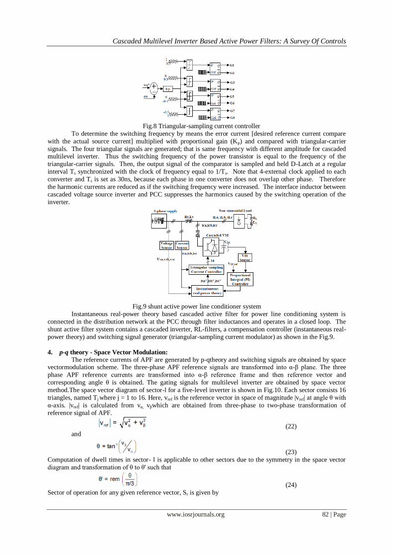
Fig.8 Triangular-sampling current controller
To determine the switching frequency by means the error current [desired reference current compare
with the actual source current] multiplied with proportional gain (Kp) and compared with triangular-carrier
signals. The four triangular signals are generated; that is same frequency with different amplitude for cascaded multilevel inverter. Thus the switching frequency of the power transistor is equal to the frequency of the
triangular-carrier signals. Then, the output signal of the comparator is sampled and held D-Latch at a regular
interval Ts synchronized with the clock of frequency equal to 1/Ts. Note that 4-external clock applied to each
converter and Ts is set as 30ns, because each phase in one converter does not overlap other phase. Therefore
the harmonic currents are reduced as if the switching frequency were increased. The interface inductor between
cascaded voltage source inverter and PCC suppresses the harmonics caused by the switching operation of the
inverter.
Fig.9 shunt active power line conditioner system
Instantaneous real-power theory based cascaded active filter for power line conditioning system is
connected in the distribution network at the PCC through filter inductances and operates in a closed loop. The
shunt active filter system contains a cascaded inverter, RL-filters, a compensation controller (instantaneous real-
power theory) and switching signal generator (triangular-sampling current modulator) as shown in the Fig.9.
4. p-q theory - Space Vector Modulation:
The reference currents of APF are generated by p-qtheory and switching signals are obtained by space vectormodulation scheme. The three-phase APF reference signals are transformed into α-β plane. The three
phase APF reference currents are transformed into α-β reference frame and then reference vector and
corresponding angle θ is obtained. The gating signals for multilevel inverter are obtained by space vector
method.The space vector diagram of sector-l for a five-level inverter is shown in Fig.10. Each sector consists 16
triangles, named Tj where j = 1 to 16. Here, vref is the reference vector in space of magnitude |vref| at angle θ with
α-axis. |vref| is calculated from vα, vβwhich are obtained from three-phase to two-phase transformation of
reference signal of APF.
(22)
and
(23)
Computation of dwell times in sector- l is applicable to other sectors due to the symmetry in the space vector
diagram and transformation of θ to θ' such that
(24)
Sector of operation for any given reference vector, Sr is given by
Cascaded Multilevel Inverter Based Active Power Filters: A Survey Of Controls
www.iosrjournals.org 83 | Page
(25)
Where, θ (0 ≤ θ< 2n) is the angle of the reference vector with α-axis, int and rem are standard math
function"integer" and "remainder" respectively.
4.1 Development of Dwell Time Calculation Method:
The basic idea of SVM is to compensate the required volt-seconds using discrete switching states and their on-
times.In two-level inverter, on-time calculation is based on the location of the reference vector within a sector
Sr, r= l, 2 ... 6. The volt-second balance for the reference, is given by VsTs = vata + vbtb (26)
Time balance is given by
Ts = ta+tb+t0 (27)
Where ta, tband t0 are the on time state vector va, vb and zero vector respectively
Resolving (26) along α0-β0axis
vsα0Ts = ta + 0.5 tb (28)
vsβ0Ts = h tb (29)
solving (26)-(29) the following equations for time calculations of the on-times are obtained
(30)
(31)
(32)
where 'h' is the height of a sector Sr and equal to √3/2 for an equilateral triangle of unity side and Ts time period
of switching signal.
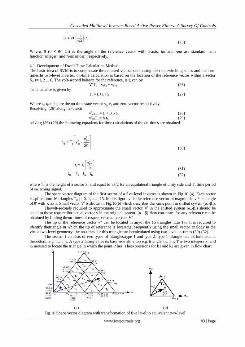
The space vector diagram of the first sector of a five-level inverter is shown in Fig.10 (a). Each sector
is splited into 16 triangles Tj, j= 0, 1, .... , 15. In this figure v* is the reference vector of magnitude |v *| an angle
of θ' with α axis. Small vector Vs is shown in Fig.10(b) which describes the same point in shifted system (αo-βo).
Thevolt-seconds required to approximate the small vector Vs in the shifted system (αo-βo) should be equal to those requiredfor actual vector v in the original system (α - β) Henceon-times for any reference can be
obtained by finding theon-times of respective small vectors Vs.
The tip of the reference vector v* can be located in anyof the 16 triangles Toto T15. It is required to
identify thetriangle in which the tip of reference is located;subsequently using the small vector analogy in the
virtualtwo-level geometry, the on-times for this triangle can becalculated using two-level on-times (30)-(32).
The sector- l consists of two types of triangles:type 1 and type 2. type 1 triangle has its base side at
thebottom, e.g. T4, T13. A type 2 triangle has its base side atthe top e.g. triangle T5, T10. The two integers k1 and
k2 areused to locate the triangle in which the point P lies. Theexpressions for k1 and k2 are given in flow chart
(a) (b)
Fig.10 Space vector diagram with transformation of five level to equivalent two-level
Cascaded Multilevel Inverter Based Active Power Filters: A Survey Of Controls
www.iosrjournals.org 84 | Page
The triangle in a sector is identified as an integer Tj using a simple algebraic expression. It greatly
simplifies the PWM process as switching states can be easily mapped with respect to the triangle number Tj. The
flowchart in Fig.8 shows the determination of triangle number and on-timesfor a reference voltage v*.
Fig.11 Flowchart of m-level SVPWM algorithm
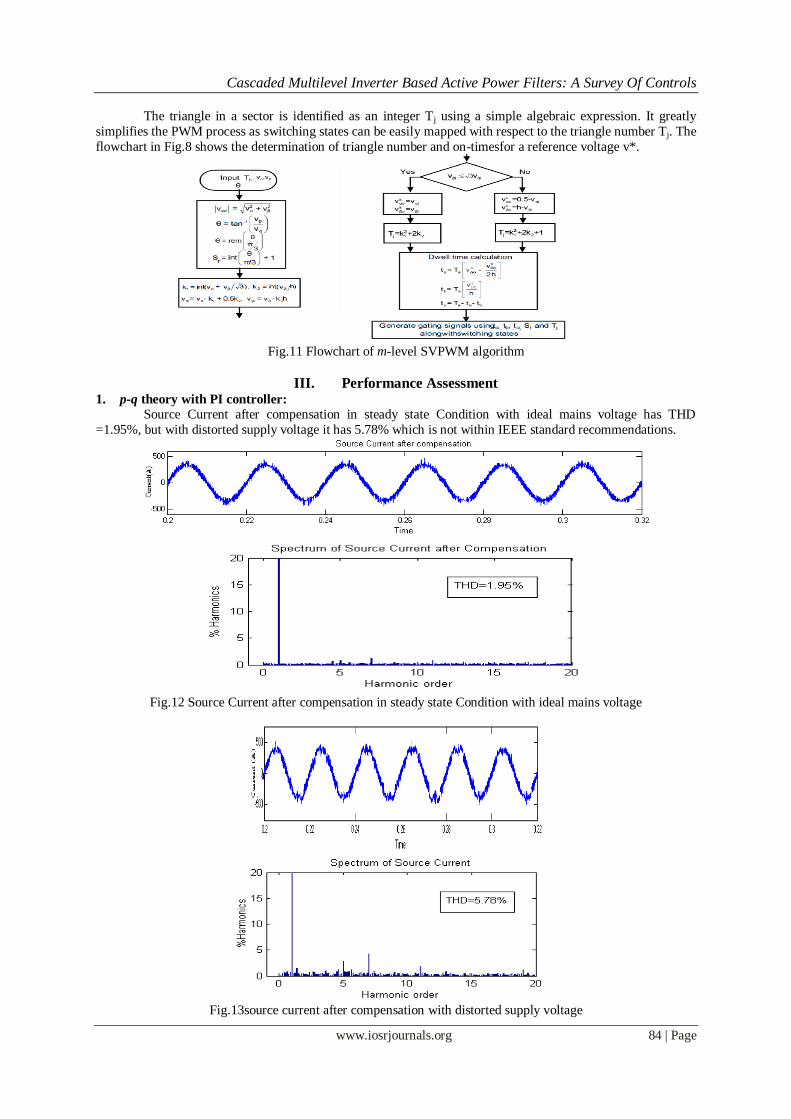
III. Performance Assessment 1. p-q theory with PI controller:
Source Current after compensation in steady state Condition with ideal mains voltage has THD
=1.95%, but with distorted supply voltage it has 5.78% which is not within IEEE standard recommendations.
Fig.12 Source Current after compensation in steady state Condition with ideal mains voltage
Fig.13source current after compensation with distorted supply voltage
Cascaded Multilevel Inverter Based Active Power Filters: A Survey Of Controls
www.iosrjournals.org 85 | Page
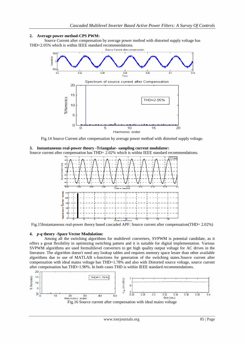
2. Average power method-CPS PWM:
Source Current after compensation by average power method with distorted supply voltage has
THD=2.05% which is within IEEE standard recommendations.
Fig.14 Source Current after compensation by average power method with distorted supply voltage.
3. Instantaneous real-power theory -Triangular- sampling current modulator: Source current after compensation has THD= 2.02% which is within IEEE standard recommendations.
Fig.15Instantaneous real-power theory based cascaded APF: Source current after compensation(THD= 2.02%)
4. p-q theory -Space Vector Modulation:
Among all the switching algorithms for multilevel converters, SVPWM is potential candidate, as it
offers a great flexibility in optimizing switching pattern and it is suitable for digital implementation. Various
SVPWM algorithms are used formultilevel converters to get high quality output voltage for AC drives in the
literature. The algorithm doesn't need any lookup tables and requires memory space lesser than other available
algorithms due to use of MATLAB s-functions for generation of the switching states.Source current after
compensation with ideal mains voltage has THD=1.78% and also with Distorted source voltage, source current
after compensation has THD=1.90%. In both cases THD is within IEEE standard recommendations.
Fig.16 Source current after compensation with ideal mains voltage
Cascaded Multilevel Inverter Based Active Power Filters: A Survey Of Controls
www.iosrjournals.org 86 | Page
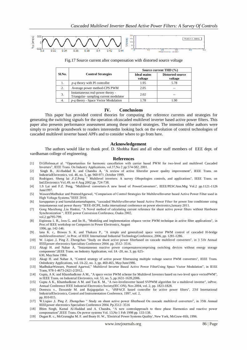
Fig.17 Source current after compensation with distorted source voltage
Sl.No. Control Strategies
Source current THD (%)
Ideal mains
voltage
Distorted source
voltage
1. p-q theory with PI controller 1.95 5.78
2. Average power method-CPS PWM 2.05 --
3. Instantaneous real-power theory -
Triangular- sampling current modulator 2.02 --
4. p-q theory - Space Vector Modulation 1.78 1.90
IV. Conclusions This paper has provided control theories for computing the reference currents and strategies for
generating the switching signals for the operation ofcascaded multilevel inverter based active power filters. This
paper also presents performance assessment among these control strategies. The intention ofthe authors were
simply to provide groundwork to readers interestedin looking back on the evolution of control technologies of
cascaded multilevel inverter based APFs and to consider where to go from here.
Acknowledgement The authors would like to thank prof. D. Shobha Rani and all other staff members of EEE dept. of vardhaman college of engineering.
References [1] D.GHolmea,et al. “Opportunities for harmonic cancellation with carrier based PWM for two-level and multilevel Cascaded
Inverters”, IEEE Trans. On Industry Applications, vol.37,No 2 pp 574-582, 2001.
[2] Singh B., AI-Haddad K. and Chandra A, "A review of active filtersfor power quality improvement", IEEE Trans. on
IndustrialElectronics, vol. 46, no. 5, pp. 960-971 ,October 1999.
[3] Rodriguez. Sheng lai ,F.Z.Peng " Multilevel inverters: A survey Oftopologies controls, and applications", IEEE Trans. on
Ind.Electronics Vo1.49, no 4 Aug 2002 pp. 724-738.
[4] 1.S Lai and F.Z. Peng, "Multilevel converters-A new breed of PowerConverters", IEEE/PESCAnn.Mtg Vol.2 pp.1121-1126
June1997.
[5] WawareMadhukar and PramodAgarwal, “Comparison of Control Strategies for MultilevelInverter based Active Power Filter used in
High Voltage Systems.”IEEE 2010.
[6] karuppanan p and kamalakantamahapatra, “cascaded MultilevelInverter based Active Power Filter for power line conditioner using
instantaneous real power theory ”IEEE-IICPE, India international conference on power electronics,January 2011.
[7] Gong Maozhong ,Liu Hankui, “A Novel method of calculating current reference for shunt active power filters without Hardware
Synchronization “, IEEE power Conversion Conference, Osaka 2002,
vol.2 pp795-799.
[8] Espinoza 1. R., loos G. and lin H., "Modeling and implementation ofspace vector PWM technique in active filter applications", in
Proc.of IEEE workshop on Computers in Power Electronics, August
1996, pp. 142-146.
[9] . lana K. c., Biswas S. K. and Thakura P., "A simple and generalized space vector PWM control of cascaded H-bridge
multilevelinverters", in Proc. of IEEE International Industrial TechnologyConference, 2006, pp. 1281-1286.
[10] W. Liqiao ,L Ping Z. Zhongchao "Study on shunt active power filterbased on cascade multilevel converters", in 3 51h Annual
IEEEpower electronics Specialists Conference 2004. pp. 3512- 3516.
[11] Akagi H. and Nabae A, "Instantaneous reactive power compensatorscomprising switching devices without energy storage
components",IEEE Trans. on Industry Application, vol. IA -20, no. 3, pp. 625-
630, May/June 1984.
[12] Akagi H. and Nabae A, "Control strategy of active power filtersusing multiple voltage source PWM converters", IEEE Trans.
OnIndustry Applications, vol. IA-22, no. 3, pp. 460-465, May/June1986.
[13] MadhukarWaware, Pramod Agarwal,” Multilevel Inverter Based Active Power FilterUsing Space Vector Modulation”, in IEEE
Trans, 978-1-4673-2421-2/2012.
[14] Gupta, A K. and Khambadkone A M., "A space vector PWM scheme for Multilevel Inverters based on two-level space vectorPWM",
in IEEE Trans. on Industrial Electronics, vol. 53, no. 5, pp.1631-1639,2006.
[15] Gupta A K., Khambadkone A M. and Tan K. M., "A two-levelinverter based SVPWM algorithm for a multilevel inverter", inProc.
Annual Conference IEEE Industrial Electronics Society(lEC ON), Nov.2004, vol. 2, pp. 1823-1828.
[16] Donescu v., Dawande M. and Rajagopalan v., "dSPACE based controller for active power filters", 23'd International
IndustrialElectronics, Control and Instrumentation Conference, 1997, vol. 2,
pp. 810-815.
[17] W.Liqiao ,L Ping Z. Zhongchao “ Study on shunt active power filterbased On cascade multilevel converters”, in 35th Annual
IEEEpower electronics Specialists Conference 2004. Pp.3512- 3516
[18] Bhim Singh, Kamal Al-Haddad and A. Chandra, “A new controlapproach to three phase Harmonics and reactive power
compensation”,IEEE Trans. On power systems Vol. 13,No 1 Feb 1998 pp. 133-138.
[19] Dugan R. c., McGranagha M. F. and Beaty H. W., 'Electrical Power Systems Quality', New York, McGraw-Hili, 1996.
Related Documents