Carrier VRF Catalog 2020 EDITION

Welcome message from author
This document is posted to help you gain knowledge. Please leave a comment to let me know what you think about it! Share it to your friends and learn new things together.
Transcript

Carrier VRF Catalog2020 EDITION
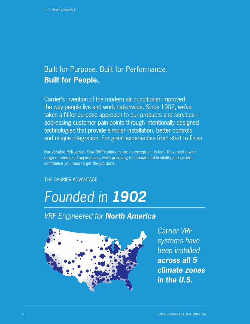
Built for Purpose. Built for Performance. Built for People.
Carrier’s invention of the modern air conditioner improved the way people live and work nationwide. Since 1902, we’ve taken a fit-for-purpose approach to our products and services—addressing customer pain points through intentionally designed technologies that provide simpler installation, better controls and unique integration. For great experiences from start to finish.
Our Variable Refrigerant Flow (VRF) solutions are no exception. In fact, they meet a wide range of needs and applications, while providing the unmatched flexibility and system confidence you need to get the job done.
THE CARRIER ADVANTAGE
Founded in 1902VRF Engineered for North America
Carrier VRF systems have been installed across all 5 climate zones in the U.S.
THE CARRIER ADVANTAGE
2 CARRIER VARIABLE REFRIGERANT FLOW
Table of Contents
The Value of VRF 4
Carrier: The VRF System of Choice 8
Faster Commissioning & Servicing 9
Flexible Design & Application 10
Worry-Free Implementation 12
The Right Solution for the Right Application 14
Heat Recovery Benefits 15
Case Studies 18
Heat Pump Benefits 20
Outdoor Units 22
Indoor Units 38
Individual Zone Controls 51
Central Controls 54
Building Automation 55
Benchmark Tools 56
TABLE OF CONTENTS
CARRIER VARIABLE REFRIGERANT FLOW 3

The Value of VRFSetting the Standard for Flexibility, Efficiency & Performance
What exactly is Variable Refrigerant Flow? It’s an HVAC system that uses refrigerant to heat and/or cool a space.
A multi-split solution, VRF systems can connect up to 64 indoor units to a single modular outdoor unit system. The system calculates the refrigerant required by each indoor unit and adjusts the amount provided to the fan coil units based on the space’s operating conditions. In other words, it controls and varies the refrigerant flow to ensure the desired comfort level of each space without over-cooling or over-heating.
1.How? VRF system outdoor units have all inverter-driven compressors. This means their speed can be varied simply by changing the frequency of power supply to that compressor. As the speed changes, so does the amount of refrigerant delivered, allowing the compressor to operate continuously rather than repeatedly cycle on and off.
As the speed changes, so does the amount of refrigerant delivered, allowing the compressor to operate continuously rather than repeatedly cycle on and off.
2.There are two types of VRF systems: heat recovery and heat pump. The biggest difference is that heat recovery units can heat and cool at the same time, while heat pump units can only heat or cool at once. So, heat recovery systems, which improve efficiency by taking heat from one space and redistributing it to another, are ideal for anywhere you need zone-by-zone control—like a hotel or assisted living facility. And heat pump systems are great for spaces where only one mode of operation is needed, like a bank.
THE VALUE OF VRF
4 CARRIER VARIABLE REFRIGERANT FLOW

Hinged Electrical Panel
Spot Check Box
Main Control Board
Heat Exchanger
Fans
Accumulator
Oil Separator
Compressor
THE VALUE OF VRF
CARRIER VARIABLE REFRIGERANT FLOW 5

A Total System Solution. With Benefits to Spare.Unlike other HVAC solutions, VRF is a closed-loop system—not just components. This means you get a complete solution from the start with confidence that everything will work seamlessly together.
THE VALUE OF VRF

FLEXIBILITY
From the system options to the ability to connect several indoor units to a single outdoor unit, VRF systems provide flexibility to accommodate almost any building requirement. ■ Zoned comfort control from a central location
■ Virtually seamless adaptation to building changes and reconfigurations
■ No need for maintenance rooms or service shafts, freeing up valuable space
■ Elimination of distribution fans, water pumps and large hydronic pipes
■ Smaller equipment footprint paired with long piping lengths means more application options
EFFICIENCY
VRF systems use no-to-minimal ductwork, depending on the application. Not only does this make installation and maintenance easier, but it also eliminates any energy waste associated with central duct systems.■ Energy savings from moving conditioned refrigerant only to the needed units
■ Asymmetric scroll compressors deliver optimal efficiency, at any speed
■ High Integrated Energy Efficiency Ratio (IEER) achievement
■ Can help commercial projects earn LEED or other “green” certifications
PERFORMANCE
System performance is significantly enhanced because of the heat transfer properties of refrigerant over other mediums.■ Air Conditioning, Heating & Refrigeration Institute (AHRI) certified
■ Inverter-driven technology allows users to precisely dial into the compressor operation to deliver optimal capacity
■ Operating hours are balanced among the compressors, distributing the load more evenly
■ Having multiple compressors means greater backup capabilities
THE VALUE OF VRF
CARRIER VARIABLE REFRIGERANT FLOW 7
Why Customers Make Carrier Their VRF System of Choice
As an industry leader for over a century, we know the challenges you face—like complex installation, complicated controls and disjointed system views. So we’ve made it our business to develop solutions, like our 2-pipe VRF systems, that help you sidestep this complex and frustrating experience to one of efficiency, simplicity and high value.
By design, Carrier systems are user-friendly, providing easy installation and operation. Combine this with our application, installation, and service training and software, and you have everything you need to be successful.
CARRIER: THE VRF SYSTEM OF CHOICE
8 CARRIER VARIABLE REFRIGERANT FLOW

FASTER COMMISSIONING & SERVICING
When time is of the essence, being able to efficiently set up, install and service a system is crucial. We help simplify the installation process with:
■ 2-Pipe Design—Decrease installation needs and streamline the process with less connections.
■ Single-Point Electrical Connection—Reduce the number of connections and eliminate intricate twinning piping with eight to 12 brazed joints on heat recovery models.
■ Spot Check Functionality—Check error codes without having to disconnect power to the entire system for easier servicing.
■ Quick-Connect System—Access wires with pre-installed connectors or field-provided wiring with the included terminal accessory without having to unscrew each wire individually.
■ Soft Copper Lines—Save installation time and effort with lightweight and durable piping that extends easily across larger spaces.
■ No Manual Port Assignments—Easily address system errors through automatic assignment of ports to individual indoor units.
■ Multiport Distribution Controller (MDC)—Reverse the refrigerant flow for six to 16 indoor units to provide simultaneous heating and cooling on heat recovery models.
Quick-Connect System
CARRIER: THE VRF SYSTEM OF CHOICE
CARRIER VARIABLE REFRIGERANT FLOW 9

FLEXIBLE DESIGN & APPLICATION
System simplicity and flexibility help improve the design experience. This idea is at the core of our VRF development process to ensure we provide:
■ Small Footprint—Get greater flexibility and save valuable space with our non-modular 2-pipe heat recovery unit.
■ Consistent Pipe Sizing—Find comfort in knowing the size of the pipes running from the outdoor unit to the MDC will never change, no matter the indoor unit capacity.
■ High Reliability—See performance in extreme temperatures with heating in as low as -13º F and cooling in up to 125º F for heat recovery, and heating in as low as -5º F or cooling in up to 122º F for heat pumps.
■ Back-Up Operation—Gain peace of mind from built-in system fallbacks, engineered to address the issue before requiring in-person service.
6-10 tons52 3/4 inches wide
12-20 tons78 3/8 inches wide
20-28 tons105 7/8 inches wide
ACCESSIBLE, CENTRALIZED CONTROLS
Access to understandable controls from a centralized location provides a uniquely enhanced experience with greater system visibility and flexibility to meet specific application needs. Ways we help with this include:
■ Integrated Design—Deliver total system regulation with individual controls at the zone level and centralized system and network controls that integrate seamlessly with existing and third-party building management systems.
■ i-Vu® Building Automation System—Present greater comfort control, optimize energy usage and increase operating efficiency with a web-based interface that provides a 360-degree view of the building’s entire operation, as well as centralized access to controls. i-Vu is optimized for Carrier equipment, but flexible enough to control any HVAC system.
CARRIER: THE VRF SYSTEM OF CHOICE
10 CARRIER VARIABLE REFRIGERANT FLOW

CARRIER VARIABLE REFRIGERANT FLOW 11
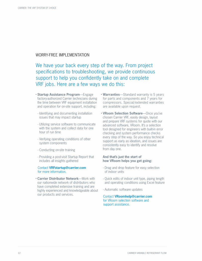
WORRY-FREE IMPLEMENTATION
We have your back every step of the way. From project specifications to troubleshooting, we provide continuous support to help you confidently take on and complete VRF jobs. Here are a few ways we do this:
■ Startup Assistance Program—Engage factory-authorized Carrier technicians during the time between VRF equipment installation and operation for on-site support, including:
- Identifying and documenting installation issues that may impact startup
- Utilizing service software to communicate with the system and collect data for one hour of run time
- Verifying operating conditions of other system components
- Conducting on-site training
- Providing a post-visit Startup Report that includes all insights gathered
Contact [email protected] for more information.
■ Carrier Distributor Network—Work with our nationwide network of distributors who have completed extensive training and are highly experienced and knowledgeable about our products and services.
■ Warranties—Standard warranty is 5 years for parts and components and 7 years for compressors. Special/extended warranties are available upon request.
■ VRoom Selection Software—Once you’ve chosen Carrier VRF, easily design, layout and prepare VRF systems for quote with our advanced software, VRoom. It’s a selection tool designed for engineers with built-in error checking and system performance checks every step of the way. So you enjoy technical support as early as ideation, and issues are consistently easy to identify and resolve from day one. And that’s just the start of how VRoom helps you get going:
- Drag and drop feature for easy selection of indoor units
- Quick edits of indoor unit type, piping length and operating conditions using Excel feature
- Automatic software updates
Contact [email protected] for VRoom selection software and support assistance.
CARRIER: THE VRF SYSTEM OF CHOICE
12 CARRIER VARIABLE REFRIGERANT FLOW

VRoom Interface
CARRIER: THE VRF SYSTEM OF CHOICE
CARRIER VARIABLE REFRIGERANT FLOW 13

THE RIGHT SOLUTION FOR YOUR APPLICATION
Understanding that specific requirements call for different solutions, we’ve intentionally designed our VRF systems to satisfy an array of needs. No matter the building, application or project specifications, we have a VRF solution for you.
2-Pipe Heat Recovery Systems
With a small footprint, the Carrier 2-pipe VRF heat recovery system is the perfect solution for new construction, retrofitting projects and expansions of medium-rise, wider buildings.
Outdoor Unit
Controls compressor speed
Maintains operational mode
Multiport Distribution Controller (MDC)
Reverses flow at indoor unit
Simultaneous heating and cooling
Indoor Units
Transfer heating or cooling to a space
Allow for optimal zoning
Controls
Controls space temperature and indoor unit fan
Remote and/or central
Simultaneous heating and cooling and zoned control provide optimal individualized comfort and customization. And, they use a centralized, multiport distribution controller, which provides better refrigerant distribution to all units.
CARRIER: THE VRF SYSTEM OF CHOICE
14 CARRIER VARIABLE REFRIGERANT FLOW

Heat Recovery Benefits
Simultaneous heating and cooling
Recovers energy that may be wasted from
one zone and transfers it to another
Connect up to three multiport
distribution controllers
Achieve up to 28-ton capacity
in a single chassis
CARRIER: THE VRF SYSTEM OF CHOICE
CARRIER VARIABLE REFRIGERANT FLOW 15

Offices
■ Less refrigerant pipe brazing joints means significant design and install cost reductions
■ A single-point electrical connection allows you to easily and cost-effectively install and maintain the system
■ Longer piping length (up to 3,280 feet) satisfies larger building needs
■ System flexibility simplifies building expansions or “shell and core” construction projects
While the system you choose will ultimately depend on factors specific to your project, like climate, building needs and project type, 2-pipe VRF heat recovery systems are great for many applications.
OFFICES
16 CARRIER VARIABLE REFRIGERANT FLOW

Hotels
■ Individual zoning and simultaneous heating and cooling optimize occupant comfort
■ Quieter operating noise (as low as 58.4 db(A)) means less disruption
■ Small footprint and non-modular design reduce the amount of piping work and eliminate the need for twinning outdoor units
■ i-Vu Building Automation System provides centralized occupancy control to adjust room temperatures before guest arrival and after check-out
Assisted Living Facilities
■ Individual zoning helps satisfy multiple HVAC needs
■ Simultaneous heating and cooling provides flexibility and control of tenant comfort
HOTELS ASSISTED LIVING FACILITIES
CARRIER VARIABLE REFRIGERANT FLOW 17

SAMPLE APPLICATION: HOTEL
The Situation: A hotel in a national chain with over 100 rooms, this large new build required an HVAC system that would provide maximum guest comfort while operating quietly and taking up minimum space.
100+ Rooms
Minumum Space
Quiet Operation
The Solution: Carrier VRF Heat RecoveryGiven the number of indoor units needed and the limited space on each floor, Carrier VRF heat recovery was the best system to satisfy the design. All refrigeration distribution devices were placed on the top floor and then piped down through chases to feed the rooms on floors two through seven. Outdoor units were cleanly installed across the roof, providing easy access for maintenance and troubleshooting.
The Results: Because of the system’s small footprint and non-modular design, the Carrier VRF heat recovery system reduced the amount of piping work needed on-site. The system also provides simultaneous heating and cooling, extremely quiet operation (as low as 58.4 dB(A)) and occupancy control via i-Vu Building Automation System.
CARRIER: THE VRF SYSTEM OF CHOICE
18 CARRIER VARIABLE REFRIGERANT FLOW
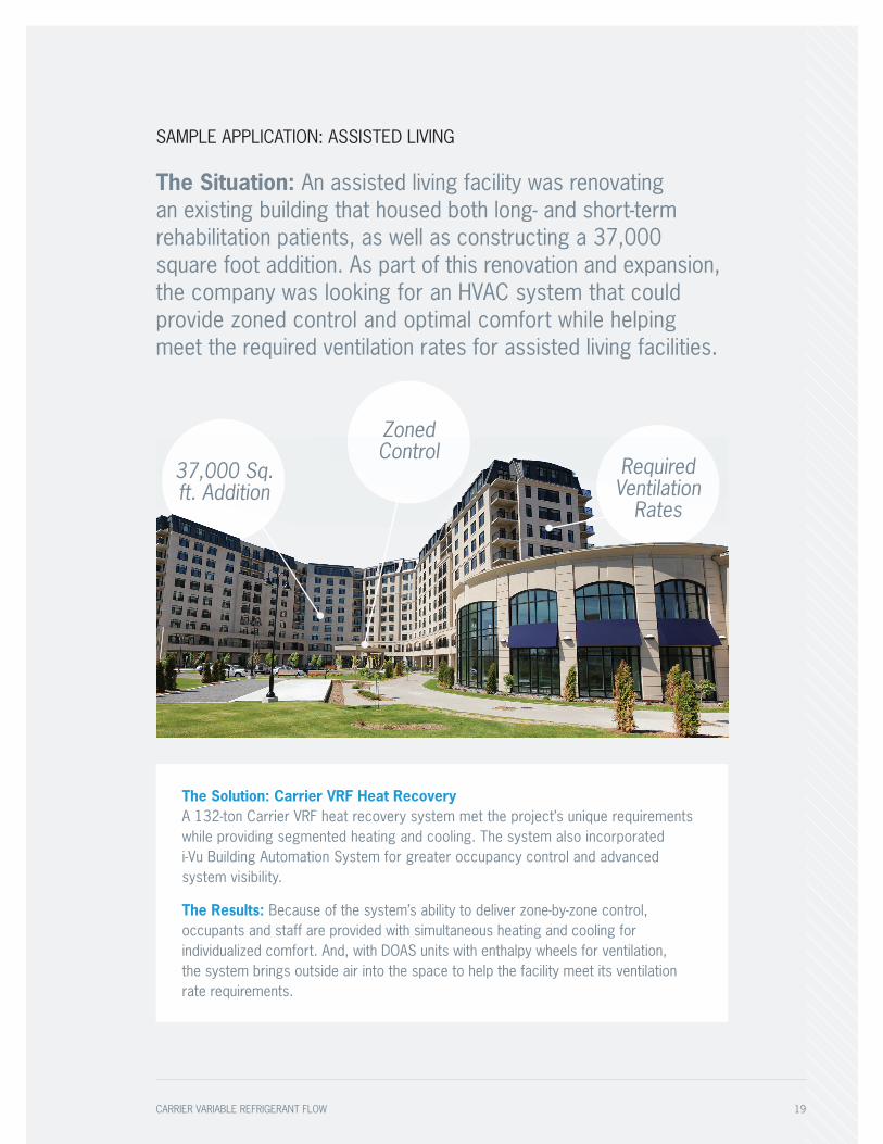
SAMPLE APPLICATION: ASSISTED LIVING
The Situation: An assisted living facility was renovating an existing building that housed both long- and short-term rehabilitation patients, as well as constructing a 37,000 square foot addition. As part of this renovation and expansion, the company was looking for an HVAC system that could provide zoned control and optimal comfort while helping meet the required ventilation rates for assisted living facilities.
37,000 Sq. ft. Addition
ZonedControl
Required Ventilation
Rates
The Solution: Carrier VRF Heat RecoveryA 132-ton Carrier VRF heat recovery system met the project’s unique requirements while providing segmented heating and cooling. The system also incorporated i-Vu Building Automation System for greater occupancy control and advanced system visibility.
The Results: Because of the system’s ability to deliver zone-by-zone control, occupants and staff are provided with simultaneous heating and cooling for individualized comfort. And, with DOAS units with enthalpy wheels for ventilation, the system brings outside air into the space to help the facility meet its ventilation rate requirements.
CARRIER VARIABLE REFRIGERANT FLOW 19

Heat Pump Benefits
Either heat or cool
3,280 feet of piping that can extend up to 164 feet between the outdoor and indoor units
Improves system efficiency and long-term reliability
Uses variable speed technology with an inverter compressor for consistent temperature regulation
Achieve up to 36-ton capacity
CARRIER: THE VRF SYSTEM OF CHOICE
20 CARRIER VARIABLE REFRIGERANT FLOW

3-PHASE HEAT PUMP SYSTEMS
Perfect for new builds and retrofitting projects in climates where only one zone is necessary, the Carrier VRF heat pump system either heats or cools at any given time. Its modular, scalable design allows for easy reconfiguration and add-ons, and its energy efficiency reduces operating costs.
3-phase heat pump systems are great for:
■ Medium- or low-occupancy buildings
■ K-12 schools and university buildings
■ Places of worship
■ Banks and municipalities
■ Retail spaces■ Storage facilities■ Parking garages
SINGLE-PHASE HEAT PUMP SYSTEMS
A residential and light-commercial application, Carrier single-phase heat pump systems are ideal for spaces that are too small for a standard VRF system. Available in three capacities (3-, 4- and 5-ton), they can connect up to nine indoor units for the ultimate hybrid solution. And if you ever need to expand usable space or divide a building into smaller units, single-phase systems offer exceptional design flexibility.
Single-phase heat pump solutions are great for:
■ One- or two-story office buildings
■ Strip malls and retail spaces
■ Fire and police stations
■ Banks and municipalities
Indoor Units
Transfer heating or cooling to a space
Allow for optimal zoning
Controls
Controls space temperature and indoor unit fan
Remote and/or central
Outdoor Unit
Controls compressor speed
Maintains operational mode
CARRIER: THE VRF SYSTEM OF CHOICE
CARRIER VARIABLE REFRIGERANT FLOW 21

CARRIER VRF
SYSTEMS: OUTDOOR
UNITSThe powerhouse of the
system, Carrier VRF outdoor units are reliable
and quiet—a fit for virtually every application. A single
modular unit system can connect up to 64 indoor
units for simple and flexible installation.
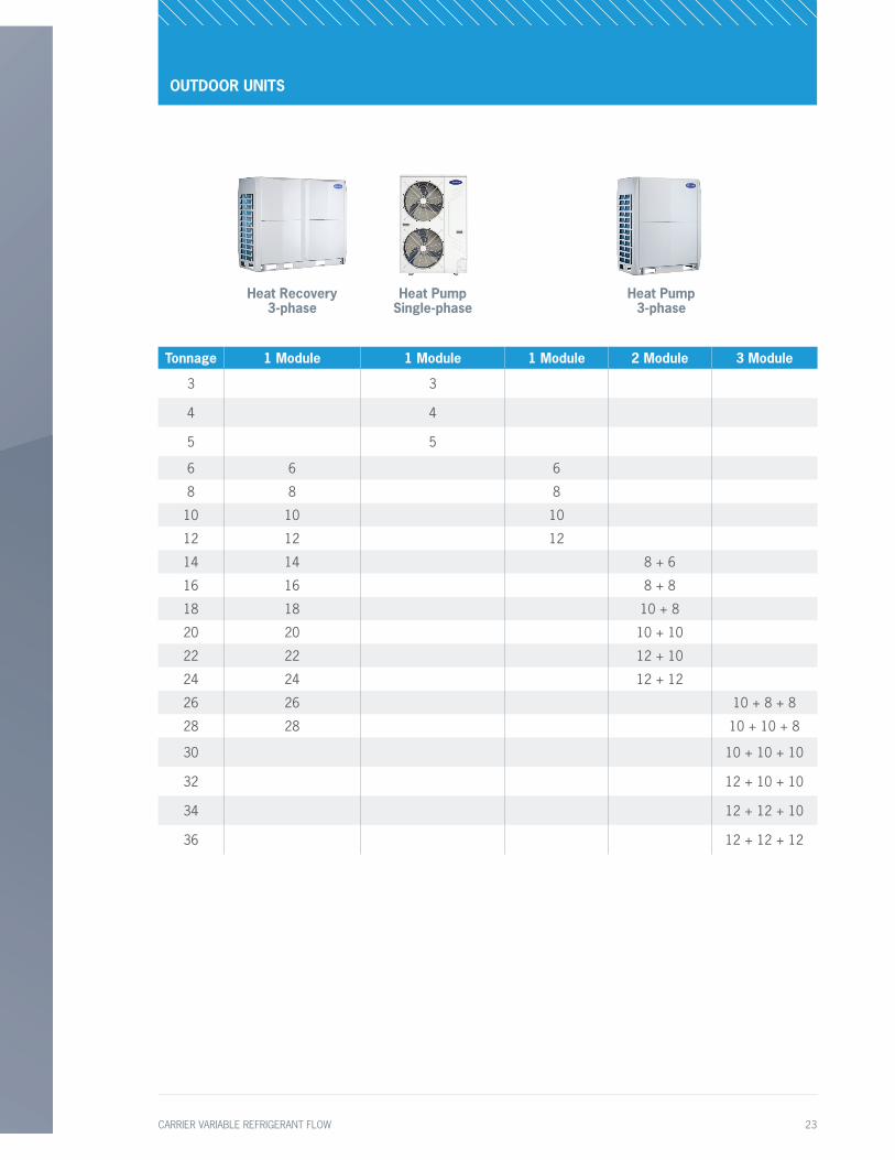
Heat Recovery 3-phase
Heat Pump Single-phase
Heat Pump 3-phase
Tonnage 1 Module 1 Module 1 Module 2 Module 3 Module
3 3
4 4
5 5
6 6 6
8 8 8
10 10 10
12 12 12
14 14 8 + 6
16 16 8 + 8
18 18 10 + 8
20 20 10 + 10
22 22 12 + 10
24 24 12 + 12
26 26 10 + 8 + 8
28 28 10 + 10 + 8
30 10 + 10 + 10
32 12 + 10 + 10
34 12 + 12 + 10
36 12 + 12 + 12
OUTDOOR UNITS
CARRIER VARIABLE REFRIGERANT FLOW 23

Outdoor Unit Model Name 38VMA072RDS5-1 38VMA096RDS5-1 38VMA120RDS5-1Nominal Tons 6 8 10Cooling Capacity1 (With Non-Ducted Indoor Units / Ducted)
Nominal kBtu/h 72.0 96.0 119.7
Rated kBtu/h 69.0 92.0 114.0
Heating Capacity1 (With Non-Ducted Indoor Units / Ducted)
Nominal kBtu/h 80.0 108.0 126.0
Rated kBtu/h 77.0 103.0 120.0
With Non-Ducted Indoor Units Electrical Characteristics (Nominal)1
Power Supply2 208/230V, 3-Phase, 60Hz 208/230V, 3-Phase, 60Hz 208/230V, 3-Phase, 60Hz
CoolingPower Consumption kW 4.2 6.2 9.3IEER3 Btu/W*hr 24.6 23.7 22.8
HeatingPower Consumption kW 4.4 7.2 9.5
SCHE4 Btu/W*hr 30.0 30.0 30.0
With Ducted Indoor Units Electrical Characteristics (Nominal)1
Power Supply2 208/230V, 3-Phase, 60Hz 208/230V, 3-Phase, 60Hz 208/230V, 3-Phase, 60Hz
CoolingPower Consumption kW 5.0 7.1 9.5
IEER3 Btu/W*hr 24.2 24.3 23.2
HeatingPower Consumption kW 5.7 8.0 9.8 SCHE4 Btu/W*hr 27.4 27.7 26.7
External DimensionsHeight in 64-3/8 64-3/8 64-3/8Width in 52-3/4 52-3/4 52-3/4Depth in 31-1/8 31-1/8 31-1/8
Total Weight Unit lb 672 672 672Compressor Fan Unit
Type / Quantity INVERTER-driven Hermetic Scroll / 1 INVERTER-driven Hermetic Scroll / 1 INVERTER-driven Hermetic Scroll / 1Air Volume cfm 6,900 7,600 8,100
Refrigerant5 (Charged Refrigerant Amount) lb 26.5 26.5 26.5Electrical Specifications Unit
MCA6 A 43 45 46Recommended Fuse Size A 50 50 50
Refrigerant PipingConnecting Port Diameter
Gas Side (Main Pipe) (Brazing) in 3/4 7/8 1-1/8
Liquid Side (Main Pipe) (Brazing) in 5/8 3/4 3/4
Operation Temperature RangeCooling ° F DB 5~125 5~125 5~125
Heating ° F WB -13~64 -13~64 -13~64
Maximum External Static Pressure in WG 0.24 Max 0.24 Max 0.24 Max
Maximum Number of Connected Indoor Units 15 20 24
Maximum Capacity of Combined Indoor Units 50%~150% 50%~150% 50%~150%
Sound Pressure Level Cooling / Heating7 dB(A) 58.4 61.7 62.7
1 Rated conditions: Cooling: Indoor air temperature 80° F dry bulb / 67° F wet bulb, outdoor air temperature 95° F dry bulb. Heating: Indoor air temperature 70° F dry bulb, outdoor air temperature 47° F dry bulb / 43° F wet bulb.
2 The source voltage must not fluctuate more than ± 10%.
3 Integrated Energy Efficiency Ratio4 Simultaneous Cooling & Heating Efficiency5 The amount does not consider extra piping length. Refrigerant
must be added on site in accordance with the actual piping length.
6 Select wire size based on larger value of MCA: Minimum Circuit Amps (Minimum Circuit Amps required for power supply design).
7 These values, measured in anechoic chamber, at a point 3.3 ft (1 m) in front of the unit at a height of 4.6 ft (1.4m).
OUTDOOR UNITS: HEAT RECOVERY TECHNICAL SPECIFICATIONS
38VMR Heat Recovery Outdoor Unit 208/230V–3–60
24 CARRIER VARIABLE REFRIGERANT FLOW
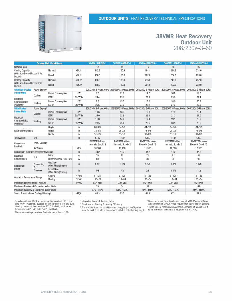
Outdoor Unit Model Name 38VMA144RDL5-1 38VMA168RDS5-1 38VMA192RDS5-1 38VMA216RDS5-1 38VMA240RDS5-1Nominal Tons 12 14 16 18 20Cooling Capacity1 (With Non-Ducted Indoor Units / Ducted)
Nominal kBtu/h 142.8 165.9 191.1 214.2 231.0
Rated kBtu/h 136.0 158.0 182.0 204.0 220.0
Heating Capacity1 (With Non-Ducted Indoor Units /Ducted)
Nominal kBtu/h 160.0 188.0 215.0 243.0 257.0
Rated kBtu/h 150.0 180.0 204.0 222.0 230.0
With Non-Ducted Indoor Units Electrical Characteristics (Nominal)1
Power Supply2 208/230V, 3-Phase, 60Hz 208/230V, 3-Phase, 60Hz 208/230V, 3-Phase, 60Hz 208/230V, 3-Phase, 60Hz 208/230V, 3-Phase, 60Hz
CoolingPower Consumption kW 9.0 11.9 14.7 16.8 19.7
IEER3 Btu/W*hr 24.4 23.1 23.9 23.0 22.4
HeatingPower Consumption kW 9.6 13.3 16.2 18.0 20.2 SCHE4 Btu/W*hr 26.5 27.0 28.2 27.3 27.0
With Ducted Indoor Units Electrical Characteristics (Nominal)1
Power Supply2 208/230V, 3-Phase, 60Hz 208/230V, 3-Phase, 60Hz 208/230V, 3-Phase, 60Hz 208/230V, 3-Phase, 60Hz 208/230V, 3-Phase, 60Hz
CoolingPower Consumption kW 10.6 13.3 15.9 17.9 20.4 IEER3 Btu/W*hr 24.0 22.9 23.6 21.7 21.0
HeatingPower Consumption kW 11.8 14.4 17.4 19.1 20.9
SCHE4 Btu/W*hr 26.5 25.2 25.5 26.5 26.5
External DimensionsHeight in 64-3/8 64-3/8 64-3/8 64-3/8 64-3/8Width in 78-3/8 78-3/8 78-3/8 78-3/8 78-3/8Depth in 31-1/8 31-1/8 31-1/8 31-1/8 31-1/8
Total Weight Unit lb 1,137 1,137 1,137 1,137 1,137
Compressor Fan Unit
Type / Quantity INVERTER-driven Hermetic Scroll / 2
INVERTER-driven Hermetic Scroll / 2
INVERTER-driven Hermetic Scroll / 2
INVERTER-driven Hermetic Scroll / 2
INVERTER-driven Hermetic Scroll / 2
Air Volume cfm 10,100 10,100 11,300 12,300 12,300Refrigerant5 (Charged Refrigerant Amount) lb 44.2 44.2 44.2 44.2 44.2Electrical Specifications Unit
MCA6 A 70 70 71 81 81Recommended Fuse Size A 80 80 80 90 90
Refrigerant Piping
Connecting Port Diameter
Gas Side (Main Pipe) (Brazing) in 1-1/8 1-1/8 1-1/8 1-1/8 1-3/8
Liquid Side (Main Pipe) (Brazing) in 7/8 7/8 7/8 1-1/8 1-1/8
Operation Temperature RangeCooling ° F DB 5~125 5~125 5~125 5~125 5~125Heating ° F WB -13~64 -13~64 -13~64 -13~64 -13~64
Maximum External Static Pressure in WG 0.24 Max 0.24 Max 0.24 Max 0.24 Max 0.24 MaxMaximum Number of Connected Indoor Units 29 34 39 44 49Maximum Capacity of Combined Indoor Units 50%~150% 50%~150% 50%~150% 50%~150% 50%~150%Sound Pressure Level Cooling / Heating7 dB(A) 63.3 63.3 64.9 67.1 67.1
1 Rated conditions: Cooling: Indoor air temperature 80° F dry bulb / 67° F wet bulb, outdoor air temperature 95° F dry bulb. Heating: Indoor air temperature 70° F dry bulb, outdoor air temperature 47° F dry bulb / 43° F wet bulb.
2 The source voltage must not fluctuate more than ± 10%.
3 Integrated Energy Efficiency Ratio4 Simultaneous Cooling & Heating Efficiency5 The amount does not consider extra piping length. Refrigerant
must be added on site in accordance with the actual piping length.
6 Select wire size based on larger value of MCA: Minimum Circuit Amps (Minimum Circuit Amps required for power supply design).
7 These values, measured in anechoic chamber, at a point 3.3 ft (1 m) in front of the unit at a height of 4.6 ft (1.4m).
OUTDOOR UNITS: HEAT RECOVERY TECHNICAL SPECIFICATIONS
38VMR Heat Recovery Outdoor Unit
208/230V–3–60
CARRIER VARIABLE REFRIGERANT FLOW 25

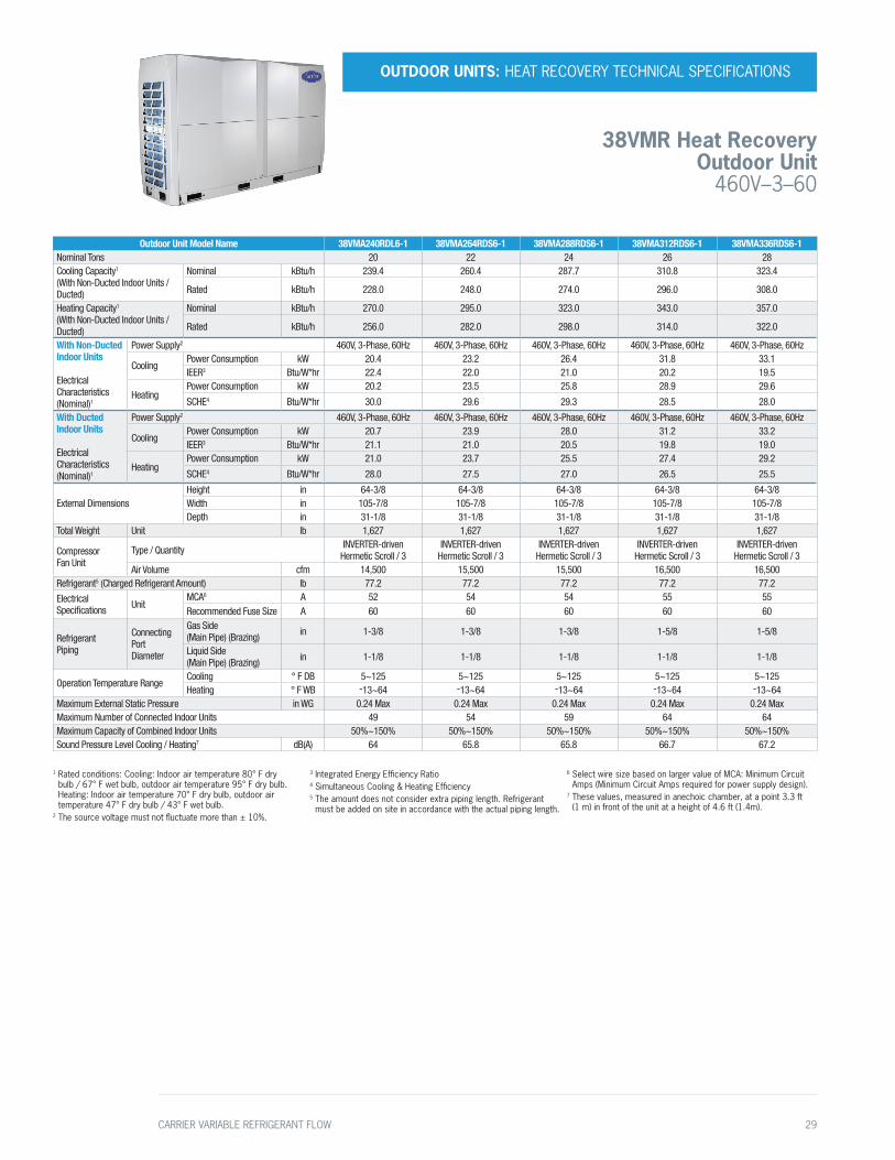
Outdoor Unit Model Name 38VMA240RDL5-1 38VMA264RDS5-1 38VMA288RDS5-1 38VMA312RDS5-1 38VMA336RDS5-1Nominal Tons 20 22 24 26 28
Cooling Capacity1 (With Non-Ducted Indoor Units /Ducted)
Nominal kBtu/h 239.4 260.4 287.7 310.8 323.4
Rated kBtu/h 230.0 248.0 274.0 296.0 308.0
Heating Capacity1 (With Non-Ducted Indoor Units /Ducted)
Nominal kBtu/h 270.0 295.0 323.0 343.0 357.0
Rated kBtu/h 256.0 282.0 298.0 314.0 322.0
With Non-Ducted Indoor Units Electrical Characteristics (Nominal)1
Power Supply2 208/230V, 3-Phase, 60Hz 208/230V, 3-Phase, 60Hz 208/230V, 3-Phase, 60Hz 208/230V, 3-Phase, 60Hz 208/230V, 3-Phase, 60Hz
CoolingPower Cconsumption kW 20.4 23.2 26.4 31.8 33.1
IEER3 Btu/W*hr 22.4 22.0 21.0 20.2 19.5
HeatingPower Consumption kW 20.2 23.5 25.8 28.9 29.6
SCHE4 Btu/W*hr 30.0 29.6 29.3 28.5 28.0
With Ducted Indoor Units Electrical Characteristics (Nominal)1
Power Supply2 208/230V, 3-Phase, 60Hz 208/230V, 3-Phase, 60Hz 208/230V, 3-Phase, 60Hz 208/230V, 3-Phase, 60Hz 208/230V, 3-Phase, 60Hz
CoolingPower Consumption kW 20.7 23.2 28.0 31.2 33.1
IEER3 Btu/W*hr 21.1 21.0 20.5 19.8 19.0
HeatingPower Consumption kW 21.0 23.7 25.5 27.4 29.2
SCHE4 Btu/W*hr 28.0 27.5 27.0 26.5 25.5
External Dimensions
Height in 64-3/8 64-3/8 64-3/8 64-3/8 64-3/8
Width in 105-7/8 105-7/8 105-7/8 105-7/8 105-7/8
Depth in 31-1/8 31-1/8 31-1/8 31-1/8 31-1/8
Total Weight Unit lb 1,627 1,627 1,627 1,627 1,627
Compressor Fan Unit
Type / Quantity INVERTER-driven Hermetic Scroll / 3
INVERTER-driven Hermetic Scroll / 3
INVERTER-driven Hermetic Scroll / 3
INVERTER-driven Hermetic Scroll / 3
INVERTER-driven Hermetic Scroll / 3
Air Volume cfm 14,500 15,500 15,500 16,500 16,500
Refrigerant5 (Charged Refrigerant Amount) lb 77.2 77.2 77.2 77.2 77.2
Electrical Specifications Unit
MCA6 A 101 104 104 106 106
Recommended Fuse Size A 110 110 110 110 110
Refrigerant Piping
Connecting Port Diameter
Gas Side (Main Pipe) (Brazing) in 1-3/8 1-3/8 1-3/8 1-5/8 1-5/8
Liquid Side (Main Pipe) (Brazing) in 1-1/8 1-1/8 1-1/8 1-1/8 1-1/8
Operation Temperature RangeCooling ° F DB 5~125 5~125 5~125 5~125 5~125
Heating ° F WB -13~64 -13~64 -13~64 -13~64 -13~64
Maximum External Static Pressure in WG 0.24 Max 0.24 Max 0.24 Max 0.24 Max 0.24 Max
Maximum Number of Connected Indoor Units 49 54 59 64 64
Maximum Capacity of Combined Indoor Units 50%~150% 50%~150% 50%~150% 50%~150% 50%~150%
Sound Pressure Level Cooling / Heating7 dB(A) 63.9 64.8 64.8 66.4 67.2
1 Rated conditions: Cooling: Indoor air temperature 80° F dry bulb / 67° F wet bulb, outdoor air temperature 95° F dry bulb. Heating: Indoor air temperature 70° F dry bulb, outdoor air temperature 47° F dry bulb / 43° F wet bulb.
2 The source voltage must not fluctuate more than ± 10%.
3 Integrated Energy Efficiency Ratio4 Simultaneous Cooling & Heating Efficiency5 The amount does not consider extra piping length. Refrigerant
must be added on site in accordance with the actual piping length.
6 Select wire size based on larger value of MCA: Minimum Circuit Amps (Minimum Circuit Amps required for power supply design).
7 These values, measured in anechoic chamber, at a point 3.3 ft (1 m) in front of the unit at a height of 4.6 ft (1.4m).
OUTDOOR UNITS: HEAT RECOVERY TECHNICAL SPECIFICATIONS
38VMR Heat Recovery Outdoor Unit 208/230V–3–60
26 CARRIER VARIABLE REFRIGERANT FLOW

Outdoor Unit Model Name 38VMA072RDS6-1 38VMA096RDS6-1 38VMA120RDS6-1
Nominal Tons 6 8 10
Cooling Capacity1 (With Non-Ducted Indoor Units / Ducted)
Nominal kBtu/h 72.0 96.0 119.7
Rated kBtu/h 69.0 92.0 114.0
Heating Capacity1 (With Non-Ducted Indoor Units / Ducted)
Nominal kBtu/h 80.0 108.0 126.0
Rated kBtu/h 77.0 103.0 120.0
With Non-Ducted Indoor Units Electrical Characteristics (Nominal)1
Power Supply2 460V, 3-Phase, 60Hz 460V, 3-Phase, 60Hz 460V, 3-Phase, 60Hz
CoolingPower Consumption kW 4.2 6.2 9.3
IEER3 Btu/W*hr 24.6 23.7 22.8
HeatingPower Consumption kW 4.4 7.2 9.5
SCHE4 Btu/W*hr 30.0 30.0 30.0
With Ducted Indoor Units Electrical Characteristics (Nominal)1
Power Supply2 460V, 3-Phase, 60Hz 460V, 3-Phase, 60Hz 460V, 3-Phase, 60Hz
CoolingPower Consumption kW 5.0 7.1 9.6
IEER3 Btu/W*hr 24.2 24.3 23.2
HeatingPower Consumption kW 5.7 8.0 9.8
SCHE4 Btu/W*hr 27.4 27.7 26.7
External Dimensions
Height in 64-3/8 64-3/8 64-3/8
Width in 52-3/4 52-3/4 52-3/4
Depth in 31-1/8 31-1/8 31-1/8
Total Weight Unit lb 672 672 672
CompressorFan Unit
Type / Quantity INVERTER-driven Hermetic Scroll / 1
INVERTER-driven Hermetic Scroll / 1
INVERTER-driven Hermetic Scroll / 1
Air Volume cfm 6,900 7,600 8,100
Refrigerant5 (Charged Refrigerant Amount) lb 26.5 26.5 26.5
Electrical Specifications Unit
MCA6 A 20 22 22
Recommended Fuse Size A 25 25 25
Refrigerant Piping
Connecting Port Diameter
Gas Side (Main Pipe) (Brazing) in 3/4 7/8 1-1/8
Liquid Side (Main Pipe) (Brazing) in 5/8 3/4 3/4
Operation Temperature RangeCooling ° F DB 5~125 5~125 5~125
Heating ° F WB -13~64 -13~64 -13~64
Maximum External Static Pressure in WG 0.24 Max 0.24 Max 0.24 Max
Maximum Number of Connected Indoor Units 15 20 24
Maximum Capacity of Combined Indoor Units 50%~150% 50%~150% 50%~150%
Sound Pressure Level Cooling / Heating7 dB(A) 58.4 61.7 62.7
1 Rated conditions: Cooling: Indoor air temperature 80° F dry bulb / 67° F wet bulb, outdoor air temperature 95° F dry bulb. Heating: Indoor air temperature 70° F dry bulb, outdoor air temperature 47° F dry bulb / 43° F wet bulb.
2 The source voltage must not fluctuate more than ± 10%.
3 Integrated Energy Efficiency Ratio4 Simultaneous Cooling & Heating Efficiency5 The amount does not consider extra piping length. Refrigerant
must be added on site in accordance with the actual piping length.
6 Select wire size based on larger value of MCA: Minimum Circuit Amps (Minimum Circuit Amps required for power supply design).
7 These values, measured in anechoic chamber, at a point 3.3 ft (1 m) in front of the unit at a height of 4.6 ft (1.4m).
OUTDOOR UNITS: HEAT RECOVERY TECHNICAL SPECIFICATIONS
38VMR Heat Recovery Outdoor Unit
460V–3–60
CARRIER VARIABLE REFRIGERANT FLOW 27

Outdoor Unit Model Name 38VMA144RDL6-1 38VMA168RDS6-1 38VMA192RDS6-1 38VMA216RDS6-1 38VMA240RDS6-1Nominal Tons 12 14 16 18 20Cooling Capacity1 (With Non-Ducted Indoor Units /Ducted)
Nominal kBtu/h 142.8 165.9 191.1 214.2 231.0
Rated kBtu/h 136.0 158.0 182.0 204.0 220.0
Heating Capacity1 (With Non-Ducted Indoor Units /Ducted)
Nominal kBtu/h 160.0 188.0 215.0 243.0 257.0
Rated kBtu/h 150.0 180.0 204.0 222.0 230.0
With Non-Ducted Indoor Units Electrical Characteristics (Nominal)1
Power Supply2 460V, 3-Phase, 60Hz 460V, 3-Phase, 60Hz 460V, 3-Phase, 60Hz 460V, 3-Phase, 60Hz 460V, 3-Phase, 60Hz
CoolingPower Consumption kW 9.0 11.9 14.7 16.8 19.7IEER3 Btu/W*hr 24.4 23.1 23.9 23.0 22.4
HeatingPower Consumption kW 9.6 13.3 16.2 18.0 20.2
SCHE4 Btu/W*hr 26.5 27.0 28.2 27.3 27.0
With Ducted Indoor Units Electrical Characteristics (Nominal)1
Power Supply2 460V, 3-Phase, 60Hz 460V, 3-Phase, 60Hz 460V, 3-Phase, 60Hz 460V, 3-Phase, 60Hz 460V, 3-Phase, 60Hz
CoolingPower Consumption kW 10.6 13.3 15.9 17.9 20.4 IEER3 Btu/W*hr 24.0 22.9 23.6 21.7 21.0
HeatingPower Consumption kW 11.8 14.4 17.4 19.1 20.9
SCHE4 Btu/W*hr 26.5 25.2 25.5 26.5 26.5
External DimensionsHeight in 64-3/8 64-3/8 64-3/8 64-3/8 64-3/8Width in 78-3/8 78-3/8 78-3/8 78-3/8 78-3/8Depth in 31-1/8 31-1/8 31-1/8 31-1/8 31-1/8
Total Weight Unit lb 1,137 1,137 1,137 1,137 1,137
CompressorFan Unit
Type / Quantity INVERTER-driven Hermetic Scroll / 2
INVERTER-driven Hermetic Scroll / 2
INVERTER-driven Hermetic Scroll / 2
INVERTER-driven Hermetic Scroll / 2
INVERTER-driven Hermetic Scroll / 2
Air Volume cfm 10,100 10,100 11,300 12,300 12,300Refrigerant5 (Charged Refrigerant Amount) lb 44.2 44.2 44.2 44.2 44.2Electrical Specifications Unit
MCA6 A 35 35 35 38 38Recommended Fuse Size A 40 40 40 40 40
Refrigerant Piping
Connecting Port Diameter
Gas Side (Main Pipe) (Brazing) in 1-1/8 1-1/8 1-1/8 1-1/8 1-3/8
Liquid Side (Main Pipe) (Brazing) in 7/8 7/8 7/8 1-1/8 1-1/8
Operation Temperature RangeCooling ° F DB 5~125 5~125 5~125 5~125 5~125Heating ° F WB -13~64 -13~64 -13~64 -13~64 -13~64
Maximum External Static Pressure in WG 0.24 Max 0.24 Max 0.24 Max 0.24 Max 0.24 MaxMaximum Number of Connected Indoor Units 29 34 39 44 49Maximum Capacity of Combined Indoor Units Sound Pressure Level Cooling / Heating7 dB(A) 63.3 63.3 64.9 67.1 67.1
1 Rated conditions: Cooling: Indoor air temperature 80° F dry bulb / 67° F wet bulb, outdoor air temperature 95° F dry bulb. Heating: Indoor air temperature 70° F dry bulb, outdoor air temperature 47° F dry bulb / 43° F wet bulb.
2 The source voltage must not fluctuate more than ± 10%.
3 Integrated Energy Efficiency Ratio4 Simultaneous Cooling & Heating Efficiency5 The amount does not consider extra piping length. Refrigerant
must be added on site in accordance with the actual piping length.
6 Select wire size based on larger value of MCA: Minimum Circuit Amps (Minimum Circuit Amps required for power supply design).
7 These values, measured in anechoic chamber, at a point 3.3 ft (1 m) in front of the unit at a height of 4.6 ft (1.4m).
OUTDOOR UNITS: HEAT RECOVERY TECHNICAL SPECIFICATIONS
38VMR Heat Recovery Outdoor Unit 460V–3–60
28 CARRIER VARIABLE REFRIGERANT FLOW
Outdoor Unit Model Name 38VMA240RDL6-1 38VMA264RDS6-1 38VMA288RDS6-1 38VMA312RDS6-1 38VMA336RDS6-1Nominal Tons 20 22 24 26 28Cooling Capacity1 (With Non-Ducted Indoor Units /Ducted)
Nominal kBtu/h 239.4 260.4 287.7 310.8 323.4
Rated kBtu/h 228.0 248.0 274.0 296.0 308.0
Heating Capacity1 (With Non-Ducted Indoor Units /Ducted)
Nominal kBtu/h 270.0 295.0 323.0 343.0 357.0
Rated kBtu/h 256.0 282.0 298.0 314.0 322.0
With Non-Ducted Indoor Units Electrical Characteristics (Nominal)1
Power Supply2 460V, 3-Phase, 60Hz 460V, 3-Phase, 60Hz 460V, 3-Phase, 60Hz 460V, 3-Phase, 60Hz 460V, 3-Phase, 60Hz
CoolingPower Consumption kW 20.4 23.2 26.4 31.8 33.1IEER3 Btu/W*hr 22.4 22.0 21.0 20.2 19.5
HeatingPower Consumption kW 20.2 23.5 25.8 28.9 29.6
SCHE4 Btu/W*hr 30.0 29.6 29.3 28.5 28.0
With Ducted Indoor Units Electrical Characteristics (Nominal)1
Power Supply2 460V, 3-Phase, 60Hz 460V, 3-Phase, 60Hz 460V, 3-Phase, 60Hz 460V, 3-Phase, 60Hz 460V, 3-Phase, 60Hz
CoolingPower Consumption kW 20.7 23.9 28.0 31.2 33.2 IEER3 Btu/W*hr 21.1 21.0 20.5 19.8 19.0
HeatingPower Consumption kW 21.0 23.7 25.5 27.4 29.2
SCHE4 Btu/W*hr 28.0 27.5 27.0 26.5 25.5
External DimensionsHeight in 64-3/8 64-3/8 64-3/8 64-3/8 64-3/8Width in 105-7/8 105-7/8 105-7/8 105-7/8 105-7/8Depth in 31-1/8 31-1/8 31-1/8 31-1/8 31-1/8
Total Weight Unit lb 1,627 1,627 1,627 1,627 1,627
CompressorFan Unit
Type / Quantity INVERTER-driven Hermetic Scroll / 3
INVERTER-driven Hermetic Scroll / 3
INVERTER-driven Hermetic Scroll / 3
INVERTER-driven Hermetic Scroll / 3
INVERTER-driven Hermetic Scroll / 3
Air Volume cfm 14,500 15,500 15,500 16,500 16,500Refrigerant5 (Charged Refrigerant Amount) lb 77.2 77.2 77.2 77.2 77.2
Electrical Specifications Unit
MCA6 A 52 54 54 55 55Recommended Fuse Size A 60 60 60 60 60
Refrigerant Piping
Connecting Port Diameter
Gas Side (Main Pipe) (Brazing) in 1-3/8 1-3/8 1-3/8 1-5/8 1-5/8
Liquid Side (Main Pipe) (Brazing) in 1-1/8 1-1/8 1-1/8 1-1/8 1-1/8
Operation Temperature RangeCooling ° F DB 5~125 5~125 5~125 5~125 5~125Heating ° F WB -13~64 -13~64 -13~64 -13~64 -13~64
Maximum External Static Pressure in WG 0.24 Max 0.24 Max 0.24 Max 0.24 Max 0.24 MaxMaximum Number of Connected Indoor Units 49 54 59 64 64Maximum Capacity of Combined Indoor Units 50%~150% 50%~150% 50%~150% 50%~150% 50%~150%Sound Pressure Level Cooling / Heating7 dB(A) 64 65.8 65.8 66.7 67.2
1 Rated conditions: Cooling: Indoor air temperature 80° F dry bulb / 67° F wet bulb, outdoor air temperature 95° F dry bulb. Heating: Indoor air temperature 70° F dry bulb, outdoor air temperature 47° F dry bulb / 43° F wet bulb.
2 The source voltage must not fluctuate more than ± 10%.
3 Integrated Energy Efficiency Ratio4 Simultaneous Cooling & Heating Efficiency5 The amount does not consider extra piping length. Refrigerant
must be added on site in accordance with the actual piping length.
6 Select wire size based on larger value of MCA: Minimum Circuit Amps (Minimum Circuit Amps required for power supply design).
7 These values, measured in anechoic chamber, at a point 3.3 ft (1 m) in front of the unit at a height of 4.6 ft (1.4m).
OUTDOOR UNITS: HEAT RECOVERY TECHNICAL SPECIFICATIONS
38VMR Heat Recovery Outdoor Unit
460V–3–60
CARRIER VARIABLE REFRIGERANT FLOW 29
Main MDC Units
Outdoor Unit Model Name 40VMD006M---3 40VMD008M---3 40VMD010M---3 40VMD016M---3 40VMD016ML-3Power Supply 208/230V, 1-Phase, 60Hz 208/230V, 1-Phase, 60Hz 208/230V, 1-Phase, 60Hz 208/230V, 1-Phase, 60Hz 208/230V, 1-Phase, 60Hz
Number of Ports 6 8 10 16 16
Unit
Unit Dimensions W x H x D in 37 x 12-3/4 x 22-5/8 37 x 12-3/4 x 22-5/8 37 x 12-3/4 x 22-5/8 46-1/2 x 12-3/4
x 22-5/846-1/2 x 12-3/4
x 22-5/8
Packing Dimensions W x H x D in 44-1/2 x 18 x 33-1/8 44-1/2 x 18 x 33-1/8 44-1/2 x 18 x 33-1/8 53-7/8 x 18 x 33-1/8 53-7/8 x 18 x 33-1/8
Net / Gross Weight lb 132/205 137/209 143/216 190/269 196/273
Design Pressure, High / Low psig 580/320 580/320 580/320 580/320 580/320
Connecting Wiring
Power WiringSized Per NEC and
Local Codes Based on Nameplate Electrical Data
Sized Per NEC and Local Codes Based on
Nameplate Electrical Data
Sized Per NEC and Local Codes Based on
Nameplate Electrical Data
Sized Per NEC and Local Codes Based on
Nameplate Electrical Data
Sized Per NEC and Local Codes Based on
Nameplate Electrical Data
Signal Wiring 2-Core Shielded Cable 18 AWG
2-Core Shielded Cable 18 AWG
2-Core Shielded Cable 18 AWG
2-Core Shielded Cable 18 AWG
2-Core Shielded Cable 18 AWG
Condensate Pipe Diameter, “OD” in 1 1 1 1 1
MCA(A) 0.73 0.89 1.05 1.54 1.54
Capacity Per Port kBtu/h 54 54 54 54 54
Sub MDC Units
Outdoor Unit Model Name 40VMD006S--3 40VMD008S--3 40VMD010S--3 40VMD016S--3Power Supply 208/230V, 1-Phase, 60Hz 208/230V, 1-Phase, 60Hz 208/230V, 1-Phase, 60Hz 208/230V, 1-Phase, 60Hz
Number of Ports 6 8 10 16
Unit
Unit Dimensions W x H x D in 37 x 12-3/4 x 22-5/8 37 x 12-3/4 x 22-5/8 37 x 12-3/4 x 22-5/8 46-1/2 x 12-3/4 x 22-5/8
Packing Dimensions W x H x D in 44-1/2 x 18 x 33-1/8 44-1/2 x 18 x 33-1/8 44-1/2 x 18 x 33-1/8 53-7/8 x 18 x 33-1/8
Net / Gross Weight lb 126/168 130/203 137/209 183/262
Design Pressure, High / Low psig 580/320 580/320 580/320 580/320
Connecting Wiring
Power Wiring Sized Per NEC and Local Codes Based On Nameplate Electrical Data
Sized Per NEC and Local Codes Based On Nameplate Electrical Data
Sized Per NEC and Local Codes Based On Nameplate Electrical Data
Sized Per NEC and Local Codes Based On Nameplate Electrical Data
Signal Wiring 2-Core Shielded Cable 18 AWG
2-Core Shielded Cable 18 AWG
2-Core Shielded Cable 18 AWG
2-Core Shielded Cable 18 AWG
Condensate Pipe Diameter, “OD” in 1 1 1 1
MCA(A) 0.69 0.85 1.01 1.49
Capacity Per Port kBtu/h 54 54 54 54
OUTDOOR UNITS: MULTIPORT DISTRIBUTION CONTROLLER SPECIFICATIONS
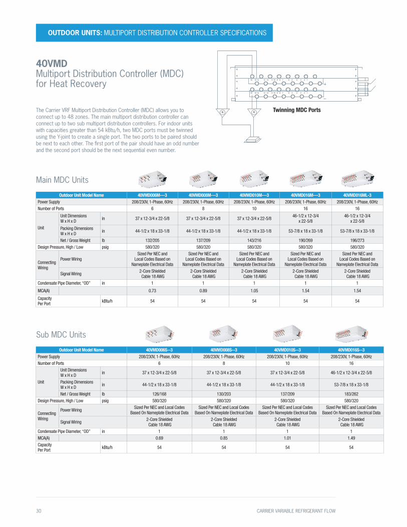
40VMD Multiport Distribution Controller (MDC) for Heat Recovery
Twinning MDC Ports
16 15 14 13 12 11 10 9 8 7 6 5 4 3 2 1
GG
16 15 14 13 12 11 10 9 8 7 6 5 4 3 2 1
The Carrier VRF Multiport Distribution Controller (MDC) allows you to connect up to 48 zones. The main multiport distribution controller can connect up to two sub multiport distribution controllers. For indoor units with capacities greater than 54 kBtu/h, two MDC ports must be twinned using the Y-joint to create a single port. The two ports to be paired should be next to each other. The first port of the pair should have an odd number and the second port should be the next sequential even number.
30 CARRIER VARIABLE REFRIGERANT FLOW

Outdoor Unit Model Name 38VMB036HDS3-1 38VMB048HDS3-1 38VMB060HDS3-1Nominal Tons 3 4 5
Cooling Capacity1 (With Non-Ducted Indoor Units / Ducted)
Nominal kBtu/h 36.0 48.0 60.0
Rated kBtu/h 36.0 48.0 60.0
Heating Capacity1 (With Non-Ducted Indoor Units / Ducted)
Nominal kBtu/h 40.0 52.5 66
Rated kBtu/h 40.0 52.5 66
With Non-Ducted Indoor Units Electrical Characteristics (Nominal)1
Power Supply2 208/230V, 1-Phase, 60Hz 208/230V, 1-Phase, 60Hz 208/230V, 1-Phase, 60Hz
CoolingPower Consumption kW 3.1 4.6 6.1
SEER3 Btu/W*hr 19.2 19.2 18.6
HeatingPower Consumption kW 3.1 4.3 5.8
HSPF4 Btu/W*hr 9.2 9.2 10.0
With Ducted Indoor Units Electrical Characteristics (Nominal)1
Power Supply2 208/230V, 1-Phase, 60Hz 208/230V, 1-Phase, 60Hz 208/230V, 1-Phase, 60Hz
CoolingPower Consumption kW 2.9 4.7 6.1
SEER3 Btu/W*hr 17.8 17.8 18.2
HeatingPower Consumption kW 3.0 4.2 5.7
HSPF4 Btu/W*hr 9.6 9.6 10.0
External Dimensions
Height in 52-1/4 52-1/4 52-1/4
Width in 35-1/2 35-1/2 35-1/2
Depth in 15-3/4 15-3/4 15-3/4
Total Weight Unit lb 220 220 220
CompressorFan Unit
Type / Quantity INVERTER-driven Hermetic Rotary / 1
INVERTER-driven Hermetic Rotary / 1
INVERTER-driven Hermetic Rotary / 1
Air Volume cfm 4,100 4,100 4,100
Refrigerant5 (Charged Refrigerant Amount) lb 8.6 8.6 8.6
Electrical Specifications Unit
MCA6 A 36 38 40
Recommended Fuse Size A 40 40 45
Refrigerant Piping
Connecting Port Diameter
Gas Side (Main Pipe) (Brazing) in 5/8 5/8 3/4
Liquid Side (Main Pipe) (Brazing) in 3/8 3/8 3/8
Operation Temperature RangeCooling ° F DB 5~118 5~118 5~118
Heating ° F WB -13~64 -13~64 -13~64
Maximum Number of Connected Indoor Units 5 7 9
Maximum Capacity of Combined Indoor Units 50%~130% 50%~130% 50%~130%
Sound Pressure Level Cooling / Heating7 dB(A) 58.7 60.1 60.7
1 Rated conditions: Cooling: Indoor air temperature 80° F dry bulb / 67° F wet bulb, outdoor air temperature 95° F dry bulb. Heating: Indoor air temperature 70° F dry bulb, outdoor air temperature 47° F dry bulb / 43° F wet bulb.
2 The source voltage must not fluctuate more than ± 10%.
3 Seasonal Energy Efficiency Ratio4 Heating Seasonal Performance Factor5 The amount does not consider extra piping length. Refrigerant
must be added on site in accordance with the actual piping length.
6 Select wire size based on larger value of MCA: Minimum Circuit Amps (Minimum Circuit Amps required for power supply design).
7 These values, measured in anechoic chamber, at a point 3.3 ft (1 m) in front of the unit at a height of 4.6 ft (1.4m).
OUTDOOR UNITS: HEAT PUMP TECHNICAL SPECIFICATIONS
38VMH–1PH Single-phase Heat Pump Outdoor Unit
208/230V–1–60
CARRIER VARIABLE REFRIGERANT FLOW 31
Single ModuleOutdoor Unit Model Name 38VMA072HDS5-1 38VMA096HDS5-1 38VMA120HDS5-1 38VMA144HDS5-1
Nominal Tons 6 8 10 12
Cooling Capacity1 (With Non-Ducted Indoor Units / Ducted)
Nominal kBtu/h 72.0 96.0 117.6 142.8
Rated kBtu/h 69.0 92.0 112.0 136.0
Heating Capacity1 (With Non-Ducted Indoor Units / Ducted)
Nominal kBtu/h 80.0 108.0 126.0 160.0
Rated kBtu/h 77.0 103.0 120.0 150.0
With Non-Ducted Indoor Units Electrical Characteristics (Nominal)1
Power Supply2 208/230V, 3-Phase, 60Hz 208/230V, 3-Phase, 60Hz 208/230V, 3-Phase, 60Hz 208/230V, 3-Phase, 60Hz
CoolingPower Consumption kW 4.1 6.2 8.8 12.1
IEER3 Btu/W*hr 22.5 23.5 22.5 19.5
HeatingPower Consumption kW 4.5 7.2 9.0 12.1
COP4 W/W 4.29 3.82 3.6 3.4
With Ducted Indoor Units Electrical Characteristics (Nominal)1
Power Supply2 208/230V, 3-Phase, 60Hz 208/230V, 3-Phase, 60Hz 208/230V, 3-Phase, 60Hz 208/230V, 3-Phase, 60Hz
CoolingPower Consumption kW 5.1 7.5 9.6 12.3
IEER3 Btu/W*hr 23.6 23.0 21.9 19.5
HeatingPower Consumption kW 5.6 8.0 9.8 12.6
COP4 W/W 3.85 3.63 3.45 3.35
External Dimensions
Height in 64-3/8 64-3/8 64-3/8 64-3/8
Width in 52-3/4 52-3/4 52-3/4 52-3/4
Depth in 31-1/8 31-1/8 31-1/8 31-1/8
Total Weight Unit lb 659 659 659 780
CompressorFan Unit
Type / Quantity INVERTER-driven Hermetic Scroll / 1
INVERTER-driven Hermetic Scroll / 1
INVERTER-driven Hermetic Scroll / 1
INVERTER-driven Hermetic Scroll / 2
Air Volume cfm 7,650 7,650 8,250 8,830
Refrigerant5 (Charged Refrigerant Amount) lb 37.5 37.5 37.5 37.5
Electrical Specifications Unit
MCA6 A 45 46 46 70
Recommended Fuse Size A 50 50 50 80
Refrigerant Piping
Connecting Port Diameter
Gas Side (Main Pipe) (Brazing) in 7/8 7/8 1-1/8 1-1/8
Liquid Side (Main Pipe) (Brazing) in 3/8 3/8 1/2 1/2
Balance Pipe (Brazing) in 1/4 1/4 1/4 1/4
Operation Temperature RangeCooling ° F DB 5~125 5~125 5~125 5~125
Heating ° F WB -5~64 -5~64 -5~64 -5~64
Maximum External Static Pressure in WG 0.24 0.24 0.24 0.24
Maximum Number of Connected Indoor Units 13 16 20 26
Maximum Capacity of Combined Indoor Units 50%~135% 50%~135% 50%~135% 50%~135%
Sound Pressure Level Cooling / Heating7 dB(A) 62.5 63 63 65.5
1 Rated conditions: Cooling: Indoor air temperature 80° F dry bulb / 67° F wet bulb, outdoor air temperature 95° F dry bulb. Heating: Indoor air temperature 70° F dry bulb, outdoor air temperature 47° F dry bulb / 43° F wet bulb.
2 The source voltage must not fluctuate more than ± 10%.
3 Integrated Energy Efficiency Ratio4 Coefficient of Performance5 The amount does not consider extra piping length. Refrigerant
must be added on site in accordance with the actual piping length.
6 Select wire size based on larger value of MCA: Minimum Circuit Amps (Minimum Circuit Amps required for power supply design).
7 These values, measured in anechoic chamber, at a point 3.3 ft (1 m) in front of the unit at a height of 4.6 ft (1.4m).
OUTDOOR UNITS: HEAT PUMP TECHNICAL SPECIFICATIONS
38VMH Heat Pump Outdoor Unit 208/230V–3–60
32 CARRIER VARIABLE REFRIGERANT FLOW

Dual Module (Combined)Combination Model Number 38VMA168HDS5-1 38VMA192HDS5-1 38VMA216HDS5-1 38VMA240HDS5-1 38VMA264HDS5-1 38VMA288HDS5-1
Combination Units38VMA096HDS5-1 38VMA096HDS5-1 38VMA120HDS5-1 38VMA120HDS5-1 38VMA144HDS5-1 38VMA144HDS5-138VMA072HDS5-1 38VMA096HDS5-1 38VMA096HDS5-1 38VMA120HDS5-1 38VMA120HDS5-1 38VMA144HDS5-1
Nominal Tons 14 16 18 20 22 24Cooling Capacity1 (With Non-Ducted Indoor Units / Ducted)
Nominal kBtu/h 163.8 184.8 205.8 224.7 258.3 283.5
Rated kBtu/h 156.0 176.0 196.0 214.0 246.0 270.0
Heating Capacity1 (With Non-Ducted Indoor Units / Ducted)
Nominal kBtu/h 188.0 216.0 234.0 252.0 286.0 320.0
Rated kBtu/h 180.0 206.0 224.0 240.0 270.0 300.0
With Non-ducted Indoor Units Electrical Characteristics (Nominal)1
Power supply2 208/230V, 3-Phase, 60Hz
208/230V, 3-Phase, 60Hz
208/230V, 3-Phase, 60Hz
208/230V, 3-Phase, 60Hz
208/230V, 3-Phase, 60Hz
208/230V, 3-Phase, 60Hz
CoolingPower Consumption kW 11.0 12.9 15.3 18.6 23.9 27.0 IEER3 Btu/W*hr 22.0 21.5 20.5 20.0 19.0 18.0
HeatingPower Consumption kW 12.4 14.7 16.7 18.4 22.8 26.0 COP4 W/W 3.80 3.75 3.62 3.54 3.27 3.20
With Ducted Indoor Units Electrical Characteristics (Nominal)1
Power supply2 208/230V, 3-Phase, 60Hz
208/230V, 3-Phase, 60Hz
208/230V, 3-Phase, 60Hz
208/230V, 3-Phase, 60Hz
208/230V, 3-Phase, 60Hz
208/230V, 3-Phase, 60Hz
CoolingPower Consumption kW 12.4 14.5 16.6 18.7 24.2 27.4 IEER3 Btu/W*hr 22.0 22.0 21.3 20.6 19.0 18.0
HeatingPower Consumption kW 13.9 16.1 17.8 19.5 23.8 26.4 COP4 W/W 3.64 3.60 3.54 3.47 3.20 3.20
External DimensionsHeight in 64-3/8 64-3/8 64-3/8 64-3/8 64-3/8 64-3/8Width in 52-3/4 x 2 52-3/4 x 2 52-3/4 x 2 52-3/4 x 2 52-3/4 x 2 52-3/4 x 2Depth in 31-1/8 31-1/8 31-1/8 31-1/8 31-1/8 31-1/8
Total Weight Unit lb 659 x 2 659 x 2 659 x 2 659 x 2 780 + 659 780 + 780
CompressorFan Unit
Type / Quantity INVERTER-driven Hermetic Scroll / 2
INVERTER-driven Hermetic Scroll / 2
INVERTER-driven Hermetic Scroll / 2
INVERTER-driven Hermetic Scroll / 2
INVERTER-driven Hermetic Scroll / 3
INVERTER-driven Hermetic Scroll / 4
Air Volume cfm 7,650 x 2 7,650 x 2 8,250 + 7650 8,250 x 2 8,830 + 8250 8,830 x 2Refrigerant5 (Charged Refrigerant Amount) lb 37.5 x 2 37.5 x 2 37.5 x 2 37.5 x 2 37.5 x 2 37.5 x 2Electrical Specifications Unit
MCA6 A 46 + 45 46 + 46 46 + 46 46 + 46 70 + 46 70 + 70Recommended Fuse Size A 50 + 50 50 + 50 50 + 50 50 + 50 80 + 50 80 + 80
Refrigerant Piping
Connecting Port Diameter
Gas Side (Main Pipe) (Brazing) in 1-1/8 1-1/8 1-1/8 1-1/8 1-3/8 1-3/8
Liquid Side (Main Pipe) (Brazing) in 5/8 5/8 5/8 5/8 3/4 3/4
Balance Pipe (Brazing) in 1/4 1/4 1/4 1/4 1/4 1/4
Operation Temperature RangeCooling ° F DB 5~125 5~125 5~125 5~125 5~125 5~125Heating ° F WB -5~64 -5~64 -5~64 -5~64 -5~64 -5~64
Maximum External Static Pressure in WG 0.24 0.24 0.24 0.24 0.24 0.24Maximum Number of Connected Indoor Units 29 33 36 39 46 50Maximum Capacity of Combined Indoor Units 50%~135% 50%~135% 50%~135% 50%~135% 50%~135% 50%~135%Sound Pressure Level Cooling / Heating7 dB(A) 65 65 65 65 66.5 67.5
1 Rated conditions: Cooling: Indoor air temperature 80° F dry bulb / 67° F wet bulb, outdoor air temperature 95° F dry bulb. Heating: Indoor air temperature 70° F dry bulb, outdoor air temperature 47° F dry bulb / 43° F wet bulb.
2 The source voltage must not fluctuate more than ± 10%.
3 Integrated Energy Efficiency Ratio4 Coefficient of Performance5 The amount does not consider extra piping length. Refrigerant
must be added on site in accordance with the actual piping length.
6 Select wire size based on larger value of MCA: Minimum Circuit Amps (Minimum Circuit Amps required for power supply design).
7 These values, measured in anechoic chamber, at a point 3.3 ft (1 m) in front of the unit at a height of 4.6 ft (1.4m).
OUTDOOR UNITS: HEAT PUMP TECHNICAL SPECIFICATIONS
38VMH Heat Pump Outdoor Unit
208/230V–3–60
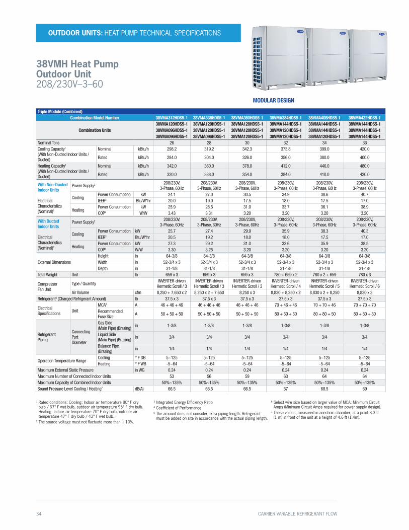
MODULAR DESIGN
CARRIER VARIABLE REFRIGERANT FLOW 33
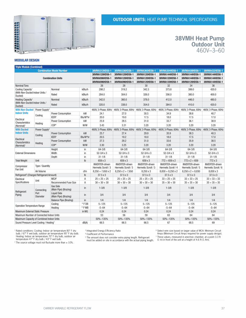
Triple Module (Combined)Combination Model Number 38VMA312HDS5-1 38VMA336HDS5-1 38VMA360HDS5-1 38VMA384HDS5-1 38VMA408HDS5-1 38VMA432HDS5-1
Combination Units38VMA120HDS5-1 38VMA120HDS5-1 38VMA120HDS5-1 38VMA144HDS5-1 38VMA144HDS5-1 38VMA144HDS5-138VMA096HDS5-1 38VMA120HDS5-1 38VMA120HDS5-1 38VMA120HDS5-1 38VMA144HDS5-1 38VMA144HDS5-138VMA096HDS5-1 38VMA096HDS5-1 38VMA120HDS5-1 38VMA120HDS5-1 38VMA120HDS5-1 38VMA144HDS5-1
Nominal Tons 26 28 30 32 34 36Cooling Capacity1 (With Non-Ducted Indoor Units / Ducted)
Nominal kBtu/h 298.2 319.2 342.3 373.8 399.0 420.0
Rated kBtu/h 284.0 304.0 326.0 356.0 380.0 400.0
Heating Capacity1 (With Non-Ducted Indoor Units / Ducted)
Nominal kBtu/h 342.0 360.0 378.0 412.0 446.0 480.0
Rated kBtu/h 320.0 338.0 354.0 384.0 410.0 420.0
With Non-Ducted Indoor Units Electrical Characteristics (Nominal)1
Power Supply2 208/230V, 3-Phase, 60Hz
208/230V, 3-Phase, 60Hz
208/230V, 3-Phase, 60Hz
208/230V, 3-Phase, 60Hz
208/230V, 3-Phase, 60Hz
208/230V, 3-Phase, 60Hz
CoolingPower Consumption kW 24.1 27.0 30.5 34.9 38.6 40.7 IEER3 Btu/W*hr 20.0 19.0 17.5 18.0 17.5 17.0
HeatingPower Consumption kW 25.9 28.5 31.0 33.7 36.1 38.9 COP4 W/W 3.43 3.31 3.20 3.20 3.20 3.20
With Ducted Indoor Units Electrical Characteristics (Nominal)1
Power Supply2 208/230V, 3-Phase, 60Hz
208/230V, 3-Phase, 60Hz
208/230V, 3-Phase, 60Hz
208/230V, 3-Phase, 60Hz
208/230V, 3-Phase, 60Hz
208/230V, 3-Phase, 60Hz
CoolingPower Consumption kW 25.7 27.4 29.9 35.9 38.3 40.3 IEER3 Btu/W*hr 20.5 19.2 18.0 18.0 17.5 17.0
HeatingPower Consumption kW 27.3 29.2 31.0 33.6 35.9 38.5 COP4 W/W 3.30 3.25 3.20 3.20 3.20 3.20
External DimensionsHeight in 64-3/8 64-3/8 64-3/8 64-3/8 64-3/8 64-3/8Width in 52-3/4 x 3 52-3/4 x 3 52-3/4 x 3 52-3/4 x 3 52-3/4 x 3 52-3/4 x 3Depth in 31-1/8 31-1/8 31-1/8 31-1/8 31-1/8 31-1/8
Total Weight Unit lb 659 x 3 659 x 3 659 x 3 780 + 659 x 2 780 x 2 + 659 780 x 3
CompressorFan Unit
Type / Quantity INVERTER-driven Hermetic Scroll / 3
INVERTER-driven Hermetic Scroll / 3
INVERTER-driven Hermetic Scroll / 3
INVERTER-driven Hermetic Scroll / 4
INVERTER-driven Hermetic Scroll / 5
INVERTER-driven Hermetic Scroll / 6
Air Volume cfm 8,250 + 7,650 x 2 8,250 x 2 + 7,650 8,250 x 3 8,830 + 8,250 x 2 8,830 x 2 + 8,250 8,830 x 3Refrigerant5 (Charged Refrigerant Amount) lb 37.5 x 3 37.5 x 3 37.5 x 3 37.5 x 3 37.5 x 3 37.5 x 3
Electrical Specifications Unit
MCA6 A 46 + 46 + 46 46 + 46 + 46 46 + 46 + 46 70 + 46 + 46 70 + 70 + 46 70 + 70 + 70Recommended Fuse Size A 50 + 50 + 50 50 + 50 + 50 50 + 50 + 50 80 + 50 + 50 80 + 80 + 50 80 + 80 + 80
Refrigerant Piping
Connecting Port Diameter
Gas Side (Main Pipe) (Brazing) in 1-3/8 1-3/8 1-3/8 1-3/8 1-3/8 1-3/8
Liquid Side (Main Pipe) (Brazing) in 3/4 3/4 3/4 3/4 3/4 3/4
Balance Pipe (Brazing) in 1/4 1/4 1/4 1/4 1/4 1/4
Operation Temperature RangeCooling ° F DB 5~125 5~125 5~125 5~125 5~125 5~125Heating ° F WB -5~64 -5~64 -5~64 -5~64 -5~64 -5~64
Maximum External Static Pressure in WG 0.24 0.24 0.24 0.24 0.24 0.24Maximum Number of Connected Indoor Units 53 56 59 63 64 64Maximum Capacity of Combined Indoor Units 50%~135% 50%~135% 50%~135% 50%~135% 50%~135% 50%~135%Sound Pressure Level Cooling / Heating7 dB(A) 66.5 66.5 66.5 67 68.5 69
1 Rated conditions: Cooling: Indoor air temperature 80° F dry bulb / 67° F wet bulb, outdoor air temperature 95° F dry bulb. Heating: Indoor air temperature 70° F dry bulb, outdoor air temperature 47° F dry bulb / 43° F wet bulb.
2 The source voltage must not fluctuate more than ± 10%.
3 Integrated Energy Efficiency Ratio4 Coefficient of Performance5 The amount does not consider extra piping length. Refrigerant
must be added on site in accordance with the actual piping length.
6 Select wire size based on larger value of MCA: Minimum Circuit Amps (Minimum Circuit Amps required for power supply design).
7 These values, measured in anechoic chamber, at a point 3.3 ft (1 m) in front of the unit at a height of 4.6 ft (1.4m).
OUTDOOR UNITS: HEAT PUMP TECHNICAL SPECIFICATIONS
38VMH Heat Pump Outdoor Unit 208/230V–3–60
MODULAR DESIGN
34 CARRIER VARIABLE REFRIGERANT FLOW
Technical Specifications
Single ModuleOutdoor Unit Model Name 38VMA072HDS6-1 38VMA096HDS6-1 38VMA120HDS6-1 38VMA144HDS6-1
Nominal Tons 6 8 10 12
Cooling Capacity1 (With Non-Ducted Indoor Units / Ducted)
Nominal kBtu/h 72.0 96.0 117.6 142.8
Rated kBtu/h 69.0 92.0 112.0 136.0
Heating capacity1 (With Non-Ducted Indoor Units / Ducted)
Nominal kBtu/h 80.0 108.0 126.0 160.0
Rated kBtu/h 77.0 103.0 120.0 150.0
With Non-Ducted Indoor Units Electrical Characteristics (Nominal)1
Power Supply2 460V, 3-Phase, 60Hz 460V, 3-Phase, 60Hz 460V, 3-Phase, 60Hz 460V, 3-Phase, 60Hz
CoolingPower Consumption kW 4.1 6.2 8.8 12.1
IEER3 Btu/W*hr 22.5 23.5 22.5 19.5
HeatingPower consumption kW 4.5 7.2 9.0 12.1
COP4 W/W 4.29 3.8 3.60 3.40
With Ducted Indoor Units Electrical Characteristics (Nominal)1
Power Supply2 460V, 3-Phase, 60Hz 460V, 3-Phase, 60Hz 460V, 3-Phase, 60Hz 460V, 3-Phase, 60Hz
CoolingPower Consumption kW 5.1 7.5 9.6 12.3
IEER3 Btu/W*hr 23.6 23.0 21.9 19.5
HeatingPower Consumption kW 5.6 8.0 9.8 12.6
COP4 W/W 3.85 3.63 3.45 3.35
External Dimensions
Height in 64-3/8 64-3/8 64-3/8 64-3/8
Width in 52-3/4 52-3/4 52-3/4 52-3/4
Depth in 31-1/8 31-1/8 31-1/8 31-1/8
Total Weight Unit lb 659 659 659 772
Compressor Fan Unit
Type / Quantity INVERTER-driven Hermetic Scroll / 1
INVERTER-driven Hermetic Scroll / 1
INVERTER-driven Hermetic Scroll / 1
INVERTER-driven Hermetic Scroll / 2
Air Volume cfm 7650 7650 8250 8830
Refrigerant5 (Charged Refrigerant Amount) lb 37.5 37.5 37.5 37.5
Electrical Specifications Unit
MCA6 A 22 25 25 33
Recommended Fuse Size A 25 30 30 35
Refrigerant Piping
Connecting Port Diameter
Gas Side (Main Pipe) (Brazing) in 7/8 7/8 1-1/8 1-1/8
Liquid Side (Main Pipe) (Brazing) in 3/8 3/8 1/2 1/2
Balance Pipe (Brazing) in 1/4 1/4 1/4 1/4
Operation Temperature RangeCooling ° F DB 5~125 5~125 5~125 5~125
Heating ° F WB -5~64 -5~64 -5~64 -5~64
Maximum External Static Pressure in WG 0.24 0.24 0.24 0.24
Maximum Number of Connected Indoor Units 13 16 20 26
Maximum Capacity of Combined Indoor Units 50%~135% 50%~135% 50%~135% 50%~135%
Sound Pressure Level Cooling / Heating7 dB(A) 62.5 63 63 65.5
1 Rated conditions: Cooling: Indoor air temperature 80° F dry bulb / 67° F wet bulb, outdoor air temperature 95° F dry bulb. Heating: Indoor air temperature 70° F dry bulb, outdoor air temperature 47° F dry bulb / 43° F wet bulb.
2 The source voltage must not fluctuate more than ± 10%.
3 Integrated Energy Efficiency Ratio4 Coefficient of Performance5 The amount does not consider extra piping length. Refrigerant
must be added on site in accordance with the actual piping length.
6 Select wire size based on larger value of MCA: Minimum Circuit Amps (Minimum Circuit Amps required for power supply design).
7 These values, measured in anechoic chamber, at a point 3.3 ft (1 m) in front of the unit at a height of 4.6 ft (1.4m).
OUTDOOR UNITS: HEAT PUMP TECHNICAL SPECIFICATIONS
38VMH Heat Pump Outdoor Unit
460V–3–60
CARRIER VARIABLE REFRIGERANT FLOW 35

Dual Module (Combined)Combination Model Number 38VMA168HDS6-1 38VMA192HDS6-1 38VMA216HDS6-1 38VMA240HDS6-1 38VMA264HDS6-1 38VMA288HDS6-1
Combination Units38VMA096HDS6-1 38VMA096HDS6-1 38VMA120HDS6-1 38VMA120HDS6-1 38VMA144HDS6-1 38VMA144HDS6-138VMA072HDS6-1 38VMA096HDS6-1 38VMA096HDS6-1 38VMA120HDS6-1 38VMA120HDS6-1 38VMA144HDS6-1
Nominal Tons 14 16 18 20 22 24Cooling Capacity1 (With Non-Ducted Indoor Units / Ducted)
Nominal kBtu/h 163.8 184.8 205.8 224.7 258.3 283.5
Rated kBtu/h 156.0 176.0 196.0 214.0 246.0 270.0
Heating Capacity1 (With Non-Ducted Indoor Units / Ducted)
Nominal kBtu/h 188.0 216.0 234.0 252.0 286.0 320.0
Rated kBtu/h 180.0 206.0 224.0 240.0 270.0 300.0
With Non-Ducted Indoor Units Electrical Characteristics (Nominal)1
Power Supply2 460V, 3-Phase, 60Hz 460V, 3-Phase, 60Hz 460V, 3-Phase, 60Hz 460V, 3-Phase, 60Hz 460V, 3-Phase, 60Hz 460V, 3-Phase, 60Hz
CoolingPower Consumption kW 11.0 12.9 15.3 18.6 23.9 27.0 IEER3 Btu/W*hr 22.0 21.5 20.5 20.0 19.0 18.0
HeatingPower Consumption kW 12.4 14.7 16.7 18.4 22.8 26.0
COP4 W/W 3.80 3.75 3.62 3.54 3.27 3.20
With Ducted Indoor Units Electrical Characteristics (Nominal)1
Power Supply2 460V, 3-Phase, 60Hz 460V, 3-Phase, 60Hz 460V, 3-Phase, 60Hz 460V, 3-Phase, 60Hz 460V, 3-Phase, 60Hz 460V, 3-Phase, 60Hz
CoolingPower Consumption kW 12.4 14.5 16.6 18.7 24.2 27.4 IEER3 Btu/W*hr 22.0 22.0 21.3 20.6 19.0 18.0
HeatingPower Consumption kW 13.9 16.1 17.8 19.5 23.8 26.4
COP4 W/W 3.64 3.60 3.54 3.47 3.20 3.20
External DimensionsHeight in 64-3/8 64-3/8 64-3/8 64-3/8 64-3/8 64-3/8Width in 52-3/4 x 2 52-3/4 x 2 52-3/4 x 2 52-3/4 x 2 52-3/4 x 2 52-3/4 x 2Depth in 31-1/8 31-1/8 31-1/8 31-1/8 31-1/8 31-1/8
Total Weight Unit lb 659 x 2 659 x 2 659 x 2 659 x 2 772 + 659 772 + 772
CompressorFan Unit
Type / Quantity INVERTER-driven Hermetic Scroll / 2
INVERTER-driven Hermetic Scroll / 2
INVERTER-driven Hermetic Scroll / 2
INVERTER-driven Hermetic Scroll / 2
INVERTER-driven Hermetic Scroll / 3
INVERTER-driven Hermetic Scroll / 4
Air Volume cfm 7,650 x 2 7,650 x 2 8,250 + 7,650 8,250 x 2 8,250 + 8,830 8,830 x 2Refrigerant5 (Charged Refrigerant Amount) lb 37.5 x 2 37.5 x 2 37.5 x 2 37.5 x 2 37.5 x 2 37.5 x 2Electrical Specifications Unit
MCA6 A 25 + 22 25 + 25 25 + 25 25 + 25 33 + 25 33 + 33Recommended Fuse Size A 30 + 25 30 + 30 30 + 30 30 + 30 35 + 30 35 + 35
Refrigerant Piping
Connecting Port Diameter
Gas Side (Main Pipe) (Brazing) in 1-1/8 1-1/8 1-1/8 1-1/8 1-3/8 1-3/8
Liquid Side (Main Pipe) (Brazing) in 5/8 5/8 5/8 5/8 3/4 3/4
Balance Pipe (Brazing) in 1/4 1/4 1/4 1/4 1/4 1/4
Operation Temperature RangeCooling ° F DB 5~125 5~125 5~125 5~125 5~125 5~125Heating ° F WB -5~64 -5~64 -5~64 -5~64 -5~64 -5~64
Maximum External Static Pressure in WG 0.24 0.24 0.24 0.24 0.24 0.24Maximum Number of Connected Indoor Units 29 33 36 39 46 50Maximum Capacity of Combined Indoor Units 50%~135% 50%~135% 50%~135% 50%~135% 50%~135% 50%~135%Sound Pressure Level Cooling / Heating7 dB(A) 65 65 65 65 66.5 67.5
1 Rated conditions: Cooling: Indoor air temperature 80° F dry bulb / 67° F wet bulb, outdoor air temperature 95° F dry bulb. Heating: Indoor air temperature 70° F dry bulb, outdoor air temperature 47° F dry bulb / 43° F wet bulb.
2 The source voltage must not fluctuate more than ± 10%.
3 Integrated Energy Efficiency Ratio4 Coefficient of Performance5 The amount does not consider extra piping length. Refrigerant
must be added on site in accordance with the actual piping length.
6 Select wire size based on larger value of MCA: Minimum Circuit Amps (Minimum Circuit Amps required for power supply design).
7 These values, measured in anechoic chamber, at a point 3.3 ft (1 m) in front of the unit at a height of 4.6 ft (1.4m).
OUTDOOR UNITS: HEAT PUMP TECHNICAL SPECIFICATIONS
38VMH Heat Pump Outdoor Unit 460V–3–60
MODULAR DESIGN
36 CARRIER VARIABLE REFRIGERANT FLOW
Triple Module (Combined)Combination Model Number 38VMA312HDS6-1 38VMA336HDS6-1 38VMA360HDS6-1 38VMA384HDS6-1 38VMA408HDS6-1 38VMA432HDS6-1
Combination Units38VMA120HDS6-1 38VMA120HDS6-1 38VMA120HDS6-1 38VMA144HDS6-1 38VMA144HDS6-1 38VMA144HDS6-138VMA096HDS6-1 38VMA120HDS6-1 38VMA120HDS6-1 38VMA120HDS6-1 38VMA144HDS6-1 38VMA144HDS6-138VMA096HDS6-1 38VMA096HDS6-1 38VMA120HDS6-1 38VMA120HDS6-1 38VMA120HDS6-1 38VMA144HDS6-1
Nominal Tons 26 28 30 32 34 36Cooling Capacity1 (With Non-Ducted Indoor Units / Ducted)
Nominal kBtu/h 298.2 319.2 342.3 373.8 399.0 420.0
Rated kBtu/h 284.0 304.0 326.0 356.0 380.0 400.0
Heating Capacity1 (With Non-Ducted Indoor Units / Ducted)
Nominal kBtu/h 342.0 360.0 378.0 412.0 446.0 480.0
Rated kBtu/h 320.0 338.0 354.0 384.0 410.0 420.0
With Non-Ducted Indoor Units Electrical Characteristics (Nominal)1
Power Supply2 460V, 3-Phase, 60Hz 460V, 3-Phase, 60Hz 460V, 3-Phase, 60Hz 460V, 3-Phase, 60Hz 460V, 3-Phase, 60Hz 460V, 3-Phase, 60Hz
CoolingPower Consumption kW 24.1 27.0 30.5 34.9 38.6 40.7 IEER3 Btu/W*hr 20.0 19.0 17.5 18.0 17.5 17.0
HeatingPower Consumption kW 25.9 28.5 31.0 33.7 36.1 38.9
COP4 W/W 3.43 3.31 3.20 3.20 3.20 3.20
With Ducted Indoor Units Electrical Characteristics (Nominal)1
Power Supply2 460V, 3-Phase, 60Hz 460V, 3-Phase, 60Hz 460V, 3-Phase, 60Hz 460V, 3-Phase, 60Hz 460V, 3-Phase, 60Hz 460V, 3-Phase, 60Hz
CoolingPower Consumption kW 25.7 27.4 29.9 35.9 38.3 40.3 IEER3 Btu/W*hr 20.5 19.2 18.0 18.0 17.5 17.0
HeatingPower Consumption kW 27.3 29.2 31.0 33.6 35.9 38.5
COP4 W/W 3.30 3.25 3.20 3.20 3.20 3.20
External DimensionsHeight in 64-3/8 64-3/8 64-3/8 64-3/8 64-3/8 64-3/8Width in 52-3/4 x 3 52-3/4 x 3 52-3/4 x 3 52-3/4 x 3 52-3/4 x 3 52-3/4 x 3Depth in 31-1/8 31-1/8 31-1/8 31-1/8 31-1/8 31-1/8
Total Weight Unit lb 659 x 3 659 x 3 659 x 3 772 + 659 x 2 772 x 2 + 659 772 x 3
CompressorFan Unit
Type / Quantity INVERTER-driven Hermetic Scroll / 3
INVERTER-driven Hermetic Scroll / 3
INVERTER-driven Hermetic Scroll / 3
INVERTER-driven Hermetic Scroll / 4
INVERTER-driven Hermetic Scroll / 5
INVERTER-driven Hermetic Scroll / 6
Air Volume cfm 8,250 + 7,650 x 2 8,250 x 2 + 7,650 8,250 x 3 8,830 + 8,250 x 2 8,250 x 2 + 8,830 8,830 x 3Refrigerant5 (Charged Refrigerant Amount) lb 37.5 x 3 37.5 x 3 37.5 x 3 37.5 x 3 37.5 x 3 37.5 x 3Electrical Specifications Unit
MCA6 A 25 + 25 + 25 25 + 25 + 25 25 + 25 + 25 33 + 25 + 25 33 + 33 + 25 33 + 33 + 33Recommended Fuse Size A 30 + 30 + 30 30 + 30 + 30 30 + 30 + 30 35 + 30 + 30 35 + 35 + 30 35 + 35 + 35
Refrigerant Piping
Connecting Port Diameter
Gas Side (Main Pipe) (Brazing) in 1-3/8 1-3/8 1-3/8 1-3/8 1-3/8 1-3/8
Liquid Side (Main Pipe) (Brazing) in 3/4 3/4 3/4 3/4 3/4 3/4
Balance Pipe (Brazing) in 1/4 1/4 1/4 1/4 1/4 1/4
Operation Temperature RangeCooling ° F DB 5~125 5~125 5~125 5~125 5~125 5~125Heating ° F WB -5~64 -5~64 -5~64 -5~64 -5~64 -5~64
Maximum External Static Pressure in WG 0.24 0.24 0.24 0.24 0.24 0.24Maximum Number of Connected Indoor Units 53 56 59 63 64 64Maximum Capacity of Combined Indoor Units 50%~135% 50%~135% 50%~135% 50%~135% 50%~135% 50%~135%Sound Pressure Level Cooling / Heating7 dB(A) 66.5 66.5 66.5 67 68.5 69
1 Rated conditions: Cooling: Indoor air temperature 80° F dry bulb / 67° F wet bulb, outdoor air temperature 95° F dry bulb. Heating: Indoor air temperature 70° F dry bulb, outdoor air temperature 47° F dry bulb / 43° F wet bulb.
2 The source voltage must not fluctuate more than ± 10%.
3 Integrated Energy Efficiency Ratio4 Coefficient of Performance5 The amount does not consider extra piping length. Refrigerant
must be added on site in accordance with the actual piping length.
6 Select wire size based on larger value of MCA: Minimum Circuit Amps (Minimum Circuit Amps required for power supply design).
7 These values, measured in anechoic chamber, at a point 3.3 ft (1 m) in front of the unit at a height of 4.6 ft (1.4m).
OUTDOOR UNITS: HEAT PUMP TECHNICAL SPECIFICATIONS
38VMH Heat Pump Outdoor Unit
460V–3–60
MODULAR DESIGN
CARRIER VARIABLE REFRIGERANT FLOW 37
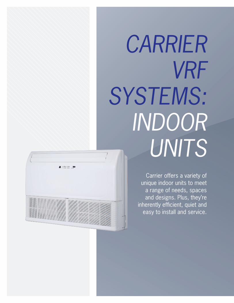
CARRIER
VRF SYSTEMS:
INDOOR UNITS
Carrier offers a variety of unique indoor units to meet
a range of needs, spaces and designs. Plus, they’re
inherently efficient, quiet and easy to install and service.

INDOOR UNITS
NON-DUCTED MODELS
4-way Cassette
Compact 4-way
Cassette
Compact One Way Cassette
High Wall Indoor Unit
Underceiling / Floor Console
(Exposed)
Floor Console
(Recessed)
40VMF 40VMC 40VMI 40VMW 40VMU 40VMR
Cooling Capacity kBtu/h (Ton)
5,000 (0.4) ■ ■ ■
7,000 (0.6) ■ ■ ■ ■
9,000 (0.75) ■ ■ ■ ■ ■
12,000 (1.0) ■ ■ ■ ■ ■ ■
15,000 (1.25) ■ ■ ■ ■ ■ ■
18,000 (1.5) ■ ■ ■ ■ ■
24,000 (2.0) ■ ■ ■ ■ ■
30,000 (2.5) ■ ■ ■
36,000 (3.0) ■ ■
48,000 (4.0) ■ ■
DUCTED MODELS
Low Static Ducted (Slim Profile)
Medium Static Ducted
High Static Ducted
Vertical Air Handling Unit (AHU)
Outside AirDucted
40VML 40VMM 40VMH 40VMV 40VMA
Cooling Capacity kBtu/h (Ton)
7,000 (0.6) ■ ■
9,000 (0.75) ■ ■
12,000 (1.0) ■ ■ ■
15,000 (1.25) ■ ■
18,000 (1.5) ■ ■ ■
24,000 (2.0) ■ ■ ■ ■
30,000 (2.5) ■ ■ ■
36,000 (3.0) ■ ■ ■ ■
48,000 (4.0) ■ ■ ■ ■
53,500 (4.4) ■ ■ ■
72,000 (6.0) ■ ■
96,000 (8.0) ■ ■
CARRIER VARIABLE REFRIGERANT FLOW 39
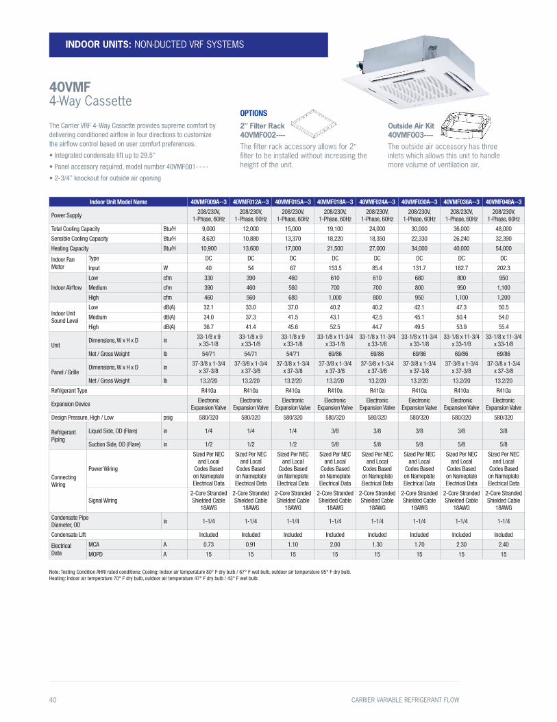
INDOOR UNITS: NON-DUCTED VRF SYSTEMS
40VMF 4-Way Cassette
Indoor Unit Model Name 40VMF009A--3 40VMF012A--3 40VMF015A--3 40VMF018A--3 40VMF024A--3 40VMF030A--3 40VMF036A--3 40VMF048A--3
Power Supply 208/230V, 1-Phase, 60Hz
208/230V, 1-Phase, 60Hz
208/230V, 1-Phase, 60Hz
208/230V, 1-Phase, 60Hz
208/230V, 1-Phase, 60Hz
208/230V, 1-Phase, 60Hz
208/230V, 1-Phase, 60Hz
208/230V, 1-Phase, 60Hz
Total Cooling Capacity Btu/H 9,000 12,000 15,000 19,100 24,000 30,000 36,000 48,000
Sensible Cooling Capacity Btu/H 8,620 10,880 13,370 18,220 18,350 22,330 26,240 32,390
Heating Capacity Btu/H 10,900 13,600 17,000 21,500 27,000 34,000 40,000 54,000
Indoor Fan Motor
Type DC DC DC DC DC DC DC DC
Input W 40 54 67 153.5 85.4 131.7 182.7 202.3
Indoor Airflow
Low cfm 330 390 460 610 610 680 800 950
Medium cfm 390 460 560 700 700 800 950 1,100
High cfm 460 560 680 1,000 800 950 1,100 1,200
Indoor Unit Sound Level
Low dB(A) 32.1 33.0 37.0 40.2 40.2 42.1 47.3 50.5
Medium dB(A) 34.0 37.3 41.5 43.1 42.5 45.1 50.4 54.0
High dB(A) 36.7 41.4 45.6 52.5 44.7 49.5 53.9 55.4
UnitDimensions, W x H x D in 33-1/8 x 9
x 33-1/833-1/8 x 9 x 33-1/8
33-1/8 x 9 x 33-1/8
33-1/8 x 11-3/4 x 33-1/8
33-1/8 x 11-3/4 x 33-1/8
33-1/8 x 11-3/4 x 33-1/8
33-1/8 x 11-3/4 x 33-1/8
33-1/8 x 11-3/4 x 33-1/8
Net / Gross Weight lb 54/71 54/71 54/71 69/86 69/86 69/86 69/86 69/86
Panel / GrilleDimensions, W x H x D in 37-3/8 x 1-3/4
x 37-3/837-3/8 x 1-3/4
x 37-3/837-3/8 x 1-3/4
x 37-3/837-3/8 x 1-3/4
x 37-3/837-3/8 x 1-3/4
x 37-3/837-3/8 x 1-3/4
x 37-3/837-3/8 x 1-3/4
x 37-3/837-3/8 x 1-3/4
x 37-3/8
Net / Gross Weight lb 13.2/20 13.2/20 13.2/20 13.2/20 13.2/20 13.2/20 13.2/20 13.2/20
Refrigerant Type R410a R410a R410a R410a R410a R410a R410a R410a
Expansion Device Electronic Expansion Valve
Electronic Expansion Valve
Electronic Expansion Valve
Electronic Expansion Valve
Electronic Expansion Valve
Electronic Expansion Valve
Electronic Expansion Valve
Electronic Expansion Valve
Design Pressure, High / Low psig 580/320 580/320 580/320 580/320 580/320 580/320 580/320 580/320
Refrigerant Piping
Liquid Side, OD (Flare) in 1/4 1/4 1/4 3/8 3/8 3/8 3/8 3/8
Suction Side, OD (Flare) in 1/2 1/2 1/2 5/8 5/8 5/8 5/8 5/8
Connecting Wiring
Power Wiring
Sized Per NEC and Local
Codes Based on Nameplate Electrical Data
Sized Per NEC and Local
Codes Based on Nameplate Electrical Data
Sized Per NEC and Local
Codes Based on Nameplate Electrical Data
Sized Per NEC and Local
Codes Based on Nameplate Electrical Data
Sized Per NEC and Local
Codes Based on Nameplate Electrical Data
Sized Per NEC and Local
Codes Based on Nameplate Electrical Data
Sized Per NEC and Local
Codes Based on Nameplate Electrical Data
Sized Per NEC and Local
Codes Based on Nameplate Electrical Data
Signal Wiring2-Core Stranded Shielded Cable
18AWG
2-Core Stranded Shielded Cable
18AWG
2-Core Stranded Shielded Cable
18AWG
2-Core Stranded Shielded Cable
18AWG
2-Core Stranded Shielded Cable
18AWG
2-Core Stranded Shielded Cable
18AWG
2-Core Stranded Shielded Cable
18AWG
2-Core Stranded Shielded Cable
18AWG
Condensate Pipe Diameter, OD in 1-1/4 1-1/4 1-1/4 1-1/4 1-1/4 1-1/4 1-1/4 1-1/4
Condensate Lift Included Included Included Included Included Included Included Included
Electrical Data
MCA A 0.73 0.91 1.10 2.00 1.30 1.70 2.30 2.40
MOPD A 15 15 15 15 15 15 15 15
Note: Testing Condition AHRI rated conditions: Cooling: Indoor air temperature 80° F dry bulb / 67° F wet bulb, outdoor air temperature 95° F dry bulb. Heating: Indoor air temperature 70° F dry bulb, outdoor air temperature 47° F dry bulb / 43° F wet bulb.
2" Filter Rack 40VMF002----The filter rack accessory allows for 2" filter to be installed without increasing the height of the unit.
Outside Air Kit 40VMF003----The outside air accessory has three inlets which allows this unit to handle more volume of ventilation air.
OPTIONSThe Carrier VRF 4-Way Cassette provides supreme comfort by delivering conditioned airflow in four directions to customize the airflow control based on user comfort preferences.
• Integrated condensate lift up to 29.5"
• Panel accessory required, model number 40VMF001- - - -
• 2-3/4” knockout for outside air opening
40 CARRIER VARIABLE REFRIGERANT FLOW

Indoor Unit Model Name 40VMC005A--3 40VMC007A--3 40VMC009A--3 40VMC012A--3 40VMC015A--3
Power Supply 208/230V, 1-Phase, 60Hz
208/230V, 1-Phase, 60Hz
208/230V, 1-Phase, 60Hz
208/230V, 1-Phase, 60Hz
208/230V, 1-Phase, 60Hz
Total Cooling Capacity Btu/H 5,070 7,100 9,130 12,170 15,210
Sensible Cooling Capacity Btu/H 4,450 5,470 6,330 8,050 9,490
Heating Capacity Btu/H 5,000 8,000 10,000 13,000 17,000
Indoor Fan Motor
Type DC DC DC DC DC
Input W 16 16 16 24 24
Indoor Airflow
Low cfm 241 229 229 253 253
Medium cfm 241 282 282 306 306
High cfm 300 306 306 359 359
Indoor Unit Sound Level
Low dB(A) 32.9 34.7 34.7 38.1 38.1
Medium 32.9 38.5 38.5 42.3 42.3
High 38.5 40.4 40.4 45.5 45.5
UnitDimensions, W x H x D in 24-13/16 x 10-1/4
x 22-7/1624-13/16 x 10-1/4
x 22-7/1624-13/16 x 10-1/4
x 22-7/1624-13/16 x 10-1/4
x 22-7/1624-13/16 x 10-1/4
x 22-7/16
Net / Gross Weight lb 40/51 40/51 40/51 53/53 53/53
Panel / GrilleDimensions, W x H x D in 25-1/2 x 2 x 25-1/2 25-1/2 x 2 x 25-1/2 25-1/2 x 2 x 25-1/2 25-1/2 x 2 x 25-1/2 25-1/2 x 2 x 25-1/2
Net / Gross Weight lb 5.5/9.9 5.5/9.9 5.5/9.9 5.5/9.9 5.5/9.9
Refrigerant Type R410A R410A R410A R410A R410A
Expansion Device EXV EXV EXV EXV EXV
Design Pressure, High / Low psig 580/320 580/320 580/320 580/320 580/320
Refrigerant Piping
Liquid Side, OD (Flare) in 1/4 1/4 1/4 1/4 1/4
Suction Side, OD (Flare) in 1/2 1/2 1/2 1/2 1/2
Connecting Wiring
Power WiringSized Per NEC and Local
Codes Based on Nameplate Electrical Data
Sized Per NEC and Local Codes Based on Nameplate
Electrical Data
Sized Per NEC and Local Codes Based on Nameplate
Electrical Data
Sized Per NEC and Local Codes Based on Nameplate
Electrical Data
Sized Per NEC and Local Codes Based on Nameplate
Electrical Data
Signal Wiring2-Core Stranded Shielded Cable
18AWG
2-Core Stranded Shielded Cable
18AWG
2-Core Stranded Shielded Cable
18AWG
2-Core Stranded Shielded Cable
18AWG
2-Core Stranded Shielded Cable
18AWG
Condensate Pipe Diameter, OD in 1 1 1 1 1
Condensate Lift Included Included Included Included Included
Electrical Data
MCA A 0.38 0.38 0.38 0.53 0.53
MOPD A 15 15 15 15 15
Note: Testing Condition AHRI rated conditions: Cooling: Indoor air temperature 80° F dry bulb / 67° F wet bulb, outdoor air temperature 95° F dry bulb. Heating: Indoor air temperature 70° F dry bulb, outdoor air temperature 47° F dry bulb / 43° F wet bulb.
The Carrier VRF Compact 4-Way Cassette provides supreme comfort by delivering conditioned airflow in four directions while fitting in a standard T grid ceiling.
• Integrated condensate lift up to 23.5"
• Panel accessory required, model number 40VMC001----
INDOOR UNITS: NON-DUCTED VRF SYSTEMS
40VMC Compact 4-Way Cassette
CARRIER VARIABLE REFRIGERANT FLOW 41
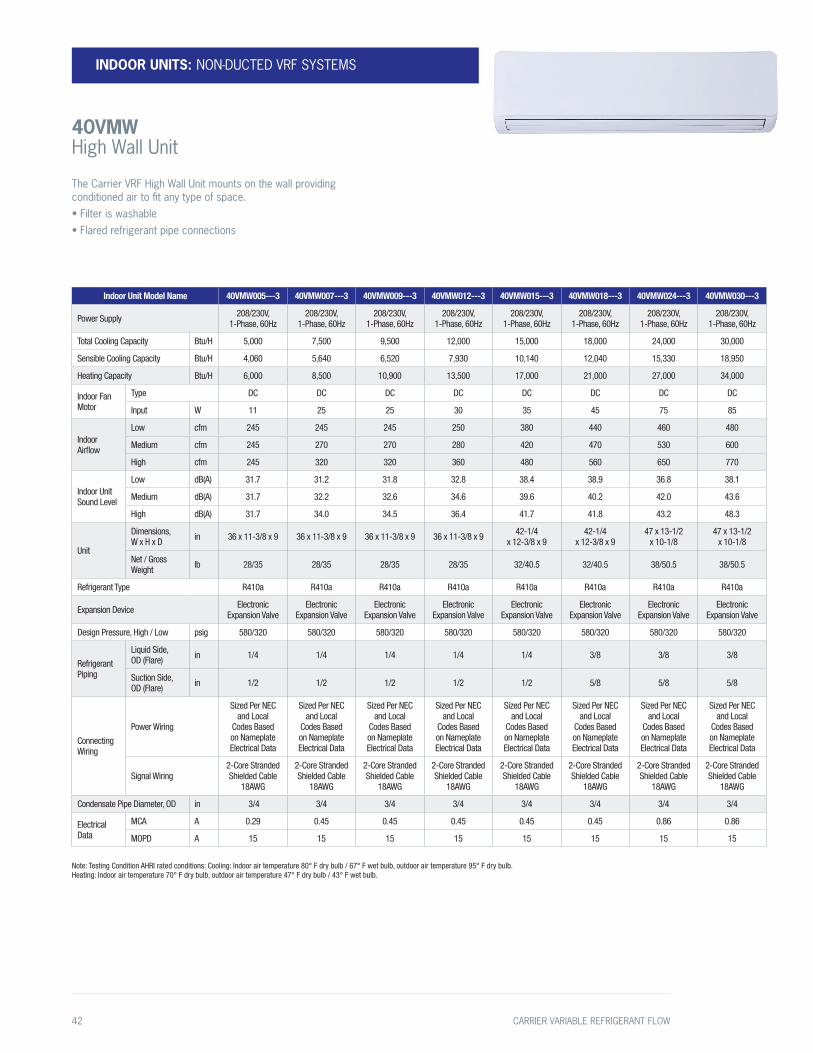
Indoor Unit Model Name 40VMW005---3 40VMW007---3 40VMW009---3 40VMW012---3 40VMW015---3 40VMW018---3 40VMW024---3 40VMW030---3
Power Supply 208/230V, 1-Phase, 60Hz
208/230V, 1-Phase, 60Hz
208/230V, 1-Phase, 60Hz
208/230V, 1-Phase, 60Hz
208/230V, 1-Phase, 60Hz
208/230V, 1-Phase, 60Hz
208/230V, 1-Phase, 60Hz
208/230V, 1-Phase, 60Hz
Total Cooling Capacity Btu/H 5,000 7,500 9,500 12,000 15,000 18,000 24,000 30,000
Sensible Cooling Capacity Btu/H 4,060 5,640 6,520 7,930 10,140 12,040 15,330 18,950
Heating Capacity Btu/H 6,000 8,500 10,900 13,500 17,000 21,000 27,000 34,000
Indoor Fan Motor
Type DC DC DC DC DC DC DC DC
Input W 11 25 25 30 35 45 75 85
Indoor Airflow
Low cfm 245 245 245 250 380 440 460 480
Medium cfm 245 270 270 280 420 470 530 600
High cfm 245 320 320 360 480 560 650 770
Indoor Unit Sound Level
Low dB(A) 31.7 31.2 31.8 32.8 38.4 38.9 36.8 38.1
Medium dB(A) 31.7 32.2 32.6 34.6 39.6 40.2 42.0 43.6
High dB(A) 31.7 34.0 34.5 36.4 41.7 41.8 43.2 48.3
Unit
Dimensions, W x H x D in 36 x 11-3/8 x 9 36 x 11-3/8 x 9 36 x 11-3/8 x 9 36 x 11-3/8 x 9 42-1/4
x 12-3/8 x 942-1/4
x 12-3/8 x 947 x 13-1/2
x 10-1/847 x 13-1/2
x 10-1/8
Net / Gross Weight lb 28/35 28/35 28/35 28/35 32/40.5 32/40.5 38/50.5 38/50.5
Refrigerant Type R410a R410a R410a R410a R410a R410a R410a R410a
Expansion Device Electronic Expansion Valve
Electronic Expansion Valve
Electronic Expansion Valve
Electronic Expansion Valve
Electronic Expansion Valve
Electronic Expansion Valve
Electronic Expansion Valve
Electronic Expansion Valve
Design Pressure, High / Low psig 580/320 580/320 580/320 580/320 580/320 580/320 580/320 580/320
Refrigerant Piping
Liquid Side, OD (Flare) in 1/4 1/4 1/4 1/4 1/4 3/8 3/8 3/8
Suction Side, OD (Flare) in 1/2 1/2 1/2 1/2 1/2 5/8 5/8 5/8
Connecting Wiring
Power Wiring
Sized Per NEC and Local
Codes Based on Nameplate Electrical Data
Sized Per NEC and Local
Codes Based on Nameplate Electrical Data
Sized Per NEC and Local
Codes Based on Nameplate Electrical Data
Sized Per NEC and Local
Codes Based on Nameplate Electrical Data
Sized Per NEC and Local
Codes Based on Nameplate Electrical Data
Sized Per NEC and Local
Codes Based on Nameplate Electrical Data
Sized Per NEC and Local
Codes Based on Nameplate Electrical Data
Sized Per NEC and Local
Codes Based on Nameplate Electrical Data
Signal Wiring2-Core Stranded Shielded Cable
18AWG
2-Core Stranded Shielded Cable
18AWG
2-Core Stranded Shielded Cable
18AWG
2-Core Stranded Shielded Cable
18AWG
2-Core Stranded Shielded Cable
18AWG
2-Core Stranded Shielded Cable
18AWG
2-Core Stranded Shielded Cable
18AWG
2-Core Stranded Shielded Cable
18AWG
Condensate Pipe Diameter, OD in 3/4 3/4 3/4 3/4 3/4 3/4 3/4 3/4
Electrical Data
MCA A 0.29 0.45 0.45 0.45 0.45 0.45 0.86 0.86
MOPD A 15 15 15 15 15 15 15 15
Note: Testing Condition AHRI rated conditions: Cooling: Indoor air temperature 80° F dry bulb / 67° F wet bulb, outdoor air temperature 95° F dry bulb. Heating: Indoor air temperature 70° F dry bulb, outdoor air temperature 47° F dry bulb / 43° F wet bulb.
INDOOR UNITS: NON-DUCTED VRF SYSTEMS
40VMW High Wall Unit
The Carrier VRF High Wall Unit mounts on the wall providing conditioned air to fit any type of space.• Filter is washable• Flared refrigerant pipe connections
42 CARRIER VARIABLE REFRIGERANT FLOW
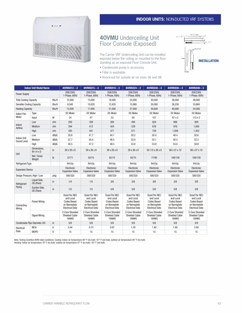
INDOOR UNITS: NON-DUCTED VRF SYSTEMS
40VMU Underceiling Unit Floor Console (Exposed)
Indoor Unit Model Name 40VMU012---3 40VMU015---3 40VMU018---3 40VMU024---3 40VMU030---3 40VMU036---3 40VMU048---3
Power Supply 208/230V, 1-Phase, 60Hz
208/230V, 1-Phase, 60Hz
208/230V, 1-Phase, 60Hz
208/230V, 1-Phase, 60Hz
208/230V, 1-Phase, 60Hz
208/230V, 1-Phase, 60Hz
208/230V, 1-Phase, 60Hz
Total Cooling Capacity Btu/H 12,000 15,000 18,000 24,000 30,000 36,000 48,000
Sensible Cooling Capacity Btu/H 8,540 10,820 12,420 15,980 20,080 26,230 33,660
Heating Capacity Btu/H 13,500 17,000 21,000 27,000 34,000 40,000 54,000
Indoor Fan Motor
Type DC Motor DC Motor DC Motor DC Motor DC Motor DC Motor DC Motor
Input W 24 47 53 80 107 67 x 2 115 x 2
Indoor Airflow
Low cfm 259 359 394 494 624 906 929
Medium cfm 294 412 424 529 676 976 1,000
High cfm 335 441 471 571 729 1,094 1,353
Indoor Unit Sound Level
Low dB(A) 35.8 41.7 44.1 50.2 50.4 48.4 50.6
Medium dB(A) 37.7 45.4 46.5 52.0 52.1 50.3 52.3
High dB(A) 40.5 47.2 48.5 53.8 53.9 53.0 59.8
Unit
Dimensions, W x H x D in 39 x 26 x 8 39 x 26 x 8 39 x 26 x 8 39 x 26 x 8 50-1/2 x 26 x 8 66 x 27 x 10 66 x 27 x 10
Net / Gross Weight lb 57/71 62/75 62/75 62/75 77/90 106/128 106/128
Refrigerant Type R410a R410a R410a R410a R410a R410a R410a
Expansion Device Electronic Expansion Valve
Electronic Expansion Valve
Electronic Expansion Valve
Electronic Expansion Valve
Electronic Expansion Valve
Electronic Expansion Valve
Electronic Expansion Valve
Design Pressure, High / Low psig 580/320 580/320 580/320 580/320 580/320 580/320 580/320
Refrigerant Piping
Liquid Side, OD (Flare) in 1/4 1/4 3/8 3/8 3/8 3/8 3/8
Suction Side, OD (Flare) in 1/2 1/2 5/8 5/8 5/8 5/8 5/8
Connecting Wiring
Power Wiring
Sized Per NEC and Local
Codes Based on Nameplate Electrical Data
Sized Per NEC and Local
Codes Based on Nameplate Electrical Data
Sized Per NEC and Local
Codes Based on Nameplate Electrical Data
Sized Per NEC and Local
Codes Based on Nameplate Electrical Data
Sized Per NEC and Local
Codes Based on Nameplate Electrical Data
Sized Per NEC and Local
Codes Based on Nameplate Electrical Data
Sized Per NEC and Local
Codes Based on Nameplate Electrical Data
Signal Wiring2-Core Stranded Shielded Cable
18AWG
2-Core Stranded Shielded Cable
18AWG
2-Core Stranded Shielded Cable
18AWG
2-Core Stranded Shielded Cable
18AWG
2-Core Stranded Shielded Cable
18AWG
2-Core Stranded Shielded Cable
18AWG
2-Core Stranded Shielded Cable
18AWG
Condensate Pipe Diameter, OD in 5/8 5/8 5/8 5/8 5/8 5/8 5/8
Electrical Data
MCA A 0.44 0.73 0.87 1.20 1.40 1.80 2.80
MOPD A 15 15 15 15 15 15 15
Note: Testing Condition AHRI rated conditions: Cooling: Indoor air temperature 80° F dry bulb / 67° F wet bulb, outdoor air temperature 95° F dry bulb. Heating: Indoor air temperature 70° F dry bulb, outdoor air temperature 47° F dry bulb / 43° F wet bulb.
INSTALLATION
The Carrier VRF Underceiling Unit can be installed exposed below the ceiling or mounted to the floor standing as an exposed Floor Console Unit.• Condensate pump is accessory• Filter is washable• Knock-out for outside air on sizes 36 and 38
CARRIER VARIABLE REFRIGERANT FLOW 43

Indoor Unit Model Name 40VMR007---3 40VMR009---3 40VMR012---3 40VMR015---3 40VMR018---3 40VMR024---3
Power Supply 208/230V, 1-Phase, 60Hz
208/230V, 1-Phase, 60Hz
208/230V, 1-Phase, 60Hz
208/230V, 1-Phase, 60Hz
208/230V, 1-Phase, 60Hz
208/230V, 1-Phase, 60Hz
Cooling Capacity Btu/H 7,000 9,000 12,000 15,000 18,000 24,000
Sensible Cooling Capacity Btu/H 6,000 6,830 9,140 11,390 12,610 17,880
Heating Capacity Btu/H 8,000 10,000 13,000 17,000 20,000 27,000
Indoor Fan Motor
Type DC Motor DC Motor DC Motor DC Motor DC Motor DC Motor
Input W 19 19 25 41 27 79
Indoor Airflow
Low cfm 253 253 271 347 365 553
Medium cfm 276 276 335 424 418 635
High cfm 300 300 400 500 488 776
Indoor External Static Pressure in WG 0.12 0.12 0.12 0.12 0.12 0.12
Indoor Unit Sound Level
Low dB(A) 35.7 35.8 32.5 36.8 32.8 42.5
Medium dB(A) 38.2 37.9 36.3 41.7 35.5 45.2
High dB(A) 39.9 39.8 40.3 45.3 39.0 49.9
Unit
Dimensions, W x H x D in 35-1/4 x 24 x 8-3/8 35-1/4 x 24 x 8-3/8 43-1/8 x 24 x 8-3/8 43-1/8 x 24 x 8-3/8 54-15/16 x 24 x 8-3/8 54-15/16 x 24 x 8-3/8
Net / Gross Weight lb 48.9/80 48.9/80 59.1/91.5 59.1/91.5 69.2/102.1 69.2/102.1
Refrigerant Type R410a R410a R410a R410a R410a R410a
Expansion Device Electronic Expansion Valve
Electronic Expansion Valve
Electronic Expansion Valve
Electronic Expansion Valve
Electronic Expansion Valve
Electronic Expansion Valve
Design Pressure, High / Low psig 580/320 580/320 580/320 580/320 580/320 580/320
Refrigerant Piping
Liquid Side, OD (Flare) in 1/4 1/4 1/4 1/4 3/8 3/8
Suction Side, OD (Flare) in 1/2 1/2 1/2 1/2 5/8 5/8
Connecting Wiring
Power Wiring
Sized Per NEC and Local Codes
Based on Nameplate Electrical Data
Sized Per NEC and Local Codes
Based on Nameplate Electrical Data
Sized Per NEC and Local Codes
Based on Nameplate Electrical Data
Sized Per NEC and Local Codes
Based on Nameplate Electrical Data
Sized Per NEC and Local Codes
Based on Nameplate Electrical Data
Sized Per NEC and Local Codes
Based on Nameplate Electrical Data
Signal Wiring2-Core Stranded Shielded Cable
18AWG
2-Core Stranded Shielded Cable
18AWG
2-Core Stranded Shielded Cable
18AWG
2-Core Stranded Shielded Cable
18AWG
2-Core Stranded Shielded Cable
18AWG
2-Core Stranded Shielded Cable
18AWG
Condensate Pipe Diameter, OD in 5/8 5/8 5/8 5/8 5/8 5/8
Electrical DataMCA 0.55 0.55 0.63 0.83 0.72 1.38
MOPD 15 15 15 15 15 15
Note: Testing Condition AHRI rated conditions: Cooling: Indoor air temperature 80° F dry bulb / 67° F wet bulb, outdoor air temperature 95° F dry bulb. Heating: Indoor air temperature 70° F dry bulb, outdoor air temperature 47° F dry bulb / 43° F wet bulb.
INDOOR UNITS: NON-DUCTED VRF SYSTEMS
40VMR Floor Console (Recessed)
The Carrier VRF Floor Console (Recessed) Units can be installed inside a wall or custom-built cabinet to match interior space design.
• Washable filter in an adjustable (1"-2") filter rack
• External static pressure up to 0.15
44 CARRIER VARIABLE REFRIGERANT FLOW

Indoor Unit Model Name 40VMI005---3 40VMI007---3 40VMI009---3 40VMI012---3 40VMI015---3 40VMI018---3 40VMI024---3
Power Supply 208/230V, 1-Phase, 60Hz
208/230V, 1-Phase, 60Hz
208/230V, 1-Phase, 60Hz
208/230V, 1-Phase, 60Hz
208/230V, 1-Phase, 60Hz
208/230V, 1-Phase, 60Hz
208/230V, 1-Phase, 60Hz
Total Cooling Capacity Btu/H 5,070 7,100 9,130 12,170 15,210 18,250 24,340
Sensible Cooling Capacity Btu/H 4,370 5,530 6,900 8,590 10,660 12,950 16,130
Heating Capacity Btu/H 6,000 8,000 10,000 13,500 17,000 21,000 27,000
Indoor Fan Motor
Type DC DC DC DC DC DC DC
Input W 10 10 10 15 20 30 31
Indoor Airflow
Low cfm 143 143 180 213 309 387 408
Medium cfm 174 181 226 266 345 429 472
High cfm 198 227 273 310 379 472 517
Indoor Unit Sound Level
Low dB(A) 28.5 29.4 32.5 36.1 36.3 40.8 42.2
Medium dB(A) 29.6 32.0 36.0 41.0 38.1 43.1 43.3
High dB(A) 31.7 35.4 41.5 45.0 40.7 45.5 46.2
Unit
Dimensions, W x H x D in 41-1/2 x 6
x 16-3/441-1/2 x 6 x 16-3/4
41-1/2 x 6 x 16-3/4
41-1/2 x 6 x 16-3/4
50-1/4 x 7-1/2 x 17-3/4
50-1/4 x 7-1/2 x 17-3/4
50-1/4 x 7-1/2 x 17-3/4
Net / Gross Weight lb 27.1/36.8 28.0/37.5 29.1/37.9 29.1/37.9 38.8/51.6 38.8/51.6 41.0/54.7
Panel / Grille
Dimensions, W x H x D in 46-1/2 x 1
x 18-1/446-1/2 x 1 x 18-1/4
46-1/2 x 1 x 18-1/4
46-1/2 x 1 x 18-1/4
53-1/8 x 1 x 19-7/8
53-1/8 x 1 x 19-7/8
53-1/8 x 1 x 19-7/8
Net / Gross Weight lb 7.7/11.4 7.7/11.4 7.7/11.4 7.7/11.4 8.8/11.9 8.8/11.9 8.8/11.9
Refrigerant Type R410a R410a R410a R410a R410a R410a R410a
Expansion Device Electronic Expansion Valve
Electronic Expansion Valve
Electronic Expansion Valve
Electronic Expansion Valve
Electronic Expansion Valve
Electronic Expansion Valve
Electronic Expansion Valve
Design Pressure, High / Low psig 580/320 580/320 580/320 580/320 580/320 580/320 580/320
Refrigerant Piping
Liquid Side, OD (Flare) in 1/4 1/4 1/4 1/4 1/4 3/8 3/8
Suction Side, OD (Flare) in 1/2 1/2 1/2 1/2 1/2 5/8 5/8
Connecting Wiring
Power Wiring
Sized Per NEC and Local Codes
Based on Nameplate
Electrical Data
Sized Per NEC and Local Codes
Based on Nameplate
Electrical Data
Sized Per NEC and Local Codes
Based on Nameplate
Electrical Data
Sized Per NEC and Local Codes
Based on Nameplate
Electrical Data
Sized Per NEC and Local Codes
Based on Nameplate
Electrical Data
Sized Per NEC and Local Codes
Based on Nameplate
Electrical Data
Sized Per NEC and Local Codes
Based on Nameplate
Electrical Data
Signal Wiring2-Core Stranded Shielded Cable
18AWG
2-Core Stranded Shielded Cable
18AWG
2-Core Stranded Shielded Cable
18AWG
2-Core Stranded Shielded Cable
18AWG
2-Core Stranded Shielded Cable
18AWG
2-Core Stranded Shielded Cable
18AWG
2-Core Stranded Shielded Cable
18AWG
Condensate Pipe Diameter, OD in 1 1 1 1 1 1 1
Condensate Lift Included Included Included Included Included Included Included
Electrical Data
MCA A 0.29 0.29 0.29 0.37 0.44 0.58 0.58
MOPD A 15 15 15 15 15 15 15
Note: Limits connected capacity at 30%.
Note: Testing Condition AHRI rated conditions: Cooling: Indoor air temperature 80° F dry bulb / 67° F wet bulb, outdoor air temperature 95° F dry bulb. Heating: Indoor air temperature 70° F dry bulb, outdoor air temperature 47° F dry bulb / 43° F wet bulb.
The Carrier One Way Compact Cassette has a slim and compact design, ideal for any solution in which ceiling space is limited.
• One directional airflow with multiple fan speeds
• Knock-out for outside air on sizes 15K to 24K
• Quite operation even at high fan speed settings
INDOOR UNITS: NON-DUCTED VRF SYSTEMS
40VMI One Way Compact Cassette
CARRIER VARIABLE REFRIGERANT FLOW 45

INDOOR UNITS: DUCTED VRF SYSTEMS
40VML Low Static Ducted (Slim Profile)
Indoor Unit Model Name 40VML007---3 40VML009---3 40VML012---3 40VML015---3 40VML018---3 40VML024---3
Power Supply 208/230V, 1-Phase, 60Hz
208/230V, 1-Phase, 60Hz
208/230V, 1-Phase, 60Hz
208/230V, 1-Phase, 60Hz
208/230V, 1-Phase, 60Hz
208/230V, 1-Phase, 60Hz
Total Cooling Capacity Btu/H 7,000 9,000 12,000 15,000 18,000 24,000
Sensible Cooling Capacit Btu/H 5,740 6,580 8,290 10,560 12,520 16,690
Heating Capacity Btu/H 8,000 10,000 13,500 17,000 21,000 27,000
Indoor Fan Motor
Type DC DC DC DC DC DC
Input W 25 25 32 43 56 68
Indoor Airflow
Low cfm 224 224 236 306 353 471
Medium cfm 253 253 294 367 424 565
High cfm 283 283 353 459 530 701
Indoor External Static Pressure in WG 0-0.20 0-0.20 0-0.20 0-0.20 0-0.20 0-0.20
Indoor Unit Sound Level
Low dB(A) 31.4 31.0 33.0 33.2 36.0 37.0
Medium dB(A) 32.0 32.0 34.6 35.2 38.0 38.8
High dB(A) 34.0 34.5 37.0 36.7 40.2 41.3
Unit
Dimensions, W x H x D in 30-3/4 x 8-1/4 x 19-3/4 30-3/4 x 8-1/4 x 19-3/4 30-3/4 x 8-1/4 x 19-3/4 39-1/4 x 8-1/4 x 19-3/4 39-1/4 x 8-1/4 x 19-3/4 48 x 8-1/4 x 19-3/4
Net / Gross Weight lb 41/48.5 41/48.5 41/48.5 48.5/57.5 48.5/57.5 59.5/71.5
Refrigerant Type R410a R410a R410a R410a R410a R410a
Expansion Device Electronic Expansion Valve
Electronic Expansion Valve
Electronic Expansion Valve
Electronic Expansion Valve
Electronic Expansion Valve
Electronic Expansion Valve
Design Pressure, High / Low psig 580/320 580/320 580/320 580/320 580/320 580/320
Refrigerant Piping (in)
Liquid Side, OD (Flare) in 1/4 1/4 1/4 1/4 3/8 3/8
Suction Side, OD (Flare) in 1/2 1/2 1/2 1/2 5/8 5/8
Connecting Wiring
Power Wiring
Sized Per NEC and Local Codes
Based on Nameplate Electrical Data
Sized Per NEC and Local Codes
Based on Nameplate Electrical Data
Sized Per NEC and Local Codes
Based on Nameplate Electrical Data
Sized Per NEC and Local Codes
Based on Nameplate Electrical Data
Sized Per NEC and Local Codes
Based on Nameplate Electrical Data
Sized Per NEC and Local Codes
Based on Nameplate Electrical Data
Signal Wiring2-Core Stranded Shielded Cable
18AWG
2-Core Stranded Shielded Cable
18AWG
2-Core Stranded Shielded Cable
18AWG
2-Core Stranded Shielded Cable
18AWG
2-Core Stranded Shielded Cable
18AWG
2-Core Stranded Shielded Cable
18AWG
Condensate Pipe Diameter, OD in 1 1 1 1 1 1
Condensate Lift Included Included Included Included Included Included
Electrical DataMCA A 0.50 0.50 0.60 0.80 0.95 1.18
MOPD A 15 15 15 15 15 15
Note: Testing Condition AHRI rated conditions: Cooling: Indoor air temperature 80° F dry bulb / 67° F wet bulb, outdoor air temperature 95° F dry bulb. Heating: Indoor air temperature 70° F dry bulb, outdoor air temperature 47° F dry bulb / 43° F wet bulb.
The Carrier VRF Low Static Ducted (Slim Profile) Unit is only 8-1/4" in height, making it an ideal candidate for narrow soffit space applications. Air return can be rear or bottom, but rear is default.
• Integrated condensate lift up to 27.5"
• Filter is washable
46 CARRIER VARIABLE REFRIGERANT FLOW
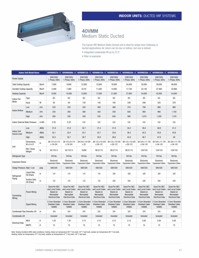
INDOOR UNITS: DUCTED VRF SYSTEMS
40VMM Medium Static Ducted
Indoor Unit Model Name 40VMM007A--3 40VMM009A--3 40VMM012A--3 40VMM015A--3 40VMM018A--3 40VMM024A--3 40VMM030A--3 40VMM036A--3 40VMM048A--3
Power Supply 208/230V, 1-Phase, 60Hz
208/230V, 1-Phase, 60Hz
208/230V, 1-Phase, 60Hz
208/230V, 1-Phase, 60Hz
208/230V, 1-Phase, 60Hz
208/230V, 1-Phase, 60Hz
208/230V, 1-Phase, 60Hz
208/230V, 1-Phase, 60Hz
208/230V, 1-Phase, 60Hz
Total Cooling Capacity Btu/H 7,000 9,000 12,000 15,000 18,000 24,000 30,000 38,000 48,000
Sensible Cooling Capacity Btu/H 5,490 7,080 9,310 11,630 14,000 17,730 23,140 27,460 32,860
Heating Capacity Btu/H 8,000 10,000 13,600 17,000 21,000 27,000 34,000 42,000 54,000
Indoor Fan Motor
Type DC DC DC DC DC DC DC DC DC
Input W 50 50 135 145 185 230 290 325 370
Indoor AirflowLow cfm 220 220 320 400 480 570 780 860 980
Medium cfm 220 260 360 450 540 640 900 980 1,100
High cfm 260 330 430 535 640 800 1,070 1,200 1,370
Indoor External Static Pressure in WG 0.32 0.32 0.6 0.6 0.6 0.6 0.6 0.6 0.6
Indoor Unit Sound Level
Low dB(A) 31.8 31.8 32.7 31.4 31.9 34.2 39.4 40.8 41.2
Medium dB(A) 32.1 32.4 33.7 32.7 33.6 36.3 42.3 43.8 43.8
High dB(A) 33.2 32.7 36.7 35.9 38.6 42.0 46.7 47.8 48
Unit
Dimensions, W x H x D in 39-1/4 x 8-1/4
x 19-3/439-1/4 x 8-1/4
x 19-3/439-3/4 x 10-5/8
x 25 48-1/2 x 10-5/8
x 30-1/248-1/2 x 10-5/8
x 30-1/248-1/2 x 10-5/8
x 30-1/250-3/4 x 11-7/8
x 34-1/850-3/4 x 11-7/8
x 34-1/850-3/4 x 11-7/8
x 34-1/8
Net / Gross Weight lb 50.7/57.5 50.7/57.5 76/88 99.2/115 99.2/115 99.2/115 124/143 124/143 124/143
Refrigerant Type R410a R410a R410a R410a R410a R410a R410a R410a R410a
Expansion Device Electronic Expansion Valve
Electronic Expansion Valve
Electronic Expansion Valve
Electronic Expansion Valve
Electronic Expansion Valve
Electronic Expansion Valve
Electronic Expansion Valve
Electronic Expansion Valve
Electronic Expansion Valve
Design Pressure, High / Low psig 580/320 580/320 580/320 580/320 580/320 580/320 580/320 580/320 580/320
Refrigerant Piping
Liquid Side, OD (Flare) in 1/4 1/4 1/4 1/4 3/8 3/8 3/8 3/8 3/8
Suction Side, OD (Flare) in 1/2 1/2 1/2 1/2 5/8 5/8 5/8 5/8 5/8
Connecting Wiring
Power Wiring
Sized Per NEC and Local Codes
Based on Nameplate
Electrical Data
Sized Per NEC and Local Codes
Based on Nameplate
Electrical Data
Sized Per NEC and Local Codes
Based on Nameplate
Electrical Data
Sized Per NEC and Local Codes
Based on Nameplate
Electrical Data
Sized Per NEC and Local Codes
Based on Nameplate
Electrical Data
Sized Per NEC and Local Codes
Based on Nameplate
Electrical Data
Sized Per NEC and Local Codes
Based on Nameplate
Electrical Data
Sized Per NEC and Local Codes
Based on Nameplate
Electrical Data
Sized Per NEC and Local Codes
Based on Nameplate
Electrical Data
Signal Wiring2-Core Stranded Shielded Cable
18AWG
2-Core Stranded Shielded Cable
18AWG
2-Core Stranded Shielded Cable
18AWG
2-Core Stranded Shielded Cable
18AWG
2-Core Stranded Shielded Cable
18AWG
2-Core Stranded Shielded Cable
18AWG
2-Core Stranded Shielded Cable
18AWG
2-Core Stranded Shielded Cable
18AWG
2-Core Stranded Shielded Cable
18AWG
Condensate Pipe Diameter, OD in 3/4 3/4 3/4 3/4 3/4 3/4 3/4 3/4 3/4
Condensate Lift Included Included Included Included Included Included Included Included Included
Electrical DataMCA A 1.25 1.25 3.13 3.13 3.13 3.13 5.00 5.00 5.00
MOPD A 15 15 15 15 15 15 15 15 15
Note: Testing Condition AHRI rated conditions: Cooling: Indoor air temperature 80° F dry bulb / 67° F wet bulb, outdoor air temperature 95° F dry bulb. Heating: Indoor air temperature 70° F dry bulb, outdoor air temperature 47° F dry bulb / 43° F wet bulb.
The Carrier VRF Medium Static Ducted unit is ideal for single room hideaway or ducted applications. Air return can be rear or bottom, but rear is default.
• Integrated condensate lift up to 27.5"
• Filter is washable
CARRIER VARIABLE REFRIGERANT FLOW 47

INDOOR UNITS: DUCTED VRF SYSTEMS
40VMH High Static Ducted
Indoor Unit Model Name 40VMH024---3 40VMH030---3 40VMH036---3 40VMH048---3 40VMH054---3 40VMH072---3 40VMH0964---3
Power Supply 208/230V, 1-Phase, 60Hz
208/230V, 1-Phase, 60Hz
208/230V, 1-Phase, 60Hz
208/230V, 1-Phase, 60Hz
208/230V, 1-Phase, 60Hz
208/230V, 1-Phase, 60Hz
208/230V, 1-Phase, 60Hz
Total Cooling Capacity Btu/H 24,000 30,000 36,000 48,000 53,500 72,000 96,000
Sensible Cooling Capacity Btu/H 16,520 20,500 24,420 32,600 38,790 50,920 64,570
Heating Capacity Btu/H 27,000 34,000 40,000 54,000 60,000 81,000 108,000
Indoor Fan Motor
Type DC DC DC DC DC DC DC
Input W 81 140 190 220 420 245*2 395*2
Indoor Airflow
Low cfm 524 647 882 1,041 1,412 1,559 2,076
Medium cfm 600 753 1,029 1,200 1,618 1,794 2,400
High cfm 735 971 1,188 1,429 1,835 2,235 2,824
Indoor External Static Pressure in WG 0.8 0.8 0.8 0.8 0.8 1.0 1.0
Indoor Unit Sound Level
Low dB(A) 44.7 43.3 49.1 48.3 52.0 48.7 52.4
Medium dB(A) 47.8 46.9 52.8 51.8 55.7 52.2 54.7
High dB(A) 50.9 51.2 55.5 54.9 58.1 55.9 56.4
Unit
Dimensions, W x H x D in 37-1/2 x 16-1/2
x 27-3/1637-1/2 x 16-1/2
x 27-3/1637-1/2 x 16-1/2
x 27-3/1651-3/16 x 16-1/2
x 27-3/1651-3/16 x 16-1/2
x 27-3/1656-3/4 x 20 x 36-7/16
56-3/4 x 20 x 36-7/16
Net / Gross Weight lb 110/168.4 114.6/171 114.6/171 159.2/231.5 159.2/231.5 254.2/342.8 254.2/342.8
Refrigerant Type R410a R410a R410a R410a R410a R410a R410a
Expansion Device Electronic Expansion Valve
Electronic Expansion Valve
Electronic Expansion Valve
Electronic Expansion Valve
Electronic Expansion Valve
Electronic Expansion Valve
Electronic Expansion Valve
Design Pressure, High / Low psig 580/320 580/320 580/320 580/320 580/320 580/320 580/320
Refrigerant Piping
Liquid Side, OD (Flare Braze) in 3/8 3/8 3/8 3/8 3/8 3/8 3/8
Suction Side, OD (Flare Braze) in 5/8 5/8 5/8 5/8 5/8 7/8 7/8
Connecting Wiring
Power Wiring
Sized Per NEC and Local Codes
Based on Nameplate Electrical Data
Sized Per NEC and Local Codes
Based on Nameplate Electrical Data
Sized Per NEC and Local Codes
Based on Nameplate Electrical Data
Sized Per NEC and Local Codes
Based on Nameplate Electrical Data
Sized Per NEC and Local Codes
Based on Nameplate Electrical Data
Sized Per NEC and Local Codes
Based on Nameplate Electrical Data
Sized Per NEC and Local Codes
Based on Nameplate Electrical Data
Signal Wiring2-Core Stranded Shielded Cable
18AWG
2-Core Stranded Shielded Cable
18AWG
2-Core Stranded Shielded Cable
18AWG
2-Core Stranded Shielded Cable
18AWG
22-Core Stranded Shielded Cable
18AWG
2-Core Stranded Shielded Cable
18AWG
2-Core Stranded Shielded Cable
18AWG
Condensate Pipe Diameter, OD in 1 1 1 1 1 1-5/8 1-5/8
Condensate Pump Included Included Included Included IncludedNot included (field
supplied, field installed)
Not included (field supplied, field
installed)
Electrical DataMCA A 5.70 7.10 7.30 7.60 7.80 9.70 10.20
MOPD A 15 15 15 15 15 15 15
Note: Testing Condition AHRI rated conditions: Cooling: Indoor air temperature 80° F dry bulb / 67° F wet bulb, outdoor air temperature 95° F dry bulb. Heating: Indoor air temperature 70° F dry bulb, outdoor air temperature 47° F dry bulb / 43° F wet bulb.
The Carrier VRF High Static Ducted indoor units can handle higher static to support longer
ductwork for a given space and are ideal for hideaway applications serving multiple zones.
• Integrated condensate lift up to 27.5", for sizes up to 54
• For sizes 72 and 96, condensate pump is an accessory (model #40VM900024)
48 CARRIER VARIABLE REFRIGERANT FLOW
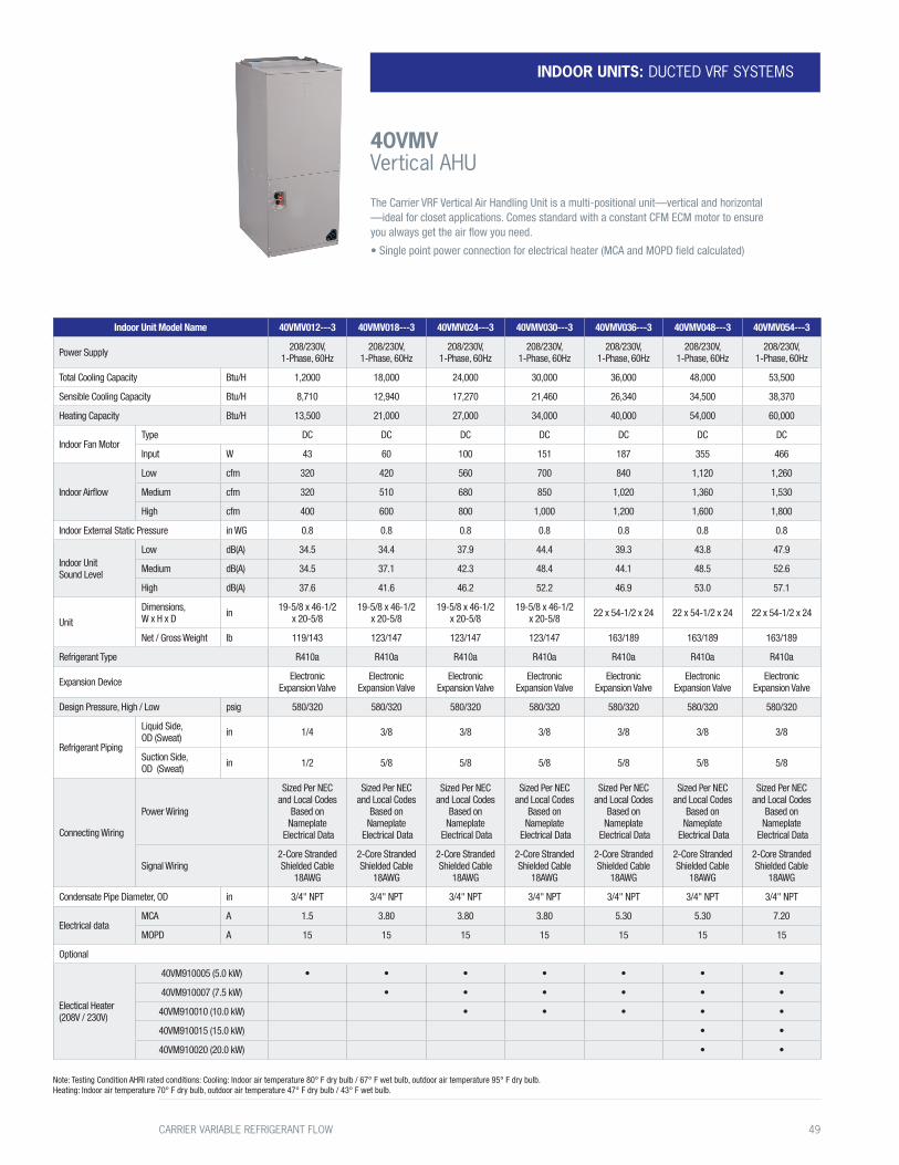
Indoor Unit Model Name 40VMV012---3 40VMV018---3 40VMV024---3 40VMV030---3 40VMV036---3 40VMV048---3 40VMV054---3
Power Supply 208/230V, 1-Phase, 60Hz
208/230V, 1-Phase, 60Hz
208/230V, 1-Phase, 60Hz
208/230V, 1-Phase, 60Hz
208/230V, 1-Phase, 60Hz
208/230V, 1-Phase, 60Hz
208/230V, 1-Phase, 60Hz
Total Cooling Capacity Btu/H 1,2000 18,000 24,000 30,000 36,000 48,000 53,500
Sensible Cooling Capacity Btu/H 8,710 12,940 17,270 21,460 26,340 34,500 38,370
Heating Capacity Btu/H 13,500 21,000 27,000 34,000 40,000 54,000 60,000
Indoor Fan MotorType DC DC DC DC DC DC DC
Input W 43 60 100 151 187 355 466
Indoor Airflow
Low cfm 320 420 560 700 840 1,120 1,260
Medium cfm 320 510 680 850 1,020 1,360 1,530
High cfm 400 600 800 1,000 1,200 1,600 1,800
Indoor External Static Pressure in WG 0.8 0.8 0.8 0.8 0.8 0.8 0.8
Indoor Unit Sound Level
Low dB(A) 34.5 34.4 37.9 44.4 39.3 43.8 47.9
Medium dB(A) 34.5 37.1 42.3 48.4 44.1 48.5 52.6
High dB(A) 37.6 41.6 46.2 52.2 46.9 53.0 57.1
Unit
Dimensions, W x H x D in 19-5/8 x 46-1/2
x 20-5/819-5/8 x 46-1/2
x 20-5/819-5/8 x 46-1/2
x 20-5/819-5/8 x 46-1/2
x 20-5/8 22 x 54-1/2 x 24 22 x 54-1/2 x 24 22 x 54-1/2 x 24
Net / Gross Weight lb 119/143 123/147 123/147 123/147 163/189 163/189 163/189
Refrigerant Type R410a R410a R410a R410a R410a R410a R410a
Expansion Device Electronic Expansion Valve
Electronic Expansion Valve
Electronic Expansion Valve
Electronic Expansion Valve
Electronic Expansion Valve
Electronic Expansion Valve
Electronic Expansion Valve
Design Pressure, High / Low psig 580/320 580/320 580/320 580/320 580/320 580/320 580/320
Refrigerant Piping
Liquid Side, OD (Sweat) in 1/4 3/8 3/8 3/8 3/8 3/8 3/8
Suction Side, OD (Sweat) in 1/2 5/8 5/8 5/8 5/8 5/8 5/8
Connecting Wiring
Power Wiring
Sized Per NEC and Local Codes
Based on Nameplate
Electrical Data
Sized Per NEC and Local Codes
Based on Nameplate
Electrical Data
Sized Per NEC and Local Codes
Based on Nameplate
Electrical Data
Sized Per NEC and Local Codes
Based on Nameplate
Electrical Data
Sized Per NEC and Local Codes
Based on Nameplate
Electrical Data
Sized Per NEC and Local Codes
Based on Nameplate
Electrical Data
Sized Per NEC and Local Codes
Based on Nameplate
Electrical Data
Signal Wiring2-Core Stranded Shielded Cable
18AWG
2-Core Stranded Shielded Cable
18AWG
2-Core Stranded Shielded Cable
18AWG
2-Core Stranded Shielded Cable
18AWG
2-Core Stranded Shielded Cable
18AWG
2-Core Stranded Shielded Cable
18AWG
2-Core Stranded Shielded Cable
18AWG
Condensate Pipe Diameter, OD in 3/4" NPT 3/4" NPT 3/4" NPT 3/4" NPT 3/4" NPT 3/4" NPT 3/4" NPT
Electrical dataMCA A 1.5 3.80 3.80 3.80 5.30 5.30 7.20
MOPD A 15 15 15 15 15 15 15
Optional
Electical Heater (208V / 230V)
40VM910005 (5.0 kW) • • • • • • •
40VM910007 (7.5 kW) • • • • • •
40VM910010 (10.0 kW) • • • • •
40VM910015 (15.0 kW) • •
40VM910020 (20.0 kW) • •
Note: Testing Condition AHRI rated conditions: Cooling: Indoor air temperature 80° F dry bulb / 67° F wet bulb, outdoor air temperature 95° F dry bulb. Heating: Indoor air temperature 70° F dry bulb, outdoor air temperature 47° F dry bulb / 43° F wet bulb.
The Carrier VRF Vertical Air Handling Unit is a multi-positional unit —vertical and horizontal —ideal for closet applications. Comes standard with a constant CFM ECM motor to ensure you always get the air flow you need.
• Single point power connection for electrical heater (MCA and MOPD field calculated)
INDOOR UNITS: DUCTED VRF SYSTEMS
40VMV Vertical AHU
CARRIER VARIABLE REFRIGERANT FLOW 49

Indoor Unit Model Name 40VMA036---3 40VMA048---3 40VMA054---3 40VMA072---3 40VMA096---3
Power Supply 208/230V, 1-Phase, 60Hz
208/230V, 1-Phase, 60Hz
208/230V, 1-Phase, 60Hz
208/230V, 1-Phase, 60Hz
208/230V, 1-Phase, 60Hz
Total Cooling Capacity Btu/H 36,000 48,000 53,500 72,000 96,000
Heating Capacity Btu/H 24,000 30,000 36,000 47,000 59,000
Indoor Fan Motor
Type DC DC DC DC DC
Input W 64 71 87 60*2 80*2
Indoor Airflow
Low cfm 441 471 529 882 1,029
Medium cfm 529 559 647 971 1,176
High cfm 588 647 765 1,059 1,294
Indoor External Static Pressure in WG 0.8 0.8 0.8 1.0 1.0
Indoor Unit Sound Level
Low dB(A) 43.8 43.4 43.9 48.5 47.7
Medium dB(A) 47.8 47.8 47.8 50.0 50.8
High dB(A) 49.5 50.4 51.4 52.1 53.5
Unit
Dimensions, W x H x D in 51-3/16 x 16-1/2 x 27-3/16 1-3/16 x 16-1/2 x 27-3/16 1-3/16 x 16-1/2 x 27-3/16 56-3/4 x 20 x 36-7/16 56-3/4 x 20 x 36-7/16
Net / Gross Weight lb 161.4/233.7 61.4/233.7 61.4/233.7 255.7/346.2 61.4/233.7
Refrigerant Type R410a R410a R410a R410a R410a
Expansion Device Electronic Expansion Valve Electronic Expansion Valve Electronic Expansion Valve Electronic Expansion Valve Electronic Expansion Valve
Design Pressure, High / Low psig 580/320 580/320 580/320 580/320 580/320
Refrigerant Piping
Liquid Side, OD (Flare Braze) in 3/8 3/8 3/8 3/8 3/8
Suction Side, OD (Flare Braze) in 5/8 5/8 5/8 7/8 7/8
Connecting Wiring
Power Wiring
Sized Per NEC and Local Codes
Based on Nameplate Electrical Data
Sized Per NEC and Local Codes
Based on Nameplate Electrical Data
Sized Per NEC and Local Codes
Based on Nameplate Electrical Data
Sized Per NEC and Local Codes
Based on Nameplate Electrical Data
Sized Per NEC and Local Codes
Based on Nameplate Electrical Data
Signal Wiring2-Core Stranded Shielded Cable
18AWG
2-Core Stranded Shielded Cable
18AWG
2-Core Stranded Shielded Cable
18AWG
2-Core Stranded Shielded Cable
18AWG
2-Core Stranded Shielded Cable
18AWG
Condensate Pipe Diameter, OD in 1 1 1 1-5/8 1-5/8
Condensate Pump Included Included Included Not included (field supplied, field installed)
Not included (field supplied, field installed)
Electrical DataMCA A 5.7 6.30 6.9 8.5 10.0
MOPD A 15 15 15 15 15
Note: Limits connected capacity at 30%
Note: Testing Condition AHRI rated conditions: Cooling: Indoor air temperature 80° F dry bulb / 67° F wet bulb, outdoor air temperature 95° F dry bulb. Heating: Indoor air temperature 70° F dry bulb, outdoor air temperature 47° F dry bulb / 43° F wet bulb.
The Carrier Outside Air unit draws in ventilation air into the space to provide outside air. The units are installed in plenum and can be connected to heat recovery and heat pump systems along with other styles of indoor unit.
• Discharge temperature control
• Integrated condensate lift up to 27.5"
INDOOR UNITS: DUCTED VRF SYSTEMS
40VMA Outside Air Ducted
50 CARRIER VARIABLE REFRIGERANT FLOW
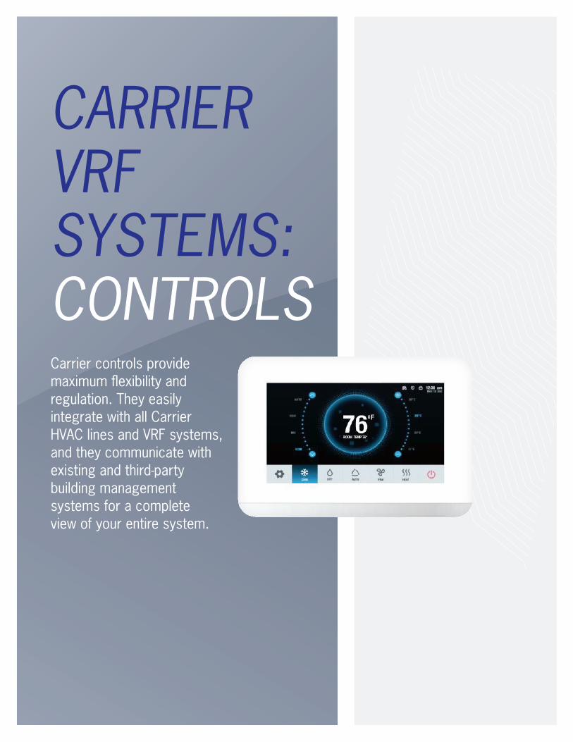
CARRIER VRF SYSTEMS: CONTROLSCarrier controls provide maximum flexibility and regulation. They easily integrate with all Carrier HVAC lines and VRF systems, and they communicate with existing and third-party building management systems for a complete view of your entire system.
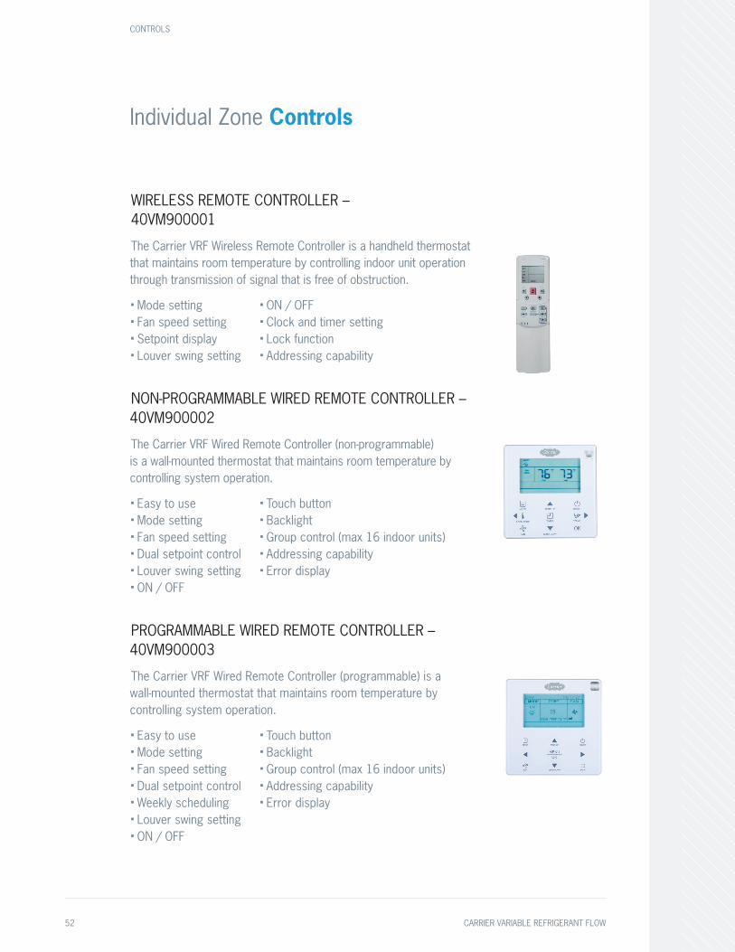
Individual Zone Controls
WIRELESS REMOTE CONTROLLER –40VM900001
The Carrier VRF Wireless Remote Controller is a handheld thermostat that maintains room temperature by controlling indoor unit operation through transmission of signal that is free of obstruction.
■ Mode setting■ Fan speed setting■ Setpoint display■ Louver swing setting
■ ON / OFF■ Clock and timer setting■ Lock function■ Addressing capability
NON-PROGRAMMABLE WIRED REMOTE CONTROLLER – 40VM900002
The Carrier VRF Wired Remote Controller (non-programmable) is a wall-mounted thermostat that maintains room temperature by controlling system operation.
■ Easy to use■ Mode setting■ Fan speed setting■ Dual setpoint control■ Louver swing setting■ ON / OFF
■ Touch button■ Backlight■ Group control (max 16 indoor units)■ Addressing capability■ Error display
PROGRAMMABLE WIRED REMOTE CONTROLLER – 40VM900003
The Carrier VRF Wired Remote Controller (programmable) is a wall-mounted thermostat that maintains room temperature by controlling system operation.
■ Easy to use■ Mode setting■ Fan speed setting■ Dual setpoint control■ Weekly scheduling■ Louver swing setting■ ON / OFF
■ Touch button■ Backlight■ Group control (max 16 indoor units)■ Addressing capability■ Error display
CONTROLS
52 CARRIER VARIABLE REFRIGERANT FLOW
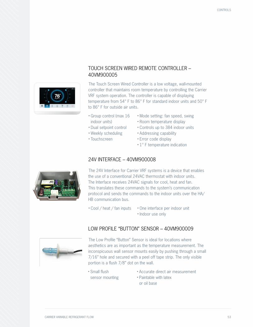
TOUCH SCREEN WIRED REMOTE CONTROLLER – 40VM900005
The Touch Screen Wired Controller is a low voltage, wall-mounted controller that maintains room temperature by controlling the Carrier VRF system operation. The controller is capable of displaying temperature from 54° F to 86° F for standard indoor units and 50° F to 86° F for outside air units.
■ Group control (max 16 indoor units)
■ Dual setpoint control■ Weekly scheduling■ Touchscreen
■ Mode setting: fan speed, swing■ Room temperature display■ Controls up to 384 indoor units■ Addressing capability■ Error code display■ 1° F temperature indication
24V INTERFACE – 40VM900008
The 24V Interface for Carrier VRF systems is a device that enables the use of a conventional 24VAC thermostat with indoor units. The Interface receives 24VAC signals for cool, heat and fan. This translates these commands to the system’s communication protocol and sends the commands to the indoor units over the HA/HB communication bus.
■ Cool / heat / fan inputs ■ One interface per indoor unit■ Indoor use only
LOW PROFILE “BUTTON” SENSOR – 40VM900009
The Low Profile “Button” Sensor is ideal for locations where aesthetics are as important as the temperature measurement. The inconspicuous wall sensor mounts easily by pushing through a small 7/16” hole and secured with a peel off tape strip. The only visible portion is a flush 7/8” dot on the wall.
■ Small flush sensor mounting
■ Accurate direct air measurement■ Paintable with latex or oil base
CONTROLS
CARRIER VARIABLE REFRIGERANT FLOW 53
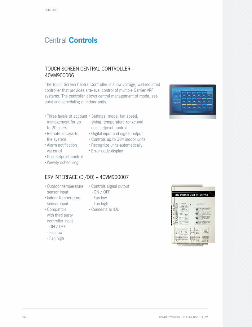
Central Controls
TOUCH SCREEN CENTRAL CONTROLLER – 40VM900006
The Touch Screen Central Controller is a low voltage, wall-mounted controller that provides site-level control of multiple Carrier VRF systems. The controller allows central management of mode, set-point and scheduling of indoor units.
■ Three levels of account management for up to 20 users
■ Remote access to the system
■ Alarm notification via email
■ Dual setpoint control■ Weekly scheduling
■ Settings: mode, fan speed, swing, temperature range and dual setpoint control
■ Digital input and digital output■ Controls up to 384 indoor units■ Recognize units automatically■ Error code display
ERV INTERFACE (DI/DO) – 40VM900007■ Outdoor temperature sensor input
■ Indoor temperature sensor input
■ Compatible with third party controller input - ON / OFF- Fan low- Fan high
■ Controls signal output - ON / OFF- Fan low- Fan high
■ Connects to IDU
CONTROLS
54 CARRIER VARIABLE REFRIGERANT FLOW

Building Automation
BACnet®/IP
LonWorks®
TOUCH SCREEN CENTRAL CONTROLLER – 40VM900006
The Touch Screen Central Controller is a low voltage, wall-mounted controller that provides site-level control of multiple Carrier VRF systems. The controller allows central management of mode, set-point and scheduling of indoor units.
■ Three levels of account management for up to 20 users
■ Remote access to the system
■ Alarm notification via email
■ Dual setpoint control■ Weekly scheduling
■ Settings: mode, fan speed, swing, temperature range and dual setpoint control
■ Digital input and digital output■ Controls up to 384 indoor units■ Recognize units automatically■ Error code display
ERV INTERFACE (DI/DO) – 40VM900007■ Outdoor temperature sensor input
■ Indoor temperature sensor input
■ Compatible with third party controller input - ON / OFF- Fan low- Fan high
■ Controls signal output - ON / OFF- Fan low- Fan high
■ Connects to IDU
BACNET® AND WEB-BASED CENTRALIZED CONTROLLER – 40VM900052■ Four 485 ports, each port can access 64 indoor units or 8 refrigeration systems
■ WEB service allows log in through web
■ Indoor unit- Temperature set- Indoor temperature- Operate mode - Error code - Set mode
■ Outdoor unit- Mode- Outdoor temperature- Error code
■ Compressor monitoring system
LONWORKS® – 40VM900053■ Can support up to 64 indoor units
■ Indoor unit- Temperature set- Indoor temperature- Operate mode- Fault code
■ Outdoor unit- Mode- Fault- Outdoor temperature- Fault code
ENERGY MANAGEMENT MODULE (EMM) – 40VM900051■ Energy Management Module (EMM)
■ Monitor both outdoor and indoor unit operation
■ Scheduling (daily/weekly)
■ Energy-saving management:- Set temperature Range limiting
- Lock mode, etc.■ Group management■ Export software log
CARRIER VARIABLE REFRIGERANT FLOW 55
Benchmark Tools
VROOM SELECTION SOFTWARE
VRoom selection software enables engineers to easily design, layout and prepare VRF systems for quote.
■ Sleek drag-and-drop interface
■ Quick global edits for wired controllers
■ Table edit features for quick editing of multiple units
For more information, contact [email protected].
SERVICE TECHNICAL TOOL
The Carrier VRF Service Technical Tool provides a graphical view of an entire system. It has a Port Check Function which checks to see if the communication wire is crossed with the refrigerant pipe. The Service Technical Tool is not required for start-up or commissioning a system.
The Service Technical Tool software can be downloaded for free on hvacpartners.com.
BENCHMARK TOOLS
56 CARRIER VARIABLE REFRIGERANT FLOW
Service, Support & Product Training
Carrier provides our family of distributors with excellent support and training programs to keep them well-informed and equipped to sell every system.For more product information visit CarrierVRF.com
CARRIER VARIABLE REFRIGERANT FLOW 57

Since 1902, Carrier has been the brand you’ve trusted for all your heating and cooling solutions. We’ve continued to make innovative products that meet the demands of tomorrow. Carrier’s family of Ductless and VRF systems deliver efficiency, performance and control thanks to advanced Inverter technology.
When it comes to creating comfort, one size or system may not fit all, but one name does: Carrier.
CARRIER VARIABLE REFRIGERANT FLOW 59

CarrierVRF.com | 1-800-CARRIER©Carrier Corporation | 03/2020 | 01-VRF-016-01
Manufacturer reserves the right to discontinue, or change at any time, specification or designs without notice or without incurring obligations.
Always look for these symbols, the air conditioning and heat pump industry seals of certified performance, efficiency and capacity.
Related Documents