Progress In Electromagnetics Research C, Vol. 78, 1–10, 2017 Carrier Aggregation Compatible MIMO Antenna for LTE Handset Kimmo Rasilainen 1, * , Anu Lehtovuori 1 , Amine Boussada 2 , and Ville Viikari 1 Abstract—This paper proposes a two-element LTE MIMO handset antenna with physically different main and diversity antennas. The performance of the design is studied theoretically and experimentally. The investigated design utilises physically different main and diversity antennas to improve especially the low-band MIMO performance. A Combined Parasitic-coupled, Aperture-Matched (CPAM) antenna is used as the main antenna, and the diversity antenna is a simple Capacitive Coupling Element (CCE) design. The antenna covers the LTE bands from 698–960 MHz and 1710–2690 MHz with fixed matching circuits suitable for low-band (LB) Carrier Aggregation (CA). Measured total efficiency of the antennas is from -3 to -6 dB and -2 to -5 dB at the low and high bands, respectively. In the MIMO case, envelope correlation coefficient (ECC) and multiplexing efficiency (˜ η mux ) are studied also from measurements. 1. INTRODUCTION In both current Long Term Evolution Advanced (LTE-A) and upcoming fifth-generation (5G) wireless communication systems, one of the main trends is going for higher and higher data rates [1]. Accomplishing this requires utilising more advanced antenna designs. Solutions include the use of higher-order Multiple-Input, Multiple-Output (MIMO) technology, in which several antennas are used for simultaneous communication. Alternatively, one can use several simultaneous component carriers (CC) for communication in Carrier Aggregation (CA) technology [2, 3]. These CCs can be either within one frequency band (intra-band CA) or spread across different bands (inter-band CA). Implementing MIMO means increasing the number of antennas within the limited volume available in current handsets. One solution to this issue is to use smaller antennas with tunable matching circuits [4–6]. With frequency tuning, antenna size can be reduced as the entire frequency band of a given radio system is not covered instantaneously. By changing the state of the tunable component (typically, a capacitor), the targeted frequency band is covered in narrower segments. In this approach, finding a well-performing matching circuit is important, as well as the fact that the tunable component causes additional losses compared to fully passive implementations. The use of tunable components is challenging for CA, which typically benefits from a passive design. This relates to losses and also to potential nonlinearities in the tuning components: they can generate harmonic frequencies that occur at the transmitting (Tx) or receiving (Rx) frequencies with certain CC combinations. Their effects need to be properly taken into account in RF front-end design. Recent multi-element handset antenna designs can be found in, e.g., [7–10]. The design presented in [7] implements a four-element MIMO antenna for the low band (LB) (698–960 MHz), but the study does not consider high band (HB) MIMO. On the other hand, the work of [8] features both LB and HB MIMO, and different frequency bands starting from the 800-MHz range are covered using a diode switch. Received 12 June 2017, Accepted 28 August 2017, Scheduled 6 September 2017 * Corresponding author: Kimmo Rasilainen (kimmo.rasilainen@aalto.fi). 1 Department of Electronics and Nanoengineering, School of Electrical Engineering, Aalto University, P. O. Box 15500, FI-00076 AALTO, Finland. 2 ˙ Izmir University of Economics, Teleferik Mahallesi, Sakarya Cd. No:156, 35330 Bal¸cova/ ˙ Izmir, Turkey.

Welcome message from author
This document is posted to help you gain knowledge. Please leave a comment to let me know what you think about it! Share it to your friends and learn new things together.
Transcript

Progress In Electromagnetics Research C, Vol. 78, 1–10, 2017
Carrier Aggregation Compatible MIMO Antenna for LTE Handset
Kimmo Rasilainen1, *, Anu Lehtovuori1, Amine Boussada2, and Ville Viikari1
Abstract—This paper proposes a two-element LTE MIMO handset antenna with physically differentmain and diversity antennas. The performance of the design is studied theoretically and experimentally.The investigated design utilises physically different main and diversity antennas to improve especiallythe low-band MIMO performance. A Combined Parasitic-coupled, Aperture-Matched (CPAM) antennais used as the main antenna, and the diversity antenna is a simple Capacitive Coupling Element(CCE) design. The antenna covers the LTE bands from 698–960 MHz and 1710–2690 MHz with fixedmatching circuits suitable for low-band (LB) Carrier Aggregation (CA). Measured total efficiency ofthe antennas is from −3 to −6 dB and −2 to −5 dB at the low and high bands, respectively. In theMIMO case, envelope correlation coefficient (ECC) and multiplexing efficiency (ηmux) are studied alsofrom measurements.
1. INTRODUCTION
In both current Long Term Evolution Advanced (LTE-A) and upcoming fifth-generation (5G) wirelesscommunication systems, one of the main trends is going for higher and higher data rates [1].Accomplishing this requires utilising more advanced antenna designs. Solutions include the use ofhigher-order Multiple-Input, Multiple-Output (MIMO) technology, in which several antennas are usedfor simultaneous communication. Alternatively, one can use several simultaneous component carriers(CC) for communication in Carrier Aggregation (CA) technology [2, 3]. These CCs can be either withinone frequency band (intra-band CA) or spread across different bands (inter-band CA).
Implementing MIMO means increasing the number of antennas within the limited volume availablein current handsets. One solution to this issue is to use smaller antennas with tunable matchingcircuits [4–6]. With frequency tuning, antenna size can be reduced as the entire frequency band of agiven radio system is not covered instantaneously. By changing the state of the tunable component(typically, a capacitor), the targeted frequency band is covered in narrower segments. In this approach,finding a well-performing matching circuit is important, as well as the fact that the tunable componentcauses additional losses compared to fully passive implementations. The use of tunable components ischallenging for CA, which typically benefits from a passive design. This relates to losses and also topotential nonlinearities in the tuning components: they can generate harmonic frequencies that occurat the transmitting (Tx) or receiving (Rx) frequencies with certain CC combinations. Their effects needto be properly taken into account in RF front-end design.
Recent multi-element handset antenna designs can be found in, e.g., [7–10]. The design presentedin [7] implements a four-element MIMO antenna for the low band (LB) (698–960 MHz), but the studydoes not consider high band (HB) MIMO. On the other hand, the work of [8] features both LB andHB MIMO, and different frequency bands starting from the 800-MHz range are covered using a diodeswitch.
Received 12 June 2017, Accepted 28 August 2017, Scheduled 6 September 2017* Corresponding author: Kimmo Rasilainen ([email protected]).1 Department of Electronics and Nanoengineering, School of Electrical Engineering, Aalto University, P.O. Box 15500, FI-00076AALTO, Finland. 2 Izmir University of Economics, Teleferik Mahallesi, Sakarya Cd. No:156, 35330 Balcova/Izmir, Turkey.

2 Rasilainen et al.
In this work, we consider a design that conforms with the requirements of MIMO and CA at bothLB and HB, and also covers all of the LTE-A LB. The proposed two-element implementation utilises twophysically different radiators as the main and diversity antennas with fully passive matching networks.The main antenna features a combination of aperture-matched, fed, and parasitic radiators, and in thecurrent work it is referred to as a Combined Parasitic-coupled, Aperture-Matched (CPAM) antenna. Amore conventional, simple Capacitive Coupling Element (CCE) [11, 12] is used as the diversity antenna.The CPAM antenna is based on a recent design presented in [13], and the design of this work issignificantly simpler and more straightforward compared to the previous work; both the number ofmatching components and feeds have been reduced by 50%. The current study looks at the two-element antenna also for its actual MIMO performance, which is investigated using both simulation andexperimental results.
2. ANTENNA AND MATCHING CIRCUIT DESIGN
The approach considered in this work utilises antennas that are placed around or near the edge ofthe device to maximise the antenna volume while occupying a relatively low surface area. Figure 1illustrates the proposed main and diversity antennas. All of the antennas are designed for a 0.8-mmthick FR-4 substrate (εr = 4.4), and handset dimensions of 160×80×5 mm3 [length×width× thickness]are considered. These dimensions are comparable to today’s high-end smartphones, e.g., the iPhone 6Plus by Apple. In this study, electromagnetic simulations of the antennas are performed in the CSTMicrowave Studio software [14], and circuit simulations are carried out in Optenni Lab [15].
The matching circuits of Figure 2 are implemented using GQM18 capacitors and LQW18 inductorsfrom Murata, and simulations use S-parameter models for them available from the manufacturer. Thematching components are placed on the chassis using a suitable networks of pads, and their effect isalso taken into account in the simulations.
2.1. Main Antenna Utilising Combined Aperture Matching and Parasitic Coupler(CPAM)
Figure 1 shows the geometry and dimensions of the proposed CPAM main antenna, and thecorresponding matching circuit is illustrated in Figure 2. The current study aims at achieving goodperformance in terms of instantaneous bandwidth and efficiency also at the LB with as simple a design aspossible. This applies both to the number of feed ports and matching components needed to implementthe desired performance.
To get a well-performing design, the antenna structure and circuits are co-optimised using CST andOptenni Lab. As a starting point, the overall device thickness was fixed to 5 mm to have a sufficientlylow-profile design. For the antennas, the length of the elements along the sides of the device, theposition of the gap between the corner-located L-shaped elements, as well as the size and location of the
(a) (b)θ
ϕ
Mainantenna
Diversityantenna
160
25
39
39
40
3
5
80
40 I-shapedparasiticelement
AperturematchingelementFed
element
3
3
5
4x
yz
7
Figure 1. Illustration of (a) the proposed CPAM main and CCE diversity antennas and (b) close-upof the different active, parasitic, and aperture-matched elements in the CPAM antenna. All dimensionsare in mm.

Progress In Electromagnetics Research C, Vol. 78, 2017 3
Feed(diversity)
Feed(main)
11 nH
Aperture-matchinginductor
1.6 p 3 p
12 n
2.2 p 2.2 p
11 n 5.6 n
Figure 2. Matching circuits used in the CPAM main and CCE diversity antennas in simulations andmeasurements. The circuits are implemented using actual Murata capacitors and inductors.
parasitic I-element were modified during the optimisation. On the circuit side, the number of matchingcomponents allowed per each radiator was at most four. The design goal was to achieve an embeddedradiation efficiency [16] better than 80% at LB (698–960 MHz) and better than 60% at HB (1710–2690 MHz). By varying one parameter at a time (different antenna dimensions or circuit properties), asuitable antenna and circuit combination was found with a relatively low number of iterations.
For the final main antenna design, the ground clearance is 7mm and 3mm along the chassis endsand sides, respectively. The 7-mm clearance in the ends is applied symmetrically in both ends, and thevalue is a suitable compromise between antenna performance and overall volume. With this approach,it is possible to cover both LB and HB with a single feed, and the number of circuit components hasreduced to four. A three-element high-pass type network is used to match the fed L-shaped antenna atthe desired bands, and an inductor is used for aperture matching in the other L-element. Figure 1(b)shows details of the different main antenna parts.
Comparing the current CPAM antenna to the previously-presented design of [13], the solutioninvestigated here has many significant benefits over the earlier one. Even though both designs areconceptually related, the one shown in Figure 1 is easier to implement in practice. Altogether fourlumped components (three for the active antenna, one for aperture matching) are needed in the CPAMantenna whereas the design of [13] has two separate feeds and eight matching components. The fully-parasitic I-shaped metal strip (80 × 3 mm2) positioned 1mm above the edge of the L-shaped antennasis simpler than the coupler grounded through an inductor in [13]. The parasitic element couples tothe L-shaped corner elements, thereby increasing the effective antenna size. Together with changes inantenna impedance, this results in improved low-band performance. A low-permittivity spacer is usedto maintain a proper placement of the I-element. The overall dimensions of the CPAM antenna aresmaller than those of [13], which makes it easier to place the antennas in the handset.
Having fewer circuit components and antenna feeds in the design is a desirable feature. This is due
0.5 1 1.5 2 2.5 3Frequency (GHz)
-18
-16
-14
-12
-10
-8
-6
-4
-2
0
2.691.70.960.698
Main antenna
Diversity antenna
S11(dB)
Figure 3. Simulated impedance matching of the CPAM main and CCE diversity antennas in thesingle-ended case.

4 Rasilainen et al.
to the fact that less components typically results in lower total losses, and using a single feed insteadof two separate ones can both reduce the amount of RF hardware needed and also simplify the designof the RF front-end. Figure 3 presents the input matching of the proposed CPAM antenna in thesingle-antenna case. The results show that the current design instantaneously covers the LTE low bandwith a fully fixed matching network. This is beneficial for using this antenna for CA applications.
2.2. Capacitive-Coupling-Element Diversity Antenna
When designing small antennas for handsets, larger antennas are better. This somewhat paradoxicalstatement results from the fact that the lowest operating frequencies benefit from a large antennavolume and are still the most challenging ones to implement despite consuming the largest overallsize. For this reason, we begin designing the diversity CCE antenna using a traditional design flowpresented in [17], wherein the implementation starts from the low-band case. The available overallvolume (7 × 80 × 4.2 mm3) is used efficiently with a coupling element that is as large and as simple aspossible.
As the next step, a matching circuit is added to the antenna for implementing the desired frequencybands. A high-pass type circuit (see Figure 2) is needed to allow for proper high-band operation. Usingfour components was found to be sufficient to make the antenna operate well at the low band. Finally,an additional triangular tapering is added to the feeding strip of the diversity antenna to further improvethe high-band performance, as introduced in [17]. Figure 3 shows the matching of the diversity antennaafter the aforementioned design steps.
Regarding practical antenna designs (e.g., in commercial implementations), the main performancemetric to consider is the (total) efficiency rather than impedance matching [18]. Therefore, the antennasand matching circuits proposed in this work are designed ‘efficiency first’, with the goal of emphasisingthe efficiency performance in both the single- and multi-antenna cases.
3. PERFORMANCE OF THE MAIN AND DIVERSITY ANTENNAS IN THE MIMOCASE
In this section, the proposed antenna is investigated computationally and experimentally in terms of S-parameters (input matching and mutual coupling), efficiency, and multiantenna (MIMO) characteristics.Particular emphasis is placed on careful and realistic MIMO characterisation. Figure 4 shows themeasurement setup used to characterise the antenna efficiency and MIMO performance.
(a) (b)
Diversityantenna
Mainantenna
Figure 4. (a) Photograph of the measurement setup (Satimo Stargate) used to characterise antennaefficiency and fields. (b) Close-up of the antenna prototype in the measurement chamber.
3.1. Impedance Matching and Mutual Coupling
Figure 5 gives the simulated and measured S-parameters of the main and diversity antennas in thetwo-element MIMO case. In the figure, ports 1 and 2 refer to the main and diversity antennas,respectively. At LB, the input matching results of the antennas are in good agreement in simulations and
Progress In Electromagnetics Research C, Vol. 78, 2017 5
0.5 1 1.5 2 2.5 3Frequency (GHz)
-18
-16
-14
-12
-10
-8
-6
-4
-2
0
2.691.70.960.698
S-pa
ram
eter
s(d
B)
| | (sim.)S11
| | (meas.)S11
| | (sim.)S22| | (meas.)S22
| | (sim.)S21
| | (meas.)S21
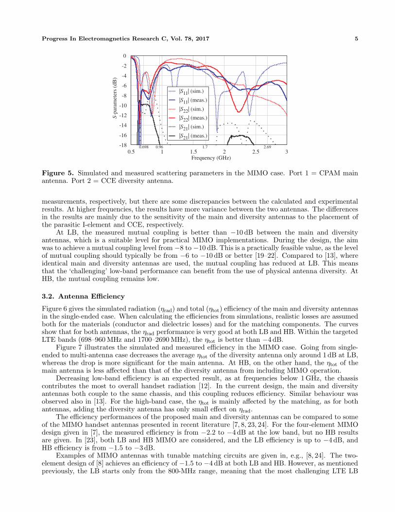
Figure 5. Simulated and measured scattering parameters in the MIMO case. Port 1 = CPAM mainantenna. Port 2 = CCE diversity antenna.
measurements, respectively, but there are some discrepancies between the calculated and experimentalresults. At higher frequencies, the results have more variance between the two antennas. The differencesin the results are mainly due to the sensitivity of the main and diversity antennas to the placement ofthe parasitic I-element and CCE, respectively.
At LB, the measured mutual coupling is better than −10 dB between the main and diversityantennas, which is a suitable level for practical MIMO implementations. During the design, the aimwas to achieve a mutual coupling level from −8 to −10 dB. This is a practically feasible value, as the levelof mutual coupling should typically be from −6 to −10 dB or better [19–22]. Compared to [13], whereidentical main and diversity antennas are used, the mutual coupling has reduced at LB. This meansthat the ‘challenging’ low-band performance can benefit from the use of physical antenna diversity. AtHB, the mutual coupling remains low.
3.2. Antenna Efficiency
Figure 6 gives the simulated radiation (ηrad) and total (ηtot) efficiency of the main and diversity antennasin the single-ended case. When calculating the efficiencies from simulations, realistic losses are assumedboth for the materials (conductor and dielectric losses) and for the matching components. The curvesshow that for both antennas, the ηrad performance is very good at both LB and HB. Within the targetedLTE bands (698–960 MHz and 1700–2690 MHz), the ηtot is better than −4 dB.
Figure 7 illustrates the simulated and measured efficiency in the MIMO case. Going from single-ended to multi-antenna case decreases the average ηtot of the diversity antenna only around 1dB at LB,whereas the drop is more significant for the main antenna. At HB, on the other hand, the ηtot of themain antenna is less affected than that of the diversity antenna from including MIMO operation.
Decreasing low-band efficiency is an expected result, as at frequencies below 1 GHz, the chassiscontributes the most to overall handset radiation [12]. In the current design, the main and diversityantennas both couple to the same chassis, and this coupling reduces efficiency. Similar behaviour wasobserved also in [13]. For the high-band case, the ηtot is mainly affected by the matching, as for bothantennas, adding the diversity antenna has only small effect on ηrad.
The efficiency performances of the proposed main and diversity antennas can be compared to someof the MIMO handset antennas presented in recent literature [7, 8, 23, 24]. For the four-element MIMOdesign given in [7], the measured efficiency is from −2.2 to −4 dB at the low band, but no HB resultsare given. In [23], both LB and HB MIMO are considered, and the LB efficiency is up to −4 dB, andHB efficiency is from −1.5 to −3 dB.
Examples of MIMO antennas with tunable matching circuits are given in, e.g., [8, 24]. The two-element design of [8] achieves an efficiency of −1.5 to −4 dB at both LB and HB. However, as mentionedpreviously, the LB starts only from the 800-MHz range, meaning that the most challenging LTE LB

6 Rasilainen et al.
0.7 0.8 0.9Frequency (GHz)
-9
-8
-7
-6
-5
-4
-3
-2
-1
0
1.8 2 2.2 2.4 2.6Frequency (GHz)
-9
-8
-7
-6
-5
-4
-3
-2
-1
0
Eff
icie
ncy
(dB
)
Eff
icie
ncy
(dB
)
rad,CPAM tot,CPAM rad,CCE tot,CCE
rad,CPAM tot,CPAM rad,CCE tot,CCE
η
η
ηη
η
ηηη
Figure 6. Simulated efficiency of the CPAM main and CCE diversity antennas in the single-endedcase.
0.7 0.8 0.9Frequency (GHz)
-9
-8
-7
-6
-5
-4
-3
-2
-1
0
rad,main (sim.) rad,div (sim.) tot,main (sim.) tot,main (meas.) tot,div (sim.) tot,div (meas.)
1.8 2 2.2 2.4 2.6Frequency (GHz)
-9
-8
-7
-6
-5
-4
-3
-2
-1
0
rad,main (sim.) rad,div (sim.) tot,main (sim.) tot,main (meas.) tot,div (sim.) tot,div (meas.)
Eff
icie
ncy
(dB
)
Eff
icie
ncy
(dB
)
ηη
ηη
η
ηη
η
η
η η
η
Figure 7. Simulated and measured antenna efficiency in the MIMO case.
frequencies are missing even with tuning. In [24], identical main and diversity antennas with a digitally-tunable capacitor (DTC) are used in the same end of the device. With this approach, the efficiency isbetter than −3 dB at LB and HB, but one drawback is the need for a tunable matching circuit. Withrespect to the results mentioned above, the efficiency performance obtained in this work is good (seeFigure 7), especially in light of the less-than-optimal matching levels.
3.3. Multi-Antenna Characteristics
When considering the suitability of the proposed design for actual multi-antenna applications, certainMIMO parameters and quantities need to be analysed. In this work, the MIMO performance ischaracterised in terms of envelope correlation coefficient (ECC) [16, 25], and multiplexing efficiency(ηmux) [26]. The ECC is a measure of how similar the radiation patterns of the two antennas are. A

Progress In Electromagnetics Research C, Vol. 78, 2017 7
Eθ (main) E (div)E (main) E (div)
E (main) E (div)E (main) E (div)
700 MHz 900 MHz 1800 MHz 2400 MHzSimulation
x-z plane
0-10-20-300
30
6090
120
150
180
210
240 270 300
330
(+ )z
(+ )x
E / dB
0
30
6090
120
150
180
210
240 270 300
330
0
30
6090
120
150
180
210
240 270 300
330
(+ )z
(+ )x0
30
6090
120
150
180
210
240 270 300
330
(+ )z
(+ )x0
30
6090
120
150
180
210
240 270 300
330
(+ )z
(+ )x
y-z plane
0-10-20-30
E / dB
0
30
6090
120
150
180
210
240 270 300
330
(+ )z
(+ )y0
30
6090
120
150
180
210
240 270 300
330
(+ )z
(+ )y0
30
6090
120
150
180
210
240 270 300
330
(+ )z
(+ )y0
30
6090
120
150
180
210
240 270 300
330
(+ )z
(+ )y
x-y plane
0-10-20-30
E / dB
(+ )x0
30
6090
120
150
180
210
240 270 300
330
(+ )y
0
30
6090
120
150
180
210
240 270 300
330
(+ )x
(+ )y
0
30
6090
120
150
180
210
240 270 300
330
(+ )x
(+ )y
0
30
6090
120
150
180
210
240 270 300
330
(+ )x
(+ )y
y-z plane
0-10-20-30
E / dB
0
30
6090
120
150
180
210
240 270 300
330
(+ )z
(+ )y0
30
6090
120
150
180
210
240 270 300
330
(+ )z
(+ )y0
30
6090
120
150
180
210
240 270 300
330
(+ )z
(+ )y0
30
6090
120
150
180
210
240 270 300
330
(+ )z
(+ )y
x-z plane
700 MHz 900 MHz 1800 MHz 2400 MHz
270
0-10-20-30
E / dB
0
30
6090
120
150
180
210
240 270 300
330
(+ )z
(+ )x0
30
6090
120
150
180
210
240 270 300
330
(+ )z
(+ )x0
30
6090
120
150
180
210
240 270 300
330
(+ )z
(+ )x0
30
6090
120
150
180
210
240 300
330
(+ )z
(+ )x
Measurement
x-y plane
0-10-20-30
E / dB
0
30
6090
120
150
180
210
240 270 300
330
(+ )y
(+ )x0
30
6090
120
150
180
210
240 270 300
330
(+ )y
(+ )x0
30
6090
120
150
180
210
240 270 300
330
(+ )y
(+ )x0
30
6090
120
150
180
210
240 270 300
330
(+ )y
(+ )x
ϕ θ ϕ
θ ϕ θ ϕ
Figure 8. Simulated and measured radiation patterns of the main and diversity antennas at 700 MHz,900 MHz, 1800 MHz, and 2400 MHz.
8 Rasilainen et al.
general guideline is that ECC values of ρe < 0.5 are typically desired to make efficient use of diversitytechniques. Multiplexing efficiency is a computationally simple metric that describes the loss of signal-to-noise ratio (SNR) with respect to ideal MIMO antennas due to antenna efficiency, efficiency imbalance,and correlation in a particular multi-antenna implementation [26].
It is possible to calculate the ECC either from antenna far fields or from S-parameters [16, 27]. Theprevious approach is laborious, especially across wide frequency ranges, whereas the latter one is simpleand fast to use. For this reason, many publications use the formula based on S-parameters to calculatethe ECC (e.g., [23, 28, 29]). The problem related to characterising the ECC from simulated and/ormeasured S-parameters is that the formulas used in the calculations are strictly valid for antennaswithout Ohmic losses [16], but as mentioned in [29], they are a sufficient approximation for antennaswith high efficiency. In a more general case, this method typically results in too optimistic ECCvalues, especially at LB. Thus, in this work we calculate the ECC from simulated and measured fields,assuming an isotropic and reflection-rich environment. Figure 8 visualises the simulated and measured(normalised) fields at 700, 900, 1800, and 2400 MHz, and losses due to impedance matching are takeninto account in the results. The patterns show that at the low band, the radiation patterns of the mainand diversity antennas are more similar than at the high band.
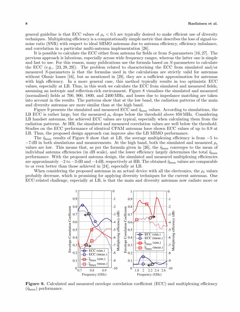
Figure 9 presents the simulated and measured ECC and ηmux values. According to simulations, theLB ECC is rather large, but the measured ρe drops below the threshold above 850 MHz. ConsideringLB handset antennas, the achieved ECC values are typical, especially when calculating them from theradiation patterns. At HB, the simulated and measured correlation values are well below the threshold.Studies on the ECC performance of identical CPAM antennas have shown ECC values of up to 0.9 atLB. Thus, the proposed design approach can improve also the LB MIMO performance.
The ηmux results of Figure 9 show that at LB, the average multiplexing efficiency is from −5 to−7 dB in both simulations and measurements. At the high band, both the simulated and measured ρe
values are low. This means that, as per the formula given in [26], the ηmux converges to the mean ofindividual antenna efficiencies (in dB scale), and the lower efficiency largely determines the total ηmux
performance. With the proposed antenna design, the simulated and measured multiplexing efficienciesare approximately −2 to −3 dB and −4 dB, respectively at HB. The obtained ηmux values are comparableto or even better than those achieved in [24], especially at LB.
When considering the proposed antennas in an actual device with all the electronics, the ρe valuesprobably decrease, which is promising for applying diversity techniques for the current antennas. OneECC-related challenge, especially at LB, is that the main and diversity antennas now radiate more or
0.7 0.8 0.9Frequency (GHz)
0
0.1
0.2
0.3
0.4
0.5
0.6
0.7
0.8
0.9
1
-10
-9
-8
-7
-6
-5
-4
-3
-2
-1
0
1.8 2 2.2 2.4 2.6Frequency (GHz)
0
0.1
0.2
0.3
0.4
0.5
0.6
0.7
0.8
0.9
1
-10
-9
-8
-7
-6
-5
-4
-3
-2
-1
0
mux (sim.)
ηmux (meas.)
ECC (sim.)ECC (meas.)
Mul
tiple
effi
cien
cy(d
B)
Env
elop
eC
orre
latio
nC
oef f
icie
nt
Mul
tiple
effi
cien
cy(d
B)
Env
elop
eC
orre
latio
nC
oef f
icie
nt
mux (sim.) mux (meas.)
ECC (sim.)ECC (meas.)
∼η∼
η∼
η∼
Figure 9. Calculated and measured envelope correlation coefficient (ECC) and multiplexing efficiency(ηmux) performance.

Progress In Electromagnetics Research C, Vol. 78, 2017 9
less the same way (see Figure 8), leading to inherently ‘high’ ECC. A solution could be to use, e.g.,capacitive main and inductive diversity antennas to get even greater benefit from physical antennadiversity, or to find suitable antenna and feed locations using the theory of characteristic modes [9].Exciting the main and diversity antennas through different (ideally, orthogonal) chassis wavemodesreduces the antenna correlation.
4. CONCLUSION
In this work, the performance of a two-element LTE MIMO handset antenna is presented. Bycombining two physically different antenna elements and a fixed matching network, the proposed simplediversity antenna covers the LTE low-band with total efficiency better than −4 dB. Measured MIMOcharacteristics show ECC values typical for this type of device without any decoupling techniques. Thefully passive implementation and good instantaneous bandwidth coverage makes the current design apotential candidate for intra-band CA applications.
ACKNOWLEDGMENT
This work was conducted within the 5G TRx research project funded by TEKES (The Finnish FundingAgency for Technology and Innovation), Nokia Solutions and Networks, TDK-EPCOS, MicrosoftMobile, Sasken Finland, Pulse Finland, and Huawei Technologies Finland, and by the Academy ofFinland under Decision 289320. The work of K. Rasilainen was supported in part by the Aalto ELECDoctoral School, by the Nokia Foundation, and by the KAUTE Foundation.
The authors would like to thank Dr. M. Keskilammi of Sasken Finland for providing antennameasurement facilities and Mr. J.-M. Hannula for useful discussions related to multi-antennacharacterisation and for help in analysing the measurement results.
REFERENCES
1. Hossain, E. and M. Hasan, “5G cellular: Key enabling technologies and research challenges,” IEEEInstrum. Meas. Mag., Vol. 18, No. 3, 11–21, Jun. 2015.
2. Bassam, S. A., W. Chen, M. Helaoui, and F. M. Ghannouchi, “Transmitter architecture forCA: Carrier aggregation in LTE-Advanced systems,” IEEE Microw. Mag., Vol. 14, No. 5, 78–86,Jul./Aug. 2013.
3. Valkonen, R., A. Lehtovuori, and C. Icheln, “Dual-feed, single-CCE antenna facilitating inter-band carrier aggregation in LTE-A handsets,” 2013 7th European Conference on Antennas andPropagation (EuCAP), 3954–3958, Gothenburg, Sweden, Apr. 2013.
4. Yoon, C., S.-G. Hwang, G.-C. Lee, W.-S. Kim, H.-C. Lee, C.-H. Lee, and H.-D. Park, “A frequency-selecting technique for mobile handset antennas based on capacitance switching,” Progress InElectromagnetics Research, Vol. 138, 99–113, 2013.
5. Ali, S. M. and K. Payandejoo, “Tunable antenna techniques for compact handset applications,”IET Microw. Antennas Propag., Vol. 8, No. 6, 401–408, Apr. 2014.
6. Caporal del Barrio, S., A. Morris, and G. F. Pedersen, “Addressing carrier aggregation with narrow-band tunable antennas,” 2016 10th European Conference on Antennas and Propagation (EuCAP),1–5, Davos, Switzerland, Apr. 2016.
7. Wong, K.-L., Y.-C. Chen, and W.-Y. Li, “Four LTE low-band smartphone antennas and theirMIMO performance with user’s hand presence,” Microw. Optical Technol. Lett., Vol. 58, No. 9,2046–2052, Sep. 2016.
8. Ban, Y.-L, Y.-F. Qiang, G. Wu, H. Wang, and K.-L. Wong, “Reconfigurable narrow-frame antennafor LTE/WWAN metal-rimmed smartphone applications,” IET Microw. Antennas Propag., Vol. 10,No. 10, 1092–1100, Jul. 2016.
9. Li, H., Z. T. Miers, and B. K. Lau, “Design of orthogonal MIMO handset antennas basedon characteristic mode manipulation at frequency bands below 1 GHz,” IEEE Trans. AntennasPropag., Vol. 62, No. 5, 2756–2766, May 2014.

10 Rasilainen et al.
10. Wi, H., B. Kim, W. Jung, and B. Lee, “Multiband handset antenna analysis including LTE bandMIMO service,” Progress In Electromagnetics Research, Vol. 138, 661–673, 2013.
11. Villanen, J., J. Ollikainen, O. Kivekas, and P. Vainikainen, “Coupling element based mobileterminal antenna structures,” IEEE Trans. Antennas Propag., Vol. 54, No. 7, 2142–2153, Jul. 2006.
12. Vainikainen, P., J. Ollikainen, O. Kivekas, and I. Kelander, “Resonator-based analysis of thecombination of mobile handset antenna and chassis,” IEEE Trans. Antennas Propag., Vol. 50,No. 10, 1433–1444, Oct. 2002.
13. Rasilainen, K., A. Lehtovuori, and V. Viikari, “LTE handset antenna with closely-locatedradiators, low-band MIMO, and high efficiency,” 2017 11th European Conference on Antennasand Propagation (EuCAP), 3074–3078, Paris, France, Mar. 2017.
14. CST Microwave Studio, an FDTD/FIT based electromagnetic simulator, version 2013, CST AG,Darmstadt, Germany, [Online], Available: http://www.cst.com (Cited Jun. 8, 2017).
15. Optenni Lab, matching circuit generation and antenna analysis software, ver. 3.3, Optenni Ltd.,Espoo, Finland, [Online], Available: http://www.optenni.com (Cited Jun. 8, 2017).
16. Kildal, P.-S., Foundations of Antenna Engineering: A Unified Approach for Line-of-Sight andMultipath, Kildal, 2015.
17. Ilvonen, J., R. Valkonen, J. Holopainen, and V. Viikari, “Design strategy for 4G handset antennaand a multiband hybrid antenna,” IEEE Trans. Antennas Propag., Vol. 62, No. 4, 1918–1927,Apr. 2014.
18. Lehtovuori, A., J. Ilvonen, K. Rasilainen, and V. Viikari, “Single-element handset antenna designfor modern smartphones: An industrial approach,” 2017 11th European Conference on Antennasand Propagation (EuCAP), 2960–2963, Paris, France, Mar. 2017.
19. Ilvonen, J., J. Holopainen, K. Rasilainen, A. Lehtovuori, and V. Viikari, “Suitable multiantennaplacement in mobile handsets based on electromagnetic isolation,” 2016 10th European Conferenceon Antennas and Propagation (EuCAP), 1–4, Davos, Switzerland, Apr. 2016.
20. Wong, K.-L., T.-W. Kang, and M.-F. Tu, “Internal mobile phone antenna array for LTE/WWANand LTE MIMO operations,” Microw. Optical Technol. Lett., Vol. 53, No. 7, 1569–1573, Jul. 2011.
21. Cihangir, A., F. Ferrero, G. Jacquemod, P. Brachat, and C. Luxey, “Neutralized coupling elemetsfor MIMO operation in 4G mobile terminals,” IEEE Antennas Wireless Propag. Lett., Vol. 13,141–144, 2014.
22. Zhang, S., K. Zhao, Z. Ying, and S. He, “Adaptive quad-element multi-wideband antenna arrayfor user-effective LTE MIMO mobile terminals,” IEEE Trans. Antennas Propag., Vol. 61, No. 8,4275–4283, Aug. 2013.
23. Li, K., Y. Shi, and C.-H. Liang, “Quad-element multi-band antenna array in the smart mobile phonefor LTE MIMO operations,” Microw. Opt. Technol. Lett., Vol. 58, No. 11, 2619–2626, Nov. 2016.
24. Ilvonen, J., R. Valkonen, J. Holopainen, and V. Viikari, “Multiband frequency reconfigurable 4Ghandset antenna with MIMO capability,” Progress In Electromagnetics Research, Vol. 148, 233–243,2014.
25. Vaughan, R. G. and J. Bach Andersen, “Antenna diversity in mobile communications,” IEEETrans. Veh. Commun., Vol. VT-36, No. 4, 149–172, Nov. 1987.
26. Tian, R., B. K. Lau, and Z. Ying, “Multiplexing efficiency of MIMO antennas,” IEEE AntennasWireless Propag. Lett., Vol. 10, 183–186, 2011.
27. Blanch, S., J. Romeu, and I. Corbella, “Exact representation of antenna system diversityperformance from input parameter description,” Electron. Lett., Vol. 39, No. 9, 705–707, May 2003.
28. Shoaib, S., I. Shoaib, X. Chen, and C. G. Parini, “MIMO antennas for next generation mobileterminals,” 2016 10th European Conference on Antennas and Propagation (EuCAP), 1–4, Davos,Switzerland, Apr. 2016.
29. Chamok, N. H., M. H. Yilmaz, H. Arslan, and M. Ali, “High-gain pattern reconfigurable MIMOantenna array for wireless handheld terminals,” IEEE Trans. Antennas Propag., Vol. 64, No. 10,4306–4315, Oct. 2016.
Related Documents