CARBON/PP COMPOSITES AND CARBON/SELF- REINFORCED PP COMPOSITES J. Ustarroz, I. Taketa, S.V. Lomov, I.Verpoest Metallurgy and Materials Engineering department, Katholieke Universiteit Leuven Kasteelpark Arenberg 44, B-3001, Heverlee, Belgium [email protected] SUMMARY Carbon/PP and carbon/self-reinforced PP hybrid composites have been produced by film-stacking. Tensile tests in carbon/PP composites show that the E-modulus is 15% lower than expected. Compared to carbon/PP materials, hybrid composites show an increase of 6-20% in ultimate strain and 10-15% in strength, while the E-modulus is kept as predicted. Keywords: Carbon reinforced thermoplastics, Self-reinforced polypropylene, hybrid composite, mechanical testing INTRODUCTION Carbon reinforced thermoplastics represent an alternative to obtain light materials with high specific mechanical properties, avoiding intrinsic drawbacks of reinforced thermosets like long curing times and hazardous chemical substances. Furthermore, thermoplastic composites can also be re-melted, post-processed and recycled. In addition, due to its lightness, low-cost, and low Life Cycle Analysis impact, polypropylene is increasingly used as matrix thermoplastic composites. However, the main shortcoming of carbon composites is their brittleness and their bad impact performance, which might hopefully be overcome by hybridisation with self- reinforced polypropylene. Self-reinforced PP (produced by Propex under the tradename CURV ) is chemically identical to PP, so it is as light and recyclable as the normal polymer. However, it has been found to be 3 to 5 times stiffer than polypropylene, as well as extremely tough and impact resistant [1]. Furthermore, self-reinforced PP, as well as CURV , has been shown to undergo shrinkage while heating up to processing temperatures [2]. This effect may lead to dimensional problems when only-CURV products are made, but on the other hand, it can also be exploited to induce compressive stresses when laminating together with another material. From another point of view, hybrid composites are defined as composites made out of two sorts of fibres, for instance stiff and brittle fibres combined with less stiff but tough fibres, embedded in the same matrix. Because of several mechanisms like thermal residual stresses, or energetic effects due to arresting of cracks initiated in the stiff fibre layer or area by the tough fibres; such hybridization may lead to a synergetic effect in mechanical performance, meaning an increase in the ultimate strain compared with the ultimate strain of the brittle fibre composite, while achieving a higher stiffness. This has

Welcome message from author
This document is posted to help you gain knowledge. Please leave a comment to let me know what you think about it! Share it to your friends and learn new things together.
Transcript
CARBON/PP COMPOSITES AND CARBON/SELF-
REINFORCED PP COMPOSITES
J. Ustarroz, I. Taketa, S.V. Lomov, I.Verpoest
Metallurgy and Materials Engineering department, Katholieke Universiteit Leuven
Kasteelpark Arenberg 44, B-3001, Heverlee, Belgium
SUMMARY
Carbon/PP and carbon/self-reinforced PP hybrid composites have been produced by
film-stacking. Tensile tests in carbon/PP composites show that the E-modulus is 15%
lower than expected. Compared to carbon/PP materials, hybrid composites show an
increase of 6-20% in ultimate strain and 10-15% in strength, while the E-modulus is
kept as predicted.
Keywords: Carbon reinforced thermoplastics, Self-reinforced polypropylene, hybrid
composite, mechanical testing
INTRODUCTION
Carbon reinforced thermoplastics represent an alternative to obtain light materials with
high specific mechanical properties, avoiding intrinsic drawbacks of reinforced
thermosets like long curing times and hazardous chemical substances. Furthermore,
thermoplastic composites can also be re-melted, post-processed and recycled. In
addition, due to its lightness, low-cost, and low Life Cycle Analysis impact,
polypropylene is increasingly used as matrix thermoplastic composites.
However, the main shortcoming of carbon composites is their brittleness and their bad
impact performance, which might hopefully be overcome by hybridisation with self-
reinforced polypropylene. Self-reinforced PP (produced by Propex under the tradename
CURV
) is chemically identical to PP, so it is as light and recyclable as the normal
polymer. However, it has been found to be 3 to 5 times stiffer than polypropylene, as
well as extremely tough and impact resistant [1]. Furthermore, self-reinforced PP, as
well as CURV
, has been shown to undergo shrinkage while heating up to processing
temperatures [2]. This effect may lead to dimensional problems when only-CURV
products are made, but on the other hand, it can also be exploited to induce compressive
stresses when laminating together with another material.
From another point of view, hybrid composites are defined as composites made out of
two sorts of fibres, for instance stiff and brittle fibres combined with less stiff but tough
fibres, embedded in the same matrix. Because of several mechanisms like thermal
residual stresses, or energetic effects due to arresting of cracks initiated in the stiff fibre
layer or area by the tough fibres; such hybridization may lead to a synergetic effect in
mechanical performance, meaning an increase in the ultimate strain compared with the
ultimate strain of the brittle fibre composite, while achieving a higher stiffness. This has
been widely investigated both experimentally [3], [4], [5], [6] and theoretically [7], [8],
[9], [10].
Thus, if CURV
layers are stacked together with carbon/PP layers (interply hybrid),
compressive stresses due to a controlled shrinkage of CURV
, may be induced in
carbon fibres, increasing this way their apparent strength and ultimate failure strain in
the composite. A further improvement could be realized when layers of highly-oriented
PP tapes and layers of carbon fibres are embedded in the same low-oriented PP matrix,
resulting in an intraply hybrid composite.
As it has been mentioned before, there already exists wide research work dealing with
the hybrid synergetic effect on mechanical properties of hybrid composites, but the
challenge lays on the fact that no studies on the hybridisation of self-reinforced
polymers have been yet published.
The present study aims first to study the processability and mechanical performance of
carbon/PP single composites, and to further hybridise them with self-reinforced PP.
Then, the challenge is to obtain carbon/self-reinforced PP hybrid composites, which will
benefit from the inherent toughness of CURV
, from the hybrid synergetic effect in
ultimate strain, and from induced compressive stresses in carbon fibres due to a
controlled shrinkage of CURV
during the manufacturing process.
MATERIALS AND METHODS
Materials
Maleic anhydride modified polypropylene films from Amcor have been used for
impregnating carbon weaves. The thickness of these films is 100 microns, the density is
0,9 g/cm3, the melt flow index is 5,2 g/10min, and standard DSC tests have shown that
the melting point is 162,5°C.
Twill 2/2 carbon fabrics from Hexcel (Hexcel G0986 D1200) with nominal weight of
285 g/m2, and nominal construction of 3,5 picks/cm and 3,5 counts/cm have been used
as reinforcement material. Yarns from Toho-Tenax (Tenax HTA 5131 6K) were used to
weave the previously mentioned carbon fabrics. 6000 filaments with 6 microns diameter
were used to form the yarns, leading to a linear density of 400 tex. The mechanical
properties of these fibres are the following: tensile strength of 3950 MPa, tensile
modulus of 238 GPa, and elongation at break of 1,7%.
Self-reinforced PP tapes from Propex (standard CURV
material) are woven into
fabrics and then consolidated into sheets of 150 and 300 microns thickness. Because of
the fact that self-reinforced PP is chemically identical to normal PP, its density is only
0,92 g/cm3, while the mechanical properties of the CURV
woven fabric sheets rise up
to the following values: tensile modulus of 3 GPa, tensile strength of 160 MPa and
elongation at break of 16%.
Processing methods
Composite plates have been made by hot-press in a Pinnette press Zenith 2, which can
apply forces up to 40 Ton and temperatures up to 500°C. Film-stacking technology has
been used to impregnate carbon fabrics with polypropylene films. Afterwards, hot-
pressure compactation has been applied to laminate various monolayers of PP
impregnated carbon fabrics and to consolidate hybrid composites with alternating layers
of self-reinforced PP and PP impregnated carbon fabrics. 300 mm x 300 mm samples,
processed at different conditions, have been produced and tested in order to study the
dependence of their mechanical properties on processing parameters such as
temperature, pressure and processing time.
Carbon/Self-Reinforced PP hybrid composites have been made stacking together
CURV
layers with carbon fabrics impregnated beforehand at optimal conditions. The
processing temperature is always kept between 165 and 175°C in order to avoid
degradation of the highly-oriented polypropylene tapes in the CURV
sheets. This way,
hybrid composite plates with different interply stacking sequences have been made in
order to determine their mechanical properties and to analyse the hybrid effect.
Quality assessment and mechanical testing methods
First of all, the density of the composite (ρC) is calculated using Equation 1. For that
purpose, the average thickness of the composite plate (hC) is measured with the
precision down to 10 microns, and the mass of the composite plate (MC) is measured
with a microbalance down to 0,1 g. Then, the fibre volume fraction can be easily
calculated with Equation 2, where Af =285 g/m2 is the areal weight of the carbon fabric,
A is the area of carbon fabric, NL is the number of layers and ρf is the density of carbon
fibre, 1,76 g/cm3.
( )( ) ( )mmhmA
gM
cmg
C
CC
1,010243
⋅=
ρ (1)
f
C
C
Lf
fM
NAAV
ρ
ρ××= (2)
( )VoidsVol
AAAA
AA
V
m
f
f
f
f
f
f
_1
+×−
+×
×
=
ρρ
ρ (3)
VoidsVolMM
VoidsVolV
m
m
f
f
Voids
_
_
++
=
ρρ
(4)
In order to calculate the void content of the material, the volume occupied by void
inside the composite plate (Vol_Voids) can be derived from Equation 3, where ρM is the
density of the matrix (ρM = ρPP = 0,9 g/cm3). Finally, the volume fraction of void is
easily calculated by means of Equation 4. All the voids are concentrated in the fibre
region (inside the yarns), so the average non-impregnated cross-sectional area of the
yarns can be obtained dividing the void volume fraction by the fibre volume fraction. In
order to qualitatively analyse the quality of the impregnation, cross-sectional optical
microscopical characterization has been also carried out.
Tensile tests in the 0° degree direction on 250 mm x 25 mm specimens have been
carried out using an INSTRON 4467 tensile testing machine with a load cell of 30 kN
and a cross-head speed of 2mm/min. An extensometer has been used to measure the real
strain during the tests.
RESULTS AND DISCUSSION
Carbon/polypropylene composites
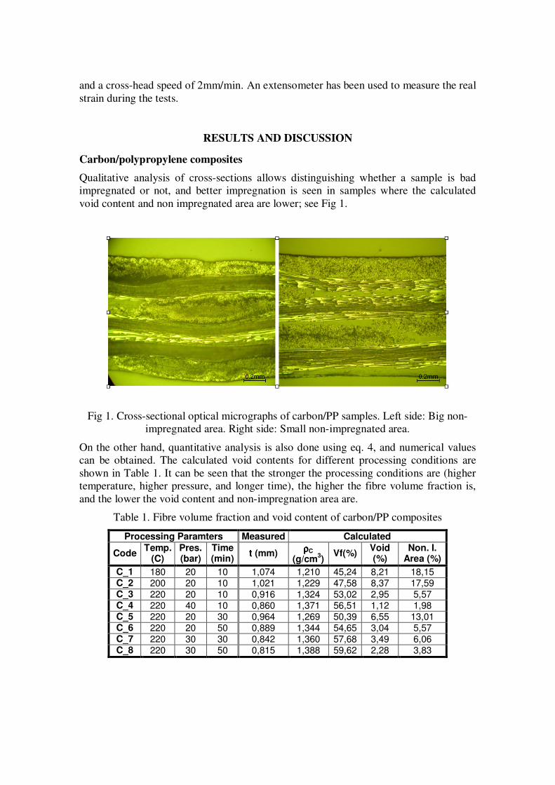
Qualitative analysis of cross-sections allows distinguishing whether a sample is bad
impregnated or not, and better impregnation is seen in samples where the calculated
void content and non impregnated area are lower; see Fig 1.
Fig 1. Cross-sectional optical micrographs of carbon/PP samples. Left side: Big non-
impregnated area. Right side: Small non-impregnated area.
On the other hand, quantitative analysis is also done using eq. 4, and numerical values
can be obtained. The calculated void contents for different processing conditions are
shown in Table 1. It can be seen that the stronger the processing conditions are (higher
temperature, higher pressure, and longer time), the higher the fibre volume fraction is,
and the lower the void content and non-impregnation area are.
Table 1. Fibre volume fraction and void content of carbon/PP composites
Processing Paramters Measured Calculated
Code Temp.
(C) Pres. (bar)
Time (min)
t (mm) ρρρρC
(g/cm3)
Vf(%) Void (%)
Non. I. Area (%)
C_1 180 20 10 1,074 1,210 45,24 8,21 18,15 C_2 200 20 10 1,021 1,229 47,58 8,37 17,59 C_3 220 20 10 0,916 1,324 53,02 2,95 5,57 C_4 220 40 10 0,860 1,371 56,51 1,12 1,98 C_5 220 20 30 0,964 1,269 50,39 6,55 13,01 C_6 220 20 50 0,889 1,344 54,65 3,04 5,57 C_7 220 30 30 0,842 1,360 57,68 3,49 6,06 C_8 220 30 50 0,815 1,388 59,62 2,28 3,83
At temperatures above 220°C, some of the curing agents which are present in the carbon
fibre sizings would start degrading, so the maximum processing temperature for the
system carbon/PP is 220°C. At pressures above 30 bars, carbon yarns become damaged
during the processing, so the maximum allowed pressure is about 30 bars. In addition,
long processing times help the impregnation and diminish the influence of the applied
pressure.
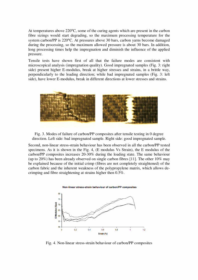
Tensile tests have shown first of all that the failure modes are consistent with
microscopical analysis (impregnation quality). Good impregnated samples (Fig. 3: right
side) present higher E-modulus, break at higher stresses and strains, in a brittle way,
perpendicularly to the loading direction; while bad impregnated samples (Fig. 3: left
side), have lower E-modulus, break in different directions at lower stresses and strains.
Fig. 3. Modes of failure of carbon/PP composites after tensile testing in 0 degree
direction. Left side: bad impregnated sample. Right side: good impregnated sample.
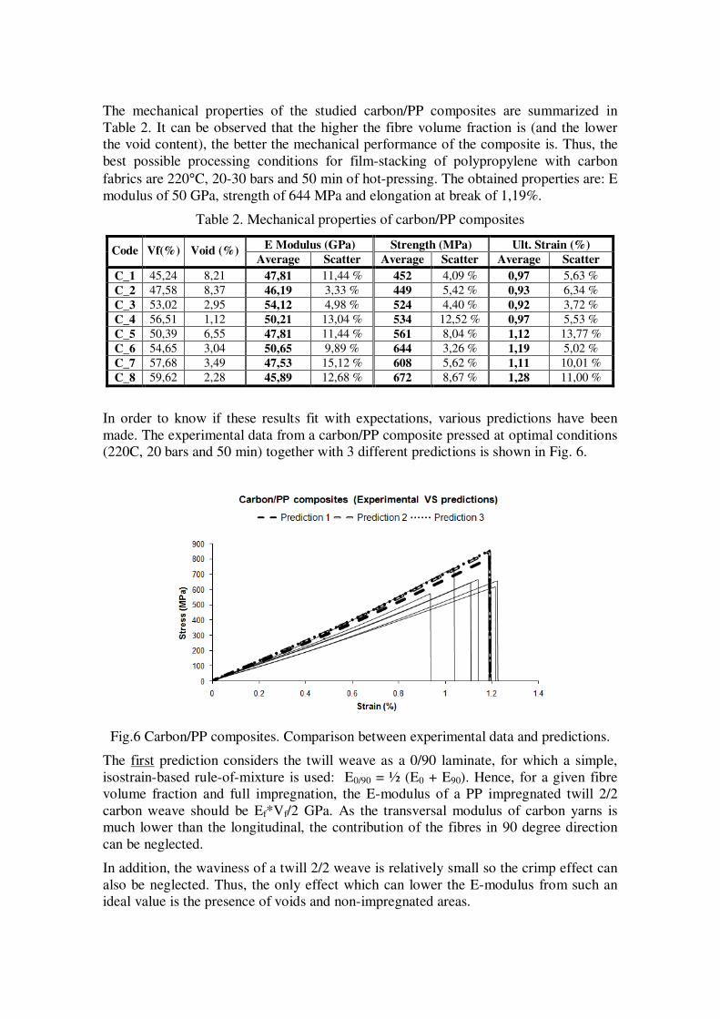
Second, non-linear stress-strain behaviour has been observed in all the carbon/PP tested
specimens. As it is shown in the Fig. 4, (E modulus Vs Strain), the E modulus of the
carbon/PP composites increases 20-30% during the loading state. The same behaviour
(up to 20%) has been already observed on single carbon fibres [11]. The other 10% may
be explained because of the initial crimp (fibres are not completely straightened) of the
carbon fabric and the inherent weakness of the polypropylene matrix, which allows de-
crimping and fibre straightening at strains higher then 0.5%.
Fig. 4. Non-linear stress-strain behaviour of carbon/PP composites
The mechanical properties of the studied carbon/PP composites are summarized in
Table 2. It can be observed that the higher the fibre volume fraction is (and the lower
the void content), the better the mechanical performance of the composite is. Thus, the
best possible processing conditions for film-stacking of polypropylene with carbon
fabrics are 220°C, 20-30 bars and 50 min of hot-pressing. The obtained properties are: E
modulus of 50 GPa, strength of 644 MPa and elongation at break of 1,19%.
Table 2. Mechanical properties of carbon/PP composites
E Modulus (GPa) Strength (MPa) Ult. Strain (%) Code Vf(%) Void (%)
Average Scatter Average Scatter Average Scatter
C_1 45,24 8,21 47,81 11,44 % 452 4,09 % 0,97 5,63 %
C_2 47,58 8,37 46,19 3,33 % 449 5,42 % 0,93 6,34 %
C_3 53,02 2,95 54,12 4,98 % 524 4,40 % 0,92 3,72 %
C_4 56,51 1,12 50,21 13,04 % 534 12,52 % 0,97 5,53 %
C_5 50,39 6,55 47,81 11,44 % 561 8,04 % 1,12 13,77 %
C_6 54,65 3,04 50,65 9,89 % 644 3,26 % 1,19 5,02 %
C_7 57,68 3,49 47,53 15,12 % 608 5,62 % 1,11 10,01 %
C_8 59,62 2,28 45,89 12,68 % 672 8,67 % 1,28 11,00 %
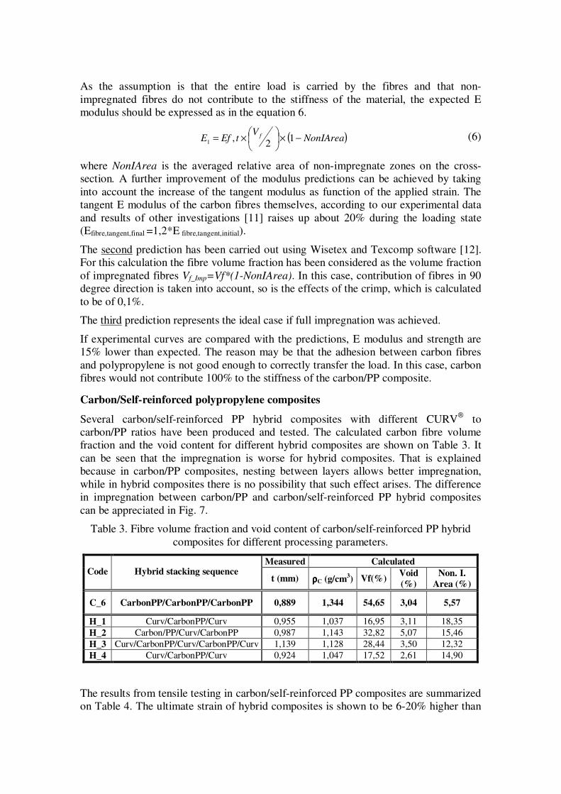
In order to know if these results fit with expectations, various predictions have been
made. The experimental data from a carbon/PP composite pressed at optimal conditions
(220C, 20 bars and 50 min) together with 3 different predictions is shown in Fig. 6.
Fig.6 Carbon/PP composites. Comparison between experimental data and predictions.
The first prediction considers the twill weave as a 0/90 laminate, for which a simple,
isostrain-based rule-of-mixture is used: E0/90 = ½ (E0 + E90). Hence, for a given fibre
volume fraction and full impregnation, the E-modulus of a PP impregnated twill 2/2
carbon weave should be Ef*Vf/2 GPa. As the transversal modulus of carbon yarns is
much lower than the longitudinal, the contribution of the fibres in 90 degree direction
can be neglected.
In addition, the waviness of a twill 2/2 weave is relatively small so the crimp effect can
also be neglected. Thus, the only effect which can lower the E-modulus from such an
ideal value is the presence of voids and non-impregnated areas.
As the assumption is that the entire load is carried by the fibres and that non-
impregnated fibres do not contribute to the stiffness of the material, the expected E
modulus should be expressed as in the equation 6.
( )NonIAreaV
tEfE f −×
×= 1
2,
1 (6)
where NonIArea is the averaged relative area of non-impregnate zones on the cross-
section. A further improvement of the modulus predictions can be achieved by taking
into account the increase of the tangent modulus as function of the applied strain. The
tangent E modulus of the carbon fibres themselves, according to our experimental data
and results of other investigations [11] raises up about 20% during the loading state
(Efibre,tangent,final =1,2*E fibre,tangent,initial).
The second prediction has been carried out using Wisetex and Texcomp software [12].
For this calculation the fibre volume fraction has been considered as the volume fraction
of impregnated fibres Vf_Imp=Vf*(1-NonIArea). In this case, contribution of fibres in 90
degree direction is taken into account, so is the effects of the crimp, which is calculated
to be of 0,1%.
The third prediction represents the ideal case if full impregnation was achieved.
If experimental curves are compared with the predictions, E modulus and strength are
15% lower than expected. The reason may be that the adhesion between carbon fibres
and polypropylene is not good enough to correctly transfer the load. In this case, carbon
fibres would not contribute 100% to the stiffness of the carbon/PP composite.
Carbon/Self-reinforced polypropylene composites
Several carbon/self-reinforced PP hybrid composites with different CURV
to
carbon/PP ratios have been produced and tested. The calculated carbon fibre volume
fraction and the void content for different hybrid composites are shown on Table 3. It
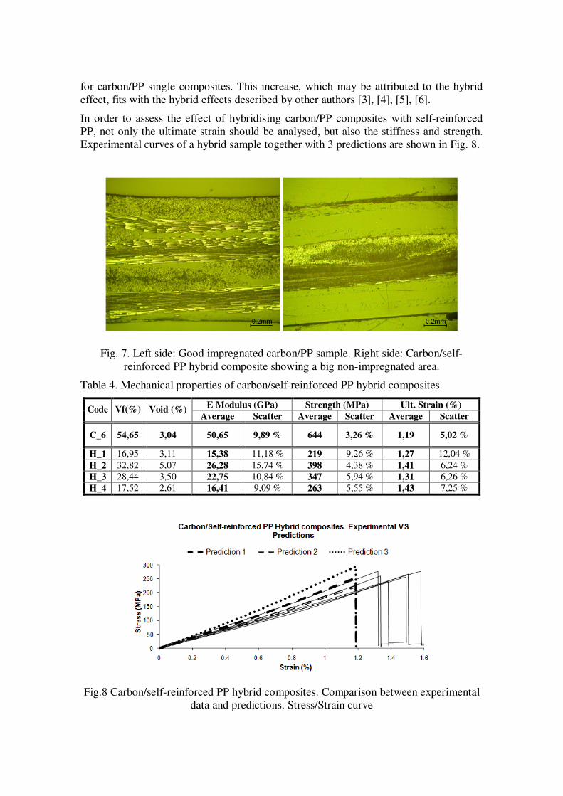
can be seen that the impregnation is worse for hybrid composites. That is explained
because in carbon/PP composites, nesting between layers allows better impregnation,
while in hybrid composites there is no possibility that such effect arises. The difference
in impregnation between carbon/PP and carbon/self-reinforced PP hybrid composites
can be appreciated in Fig. 7.
Table 3. Fibre volume fraction and void content of carbon/self-reinforced PP hybrid
composites for different processing parameters.
Measured Calculated Code Hybrid stacking sequence
t (mm) ρρρρC (g/cm3) Vf(%)
Void
(%)
Non. I.
Area (%)
C_6 CarbonPP/CarbonPP/CarbonPP 0,889 1,344 54,65 3,04 5,57
H_1 Curv/CarbonPP/Curv 0,955 1,037 16,95 3,11 18,35
H_2 Carbon/PP/Curv/CarbonPP 0,987 1,143 32,82 5,07 15,46
H_3 Curv/CarbonPP/Curv/CarbonPP/Curv 1,139 1,128 28,44 3,50 12,32
H_4 Curv/CarbonPP/Curv 0,924 1,047 17,52 2,61 14,90
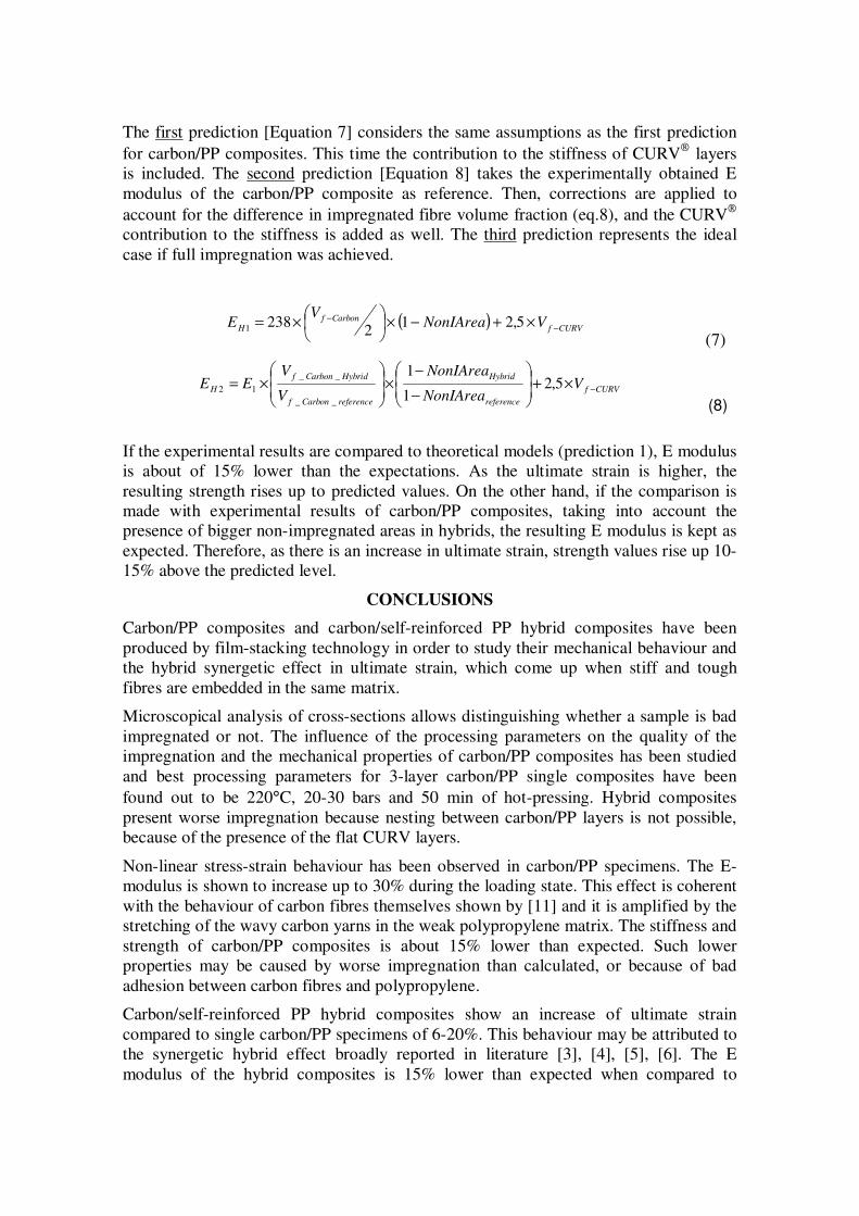
The results from tensile testing in carbon/self-reinforced PP composites are summarized
on Table 4. The ultimate strain of hybrid composites is shown to be 6-20% higher than
for carbon/PP single composites. This increase, which may be attributed to the hybrid
effect, fits with the hybrid effects described by other authors [3], [4], [5], [6].
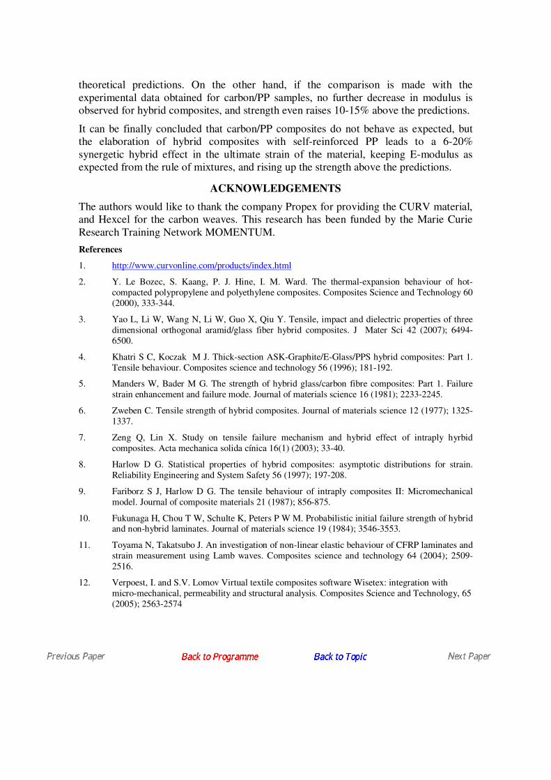
In order to assess the effect of hybridising carbon/PP composites with self-reinforced
PP, not only the ultimate strain should be analysed, but also the stiffness and strength.
Experimental curves of a hybrid sample together with 3 predictions are shown in Fig. 8.
Fig. 7. Left side: Good impregnated carbon/PP sample. Right side: Carbon/self-
reinforced PP hybrid composite showing a big non-impregnated area.
Table 4. Mechanical properties of carbon/self-reinforced PP hybrid composites.
E Modulus (GPa) Strength (MPa) Ult. Strain (%) Code Vf(%) Void (%)
Average Scatter Average Scatter Average Scatter
C_6 54,65 3,04 50,65 9,89 % 644 3,26 % 1,19 5,02 %
H_1 16,95 3,11 15,38 11,18 % 219 9,26 % 1,27 12,04 %
H_2 32,82 5,07 26,28 15,74 % 398 4,38 % 1,41 6,24 %
H_3 28,44 3,50 22,75 10,84 % 347 5,94 % 1,31 6,26 %
H_4 17,52 2,61 16,41 9,09 % 263 5,55 % 1,43 7,25 %
Fig.8 Carbon/self-reinforced PP hybrid composites. Comparison between experimental
data and predictions. Stress/Strain curve
The first prediction [Equation 7] considers the same assumptions as the first prediction
for carbon/PP composites. This time the contribution to the stiffness of CURV
layers
is included. The second prediction [Equation 8] takes the experimentally obtained E
modulus of the carbon/PP composite as reference. Then, corrections are applied to
account for the difference in impregnated fibre volume fraction (eq.8), and the CURV
contribution to the stiffness is added as well. The third prediction represents the ideal
case if full impregnation was achieved.
( )CURVf
CarbonfH
VNonIAreaV
E−
− ×+−×
×= 5,21
2238
1
(7)
CURVf
reference
Hybrid
referenceCarbonf
HybridCarbonf
H VNonIArea
NonIArea
V
VEE −×+
−
−×
×= 5,2
1
1
__
__
12
(8)
If the experimental results are compared to theoretical models (prediction 1), E modulus
is about of 15% lower than the expectations. As the ultimate strain is higher, the
resulting strength rises up to predicted values. On the other hand, if the comparison is
made with experimental results of carbon/PP composites, taking into account the
presence of bigger non-impregnated areas in hybrids, the resulting E modulus is kept as
expected. Therefore, as there is an increase in ultimate strain, strength values rise up 10-
15% above the predicted level.
CONCLUSIONS
Carbon/PP composites and carbon/self-reinforced PP hybrid composites have been
produced by film-stacking technology in order to study their mechanical behaviour and
the hybrid synergetic effect in ultimate strain, which come up when stiff and tough
fibres are embedded in the same matrix.
Microscopical analysis of cross-sections allows distinguishing whether a sample is bad
impregnated or not. The influence of the processing parameters on the quality of the
impregnation and the mechanical properties of carbon/PP composites has been studied
and best processing parameters for 3-layer carbon/PP single composites have been
found out to be 220°C, 20-30 bars and 50 min of hot-pressing. Hybrid composites
present worse impregnation because nesting between carbon/PP layers is not possible,
because of the presence of the flat CURV layers.
Non-linear stress-strain behaviour has been observed in carbon/PP specimens. The E-
modulus is shown to increase up to 30% during the loading state. This effect is coherent
with the behaviour of carbon fibres themselves shown by [11] and it is amplified by the
stretching of the wavy carbon yarns in the weak polypropylene matrix. The stiffness and
strength of carbon/PP composites is about 15% lower than expected. Such lower
properties may be caused by worse impregnation than calculated, or because of bad
adhesion between carbon fibres and polypropylene.
Carbon/self-reinforced PP hybrid composites show an increase of ultimate strain
compared to single carbon/PP specimens of 6-20%. This behaviour may be attributed to
the synergetic hybrid effect broadly reported in literature [3], [4], [5], [6]. The E
modulus of the hybrid composites is 15% lower than expected when compared to
theoretical predictions. On the other hand, if the comparison is made with the
experimental data obtained for carbon/PP samples, no further decrease in modulus is
observed for hybrid composites, and strength even raises 10-15% above the predictions.
It can be finally concluded that carbon/PP composites do not behave as expected, but
the elaboration of hybrid composites with self-reinforced PP leads to a 6-20%
synergetic hybrid effect in the ultimate strain of the material, keeping E-modulus as
expected from the rule of mixtures, and rising up the strength above the predictions.
ACKNOWLEDGEMENTS
The authors would like to thank the company Propex for providing the CURV material,
and Hexcel for the carbon weaves. This research has been funded by the Marie Curie
Research Training Network MOMENTUM.
References
1. http://www.curvonline.com/products/index.html
2. Y. Le Bozec, S. Kaang, P. J. Hine, I. M. Ward. The thermal-expansion behaviour of hot-
compacted polypropylene and polyethylene composites. Composites Science and Technology 60
(2000), 333-344.
3. Yao L, Li W, Wang N, Li W, Guo X, Qiu Y. Tensile, impact and dielectric properties of three
dimensional orthogonal aramid/glass fiber hybrid composites. J Mater Sci 42 (2007); 6494-
6500.
4. Khatri S C, Koczak M J. Thick-section ASK-Graphite/E-Glass/PPS hybrid composites: Part 1.
Tensile behaviour. Composites science and technology 56 (1996); 181-192.
5. Manders W, Bader M G. The strength of hybrid glass/carbon fibre composites: Part 1. Failure
strain enhancement and failure mode. Journal of materials science 16 (1981); 2233-2245.
6. Zweben C. Tensile strength of hybrid composites. Journal of materials science 12 (1977); 1325-
1337.
7. Zeng Q, Lin X. Study on tensile failure mechanism and hybrid effect of intraply hyrbid
composites. Acta mechanica solida cínica 16(1) (2003); 33-40.
8. Harlow D G. Statistical properties of hybrid composites: asymptotic distributions for strain.
Reliability Engineering and System Safety 56 (1997); 197-208.
9. Fariborz S J, Harlow D G. The tensile behaviour of intraply composites II: Micromechanical
model. Journal of composite materials 21 (1987); 856-875.
10. Fukunaga H, Chou T W, Schulte K, Peters P W M. Probabilistic initial failure strength of hybrid and non-hybrid laminates. Journal of materials science 19 (1984); 3546-3553.
11. Toyama N, Takatsubo J. An investigation of non-linear elastic behaviour of CFRP laminates and
strain measurement using Lamb waves. Composites science and technology 64 (2004); 2509-
2516.
12. Verpoest, I. and S.V. Lomov Virtual textile composites software Wisetex: integration with
micro-mechanical, permeability and structural analysis. Composites Science and Technology, 65
(2005); 2563-2574
Related Documents