Carbon nanofibers enhance the fracture toughness and fatigue performance of a structural epoxy system Daniel R. Bortz a , César Merino b , Ignacio Martin-Gullon a,⇑ a Department of Chemical Engineering, University of Alicante, Alicante, Spain b Grupo Antolín Ingeniería, Crta Irún 244, Burgos, Spain article info Article history: Received 28 June 2010 Received in revised form 22 September 2010 Accepted 25 September 2010 Available online 23 October 2010 Keywords: A. Nano composites A. Carbon nanotubes A. Polymer matrix composites (PMCs) B. Fatigue B. Fracture toughness abstract This study investigates the monotonic and dynamic fracture characteristics of a discontinuous fiber reinforced polymer matrix. Specifically, small amounts (0–1 wt.%) of a helical-ribbon carbon nanofiber (CNF) were added to an amine cured epoxy system. The resulting nanocomposites were tested to failure in two modes of testing; Mode I fracture toughness and constant amplitude of stress tension–tension fatigue. Fracture toughness testing revealed that adding 0.5 and 1.0 wt.% CNFs to the epoxy matrix enhanced the resistance to fracture by 66% and 78%, respectively. Fatigue testing at 20 MPa peak stress showed a median increase in fatigue life of 180% and 365% over the control by the addition of 0.5 and 1.0 wt.% CNF, respectively. These results clearly demonstrate the addition of small weight fractions of CNFs to significantly enhance the monotonic fracture behavior and long-term fatigue performance of this polymer. A discussion is presented linking the two behaviors indicating their interdependence and reliance upon the stress intensity factor, K. Ó 2010 Elsevier Ltd. All rights reserved. 1. Introduction Epoxy systems are widely used to bind laminates of glass or carbon fibers or to suspend particulate or fibrous fillers to create advanced multifunctional composite materials in which a high specific strength is required. Carbon nanomaterials offer remark- able properties and discontinuous carbon nanotube (CNT) and car- bon nanofiber (CNF) reinforcement of epoxy matrices have shown potential to augment a variety of physical and mechanical proper- ties resulting in truly multifunctional composite materials. Recent reviews by Spitalsky et al. [1] and Ma et al. [2] highlight the latest advancements. Understanding the monotonic and dynamic mechanical properties of structural epoxy reinforced with CNTs and CNFs will lend itself to the engineering of these advanced materials. In regard to the mechanical performance of these com- posites, interfacial adhesion between the matrix and reinforcing phase is essential [3,4]. From a micromechanics of materials point of view, in which the matrix and reinforcing phase act as heteroge- neous entities acting upon each other, shear stress build-up along the length of the interface is the mechanism responsible for stress transfer from the matrix to the fiber [5]. Inadequate fiber–matrix bonding is often cited as the explanation for unsatisfactory mechanical results. When the stress intensity associated with an applied load exceeds the critical level needed to propagate a crack (K Ic ), energy is dissipated through fracture. Fracture toughness enhancements (and the mechanisms which govern them) through the addition of various micro and nano-sized particles in epoxy polymers are well cited in the literatures [6–15]. Specifically, Gojny et al. [7] have demonstrated low concentrations of CNTs to increase the fracture resistance of an epoxy resin by approximately 25%. More recently, Palmeri et al. [15] have used the same CNF used in this work to demonstrate fracture toughness enhancements of 45– 80% in epoxy blends. Other work [10] though, has shown CNT rein- forcement to negatively impact the fracture toughness of epoxy. It was shown that fracture resistance was only improved through surface functionalization with 3-glycidoxypropyltrimethoxysilane. The fatigue failure of epoxy is the result of an initial reduction in stiffness due to the initiation of microscopic cracks at stress con- centrating defects such as pores or material inhomogenities. Re- peated loading causes these cracks to grow and accumulate until ultimately, a runaway crack leads to rapid, catastrophic failure. The literature has indicated that the addition of rubber [16], metal [13], silica [17] and more recently CNTs [18–21] and graphene [12,21] positively influence fatigue life and fatigue crack propaga- tion rates when dispersed in epoxy matrices. Grimmer and Dharan [18] suggested that the addition of CNTs to a glass fiber epoxy composite resulted in the adsorption of strain energy through the creation of nanoscale cracks in tension–tension fatigue testing. It was observed that CNTs had a marked effect in high-cycle fatigue 0266-3538/$ - see front matter Ó 2010 Elsevier Ltd. All rights reserved. doi:10.1016/j.compscitech.2010.09.015 ⇑ Corresponding author. Tel.: +34 965903400/2323. E-mail address: [email protected] (I. Martin-Gullon). Composites Science and Technology 71 (2011) 31–38 Contents lists available at ScienceDirect Composites Science and Technology journal homepage: www.elsevier.com/locate/compscitech

Welcome message from author
This document is posted to help you gain knowledge. Please leave a comment to let me know what you think about it! Share it to your friends and learn new things together.
Transcript
Composites Science and Technology 71 (2011) 31–38
Contents lists available at ScienceDirect
Composites Science and Technology
journal homepage: www.elsevier .com/ locate/compsci tech
Carbon nanofibers enhance the fracture toughness and fatigue performanceof a structural epoxy system
Daniel R. Bortz a, César Merino b, Ignacio Martin-Gullon a,⇑a Department of Chemical Engineering, University of Alicante, Alicante, Spainb Grupo Antolín Ingeniería, Crta Irún 244, Burgos, Spain
a r t i c l e i n f o
Article history:Received 28 June 2010Received in revised form 22 September2010Accepted 25 September 2010Available online 23 October 2010
Keywords:A. Nano compositesA. Carbon nanotubesA. Polymer matrix composites (PMCs)B. FatigueB. Fracture toughness
0266-3538/$ - see front matter � 2010 Elsevier Ltd. Adoi:10.1016/j.compscitech.2010.09.015
⇑ Corresponding author. Tel.: +34 965903400/2323E-mail address: [email protected] (I. Martin-Gullon).
a b s t r a c t
This study investigates the monotonic and dynamic fracture characteristics of a discontinuous fiberreinforced polymer matrix. Specifically, small amounts (0–1 wt.%) of a helical-ribbon carbon nanofiber(CNF) were added to an amine cured epoxy system. The resulting nanocomposites were tested to failurein two modes of testing; Mode I fracture toughness and constant amplitude of stress tension–tensionfatigue. Fracture toughness testing revealed that adding 0.5 and 1.0 wt.% CNFs to the epoxy matrixenhanced the resistance to fracture by 66% and 78%, respectively. Fatigue testing at 20 MPa peak stressshowed a median increase in fatigue life of 180% and 365% over the control by the addition of 0.5 and1.0 wt.% CNF, respectively. These results clearly demonstrate the addition of small weight fractions ofCNFs to significantly enhance the monotonic fracture behavior and long-term fatigue performance of thispolymer. A discussion is presented linking the two behaviors indicating their interdependence andreliance upon the stress intensity factor, K.
� 2010 Elsevier Ltd. All rights reserved.
1. Introduction
Epoxy systems are widely used to bind laminates of glass orcarbon fibers or to suspend particulate or fibrous fillers to createadvanced multifunctional composite materials in which a highspecific strength is required. Carbon nanomaterials offer remark-able properties and discontinuous carbon nanotube (CNT) and car-bon nanofiber (CNF) reinforcement of epoxy matrices have shownpotential to augment a variety of physical and mechanical proper-ties resulting in truly multifunctional composite materials. Recentreviews by Spitalsky et al. [1] and Ma et al. [2] highlight the latestadvancements. Understanding the monotonic and dynamicmechanical properties of structural epoxy reinforced with CNTsand CNFs will lend itself to the engineering of these advancedmaterials. In regard to the mechanical performance of these com-posites, interfacial adhesion between the matrix and reinforcingphase is essential [3,4]. From a micromechanics of materials pointof view, in which the matrix and reinforcing phase act as heteroge-neous entities acting upon each other, shear stress build-up alongthe length of the interface is the mechanism responsible for stresstransfer from the matrix to the fiber [5]. Inadequate fiber–matrixbonding is often cited as the explanation for unsatisfactorymechanical results.
ll rights reserved.
.
When the stress intensity associated with an applied loadexceeds the critical level needed to propagate a crack (KIc), energyis dissipated through fracture. Fracture toughness enhancements(and the mechanisms which govern them) through the additionof various micro and nano-sized particles in epoxy polymers arewell cited in the literatures [6–15]. Specifically, Gojny et al. [7]have demonstrated low concentrations of CNTs to increase thefracture resistance of an epoxy resin by approximately 25%. Morerecently, Palmeri et al. [15] have used the same CNF used in thiswork to demonstrate fracture toughness enhancements of 45–80% in epoxy blends. Other work [10] though, has shown CNT rein-forcement to negatively impact the fracture toughness of epoxy. Itwas shown that fracture resistance was only improved throughsurface functionalization with 3-glycidoxypropyltrimethoxysilane.
The fatigue failure of epoxy is the result of an initial reduction instiffness due to the initiation of microscopic cracks at stress con-centrating defects such as pores or material inhomogenities. Re-peated loading causes these cracks to grow and accumulate untilultimately, a runaway crack leads to rapid, catastrophic failure.The literature has indicated that the addition of rubber [16], metal[13], silica [17] and more recently CNTs [18–21] and graphene[12,21] positively influence fatigue life and fatigue crack propaga-tion rates when dispersed in epoxy matrices. Grimmer and Dharan[18] suggested that the addition of CNTs to a glass fiber epoxycomposite resulted in the adsorption of strain energy through thecreation of nanoscale cracks in tension–tension fatigue testing. Itwas observed that CNTs had a marked effect in high-cycle fatigue
32 D.R. Bortz et al. / Composites Science and Technology 71 (2011) 31–38
testing corresponding to low applied stress amplitudes. In this re-gion, fatigue life was enhanced by 2.5 times over the non CNT-modified sample. Although the phenomena of crazing is not typi-cally observed in epoxies due to its high crosslink density, Zhanget al. [20] provided SEM evidence of amido-amine-functionalizedmultiwall carbon nanotube (MWCNT) induced craze zones in fati-gue crack propagation testing. It was argued that reinforcementwas due in part, to the energy dissipative plastic deformation ofthe craze fibrils. In another report [22], the same group suggestedthat geometrical considerations and quality of dispersion are di-rectly linked to fatigue improvements in MWCNT compositeepoxy. It was maintained that reducing diameter, increasing lengthand bettering the dispersion of MWCNTs significantly reduced therate of fatigue crack propagation. Rotary bending fatigue tests atlow stress magnitudes also suggested MWCNTs to improve fatiguelife in epoxy [23]. Other reports have linked MWCNTs to significantincreases in the fatigue life of thermoplastics such as PMMA [24–26]. To this regard, it was the aim of this study to test the effectof the addition of small amounts (61.0 wt.%) of CNFs on the frac-ture resistance and fatigue performance of a structural epoxysystem.
Fig. 1. A typical helical-ribbon carbon nanofiber viewed in high-resolution trans-mission electron microscopy. Note the ordered graphene layers oblique (�25�) tothe axis of the fiber.
2. Experimental
2.1. Materials
Resoltech 1800/1805 (Resoltech, Eguilles, France), a low viscos-ity liquid epoxy system was used as the matrix. The epoxy resin, areaction product of epichlorhydine with bisphenol A and bisphenolF, was cured with an amine hardener, 1,2-diaminocyclohexane.The mixing ratio was 100:17 parts by weight.
GANF, a commercial grade, helical-ribbon CNF was supplied byGrupo Antolín Ingeniería (Burgos, Spain) and used as provided [27–30]. GANF is synthesized by the continuous floating catalyst meth-od using natural gas and sulfur as feedstock and a nickel compoundas catalyst at approximately 1100 �C. The resulting CNFs are highlygraphitic with no presence of an amorphous carbon coating. Outerdiameters are heterogeneous, with an average of approximately60 nm and a pre-processing aspect ratio (length/diameter) above100. Structurally, GANF is comprised of a continuous graphitic rib-bon helically rolled about the axis of the fiber (Fig. 1). Earlier TEMevidence [28] of unraveled fibers has confirmed their continuityand differentiates them from the discontinuous cones of the morecommon stacked-cup CNF morphology. Ribbons are arranged �25�oblique to the axis of the fiber and composed of approximately fiveindividual layers of graphene [28,31].
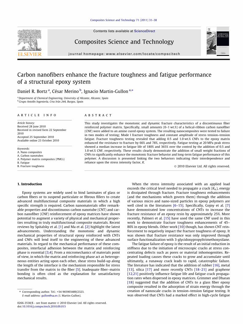
Fig. 2. Machined notch and pre-crack generated by tapping a fresh razor blade.
2.2. Sample preparation
After hand mixing, CNFs were dispersed in the epoxy resin usinga high shear laboratory mixer (Silverson L4RT) at 7000 rpm for15 min. The hardener was subsequently added and further mixedat 5000 rpm for 5 min. Dispersions were processed with 0.5 and1.0 wt.% CNF. A neat epoxy sample was similarly processed andused as a control. After mixing, the dispersions were poured intoa silicone mold and degassed for 30 min at a vacuum approaching�1 bar. Individually cast test coupons, measuring 250 � 25 �2.5 mm for tension–tension fatigue testing, 63.5 � 12.7 � 4 mmfor Mode I fracture toughness testing and 30 � 12.7 � 3.2 mm forDMA characterization, were released from the mold after 12 h at40 �C. Additional heating in air for 15 h at 60 �C and 6 h at 110 �Ccompleted the cure cycle. Specimen surfaces were smoothed on arotary polishing machine using 320 grit followed by 600 grit sili-cone carbide grinding paper. Transmitted light (100�, Nikon EclipseE200) and high-resolution transmission electron microscopy (TEM,
JEOL 1020) verified dispersion. Testing was conducted 7 days aftercuring.
For fracture toughness testing, a 1 mm wide sharpened notchwas machined at the mid-specimen point in the single edgenotched bend (SENB) coupons. A pre-crack was subsequentlyintroduced by tapping a fresh razor blade placed normal to the ma-chined notch (Fig. 2). As per the standard, the ratio between thelength of the notch plus the pre-crack (a) and the width (W) wasbetween 0.45 and 0.55 for each specimen.
2.3. Dynamic mechanical analysis
Dynamic mechanical analysis (DMA) was performed in singlecantilever mode using a TA Instruments 2980. Temperature rampswere carried out from 20 to 175 �C at a scan rate of 2 �C/min. Thespecimens were subjected to 20 lm amplitude of deflection at1 Hz. This provided a strain of approximately 0.03% and was wellwithin the linear elastic region. The glass transition temperature,
D.R. Bortz et al. / Composites Science and Technology 71 (2011) 31–38 33
Tg, was taken as the peak of the ratio of the storage modulus to theloss modulus (tan d).
2.4. Fracture toughness testing
Mode I fracture toughness tests by the 3-point bending method(ASTM D 5045 [32]) were performed using an Instron 3344 (In-stron Corporation, Canton, MA, USA) equipped with a 2 kN loadcell. Three SENB specimens from each group were loaded to failureat a crosshead rate of 10 mm/min. Load–deformation curves wererecorded and the pre-crack length was measured post mortem byoptical microscopy. Testing was conducted at room temperature(25 �C). The critical-stress-intensity (KIc) needed to propagate thecrack was calculated by
K Ic ¼P
BW1=2
� �f ðxÞ; ð1Þ
where P is max applied load, B and W are specimen thickness andwidth and x is the ratio of the previously described crack length aand specimen width W. The function f(x) is the second order poly-nomial found here [32]. The critical strain energy release rate (GIc)was computed by integration of the load–deformation curve usedin the determination of KIc.
2.5. Fatigue testing and statistical analysis
Constant amplitude of stress tension–tension fatigue testing(ASTM D 3479 M [33]) was performed at room temperature(25 �C) using an Instron 8516 100 kN servo-hydraulic materialstesting system (Instron Corporation, Canton, MA, USA). No bondedtabs were used, instead an emery cloth interface functioned to pre-vent slippage and introduce the load to the specimen. Each testcoupon was sinusoidally cycled between minimum and maximumin-plane axial load until failure at a frequency, f = 5 Hz. The ratio ofthe minimum to maximum applied load was R = 0.1. The numberof cycles to failure (N) was recorded for each test coupon. Statictensile tests were carried out at a displacement rate of 2 mm/min using identical specimen geometry.
It was assumed that the fatigue life was normally distributedand the variance of log (N) was constant over the entire range oftesting. In addition, the data contained no run-outs or suspendedtests. Therefore, the cycles to failure were analyzed by constructinglog-normally distributed S–N curves transformed into linear formaccording to ASTM [34,35] and expressed as
Y ¼ Aþ BX; ð2Þ
where Y is equal to log (N), X is the maximum value of constant-amplitude cyclic stress and A and B are constants for each sampleand estimated by
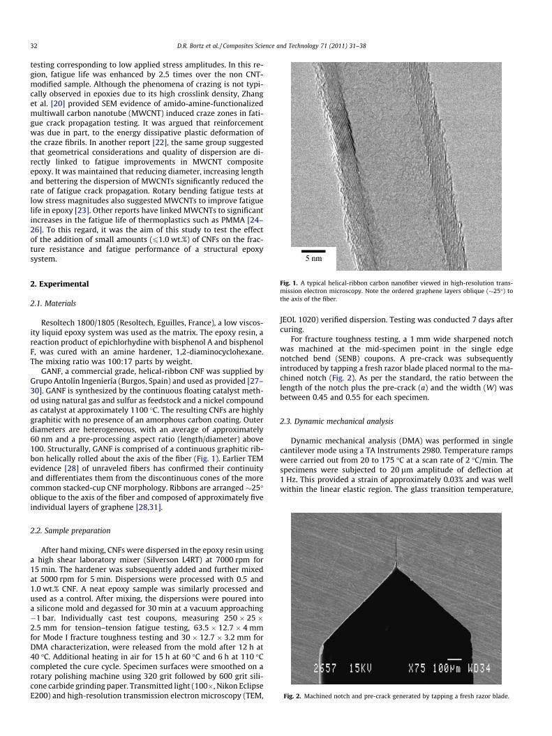
Fig. 3. (a) Transmitted light micrograph of 1.0 wt.% CNF modified epoxy and (b) high-r
A ¼ Y � BX ð3Þ
and
B ¼Pk
i¼1ðXi � XÞðYi � YÞPki¼1ðXi � XÞ2
: ð4Þ
Each test program involved two specimens tested at each of fivestress amplitudes resulting in a replication of 50%. The variance inlog (N) data was calculated by
r2 ¼Pk
i¼1ðYi � Y iÞk� 2
; ð5Þ
where Y i is the estimated fatigue life from the median S–N curvefrom Eq. (2) and k is the total number of test specimens from eachtest program (in this case, k = 10). Hyperbolic confidence bands tak-ing into account all points on the median S–N curve were computedusing
Aþ BX �ffiffiffiffiffiffiffiffi2Fp
qr 1
kþ ðX � XiÞ2Pk
i¼1ðX � XiÞ2
" #1=2
; ð6Þ
where Fp = 4.4590 and corresponds to P = 95%. The confidence inter-vals are not designed to predict the inclusion of individual datapoints. Rather, it is expected that 95% of the computed hyperbolicconfidence bands will include Eq. (2) over the entire range of X usedin the test programs.
2.6. Scanning electron microscopy
Fracture surfaces from randomly selected failed specimens inboth modes of testing were sectioned, sputter coated with goldand examined using high-resolution scanning electron microscopy(SEM, JEOL JSM-840). Qualitative conclusions were drawn from themicrographs on the fracture characteristics, reinforcement mecha-nisms and interactions between the CNFs and matrix.
3. Results and discussion
3.1. Dispersion of CNFs and degree of cure
A qualitative analysis indicated that the high-shear mixing pro-tocol provided a respectable CNF dispersion throughout the epoxymatrix (Fig. 3). Though some agglomerations were observed, TEMexploration illustrated that the filaments were typically isolatedand well wet by the matrix. Examination also revealed that thepre-processing aspect ratio of the CNFs was lessened to some ex-tent. Filament shortening due to high-shear mixing processes hasbeen reported in other work and is often unavoidable in the disper-sion process [36].
esolution TEM image of 1.0 wt.% CNF/epoxy nanocomposite on a copper TEM grid.
a
b
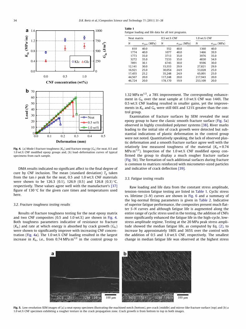
Fig. 4. (a) Mode I fracture toughness (KIc) and fracture energy (GIc) for neat, 0.5 and1.0 wt.% CNF modified epoxy groups and, (b) load–deformation curves of typicalspecimens from each sample.
Table 1Fatigue loading and life data for all test programs.
Neat matrix 0.5 wt.% CNF 1.0 wt.% CNF
N rmax (MPa) N rmax (MPa) N rmax (MPa)
810 40.0 552 40.0 1360 40.01774 40.0 1077 40.0 1466 39.91773 35.0 3713 35.0 3976 35.03272 35.0 7233 35.0 4830 34.97891 30.1 6745 30.0 9596 30.0
12,141 30.0 15,553 29.9 27,821 29.916,921 25.0 30,054 24.9 53,028 25.017,455 25.2 35,248 24.9 65,001 25.044,567 20.0 117,248 20.0 217,943 20.046,724 20.0 178,170 19.9 253,109 20.0
34 D.R. Bortz et al. / Composites Science and Technology 71 (2011) 31–38
DMA results indicated no significant affect to the final degree ofcure by CNF inclusion. The mean (standard deviation) Tg takenfrom the tan d peak for the neat, 0.5 and 1.0 wt.% CNF materialswere shown to be 126.3 (0.1), 126.9 (0.5) and 126.8 (0.3) �C,respectively. These values agree well with the manufacture’s [37]figure of 130 �C for the given cure times and temperatures usedhere.
3.2. Fracture toughness testing results
Results of fracture toughness testing for the neat epoxy matrixand two CNF composites (0.5 and 1.0 wt.%) are shown in Fig. 4.Both toughness parameters indicative of resistance to fracture(KIc) and rate at which energy is absorbed by crack growth (GIc)were shown to significantly improve with increasing CNF concen-tration (Fig. 4a). The 1.0 wt.% CNF loading resulted in the largestincrease in KIc, i.e., from 0.74 MPa m1/2 in the control group to
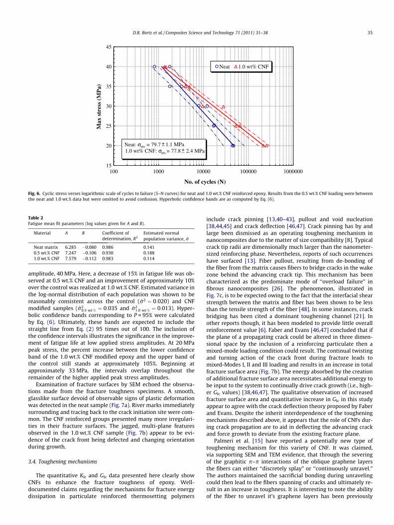
Fig. 5. Low-resolution SEM images of (a) a neat epoxy specimen illustrating the machine1.0 wt.% CNF specimen exhibiting a rougher texture in the crack propagation zone. Crac
1.32 MPa m1/2, a 78% improvement. The corresponding enhance-ment in GIc over the neat sample at 1.0 wt.% CNF was 144%. The0.5 wt.% CNF loading resulted in smaller gains, yet the improve-ments in KIc and GIc were still 66% and 121% greater than the con-trol group.
Examination of fracture surfaces by SEM revealed the neatepoxy group to have the classic smooth fracture surface (Fig. 5a)observed in highly crosslinked polymer systems [38]. River marksleading to the initial site of crack growth were detected but sub-stantial indications of plastic deformation in the control groupwere not noted. Quantitatively speaking, the lack of observed plas-tic deformation and a smooth fracture surface agree well with therelatively low measured toughness of the material (KIc = 0.74MPa m1/2). Inspection of the 1.0 wt.% CNF modified epoxy con-firmed the group to display a much rougher fracture surface(Fig. 5b). The formation of such additional surfaces during fractureis common to matrices reinforced with micrometer-sized particlesand indicative of crack deflection [39].
3.3. Fatigue testing results
Raw loading and life data from the constant stress amplitude,tension–tension fatigue testing are listed in Table 1. Cyclic stressvs. lifetime (S–N) curves are shown in Fig. 6 and a summary ofthe log-normal fitting parameters is given in Table 2. Indicativeof superior fatigue performance, the composites present much flat-ter S–N curves and although fatigue life is augmented along theentire range of cyclic stress used in the testing, the addition of CNFsmore significantly enhanced the fatigue life in the high-cycle, low-stress amplitude regime. Testing at the 20 MPa peak stress ampli-tude showed the median fatigue life, as computed by Eq. (2), toincrease by approximately 180% and 365% over the control withthe addition of 0.5 and 1.0 wt.% CNF, respectively. The smallestchange in median fatigue life was observed at the highest stress
d notch (bottom), pre-crack (middle) and mirror-like fracture surface (top) and (b) ak growth is from bottom to top in both images.
15
20
25
30
35
40
45
100 1000 10000 100000 1000000
Max
str
ess
(MP
a)
No. of cycles (N)
Neat 1.0 wt% CNF
Neat: σuts = 79.7 1.1 MPa1.0 wt% CNF: σuts = 77.8 2.4 MPa
+_+_
Fig. 6. Cyclic stress verses logarithmic scale of cycles to failure (S–N curves) for neat and 1.0 wt.% CNF reinforced epoxy. Results from the 0.5 wt.% CNF loading were betweenthe neat and 1.0 wt.% data but were omitted to avoid confusion. Hyperbolic confidence bands are as computed by Eq. (6).
Table 2Fatigue mean fit parameters (log values given for A and B).
Material A B Coefficient ofdetermination, R2
Estimated normalpopulation variance, r
Neat matrix 6.285 �0.080 0.986 0.1410.5 wt.% CNF 7.247 �0.106 0.930 0.1881.0 wt.% CNF 7.579 �0.112 0.983 0.114
D.R. Bortz et al. / Composites Science and Technology 71 (2011) 31–38 35
amplitude, 40 MPa. Here, a decrease of 15% in fatigue life was ob-served at 0.5 wt.% CNF and an improvement of approximately 10%over the control was realized at 1.0 wt.% CNF. Estimated variance inthe log-normal distribution of each population was shown to bereasonably consistent across the control (r2 ¼ 0:020) and CNFmodified samples (r2
0:5 wt:% ¼ 0:035 and r21:0 wt:% ¼ 0:013). Hyper-
bolic confidence bands corresponding to P = 95% were calculatedby Eq. (6). Ultimately, these bands are expected to include thestraight line from Eq. (2) 95 times out of 100. The inclusion ofthe confidence intervals illustrates the significance in the improve-ment of fatigue life at low applied stress amplitudes. At 20 MPapeak stress, the percent increase between the lower confidenceband of the 1.0 wt.% CNF modified epoxy and the upper band ofthe control still stands at approximately 105%. Beginning atapproximately 33 MPa, the intervals overlap throughout theremainder of the higher applied peak stress amplitudes.
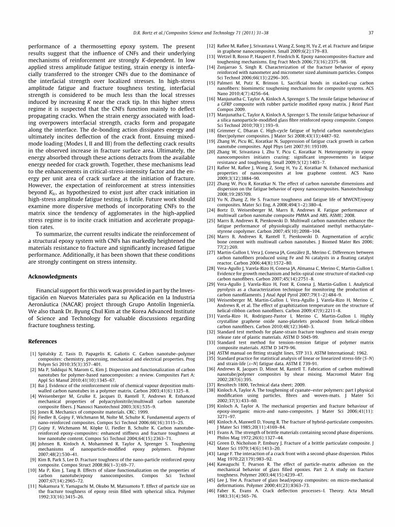
Examination of fracture surfaces by SEM echoed the observa-tions made from the fracture toughness specimens. A smooth,glasslike surface devoid of observable signs of plastic deformationwas detected in the neat sample (Fig. 7a). River marks immediatelysurrounding and tracing back to the crack initiation site were com-mon. The CNF reinforced groups presented many more irregulari-ties in their fracture surfaces. The jagged, multi-plane featuresobserved in the 1.0 wt.% CNF sample (Fig. 7b) appear to be evi-dence of the crack front being defected and changing orientationduring growth.
3.4. Toughening mechanisms
The quantitative KIc and GIc data presented here clearly showCNFs to enhance the fracture toughness of epoxy. Well-documented claims regarding the mechanisms for fracture energydissipation in particulate reinforced thermosetting polymers
include crack pinning [13,40–43], pullout and void nucleation[38,44,45] and crack deflection [46,47]. Crack pinning has by andlarge been dismissed as an operating toughening mechanism innanocomposites due to the matter of size compatibility [8]. Typicalcrack tip radii are dimensionally much larger than the nanometer-sized reinforcing phase. Nevertheless, reports of such occurrenceshave surfaced [13]. Fiber pullout, resulting from de-bonding ofthe fiber from the matrix causes fibers to bridge cracks in the wakezone behind the advancing crack tip. This mechanism has beencharacterized as the predominate mode of ‘‘overload failure” infibrous nanocomposites [26]. The phenomenon, illustrated inFig. 7c, is to be expected owing to the fact that the interfacial shearstrength between the matrix and fiber has been shown to be lessthan the tensile strength of the fiber [48]. In some instances, crackbridging has been cited a dominant toughening channel [21]. Inother reports though, it has been modeled to provide little overallreinforcement value [6]. Faber and Evans [46,47] concluded that ifthe plane of a propagating crack could be altered in three dimen-sional space by the inclusion of a reinforcing particulate then amixed-mode loading condition could result. The continual twistingand turning action of the crack front during fracture leads tomixed-Modes I, II and III loading and results in an increase in totalfracture surface area (Fig. 7b). The energy absorbed by the creationof additional fracture surface area necessitates additional energy tobe input to the system to continually drive crack growth (i.e., high-er GIc values) [38,46,47]. The qualitative observation of increasedfracture surface area and quantitative increase in GIc in this studyappear to agree with the crack deflection theory proposed by Faberand Evans. Despite the inherit interdependence of the tougheningmechanisms described above, it appears that the role of CNFs dur-ing crack propagation are to aid in deflecting the advancing crackand force growth to deviate from the existing fracture plane.
Palmeri et al. [15] have reported a potentially new type oftoughening mechanism for this variety of CNF. It was claimed,via supporting SEM and TEM evidence, that through the severingof the graphitic p–p interactions of the oblique graphene layersthe fibers can either ‘‘discretely splay” or ‘‘continuously unravel.”The authors maintained the sacrificial bonding during unravelingcould then lead to the fibers spanning of cracks and ultimately re-sult in an increase in toughness. It is interesting to note the abilityof the fiber to unravel it’s graphene layers has been previously
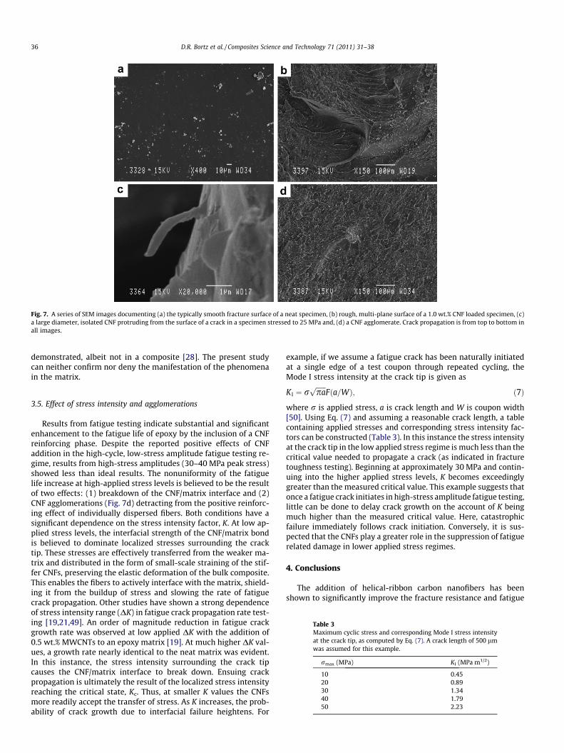
Fig. 7. A series of SEM images documenting (a) the typically smooth fracture surface of a neat specimen, (b) rough, multi-plane surface of a 1.0 wt.% CNF loaded specimen, (c)a large diameter, isolated CNF protruding from the surface of a crack in a specimen stressed to 25 MPa and, (d) a CNF agglomerate. Crack propagation is from top to bottom inall images.
36 D.R. Bortz et al. / Composites Science and Technology 71 (2011) 31–38
demonstrated, albeit not in a composite [28]. The present studycan neither confirm nor deny the manifestation of the phenomenain the matrix.
Table 3Maximum cyclic stress and corresponding Mode I stress intensityat the crack tip, as computed by Eq. (7). A crack length of 500 lmwas assumed for this example.
rmax (MPa) KI (MPa m1/2)
10 0.4520 0.8930 1.3440 1.7950 2.23
3.5. Effect of stress intensity and agglomerations
Results from fatigue testing indicate substantial and significantenhancement to the fatigue life of epoxy by the inclusion of a CNFreinforcing phase. Despite the reported positive effects of CNFaddition in the high-cycle, low-stress amplitude fatigue testing re-gime, results from high-stress amplitudes (30–40 MPa peak stress)showed less than ideal results. The nonuniformity of the fatiguelife increase at high-applied stress levels is believed to be the resultof two effects: (1) breakdown of the CNF/matrix interface and (2)CNF agglomerations (Fig. 7d) detracting from the positive reinforc-ing effect of individually dispersed fibers. Both conditions have asignificant dependence on the stress intensity factor, K. At low ap-plied stress levels, the interfacial strength of the CNF/matrix bondis believed to dominate localized stresses surrounding the cracktip. These stresses are effectively transferred from the weaker ma-trix and distributed in the form of small-scale straining of the stif-fer CNFs, preserving the elastic deformation of the bulk composite.This enables the fibers to actively interface with the matrix, shield-ing it from the buildup of stress and slowing the rate of fatiguecrack propagation. Other studies have shown a strong dependenceof stress intensity range (DK) in fatigue crack propagation rate test-ing [19,21,49]. An order of magnitude reduction in fatigue crackgrowth rate was observed at low applied DK with the addition of0.5 wt.% MWCNTs to an epoxy matrix [19]. At much higher DK val-ues, a growth rate nearly identical to the neat matrix was evident.In this instance, the stress intensity surrounding the crack tipcauses the CNF/matrix interface to break down. Ensuing crackpropagation is ultimately the result of the localized stress intensityreaching the critical state, Kc. Thus, at smaller K values the CNFsmore readily accept the transfer of stress. As K increases, the prob-ability of crack growth due to interfacial failure heightens. For
example, if we assume a fatigue crack has been naturally initiatedat a single edge of a test coupon through repeated cycling, theMode I stress intensity at the crack tip is given as
K I ¼ rffiffiffiffiffiffipap
Fða=WÞ; ð7Þ
where r is applied stress, a is crack length and W is coupon width[50]. Using Eq. (7) and assuming a reasonable crack length, a tablecontaining applied stresses and corresponding stress intensity fac-tors can be constructed (Table 3). In this instance the stress intensityat the crack tip in the low applied stress regime is much less than thecritical value needed to propagate a crack (as indicated in fracturetoughness testing). Beginning at approximately 30 MPa and contin-uing into the higher applied stress levels, K becomes exceedinglygreater than the measured critical value. This example suggests thatonce a fatigue crack initiates in high-stress amplitude fatigue testing,little can be done to delay crack growth on the account of K beingmuch higher than the measured critical value. Here, catastrophicfailure immediately follows crack initiation. Conversely, it is sus-pected that the CNFs play a greater role in the suppression of fatiguerelated damage in lower applied stress regimes.
4. Conclusions
The addition of helical-ribbon carbon nanofibers has beenshown to significantly improve the fracture resistance and fatigue
D.R. Bortz et al. / Composites Science and Technology 71 (2011) 31–38 37
performance of a thermosetting epoxy system. The presentresults suggest that the influence of CNFs and their underlyingmechanisms of reinforcement are strongly K-dependent. In lowapplied stress amplitude fatigue testing, strain energy is interfa-cially transferred to the stronger CNFs due to the dominance ofthe interfacial strength over localized stresses. In high-stressamplitude fatigue and fracture toughness testing, interfacialstrength is considered to be much less than the local stressesinduced by increasing K near the crack tip. In this higher stressregime it is suspected that the CNFs function mainly to deflectpropagating cracks. When the strain energy associated with load-ing overpowers interfacial strength, cracks form and propagatealong the interface. The de-bonding action dissipates energy andultimately incites deflection of the crack front. Ensuing mixed-mode loading (Modes I, II and III) from the deflecting crack resultsin the observed increase in fracture surface area. Ultimately, theenergy absorbed through these actions detracts from the availableenergy needed for crack growth. Together, these mechanisms leadto the enhancements in critical-stress-intensity factor and the en-ergy per unit area of crack surface at the initiation of fracture.However, the expectation of reinforcement at stress intensitiesbeyond KIc, as hypothesized to exist just after crack initiation inhigh-stress amplitude fatigue testing, is futile. Future work shouldexamine more dispersive methods of incorporating CNFs to thematrix since the tendency of agglomerates in the high-appliedstress regime is to incite crack initiation and accelerate propaga-tion rates.
To summarize, the current results indicate the reinforcement ofa structural epoxy system with CNFs has markedly heightened thematerials resistance to fracture and significantly increased fatigueperformance. Additionally, it has been shown that these conditionsare strongly contingent on stress intensity.
Acknowledgments
Financial support for this work was provided in part by the Inves-tigación en Nuevos Materiales para su Aplicación en la IndustriaAeronáutica (NACAR) project through Grupo Antolín Ingeniería.We also thank Dr. Byung Chul Kim at the Korea Advanced Instituteof Science and Technology for valuable discussions regardingfracture toughness testing.
References
[1] Spitalsky Z, Tasis D, Papagelis K, Galiotis C. Carbon nanotube–polymercomposites: chemistry, processing, mechanical and electrical properties. ProgPolym Sci 2010;35(3):357–401.
[2] Ma P, Siddiqui N, Marom G, Kim J. Dispersion and functionalization of carbonnanotubes for polymer-based nanocomposites: a review. Composites Part A:Appl Sci Manuf 2010;41(10):1345–67.
[3] Bai J. Evidence of the reinforcement role of chemical vapour deposition multi-walled carbon nanotubes in a polymer matrix. Carbon 2003;41(6):1325–8.
[4] Weisenberger M, Grulke E, Jacques D, Rantell T, Andrews R. Enhancedmechanical properties of polyacrylonitrile/multiwall carbon nanotubecomposite fibers. J Nanosci Nanotechnol 2003;3(6):535–9.
[5] Jones R. Mechanics of composite materials. CRC; 1999.[6] Fiedler B, Gojny F, Wichmann M, Nolte M, Schulte K. Fundamental aspects of
nano-reinforced composites. Compos Sci Technol 2006;66(16):3115–25.[7] Gojny F, Wichmann M, Köpke U, Fiedler B, Schulte K. Carbon nanotube-
reinforced epoxy-composites: enhanced stiffness and fracture toughness atlow nanotube content. Compos Sci Technol 2004;64(15):2363–71.
[8] Johnsen B, Kinloch A, Mohammed R, Taylor A, Sprenger S. Tougheningmechanisms of nanoparticle-modified epoxy polymers. Polymer2007;48(2):530–41.
[9] Kim B, Park S, Lee D. Fracture toughness of the nano-particle reinforced epoxycomposite. Compos Struct 2008;86(1–3):69–77.
[10] Ma P, Kim J, Tang B. Effects of silane functionalization on the properties ofcarbon nanotube/epoxy nanocomposites. Compos Sci Technol2007;67(14):2965–72.
[11] Nakamura Y, Yamaguchi M, Okubo M, Matsumoto T. Effect of particle size onthe fracture toughness of epoxy resin filled with spherical silica. Polymer1992;33(16):3415–26.
[12] Rafiee M, Rafiee J, Srivastava I, Wang Z, Song H, Yu Z, et al. Fracture and fatiguein graphene nanocomposites. Small 2009;6(2):179–83.
[13] Wetzel B, Rosso P, Haupert F, Friedrich K. Epoxy nanocomposites-fracture andtoughening mechanisms. Eng Fract Mech 2006;73(16):2375–98.
[14] Zunjarrao S, Singh R. Characterization of the fracture behavior of epoxyreinforced with nanometer and micrometer sized aluminum particles. ComposSci Technol 2006;66(13):2296–305.
[15] Palmeri M, Putz K, Brinson L. Sacrificial bonds in stacked-cup carbonnanofibers: biomimetic toughening mechanisms for composite systems. ACSNano 2010;4(7):4256–64.
[16] Manjunatha C, Taylor A, Kinloch A, Sprenger S. The tensile fatigue behaviour ofa GFRP composite with rubber particle modified epoxy matrix. J Reinf PlastCompos 2009.
[17] Manjunatha C, Taylor A, Kinloch A, Sprenger S. The tensile fatigue behaviour ofa silica nanoparticle-modified glass fibre reinforced epoxy composite. ComposSci Technol 2010;70(1):193–9.
[18] Grimmer C, Dharan C. High-cycle fatigue of hybrid carbon nanotube/glassfiber/polymer composites. J Mater Sci 2008;43(13):4487–92.
[19] Zhang W, Picu RC, Koratkar N. Suppression of fatigue crack growth in carbonnanotube composites. Appl Phys Lett 2007;91:193109.
[20] Zhang W, Srivastava I, Zhu Y, Picu C, Koratkar N. Heterogeneity in epoxynanocomposites initiates crazing: significant improvements in fatigueresistance and toughening. Small 2009;5(12):1403–7.
[21] Rafiee M, Rafiee J, Wang Z, Song H, Yu Z, Koratkar N. Enhanced mechanicalproperties of nanocomposites at low graphene content. ACS Nano2009;3(12):3884–90.
[22] Zhang W, Picu R, Koratkar N. The effect of carbon nanotube dimensions anddispersion on the fatigue behavior of epoxy nanocomposites. Nanotechnology2008;19:285709.
[23] Yu N, Zhang Z, He S. Fracture toughness and fatigue life of MWCNT/epoxycomposites. Mater Sci Eng, A 2008;494(1–2):380–4.
[24] Bortz D, Weisenberger M, Marrs B, Andrews R. Fatigue performance ofmultiwall carbon nanotube composite PMMA and ABS. ASME; 2008.
[25] Marrs B, Andrews R, Pienkowski D. Multiwall carbon nanotubes enhance thefatigue performance of physiologically maintained methyl methacrylate–styrene copolymer. Carbon 2007;45(10):2098–104.
[26] Marrs B, Andrews R, Rantell T, Pienkowski D. Augmentation of acrylicbone cement with multiwall carbon nanotubes. J Biomed Mater Res 2006;77(2):269.
[27] Martin-Gullon I, Vera J, Conesa JA, González JL, Merino C. Differences betweencarbon nanofibers produced using Fe and Ni catalysts in a floating catalystreactor. Carbon 2006;44(8):1572–80.
[28] Vera-Agullo J, Varela-Rizo H, Conesa JA, Almansa C, Merino C, Martin-Gullon I.Evidence for growth mechanism and helix-spiral cone structure of stacked-cupcarbon nanofibers. Carbon 2007;45(14):2751–8.
[29] Vera-Agullo J, Varela-Rizo H, Font R, Conesa J, Martin-Gullon I. Analyticalpyrolysis as a characterization technique for monitoring the production ofcarbon nanofilaments. J Anal Appl Pyrol 2007;79(1–2):484–9.
[30] Weisenberger M, Martin-Gullon I, Vera-Agullo J, Varela-Rizo H, Merino C,Andrews R, et al. The effect of graphitization temperature on the structure ofhelical-ribbon carbon nanofibers. Carbon 2009;47(9):2211–8.
[31] Varela-Rizo H, Rodriguez-Pastor I, Merino C, Martin-Gullon I. Highlycrystalline graphene oxide nano-platelets produced from helical-ribboncarbon nanofibers. Carbon 2010;48(12):3640–3.
[32] Standard test methods for plane-strain fracture toughness and strain energyrelease rate of plastic materials. ASTM D 5045-99.
[33] Standard test method for tension–tension fatigue of polymer matrixcomposite materials. ASTM D 3479-96.
[34] ASTM manual on fitting straight lines, STP 313. ASTM International; 1962.[35] Standard practice for statistical analysis of linear or linearized stress-life (S–N)
and strain-life (e–N) fatigue data. ASTM E 739-91.[36] Andrews R, Jacques D, Minot M, Rantell T. Fabrication of carbon multiwall
nanotube/polymer composites by shear mixing. Macromol Mater Eng2002;287(6):395.
[37] Resoltech 1800, Technical data sheet; 2009.[38] Kinloch A, Taylor A. The toughening of cyanate–ester polymers: part I physical
modification using particles, fibres and woven-mats. J Mater Sci2002;37(3):433–60.
[39] Kinloch A, Taylor A. The mechanical properties and fracture behaviour ofepoxy-inorganic micro-and nano-composites. J Mater Sci 2006;41(11):3271–97.
[40] Kinloch A, Maxwell D, Young R. The fracture of hybrid-particulate composites.J Mater Sci 1985;20(11):4169–84.
[41] Evans A. The strength of brittle materials containing second phase dispersions.Philos Mag 1972;26(6):1327–44.
[42] Green D, Nicholson P, Embury J. Fracture of a brittle particulate composite. JMater Sci 1979;14(6):1413–20.
[43] Lange F. The interaction of a crack front with a second-phase dispersion. PhilosMag 1970;22(179):983–92.
[44] Kawaguchi T, Pearson R. The effect of particle–matrix adhesion on themechanical behavior of glass filled epoxies. Part 2. A study on fracturetoughness. Polymer 2003;44(15):4239–47.
[45] Lee J, Yee A. Fracture of glass bead/epoxy composites: on micro-mechanicaldeformations. Polymer 2000;41(23):8363–73.
[46] Faber K, Evans A. Crack deflection processes–I. Theory. Acta Metall1983;31(4):565–76.

38 D.R. Bortz et al. / Composites Science and Technology 71 (2011) 31–38
[47] Faber K, Evans A. Crack deflection processes—II. Experiment. Acta Metall1983;31(4):577–84.
[48] Barber AH, Cohen SR, Wagner HD. Measurement of carbon nanotube–polymerinterfacial strength. Appl Phys Lett 2003;82:4140.
[49] Marrs BH. Carbon nanotube augmentation of a bone cement polymer.University of Kentucky, Biomedical Engineering; 2007.
[50] Tada H, Paris P, Irwin G. The stress analysis of cracks handbook. 3rd ed., 2000.
Related Documents