nanomaterials Review Carbon-Based Nanofluids and Their Advances towards Heat Transfer Applications—A Review Naser Ali 1 , Ammar M. Bahman 2 , Nawaf F. Aljuwayhel 2, * , Shikha A. Ebrahim 2 , Sayantan Mukherjee 3 and Ali Alsayegh 4 Citation: Ali, N.; Bahman, A.M.; Aljuwayhel, N.F.; Ebrahim, S.A.; Mukherjee, S.; Alsayegh, A. Carbon-Based Nanofluids and Their Advances towards Heat Transfer Applications—A Review. Nanomaterials 2021, 11, 1628. https://doi.org/10.3390/ nano11061628 Academic Editor: S M Sohel Murshed Received: 26 May 2021 Accepted: 17 June 2021 Published: 21 June 2021 Publisher’s Note: MDPI stays neutral with regard to jurisdictional claims in published maps and institutional affil- iations. Copyright: © 2021 by the authors. Licensee MDPI, Basel, Switzerland. This article is an open access article distributed under the terms and conditions of the Creative Commons Attribution (CC BY) license (https:// creativecommons.org/licenses/by/ 4.0/). 1 Nanotechnology and Advanced Materials Program, Energy and Building Research Center, Kuwait Institute for Scientific Research, Safat 13109, Kuwait; [email protected] 2 Mechanical Engineering Department, College of Engineering and Petroleum, Kuwait University, P.O. Box 5969, Safat 13060, Kuwait; [email protected] (A.M.B.); [email protected] (S.A.E.) 3 Thermal Research Laboratory (TRL), School of Mechanical Engineering, Kalinga Institute of Industrial Technology, Bhubaneswar, Odisha 751024, India; [email protected] 4 School of Aerospace, Transport and Manufacturing (SATM), Cranfield University, Cranfield MK43 0AL, UK; a.alsayegh@cranfield.ac.uk * Correspondence: [email protected] Abstract: Nanofluids have opened the doors towards the enhancement of many of today’s existing thermal applications performance. This is because these advanced working fluids exhibit exceptional thermophysical properties, and thus making them excellent candidates for replacing conventional working fluids. On the other hand, nanomaterials of carbon-base were proven throughout the literature to have the highest thermal conductivity among all other types of nanoscaled materials. Therefore, when these materials are homogeneously dispersed in a base fluid, the resulting suspension will theoretically attain orders of magnitude higher effective thermal conductivity than its counterpart. Despite this fact, there are still some challenges that are associated with these types of fluids. The main obstacle is the dispersion stability of the nanomaterials, which can lead the attractive properties of the nanofluid to degrade with time, up to the point where they lose their effectiveness. For such reason, this work has been devoted towards providing a systematic review on nanofluids of carbon-base, precisely; carbon nanotubes, graphene, and nanodiamonds, and their employment in thermal systems commonly used in the energy sectors. Firstly, this work reviews the synthesis approaches of the carbon-based feedstock. Then, it explains the different nanofluids fabrication methods. The dispersion stability is also discussed in terms of measuring techniques, enhancement methods, and its effect on the suspension thermophysical properties. The study summarizes the development in the correlations used to predict the thermophysical properties of the dispersion. Furthermore, it assesses the influence of these advanced working fluids on parabolic trough solar collectors, nuclear reactor systems, and air conditioning and refrigeration systems. Lastly, the current gap in scientific knowledge is provided to set up future research directions. Keywords: carbon nanotubes; graphene; nanodiamond; parabolic trough solar collector; nuclear reactor; air conditioning and refrigeration 1. Introduction Since the 20th century, scientists have been working with considerable effort to de- velop fluids that can surpass those conventionally known by the scientific society and industry in terms of thermal and physical performance. The idea of dispersing solid parti- cles of millimeter (mm) and micrometer (μm) in size is the milestone, which was physically initiated by Ahuja [1,2] in 1975, Liu et al. [3] in 1988, and other researchers at Argonne National Laboratory (ANL) [4–6] in 1992 on the bases of Maxwell theoretical work [7]. Such suspensions have shown tremendous improvements in heat transfer characteristics compared to their base fluids. This is due to the dispersed solid particles’ significantly Nanomaterials 2021, 11, 1628. https://doi.org/10.3390/nano11061628 https://www.mdpi.com/journal/nanomaterials

Welcome message from author
This document is posted to help you gain knowledge. Please leave a comment to let me know what you think about it! Share it to your friends and learn new things together.
Transcript
nanomaterials
Review
Carbon-Based Nanofluids and Their Advances towards HeatTransfer Applications—A Review
Naser Ali 1 , Ammar M. Bahman 2 , Nawaf F. Aljuwayhel 2,* , Shikha A. Ebrahim 2 , Sayantan Mukherjee 3
and Ali Alsayegh 4
�����������������
Citation: Ali, N.; Bahman, A.M.;
Aljuwayhel, N.F.; Ebrahim, S.A.;
Mukherjee, S.; Alsayegh, A.
Carbon-Based Nanofluids and Their
Advances towards Heat Transfer
Applications—A Review.
Nanomaterials 2021, 11, 1628.
https://doi.org/10.3390/
nano11061628
Academic Editor: S M Sohel Murshed
Received: 26 May 2021
Accepted: 17 June 2021
Published: 21 June 2021
Publisher’s Note: MDPI stays neutral
with regard to jurisdictional claims in
published maps and institutional affil-
iations.
Copyright: © 2021 by the authors.
Licensee MDPI, Basel, Switzerland.
This article is an open access article
distributed under the terms and
conditions of the Creative Commons
Attribution (CC BY) license (https://
creativecommons.org/licenses/by/
4.0/).
1 Nanotechnology and Advanced Materials Program, Energy and Building Research Center,Kuwait Institute for Scientific Research, Safat 13109, Kuwait; [email protected]
2 Mechanical Engineering Department, College of Engineering and Petroleum, Kuwait University,P.O. Box 5969, Safat 13060, Kuwait; [email protected] (A.M.B.); [email protected] (S.A.E.)
3 Thermal Research Laboratory (TRL), School of Mechanical Engineering, Kalinga Institute of IndustrialTechnology, Bhubaneswar, Odisha 751024, India; [email protected]
4 School of Aerospace, Transport and Manufacturing (SATM), Cranfield University, Cranfield MK43 0AL, UK;[email protected]
* Correspondence: [email protected]
Abstract: Nanofluids have opened the doors towards the enhancement of many of today’s existingthermal applications performance. This is because these advanced working fluids exhibit exceptionalthermophysical properties, and thus making them excellent candidates for replacing conventionalworking fluids. On the other hand, nanomaterials of carbon-base were proven throughout theliterature to have the highest thermal conductivity among all other types of nanoscaled materials.Therefore, when these materials are homogeneously dispersed in a base fluid, the resulting suspensionwill theoretically attain orders of magnitude higher effective thermal conductivity than its counterpart.Despite this fact, there are still some challenges that are associated with these types of fluids. Themain obstacle is the dispersion stability of the nanomaterials, which can lead the attractive propertiesof the nanofluid to degrade with time, up to the point where they lose their effectiveness. Forsuch reason, this work has been devoted towards providing a systematic review on nanofluids ofcarbon-base, precisely; carbon nanotubes, graphene, and nanodiamonds, and their employmentin thermal systems commonly used in the energy sectors. Firstly, this work reviews the synthesisapproaches of the carbon-based feedstock. Then, it explains the different nanofluids fabricationmethods. The dispersion stability is also discussed in terms of measuring techniques, enhancementmethods, and its effect on the suspension thermophysical properties. The study summarizes thedevelopment in the correlations used to predict the thermophysical properties of the dispersion.Furthermore, it assesses the influence of these advanced working fluids on parabolic trough solarcollectors, nuclear reactor systems, and air conditioning and refrigeration systems. Lastly, the currentgap in scientific knowledge is provided to set up future research directions.
Keywords: carbon nanotubes; graphene; nanodiamond; parabolic trough solar collector; nuclearreactor; air conditioning and refrigeration
1. Introduction
Since the 20th century, scientists have been working with considerable effort to de-velop fluids that can surpass those conventionally known by the scientific society andindustry in terms of thermal and physical performance. The idea of dispersing solid parti-cles of millimeter (mm) and micrometer (µm) in size is the milestone, which was physicallyinitiated by Ahuja [1,2] in 1975, Liu et al. [3] in 1988, and other researchers at ArgonneNational Laboratory (ANL) [4–6] in 1992 on the bases of Maxwell theoretical work [7].Such suspensions have shown tremendous improvements in heat transfer characteristicscompared to their base fluids. This is due to the dispersed solid particles’ significantly
Nanomaterials 2021, 11, 1628. https://doi.org/10.3390/nano11061628 https://www.mdpi.com/journal/nanomaterials
Nanomaterials 2021, 11, 1628 2 of 78
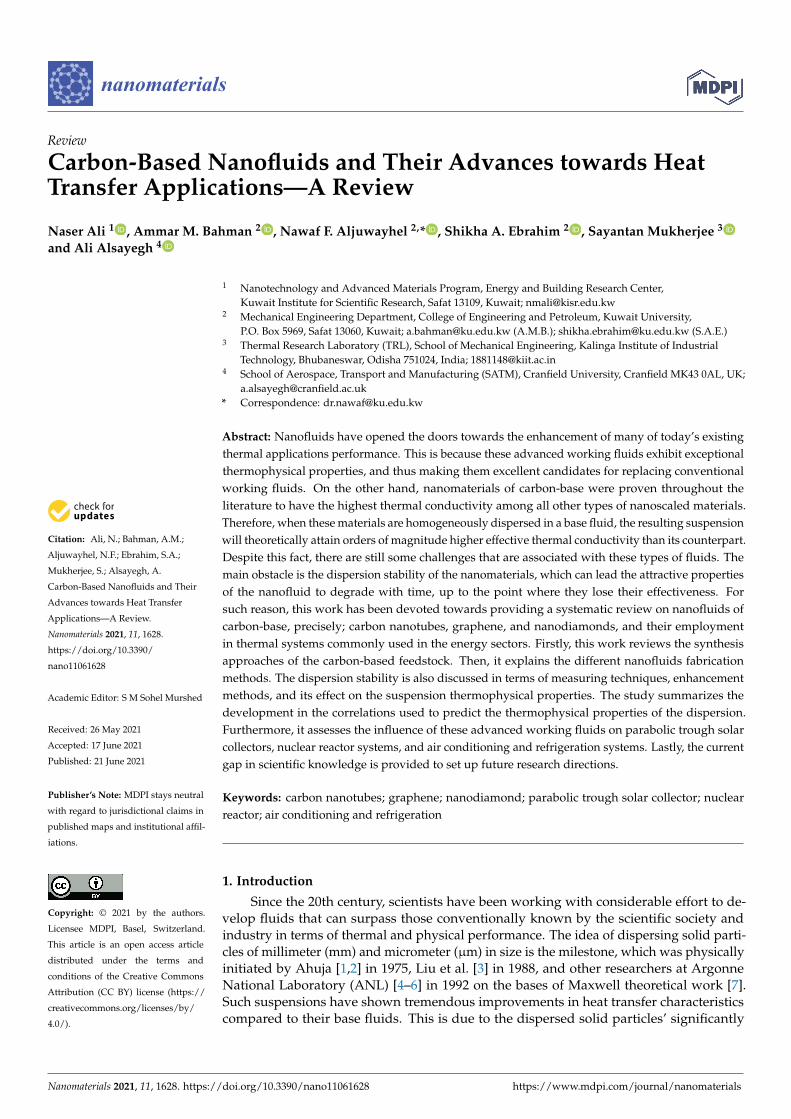
higher thermal conductivity compared to their hosting fluid, which would enhance theeffective thermal conductivity of the colloidal. The term ‘effective’ is generally used whenreferring to the net property of a solid–liquid suspension [8]. However, it was found thatin flow areas of low velocities, the particles hosted by the suspension tended to depositfrom its carrier liquid. Additionally, hence the fluid starts to lose its tuned properties.Furthermore, clogging of small passages was also experienced due to the significant levelof agglomeration between the dispersed particles, and therefore making it extremely chal-lenging to employ in heat transfer devices containing small channels. This is when, in 1993,Masuda et al. [9] conceived the idea of fabricating suspensions with ultrafine particlesof silica, alumina, and titanium dioxide, where these dispersions were afterward giventhe name ‘Nanofluids’ by Choi and Eastman [10], in 1995, as a result of their extensiveresearch work at ANL. According to the founders, a nanofluid can be generally defined asan advanced category of fluid that is produced by homogeneously dispersing low concen-trations (preferably ≤1 vol. %) of particles of less than 100 nanometers (nm) in size withina non-dissolving base fluid [11]. Both Masuda et al.’s [9] and Choi and Eastman’s [10]primary motivation at that time was to overcome the limitations associated with suspen-sions made by their counterparts (i.e., colloidal containing millimeter or micrometer sizedparticles). In addition, Choi and Eastman [10] have theoretically known beforehand thatreducing the size of the dispersed particles to the nanoscale would greatly enlarge the par-ticle exposed surface area to the surrounding, and thus increasing the suspension overallthermal conductivity [12]. The significant variation in thermal conductivity between solidparticles and liquids can be clearly seen in Figure 1 for some of the most commonly usedparticles and base fluids, at room temperature and atmospheric pressure, for fabricatingnanofluids [13–17]. It is worth noticing that CuO, MgO, Al2O3, ZnO, TiO2, Fe2O3, SiO2, Ag,Cu, Au, Al, Fe, carbon nanotubes (CNTs), and multiwalled carbon nanotubes (MWCNTs)stands for cupric oxide, magnesium oxide, aluminum oxide, zinc oxide, titanium dioxide,iron(III) oxide, silicon dioxide, silver, copper, gold, aluminum, iron, carbon nanotubes,and multiwalled carbon nanotubes, respectively. Furthermore, the thermal conductivity ofsome of the materials shown in Figure 1 was seen to have a significant scatter of data acrossthe literature, which can be linked to several factors such as the purity, crystallinity, particlesize, and the determination approach used to find this thermal property. In addition, thethermal conductivity of graphene after being subjected to oxidization (i.e., having theform of graphene oxide) gets highly reduced, where it can reach values between 1000 and2 W/m·K [18–20].
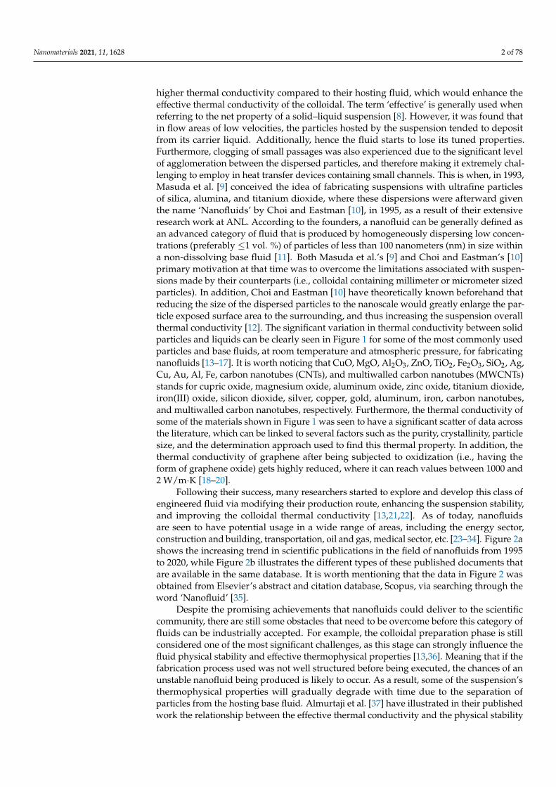
Following their success, many researchers started to explore and develop this class ofengineered fluid via modifying their production route, enhancing the suspension stability,and improving the colloidal thermal conductivity [13,21,22]. As of today, nanofluidsare seen to have potential usage in a wide range of areas, including the energy sector,construction and building, transportation, oil and gas, medical sector, etc. [23–34]. Figure 2ashows the increasing trend in scientific publications in the field of nanofluids from 1995to 2020, while Figure 2b illustrates the different types of these published documents thatare available in the same database. It is worth mentioning that the data in Figure 2 wasobtained from Elsevier’s abstract and citation database, Scopus, via searching through theword ‘Nanofluid’ [35].
Despite the promising achievements that nanofluids could deliver to the scientificcommunity, there are still some obstacles that need to be overcome before this category offluids can be industrially accepted. For example, the colloidal preparation phase is stillconsidered one of the most significant challenges, as this stage can strongly influence thefluid physical stability and effective thermophysical properties [13,36]. Meaning that if thefabrication process used was not well structured before being executed, the chances of anunstable nanofluid being produced is likely to occur. As a result, some of the suspension’sthermophysical properties will gradually degrade with time due to the separation ofparticles from the hosting base fluid. Almurtaji et al. [37] have illustrated in their publishedwork the relationship between the effective thermal conductivity and the physical stability
Nanomaterials 2021, 11, 1628 3 of 78
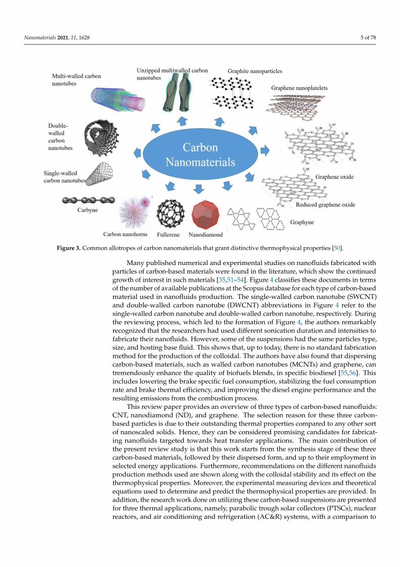
of suspensions. They showed that the effective thermal conductivity of a nanofluid couldreach its optimum possible value when the dispersion is physically stable, and vice versa. Inaddition, the commonly employed two-step fabrication method that relies on an ultrasonicbath type device, was reported to raise the as-prepared nanofluid temperature and thatthe surrounding atmospheric conditions govern this increase in temperature along withthe sonicator working power. Thus, it is highly unlikely that similar nanofluids can beproduced through the conventional two-step route without simultaneously fabricatingthe products at the same preparation conditions. A more convenient two-step methodemployed for nanofluid production would be the two-step controlled sonicator bathtemperature approach, as was reported by Ali et al. [8,11] and Song et al. [38]. Theaforementioned approach would eliminate the rise in bath temperature obstacle, andhence will ensure an optimum level of nanofluids reproducibility to the manufacturer atany surrounding atmospheric conditions, and even when using different types of bathsonicators. Furthermore, as the thermal properties of a nanofluid are influenced mainly bythe dispersed particles compared to its base fluid, researchers have been focusing moreon carbon-based materials. This is because some of these materials, in the nanoscale,have exceptional thermophysical properties compared to other commonly used materials(e.g., metals and oxides) [39–41]. For instance, CNTs and graphene have significantlyelevated thermal conductivity [42,43], large aspect ratio [44], lower density [45,46], lowererosion and corrosion surface effects [47], higher stability [43], and lower pressure dropand pumping power requirement in comparison to other types of nanomaterials [48,49].Figure 3 demonstrates common allotropes of carbon nanomaterials.
Nanomaterials 2021, 11, x FOR PEER REVIEW 3 of 79
thermophysical properties will gradually degrade with time due to the separation of par-
ticles from the hosting base fluid. Almurtaji et al. [37] have illustrated in their published
work the relationship between the effective thermal conductivity and the physical stabil-
ity of suspensions. They showed that the effective thermal conductivity of a nanofluid
could reach its optimum possible value when the dispersion is physically stable, and vice
versa. In addition, the commonly employed two-step fabrication method that relies on an
ultrasonic bath type device, was reported to raise the as-prepared nanofluid temperature
and that the surrounding atmospheric conditions govern this increase in temperature
along with the sonicator working power. Thus, it is highly unlikely that similar nanofluids
can be produced through the conventional two-step route without simultaneously fabri-
cating the products at the same preparation conditions. A more convenient two-step
method employed for nanofluid production would be the two-step controlled sonicator
bath temperature approach, as was reported by Ali et al. [8,11] and Song et al. [38]. The
aforementioned approach would eliminate the rise in bath temperature obstacle, and
hence will ensure an optimum level of nanofluids reproducibility to the manufacturer at
any surrounding atmospheric conditions, and even when using different types of bath
sonicators. Furthermore, as the thermal properties of a nanofluid are influenced mainly
by the dispersed particles compared to its base fluid, researchers have been focusing more
on carbon-based materials. This is because some of these materials, in the nanoscale, have
exceptional thermophysical properties compared to other commonly used materials (e.g.,
metals and oxides) [39–41]. For instance, CNTs and graphene have significantly elevated
thermal conductivity [42,43], large aspect ratio [44], lower density [45,46], lower erosion
and corrosion surface effects [47], higher stability [43], and lower pressure drop and
pumping power requirement in comparison to other types of nanomaterials [48,49]. Fig-
ure 3 demonstrates common allotropes of carbon nanomaterials.
Figure 1. Thermal conductivity of commonly used particles and base fluids for fabricating nanofluids showing an order ofmagnitude higher in the thermal property for some of the carbon-based materials.
Nanomaterials 2021, 11, 1628 4 of 78
Nanomaterials 2021, 11, x FOR PEER REVIEW 4 of 79
Figure 1. Thermal conductivity of commonly used particles and base fluids for fabricating nanofluids showing an order
of magnitude higher in the thermal property for some of the carbon-based materials.
Figure 2. Search result obtained from Scopus database on nanofluids, where (a) illustrates the number of published works
per year and (b) shows the percentage of each type of these documents [35].
Figure 2. Search result obtained from Scopus database on nanofluids, where (a) illustrates the number of published worksper year and (b) shows the percentage of each type of these documents [35].
Nanomaterials 2021, 11, 1628 5 of 78Nanomaterials 2021, 11, x FOR PEER REVIEW 5 of 79
Figure 3. Common allotropes of carbon nanomaterials that grant distinctive thermophysical properties [50].
Many published numerical and experimental studies on nanofluids fabricated with
particles of carbon-based materials were found in the literature, which show the contin-
ued growth of interest in such materials [35,51–54]. Figure 4 classifies these documents in
terms of the number of available publications at the Scopus database for each type of car-
bon-based material used in nanofluids production. The single-walled carbon nanotube
(SWCNT) and double-walled carbon nanotube (DWCNT) abbreviations in Figure 4 refer
to the single-walled carbon nanotube and double-walled carbon nanotube, respectively.
During the reviewing process, which led to the formation of Figure 4, the authors remark-
ably recognized that the researchers had used different sonication duration and intensities
to fabricate their nanofluids. However, some of the suspensions had the same particles
type, size, and hosting base fluid. This shows that, up to today, there is no standard fabri-
cation method for the production of the colloidal. The authors have also found that dis-
persing carbon-based materials, such as walled carbon nanotubes (MCNTs) and gra-
phene, can tremendously enhance the quality of biofuels blends, in specific biodiesel
[55,56]. This includes lowering the brake specific fuel consumption, stabilizing the fuel
consumption rate and brake thermal efficiency, and improving the diesel engine perfor-
mance and the resulting emissions from the combustion process.
This review paper provides an overview of three types of carbon-based nanofluids:
CNT, nanodiamond (ND), and graphene. The selection reason for these three carbon-
based particles is due to their outstanding thermal properties compared to any other sort
of nanoscaled solids. Hence, they can be considered promising candidates for fabricating
nanofluids targeted towards heat transfer applications. The main contribution of the pre-
sent review study is that this work starts from the synthesis stage of these three carbon-
based materials, followed by their dispersed form, and up to their employment in selected
energy applications. Furthermore, recommendations on the different nanofluids produc-
tion methods used are shown along with the colloidal stability and its effect on the ther-
mophysical properties. Moreover, the experimental measuring devices and theoretical
equations used to determine and predict the thermophysical properties are provided. In
addition, the research work done on utilizing these carbon-based suspensions are pre-
sented for three thermal applications, namely, parabolic trough solar collectors (PTSCs),
Figure 3. Common allotropes of carbon nanomaterials that grant distinctive thermophysical properties [50].
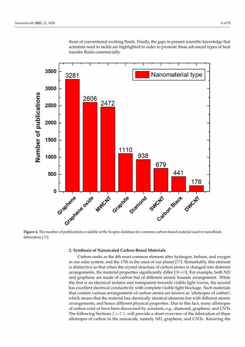
Many published numerical and experimental studies on nanofluids fabricated withparticles of carbon-based materials were found in the literature, which show the continuedgrowth of interest in such materials [35,51–54]. Figure 4 classifies these documents in termsof the number of available publications at the Scopus database for each type of carbon-basedmaterial used in nanofluids production. The single-walled carbon nanotube (SWCNT)and double-walled carbon nanotube (DWCNT) abbreviations in Figure 4 refer to thesingle-walled carbon nanotube and double-walled carbon nanotube, respectively. Duringthe reviewing process, which led to the formation of Figure 4, the authors remarkablyrecognized that the researchers had used different sonication duration and intensities tofabricate their nanofluids. However, some of the suspensions had the same particles type,size, and hosting base fluid. This shows that, up to today, there is no standard fabricationmethod for the production of the colloidal. The authors have also found that dispersingcarbon-based materials, such as walled carbon nanotubes (MCNTs) and graphene, cantremendously enhance the quality of biofuels blends, in specific biodiesel [55,56]. Thisincludes lowering the brake specific fuel consumption, stabilizing the fuel consumptionrate and brake thermal efficiency, and improving the diesel engine performance and theresulting emissions from the combustion process.
This review paper provides an overview of three types of carbon-based nanofluids:CNT, nanodiamond (ND), and graphene. The selection reason for these three carbon-based particles is due to their outstanding thermal properties compared to any other sortof nanoscaled solids. Hence, they can be considered promising candidates for fabricat-ing nanofluids targeted towards heat transfer applications. The main contribution ofthe present review study is that this work starts from the synthesis stage of these threecarbon-based materials, followed by their dispersed form, and up to their employment inselected energy applications. Furthermore, recommendations on the different nanofluidsproduction methods used are shown along with the colloidal stability and its effect on thethermophysical properties. Moreover, the experimental measuring devices and theoreticalequations used to determine and predict the thermophysical properties are provided. Inaddition, the research work done on utilizing these carbon-based suspensions are presentedfor three thermal applications, namely, parabolic trough solar collectors (PTSCs), nuclearreactors, and air conditioning and refrigeration (AC&R) systems, with a comparison to
Nanomaterials 2021, 11, 1628 6 of 78
those of conventional working fluids. Finally, the gaps in present scientific knowledge thatscientists need to tackle are highlighted in order to promote these advanced types of heattransfer fluids commercially.
Nanomaterials 2021, 11, x FOR PEER REVIEW 6 of 79
nuclear reactors, and air conditioning and refrigeration (AC&R) systems, with a compar-
ison to those of conventional working fluids. Finally, the gaps in present scientific
knowledge that scientists need to tackle are highlighted in order to promote these ad-
vanced types of heat transfer fluids commercially.
Figure 4. The number of publications available at the Scopus database for common carbon-based material used in nanoflu-
ids fabrication [35].
2. Synthesis of Nanoscaled Carbon-Based Materials
Carbon ranks as the 4th most common element after hydrogen, helium, and oxygen
in our solar system, and the 17th in the crust of our planet [57]. Remarkably, this element
is distinctive so that when the crystal structure of carbon atoms is changed into deferent
arrangements, the material properties significantly differ [58–63]. For example, both ND
and graphene are made of carbon but of different atomic bounds arrangement. While the
first is an electrical isolator and transparent towards visible light waves, the second has
excellent electrical conductivity with complete visible light blockage. Such materials that
contain various arrangements of carbon atoms are known as ‘allotropes of carbon’, which
means that the material has chemically identical elements but with different atomic ar-
rangements, and hence different physical properties. Due to this fact, many allotropes of
carbon exist or have been discovered by scientists, e.g., diamond, graphene, and CNTs.
The following Sections 2.1–2.3. will provide a short overview of the fabrication of three
allotropes of carbon in the nanoscale, namely ND, graphene, and CNTs. Knowing the pro-
duction methods of these materials is essential and will, later on, help us understand
which nanofluid fabrication route is suitable to conduct.
Figure 4. The number of publications available at the Scopus database for common carbon-based material used in nanofluidsfabrication [35].
2. Synthesis of Nanoscaled Carbon-Based Materials
Carbon ranks as the 4th most common element after hydrogen, helium, and oxygenin our solar system, and the 17th in the crust of our planet [57]. Remarkably, this elementis distinctive so that when the crystal structure of carbon atoms is changed into deferentarrangements, the material properties significantly differ [58–63]. For example, both NDand graphene are made of carbon but of different atomic bounds arrangement. Whilethe first is an electrical isolator and transparent towards visible light waves, the secondhas excellent electrical conductivity with complete visible light blockage. Such materialsthat contain various arrangements of carbon atoms are known as ‘allotropes of carbon’,which means that the material has chemically identical elements but with different atomicarrangements, and hence different physical properties. Due to this fact, many allotropesof carbon exist or have been discovered by scientists, e.g., diamond, graphene, and CNTs.The following Sections 2.1–2.3. will provide a short overview of the fabrication of threeallotropes of carbon in the nanoscale, namely ND, graphene, and CNTs. Knowing the
Nanomaterials 2021, 11, 1628 7 of 78
production methods of these materials is essential and will, later on, help us understandwhich nanofluid fabrication route is suitable to conduct.
2.1. Nanodiamonds
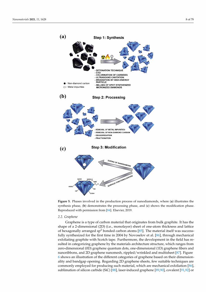
NDs have existed for billions of years in nature within meteorites, crude oil, inter-stellar dust protoplanetary nebulae, and different sediment layers of the Earth’s crust.Nevertheless, the synthetization process of this valuable material only started in the secondhalf of the nineteenth century through either exposing graphite to high pressure and hightemperature conditions, or by the explosive detonation of bulk graphite [64–66]. The first isknown as the high-pressure and high-temperature (HPHT) approach, whereas the secondroute is known as the detonation technique. In the literature, it was reported that thefirst study conducted on the preparation of NDs was performed by Bovenkerk et al. [67],in 1959, after which Danilenko [68] used the detonation technique as part of his synthe-sis approach. Furthermore, many approaches were developed afterward for fabricatingND, such as the microplasma-assisted formation [69], chemical vapor deposition (CVD)method [70], laser ablation [71], high energy ball milling of microdiamonds produced fromhigh pressure and high temperature conditions [72], high energy ball milling of ultra-finegraphite powder [73,74], ultrasound cavitation [75], chlorination of carbides [76], carbononions irradiated by electron [77], and irradiation of graphite by ion beam [78]. In additionto the previous synthesizing methods, El-Eskandarany has proposed a novel approach forproducing superfine NDs from commercial graphite powders and SWCNTs under ambienttemperature and atmospheric pressure conditions, using a high-energy ball mill tech-nique [79]. It is important to note that, according to Ali et al. [66] and Mochalin et al. [80],the most common types of NDs seen today are the detonation NDs (DNDs) and the HPHT-NDs. From the aforementioned production routes, it can be concluded that the synthesizedNDs can only be produced as independent solid particles, and therefore cannot be grownwithin liquids through chemical and/or physical approaches. Regardless of the methodused, the production of NDs usually involves three major phases, which are 1—synthesis(methods mentioned earlier), 2—processing, and 3—modification. The processing stage,which follows the synthesis phase, enhances the as-produced NDs purity by removingthe metals and metals oxides along with the non-diamond carbons that remain attachedto the ND surface. Hence, a high level of sp3 carbon bonded diamond nanoparticles canbe obtained. This can be done by using oxidants such as nitric acid (HNO3), perchloricacid (HCLO4), or hydrochloric acid (HCL) [81]. Furthermore, the modification phase isessential so that the fabricated NDs can meet the requirements of their targeted application.Modification can be performed using either surface functionalization (widely used) ordoping of the NDs particles. It is important to note that some researchers have recentlystarted focusing on the doping technique due to the distinct optical properties gained fromthis NDs modification approach [82,83]. Figure 5 shows the three phases involved in theproduction of NDs [84].
Nanomaterials 2021, 11, 1628 8 of 78Nanomaterials 2021, 11, x FOR PEER REVIEW 8 of 79
Figure 5. Phases involved in the production process of nanodiamonds, where (a) illustrates the syn-
thesis phase, (b) demonstrates the processing phase, and (c) shows the modification phase. Repro-
duced with permission from [84]. Elsevier, 2019.
2.2. Graphene
Graphene is a type of carbon material that originates from bulk graphite. It has the
shape of a 2-dimensional (2D) (i.e., monolayer) sheet of one-atom thickness and lattice of
hexagonally arranged sp2 bonded carbon atoms [85]. The material itself was successfully
synthesized for the first time in 2004 by Novoselov et al. [86], through mechanical exfoli-
ating graphite with Scotch tape. Furthermore, the development in the field has resulted in
categorizing graphene by the materials architecture structure, which ranges from zero-
dimensional (0D) graphene quantum dots, one-dimensional (1D) graphene fibers and na-
noribbons, and 2D graphene nanomesh, rippled/wrinkled and multisheet [87]. Figure 6
shows an illustration of the different categories of graphene based on their dimensionality
and bandgap opening. Regarding 2D graphene sheets, few suitable techniques are com-
monly employed for producing such material, which are mechanical exfoliation [86], sub-
limation of silicon carbide (SiC) [88], laser-induced graphene [89,90], covalent [91,92] or
Figure 5. Phases involved in the production process of nanodiamonds, where (a) illustrates thesynthesis phase, (b) demonstrates the processing phase, and (c) shows the modification phase.Reproduced with permission from [84]. Elsevier, 2019.
2.2. Graphene
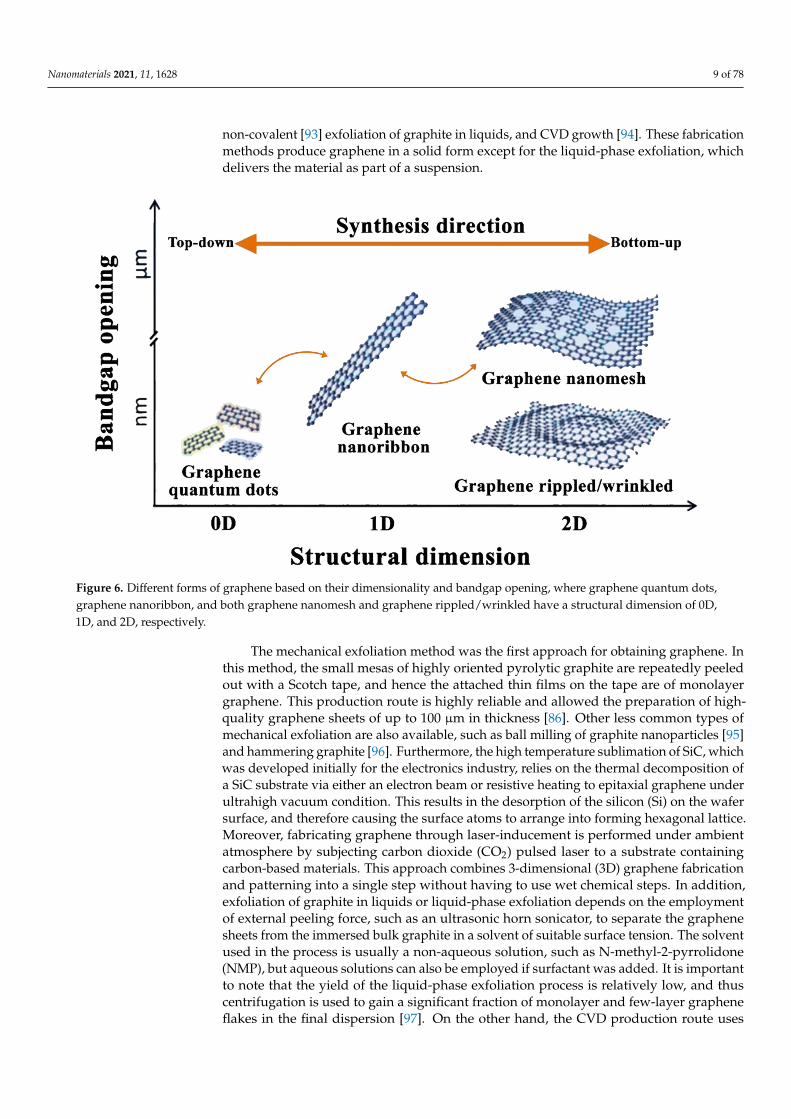
Graphene is a type of carbon material that originates from bulk graphite. It has theshape of a 2-dimensional (2D) (i.e., monolayer) sheet of one-atom thickness and latticeof hexagonally arranged sp2 bonded carbon atoms [85]. The material itself was success-fully synthesized for the first time in 2004 by Novoselov et al. [86], through mechanicalexfoliating graphite with Scotch tape. Furthermore, the development in the field has re-sulted in categorizing graphene by the materials architecture structure, which ranges fromzero-dimensional (0D) graphene quantum dots, one-dimensional (1D) graphene fibers andnanoribbons, and 2D graphene nanomesh, rippled/wrinkled and multisheet [87]. Figure6 shows an illustration of the different categories of graphene based on their dimension-ality and bandgap opening. Regarding 2D graphene sheets, few suitable techniques arecommonly employed for producing such material, which are mechanical exfoliation [86],sublimation of silicon carbide (SiC) [88], laser-induced graphene [89,90], covalent [91,92] or
Nanomaterials 2021, 11, 1628 9 of 78
non-covalent [93] exfoliation of graphite in liquids, and CVD growth [94]. These fabricationmethods produce graphene in a solid form except for the liquid-phase exfoliation, whichdelivers the material as part of a suspension.
Nanomaterials 2021, 11, x FOR PEER REVIEW 9 of 79
non-covalent [93] exfoliation of graphite in liquids, and CVD growth [94]. These fabrica-
tion methods produce graphene in a solid form except for the liquid-phase exfoliation,
which delivers the material as part of a suspension.
Figure 6. Different forms of graphene based on their dimensionality and bandgap opening, where graphene quantum
dots, graphene nanoribbon, and both graphene nanomesh and graphene rippled/wrinkled have a structural dimension of
0D, 1D, and 2D, respectively.
The mechanical exfoliation method was the first approach for obtaining graphene. In
this method, the small mesas of highly oriented pyrolytic graphite are repeatedly peeled
out with a Scotch tape, and hence the attached thin films on the tape are of monolayer
graphene. This production route is highly reliable and allowed the preparation of high-
quality graphene sheets of up to 100 µm in thickness [86]. Other less common types of
mechanical exfoliation are also available, such as ball milling of graphite nanoparticles
[95] and hammering graphite [96]. Furthermore, the high temperature sublimation of SiC,
which was developed initially for the electronics industry, relies on the thermal decom-
position of a SiC substrate via either an electron beam or resistive heating to epitaxial
graphene under ultrahigh vacuum condition. This results in the desorption of the silicon
(Si) on the wafer surface, and therefore causing the surface atoms to arrange into forming
hexagonal lattice. Moreover, fabricating graphene through laser-inducement is performed
under ambient atmosphere by subjecting carbon dioxide (CO2) pulsed laser to a substrate
containing carbon-based materials. This approach combines 3-dimensional (3D) graphene
fabrication and patterning into a single step without having to use wet chemical steps. In
addition, exfoliation of graphite in liquids or liquid-phase exfoliation depends on the em-
ployment of external peeling force, such as an ultrasonic horn sonicator, to separate the
graphene sheets from the immersed bulk graphite in a solvent of suitable surface tension.
The solvent used in the process is usually a non-aqueous solution, such as N-methyl-2-
pyrrolidone (NMP), but aqueous solutions can also be employed if surfactant was added.
It is important to note that the yield of the liquid-phase exfoliation process is relatively
low, and thus centrifugation is used to gain a significant fraction of monolayer and few-
layer graphene flakes in the final dispersion [97]. On the other hand, the CVD production
Figure 6. Different forms of graphene based on their dimensionality and bandgap opening, where graphene quantum dots,graphene nanoribbon, and both graphene nanomesh and graphene rippled/wrinkled have a structural dimension of 0D,1D, and 2D, respectively.
The mechanical exfoliation method was the first approach for obtaining graphene. Inthis method, the small mesas of highly oriented pyrolytic graphite are repeatedly peeledout with a Scotch tape, and hence the attached thin films on the tape are of monolayergraphene. This production route is highly reliable and allowed the preparation of high-quality graphene sheets of up to 100 µm in thickness [86]. Other less common types ofmechanical exfoliation are also available, such as ball milling of graphite nanoparticles [95]and hammering graphite [96]. Furthermore, the high temperature sublimation of SiC, whichwas developed initially for the electronics industry, relies on the thermal decomposition ofa SiC substrate via either an electron beam or resistive heating to epitaxial graphene underultrahigh vacuum condition. This results in the desorption of the silicon (Si) on the wafersurface, and therefore causing the surface atoms to arrange into forming hexagonal lattice.Moreover, fabricating graphene through laser-inducement is performed under ambientatmosphere by subjecting carbon dioxide (CO2) pulsed laser to a substrate containingcarbon-based materials. This approach combines 3-dimensional (3D) graphene fabricationand patterning into a single step without having to use wet chemical steps. In addition,exfoliation of graphite in liquids or liquid-phase exfoliation depends on the employmentof external peeling force, such as an ultrasonic horn sonicator, to separate the graphenesheets from the immersed bulk graphite in a solvent of suitable surface tension. The solventused in the process is usually a non-aqueous solution, such as N-methyl-2-pyrrolidone(NMP), but aqueous solutions can also be employed if surfactant was added. It is importantto note that the yield of the liquid-phase exfoliation process is relatively low, and thuscentrifugation is used to gain a significant fraction of monolayer and few-layer grapheneflakes in the final dispersion [97]. On the other hand, the CVD production route uses
Nanomaterials 2021, 11, 1628 10 of 78
hydrocarbon gases to grow graphene on a targeted substrate by carbon diffusion andsegregation of high carbon solubility metallic substrates, such as nickel (Ni), or by surfaceadsorption of low carbon solubility metals (e.g., Cu) [98,99]. From all of the previousmethods, CVD has shown to be the most successful, promising, and feasible approach inthe field for producing monolayer graphene of high quality and large area [94]. For deeperinsight into the various graphene synthesis methods, the reader is referred to the publishedwork of Rao et al. [100].
2.3. Carbon Nanotubes
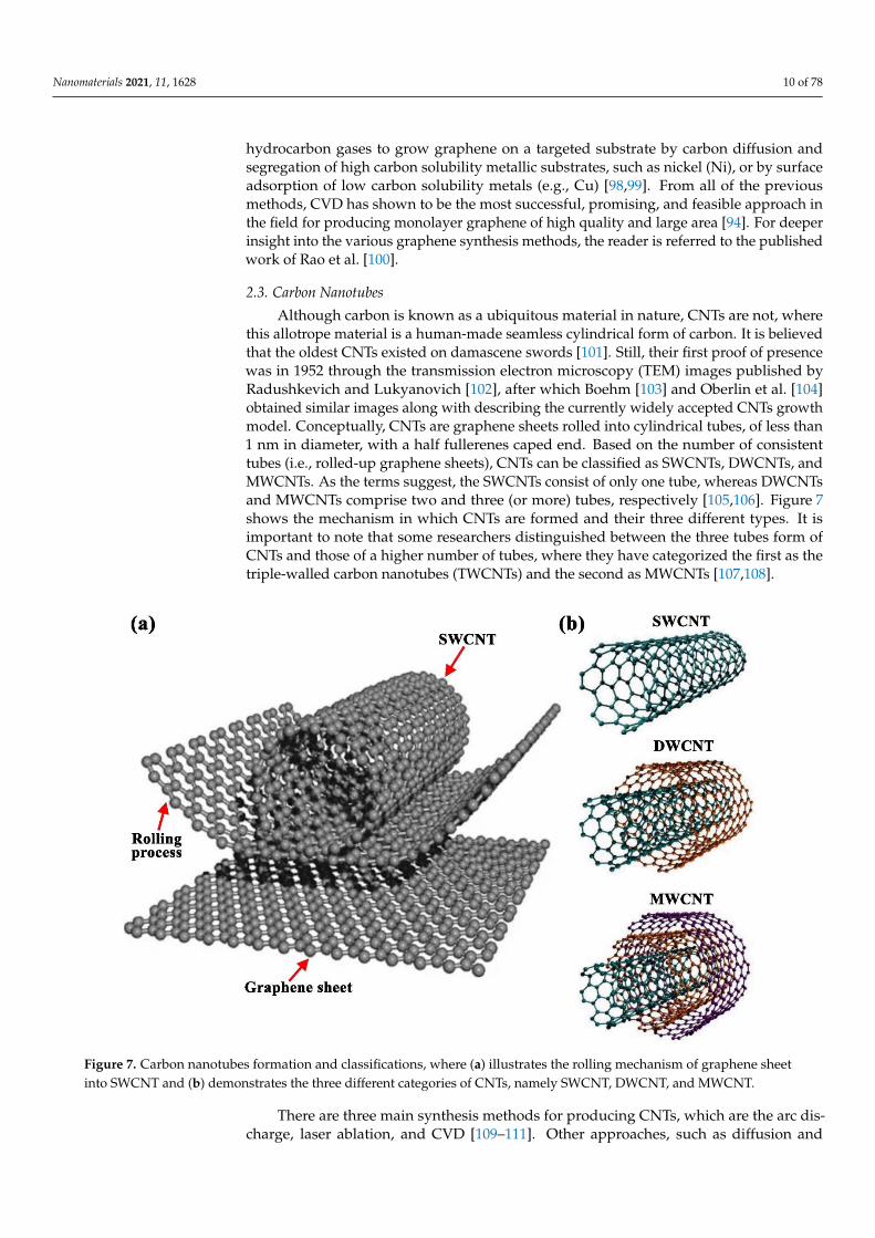
Although carbon is known as a ubiquitous material in nature, CNTs are not, wherethis allotrope material is a human-made seamless cylindrical form of carbon. It is believedthat the oldest CNTs existed on damascene swords [101]. Still, their first proof of presencewas in 1952 through the transmission electron microscopy (TEM) images published byRadushkevich and Lukyanovich [102], after which Boehm [103] and Oberlin et al. [104]obtained similar images along with describing the currently widely accepted CNTs growthmodel. Conceptually, CNTs are graphene sheets rolled into cylindrical tubes, of less than1 nm in diameter, with a half fullerenes caped end. Based on the number of consistenttubes (i.e., rolled-up graphene sheets), CNTs can be classified as SWCNTs, DWCNTs, andMWCNTs. As the terms suggest, the SWCNTs consist of only one tube, whereas DWCNTsand MWCNTs comprise two and three (or more) tubes, respectively [105,106]. Figure 7shows the mechanism in which CNTs are formed and their three different types. It isimportant to note that some researchers distinguished between the three tubes form ofCNTs and those of a higher number of tubes, where they have categorized the first as thetriple-walled carbon nanotubes (TWCNTs) and the second as MWCNTs [107,108].
Nanomaterials 2021, 11, x FOR PEER REVIEW 10 of 79
route uses hydrocarbon gases to grow graphene on a targeted substrate by carbon diffu-
sion and segregation of high carbon solubility metallic substrates, such as nickel (Ni), or
by surface adsorption of low carbon solubility metals (e.g., Cu) [98,99]. From all of the
previous methods, CVD has shown to be the most successful, promising, and feasible ap-
proach in the field for producing monolayer graphene of high quality and large area [94].
For deeper insight into the various graphene synthesis methods, the reader is referred to
the published work of Rao et al. [100].
2.3. Carbon Nanotubes
Although carbon is known as a ubiquitous material in nature, CNTs are not, where
this allotrope material is a human-made seamless cylindrical form of carbon. It is believed
that the oldest CNTs existed on damascene swords [101]. Still, their first proof of presence
was in 1952 through the transmission electron microscopy (TEM) images published by
Radushkevich and Lukyanovich [102], after which Boehm [103] and Oberlin et al. [104]
obtained similar images along with describing the currently widely accepted CNTs
growth model. Conceptually, CNTs are graphene sheets rolled into cylindrical tubes, of
less than 1 nm in diameter, with a half fullerenes caped end. Based on the number of con-
sistent tubes (i.e., rolled-up graphene sheets), CNTs can be classified as SWCNTs,
DWCNTs, and MWCNTs. As the terms suggest, the SWCNTs consist of only one tube,
whereas DWCNTs and MWCNTs comprise two and three (or more) tubes, respectively
[105,106]. Figure 7 shows the mechanism in which CNTs are formed and their three dif-
ferent types. It is important to note that some researchers distinguished between the three
tubes form of CNTs and those of a higher number of tubes, where they have categorized
the first as the triple-walled carbon nanotubes (TWCNTs) and the second as MWCNTs
[107,108].
Figure 7. Carbon nanotubes formation and classifications, where (a) illustrates the rolling mechanism of graphene sheet
into SWCNT and (b) demonstrates the three different categories of CNTs, namely SWCNT, DWCNT, and MWCNT. Figure 7. Carbon nanotubes formation and classifications, where (a) illustrates the rolling mechanism of graphene sheetinto SWCNT and (b) demonstrates the three different categories of CNTs, namely SWCNT, DWCNT, and MWCNT.
There are three main synthesis methods for producing CNTs, which are the arc dis-charge, laser ablation, and CVD [109–111]. Other approaches, such as diffusion and
Nanomaterials 2021, 11, 1628 11 of 78
premised flame method, can be used for CNTs fabrication but are less frequently uti-lized [112]. All three primary production methods depend on the carbon feedstock, eitheras a solid phased carbon source (arc discharge and laser ablation) or carbonaceous gases(CVD method). An example of the gases employed in the CVD process include carbonmonoxide (CO), ethanol, and acetylene. Moreover, the final product is always delivered in adried form; thus, CNTs cannot be grown within liquids as dispersions. In the arc dischargeprocess, doped graphite rods or two catalysts loaded are vaporized at 4000–5000 K, withina closed chamber, by an electric arc placed between them, after which the resulting depositis of CNTs. Like the arc discharge method, the laser ablation route relies on the evaporationof a carbon feedstock, usually a graphite rod with a metallic based catalyst, to obtain theCNTs. The difference between this approach and the previous one is that the laser ablationuses high energy laser irradiation to heat the carbon source, and thus causing the phasetransformation (i.e., from the solid to gaseous phase). Additionally, the final product getsaccumulated in a cold trap located within the chamber. Therefore, this technique is muchmore efficient than the arc discharge process in terms of the losses in the as-produced CNTs.On the other hand, the CVD, which was mentioned earlier in Section 2.2, decomposescarbonaceous gases on catalytic nanoparticles to produce the CNTs. The catalytic nanopar-ticles used for this purpose are either grown while conducting the process or are initiallyfabricated through a separate procedure. Furthermore, the advantage associated with thisproduction technique is the high level of control over the synthesis process parameters suchas carbon supply rate, growth temperature, catalyst particles size, and type of substrateused for the CNTs growth.
3. Preparation of Nanofluids
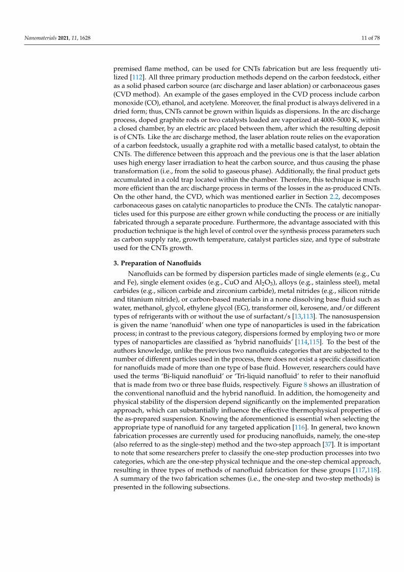
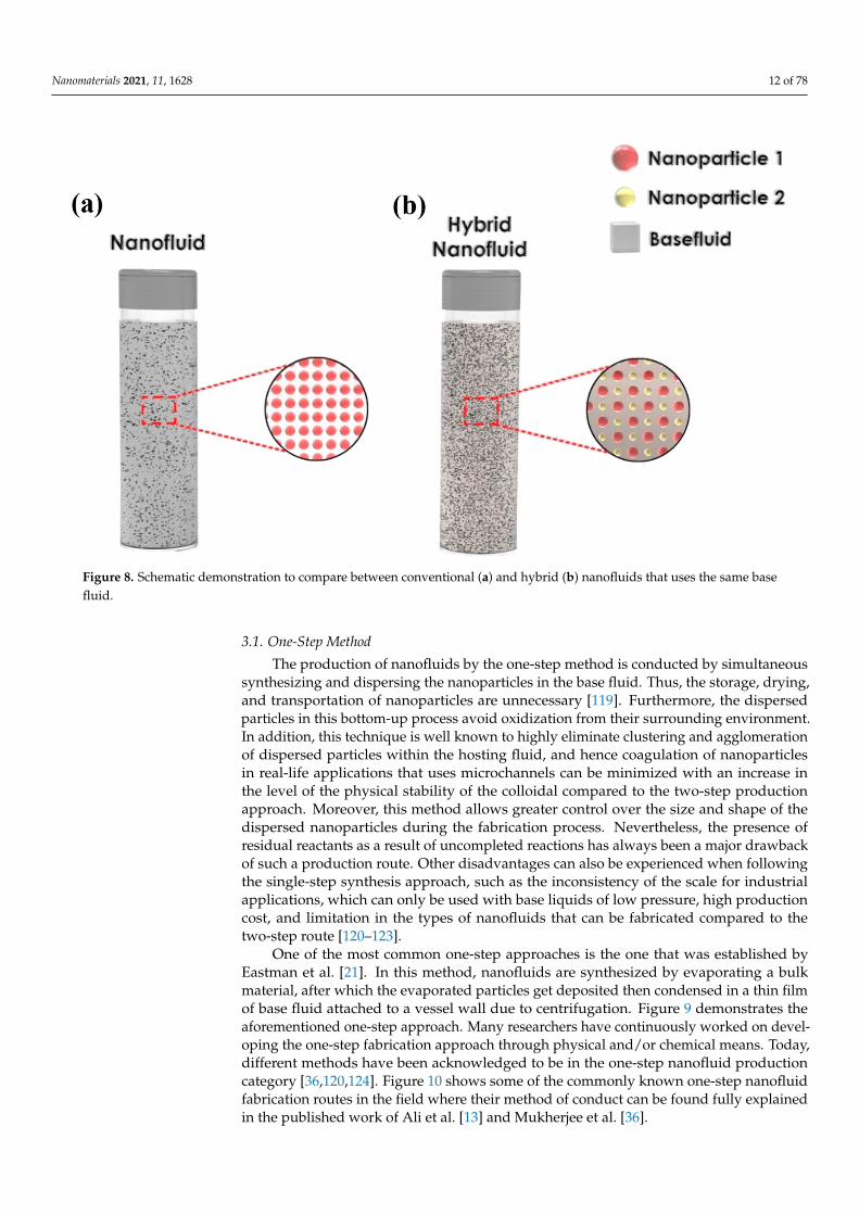
Nanofluids can be formed by dispersion particles made of single elements (e.g., Cuand Fe), single element oxides (e.g., CuO and Al2O3), alloys (e.g., stainless steel), metalcarbides (e.g., silicon carbide and zirconium carbide), metal nitrides (e.g., silicon nitrideand titanium nitride), or carbon-based materials in a none dissolving base fluid such aswater, methanol, glycol, ethylene glycol (EG), transformer oil, kerosene, and/or differenttypes of refrigerants with or without the use of surfactant/s [13,113]. The nanosuspensionis given the name ‘nanofluid’ when one type of nanoparticles is used in the fabricationprocess; in contrast to the previous category, dispersions formed by employing two or moretypes of nanoparticles are classified as ‘hybrid nanofluids’ [114,115]. To the best of theauthors knowledge, unlike the previous two nanofluids categories that are subjected to thenumber of different particles used in the process, there does not exist a specific classificationfor nanofluids made of more than one type of base fluid. However, researchers could haveused the terms ‘Bi-liquid nanofluid’ or ‘Tri-liquid nanofluid’ to refer to their nanofluidthat is made from two or three base fluids, respectively. Figure 8 shows an illustration ofthe conventional nanofluid and the hybrid nanofluid. In addition, the homogeneity andphysical stability of the dispersion depend significantly on the implemented preparationapproach, which can substantially influence the effective thermophysical properties ofthe as-prepared suspension. Knowing the aforementioned is essential when selecting theappropriate type of nanofluid for any targeted application [116]. In general, two knownfabrication processes are currently used for producing nanofluids, namely, the one-step(also referred to as the single-step) method and the two-step approach [37]. It is importantto note that some researchers prefer to classify the one-step production processes into twocategories, which are the one-step physical technique and the one-step chemical approach,resulting in three types of methods of nanofluid fabrication for these groups [117,118].A summary of the two fabrication schemes (i.e., the one-step and two-step methods) ispresented in the following subsections.
Nanomaterials 2021, 11, 1628 12 of 78Nanomaterials 2021, 11, x FOR PEER REVIEW 12 of 79
Figure 8. Schematic demonstration to compare between conventional (a) and hybrid (b) nanofluids that uses the same
base fluid.
3.1. One-Step Method
The production of nanofluids by the one-step method is conducted by simultaneous
synthesizing and dispersing the nanoparticles in the base fluid. Thus, the storage, drying,
and transportation of nanoparticles are unnecessary [119]. Furthermore, the dispersed
particles in this bottom-up process avoid oxidization from their surrounding environ-
ment. In addition, this technique is well known to highly eliminate clustering and agglom-
eration of dispersed particles within the hosting fluid, and hence coagulation of nanopar-
ticles in real-life applications that uses microchannels can be minimized with an increase
in the level of the physical stability of the colloidal compared to the two-step production
approach. Moreover, this method allows greater control over the size and shape of the
dispersed nanoparticles during the fabrication process. Nevertheless, the presence of re-
sidual reactants as a result of uncompleted reactions has always been a major drawback
of such a production route. Other disadvantages can also be experienced when following
the single-step synthesis approach, such as the inconsistency of the scale for industrial
applications, which can only be used with base liquids of low pressure, high production
cost, and limitation in the types of nanofluids that can be fabricated compared to the two-
step route [120–123].
One of the most common one-step approaches is the one that was established by
Eastman et al. [21]. In this method, nanofluids are synthesized by evaporating a bulk ma-
terial, after which the evaporated particles get deposited then condensed in a thin film of
base fluid attached to a vessel wall due to centrifugation. Figure 9 demonstrates the afore-
mentioned one-step approach. Many researchers have continuously worked on develop-
ing the one-step fabrication approach through physical and/or chemical means. Today,
different methods have been acknowledged to be in the one-step nanofluid production
category [36,120,124]. Figure 10 shows some of the commonly known one-step nanofluid
fabrication routes in the field where their method of conduct can be found fully explained
in the published work of Ali et al. [13] and Mukherjee et al. [36].
Figure 8. Schematic demonstration to compare between conventional (a) and hybrid (b) nanofluids that uses the same basefluid.
3.1. One-Step Method
The production of nanofluids by the one-step method is conducted by simultaneoussynthesizing and dispersing the nanoparticles in the base fluid. Thus, the storage, drying,and transportation of nanoparticles are unnecessary [119]. Furthermore, the dispersedparticles in this bottom-up process avoid oxidization from their surrounding environment.In addition, this technique is well known to highly eliminate clustering and agglomerationof dispersed particles within the hosting fluid, and hence coagulation of nanoparticlesin real-life applications that uses microchannels can be minimized with an increase inthe level of the physical stability of the colloidal compared to the two-step productionapproach. Moreover, this method allows greater control over the size and shape of thedispersed nanoparticles during the fabrication process. Nevertheless, the presence ofresidual reactants as a result of uncompleted reactions has always been a major drawbackof such a production route. Other disadvantages can also be experienced when followingthe single-step synthesis approach, such as the inconsistency of the scale for industrialapplications, which can only be used with base liquids of low pressure, high productioncost, and limitation in the types of nanofluids that can be fabricated compared to thetwo-step route [120–123].
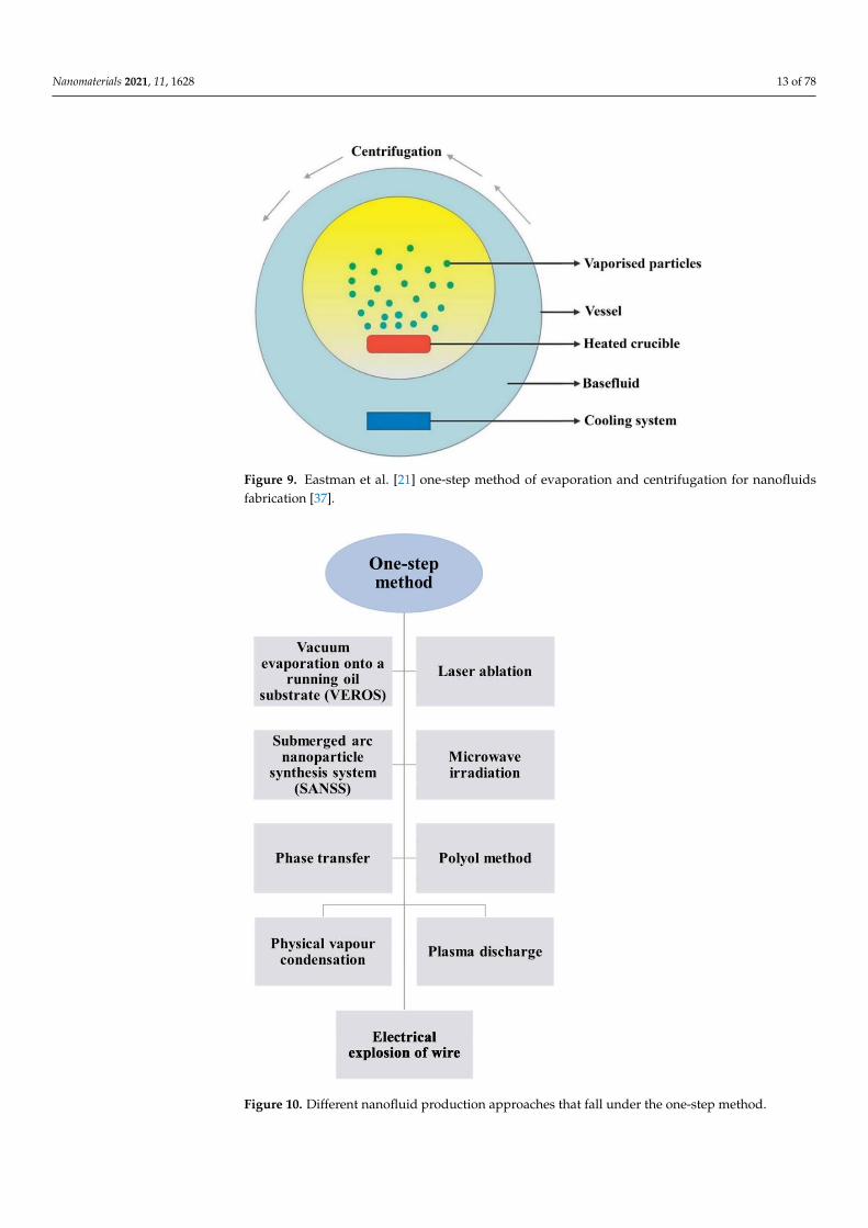
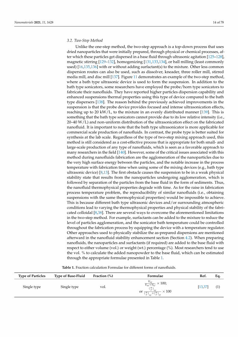
One of the most common one-step approaches is the one that was established byEastman et al. [21]. In this method, nanofluids are synthesized by evaporating a bulkmaterial, after which the evaporated particles get deposited then condensed in a thin filmof base fluid attached to a vessel wall due to centrifugation. Figure 9 demonstrates theaforementioned one-step approach. Many researchers have continuously worked on devel-oping the one-step fabrication approach through physical and/or chemical means. Today,different methods have been acknowledged to be in the one-step nanofluid productioncategory [36,120,124]. Figure 10 shows some of the commonly known one-step nanofluidfabrication routes in the field where their method of conduct can be found fully explainedin the published work of Ali et al. [13] and Mukherjee et al. [36].
Nanomaterials 2021, 11, 1628 13 of 78Nanomaterials 2021, 11, x FOR PEER REVIEW 13 of 79
Figure 9. Eastman et al. [21] one-step method of evaporation and centrifugation for nanofluids fab-
rication [37].
Figure 10. Different nanofluid production approaches that fall under the one-step method.
Figure 9. Eastman et al. [21] one-step method of evaporation and centrifugation for nanofluidsfabrication [37].
Nanomaterials 2021, 11, x FOR PEER REVIEW 13 of 79
Figure 9. Eastman et al. [21] one-step method of evaporation and centrifugation for nanofluids fab-
rication [37].
Figure 10. Different nanofluid production approaches that fall under the one-step method. Figure 10. Different nanofluid production approaches that fall under the one-step method.
Nanomaterials 2021, 11, 1628 14 of 78
3.2. Two-Step Method
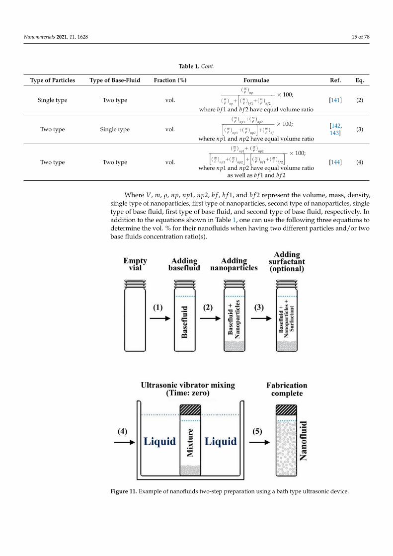
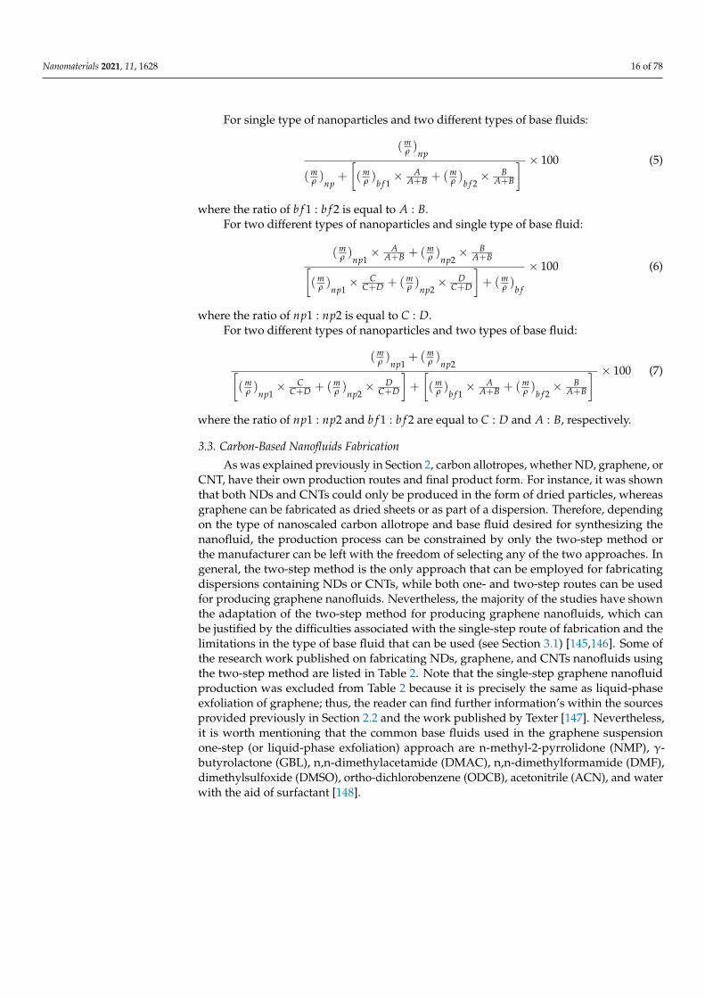
Unlike the one-step method, the two-step approach is a top-down process that usesdried nanoparticles that were initially prepared, through physical or chemical processes, af-ter which these particles get dispersed in a base fluid through ultrasonic agitation [125–128],magnetic stirring [129–132], homogenizing [131,133,134], or ball milling (least commonlyused) [16,135,136] with or without adding surfactant(s) to the mixture. Other less commondispersion routes can also be used, such as dissolver, kneader, three roller mill, stirredmedia mill, and disc mill [137]. Figure 11 demonstrates an example of the two-step method,where a bath type ultrasonic device is used to form the suspension. In addition to thebath type sonicators, some researchers have employed the probe/horn type sonicators tofabricate their nanofluids. They have reported higher particles dispersion capability andenhanced suspensions thermal properties using this type of device compared to the bathtype dispersers [138]. The reason behind the previously achieved improvements in thesuspension is that the probe device provides focused and intense ultrasonication effects,reaching up to 20 kW/L, to the mixture in an evenly distributed manner [139]. This issomething that the bath type sonicators cannot provide due to its low relative intensity (i.e.,20–40 W/L) and non-uniform distribution of the ultrasonication effect on the fabricatednanofluid. It is important to note that the bath type ultrasonicator is more applicable forcommercial scale production of nanofluids. In contrast, the probe type is better suited forsynthesis at the lab scale. Regardless of the type of two-step mixing approach used, thismethod is still considered as a cost-effective process that is appropriate for both small- andlarge-scale production of any type of nanofluids, which is seen as a favorable approach tomany researchers in the field [140]. However, some of the critical issues associated with thismethod during nanofluids fabrication are the agglomeration of the nanoparticles due tothe very high surface energy between the particles, and the notable increase in the processtemperature with fabrication time when using some of the mixing devices (e.g., bath typeultrasonic device) [8,13]. The first obstacle causes the suspension to be in a weak physicalstability state that results from the nanoparticles undergoing agglomeration, which isfollowed by separation of the particles from the base fluid in the form of sediments. Thus,the nanofluid thermophysical properties degrade with time. As for the raise in fabricationprocess temperature problem, the reproducibility of similar nanofluids (i.e., obtainingsuspensions with the same thermophysical properties) would be impossible to achieve.This is because different bath type ultrasonic devices and/or surrounding atmosphericconditions lead to varying the thermophysical properties and physical stability of the fabri-cated colloidal [8,38]. There are several ways to overcome the aforementioned limitationsin the two-step method. For example, surfactants can be added to the mixture to reduce thelevel of particles agglomeration, and the sonicator bath temperature could be controlledthroughout the fabrication process by equipping the device with a temperature regulator.Other approaches used to physically stabilize the as-prepared dispersions are mentionedafterward in the nanofluid stability enhancement section (Section 4.2). When preparingnanofluids, the nanoparticles and surfactants (if required) are added to the base fluid withrespect to either volume (vol.) or weight (wt.) percentage (%). Most researchers tend to usethe vol. % to calculate the added nanopowder to the base fluid, which can be estimatedthrough the appropriate formulae presented in Table 1.
Table 1. Fraction calculation Formulae for different forms of nanofluids.
Type of Particles Type of Base-Fluid Fraction (%) Formulae Ref. Eq.
Single type Single type vol.
VnpVnp+Vb f
× 100;
or( m
ρ )np
( mρ )np
+( mρ )b f
× 100[13,37] (1)
Nanomaterials 2021, 11, 1628 15 of 78
Table 1. Cont.
Type of Particles Type of Base-Fluid Fraction (%) Formulae Ref. Eq.
Single type Two type vol.
( mρ )np
( mρ )np
+
[( m
ρ )b f 1+( m
ρ )b f 2
] × 100;
where b f 1 and b f 2 have equal volume ratio
[141] (2)
Two type Single type vol.
( mρ )np1
+( mρ )np2[
( mρ )np1
+( mρ )np2
]+( m
ρ )b f
× 100;
where np1 and np2 have equal volume ratio
[142,143] (3)
Two type Two type vol.
( mρ )np1
+ ( mρ )np2[
( mρ )np1
+( mρ )np2
]+
[( m
ρ )b f 1+( m
ρ )b f 2
] × 100;
where np1 and np2 have equal volume ratioas well as b f 1 and b f 2
[144] (4)
Where V, m, ρ, np, np1, np2, b f , b f 1, and b f 2 represent the volume, mass, density,single type of nanoparticles, first type of nanoparticles, second type of nanoparticles, singletype of base fluid, first type of base fluid, and second type of base fluid, respectively. Inaddition to the equations shown in Table 1, one can use the following three equations todetermine the vol. % for their nanofluids when having two different particles and/or twobase fluids concentration ratio(s).
Nanomaterials 2021, 11, x FOR PEER REVIEW 15 of 79
or (𝑚
𝜌)𝑛𝑝
(𝑚
𝜌)𝑛𝑝+ (
𝑚
𝜌)𝑏𝑓 × 100
Single type Two
type vol.
(𝑚𝜌)𝑛𝑝
(𝑚𝜌)𝑛𝑝 + [(
𝑚𝜌)𝑏𝑓1 + (
𝑚𝜌)𝑏𝑓2]
× 100;
where 𝑏𝑓1 and 𝑏𝑓2 have equal volume ratio
[141] (2)
Two type Single
type vol.
(𝑚𝜌)𝑛𝑝1 + (
𝑚𝜌)𝑛𝑝2
[(𝑚𝜌)𝑛𝑝1 + (
𝑚𝜌)𝑛𝑝2] + (
𝑚𝜌)𝑏𝑓
× 100;
where 𝑛𝑝1 and 𝑛𝑝2 have equal volume ratio
[142,143] (3)
Two type Two
type vol.
(𝑚𝜌)𝑛𝑝1 + (
𝑚𝜌)𝑛𝑝2
[(𝑚𝜌)𝑛𝑝1 + (
𝑚𝜌)𝑛𝑝2] + [(
𝑚𝜌)𝑏𝑓1 + (
𝑚𝜌)𝑏𝑓2]
× 100;
where 𝑛𝑝1 and 𝑛𝑝2 have equal volume ratio as well as 𝑏𝑓1
and 𝑏𝑓2
[144] (4)
Where 𝑉 , 𝑚 , 𝜌 , 𝑛𝑝 , 𝑛𝑝1, 𝑛𝑝2, 𝑏𝑓 , 𝑏𝑓1, and 𝑏𝑓2 represent the volume, mass,
density, single type of nanoparticles, first type of nanoparticles, second type of nanopar-
ticles, single type of base fluid, first type of base fluid, and second type of base fluid, re-
spectively. In addition to the equations shown in Table 1, one can use the following three
equations to determine the vol. % for their nanofluids when having two different particles
and/or two base fluids concentration ratio(s).
Figure 11. Example of nanofluids two-step preparation using a bath type ultrasonic device. Figure 11. Example of nanofluids two-step preparation using a bath type ultrasonic device.
Nanomaterials 2021, 11, 1628 16 of 78
For single type of nanoparticles and two different types of base fluids:
(mρ )np
(mρ )np
+
[(m
ρ )b f 1× A
A+B + (mρ )b f 2
× BA+B
] × 100 (5)
where the ratio of b f 1 : b f 2 is equal to A : B.For two different types of nanoparticles and single type of base fluid:
(mρ )np1
× AA+B + (m
ρ )np2× B
A+B[(m
ρ )np1× C
C+D + (mρ )np2
× DC+D
]+ (m
ρ )b f
× 100 (6)
where the ratio of np1 : np2 is equal to C : D.For two different types of nanoparticles and two types of base fluid:
(mρ )np1
+ (mρ )np2[
(mρ )np1
× CC+D + (m
ρ )np2× D
C+D
]+
[(m
ρ )b f 1× A
A+B + (mρ )b f 2
× BA+B
] × 100 (7)
where the ratio of np1 : np2 and b f 1 : b f 2 are equal to C : D and A : B, respectively.
3.3. Carbon-Based Nanofluids Fabrication
As was explained previously in Section 2, carbon allotropes, whether ND, graphene, orCNT, have their own production routes and final product form. For instance, it was shownthat both NDs and CNTs could only be produced in the form of dried particles, whereasgraphene can be fabricated as dried sheets or as part of a dispersion. Therefore, dependingon the type of nanoscaled carbon allotrope and base fluid desired for synthesizing thenanofluid, the production process can be constrained by only the two-step method orthe manufacturer can be left with the freedom of selecting any of the two approaches. Ingeneral, the two-step method is the only approach that can be employed for fabricatingdispersions containing NDs or CNTs, while both one- and two-step routes can be usedfor producing graphene nanofluids. Nevertheless, the majority of the studies have shownthe adaptation of the two-step method for producing graphene nanofluids, which canbe justified by the difficulties associated with the single-step route of fabrication and thelimitations in the type of base fluid that can be used (see Section 3.1) [145,146]. Some ofthe research work published on fabricating NDs, graphene, and CNTs nanofluids usingthe two-step method are listed in Table 2. Note that the single-step graphene nanofluidproduction was excluded from Table 2 because it is precisely the same as liquid-phaseexfoliation of graphene; thus, the reader can find further information’s within the sourcesprovided previously in Section 2.2 and the work published by Texter [147]. Nevertheless,it is worth mentioning that the common base fluids used in the graphene suspensionone-step (or liquid-phase exfoliation) approach are n-methyl-2-pyrrolidone (NMP), γ-butyrolactone (GBL), n,n-dimethylacetamide (DMAC), n,n-dimethylformamide (DMF),dimethylsulfoxide (DMSO), ortho-dichlorobenzene (ODCB), acetonitrile (ACN), and waterwith the aid of surfactant [148].
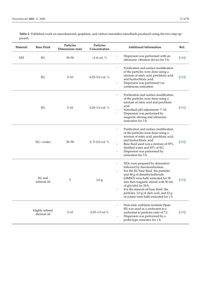
Nanomaterials 2021, 11, 1628 17 of 78
Table 2. Published work on nanodiamond, graphene, and carbon nanotubes nanofluids produced using the two-step ap-proach.
Material Base Fluid ParticlesDimensions (nm)
ParticlesConcentration Additional Information Ref.
ND EG 30–50 <1.4 vol. % - Dispersion was performed with anultrasonic vibration device for 3 h.
[149]
EG 5–10 0.25–5.0 vol. %
- Purification and surface modificationof the particles were done using amixture of nitric acid, perchloric acid,and hydrochloric acid.
- Dispersion was performed viacontinuous sonication.
[150]
EG 5–10 0.25–1.0 vol. %
- Purification and surface modificationof the particles were done using amixture of nitric acid and perchloricacid.
- Nanofluid pH adjustment: 7–10.- Dispersion was performed by
magnetic stirring and ultrasonicsonication for 3 h.
[151]
EG—water 30–50 0. 5–2.0 vol. %
- Purification and surface modificationof the particles were done using amixture of nitric acid, perchloric acid,and hydrochloric acid.
- Base fluid used was a mixture of 55%distilled water and 45% of EG.
- Dispersion was performed bysonication for 3 h.
[152]
EG andmineral oil 5 2.0 g
- NDs were prepared by detonationfollowed by functionalization.
- For the EG base fluid: the particlesand 48 g of dimethylsulfoxide(DMSO) were bath sonicated for 30min then magnetic stirred with 50 mLof glycidol for 24 h.
- For the mineral oil base fluid: theparticles, 2.0 g of oleic acid, and 63 gof octane were bath sonicated for 1 h
[153]
Highly refinedthermal oil 3–10 0.25–1.0 wt %
- Non-ionic sorbitane trioleate (Span85) was used as a surfactant in asurfactant to particles ratio of 7:1.
- Dispersion was performed by aprobe-type sonicator for 1 h.
[154]
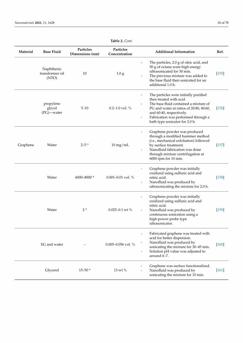
Nanomaterials 2021, 11, 1628 18 of 78
Table 2. Cont.
Material Base Fluid ParticlesDimensions (nm)
ParticlesConcentration Additional Information Ref.
Naphthenictransformer oil
(NTO)10 1.0 g
- The particles, 2.0 g of oleic acid, and50 g of octane were high energyultrasonicated for 30 min.
- The previous mixture was added tothe base fluid then sonicated for anadditional 1.0 h.
[155]
propyleneglycol
(PG)—water5–10 0.2–1.0 vol. %
- The particles were initially purifiedthen treated with acid.
- The base fluid contained a mixture ofPG and water at ratios of 20:80, 40:60,and 60:40, respectively.
- Fabrication was performed through abath type sonicator for 2.0 h.
[156]
Graphene Water 2–5 * 10 mg/mL
- Graphene powder was producedthrough a modified hummer method(i.e., mechanical exfoliation) followedby surface treatment.
- Nanofluid fabrication was donethrough mixture centrifugation at6000 rpm for 10 min.
[157]
Water 6000–8000 * 0.001–0.01 vol. %
- Graphene powder was initiallyoxidized using sulfuric acid andnitric acid.
- Nanofluid was produced byultrasonicating the mixture for 2.0 h.
[158]
Water 2 * 0.025–0.1 wt %
- Graphene powder was initiallyoxidized using sulfuric acid andnitric acid.
- Nanofluid was produced bycontinuous sonication using ahigh-power probe typeultrasonicator.
[159]
EG and water – 0.005–0.056 vol. %
- Fabricated graphene was treated withacid for better dispersion.
- Nanofluid was produced bysonicating the mixture for 30–45 min.
- Solution pH value was adjusted toaround 6–7.
[160]
Glycerol 15–50 * 13 wt %- Graphene was surface functionalized.- Nanofluid was produced by
sonicating the mixture for 10 min.[161]
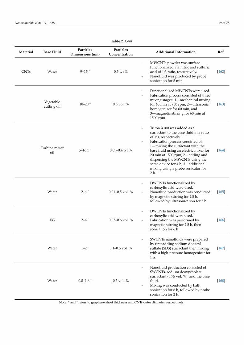
Nanomaterials 2021, 11, 1628 19 of 78
Table 2. Cont.
Material Base Fluid ParticlesDimensions (nm)
ParticlesConcentration Additional Information Ref.
CNTs Water 9–15 ˆ 0.5 wt %
- MWCNTs powder was surfacefunctionalized via nitric and sulfuricacid of 1:3 ratio, respectively.
- Nanofluid was produced by probesonication for 5 min.
[162]
Vegetablecutting oil 10–20 ˆ 0.6 vol. %
- Functionalized MWCNTs were used.- Fabrication process consisted of three
mixing stages: 1—mechanical mixingfor 60 min at 750 rpm, 2—ultrasonichomogenizer for 60 min, and3—magnetic stirring for 60 min at1500 rpm.
[163]
Turbine meteroil 5–16.1 ˆ 0.05–0.4 wt %
- Triton X100 was added as asurfactant to the base fluid in a ratioof 1:3, respectively.
- Fabrication process consisted of:1—mixing the surfactant with thebase fluid using an electric mixer for20 min at 1500 rpm, 2—adding anddispersing the MWCNTs using thesame device for 4 h, 3—additionalmixing using a probe sonicator for2 h.
[164]
Water 2–4 ˆ 0.01–0.5 vol. %
- DWCNTs functionalized bycarboxylic acid were used.
- Nanofluid production was conductedby magnetic stirring for 2.5 h,followed by ultrasonication for 5 h.
[165]
EG 2–4 ˆ 0.02–0.6 vol. %
- DWCNTs functionalized bycarboxylic acid were used.
- Fabrication was performed bymagnetic stirring for 2.5 h, thensonication for 6 h.
[166]
Water 1–2 ˆ 0.1–0.5 vol. %
- SWCNTs nanofluids were preparedby first adding sodium dodecylsulfate (SDS) surfactant then mixingwith a high-pressure homogenizer for1 h.
[167]
Water 0.8–1.6 ˆ 0.3 vol. %
- Nanofluid production consisted ofSWCNTs, sodium deoxycholatesurfactant (0.75 vol. %), and the basefluid.
- Mixing was conducted by bathsonication for 6 h, followed by probesonication for 2 h.
[168]
Note: * and ˆ refers to graphene sheet thickness and CNTs outer diameter, respectively.
Nanomaterials 2021, 11, 1628 20 of 78
4. Nanofluids Stability4.1. Stability Mechanism and Evaluation
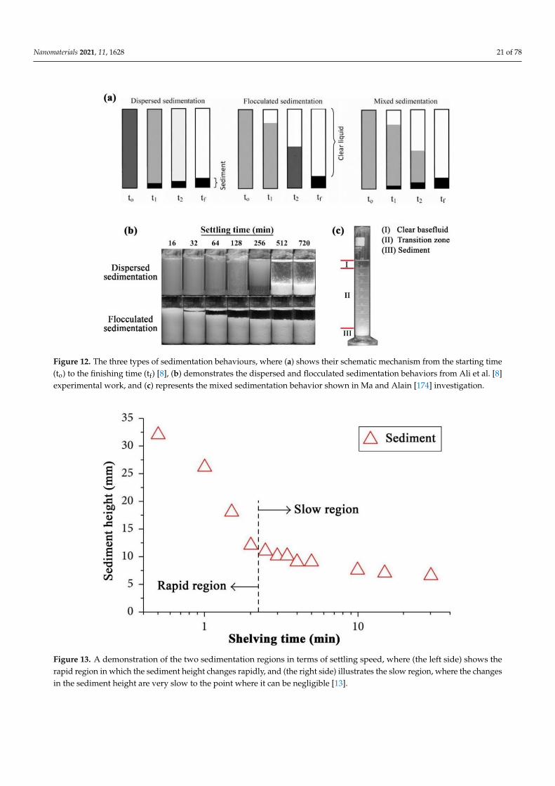
The stability of nanofluids is of major concern for maintaining the thermophysicalproperties of the mixture [169]. Specifically, the stability of the suspension combines severalaspects such as dispersion stability, kinetic stability, and chemical stability [120,170]. Thedispersion stability deals with nanoparticles aggregation within the colloidal, while thekinetic stability describes the Brownian motion of nanoparticles hosted by the base fluid(i.e., sedimentation of randomly agglomerated particles due to gravity). As for the chemicalstability, it is associated with the chemical reactions that occur between the nanoparticlesthemselves and between the nanoparticles and the surrounding base fluid. However, itis essential to note that chemical reactions in a nanofluid are minimized or halted at lowtemperature conditions (i.e., below the temperature point of a chemical reaction). Hence,agglomeration and sedimentation of nanoparticles would be the primary aspects concernedwith suspension stability. When a nanofluid is physically unstable, the formed sedimenta-tion can have one of three behaviors, namely; 1—dispersed sedimentation, 2—flocculatedsedimentation, or 3—mixed sedimentation [8]. Figure 12 shows a schematic illustration ofthe realistic reflection for the three types of sedimentation behaviors. In addition, the speedat which the sediment forms and settles within an unstable suspension can be classifiedinto two main regions. The first is known as the rapid settling region, which occurs atthe beginning stage of the separation of the particles from the hosting base fluid; and thefollowing stage is called the slow settling region, where the changes in sediment formationand settling becomes insignificant along the shelving lifetime [171]. Figure 13 demonstratesan example of the two sedimentation speed formation regions from Witharana et al. [171]investigation. Furthermore, there are about eight techniques that can be used to evaluatethe stability of nanofluids, such as 1—sedimentation photographical capturing method,2—dynamic light scattering (DLS) approach, 3—zeta potential analysis, 4—3-ω approach,5—scanning electron microscopy (SEM) analysis, 6—TEM characterization, 7—spectralanalysis, and 8—centrifugation method. From the previous stability evaluation methods,the sedimentation photographical capturing approach is considered as the most reliableroute between them all, but at the expense of time (i.e., it takes a very long time to conductand analyze). The DLS approach usually over-predicts the size of the particles, especiallywhen using a non-ionized base fluid (e.g., deionized water), where the analysis can showlarger values (from 2 to 10 nm more) than the actual particle size [172]. Such results are veryproblematic and misleading when analyzing nanofluids, especially when the dispersedparticles are 10 nm or less in size, where the oversized prediction can incorrectly indicatean instability state. On the other hand, the zeta potential analysis should only be used asa supportive characterization tool. This is because if the nanoparticles and/or the basefluid are non-polar or even of low polarity, there may be other mechanisms affecting thesuspension stability [172]. Thus, it is highly recommended to use multiple approaches (e.g.,three methods) to determine the stability of the nanofluid. A detailed description of each ofthe experimental stability evaluation approaches, and their advantages and limitations canbe found in the work published by Ali et al. [13]. Other than the previous stability evalua-tion approaches, Carrillo-Berdugo et al. [173] have proposed a novel theory-based designframework for determining the polarity between the solid and liquid interface, whichcan be used to adjust the interface tension by adding the required number of dispersivecomponents to meet those of the dispersed nanomaterial.
Nanomaterials 2021, 11, 1628 21 of 78Nanomaterials 2021, 11, x FOR PEER REVIEW 21 of 79
Figure 12. The three types of sedimentation behaviours, where (a) shows their schematic mechanism
from the starting time (to) to the finishing time (tf) [8], (b) demonstrates the dispersed and flocculated
sedimentation behaviors from Ali et al. [8] experimental work, and (c) represents the mixed sedi-
mentation behavior shown in Ma and Alain [174] investigation.
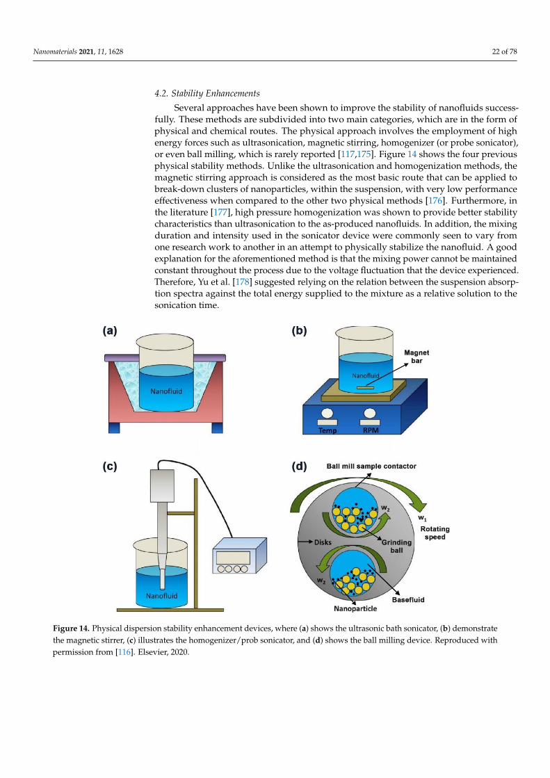
Figure 13. A demonstration of the two sedimentation regions in terms of settling speed, where (the
left side) shows the rapid region in which the sediment height changes rapidly, and (the right side)
illustrates the slow region, where the changes in the sediment height are very slow to the point
where it can be negligible [13].
4.2. Stability Enhancements
Several approaches have been shown to improve the stability of nanofluids success-
fully. These methods are subdivided into two main categories, which are in the form of
Figure 12. The three types of sedimentation behaviours, where (a) shows their schematic mechanism from the starting time(to) to the finishing time (tf) [8], (b) demonstrates the dispersed and flocculated sedimentation behaviors from Ali et al. [8]experimental work, and (c) represents the mixed sedimentation behavior shown in Ma and Alain [174] investigation.
Nanomaterials 2021, 11, x FOR PEER REVIEW 21 of 79
Figure 12. The three types of sedimentation behaviours, where (a) shows their schematic mechanism
from the starting time (to) to the finishing time (tf) [8], (b) demonstrates the dispersed and flocculated
sedimentation behaviors from Ali et al. [8] experimental work, and (c) represents the mixed sedi-
mentation behavior shown in Ma and Alain [174] investigation.
Figure 13. A demonstration of the two sedimentation regions in terms of settling speed, where (the
left side) shows the rapid region in which the sediment height changes rapidly, and (the right side)
illustrates the slow region, where the changes in the sediment height are very slow to the point
where it can be negligible [13].
4.2. Stability Enhancements
Several approaches have been shown to improve the stability of nanofluids success-
fully. These methods are subdivided into two main categories, which are in the form of
Figure 13. A demonstration of the two sedimentation regions in terms of settling speed, where (the left side) shows therapid region in which the sediment height changes rapidly, and (the right side) illustrates the slow region, where the changesin the sediment height are very slow to the point where it can be negligible [13].
Nanomaterials 2021, 11, 1628 22 of 78
4.2. Stability Enhancements
Several approaches have been shown to improve the stability of nanofluids success-fully. These methods are subdivided into two main categories, which are in the form ofphysical and chemical routes. The physical approach involves the employment of highenergy forces such as ultrasonication, magnetic stirring, homogenizer (or probe sonicator),or even ball milling, which is rarely reported [117,175]. Figure 14 shows the four previousphysical stability methods. Unlike the ultrasonication and homogenization methods, themagnetic stirring approach is considered as the most basic route that can be applied tobreak-down clusters of nanoparticles, within the suspension, with very low performanceeffectiveness when compared to the other two physical methods [176]. Furthermore, inthe literature [177], high pressure homogenization was shown to provide better stabilitycharacteristics than ultrasonication to the as-produced nanofluids. In addition, the mixingduration and intensity used in the sonicator device were commonly seen to vary fromone research work to another in an attempt to physically stabilize the nanofluid. A goodexplanation for the aforementioned method is that the mixing power cannot be maintainedconstant throughout the process due to the voltage fluctuation that the device experienced.Therefore, Yu et al. [178] suggested relying on the relation between the suspension absorp-tion spectra against the total energy supplied to the mixture as a relative solution to thesonication time.
Nanomaterials 2021, 11, x FOR PEER REVIEW 22 of 79
physical and chemical routes. The physical approach involves the employment of high
energy forces such as ultrasonication, magnetic stirring, homogenizer (or probe soni-
cator), or even ball milling, which is rarely reported [117,175]. Figure 14 shows the four
previous physical stability methods. Unlike the ultrasonication and homogenization
methods, the magnetic stirring approach is considered as the most basic route that can be
applied to break-down clusters of nanoparticles, within the suspension, with very low
performance effectiveness when compared to the other two physical methods [176]. Fur-
thermore, in the literature [177], high pressure homogenization was shown to provide
better stability characteristics than ultrasonication to the as-produced nanofluids. In ad-
dition, the mixing duration and intensity used in the sonicator device were commonly
seen to vary from one research work to another in an attempt to physically stabilize the
nanofluid. A good explanation for the aforementioned method is that the mixing power
cannot be maintained constant throughout the process due to the voltage fluctuation that
the device experienced. Therefore, Yu et al. [178] suggested relying on the relation be-
tween the suspension absorption spectra against the total energy supplied to the mixture
as a relative solution to the sonication time.
Figure 14. Physical dispersion stability enhancement devices, where (a) shows the ultrasonic bath
sonicator, (b) demonstrate the magnetic stirrer, (c) illustrates the homogenizer/prob sonicator, and
(d) shows the ball milling device. Reproduced with permission from [116]. Elsevier, 2020.
On the other hand, the chemical route stabilizes the suspension by declustering the
agglomerated nanoparticles by alternating the pH value of the base fluid or the mixture,
adding surfactant(s) to the solid–liquid matrix, or modifying the surface of the nanoparti-
cles. Nanofluids pH alteration affects the level of free cations or anions charges in the me-
dia surrounding the dispersed particles, and hence the hydrophilicity or hydrophobicity
nature of the particles changes causing the colloidal to either stabilize or destabilize
[179,180]. The disadvantage of the previous method is that fabricating suspensions of high
or low pH values may be corrosive for high heat flux applications. In addition, surfactants
Figure 14. Physical dispersion stability enhancement devices, where (a) shows the ultrasonic bath sonicator, (b) demonstratethe magnetic stirrer, (c) illustrates the homogenizer/prob sonicator, and (d) shows the ball milling device. Reproduced withpermission from [116]. Elsevier, 2020.
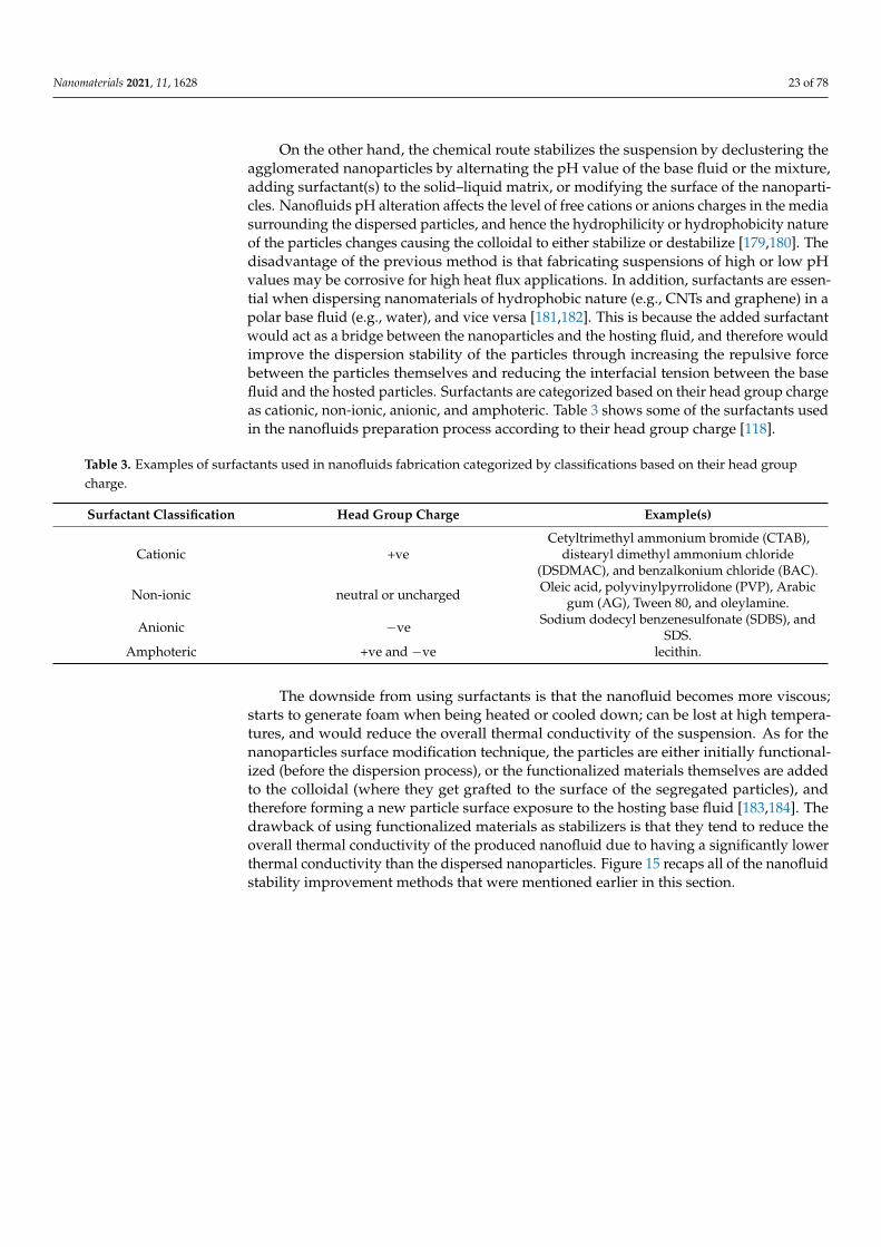
Nanomaterials 2021, 11, 1628 23 of 78
On the other hand, the chemical route stabilizes the suspension by declustering theagglomerated nanoparticles by alternating the pH value of the base fluid or the mixture,adding surfactant(s) to the solid–liquid matrix, or modifying the surface of the nanoparti-cles. Nanofluids pH alteration affects the level of free cations or anions charges in the mediasurrounding the dispersed particles, and hence the hydrophilicity or hydrophobicity natureof the particles changes causing the colloidal to either stabilize or destabilize [179,180]. Thedisadvantage of the previous method is that fabricating suspensions of high or low pHvalues may be corrosive for high heat flux applications. In addition, surfactants are essen-tial when dispersing nanomaterials of hydrophobic nature (e.g., CNTs and graphene) in apolar base fluid (e.g., water), and vice versa [181,182]. This is because the added surfactantwould act as a bridge between the nanoparticles and the hosting fluid, and therefore wouldimprove the dispersion stability of the particles through increasing the repulsive forcebetween the particles themselves and reducing the interfacial tension between the basefluid and the hosted particles. Surfactants are categorized based on their head group chargeas cationic, non-ionic, anionic, and amphoteric. Table 3 shows some of the surfactants usedin the nanofluids preparation process according to their head group charge [118].
Table 3. Examples of surfactants used in nanofluids fabrication categorized by classifications based on their head groupcharge.
Surfactant Classification Head Group Charge Example(s)
Cationic +veCetyltrimethyl ammonium bromide (CTAB),
distearyl dimethyl ammonium chloride(DSDMAC), and benzalkonium chloride (BAC).
Non-ionic neutral or uncharged Oleic acid, polyvinylpyrrolidone (PVP), Arabicgum (AG), Tween 80, and oleylamine.
Anionic −ve Sodium dodecyl benzenesulfonate (SDBS), andSDS.
Amphoteric +ve and −ve lecithin.
The downside from using surfactants is that the nanofluid becomes more viscous;starts to generate foam when being heated or cooled down; can be lost at high tempera-tures, and would reduce the overall thermal conductivity of the suspension. As for thenanoparticles surface modification technique, the particles are either initially functional-ized (before the dispersion process), or the functionalized materials themselves are addedto the colloidal (where they get grafted to the surface of the segregated particles), andtherefore forming a new particle surface exposure to the hosting base fluid [183,184]. Thedrawback of using functionalized materials as stabilizers is that they tend to reduce theoverall thermal conductivity of the produced nanofluid due to having a significantly lowerthermal conductivity than the dispersed nanoparticles. Figure 15 recaps all of the nanofluidstability improvement methods that were mentioned earlier in this section.
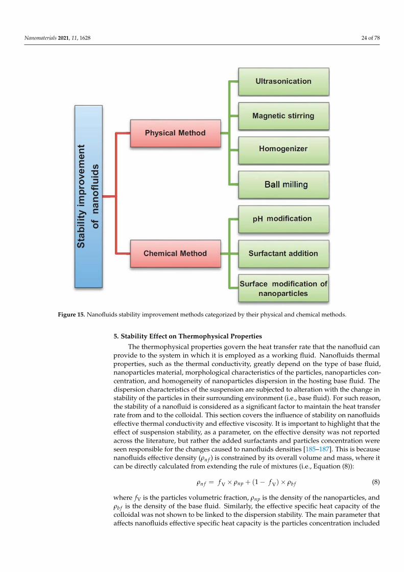
Nanomaterials 2021, 11, 1628 24 of 78Nanomaterials 2021, 11, x FOR PEER REVIEW 24 of 79
Figure 15. Nanofluids stability improvement methods categorized by their physical and chemical
methods.
5. Stability Effect on Thermophysical Properties
The thermophysical properties govern the heat transfer rate that the nanofluid can
provide to the system in which it is employed as a working fluid. Nanofluids thermal
properties, such as the thermal conductivity, greatly depend on the type of base fluid,
nanoparticles material, morphological characteristics of the particles, nanoparticles con-
centration, and homogeneity of nanoparticles dispersion in the hosting base fluid. The
dispersion characteristics of the suspension are subjected to alteration with the change in
stability of the particles in their surrounding environment (i.e., base fluid). For such rea-
son, the stability of a nanofluid is considered as a significant factor to maintain the heat
transfer rate from and to the colloidal. This section covers the influence of stability on
nanofluids effective thermal conductivity and effective viscosity. It is important to high-
light that the effect of suspension stability, as a parameter, on the effective density was
not reported across the literature, but rather the added surfactants and particles concen-
tration were seen responsible for the changes caused to nanofluids densities [185–187].
This is because nanofluids effective density (ρnf) is constrained by its overall volume and
mass, where it can be directly calculated from extending the rule of mixtures (i.e., Equa-
tion (8)):
ρnf = ƒV × ρnp + (1 − ƒV) × ρbf (8)
where ƒV is the particles volumetric fraction, ρnp is the density of the nanoparticles, and
ρbf is the density of the base fluid. Similarly, the effective specific heat capacity of the
colloidal was not shown to be linked to the dispersion stability. The main parameter that
Figure 15. Nanofluids stability improvement methods categorized by their physical and chemical methods.
5. Stability Effect on Thermophysical Properties
The thermophysical properties govern the heat transfer rate that the nanofluid canprovide to the system in which it is employed as a working fluid. Nanofluids thermalproperties, such as the thermal conductivity, greatly depend on the type of base fluid,nanoparticles material, morphological characteristics of the particles, nanoparticles con-centration, and homogeneity of nanoparticles dispersion in the hosting base fluid. Thedispersion characteristics of the suspension are subjected to alteration with the change instability of the particles in their surrounding environment (i.e., base fluid). For such reason,the stability of a nanofluid is considered as a significant factor to maintain the heat transferrate from and to the colloidal. This section covers the influence of stability on nanofluidseffective thermal conductivity and effective viscosity. It is important to highlight that theeffect of suspension stability, as a parameter, on the effective density was not reportedacross the literature, but rather the added surfactants and particles concentration wereseen responsible for the changes caused to nanofluids densities [185–187]. This is becausenanofluids effective density (ρn f ) is constrained by its overall volume and mass, where itcan be directly calculated from extending the rule of mixtures (i.e., Equation (8)):
ρn f = f V × ρnp + (1− f V)× ρb f (8)
where fV is the particles volumetric fraction, ρnp is the density of the nanoparticles, andρb f is the density of the base fluid. Similarly, the effective specific heat capacity of thecolloidal was not shown to be linked to the dispersion stability. The main parameter thataffects nanofluids effective specific heat capacity is the particles concentration included
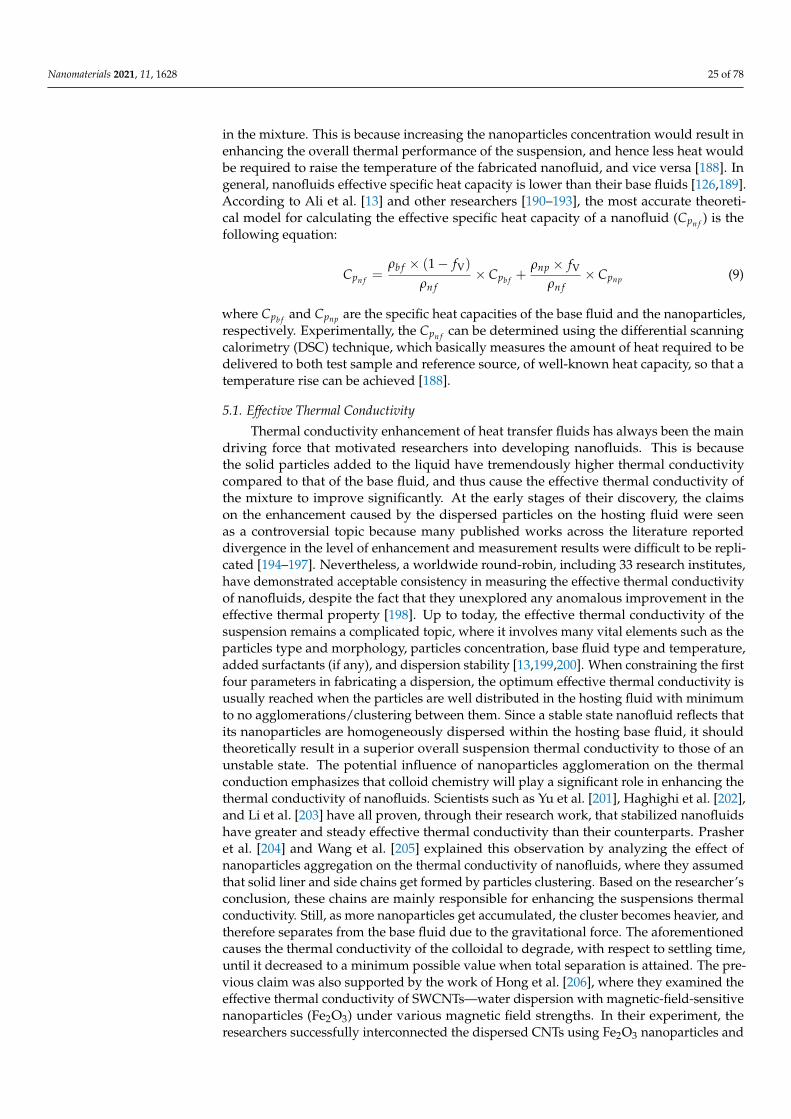
Nanomaterials 2021, 11, 1628 25 of 78
in the mixture. This is because increasing the nanoparticles concentration would result inenhancing the overall thermal performance of the suspension, and hence less heat wouldbe required to raise the temperature of the fabricated nanofluid, and vice versa [188]. Ingeneral, nanofluids effective specific heat capacity is lower than their base fluids [126,189].According to Ali et al. [13] and other researchers [190–193], the most accurate theoreti-cal model for calculating the effective specific heat capacity of a nanofluid (Cpn f ) is thefollowing equation:
Cpn f =ρb f × (1− fV)
ρn f× Cpb f +
ρnp × fV
ρn f× Cpnp (9)
where Cpb f and Cpnp are the specific heat capacities of the base fluid and the nanoparticles,respectively. Experimentally, the Cpn f can be determined using the differential scanningcalorimetry (DSC) technique, which basically measures the amount of heat required to bedelivered to both test sample and reference source, of well-known heat capacity, so that atemperature rise can be achieved [188].
5.1. Effective Thermal Conductivity
Thermal conductivity enhancement of heat transfer fluids has always been the maindriving force that motivated researchers into developing nanofluids. This is becausethe solid particles added to the liquid have tremendously higher thermal conductivitycompared to that of the base fluid, and thus cause the effective thermal conductivity ofthe mixture to improve significantly. At the early stages of their discovery, the claimson the enhancement caused by the dispersed particles on the hosting fluid were seenas a controversial topic because many published works across the literature reporteddivergence in the level of enhancement and measurement results were difficult to be repli-cated [194–197]. Nevertheless, a worldwide round-robin, including 33 research institutes,have demonstrated acceptable consistency in measuring the effective thermal conductivityof nanofluids, despite the fact that they unexplored any anomalous improvement in theeffective thermal property [198]. Up to today, the effective thermal conductivity of thesuspension remains a complicated topic, where it involves many vital elements such as theparticles type and morphology, particles concentration, base fluid type and temperature,added surfactants (if any), and dispersion stability [13,199,200]. When constraining the firstfour parameters in fabricating a dispersion, the optimum effective thermal conductivity isusually reached when the particles are well distributed in the hosting fluid with minimumto no agglomerations/clustering between them. Since a stable state nanofluid reflects thatits nanoparticles are homogeneously dispersed within the hosting base fluid, it shouldtheoretically result in a superior overall suspension thermal conductivity to those of anunstable state. The potential influence of nanoparticles agglomeration on the thermalconduction emphasizes that colloid chemistry will play a significant role in enhancing thethermal conductivity of nanofluids. Scientists such as Yu et al. [201], Haghighi et al. [202],and Li et al. [203] have all proven, through their research work, that stabilized nanofluidshave greater and steady effective thermal conductivity than their counterparts. Prasheret al. [204] and Wang et al. [205] explained this observation by analyzing the effect ofnanoparticles aggregation on the thermal conductivity of nanofluids, where they assumedthat solid liner and side chains get formed by particles clustering. Based on the researcher’sconclusion, these chains are mainly responsible for enhancing the suspensions thermalconductivity. Still, as more nanoparticles get accumulated, the cluster becomes heavier, andtherefore separates from the base fluid due to the gravitational force. The aforementionedcauses the thermal conductivity of the colloidal to degrade, with respect to settling time,until it decreased to a minimum possible value when total separation is attained. The pre-vious claim was also supported by the work of Hong et al. [206], where they examined theeffective thermal conductivity of SWCNTs—water dispersion with magnetic-field-sensitivenanoparticles (Fe2O3) under various magnetic field strengths. In their experiment, theresearchers successfully interconnected the dispersed CNTs using Fe2O3 nanoparticles and
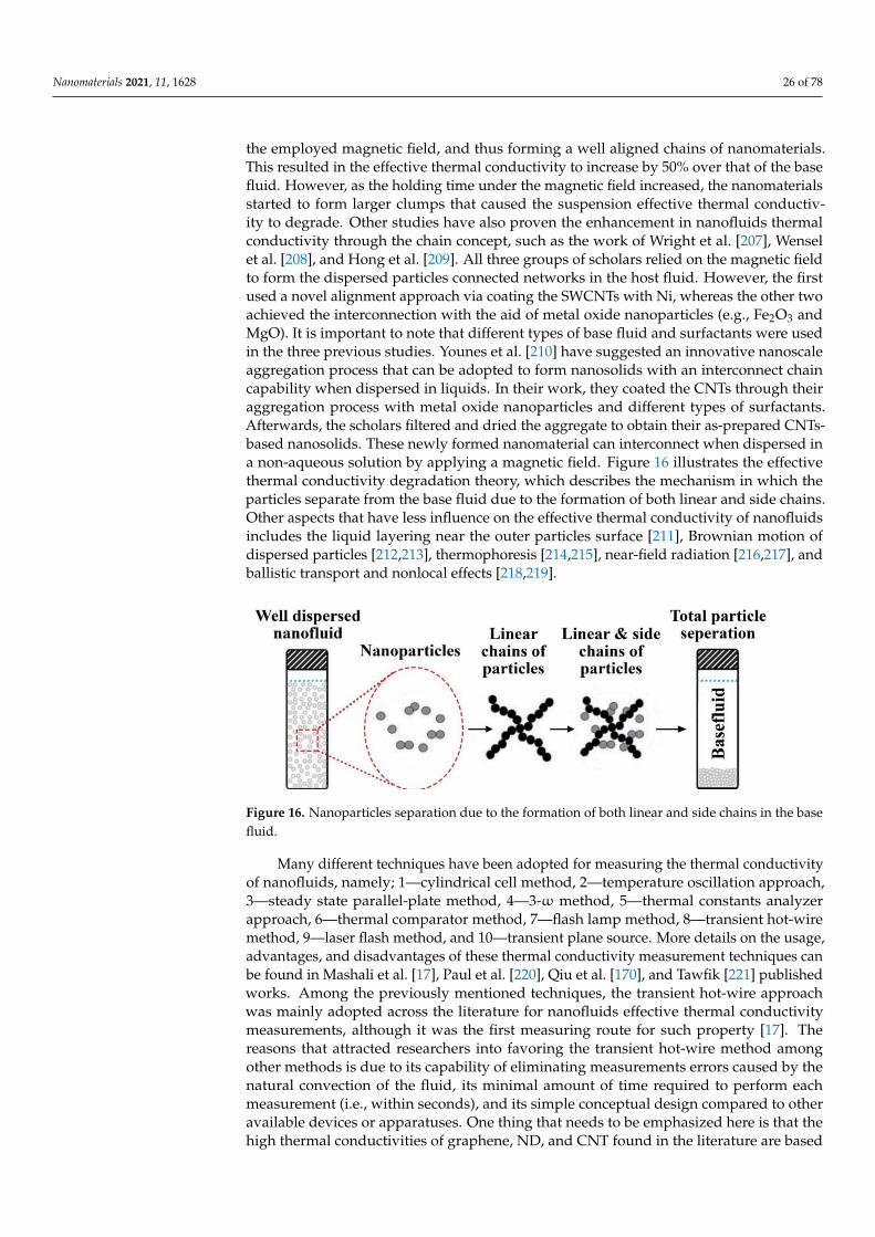
Nanomaterials 2021, 11, 1628 26 of 78
the employed magnetic field, and thus forming a well aligned chains of nanomaterials.This resulted in the effective thermal conductivity to increase by 50% over that of the basefluid. However, as the holding time under the magnetic field increased, the nanomaterialsstarted to form larger clumps that caused the suspension effective thermal conductiv-ity to degrade. Other studies have also proven the enhancement in nanofluids thermalconductivity through the chain concept, such as the work of Wright et al. [207], Wenselet al. [208], and Hong et al. [209]. All three groups of scholars relied on the magnetic fieldto form the dispersed particles connected networks in the host fluid. However, the firstused a novel alignment approach via coating the SWCNTs with Ni, whereas the other twoachieved the interconnection with the aid of metal oxide nanoparticles (e.g., Fe2O3 andMgO). It is important to note that different types of base fluid and surfactants were usedin the three previous studies. Younes et al. [210] have suggested an innovative nanoscaleaggregation process that can be adopted to form nanosolids with an interconnect chaincapability when dispersed in liquids. In their work, they coated the CNTs through theiraggregation process with metal oxide nanoparticles and different types of surfactants.Afterwards, the scholars filtered and dried the aggregate to obtain their as-prepared CNTs-based nanosolids. These newly formed nanomaterial can interconnect when dispersed ina non-aqueous solution by applying a magnetic field. Figure 16 illustrates the effectivethermal conductivity degradation theory, which describes the mechanism in which theparticles separate from the base fluid due to the formation of both linear and side chains.Other aspects that have less influence on the effective thermal conductivity of nanofluidsincludes the liquid layering near the outer particles surface [211], Brownian motion ofdispersed particles [212,213], thermophoresis [214,215], near-field radiation [216,217], andballistic transport and nonlocal effects [218,219].
Nanomaterials 2021, 11, x FOR PEER REVIEW 26 of 79
with magnetic-field-sensitive nanoparticles (Fe2O3) under various magnetic field
strengths. In their experiment, the researchers successfully interconnected the dispersed
CNTs using Fe2O3 nanoparticles and the employed magnetic field, and thus forming a
well aligned chains of nanomaterials. This resulted in the effective thermal conductivity
to increase by 50% over that of the base fluid. However, as the holding time under the
magnetic field increased, the nanomaterials started to form larger clumps that caused the
suspension effective thermal conductivity to degrade. Other studies have also proven the
enhancement in nanofluids thermal conductivity through the chain concept, such as the
work of Wright et al. [207], Wensel et al. [208], and Hong et al. [209]. All three groups of
scholars relied on the magnetic field to form the dispersed particles connected networks
in the host fluid. However, the first used a novel alignment approach via coating the
SWCNTs with Ni, whereas the other two achieved the interconnection with the aid of
metal oxide nanoparticles (e.g., Fe2O3 and MgO). It is important to note that different types
of base fluid and surfactants were used in the three previous studies. Younes et al. [210]
have suggested an innovative nanoscale aggregation process that can be adopted to form
nanosolids with an interconnect chain capability when dispersed in liquids. In their work,
they coated the CNTs through their aggregation process with metal oxide nanoparticles
and different types of surfactants. Afterwards, the scholars filtered and dried the aggre-
gate to obtain their as-prepared CNTs-based nanosolids. These newly formed nano-
material can interconnect when dispersed in a non-aqueous solution by applying a mag-
netic field. Figure 16 illustrates the effective thermal conductivity degradation theory,
which describes the mechanism in which the particles separate from the base fluid due to
the formation of both linear and side chains. Other aspects that have less influence on the
effective thermal conductivity of nanofluids includes the liquid layering near the outer
particles surface [211], Brownian motion of dispersed particles [212,213], thermophoresis
[214,215], near-field radiation [216,217], and ballistic transport and nonlocal effects
[218,219].
Figure 16. Nanoparticles separation due to the formation of both linear and side chains in the base
fluid.
Many different techniques have been adopted for measuring the thermal conductiv-
ity of nanofluids, namely; 1—cylindrical cell method, 2—temperature oscillation ap-
proach, 3—steady state parallel-plate method, 4—3-ω method, 5—thermal constants ana-
lyzer approach, 6—thermal comparator method, 7—flash lamp method, 8—transient hot-
wire method, 9—laser flash method, and 10—transient plane source. More details on the
usage, advantages, and disadvantages of these thermal conductivity measurement tech-
niques can be found in Mashali et al. [17], Paul et al. [220], Qiu et al. [170], and Tawfik
[221] published works. Among the previously mentioned techniques, the transient hot-
wire approach was mainly adopted across the literature for nanofluids effective thermal
conductivity measurements, although it was the first measuring route for such property
[17]. The reasons that attracted researchers into favoring the transient hot-wire method
among other methods is due to its capability of eliminating measurements errors caused
by the natural convection of the fluid, its minimal amount of time required to perform
Figure 16. Nanoparticles separation due to the formation of both linear and side chains in the basefluid.
Many different techniques have been adopted for measuring the thermal conductivityof nanofluids, namely; 1—cylindrical cell method, 2—temperature oscillation approach,3—steady state parallel-plate method, 4—3-ω method, 5—thermal constants analyzerapproach, 6—thermal comparator method, 7—flash lamp method, 8—transient hot-wiremethod, 9—laser flash method, and 10—transient plane source. More details on the usage,advantages, and disadvantages of these thermal conductivity measurement techniques canbe found in Mashali et al. [17], Paul et al. [220], Qiu et al. [170], and Tawfik [221] publishedworks. Among the previously mentioned techniques, the transient hot-wire approachwas mainly adopted across the literature for nanofluids effective thermal conductivitymeasurements, although it was the first measuring route for such property [17]. Thereasons that attracted researchers into favoring the transient hot-wire method amongother methods is due to its capability of eliminating measurements errors caused by thenatural convection of the fluid, its minimal amount of time required to perform eachmeasurement (i.e., within seconds), and its simple conceptual design compared to otheravailable devices or apparatuses. One thing that needs to be emphasized here is that thehigh thermal conductivities of graphene, ND, and CNT found in the literature are based
Nanomaterials 2021, 11, 1628 27 of 78
on theoretical calculations for a single particle, and that when attempting to measure thisthermal property for a powder sample, the results will show tremendously lower valuesdue to the presence of air along with the limitation associated with the measuring toolitself [222,223].
Furthermore, researchers have published numerous amounts of literature on improv-ing nanofluids effective thermal conductivity over their base fluids [224–228]. For example,Yu et al. [224] compared the thermal conductivity of their stable graphene—EG nanofluidsto that of pure EG. The researchers have dispersed 2.0 and 5.0 vol. % of graphene, of0.7–1.3 nm in size, in EG to fabricate their nanofluids at a set of temperatures from 10to 60 ◦C, using the two-step approach. They have found that the as-prepared 5.0 vol. %suspension had 86% enhanced thermal conductivity over its base fluid at 60 ◦C. Yarmandet al. [225] synthesized water based nanofluids from 0.02 to 0.1 wt % of functionalizedgraphene nanoplatelets using the two-step method at 20–40 ◦C. The functionalizationprocess was conducted through an acidic treatment to the graphene powder by dispersingthe as-received graphene in a 1:3 mixture of HNO3 and H2SO4, respectively. They foundthat the formation of sedimentation within their as-fabricated nanofluids was minimalthroughout their 245 h test. The heat transfer coefficient improved by 19.68% comparedto the base fluid when using the 0.1 wt % nanofluid. Furthermore, Yarmand et al. [225]concluded that the thermal property of the suspension is influenced by the temperature offabrication and the dispersed solid concentration. Zhang et al. [226] compared the thermalconductivity of three ionic based nanofluids containing graphene sheets, graphite nanopar-ticles, and SWCNTs. All three types showed enhanced thermal conductivity with a partialincrease in viscosity compared to their base fluids. Nevertheless, the nanofluid fabricatedfrom graphene had a higher increase in thermal conductivity compared to the other twotypes of dispersions. Ghozatloo et al. [227] studied the effect of time, temperature, andconcentration on the thermal conductivity of pure and functionalized CVD graphene–waternanofluids. The functionalizing process of graphene was conducted through an alkalinemethod, and the suspensions were fabricated using sonication (i.e., the two-step approach).Moreover, the concentration used in the production of the suspension was of 0.01–0.05wt %, and the duration of the dispersion mechanism was 1 h. The authors found that thenanofluids samples containing pure graphene had promptly developed clusters betweenits solid content, whereas the functionalized suspensions were highly stable. Furthermore,the effective thermal conductivity was seen to reduce to a certain extent for all nanofluidsafter the time of production. In addition, the enhancement in the effective thermal con-ductivity using functionalized graphene showed to be 13.5% (0.05 wt %) and 17% (0.03 wt%) over 25 ◦C and 50 ◦C water, respectively. Askari et al. [46] experimentally investigatedthe thermal and rheological properties of 0.1–1.0 wt % CVD nanoporous graphene–waternanofluids along with heat transfer suspension effect on the thermal performance of acounter-flow arranged mechanical wet tower. The base fluid used in the two-step sus-pension fabrication was taken from one of the working cooling towers located in SouthIran to reflect a real-life case scenario. Different types of surfactants were used to stabilizethe dispersion of the as-prepared nanofluids, such as AG, Tween 80, CTAB, Triton X-100,and Acumer Terpolymer. The authors found through analyzing the physical stability oftheir nanofluids, utilizing the sedimentation capturing method and zeta potential mea-surements, that using Tween80 as a disperser resulted in a stabilized suspension that canlast for up to two months. Furthermore, their 1.0 wt % nanofluid showed a 16% increasein the thermal conductivity at a dispersion temperature of 45 ◦C. At the same time, thelow concentration suspensions would be appropriate for industrial applications because oftheir increasing effect on the effective density and viscosity. Moreover, the as-producednanofluids enhanced the efficiency, cooling range, and tower characteristic compared to theconventional base fluid. For example, using a 0.1 wt % fabricated nanofluid had resulted ina 67% increase in the cooling range and a 19% decrease in the overall water consumption.Goodarzi et al. [229] studied the effective thermal conductivity, specific heat capacity, andviscosity of their as-prepared nitrogen-doped graphene–water nanofluids along with their
Nanomaterials 2021, 11, 1628 28 of 78
convective heat transfer behavior when employed in a double-pipe type heat exchanger.The authors used 0.025 wt % of Triton X-100, as their surfactant, along with 0.01–0.06 wt %of graphene to prepare the suspensions using the two-step method. Their results showedthat the examined thermophysical properties where very sensitive to both temperatureand concentration. As an example, the effective thermal conductivity of their suspensionshowed an increase from 0.774 to 0.942 W/m·K with the increase in temperature (from 20to 60 ◦C). The maximum effective thermal conductivity achieved by the scholars was 37%higher than that of the base fluid. Furthermore, they found that increasing the concentra-tion of their nanosheets in the base fluid had caused the heat transfer coefficient of theirworking fluid to improve but at the same time results in increasing the pressure drop inthe system and the pumping power requirement. Liu et al. [230] examined the effectivethermal conductivity and physical stability of their synthesized graphene oxide–waternanofluids. Moreover, the mass fraction and temperature of the investigated samples were1.0–4.5 mg/mL and 25–50 ◦C, respectively. The researchers found that they can achievea homogeneously stable nanofluid for about 3 months using their preparation process.They also found that the effective thermal conductivity of their as-prepared nanofluidwas 25.27% higher than the base fluid, at 4.5 mg/mL mass fraction, and a temperatureof 50 ◦C. Ghozatloo et al. [228] explored the possibility of improving the convection heattransfer behavior of a shell and tube heat exchanger, under laminar flow conditions, usingCVD graphene nanofluid of water base. The researchers also investigated the effect oftemperature and solid dispersed concentration of the mixture on the thermal conductivityand convective heat transfer coefficients. The dispersions were prepared using 0.05, 0.075,and 0.1 wt % of treated CVD graphene and 15 min sonication in water. According to theauthors outcomes, using 0.05, 0.075, and 0.1 wt % suspensions, at 25 ◦C, enhanced thethermal conductivity over pure water by 15.0%, 29.2%, and 12.6%, respectively. Moreover,the convective heat transfer coefficients of the as-produced mixtures depended on theflow conditions in which the working fluid undergoes but were in all cases higher thanthe base fluid. From the previously mentioned studies, it can be concluded that carbon-based nanomaterials can form stabilized nanofluids, either by selecting the appropriatebase fluid–nanoscaled material matrix or through external physical and/or chemical ap-proaches. Moreover, these suspensions have enhanced thermal properties compared totheir conventional base fluids, but the level of enhancement gets affected by parameterssuch as concentration, temperature, physical stability, etc. Thus, such factors should becarefully considered to obtain the optimum suspension thermophysical condition.
Besides the experimental studies, many researchers have developed theoretical cor-relations to predict the effective thermal conductivity of nanofluids. Still, most of theseformulas have shown conceptual limitations towards their experimental origin. Table 4demonstrates the developments in the effective thermal conductivity equations.
Table 4. Developments of nanofluids effective thermal conductivity formulas.
Developer/s Year Formula DependentParameter Limitations
Maxwell [231] 1890
ke f fkb f
=knp+2kb f +2 fV (knp−kb f )knp+2kb f− fV (knp−kb f )
;
where ke f f , kb f , and knp are the effectivethermal conductivity of the nanofluid, basefluid thermal conductivity, and nanoparticlesthermal conductivity, respectively.
fVSuited for sphericalshaped particles.
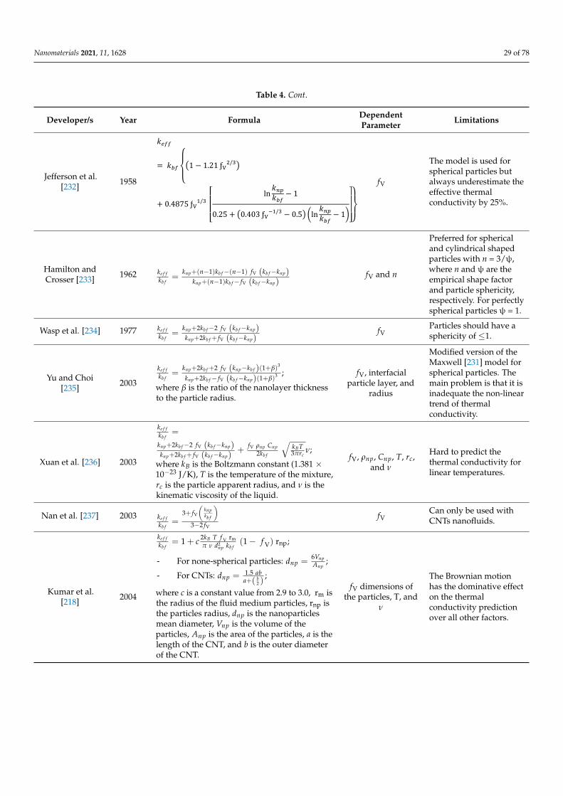
Nanomaterials 2021, 11, 1628 29 of 78
Table 4. Cont.
Developer/s Year Formula DependentParameter Limitations
Jefferson et al.[232] 1958
Nanomaterials 2021, 11, x FOR PEER REVIEW 29 of 80
Jefferson et al. [232] 1958
= 1 − 1.21 ƒ /
+ 0.4875 ƒ / ln − 10.25 + 0.403 ƒ / − 0.5 ln − 1 ƒ
The model is used for spherical particles but always underestimate the effective thermal conductivity by 25%.
Hamilton and Crosser
[233] 1962 = + ( − 1) − ( − 1) ƒ −+ ( − 1) − ƒ − ƒ and
Preferred for spherical and cylindrical shaped particles with = 3/ψ, where and ψ are the empirical shape factor and particle sphericity, respectively. For perfectly spherical particles ψ = 1.
Wasp et al. [234] 1977 = + 2 − 2 ƒ −+ 2 + ƒ − ƒ Particles should have a
sphericity of ≤ 1.
Yu and Choi [235]
2003 = ƒ ( ) ƒ ( ) ;
where is the ratio of the nanolayer thickness to the particle radius.
ƒ , interfacial
particle layer, and
radius
Modified version of the Maxwell [231] model for spherical particles. The main problem is that it is inadequate the non-linear trend of thermal conductivity.
Xuan et al. [236] 2003
= ƒ ƒ + ƒ ;
where is the Boltzmann constant (1.381 × 10⁻²³ J/K), is the temperature of the mixture, is the particle
apparent radius, and is the kinematic viscosity of the liquid.
ƒ , , , , , and
Hard to predict the thermal conductivity for linear temperatures.
Nan et al. [237] 2003 = 3 + ƒ3 − 2ƒ ƒ Can only be used with CNTs
nanofluids.
Kumar et al. [218] 2004
= 1 + ƒ (1 − ƒ ) r ;
- For none-spherical particles: = ;
- For CNTs: = . . ;
where is a constant value from 2.9 to 3.0, r is the radius of the fluid medium particles, r is the particles radius, is the nanoparticles mean diameter, is the volume of the particles, is the area of the particles, is the length of the CNT, and is the outer diameter of the CNT.
ƒ dimensions
of the particles, T,
and
The Brownian motion has the dominative effect on the thermal conductivity prediction over all other factors.
Jang and Choi [213] 2004
= (1 − ƒ ) + ƒ+ 3 ƒ ; - = . . ;
- . . = ℓ ;
where is a proportional constant, is the diameter of the base fluid molecule, is the
ƒ , dimensions
of the particles, T,
, and ℓ
Both conduction and convection heat transfer are accounted for, while the heating duration is much higher.
fV
The model is used forspherical particles butalways underestimate theeffective thermalconductivity by 25%.
Hamilton andCrosser [233] 1962 ke f f
kb f=
knp+(n−1)kb f−(n−1) fV (kb f−knp)knp+(n−1)kb f− fV (kb f−knp)
fV and n
Preferred for sphericaland cylindrical shapedparticles with n = 3/ψ,where n and ψ are theempirical shape factorand particle sphericity,respectively. For perfectlyspherical particles ψ = 1.
Wasp et al. [234] 1977 ke f fkb f
=knp+2kb f−2 fV (kb f−knp)knp+2kb f + fV (kb f−knp)
fVParticles should have asphericity of ≤1.
Yu and Choi[235] 2003
ke f fkb f
=knp+2kb f +2 fV (knp−kb f )(1+β)3
knp+2kb f− fV (kb f−knp)(1+β)3 ;
where β is the ratio of the nanolayer thicknessto the particle radius.
fV, interfacialparticle layer, and
radius
Modified version of theMaxwell [231] model forspherical particles. Themain problem is that it isinadequate the non-lineartrend of thermalconductivity.
Xuan et al. [236] 2003
ke f fkb f
=
knp+2kb f−2 fV (kb f−knp)knp+2kb f + fV (kb f−knp)
+fV ρnp Cnp
2kb f
√kBT3πrc
ν;
where kB is the Boltzmann constant (1.381 ×10⁻²³ J/K), T is the temperature of the mixture,rc is the particle apparent radius, and ν is thekinematic viscosity of the liquid.
fV, ρnp, Cnp, T, rc,and ν
Hard to predict thethermal conductivity forlinear temperatures.
Nan et al. [237] 2003 ke f fkb f
=3+ fV
(knpkb f
)3−2 fV
fVCan only be used withCNTs nanofluids.
Kumar et al.[218] 2004
ke f fkb f
= 1 + c 2kB T f V rm
π ν d2np kb f
(1− f V) rnp;
- For none-spherical particles: dnp =6VnpAnp
;
- For CNTs: dnp = 1.5 aba+( b
2 );
where c is a constant value from 2.9 to 3.0, rm isthe radius of the fluid medium particles, rnp isthe particles radius, dnp is the nanoparticlesmean diameter, Vnp is the volume of theparticles, Anp is the area of the particles, a is thelength of the CNT, and b is the outer diameterof the CNT.
fV dimensions ofthe particles, T, and
ν
The Brownian motionhas the dominative effecton the thermalconductivity predictionover all other factors.
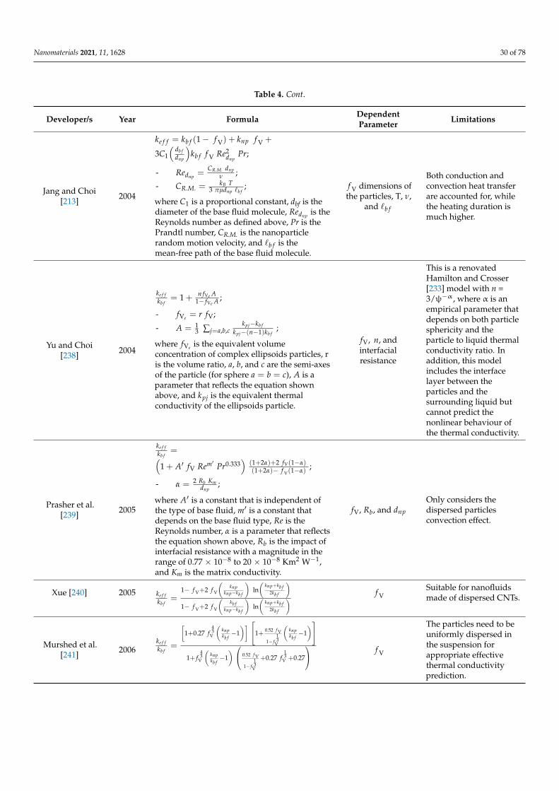
Nanomaterials 2021, 11, 1628 30 of 78
Table 4. Cont.
Developer/s Year Formula DependentParameter Limitations
Jang and Choi[213] 2004
ke f f = kb f (1− f V) + knp f V +
3C1
(db fdnp
)kb f f V Re2
dnpPr;
- Rednp =CR.M. dnp
ν ;
- CR.M. =kB T
3 πµdnp `b f;
where C1 is a proportional constant, dbf is thediameter of the base fluid molecule, Rednp is theReynolds number as defined above, Pr is thePrandtl number, CR.M. is the nanoparticlerandom motion velocity, and `b f is themean-free path of the base fluid molecule.
f V dimensions ofthe particles, T, ν,
and `b f
Both conduction andconvection heat transferare accounted for, whilethe heating duration ismuch higher.
Yu and Choi[238] 2004
ke f fkb f
= 1 + n fVe A1− fVe A ;
- fVe = r fV;
- A = 13 ∑j=a,b,c
kpj−kb f
kpj−(n−1)kb f;
where fVe is the equivalent volumeconcentration of complex ellipsoids particles, ris the volume ratio, a, b, and c are the semi-axesof the particle (for sphere a = b = c), A is aparameter that reflects the equation shownabove, and kpj is the equivalent thermalconductivity of the ellipsoids particle.
fV, n, andinterfacialresistance
This is a renovatedHamilton and Crosser[233] model with n =3/ψ−α, where α is anempirical parameter thatdepends on both particlesphericity and theparticle to liquid thermalconductivity ratio. Inaddition, this modelincludes the interfacelayer between theparticles and thesurrounding liquid butcannot predict thenonlinear behaviour ofthe thermal conductivity.
Prasher et al.[239] 2005
ke f fkb f
=(1 + A′ fV Rem′ Pr0.333
)(1+2α)+2 fV(1−α)(1+2α)− f V(1−α)
;
- α = 2 Rb Kmdnp
;
where A′ is a constant that is independent ofthe type of base fluid, m′ is a constant thatdepends on the base fluid type, Re is theReynolds number, α is a parameter that reflectsthe equation shown above, Rb is the impact ofinterfacial resistance with a magnitude in therange of 0.77 × 10⁻⁸ to 20 × 10−8 Km2 W−1,and Km is the matrix conductivity.
fV, Rb, and dnp
Only considers thedispersed particlesconvection effect.
Xue [240] 2005 ke f fkb f
=1− f V+2 f V
(knp
knp−kb f
)ln(
knp+kb f2kb f
)1− f V+2 f V
(kb f
knp−kb f
)ln(
knp+kb f2kb f
) f VSuitable for nanofluidsmade of dispersed CNTs.
Murshed et al.[241] 2006
ke f fkb f
=
[1+0.27 f
43
V
(knpkb f−1)] 1+ 0.52 f V
1− f13
V
(knpkb f−1)
1+ f43
V
(knpkb f−1) 0.52 f V
1− f13
V
+0.27 f13
V +0.27
f V
The particles need to beuniformly dispersed inthe suspension forappropriate effectivethermal conductivityprediction.
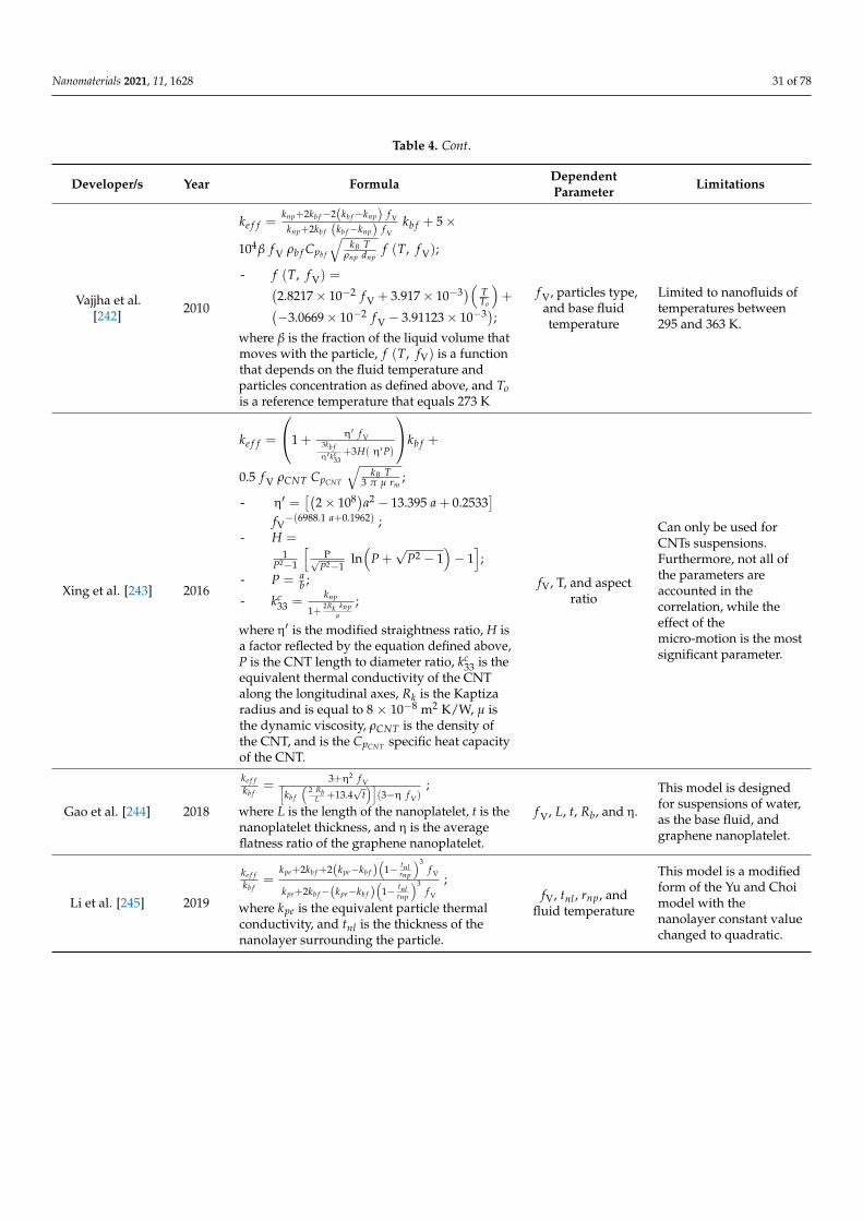
Nanomaterials 2021, 11, 1628 31 of 78
Table 4. Cont.
Developer/s Year Formula DependentParameter Limitations
Vajjha et al.[242] 2010
ke f f =knp+2kb f−2(kb f−knp) f V
knp+2kb f (kb f−knp) f Vkb f + 5×
104β f V ρb f Cpb f
√kB T
ρnp dnpf (T, f V);
- f (T, f V) =(2.8217× 10⁻² f V + 3.917× 10⁻³)( T
To
)+(
−3.0669× 10⁻² f V − 3.91123× 10⁻³);where β is the fraction of the liquid volume thatmoves with the particle, f (T, fV) is a functionthat depends on the fluid temperature andparticles concentration as defined above, and Tois a reference temperature that equals 273 K
f V, particles type,and base fluidtemperature
Limited to nanofluids oftemperatures between295 and 363 K.
Xing et al. [243] 2016
ke f f =
1 + η′ f V3kb fη′kc
33+3H( η′P)
kb f +
0.5 f V ρCNT CpCNT
√kB T
3 π µ rm;
- η′ =[(
2× 10⁸)a2 − 13.395 a + 0.2533]
fV−(6988.1 a+0.1962) ;
- H =1
P2−1
[P√
P2−1ln(
P +√
P2 − 1)− 1];
- P = ab ;
- kc33 =
knp
1+2Rk knp
a
;
where η′ is the modified straightness ratio, H isa factor reflected by the equation defined above,P is the CNT length to diameter ratio, kc
33 is theequivalent thermal conductivity of the CNTalong the longitudinal axes, Rk is the Kaptizaradius and is equal to 8 × 10⁻⁸ m2 K/W, µ isthe dynamic viscosity, ρCNT is the density ofthe CNT, and is the CpCNT specific heat capacityof the CNT.
fV, T, and aspectratio
Can only be used forCNTs suspensions.Furthermore, not all ofthe parameters areaccounted in thecorrelation, while theeffect of themicro-motion is the mostsignificant parameter.
Gao et al. [244] 2018
ke f fkb f
=3+η2 f V[
kb f
(2 Rb
L +13.4√
t)]
(3−η f V);
where L is the length of the nanoplatelet, t is thenanoplatelet thickness, and η is the averageflatness ratio of the graphene nanoplatelet.
f V, L, t, Rb, and η.
This model is designedfor suspensions of water,as the base fluid, andgraphene nanoplatelet.
Li et al. [245] 2019
ke f fkb f
=kpe+2kb f +2(kpe−kb f )
(1− tnl
rnp
)3f V
kpe+2kb f−(kpe−kb f )(
1− tnlrnp
)3f V
;
where kpe is the equivalent particle thermalconductivity, and tnl is the thickness of thenanolayer surrounding the particle.
fV, tnl , rnp, andfluid temperature
This model is a modifiedform of the Yu and Choimodel with thenanolayer constant valuechanged to quadratic.
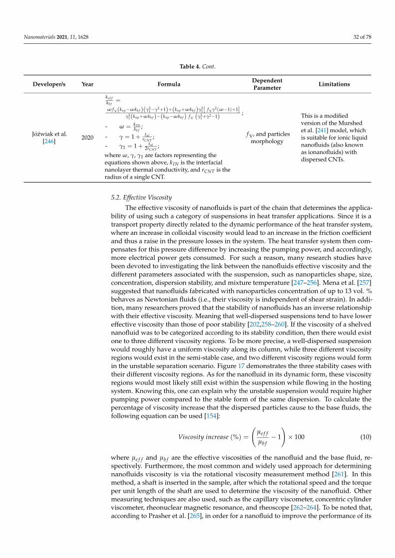
Nanomaterials 2021, 11, 1628 32 of 78
Table 4. Cont.
Developer/s Year Formula DependentParameter Limitations
Józwiak et al.[246] 2020
ke f fkb f
=
ω f V(knp−ωkb f )(γ21−γ2+1)+(knp+ωkb f )γ2
1[ f Vγ2(ω−1)+1]γ2
1(knp+ωkb f )−(knp−ωkb f ) f V (γ21+γ2−1)
;
- ω = k INkb f
;
- γ = 1 + tnlrCNT
;
- γ1 = 1 + tnl2rCNT
;
whereω, γ, γ1 are factors representing theequations shown above, kIN is the interfacialnanolayer thermal conductivity, and rCNT is theradius of a single CNT.
f V, and particlesmorphology
This is a modifiedversion of the Murshedet al. [241] model, whichis suitable for ionic liquidnanofluids (also knownas ionanofluids) withdispersed CNTs.
5.2. Effective Viscosity
The effective viscosity of nanofluids is part of the chain that determines the applica-bility of using such a category of suspensions in heat transfer applications. Since it is atransport property directly related to the dynamic performance of the heat transfer system,where an increase in colloidal viscosity would lead to an increase in the friction coefficientand thus a raise in the pressure losses in the system. The heat transfer system then com-pensates for this pressure difference by increasing the pumping power, and accordingly,more electrical power gets consumed. For such a reason, many research studies havebeen devoted to investigating the link between the nanofluids effective viscosity and thedifferent parameters associated with the suspension, such as nanoparticles shape, size,concentration, dispersion stability, and mixture temperature [247–256]. Mena et al. [257]suggested that nanofluids fabricated with nanoparticles concentration of up to 13 vol. %behaves as Newtonian fluids (i.e., their viscosity is independent of shear strain). In addi-tion, many researchers proved that the stability of nanofluids has an inverse relationshipwith their effective viscosity. Meaning that well-dispersed suspensions tend to have lowereffective viscosity than those of poor stability [202,258–260]. If the viscosity of a shelvednanofluid was to be categorized according to its stability condition, then there would existone to three different viscosity regions. To be more precise, a well-dispersed suspensionwould roughly have a uniform viscosity along its column, while three different viscosityregions would exist in the semi-stable case, and two different viscosity regions would formin the unstable separation scenario. Figure 17 demonstrates the three stability cases withtheir different viscosity regions. As for the nanofluid in its dynamic form, these viscosityregions would most likely still exist within the suspension while flowing in the hostingsystem. Knowing this, one can explain why the unstable suspension would require higherpumping power compared to the stable form of the same dispersion. To calculate thepercentage of viscosity increase that the dispersed particles cause to the base fluids, thefollowing equation can be used [154]:
Viscosity increase (%) =
(µe f f
µb f− 1
)× 100 (10)
where µe f f and µb f are the effective viscosities of the nanofluid and the base fluid, re-spectively. Furthermore, the most common and widely used approach for determiningnanofluids viscosity is via the rotational viscosity measurement method [261]. In thismethod, a shaft is inserted in the sample, after which the rotational speed and the torqueper unit length of the shaft are used to determine the viscosity of the nanofluid. Othermeasuring techniques are also used, such as the capillary viscometer, concentric cylinderviscometer, rheonuclear magnetic resonance, and rheoscope [262–264]. To be noted that,according to Prasher et al. [265], in order for a nanofluid to improve the performance of its
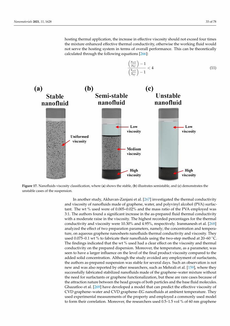
Nanomaterials 2021, 11, 1628 33 of 78
hosting thermal application, the increase in effective viscosity should not exceed four timesthe mixture enhanced effective thermal conductivity, otherwise the working fluid wouldnot serve the hosting system in terms of overall performance. This can be theoreticallycalculated through the following equations [266]:(
µe f fµb f
)− 1( ke f f
kb f
)− 1
< 4 (11)Nanomaterials 2021, 11, x FOR PEER REVIEW 33 of 79
Figure 17. Nanofluids viscosity classification, where (a) shows the stable, (b) illustrates semistable, and (c) demonstrates
the unstable cases of the suspension.
In another study, Akhavan-Zanjani et al. [267] investigated the thermal conductivity
and viscosity of nanofluids made of graphene, water, and polyvinyl alcohol (PVA) sur-
factant. The wt % used were of 0.005–0.02% and the mass ratio of the PVA employed was
3:1. The authors found a significant increase in the as-prepared fluid thermal conductivity
with a moderate raise in the viscosity. The highest recorded percentages for the thermal
conductivity and viscosity were 10.30% and 4.95%, respectively. Iranmanesh et al. [268]
analyzed the effect of two preparation parameters, namely; the concentration and temper-
ature, on aqueous graphene nanosheets nanofluids thermal conductivity and viscosity.
They used 0.075–0.1 wt % to fabricate their nanofluids using the two-step method at 20–
60 °C. The findings indicated that the wt % used had a clear effect on the viscosity and
thermal conductivity on the prepared dispersion. Moreover, the temperature, as a param-
eter, was seen to have a larger influence on the level of the final product viscosity com-
pared to the added solid concentration. Although the study avoided any employment of
surfactants, the authors as-prepared suspension was stable for several days. Such an ob-
servation is not new and was also reported by other researchers, such as Mehrali et al.
[159], where they successfully fabricated stabilized nanofluids made of the graphene–wa-
ter mixture without the need for surfactants or graphene functionalization, but these are
rare cases because of the attraction nature between the head groups of both particles and
the base fluid molecules. Ghazatloo et al. [269] have developed a model that can predict
the effective viscosity of CVD graphene–water and CVD graphene–EG nanofluids at am-
bient temperature. They used experimental measurements of the property and employed
a commonly used model to form their correlation. Moreover, the researchers used 0.5–1.5
vol % of 60 nm graphene sheets with two separate base fluids (i.e., water and EG), after
which the content was subjected to sonication for 45 min. For their water based nanoflu-
ids, a volume ratio of 1.5:1 of SDBS surfactant to solid content was used to physical stabi-
lize the dispersion. The outcome of their research indicated that the effective viscosity
remarkably increased with the raise of vol. %, and hence the concentration as a parameter
had a significant effect on the property. Furthermore, the Batchelor model [270] showed
some deviation from the experimental data of the as-prepared suspensions viscosity. This
Figure 17. Nanofluids viscosity classification, where (a) shows the stable, (b) illustrates semistable, and (c) demonstrates theunstable cases of the suspension.
In another study, Akhavan-Zanjani et al. [267] investigated the thermal conductivityand viscosity of nanofluids made of graphene, water, and polyvinyl alcohol (PVA) surfac-tant. The wt % used were of 0.005–0.02% and the mass ratio of the PVA employed was3:1. The authors found a significant increase in the as-prepared fluid thermal conductivitywith a moderate raise in the viscosity. The highest recorded percentages for the thermalconductivity and viscosity were 10.30% and 4.95%, respectively. Iranmanesh et al. [268]analyzed the effect of two preparation parameters, namely; the concentration and tempera-ture, on aqueous graphene nanosheets nanofluids thermal conductivity and viscosity. Theyused 0.075–0.1 wt % to fabricate their nanofluids using the two-step method at 20–60 ◦C.The findings indicated that the wt % used had a clear effect on the viscosity and thermalconductivity on the prepared dispersion. Moreover, the temperature, as a parameter, wasseen to have a larger influence on the level of the final product viscosity compared to theadded solid concentration. Although the study avoided any employment of surfactants,the authors as-prepared suspension was stable for several days. Such an observation is notnew and was also reported by other researchers, such as Mehrali et al. [159], where theysuccessfully fabricated stabilized nanofluids made of the graphene–water mixture withoutthe need for surfactants or graphene functionalization, but these are rare cases because ofthe attraction nature between the head groups of both particles and the base fluid molecules.Ghazatloo et al. [269] have developed a model that can predict the effective viscosity ofCVD graphene–water and CVD graphene–EG nanofluids at ambient temperature. Theyused experimental measurements of the property and employed a commonly used modelto form their correlation. Moreover, the researchers used 0.5–1.5 vol % of 60 nm graphene
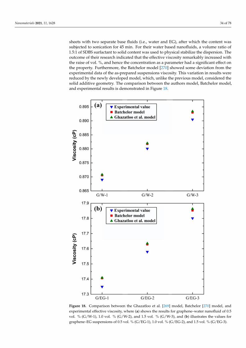
Nanomaterials 2021, 11, 1628 34 of 78
sheets with two separate base fluids (i.e., water and EG), after which the content wassubjected to sonication for 45 min. For their water based nanofluids, a volume ratio of1.5:1 of SDBS surfactant to solid content was used to physical stabilize the dispersion. Theoutcome of their research indicated that the effective viscosity remarkably increased withthe raise of vol. %, and hence the concentration as a parameter had a significant effect onthe property. Furthermore, the Batchelor model [270] showed some deviation from theexperimental data of the as-prepared suspensions viscosity. This variation in results werereduced by the newly developed model, which, unlike the previous model, considered thesolid additive geometry. The comparison between the authors model, Batchelor model,and experimental results is demonstrated in Figure 18.
Nanomaterials 2021, 11, x FOR PEER REVIEW 34 of 79
variation in results were reduced by the newly developed model, which, unlike the pre-
vious model, considered the solid additive geometry. The comparison between the au-
thors model, Batchelor model, and experimental results is demonstrated in Figure 18.
On the other hand, in terms of the effective viscosity theoretical models develop-
ments, Table 5 lists these correlations with their year of development, dependent param-
eters, and limitations. From the formulas shown in Table 5, it can be concluded that most
of the authors have used specific experimental conditions to come up with their correla-
tions, and hence the majority of the models are limited to their operating conditions (i.e.,
they cannot be accounted as universal models).
Figure 18. Comparison between the Ghazatloo et al. [269] model, Batchelor [270] model, and experimental effective vis-
cosity, where (a) shows the results for graphene–water nanofluid of 0.5 vol. % (G/W-1), 1.0 vol. % (G/W-2), and 1.5 vol. %
(G/W-3), and (b) illustrates the values for graphene–EG suspensions of 0.5 vol. % (G/EG-1), 1.0 vol. % (G/EG-2), and 1.5
vol. % (G/EG-3).
Figure 18. Comparison between the Ghazatloo et al. [269] model, Batchelor [270] model, andexperimental effective viscosity, where (a) shows the results for graphene–water nanofluid of 0.5vol. % (G/W-1), 1.0 vol. % (G/W-2), and 1.5 vol. % (G/W-3), and (b) illustrates the values forgraphene–EG suspensions of 0.5 vol. % (G/EG-1), 1.0 vol. % (G/EG-2), and 1.5 vol. % (G/EG-3).
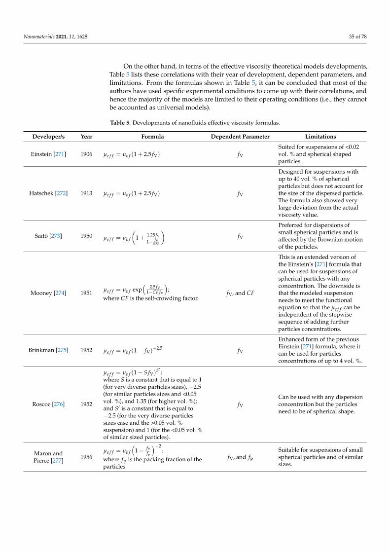
Nanomaterials 2021, 11, 1628 35 of 78
On the other hand, in terms of the effective viscosity theoretical models developments,Table 5 lists these correlations with their year of development, dependent parameters, andlimitations. From the formulas shown in Table 5, it can be concluded that most of theauthors have used specific experimental conditions to come up with their correlations, andhence the majority of the models are limited to their operating conditions (i.e., they cannotbe accounted as universal models).
Table 5. Developments of nanofluids effective viscosity formulas.
Developer/s Year Formula Dependent Parameter Limitations
Einstein [271] 1906 µe f f = µb f (1 + 2.5 fV) fV
Suited for suspensions of <0.02vol. % and spherical shapedparticles.
Hatschek [272] 1913 µe f f = µb f (1 + 2.5 fV) fV
Designed for suspensions withup to 40 vol. % of sphericalparticles but does not account forthe size of the dispersed particle.The formula also showed verylarge deviation from the actualviscosity value.
Saitô [273] 1950 µe f f = µb f
(1 + 1.25 fV
1− fV0.87
)fV
Preferred for dispersions ofsmall spherical particles and isaffected by the Brownian motionof the particles.
Mooney [274] 1951 µe f f = µb f exp(
2.5 fV1−CF fV
);
where CF is the self-crowding factor.fV, and CF
This is an extended version ofthe Einstein’s [271] formula thatcan be used for suspensions ofspherical particles with anyconcentration. The downside isthat the modeled suspensionneeds to meet the functionalequation so that the µe f f can beindependent of the stepwisesequence of adding furtherparticles concentrations.
Brinkman [275] 1952 µe f f = µb f (1− fV)−2.5 fV
Enhanced form of the previousEinstein [271] formula, where itcan be used for particlesconcentrations of up to 4 vol. %.
Roscoe [276] 1952
µe f f = µb f (1− S fV)S′ ;
where S is a constant that is equal to 1(for very diverse particles sizes), −2.5(for similar particles sizes and <0.05vol. %), and 1.35 (for higher vol. %);and S′ is a constant that is equal to−2.5 (for the very diverse particlessizes case and the >0.05 vol. %suspension) and 1 (for the <0.05 vol. %of similar sized particles).
fV
Can be used with any dispersionconcentration but the particlesneed to be of spherical shape.
Maron andPierce [277] 1956
µe f f = µb f
(1− fV
fp
)−2;
where fp is the packing fraction of theparticles.
fV, and fp
Suitable for suspensions of smallspherical particles and of similarsizes.
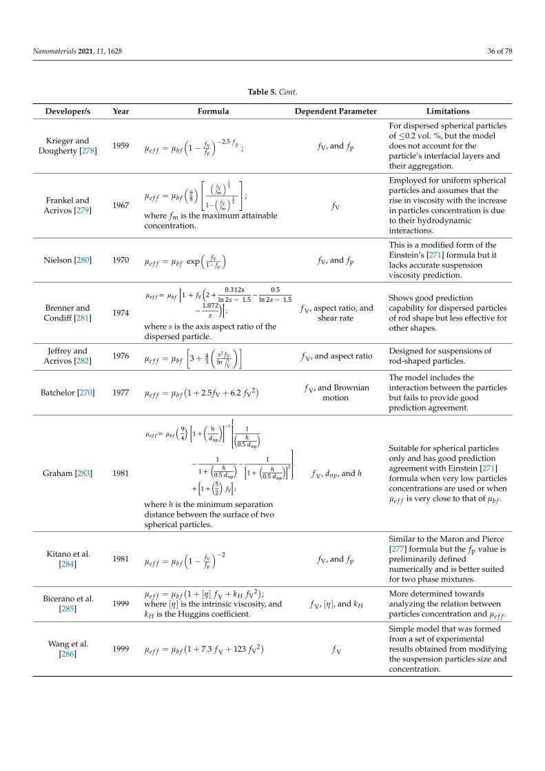
Nanomaterials 2021, 11, 1628 36 of 78
Table 5. Cont.
Developer/s Year Formula Dependent Parameter Limitations
Krieger andDougherty [278] 1959 µe f f = µb f
(1− fV
fp
)−2.5 f p ; fV, and fp
For dispersed spherical particlesof ≤0.2 vol. %, but the modeldoes not account for theparticle’s interfacial layers andtheir aggregation.
Frankel andAcrivos [279] 1967
µe f f = µb f
(98
) (fVfm
) 13
1−(
fVfm
) 13
;
where fm is the maximum attainableconcentration.
fV
Employed for uniform sphericalparticles and assumes that therise in viscosity with the increasein particles concentration is dueto their hydrodynamicinteractions.
Nielson [280] 1970 µe f f = µb f exp(
fV1− fp
)fV, and fp
This is a modified form of theEinstein’s [271] formula but itlacks accurate suspensionviscosity prediction.
Brenner andCondiff [281] 1974
Nanomaterials 2021, 11, x FOR PEER REVIEW 36 of 80
Frankel and Acrivos [279]
1967 μ = μ ƒƒ
ƒƒ ;
where ƒ is the maximum attainable concentration.
ƒEmployed for uniform spherical particles and assumes that the rise in viscosity with the increase in particlesconcentration is due to their hydrodynamic interactions.
Nielson [280] 1970 μ = μ exp ƒ1 − ƒ ƒ , and ƒ This is a modified form of the Einstein’s [271] formula but it lacks accurate suspension viscosity prediction.
Brenner and Condiff [281]
1974
μ = μ 1 + ƒ 2 + 0.312sln 2 − 1.5 − 0.5ln 2 − 1.5− 1.872 ; where is the axis aspect ratio of the dispersed particle.
ƒ , aspect ratio, and shear rate
Shows good prediction capability for dispersed particles of rod shape but less effective for other shapes.
Jeffrey and Acrivos [282]
1976 μ = μ 3 + 43 ƒln πƒ ƒ , and aspect ratio
Designed for suspensions of rod-shaped particles.
Batchelor [270] 1977 μ = μ 1 + 2.5ƒ + 6.2 ƒ
ƒ , and Brownian
motion
The model includes the interaction between the particles but fails to provide good prediction agreement.
Graham [283]
1981
μ = μ 94 1 + h 1ℎ0.5 − 11 + ℎ0.5 − 11 + ℎ0.5 + 1 + 52 ƒ ;
where ℎ is the minimum separation distance between the surface of two spherical particles.
ƒ , , and ℎ
Suitable for spherical particles only and has good prediction agreement with Einstein [271]formula when very low particles concentrations are used or when μ is very close to that of μ .
Kitano et al. [284] 1981 μ = μ 1 − ƒƒ ƒ , and ƒ Similar to the Maron and
Pierce [277] formula but the ƒvalue is preliminarily defined numerically and is better suitedfor two phase mixtures.
Bicerano et al. [285]
1999 μ = μ 1 + ƒ + ƒ ; where is the intrinsic viscosity, and is the Huggins coefficient.
ƒ , , and
More determined towards analyzing the relation between particles concentration andμ .
Wang et al. [286] 1999 μ = μ 1 + 7.3 ƒ + 123 ƒ ƒ
Simple model that was formed from a set of experimental results obtained from modifying the suspension particles size and concentration.
Masoumi et al. [248] 2009 μ = μ + 72 . 12 182 2 ; ƒ , T, ,
particlesize, and
The formula is bound by the experimental conditions that were used in its development.
where s is the axis aspect ratio of thedispersed particle.
f V, aspect ratio, andshear rate
Shows good predictioncapability for dispersed particlesof rod shape but less effective forother shapes.
Jeffrey andAcrivos [282] 1976 µe f f = µb f
[3 + 4
3
(s2 fVln π
fV
)]f V, and aspect ratio Designed for suspensions of
rod-shaped particles.
Batchelor [270] 1977 µe f f = µb f(1 + 2.5 fV + 6.2 fV
2) f V, and Brownianmotion
The model includes theinteraction between the particlesbut fails to provide goodprediction agreement.
Graham [283] 1981
Nanomaterials 2021, 11, x FOR PEER REVIEW 36 of 80
Frankel and Acrivos [279]
1967 μ = μ ƒƒ
ƒƒ ;
where ƒ is the maximum attainable concentration.
ƒEmployed for uniform spherical particles and assumes that the rise in viscosity with the increase in particlesconcentration is due to their hydrodynamic interactions.
Nielson [280] 1970 μ = μ exp ƒ1 − ƒ ƒ , and ƒ This is a modified form of the Einstein’s [271] formula but it lacks accurate suspension viscosity prediction.
Brenner and Condiff [281]
1974
μ = μ 1 + ƒ 2 + 0.312sln 2 − 1.5 − 0.5ln 2 − 1.5− 1.872 ; where is the axis aspect ratio of the dispersed particle.
ƒ , aspect ratio, and shear rate
Shows good prediction capability for dispersed particles of rod shape but less effective for other shapes.
Jeffrey and Acrivos [282]
1976 μ = μ 3 + 43 ƒln πƒ ƒ , and aspect ratio
Designed for suspensions of rod-shaped particles.
Batchelor [270]
1977 μ = μ 1 + 2.5ƒ + 6.2 ƒ ƒ , and
Brownian motion
The model includes the interaction between the particles but fails to provide good prediction agreement.
Graham [283]
1981
μ = μ 94 1 + h 1ℎ0.5
− 11 + ℎ0.5 − 11 + ℎ0.5 52+ 1 + ƒ ; where ℎ is the minimum separation distance between the surface of two spherical particles.
ƒ , , and ℎ
Suitable for spherical particles only and has good prediction agreement with Einstein [271]formula when very low particles concentrations are used or when μ is very close to that of μ .
Kitano et al. [284] 1981 μ = μ 1 − ƒƒ ƒ , and ƒ Similar to the Maron and
Pierce [277] formula but the ƒvalue is preliminarily defined numerically and is better suitedfor two phase mixtures.
Bicerano et al. [285]
1999 μ = μ 1 + ƒ + ƒ ; where is the intrinsic viscosity, and is the Huggins coefficient.
ƒ , , and
More determined towards analyzing the relation between particles concentration andμ .
Wang et al. [286] 1999 μ = μ 1 + 7.3 ƒ + 123 ƒ ƒ
Simple model that was formed from a set of experimental results obtained from modifying the suspension particles size and concentration.
Masoumi et al. [248] 2009 μ = μ + 72 . 12 182 2 ; ƒ , T, ,
particlesize, and
The formula is bound by the experimental conditions that were used in its development.
where h is the minimum separationdistance between the surface of twospherical particles.
f V, dnp, and h
Suitable for spherical particlesonly and has good predictionagreement with Einstein [271]formula when very low particlesconcentrations are used or whenµe f f is very close to that of µb f .
Kitano et al.[284] 1981 µe f f = µb f
(1− fV
fp
)−2 fV, and fp
Similar to the Maron and Pierce[277] formula but the fp value ispreliminarily definednumerically and is better suitedfor two phase mixtures.
Bicerano et al.[285] 1999
µe f f = µb f(1 + [η] f V + kH fV
2);where [η] is the intrinsic viscosity, andkH is the Huggins coefficient.
f V, [η], and kH
More determined towardsanalyzing the relation betweenparticles concentration and µe f f .
Wang et al.[286] 1999 µe f f = µb f
(1 + 7.3 f V + 123 fV
2) f V
Simple model that was formedfrom a set of experimentalresults obtained from modifyingthe suspension particles size andconcentration.
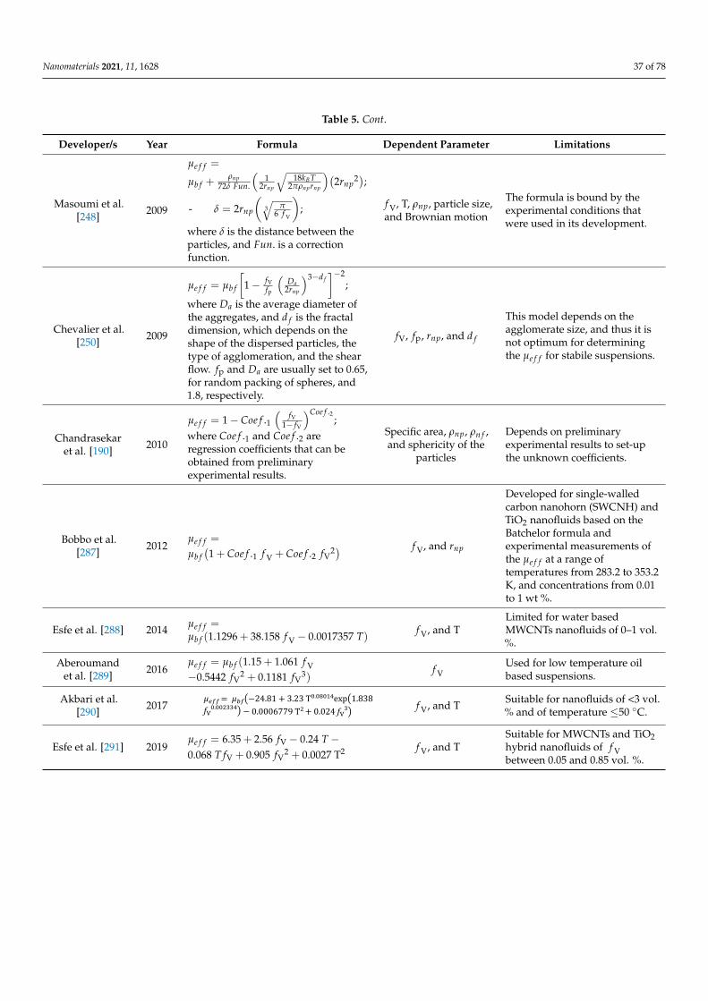
Nanomaterials 2021, 11, 1628 37 of 78
Table 5. Cont.
Developer/s Year Formula Dependent Parameter Limitations
Masoumi et al.[248] 2009
µe f f =
µb f +ρnp
72δ Fun.
(1
2rnp
√18kBT
2πρnprnp
)(2rnp
2);- δ = 2rnp
(3√
π6 f V
);
where δ is the distance between theparticles, and Fun. is a correctionfunction.
f V, T, ρnp, particle size,and Brownian motion
The formula is bound by theexperimental conditions thatwere used in its development.
Chevalier et al.[250] 2009
µe f f = µb f
[1− fV
fp
(Da
2rnp
)3−d f]−2
;
where Da is the average diameter ofthe aggregates, and d f is the fractaldimension, which depends on theshape of the dispersed particles, thetype of agglomeration, and the shearflow. fp and Da are usually set to 0.65,for random packing of spheres, and1.8, respectively.
fV, fp, rnp, and d f
This model depends on theagglomerate size, and thus it isnot optimum for determiningthe µe f f for stabile suspensions.
Chandrasekaret al. [190] 2010
µe f f = 1− Coe f .1(
fV1− fV
)Coe f .2;
where Coe f .1 and Coe f .2 areregression coefficients that can beobtained from preliminaryexperimental results.
Specific area, ρnp, ρn f ,and sphericity of the
particles
Depends on preliminaryexperimental results to set-upthe unknown coefficients.
Bobbo et al.[287] 2012
µe f f =
µb f(1 + Coe f .1 f V + Coe f .2 fV
2) f V, and rnp
Developed for single-walledcarbon nanohorn (SWCNH) andTiO2 nanofluids based on theBatchelor formula andexperimental measurements ofthe µe f f at a range oftemperatures from 283.2 to 353.2K, and concentrations from 0.01to 1 wt %.
Esfe et al. [288] 2014 µe f f =µb f (1.1296 + 38.158 f V − 0.0017357 T) f V, and T
Limited for water basedMWCNTs nanofluids of 0–1 vol.%.
Aberoumandet al. [289] 2016
µe f f = µb f (1.15 + 1.061 f V−0.5442 fV
2 + 0.1181 fV3)
f VUsed for low temperature oilbased suspensions.
Akbari et al.[290] 2017
Nanomaterials 2021, 11, x FOR PEER REVIEW 37 of 80
- = 2 ƒ ;
where is the distance between the particles, and . is a correction function.
Brownian motion
Chevalier et al. [250]
2009
μ = μ 1 − ƒƒ 2 ; where is the average diameter of the aggregates, and is the fractal dimension, which depends on the shape of the dispersed particles, the type of agglomeration, and the shear flow. ƒ and are usually set to 0.65, for random packing of spheres, and 1.8, respectively.
ƒ , ƒ , , and
This model depends on the agglomerate size, and thus it is not optimum for determining the μ for stabile suspensions.
Chandrasekar et al. [190]
2010
μ = 1 − . ƒ1 − ƒ . ; where . and . are regression coefficients that can be obtained from preliminary experimentalresults.
Specific area, ,
, and sphericity
of the particles
Depends on preliminary experimental results to set-up the unknown coefficients.
Bobbo et al. [287]
2012 μ = μ 1 + . ƒ + . ƒ ƒ , and
Developed for single-walled carbon nanohorn (SWCNH) and TiO2 nanofluids based on the Batchelor formula and experimental measurements of the μ at a range of temperatures from 283.2 to353.2 K, and concentrationsfrom 0.01 to 1 wt %.
Esfe et al. [288]
2014 μ = μ (1.1296 + 38.158 ƒ − 0.0017357 ) ƒ , and T
Limited for water based MWCNTs nanofluids of 0–1 vol. %.
Aberoumand et al. [289]
2016 μ = μ 1.15 + 1.061 ƒ − 0.5442 ƒ + 0.1181 ƒ ƒ Used for low temperature oil based suspensions.
Akbari et al. [290]
2017 μ = μ −24.81 + 3.23 T . exp 1.838 ƒ . − 0.0006779 T + 0.024 ƒ ƒ , and T
Suitable for nanofluids of < 3 vol. % and of temperature ≤50 °C.
Esfe et al. [291]
2019 μ = 6.35 + 2.56 ƒ − 0.24 − 0.068 ƒ + 0.905 ƒ+ 0.0027 T ƒ , and T
Suitable for MWCNTs and TiO2 hybrid nanofluids of ƒ between 0.05 and 0.85 vol. %.
Ansón-Casaos et al.
[292] 2020
μ = μ 1 − χ2 ƒ ; where χ is equal to 2.5 for spherical particles or can bereplaced by a function, , to determine the suspension property containing 1D and 2D dispersed solids.
ƒ , and χ Suitable for SWCNTs and graphene oxide.
Ilyas et al. [154]
2020
μ = μ exp .− . + . ƒ exp .− . ƒ ; where . , . , and . are the temperature fitting parameters in Kelvin, whereas . and . are the dynamic viscosity fitting parameters in Pa.s. The values
ƒ , and
Suitable for ND dispersed in thermal oil and is valid for the range of 0 ≤ ƒ ≤ 1 and 298.65 ≤T (K) ≤ 338.15.
f V, and T Suitable for nanofluids of <3 vol.% and of temperature ≤50 ◦C.
Esfe et al. [291] 2019µe f f = 6.35 + 2.56 fV − 0.24 T −0.068 T fV + 0.905 fV
2 + 0.0027 T2 f V, and TSuitable for MWCNTs and TiO2hybrid nanofluids of f Vbetween 0.05 and 0.85 vol. %.
Nanomaterials 2021, 11, 1628 38 of 78
Table 5. Cont.
Developer/s Year Formula Dependent Parameter Limitations
Ansón-Casaoset al. [292] 2020
µe f f = µb f(1− χ
2 fV)−2;
where χ is equal to 2.5 for sphericalparticles or can be replaced by afunction, f
(rnp), to determine the
suspension property containing 1Dand 2D dispersed solids.
f V, and χ Suitable for SWCNTs andgraphene oxide.
Ilyas et al. [154] 2020
µe f f = µb f exp(
FP.1T−FP.2
)+
FP.3 fV exp(
FP.4T
)− FP.5 fV
2;where FP.1, FP.2, and FP.4 are thetemperature fitting parameters inKelvin, whereas FP.3 and FP.5 are thedynamic viscosity fitting parametersin Pa.s. The values of theseparameters (i.e., FP.1 to FP.5) can befound in the published source.
f V, FP and T
Suitable for ND dispersed inthermal oil and is valid for therange of 0 ≤ fV ≤ 1 and 298.65≤ T (K) ≤ 338.15.
6. Thermal Applications
The previous sections showed how dispersing carbon-based nanomaterials in conven-tional working fluids could positively affect these liquids properties, especially when itcomes to their overall thermal conductivity. On the contrary, this section concentrates on uti-lizing carbon-based suspensions in three heat and mass transfer systems widely used in theenergy sector, namely, PTSCs, nuclear reactors systems, and AC&R systems. This is becausethe previous attempts that many researchers undertook to enhance the performance of thesesystems were mainly through design modifications, such as adding turbulators, geometricand construction materials variations, and surface alterations. However, these techniqueshave reached a point where limited enhancements can be accomplished. Therefore, tobreak these boundaries for further progress, some scientists have proposed exchangingthe working fluids of these thermal applications with nanofluids [293]. This is becauseemploying a working fluid that possesses higher thermal conductivity would eventuallyimprove the heat transfer rate in these systems, as will be demonstrated next.
6.1. Parabolic Trough Solar Collectors
A PTSC is part of the existing energy solar systems that utilizes solar radiation (usuallyemitted from the sun) to generate thermal energy with high efficiency [294]. This happenswhen reflecting concentrated incident sunlight from its reflector surface, which consists ofa parabolically curved mirror polished metal, to a focal line where the receiver or absorbertube containing the working fluid is located. The lower temperature heat transfer fluid,which is usually water or oil, then absorbs the solar heat flux from the attached innertube surface, and thus causes its temperature to raise. Figure 19 shows an example ofa real life PTSC system and its working mechanism in a schematic diagram. Based onthe system configuration and the application used, the working fluid temperature in aPTSC can exceed 500 ◦C at concentrated solar power plants (CSPP), for steam powercycles; or can be lower than 100 ◦C, for industrial process heat (IPH) applications, such asdomestic and industrial water heating [295]. Examples of low temperature requirements(i.e., temperature starting from ≤100 ◦C) for different industrial processes are shown inTable 6 [296]. Most of the modern designs of PTSC contain a sunlight tracking system thathelps improve the efficiency of these systems [297].
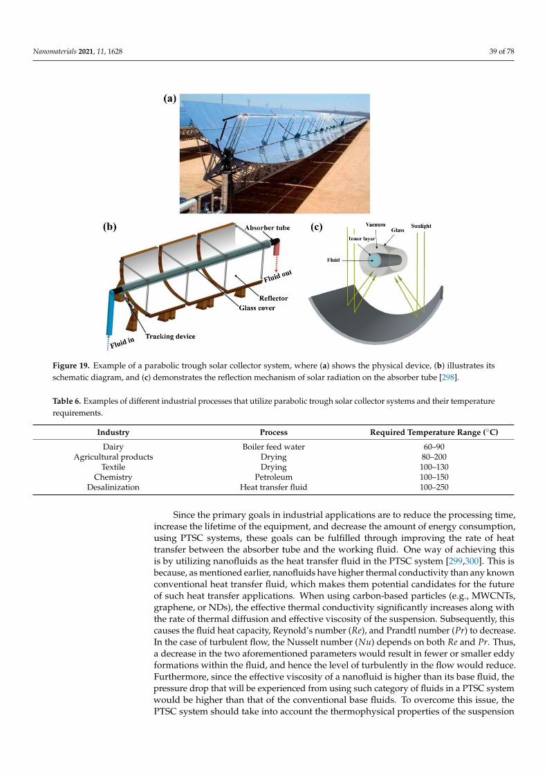
Nanomaterials 2021, 11, 1628 39 of 78Nanomaterials 2021, 11, x FOR PEER REVIEW 39 of 79
Figure 19. Example of a parabolic trough solar collector system, where (a) shows the physical device,
(b) illustrates its schematic diagram, and (c) demonstrates the reflection mechanism of solar radia-
tion on the absorber tube [298].
Table 6. Examples of different industrial processes that utilize parabolic trough solar collector systems and their temper-
ature requirements.
Industry Process Required Temperature Range (°C)
Dairy Boiler feed water 60–90
Agricultural products Drying 80–200
Textile Drying 100–130
Chemistry Petroleum 100–150
Desalinization Heat transfer fluid 100–250
Since the primary goals in industrial applications are to reduce the processing time,
increase the lifetime of the equipment, and decrease the amount of energy consumption,
using PTSC systems, these goals can be fulfilled through improving the rate of heat trans-
fer between the absorber tube and the working fluid. One way of achieving this is by uti-
lizing nanofluids as the heat transfer fluid in the PTSC system [299,300]. This is because,
as mentioned earlier, nanofluids have higher thermal conductivity than any known con-
ventional heat transfer fluid, which makes them potential candidates for the future of such
heat transfer applications. When using carbon-based particles (e.g., MWCNTs, graphene,
or NDs), the effective thermal conductivity significantly increases along with the rate of
thermal diffusion and effective viscosity of the suspension. Subsequently, this causes the
fluid heat capacity, Reynold’s number (𝑅𝑒), and Prandtl number (𝑃𝑟) to decrease. In the
case of turbulent flow, the Nusselt number (𝑁𝑢) depends on both 𝑅𝑒 and 𝑃𝑟. Thus, a
decrease in the two aforementioned parameters would result in fewer or smaller eddy
formations within the fluid, and hence the level of turbulently in the flow would reduce.
Furthermore, since the effective viscosity of a nanofluid is higher than its base fluid, the
pressure drop that will be experienced from using such category of fluids in a PTSC sys-
tem would be higher than that of the conventional base fluids. To overcome this issue, the
PTSC system should take into account the thermophysical properties of the suspension
Figure 19. Example of a parabolic trough solar collector system, where (a) shows the physical device, (b) illustrates itsschematic diagram, and (c) demonstrates the reflection mechanism of solar radiation on the absorber tube [298].
Table 6. Examples of different industrial processes that utilize parabolic trough solar collector systems and their temperaturerequirements.
Industry Process Required Temperature Range (◦C)
Dairy Boiler feed water 60–90Agricultural products Drying 80–200
Textile Drying 100–130Chemistry Petroleum 100–150
Desalinization Heat transfer fluid 100–250
Since the primary goals in industrial applications are to reduce the processing time,increase the lifetime of the equipment, and decrease the amount of energy consumption,using PTSC systems, these goals can be fulfilled through improving the rate of heattransfer between the absorber tube and the working fluid. One way of achieving thisis by utilizing nanofluids as the heat transfer fluid in the PTSC system [299,300]. This isbecause, as mentioned earlier, nanofluids have higher thermal conductivity than any knownconventional heat transfer fluid, which makes them potential candidates for the futureof such heat transfer applications. When using carbon-based particles (e.g., MWCNTs,graphene, or NDs), the effective thermal conductivity significantly increases along withthe rate of thermal diffusion and effective viscosity of the suspension. Subsequently, thiscauses the fluid heat capacity, Reynold’s number (Re), and Prandtl number (Pr) to decrease.In the case of turbulent flow, the Nusselt number (Nu) depends on both Re and Pr. Thus,a decrease in the two aforementioned parameters would result in fewer or smaller eddyformations within the fluid, and hence the level of turbulently in the flow would reduce.Furthermore, since the effective viscosity of a nanofluid is higher than its base fluid, thepressure drop that will be experienced from using such category of fluids in a PTSC systemwould be higher than that of the conventional base fluids. To overcome this issue, thePTSC system should take into account the thermophysical properties of the suspension
Nanomaterials 2021, 11, 1628 40 of 78
used at its design phase. One important thing to consider is that when using nanofluids, asthe PTSC working fluid, the absorber tube needs to be transparent so that the dispersedparticles can directly absorb the sunlight throughout their cycle [301].
Although the previous facts showed how promising nanofluids could be when usedin PTSC systems, the scientific field is still scarce with the amount of published worksthat investigate carbon-based nanofluids in such system. Most of the work covered onnanofluids were those involving nanoparticles of Al2O3, CuO, TiO2, Fe2O3, SiO2, Cu, SiC,Fe3O4, and limited other literature were found for CNTs, MWCNTs, and SWCNTs [298]. Forinstance, Kasaeian et al. [302] explored the overall efficiency enhancement of a pilot PTSCsystem using MWCNTs–mineral oil suspensions of 0.1 wt % and 0.3 wt %. The researchersfound that the 0.1 wt % and 0.3 wt % dispersions had improved the system efficiencyby 4–5% and 5–7%, respectively, compared to conventional base fluid (i.e., mineral oil).Furthermore, Kasaeian et al. [303] studied the effect of 0.1, 0.2, and 0.3 vol. % of MWCNTsdispersed in EG, as the working fluid, for a direct absorber solar collector attached to aparabolic trough. They found that the optical efficiency reached up to 71.4%, due to the0.3 vol. % of MWCNTs particles employed in their heat transfer fluid. In addition, thethermal efficiency of their system was found to be 17% higher, when using the 0.3 vol. %nanofluid, than that obtained from pure EG. Moreover, Mwesigye et al. [304] coupled aMonte Carlo ray tracing (MCRT) optical model along with a computational fluid dynamics(CFD) finite volume method (FVM)-based model to analyze a PTSC, hosting a SWCNTs–Therminon VP-1 suspension, thermal performance. The authors found that raising theparticles concentration from 0 to 2.5 vol. % caused the entropy generation to reduce by70%, with the heat transfer rate to increase by 234%, and the thermal efficiency of thesystem to improve by 4.4%. In addition, Dugaria et al. [305] designed and modeled theoptical efficiency of a direct absorber solar collector (DASC) that is connected to a parabolictrough system. In their experiment, they used 0.006, 0.01, 0.02, and 0.05 g/L of SWCNTs tofabricate their aqueous nanofluids. Their results showed that increasing the nanoparticlesconcentration to more than 0.05 g/L would cause the thermal efficiency to reduce due tothe thermal radiation being mostly contained in the surrounding area between the absorbertube inner surface and the nanofluid. In addition, using nanofluids made of 0.05 g/LSWCNTs caused the thermal efficiency of the system, including the optical losses of theconcentrating trough, to reach 90.6% at a reduced temperature range (T∗m) = 0 K·m2/Wand 77.2% at T∗m = 0.128 K·m2/W. It is important to note that the thermal efficiency of solarcollectors is usually shown in a graph as a function of T∗m, which is defined for the case ofnanofluids as:
T∗m =
(Tmn f − Tamb
)DNI
(12)
where Tmn f , Tamb, and DNI are the mean temperature of the nanofluid, ambient air temper-ature, and direct normal irradiance, respectively. One of the main aspects for the enhance-ment in the thermal performance of the two aforementioned published works [304,305] wasdue to the fact that CNTs, along with other carbon-based materials, possessed extremelyhigh solar absorption characteristics (i.e., more than 90%) [306]. Despite the research investi-gations that were covered in this section on carbon-based nanofluids usage in PTSC’s, thereare only a few other alternatives [298]. To the best of the authors of this article knowledge,there is still a lack of exploration on utilizing ND’s and graphene nanofluids for PTSC’s.This shows that further investigation is required from the researchers working in the so-lar energy field; especially since, for example, nanofluids of ND base showed to containremarkable optical and thermal properties when studied in other similar applications [307].
6.2. Nuclear Reactors
Nuclear power plants are part of the energy network that has been adopted by manycountries across the globe, such as France, USA, UK, Russia, Iran, and UAE, among othersto support their growth in energy demands [308]. Unlike most energy sources, the powerproduced from the fission process of the fuel (i.e., enriched uranium or plutonium) within
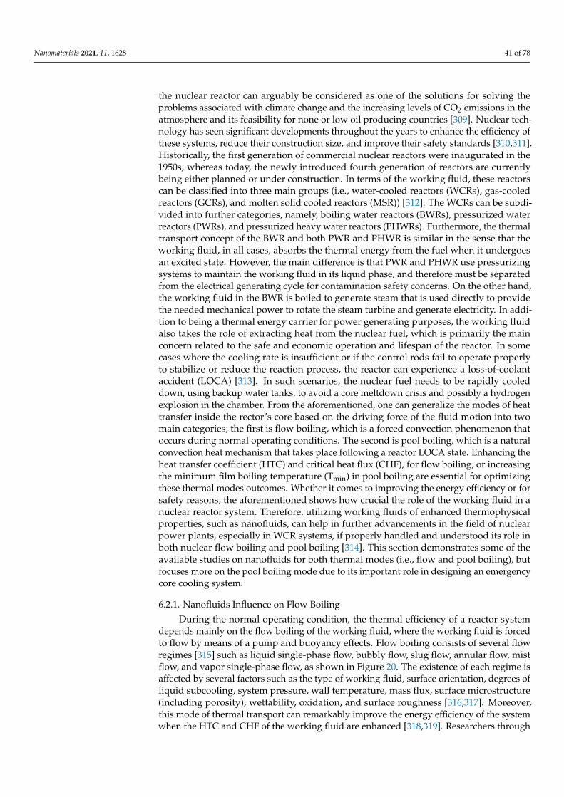
Nanomaterials 2021, 11, 1628 41 of 78
the nuclear reactor can arguably be considered as one of the solutions for solving theproblems associated with climate change and the increasing levels of CO2 emissions in theatmosphere and its feasibility for none or low oil producing countries [309]. Nuclear tech-nology has seen significant developments throughout the years to enhance the efficiency ofthese systems, reduce their construction size, and improve their safety standards [310,311].Historically, the first generation of commercial nuclear reactors were inaugurated in the1950s, whereas today, the newly introduced fourth generation of reactors are currentlybeing either planned or under construction. In terms of the working fluid, these reactorscan be classified into three main groups (i.e., water-cooled reactors (WCRs), gas-cooledreactors (GCRs), and molten solid cooled reactors (MSR)) [312]. The WCRs can be subdi-vided into further categories, namely, boiling water reactors (BWRs), pressurized waterreactors (PWRs), and pressurized heavy water reactors (PHWRs). Furthermore, the thermaltransport concept of the BWR and both PWR and PHWR is similar in the sense that theworking fluid, in all cases, absorbs the thermal energy from the fuel when it undergoesan excited state. However, the main difference is that PWR and PHWR use pressurizingsystems to maintain the working fluid in its liquid phase, and therefore must be separatedfrom the electrical generating cycle for contamination safety concerns. On the other hand,the working fluid in the BWR is boiled to generate steam that is used directly to providethe needed mechanical power to rotate the steam turbine and generate electricity. In addi-tion to being a thermal energy carrier for power generating purposes, the working fluidalso takes the role of extracting heat from the nuclear fuel, which is primarily the mainconcern related to the safe and economic operation and lifespan of the reactor. In somecases where the cooling rate is insufficient or if the control rods fail to operate properlyto stabilize or reduce the reaction process, the reactor can experience a loss-of-coolantaccident (LOCA) [313]. In such scenarios, the nuclear fuel needs to be rapidly cooleddown, using backup water tanks, to avoid a core meltdown crisis and possibly a hydrogenexplosion in the chamber. From the aforementioned, one can generalize the modes of heattransfer inside the rector’s core based on the driving force of the fluid motion into twomain categories; the first is flow boiling, which is a forced convection phenomenon thatoccurs during normal operating conditions. The second is pool boiling, which is a naturalconvection heat mechanism that takes place following a reactor LOCA state. Enhancing theheat transfer coefficient (HTC) and critical heat flux (CHF), for flow boiling, or increasingthe minimum film boiling temperature (Tmin) in pool boiling are essential for optimizingthese thermal modes outcomes. Whether it comes to improving the energy efficiency or forsafety reasons, the aforementioned shows how crucial the role of the working fluid in anuclear reactor system. Therefore, utilizing working fluids of enhanced thermophysicalproperties, such as nanofluids, can help in further advancements in the field of nuclearpower plants, especially in WCR systems, if properly handled and understood its role inboth nuclear flow boiling and pool boiling [314]. This section demonstrates some of theavailable studies on nanofluids for both thermal modes (i.e., flow and pool boiling), butfocuses more on the pool boiling mode due to its important role in designing an emergencycore cooling system.
6.2.1. Nanofluids Influence on Flow Boiling
During the normal operating condition, the thermal efficiency of a reactor systemdepends mainly on the flow boiling of the working fluid, where the working fluid is forcedto flow by means of a pump and buoyancy effects. Flow boiling consists of several flowregimes [315] such as liquid single-phase flow, bubbly flow, slug flow, annular flow, mistflow, and vapor single-phase flow, as shown in Figure 20. The existence of each regime isaffected by several factors such as the type of working fluid, surface orientation, degrees ofliquid subcooling, system pressure, wall temperature, mass flux, surface microstructure(including porosity), wettability, oxidation, and surface roughness [316,317]. Moreover,this mode of thermal transport can remarkably improve the energy efficiency of the systemwhen the HTC and CHF of the working fluid are enhanced [318,319]. Researchers through
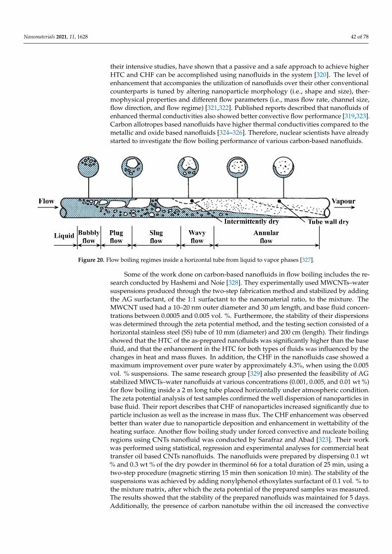
Nanomaterials 2021, 11, 1628 42 of 78
their intensive studies, have shown that a passive and a safe approach to achieve higherHTC and CHF can be accomplished using nanofluids in the system [320]. The level ofenhancement that accompanies the utilization of nanofluids over their other conventionalcounterparts is tuned by altering nanoparticle morphology (i.e., shape and size), ther-mophysical properties and different flow parameters (i.e., mass flow rate, channel size,flow direction, and flow regime) [321,322]. Published reports described that nanofluids ofenhanced thermal conductivities also showed better convective flow performance [319,323].Carbon allotropes based nanofluids have higher thermal conductivities compared to themetallic and oxide based nanofluids [324–326]. Therefore, nuclear scientists have alreadystarted to investigate the flow boiling performance of various carbon-based nanofluids.
Nanomaterials 2021, 11, x FOR PEER REVIEW 42 of 79
Moreover, this mode of thermal transport can remarkably improve the energy efficiency
of the system when the HTC and CHF of the working fluid are enhanced [318,319]. Re-
searchers through their intensive studies, have shown that a passive and a safe approach
to achieve higher HTC and CHF can be accomplished using nanofluids in the system
[320]. The level of enhancement that accompanies the utilization of nanofluids over their
other conventional counterparts is tuned by altering nanoparticle morphology (i.e., shape
and size), thermophysical properties and different flow parameters (i.e., mass flow rate,
channel size, flow direction, and flow regime) [321,322]. Published reports described that
nanofluids of enhanced thermal conductivities also showed better convective flow perfor-
mance [319,323]. Carbon allotropes based nanofluids have higher thermal conductivities
compared to the metallic and oxide based nanofluids [324–326]. Therefore, nuclear scien-
tists have already started to investigate the flow boiling performance of various carbon-
based nanofluids.
Figure 20. Flow boiling regimes inside a horizontal tube from liquid to vapor phases [327].
Some of the work done on carbon-based nanofluids in flow boiling includes the re-
search conducted by Hashemi and Noie [328]. They experimentally used MWCNTs–water
suspensions produced through the two-step fabrication method and stabilized by adding
the AG surfactant, of the 1:1 surfactant to the nanomaterial ratio, to the mixture. The
MWCNT used had a 10–20 nm outer diameter and 30 µm length, and base fluid concen-
trations between 0.0005 and 0.005 vol. %. Furthermore, the stability of their dispersions
was determined through the zeta potential method, and the testing section consisted of a
horizontal stainless steel (SS) tube of 10 mm (diameter) and 200 cm (length). Their findings
showed that the HTC of the as-prepared nanofluids was significantly higher than the base
fluid, and that the enhancement in the HTC for both types of fluids was influenced by the
changes in heat and mass fluxes. In addition, the CHF in the nanofluids case showed a
maximum improvement over pure water by approximately 4.3%, when using the 0.005
vol. % suspensions. The same research group [329] also presented the feasibility of AG
stabilized MWCTs–water nanofluids at various concentrations (0.001, 0.005, and 0.01 wt
%) for flow boiling inside a 2 m long tube placed horizontally under atmospheric condi-
tion. The zeta potential analysis of test samples confirmed the well dispersion of nanopar-
ticles in base fluid. Their report describes that CHF of nanoparticles increased significantly
due to particle inclusion as well as the increase in mass flux. The CHF enhancement was
observed better than water due to nanoparticle deposition and enhancement in wettability
of the heating surface. Another flow boiling study under forced convective and nucleate
boiling regions using CNTs nanofluid was conducted by Sarafraz and Abad [323]. Their
work was performed using statistical, regression and experimental analyses for commer-
cial heat transfer oil based CNTs nanofluids. The nanofluids were prepared by dispersing
0.1 wt % and 0.3 wt % of the dry powder in therminol 66 for a total duration of 25 min,
using a two-step procedure (magnetic stirring 15 min then sonication 10 min). The stabil-
ity of the suspensions was achieved by adding nonylphenol ethoxylates surfactant of 0.1
Figure 20. Flow boiling regimes inside a horizontal tube from liquid to vapor phases [327].
Some of the work done on carbon-based nanofluids in flow boiling includes the re-search conducted by Hashemi and Noie [328]. They experimentally used MWCNTs–watersuspensions produced through the two-step fabrication method and stabilized by addingthe AG surfactant, of the 1:1 surfactant to the nanomaterial ratio, to the mixture. TheMWCNT used had a 10–20 nm outer diameter and 30 µm length, and base fluid concen-trations between 0.0005 and 0.005 vol. %. Furthermore, the stability of their dispersionswas determined through the zeta potential method, and the testing section consisted of ahorizontal stainless steel (SS) tube of 10 mm (diameter) and 200 cm (length). Their findingsshowed that the HTC of the as-prepared nanofluids was significantly higher than the basefluid, and that the enhancement in the HTC for both types of fluids was influenced by thechanges in heat and mass fluxes. In addition, the CHF in the nanofluids case showed amaximum improvement over pure water by approximately 4.3%, when using the 0.005vol. % suspensions. The same research group [329] also presented the feasibility of AGstabilized MWCTs–water nanofluids at various concentrations (0.001, 0.005, and 0.01 wt %)for flow boiling inside a 2 m long tube placed horizontally under atmospheric condition.The zeta potential analysis of test samples confirmed the well dispersion of nanoparticles inbase fluid. Their report describes that CHF of nanoparticles increased significantly due toparticle inclusion as well as the increase in mass flux. The CHF enhancement was observedbetter than water due to nanoparticle deposition and enhancement in wettability of theheating surface. Another flow boiling study under forced convective and nucleate boilingregions using CNTs nanofluid was conducted by Sarafraz and Abad [323]. Their workwas performed using statistical, regression and experimental analyses for commercial heattransfer oil based CNTs nanofluids. The nanofluids were prepared by dispersing 0.1 wt% and 0.3 wt % of the dry powder in therminol 66 for a total duration of 25 min, using atwo-step procedure (magnetic stirring 15 min then sonication 10 min). The stability of thesuspensions was achieved by adding nonylphenol ethoxylates surfactant of 0.1 vol. % tothe mixture matrix, after which the zeta potential of the prepared samples was measured.The results showed that the stability of the prepared nanofluids was maintained for 5 days.Additionally, the presence of carbon nanotube within the oil increased the convective
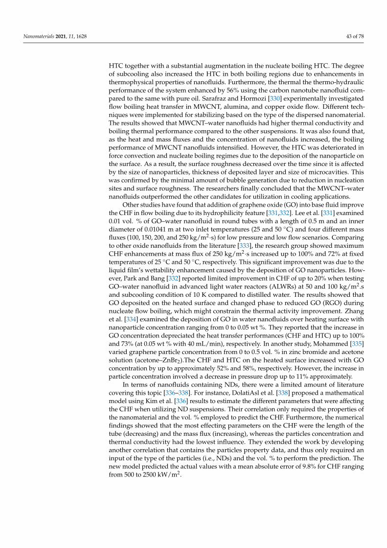
Nanomaterials 2021, 11, 1628 43 of 78
HTC together with a substantial augmentation in the nucleate boiling HTC. The degreeof subcooling also increased the HTC in both boiling regions due to enhancements inthermophysical properties of nanofluids. Furthermore, the thermal the thermo-hydraulicperformance of the system enhanced by 56% using the carbon nanotube nanofluid com-pared to the same with pure oil. Sarafraz and Hormozi [330] experimentally investigatedflow boiling heat transfer in MWCNT, alumina, and copper oxide flow. Different tech-niques were implemented for stabilizing based on the type of the dispersed nanomaterial.The results showed that MWCNT–water nanofluids had higher thermal conductivity andboiling thermal performance compared to the other suspensions. It was also found that,as the heat and mass fluxes and the concentration of nanofluids increased, the boilingperformance of MWCNT nanofluids intensified. However, the HTC was deteriorated inforce convection and nucleate boiling regimes due to the deposition of the nanoparticle onthe surface. As a result, the surface roughness decreased over the time since it is affectedby the size of nanoparticles, thickness of deposited layer and size of microcavities. Thiswas confirmed by the minimal amount of bubble generation due to reduction in nucleationsites and surface roughness. The researchers finally concluded that the MWCNT–waternanofluids outperformed the other candidates for utilization in cooling applications.
Other studies have found that addition of graphene oxide (GO) into base fluid improvethe CHF in flow boiling due to its hydrophilicity feature [331,332]. Lee et al. [331] examined0.01 vol. % of GO–water nanofluid in round tubes with a length of 0.5 m and an innerdiameter of 0.01041 m at two inlet temperatures (25 and 50 ◦C) and four different massfluxes (100, 150, 200, and 250 kg/m2·s) for low pressure and low flow scenarios. Comparingto other oxide nanofluids from the literature [333], the research group showed maximumCHF enhancements at mass flux of 250 kg/m2·s increased up to 100% and 72% at fixedtemperatures of 25 ◦C and 50 ◦C, respectively. This significant improvement was due to theliquid film’s wettability enhancement caused by the deposition of GO nanoparticles. How-ever, Park and Bang [332] reported limited improvement in CHF of up to 20% when testingGO–water nanofluid in advanced light water reactors (ALWRs) at 50 and 100 kg/m2.sand subcooling condition of 10 K compared to distilled water. The results showed thatGO deposited on the heated surface and changed phase to reduced GO (RGO) duringnucleate flow boiling, which might constrain the thermal activity improvement. Zhanget al. [334] examined the deposition of GO in water nanofluids over heating surface withnanoparticle concentration ranging from 0 to 0.05 wt %. They reported that the increase inGO concentration depreciated the heat transfer performances (CHF and HTC) up to 100%and 73% (at 0.05 wt % with 40 mL/min), respectively. In another study, Mohammed [335]varied graphene particle concentration from 0 to 0.5 vol. % in zinc bromide and acetonesolution (acetone–ZnBr2).The CHF and HTC on the heated surface increased with GOconcentration by up to approximately 52% and 58%, respectively. However, the increase inparticle concentration involved a decrease in pressure drop up to 11% approximately.
In terms of nanofluids containing NDs, there were a limited amount of literaturecovering this topic [336–338]. For instance, DolatiAsl et al. [338] proposed a mathematicalmodel using Kim et al. [336] results to estimate the different parameters that were affectingthe CHF when utilizing ND suspensions. Their correlation only required the properties ofthe nanomaterial and the vol. % employed to predict the CHF. Furthermore, the numericalfindings showed that the most effecting parameters on the CHF were the length of thetube (decreasing) and the mass flux (increasing), whereas the particles concentration andthermal conductivity had the lowest influence. They extended the work by developinganother correlation that contains the particles property data, and thus only required aninput of the type of the particles (i.e., NDs) and the vol. % to perform the prediction. Thenew model predicted the actual values with a mean absolute error of 9.8% for CHF rangingfrom 500 to 2500 kW/m2.
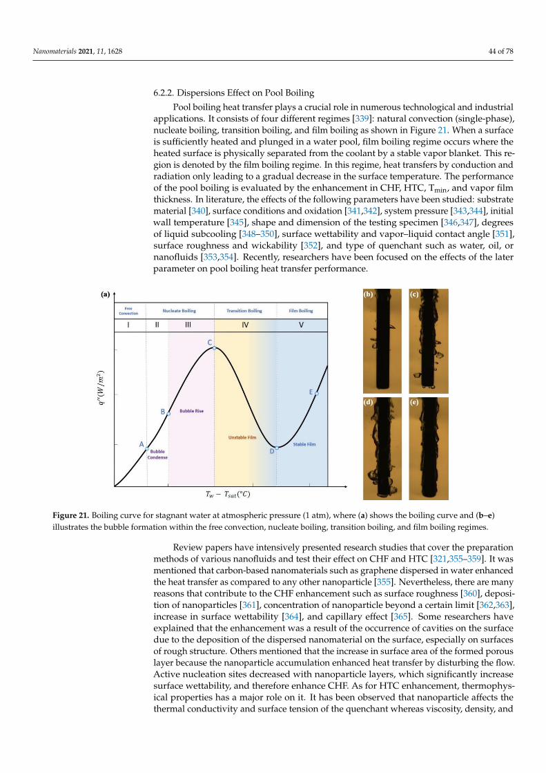
Nanomaterials 2021, 11, 1628 44 of 78
6.2.2. Dispersions Effect on Pool Boiling
Pool boiling heat transfer plays a crucial role in numerous technological and industrialapplications. It consists of four different regimes [339]: natural convection (single-phase),nucleate boiling, transition boiling, and film boiling as shown in Figure 21. When a surfaceis sufficiently heated and plunged in a water pool, film boiling regime occurs where theheated surface is physically separated from the coolant by a stable vapor blanket. This re-gion is denoted by the film boiling regime. In this regime, heat transfers by conduction andradiation only leading to a gradual decrease in the surface temperature. The performanceof the pool boiling is evaluated by the enhancement in CHF, HTC, Tmin, and vapor filmthickness. In literature, the effects of the following parameters have been studied: substratematerial [340], surface conditions and oxidation [341,342], system pressure [343,344], initialwall temperature [345], shape and dimension of the testing specimen [346,347], degreesof liquid subcooling [348–350], surface wettability and vapor–liquid contact angle [351],surface roughness and wickability [352], and type of quenchant such as water, oil, ornanofluids [353,354]. Recently, researchers have been focused on the effects of the laterparameter on pool boiling heat transfer performance.
Nanomaterials 2021, 11, x FOR PEER REVIEW 44 of 79
quired an input of the type of the particles (i.e., NDs) and the vol. % to perform the pre-
diction. The new model predicted the actual values with a mean absolute error of 9.8% for
CHF ranging from 500 to 2500 kW/m2.
6.2.2. Dispersions Effect on Pool Boiling
Pool boiling heat transfer plays a crucial role in numerous technological and indus-
trial applications. It consists of four different regimes [339]: natural convection (single-
phase), nucleate boiling, transition boiling, and film boiling as shown in Figure 21. When
a surface is sufficiently heated and plunged in a water pool, film boiling regime occurs
where the heated surface is physically separated from the coolant by a stable vapor blan-
ket. This region is denoted by the film boiling regime. In this regime, heat transfers by
conduction and radiation only leading to a gradual decrease in the surface temperature.
The performance of the pool boiling is evaluated by the enhancement in CHF, HTC, Tmin,
and vapor film thickness. In literature, the effects of the following parameters have been
studied: substrate material [340], surface conditions and oxidation [341,342], system pres-
sure [343,344], initial wall temperature [345], shape and dimension of the testing specimen
[346,347], degrees of liquid subcooling [348–350], surface wettability and vapor–liquid
contact angle [351], surface roughness and wickability [352], and type of quenchant such
as water, oil, or nanofluids [353,354]. Recently, researchers have been focused on the ef-
fects of the later parameter on pool boiling heat transfer performance.
Figure 21. Boiling curve for stagnant water at atmospheric pressure (1 atm), where (a) shows the
boiling curve and (b–e) illustrates the bubble formation within the free convection, nucleate boiling,
transition boiling, and film boiling regimes.
Review papers have intensively presented research studies that cover the prepara-
tion methods of various nanofluids and test their effect on CHF and HTC [321,355–359].
It was mentioned that carbon-based nanomaterials such as graphene dispersed in water
enhanced the heat transfer as compared to any other nanoparticle [355]. Nevertheless,
there are many reasons that contribute to the CHF enhancement such as surface roughness
[360], deposition of nanoparticles [361], concentration of nanoparticle beyond a certain
limit [362,363], increase in surface wettability [364], and capillary effect [365]. Some re-
searchers have explained that the enhancement was a result of the occurrence of cavities
on the surface due to the deposition of the dispersed nanomaterial on the surface, espe-
cially on surfaces of rough structure. Others mentioned that the increase in surface area
of the formed porous layer because the nanoparticle accumulation enhanced heat transfer
Figure 21. Boiling curve for stagnant water at atmospheric pressure (1 atm), where (a) shows the boiling curve and (b–e)illustrates the bubble formation within the free convection, nucleate boiling, transition boiling, and film boiling regimes.
Review papers have intensively presented research studies that cover the preparationmethods of various nanofluids and test their effect on CHF and HTC [321,355–359]. It wasmentioned that carbon-based nanomaterials such as graphene dispersed in water enhancedthe heat transfer as compared to any other nanoparticle [355]. Nevertheless, there are manyreasons that contribute to the CHF enhancement such as surface roughness [360], deposi-tion of nanoparticles [361], concentration of nanoparticle beyond a certain limit [362,363],increase in surface wettability [364], and capillary effect [365]. Some researchers haveexplained that the enhancement was a result of the occurrence of cavities on the surfacedue to the deposition of the dispersed nanomaterial on the surface, especially on surfacesof rough structure. Others mentioned that the increase in surface area of the formed porouslayer because the nanoparticle accumulation enhanced heat transfer by disturbing the flow.Active nucleation sites decreased with nanoparticle layers, which significantly increasesurface wettability, and therefore enhance CHF. As for HTC enhancement, thermophys-ical properties has a major role on it. It has been observed that nanoparticle affects thethermal conductivity and surface tension of the quenchant whereas viscosity, density, and
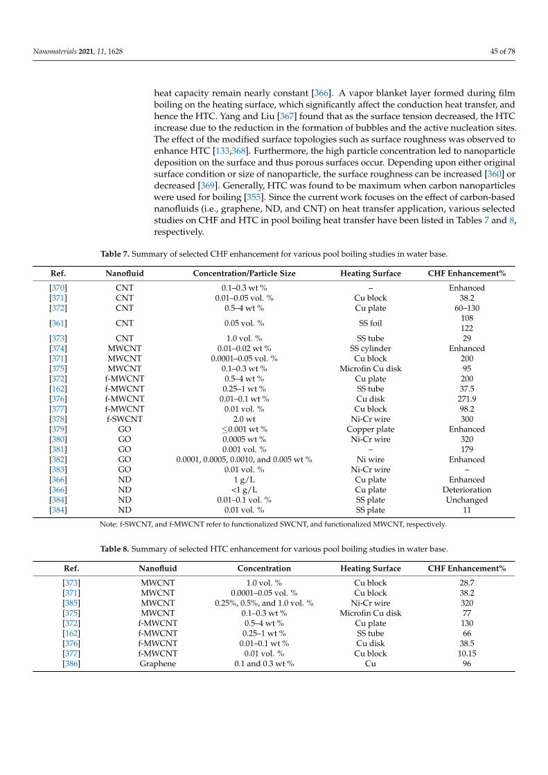
Nanomaterials 2021, 11, 1628 45 of 78
heat capacity remain nearly constant [366]. A vapor blanket layer formed during filmboiling on the heating surface, which significantly affect the conduction heat transfer, andhence the HTC. Yang and Liu [367] found that as the surface tension decreased, the HTCincrease due to the reduction in the formation of bubbles and the active nucleation sites.The effect of the modified surface topologies such as surface roughness was observed toenhance HTC [133,368]. Furthermore, the high particle concentration led to nanoparticledeposition on the surface and thus porous surfaces occur. Depending upon either originalsurface condition or size of nanoparticle, the surface roughness can be increased [360] ordecreased [369]. Generally, HTC was found to be maximum when carbon nanoparticleswere used for boiling [355]. Since the current work focuses on the effect of carbon-basednanofluids (i.e., graphene, ND, and CNT) on heat transfer application, various selectedstudies on CHF and HTC in pool boiling heat transfer have been listed in Tables 7 and 8,respectively.
Table 7. Summary of selected CHF enhancement for various pool boiling studies in water base.
Ref. Nanofluid Concentration/Particle Size Heating Surface CHF Enhancement%
[370] CNT 0.1–0.3 wt % – Enhanced[371] CNT 0.01–0.05 vol. % Cu block 38.2[372] CNT 0.5–4 wt % Cu plate 60–130
[361] CNT 0.05 vol. % SS foil 108122
[373] CNT 1.0 vol. % SS tube 29[374] MWCNT 0.01–0.02 wt % SS cylinder Enhanced[371] MWCNT 0.0001–0.05 vol. % Cu block 200[375] MWCNT 0.1–0.3 wt % Microfin Cu disk 95[372] f-MWCNT 0.5–4 wt % Cu plate 200[162] f-MWCNT 0.25–1 wt % SS tube 37.5[376] f-MWCNT 0.01–0.1 wt % Cu disk 271.9[377] f-MWCNT 0.01 vol. % Cu block 98.2[378] f-SWCNT 2.0 wt Ni-Cr wire 300[379] GO ≤0.001 wt % Copper plate Enhanced[380] GO 0.0005 wt % Ni-Cr wire 320[381] GO 0.001 vol. % – 179[382] GO 0.0001, 0.0005, 0.0010, and 0.005 wt % Ni wire Enhanced[383] GO 0.01 vol. % Ni-Cr wire –[366] ND 1 g/L Cu plate Enhanced[366] ND <1 g/L Cu plate Deterioration[384] ND 0.01–0.1 vol. % SS plate Unchanged[384] ND 0.01 vol. % SS plate 11
Note: f-SWCNT, and f-MWCNT refer to functionalized SWCNT, and functionalized MWCNT, respectively.
Table 8. Summary of selected HTC enhancement for various pool boiling studies in water base.
Ref. Nanofluid Concentration Heating Surface CHF Enhancement%
[373] MWCNT 1.0 vol. % Cu block 28.7[371] MWCNT 0.0001–0.05 vol. % Cu block 38.2[385] MWCNT 0.25%, 0.5%, and 1.0 vol. % Ni-Cr wire 320[375] MWCNT 0.1–0.3 wt % Microfin Cu disk 77[372] f-MWCNT 0.5–4 wt % Cu plate 130[162] f-MWCNT 0.25–1 wt % SS tube 66[376] f-MWCNT 0.01–0.1 wt % Cu disk 38.5[377] f-MWCNT 0.01 vol. % Cu block 10.15[386] Graphene 0.1 and 0.3 wt % Cu 96
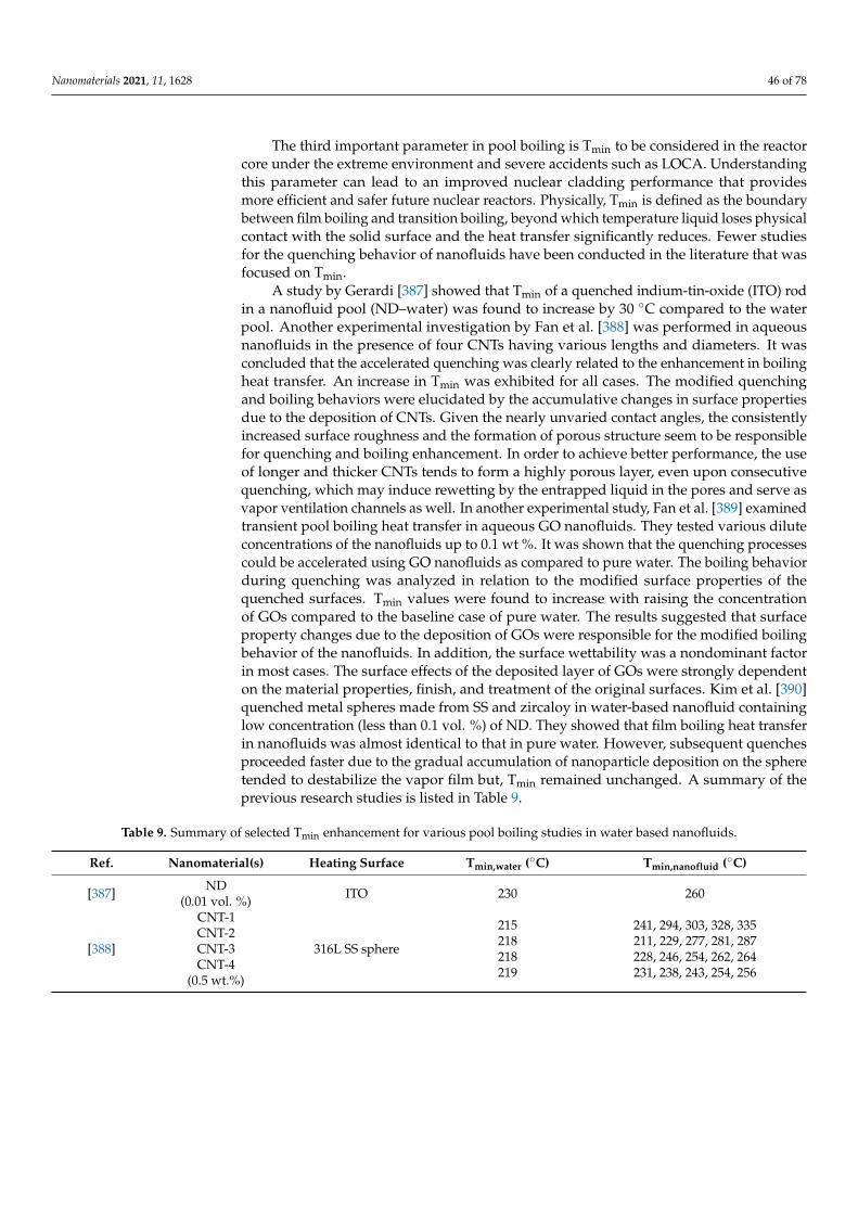
Nanomaterials 2021, 11, 1628 46 of 78
The third important parameter in pool boiling is Tmin to be considered in the reactorcore under the extreme environment and severe accidents such as LOCA. Understandingthis parameter can lead to an improved nuclear cladding performance that providesmore efficient and safer future nuclear reactors. Physically, Tmin is defined as the boundarybetween film boiling and transition boiling, beyond which temperature liquid loses physicalcontact with the solid surface and the heat transfer significantly reduces. Fewer studiesfor the quenching behavior of nanofluids have been conducted in the literature that wasfocused on Tmin.
A study by Gerardi [387] showed that Tmin of a quenched indium-tin-oxide (ITO) rodin a nanofluid pool (ND–water) was found to increase by 30 ◦C compared to the waterpool. Another experimental investigation by Fan et al. [388] was performed in aqueousnanofluids in the presence of four CNTs having various lengths and diameters. It wasconcluded that the accelerated quenching was clearly related to the enhancement in boilingheat transfer. An increase in Tmin was exhibited for all cases. The modified quenchingand boiling behaviors were elucidated by the accumulative changes in surface propertiesdue to the deposition of CNTs. Given the nearly unvaried contact angles, the consistentlyincreased surface roughness and the formation of porous structure seem to be responsiblefor quenching and boiling enhancement. In order to achieve better performance, the useof longer and thicker CNTs tends to form a highly porous layer, even upon consecutivequenching, which may induce rewetting by the entrapped liquid in the pores and serve asvapor ventilation channels as well. In another experimental study, Fan et al. [389] examinedtransient pool boiling heat transfer in aqueous GO nanofluids. They tested various diluteconcentrations of the nanofluids up to 0.1 wt %. It was shown that the quenching processescould be accelerated using GO nanofluids as compared to pure water. The boiling behaviorduring quenching was analyzed in relation to the modified surface properties of thequenched surfaces. Tmin values were found to increase with raising the concentrationof GOs compared to the baseline case of pure water. The results suggested that surfaceproperty changes due to the deposition of GOs were responsible for the modified boilingbehavior of the nanofluids. In addition, the surface wettability was a nondominant factorin most cases. The surface effects of the deposited layer of GOs were strongly dependenton the material properties, finish, and treatment of the original surfaces. Kim et al. [390]quenched metal spheres made from SS and zircaloy in water-based nanofluid containinglow concentration (less than 0.1 vol. %) of ND. They showed that film boiling heat transferin nanofluids was almost identical to that in pure water. However, subsequent quenchesproceeded faster due to the gradual accumulation of nanoparticle deposition on the spheretended to destabilize the vapor film but, Tmin remained unchanged. A summary of theprevious research studies is listed in Table 9.
Table 9. Summary of selected Tmin enhancement for various pool boiling studies in water based nanofluids.
Ref. Nanomaterial(s) Heating Surface Tmin,water (◦C) Tmin,nanofluid (◦C)
[387] ND(0.01 vol. %) ITO 230 260
[388]
CNT-1CNT-2CNT-3CNT-4
(0.5 wt.%)
316L SS sphere
215218218219
241, 294, 303, 328, 335211, 229, 277, 281, 287228, 246, 254, 262, 264231, 238, 243, 254, 256
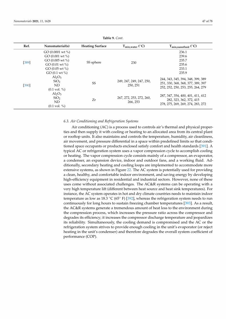
Nanomaterials 2021, 11, 1628 47 of 78
Table 9. Cont.
Ref. Nanomaterial(s) Heating Surface Tmin,water (◦C) Tmin,nanofluid (◦C)
[389]
GO (0.0001 wt %)
SS sphere 230
236.1GO (0.001 wt %) 239.6GO (0.005 wt %) 235.7GO (0.01 wt %) 235.6GO (0.05 wt %) 233.1GO (0.1 wt %) 235.9
[390]
Al2O3SiO2ND
(0.1 vol. %)
SS 249, 247, 249, 247, 250,250, 251
244, 343, 345, 394, 348, 399, 389251, 330, 368, 368, 377, 389, 397252, 252, 250, 253, 255, 264, 279
Al2O3SiO2ND
(0.1 vol. %)
Zr 267, 272, 253, 272, 260,266, 253
287, 347, 354, 400, 401, 411, 412282, 323, 362, 372, 415
278, 275, 269, 269, 274, 283, 272
6.3. Air Conditioning and Refrigeration Systems
Air conditioning (AC) is a process used to controls air’s thermal and physical proper-ties and then supply it with cooling or heating to an allocated area from its central plantor rooftop units. It also maintains and controls the temperature, humidity, air cleanliness,air movement, and pressure differential in a space within predefined limits so that condi-tioned space occupants or products enclosed satisfy comfort and health standards [391]. Atypical AC or refrigeration system uses a vapor compression cycle to accomplish coolingor heating. The vapor compression cycle consists mainly of a compressor, an evaporator,a condenser, an expansion device, indoor and outdoor fans, and a working fluid. Ad-ditionally, secondary heating and cooling loops are implemented to accommodate moreextensive systems, as shown in Figure 22. The AC system is potentially used for providinga clean, healthy, and comfortable indoor environment, and saving energy by developinghigh-efficiency equipment in residential and industrial sectors. However, none of theseuses come without associated challenges. The AC&R systems can be operating with avery high temperature lift (different between heat source and heat sink temperatures). Forinstance, the AC system operates in hot and dry climate countries needs to maintain indoortemperature as low as 18.3 ◦C (65◦ F) [392], whereas the refrigeration system needs to runcontinuously for long hours to sustain freezing chamber temperatures [393]. As a result,the AC&R systems generate a tremendous amount of heat loss to the environment duringthe compression process, which increases the pressure ratio across the compressor anddegrades its efficiency; it increases the compressor discharge temperature and jeopardizesits reliability. Simultaneously, the cooling demand is compromised and the AC or therefrigeration system strives to provide enough cooling in the unit’s evaporator (or rejectheating in the unit’s condenser) and therefore degrades the overall system coefficient ofperformance (COP).
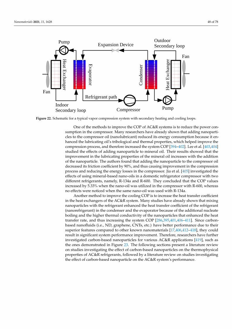
Nanomaterials 2021, 11, 1628 48 of 78Nanomaterials 2021, 11, x FOR PEER REVIEW 48 of 79
Figure 22. Schematic for a typical vapor compression system with secondary heating and cooling
loops.
One of the methods to improve the COP of AC&R systems is to reduce the power
consumption in the compressor. Many researchers have already shown that adding nano-
particles to the compressor oil (nanolubricant) reduced its energy consumption because it
enhanced the lubricating oil’s tribological and thermal properties, which helped improve
the compression process, and therefore increased the system COP [394–402]. Lee et al.
[403,404] studied the effects of adding nanoparticle to mineral oil. Their results showed
that the improvement in the lubricating properties of the mineral oil increases with the
addition of the nanoparticle. The authors found that adding the nanoparticle to the com-
pressor oil decreased its friction coefficient by 90%, and thus causing improvement in the
compression process and reducing the energy losses in the compressor. Jia et al. [405] in-
vestigated the effects of using mineral-based nano-oils in a domestic refrigerator compres-
sor with two different refrigerants, namely, R-134a and R-600. They concluded that the
COP values increased by 5.33% when the nano-oil was utilized in the compressor with R-
600, whereas no effects were noticed when the same nano-oil was used with R-134a.
Another method to improve the cooling COP is to increase the heat transfer coeffi-
cient in the heat exchangers of the AC&R system. Many studies have already shown that
mixing nanoparticles with the refrigerant enhanced the heat transfer coefficient of the re-
frigerant (nanorefrigerant) in the condenser and the evaporator because of the additional
nucleate boiling and the higher thermal conductivity of the nanoparticles that enhanced
the heat transfer rate, and thus increasing the system COP [286,395,401,406–411]. Since
carbon-based nanofluids (i.e., ND, graphene, CNTs, etc.) have better performance due to
their superior features compared to other known nanomaterials [17,406,412–418], they
could result in significant system performance improvement. Therefore, researchers have
further investigated carbon-based nanoparticles for various AC&R applications [419],
such as the ones demonstrated in Figure 23. The following sections present a literature
review on studies investigating the effect of carbon-based nanoparticles on the thermo-
physical properties of AC&R refrigerants, followed by a literature review on studies in-
vestigating the effect of carbon-based nanoparticle on the AC&R system’s performance.
Figure 22. Schematic for a typical vapor compression system with secondary heating and cooling loops.
One of the methods to improve the COP of AC&R systems is to reduce the power con-sumption in the compressor. Many researchers have already shown that adding nanoparti-cles to the compressor oil (nanolubricant) reduced its energy consumption because it en-hanced the lubricating oil’s tribological and thermal properties, which helped improve thecompression process, and therefore increased the system COP [394–402]. Lee et al. [403,404]studied the effects of adding nanoparticle to mineral oil. Their results showed that theimprovement in the lubricating properties of the mineral oil increases with the additionof the nanoparticle. The authors found that adding the nanoparticle to the compressor oildecreased its friction coefficient by 90%, and thus causing improvement in the compressionprocess and reducing the energy losses in the compressor. Jia et al. [405] investigated theeffects of using mineral-based nano-oils in a domestic refrigerator compressor with twodifferent refrigerants, namely, R-134a and R-600. They concluded that the COP valuesincreased by 5.33% when the nano-oil was utilized in the compressor with R-600, whereasno effects were noticed when the same nano-oil was used with R-134a.
Another method to improve the cooling COP is to increase the heat transfer coefficientin the heat exchangers of the AC&R system. Many studies have already shown that mixingnanoparticles with the refrigerant enhanced the heat transfer coefficient of the refrigerant(nanorefrigerant) in the condenser and the evaporator because of the additional nucleateboiling and the higher thermal conductivity of the nanoparticles that enhanced the heattransfer rate, and thus increasing the system COP [286,395,401,406–411]. Since carbon-based nanofluids (i.e., ND, graphene, CNTs, etc.) have better performance due to theirsuperior features compared to other known nanomaterials [17,406,412–418], they couldresult in significant system performance improvement. Therefore, researchers have furtherinvestigated carbon-based nanoparticles for various AC&R applications [419], such asthe ones demonstrated in Figure 23. The following sections present a literature reviewon studies investigating the effect of carbon-based nanoparticles on the thermophysicalproperties of AC&R refrigerants, followed by a literature review on studies investigatingthe effect of carbon-based nanoparticle on the AC&R system’s performance.

Nanomaterials 2021, 11, 1628 49 of 78Nanomaterials 2021, 11, x FOR PEER REVIEW 49 of 79
Figure 23. Nanofluids employment in AC&R applications, namely; air conditioning units, air han-
dling units, industrial refrigerators, and domestic refrigerators.
6.3.1. Influence of Carbon-Based Nanoparticles on the Thermophysical Properties of
Working Fluid in AC&R Systems
It is evident from the literature that there are many researchers investigated the per-
formance properties (i.e., heat transfer coefficient and viscosity) of nanoparticles applied
to the refrigerants in AC&R systems including copper (Cu), aluminum (Al), nickel (Ni),
copper oxide (CuO), zinc oxide (ZnO), aluminum oxide (Al2O3), titanium oxide (TiO2),
and other metal nanoparticles [325,419–434]. However, only a limited number of research
work is available for ND, graphene, and CNTs, which can be summarized in Table 10.
Park and Jung [435] investigated the possible contribution of CNT on the nucleate boiling
heat transfer coefficients of R-123 and R-134a. They reported an enhancement up to 36.6%
in nucleate boiling heat transfer coefficients of the nanorefrigerant at low heat flux com-
pared to the baseline refrigerant. However, as the heat flux increases the enhancement
decreased due to robust bubble generation that prevented the CNT from penetrating the
thermal boundary layer and touch the surface. The flow boiling heat transfer characteris-
tics and pressure drop were also investigated experimentally by Zhang et al. [436], using
MWCNT dispersed in the R-123 refrigerant with SDBS surfactant flowing in a horizontal
circular tube heat exchanger. Their results showed that the nanorefrigerant heat transfer
coefficient and frictional pressure drop increased with the increase of nanoparticle con-
centration, mass flux, and vapor quality. Similar conclusions were observed by Sun et al.
[437] when they investigated MWCNT with R-141b. Jiang et al. [438] studied the influence
of CNT diameters and aspect ratios on CNT–R-113 nanorefrigerant. The study involved
four different groups of CNTs with different physical dimensions (diameters, length, and
aspect ratio). Their experimental results showed that the thermal conductivities of CNT
nanorefrigerant increased proportionally with the increase of CNT’s volume fraction and
aspect ratio and with the decrease of CNT’s diameter. The maximum increase in the ther-
mal conductivity was about 104% for a volume fraction of 1.0 vol. %. Peng et al. [439]
studied the influence of CNT physical dimensions such as diameters, length, and aspect
ratios for the CNT–R-113–oil mixture. They used the same four different groups of CNTs
with different physical dimensions as Jiang et al. [438] and VG68 ester lubricating oil. An
enhancement of up to 61% was obtained in the nucleate pool boiling heat transfer coeffi-
Figure 23. Nanofluids employment in AC&R applications, namely; air conditioning units, air handling units, industrialrefrigerators, and domestic refrigerators.
6.3.1. Influence of Carbon-Based Nanoparticles on the Thermophysical Properties ofWorking Fluid in AC&R Systems
It is evident from the literature that there are many researchers investigated theperformance properties (i.e., heat transfer coefficient and viscosity) of nanoparticles appliedto the refrigerants in AC&R systems including copper (Cu), aluminum (Al), nickel (Ni),copper oxide (CuO), zinc oxide (ZnO), aluminum oxide (Al2O3), titanium oxide (TiO2),and other metal nanoparticles [325,419–434]. However, only a limited number of researchwork is available for ND, graphene, and CNTs, which can be summarized in Table 10. Parkand Jung [435] investigated the possible contribution of CNT on the nucleate boiling heattransfer coefficients of R-123 and R-134a. They reported an enhancement up to 36.6% innucleate boiling heat transfer coefficients of the nanorefrigerant at low heat flux comparedto the baseline refrigerant. However, as the heat flux increases the enhancement decreaseddue to robust bubble generation that prevented the CNT from penetrating the thermalboundary layer and touch the surface. The flow boiling heat transfer characteristics andpressure drop were also investigated experimentally by Zhang et al. [436], using MWCNTdispersed in the R-123 refrigerant with SDBS surfactant flowing in a horizontal circulartube heat exchanger. Their results showed that the nanorefrigerant heat transfer coefficientand frictional pressure drop increased with the increase of nanoparticle concentration,mass flux, and vapor quality. Similar conclusions were observed by Sun et al. [437]when they investigated MWCNT with R-141b. Jiang et al. [438] studied the influence ofCNT diameters and aspect ratios on CNT–R-113 nanorefrigerant. The study involvedfour different groups of CNTs with different physical dimensions (diameters, length, andaspect ratio). Their experimental results showed that the thermal conductivities of CNTnanorefrigerant increased proportionally with the increase of CNT’s volume fraction andaspect ratio and with the decrease of CNT’s diameter. The maximum increase in thethermal conductivity was about 104% for a volume fraction of 1.0 vol. %. Peng et al. [439]studied the influence of CNT physical dimensions such as diameters, length, and aspectratios for the CNT–R-113–oil mixture. They used the same four different groups of CNTswith different physical dimensions as Jiang et al. [438] and VG68 ester lubricating oil. Anenhancement of up to 61% was obtained in the nucleate pool boiling heat transfer coefficientcompared to R-311–oil mixture without CNTs. They also showed that the improvement ofthe nucleate pool boiling heat transfer coefficient increased as the CNTs length increases
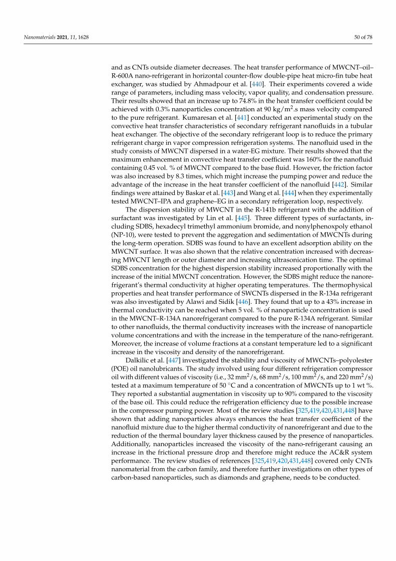
Nanomaterials 2021, 11, 1628 50 of 78
and as CNTs outside diameter decreases. The heat transfer performance of MWCNT–oil–R-600A nano-refrigerant in horizontal counter-flow double-pipe heat micro-fin tube heatexchanger, was studied by Ahmadpour et al. [440]. Their experiments covered a widerange of parameters, including mass velocity, vapor quality, and condensation pressure.Their results showed that an increase up to 74.8% in the heat transfer coefficient could beachieved with 0.3% nanoparticles concentration at 90 kg/m2.s mass velocity comparedto the pure refrigerant. Kumaresan et al. [441] conducted an experimental study on theconvective heat transfer characteristics of secondary refrigerant nanofluids in a tubularheat exchanger. The objective of the secondary refrigerant loop is to reduce the primaryrefrigerant charge in vapor compression refrigeration systems. The nanofluid used in thestudy consists of MWCNT dispersed in a water-EG mixture. Their results showed that themaximum enhancement in convective heat transfer coefficient was 160% for the nanofluidcontaining 0.45 vol. % of MWCNT compared to the base fluid. However, the friction factorwas also increased by 8.3 times, which might increase the pumping power and reduce theadvantage of the increase in the heat transfer coefficient of the nanofluid [442]. Similarfindings were attained by Baskar et al. [443] and Wang et al. [444] when they experimentallytested MWCNT–IPA and graphene–EG in a secondary refrigeration loop, respectively.
The dispersion stability of MWCNT in the R-141b refrigerant with the addition ofsurfactant was investigated by Lin et al. [445]. Three different types of surfactants, in-cluding SDBS, hexadecyl trimethyl ammonium bromide, and nonylphenoxpoly ethanol(NP-10), were tested to prevent the aggregation and sedimentation of MWCNTs duringthe long-term operation. SDBS was found to have an excellent adsorption ability on theMWCNT surface. It was also shown that the relative concentration increased with decreas-ing MWCNT length or outer diameter and increasing ultrasonication time. The optimalSDBS concentration for the highest dispersion stability increased proportionally with theincrease of the initial MWCNT concentration. However, the SDBS might reduce the nanore-frigerant’s thermal conductivity at higher operating temperatures. The thermophysicalproperties and heat transfer performance of SWCNTs dispersed in the R-134a refrigerantwas also investigated by Alawi and Sidik [446]. They found that up to a 43% increase inthermal conductivity can be reached when 5 vol. % of nanoparticle concentration is usedin the MWCNT–R-134A nanorefrigerant compared to the pure R-134A refrigerant. Similarto other nanofluids, the thermal conductivity increases with the increase of nanoparticlevolume concentrations and with the increase in the temperature of the nano-refrigerant.Moreover, the increase of volume fractions at a constant temperature led to a significantincrease in the viscosity and density of the nanorefrigerant.
Dalkilic et al. [447] investigated the stability and viscosity of MWCNTs–polyolester(POE) oil nanolubricants. The study involved using four different refrigeration compressoroil with different values of viscosity (i.e., 32 mm2/s, 68 mm2/s, 100 mm2/s, and 220 mm2/s)tested at a maximum temperature of 50 ◦C and a concentration of MWCNTs up to 1 wt %.They reported a substantial augmentation in viscosity up to 90% compared to the viscosityof the base oil. This could reduce the refrigeration efficiency due to the possible increasein the compressor pumping power. Most of the review studies [325,419,420,431,448] haveshown that adding nanoparticles always enhances the heat transfer coefficient of thenanofluid mixture due to the higher thermal conductivity of nanorefrigerant and due to thereduction of the thermal boundary layer thickness caused by the presence of nanoparticles.Additionally, nanoparticles increased the viscosity of the nano-refrigerant causing anincrease in the frictional pressure drop and therefore might reduce the AC&R systemperformance. The review studies of references [325,419,420,431,448] covered only CNTsnanomaterial from the carbon family, and therefore further investigations on other types ofcarbon-based nanoparticles, such as diamonds and graphene, needs to be conducted.
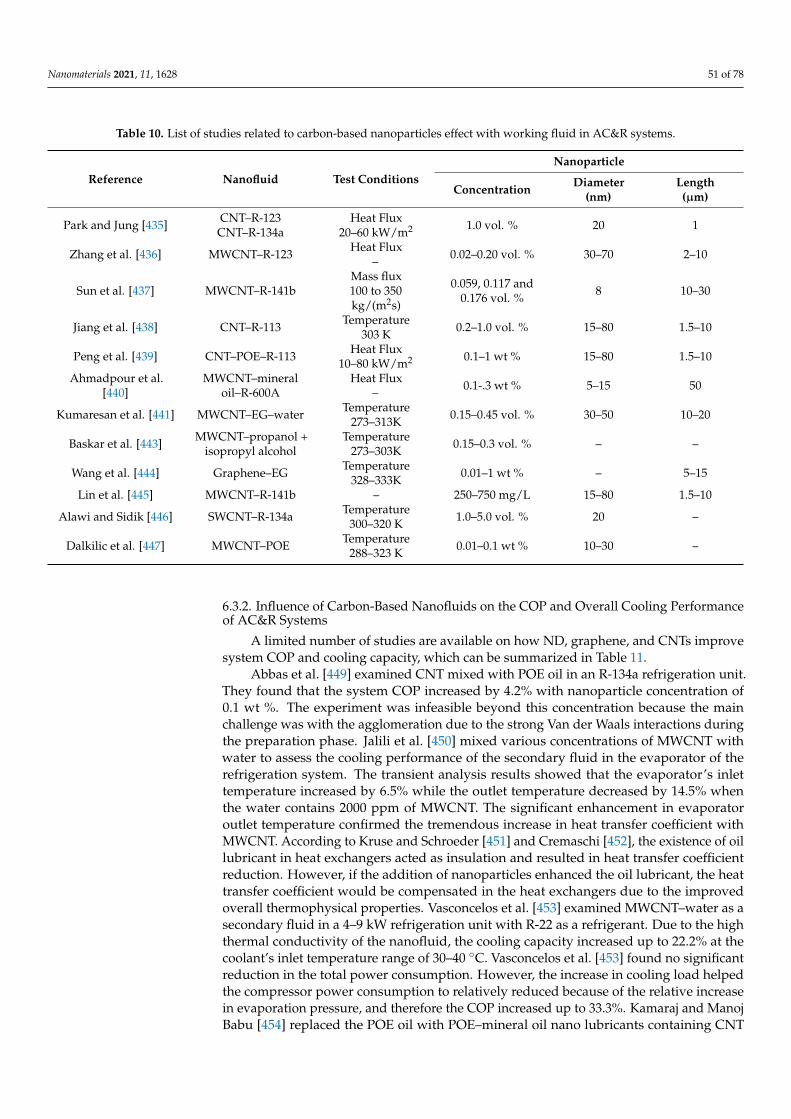
Nanomaterials 2021, 11, 1628 51 of 78
Table 10. List of studies related to carbon-based nanoparticles effect with working fluid in AC&R systems.
Reference Nanofluid Test ConditionsNanoparticle
Concentration Diameter(nm)
Length(µm)
Park and Jung [435] CNT–R-123CNT–R-134a
Heat Flux20–60 kW/m2 1.0 vol. % 20 1
Zhang et al. [436] MWCNT–R-123 Heat Flux– 0.02–0.20 vol. % 30–70 2–10
Sun et al. [437] MWCNT–R-141bMass flux100 to 350kg/(m2s)
0.059, 0.117 and0.176 vol. % 8 10–30
Jiang et al. [438] CNT–R-113 Temperature303 K 0.2–1.0 vol. % 15–80 1.5–10
Peng et al. [439] CNT–POE–R-113 Heat Flux10–80 kW/m2 0.1–1 wt % 15–80 1.5–10
Ahmadpour et al.[440]
MWCNT–mineraloil–R-600A
Heat Flux– 0.1-.3 wt % 5–15 50
Kumaresan et al. [441] MWCNT–EG–water Temperature273–313K 0.15–0.45 vol. % 30–50 10–20
Baskar et al. [443] MWCNT–propanol +isopropyl alcohol
Temperature273–303K 0.15–0.3 vol. % – –
Wang et al. [444] Graphene–EG Temperature328–333K 0.01–1 wt % – 5–15
Lin et al. [445] MWCNT–R-141b – 250–750 mg/L 15–80 1.5–10
Alawi and Sidik [446] SWCNT–R-134a Temperature300–320 K 1.0–5.0 vol. % 20 –
Dalkilic et al. [447] MWCNT–POE Temperature288–323 K 0.01–0.1 wt % 10–30 –
6.3.2. Influence of Carbon-Based Nanofluids on the COP and Overall Cooling Performanceof AC&R Systems
A limited number of studies are available on how ND, graphene, and CNTs improvesystem COP and cooling capacity, which can be summarized in Table 11.
Abbas et al. [449] examined CNT mixed with POE oil in an R-134a refrigeration unit.They found that the system COP increased by 4.2% with nanoparticle concentration of0.1 wt %. The experiment was infeasible beyond this concentration because the mainchallenge was with the agglomeration due to the strong Van der Waals interactions duringthe preparation phase. Jalili et al. [450] mixed various concentrations of MWCNT withwater to assess the cooling performance of the secondary fluid in the evaporator of therefrigeration system. The transient analysis results showed that the evaporator’s inlettemperature increased by 6.5% while the outlet temperature decreased by 14.5% whenthe water contains 2000 ppm of MWCNT. The significant enhancement in evaporatoroutlet temperature confirmed the tremendous increase in heat transfer coefficient withMWCNT. According to Kruse and Schroeder [451] and Cremaschi [452], the existence of oillubricant in heat exchangers acted as insulation and resulted in heat transfer coefficientreduction. However, if the addition of nanoparticles enhanced the oil lubricant, the heattransfer coefficient would be compensated in the heat exchangers due to the improvedoverall thermophysical properties. Vasconcelos et al. [453] examined MWCNT–water as asecondary fluid in a 4–9 kW refrigeration unit with R-22 as a refrigerant. Due to the highthermal conductivity of the nanofluid, the cooling capacity increased up to 22.2% at thecoolant’s inlet temperature range of 30–40 ◦C. Vasconcelos et al. [453] found no significantreduction in the total power consumption. However, the increase in cooling load helpedthe compressor power consumption to relatively reduced because of the relative increasein evaporation pressure, and therefore the COP increased up to 33.3%. Kamaraj and ManojBabu [454] replaced the POE oil with POE–mineral oil nano lubricants containing CNT
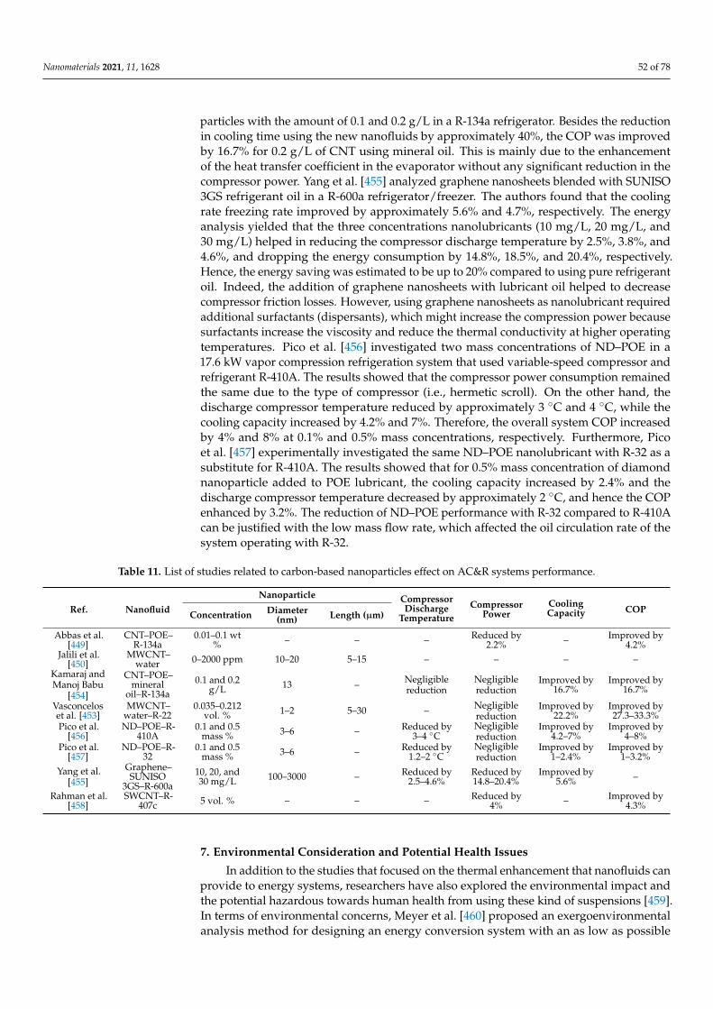
Nanomaterials 2021, 11, 1628 52 of 78
particles with the amount of 0.1 and 0.2 g/L in a R-134a refrigerator. Besides the reductionin cooling time using the new nanofluids by approximately 40%, the COP was improvedby 16.7% for 0.2 g/L of CNT using mineral oil. This is mainly due to the enhancementof the heat transfer coefficient in the evaporator without any significant reduction in thecompressor power. Yang et al. [455] analyzed graphene nanosheets blended with SUNISO3GS refrigerant oil in a R-600a refrigerator/freezer. The authors found that the coolingrate freezing rate improved by approximately 5.6% and 4.7%, respectively. The energyanalysis yielded that the three concentrations nanolubricants (10 mg/L, 20 mg/L, and30 mg/L) helped in reducing the compressor discharge temperature by 2.5%, 3.8%, and4.6%, and dropping the energy consumption by 14.8%, 18.5%, and 20.4%, respectively.Hence, the energy saving was estimated to be up to 20% compared to using pure refrigerantoil. Indeed, the addition of graphene nanosheets with lubricant oil helped to decreasecompressor friction losses. However, using graphene nanosheets as nanolubricant requiredadditional surfactants (dispersants), which might increase the compression power becausesurfactants increase the viscosity and reduce the thermal conductivity at higher operatingtemperatures. Pico et al. [456] investigated two mass concentrations of ND–POE in a17.6 kW vapor compression refrigeration system that used variable-speed compressor andrefrigerant R-410A. The results showed that the compressor power consumption remainedthe same due to the type of compressor (i.e., hermetic scroll). On the other hand, thedischarge compressor temperature reduced by approximately 3 ◦C and 4 ◦C, while thecooling capacity increased by 4.2% and 7%. Therefore, the overall system COP increasedby 4% and 8% at 0.1% and 0.5% mass concentrations, respectively. Furthermore, Picoet al. [457] experimentally investigated the same ND–POE nanolubricant with R-32 as asubstitute for R-410A. The results showed that for 0.5% mass concentration of diamondnanoparticle added to POE lubricant, the cooling capacity increased by 2.4% and thedischarge compressor temperature decreased by approximately 2 ◦C, and hence the COPenhanced by 3.2%. The reduction of ND–POE performance with R-32 compared to R-410Acan be justified with the low mass flow rate, which affected the oil circulation rate of thesystem operating with R-32.
Table 11. List of studies related to carbon-based nanoparticles effect on AC&R systems performance.
Ref. NanofluidNanoparticle Compressor
DischargeTemperature
CompressorPower
CoolingCapacity COPConcentration Diameter
(nm) Length (µm)
Abbas et al.[449]
CNT–POE–R-134a
0.01–0.1 wt% – – – Reduced by
2.2% – Improved by4.2%
Jalili et al.[450]
MWCNT–water 0–2000 ppm 10–20 5–15 – – – –
Kamaraj andManoj Babu
[454]
CNT–POE–mineral
oil–R-134a0.1 and 0.2
g/L 13 – Negligiblereduction
Negligiblereduction
Improved by16.7%
Improved by16.7%
Vasconceloset al. [453]
MWCNT–water–R-22
0.035–0.212vol. % 1–2 5–30 – Negligible
reductionImproved by
22.2%Improved by27.3–33.3%
Pico et al.[456]
ND–POE–R-410A
0.1 and 0.5mass % 3–6 – Reduced by
3–4 ◦CNegligiblereduction
Improved by4.2–7%
Improved by4–8%
Pico et al.[457]
ND–POE–R-32
0.1 and 0.5mass % 3–6 – Reduced by
1.2–2 ◦CNegligiblereduction
Improved by1–2.4%
Improved by1–3.2%
Yang et al.[455]
Graphene–SUNISO
3GS–R-600a10, 20, and30 mg/L 100–3000 – Reduced by
2.5–4.6%Reduced by14.8–20.4%
Improved by5.6% –
Rahman et al.[458]
SWCNT–R-407c 5 vol. % – – – Reduced by
4% – Improved by4.3%
7. Environmental Consideration and Potential Health Issues
In addition to the studies that focused on the thermal enhancement that nanofluids canprovide to energy systems, researchers have also explored the environmental impact andthe potential hazardous towards human health from using these kind of suspensions [459].In terms of environmental concerns, Meyer et al. [460] proposed an exergoenvironmentalanalysis method for designing an energy conversion system with an as low as possible
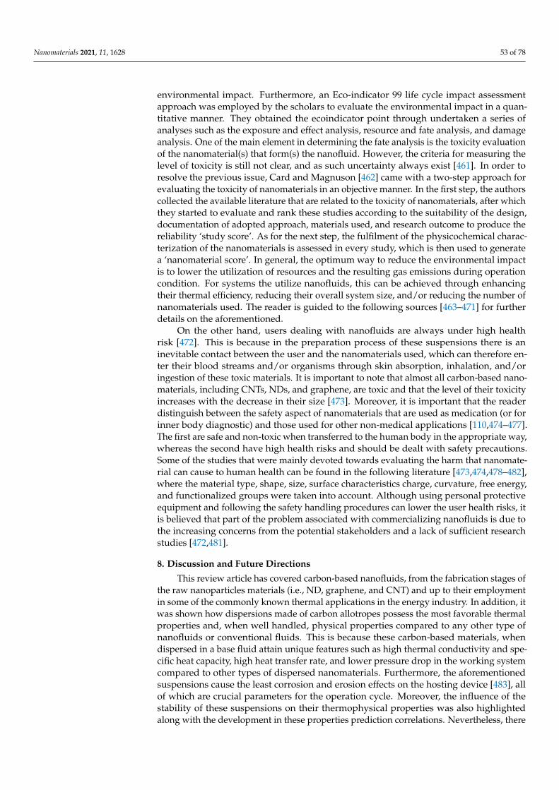
Nanomaterials 2021, 11, 1628 53 of 78
environmental impact. Furthermore, an Eco-indicator 99 life cycle impact assessmentapproach was employed by the scholars to evaluate the environmental impact in a quan-titative manner. They obtained the ecoindicator point through undertaken a series ofanalyses such as the exposure and effect analysis, resource and fate analysis, and damageanalysis. One of the main element in determining the fate analysis is the toxicity evaluationof the nanomaterial(s) that form(s) the nanofluid. However, the criteria for measuring thelevel of toxicity is still not clear, and as such uncertainty always exist [461]. In order toresolve the previous issue, Card and Magnuson [462] came with a two-step approach forevaluating the toxicity of nanomaterials in an objective manner. In the first step, the authorscollected the available literature that are related to the toxicity of nanomaterials, after whichthey started to evaluate and rank these studies according to the suitability of the design,documentation of adopted approach, materials used, and research outcome to produce thereliability ‘study score’. As for the next step, the fulfilment of the physicochemical charac-terization of the nanomaterials is assessed in every study, which is then used to generatea ‘nanomaterial score’. In general, the optimum way to reduce the environmental impactis to lower the utilization of resources and the resulting gas emissions during operationcondition. For systems the utilize nanofluids, this can be achieved through enhancingtheir thermal efficiency, reducing their overall system size, and/or reducing the number ofnanomaterials used. The reader is guided to the following sources [463–471] for furtherdetails on the aforementioned.
On the other hand, users dealing with nanofluids are always under high healthrisk [472]. This is because in the preparation process of these suspensions there is aninevitable contact between the user and the nanomaterials used, which can therefore en-ter their blood streams and/or organisms through skin absorption, inhalation, and/oringestion of these toxic materials. It is important to note that almost all carbon-based nano-materials, including CNTs, NDs, and graphene, are toxic and that the level of their toxicityincreases with the decrease in their size [473]. Moreover, it is important that the readerdistinguish between the safety aspect of nanomaterials that are used as medication (or forinner body diagnostic) and those used for other non-medical applications [110,474–477].The first are safe and non-toxic when transferred to the human body in the appropriate way,whereas the second have high health risks and should be dealt with safety precautions.Some of the studies that were mainly devoted towards evaluating the harm that nanomate-rial can cause to human health can be found in the following literature [473,474,478–482],where the material type, shape, size, surface characteristics charge, curvature, free energy,and functionalized groups were taken into account. Although using personal protectiveequipment and following the safety handling procedures can lower the user health risks, itis believed that part of the problem associated with commercializing nanofluids is due tothe increasing concerns from the potential stakeholders and a lack of sufficient researchstudies [472,481].
8. Discussion and Future Directions
This review article has covered carbon-based nanofluids, from the fabrication stages ofthe raw nanoparticles materials (i.e., ND, graphene, and CNT) and up to their employmentin some of the commonly known thermal applications in the energy industry. In addition, itwas shown how dispersions made of carbon allotropes possess the most favorable thermalproperties and, when well handled, physical properties compared to any other type ofnanofluids or conventional fluids. This is because these carbon-based materials, whendispersed in a base fluid attain unique features such as high thermal conductivity and spe-cific heat capacity, high heat transfer rate, and lower pressure drop in the working systemcompared to other types of dispersed nanomaterials. Furthermore, the aforementionedsuspensions cause the least corrosion and erosion effects on the hosting device [483], allof which are crucial parameters for the operation cycle. Moreover, the influence of thestability of these suspensions on their thermophysical properties was also highlightedalong with the development in these properties prediction correlations. Nevertheless, there

Nanomaterials 2021, 11, 1628 54 of 78
are still some challenges and gaps in the scientific knowledge that need to be tackled forfurther advancement in the field and the possible industrial viability of such advancedfluids. Some of these issues are pointed out in this section.
8.1. Challenges in Carbon-Based Nanofluids
Carbon allotropes in the nanoscale have shown to be promising in enhancing thethermal performance of liquids when homogeneously dispersed, and their products arecommercially available through a wide range of companies. Nevertheless, these powdersare very expansive from an economic perspective compared to other sorts of nanomaterials,which makes their utilization quite questionable in the sense of their feasibility towards thetargeted application [484]. Therefore, one of the challenges that need to be focused on is howto fabricate large quantities of these nanopowders at minimal production cost. In the currentsituation and before even introducing such type of nanofluids to the industry, researchersneed to initially evaluate the gained performance enhancement and economic benefits ofcarbon-based nanofluids for each selected application before hands, and hence more workis needed in this area. Some scholars have proposed combining carbon-based nanomaterialswith other cheaper types of nanoparticles (e.g., Cu, Al, and Fe) to form hybrid nanofluidscontaining carbon allotropes, and thus reducing the suspension cost [485–488]. However,the feasibility of such an approach remains limited, and the consideration of such typesof hybrid nanofluids remains in the exploration stages. As it is well-known by nowthat the favorable thermophysical properties of nanofluids have made such a categoryof working fluids beneficial when used for enhancing the system performance of manythermal applications. Yet, the stability of the dispersed particles remains a major drawbackand thus limiting the widespread of these suspensions. This is because, in an unstable state,the particles tend to cluster into larger forms of agglomerate, and therefore the benefits ofthe high surface area of the nanoparticles losses its optimum effectiveness on the exposedhost (i.e., base fluids). For such a reason, it is essential that any proposed nanofluid tothe industry maintains its long-term stability. This is where the preparation phase of theproduct plays a critical role. In order to overcome this difficulty, scientists have suggestedusing physical approaches (e.g., sonication) and/or chemical methods, such as surfactantsand surface functionalization. Although this can help solve the aggregation problem, thechanges caused to the surface of the dispersed particles remain another uncertainty thatneeds to be understood. In addition, further exploration on combining the two stabilizationmethods (i.e., physical and chemical routes) need to be conducted. Moreover, a jointinternational standard database on the thermophysical properties and physical stability ofdifferent types of nanofluids, their dispersed nanomaterial(s) concentration, and fabricationapproach is strongly needed [198]. This is because even after more than 25 years from thefirst discovery of nanofluids, scientist are still reporting different thermophysical propertiesand physical stability for similar synthesized suspensions. In terms of properties prediction,it was shown previously that both effective thermal conductivity and effective viscositylacks universal correlations and can only be determined through experimental means.However, artificial neural networking that is based on data mining has started to showgood accuracy in predicting these properties, but further research is still required in thisarea [489–492].
8.2. Limitations in Parabolic Trough Solar Collector Systems
In PTSCs, the main challenge is that most of the studies shown in the literature were ofpilot-scale tests, and thus further investigations are needed on the real-life application itself.Moreover, systematic studies are required to understand and standardize the influenceof operational parameters such as high pressure, high temperature, flow rate, particlesconcentration, and suspension thermophysical properties on the system performance. Fur-thermore, there is still a need for a better understanding of the fouling build-up mechanismthat is commonly associated with the use of nanofluids in systems of elevated tempera-tures as this newly introduced thin-film is likely to change the wettability behavior of the
Nanomaterials 2021, 11, 1628 55 of 78
surface, and with it the dynamics of the flow [493–495]. Knowing this can open the doorfor introducing systematic washing routines, whether online, offline, or both, that can helpin extending the heat transfer efficiency of the PTSC. Other aspects such as the frictionfactor and pressure drop should also be considered and explored intensively due to thenature of nanofluids having higher effective viscosity than conventional fluids.
8.3. Limitations in Nuclear Reactor Systems
As with most heat transfer systems, nuclear reactors were shown to have potentialperformance benefits from replacing their working fluids with nanofluids. Although onsome occasions, certain types of nanofluids cannot compile with such application require-ments (e.g., gold and platinum), due to the high temperature nature of such systems andthe presence of emitted radiations that effects the dispersed particles [496]. Nevertheless,carbon-based materials have shown the capability of being an acceptable candidate forthese systems. Despite that, the common challenge with almost every application that usesthis category of suspensions remains rounded on the feasibility of such fluids and theirparticles clustering issue within the hosting system. When focusing on nuclear reactors,these systems design, sizes, and mechanisms can be seen changing rapidly throughoutthe past 20 years [308,312,497]. While this shows how this area of science is advancing, italso constrains the exploration capability of researchers working in the field of nanofluids.Thus, scientists specialized in nanofluids cannot investigate the performance enhancementcaused by their suspensions on pre-existing reactors. Still, at the same time, they need totake into account the operation lifetime of the facility and understand how the isotopesbuild up and decay within these systems. This is because such changes in these isotopescould cause different behaviors when exposed to the dispersed particles. In addition, thefact that some of the dispersed particles may deposit on the nuclear fuel surface needsto be also considered and evaluated with respect to the possible corrosion developmenton the outer surface of the fuel. Moreover, studies on the long-term physical stability ofnanofluids, when employed in nuclear reactors, remain unknown and need to be inves-tigated. In addition, further work is needed to determine the effect of surfactants, whenused as stabilizers, on the heat transfer rate in such application. This is because most (if notall) of these chemicals cannot withstand high temperature operating conditions. In termsof LOCA scenarios, nanofluids can help stop (or reduce) the level of damages that thefuel of elevated temperature may cause to the facility, but the method in which the newlyintroduced waste can be dealt with remains questionable and needs to be solved. Thisis because, unlike conventional liquids, the dispersed particles conserve more radiations,and hence remain radioactive for a very long time before they decay and stabilize. Whenit comes to pool boiling during quenching, to the best of our knowledge, there is stillno existing literature that covers the effect of nanofluids on the minimum film boilingtemperature (Tmin) such as what was presented in Section 6.2.2. In general, there is alack of studies about the impact of nanofluids on Tmin during quenching. Owing to theimportance of Tmin, various types, concentrations, and sizes of nanofluids should haveexperimented with to investigate their effects on this parameter in specific. Furthermore,most of the investigations that are concern the effect of nanofluids on the CHF uses blockplates, flat plates, or wires. However, research work on other geometries is crucial becauseit is evidence that the CHF will strongly be influenced by it. In addition, the currentlyemployed models (e.g., Zuber’s correlation) fails to accurately predict CHF when usingthin wires [498], and therefore scholars need to focus more into developing a universalmodel that can withstand such limitation.
8.4. Limitations in Air Conditioning and Refrigeration Systems
Based on the research conducted by Hu et al. [499], it was shown that some carbon-based nanomaterials need surfactant(s) to ensure long-term stability and avoid agglom-eration when they are mixed with the oil–refrigerant in the AC&R system. Additionally,surfactant might help to increase the performance of the AC&R system because it enhances
Nanomaterials 2021, 11, 1628 56 of 78
the nucleate pool boiling heat transfer coefficient. However, this improvement is onlyattained under limited conditions because it is highly dependent on certain specifications(e.g., nanoparticle type, nanoparticle size, nanoparticle concentration, surfactant type,surfactant concentration, nanolubricant concentration, base fluid type, and heat flux). Inaddition, Cheng and Liu [500] recommended further investigation on nucleate pool boilingand flow boiling for refrigerant based-nanofluids. Therefore, further investigations mustbe conducted toward carbon-based nanofluids with refrigerant–oil–surfactants for AC&Rapplications. According to Bahiraei et al. [501] and Dalkılıç et al. [502], nanofluids helpedto improve the heat transfer coefficient in heat exchangers (i.e., spiral-type and double-typeheat exchangers). However, due to the increase in the nanofluid’s viscosity, the pressuredrop can be escalated, especially for low mass flow rates [503,504]. In AC&R systems,the pressure drop is an important factor that needs to be incorporated during the systemdesign phase because any additional increase in the pressure drop in the heat exchangersduring the operation of the AC&R system will result in significant degradation in thesystem COP performance as reported by Sunardi et al. [505] and Tashtoush et al. [506]. Yet,pressure drop due to a carbon-based nanofluids additive has not been studied in AC&Rsystems and needs to be further investigated. In fact, engineers need robust software toolsto design AC&R systems with nanofluid additives. Some studies provided correlationsfor all thermophysical properties of the nanofluids (heat transfer coefficient, friction factor,thermal conductivity, viscosity, etc.) [507–510]. However, computational models integrat-ing component models (as employed in Bahman et al. [511] and Loaiza et al. [512]) andthe influence of carbon-based nanofluids in AC&R systems are still lacking. In addition,those kinds of models might have the potential to predict the overall system performanceand ensure optimal operations. Furthermore, experimental investigations were limited toa specific concentration amount of nanofluids. The optimal concentration for maximumAC&R performance can be obtained numerically with the formerly mentioned computa-tional models. Moreover, the determination of the optimal amount of concentration has notbeen proposed yet in the literature for carbon-based nanofluids in AC&R systems. In theAC&R system, nanofluid additives ultimately enhance the viscosity of the lubricating oil.Conversely, this might relatively increase the compressor power consumption. Therefore,it is vivid to find the relationship between nanofluid viscosity and compressor pumpingpower for AC&R application [513–515]. A limited number of research employed energyand exergy analysis on carbon-based nanofluids applied in AC&R systems. They haveshown that there is a high potential for decreasing the irreversibility with carbon-basednanofluids due to their higher thermal conductivity compared to oxide materials [516].Therefore, more compressive studies similar to Bahman and Groll [517] are required toidentify the AC&R components with major irreversibility when employing nanofluids.Moreover, the literature is scarce in techno-economic analysis for nanofluids in AC&Rapplications. Although Bhattad et al. [518] showed that nanofluids could result in a higherpayback period than the AC&R’s components (i.e., heat exchangers), however, further stud-ies need to be conducted on carbon-based nanofluids because by optimizing the number ofnanoparticles with respect to operating condition and stability, it can be more cost-effective.Finally, AC&R systems combine several components, as nanofluid pass through thesecomponents, it would be compressed, expanded, or changed phases. All these processesmay lead to the possibility of getting nanoparticles to be separated from the carrier fluidduring long-term operation and probably degrade the system performance. Therefore,the long-term operating performance of the nanorefrigerant (and nanolubricant) must beinvestigated.
9. Conclusions
This paper provides a comprehensive state-of-the-art review on carbon-based nanoflu-ids, including the initial synthesis methods used for producing carbon nanotubes, graphene,and nanodiamonds, and up to the employment of their dispersions into thermal energyapplications, namely; parabolic trough solar collectors, quenching systems, and air condi-
Nanomaterials 2021, 11, 1628 57 of 78
tioning and refrigeration systems. It was shown how some of these nanomaterials couldonly be fabricated in a dry form, such as high purity nanodiamonds, whereas graphene,for example, can be produced as a dry powder or a suspension. Thus, when selecting thenanofluids’ preparation approach containing these nanomaterials, the available optionscan be narrowed from two routes to only a single process. Furthermore, the main equationsused in calculating the volume concentration that are commonly required for the nanofluidtwo-step production method were provided. Moreover, the physical stability of the sus-pension, which is considered as one of the most influential aspect that can dramaticallyaffect the thermophysical properties of any nanofluid, was discussed in terms of its forma-tion mechanism and evaluation approaches. Although there are many advanced ways tocharacterize the dispersion stability, it was concluded that the photographical capturingmethod remains the most reliable approach due to its capability of determining both short-and long-term dispersion stability of the mixture in real-time and at high accuracy. Never-theless, this method is very time-consuming to conduct, especially when the characterizedsample is of high state of stability. In addition, chemical methods, such as surfactantsand surface functionalization; and physical approaches, namely, ultrasonication, magneticstirring, homogenizer, and ball milling, were also discussed and shown in how they can beemployed to improve the level of particles dispersion within an instable suspension. It wasconcluded that, unlike the chemical approaches, using physical methods for enhancing thedispersion stability is a better option when it comes to conserving the optimum possibleeffective thermal conductivity of the nanofluid and that between the available physicalroutes, the homogenizer can provide the best outcomes. In general, the stability of thesuspension does not affect the mixture density nor its specific heat capacity but ratherinfluences both the effective thermal conductivity and effective viscosity of the nanofluid.These two properties were seen to degrade gradually with time due to the nanomaterial’sagglomerations and their sediment formation. Many methods were shown to determinethese two properties (i.e., effective thermal conductivity and effective viscosity), either byexperimental means or through pre-existing correlations. Still, up to today, the scientificfield has failed to provide a universal formula for both of these two properties, and hencethe only reliable approach is through experimental analysis. When it comes to replacingconventional working fluids with carbon-based nanofluid in thermal applications (i.e.,parabolic trough solar collectors, nuclear reactor systems, and air conditioning and refriger-ation systems), it was proven, at least at the lab and pilot-scale, that such advanced fluidsare very beneficial in terms of enhancing the overall performance of these systems, and cantherefore be seen as strong candidates for such industries when their associated challengesare solved and fully understood.
Author Contributions: N.A., A.M.B., N.F.A. and A.A. conducted the Introduction Section. N.A. car-ried out the Synthesis of Nanoscaled Carbon-Based Materials Section, the Preparation of NanofluidsSection, and the Stability Effect on Thermophysical Properties Section. N.A. conducted the Parabolictrough solar collectors Section. S.A.E. and S.M. worked on the Nuclear reactors Section. A.M.B. andN.F.A. conducted the Air conditioning and refrigeration systems Section. N.A., N.F.A., A.M.B. andS.A.E. have worked on the Discussion and Future Directions Section along with the ConclusionSection. All authors have read and agreed to the published version of the manuscript.
Funding: This research received no external funding.
Acknowledgments: The authors of this article are grateful and acknowledge the help provided bytheir institutes. They are also grateful to the journals that have waved their copy rights fees for someof the figures that were used in this article. This includes Materials Science and Engineering: C,Elsevier (License Number: 5054231133553); and Applied Thermal Engineering, Elsevier (LicenseNumber: 5054240415839).
Conflicts of Interest: The authors declare no conflict of interest.

Nanomaterials 2021, 11, 1628 58 of 78
Nomenclature
A Area (nm2)AC Air conditioningAC&R Air conditioning and refrigerationAG Arabic gumALWR Advanced light water reactorANL Argonne National LaboratoryBAC Benzalkonium chlorideBWR Boiling water reactorCR.M. Nanoparticle random motion velocity (nm/s)CF Self-crowding factorCFD Computational fluid dynamicsCHF Critical heat flux (W/m2)CNT Carbon nanotubeCOP Coefficient of performanceCp Specific heat capacity (J/kg·K)CSPP Concentrated solar power plantCTAB Cetyltrimethyl ammonium bromideCVD Chemical vapour depositionDASC Direct absorber solar collectordb f Diameter of the base fluid molecule (nm)DND Detonation nanodiamondDNI Direct normal irradiancednp Nanoparticles mean diameterDSC Differential scanning calorimetryDSDMAC Distearyl dimethyl ammonium chlorideDWCNT Double-walled carbon nanotubeDX Direct expansionEG Ethylene glycolfm Maximum attainable concentrationfp Packing fraction of the particlesfV Particles volumetric fractionFVM Finite volume methodGCR Gas-cooled reactorGO Graphene oxideHFC HydrofluorocarbonHPHT High-pressure and high-temperatureHTC Heat transfer coefficient (W/m2·K)IPH Industrial process heatkpj Equivalent thermal conductivity of the ellipsoids particle (W/m·K)kB Boltzmann constant (1.381 × 10⁻²³ J/K)kH Huggins coefficientKm Matrix conductivity (W/m·K)kpe Equivalent particle thermal conductivity (W/m·K)`b f Mean-free path of the base fluid molecule (nm)LOCA Loss-of-coolant accidentm Mass (Kg)MCRT Monte Carlo ray tracingMSR Molten solid cooled reactorMWCNT Multiwalled carbon nanotubeND NanodiamondNu Nusselt numberPHWR Pressurized heavy water reactorPOE Polyolester oil
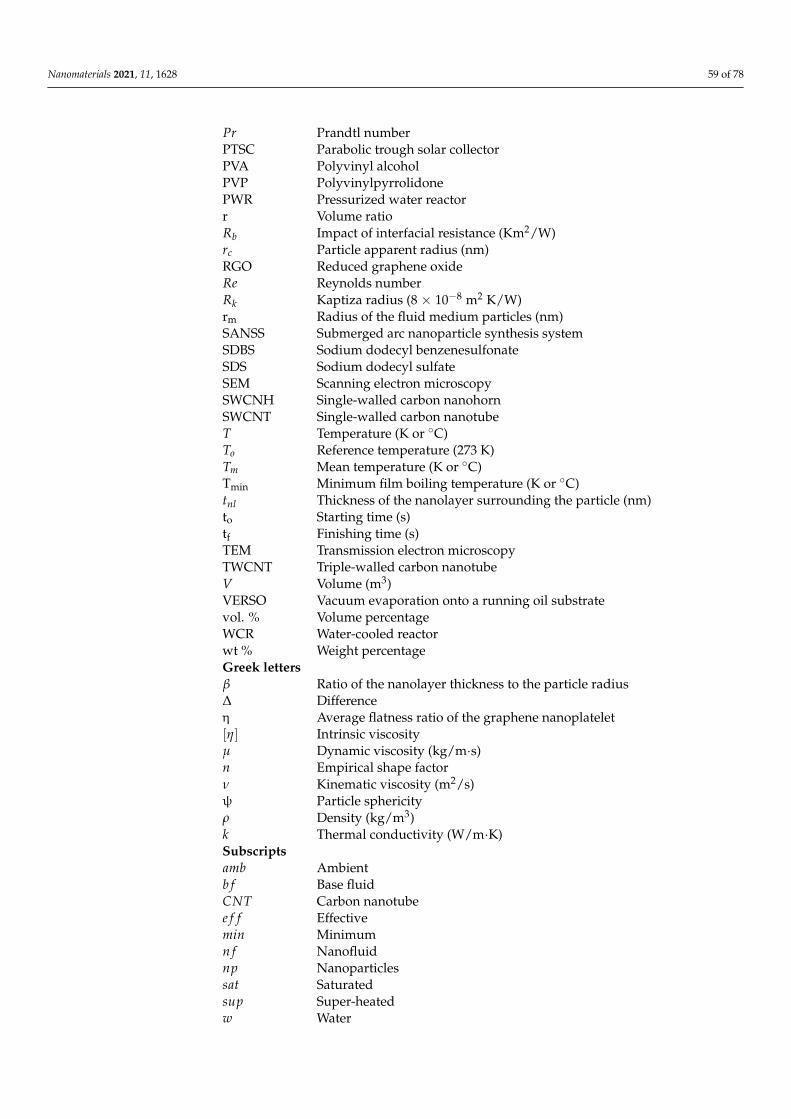
Nanomaterials 2021, 11, 1628 59 of 78
Pr Prandtl numberPTSC Parabolic trough solar collectorPVA Polyvinyl alcoholPVP PolyvinylpyrrolidonePWR Pressurized water reactorr Volume ratioRb Impact of interfacial resistance (Km2/W)rc Particle apparent radius (nm)RGO Reduced graphene oxideRe Reynolds numberRk Kaptiza radius (8 × 10⁻⁸ m2 K/W)rm Radius of the fluid medium particles (nm)SANSS Submerged arc nanoparticle synthesis systemSDBS Sodium dodecyl benzenesulfonateSDS Sodium dodecyl sulfateSEM Scanning electron microscopySWCNH Single-walled carbon nanohornSWCNT Single-walled carbon nanotubeT Temperature (K or ◦C)To Reference temperature (273 K)Tm Mean temperature (K or ◦C)Tmin Minimum film boiling temperature (K or ◦C)tnl Thickness of the nanolayer surrounding the particle (nm)to Starting time (s)tf Finishing time (s)TEM Transmission electron microscopyTWCNT Triple-walled carbon nanotubeV Volume (m3)VERSO Vacuum evaporation onto a running oil substratevol. % Volume percentageWCR Water-cooled reactorwt % Weight percentageGreek lettersβ Ratio of the nanolayer thickness to the particle radius∆ Differenceη Average flatness ratio of the graphene nanoplatelet[η] Intrinsic viscosityµ Dynamic viscosity (kg/m·s)n Empirical shape factorν Kinematic viscosity (m2/s)ψ Particle sphericityρ Density (kg/m3)k Thermal conductivity (W/m·K)Subscriptsamb Ambientb f Base fluidCNT Carbon nanotubee f f Effectivemin Minimumn f Nanofluidnp Nanoparticlessat Saturatedsup Super-heatedw Water
Nanomaterials 2021, 11, 1628 60 of 78
References1. Ahuja, A.S. Augmentation of heat transport in laminar flow of polystyrene suspensions. I. Experiments and results. J. Appl. Phys.
1975, 46, 3408–3416. [CrossRef]2. Ahuja, A.S. Augmentation of heat transport in laminar flow of polystyrene suspensions. II. Analysis of the data. J. Appl. Phys.
1975, 46, 3417–3425. [CrossRef]3. Liu, K.V.; Choi, U.S.; Kasza, K.E. Measurements of Pressure Drop and Heat Transfer in Turbulent Pipe Flows of Particulate Slurries;
Argonne National Lab: Lemont, IL, USA, 1988.4. Choi, S.U.; Cho, Y.I.; Kasza, K.E. Degradation effects of dilute polymer solutions on turbulent friction and heat transfer behavior.
J. Non-Newton Fluid Mech. 1992, 41, 289–307. [CrossRef]5. Choi, U.; France, D.M.; Knodel, B.D. Impact of Advanced Fluids on Costs of District Cooling Systems; Argonne National Lab: Lemont,
IL, USA, 1992.6. Choi, U.; Tran, T. Experimental Studies of the Effects of Non-Newtonian Surfactant Solutions on the Performance of a Shell-
and-Tube Heat Exchanger. In Recent Developments in Non-Newtonian Flows and Industrial Applications; The American Society ofMechanical Engineers New York: New York, NY, USA; FED: Atlanta, GA, USA, 1991; pp. 47–52.
7. Maxwell, J.C. A Treatise on Electricity and Magnetism, 2nd ed.; Clarendon Press: Oxford, UK, 1881.8. Ali, N.; Teixeira, J.A.; Addali, A. Aluminium Nanofluids Stability: A Comparison between the Conventional Two-Step Fabrication
Approach and the Controlled Sonication Bath Temperature Method. J. Nanomater. 2019, 2019, 1–9. [CrossRef]9. Masuda, H.; Ebata, A.; Teramae, K. Alteration of Thermal Conductivity and Viscosity of Liquid by Dispersing Ultra-Fine Particles.
Dispersion of Al2o3, Sio2 and Tio2 Ultra-Fine Particles; Netsu Bussei: Tokyo, Japan, 1993; Volume 7, pp. 227–233. [CrossRef]10. Choi, S.U.S.; Eastman, J.A. Enhancing thermal conductivity of fluids with nanoparticles. In Proceedings of the 1995 International
Mechanical Engineering Congress and Exhibition, San Francisco, CA, USA, 12–17 November 1995; PBD: Washington, DC, USA; ArgonneNational Lab: Lemont, IL, USA, 1995; 8p.
11. Naser, A.; Teixeira, J.A.; Ali, N. New pH Correlations for Stainless Steel 316L, Alumina, and Copper(I) Oxide NanofluidsFabricated at Controlled Sonication Temperatures. J. Nano Res. 2019, 58, 125–138. [CrossRef]
12. Lee, S.; Choi, S.U.S. Application of Metallic Nanoparticle Suspensions in Advanced Cooling Systems; American Society of MechanicalEngineers, Materials Division: Atlanta, GA, USA, 1996; Volume 72, pp. 227–234.
13. Ali, N.; Teixeira, J.A.; Addali, A. A Review on Nanofluids: Fabrication, Stability, and Thermophysical Properties. J. Nanomater.2018, 2018, 1–33. [CrossRef]
14. Pop, E.; Varshney, V.; Roy, A.K. Thermal properties of graphene: Fundamentals and applications. MRS Bull. 2012, 37, 1273–1281.[CrossRef]
15. Han, Z.; Fina, A. Thermal conductivity of carbon nanotubes and their polymer nanocomposites: A review. Prog. Polym. Sci. 2011,36, 914–944. [CrossRef]
16. Sezer, N.; Atieh, M.; Koc, M. A comprehensive review on synthesis, stability, thermophysical properties, and characterization ofnanofluids. Powder Technol. 2019, 344, 404–431. [CrossRef]
17. Mashali, F.; Languri, E.M.; Davidson, J.; Kerns, D.; Johnson, W.; Nawaz, K.; Cunningham, G. Thermo-physical properties ofdiamond nanofluids: A review. Int. J. Heat Mass Transf. 2019, 129, 1123–1135. [CrossRef]
18. Schwamb, T.; Burg, B.R.; Schirmer, N.C.; Poulikakos, D. An electrical method for the measurement of the thermal and electricalconductivity of reduced graphene oxide nanostructures. Nanotechnology 2009, 20, 405704. [CrossRef]
19. Mahanta, N.K.; Abramson, A.R. Thermal conductivity of graphene and graphene oxide nanoplatelets. In Proceedings of the 13thInterSociety Conference on Thermal and Thermomechanical Phenomena in Electronic Systems, San Diego, CA, USA, 30 May–1June 2012; IEEE: New York, NY, USA, 2012; pp. 1–6.
20. Zhang, H.; Fonseca, A.F.; Cho, K. Tailoring Thermal Transport Property of Graphene through Oxygen Functionalization. J. Phys.Chem. C 2014, 118, 1436–1442. [CrossRef]
21. Eastman, J.A.; Choi, U.S.; Li, S.; Thompson, L.J.; Lee, S. Enhanced thermal conductivity through the development of nanofluids.In Proceedings of the 1996 MRS Fall Symposium; George, E.P., Gotthardt, R., Otsuka, K., Trolier-McKinstry, S., Wun-Fogle, M., Eds.;Materials Research Society: Pittsburgh, PA, USA; Boston, MA, USA, 1997; pp. 3–11.
22. Li, Z.X.; Khaled, U.; Al-Rashed, A.A.A.A.; Goodarzi, M.; Sarafraz, M.M.; Meer, R. Heat transfer evaluation of a micro heatexchanger cooling with spherical carbon-acetone nanofluid. Int. J. Heat Mass Transf. 2020, 149, 119124. [CrossRef]
23. Ilyas, S.U.; Pendyala, R.; Shuib, A.; Marneni, N. A review on the viscous and thermal transport properties of nanofluids. InInternational Conference on Process Engineering and Advanced Materials, ICPEAM 2012; Trans Tech Publications Ltd.: Kuala Lumpur,Malaysia, 2014; pp. 18–27.
24. Shanthi, R.; Anandan, S.; Ramalingam, V. Heat transfer enhancement using nanofluids: An overview. Therm. Sci. 2012, 16,423–444. [CrossRef]
25. Wen, D.; Lin, G.; Vafaei, S.; Zhang, K. Review of nanofluids for heat transfer applications. Particuology 2009, 7, 141–150. [CrossRef]26. Vékás, L.; Bica, D.; Avdeev, M.V. Magnetic nanoparticles and concentrated magnetic nanofluids: Synthesis, properties and some
applications. China Particuol. 2007, 5, 43–49. [CrossRef]27. Reddy, K.S.; Kamnapure, N.R.; Srivastava, S. Nanofluid and nanocomposite applications in solar energy conversion systems for
performance enhancement: A review. Int. J. Low Carbon Technol. 2016, 12, 1–23. [CrossRef]
Nanomaterials 2021, 11, 1628 61 of 78
28. Sheikholeslami, M.; Ganji, D.D. Application of Nanofluids. In Applications of Semi Analytical Methods for Nanofluid Flow and HeatTransfer; Sheikholeslami, M., Ganji, D.D., Eds.; Elsevier: Amsterdam, The Netherlands, 2018; pp. 1–44.
29. Mansoury, D.; Doshmanziari, F.I.; Kiani, A.; Chamkha, A.J.; Sharifpur, M. Heat Transfer and Flow Characteristics of Al2O3/WaterNanofluid in Various Heat Exchangers: Experiments on Counter Flow. Heat Transf. Eng. 2018, 41, 1–36. [CrossRef]
30. Chamkha, A.J.; Molana, M.; Rahnama, A.; Ghadami, F. On the nanofluids applications in microchannels: A comprehensivereview. Powder Technol. 2018, 332, 287–322. [CrossRef]
31. Alsayegh, A.; Ali, N. Gas Turbine Intercoolers: Introducing Nanofluids—A Mini-Review. Processes 2020, 8, 1572. [CrossRef]32. Mannu, R.; Karthikeyan, V.; Velu, N.; Arumugam, C.; Roy, V.A.L.; Gopalan, A.-I.; Saianand, G.; Sonar, P.; Lee, K.-P.; Kim, W.-J.;
et al. Polyethylene Glycol Coated Magnetic Nanoparticles: Hybrid Nanofluid Formulation, Properties and Drug DeliveryProspects. Nanomaterials 2021, 11, 440. [CrossRef]
33. Martínez-Merino, P.; Sánchez-Coronilla, A.; Alcántara, R.; Martín, E.I.; Carrillo-Berdugo, I.; Gómez-Villarejo, R.; Navas, J. TheRole of the Interactions at the Tungsten Disulphide Surface in the Stability and Enhanced Thermal Properties of Nanofluids withApplication in Solar Thermal Energy. Nanomaterials 2020, 10, 970. [CrossRef] [PubMed]
34. Rostami, S.; Aghakhani, S.; Pordanjani, A.H.; Afrand, M.; Cheraghian, G.; Oztop, H.F.; Shadloo, M.S. A Review on the ControlParameters of Natural Convection in Different Shaped Cavities with and Without Nanofluid. Processes 2020, 8, 1011. [CrossRef]
35. Scopus-Database, Nanofluid Analyze Search Results for Documents Published from 1995 to 2020 with the Word ‘Nanofluid’;Elsevier: Amsterdam, The Netherlands. 2021. Available online: www.scopus.com (accessed on 1 April 2021).
36. Mukherjee, S.; Mishra, P.C.; Chaudhuri, P. Stability of Heat Transfer Nanofluids—A Review. ChemBioEng Rev. 2018, 5, 312–333.[CrossRef]
37. Almurtaji, S.; Ali, N.; Teixeira, J.A.; Addali, A. On the Role of Nanofluids in Thermal-hydraulic Performance of Heat Exchangers-AReview. Nanomaterials 2020, 10, 734. [CrossRef] [PubMed]
38. Song, Y.Y.; Bhadeshia, H.; Suh, D.-W. Stability of stainless-steel nanoparticle and water mixtures. Powder Technol. 2015, 272, 34–44.[CrossRef]
39. Ebrahimnia-Bajestan, E.; Niazmand, H.; Duangthongsuk, W.; Wongwises, S. Numerical investigation of effective parametersin convective heat transfer of nanofluids flowing under a laminar flow regime. Int. J. Heat Mass Transf. 2011, 54, 4376–4388.[CrossRef]
40. Martínez-Cuenca, R.; Mondragón, R.; Hernández, L.; Segarra, C.; Jarque, J.C.; Hibiki, T.; Juliá, J.E. Forced-convective heat-transfercoefficient and pressure drop of water-based nanofluids in a horizontal pipe. Appl. Therm. Eng. 2016, 98, 841–849. [CrossRef]
41. Benedict, L.X.; Louie, S.G.; Cohen, M.L. Heat capacity of carbon nanotubes. Solid State Commun. 1996, 100, 177–180. [CrossRef]42. Yazid, M.N.A.W.M.; Sidik, N.A.C.; Mamat, R.; Najafi, G. A review of the impact of preparation on stability of carbon nanotube
nanofluids. Int. Commun. Heat Mass Transf. 2016, 78, 253–263. [CrossRef]43. Shah, K.A.; Tali, B.A. Synthesis of carbon nanotubes by catalytic chemical vapour deposition: A review on carbon sources,
catalysts and substrates. Mater. Sci. Semicond. Process. 2016, 41, 67–82. [CrossRef]44. Wang, H.; Xu, Z.; Eres, G. Order in vertically aligned carbon nanotube arrays. Appl. Phys. Lett. 2006, 88, 213111. [CrossRef]45. Hong, P.N.; Minh, D.N.; Van Hung, N.; Minh, P.N.; Khoi, P.H. Carbon Nanotube and Graphene Aerogels—The World’s 3D
Lightest Materials for Environment Applications: A Review. Int. J. Mater. Sci. Appl. 2017, 6, 277. [CrossRef]46. Askari, S.; Lotfi, R.; Seifkordi, A.; Rashidi, A.; Koolivand, H. A novel approach for energy and water conservation in wet cooling
towers by using MWNTs and nanoporous graphene nanofluids. Energy Convers. Manag. 2016, 109, 10–18. [CrossRef]47. Neuberger, N.; Adidharma, H.; Fan, M. Graphene: A review of applications in the petroleum industry. J. Pet. Sci. Eng. 2018, 167,
152–159. [CrossRef]48. Shanbedi, M.; Heris, S.Z.; Amiri, A.; Hosseinipour, E.; Eshghi, H.; Kazi, S. Synthesis of aspartic acid-treated multi-walled carbon
nanotubes based water coolant and experimental investigation of thermal and hydrodynamic properties in circular tube. EnergyConvers. Manag. 2015, 105, 1366–1376. [CrossRef]
49. Sadeghinezhad, E.; Mehrali, M.; Saidur, R.; Mehrali, M.; Latibari, S.T.; Akhiani, A.R.; Metselaar, H.S.C. A comprehensive reviewon graphene nanofluids: Recent research, development and applications. Energy Convers. Manag. 2016, 111, 466–487. [CrossRef]
50. Tam, N.T.; Phuong, N.V.; Khoi, P.H.; Minh, P.N.; Afrand, M.; Van Trinh, P.; Thang, B.H.; Zyła, G.; Estellé, P. Carbon Nanomaterial-Based Nanofluids for Direct Thermal Solar Absorption. Nanomaterials 2020, 10, 1199. [CrossRef]
51. Ambreen, T.; Saleem, A.; Park, C. Homogeneous and Multiphase Analysis of Nanofluids Containing Nonspherical MWCNT andGNP Nanoparticles Considering the Influence of Interfacial Layering. Nanomaterials 2021, 11, 277. [CrossRef] [PubMed]
52. Giwa, S.O.; Sharifpur, M.; Ahmadi, M.H.; Murshed, S.M.S.; Meyer, J.P. Experimental Investigation on Stability, Viscosity, andElectrical Conductivity of Water-Based Hybrid Nanofluid of MWCNT-Fe2O3. Nanomaterials 2021, 11, 136. [CrossRef] [PubMed]
53. Freitas, E.; Pontes, P.; Cautela, R.; Bahadur, V.; Miranda, J.; Ribeiro, A.P.C.; Souza, R.R.; Oliveira, J.D.; Copetti, J.B.; Lima, R.;et al. Article pool boiling of nanofluids on biphilic surfaces: An experimental and numerical study. Nanomaterials 2021, 11, 125.[CrossRef]
54. Karagiannakis, N.P.; Skouras, E.D.; Burganos, V.N. Modelling Thermal Conduction in Nanoparticle Aggregates in the Presence ofSurfactants. Nanomaterials 2020, 10, 2288. [CrossRef]
55. Khan, H.; Soudagar, M.E.M.; Kumar, R.H.; Safaei, M.R.; Farooq, M.; Khidmatgar, A.; Banapurmath, N.R.; Farade, R.A.; Abbas,M.M.; Afzal, A.; et al. Effect of Nano-Graphene Oxide and n-Butanol Fuel Additives Blended with Diesel—Nigella sativaBiodiesel Fuel Emulsion on Diesel Engine Characteristics. Symmetry 2020, 12, 961. [CrossRef]
Nanomaterials 2021, 11, 1628 62 of 78
56. Soudagar, M.E.M.; Afzal, A.; Safaei, M.R.; Manokar, A.M.; El-Seesy, A.I.; Mujtaba, M.A.; Samuel, O.D.; Badruddin, I.A.; Ahmed,W.; Shahapurkar, K.; et al. Investigation on the effect of cottonseed oil blended with different percentages of octanol andsuspended MWCNT nanoparticles on diesel engine characteristics. J. Therm. Anal. Calorim. 2020. [CrossRef]
57. Zhang, Y.; Yin, Q.Z. Carbon and other light element contents in the Earth’s core based on first-principles molecular dynamics.Proc. Natl. Acad. Sci. USA 2012, 109, 19579–19583. [CrossRef]
58. Ferrari, A.C.; Robertson, J.; Ferrari, A.C.; Robertson, J. Interpretation of Raman spectra of disordered and amorphous carbon.Phys. Rev. B 2000, 61, 14095–14107. [CrossRef]
59. Wei, L.; Kuo, P.K.; Thomas, R.L.; Anthony, T.R.; Banholzer, W.F. Thermal conductivity of isotopically modified single crystaldiamond. Phys. Rev. Lett. 1993, 70, 3764–3767. [CrossRef]
60. Hodkiewicz, J.; Scientific, T. Characterizing Carbon Materials with Raman Spectroscopy; Thermo Scientific Application Note; ThermoFisher Scientific: Madison, WI, USA, 2010.
61. Dai, L.; Chang, D.W.; Baek, J.-B.; Lu, W. Carbon Nanomaterials for Advanced Energy Conversion and Storage. Small 2012, 8,1130–1166. [CrossRef] [PubMed]
62. Kaneko, K.; Ishii, C.; Ruike, M.; Kuwabara, H. Origin of superhigh surface area and microcrystalline graphitic structures ofactivated carbons. Carbon 1992, 30, 1075–1088. [CrossRef]
63. Pang, J.; Bachmatiuk, A.; Ibrahim, I.; Fu, L.; Placha, D.; Martynková, G.S.; Trzebicka, B.; Gemming, T.; Eckert, J.; Rümmeli, M.H.CVD growth of 1D and 2D sp2 carbon nanomaterials. J. Mater. Sci. 2015, 51, 640–667. [CrossRef]
64. van Thiel, M.; Ree, F.H. Properties of carbon clusters in TNT detonation products: Graphite-diamond transition. J. Appl. Phys.1987, 62, 1761–1767. [CrossRef]
65. Morita, Y.; Takimoto, T.; Yamanaka, H.; Kumekawa, K.; Morino, S.; Aonuma, S.; Kimura, T.; Komatsu, N. A Facile and ScalableProcess for Size-Controllable Separation of Nanodiamond Particles as Small as 4 nm. Small 2008, 4, 2154–2157. [CrossRef]
66. Ali, M.S.; Metwally, A.; Fahmy, R.H.; Osman, R. Nanodiamonds: Minuscule gems that ferry antineoplastic drugs to resistanttumors. Int. J. Pharm. 2019, 558, 165–176. [CrossRef] [PubMed]
67. Bovenkerk, H.P.; Bundy, F.P.; Hall, H.T.; Strong, H.M.; Wentorf, R.H. Preparation of Diamond. Nat. Cell Biol. 1959, 184, 1094–1098.[CrossRef]
68. Danilenko, V.V. On the history of the discovery of nanodiamond synthesis. Phys. Solid State 2004, 46, 595–599. [CrossRef]69. Kumar, A.; Lin, P.A.; Xue, A.; Hao, B.; Yap, Y.K.; Sankaran, R.M. Formation of nanodiamonds at near-ambient conditions via
microplasma dissociation of ethanol vapour. Nat. Commun. 2013, 4, 2618. [CrossRef]70. Frenklach, M.; Howard, W.; Huang, D.; Yuan, J.; Spear, K.E.; Koba, R. Induced nucleation of diamond powder. Appl. Phys. Lett.
1991, 59, 546–548. [CrossRef]71. Yang, G.-W.; Wang, J.-B.; Liu, Q.-X. Preparation of nano-crystalline diamonds using pulsed laser induced reactive quenching. J.
Phys. Condens. Matter 1998, 10, 7923–7927. [CrossRef]72. Boudou, J.P.; Curmi, P.A.; Jelezko, F.; Wrachtrup, J.; Aubert, P.; Sennour, M.; Balasubramanian, G.; Reuter, R.; Thorel, A.; Gaffet, E.
High yield fabrication of fluorescent nanodiamonds. Nanotechnology 2009, 20, 235602. [CrossRef]73. El-Eskandarany, M.S. Mechanically Induced Graphite-Nanodiamonds-Phase Transformations During High-Energy Ball Milling.
J. Mater. Eng. Perform. 2017, 26, 2974–2982. [CrossRef]74. Lin, C.R.; Wei, D.H.; Dao, M.K.; Chung, R.J.; Chang, M.H. Nanocrystalline diamond particles prepared by high-energy ball
milling method. In Applied Mechanics and Materials; Trans Tech Publications Ltd.: Schwyz, Switzerland, 2013; Volume 284, pp.168–172. [CrossRef]
75. Galimov, A.É.M.; Kudin, A.M.; Skorobogatskii, V.N.; Plotnichenko, V.G.; Bondarev, O.L.; Zarubin, B.G.; Strazdovskii, V.V.; Aronin,A.S.; Fisenko, A.V.; Bykov, I.; et al. Experimental corroboration of the synthesis of diamond in the cavitation process. Dokl. Phys.2004, 49, 150–153. [CrossRef]
76. Welz, S.; Gogotsi, Y.; McNallan, M.J. Nucleation, growth, and graphitization of diamond nanocrystals during chlorination ofcarbides. J. Appl. Phys. 2003, 93, 4207–4214. [CrossRef]
77. Banhart, F.; Ajayan, P.M. Carbon onions as nanoscopic pressure cells for diamond formation. Nature 1996, 382, 433–435. [CrossRef]78. Daulton, T.; Kirk, M.; Lewis, R.; Rehn, L. Production of nanodiamonds by high-energy ion irradiation of graphite at room
temperature. Nucl. Instrum. Methods Phys. Res. Sect. B Beam Interact. Mater. Atoms 2001, 175–177, 12–20. [CrossRef]79. El-Eskandarany, M.S. Method for Synthesizing Nanodiamonds. U.S. Patent 9,540,245 B1, 10 January 2017.80. Mochalin, V.N.; Shenderova, O.; Ho, D.; Gogotsi, Y. The properties and applications of nanodiamonds. Nat. Nanotechnol. 2012, 7,
11–23. [CrossRef]81. Mashali, F.; Languri, E.M.; Davidson, J.; Kerns, D. Diamond Nanofluids: Microstructural Analysis and Heat Transfer Study. Heat
Transf. Eng. 2020, 42, 479–491. [CrossRef]82. Crane, M.J.; Petrone, A.; Beck, R.A.; Lim, M.B.; Zhou, X.; Li, X.; Stroud, R.M.; Pauzauskie, P.J. High-pressure, high-temperature
molecular doping of nanodiamond. Sci. Adv. 2019, 5, eaau6073. [CrossRef] [PubMed]83. Afandi, A.; Howkins, A.; Boyd, I.W.; Jackman, R.B. Nanodiamonds for device applications: An investigation of the properties of
boron-doped detonation nanodiamonds. Sci. Rep. 2018, 8, 1–10. [CrossRef]84. Tinwala, H.; Wairkar, S. Production, surface modification and biomedical applications of nanodiamonds: A sparkling tool for
theranostics. Mater. Sci. Eng. C 2019, 97, 913–931. [CrossRef]
Nanomaterials 2021, 11, 1628 63 of 78
85. Compton, O.C.; Nguyen, S. Graphene Oxide, Highly Reduced Graphene Oxide, and Graphene: Versatile Building Blocks forCarbon-Based Materials. Small 2010, 6, 711–723. [CrossRef]
86. Novoselov, K.S.; Geim, A.K.; Morozov, S.V.; Jiang, D.; Zhang, Y.; Dubonos, S.V.; Grigorieva, I.V.; Firsov, A.A. Electric field effect inatomically thin carbon films. Science 2004, 306, 666–669. [CrossRef]
87. Ma, R.; Zhou, Y.; Bi, H.; Yang, M.; Wang, J.; Liu, Q.; Huang, F. Multidimensional graphene structures and beyond: Uniqueproperties, syntheses and applications. Prog. Mater. Sci. 2020, 113, 100665. [CrossRef]
88. Moreau, E.; Ferrer, F.J.; Vignaud, D.; Godey, S.; Wallart, X. Graphene growth by molecular beam epitaxy using a solid carbonsource. Phys. Status Solidi (a) 2010, 207, 300–303. [CrossRef]
89. Chyan, Y.; Ye, R.; Li, Y.; Singh, S.P.; Arnusch, C.J.; Tour, J.M. Laser-Induced Graphene by Multiple Lasing: Toward Electronics onCloth, Paper, and Food. ACS Nano 2018, 12, 2176–2183. [CrossRef]
90. Ye, R.; James, D.K.; Tour, J.M. Laser-Induced Graphene: From Discovery to Translation. Adv. Mater. 2019, 31, e1803621. [CrossRef]91. Stankovich, S.; Dikin, D.A.; Dommett, G.H.B.; Kohlhaas, K.M.; Zimney, E.J.; Stach, E.A.; Piner, R.D.; Nguyen, S.; Ruoff, R.S.
Graphene-based composite materials. Nature 2006, 442, 282–286. [CrossRef] [PubMed]92. Eda, G.; Fanchini, G.; Chhowalla, M. Large-area ultrathin films of reduced graphene oxide as a transparent and flexible electronic
material. Nat. Nanotechnol. 2008, 3, 270–274. [CrossRef]93. Hernandez, Y.; Lotya, M.; Rickard, D.; Bergin, S.D.; Coleman, J.N. Measurement of Multicomponent Solubility Parameters for
Graphene Facilitates Solvent Discovery. Langmuir 2010, 26, 3208–3213. [CrossRef] [PubMed]94. Hussain, A.; Mehdi, S.M.; Abbas, N.; Hussain, M.; Naqvi, R.A. Synthesis of graphene from solid carbon sources: A focused
review. Mater. Chem. Phys. 2020, 248, 122924. [CrossRef]95. Tetsuka, H.; Nagoya, A.; Fukusumi, T.; Matsui, T. Molecularly Designed, Nitrogen-Functionalized Graphene Quantum Dots for
Optoelectronic Devices. Adv. Mater. 2016, 28, 4632–4638. [CrossRef]96. Shen, J.; Zhu, Y.; Yang, X.; Li, C. Graphene quantum dots: Emergent nanolights for bioimaging, sensors, catalysis and photovoltaic
devices. Chem. Commun. 2012, 48, 3686–3699. [CrossRef]97. Novoselov, K.S.; Fal’ko, V.I.; Colombo, L.; Gellert, P.R.; Schwab, M.G.; Kim, K. A roadmap for graphene. Nature 2012, 490, 192–200.
[CrossRef]98. Tochihara, H.; Pomprasit, A.; Kadowaki, T.; Mizuno, S.; Minagawa, H.; Hayakawa, K.; Toyoshima, I. Decomposition of the surface
carbide on Ni(001) induced by copper adsorption and surface segregation of carbon. Surf. Sci. Lett. 1991, 257, L623–L627.99. Li, X.; Colombo, L.; Ruoff, R.S. Synthesis of Graphene Films on Copper Foils by Chemical Vapor Deposition. Adv. Mater. 2016, 28,
6247–6252. [CrossRef] [PubMed]100. Rao, C.N.R.; Subrahmanyam, K.S.; Matte, H.S.; Abdulhakeem, B.; Govindaraj, A.; Das, B.; Kumar, P.; Ghosh, A.; Late, D.J. A study
of the synthetic methods and properties of graphenes. Sci. Technol. Adv. Mater. 2010, 11, 054502. [CrossRef]101. Reibold, M.; Paufler, P.; Levin, A.A.; Kochmann, W.; Patzke, N.; Meyer, D.C. Materials: Carbon nanotubes in an ancient Damascus
sabre. Nature 2006, 444, 286. [CrossRef]102. Radushkevich, L.; Lukyanovich, V.Á. O strukture ugleroda, obrazujucegosja pri termiceskom razlozenii okisi ugleroda na
zeleznom kontakte. Zurn Fisic Chim 1952, 26, 88–95.103. Boehm, H. Carbon from carbon monoxide disproportionation on nickel and iron catalysts: Morphological studies and possible
growth mechanisms. Carbon 1973, 11, 583–590. [CrossRef]104. Oberlin, A.; Endo, M.; Koyama, T. Filamentous growth of carbon through benzene decomposition. J. Cryst. Growth 1976, 32,
335–349. [CrossRef]105. Costa, S.; Borowiak-Palen, E.; Kruszynska, M.; Bachmatiuk, A.; Kalenczuk, R. Characterization of carbon nanotubes by Raman
spectroscopy. Mater. Sci. Pol. 2008, 26, 433–441.106. Rafique, I.; Kausar, A.; Anwar, Z.; Muhammad, B. Exploration of Epoxy Resins, Hardening Systems, and Epoxy/Carbon
Nanotube Composite Designed for High Performance Materials: A Review. Polym. Technol. Eng. 2015, 55, 312–333. [CrossRef]107. Da Cunha, T.H.; De Oliveira, S.; Martins, I.L.; Geraldo, V.; Miquita, D.; Ramos, S.L.; Lacerda, R.G.; Ladeira, L.O.; Ferlauto, A.S.
High-yield synthesis of bundles of double- and triple-walled carbon nanotubes on aluminum flakes. Carbon 2018, 133, 53–61.[CrossRef]
108. Xia, D.; Luo, Y.; Li, Q.; Xue, Q.; Zhang, X.; Liang, C.; Dong, M. Extracting the inner wall from nested double-walled carbonnanotube by platinum nanowire: Molecular dynamics simulations. RSC Adv. 2017, 7, 39480–39489. [CrossRef]
109. Dresselhaus, G.; Riichiro, S. Physical Properties of Carbon Nanotubes; World Scientific: Singapore, 1998.110. Ibrahim, K.S. Carbon nanotubes-properties and applications: A review. Carbon Lett. 2013, 14, 131–144. [CrossRef]111. Mubarak, N.; Abdullah, E.C.; Jayakumar, N.; Sahu, J. An overview on methods for the production of carbon nanotubes. J. Ind.
Eng. Chem. 2014, 20, 1186–1197. [CrossRef]112. Mittal, G.; Dhand, V.; Rhee, K.Y.; Kim, H.-J.; Jung, D.H. Carbon nanotubes synthesis using diffusion and premixed flame methods:
A review. Carbon Lett. 2015, 16, 1–10. [CrossRef]113. Ibrahim, M.; Saeed, T.; Chu, Y.-M.; Ali, H.M.; Cheraghian, G.; Kalbasi, R. Comprehensive study concerned graphene nano-sheets
dispersed in ethylene glycol: Experimental study and theoretical prediction of thermal conductivity. Powder Technol. 2021, 386,51–59. [CrossRef]
Nanomaterials 2021, 11, 1628 64 of 78
114. Yarmand, H.; Gharehkhani, S.; Shirazi, S.F.S.; Goodarzi, M.; Amiri, A.; Sarsam, W.; Alehashem, M.; Dahari, M.; Kazi, S. Study ofsynthesis, stability and thermo-physical properties of graphene nanoplatelet/platinum hybrid nanofluid. Int. Commun. HeatMass Transf. 2016, 77, 15–21. [CrossRef]
115. You, X.; Li, S. Fully Developed Opposing Mixed Convection Flow in the Inclined Channel Filled with a Hybrid Nanofluid.Nanomaterials 2021, 11, 1107. [CrossRef] [PubMed]
116. Chakraborty, S.; Panigrahi, P.K. Stability of nanofluid: A review. Appl. Therm. Eng. 2020, 174, 115259. [CrossRef]117. Yu, W.; Xie, H. A Review on Nanofluids: Preparation, Stability Mechanisms, and Applications. J. Nanomater. 2012, 2012, 1–17.
[CrossRef]118. Okonkwo, E.C.; Wole-Osho, I.; Almanassra, I.W.; Abdullatif, Y.M.; Al-Ansari, T. An updated review of nanofluids in various heat
transfer devices. J. Therm. Anal. Calorim. 2020, 1–56. [CrossRef]119. Li, Y.; Zhou, J.; Tung, S.; Schneider, E.; Xi, S. A review on development of nanofluid preparation and characterization. Powder
Technol. 2009, 196, 89–101. [CrossRef]120. Bakthavatchalam, B.; Habib, K.; Saidur, R.; Saha, B.B.; Irshad, K. Comprehensive study on nanofluid and ionanofluid for heat
transfer enhancement: A review on current and future perspective. J. Mol. Liq. 2020, 305, 112787. [CrossRef]121. Toghraie, D.; Chaharsoghi, V.A.; Afrand, M. Measurement of thermal conductivity of ZnO–TiO2/EG hybrid nanofluid. J. Therm.
Anal. Calorim. 2016, 125, 527–535. [CrossRef]122. Abbasi, S.M.; Rashidi, A.; Nemati, A.; Arzani, K. The effect of functionalisation method on the stability and the thermal
conductivity of nanofluid hybrids of carbon nanotubes/gamma alumina. Ceram. Int. 2013, 39, 3885–3891. [CrossRef]123. Yang, L.; Ji, W.; Mao, M.; Huang, J.-N. An updated review on the properties, fabrication and application of hybrid-nanofluids
along with their environmental effects. J. Clean. Prod. 2020, 257, 120408. [CrossRef]124. Shenoy, U.S.; Shetty, A.N. A simple single-step approach towards synthesis of nanofluids containing cuboctahedral cuprous
oxide particles using glucose reduction. Front. Mater. Sci. 2018, 12, 74–82. [CrossRef]125. Hwang, Y.; Lee, J.; Lee, C.; Jung, Y.; Cheong, S.; Ku, B.; Jang, S. Stability and thermal conductivity characteristics of nanofluids.
Thermochim. Acta 2007, 455, 70–74. [CrossRef]126. Sabiha, M.; Mostafizur, R.; Saidur, R.; Mekhilef, S. Experimental investigation on thermo physical properties of single walled
carbon nanotube nanofluids. Int. J. Heat Mass Transf. 2016, 93, 862–871. [CrossRef]127. Alam Khairul, M.; Saidur, R.; Hossain, A.; Alim, M.A.; Mahbubul, I.M. Heat Transfer Performance of Different Nanofluids Flows
in a Helically Coiled Heat Exchanger. Adv. Mater. Res. 2014, 832, 160–165. [CrossRef]128. Lee, J.-H.; Choi, S.U.S.; Jang, S.P.; Lee, S.Y. Production of aqueous spherical gold nanoparticles using conventional ultrasonic bath.
Nanoscale Res. Lett. 2012, 7, 420. [CrossRef] [PubMed]129. Duangthongsuk, W.; Wongwises, S. Measurement of temperature-dependent thermal conductivity and viscosity of TiO2-water
nanofluids. Exp. Therm. Fluid Sci. 2009, 33, 706–714. [CrossRef]130. Sandhu, H.; Gangacharyulu, D. An experimental study on stability and some thermophysical properties of multiwalled carbon
nanotubes with water–ethylene glycol mixtures. Part. Sci. Technol. 2016, 35, 547–554. [CrossRef]131. Drzazga, M.; Dzido, G.; Lemanowicz, M.; Gierczycki, A. Influence of nonionic surfactant on nanofluid properties. In Proceedings
of the 14th European Conference on Mixing, Warszawa, Poland, 10–13 September 2012; pp. 89–94.132. Ilyas, S.U.; Pendyala, R.; Narahari, M.; Susin, L. Stability, rheology and thermal analysis of functionalized alumina- thermal
oil-based nanofluids for advanced cooling systems. Energy Convers. Manag. 2017, 142, 215–229. [CrossRef]133. Wen, D.; Ding, Y. Experimental investigation into the pool boiling heat transfer of aqueous based γ-alumina nanofluids. J.
Nanoparticle Res. 2005, 7, 265–274. [CrossRef]134. Fontes, D.H.; Ribatski, G.; Filho, E.P.B. Experimental evaluation of thermal conductivity, viscosity and breakdown voltage AC of
nanofluids of carbon nanotubes and diamond in transformer oil. Diam. Relat. Mater. 2015, 58, 115–121. [CrossRef]135. Farbod, M.; Asl, R.K.; Abadi, A.R.N. Morphology dependence of thermal and rheological properties of oil-based nanofluids of
CuO nanostructures. Colloids Surfaces A Physicochem. Eng. Asp. 2015, 474, 71–75. [CrossRef]136. Ettefaghi, E.-O.-L.; Mohtasebi, S.S.; Alaei, M.; Ahmadi, H.; Rashidi, A. Experimental evaluation of engine oil properties containing
copper oxide nanoparticles as a nanoadditive. Int. J. Ind. Chem. 2013, 4, 28. [CrossRef]137. Khan, A.I.; Valan Arasu, A. A review of influence of nanoparticle synthesis and geometrical parameters on thermophysical
properties and stability of nanofluids. Therm. Sci. Eng. Prog. 2019, 11, 334–364. [CrossRef]138. Noroozi, M.; Radiman, S.; Zakaria, A. Influence of Sonication on the Stability and Thermal Properties of Al2O3Nanofluids. J.
Nanomater. 2014, 2014, 1–10. [CrossRef]139. Asadi, A.; Pourfattah, F.; Szilágyi, I.M.; Afrand, M.; Zyła, G.; Ahn, H.S.; Wongwises, S.; Nguyen, H.M.; Arabkoohsar, A.; Mahian,
O. Effect of sonication characteristics on stability, thermophysical properties, and heat transfer of nanofluids: A comprehensivereview. Ultrason. Sonochemistry 2019, 58, 104701. [CrossRef]
140. Wcislik, S. Efficient Stabilization of Mono and Hybrid Nanofluids. Energies 2020, 13, 3793. [CrossRef]141. Hamid, K.A.; Azmi, W.; Mamat, R.; Usri, N.; Najafi, G. Investigation of Al2O3 Nanofluid Viscosity for Different Water/EG
Mixture Based. Energy Procedia 2015, 79, 354–359. [CrossRef]142. Asadi, A.; Alarifi, I.M.; Foong, L.K. An experimental study on characterization, stability and dynamic viscosity of CuO-TiO2/water
hybrid nanofluid. J. Mol. Liq. 2020, 307, 112987. [CrossRef]
Nanomaterials 2021, 11, 1628 65 of 78
143. Aghahadi, M.H.; Niknejadi, M.; Toghraie, D. An experimental study on the rheological behavior of hybrid Tungsten oxide(WO3)-MWCNTs/engine oil Newtonian nanofluids. J. Mol. Struct. 2019, 1197, 497–507. [CrossRef]
144. Kakavandi, A.; Akbari, M. Experimental investigation of thermal conductivity of nanofluids containing of hybrid nanoparticlessuspended in binary base fluids and propose a new correlation. Int. J. Heat Mass Transf. 2018, 124, 742–751. [CrossRef]
145. Bahiraei, M.; Heshmatian, S. Graphene family nanofluids: A critical review and future research directions. Energy Convers. Manag.2019, 196, 1222–1256. [CrossRef]
146. Le Ba, T.; Mahian, O.; Wongwises, S.; Szilágyi, I.M. Review on the recent progress in the preparation and stability of graphene-based nanofluids. J. Therm. Anal. Calorim. 2020, 142, 1–28. [CrossRef]
147. Texter, J. Graphene dispersions. Curr. Opin. Colloid Interface Sci. 2014, 19, 163–174. [CrossRef]148. Xu, Y.; Cao, H.; Xue, Y.; Li, B.; Cai, W. Liquid-Phase Exfoliation of Graphene: An Overview on Exfoliation Media, Techniques, and
Challenges. Nanomaterials 2018, 8, 942. [CrossRef] [PubMed]149. Kang, H.U.; Kim, S.H.; Oh, J.M. Estimation of Thermal Conductivity of Nanofluid Using Experimental Effective Particle Volume.
Exp. Heat Transf. 2006, 19, 181–191. [CrossRef]150. Xie, H.; Yu, W.; Li, Y.; Chen, L. Discussion on the thermal conductivity enhancement of nanofluids. Nanoscale Res. Lett. 2011, 6,
124. [CrossRef]151. Yu, W.; Xie, H.; Li, Y.; Chen, L.; Wang, Q. Experimental investigation on the thermal transport properties of ethylene glycol based
nanofluids containing low volume concentration diamond nanoparticles. Colloids Surfaces A: Physicochem. Eng. Asp. 2011, 380,1–5. [CrossRef]
152. Xie, H.; Yu, W.; Li, Y. Thermal performance enhancement in nanofluids containing diamond nanoparticles. J. Phys. D Appl. Phys.2009, 42, 095413. [CrossRef]
153. Branson, B.T.; Beauchamp, P.S.; Beam, J.C.; Lukehart, C.M.; Davidson, J.L. Nanodiamond Nanofluids for Enhanced ThermalConductivity. ACS Nano 2013, 7, 3183–3189. [CrossRef]
154. Ilyas, S.U.; Narahari, M.; Pendyala, R. Rheological characteristics of ultrastable diamond-thermal oil nanofluids. J. Mol. Liq. 2020,309, 113098. [CrossRef]
155. Shukla, G.; Aiyer, H. Thermal conductivity enhancement of transformer oil using functionalized nanodiamonds. IEEE Trans.Dielectr. Electr. Insul. 2015, 22, 2185–2190. [CrossRef]
156. Sundar, L.S.; Singh, M.K.; Sousa, A.C.M. Experimental thermal conductivity and viscosity of nanodiamond-based propyleneglycol and water mixtures. Diam. Relat. Mater. 2016, 69, 49–60. [CrossRef]
157. Li, P.; Zheng, Y.; Wu, Y.; Qu, P.; Yang, R.; Zhang, A. Nanoscale ionic graphene material with liquid-like behavior in the absence ofsolvent. Appl. Surf. Sci. 2014, 314, 983–990. [CrossRef]
158. Park, S.S.; Kim, N.J. Influence of the oxidation treatment and the average particle diameter of graphene for thermal conductivityenhancement. J. Ind. Eng. Chem. 2014, 20, 1911–1915. [CrossRef]
159. Mehrali, M.; Sadeghinezhad, E.; Latibari, S.T.; Kazi, S.N.; Mehrali, M.; Zubir, M.N.B.M.; Metselaar, H.S.C. Investigation ofthermal conductivity and rheological properties of nanofluids containing graphene nanoplatelets. Nanoscale Res. Lett. 2014, 9, 15.[CrossRef] [PubMed]
160. Baby, T.T.; Ramaprabhu, S. Investigation of thermal and electrical conductivity of graphene based nanofluids. J. Appl. Phys. 2010,108, 124308. [CrossRef]
161. Moghaddam, M.B.; Goharshadi, E.K.; Entezari, M.H.; Nancarrow, P. Preparation, characterization, and rheological properties ofgraphene–glycerol nanofluids. Chem. Eng. J. 2013, 231, 365–372. [CrossRef]
162. Babu, K.; Kumar, T.P. Effect of CNT concentration and agitation on surface heat flux during quenching in CNT nanofluids. Int. J.Heat Mass Transf. 2011, 54, 106–117. [CrossRef]
163. Öndin, O.; Kıvak, T.; Sarıkaya, M.; Yıldırım, Ç.V. Investigation of the influence of MWCNTs mixed nanofluid on the machinabilitycharacteristics of PH 13-8 Mo stainless steel. Tribol. Int. 2020, 148, 106323. [CrossRef]
164. Pourpasha, H.; Heris, S.Z.; Mahian, O.; Wongwises, S. The effect of multi-wall carbon nanotubes/turbine meter oil nanofluidconcentration on the thermophysical properties of lubricants. Powder Technol. 2020, 367, 133–142. [CrossRef]
165. Rahimi, A.; Kasaeipoor, A.; Malekshah, E.H.; Kolsi, L. Experimental and numerical study on heat transfer performance ofthree-dimensional natural convection in an enclosure filled with DWCNTs-water nanofluid. Powder Technol. 2017, 322, 340–352.[CrossRef]
166. Shamaeil, M.; Firouzi, M.; Fakhar, A. The effects of temperature and volume fraction on the thermal conductivity of functionalizedDWCNTs/ethylene glycol nanofluid. J. Therm. Anal. Calorim. 2016, 126, 1455–1462. [CrossRef]
167. Said, Z. Thermophysical and optical properties of SWCNTs nanofluids. Int. Commun. Heat Mass Transf. 2016, 78, 207–213.[CrossRef]
168. Harish, S.; Ishikawa, K.; Einarsson, E.; Aikawa, S.; Inoue, T.; Zhao, P.; Watanabe, M.; Chiashi, S.; Shiomi, J.; Maruyama, S.Temperature Dependent Thermal Conductivity Increase of Aqueous Nanofluid with Single Walled Carbon Nanotube Inclusion.Mater. Express 2012, 2, 213–223. [CrossRef]
169. Keblinski, P.; Eastman, J.A.; Cahill, D.G. Nanofluids for thermal transport. Mater. Today 2005, 8, 36–44. [CrossRef]

Nanomaterials 2021, 11, 1628 66 of 78
170. Qiu, L.; Zhu, N.; Feng, Y.; Michaelides, E.E.; Zyła, G.; Jing, D.; Zhang, X.; Norris, P.M.; Markides, C.N.; Mahian, O. A review ofrecent advances in thermophysical properties at the nanoscale: From solid state to colloids. Phys. Rep. 2020, 843, 1–81. [CrossRef]
171. Witharana, S.; Hodges, C.; Xu, D.; Lai, X.; Ding, Y. Aggregation and settling in aqueous polydisperse alumina nanoparticlesuspensions. J. Nanoparticle Res. 2012, 14, 851. [CrossRef]
172. Bhattacharjee, S. DLS and zeta potential—What they are and what they are not? J. Control. Release 2016, 235, 337–351. [CrossRef]173. Carrillo-Berdugo, I.; Zorrilla, D.; Sánchez-Márquez, J.; Aguilar, T.; Gallardo, J.J.; Gómez-Villarejo, R.; Alcántara, R.; Fernández-
Lorenzo, C.; Navas, J. Interface-inspired formulation and molecular-level perspectives on heat conduction and energy storage ofnanofluids. Sci. Rep. 2019, 9, 7595. [CrossRef] [PubMed]
174. Kunsong, M. Sedimentation Behavior of a Fine Kaolinite in the Presence of Fresh Fe Electrolyte. Clays Clay Miner. 1992, 40,586–592. [CrossRef]
175. Joni, I.M.; Purwanto, A.; Iskandar, F.; Okuyama, K. Dispersion Stability Enhancement of Titania Nanoparticles in Organic SolventUsing a Bead Mill Process. Ind. Eng. Chem. Res. 2009, 48, 6916–6922. [CrossRef]
176. Hwang, Y.; Lee, J.-K.; Lee, J.-K.; Jeong, Y.-M.; Cheong, S.-I.; Ahn, Y.-C.; Kim, S.H. Production and dispersion stability ofnanoparticles in nanofluids. Powder Technol. 2008, 186, 145–153. [CrossRef]
177. Fedele, L.; Colla, L.; Bobbo, S.; Barison, S.; Agresti, F. Experimental stability analysis of different water-based nanofluids. NanoscaleRes. Lett. 2011, 6, 300. [CrossRef]
178. Yu, J.; Grossiord, N.; Koning, C.E.; Loos, J. Controlling the dispersion of multi-wall carbon nanotubes in aqueous surfactantsolution. Carbon 2007, 45, 618–623. [CrossRef]
179. Xie, H.; Lee, H.; Youn, W.; Choi, M. Nanofluids containing multiwalled carbon nanotubes and their enhanced thermal conductivi-ties. J. Appl. Phys. 2003, 94, 4967. [CrossRef]
180. Xian-Ju, W.; Xin-Fang, L. Influence of pH on Nanofluids’ Viscosity and Thermal Conductivity. Chin. Phys. Lett. 2009, 26, 056626.[CrossRef]
181. Yu, H.; Hermann, S.; Schulz, S.E.; Gessner, T.; Dong, Z.; Li, W.J. Optimizing sonication parameters for dispersion of single-walledcarbon nanotubes. Chem. Phys. 2012, 408, 11–16. [CrossRef]
182. Xia, G.; Jiang, H.; Liu, R.; Zhai, Y. Effects of surfactant on the stability and thermal conductivity of Al2O3/de-ionized waternanofluids. Int. J. Therm. Sci. 2014, 84, 118–124. [CrossRef]
183. Tang, E.; Cheng, G.; Ma, X.; Pang, X.; Zhao, Q. Surface modification of zinc oxide nanoparticle by PMAA and its dispersion inaqueous system. Appl. Surf. Sci. 2006, 252, 5227–5232. [CrossRef]
184. Zhang, S.; Han, X. Effect of different surface modified nanoparticles on viscosity of nanofluids. Adv. Mech. Eng. 2018, 10.[CrossRef]
185. Halelfadl, S.; Maré, T.; Estellé, P. Efficiency of carbon nanotubes water based nanofluids as coolants. Exp. Therm. Fluid Sci. 2014,53, 104–110. [CrossRef]
186. Pastoriza-Gallego, M.J.; Casanova, C.; Páramo, R.; Barbés, B.; Legido, J.L.; Piñeiro, M.M. A study on stability and thermophysicalproperties (density and viscosity) of Al2O3 in water nanofluid. J. Appl. Phys. 2009, 106, 064301. [CrossRef]
187. Saini, H.; Sandhu, A.; Sharma, S.; Dasaroju, G. Nanofluids: A Review Preparation, Stability, Properties and Applications. Int. J.Eng. Res. Technol. 2016, 5, 11–16.
188. Zhou, S.; Ni, R. Measurement of the specific heat capacity of water-based Al2O3 nanofluid. Appl. Phys. Lett. 2008, 92, 093123.[CrossRef]
189. Cabaleiro, D.; Gracia-Fernández, C.; Legido, J.; Lugo, L. Specific heat of metal oxide nanofluids at high concentrations for heattransfer. Int. J. Heat Mass Transf. 2015, 88, 872–879. [CrossRef]
190. Chandrasekar, M.; Suresh, S.; Bose, A.C. Experimental investigations and theoretical determination of thermal conductivity andviscosity of Al2O3/water nanofluid. Exp. Therm. Fluid Sci. 2010, 34, 210–216. [CrossRef]
191. Utomo, A.T.; Poth, H.; Robbins, P.T.; Pacek, A.W. Experimental and theoretical studies of thermal conductivity, viscosity and heattransfer coefficient of titania and alumina nanofluids. Int. J. Heat Mass Transf. 2012, 55, 7772–7781. [CrossRef]
192. Shin, D.; Banerjee, D. Enhancement of specific heat capacity of high-temperature silica-nanofluids synthesized in alkali chloridesalt eutectics for solar thermal-energy storage applications. Int. J. Heat Mass Transf. 2011, 54, 1064–1070. [CrossRef]
193. Starace, A.K.; Gomez, J.C.; Pradhan, S.; Glatzmaier, G.C.; Wang, J. Nanofluid heat capacities. J. Appl. Phys. 2011, 110, 124323.[CrossRef]
194. Putnam, S.A.; Cahill, D.G.; Braun, P.V.; Ge, Z.; Shimmin, R.G. Thermal conductivity of nanoparticle suspensions. J. Appl. Phys.2006, 99, 084308. [CrossRef]
195. Zhang, X.; Gu, H.; Fujii, M. Effective thermal conductivity and thermal diffusivity of nanofluids containing spherical andcylindrical nanoparticles. J. Appl. Phys. 2006, 100, 44325. [CrossRef]
196. Eapen, J.; Williams, W.C.; Buongiorno, J.; Hu, L.-W.; Yip, S.; Rusconi, R.; Piazza, R. Mean-Field Versus Microconvection Effects inNanofluid Thermal Conduction. Phys. Rev. Lett. 2007, 99, 095901. [CrossRef] [PubMed]
197. Timofeeva, E.V.; Gavrilov, A.N.; McCloskey, J.M.; Tolmachev, Y.; Sprunt, S.; Lopatina, L.M.; Selinger, J. Thermal conductivity andparticle agglomeration in alumina nanofluids: Experiment and theory. Phys. Rev. E 2007, 76, 061203. [CrossRef]
Nanomaterials 2021, 11, 1628 67 of 78
198. Buongiorno, J.; Venerus, D.C.; Prabhat, N.; McKrell, T.J.; Townsend, J.; Christianson, R.J.; Tolmachev, Y.; Keblinski, P.; Hu, L.-W.;Alvarado, J.L.; et al. A benchmark study on the thermal conductivity of nanofluids. J. Appl. Phys. 2009, 106, 094312. [CrossRef]
199. Barai, D.P.; Bhanvase, B.A.; Sonawane, S.H. A Review on Graphene Derivatives-Based Nanofluids: Investigation on Propertiesand Heat Transfer Characteristics. Ind. Eng. Chem. Res. 2020, 59, 10231–10277. [CrossRef]
200. Ambreen, T.; Kim, M.-H. Influence of particle size on the effective thermal conductivity of nanofluids: A critical review. Appl.Energy 2020, 264, 114684. [CrossRef]
201. Yu, W.; Xie, H.; Wang, X. Enhanced Thermal Conductivity of Liquid Paraffin Based Nanofluids Containing Copper Nanoparticles.J. Dispers. Sci. Technol. 2011, 32, 948–951. [CrossRef]
202. Haghighi, E.B.; Nikkam, N.; Saleemi, M.; Behi, M.; Mirmohammadi, S.A.; Poth, H.; Khodabandeh, R.; Toprak, M.; Muhammed,M.; Palm, B. Shelf stability of nanofluids and its effect on thermal conductivity and viscosity. Meas. Sci. Technol. 2013, 24.[CrossRef]
203. Li, X.; Zhu, D.; Wang, X.; Wang, N.; Gao, J.; Li, H. Thermal conductivity enhancement dependent pH and chemical surfactant forCu-H2O nanofluids. Thermochim. Acta 2008, 469, 98–103. [CrossRef]
204. Prasher, R.; Evans, W.; Meakin, P.; Fish, J.; Phelan, P.; Keblinskia, P. Effect of aggregation on thermal conduction in colloidalnanofluids. Appl. Phys. Lett. 2006, 89, 143119. [CrossRef]
205. Wang, J.; Zheng, R.; Gao, J.; Chen, G. Heat conduction mechanisms in nanofluids and suspensions. Nano Today 2012, 7, 124–136.[CrossRef]
206. Hong, H.; Wright, B.; Wensel, J.; Jin, S.; Ye, X.R.; Roy, W. Enhanced thermal conductivity by the magnetic field in heat transfernanofluids containing carbon nanotube. Synth. Met. 2007, 157, 437–440. [CrossRef]
207. Wright, B.; Thomas, D.; Hong, H.; Groven, L.; Puszynski, J.; Duke, E.; Ye, X.; Jin, S. Magnetic field enhanced thermal conductivityin heat transfer nanofluids containing Ni coated single wall carbon nanotubes. Appl. Phys. Lett. 2007, 91, 173116. [CrossRef]
208. Wensel, J.; Wright, B.; Thomas, D.; Douglas, W.; Mannhalter, B.; Cross, W.; Hong, H.; Kellar, J.J.; Smith, P.; Roy, W. Enhancedthermal conductivity by aggregation in heat transfer nanofluids containing metal oxide nanoparticles and carbon nanotubes.Appl. Phys. Lett. 2008, 92, 023110. [CrossRef]
209. Hong, H.; Luan, X.; Horton, M.; Li, C.; Peterson, G. Alignment of carbon nanotubes comprising magnetically sensitive metaloxides in heat transfer nanofluids. Thermochim. Acta 2011, 525, 87–92. [CrossRef]
210. Younes, H.; Hong, H.; Peterson, G.P. A Novel Approach to Fabricate Carbon Nanomaterials–Nanoparticle Solids throughAqueous Solutions and Their Applications. Nanomanufacturing Metrol. 2021, 1–11. [CrossRef]
211. Xue, L.; Keblinski, P.; Phillpot, S.; Choi, S.-S.; Eastman, J.; Xue, L.; Keblinski, P.; Phillpot, S.; Choi, S.-S.; Eastman, J. Effect of liquidlayering at the liquid–solid interface on thermal transport. Int. J. Heat Mass Transf. 2004, 47, 4277–4284. [CrossRef]
212. Keblinski, P.; Phillpot, S.; Choi, S.; Eastman, J. Mechanisms of heat flow in suspensions of nano-sized particles (nanofluids). Int. J.Heat Mass Transf. 2002, 45, 855–863. [CrossRef]
213. Jang, S.P.; Choi, S.U.S. Role of Brownian motion in the enhanced thermal conductivity of nanofluids. Appl. Phys. Lett. 2004, 84,4316–4318. [CrossRef]
214. Buongiorno, J. Convective Transport in Nanofluids. J. Heat Transf. 2006, 128, 240–250. [CrossRef]215. Koo, J.; Kleinstreuer, C. Impact analysis of nanoparticle motion mechanisms on the thermal conductivity of nanofluids. Int.
Commun. Heat Mass Transf. 2005, 32, 1111–1118. [CrossRef]216. Domingues, G.; Voltz, S.; Joulain, K.; Greffet, J.-J. Heat Transfer between Two Nanoparticles Through Near Field Interaction. Phys.
Rev. Lett. 2005, 94, 085901. [CrossRef] [PubMed]217. Shen, S.; Narayanaswamy, A.; Chen, G. Surface Phonon Polaritons Mediated Energy Transfer between Nanoscale Gaps. Nano
Lett. 2009, 9, 2909–2913. [CrossRef] [PubMed]218. Kumar, D.H.; Patel, H.E.; Kumar, V.R.R.; Sundararajan, T.; Pradeep, T.; Das, S.K. Model for Heat Conduction in Nanofluids. Phys.
Rev. Lett. 2004, 93, 144301. [CrossRef]219. Keblinski, P.; Cahill, D.G. Comment on “Model for heat conduction in nanofluids”. Phys. Rev. Lett. 2005, 95, 209401. [CrossRef]220. Paul, G.; Chopkar, M.; Manna, I.; Das, P. Techniques for measuring the thermal conductivity of nanofluids: A review. Renew.
Sustain. Energy Rev. 2010, 14, 1913–1924. [CrossRef]221. Tawfik, M.M. Experimental studies of nanofluid thermal conductivity enhancement and applications: A review. Renew. Sustain.
Energy Rev. 2017, 75, 1239–1253. [CrossRef]222. [Pradhan, N.R.; Duan, H.; Liang, J.; Iannacchione, G.S. The specific heat and effective thermal conductivity of composites
containing single-wall and multi-wall carbon nanotubes. Nanotechnology 2009, 20, 245705. [CrossRef]223. Che, J.; Çagin, T.; Goddard, W.A. Thermal conductivity of carbon nanotubes. Nanotechnology 2000, 11, 65–69. [CrossRef]224. Yu, W.; Xie, H.; Wang, X. Significant thermal conductivity enhancement for nanofluids containing graphene nanosheets. Phys.
Lett. A 2011, 375, 1323–1328. [CrossRef]225. Yarmand, H.; Gharehkhani, S.; Shirazi, S.F.S.; Amiri, A.; Alehashem, M.S.; Dahari, M.; Kazi, S. Experimental investigation
of thermo-physical properties, convective heat transfer and pressure drop of functionalized graphene nanoplatelets aqueousnanofluid in a square heated pipe. Energy Convers. Manag. 2016, 114, 38–49. [CrossRef]
226. Zhang, L.; Chen, L.; Liu, J.; Fang, X.; Zhang, Z. Effect of morphology of carbon nanomaterials on thermo-physical characteristics,optical properties and photo-thermal conversion performance of nanofluids. Renew. Energy 2016, 99, 888–897. [CrossRef]
Nanomaterials 2021, 11, 1628 68 of 78
227. Ghozatloo, A.; Shariaty-Niasar, M.; Rashidi, A.M. Preparation of nanofluids from functionalized Graphene by new alkalinemethod and study on the thermal conductivity and stability. Int. Commun. Heat Mass Transf. 2013, 42, 89–94. [CrossRef]
228. Ghozatloo, A.; Rashidi, A.; Shariaty-Niassar, M. Convective heat transfer enhancement of graphene nanofluids in shell and tubeheat exchanger. Exp. Therm. Fluid Sci. 2014, 53, 136–141. [CrossRef]
229. Goodarzi, M.; Kherbeet, A.; Afrand, M.; Sadeghinezhad, E.; Mehrali, M.; Zahedi, P.; Wongwises, S.; Dahari, M. Investigation ofheat transfer performance and friction factor of a counter-flow double-pipe heat exchanger using nitrogen-doped, graphene-basednanofluids. Int. Commun. Heat Mass Transf. 2016, 76, 16–23. [CrossRef]
230. Liu, W.; Malekahmadi, O.; Bagherzadeh, S.A.; Ghashang, M.; Karimipour, A.; Hasani, S.; Tlili, I.; Goodarzi, M. A novelcomprehensive experimental study concerned graphene oxide nanoparticles dispersed in water: Synthesise, characterisation,thermal conductivity measurement and present a new approach of RLSF neural network. Int. Commun. Heat Mass Transf. 2019,109, 104333. [CrossRef]
231. Maxwell, J.C. The Scientific Papers of James Clerk Maxwell; Cambridge University Press: London, UK, 1890.232. Jefferson, T.B.; Witzell, O.W.; Sibbitt, W.L. Thermal Conductivity of Graphite—Silicone Oil and Graphite-Water Suspensions. Ind.
Eng. Chem. 1958, 50, 1589–1592. [CrossRef]233. Hamilton, R.L.; Crosser, O.K. Thermal Conductivity of Heterogeneous Two-Component Systems. Ind. Eng. Chem. Fundam. 1962,
1, 187–191. [CrossRef]234. Wasp, E.J.; Kenny, J.P.; Gandhi, R.L. Solid-liquid flow: Slurry pipeline transportation. Pumps, valves, mechanical equipment,
economics. Ser. Bulk Mater. Handl. 1977, 1, 216–219.235. Yu, W.; Choi, S. The Role of Interfacial Layers in the Enhanced Thermal Conductivity of Nanofluids: A Renovated Maxwell
Model. J. Nanoparticle Res. 2003, 5, 167–171. [CrossRef]236. Xuan, Y.; Li, Q.; Hu, W. Aggregation structure and thermal conductivity of nanofluids. AIChE J. 2003, 49, 1038–1043. [CrossRef]237. Nan, C.-W.; Shi, Z.; Lin, Y. A simple model for thermal conductivity of carbon nanotube-based composites. Chem. Phys. Lett. 2003,
375, 666–669. [CrossRef]238. Yu, W.; Choi, S. The role of interfacial layers in the enhanced thermal conductivity of nanofluids: A renovated Hamilton?Crosser
model. J. Nanopart. Res. 2004, 6, 355–361. [CrossRef]239. Prasher, R.; Bhattacharya, P.; Phelan, P.E. Thermal Conductivity of Nanoscale Colloidal Solutions (Nanofluids). Phys. Rev. Lett.
2005, 94, 025901. [CrossRef] [PubMed]240. Xue, Q. Model for thermal conductivity of carbon nanotube-based composites. Phys. B Condens. Matter 2005, 368, 302–307.
[CrossRef]241. Murshed, S.M.S.; Leong, K.C.; Yang, C. A Model for Predicting the Effective Thermal Conductivity of Nanoparticle-Fluid
Suspensions. Int. J. Nanosci. 2011, 5, 23–33. [CrossRef]242. Vajjha, R.S.; Das, D.K.; Kulkarni, D.P. Development of new correlations for convective heat transfer and friction factor in turbulent
regime for nanofluids. Int. J. Heat Mass Transf. 2010, 53, 4607–4618. [CrossRef]243. Xing, M.; Yu, J.; Wang, R. Experimental investigation and modelling on the thermal conductivity of CNTs based nanofluids. Int. J.
Therm. Sci. 2016, 104, 404–411. [CrossRef]244. Gao, Y.; Wang, H.; Sasmito, A.P.; Mujumdar, A.S. Measurement and modeling of thermal conductivity of graphene nanoplatelet
water and ethylene glycol base nanofluids. Int. J. Heat Mass Transf. 2018, 123, 97–109. [CrossRef]245. Li, M.-J.; He, Y.-L.; Tao, W.-Q. A novel semi-empirical model on predicting the thermal conductivity of diathermic oil-based
nanofluid for solar thermal application. Int. J. Heat Mass Transf. 2019, 138, 1002–1013. [CrossRef]246. Józwiak, B.; Dzido, G.; Zorebski, E.; Kolanowska, A.; Jedrysiak, R.; Dziadosz, J.; Libera, M.; Boncel, S.; Dzida, M. Remarkable
Thermal Conductivity Enhancement in Carbon-Based Ionanofluids: Effect of Nanoparticle Morphology. ACS Appl. Mater.Interfaces 2020, 12, 38113–38123. [CrossRef]
247. Pantzali, M.; Kanaris, A.; Antoniadis, K.; Mouza, A.; Paras, S. Effect of nanofluids on the performance of a miniature plate heatexchanger with modulated surface. Int. J. Heat Fluid Flow 2009, 30, 691–699. [CrossRef]
248. Masoumi, N.; Sohrabi, N.; Behzadmehr, A. A new model for calculating the effective viscosity of nanofluids. J. Phys. D: Appl.Phys. 2009, 42, 055501. [CrossRef]
249. Hosseini, S.M.; Moghadassi, A.R.; Henneke, D.E. A new dimensionless group model for determining the viscosity of nanofluids.J. Therm. Anal. Calorim. 2010, 100, 873–877. [CrossRef]
250. Chevalier, J.; Tillement, O.; Ayela, F. Structure and rheology of SiO2 nanoparticle suspensions under very high shear rates. Phys.Rev. E Stat. Nonlin Soft Matter Phys. 2009, 80, 051403. [CrossRef] [PubMed]
251. Nguyen, C.; Desgranges, F.; Galanis, N.; Roy, G.; Maré, T.; Boucher, S.; Mintsa, H.A. Viscosity data for Al2O3–water nanofluid—hysteresis: Is heat transfer enhancement using nanofluids reliable? Int. J. Therm. Sci. 2008, 47, 103–111. [CrossRef]
252. Jarahnejad, M.; Haghighi, E.B.; Saleemi, M.; Nikkam, N.; Khodabandeh, R.; Palm, B.; Toprak, M.S.; Muhammed, M. Experimentalinvestigation on viscosity of water-based Al2O3 and TiO2 nanofluids. Rheol. Acta 2015, 54, 411–422. [CrossRef]
253. Dalkilic, A.; Küçükyıldırım, B.; Eker, A.A.; Çebi, A.; Tapan, S.; Jumpholkul, C.; Wongwises, S. Experimental investigation on theviscosity of Water-CNT and Antifreeze-CNT nanofluids. Int. Commun. Heat Mass Transf. 2017, 80, 47–59. [CrossRef]
254. Contreras, E.M.C.; Oliveira, G.A.; Filho, E.P.B. Experimental analysis of the thermohydraulic performance of graphene and silvernanofluids in automotive cooling systems. Int. J. Heat Mass Transf. 2019, 132, 375–387. [CrossRef]
Nanomaterials 2021, 11, 1628 69 of 78
255. Asadi, M.; Asadi, A. Dynamic viscosity of MWCNT/ZnO–engine oil hybrid nanofluid: An experimental investigation and newcorrelation in different temperatures and solid concentrations. Int. Commun. Heat Mass Transf. 2016, 76, 41–45. [CrossRef]
256. Zyła, G.; Fal, J.; Estellé, P. The influence of ash content on thermophysical properties of ethylene glycol based graphite/diamondsmixture nanofluids. Diam. Relat. Mater. 2017, 74, 81–89. [CrossRef]
257. Mena, J.B.; de Moraes, A.A.U.; Benito, Y.R.; Ribatski, G.; Parise, J.A.R. Extrapolation of Al2O3–water nanofluid viscosity fortemperatures and volume concentrations beyond the range of validity of existing correlations. Appl. Therm. Eng. 2013, 51,1092–1097. [CrossRef]
258. Srivastava, S. Effect of aggregation on thermal conductivity and viscosity of nanofluids. Appl. Nanosci. 2012, 2, 325–331.259. Sadri, R.; Ahmadi, G.; Togun, H.; Dahari, M.; Kazi, S.N.; Sadeghinezhad, E.; Zubir, N. An experimental study on thermal
conductivity and viscosity of nanofluids containing carbon nanotubes. Nanoscale Res. Lett. 2014, 9, 151. [CrossRef] [PubMed]260. Asadi, A.; Alarifi, I.M. Effects of ultrasonication time on stability, dynamic viscosity, and pumping power management of
MWCNT-water nanofluid: An experimental study. Sci. Rep. 2020, 10, 1–10. [CrossRef]261. Doganay, S.; Alsangur, R.; Turgut, A. Effect of external magnetic field on thermal conductivity and viscosity of magnetic
nanofluids: A review. Mater. Res. Express 2019, 6, 112003. [CrossRef]262. Yiamsawas, T.; Mahian, O.; Dalkilic, A.S.; Kaewnai, S.; Wongwises, S. Experimental studies on the viscosity of TiO2 and Al2O3
nanoparticles suspended in a mixture of ethylene glycol and water for high temperature applications. Appl. Energy 2013, 111,40–45. [CrossRef]
263. Walters, K.; Jones, W. Measurement of Viscosity. In Instrumentation Reference Book; Boyes, W., Ed.; Butterworth-Heinemann:Boston, MA, USA, 2010; pp. 69–75.
264. Zyła, G.; Cholewa, M. On unexpected behavior of viscosity of diethylene glycol-based MgAl2O4 nanofluids. RSC Adv. 2014, 4,26057–26062. [CrossRef]
265. Prasher, R.; Song, D.; Wang, J.; Phelan, P. Measurements of nanofluid viscosity and its implications for thermal applications. Appl.Phys. Lett. 2006, 89, 133108. [CrossRef]
266. Lyu, Z.; Asadi, A.; Alarifi, I.M.; Ali, V.; Foong, L.K. Thermal and Fluid Dynamics Performance of MWCNT-Water NanofluidBased on Thermophysical Properties: An Experimental and Theoretical Study. Sci. Rep. 2020, 10, 1–14. [CrossRef]
267. Akhavan-Zanjani, H.; Saffar-Avval, M.; Mansourkiaei, M.; Ahadi, M.; Sharif, F. Turbulent Convective Heat Transfer and PressureDrop of Graphene–Water Nanofluid Flowing Inside a Horizontal Circular Tube. J. Dispers. Sci. Technol. 2014, 35, 1230–1240.[CrossRef]
268. Iranmanesh, S.; Mehrali, M.; Sadeghinezhad, E.; Ang, B.C.; Ong, H.C.; Esmaeilzadeh, A. Evaluation of viscosity and thermalconductivity of graphene nanoplatelets nanofluids through a combined experimental–statistical approach using respond surfacemethodology method. Int. Commun. Heat Mass Transf. 2016, 79, 74–80. [CrossRef]
269. Ghozatloo, A.; Azimi, M.S.; Shariaty, N.M.; Morad, R.A. Investigation of nanoparticles morphology on viscosity of nanofluidsand new correlation for prediction. J. Nanostructures 2015, 5, 161–168.
270. Batchelor, G.K. The effect of Brownian motion on the bulk stress in a suspension of spherical particles. J. Fluid Mech. 1977, 83,97–117. [CrossRef]
271. Einstein, A. Eine neue Bestimmung der Moleküldimensionen. Ann. Phys. Leipzig 1906, 324, 289–306. [CrossRef]272. Hatschek, E. The general theory of viscosity of two-phase systems. Trans. Faraday Soc. 1913, 9, 80–92. [CrossRef]273. Saitô, N. Concentration Dependence of the Viscosity of High Polymer Solutions. I. J. Phys. Soc. Jpn. 1950, 5, 4–8. [CrossRef]274. Mooney, M. The viscosity of a concentrated suspension of spherical particles. J. Colloid Sci. 1951, 6, 162–170. [CrossRef]275. Brinkman, H.C. The Viscosity of Concentrated Suspensions and Solutions. J. Chem. Phys. 1952, 20, 571. [CrossRef]276. Roscoe, R. The viscosity of suspensions of rigid spheres. Br. J. Appl. Phys. 1952, 3, 267–269. [CrossRef]277. Maron, S.H.; Pierce, P.E. Application of ree-eyring generalized flow theory to suspensions of spherical particles. J. Colloid Sci.
1956, 11, 80–95. [CrossRef]278. Krieger, I.M.; Dougherty, T.J. A Mechanism for Non-Newtonian Flow in Suspensions of Rigid Spheres. Trans. Soc. Rheol. 1959, 3,
137–152. [CrossRef]279. Frankel, N.; Acrivos, A. On the viscosity of a concentrated suspension of solid spheres. Chem. Eng. Sci. 1967, 22, 847–853.
[CrossRef]280. Nielsen, L.E. Generalized Equation for the Elastic Moduli of Composite Materials. J. Appl. Phys. 1970, 41, 4626–4627. [CrossRef]281. Brenner, H.; Condiff, D.W. Transport mechanics in systems of orientable particles. IV. convective transport. J. Colloid Interface Sci.
1974, 47, 199–264. [CrossRef]282. Jeffrey, D.J.; Acrivos, A. The rheological properties of suspensions of rigid particles. AIChE J. 1976, 22, 417–432. [CrossRef]283. Graham, A.L. On the viscosity of suspensions of solid spheres. Flow Turbul. Combust. 1981, 37, 275–286. [CrossRef]284. Kitano, T.; Kataoka, T.; Shirota, T. An empirical equation of the relative viscosity of polymer melts filled with various inorganic
fillers. Rheol. Acta 1981, 20, 207–209. [CrossRef]285. Bicerano, J.; Douglas, J.F.; Brune, D.A. Model for the Viscosity of Particle Dispersions. J. Macromol. Sci. Part C 1999, 39, 561–642.
[CrossRef]286. Wang, X.; Xu, X.; Choi, S.U.S. Thermal Conductivity of Nanoparticle—Fluid Mixture. J. Thermophys. Heat Transf. 1999, 13, 474–480.
[CrossRef]
Nanomaterials 2021, 11, 1628 70 of 78
287. Bobbo, S.; Fedele, L.; Benetti, A.; Colla, L.; Fabrizio, M.; Pagura, C.; Barison, S. Viscosity of water based SWCNH and TiO2nanofluids. Exp. Therm. Fluid Sci. 2012, 36, 65–71. [CrossRef]
288. Esfe, M.H.; Saedodin, S.; Mahian, O.; Wongwises, S. Thermophysical properties, heat transfer and pressure drop of COOH-functionalized multi walled carbon nanotubes/water nanofluids. Int. Commun. Heat Mass Transf. 2014, 58, 176–183. [CrossRef]
289. Aberoumand, S.; Jafarimoghaddam, A.; Moravej, M.; Aberoumand, H.; Javaherdeh, K. Experimental study on the rheologicalbehavior of silver-heat transfer oil nanofluid and suggesting two empirical based correlations for thermal conductivity andviscosity of oil based nanofluids. Appl. Therm. Eng. 2016, 101, 362–372. [CrossRef]
290. Akbari, M.; Afrand, M.; Arshi, A.; Karimipour, A. An experimental study on rheological behavior of ethylene glycol basednanofluid: Proposing a new correlation as a function of silica concentration and temperature. J. Mol. Liq. 2017, 233, 352–357.[CrossRef]
291. Esfe, M.H.; Raki, H.R.; Emami, M.R.S.; Afrand, M. Viscosity and rheological properties of antifreeze based nanofluid containinghybrid nano-powders of MWCNTs and TiO2 under different temperature conditions. Powder Technol. 2019, 342, 808–816.[CrossRef]
292. Ansón-Casaos, A.; Ciria, J.C.; Sanahuja-Parejo, O.; Víctor-Román, S.; González-Domínguez, J.M.; García-Bordejé, E.; Benito, A.M.;Maser, W.K. The viscosity of dilute carbon nanotube (1D) and graphene oxide (2D) nanofluids. Phys. Chem. Chem. Phys. 2020, 22,11474–11484. [CrossRef] [PubMed]
293. Kumar, V.; Tiwari, A.K.; Ghosh, S.K. Application of nanofluids in plate heat exchanger: A review. Energy Convers. Manag. 2015,105, 1017–1036. [CrossRef]
294. Duffie, J.A.; Beckman, W.A. Concentrating Collectors. In Solar Engineering of Thermal Processes, 4th ed.; John Wiley & Sons:Hoboken, NJ, USA, 2013; pp. 322–370.
295. Fernández-García, A.; Zarza, E.; Valenzuela, L.; Pérez, M. Parabolic-trough solar collectors and their applications. Renew. Sustain.Energy Rev. 2010, 14, 1695–1721. [CrossRef]
296. Lillo, I.; Pérez, E.; Moreno, S.; Silva, M. Process Heat Generation Potential from Solar Concentration Technologies in LatinAmerica: The Case of Argentina. Energies 2017, 10, 383. [CrossRef]
297. Kalogirou, S. Solar thermal collectors and applications. Prog. Energy Combust. Sci. 2004, 30, 231–295. [CrossRef]298. Olia, H.; Torabi, M.; Bahiraei, M.; Ahmadi, M.H.; Goodarzi, M.; Safaei, M.R. Application of Nanofluids in Thermal Performance
Enhancement of Parabolic Trough Solar Collector: State-of-the-Art. Appl. Sci. 2019, 9, 463. [CrossRef]299. Khan, M.S.; Abid, M.; Ratlamwala, T.A.H. Energy, Exergy and Economic Feasibility Analyses of a 60 MW Conventional Steam
Power Plant Integrated with Parabolic Trough Solar Collectors Using Nanofluids. Iran. J. Sci. Technol. Trans. Mech. Eng. 2018, 43,193–209. [CrossRef]
300. Abed, N.; Afgan, I.; Iacovides, H.; Cioncolini, A.; Khurshid, I.; Nasser, A. Thermal-Hydraulic Analysis of Parabolic TroughCollectors Using Straight Conical Strip Inserts with Nanofluids. Nanomaterials 2021, 11, 853. [CrossRef]
301. Ebrazeh, S.; Sheikholeslami, M. Applications of nanomaterial for parabolic trough collector. Powder Technol. 2020, 375, 472–492.[CrossRef]
302. Kasaeian, A.; Daviran, S.; Azarian, R.D.; Rashidi, A. Performance evaluation and nanofluid using capability study of a solarparabolic trough collector. Energy Convers. Manag. 2015, 89, 368–375. [CrossRef]
303. Kasaeian, A.; Daneshazarian, R.; Rezaei, R.; Pourfayaz, F.; Kasaeian, G. Experimental investigation on the thermal behavior ofnanofluid direct absorption in a trough collector. J. Clean. Prod. 2017, 158, 276–284. [CrossRef]
304. Mwesigye, A.; Yılmaz, I.H.; Meyer, J.P. Numerical analysis of the thermal and thermodynamic performance of a parabolic troughsolar collector using SWCNTs-Therminol® VP-1 nanofluid. Renew. Energy 2018, 119, 844–862. [CrossRef]
305. Dugaria, S.; Bortolato, M.; Del Col, D. Modelling of a direct absorption solar receiver using carbon based nanofluids underconcentrated solar radiation. Renew. Energy 2018, 128, 495–508. [CrossRef]
306. Muhammad, M.; Che Sidik, N.A.; Umar, U.; Hamisu, M.; Sa’ad, A.; Malaysia, T.; Lumpur, K.; Sultan, J.; Petra, Y.; Semarak, J.Carbon Nanotube for Solar Energy Applications: A Review. J. Adv. Res. Fluid Mech. Therm. Sci. 2019, 56, 233–247.
307. Di Rosa, D.; Wanic, M.; Fal, J.; Zyła, G.; Mercatelli, L.; Sani, E. Optical and dielectric properties of ethylene glycol-based nanofluidscontaining nanodiamonds with various purities. Powder Technol. 2019, 356, 508–516. [CrossRef]
308. Ho, M.; Obbard, E.; A Burr, P.; Yeoh, G. A review on the development of nuclear power reactors. Energy Procedia 2019, 160,459–466. [CrossRef]
309. Fernández-Arias, P.; Vergara, D.; Orosa, J.A. A Global Review of PWR Nuclear Power Plants. Appl. Sci. 2020, 10, 4434. [CrossRef]310. Rowinski, M.K.; White, T.; Zhao, J. Small and Medium sized Reactors (SMR): A review of technology. Renew. Sustain. Energy Rev.
2015, 44, 643–656. [CrossRef]311. Estrada-Domínguez, L.-A.; Espinosa-Paredes, G.; Nuñez-Carrera, A.; del Valle-Gallegos, E.; Vázquez-Rodriguez, R. Progress and
utilization of small nuclear reactors. Energy Sources, Part A: Recover. Util. Environ. Eff. 2016, 38, 2362–2369. [CrossRef]312. Abu-Khader, M.M. Recent advances in nuclear power: A review. Prog. Nucl. Energy 2009, 51, 225–235. [CrossRef]313. Gu, Z. History review of nuclear reactor safety. Ann. Nucl. Energy 2018, 120, 682–690. [CrossRef]314. Buongiorno, J.; Hu, L.-W. Nanofluid heat transfer enhancement for nuclear reactor applications. In International Conference on
Micro/Nanoscale Heat Transfer; ASME: Shanghai, China, 2009; pp. 517–522.315. Martin Callizo, C. Flow Boiling Heat Transfer in Single Vertical Channels of Small Diameter. Ph.D. Thesis, KTH, Brinellvägen,
Stockholm, 2010.
Nanomaterials 2021, 11, 1628 71 of 78
316. Beck, F.R.; Jin, Y.; Garrett, G.; Cheung, F.-B.; Bajorek, S.M.; Tien, K. Effect of Fouling on Quenching of Simulated Fuel Rods.Transactions 2019, 120, 1123–1125.
317. Garrett, G.; Beck, F.R.; Jin, Y.; Cheung, F.B.; Bajorek, S.M.; Tien, K.; Hoxie, C. Effects of system parameters on the two-phase flowand heat transfer behavior in a rod bundle. In 4th Thermal and Fluids Engineering Conference; Begel House Inc.: Las Vegas, NV,USA, 2019; pp. 1383–1396.
318. Mesquita, A.Z.; Rodrigues, R.R. Detection of the Departure from Nucleate Boiling in Nuclear Fuel Rod Simulators. Int. J. Nucl.Energy 2013, 2013, 1–7. [CrossRef]
319. Kamel, M.S.; Lezsovits, F.; Hussein, A.K. Experimental studies of flow boiling heat transfer by using nanofluids. J. Therm. Anal.Calorim. 2019, 138, 4019–4043. [CrossRef]
320. Ahn, H.S.; Kim, M.H. A Review on Critical Heat Flux Enhancement with Nanofluids and Surface Modification. J. Heat Transf.2011, 134, 024001. [CrossRef]
321. Dadhich, M.; Prajapati, O.S. A brief review on factors affecting flow and pool boiling. Renew. Sustain. Energy Rev. 2019, 112,607–625. [CrossRef]
322. Mukherjee, S.; Jana, S.; Mishra, P.C.; Chaudhuri, P.; Chakrabarty, S. Experimental investigation on thermo-physical propertiesand subcooled flow boiling performance of Al2O3/water nanofluids in a horizontal tube. Int. J. Therm. Sci. 2021, 159, 106581.[CrossRef]
323. Sarafraz, M.M.; Abad, A.T.K. Statistical and experimental investigation on flow boiling heat transfer to carbon nanotube-therminolnanofluid. Phys. A Stat. Mech. Appl. 2019, 536, 122505. [CrossRef]
324. Le Ba, T.; Alkurdi, A.Q.; Lukács, I.E.; Molnár, J.; Wongwises, S.; Gróf, G.; Szilágyi, I.M. A Novel Experimental Study on theRheological Properties and Thermal Conductivity of Halloysite Nanofluids. Nanomaterials 2020, 10, 1834. [CrossRef] [PubMed]
325. Murshed, S.M.S.; Nieto de Castro, C.A. Superior thermal features of carbon nanotubes-based nanofluids—A review. Renew.Sustain. Energy Rev. 2014, 37, 155–167. [CrossRef]
326. Younes, H.; Al Ghaferi, A.; Saadat, I.; Hong, H. Nanofluids based on carbon nanostructures. In Advances in Carbon Nanostructures;IntechOpen: London, UK, 2016.
327. Manthey, R.; Viereckl, F.; Shabestary, A.M.; Zhang, Y.; Ding, W.; Lucas, D.; Schuster, C.; Leyer, S.; Hurtado, A.; Hampel, U.Modelling of Passive Heat Removal Systems: A Review with Reference to the Framatome BWR Reactor KERENA: Part II. Energies2020, 13, 109. [CrossRef]
328. Hashemi, M.; Noie, S.H. Study of flow boiling heat transfer characteristics of critical heat flux using carbon nanotubes and waternanofluid. J. Therm. Anal. Calorim. 2017, 130, 2199–2209. [CrossRef]
329. Hashemi, M.; Noie, S.H. Investigation of critical heat flux (CHF) enhancement in flow boiling using carbon nanotubes/waternanofluid. Transp. Phenom. Nano Micro. Scales 2020, 8, 81–88.
330. Sarafraz, M.; Hormozi, F. Comparatively experimental study on the boiling thermal performance of metal oxide and multi-walledcarbon nanotube nanofluids. Powder Technol. 2016, 287, 412–430. [CrossRef]
331. Lee, S.W.; Kim, K.M.; Bang, I.C. Study on flow boiling critical heat flux enhancement of graphene oxide/water nanofluid. Int. J.Heat Mass Transf. 2013, 65, 348–356. [CrossRef]
332. Park, S.D.; Bang, I.C. Flow boiling CHF enhancement in an external reactor vessel cooling (ERVC) channel using graphene oxidenanofluid. Nucl. Eng. Des. 2013, 265, 310–318. [CrossRef]
333. Groeneveld, D.; Shan, J.; Vasic, A.; Leung, L.; Durmayaz, A.; Yang, J.; Cheng, S.; Tanase, A. The 2006 CHF look-up table. Nucl.Eng. Des. 2007, 237, 1909–1922. [CrossRef]
334. Zhang, C.; Zhang, L.; Xu, H.; Wang, D.; Ye, B. Investigation of flow boiling performance and the resulting surface deposition ofgraphene oxide nanofluid in microchannels. Exp. Therm. Fluid Sci. 2017, 86, 1–10. [CrossRef]
335. Mohammed, H.I.; Giddings, D.; Walker, G.S. Experimental investigation of nanoparticles concentration, boiler temperature andflow rate on flow boiling of zinc bromide and acetone solution in a rectangular duct. Int. J. Heat Mass Transf. 2019, 130, 710–721.[CrossRef]
336. Kim, S.J.; McKrell, T.; Buongiorno, J.; Hu, L.-W. Experimental Study of Flow Critical Heat Flux in Alumina-Water, Zinc-Oxide-Water, and Diamond-Water Nanofluids. J. Heat Transf. 2009, 131, 043204. [CrossRef]
337. Kim, S.J.; McKrell, T.; Buongiorno, J.; Hu, L.-W. Subcooled flow boiling heat transfer of dilute alumina, zinc oxide, and diamondnanofluids at atmospheric pressure. Nucl. Eng. Des. 2010, 240, 1186–1194. [CrossRef]
338. DolatiAsl, K.; Bakhshan, Y.; Abedini, E.; Niazi, S. Correlations for estimating critical heat flux (CHF) of nanofluid flow boiling.Int. J. Heat Mass Transf. 2019, 139, 69–76. [CrossRef]
339. Incropera, F.P.; Dewitt, D.P.; Bergman, T.; Lavine, A. Fundamentals of Mass and Heat Transfer; John Wiley and Sons: Hoboken, NJ,USA, 2002.
340. Peterson, L.J.; Bajorek, S.M. Experimental Investigation of Minimum Film Boiling Temperature for Vertical Cylinders at ElevatedPressure. In 10th International Conference on Nuclear Engineering; ASME: Arlington, VA, USA, 2002; pp. 883–892.
341. Sinha, J. Effects of surface roughness, oxidation level, and liquid subcooling on the minimum film boiling temperature. Exp. HeatTransf. 2003, 16, 45–60. [CrossRef]
342. Lee, C.Y.; Chun, T.H.; In, W.K. Effect of change in surface condition induced by oxidation on transient pool boiling heat transferof vertical stainless steel and copper rodlets. Int. J. Heat Mass Transf. 2014, 79, 397–407. [CrossRef]
Nanomaterials 2021, 11, 1628 72 of 78
343. Henry, R. A correlation for the minimum film boiling temperature. AIChE Symp. Ser. 1974, 70, 81–90.344. Bahman, A.M.; Ebrahim, S.A. Prediction of the minimum film boiling temperature using artificial neural network. Int. J. Heat
Mass Transf. 2020, 155, 119834. [CrossRef]345. Kang, J.-Y.; Kim, T.K.; Lee, G.C.; Jo, H.; Kim, M.H.; Park, H.S. Impact of system parameters on quenching heat transfer in the
candidate materials for accident tolerant fuel-cladding in LWRs. Ann. Nucl. Energy 2019, 129, 375–389. [CrossRef]346. Sakurai, A.; Shiotsu, M.; Hata, K. Transient boiling caused by vapor film collapse at minimum heat flux in film boiling. Nucl. Eng.
Des. 1987, 99, 167–175. [CrossRef]347. Jun-Young, K.; Cheol, L.G.; Kaviany, M.; Sun, P.H.; Moriyama, K.; Hwan, K.M. Control of minimum film-boiling quench
temperature of small spheres with micro-structured surface. Int. J. Multiph. Flow 2018, 103, 30–42. [CrossRef]348. Adler, M.R. The Influence of Water Purity and Subcooling on the Minimum Film Boiling Temperature; University of Illinois at Urbana-
Champaign: Champaign, IL, USA, 1979.349. Freud, R.; Harari, R.; Sher, E. Collapsing criteria for vapor film around solid spheres as a fundamental stage leading to vapor
explosion. Nucl. Eng. Des. 2009, 239, 722–727. [CrossRef]350. Ebrahim, S.A.; Alat, E.; Sohag, F.A.; Fudurich, V.; Chang, S.; Cheung, F.-B.; Bajorek, S.M.; Tien, K.; Hoxie, C.L. Effects of Substrate
Materials and Surface Conditions on the Minimum Film-Boiling Temperature. Nucl. Technol. 2018, 205, 226–238. [CrossRef]351. Ebrahim, S.A.; Chang, S.; Cheung, F.-B.; Bajorek, S.M. Parametric investigation of film boiling heat transfer on the quenching of
vertical rods in water pool. Appl. Therm. Eng. 2018, 140, 139–146. [CrossRef]352. Carey, V.P. Liquid-Vapor Phase-Change Phenomena: An Introduction to the Thermophysics of Vaporization and Condensation Processes in
Heat Transfer Equipment; CRC Press: Boca Raton, FL, USA, 2020.353. Shoji, M.; Witte, L.C.; Sankaran, S. The influence of surface conditions and subcooling on film-transition boiling. Exp. Therm.
Fluid Sci. 1990, 3, 280–290. [CrossRef]354. Lee, C.Y.; Kim, S. Parametric investigation on transient boiling heat transfer of metal rod cooled rapidly in water pool. Nucl. Eng.
Des. 2017, 313, 118–128. [CrossRef]355. Khan, A.; Ali, H.M. A comprehensive review on pool boiling heat transfer using nanofluids. Therm. Sci. 2019, 23, 3209–3237.
[CrossRef]356. Liang, G.; Mudawar, I. Review of pool boiling enhancement with additives and nanofluids. Int. J. Heat Mass Transf. 2018, 124,
423–453. [CrossRef]357. Kamatchi, R.; Venkatachalapathy, S. Parametric study of pool boiling heat transfer with nanofluids for the enhancement of critical
heat flux: A review. Int. J. Therm. Sci. 2015, 87, 228–240. [CrossRef]358. Yazid, M.N.A.W.M.; Sidik, N.A.C.; Yahya, W.J. Heat and mass transfer characteristics of carbon nanotube nanofluids: A review.
Renew. Sustain. Energy Rev. 2017, 80, 914–941. [CrossRef]359. Barber, J.; Brutin, D.; Tadrist, L. A review on boiling heat transfer enhancement with nanofluids. Nanoscale Res. Lett. 2011, 6, 280.
[CrossRef]360. Bang, I.C.; Chang, S.H. Boiling heat transfer performance and phenomena of Al2O3–water nano-fluids from a plain surface in a
pool. Int. J. Heat Mass Transf. 2005, 48, 2407–2419. [CrossRef]361. Pham, Q.; Kim, T.; Lee, S.; Chang, S. Enhancement of critical heat flux using nano-fluids for Invessel Retention–External Vessel
Cooling. Appl. Therm. Eng. 2012, 35, 157–165. [CrossRef]362. Sakashita, H. CHF and near-wall boiling behaviors in pool boiling of water on a heating surface coated with nanoparticles. Int. J.
Heat Mass Transf. 2012, 55, 7312–7320. [CrossRef]363. Kathiravan, R.; Kumar, R.; Gupta, A.; Chandra, R. Characterization and Pool Boiling Heat Transfer Studies of Nanofluids. J. Heat
Transf. 2009, 131, 081902. [CrossRef]364. Coursey, J.S.; Kim, J. Nanofluid boiling: The effect of surface wettability. Int. J. Heat Fluid Flow 2008, 29, 1577–1585. [CrossRef]365. Kim, S.; Bang, I.; Buongiorno, J.; Hu, L. Surface wettability change during pool boiling of nanofluids and its effect on critical heat
flux. Int. J. Heat Mass Transf. 2007, 50, 4105–4116. [CrossRef]366. Kwark, S.M.; Kumar, R.; Moreno, G.; Yoo, J.; You, S.M. Pool boiling characteristics of low concentration nanofluids. Int. J. Heat
Mass Transf. 2010, 53, 972–981. [CrossRef]367. Yang, X.-F.; Liu, Z.-H. Pool boiling heat transfer of functionalized nanofluid under sub-atmospheric pressures. Int. J. Therm. Sci.
2011, 50, 2402–2412. [CrossRef]368. Okawa, T.; Takamura, M.; Kamiya, T. Boiling time effect on CHF enhancement in pool boiling of nanofluids. Int. J. Heat Mass
Transf. 2012, 55, 2719–2725. [CrossRef]369. Liu, Z.-H.; Xiong, J.-G.; Bao, R. Boiling heat transfer characteristics of nanofluids in a flat heat pipe evaporator with micro-grooved
heating surface. Int. J. Multiph. Flow 2007, 33, 1284–1295. [CrossRef]370. Sarafraz, M.; Hormozi, F.; Silakhori, M.; Peyghambarzadeh, S. On the fouling formation of functionalized and non-functionalized
carbon nanotube nano-fluids under pool boiling condition. Appl. Therm. Eng. 2016, 95, 433–444. [CrossRef]371. Park, K.-J.; Jung, D.; Shim, S.E. Nucleate boiling heat transfer in aqueous solutions with carbon nanotubes up to critical heat
fluxes. Int. J. Multiph. Flow 2009, 35, 525–532. [CrossRef]372. Liu, Z.-H.; Yang, X.-F.; Xiong, J.-G. Boiling characteristics of carbon nanotube suspensions under sub-atmospheric pressures. Int.
J. Therm. Sci. 2010, 49, 1156–1164. [CrossRef]
Nanomaterials 2021, 11, 1628 73 of 78
373. Park, K.-J.; Jung, D. Enhancement of nucleate boiling heat transfer using carbon nanotubes. Int. J. Heat Mass Transf. 2007, 50,4499–4502. [CrossRef]
374. Shoghl, S.N.; Bahrami, M.; Moraveji, M.K. Experimental investigation and CFD modeling of the dynamics of bubbles in nanofluidpool boiling. Int. Commun. Heat Mass Transf. 2014, 58, 12–24. [CrossRef]
375. Sarafraz, M.; Hormozi, F. Experimental investigation on the pool boiling heat transfer to aqueous multi-walled carbon nanotubenanofluids on the micro-finned surfaces. Int. J. Therm. Sci. 2016, 100, 255–266. [CrossRef]
376. Amiri, A.; Shanbedi, M.; Amiri, H.; Heris, S.Z.; Kazi, S.; Chew, B.; Eshghi, H. Pool boiling heat transfer of CNT/water nanofluids.Appl. Therm. Eng. 2014, 71, 450–459. [CrossRef]
377. Park, S.-S.; Kim, N.-J. Critical heat flux enhancement in pool-boiling heat transfer using oxidized multi-wall carbon nanotubes.Int. J. Energy Res. 2015, 39, 1391–1401. [CrossRef]
378. Kumar, R.; Milanova, D. Effect of surface tension on nanotube nanofluids. Appl. Phys. Lett. 2009, 94, 073107. [CrossRef]379. Zhang, L.; Fan, L.; Yu, Z.; Cen, K. An experimental investigation of transient pool boiling of aqueous nanofluids with graphene
oxide nanosheets as characterized by the quenching method. Int. J. Heat Mass Transf. 2014, 73, 410–414. [CrossRef]380. Ahn, H.S.; Kim, J.M.; Kim, M.H. Experimental study of the effect of a reduced graphene oxide coating on critical heat flux
enhancement. Int. J. Heat Mass Transf. 2013, 60, 763–771. [CrossRef]381. Park, S.D.; Won Lee, S.; Kang, S.; Bang, I.C.; Kim, J.H.; Shin, H.S.; Lee, D.W.; Won Lee, D. Effects of nanofluids containing
graphene/graphene-oxide nanosheets on critical heat flux. Appl. Phys. Lett. 2010, 97, 023103. [CrossRef]382. Kim, J.M.; Kim, T.; Kim, J.; Kim, M.H.; Ahn, H.S. Effect of a graphene oxide coating layer on critical heat flux enhancement under
pool boiling. Int. J. Heat Mass Transf. 2014, 77, 919–927. [CrossRef]383. Park, S.D.; Bang, I.C. Experimental study of a universal CHF enhancement mechanism in nanofluids using hydrodynamic
instability. Int. J. Heat Mass Transf. 2014, 70, 844–850. [CrossRef]384. Truong, B.; Hu, L.-W.; Buongiorno, J.; McKrell, T. Modification of sandblasted plate heaters using nanofluids to enhance pool
boiling critical heat flux. Int. J. Heat Mass Transf. 2010, 53, 85–94. [CrossRef]385. Kathiravan, R.; Kumar, R.; Gupta, A.; Chandra, R.; Jain, P.K. Pool Boiling Characteristics of Carbon Nanotube Based Nanofluids
Over a Horizontal Tube. J. Therm. Sci. Eng. Appl. 2009, 1, 022001. [CrossRef]386. Jaikumar, A.; Kandlikar, S.G.; Gupta, A. Pool Boiling Enhancement through Graphene and Graphene Oxide Coatings. Heat Transf.
Eng. 2016, 38, 1274–1284. [CrossRef]387. Gerardi, C.D. Investigation of the Pool Boiling Heat Transfer Enhancement of Nano-Engineered Fluids by Means of High-Speed
Infrared Thermography. Ph.D. Thesis, Massachusetts Institute of Technology, Cambridge, MA, USA, 2009.388. Fan, L.-W.; Li, J.-Q.; Wu, Y.-Z.; Zhang, L.; Yu, Z.-T. Pool boiling heat transfer during quenching in carbon nanotube (CNT)-based
aqueous nanofluids: Effects of length and diameter of the CNTs. Appl. Therm. Eng. 2017, 122, 555–565. [CrossRef]389. Fan, L.-W.; Li, J.-Q.; Li, D.-Y.; Zhang, L.; Yu, Z.-T.; Cen, K.-F. The effect of concentration on transient pool boiling heat transfer of
graphene-based aqueous nanofluids. Int. J. Therm. Sci. 2015, 91, 83–95. [CrossRef]390. Kim, H.; DeWitt, G.; McKrell, T.; Buongiorno, J.; Hu, L.-W. On the quenching of steel and zircaloy spheres in water-based
nanofluids with alumina, silica and diamond nanoparticles. Int. J. Multiph. Flow 2009, 35, 427–438. [CrossRef]391. Wang, S.K. Handbook of Air Conditioning and Refrigeration, 2nd ed.; McGraw-Hill: New York, NY, USA, 2001.392. Pérez-Tello, C.; Campbell-Ramírez, H.; Suástegui-Macías, J.A.; Reinhardt, M.S. Methodology of Energy Management in Housing and
Buildings of Regions with Hot and Dry Climates; IntechOpen: London, UK, 2018; pp. 13–29.393. Said, S.A.; El-Shaarawi, M.A.; Siddiqui, M.U. Alternative designs for a 24-h operating solar-powered absorption refrigeration
technology. Int. J. Refrig. 2012, 35, 1967–1977. [CrossRef]394. Veera Raghavalu, K.; Govindha Rasu, N. Review on Applications of NanoFluids used in Vapour Compression Refrigeration
System for Cop Enhancement. IOP Conf. Series: Mater. Sci. Eng. 2018, 330, 012112. [CrossRef]395. Nair, V.; Tailor, P.; Parekh, A. Nanorefrigerants: A comprehensive review on its past, present and future. Int. J. Refrig. 2016, 67,
290–307. [CrossRef]396. Bandgar, M.; Ragit, S.; Kolhe, K.; Biradar, N. Effect of Nano Lubricant on the Performance of Vapour Compression Refrigeration
System: A Review. J. Emerg. Technol. Innov. Res. 2016, 3, 56–59.397. Azmi, W.; Sharif, M.; Yusof, T.; Mamat, R.; Redhwan, A. Potential of nanorefrigerant and nanolubricant on energy saving in
refrigeration system—A review. Renew. Sustain. Energy Rev. 2017, 69, 415–428. [CrossRef]398. Alawi, O.A.; Salih, J.M.; Mallah, A. Thermo-physical properties effectiveness on the coefficient of performance of Al2O3/R141b
nano-refrigerant. Int. Commun. Heat Mass Transf. 2019, 103, 54–61. [CrossRef]399. Jwo, C.-S.; Jeng, L.-Y.; Teng, T.-P.; Chang, H. Effects of nanolubricant on performance of hydrocarbon refrigerant system. J. Vac.
Sci. Technol. B: Microelectron. Nanometer Struct. 2009, 27, 1473. [CrossRef]400. Lee, J.; Cho, S.; Hwang, Y.; Lee, C.; Kim, S.H. Enhancement of Lubrication Properties of Nano-oil by Controlling the Amount of
Fullerene Nanoparticle Additives. Tribol. Lett. 2007, 28, 203–208. [CrossRef]401. Sheikholeslami, M.; Rezaeianjouybari, B.; Darzi, M.; Shafee, A.; Li, Z.; Nguyen, T.K. Application of nano-refrigerant for boiling
heat transfer enhancement employing an experimental study. Int. J. Heat Mass Transf. 2019, 141, 974–980. [CrossRef]402. Krishnan, R.S.; Arulprakasajothi, M.; Logesh, K.; Raja, N.D.; Rajendra, M. Analysis and Feasibilty of Nano-Lubricant in Vapour
Compression Refrigeration System. Mater. Today Proc. 2018, 5, 20580–20587. [CrossRef]
Nanomaterials 2021, 11, 1628 74 of 78
403. Lee, K.; Hwang, Y.; Cheong, S.; Kwon, L.; Kim, S.; Lee, J. Performance evaluation of nano-lubricants of fullerene nanoparticles inrefrigeration mineral oil. Curr. Appl. Phys. 2009, 9, e128–e131. [CrossRef]
404. Lee, K.; Hwang, Y.; Cheong, S.; Choi, Y.; Kwon, L.; Lee, J.; Kim, S.H. Understanding the Role of Nanoparticles in Nano-oilLubrication. Tribol. Lett. 2009, 35, 127–131. [CrossRef]
405. Jia, T.; Wang, R.; Xu, R. Performance of MoFe2O4–NiFe2O4/Fullerene-added nano-oil applied in the domestic refrigeratorcompressors. Int. J. Refrig. 2014, 45, 120–127. [CrossRef]
406. Saidur, R.; Kazi, S.; Hossain, M.; Rahman, M.; Mohammed, H. A review on the performance of nanoparticles suspended withrefrigerants and lubricating oils in refrigeration systems. Renew. Sustain. Energy Rev. 2011, 15, 310–323. [CrossRef]
407. Kasaeian, A.; Hosseini, S.M.; Sheikhpour, M.; Mahian, O.; Yan, W.-M.; Wongwises, S. Applications of eco-friendly refrigerantsand nanorefrigerants: A review. Renew. Sustain. Energy Rev. 2018, 96, 91–99. [CrossRef]
408. Alawi, O.A.; Sidik, N.A.C.; Mohammed, H. A comprehensive review of fundamentals, preparation and applications of nanore-frigerants. Int. Commun. Heat Mass Transf. 2014, 54, 81–95. [CrossRef]
409. Sun, B.; Yang, D. Flow boiling heat transfer characteristics of nano-refrigerants in a horizontal tube. Int. J. Refrig. 2014, 38, 206–214.[CrossRef]
410. Zhang, S.; Yu, Y.; Xu, Z.; Huang, H.; Liu, Z.; Liu, C.; Long, X.; Ge, Z. Measurement and modeling of the thermal conductivity ofnanorefrigerants with low volume concentrations. Thermochim. Acta 2020, 688, 178603. [CrossRef]
411. Selimefendigil, F. Experimental investigation of nano compressor oil effect on the cooling performance of a vapor-compressionrefrigeration system. J. Therm. Eng. 2019, 5, 100–104. [CrossRef]
412. Celen, A.; Çebi, A.; Aktas, M.; Mahian, O.; Dalkilic, A.S.; Wongwises, S. A review of nanorefrigerants: Flow characteristics andapplications. Int. J. Refrig. 2014, 44, 125–140. [CrossRef]
413. Sundar, L.S.; Singh, M.K.; Ramana, E.V.; Singh, B.K.; Grácio, J.; Sousa, A. Enhanced Thermal Conductivity and Viscosity ofNanodiamond-Nickel Nanocomposite Nanofluids. Sci. Rep. 2014, 4, 4039. [CrossRef]
414. Sundar, L.S.; Ramana, E.V.; Graca, M.P.; Singh, M.K.; Sousa, A. Nanodiamond-Fe 3 O 4 nanofluids: Preparation and measurementof viscosity, electrical and thermal conductivities. Int. Commun. Heat Mass Transf. 2016, 73, 62–74. [CrossRef]
415. Bhattad, A.; Sarkar, J.; Ghosh, P. Improving the performance of refrigeration systems by using nanofluids: A comprehensivereview. Renew. Sustain. Energy Rev. 2018, 82, 3656–3669. [CrossRef]
416. Liu, M.; Lin, M.C.; Wang, C. Enhancements of thermal conductivities with Cu, CuO, and carbon nanotube nanofluids andapplication of MWNT/water nanofluid on a water chiller system. Nanoscale Res. Lett. 2011, 6, 297. [CrossRef]
417. Maheshwary, P.B.; Handa, C.C.; Nemade, K.R. Preparation of nanorefrigerants using mono-, bi- and tri-layer graphene nanosheetsin R134a refrigerant. AIP Conf. Proc. 2019, 2104, 020017. [CrossRef]
418. Cantuario, T.E.; Fonseca, A.F. High Performance of Carbon Nanotube Refrigerators. Ann. der Phys. 2019, 531, 1800502. [CrossRef]419. Yang, L.; Jiang, W.; Ji, W.; Mahian, O.; Bazri, S.; Sadri, R.; Badruddin, I.A.; Wongwises, S. A review of heating/cooling processes
using nanomaterials suspended in refrigerants and lubricants. Int. J. Heat Mass Transf. 2020, 153, 119611. [CrossRef]420. Molana, M.; Wang, H. A critical review on numerical study of nanorefrigerant heat transfer enhancement. Powder Technol. 2020,
368, 18–31. [CrossRef]421. Hamisa, A.H.; Yusof, T.M.; Azmi, W.H.; Mamat, R.; Sharif, M. The stability of TiO2/POE nanolubricant for automotive air-
conditioning system of hybrid electric vehicles. IOP Conf. Series: Mater. Sci. Eng. 2020, 863, 012050. [CrossRef]422. Nair, V.; Parekh, A.D.; Tailor, P.R. Performance analysis of Al2O3–R718 nanorefrigerant turbulent flow through a flooded chiller
tube: A numerical investigation. J. Braz. Soc. Mech. Sci. Eng. 2020, 42, 1–16. [CrossRef]423. Safaei, M.R.; Ranjbarzadeh, R.; Hajizadeh, A.; Bahiraei, M.; Afrand, M.; Karimipour, A. Effects of cobalt ferrite coated with silica
nanocomposite on the thermal conductivity of an antifreeze: New nanofluid for refrigeration condensers. Int. J. Refrig. 2019, 102,86–95. [CrossRef]
424. Aktas, M.; Dalkilic, A.S.; Celen, A.; Cebi, A.; Mahian, O.; Wongwises, S. A Theoretical Comparative Study on NanorefrigerantPerformance in a Single-Stage Vapor-Compression Refrigeration Cycle. Adv. Mech. Eng. 2014, 7, 138725. [CrossRef]
425. Adelekan, D.S.; Ohunakin, O.; Babarinde, T.O.; Odunfa, M.K.; Leramo, R.O.; Oyedepo, S.O.; Badejo, D.C. Experimentalperformance of LPG refrigerant charges with varied concentration of TiO 2 nano-lubricants in a domestic refrigerator. Case Stud.Therm. Eng. 2017, 9, 55–61. [CrossRef]
426. Kumar, R.; Singh, D.K.; Chander, S. An experimental approach to study thermal and tribology behavior of LPG refrigerant andMO lubricant appended with ZnO nanoparticles in domestic refrigeration cycle. Heat Mass Transf. 2020, 56, 2303–2311. [CrossRef]
427. Krishna Sabareesh, R.; Gobinath, N.; Sajith, V.; Das, S.; Sobhan, C.B. Application of TiO2 nanoparticles as a lubricant-additive forvapor compression refrigeration systems—An experimental investigation. Int. J. Refrig. 2012, 35, 1989–1996. [CrossRef]
428. Wang, R.; Wu, Q.; Wu, Y. Use of nanoparticles to make mineral oil lubricants feasible for use in a residential air conditioneremploying hydro-fluorocarbons refrigerants. Energy Build. 2010, 42, 2111–2117. [CrossRef]
429. Coumaressin, T.; Palaniradja, K. Performance analysis of a refrigeration system using nano fluid. Int. J. Adv. Mech. Eng. 2014, 4,459–470.
430. Xuan, Y.; Li, Q. Heat transfer enhancement of nanofluids. Int. J. Heat Fluid Flow 2000, 21, 58–64. [CrossRef]431. Babarinde, T.O.; Akinlabi, S.A.; Madyira, D.M. Enhancing the Performance of Vapour Compression Refrigeration System using
Nano Refrigerants: A review. IOP Conf. Series: Mater. Sci. Eng. 2018, 413, 012068. [CrossRef]
Nanomaterials 2021, 11, 1628 75 of 78
432. Akhavan-Behabadi, M.A.; Sadoughi, M.K.; Darzi, M.; Fakoor-Pakdaman, M. Experimental study on heat transfer characteristicsof R600a/POE/CuO nano-refrigerant flow condensation. Exp. Therm. Fluid Sci. 2015, 66, 46–52. [CrossRef]
433. Ajayi, O.O.; Useh, O.O.; Banjo, S.O.; Oweoye, F.T.; Attabo, A.; Ogbonnaya, M.; Okokpujie, I.P.; Salawu, E.Y. Investigation of theheat transfer effect of Ni/R134a nanorefrigerant in a mobile hybrid powered vapour compression refrigerator. IOP Conf. Series:Mater. Sci. Eng. 2018, 391, 012001. [CrossRef]
434. Bhutta, M.U.; Khan, Z.A. Wear and friction performance evaluation of nickel based nanocomposite coatings under refrigerantlubrication. Tribol. Int. 2020, 148, 106312. [CrossRef]
435. Park, K.-J.; Jung, D. Boiling heat transfer enhancement with carbon nanotubes for refrigerants used in building air-conditioning.Energy Build. 2007, 39, 1061–1064. [CrossRef]
436. Zhang, S.Y.; Ge, Z.; Wang, H.T. Characteristics of Flow Boiling Heat Transfer and Pressure Drop of MWCNT–R123 Nanorefrigerant:Experimental Investigations and Correlations. Nanoscale Microscale Thermophys. Eng. 2016, 20, 97–120. [CrossRef]
437. Sun, B.; Wang, H.; Yang, D. Effects of surface functionalization on the flow boiling heat transfer characteristics of MWCNT/R141bnanorefrigerants in smooth tube. Exp. Therm. Fluid Sci. 2018, 92, 162–173. [CrossRef]
438. Jiang, W.; Ding, G.; Peng, H. Measurement and model on thermal conductivities of carbon nanotube nanorefrigerants. Int. J.Therm. Sci. 2009, 48, 1108–1115. [CrossRef]
439. Peng, H.; Ding, G.; Hu, H.; Jiang, W. Influence of carbon nanotubes on nucleate pool boiling heat transfer characteristics ofrefrigerant–oil mixture. Int. J. Therm. Sci. 2010, 49, 2428–2438. [CrossRef]
440. Ahmadpour, M.; Akhavan-Behabadi, M.A.; Sajadi, B.; Salehi-Kohestani, A. Experimental study of R600a/oil/MWCNT nano-refrigerant condensing flow inside micro-fin tubes. Heat Mass Transf. 2020, 56, 749–757. [CrossRef]
441. Kumaresan, V.; Velraj, R.; Das, S.K. Convective heat transfer characteristics of secondary refrigerant based CNT nanofluids in atubular heat exchanger. Int. J. Refrig. 2012, 35, 2287–2296. [CrossRef]
442. Asadi, M.; Asadi, A.; Aberoumand, S. An experimental and theoretical investigation on the effects of adding hybrid nanoparticleson heat transfer efficiency and pumping power of an oil-based nanofluid as a coolant fluid. Int. J. Refrig. 2018, 89, 83–92.[CrossRef]
443. Baskar, S.; Chandrasekaran, M.; Kumar, T.V.; Vivek, P.; Ramasubramanian, S. Experimental studies on flow and heat transfercharacteristics of secondary refrigerant-based CNT nanofluids for cooling applications. Int. J. Ambient. Energy 2018, 41, 285–288.[CrossRef]
444. Wang, Z.; Han, F.; Ji, Y.; Li, W. Performance and Exergy Transfer Analysis of Heat Exchangers with Graphene Nanofluids inSeawater Source Marine Heat Pump System. Energies 2020, 13, 1762. [CrossRef]
445. Lin, L.; Peng, H.; Ding, G. Dispersion stability of multi-walled carbon nanotubes in refrigerant with addition of surfactant. Appl.Therm. Eng. 2015, 91, 163–171. [CrossRef]
446. Alawi, O.A.; Sidik, N.A.C. The effect of temperature and particles concentration on the determination of thermo and physicalproperties of SWCNT-nanorefrigerant. Int. Commun. Heat Mass Transf. 2015, 67, 8–13. [CrossRef]
447. Dalkilic, A.S.; Mahian, O.; Kucukyildirim, B.O.; Eker, A.A.; Ozturk, T.H.; Jumpholkul, C.; Wongwises, S. Experimental Study onthe Stability and Viscosity for the Blends of Functionalized MWCNTs with Refrigeration Compressor Oils. Curr. Nanosci. 2018, 14,216–226. [CrossRef]
448. Patil, M.S.; Kim, S.C.; Seo, J.-H.; Lee, M.-Y. Review of the Thermo-Physical Properties and Performance Characteristics of aRefrigeration System Using Refrigerant-Based Nanofluids. Energies 2016, 9, 22. [CrossRef]
449. Abbas, M.; Walvekar, R.G.; Hajibeigy, M.T.; Javadi, F.S. Efficient air-condition unit by using nano-refrigerant. In Proceedings ofthe 1st Engineering Undergraduate Research Catalyst Conference, Selangor, Malaysia, 1–2 July 2013.
450. Jalili, B.; Ghafoori, H.; Jalili, P. Investigation of carbon nano-tube (CNT) particles effect on the performance of a refrigeration cycle.Int. J. Mater. Sci. Innov. 2014, 2, 8–17.
451. Kruse, H.; Schroeder, M. Fundamentals of lubrication in refrigerating systems and heat pumps. Int. J. Refrig. 1985, 8, 347–355.[CrossRef]
452. Cremaschi, L. A fundamental view of the flow boiling heat transfer characteristics of nano-refrigerants. In ASME InternationalMechanical Engineering Congress and Exposition; American Society of Mechanical Engineers: Houston, TX, USA, 2012; pp. 2779–2792.
453. Vasconcelos, A.A.; Gómez, A.O.C.; Filho, E.P.B.; Parise, J.A.R. Experimental evaluation of SWCNT-water nanofluid as a secondaryfluid in a refrigeration system. Appl. Therm. Eng. 2017, 111, 1487–1492. [CrossRef]
454. Kamaraj, N.; Manoj Babu, A. Experimental analysis of Vapour Compression Refrigeration System using the refrigerant withNano particles. In International Conference on Engineering Innovations and Solutions (ICEIS) 2016; Seventh Sense Research Group:Tamilnadu, India, 2016; pp. 16–25.
455. Yang, S.; Cui, X.; Zhou, Y.; Chen, C. Study on the effect of graphene nanosheets refrigerant oil on domestic refrigerator performance.Int. J. Refrig. 2020, 110, 187–195. [CrossRef]
456. Pico, D.F.M.; da Silva, L.R.R.; Schneider, P.; Filho, E.P.B. Performance evaluation of diamond nanolubricants applied to arefrigeration system. Int. J. Refrig. 2019, 100, 104–112. [CrossRef]
457. Pico, D.F.M.; da Silva, L.R.R.; Mendoza, O.S.H.; Filho, E.P.B. Experimental study on thermal and tribological performance ofdiamond nanolubricants applied to a refrigeration system using R32. Int. J. Heat Mass Transf. 2020, 152, 119493. [CrossRef]
Nanomaterials 2021, 11, 1628 76 of 78
458. Rahman, S.; Issa, S.; Said, Z.; El Haj Assad, M.; Zadeh, R.; Barani, Y. Performance enhancement of a solar powered air conditioningsystem using passive techniques and SWCNT /R-407c nano refrigerant. Case Stud. Therm. Eng. 2019, 16, 100565. [CrossRef]
459. Mahian, O.; Bellos, E.; Markides, C.N.; Taylor, R.A.; Alagumalai, A.; Yang, L.; Qin, C.; Lee, B.J.; Ahmadi, G.; Safaei, M.R.; et al.Recent advances in using nanofluids in renewable energy systems and the environmental implications of their uptake. NanoEnergy 2021, 86, 106069. [CrossRef]
460. Meyer, L.; Tsatsaronis, G.; Buchgeister, J.; Schebek, L. Exergoenvironmental analysis for evaluation of the environmental impactof energy conversion systems. Energy 2009, 34, 75–89. [CrossRef]
461. Bertoldo, R.; Mays, C.; Poumadère, M.; Schneider, N.; Svendsen, C. Great deeds or great risks? Scientists’ social representations ofnanotechnology. J. Risk Res. 2016, 19, 760–779.
462. Card, J.W.; Magnuson, B.A. A method to assess the quality of studies that examine the toxicity of engineered nanomaterials. Int. J.Toxicol. 2010, 29, 402–410. [CrossRef]
463. Faizal, M.; Saidur, R.; Mekhilef, S.; Alim, M. Energy, economic and environmental analysis of metal oxides nanofluid for flat-platesolar collector. Energy Convers. Manag. 2013, 76, 162–168. [CrossRef]
464. Michael Joseph Stalin, P.; Arjunan, T.V.; Matheswaran, M.M.; Dolli, H.; Sadanandam, N. Energy, economic and environmentalinvestigation of a flat plate solar collector with CeO2/water nanofluid. J. Therm. Anal. Calorim. 2020, 139, 3219–3233. [CrossRef]
465. Hassani, S.; Saidur, R.; Mekhilef, S.; Taylor, R.A. Environmental and exergy benefit of nanofluid-based hybrid PV/T systems.Energy Convers. Manag. 2016, 123, 431–444. [CrossRef]
466. Sharafeldin, M.; Gróf, G.; Abu-Nada, E.; Mahian, O. Evacuated tube solar collector performance using copper nanofluid: Energyand environmental analysis. Appl. Therm. Eng. 2019, 162, 114205. [CrossRef]
467. Boyaghchi, F.A.; Chavoshi, M.; Sabeti, V. Optimization of a novel combined cooling, heating and power cycle driven by geothermaland solar energies using the water/CuO (copper oxide) nanofluid. Energy 2015, 91, 685–699. [CrossRef]
468. Boyaghchi, F.A.; Chavoshi, M. Multi-criteria optimization of a micro solar-geothermal CCHP system applying water/CuOnanofluid based on exergy, exergoeconomic and exergoenvironmental concepts. Appl. Therm. Eng. 2017, 112, 660–675. [CrossRef]
469. Sahota, L.; Shyam; Tiwari, G. Energy matrices, enviroeconomic and exergoeconomic analysis of passive double slope solar stillwith water based nanofluids. Desalination 2017, 409, 66–79. [CrossRef]
470. Grosu, Y.; Anagnostopoulos, A.; Balakin, B.; Krupanek, J.; Navarro, M.E.; González-Fernández, L.; Ding, Y.; Faik, A. Nanofluidsbased on molten carbonate salts for high-temperature thermal energy storage: Thermophysical properties, stability, compatibilityand life cycle analysis. Sol. Energy Mater. Sol. Cells 2021, 220, 110838. [CrossRef]
471. Sahota, L.; Tiwari, G. Exergoeconomic and enviroeconomic analyses of hybrid double slope solar still loaded with nanofluids.Energy Convers. Manag. 2017, 148, 413–430. [CrossRef]
472. Khan, I.; Saeed, K.; Khan, I. Nanoparticles: Properties, applications and toxicities. Arab. J. Chem. 2019, 12, 908–931. [CrossRef]473. Magrez, A.; Kasas, S.; Salicio, V.; Pasquier, N.; Seo, J.W.; Celio, M.; Catsicas, S.; Schwaller, B.; Forró, L. Cellular Toxicity of
Carbon-Based Nanomaterials. Nano Lett. 2006, 6, 1121–1125. [CrossRef]474. Bahadar, H.; Maqbool, F.; Niaz, K.; Abdollahi, M. Toxicity of Nanoparticles and an Overview of Current Experimental Models.
Iran. Biomed. J. 2016, 20, 1–11.475. Khlebtsov, N.; Dykman, L. Biodistribution and toxicity of engineered gold nanoparticles: A review of in vitro and in vivo studies.
Chem. Soc. Rev. 2011, 40, 1647–1671. [CrossRef]476. Khlebtsov, N.G.; Dykman, L.A. Optical properties and biomedical applications of plasmonic nanoparticles. J. Quant. Spectrosc.
Radiat. Transf. 2010, 111, 1–35. [CrossRef]477. Ali, N. Assessment of Using 99Mo and 99mTc Isotopes in Kuwait Medical Sector. Heal. Phys. 2016, 110, 387–390. [CrossRef]
[PubMed]478. Vishwakarma, V.; Samal, S.S.; Manoharan, N. Safety and Risk Associated with Nanoparticles—A Review. J. Miner. Mater. Charact.
Eng. 2010, 9, 455–459. [CrossRef]479. Pan, Y.; Neuss, S.; Leifert, A.; Fischler, M.; Wen, F.; Simon, U.; Schmid, G.; Brandau, W.; Jahnen-Dechent, W. Size-Dependent
Cytotoxicity of Gold Nanoparticles. Small 2007, 3, 1941–1949. [CrossRef] [PubMed]480. Schaeublin, N.M.; Braydich-Stolle, L.K.; Maurer, E.I.; Park, K.; MacCuspie, R.; Afrooz, A.; Vaia, R.A.; Saleh, N.B.; Hussain, S.M.
Does Shape Matter? Bioeffects of Gold Nanomaterials in a Human Skin Cell Model. Langmuir 2012, 28, 3248–3258. [CrossRef]481. Cancino-Bernardi, J.; Paino, I.; Souza, J.; Marangoni, V.; Nogueira, P.; Zucolotto, V. Current Challenges in the Commercialization of
Nanocolloids: Toxicology and Environmental Issues. In Nanocolloids; Elsevier: Amsterdam, The Netherlands, 2016; pp. 427–463.482. Ferreira, A.; Cemlyn-Jones, J.; Cordeiro, C.R. Nanoparticles, Nanotechnology and Pulmonary Nanotoxicology. Rev. Port. de
Pneumol. (Engl. Ed.) 2013, 19, 28–37. [CrossRef]483. Arshad, A.; Jabbal, M.; Yan, Y.; Reay, D. A review on graphene based nanofluids: Preparation, characterization and applications.
J. Mol. Liq. 2019, 279, 444–484. [CrossRef]484. Zhang, Q.; Huang, J.-Q.; Zhao, M.-Q.; Qian, W.-Z.; Wei, F. Carbon Nanotube Mass Production: Principles and Processes.
ChemSusChem 2011, 4, 864–889. [CrossRef]485. Syam Sundar, L.; Sousa, A.; Singh, M.K. Heat transfer enhancement of low volume concentration of carbon nanotube-Fe3O4/water
hybrid nanofluids in a tube with twisted tape inserts under turbulent flow. J. Therm. Sci. Eng. Appl. 2015, 7. [CrossRef]486. Sundar, L.S.; Singh, M.K.; Sousa, A. Enhanced heat transfer and friction factor of MWCNT–Fe3O4/water hybrid nanofluids. Int.
Commun. Heat Mass Transf. 2014, 52, 73–83. [CrossRef]
Nanomaterials 2021, 11, 1628 77 of 78
487. Huang, D.; Wu, Z.; Sunden, B. Effects of hybrid nanofluid mixture in plate heat exchangers. Exp. Therm. Fluid Sci. 2016, 72,190–196. [CrossRef]
488. Leong, K.; Ahmad, K.Z.K.; Ong, H.C.; Ghazali, M.; Baharum, A. Synthesis and thermal conductivity characteristic of hybridnanofluids—A review. Renew. Sustain. Energy Rev. 2017, 75, 868–878. [CrossRef]
489. Maddah, H.; Aghayari, R.; Ahmadi, M.H.; Rahimzadeh, M.; Ghasemi, N. Prediction and modeling of MWCNT/Carbon(60/40)/SAE 10 W 40/SAE 85 W 90(50/50) nanofluid viscosity using artificial neural network (ANN) and self-organizing map(SOM). J. Therm. Anal. Calorim. 2018, 134, 2275–2286. [CrossRef]
490. Bakthavatchalam, B.; Shaik, N.B.; Hussain, P.B. An Artificial Intelligence Approach to Predict the Thermophysical Properties ofMWCNT Nanofluids. Processes 2020, 8, 693. [CrossRef]
491. Afrand, M.; Nadooshan, A.A.; Hassani, M.; Yarmand, H.; Dahari, M. Predicting the viscosity of multi-walled carbon nan-otubes/water nanofluid by developing an optimal artificial neural network based on experimental data. Int. Commun. Heat MassTransf. 2016, 77, 49–53. [CrossRef]
492. Alrashed, A.A.A.A.; Gharibdousti, M.S.; Goodarzi, M.; de Oliveira, L.R.; Safaei, M.R.; Bandarra Filho, E.P. Effects on thermophys-ical properties of carbon based nanofluids: Experimental data, modelling using regression, ANFIS and ANN. Int. J. Heat MassTransf. 2018, 125, 920–932. [CrossRef]
493. Ali, N.; Teixeira, J.A.; Addali, A.; Saeed, M.; Al-Zubi, F.; Sedaghat, A.; Bahzad, H. Deposition of Stainless Steel Thin Films: AnElectron Beam Physical Vapour Deposition Approach. Materials 2019, 12, 571. [CrossRef]
494. Ali, N.; Teixeira, J.A.; Addali, A. Effect of Water Temperature, pH Value, and Film Thickness on the Wettability Behaviour ofCopper Surfaces Coated with Copper Using EB-PVD Technique. J. Nano Res. 2019, 60, 124–141. [CrossRef]
495. Ali, N.; Teixeira, J.A.; Addali, A.; Al-Zubi, F.; Shaban, E.; Behbehani, I. The effect of aluminium nanocoating and water pH valueon the wettability behavior of an aluminium surface. Appl. Surf. Sci. 2018, 443, 24–30. [CrossRef]
496. Buongiorno, J.; Hu, L.-W.; Kim, S.J.; Hannink, R.; Truong, B.; Forrest, E. Nanofluids for Enhanced Economics and Safety ofNuclear Reactors: An Evaluation of the Potential Features, Issues, and Research Gaps. Nucl. Technol. 2008, 162, 80–91. [CrossRef]
497. Mignacca, B.; Locatelli, G. Economics and finance of Small Modular Reactors: A systematic review and research agenda. Renew.Sustain. Energy Rev. 2020, 118, 109519. [CrossRef]
498. Hernandez, R.; Folsom, C.P.; Woolstenhulme, N.E.; Jensen, C.B.; Bess, J.D.; Gorton, J.P.; Brown, N.R. Review of pool boilingcritical heat flux (CHF) and heater rod design for CHF experiments in TREAT. Prog. Nucl. Energy 2020, 123, 103303. [CrossRef]
499. Hu, H.; Peng, H.; Ding, G. Nucleate pool boiling heat transfer characteristics of refrigerant/nanolubricant mixture with surfactant.Int. J. Refrig. 2013, 36, 1045–1055. [CrossRef]
500. Cheng, L.; Liu, L. Boiling and two-phase flow phenomena of refrigerant-based nanofluids: Fundamentals, applications andchallenges. Int. J. Refrig. 2013, 36, 421–446. [CrossRef]
501. Bahiraei, M.; Salmi, H.K.; Safaei, M.R. Effect of employing a new biological nanofluid containing functionalized graphenenanoplatelets on thermal and hydraulic characteristics of a spiral heat exchanger. Energy Convers. Manag. 2019, 180, 72–82.[CrossRef]
502. Dalkılıç, A.S.; Mercan, H.; Özçelik, G.; Wongwises, S. Optimization of the finned double-pipe heat exchanger using nanofluids asworking fluids. J. Therm. Anal. Calorim. 2020, 143, 859–878. [CrossRef]
503. Darzi, M.; Sadoughi, M.; Sheikholeslami, M. Condensation of nano-refrigerant inside a horizontal tube. Phys. B Condens. Matter2018, 537, 33–39. [CrossRef]
504. Sheikholeslami, M.; Darzi, M.; Sadoughi, M. Heat transfer improvement and pressure drop during condensation of refrigerant-based nanofluid; an experimental procedure. Int. J. Heat Mass Transf. 2018, 122, 643–650. [CrossRef]
505. Sunardi, C.; Markus; Setyawan, A. The effects of the condenser pressure drop on the cooling performance of an air conditioningunit using R-410A. AIP Conf. Proc. 2001, 2018, 020006.
506. Tashtoush, B.M.; Al-Nimr, M.d.A.; Khasawneh, M.A. Investigation of the use of nano-refrigerants to enhance the performance ofan ejector refrigeration system. Appl. Energy 2017, 206, 1446–1463. [CrossRef]
507. Ambreen, T.; Kim, M.-H. Heat transfer and pressure drop correlations of nanofluids: A state of art review. Renew. Sustain. EnergyRev. 2018, 91, 564–583. [CrossRef]
508. Jiang, W.; Ding, G.; Peng, H.; Gao, Y.; Wang, K. Experimental and Model Research on Nanorefrigerant Thermal Conductivity.HVACR Res. 2009, 15, 651–669. [CrossRef]
509. Sidik, N.C.; Alawi, O.A. Computational investigations on heat transfer enhancement using nanorefrigerants. J. Adv. Res. Des.2014, 1, 35–41.
510. Ndoye, F.T.; Schalbart, P.; Leducq, D.; Alvarez, G. Numerical study of energy performance of nanofluids used in secondary loopsof refrigeration systems. Int. J. Refrig. 2015, 52, 122–132. [CrossRef]
511. Bahman, A.M.; Ziviani, D.; Groll, E.A. Vapor injected compression with economizing in packaged air conditioning systems forhigh temperature climate. Int. J. Refrig. 2018, 94, 136–150. [CrossRef]
512. Loaiza, J.C.V.; Pruzaesky, F.C.; Parise, J.A.R. A numerical study on the application of nanofluids in refrigeration systems. InInternational Refrigeration and Air Conditioning Conference at Purdue; Purdue University: Purdue, IN, USA, 2010; p. 1495.
513. Mahbubul, I.M.; Fadhilah, S.A.; Saidur, R.; Leong, K.Y.; Amalina, M.A. Thermophysical properties and heat transfer performanceof Al2O3/R-134a nanorefrigerants. Int. J. Heat Mass Transf. 2013, 57, 100–108. [CrossRef]

Nanomaterials 2021, 11, 1628 78 of 78
514. Mahbubul, I.; Saidur, R.; Amalina, M. Influence of particle concentration and temperature on thermal conductivity and viscosityof Al2O3/R141b nanorefrigerant. Int. Commun. Heat Mass Transf. 2013, 43, 100–104. [CrossRef]
515. Mahbubul, I.; Saadah, A.; Saidur, R.; Khairul, M.; Kamyar, A. Thermal performance analysis of Al2O3/R-134a nanorefrigerant.Int. J. Heat Mass Transf. 2015, 85, 1034–1040. [CrossRef]
516. Li, Z.; Renault, F.L.; Gómez, A.O.C.; Sarafraz, M.; Khan, H.; Safaei, M.R.; Filho, E.P.B. Nanofluids as secondary fluid in therefrigeration system: Experimental data, regression, ANFIS, and NN modeling. Int. J. Heat Mass Transf. 2019, 144, 118635.[CrossRef]
517. Bahman, A.M.; Groll, E.A. Application of Second-Law Analysis for the Environmental Control Unit at High Ambient Temperature.Energies 2020, 13, 3274. [CrossRef]
518. Bhattad, A.; Sarkar, J.; Ghosh, P. Energy-Economic Analysis of Plate Evaporator using Brine-based Hybrid Nanofluids asSecondary Refrigerant. Int. J. Air. Cond. Refrig. 2018, 26, 1850003. [CrossRef]
Related Documents


![Nanofluids Review Paper [1]](https://static.cupdf.com/doc/110x72/577cc7131a28aba7119fe55c/nanofluids-review-paper-1.jpg)