Capture of Heat Energy From Diesel Engine After Cooler Circuit (2006 Annual Report) Mark Teitzel Alaska Village Energy Corporation 907-565-5337 [email protected] Chuen-Sen Lin University of Alaska Fairbanks 907-474-5126 [email protected]

Capture of Heat Energy From Diesel Engine After Cooler Circuit (2006 Annual Report) Mark Teitzel Alaska Village Energy Corporation 907-565-5337 [email protected].
Dec 18, 2015
Welcome message from author
This document is posted to help you gain knowledge. Please leave a comment to let me know what you think about it! Share it to your friends and learn new things together.
Transcript

Capture of Heat Energy From
Diesel Engine After Cooler Circuit (2006 Annual Report)
Mark Teitzel
Alaska Village Energy Corporation
907-565-5337
Chuen-Sen Lin
University of Alaska Fairbanks
907-474-5126
Milestones
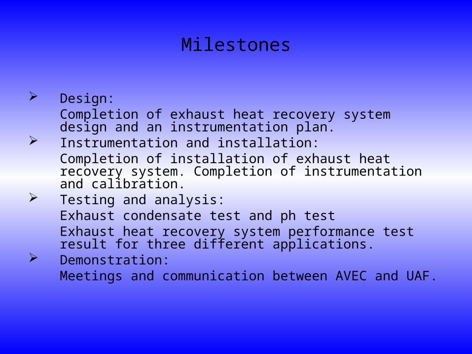
Design: Completion of exhaust heat recovery system design and an instrumentation plan.
Instrumentation and installation: Completion of installation of exhaust heat recovery system. Completion of instrumentation and calibration.
Testing and analysis: Exhaust condensate test and ph testExhaust heat recovery system performance test result for three different applications.
Demonstration: Meetings and communication between AVEC and UAF.
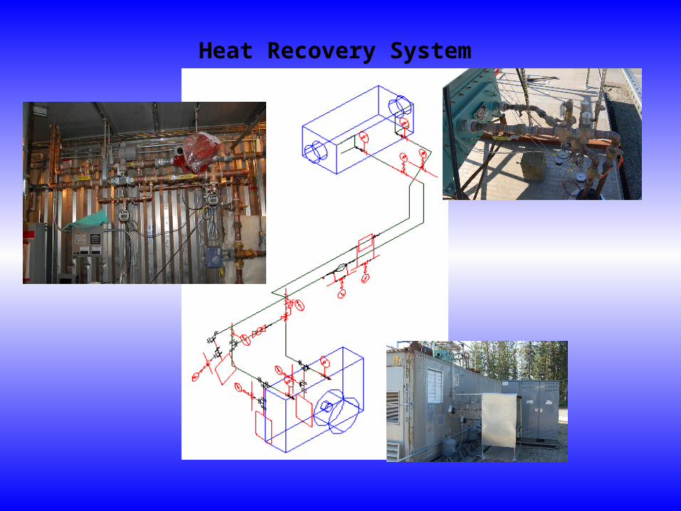
Heat Recovery System

Three Application Cases
Future cogeneration market segments (Alaska Energy Plan- Cogeneration chapter)
Building with low temperature baseboard heating Building with in floor radiant heating Community water loop temperature maintenance
o Residential micro cogeneration units (e.g. Stirling)o School cogeneration units (e.g. Diesel Generator)

Line Diagram
Heat Exchanger
Unit Heater
1102 - 13
1102 - 08
1102 - 17
1102 - 18
1102 - 20
1102 - 19
1102 - 14
1102 - 15
T1
T2
T3
mc
T6
T5
T4
T 7 T8
mu
mb
Pump
Flow Meter
Mass flow meterSCXI 1120
Before 3-way valve Temp20
After 3-way valve Temp19
Bypass Temp18
Before bypass Temp17
Exhaust15
Heat exchanger outlet Temp14
Heat exchanger inlet Temp13
Shell outlet 8
Name in DAQSlot in SCXI 1102
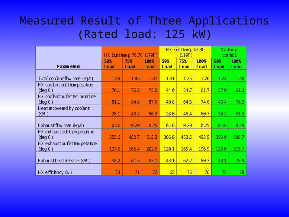
Measured Result of Three Applications(Rated load: 125 kW)
HX inlet temp 76.7C (170F) HX inlet temp 43.3C
(110F) No temp control
Parameters 50% Load
75% Load
100% Load
50% Load
75% Load
100% Load
50% Load
100% Load
Total coolant flow rate (kg/s) 1.49 1.45 1.37 1.31 1.25 1.26 1.24 1.26 HX coolant inlet temperature (deg C) 76.1 76.8 75.9 44.0 54.7 61.7 37.0 61.3 HX coolant outlet temperature (deg C) 81.1 84.8 87.6 49.8 64.6 74.6 43.4 74.2 Heat recovered by coolant (KW) 28.1 43.7 60.2 28.0 46.4 60.7 30.2 61.2
Exhaust flow rate (kg/s) 0.16 0.20 0.25 0.16 0.20 0.25 0.16 0.25 HX exhaust inlet temperature (deg C) 355.6 452.7 513.3 366.8 453.5 498.5 359.0 508.7 HX exhaust outlet temperature (deg C) 127.6 166.4 202.6 120.1 165.4 196.9 123.0 215.7
Exhaust heat release (KW) 38.2 61.5 83.1 43.1 62.2 80.3 40.1 78.9
HX efficiency (%) 74 71 72 65 75 76 75 78
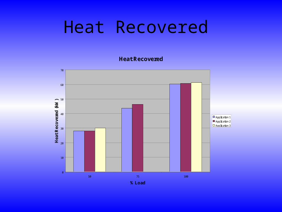
Heat Recovered
Heat Recovered
0
10
20
30
40
50
60
70
50 75 100
% Load
Hea
t R
eco
vere
d (
kW)
Application 1
Application 2
Application 3

Efficiencies of the Three Applications
Efficiency
55
60
65
70
75
80
50 75 100
Load (%)
Eff
icie
ncy
(%
)
application 1
Application 2
Application 3

Discussion of Data Heat recovery system has worked as expected (consistent
performance).
Temperature control valve has worked as expected. Circuit setters effectively controlled the flow rates and pressure
drops.
According to engine performance data (before and after the installation of the system), the system showed no noticeable influence on engine performance (e.g. P, T).
According to the experimental data of the last 100 hours of engine operation, the performance of heat exchanger was consistent (e.g. Q, T).

Discussion of Data (continued)
The temperatures at various locations of the shell (i.e. exhaust) side of the heat exchanger (including exhaust outlet temperature) were much higher than the dew point (40C) for all operation conditions.
Coolant flow rate was lower than expected (24 gpm versus 30 gpm). What would be the effect on heat recovery?
Heat exchanger efficiencies at different loads were between 71% to 78%, which were lower than expected. According to the insulation of the shell of the heat exchanger (4-in Kaowool), the heat loss to the environment from the exhaust should be about 1/3 of the current heat loss (15 kW). (Double check: [1] homemade insulation to the connection pipes. [2] the measurement instrument and procedure)

Discussion of Data (Continue)
For the first type of heat recovery application, the inlet coolant temperatures of the HX for all three loads were controlled to the desired value (around 76C).
For the second application, the inlet coolant temperatures of HX could not be controlled to the desired temperature (around 43C) except for the case of 50% load (or lower load). Reason: the load simulator (i.e. the unit heat) did not have enough surface area. This problem can be solved by increasing the load capacity of the load simulator.

Engine Performance Data at 50 –hr and 100-hr
Engine Hours
Exhaust Temp (C)
Turbocharger Temp (C)
Fuel Consumption (L/hr.)
Before HX Installed
542 122 34
50 Hours After
540 142 34
100 Hours After
533 140 34
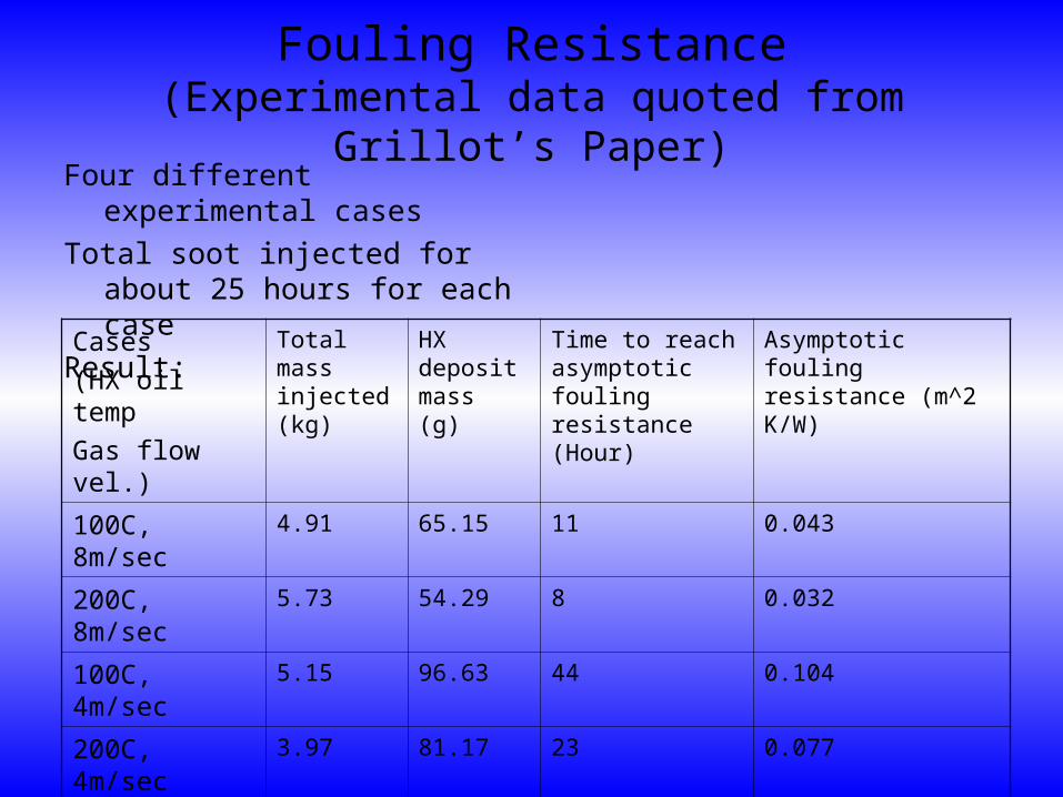
Fouling Resistance(Experimental data quoted from Grillot’s Paper)
Four different experimental cases
Total soot injected for about 25 hours for each case
Result:
Cases
(HX oil temp
Gas flow vel.)
Total mass injected (kg)
HX deposit mass (g)
Time to reach asymptotic fouling resistance (Hour)
Asymptotic fouling resistance (m^2 K/W)
100C, 8m/sec 4.91 65.15 11 0.043
200C, 8m/sec 5.73 54.29 8 0.032
100C, 4m/sec 5.15 96.63 44 0.104
200C, 4m/sec 3.97 81.17 23 0.077
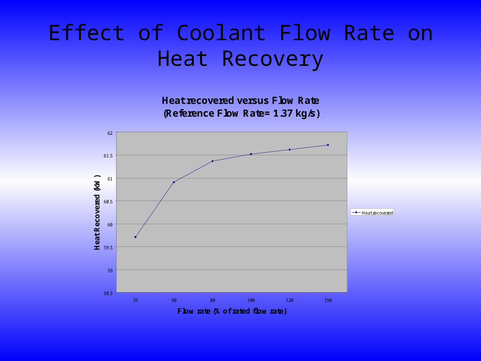
Effect of Coolant Flow Rate on Heat Recovery
Heat recovered versus Flow Rate (Reference Flow Rate= 1.37 kg/s)
58.5
59
59.5
60
60.5
61
61.5
62
25 50 80 100 120 150
Flow rate (% of rated flow rate)
Hea
t R
eco
vere
d (
kW)
Heat recovered

Effect of Coolant Inlet Temperature on Heat Recovery
Effect of Coolant Temperature on Heat Recovery
54
56
58
60
62
64
66
68
70
72
74
15 35 55 65 76.7 85
Coolant Inlet Temperature (C)
Hea
t R
eco
vere
d
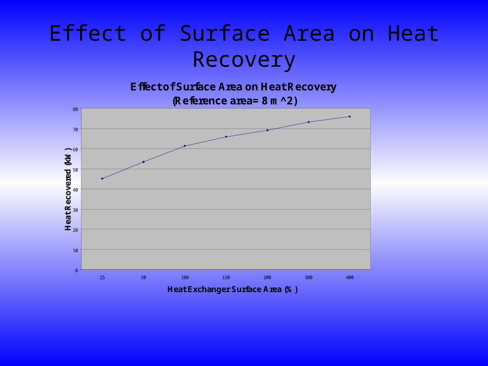
Effect of Surface Area on Heat Recovery
Effect of Surface Area on Heat Recovery(Reference area= 8 m^2)
0
10
20
30
40
50
60
70
80
25 50 100 150 200 300 400
Heat Exchanger Surface Area (%)
Hea
t R
eco
vere
d (
kW)
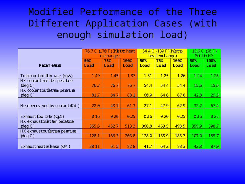
Modified Performance of the Three Different Application Cases (with enough simulation load)
76.7 C (170 F) Inlet to heat exchanger
54.4 C (130 F) Inlet to heat exchanger
15.6 C (60 F) Inlet to HX
Parameters 50% Load
75% Load
100% Load
50% Load
75% Load
100% Load
50% Load
100% Load
Total coolant flow rate (kg/s) 1.49 1.45 1.37 1.31 1.25 1.26 1.24 1.26 HX coolant inlet temperature (deg C) 76.7 76.7 76.7 54.4 54.4 54.4 15.6 15.6 HX coolant outlet temperature (deg C) 81.7 84.7 88.1 60.0 64.6 67.8 42.8 29.8
Heat recovered by coolant (KW) 28.0 43.7 61.3 27.1 47.9 62.9 32.2 67.4
Exhaust flow rate (kg/s) 0.16 0.20 0.25 0.16 0.20 0.25 0.16 0.25 HX exhaust inlet temperature (deg C) 355.6 452.7 513.3 366.8 453.5 498.5 359.0 508.7 HX exhaust outlet temperature (deg C) 128.1 166.3 203.8 128.0 155.9 185.7 107.0 185.7
Exhaust heat release (KW) 38.11 61.5 82.8 41.7 64.2 83.3 42.8 87.0
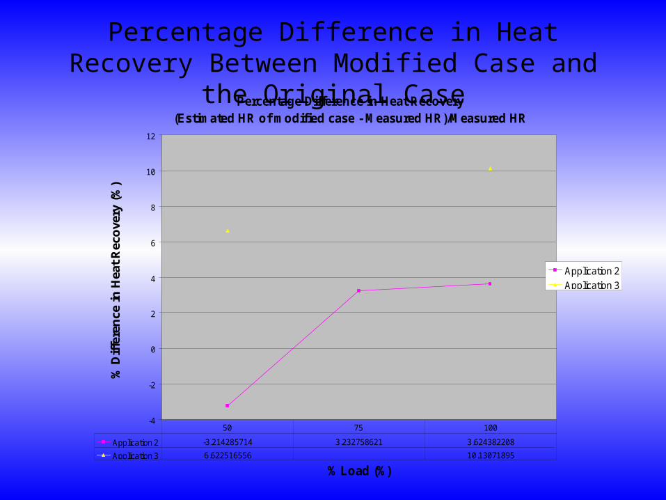
Percentage Difference in Heat Recovery Between Modified Case and the Original Case
Percentage Difference in Heat Recovery(Estimated HR of modified case - Measured HR)/Measured HR
-4
-2
0
2
4
6
8
10
12
% Load (%)
% D
iffe
ren
ce in
Hea
t R
eco
very
(%
)
Application 2
Application 3
Application 2 -3.214285714 3.232758621 3.624382208
Application 3 6.622516556 10.13071895
50 75 100

Heating fuel savings
76.7 C (170 F) Inlet to heat exchanger
54.4 C (130 F) Inlet to heat exchanger
15.6 C (60 F) Inlet to HX
Parameters (Full load: 125 kW)
50% Load
75% Load
100% Load
50% Load
75% Load
100% Load
50% Load
100% Load
Heat released by exhaust (kW) 38.1 61.5 82.8 41.7 64.2 83.3 42.8 87.0
Heat recovered by coolant (kW) 28.0 43.7 61.3 27.1 47.9 62.9 32.2 67.4 Heating fuel saved per 100 kW-hr of electrical power (gal)
1.10
1.14
1.20
1.06
1.25 1.23 1.26 1.32 Heating fuel cost saved per 100 kW-hr electrical power ($2.5/gal)
2.75
2.86
3.00
2.66
3.13 3.09 3.16 3.31
Heating Fuel Saving per 100 kW-hr of electric Power
0
0.2
0.4
0.6
0.8
1
1.2
1.4
50 75 100
% Load
He
atin
g F
ue
l S
av
ing
(G
allo
n)
Application 1
Application 2
Application 3
Conclusion Completion of design installation and instrumentation of the exhaust
heat recovery system.
Study of the system performance:
Control components (e.g. valve controller and circuit setters) worked as expected.
System performance data indicated that HX system had no noticeable effect on engine performance.
Based on HX performance data, soot thermal resistance has not changed much during the last 50 hours operation (need further investigation)
Conclusion (continue)Heating fuel saving per unit kW-hour for higher load was better but not critical.
A relatively large amount of heat (compared to calculated result) dissipated into the surrounding. (Needs further investigation)
According to measured temperature distribution of the shell side, corrosion may not become a problem for this exhaust HX.
Lower coolant flow rate (24 gpm versus 30 gpm) may not affect the heat recovery rate significant (less than 1%).
To lower the requirement of coolant inlet temperature will moderately increase the heat recovery rate. (Application 1 has the lowest heat recovery and application 3 has the highest).

Current Work
To continue performance data collection to further confirm the conclusion listed previously.
To develop a preliminary tool for heat exchanger system cost analysis. (Parameters: size, pressure drop, flow rate, capital and operation cost, etc.).
To propose some recommendations for exhaust heat exchanger design.
To continue collect data and conduct economic analysis.

Future work
Select a turbocharger compressed air heat exchanger and install the turbocharger after cooler heat exchanger system.
Conduct performance and economic analysis for the turbocharger heat recovery system.
Select a village as demonstration site for turbocharger after cooler heat recovery system field demonstration.

Acknowledgement
DOE AETDL AVEC ICRC

Questions ?
Related Documents