Capacity Planning in Non-uniform Depth Anchorages Milad Malekipirbazari, Dindar Oz, Vural Aksakalli, A. Fuat Alkaya and Volkan Aydogdu Abstract Commercial vessels utilize anchorages on a regular basis for various rea- sons such as waiting for loading/unloading, supply, and bad weather conditions. Recent increase in demand for anchorage areas has mandated a review of current anchorage planning strategies. In particular, current state-of-the-art anchorage plan- ning algorithms assume that the anchorage areas are of uniform depth, which is quite unrealistic in general. In this study, we introduce an algorithmic modification to cur- rent anchorage planning methods that takes into account non-uniformity of anchor- ages. By exploiting the depth non-uniformity, our algorithm significantly improves the number of vessels that can be accommodated in an anchorage and it can easily be incorporated into existing anchorage capacity planning decision support systems. Keywords Maritime transportation ⋅ Anchorage ⋅ Optimization algorithm ⋅ Decision support system 1 Introduction Maritime transportation accounts for about 90 % of world’s commerce and there are currently more than a hundred thousand commercial vessels operating in the world [1]. An important component in dealing with maritime traffic congestion is anchor- ages that serve as a temporary waiting area for vessels for various purposes such as land services (fueling, legal issues, repairs, etc.), loading/unloading of cargo, and as M. Malekipirbazari ⋅ V. Aksakalli ( ✉ ) Department of Industrial Engineering, Istanbul Sehir University, 34662 Istanbul, Turkey e-mail: [email protected] D. Oz ⋅ A.F. Alkaya Department of Computer Engineering, Marmara University, 34722 Istanbul, Turkey V. Aydogdu Maritime Faculty, Istanbul Technical University, 34940 Istanbul, Turkey © Springer International Publishing Switzerland 2015 R. Neves-Silva et al. (eds.), Intelligent Decision Technologies, Smart Innovation, Systems and Technologies 39, DOI 10.1007/978-3-319-19857-6_3 21 [email protected]

Welcome message from author
This document is posted to help you gain knowledge. Please leave a comment to let me know what you think about it! Share it to your friends and learn new things together.
Transcript

Capacity Planning in Non-uniformDepth Anchorages
Milad Malekipirbazari, Dindar Oz, Vural Aksakalli, A. Fuat Alkayaand Volkan Aydogdu
Abstract Commercial vessels utilize anchorages on a regular basis for various rea-sons such as waiting for loading/unloading, supply, and bad weather conditions.Recent increase in demand for anchorage areas has mandated a review of currentanchorage planning strategies. In particular, current state-of-the-art anchorage plan-ning algorithms assume that the anchorage areas are of uniform depth, which is quiteunrealistic in general. In this study, we introduce an algorithmic modification to cur-rent anchorage planning methods that takes into account non-uniformity of anchor-ages. By exploiting the depth non-uniformity, our algorithm significantly improvesthe number of vessels that can be accommodated in an anchorage and it can easilybe incorporated into existing anchorage capacity planning decision support systems.Keywords Maritime transportation ⋅ Anchorage ⋅ Optimization algorithm ⋅Decision support system
1 Introduction
Maritime transportation accounts for about 90% of world’s commerce and there arecurrently more than a hundred thousand commercial vessels operating in the world[1]. An important component in dealing with maritime traffic congestion is anchor-ages that serve as a temporary waiting area for vessels for various purposes such asland services (fueling, legal issues, repairs, etc.), loading/unloading of cargo, and as
M. Malekipirbazari ⋅ V. Aksakalli (✉)Department of Industrial Engineering, Istanbul Sehir University, 34662 Istanbul, Turkeye-mail: [email protected]. Oz ⋅ A.F. AlkayaDepartment of Computer Engineering, Marmara University, 34722 Istanbul, TurkeyV. AydogduMaritime Faculty, Istanbul Technical University, 34940 Istanbul, Turkey© Springer International Publishing Switzerland 2015R. Neves-Silva et al. (eds.), Intelligent Decision Technologies,Smart Innovation, Systems and Technologies 39,DOI 10.1007/978-3-319-19857-6_3
21
22 M. Malekipirbazari et al.
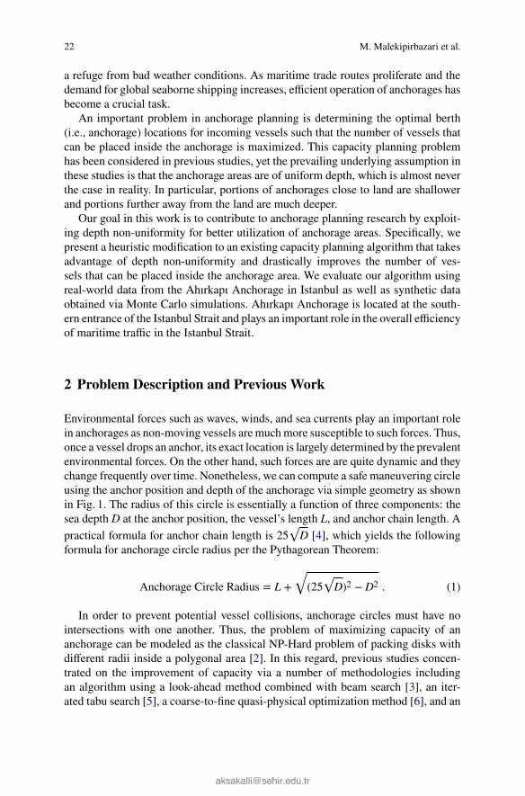
a refuge from bad weather conditions. As maritime trade routes proliferate and thedemand for global seaborne shipping increases, efficient operation of anchorages hasbecome a crucial task.
An important problem in anchorage planning is determining the optimal berth(i.e., anchorage) locations for incoming vessels such that the number of vessels thatcan be placed inside the anchorage is maximized. This capacity planning problemhas been considered in previous studies, yet the prevailing underlying assumption inthese studies is that the anchorage areas are of uniform depth, which is almost neverthe case in reality. In particular, portions of anchorages close to land are shallowerand portions further away from the land are much deeper.
Our goal in this work is to contribute to anchorage planning research by exploit-ing depth non-uniformity for better utilization of anchorage areas. Specifically, wepresent a heuristic modification to an existing capacity planning algorithm that takesadvantage of depth non-uniformity and drastically improves the number of ves-sels that can be placed inside the anchorage area. We evaluate our algorithm usingreal-world data from the Ahırkapı Anchorage in Istanbul as well as synthetic dataobtained via Monte Carlo simulations. Ahırkapı Anchorage is located at the south-ern entrance of the Istanbul Strait and plays an important role in the overall efficiencyof maritime traffic in the Istanbul Strait.
2 Problem Description and Previous Work
Environmental forces such as waves, winds, and sea currents play an important rolein anchorages as non-moving vessels aremuchmore susceptible to such forces. Thus,once a vessel drops an anchor, its exact location is largely determined by the prevalentenvironmental forces. On the other hand, such forces are are quite dynamic and theychange frequently over time. Nonetheless, we can compute a safe maneuvering circleusing the anchor position and depth of the anchorage via simple geometry as shownin Fig. 1. The radius of this circle is essentially a function of three components: thesea depth D at the anchor position, the vessel’s length L, and anchor chain length. Apractical formula for anchor chain length is 25√D [4], which yields the followingformula for anchorage circle radius per the Pythagorean Theorem:
Anchorage Circle Radius = L +√
(25√D)2 − D2 . (1)
In order to prevent potential vessel collisions, anchorage circles must have nointersections with one another. Thus, the problem of maximizing capacity of ananchorage can be modeled as the classical NP-Hard problem of packing disks withdifferent radii inside a polygonal area [2]. In this regard, previous studies concen-trated on the improvement of capacity via a number of methodologies includingan algorithm using a look-ahead method combined with beam search [3], an iter-ated tabu search [5], a coarse-to-fine quasi-physical optimization method [6], and an

Capacity Planning in Non-uniform Depth Anchorages 23
Fig. 1 Illustration of the anchorage circle associated with an anchored vessel
action-space-based global optimization approach for the problem of packing unequalcircles into a square container [7].
The current state-of-the-art in anchorage planning is the MHDF Algorithm pro-posed in Huang et al. [8] based on the notion of corner points evaluated via MonteCarlo simulations. This algorithm is heuristic in nature without any optimality guar-antees. The simulation tool and the algorithm introduced therein were later utilizedin a marine traffic simulation system for hub ports [9]. Another simulation-basedapproach was presented in Shyshou et al. [10] where the authors investigated theoptimal number of tug ships needed to move an oil rig with respect to equipment andweather related constraints. The algorithm we propose in this study is an extensionof the MHDF Algorithm that exploits depth non-uniformity. Thus, our algorithmis also heuristic in nature. We are not aware of any previous studies on anchoragecapacity planning that consider any depth non-uniformity aspects of the problem.
3 Corner Points and the MHDF Algorithm
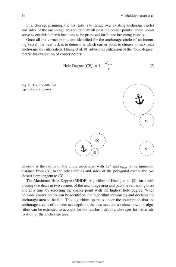
A corner pointCPi associated with an anchorage circle i is defined as the point wherethe circle is tangent to at least two elements when its center is located at CPi (see,e.g., [8]). These elements can either be the existing anchored vessels representedas circles or sides of the anchorage polygon. Corner points are classified into threecategories with respect to the element types they are tangent to. These categories areillustrated in Fig. 2 and described below:1. Side-and-Side (SS) Corner Points: The circle center is tangent to any two sides
of the anchorage area.2. Side-and-Circle (SC) Corner Points: The circle center is tangent to an existing
anchorage and a side of the anchorage area.3. Circle-and-Circle (CC) Corner Points: The circle center is tangent to two existing
anchorage circles.
24 M. Malekipirbazari et al.
In anchorage planning, the first task is to iterate over existing anchorage circlesand sides of the anchorage area to identify all possible corner points. These pointsserve as candidate berth locations to be proposed for future incoming vessels.
Once all the corner points are identified for the anchorage circle of an incom-ing vessel, the next task is to determine which corner point to choose to maximizeanchorage area utilization. Huang et al. [8] advocates utilization of the “hole degree”metric for evaluation of corner points:
Hole Degree (CPi) = 1 −dminr
(2)
Fig. 2 The tree differenttypes of corner points
where r is the radius of the circle associated with CPi and dmin is the minimumdistance from CPi to the other circles and sides of the polygonal except the twoclosest item tangent to CPi.The Maximum Hole-Degree (MHDF) Algorithm of Huang et al. [8] starts withplacing two discs at two corners of the anchorage area and puts the remaining discsone at a time by selecting the corner point with the highest hole degree. Whenno more corner points can be identified, the algorithm terminates and declares theanchorage area to be full. This algorithm operates under the assumption that theanchorage area is of uniform sea depth. In the next section, we show how this algo-rithm can be extended to account for non-uniform depth anchorages for better uti-lization of the anchorage area.

Capacity Planning in Non-uniform Depth Anchorages 25
4 The Non-uniform MHDF Algorithm
4.1 A Model for Non-uniform Depth Anchorage Areas
We model non-uniform depth anchorage areas as a partitioning of the entire anchor-age area into uniform-depth polygonal segments. This model is illustrated in Fig. 3for the Dangerous Cargo Zone of Ahırkapı Anchorage. In a polygonal segment, radiiof the anchorage circles are determined by the segment’s sea depth as can be seenin Eq. 1. In addition, the segment depth determines the maximum length for vesselsthat can safely be placed inside the segment, as explained below.
Fig. 3 The Ahırkapı Dangerous Cargo Anchorage Zone. The arrow shows the entry side of thezone. The numbers denote the sea depth in each polygonal sub-segment in meters
In seamanship terminology, draft refers to the depth of the ship from water lineto the bottom of the ship which is typically equal to the length of the ship dividedby 10.5 for tankers and 11.75 for bulk carriers and container ships [11]. The mini-mum sea depth that a vessel with a particular length can safely anchor can then becalculated as
Minimum D = Draft × UKCF = L × UKCF(10.5 or 11.75) (3)
where UKCF stands for Under Keal Clearance Factor. A practical UKCF value forships at anchorage is 1.5. For example, a tanker with a length of 100m requires asea depth of at least 14m for safe anchorage. Thus, the longest vessel that can safelyanchor at depth D can be calculated as follows:
Maximum L = D × (10.5 or 11.75)UKCF . (4)
Therefore, for each polygonal segment, there exist a maximum vessel length con-straint as determined by Eq. 4. In our model, we take into account this constraint and

26 M. Malekipirbazari et al.
we do not allow vessels anchor at segments that are not deep enough. Specifically,during the corner point identification process, we only consider corner points thatare inside polygonal segments deep enough for the incoming vessel.
4.2 Corner Point Calculation in Non-uniform DepthAnchorages
In the MHDF Algorithm, all possible corner points are calculated and the one withthe highest hole degree is chosen as the berth location for an incoming vessel. In thecase of non-uniform depth anchorages, the corner point calculation process needs tobe modified to account for the minimum depth constraint for the incoming vessels.A critical challenge arise in this modification: Per Eq. 1, the radius of the incomingvessel’s anchorage circle depends on the depth of the seawater. Thus, we must firstfind the depth of the seawater at the position of the anchorage circle and then calculatethe radius of the anchorage circle. However, due to non-uniforms depths, the exactposition of corner point associated with the anchorage circle cannot be determinedwithout the radius information.
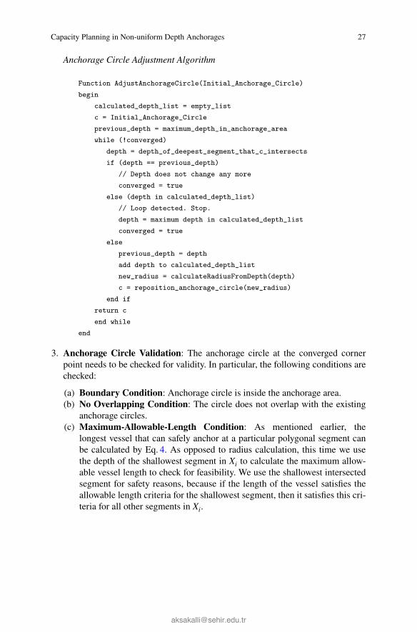
In this section, we present a three-stage algorithm that overcomes the above chal-lenge by iterative calculation of the exact location of the corner point given the pairof items that the anchorage circle will be tangent to. These items can be either oneof the existing anchorage circles or a side of the anchorage area. The algorithm takesthose two items and the length of the vessel as inputs. The algorithm is then exe-cuted for every pair of items in the anchorage area in order to calculate all possi-ble anchorage circles for an incoming vessel. Once this three-stage algorithm is runand all the feasible corner points are identified, as in MHDF, we declare the cor-ner point with the highest hole degree as the berth location for the incoming vessel.The MHDF Algorithm with this three-stage corner point calculation algorithm (inthe case of non-uniform depths) is called the Non-uniform MHDF Algorithm, NU-MHDF Algorithm in short. The three-stage corner point calculation algorithm isdescribed below.1. Initial Placement: The algorithm starts with an initial placement of the corner
point CPi in the deepest polygonal segment in the anchorage area.2. Anchorage Circle Adjustment: After the initial placement, the algorithm finds
the depth segments that the anchorage circle at the corner point has intersectionswith, which we denote by Xi. Due to the minimum sea depth constraint, the algo-rithm takes the depth of the deepest segment in Xi and adjusts the radius of theanchorage circle accordingly. After the radius is updated, it repositions the cornerpoint with the new radius and calculates the setXi again. This loop continues untilthe deepest depth segment with which the anchorage circle has intersection withdoes not change in the next iteration or a depth value is obtained that has beenpreviously calculated. The pseudo-code for this adjustment algorithm is givenbelow.
Capacity Planning in Non-uniform Depth Anchorages 27
Anchorage Circle Adjustment Algorithm
Function AdjustAnchorageCircle(Initial_Anchorage_Circle)begin
calculated_depth_list = empty_listc = Initial_Anchorage_Circleprevious_depth = maximum_depth_in_anchorage_areawhile (!converged)
depth = depth_of_deepest_segment_that_c_intersectsif (depth == previous_depth)
// Depth does not change any moreconverged = true
else (depth in calculated_depth_list)// Loop detected. Stop.depth = maximum depth in calculated_depth_listconverged = true
elseprevious_depth = depthadd depth to calculated_depth_listnew_radius = calculateRadiusFromDepth(depth)c = reposition_anchorage_circle(new_radius)
end ifreturn cend while
end
3. Anchorage Circle Validation: The anchorage circle at the converged cornerpoint needs to be checked for validity. In particular, the following conditions arechecked:(a) Boundary Condition: Anchorage circle is inside the anchorage area.(b) No Overlapping Condition: The circle does not overlap with the existing
anchorage circles.(c) Maximum-Allowable-Length Condition: As mentioned earlier, the
longest vessel that can safely anchor at a particular polygonal segment canbe calculated by Eq. 4. As opposed to radius calculation, this time we usethe depth of the shallowest segment in Xi to calculate the maximum allow-able vessel length to check for feasibility. We use the shallowest intersectedsegment for safety reasons, because if the length of the vessel satisfies theallowable length criteria for the shallowest segment, then it satisfies this cri-teria for all other segments in Xi.

28 M. Malekipirbazari et al.
4.3 Proof of Convergence
We now show that the Anchorage Circle Adjustment process above converges in afinite number of steps. Let d1, d2, ...dN ∈ X denote the finite set of depth segments inthe anchorage A and dmax be the deepest segment in A. Let I1 and I2 be the two itemsfor which the algorithm needs to find the anchorage circle. The algorithm computesthe place of the anchorage circle tangent to I1 and I2 in A with the depth segmentsof X (i.e., A, X, I1 and I2 are the inputs).Let rinitial be the radius of the initial circle Cinitial calculated for I1 and I2 withdepth dmax. Let Ci denote the anchorage circle calculated at the i−th iteration wherei > 0 and ri denotes its radius. Note thatC1 equalsCinitial and r1 equals rinitial accord-ing to this definition. Let Xi be the set of depth segments intersecting with Ci. Sincethe entire anchorage area is comprised by the depth segments in X, Xi cannot beempty. Let dmaxi denote the deepest segment in Xi. Finally, let CDLi denote the cal-culated depth list at i−th iteration. CDLi is the set of depth segments which are cal-culated as dmaxj at some j−th iteration where j < i. Notice that CDL1 is simply theempty set as assigned in the algorithm.
At each iteration, the while loop has three branches listed below, two of whichresults in convergence.1. If dmaxi = dmaxi−1 , the algorithm converges. Note that dmax0 = dmax.2. Else if dmaxi ∈ CDLi, the algorithm converges.3. Else
CDLi+1 = CDLi + dmaxiri+1 = new radius calculated from dmaxiCi+1 = new circle calculated from ri+1And proceed to (i + 1)-th iteration.
In order for the algorithm to diverge and execute indefinitely, the third branch listedabovemust be executed infinitelymany times. To prove by contradiction, suppose thealgorithm executes the third branch for infinitely many times for a particular instanceof A, I1, I2, and X. Observe that CDLi gets expanded by one element at each iterationwhen the loop falls into the third branch. Also note that CDLi is the subset of X. Ifthe algorithm falls into the third branch infinitely many times for this instance, thenthe set CDLi must be expanded infinitely which is a contradiction since X is assumedto be a finite set. Thus, we conclude that the Anchorage Circle Adjustment algorithmconverges in a finite number of iterations.
5 Computational Experiments
This section presents a comparison of NU-MHDF against regular MHDF via MonteCarlo simulations using three different vessel length distributions on three differ-ent real-world anchorage topologies. Throughout our experiments, the anchorage
Capacity Planning in Non-uniform Depth Anchorages 29
circle radii in MHDF are calculated with respect to the deepest sea depth inside theanchorage as any other depths would result in the dangerous situation of overlappinganchorage circles.
The vessel length distributions used in our experiments are (1) the historical ves-sel length distribution in the Ahırkapı Anchorage in 2013, (2) the uniform distrib-ution between 25 and 250m, and (3) Gamma distributed lengths between 25 and250m with shape parameters of 4 and 7 respectively (with a mean of about 100m)that closely fits the historical Ahırkapı data.
The anchorage topologies we consider are the Harbor Approach, Departure LongStay, and Dangerous Cargo anchorage zones inside the Ahırkapı Anchorage Area.We implemented a comprehensive and realistic simulation environment for compar-ison of the algorithms. In particular, we used common random numbers for both ofthe algorithms so that theywere tested on the exact same sequences of vessel arrivals.
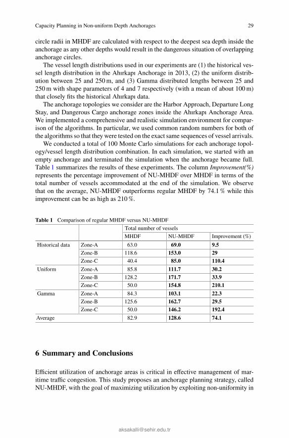
We conducted a total of 100 Monte Carlo simulations for each anchorage topol-ogy/vessel length distribution combination. In each simulation, we started with anempty anchorage and terminated the simulation when the anchorage became full.Table 1 summarizes the results of these experiments. The column Improvement(%)represents the percentage improvement of NU-MHDF over MHDF in terms of thetotal number of vessels accommodated at the end of the simulation. We observethat on the average, NU-MHDF outperforms regular MHDF by 74.1% while thisimprovement can be as high as 210%.
Table 1 Comparison of regular MHDF versus NU-MHDFTotal number of vesselsMHDF NU-MHDF Improvement (%)
Historical data Zone-A 63.0 69.0 9.5Zone-B 118.6 153.0 29Zone-C 40.4 85.0 110.4
Uniform Zone-A 85.8 111.7 30.2Zone-B 128.2 171.7 33.9Zone-C 50.0 154.8 210.1
Gamma Zone-A 84.3 103.1 22.3Zone-B 125.6 162.7 29.5Zone-C 50.0 146.2 192.4
Average 82.9 128.6 74.1
6 Summary and Conclusions
Efficient utilization of anchorage areas is critical in effective management of mar-itime traffic congestion. This study proposes an anchorage planning strategy, calledNU-MHDF, with the goal of maximizing utilization by exploiting non-uniformity in

30 M. Malekipirbazari et al.
sea depths inside the anchorages. The NU-MHDF Algorithm is an extension of theMHDF Algorithm that starts with the deepest polygonal segment inside the anchor-age area and iteratively adjusts the corner point locations until convergence. We pro-vide a proof that the algorithm converges in a finite number of steps. Our simulationresults with three different vessel length distributions and three different anchoragezones show that NU-MHDF consistently yields much higher utilization levels com-pared to MHDF. The NU-MHDF Algorithm stands as a high-performing anchorageplanning strategy that can be integrated into existing anchorage planning decisionsupport systems in a straightforward manner.Acknowledgments This work was supported by The Scientific and Technological Research Coun-cil of Turkey (TUBITAK), Grant No. 113M489.Wewould like to thank TurkishDirectorate Generalof Coastal Safety for providing us the historical traffic data for the Ahırkapı Anchorage.
References
1. AGCS: Safety and shipping 1912–2012 from Titanic to Costa Concordia. Technical Report,Allianz Global Corporate & Specialty (2013)
2. Akeb, H., Hifi, M.: Algorithms for the circular two-dimensional open dimension problem. Int.Trans. Oper. Res. 15(1), 685–704 (2008)
3. Akeb, H., Hifi, M.: Solving the circular open dimension problem by using separate beams andlook-ahead strategies. Comput. Oper. Res. 40(5), 1243–1255 (2013)
4. Danton, G.: The Theory and Practice of Seamanship. Routledge & Kegan Paul, London, UK(1996)
5. Fu, Z., Huang, W., Lu, Z.: Iterated tabu search for the circular open dimension problem. Eur.J. Oper. Res. 225(2), 236–243 (2013)
6. He, K., Mo, D., Ye, T., Huang, W.: A coarse-to-fine quasi-physical optimization method forsolving the circle packing problem with equilibrium constraints. Comput. Ind. Eng. 66(4),1049–1060 (2013)
7. He, K., Huang, M., Yang, C.: An action-space-based global optimization algorithm for packingcircles into a square container. Comput. Oper. Res. 58(1), 67–74 (2015)
8. Huang, S., Hsu, W., He, Y.: Assessing capacity and improving utilization of anchorages.Transp. Res. Part E Logistics Transp. Rev. 47(2), 216–227 (2011)
9. Huang, S., Hsu, W., He, Y., Song, T.: A marine traffic simulation system for hub ports. In:Proceedings of ACM SIGSIM Conference on Principles of Advanced Discrete Simulation. pp.295–304 (2013)
10. Shyshou, A., Gribkovskaia, I., Barcel, J.: A simulation study of the fleet sizing problem arisingin offshore anchor handling operations. Eur. J. Oper. Res. 203(1), 230–240 (2010)
11. Watson, D.: Practical Ship Design. Elsevier Science, Oxford (1998)
Related Documents