Page 1 of 20 CAPACITORS, FIXED, CERAMIC DIELECTRIC, TYPE I, HIGH VOLTAGE, 1kV TO 5kV BASED ON TYPES VR, CV AND CH ESCC Detail Specification No. 3001/033 Issue 6 November 2021 Document Custodian: European Space Agency – see https://escies.org

Welcome message from author
This document is posted to help you gain knowledge. Please leave a comment to let me know what you think about it! Share it to your friends and learn new things together.
Transcript
Page 1 of 20
CAPACITORS, FIXED, CERAMIC DIELECTRIC, TYPE I, HIGH VOLTAGE, 1kV TO 5kV
BASED ON TYPES VR, CV AND CH
ESCC Detail Specification No. 3001/033
Issue 6 November 2021
Document Custodian: European Space Agency – see https://escies.org
ESCC Detail Specification
No. 3001/033
PAGE 2
ISSUE 6
LEGAL DISCLAIMER AND COPYRIGHT
European Space Agency, Copyright © 2021. All rights reserved.
The European Space Agency disclaims any liability or responsibility, to any person or entity, with respect to any loss or damage caused, or alleged to be caused, directly or indirectly by the use and application of this ESCC publication.
This publication, without prior the permission of the European Space Agency and provided that it is not used for a commercial purpose, may be:
− copied in whole, in any medium, without alteration or modification. − copied in part, in any medium, provided that the ESCC document identification, comprising the
ESCC symbol, document number and document issue, is removed.
ESCC Detail Specification
No. 3001/033
PAGE 3
ISSUE 6
DOCUMENTATION CHANGE NOTICE
(Refer to https://escies.org for ESCC DCR content)
DCR No. CHANGE DESCRIPTION
1467 Specification updated to incorporate changes per DCR.
ESCC Detail Specification
No. 3001/033
PAGE 4
ISSUE 6
TABLE OF CONTENTS
1 GENERAL 5
1.1 SCOPE 5
1.2 APPLICABLE DOCUMENTS 5
1.3 TERMS, DEFINITIONS, ABBREVIATIONS, SYMBOLS AND UNITS 5
1.4 THE ESCC COMPONENT NUMBER AND COMPONENT TYPE VARIANTS 5
1.4.1 The ESCC Component Number 5
1.4.2 Component Type Variants and Range of Components 7
1.5 MAXIMUM RATINGS 8
1.6 PHYSICAL DIMENSIONS 9
1.6.1 Case Type VR with Radial Leads 9
1.6.2 Case Type CV with Radial Leads 10
1.6.3 Case Type CH with Straight DIL Leads 11
1.6.4 Case Type CH with L DIL Leads 12
1.7 FUNCTIONAL DIAGRAM 12
2 REQUIREMENTS 13
2.1 GENERAL 13
2.1.1 Deviations from the Generic Specification 13
2.2 MARKING 13
2.3 ROBUSTNESS OF TERMINATIONS 14
2.4 ELECTRICAL MEASUREMENTS AT ROOM, HIGH AND LOW TEMPERATURES 15
2.4.1 Room Temperature Electrical Measurements 15
2.4.2 High and Low Temperatures Electrical Measurements 16
2.5 INTERMEDIATE AND END-POINT ELECTRICAL MEASUREMENTS 17
2.6 BURN-IN 19
APPENDIX A 20
ESCC Detail Specification
No. 3001/033
PAGE 5
ISSUE 6
1 GENERAL
1.1 SCOPE This specification details the ratings, physical and electrical characteristics, and test and inspection data for the component type variants and/or the range of components specified below. It supplements the requirements of, and shall be read in conjunction with, the ESCC Generic Specification listed under Applicable Documents.
1.2 APPLICABLE DOCUMENTS The following documents form part of this specification and shall be read in conjunction with it:
(a) ESCC Generic Specification No. 3001.
1.3 TERMS, DEFINITIONS, ABBREVIATIONS, SYMBOLS AND UNITS For the purpose of this specification, the terms, definitions, abbreviations, symbols and units specified in ESCC Basic Specification No. 21300 shall apply.
1.4 THE ESCC COMPONENT NUMBER AND COMPONENT TYPE VARIANTS
1.4.1 The ESCC Component Number The ESCC Component Number shall be constituted as follows:
Example: 300103301470K1R
• Detail Specification Reference: 3001033 • Component Type Variant Number: 01 (as required) • Characteristic code: Capacitance Value (47pF): 470 (as required) • Characteristic code: Capacitance Tolerance (±10%): K (as required) • Characteristic code: Temperature Coefficient (±30 ×10-6/°C): 1 • Rating code: Rated Voltage (3kV): R (as required)
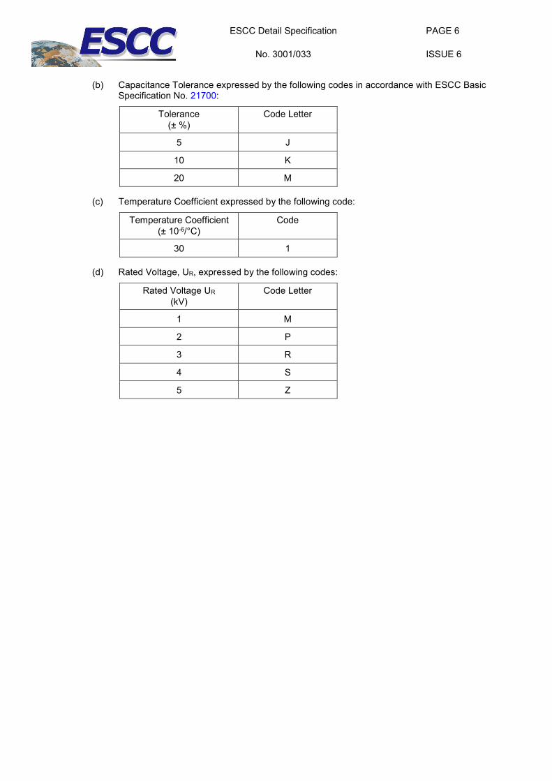
1.4.1.1 Characteristics and Ratings Codes Characteristics and ratings to be codified as part of the ESCC Component Number shall be as follows:
(a) Rated Capacitance Value, Cn, expressed by means of the following codes in accordance with ESCC Basic Specification No. 21700. The unit quantity shall be picofarad (pF).
Capacitance Value Cn (pF)
Code
XX 100 XX0
XX 101 XX1
XX 102 XX2
XX 103 XX3
XX 104 XX4
ESCC Detail Specification
No. 3001/033
PAGE 6
ISSUE 6
(b) Capacitance Tolerance expressed by the following codes in accordance with ESCC Basic
Specification No. 21700:
Tolerance (± %)
Code Letter
5 J
10 K
20 M
(c) Temperature Coefficient expressed by the following code:
Temperature Coefficient (± 10-6/°C)
Code
30 1
(d) Rated Voltage, UR, expressed by the following codes:
Rated Voltage UR (kV)
Code Letter
1 M
2 P
3 R
4 S
5 Z
ESCC Detail Specification
No. 3001/033
PAGE 7
ISSUE 6
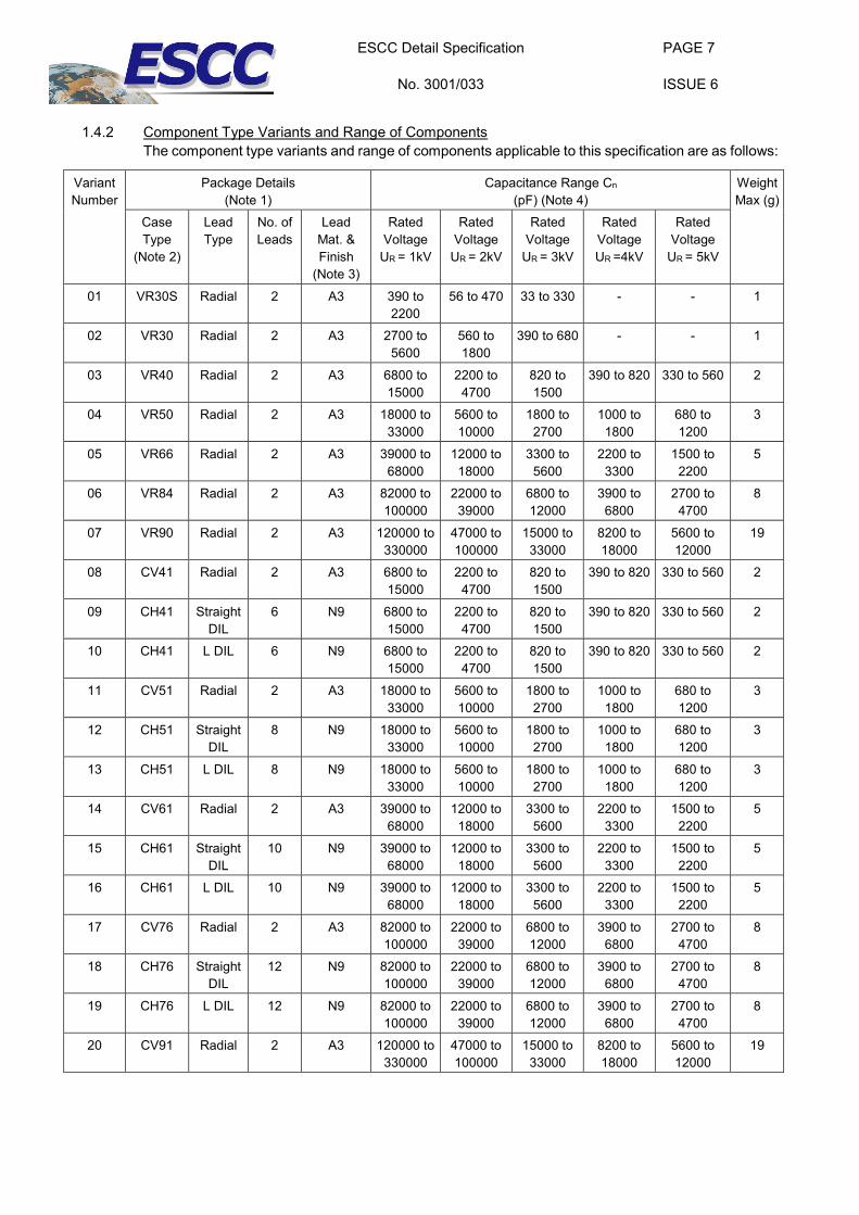
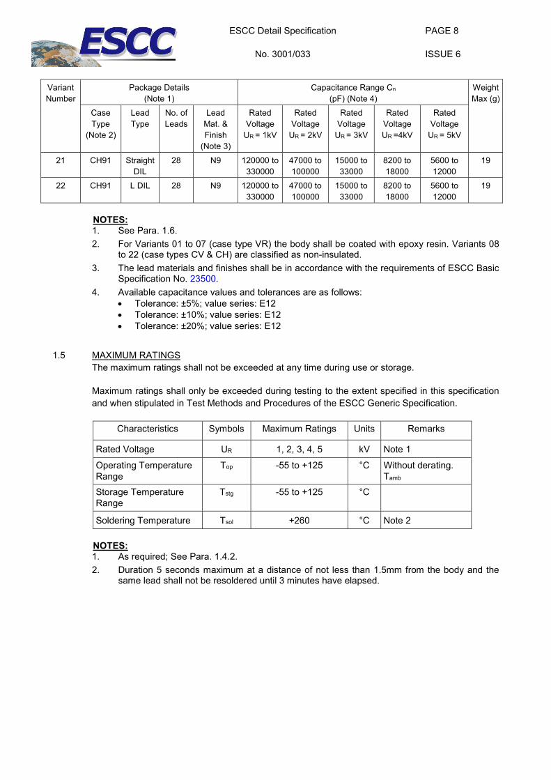
1.4.2 Component Type Variants and Range of Components
The component type variants and range of components applicable to this specification are as follows:
Variant Number
Package Details (Note 1)
Capacitance Range Cn (pF) (Note 4)
Weight Max (g)
Case Type
(Note 2)
Lead Type
No. of Leads
Lead Mat. & Finish
(Note 3)
Rated Voltage
UR = 1kV
Rated Voltage
UR = 2kV
Rated Voltage
UR = 3kV
Rated Voltage UR =4kV
Rated Voltage
UR = 5kV
01 VR30S Radial 2 A3 390 to 2200
56 to 470 33 to 330 - - 1
02 VR30 Radial 2 A3 2700 to 5600
560 to 1800
390 to 680 - - 1
03 VR40 Radial 2 A3 6800 to 15000
2200 to 4700
820 to 1500
390 to 820 330 to 560 2
04 VR50 Radial 2 A3 18000 to 33000
5600 to 10000
1800 to 2700
1000 to 1800
680 to 1200
3
05 VR66 Radial 2 A3 39000 to 68000
12000 to 18000
3300 to 5600
2200 to 3300
1500 to 2200
5
06 VR84 Radial 2 A3 82000 to 100000
22000 to 39000
6800 to 12000
3900 to 6800
2700 to 4700
8
07 VR90 Radial 2 A3 120000 to 330000
47000 to 100000
15000 to 33000
8200 to 18000
5600 to 12000
19
08 CV41 Radial 2 A3 6800 to 15000
2200 to 4700
820 to 1500
390 to 820 330 to 560 2
09 CH41 Straight DIL
6 N9 6800 to 15000
2200 to 4700
820 to 1500
390 to 820 330 to 560 2
10 CH41 L DIL 6 N9 6800 to 15000
2200 to 4700
820 to 1500
390 to 820 330 to 560 2
11 CV51 Radial 2 A3 18000 to 33000
5600 to 10000
1800 to 2700
1000 to 1800
680 to 1200
3
12 CH51 Straight DIL
8 N9 18000 to 33000
5600 to 10000
1800 to 2700
1000 to 1800
680 to 1200
3
13 CH51 L DIL 8 N9 18000 to 33000
5600 to 10000
1800 to 2700
1000 to 1800
680 to 1200
3
14 CV61 Radial 2 A3 39000 to 68000
12000 to 18000
3300 to 5600
2200 to 3300
1500 to 2200
5
15 CH61 Straight DIL
10 N9 39000 to 68000
12000 to 18000
3300 to 5600
2200 to 3300
1500 to 2200
5
16 CH61 L DIL 10 N9 39000 to 68000
12000 to 18000
3300 to 5600
2200 to 3300
1500 to 2200
5
17 CV76 Radial 2 A3 82000 to 100000
22000 to 39000
6800 to 12000
3900 to 6800
2700 to 4700
8
18 CH76 Straight DIL
12 N9 82000 to 100000
22000 to 39000
6800 to 12000
3900 to 6800
2700 to 4700
8
19 CH76 L DIL 12 N9 82000 to 100000
22000 to 39000
6800 to 12000
3900 to 6800
2700 to 4700
8
20 CV91 Radial 2 A3 120000 to 330000
47000 to 100000
15000 to 33000
8200 to 18000
5600 to 12000
19
ESCC Detail Specification
No. 3001/033
PAGE 8
ISSUE 6
Variant Number
Package Details (Note 1)
Capacitance Range Cn (pF) (Note 4)
Weight Max (g)
Case Type
(Note 2)
Lead Type
No. of Leads
Lead Mat. & Finish
(Note 3)
Rated Voltage
UR = 1kV
Rated Voltage
UR = 2kV
Rated Voltage
UR = 3kV
Rated Voltage UR =4kV
Rated Voltage
UR = 5kV
21 CH91 Straight DIL
28 N9 120000 to 330000
47000 to 100000
15000 to 33000
8200 to 18000
5600 to 12000
19
22 CH91 L DIL 28 N9 120000 to 330000
47000 to 100000
15000 to 33000
8200 to 18000
5600 to 12000
19
NOTES: 1. See Para. 1.6. 2. For Variants 01 to 07 (case type VR) the body shall be coated with epoxy resin. Variants 08
to 22 (case types CV & CH) are classified as non-insulated. 3. The lead materials and finishes shall be in accordance with the requirements of ESCC Basic
Specification No. 23500. 4. Available capacitance values and tolerances are as follows:
• Tolerance: ±5%; value series: E12 • Tolerance: ±10%; value series: E12 • Tolerance: ±20%; value series: E12
1.5 MAXIMUM RATINGS The maximum ratings shall not be exceeded at any time during use or storage.
Maximum ratings shall only be exceeded during testing to the extent specified in this specification and when stipulated in Test Methods and Procedures of the ESCC Generic Specification.
Characteristics Symbols Maximum Ratings Units Remarks
Rated Voltage UR 1, 2, 3, 4, 5 kV Note 1
Operating Temperature Range
Top -55 to +125 °C Without derating. Tamb
Storage Temperature Range
Tstg -55 to +125 °C
Soldering Temperature Tsol +260 °C Note 2
NOTES: 1. As required; See Para. 1.4.2. 2. Duration 5 seconds maximum at a distance of not less than 1.5mm from the body and the
same lead shall not be resoldered until 3 minutes have elapsed.
ESCC Detail Specification
No. 3001/033
PAGE 9
ISSUE 6
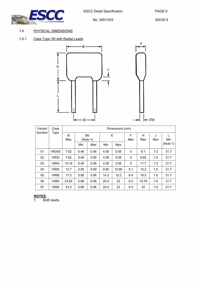
1.6 PHYSICAL DIMENSIONS
1.6.1 Case Type VR with Radial Leads
Variant Number
Case Type
Dimensions (mm)
B Max
Ød (Note 1)
E
F Max
H Max
J Max
L Min
(Note 1) Min Max Min Max
01 VR30S 7.62 0.46 0.56 4.58 5.58 5 6.1 1.5 31.7
02 VR30 7.62 0.46 0.56 4.58 5.58 5 9.62 1.5 31.7
03 VR40 10.16 0.46 0.56 4.58 5.58 5 11.7 1.5 31.7
04 VR50 12.7 0.59 0.69 9.66 10.66 5.1 14.2 1.5 31.7
05 VR66 17.5 0.86 0.96 14.2 15.2 6.4 16.5 1.5 31.7
06 VR84 23.62 0.86 0.96 20.4 22 6.4 19.78 1.5 31.7
07 VR90 23.5 0.86 0.96 20.4 22 6.4 42 1.5 31.7
NOTES: 1. Both leads.
ESCC Detail Specification
No. 3001/033
PAGE 10
ISSUE 6
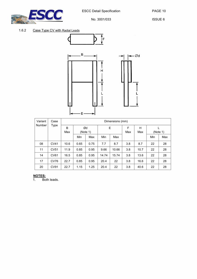
1.6.2 Case Type CV with Radial Leads
Variant Number
Case Type
Dimensions (mm)
B Max
Ød (Note 1)
E
F Max
H Max
L (Note 1)
Min Max Min Max Min Max
08 CV41 10.6 0.65 0.75 7.7 8.7 3.8 8.7 22 28
11 CV51 11.9 0.85 0.95 9.66 10.66 3.8 10.7 22 28
14 CV61 16.5 0.85 0.95 14.74 15.74 3.8 13.6 22 28
17 CV76 22.7 0.85 0.95 20.4 22 3.8 16.6 22 28
20 CV91 22.7 1.15 1.25 20.4 22 3.8 40.6 22 28
NOTES: 1. Both leads.
ESCC Detail Specification
No. 3001/033
PAGE 11
ISSUE 6
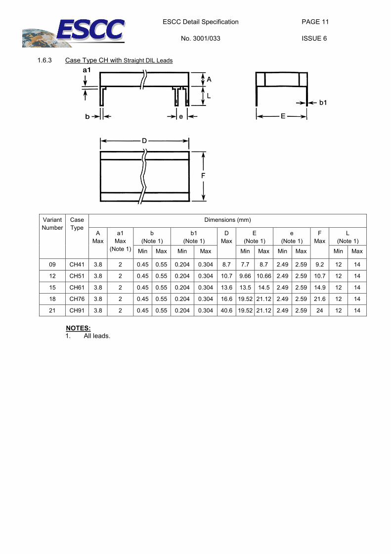
1.6.3 Case Type CH with Straight DIL Leads
Variant Number
Case Type
Dimensions (mm)
A Max
a1 Max
(Note 1)
b (Note 1)
b1 (Note 1)
D Max
E (Note 1)
e (Note 1)
F Max
L (Note 1)
Min Max Min Max Min Max Min Max Min Max
09 CH41 3.8 2 0.45 0.55 0.204 0.304 8.7 7.7 8.7 2.49 2.59 9.2 12 14
12 CH51 3.8 2 0.45 0.55 0.204 0.304 10.7 9.66 10.66 2.49 2.59 10.7 12 14
15 CH61 3.8 2 0.45 0.55 0.204 0.304 13.6 13.5 14.5 2.49 2.59 14.9 12 14
18 CH76 3.8 2 0.45 0.55 0.204 0.304 16.6 19.52 21.12 2.49 2.59 21.6 12 14
21 CH91 3.8 2 0.45 0.55 0.204 0.304 40.6 19.52 21.12 2.49 2.59 24 12 14
NOTES: 1. All leads.
ESCC Detail Specification
No. 3001/033
PAGE 12
ISSUE 6
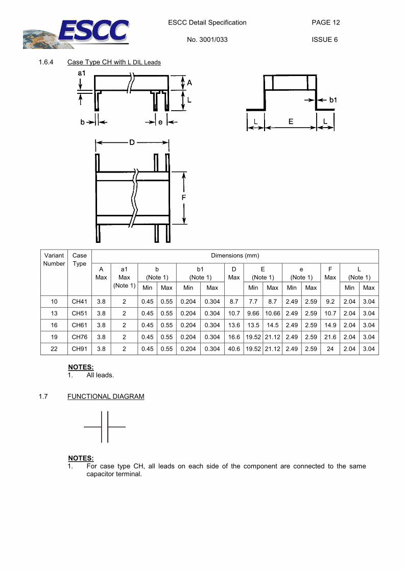
1.6.4 Case Type CH with L DIL Leads
Variant Number
Case Type
Dimensions (mm)
A Max
a1 Max
(Note 1)
b (Note 1)
b1 (Note 1)
D Max
E (Note 1)
e (Note 1)
F Max
L (Note 1)
Min Max Min Max Min Max Min Max Min Max
10 CH41 3.8 2 0.45 0.55 0.204 0.304 8.7 7.7 8.7 2.49 2.59 9.2 2.04 3.04
13 CH51 3.8 2 0.45 0.55 0.204 0.304 10.7 9.66 10.66 2.49 2.59 10.7 2.04 3.04
16 CH61 3.8 2 0.45 0.55 0.204 0.304 13.6 13.5 14.5 2.49 2.59 14.9 2.04 3.04
19 CH76 3.8 2 0.45 0.55 0.204 0.304 16.6 19.52 21.12 2.49 2.59 21.6 2.04 3.04
22 CH91 3.8 2 0.45 0.55 0.204 0.304 40.6 19.52 21.12 2.49 2.59 24 2.04 3.04
NOTES: 1. All leads.
1.7 FUNCTIONAL DIAGRAM
NOTES: 1. For case type CH, all leads on each side of the component are connected to the same
capacitor terminal.
ESCC Detail Specification
No. 3001/033
PAGE 13
ISSUE 6
2 REQUIREMENTS
2.1 GENERAL The complete requirements for procurement of the components specified herein are as stated in this specification and the ESCC Generic Specification. Permitted deviations from the Generic Specification, applicable to this specification only, are listed below.
Permitted deviations from the Generic Specification and this Detail Specification, formally agreed with specific Manufacturers on the basis that the alternative requirements are equivalent to the ESCC requirement and do not affect the component’s reliability, are listed in the appendices attached to this specification.
2.1.1 Deviations from the Generic Specification
2.1.1.1 Deviations from Special In-Process Controls - Chart F2 (a) Robustness of Terminations: Shall be replaced with a lead peel test as specified in Para. 2.3
herein.
2.1.1.2 Deviations from Qualification and Periodic Tests - Chart F4 (a) Steady State Humidity (85/85): Not applicable and shall be replaced in Chart F4
Subgroup 1A of the Generic Specification by a Damp Heat Steady State test as follows:
Components shall be subjected to Test Cab of IEC Publication No. 60068-2-78. The following details shall apply:
• Test Conditions: (a) Temperature: 40 ±2°C (b) Relative humidity: 93 ±3% (c) Duration: 56 days (d) Bias during test: Half the samples shall have no voltage applied; the remaining half
shall have 100V applied.
• Data Points: Prior to the test, Capacitance shall be measured as specified in Para. 2.5 Intermediate and End-Point Electrical Measurements.
On completion of testing, the components shall be subjected to standard atmospheric conditions for recovery for 6 to 24 hours.
After recovery, the components shall be visually examined. There shall be no evidence of damage. Capacitance, Change in Capacitance, Tangent of Loss Angle, Insulation Resistance and Voltage Proof (Body Insulation) shall be measured as specified in Para. 2.5 Intermediate and End-Point Electrical Measurements. Change in Capacitance shall be related to the initial measurements.
2.2 MARKING The marking shall be in accordance with the requirements of ESCC Basic Specification No. 21700 and as follows.
The information to be marked on the component shall be:
(a) The ESCC qualified components symbol (for ESCC qualified components only). (b) The ESCC Component Number (see Para. 1.4.1). (c) Traceability information.
ESCC Detail Specification
No. 3001/033
PAGE 14
ISSUE 6
2.3 ROBUSTNESS OF TERMINATIONS
The terminations of these devices are classified as rigid.
Robustness of Terminations shall be performed as a lead peel test on a sample of 5 components from each manufacturing lot with 0 failures allowed. The sample components shall be leaded but not encapsulated or coated. Where necessary, the leads of the component under test shall be bent through 90° in the plane of the joint such that a tensile force applied to the leads will result in a peeling force being applied to the leads’ joint.
A tensile force shall be applied evenly across the length, on the capacitor terminal, to all leads on that side of the component together, until the lead joint peels. All leads shall be tested.
The minimum peeling force shall be as follows:
• For case types VR & CV: 8.9N • For case type CH: 22.25N
ESCC Detail Specification
No. 3001/033
PAGE 15
ISSUE 6
2.4 ELECTRICAL MEASUREMENTS AT ROOM, HIGH AND LOW TEMPERATURES
Electrical measurements shall be performed at room, high and low temperatures.
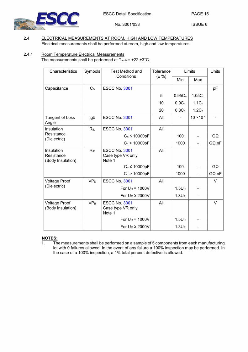
2.4.1 Room Temperature Electrical Measurements The measurements shall be performed at Tamb = +22 ±3°C.
Characteristics Symbols Test Method and Conditions
Tolerance (± %)
Limits Units
Min Max
Capacitance CA ESCC No. 3001 pF
5 0.95Cn 1.05Cn
10 0.9Cn 1.1Cn
20 0.8Cn 1.2Cn
Tangent of Loss Angle
tgδ ESCC No. 3001 All - 10 ×10-4 -
Insulation Resistance (Dielectric)
RID ESCC No. 3001 All Cn ≤ 10000pF 100 - GΩ Cn > 10000pF 1000 - GΩ.nF
Insulation Resistance (Body Insulation)
RIB ESCC No. 3001 Case type VR only Note 1
All
Cn ≤ 10000pF 100 - GΩ Cn > 10000pF 1000 - GΩ.nF
Voltage Proof (Dielectric)
VPD ESCC No. 3001 All V
For UR = 1000V 1.5UR -
For UR ≥ 2000V 1.3UR -
Voltage Proof (Body Insulation)
VPB ESCC No. 3001 Case type VR only Note 1
All V
For UR = 1000V 1.5UR -
For UR ≥ 2000V 1.3UR -
NOTES: 1. The measurements shall be performed on a sample of 5 components from each manufacturing
lot with 0 failures allowed. In the event of any failure a 100% inspection may be performed. In the case of a 100% inspection, a 1% total percent defective is allowed.
ESCC Detail Specification
No. 3001/033
PAGE 16
ISSUE 6
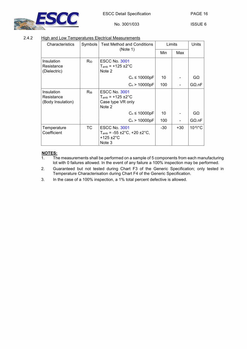
2.4.2 High and Low Temperatures Electrical Measurements
Characteristics Symbols Test Method and Conditions (Note 1)
Limits Units
Min Max
Insulation Resistance (Dielectric)
RID ESCC No. 3001 Tamb = +125 ±2°C Note 2
Cn ≤ 10000pF 10 - GΩ
Cn > 10000pF 100 - GΩ.nF
Insulation Resistance (Body Insulation)
RIB ESCC No. 3001 Tamb = +125 ±2°C Case type VR only Note 2
Cn ≤ 10000pF 10 - GΩ
Cn > 10000pF 100 - GΩ.nF
Temperature Coefficient
TC ESCC No. 3001 Tamb = -55 ±2°C, +20 ±2°C, +125 ±2°C Note 3
-30 +30 10-6/°C
NOTES: 1. The measurements shall be performed on a sample of 5 components from each manufacturing
lot with 0 failures allowed. In the event of any failure a 100% inspection may be performed. 2. Guaranteed but not tested during Chart F3 of the Generic Specification; only tested in
Temperature Characterisation during Chart F4 of the Generic Specification. 3. In the case of a 100% inspection, a 1% total percent defective is allowed.
ESCC Detail Specification
No. 3001/033
PAGE 17
ISSUE 6
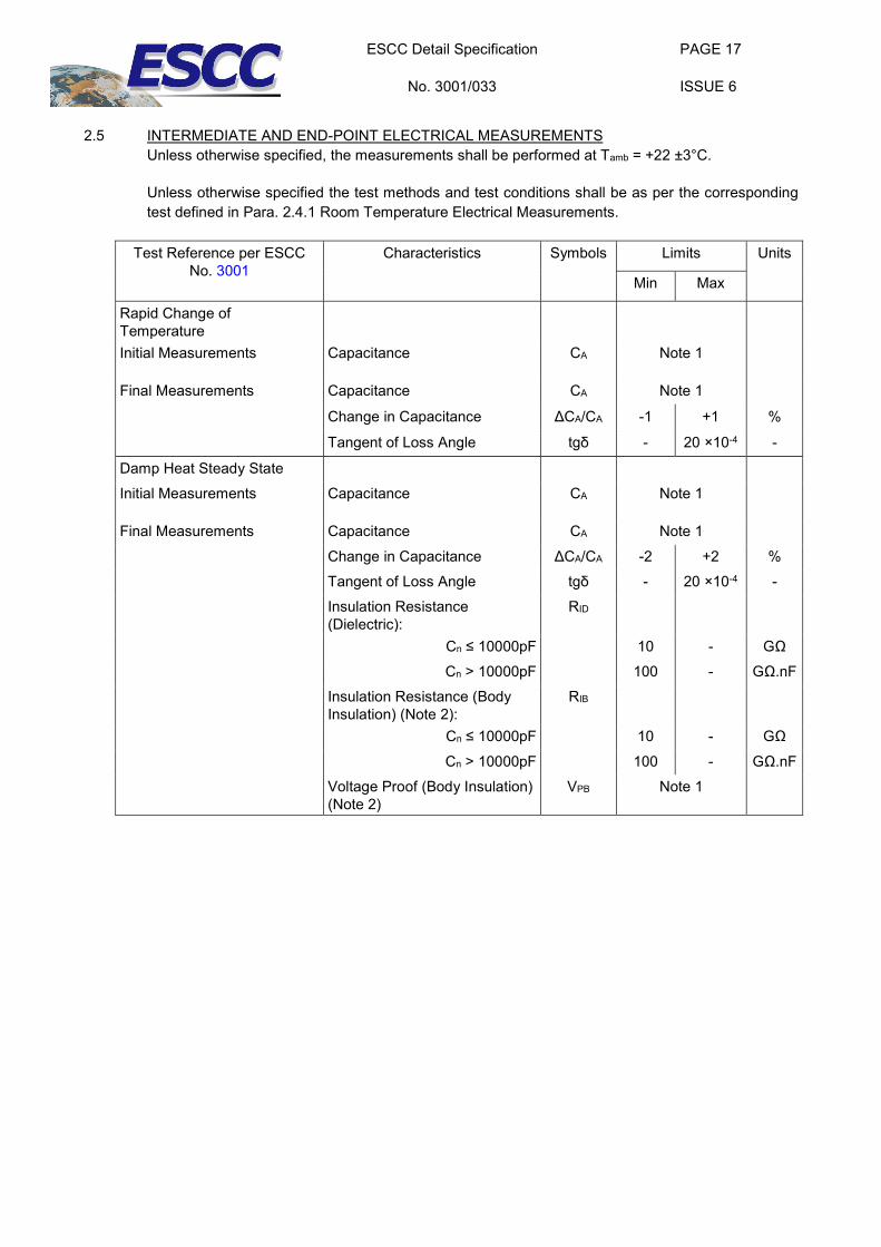
2.5 INTERMEDIATE AND END-POINT ELECTRICAL MEASUREMENTS
Unless otherwise specified, the measurements shall be performed at Tamb = +22 ±3°C.
Unless otherwise specified the test methods and test conditions shall be as per the corresponding test defined in Para. 2.4.1 Room Temperature Electrical Measurements.
Test Reference per ESCC No. 3001
Characteristics Symbols Limits Units
Min Max
Rapid Change of Temperature
Initial Measurements Capacitance CA Note 1
Final Measurements Capacitance CA Note 1
Change in Capacitance ΔCA/CA -1 +1 %
Tangent of Loss Angle tgδ - 20 ×10-4 -
Damp Heat Steady State Initial Measurements Capacitance CA Note 1
Final Measurements Capacitance CA Note 1
Change in Capacitance ΔCA/CA -2 +2 % Tangent of Loss Angle tgδ - 20 ×10-4 - Insulation Resistance (Dielectric):
RID
Cn ≤ 10000pF 10 - GΩ Cn > 10000pF 100 - GΩ.nF
Insulation Resistance (Body Insulation) (Note 2):
RIB
Cn ≤ 10000pF 10 - GΩ
Cn > 10000pF 100 - GΩ.nF Voltage Proof (Body Insulation) (Note 2)
VPB Note 1
ESCC Detail Specification
No. 3001/033
PAGE 18
ISSUE 6
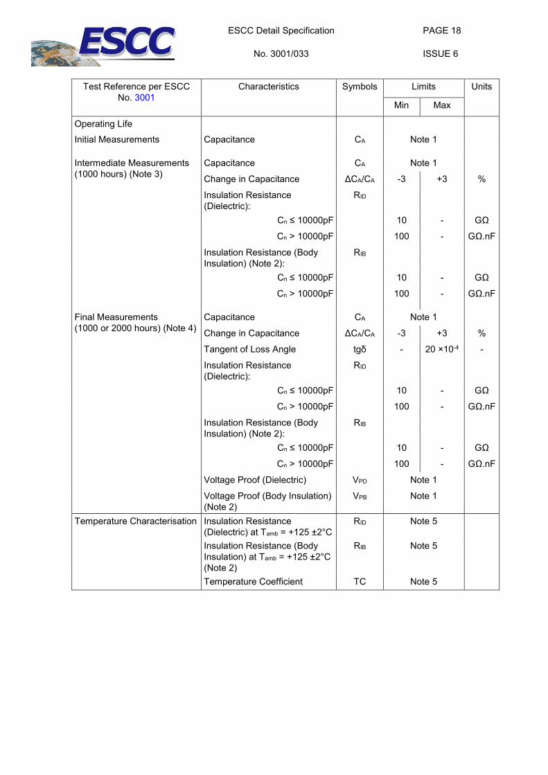
Test Reference per ESCC
No. 3001 Characteristics Symbols Limits Units
Min Max
Operating Life Initial Measurements Capacitance CA Note 1
Intermediate Measurements (1000 hours) (Note 3)
Capacitance CA Note 1
Change in Capacitance ΔCA/CA -3 +3 %
Insulation Resistance (Dielectric):
RID
Cn ≤ 10000pF 10 - GΩ
Cn > 10000pF 100 - GΩ.nF
Insulation Resistance (Body Insulation) (Note 2):
RIB
Cn ≤ 10000pF 10 - GΩ
Cn > 10000pF 100 - GΩ.nF
Final Measurements (1000 or 2000 hours) (Note 4)
Capacitance CA Note 1
Change in Capacitance ΔCA/CA -3 +3 %
Tangent of Loss Angle tgδ - 20 ×10-4 -
Insulation Resistance (Dielectric):
RID
Cn ≤ 10000pF 10 - GΩ
Cn > 10000pF 100 - GΩ.nF
Insulation Resistance (Body Insulation) (Note 2):
RIB
Cn ≤ 10000pF 10 - GΩ
Cn > 10000pF 100 - GΩ.nF
Voltage Proof (Dielectric) VPD Note 1
Voltage Proof (Body Insulation) (Note 2)
VPB Note 1
Temperature Characterisation Insulation Resistance (Dielectric) at Tamb = +125 ±2°C
RID Note 5
Insulation Resistance (Body Insulation) at Tamb = +125 ±2°C (Note 2)
RIB Note 5
Temperature Coefficient TC Note 5
ESCC Detail Specification
No. 3001/033
PAGE 19
ISSUE 6
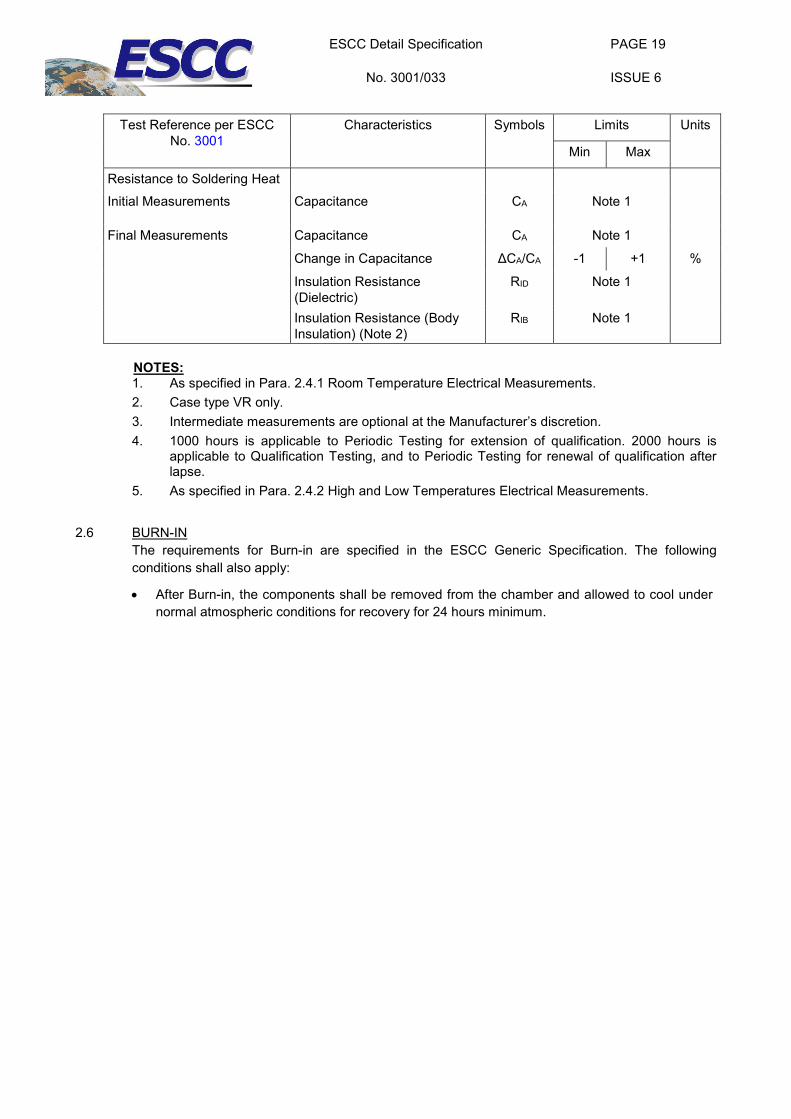
Test Reference per ESCC
No. 3001 Characteristics Symbols Limits Units
Min Max
Resistance to Soldering Heat Initial Measurements Capacitance CA Note 1
Final Measurements Capacitance CA Note 1
Change in Capacitance ΔCA/CA -1 +1 %
Insulation Resistance (Dielectric)
RID Note 1
Insulation Resistance (Body Insulation) (Note 2)
RIB Note 1
NOTES: 1. As specified in Para. 2.4.1 Room Temperature Electrical Measurements. 2. Case type VR only. 3. Intermediate measurements are optional at the Manufacturer’s discretion. 4. 1000 hours is applicable to Periodic Testing for extension of qualification. 2000 hours is
applicable to Qualification Testing, and to Periodic Testing for renewal of qualification after lapse.
5. As specified in Para. 2.4.2 High and Low Temperatures Electrical Measurements.
2.6 BURN-IN The requirements for Burn-in are specified in the ESCC Generic Specification. The following conditions shall also apply:
• After Burn-in, the components shall be removed from the chamber and allowed to cool under normal atmospheric conditions for recovery for 24 hours minimum.
ESCC Detail Specification
No. 3001/033
PAGE 20
ISSUE 6
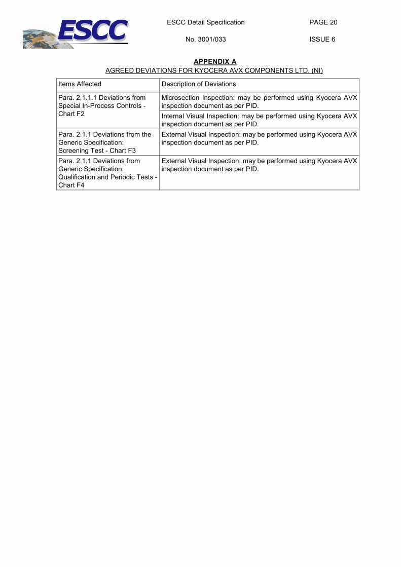
APPENDIX A
AGREED DEVIATIONS FOR KYOCERA AVX COMPONENTS LTD. (NI)
Items Affected Description of Deviations
Para. 2.1.1.1 Deviations from Special In-Process Controls - Chart F2
Microsection Inspection: may be performed using Kyocera AVX inspection document as per PID. Internal Visual Inspection: may be performed using Kyocera AVX inspection document as per PID.
Para. 2.1.1 Deviations from the Generic Specification: Screening Test - Chart F3
External Visual Inspection: may be performed using Kyocera AVX inspection document as per PID.
Para. 2.1.1 Deviations from Generic Specification: Qualification and Periodic Tests - Chart F4
External Visual Inspection: may be performed using Kyocera AVX inspection document as per PID.
Related Documents


![REP002, [ARCHIVED] - ESCIES](https://static.cupdf.com/doc/110x72/616a52b711a7b741a3513e5a/rep002-archived-escies.jpg)
