1

Welcome message from author
This document is posted to help you gain knowledge. Please leave a comment to let me know what you think about it! Share it to your friends and learn new things together.
Transcript

1
2

3
INTRODUCTION Step One
About Non‐Intrusive RF Capacitance Technology: OMEGA ENGINEERING's LVP‐51‐R level switch generates a
high radio frequency signal from the capacitance electrode on the tank side of each sensor. Depending on the
thickness of the tank wall and the material of which it is made, there is a particular minimum dielectric value
the electrode measures when there is no liquid on the other side of the tank wall from the sensor. When liquid
is on the other side of the wall, the dielectric value rises.
As part of installation, a two‐step calibration procedure ensures that the threshold between wet and dry is set at the ideal point for your particular tank and application fluid, without the use of any external test equipment. The sensor’s operation and point of actuation may vary based on the dielectric properties of various application liquids, tank materials and thicknesses. The LVP‐51‐R sensor is intended to be used with liquids with a dielectric value between 20 and 80. Due to its user calibration capability it may be able to detect liquids below a dielectric constant of 20 under certain conditions, but this must be verified by experimentation.
Table of Contents Specifications & Dimensions: ................................................................................................................................. 4 Safety Precautions: ................................................................................................................................................ 5 Make a Fail‐Safe System: ........................................................................................................................... 6 Components: .............................................................................................................................................. 6 Installation: ............................................................................................................................................................ 7 Attach fitting to Tank: ................................................................................................................................ 7 Mount Sensor in Fitting: ............................................................................................................................ 7 Electrical: ................................................................................................................................................................ 8
Signal Output (current sensing): ................................................................................................................ 8 Signal Output (relay switching): ................................................................................................................. 9 Wiring: .................................................................................................................................................................. 10
Wiring to a OMEGA ENGINEERING Controller: ........................................................................................ 10
Switching Inductive Loads: ....................................................................................................................... 10
Wiring the Relay Output: ......................................................................................................................... 11
Wiring as a P‐Channel or N‐Channel Output: .......................................................................................... 12
Calibration: ........................................................................................................................................................... 13 Maintenance: ....................................................................................................................................................... 14 Checking Point of Actuation: ................................................................................................................................... 14
Testing the Sensor: .................................................................................................................................................. 14
Maintenance: .......................................................................................................................................................... 14
4
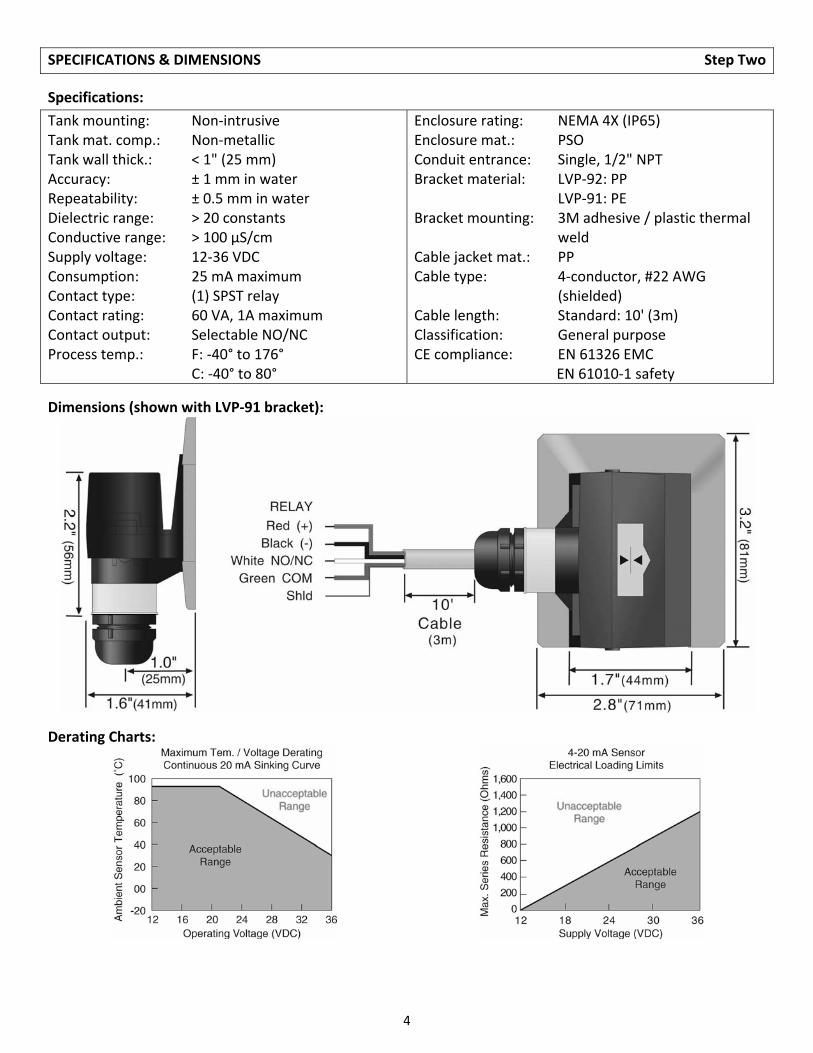
SPECIFICATIONS & DIMENSIONS Step Two
Specifications:
Tank mounting: Non‐intrusive Tank mat. comp.: Non‐metallic Tank wall thick.: < 1" (25 mm) Accuracy: ± 1 mm in water Repeatability: ± 0.5 mm in water Dielectric range: > 20 constants Conductive range: > 100 µS/cm Supply voltage: 12‐36 VDC Consumption: 25 mA maximum Contact type: (1) SPST relay Contact rating: 60 VA, 1A maximum Contact output: Selectable NO/NC Process temp.: F: ‐40° to 176° C: ‐40° to 80°
Enclosure rating: NEMA 4X (IP65) Enclosure mat.: PSO Conduit entrance: Single, 1/2" NPT Bracket material: LVP‐92: PP LVP‐91: PE Bracket mounting: 3M adhesive / plastic thermal
weld Cable jacket mat.: PP Cable type: 4‐conductor, #22 AWG
(shielded) Cable length: Standard: 10' (3m) Classification: General purpose CE compliance: EN 61326 EMC EN 61010‐1 safety
Dimensions (shown with LVP‐91 bracket):
Derating Charts:
5
SAFETY PRECAUTION Step Three
About Manual: PLEASE READ THE ENTIRE MANUAL PRIOR TO INSTALLING OR USING THIS PRODUCT. This manual includes information on all models of OMEGA ENGINEERING Non‐Intrusive RF Capacitance Level Switch: LVP‐51‐R. Please refer to the part number located on the sensor label to verify the exact model which you have purchased.
User’s Responsibility for Safety: OMEGA ENGINEERING manufactures a wide range of liquid level switches and technologies. While each of the these switches are designed to operate in a wide variety of applications, it is the user’s responsibility to select a switch model that is appropriate for the application, install it properly, perform tests of the installed system, and maintain all components. The failure to do so could result in property damage or serious injury.
Proper Installation and Handling: Because this is an electrically operated device, only properly trained staff should install and/or repair this product. The adhesive on the fitting is for temporary installation only. For permanent installation, the fitting for the sensor should be welded, glassed or strapped to the tank itself using approved plastic welding techniques. Do not install the LVP‐51‐R sensor on a metal tank, or within 6" of any metal pipe or fitting.
Mounting Bracket: The LVP‐51‐R sensor may be mounted in the PE (LVP‐91) or PP (LVP‐92) bracket. Make
sure that the fitting is compatible with the tank it will be applied to.
Material Compatibility: The sensor itself is not designed to be immersed. It should be mounted in such a way that it does not normally come into contact with fluid. Its case is made out of Polysulfone (PSO). Refer to an industry reference such as the Compass Corrosion Guide to ensure that compounds that may splash onto the controller housing will not damage it. Such damage is not covered by the warranty.
Wiring and Electrical: The supply voltage used to power the LVP‐51‐R sensor should never exceed a maximum of 36 volts DC. Electrical wiring of the sensor should be performed in accordance with all applicable national, state, and local codes.
Flammable, Explosive and Hazardous Applications: The LVP‐51‐R switch is not rated for use in hazardous locations. Refer to the National Electric Code (NEC) for all applicable installation requirements in hazardous locations. DO NOT USE THE LVP‐51‐R GENERAL PURPOSE SWITCH IN HAZARDOUS LOCATIONS.
Warning The rating for the relay is 60 VA.
Do not install the LVP‐51‐R level switch on a metallic tank, or within 6" of any metallic object. Metal will adversely affect the dielectric sensitivity of the sensor.
OMEGA ENGINEERING's LVP‐51‐R sensors are not recommended for use with electrically charged application liquids. For most reliable operation, the liquid being measured may need to be electrically grounded.
6
SAFETY PRECAUTION (capacitance) Step Three
Make a Fail‐Safe System: Design a fail‐safe system that accommodates the possibility of switch and/or power
failure. OMEGA ENGINEERING recommends the use of redundant backup systems and alarms in addition to
the primary system. Adding a redundant high level float switch to the system is a cost effective means to
prevent costly tank overflows.
The LVP‐51‐R switch has a single relay. The normally open (NO) or normally closed (NC) operation is user
selected based on the desired system control. Always design a fail‐safe system that accommodates for the
possibility of functional and/or power failure to the instrument. The "normal" relay state is where the relay
coil is de‐energized and the relay indicator is OFF. Therefore, if power is cut OFF to the switch it will de‐
energize the relay. Make sure that the de‐energized state is the safe state in your system design. As such, if
switch power is lost, a pump will turn OFF if it is connected to the normally open side of the relay.
Technology: The non‐intrusive RF capacitance switch detects the presence of liquid or air by measuring the
conductive or dielectric values which are present in all materials. An electrical capacitor is formed between
the level switch and the outer tank wall. As liquid rises and falls against the inner wall, the capacitance effect is
greatly increased and the 60VA SPST relay changes state.
The sensor’s operation may vary based on the dielectric properties of various application liquids. Liquids
with a dielectric constant less than 20 may not be detected by an LVP‐51‐R sensor.
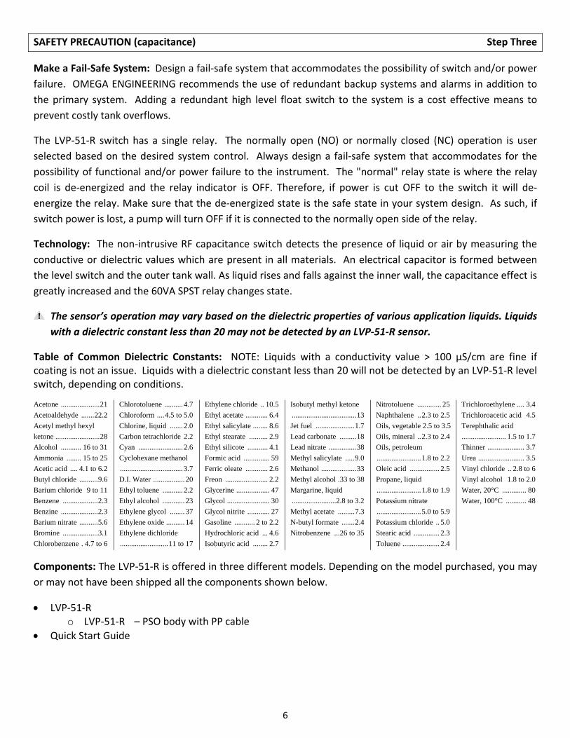
Table of Common Dielectric Constants: NOTE: Liquids with a conductivity value > 100 µS/cm are fine if coating is not an issue. Liquids with a dielectric constant less than 20 will not be detected by an LVP‐51‐R level switch, depending on conditions.
Acetone ..................... 21
Acetoaldehyde ....... 22.2
Acetyl methyl hexyl
ketone ........................ 28
Alcohol ........... 16 to 31
Ammonia ........ 15 to 25
Acetic acid .... 4.1 to 6.2
Butyl chloride .......... 9.6
Barium chloride 9 to 11
Benzene ................... 2.3
Benzine .................... 2.3
Barium nitrate .......... 5.6
Bromine ................... 3.1
Chlorobenzene . 4.7 to 6
Chlorotoluene .......... 4.7
Chloroform .... 4.5 to 5.0
Chlorine, liquid ....... 2.0
Carbon tetrachloride 2.2
Cyan ........................ 2.6
Cyclohexane methanol
.................................. 3.7
D.I. Water ................. 20
Ethyl toluene ........... 2.2
Ethyl alcohol ............ 23
Ethylene glycol ........ 37
Ethylene oxide .......... 14
Ethylene dichloride
.......................... 11 to 17
Ethylene chloride .. 10.5
Ethyl acetate ............ 6.4
Ethyl salicylate ........ 8.6
Ethyl stearate .......... 2.9
Ethyl silicote ........... 4.1
Formic acid .............. 59
Ferric oleate ............ 2.6
Freon ....................... 2.2
Glycerine .................. 47
Glycol ....................... 30
Glycol nitrite ............ 27
Gasoline ........... 2 to 2.2
Hydrochloric acid ... 4.6
Isobutyric acid ........ 2.7
Isobutyl methyl ketone
................................... 13
Jet fuel ..................... 1.7
Lead carbonate ......... 18
Lead nitrate ............... 38
Methyl salicylate ..... 9.0
Methanol ................... 33
Methyl alcohol . 33 to 38
Margarine, liquid
........................2.8 to 3.2
Methyl acetate ......... 7.3
N-butyl formate ....... 2.4
Nitrobenzene ... 26 to 35
Nitrotoluene ............. 25
Naphthalene .. 2.3 to 2.5
Oils, vegetable 2.5 to 3.5
Oils, mineral .. 2.3 to 2.4
Oils, petroleum
........................ 1.8 to 2.2
Oleic acid ................ 2.5
Propane, liquid
........................ 1.8 to 1.9
Potassium nitrate
........................ 5.0 to 5.9
Potassium chloride .. 5.0
Stearic acid .............. 2.3
Toluene .................... 2.4
Trichloroethylene .... 3.4
Trichloroacetic acid 4.5
Terephthalic acid
........................ 1.5 to 1.7
Thinner .................... 3.7
Urea ......................... 3.5
Vinyl chloride .. 2.8 to 6
Vinyl alcohol 1.8 to 2.0
Water, 20°C ............. 80
Water, 100°C ........... 48
Components: The LVP‐51‐R is offered in three different models. Depending on the model purchased, you may
or may not have been shipped all the components shown below.
LVP‐51‐R o LVP‐51‐R – PSO body with PP cable
Quick Start Guide

7
INSTALLATION Step Four
OMEGA ENGINEERING's LVP‐51‐R level switch may be installed anywhere on a tank wall using the PE (LVP‐91)
or PP (LVP‐92) bracket that the switch slides into. The bracket comes with adhesive on the tank side that is
sufficient to hold the sensor in position temporarily while the installation is tested, but for permanent
installation the bracket must be welded, glassed or strapped to the tank. Extra brackets are available from
OMEGA ENGINEERING, so that the level switch may be moved to different locations on the tank by sliding it
into other brackets.
Attach the bracket to the tank:
1. Determine whether the tank is PP or PE. The slide‐in fitting shipped with the sensor is determined by
the part number. If necessary, obtain an additional
bracket.
2. Determine the mounting location for the level switch. The
point of actuation (where the sensor will send a “wet”
signal) is most often at the center of the sensor; however
the actual Point of Actuation (POA) may differ depending
on the application liquid and tank wall characteristics.
After positioning the fitting to check clearances, etc.,
remove the paper protective strips from the adhesive of
the bracket.
3. Press the bracket into place. The adhesive provides a seal
between the sensor and the tank wall, and will hold it in
place during testing and installation. If desired, the sensor may be installed temporarily without
welding the fitting to the wall. If several different locations must be tried before permanent
installation, use double‐sided foam stick tape designed for PP or PE.
4. After the sensor has been tested to verify the POA, weld, glass or strap the bracket to the tank using
standard industrial plastic techniques.
Special note for small round tanks: The bracket may be attached to small, round tanks, as long as the
majority of the bracket is firmly attached to the wall. However, extreme installations may affect the switches
performance.
Mount the sensor in the bracket:
1. Slide the sensor into the bracket.
2. After trimming the sensor wire to length if needed by the installation, thread the sensor wire into a
plastic flexible conduit with a 1/2" male fitting. Screw the conduit into the sensor, being careful not to
cross the threads. Do not over tighten the conduit in the sensor as this may break the fitting. Such
damage is not covered by the warranty. Take care while pulling the wire through conduit that no
excessive tension is placed on the sensor end of the wire, so that the wire is not broken from the
sensor housing.
3. Connect the sensor wire to the controller following the instructions in its manual. See the following
Wiring Section for detailed wiring instructions.
8
ELECTRICAL Step Five
Supply Voltage: The supply voltage to the LVP‐51‐R level switch should never exceed a maximum of 36 VDC.
OMEGA ENGINEERING controllers have a built‐in 13.5 VDC power supply which provides power to all of
OMEGA ENGINEERING’s electrically powered sensors. Alternative controllers and power supplies, with a
minimum output of 12 VDC up to a maximum output of 36 VDC, may also be used with the level switch.
Required Cable Length: Determine the length of cable required between the level switch and its point of
termination. Allow enough slack to ensure the easy installation, removal and/or maintenance of the sensor.
The cable length may be extended up to a maximum of 1000 feet, using a well‐insulated, 14 to 20 gauge
shielded four conductor cable.
Wire Stripping: Using a 10 gauge wire stripper, carefully remove the outer layer of insulation from the last 1‐
1/4" of the sensor's cable. Unwrap and discard the exposed foil shield from around the signal wires, leaving
the drain wire attached if desired. With a 20 gauge wire stripper, remove the last 1/4" of the colored
insulation from the signal wires.
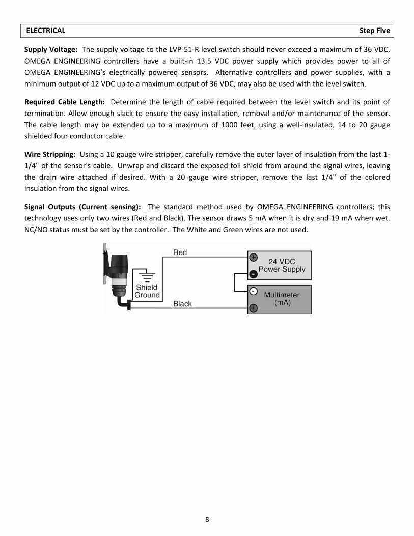
Signal Outputs (Current sensing): The standard method used by OMEGA ENGINEERING controllers; this
technology uses only two wires (Red and Black). The sensor draws 5 mA when it is dry and 19 mA when wet.
NC/NO status must be set by the controller. The White and Green wires are not used.
9
ELECTRICAL (continued) Step Five
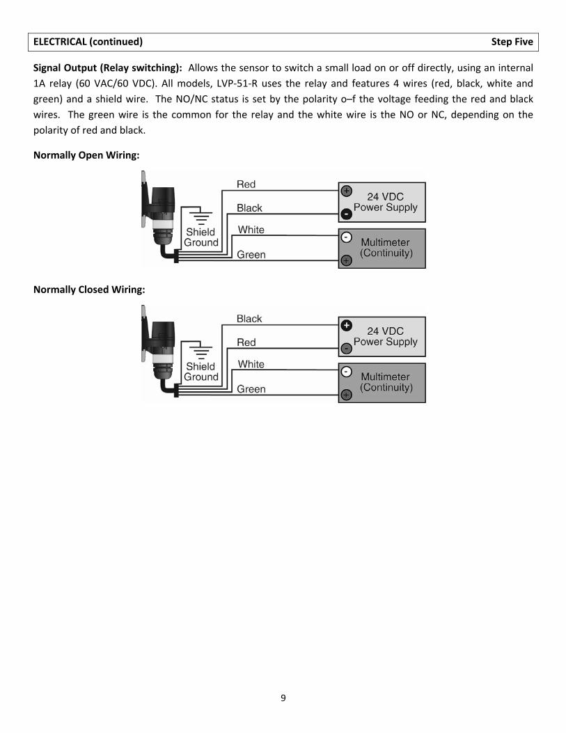
Signal Output (Relay switching): Allows the sensor to switch a small load on or off directly, using an internal
1A relay (60 VAC/60 VDC). All models, LVP‐51‐R uses the relay and features 4 wires (red, black, white and
green) and a shield wire. The NO/NC status is set by the polarity o–f the voltage feeding the red and black
wires. The green wire is the common for the relay and the white wire is the NO or NC, depending on the
polarity of red and black.
Normally Open Wiring:
Normally Closed Wiring:
10
WIRING Step Six
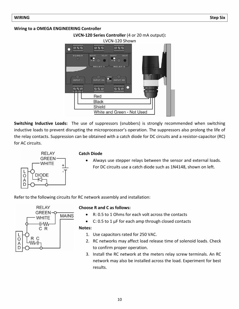
Wiring to a OMEGA ENGINEERING Controller
LVCN‐120 Series Controller (4 or 20 mA output): LVCN‐120 Shown
Switching Inductive Loads: The use of suppressors (snubbers) is strongly recommended when switching
inductive loads to prevent disrupting the microprocessor’s operation. The suppressors also prolong the life of
the relay contacts. Suppression can be obtained with a catch diode for DC circuits and a resistor‐capacitor (RC)
for AC circuits.
Catch Diode
Always use stepper relays between the sensor and external loads.
For DC circuits use a catch diode such as 1N4148, shown on left.
Refer to the following circuits for RC network assembly and installation:
Choose R and C as follows:
R: 0.5 to 1 Ohms for each volt across the contacts
C: 0.5 to 1 μF for each amp through closed contacts
Notes:
1. Use capacitors rated for 250 VAC.
2. RC networks may affect load release time of solenoid loads. Check
to confirm proper operation.
3. Install the RC network at the meters relay screw terminals. An RC
network may also be installed across the load. Experiment for best
results.

11
WIRING (continued) Step Six
Wiring the Relay Output: The LVP‐51‐R requires 12 ‐ 36 VDC power to operate the sensor and switch the
relay. All illustrations below identify a Dry switch state as the normal position of the relay.
Switching a Normally Open DC Load: The Red wire connects to Positive (+) of the power supply and the Black wire connects to Negative (‐). The LOAD can be attached to either the Green or White wires. Complete the circuit by connecting the Green to (+) VDC power or White to (‐) VDC power (see illustration below).
Switching a Normally Closed DC Load: The Black wire connects to Positive (+) of the power supply and the Red wire connects to Negative (‐). The LOAD can be attached to either the Green or White wires. Complete the circuit by connecting the Green to (+) VDC power or White to (‐) VDC power (see illustration below).
Sensor Power [RED & BLK wires] / 36 VDC Max. 5 ±1mA Dry / 20 ±1mA Wet
Relay Rating [GRN & WHT wires] / 60 VA
Switching a Normally Open AC Load: The Red wire connects to Positive (+) of the DC power supply and the Black wire connects to Negative (‐). The LOAD can be attached to the Green wire and the Hot of the VAC power. Connect the White to the Neutral of the VAC power (see illustration below).
Switching a Normally Closed AC Load: The Black wire connects to Positive (+) of the DC power supply and the Red wire connects to Negative (‐). The LOAD can be attached to the Green wire and the Hot of the VAC power. Connect the White to the Neutral of the VAC power (see illustration below).
Sensor Power [RED & BLK wires] / 36 VDC Max. 5 ±1mA Dry / 20 ±1mA Wet
Relay Rating [GRN & WHT wires] / 60 VA
12
WIRING (continued) Step Six
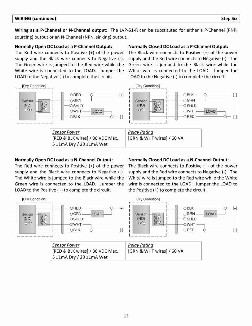
Wiring as a P‐Channel or N‐Channel output: The LVP‐51‐R can be substituted for either a P‐Channel (PNP,
sourcing) output or an N‐Channel (NPN, sinking) output.
Normally Open DC Load as a P‐Channel Output: The Red wire connects to Positive (+) of the power supply and the Black wire connects to Negative (‐). The Green wire is jumped to the Red wire while the White wire is connected to the LOAD. Jumper the LOAD to the Negative (‐) to complete the circuit.
Normally Closed DC Load as a P‐Channel Output: The Black wire connects to Positive (+) of the power supply and the Red wire connects to Negative (‐). The Green wire is jumped to the Black wire while the White wire is connected to the LOAD. Jumper the LOAD to the Negative (‐) to complete the circuit.
Sensor Power [RED & BLK wires] / 36 VDC Max. 5 ±1mA Dry / 20 ±1mA Wet
Relay Rating [GRN & WHT wires] / 60 VA
Normally Open DC Load as a N‐Channel Output: The Red wire connects to Positive (+) of the power supply and the Black wire connects to Negative (‐). The White wire is jumped to the Black wire while the Green wire is connected to the LOAD. Jumper the LOAD to the Positive (+) to complete the circuit.
Normally Closed DC Load as a N‐Channel Output: The Black wire connects to Positive (+) of the power supply and the Red wire connects to Negative (‐). The White wire is jumped to the Red wire while the White wire is connected to the LOAD. Jumper the LOAD to the Positive (+) to complete the circuit.
Sensor Power [RED & BLK wires] / 36 VDC Max. 5 ±1mA Dry / 20 ±1mA Wet
Relay Rating [GRN & WHT wires] / 60 VA

13
CALIBRATION Step Seven
After it is installed in place, the must be calibrated by the user before operation. Everything needed for the
procedure is self‐contained within the electronics of the LVP‐51‐R level switch. Two dielectric states—full
condition and empty condition—are measured by the LVP‐51‐R, and then averaged to set the threshold
between “wet” and “dry” at the sensor. The empty state must be at least 6" below the bottom of the sensor
for calibration. The full state must be to the top of the sensor (not just to the point of actuation) for
calibration. The actual application fluid at its intended operating temperature must be used during
calibration. Use the following procedure assumes that the sensor has already been wired to a power supply.
1. Remove the cap from the sensor body by loosening the two screws located below the sensor. Do not
remove the screws from the sensor. Insert a small screwdriver into the small slot at the edge of the cap
and gently pry upwards.
2. Looking down you will see a small three‐position switch and two trim pots marked Full and Empty. You
may start with whatever state the tank is in.
3. Full state: With the tank filled to the top of the sensor, set the switch to the Full position (right). Make sure your hands or any other objects are not touching the sensor while calibrating because this will cause a false reading. Using a small nonmetallic screwdriver or alignment tool, turn trim pot Full until the LED just lights, and no farther. Note the position. Now turn the trim pot back until the LED turns off. The ideal setting for the trim pot is midway between these on and off points.
4. Empty state: With the tank drained to a point no closer than 6 inches below the bottom of the sensor,
set the switch to the Empty position (left). Set the Empty trim pot as in Step 3.
5. After completing calibration, make sure to return the switch to the center position. Snap the cap back
on by pressing down, and tighten the two screws.
14
MAINTENANCE Step Seven
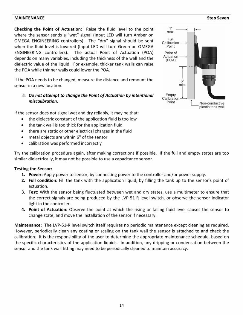
Checking the Point of Actuation: Raise the fluid level to the point where the sensor sends a “wet” signal (Input LED will turn Amber on OMEGA ENGINEERING controllers). The “dry” signal should be sent when the fluid level is lowered (Input LED will turn Green on OMEGA ENGINEERING controllers). The actual Point of Actuation (POA) depends on many variables, including the thickness of the wall and the dielectric value of the liquid. For example, thicker tank walls can raise the POA while thinner walls could lower the POA.
If the POA needs to be changed, measure the distance and remount the sensor in a new location.
Do not attempt to change the Point of Actuation by intentional miscalibration.
If the sensor does not signal wet and dry reliably, it may be that:
the dielectric constant of the application fluid is too low
the tank wall is too thick for the application fluid
there are static or other electrical charges in the fluid
metal objects are within 6" of the sensor
calibration was performed incorrectly
Try the calibration procedure again, after making corrections if possible. If the full and empty states are too similar dielectrically, it may not be possible to use a capacitance sensor.
Testing the Sensor: 1. Power: Apply power to sensor, by connecting power to the controller and/or power supply. 2. Full condition: Fill the tank with the application liquid, by filling the tank up to the sensor’s point of
actuation. 3. Test: With the sensor being fluctuated between wet and dry states, use a multimeter to ensure that
the correct signals are being produced by the LVP‐51‐R level switch, or observe the sensor indicator light in the controller.
4. Point of Actuation: Observe the point at which the rising or falling fluid level causes the sensor to change state, and move the installation of the sensor if necessary.
Maintenance: The LVP‐51‐R level switch itself requires no periodic maintenance except cleaning as required. However, periodically clean any coating or scaling on the tank wall the sensor is attached to and check the calibration. It is the responsibility of the user to determine the appropriate maintenance schedule, based on the specific characteristics of the application liquids. In addition, any dripping or condensation between the sensor and the tank wall fitting may need to be periodically cleaned to maintain accuracy.

15

16
Related Documents