IOP PUBLISHING REPORTS ON PROGRESS IN PHYSICS Rep. Prog. Phys. 74 (2011) 036101 (30pp) doi:10.1088/0034-4885/74/3/036101 Cantilever-like micromechanical sensors Anja Boisen, Søren Dohn, Stephan Sylvest Keller, Silvan Schmid and Maria Tenje DTU Nanotech–Department of Micro- and Nanotechnology, Technical University of Denmark, Bldg. 345 East, DK-2800 Kgs. Lyngby, Denmark E-mail: [email protected] Received 25 May 2010, in final form 16 November 2010 Published 28 February 2011 Online at stacks.iop.org/RoPP/74/036101 Abstract The field of cantilever-based sensing emerged in the mid-1990s and is today a well-known technology for label-free sensing which holds promise as a technique for cheap, portable, sensitive and highly parallel analysis systems. The research in sensor realization as well as sensor applications has increased significantly over the past 10 years. In this review we will present the basic modes of operation in cantilever-like micromechanical sensors and discuss optical and electrical means for signal transduction. The fundamental processes for realizing miniaturized cantilevers are described with focus on silicon- and polymer-based technologies. Examples of recent sensor applications are given covering such diverse fields as drug discovery, food diagnostics, material characterizations and explosives detection. (Some figures in this article are in colour only in the electronic version) This article was invited by H-G Rubahn. Contents 1. Introduction 1 2. Sensing principles 2 2.1. Detection of mass changes 3 2.2. Detection of surface stress changes 6 2.3. Detection of effects related to bulk stress changes 9 3. Sensor materials and fabrication 10 3.1. Silicon-based devices 10 3.2. Polymer-based devices 11 3.3. Cantilevers with integrated functionality 13 3.4. Comparison of materials and fabrication methods 14 4. Sensor read-out principles 14 4.1. Optical read-out 14 4.2. Capacitive read-out 16 4.3. Piezoelectric read-out 16 4.4. Piezoresistive read-out 17 4.5. Hard-contact/tunnelling 18 4.6. Autonomous devices 18 4.7. Actuation 18 5. Applications 19 5.1. Surface functionalization 19 5.2. Bacteria detection 19 5.3. Point of care 20 5.4. Drug discovery 20 5.5. Explosives detection 21 5.6. Material characterization 21 5.7. Mass spectrometry 23 6. Conclusion 23 References 24 1. Introduction The field of cantilever-based sensing is still relatively young and was initiated in the mid-1990s. The research area has since then been rapidly increasing in terms of both number of publications and research groups involved. Micrometre-sized cantilevers hold promises as label-free, sensitive, portable, cheap, highly parallel and fast sensors for field use and have thus attracted considerable interest from applications such as point of care (POC) diagnostics, homeland security and environmental monitoring. Moreover, the sensors offer the possibility of measuring quantities and phenomena that are very difficult to achieve by other methods and they are therefore also very interesting fundamental research tools. Finally, the sensors can be operated in different modes which yield different information and which when combined can be used to obtain a unique set of coupled data. The sensors are versatile and can measure phenomena such as changes in surface stress, temperature and mass. The sensing technique has already been featured and compared with other label-free sensor technologies in several review papers [1–7]. The focus of this review will be on 0034-4885/11/036101+30$88.00 1 © 2011 IOP Publishing Ltd Printed in the UK & the USA

Welcome message from author
This document is posted to help you gain knowledge. Please leave a comment to let me know what you think about it! Share it to your friends and learn new things together.
Transcript

IOP PUBLISHING REPORTS ON PROGRESS IN PHYSICS
Rep. Prog. Phys. 74 (2011) 036101 (30pp) doi:10.1088/0034-4885/74/3/036101
Cantilever-like micromechanical sensorsAnja Boisen, Søren Dohn, Stephan Sylvest Keller, Silvan Schmid and Maria Tenje
DTU Nanotech–Department of Micro- and Nanotechnology, Technical University of Denmark, Bldg. 345 East,DK-2800 Kgs. Lyngby, Denmark
E-mail: [email protected]
Received 25 May 2010, in final form 16 November 2010Published 28 February 2011Online at stacks.iop.org/RoPP/74/036101
AbstractThe field of cantilever-based sensing emerged in the mid-1990s and is today a well-known technology forlabel-free sensing which holds promise as a technique for cheap, portable, sensitive and highly parallelanalysis systems. The research in sensor realization as well as sensor applications has increasedsignificantly over the past 10 years. In this review we will present the basic modes of operation incantilever-like micromechanical sensors and discuss optical and electrical means for signal transduction.The fundamental processes for realizing miniaturized cantilevers are described with focus on silicon- andpolymer-based technologies. Examples of recent sensor applications are given covering such diverse fieldsas drug discovery, food diagnostics, material characterizations and explosives detection.
(Some figures in this article are in colour only in the electronic version)
This article was invited by H-G Rubahn.
Contents
1. Introduction 12. Sensing principles 2
2.1. Detection of mass changes 32.2. Detection of surface stress changes 62.3. Detection of effects related to bulk stress changes 9
3. Sensor materials and fabrication 103.1. Silicon-based devices 103.2. Polymer-based devices 113.3. Cantilevers with integrated functionality 133.4. Comparison of materials and fabrication
methods 144. Sensor read-out principles 14
4.1. Optical read-out 144.2. Capacitive read-out 164.3. Piezoelectric read-out 16
4.4. Piezoresistive read-out 174.5. Hard-contact/tunnelling 184.6. Autonomous devices 184.7. Actuation 18
5. Applications 195.1. Surface functionalization 195.2. Bacteria detection 195.3. Point of care 205.4. Drug discovery 205.5. Explosives detection 215.6. Material characterization 215.7. Mass spectrometry 23
6. Conclusion 23References 24
1. Introduction
The field of cantilever-based sensing is still relatively youngand was initiated in the mid-1990s. The research area hassince then been rapidly increasing in terms of both number ofpublications and research groups involved. Micrometre-sizedcantilevers hold promises as label-free, sensitive, portable,cheap, highly parallel and fast sensors for field use and havethus attracted considerable interest from applications suchas point of care (POC) diagnostics, homeland security andenvironmental monitoring. Moreover, the sensors offer the
possibility of measuring quantities and phenomena that arevery difficult to achieve by other methods and they are thereforealso very interesting fundamental research tools. Finally,the sensors can be operated in different modes which yielddifferent information and which when combined can be usedto obtain a unique set of coupled data. The sensors are versatileand can measure phenomena such as changes in surface stress,temperature and mass.
The sensing technique has already been featured andcompared with other label-free sensor technologies in severalreview papers [1–7]. The focus of this review will be on
0034-4885/11/036101+30$88.00 1 © 2011 IOP Publishing Ltd Printed in the UK & the USA
Rep. Prog. Phys. 74 (2011) 036101 A Boisen et al
the instrumentation and recent fundamental scientific andtechnological advances. The review focuses on the cantilevergeometry but will include a few related beam-based sensorswith the same sensing principles.
Micrometre-sized cantilevers became available with theinvention of the atomic force microscope (AFM) in 1986 [8].Basically, the AFM functions as a miniaturized phonographwhere images are obtained by raster scanning the surface withan AFM probe. The probe consists of a sharp tip mounted ona cantilever, which deflects due to the forces between tip andsample. The AFM probe needs to have micrometre dimensionsin order to achieve a relative high resonant frequency (inthe KHz regime) and a low spring constant (in the N m−1
regime). Typically, the cantilevers are 100 µm long, 50 µmwide and 0.5 µm thick. The high resonant frequency makesthe probe less sensitive to external vibrations and the lowspring constant improves the force sensitivity of the probe.Because of the small dimensions microfabrication is necessary.The first micromachined cantilevers with integrated tips wererealized in 1990 by Tom Albrecht and co-workers at StanfordUniversity [9] and by the group of Wolter at IBM [10].
Possibly inspired by some of the often encounteredannoyances in AFM work Thomas Thundat and co-workersat Oakridge National Laboratory (Tennessee, USA) started in1994 to explore the cantilevers’ possible potential as a physicaland chemical sensor [11]. Their initial work demonstratedthat an AFM probe which is coated on one side with ametal layer for improved reflection of the laser beam willbe prone to bimorph effects. This can cause severe driftproblems in the AFM set-up. However, the effect can alsobe used as a simple principle for a very sensitive thermometer,where a static cantilever deflection can be related to a giventemperature change. Moreover, it was demonstrated that ametal-coated cantilever kept at constant temperature respondsreproducibly with a constant bending to humidity changes[11] and to exposure of other vapours such as mercury [12].Also, it was showed that the amount of adsorbates can beestimated by monitoring shifts in the resonant frequency of thecantilever. Simultaneously, European groups started similaractivities. The group around Mark Welland in Cambridgeand the group around Jim Gimzewski and Christoph Gerberat IBM, Zurich, both used the bimorph effect to performsensitive photothermal spectroscopy [13, 14]. Roberto Raiteriand Hans-Jurgen Butt from the Max-Planck-institute forBiophysics in Frankfurt reported on studies of surface stresschanges induced electrochemically [15]. Unspecific bindingof proteins to a hydrophobic surface was reported in 1996 [16].The cantilever sensors can be used for online measurementsof surface stress changes. This was demonstrated on agold-coated cantilever exposed to alkanethiols [17]. Thesemeasurements illustrated that it is possible to follow theformation of a self-assembled monolayer (SAM) in real time,and the surface stress change was in this work seen to be relatedto the length of the alkane chain.
Most of the early cantilever-based sensing work wasperformed in standard AFM set-ups using normal AFM probes.In a normal AFM set-up it is only possible to measure on onecantilever at a time. This makes it impossible to simultaneously
perform control measurements on a reference cantilever. TheAFM probes used in the experiments typically had tips on,although for sensor applications this is not necessary. Oneof the first specifically designed large scale sensor systemswas developed by Christoph Gerber and co-workers at IBM,Zurich. An array of polymer-coated silicon cantilevers wasused to simultaneously detect the adsorption induced change inthe surface stress of the cantilevers. The system could read-outfrom eight cantilevers simultaneously and different alcoholscould be distinguished due to their different adsorption ratesin the polymers [18]. Reference measurements on un-coatedcantilevers were included here.
The potential of cantilever-based sensing in the field ofdiagnostics was highlighted in 2000 where it was demonstratedthat a pair of cantilevers coated with two short strands ofDNA-oligos that only differ by a single base can be used forsingle-nucleotide polymorphism detection [19]. These datawere the source of many studies related to specific recognitionof DNA, proteins and macromolecules.
On the technology side, cantilevers with integrated read-out started to appear in the late 1990s. The integrated read-out facilitates the realization of compact devices that canoperate in even non-transparent environments. For example,in 2000 piezoresistive cantilevers for surface stress sensingwere presented, demonstrating the possibility of realizing adense array of sensors with a compact read-out system [20].Even highly advanced systems with integrated electronics weresoon demonstrated [21]. The field of self-sensing cantilevershas developed rapidly. Today several groups around theworld are investigating different read-out techniques for thecantilever.
It is the aim of this review to give an overview ofthe expanding field of cantilever-based detection and todiscuss fundamental issues regarding signal generation andinterpretation based on recent experimental and theoreticalfindings. In section 2 we introduce the basic sensing principles,describing the generally used theoretical models and conceptsof operation. The cleanroom-based fabrication techniquesare introduced in section 3 with emphasis on new emergingmaterials such as polymers. The methods for reading out thecantilever deflection are described in section 4, which ends witha summary and comparison of the major read-out technologiesused today. Recent examples on applications are described insection 5 and the review ends with general reflections on thefuture work on cantilever-based sensors in section 6.
2. Sensing principles
We will in the following concentrate on the use of cantilever-based sensors in the monitoring of changes in surface stress,bulk stress and mass depicted graphically in figure 1. In afirst mode of operation, static deflection of the cantilever ismeasured. Change in static deflection is related to differencein surface stress of the two faces of the cantilever. Thistechnique can be used to directly measure surface stresschanges and as a sensing mechanism by functionalizingone surface of the cantilever with a specific detector layer(figure 1(a)). A bending will thus indicate whether material
2

Rep. Prog. Phys. 74 (2011) 036101 A Boisen et al
Figure 1. Schematic of three modes of operation of a cantilever-based sensor. The cantilever is seen from the side. Molecules on one side ofthe cantilever cause a change in surface stress which causes the cantilever to deflect (a). Bulk stress changes in the cantilever material can beused to detect temperature changes caused by a chemical reaction (b). Mass changes are registered by measuring changes in the resonantfrequency of the cantilever (c).
has been interacting with the surface. If an added molecularlayer, for example, contracts compared with the underlyingmaterial, the cantilever will bend towards the molecularlayer. This measuring principle has been used to detect, forexample, prostate-specific antigen (PSA) [22] and to studyantibiotics binding to drug resistant super bugs [23]. Arelated technique to study surface stress changes is calledthe bending plate technique and was first observed andapplied on wafers of III–V compounds in the 1960s [24].By introducing the cantilever technique this measurementprinciple was significantly improved. Using the bending platetechnique surface stress changes of 1 N m−1 were normallyreported whereas the first measurements of surface stresschanges with micrometre-sized cantilevers were of the orderof 10−3 N m−1. Now, surface stress changes of 10−6 N m−1
are routinely observed.In a second mode of operation the cantilever is used
as a tool to evaluate stress changes in the bulk of thecantilever material, for example, caused by humidity ortemperature. Stress changes are explored in the realizationof extremely sensitive thermometers. Cantilevers consistingof two materials with different thermal expansion coefficientswill bend as a function of temperature due to the bimorph effect.This effect can be used to measure temperature changes downto 10−5 K and can, for example, be used to investigate phasechanges in minute amounts of sample [25] (figure 1(b)).
In a third mode of operation the fact that the resonantfrequency of the cantilever depends on the mass of thecantilever and the resonant frequency drops as the massincreases is used. Thus, it is possible to make indirect masschange estimations in the atto- to zepto-gram range [26] byfollowing the resonant frequency change of the cantilever(figure 1(c)).
The change in static cantilever deflection or change invibrational amplitude is most commonly detected by theso-called optical leverage technique which is well known fromAFM. The principle will be described in section 4 and basicallya laser is reflected off the backside of the cantilever and onto aposition sensitive diode.
In nearly all experiments performed today a referencemeasurement is included. This means that a second cantileverwith identical mechanical performance but without the specificsurface funtionalization is monitored simultaneously. Oftenonly the differential signals are presented since the use ofreference measurements significantly reduces drift and noisefrom, for example, temperature and humidity changes.
2.1. Detection of mass changes
In mass sensing, cantilever and bridge shaped geometriesare both commonly used and are in general referred toas beam-based mass sensors. Both geometries will beintroduced in the following. A cantilever is a singly clampedbeam whereas a bridge is a doubly clamped beam. Oneof the ultimate goals of a beam-based mass sensor is theability to measure single small molecules which requiresa sensitivity in the sub-zepto-gram (10−21 g) regime. Thiswould, for example, make it possible to use a cantilever as amass-spectrometer with sensitivity better than commerciallyavailable systems of today. The sensitivity or minimumdetectable mass depends on the ratio between the massand the resonant frequency of the beam. Generally, theresonant frequency increases and the mass decreases when thedimensions are decreased. Thus, a straightforward approachto enhance the sensitivity is to decrease the dimensions of thebeam. The feature size of beam-based mass sensors is currentlyapproaching the nanometre scale. Recently, systems capableof detecting masses in the atto- and zepto-gram (10−18–10−21 g) range have been reported [27, 28], and the claimis that yocto-gram sensitivity is within reach [29]. This isfar better than the reported mass sensitivities of other masssensing techniques, such as the quartz crystal microbalancetechnique where typical sensitivities are in the nano/pico-gram range [30] for a single device. Sensors with a largersurface area generally have a relatively large distributed massresolution (mass resolution per area). For example, so-called bulk disc resonators with micrometre dimensions nowhave similar distributed mass resolution as nanometre-sizedcantilever resonators [31]. As a consequence, nanometre-sized resonators are useful when striving to achieve ultra-high point mass resolution. In terms of distributed massresolution the benefit of miniaturization is less pronounced.Here, for example, micrometre [32] and nanometre-sized [33]cantilevers have been reported to have similar distributed masssensitivities.
To explain the working principle of a beam-based masssensor we will in the following introduce the equationsdescribing the motion of a beam. Also, the importance ofdamping and Q-factor will be introduced.
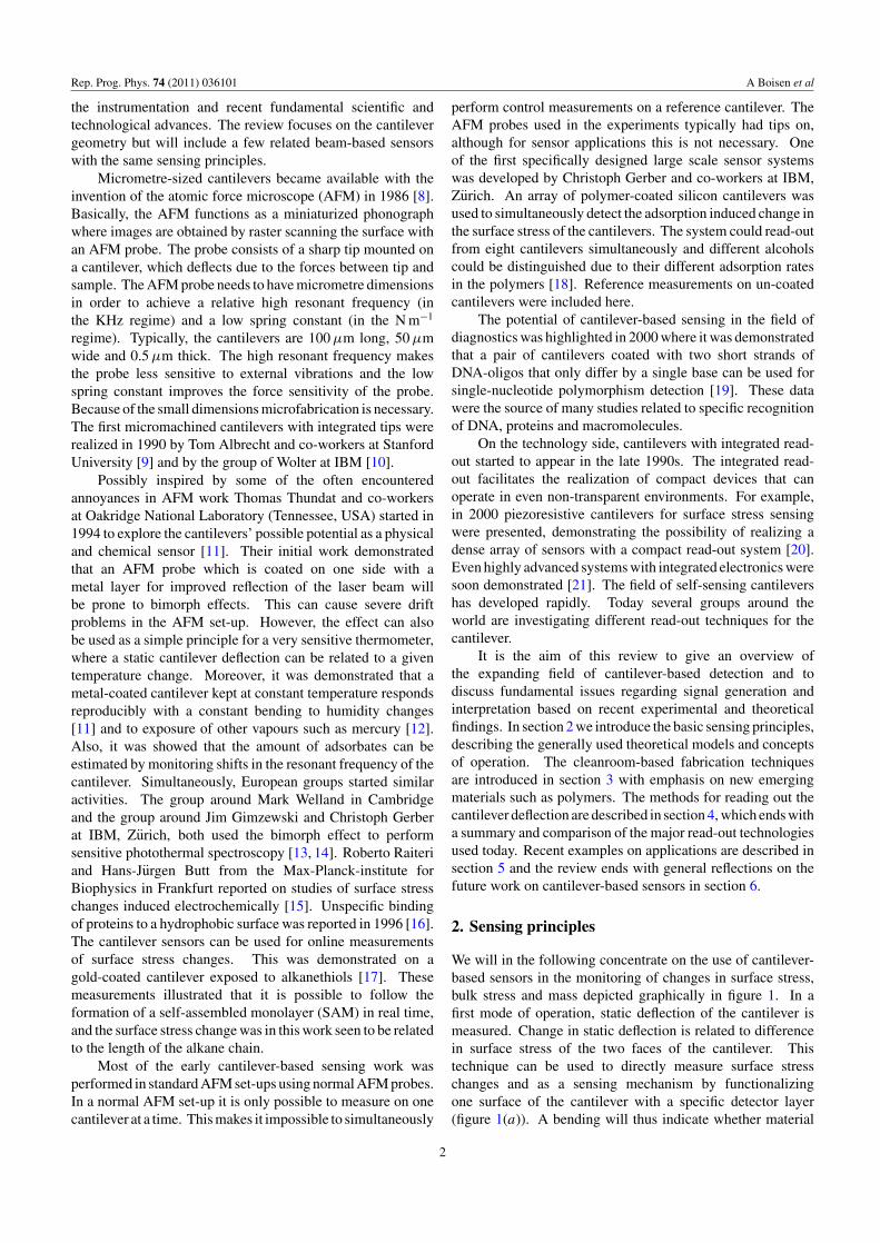
2.1.1. The eigenfrequency of bending beams. For a thin beamas depicted in figure 2, rotational inertia and shear deformationcan be neglected. Assuming a linear elastic material and small
3
Rep. Prog. Phys. 74 (2011) 036101 A Boisen et al
Figure 2. Schematic of a simple cantilever geometry.
deflections, the equation of motion is given by the Euler–Bernoulli beam equation [34]
∂2U(z, t)
∂t2ρ� +
∂4U(z, t)
∂z4EIz = 0, (2.1)
where U(z, t) is the displacement in the x-direction, ρ is themass density, � = wh is the cross-sectional area, E is Young’smodulus and Iz is the geometric moment of inertia. Thesolution to this differential equation is a harmonic that canbe separated into a position dependent and a time-dependentterm, U(z, t) = Un(z) exp(−iωnt), where ωn is the frequencyof motion and where n denotes the modal number. By insertioninto equation (2.1) the differential equation can be rewritten as
∂4U(z, t)
∂z4= κ4U(z, t), κ4 = ω2ρ�
EIz
. (2.2)
The solutions (eigenfunctions) to the simplified beam equation(equation (2.2)) can be written in the form [35]
Un(z) = An(cos κnz − cosh κnz) + Bn(sin κnz − sinh κnz).
(2.3)
The modal constants are determined from the boundaryconditions. For a singly clamped beam (cantilever), thefrequency equation becomes 1 + cos(κnL) cosh(κnL) = 0and the solutions for n = 1, 2, 3, n > 3 are λn = κnL =1.8751, 4.6941, 7.8548, (2n − 1)π /2, respectively. For adoubly clamped beam (bridge) the frequency equation is1 − cos(κnL) cosh(κnL) = 0 and the solutions for n =1, 2, 3, n > 3 are λn = κnL = 4.7300, 7.8532, 10.9956,(2n + 1)π /2, respectively.
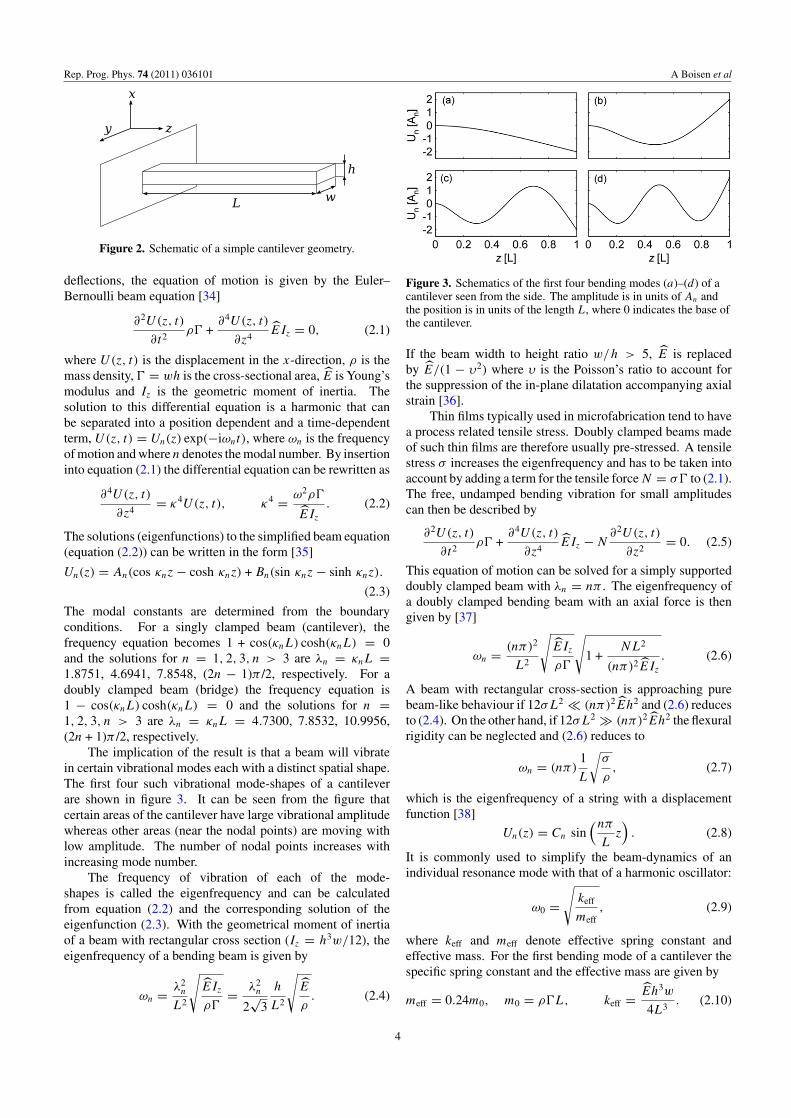
The implication of the result is that a beam will vibratein certain vibrational modes each with a distinct spatial shape.The first four such vibrational mode-shapes of a cantileverare shown in figure 3. It can be seen from the figure thatcertain areas of the cantilever have large vibrational amplitudewhereas other areas (near the nodal points) are moving withlow amplitude. The number of nodal points increases withincreasing mode number.
The frequency of vibration of each of the mode-shapes is called the eigenfrequency and can be calculatedfrom equation (2.2) and the corresponding solution of theeigenfunction (2.3). With the geometrical moment of inertiaof a beam with rectangular cross section (Iz = h3w/12), theeigenfrequency of a bending beam is given by
ωn = λ2n
L2
√EIz
ρ�= λ2
n
2√
3
h
L2
√E
ρ. (2.4)
Figure 3. Schematics of the first four bending modes (a)–(d) of acantilever seen from the side. The amplitude is in units of An andthe position is in units of the length L, where 0 indicates the base ofthe cantilever.
If the beam width to height ratio w/h > 5, E is replacedby E/(1 − υ2) where υ is the Poisson’s ratio to account forthe suppression of the in-plane dilatation accompanying axialstrain [36].
Thin films typically used in microfabrication tend to havea process related tensile stress. Doubly clamped beams madeof such thin films are therefore usually pre-stressed. A tensilestress σ increases the eigenfrequency and has to be taken intoaccount by adding a term for the tensile force N = σ� to (2.1).The free, undamped bending vibration for small amplitudescan then be described by
∂2U(z, t)
∂t2ρ� +
∂4U(z, t)
∂z4EIz − N
∂2U(z, t)
∂z2= 0. (2.5)
This equation of motion can be solved for a simply supporteddoubly clamped beam with λn = nπ . The eigenfrequency ofa doubly clamped bending beam with an axial force is thengiven by [37]
ωn = (nπ)2
L2
√EIz
ρ�
√1 +
NL2
(nπ)2EIz
. (2.6)
A beam with rectangular cross-section is approaching purebeam-like behaviour if 12σL2 � (nπ)2Eh2 and (2.6) reducesto (2.4). On the other hand, if 12σL2 � (nπ)2Eh2 the flexuralrigidity can be neglected and (2.6) reduces to
ωn = (nπ)1
L
√σ
ρ, (2.7)
which is the eigenfrequency of a string with a displacementfunction [38]
Un(z) = Cn sin(nπ
Lz)
. (2.8)
It is commonly used to simplify the beam-dynamics of anindividual resonance mode with that of a harmonic oscillator:
ω0 =√
keff
meff, (2.9)
where keff and meff denote effective spring constant andeffective mass. For the first bending mode of a cantilever thespecific spring constant and the effective mass are given by
meff = 0.24m0, m0 = ρ�L, keff = Eh3w
4L3. (2.10)
4

Rep. Prog. Phys. 74 (2011) 036101 A Boisen et al
2.1.2. Sensitivity and resolution. From equation (2.9) it isclear that the resonant frequency depends on the vibratingmass. The change in resonant frequency due to a change inmass is called the sensitivity S of a resonant mass sensor. Thisis a very important parameter for bending beam-based masssensors, since it in turn will determine the minimum detectablemass.
Assuming that the change in mass, m, is very smallcompared with m0 and distributed evenly over the entireresonant beam surface, the mass sensitivity of a beam can befound by differentiation of equation (2.9) with respect to themass of the beam:
S = ∂ω0
∂meff= − ω0
2meff≈ ω0
m, (2.11)
where ω0 is the change in the resonant frequency caused byan added mass, m.
To obtain a high sensitivity a beam must have a highresonant frequency, which can be obtained by having alarge Young’s modulus, low density and small dimensions.Furthermore, it must have a low mass, requiring a low densityand small dimensions. Thus, for bending beams a highersensitivity can be obtained at higher vibrational modes due to adecreasing effective mass at higher modes [39]. Also, doublyclamped beams have higher resonant frequencies than singlyclamped beams of same dimensions. However, the vibrationalamplitude is smaller and the doubly clamped structures aretherefore in general more difficult to read-out.
The resolution, that is the smallest detectable mass of thesensor, mmin, is given by the inverse sensitivity times theminimum detectable frequency change ωmin:
mmin = S−1ωmin. (2.12)
The frequency stability and thereby ωmin is determined by thenoise of the system originating from both the read-out circuitryand the resonator itself [29].
2.1.3. Damping and noise. A beam with a kinetic energywill experience damping and thereby dissipation of its kineticenergy. The dissipation is defined as the ratio of energylost per cycle to the stored energy, and is the inverse of thequality factor (Q-factor). The damping will cause a broadeningof the resonant peak and introduce frequency noise, therebyincreasing the minimum detectable change in frequency.
Dissipation occurs through several mechanisms thatare either intrinsic to the cantilever or due to extrinsicprocesses. The intrinsic processes are, among others,material damping (phonon–phonon interactions, phonon–electron interactions, thermo-elastic damping) [40–42] andanchor losses [40, 43, 44]. Extrinsic dissipation occurs due tointeractions with the surrounding media and can be controlledby mode of operation and atmospheric pressure. The totaldissipation is the sum of all contributions
1
Q=
∑ 1
Qint+
∑ 1
Qext= 1
Qair+
1
Qmat
+1
Qanc+
1
Qsur+ · · · .
Figure 4. Schematic of a cantilever with a single bead, having themass m, positioned at zm.
For bending beam resonators operated under ambientconditions viscous damping or momentum exchange with thesurrounding medium is the dominant source of dissipation,giving rise to low Q-factors (around 100) [29]. Thus, high-sensitivity beam-based mass sensors are generally operated atlow pressures [45]. If a beam is a sandwiched structure, suchas a metal-coated silicon cantilever, material damping can bedominant [46, 47].
Pre-stressed doubly clamped beams have been seen tohave extraordinary high quality factors [48] and in polymericdoubly clamped beams the material damping is significantlyreduced when the beams become string like [49]. Clampingloss is one of the limiting damping effects for resonant strings[49, 50]. By improving the clamping, quality factors of upto 4 million have been obtained with silicon nitride micro-strings [51].
Often, beam-based mass sensors are affected by noiseattributed to individual molecules that adsorb and desorb onthe surface of the beam [29]. This process changes the massand thereby the resonant frequency of the beam. Also, theread-out system introduces noise which is associated withthe transduction of the mechanical response into an electricalsignal and which is highly dependent on the method of choice[27, 52–57].
2.1.4. Position dependent mass measurements. In theprevious section the mass of adsorbed molecules is assumedto be distributed uniformly over the beam surface. Thisapproach is not viable if single molecules or particles are tobe measured, since the change in resonant frequency is notonly dependent on the mass of the attached particle but alsoon the position on the beam [39, 58, 59]. This is due to theshape of the vibrational modes. The areas of the beam witha large vibrational amplitude are areas where an added masswill gain a high kinetic energy and thereby change the resonantfrequency considerably compared with the nodal points whereno energy is transferred from the beam to the added particles.
Consider a cantilever with the mass m0 loaded with a pointmass m positioned at zm (figure 4). If the mass load is muchless than the cantilever mass, m � m0, the cantilever mode-shape will not change significantly, and the resonant frequencyof such a system can be accurately estimated using an energyapproach. According to Rayleigh’s method the time averagekinetic energy, Ekin, equals the time average strain energy,Estrain, at resonance [60].
5

Rep. Prog. Phys. 74 (2011) 036101 A Boisen et al
Assuming a small deflection and thereby neglecting shearstress, the energy of a deflected cantilever is the energy storeddue to the induced strain. The eigenfrequency of a cantilevercan be derived by equalizing the kinetic with the strain energy:
Estrain = Ekin + Ekin,m. (2.13)
The kinetic energy for the cantilever loaded with a mass, m, is
Ekin = 12m0ω
2n,m, (2.14)
where ωn,m is the frequency of motion and n is the modalnumber. The kinetic energy of the added point mass at zm is
Ekin,m = 12mω2
n,mU 2n (zm). (2.15)
Assuming that the mode-shape will not change significantlydue to the added mass, the strain energy in the cantilever isapproximately equal to the kinetic energy of the cantileverwithout the added mass:
Estrain ≈ 12m0ω
2n. (2.16)
With (2.13), the eigenfrequency of the cantilever with theadded mass becomes
ω2n,m = ω2
n
(1 +
m
m0U 2
n (zm)
)−1
. (2.17)
The position dependent mass responsivity can now becalculated for a given position, zm, of the adsorbed mass m:
Spoint ≈ ωn
m= ωn,m − ωn
m,
Spoint ≈ ωn
m
(√1 + Un(zm)m/m0
−1 − 1
).
(2.18)
For zm = L the mass responsivity exhibits the same modedependence as the mass responsivity of a uniform distributedmass, Spoint,L ∝ λ2
n. But, the mass responsivity is alsohighly dependent on the position and for zm �= L themass responsivity has a complicated dependence on the mode-number and must be calculated for each position and mode.
Knowing the mass responsivity and a measured change inresonant frequency it is possible to calculate the mass of themolecules or particles forming a homogeneous layer on thecantilever using equation (2.12). That is
mmeas = S−1ωmeas. (2.19)
If a single point mass is adhering to the cantilever, and thechange in resonant frequency of several modes are measured,both position and mass can be calculated. Using the approachof Dohn et al [59] the position can be found by minimizing
χ2 =N∑
n=1
(ωn,m
ωn
− 1√1 + (m/m0)U 2
n (zm)
)2
(2.20)
with respect to the position and where N is the total number ofmodes measured. The position minimizing equation (2.20)yields the most likely position of the adhering point mass.The mass can subsequently be calculated. The calculationof a point mass based on resonant frequency measurementscan be extended to multiple point masses [61] and a similarapproach to determine position and mass has been developedfor strings [62].
Figure 5. Stress in a thin film on a cantilever. The relative filmthickness is highly exaggerated for clarity. As the film expands thecantilever bends down. The resulting stress in the film iscompressive as its expansion is hindered and balanced by thebending of the cantilever. For a contracting film the cantilever bendsup and the resulting stress in the film is tensile.
2.2. Detection of surface stress changes
Molecules that adsorb on a cantilever do not only add a massbut also generate a surface stress due to interactions betweenthe molecules and the cantilever surface. In 1909, Stoneydeveloped a theory to measure surface stress/elastic strain of athin film deposited onto a sheet of metal [63]. Although Stoneystudied thin metal films, this equation is still used to quantifythe surface stresses generated in molecular/chemical thin filmsfrom different molecular recognition events. Stoney’s formulais given by
R = Eh2
6σ(1 − υ), (2.21)
where R is the radius of curvature, E is Young’s modulus,h is the thickness of the metal sheet, σ is the surface stressgenerated and ν is Poisson’s ratio of the metal sheet. In1966 Stoney’s formula was further developed by Jaccodineand Schliegel [64] to be applicable to cantilever structures thatare clamped at one side, which introduces some mechanicallimitations compared with a free sheet of metal. Now thesurface stress, σ , is related to the cantilever deflection, z, viathe length of the cantilever, L:
z = 3(1 − ν)L2
Eh2σ. (2.22)
From here it is seen that the deflection can be optimizedby decreasing the thickness and increasing the length of thecantilever.
Stoney’s formula requires that one knows Young’smodulus of the cantilever. In particular, in situations wheremore exotic materials are used for cantilever fabrication thismight be a major source of error. The group of Grutterhas re-worked Stoney’s formula to overcome this issue [65].Today, a modified Stoney’s formula is available for cantileverswith only nanometre thickness [66] that might be realized inthe near future. Stress changes in a thin film on the surfaceof a cantilever are illustrated in figure 5. In figure 5(a) thecantilever bends downwards and expands until the stress thuscreated in the cantilever balances the stress in the thin film ontop. The stress in the film is compressive as the expansion ishindered by the supporting cantilever. The stress on the topside of the supporting cantilever is tensile. In the case of acontracting film the cantilever bends upwards and the stress inthe thin film is said to be tensile (figure 5(b)).
6

Rep. Prog. Phys. 74 (2011) 036101 A Boisen et al
2.2.1. Origin of surface stress—experimental focus.Although the equation for measuring the surface stress froma cantilever deflection has been available for more than 100years, the origin of the surface stress and the relation to theforce transduction (chemical recognition event to mechanicaldeflection of the cantilever) has been under dispute and is stillnot clarified within the research community. There exist a fewtheoretical papers that try to decipher the fundamental physicsof the origin of surface stress [67–69]. These papers are notlinked to experimental studies. In this section, we will focuson the most relevant experimental findings existing within thecommunity. For clarity, we only consider studies of DNAhybridization and alkanethiol layers.
DNA hybridization is studied in two steps. First, single-stranded DNA (ss-DNA) is immobilized on a cantilever. Theactual hybridization event takes place when a complementaryss-DNA strand is introduced, resulting in a hybridized double-stranded DNA (ds-DNA) bound to the cantilever. The firstproposal on the physics of surface stress came in 2000from Fritz et al, where it was suggested that the surfacestress originates from electrostatic, steric and hydrophobicinteractions [19] between the hybridized DNA strands onthe cantilever. It was observed that the DNA hybridizationevent causes a compressive surface stress. DNA strands holda net negative charge. It is argued that the electrostaticinteraction changes since ds-DNA has a larger number ofcharges compared with ss-DNA. The steric contribution isbelieved to arise from a denser chain packing as a resultof the hybridization. A year later, Wu et al [70] showedon-line measurements of a cantilever first being functionalizedwith ss-DNA and then exposed to complementary DNA forhybridization. The immobilization step resulted in a largecompressive stress whereas the hybridization event resultedin a small tensile stress. Their findings indicated that thecantilever deflects in the opposite direction as to what Fritzet al reported. Furthermore, the cantilever was observed tobend in opposing directions for the ss-DNA immobilizationand the subsequent ds-DNA hybridization. Intuitively this israther surprising as one might simply expect the cantileverto bend more (in the same direction) as more molecules areadded to the surface. To explain the experimental results,Wu et al argued that the surface stress cannot be a resultof electrostatic and steric interactions alone. They proposedto also consider configurational entropy, which is related tothe order of the immobilized molecules. The ss-DNA hasa significantly lower persistence length than ds-DNA (underthe same buffer conditions), which means that the ds-DNAhas a higher stiffness and is more rod like. As a result, thecantilever is required to bend more to ensure sufficient spacefor the ss-DNA strands to form a SAM. The ds-DNA in turn willnot force the cantilever to deflect as much since it requires lessspace to form a SAM due to its more rigid structure. Therefore,when Wu et al started with a blank cantilever and introducedss-DNA for immobilization they observed a compressive stresson the cantilever. When the complementary strands wereintroduced to form the ds-DNA this stress was released (sincea more ordered SAM could be formed). They then observed atensile stress/release of compressive stress.
However, this does not explain why their findingscontradict the findings of Fritz et al with respect toDNA hybridization. To further support their theory onthe significance of the configurational entropy, Wu et alimmobilized ss-DNA on two different cantilevers in a 1Mbuffer. These cantilevers were then exposed to two differenthybridization conditions. In the first situation, DNA washybridized under the same buffer conditions (1M) and a tensilestress was observed. In the second situation, the bufferconcentration was reduced to 0.1M before the complementaryss-DNA strand was introduced. The change in bufferconcentration forced the ss-DNA to form a more orderedmonolayer. In turn, a compressive stress was observed duringhybridization. This clearly indicates that configurationalentropy plays a role in signal generation and it stressesthe importance of controlling all aspects of a cantilevermeasurement (buffer conditions, pre-treatments, temperaturevariations, etc) since several effects are involved in generatingthe surface stress signal.
The group of Rachel McKendry has studied the originof surface stress in a methodical manner. In 2002 [71]the influence of the physical steric crowding of moleculeson a cantilever was pinpointed as the main contributor tothe cantilever deflection for DNA hybridization. It wasseen that the hybridization signal is close to non-existentwhen the density of probe ss-DNA is tailored for maximizedhybridization efficiency. Again, this indicates that moleculeswith ‘sufficient space’ do not generate a cantilever deflection.
In 2007, the effects of electrostatics [72] were investigated.Here, simple SAMs of thiolated n-alkane chains withdifferent end-groups were used as model system. Theactive SAM had carboxyl-groups at the end, which couldbe protonated/deprotonated upon pH variations. The mainphysical effect of the cantilever deflection in this situation wasassigned to electrostatic repulsion and ionic hydrogen bondformation. Emphasis was also put on the counter ions presentin the aqueous solution; these can affect both the magnitudeand direction of the cantilever deflection. Figure 6 showsthe contribution from each individual effect (electrostaticrepulsion and ionic hydrogen bond formation) as well as theeffective interactions. Experimental data are also plotted andseen to agree well with the proposed theory.
In 2008, McKendry, Sushko and co-authors proposedthe ‘first quantitative model to rationalize the physics ofnanomechanical sensors’ [73]. Here, a theoretical model isdeveloped that predicts the cantilever deflection direction andmagnitude upon pH variations of the buffer solution and forvarious chain lengths of SAMs. The model considers theeffects of chemical, elastic and entropic properties of bothcantilever material and sensing layer.
Recently, the group of Grutter [74] analysed the effects ofintermolecular electrostatics, Lennard-Jones interactions andadsorption-induced changes in the electronic density of a metalfilm when thiolated alkane chains are immobilized on a gold-coated silicon cantilever. Their findings indicate that it is thelatter effect combined with the associated electronic chargetransfer from the gold to the thiol bond that account for thelargest contribution to the measured surface stress. These
7

Rep. Prog. Phys. 74 (2011) 036101 A Boisen et al
Figure 6. As the pH of the buffer solution is changed from 4.5 to 9.0 the cantilever displays both tensile and compressive stress as thecarboxyl group at the end of the SAM goes from fully protonated (region I) to fully ionized (region III). The insets illustrate the proposedmolecular configuration on the gold-coated cantilever surface at different pH values [72].
findings bring something completely new to the communityand the manuscript even proposes a method to enhance thesurface stress signal: one should enable anions from themeasuring solution to come in contact with the metal surface,to give an increased cantilever deflection, see figure 7. Thiscould possibly be obtained by either using a sensing layer withpinholes or by using a sensing layer that deforms and opens upafter the molecular recognition event has occurred.
2.2.2. Effect of gold layer. Gold is a preferred cantilevercoating in combination with thiol chemistry. In 2001 itwas noted that the cleanliness of the gold surface is highlyinfluential on the resulting surface stress signal generatedfrom the self-assembly of thiolated alkanechains [75]. Thegenerated surface stress after an injection of hexanethiol wasobserved for a gold layer (i) stored under ambient conditionsfor ten days and (ii) gold cleaned in either 33% aqua regiaor (iii) 5 min O2/N2 plasma. From the measurements it couldbe seen that cleaning the gold surface significantly increasesthe cantilever deflection. A difference between the cleaningmethods was also noted, with the aqua regia cleaning methodgenerating the largest surface roughness and the largest surfacestress signal.
Both Godin et al [76] and Mertens et al [77] haveinvestigated the effect of the gold topography on the resultingcantilever deflection. Godin et al have compared goldcoatings with (>500 nm) and (<100 nm) grains. Both goldlayers have been functionalized with dodecanthiol and it isconcluded that the resulting cantilever deflection is largest forthe (>500 nm) grains. It is argued that highly uniform SAMswith all molecules in the ‘standing up’ phase can only beobtained when the SAM is not interrupted by grain boundaries.Mertens et al presented somewhat opposite findings. Here, thecantilever deflection was seen to be larger for gold coating withsmall (∼20 nm) grain sizes than for larger grains (∼100 nm).However, it should be noted that the studied grain sizes andimmobilization procedures are different. Mertens et al arguethat a large number of grain boundaries results in a large
Figure 7. A large cantilever deflection is seen as the surfacepotential of a cantilever is increased from −400 mV to +400 mVversus Ag/AgCl. There are anions present in the surrounding bufferthat can come into contact with the gold-coated cantilever. Thesituations (a)–(d) show that larger deflections are seen when theanions have more easy access to the surface. (c) and (d) comparesthe effect of ClO−
4 and Cl− anions attracted to a pure goldsurface [74].
surface area which consequently increases the possibility formolecules to adsorb.
In 2009, Arroyo-Hernandez et al [78] introduced anotherfeature that is critical to control when using a gold anchoringlayer: the charge state. They investigated the resultingcantilever deflections arising from thiolated DNA strandsbinding to gold. The gold coating on the cantilevers wasdeposited using either e-beam deposition or resistive heating.
8
Rep. Prog. Phys. 74 (2011) 036101 A Boisen et al
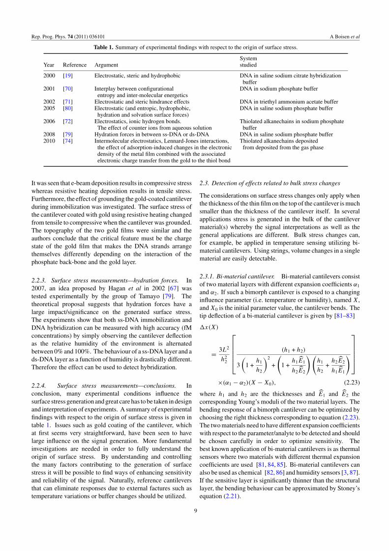
Table 1. Summary of experimental findings with respect to the origin of surface stress.
SystemYear Reference Argument studied
2000 [19] Electrostatic, steric and hydrophobic DNA in saline sodium citrate hybridizationbuffer
2001 [70] Interplay between configurational DNA in sodium phosphate bufferentropy and inter-molecular energetics
2002 [71] Electrostatic and steric hindrance effects DNA in triethyl ammonium acetate buffer2005 [80] Electrostatic (and entropic, hydrophobic, DNA in saline sodium phosphate buffer
hydration and solvation surface forces)2006 [72] Electrostatics, ionic hydrogen bonds. Thiolated alkanechains in sodium phosphate
The effect of counter ions from aqueous solution buffer2008 [79] Hydration forces in between ss-DNA or ds-DNA DNA in saline sodium phosphate buffer2010 [74] Intermolecular electrostatics, Lennard-Jones interactions, Thiolated alkanechains deposited
the effect of adsorption-induced changes in the electronic from deposited from the gas phasedensity of the metal film combined with the associatedelectronic charge transfer from the gold to the thiol bond
It was seen that e-beam deposition results in compressive stresswhereas resistive heating deposition results in tensile stress.Furthermore, the effect of grounding the gold-coated cantileverduring immobilization was investigated. The surface stress ofthe cantilever coated with gold using resistive heating changedfrom tensile to compressive when the cantilever was grounded.The topography of the two gold films were similar and theauthors conclude that the critical feature must be the chargestate of the gold film that makes the DNA strands arrangethemselves differently depending on the interaction of thephosphate back-bone and the gold layer.
2.2.3. Surface stress measurements—hydration forces. In2007, an idea proposed by Hagan et al in 2002 [67] wastested experimentally by the group of Tamayo [79]. Thetheoretical proposal suggests that hydration forces have alarge impact/significance on the generated surface stress.The experiments show that both ss-DNA immobilization andDNA hybridization can be measured with high accuracy (fMconcentrations) by simply observing the cantilever deflectionas the relative humidity of the environment is alternatedbetween 0% and 100%. The behaviour of a ss-DNA layer and ads-DNA layer as a function of humidity is drastically different.Therefore the effect can be used to detect hybridization.
2.2.4. Surface stress measurements—conclusions. Inconclusion, many experimental conditions influence thesurface stress generation and great care has to be taken in designand interpretation of experiments. A summary of experimentalfindings with respect to the origin of surface stress is given intable 1. Issues such as gold coating of the cantilever, whichat first seems very straightforward, have been seen to havelarge influence on the signal generation. More fundamentalinvestigations are needed in order to fully understand theorigin of surface stress. By understanding and controllingthe many factors contributing to the generation of surfacestress it will be possible to find ways of enhancing sensitivityand reliability of the signal. Naturally, reference cantileversthat can eliminate responses due to external factures such astemperature variations or buffer changes should be utilized.
2.3. Detection of effects related to bulk stress changes
The considerations on surface stress changes only apply whenthe thickness of the thin film on the top of the cantilever is muchsmaller than the thickness of the cantilever itself. In severalapplications stress is generated in the bulk of the cantilevermaterial(s) whereby the signal interpretations as well as thegeneral applications are different. Bulk stress changes can,for example, be applied in temperature sensing utilizing bi-material cantilevers. Using strings, volume changes in a singlematerial are easily detectable.
2.3.1. Bi-material cantilever. Bi-material cantilevers consistof two material layers with different expansion coefficients α1
and α2. If such a bimorph cantilever is exposed to a changinginfluence parameter (i.e. temperature or humidity), named X,and X0 is the initial parameter value, the cantilever bends. Thetip deflection of a bi-material cantilever is given by [81–83]
x(X)
= 3L2
h22
(h1 + h2)
3
(1 +
h1
h2
)2
+
(1 +
h1E1
h2E2
) (h1
h2+
h2E2
h1E1
)
×(α1 − α2)(X − X0), (2.23)
where h1 and h2 are the thicknesses and E1 and E2 thecorresponding Young’s moduli of the two material layers. Thebending response of a bimorph cantilever can be optimized bychoosing the right thickness corresponding to equation (2.23).The two materials need to have different expansion coefficientswith respect to the parameter/analyte to be detected and shouldbe chosen carefully in order to optimize sensitivity. Thebest known application of bi-material cantilevers is as thermalsensors where two materials with different thermal expansioncoefficients are used [81, 84, 85]. Bi-material cantilevers canalso be used as chemical [82, 86] and humidity sensors [3, 87].If the sensitive layer is significantly thinner than the structurallayer, the bending behaviour can be approximated by Stoney’sequation (2.21).
9

Rep. Prog. Phys. 74 (2011) 036101 A Boisen et al
2.3.2. Volume changes measured with strings. Theeigenfrequency of strings is mainly defined by the tensile stressin the string material and is given by (2.7). If the volume of thestring material expands due to an external changing parameter,the strain in the string is released which results in a resonantfrequency shift. Assuming the volume expansion to be a linearfunction of an external parameter X, the total strain in the stringcan be written as
ε(X) = ε0 − (αstr − αsub)(X − X0), (2.24)
where ε0 is the initial pre-strain of the string, αstr and αsub
are coefficients of a specific length expansion of the stringmaterial and the substrate material, respectively. In a specificapplication αstr and αsub represent, e.g., the coefficient ofthermal expansion or the coefficient of humidity-inducedvolume expansion. Assuming that Young’s modulus E is nota function of X, the stress in the string becomes
σ(X) = σ0 − v(αstr − αsub)(X − X0) (2.25)
with the pre-stress σ0. The eigenfrequency of a string is thengiven by [38]
ωn(X) = (nπ)1
L
√σ0 − E(αstr − αsub)(X − X0)
ρ. (2.26)
The sensitivity of a string-based sensor can consequently beoptimized by choosing stiff string and substrate materials witha large difference in their volume expansion behaviour. Inthe case of using polymeric strings on a glass substrate thedifference in the swelling due to moisture is large, sincethe water absorption of the polymer is relatively high andthe water uptake of glass can be neglected. For SU-8strings a relative humidity resolution of 0.006% [88] has beenachieved. Temperature also causes the string material toexpand. Resonant AuPd micro-strings have been successfullyused as temperature sensors [89].
3. Sensor materials and fabrication
Basically, cantilevers are fabricated in either silicon- orpolymer-based materials. Examples of the two types ofcantilevers are shown in figure 8. Although the design of thesensors is similar, the schemes of fabrication are very differentand will therefore be described separately below. In themajority of the research results published up to now, externaloptical read-out is used to measure the cantilever deflection.Therefore, the focus will be on the fabrication of simple free-standing beams suitable for optical read-out. In section 3.3, ashort overview on the design and processing of more complexdevices with integrated functionality is given. Independent ofthe cantilever material there are some requirements to the finalcantilever structure.
(i) For increased surface stress sensitivity, the cantilevershould be as thin and long as possible. This requiresprocessing of suspended fragile structures.
Figure 8. Scanning electron micrographs of silicon (a) and polymer(b) cantilevers. Both the chips have an array of eight cantileverswith a length of 500 µm and a width of 100 µm.
(ii) For mass sensing the clamping of the cantilever shouldminimize clamping losses. Furthermore, the materialshould have low internal damping and the cantilevergeometry should allow for a high Q factor.
(iii) For all purposes the geometries of the cantilevers shouldbe controlled with a high accuracy since the dimensionshave a huge influence on the sensitivity and thus theuniformity of the sensors. For example, precise control ofthe geometries of reference and measurement cantileversis crucial to avoid measurement errors.
(iv) For optical read-out, the surface of the cantilever needsto be reflecting and of high optical quality. The surfaceshould not be rough and thereby scatter the light in alldirections.
(v) The cantilevers should ideally have no initial bending.Initial bending complicates the optical alignment andmakes the cantilevers more prone to spurious signals dueto changes in temperature, refractive index, etc.
3.1. Silicon-based devices
3.1.1. Materials. Silicon-based materials are pre-dominantly used for the fabrication of cantilever sensors.Silicon microfabrication is well established and usestechnologies initially developed by the IC industry in the1960s. Hence, integration of wiring for actuation and read-out is quite straightforward. Materials such as silicon, siliconnitride and silicon oxide are also well characterized and stableover time. As a consequence, cantilevers fabricated withthese classical materials can be operated in a large range oftemperatures and environmental conditions. Microcantileversare typically around 1 µm thick and 450–950 µm long. Highlysensitive cantilevers with thickness h = 500 nm and lengthL = 500 µm are commercially available [90, 91] and ultrathincantilevers with h < 200 nm have been fabricated [92, 93].
3.1.2. Bulk micromachining. It is impossible to realizeadvanced mechanical structures with micrometre dimensionsusing fine mechanics. Instead, cleanroom-based processesare used where the cantilevers are fabricated by etchingthree dimensionally in a silicon wafer. A typical strategyfor realization of silicon-based cantilevers consists of threemain steps illustrated in figure 9: (a) substrate preparation,(b) cantilever patterning and ((c), (d)) device release. This
10

Rep. Prog. Phys. 74 (2011) 036101 A Boisen et al
Si substrate
photoresist
(a) Si substrate
(b)
(c)
photoresist
(d)
Figure 9. Fabrication of silicon-based cantilevers by bulkmicromachining: (a) substrate preparation by thin film deposition;(b) patterning of cantilevers by photolithography and etching;(c) cantilever release by etching through the bulk wafer from thebackside and (d) removal of the etch stop layer.
approach, where the suspended structures are defined byetching from the backside all the way through the wafer, iscalled bulk micromachining [94].
The fabrication is based on single crystal silicon waferswith thicknesses of 350–500 µm. During substrate preparationthin films of the actual cantilever material such as siliconnitride, silicon oxide or poly-silicon are deposited. Thethickness of these films defines the final thickness of thecantilevers. Usually, a three-layered substrate is prepared, seefigure 9(a), where the intermediate material is the so-calledetch stop layer. This material protects the actual device layerduring the release in order to secure a well-defined thicknessand a highly reflecting surface of the cantilever. A commonmethod is the use of single crystal silicon wafers (1 0 0) with abuilt-in silicon oxide film. These wafers are also called silicon-on-insulator (SOI) and can be ordered from a range of suppliers[95–97]. The cantilevers are defined by UV patterning ofphotoresist [98] on the front side of the wafer. For nanoscalecantilevers, the UV lithography can be replaced by electron-beam lithography [99]. The resist pattern is transferred tothe device layer by wet etching [98] or reactive ion etching(RIE) [98], figure 9(b). The etching from the backside isachieved with potassium hydroxide (KOH) [98] or by deepreactive ion etching (DRIE) [100], figure 9(c). As a finalstep the etch stop layer is removed to release the cantilevers,figure 9(d).
The process results in free-standing cantilevers, accessiblefrom both sides of the wafer. This is often advantageous.Both sides of the cantilever can be easily inspected and thecantilever can be placed in a liquid or gas flow perpendicularto the cantilever where the etched holes in the wafer serveas microfluidic channels. However, the cantilevers are ratherfragile and not well protected. Moreover, etching through theentire silicon wafer is time consuming.
In recent years, materials such as silicon carbide [101],graphene [102] and diamond-like carbon [103] have emergedas alternatives to silicon, all offering unique chemical andmechanical properties.
3.2. Polymer-based devices
3.2.1. Materials. Since the late 1990s, an increasing amountof work has been reported on the fabrication of polymer-basedcantilevers. The main motivation to introduce polymers is thatYoung’s modulus typically is two orders of magnitude lowerthan for traditional silicon-based materials. Consequently,the stiffness of the cantilevers is reduced and the sensitivityincreases. Equation (2.19) shows that the cantilever bendingdue to surface stress changes is directly proportional to Young’smodulus of the cantilever material. The increased sensitivityis achieved if the thickness of the polymer cantilevers iscomparable to the ones fabricated using silicon. Anotherimportant driving force to evaluate various polymers andfabrication methods is the possibility to reduce costs of rawmaterial and fabrication.
In 1994, Pechmann and co-workers fabricated thefirst polymer microcantilevers with a standard Novolak-based photoresist as cantilever material [104]. In 1999,Genolet used the negative epoxy photo-resist SU-8 to defineAFM-cantilevers [105]. Young’s modulus of SU-8 is low(around 4 GPa [106]) compared with silicon and silicon nitride(180 and 290 GPa, respectively) which makes it a suitablecandidate for micromechanical structures for surface stressmeasurements [107, 108]. In parallel, a large number of well-known polymers such as polyimide [109, 110], polystyrene[111–113], polypropylene [113], polyethylene therephtalate(PET) [114] and fluoropolymer [115] have been evaluatedfor the fabrication of micromechanical sensors. Recently,new thermoplasts specifically developed for microfabricationsuch as parylene [116, 117] and TOPAS® [118, 119] wereintroduced as cantilever materials.
3.2.2. Surface micromachining. A typical process schemefor the fabrication of polymer cantilevers is illustrated infigure 10. Compared with silicon-based devices, the free-standing structures are fabricated by building up layers onthe surface of a carrier substrate. This approach is calledsurface micromachining [120]. First, a so-called sacrificiallayer is applied, figure 10(a), followed by deposition of athin cantilever material. In most cases this is achieved byspin-coating an organic solution of a polymer. An interestingalternative is parylene, which is deposited by chemical vapourdeposition using di-para(xylylene) [121].
The most straightforward method to pattern the polymercantilever is to use UV-photolithography, figure 10(b). Thisrequires that the polymer is a photoresist such as SU-8 orpolyimide [105, 107–109]. The thin polymer film definingthe cantilevers is spin-coated, baked and exposed usingstandard equipment, which minimizes fabrication time andcosts. An alternative approach is patterning the cantileversby a combination of traditional photolithography and polymeretching. For example, O2-plasma etching has been used
11
Rep. Prog. Phys. 74 (2011) 036101 A Boisen et al
(a)
(b)
Si substrate
(c)
(d)
UV
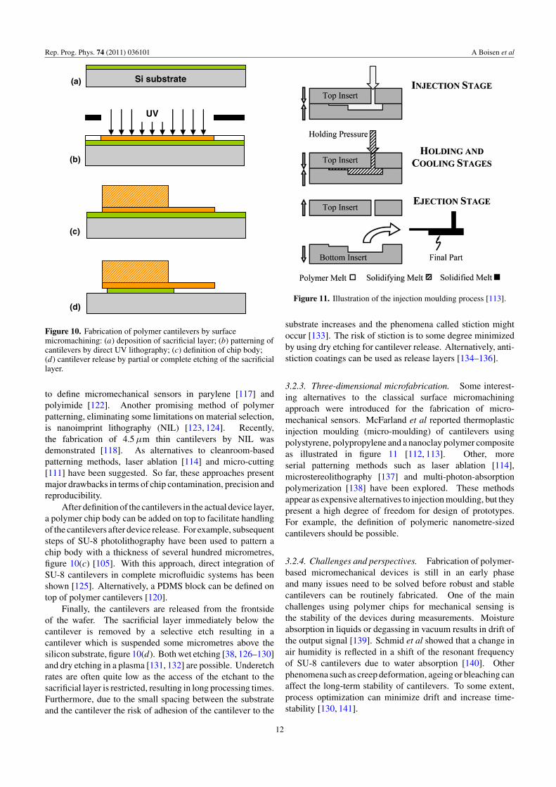
Figure 10. Fabrication of polymer cantilevers by surfacemicromachining: (a) deposition of sacrificial layer; (b) patterning ofcantilevers by direct UV lithography; (c) definition of chip body;(d) cantilever release by partial or complete etching of the sacrificiallayer.
to define micromechanical sensors in parylene [117] andpolyimide [122]. Another promising method of polymerpatterning, eliminating some limitations on material selection,is nanoimprint lithography (NIL) [123, 124]. Recently,the fabrication of 4.5 µm thin cantilevers by NIL wasdemonstrated [118]. As alternatives to cleanroom-basedpatterning methods, laser ablation [114] and micro-cutting[111] have been suggested. So far, these approaches presentmajor drawbacks in terms of chip contamination, precision andreproducibility.
After definition of the cantilevers in the actual device layer,a polymer chip body can be added on top to facilitate handlingof the cantilevers after device release. For example, subsequentsteps of SU-8 photolithography have been used to pattern achip body with a thickness of several hundred micrometres,figure 10(c) [105]. With this approach, direct integration ofSU-8 cantilevers in complete microfluidic systems has beenshown [125]. Alternatively, a PDMS block can be defined ontop of polymer cantilevers [120].
Finally, the cantilevers are released from the frontsideof the wafer. The sacrificial layer immediately below thecantilever is removed by a selective etch resulting in acantilever which is suspended some micrometres above thesilicon substrate, figure 10(d). Both wet etching [38, 126–130]and dry etching in a plasma [131, 132] are possible. Underetchrates are often quite low as the access of the etchant to thesacrificial layer is restricted, resulting in long processing times.Furthermore, due to the small spacing between the substrateand the cantilever the risk of adhesion of the cantilever to the
Figure 11. Illustration of the injection moulding process [113].
substrate increases and the phenomena called stiction mightoccur [133]. The risk of stiction is to some degree minimizedby using dry etching for cantilever release. Alternatively, anti-stiction coatings can be used as release layers [134–136].
3.2.3. Three-dimensional microfabrication. Some interest-ing alternatives to the classical surface micromachiningapproach were introduced for the fabrication of micro-mechanical sensors. McFarland et al reported thermoplasticinjection moulding (micro-moulding) of cantilevers usingpolystyrene, polypropylene and a nanoclay polymer compositeas illustrated in figure 11 [112, 113]. Other, moreserial patterning methods such as laser ablation [114],microstereolithography [137] and multi-photon-absorptionpolymerization [138] have been explored. These methodsappear as expensive alternatives to injection moulding, but theypresent a high degree of freedom for design of prototypes.For example, the definition of polymeric nanometre-sizedcantilevers should be possible.
3.2.4. Challenges and perspectives. Fabrication of polymer-based micromechanical devices is still in an early phaseand many issues need to be solved before robust and stablecantilevers can be routinely fabricated. One of the mainchallenges using polymer chips for mechanical sensing isthe stability of the devices during measurements. Moistureabsorption in liquids or degassing in vacuum results in drift ofthe output signal [139]. Schmid et al showed that a change inair humidity is reflected in a shift of the resonant frequencyof SU-8 cantilevers due to water absorption [140]. Otherphenomena such as creep deformation, ageing or bleaching canaffect the long-term stability of cantilevers. To some extent,process optimization can minimize drift and increase time-stability [130, 141].
12

Rep. Prog. Phys. 74 (2011) 036101 A Boisen et al
For thin polymer cantilevers, reflectivity is insufficientfor optical read-out and therefore a metal coating is required.Furthermore, gold coatings are typically used as linker surfacesfor the attachment of receptor molecules. The depositionof metals is a critical step as it implies the use of elevatedtemperatures. This heavily affects the stress gradients inpolymer cantilevers [142]. A possible solution is direct surfacefunctionalization of polymer cantilevers, avoiding gold layersas binding interfaces [143, 144]. The laser reflection can beensured by only integrating a small metal pad at the apex ofthe cantilever.
Since the introduction of polymers for the fabrication ofcantilever sensors, the spring constant has been continuouslyreduced. The fabrication of 2 µm thin SU-8 cantilevers withL = 500 µm and low initial bending is possible [141]. Thisis promising in terms of sensitivity, but at the same timethe reduction in the thickness implies an amplification of theaforementioned instabilities during measurements. For mostapplications, polymer cantilevers with a thickness of 5 µm aremore than suitable for surface stress measurements. Insteadof trying to further increase sensitivity by decreasing thecantilever thickness, the focus should be on improving controlof stability.
In the future, the improvement of new fabrication methodssuch as NIL or injection moulding could allow the selectionof new polymer materials which are less affected by themeasurement conditions. In parallel, fabrication costs couldbe significantly reduced.
3.3. Cantilevers with integrated functionality
Fabrication becomes more complicated when read-out ofthe cantilever bending and/or additional features such aselectrodes or heater elements are integrated into the structure.Here the integration of piezoresistive read-out is describedas an example. The details of this read-out method arediscussed in section 4. Other examples are the integrationof metal electrodes for electrochemistry [145] and thermalactuation [146].
In piezoresistive cantilever sensing each cantilever hasan integrated resistor which has piezoresistive properties.For silicon-based cantilevers, a silicon resistor is defined inmicrocrystalline or single crystal silicon and encapsulated insilicon nitride [147]. The silicon nitride serves as an efficientelectrical insulation of the resistor and ensures that the devicecan be operated in liquids. The signal-to-noise ratio of thepiezoresistive cantilever depends highly on the doping andthe crystallinity of the silicon layer and the best performanceis clearly found for single crystalline resistors [148]. Thepiezoresistive coefficient of doped silicon is high, resulting invery sensitive read-out. The cantilevers can detect deflectionsbelow 1 nm and the small size of the cantilevers makes itpossible to realize a complete device with liquid handlingand electronics on a few cm2. In figure 12 an image of 10cantilevers placed in a channel is shown. The channel is usedto guide the liquids under investigation to the cantilevers [149].
Similar devices with integrated piezoresistive read-out canbe realized in SU-8 [150, 151]. An example of two polymer
Figure 12. Scanning electron microscope image of 10 siliconnitride cantilevers with integrated silicon piezoresistors in a channel.The channel has two inlets and two outlets. Every second cantileveris coated on the top side with a 20 nm thick gold layer for surfacefunctionalization. These cantilevers appear brighter.
Figure 13. Optical microscope image of two polymer cantileverswith integrated gold resistors placed in a channel. Two additionalgold resistors can be seen on the body of the chip.
cantilevers with integrated gold resistors is shown in figure 13.The gold resistors serve as low noise piezoresistors and thesignal-to-noise ratio is comparable to the value for the siliconnitride cantilevers with single crystal resistors [152] due tothe much lower electrical noise in gold compared with silicon.The relative resistance change of gold is approximately 40times smaller than for single crystal silicon and new materialsare therefore being investigated as possible candidates for evenbetter piezoresistors.
Several groups have synthesized composite materials bymixing nanoparticles into polymers. The availability ofconductive [153, 154], magnetic [155] and luminescent [156]polymers for cantilever fabrication allows adding functionalityto the devices. For example, composites of carbonnanoparticles and SU-8 were used to fabricate cantilevers withintegrated polymer piezoresistors [157]. There, the challengeis to find a material which is soft and at the same time hasa large resistance change upon deflection. Moreover, theelectrical noise in the system should be low. Materials such aspolyaniline [158], 3,4-ethylenedioxythiophene (PEDT) [159]
13
Rep. Prog. Phys. 74 (2011) 036101 A Boisen et al
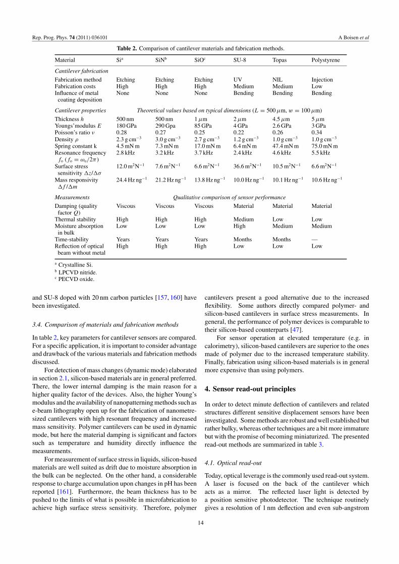
Table 2. Comparison of cantilever materials and fabrication methods.
Material Sia SiNb SiOc SU-8 Topas Polystyrene
Cantilever fabrication
Fabrication method Etching Etching Etching UV NIL InjectionFabrication costs High High High Medium Medium LowInfluence of metal None None None Bending Bending Bending
coating deposition
Cantilever properties Theoretical values based on typical dimensions (L = 500 µm, w = 100 µm)
Thickness h 500 nm 500 nm 1 µm 2 µm 4.5 µm 5 µmYoungs’modulus E 180 GPa 290 Gpa 85 GPa 4 GPa 2.6 GPa 3 GPaPoisson’s ratio ν 0.28 0.27 0.25 0.22 0.26 0.34Density ρ 2.3 g cm−3 3.0 g cm−3 2.7 g cm−3 1.2 g cm−3 1.0 g cm−3 1.0 g cm−3
Spring constant k 4.5 mN m 7.3 mN m 17.0 mN m 6.4 mN m 47.4 mN m 75.0 mN mResonance frequency 2.8 kHz 3.2 kHz 3.7 kHz 2.4 kHz 4.6 kHz 5.5 kHzfo (fo = ωo/2π )
Surface stress 12.0 m2N−1 7.6 m2N−1 6.6 m2N−1 36.6 m2N−1 10.5 m2N−1 6.6 m2N−1
sensitivity z/σ
Mass responsivity 24.4 Hz ng−1 21.2 Hz ng−1 13.8 Hz ng−1 10.0 Hz ng−1 10.1 Hz ng−1 10.6 Hz ng−1
f /m
Measurements Qualitative comparison of sensor performance
Damping (quality Viscous Viscous Viscous Material Material Materialfactor Q)
Thermal stability High High High Medium Low LowMoisture absorption Low Low Low High Medium Medium
in bulkTime-stability Years Years Years Months Months —Reflection of optical High High High Low Low Low
beam without metal
a Crystalline Si.b LPCVD nitride.c PECVD oxide.
and SU-8 doped with 20 nm carbon particles [157, 160] havebeen investigated.
3.4. Comparison of materials and fabrication methods
In table 2, key parameters for cantilever sensors are compared.For a specific application, it is important to consider advantageand drawback of the various materials and fabrication methodsdiscussed.
For detection of mass changes (dynamic mode) elaboratedin section 2.1, silicon-based materials are in general preferred.There, the lower internal damping is the main reason for ahigher quality factor of the devices. Also, the higher Young’smodulus and the availability of nanopatterning methods such ase-beam lithography open up for the fabrication of nanometre-sized cantilevers with high resonant frequency and increasedmass sensitivity. Polymer cantilevers can be used in dynamicmode, but here the material damping is significant and factorssuch as temperature and humidity directly influence themeasurements.
For measurement of surface stress in liquids, silicon-basedmaterials are well suited as drift due to moisture absorption inthe bulk can be neglected. On the other hand, a considerableresponse to charge accumulation upon changes in pH has beenreported [161]. Furthermore, the beam thickness has to bepushed to the limits of what is possible in microfabrication toachieve high surface stress sensitivity. Therefore, polymer
cantilevers present a good alternative due to the increasedflexibility. Some authors directly compared polymer- andsilicon-based cantilevers in surface stress measurements. Ingeneral, the performance of polymer devices is comparable totheir silicon-based counterparts [47].
For sensor operation at elevated temperature (e.g. incalorimetry), silicon-based cantilevers are superior to the onesmade of polymer due to the increased temperature stability.Finally, fabrication using silicon-based materials is in generalmore expensive than using polymers.
4. Sensor read-out principles
In order to detect minute deflection of cantilevers and relatedstructures different sensitive displacement sensors have beeninvestigated. Some methods are robust and well established butrather bulky, whereas other techniques are a bit more immaturebut with the promise of becoming miniaturized. The presentedread-out methods are summarized in table 3.
4.1. Optical read-out
Today, optical leverage is the commonly used read-out system.A laser is focused on the back of the cantilever whichacts as a mirror. The reflected laser light is detected bya position sensitive photodetector. The technique routinelygives a resolution of 1 nm deflection and even sub-angstrom
14

Rep. Prog. Phys. 74 (2011) 036101 A Boisen et al
Table 3. Summary of read-out methods.
Read-outmethod Pros Cons Used in Company
Optical Simple read-out method, known Difficult to apply for large arrays; Surface stress; Concentris,leverage from AFM; can be used on prone to optical artefacts mass; bulk stress Veeco
any cantilever with a good such as change in refractive index;optical quality not suitable for nanometre-sized
cantileversCapacitive Useful for nanometre-sized Stray capacitances make Mass —
cantilevers; read-out does not pre-amplifications and CMOSaffect the mechanical properties integration necessary; thisof the cantilever complicates the fabrication
Piezoelectric The principle can be used Many piezoelectric materials are not Surface stress; Intelligentfor actuation as well cleanroom compatible; many mass; bulk stress Microsystemsas read-out piezoelectrical materials are only Center
suitable for dynamic measurementsPiezoresistive Facilitates large arrays A piezoresistive layer needs Surface stress; Nanonord,
and system integration; to be integrated into the cantilever mass; bulk stress Seikoworks in all media and in which affects the mechanicalall modes of operation performance; for operation
in liquid, care has to be taken inorder to insulate the resistor
Hard contact Offers a ‘digital’ read-out Wear of the counter electrode Mass —where a signal is only is a challenge; works onlygenerated when the cantilever in airis in resonance; highsignal-to-noise ratio
Tunnelling Potentially very sensitive Complicated operation Mass —detection of cantilever and only works in airbending
Integrated Suitable for large scale arrays More complicated fabrication Surface stress —optical with the same sensitivity and packaging; prone to opticalmethods as optical leverage artefacts, such as changes(waveguides) in refractive index
Autonomous Simple device concept Difficult to realize the device Surface stress —devices with no need for such that there is no leakage
external energy of dye molecules
resolution can be achieved. However, this set-up doesnot facilitate the simultaneous read-out from a referencecantilever. To allow for the detection of multiple cantileverdeflections simultaneously new optical read-out schemes havebeen developed. In a solution originally developed at IBM,Zurich [18, 162, 163], an array of eight commercially availableVCSELs (vertical cavity surface emitting lasers) is usedto illuminate eight cantilevers spaced with the same pitch(250 µm) as the individual VCSELs. The reflected light iscollected by a single photodetector. The photodetector cantrack the individual movement of the spots reflected from eachrespective cantilever. This concept is now the platform inthe commercially available system from Concentris [90]. Adifferent approach has been developed in the group of ArunMajumdar at Berkeley, USA. There, a two-dimensional arrayof cantilevers is illuminated simultaneously with an expandedand collimated laser beam. Each cantilever only reflects thelight from a mirror placed at the apex. The resulting two-dimensional arrays of reflected spots are captured by a highresolution CCD camera [164–166]. The movement of theindividual spots can be registered with a resolution of 1 nm andread out from two-dimensional cantilever arrays with about720 cantilevers has been reported using this technique. Thetechnique is simple to instrument, however the optics is, in
its present form, bulky and the resolution is less than for theoptical leverage technique—being limited by the resolution ofthe CCD array.
In some cases, especially in more fundamental studies of,for example, signal generation, information on the bendingprofile of the full cantilever is advantageous. One possibilityis to scan a laser across a single cantilever and monitor thedeflection as a function of cantilever position. A line profile ofthe cantilever can then be obtained [167]. A full field deflectionpicture can be obtained using interferometric imaging methods[168]. Thereby it is possible in real-time to monitor thedeformation of the full cantilever surface. Such studies haveshed new light on the cantilevers mechanical response tosurface stress changes [167] and charge distributions on thecantilever surface [169].
Recently, new ways of realizing potentially extremelycompact and sensitive sensor systems have been published.One possibility is to place the cantilever above a VCSELand use the cantilever to create a so-called external cavitybetween the laser and cantilever. The light reflected backinto the VCSEL creates a self-mixing interference signal[170]. Thereby a deflection resolution of less than 1 Å canbe achieved and large arrays can be realized using sandwichedtwo-dimensional VCSEL and cantilever arrays.
15
Rep. Prog. Phys. 74 (2011) 036101 A Boisen et al
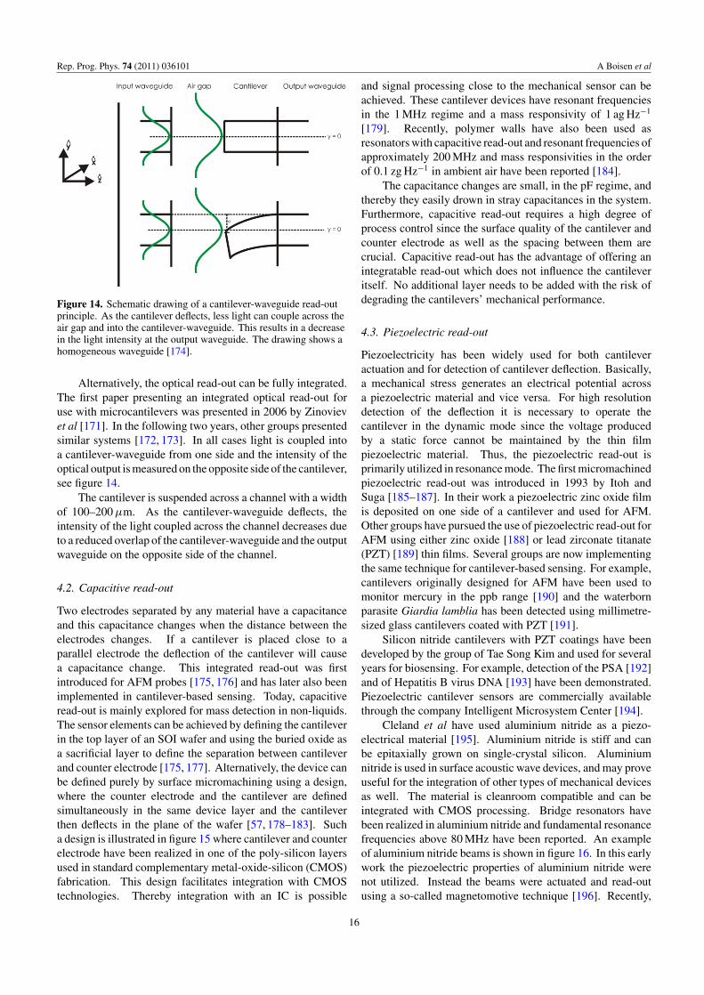
Figure 14. Schematic drawing of a cantilever-waveguide read-outprinciple. As the cantilever deflects, less light can couple across theair gap and into the cantilever-waveguide. This results in a decreasein the light intensity at the output waveguide. The drawing shows ahomogeneous waveguide [174].
Alternatively, the optical read-out can be fully integrated.The first paper presenting an integrated optical read-out foruse with microcantilevers was presented in 2006 by Zinovievet al [171]. In the following two years, other groups presentedsimilar systems [172, 173]. In all cases light is coupled intoa cantilever-waveguide from one side and the intensity of theoptical output is measured on the opposite side of the cantilever,see figure 14.
The cantilever is suspended across a channel with a widthof 100–200 µm. As the cantilever-waveguide deflects, theintensity of the light coupled across the channel decreases dueto a reduced overlap of the cantilever-waveguide and the outputwaveguide on the opposite side of the channel.
4.2. Capacitive read-out
Two electrodes separated by any material have a capacitanceand this capacitance changes when the distance between theelectrodes changes. If a cantilever is placed close to aparallel electrode the deflection of the cantilever will causea capacitance change. This integrated read-out was firstintroduced for AFM probes [175, 176] and has later also beenimplemented in cantilever-based sensing. Today, capacitiveread-out is mainly explored for mass detection in non-liquids.The sensor elements can be achieved by defining the cantileverin the top layer of an SOI wafer and using the buried oxide asa sacrificial layer to define the separation between cantileverand counter electrode [175, 177]. Alternatively, the device canbe defined purely by surface micromachining using a design,where the counter electrode and the cantilever are definedsimultaneously in the same device layer and the cantileverthen deflects in the plane of the wafer [57, 178–183]. Sucha design is illustrated in figure 15 where cantilever and counterelectrode have been realized in one of the poly-silicon layersused in standard complementary metal-oxide-silicon (CMOS)fabrication. This design facilitates integration with CMOStechnologies. Thereby integration with an IC is possible
and signal processing close to the mechanical sensor can beachieved. These cantilever devices have resonant frequenciesin the 1 MHz regime and a mass responsivity of 1 ag Hz−1
[179]. Recently, polymer walls have also been used asresonators with capacitive read-out and resonant frequencies ofapproximately 200 MHz and mass responsivities in the orderof 0.1 zg Hz−1 in ambient air have been reported [184].
The capacitance changes are small, in the pF regime, andthereby they easily drown in stray capacitances in the system.Furthermore, capacitive read-out requires a high degree ofprocess control since the surface quality of the cantilever andcounter electrode as well as the spacing between them arecrucial. Capacitive read-out has the advantage of offering anintegratable read-out which does not influence the cantileveritself. No additional layer needs to be added with the risk ofdegrading the cantilevers’ mechanical performance.
4.3. Piezoelectric read-out
Piezoelectricity has been widely used for both cantileveractuation and for detection of cantilever deflection. Basically,a mechanical stress generates an electrical potential acrossa piezoelectric material and vice versa. For high resolutiondetection of the deflection it is necessary to operate thecantilever in the dynamic mode since the voltage producedby a static force cannot be maintained by the thin filmpiezoelectric material. Thus, the piezoelectric read-out isprimarily utilized in resonance mode. The first micromachinedpiezoelectric read-out was introduced in 1993 by Itoh andSuga [185–187]. In their work a piezoelectric zinc oxide filmis deposited on one side of a cantilever and used for AFM.Other groups have pursued the use of piezoelectric read-out forAFM using either zinc oxide [188] or lead zirconate titanate(PZT) [189] thin films. Several groups are now implementingthe same technique for cantilever-based sensing. For example,cantilevers originally designed for AFM have been used tomonitor mercury in the ppb range [190] and the waterbornparasite Giardia lamblia has been detected using millimetre-sized glass cantilevers coated with PZT [191].
Silicon nitride cantilevers with PZT coatings have beendeveloped by the group of Tae Song Kim and used for severalyears for biosensing. For example, detection of the PSA [192]and of Hepatitis B virus DNA [193] have been demonstrated.Piezoelectric cantilever sensors are commercially availablethrough the company Intelligent Microsystem Center [194].
Cleland et al have used aluminium nitride as a piezo-electrical material [195]. Aluminium nitride is stiff and canbe epitaxially grown on single-crystal silicon. Aluminiumnitride is used in surface acoustic wave devices, and may proveuseful for the integration of other types of mechanical devicesas well. The material is cleanroom compatible and can beintegrated with CMOS processing. Bridge resonators havebeen realized in aluminium nitride and fundamental resonancefrequencies above 80 MHz have been reported. An exampleof aluminium nitride beams is shown in figure 16. In this earlywork the piezoelectric properties of aluminium nitride werenot utilized. Instead the beams were actuated and read-outusing a so-called magnetomotive technique [196]. Recently,
16
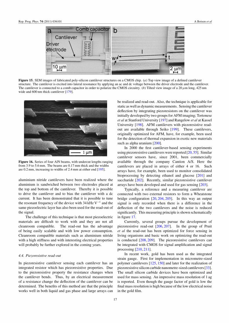
Rep. Prog. Phys. 74 (2011) 036101 A Boisen et al
Figure 15. SEM images of fabricated poly-silicon cantilever structures on a CMOS chip. (a) Top view image of a defined cantileverstructure. The cantilever is excited into lateral resonance by applying an ac and dc voltage between the driver electrode and the cantilever.The cantilever is connected to a comb capacitor in order to polarize the CMOS circuitry. (b) Tilted view image of a 20 µm long, 425 nmwide and 600 nm thick cantilever [179].
Figure 16. Series of four AlN beams, with undercut lengths rangingfrom 3.9 to 5.6 mm. The beams are 0.17 mm thick and the widthsare 0.2 mm, increasing to widths of 2.4 mm at either end [195].
aluminium nitride cantilevers have been realized where thealuminium is sandwiched between two electrodes placed atthe top and bottom of the cantilever. Thereby it is possibleto drive the cantilever and to bias the cantilever with a dccurrent. It has been demonstrated that it is possible to tunethe resonant frequency of the device with 34 kHz V−1 and thesame piezoelectric layer has also been used for the read-out ofthe signal.
The challenge of this technique is that most piezoelectricmaterials are difficult to work with and they are not allcleanroom compatible. The read-out has the advantageof being easily scalable and with low power consumption.Cleanroom compatible materials such as aluminium nitridewith a high stiffness and with interesting electrical propertieswill probably be further explored in the coming years.
4.4. Piezoresistive read-out
In piezoresistive cantilever sensing each cantilever has anintegrated resistor which has piezoresistive properties. Dueto the piezoresistive property the resistance changes whenthe cantilever bends. Thus, by an electrical measurementof a resistance change the deflection of the cantilever can bedetermined. The benefits of this method are that the principleworks well in both liquid and gas phase and large arrays can
be realized and read-out. Also, the technique is applicable forstatic as well as dynamic measurements. Sensing the cantileverdeflection by integrating piezoresistors on the cantilever wasinitially developed by two groups for AFM imaging; Tortoneseet al at Stanford University [197] and Rangelow et al at KasselUniversity [198]. AFM cantilevers with piezoresistive read-out are available through Seiko [199]. These cantilevers,originally optimized for AFM, have, for example, been usedfor the detection of thermal expansion in exotic new materialssuch as alpha uranium [200].
In 2000 the first cantilever-based sensing experimentsusing piezoresistive cantilevers were reported [20, 55]. Similarcantilever sensors have, since 2001, been commerciallyavailable through the company Cantion A/S. Here thecantilevers are placed in arrays of either 4 or 16. Sucharrays have, for example, been used to monitor consolidatedbioprocessing by detecting ethanol and glucose [201] andsaccharide [202]. Recently, similar piezoresistive cantileverarrays have been developed and used for gas sensing [203].
Typically, a reference and a measuring cantilever areconnected with two external resistors to form a Wheatstonebridge configuration [20, 204, 205]. In this way an outputsignal is only recorded when there is a difference in thedeflection of the two cantilevers and the noise is reducedsignificantly. This measuring principle is shown schematicallyin figure 17.
Currently, several groups pursue the development ofpiezoresistive read-out [206, 207]. In the group of Pruitet al the read-out has been optimized for force sensing inliving organisms and basic work on optimizing the read-outis conducted [208, 209]. The piezoresistive cantilevers canbe integrated with CMOS for signal amplification and signalprocessing [210, 211].
In recent work, gold has been used as the integratedstrain gauge. First for implementation in micrometre-sizedpolymer cantilevers [125, 150] and later for the realization ofpiezoresistive silicon carbide nanometre-sized cantilevers [33].The small silicon carbide devices have been optimized andused for mass sensing. An impressive mass resolution of 1 agis reported. Even though the gauge factor of gold is low thefinal mass resolution is high because of the low electrical noisein the gold film.
17
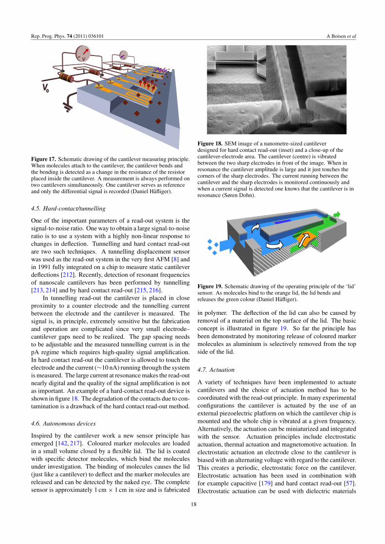
Rep. Prog. Phys. 74 (2011) 036101 A Boisen et al
Figure 17. Schematic drawing of the cantilever measuring principle.When molecules attach to the cantilever, the cantilever bends andthe bending is detected as a change in the resistance of the resistorplaced inside the cantilever. A measurement is always performed ontwo cantilevers simultaneously. One cantilever serves as referenceand only the differential signal is recorded (Daniel Hafliger).
4.5. Hard-contact/tunnelling
One of the important parameters of a read-out system is thesignal-to-noise ratio. One way to obtain a large signal-to-noiseratio is to use a system with a highly non-linear response tochanges in deflection. Tunnelling and hard contact read-outare two such techniques. A tunnelling displacement sensorwas used as the read-out system in the very first AFM [8] andin 1991 fully integrated on a chip to measure static cantileverdeflections [212]. Recently, detection of resonant frequenciesof nanoscale cantilevers has been performed by tunnelling[213, 214] and by hard contact read-out [215, 216].
In tunnelling read-out the cantilever is placed in closeproximity to a counter electrode and the tunnelling currentbetween the electrode and the cantilever is measured. Thesignal is, in principle, extremely sensitive but the fabricationand operation are complicated since very small electrode–cantilever gaps need to be realized. The gap spacing needsto be adjustable and the measured tunnelling current is in thepA regime which requires high-quality signal amplification.In hard contact read-out the cantilever is allowed to touch theelectrode and the current (∼10 nA) running through the systemis measured. The large current at resonance makes the read-outnearly digital and the quality of the signal amplification is notas important. An example of a hard-contact read-out device isshown in figure 18. The degradation of the contacts due to con-tamination is a drawback of the hard contact read-out method.
4.6. Autonomous devices
Inspired by the cantilever work a new sensor principle hasemerged [142, 217]. Coloured marker molecules are loadedin a small volume closed by a flexible lid. The lid is coatedwith specific detector molecules, which bind the moleculesunder investigation. The binding of molecules causes the lid(just like a cantilever) to deflect and the marker molecules arereleased and can be detected by the naked eye. The completesensor is approximately 1 cm × 1 cm in size and is fabricated
Figure 18. SEM image of a nanometre-sized cantileverdesigned for hard contact read-out (inset) and a close-up of thecantilever-electrode area. The cantilever (centre) is vibratedbetween the two sharp electrodes in front of the image. When inresonance the cantilever amplitude is large and it just touches thecorners of the sharp electrodes. The current running between thecantilever and the sharp electrodes is monitored continuously andwhen a current signal is detected one knows that the cantilever is inresonance (Søren Dohn).
Figure 19. Schematic drawing of the operating principle of the ‘lid’sensor. As molecules bind to the orange lid, the lid bends andreleases the green colour (Daniel Hafliger).
in polymer. The deflection of the lid can also be caused byremoval of a material on the top surface of the lid. The basicconcept is illustrated in figure 19. So far the principle hasbeen demonstrated by monitoring release of coloured markermolecules as aluminium is selectively removed from the topside of the lid.
4.7. Actuation
A variety of techniques have been implemented to actuatecantilevers and the choice of actuation method has to becoordinated with the read-out principle. In many experimentalconfigurations the cantilever is actuated by the use of anexternal piezoelectric platform on which the cantilever chip ismounted and the whole chip is vibrated at a given frequency.Alternatively, the actuation can be miniaturized and integratedwith the sensor. Actuation principles include electrostaticactuation, thermal actuation and magnetomotive actuation. Inelectrostatic actuation an electrode close to the cantilever isbiased with an alternating voltage with regard to the cantilever.This creates a periodic, electrostatic force on the cantilever.Electrostatic actuation has been used in combination withfor example capacitive [179] and hard contact read-out [57].Electrostatic actuation can be used with dielectric materials
18
Rep. Prog. Phys. 74 (2011) 036101 A Boisen et al
such as silicon nitride or polymers where an inhomogeneouselectric field produces a net force (Kelvin polarization force)acting on a dielectric micro- or nano-beam [128, 218–220].In thermal actuation a bimorph cantilever is heated in apulsed manner using for example an integrated resistive heater[221] or an external laser [222]. Also, natural thermalvibrations due to fluctuations in the temperature of the structurecan be used [223]. In magnetomotive actuation a staticmagnetic field is applied perpendicular to a cantilever throughwhich an alternating current is running. The Lorentz forceswill thereby cause the cantilever to deflect. The methodrequires large magnetic fields and low temperatures and hasrecently been used in mass detection using nanometre-sizedcantilevers [224].
5. Applications
Examples of biomolecule detection have recently beenpresented in review papers [2, 7, 225] where levels ofdetections have also been compared. Also, the use ofcantilever-based sensors in explosives detection has recentlybeen discussed in a broader context [226]. Here some ofthe major research areas within cantilever applications willbe described.
5.1. Surface functionalization
In order for a cantilever-based sensor to be able to detectspecific molecules it needs to be coated with specific ‘detector’molecules. For surface stress measurements it is importantthat only one side of the cantilever is coated since a uniformgeneration of surface stress on both cantilever sides willnot result in a cantilever deflection. For mass sensingboth sides can be functionalized although for maximumsensitivity it might be beneficial to have only the end of thecantilever functionalized. For all functionalization strategiesthe blocking of all other surfaces is crucial in order to preventunspecific binding.
In order to selectively coat closely spaced cantileversseveral different technologies have been developed. Acommon and widely used technology is to first coat thecantilevers with a thin gold layer on one side and then later usethiol-based chemistry to bind the probe molecules strongly tothe gold surface. Within the cantilever community it is knownthat the quality of the evaporated gold has a high influence onthe size and signature of the generated signals, as discussedin section 2.2.2. Great care has to be taken in preparing cleansurfaces and also the crystallinity seems to have an effect onthe signals. For silicon surfaces, silane coupling chemistry isoften used and for polymer cantilevers new methods have beendeveloped which, for example, use the epoxy groups on thesurface of SU-8 [227]. Also, photo-activated chemistry whichreacts with C–H bonds in polymers [143] has been utilized.
To expose different cantilevers in an array to differentliquids one can apply microspotting using technologiesdeveloped for the realization of DNA arrays [228, 229].Alternatively, capillaries placed with a spacing correspondingto the cantilever spacing are used as small beakers in whichthe cantilevers are inserted [90].
5.2. Bacteria detection
Whole bacteria or segments of bacteria can be caught directlyon a cantilever. For example, if a cantilever is coated withantibodies against E.coli the cantilever will specifically bindto E.coli. The sensor might be expanded to contain severalcantilevers each coated with a specific antibody. In this wayit is possible to detect multiple bacteria simultaneously. Oneof the first groups to demonstrate bacteria detection was thegroup of Craighead et al which, in 2001, showed the massdetection of E.coli bacteria [223]. As more bacteria werebound to a cantilever the resonant frequency was seen to changecorrespondingly. Later the detection of Salmonella entericawas reported—in this case monitoring the change in surfacestress upon binding of bacteria [230].
More fundamental studies have illustrated the influence ofbacteria position on the generated mass signal [231, 232]. Byanalysing the resonant frequency shift for bacteria positionedat different positions along the cantilever and by operating thecantilever at different modes it was found that the mass signaldepends on both the added mass and on the resulting changein stiffness of the cantilever as seen from equation (2.10).When a bacterium adsorbs on regions of high vibrationalamplitude the resonant frequency change will be dominatedby the mass changes. When the bacterium is positionedat a nodal point or at the clamped region the measuredfrequency response is governed by the change in stiffness. Theaddition of mass will thus result in an increase in the resonantfrequency. These results highlight the necessity of controllingthe position of bacteria absorption and show that either thestiffness effect or the mass change can be used for sensingpurposes.
The growth of E.coli has been studied by coatingcantilevers with a nutrient layer and monitoring the change inresonant frequency continuously [233] as the E.coli bacteriaplaced on top of the nutrient layer are growing. The resultingdata show that it is possible to detect active bacterial growth inless than 1 h. Using rather large piezoelectric cantilevers madeof PZT and glass (5 and 3 mm in length, 1.8 and 2.0 mm wide)the possibility of distinguishing between pathogen and non-pathogen E.coli was demonstrated [234]. The cantilever wascoated with antibodies against pathogen E.coli and immersedin a mixed population of both pathogenic and non-pathogenicstrains. The cantilever was seen to be highly selective onlybinding the pathogen species.
A highly sophisticated system for single cell detectionhas been developed by Manalis et al. Normally, resonatorsare damped when operated in liquid, thus lowering thesensitivity significantly. Manalis et al have removed thisobstacle by flowing liquid inside the cantilever. Thereby, thedevice can be operated in a vacuum while analysing liquidsinside the cantilever structure [235]. The first experimentsfocused on the demonstration of the detection of avidinbinding. This was done by flushing the inner channel wallswith biotinylated bovine serum albumin and subsequentlymonitoring the resulting resonant frequency shift as avidin isflushed through the system and binds to the functionalizedwalls. Single E.coli cell detection was demonstrated in2007 [236]. Here a buffer solution containing E.coli is run
19

Rep. Prog. Phys. 74 (2011) 036101 A Boisen et al
Figure 20. Schematic drawing of the principle of operation of ahollow cantilever. (a) A suspended microchannel translates masschanges into changes in resonance frequency. Fluid continuouslyflows through the channel and delivers biomolecules, cells orsynthetic particles. Sub-femtogram mass resolution is attained byshrinking the wall and fluid layer thickness to the micrometre scaleand by packaging the cantilever under high vacuum. (b) Whilebound and unbound molecules both increase the mass of thechannel, species that bind to the channel wall accumulate inside thedevice, and, as a result, their number can greatly exceed the numberof free molecules in solution. This enables specific detection by wayof immobilized receptors. (c) In another measurement modeparticles flow through the cantilever without binding to the surface,and the observed signal depends on the position of particles alongthe channel (insets 1–3). The exact mass excess of a particle can bequantified by the peak frequency shift induced at the apex [236].
through the system and the frequency response is measuredcontinuously. The measured frequency changes are plotted ina histogram in order to find the mass distribution. The mass ofan E.coli cell is found to be 110 ± 30 fg. A schematic of thedevice and its operation is shown in figure 20.
5.3. Point of care
As the cantilevers are label-free, potentially very sensitiveand possible to integrate in portable systems they are often
mentioned as a promising tool for POC diagnostics. One ofthe first examples of detection of clinically relevant proteinsfor diagnostics of prostate cancer was shown by the group ofMajumdar et al [22]. Here, cantilevers were used to detecttwo forms of PSA over a wide range of concentrations from0.2 ng ml−1 to 60 µg/ml in a background of human serumalbumin and human plasminogen at 1 mg ml−1. Antigenagainst PSA was immobilized using thiol chemistry on gold-coated silicon nitride cantilevers.
Microarrays that measure the expression levels of specificgenes are today being developed for diagnostics. Methodsthat involve, for example, fluorescent labelling can achievepicomolar detection sensitivity, but they are costly, labour-intensive and time-consuming. Moreover, labelling withmarkers can influence the original signal. In 2006 it wasdemonstrated that cantilever sensors can be used to detectmessenger RNA biomarker candidates in a solution of totalcellular RNA [237]. The cantilevers were able to detect at thepicomolar level without target amplification, and they wereshown to be sensitive to base mismatches.
5.4. Drug discovery
In the field of drug discovery today, the study of membraneproteins is essential. Membrane proteins are important targetsfor new medicine. The group of Hegner et al [238] hasrecently shown that cantilever sensors can be used to studythe interaction between specific membrane proteins and thebacteriophage T5. The bacteriophage is known to cause largestructural changes in the cell upon binding. Subsequently thephage penetrates the cell and injects DNA. This binding eventand the following conformational changes have been studiedusing cantilevers. In order to study the event, liposomeswith specific membrane proteins have been realized andfunctionalized on one side of cantilevers by ink-jet spotting.The liposomes serve as simple cell membrane models. Oneof the results is shown in figure 21. A concentration of 3pMof T5 phages is exposed to the cantilevers and a clear shift inresonance is observed corresponding to an uptake of mass.When the cantilevers are subsequently exposed to a bufferthe resonant frequency remains unchanged demonstrating theirreversible nature of the binding of the phages. This isthe first time that membrane protein interactions have beenstudied in a microarray format and the cantilevers could be aninteresting tool for drug screening as well as for measuringcells’ mechanical response to drug treatments.
The growth of antibiotic-resistant superbugs such asmethicillin-resistant Staphylococcus aureus (MRSA) andvancomycin-resistant Enterococcus has motivated studies onantibiotics and their modes of action. The bacteria’s resistanceto antibiotics can be caused by small changes in the bacteriacell wall and there is thus an interest in studies of theinteraction between antibiotics and bacterial cell wall precursoranalogues (mucopeptides). In the group of Mckendry et althe binding properties of the ‘vancomycin’ antibiotics havebeen investigated for vancomycin-sensitive and vancomycinresistant peptides [23]. It was possible to detecet vancomycinbinding to peptide-coated cantilever arrays, with 10nM
20
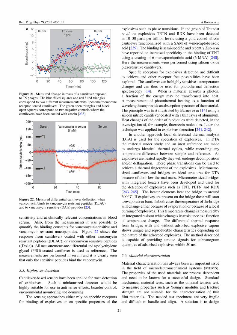
Rep. Prog. Phys. 74 (2011) 036101 A Boisen et al
Figure 21. Measured change in mass of a cantilever exposedto T5 phages. The blue filled squares and red filled trianglescorrespond to two different measurements with liposome/membranereceptor coated cantilevers. The green open triangles and blackopen squares correspond to two negative controls where thecantilevers have been coated with casein [238].
Figure 22. Measured differential cantilever deflection whenvancomycin binds to vancomycin resistant peptides (DLAC)and to vancomycin sensitive (DAla) peptides [23].
sensitivity and at clinically relevant concentrations in bloodserum. Also, from the measurements it was possible toquantify the binding constants for vancomycin-sensitive andvancomycin-resistant mucopeptides. Figure 22 shows theresponse from cantilevers coated with either vancomycinresistant peptides ((DLAC)) or vancomycin sensitive peptides((DAla)). All measurements are differential and a polyethyleneglycol (PEG)-coated cantilever is used as reference. Themeasurements are performed in serum and it is clearly seenthat only the sensitive peptides bind the vancomycin.
5.5. Explosives detection
Cantilever-based sensors have been applied for trace detectionof explosives. Such a miniaturized detector would behighly suitable for use in anti-terror efforts, boarder control,environmental monitoring and demining.
The sensing approaches either rely on specific receptorsfor binding of explosives or on specific properties of the
explosives such as phase transitions. In the group of Thundatet al the explosives TETN and RDX have been detectedin 10–30 parts-per-trillion levels using a gold-coated siliconcantilever functionalized with a SAM of 4-mercaptobenzoicacid [239]. The binding is semi-specific and recently Zuo et alhave reported on increased specificity in the binding of TNTusing a coating of 6-mercaptonicotinic acid (6-MNA) [240].Here the measurements were performed using silicon oxidepiezoresistive cantilevers.
Specific receptors for explosives detection are difficultto achieve and other receptor free possibilities have beenexplored. The cantilever can be highly sensitive to temperaturechanges and can thus be used for photothermal deflectionspectroscopy [14]. When a material absorbs a photon,a fraction of the energy may be transformed into heat.A measurement of photothermal heating as a function ofwavelength can provide an absorption spectrum of the material.The principle was first illustrated by Barnes et al [14] using asilicon nitride cantilever coated with a thin layer of aluminum.Heat changes of the order of picojoules were detected, in theinvestigation of, for example, fluorecein molecules. Later, thetechnique was applied in explosives detection [241, 242].
In another approach local differential thermal analysis(DTA) is used for the speciation of explosives. In DTAthe material under study and an inert reference are madeto undergo identical thermal cycles, while recording anytemperature difference between sample and reference. Asexplosives are heated rapidly they will undergo decompositionand/or deflagration. These phase transitions can be used toachieve a thermal fingerprint of the explosives. Micrometre-sized cantilevers and bridges are ideal structures for DTAbecause of their low thermal mass. Micrometre-sized bridgeswith integrated heaters have been developed and used forthe detection of explosives such as TNT, PETN and RDX[243–245]. The heater elements heat the bridge to around600 ◦C. If explosives are present on the bridge these will startto evaporate or burn. In both cases the temperature of the bridgewill change either because of evaporation or because of a localburning of explosives. This temperature change is measured byan integrated resistor which changes its resistance as a functionof temperature change. The differential thermal responsefrom bridges with and without adsorbed explosive vapourshows unique and reproducible characteristics depending onthe nature of the adsorbed explosives. The method describedis capable of providing unique signals for subnanogramquantities of adsorbed explosives within 50 ms.
5.6. Material characterization
Material characterization has always been an important issuein the field of microelectromechanical systems (MEMS).The properties of the used materials are process dependentand need to be known for a successful design. Standardmechanical material tests, such as the uniaxial tension test,to measure properties such as Young’s modulus and fracturestrength are not suitable for the characterization of thinfilm materials. The needed test specimens are very fragileand difficult to handle and align. A solution is to design
21
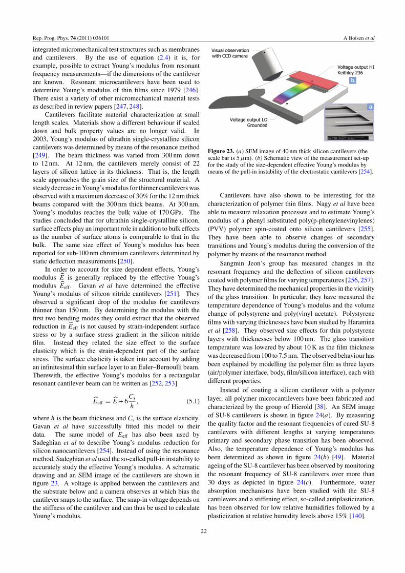
Rep. Prog. Phys. 74 (2011) 036101 A Boisen et al
integrated micromechanical test structures such as membranesand cantilevers. By the use of equation (2.4) it is, forexample, possible to extract Young’s modulus from resonantfrequency measurements—if the dimensions of the cantileverare known. Resonant microcantilevers have been used todetermine Young’s modulus of thin films since 1979 [246].There exist a variety of other micromechanical material testsas described in review papers [247, 248].
Cantilevers facilitate material characterization at smalllength scales. Materials show a different behaviour if scaleddown and bulk property values are no longer valid. In2003, Young’s modulus of ultrathin single-crystalline siliconcantilevers was determined by means of the resonance method[249]. The beam thickness was varied from 300 nm downto 12 nm. At 12 nm, the cantilevers merely consist of 22layers of silicon lattice in its thickness. That is, the lengthscale approaches the grain size of the structural material. Asteady decrease in Young’s modulus for thinner cantilevers wasobserved with a maximum decrease of 30% for the 12 nm thickbeams compared with the 300 nm thick beams. At 300 nm,Young’s modulus reaches the bulk value of 170 GPa. Thestudies concluded that for ultrathin single-crystalline silicon,surface effects play an important role in addition to bulk effectsas the number of surface atoms is comparable to that in thebulk. The same size effect of Young’s modulus has beenreported for sub-100 nm chromium cantilevers determined bystatic deflection measurements [250].
In order to account for size dependent effects, Young’smodulus E is generally replaced by the effective Young’smodulus Eeff . Gavan et al have determined the effectiveYoung’s modulus of silicon nitride cantilevers [251]. Theyobserved a significant drop of the modulus for cantileversthinner than 150 nm. By determining the modulus with thefirst two bending modes they could extract that the observedreduction in Eeff is not caused by strain-independent surfacestress or by a surface stress gradient in the silicon nitridefilm. Instead they related the size effect to the surfaceelasticity which is the strain-dependent part of the surfacestress. The surface elasticity is taken into account by addingan infinitesimal thin surface layer to an Euler–Bernoulli beam.Therewith, the effective Young’s modulus for a rectangularresonant cantilever beam can be written as [252, 253]
Eeff = E + 6Cs
h, (5.1)
where h is the beam thickness and Cs is the surface elasticity.Gavan et al have successfully fitted this model to theirdata. The same model of Eeff has also been used bySadeghian et al to describe Young’s modulus reduction forsilicon nanocantilevers [254]. Instead of using the resonancemethod, Sadeghian et al used the so-called pull-in instability toaccurately study the effective Young’s modulus. A schematicdrawing and an SEM image of the cantilevers are shown infigure 23. A voltage is applied between the cantilevers andthe substrate below and a camera observes at which bias thecantilever snaps to the surface. The snap-in voltage depends onthe stiffness of the cantilever and can thus be used to calculateYoung’s modulus.
Figure 23. (a) SEM image of 40 nm thick silicon cantilevers (thescale bar is 5 µm). (b) Schematic view of the measurement set-upfor the study of the size-dependent effective Young’s modulus bymeans of the pull-in instability of the electrostatic cantilevers [254].
Cantilevers have also shown to be interesting for thecharacterization of polymer thin films. Nagy et al have beenable to measure relaxation processes and to estimate Young’smodulus of a phenyl substituted poly(p-phenylenevinylenes)(PVV) polymer spin-coated onto silicon cantilevers [255].They have been able to observe changes of secondarytransitions and Young’s modulus during the conversion of thepolymer by means of the resonance method.
Sangmin Jeon’s group has measured changes in theresonant frequency and the deflection of silicon cantileverscoated with polymer films for varying temperatures [256, 257].They have determined the mechanical properties in the vicinityof the glass transition. In particular, they have measured thetemperature dependence of Young’s modulus and the volumechange of polystyrene and poly(vinyl acetate). Polystyrenefilms with varying thicknesses have been studied by Haraminaet al [258]. They observed size effects for thin polystyrenelayers with thicknesses below 100 nm. The glass transitiontemperature was lowered by about 10 K as the film thicknesswas decreased from 100 to 7.5 nm. The observed behaviour hasbeen explained by modelling the polymer film as three layers(air/polymer interface, body, film/silicon interface), each withdifferent properties.
Instead of coating a silicon cantilever with a polymerlayer, all-polymer microcantilevers have been fabricated andcharacterized by the group of Hierold [38]. An SEM imageof SU-8 cantilevers is shown in figure 24(a). By measuringthe quality factor and the resonant frequencies of cured SU-8cantilevers with different lengths at varying temperaturesprimary and secondary phase transition has been observed.Also, the temperature dependence of Young’s modulus hasbeen determined as shown in figure 24(b) [49]. Materialageing of the SU-8 cantilever has been observed by monitoringthe resonant frequency of SU-8 cantilevers over more than30 days as depicted in figure 24(c). Furthermore, waterabsorption mechanisms have been studied with the SU-8cantilevers and a stiffening effect, so-called antiplasticization,has been observed for low relative humidifies followed by aplasticization at relative humidity levels above 15% [140].
22
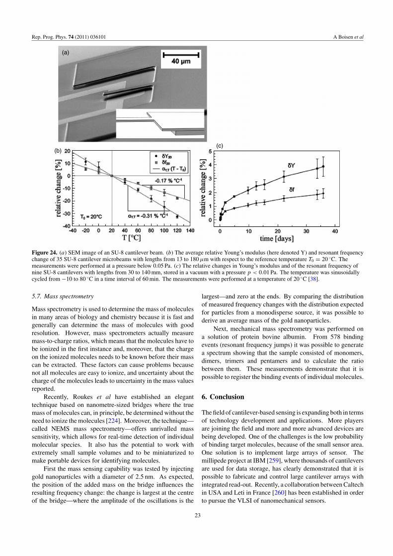
Rep. Prog. Phys. 74 (2011) 036101 A Boisen et al
Figure 24. (a) SEM image of an SU-8 cantilever beam. (b) The average relative Young’s modulus (here denoted Y) and resonant frequencychange of 35 SU-8 cantilever microbeams with lengths from 13 to 180 µm with respect to the reference temperature T0 = 20 ◦C. Themeasurements were performed at a pressure below 0.05 Pa. (c) The relative changes in Young’s modulus and of the resonant frequency ofnine SU-8 cantilevers with lengths from 30 to 140 mm, stored in a vacuum with a pressure p < 0.01 Pa. The temperature was sinusoidallycycled from −10 to 80 ◦C in a time interval of 60 min. The measurements were performed at a temperature of 20 ◦C [38].
5.7. Mass spectrometry
Mass spectrometry is used to determine the mass of moleculesin many areas of biology and chemistry because it is fast andgenerally can determine the mass of molecules with goodresolution. However, mass spectrometers actually measuremass-to-charge ratios, which means that the molecules have tobe ionized in the first instance and, moreover, that the chargeon the ionized molecules needs to be known before their masscan be extracted. These factors can cause problems becausenot all molecules are easy to ionize, and uncertainty about thecharge of the molecules leads to uncertainty in the mass valuesreported.
Recently, Roukes et al have established an eleganttechnique based on nanometre-sized bridges where the truemass of molecules can, in principle, be determined without theneed to ionize the molecules [224]. Moreover, the technique—called NEMS mass spectrometry—offers unrivalled masssensitivity, which allows for real-time detection of individualmolecular species. It also has the potential to work withextremely small sample volumes and to be miniaturized tomake portable devices for identifying molecules.
First the mass sensing capability was tested by injectinggold nanoparticles with a diameter of 2.5 nm. As expected,the position of the added mass on the bridge influences theresulting frequency change: the change is largest at the centreof the bridge—where the amplitude of the oscillations is the
largest—and zero at the ends. By comparing the distributionof measured frequency changes with the distribution expectedfor particles from a monodisperse source, it was possible toderive an average mass of the gold nanoparticles.
Next, mechanical mass spectrometry was performed ona solution of protein bovine albumin. From 578 bindingevents (resonant frequency jumps) it was possible to generatea spectrum showing that the sample consisted of monomers,dimers, trimers and pentamers and to calculate the ratiobetween them. These measurements demonstrate that it ispossible to register the binding events of individual molecules.
6. Conclusion
The field of cantilever-based sensing is expanding both in termsof technology development and applications. More playersare joining the field and more and more advanced devices arebeing developed. One of the challenges is the low probabilityof binding target molecules, because of the small sensor area.One solution is to implement large arrays of sensor. Themillipede project at IBM [259], where thousands of cantileversare used for data storage, has clearly demonstrated that it ispossible to fabricate and control large cantilever arrays withintegrated read-out. Recently, a collaboration between Caltechin USA and Leti in France [260] has been established in orderto pursue the VLSI of nanomechanical sensors.
23

Rep. Prog. Phys. 74 (2011) 036101 A Boisen et al
The surface chemistries developed and the applicationsreported have become more and more advanced in termsof detection limit and use of non-trivial probe-molecules.However, there are still several fundamental questions to beaddressed. For example, the origin of surface stress changesis still not fully understood and several models have beenpresented on, for example, the generation of signals fromDNA. Now researchers start to perform thorough and detailedstudies on rather simple systems in order to fully understandthe signal generations and, in parallel, model the surface stressgeneration.
The technology is in a maturing phase where some ofthe unanswered questions are now being addressed. Oneimportant experimental factor is the use of reference sensorsfor controlling the measurements and to reduce unspecificsignals from for example changes in temperature. As thesensors are extremely sensitive to side effects such as changein temperature and measuring liquid there is a great risk ofachieving false signals. It is therefore crucial to conductmeasurements under very well controlled conditions andto perform control measurements by other supplementingtechniques. Clearly, there is now a need for theoreticians,technology developers and application experts to initiatecollaborative projects where critical aspects of cantilever andrelated sensing techniques are identified and carefully studied.
Also, change in surface stress, bulk stress and resonantfrequency are coupled phenomena and there is a need forthorough studies on how these different mechanisms can bede-coupled. Before this is solved it will be difficult to obtainreliable and reproducible data. Since the cantilevers can giveunique information on several parameters such as mass andsurface stress changes, more information can be gained bymeasuring multiple parameters. The potential of cantileversensors has not yet been fully explored.
In conclusion, the cantilever sensors have demonstratedunencumbered mass and surface stress sensitivity and it seemslikely that these structures will be utilized in future products in,for example, diagnostics and drug discovery. The cantileversensor field is exciting and dynamic. The limit for detection isconstantly challenged and only the imagination sets the limitto new applications.
References
[1] Qavi A J, Washburn A L, Byeon J Y and Bailey R C 2009Label-free technologies for quantitative multiparameterbiological analysis Anal. Bioanal. Chem. 394 121
[2] Fritz J 2008 Cantilever biosensors Analyst 133 855[3] Singamaneni S et al 2008 Bimaterial microcantilevers as a
hybrid sensing platform Adv. Mater. 20 653[4] Waggoner P S and Craighead H G 2007 Micro- and
nanomechanical sensors for environmental, chemical, andbiological detection Lab Chip 7 1238
[5] Carrascosa L G, Moreno M, Alvarez M and Lechuga L M2006 Nanomechanical biosensors: a new sensing toolTrac-Trends Anal. Chem. 25 196
[6] Boisen A and Thundat T 2009 Design & fabrication ofcantilever array biosensors Mater. Today 12 32
[7] Hwang K S, Lee S M, Kim S K, Lee J H and Kim T S 2009Micro- and nanocantilever devices and systems forbiomolecule detection Annu. Rev. Anal. Chem. 2 77
[8] Binnig G, Quate C F and Gerber C 1986 Atomic forcemicroscope Phys. Rev. Lett. 56 930
[9] Albrecht T R, Akamine S, Carver T E and Quate C F 1990Microfabrication of cantilever styli for the atomic forcemicroscope J. Vac. Sci. Technol. A 8 3386
[10] Wolter O, Bayer T and Greschner J 1991 Micromachinedsilicon sensors for scanning force microscopy J. Vac. Sci.Technol. B 9 1353
[11] Thundat T, Warmack R J, Chen G Y and Allison D P 1994Thermal and ambient-induced deflections of scanningforce microscope cantilevers Appl. Phys. Lett. 64 2894
[12] Thundat T, Wachter E A, Sharp S L and Warmack R J 1995Detection of mercury-vapor using resonatingmicrocantilevers Appl. Phys. Lett. 66 1695
[13] Barnes J R, Stephenson R J, Woodburn C N, O’Shea S J,Welland M E, Rayment T, Gimzewski J K and Gerber C1994 A femtojoule calorimeter using micromechanicalsensors Rev. Sci. Instrum. 65 3793
[14] Barnes J R, Stephenson R J, Welland M E, Gerber C andGimzewski J K 1994 Photothermal spectroscopy withfemtojoule sensitivity using a micromechanical deviceNature 372 79
[15] Raiteri R and Butt H-J 1995 Measuring electrochemicallyinduced surface stress with an atomic force microscopeJ. Phys. Chem. 99 15728
[16] Butt H J 1996 A sensitive method to measure changes in thesurface stress of solids J. Colloid Interface Sci. 180 251
[17] Berger R, Delamarche E, Lang H P, Gerber C,Gimzewski J K, Meyer E and Guntherodt H-J 1997Surface stress in the self-assembly of alkanethiols on goldScience 276 2021
[18] Lang H P et al 1998 A chemical sensor based on amicromechanical cantilever array for the identification ofgases and vapors Appl. Phys. A 66 S61
[19] Fritz J, Baller M K, Lang H P, Rothuizen H, Vettiger P,Meyer E, Guntherodt H-J, Gerber C and Gimzewski J K2000 Translating biomolecular recognition intonanomechanics Science 288 316
[20] Boisen A, Thaysen J, Jensenius H and Hansen O 2000Environmental sensors based on micromachinedcantilevers with integrated read-out Ultramicroscopy 82 11
[21] Lange D, Hagleitner C, Hierlemann A, Brand O and Baltes H2002 Complementary metal oxide semiconductorcantilever arrays on a single chip: mass-sensitive detectionof volatile organic compounds Anal. Chem. 74 3084
[22] Wu G, Datar R H, Hansen K M, Thundat T, Cote R J andMajumdar A 2001 Bioassay of prostate-specific antigen(PSA) using microcantilevers Nature Biotechnol. 19 856
[23] Ndieyira J W et al 2008 Nanomechanical detection ofantibiotic mucopeptide binding in a model for superbugdrug resistance Nature Nanotechnol. 3 691
[24] Butt H J and Raiteri R 1999 Measurements of the surfacetension and surface stress of solids SurfaceCharacterization Methods (New York: Dekker)
[25] Berger R, Gerber C, Gimzewski J K, Meyer E andGuntherodt H J 1996 Thermal analysis using amicromechanical calorimeter Appl. Phys. Lett. 69 40
[26] Feng X L, He R R, Yang P D and Roukes M L 2007 Veryhigh frequency silicon nanowire electromechanicalresonators Nano Lett. 7 1953
[27] Ekinci K L, Huang X M H and Roukes M L 2004Ultrasensitive nanoelectromechanical mass detectionAppl. Phys. Lett. 84 4469
[28] Yang Y T, Callegari C, Feng X L, Ekinci K L andRoukes M L 2006 Zeptogram-scale nanomechanical masssensing Nano Lett. 6 583
[29] Ekinci K L, Yang Y T and Roukes M L 2004 Ultimate limitsto inertial mass sensing based upon nanoelectromechanicalsystems J. Appl. Phys. 95 2682
24
Rep. Prog. Phys. 74 (2011) 036101 A Boisen et al
[30] Rodahl M, Hook F, Krozer A, Brzezinski P and Kasemo B1995 Quartz-crystal microbalance setup for frequency andQ-factor measurements in gaseous and liquidenvironments Rev. Sci. Instrum. 66 3924
[31] Cagliani A and Davis Z J 2009 Bulk disk resonator basedultrasensitive mass sensor IEEE Sensors 2009(Christchurch, New Zealand) vols 1–3 (New York: IEEE)1254pp
[32] Lavrik N V and Datskos P G 2003 Femtogram massdetection using photothermally actuated nanomechanicalresonators Appl. Phys. Lett. 82 2697
[33] Li M, Tang H X and Roukes M L 2007 Ultra-sensitiveNEMS-based cantilevers for sensing, scanned probe andvery high-frequency applications Nature Nanotechnol.2 114
[34] Young W C, Budynas R G and Roark R J 2002 Roark’sFormulas for Stress and Strain (Boston, MA:McGraw-Hill)
[35] Cleland A N 2003 Foundations of Nanomechanics (Berlin:Springer)
[36] Timoshenko S and Woinowski-Krieger S 1970 Theory ofPlates and Shells (New York: McGraw-Hill)
[37] Weaver W, Timoshenko S P and Young D H 1990 VibrationProblems in Engineering (New York: Wiley)
[38] Schmid S 2009 Electrostatically Actuated All-PolymerMicrobeam Resonators—Characterization andApplication ed C Hierold (Toenning: Der Andere)
[39] Dohn S, Sandberg R, Svendsen W and Boisen A 2005Enhanced functionality of cantilever based mass sensorsusing higher modes Appl. Phys. Lett. 86 233501
[40] Yasumura K Y, Stowe T D, Chow E M, Pfafman T,Kenny T W, Stipe B C and Rugar D 2000 Quality factorsin micron- and submicron-thick cantilevers J.Microelectromech. Syst. 9 117
[41] Lifshitz R and Roukes M L 2000 Thermoelastic dampingin micro- and nanomechanical systems Phys. Rev. B61 5600
[42] Mohanty P, Harrington D A, Ekinci K L, Yang Y T,Murphy M J and Roukes M L 2002 Intrinsic dissipation inhigh-frequency micromechanical resonators Phys. Rev. B66 085416
[43] Stemme G 1991 Resonant silicon sensors J. Micromech.Microeng. 1 113
[44] Photiadis D M and Judge J A 2004 Attachment losses of highQ oscillators Appl. Phys. Lett. 85 482
[45] Blom F R, Bouwstra S, Elwenspoek M and Fluitman J H J1992 Dependence of the quality factor of micromachinedsilicon beam resonators on pressure and geometry J. Vac.Sci. Technol. B 10 19
[46] Sandberg R, Molhave K, Boisen A and Svendsen W 2005Effect of gold coating on the Q-factor of a resonantcantilever J. Micromech. Microeng. 15 2249
[47] Calleja M, Nordstrom M, Alvarez M, Tamayo J,Lechuga L M and Boisen A 2005 Highly sensitivepolymer-based cantilever-sensors for DNA detectionUltramicroscopy 105 215
[48] Verbridge S S, Parpia J M, Reichenbach R B, Bellan L M andCraighead H G 2006 High quality factor resonance atroom temperature with nanostrings under high tensilestress J. Appl. Phys. 99 124304
[49] Schmid S and Hierold C 2008 Damping mechanisms ofsingle-clamped and prestressed double-clamped resonantpolymer microbeams J. Appl. Phys. 104 093516
[50] Verbridge S S, Shapiro D F, Craighead H G and Parpia J M2007 Macroscopic tuning of nanomechanics: substratebending for reversible control of frequency and qualityfactor of nanostring resonators Nano Lett. 7 1728
[51] Schmid S, Malm B and Boisen A 2011 Quality factorimprovement of silicon nitride micro string resonators
24th Int. Conf. on Micro Electro Mechanical Systems(IEEE MEMS) (Cancun, Mexico)
[52] Putman C A J, Degrooth B G, Vanhulst N F and Greve J 1992A detailed analysis of the optical beam deflectiontechnique for use in atomic force microscopy J. Appl.Phys. 72 6
[53] Beck R G, Eriksson M A, Topinka M A, Westervelt R M,Maranowski K D and Gossard A C 1998 GaAs/AlGaAsself-sensing cantilevers for low temperature scanningprobe microscopy Appl. Phys. Lett. 73 1149
[54] Cleland A N and Roukes M L 1999 External controlof dissipation in a nanometer-scale radiofrequencymechanical resonator Sensors Actuators A72 256
[55] Jensenius H, Thaysen J, Rasmussen A A, Veje L H,Hansen O and Boisen A 2000 A microcantilever-basedalcohol vapor sensor-application and response model Appl.Phys. Lett. 76 2615
[56] Zhang Y and Blencowe M P 2002 Intrinsic noise of amicromechanical displacement detector based on theradio-frequency single-electron transistor J. Appl. Phys.91 4249
[57] Ghatnekar-Nilsson S, Forsen E, Abadal G, Verd J,Campabadal F, Perez-Murano F, Esteve J, Barniol N,Boisen A and Montelius L 2005 Resonators withintegrated CMOS circuitry for mass sensing applications,fabricated by electron beam lithography Nanotechnology16 98
[58] Lee D, Kim S, Jung N, Thundat T and Jeon S 2009 Effects ofgold patterning on the bending profile and frequencyresponse of a microcantilever J. Appl. Phys. 106 024310
[59] Dohn S, Svendsen W, Boisen A and Hansen O 2007 Massand position determination of attached particles oncantilever based mass sensors Rev. Sci. Instrum. 78 103303
[60] Senturia S D 2002 Energy Methods, Microsystem Design(Dordrecht: Kluwer) 239pp
[61] Dohn S, Schmid S, Amiot F and Boisen A 2010 Position andmass determination of multiple particles using cantileverbased mass sensors Appl. Phys. Lett. 97 044103
[62] Schmid S, Dohn S and Boisen A 2010 Real-time particlemass spectrometry based on resonant micro stringsSensors 10 8092
[63] Stoney G G 1909 The tension of metallic films deposited byelectrolysis Proc. R. Soc. Lond. A 82 172
[64] Jaccodin Rj and Schlegel W A 1966 Measurement of strainsat Si–SiO2 interface J. Appl. Phys. 37 2429
[65] Godin M, Tabard-Cossa V, Grutter P and Williams P 2001Quantitative surface stress measurements using amicrocantilever Appl. Phys. Lett. 79 551
[66] Zang J and Liu F 2007 Theory of bending of Sinanocantilevers induced by molecular adsorption: amodified Stoney formula for the calibration ofnanomechanochemical sensors Nanotechnology18 405501
[67] Hagan M F, Majumdar A and Chakraborty A K 2002Nanomechanical forces generated by surface grafted DNAJ. Phys. Chem. B 106 10163
[68] Liu F, Zhang Y and Ou-Yang Z C 2003 Flexoelectric originof nanomechanic deflection in DNA-microcantileversystem Biosensors Bioelectron. 18 655
[69] Begley M R, Utz M and Komaragiri U 2005Chemo-mechanical interactions between adsorbedmolecules and thin elastic films J. Mech. Phys. Solids53 2119
[70] Wu G, Ji H, Hansen K, Thundat T, Datar R, Cote R,Hagan M F, Chakraborty A K and Majumdar A 2001Origin of nanomechanical cantilever motion generatedfrom biomolecular interactions Proc. Natl Acad. Sci. USA98 1560
25

Rep. Prog. Phys. 74 (2011) 036101 A Boisen et al
[71] McKendry R et al 2002 Multiple label-free biodetection andquantitative dna-binding assays on a nanomechanicalcantilever array Proc. Natl Acad. Sci. USA 99 9783
[72] Watari M, Galbraith J, Lang H P, Sousa M, Hegner M,Gerber C, Horton M A and McKendry R A 2007Investigating the molecular mechanisms of in-planemechanochemistry on cantilever arrays J. Am. Chem. Soc.129 601
[73] Sushko M L, Harding J H, Shluger A L, McKendry R A andWatari M 2008 Physics of nanomechanical biosensing oncantilever arrays Adv. Mater. 20 3848
[74] Godin M, Tabard-Cossa V, Miyahara Y, Monga T,Williams P J, Beaulieu L Y, Lennox R B and Grutter P2010 Cantilever-based sensing: the origin of surfacestress and optimization strategies Nanotechnology21 075501
[75] Hansen A G, Mortensen M W, Andersen J E T, Ulstrup J,Kuhle A, Garnæs J and Boisen A 2001 Stress formationduring self-assembly of alkanethiols Probe Microsc. 2 139
[76] Godin M, Williams P J, Tabard-Cossa V, Laroche O,Beaulieu L Y, Lennox R B and Grutter P 2004 Surfacestress, kinetics, and structure of alkanethiol self-assembledmonolayers Langmuir 20 7090
[77] Mertens J, Calleja M, Ramos D, Taryn A and Tamayo J 2007Role of the gold film nanostructure on the nanomechanicalresponse of microcantilever sensors J. Appl. Phys.101 034904
[78] Arroyo-Hernandez M, Tamayo J and Costa-Kramer J L 2009Stress and DNA assembly differences on cantilevers goldcoated by resistive and e-beam evaporation techniquesLangmuir 25 10633
[79] Mertens J, Rogero C, Calleja M, Ramos D, Martin-Gago J A,Briones C and Tamayo J 2008 Label-free detection ofDNA hybridization based on hydration-induced tension innucleic acid films Nature Nanotechnol. 3 301
[80] Shu W M, Liu D S, Watari M, Riener C K, Strunz T,Welland M E, Balasubramanian S and McKendry R A2005 DNA molecular motor driven micromechanicalcantilever arrays J. Am. Chem. Soc. 127 17054
[81] Timoshenko S 1925 Analysis of bi-metal thermostats J. Opt.Soc. Am. 11 233
[82] Zhiyu H, Thundat T and Warmack R J 2001 Investigation ofadsorption and absorption-induced stresses usingmicrocantilever sensors J. Appl. Phys. 90 427
[83] Lavrik N V, Sepaniak M J and Datskos P G 2004 Cantilevertransducers as a platform for chemical and biologicalsensors Rev. Sci. Instrum. 75 2229
[84] LeMieux M C, McConney M E, Lin Y-H, Singamaneni S,Jiang H, Bunning T J and Tsukruk V V 2006 Polymericnanolayers as actuators for ultrasensitive thermal bimorphsNano Lett. 6 730
[85] He J-H et al 2009 A thermal sensor and switch based on aplasma polymer/ZnO suspended nanobelt bimorphstructure Nanotechnology 20 065502
[86] Gimzewski J K, Gerber C, Meyer E and Schlittler R R 1994Observation of a chemical reaction using amicromechanical sensor Chem. Phys. Lett. 217 589
[87] Singamaneni S, McConney M E, LeMieux M C, Jiang H,Enlow J O, Bunning T J, Naik R R and Tsukruk V V 2007Polymer-silicon flexible structures for fast chemical vapordetection Adv. Mater. 19 4248
[88] Schmid S, Wagli P and Hierold C 2008 All-polymermicrostring resonant humidity sensor with enhancedsensitivity due to change of intrinsic stressEUROSENSORS 22nd Conf. (Dresden, Germany) p 697
[89] Pandey A K, Gottlieb O, Shtempluck O and Buks E 2010Performance of an AuPd micromechanical resonator as atemperature sensor Appl. Phys. Lett. 96 203105
[90] www.concentris.ch
[91] www.micromotive.de[92] Yang J, Ono T and Esashi M 2000 Mechanical behavior
of ultrathin microcantilever Sensors Actuators A 82 102[93] Ramos D, Arroyo-Hernandez M, Gil-Santos E, Tong H D,
Van Rijn C, Calleja M and Tamayo J 2009 Arrays of dualnanomechanical resonators for selective biologicaldetection Anal. Chem. 81 2274
[94] Kovacs G T A, Maluf N I and Petersen K E 1998 Bulkmicromachining of silicon Proc. IEEE 86 1536
[95] http://www.svmi.com[96] http://www.soitec.com/en/index.php[97] http://www.universitywafers.com[98] May G S and Sze S M 2004 Photolithography, Fundamentals
of Semiconductor Fabrication (New York: Wiley)[99] McCord M A and Rooks M J 1997 Electron beam
lithography Handbook of Microlithography,Micromachining, and Microfabrication vol 1ed P Rai-Choudhury (Washington, DC: SPIE)
[100] Garrou P, Bower C and Ramm P 2008 Handbook of 3DIntegration (Weinheim: Wiley)
[101] Bagolini A, Pakula L, Scholtes T L M, Pham H T M,French P J and Sarro P M 2002 Polyimide sacrificial layerand novel materials for post-processing surfacemicromachining J. Micromech. Microeng. 12 385
[102] Geim A K and Novoselov K S 2007 The rise of grapheneNature Mater. 6 183
[103] Robertson J 2002 Diamond-like amorphous carbon Mater.Sci. Eng. R 37 129
[104] Pechmann R, Kohler J M, Fritzsche W, Schaper A andJovin T M 1994 The Novolever: a new cantilever forscanning force microscopy microfabricated frompolymeric materials Rev. Sci. Instrum. 65 3702
[105] Genolet G, Brugger J, Despont M, Drechsler U, Vettiger P,de Rooij N F and Anselmetti D 1999 Soft, entirelyphotoplastic probes for scanning force microscopyRev. Sci. Instrum. 70 2398
[106] Hopcroft M, Kramer T, Kim G, Takashima K, Higo Y,Moore D and Brugger J 2005 Micromechanical testingof SU-8 cantilevers Fatigue Fract. Eng. Mater. Struct.28 735
[107] Calleja M, Tamayo J, Johansson A, Rasmussen P,Lechuga L M and Boisen A 2003 Polymeric cantileverarrays for biosensing applications Sensor Lett. 1 20
[108] Ransley J H T, Watari M, Sukumaran D, McKendry R A andSeshia A A 2006 SU8 bio-chemical sensor microarraysMicroelectron. Eng. 83 1621
[109] Wang X, Ryu K S, Bullen D A, Zou J, Zhang H, Mirkin C Aand Liu C 2003 Scanning probe contact printing Langmuir19 8951
[110] Gaitas A and Gianchandani Y B 2006 An experimental studyof the contact mode AFM scanning capability ofpolyimide cantilever probes Ultramicroscopy 106 874
[111] McFarland A W, Poggi M A, Bottomley L A and Colton J S2004 Production and characterization of polymermicrocantilevers Rev. Sci. Instrum. 75 2756
[112] McFarland A W, Poggi M A, Bottomley L A and Colton J S2004 Injection moulding of high aspect ratio micron-scalethickness polymeric microcantilevers Nanotechnology15 1628
[113] McFarland A W and Colton J S 2005 Chemicalsensing with micromolded plastic microcantileversJ. Microelectromech. Syst. 14 1375
[114] Zhang X R and Xu X 2004 Development of a biosensor basedon laser-fabricated polymer microcantilevers Appl. Phys.Lett. 85 2423
[115] Lee L P, Berger S A, Liepmann D and Pruitt L 1998 Highaspect ratio polymer microstructures and cantilevers forbioMEMS using low energy ion beam andphotolithography Sensors Actuators A 71 144
26
Rep. Prog. Phys. 74 (2011) 036101 A Boisen et al
[116] Yao T-J, Yang X and Tai Y-C 2002 BrF3 dry releasetechnology for large freestanding parylene microstructuresand electrostatic actuators Sensors Actuators A 97/98 771
[117] Katragadda R, Wang Z, Khalid W, Li Y and Xu Y 2007Parylene cantilevers integrated with polycrystalline siliconpiezoresistors for surface stress sensing Appl. Phys. Lett.91 083505
[118] Greve A, Keller S, Vig A L, Kristensen A, Larsson D,Yvind K, Hvam J M, Cerruti M, Majumdar A andBoisen A 2010 Thermoplastic microcantilevers fabricatedby nanoimprint lithography J. Micromech. Microeng.20 015009
[119] www.topas.com[120] Zou J, Wang X, Bullen D, Ryu K, Liu C and Mirkin C A 2004
A mould-and-transfer technology for fabricating scanningprobe microscopy probes J. Micromech. Microeng. 14 204
[121] Kramer P, Sharma A K, Hennecke E E and Yasuda H 1984Polymerization of para-xylylene derivatives (parylenepolymerization): I. Deposition kinetics for parylene Nand parylene C J. Polym. Sci.: Polym. Chem. Edn22 475
[122] Ibbotson R H, Dunn R J, Djakov V, Ferrigno P K and Huq S E2008 Polyimide microcantilever surface stress sensorusing low-cost, rapidly-interchangeable, spring-loadedmicroprobe connections Microelectron. Eng. 85 1314
[123] Guo L J 2004 Recent progress in nanoimprint technology andits applications J. Phys. D: Appl. Phys. 37 R123
[124] Schift H 2008 Nanoimprint lithography: an old storyin modern times? A review J. Vac. Sci. Technol. B 26 458
[125] Johansson A, Blagoi G and Boisen A 2006 Polymericcantilever-based biosensors with integrated readoutAppl. Phys. Lett. 89 173505
[126] Genolet G 2001 New photoplastic fabrication techniques anddevices based on high aspect ratio photoresist PhD ThesisEcole Polytechnique Federale de Lausanne
[127] Dellmann L, Roth S, Beuret C, Racine G A, Lorenz H,Despont M, Renaud P, Vettiger P and de Rooij N F 1998Fabrication process of high aspect ratio elastic and SU-8structures for piezoelectric motor applications SensorsActuators A 70 42
[128] Schmid S, Wendlandt M, Junker D and Hierold C 2006Nonconductive polymer microresonators actuated by theKelvin polarization force Appl. Phys. Lett. 89 163506
[129] Jeppesen C 2008 Optically actuated cantilevers MastersThesis Technical University of Denmark, Lyngby
[130] Martin C, Llobera A, Villanueva G, Voigt A, Gruetzner G,Brugger J and Perez-Murano F 2009 Stress and agingminimization in photoplastic AFM probes Microelectron.Eng. 86 1226
[131] Mouaziz S, Boero G, Popovic R S and Brugger J A B J 2006Polymer-based cantilevers with integrated electrodesJ. microelectromech. Syst. 15 890
[132] Foulds I G, Johnstone R W and Parameswaran M 2008Polydimethylglutarimide (PMGI) as a sacrificial materialfor SU-8 surface-micromachining J. Micromech.Microeng. 18 075011
[133] Legtenberg R, Tilmans H A C, Elders J and Elwenspoek M1994 Stiction of surface micromachined structures afterrinsing and drying: model and investigation of adhesionmechanisms Sensors Actuators A 43 230
[134] Cheng M C, Gadre A P, Garra J A, Nijdam A J, Luo C,Schneider T W, White R C, Currie J F and Paranjape M2004 Dry release of polymer structures with anti-stickinglayer J. Vac. Sci. Technol. A 22 837
[135] Haefliger D, Nordstrom M, Rasmussen P A and Boisen A2005 Dry release of all-polymer structures Microelectron.Eng. 78/79 88
[136] Keller S, Haefliger D and Boisen A 2007 Optimizedplasma-deposited fluorocarbon coating for dry release and
passivation of thin SU-8 cantilevers J. Vac. Sci. Technol. B25 1903
[137] Manias E, Chen J, Fang N and Zhang X 2001 Polymericmicromechanical components with tunable stiffnessAppl. Phys. Lett. 79 1700
[138] Bayindir Z, Sun Y, Naughton M J, LaFratta C N,Baldacchini T, Fourkas J T, Stewart J, Saleh B E A andTeich M C 2005 Polymer microcantilevers fabricated viamultiphoton absorption polymerization Appl. Phys. Lett.86 064105
[139] Tenje M, Keller S, Dohn S, Davis Z J and Boisen A 2010Drift study of SU8 cantilevers in liquid and gaseousenvironments Ultramicroscopy 101 596
[140] Schmid S, Kuhne S and Hierold C 2009 Influence of airhumidity on polymeric microresonators J. Micromech.Microeng. 19 065018
[141] Keller S, Haefliger D and Boisen A 2010 Fabrication of thinSU-8 cantilevers: initial bending, release andtime-stability J. Micromech. Microeng. 20 045024
[142] Haefliger D, Hansen O and Boisen A 2006 Self-positioningof polymer membranes driven by thermomechanicallyinduced plastic deformation Adv. Mater. 18 238
[143] Blagoi G, Keller S, Persson F, Boisen A and Jakobsen M H2008 Photochemical modification and patterning of SU-8using anthraquinone photolinkers Langmuir 24 9929
[144] Tao S L, Popat K C, Norman J J and Desai T A 2008 Surfacemodification of SU-8 for enhanced biofunctionality andnonfouling properties Langmuir 24 2631
[145] Fischer L M, Pedersen C, Elkjær K, Noeth N N, Dohn S,Boisen A and Tenje M 2011 Development of amicrofabricated electrochemical-cantilever hybridplatform Sensors Actuators B accepted
[146] Ivanov T, Gotszalk T, Grabiec P, Tomerov E andRangelow I W 2003 Thermally driven micromechanicalbeam with piezoresistive deflection readout Microelectron.Eng. 67/68 550
[147] Rasmussen P A, Thaysen J, Hansen O, Eriksen S C andBoisen A 2003 Optimised cantilever biosensor withpiezoresistive read-out Ultramicroscopy 97 371
[148] Yu X M, Thaysen J, Hansen O and Boisen A 2002Optimization of sensitivity and noise in piezoresistivecantilevers J. Appl. Phys. 92 6296
[149] Thaysen J, Marie R and Boisen A 2001 Cantilever-basedbio-chemical sensor integrated in a microliquid handlingsystem 14th IEEE Int. Conf. on Micro Electro MechanicalSystems, Technical Digest (Interlaken, Switzerland) 401pp
[150] Thaysen J, Yalcinkaya A D, Vettiger P and Menon A 2002Polymer-based stress sensor with integrated readoutJ. Phys. D: Appl. Phys. 35 2698
[151] Johansson A, Calleja M, Rasmussen P A and Boisen A 2005SU-8 cantilever sensor system with integrated readoutSensors Actuators A 123/124 111
[152] Johansson A 2006 SU-8 cantilever sensor with integratedreadout PhD Thesis Technical University of Denmark,Lyngby
[153] Jiguet S, Bertsch A, Hofmann H and Renaud P 2004SU8-silver photosensitive nanocomposite Adv. Eng. Mater.6 719
[154] Lillemose M, Gammelgaard L, Richter J, Thomsen E Vand Boisen A 2008 Epoxy based photoresist/carbonnanoparticle composites Compos. Sci. Technol.68 1831
[155] Damean N, Parviz B A, Lee J N, Odom T andWhitesides G M 2005 Composite ferromagneticphotoresist for the fabrication of microelectromechanicalsystems J. Micromech. Microeng. 15 29
[156] Fakhfouri V, Ingrosso C, Curri M L, Striccoli M,Agostiano A, Voigt A, Gruetzner G and Brugger J 2009An epoxy photoresist modified by luminescent
27

Rep. Prog. Phys. 74 (2011) 036101 A Boisen et al
nanocrystals for the fabrication of 3D high-aspect-ratiomicrostructures Adv. Func. Mat. 17 2009–17
[157] Gammelgaard L, Rasmussen P A, Calleja M, Vettiger P andBoisen A 2006 Microfabricated photoplastic cantileverwith integrated photoplastic/carbon based piezoresistivestrain sensor Appl. Phys. Lett. 88 113508
[158] Lillemose M, Spieser M, Christiansen N O, Christensen Aand Boisen A 2008 Intrinsically conductive polymer thinfilm piezoresistors Microelectron. Eng. 85 969
[159] Mateiu R, Lillemose M, Hansen T S, Boisen A andGeschke O 2007 Reliability of poly3,4-ethylenedioxythiophene strain gauge Microelectron.Eng. 84 1270
[160] Seena V, Rajorya A, Pant P, Mukherji S and Rao V R 2009Polymer microcantilever biochemical sensors withintegrated polymer composites for electrical detectionSolid State Sci. 11 1606
[161] Ji H-F, Hansen K M, Hu Z and Thundat T 2001 Detection ofpH variation using modified microcantilever sensorsSensors Actuators B 72 233
[162] Lang H P, Baller M K, Berger R, Gerber C, Gimzewski J K,Battiston F M, Fornaro P, Ramseyer J P, Meyer E andGuntherodt H J 1999 An artificial nose based on amicromechanical cantilever array Anal. Chim. Acta393 59
[163] Lang H P et al 1998 Sequential position readout from arraysof micromechanical cantilever sensors Appl. Phys. Lett.72 383
[164] Lim S H, Raorane D, Satyanarayana S and Majumdar A 2006Nano-chemo-mechanical sensor array platform forhigh-throughput chemical analysis Sensors Actuators B119 466
[165] Yue M, Stachowiak J C, Lin H, Datar R, Cote R andMajumdar A 2008 Label-free protein recognitiontwo-dimensional array using nanomechanical sensorsNano Lett. 8 520
[166] Yue M, Lin H, Dedrick D E, Satyanarayana S, Majumdar A,Bedekar A S, Jenkins J W and Sundaram S 2004 A 2-Dmicrocantilever array for multiplexed biomolecularanalysis J. Microelectromech. Syst. 13 290
[167] Mertens J, Alvarez M and Tamayo J 2005 Real-time profileof microcantilevers for sensing applications Appl. Phys.Lett. 87 234102
[168] Amiot F and Roger J P 2006 Nomarski imaginginterferometry to measure the displacement field ofmicro-electro-mechanical systems Appl. Opt. 45 7800
[169] Amiot F, Hild F, Kanoufi F and Roger J P 2007 Identificationof the electroelastic coupling from full multi-physicalfields measured at the micrometre scale J. Phys. D: Appl.Phys. 40 3314
[170] Larsson D, Greve A, Hvam J M, Boisen A and Yvind K 2009Self-mixing interferometry in vertical-cavitysurface-emitting lasers for nanomechanical cantileversensing Appl. Phys. Lett. 94 091103
[171] Zinoviev K, Dominguez C, Plaza J A, Busto V J C andLechuga L M 2006 A novel optical waveguidemicrocantilever sensor for the detection ofnanomechanical forces J. Lightwave Technol. 24 2132
[172] Nordstrom M, Zauner D A, Calleja M, Hubner J andBoisen A 2007 Integrated optical readout forminiaturization of cantilever-based sensor system Appl.Phys. Lett. 91 103512
[173] Noh J W, Anderson R, Kim S, Cardenas J and Nordin G P2008 In-plane photonic transduction of silicon-on-insulatormicrocantilevers Opt. Express 16 12114
[174] Nordstrom M 2007 Integrated optical read-out for polymericcantilever-based sensors PhD Thesis DTU, Lyngby
[175] Blanc N, Brugger J, de Rooij N F and Durig U 1996Scanning force microscopy in the dynamic mode using
microfabricated capacitive sensors J. Vac. Sci. Technol. B14 901
[176] Bay J, Bouwstra S, Laegsgaard E and Hansen O 1995Micromachined AFM transducer with differentialcapacitive read-out J. Micromech. Microeng. 5 161
[177] Kim S J, Ono T and Esashi M 2006 Capacitive resonant masssensor with frequency demodulation detection based onresonant circuit Appl. Phys. Lett. 88 053116
[178] Villarroya M et al 2006 System on chip mass sensor based onpolysilicon cantilevers arrays for multiple detectionSensors Actuators A 132 154
[179] Forsen E et al 2005 Ultrasensitive masssensor fully integrated with complementarymetal-oxide-semiconductor circuitry Appl. Phys. Lett.87 043507
[180] Verd J et al 2005 Design, fabrication, and characterizationof a submicroelectromechanical resonator withmonolithically integrated CMOS readout circuitJ. Microelectromech. Syst. 14 508
[181] Forsen E et al 2004 Fabrication of cantilever based masssensors integrated with CMOS using direct write laserlithography on resist Nanotechnology 15 S628
[182] Teva J, Abadal G, Torres F, Verd J, Perez-Murano F andBarniol N 2006 A femtogram resolution mass sensorplatform, based on SOI electrostatically driven resonantcantilever: I. Electromechanical model and parameterextraction Ultramicroscopy 106 800
[183] Arcamone J, Rius G, Abadal G, Teva J, Barniol N andPerez-Murano F 2006 Micro/nanomechanical resonatorsfor distributed mass sensing with capacitive detectionMicroelectron. Eng. 83 1216
[184] Ghatnekar-Nilsson S, Karlsson I, Kvennefors A, Luo G,Zela V, Arlelid M, Parker T, Montelius L and Litwin A2009 A new multifunctional platform based on high aspectratio interdigitated NEMS structures Nanotechnology20 175502
[185] Itoh T and Suga T 1993 Development of a force sensor foratomic force microscopy using piezoelectric thin filmsNanotechnology 4 218
[186] Itoh T and Suga T 1994 Piezoelectric force sensorfor scanning force microscopy Sensors Actuators A 43 305
[187] Lee C, Itoh T and Suga T 1999 Self-excited piezoelectric PZTmicrocantilevers for dynamic SFM—with inherent sensingand actuating capabilities Sensors Actuators A 72 179
[188] Minne S C, Manalis S R, Atalar A and Quate C F 1996Contact imaging in the atomic force microscope using ahigher order flexural mode combined with a new sensorAppl. Phys. Lett. 68 1427
[189] Watanabe S and Fujii T 1996 Micro-fabricated piezoelectriccantilever for atomic force microscopy Rev. Sci. Instrum.67 3898
[190] Adams J D, Rogers B, Manning L, Hu Z, Thundat T,Cavazos H and Minne S C 2005 Piezoelectric self-sensingof adsorption-induced microcantilever bending SensorsActuators A 121 457
[191] Xu S and Mutharasan R 2010 Rapid and sensitive detectionof Giardia lamblia using a piezoelectric cantileverbiosensor in finished and source waters Environ. Sci.Technol. 44 1736
[192] Lee J H, Hwang K S, Park J, Yoon K H, Yoon D S andKim T S 2005 Immunoassay of prostate-specific antigen(PSA) using resonant frequency shift of piezoelectricnanomechanical microcantilever Biosensors Bioelectron.20 2157
[193] Cha B H, Lee S M, Park J C, Hwang K S, Kim S K, Lee Y S,Ju B K and Kim T S 2009 Detection of Hepatitis B Virus(HBV) DNA at femtomolar concentrations using a silicananoparticle-enhanced microcantilever sensor BiosensorsBioelectron. 25 130
28

Rep. Prog. Phys. 74 (2011) 036101 A Boisen et al
[194] http://www.microsystem.re.kr[195] Cleland A N, Pophristic M and Ferguson I 2001
Single-crystal aluminum nitride nanomechanicalresonators Appl. Phys. Lett. 79 2070
[196] Cleland A N and Roukes M L 1996 Fabrication of highfrequency nanometer scale mechanical resonators frombulk Si crystals Appl. Phys. Lett. 69 2653
[197] Tortonese M, Barrett R C and Quate C F 1993 Atomicresolution with an atomic force microscope usingpiezoresistive detection Appl. Phys. Lett. 62 834
[198] Linnemann R, Gotszalk T, hadjiski L and Rangelow I W1995 Characterization of a cantilever with an integrateddeflection sensor Thin Solid Films 264 159
[199] http://www.sii.co.jp/info/eg/mems2.html[200] Park J H, Graf D, Murphy T P, Schmiedeshoff G M and
Tozer S W 2009 High resolution miniature dilatometerbased on an atomic force microscope piezocantilever Rev.Sci. Instrum. 80 116101
[201] Kim S, Rahman T, Senesac L R, Davison B H and Thundat T2009 Piezoresistive cantilever array sensor forconsolidated bioprocess monitoring Scanning 31 204
[202] Baker G A, Desikan R and Thundat T 2008 Label-freesugar detection using phenylboronic acid-functionalizedpiezoresistive microcantilevers Anal. Chem.80 4860
[203] Yoshikawa G, Lang H P, Akiyama T, Aeschimann L,Staufer U, Vettiger P, Aono M, Sakurai T and Gerber C2009 Sub-ppm detection of vapors using piezoresistivemicrocantilever array sensors Nanotechnology20 015501
[204] Thaysen J, Boisen A, Hansen O and Bouwstra S 2000Atomic force microscopy probe with piezoresistiveread-out and a highly symmetrical Wheatstone bridgearrangement Sensors Actuators A 83 47
[205] Rasmussen P A, Thaysen J, Bouwstra S and Boisen A 2001Modular design of AFM probe with sputtered silicon tipSensors Actuators A 92 96
[206] Yu H T, Li X X, Gan X H, Liu Y J, Liu X, Xu P C, Li J G andLiu M 2009 Resonant-cantilever bio/chemical sensorswith an integrated heater for both resonance excitingoptimization and sensing repeatability enhancementJ. Micromechan. Microeng. 19 045023
[207] Narducci M, Figueras E, Lopez M J, Gracia I, Santander J,Ivanov P, Fonseca L and Cane C 2009 Sensitivityimprovement of a microcantilever based mass sensorMicroelectron. Eng. 86 1187
[208] Park S J, Doll J C and Pruitt B L 2010 Piezoresistivecantilever performance: I. Analytical model for sensitivityJ. Microelectromech. Syst. 19 137
[209] Park S J, Doll J C, Rastegar A J and Pruitt B L 2010Piezoresistive cantilever performance: II. OptimizationJ. Microelectromech. Syst. 19 149
[210] Hierlemann A, Lange D, Hagleitner C, Kerness N, Koll A,Brand O and Baltes H 2000 Application-specific sensorsystems based on CMOS chemical microsensors SensorsActuators B 70 2
[211] Voiculescu I, Zaghloul M E, McGill R A, Houser E J andFedder G K 2005 Electrostatically actuated resonantmicrocantilever beam in CMOS technology for thedetection of chemical weapons IEEE Sensors J. 5 641
[212] Kenny T W, Waltman S B, Reynolds J K and Kaiser W J1991 Micromachined silicon tunnel sensor for motiondetection Appl. Phys. Lett. 58 100
[213] Scheible D V, Erbe A and Blick R H 2002 Tunable couplednanomechanical resonators for single-electron transportNew J. Phys. 4 86
[214] Scheible D V, Erbe A and Blick R H 2003 Dynamic controland modal analysis of coupled nano-mechanical resonatorsAppl. Phys. Lett. 82 3333
[215] Dohn S, Hansen O and Boisen A 2006 Cantilever basedmass sensor with hard contact readout Appl. Phys. Lett.88 264104
[216] Dohn S, Hansen O and Boisen A 2008 Measurement of theresonant frequency of nano-scale cantilevers by hardcontact readout 85 1390
[217] Haefliger D, Marie R and Boisen A 2005 Self-actuatedpolymeric valve for autonomous sensing and mixing 13thInt. Conf. on Solid-State Sensors and Actuators andMicrosystems, TRANSDUCERS ’05 (Seoul, Korea) p 1569
[218] Unterreithmeier Q P, Weig E M and Kotthaus J P 2009Universal transduction scheme for nanomechanicalsystems based on dielectric forces Nature 458 1001
[219] Schmid S, Senn P and Hierold C 2008 Electrostaticallyactuated nonconductive polymer microresonators ingaseous and aqueous environment Sensors Actuators A145/146 442
[220] Schmid S, Hierold C and Boisen A 2010 Modeling theKelvin polarization force actuation of micro- andnanomechanical systems J. Appl. Phys. 107 054510
[221] Mitra B and Gaitas A 2009 Thermally actuated tapping modeatomic force microscopy with polymer microcantileversRev. Sci. Instrum. 80 023703
[222] Ilic B, Krylov S and Craighead H G 2010 Theoretical andexperimental investigation of optically drivennanoelectromechanical oscillators J. Appl. Phys.107 13
[223] Ilic B, Czaplewski D, Zalalutdinov M, Craighead H G,Neuzil P, Campagnolo C and Batt C 2001 Single celldetection with micromechanical oscillators J. Vac. Sci.Technol. B 19 2825
[224] Naik A K, Hanay M S, Hiebert W K, Feng X L andRoukes M L 2009 Towards single-moleculenanomechanical mass spectrometry Nature Nanotechnol.4 445
[225] Xu S and Mutharasan R 2009 Cantilever biosensors in drugdiscovery Expert Opin. Drug Discov. 4 1237
[226] Senesac L and Thundat T G 2008 Nanosensors for traceexplosive detection Mater Today 11 28
[227] Blagoi G, Keller S, Johansson A, Boisen A and Dufva M2008 Functionalization of SU-8 photoresist surfaces withIgG proteins Appl. Surf. Sci. 255 2896
[228] Bietsch A, Zhang J Y, Hegner M, Lang H P and Gerber C2004 Rapid functionalization of cantilever array sensorsby inkjet printing Nanotechnology 15 873
[229] http://www.cantion.com/CantiSpot.htm[230] Weeks B L, Camarero J, Noy A, Miller A E, Stanker L and
De Yoreo J J 2003 A microcantilever-based pathogendetector Scanning 25 297
[231] Ramos D, Tamayo J, Mertens J, Calleja M, Villanueva L Gand Zaballos A 2008 Detection of bacteria based on thethermomechanical noise of a nanomechanical resonator:origin of the response and detection limits Nanotechnology19 035503
[232] Ramos D, Tamayo J, Mertens J, Calleja M and Zaballos A2006 Origin of the response of nanomechanical resonatorsto bacteria adsorption J. Appl. Phys. 100 106105
[233] Gfeller K Y, Nugaeva N and Hegner M 2005Micromechanical oscillators as rapid biosensor for thedetection of active growth of Escherichia coli BiosensorsBioelectron. 21 528
[234] Campbell G A and Mutharasan R 2005 Detection of pathogenEscherichia coli O157 : H7 using self-excited PZT-glassmicrocantilevers Biosensors Bioelectron. 21 462
[235] Burg T P and Manalis S R 2003 Suspended microchannelresonators for biomolecular detection Appl. Phys. Lett.83 2698
[236] Burg T P, Godin M, Knudsen S M, Shen W, Carlson G,Foster J S, Babcock K and Manalis S R 2007 Weighing of
29
Rep. Prog. Phys. 74 (2011) 036101 A Boisen et al
biomolecules, single cells and single nanoparticles in fluidNature 446 1066
[237] Zhang J, Lang H P, Huber F, Bietsch A, Grange W, Certa U,McKendry R, Guntgerodt H J, Hegner M and Gerber C2006 Rapid and label-free nanomechanical detection ofbiomarker transcripts in human RNA Nature Nanotechnol.1 214
[238] Braun T, Ghatkesar M K, Backmann N, Grange W,Boulanger P, Letellier L, Lang H P, Bietsch A, Gerber Cand Hegner M 2009 Quantitative time-resolvedmeasurement of membrane protein–ligand interactionsusing microcantilever array sensors Nature Nanotechnol.4 179
[239] Pinnaduwage L A, Boiadjiev V, Hawk J E and Thundat T2003 Sensitive detection of plastic explosives withself-assembled monolayer-coated microcantileversAppl. Phys. Lett. 83 1471
[240] Zuo G M, Li X X, Zhang Z X, Yang T T, Wang Y L,Cheng Z X and Feng S L 2007 Dual-SAMfunctionalization on integrated cantilevers for specifictrace-explosive sensing and non-specific adsorptionsuppression Nanotechnology 18 255501
[241] Datskos P G, Rajic S, Sepaniak M J, Lavrik N, Tipple C A,Senesac L R and Datskou I 2001 Chemical detection basedon adsorption-induced and photoinduced stresses inmicroelectromechanical systems devices J. Vac. Sci.Technol. B 19 1173
[242] Krause A R, Van Neste C, Senesac L, Thundat T and Finot E2008 Trace explosive detection using photothermaldeflection spectroscopy J. Appl. Phys. 103 094906
[243] Yi D C, Greve A, Hales J H, Senesac L R, Davis Z J,Nicholson D M, Boisen A and Thundat T 2008 Detectionof adsorbed explosive molecules using thermal response ofsuspended microfabricated bridges Appl. Phys. Lett.93 154102
[244] Senesac L R, Yi D, Greve A, Hales J H, Davis Z J,Nicholson D M, Boisen A and Thundat T 2009Micro-differential thermal analysis detection of adsorbedexplosive molecules using microfabricated bridges Rev.Sci. Instrum. 80 035102
[245] Greve A, Olsen J, Privorotskaya N, Senesac L, Thundat T,King W P and Boisen A 2010 Micro-calorimetric sensorfor vapor phase explosive detection with optimized heatprofile Microelectron. Eng. 87 696
[246] Petersen K E and Guarnieri C R 1979 Young’s modulusmeasurements of thin films using micromechanics J. Appl.Phys. 50 6761
[247] Taechung Y and Chang-Jin K 1999 Measurement ofmechanical properties for MEMS materials Meas. Sci.Technol. 10 706
[248] Srikar V and Spearing S 2003 A critical review ofmicroscale mechanical testing methods used in thedesign of microelectromechanical systems Exp. Mech.43 238
[249] Li X, Ono T, Wang Y and Esashi M 2003 Ultrathinsingle-crystalline-silicon cantilever resonators: fabricationtechnology and significant specimen size effect onYoung’s modulus Appl. Phys. Lett. 83 3081
[250] Nilsson S G, Borrise X and Montelius L 2004 Size effect onYoung’s modulus of thin chromium cantilevers Appl. Phys.Lett. 85 3555
[251] Gavan K B, Westra H J R, van der Drift E W J M,Venstra W J and van der Zant H S J 2009 Size-dependenteffective Young’s modulus of silicon nitride cantileversAppl. Phys. Lett. 94 233108
[252] He J and Lilley C M 2008 Surface stress effect on bendingresonance of nanowires with different boundary conditionsAppl. Phys. Lett. 93 263108
[253] Miller R E and Shenoy V B 2000 Size-dependent elasticproperties of nanosized structural elementsNanotechnology 11 139
[254] Sadeghian H, Yang C K, Goosen J F L, van der Drift E,Bossche A, French P J and van Keulen F 2009Characterizing size-dependent effective elastic modulus ofsilicon nanocantilevers using electrostatic pull-ininstability Appl. Phys. Lett. 94 221903
[255] Nagy A, Strahl A, Neuhauser H, Schrader S, Behrens I,Peiner E and Schlachetzki A 2004 Mechanicalspectroscopy of thin layers of PPV polymer on Sisubstrates Mater. Sci. Eng. A 370 311
[256] Jung N, Seo H, Lee D, Ryu C Y and Jeon S 2008Nanomechanical thermal analysis of the glass transition ofpolystyrene using silicon cantilevers Macromolecules41 6873
[257] Jung N and Jeon S 2008 Nanomechanical thermal analysiswith silicon cantilevers of the mechanical properties ofpoly(vinyl acetate) near the glass transition temperatureMacromolecules 41 9819
[258] Haramina T, Kirchheim R, Tibrewala A and Peiner E 2008Mechanical spectroscopy of thin polystyrene filmsPolymer 49 2115
[259] Pantazi A et al 2008 Probe-based ultrahigh-density storagetechnology IBM J. Res. Dev. 52 493
[260] http://www.nanovlsi.caltech.edu/index.html
30
Related Documents