1 1 R.R INSTITUTE OF TECHNOLOGY Chikkabanavara, Bangalore-560090 DEPARTMENT OF ELECTRONICS AND COMMUNICATION ENGINEERING CAN AND LIN PROTOCOL BASED BUS ARCHITECTURE FOR INTRA SATELLITE COMMUNICATION JANAN 1RI11EC017 JEFRY 1RI11EC018 NAVEEN KALE N 1RI11EC029 RAMAN K S 1RI11EC036 Guide : Dr.SHIPRA UPADHYAY Associate Professor

Welcome message from author
This document is posted to help you gain knowledge. Please leave a comment to let me know what you think about it! Share it to your friends and learn new things together.
Transcript

1
1R.R INSTITUTE OF TECHNOLOGY
Chikkabanavara, Bangalore-560090DEPARTMENT OF ELECTRONICS AND COMMUNICATION ENGINEERING
CAN AND LIN PROTOCOL BASED BUS ARCHITECTURE FOR INTRA SATELLITE COMMUNICATION
JANAN 1RI11EC017
JEFRY 1RI11EC018
NAVEEN KALE N 1RI11EC029
RAMAN K S 1RI11EC036
Guide :
Dr.SHIPRA UPADHYAY
Associate Professor

CONTENTS
SATELLITE COMMUNICATION EXISTING SYSTEM PROPOSED SYSTEM CAN PROTOCOL CAN BUS AND OSI MODEL LIN PROTOCOL BLOCK DIAGRAM RESULT APPLICATION

A satellite is an artificial body which is placed in an
orbit around the earth or any other planet.
A communications satellite or comsat is an artificial satellite sent to space for the purpose
of telecommunications.
The communication satellites relay around the world
telephone and fax messages television programs and
radio signals.
Communication satellite

PRINCIPLE OF SATELLITE COMMUNICATION
The process of communication begins at the earth station. The earth station is the one designed to transmit and receive signals from the satellite moving around the earth.
ES sends information in the form of high powered high frequency signals to the satellite which receive and retransmit signals back to earth.
Transmission system from the ES to satellite is called UPLINK and the transmission system from satellite to ES is called DOWNLINK. Area of coverage is called the FOOTPRINT.

Satellite consists of two parts
1. Payload
2. House keeping
Payload- Total weight of the satellite.
Housekeeping purposes -Temperature control, Gyro parameter, Fuel indication.
EXISTING SYSTEM
The intra satellite communication uses parallel bus configuration.
The Parallel Communication in satellites results in the increase of the weight of satellite due to use of buses.
Due to the increase of weight the cost also increases

PROPOSED SYSTEM
The main aim of the project is to use serial communication using CAN and LIN protocol, which in turn provides reliable communication and reduces the use of bulky bus.
CAN and LIN protocols are serial communication protocols that are used in various industries.
Critical aspects of data acquisition of the system is taken care by the CAN field bus. For example, the indication of low fuel, temperature, gyro parameters etc. Less critical aspect of data acquisition is taken care by the LIN field bus.
This system is highly efficient in terms of data acquisition and has a good prospect in the field of automotive and satellite communication.

8
CANBUS – Controller Area Network Bus
An automotive serial bus system developed to satisfy
the following requirements:
Multiple microcontrollers with single twisted pair cable.
Allows microcontrollers to communicate with each other.
High speed up to 1Mbps.
Provide noise immunity in an electrically noisy environment.
All devices on the network receive every bit of information sent on the BUS
Low cost
can protocol
9
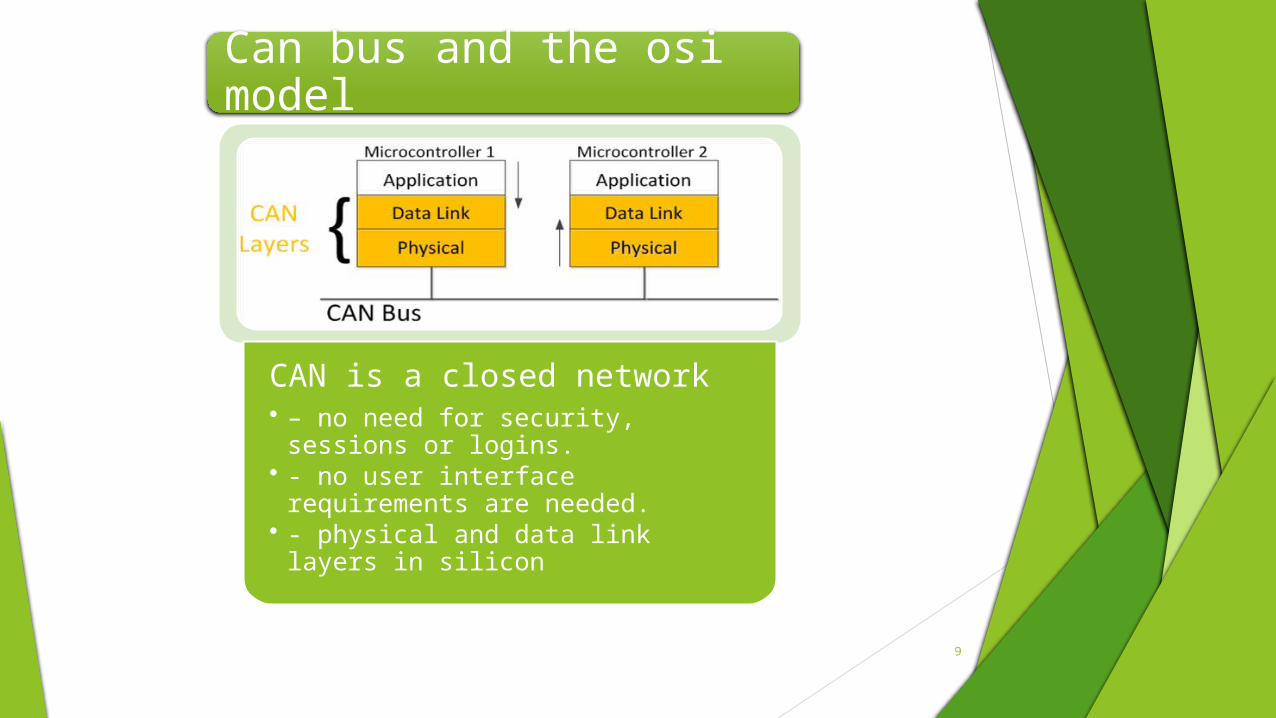
CAN is a closed network• – no need for security, sessions or
logins.• - no user interface requirements are
needed.• - physical and data link layers in
silicon
Can bus and the osi model

Can frame structure
Two flavours of CAN, i.e CAN 2.0a AND CAN 2.0b
The primary difference lies in the length of the identifier bits, these are useful for arbiteration
Data frame is 8 byte long
A Substitute Remote Request (SRR) bit is included in the Arbitration Field for CAN 2.0 B. The SRR bit is always transmitted as a recessive bit to ensure that, in the case of arbitration between a Standard Data Frame and an Extended Data Frame, the Standard Data Frame will always have priority if both messages have the same base (11 bit) identifier.
a four bit Data Length Code (DLC). The DLC indicates the number of bytes in the Data Field that follows
The CRC field, containing a fifteen bit cyclic redundancy check code and a recessive delimiter bit
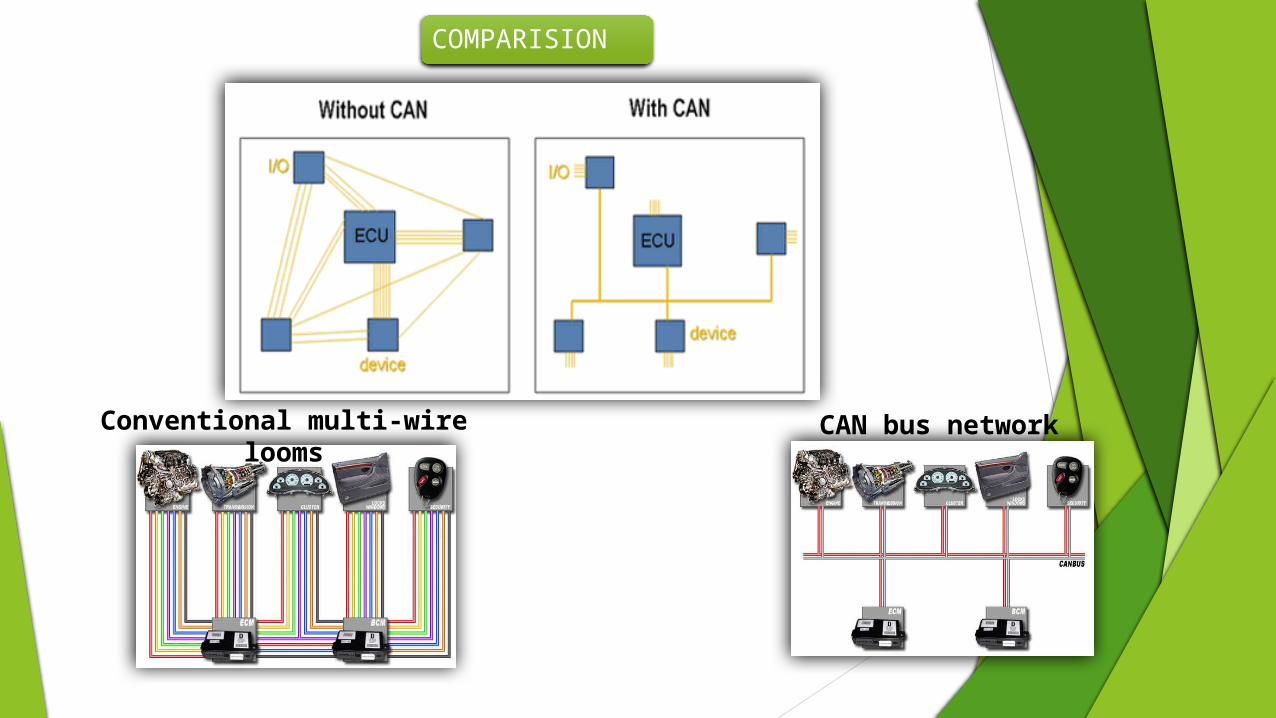
Conventional multi-wire looms CAN bus network
COMPARISION

Arbiteration in CAN
Can is multi master- multi slave; multiple processes compete with each other to gain access to the single CAN bus
Only the most critical of the processes will be granted access to the bus, this is achieved by arbiteration
The process which achieves a recessive state(logic state =1) while other processes are still in dominant state (logic state=0) is kicked out

13
LIN – Local Interconnect Network
Low cost single-wire implementation
Speed up to 20Kbit/s
Single Master Multiple Slave Concept
No arbitration necessary
Almost any Microcontroller has necessary hardware on chip
Significant cost reduction of hardware platform
Guaranteed latency times for signal transmission
LIN
14
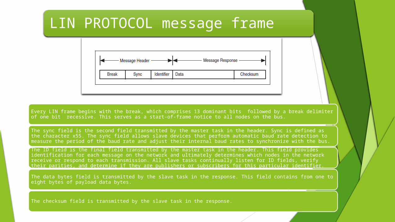
Every LIN frame begins with the break, which comprises 13 dominant bits followed by a break delimiter of one bit recessive. This serves as a start-of-frame notice to all nodes on the bus.
The sync field is the second field transmitted by the master task in the header. Sync is defined as the character x55. The sync field allows slave devices that perform automatic baud rate detection to measure the period of the baud rate and adjust their internal baud rates to synchronize with the bus.
The ID field is the final field transmitted by the master task in the header. This field provides identification for each message on the network and ultimately determines which nodes in the network receive or respond to each transmission. All slave tasks continually listen for ID fields, verify their parities, and determine if they are publishers or subscribers for this particular identifier.
The data bytes field is transmitted by the slave task in the response. This field contains from one to eight bytes of payload data bytes.
The checksum field is transmitted by the slave task in the response.
LIN PROTOCOL message frame
15
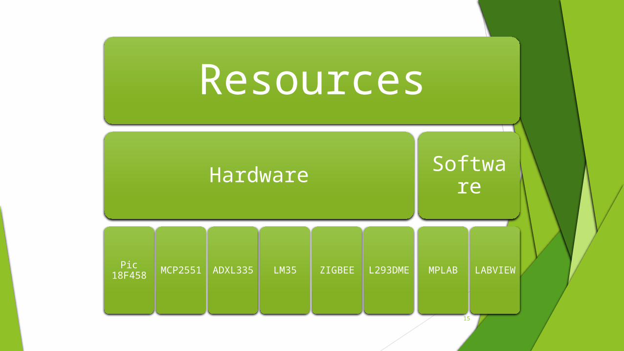
Resources
Hardware
Pic 18F458
MCP2551
ADXL335 LM35 ZIGBEE L293DM
E
Software
MPLAB LABVIEW

40 pin IC available in PDIP OR TQFP packaging
Inbuilt CAN 2.0B module with 3Tx and 2 Rx buffers
Operating frequency is 40 Mhz, Cpu speed is 10MIPS
Operating voltage range is 2 to 5.5 volts
1*8bit and 3*16bit timers with 8channel,10bit ADC
32KB of inbuilt ROM and 1.5KB of RAM
16Bit, RISC based high performance microcontroller
PIC18F458
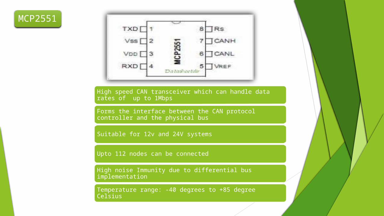
High speed CAN transceiver which can handle data rates of up to 1Mbps
Forms the interface between the CAN protocol controller and the physical bus
Suitable for 12v and 24V systems
Upto 112 nodes can be connected
High noise Immunity due to differential bus implementation
Temperature range: -40 degrees to +85 degree Celsius
MCP2551

ADXL335 is a 3 axis accelerometer which can measure both the static acceleration of gravity in tilt sensing applications as well as dynamic acceleration resulting from motion, shock and vibration
Small, low profile packaging (4mm*4mm*1.45mm LFCSP)
Low power consumption(typically 350 Microamperes)
Operating voltage range:-1.8 V to 3.6 V
Excellent temperature stability
ADXL335
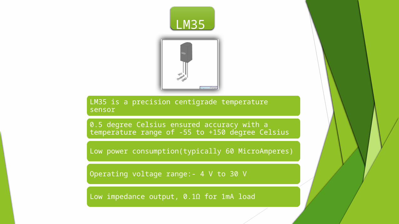
LM35 is a precision centigrade temperature sensor
0.5 degree Celsius ensured accuracy with a temperature range of -55 to +150 degree Celsius
Low power consumption(typically 60 MicroAmperes)
Operating voltage range:- 4 V to 30 V
Low impedance output, 0.1Ω for 1mA load
LM35

L293D is a dual H-bridge motor driver integrated circuit (IC). Motor drivers act as current amplifiers since they take a low-current control signal and provide a higher-current signal. This higher current signal is used to drive the motors.
L293D contains two inbuilt H-bridge driver circuits. In its common mode of operation, two DC motors can be driven simultaneously, both in forward and reverse direction. The motor operations of two motors can be controlled by input logic at pins 2 & 7 and 10 & 15. Input logic 00 or 11 will stop the corresponding motor. Logic 01 and 10 will rotate it in clockwise and anticlockwise directions, respectively.
Enable pins 1 and 9 (corresponding to the two motors) must be high for motors to start operating. When an enable input is high, the associated driver gets enabled. As a result, the outputs become active and work in phase with their inputs. Similarly, when the enable input is low, that driver is disabled, and their outputs are off and in the high-impedance state.
L293DME

Block diagram
TRANSMITTER
RECEIVER

RESULT
CAN DRIVER
MAIN CAN CAN SLAVE LIN
MOTOR DRIVER
ACCELEROMETER
THERMISTER

GRAPHICAL USER INTERFACE
Controller Area Networks are used in many different fields, the bulk of which are
Auto-motive industry
Factory Automation
Machine Control
Medical Equipment and devices.
This technology is used in house keeping purpose in intra-satellite communication with high speed transmission capabilities.
The use of CAN and LIN protocol reduces the amount of bus needed to communicate with the same speed as that of parallel communication.
CAN and LIN provides high security and more speed with less number of bus which makes it more reliable.
Degree of complexity is reduced compared to parallel communication.
APPLICATION

REFRENCES
[1] Comparison of Field Bus Systems, CAN, TTCAN, Flex Ray and LIN in Passenger Vehicles
Authors: Steve C. Talbot and Shangping Ren,Illinois Institute of Technology, Chicago, Illinois 60616, USA talbste,[email protected]
[2] Implementation of CAN bus in an autonomous All-Terrain Vehicle
Authors: Sunil Kumar Gurram and James M. Conrad
Electrical and Computer Engineering Department, University of North Carolina at Charlotte, NC, USA
E-mails: fsgurram, [email protected]
[3] LIN Protocol Implementation Using PICmicro® MCUs
Authors: Dan Butler, Thomas Schmidt,Thorsten Waclawczyk,
[4] Microcomputer Protocol Implementation at Local Interconnect Network
Author: Georgi Krastev
[5] Implementing a LIN Master Node Driver on a PIC18 Microcontroller with USART
Author: Ross M. Fosler

THANK YOU!!