Author's personal copy Canada’s program on nuclear hydrogen production and the thermochemical CueCl cycle G.F. Naterer a, *, S. Suppiah b , L. Stolberg b , M. Lewis c , Z. Wang a , V. Daggupati a , K. Gabriel a , I. Dincer a , M.A. Rosen a , P. Spekkens d , S.N. Lvov e , M. Fowler f , P. Tremaine g , J. Mostaghimi h , E.B. Easton a , L. Trevani a , G. Rizvi a , B.M. Ikeda a , M.H. Kaye a , L. Lu a , I. Pioro a , W.R. Smith a , E. Secnik a , J. Jiang i , J. Avsec j a University of Ontario Institute of Technology (UOIT), 2000 Simcoe Street North, Oshawa, Ontario, Canada L1H 7K4 b Atomic Energy of Canada Limited (AECL), Chalk River, Ontario, Canada K0J 1J0 c Argonne National Laboratory, Chemical Engineering Division, 9700 S. Cass Avenue, Argonne, Illinois 60439, USA d Ontario Power Generation (OPG), 889 Brock Road, Pickering, Ontario, Canada e Pennsylvania State University, Department of Materials Science and Engineering, 207 Hosler Building, University Park, PA 16802, USA f University of Waterloo, 200 University Ave., Waterloo, Ontario, Canada N2L 3G1 g University of Guelph, 50 Stone Road East, Guelph, Ontario, Canada N1G 2W1 h University of Toronto, Department of Mechanical and Industrial Engineering, Toronto, Ontario, Canada M5S 3E5 i University of Western Ontario, Electrical and Computer Engineering, London, Ontario, Canada N6A 5B9 j University of Maribor, Faculty of Energy Technology, Hocevarjev trg 1, 8270 Krsko, Maribor, Slovenia article info Article history: Received 15 June 2010 Received in revised form 11 July 2010 Accepted 18 July 2010 Available online 21 August 2010 Keywords: Thermochemical hydrogen production Copperechlorine cycle abstract This paper presents an overview of the status of Canada’s program on nuclear hydrogen production and the thermochemical copperechlorine (CueCl) cycle. Enabling technologies for the CueCl cycle are being developed by a Canadian consortium, as part of the Gener- ation IV International Forum (GIF) for hydrogen production with the next generation of nuclear reactors. Particular emphasis in this paper is given to hydrogen production with Canada’s Super-Critical Water Reactor, SCWR. Recent advances towards an integrated lab- scale CueCl cycle are discussed, including experimentation, modeling, simulation, advanced materials, thermochemistry, safety, reliability and economics. In addition, electrolysis during off-peak hours, and the processes of integrating hydrogen plants with Canada’s nuclear plants are presented. ª 2010 Professor T. Nejat Veziroglu. Published by Elsevier Ltd. All rights reserved. 1. Introduction Climate change and urban air quality continue to be signifi- cant issues today with well documented environmental and health impacts. Hydrogen is a potentially major solution to the problem of climate change, as well as addressing urban air pollution issues. But a key future challenge for hydrogen as a clean energy carrier is a sustainable, low-cost method of producing it in large capacities. Most of the world’s hydrogen (about 97%) is currently derived from fossil fuels through some type of reforming process (such as steamemethane reforming; SMR). Nuclear hydrogen production is an emerging and promising alternative to SMR for carbon-free hydrogen production in the future. This paper presents an overview of Canada’s program on nuclear hydrogen produc- tion and the thermochemical CueCl cycle, specifically with * Corresponding author. E-mail address: [email protected] (G.F. Naterer). Available at www.sciencedirect.com journal homepage: www.elsevier.com/locate/he international journal of hydrogen energy 35 (2010) 10905 e10926 0360-3199/$ e see front matter ª 2010 Professor T. Nejat Veziroglu. Published by Elsevier Ltd. All rights reserved. doi:10.1016/j.ijhydene.2010.07.087

Welcome message from author
This document is posted to help you gain knowledge. Please leave a comment to let me know what you think about it! Share it to your friends and learn new things together.
Transcript

Author's personal copy
Canada’s program on nuclear hydrogen productionand the thermochemical CueCl cycle
G.F. Naterer a,*, S. Suppiah b, L. Stolberg b, M. Lewis c, Z. Wang a, V. Daggupati a,K. Gabriel a, I. Dincer a, M.A. Rosen a, P. Spekkens d, S.N. Lvov e, M. Fowler f, P. Tremaine g,J. Mostaghimi h, E.B. Easton a, L. Trevani a, G. Rizvi a, B.M. Ikeda a, M.H. Kaye a, L. Lu a,I. Pioro a, W.R. Smith a, E. Secnik a, J. Jiang i, J. Avsec j
aUniversity of Ontario Institute of Technology (UOIT), 2000 Simcoe Street North, Oshawa, Ontario, Canada L1H 7K4bAtomic Energy of Canada Limited (AECL), Chalk River, Ontario, Canada K0J 1J0cArgonne National Laboratory, Chemical Engineering Division, 9700 S. Cass Avenue, Argonne, Illinois 60439, USAdOntario Power Generation (OPG), 889 Brock Road, Pickering, Ontario, Canadae Pennsylvania State University, Department of Materials Science and Engineering, 207 Hosler Building, University Park, PA 16802, USAfUniversity of Waterloo, 200 University Ave., Waterloo, Ontario, Canada N2L 3G1gUniversity of Guelph, 50 Stone Road East, Guelph, Ontario, Canada N1G 2W1hUniversity of Toronto, Department of Mechanical and Industrial Engineering, Toronto, Ontario, Canada M5S 3E5iUniversity of Western Ontario, Electrical and Computer Engineering, London, Ontario, Canada N6A 5B9jUniversity of Maribor, Faculty of Energy Technology, Hocevarjev trg 1, 8270 Krsko, Maribor, Slovenia
a r t i c l e i n f o
Article history:
Received 15 June 2010
Received in revised form
11 July 2010
Accepted 18 July 2010
Available online 21 August 2010
Keywords:
Thermochemical hydrogen
production
Copperechlorine cycle
a b s t r a c t
This paper presents an overview of the status of Canada’s program on nuclear hydrogen
production and the thermochemical copperechlorine (CueCl) cycle. Enabling technologies
for the CueCl cycle are being developed by a Canadian consortium, as part of the Gener-
ation IV International Forum (GIF) for hydrogen production with the next generation of
nuclear reactors. Particular emphasis in this paper is given to hydrogen production with
Canada’s Super-Critical Water Reactor, SCWR. Recent advances towards an integrated lab-
scale CueCl cycle are discussed, including experimentation, modeling, simulation,
advanced materials, thermochemistry, safety, reliability and economics. In addition,
electrolysis during off-peak hours, and the processes of integrating hydrogen plants with
Canada’s nuclear plants are presented.
ª 2010 Professor T. Nejat Veziroglu. Published by Elsevier Ltd. All rights reserved.
1. Introduction
Climate change and urban air quality continue to be signifi-
cant issues today with well documented environmental and
health impacts. Hydrogen is a potentially major solution to
the problem of climate change, as well as addressing urban
air pollution issues. But a key future challenge for hydrogen
as a clean energy carrier is a sustainable, low-cost method of
producing it in large capacities. Most of the world’s hydrogen
(about 97%) is currently derived from fossil fuels through
some type of reforming process (such as steamemethane
reforming; SMR). Nuclear hydrogen production is an
emerging and promising alternative to SMR for carbon-free
hydrogen production in the future. This paper presents an
overview of Canada’s program on nuclear hydrogen produc-
tion and the thermochemical CueCl cycle, specifically with
* Corresponding author.E-mail address: [email protected] (G.F. Naterer).
Avai lab le a t www.sc iencedi rec t .com
journa l homepage : www.e lsev ier . com/ loca te /he
i n t e r n a t i o n a l j o u r n a l o f h y d r o g e n en e r g y 3 5 ( 2 0 1 0 ) 1 0 9 0 5e1 0 9 2 6
0360-3199/$ e see front matter ª 2010 Professor T. Nejat Veziroglu. Published by Elsevier Ltd. All rights reserved.doi:10.1016/j.ijhydene.2010.07.087

Author's personal copy
recent advances in Canada since the time of an earlier review
paper by Naterer et al. [1].
Hydrogen is used widely by petrochemical, agricultural
(e.g., ammonia for fertilizers), manufacturing, food process-
ing, electronics, plastics, metallurgical, aerospace and other
industries. For example, in Alberta, Canada, the oil sands
sector needs vast amounts of hydrogen to upgrade bitumen to
synthetic crude oil and remove impurities. Hydrogen has
recently made significant commercial penetration with fuel
cells in the lift-truck market, as well as back-up power
systems for cell phone communication towers. In the trans-
portation sector, major auto-makers are investing signifi-
cantly in fuel cell vehicles, and there are a number of
demonstration projects ongoing. Hydrogen is becoming an
increasingly important energy carrier. It can be stored and
used to generate electricity, either onboard vehicles or
stationary power systems [2].
The transportation sector contributes significantly to GHG
emissions in Canada. A fuel cell vehicle (FCV) and battery
electric vehicle (BEV) are the two main transportation tech-
nologies that can achieve amajor reduction in GHG emissions.
Despite the promising capabilities of hybrid, plug-in hybrid,
and electric vehicles, some ongoing challenges associated
with battery powered vehicles include: long battery recharge
times, limited storage capacity, cold weather performance,
and durability in real-world conditions, among others. As
a result, hydrogen will continue to have an important role in
light duty vehicle powertrains as a “range extender” fuel in
plug-in hybrid vehicles, or eventually as standalone hydrogen
fuel cell vehicles. The envisioned future hydrogen economy in
the transportation sector will require significant increases to
the world’s current capacity to generate hydrogen, particu-
larly in a clean, sustainable manner without relying on fossil
fuels.
Thermochemical water decomposition is an emerging
technology for large-scale production of hydrogen. Typically
using two or more intermediate compounds, a sequence of
chemical and physical processes split water into hydrogen
and oxygen, without releasing any pollutants externally to the
atmosphere. These intermediate compounds are recycled
internally within a closed loop. Previous studies have identi-
fied over 200 possible thermochemical cycles [3,4]. However,
very few have progressed beyond theoretical calculations to
working experimental demonstrations that establish scien-
tific and practical feasibility of the thermochemical processes.
The sulfureiodine (SeI) and hybrid sulfur cycles are
prominent cycles that have been developed extensively by
several countries. These include the USA (General Atomics,
Savannah River National Laboratory, among others), Japan
(Japan Atomic Energy Agency, JAEA), France (Commissariat a
l’Energie Atomique, CEA), Italy and others [5,6]. About 30 l/h of
hydrogen production has been demonstrated by an SeI pilot
facility at JAEA [5]. Canada, Korea (KAERI), China and South
Africa also have active programs in nuclear hydrogen
production. The following seven cycles (in addition to the SeI
and hybrid sulfur cycles)were identified in aNuclear Hydrogen
Initiative [4] as the most promising cycles: copperechlorine
(CueCl) [7], ceriumechlorine (CeeCl) [8], ironechlorine (FeeCl)
[8], vanadiumechlorine (VeCl) [8], copper-sulfate (Cu-SO4)
[8] and hybrid chlorine [8]. Experimental work has been
conducted for processes in these cycles to demonstrate their
scientific feasibility. However, most of these cycles require
heat at temperatures over 800 �C from very high temperature
(Generation IV) reactors, which are not currently available and
entail major design and material challenges. The CueCl cycle
has a significant advantage over these other cycles, due to
lower temperature requirements around 530 �C and lower. As
a result, it can be eventually linked with the Generation IV
SCWR (Super-Critical Water Reactor) or ultra-super-critical
thermal stations.
Advantages of the CueCl cycle over others include lower
operating temperatures, ability to utilize low-gradewaste heat
to improve energy efficiency, and potentially lower cost
materials. Another significant advantage is a relatively low
voltage required for the electrochemical step (thus low elec-
tricity input), which will be further explained in this paper.
Other advantages include common chemical agents and
reactions going to completion without side reactions, and
lower demands on materials of construction. Solids handling
between processes and corrosive working fluids present
unique challenges, however this paper will outline recent
advances made towards the development of corrosion resis-
tant materials for these working fluids.
The University of Ontario Institute of Technology (UOIT),
Atomic Energy of Canada Limited (AECL), Argonne National
Laboratory (ANL) and other partner institutions are currently
collaborating on the development of enabling technologies for
the CueCl cycle, through the Generation IV International
Forum (GIF; [7]). This paper describes the status of these
enabling technologies for the CueCl cycle, as well as other
nuclear hydrogen research and development programs in
Canada, including electrolysis during off-peak hours for
hydrogen usage by the transportation sector. Experimental
work on the CueCl cycle, modeling and simulation, thermo-
chemistry, corrosion resistantmaterials, safety, reliability and
linkage between nuclear and hydrogen plants, will be pre-
sented and discussed in this paper.
2. Thermochemical copperechlorine (CueCl)cycle
2.1. Description of the CueCl cycle
The CueCl cycle performs a sequence of reactions to achieve
the overall splitting of water into hydrogen and oxygen. Using
intermediate copper chloride compounds, the cycle decom-
poses water into hydrogen and oxygen, in a closed internal
loop that recycles all chemicals on a continuous basis. Process
steps in the CueCl cycle and a schematic realization of the
cycle are shown in Table 1 and Fig. 1, respectively.
There are three key variations of the CueCl cycle: 5-step,
4-step and 3-step cycles. In the 5-step cycle, copper is
produced electrolytically, moved to an exothermic thermo-
chemical hydrogen reactor and then reacted with HCl gas to
produce hydrogen gas and molten CuCl. The 4-step cycle
combines these processes together to eliminate the interme-
diate production and handling of copper solids, through
a CuCl/HCl electrolyzer that produces hydrogen electrolyti-
cally and aqueous Cu(II) chloride. Afterwards, the aqueous
i n t e rn a t i o n a l j o u r n a l o f h y d r o g e n en e r g y 3 5 ( 2 0 1 0 ) 1 0 9 0 5e1 0 9 2 610906

Author's personal copy
product is dried to generate Cu(II) chloride particles; then fed
to a hydrolysis reactor to produce copper oxychloride. The
3-step cycle further combines these processes by supplying
aqueous Cu(II) chloride directly into the hydrolysis chamber,
such as spraying the solution with co-flowing steam to
produce the same copper oxychloride product. This paper will
focus on the 4-step cycle (Table 1), since separation of the
hydrolysis and drying processes can significantly improve the
cycle’s thermal efficiency.
The overall efficiency of the CueCl cycle is potentially
much higher than conventional water electrolysis via
thermal power plants, since heat is used directly to produce
hydrogen, rather than indirectly to first produce electricity,
after which hydrogen is generated. A 42% efficiency (elec-
tricity) with the Generation IV reactor (SCWR; Super-Critical
Water Reactor) leads to about 30% net efficiency by electrol-
ysis for hydrogen production. In contrast, a 54% heat-to-
hydrogen efficiency has been demonstrated from Aspen Plus
simulations for the CueCl cycle [9], although 43% is more
realistic. This is a significant margin of superior overall
conversion efficiency, with more than one-third improve-
ment over electrolysis, excluding larger gains if “waste heat”
is utilized in the CueCl cycle.
2.2. CuCl/HCl electrolysis for hydrogenproduction (step 1)
This section presents the recent advances in Cu(I) chloride/
HCl electrolysis for electrochemical production of hydrogen.
Oxidation of Cu(I) chloride (CuCl) during an electrochemical
reaction occurs in the presence of hydrochloric acid (HCl) to
generate hydrogen. The Cu(I) ion is oxidized to Cu(II) at the
anode, and the hydrogen ion is reduced at the cathode. While
the majority of the Cu species present is expected to be
anionic (which would not permeate through a cation
exchange membrane), an appreciable concentration of
cationic or neutral Cu species still exists and can permeate
through the membrane and enter the cathode compartment
where they are reduced to metallic copper.
The CuCl/HCl electrolysis cell is depicted to Fig. 2. It has
been demonstrated by AECL that hydrogen can be produced at
a current density of 0.1 A cm�2 for a cell voltage in the range of
0.6e0.7 V. A schematic of the electrolysis cell and copper
crossover process is illustrated in Fig. 2. Metallic copper at the
cathode acts as a poison, greatly reducing the activity of the Pt
catalyst towards the hydrogen evolution reaction (HER). This
could result in a catastrophic decrease in cell performance, so
Table 1 e Steps and chemical reactions in the CueCl cycle.
Step Reaction Temp. range (�C) Feed outputa
1 2CuCl (aq) þ 2HCl (aq) / H2 (g) þ 2CuCl2 (aq) <100 (electrolysis) Feed Aqueous CuCl and HCl þ V þ Q
Output H2 þ CuCl2 (aq)
2 CuCl2 (aq) / CuCl2 (s) <100 Feed Slurry containing HCl and CuCl2 þ Q
Output Granular CuCl2 þ H2O/HCl vapors
3 2CuCl2 (s) þ H2O (g) / CuO�CuCl2 (s) þ 2HCl (g) 400 Feed Powder/granular CuCl2 þ H2O (g) þ Q
Output Powder/granular Cu2OCl2 þ 2HCl (g)
4 CuO � CuCl2(s) / 2CuCl(l) þ 1/2O2 (g) 500 Feed Powder/granular Cu2OCl2(s) þ Q
Output Molten CuCl salt þ oxygen
a: Q ¼ thermal energy, V ¼ electrical energy.
Fig. 1 e Schematic of the copperechlorine (CueCl) cycle.
i n t e r n a t i o n a l j o u r n a l o f h y d r o g e n en e r g y 3 5 ( 2 0 1 0 ) 1 0 9 0 5e1 0 9 2 6 10907
Author's personal copy
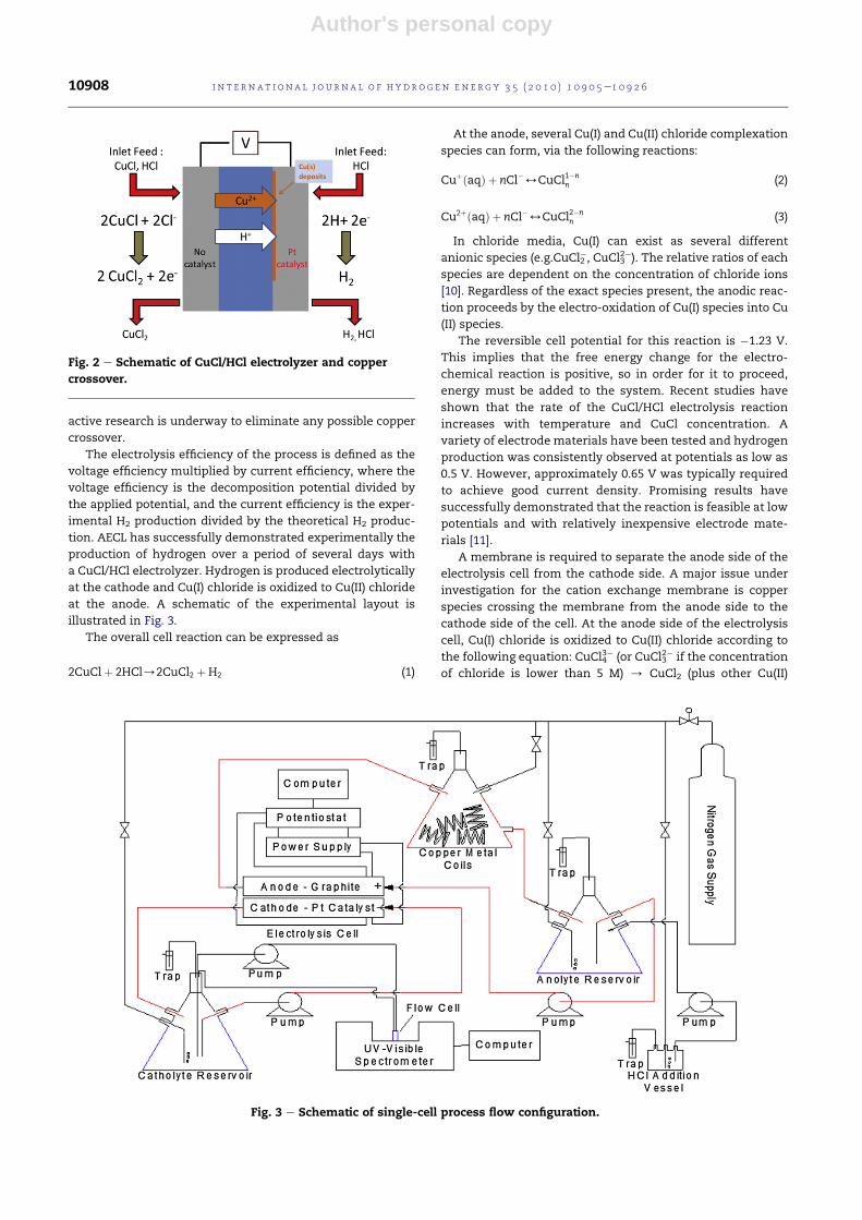
active research is underway to eliminate any possible copper
crossover.
The electrolysis efficiency of the process is defined as the
voltage efficiency multiplied by current efficiency, where the
voltage efficiency is the decomposition potential divided by
the applied potential, and the current efficiency is the exper-
imental H2 production divided by the theoretical H2 produc-
tion. AECL has successfully demonstrated experimentally the
production of hydrogen over a period of several days with
a CuCl/HCl electrolyzer. Hydrogen is produced electrolytically
at the cathode and Cu(I) chloride is oxidized to Cu(II) chloride
at the anode. A schematic of the experimental layout is
illustrated in Fig. 3.
The overall cell reaction can be expressed as
2CuClþ 2HCl/2CuCl2 þH2 (1)
At the anode, several Cu(I) and Cu(II) chloride complexation
species can form, via the following reactions:
CuþðaqÞ þ nCl�4CuCl1�nn (2)
Cu2þðaqÞ þ nCl�4CuCl2�nn (3)
In chloride media, Cu(I) can exist as several different
anionic species (e.g.CuCl2�, CuCl3
2�). The relative ratios of each
species are dependent on the concentration of chloride ions
[10]. Regardless of the exact species present, the anodic reac-
tion proceeds by the electro-oxidation of Cu(I) species into Cu
(II) species.
The reversible cell potential for this reaction is �1.23 V.
This implies that the free energy change for the electro-
chemical reaction is positive, so in order for it to proceed,
energy must be added to the system. Recent studies have
shown that the rate of the CuCl/HCl electrolysis reaction
increases with temperature and CuCl concentration. A
variety of electrode materials have been tested and hydrogen
production was consistently observed at potentials as low as
0.5 V. However, approximately 0.65 V was typically required
to achieve good current density. Promising results have
successfully demonstrated that the reaction is feasible at low
potentials and with relatively inexpensive electrode mate-
rials [11].
A membrane is required to separate the anode side of the
electrolysis cell from the cathode side. A major issue under
investigation for the cation exchange membrane is copper
species crossing the membrane from the anode side to the
cathode side of the cell. At the anode side of the electrolysis
cell, Cu(I) chloride is oxidized to Cu(II) chloride according to
the following equation: CuCl43� (or CuCl3
2� if the concentration
of chloride is lower than 5 M) / CuCl2 (plus other Cu(II)
Fig. 2 e Schematic of CuCl/HCl electrolyzer and copper
crossover.
Fig. 3 e Schematic of single-cell process flow configuration.
i n t e rn a t i o n a l j o u r n a l o f h y d r o g e n en e r g y 3 5 ( 2 0 1 0 ) 1 0 9 0 5e1 0 9 2 610908

Author's personal copy
chloride species if the concentration of chloride is greater
than 5 M) þ 2Cl� þ e�. This reaction could occur if the free
chloride ion concentration is above 4 M. In recent experi-
ments, the anolyte is a solution of CuCl dissolved in 0.5e2 M
HCl. The Cu(I) oxidation reaction does not require a catalyst.
The anode is a catalyst-free fuel cell graphite separator plate
material.
This reaction at the cathode (2Hþ þ 2e� /H2) describes the
reduction of protons to form hydrogen gas. The cathode is
a fuel cell graphite separator plate coated with a Pt electro-
catalyst. Fig. 4 illustrates the measured cell potential over
approximately 3 days of continuous hydrogen production. In
the experiments, the catholyte and anolyte HCl concentra-
tions are 6 and 10 M, respectively. The CuCl concentration in
the anolyte is 1.0 M.When 10MHCl is used instead of 6 MHCl,
the performance of the cell improves significantly. The cath-
olyte passed through the cathode compartment a single time,
while the anolyte was recycled. The measured oscillations in
Fig. 4 reflect temperature variations in the lab, overnight vs.
daytime. Over a 72 h period, the cell potential changed by
0.016 V.
Fig. 5 shows that increasing the HCl concentration
decreases the amount of copper species present in the cath-
olyte. Each data set was fitted to a second order polynomial in
Fig. 5. The data suggests that copper chloride speciation in the
anolyte depends on the HCl concentration. The experiments
indicated that relatively stable cell potentials can bemeasured
when the catholyte solution is not recycled, but passes
through the cathode compartment of the electrolysis cell
a single time. The catholyte copper species concentration
decreases as the HCl concentration increases. It was found
that the CuCl/HCl electrolysis reaction should be performed
with an HCl concentration of at least 11 M, so copper metal
deposition does not occur at a current density of 0.1 A/cm2.
The catholyte copper species concentration increases as the
CuCl concentration increases. Thus, low CuCl concentrations
are preferred. The preferred anolyte concentration is 0.5 M
CuCl in 11 M HCl, while the preferred catholyte concentration
is 11 M HCl.
Additional laboratory scale CuCl/HCl electrolyzer experi-
ments have also been performed at Pennsylvania State
University [11] to determine the electrolysis efficiency. Elec-
trolysis with a Nafion-based proton conductive membrane
was shown to be a highly efficient process. The measured
current efficiency was around 98% and the voltage efficiency
was up to 80% for usable current densities. In Fig. 6, the filled
circles depict the best obtained results with a HYDRion115
MEA. The other curves refer to a number of experimental
conditions tested with lower performance. The experimental
results in Fig. 6 by Lvov et al. [11] at Pennsylvania State
University were obtained independently and with different
membranes than AECL results reported in Figs. 4 and 5. The
catholyte is 0.2 mol kg�1 CuCl in 2 mol kg�1 HCl (aq), the
anolyte is H2O, the catholyte flow rate is 68 cm3 min�1, and
the temperature is 30 �C. Ongoing research aims to optimize
the MEA preparation to achieve a target performance of 0.5 A/
cm2 at 0.7 V, and completely eliminate the Cu permeation
through the membrane.
2.3. Drying of aqueous Cu(II) chloride (step 2)
Step 2 of the CueCl cycle is the drying step as expressed by:
2CuCl2 (aq) / 2CuCl2 (s) (see Table 1). Aqueous CuCl2 exiting
from the previous electrolysis cell is dried to produce solid
Fig. 4 e Varying cell potential over a period of about 3 days
of hydrogen production.
Fig. 5 e Effects of HCl concentration on total catholyte
copper.
Fig. 6 e Measured polarization curves for CuCl/HCl
electrolysis.
i n t e r n a t i o n a l j o u r n a l o f h y d r o g e n en e r g y 3 5 ( 2 0 1 0 ) 1 0 9 0 5e1 0 9 2 6 10909
Author's personal copy
CuCl2 (s), which is required for a subsequent hydrolysis step
that produces copper oxychloride (CuO � CuCl2) and HCl gas.
The drying process is an energy-intensive step within the
CueCl cycle. Although the amount of heat required for the
drying step is much higher than other steps in the cycle, it
occurs at a lower temperature (lower quality) and therefore
with heat that is more readily available. Within the drying
step, the energy requirement increases from 1 to 5 times
higher for slurry feed to solution, respectively, depending on
the CuCl2 concentration. The required heat can be obtained
from low-grade “waste” heat to improve the cycle efficiency.
Spray drying is an efficient method of water removal due to
the relatively large surface area available for heat and mass
transfer, provided the liquid atomizes into sufficiently small
droplets (on the order of a few hundred microns).
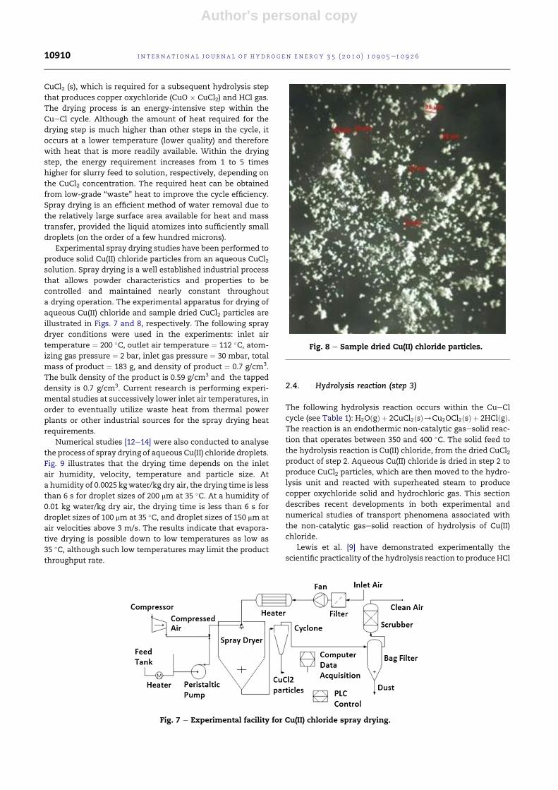
Experimental spray drying studies have been performed to
produce solid Cu(II) chloride particles from an aqueous CuCl2solution. Spray drying is a well established industrial process
that allows powder characteristics and properties to be
controlled and maintained nearly constant throughout
a drying operation. The experimental apparatus for drying of
aqueous Cu(II) chloride and sample dried CuCl2 particles are
illustrated in Figs. 7 and 8, respectively. The following spray
dryer conditions were used in the experiments: inlet air
temperature ¼ 200 �C, outlet air temperature ¼ 112 �C, atom-
izing gas pressure ¼ 2 bar, inlet gas pressure ¼ 30 mbar, total
mass of product ¼ 183 g, and density of product ¼ 0.7 g/cm3.
The bulk density of the product is 0.59 g/cm3 and the tapped
density is 0.7 g/cm3. Current research is performing experi-
mental studies at successively lower inlet air temperatures, in
order to eventually utilize waste heat from thermal power
plants or other industrial sources for the spray drying heat
requirements.
Numerical studies [12e14] were also conducted to analyse
the process of spray drying of aqueous Cu(II) chloride droplets.
Fig. 9 illustrates that the drying time depends on the inlet
air humidity, velocity, temperature and particle size. At
a humidity of 0.0025 kgwater/kg dry air, the drying time is less
than 6 s for droplet sizes of 200 mm at 35 �C. At a humidity of
0.01 kg water/kg dry air, the drying time is less than 6 s for
droplet sizes of 100 mm at 35 �C, and droplet sizes of 150 mm at
air velocities above 3 m/s. The results indicate that evapora-
tive drying is possible down to low temperatures as low as
35 �C, although such low temperatures may limit the product
throughput rate.
2.4. Hydrolysis reaction (step 3)
The following hydrolysis reaction occurs within the CueCl
cycle (see Table 1): H2OðgÞ þ 2CuCl2ðsÞ/Cu2OCl2ðsÞ þ 2HClðgÞ.The reaction is an endothermic non-catalytic gasesolid reac-
tion that operates between 350 and 400 �C. The solid feed to
the hydrolysis reaction is Cu(II) chloride, from the dried CuCl2product of step 2. Aqueous Cu(II) chloride is dried in step 2 to
produce CuCl2 particles, which are then moved to the hydro-
lysis unit and reacted with superheated steam to produce
copper oxychloride solid and hydrochloric gas. This section
describes recent developments in both experimental and
numerical studies of transport phenomena associated with
the non-catalytic gasesolid reaction of hydrolysis of Cu(II)
chloride.
Lewis et al. [9] have demonstrated experimentally the
scientific practicality of the hydrolysis reaction to produce HCl
Fig. 7 e Experimental facility for Cu(II) chloride spray drying.
Fig. 8 e Sample dried Cu(II) chloride particles.
i n t e rn a t i o n a l j o u r n a l o f h y d r o g e n en e r g y 3 5 ( 2 0 1 0 ) 1 0 9 0 5e1 0 9 2 610910

Author's personal copy
gas and solid copper oxychloride. Experimental results and
simulations showed a large excess of water was needed for
complete conversion (up to 98%) of CuCl2. Byproducts other
than Cu2OCl2 may appear, i.e., CuCl and CuOHCl, although
ongoing research is investigating how and why these
byproducts appear. For an efficient and low capital cost
process, it is important to reduce the water consumption.
Aspen Plus simulations predict that 100% yield can be
obtained with steam to a CuCl2 molar ratio of 17 at 370 �C [9].
In recent experiments, a range of steam to CuCl2 molar
ratios was used in the hydrolysis spray reactor at the Argonne
National Laboratory. It was found that water requirements
could be reduced by using sub-atmospheric pressures. For
complete conversion, Aspen Plus sensitivity studies indicate
a steam to Cu(II) chloride molar ratio of about 18 for 1 bar, and
about 12 for 0.5 bar (see Fig. 10). Adding an aspirator to the
hydrolysis reactor allows operation of the reactor at reduced
pressures: 0.4 and 0.7 bar tests were conducted. The reactor
was flushed with more humid inert gas in the experiments.
The steam demand and CuCl formation were reduced. Fig. 11
illustrates the XRD patterns for various CueCl compounds. It
was observed that all experiments at reduced pressure had
lower CuCl content.
Unlike a spray reactor (ultrasonic nozzle) used by the
Argonne National Laboratory for the hydrolysis reaction,
UOIT experiments have separated the drying and reaction
processes, thereby using separate steps 2 (drying) and 3
(gasesolid reaction in a fluidized bed for hydrolysis). At UOIT,
high temperature fluidized bed experiments with actual
CueCl compounds are being investigated, as well as low
temperature experiments with simulated working fluids (air
and spherical beads) to examine fluid dynamics and heat
transfer phenomena in the fluidized bed. Fig. 12 illustrates the
layout of the high temperature experiments. In Fig. 13,
measured results of pressure drop in the low temperature
experiments are shown, which are useful to improve the
optimal packing density of particles and solid conversion
rates.
The experimental unit was designed similar to the high
temperature hydrolysis reactor, both geometrically and
dynamically, by matching the Archimedes number, Froude
number, density ratio, particle to column diameter and
particle size distribution. The solid to gas density ratio is
matched for accurate scaling of the hydrodynamics in
a bubbling or turbulent bed. The fluidized bed unit is made of
plexiglass with a 0.1 m diameter and 0.6 m test section. The
gas distributor consists of seven nozzles equally and
symmetrically spaced over the bottom plate. Instantaneous
pressure measurements are taken with Omega, PX140 pres-
sure transducers, two differential (15 psi) and one absolute
(30 psi). For each experiment, 10,000 data points were
collected at a frequency of 100 Hz. The measured data was
processed by means of statistical algorithms to obtain the
standard deviations and average pressure drops. The experi-
mental data indicated the importance of the pressure drop on
the fluidization quality at high temperatures. Variations of
particle properties at high temperatures reduce the fluidiza-
tion quality. The measurements of pressure fluctuations
provided useful data for monitoring the behavior of the high
temperature hydrolysis reactor.
Additional numerical and experimental studies have been
performed to investigate the transport phenomena associated
with the gasesolid reaction of particles in the fluidized bed
during hydrolysis of Cu(II) chloride ([15e18]; see Fig. 14). The
conversion of solids depends on the rate of reaction and
residence time of a particle. A shrinking-coremodel (SCM) has
Fig. 9 e Variation of drying time with air velocity, humidity
and droplet size.
Fig. 10 e Percentage yields of copper oxychloride.
Fig. 11 e XRD patterns for products at 0.4 and 1 bar (steam
to CuCl2 ratio [ 11.
i n t e r n a t i o n a l j o u r n a l o f h y d r o g e n en e r g y 3 5 ( 2 0 1 0 ) 1 0 9 0 5e1 0 9 2 6 10911

Author's personal copy
been developed to estimate the reaction rate of the gasesolid
reaction. When the diffusion of gaseous reactant into
a particle is much faster than the chemical reaction, the solid
reactant is consumed nearly uniformly throughout the
particle (see Fig. 14a). In this situation, a uniform-reaction
model can be used. On the other hand, when the diffusion of
gaseous reactant is much slower and it restricts the reaction
zone to a thin layer that advances from the outer surface into
the particle (Fig. 14b), then the shrinking-core model is
adopted. The predicted variation of solid conversion timewith
vapor fraction in the gas is illustrated in Fig. 15. Close agree-
ment is achieved with measured data of solid conversion for
uniformly sized particles of 200 mm diameter in plug flow of
solids. As the mole fraction of steam in the gas increases, the
time of solid conversion decreases.
2.5. Copper oxychloride decomposition (step 4)
The oxygen production step (step 4; see Table 1) receives solid
feed of copper oxychloride (Cu2OCl2) and produces O2 gas and
molten Cu(I) chloride. The decomposition reaction is given by
Cu2OCl2 (s) ¼ 2CuCl (molten) þ 0.5O2 (gas) at 530 �C. Copperoxychloride particles decompose into molten salt and oxygen
gas bubbles. The reactant particles absorb decomposition heat
from the surrounding molten bath. Gas species leaving the
oxygen reactor include oxygen gas and potentially impurities
of products from side reactions, such as CuCl vapor, chlorine
gas, HCl gas (trace amount) andH2O vapor (trace amount). The
substances exiting the reactor are molten CuCl, potentially
unreacted solid CuCl2 from the upstream hydrolysis reaction,
due to the incomplete decomposition of CuCl2, as well as
reactant particles entrained by the flow of molten CuCl
(Fig. 16).
Fig. 12 e Schematic of hydrolysis experiments with a fluidized bed reactor.
Fig. 13 e Measured pressure drop in the fluidized bed.
Fig. 14 e Schematic of (a) particle conversion and
(b) particle shrinkage with an ash layer and gas film.
i n t e rn a t i o n a l j o u r n a l o f h y d r o g e n en e r g y 3 5 ( 2 0 1 0 ) 1 0 9 0 5e1 0 9 2 610912

Author's personal copy
Serban et al. [19] have demonstrated experimentally the
scientific practicality of the oxygen production reaction at
a small test-tube scale. Recent advances have demonstrated
experimentally the processes in a larger engineering scale
reactor, with flow capacities of 2 kg/day of oxygen production,
by decomposing about 21 kg/day of solid Cu2OCl2 feed that
enters the reactor. A number of experimental and operational
issues with the unit reactor are currently being investigated,
such as aggregation into solid blocks of Cu2OCl2 when
conveying and feeding solid particles. The aggregation may
choke or clog the feeder and cause sudden spouting of parti-
cles. Also, embedded particles of CuCl2 from the upstream
hydrolysis reactor in Cu2OCl2 may lead to undesirable prod-
ucts and side reactions, such as CuCl2 decomposing to CuCl
and Cl2 gas. If particles enter the reactor at a temperature
lower than 430 �C, a challenge arises with the presence of
bubbles in the molten salt. Some CuCl vapor might condense
and molten CuCl can solidify around the Cu2OCl2 particles. If
an aggregation develops with particles, molten salt and
bubbles, the contact area between a reactant particle and
heating medium (molten CuCl) will decrease and the aggre-
gations float along the surface of the molten salt. This deters
the decomposition of reactant particles and potentially leads
to choking of the reactor (a major safety concern). These
issues and others are currently under investigation for the
copper oxychloride decomposition experiments.
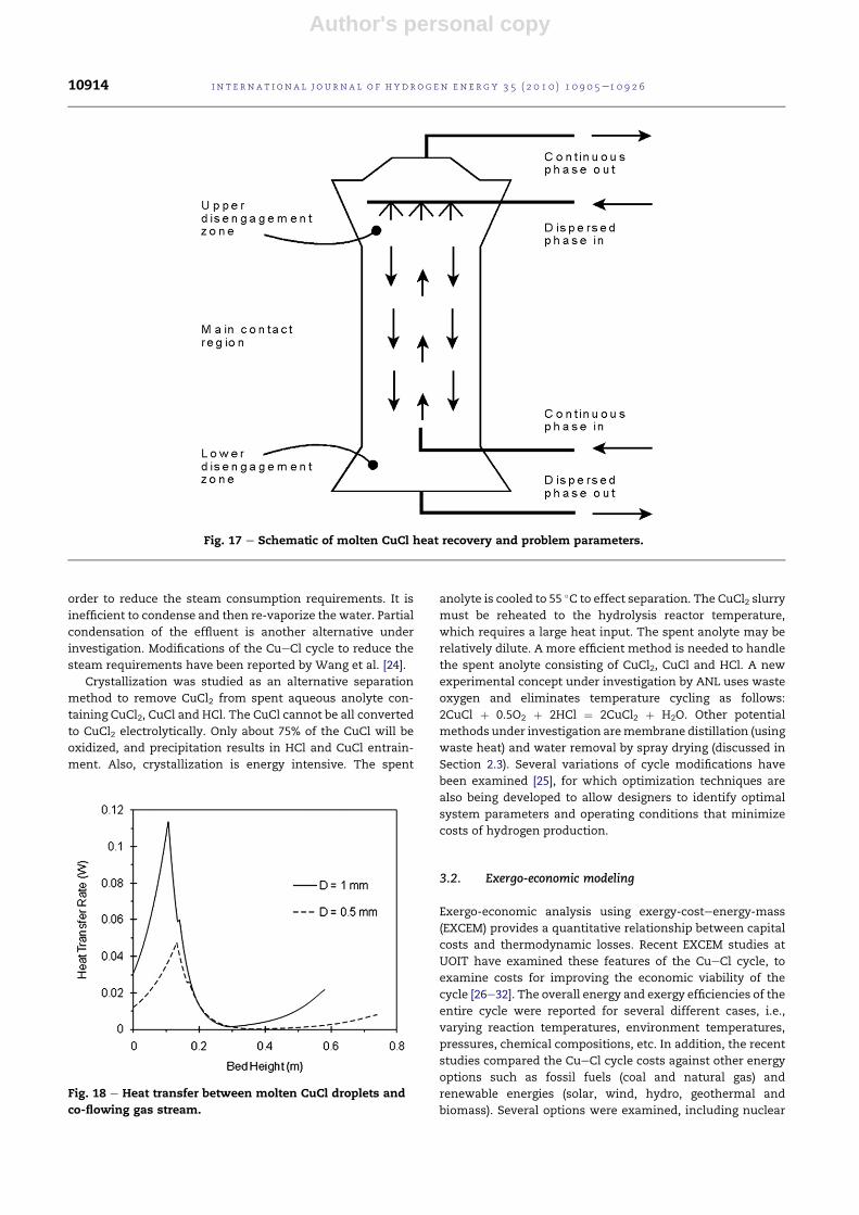
Additional studies have also been performed to effectively
recover heat frommolten CuCl exiting the copper oxychloride
decomposer. A configuration with convective heat transfer
between molten CuCl droplets and air in a counter-current
spray flow heat exchanger has been developed (see Fig. 17).
Recovering heat from molten CuCl is challenging due to the
phase transformations of molten CuCl, as it cools from liquid
to two different solid states. A predictive model of heat
transfer and CuCl droplet flow has been developed and solved
numerically [20]. The results indicated that full heat recovery
can be achievedwith a heat exchanger diameter of 0.13m, and
heights of 0.6 and 0.8 m, for a 1 and 0.5 mm droplet diameter,
respectively. Other configurations of heat recovery from
molten CuCl have been reported by Ghandehariun et al. [21].
Fig. 18 shows the variation of the heat transfer rate for
droplets with 1 and 0.5 mm diameters throughout the height
of the heat exchanger. The larger droplet diameter has
a higher heat transfer rate, due to the larger surface area. The
heat transfer rate increases initially at the bottom of the heat
exchanger, because of the large temperature difference
between both streams. Then it reaches a maximumwhen the
second phase transformation ends, after which it decreases,
due to the lower temperature difference between both fluids
in the phase transformation process. When the second
sensible heat transfer process is completed, the heat transfer
rate starts increasing again. This does not take long because
the first phase transformation differs with the second phase
change process by 11�.
3. System modeling for cycle modificationsand enhancements
3.1. Aspen Plus simulations
Aspen Plus simulations of the CueCl cycle have been per-
formed at the Argonne National Laboratory ([22]; see Fig. 19)
and UOIT [23]. In Fig. 19, the cycle is based on four unit oper-
ations, all commercially practiced in industry: hydrolysis and
oxychloride decomposition reactors, direct heat exchanger,
electrolyzer and crystallizer. The simulations indicated that
the steam requirement was reduced by operating the hydro-
lysis reactor at a partial vacuum, obtained by an ejector
(similar to an aspirator). Spent anolyte can be processed to
provide CuCl2 slurry for the hydrolysis feed with minimal
costs in energy and capital by crystallization. The cell voltage
used for the electrolyzer was 0.7 V with a current density of
500 mA/cm2. The electrolyzer operates at temperatures above
80 C and 24 bar. The flowsheet uses a reduced pressure in the
hydrolysis reactor, 0.25 bar, in the simulations.
The amount of steam impacts the hydrogen production
costs significantly. Handling and condensing the effluent
steam from the hydrolysis reactor is being investigated, in
Fig. 15 e Comparison of solid conversion time with
experimental data.
Fig. 16 e Schematic of oxygen decomposition reactor.
i n t e r n a t i o n a l j o u r n a l o f h y d r o g e n en e r g y 3 5 ( 2 0 1 0 ) 1 0 9 0 5e1 0 9 2 6 10913
Author's personal copy
order to reduce the steam consumption requirements. It is
inefficient to condense and then re-vaporize the water. Partial
condensation of the effluent is another alternative under
investigation. Modifications of the CueCl cycle to reduce the
steam requirements have been reported by Wang et al. [24].
Crystallization was studied as an alternative separation
method to remove CuCl2 from spent aqueous anolyte con-
taining CuCl2, CuCl and HCl. The CuCl cannot be all converted
to CuCl2 electrolytically. Only about 75% of the CuCl will be
oxidized, and precipitation results in HCl and CuCl entrain-
ment. Also, crystallization is energy intensive. The spent
anolyte is cooled to 55 �C to effect separation. The CuCl2 slurry
must be reheated to the hydrolysis reactor temperature,
which requires a large heat input. The spent anolyte may be
relatively dilute. A more efficient method is needed to handle
the spent anolyte consisting of CuCl2, CuCl and HCl. A new
experimental concept under investigation by ANL uses waste
oxygen and eliminates temperature cycling as follows:
2CuCl þ 0.5O2 þ 2HCl ¼ 2CuCl2 þ H2O. Other potential
methods under investigation aremembrane distillation (using
waste heat) and water removal by spray drying (discussed in
Section 2.3). Several variations of cycle modifications have
been examined [25], for which optimization techniques are
also being developed to allow designers to identify optimal
system parameters and operating conditions that minimize
costs of hydrogen production.
3.2. Exergo-economic modeling
Exergo-economic analysis using exergy-costeenergy-mass
(EXCEM) provides a quantitative relationship between capital
costs and thermodynamic losses. Recent EXCEM studies at
UOIT have examined these features of the CueCl cycle, to
examine costs for improving the economic viability of the
cycle [26e32]. The overall energy and exergy efficiencies of the
entire cycle were reported for several different cases, i.e.,
varying reaction temperatures, environment temperatures,
pressures, chemical compositions, etc. In addition, the recent
studies compared the CueCl cycle costs against other energy
options such as fossil fuels (coal and natural gas) and
renewable energies (solar, wind, hydro, geothermal and
biomass). Several options were examined, including nuclear
Fig. 18 e Heat transfer between molten CuCl droplets and
co-flowing gas stream.
Fig. 17 e Schematic of molten CuCl heat recovery and problem parameters.
i n t e rn a t i o n a l j o u r n a l o f h y d r o g e n en e r g y 3 5 ( 2 0 1 0 ) 1 0 9 0 5e1 0 9 2 610914

Author's personal copy
with/without other renewable energy systems, usage of
a CueCl cycle in off-peak hours, and integrated systems
where thermochemical generated hydrogen is stored and
then converted back to electricity when needed, via fuel cells.
A thermodynamic analysis using energy and exergy, aswell as
several parametric studies, were conducted for various
configurations of coupled systems to assess and compare
their efficiencies.
The overall energy efficiency of the coupled system, hoverall,
represents both the efficiency of the energy source and the
hydrogen production technology, namely the CueCl cycle.
The overall efficiency can be expressed as
hoverall ¼ henergy source � hCu�Cl (4)
The efficiency of the CueCl cycle is expressed as
hCu�Cl ¼HHVH2
Ein; Total¼ HHVH2
ðQ þWÞin(5)
where HHV, E, Q and W represent the higher heating value,
energy, heat and electrical work (electricity), respectively. The
HHV of 286 kJ/mol (used in these studies) is the energy gained
from burning hydrogen in oxygen at ambient conditions, with
initial and final conditions at the same 1 bar and 25 �C. The
LHV of 236 kJ/mol assumes water is produced at 150 �C, from
an initial state of 25 �C, and the energy of vaporization is not
recuperated.
The cost of hydrogen production consists of (a) the energy
cost, (b) raw material cost, and (c) capital costs (including
operational and maintenance costs). The only raw input
material to the CueCl cycle is water, assumed to be no cost, so
the cost of produced hydrogen becomes
_CH2¼ _Cenergy þ _Z (6)
where _C denotes the cost rate of the respective stream and _Z
the cost rate associated with owning and operating the
cycle. The cost rates are expressed in units such as ($/h) or
($/kg H2) for example. Equation (6) states that the total cost
of the exiting streams (hydrogen) equals the total expendi-
ture to obtain them, i.e., cost of the entering streams plus
the capital and other costs. Since the entering streams to
the CueCl cycle are heat and electricity, Eq. (6) can be
written as
_CH2¼ _CHeat þ _CElectricity þ _Z (7)
In these studies, the cost of oxygen was not included,
however oxygen is a useful byproduct that can be sold and
used in industrial processes. In this case, the price of
Fig. 20 e Acidification potential of hydrogen production
methods.
Fig. 19 e Simplified process flow diagram for one Aspen Plus simulation.
i n t e r n a t i o n a l j o u r n a l o f h y d r o g e n en e r g y 3 5 ( 2 0 1 0 ) 1 0 9 0 5e1 0 9 2 6 10915

Author's personal copy
produced oxygen should be reduced from the cost of
produced hydrogen. In the past studies by Orhan et al.
[26e32], the costs associated with various operations in the
CueCl cycle were examined. It was found that the capital
cost is high for relatively small scale production capacity, and
inversely proportional to the plant’s capacity. For small scale
production capacity (less than 50 tons H2/day), capital costs
of the cycle account for a major portion of the overall cost, in
comparison to storage and distribution costs. In contrast, for
large-scale production (>50 tons/day), storage becomes
a major cost portion.
3.3. Life cycle assessment
In addition, system analysis for a life cycle assessment
(LCA) was reported ([33]; see Figs. 20 and 21). It analyzed the
environmental emissions and impacts, based on categories
shown in Table 2. Emissions from the overall system are
the sum of outputs from the nuclear plant and thermo-
chemical hydrogen plant. The life cycle assessment of
hydrogen production with the thermochemical CueCl cycle
was compared against other hydrogen production methods.
For the environmental impact of hydrogen production by
the thermochemical SeI cycle, the study of Solli et al. [34]
was used. Utgikar et al. [35] investigated the environ-
mental effect of high temperature electrolysis for hydrogen
production via nuclear energy and compared it against
other methods.
Fig. 20 shows the acidification potential of various
methods. The results indicated that the CueCl cycle has the
lowest magnitude. To find the overall environmental impact,
the Eco-indicator 95 method was applied. In order to perform
the analysis, the acidification potential is multiplied by 10 and
then GWP is multiplied by 2.5 [36]. Afterwards, these values
are added. Fig. 21 shows the overall environmental impact,
again showing the CueCl cycle with the lowest environmental
impact.
3.4. Utilizing waste heat and heat pumps
A unique advantage of the CueCl cycle is its ability to
utilize low-grade “waste heat” from power plants or other
sources to aid hydrogen production, rather than rejecting
that heat to the environment (such as a nearby lake). This
could significantly improve the economics of hydrogen
production, as well as potentially the generation of elec-
tricity. For example, a nuclear plant’s efficiency usually
refers to electricity output alone, but the “efficiency” would
be higher if nuclear energy contributed to production of
another valuable energy carrier, hydrogen, from the same
nuclear source. The CueCl cycle’s efficiency implies that
the heat supply comes at some “cost”. But if low-grade
waste heat is utilized as a heat source at minimal or no
cost, then the economics of hydrogen production is
improved and advantageous over other high temperature
thermochemical cycles that cannot use such low-grade
heat.
Drying of aqueous Cu(II) chloride (step 2; Table 1) is an
energy-intensive process that requires heat at a relatively
low temperature, below 100 �C. Waste heat at 75 �C from the
moderator vessel of CANDU nuclear reactors could be
transferred by fluid through a pipeline over some distance to
a nearby thermochemical hydrogen plant. Flow through
a liquidegas heat exchanger would then transfer this waste
Fig. 21 e Eco-indicator values for hydrogen production
methods.
Table 2 e Environmental impact categories and definitions.
Environmental Impact Category Definition
Abiotic resource depletion potential
(ADP) (g extracted element)
Abiotic depletion involves the extraction of
Non-renewable raw materials
Global warming potential (GWP) (g CO2-eq) Amount of CO2 in the earth’s atmosphere
Ozone depletion potential (ODP) (g CFC-eq) Depletion of ozone layer leads to an increase
in the ultraviolet radiation reaching the earth’s surface
Eutrophication potential (EP) (kg phosphate-eq) Over-fertilisation or nutrition enrichment at a certain location
Acidification potential (AP) (g SO2-eq) Acid depletion on soil and into water may lead to changes
in the degree of acidity
Photochemical ozone creation potential
(POCP) (kg ethene-eq)
Due to volatile organic compounds in the atmosphere
Radioactive radiation (RAD)
(disability-adjusted life years, DALY)
Emission and propagation of energy
in the form of rays or waves
i n t e rn a t i o n a l j o u r n a l o f h y d r o g e n en e r g y 3 5 ( 2 0 1 0 ) 1 0 9 0 5e1 0 9 2 610916
Author's personal copy
heat to a gas stream, which would be used as a drying
medium in a spray dryer to produce CuCl2(s) in the CueCl
cycle. Currently a shell and tube heat exchanger is used in
CANDU nuclear plants for heat rejection from the moderator
vessel, with heavy water on the tube side and lake water on
the shell side. To utilize waste heat from the tube side, an
intermediate heat exchanger is needed, in order to ensure no
tritium transport from the heavy to light water side into the
hydrogen plant [37]. Additional safety considerations are
needed to handle linkage between nuclear and hydrogen
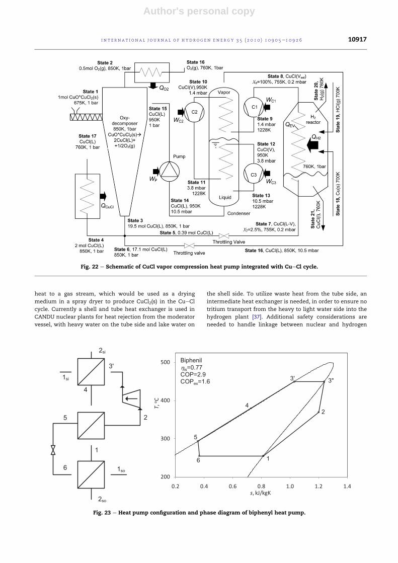
Fig. 22 e Schematic of CuCl vapor compression heat pump integrated with CueCl cycle.
Fig. 23 e Heat pump configuration and phase diagram of biphenyl heat pump.
i n t e r n a t i o n a l j o u r n a l o f h y d r o g e n en e r g y 3 5 ( 2 0 1 0 ) 1 0 9 0 5e1 0 9 2 6 10917

Author's personal copy
plants, such as disruption to heat supply due to nuclear plant
outage.
Alternatively, heat pumps could further upgrade the
waste heat, either by chemical heat pumps that release
heat at successively higher temperatures in exothermic
reactors (i.e., salt/ammonia or MgO/vapor chemical heat
pumps), or vapor compression heat pumps [38e42]. A CuCl
vapor compression heat pump is illustrated in Fig. 22. It
uses CuCl as a cycle working fluid and heat pump fluid
simultaneously. High coefficients of performance (COP)
above 10 have been predicted with direct contact heat
exchangers, using internal heat recovery with a CuCl heat
pump [43].
Organic and titanium based working fluids for high
temperature heat pumps have also been investigated. High
COPs above 7 can be obtained by two-phase compression
and internal heat recovery with retrograde organic working
fluids. Biphenyl, biphenylmethane, naphthalene, isoquino-
line, titanium-tetrabromide and titanium-tetraiodide have
been investigated. Thermodynamic T-s diagrams and equa-
tions of state were developed. A conceptual cycle configu-
ration and T-s diagram with internal heat recovery in
a biphenyl heat pump is illustrated in Fig. 23. These types of
high temperature heat pumps can allow temperature
upgrading to higher levels from waste heat to supply
thermal energy requirements of endothermic reactors in the
CueCl cycle. Promising results with high COPs have been
obtained from a number of parametric studies of these heat
pumps [40,41].
3.5. Linkage of hydrogen and nuclear plants
A Generation IV nuclear reactor, SCWR (Super-Critical Water
Reactor) is being designed by AECL to operate at higher
temperatures (up to 625 �C) that can facilitate co-generation of
electricity and hydrogen. SCWR is expected to be able to co-
generate electricity and hydrogen uniformly throughout the
year, independently of the electrical load. With an electrical
load decrease, the SCWR could produce more hydrogen and
vice versa. Using high temperature heat from a nuclear power
plant to heat wateresteam in the hydrogen production loop is
a promising option with SCWR. Heat exchangers of a recuper-
ator-typewouldbeused for thispurpose (seeFig. 24).Currently,
UOIT is collaborating with AECL on various plant configura-
tions for co-generation of electricity and hydrogen [43e48].
3.6. Safety and reliability
Collaboration between UOIT and the University of Western
Ontario, Canada, is investigating the reliability, fault diag-
nosis and probabilistic safety assessments of a nuclear
hydrogen plant under various risk scenarios. Risk levels of
a thermochemical CueCl plant under different accident
scenarios were analyzed by Zhang et al. [49]. Based on the
results, potential problems encountered in the CueCl cycle
were identified and solutions recommended for future
improvements.
Ma and Jiang [50,51] presented fault detection and
isolation techniques for the power plant components. Sun
Fig. 24 e Single-reheat cycle with co-generation of hydrogen in a nuclear power plant.
i n t e rn a t i o n a l j o u r n a l o f h y d r o g e n en e r g y 3 5 ( 2 0 1 0 ) 1 0 9 0 5e1 0 9 2 610918
Author's personal copy
and Jiang [52] performed modeling and simulation studies
of the dynamic characteristics of SCWR. Al-Dabbagh and
Lu [53,54] developed a distributed control system design
for a nuclear hydrogen plant operating on the CueCl
cycle. The aim of these studies has been to develop
control systems and safety precautions for various risk
scenarios encountered in commercial operation of a nuclear
hydrogen plant.
4. Thermochemistry and physical propertiesof working fluids
4.1. Chemical potentials and solubility data
Limited thermochemical data is available for the working
fluids in the CueCl cycle. Recent advances at UOIT have
developed a new molecular-level simulation methodology to
predict such data. The approach can either be used directly, or
the simulation results can be fitted to standard empirical
expressions and used in chemical process simulators. The
methodology has been developed [55] to directly predict
solubility data, in addition to chemical potentials, of electro-
lytes in aqueous solvents, using a molecular-level force-field
model for the underlying system components. A description
of the approach to calculate the solubilities and chemical
potentials of aqueous electrolytes involving CuCl and CuCl2has been reported by Jirsak et al. [56]. The method incorpo-
rates multiple reactions involving the ionic complexes, and is
based on the use of charged-Lennard-Jones potentials for the
monatomic ions, whose parameters are obtained by fitting to
experimental data. For the ionic complexes, the monatomic
ions are used as building blocks, and the structures are
determined by quantum mechanical approaches.
4.2. Formation of Cu(I) and Cu(II) complexes
Related studies have determined the equilibrium constants
associated with Cu(I) and Cu(II) complexation with chloride
ions as a function of temperature. These are being combined
with literature values of complexation constants to yield
a thermodynamic database for the copper-chlorideewater
system, in order to improve OLI and Aspen solubility
calculations and electrochemical modeling capability. The
thermodynamic data for the formation of Cu(I) and Cu(II)
chloride species is crucial for improving the performance of
the CuCl/HCl electrolysis cell. Cumulative formation
constants of Cu2(II) (aq) complexes with Cl� (aq) were deter-
mined by a Principal Component Analysis of UV-spectra,
obtained over a wide range of solution compositions and
temperatures, coupledwith amodel for activity coefficients of
the solution species. Fig. 25 illustrates measurements by
Trevani et al. [57] and Ehlerova [58] for complexation equilib-
rium constants for CuClx compounds. Shortcomings in the
existing database are being addressed with extensions of past
studies to higher temperatures and copper concentrations.
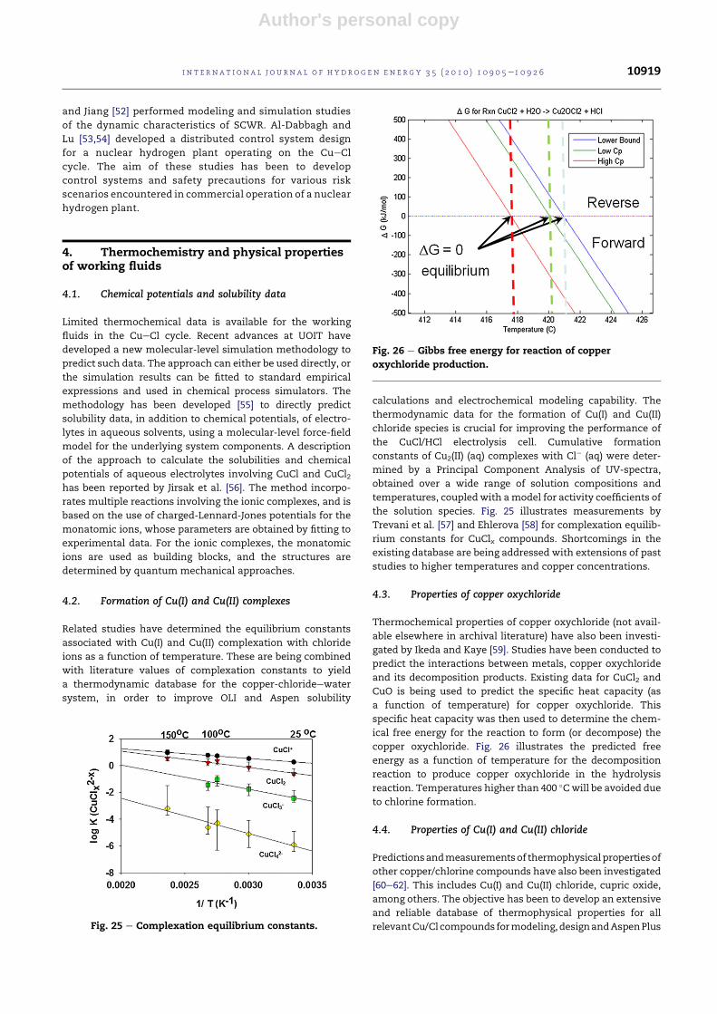
4.3. Properties of copper oxychloride
Thermochemical properties of copper oxychloride (not avail-
able elsewhere in archival literature) have also been investi-
gated by Ikeda and Kaye [59]. Studies have been conducted to
predict the interactions between metals, copper oxychloride
and its decomposition products. Existing data for CuCl2 and
CuO is being used to predict the specific heat capacity (as
a function of temperature) for copper oxychloride. This
specific heat capacity was then used to determine the chem-
ical free energy for the reaction to form (or decompose) the
copper oxychloride. Fig. 26 illustrates the predicted free
energy as a function of temperature for the decomposition
reaction to produce copper oxychloride in the hydrolysis
reaction. Temperatures higher than 400 �Cwill be avoided due
to chlorine formation.
4.4. Properties of Cu(I) and Cu(II) chloride
Predictionsandmeasurementsof thermophysicalpropertiesof
other copper/chlorine compounds have also been investigated
[60e62]. This includes Cu(I) and Cu(II) chloride, cupric oxide,
among others. The objective has been to develop an extensive
and reliable database of thermophysical properties for all
relevantCu/Cl compounds formodeling,designandAspenPlus
Fig. 26 e Gibbs free energy for reaction of copper
oxychloride production.
Fig. 25 e Complexation equilibrium constants.
i n t e r n a t i o n a l j o u r n a l o f h y d r o g e n en e r g y 3 5 ( 2 0 1 0 ) 1 0 9 0 5e1 0 9 2 6 10919

Author's personal copy
simulations, as well as potential byproducts from incomplete
reactions in the CueCl cycle.
Zamfirescu et al. [61] have developed new regression
formulae to correlate the specific heat, enthalpy, entropy,
Gibbs free energy, density, formation enthalpy and free
energy of Cu(I) and Cu(II) chloride. Insufficient past literature
data was available for the viscosity and thermal conductivity
of molten CuCl, so new predictions were recently reported
[61]. The properties were evaluated at 1 bar over a range of
temperatures from ambient to 675e1000 K, which are
consistent with the operating conditions of the CueCl cycle.
For molten CuCl, the estimated viscosity varies from 1.7 to
2.6 mPa s for the envisaged range of temperatures. A Riedel-
like equation was developed for molten CuCl to correlate the
vapor pressures with temperature.
5. Advanced materials
5.1. Materials of construction for the CuCl/HClelectrolyzer
Material degradation studies have been performed by AECL
for selected materials under the expected operating condi-
tions of the CuCl/HCl electrolyzer [11]. In the experiments, 24
selected materials were tested, including metals, ceramics,
elastomers, polymers, carbon-based and composites. Each
was exposed to operating conditions of 160 �C, 2.5 MPa and
concentrated solutions of HCl, CuCl and CuCl2. These include
very aggressive conditions that accelerate the corrosion
reactions. The electrolyzer requires a range of materials of
construction, so a variety ofmaterials have been tested. Glass-
lined metal may be suitable as a material of construction,
however it was found that glass may dissolve up to 0.7 mm/
annum in aqueous conditions.
Ongoing research is also being performed at UOIT by
Ranganathan and Easton [63], who have studied ceramic
carbon electrodes (CCE) for the anode of the CuCl/HCl elec-
trolysis cell. The CCE catalyst layer is a three-dimensional
porous structure composed of carbon black and poly amino-
propyl siloxane (PAPS). An SEM image of a CCE layer con-
taining 36wt% PAPS is shown in Fig. 27. These CCE layers were
found to outperform bare CFP or graphite plates at low CuCl
concentrations [63]. The superior electrode performance was
attributed to the CCE’s higher carbon surface area and greatly
enhanced transport of anionic Cu(I) species arising from the
presence of PAPS in its protonated form. More recent experi-
ments have examined the CCE performance at higher
concentrations of CuCl. More recent experiments have
examined the CCE performance at higher concentrations of
CuCl [74]. Fig. 28 compares the anodic polarization curves
obtained with CCEs to that obtained with a bare CFP (carbon
fiber paper) electrode in a solution containing 0.5 M CuCl in
6 M HCl. A clear performance advantage is retained at high
CuCl concentrations that closely mimic the targeted cell
operating conditions.
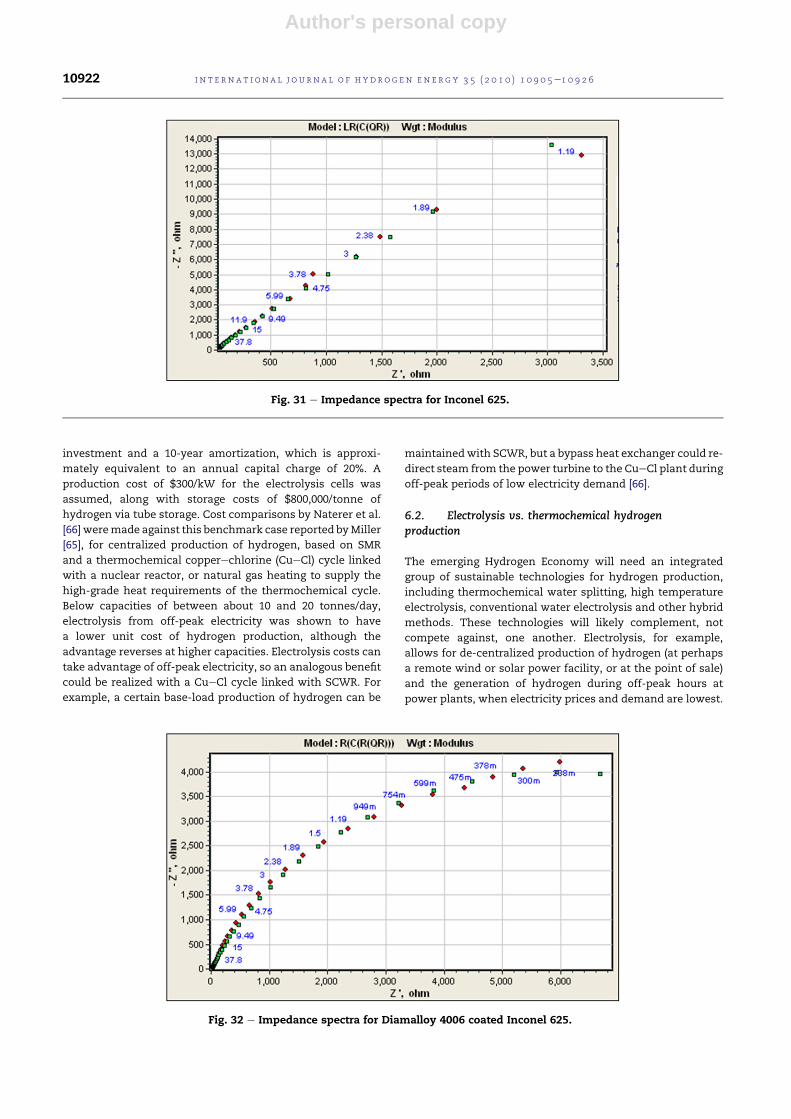
5.2. Corrosion resistant nickel alloy coatings
Nickel alloy coatings are also being developed for corrosion
resistance against high temperature Cu(I) chloride and HCl
environments (exiting hydrolysis reactor) in the CueCl cycle.
Experimental studies have evaluated various surface coatings
using electrochemical impedance spectroscopy (EIS). The
corrosion performance of specimens is tested by immersing
coupons in different CuCl/HCl environments. Fig. 29 shows
a schematic of the immersion cell apparatus. An HCl cylinder
(1) supplies a test cell (3) containing CuCl and the specimen. A
heater (2) is used tomelt the CuCl and control the temperature
of the experiment. Items 4 and 5 are the exhaust and scrubber
systems to control the release of the noxious fumes.
A potentiostat is used to control the voltage of the test
specimen in the cell by passing current through the electro-
lyte. The working electrode potential is monitored using an
Ag/AgCl reference electrode (see Fig. 30). A small AC signal is
added to the control signal, and the phase and amplitude of
the current response are measured. By comparing the AC
voltage input and the AC current response, an impedance for
the system is determined. By removing oxygen from the
electrolyte, using an inert electrolyte system, andmaintaining
a base electrode potential in an inactive (non-corroding)
range, the impedance of the metal/coating/interface system
can be determined in the absence of a corrosion reaction.
Impedance spectra of uncoated and coated Inconel 625
specimens are shown in Figs. 31 and 32. It was found that
Inconel 625 has a higher imaginary impedance (Z”, vertical
axis) and resistance (real impedance, Z’, horizontal axis) than
Al6XN stainless steel (not shown), suggesting that the natu-
rally formed Inconel film is more protective than the film on
Al6XN (smaller impedance). The impedance is inversely
proportional to capacitance, and the capacitance is inversely
proportional to the film thickness, so the higher impedance
suggests a thicker film. The impedance data was numerically
fitted to a variety of equivalent passive-electric circuits. The
best fit was obtained in Figs. 31 and 32. The circuit element Rs
was the solution resistance, Rf was designated as the film
resistance and Cf was designated as the film capacitance. The
result of the best fit circuit was obtained when a CPE element
Fig. 27 e SEM image of a CCE anode catalyst layer
containing 36 wt% PAPS.
i n t e rn a t i o n a l j o u r n a l o f h y d r o g e n en e r g y 3 5 ( 2 0 1 0 ) 1 0 9 0 5e1 0 9 2 610920

Author's personal copy
(constant phase element) included non-ideal capacitance
effects such as surface roughness.
The effects of a coating on the impedance response of
Inconel 625 are shown in Fig. 32. The coating now dominates
the impedance response, replacing the natural passive layer
as the important conduction path from the solution to the
metal. The new best fit circuit shown below the figure
contains a resistor across the CPE element. Coating the Al6XN
specimen changed the shape of the impedance plot in the
same way as observed for the Inconel uncoated-to-coated
specimens. The Z” changewas not as dramatic as observed for
Inconel (7500e6500 U), but the resistance nearly doubled. This
may indicate that the quality of the coating has not changed
much from the Al6XN base oxide, but the effective thickness
of the layer has increased. The best circuit fit found for the
Al6XN coated specimen was the same as the circuit for the
coated Inconel specimen, indicating that both impedance
measurements were interrogating the same type of film.
6. Economics and commercial transition tohydrogen economy
6.1. Economics of nuclear hydrogen production
A case study of distributed hydrogen production by electrol-
ysis was presented by Miller [64,65], for hydrogen vehicles
supplied by neighborhood fueling stations. Naterer et al. [66]
compared electrolysis against SMR (steamemethane reform-
ing) and thermochemical production of hydrogen with the
CueCl cycle. Thermochemical CueCl plant costs were esti-
mated by Orhan et al. [27], assuming a 15%/year return on
Fig. 28 e Comparison of anodic polarization curves obtained with bare CFP and CCE catalyst layers under (a) quiescent
conditions and (b) with the solution stirred at 380 RPM (note: measurements at 25 �C using 0.5 M CuCl dissolved in 6 M HCl)
[74].
Fig. 29 e Schematic of immersion cell apparatus for
working fluids in CueCl cycle. Fig. 30 e Electrochemical cell for corrosion testing.
i n t e r n a t i o n a l j o u r n a l o f h y d r o g e n en e r g y 3 5 ( 2 0 1 0 ) 1 0 9 0 5e1 0 9 2 6 10921
Author's personal copy
investment and a 10-year amortization, which is approxi-
mately equivalent to an annual capital charge of 20%. A
production cost of $300/kW for the electrolysis cells was
assumed, along with storage costs of $800,000/tonne of
hydrogen via tube storage. Cost comparisons by Naterer et al.
[66] weremade against this benchmark case reported byMiller
[65], for centralized production of hydrogen, based on SMR
and a thermochemical copperechlorine (CueCl) cycle linked
with a nuclear reactor, or natural gas heating to supply the
high-grade heat requirements of the thermochemical cycle.
Below capacities of between about 10 and 20 tonnes/day,
electrolysis from off-peak electricity was shown to have
a lower unit cost of hydrogen production, although the
advantage reverses at higher capacities. Electrolysis costs can
take advantage of off-peak electricity, so an analogous benefit
could be realized with a CueCl cycle linked with SCWR. For
example, a certain base-load production of hydrogen can be
maintainedwith SCWR, but a bypass heat exchanger could re-
direct steam from the power turbine to the CueCl plant during
off-peak periods of low electricity demand [66].
6.2. Electrolysis vs. thermochemical hydrogenproduction
The emerging Hydrogen Economy will need an integrated
group of sustainable technologies for hydrogen production,
including thermochemical water splitting, high temperature
electrolysis, conventional water electrolysis and other hybrid
methods. These technologies will likely complement, not
compete against, one another. Electrolysis, for example,
allows for de-centralized production of hydrogen (at perhaps
a remote wind or solar power facility, or at the point of sale)
and the generation of hydrogen during off-peak hours at
power plants, when electricity prices and demand are lowest.
Fig. 31 e Impedance spectra for Inconel 625.
Fig. 32 e Impedance spectra for Diamalloy 4006 coated Inconel 625.
i n t e rn a t i o n a l j o u r n a l o f h y d r o g e n en e r g y 3 5 ( 2 0 1 0 ) 1 0 9 0 5e1 0 9 2 610922

Author's personal copy
Thermochemical cycles, by comparison, are much more effi-
cient emerging technologies that can integrate well with
electrolysis because they allow for centralized, base-load
production of hydrogen, and the utilization ofwaste heat from
power plants. Thermochemical cycles have the potential to be
much more efficient than electrolysis when associated with
nuclear power because there is no need for generation of
electricity from the process heat (which encounters a signifi-
cant energy loss). Naterer et al. [67,68] examined how the
integration of these technologies can lead to reduced cost and
environmental impact of hydrogen production.
The use of hydrogen as an energy carrier is appealing from
the perspective of electrical grid management, because of its
energy storage potential. The use of hydrogen as an energy
carrier can increase the efficiency and reliability of the electric
grid. When integrated into the electrical power distribution
system, hydrogen can become a major solution to the elec-
tricity storage issue, facilitating the increased use of inter-
mittent renewable energy sources such as wind and solar,
whilemaintaining the necessary reliability and consistency of
the electrical grid.
Near-term clean production of hydrogen is likely to be
associated with electrolysis to support and enable intermit-
tent renewable power sources, as well as load leveling of base-
load power sources, such as nuclear plants. From the elec-
trical grid management point of view, the use of hydrogen as
an energy carrier is appealing in the context of energy storage
impact on competitive electricity markets. It enables power
utilities to take advantage of significant price differences
between peak and off-peak pricing hours (which may or may
not necessarily coincide with peak and off-peak demand
hours). Ancillary services such as voltage and frequency
regulation are those services necessary to support the trans-
mission of electric power from seller to purchaser, while
maintaining reliable operations of the interconnected trans-
mission system. Some of these services require a “spinning
reserve”, where generation reserve capacity may be called
shortly after an event that causes significant deviation from
the standard voltage and frequency of the grid. This service
requires a payment to the generator that is ready to increase/
reduce powerwhen requested.Water electrolysis as a variable
and controllable load has the potential to address this market
need in the short term. However, this only represents a frac-
tion of the required hydrogen for the emerging hydrogen
economy, so larger scale production via thermochemical
plants will become increasingly important.
6.3. Hydrogen transition in the transportation sector
Hajimiragha et al. [68] investigated the implementation of
electrolytic hydrogen production for Ontario’s transportation
sector, based on its existing electricity system infrastructure
and planned future development up to 2025. Using a zonal
basedmodel of Ontario’s electricity transmission network and
Ontario’s Integrated Power System Plan (IPSP), a pattern of
generation capacity procurement in Ontario from 2008 to 2025
was presented. A model was also developed to find the
optimal size of hydrogen production plants in different zones,
as well as optimal hydrogen transportation routes for
a significant hydrogen economy penetration in Ontario by
2025. The results indicate that the present and projected
electricity supply in Ontario can achieve significant levels of
hydrogen penetration in the transportation sector by 2025,
without additional grid or power generation infrastructure
beyond those currently planned. The study showed that up to
1.2% of the current light duty vehicle fleet (over 100,000 vehi-
cles) can be supported within this period, however beyond
this time frame with increased penetration of hydrogen
vehicles, large-scale hydrogen production will be required.
Nevertheless, even with this limited penetration of hydrogen
vehicles, Kantor et al. [69] have shown that there would be
measurable impact on urban air quality in Ontario.
Althoughmuch attention has focused on hydrogen fuel cell
vehicles for the automotive sector, several studies have shown
that hydrogen may be more advantageous and economical for
passenger trains. Of all transportationmodes, train andmarine
transport may be the most attractive entry points for the
Hydrogen Economy [70]. Rail transport is more efficient than
trucks for long-range transport and it has better opportunities
for expansion. Hydrogen for airplanes is also feasible and
attractive, although the aircraft industry is conservative,
requires long lead times for major design changes, and aircraft
designs would need significant re-configurations to accom-
modate the volume of liquid hydrogen.
Recent studies by Haseli et al. [71] and Marin et al. [72,73]
have examined the environmental impact and feasibility of
hydrogen vs. electrification as a cleaner alternative to diesel
locomotives in Ontario, Canada. Disadvantages of electrifica-
tion include the capital investment to install electrical substa-
tions and catenaries, together with lack of flexibility for trains
to move into other service areas not covered by electrification.
Marin et al. [72,73] analyzed the implementation and operation
of hydrogen passenger locomotives (fueled by nuclear-
produced hydrogen) in the GO Transit Lakeshore corridor,
between Oshawa and Toronto, Ontario. A sensitivity analysis
was performed over a range of operational costs for a hydrogen
train, with variability of feedstock prices, fuel cell power
density and expected return on capital investment. Various
methods of propulsion and storage were compared against
electrification. It was found that hydrogen trains offer
a number of environmental, technical and economic benefits
over electrification and other modes of transportation, specif-
ically through a case study for Ontario, Canada.
7. Conclusions
This paper has presented the recent Canadian advances in
nuclear-based hydrogen production, particularly involving the
thermochemical CueCl cycle and electrolysis. The CueCl cycle
was identified by Atomic Energy of Canada Limited, AECL (CRL;
Chalk River Laboratories), as the most promising cycle for
thermochemical hydrogen production with the Generation IV
nuclear reactor, SCWR (Super-Critical Water Reactor). Objec-
tives of Canada’s nuclear hydrogen program are to develop
commercially viable processes for producing hydrogen based
on the thermochemical CueCl cycle and water electrolysis. In
collaborationwith the ArgonneNational Laboratory, thiswould
ultimately achieve the DOE cost target ($3 gge) and efficiency
target (>35% based on LHV) for nuclear hydrogen production.
i n t e r n a t i o n a l j o u r n a l o f h y d r o g e n en e r g y 3 5 ( 2 0 1 0 ) 1 0 9 0 5e1 0 9 2 6 10923

Author's personal copy
The CueCl cycle has attractive features that should help to
meet these targets, particularly a 530 �C maximum tempera-
ture that reduces demands on materials, compared to higher
temperature cycles. Also, the CueCl cycle couples well with
various heat sources, such as the SCWR, solar power tower or
Na-cooled fast reactor. The yields are nearly 100% in the
hydrolysis and copper oxychloride decomposition processes,
without catalysts and no recycle streams in these reactions.
Also, conceptual process designs use commercially practiced
processes in industry. The hydrogen production costs are
therefore believed to be within the range of DOE targets.
Acknowledgements
Support of this research and assistance fromAtomic Energy of
Canada Limited, Ontario Research Excellence Fund, Argonne
National Laboratory (International Nuclear Energy Research
Initiative; U.S. Department of Energy), Natural Sciences and
Engineering Research Council of Canada (NSERC), University
Network of Excellence in Nuclear Engineering (UNENE) and
the Canada Research Chairs (CRC) program are gratefully
acknowledged.
r e f e r e n c e s
[1] Naterer GF, Suppiah S, Lewis M, Gabriel K, Dincer I,Rosen MA, et al. Recent Canadian advances in nuclear-basedhydrogen production and the thermochemical CueCl cycle.International Journal of Hydrogen Energy 2009;34:2901e17.
[2] Stevens MB, Fowler MW, Elkamel A, Elhedhli S. Macro-leveloptimized deployment of an electrolyser-based hydrogenrefuelling infrastructure with demand growth. EngineeringOptimization 2008;40(10):955e67.
[3] McQuillan BW, Brown LC, Besenbruch GE, Tolman R,Cramer T, Russ BE, et al. High efficiency generation ofhydrogen fuels using solar thermochemical splitting ofwater. Annual report, GA-A24972. San Diego, CA: GeneralAtomics; 2002.
[4] Lewis M, Taylor A. High temperature thermochemicalprocesses. DOE hydrogen program. Annual progress report.Washington, DC; 2006. p. 182e85
[5] Sakurai M, Nakajima H, Amir R, Onuki K, Shimizu S.Experimental study on side-reaction occurrence condition inthe iodineesulfur thermochemical hydrogen productionprocess. International Journal of Hydrogen Energy 2000;23:613e9.
[6] Schultz K. Thermochemical production of hydrogen fromsolar and nuclear energy. Technical report for the Stanfordglobal climate and energy project. San Diego, CA: GeneralAtomics; 2003.
[7] Sadhankar RR, Li J, Li H, Ryland D, Suppiah S. Hydrogengeneration using high-temperature nuclear reactors. In: 55thCanadian chemical engineering conference, Toronto,Ontario; October, 2005.
[8] Carty RH, Mazumder M, Schreider JD, Panborn JB. GRI Report80-0023. Thermochemical hydrogen production, vol. 1.Chicago, IL 60616: Gas Research Institute for the Institute ofGas Technology; 1981.
[9] Lewis MA, Masin JG, Vilim RB, Serban M. Development of thelow temperature CueCl thermochemical cycle. In:
International congress on advances in nuclear power plants,Seoul, Korea; May 15e19, 2005.
[10] Xiao ZF, Gammons CH, Williams-Jones AE. Experimentalstudy of copper(I) chloride complexing in hydrothermalsolutions at 40 to 300 �C and saturated water vapor pressure.Geochimica et Cosmochimica Acta 1998;62:2949e64.
[11] Suppiah S, Naterer GF, Lewis M, Lvov S, Easton B, Dincer I,et al. Thermo-mechanical design of nuclear-based hydrogenproduction. In: ORF workshops on nuclear-basedthermochemical hydrogen production, Oshawa, ON(December 2007, May 2009, February 2010) and Chalk River,ON (October 2008).
[12] Naterer GF, Daggupati V, Marin G, Gabriel K, Wang Z.Thermochemical hydrogen production witha copperechlorine cycle, II: flashing and drying of aqueouscupric chloride. International Journal of Hydrogen Energy2008;33:5451e9.
[13] Bahadorani P, Naterer GF, Gabriel K. Effects of cupric chlorideconcentration on aqueous droplet evaporation in the CueClcycle. In: International conference on hydrogen production,Oshawa, Ontario; May 3e6, 2009.
[14] Bahadorani P, Naterer GF, Gabriel K. Particle formation fromslurry spray drying in nuclear-based hydrogen production.In: International conference on hydrogen and fuel cells,Vancouver, British Columbia; May 31eJune 3, 2009.
[15] Daggupati V, Naterer GF, Gabriel K. Diffusion of gaseousproducts through a particle surface layer in a fluidized bedreactor. International Journal of Heat and Mass Transfer2010;53:2449e58.
[16] Daggupati V, Naterer GF, Gabriel K, Gravelsins R, Wang Z.Equilibrium conversion in CueCl cycle multiphase processesof hydrogen production. Thermochimica Acta 2009;496:117e23.
[17] Daggupati V, Naterer GF, Gabriel K, Gravelsins R, Wang Z.Decomposition analysis of cupric chloride hydrolysis in theCueCl cycle of hydrogen production. In: Internationalconference on hydrogen production, Oshawa, Ontario; May3e6, 2009.
[18] Daggupati V, Naterer GF, Gabriel K. Reaction rate analysis ofcupric chloride hydrolysis for production of hydrogen ina copperechlorine thermochemical cycle. In: Nationalhydrogen association conference, Columbia, SC; March30eApril 3, 2009.
[19] Serban M, Lewis MA, Basco JK, Kinetic study of the hydrogenand oxygen production reactions in the copper-chloridethermochemical cycle. In: AIChE 2004 spring nationalmeeting, New Orleans, LA; April 25e29, 2004.
[20] Jaber O, Naterer GF, Dincer I. Heat recovery frommolten CuClin the CueCl cycle of hydrogen production. InternationalJournal of Hydrogen Energy June 2010;35(12):6140e51.
[21] Ghandehariun S, Naterer GF, Rosen MA, Wang Z. Options forheat recovery from molten salt in thermochemical hydrogenproduction. In: CSME Forum 2010, Victoria, BC; June 7e9,2010.
[22] Ferrandon MS, Lewis MA, Tatterson DF, Nankanic RV,Kumarc M, Wedgewood LE, et al. The hybrid CueClthermochemical cycle. I. Conceptual process design and H2Acost analysis. II. Limiting the formation of CuCl duringhydrolysis. In: NHA annual hydrogen conference,Sacramento convention center, CA; March 30eApril 3, 2008.
[23] Chukwu C, Naterer GF, Rosen MA. Process simulation ofnuclear-produced hydrogen with a CueCl Cycle. In: 29thConference of the Canadian nuclear society, Toronto,Ontario; June 1e4, 2008
[24] Wang ZL, Naterer GF, Gabriel KS, Gravelsins R, Daggupati VN.New CueCl thermochemical cycle for hydrogen productionwith reduced excess steam requirements. InternationalJournal of Green Energy 2009;6:616e26.
i n t e rn a t i o n a l j o u r n a l o f h y d r o g e n en e r g y 3 5 ( 2 0 1 0 ) 1 0 9 0 5e1 0 9 2 610924
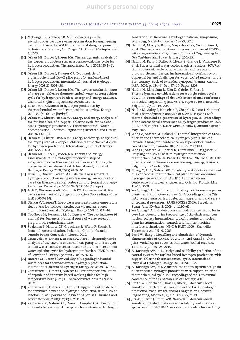
Author's personal copy
[25] McDougall R, Nokleby SB. Multi-objective parallelasynchronous particle swarm optimization for engineeringdesign problems. In: ASME international design engineeringtechnical conferences, San Diego, CA; August 30eSeptember2, 2009.
[26] Orhan MF, Dincer I, Rosen MA. Thermodynamic analysis ofthe copper production step in a copperechlorine cycle forhydrogen production. Thermochimica Acta 2008;480(1e2):22e9.
[27] Orhan MF, Dincer I, Naterer GF. Cost analysis ofa thermochemical CueCl pilot plant for nuclear-basedhydrogen production. International Journal of HydrogenEnergy 2008;33:6006e20.
[28] Orhan MF, Dincer I, Rosen MA. The oxygen production stepof a copperechlorine thermochemical water decompositioncycle for hydrogen production: energy and exergy analyses.Chemical Engineering Science 2009;64:860e9.
[29] Rosen MA. Advances in hydrogen production bythermochemical water decomposition: a review. Energy2010;35(2):1068e76 [invited].
[30] Orhan MF, Dincer I, Rosen MA. Energy and exergy analyses ofthe fluidized bed of a copperechlorine cycle for nuclear-based hydrogen production via thermochemical waterdecomposition. Chemical Engineering Research and Design2009;87:684e94.
[31] Orhan MF, Dincer I, Rosen MA. Energy and exergy analyses ofthe drying step of a copperechlorine thermochemical cyclefor hydrogen production. International Journal of Exergy2009;6:793e808.
[32] Orhan MF, Dincer I, Rosen MA. Energy and exergyassessments of the hydrogen production step ofa copperechlorine thermochemical water splitting cycledriven by nuclear-based heat. International Journal ofHydrogen Energy 2008;33(22):6456e66.
[33] Lubis LL, Dincer I, Rosen MA. Life cycle assessment ofhydrogen production using nuclear energy: an applicationbased on thermochemical water splitting. Journal of EnergyResources Technology 2010;132(2):021004 (6 pages).
[34] Solli C, Stromman AH, Hertwish EG. Fission or fossil: lifecycle assessment of hydrogen production. Proceedings of theIEEE 2006;94(10).
[35] UtgikarV,ThiesenT.Life cycleassessmentofhigh temperatureelectrolysis for hydrogen production via nuclear energy.International Journal of Hydrogen Energy 2006;31:939e44.
[36] Goedkoop M, Demmers M, Collignon M. The eco-indicator 95manual for designers. National reuse of waste researchprogramme, Netherlands; 1996
[37] Spekkens P, Naterer GF, Gravelsins R, Wang F, Secnik E.Personal communication. Pickering, Ontario, Canada:Ontario Power Generation; March, 2010.
[38] Granovskii M, Dincer I, Rosen MA, Pioro I. Thermodynamicanalysis of the use of a chemical heat pump to link a super-critical water-cooled nuclear reactor and a thermochemicalwater-splitting cycle for hydrogen production. JSME Journalof Power and Energy Systems 2008;2:756e67.
[39] Naterer GF. Second law viability of upgrading industrialwaste heat for thermochemical hydrogen production.International Journal of Hydrogen Energy 2008;33:6037e45.
[40] Zamfirescu C, Dincer I, Naterer GF. Performance evaluationof organic and titanium based working fluids for hightemperature heat pumps. Thermochimica Acta 2009;496:18e25.
[41] Zamfirescu C, Naterer GF, Dincer I. Upgrading of waste heatfor combined power and hydrogen production with nuclearreactors. ASME Journal of Engineering for Gas Turbines andPower October, 2010;132(10):102911e9.
[42] Zamfirescu C, Naterer GF, Dincer I. Coupled CuCl heat pumpand endothermic oxy-decomposer for sustainable hydrogen
generation. In: Renewable hydrogen national symposium,Winnipeg, Manitoba; January 18e29, 2010.
[43] Naidin M, Mokry S, Baig F, Gospodinov Ye, Zirn U, Pioro I,et al. Thermal-design options for pressure-channel SCWRswith co-generation of hydrogen. Journal of Engineering forGas Turbines and Power January, 2009;131.
[44] Naidin M, Pioro I, Duffey R, Mokry S, Grande L, Villamere B,et al. Super-critical water-cooled nuclear reactors (SCWRs):thermodynamic cycle options and thermal aspects ofpressure-channel design. In: International conference onopportunities and challenges for water cooled reactors in the21st century. Book of extended synopses. Vienna, Austria:IAEA; 2009. p. 134e5. Oct. 27e30, Paper 5S03.
[45] Naidin M, Monichan R, Zirn U, Gabriel K, Pioro I.Thermodynamic considerations for a single-reheat cycleSCWR. In: Proceedings of the 17th international conferenceon nuclear engineering (ICONE-17), Paper #75984, Brussels,Belgium; July 12e16, 2009.
[46] Naidin M, Mokry S, Monichan R, Chophla K, Pioro I, Naterer G,et al. Thermodynamic analysis of SCW NPP cycles withthermo-chemical co-generation of hydrogen. In: Proceedingsof the international conference on hydrogen production-2009(ICH2P-09), Paper No. ICH2P-GP163, Oshawa, Ontario, Canada;May, 2009.
[47] Wang Z, Naterer GF, Gabriel K. Thermal integration of SCWRnuclear and thermochemical hydrogen plants. In: 2ndCanadaeChina joint conference on super-critical water-cooled reactors, Toronto, ON; April 25e28, 2010.
[48] Wang F, Naterer GF, Gabriel K, Gravelsins R, Daggupati V.Coupling of nuclear heat to hydrogen productionthermochemical cycles, Paper ICONE 17-75702. In: ASME 17thinternational conference on nuclear engineering, Brussels,Belgium; July 12e16, 2009.
[49] Zhang Y, Lu L, Naterer GF. Reliability and safety assessmentof a conceptual thermochemical plant for nuclear-basedhydrogen generation. In: ASME 16th internationalconference on nuclear engineering, Orlando, Florida; May11e15, 2008.
[50] Ma J, Jiang J. Applications of fault diagnosis in nuclear powerplants: an introductory survey. In: Proceedings of the 7thIFAC symposium on fault detection, supervision and safetyof technical processes (SAFEPROCESS 2009), Barcelona,Spain; June 30eJuly 3, 2009. p. 1150e61.
[51] Ma J, Jiang J. A fault detection and isolation technique for in-core flux detectors. In: Proceedings of the sixth americannuclear society international topical meeting on nuclearplant instrumentation, control, and human-machineinterface technologies (NPIC & HMIT 2009), Knoxville,Tennessee; April 5e9, 2009.
[52] Sun PW, Jiang J. Modelling and simulation of dynamiccharacteristics of CANDU-SCWR. In: 2nd CanadaeChinajoint workshop on super-critical water-cooled reactors,Toronto; April 25e28, 2010.
[53] Al-Dabbagh AW, Lu L. Design and reliability prediction of thecontrol system for nuclear-based hydrogen production withcopperechlorine thermochemical cycle. InternationalJournal of Hydrogen Energy 2010;35:966e77.
[54] Al-Dabbagh AW, Lu L. A distributed control system design fornuclear-based hydrogen production with copperechlorinethermochemical cycle. In: Proceedings of the 30th annualconference of the Canadian nuclear society; 2009.
[55] Smith WR, Nezbeda I, Jirsak J, Skvor J. Molecular-levelsimulation of electrolyte systems in the CueCl hydrogenproduction cycle. In: 8th World Congress on ChemicalEngineering, Montreal, QC; Aug 23e27, 2009.
[56] Jirsak J, Skvor J, Smith WR, Nezbeda I. Molecular-levelsimulation of electrolyte system solubility and chemicalspeciation. In: DECHEMA workshop on molecular modeling
i n t e r n a t i o n a l j o u r n a l o f h y d r o g e n en e r g y 3 5 ( 2 0 1 0 ) 1 0 9 0 5e1 0 9 2 6 10925

Author's personal copy
and simulation for industrial applications, Wurzburg,Germany; Mar. 22e23, 2010.
[57] Trevani L, Ehlerova J, Sedlbauer J, Tremaine PR.Complexation in the Cu(II)eLiCleH2O system attemperatures to 423 K by UVevisible spectroscopy. In:International Journal of Hydrogen Energy 2010;35(10):4893e4900.
[58] Ehlerova J. Spectrophotometric determination of equilibriumconstants and speciation of aqueous systems over a widerange of temperatures and pressures. PhD Thesis. TechnicalUniversity of Liberec, Czech Republic; 2009
[59] Ikeda BM, Kaye MH. Thermodynamic properties in theCueCleOeH system. In: 7th International conference onnuclear and radiochemistry, Budapest, Hungary; August2008.
[60] Avsec J, Naterer GF. Thermodynamic property evaluation ofcopper-chlorine fluid components at high temperatures. In:AIAA 40th thermophysics conference, Seattle, WA; June23e26, 2008.
[61] Zamfirescu C, Dincer I, Naterer GF. Thermophysicalproperties of copper compounds in copperechlorinethermochemical water splitting cycles. International Journalof Hydrogen Energy May 2010;35(10):4839e52.
[62] Avsec J, Naterer GF, Predin A. Calculation of thermodynamicproperties for hydrochloric and copper compounds ina hydrogen production process. Journal of EnergyTechnology, in press.
[63] Ranganathan S, Easton EB. Ceramic carbon electrode-basedanodes for use in the CueCl thermochemical cycle.International Journal of Hydrogen Energy May 2010;35(10):4871e6.
[64] Miller AI, Duffey RB. Sustainable and economic hydrogen co-generation from nuclear energy in competitive powermarkets. In: International energy workshop, Laxenburg,Austria; June 24e26, 2003.
[65] Miller AI. Electrochemical production of hydrogen by nuclearenergy. Nuclear production of hydrogen e technologies and
perspectives for global deployment. La Grange Park, Illinois:American Nuclear Society; 2004 [Chapter 4].
[66] Naterer GF, Fowler M, Cotton J, Gabriel K. Synergistic roles ofoff-peak electrolysis and thermochemical production ofhydrogen from nuclear energy in Canada. InternationalJournal of Hydrogen Energy 2008;33:6849e57.
[67] Naterer GF, Jaber O, Dincer I. Environmental impactcomparison of steam methane reformation andthermochemical processes of hydrogen production. In: 18thWorld hydrogen energy conference, Essen, Germany; May16e21, 2010.
[68] Hajimiragha A, Fowler MW, Canizares CA. Hydrogeneconomy transition in Ontario e Canada considering theelectricity grid constraints. International Journal of HydrogenEnergy 2009;34(13):5275e93.
[69] Kantor I, Fowler MW, Hajimiragha A, Elkamel A. Air qualityand environmental impacts of alternative vehicletechnologies in Ontario, Canada. International Journal ofHydrogen Energy May 2010;35(10):5145e53.
[70] Miller A. Hydrail: an adaptable, low-cost alternative toelectrification, Paper 4-205-4. In: Hydrogen and fuel cellsconference,Vancouver, BritishColumbia;April 29eMay2,2007.
[71] Haseli Y, Naterer GF, Dincer I. Comparative assessment ofgreenhouse gas mitigation of hydrogen passenger trains.International Journal of Hydrogen Energy 2008;33:1788e96.
[72] Marin G, Naterer GF, Gabriel KS. Rail transportation byhydrogen vs. electrification e case study for Ontario Canada,I: propulsion and storage. International Journal of HydrogenEnergy 2010;35:6084e96.
[73] Marin G, Naterer GF, Gabriel KS. Rail transportation byhydrogen vs. electrification e case study for Ontario Canada,II: energy supply and distribution. International Journal ofHydrogen Energy 2010;35:6097e107.
[74] Ranganathan S, Easton EB. High performance ceramiccarbon electrode-based anodes for use in the Cu–Clthermochemical cycle for hydrogen production.International Journal of Hydrogen Energy 2010;35(3):1001e7.
i n t e rn a t i o n a l j o u r n a l o f h y d r o g e n en e r g y 3 5 ( 2 0 1 0 ) 1 0 9 0 5e1 0 9 2 610926
Related Documents