Introduction In today’s world, automation is needed in many systems which provide better performance. Large numbers of systems are fully automated. Vehicle system is composed automotive electrical architectures consist of a large number of electronic control units (ECU) carrying out a variety of control functions. In vehicle system we generally want greater safety, more comfort, convenience, pollution control and less fuel consumption. Modern vehicle may have many electronic control units (ECU) for various subsystems. Different such subsystems are airbags, antilock braking, engine control, audio systems, windows, doors, mirror adjustment etc. Some of these subsystems form independent dependent subsystems. Communications among dependent sub systems is essential. Traditional electronic control system can improve a vehicle dynamics, economy comfort. But some problems also have come up, such as the body wiring complexity, space constraints and some reliability issues. In order to solve these problems, the vehicle network technology has been created. In-vehicle networking protocols must satisfy requirements which include, significant reduction of wiring harness, reducing body weight and costs, improving the efficiency of fault diagnosis, low latency times and configuration flexibility and enhancing the level of intelligent control. Sub-systems (ECU) require the exchange particular performance and position information within defined communication latency.

CAN Protocol
Dec 22, 2015
can protocol based dpcument
Welcome message from author
This document is posted to help you gain knowledge. Please leave a comment to let me know what you think about it! Share it to your friends and learn new things together.
Transcript
Introduction
In today’s world, automation is needed in many systems which provide better performance. Large
numbers of systems are fully automated. Vehicle system is composed automotive electrical architectures
consist of a large number of electronic control units (ECU) carrying out a variety of control functions. In
vehicle system we generally want greater safety, more comfort, convenience, pollution control and less
fuel consumption. Modern vehicle may have many electronic control units (ECU) for various subsystems.
Different such subsystems are airbags, antilock braking, engine control, audio systems, windows, doors,
mirror adjustment etc. Some of these subsystems form independent dependent subsystems.
Communications among dependent sub systems is essential.
Traditional electronic control system can improve a vehicle dynamics, economy comfort. But some
problems also have come up, such as the body wiring complexity, space constraints and some reliability
issues. In order to solve these problems, the vehicle network technology has been created. In-vehicle
networking protocols must satisfy requirements which include, significant reduction of wiring harness,
reducing body weight and costs, improving the efficiency of fault diagnosis, low latency times and
configuration flexibility and enhancing the level of intelligent control. Sub-systems (ECU) require the
exchange particular performance and position information within defined communication latency.
Therefore the requirement for each ECU is to communicate via network technology called CAN
(Controller Area Network) bus. The project focuses on using CAN bus protocol for vehicle automation.
Objective:
The goal of this project is to develop few automated features for the driver-vehicle control system using
CAN Protocol. In this project we control switching of the vehicle’s AC/Fan using temperature sensor and
help the vehicle in parking using ultrasonic obstacle sensor. The status of the car temperature and the rear
distance of the vehicle from obstacle are conveyed to the user by displaying on the LCD. The primary aim
of the project is to learn about the CAN Protocol which is a highly reliable protocol and has good real
time performance with very low cost.
Scope of the Project:
The scope of our project is to achieve AC/Engine Heat controlling technique and Vehicle parking system
which can be implemented in all the automobiles. The use of CAN protocol to implement the above
features accurately is our main goal.
With rapidly changing computer and information technology and much of the technology finding way
into vehicles. They are undergoing dramatic changes in their capabilities and how they interact with the
drivers. Hence the automated features inside a vehicle are very much necessary to be achieved. The
AC/Engine Heat control mechanism and vehicle parking system used in our project uses ARM 7
processors and CAN controllers where each ECU is connected across the CAN bus and communicates
with the Monitor ECU. The project can be further extended for vehicle security, cruise control and
electric power steering (EPS), audio systems, power windows, doors, mirror adjustment, battery and
recharging systems for hybrid/electric cars.

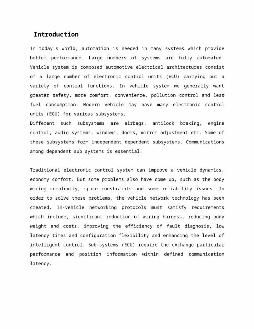
BASIC BLOCK DIAGRAM
Basic Block Diagram of CAN communication
CAN is a multi-master broadcast serial bus standard for cis able to send and receive messages, but not
simultaneously.
Each node requires a:
• Central processing unit or host processor
– The host processor decides what received messages mean and which messages it wants to transmit
itself.
– Sensors, actuators and control devices can be connected to the host processor.
• CAN controller; hardware with a synchronous clock
– Receiving: the CAN controller stores received bits serially message is available, which can then be
fetched by the host processor (usually after the CAN controller has triggered an interrupt).
– Sending: the host processor stores it’s transmit messages to a CAN controller, which transmits the bits
serially onto the bus.
• Transceiver
– Receiving: it adapts signal levels from the bus to levels that the CAN controller expects and has
protective circuitry that protects the CAN controller.
– Transmitting: it converts the transmit-bit signal received from the CAN controller into a signal that is
sent onto the bus.
Applications:
The primary applications for this project are for the drivers. The project delivers the following two
features:
ye Blink sensor
2. GPS (Global Positioning System)
Hardware Requirement:
ARM7 – LPC2129:
The ARM architecture is based on Reduced Instruction Set Computer (RISC) principles. The RISC
instruction set and related decode mechanism are much simpler than those of Complex Instruction Set
Computer (CISC) design. This simplicity gives:
A high instruction throughput.
An excellence real-time interrupts response.
A small, cost-effective, processor macro cell.
The ARM7TDMI core is the industry’s most widely used 32-bit embedded RISC Microprocessor
solution. Optimized for cost and power-sensitive application, the ARM7TDMI solution provides low
power consumption, small size, and high performance needed in portable, embedded application. The
ARM7DMI-S is synthesizable version of ARM7TDMI core.
Features:
16/32-bit ARM7TDMI-S microcontroller in a 64 or 144 pin package.
16 kB on-chip Static RAM, 128/256 kB on-chip Flash Program Memory
In-System Programming (ISP) and In-Application Programming (IAP) via on- chip boot-loader
software. Flash programming takes 1 ms per 512 byte line. Single sector or full chip erase takes 400 ms.
Two interconnected CAN interfaces with advanced acceptance filters.
Four channel 10-bit A/D converter with conversion time as low as 2.44 ms.
Two 32-bit timers (with 4 capture and 4 compare channels), PWM unit (6 outputs), Real Time Clock
and Watchdog.
Multiple serial interfaces including two UARTs (16C550), Fast I2C (400 Kbits/s) and two SPIs.
60 MHz maximum CPU clock available from programmable on-chip PhaseLocked Loop.
Vectored Interrupt Controller with configurable priorities and vector addresses.
Up to forty-six, 5 V tolerant general purpose I/O pins.

On-chip crystal oscillator with an operating range of 1 MHz to 30 MHz
Two low power modes Idle and Power-down.
Processor wake-up from Power-down mode via external interrupt.
Individual enable/disable of peripheral functions for power optimization.
Dual power supply.
- CPU operating voltage range of 1.65V to 1.95V (1.8V +/- 8.3%).
- I/O power supply range of 3.0V to 3.6V (3.3V +/- 10%).
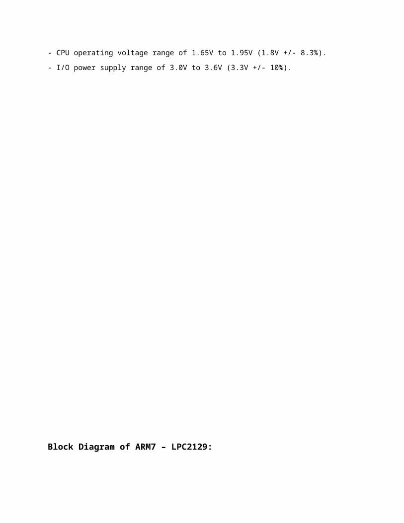
Block Diagram of ARM7 – LPC2129:
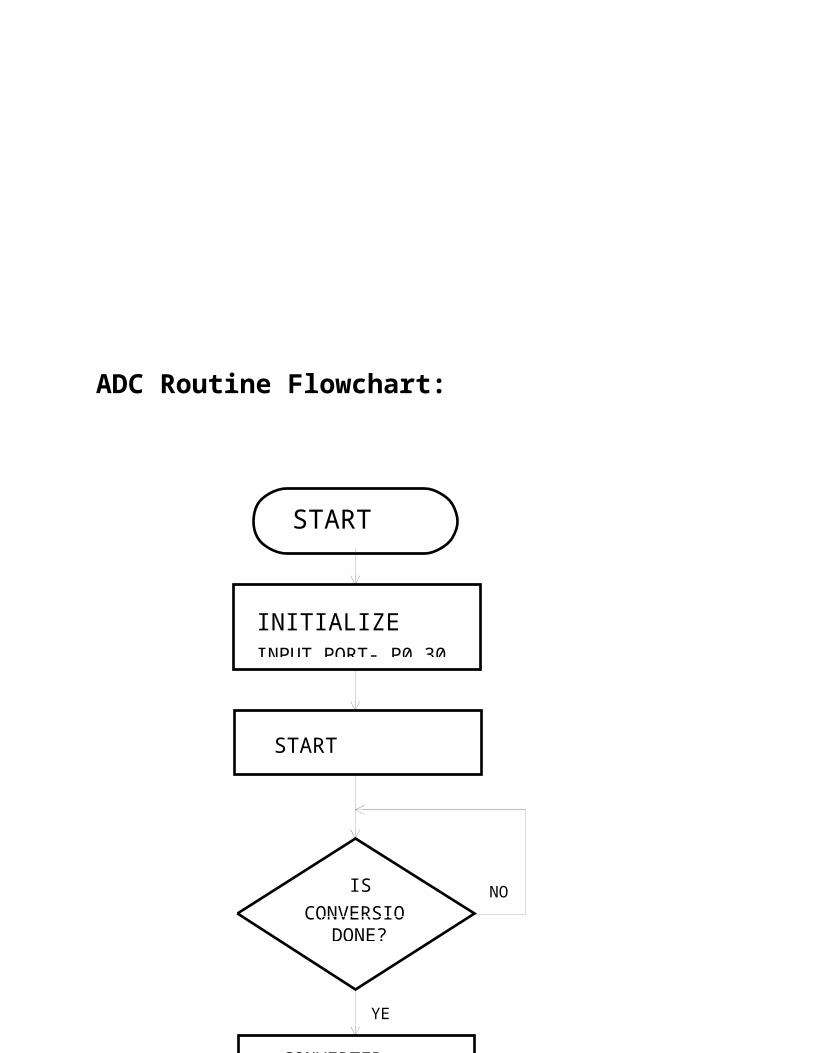
4.1.1.1 Analog to Digital Converter (ADC):
Basic clocking for the A/D converters is provided by the APB clock. A programmable divider is included
in each converter, to scale this clock to the 4.5 MHz (max) clock needed by the successive approximation
process. A fully accurate conversion requires 11 of these clocks.
Features:
• 10 bit successive approximation analog to digital converter.
• Input multiplexing among 4 pins.
• Power-down mode.
• Measurement ranges 0 V to VREF (typically 3 V; not to exceed VDDA voltage level).
• 10 bit conversion time = 2.44 µs.
• Burst conversion mode for single or multiple inputs

ADC Routine Flowchart:
START
INITIALIZEINPUT PORT- P0.30
START CONVERSION
CONVERSIOIS
DONE?
NO
YES
CONVERTED DATA PRESENT IN ADDR
STOP
Global Positioning System (GPS)
The Global Positioning System (GPS) is a space-based satellite navigation system that provides
location and time information in all weather conditions, anywhere on or near the earth where
there is an unobstructed line of sight to four or more GPS satellites. The system provides critical
capabilities to military, civil, and commercial users around the world. The United States
government created the system, maintains it, and makes it freely accessible to anyone with a
GPS receiver.
The US began the GPS project in 1973 to overcome the limitations of previous navigation
systems, integrating ideas from several predecessors, including a number of classified
engineering design studies from the 1960s. The U.S. Department of Defense (DoD) developed
the system, which originally used 24 satellites. It became fully operational in 1995. Bradford
Parkinson, Roger L. Easton, and Ivan A. Getting are credited with inventing it.
Advances in technology and new demands on the existing system have now led to efforts to
modernize the GPS system and implement the next generation of GPS Block IIIA satellites and
Next Generation Operational Control System (OCX). Announcements from Vice President Al
Gore and the White House in 1998 initiated these changes. In 2000, the U.S. Congress
authorized the modernization effort, GPS III.
Fundamental
The GPS system concept is based on time. The satellites carry very stable atomic clocks that are
synchronized to each other and to ground clocks. Any drift from true time maintained on the
ground is corrected daily. Likewise, the satellite locations are monitored precisely. GPS receivers
have clocks as well—however, they are not synchronized with true time, and are less stable. GPS
satellites continuously transmit their current time and position. A GPS receiver monitors multiple
satellites and solves equations to determine the exact position of the receiver and its deviation
from true time. At a minimum, four satellites must be in view of the receiver for it to compute
four unknown quantities (three position coordinates and clock deviation from satellite time).
More detailed description
Each GPS satellite continually broadcasts a signal (carrier frequency with modulation) that
includes:
A pseudorandom code (sequence of ones and zeros) that is known to the receiver. By
time-aligning a receiver-generated version and the receiver-measured version of the code,
the time of arrival (TOA) of a defined point in the code sequence, called an epoch, can be
found in the receiver clock time scale
A message that includes the time of transmission (TOT) of the code epoch (in GPS
system time scale) and the satellite position at that time
Conceptually, the receiver measures the TOAs (according to its own clock) of four satellite
signals. From the TOAs and the TOTs, the receiver forms four time of flight (TOF) values,
which are (given the speed of light) approximately equivalent to receiver-satellite range
differences. The receiver then computes its three-dimensional position and clock deviation from
the four TOFs.
In practice the receiver position (in three dimensional Cartesian coordinates with origin at the
earth's center) and the offset of the receiver clock relative to GPS system time are computed
simultaneously, using the navigation equations to process the TOFs.
The receiver's earth-centered solution location is usually converted to latitude, longitude and
height relative to an ellipsoidal earth model. The height may then be further converted to height
relative the geoid (e.g., EGM96) (essentially, mean sea level). These coordinates may be
displayed, e.g. on a moving map display and/or recorded and/or used by other system (e.g.,
vehicle guidance).

User-satellite geometry
Although usually not formed explicitly in the receiver processing, the conceptual time
differences of arrival (TDOAs) define the measurement geometry. Each TDOA corresponds to a
hyperboloid of revolution (see Multilateration). The line connecting the two satellites involved
(and its extensions) forms the axis of the hyperboloid. The receiver is located at the point where
three hyperboloids intersect. It is sometimes incorrectly said that the user location is at the
intersection of three spheres. While simpler to visualize, this is only the case if the receiver has a
clock synchronized with the satellite clocks (i.e., the receiver measures true ranges to the
satellites rather than range differences). There are significant performance benefits to the user
carrying a clock synchronized with the satellites. Foremost is that only three satellites are needed
to compute a position solution. If this were part of the GPS system concept so that all users
needed to carry a synchronized clock, then a smaller number of satellites could be deployed.
However, the cost and complexity of the user equipment would increase significantly.
Receiver in continuous operation
The description above is representative of a receiver start-up situation. Most receivers have a
track algorithm, sometimes called a tracker, that combines sets of satellite measurements
collected at different times—in effect, taking advantage of the fact that successive receiver
positions are usually close to each other. After a set of measurements are processed, the tracker
predicts the receiver location corresponding to the next set of satellite measurements. When the
new measurements are collected, the receiver uses a weighting scheme to combine the new
measurements with the tracker prediction. In general, a tracker can (a) improve receiver position
and time accuracy, (b) reject bad measurements, and (c) estimate receiver speed and direction.
The disadvantage of a tracker is that changes in speed or direction can only be computed with a
delay, and that derived direction becomes inaccurate when the distance traveled between two
position measurements drops below or near the random error of position measurement. GPS
units can use measurements of the doppler shift of the signals received to compute velocity
accurately. More advanced navigation systems use additional sensors like a compass or an
inertial navigation system to complement GPS.

Non-navigation application
In typical GPS operation as a navigator, four or more satellites must be visible to obtain an
accurate result. The solution of the navigation equations gives the position of the receiver along
with the difference between the time kept by the receiver's on-board clock and the true time-of-
day, thereby eliminating the need for a more precise and possibly impractical receiver based
clock. Applications for GPS such as time transfer, traffic signal timing, and synchronization of
cell phone base stations, make use of this cheap and highly accurate timing. Some GPS
applications use this time for display, or, other than for the basic position calculations, do not use
it at all.
Although four satellites are required for normal operation, fewer apply in special cases. If one
variable is already known, a receiver can determine its position using only three satellites. For
example, a ship or aircraft may have known elevation. Some GPS receivers may use additional
clues or assumptions such as reusing the last known altitude, dead reckoning, inertial navigation,
or including information from the vehicle computer, to give a (possibly degraded) position when
fewer than four satellites are visible

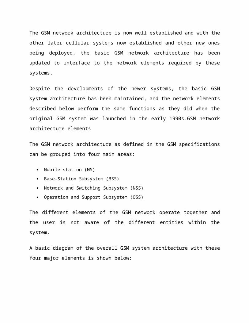
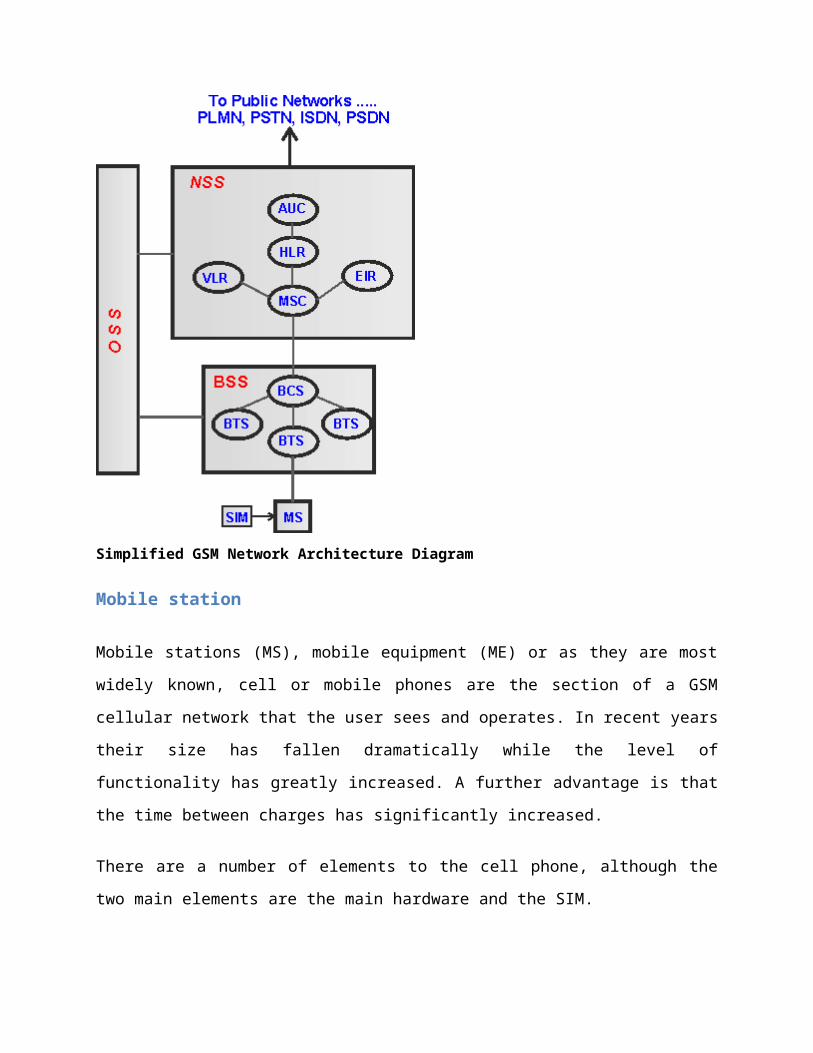
GSM
The GSM technical specifications define the different elements within the GSM network
architecture. It defines the different elements and the ways in which they interact to enable the
overall system operation to be maintained.
The GSM network architecture is now well established and with the other later cellular systems
now established and other new ones being deployed, the basic GSM network architecture has
been updated to interface to the network elements required by these systems.
Despite the developments of the newer systems, the basic GSM system architecture has been
maintained, and the network elements described below perform the same functions as they did
when the original GSM system was launched in the early 1990s.GSM network architecture
elements
The GSM network architecture as defined in the GSM specifications can be grouped into four
main areas:
Mobile station (MS)
Base-Station Subsystem (BSS)
Network and Switching Subsystem (NSS)
Operation and Support Subsystem (OSS)
The different elements of the GSM network operate together and the user is not aware of the
different entities within the system.

A basic diagram of the overall GSM system architecture with these four major elements is shown
below:
Simplified GSM Network Architecture Diagram
Mobile station
Mobile stations (MS), mobile equipment (ME) or as they are most widely known, cell or mobile
phones are the section of a GSM cellular network that the user sees and operates. In recent years
their size has fallen dramatically while the level of functionality has greatly increased. A further
advantage is that the time between charges has significantly increased.
There are a number of elements to the cell phone, although the two main elements are the main
hardware and the SIM.
The hardware itself contains the main elements of the mobile phone including the display, case,
battery, and the electronics used to generate the signal, and process the data receiver and to be
transmitted. It also contains a number known as the International Mobile Equipment Identity
(IMEI). This is installed in the phone at manufacture and "cannot" be changed. It is accessed by
the network during registration to check whether the equipment has been reported as stolen.
The SIM or Subscriber Identity Module contains the information that provides the identity of the
user to the network. It contains are variety of information including a number known as the
International Mobile Subscriber Identity (IMSI).
Base Station Subsystem (BSS)
The Base Station Subsystem (BSS) section of the GSM network architecture that is
fundamentally associated with communicating with the mobiles on the network. It consists of
two elements:
Base Transceiver Station (BTS): The BTS used in a GSM network comprises the radio
transmitter receivers, and their associated antennas that transmit and receive to directly
communicate with the mobiles. The BTS is the defining element for each cell. The BTS
communicates with the mobiles and the interface between the two is known as the Um
interface with its associated protocols.
Base Station Controller (BSC): The BSC forms the next stage back into the GSM network. It
controls a group of BTSs, and is often co-located with one of the BTSs in its group. It manages
the radio resources and controls items such as handover within the group of BTSs, allocates
channels and the like. It communicates with the BTSs over what is termed the Abis interface.
Network Switching Subsystem (NSS)
The GSM system architecture contains a variety of different elements, and is often termed the
core network. It provides the main control and interfacing for the whole mobile network. The
major elements within the core network include:
Mobile Switching services Centre (MSC): The main element within the core network area of
the overall GSM network architecture is the Mobile switching Services Centre (MSC). The MSC
acts like a normal switching node within a PSTN or ISDN, but also provides additional
functionality to enable the requirements of a mobile user to be supported. These include
registration, authentication, call location, inter-MSC handovers and call routing to a mobile
subscriber. It also provides an interface to the PSTN so that calls can be routed from the mobile
network to a phone connected to a landline. Interfaces to other MSCs are provided to enable
calls to be made to mobiles on different networks.
Home Location Register (HLR): This database contains all the administrative information about
each subscriber along with their last known location. In this way, the GSM network is able to
route calls to the relevant base station for the MS. When a user switches on their phone, the
phone registers with the network and from this it is possible to determine which BTS it
communicates with so that incoming calls can be routed appropriately. Even when the phone is
not active (but switched on) it re-registers periodically to ensure that the network (HLR) is aware
of its latest position. There is one HLR per network, although it may be distributed across various
sub-centres to for operational reasons.
Visitor Location Register (VLR): This contains selected information from the HLR that enables
the selected services for the individual subscriber to be provided. The VLR can be implemented
as a separate entity, but it is commonly realised as an integral part of the MSC, rather than a
separate entity. In this way access is made faster and more convenient.
Equipment Identity Register (EIR): The EIR is the entity that decides whether a given mobile
equipment may be allowed onto the network. Each mobile equipment has a number known as
the International Mobile Equipment Identity. This number, as mentioned above, is installed in
the equipment and is checked by the network during registration. Dependent upon the
information held in the EIR, the mobile may be allocated one of three states - allowed onto the
network, barred access, or monitored in case its problems.
Authentication Centre (AuC): The AuC is a protected database that contains the secret key also
contained in the user's SIM card. It is used for authentication and for ciphering on the radio
channel.
Gateway Mobile Switching Centre (GMSC): The GMSC is the point to which a ME terminating
call is initially routed, without any knowledge of the MS's location. The GMSC is thus in charge of
obtaining the MSRN (Mobile Station Roaming Number) from the HLR based on the MSISDN

(Mobile Station ISDN number, the "directory number" of a MS) and routing the call to the
correct visited MSC. The "MSC" part of the term GMSC is misleading, since the gateway
operation does not require any linking to an MSC.
SMS Gateway (SMS-G): The SMS-G or SMS gateway is the term that is used to collectively
describe the two Short Message Services Gateways defined in the GSM standards. The two
gateways handle messages directed in different directions. The SMS-GMSC (Short Message
Service Gateway Mobile Switching Centre) is for short messages being sent to an ME. The SMS-
IWMSC (Short Message Service Inter-Working Mobile Switching Centre) is used for short
messages originated with a mobile on that network. The SMS-GMSC role is similar to that of the
GMSC, whereas the SMS-IWMSC provides a fixed access point to the Short Message Service
Centre.
CAN Bus in an Automobile
The Controller Area Network (CAN) is a serial communications protocol which efficiently supports
distributed real time control with a very high level of security. CAN Bus is a vehicle bus standard
designed to allow microcontrollers and devices to communicate with each other within a vehicle.
Its domain of application ranges from high speed networks to low cost multiplex wiring. In automotive
electronics, engine control units, sensors, anti-skid-systems, etc. are connected using CAN with bitrates
up to 1 Mbit/s. At the same time it is cost effective to build into vehicle body electronics, e.g. lamp
clusters electric windows etc. to replace the wiring harness otherwise required.
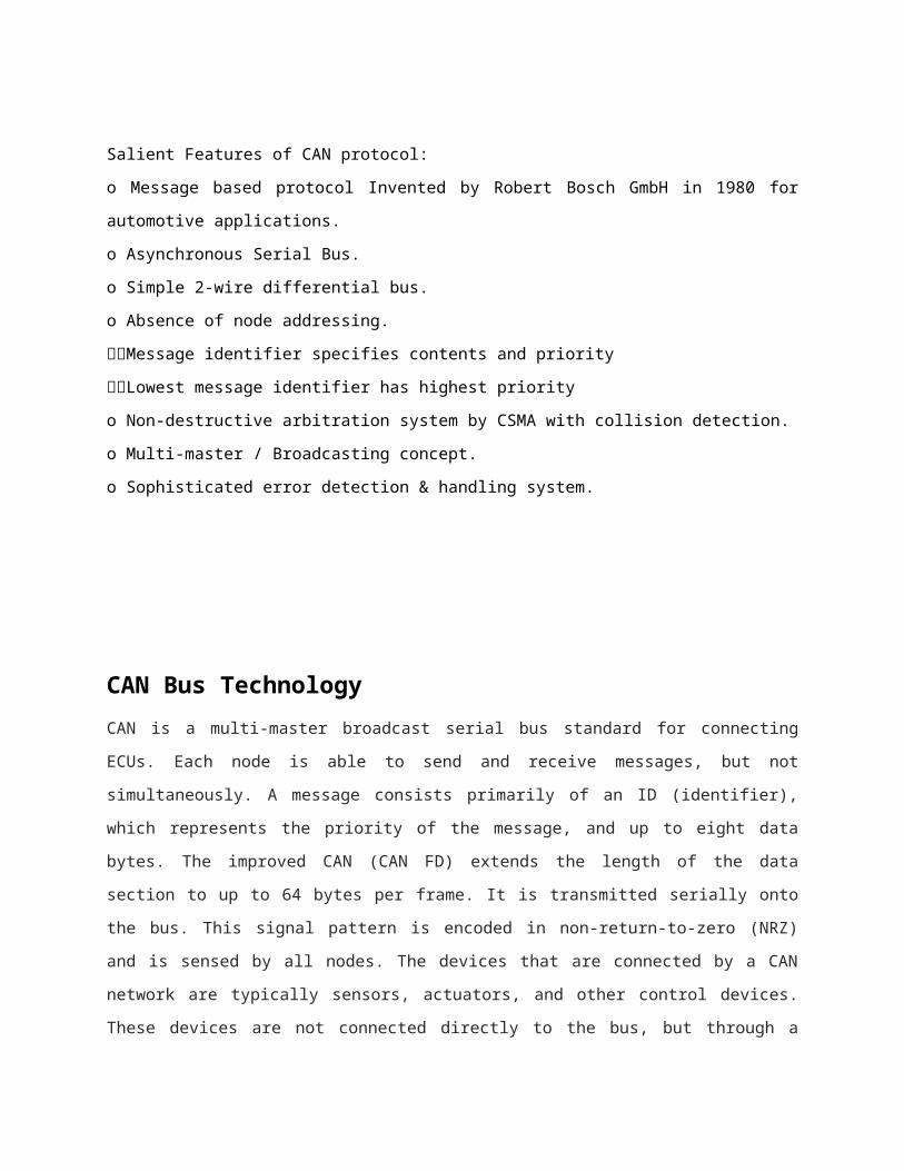
Salient Features of CAN protocol:
o Message based protocol Invented by Robert Bosch GmbH in 1980 for automotive applications.
o Asynchronous Serial Bus.
o Simple 2-wire differential bus.
o Absence of node addressing.
Message identifier specifies contents and priority
Lowest message identifier has highest priority
o Non-destructive arbitration system by CSMA with collision detection.
o Multi-master / Broadcasting concept.
o Sophisticated error detection & handling system.
CAN Bus Technology
CAN is a multi-master broadcast serial bus standard for connecting ECUs. Each node is able to send and
receive messages, but not simultaneously. A message consists primarily of an ID (identifier), which
represents the priority of the message, and up to eight data bytes. The improved CAN (CAN FD) extends
the length of the data section to up to 64 bytes per frame. It is transmitted serially onto the bus. This
signal pattern is encoded in non-return-to-zero (NRZ) and is sensed by all nodes. The devices that are
connected by a CAN network are typically sensors, actuators, and other control devices. These devices
are not connected directly to the bus, but through a host processor and a CAN controller. If the bus is idle
which is represented by recessive level (Logical 1), any node may begin to transmit. If two or more nodes
begin sending messages at the same time, the message with the more dominant ID (which has the higher-
order dominant - i.e., zero bit) will overwrite other nodes' less dominant IDs, so that eventually (after this
arbitration on the ID.) only the dominant message remains and is received by all nodes. This mechanism
is referred to as priority based bus arbitration. Messages with numerically smaller values of IDs have
higher priority and are transmitted first.
CAN Frames
A CAN network can be configured to work with two different message (or "frame") formats: the standard
or base frame format and the only difference between the two formats is that the "CAN base frame"
supports a length of 11 bits for the identifier, and the "CAN extended frame" supports a length of 29 bits
for the identifier All frames begin with a start the frame transmission. A CAN network can be configured
to work with two different message (or "frame") formats: the standard or base frame format and the
extended frame format. All frames begin with a start-of-frame (SOF) bit that denotes the start of CAN
has four frame types:
Data frame: a frame containing node data for transmission
Remote frame: a frame requesting the transmission of a specific identifier
Error frame: a frame transmitted
Overload frame: a frame to inject a delay between data and/or remote frame
Data frame
The data frame is the only frame for actual data transmission. There are two message formats:
Base frame format: with 11 identifier bits
Extended frame format: with 29 identifier bits
The CAN standard requires the implementation must accept the base frame format and may accept the
extended frame format, but must tolerate the extended frame format.
Control Flow at each CAN node:
START
Initialize ADC,CAN controller,ISR.
Is 20ms elapsed Or remote request received?
Read ADC, create message and set up frame ID.
Is transmit buffer full?
YES
NO
YES

NO
CAN Data Transmission:
START
Initialisation of I/O ports
Read Data from sensor
Initialisation of CAN Module
While (1)
Check ifCAN Bus is
Free?
Return Statement
Assign message ID
Transmit data on CAN bus
Delay
STOP
NO
NO
YES
YES
CAN Data Reception:
START
Initialisation of I/O ports
Initialisation of CAN
While (1)
Check ECU1 for
interruptupt
Return Statement
Check ECU2 forinterruptupt
Read ECU1 data
Read ECU2 data
Fan control / Buzzer alert
STOP
YES
NO
Related Documents


![[MS-IPDSP]: InfoPath Digital Signing Protocol Specification · 2016. 5. 11. · The InfoPath Digital Signing Protocol specifies a mechanism by which a protocol client can work with](https://static.cupdf.com/doc/110x72/60bc982249412247a6654853/ms-ipdsp-infopath-digital-signing-protocol-specification-2016-5-11-the-infopath.jpg)
![Testability Protocol and Service Primitives...The testability protocol format is conform to the SOME/IP protocol [1] and can be configured and used with the same. Testability Protocol](https://static.cupdf.com/doc/110x72/5fa40cc056e9c059ca0beb03/testability-protocol-and-service-primitives-the-testability-protocol-format.jpg)