CAN Critical CAN Critical Parameters and Setup Parameters and Setup Considerations for Considerations for Module Level EMC Module Level EMC Testing Testing Jim Lawlis Jim Lawlis Ford Motor Company Ford Motor Company Network Communications Network Communications 1/19/2005 1/19/2005

CAN Critical Parameters and Setup Considerations for Module Level EMC Testing Jim Lawlis Ford Motor Company Network Communications 1/19/2005.
Dec 14, 2015
Welcome message from author
This document is posted to help you gain knowledge. Please leave a comment to let me know what you think about it! Share it to your friends and learn new things together.
Transcript
CAN Critical Parameters CAN Critical Parameters and Setup Considerations and Setup Considerations
for Module Level EMC for Module Level EMC TestingTesting
Jim LawlisJim LawlisFord Motor CompanyFord Motor Company
Network CommunicationsNetwork Communications1/19/20051/19/2005
1/19/20051/19/2005 Jim Lawlis - Ford Motor CompanyJim Lawlis - Ford Motor Company 22
AgendaAgenda CAN Protocol Critical ParametersCAN Protocol Critical Parameters CAN Bit TimingCAN Bit Timing Load Box Termination, CAN OptionsLoad Box Termination, CAN Options Load Box ExperimentLoad Box Experiment Special Considerations for Optical Special Considerations for Optical
RepeatersRepeaters Diagnosing IssuesDiagnosing Issues CAN Emission ReductionCAN Emission Reduction
1/19/20051/19/2005 Jim Lawlis - Ford Motor CompanyJim Lawlis - Ford Motor Company 33
CAN Protocol Critical for CAN Protocol Critical for Communication ParametersCommunication Parameters
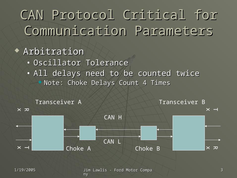
ArbitrationArbitration• Oscillator ToleranceOscillator Tolerance• All delays need to be counted twiceAll delays need to be counted twice
Note: Choke Delays Count 4 TimesNote: Choke Delays Count 4 Times
RxTx
TxRx
CAN H
CAN L
Transceiver A Transceiver B
Choke A Choke B
1/19/20051/19/2005 Jim Lawlis - Ford Motor CompanyJim Lawlis - Ford Motor Company 44
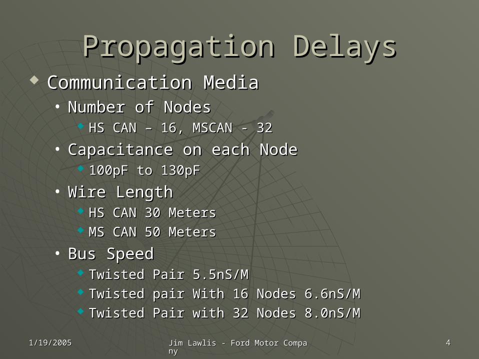
Propagation DelaysPropagation Delays Communication MediaCommunication Media
• Number of Nodes Number of Nodes HS CAN – 16, MSCAN - 32HS CAN – 16, MSCAN - 32
• Capacitance on each NodeCapacitance on each Node 100pF to 130pF100pF to 130pF
• Wire LengthWire Length HS CAN 30 MetersHS CAN 30 Meters MS CAN 50 Meters MS CAN 50 Meters
• Bus SpeedBus Speed Twisted Pair 5.5nS/MTwisted Pair 5.5nS/M Twisted pair With 16 Nodes 6.6nS/MTwisted pair With 16 Nodes 6.6nS/M Twisted Pair with 32 Nodes 8.0nS/MTwisted Pair with 32 Nodes 8.0nS/M
1/19/20051/19/2005 Jim Lawlis - Ford Motor CompanyJim Lawlis - Ford Motor Company 55
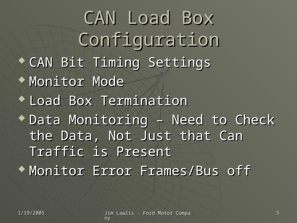
CAN Load Box ConfigurationCAN Load Box Configuration
CAN Bit Timing SettingsCAN Bit Timing Settings Monitor ModeMonitor Mode Load Box TerminationLoad Box Termination Data Monitoring – Need to Check the Data Monitoring – Need to Check the
Data, Not Just that Can Traffic is Data, Not Just that Can Traffic is PresentPresent
Monitor Error Frames/Bus offMonitor Error Frames/Bus off
1/19/20051/19/2005 Jim Lawlis - Ford Motor CompanyJim Lawlis - Ford Motor Company 66
CAN Bit Timing BasicsCAN Bit Timing Basics
The CAN bitThe CAN bit Measuring Total DelaysMeasuring Total Delays J2284 equationsJ2284 equations The Bit Timing SpreadsheetThe Bit Timing Spreadsheet
1/19/20051/19/2005 Jim Lawlis - Ford Motor CompanyJim Lawlis - Ford Motor Company 77
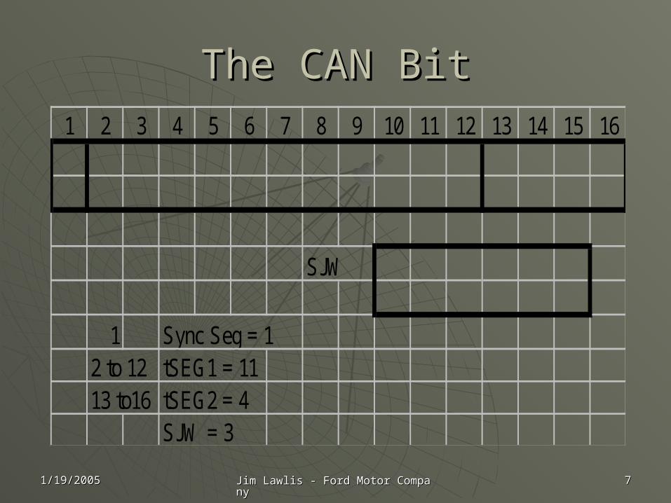
The CAN BitThe CAN Bit1 2 3 4 5 6 7 8 9 10 11 12 13 14 15 16
SJW
1 Sync Seg = 12 to 12 tSEG1 = 1113 to16 tSEG2 = 4
SJW = 3
1/19/20051/19/2005 Jim Lawlis - Ford Motor CompanyJim Lawlis - Ford Motor Company 88
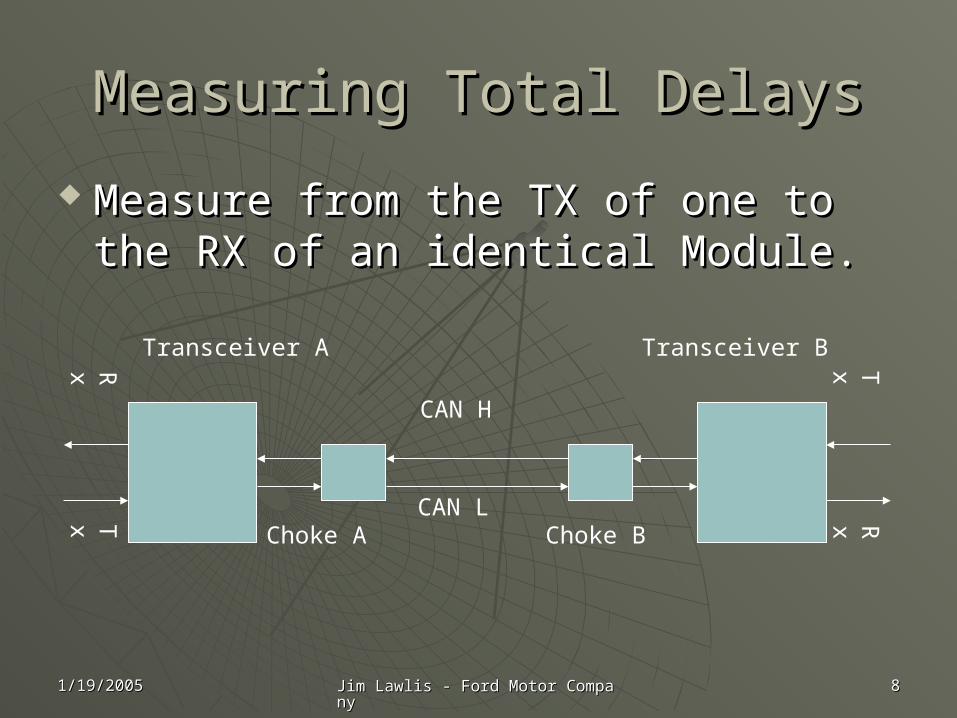
Measuring Total DelaysMeasuring Total Delays
Measure from the TX of one to the Measure from the TX of one to the RX of an identical Module.RX of an identical Module.
RxTx
TxRx
CAN H
CAN L
Transceiver A Transceiver B
Choke A Choke B
1/19/20051/19/2005 Jim Lawlis - Ford Motor CompanyJim Lawlis - Ford Motor Company 99
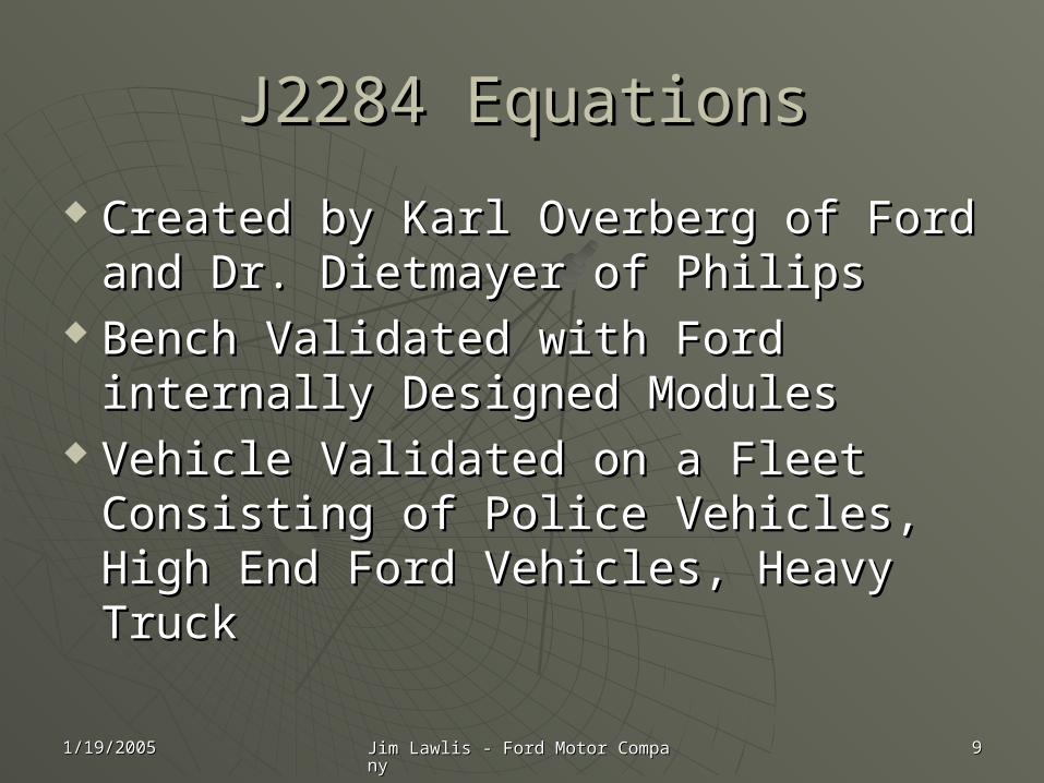
J2284 EquationsJ2284 Equations
Created by Karl Overberg of Ford and Created by Karl Overberg of Ford and Dr. Dietmayer of PhilipsDr. Dietmayer of Philips
Bench Validated with Ford internally Bench Validated with Ford internally Designed ModulesDesigned Modules
Vehicle Validated on a Fleet Vehicle Validated on a Fleet Consisting of Police Vehicles, High Consisting of Police Vehicles, High End Ford Vehicles, Heavy TruckEnd Ford Vehicles, Heavy Truck
1/19/20051/19/2005 Jim Lawlis - Ford Motor CompanyJim Lawlis - Ford Motor Company 1010
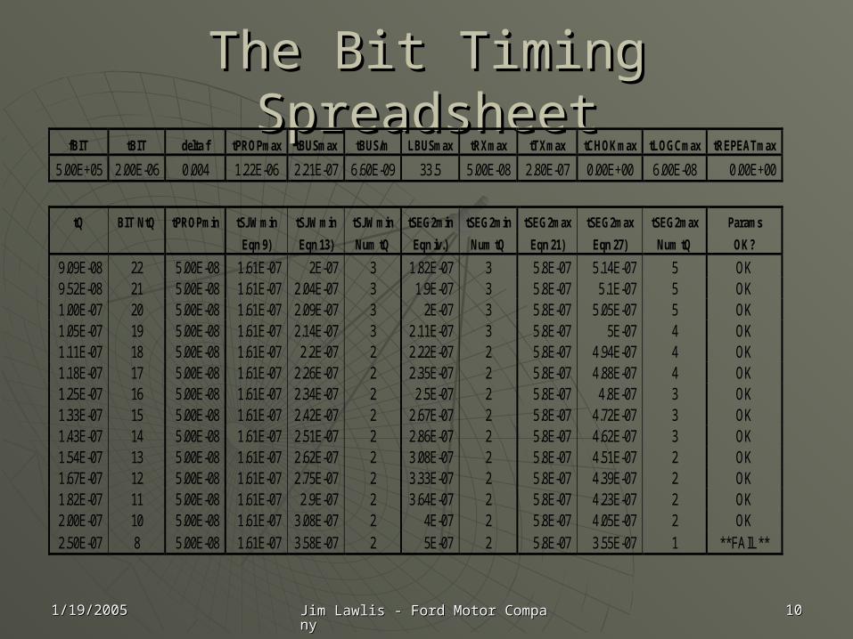
The Bit Timing SpreadsheetThe Bit Timing SpreadsheetfBIT tBIT delta f tPROPmax tBUSmax tBUS/m LBUSmax tRXmax tTXmax tCHOKmax tLOGCmax tREPEATmax
5.00E+05 2.00E-06 0.004 1.22E-06 2.21E-07 6.60E-09 33.5 5.00E-08 2.80E-07 0.00E+00 6.00E-08 0.00E+00
tQ BIT NtQ tPROPmin tSJWmin tSJWmin tSJWmin tSEG2min tSEG2min tSEG2max tSEG2max tSEG2max Params
Eqn 9) Eqn 13) Num tQ Eqn iv.) Num tQ Eqn 21) Eqn 27) Num tQ OK?
9.09E-08 22 5.00E-08 1.61E-07 2E-07 3 1.82E-07 3 5.8E-07 5.14E-07 5 OK 9.52E-08 21 5.00E-08 1.61E-07 2.04E-07 3 1.9E-07 3 5.8E-07 5.1E-07 5 OK 1.00E-07 20 5.00E-08 1.61E-07 2.09E-07 3 2E-07 3 5.8E-07 5.05E-07 5 OK 1.05E-07 19 5.00E-08 1.61E-07 2.14E-07 3 2.11E-07 3 5.8E-07 5E-07 4 OK 1.11E-07 18 5.00E-08 1.61E-07 2.2E-07 2 2.22E-07 2 5.8E-07 4.94E-07 4 OK 1.18E-07 17 5.00E-08 1.61E-07 2.26E-07 2 2.35E-07 2 5.8E-07 4.88E-07 4 OK 1.25E-07 16 5.00E-08 1.61E-07 2.34E-07 2 2.5E-07 2 5.8E-07 4.8E-07 3 OK 1.33E-07 15 5.00E-08 1.61E-07 2.42E-07 2 2.67E-07 2 5.8E-07 4.72E-07 3 OK 1.43E-07 14 5.00E-08 1.61E-07 2.51E-07 2 2.86E-07 2 5.8E-07 4.62E-07 3 OK 1.54E-07 13 5.00E-08 1.61E-07 2.62E-07 2 3.08E-07 2 5.8E-07 4.51E-07 2 OK 1.67E-07 12 5.00E-08 1.61E-07 2.75E-07 2 3.33E-07 2 5.8E-07 4.39E-07 2 OK 1.82E-07 11 5.00E-08 1.61E-07 2.9E-07 2 3.64E-07 2 5.8E-07 4.23E-07 2 OK 2.00E-07 10 5.00E-08 1.61E-07 3.08E-07 2 4E-07 2 5.8E-07 4.05E-07 2 OK 2.50E-07 8 5.00E-08 1.61E-07 3.58E-07 2 5E-07 2 5.8E-07 3.55E-07 1 **FAIL**
1/19/20051/19/2005 Jim Lawlis - Ford Motor CompanyJim Lawlis - Ford Motor Company 1111
CAN Monitor Only Load BoxesCAN Monitor Only Load Boxes
Note: CAN is an all Node ACK or Note: CAN is an all Node ACK or NACK ProtocolNACK Protocol
You may think you are only You may think you are only Monitoring. Unless the tool has a Monitoring. Unless the tool has a Monitor Only Option and it has been Monitor Only Option and it has been Enabled, the load box is Participating Enabled, the load box is Participating in Communication!!!in Communication!!!
1/19/20051/19/2005 Jim Lawlis - Ford Motor CompanyJim Lawlis - Ford Motor Company 1212
Termination MethodsTermination Methods
Termination MethodsTermination Methods• Terminated NodesTerminated Nodes
Standard TerminationStandard Termination Split TerminationSplit Termination
• Test Tool TerminationTest Tool Termination A/C Termination (ISO 15765, Part 4, section A/C Termination (ISO 15765, Part 4, section
9.4.1.3)9.4.1.3)
1/19/20051/19/2005 Jim Lawlis - Ford Motor CompanyJim Lawlis - Ford Motor Company 1313
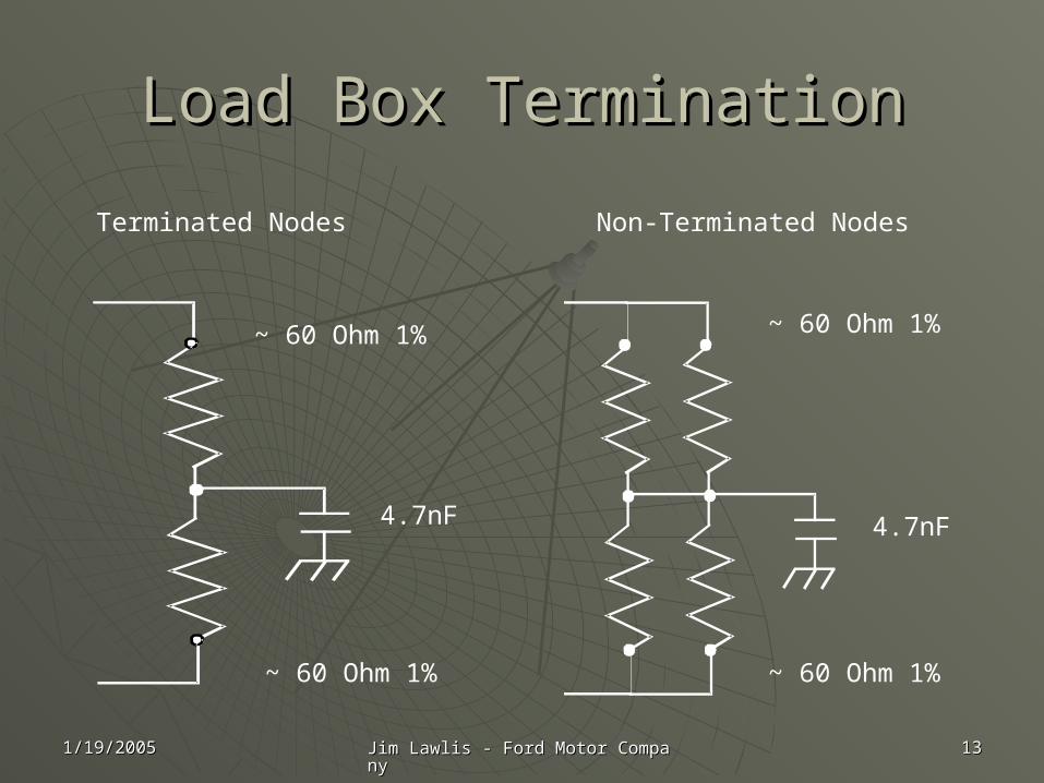
Load Box TerminationLoad Box Termination
Terminated Nodes Non-Terminated Nodes
~ 60 Ohm 1%
~ 60 Ohm 1% ~ 60 Ohm 1%
~ 60 Ohm 1%
4.7nF 4.7nF
1/19/20051/19/2005 Jim Lawlis - Ford Motor CompanyJim Lawlis - Ford Motor Company 1414
Chamber Set-UpChamber Set-Up
Tool is Configured Tool is Configured
Delays Have been identified/CheckedDelays Have been identified/Checked
How do We Connect the Load Box to How do We Connect the Load Box to the set up in the chamber?the set up in the chamber?
1/19/20051/19/2005 Jim Lawlis - Ford Motor CompanyJim Lawlis - Ford Motor Company 1515
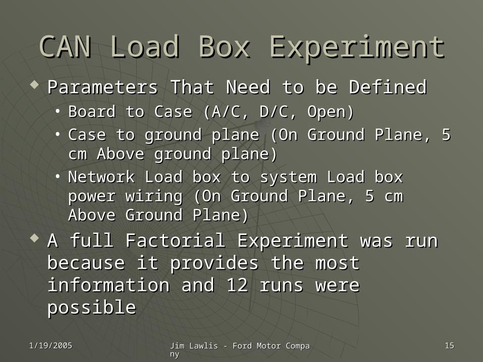
CAN Load Box ExperimentCAN Load Box Experiment Parameters That Need to be DefinedParameters That Need to be Defined
• Board to Case (A/C, D/C, Open)Board to Case (A/C, D/C, Open)• Case to ground plane (On Ground Plane, 5 cm Case to ground plane (On Ground Plane, 5 cm
Above ground plane)Above ground plane)• Network Load box to system Load box power Network Load box to system Load box power
wiring (On Ground Plane, 5 cm Above Ground wiring (On Ground Plane, 5 cm Above Ground Plane)Plane)
A full Factorial Experiment was run A full Factorial Experiment was run because it provides the most information because it provides the most information and 12 runs were possibleand 12 runs were possible
1/19/20051/19/2005 Jim Lawlis - Ford Motor CompanyJim Lawlis - Ford Motor Company 1616
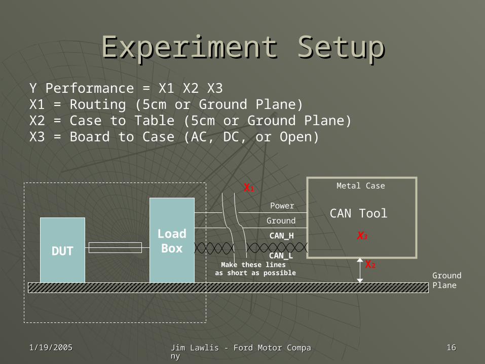
Experiment SetupExperiment SetupY Performance = X1 X2 X3X1 = Routing (5cm or Ground Plane)X2 = Case to Table (5cm or Ground Plane)X3 = Board to Case (AC, DC, or Open)
DUT
LoadBox
Metal Case
X2
GroundPlane
CAN Tool
X3
Power
Ground
CAN_H
CAN_LMake these lines
as short as possible
X1
1/19/20051/19/2005 Jim Lawlis - Ford Motor CompanyJim Lawlis - Ford Motor Company 1717
Experiment AnalysisExperiment Analysis
Previous Experience determined the Previous Experience determined the worst case Load Box Setup noise was worst case Load Box Setup noise was observed in the Vertical BICON 30 to observed in the Vertical BICON 30 to 200Mhz 200Mhz
Area of violations above the limit line Area of violations above the limit line were measured and calculated for were measured and calculated for each testeach test
The Best Performance was IdentifiedThe Best Performance was Identified
1/19/20051/19/2005 Jim Lawlis - Ford Motor CompanyJim Lawlis - Ford Motor Company 1818
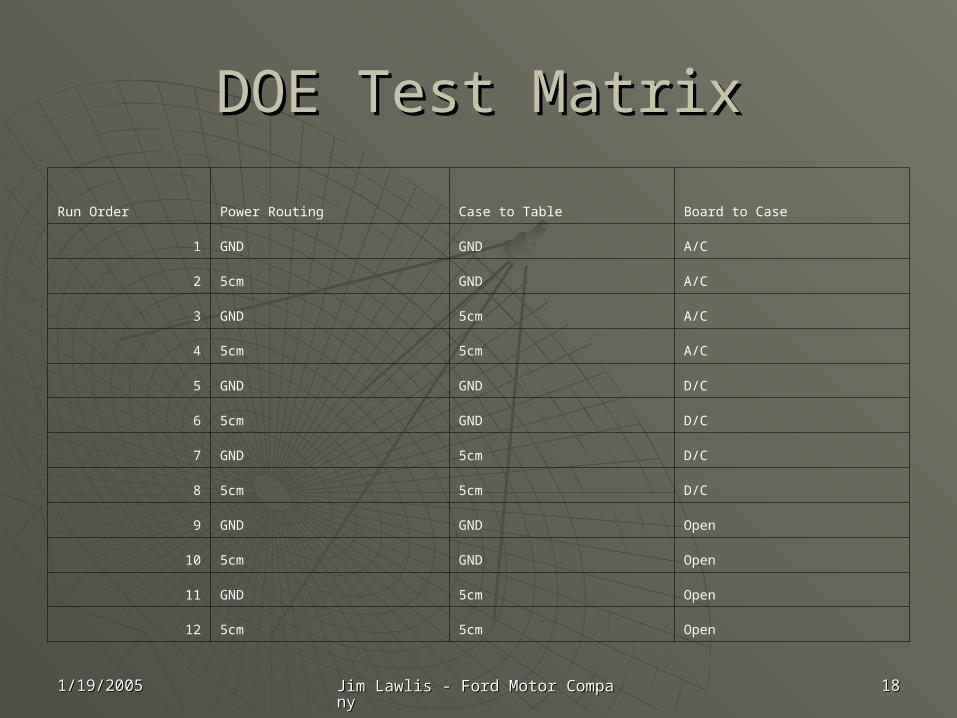
DOE Test MatrixDOE Test Matrix
Run Order Power Routing Case to Table Board to Case
1 GND GND A/C
2 5cm GND A/C
3 GND 5cm A/C
4 5cm 5cm A/C
5 GND GND D/C
6 5cm GND D/C
7 GND 5cm D/C
8 5cm 5cm D/C
9 GND GND Open
10 5cm GND Open
11 GND 5cm Open
12 5cm 5cm Open
1/19/20051/19/2005 Jim Lawlis - Ford Motor CompanyJim Lawlis - Ford Motor Company 1919
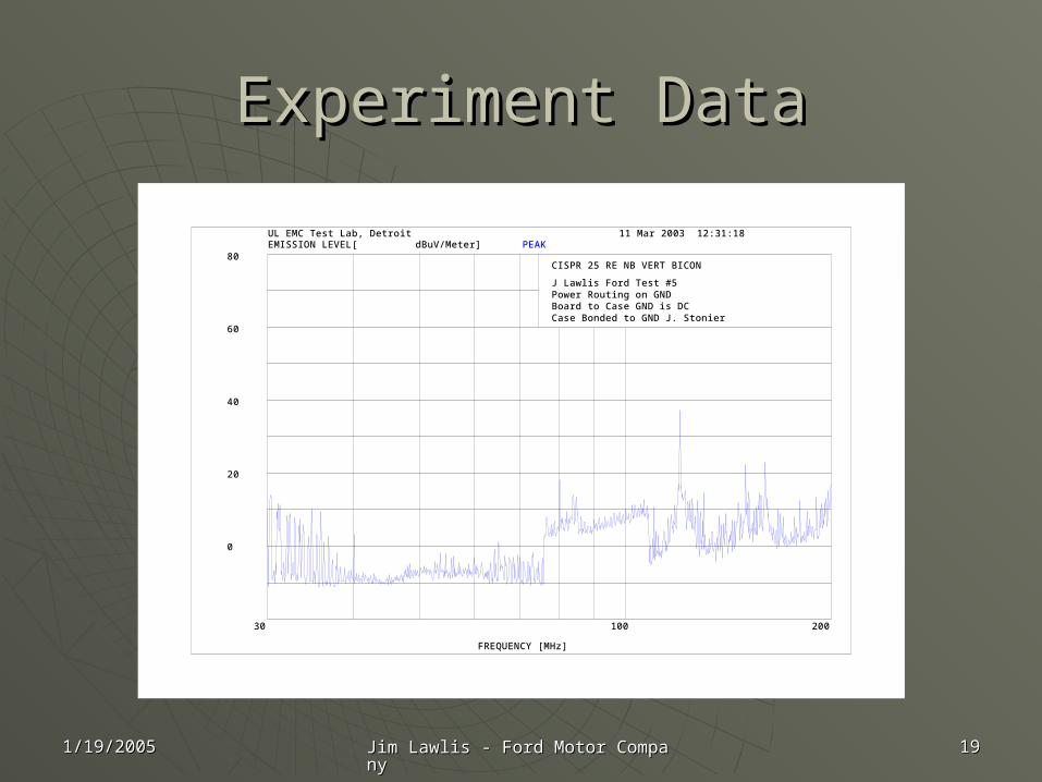
Experiment DataExperiment Data
PEAK
FREQUENCY [MHz]
EMISSION LEVEL[ dBuV/Meter]
30 100 200
0
20
40
60
80CISPR 25 RE NB VERT BICON
J Lawlis Ford Test #5 Power Routing on GND Board to Case GND is DC Case Bonded to GND J. Stonier
11 Mar 2003 12:31:18UL EMC Test Lab, Detroit
1/19/20051/19/2005 Jim Lawlis - Ford Motor CompanyJim Lawlis - Ford Motor Company 2020
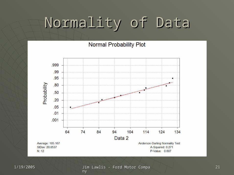
Data Processing Data Processing
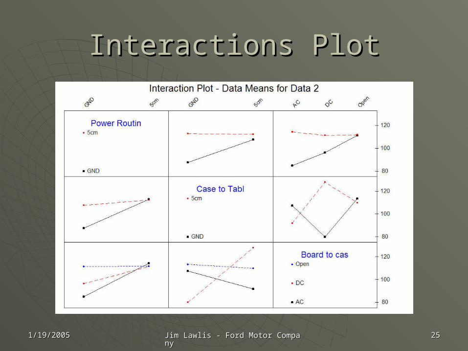
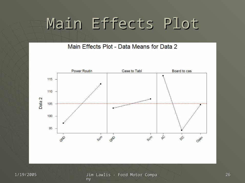
Normality of the Data and ResidualsNormality of the Data and Residuals Minitab DOE AnalysisMinitab DOE Analysis Multi-Variable ChartMulti-Variable Chart Interaction PlotInteraction Plot Main Effects PlotMain Effects Plot
1/19/20051/19/2005 Jim Lawlis - Ford Motor CompanyJim Lawlis - Ford Motor Company 2121
Normality of DataNormality of Data
1/19/20051/19/2005 Jim Lawlis - Ford Motor CompanyJim Lawlis - Ford Motor Company 2222
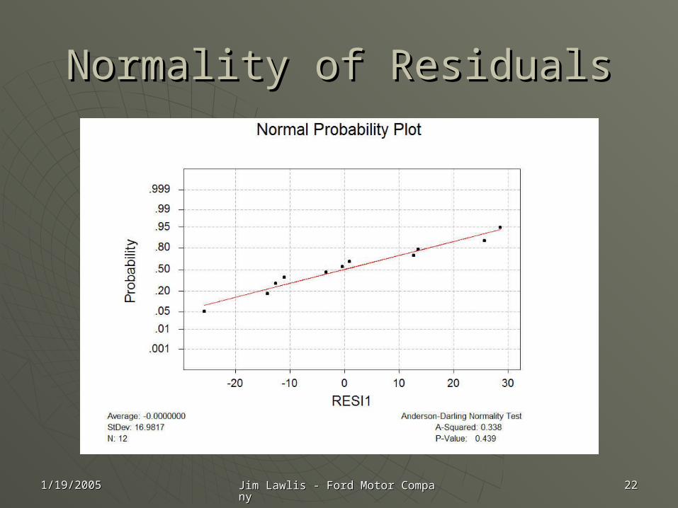
Normality of ResidualsNormality of Residuals
1/19/20051/19/2005 Jim Lawlis - Ford Motor CompanyJim Lawlis - Ford Motor Company 2323
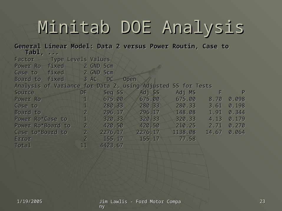
Minitab DOE AnalysisMinitab DOE AnalysisGeneral Linear Model: Data 2 versus Power Routin, Case to Tabl, ...General Linear Model: Data 2 versus Power Routin, Case to Tabl, ...Factor Type Levels Values Factor Type Levels Values Power Ro fixed 2 GND 5cmPower Ro fixed 2 GND 5cmCase to fixed 2 GND 5cmCase to fixed 2 GND 5cmBoard to fixed 3 AC DC OpenBoard to fixed 3 AC DC OpenAnalysis of Variance for Data 2, using Adjusted SS for TestsAnalysis of Variance for Data 2, using Adjusted SS for TestsSource DF Seq SS Adj SS Adj MS F PSource DF Seq SS Adj SS Adj MS F PPower Ro 1 675.00 675.00 675.00 8.70 0.098Power Ro 1 675.00 675.00 675.00 8.70 0.098Case to 1 280.33 280.33 280.33 3.61 0.198Case to 1 280.33 280.33 280.33 3.61 0.198Board to 2 296.17 296.17 148.08 1.91 0.344Board to 2 296.17 296.17 148.08 1.91 0.344Power Ro*Case to 1 320.33 320.33 320.33 4.13 0.179Power Ro*Case to 1 320.33 320.33 320.33 4.13 0.179Power Ro*Board to 2 420.50 420.50 210.25 2.71 0.270Power Ro*Board to 2 420.50 420.50 210.25 2.71 0.270Case to*Board to 2 2276.17 2276.17 1138.08 14.67 0.064Case to*Board to 2 2276.17 2276.17 1138.08 14.67 0.064Error 2 155.17 155.17 77.58Error 2 155.17 155.17 77.58Total 11 4423.67Total 11 4423.67
1/19/20051/19/2005 Jim Lawlis - Ford Motor CompanyJim Lawlis - Ford Motor Company 2424
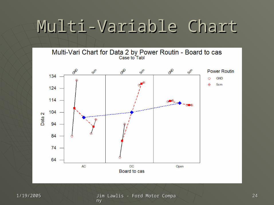
Multi-Variable ChartMulti-Variable Chart
1/19/20051/19/2005 Jim Lawlis - Ford Motor CompanyJim Lawlis - Ford Motor Company 2525
Interactions PlotInteractions Plot
1/19/20051/19/2005 Jim Lawlis - Ford Motor CompanyJim Lawlis - Ford Motor Company 2626
Main Effects PlotMain Effects Plot
1/19/20051/19/2005 Jim Lawlis - Ford Motor CompanyJim Lawlis - Ford Motor Company 2727
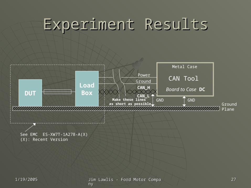
Experiment ResultsExperiment Results
DUTLoadBox
Metal Case
GNDGroundPlane
See EMC ES-XW7T-1A278-A(X)(X): Recent Version
CAN Tool
Board to Case DC
GND
Power
Ground
CAN_H
CAN_LMake these lines
as short as possible
1/19/20051/19/2005 Jim Lawlis - Ford Motor CompanyJim Lawlis - Ford Motor Company 2828
Monitoring CAN through Optical Monitoring CAN through Optical RepeatersRepeaters
The Signal Delay of a Typical Optical The Signal Delay of a Typical Optical Repeater (wire to optical to wire) will Repeater (wire to optical to wire) will be ~300nsbe ~300ns
This does not include the signal delay This does not include the signal delay through the Optical Cable through the Optical Cable ~5.0ns/meter.~5.0ns/meter.
1/19/20051/19/2005 Jim Lawlis - Ford Motor CompanyJim Lawlis - Ford Motor Company 2929
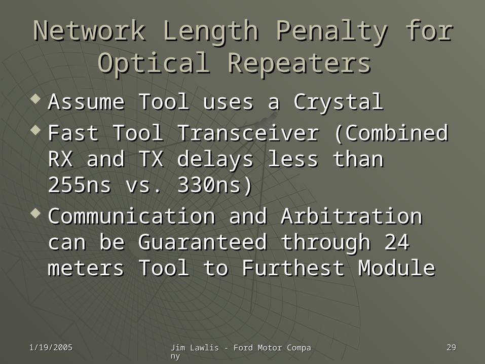
Network Length Penalty for Optical Network Length Penalty for Optical Repeaters Repeaters
Assume Tool uses a CrystalAssume Tool uses a Crystal Fast Tool Transceiver (Combined RX Fast Tool Transceiver (Combined RX
and TX delays less than 255ns vs. and TX delays less than 255ns vs. 330ns)330ns)
Communication and Arbitration can Communication and Arbitration can be Guaranteed through 24 meters be Guaranteed through 24 meters Tool to Furthest ModuleTool to Furthest Module
1/19/20051/19/2005 Jim Lawlis - Ford Motor CompanyJim Lawlis - Ford Motor Company 3030
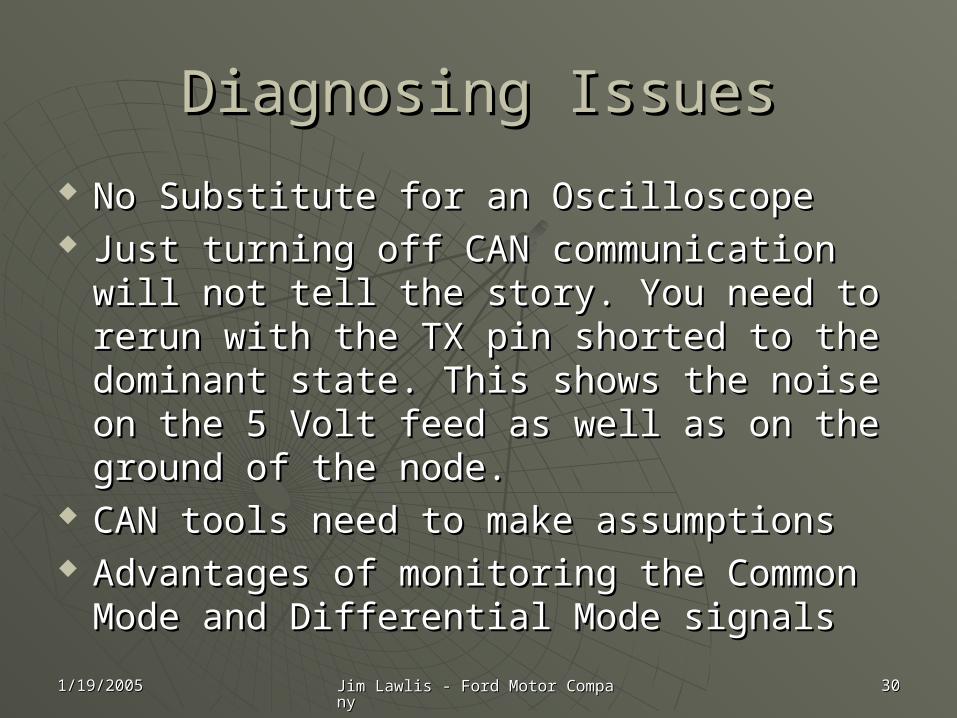
Diagnosing IssuesDiagnosing Issues
No Substitute for an OscilloscopeNo Substitute for an Oscilloscope Just turning off CAN communication will Just turning off CAN communication will
not tell the story. You need to rerun with not tell the story. You need to rerun with the TX pin shorted to the dominant state. the TX pin shorted to the dominant state. This shows the noise on the 5 Volt feed as This shows the noise on the 5 Volt feed as well as on the ground of the node.well as on the ground of the node.
CAN tools need to make assumptionsCAN tools need to make assumptions Advantages of monitoring the Common Advantages of monitoring the Common
Mode and Differential Mode signalsMode and Differential Mode signals
1/19/20051/19/2005 Jim Lawlis - Ford Motor CompanyJim Lawlis - Ford Motor Company 3131
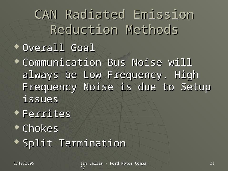
CAN Radiated Emission Reduction CAN Radiated Emission Reduction MethodsMethods
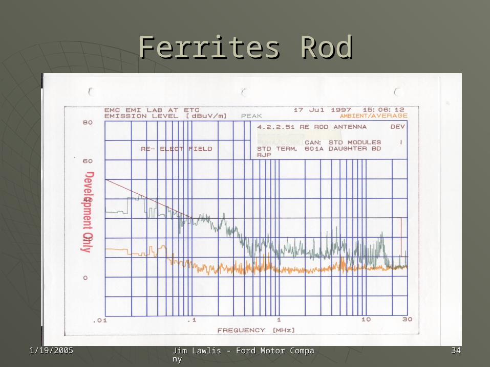
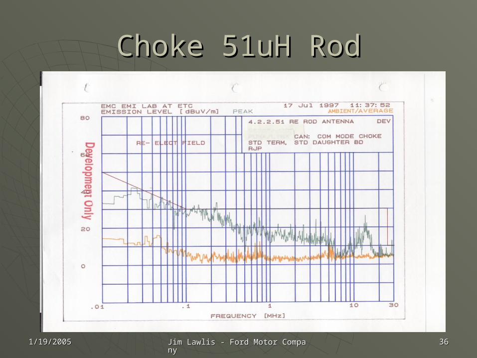
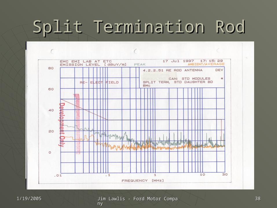
Overall GoalOverall Goal Communication Bus Noise will always Communication Bus Noise will always
be Low Frequency. High Frequency be Low Frequency. High Frequency Noise is due to Setup issuesNoise is due to Setup issues
Ferrites Ferrites ChokesChokes Split TerminationSplit Termination
1/19/20051/19/2005 Jim Lawlis - Ford Motor CompanyJim Lawlis - Ford Motor Company 3232
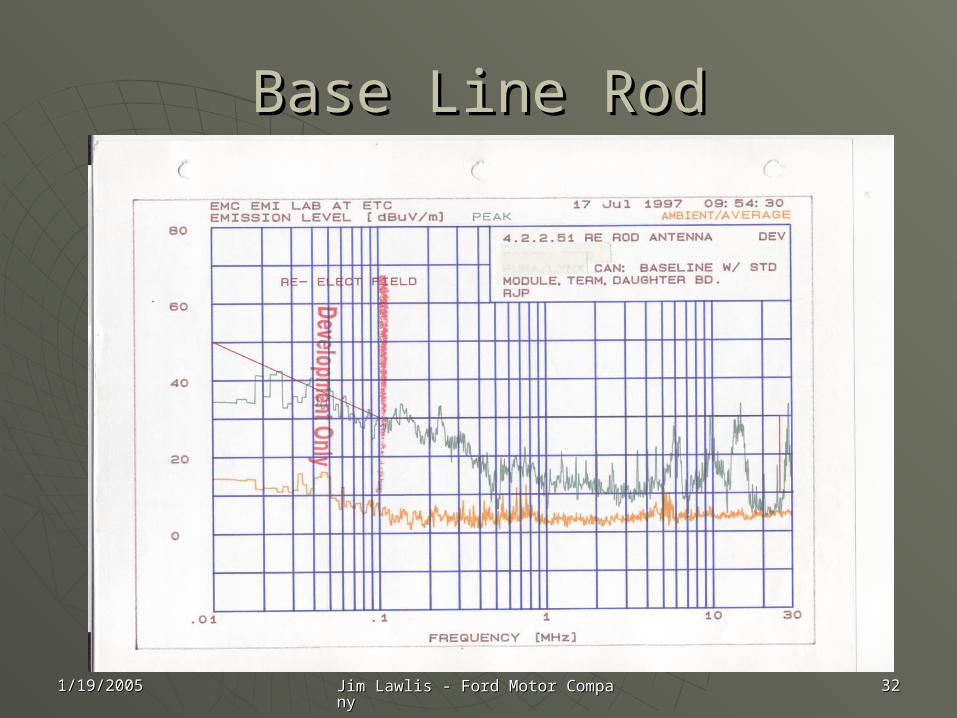
Base Line RodBase Line Rod
1/19/20051/19/2005 Jim Lawlis - Ford Motor CompanyJim Lawlis - Ford Motor Company 3434
Ferrites RodFerrites Rod
1/19/20051/19/2005 Jim Lawlis - Ford Motor CompanyJim Lawlis - Ford Motor Company 3636
Choke 51uH RodChoke 51uH Rod
1/19/20051/19/2005 Jim Lawlis - Ford Motor CompanyJim Lawlis - Ford Motor Company 3838
Split Termination RodSplit Termination Rod
Related Documents