This is a preprint of a paper intended for publication in a journal or proceedings. Since changes may be made before publication, this preprint should not be cited or reproduced without permission of the author. This document was prepared as an account of work sponsored by an agency of the United States Government. Neither the United States Government nor any agency thereof, or any of their employees, makes any warranty, expressed or implied, or assumes any legal liability or responsibility for any third party’s use, or the results of such use, of any information, apparatus, product or process disclosed in this report, or represents that its use by such third party would not infringe privately owned rights. The views expressed in this paper are not necessarily those of the United States Government or the sponsoring agency. INL/CON-16-37908 PREPRINT Cyber Security Research and Development – CAN Bus Security Research Across Multiple Sectors ESCAR USA Conference 2016 Jonathan Chugg, Reston Condit, Ashley Keith, Kenneth Rohde, Bryce Wheeler May 2016

Welcome message from author
This document is posted to help you gain knowledge. Please leave a comment to let me know what you think about it! Share it to your friends and learn new things together.
Transcript
This is a preprint of a paper intended for publication in a journal or proceedings. Since changes may be made before publication, this preprint should not be cited or reproduced without permission of the author. This document was prepared as an account of work sponsored by an agency of the United States Government. Neither the United States Government nor any agency thereof, or any of their employees, makes any warranty, expressed or implied, or assumes any legal liability or responsibility for any third party’s use, or the results of such use, of any information, apparatus, product or process disclosed in this report, or represents that its use by such third party would not infringe privately owned rights. The views expressed in this paper are not necessarily those of the United States Government or the sponsoring agency.
INL/CON-16-37908 PREPRINT
Cyber Security Research and Development – CAN Bus Security Research Across Multiple Sectors ESCAR USA Conference 2016
Jonathan Chugg, Reston Condit, Ashley Keith, Kenneth Rohde, Bryce Wheeler
May 2016

INL/CON-16-37908
Cyber Security Research and Development
CAN Bus Security Research Across Multiple Sectors
May 2016
Research Team
Jonathan Chugg
Reston Condit
Ashley Keith
Kenneth Rohde
Bryce Wheeler
2
Table of Contents
Introduction ......................................................................................................................................................................................... 4
Laboratory Space and Capabilities Development (Year 1 - FY2014) .............................................................................. 4
Vehicle on Board ........................................................................................................................................................................... 4
Protocol Fuzzing ............................................................................................................................................................................................ 5
Message Spoofing.......................................................................................................................................................................................... 6
Denial of Service ............................................................................................................................................................................................ 7
Message Protections .................................................................................................................................................................................... 8
Message Decoding ........................................................................................................................................................................................ 8
Open Source Information ......................................................................................................................................................... 10
Service Manuals ........................................................................................................................................................................................... 11
Standard Diagnostic Tools ...................................................................................................................................................................... 11
Advanced Diagnostics and Flashing .................................................................................................................................................... 13
Open Source on the Internet .................................................................................................................................................................. 14
Vehicle Procurement ................................................................................................................................................................. 14
Network Fingerprinting ............................................................................................................................................................ 14
Remote (Wireless) Connectivity ............................................................................................................................................ 14
Tire Pressure Monitoring ........................................................................................................................................................................ 15
External CAN Connections (Physical) .................................................................................................................................. 15
Hardware and Software Testing (Year 2 - FY2015) ............................................................................................................ 16
Hardware Disassembly and Reverse Engineering .......................................................................................................... 16
Telematics ...................................................................................................................................................................................................... 16
CAN Bus Gateways...................................................................................................................................................................................... 19
Firmware Reflashing ................................................................................................................................................................. 19
Firmware Located in Temporary Files .............................................................................................................................................. 19
Firmware Recorded in Transit .............................................................................................................................................................. 19
Electric Vehicle Research ......................................................................................................................................................... 20
Electric Vehicle Supply Equipment (EVSE) ...................................................................................................................................... 20
Plug-in Electric Vehicle Procurement .................................................................................................................................. 21
European Plug-in Electric Vehicle Assessment ................................................................................................................ 21
Vehicle to Infrastructure Communications (Year 3 - FY2016) ........................................................................................ 21
DC Fast Charger Procurement ................................................................................................................................................ 22
DCFC Internal Use of CAN Bus ............................................................................................................................................................... 28
Exploit Scenario Implementation ........................................................................................................................................................ 29
Vehicle Comparison Matrices ...................................................................................................................................................... 29
General Mitigations ......................................................................................................................................................................... 30
Conclusion .......................................................................................................................................................................................... 30
3
List of Figures
Figure 1: Salvaged 2012 American Sedan ..................................................................................................................................................... 5
Figure 2: PCAN Symbol Editor Example CAN Message Decoding ....................................................................................................... 9
Figure 3: Example Usage of PCAN-Explorer 5 ........................................................................................................................................... 10
Figure 4: Sparkfun ELM327 Kit ....................................................................................................................................................................... 11
Figure 5: Example CAN Architecture With Diagnostic Connections ................................................................................................ 12
Figure 6: Bosch Enhanced ODB Tool ............................................................................................................................................................. 13
Figure 7: GNU Octave Plot of TPMS Data ..................................................................................................................................................... 15
Figure 8: BeagleBone Black Connected to CAN Under Rear Bumper .............................................................................................. 16
Figure 9: Wireshark Capture of Firmware Upload .................................................................................................................................. 20
Figure 10: General Smart Grid EVSE Architecture .................................................................................................................................. 21
Figure 11: DCFC Block Diagram and Example Usage ............................................................................................................................. 22
Figure 12: Malware Infected Charging Infrastructure ........................................................................................................................... 23
Figure 13: Hypothetical DCFC Exploitation Scenario ............................................................................................................................. 24
Figure 14: DCFC Local Server Running in VMware Workstation ...................................................................................................... 26
Figure 15: CAN Bus Interfaces to Connect the Local Server to Vehicle Controller Virtual Machines ................................ 27
Figure 16: Simulated Vehicle Controllers in a Virtual Machine ......................................................................................................... 28
4
Introduction The Idaho National Laboratory (INL) allocated 3 years of internal funds, known as Laboratory Directed Research
and Development (LDRD) funds, to evaluate the cyber security of CAN Bus networks and how they are used and
implemented in a variety of critical infrastructure sectors. This research was performed to leverage the existing
cyber security expertise at INL and allow researchers to explore a control system protocol not yet researched by
INL.
Officially organized in 1991, the LDRD program serves a number of important purposes. It enables high risk R&D at
Department of Energy (DOE) laboratories in areas of potential value to national R&D programs. Its flexibility
allows the laboratories to assemble experts from different fields into teams whose collaboration uncovers
synergies and multidisciplinary solutions not otherwise evident without the freedom to reach across traditional
technical boundaries. In addition, LDRD serves as a proving ground for advanced R&D concepts that are often
subsequently pursued by DOE programs and, at the same time, helps the government identify more creative
approaches to fulfilling future mission needs.1
The ultimate goal of this project was to determine what types of vulnerabilities exist and how susceptible the CAN
protocol is to a variety of attacks. This paper will detail the general findings of the research team while performing
security assessments of 3 different vehicles: (1) a conventional domestic passenger vehicle, (2) a Plug-in Electric
Vehicle (PEV) from an Asian auto manufacturer, and (3) a PEV from a European manufacturer. A contrast of these
vehicles and how CAN was implemented, what capabilities were available via CAN, and an overview of the level of
complexity and difficulty of compromise will be summarized.
The most recent research is focusing on the integration of electric vehicles with the Energy Sector. Many
government departments and agencies are rapidly adopting PEVs in an effort to reduce emissions. The general
public is starting to embrace electric vehicles thus requiring more infrastructure development to support these
new vehicles’ energy demands. Much of this adoption has happened before any analysis of cyber security
vulnerabilities has been performed. Leveraging this LDRD and INL’s experience with energy and grid security, the
team performed assessments of Electric Vehicle Supply Equipment (EVSE) and their connectivity to critical
infrastructure. An overview of the findings from assessing several different charging stations, including one DC
Level 2 Fast Charger (DCFC), will detail the potential risks posed by integrating PEVs into the energy
infrastructure.
Laboratory Space and Capabilities Development (Year 1 - FY2014) The first year of research was spent developing basic capabilities for CAN Bus research. The automotive sector
was selected due to the wide spread use of CAN as well as the relatively inexpensive equipment produced for the
auto industry. Physical space at INL was allocated for this research project and the team began some basic
research of CAN and the procurement of commercial tools and software.
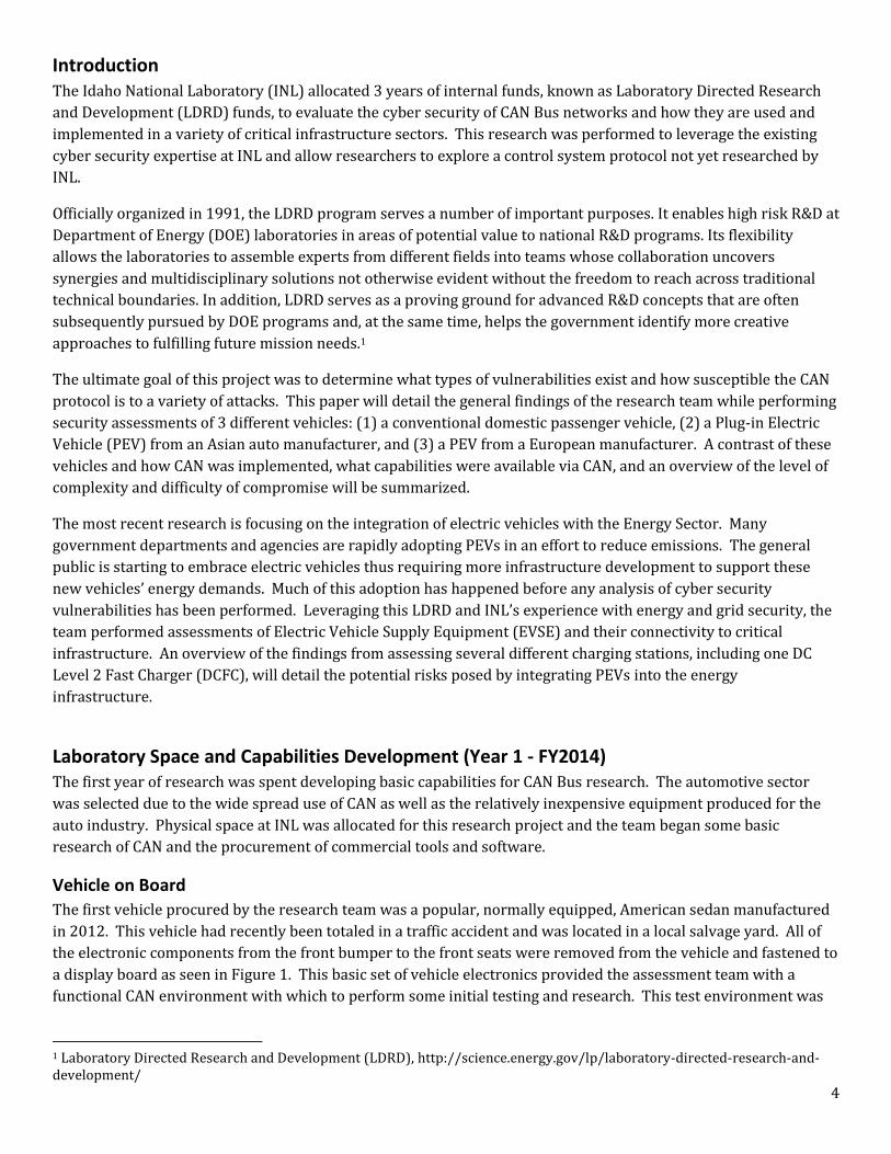
Vehicle on Board
The first vehicle procured by the research team was a popular, normally equipped, American sedan manufactured
in 2012. This vehicle had recently been totaled in a traffic accident and was located in a local salvage yard. All of
the electronic components from the front bumper to the front seats were removed from the vehicle and fastened to
a display board as seen in Figure 1. This basic set of vehicle electronics provided the assessment team with a
functional CAN environment with which to perform some initial testing and research. This test environment was
1 Laboratory Directed Research and Development (LDRD), http://science.energy.gov/lp/laboratory-directed-research-and-development/
5
not only extremely useful during the initial months of this project but has continued to be used even through the
third year of work.
Figure 1: Salvaged 2012 American Sedan
Protocol Fuzzing
Once the salvaged vehicle was operational on the display board, the research team developed some basic protocol
fuzzing2 code for the CAN Bus messages observed on the vehicle. Fuzzing is a methodology used to test inputs into
a program. Using the fuzzing technique, the team tested inputs in the identifier and data sections of the CAN
message protocols. This effort resulted in the identification of a few message IDs that generated obvious physical
reactions in the system (e.g. horn honking, door locks, etc.). The most notable finding that came from the fuzz
testing is that the newly found message IDs were never observed on the CAN Bus during normal operations. The
research team also monitored several other vehicles from the same manufacturer (personal vehicles, rental cars,
etc.) and never saw these new message IDs in use.
One hypothesis regarding these “hidden” or “undocumented” CAN IDs is that they are old or legacy IDs that are no
longer used in production. The modules responding to these messages are likely still running older code that has
implemented responses to these messages. Another reasonable assumption is that these message IDs are only
used for diagnostics, telematics, or final testing and would not be seen on the CAN Bus during normal driving
conditions. Further more, these discovered IDs might be processed because they are similar enough to other
“normal” IDs and the receiving ECU is handling all messages that meet a certain bit or byte mask scheme (i.e.
similar to multicast addressing in Ethernet networks).
2 Fuzz Testing or Fuzzing, https://www.owasp.org/index.php/Fuzzing
6
Fuzz testing is a tedious and time intensive task that can be fruitful, but it is difficult to fully determine what tests
are actually successful. For example, in this case it was obvious when a valid message was found because the horn
honked. At other times the responses were less obvious such as turning on an indicator lamp on the dashboard.
Some responses could be near impossible to detect when the effect is internal to a control unit and there is no
physical indication. Because of the difficulties associated with fuzzing, the test team didn’t spend a great deal of
time doing so, but rather used the successes as evidence that it is still a valid assessment technique.
Message Spoofing
Monitoring a CAN Bus for valid messages is one of the easiest methods for finding messages that may invoke a
desired response. This was, however, not a simple task due to the amount of traffic found on a high-speed bus.
Using commercial and open-source tools for watching CAN traffic helped identify desired CAN messages more
quickly, but the team still needed to develop some custom software to better categorize the traffic. More details
regarding this software is found in the Network Fingerprinting section of this report.
Once a message was identified, it was generally easy to send that message to invoke the desired response (e.g.,
rolling up a window). There are times, however, that sending these messages (i.e., spoofed because they are being
sent by a research laptop rather than a valid Electronic Control Unit [ECU]) is very difficult. This includes
attempting to send a message that is already being sent by an ECU at a rapid rate, such as updating the
instrumentation with the engine RPM. The spoofed messages are then competing with the valid ECU messages and
can thus cause some less effective responses.
Message spoofing was also difficult at times simply due to bus load or utilization. A heavily saturated bus leaves
little bandwidth for the research team to inject competing messages. In these instances the bus either entered a
fault state, or the spoofed messages were sent so infrequently that the desired action was unpredictable and/or
unreliable. However, in some cases higher priority message IDs were able to be injected into a heavily saturated
bus if a number of the existing message were a lower priority, e.g., extended frame IDs. The physical
implementation of CAN3 is beyond the scope of this report, but due to the method in which devices compete for bus
arbitration, it is possible to inject lower IDs (high priority) into a heavily utilized bus that contains extended (lower
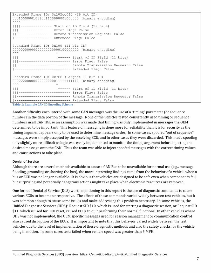
priority) IDs. A good illustration of this is found in Table 1 where two message IDs encodings are depicted. Due to
ID 0x100 containing more leading zeros than ID 0x102cc040, the 0x100 message will win arbitration before the
device writing the 0x102cc040 message.
3 CAN frame format overview, https://en.wikipedia.org/wiki/CAN_bus#Frames
7
Extended Frame ID: 0x102cc040 (29 bit ID)
00010000001011001100000001000000 (binary encoding)
^^^^
||||--------------- Start of ID Field (29 bits)
|||---------------- Error Flag: False
||----------------- Remote Transmission Request: False
|------------------ Extended Flag: False
Standard Frame ID: 0x100 (11 bit ID)
00000000000000000000000100000000 (binary encoding)
^^^ ^
||| |------ Start of ID Field (11 bits)
|||------------------------- Error Flag: False
||-------------------------- Remote Transmission Request: False
|--------------------------- Extended Flag: False
Standard Frame ID: 0x7FF (Largest 11 bit ID)
00000000000000000000011111111111 (binary encoding)
^^^ ^
||| |------ Start of ID Field (11 bits)
|||------------------------- Error Flag: False
||-------------------------- Remote Transmission Request: False
|--------------------------- Extended Flag: False
Table 1: Example CAN ID Encoding Scheme
Another difficulty encountered with some CAN messages was the use of a “timing” parameter (or sequence
number) in the data portion of the message. None of the vehicles tested consistently used timing or sequence
numbers in all CAN IDs, so an assumption was made that timing was only implemented in messages the OEM
determined to be important. This feature of messaging is done more for reliability than it is for security as the
timing argument appears only to be used to determine message order. In some cases, spoofed “out of sequence”
messages were simply accepted by the receiving ECU, and in other cases they were discarded. This made spoofing
only slightly more difficult as logic was easily implemented to monitor the timing argument before injecting the
desired message onto the CAN. Thus the team was able to inject spoofed messages with the correct timing values
and cause actions to take place.
Denial of Service
Although there are several methods available to cause a CAN Bus to be unavailable for normal use (e.g., message
flooding, grounding or shorting the bus), the more interesting findings came from the behavior of a vehicle when a
bus or ECU was no longer available. It is obvious that vehicles are designed to be safe even when components fail,
but surprising and potentially dangerous actions might take place when electronic resources are removed.
One form of Denial of Service (DoS) worth mentioning in this report is the use of diagnostic commands to cause
various ECUs to become unresponsive. The effects of these commands varied widely between test vehicles, but it
was common enough to cause some issues and make addressing this problem necessary. In some vehicles, the
Unified Diagnostic Services (UDS)4 Request SID $10, which is used for starting a diagnostic session, or Request SID
$11, which is used for ECU reset, caused ECUs to quit performing their normal functions. In other vehicles where
UDS was not implemented, the OEM specific messages used for session management or communication control
also caused disruption of the ECUs. It is important to note that this behavior varied widely between the test
vehicles due to the level of implementation of these diagnostic methods and also the safety checks for the vehicle
being in motion. In some cases tests failed when vehicle speed was greater than 5 MPH.
4 Unified Diagnostic Services (UDS) overview, https://en.wikipedia.org/wiki/Unified_Diagnostic_Services
8
Message Protections
In some instances it was observed that CAN messages appeared to be random in their data content. As the
research toolsets matured, it was evident that the data was not random but simply used a few bytes in the data
portion of the message for a checksum or CRC. The use of CRCs or checksums is a method for ensuring message
integrity and is not considered a method for implementing security. Similar in nature to adding a timing or
checksum parameter to a message, CRCs and checksums can be monitored and decoded.
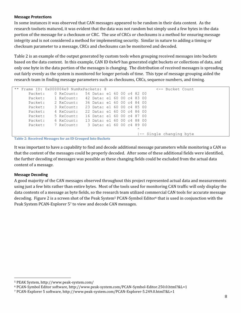
Table 2 is an example of the output generated by custom tools when grouping received messages into buckets
based on the data content. In this example, CAN ID 0x4e9 has generated eight buckets or collections of data, and
only one byte in the data portion of the messages is changing. The distribution of received messages is spreading
out fairly evenly as the system is monitored for longer periods of time. This type of message grouping aided the
research team in finding message parameters such as checksums, CRCs, sequence numbers, and timing.
** Frame ID: 0x000004e9 NumRxPackets: 8 <-- Bucket Count
Packet: 0 RxCount: 54 Data: e1 60 00 c4 82 00
Packet: 1 RxCount: 42 Data: e1 60 00 c4 83 00
Packet: 2 RxCount: 36 Data: e1 60 00 c4 84 00
Packet: 3 RxCount: 23 Data: e1 60 00 c4 85 00
Packet: 4 RxCount: 22 Data: e1 60 00 c4 86 00
Packet: 5 RxCount: 16 Data: e1 60 00 c4 87 00
Packet: 6 RxCount: 13 Data: e1 60 00 c4 88 00
Packet: 7 RxCount: 3 Data: e1 60 00 c4 89 00
^
|-- Single changing byte
Table 2: Received Messages for an ID Grouped Into Buckets
It was important to have a capability to find and decode additional message parameters while monitoring a CAN so
that the content of the messages could be properly decoded. After some of these additional fields were identified,
the further decoding of messages was possible as these changing fields could be excluded from the actual data
content of a message.
Message Decoding
A good majority of the CAN messages observed throughout this project represented actual data and measurements
using just a few bits rather than entire bytes. Most of the tools used for monitoring CAN traffic will only display the
data contents of a message as byte fields, so the research team utilized commercial CAN tools for accurate message
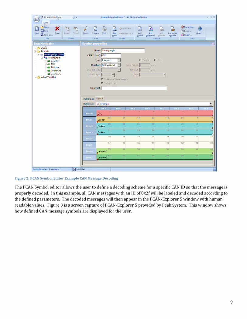
decoding. Figure 2 is a screen shot of the Peak System5 PCAN-Symbol Editor6 that is used in conjunction with the
Peak System PCAN-Explorer 57 to view and decode CAN messages.
5 PEAK System, http://www.peak-system.com/ 6 PCAN-Symbol Editor software, http://www.peak-system.com/PCAN-Symbol-Editor.250.0.html?&L=1 7 PCAN-Explorer 5 software, http://www.peak-system.com/PCAN-Explorer-5.249.0.html?&L=1
9
Figure 2: PCAN Symbol Editor Example CAN Message Decoding
The PCAN Symbol editor allows the user to define a decoding scheme for a specific CAN ID so that the message is
properly decoded. In this example, all CAN messages with an ID of 0x2f will be labeled and decoded according to
the defined parameters. The decoded messages will then appear in the PCAN-Explorer 5 window with human
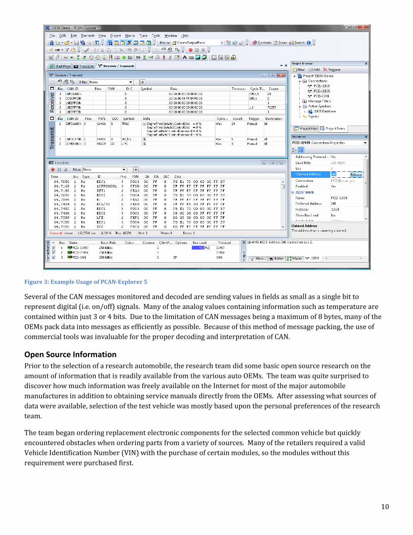
readable values. Figure 3 is a screen capture of PCAN-Explorer 5 provided by Peak System. This window shows
how defined CAN message symbols are displayed for the user.
10
Figure 3: Example Usage of PCAN-Explorer 5
Several of the CAN messages monitored and decoded are sending values in fields as small as a single bit to
represent digital (i.e. on/off) signals. Many of the analog values containing information such as temperature are
contained within just 3 or 4 bits. Due to the limitation of CAN messages being a maximum of 8 bytes, many of the
OEMs pack data into messages as efficiently as possible. Because of this method of message packing, the use of
commercial tools was invaluable for the proper decoding and interpretation of CAN.
Open Source Information
Prior to the selection of a research automobile, the research team did some basic open source research on the
amount of information that is readily available from the various auto OEMs. The team was quite surprised to
discover how much information was freely available on the Internet for most of the major automobile
manufactures in addition to obtaining service manuals directly from the OEMs. After assessing what sources of
data were available, selection of the test vehicle was mostly based upon the personal preferences of the research
team.
The team began ordering replacement electronic components for the selected common vehicle but quickly
encountered obstacles when ordering parts from a variety of sources. Many of the retailers required a valid
Vehicle Identification Number (VIN) with the purchase of certain modules, so the modules without this
requirement were purchased first.
11
Service Manuals
One of the best sources of technical information came in the form of shop or service manuals. The team ordered
several complete service manual sets from online retailer HELM Inc.8 This retailer provides electronic and paper
copies of OEM quality service and diagnostic manuals. Using these manuals, the team was able to quickly
determine the basic architecture of a few different domestic vehicles. The information found in these manuals was
instrumental in the selection of a target vehicle, and they continued to be invaluable throughout this research
project by providing detailed technical information.
Standard Diagnostic Tools
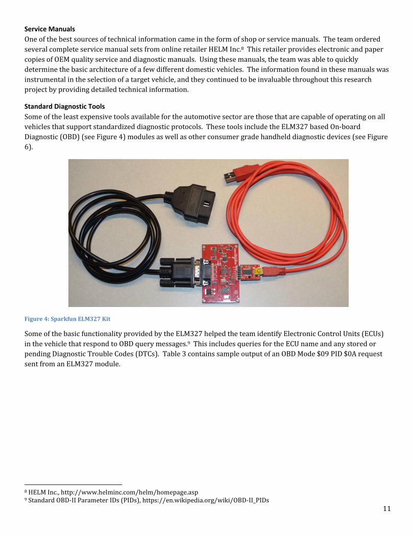
Some of the least expensive tools available for the automotive sector are those that are capable of operating on all
vehicles that support standardized diagnostic protocols. These tools include the ELM327 based On-board
Diagnostic (OBD) (see Figure 4) modules as well as other consumer grade handheld diagnostic devices (see Figure
6).
Figure 4: Sparkfun ELM327 Kit
Some of the basic functionality provided by the ELM327 helped the team identify Electronic Control Units (ECUs)
in the vehicle that respond to OBD query messages.9 This includes queries for the ECU name and any stored or
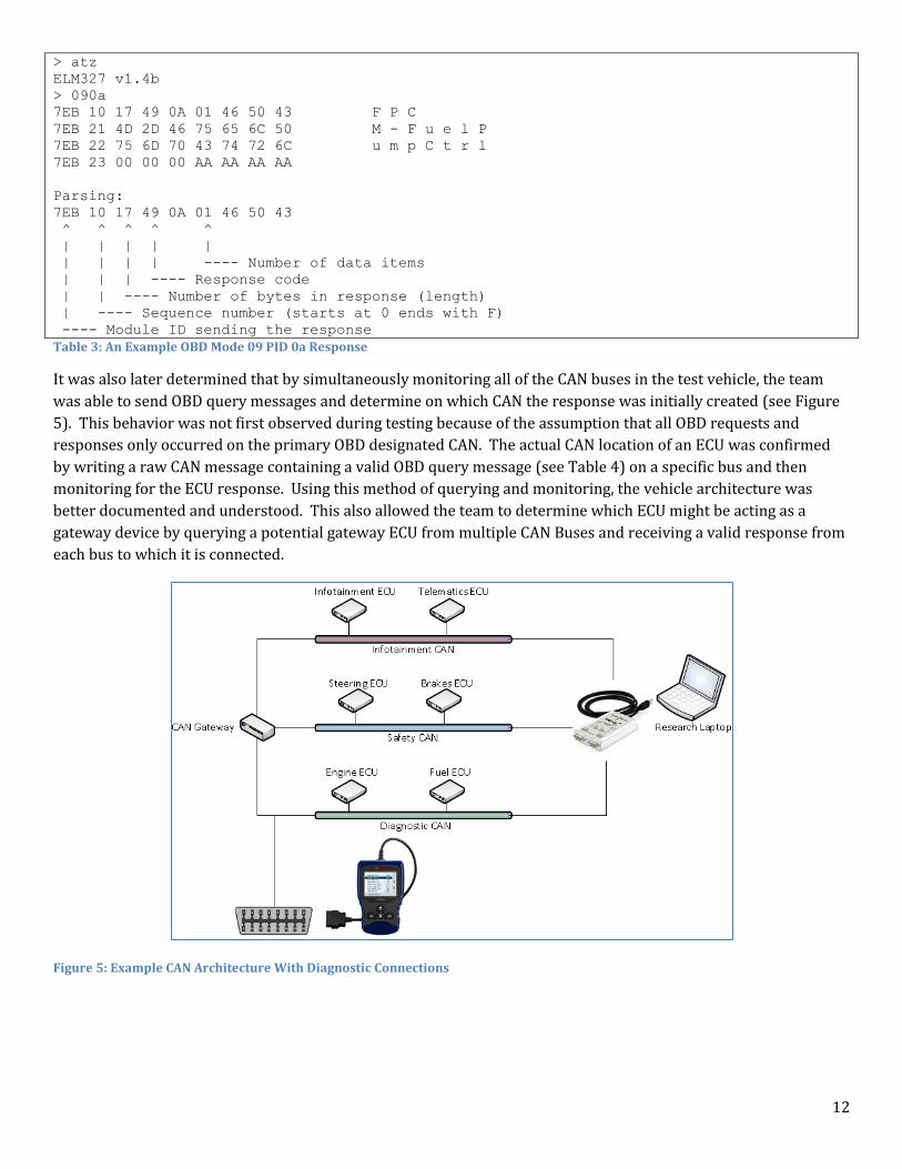
pending Diagnostic Trouble Codes (DTCs). Table 3 contains sample output of an OBD Mode $09 PID $0A request
sent from an ELM327 module.
8 HELM Inc., http://www.helminc.com/helm/homepage.asp 9 Standard OBD-II Parameter IDs (PIDs), https://en.wikipedia.org/wiki/OBD-II_PIDs
12
> atz
ELM327 v1.4b
> 090a
7EB 10 17 49 0A 01 46 50 43 F P C
7EB 21 4D 2D 46 75 65 6C 50 M - F u e l P
7EB 22 75 6D 70 43 74 72 6C u m p C t r l
7EB 23 00 00 00 AA AA AA AA
Parsing:
7EB 10 17 49 0A 01 46 50 43
^ ^ ^ ^ ^
| | | | |
| | | | ---- Number of data items
| | | ---- Response code
| | ---- Number of bytes in response (length)
| ---- Sequence number (starts at 0 ends with F)
---- Module ID sending the response
Table 3: An Example OBD Mode 09 PID 0a Response
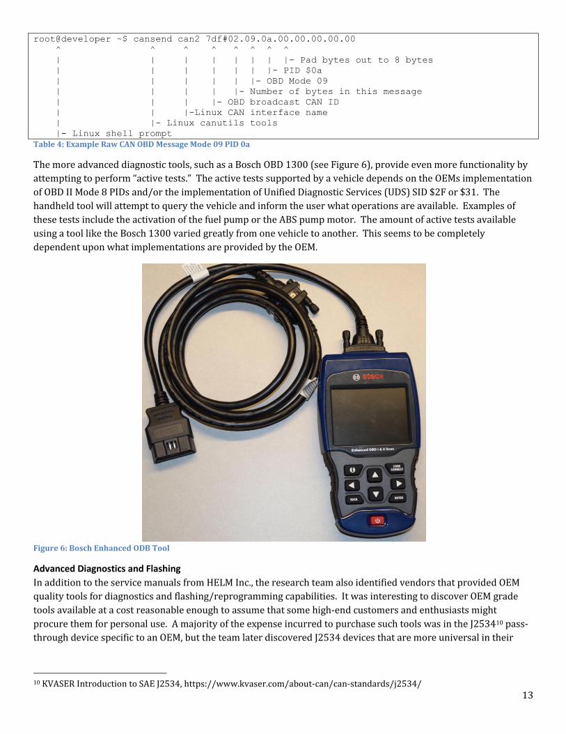
It was also later determined that by simultaneously monitoring all of the CAN buses in the test vehicle, the team
was able to send OBD query messages and determine on which CAN the response was initially created (see Figure
5). This behavior was not first observed during testing because of the assumption that all OBD requests and
responses only occurred on the primary OBD designated CAN. The actual CAN location of an ECU was confirmed
by writing a raw CAN message containing a valid OBD query message (see Table 4) on a specific bus and then
monitoring for the ECU response. Using this method of querying and monitoring, the vehicle architecture was
better documented and understood. This also allowed the team to determine which ECU might be acting as a
gateway device by querying a potential gateway ECU from multiple CAN Buses and receiving a valid response from
each bus to which it is connected.
Figure 5: Example CAN Architecture With Diagnostic Connections
13
root@developer ~$ cansend can2 7df#02.09.0a.00.00.00.00.00
^ ^ ^ ^ ^ ^ ^ ^
| | | | | | | |- Pad bytes out to 8 bytes
| | | | | | |- PID $0a
| | | | | |- OBD Mode 09
| | | | |- Number of bytes in this message
| | | |- OBD broadcast CAN ID
| | |-Linux CAN interface name
| |- Linux canutils tools
|- Linux shell prompt
Table 4: Example Raw CAN OBD Message Mode 09 PID 0a
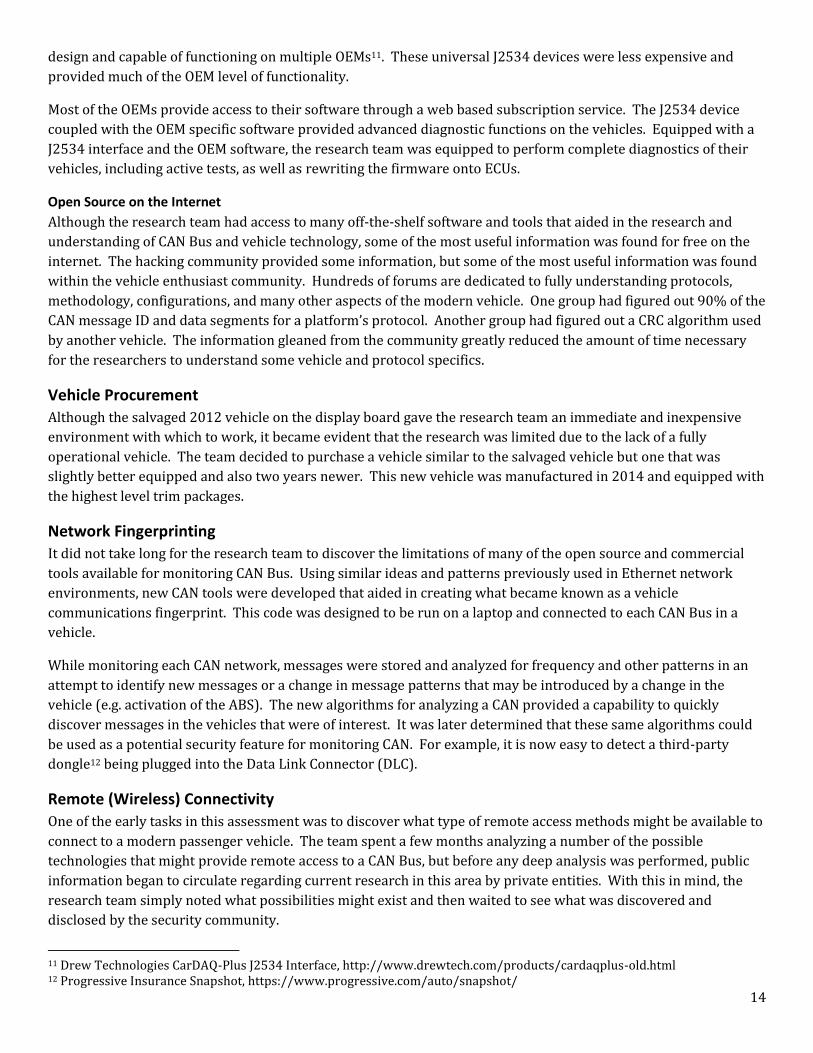
The more advanced diagnostic tools, such as a Bosch OBD 1300 (see Figure 6), provide even more functionality by
attempting to perform “active tests.” The active tests supported by a vehicle depends on the OEMs implementation
of OBD II Mode 8 PIDs and/or the implementation of Unified Diagnostic Services (UDS) SID $2F or $31. The
handheld tool will attempt to query the vehicle and inform the user what operations are available. Examples of
these tests include the activation of the fuel pump or the ABS pump motor. The amount of active tests available
using a tool like the Bosch 1300 varied greatly from one vehicle to another. This seems to be completely
dependent upon what implementations are provided by the OEM.
Figure 6: Bosch Enhanced ODB Tool
Advanced Diagnostics and Flashing
In addition to the service manuals from HELM Inc., the research team also identified vendors that provided OEM
quality tools for diagnostics and flashing/reprogramming capabilities. It was interesting to discover OEM grade
tools available at a cost reasonable enough to assume that some high-end customers and enthusiasts might
procure them for personal use. A majority of the expense incurred to purchase such tools was in the J253410 pass-
through device specific to an OEM, but the team later discovered J2534 devices that are more universal in their
10 KVASER Introduction to SAE J2534, https://www.kvaser.com/about-can/can-standards/j2534/
14
design and capable of functioning on multiple OEMs11. These universal J2534 devices were less expensive and
provided much of the OEM level of functionality.
Most of the OEMs provide access to their software through a web based subscription service. The J2534 device
coupled with the OEM specific software provided advanced diagnostic functions on the vehicles. Equipped with a
J2534 interface and the OEM software, the research team was equipped to perform complete diagnostics of their
vehicles, including active tests, as well as rewriting the firmware onto ECUs.
Open Source on the Internet
Although the research team had access to many off-the-shelf software and tools that aided in the research and
understanding of CAN Bus and vehicle technology, some of the most useful information was found for free on the
internet. The hacking community provided some information, but some of the most useful information was found
within the vehicle enthusiast community. Hundreds of forums are dedicated to fully understanding protocols,
methodology, configurations, and many other aspects of the modern vehicle. One group had figured out 90% of the
CAN message ID and data segments for a platform’s protocol. Another group had figured out a CRC algorithm used
by another vehicle. The information gleaned from the community greatly reduced the amount of time necessary
for the researchers to understand some vehicle and protocol specifics.
Vehicle Procurement
Although the salvaged 2012 vehicle on the display board gave the research team an immediate and inexpensive
environment with which to work, it became evident that the research was limited due to the lack of a fully
operational vehicle. The team decided to purchase a vehicle similar to the salvaged vehicle but one that was
slightly better equipped and also two years newer. This new vehicle was manufactured in 2014 and equipped with
the highest level trim packages.
Network Fingerprinting
It did not take long for the research team to discover the limitations of many of the open source and commercial
tools available for monitoring CAN Bus. Using similar ideas and patterns previously used in Ethernet network
environments, new CAN tools were developed that aided in creating what became known as a vehicle
communications fingerprint. This code was designed to be run on a laptop and connected to each CAN Bus in a
vehicle.
While monitoring each CAN network, messages were stored and analyzed for frequency and other patterns in an
attempt to identify new messages or a change in message patterns that may be introduced by a change in the
vehicle (e.g. activation of the ABS). The new algorithms for analyzing a CAN provided a capability to quickly
discover messages in the vehicles that were of interest. It was later determined that these same algorithms could
be used as a potential security feature for monitoring CAN. For example, it is now easy to detect a third-party
dongle12 being plugged into the Data Link Connector (DLC).
Remote (Wireless) Connectivity
One of the early tasks in this assessment was to discover what type of remote access methods might be available to
connect to a modern passenger vehicle. The team spent a few months analyzing a number of the possible
technologies that might provide remote access to a CAN Bus, but before any deep analysis was performed, public
information began to circulate regarding current research in this area by private entities. With this in mind, the
research team simply noted what possibilities might exist and then waited to see what was discovered and
disclosed by the security community.
11 Drew Technologies CarDAQ-Plus J2534 Interface, http://www.drewtech.com/products/cardaqplus-old.html 12 Progressive Insurance Snapshot, https://www.progressive.com/auto/snapshot/
15
Tire Pressure Monitoring
The Tire Pressure Monitoring System (TPMS) was an interesting wireless signal that was analyzed due to the lack
of public information available at the time regarding its use as a potential access vector. The TPMS in both of the
American sedans use sensors located in each wheel that measure the tire pressure and then transmit that data to
the vehicle using a 315 MHz signal. These signals are received by the same system responsible for receiving the
315 MHz signals from the remote key fob for locking and unlocking the vehicle.
Software Defined Radio
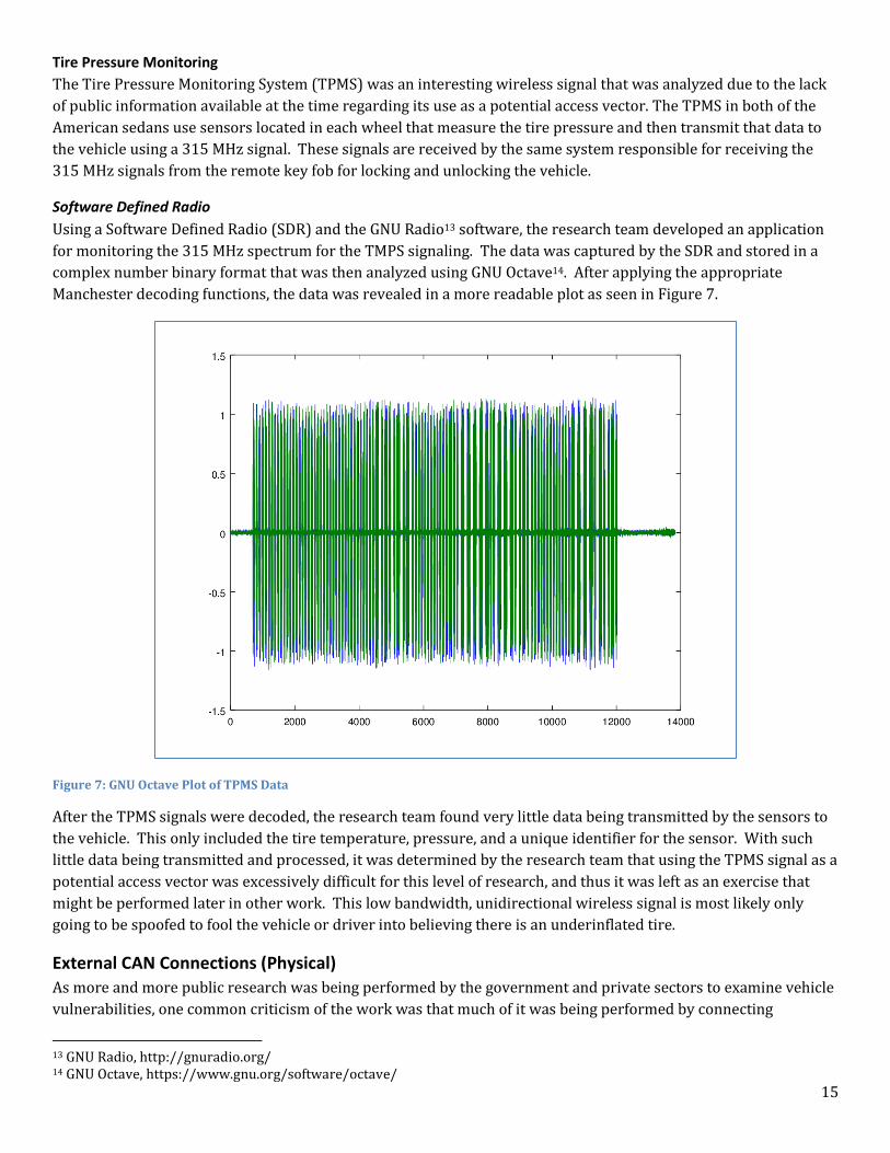
Using a Software Defined Radio (SDR) and the GNU Radio13 software, the research team developed an application
for monitoring the 315 MHz spectrum for the TMPS signaling. The data was captured by the SDR and stored in a
complex number binary format that was then analyzed using GNU Octave14. After applying the appropriate
Manchester decoding functions, the data was revealed in a more readable plot as seen in Figure 7.
Figure 7: GNU Octave Plot of TPMS Data
After the TPMS signals were decoded, the research team found very little data being transmitted by the sensors to
the vehicle. This only included the tire temperature, pressure, and a unique identifier for the sensor. With such
little data being transmitted and processed, it was determined by the research team that using the TPMS signal as a
potential access vector was excessively difficult for this level of research, and thus it was left as an exercise that
might be performed later in other work. This low bandwidth, unidirectional wireless signal is most likely only
going to be spoofed to fool the vehicle or driver into believing there is an underinflated tire.
External CAN Connections (Physical)
As more and more public research was being performed by the government and private sectors to examine vehicle
vulnerabilities, one common criticism of the work was that much of it was being performed by connecting
13 GNU Radio, http://gnuradio.org/ 14 GNU Octave, https://www.gnu.org/software/octave/
16
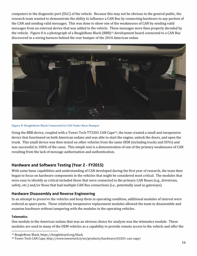
computers to the diagnostic port (DLC) of the vehicle. Because this may not be obvious to the general public, the
research team wanted to demonstrate the ability to influence a CAN Bus by connecting hardware to any portion of
the CAN and sending valid messages. This was done to show one of the weaknesses of CAN by sending valid
messages from an external device that was added to the vehicle. These messages were then properly decoded by
the vehicle. Figure 8 is a photograph of a BeagleBone Black (BBB)15 development board connected to a CAN Bus
discovered in a wiring harness behind the rear bumper of the 2014 American sedan.
Figure 8: BeagleBone Black Connected to CAN Under Rear Bumper
Using the BBB device, coupled with a Tower Tech TT3201 CAN Cape16, the team created a small and inexpensive
device that functioned on both American sedans and was able to start the engine, unlock the doors, and open the
trunk. This small device was then tested on other vehicles from the same OEM (including trucks and SUVs) and
was successful in 100% of the cases. This simple test is a demonstration of one of the primary weaknesses of CAN
resulting from the lack of message authorization and authentication.
Hardware and Software Testing (Year 2 - FY2015) With some basic capabilities and understanding of CAN developed during the first year of research, the team then
began to focus on hardware components in the vehicles that might be considered most critical. The modules that
were easy to identify as critical included those that were connected to the primary CAN Buses (e.g., drivetrain,
safety, etc.) and/or those that had multiple CAN Bus connections (i.e., potentially used as gateways).
Hardware Disassembly and Reverse Engineering
In an attempt to preserve the vehicles and keep them in operating condition, additional modules of interest were
ordered as spare parts. These relatively inexpensive replacement modules allowed the team to disassemble and
examine hardware without tampering with the modules in the operating vehicles.
Telematics
One module in the American sedans that was an obvious choice for analysis was the telematics module. These
modules are used in many of the OEM vehicles as a capability to provide remote access to the vehicle and offer the 15 BeagleBone Black, https://beagleboard.org/black 16 Tower Tech CAN Cape, http://www.towertech.it/en/products/hardware/tt3201-can-cape/
17
consumer a variety of convenience services. Examples of these systems include GM OnStar, Ford Sync, Chrysler
Uconnect, and other similar services.
The telematics module from the 2012 American sedan was disassembled and reverse engineered to determine the
architecture and chipset. In this module, the complete system is stored in a flash memory Integrated Circuit (IC)17
separate from the main system microcontroller (MCU)18. The IC was easily removed from the circuit board and the
contents of this memory chip were read and stored in a binary file. After extraction, this binary file was byte
swapped due to the big-endian19 architecture. This allowed the research team to analyze this file without having to
perform the analysis on a big-endian computer.
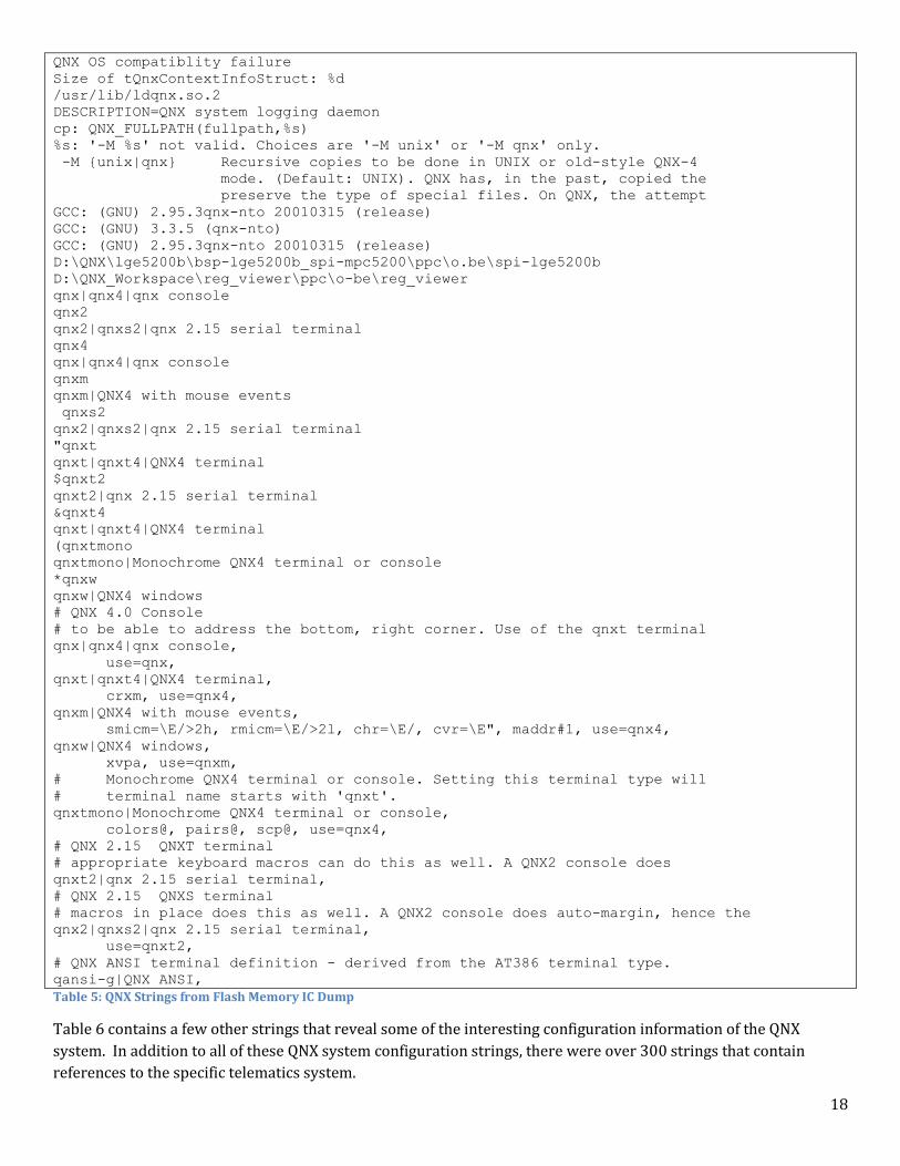
QNX System
Some basic inspection of the contents of the FLASH revealed what appears to be a complete filesystem of a QNX20
operating system (OS). This particular OS is for big-endian systems such as the one in the 2012 American sedan
telematics system. Because of the OS and big-endian architecture it was found on, only basic analysis of the flash IC
dump was performed. Table 5 contains a sample of the strings found in the flash dump that contains references to
QNX.
17 Integrated Circuit overview, https://en.wikipedia.org/wiki/Integrated_circuit 18 Microcontroller overview, https://en.wikipedia.org/wiki/Microcontroller 19 Endianness overview, https://en.wikipedia.org/wiki/Endianness 20 QNX Operating Systems, http://www.qnx.com/products/neutrino-rtos/index.html
18
QNX OS compatiblity failure
Size of tQnxContextInfoStruct: %d
/usr/lib/ldqnx.so.2
DESCRIPTION=QNX system logging daemon
cp: QNX_FULLPATH(fullpath,%s)
%s: '-M %s' not valid. Choices are '-M unix' or '-M qnx' only.
-M {unix|qnx} Recursive copies to be done in UNIX or old-style QNX-4
mode. (Default: UNIX). QNX has, in the past, copied the
preserve the type of special files. On QNX, the attempt
GCC: (GNU) 2.95.3qnx-nto 20010315 (release)
GCC: (GNU) 3.3.5 (qnx-nto)
GCC: (GNU) 2.95.3qnx-nto 20010315 (release)
D:\QNX\lge5200b\bsp-lge5200b_spi-mpc5200\ppc\o.be\spi-lge5200b
D:\QNX_Workspace\reg_viewer\ppc\o-be\reg_viewer
qnx|qnx4|qnx console
qnx2
qnx2|qnxs2|qnx 2.15 serial terminal
qnx4
qnx|qnx4|qnx console
qnxm
qnxm|QNX4 with mouse events
qnxs2
qnx2|qnxs2|qnx 2.15 serial terminal
"qnxt
qnxt|qnxt4|QNX4 terminal
$qnxt2
qnxt2|qnx 2.15 serial terminal
&qnxt4
qnxt|qnxt4|QNX4 terminal
(qnxtmono
qnxtmono|Monochrome QNX4 terminal or console
*qnxw
qnxw|QNX4 windows
# QNX 4.0 Console
# to be able to address the bottom, right corner. Use of the qnxt terminal
qnx|qnx4|qnx console,
use=qnx,
qnxt|qnxt4|QNX4 terminal,
crxm, use=qnx4,
qnxm|QNX4 with mouse events,
smicm=\E/>2h, rmicm=\E/>2l, chr=\E/, cvr=\E", maddr#1, use=qnx4,
qnxw|QNX4 windows,
xvpa, use=qnxm,
# Monochrome QNX4 terminal or console. Setting this terminal type will
# terminal name starts with 'qnxt'.
qnxtmono|Monochrome QNX4 terminal or console,
colors@, pairs@, scp@, use=qnx4,
# QNX 2.15 QNXT terminal
# appropriate keyboard macros can do this as well. A QNX2 console does
qnxt2|qnx 2.15 serial terminal,
# QNX 2.15 QNXS terminal
# macros in place does this as well. A QNX2 console does auto-margin, hence the
qnx2|qnxs2|qnx 2.15 serial terminal,
use=qnxt2,
# QNX ANSI terminal definition - derived from the AT386 terminal type.
qansi-g|QNX ANSI,
Table 5: QNX Strings from Flash Memory IC Dump
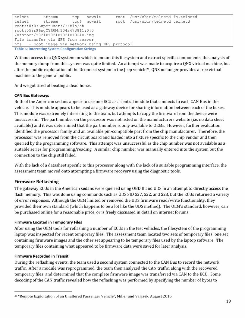
Table 6 contains a few other strings that reveal some of the interesting configuration information of the QNX
system. In addition to all of these QNX system configuration strings, there were over 300 strings that contain
references to the specific telematics system.
19
telnet stream tcp nowait root /usr/sbin/telnetd in.telnetd
telnet stream tcp6 nowait root /usr/sbin/telnetd telnetd
root::0:0:Superuser:/:/bin/sh
root:058rF6sgCYR0M:1042473811:0:0
/nfsroot/%02lX%02lX%02lX%02lX.img
File transfer via NFS from server
nfs - boot image via network using NFS protocol
Table 6: Interesting System Configuration Strings
Without access to a QNX system on which to mount this filesystem and extract specific components, the analysis of
the memory dump from this system was quite limited. An attempt was made to acquire a QNX virtual machine, but
after the public exploitation of the Uconnect system in the Jeep vehicle21, QNX no longer provides a free virtual
machine to the general public.
And we got tired of beating a dead horse.
CAN Bus Gateways
Both of the American sedans appear to use one ECU as a central module that connects to each CAN Bus in the
vehicle. This module appears to be used as a gateway device for sharing information between each of the buses.
This module was extremely interesting to the team, but attempts to copy the firmware from the device were
unsuccessful. The part number on the processor was not listed on the manufacturers website (i.e. no data sheet
available) and it was determined that the part number is only available to OEMs. However, further evaluation
identified the processor family and an available pin-compatible part from the chip manufacturer. Therefore, the
processor was removed from the circuit board and loaded into a fixture specific to the chip vendor and then
queried by the programming software. This attempt was unsuccessful as the chip number was not available as a
suitable series for programming/reading. A similar chip number was manually entered into the system but the
connection to the chip still failed.
With the lack of a datasheet specific to this processor along with the lack of a suitable programming interface, the
assessment team moved onto attempting a firmware recovery using the diagnostic tools.
Firmware Reflashing
The gateway ECUs in the American sedans were queried using OBD II and UDS in an attempt to directly access the
flash memory. This was done using commands such as UDS SID $27, $22, and $23, but the ECUs returned a variety
of error responses. Although the OEM limited or removed the UDS firmware read/write functionality, they
provided their own standard (which happens to be a lot like the UDS method). The OEM’s standard, however, can
be purchased online for a reasonable price, or is freely discussed in detail on internet forums.
Firmware Located in Temporary Files
After using the OEM tools for reflashing a number of ECUs in the test vehicles, the filesystem of the programming
laptop was inspected for recent temporary files. The assessment team located two sets of temporary files; one set
containing firmware images and the other set appearing to be temporary files used by the laptop software. The
temporary files containing what appeared to be firmware data were saved for later analysis.
Firmware Recorded in Transit
During the reflashing events, the team used a second system connected to the CAN Bus to record the network
traffic. After a module was reprogrammed, the team then analyzed the CAN traffic, along with the recovered
temporary files, and determined that the complete firmware image was transferred via CAN to the ECU. Some
decoding of the CAN traffic revealed how the reflashing was performed by specifying the number of bytes to
21 “Remote Exploitation of an Unaltered Passenger Vehicle”, Miller and Valasek, August 2015
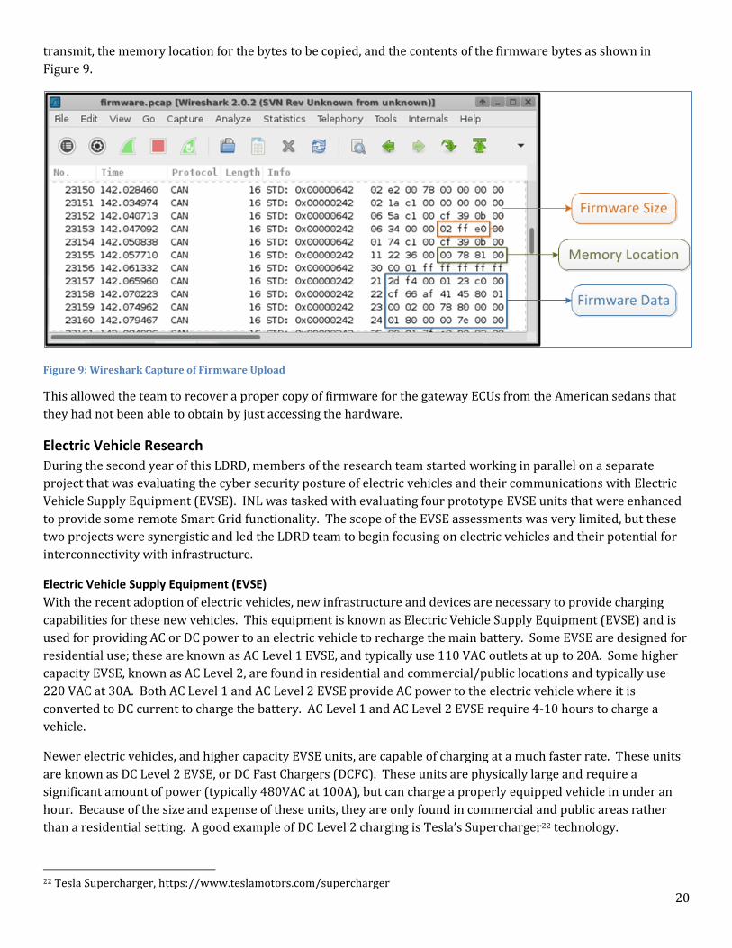
20
transmit, the memory location for the bytes to be copied, and the contents of the firmware bytes as shown in
Figure 9.
Figure 9: Wireshark Capture of Firmware Upload
This allowed the team to recover a proper copy of firmware for the gateway ECUs from the American sedans that
they had not been able to obtain by just accessing the hardware.
Electric Vehicle Research
During the second year of this LDRD, members of the research team started working in parallel on a separate
project that was evaluating the cyber security posture of electric vehicles and their communications with Electric
Vehicle Supply Equipment (EVSE). INL was tasked with evaluating four prototype EVSE units that were enhanced
to provide some remote Smart Grid functionality. The scope of the EVSE assessments was very limited, but these
two projects were synergistic and led the LDRD team to begin focusing on electric vehicles and their potential for
interconnectivity with infrastructure.
Electric Vehicle Supply Equipment (EVSE)
With the recent adoption of electric vehicles, new infrastructure and devices are necessary to provide charging
capabilities for these new vehicles. This equipment is known as Electric Vehicle Supply Equipment (EVSE) and is
used for providing AC or DC power to an electric vehicle to recharge the main battery. Some EVSE are designed for
residential use; these are known as AC Level 1 EVSE, and typically use 110 VAC outlets at up to 20A. Some higher
capacity EVSE, known as AC Level 2, are found in residential and commercial/public locations and typically use
220 VAC at 30A. Both AC Level 1 and AC Level 2 EVSE provide AC power to the electric vehicle where it is
converted to DC current to charge the battery. AC Level 1 and AC Level 2 EVSE require 4-10 hours to charge a
vehicle.
Newer electric vehicles, and higher capacity EVSE units, are capable of charging at a much faster rate. These units
are known as DC Level 2 EVSE, or DC Fast Chargers (DCFC). These units are physically large and require a
significant amount of power (typically 480VAC at 100A), but can charge a properly equipped vehicle in under an
hour. Because of the size and expense of these units, they are only found in commercial and public areas rather
than a residential setting. A good example of DC Level 2 charging is Tesla’s Supercharger22 technology.
22 Tesla Supercharger, https://www.teslamotors.com/supercharger
21
New AC Level 2 EVSE charging stations are being introduced with the ability to share connectivity with the Smart
Grid. Some of these stations are targeted at the consumer market while others are being developed for the
commercial workspace. INL assessed four prototype EVSE chargers capable of external communications with the
utility company and/or the private sector.
These new charging stations are intended to provide the end user with greater flexibility for managing the
charging infrastructure. Enhanced billing information, authorization for charging, and coordination of charging
activities are just a few of the benefits of a smart EVSE. But, as was discovered during these assessments, the cyber
security technology utilized is not ready for production deployment.
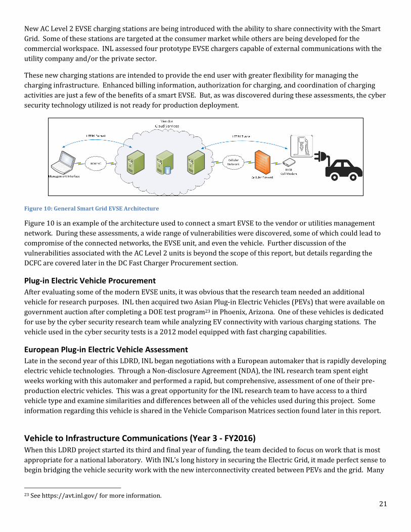
Figure 10: General Smart Grid EVSE Architecture
Figure 10 is an example of the architecture used to connect a smart EVSE to the vendor or utilities management
network. During these assessments, a wide range of vulnerabilities were discovered, some of which could lead to
compromise of the connected networks, the EVSE unit, and even the vehicle. Further discussion of the
vulnerabilities associated with the AC Level 2 units is beyond the scope of this report, but details regarding the
DCFC are covered later in the DC Fast Charger Procurement section.
Plug-in Electric Vehicle Procurement
After evaluating some of the modern EVSE units, it was obvious that the research team needed an additional
vehicle for research purposes. INL then acquired two Asian Plug-in Electric Vehicles (PEVs) that were available on
government auction after completing a DOE test program23 in Phoenix, Arizona. One of these vehicles is dedicated
for use by the cyber security research team while analyzing EV connectivity with various charging stations. The
vehicle used in the cyber security tests is a 2012 model equipped with fast charging capabilities.
European Plug-in Electric Vehicle Assessment
Late in the second year of this LDRD, INL began negotiations with a European automaker that is rapidly developing
electric vehicle technologies. Through a Non-disclosure Agreement (NDA), the INL research team spent eight
weeks working with this automaker and performed a rapid, but comprehensive, assessment of one of their pre-
production electric vehicles. This was a great opportunity for the INL research team to have access to a third
vehicle type and examine similarities and differences between all of the vehicles used during this project. Some
information regarding this vehicle is shared in the Vehicle Comparison Matrices section found later in this report.
Vehicle to Infrastructure Communications (Year 3 - FY2016) When this LDRD project started its third and final year of funding, the team decided to focus on work that is most
appropriate for a national laboratory. With INL’s long history in securing the Electric Grid, it made perfect sense to
begin bridging the vehicle security work with the new interconnectivity created between PEVs and the grid. Many
23 See https://avt.inl.gov/ for more information.
22
new and existing companies are rapidly evaluating vehicle cyber security, so it was a prudent decision for INL to
focus on an area that might be more difficult for the private sector.
DC Fast Charger Procurement
The continued push for additional connectivity of vehicles to the surrounding infrastructure poses the potential for
serious security risks. In an attempt to address some of these concerns during the early adoption of Vehicle to
Infrastructure (V2I) communications, the INL security team focused on one of today’s available V2I use cases: the
connection of a PEV to a DCFC.
INL procured a modern 50 kW DC Fast Charger (DCFC) capable of charging PEVs using either the CHAdeMO or SAE
J1772 Combo connector. This charging station is also capable of being remotely managed by either the vendor or
the owner-operator by using the provided networking capabilities. With this charging station and a PEV, the final
year of the INL CAN Bus security research was focused on the range of vulnerabilities created by this V2I
connectivity.
Modern DCFC stations are connected to the Internet similarly to what was observed with the Level 2 smart
chargers described in Figure 10, but the DCFC is a much more complex device. The power requirement for a fast
charger is generally 480VAC at 100A - the power requirements of a small business. In addition to the increased
load on the energy grid, the DCFC also performs all of the AC to DC power conversion outside of the vehicle by
relying upon enhanced communication from the PEV to manage the charging cycle.
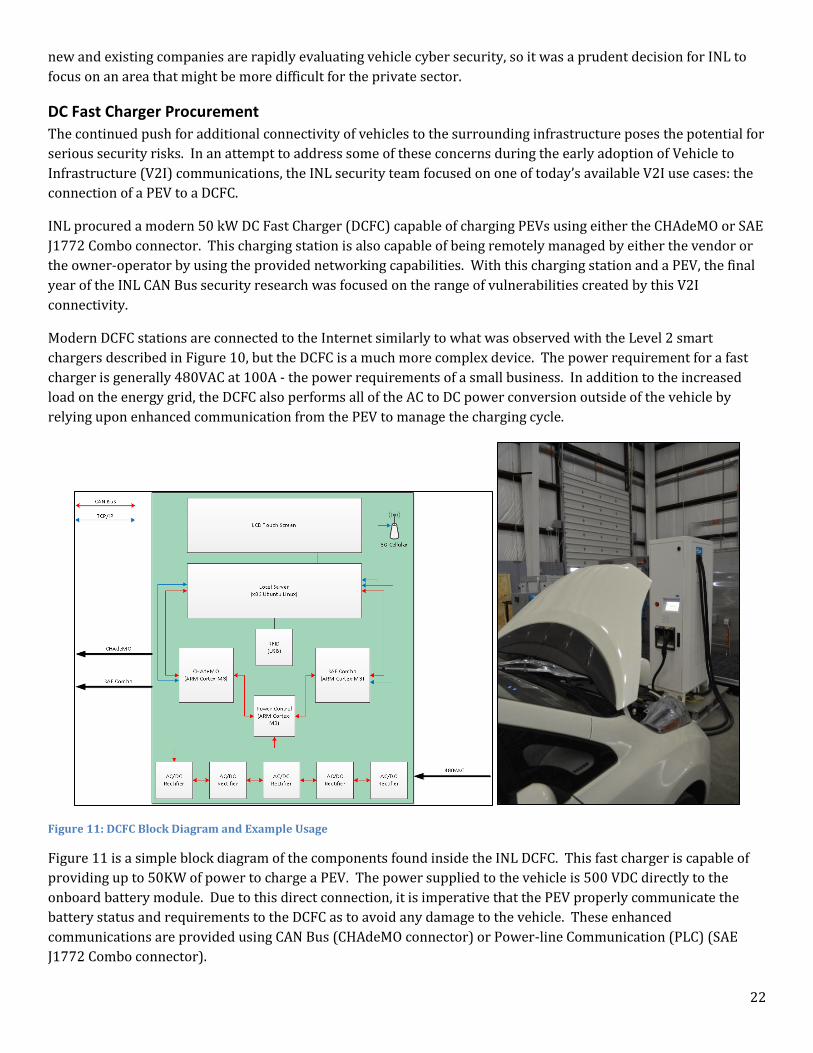
Figure 11: DCFC Block Diagram and Example Usage
Figure 11 is a simple block diagram of the components found inside the INL DCFC. This fast charger is capable of
providing up to 50KW of power to charge a PEV. The power supplied to the vehicle is 500 VDC directly to the
onboard battery module. Due to this direct connection, it is imperative that the PEV properly communicate the
battery status and requirements to the DCFC as to avoid any damage to the vehicle. These enhanced
communications are provided using CAN Bus (CHAdeMO connector) or Power-line Communication (PLC) (SAE
J1772 Combo connector).
23
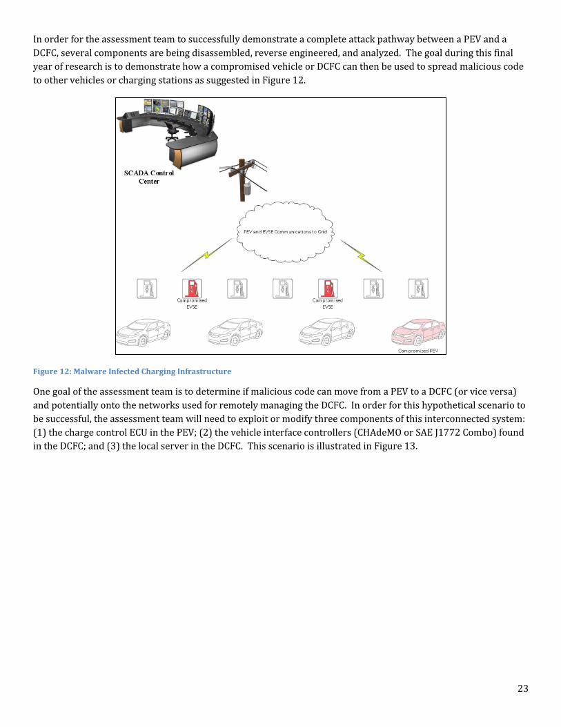
In order for the assessment team to successfully demonstrate a complete attack pathway between a PEV and a
DCFC, several components are being disassembled, reverse engineered, and analyzed. The goal during this final
year of research is to demonstrate how a compromised vehicle or DCFC can then be used to spread malicious code
to other vehicles or charging stations as suggested in Figure 12.
Figure 12: Malware Infected Charging Infrastructure
One goal of the assessment team is to determine if malicious code can move from a PEV to a DCFC (or vice versa)
and potentially onto the networks used for remotely managing the DCFC. In order for this hypothetical scenario to
be successful, the assessment team will need to exploit or modify three components of this interconnected system:
(1) the charge control ECU in the PEV; (2) the vehicle interface controllers (CHAdeMO or SAE J1772 Combo) found
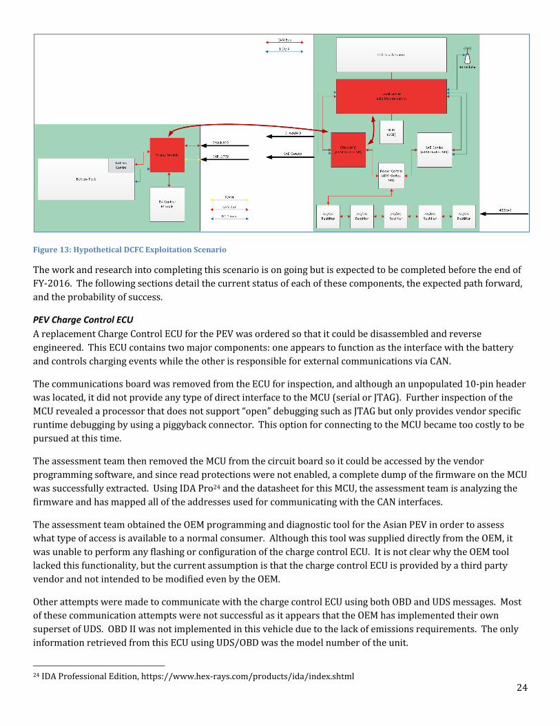
in the DCFC; and (3) the local server in the DCFC. This scenario is illustrated in Figure 13.
24
Figure 13: Hypothetical DCFC Exploitation Scenario
The work and research into completing this scenario is on going but is expected to be completed before the end of
FY-2016. The following sections detail the current status of each of these components, the expected path forward,
and the probability of success.
PEV Charge Control ECU
A replacement Charge Control ECU for the PEV was ordered so that it could be disassembled and reverse
engineered. This ECU contains two major components: one appears to function as the interface with the battery
and controls charging events while the other is responsible for external communications via CAN.
The communications board was removed from the ECU for inspection, and although an unpopulated 10-pin header
was located, it did not provide any type of direct interface to the MCU (serial or JTAG). Further inspection of the
MCU revealed a processor that does not support “open” debugging such as JTAG but only provides vendor specific
runtime debugging by using a piggyback connector. This option for connecting to the MCU became too costly to be
pursued at this time.
The assessment team then removed the MCU from the circuit board so it could be accessed by the vendor
programming software, and since read protections were not enabled, a complete dump of the firmware on the MCU
was successfully extracted. Using IDA Pro24 and the datasheet for this MCU, the assessment team is analyzing the
firmware and has mapped all of the addresses used for communicating with the CAN interfaces.
The assessment team obtained the OEM programming and diagnostic tool for the Asian PEV in order to assess
what type of access is available to a normal consumer. Although this tool was supplied directly from the OEM, it
was unable to perform any flashing or configuration of the charge control ECU. It is not clear why the OEM tool
lacked this functionality, but the current assumption is that the charge control ECU is provided by a third party
vendor and not intended to be modified even by the OEM.
Other attempts were made to communicate with the charge control ECU using both OBD and UDS messages. Most
of these communication attempts were not successful as it appears that the OEM has implemented their own
superset of UDS. OBD II was not implemented in this vehicle due to the lack of emissions requirements. The only
information retrieved from this ECU using UDS/OBD was the model number of the unit.
24 IDA Professional Edition, https://www.hex-rays.com/products/ida/index.shtml
25
The firmware has been successfully extracted from the ECU, and we are 99% certain that it contains a valid OS and
configuration due to the lack of ability the OEM tool has to interface with the ECU. Most firmware found in ECUs is
sufficiently stripped of strings and debugging symbols so that reverse engineering is a tedious effort. For this
reason, and others noted in the following sections, the assessment team will not likely pursue the modification and
replacement of the firmware on this ECU.
DCFC Vehicle Controller (CHAdeMO and SAE J1772 Combo)
The vehicle interface controllers found in the DCFC are only two of the modules present in this charging station.
Upon inspection, each of these controllers provides a 10-pin header on one of their boards that is labeled
UART/JTAG. A JTAGULATOR25 interface was used to query the 10-pin header in an attempt to identify the JTAG
and UART pins. After the appropriate pins were identified, a SEGGER J-Link PRO26 and a 3.3 VDC USB FTDI were
used to interface with the MCU and extract the chip firmware.
Both of the DCFC vehicle interface controllers use the same MCU chipset, and surprisingly the firmware is quite
similar to one another. This firmware was much more like traditional software reverse engineering as the layout
of the firmware still includes some debugging symbols as well as string information. Analysis of this firmware is
90% complete.
After the removal of the interfaces controller firmware, the DCFC restarted without a valid configuration for the
installed vehicle interfaces. This was extremely worrisome to the assessment team, but after some lengthy
analysis of the DCFC Local Server, factory reset scripts, as well as the untouched firmware for all of the modules in
the DCFC, were located. After simply executing the scripts the DCFC was restored to a factory fresh state.
DCFC Local Server
The third major component being analyzed in this hypothetical exploitation scenario is what the vendor of the
DCFC refers to as the Local Server. This component is x86 based embedded computer running Ubuntu Linux 10.04
LTS, and it is primarily used for local storage and management of the DCFC. This system connects to the vendor’s
network using a 3G cellular modem and VPN tunneling software. All of the other modules in the DCFC log all of
their events and status information (e.g. billing, scheduling, etc.) to the Local Server.
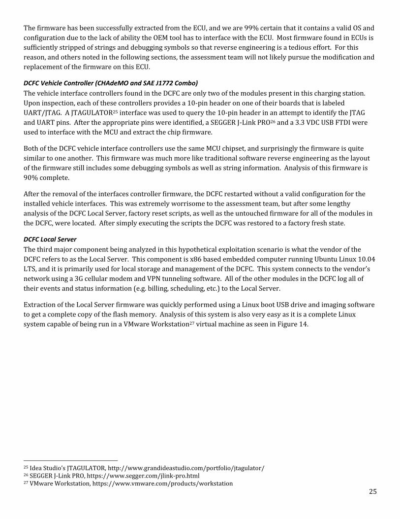
Extraction of the Local Server firmware was quickly performed using a Linux boot USB drive and imaging software
to get a complete copy of the flash memory. Analysis of this system is also very easy as it is a complete Linux
system capable of being run in a VMware Workstation27 virtual machine as seen in Figure 14.
25 Idea Studio’s JTAGULATOR, http://www.grandideastudio.com/portfolio/jtagulator/ 26 SEGGER J-Link PRO, https://www.segger.com/jlink-pro.html 27 VMware Workstation, https://www.vmware.com/products/workstation
26
Figure 14: DCFC Local Server Running in VMware Workstation
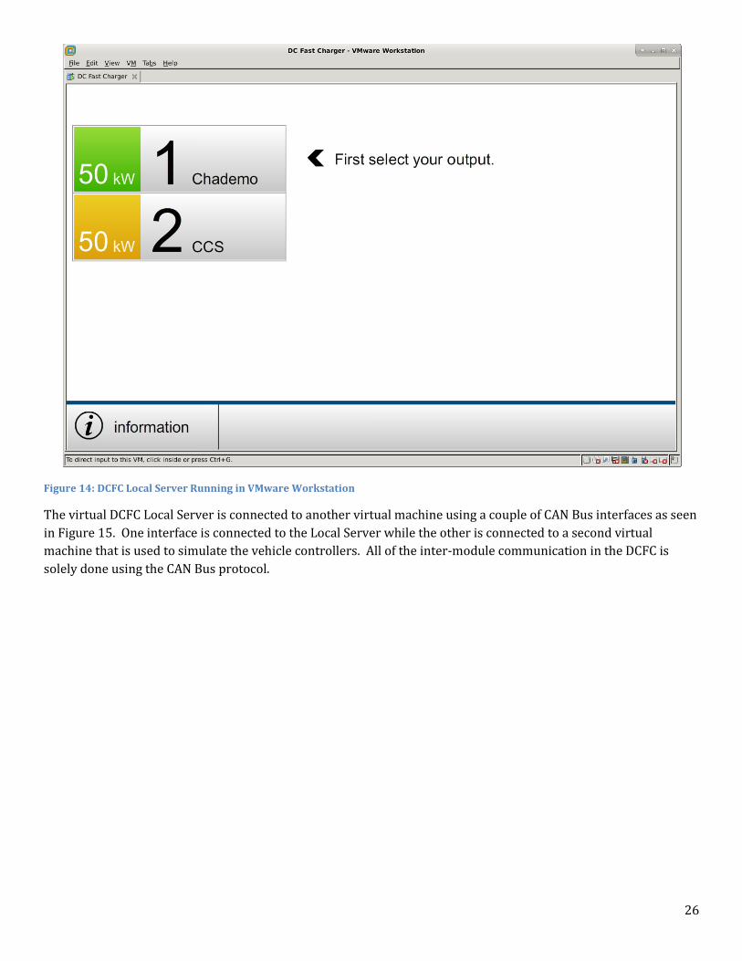
The virtual DCFC Local Server is connected to another virtual machine using a couple of CAN Bus interfaces as seen
in Figure 15. One interface is connected to the Local Server while the other is connected to a second virtual
machine that is used to simulate the vehicle controllers. All of the inter-module communication in the DCFC is
solely done using the CAN Bus protocol.
27
Figure 15: CAN Bus Interfaces to Connect the Local Server to Vehicle Controller Virtual Machines
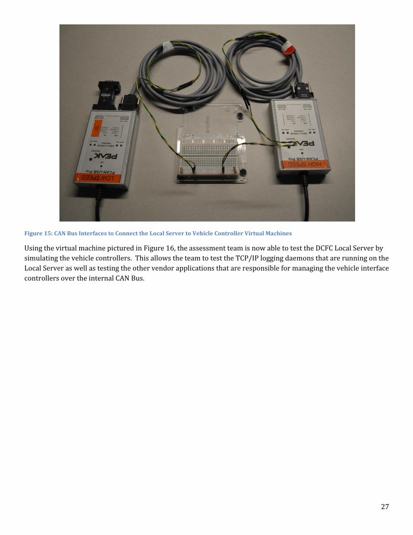
Using the virtual machine pictured in Figure 16, the assessment team is now able to test the DCFC Local Server by
simulating the vehicle controllers. This allows the team to test the TCP/IP logging daemons that are running on the
Local Server as well as testing the other vendor applications that are responsible for managing the vehicle interface
controllers over the internal CAN Bus.
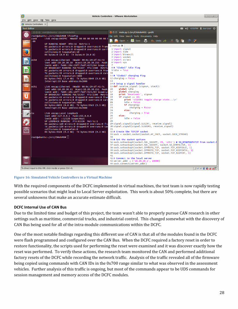
28
Figure 16: Simulated Vehicle Controllers in a Virtual Machine
With the required components of the DCFC implemented in virtual machines, the test team is now rapidly testing
possible scenarios that might lead to Local Server exploitation. This work is about 50% complete, but there are
several unknowns that make an accurate estimate difficult.
DCFC Internal Use of CAN Bus
Due to the limited time and budget of this project, the team wasn’t able to properly pursue CAN research in other
settings such as maritime, commercial trucks, and industrial control. This changed somewhat with the discovery of
CAN Bus being used for all of the intra-module communications within the DCFC.
One of the most notable findings regarding this different use of CAN is that all of the modules found in the DCFC
were flash programmed and configured over the CAN Bus. When the DCFC required a factory reset in order to
restore functionality, the scripts used for performing the reset were examined and it was discover exactly how the
reset was performed. To verify these actions, the research team monitored the CAN and performed additional
factory resets of the DCFC while recording the network traffic. Analysis of the traffic revealed all of the firmware
being copied using commands with CAN IDs in the 0x700 range similar to what was observed in the assessment
vehicles. Further analysis of this traffic is ongoing, but most of the commands appear to be UDS commands for
session management and memory access of the DCFC modules.
29
Exploit Scenario Implementation
It is unclear if the research team will ever fully implement this hypothetical PEV and DCFC attack scenario for a
number of reasons; the most notable is the question of why such a scenario should ever be implemented. It is quite
clear that the major components required to execute such an attack are available and likely vulnerable, so the
effort and expense of a final implementation might only be useful for conference speeches and demonstrations.
The following list summarizes what is theoretically very possible:
1. The PEV Charge Control ECU may or may not be vulnerable to remote exploitation via CAN, but the need for
modification of this module may not be necessary. Connecting a laptop with the appropriate interfaces
directly to the DCFC charge port(s) is a more likely scenario that could lead to compromise of the DCFC
rather than using a PEV as the entry point. The propagation of malware from one DCFC to another via the
PEV Charge Control ECU is still being analyzed.
2. Modification of the DCFC Vehicle Controllers is extremely likely and certainly possible if the DCFC Local
Server is ever compromised. These controllers are all configurable via CAN, and no security measures were
implemented to control what or who is programming these modules. Current research is still pending to
determine if the Vehicle Controllers are programmable from the CAN interface external to the DCFC as
found in the CHAdeMO or SAE J1772 Combo connectors.
3. The DCFC Local Server is yet another typical Linux system located in the world of the Internet of Things
(IoT). Although the INL unit is connected to a vendor VPN provided by a 3G cellular company, it is
reasonable to assume that many similar DCFC stations are connected to a variety of management networks.
If this Local Server is exposed to the Internet, it will certainly become a target of exploitation. Current
research is also pending with this unit to assess what vulnerabilities might exist to exploit the Local Server
via the internal CAN or TCP/IP logging services.
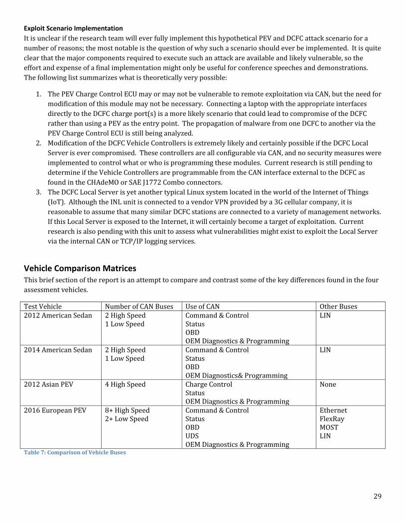
Vehicle Comparison Matrices This brief section of the report is an attempt to compare and contrast some of the key differences found in the four
assessment vehicles.
Test Vehicle Number of CAN Buses Use of CAN Other Buses 2012 American Sedan 2 High Speed
1 Low Speed Command & Control Status OBD OEM Diagnostics & Programming
LIN
2014 American Sedan 2 High Speed 1 Low Speed
Command & Control Status OBD OEM Diagnostics& Programming
LIN
2012 Asian PEV 4 High Speed Charge Control Status OEM Diagnostics & Programming
None
2016 European PEV 8+ High Speed 2+ Low Speed
Command & Control Status OBD UDS OEM Diagnostics & Programming
Ethernet FlexRay MOST LIN
Table 7: Comparison of Vehicle Buses
30
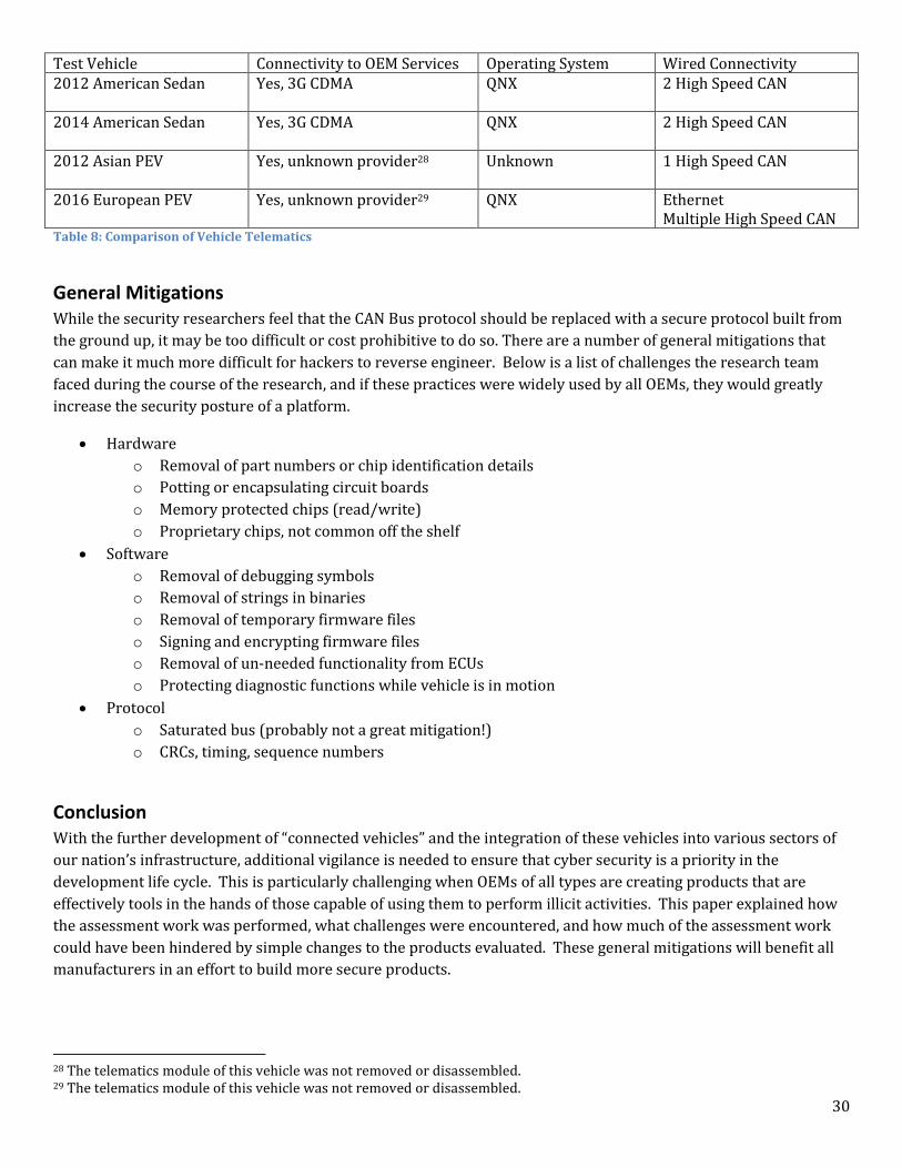
Test Vehicle Connectivity to OEM Services Operating System Wired Connectivity 2012 American Sedan Yes, 3G CDMA
QNX 2 High Speed CAN
2014 American Sedan Yes, 3G CDMA
QNX 2 High Speed CAN
2012 Asian PEV Yes, unknown provider28
Unknown 1 High Speed CAN
2016 European PEV Yes, unknown provider29 QNX Ethernet Multiple High Speed CAN
Table 8: Comparison of Vehicle Telematics
General Mitigations While the security researchers feel that the CAN Bus protocol should be replaced with a secure protocol built from
the ground up, it may be too difficult or cost prohibitive to do so. There are a number of general mitigations that
can make it much more difficult for hackers to reverse engineer. Below is a list of challenges the research team
faced during the course of the research, and if these practices were widely used by all OEMs, they would greatly
increase the security posture of a platform.
Hardware
o Removal of part numbers or chip identification details
o Potting or encapsulating circuit boards
o Memory protected chips (read/write)
o Proprietary chips, not common off the shelf
Software
o Removal of debugging symbols
o Removal of strings in binaries
o Removal of temporary firmware files
o Signing and encrypting firmware files
o Removal of un-needed functionality from ECUs
o Protecting diagnostic functions while vehicle is in motion
Protocol
o Saturated bus (probably not a great mitigation!)
o CRCs, timing, sequence numbers
Conclusion With the further development of “connected vehicles” and the integration of these vehicles into various sectors of
our nation’s infrastructure, additional vigilance is needed to ensure that cyber security is a priority in the
development life cycle. This is particularly challenging when OEMs of all types are creating products that are
effectively tools in the hands of those capable of using them to perform illicit activities. This paper explained how
the assessment work was performed, what challenges were encountered, and how much of the assessment work
could have been hindered by simple changes to the products evaluated. These general mitigations will benefit all
manufacturers in an effort to build more secure products.
28 The telematics module of this vehicle was not removed or disassembled. 29 The telematics module of this vehicle was not removed or disassembled.
Related Documents