2009 Chevrolet Traverse - AWD | Acadia, Enclave, OUTLOOK, Traverse VIN R/V Service Manual | Engine | Engine Mechanical - 2.8L, 3.0L, 3.2L, or 3.6L | Repair Instructions - On Vehicle | Document ID: 2083081 Camshaft Position Actuator Replacement - Bank 1 Right Side Exhaust Special Tools EN-48313 Timing Chain Retention Tool Removal Procedure 1. Remove the intake manifold. Refer to Intake Manifold Replacement. 2. Remove the right camshaft cover. Refer to Camshaft Cover Replacement - Right Side. 3. Remove the right intake and exhaust camshaft position sensors. Refer to Camshaft Position Sensor Replacement - Bank 1 (Right Side) Intake and Camshaft Position Sensor Replacement - Bank 1 (Right Side) Exhaust. 4. Remove the right intake and exhaust camshaft position actuator solenoids. Refer to Camshaft Position Actuator Solenoid Valve Solenoid Replacement - Bank 1 (Right Side) Intake and Camshaft Position Actuator Solenoid Valve Solenoid Replacement - Bank 1 (Right Side) Exhaust. 5. Rotate the crankshaft balancer bolt in a clockwise direction ONLY. Rotate the crankshaft balancer using the balancer bolt until the camshafts are in a neutral (low tension) position. The camshafts will be parallel with the camshaft cover rail (1). © 2017 General Motors. All rights reserved. Document ID: 2083081 https://gsi.ext.gm.com/gsi/cellHandler.do?cellId=78362&refDo... 1 of 6 9/4/17, 10:49 AM

Welcome message from author
This document is posted to help you gain knowledge. Please leave a comment to let me know what you think about it! Share it to your friends and learn new things together.
Transcript
2009 Chevrolet Traverse - AWD | Acadia, Enclave, OUTLOOK, Traverse VIN R/V Service Manual | Engine |Engine Mechanical - 2.8L, 3.0L, 3.2L, or 3.6L | Repair Instructions - On Vehicle | Document ID: 2083081
Camshaft Position Actuator Replacement - Bank 1 RightSide Exhaust
Special Tools
EN-48313 Timing Chain Retention Tool
Removal Procedure
1. Remove the intake manifold. Refer to Intake Manifold Replacement.
2. Remove the right camshaft cover. Refer to Camshaft Cover Replacement - Right Side.
3. Remove the right intake and exhaust camshaft position sensors. Refer to Camshaft PositionSensor Replacement - Bank 1 (Right Side) Intake and Camshaft Position Sensor Replacement- Bank 1 (Right Side) Exhaust.
4. Remove the right intake and exhaust camshaft position actuator solenoids. Refer to CamshaftPosition Actuator Solenoid Valve Solenoid Replacement - Bank 1 (Right Side) Intake andCamshaft Position Actuator Solenoid Valve Solenoid Replacement - Bank 1 (Right Side)Exhaust.
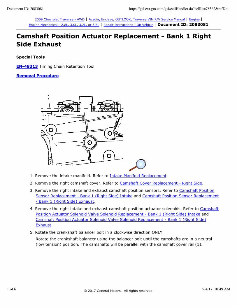
5. Rotate the crankshaft balancer bolt in a clockwise direction ONLY.
Rotate the crankshaft balancer using the balancer bolt until the camshafts are in a neutral(low tension) position. The camshafts will be parallel with the camshaft cover rail (1).
© 2017 General Motors. All rights reserved.
Document ID: 2083081 https://gsi.ext.gm.com/gsi/cellHandler.do?cellId=78362&refDo...
1 of 6 9/4/17, 10:49 AM

Note: Ensure that the camshaft timing chain and the camshaft position actuators are markedfor proper assembly.
6. Use a paint stick to create an alignment mark (17) on one of the timing chain links and theadjacent tooth on the exhaust camshaft position actuator (18).
7. Use a paint stick to create an alignment mark (16) on one of the timing chain links and theadjacent tooth on the intake camshaft position actuator (15).
Caution: Refer to Torque Reaction Against Timing Drive Chain Caution. 8. Use an open end wrench on the hex cast into the left intake and exhaust camshafts and rotate
the camshafts toward each other in order to create slack in the chain between the actuators.
9. Unscrew the EN-48313 so that the legs of the tool are retracted.
10. Insert the EN-48313 between the camshaft actuators, rearward of the timing chain until thetop line that is scribed in the body of the tool (1) is adjacent to the top surface of the cylinderhead (2). This is the approximate installed position.
Document ID: 2083081 https://gsi.ext.gm.com/gsi/cellHandler.do?cellId=78362&refDo...
2 of 6 9/4/17, 10:49 AM
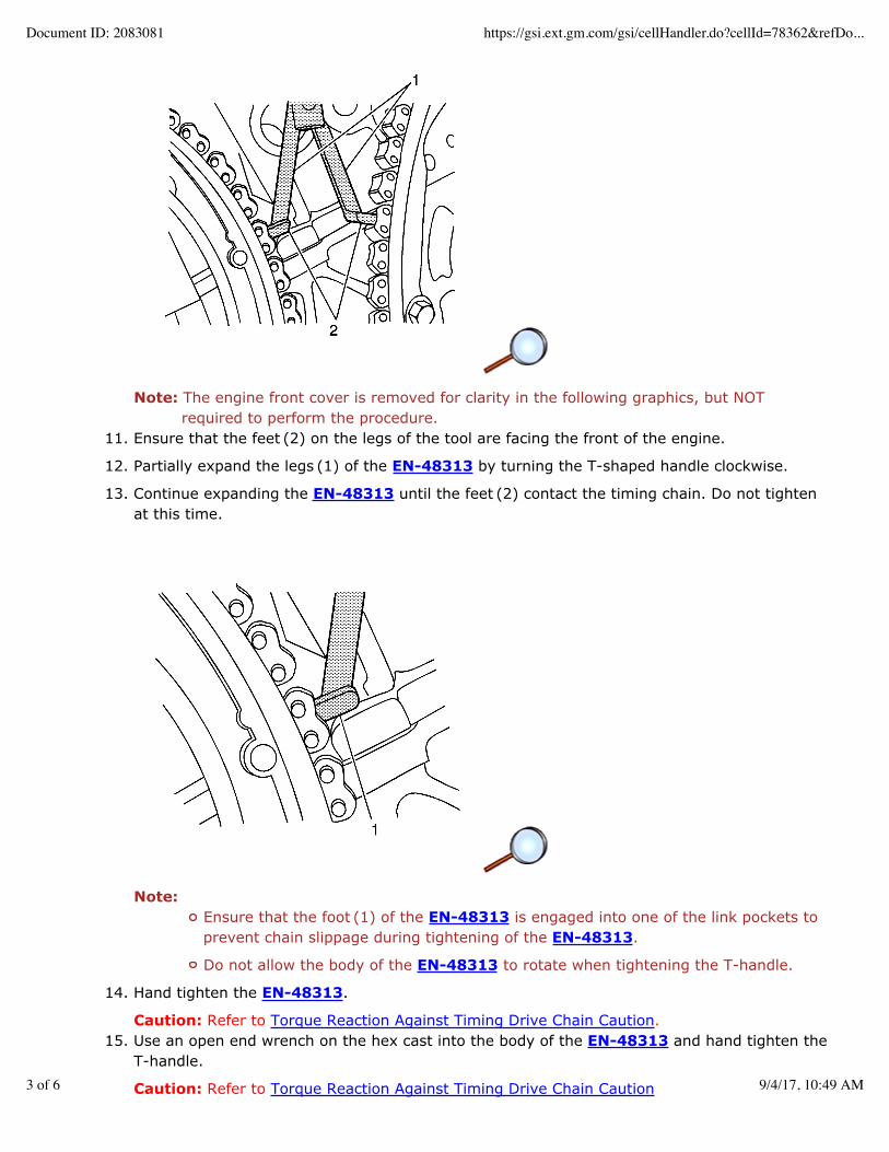
Note: The engine front cover is removed for clarity in the following graphics, but NOTrequired to perform the procedure.
11. Ensure that the feet (2) on the legs of the tool are facing the front of the engine.
12. Partially expand the legs (1) of the EN-48313 by turning the T-shaped handle clockwise.
13. Continue expanding the EN-48313 until the feet (2) contact the timing chain. Do not tightenat this time.
Note:Ensure that the foot (1) of the EN-48313 is engaged into one of the link pockets toprevent chain slippage during tightening of the EN-48313.
Do not allow the body of the EN-48313 to rotate when tightening the T-handle.
14. Hand tighten the EN-48313.
Caution: Refer to Torque Reaction Against Timing Drive Chain Caution.15. Use an open end wrench on the hex cast into the body of the EN-48313 and hand tighten the
T-handle.
Caution: Refer to Torque Reaction Against Timing Drive Chain Caution
Document ID: 2083081 https://gsi.ext.gm.com/gsi/cellHandler.do?cellId=78362&refDo...
3 of 6 9/4/17, 10:49 AM

16. Use an open end wrench on the hex cast into the right intake and exhaust camshafts androtate the camshafts towards each other in order to create slack in the chain between theactuators.
17. The EN-48313 is now properly installed to hold the timing chain in position.
Caution: Refer to Torque Reaction Against Timing Drive Chain Caution18. Use an open end wrench on the hex cast into the camshaft in order to prevent engine rotation
when loosening the camshaft position actuator bolt.
19. Remove the right exhaust camshaft position actuator bolt.
20. Remove the right exhaust camshaft position actuator. When removing the actuator, place thechain on the engine cover side of the actuators.
21. Rotate the actuator in order to align the opening in the actuator reluctor wheel with the camsensor boss in the front cover, to allow actuator removal.
22. If removing both the exhaust and intake camshaft actuators, the timing chain can be drapedover the EN-48313 once the actuators have been removed.
Installation Procedure
Document ID: 2083081 https://gsi.ext.gm.com/gsi/cellHandler.do?cellId=78362&refDo...
4 of 6 9/4/17, 10:49 AM
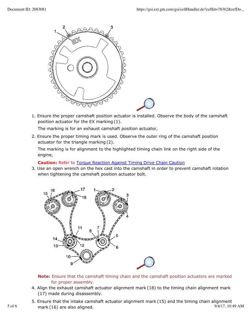
1. Ensure the proper camshaft position actuator is installed. Observe the body of the camshaftposition actuator for the EX marking (1).
The marking is for an exhaust camshaft position actuator,
2. Ensure the proper timing mark is used. Observe the outer ring of the camshaft positionactuator for the triangle marking (2).
The marking is for alignment to the highlighted timing chain link on the right side of theengine,
Caution: Refer to Torque Reaction Against Timing Drive Chain Caution 3. Use an open wrench on the hex cast into the camshaft in order to prevent camshaft rotation
when tightening the camshaft position actuator bolt.
Note: Ensure that the camshaft timing chain and the camshaft position actuators are markedfor proper assembly.
4. Align the exhaust camshaft actuator alignment mark (18) to the timing chain alignment mark (17) made during disassembly.
5. Ensure that the intake camshaft actuator alignment mark (15) and the timing chain alignmentmark (16) are also aligned.
Document ID: 2083081 https://gsi.ext.gm.com/gsi/cellHandler.do?cellId=78362&refDo...
5 of 6 9/4/17, 10:49 AM

6. Position the exhaust camshaft actuator to the camshaft and install the actuator bolt handtight.
7. Remove the EN-48313.
Caution: Refer to Fastener Caution 8. Tighten the right exhaust camshaft position actuator bolt.
TightenTighten the bolt to 58 Y (43 lb ft).
9. Install the right intake and exhaust camshaft position actuator solenoids. Refer to CamshaftPosition Actuator Solenoid Valve Solenoid Replacement - Bank 1 (Right Side) Intake andCamshaft Position Actuator Solenoid Valve Solenoid Replacement - Bank 1 (Right Side)Exhaust.
10. Install the right intake and exhaust camshaft position sensors. Refer to Camshaft PositionSensor Replacement - Bank 1 (Right Side) Intake and Camshaft Position Sensor Replacement- Bank 1 (Right Side) Exhaust.
11. Install the right camshaft cover. Refer to Camshaft Cover Replacement - Right Side.
12. Install the intake manifold. Refer to Intake Manifold Replacement.
Document ID: 2083081 https://gsi.ext.gm.com/gsi/cellHandler.do?cellId=78362&refDo...
6 of 6 9/4/17, 10:49 AM
Related Documents