ADVERTENCIA • Seleccione el tamaño de mordaza adecuado para el trabajo. • Determine el peso de la placa a ser alzada. • No exceda el limite de carga de trabajo (WLL) mostrado en la mordaza. • El espesor de la placa debe estar dentro de la gama de agarre mostrada en la mordaza. WARNING • Select proper size clamp for the job. • Determine the weight of the plate to be lifted. • Do not exceed WLL (Working Load Limit) shown on clamp. • Plate thickness must be within grip range shown on clamp. Contents Clamps, Chain Connector Clamps, Drag Clamps, “GX” Clamps, “GXL” Clamps, Horizontal Plate Clamps, Locking “E” Clamps, Non-Marring Clamps, Rubber Pad Clamps, SAC (Screw-Adjusted Cam) Clamps, Sharp Leg Clamps, Short Leg Structural Connector, Chain Drum Deheader Drum Lifter, Fork Truck Drum Lifter, Single Drum Lifter, Twin Grip, Duplex Hand Inspection of Clamps Slings, Drum Warning Statement Though it began manufacturing operations in 1866, Campbell first made its lightweight, rugged plate lifting clamp in 1938. It was designed by an Englishman named Volz. Because it incorporated forged parts of heat treated, alloy steel, the Campbell clamp earned a worldwide reputation for reliability and long life. It is widely used by steel mills, warehouses and fabricating shops and is much preferred because its forged parts give increased strength yet are light- weight. And, they are readily available when servicing is required. Campbell ® Clamps Table of Contents The Campbell operation facilities in York, PA, and Cortland, NY, conform to Quality Standard ISO 9001. on the section you want Click

Welcome message from author
This document is posted to help you gain knowledge. Please leave a comment to let me know what you think about it! Share it to your friends and learn new things together.
Transcript
ADVERTENCIA• Seleccione el tamaño de mordaza adecuado para el trabajo.• Determine el peso de la placa a ser alzada.• No exceda el limite de carga de trabajo (WLL) mostrado en la mordaza.• El espesor de la placa debe estar dentro de la gama de agarre mostrada
en la mordaza.
WARNING• Select proper size clamp for the job. • Determine the weight of the plate to be lifted. • Do not exceed WLL (Working Load Limit) shown on clamp.• Plate thickness must be within grip range shown on clamp.
Contents
Clamps, Chain Connector
Clamps, Drag
Clamps, “GX”
Clamps, “GXL”
Clamps, Horizontal Plate
Clamps, Locking “E”
Clamps, Non-Marring
Clamps, Rubber Pad
Clamps, SAC (Screw-Adjusted Cam)
Clamps, Sharp Leg
Clamps, Short Leg Structural
Connector, Chain
Drum Deheader
Drum Lifter, Fork Truck
Drum Lifter, Single
Drum Lifter, Twin
Grip, Duplex Hand
Inspection of Clamps
Slings, Drum
Warning Statement
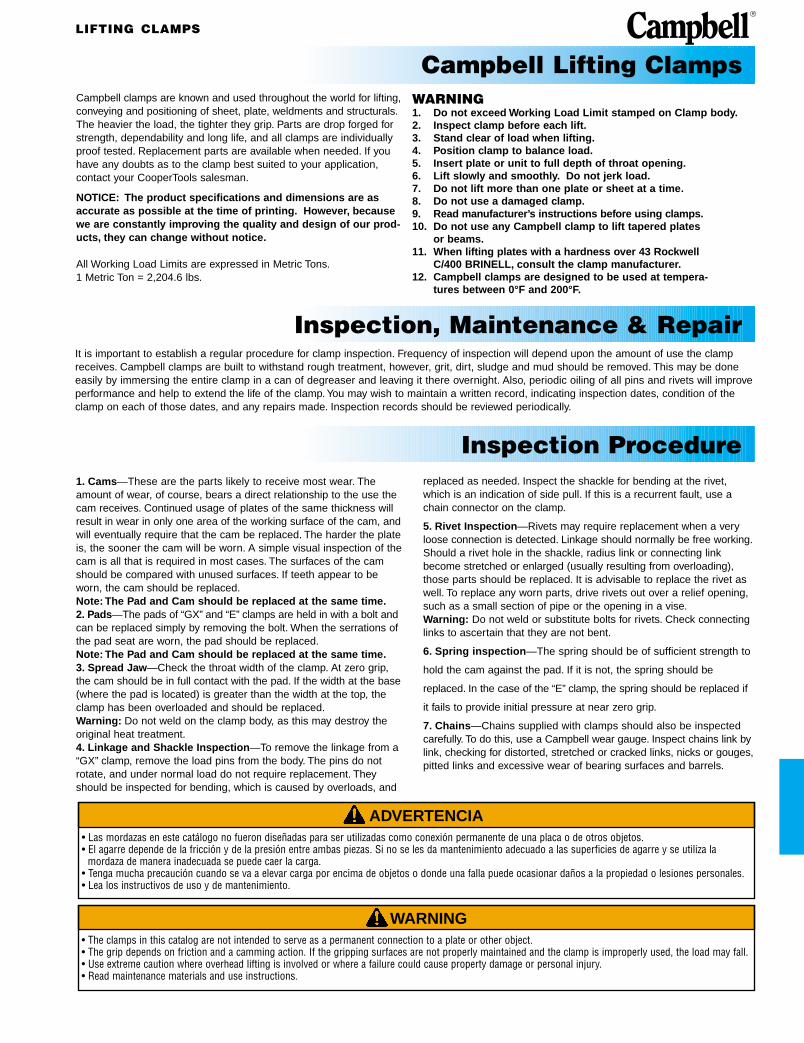
Though it began manufacturing operations in 1866, Campbell first made itslightweight, rugged plate lifting clamp in 1938. It was designed by anEnglishman named Volz. Because it incorporated forged parts of heat treated,alloy steel, the Campbell clamp earned a worldwide reputation for reliability andlong life. It is widely used by steel mills, warehouses and fabricating shops andis much preferred because its forged parts give increased strength yet are light-weight. And, they are readily available when servicing is required.
Campbell® Clamps Table of Contents
The Campbell operation facilities in York, PA,and Cortland, NY, conform to QualityStandard ISO 9001.
on the sectionyou want
Click
WARNING• The clamps in this catalog are not intended to serve as a permanent connection to a plate or other object. • The grip depends on friction and a camming action. If the gripping surfaces are not properly maintained and the clamp is improperly used, the load may fall. • Use extreme caution where overhead lifting is involved or where a failure could cause property damage or personal injury. • Read maintenance materials and use instructions.
Campbell clamps are known and used throughout the world for lifting,conveying and positioning of sheet, plate, weldments and structurals.The heavier the load, the tighter they grip. Parts are drop forged forstrength, dependability and long life, and all clamps are individuallyproof tested. Replacement parts are available when needed. If youhave any doubts as to the clamp best suited to your application,contact your CooperTools salesman.
NOTICE: The product specifications and dimensions are asaccurate as possible at the time of printing. However, becausewe are constantly improving the quality and design of our prod-ucts, they can change without notice.
All Working Load Limits are expressed in Metric Tons.1 Metric Ton = 2,204.6 lbs.
It is important to establish a regular procedure for clamp inspection. Frequency of inspection will depend upon the amount of use the clamp receives. Campbell clamps are built to withstand rough treatment, however, grit, dirt, sludge and mud should be removed. This may be doneeasily by immersing the entire clamp in a can of degreaser and leaving it there overnight. Also, periodic oiling of all pins and rivets will improveperformance and help to extend the life of the clamp. You may wish to maintain a written record, indicating inspection dates, condition of theclamp on each of those dates, and any repairs made. Inspection records should be reviewed periodically.
1. Cams—These are the parts likely to receive most wear. The amount of wear, of course, bears a direct relationship to the use thecam receives. Continued usage of plates of the same thickness willresult in wear in only one area of the working surface of the cam, andwill eventually require that the cam be replaced. The harder the plateis, the sooner the cam will be worn. A simple visual inspection of thecam is all that is required in most cases. The surfaces of the camshould be compared with unused surfaces. If teeth appear to beworn, the cam should be replaced.Note: The Pad and Cam should be replaced at the same time.2. Pads—The pads of “GX” and “E” clamps are held in with a bolt andcan be replaced simply by removing the bolt. When the serrations ofthe pad seat are worn, the pad should be replaced.Note: The Pad and Cam should be replaced at the same time.3. Spread Jaw—Check the throat width of the clamp. At zero grip, the cam should be in full contact with the pad. If the width at the base(where the pad is located) is greater than the width at the top, theclamp has been overloaded and should be replaced.Warning: Do not weld on the clamp body, as this may destroy theoriginal heat treatment.4. Linkage and Shackle Inspection—To remove the linkage from a “GX” clamp, remove the load pins from the body. The pins do notrotate, and under normal load do not require replacement. Theyshould be inspected for bending, which is caused by overloads, and
WARNING1. Do not exceed Working Load Limit stamped on Clamp body.2. Inspect clamp before each lift.3. Stand clear of load when lifting.4. Position clamp to balance load.5. Insert plate or unit to full depth of throat opening.6. Lift slowly and smoothly. Do not jerk load.7. Do not lift more than one plate or sheet at a time.8. Do not use a damaged clamp.9. Read manufacturer’s instructions before using clamps.10. Do not use any Campbell clamp to lift tapered plates
or beams.11. When lifting plates with a hardness over 43 Rockwell
C/400 BRINELL, consult the clamp manufacturer.12. Campbell clamps are designed to be used at tempera-
tures between 0°F and 200°F.
replaced as needed. Inspect the shackle for bending at the rivet,which is an indication of side pull. If this is a recurrent fault, use achain connector on the clamp.
5. Rivet Inspection—Rivets may require replacement when a very loose connection is detected. Linkage should normally be free working.Should a rivet hole in the shackle, radius link or connecting linkbecome stretched or enlarged (usually resulting from overloading),those parts should be replaced. It is advisable to replace the rivet aswell. To replace any worn parts, drive rivets out over a relief opening,such as a small section of pipe or the opening in a vise.Warning: Do not weld or substitute bolts for rivets. Check connectinglinks to ascertain that they are not bent.
6. Spring inspection—The spring should be of sufficient strength to
hold the cam against the pad. If it is not, the spring should be
replaced. In the case of the “E” clamp, the spring should be replaced if
it fails to provide initial pressure at near zero grip.
7. Chains—Chains supplied with clamps should also be inspected carefully. To do this, use a Campbell wear gauge. Inspect chains link bylink, checking for distorted, stretched or cracked links, nicks or gouges,pitted links and excessive wear of bearing surfaces and barrels.
ADVERTENCIA• Las mordazas en este catálogo no fueron diseñadas para ser utilizadas como conexión permanente de una placa o de otros objetos.• El agarre depende de la fricción y de la presión entre ambas piezas. Si no se les da mantenimiento adecuado a las superficies de agarre y se utiliza la
mordaza de manera inadecuada se puede caer la carga.• Tenga mucha precaución cuando se va a elevar carga por encima de objetos o donde una falla puede ocasionar daños a la propiedad o lesiones personales.• Lea los instructivos de uso y de mantenimiento.
Inspection, Maintenance & Repair
Inspection Procedure
LIFTING CLAMPS
Campbell Lifting Clamps

ADVERTENCIA• Seleccione el tamaño de mordaza adecuado para el trabajo.• Determine el peso de la placa a ser alzada.• No exceda el limite de carga de trabajo (WLL) mostrado en la mordaza.• El espesor de la placa debe estar dentro de la gama de agarre mostrada
en la mordaza.
WARNING• Select proper size clamp for the job. • Determine the weight of the plate to be lifted. • Do not exceed WLL (Working Load Limit) shown on clamp.• Plate thickness must be within grip range shown on clamp.
DimensionsCat. UPC No. A B C D E F G H INo. 020418 in. mm in. mm in. mm in. mm in. mm in. mm in. mm in. mm in. mm
6422012 187049 5 15⁄16 151 10 254 2 1⁄8 54 2 5⁄8 67 2 51 4 102 3 1⁄4 83 1 3⁄16 30 5 3⁄16 132
6422001 185687 6 9⁄16 167 11 1⁄4 286 3 13⁄16 97 3 1⁄16 78 2 1⁄16 52 5 127 3 5⁄8 92 1 5⁄8 41 5 7⁄8 149
6422002 187032 7 1⁄4 184 12 1⁄8 308 2 9⁄16 65 3 5⁄16 84 2 1⁄4 57 4 7⁄8 124 3 1⁄2 89 1 5⁄8 41 5 15⁄16 151
6422003 187810 8 3⁄4 122 14 5⁄8 371 3 1⁄4 82 3 7⁄8 98 3 76 7 1⁄2 190 4 101 1 13⁄16 46 7 1⁄8 181
• Available in a 1/2, 1, 2, and 3 ton capacity• Drop forged and heat treated components, with gripping
surfaces of case hardened alloy steel• Exclusive feature is a patented wear indicator system.
When any of cam’s straight line, convex teeth are flattened between unique wear indicator grooves, it is time to change the cam
• Note: The Pad and Cam should be replaced at the same time
• Newly designed “Cam Engaging Lever” keeps the cam in contact with the plate. The tension arm and spring mechanism facilitate attaching and removing the clamp.These clamps will not lift plate when in the “lever open”position
• Clamps are 100% Proof Tested and Certificate of Test supplied with each clamp
• Warning: Never tamper with a clamp’s tension arm and spring mechanism during a lift
NORMAL WORN
Grip Clamp WorkingCat. UPC No. Range Weight Load LimitNo. 020418 in. mm lb kg Metric Ton
6422012 187049 1⁄16 - 5⁄8 2 - 16 5.5 2.50 1⁄26422001 185687 1⁄16 - 3⁄4 2 - 19 8 3.63 1
6422002 187032 1⁄16 - 7⁄8 2 - 23 10.5 4.77 2
6422003 187810 1⁄16 - 1 2 - 25 18 8.1 3
LIFTING CLAMPS
“GXL” Clamps

ADVERTENCIA• Seleccione el tamaño de mordaza adecuado para el trabajo.• Determine el peso de la placa a ser alzada.• No exceda el limite de carga de trabajo (WLL) mostrado en la mordaza.• El espesor de la placa debe estar dentro de la gama de agarre mostrada
en la mordaza.
WARNING• Select proper size clamp for the job. • Determine the weight of the plate to be lifted. • Do not exceed WLL (Working Load Limit) shown on clamp.• Plate thickness must be within grip range shown on clamp.
LIFTING CLAMPS
Replacement parts for “GXL” Clamps
Capacity 1⁄2 TON 1TON 2 TON 3 TONCat. UPC No. Cat. UPC No. Cat. UPC No. Cat. UPC No.
Part Name No. 020418 Qty. No. 020418 Qty. No. 020418 Qty. No. 020418 Qty.
Shackle 6501005 170720 1 6501105 170805 1 6501205 186226 1 6501305 170904 1
Radius Link 6504002 - 1 6504102 186783 1 6504202 - 1 6504302 187896 1
T-Spring 6501016 170751 1 6501116 170836 1 6501216 186264 1 6501316 170935 1
Conn. Link 6501007 170737 2 6501107 170812 2 6501207 186233 2 6501307 170911 2
Cam 6504001 - 1 6501201 170850 1 6501210 186257 1 6501301 170867 1
Pad 6501017 170768 1 6501117 170843 1 6501217 186271 1 6501317 170942 1
Cam Kit 6505030 - 1 6505021 179037 1 6505029 186288 1 6505022 179044 1
Pivot 6504005 - 1 6504105 186790 1 6504205 - 1 6504305 187902 1
Lever 6504106 - 1 6504106 186806 1 6504106 - 1 6504306 187919 1
E-Spring 6504008 - 1 6504108 186813 1 6504208 - 1 6504308 187926 1
* Cam and RadiusLink Pin 6501003 170713 3 6501103 170782 2 6501203 186202 2 6501303 170881 2
* Pad Pin ** 6501104 170799 1 6501204 186219 1 6501304 170898 1
Rivets 6501008 170744 3 6501108 170829 3 6501208 186240 3 6501308 170928 3
* Drive pins included.** The swivel pad pin on this model is the same as the cam and radius link pin.

LIFTING CLAMPS
ADVERTENCIA• Seleccione el tamaño de mordaza adecuado para el trabajo.• Determine el peso de la placa a ser alzada.• No exceda el limite de carga de trabajo (WLL) mostrado en la mordaza.• El espesor de la placa debe estar dentro de la gama de agarre mostrada
en la mordaza.
WARNING• Select proper size clamp for the job. • Determine the weight of the plate to be lifted. • Do not exceed WLL (Working Load Limit) shown on clamp.• Plate thickness must be within grip range shown on clamp.
Grip Clamp WorkingCat. UPC No. Range Weight Load LimitNo. 020418 in. mm lb kg Metric Ton
6423000 172199 1⁄16 - 5⁄8 1 - 16 4 2 1⁄26423920 175657 5⁄8 - 1 1⁄8 16 - 28 5 2 1⁄26423921 176005 1 1⁄8 - 1 5⁄8 28 - 41 5 2 1⁄26423005 172205 1⁄16 - 3⁄4 1 - 19 8 4 1
6423923 175664 3⁄4 - 1 3⁄8 19 - 35 9 4 1
6423924 176012 1 3⁄8 - 2 35 - 51 11 5 1
6423010 172229 1⁄16 - 1 1 - 25 17 8 3
6423925 175671 1 - 1 3⁄4 25 - 44 20 9 3
6423926 176029 1 3⁄4 - 2 1⁄2 44 - 64 20 9 3
6423015 177583 1⁄2 - 2 13 - 51 40 18 5
6423020 177590 1⁄2 - 2 1⁄2 3 - 64 143 65 10
“GX” Clamps• “GX” clamp is entirely drop forged and heat treated• Can be used for both vertical and horizontal-to-vertical
lifting• Exclusive feature is a patented wear indicator system.
When any of cam’s straight line, convex teeth are flattened between unique wear indicator grooves, it is time to change the cam
• Shackle and “G” link combined into one part for fewer stresspoints and less chance of side loading damage
• Note: The pad should be replaced same time as cam• 100% proof tested with certificate of test attached to each
clamp• Note: The Pad and Cam should be replaced at the same
time• Clamps are 100% Proof Tested and Certificate of Test
supplied with each clamp
DimensionsCat. UPC No. A B C D E F G H INo. 020418 in. mm in. mm in. mm in. mm in. mm in. mm in. mm in. mm in. mm
6423000 172199 4 102 9 1⁄2 241 2 3⁄16 56 2 3⁄4 67 2 51 4 1⁄8 105 2 7⁄8 73 1 3⁄8 35 4 7⁄8 124
6423920 175657 5 127 9 1⁄2 241 2 3⁄16 56 2 5⁄8 67 2 51 4 1⁄8 105 2 7⁄8 73 1 5⁄8 41 4 7⁄8 124
6423921 176005 5 1⁄2 140 9 1⁄2 241 2 3⁄16 56 2 5⁄8 67 2 51 4 1⁄8 105 2 7⁄8 73 1 5⁄8 41 4 7⁄8 124
6423005 172205 4 3⁄4 121 11 1⁄4 286 3 1⁄16 78 3 1⁄16 78 2 1⁄16 52 5 1⁄4 133 3 5⁄8 92 1 5⁄8 41 5 7⁄8 149
6423923 175664 5 7⁄8 149 11 1⁄4 286 3 1⁄16 78 3 1⁄16 78 2 1⁄16 52 5 1⁄4 133 3 5⁄8 92 1 5⁄8 54 5 7⁄8 149
6423924 176012 6 1⁄2 165 11 1⁄4 286 3 1⁄16 78 3 1⁄16 78 2 1⁄16 52 5 1⁄4 133 3 5⁄8 92 1 5⁄8 54 5 7⁄8 149
6423010 172229 6 152 14 356 3 9⁄16 90 3 13⁄16 97 3 76 6 3⁄4 171 4 7⁄16 113 2 51 7 5⁄8 194
6423925 175671 7 1⁄4 184 14 356 3 9⁄16 90 3 13⁄16 97 3 76 6 3⁄4 171 4 7⁄16 113 2 1⁄4 57 7 5⁄8 194
6423926 176029 8 203 14 356 3 9⁄16 90 3 13⁄16 97 3 76 6 3⁄4 171 4 7⁄16 113 2 1⁄4 57 7 5⁄8 194
6423015 177583 8 7⁄8 225 20 508 4 11⁄16 119 5 127 3 15⁄16 100 8 3⁄4 219 5 15⁄16 151 3 13⁄16 97 9 15⁄16 252
6423020 177590 14 3⁄4 375 30 762 7 7⁄8 194 7 3⁄8 187 5 127 13 3⁄4 349 10 1⁄4 260 4 15⁄16 125 16 3⁄8 416
LIFTING CLAMPS
ADVERTENCIA• Seleccione el tamaño de mordaza adecuado para el trabajo.• Determine el peso de la placa a ser alzada.• No exceda el limite de carga de trabajo (WLL) mostrado en la mordaza.• El espesor de la placa debe estar dentro de la gama de agarre mostrada
en la mordaza.
WARNING• Select proper size clamp for the job. • Determine the weight of the plate to be lifted. • Do not exceed WLL (Working Load Limit) shown on clamp.• Plate thickness must be within grip range shown on clamp.
DimensionsCat. UPC No. A B C D E F G H INo. 020418 in. mm in. mm in. mm in. mm in. mm in. mm in. mm in. mm in. mm
6423100 177330 4 102 9 1⁄2 241 2 1⁄8 54 2 5⁄8 67 2 51 4 1⁄16 103 2 7⁄8 73 1 3⁄8 35 4 3⁄4 121
6423105 177347 4 3⁄4 121 11 5⁄16 287 2 5⁄8 67 3 1⁄16 78 2 1⁄16 52 4 7⁄8 124 3 9⁄16 90 1 21⁄32 42 5 13⁄16 148
6423108 183041 5 1⁄8 130 12 1⁄8 308 2 5⁄8 67 3 5⁄16 84 2 1⁄4 57 5 127 3 9⁄16 90 1 5⁄8 41 5 15⁄16 151
6423110 177354 6 152 15 1⁄16 383 3 7⁄16 87 3 13⁄16 97 3 76 6 9⁄16 167 4 3⁄16 106 2 51 7 5⁄16 186
Grip Clamp WorkingCat. UPC No. Range Weight Load LimitNo. 020418 in. mm lb kg Metric Ton
6423100 177330 1⁄16 - 5⁄8 1 - 16 4 2 1⁄26423105 177347 1⁄16 - 3⁄4 1 - 19 7 3 1
6423108 183041 1⁄16 - 7⁄8 1 - 22 15 7 2
6423110 177354 1⁄16 - 1 1 - 25 18 8 3
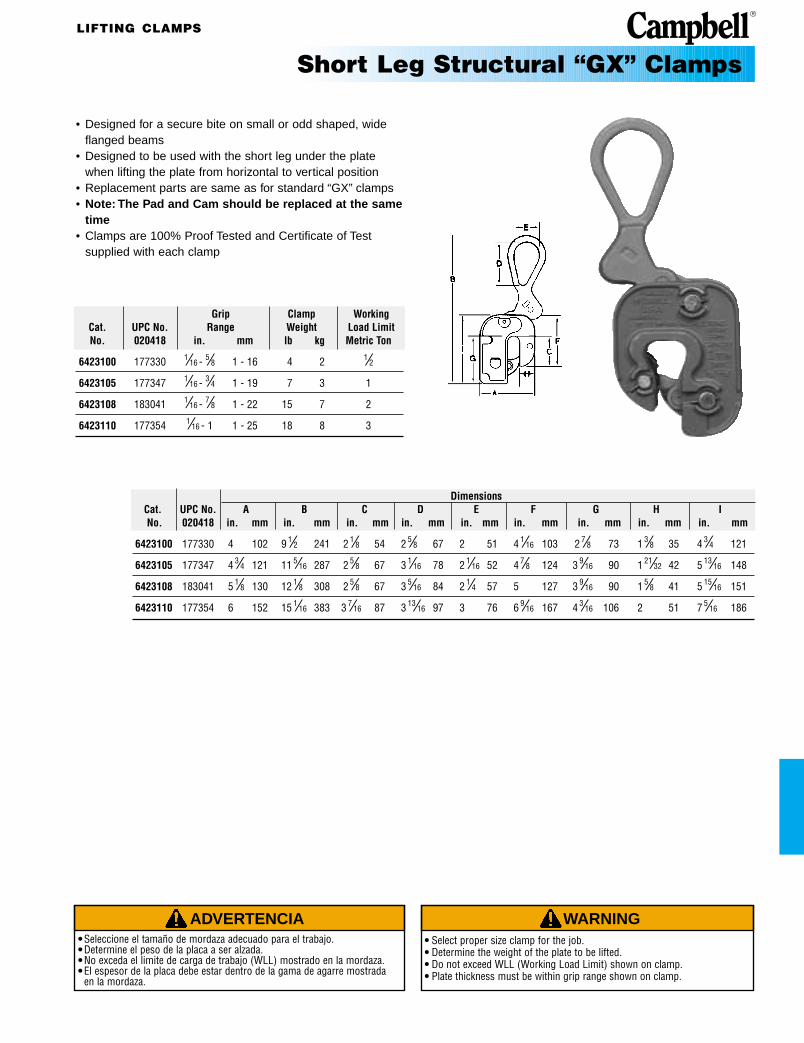
Short Leg Structural “GX” Clamps
• Designed for a secure bite on small or odd shaped, wide flanged beams
• Designed to be used with the short leg under the plate when lifting the plate from horizontal to vertical position
• Replacement parts are same as for standard “GX” clamps• Note: The Pad and Cam should be replaced at the same
time• Clamps are 100% Proof Tested and Certificate of Test
supplied with each clamp
LIFTING CLAMPS
ADVERTENCIA• Seleccione el tamaño de mordaza adecuado para el trabajo.• Determine el peso de la placa a ser alzada.• No exceda el limite de carga de trabajo (WLL) mostrado en la mordaza.• El espesor de la placa debe estar dentro de la gama de agarre mostrada
en la mordaza.
WARNING• Select proper size clamp for the job. • Determine the weight of the plate to be lifted. • Do not exceed WLL (Working Load Limit) shown on clamp.• Plate thickness must be within grip range shown on clamp.
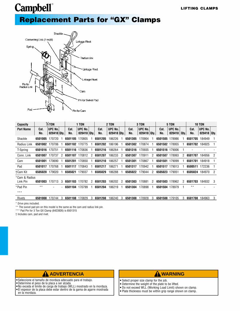
Replacement Parts for “GX” Clamps
Capacity 1⁄2 TON 1 TON 2 TON 3 TON 5 TON 10 TONPart Name Cat. UPC No. Cat. UPC No. Cat. UPC No. Cat. UPC No. Cat. UPC No. Cat. UPC No.
No. 020418 Qty. No. 020418 Qty. No. 020418 Qty. No. 020418 Qty. No. 020418 Qty. No. 020418 Qty.
Shackle 6501005 170720 1 6501105 170805 1 6501205 186226 1 6501305 170904 1 6501505 178986 1 6501705 184949 1
Radius Link 6501002 170706 1 6501102 170775 1 6501202 186196 1 6501302 170874 1 6501502 178955 1 6501702 184925 1
T-Spring 6501016 170751 1 6501116 170836 1 6501216 186264 1 6501316 170935 1 6501516 179006 1 - - -
Conn. Link 6501007 170737 2 6501107 170812 2 6501207 186233 2 6501307 170911 2 6501507 178993 2 6501707 184956 2
Cam 6501001 170690 1 6501201 170850 1 6501210 186257 1 6501301 170867 1 6501501 179099 1 6501701 184918 1
Pad 6501017 170768 1 6501117 170843 1 6501217 186271 1 6501317 170942 1 6501517 179013 1 6500511 172236 1
†Cam Kit 6505020 179020 1 6505021 179037 1 6505029 186288 1 6505022 179044 2 6505023 179051 1 6505024 184970 2
*Cam & RadiusLink Pin 6501003 170713 3 6501103 170782 2 6501203 186202 2 6501303 170881 2 6501503 178962 2 6501703 184932 3
*Pad Pin ** - - 6501104 170799 1 6501204 186219 1 6501304 170898 1 6501504 178979 1 ** - -
***
Rivets 6501008 170744 3 6501108 170829 3 6501208 186240 3 6501308 170928 3 6501508 179105 3 6501708 184963 3
* Drive pins included.** The swivel pad pin on this model is the same as the cam and radius link pin.*** Pad Pin for 3 Ton GX Clamp (6423926) is 6501315† Includes cam, pad and rivet.
LIFTING CLAMPS
ADVERTENCIA• Seleccione el tamaño de mordaza adecuado para el trabajo.• Determine el peso de la placa a ser alzada.• No exceda el limite de carga de trabajo (WLL) mostrado en la mordaza.• El espesor de la placa debe estar dentro de la gama de agarre mostrada
en la mordaza.
WARNING• Select proper size clamp for the job. • Determine the weight of the plate to be lifted. • Do not exceed WLL (Working Load Limit) shown on clamp.• Plate thickness must be within grip range shown on clamp.
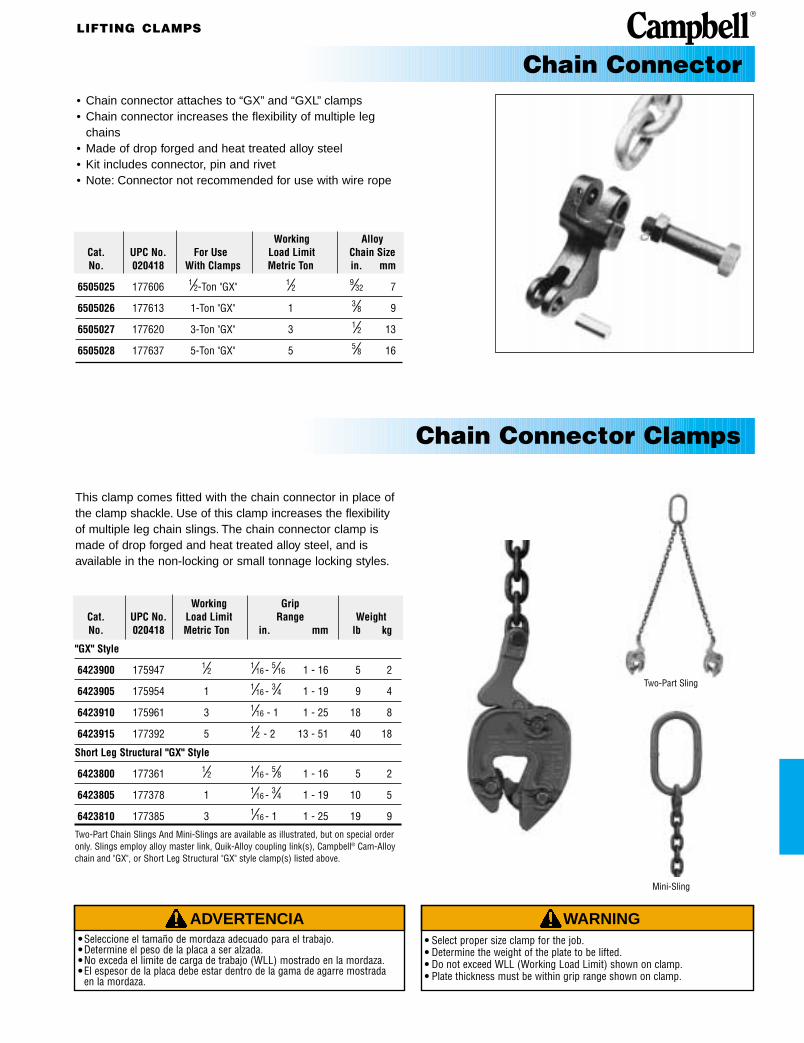
• Chain connector attaches to “GX” and “GXL” clamps• Chain connector increases the flexibility of multiple leg
chains• Made of drop forged and heat treated alloy steel• Kit includes connector, pin and rivet• Note: Connector not recommended for use with wire rope
Chain Connector
Chain Connector Clamps
This clamp comes fitted with the chain connector in place ofthe clamp shackle. Use of this clamp increases the flexibilityof multiple leg chain slings. The chain connector clamp ismade of drop forged and heat treated alloy steel, and is available in the non-locking or small tonnage locking styles.
Working GripCat. UPC No. Load Limit Range WeightNo. 020418 Metric Ton in. mm lb kg
"GX" Style
6423900 175947 1⁄2 1⁄16 - 5⁄16 1 - 16 5 2
6423905 175954 1 1⁄16 - 3⁄4 1 - 19 9 4
6423910 175961 3 1⁄16 - 1 1 - 25 18 8
6423915 177392 5 1⁄2 - 2 13 - 51 40 18
Short Leg Structural "GX" Style
6423800 177361 1⁄2 1⁄16 - 5⁄8 1 - 16 5 2
6423805 177378 1 1⁄16 - 3⁄4 1 - 19 10 5
6423810 177385 3 1⁄16 - 1 1 - 25 19 9
Two-Part Chain Slings And Mini-Slings are available as illustrated, but on special order only. Slings employ alloy master link, Quik-Alloy coupling link(s), Campbell® Cam-Alloychain and "GX", or Short Leg Structural "GX" style clamp(s) listed above.
Two-Part Sling
Mini-Sling
Working AlloyCat. UPC No. For Use Load Limit Chain SizeNo. 020418 With Clamps Metric Ton in. mm
6505025 177606 1⁄2-Ton "GX" 1⁄2 9⁄32 7
6505026 177613 1-Ton "GX" 1 3⁄8 9
6505027 177620 3-Ton "GX" 3 1⁄2 13
6505028 177637 5-Ton "GX" 5 5⁄8 16

ADVERTENCIA• Seleccione el tamaño de mordaza adecuado para el trabajo.• Determine el peso de la placa a ser alzada.• No exceda el limite de carga de trabajo (WLL) mostrado en la mordaza.• El espesor de la placa debe estar dentro de la gama de agarre mostrada
en la mordaza.
WARNING• Select proper size clamp for the job. • Determine the weight of the plate to be lifted. • Do not exceed WLL (Working Load Limit) shown on clamp.• Plate thickness must be within grip range shown on clamp.
Replacement Parts for “GX” Rubber Pad Clamps
Capacity 1⁄2 TON 1 TON 3 TONGrip 1⁄16" - 3⁄4" 1⁄16" - 3⁄4" 1⁄16" - 3⁄4"Part Name Pkg Cat. UPC No. Cat. UPC No. Cat. UPC No.
Qty. No. 020418 No. 020418 No. 020418
Shackle 1 6501005 170720 6501105 170805 6501305 170904
Radius Link 1 6501013 184802 6501113 184840 6501313 184888
Conn. Link 2 6501009 184796 6501109 184833 6501309 184871
Smooth Cam 1 6501099 184826 6501199 184864 6501399 184901
Pin for Cam& Radius Link 2 6501103 184819 6501303 184857 6501503 178962
Rubber Pad 1 6501096 170782 6501196 170881 6501396 184895
Spring 1 6501116 170829 6501316 170928 6501516 179006
Linkage Rivet for Shackle 1 6501008 170836 6501108 170829 6501308 170928
Linkage Rivets for Cam&Radius Link 2 6501108 170744 6501308 170935 6501508 179105
* Drive Pins Included.
Model “GX” Rubber Pad (Non-Marring) Clamps
Grip Clamp WorkingCat. UPC No. Range Weight Load LimitNo. 020418 in. mm lb kg Metric Ton
6423600 175916 1⁄16 - 3⁄8 1 - 9 6 3 1⁄26423605 175923 1⁄16 - 5⁄8 1 - 16 22 10 1
6423610 175930 1⁄16 - 7⁄8 1 - 25 55 25 3
• Has a rubber covered pad and cam of relatively smooth metal conditioned to grip tightly
• Should be used for lifting smooth polished plates and/or hard plates over 43 Rockwell C/400 Brinnell
• Lifts heavy plates with minimum marring• Clamps are 100% Proof Tested and Certificate of Test
supplied with each clamp
LIFTING CLAMPS

LIFTING CLAMPS
ADVERTENCIA• Seleccione el tamaño de mordaza adecuado para el trabajo.• Determine el peso de la placa a ser alzada.• No exceda el limite de carga de trabajo (WLL) mostrado en la mordaza.• El espesor de la placa debe estar dentro de la gama de agarre mostrada
en la mordaza.
WARNING• Select proper size clamp for the job. • Determine the weight of the plate to be lifted. • Do not exceed WLL (Working Load Limit) shown on clamp.• Plate thickness must be within grip range shown on clamp.
• Clamp lifts from either horizontal or vertical position• Clamps turn plates through 90°• Locks open or closed with a lever• Has large throat that gives a secure bite and wide grip range• Note: Be sure clamp is in lock closed position before making
lift• Clamps are 100% Proof Tested and Certificate of Test
supplied with each clamp
DimensionsCat. UPC No. A B C D E H JNo. 020418 in. mm in. mm in. mm in. mm in. mm in. mm in. mm
6420701 096112 7 1⁄4 184 14 3⁄8 365 9 1⁄4 235 3 1⁄2 89 2 51 2 51 4 3⁄8 111
6420702 096129 8 7⁄8 225 16 406 10 1⁄2 267 3 1⁄2 89 2 1⁄2 64 2 11⁄16 68 5 127
6420703 096136 10 1⁄2 267 16 5⁄8 422 11 1⁄4 286 3 1⁄2 89 2 1⁄2 64 3 1⁄8 79 5 1⁄4 133
6420705 096150 14 1⁄8 359 22 3⁄4 578 15 3⁄4 400 5 127 3 1⁄2 89 4 7⁄8 124 8 1⁄2 216
6420706 096167 16 406 23 584 16 1⁄4 413 5 127 3 1⁄2 89 5 1⁄16 129 8 3⁄4 222
6420707 096174 18 457 25 3⁄4 654 18 7⁄8 479 5 127 3 1⁄2 89 5 1⁄4 133 10 1⁄4 260
6420708 096181 14 1⁄4 362 22 3⁄4 578 16 406 5 127 3 1⁄2 89 4 7⁄8 124 8 1⁄2 216
6420709 096198 16 1⁄4 413 23 584 16 1⁄4 413 5 127 3 1⁄2 89 5 1⁄2 140 8 3⁄4 222
6420710 096204 18 1⁄2 470 26 660 19 483 5 127 3 1⁄2 89 5 7⁄16 138 10 1⁄4 260
6420711 096211 16 1⁄2 419 25 1⁄4 641 17 1⁄4 438 5 127 3 1⁄2 89 6 1⁄8 156 8 1⁄2 216
6420712 096228 19 1⁄2 495 26 3⁄8 670 18 1⁄4 464 5 127 3 1⁄2 89 6 1⁄2 165 9 3⁄4 248
6420713 096235 21 1⁄2 546 26 1⁄4 667 18 1⁄4 464 5 127 3 1⁄2 89 6 1⁄2 165 9 3⁄4 248Made to order
∆
∆
∆
∆
Locking “E” Clamps
Grip Clamp WorkingMerrill Cat. UPC No. Range Weight Load Limit
Model No. No. 020418 in. mm lb kg Metric Ton
3E 6420701 096112 0 - 1 1⁄4 0 - 32 20 9 3
5E 6420702 096129 0 - 1 1⁄2 0 - 38 28 13 5
5E 6420703 096136 1 1⁄4 - 2 1⁄2 32 - 64 33 15 5
8E 6420705 096150 1⁄2 - 2 1⁄2 13 - 64 81 37 8
8E 6420706 096167 2 - 4 51 - 102 84 38 8
8E 6420707 096174 4 - 6 102 - 152 108 49 8
12E 6420708 096181 1⁄2 - 2 1⁄2 13 - 64 78 35 12
12E 6420709 096198 2 - 4 51 - 102 84 38 12
12E 6420710 096204 4 - 6 102 - 152 117 53 12
20E 6420711 096211 1⁄2 - 3 13 - 76 146 66 20
20E 6420712 096228 3 - 5 1⁄2 76 - 140 158 72 20
20E 6420713 096235 5 1⁄2 - 8 140 - 203 170 77 20Made to order
∆
∆
∆
∆
∆
∆
LIFTING CLAMPS
ADVERTENCIA• Seleccione el tamaño de mordaza adecuado para el trabajo.• Determine el peso de la placa a ser alzada.• No exceda el limite de carga de trabajo (WLL) mostrado en la mordaza.• El espesor de la placa debe estar dentro de la gama de agarre mostrada
en la mordaza.
WARNING• Select proper size clamp for the job. • Determine the weight of the plate to be lifted. • Do not exceed WLL (Working Load Limit) shown on clamp.• Plate thickness must be within grip range shown on clamp.
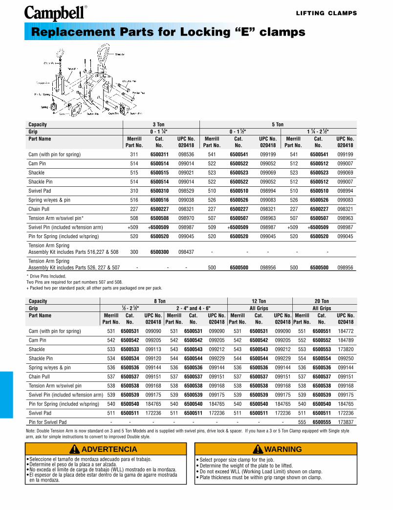
Capacity 3 Ton 5 TonGrip 0 - 1 1⁄4" 0 - 1 1⁄2" 1 1⁄4 - 2 1⁄2"Part Name Merrill Cat. UPC No. Merrill Cat. UPC No. Merrill Cat. UPC No.
Part No. No. 020418 Part No. No. 020418 Part No. No. 020418
Cam (with pin for spring) 311 6500311 098536 541 6500541 099199 541 6500541 099199
Cam Pin 514 6500514 099014 522 6500522 099052 512 6500512 099007
Shackle 515 6500515 099021 523 6500523 099069 523 6500523 099069
Shackle Pin 514 6500514 099014 522 6500522 099052 512 6500512 099007
Swivel Pad 310 6500310 098529 510 6500510 098994 510 6500510 098994
Spring w/eyes & pin 516 6500516 099038 526 6500526 099083 526 6500526 099083
Chain Pull 227 6500227 098321 227 6500227 098321 227 6500227 098321
Tension Arm w/swivel pin* 508 6500508 098970 507 6500507 098963 507 6500507 098963
Swivel Pin (included w/tension arm) +509 +6500509 098987 509 +6500509 098987 +509 +6500509 098987
Pin for Spring (included w/spring) 520 6500520 099045 520 6500520 099045 520 6500520 099045
Tension Arm SpringAssembly Kit includes Parts 516,227 & 508 300 6500300 098437 - - - - -
Tension Arm SpringAssembly Kit includes Parts 526, 227 & 507 - - - 500 6500500 098956 500 6500500 098956
* Drive Pins Included.Two Pins are required for part numbers 507 and 508.+ Packed two per standard pack; all other parts are packaged one per pack.
Capacity 8 Ton 12 Ton 20 TonGrip 1⁄2 - 2 1⁄2" 2 - 4" and 4 - 6" All Grips All GripsPart Name Merrill Cat. UPC No. Merrill Cat. UPC No. Merrill Cat. UPC No. Merrill Cat. UPC No.
Part No. No. 020418 Part No. No. 020418 Part No. No. 020418 Part No. No. 020418
Cam (with pin for spring) 531 6500531 099090 531 6500531 099090 531 6500531 099090 551 6500551 184772
Cam Pin 542 6500542 099205 542 6500542 099205 542 6500542 099205 552 6500552 184789
Shackle 533 6500533 099113 543 6500543 099212 543 6500543 099212 553 6500553 173820
Shackle Pin 534 6500534 099120 544 6500544 099229 544 6500544 099229 554 6500554 099250
Spring w/eyes & pin 536 6500536 099144 536 6500536 099144 536 6500536 099144 536 6500536 099144
Chain Pull 537 6500537 099151 537 6500537 099151 537 6500537 099151 537 6500537 099151
Tension Arm w/swivel pin 538 6500538 099168 538 6500538 099168 538 6500538 099168 538 6500538 099168
Swivel Pin (included w/tension arm) 539 6500539 099175 539 6500539 099175 539 6500539 099175 539 6500539 099175
Pin for Spring (included w/spring) 540 6500540 184765 540 6500540 184765 540 6500540 184765 540 6500540 184765
Swivel Pad 511 6500511 172236 511 6500511 172236 511 6500511 172236 511 6500511 172236
Pin for Swivel Pad - - - - - - - - - 555 6500555 173837
Note: Double Tension Arm is now standard on 3 and 5 Ton Models and is supplied with swivel pins, drive lock & spacer. If you have a 3 or 5 Ton Clamp equipped with Single stylearm, ask for simple instructions to convert to improved Double style.
Replacement Parts for Locking “E” clamps
LIFTING CLAMPS
ADVERTENCIA• Seleccione el tamaño de mordaza adecuado para el trabajo.• Determine el peso de la placa a ser alzada.• No exceda el limite de carga de trabajo (WLL) mostrado en la mordaza.• El espesor de la placa debe estar dentro de la gama de agarre mostrada
en la mordaza.
WARNING• Select proper size clamp for the job. • Determine the weight of the plate to be lifted. • Do not exceed WLL (Working Load Limit) shown on clamp.• Plate thickness must be within grip range shown on clamp.
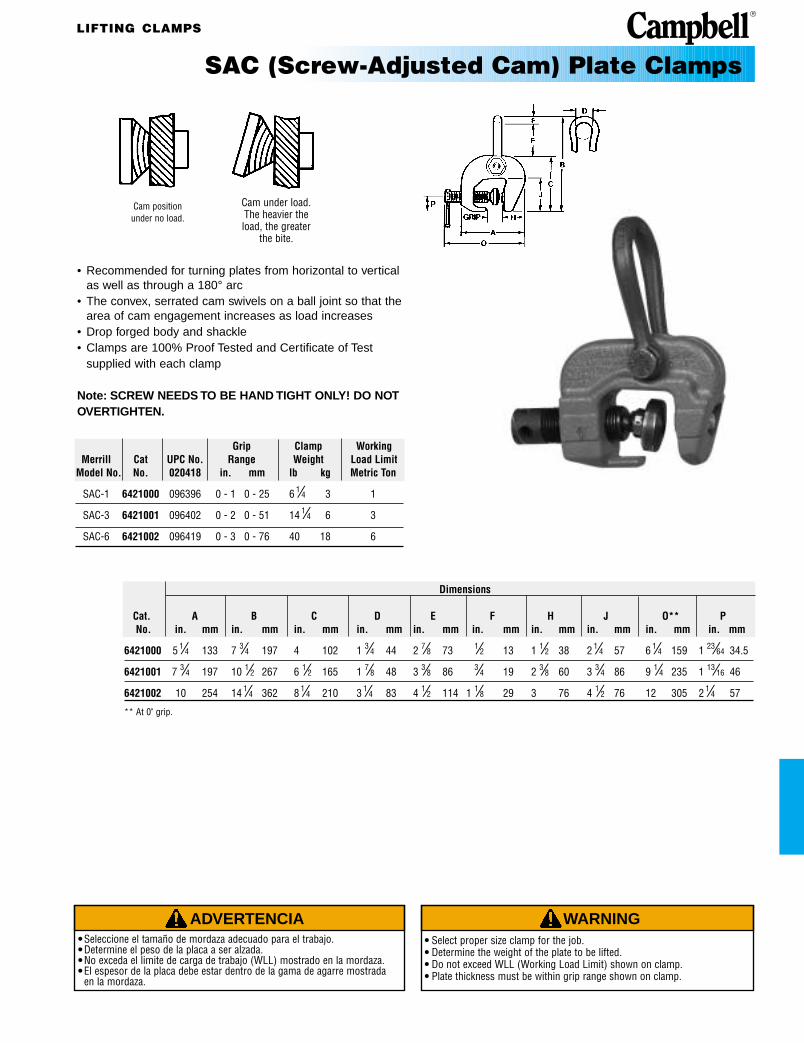
SAC (Screw-Adjusted Cam) Plate Clamps
• Recommended for turning plates from horizontal to vertical as well as through a 180° arc
• The convex, serrated cam swivels on a ball joint so that the area of cam engagement increases as load increases
• Drop forged body and shackle• Clamps are 100% Proof Tested and Certificate of Test
supplied with each clamp
Note: SCREW NEEDS TO BE HAND TIGHT ONLY! DO NOTOVERTIGHTEN.
Cam position under no load.
Cam under load.The heavier theload, the greater
the bite.
Grip Clamp WorkingMerrill Cat UPC No. Range Weight Load Limit
Model No. No. 020418 in. mm lb kg Metric Ton
SAC-1 6421000 096396 0 - 1 0 - 25 6 1⁄4 3 1
SAC-3 6421001 096402 0 - 2 0 - 51 14 1⁄4 6 3
SAC-6 6421002 096419 0 - 3 0 - 76 40 18 6
Dimensions
Cat. A B C D E F H J O** PNo. in. mm in. mm in. mm in. mm in. mm in. mm in. mm in. mm in. mm in. mm
6421000 5 1⁄4 133 7 3⁄4 197 4 102 1 3⁄4 44 2 7⁄8 73 1⁄2 13 1 1⁄2 38 2 1⁄4 57 6 1⁄4 159 1 23⁄64 34.5
6421001 7 3⁄4 197 10 1⁄2 267 6 1⁄2 165 1 7⁄8 48 3 3⁄8 86 3⁄4 19 2 3⁄8 60 3 3⁄4 86 9 1⁄4 235 1 13⁄16 46
6421002 10 254 14 1⁄4 362 8 1⁄4 210 3 1⁄4 83 4 1⁄2 114 1 1⁄8 29 3 76 4 1⁄2 76 12 305 2 1⁄4 57
** At 0" grip.

LIFTING CLAMPS
ADVERTENCIA• Seleccione el tamaño de mordaza adecuado para el trabajo.• Determine el peso de la placa a ser alzada.• No exceda el limite de carga de trabajo (WLL) mostrado en la mordaza.• El espesor de la placa debe estar dentro de la gama de agarre mostrada
en la mordaza.
WARNING• Select proper size clamp for the job. • Determine the weight of the plate to be lifted. • Do not exceed WLL (Working Load Limit) shown on clamp.• Plate thickness must be within grip range shown on clamp.
Applications for Multi-purpose SAC Clamp
• Clamp offers same superior gripping features as SAC clamp with added benefit of a swiveling pad
• Can be used for a variety of lifting applications as illustrated• Both gripping surfaces of swivel pad are smooth and
non-marring, however, cam has marring teeth• Clamps are 100% Proof Tested and Certificate of Test
supplied with each clamp
Note: SCREW NEEDS TO BE HAND TIGHT ONLY! DO NOTOVERTIGHTEN.
Grip Clamp WorkingMerrill Cat. UPC No. Range Weight Load Limit
Model No. No. 020418 in. mm lb kg Metric Ton
MP-1 6421010 096426 0 - 1 0 - 25 10 5 1
MP-3 6421012 096433 0 - 1 1⁄4 0 - 32 32 15 3
DimensionsMax. Max.
Cat. UPC No. A B C D E H J WNo. 020418 in. mm in. mm in. mm in. mm in. mm in. mm in. mm in. mm
6421010 096426 4 7⁄8 124 16 406 7 178 1 7⁄8 48 6 152 3 3⁄8 86 4 1⁄8 105 6 1⁄2 165
6421012 096433 6 3⁄4 171 213⁄4 552 9 1⁄4 235 2 3⁄8 60 7 1⁄4 184 4 3⁄8 111 4 3⁄4 121 10 254
Multipurpose SAC Clamps
Handles boiler sections in horizontalpositions.
Lifts and turnsstructural shapes.
Attaches to beamsfor overhead lifting.
Handles beams inhorizontal position.
Lifts plates.

LIFTING CLAMPS
ADVERTENCIA• Seleccione el tamaño de mordaza adecuado para el trabajo.• Determine el peso de la placa a ser alzada.• No exceda el limite de carga de trabajo (WLL) mostrado en la mordaza.• El espesor de la placa debe estar dentro de la gama de agarre mostrada
en la mordaza.
WARNING• Select proper size clamp for the job. • Determine the weight of the plate to be lifted. • Do not exceed WLL (Working Load Limit) shown on clamp.• Plate thickness must be within grip range shown on clamp.
Campbell SAC-1, 1 Ton Campbell SAC-3, 3 Ton Campbell SAC-6, 6 TonClamp with 0-1" Grip Clamp with 0-2" Grip Clamp with 0-3" Grip
Cat. No. 6421000 Cat. No. 6421001 Cat. No. 6421002Part Name Merrill Cat. UPC No. Merrill Cat. UPC No. Merrill Cat. UPC No.
Part No. No. 020418 Part No. No. 020418 Part No. No. 020418
Screw 240 6500240 098383 340 6500340 098666 640 6500640 099595
Cam 238 6500238 098376 338 6500338 098642 638 6500638 099571
Pad Kit 112 6500112 098017 525 6500527 186875 636 6500636 099557
Handle * * * 339 6500339 098659 639 6500639 099588
Shackle 234 6500234 098352 334 6500334 098611 634 6500634 099533
Shackle Bolt 235 6500235 098369 335 6500335 098628 635 6500635 099540
* Note: No handle is included with SAC-1.
Replacement Parts for SAC Clamps
1 Ton 3 TonCat. No. 6421010 Cat. No. 6421012
Part Name Merrill Cat. UPC No. Merrill Cat. UPC No.Part No. No. 020418 Part No. No. 020418
Shackle 105 6500105 097966 405 6500405 098901
Rivet 108 6500108 097997 308 6500308 098505
Pin 514 6500514 099014 491 6500491 098932
Cam 238 6500238 098376 338 6500338 098642
Screw 240 6500240 098383 440 6500440 173813
Swivel Pad 265 6500265 098406 365 6500365 098789
Handle - - - 365 6500339 098659
* Note: No handle is included with MPSAC-1.
Replacement Parts for Multipurpose SAC Clamps
LIFTING CLAMPS
ADVERTENCIA• Seleccione el tamaño de mordaza adecuado para el trabajo.• Determine el peso de la placa a ser alzada.• No exceda el limite de carga de trabajo (WLL) mostrado en la mordaza.• El espesor de la placa debe estar dentro de la gama de agarre mostrada
en la mordaza.
WARNING• Select proper size clamp for the job. • Determine the weight of the plate to be lifted. • Do not exceed WLL (Working Load Limit) shown on clamp.• Plate thickness must be within grip range shown on clamp.
3⁄4 TonCat. No. 6421610
Part Name Merrill Cat. UPC NoPart No. No. 020418
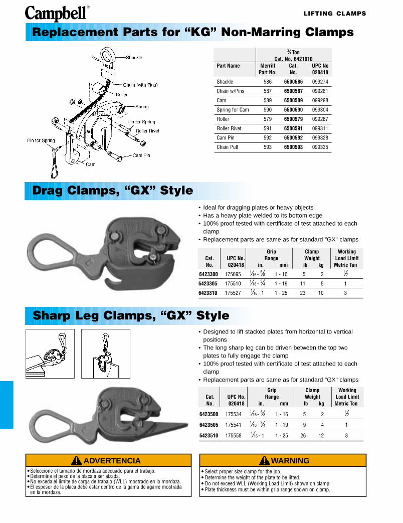
Shackle 586 6500586 099274
Chain w/Pins 587 6500587 099281
Cam 589 6500589 099298
Spring for Cam 590 6500590 099304
Roller 579 6500579 099267
Roller Rivet 591 6500591 099311
Cam Pin 592 6500592 099328
Chain Pull 593 6500593 099335
Replacement Parts for “KG” Non-Marring Clamps
Grip Clamp WorkingCat. UPC No. Range Weight Load LimitNo. 020418 in. mm lb kg Metric Ton
6423300 175695 1⁄16 - 5⁄8 1 - 16 5 2 1⁄26423305 175510 1⁄16 - 3⁄4 1 - 19 11 5 1
6423310 175527 1⁄16 - 1 1 - 25 23 10 3
Drag Clamps, “GX” Style• Ideal for dragging plates or heavy objects• Has a heavy plate welded to its bottom edge• 100% proof tested with certificate of test attached to each
clamp• Replacement parts are same as for standard "GX" clamps
• Designed to lift stacked plates from horizontal to vertical positions
• The long sharp leg can be driven between the top two plates to fully engage the clamp
• 100% proof tested with certificate of test attached to each clamp
• Replacement parts are same as for standard "GX" clamps
Grip Clamp WorkingCat. UPC No. Range Weight Load LimitNo. 020418 in. mm lb kg Metric Ton
6423500 175534 1⁄16 - 5⁄8 1 - 16 5 2 1⁄26423505 175541 1⁄16 - 3⁄4 1 - 19 9 4 1
6423510 175558 1⁄16 - 1 1 - 25 26 12 3
Sharp Leg Clamps, “GX” Style

LIFTING CLAMPS
ADVERTENCIA• Seleccione el tamaño de mordaza adecuado para el trabajo.• Determine el peso de la placa a ser alzada.• No exceda el limite de carga de trabajo (WLL) mostrado en la mordaza.• El espesor de la placa debe estar dentro de la gama de agarre mostrada
en la mordaza.
WARNING• Select proper size clamp for the job. • Determine the weight of the plate to be lifted. • Do not exceed WLL (Working Load Limit) shown on clamp.• Plate thickness must be within grip range shown on clamp.
Working Grip Cam Dimensions WeightLoad Limit Range Width Width A B C D O Per
Merrill Cat. UPC No. Per Pair PairPart No. No. 020418 Metric Ton in. mm in. mm in. mm in. mm in. mm in. mm in. mm in. mm lb kg
6H 6421701 096686 6 0-1 1⁄2 0-38 5 127 3⁄4 19 4 1⁄2 114 1 25 8 203 1 25 7 1⁄2 191 30 13.6
Horizontal Plate Clamp
• One man can handle plates with this clamp• Dual springs hold cam on the work while the second clamp
is placed• Sold in pairs ONLY• Clamps are 100% Proof Tested and Certificate of Test
supplied with each clamp
Merrill Cat. UPC No. Part Name Part No. No. 020418
Cam 350 6500350 098734
Cam bolt 351 6500351 178504
Springs (Pkg. of 2) 356 6500356 181795
Replacement Parts for Horizontal Plate Clamp
LIFTING CLAMPS
ADVERTENCIA• Seleccione el tamaño de mordaza adecuado para el trabajo.• Determine el peso de la placa a ser alzada.• No exceda el limite de carga de trabajo (WLL) mostrado en la mordaza.• El espesor de la placa debe estar dentro de la gama de agarre mostrada
en la mordaza.
WARNING• Select proper size clamp for the job. • Determine the weight of the plate to be lifted. • Do not exceed WLL (Working Load Limit) shown on clamp.• Plate thickness must be within grip range shown on clamp.
Pkg. Merrill Cat. UPC No. Part Name Qty. Part No. No. 020418
Slide Plate Assembly 1 087 6500087 184666
Handle 1 088 6500088 184673
Slide 1 089 6500089 184680
Cam 2 090 6500090 184697
Conn. Link 4 091 6500091 184703
Pin for Cam 2 092 6500092 184710
Rivet for Link 4 093 6500093 184727
Stop 1 097 6500097 184741
Spring 1 095 6500095 184734
Rivet for Stop 1 098 6500098 184758
Eye nut 1 083 6500083 184659
Merrill Working Handle Grip DimensionsPart Cat. UPC No. Load Limit Length Range C J O WeightNo. No. 020418 lb kg in. in. mm in. mm in. mm in. mm lb kg
3 6421801 096693 500 227 2 0 - 5⁄16 0 - 8 6 152 1 7⁄8 48 3 3⁄4 95 2 1
3 6421802 096709 500 227 Eye nut 0 - 5⁄16 0 - 8 8 203 1 7⁄8 48 3 3⁄4 95 2 1
3 6421803 096716 500 227 6 0 - 5⁄16 0 - 8 12 305 1 7⁄8 48 3 3⁄4 95 3 1
3 6421805 096723 500 227 10 0 - 5⁄16 0 - 8 16 406 1 7⁄8 48 3 3⁄4 95 3 1
3 6421806 096730 500 227 18 0 - 5⁄16 0 - 8 23 584 1 7⁄8 48 3 3⁄4 95 4 2
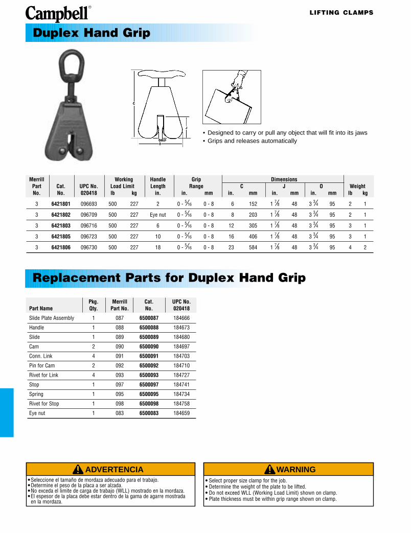
Duplex Hand Grip
• Designed to carry or pull any object that will fit into its jaws• Grips and releases automatically
Replacement Parts for Duplex Hand Grip

LIFTING CLAMPS
ADVERTENCIA• Seleccione el tamaño de mordaza adecuado para el trabajo.• Determine el peso de la placa a ser alzada.• No exceda el limite de carga de trabajo (WLL) mostrado en la mordaza.• El espesor de la placa debe estar dentro de la gama de agarre mostrada
en la mordaza.
WARNING• Select proper size clamp for the job. • Determine the weight of the plate to be lifted. • Do not exceed WLL (Working Load Limit) shown on clamp.• Plate thickness must be within grip range shown on clamp.
DimensionsMerrill Working Overall Bearing to I.D. Bead Max. JawModel Cat. UPC No. Load Limit Width Pad Center Eye Recess Opening Weight
No. No. 020418 Metric Ton in. mm in. mm in. mm in. mm in. mm lb kg
52 6410101 095634 1/2 5 127 6 152 1 3⁄4 44 1⁄2 x 3⁄4 13 x 19 7⁄8 22 4 3⁄4 2
Pkg. Merrill Cat. UPC No. Part Name Qty. Part No. No. 020418
Shackle 1 023 6500023 097539
Linkage Rivet 4 008 6500008 097423
Radius Link 1 002 6500002 097379
Pin for radius ink and cam 2 003 6500003 097386
Conn. Link 2 007 6500007 097416
Cam 1 024 6500024 097546
Spring 1 027 6500027 097560
Pad (includes bolt) 1 025 6500025 097553
Cam, pad, rivet and spring 1 ea K024 6505011 099823
Drum Handling Equipment, Single Drum Lifter, No. 52
• Lifts drums with or without heads removed• Drums can be lifted from either horizontal or vertical
positions and then reversed• Snaps onto drum and is held there by its spring-loaded
cam even when there is no load• Note: THIS CLAMP IS NOT SUITABLE FOR LIFTING
PLATES OR SHEETS
Replacement Parts for Drum Lifter, No. 52
CHAIN SLING & DRUM LIFTER
ADVERTENCIA• Seleccione el tamaño de mordaza adecuado para el trabajo.• Determine el peso de la placa a ser alzada.• No exceda el limite de carga de trabajo (WLL) mostrado en la mordaza.• El espesor de la placa debe estar dentro de la gama de agarre mostrada
en la mordaza.
WARNING• Select proper size clamp for the job. • Determine the weight of the plate to be lifted. • Do not exceed WLL (Working Load Limit) shown on clamp.• Plate thickness must be within grip range shown on clamp.
Complete Sling Clamp UsedWorking Alloy
Merrill Load Limit Overall Chain Merrill WorkingModel Cat. UPC No. at 60° Length Size Weight Clamp Cat. UPC No. Load Limit
No. No. 020418 Metric Ton in. mm in. mm lb kg No. No. 020418 ton kg
13 6410301 095665 1 27 686 9⁄32 7 13 6 52 6410101 095634 1⁄2 454
Merrill Working Grip Overall Height BearingModel Cat. UPC No. Load Limit Range Length Point to Grip Weight
No. No. 020418 Metric Ton in. mm in. mm in. mm lb kg
252 6410401 095672 1 17 1⁄2 - 25 445 - 635 28 711 12 305 22 3⁄4 10
252-BB 6410402 095689 1 17 1⁄2 - 25 445 - 635 28 711 12 305 24 11
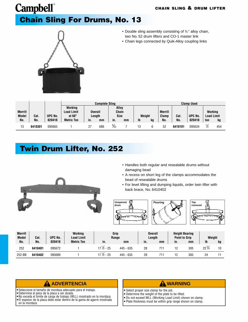
Chain Sling For Drums, No. 13• Double sling assembly consisting of 9⁄32" alloy chain,
two No. 52 drum lifters and CO-1 master link• Chain legs connected by Quik-Alloy coupling links
• Handles both regular and resealable drums without damaging bead
• A recess on short leg of the clamps accommodates the bead of resealable drums
• For level lifting and dumping liquids, order twin lifter with back brace, No. 6410402
Unopeneddrum
Pouring Topremoved
Twin Drum Lifter, No. 252
DRUM DEHEADER
ADVERTENCIA• Seleccione el tamaño de mordaza adecuado para el trabajo.• Determine el peso de la placa a ser alzada.• No exceda el limite de carga de trabajo (WLL) mostrado en la mordaza.• El espesor de la placa debe estar dentro de la gama de agarre mostrada
en la mordaza.
WARNING• Select proper size clamp for the job. • Determine the weight of the plate to be lifted. • Do not exceed WLL (Working Load Limit) shown on clamp.• Plate thickness must be within grip range shown on clamp.
Merrill Cat. UPC No. Length of Tool WeightModel No. No. 020418 Description in. mm lb kg
138 6410701 095719 Deheader with alloy blade 24 610 5 1⁄2 2
139 6410702 095726 Deheader with non-sparking blade 24 610 5 1⁄2 2
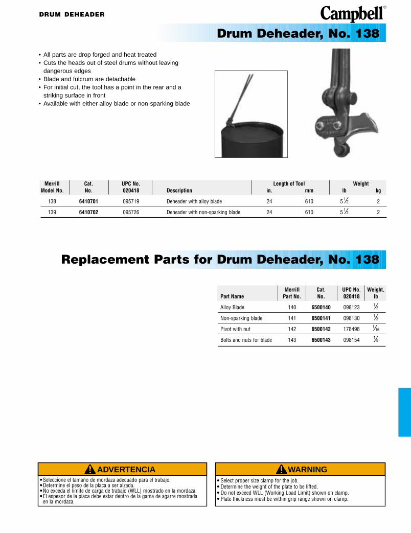
Drum Deheader, No. 138• All parts are drop forged and heat treated• Cuts the heads out of steel drums without leaving
dangerous edges• Blade and fulcrum are detachable• For initial cut, the tool has a point in the rear and a
striking surface in front• Available with either alloy blade or non-sparking blade
Merrill Cat. UPC No. Weight,Part Name Part No. No. 020418 lb
Alloy Blade 140 6500140 098123 1⁄2Non-sparking blade 141 6500141 098130 1⁄2Pivot with nut 142 6500142 178498 1⁄16
Bolts and nuts for blade 143 6500143 098154 1⁄8
Replacement Parts for Drum Deheader, No. 138

DRUM LIFTER
ADVERTENCIA• Seleccione el tamaño de mordaza adecuado para el trabajo.• Determine el peso de la placa a ser alzada.• No exceda el limite de carga de trabajo (WLL) mostrado en la mordaza.• El espesor de la placa debe estar dentro de la gama de agarre mostrada
en la mordaza.
WARNING• Select proper size clamp for the job. • Determine the weight of the plate to be lifted. • Do not exceed WLL (Working Load Limit) shown on clamp.• Plate thickness must be within grip range shown on clamp.
Fork Truck Drum Lifter, No. 260• Transforms any fork lift truck into an efficient drum handler• Handles drums with or without heads• With shackle reversed in body, a chain sling can be
attached to lift many objects besides drums
Dimensions WorkingMin. Space Max. Fork Size, Max Load Limit
Merrill Between Outside Drum Using Using CenterModel Cat. UPC No. Forks Forks Thickness Width Dia. Clamps Shackles Weight
No. No. 020418 in. mm in. mm in. mm in. mm in. lb Metric Ton Metric Ton lb kg
260 6410501 095696 5 1⁄2 140 18 457 1 3⁄4 44 6 1⁄4 159 17 1⁄2-25 445-635 1 3 29 13
Merrill Cat. UPC No. Pkg. PiecesPart Name Part No. No. 020418 Qty. Required
Bar Assembly 036 6500036 097614 1 17⁄8” Shackle & Pin 037 6500037 097621 1 1
Gripper blades 039 6500039 097638 2 2
Pins for gripper blades 040 6500040 185113 2 2
Springs 041 6500041 185120 2 2
Rivets for blades 042 6500042 176036 2 2
Lifter Links 043 6500043 097676 2 4
Clamps with Lifter links 151 6500151 175824 1 2
Replacement Parts for Fork Truck Drum Lifter, No. 260
Related Documents