Founded in 1919, Campbell is the largest manufacturer of welded and weldless chain in the United States. Users of Campbell chain can select from a wide range of working load capacities including proof coil, high test, transport and alloy; finishes including self-colored, Blu-Krome ® , galvanized and bright color polycoated; links that are short, long, twisted, locked, looped, even stamped from flat stock. Several chain types are even available in solid brass and bronze. Campbell chains and assemblies, including slings for overhead lifting, tie-downs and binder chains, have earned for the manufacturer an outstanding reputation for quality. NOTICE: The product specifications and dimensions are as accurate as possible at the time of printing. However, because we are constantly improving the quality and design of our product, they can change without notice. Contents Chain Shortener Chain Sling Program, Surveys, Seminars, Schools Chain Sling Literature Supplements Chain Sling Lifting Angles Chain Sling Rated Loads Chain Service Centers Chain Specifications Chain Terms, Certificate of Test Chains, Magnet Endless Chain Field I.D. Tags Hooks, Foundry Hooks, Grab Hooks, “J” Hooks, Plate Hooks, “S” Hooks, Sling How to Assemble Coupling Links How to Order Chain Slings Identification Tags Contents Latches Links, Coupling Links, Oblong Off-Center Working Load Limits Chart Sling Assembly Tables Sling Design Sling Inspection, Care and Use Slings, Adjustable Slings, Adjustable Loop Slings, Basket Slings, Double Slings, Double with Links Slings, One-End-Only, Chain Fitting Slings, Quadruple Slings, Single Slings, Triple Sub-Assembly, Oblong Master Links Campbell ® Chain Slings Table of Contents The Campbell operation facilities in York, PA, and Cortland, NY, conform to Quality Standard ISO 9001. on the section you want Click

Welcome message from author
This document is posted to help you gain knowledge. Please leave a comment to let me know what you think about it! Share it to your friends and learn new things together.
Transcript

Founded in 1919, Campbell is the largest manufacturer of welded and weldlesschain in the United States. Users of Campbell chain can select from a widerange of working load capacities including proof coil, high test, transport andalloy; finishes including self-colored, Blu-Krome®, galvanized and bright colorpolycoated; links that are short, long, twisted, locked, looped, even stampedfrom flat stock. Several chain types are even available in solid brass and bronze.Campbell chains and assemblies, including slings for overhead lifting, tie-downsand binder chains, have earned for the manufacturer an outstanding reputationfor quality.
NOTICE: The product specifications and dimensions are as accurate as possible at the time of printing. However,because we are constantly improving the quality and design of our product, they can change without notice.
Contents
Chain Shortener
Chain Sling Program, Surveys, Seminars, Schools
Chain Sling Literature Supplements
Chain Sling Lifting Angles
Chain Sling Rated Loads
Chain Service Centers
Chain Specifications
Chain Terms, Certificate of Test
Chains, Magnet
Endless Chain
Field I.D. Tags
Hooks, Foundry
Hooks, Grab
Hooks, “J”
Hooks, Plate
Hooks, “S”
Hooks, Sling
How to Assemble Coupling Links
How to Order Chain Slings
Identification Tags
Contents
Latches
Links, Coupling
Links, Oblong
Off-Center Working Load Limits Chart
Sling Assembly Tables
Sling Design
Sling Inspection, Care and Use
Slings, Adjustable
Slings, Adjustable Loop
Slings, Basket
Slings, Double
Slings, Double with Links
Slings, One-End-Only, Chain Fitting
Slings, Quadruple
Slings, Single
Slings, Triple
Sub-Assembly, Oblong Master Links
Campbell® Chain Slings Table of Contents
The Campbell operation facilities in York, PA,and Cortland, NY, conform to QualityStandard ISO 9001.
on the sectionyou want
Click

Users of Campbell Chain Slings may receive annual surveysto assure compliance with OSHA standards. These thoroughin-plant inspections by qualified Cooper Tools/Campbellpersonnel can point out potential problems, encourage properhandling and storage, show how to reduce inventory andincrease productivity.Upon completion of the survey, Campbell will provide a com-plete report on the status of every Campbell chain sling andclamp for your OSHA compliance files.
To instruct customers in the proper use of slings as well as inmaintenance and safety procedures, Campbell will conductseminars in your plant or at its local sling repair center.Further, if interested, we’ll train your plant personnel to con-duct their own sling survey in a one and a half day “school”held at our York, Pennsylvania plant. Upon completion of thisschool, your personnel will be fully qualified to perform OSHAcompliance inspections.
Repairs
Campbell’s sling repair centers across the U.S. help make themost of your company’s chain sling investment. Wherevereconomical reconditioning is possible, Campbell will advise
you on estimated cost. A nearby center will then repair, proof-test and issue new certificates of test to put your slings backto work quickly.
Cooper Number 550053 Cooper Number 55943
Cooper Number 7503515 Cooper Number 55068
To Supplement Your Sling Chain Program
CHAIN SLING PRODUCTS
Campbell’s Chain Sling ProgramSurveys, Seminars and Schools

ADVERTENCIAPara prevenir la posibilidad de una lesión personal sería:• NO EXCEDA los límites de carga de las cadenas o componentes.• NO LA UTILICE si la cadena o los componentes están visualmente
distorsionados o gastados.
WARNINGTo prevent the possibility of serious bodily injury:• DO NOT EXCEED the working load limits for chain or components.• DO NOT USE if the chain or components are visibly distorted or worn.
Chain Single Leg Sling - Rated load Triple and Quadruple Size 90° - Horizontal Double Leg Sling and Single Basket Leg Sling and Double Basket
Nominal Loading at Horizontal Angle at Horizontal Angle
in. mm lb kg lb kg lb kg lb kg lb kg lb kg lb kg7⁄32 5.5 2,100 950 3,600 1,650 3,000 1,350 2,100 950 5,500 2,450 4,400 2,000 3,200 1,4509⁄32 7 3,500 1,600 6,100 2,750 4,900 2,250 3,500 1,600 9,100 4,150 7,400 3,400 5,200 2,4003⁄8 10 7,100 3,200 12,300 5,550 10,000 4,500 7,100 3,200 18,400 8,300 15,100 6,800 10,600 4,8001⁄2 13 12,000 5,400 20,800 9,450 17,000 7,700 12,000 5,400 31,200 14,150 25,500 11,550 18,000 8,2005⁄8 16 18,100 8,200 31,300 14,200 25,600 11,600 18,100 8,200 47,000 21,300 38,400 17,400 27,100 12,3003⁄4 20 28,300 12,800 49,000 22,250 40,000 18,150 28,300 12,800 73,500 33,400 60,000 27,250 42,400 19,3007⁄8 22 34,200 15,500 59,200 26,850 48,400 21,900 34,200 15,500 88,900 40,250 72,500 32,900 51,300 23,250
1 26 47,700 21,600 82,600 37,500 67,400 30,600 47,700 21,600 123,900 56,250 101,200 45,950 71,500 32,500
11⁄4 32 72,300 32,800 125,200 56,800 102,200 46,400 72,300 32,800 187,800 85,200 153,400 69,600 108,400 49,200
Double at 60°
60° 30°45°60°45° 30°
Double at 45° Double at 30° Quad at 60° Quad at 45° Quad at 30°
Rated Load for Grade 80 Alloy Steel Chain Slings
Chain Size Single Leg Double Leg and Single Baskets Triple and Quadruple Leg; Double BasketsNominal 90° 60° 45° 30° 60° 45° 30°
in. mm lb kg lb kg lb kg lb kg lb kg lb kg lb kg7⁄32 5.5 1,700 750 2,900 1,300 2,400 1,100 1,700 750 4,400 1,950 3,500 1,600 2,550 1,1509⁄32 7 2,800 1,300 5,000 2,200 3,900 1,800 2,800 1,300 7,300 3,300 5,900 2,700 4,150 1,9003⁄8 10 5,700 2,550 9,800 4,450 8,000 3,650 5,700 2,550 14,700 6,650 12,100 5,450 8,500 3,8501⁄2 13 9,600 4,300 16,600 7,550 13,600 6,150 9,600 4,300 25,000 11,300 20,400 9,250 14,400 6,5505⁄8 16 14,500 6,550 25,000 11,350 20,500 9,300 14,500 6,550 37,600 17,050 30,700 13,900 21,700 9,8503⁄4 20 22,600 10,250 39,200 17,800 32,000 14,500 22,600 10,250 58,800 26,700 48,000 21,800 33,900 15,4507⁄8 22 27,400 12,400 47,400 21,500 38,700 17,500 27,400 12,400 71,100 32,200 58,000 26,300 41,000 18,600
1 26 38,200 17,300 66,100 30,000 53,900 24,500 38,200 17,300 99,100 45,000 81,000 36,750 57,200 26,000
1-11⁄4 32 57,800 26,250 100,200 45,450 81,800 37,100 57,800 26,250 150,200 68,150 122,700 55,700 86,700 39,350
Note: Angle of choke should be greater than 120°
Rated Loads for Grade 80 Alloy Steel Chain Slings - Choke Hitches
CHAIN SLING PRODUCTS
Rated Loads For Grade 80 (System 8) Alloy SteelChain Slings

ADVERTENCIAPara prevenir la posibilidad de una lesión personal sería:• NO EXCEDA los límites de carga de las cadenas o componentes.• NO LA UTILICE si la cadena o los componentes están visualmente
distorsionados o gastados.
WARNINGTo prevent the possibility of serious bodily injury:• DO NOT EXCEED the working load limits for chain or components.• DO NOT USE if the chain or components are visibly distorted or worn.
CHAIN SLING PRODUCTS
Rated Loads For Grade 100 (System 10) Alloy SteelChain Slings
Chain Single Leg Sling - Rated Load Triple and QuadrupleSize 90° to Horizontal Double Leg Sling and Single Basket Leg Sling and Double Basket
Nominal Loading at Horizontal Angle at Horizontal Angle
in. mm lb kg lb kg lb kg lb kg lb kg lb kg lb kg9⁄32 7 4,300 1,950 7,400 3,400 6,100 2,750 4,300 1,950 11,200 5,050 9,100 4,150 6,400 2,9503⁄8 10 8,800 4,000 15,200 6,950 12,400 5,650 8,800 4,000 22,900 10,400 18,700 8,500 13,200 6,0001⁄2 13 15,000 6,800 26,000 11,800 21,200 9,600 15,000 6,800 39,000 17,650 31,800 14,450 22,500 10,2005⁄8 16 22,600 10,300 39,100 17,750 32,000 14,500 22,600 10,300 58,700 26,650 47,900 21,750 33,900 15,4003⁄4 20 35,300 16,000 61,100 27,700 49,900 22,650 35,300 16,000 91,700 41,550 74,900 33,950 53,000 24,0007⁄8 22 42,700 19,400 74,000 33,500 60,400 27,350 42,700 19,400 110,900 50,250 90,600 41,050 64,000 29,050
Double at 60°
60° 45° 30°
Double at 45° Double at 30°
Rated Load for Grade 100 Alloy Steel Chain Slings
Chain Size Single Leg Double Leg and Single Baskets Triple and Quadruple Leg; Double BasketsNominal 90° 60° 45° 30° 60° 45° 30°
in. mm lb kg lb kg lb kg lb kg lb kg lb kg lb kg9⁄32 7 3,500 1,600 6,100 2,750 4,900 2,250 3,500 1,600 9,100 4,150 7,400 3,400 5,200 2,4003⁄8 10 7,100 3,200 12,300 5,550 10,000 4,550 7,100 3,200 18,400 8,300 15,100 6,800 10,600 4,8001⁄2 13 12,000 5,400 20,800 9,450 17,000 7,700 12,000 5,400 31,200 14,150 25,500 11,550 18,000 8,2005⁄8 16 18,100 8,200 31,300 14,200 25,600 11,600 18,100 8,200 47,000 21,300 38,400 17,400 27,100 12,3003⁄4 20 28,300 12,800 49,000 22,250 40,000 18,150 28,300 12,800 73,500 33,400 60,000 27,250 42,400 19,3007⁄8 22 34,200 15,500 59,200 26,850 48,400 21,900 34,200 15,500 88,900 40,250 72,500 32,900 51,300 23,250
Note: Angle of choke should be greater than 120°
Rated Loads for Grade 100 Alloy Steel Chain Slings - Choke Hitches
30°45°60°
Quad at 60° Quad at 45° Quad at 30°
CHAIN SLING PRODUCTS
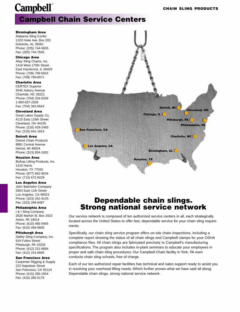
Campbell Chain Service Centers
Birmingham AreaAlabama Sling Center1103 Hoke Ave. Box 203Dolomite, AL 35061Phone: (205) 744-5605Fax: (205) 744-7645
Chicago AreaAlloy Sling Chains, Inc.1416 West 175th StreetEast Hazelcrest, IL 60429Phone: (708) 799-5915Fax: (708) 799-6071
Charlotte AreaCERTEX Superior3545 Asbury AvenueCharlotte, NC 28221Phone: (704) 334-53341-800-637-2339Fax: (704) 342-0643
Cleveland AreaGreat Lakes Supply Co.4115 East 116th StreetCleveland, OH 44105Phone: (216) 429-2483Fax: (216) 641-1814
Detroit AreaDetroit Chain Products8881 Central AvenueDetroit, MI 48204Phone: (313) 834-1002
Houston AreaBishop Lifting Products, Inc.1410 HarrisHouston, TX 77020Phone: (877) 662-9034Fax: (713) 672-9229
Los Angeles AreaJohn Batchelor Company2853 East 11th StreetLos Angeles, CA 90023Phone: (323) 262-4125Fax: (323) 268-8487
Philadelphia AreaI & I Sling Company2626 Market St. Box 2423Aston, PA 19014Phone: (610) 485-0405Fax: (610) 494-5835
Pittsburgh AreaSafety Sling Company, Inc.919 Fulton StreetPittsburgh, PA 15233Phone: (412) 231-6684Fax: (412) 231-6695
San Francisco AreaCarpenter Rigging & Supply222 Napolean StreetSan Francisco, CA 92124Phone: (415) 285-1954Fax: (415) 285-0176
Dependable chain slings. Strong national service network
Our service network is composed of ten authorized service centers in all, each strategicallylocated across the United States to offer fast, dependable service for your chain sling require-ments.
Specifically, our chain sling service program offers on-site chain inspections, including acomplete report showing the status of all chain slings and Campbell clamps for your OSHAcompliance files. All chain slings are fabricated precisely to Campbell's manufacturingspecifications. The program also includes in-plant seminars to educate your employees inproper and safe chain sling procedures. Our Campbell Chain facility in York, PA even conducts chain sling schools, free of charge.
Each of our ten authorized repair facilities has technical and sales support ready to assist youin resolving your overhead lifting needs. Which further proves what we have said all along:Dependable chain slings, strong national service network.
San Francisco, CA
Houston, TX
Birmingham, AL
Charlotte, NC
Pittsburgh, PA
Chicago, IL
Detroit, MICleveland, OH
Philadelphia, PA
Los Angeles, CA

CHAIN SLING PRODUCTS
ADVERTENCIAPara prevenir la posibilidad de una lesión personal sería:• NO EXCEDA los límites de carga de las cadenas o componentes.• NO LA UTILICE si la cadena o los componentes están visualmente
distorsionados o gastados.
WARNINGTo prevent the possibility of serious bodily injury:• DO NOT EXCEED the working load limits for chain or components.• DO NOT USE if the chain or components are visibly distorted or worn.
PROOF TESTThe “proof test” is a quality control test applied to chain for the purposeof verifying weld and material quality. It is the minimum force in poundsor newtons that the chain has withstood in direct tension as part of themanufacturing process. Proof testing assures that the chain is morethan capable of performing at its rated working load limit. Proof testloads are a manufacturing integrity test and shall not be used as crite-ria for service or design purposes. All Campbell chain and componentsare proof tested in accordance with the applicable ASTM, NACM,OSHA and AISI/ASME requirements.
Cam-Alloy Chain SlingsCampbell manufactures a complete line of standard sling assemblies,as well as assemblies to customer specifications. This work is done
at authorized Campbell Sling Service Centers located in strategicareas of the country to provide maximum customer service.
Important Chain TermsWORKING LOAD LIMITThe “working load limit” (rated capacity) is the maximum combinedstatic and dynamic load in pounds or kilograms which should ever beapplied to the product in service, even when the product is new, andwhen the load is uniformly applied in direct tension to the product.
Certificate of Test and Identification Tags
Certificate of TestIdentification Tag
Basic Types of Chain SlingsSlings are designated throughout the industry by the symbols.First Symbol (Basic type)S Single Chain Sling with master link and hook, or hook each end.C Single Choker Chain Sling with master link each end. No hooks.D Double Chain Sling with standard master link and hooks.T Triple Chain Sling with standard master link and hooks.Q Quadruple Chain Sling with standard master link and hooks.Second Symbol (Type of master link or end link)O Standard Oblong Master Link–Recommended for all types.Third Symbol (Type of Hooks)S Sling HookG Grab HookF Foundry Hook
How to Order Chain Slings1. Determine the maximum load to be lifted.2. Refer to the following pages and choose the proper type of
chain sling (single, double, etc.) dictated by the size, shape and weight of the load.
3. Estimate the approximate angle between a leg of the sling and the load during operation.
4. Select the proper attachments (hooks and master links) for your chain sling.
5. Determine the overall reach from bearing point on master link to bearing point on attachment.
6. Refer to the Working Load Limit Chart and to your predeterminedangle of the type sling you have selected.
7. Choose the chain size which meets your requirements.8. When entering your order be sure you give complete information as
to the size, reach and attachments required.Note: Angle to the load on multiple leg slings will be 60° or greater aslong as the distance between lifting eyes of load is not greater than reachshown on identification tag.
Campbell provides information in several forms that enables purchasersand users to operate safely and effectively in conformity with OSHArequirements. The drop forged Identification Tag is attached to the MasterEnd Coupling link of each chain sling and provides the following lifetimeinformation:• Grade • Working Load Limit (at a specific angle of lift)• Size • Serial number• Reach • TypeA Certificate of Test is provided for every Campbell manufactured chainsling. The Campbell Certificate contains all of the information provided onthe identification tag, plus the Proof Test load as required by OSHA regu-lations.

CHAIN SLING PRODUCTS
ADVERTENCIAPara prevenir la posibilidad de una lesión personal sería:• NO EXCEDA los límites de carga de las cadenas o componentes.• NO LA UTILICE si la cadena o los componentes están visualmente
distorsionados o gastados.
WARNINGTo prevent the possibility of serious bodily injury:• DO NOT EXCEED the working load limits for chain or components.• DO NOT USE if the chain or components are visibly distorted or worn.
Campbell welded chain products and components are designed and built for rugged last-ing service. As with any quality product certain precautions and standards of treatmentshould be observed. Proper care will extend the useful life of the product.
INSTRUCTIONS REGARDING COMPONENTS & FITTINGSComponents, such as master links and hooks, should have at least the same workingload limit (rated capacity) as the chain with which they are used. If not, the sling shall berated to the capacity of the weakest component. Campbell offers a full line of Cam-Alloy®
and Quik-Alloy® sling components engineered specifically to be compatible with our alloychain products.
WARNINGS AND CAUTIONS• The use of chain, slings, and components are subject to certain hazards that cannot be
met by mechanical or manufacturing means, but only by the exercise of intelligence, care, and common sense
• Sling use is subject to the Occupational Safety & Health Administration (OSHA 29 CFR 1910.184) and American Society for Mechanical Engineers (ASME B30.9) safety stan-dards, requiring the sling user to conduct safe working practices and performinspections
• Do not exceed the working load limit of the sling or any component• Chemically active environments may adversely affect chain slings. Do not use in highly
acidic or caustic environments. Campbell should be contacted if the sling will be exposed to chemically active environments during use
• High and low temperatures will affect chain slings. Campbell should be contacted if temperatures below -20°F (-29°C) will be experienced. The attached Effect of Elevated Temperature on the Working Load Limit of Alloy Chain chart shows the reduction instrength that occurs when chain slings are used at or have been exposed to temper-tures above 400°F (204°C)
• Never field weld or repair a chain sling. Chain slings should only be repaired by a quali-fied repair facility
• See other specific information under the Care, Inspection, and Proper Use sectionsINSPECTIONOSHA and ASME safety standards require the user to conduct:a) Frequent Inspections: A visual inspection for damage, which should be performed
each day the sling is used.b) Periodic Inspections: A complete link by link and component inspection. Periodic
inspection intervals vary depending on sling usage and conditions, but must occur at least annually. Written records of periodic inspections are required.
The slings should be inspected for the presence damage. The sling should immediatelybe removed from service if any of the following conditions are present:• Missing or unreadable identification tag• Cracks in the chain or any component• Excessive nicks, gouges or wear. Chain should be removed from service if the thickness
at any point on the link is below the value shown in the attached Cam- Alloy Chain Minimum Allowable Thickness chart. All other components should be removed from service if any dimension is worn more than 10% from the original dimension
• Stretched, bent, twisted, or distorted chain links or components• Excessive corrosion• Evidence of heat damage• Evidence of field welding or weld spatter• Any other condition which questions the integrity of the chain slingCARE • Chain slings should be stored in a clean and dry area, preferably on a rack, in order to
extend their life• Chain slings should not be stored in areas where they would be subject to damage,
corrosion, chemical attack, or extreme temperatures• Clean slings periodically, as dust and grit can accelerate wear• During use, chain slings should not be dragged over abrasive surfaces. Loads should
not be rested on the chain sling to avoid damagePROPER USETo protect the operators, the load, and the sling, the following safe practices should befollowed. Campbell also recommends compliance with the OSHA and ASME safety standard practices.• Select a sling suitable for the load, type of hitch, angle of loading, and environment. The
hooks and master links should be of a size to fit the intended connections• Avoid shock loading• Pad all sharp edges or corners in contact with the sling to prevent damage to either
the sling or the load• Balance the load to prevent shifting, to maintain control of the load, and to prevent
overloading of any leg in a multiple leg sling• Rig so that the load is properly seated in the hooks and master link. Avoid tip loading of
hooks and side loading of master links• Avoid twisting or kinking of sling legs• Never knot chain legs• Horizontal angles less than 30° should not be used without consulting Campbell or a
qualified person
Inspection, Care and Proper Use of Chain Slings
Cam-Alloy Chain - Minimum Allowable Thickness
PROPER USE (continued)• For choker hitches, angles of choke greater than 120° should not be used without
consulting Campbell or a qualified person. Choker hitches reduce the working load limit by 20% (See pages 4 & 5)
• For basket hitches, the minimum recommended diameter of the load is 10 times the nominal chain diameter
Purchasers please note that all “Warnings and Cautions” apply to chain, components andfittings, as well as chain slings. Purchasers are responsible for conveying the “Warningsand Cautions” including the "Inspection, Care and Proper Use" section information to theend user.
Campbell denies any liability for damage that results from use in excess of the workingload limit or any abuse or misuse of the product.Any questions concerning the use of Campbell products may be directed to yourCooperTools Sales Representative or Customer Service.
Temperature Grade of ChainGrade 80 (System8) Grade 100 (System 10)
Reduction of Reduction of Reduction of Reduction ofWorking Working Load Working Working Load
(F°) (C°) Load Limit Limit AFTER Load Limit Limit AFTERWHILE AT EXPOSURE to WHILE AT EXPOSURE to
Temperature Temperature Temperture Temperature
< 400° < 204° None None None None
400° 204° 10% None 15% None
500° 260° 15% None 25% 5%
600° 316° 20% 5% 30% 15%
700° 371° 30% 10% 40% 20%
800° 427° 40% 15% 50% 25%
900° 482° 50% 20% 60% 30%
1000° 538° 60% 25% 70% 35%
>1000° >538° OSHA requires that any chain sling which has experiencedtemperatures in excess of 1000° F be removed from service.
Effect of Elevated Temperature onthe Working Load Limit of Alloy Chain
Actual Size Min. AllowableCat. Stock Dia. Thickness on Any
Chain Size No. New Part of Linkin. mm Drum in. mm in. mm7⁄32 5.5 0400312 .218 6 .189 59⁄32 7 0405212 .282 7 .239 63⁄8 10 0405412 .402 10 .342 91⁄2 13 0405512 .522 13 .443 115⁄8 16 0405612 .643 16 .546 143⁄4 20 0405712 .802 20 .687 177⁄8 22 0405812 .881 22 .750 19
1 26 0401612 1.000 25 .887 23
11⁄4 32 0402012 1.250 32 1.091 28
11⁄2 38 0402412 1.500 38 1.300 33

CHAIN SLING PRODUCTS
ADVERTENCIAPara prevenir la posibilidad de una lesión personal sería:• NO EXCEDA los límites de carga de las cadenas o componentes.• NO LA UTILICE si la cadena o los componentes están visualmente
distorsionados o gastados.
WARNINGTo prevent the possibility of serious bodily injury:• DO NOT EXCEED the working load limits for chain or components.• DO NOT USE if the chain or components are visibly distorted or worn.
Nominal Dimensions (in. and mm)Trade Material Inside Dimensions Drum Working Size Diameter Length Width Cat. UPC No. Load Limit Feet/ Lb/ Links/
in. mm System in. mm in. mm in. mm No. 020418 lb kg Drum 100ft. ft.7⁄32 5.5 8 .22 6 .69 18 .30 8 0400312 063312 2100 970 800 43 17.59⁄32 7 10 .29 7 .86 22 .41 10 0405212 182204 4300 1950 500 74 13.83⁄8 10 10 .40 10 1.22 31 .55 14 0405412 182211 8800 3990 500 148 10.01⁄2 13 10 .52 13 1.57 40 .75 19 0405512 182228 15,000 6800 300 250 7.85⁄8 16 10 .64 16 1.93 49 .87 22 0405612 182235 22,600 10,250 200 379 6.53⁄4 20 10 .80 20 2.42 61 1.04 26 0405712 182242 35,300 16,000 100 610 4.97⁄8 22 10 .88 22 2.70 69 1.28 31 0405812 063497 42,700 19,400 100 775 4.4
1 26 8 1.00 25 2.80 71 1.40 36 0401612 063510 47,700 21,600 100 965 4.3
11⁄4 32 8 1.25 32 3.50 89 1.75 44 0402012 063534 72,300 32,800 60 1525 3.5
The last digit of the catalog number changes to a 1 if a non-standard quantity is ordered.
Cam-Alloy Chain Slings
Reduction of Working Loadwith Varying Lifting Angle
Percentages shown are of the maxi-mum Working Load Limit of chain.
Cam-Alloy Chain SpecificationsCam-Alloy steel chain is electrically welded alloy steel embodyingthe latest manufacturing technology. Alloy provides a superiorchain sling with high tensile strength and excellent wear resis-tance. The following chains meet or exceed all existing OSHA,ANSI, ASME, NACM and ASTM specification requirements.
The Cam-Alloy chain and attachments used in fabricatingCampbell chain slings offer a design factor of 4 to 1. System 8is Campbell's trade name for Grade 80 chain. System 10 isCampbell's trade name for Grade 100 chain.
Normal WorkingLoad Limit of aStandard Sling
How Lifting Angles Reduce Working Load Limits of Slings

CHAIN SLING PRODUCTS
ADVERTENCIAPara prevenir la posibilidad de una lesión personal sería:• NO EXCEDA los límites de carga de las cadenas o componentes.• NO LA UTILICE si la cadena o los componentes están visualmente
distorsionados o gastados.
WARNINGTo prevent the possibility of serious bodily injury:• DO NOT EXCEED the working load limits for chain or components.• DO NOT USE if the chain or components are visibly distorted or worn.
Cam-Alloy Chain SlingsSingle Types: S and C
Type CO Type SOS Type SOG Type SSG Type SSS Type SOF
Oblong LinkChain Nominal Size Inside Dimensions WorkingSize Material Width Length Load Limit
in. mm System in. mm in. mm in. mm lb kg7⁄32 5.5 8 13⁄32 10 11⁄2 38 3 76 2,100 9709⁄32 7 10 37⁄64 15 21⁄2 64 5 127 4,300 1,9503⁄8 10 10 13⁄16 21 3 76 6 152 8,800 4,0001⁄2 13 10 11⁄8 29 4 102 8 203 15,000 6,8005⁄8 16 10 11⁄8 29 4 102 8 203 22,600 10,3003⁄4 20 10 11⁄4 32 4 102 8 203 35,300 16,0007⁄8 22 10 15⁄8 41 51⁄4 133 101⁄2 267 42,700 19,400
1 26 8 17⁄8 48 6 152 12 305 47,700 21,600
11⁄4 32 8 2 51 7 178 14 356 72,300 32,800
Dimensions are approximate.Single chain slings are available in other combinations.These items are made to order.

CHAIN SLING PRODUCTS
ADVERTENCIAPara prevenir la posibilidad de una lesión personal sería:• NO EXCEDA los límites de carga de las cadenas o componentes.• NO LA UTILICE si la cadena o los componentes están visualmente
distorsionados o gastados.
WARNINGTo prevent the possibility of serious bodily injury:• DO NOT EXCEED the working load limits for chain or components.• DO NOT USE if the chain or components are visibly distorted or worn.
Cam-Alloy Chain SlingsDouble Type: D
30°45°60°
Type DOS Type DOG Type DOF
Working Load LimitOblong Master Link
NominalChain Size Inside Dimensions Size Material Width Length Double at 60° Double at 45° Double at 30°
in. mm System in. mm in. mm in. mm lb kg lb kg lb kg7⁄32 5.5 8 13⁄32 10 1 1⁄2 38 3 76 3,600 1,630 3,000 1,360 2,100 9709⁄32 7 10 37⁄64 15 2 1⁄2 64 5 127 7,400 3,400 6,100 2,700 4,300 1,9503⁄8 10 10 13⁄16 21 3 76 6 152 15,200 6,900 12,400 6,900 8,800 3,9901⁄2 13 10 1 1⁄8 29 4 102 8 203 26,000 11,800 21,200 9,600 15,000 6,8005⁄8 16 10 1 1⁄4 32 4 102 8 203 39,100 17,700 32,000 14,500 22,600 10,3003⁄4 20 10 1 5⁄8 41 5 1⁄4 133 10 1⁄2 267 61,100 27,700 49,900 22,600 35,300 16,0007⁄8 22 10 1 7⁄8 48 6 152 12 305 74,000 33,500 60,400 27,350 42,700 19,400
1 26 8 2 51 7 178 14 356 82,600 37,900 67,400 31,000 47,700 21,600
1 1⁄4 32 8 2 1⁄4 57 8 203 16 406 125,200 56,800 102,200 46,400 72,300 32,800
Dimensions are approximate.Double chain slings are available in other combinations.These items are made to order.

CHAIN SLING PRODUCTS
ADVERTENCIAPara prevenir la posibilidad de una lesión personal sería:• NO EXCEDA los límites de carga de las cadenas o componentes.• NO LA UTILICE si la cadena o los componentes están visualmente
distorsionados o gastados.
WARNINGTo prevent the possibility of serious bodily injury:• DO NOT EXCEED the working load limits for chain or components.• DO NOT USE if the chain or components are visibly distorted or worn.
Type TOS Type TOG
Cam-Alloy Chain SlingsTriple Type: T
45° 30°60°
Working Load LimitOblong Master Link
NominalChain Size Inside Dimensions Size Material Width Length Triple at 60° Triple at 45° Triple at 30°
in. mm System in. mm in. mm in. mm lb kg lb kg lb kg7⁄32 5.5 8 37⁄64 15 21⁄2 64 5 127 5,450 2,470 4,450 2,020 3,150 1,4309⁄32 7 10 13⁄16 21 3 76 6 152 11,200 5,100 9,100 4,100 6,450 2,9003⁄8 10 10 11⁄8 29 4 102 8 203 22,800 10,300 18,600 8,400 13,200 6,0001⁄2 13 10 11⁄4 32 4 102 8 203 39,000 17,700 31,800 14,400 22,500 10,2005⁄8 16 10 15⁄8 41 51⁄4 133 101⁄2 267 58,700 26,600 47,900 21,700 33,900 15,4003⁄4 20 10 17⁄8 48 6 152 12 305 91,700 41,600 74,900 34,000 53,000 24,0007⁄8 22 10 21⁄4 57 8 203 16 406 110,900 50,250 90,600 41,050 64,000 29,050
1 26 8 21⁄4 57 8 203 16 406 123,900 56,900 101,200 46,500 71,500 32,800
11⁄4 32 8 23⁄4 70 9 229 16 406 187,800 85,200 153,400 69,600 108,400 49,200
Dimensions are approximate.Triple chain slings are available in other combinations.These items are made to order.
CHAIN SLING PRODUCTS
ADVERTENCIAPara prevenir la posibilidad de una lesión personal sería:• NO EXCEDA los límites de carga de las cadenas o componentes.• NO LA UTILICE si la cadena o los componentes están visualmente
distorsionados o gastados.
WARNINGTo prevent the possibility of serious bodily injury:• DO NOT EXCEED the working load limits for chain or components.• DO NOT USE if the chain or components are visibly distorted or worn.
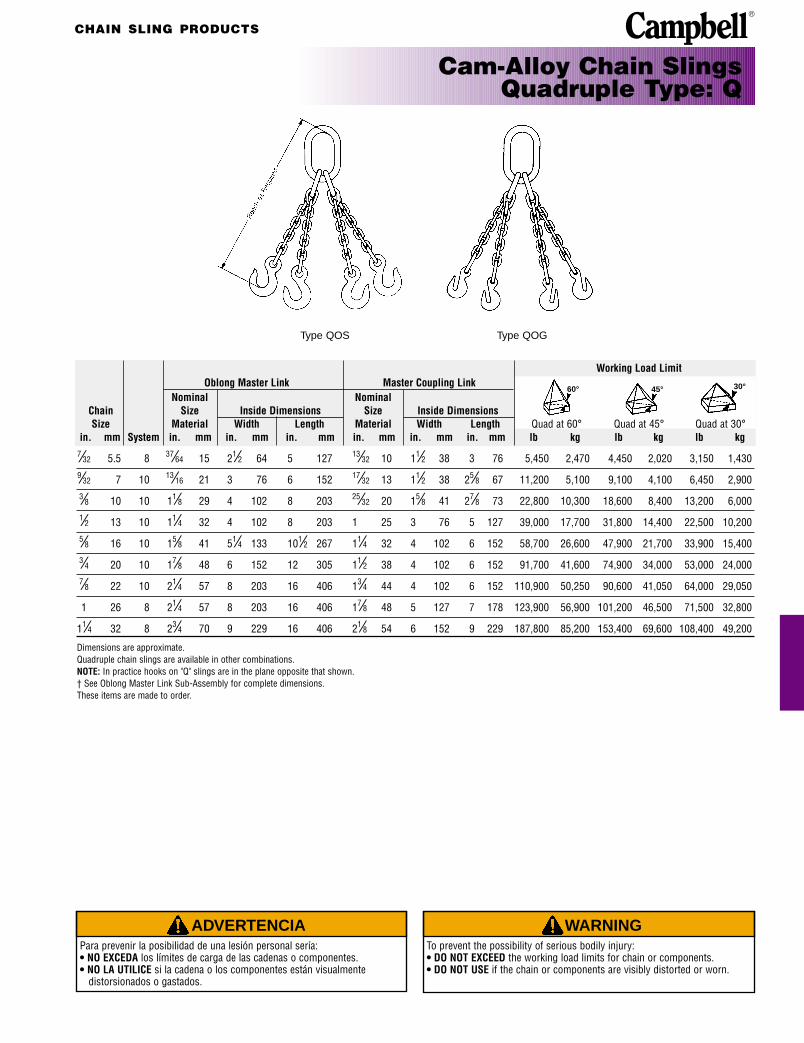
Cam-Alloy Chain SlingsQuadruple Type: Q
Type QOS Type QOG
60° 45° 30°
Working Load LimitOblong Master Link Master Coupling Link
Nominal Nominal Chain Size Inside Dimensions Size Inside DimensionsSize Material Width Length Material Width Length Quad at 60° Quad at 45° Quad at 30°
in. mm System in. mm in. mm in. mm in. mm in. mm in. mm lb kg lb kg lb kg7⁄32 5.5 8 37⁄64 15 21⁄2 64 5 127 13⁄32 10 11⁄2 38 3 76 5,450 2,470 4,450 2,020 3,150 1,4309⁄32 7 10 13⁄16 21 3 76 6 152 17⁄32 13 11⁄2 38 25⁄8 67 11,200 5,100 9,100 4,100 6,450 2,9003⁄8 10 10 11⁄8 29 4 102 8 203 25⁄32 20 15⁄8 41 27⁄8 73 22,800 10,300 18,600 8,400 13,200 6,0001⁄2 13 10 11⁄4 32 4 102 8 203 1 25 3 76 5 127 39,000 17,700 31,800 14,400 22,500 10,2005⁄8 16 10 15⁄8 41 51⁄4 133 101⁄2 267 11⁄4 32 4 102 6 152 58,700 26,600 47,900 21,700 33,900 15,4003⁄4 20 10 17⁄8 48 6 152 12 305 11⁄2 38 4 102 6 152 91,700 41,600 74,900 34,000 53,000 24,0007⁄8 22 10 21⁄4 57 8 203 16 406 13⁄4 44 4 102 6 152 110,900 50,250 90,600 41,050 64,000 29,050
1 26 8 21⁄4 57 8 203 16 406 17⁄8 48 5 127 7 178 123,900 56,900 101,200 46,500 71,500 32,800
11⁄4 32 8 23⁄4 70 9 229 16 406 21⁄8 54 6 152 9 229 187,800 85,200 153,400 69,600 108,400 49,200
Dimensions are approximate.Quadruple chain slings are available in other combinations.NOTE: In practice hooks on "Q" slings are in the plane opposite that shown.† See Oblong Master Link Sub-Assembly for complete dimensions.These items are made to order.
CHAIN SLING PRODUCTS
ADVERTENCIAPara prevenir la posibilidad de una lesión personal sería:• NO EXCEDA los límites de carga de las cadenas o componentes.• NO LA UTILICE si la cadena o los componentes están visualmente
distorsionados o gastados.
WARNINGTo prevent the possibility of serious bodily injury:• DO NOT EXCEED the working load limits for chain or components.• DO NOT USE if the chain or components are visibly distorted or worn.
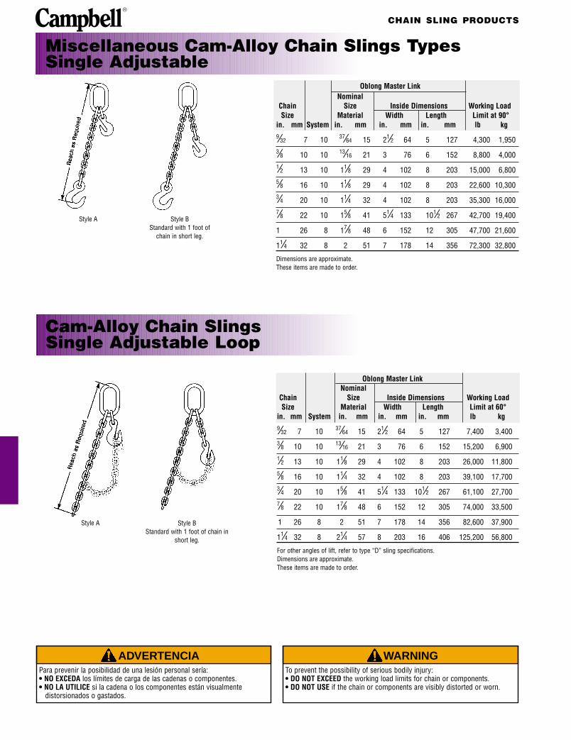
Cam-Alloy Chain SlingsSingle Adjustable Loop
Style A Style BStandard with 1 foot of chain in
short leg.
Oblong Master LinkNominal
Chain Size Inside Dimensions Working LoadSize Material Width Length Limit at 60°
in. mm System in. mm in. mm in. mm lb kg9⁄32 7 10 37⁄64 15 21⁄2 64 5 127 7,400 3,4003⁄8 10 10 13⁄16 21 3 76 6 152 15,200 6,9001⁄2 13 10 11⁄8 29 4 102 8 203 26,000 11,8005⁄8 16 10 11⁄4 32 4 102 8 203 39,100 17,7003⁄4 20 10 15⁄8 41 51⁄4 133 101⁄2 267 61,100 27,7007⁄8 22 10 17⁄8 48 6 152 12 305 74,000 33,500
1 26 8 2 51 7 178 14 356 82,600 37,900
11⁄4 32 8 21⁄4 57 8 203 16 406 125,200 56,800
For other angles of lift, refer to type “D” sling specifications.Dimensions are approximate.These items are made to order.
Miscellaneous Cam-Alloy Chain Slings TypesSingle Adjustable
Style A Style BStandard with 1 foot of
chain in short leg.
Oblong Master LinkNominal
Chain Size Inside Dimensions Working LoadSize Material Width Length Limit at 90°
in. mm System in. mm in. mm in. mm lb kg9⁄32 7 10 37⁄64 15 21⁄2 64 5 127 4,300 1,9503⁄8 10 10 13⁄16 21 3 76 6 152 8,800 4,0001⁄2 13 10 11⁄8 29 4 102 8 203 15,000 6,8005⁄8 16 10 11⁄8 29 4 102 8 203 22,600 10,3003⁄4 20 10 11⁄4 32 4 102 8 203 35,300 16,0007⁄8 22 10 15⁄8 41 51⁄4 133 101⁄2 267 42,700 19,400
1 26 8 17⁄8 48 6 152 12 305 47,700 21,600
11⁄4 32 8 2 51 7 178 14 356 72,300 32,800
Dimensions are approximate.These items are made to order.

CHAIN SLING PRODUCTS
ADVERTENCIAPara prevenir la posibilidad de una lesión personal sería:• NO EXCEDA los límites de carga de las cadenas o componentes.• NO LA UTILICE si la cadena o los componentes están visualmente
distorsionados o gastados.
WARNINGTo prevent the possibility of serious bodily injury:• DO NOT EXCEED the working load limits for chain or components.• DO NOT USE if the chain or components are visibly distorted or worn.
Cam-Alloy Chain SlingsDouble Adjustable
Style A Style BStandard with 1 foot of chain in
short leg.
Cam-Alloy Chain SlingsDouble Adjustable Loop
Style A Style BStandard with 1 foot of chain in
short leg.
Oblong Master LinkNominal
Chain Size Inside Dimensions Working LoadSize Material Width Length Limit at 60°
in. mm System in. mm in. mm in. mm lb kg9⁄32 7 10 37⁄64 15 21⁄2 64 5 127 7,400 3,4003⁄8 10 10 13⁄16 21 3 76 6 152 15,200 6,9001⁄2 13 10 11⁄8 29 4 102 8 203 26,000 11,8005⁄8 16 10 11⁄4 32 4 102 8 203 39,100 17,7003⁄4 20 10 15⁄8 41 51⁄4 133 101⁄2 267 61,100 27,7007⁄8 22 10 17⁄8 48 6 152 12 305 74,000 33,500
1 26 8 2 51 7 178 14 356 82,600 37,900
11⁄4 32 8 21⁄4 57 8 203 16 406 125,200 56,800
For other angles of lift, refer to Type “D” slings.Dimensions are approximate.These items are made to order.
Oblong Master LinkNominal
Chain Size Inside Dimensions Working LoadSize Material Width Length Limit at 60°
in. mm System in. mm in. mm in. mm lb kg9⁄32 7 10 13⁄16 21 3 76 6 152 11,200 5,1003⁄8 10 10 11⁄8 29 4 102 8 203 22,800 10,3001⁄2 13 10 11⁄4 32 4 102 8 203 39,000 17,7005⁄8 16 10 15⁄8 41 51⁄4 133 101⁄2 267 58,700 26,6003⁄4 20 10 17⁄8 48 6 152 12 305 91,700 41,6007⁄8 22 10 21⁄4 57 8 203 16 406 110,900 50,250
1 26 8 21⁄4 57 8 203 16 406 123,900 56,900
11⁄4 32 8 23⁄4 70 9 229 16 406 187,800 85,200
For other angles of lift, refer to quadruple slings.Dimensions are approximate.These items are made to order.

CHAIN SLING PRODUCTS
ADVERTENCIAPara prevenir la posibilidad de una lesión personal sería:• NO EXCEDA los límites de carga de las cadenas o componentes.• NO LA UTILICE si la cadena o los componentes están visualmente
distorsionados o gastados.
WARNINGTo prevent the possibility of serious bodily injury:• DO NOT EXCEED the working load limits for chain or components.• DO NOT USE if the chain or components are visibly distorted or worn.
Cam-Alloy Chain SlingSingle and Double Basket
Single Basket
Double Basket
Oblong Master LinkNominal
Chain Size Inside Dimensions Working LoadSize Material Width Length Limit at 60°
in. mm System in. mm in. mm in. mm lb kg9⁄32 7 10 37⁄64 15 21⁄2 64 5 127 7,400 3,4003⁄8 10 10 13⁄16 21 3 76 6 152 15,200 6,9001⁄2 13 10 11⁄8 29 4 102 8 203 26,000 11,8005⁄8 16 10 11⁄4 32 4 102 8 203 39,100 17,7003⁄4 20 10 15⁄8 41 51⁄4 133 101⁄2 267 61,100 27,7007⁄8 22 10 17⁄8 48 6 152 12 305 74,000 33,500
1 26 8 2 51 7 178 14 356 82,600 37,900
11⁄4 32 8 21⁄4 57 8 203 16 406 125,200 56,800
Oblong Master LinkNominal
Chain Size Inside Dimensions Working LoadSize Material Width Length Limit at 60°
in. mm System in. mm in. mm in. mm lb kg9⁄32 7 10 13⁄16 21 3 76 6 152 11,200 5,1003⁄8 10 10 11⁄8 29 4 102 8 203 22,800 10,3001⁄2 13 10 11⁄4 32 4 102 8 203 39,000 17,7005⁄8 16 10 15⁄8 41 51⁄4 133 101⁄2 267 58,700 26,6003⁄4 19 10 17⁄8 48 6 152 12 305 91,700 41,6007⁄8 22 10 21⁄4 57 8 203 16 406 110,900 50,250
1 26 8 21⁄4 57 8 203 16 406 123,900 56,900
11⁄4 32 8 23⁄4 70 9 229 16 406 187,800 85,200
For other angles of lift, refer to Type “D” for single basket slings andType “Q” for double basket slings.Dimensions are approximate.These items are made to order.

CHAIN SLING PRODUCTS
ADVERTENCIAPara prevenir la posibilidad de una lesión personal sería:• NO EXCEDA los límites de carga de las cadenas o componentes.• NO LA UTILICE si la cadena o los componentes están visualmente
distorsionados o gastados.
WARNINGTo prevent the possibility of serious bodily injury:• DO NOT EXCEED the working load limits for chain or components.• DO NOT USE if the chain or components are visibly distorted or worn.
Oblong Master LinkNominal
Chain Size Inside Dimensions Working LoadSize Material Width Length Limit at 60°
in. mm System in. mm in. mm in. mm lb kg9⁄32 7 10 37⁄64 15 21⁄2 64 5 127 4,300 1,9503⁄8 10 10 13⁄16 21 3 76 6 152 8,800 3,9901⁄2 13 10 11⁄8 29 4 102 8 203 15,000 6,8005⁄8 16 10 11⁄8 29 4 102 8 203 22,600 10,2503⁄4 20 10 11⁄4 32 4 102 8 203 35,300 16,0007⁄8 22 10 15⁄8 41 51⁄4 133 101⁄2 267 42,700 19,400
1 26 8 17⁄8 48 6 152 12 305 47,700 21,600
11⁄4 32 8 2 51 7 178 14 356 72,300 32,800
Oblong Master LinkNominal
Chain Size Inside Dimensions Working LoadSize Material Width Length Limit at 60°
in. mm System in. mm in. mm in. mm lb kg9⁄32 7 10 37⁄64 15 21⁄2 64 5 127 7,400 3,4003⁄8 10 10 13⁄16 21 3 76 6 152 15,200 6,9001⁄2 13 10 11⁄8 29 4 102 8 203 26,000 11,8005⁄8 16 10 11⁄4 32 4 102 8 203 39,100 17,7003⁄4 20 10 15⁄8 41 51⁄4 133 101⁄2 267 61,100 27,7007⁄8 22 10 17⁄8 48 6 152 12 305 74,000 33,500
1 26 8 2 51 7 178 14 356 82,600 37,900
11⁄4 32 8 21⁄4 57 8 203 16 406 125,200 56,800
For other angles of lift, refer to Type “D” for single basket slings andType “Q” for double basket slings.Dimensions are approximate.These items are made to order.
Cam-Alloy Chain SlingsSingle and Double Endless Basket
Single Endless Basket
Double Endless Basket

CHAIN SLING PRODUCTS
ADVERTENCIAPara prevenir la posibilidad de una lesión personal sería:• NO EXCEDA los límites de carga de las cadenas o componentes.• NO LA UTILICE si la cadena o los componentes están visualmente
distorsionados o gastados.
WARNINGTo prevent the possibility of serious bodily injury:• DO NOT EXCEED the working load limits for chain or components.• DO NOT USE if the chain or components are visibly distorted or worn.
Cam-Alloy Chain SlingsDouble with Links Only
Type DOO
Cam-AlloyChain Shortener
Oblong Master Link Standard Oblong End LinkChain Nominal Size Inside Dimensions Nominal Size Inside Working LoadSize Material Width Length Material Width Length Limit at 60°
in. mm System in. mm in. mm in. mm in. mm in. mm in. mm lb kg9⁄32 7 10 37⁄64 15 21⁄2 64 5 127 37⁄64 15 21⁄2 64 5 127 7,400 3,4003⁄8 10 10 13⁄16 21 3 76 6 152 13⁄16 21 3 76 6 152 15,200 6,9001⁄2 13 10 11⁄8 29 4 102 8 203 11⁄8 29 4 102 8 203 26,000 11,8005⁄8 16 10 11⁄4 32 4 102 8 203 11⁄8 29 4 102 8 203 39,100 17,7003⁄4 20 10 15⁄8 41 51⁄4 133 101⁄2 267 11⁄4 32 4 102 8 203 61,100 27,7007⁄8 22 10 1 7⁄8 48 6 152 12 305 11⁄2 38 51⁄4 133 101⁄2 267 74,000 33,500
1 26 8 2 51 7 178 14 356 13⁄4 44 6 152 12 305 82,600 37,900
11⁄4 32 8 21⁄4 57 8 203 16 406 2 51 7 178 14 356 125,200 56,800
Dimensions and weights are approximate.For other angles of lift, refer to Type "D" slings.These items are made to order.
Chain Size Working Load Limitin. mm System Reach lb kg9⁄32 7 10 1'1" 4,300 1,9503⁄8 10 10 1'3" 8,800 4,0001⁄2 13 10 1'8" 15,000 6,8005⁄8 16 10 2'0" 22,600 10,3003⁄4 20 10 2'4" 35,300 16,0007⁄8 22 10 2'8" 42,700 19,400
1 26 8 3'1" 47,700 21,600
11⁄4 32 8 3'10" 72,300 32,800
Dimensions are approximate.These items are made to order.

CHAIN SLING PRODUCTS
ADVERTENCIAPara prevenir la posibilidad de una lesión personal sería:• NO EXCEDA los límites de carga de las cadenas o componentes.• NO LA UTILICE si la cadena o los componentes están visualmente
distorsionados o gastados.
WARNINGTo prevent the possibility of serious bodily injury:• DO NOT EXCEED the working load limits for chain or components.• DO NOT USE if the chain or components are visibly distorted or worn.
Cam-Alloy Endless Chain Slings• Cam-Alloy Chain can be made endless to any length
desired. When ordering, specify reach of loop.
Cam-Alloy Chain Slings Attachment, One End Only
WorkingChain Size Load Limit
in. mm System lb kg9⁄32 7 10 4,300 1,9503⁄8 10 10 8,800 4,0001⁄2 13 10 15,000 6,8005⁄8 16 10 22,600 10,3003⁄4 20 10 35,300 16,0007⁄8 22 10 42,700 19,400
1 26 8 47,700 21,600
11⁄4 32 8 72,300 32,800
Dimensions are approximate.These items are made to order.
WorkingChain Size Load Limit
in. mm System lb kg9⁄32 7 10 4,300 1,9503⁄8 10 10 8,800 4,0001⁄2 13 10 15,000 6,8005⁄8 16 10 22,600 10,3003⁄4 20 10 35,300 16,0007⁄8 22 10 42,700 19,400
1 26 8 47,700 21,600
11⁄4 32 8 72,300 32,800
Dimensions are approximate.These items are made to order.

CHAIN SLING PRODUCTSC
amp
bel
l Slin
gs
ADVERTENCIAPara prevenir la posibilidad de una lesión personal sería:• NO EXCEDA los límites de carga de las cadenas o componentes.• NO LA UTILICE si la cadena o los componentes están visualmente
distorsionados o gastados.
WARNINGTo prevent the possibility of serious bodily injury:• DO NOT EXCEED the working load limits for chain or components.• DO NOT USE if the chain or components are visibly distorted or worn.
Cam-Alloy Sling Hooks
Chain DimensionsSize R T H Ed Es D W OAL OAW
in. mm in. mm in. mm in. mm in. mm in. mm in. mm in. mm in. mm in. mm7⁄32 5.5 3.23 82 1.00 25 1.25 32 .75 19 .38 10 .81 21 .56 14 4.33 110 2.88 739⁄32 7 4.06 103 1.18 30 1.37 35 .75 19 .44 11 1.22 31 .75 19 5.56 141 3.50 893⁄8 10 4.41 112 1.62 41 1.87 47 .81 21 .62 16 1.38 35 .94 24 6.25 159 4.75 1211⁄2 13 5.50 140 1.87 47 2.37 60 1.12 28 .75 19 1.81 46 1.19 30 7.87 200 5.56 1415⁄8 16 7.47 190 2.28 58 2.62 67 1.31 33 .87 22 2.37 60 1.44 37 10.47 266 6.94 1763⁄4 19 8.00 203 2.59 66 3.00 76 1.50 38 1.00 25 2.87 73 1.69 43 11.56 294 8.00 2037⁄8 22 9.75 248 3.18 81 3.75 95 2.00 51 1.12 28 2.88 73 1.88 48 13.38 340 8.75 222
1 26 10.18 259 3.25 83 4.25 108 1.94 49 1.38 35 3.50 89 2.38 60 14.56 370 9.59 244
11⁄4 32 12.94 329 4.12 105 5.25 133 2.25 57 1.50 38 4.00 102 2.38 60 17.93 455 12.12 308
How Off-Center (Tip) Loading Reduces WorkingLoad Limits of 1⁄2" - Cam-Alloy Sling Hooks
True 1⁄4 in. 1⁄2 in. 3⁄4 in. TipLoading Off Center Off Center Off Center Loading
100% 88% 79% 71% 41%of Rating of Rating of Rating of Rating of Rating
Approx.Chain Weight WorkingSize Hook Cat. UPC No. Each Load Limit
in. mm System No. No. 020418 lb kg lb kg7⁄32 5 8 C-89 5640315 078712 .60 .3 2,100 9709⁄32 7 10 C-80 5644415 182358 1.18 .5 4,300 1,9503⁄8 10 10 C-81 5644615 182372 2.25 1.0 8,800 4,0001⁄2 13 10 C-82 5644815 182396 4.40 2.0 15,000 6,8005⁄8 16 10 C-83 5645015 182419 9.00 4.0 22,600 10,3003⁄4 20 10 C-84 5645215 182433 14.00 6.0 35,300 16,0007⁄8 22 10 C-85 5645415 152962 18.50 8.4 42,700 19,400
1 26 8 C-86 5641615 078859 27.00 12.0 47,700 21,600
11⁄4 32 8 C-88 5642015 180170 44.70 20.3 72,300 32,800
6150lbs.
10,600lbs.11,850
lbs.13,200
lbs.15,000lbs.
CHAIN SLING PRODUCTS
ADVERTENCIAPara prevenir la posibilidad de una lesión personal sería:• NO EXCEDA los límites de carga de las cadenas o componentes.• NO LA UTILICE si la cadena o los componentes están visualmente
distorsionados o gastados.
WARNINGTo prevent the possibility of serious bodily injury:• DO NOT EXCEED the working load limits for chain or components.• DO NOT USE if the chain or components are visibly distorted or worn.
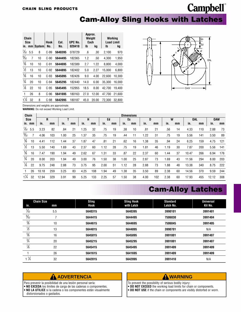
Approx.Chain Weight WorkingSize Hook Cat. UPC No. Each Load Limit
in. mm System No. No. 020418 lb kg lb kg7⁄32 5.5 8 C-99 5640395 078729 .6 .30 2,100 9709⁄32 7 10 C-90 5644495 182365 1.2 .50 4,300 1,9503⁄8 10 10 C-91 5644695 182389 2.7 1.22 8,800 4,0001⁄2 13 10 C-92 5644895 182402 5.0 2.27 15,000 6,8005⁄8 16 10 C-93 5645095 182426 9.0 4.00 22,600 10,3003⁄4 20 10 C-94 5645295 182440 14.0 6.00 35,300 16,0007⁄8 22 10 C-95 5645495 152955 18.5 8.00 42,700 19,400
1 26 8 C-96 5641695 180163 27.0 12.00 47,700 21,600
11⁄4 32 8 C-98 5642095 180187 45.0 20.00 72,300 32,800
Dimensions and weights are approximate.WARNING: Do not exceed Working Load Limit.
Chain DimensionsSize R T H Ed Es D W OAL OAW
in. mm in. mm in. mm in. mm in. mm in. mm in. mm in. mm in. mm in. mm7⁄32 5.5 3.23 82 .84 21 1.25 32 .75 19 .38 10 .81 21 .56 14 4.33 110 2.88 739⁄32 7 4.06 103 1.00 25 1.37 35 .75 19 .44 11 1.22 31 .75 19 5.56 141 3.50 893⁄8 10 4.41 112 1.44 37 1.87 47 .81 21 .62 16 1.38 35 .94 24 6.25 159 4.75 1211⁄2 13 5.50 140 1.69 43 2.37 60 1.12 28 .75 19 1.81 46 1.19 30 7.87 200 5.56 1415⁄8 16 7.47 190 1.94 49 2.62 67 1.31 33 .87 22 2.37 60 1.44 37 10.47 266 6.94 1763⁄4 20 8.00 203 1.94 49 3.00 76 1.50 38 1.00 25 2.87 73 1.69 43 11.56 294 8.00 2037⁄8 22 9.75 248 2.88 73 3.75 95 2.00 51 1.12 28 2.88 73 1.88 48 13.38 340 8.75 222
1 26 10.18 259 3.25 83 4.25 108 1.94 49 1.38 35 3.50 89 2.38 60 14.56 370 9.59 244
11⁄4 32 12.94 329 3.91 99 5.25 133 2.25 57 1.50 38 4.00 102 2.38 60 17.93 455 12.12 308
Cam-Alloy Sling Hooks with Latches
Cam-Alloy LatchesChain Size Sling Sling Hook Standard Universal
in. mm Hook with Latch Latch No. Kit No.7⁄32 5.5 5640315 5640395 3990101 39914019⁄32 7 5644415 5644495 7506030 39914043⁄8 10 5644615 5644695 7506045 39914051⁄2 13 5644815 5644895 3990701 N/A5⁄8 16 5645015 5645095 3991001 39914073⁄4 20 5645215 5645295 3991001 39914077⁄8 22 5645415 5645495 3991409 3991409
1 26 5641615 5641695 3991409 3991409
1 1⁄4 32 5642015 5642095 3991410 N/A

CHAIN SLING PRODUCTS
ADVERTENCIAPara prevenir la posibilidad de una lesión personal sería:• NO EXCEDA los límites de carga de las cadenas o componentes.• NO LA UTILICE si la cadena o los componentes están visualmente
distorsionados o gastados.
WARNINGTo prevent the possibility of serious bodily injury:• DO NOT EXCEED the working load limits for chain or components.• DO NOT USE if the chain or components are visibly distorted or worn.
Cam-Alloy Foundry Hooks
DimensionsChain SphericalSize R T Ed Es D W H Radius
in. mm in. mm in. mm in. mm in. mm in. mm in. mm in. mm in. mm9⁄32 7 4.75 121 2.5 64 .62 16 .47 12 1.30 33 1.00 25 1.56 40 .25 63⁄8 10 5.75 146 3.0 76 .75 19 .62 16 1.56 40 1.25 32 1.87 47 .31 81⁄2 13 6.87 174 3.5 89 1.00 25 .75 19 1.81 46 1.50 38 2.25 57 .37 95⁄8 16 8.06 205 4.0 102 1.25 32 .87 22 2.33 59 1.75 44 2.62 67 .44 113⁄4 20 9.25 235 4.5 114 1.50 38 1.00 25 2.81 71 2.00 51 3.00 76 .50 137⁄8 22 10.37 263 5.0 127 1.84 47 1.12 28 3.08 78 2.25 57 3.37 86 .56 14
1 26 11.56 294 5.5 140 2.09 53 1.25 32 3.25 83 2.50 64 3.75 95 .62 16
11⁄4 32 12.87 327 6.0 152 2.47 63 1.37 35 3.88 99 3.00 76 4.25 108 .75 19
Approx.Chain Weight WorkingSize Hook Cat. UPC No. Each Load Limit
in. mm System No. No. 020418 lb kg lb kg9⁄32 7 10 C-498 5664415 182457 2.2 .99 4,300 1,9503⁄8 10 10 C-499 5664615 182464 3.9 1.80 8,800 4,0001⁄2 13 10 C-500 5664815 182471 6.7 3.00 15,000 6,8005⁄8 16 10 C-501 5665015 182488 10.5 4.80 22,600 10,3003⁄4 20 10 C-502 5665215 182495 15.6 7.10 35,300 16,0007⁄8 22 10 C-503 5665415 152948 24.1 10.90 42,700 19,400
1 26 8 C-504 5661615 078965 33.7 15.30 47,700 21,600
11⁄4 32 8 C-505 5662015 078972 52.0 23.60 72,300 32,800
Dimensions and weights are approximate.WARNING: Do not exceed Working Load Limit.

CHAIN SLING PRODUCTS
ADVERTENCIAPara prevenir la posibilidad de una lesión personal sería:• NO EXCEDA los límites de carga de las cadenas o componentes.• NO LA UTILICE si la cadena o los componentes están visualmente
distorsionados o gastados.
WARNINGTo prevent the possibility of serious bodily injury:• DO NOT EXCEED the working load limits for chain or components.• DO NOT USE if the chain or components are visibly distorted or worn.
Chain DimensionsSize R T Ed Es D W OAL OAW
in. mm in. mm in. mm in. mm in. mm in. mm in. mm in. mm in. mm7⁄32 5.5 1.91 49 .37 9 .44 11 .35 9 .76 19 .53 13 2.94 75 1.69 439⁄32 7 2.50 64 .37 9 .56 14 .37 9 .81 21 .59 15 3.69 94 1.87 473⁄8 10 2.41 61 .50 13 .75 19 .44 11 1.16 29 .66 17 4.00 102 2.56 651⁄2 13 3.40 86 .66 17 1.12 28 .56 14 1.44 37 .88 22 5.40 137 3.50 895⁄8 16 4.22 107 .78 20 1.22 31 .69 18 1.75 44 1.12 28 6.66 169 4.25 1083⁄4 20 5.15 131 .94 24 1.44 37 1.00 25 2.12 54 1.38 35 8.28 210 5.18 1327⁄8 22 7.00 178 1.06 27 1.75 44 1.00 25 2.44 62 1.62 41 10.44 265 5.68 144
1 26 7.98 203 1.19 30 1.87 47 1.12 28 3.00 76 1.81 46 12.14 308 6.75 171
11⁄4 32 10.00 254 1.50 38 2.25 57 1.50 38 3.75 95 2.25 57 15.25 387 8.63 219
Dimensions and weights are approximate.Note: Use of chain in a grab hook may reduce the breaking load of the chain by up to 20%
Cam-Alloy Grab Hooks
Approx.Chain Weight WorkingSize Hook Cat. UPC No. Each Load Limit
in. mm System No. No. 020418 lb kg lb kg7⁄32 5.5 8 C-71 5620315 078583 .25 .11 2,100 9709⁄32 7 10 C-72 5624415 182303 .60 .27 4,300 1,9503⁄8 10 10 C-73 5624615 182310 .90 .41 8,800 4,0001⁄2 13 10 C-75 5624815 182327 1.78 .81 15,000 6,8005⁄8 16 10 C-76 5625015 182334 4.41 2.00 22,600 10,3003⁄4 20 10 C-77 5625215 182341 7.50 3.40 35,300 16,0007⁄8 22 10 C-78 5625415 152979 12.20 5.50 42,700 19,400
1 26 8 C-79 5621615 078651 19.90 9.03 47,700 21,600
11⁄4 32 8 C-51 5622015 180156 38.10 17.30 72,300 32,800

CHAIN SLING PRODUCTS
ADVERTENCIAPara prevenir la posibilidad de una lesión personal sería:• NO EXCEDA los límites de carga de las cadenas o componentes.• NO LA UTILICE si la cadena o los componentes están visualmente
distorsionados o gastados.
WARNINGTo prevent the possibility of serious bodily injury:• DO NOT EXCEED the working load limits for chain or components.• DO NOT USE if the chain or components are visibly distorted or worn.
Cam-Alloy Oblong Links
Approximate WorkingLink Cat. UPC No. Wgt. Each Load LimitNo. No. 020418 lb kg lb kg
CO-0 5685615 079214 .50 .23 4,200 1,900
VO-1 5683215 182549 1.90 .86 8,600 3,900
VO-2 5683315 182556 2.63 1.19 17,600 8,000
VO-3 5683415 182563 6.78 3.08 30,000 13,600
VO-4 5683515 182570 9.20 4.17 45,200 20,500
VO-5 5683615 182587 18.90 8.60 70,600 32,100
VO-6 5683715 182594 28.71 13.00 105,900 48,100
CO-7 5687015 079351 37.80 16.92 102,600 46,600
CO-8 5687215 079375 54.00 24.49 144,600 65,700
CO-10 5687615 079399 84.80 38.46 216,900 98,600
Nominal Used with Type and Size of SlingDiameter Inside Single Double Triple or QuadMaterial Width Length Type Type Type
Link A B C S & C D T or QNo. in. mm in. mm in. mm in. mm in. mm in. mm
CO-0 13⁄32 10 11⁄2 38 3 76 7⁄32 6 7⁄32 6 - -
VO-1 37⁄64 15 21⁄2 64 5 127 9⁄32 7 9⁄32 7 7⁄32 6
VO-2 13⁄16 21 3 76 6 152 3⁄8 10 3⁄8 10 9⁄32 7
VO-3 11⁄8 29 4 102 8 203 1⁄2 or 5⁄8 13 or 16 1⁄2 13 3⁄8 10
VO-4 11⁄4 32 4 102 8 203 3⁄4 19 5⁄8 16 1⁄2 13
VO-5 15⁄8 41 51⁄4 133 101⁄2 267 7⁄8 22 3⁄4 19 5⁄8 16
VO-6 17⁄8 48 6 152 12 305 1 26 7⁄8 22 3⁄4 19
CO-7 2 51 7 178 14 356 11⁄4 or 11⁄2 32 or 38 1 26 -- --
CO-8 21⁄4 57 8 203 16 406 - - 11⁄4 or 11⁄2 32 or 38 7⁄8 or 1 22 or 26
CO-10 23⁄4 70 9 229 16 406 - - 11⁄2 38 11⁄4 32
Dimensions and weights are approximate.

CHAIN SLING PRODUCTS
ADVERTENCIAPara prevenir la posibilidad de una lesión personal sería:• NO EXCEDA los límites de carga de las cadenas o componentes.• NO LA UTILICE si la cadena o los componentes están visualmente
distorsionados o gastados.
WARNINGTo prevent the possibility of serious bodily injury:• DO NOT EXCEED the working load limits for chain or components.• DO NOT USE if the chain or components are visibly distorted or worn.
Cam-Alloy Oblong, Master Link Sub-Assembly
Oblong Master Link Master Coupling LinkNominal NominalDiameter Inside Dimensions Diameter Inside Dimensions
Chain Material Width Length Material Width LengthSize A B C D E F
in. mm in. mm in. mm in. mm in. mm in. mm in. mm7⁄32 5.5 37⁄64 15 21⁄2 64 5 127 13⁄32 10 11⁄2 38 3 769⁄32 7 13⁄16 21 3 76 6 152 17⁄32 13 11⁄2 38 23⁄4 703⁄8 10 11⁄8 29 4 102 8 203 25⁄32 20 19⁄16 40 27⁄8 731⁄2 13 11⁄4 32 4 102 8 203 1 25 3 76 5 1275⁄8 16 15⁄8 41 51⁄4 133 101⁄2 267 11⁄4 32 4 102 6 1523⁄4 20 17⁄8 48 6 152 12 305 11⁄2 38 4 102 6 1527⁄8 22 21⁄4 57 8 203 16 406 13⁄4 44 4 102 6 152
1 26 21⁄4 57 8 203 16 406 17⁄8 48 5 127 7 178
11⁄4 32 23⁄4 70 9 229 16 406 21⁄8 54 6 152 9 229
Dimensions and weights are approximate.These items are made to order.
• For construction of Quad Slings, and Double Basket Slings
Approx.Chain Weight WorkingSize Cat. UPC No. Each Load Limit
in. mm No. 020418 lb kg lb kg7⁄32 5.5 5680315 079108 2.60 1 6,300 2,9009⁄32 7 5682215 182501 4.40 2 12,900 5,9003⁄8 10 5682315 182846 9.50 4 26,400 12,0001⁄2 13 5682415 182518 16.00 7 45,000 20,5005⁄8 16 5682515 182525 31.75 14 67,800 30,8003⁄4 20 5682615 182532 50.00 23 105,900 48,1007⁄8 22 5682715 167409 65.90 30 128,100 58,200
1 26 5681615 181610 92.20 42 143,100 65,000
11⁄4 32 5682015 180200 131.00 59 216,900 98,600

1. Loop one half of body over the master link at the flat embossed area, the other half through the chain. Fit together.
2. Place stud assembly and alloy locking pin in link as shown.
3. Drive the locking pin in until the snap ring engages the recessed portion of the pin. (Link is disassem-bled by simply driving locking pin out.)
CHAIN SLING PRODUCTS
ADVERTENCIAPara prevenir la posibilidad de una lesión personal sería:• NO EXCEDA los límites de carga de las cadenas o componentes.• NO LA UTILICE si la cadena o los componentes están visualmente
distorsionados o gastados.
WARNINGTo prevent the possibility of serious bodily injury:• DO NOT EXCEED the working load limits for chain or components.• DO NOT USE if the chain or components are visibly distorted or worn.
Quik-Alloy Chain SlingsThe Campbell Quik-Alloy system provides proof tested andcertified components for easily and quickly assembling all ofthe popular types of chain slings plus many special slings.Hooks and coupling links have rotating load pins that resistbending and offer shear values equivalent to the chain. Theopen design of the hooks allows for easy inspection. All Quik-
Alloy components are sized and identified according to thechain with which they are to be used. They meet or exceedall OSHA, ANSI, and ASME specifications.
How to Design Quik-Alloy Chain Slings1. Determine the maximum LOAD to be lifted.2. Choose the TYPE of sling assembly necessitated by the
size and dimension of the load.3. Estimate the approximate ANGLE to the load in which the
legs of the assembly will be positioned for operation.4. Determine the SIZE OF CHAIN ATTACHMENTS by refer-
ring to the Assembly Tables that follow. On multi-leg slings,if the distance between the points of attachment equals the reach of the sling, the angle is approximately 60°
5. Determine the overall REACH (see illustration). Use the Assembly Tables that follow to determine length of Cam-Alloy chain to order.
6. Attach field identification tag to all slings. One box of 50- No. 7503506.
For any problem involving reach, angle of lift or working loadlimit, consult your local Campbell distributor.Remember to use only Campbell “Quik-Alloy” components inassembling chain slings.
SUBSTITUTION OF ANY COMPONENTS WITH PARTSNOT INDICATED ON THE CHART COULD SERIOUSLYDIMINISH THE WORKING LOAD OF THE ASSEMBLY. Donot use any coupling links to repair damaged or broken chain.It is imperative that such chain be replaced.
How to Assemble Quik-Alloy Coupling Links

CHAIN SLING PRODUCTS
ADVERTENCIAPara prevenir la posibilidad de una lesión personal sería:• NO EXCEDA los límites de carga de las cadenas o componentes.• NO LA UTILICE si la cadena o los componentes están visualmente
distorsionados o gastados.
WARNINGTo prevent the possibility of serious bodily injury:• DO NOT EXCEED the working load limits for chain or components.• DO NOT USE if the chain or components are visibly distorted or worn.
lb kg lb kg lb kg lb kg lb kgWorking Load Limit 4,300 1,952 8,800 3,995 15,000 6,810 22,600 10,260 35,300 16,026Master Link Number VO-1 VO-2 VO-3 VO-3 VO-4
Master Link 5683215 5683315 5683415 5683515 5683615
Cat. QA Sling Hook 5744415 5744615 5744815 5745015 5745215
No. QA Grab Hook 5724415 5724615 5724815 5725015 5725215
QA Coupling Link 5779415 5779135 5779145 5779155 5779165
Chain needed Sling Hook 4'1" 3'10" 3'7" 3'5" 3'3"
for 5’ reach Grab Hook 4'3" 4'0" 3'9" 3'8" 3'6"
lb kg lb kg lb kg lb kg lb kg60° 7,500 3,405 15,200 6,901 26,000 77,804 39,100 17,751 61,100 27,739
Working Load Limit 45° 6,100 2,769 12,400 5,630 21,200 9,625 32,000 14,528 49,900 22,65530° 4,300 1,952 8,800 3,995 15,000 6,810 22,600 10,260 35,300 16,026
Master Link Number VO-1 VO-2 VO-3 VO-4 VO-5
Master Link 5683215 5683315 5683415 5683515 5683615
Cat. QA Sling Hook 5744415 5744615 5744815 5745015 5745215
No. QA Grab Hook 5724415 5724615 5724815 5725015 5725215
QA Coupling Link 5779125 5779135 5779145 5779155 5779165
Chain needed Sling Hook 4'1" 3'10" 3'7" 3'5" 3'1"
for 5’ reach Grab Hook 4'3" 4'0" 3'9" 3'8" 3'3"
Double Chain Slings: Type D
Single Chain Slings: Types S and C
If the overall reach of your sling is determined to be more than five feet, sub-tract five feet, then add this difference to the “chain needed” length given onthe Assembly Table. If overall reach is less than five feet, subtract reach fromfive feet.Then subtract the difference from the “chain needed” length in theAssembly Table. All measurements are based on using Quik-Alloy hooks (notCam-Alloy hooks).
WHEN USING QUIK-ALLOY HOOKS (NOT CAM-ALLOY HOOKS), BE SURETHAT EACH LEG OF A DOUBLE SLING HAS THE SAME, EVEN (DIVISIBLE BYTWO) NUMBER OF LINKS. For triple or quad slings, each leg should have oddnumbers of links to compensate for coupling links on master link sub-assembly.When cutting, if the required reach falls within a link, LEAVE THAT LINK. Reachmeasurements are given as a minimum. Never cut less than specified reach.
Quik-Alloy Chain Sling Assembly Tablesin. mm in. mm in. mm in. mm in. mm
Chain Size 9⁄32 7 3⁄8 10 1⁄2 13 5⁄8 16 3⁄4 19
Triple Chain Slings: Type T and Quad Chain Slings: Type Q
lb kg lb kg lb kg lb kg lb kg60° 11,200 5,085 22,800 10,351 39,000 17,706 58,700 26,650 91,700 41,632
Working Load Limit 45° 9,100 4,131 18,600 8,444 31,800 14,437 47,900 21,747 74,900 34,00530° 6,450 2,928 13,200 5,993 22,500 10,215 33,900 15,391 53,000 24,062
Master Link Number VO-2 VO-3 VO-4 VO-5 VO-6
Sub-Assembly 5682215 5682315 5682415 5682515 5682615
Cat. QA Sling Hook 5744415 5744615 5744815 5745015 5745215
No. QA Grab Hook 5724415 5724615 5724815 5725015 5725215
QA Coupling Link 5779125 5779135 5779145 5779155 5779165
Chain needed Sling Hook 3'10" 3'6" 3'2" 2'10" 2'5"
for 5’ reach Grab Hook 3'11" 3'8" 3'4" 2'10" 2'8"
How to Use Quik-Alloy Chain Sling Assembly Tables

CHAIN SLING PRODUCTS
ADVERTENCIAPara prevenir la posibilidad de una lesión personal sería:• NO EXCEDA los límites de carga de las cadenas o componentes.• NO LA UTILICE si la cadena o los componentes están visualmente
distorsionados o gastados.
WARNINGTo prevent the possibility of serious bodily injury:• DO NOT EXCEED the working load limits for chain or components.• DO NOT USE if the chain or components are visibly distorted or worn.
Approx.Chain Weight WorkingSize Cat. UPC No. Each Load Limit
in. mm System No. 020418 lb kg lb kg7⁄32 5.5 8 5770315 079993 .10 .05 2,100 9709⁄32 7 10 5779125 182754 .27 .13 4,300 1,9503⁄8 10 10 5779135 182761 .55 .25 8,800 4,0001⁄2 13 10 5779145 182860 1.65 .75 15,000 6,8005⁄8 16 10 5779155 182778 2.70 1.23 22,600 10,3003⁄4 19 10 5779165 182785 4.30 1.95 35,300 16,0007⁄8 22 10 5771415 080050 4.35 1.97 42,700 19,400
1 26 8 5771615 080067 8.43 3.82 47,700 21,600
11⁄4 32 8 5772015 080074 15.74 7.14 72,300 32,800
Pins and Retainers7⁄32 5.5 8 5784105 181689 .02 .009 - -9⁄32 7 10 5784425 182792 .02 .009 - -3⁄8 10 10 5784435 182808 .06 .027 - -1⁄2 13 10 5784445 182815 .11 .050 - -5⁄8 16 10 5784455 182822 .17 .077 - -3⁄4 19 10 5784465 182839 .35 .159 - -7⁄8 22 10 5784165 181740 - - - -
1 26 8 5784175 181757 - - - -
11⁄4 32 8 5784185 181764 - - - -
Quik-Alloy Coupling LinksHow to Assemble:1. Loop one half body through attachment, the other through
chain. Fit together.2. Place stud assembly and alloy locking pin in link.3. Drive the locking pin in until the snap ring engages the
recessed portion of the pin. (Link is disassembled by simply driving locking pin out.)
Chain Dimensions Max. mat.Size A B C D E F G Dia.
in. mm in. mm in. mm in. mm in. mm in. mm in. mm in. mm in. mm7⁄32 5.5 17⁄64 7 7⁄32 6 15⁄16 33 7⁄16 11 5⁄32 4 117⁄32 39 3⁄8 10 1⁄2 139⁄32 7 3⁄8 10 11⁄32 9 23⁄32 44 9⁄16 14 13⁄64 5 125⁄32 45 3⁄8 10 37⁄64 153⁄8 10 1⁄2 13 7⁄16 11 23⁄8 60 13⁄16 21 5⁄16 8 27⁄16 62 23⁄64 9 13⁄16 211⁄2 13 11⁄16 17 9⁄16 14 3 76 11⁄32 26 25⁄64 10 33⁄8 86 29⁄64 12 13⁄16 305⁄8 16 13⁄16 21 23⁄32 18 37⁄8 98 19⁄32 33 15⁄32 12 329⁄32 99 35⁄64 14 15⁄16 333⁄4 20 15⁄16 24 61⁄64 24 45⁄8 117 19⁄16 40 9⁄16 14 4 ⁄4 121 41⁄64 16 111⁄16 437⁄8 22 13⁄16 30 11⁄16 24 53⁄8 137 113⁄16 46 41⁄64 16 55⁄16 135 13⁄16 30 17⁄8 48
1 26 115⁄64 31 19⁄64 29 57⁄8 149 21⁄32 52 11⁄16 17 57⁄8 149 13⁄8 35 21⁄8 54
11⁄4 32 11⁄2 38 13⁄8 35 73⁄8 187 29⁄32 58 15⁄16 24 615⁄16 176 15⁄8 41 211⁄32 60
Dimensions and weights are approximate.

CHAIN SLING PRODUCTS
ADVERTENCIAPara prevenir la posibilidad de una lesión personal sería:• NO EXCEDA los límites de carga de las cadenas o componentes.• NO LA UTILICE si la cadena o los componentes están visualmente
distorsionados o gastados.
WARNINGTo prevent the possibility of serious bodily injury:• DO NOT EXCEED the working load limits for chain or components.• DO NOT USE if the chain or components are visibly distorted or worn.
Quik-Alloy Sling Hooks
Chain Regular Latched Approx. WorkingSize Cat. UPC No. Cat. UPC No. Wgt. Each Load Limit
in. mm No. 020418 No. 020418 lb kg lb kg9⁄32 7 5744415 182655 5744495 182662 1.3 .59 4,300 1,9503⁄8 10 5744615 182679 5744695 182686 2.8 1.27 8,800 4,0001⁄2 13 5744815 182693 5744895 182709 5.4 2.45 15,000 6,8005⁄8 16 5745015 182716 5745095 182723 8.5 3.85 22,600 10,3003⁄4 20 5745215 182730 5745295 182747 16.7 7.60 35,300 16,000
DimensionsChain Load PinSize R T U A E Dia. D W HP OAW
in. mm in. mm in. mm in. mm in. mm in. mm in. mm in. mm in. mm in. mm in. mm9⁄32 7 33⁄4 95 11⁄4 32 11⁄16 27 5⁄16 8 11⁄32 9 3⁄8 10 11⁄8 29 3⁄4 19 123⁄32 44 37⁄8 983⁄8 10 43⁄4 121 19⁄16 40 15⁄16 33 7⁄16 11 1⁄2 13 1⁄2 13 17⁄16 37 15⁄16 24 23⁄8 60 41⁄2 1141⁄2 13 53⁄4 146 17⁄8 48 19⁄16 40 9⁄16 14 5⁄8 16 5⁄8 16 17⁄8 48 11⁄4 32 211⁄16 68 61⁄8 1565⁄8 16 63⁄4 171 23⁄16 56 113⁄16 46 23⁄32 18 3⁄4 19 3⁄4 19 25⁄16 59 13⁄8 35 31⁄8 79 71⁄16 1793⁄4 20 73⁄4 197 21⁄2 64 23⁄16 56 13⁄16 21 7⁄8 22 7⁄8 22 23⁄4 70 15⁄8 41 33⁄8 86 81⁄16 205
Dimensions and weights are approximate.
Quik-Alloy Latches
Chain Size Sling Sling Hook Standard Universalin. mm Hook with Latch Latch No. Kit No.9⁄32 7 5744415 5744495 7506030 39914043⁄8 10 5744615 5744695 7506045 39914051⁄2 13 5744815 5744895 7506070 39914065⁄8 16 5745015 5745095 7506110 39914073⁄4 20 5745215 5745295 3991101 3991408

CHAIN SLING PRODUCTS
ADVERTENCIAPara prevenir la posibilidad de una lesión personal sería:• NO EXCEDA los límites de carga de las cadenas o componentes.• NO LA UTILICE si la cadena o los componentes están visualmente
distorsionados o gastados.
WARNINGTo prevent the possibility of serious bodily injury:• DO NOT EXCEED the working load limits for chain or components.• DO NOT USE if the chain or components are visibly distorted or worn.
Quik-Alloy Grab Hooks
DimensionsChain Load PinSize R T A E Dia. D W HP OAW
in. mm in. mm in. mm in. mm in. mm in. mm in. mm in. mm in. mm in. mm9⁄32 7 211⁄32 60 3⁄8 10 5⁄16 8 11⁄32 9 3⁄8 10 13⁄16 21 5⁄8 16 11⁄4 32 2 513⁄8 10 229⁄32 74 1⁄2 13 7⁄16 11 1⁄2 13 1⁄2 13 11⁄4 32 3⁄4 19 15⁄8 41 213⁄16 711⁄2 13 323⁄32 94 21⁄32 17 9⁄16 14 5⁄8 16 5⁄8 16 11⁄2 38 15⁄16 24 2 51 31⁄2 895⁄8 16 47⁄16 113 25⁄32 20 23⁄32 18 3⁄4 19 3⁄4 19 13⁄4 44 17⁄32 31 25⁄8 67 41⁄8 1053⁄4 20 51⁄8 130 31⁄32 25 13⁄16 21 7⁄8 22 7⁄8 22 21⁄8 54 13⁄8 35 31⁄4 83 47⁄8 124
Dimensions and weights are approximate.Note: Use of chain in a grab hook may reduce the breaking load of the chain by up to 20%
Approx.Chain Weight WorkingSize Cat. UPC No. Each Load Limit
in. mm No. 020418 lb kg lb kg9⁄32 7 5724415 182600 .5 .23 4,300 1,9503⁄8 10 5724615 182617 1.6 .73 8,800 4,0001⁄2 13 5724815 182624 2.6 1.18 15,000 6,8005⁄8 16 5725015 182631 5.2 2.36 22,600 10,3003⁄4 20 5725215 182648 10.5 4.77 35,300 16,000

CHAIN SLING PRODUCTS
ADVERTENCIAPara prevenir la posibilidad de una lesión personal sería:• NO EXCEDA los límites de carga de las cadenas o componentes.• NO LA UTILICE si la cadena o los componentes están visualmente
distorsionados o gastados.
WARNINGTo prevent the possibility of serious bodily injury:• DO NOT EXCEED the working load limits for chain or components.• DO NOT USE if the chain or components are visibly distorted or worn.
Cam-Alloy Plate Hooks
Approx.Chain Weight WorkingSize Cat. UPC No. Each Load Limit
in. mm No. 020418 lb kg lb kg9⁄32 7 5450415 077258 2.5 1.10 3,500 1,5703⁄8 10 5450615 077265 4.5 2.04 7,100 3,2001⁄2 13 5450815 077272 11.0 5.00 12,000 5,4005⁄8 16 5451015 077289 20.0 9.07 18,100 8,2003⁄4 20 5451215 180033 34.0 15.40 28,300 12,8007⁄8 22 5451415 - 53.0 24.00 34,200 15,500
Chain DimensionsSize A B C D E F G H T W
in. mm in. mm in. mm in. mm in. mm in. mm in. mm in. mm in. mm in. mm in. mm9⁄32 7 2.0 51 2 51 1.5 38 .75 19 .87 22 .125 3 .75 19 .19 5 .63 16 2.0 513⁄8 10 2.6 66 3 76 1.9 48 1.00 25 1.00 25 .188 5 1.00 25 .25 6 .75 19 2.3 581⁄2 13 3.5 89 4 102 2.5 64 1.40 36 1.50 38 .250 6 1.25 32 .31 8 1.00 25 3.0 765⁄8 16 4.4 112 5 127 3.1 79 1.80 46 1.90 48 .310 8 1.50 38 .31 8 1.30 33 3.8 973⁄4 20 5.2 132 6 152 3.8 97 2.10 53 2.30 58 .380 10 1.80 46 .31 8 1.50 38 4.5 1147⁄8 22 6.0 152 7 178 4.3 109 2.40 61 2.60 66 .430 11 2.00 51 .37 9 1.80 46 5.3 135
Dimensions are approximate.These items are made to order.

CHAIN SLING PRODUCTS
ADVERTENCIAPara prevenir la posibilidad de una lesión personal sería:• NO EXCEDA los límites de carga de las cadenas o componentes.• NO LA UTILICE si la cadena o los componentes están visualmente
distorsionados o gastados.
WARNINGTo prevent the possibility of serious bodily injury:• DO NOT EXCEED the working load limits for chain or components.• DO NOT USE if the chain or components are visibly distorted or worn.
Miscellaneous Cam-Alloy Sling Products"J" Hooks
NominalDiameter DimensionsMaterial BR C° D E F G H
Style in. mm in. mm Angle in. mm in. mm in. mm in. mm in. mm
A 3⁄4 19 1.31 33 25 2.69 68 4.38 111 2.06 52 .38 10 15⁄32 12
B 1 26 2.00 51 90 3.64 92 6.75 171 4.00 102 .28 7 15⁄32 12
*A 1 26 2.00 51 90 4.13 105 6.75 171 3.88 99 .28 7 15⁄32 12
* Available on special order only.Dimensions and weights are approximate.
Nominal Approx.Diameter Weight WorkingMaterial Cat. UPC No. Each Load Limit
Style in. mm No. 020418 lb kg lb kg
A 3⁄4 19 5616215 078484 1.2 .54 2,250 1,000
B 1 26 5616615 078491 2.8 1.27 3,600 1,600
*A 1 26 5616616 189777 2.8 1.27 3,600 1,600

CHAIN SLING PRODUCTS
ADVERTENCIAPara prevenir la posibilidad de una lesión personal sería:• NO EXCEDA los límites de carga de las cadenas o componentes.• NO LA UTILICE si la cadena o los componentes están visualmente
distorsionados o gastados.
WARNINGTo prevent the possibility of serious bodily injury:• DO NOT EXCEED the working load limits for chain or components.• DO NOT USE if the chain or components are visibly distorted or worn.
"S" Hooks
Nominal Approx.Diameter Dimensions Weight WorkingMaterial Cat. UPC No. A B C R Each Load Limitin. mm No. 020418 in. mm in. mm in. mm in. mm lb kg lb kg9⁄32 7 5610405 078262 2.75 70 .75 19 .38 10 .38 10 .07 .03 250 1103⁄8 10 5610605 078279 4.13 105 1.13 29 .56 14 .56 14 .33 .15 500 2001⁄2 13 5610805 078286 5.50 140 1.50 38 .75 19 .75 19 .59 .27 1,000 5005⁄8 16 5611005 078293 7.00 178 1.88 48 .94 24 .94 24 1.24 .56 1,500 7003⁄4 19 5611205 078309 8.25 210 2.25 57 1.13 29 1.13 29 2.31 1.05 2,000 9007⁄8 22 5611405 181580 9.63 245 2.63 67 1.31 33 1.31 33 3.05 1.38 2,700 1,200
1 26 5611605 078323 11.00 279 3.00 76 1.50 38 1.50 38 4.45 2.02 3,200 1,500
11⁄8 29 5611805 180125 12.13 308 3.38 86 1.69 43 1.69 43 6.48 2.94 3,500 1,600
11⁄4 32 5612005 180132 13.75 349 3.75 95 1.88 48 1.88 48 8.36 3.79 4,600 2,100
13⁄8 35 5612205 180149 14.88 378 4.13 105 2.06 52 2.06 52 9.94 4.51 6,500 2,900
11⁄2 38 5612405 078361 16.50 419 4.50 114 2.25 57 2.25 57 15.02 6.81 7,600 3,400
Dimensions and weights are approximate.These items are made to order.

CHAIN SLING PRODUCTS
ADVERTENCIAPara prevenir la posibilidad de una lesión personal sería:• NO EXCEDA los límites de carga de las cadenas o componentes.• NO LA UTILICE si la cadena o los componentes están visualmente
distorsionados o gastados.
WARNINGTo prevent the possibility of serious bodily injury:• DO NOT EXCEED the working load limits for chain or components.• DO NOT USE if the chain or components are visibly distorted or worn.
DimesionsEnd Link Dimensions
Chain Bell Dimensions Inside Dimensions Length ofSize X1 X W L W1 Dia. Width Length Two Links
in. mm in. mm in. mm in. mm in. mm in. mm in. mm in. mm in. mm in. mm
Bell Type3⁄4 20 2 51 2 51 41⁄4 108 7 178 3 76 7⁄8 22 2 51 6 152 43⁄8 1117⁄8 22 2 51 2 51 41⁄4 108 7 178 3 76 1 25 21⁄8 54 6 152 47⁄8 124
1 26 23⁄4 70 21⁄4 57 53⁄16 132 8 203 31⁄2 89 11⁄8 29 21⁄4 57 6 152 55⁄8 143
11⁄4 32 21⁄2 64 21⁄2 64 71⁄2 191 11 279 6 152 11⁄2 38 25⁄8 67 7 178 7 178
Large Bail (Special Bell)
11⁄4 32 23⁄4 70 23⁄4 70 91⁄2 241 141⁄2 368 7 178 11⁄2 38 25⁄8 67 7 178 7 178
† Reach shown is standard unless otherwise specified. If additional reach is required, add 2 link increments to each leg. Dimensions and weights are approximate.These items are made to order.
Magnet Chains (bell type)
The Campbell Magnet Bell• Alloy casting with no moving parts• Designed for operational ease and long life• Supplied with Quik-Alloy® coupling links• Equally spaced legs• All legs operate without twist• Entire assembly is proof tested alloy steel• Bell stands upright when at rest
Standard Approx. Approx. AssemblyChain Magnet Total Length of Wgt. of Wgt. of WorkingSize Cat. UPC No. Diameter Reach† Two Links Assy. Bell Only Load Limit
in. mm No. 020418 in. mm in. mm in. mm lb kg lb kg lb kg
Bell Type3⁄4 20 0431235 179938 39-44 991-1118 331⁄2 851 43⁄8 111 75 34 37 17 59,700 27,1007⁄8 22 0431435 179946 44-45 1118-1143 351⁄2 902 47⁄8 124 92 42 37 17 74,700 33,900
1 26 0431635 179952 45- 60 1143 - 1524 391⁄2 1003 55⁄8 143 137 62 60 27 100,600 45,700
11⁄4 32 0432035 179969 60 & over 1524 & over 491⁄2 1257 7 178 281 127 124 56 149,400 67,800
Large Bail (Special Bell)
11⁄4 32 0432135 179976 60 & over 1524 & over 53 1346 7 178 302 137 145 66 149,400 67,800

CHAIN SLING PRODUCTS
ADVERTENCIAPara prevenir la posibilidad de una lesión personal sería:• NO EXCEDA los límites de carga de las cadenas o componentes.• NO LA UTILICE si la cadena o los componentes están visualmente
distorsionados o gastados.
WARNINGTo prevent the possibility of serious bodily injury:• DO NOT EXCEED the working load limits for chain or components.• DO NOT USE if the chain or components are visibly distorted or worn.
Cat. UPC No. Tags PerNo. 020418 Carton
7503506 135309 50
DimensionsMaster Link End Link Length
Chain Inside Dimensions Inside Dimensions of TwoSize Dia. Width Length Dia. Width Length Links
in. mm in. mm in. mm in. mm in. mm in. mm in. mm in. mm5⁄8 16 13⁄4 44 6 152 10 254 3⁄4 19 2 51 51⁄2 140 33⁄4 953⁄4 20 2 51 6 152 10 254 7⁄8 22 2 51 6 152 43⁄8 1117⁄8 22 21⁄8 54 6 152 10 254 1 25 21⁄8 54 6 152 47⁄8 124
1 26 21⁄4 57 61⁄2 165 11 279 11⁄8 29 21⁄4 57 6 152 55⁄8 143
11⁄4 32 21⁄2 64 61⁄2 165 12 305 11⁄2 38 25⁄8 67 7 178 7 178
† Reach shown is standard unless otherwise specified. If additional reach is required, add 2 link increments to each leg. Dimensions and weights are approximate.These items are made to order.
Standard Approximate AssemblyChain Magnet Total Wgt. of WorkingSize Cat. UPC No. Diameter Reach† Assembly Load Limit
in. mm No. 020418 in. mm in. mm lb kg lb kg5⁄8 16 0461035 179983 up to 39 991 281⁄4 718 45 20 47,000 21,3003⁄4 20 0461235 179990 39-44 991 - 1118 31 787 60 27 73,500 33,5007⁄8 22 0461435 180002 44-45 1118 - 1143 321⁄2 826 75 34 88,900 40,800
1 26 0461635 180019 45-60 1143 - 1524 36 914 90 41 123,900 56,900
11⁄4 32 0462035 180026 60 or over 1524 & over 42 1067 160 73 175,000 79,400
Magnet Chains (conventional type)Campbell’s conventional type magnet chain assemblies• Made entirely from alloy steel• Assembly is heat treated and proof tested as a unit• Assembly does not have connection dowels or cotter pins,
never require annealing, and incorporate uniform hardness which provides abrasion resistance
• Custom assemblies can be made to fit special requirements
∆
∆
∆
∆
∆
∆
These tags are designed for field attachment. They are prestamped for easy addition of reach, working load limit,chain size, chain grade and sling serial number. Each steeltag measures 1 1⁄2" x 4 1⁄8" x 5⁄32" thick and has a 1 1⁄16"-diameterhole. Cut at top of tag allows you to attach to sling link.
Box of 50 tags (order unit is “Carton”). Stock No. 7503506.
Field I.D. Tags
Related Documents