CAMEO SIMULATION TOOLKIT version 17.0.1 user guide No Magic, Inc. 2011

Welcome message from author
This document is posted to help you gain knowledge. Please leave a comment to let me know what you think about it! Share it to your friends and learn new things together.
Transcript

CAMEO SIMULATION TOOLKIT
version 17.0.1
user guide
No Magic, Inc.
2011

All material contained herein is considered proprietary information owned by No Magic, Inc. and is not to be shared, copied, or reproduced by any means. All information copyright 2010-2011 by No Magic, Inc. All Rights Reserved.
C O N T E N T S
1 CAMEO SIMULATION TOOLKIT 51. Getting Started 5
1.1 Introduction to Cameo Simulation Toolkit 51.2 Key Features 51.3 Installation 6
2. Model Execution 62.1 Simulation by Executing Elements 7
2.1.1 Behaviors 102.1.2 Class 142.1.3 Diagram 172.1.4 Instance Specification 17
2.2 Simulation by Executing the Execution Configuration 183. Execution Configuration 20
3.1 ExecutionConfig Stereotype 203.2 Execution Log 213.3 Simulation Time and Simulation Clock 223.4 Automatic Start Active Objects 233.5 User Interface Prototyping 253.6 UI Modeling Diagram Execution 253.7 ActiveImage and ImageSwitcher 283.8 Time Series Chart 293.9 Nested UI Configuration 31
3.9.1 NestedUIConfig Stereotype Representing a Part of Execution Context 313.9.2 NestedUIConfig Stereotype Representing a Part Using UI Configuration 34
4. Animation 394.1 Active, Visited, and Last Visited Elements 394.2 Customizing Animation Colors 40
5. Simulation Debugging 415.1 Understanding Simulation Sessions 415.2 Simulation Debugger 425.3 Simulation Console 43
5.3.1 Console Pane 435.3.2 Simulation Information 445.3.3 Simulation Log File 45
5.4 Runtime Values Monitoring 455.4.1 Variables Pane 455.4.2 Monitoring Runtime Value with Time Series Chart 465.4.3 Runtime Object Created from InstanceSpecification 485.4.4 Exporting Runtime Objects to InstanceSpecification 48
5.5 Breakpoints 505.5.1 Adding Breakpoints 515.5.2 Removing Breakpoints 52
5.6 Disabling Updates in Simulation Panes 546. Validation and Verification 547. State Machine Simulation 56
7.1 Supported Elements 567.2 Adapting Models for State Machine Simulation 57
7.2.1 Defining Trigger on Transition 577.2.2 Using Guard on Transition 587.2.3 Behaviors on Entry, Exit, and Do Activity of State 59
7.3 Running State Machine Execution 59
3 Copyright © 2010-2011 No Magic, Inc..
C O N T E N T S
7.4 Sample Projects 607.4.1 The test_regions.mdzip Sample 607.4.2 The test_timers.mdzip Sample 617.4.3 The test_guard.mdzip Sample 61
8. Activity Simulation 618.1 Activity Execution Engine 618.2 Creating Model for Activity Execution 638.3 Executing Activity 87
9. Parametrics Simulation 929.1 About Parametics Engine 929.2 Adapting Model for Parametric Execution 93
9.2.1 Understanding the Flow of Parametric Execution 939.2.2 Typing Value Properties by Boolean, Integer, Real, Complex, or Their Subtypes 949.2.3 Using Binding Connectors 959.2.4 Creating InstanceSpecification with Initial Values 969.2.5 Working with Multiple Values 97
9.3 Running Parametric Simulation 989.4 Retrieving Simulated Values 1019.5 Executing Parametric Simulation from Activity 1029.6 Sample Projects 102
10. Interaction between Engines 10310.1 Stopwatch Sample 103
10.1.1 Manual Execution 10310.1.2 Controlling Execution Using Activity Diagram 104
11. Recording Signals to Sequence Diagram 10412. Mathematical Engine 106
12.1 Math Console 10612.2 Exchanging Values between Cameo Simulation Toolkit and Mathematical Engine 108
12.2.1 Exchanging Values between Slot and Mathematical Environment 10812.2.2 Exporting Runtime Value to the Mathematical Engine 110
12.3 Built-in Math Solver 11012.3.1 Using Math Solver in Math Console 11012.3.2 Variables 11112.3.3 Values 11112.3.4 Constants 11312.3.5 Operators 11312.3.6 Functions 11512.3.7 Built-in Math Solver API for User-defined Functions 120
12.4 Using MATLAB® as Mathematical Solver 12312.4.1 Setting Up System to Call MATLAB® from Cameo Simulation Toolkit 12312.4.2 Selecting MATLAB® as the Mathematical Solver for Cameo Simulation Toolkit 127
13. Action Languages 128
4 Copyright © 2010-2011 No Magic, Inc..
CAMEO SIMULATION TOOLKIT
1. Getting StartedCameo Simulation Toolkit is a MagicDraw plugin which provides a unique set of tools supporting the standard-ized construction, verification, and execution of computational complete models based on a foundational sub-set of the UML.
No Magic is the first in the industry to provide customers with an easy-to-use, standard-based executable UML solution that integrates the semantics of different UML behaviors.
1.1 Introduction to Cameo Simulation Toolkit
The purpose of simulation is to understand the function or performance of a system without manipulating it directly because the real system may have not been completely defined or available, or it cannot be experi-mented due to costs, time, resources, or any other constraints. A simulation is typically performed on a model of a system.
With Cameo Simulation Toolkit, you can execute a model and validate the functionality or performance of a system in the context of a realistic mockup of the intended user interface. The solutions provided by Cameo Simulation Toolkit allow you to predict how the system responds to user interactions, predefined test data, and execution scenarios.
Cameo Simulation Toolkit contains the Simulation Framework plugin that provides the basic GUI to manage the runtime of any kind of executable models and integrations with any simulation engines. The main function-alities of Cameo Simulation Toolkit are as follows:
(i) Simulation Window:
• Toolbars and Debugger Pane: to control an execution or simulation
• Simulation Console: to execute log outputs and command lines for active engines
• Sessions Pane: to select particular sessions of executions
• Variables Pane: to monitor the runtime values of each execution session
• Math Console: to communicate with mathematical engines
• Breakpoints Pane
• Triggers Options
(ii) Pluggable Execution Engines(iii) Execution Animation(iv) Model Debugger(v) Pluggable Events and Data Sources(vi) Pluggable Mockup Panels(vii) Model-driven Execution Configurations(viii) Pluggable Expression Evaluators and Action Languages
1.2 Key Features
Cameo Simulation Toolkit is capable of executing your UML or SysML models. The key features of Cameo Simulation Toolkit are as follows:
Copyright © 2010-2011 No Magic, Inc.5
CAMEO SIMULATION TOOLKITModel Execution
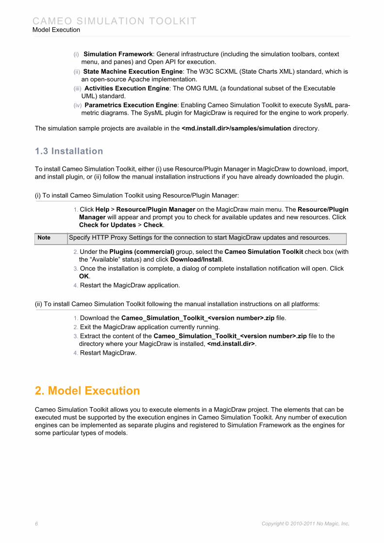
(i) Simulation Framework: General infrastructure (including the simulation toolbars, context menu, and panes) and Open API for execution.
(ii) State Machine Execution Engine: The W3C SCXML (State Charts XML) standard, which is an open-source Apache implementation.
(iii) Activities Execution Engine: The OMG fUML (a foundational subset of the Executable UML) standard.
(iv) Parametrics Execution Engine: Enabling Cameo Simulation Toolkit to execute SysML para-metric diagrams. The SysML plugin for MagicDraw is required for the engine to work properly.
The simulation sample projects are available in the <md.install.dir>/samples/simulation directory.
1.3 Installation
To install Cameo Simulation Toolkit, either (i) use Resource/Plugin Manager in MagicDraw to download, import, and install plugin, or (ii) follow the manual installation instructions if you have already downloaded the plugin.
(i) To install Cameo Simulation Toolkit using Resource/Plugin Manager:
1. Click Help > Resource/Plugin Manager on the MagicDraw main menu. The Resource/Plugin Manager will appear and prompt you to check for available updates and new resources. Click Check for Updates > Check.
2. Under the Plugins (commercial) group, select the Cameo Simulation Toolkit check box (with the “Available” status) and click Download/Install.
3. Once the installation is complete, a dialog of complete installation notification will open. Click OK.
4. Restart the MagicDraw application.
(ii) To install Cameo Simulation Toolkit following the manual installation instructions on all platforms:
1. Download the Cameo_Simulation_Toolkit_<version number>.zip file.2. Exit the MagicDraw application currently running.3. Extract the content of the Cameo_Simulation_Toolkit_<version number>.zip file to the
directory where your MagicDraw is installed, <md.install.dir>.4. Restart MagicDraw.
2. Model ExecutionCameo Simulation Toolkit allows you to execute elements in a MagicDraw project. The elements that can be executed must be supported by the execution engines in Cameo Simulation Toolkit. Any number of execution engines can be implemented as separate plugins and registered to Simulation Framework as the engines for some particular types of models.
Note Specify HTTP Proxy Settings for the connection to start MagicDraw updates and resources.
6 Copyright © 2010-2011 No Magic, Inc..
CAMEO SIMULATION TOOLKITModel Execution
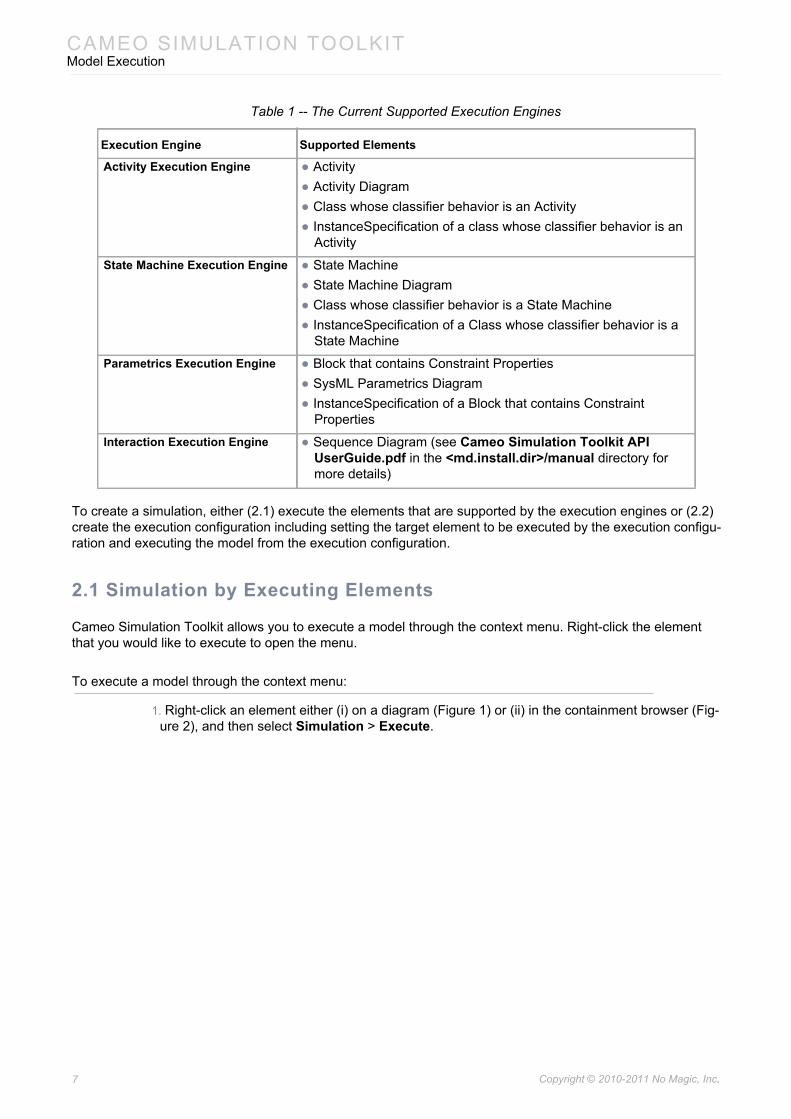
Table 1 -- The Current Supported Execution Engines
To create a simulation, either (2.1) execute the elements that are supported by the execution engines or (2.2) create the execution configuration including setting the target element to be executed by the execution configu-ration and executing the model from the execution configuration.
2.1 Simulation by Executing Elements
Cameo Simulation Toolkit allows you to execute a model through the context menu. Right-click the element that you would like to execute to open the menu.
To execute a model through the context menu:
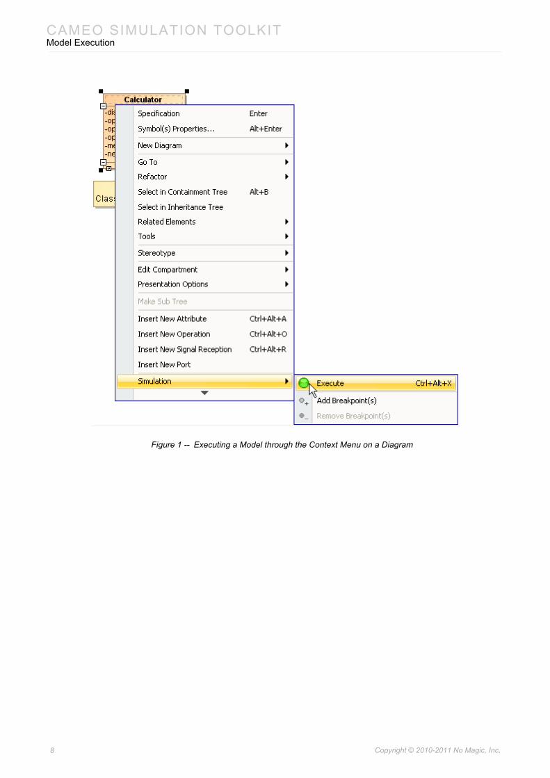
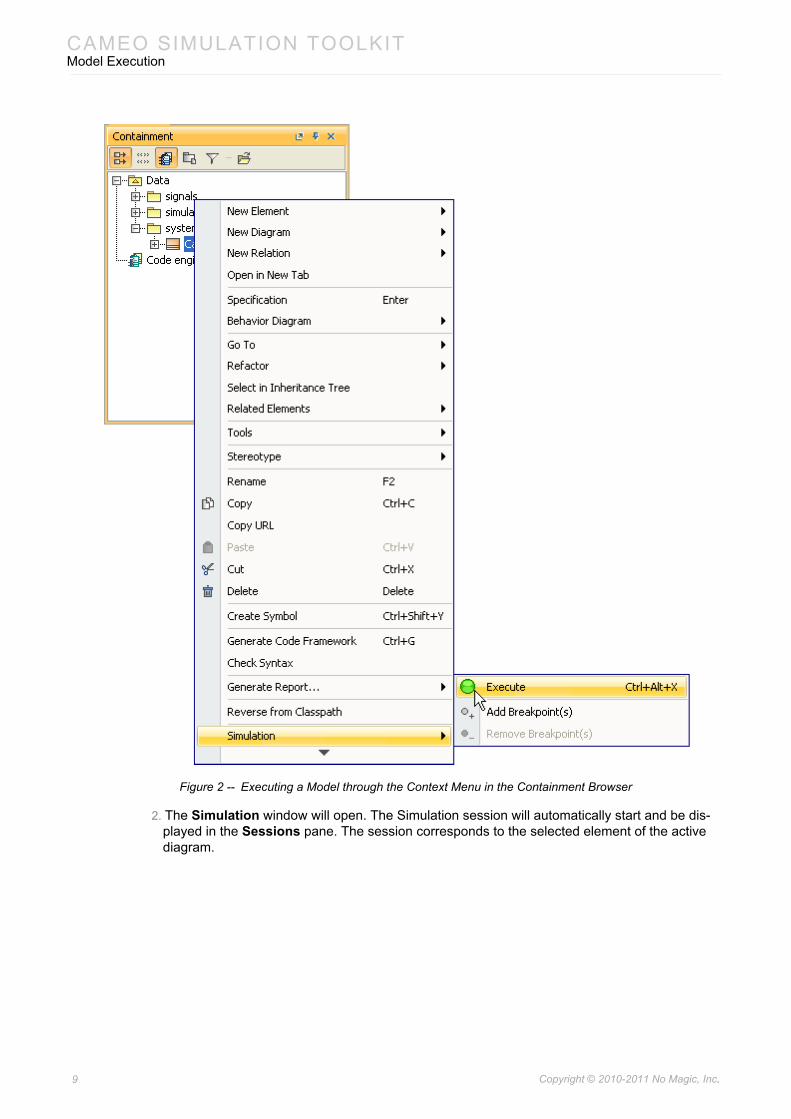
1. Right-click an element either (i) on a diagram (Figure 1) or (ii) in the containment browser (Fig-ure 2), and then select Simulation > Execute.
Execution Engine Supported Elements
Activity Execution Engine • Activity• Activity Diagram• Class whose classifier behavior is an Activity• InstanceSpecification of a class whose classifier behavior is an
Activity
State Machine Execution Engine • State Machine• State Machine Diagram• Class whose classifier behavior is a State Machine• InstanceSpecification of a Class whose classifier behavior is a
State Machine
Parametrics Execution Engine • Block that contains Constraint Properties• SysML Parametrics Diagram• InstanceSpecification of a Block that contains Constraint
Properties
Interaction Execution Engine • Sequence Diagram (see Cameo Simulation Toolkit API UserGuide.pdf in the <md.install.dir>/manual directory for more details)
7 Copyright © 2010-2011 No Magic, Inc..
CAMEO SIMULATION TOOLKITModel Execution
Figure 1 -- Executing a Model through the Context Menu on a Diagram
8 Copyright © 2010-2011 No Magic, Inc..
CAMEO SIMULATION TOOLKITModel Execution
Figure 2 -- Executing a Model through the Context Menu in the Containment Browser
2. The Simulation window will open. The Simulation session will automatically start and be dis-played in the Sessions pane. The session corresponds to the selected element of the active diagram.
9 Copyright © 2010-2011 No Magic, Inc..
CAMEO SIMULATION TOOLKITModel Execution
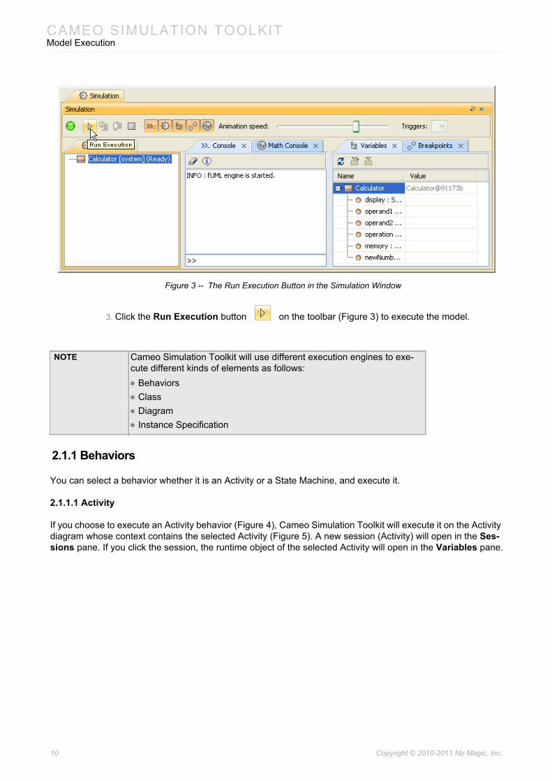
Figure 3 -- The Run Execution Button in the Simulation Window
3. Click the Run Execution button on the toolbar (Figure 3) to execute the model.
2.1.1 Behaviors
You can select a behavior whether it is an Activity or a State Machine, and execute it.
2.1.1.1 Activity
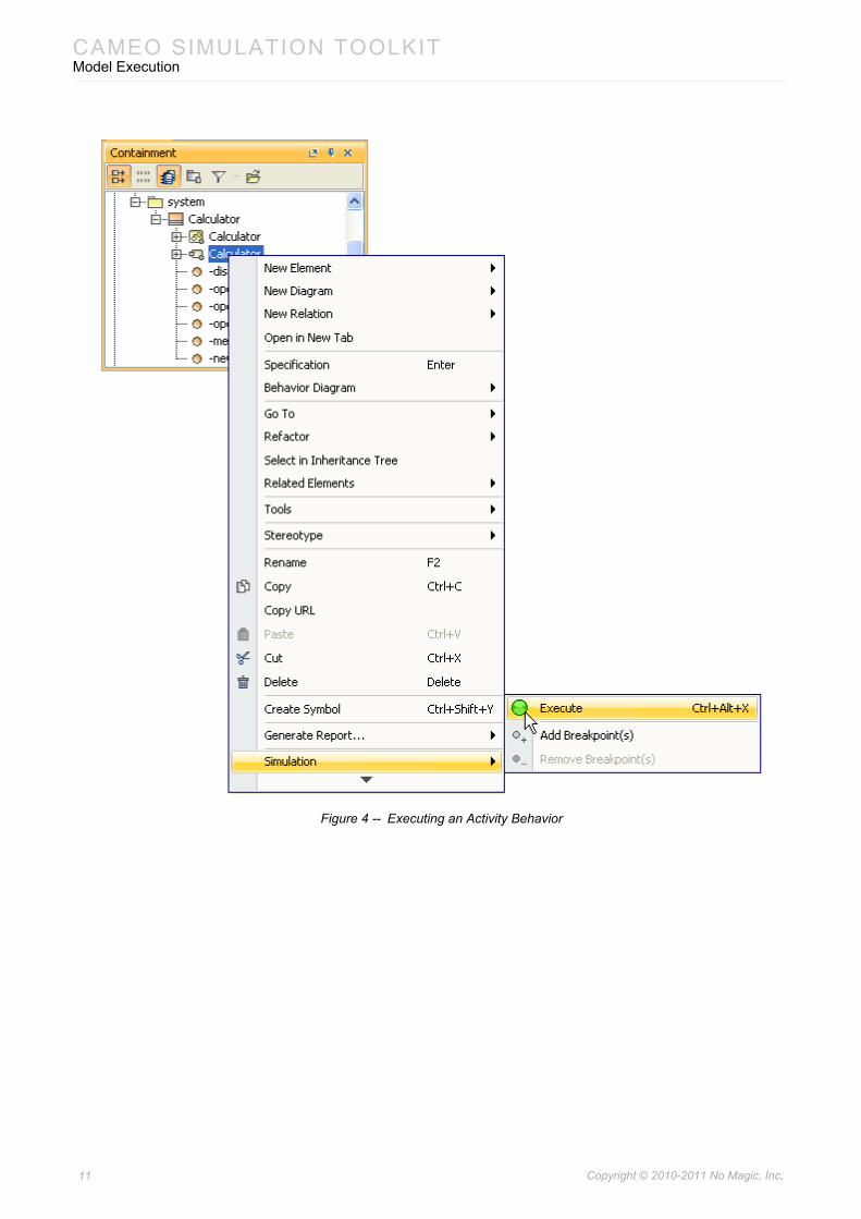
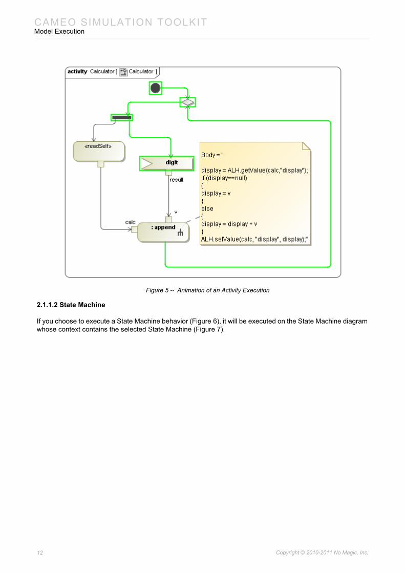
If you choose to execute an Activity behavior (Figure 4), Cameo Simulation Toolkit will execute it on the Activity diagram whose context contains the selected Activity (Figure 5). A new session (Activity) will open in the Ses-sions pane. If you click the session, the runtime object of the selected Activity will open in the Variables pane.
NOTE Cameo Simulation Toolkit will use different execution engines to exe-cute different kinds of elements as follows: • Behaviors• Class• Diagram• Instance Specification
10 Copyright © 2010-2011 No Magic, Inc..
CAMEO SIMULATION TOOLKITModel Execution
Figure 4 -- Executing an Activity Behavior
11 Copyright © 2010-2011 No Magic, Inc..
CAMEO SIMULATION TOOLKITModel Execution
Figure 5 -- Animation of an Activity Execution
2.1.1.2 State Machine
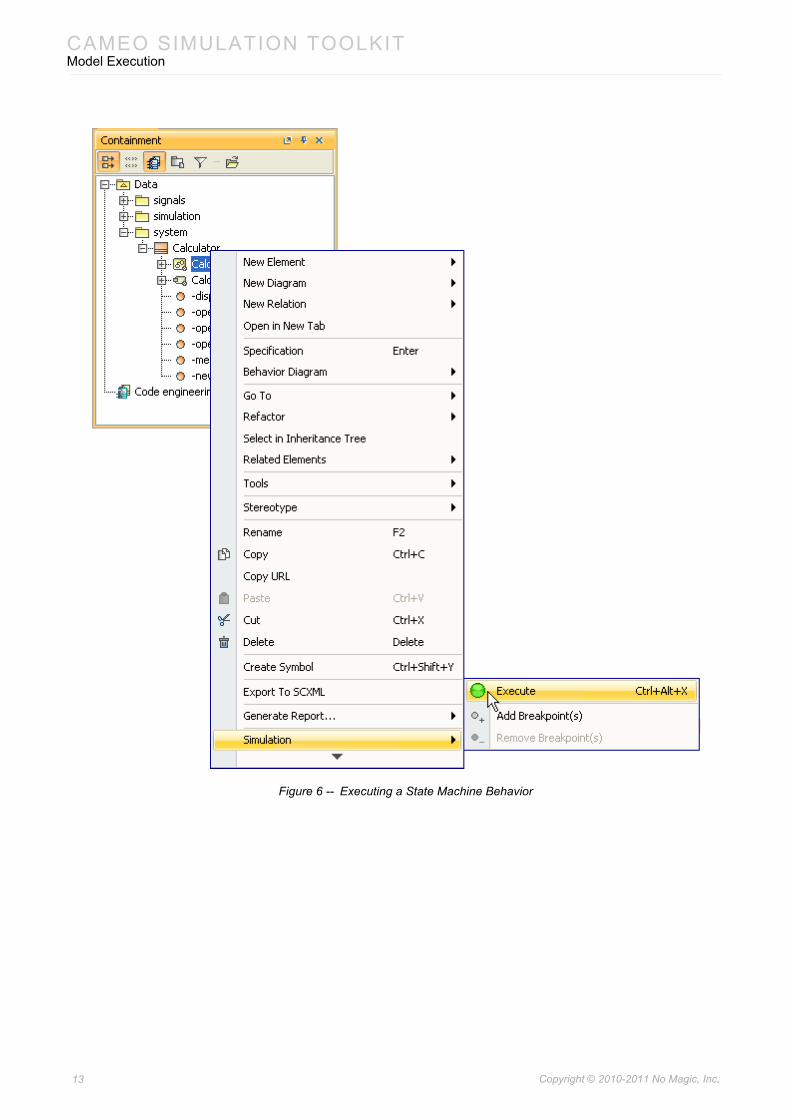
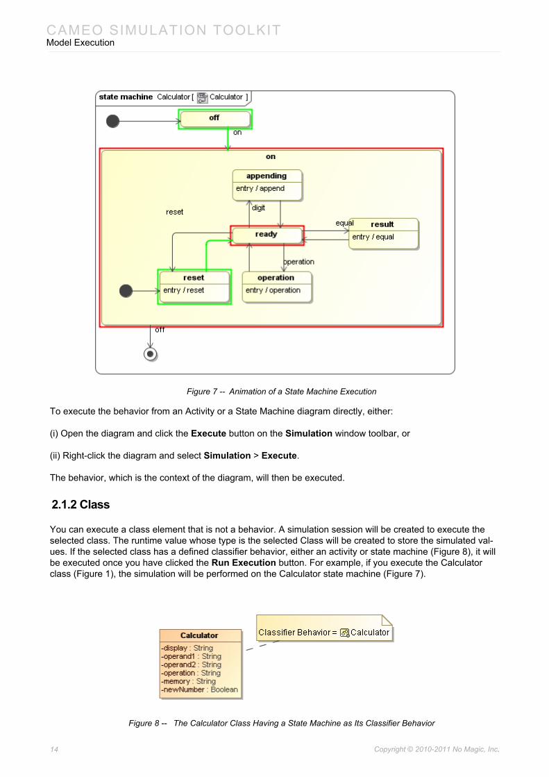
If you choose to execute a State Machine behavior (Figure 6), it will be executed on the State Machine diagram whose context contains the selected State Machine (Figure 7).
12 Copyright © 2010-2011 No Magic, Inc..
CAMEO SIMULATION TOOLKITModel Execution
Figure 6 -- Executing a State Machine Behavior
13 Copyright © 2010-2011 No Magic, Inc..
CAMEO SIMULATION TOOLKITModel Execution
Figure 7 -- Animation of a State Machine Execution
To execute the behavior from an Activity or a State Machine diagram directly, either:
(i) Open the diagram and click the Execute button on the Simulation window toolbar, or
(ii) Right-click the diagram and select Simulation > Execute.
The behavior, which is the context of the diagram, will then be executed.
2.1.2 Class
You can execute a class element that is not a behavior. A simulation session will be created to execute the selected class. The runtime value whose type is the selected Class will be created to store the simulated val-ues. If the selected class has a defined classifier behavior, either an activity or state machine (Figure 8), it will be executed once you have clicked the Run Execution button. For example, if you execute the Calculator class (Figure 1), the simulation will be performed on the Calculator state machine (Figure 7).
Figure 8 -- The Calculator Class Having a State Machine as Its Classifier Behavior
14 Copyright © 2010-2011 No Magic, Inc..
CAMEO SIMULATION TOOLKITModel Execution
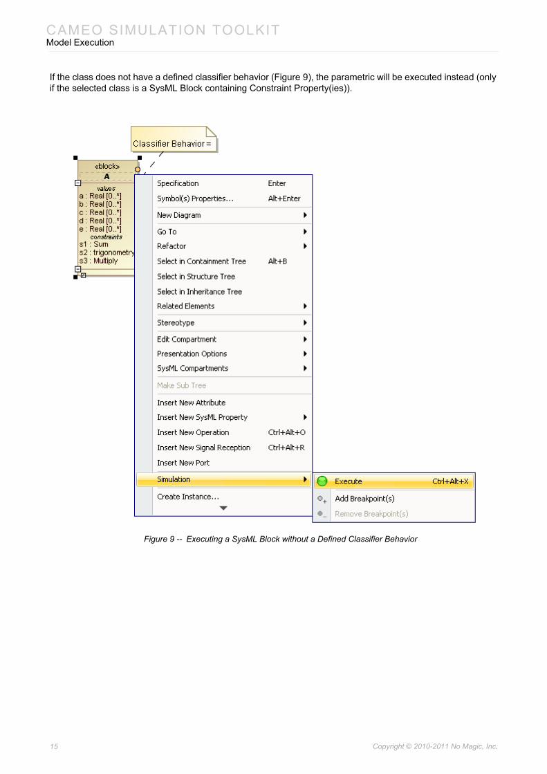
If the class does not have a defined classifier behavior (Figure 9), the parametric will be executed instead (only if the selected class is a SysML Block containing Constraint Property(ies)).
Figure 9 -- Executing a SysML Block without a Defined Classifier Behavior
15 Copyright © 2010-2011 No Magic, Inc..
CAMEO SIMULATION TOOLKITModel Execution
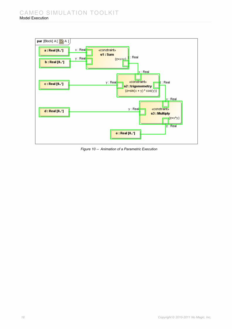
Figure 10 -- Animation of a Parametric Execution
16 Copyright © 2010-2011 No Magic, Inc..
CAMEO SIMULATION TOOLKITModel Execution
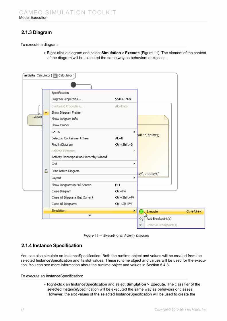
2.1.3 Diagram
To execute a diagram:
• Right-click a diagram and select Simulation > Execute (Figure 11). The element of the context of the diagram will be executed the same way as behaviors or classes.
Figure 11 -- Executing an Activity Diagram
2.1.4 Instance Specification
You can also simulate an InstanceSpecification. Both the runtime object and values will be created from the selected InstanceSpecification and its slot values. These runtime object and values will be used for the execu-tion. You can see more information about the runtime object and values in Section 5.4.3.
To execute an InstanceSpecification:
• Right-click an InstanceSpecification and select Simulation > Execute. The classifier of the selected InstanceSpecification will be executed the same way as behaviors or classes. However, the slot values of the selected InstanceSpecification will be used to create the
17 Copyright © 2010-2011 No Magic, Inc..
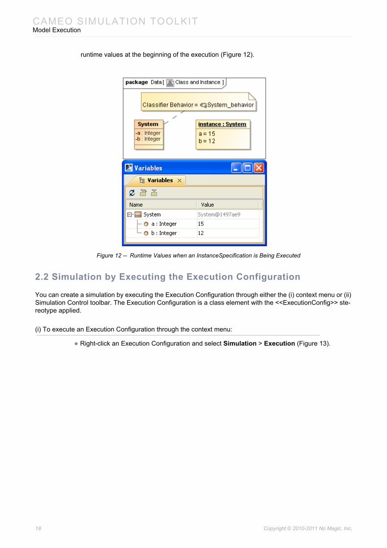
CAMEO SIMULATION TOOLKITModel Execution
runtime values at the beginning of the execution (Figure 12).
Figure 12 -- Runtime Values when an InstanceSpecification is Being Executed
2.2 Simulation by Executing the Execution Configuration
You can create a simulation by executing the Execution Configuration through either the (i) context menu or (ii) Simulation Control toolbar. The Execution Configuration is a class element with the <<ExecutionConfig>> ste-reotype applied.
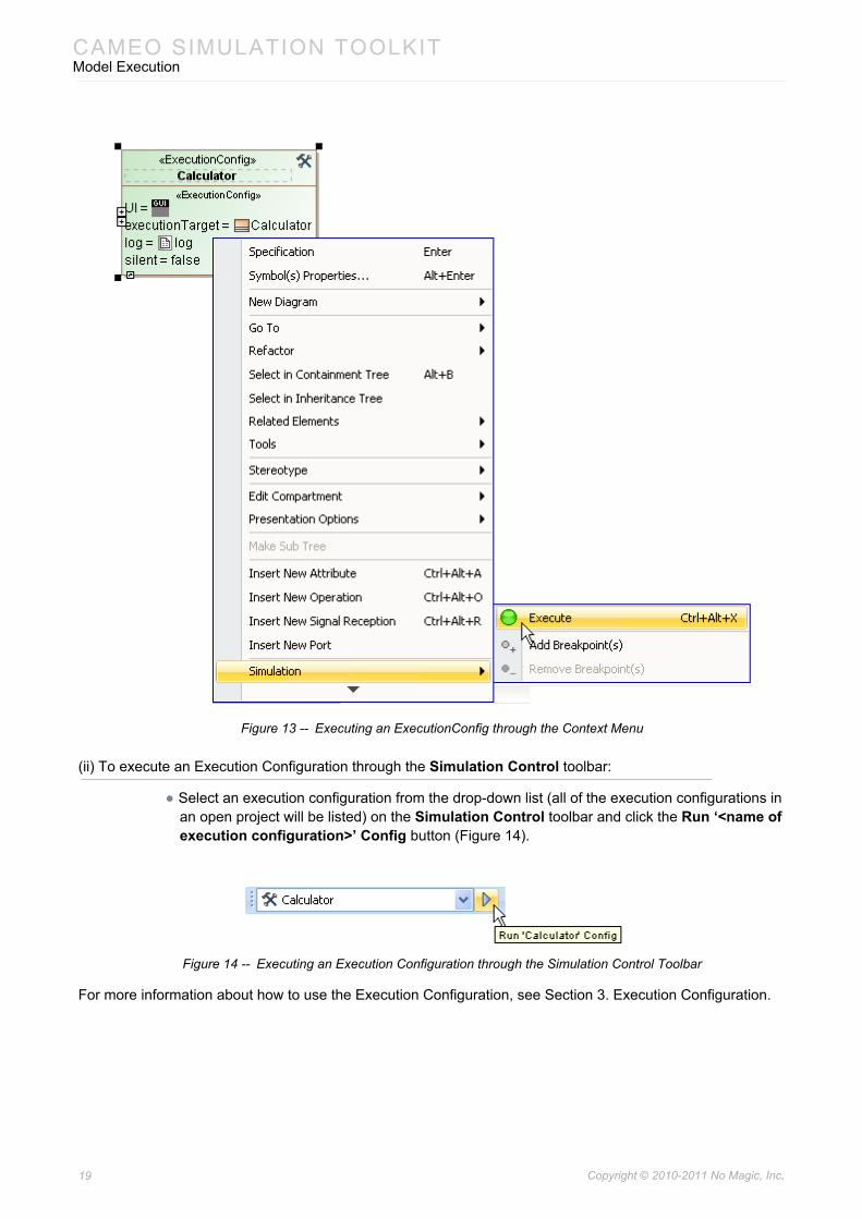
(i) To execute an Execution Configuration through the context menu:
• Right-click an Execution Configuration and select Simulation > Execution (Figure 13).
18 Copyright © 2010-2011 No Magic, Inc..
CAMEO SIMULATION TOOLKITModel Execution
Figure 13 -- Executing an ExecutionConfig through the Context Menu
(ii) To execute an Execution Configuration through the Simulation Control toolbar:
• Select an execution configuration from the drop-down list (all of the execution configurations in an open project will be listed) on the Simulation Control toolbar and click the Run ‘<name of execution configuration>’ Config button (Figure 14).
Figure 14 -- Executing an Execution Configuration through the Simulation Control Toolbar
For more information about how to use the Execution Configuration, see Section 3. Execution Configuration.
19 Copyright © 2010-2011 No Magic, Inc..
CAMEO SIMULATION TOOLKITExecution Configuration
3. Execution Configuration
3.1 ExecutionConfig Stereotype
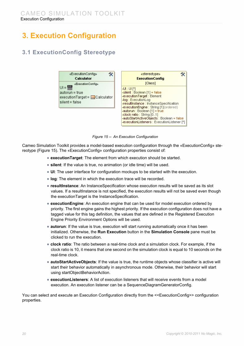
Figure 15 -- An Execution Configuration
Cameo Simulation Toolkit provides a model-based execution configuration through the «ExecutionConfig» ste-reotype (Figure 15). The «ExecutionConfig» configuration properties consist of:
• executionTarget: The element from which execution should be started.
• silent: If the value is true, no animation (or idle time) will be used.
• UI: The user interface for configuration mockups to be started with the execution.
• log: The element in which the execution trace will be recorded.
• resultInstance: An InstanceSpecification whose execution results will be saved as its slot values. If a resultInstance is not specified, the execution results will not be saved even though the executionTarget is the InstanceSpecification.
• executionEngine: An execution engine that can be used for model execution ordered by priority. The first engine gains the highest priority. If the execution configuration does not have a tagged value for this tag definition, the values that are defined in the Registered Execution Engine Priority Environment Options will be used.
• autorun: If the value is true, execution will start running automatically once it has been initialized. Otherwise, the Run Execution button in the Simulation Console pane must be clicked to run the execution.
• clock ratio: The ratio between a real-time clock and a simulation clock. For example, if the clock ratio is 10, it means that one second on the simulation clock is equal to 10 seconds on the real-time clock.
• autoStartActiveObjects: If the value is true, the runtime objects whose classifier is active will start their behavior automatically in asynchronous mode. Otherwise, their behavior will start using startObjectBehaviorAction.
• executionListeners: A list of execution listeners that will receive events from a model execution. An execution listener can be a SequenceDiagramGeneratorConfig.
You can select and execute an Execution Configuration directly from the <<ExecutionConfig>> configuration properties.
20 Copyright © 2010-2011 No Magic, Inc..
CAMEO SIMULATION TOOLKITExecution Configuration
3.2 Execution Log
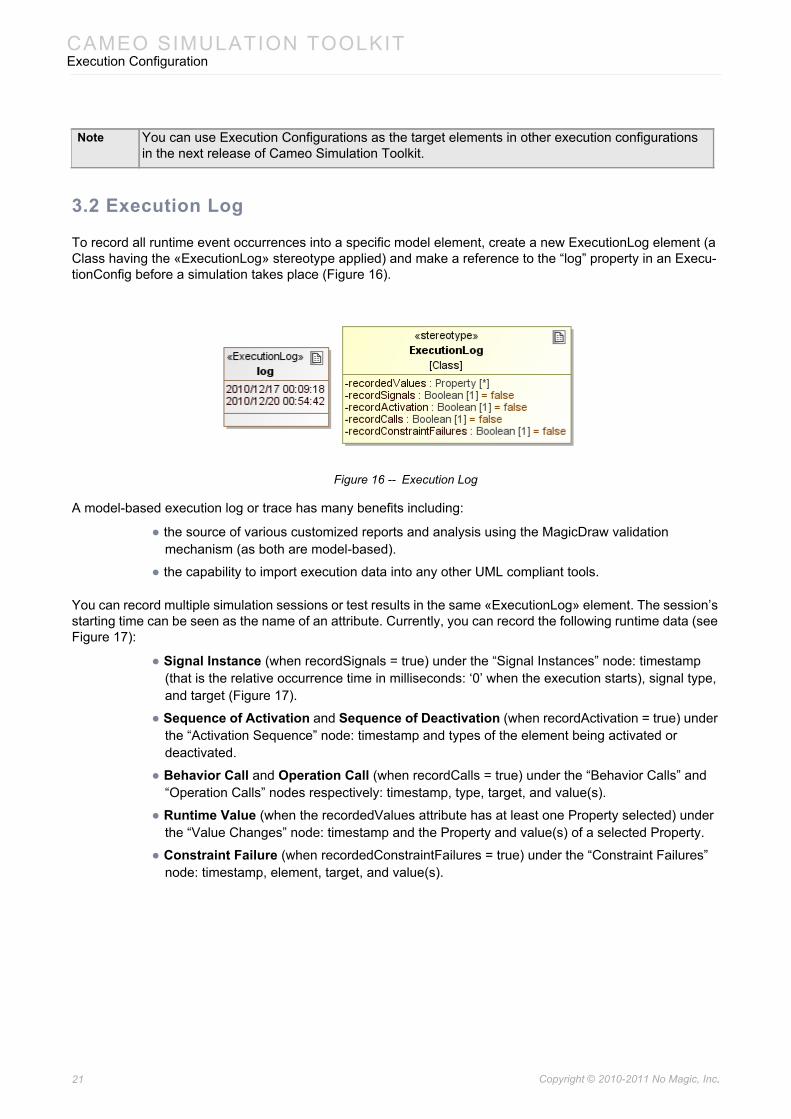
To record all runtime event occurrences into a specific model element, create a new ExecutionLog element (a Class having the «ExecutionLog» stereotype applied) and make a reference to the “log” property in an Execu-tionConfig before a simulation takes place (Figure 16).
Figure 16 -- Execution Log
A model-based execution log or trace has many benefits including:
• the source of various customized reports and analysis using the MagicDraw validation mechanism (as both are model-based).
• the capability to import execution data into any other UML compliant tools.
You can record multiple simulation sessions or test results in the same «ExecutionLog» element. The session’s starting time can be seen as the name of an attribute. Currently, you can record the following runtime data (see Figure 17):
• Signal Instance (when recordSignals = true) under the “Signal Instances” node: timestamp (that is the relative occurrence time in milliseconds: ‘0’ when the execution starts), signal type, and target (Figure 17).
• Sequence of Activation and Sequence of Deactivation (when recordActivation = true) under the “Activation Sequence” node: timestamp and types of the element being activated or deactivated.
• Behavior Call and Operation Call (when recordCalls = true) under the “Behavior Calls” and “Operation Calls” nodes respectively: timestamp, type, target, and value(s).
• Runtime Value (when the recordedValues attribute has at least one Property selected) under the “Value Changes” node: timestamp and the Property and value(s) of a selected Property.
• Constraint Failure (when recordedConstraintFailures = true) under the “Constraint Failures” node: timestamp, element, target, and value(s).
Note You can use Execution Configurations as the target elements in other execution configurations in the next release of Cameo Simulation Toolkit.
21 Copyright © 2010-2011 No Magic, Inc..
CAMEO SIMULATION TOOLKITExecution Configuration
Figure 17 -- Recorded Runtime Data: Signal Instance (StopWatch_advanced.mdzip)
3.3 Simulation Time and Simulation Clock
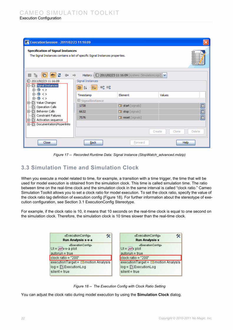
When you execute a model related to time, for example, a transition with a time trigger, the time that will be used for model execution is obtained from the simulation clock. This time is called simulation time. The ratio between time on the real-time clock and the simulation clock in the same interval is called “clock ratio.” Cameo Simulation Toolkit allows you to set a clock ratio for model execution. To set the clock ratio, specify the value of the clock ratio tag definition of execution config (Figure 18). For further information about the stereotype of exe-cution configuration, see Section 3.1 ExecutionConfig Stereotype.
For example, if the clock ratio is 10, it means that 10 seconds on the real-time clock is equal to one second on the simulation clock. Therefore, the simulation clock is 10 times slower than the real-time clock.
Figure 18 -- The Execution Config with Clock Ratio Setting
You can adjust the clock ratio during model execution by using the Simulation Clock dialog.
22 Copyright © 2010-2011 No Magic, Inc..
CAMEO SIMULATION TOOLKITExecution Configuration
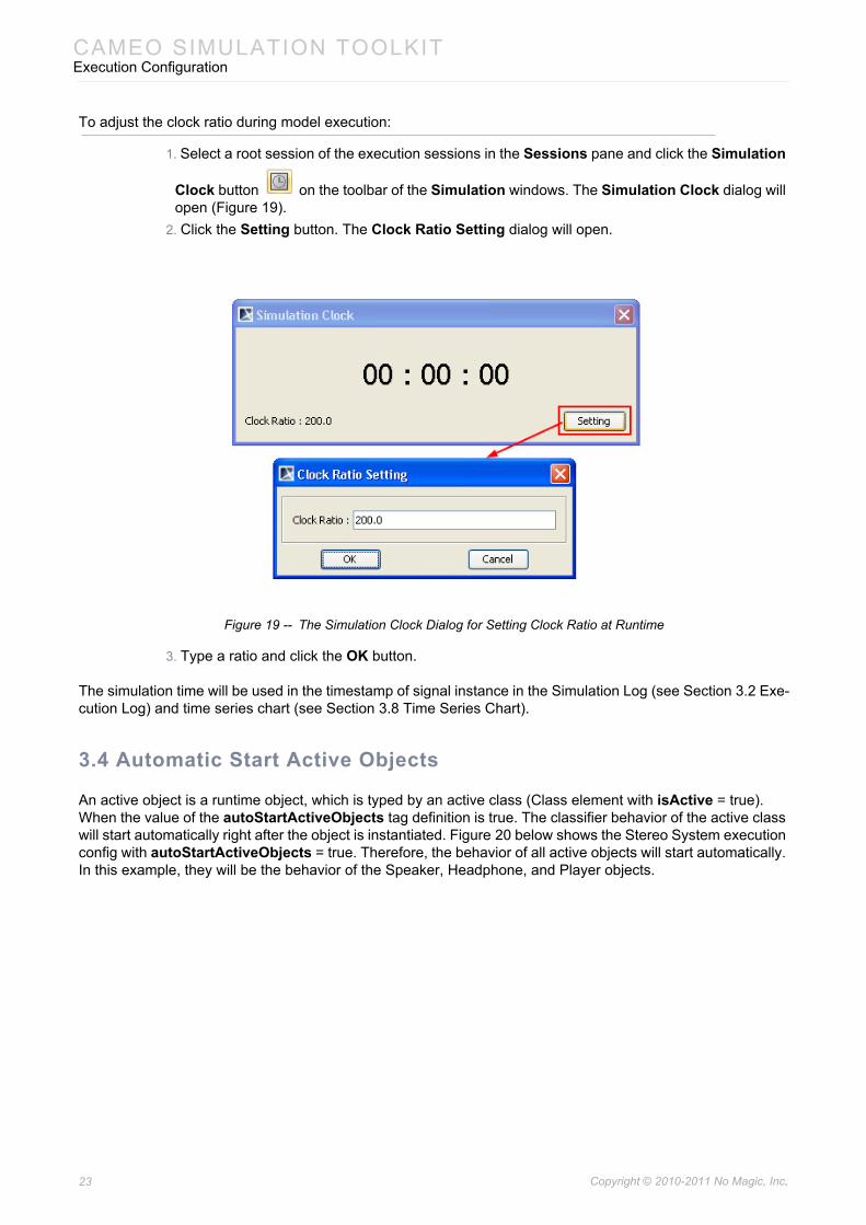
To adjust the clock ratio during model execution:
1. Select a root session of the execution sessions in the Sessions pane and click the Simulation
Clock button on the toolbar of the Simulation windows. The Simulation Clock dialog will open (Figure 19).
2. Click the Setting button. The Clock Ratio Setting dialog will open.
Figure 19 -- The Simulation Clock Dialog for Setting Clock Ratio at Runtime
3. Type a ratio and click the OK button.
The simulation time will be used in the timestamp of signal instance in the Simulation Log (see Section 3.2 Exe-cution Log) and time series chart (see Section 3.8 Time Series Chart).
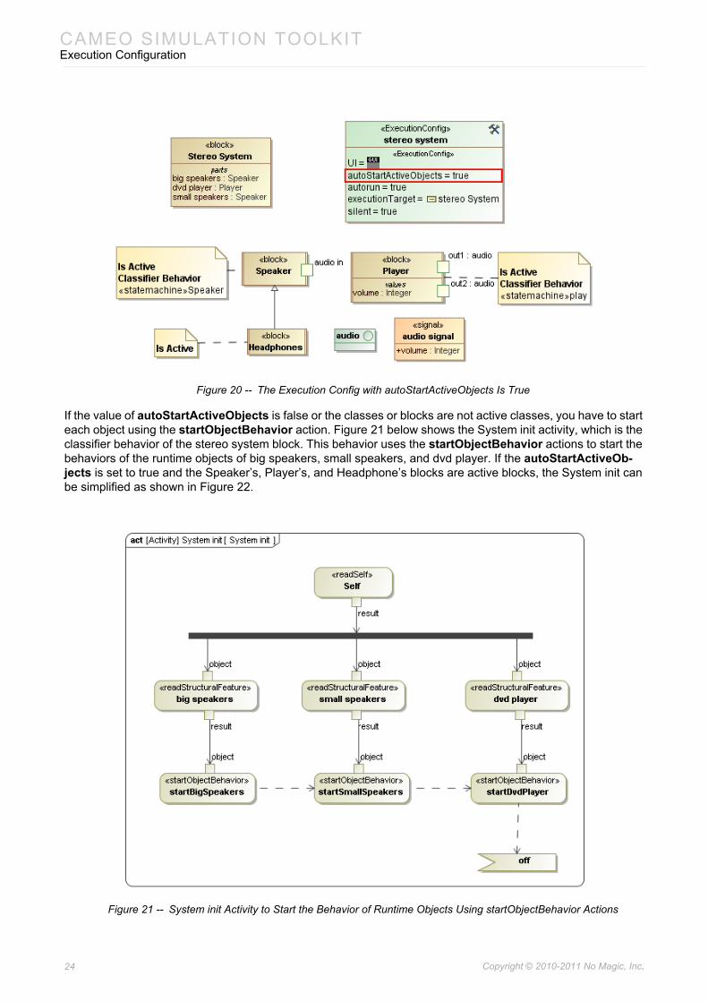
3.4 Automatic Start Active Objects
An active object is a runtime object, which is typed by an active class (Class element with isActive = true). When the value of the autoStartActiveObjects tag definition is true. The classifier behavior of the active class will start automatically right after the object is instantiated. Figure 20 below shows the Stereo System execution config with autoStartActiveObjects = true. Therefore, the behavior of all active objects will start automatically. In this example, they will be the behavior of the Speaker, Headphone, and Player objects.
23 Copyright © 2010-2011 No Magic, Inc..
CAMEO SIMULATION TOOLKITExecution Configuration
Figure 20 -- The Execution Config with autoStartActiveObjects Is True
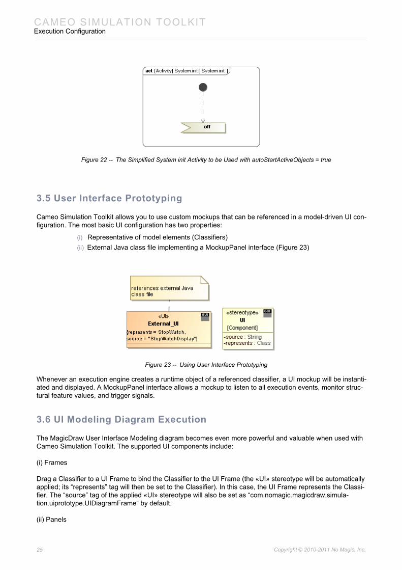
If the value of autoStartActiveObjects is false or the classes or blocks are not active classes, you have to start each object using the startObjectBehavior action. Figure 21 below shows the System init activity, which is the classifier behavior of the stereo system block. This behavior uses the startObjectBehavior actions to start the behaviors of the runtime objects of big speakers, small speakers, and dvd player. If the autoStartActiveOb-jects is set to true and the Speaker’s, Player’s, and Headphone’s blocks are active blocks, the System init can be simplified as shown in Figure 22.
Figure 21 -- System init Activity to Start the Behavior of Runtime Objects Using startObjectBehavior Actions
24 Copyright © 2010-2011 No Magic, Inc..
CAMEO SIMULATION TOOLKITExecution Configuration
Figure 22 -- The Simplified System init Activity to be Used with autoStartActiveObjects = true
3.5 User Interface Prototyping
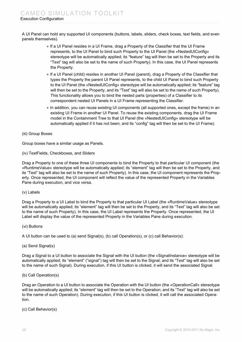
Cameo Simulation Toolkit allows you to use custom mockups that can be referenced in a model-driven UI con-figuration. The most basic UI configuration has two properties:
(i) Representative of model elements (Classifiers)(ii) External Java class file implementing a MockupPanel interface (Figure 23)
Figure 23 -- Using User Interface Prototyping
Whenever an execution engine creates a runtime object of a referenced classifier, a UI mockup will be instanti-ated and displayed. A MockupPanel interface allows a mockup to listen to all execution events, monitor struc-tural feature values, and trigger signals.
3.6 UI Modeling Diagram Execution
The MagicDraw User Interface Modeling diagram becomes even more powerful and valuable when used with Cameo Simulation Toolkit. The supported UI components include:
(i) Frames
Drag a Classifier to a UI Frame to bind the Classifier to the UI Frame (the «UI» stereotype will be automatically applied; its “represents” tag will then be set to the Classifier). In this case, the UI Frame represents the Classi-fier. The “source” tag of the applied «UI» stereotype will also be set as “com.nomagic.magicdraw.simula-tion.uiprototype.UIDiagramFrame“ by default.
(ii) Panels
25 Copyright © 2010-2011 No Magic, Inc..
CAMEO SIMULATION TOOLKITExecution Configuration
A UI Panel can hold any supported UI components (buttons, labels, sliders, check boxes, text fields, and even panels themselves).
• If a UI Panel resides in a UI Frame, drag a Property of the Classifier that the UI Frame represents, to the UI Panel to bind such Property to the UI Panel (the «NestedUIConfig» stereotype will be automatically applied; its “feature” tag will then be set to the Property and its “Text” tag will also be set to the name of such Property). In this case, the UI Panel represents the Property.
• If a UI Panel (child) resides in another UI Panel (parent), drag a Property of the Classifier that types the Property the parent UI Panel represents, to the child UI Panel to bind such Property to the UI Panel (the «NestedUIConfig» stereotype will be automatically applied; its “feature” tag will then be set to the Property, and its “Text” tag will also be set to the name of such Property). This functionality allows you to bind the nested parts (properties) of a Classifier to its correspondent nested UI Panels in a UI Frame representing the Classifier.
• In addition, you can reuse existing UI components (all supported ones, except the frame) in an existing UI Frame in another UI Panel. To reuse the existing components, drag the UI Frame model in the Containment Tree to that UI Panel (the «NestedUIConfig» stereotype will be automatically applied if it has not been; and its “config” tag will then be set to the UI Frame).
(iii) Group Boxes
Group boxes have a similar usage as Panels.
(iv) TextFields, Checkboxes, and Sliders
Drag a Property to one of these three UI components to bind the Property to that particular UI component (the «RuntimeValue» stereotype will be automatically applied; its “element” tag will then be set to the Property, and its “Text” tag will also be set to the name of such Property). In this case, the UI component represents the Prop-erty. Once represented, the UI component will reflect the value of the represented Property in the Variables Pane during execution, and vice versa.
(v) Labels
Drag a Property to a UI Label to bind the Property to that particular UI Label (the «RuntimeValue» stereotype will be automatically applied; its “element” tag will then be set to the Property, and its “Text” tag will also be set to the name of such Property). In this case, the UI Label represents the Property. Once represented, the UI Label will display the value of the represented Property in the Variables Pane during execution.
(vi) Buttons
A UI button can be used to (a) send Signal(s), (b) call Operation(s), or (c) call Behavior(s):
(a) Send Signal(s)
Drag a Signal to a UI button to associate the Signal with the UI button (the «SignalInstance» stereotype will be automatically applied; its “element” (“signal”) tag will then be set to the Signal; and its “Text” tag will also be set to the name of such Signal). During execution, if this UI button is clicked, it will send the associated Signal.
(b) Call Operation(s)
Drag an Operation to a UI button to associate the Operation with the UI button (the «OperationCall» stereotype will be automatically applied; its “element” tag will then be set to the Operation; and its “Text” tag will also be set to the name of such Operation). During execution, if this UI button is clicked, it will call the associated Opera-tion.
(c) Call Behavior(s)
26 Copyright © 2010-2011 No Magic, Inc..
CAMEO SIMULATION TOOLKITExecution Configuration
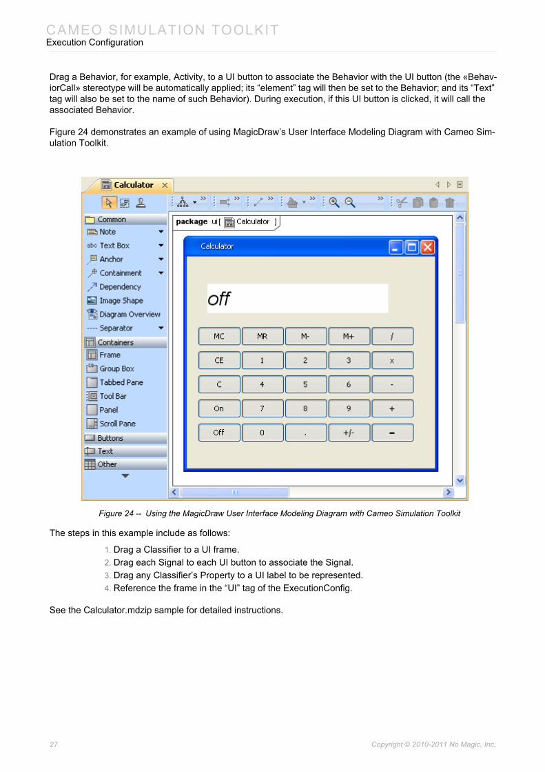
Drag a Behavior, for example, Activity, to a UI button to associate the Behavior with the UI button (the «Behav-iorCall» stereotype will be automatically applied; its “element” tag will then be set to the Behavior; and its “Text” tag will also be set to the name of such Behavior). During execution, if this UI button is clicked, it will call the associated Behavior.
Figure 24 demonstrates an example of using MagicDraw’s User Interface Modeling Diagram with Cameo Sim-ulation Toolkit.
Figure 24 -- Using the MagicDraw User Interface Modeling Diagram with Cameo Simulation Toolkit
The steps in this example include as follows:
1. Drag a Classifier to a UI frame.2. Drag each Signal to each UI button to associate the Signal.3. Drag any Classifier’s Property to a UI label to be represented.4. Reference the frame in the “UI” tag of the ExecutionConfig.
See the Calculator.mdzip sample for detailed instructions.
27 Copyright © 2010-2011 No Magic, Inc..
CAMEO SIMULATION TOOLKITExecution Configuration
When you drag any GUI elements to a diagram, click Execute to run the simulation animation.
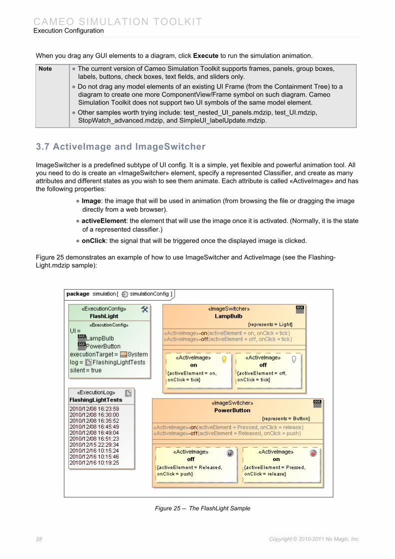
3.7 ActiveImage and ImageSwitcher
ImageSwitcher is a predefined subtype of UI config. It is a simple, yet flexible and powerful animation tool. All you need to do is create an «ImageSwitcher» element, specify a represented Classifier, and create as many attributes and different states as you wish to see them animate. Each attribute is called «ActiveImage» and has the following properties:
• Image: the image that will be used in animation (from browsing the file or dragging the image directly from a web browser).
• activeElement: the element that will use the image once it is activated. (Normally, it is the state of a represented classifier.)
• onClick: the signal that will be triggered once the displayed image is clicked.
Figure 25 demonstrates an example of how to use ImageSwitcher and ActiveImage (see the Flashing-Light.mdzip sample):
Figure 25 -- The FlashLight Sample
Note • The current version of Cameo Simulation Toolkit supports frames, panels, group boxes, labels, buttons, check boxes, text fields, and sliders only.
• Do not drag any model elements of an existing UI Frame (from the Containment Tree) to a diagram to create one more ComponentView/Frame symbol on such diagram. Cameo Simulation Toolkit does not support two UI symbols of the same model element.
• Other samples worth trying include: test_nested_UI_panels.mdzip, test_UI.mdzip, StopWatch_advanced.mdzip, and SimpleUI_labelUpdate.mdzip.
28 Copyright © 2010-2011 No Magic, Inc..
CAMEO SIMULATION TOOLKITExecution Configuration
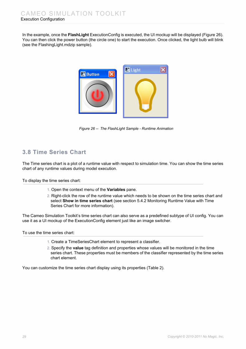
In the example, once the FlashLight ExecutionConfig is executed, the UI mockup will be displayed (Figure 26). You can then click the power button (the circle one) to start the execution. Once clicked, the light bulb will blink (see the FlashingLight.mdzip sample).
Figure 26 -- The FlashLight Sample - Runtime Animation
3.8 Time Series Chart
The Time series chart is a plot of a runtime value with respect to simulation time. You can show the time series chart of any runtime values during model execution.
To display the time series chart:
1. Open the context menu of the Variables pane.2. Right-click the row of the runtime value which needs to be shown on the time series chart and
select Show in time series chart (see section 5.4.2 Monitoring Runtime Value with Time Series Chart for more information).
The Cameo Simulation Toolkit’s time series chart can also serve as a predefined subtype of UI config. You can use it as a UI mockup of the ExecutionConfig element just like an image switcher.
To use the time series chart:
1. Create a TimeSeriesChart element to represent a classifier.2. Specify the value tag definition and properties whose values will be monitored in the time
series chart. These properties must be members of the classifier represented by the time series chart element.
You can customize the time series chart display using its properties (Table 2).
29 Copyright © 2010-2011 No Magic, Inc..
CAMEO SIMULATION TOOLKITExecution Configuration
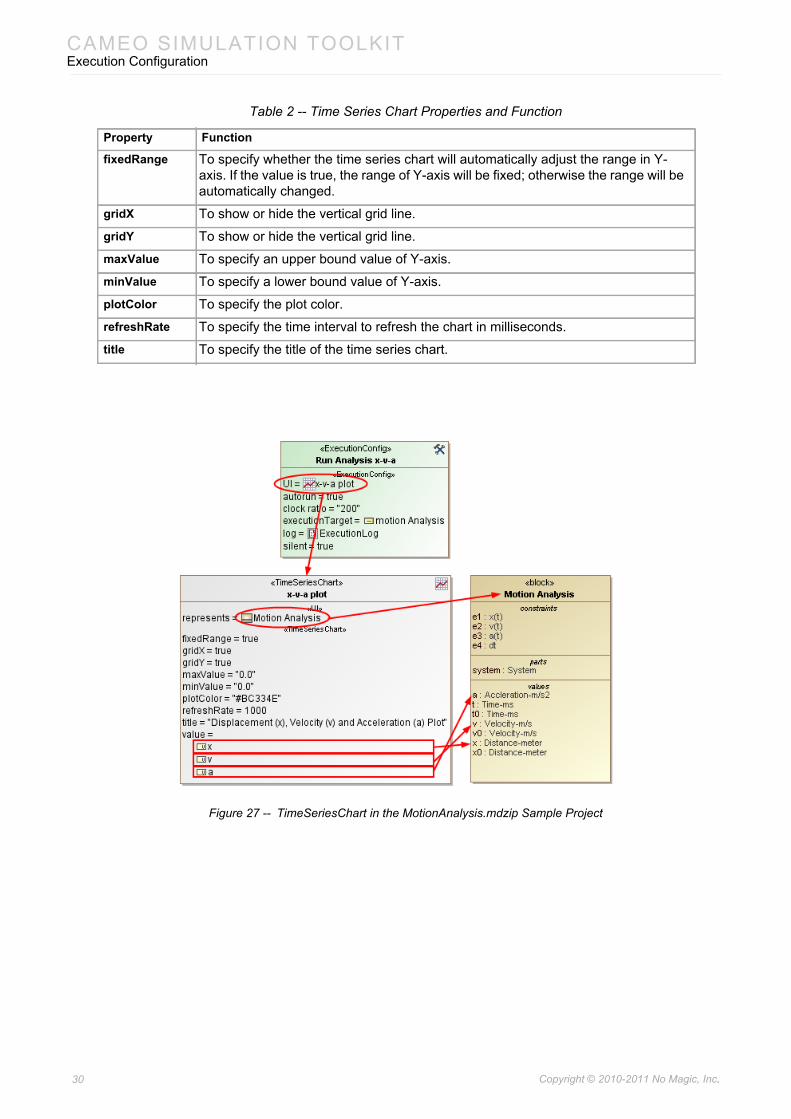
Table 2 -- Time Series Chart Properties and Function
Figure 27 -- TimeSeriesChart in the MotionAnalysis.mdzip Sample Project
Property Function
fixedRange To specify whether the time series chart will automatically adjust the range in Y-axis. If the value is true, the range of Y-axis will be fixed; otherwise the range will be automatically changed.
gridX To show or hide the vertical grid line.
gridY To show or hide the vertical grid line.
maxValue To specify an upper bound value of Y-axis.
minValue To specify a lower bound value of Y-axis.
plotColor To specify the plot color.
refreshRate To specify the time interval to refresh the chart in milliseconds.
title To specify the title of the time series chart.
30 Copyright © 2010-2011 No Magic, Inc..
CAMEO SIMULATION TOOLKITExecution Configuration
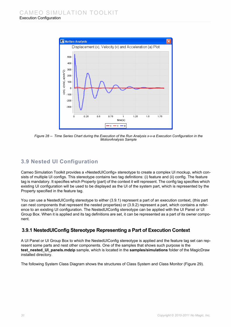
Figure 28 -- Time Series Chart during the Execution of the Run Analysis x-v-a Execution Configuration in the MotionAnalysis Sample
3.9 Nested UI Configuration
Cameo Simulation Toolkit provides a «NestedUIConfig» stereotype to create a complex UI mockup, which con-sists of multiple UI configs. This stereotype contains two tag definitions: (i) feature and (ii) config. The feature tag is mandatory. It specifies which Property (part) of the context it will represent. The config tag specifies which existing UI configuration will be used to be displayed as the UI of the system part, which is represented by the Property specified in the feature tag.
You can use a NestedUIConfig stereotype to either (3.9.1) represent a part of an execution context, (this part can nest components that represent the nested properties) or (3.9.2) represent a part, which contains a refer-ence to an existing UI configuration. The NestedUIConfig stereotype can be applied with the UI Panel or UI Group Box. When it is applied and its tag definitions are set, it can be represented as a part of its owner compo-nent.
3.9.1 NestedUIConfig Stereotype Representing a Part of Execution Context
A UI Panel or UI Group Box to which the NestedUIConfig stereotype is applied and the feature tag set can rep-resent some parts and nest other components. One of the samples that shows such purpose is the test_nested_UI_panels.mdzip sample, which is located in the samples/simulations folder of the MagicDraw installed directory.
The following System Class Diagram shows the structures of Class System and Class Monitor (Figure 29).
31 Copyright © 2010-2011 No Magic, Inc..
CAMEO SIMULATION TOOLKITExecution Configuration
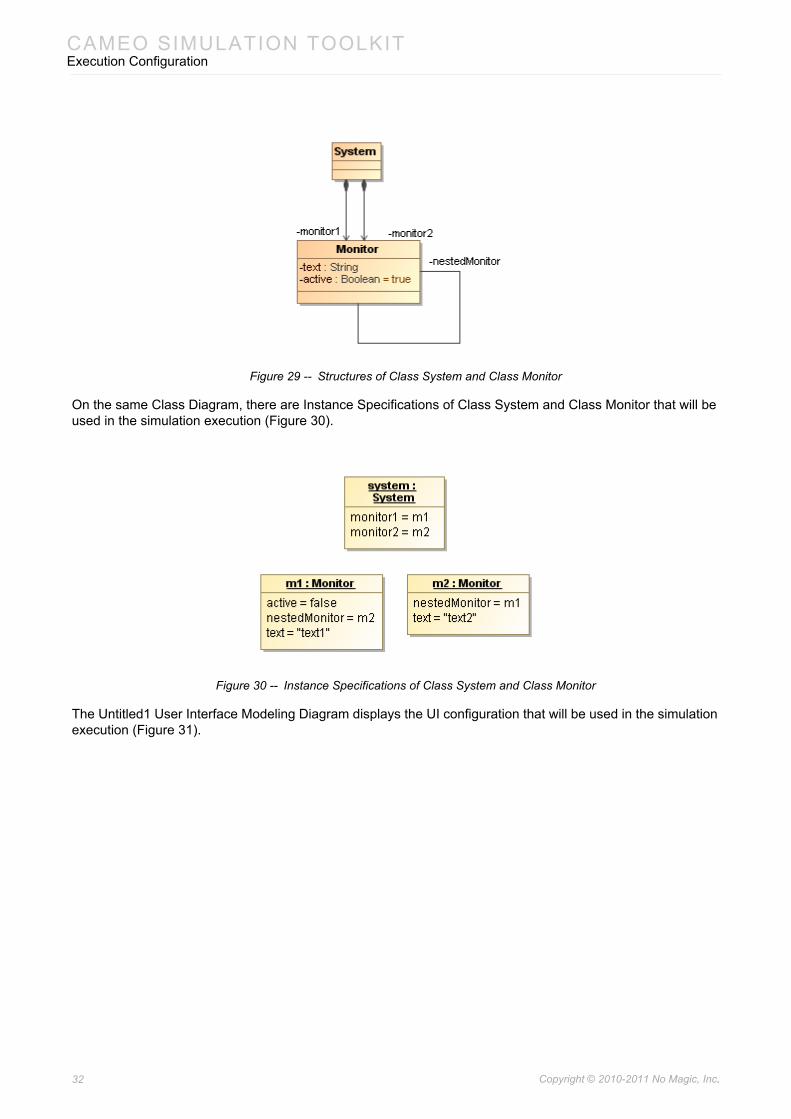
Figure 29 -- Structures of Class System and Class Monitor
On the same Class Diagram, there are Instance Specifications of Class System and Class Monitor that will be used in the simulation execution (Figure 30).
Figure 30 -- Instance Specifications of Class System and Class Monitor
The Untitled1 User Interface Modeling Diagram displays the UI configuration that will be used in the simulation execution (Figure 31).
32 Copyright © 2010-2011 No Magic, Inc..
CAMEO SIMULATION TOOLKITExecution Configuration
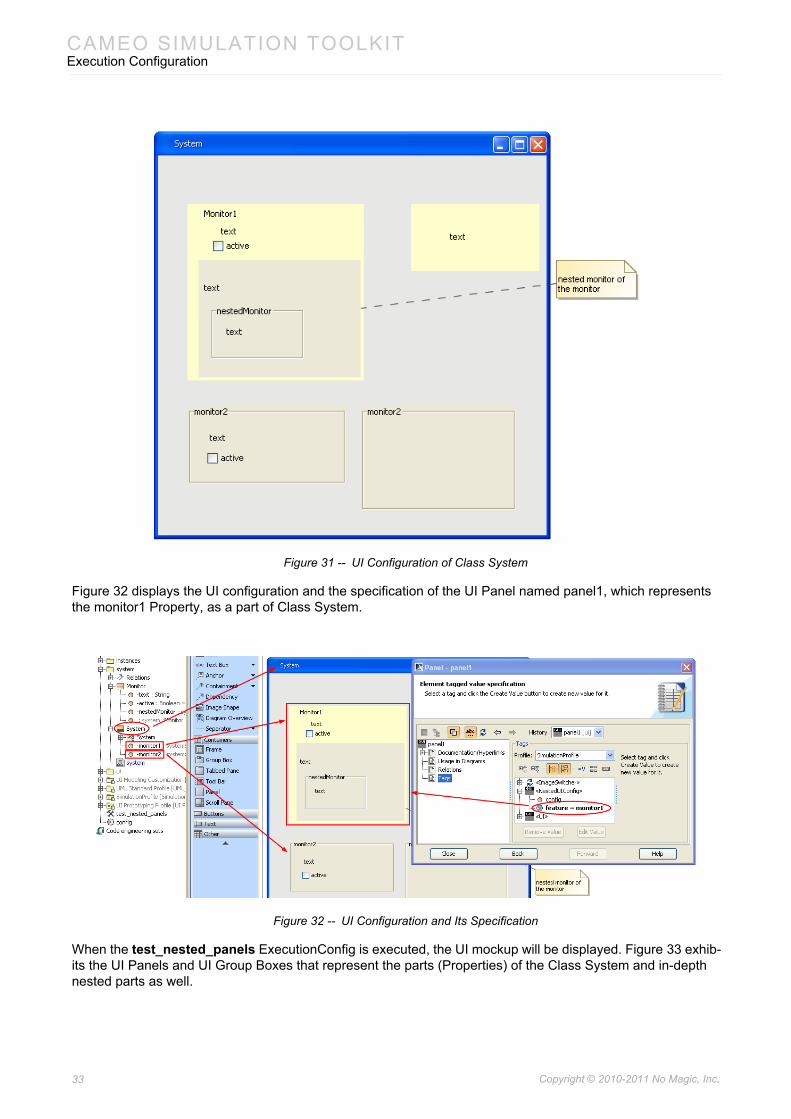
Figure 31 -- UI Configuration of Class System
Figure 32 displays the UI configuration and the specification of the UI Panel named panel1, which represents the monitor1 Property, as a part of Class System.
Figure 32 -- UI Configuration and Its Specification
When the test_nested_panels ExecutionConfig is executed, the UI mockup will be displayed. Figure 33 exhib-its the UI Panels and UI Group Boxes that represent the parts (Properties) of the Class System and in-depth nested parts as well.
33 Copyright © 2010-2011 No Magic, Inc..
CAMEO SIMULATION TOOLKITExecution Configuration
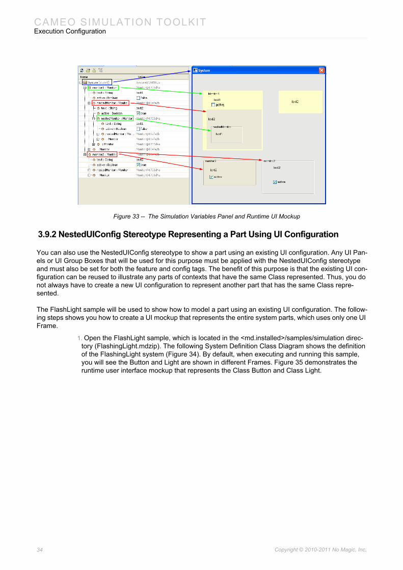
Figure 33 -- The Simulation Variables Panel and Runtime UI Mockup
3.9.2 NestedUIConfig Stereotype Representing a Part Using UI Configuration
You can also use the NestedUIConfig stereotype to show a part using an existing UI configuration. Any UI Pan-els or UI Group Boxes that will be used for this purpose must be applied with the NestedUIConfig stereotype and must also be set for both the feature and config tags. The benefit of this purpose is that the existing UI con-figuration can be reused to illustrate any parts of contexts that have the same Class represented. Thus, you do not always have to create a new UI configuration to represent another part that has the same Class repre-sented.
The FlashLight sample will be used to show how to model a part using an existing UI configuration. The follow-ing steps shows you how to create a UI mockup that represents the entire system parts, which uses only one UI Frame.
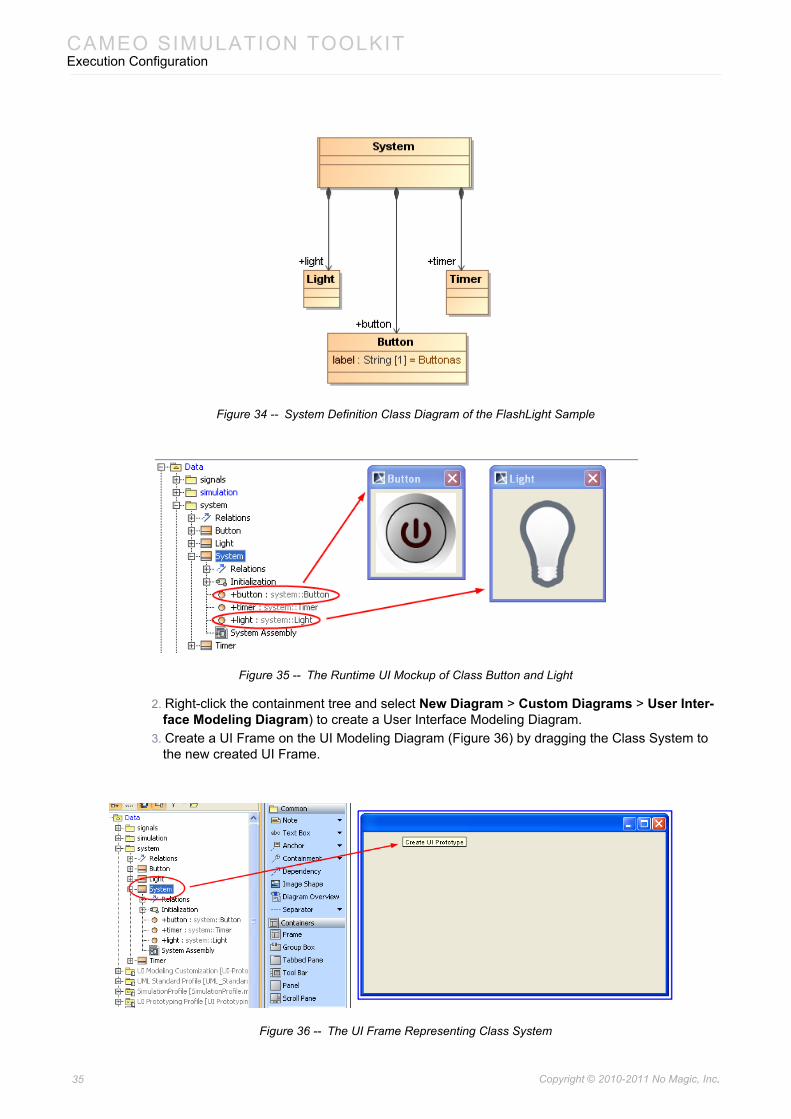
1. Open the FlashLight sample, which is located in the <md.installed>/samples/simulation direc-tory (FlashingLight.mdzip). The following System Definition Class Diagram shows the definition of the FlashingLight system (Figure 34). By default, when executing and running this sample, you will see the Button and Light are shown in different Frames. Figure 35 demonstrates the runtime user interface mockup that represents the Class Button and Class Light.
34 Copyright © 2010-2011 No Magic, Inc..
CAMEO SIMULATION TOOLKITExecution Configuration
Figure 34 -- System Definition Class Diagram of the FlashLight Sample
Figure 35 -- The Runtime UI Mockup of Class Button and Light
2. Right-click the containment tree and select New Diagram > Custom Diagrams > User Inter-face Modeling Diagram) to create a User Interface Modeling Diagram.
3. Create a UI Frame on the UI Modeling Diagram (Figure 36) by dragging the Class System to the new created UI Frame.
Figure 36 -- The UI Frame Representing Class System
35 Copyright © 2010-2011 No Magic, Inc..
CAMEO SIMULATION TOOLKITExecution Configuration
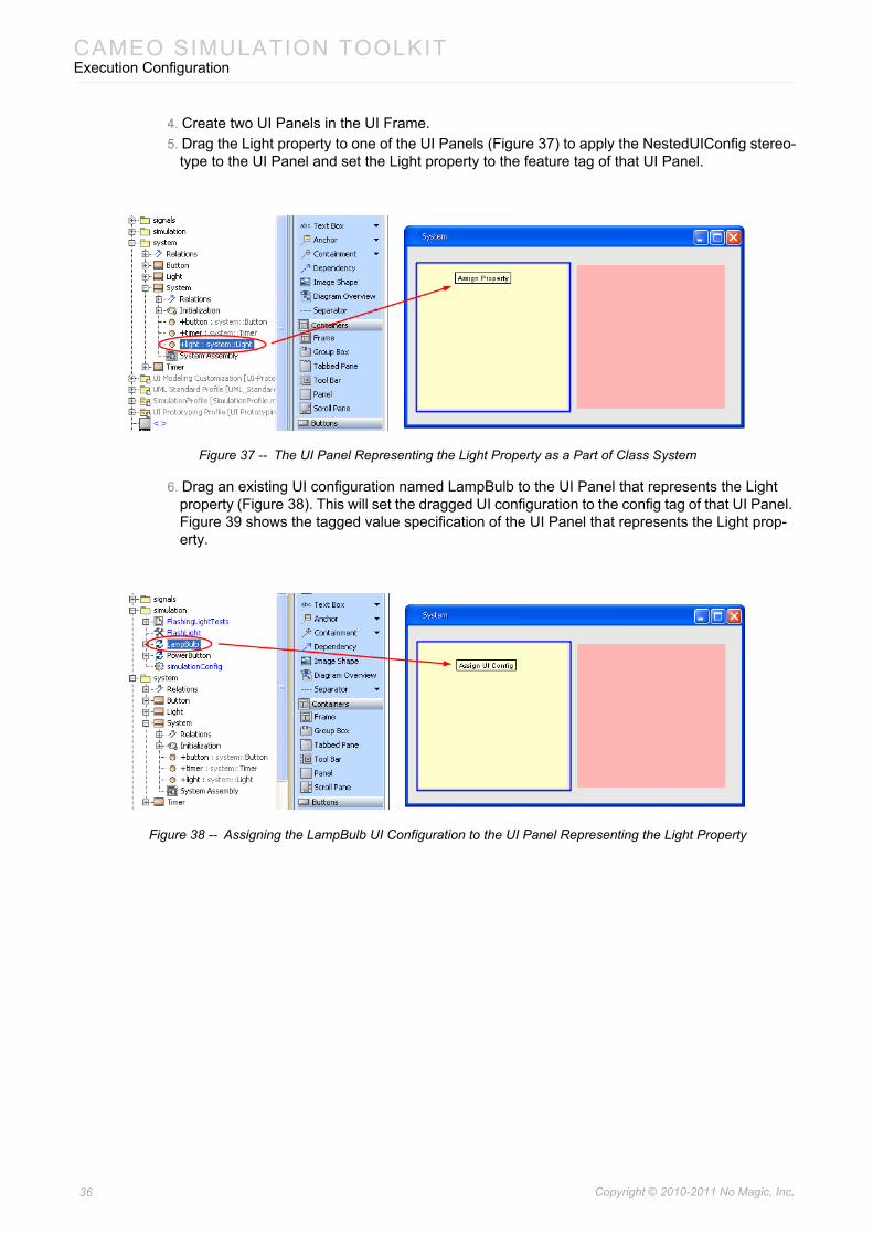
4. Create two UI Panels in the UI Frame.5. Drag the Light property to one of the UI Panels (Figure 37) to apply the NestedUIConfig stereo-
type to the UI Panel and set the Light property to the feature tag of that UI Panel.
Figure 37 -- The UI Panel Representing the Light Property as a Part of Class System
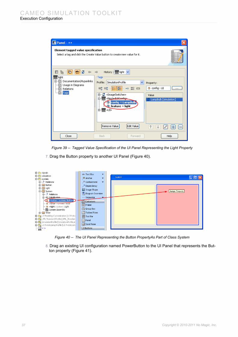
6. Drag an existing UI configuration named LampBulb to the UI Panel that represents the Light property (Figure 38). This will set the dragged UI configuration to the config tag of that UI Panel. Figure 39 shows the tagged value specification of the UI Panel that represents the Light prop-erty.
Figure 38 -- Assigning the LampBulb UI Configuration to the UI Panel Representing the Light Property
36 Copyright © 2010-2011 No Magic, Inc..
CAMEO SIMULATION TOOLKITExecution Configuration
Figure 39 -- Tagged Value Specification of the UI Panel Representing the Light Property
7. Drag the Button property to another UI Panel (Figure 40).
Figure 40 -- The UI Panel Representing the Button PropertyAs Part of Class System
8. Drag an existing UI configuration named PowerButton to the UI Panel that represents the But-ton property (Figure 41).
37 Copyright © 2010-2011 No Magic, Inc..
CAMEO SIMULATION TOOLKITExecution Configuration
Figure 41 -- Assigning the PowerButton UI Configuration to the UI Panel Representing the Button Property
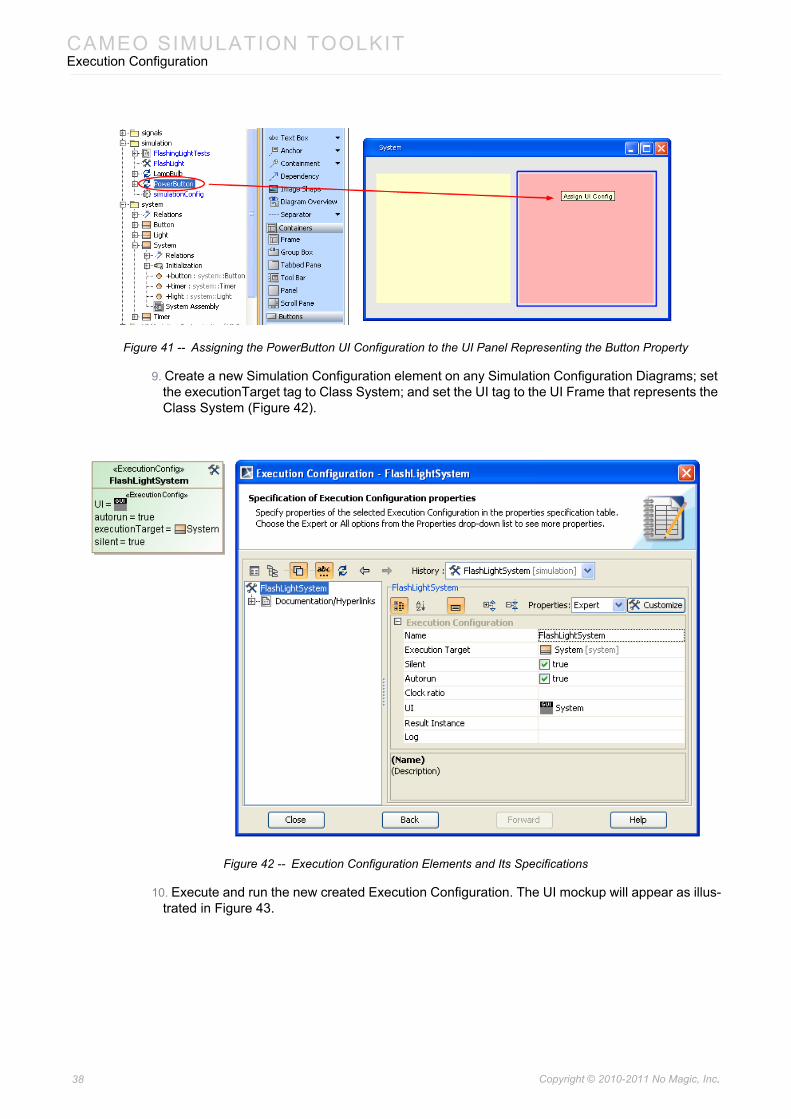
9. Create a new Simulation Configuration element on any Simulation Configuration Diagrams; set the executionTarget tag to Class System; and set the UI tag to the UI Frame that represents the Class System (Figure 42).
Figure 42 -- Execution Configuration Elements and Its Specifications
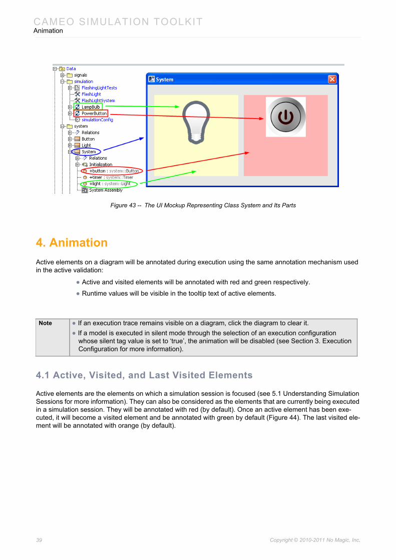
10. Execute and run the new created Execution Configuration. The UI mockup will appear as illus-trated in Figure 43.
38 Copyright © 2010-2011 No Magic, Inc..
CAMEO SIMULATION TOOLKITAnimation
Figure 43 -- The UI Mockup Representing Class System and Its Parts
4. AnimationActive elements on a diagram will be annotated during execution using the same annotation mechanism used in the active validation:
• Active and visited elements will be annotated with red and green respectively.
• Runtime values will be visible in the tooltip text of active elements.
4.1 Active, Visited, and Last Visited Elements
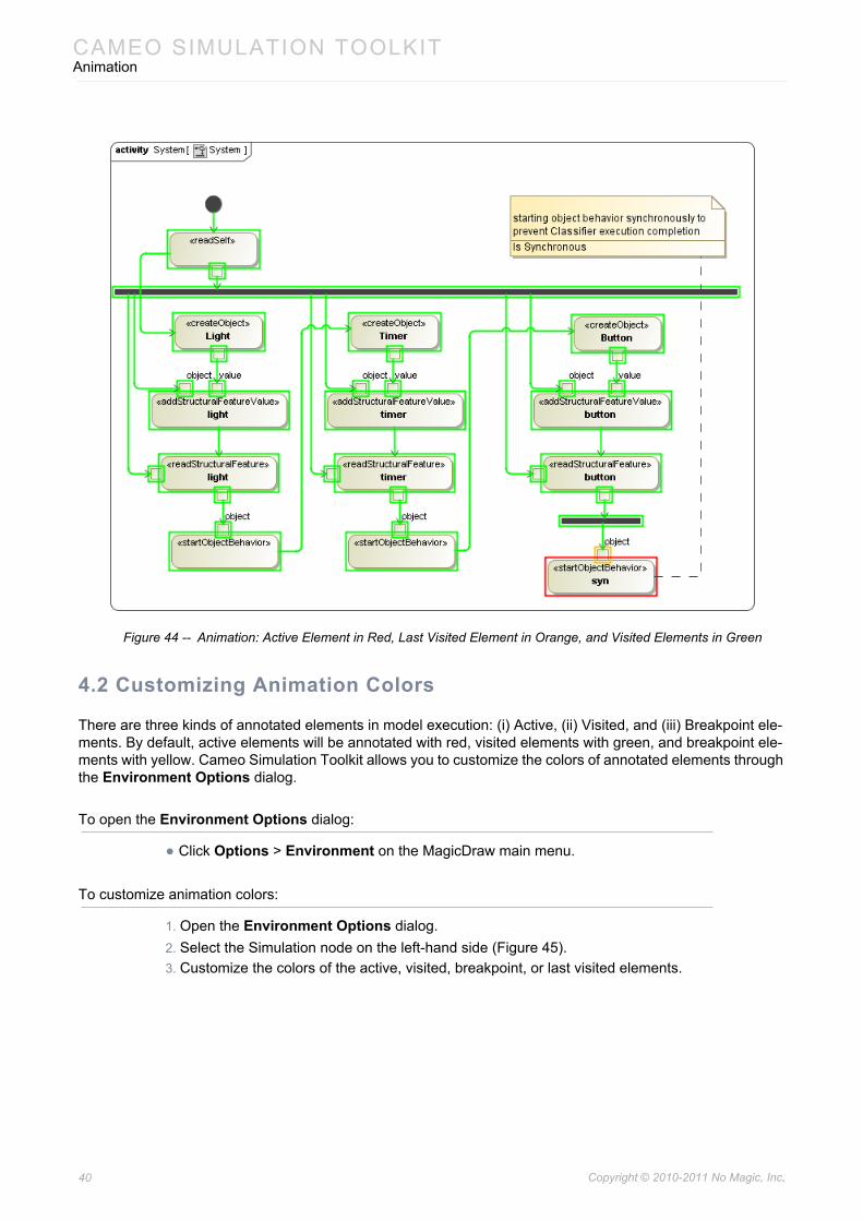
Active elements are the elements on which a simulation session is focused (see 5.1 Understanding Simulation Sessions for more information). They can also be considered as the elements that are currently being executed in a simulation session. They will be annotated with red (by default). Once an active element has been exe-cuted, it will become a visited element and be annotated with green by default (Figure 44). The last visited ele-ment will be annotated with orange (by default).
Note • If an execution trace remains visible on a diagram, click the diagram to clear it.• If a model is executed in silent mode through the selection of an execution configuration
whose silent tag value is set to ‘true’, the animation will be disabled (see Section 3. Execution Configuration for more information).
39 Copyright © 2010-2011 No Magic, Inc..
CAMEO SIMULATION TOOLKITAnimation
Figure 44 -- Animation: Active Element in Red, Last Visited Element in Orange, and Visited Elements in Green
4.2 Customizing Animation Colors
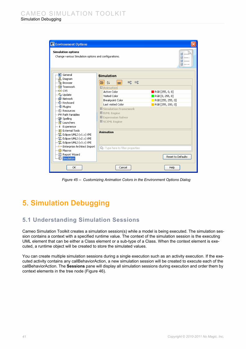
There are three kinds of annotated elements in model execution: (i) Active, (ii) Visited, and (iii) Breakpoint ele-ments. By default, active elements will be annotated with red, visited elements with green, and breakpoint ele-ments with yellow. Cameo Simulation Toolkit allows you to customize the colors of annotated elements through the Environment Options dialog.
To open the Environment Options dialog:
• Click Options > Environment on the MagicDraw main menu.
To customize animation colors:
1. Open the Environment Options dialog.2. Select the Simulation node on the left-hand side (Figure 45).3. Customize the colors of the active, visited, breakpoint, or last visited elements.
40 Copyright © 2010-2011 No Magic, Inc..
CAMEO SIMULATION TOOLKITSimulation Debugging
Figure 45 -- Customizing Animation Colors in the Environment Options Dialog
5. Simulation Debugging
5.1 Understanding Simulation Sessions
Cameo Simulation Toolkit creates a simulation session(s) while a model is being executed. The simulation ses-sion contains a context with a specified runtime value. The context of the simulation session is the executing UML element that can be either a Class element or a sub-type of a Class. When the context element is exe-cuted, a runtime object will be created to store the simulated values.
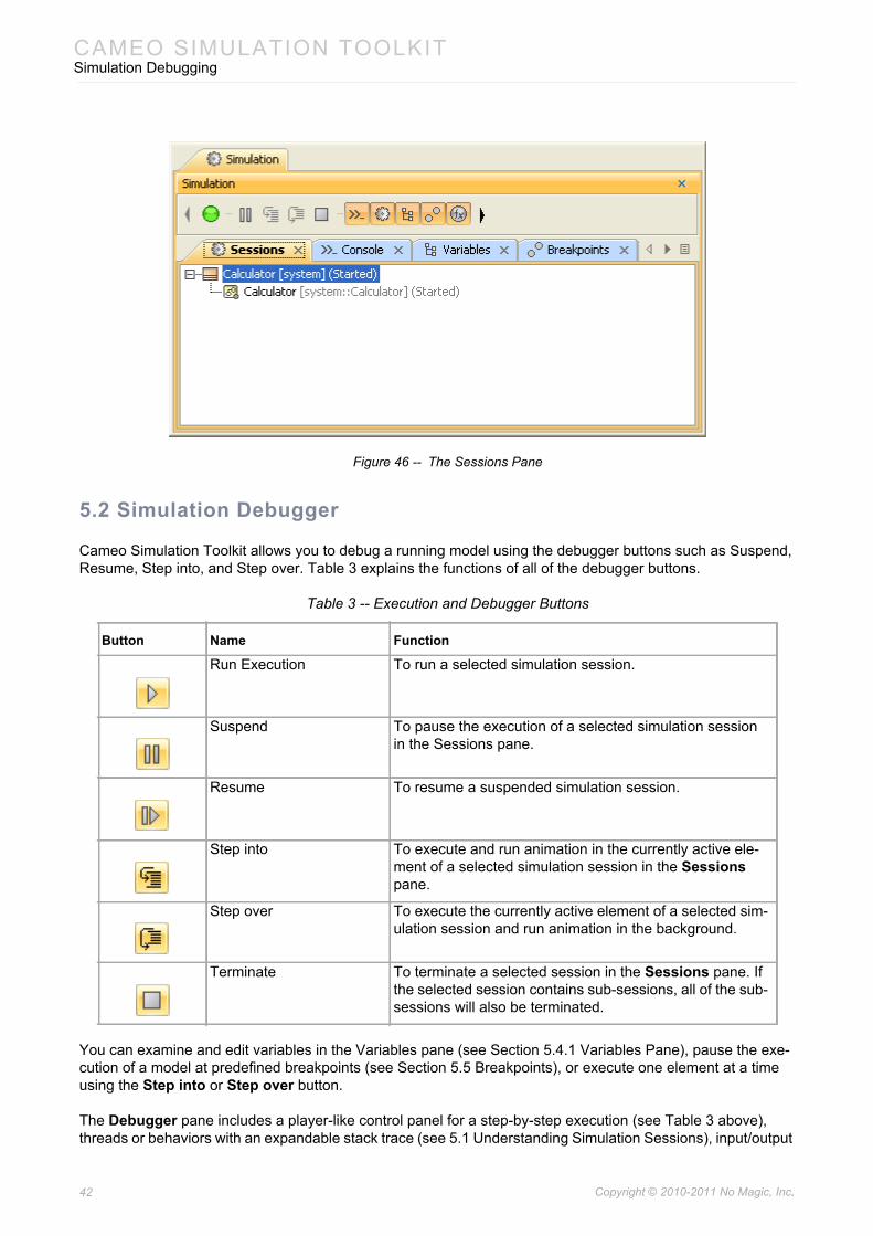
You can create multiple simulation sessions during a single execution such as an activity execution. If the exe-cuted activity contains any callBehaviorAction, a new simulation session will be created to execute each of the callBehaviorAction. The Sessions pane will display all simulation sessions during execution and order them by context elements in the tree node (Figure 46).
41 Copyright © 2010-2011 No Magic, Inc..
CAMEO SIMULATION TOOLKITSimulation Debugging
Figure 46 -- The Sessions Pane
5.2 Simulation Debugger
Cameo Simulation Toolkit allows you to debug a running model using the debugger buttons such as Suspend, Resume, Step into, and Step over. Table 3 explains the functions of all of the debugger buttons.
Table 3 -- Execution and Debugger Buttons
You can examine and edit variables in the Variables pane (see Section 5.4.1 Variables Pane), pause the exe-cution of a model at predefined breakpoints (see Section 5.5 Breakpoints), or execute one element at a time using the Step into or Step over button.
The Debugger pane includes a player-like control panel for a step-by-step execution (see Table 3 above), threads or behaviors with an expandable stack trace (see 5.1 Understanding Simulation Sessions), input/output
Button Name Function
Run Execution To run a selected simulation session.
Suspend To pause the execution of a selected simulation session in the Sessions pane.
Resume To resume a suspended simulation session.
Step into To execute and run animation in the currently active ele-ment of a selected simulation session in the Sessions pane.
Step over To execute the currently active element of a selected sim-ulation session and run animation in the background.
Terminate To terminate a selected session in the Sessions pane. If the selected session contains sub-sessions, all of the sub-sessions will also be terminated.
42 Copyright © 2010-2011 No Magic, Inc..
CAMEO SIMULATION TOOLKITSimulation Debugging
console for custom commands or expressions evaluation (5.3 Simulation Console), Variables Pane/runtime structure (5.4 Runtime Values Monitoring), and the Breakpoints pane (5.5 Breakpoints).
5.3 Simulation Console
5.3.1 Console Pane
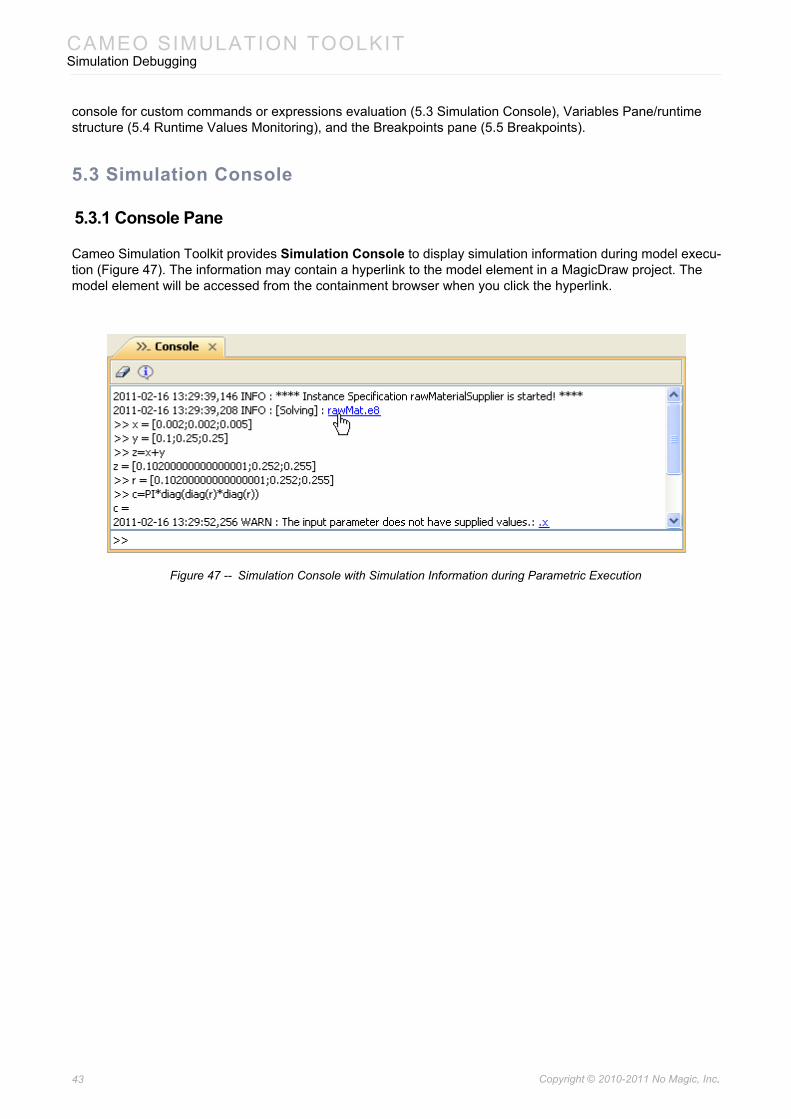
Cameo Simulation Toolkit provides Simulation Console to display simulation information during model execu-tion (Figure 47). The information may contain a hyperlink to the model element in a MagicDraw project. The model element will be accessed from the containment browser when you click the hyperlink.
Figure 47 -- Simulation Console with Simulation Information during Parametric Execution
43 Copyright © 2010-2011 No Magic, Inc..
CAMEO SIMULATION TOOLKITSimulation Debugging
Table 4 -- Console Pane Buttons
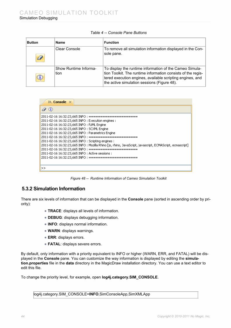
Figure 48 -- Runtime Information of Cameo Simulation Toolkit
5.3.2 Simulation Information
There are six levels of information that can be displayed in the Console pane (sorted in ascending order by pri-ority):
• TRACE: displays all levels of information.
• DEBUG: displays debugging information.
• INFO: displays normal information.
• WARN: displays warnings.
• ERR: displays errors.
• FATAL: displays severe errors.
By default, only information with a priority equivalent to INFO or higher (WARN, ERR, and FATAL) will be dis-played in the Console pane. You can customize the way information is displayed by editing the simula-tion.properties file in the data directory in the MagicDraw installation directory. You can use a text editor to edit this file.
To change the priority level, for example, open log4j.category.SIM_CONSOLE.
Button Name Function
Clear Console To remove all simulation information displayed in the Con-sole pane.
Show Runtime Informa-tion
To display the runtime information of the Cameo Simula-tion Toolkit. The runtime information consists of the regis-tered execution engines, available scripting engines, and the active simulation sessions (Figure 48).
log4j.category.SIM_CONSOLE=INFO,SimConsoleApp,SimXMLApp
44 Copyright © 2010-2011 No Magic, Inc..
CAMEO SIMULATION TOOLKITSimulation Debugging
Change the first parameter’s priority level from INFO (default value) to TRACE to display all levels of simulation information in the Console pane.
You can see more information about customizing the information displayed in the Console pane from the com-ment in the simulation.properties file.
5.3.3 Simulation Log File
During model execution, the simulation information will be displayed in the Console pane. However, the Con-sole pane is limited to display only 60,000 characters owing to the performance constraints. The characters that exceed the maximum character limit will not be displayed. Nevertheless, your old simulation information will be automatically archived in the simulation.log file in the user home directory (<User home directory>/.magicdraw/<version>). The simulation.log file is an XML file (or a text file) that records all simulation infor-mation that has ever been displayed in the Console pane during model execution (see the comment in the simulation.properties file to customize the file).
5.4 Runtime Values Monitoring
5.4.1 Variables Pane
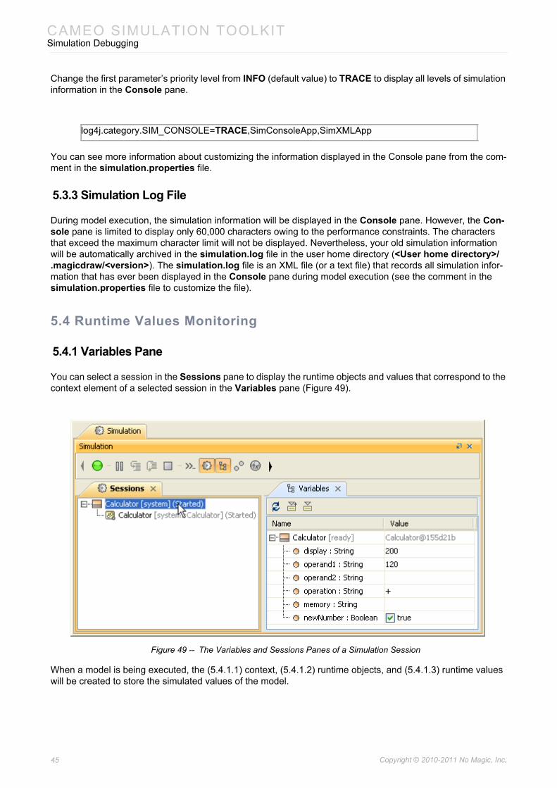
You can select a session in the Sessions pane to display the runtime objects and values that correspond to the context element of a selected session in the Variables pane (Figure 49).
Figure 49 -- The Variables and Sessions Panes of a Simulation Session
When a model is being executed, the (5.4.1.1) context, (5.4.1.2) runtime objects, and (5.4.1.3) runtime values will be created to store the simulated values of the model.
log4j.category.SIM_CONSOLE=TRACE,SimConsoleApp,SimXMLApp
45 Copyright © 2010-2011 No Magic, Inc..
CAMEO SIMULATION TOOLKITSimulation Debugging
5.4.1.1 Context
A simulation session is always associated with its context of execution. The context of a simulation session is a Class or one of its subtypes. When a context element is executed, a runtime object (of the context’s type) will be created to store the runtime values. In Figure 49, the context of the selected simulation session is the “Cal-culator” class.
5.4.1.2 Runtime Object
A runtime object is the simulated value of a Class. In other words, it is a runtime instance of a Class, and hence of the context as well. In Figure 49, the runtime object of the simulation session context is the “Calcula-tor@155d21b” instance. Since the runtime instance is the “Calculator” Class type, it can contain structural fea-tures (which correspond to the Class attributes), such as “display” and “operand1”.
5.4.1.3 Runtime Value
A runtime value refers to the value of the structural features mentioned in section 5.4.1.2 above, such as “200” and “120”. However, if the type of a structural feature is a classifier, its runtime value can also refer to another runtime object of a structural feature type.
The Variables pane (Figure 49) displays the structure of an executing model and the runtime values during the execution of the model. This pane contains two columns: (i) Name and (ii) Value.
(i) Name column
The Name column represents the context and its structural features. If the context is a State Machine ses-sion’s, the current state of the context will be displayed in square brackets. If a structural feature is typed by a Class, which is the context of another State Machine session, the current state of such context will also be dis-played in square brackets after the structural feature.
(ii) Value column
The Value column represents the runtime values of those structural features in the Name column. A runtime value can be the input or the output of an execution. You can directly edit the runtime values in the Value col-umn if they are of the following types: Boolean, Integer, Real, and String.
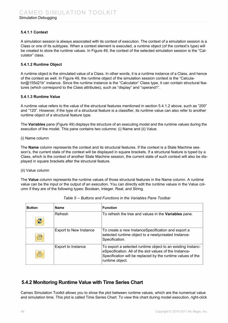
Table 5 -- Buttons and Functions in the Variables Pane Toolbar
5.4.2 Monitoring Runtime Value with Time Series Chart
Cameo Simulation Toolkit allows you to show the plot between runtime values, which are the numerical value and simulation time. This plot is called Time Series Chart. To view this chart during model execution, right-click
Button Name Function
Refresh To refresh the tree and values in the Variables pane.
Export to New Instance To create a new InstanceSpecification and export a selected runtime object to a newlycreated Instance-Specification.
Export to Instance To export a selected runtime object to an existing Instanc-eSpecification. All of the slot values of the Instance-Specification will be replaced by the runtime values of the runtime object.
46 Copyright © 2010-2011 No Magic, Inc..
CAMEO SIMULATION TOOLKITSimulation Debugging
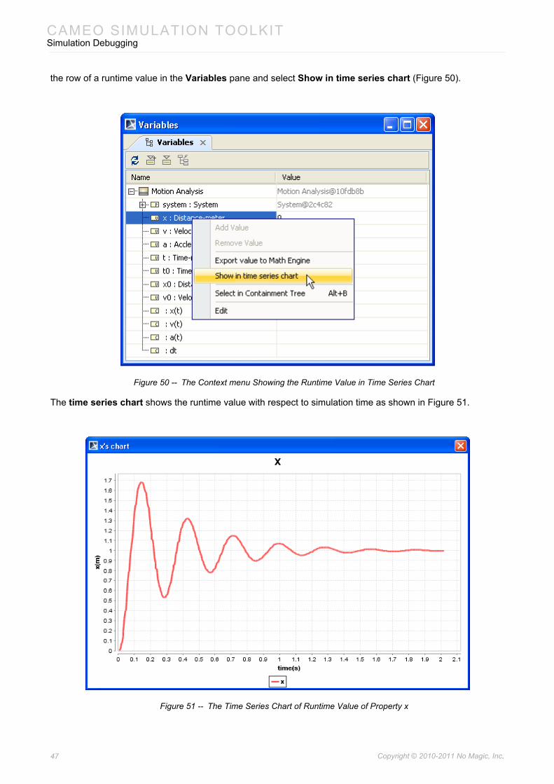
the row of a runtime value in the Variables pane and select Show in time series chart (Figure 50).
Figure 50 -- The Context menu Showing the Runtime Value in Time Series Chart
The time series chart shows the runtime value with respect to simulation time as shown in Figure 51.
Figure 51 -- The Time Series Chart of Runtime Value of Property x
47 Copyright © 2010-2011 No Magic, Inc..
CAMEO SIMULATION TOOLKITSimulation Debugging
5.4.3 Runtime Object Created from InstanceSpecification
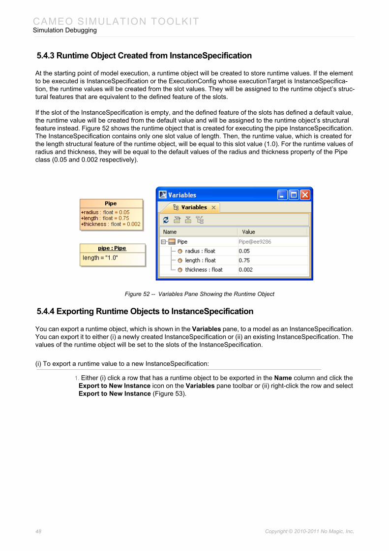
At the starting point of model execution, a runtime object will be created to store runtime values. If the element to be executed is InstanceSpecification or the ExecutionConfig whose executionTarget is InstanceSpecifica-tion, the runtime values will be created from the slot values. They will be assigned to the runtime object’s struc-tural features that are equivalent to the defined feature of the slots.
If the slot of the InstanceSpecification is empty, and the defined feature of the slots has defined a default value, the runtime value will be created from the default value and will be assigned to the runtime object’s structural feature instead. Figure 52 shows the runtime object that is created for executing the pipe InstanceSpecification. The InstanceSpecification contains only one slot value of length. Then, the runtime value, which is created for the length structural feature of the runtime object, will be equal to this slot value (1.0). For the runtime values of radius and thickness, they will be equal to the default values of the radius and thickness property of the Pipe class (0.05 and 0.002 respectively).
Figure 52 -- Variables Pane Showing the Runtime Object
5.4.4 Exporting Runtime Objects to InstanceSpecification
You can export a runtime object, which is shown in the Variables pane, to a model as an InstanceSpecification. You can export it to either (i) a newly created InstanceSpecification or (ii) an existing InstanceSpecification. The values of the runtime object will be set to the slots of the InstanceSpecification.
(i) To export a runtime value to a new InstanceSpecification:
1. Either (i) click a row that has a runtime object to be exported in the Name column and click the Export to New Instance icon on the Variables pane toolbar or (ii) right-click the row and select Export to New Instance (Figure 53).
48 Copyright © 2010-2011 No Magic, Inc..

CAMEO SIMULATION TOOLKITSimulation Debugging
Figure 53 -- Exporting a Runtime Value to a New InstanceSpec through the Context Menu
2. The Select Owner dialog will open. Select the owner of the created InstanceSpecfication (the system folder) and click OK (Figure 54).
Figure 54 -- Selecting an InstanceSpecification Owner in the Select Owner Dialog
(ii) To export a runtime value to an existing InstanceSpecification:
1. Either (i) click a row that has a runtime object to be exported in the Name column and click the Export to Instance icon on the Variables pane toolbar or (ii) right-click the row and select Export to Instance (Figure 55).
49 Copyright © 2010-2011 No Magic, Inc..
CAMEO SIMULATION TOOLKITSimulation Debugging
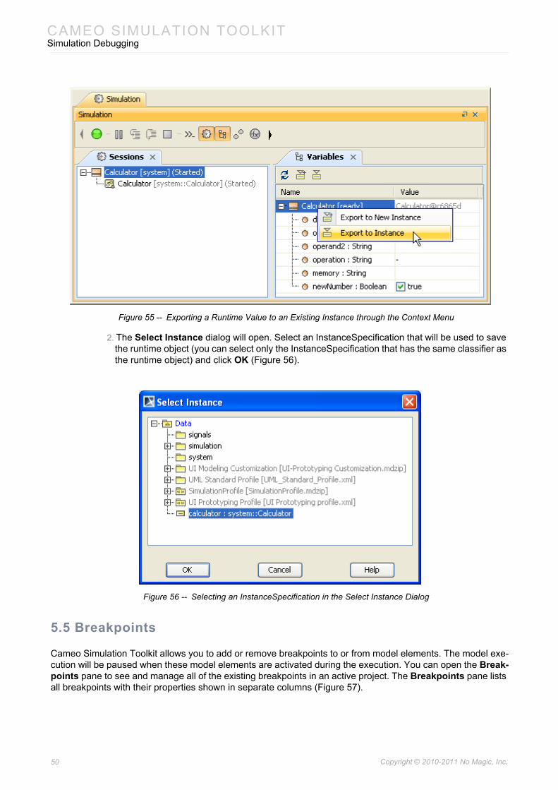
Figure 55 -- Exporting a Runtime Value to an Existing Instance through the Context Menu
2. The Select Instance dialog will open. Select an InstanceSpecification that will be used to save the runtime object (you can select only the InstanceSpecification that has the same classifier as the runtime object) and click OK (Figure 56).
Figure 56 -- Selecting an InstanceSpecification in the Select Instance Dialog
5.5 Breakpoints
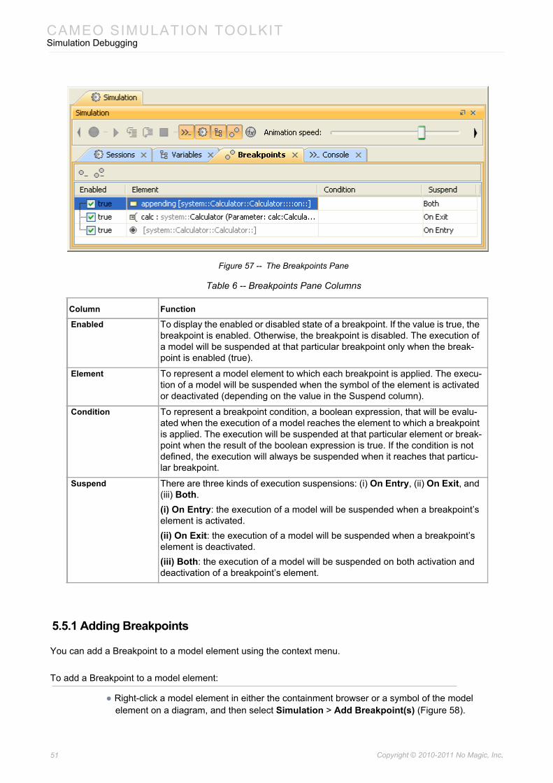
Cameo Simulation Toolkit allows you to add or remove breakpoints to or from model elements. The model exe-cution will be paused when these model elements are activated during the execution. You can open the Break-points pane to see and manage all of the existing breakpoints in an active project. The Breakpoints pane lists all breakpoints with their properties shown in separate columns (Figure 57).
50 Copyright © 2010-2011 No Magic, Inc..
CAMEO SIMULATION TOOLKITSimulation Debugging
Figure 57 -- The Breakpoints Pane
Table 6 -- Breakpoints Pane Columns
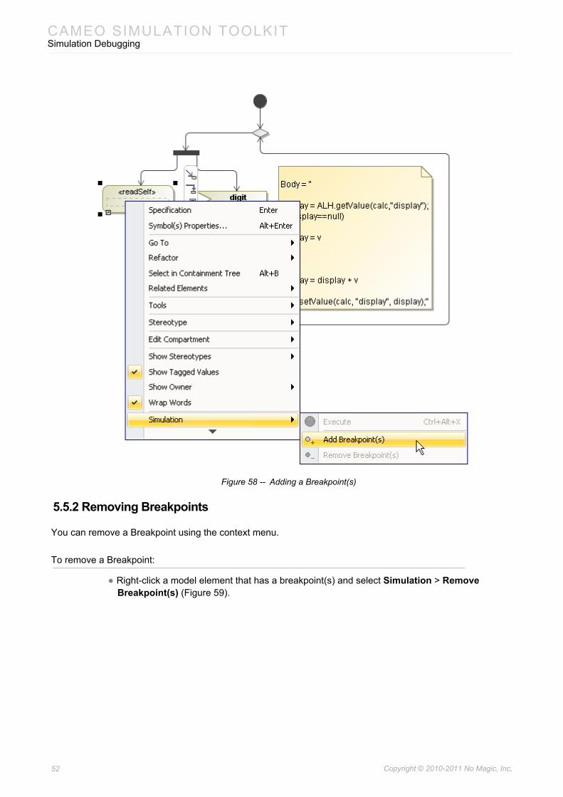
5.5.1 Adding Breakpoints
You can add a Breakpoint to a model element using the context menu.
To add a Breakpoint to a model element:
• Right-click a model element in either the containment browser or a symbol of the model element on a diagram, and then select Simulation > Add Breakpoint(s) (Figure 58).
Column Function
Enabled To display the enabled or disabled state of a breakpoint. If the value is true, the breakpoint is enabled. Otherwise, the breakpoint is disabled. The execution of a model will be suspended at that particular breakpoint only when the break-point is enabled (true).
Element To represent a model element to which each breakpoint is applied. The execu-tion of a model will be suspended when the symbol of the element is activated or deactivated (depending on the value in the Suspend column).
Condition To represent a breakpoint condition, a boolean expression, that will be evalu-ated when the execution of a model reaches the element to which a breakpoint is applied. The execution will be suspended at that particular element or break-point when the result of the boolean expression is true. If the condition is not defined, the execution will always be suspended when it reaches that particu-lar breakpoint.
Suspend There are three kinds of execution suspensions: (i) On Entry, (ii) On Exit, and (iii) Both. (i) On Entry: the execution of a model will be suspended when a breakpoint’s element is activated. (ii) On Exit: the execution of a model will be suspended when a breakpoint’s element is deactivated. (iii) Both: the execution of a model will be suspended on both activation and deactivation of a breakpoint’s element.
51 Copyright © 2010-2011 No Magic, Inc..
CAMEO SIMULATION TOOLKITSimulation Debugging
Figure 58 -- Adding a Breakpoint(s)
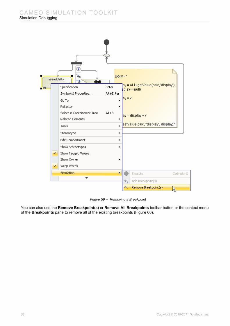
5.5.2 Removing Breakpoints
You can remove a Breakpoint using the context menu.
To remove a Breakpoint:
• Right-click a model element that has a breakpoint(s) and select Simulation > Remove Breakpoint(s) (Figure 59).
52 Copyright © 2010-2011 No Magic, Inc..
CAMEO SIMULATION TOOLKITSimulation Debugging
Figure 59 -- Removing a Breakpoint
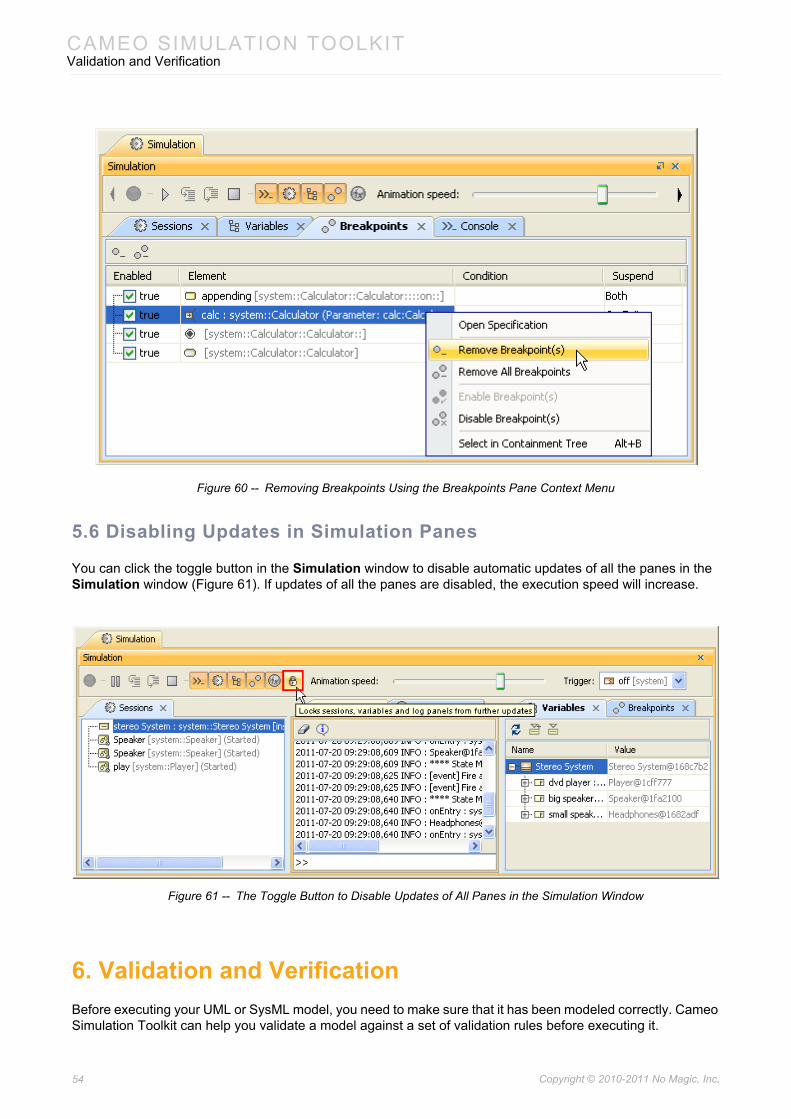
You can also use the Remove Breakpoint(s) or Remove All Breakpoints toolbar button or the context menu of the Breakpoints pane to remove all of the existing breakpoints (Figure 60).
53 Copyright © 2010-2011 No Magic, Inc..
CAMEO SIMULATION TOOLKITValidation and Verification
Figure 60 -- Removing Breakpoints Using the Breakpoints Pane Context Menu
5.6 Disabling Updates in Simulation Panes
You can click the toggle button in the Simulation window to disable automatic updates of all the panes in the Simulation window (Figure 61). If updates of all the panes are disabled, the execution speed will increase.
Figure 61 -- The Toggle Button to Disable Updates of All Panes in the Simulation Window
6. Validation and VerificationBefore executing your UML or SysML model, you need to make sure that it has been modeled correctly. Cameo Simulation Toolkit can help you validate a model against a set of validation rules before executing it.
54 Copyright © 2010-2011 No Magic, Inc..
CAMEO SIMULATION TOOLKITValidation and Verification
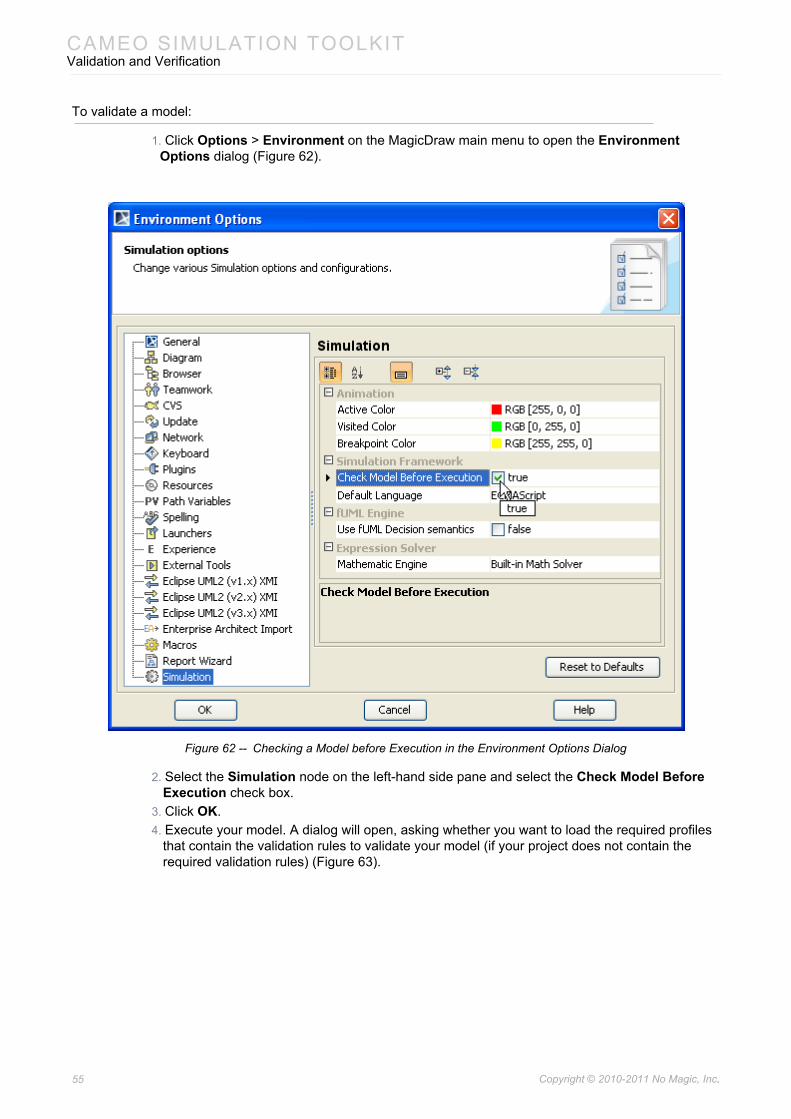
To validate a model:
1. Click Options > Environment on the MagicDraw main menu to open the Environment Options dialog (Figure 62).
Figure 62 -- Checking a Model before Execution in the Environment Options Dialog
2. Select the Simulation node on the left-hand side pane and select the Check Model Before Execution check box.
3. Click OK.4. Execute your model. A dialog will open, asking whether you want to load the required profiles
that contain the validation rules to validate your model (if your project does not contain the required validation rules) (Figure 63).
55 Copyright © 2010-2011 No Magic, Inc..
CAMEO SIMULATION TOOLKITState Machine Simulation
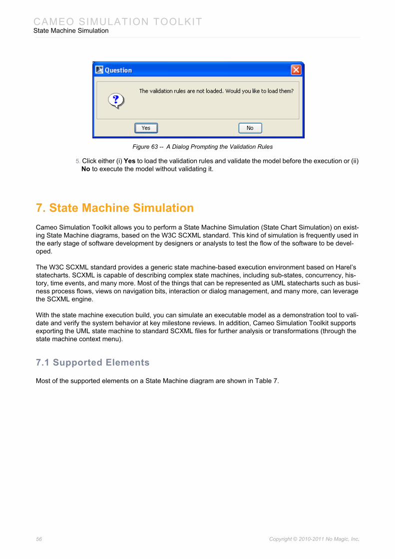
Figure 63 -- A Dialog Prompting the Validation Rules
5. Click either (i) Yes to load the validation rules and validate the model before the execution or (ii) No to execute the model without validating it.
7. State Machine SimulationCameo Simulation Toolkit allows you to perform a State Machine Simulation (State Chart Simulation) on exist-ing State Machine diagrams, based on the W3C SCXML standard. This kind of simulation is frequently used in the early stage of software development by designers or analysts to test the flow of the software to be devel-oped.
The W3C SCXML standard provides a generic state machine-based execution environment based on Harel’s statecharts. SCXML is capable of describing complex state machines, including sub-states, concurrency, his-tory, time events, and many more. Most of the things that can be represented as UML statecharts such as busi-ness process flows, views on navigation bits, interaction or dialog management, and many more, can leverage the SCXML engine.
With the state machine execution build, you can simulate an executable model as a demonstration tool to vali-date and verify the system behavior at key milestone reviews. In addition, Cameo Simulation Toolkit supports exporting the UML state machine to standard SCXML files for further analysis or transformations (through the state machine context menu).
7.1 Supported Elements
Most of the supported elements on a State Machine diagram are shown in Table 7.
56 Copyright © 2010-2011 No Magic, Inc..
CAMEO SIMULATION TOOLKITState Machine Simulation
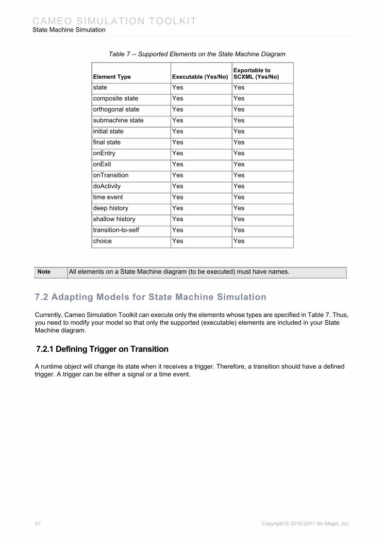
Table 7 -- Supported Elements on the State Machine Diagram
7.2 Adapting Models for State Machine Simulation
Currently, Cameo Simulation Toolkit can execute only the elements whose types are specified in Table 7. Thus, you need to modify your model so that only the supported (executable) elements are included in your State Machine diagram.
7.2.1 Defining Trigger on Transition
A runtime object will change its state when it receives a trigger. Therefore, a transition should have a defined trigger. A trigger can be either a signal or a time event.
Element Type Executable (Yes/No)Exportable to SCXML (Yes/No)
state Yes Yes
composite state Yes Yes
orthogonal state Yes Yes
submachine state Yes Yes
initial state Yes Yes
final state Yes Yes
onEntry Yes Yes
onExit Yes Yes
onTransition Yes Yes
doActivity Yes Yes
time event Yes Yes
deep history Yes Yes
shallow history Yes Yes
transition-to-self Yes Yes
choice Yes Yes
Note All elements on a State Machine diagram (to be executed) must have names.
57 Copyright © 2010-2011 No Magic, Inc..
CAMEO SIMULATION TOOLKITState Machine Simulation
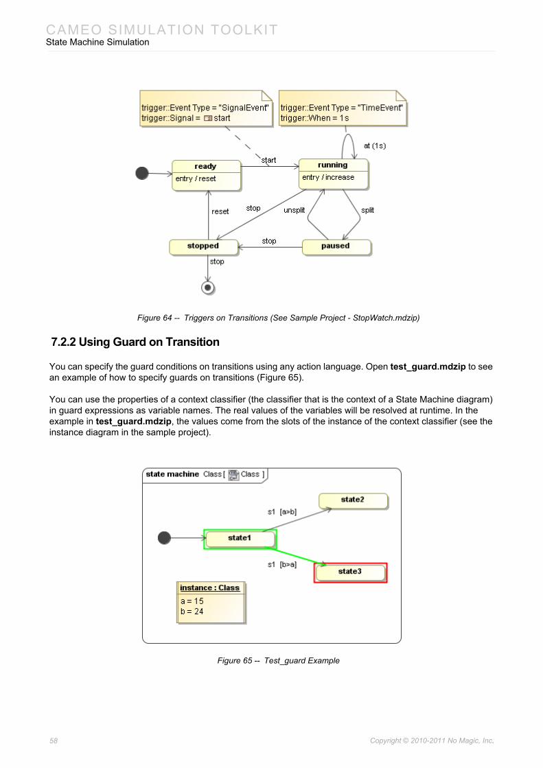
Figure 64 -- Triggers on Transitions (See Sample Project - StopWatch.mdzip)
7.2.2 Using Guard on Transition
You can specify the guard conditions on transitions using any action language. Open test_guard.mdzip to see an example of how to specify guards on transitions (Figure 65).
You can use the properties of a context classifier (the classifier that is the context of a State Machine diagram) in guard expressions as variable names. The real values of the variables will be resolved at runtime. In the example in test_guard.mdzip, the values come from the slots of the instance of the context classifier (see the instance diagram in the sample project).
Figure 65 -- Test_guard Example
58 Copyright © 2010-2011 No Magic, Inc..
CAMEO SIMULATION TOOLKITState Machine Simulation
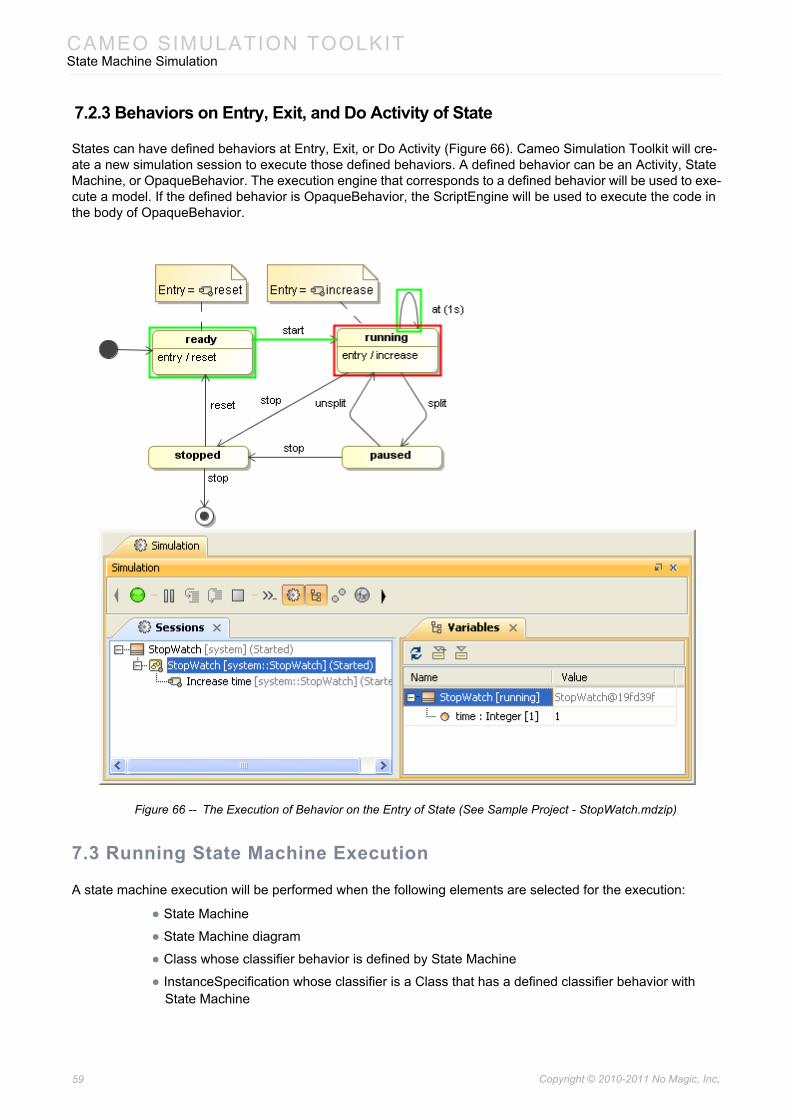
7.2.3 Behaviors on Entry, Exit, and Do Activity of State
States can have defined behaviors at Entry, Exit, or Do Activity (Figure 66). Cameo Simulation Toolkit will cre-ate a new simulation session to execute those defined behaviors. A defined behavior can be an Activity, State Machine, or OpaqueBehavior. The execution engine that corresponds to a defined behavior will be used to exe-cute a model. If the defined behavior is OpaqueBehavior, the ScriptEngine will be used to execute the code in the body of OpaqueBehavior.
Figure 66 -- The Execution of Behavior on the Entry of State (See Sample Project - StopWatch.mdzip)
7.3 Running State Machine Execution
A state machine execution will be performed when the following elements are selected for the execution:
• State Machine
• State Machine diagram
• Class whose classifier behavior is defined by State Machine
• InstanceSpecification whose classifier is a Class that has a defined classifier behavior with State Machine
59 Copyright © 2010-2011 No Magic, Inc..
CAMEO SIMULATION TOOLKITState Machine Simulation
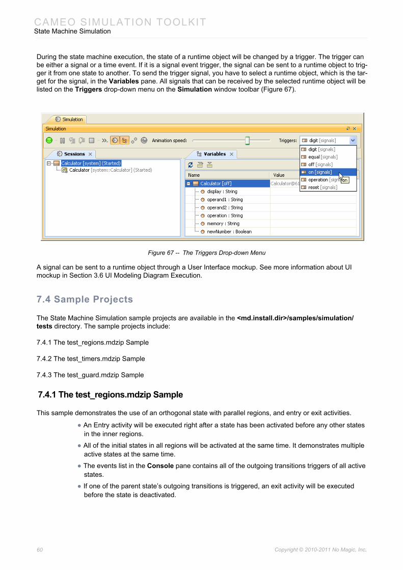
During the state machine execution, the state of a runtime object will be changed by a trigger. The trigger can be either a signal or a time event. If it is a signal event trigger, the signal can be sent to a runtime object to trig-ger it from one state to another. To send the trigger signal, you have to select a runtime object, which is the tar-get for the signal, in the Variables pane. All signals that can be received by the selected runtime object will be listed on the Triggers drop-down menu on the Simulation window toolbar (Figure 67).
Figure 67 -- The Triggers Drop-down Menu
A signal can be sent to a runtime object through a User Interface mockup. See more information about UI mockup in Section 3.6 UI Modeling Diagram Execution.
7.4 Sample Projects
The State Machine Simulation sample projects are available in the <md.install.dir>/samples/simulation/tests directory. The sample projects include:
7.4.1 The test_regions.mdzip Sample
7.4.2 The test_timers.mdzip Sample
7.4.3 The test_guard.mdzip Sample
7.4.1 The test_regions.mdzip Sample
This sample demonstrates the use of an orthogonal state with parallel regions, and entry or exit activities.
• An Entry activity will be executed right after a state has been activated before any other states in the inner regions.
• All of the initial states in all regions will be activated at the same time. It demonstrates multiple active states at the same time.
• The events list in the Console pane contains all of the outgoing transitions triggers of all active states.
• If one of the parent state’s outgoing transitions is triggered, an exit activity will be executed before the state is deactivated.
60 Copyright © 2010-2011 No Magic, Inc..
CAMEO SIMULATION TOOLKITActivity Simulation
7.4.2 The test_timers.mdzip Sample
This sample demonstrates the implementation of timing events on a State Machine diagram.
• Transitions with the specified time events will be automatically triggered after a specified amount of time (in seconds or milliseconds).
• Only relative time (delays) are supported.
7.4.3 The test_guard.mdzip Sample
This sample demonstrates the ability to specify and resolve the guard conditions on transitions.
• The properties of a context classifier can be used in the expressions as variable names.
• The real values of the variables will be resolved at runtime.
• In this case, they come from the slots of the instance of the context classifier (see the Instance diagram).
8. Activity Simulation
8.1 Activity Execution Engine
Cameo Simulation Toolkit provides an Activity Execution Engine that allows you to perform an Activity Simula-tion (Execution) on Activity Diagrams or Activity Elements. Cameo Simulation Toolkit also includes the imple-mentation of OMG Semantics of a Foundational Subset for Executable UML Models (fUML), which is an executable subset of standard UML, that can be used to define the structural and behavioral semantics of sys-tems. fUML defines a basic virtual machine for the Unified Modeling Language and supports specific abstrac-tions enabling compliant models to be transformed into various executable forms for verification, integration, and deployment.
Various UML activity diagram concepts are supported, including object and control flows, behavior and opera-tion calls, sending and accepting signals and time events, pins, parameters, decisions, structured activity nodes, and many more.*
The Activity Execution Engine features include:
• fUML 1.0 specification support
• Any action languages in opaqueBehaviors, opaqueExpressions, decisions, guards, constraints (see 12.4 Using MATLAB® as Mathematical Solver for more details)
• CallBehaviorAction with nested diagrams execution and animation
• SendSignalAction can be used to send a signal to a global event queue to be consumed by any other engines (such as state machine)
61 Copyright © 2010-2011 No Magic, Inc..

CAMEO SIMULATION TOOLKITActivity Simulation
Note • Activities that will be executed must be owned in a Package or Class only. As a workaround, the CallBehavior actions, owned by the call behaviors in a package, will be used for the entry/do/exit behaviors in states.
• The guards on an ObjectFlow are not Boolean expressions in fUML. They contain a value that should match with the runtime value that flows on the ObjectFlow during execution. To change this mode to a regular UML (Boolean expression), click Options > Environment on the main menu, and then select the Simulation node on the left-hand side of the Environment Options dialog. Next, select the Use fUML Decision Semantics value check box so that the value becomes false. The value is false by default in UML mode.
62 Copyright © 2010-2011 No Magic, Inc..
CAMEO SIMULATION TOOLKITActivity Simulation
8.2 Creating Model for Activity Execution
You can simulate a UML activity or a classifier whose classifier behavior is defined by an activity. This section demonstrates how to create a simple, executable Activity model through the following steps:
(i) Create a class containing two properties typed by Integers.(ii) Create an activity to print the summation value of the two properties.(iii) Assign the activity as the classifier behavior of the created class.(iv) Create an opaque behavior to print the summation value of two input parameters of type Inte-
ger.(v) Write a script to print the summation of the given integer values that are referred to by the two
input parameters.(vi) Complete the activity diagram of the class.(vii) Create a ReadSelfAction to read a runtime object that will be supplied to the input pins of
both the readX and readY actions.(viii) Create an InstanceSpecification and assign the values to the slots that correspond to the
two created properties.
(i) To create a class containing two attributes typed by Integers:
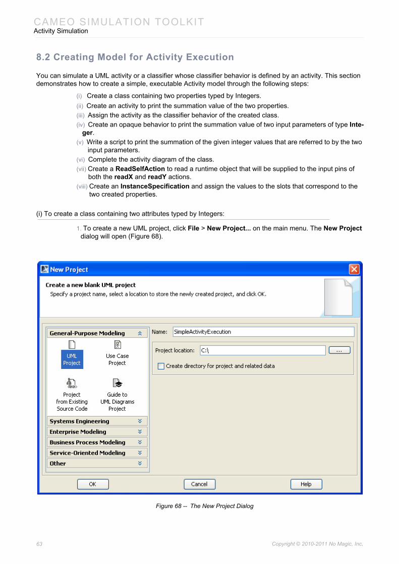
1. To create a new UML project, click File > New Project... on the main menu. The New Project dialog will open (Figure 68).
Figure 68 -- The New Project Dialog
63 Copyright © 2010-2011 No Magic, Inc..
CAMEO SIMULATION TOOLKITActivity Simulation
2. Select UML Project from the General-Purpose Modeling group and specify the project’s name, such as “SimpleActivityExecution”.
3. Specify the location where you want to save your project file, and then click OK.4. Right-click the Data model in the containment browser and select New Element > Class. A
new class element, which is the context of the activity, will be created in the containment browser. Name the created class, for example, “SumPrinter”.
5. Add two properties: (i) x and (ii) y of type Integer.
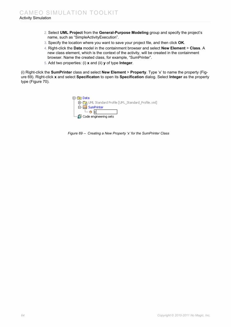
(i) Right-click the SumPrinter class and select New Element > Property. Type ‘x’ to name the property (Fig-ure 69). Right-click x and select Specificaton to open its Specification dialog. Select Integer as the property type (Figure 70).
Figure 69 -- Creating a New Property ‘x’ for the SumPrinter Class
64 Copyright © 2010-2011 No Magic, Inc..
CAMEO SIMULATION TOOLKITActivity Simulation
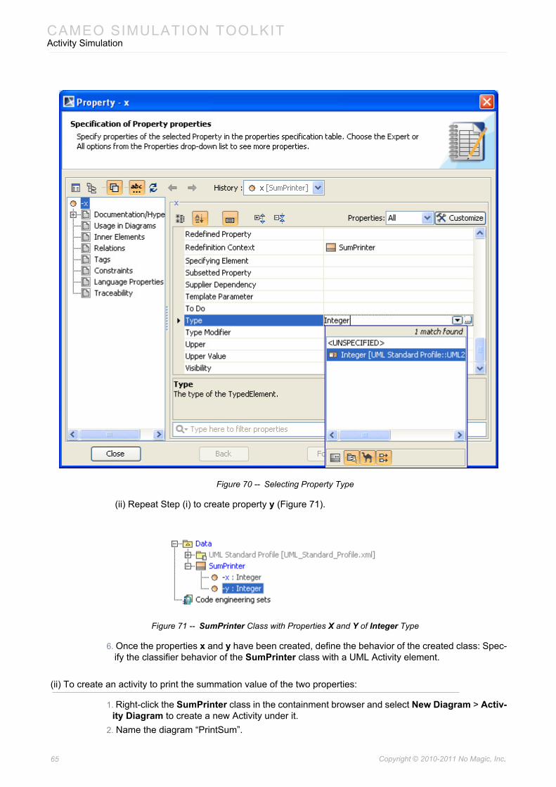
Figure 70 -- Selecting Property Type
(ii) Repeat Step (i) to create property y (Figure 71).
Figure 71 -- SumPrinter Class with Properties X and Y of Integer Type
6. Once the properties x and y have been created, define the behavior of the created class: Spec-ify the classifier behavior of the SumPrinter class with a UML Activity element.
(ii) To create an activity to print the summation value of the two properties:
1. Right-click the SumPrinter class in the containment browser and select New Diagram > Activ-ity Diagram to create a new Activity under it.
2. Name the diagram “PrintSum”.
65 Copyright © 2010-2011 No Magic, Inc..
CAMEO SIMULATION TOOLKITActivity Simulation
Now that the activity has been created, assign it as the classifier behavior of SumPrinter.
(iii) To assign the activity as the classifier behavior of the created class:
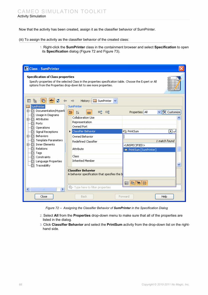
1. Right-click the SumPrinter class in the containment browser and select Specification to open its Specification dialog (Figure 72 and Figure 73).
Figure 72 -- Assigning the Classifier Behavior of SumPrinter in the Specification Dialog
2. Select All from the Properties drop-down menu to make sure that all of the properties are listed in the dialog.
3. Click Classifier Behavior and select the PrintSum activity from the drop-down list on the right-hand side.
66 Copyright © 2010-2011 No Magic, Inc..
CAMEO SIMULATION TOOLKITActivity Simulation
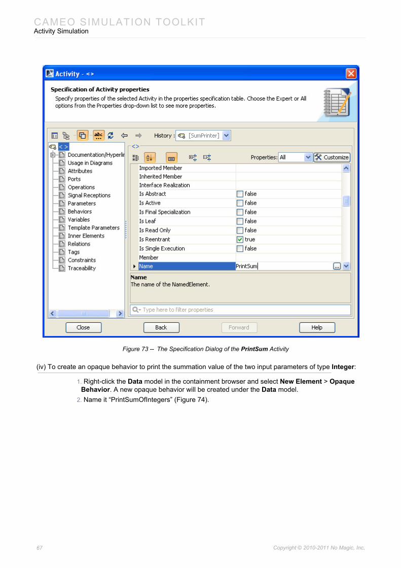
Figure 73 -- The Specification Dialog of the PrintSum Activity
(iv) To create an opaque behavior to print the summation value of the two input parameters of type Integer:
1. Right-click the Data model in the containment browser and select New Element > Opaque Behavior. A new opaque behavior will be created under the Data model.
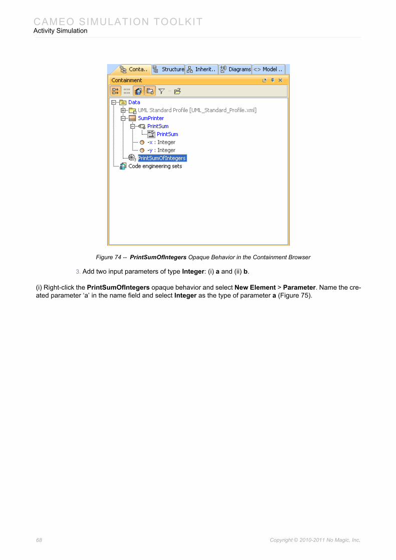
2. Name it “PrintSumOfIntegers” (Figure 74).
67 Copyright © 2010-2011 No Magic, Inc..
CAMEO SIMULATION TOOLKITActivity Simulation
Figure 74 -- PrintSumOfIntegers Opaque Behavior in the Containment Browser
3. Add two input parameters of type Integer: (i) a and (ii) b.
(i) Right-click the PrintSumOfIntegers opaque behavior and select New Element > Parameter. Name the cre-ated parameter ‘a’ in the name field and select Integer as the type of parameter a (Figure 75).
68 Copyright © 2010-2011 No Magic, Inc..
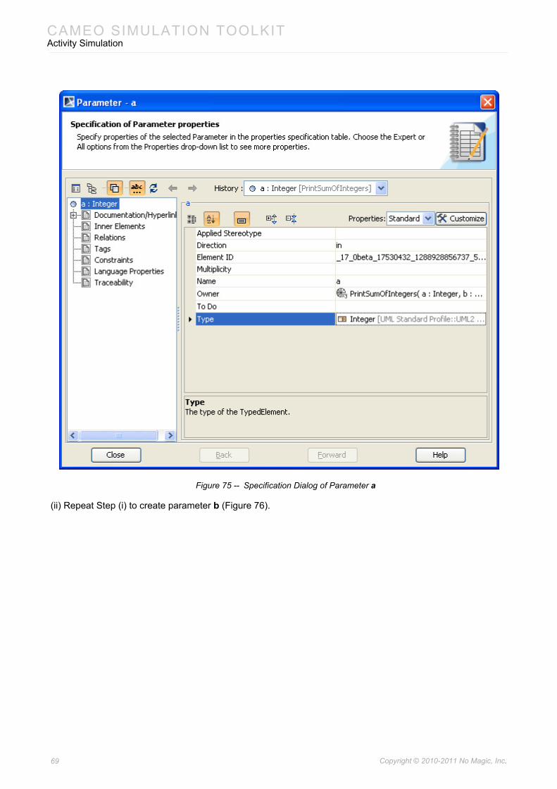
CAMEO SIMULATION TOOLKITActivity Simulation
Figure 75 -- Specification Dialog of Parameter a
(ii) Repeat Step (i) to create parameter b (Figure 76).
69 Copyright © 2010-2011 No Magic, Inc..
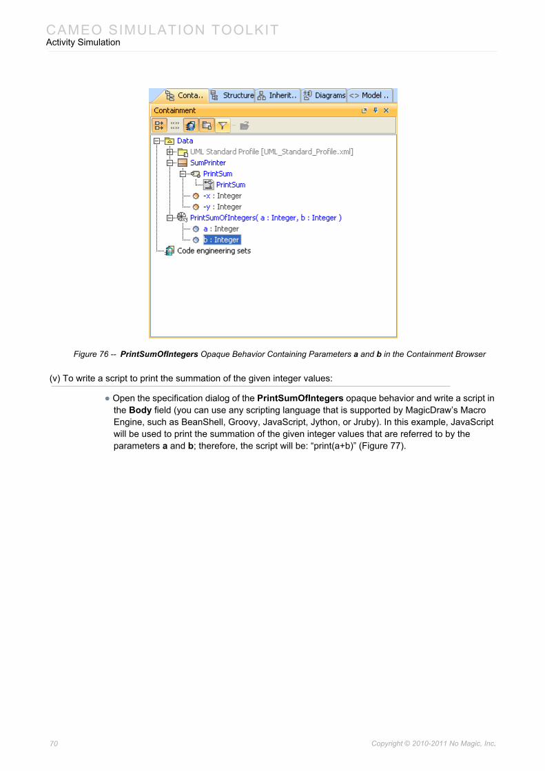
CAMEO SIMULATION TOOLKITActivity Simulation
Figure 76 -- PrintSumOfIntegers Opaque Behavior Containing Parameters a and b in the Containment Browser
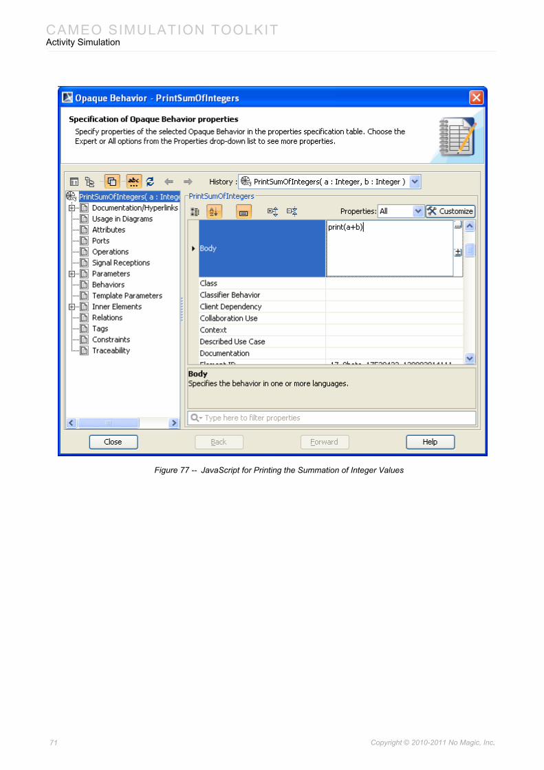
(v) To write a script to print the summation of the given integer values:
• Open the specification dialog of the PrintSumOfIntegers opaque behavior and write a script in the Body field (you can use any scripting language that is supported by MagicDraw’s Macro Engine, such as BeanShell, Groovy, JavaScript, Jython, or Jruby). In this example, JavaScript will be used to print the summation of the given integer values that are referred to by the parameters a and b; therefore, the script will be: “print(a+b)” (Figure 77).
70 Copyright © 2010-2011 No Magic, Inc..
CAMEO SIMULATION TOOLKITActivity Simulation
Figure 77 -- JavaScript for Printing the Summation of Integer Values
71 Copyright © 2010-2011 No Magic, Inc..
CAMEO SIMULATION TOOLKITActivity Simulation
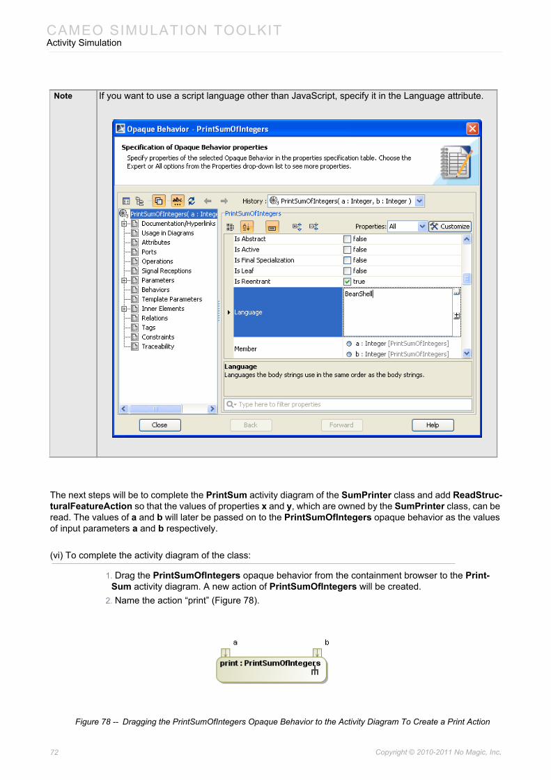
The next steps will be to complete the PrintSum activity diagram of the SumPrinter class and add ReadStruc-turalFeatureAction so that the values of properties x and y, which are owned by the SumPrinter class, can be read. The values of a and b will later be passed on to the PrintSumOfIntegers opaque behavior as the values of input parameters a and b respectively.
(vi) To complete the activity diagram of the class:
1. Drag the PrintSumOfIntegers opaque behavior from the containment browser to the Print-Sum activity diagram. A new action of PrintSumOfIntegers will be created.
2. Name the action “print” (Figure 78).
Figure 78 -- Dragging the PrintSumOfIntegers Opaque Behavior to the Activity Diagram To Create a Print Action
Note If you want to use a script language other than JavaScript, specify it in the Language attribute.
72 Copyright © 2010-2011 No Magic, Inc..
CAMEO SIMULATION TOOLKITActivity Simulation
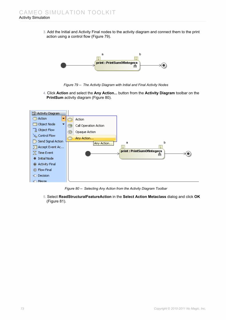
3. Add the Initial and Activity Final nodes to the activity diagram and connect them to the print action using a control flow (Figure 79).
Figure 79 -- The Activity Diagram with Initial and Final Activity Nodes
4. Click Action and select the Any Action... button from the Activity Diagram toolbar on the PrintSum activity diagram (Figure 80).
Figure 80 -- Selecting Any Action from the Activity Diagram Toolbar
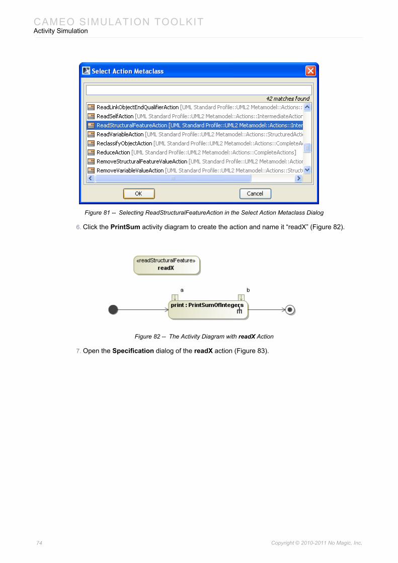
5. Select ReadStructuralFeatureAction in the Select Action Metaclass dialog and click OK (Figure 81).
73 Copyright © 2010-2011 No Magic, Inc..
CAMEO SIMULATION TOOLKITActivity Simulation
Figure 81 -- Selecting ReadStructuralFeatureAction in the Select Action Metaclass Dialog
6. Click the PrintSum activity diagram to create the action and name it “readX” (Figure 82).
Figure 82 -- The Activity Diagram with readX Action
7. Open the Specification dialog of the readX action (Figure 83).
74 Copyright © 2010-2011 No Magic, Inc..
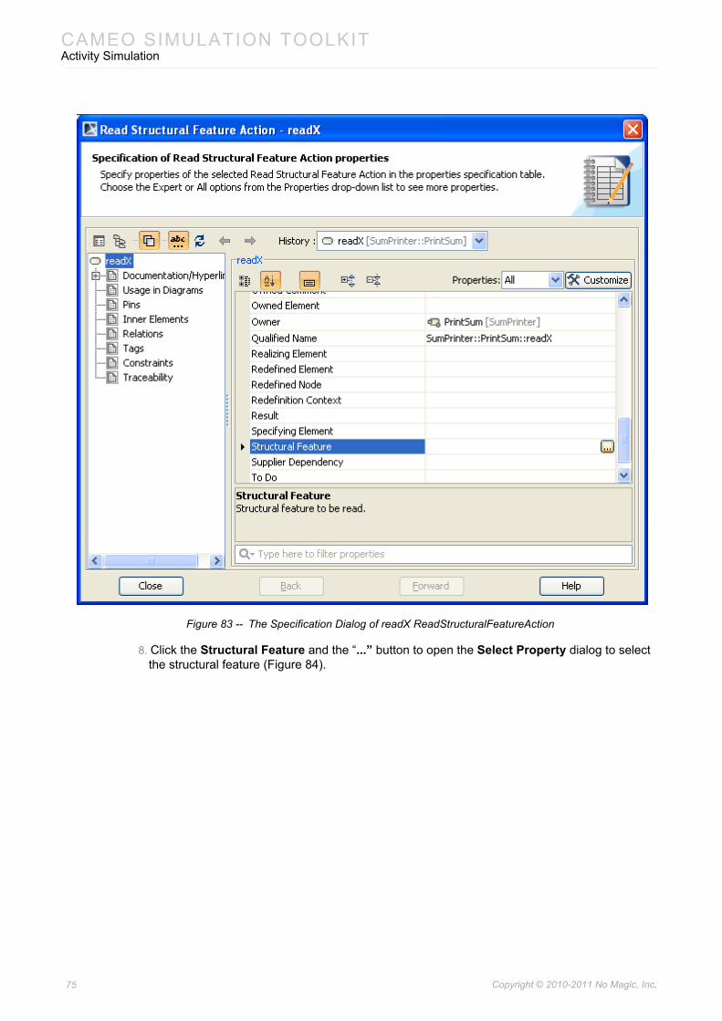
CAMEO SIMULATION TOOLKITActivity Simulation
Figure 83 -- The Specification Dialog of readX ReadStructuralFeatureAction
8. Click the Structural Feature and the “...” button to open the Select Property dialog to select the structural feature (Figure 84).
75 Copyright © 2010-2011 No Magic, Inc..
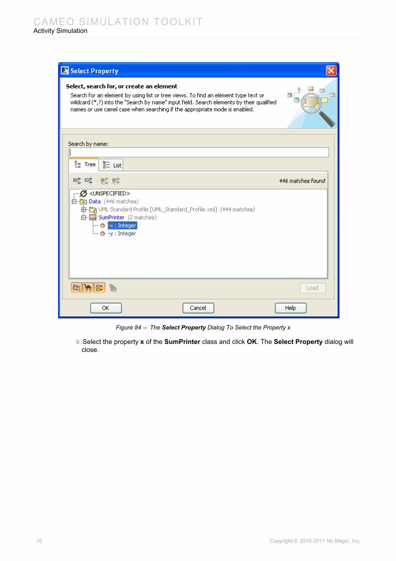
CAMEO SIMULATION TOOLKITActivity Simulation
Figure 84 -- The Select Property Dialog To Select the Property x
9. Select the property x of the SumPrinter class and click OK. The Select Property dialog will close.
76 Copyright © 2010-2011 No Magic, Inc..
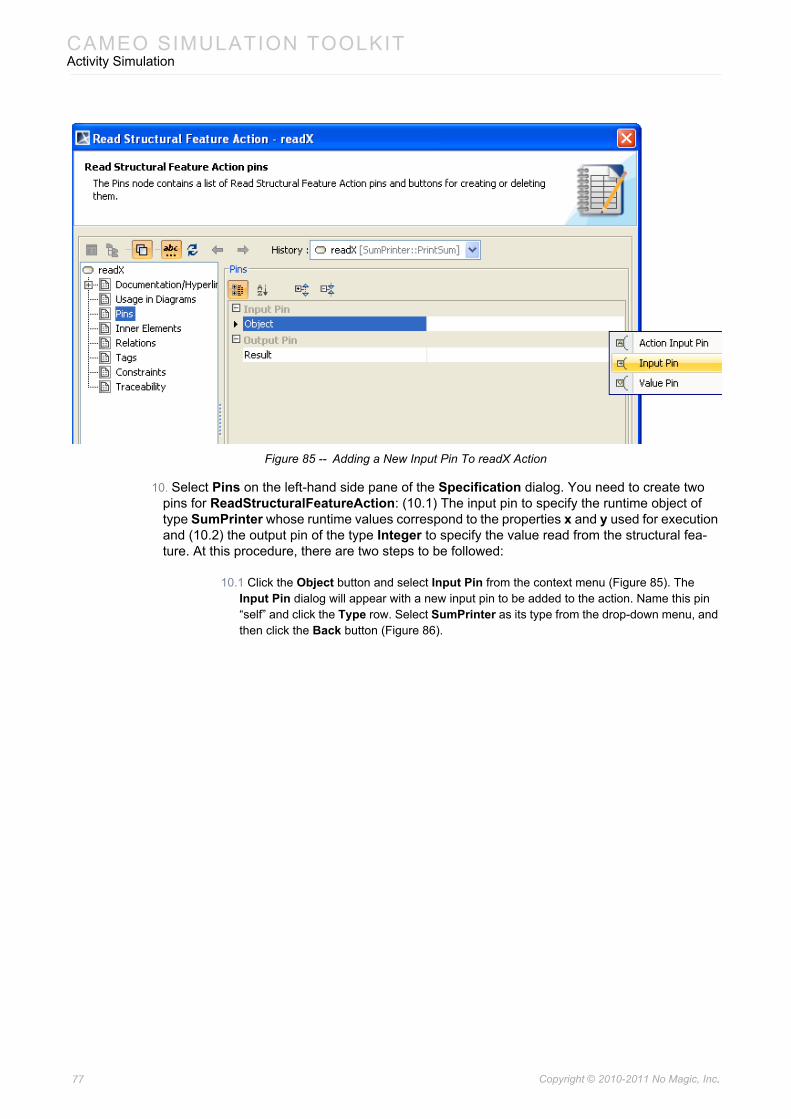
CAMEO SIMULATION TOOLKITActivity Simulation
Figure 85 -- Adding a New Input Pin To readX Action
10. Select Pins on the left-hand side pane of the Specification dialog. You need to create two pins for ReadStructuralFeatureAction: (10.1) The input pin to specify the runtime object of type SumPrinter whose runtime values correspond to the properties x and y used for execution and (10.2) the output pin of the type Integer to specify the value read from the structural fea-ture. At this procedure, there are two steps to be followed:
10.1 Click the Object button and select Input Pin from the context menu (Figure 85). The Input Pin dialog will appear with a new input pin to be added to the action. Name this pin “self” and click the Type row. Select SumPrinter as its type from the drop-down menu, and then click the Back button (Figure 86).
77 Copyright © 2010-2011 No Magic, Inc..
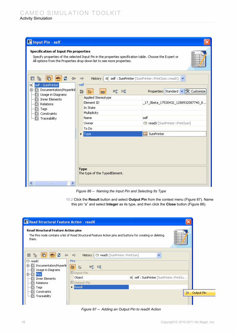
CAMEO SIMULATION TOOLKITActivity Simulation
Figure 86 -- Naming the Input Pin and Selecting Its Type
10.2 Click the Result button and select Output Pin from the context menu (Figure 87). Name this pin “a” and select Integer as its type, and then click the Close button (Figure 88).
Figure 87 -- Adding an Output Pin to readX Action
78 Copyright © 2010-2011 No Magic, Inc..
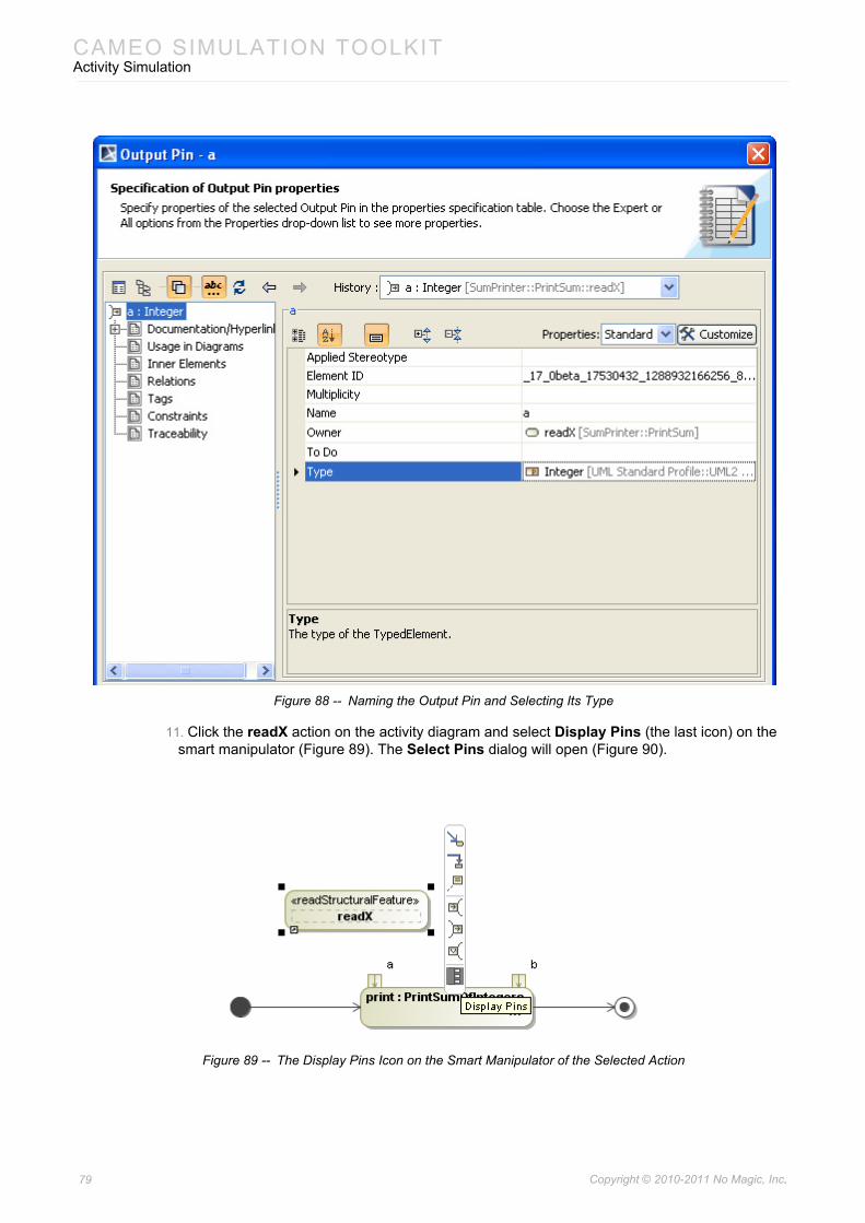
CAMEO SIMULATION TOOLKITActivity Simulation
Figure 88 -- Naming the Output Pin and Selecting Its Type
11. Click the readX action on the activity diagram and select Display Pins (the last icon) on the smart manipulator (Figure 89). The Select Pins dialog will open (Figure 90).
Figure 89 -- The Display Pins Icon on the Smart Manipulator of the Selected Action
79 Copyright © 2010-2011 No Magic, Inc..
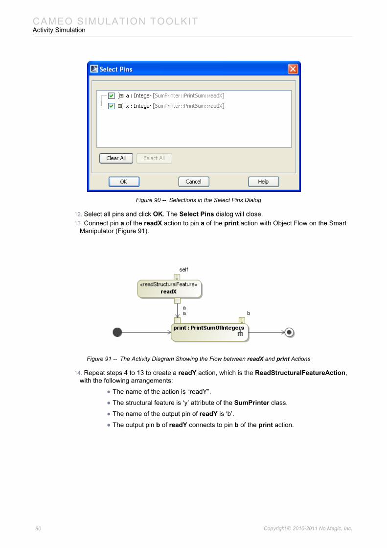
CAMEO SIMULATION TOOLKITActivity Simulation
Figure 90 -- Selections in the Select Pins Dialog
12. Select all pins and click OK. The Select Pins dialog will close.13. Connect pin a of the readX action to pin a of the print action with Object Flow on the Smart
Manipulator (Figure 91).
Figure 91 -- The Activity Diagram Showing the Flow between readX and print Actions
14. Repeat steps 4 to 13 to create a readY action, which is the ReadStructuralFeatureAction, with the following arrangements:
• The name of the action is “readY”.
• The structural feature is ‘y’ attribute of the SumPrinter class.
• The name of the output pin of readY is ‘b’.
• The output pin b of readY connects to pin b of the print action.
80 Copyright © 2010-2011 No Magic, Inc..
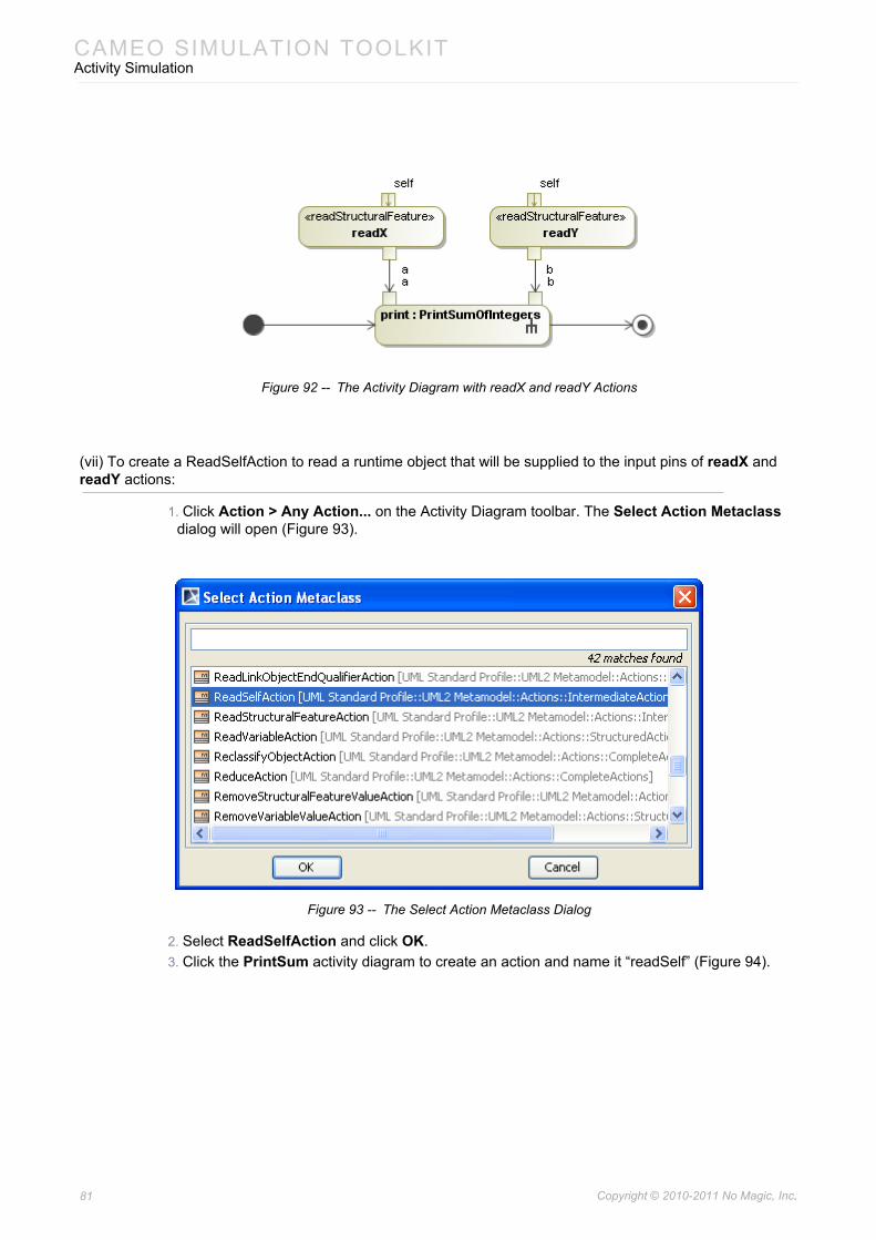
CAMEO SIMULATION TOOLKITActivity Simulation
Figure 92 -- The Activity Diagram with readX and readY Actions
(vii) To create a ReadSelfAction to read a runtime object that will be supplied to the input pins of readX and readY actions:
1. Click Action > Any Action... on the Activity Diagram toolbar. The Select Action Metaclass dialog will open (Figure 93).
Figure 93 -- The Select Action Metaclass Dialog
2. Select ReadSelfAction and click OK.3. Click the PrintSum activity diagram to create an action and name it “readSelf” (Figure 94).
81 Copyright © 2010-2011 No Magic, Inc..
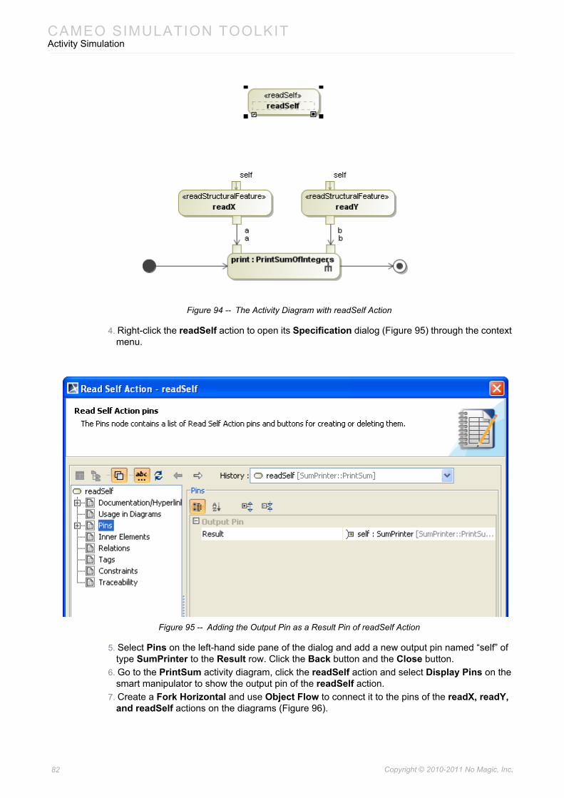
CAMEO SIMULATION TOOLKITActivity Simulation
Figure 94 -- The Activity Diagram with readSelf Action
4. Right-click the readSelf action to open its Specification dialog (Figure 95) through the context menu.
Figure 95 -- Adding the Output Pin as a Result Pin of readSelf Action
5. Select Pins on the left-hand side pane of the dialog and add a new output pin named “self” of type SumPrinter to the Result row. Click the Back button and the Close button.
6. Go to the PrintSum activity diagram, click the readSelf action and select Display Pins on the smart manipulator to show the output pin of the readSelf action.
7. Create a Fork Horizontal and use Object Flow to connect it to the pins of the readX, readY, and readSelf actions on the diagrams (Figure 96).
82 Copyright © 2010-2011 No Magic, Inc..
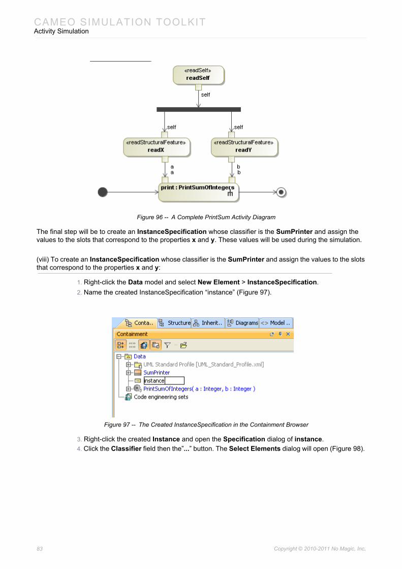
CAMEO SIMULATION TOOLKITActivity Simulation
Figure 96 -- A Complete PrintSum Activity Diagram
The final step will be to create an InstanceSpecification whose classifier is the SumPrinter and assign the values to the slots that correspond to the properties x and y. These values will be used during the simulation.
(viii) To create an InstanceSpecification whose classifier is the SumPrinter and assign the values to the slots that correspond to the properties x and y:
1. Right-click the Data model and select New Element > InstanceSpecification.2. Name the created InstanceSpecification “instance” (Figure 97).
Figure 97 -- The Created InstanceSpecification in the Containment Browser
3. Right-click the created Instance and open the Specification dialog of instance.4. Click the Classifier field then the”...” button. The Select Elements dialog will open (Figure 98).
83 Copyright © 2010-2011 No Magic, Inc..
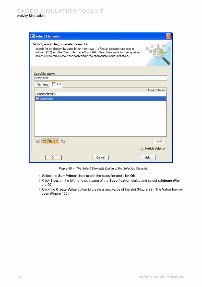
CAMEO SIMULATION TOOLKITActivity Simulation
Figure 98 -- The Select Elements Dialog of the Selected Classifier
5. Select the SumPrinter class to edit the classifier and click OK.6. Click Slots on the left-hand side pane of the Specification dialog and select x:Integer (Fig-
ure 99).7. Click the Create Value button to create a new value of the slot (Figure 99). The Value box will
open (Figure 100).
84 Copyright © 2010-2011 No Magic, Inc..
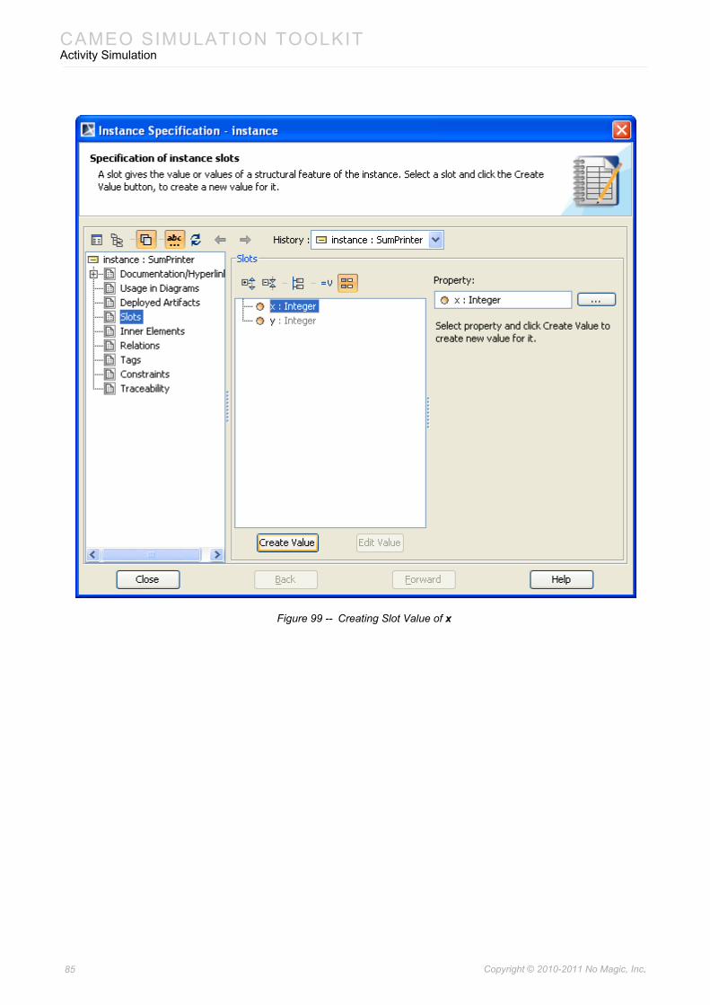
CAMEO SIMULATION TOOLKITActivity Simulation
Figure 99 -- Creating Slot Value of x
85 Copyright © 2010-2011 No Magic, Inc..
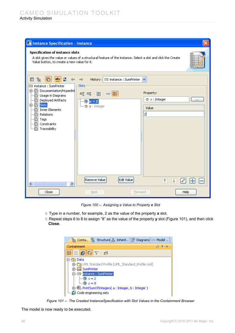
CAMEO SIMULATION TOOLKITActivity Simulation
Figure 100 -- Assigning a Value to Property x Slot
8. Type in a number, for example, 2 as the value of the property x slot.9. Repeat steps 6 to 8 to assign “8” as the value of the property y slot (Figure 101), and then click
Close.
Figure 101 -- The Created InstanceSpecification with Slot Values in the Containment Browser
The model is now ready to be executed.
86 Copyright © 2010-2011 No Magic, Inc..
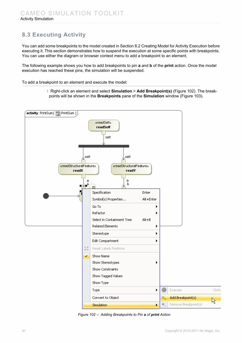
CAMEO SIMULATION TOOLKITActivity Simulation
8.3 Executing Activity
You can add some breakpoints to the model created in Section 8.2 Creating Model for Activity Execution before executing it. This section demonstrates how to suspend the execution at some specific points with breakpoints. You can use either the diagram or browser context menu to add a breakpoint to an element.
The following example shows you how to add breakpoints to pin a and b of the print action. Once the model execution has reached these pins, the simulation will be suspended.
To add a breakpoint to an element and execute the model:
1. Right-click an element and select Simulation > Add Breakpoint(s) (Figure 102). The break-points will be shown in the Breakpoints pane of the Simulation window (Figure 103).
Figure 102 -- Adding Breakpoints to Pin a of print Action
87 Copyright © 2010-2011 No Magic, Inc..
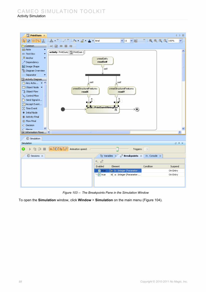
CAMEO SIMULATION TOOLKITActivity Simulation
Figure 103 -- The Breakpoints Pane in the Simulation Window
To open the Simulation window, click Window > Simulation on the main menu (Figure 104).
88 Copyright © 2010-2011 No Magic, Inc..
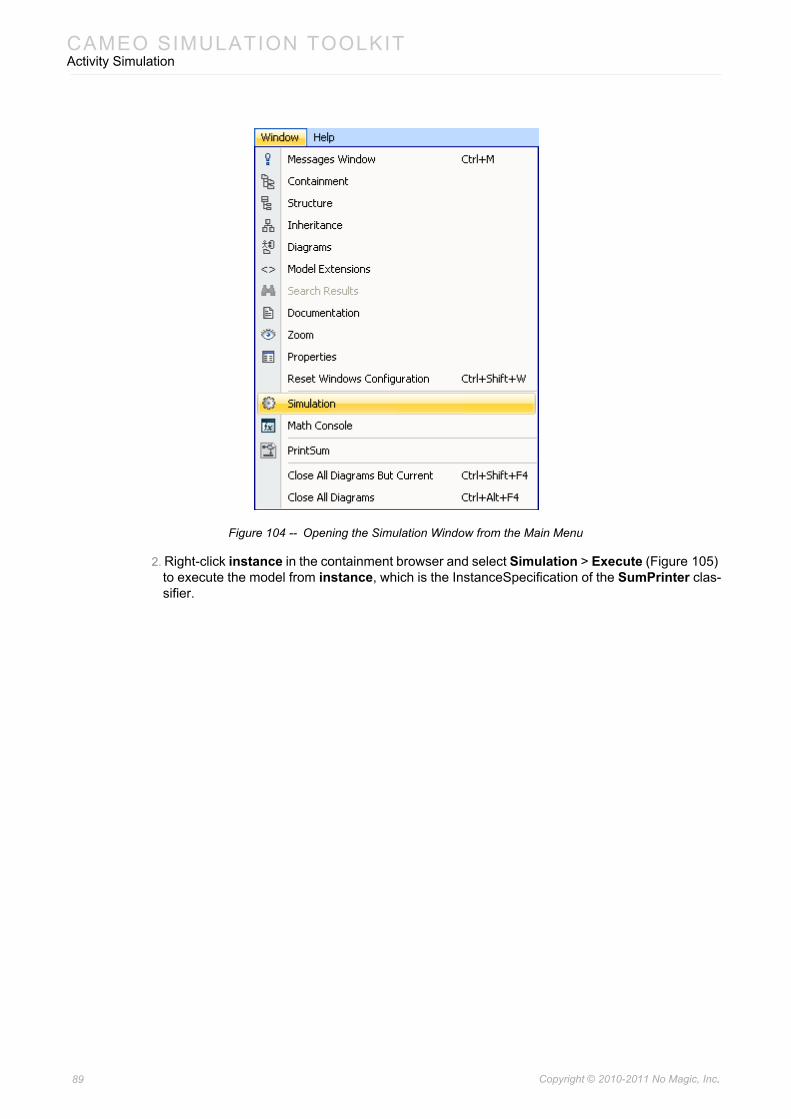
CAMEO SIMULATION TOOLKITActivity Simulation
Figure 104 -- Opening the Simulation Window from the Main Menu
2. Right-click instance in the containment browser and select Simulation > Execute (Figure 105) to execute the model from instance, which is the InstanceSpecification of the SumPrinter clas-sifier.
89 Copyright © 2010-2011 No Magic, Inc..
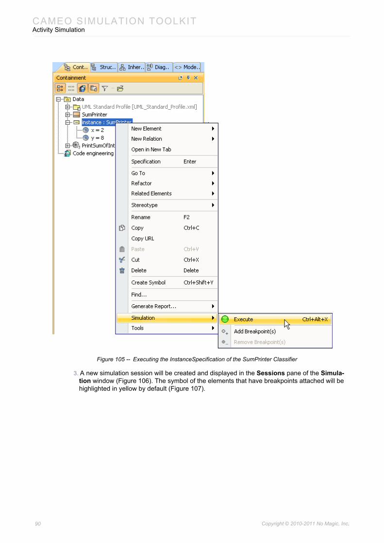
CAMEO SIMULATION TOOLKITActivity Simulation
Figure 105 -- Executing the InstanceSpecification of the SumPrinter Classifier
3. A new simulation session will be created and displayed in the Sessions pane of the Simula-tion window (Figure 106). The symbol of the elements that have breakpoints attached will be highlighted in yellow by default (Figure 107).
90 Copyright © 2010-2011 No Magic, Inc..
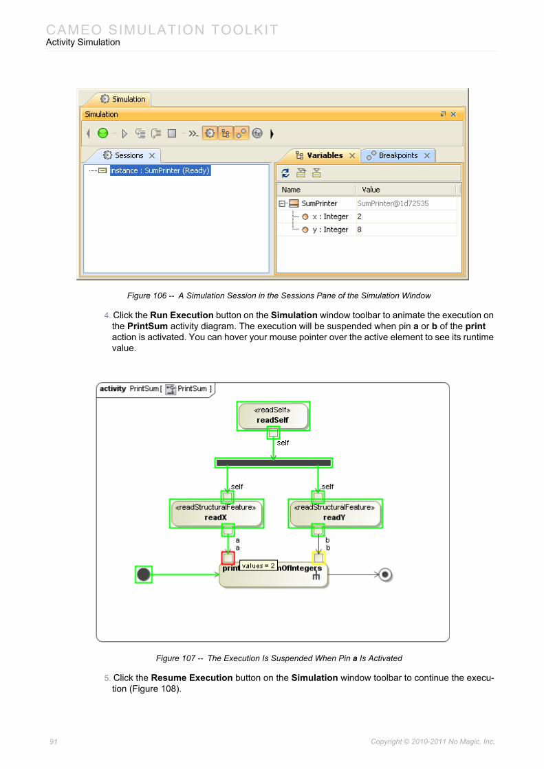
CAMEO SIMULATION TOOLKITActivity Simulation
Figure 106 -- A Simulation Session in the Sessions Pane of the Simulation Window
4. Click the Run Execution button on the Simulation window toolbar to animate the execution on the PrintSum activity diagram. The execution will be suspended when pin a or b of the print action is activated. You can hover your mouse pointer over the active element to see its runtime value.
Figure 107 -- The Execution Is Suspended When Pin a Is Activated
5. Click the Resume Execution button on the Simulation window toolbar to continue the execu-tion (Figure 108).
91 Copyright © 2010-2011 No Magic, Inc..
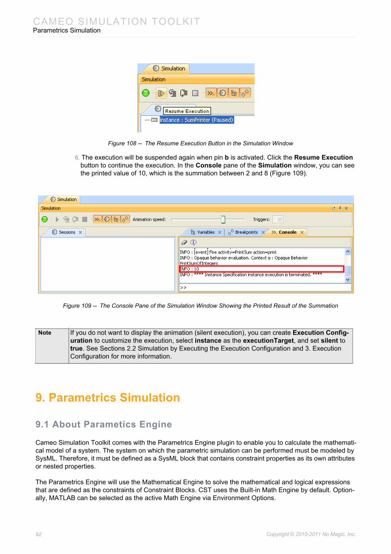
CAMEO SIMULATION TOOLKITParametrics Simulation
Figure 108 -- The Resume Execution Button in the Simulation Window
6. The execution will be suspended again when pin b is activated. Click the Resume Execution button to continue the execution. In the Console pane of the Simulation window, you can see the printed value of 10, which is the summation between 2 and 8 (Figure 109).
Figure 109 -- The Console Pane of the Simulation Window Showing the Printed Result of the Summation
9. Parametrics Simulation
9.1 About Parametics Engine
Cameo Simulation Toolkit comes with the Parametrics Engine plugin to enable you to calculate the mathemati-cal model of a system. The system on which the parametric simulation can be performed must be modeled by SysML. Therefore, it must be defined as a SysML block that contains constraint properties as its own attributes or nested properties.
The Parametrics Engine will use the Mathematical Engine to solve the mathematical and logical expressions that are defined as the constraints of Constraint Blocks. CST uses the Built-in Math Engine by default. Option-ally, MATLAB can be selected as the active Math Engine via Environment Options.
Note If you do not want to display the animation (silent execution), you can create Execution Config-uration to customize the execution, select instance as the executionTarget, and set silent to true. See Sections 2.2 Simulation by Executing the Execution Configuration and 3. Execution Configuration for more information.
92 Copyright © 2010-2011 No Magic, Inc..
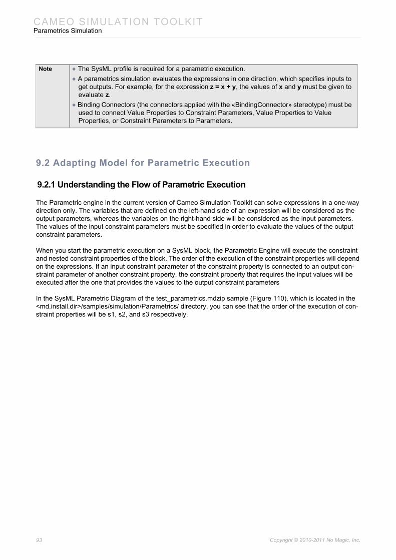
CAMEO SIMULATION TOOLKITParametrics Simulation
9.2 Adapting Model for Parametric Execution
9.2.1 Understanding the Flow of Parametric Execution
The Parametric engine in the current version of Cameo Simulation Toolkit can solve expressions in a one-way direction only. The variables that are defined on the left-hand side of an expression will be considered as the output parameters, whereas the variables on the right-hand side will be considered as the input parameters. The values of the input constraint parameters must be specified in order to evaluate the values of the output constraint parameters.
When you start the parametric execution on a SysML block, the Parametric Engine will execute the constraint and nested constraint properties of the block. The order of the execution of the constraint properties will depend on the expressions. If an input constraint parameter of the constraint property is connected to an output con-straint parameter of another constraint property, the constraint property that requires the input values will be executed after the one that provides the values to the output constraint parameters
In the SysML Parametric Diagram of the test_parametrics.mdzip sample (Figure 110), which is located in the <md.install.dir>/samples/simulation/Parametrics/ directory, you can see that the order of the execution of con-straint properties will be s1, s2, and s3 respectively.
Note • The SysML profile is required for a parametric execution.• A parametrics simulation evaluates the expressions in one direction, which specifies inputs to
get outputs. For example, for the expression z = x + y, the values of x and y must be given to evaluate z.
• Binding Connectors (the connectors applied with the «BindingConnector» stereotype) must be used to connect Value Properties to Constraint Parameters, Value Properties to Value Properties, or Constraint Parameters to Parameters.
93 Copyright © 2010-2011 No Magic, Inc..
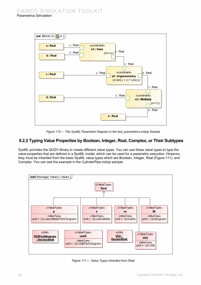
CAMEO SIMULATION TOOLKITParametrics Simulation
Figure 110 -- The SysML Parametric Diagram in the test_parametrics.mdzip Sample
9.2.2 Typing Value Properties by Boolean, Integer, Real, Complex, or Their Subtypes
SysML provides the QUDV library to create different value types. You can use these value types to type the value properties that are defined in a SysML model, which can be used for a parametric execution. However, they must be inherited from the basic SysML value types which are Boolean, Integer, Real (Figure 111), and Complex. You can see the example in the CylinderPipe.mdzip sample.
Figure 111 -- Value Types Inherited from Real
94 Copyright © 2010-2011 No Magic, Inc..
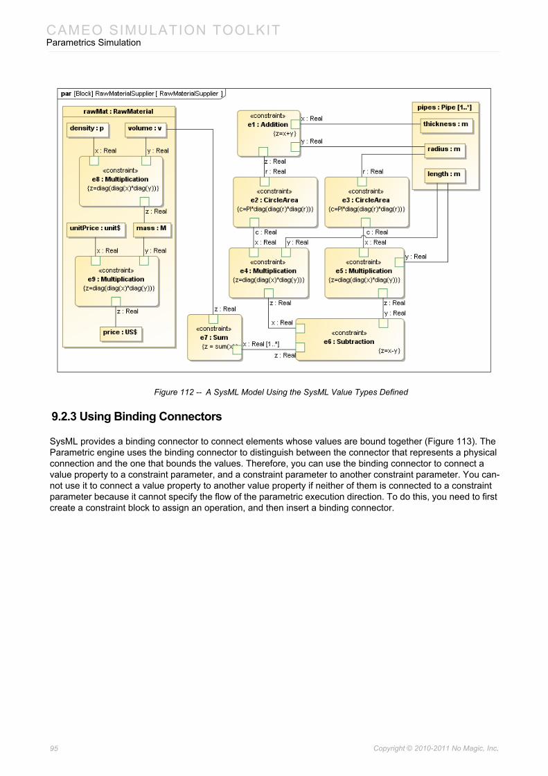
CAMEO SIMULATION TOOLKITParametrics Simulation
Figure 112 -- A SysML Model Using the SysML Value Types Defined
9.2.3 Using Binding Connectors
SysML provides a binding connector to connect elements whose values are bound together (Figure 113). The Parametric engine uses the binding connector to distinguish between the connector that represents a physical connection and the one that bounds the values. Therefore, you can use the binding connector to connect a value property to a constraint parameter, and a constraint parameter to another constraint parameter. You can-not use it to connect a value property to another value property if neither of them is connected to a constraint parameter because it cannot specify the flow of the parametric execution direction. To do this, you need to first create a constraint block to assign an operation, and then insert a binding connector.
95 Copyright © 2010-2011 No Magic, Inc..
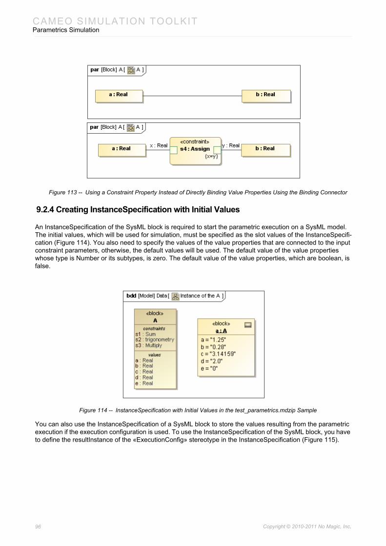
CAMEO SIMULATION TOOLKITParametrics Simulation
Figure 113 -- Using a Constraint Property Instead of Directly Binding Value Properties Using the Binding Connector
9.2.4 Creating InstanceSpecification with Initial Values
An InstanceSpecification of the SysML block is required to start the parametric execution on a SysML model. The initial values, which will be used for simulation, must be specified as the slot values of the InstanceSpecifi-cation (Figure 114). You also need to specify the values of the value properties that are connected to the input constraint parameters, otherwise, the default values will be used. The default value of the value properties whose type is Number or its subtypes, is zero. The default value of the value properties, which are boolean, is false.
Figure 114 -- InstanceSpecification with Initial Values in the test_parametrics.mdzip Sample
You can also use the InstanceSpecification of a SysML block to store the values resulting from the parametric execution if the execution configuration is used. To use the InstanceSpecification of the SysML block, you have to define the resultInstance of the «ExecutionConfig» stereotype in the InstanceSpecification (Figure 115).
96 Copyright © 2010-2011 No Magic, Inc..
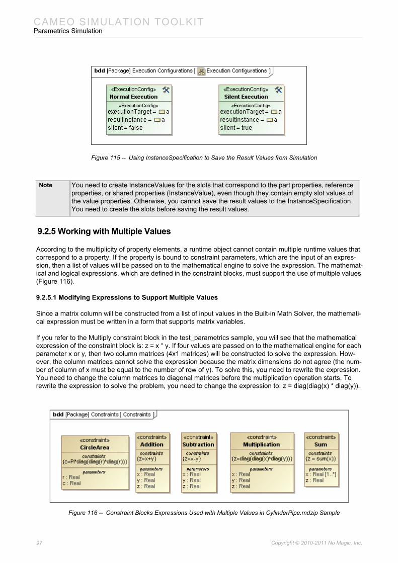
CAMEO SIMULATION TOOLKITParametrics Simulation
Figure 115 -- Using InstanceSpecification to Save the Result Values from Simulation
9.2.5 Working with Multiple Values
According to the multiplicity of property elements, a runtime object cannot contain multiple runtime values that correspond to a property. If the property is bound to constraint parameters, which are the input of an expres-sion, then a list of values will be passed on to the mathematical engine to solve the expression. The mathemat-ical and logical expressions, which are defined in the constraint blocks, must support the use of multiple values (Figure 116).
9.2.5.1 Modifying Expressions to Support Multiple Values
Since a matrix column will be constructed from a list of input values in the Built-in Math Solver, the mathemati-cal expression must be written in a form that supports matrix variables.
If you refer to the Multiply constraint block in the test_parametrics sample, you will see that the mathematical expression of the constraint block is: z = x * y. If four values are passed on to the mathematical engine for each parameter x or y, then two column matrices (4x1 matrices) will be constructed to solve the expression. How-ever, the column matrices cannot solve the expression because the matrix dimensions do not agree (the num-ber of column of x must be equal to the number of row of y). To solve this, you need to rewrite the expression. You need to change the column matrices to diagonal matrices before the multiplication operation starts. To rewrite the expression to solve the problem, you need to change the expression to: z = diag(diag(x) * diag(y)).
Figure 116 -- Constraint Blocks Expressions Used with Multiple Values in CylinderPipe.mdzip Sample
Note You need to create InstanceValues for the slots that correspond to the part properties, reference properties, or shared properties (InstanceValue), even though they contain empty slot values of the value properties. Otherwise, you cannot save the result values to the InstanceSpecification. You need to create the slots before saving the result values.
97 Copyright © 2010-2011 No Magic, Inc..
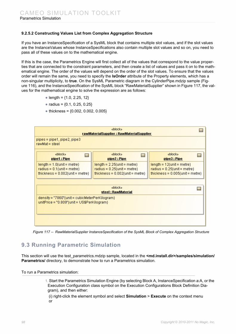
CAMEO SIMULATION TOOLKITParametrics Simulation
9.2.5.2 Constructing Values List from Complex Aggregation Structure
If you have an InstanceSpecification of a SysML block that contains multiple slot values, and if the slot values are the InstanceValues whose InstanceSpecifications also contain multiple slot values and so on, you need to pass all of these values on to the mathematical engine.
If this is the case, the Parametrics Engine will first collect all of the values that correspond to the value proper-ties that are connected to the constraint parameters, and then create a list of values and pass it on to the math-ematical engine. The order of the values will depend on the order of the slot values. To ensure that the values order will remain the same, you need to specify the IsOrder attribute of the Property elements, which has a non-singular multiplicity, to true. On the SysML Parametric diagram in the CylinderPipe.mdzip sample (Fig-ure 116), and the InstanceSpecification of the SysML block “RawMaterialSupplier” shown in Figure 117, the val-ues for the mathematical engine to solve the expression are as follows:
• length = {1.0, 2.25, 12}
• radius = {0.1, 0.25, 0.25}
• thickness = {0.002, 0.002, 0.005}
Figure 117 -- RawMaterialSupplier InstanceSpecification of the SysML Block of Complex Aggregation Structure
9.3 Running Parametric Simulation
This section will use the test_parametrics.mdzip sample, located in the <md.install.dir>/samples/simulation/Parametrics/ directory, to demonstrate how to run a Parametrics simulation.
To run a Parametrics simulation:
1. Start the Parametrics Simulation Engine (by selecting Block A, InstanceSpecification a:A, or the Execution Configuration class symbol on the Execution Configurations Block Definition Dia-gram), and then either:(i) right-click the element symbol and select Simulation > Execute on the context menuor
98 Copyright © 2010-2011 No Magic, Inc..
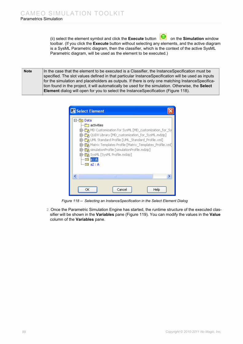
CAMEO SIMULATION TOOLKITParametrics Simulation
(ii) select the element symbol and click the Execute button on the Simulation window toolbar. (If you click the Execute button without selecting any elements, and the active diagram is a SysML Parametric diagram, then the classifier, which is the context of the active SysML Parametric diagram, will be used as the element to be executed.)
Figure 118 -- Selecting an InstanceSpecification in the Select Element Dialog
2. Once the Parametric Simulation Engine has started, the runtime structure of the executed clas-sifier will be shown in the Variables pane (Figure 119). You can modify the values in the Value column of the Variables pane.
Note In the case that the element to be executed is a Classifier, the InstanceSpecification must be specified. The slot values defined in that particular InstanceSpecification will be used as inputs for the simulation and placeholders as outputs. If there is only one matching InstanceSpecifica-tion found in the project, it will automatically be used for the simulation. Otherwise, the Select Element dialog will open for you to select the InstanceSpecification (Figure 118).
99 Copyright © 2010-2011 No Magic, Inc..
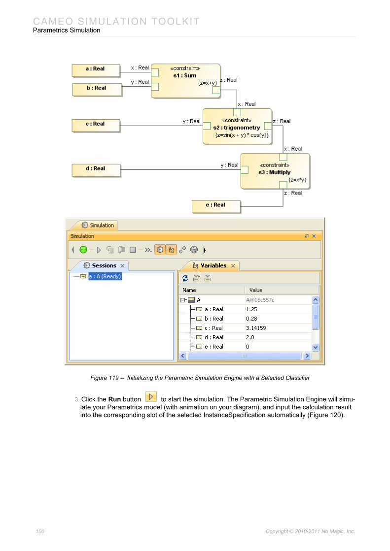
CAMEO SIMULATION TOOLKITParametrics Simulation
Figure 119 -- Initializing the Parametric Simulation Engine with a Selected Classifier
3. Click the Run button to start the simulation. The Parametric Simulation Engine will simu-late your Parametrics model (with animation on your diagram), and input the calculation result into the corresponding slot of the selected InstanceSpecification automatically (Figure 120).
100 Copyright © 2010-2011 No Magic, Inc..
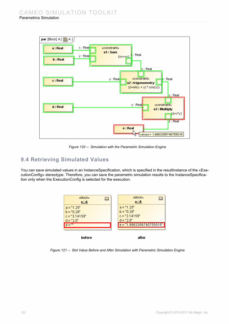
CAMEO SIMULATION TOOLKITParametrics Simulation
Figure 120 -- Simulation with the Parametric Simulation Engine
9.4 Retrieving Simulated Values
You can save simulated values in an InstanceSpecification, which is specified in the resultInstance of the «Exe-cutionConfig» stereotype. Therefore, you can save the parametric simulation results to the InstanceSpecifica-tion only when the ExecutionConfig is selected for the execution.
Figure 121 -- Slot Value Before and After Simulation with Parametric Simulation Engine
101 Copyright © 2010-2011 No Magic, Inc..
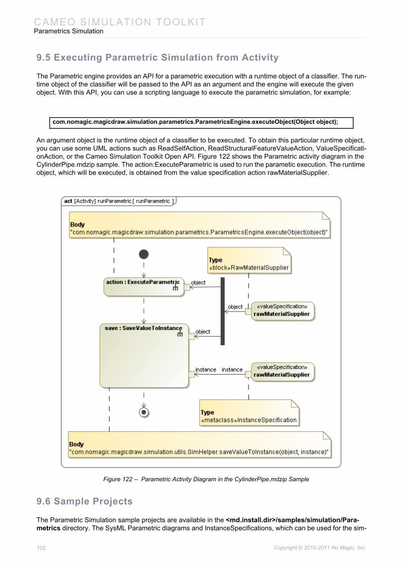
CAMEO SIMULATION TOOLKITParametrics Simulation
9.5 Executing Parametric Simulation from Activity
The Parametric engine provides an API for a parametric execution with a runtime object of a classifier. The run-time object of the classifier will be passed to the API as an argument and the engine will execute the given object. With this API, you can use a scripting language to execute the parametric simulation, for example:
An argument object is the runtime object of a classifier to be executed. To obtain this particular runtime object, you can use some UML actions such as ReadSelfAction, ReadStructuralFeatureValueAction, ValueSpecificati-onAction, or the Cameo Simulation Toolkit Open API. Figure 122 shows the Parametric activity diagram in the CylinderPipe.mdzip sample. The action:ExecuteParametric is used to run the parametic execution. The runtime object, which will be executed, is obtained from the value specification action rawMaterialSupplier.
Figure 122 -- Parametric Activity Diagram in the CylinderPipe.mdzip Sample
9.6 Sample Projects
The Parametric Simulation sample projects are available in the <md.install.dir>/samples/simulation/Para-metrics directory. The SysML Parametric diagrams and InstanceSpecifications, which can be used for the sim-
com.nomagic.magicdraw.simulation.parametrics.ParametricsEngine.executeObject(Object object);
102 Copyright © 2010-2011 No Magic, Inc..
CAMEO SIMULATION TOOLKITInteraction between Engines
ulation as described in Step 1of Section 9.2.5 Working with Multiple Values, are as follows:
(i) The test_parametrics.mdzip sample: Demonstrates a simple mathematical model of block A. (ii) The CylinderPipe.mdzip sample: Demonstrates how to deal with multiple values (see Section
9.2.5). It shows the calculation for the cost of raw materials that will be used to manufacture the cylinder pipes. It also demonstrates the use of OpaqueBehaviorAction to execute the paramet-ric.
(iii) The ActParIntegrate.mdzip sample: Demonstrates the use of OpaqueBehavior to execute the parametric.
(iv) TradeTransformModel.mdzip(v) Financial.mdzip(vi) SCARA manipulator.mdzip: Demonstrates the use of Parametric Simulation to evaluate the
position of end-effector of the SCARA manipulator from the given angles of actuators.
10. Interaction between EnginesYou can use all of the simulation engines at the same time. Here are some examples:
• A SendSignalAction can send a signal to a trigger transition on an active State Machine (using Activity Simulation to control State Machine Simulation). The Stopwatch sample gives the example of such collaboration.
• Activating a State can invoke an entry/do/exit Activity. The testDoActivity.mdzip and test_regions.mdzip samples gives the examples of such collaboration.
The Stopwatch sample will be further explained in details in the following section.
10.1 Stopwatch Sample
To execute and control the Stopwatch (see the StopWatch.mdzip sample), located in the <md.install.dir>/samples/simulation/StopWatch directory, you can either (10.1.1) manually handle the Stopwatch or (10.1.2) use an activity diagram.
10.1.1 Manual Execution
To execute and control the Stopwatch sample manually:
1. Open StopWatch.mdzip.2. Right-click the stopwatch_config ExectionConfig (in the Config Simulation Configuration Dia-
gram) and select Simulation > Execute on the context menu.3. Click the Run Execution button in the Simulation window to start the execution. The Stop-
watch mockup pane will open and the StopWatch will be at the “ready” state.4. Either (i) click the start button in the mockup pane, or (ii) select the context (StopWatch
[ready]) in the Variables pane, and then select the start signal from the Triggers: combo box in the Simulation window to initiate the timer. You can use the following buttons or signals in different states:
Note All of the sample projects of the Parametric Simulation Engine include the Execution Configura-tions package that contains two ExecutionConfig elements for normal and silent execution. You can select this ExecutionConfig class to start the Parametric Simulation Engine.
103 Copyright © 2010-2011 No Magic, Inc..
CAMEO SIMULATION TOOLKITRecording Signals to Sequence Diagram
• The stop button or signal will stop the timer when the current state is either running or paused.
• The reset button or signal will reset the timer to zero if the current state is stopped.
• The split button or signal will stop displaying the elapsed time, but the timer still runs in background, if the current state is running.
• The unsplit button will redisplay the elapsed time if the current state is paused.
10.1.2 Controlling Execution Using Activity Diagram
If you do not want to trigger events manually, you can model the events instead. Activity diagrams allow you to model a SendSignalActions sequence and send Signals to any target objects. Cameo Simulation Toolkit allows you to execute this particular activity and send the signals to other active Engines. Thus, whenever you start a State Machine simulation, the transitions will be automatically triggered.
To execute the Stopwatch sample and control it using an Activity diagram:
1. Open StopWatch.mdzip.2. Right-click the Stopwatch Testcase ExectionConfig (in the scenario Simulation Configuration
Diagram) and select Simulation > Execute on the context menu. 3. Click the Run Execution button in the Simulation window to start the execution. The Test-
case scenario Activity diagram will then be executed. Once the context created by the Create Object createObject is passed to the startObjectBehavior element, the Stopwatch mockup pane will open, and the state machine will start the simulation. You will see how the activity dia-gram is executed, each SendSignalAction will be highlighted in red; the transition will be trig-gered; and the StopWatch system will start, pause, or stop according to the signals sent by each SendSignalAction.
11. Recording Signals to Sequence DiagramThis section will use the StereoSystem.mdzip sample, located in the <md.install.dir>/samples/simulation/ directory, to demonstrate how to record signals to a sequence diagram.
During model execution, Cameo Simulation Toolkit can record all of the signals sent from a selected runtime object to a sequence diagram.
To record signals sent from a runtime object to a sequence diagram:
1. In the Variables pane, right-click the runtime object from which the signals to the sequence dia-gram will be sent and recorded.
2. Click Create Sequence Diagram from the context menu (Figure 123). An empty sequence dia-gram will be created.
Note You need to close all of the current project control windows before switching to another project, or close the project or MagicDraw to ensure that the tool is in proper working order.
104 Copyright © 2010-2011 No Magic, Inc..
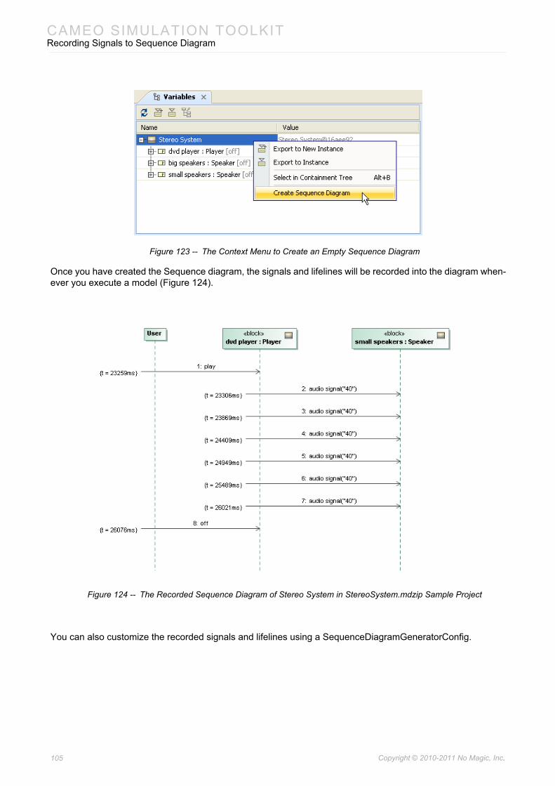
CAMEO SIMULATION TOOLKITRecording Signals to Sequence Diagram
Figure 123 -- The Context Menu to Create an Empty Sequence Diagram
Once you have created the Sequence diagram, the signals and lifelines will be recorded into the diagram when-ever you execute a model (Figure 124).
Figure 124 -- The Recorded Sequence Diagram of Stereo System in StereoSystem.mdzip Sample Project
You can also customize the recorded signals and lifelines using a SequenceDiagramGeneratorConfig.
105 Copyright © 2010-2011 No Magic, Inc..
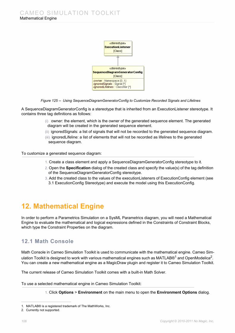
CAMEO SIMULATION TOOLKITMathematical Engine
Figure 125 -- Using SequenceDiagramGeneratorConfig to Customize Recorded Signals and Lifelines
A SequenceDiagramGeneratorConfig is a stereotype that is inherited from an ExecutionListener stereotype. It contains three tag definitions as follows:
(i) owner: the element, which is the owner of the generated sequence element. The generated diagram will be created in the generated sequence element.
(ii) ignoredSignals: a list of signals that will not be recorded to the generated sequence diagram.(iii) ignoredLifeline: a list of elements that will not be recorded as lifelines to the generated
sequence diagram.
To customize a generated sequence diagram:
1. Create a class element and apply a SequenceDiagramGeneratorConfig stereotype to it. 2. Open the Specification dialog of the created class and specify the value(s) of the tag definition
of the SequenceDiagramGeneratorConfig stereotype. 3. Add the created class to the values of the executionListeners of ExecutionConfig element (see
3.1 ExecutionConfig Stereotype) and execute the model using this ExecutionConfig.
12. Mathematical EngineIn order to perform a Parametrics Simulation on a SysML Parametrics diagram, you will need a Mathematical Engine to evaluate the mathematical and logical expressions defined in the Constraints of Constraint Blocks, which type the Constraint Properties on the diagram.
12.1 Math Console
Math Console in Cameo Simulation Toolkit is used to communicate with the mathematical engine. Cameo Sim-ulation Toolkit is designed to work with various mathematical engines such as MATLAB®1 and OpenModelica2. You can create a new mathematical engine as a MagicDraw plugin and register it to Cameo Simulation Toolkit.
The current release of Cameo Simulation Toolkit comes with a built-in Math Solver.
To use a selected mathematical engine in Cameo Simulation Toolkit:
1. Click Options > Environment on the main menu to open the Environment Options dialog.
1. MATLAB® is a registered trademark of The MathWorks, Inc. 2. Currently not supported.
106 Copyright © 2010-2011 No Magic, Inc..
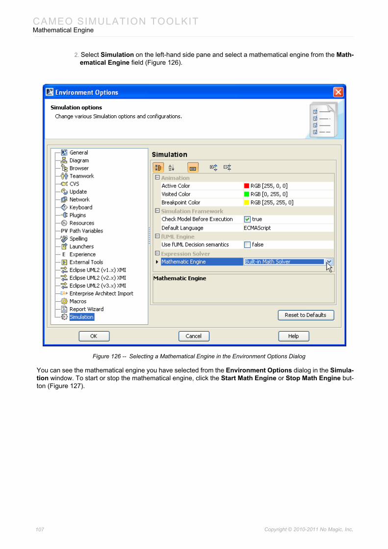
CAMEO SIMULATION TOOLKITMathematical Engine
2. Select Simulation on the left-hand side pane and select a mathematical engine from the Math-ematical Engine field (Figure 126).
Figure 126 -- Selecting a Mathematical Engine in the Environment Options Dialog
You can see the mathematical engine you have selected from the Environment Options dialog in the Simula-tion window. To start or stop the mathematical engine, click the Start Math Engine or Stop Math Engine but-ton (Figure 127).
107 Copyright © 2010-2011 No Magic, Inc..
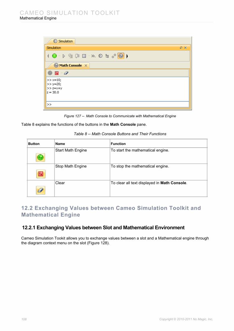
CAMEO SIMULATION TOOLKITMathematical Engine
Figure 127 -- Math Console to Communicate with Mathematical Engine
Table 8 explains the functions of the buttons in the Math Console pane.
Table 8 -- Math Console Buttons and Their Functions
12.2 Exchanging Values between Cameo Simulation Toolkit and Mathematical Engine
12.2.1 Exchanging Values between Slot and Mathematical Environment
Cameo Simulation Tookit allows you to exchange values between a slot and a Mathematical engine through the diagram context menu on the slot (Figure 128).
Button Name Function
Start Math Engine To start the mathematical engine.
Stop Math Engine To stop the mathematical engine.
Clear To clear all text displayed in Math Console.
108 Copyright © 2010-2011 No Magic, Inc..
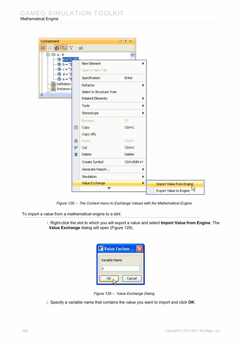
CAMEO SIMULATION TOOLKITMathematical Engine
Figure 128 -- The Context menu to Exchange Values with the Mathematical Engine
To import a value from a mathematical engine to a slot:
1. Right-click the slot to which you will export a value and select Import Value from Engine. The Value Exchange dialog will open (Figure 129).
Figure 129 -- Value Exchange Dialog
2. Specify a variable name that contains the value you want to import and click OK.
109 Copyright © 2010-2011 No Magic, Inc..
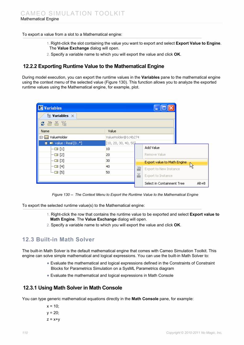
CAMEO SIMULATION TOOLKITMathematical Engine
To export a value from a slot to a Mathematical engine:
1. Right-click the slot containing the value you want to export and select Export Value to Engine. The Value Exchange dialog will open.
2. Specify a variable name to which you will export the value and click OK.
12.2.2 Exporting Runtime Value to the Mathematical Engine
During model execution, you can export the runtime values in the Variables pane to the mathematical engine using the context menu of the selected value (Figure 130). This function allows you to analyze the exported runtime values using the Mathematical engine, for example, plot.
Figure 130 -- The Context Menu to Export the Runtime Value to the Mathematical Engine
To export the selected runtime value(s) to the Mathematical engine:
1. Right-click the row that contains the runtime value to be exported and select Export value to Math Engine. The Value Exchange dialog will open.
2. Specify a variable name to which you will export the value and click OK.
12.3 Built-in Math Solver
The built-in Math Solver is the default mathematical engine that comes with Cameo Simulation Toolkit. This engine can solve simple mathematical and logical expressions. You can use the built-in Math Solver to:
• Evaluate the mathematical and logical expressions defined in the Constraints of Constraint Blocks for Parametrics Simulation on a SysML Parametrics diagram
• Evaluate the mathematical and logical expressions in Math Console
12.3.1 Using Math Solver in Math Console
You can type generic mathematical equations directly in the Math Console pane, for example:
x = 10;y = 20;z = x+y
110 Copyright © 2010-2011 No Magic, Inc..
CAMEO SIMULATION TOOLKITMathematical Engine
and z = 30 (the calculation result) will be displayed.
Or, if you type, for example, in Math Console:
a = true;b = false;c = a & b;
The calculation result (false) will be assigned to the variable c, but it will not be displayed in Math Console.
If an expression does not contain any assignment operators, the calculation result will be set to the variable 'ans'. For example:
x = 10;20 + x
ans = 30 will be displayed in Math Console.
You can calculate multiple expressions at the same time by typing a semicolon (;) at the end of each expres-sion, for example:
x = 10; y = 20; z = x+y; a = z / x
a = 3 will be displayed in Math Console.
12.3.2 Variables
The variables (operands) that can be used in the built-in Math Solver must conform to the following naming conventions:
• The characters in a variable name must be a-z, A-Z, or 0-9.
• The first character must not be a number.• Variable names must not be Constants (“E” or “PI”) • Variable names must not be Functions (“sqrt”, “sin”, “cos”).
• Variable names must not be Operators (“+”, “-”, “*”, “/”).
12.3.3 Values
The valid values that can be used in an expression are: (12.3.3.1) Real Number, (12.3.3.2) Complex Number, (12.3.3.3) Boolean, and (12.3.3.4) Matrix.
12.3.3.1 Real Numberx = 3.14159y = 2
12.3.3.2 Complex Numberc = 3 + 4id = 1.25 + 0.25i
Note The calculation results for expressions ended with a semicolon (;) will be set to the correspond-ing variables in the Math Solver environment. It will not be displayed in Math Console.
111 Copyright © 2010-2011 No Magic, Inc..
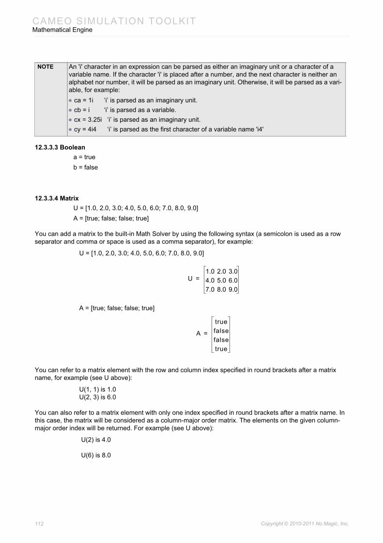
CAMEO SIMULATION TOOLKITMathematical Engine
12.3.3.3 Booleana = trueb = false
12.3.3.4 MatrixU = [1.0, 2.0, 3.0; 4.0, 5.0, 6.0; 7.0, 8.0, 9.0]A = [true; false; false; true]
You can add a matrix to the built-in Math Solver by using the following syntax (a semicolon is used as a row separator and comma or space is used as a comma separator), for example:
U = [1.0, 2.0, 3.0; 4.0, 5.0, 6.0; 7.0, 8.0, 9.0]
A = [true; false; false; true]
You can refer to a matrix element with the row and column index specified in round brackets after a matrix name, for example (see U above):
U(1, 1) is 1.0U(2, 3) is 6.0
You can also refer to a matrix element with only one index specified in round brackets after a matrix name. In this case, the matrix will be considered as a column-major order matrix. The elements on the given column-major order index will be returned. For example (see U above):
U(2) is 4.0
U(6) is 8.0
NOTE An 'i' character in an expression can be parsed as either an imaginary unit or a character of a variable name. If the character 'i' is placed after a number, and the next character is neither an alphabet nor number, it will be parsed as an imaginary unit. Otherwise, it will be parsed as a vari-able, for example:• ca = 1i ‘i’ is parsed as an imaginary unit.• cb = i ‘i’ is parsed as a variable.• cx = 3.25i ‘i’ is parsed as an imaginary unit.• cy = 4i4 ‘i’ is parsed as the first character of a variable name 'i4'
U1.0 2.0 3.04.0 5.0 6.07.0 8.0 9.0
=
A
truefalsefalsetrue
=
112 Copyright © 2010-2011 No Magic, Inc..
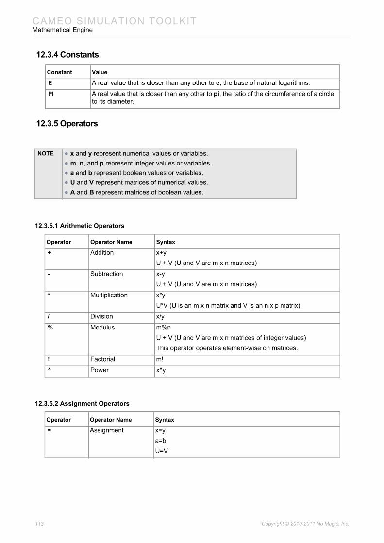
CAMEO SIMULATION TOOLKITMathematical Engine
12.3.4 Constants
12.3.5 Operators
12.3.5.1 Arithmetic Operators
12.3.5.2 Assignment Operators
Constant Value
E A real value that is closer than any other to e, the base of natural logarithms.
PI A real value that is closer than any other to pi, the ratio of the circumference of a circle to its diameter.
NOTE • x and y represent numerical values or variables.• m, n, and p represent integer values or variables.• a and b represent boolean values or variables.• U and V represent matrices of numerical values.• A and B represent matrices of boolean values.
Operator Operator Name Syntax
+ Addition x+yU + V (U and V are m x n matrices)
- Subtraction x-yU + V (U and V are m x n matrices)
* Multiplication x*yU*V (U is an m x n matrix and V is an n x p matrix)
/ Division x/y
% Modulus m%nU + V (U and V are m x n matrices of integer values)This operator operates element-wise on matrices.
! Factorial m!
^ Power x^y
Operator Operator Name Syntax
= Assignment x=ya=bU=V
113 Copyright © 2010-2011 No Magic, Inc..
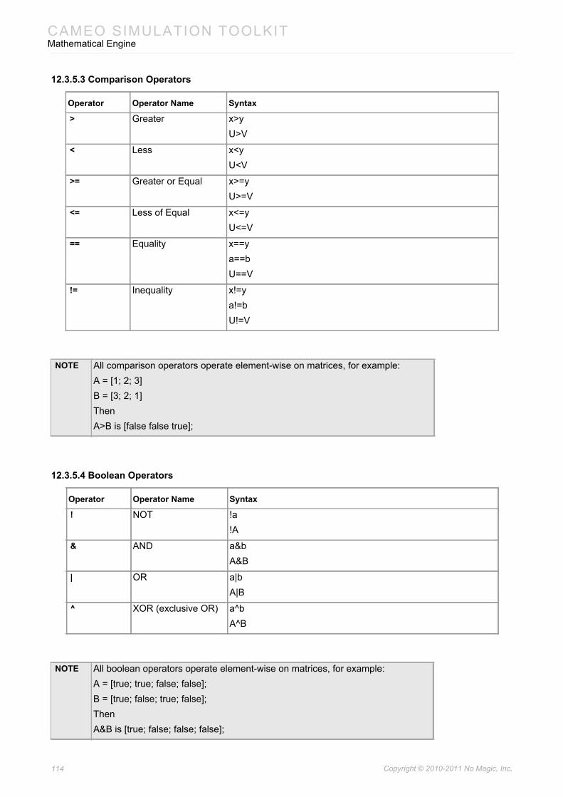
CAMEO SIMULATION TOOLKITMathematical Engine
12.3.5.3 Comparison Operators
12.3.5.4 Boolean Operators
Operator Operator Name Syntax
> Greater x>yU>V
< Less x<yU<V
>= Greater or Equal x>=yU>=V
<= Less of Equal x<=yU<=V
== Equality x==ya==bU==V
!= Inequality x!=ya!=bU!=V
NOTE All comparison operators operate element-wise on matrices, for example:A = [1; 2; 3]B = [3; 2; 1]ThenA>B is [false false true];
Operator Operator Name Syntax
! NOT !a!A
& AND a&bA&B
| OR a|bA|B
^ XOR (exclusive OR) a^bA^B
NOTE All boolean operators operate element-wise on matrices, for example:A = [true; true; false; false];B = [true; false; true; false];ThenA&B is [true; false; false; false];
114 Copyright © 2010-2011 No Magic, Inc..
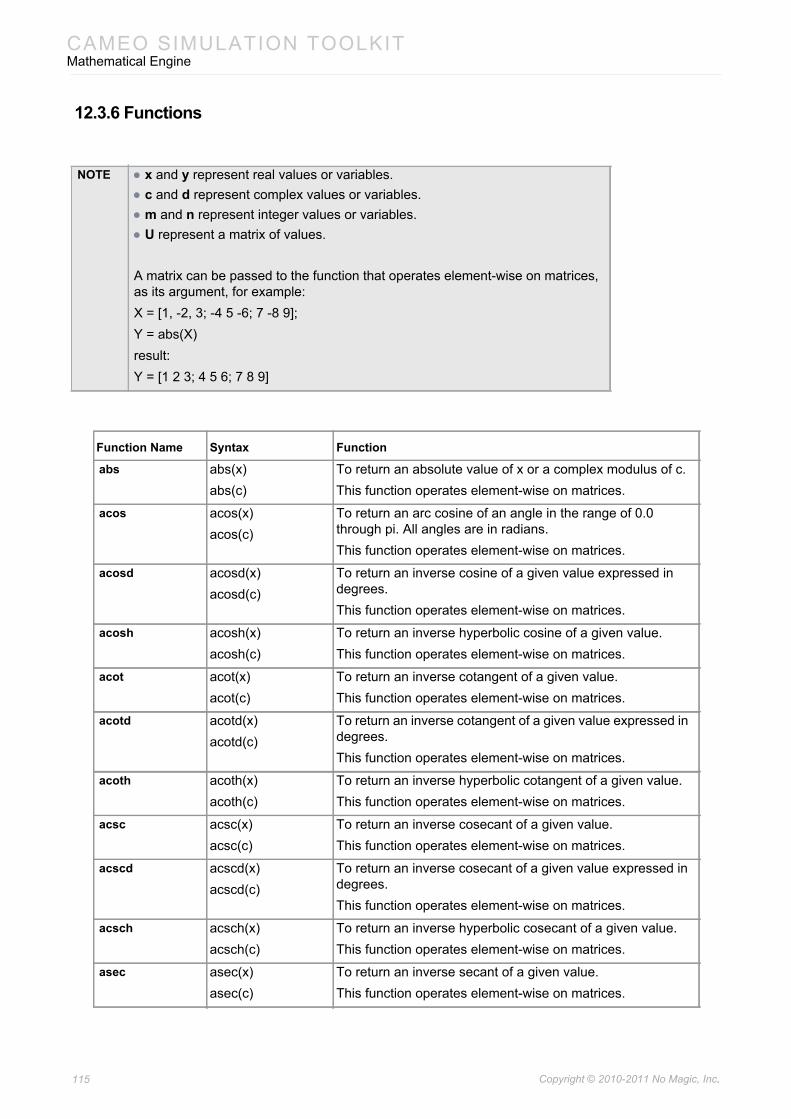
CAMEO SIMULATION TOOLKITMathematical Engine
12.3.6 Functions
NOTE • x and y represent real values or variables.• c and d represent complex values or variables.• m and n represent integer values or variables.• U represent a matrix of values.
A matrix can be passed to the function that operates element-wise on matrices, as its argument, for example:X = [1, -2, 3; -4 5 -6; 7 -8 9];Y = abs(X)result:Y = [1 2 3; 4 5 6; 7 8 9]
Function Name Syntax Function
abs abs(x)abs(c)
To return an absolute value of x or a complex modulus of c.This function operates element-wise on matrices.
acos acos(x)acos(c)
To return an arc cosine of an angle in the range of 0.0 through pi. All angles are in radians. This function operates element-wise on matrices.
acosd acosd(x)acosd(c)
To return an inverse cosine of a given value expressed in degrees.This function operates element-wise on matrices.
acosh acosh(x)acosh(c)
To return an inverse hyperbolic cosine of a given value.This function operates element-wise on matrices.
acot acot(x)acot(c)
To return an inverse cotangent of a given value.This function operates element-wise on matrices.
acotd acotd(x)acotd(c)
To return an inverse cotangent of a given value expressed in degrees.This function operates element-wise on matrices.
acoth acoth(x)acoth(c)
To return an inverse hyperbolic cotangent of a given value.This function operates element-wise on matrices.
acsc acsc(x)acsc(c)
To return an inverse cosecant of a given value.This function operates element-wise on matrices.
acscd acscd(x)acscd(c)
To return an inverse cosecant of a given value expressed in degrees.This function operates element-wise on matrices.
acsch acsch(x)acsch(c)
To return an inverse hyperbolic cosecant of a given value.This function operates element-wise on matrices.
asec asec(x)asec(c)
To return an inverse secant of a given value.This function operates element-wise on matrices.
115 Copyright © 2010-2011 No Magic, Inc..
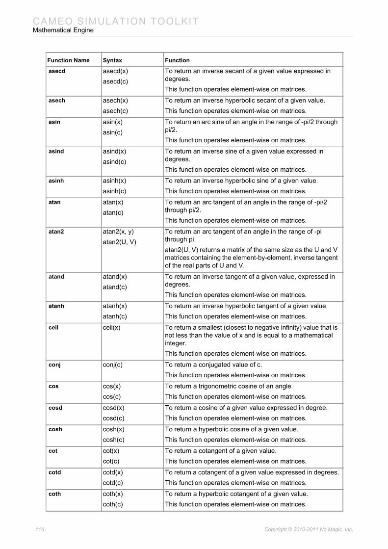
CAMEO SIMULATION TOOLKITMathematical Engine
asecd asecd(x)asecd(c)
To return an inverse secant of a given value expressed in degrees.This function operates element-wise on matrices.
asech asech(x)asech(c)
To return an inverse hyperbolic secant of a given value.This function operates element-wise on matrices.
asin asin(x)asin(c)
To return an arc sine of an angle in the range of -pi/2 through pi/2.This function operates element-wise on matrices.
asind asind(x)asind(c)
To return an inverse sine of a given value expressed in degrees.This function operates element-wise on matrices.
asinh asinh(x)asinh(c)
To return an inverse hyperbolic sine of a given value.This function operates element-wise on matrices.
atan atan(x)atan(c)
To return an arc tangent of an angle in the range of -pi/2 through pi/2.This function operates element-wise on matrices.
atan2 atan2(x, y)atan2(U, V)
To return an arc tangent of an angle in the range of -pi through pi.atan2(U, V) returns a matrix of the same size as the U and V matrices containing the element-by-element, inverse tangent of the real parts of U and V.
atand atand(x)atand(c)
To return an inverse tangent of a given value, expressed in degrees.This function operates element-wise on matrices.
atanh atanh(x)atanh(c)
To return an inverse hyperbolic tangent of a given value.This function operates element-wise on matrices.
ceil ceil(x) To return a smallest (closest to negative infinity) value that is not less than the value of x and is equal to a mathematical integer.This function operates element-wise on matrices.
conj conj(c) To return a conjugated value of c.This function operates element-wise on matrices.
cos cos(x)cos(c)
To return a trigonometric cosine of an angle.This function operates element-wise on matrices.
cosd cosd(x)cosd(c)
To return a cosine of a given value expressed in degree.This function operates element-wise on matrices.
cosh cosh(x)cosh(c)
To return a hyperbolic cosine of a given value.This function operates element-wise on matrices.
cot cot(x)cot(c)
To return a cotangent of a given value.This function operates element-wise on matrices.
cotd cotd(x)cotd(c)
To return a cotangent of a given value expressed in degrees.This function operates element-wise on matrices.
coth coth(x)coth(c)
To return a hyperbolic cotangent of a given value.This function operates element-wise on matrices.
Function Name Syntax Function
116 Copyright © 2010-2011 No Magic, Inc..
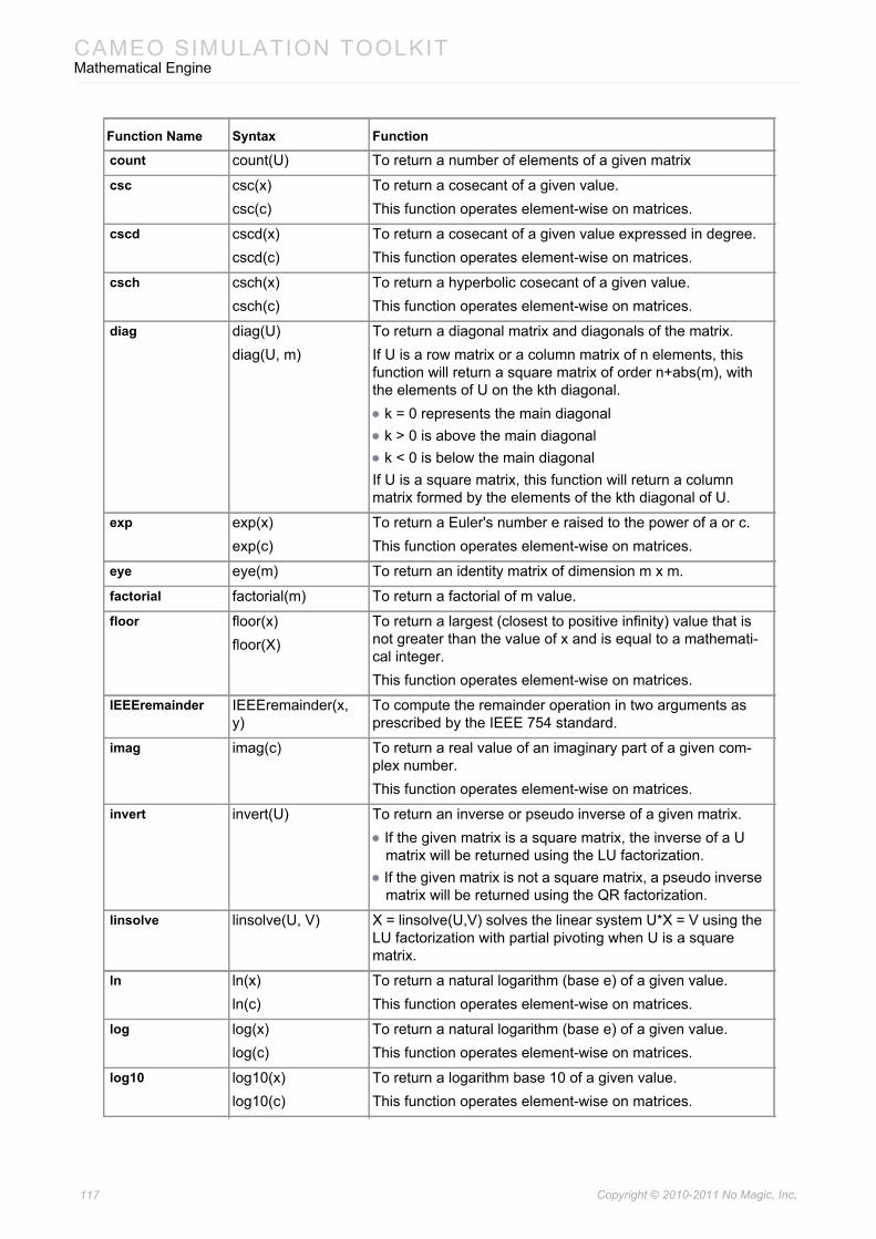
CAMEO SIMULATION TOOLKITMathematical Engine
count count(U) To return a number of elements of a given matrix
csc csc(x)csc(c)
To return a cosecant of a given value.This function operates element-wise on matrices.
cscd cscd(x)cscd(c)
To return a cosecant of a given value expressed in degree.This function operates element-wise on matrices.
csch csch(x)csch(c)
To return a hyperbolic cosecant of a given value.This function operates element-wise on matrices.
diag diag(U)diag(U, m)
To return a diagonal matrix and diagonals of the matrix.If U is a row matrix or a column matrix of n elements, this function will return a square matrix of order n+abs(m), with the elements of U on the kth diagonal. • k = 0 represents the main diagonal• k > 0 is above the main diagonal• k < 0 is below the main diagonalIf U is a square matrix, this function will return a column matrix formed by the elements of the kth diagonal of U.
exp exp(x)exp(c)
To return a Euler's number e raised to the power of a or c.This function operates element-wise on matrices.
eye eye(m) To return an identity matrix of dimension m x m.
factorial factorial(m) To return a factorial of m value.
floor floor(x)floor(X)
To return a largest (closest to positive infinity) value that is not greater than the value of x and is equal to a mathemati-cal integer.This function operates element-wise on matrices.
IEEEremainder IEEEremainder(x, y)
To compute the remainder operation in two arguments as prescribed by the IEEE 754 standard.
imag imag(c) To return a real value of an imaginary part of a given com-plex number.This function operates element-wise on matrices.
invert invert(U) To return an inverse or pseudo inverse of a given matrix.• If the given matrix is a square matrix, the inverse of a U
matrix will be returned using the LU factorization.• If the given matrix is not a square matrix, a pseudo inverse
matrix will be returned using the QR factorization.
linsolve linsolve(U, V) X = linsolve(U,V) solves the linear system U*X = V using the LU factorization with partial pivoting when U is a square matrix.
ln ln(x)ln(c)
To return a natural logarithm (base e) of a given value.This function operates element-wise on matrices.
log log(x)log(c)
To return a natural logarithm (base e) of a given value.This function operates element-wise on matrices.
log10 log10(x)log10(c)
To return a logarithm base 10 of a given value.This function operates element-wise on matrices.
Function Name Syntax Function
117 Copyright © 2010-2011 No Magic, Inc..
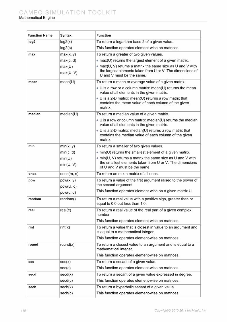
CAMEO SIMULATION TOOLKITMathematical Engine
log2 log2(x)log2(c)
To return a logarithm base 2 of a given value.This function operates element-wise on matrices.
max max(x, y)max(c, d)max(U)max(U, V)
To return a greater of two given values.• max(U) returns the largest element of a given matrix.• max(U, V) returns a matrix the same size as U and V with
the largest elements taken from U or V. The dimensions of U and V must be the same.
mean mean(U) To return a mean or average value of a given matrix.• U is a row or a column matrix: mean(U) returns the mean
value of all elements in the given matrix.• U is a 2-D matrix: mean(U) returns a row matrix that
contains the mean value of each column of the given matrix.
median median(U) To return a median value of a given matrix.• U is a row or column matrix: median(U) returns the median
value of all elements in the given matrix.• U is a 2-D matrix: median(U) returns a row matrix that
contains the median value of each column of the given matrix.
min min(x, y)min(c, d)min(U)min(U, V)
To return a smaller of two given values.• min(U) returns the smallest element of a given matrix.• min(U, V) returns a matrix the same size as U and V with
the smallest elements taken from U or V. The dimensions of U and V must be the same.
ones ones(m, n) To return an m x n matrix of all ones.
pow pow(x, y)pow(U, c)pow(c, d)
To return a value of the first argument raised to the power of the second argument.This function operates element-wise on a given matrix U.
random random() To return a real value with a positive sign, greater than or equal to 0.0 but less than 1.0.
real real(c) To return a real value of the real part of a given complex number.This function operates element-wise on matrices.
rint rint(x) To return a value that is closest in value to an argument and is equal to a mathematical integer.This function operates element-wise on matrices.
round round(x) To return a closest value to an argument and is equal to a mathematical integer.This function operates element-wise on matrices.
sec sec(x)sec(c)
To return a secant of a given value.This function operates element-wise on matrices.
secd secd(x)secd(c)
To return a secant of a given value expressed in degree.This function operates element-wise on matrices.
sech sech(x)sech(c)
To return a hyperbolic secant of a given value.This function operates element-wise on matrices.
Function Name Syntax Function
118 Copyright © 2010-2011 No Magic, Inc..
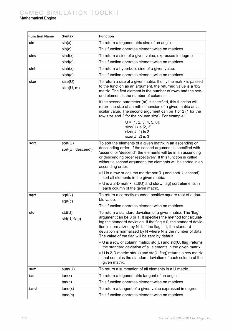
CAMEO SIMULATION TOOLKITMathematical Engine
sin sin(x)sin(c)
To return a trigonometric sine of an angle.This function operates element-wise on matrices.
sind sind(x)sind(c)
To return a sine of a given value, expressed in degreeThis function operates element-wise on matrices.
sinh sinh(x)sinh(c)
To return a hyperbolic sine of a given value.This function operates element-wise on matrices.
size size(U)size(U, m)
To return a size of a given matrix. If only the matrix is passed to the function as an argument, the returned value is a 1x2 matrix. The first element is the number of rows and the sec-ond element is the number of columns.If the second parameter (m) is specified, this function will return the size of an mth dimension of a given matrix as a scalar value. The second argument can be 1 or 2 (1 for the row size and 2 for the column size). For example:
U = [1, 2, 3; 4, 5, 6];size(U) is [2, 3]size(U, 1) is 2size(U, 2) is 3
sort sort(U)sort(U, ‘descend’)
To sort the elements of a given matrix in an ascending or descending order. If the second argument is specified with ‘ascend’ or ‘descend’, the elements will be in an ascending or descending order respectively. If this function is called without a second argument, the elements will be sorted in an ascending order.• U is a row or column matrix: sort(U) and sort(U, ascend)
sort all elements in the given matrix.• U is a 2-D matrix: std(U) and std(U,flag) sort elements in
each column of the given matrix.
sqrt sqrt(x)sqrt(c)
To return a correctly rounded positive square root of a dou-ble value.This function operates element-wise on matrices.
std std(U)std(U, flag)
To return a standard deviation of a given matrix. The ’flag’ argument can be 0 or 1. It specifies the method for calculat-ing the standard deviation. If the flag = 0, the standard devia-tion is normalized by N-1. If the flag = 1, the standard deviation is normalized by N where N is the number of data. The value of the flag will be zero by default.• U is a row or column matrix: std(U) and std(U, flag) returns
the standard deviation of all elements in the given matrix.• U is 2-D matrix: std(U) and std(U,flag) returns a row matrix
that contains the standard deviation of each column of the given matrix.
sum sum(U) To return a summation of all elements in a U matrix.
tan tan(x)tan(c)
To return a trigonometric tangent of an angle.This function operates element-wise on matrices.
tand tand(x)tand(c)
To return a tangent of a given value expressed in degree.This function operates element-wise on matrices.
Function Name Syntax Function
119 Copyright © 2010-2011 No Magic, Inc..
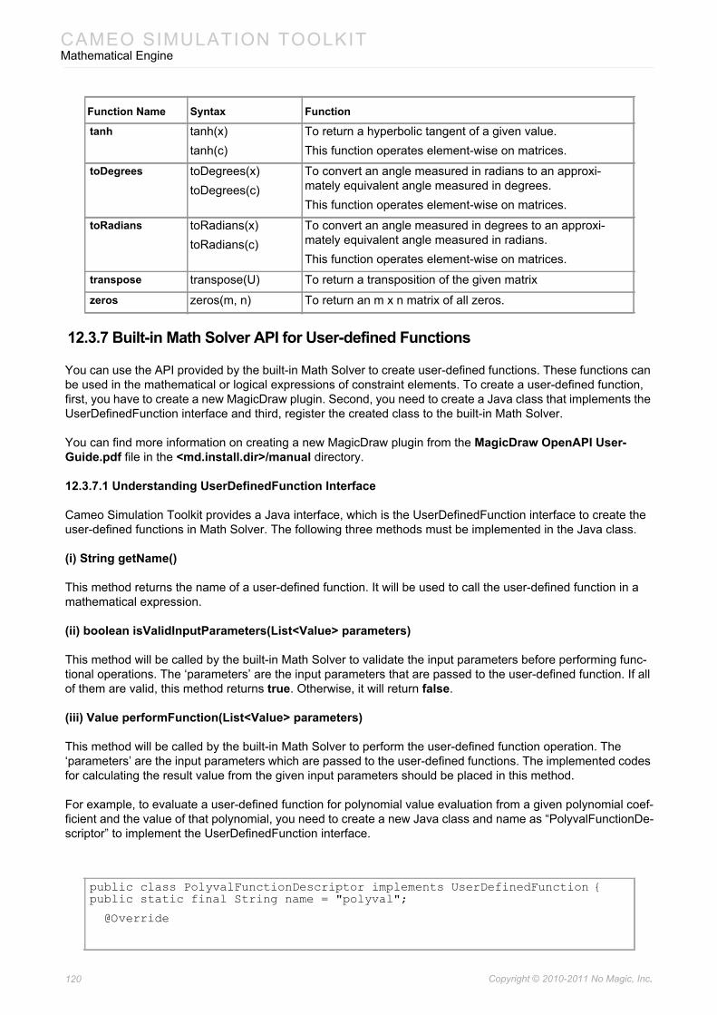
CAMEO SIMULATION TOOLKITMathematical Engine
12.3.7 Built-in Math Solver API for User-defined Functions
You can use the API provided by the built-in Math Solver to create user-defined functions. These functions can be used in the mathematical or logical expressions of constraint elements. To create a user-defined function, first, you have to create a new MagicDraw plugin. Second, you need to create a Java class that implements the UserDefinedFunction interface and third, register the created class to the built-in Math Solver.
You can find more information on creating a new MagicDraw plugin from the MagicDraw OpenAPI User-Guide.pdf file in the <md.install.dir>/manual directory.
12.3.7.1 Understanding UserDefinedFunction Interface
Cameo Simulation Toolkit provides a Java interface, which is the UserDefinedFunction interface to create the user-defined functions in Math Solver. The following three methods must be implemented in the Java class.
(i) String getName()
This method returns the name of a user-defined function. It will be used to call the user-defined function in a mathematical expression.
(ii) boolean isValidInputParameters(List<Value> parameters)
This method will be called by the built-in Math Solver to validate the input parameters before performing func-tional operations. The ‘parameters’ are the input parameters that are passed to the user-defined function. If all of them are valid, this method returns true. Otherwise, it will return false.
(iii) Value performFunction(List<Value> parameters)
This method will be called by the built-in Math Solver to perform the user-defined function operation. The ‘parameters’ are the input parameters which are passed to the user-defined functions. The implemented codes for calculating the result value from the given input parameters should be placed in this method.
For example, to evaluate a user-defined function for polynomial value evaluation from a given polynomial coef-ficient and the value of that polynomial, you need to create a new Java class and name as “PolyvalFunctionDe-scriptor” to implement the UserDefinedFunction interface.
tanh tanh(x)tanh(c)
To return a hyperbolic tangent of a given value.This function operates element-wise on matrices.
toDegrees toDegrees(x)toDegrees(c)
To convert an angle measured in radians to an approxi-mately equivalent angle measured in degrees.This function operates element-wise on matrices.
toRadians toRadians(x)toRadians(c)
To convert an angle measured in degrees to an approxi-mately equivalent angle measured in radians.This function operates element-wise on matrices.
transpose transpose(U) To return a transposition of the given matrix
zeros zeros(m, n) To return an m x n matrix of all zeros.
public class PolyvalFunctionDescriptor implements UserDefinedFunction {public static final String name = "polyval";
@Override
Function Name Syntax Function
120 Copyright © 2010-2011 No Magic, Inc..
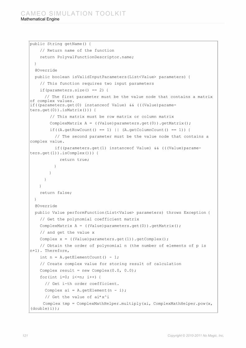
CAMEO SIMULATION TOOLKITMathematical Engine
public String getName() {
// Return name of the function
return PolyvalFunctionDescriptor.name;
}
@Override
public boolean isValidInputParameters(List<Value> parameters) {
// This function requires two input parameters
if(parameters.size() == 2) {
// The first parameter must be the value node that contains a matrix of complex values.if((parameters.get(0) instanceof Value) && (((Value)parame-ters.get(0)).isMatrix())) {
// This matrix must be row matrix or column matrix
ComplexMatrix A = ((Value)parameters.get(0)).getMatrix();
if((A.getRowCount() == 1) || (A.getColumnCount() == 1)) {
// The second parameter must be the value node that contains a complex value.
if((parameters.get(1) instanceof Value) && (((Value)parame-ters.get(1)).isComplex())) {
return true;
}
}
}
}
return false;
}
@Override
public Value performFunction(List<Value> parameters) throws Exception {
// Get the polynomial coefficient matrix
ComplexMatrix A = ((Value)parameters.get(0)).getMatrix();
// and get the value x
Complex x = ((Value)parameters.get(1)).getComplex();
// Obtain the order of polynomial n (the number of elements of p is n+1). Therefore,
int n = A.getElementCount() - 1;
// Create complex value for storing result of calculation
Complex result = new Complex(0.0, 0.0);
for(int i=0; i<=n; i++) {
// Get i-th order coefficient.
Complex ai = A.getElement(n - i);
// Get the value of ai*x^i
Complex tmp = ComplexMathHelper.multiply(ai, ComplexMathHelper.pow(x, (double)i));
121 Copyright © 2010-2011 No Magic, Inc..
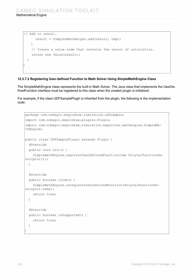
CAMEO SIMULATION TOOLKITMathematical Engine
12.3.7.2 Registering User-defined Function to Math Solver Using SimpleMathEngine Class
The SimpleMathEngine class represents the built-in Math Solver. The Java class that implements the UserDe-finedFunction interface must be registered to this class when the created plugin is initialized.
For example, if the class UDFSamplePlugin is inherited from the plugin, the following is the implementation code:
// Add to result.
result = ComplexMathHelper.add(result, tmp);
}
// Create a value node that contains the result of calculation.
return new Value(result);
}
}
package com.nomagic.magicdraw.simulation.udfsample;
import com.nomagic.magicdraw.plugins.Plugin;
import com.nomagic.magicdraw.simulation.expsolver.mathengine.SimpleMa-thEngine;
public class UDFSamplePlugin extends Plugin {
@Override
public void init() {
SimpleMathEngine.registerUserDefinedFunction(new PolyvalFunctionDe-scriptor());
}
@Override
public boolean close() {
SimpleMathEngine.unregisterUserDefinedFunction(PolyvalFunctionDe-scriptor.name);
return true;
}
@Override
public boolean isSupported() {
return true;
}
}
122 Copyright © 2010-2011 No Magic, Inc..
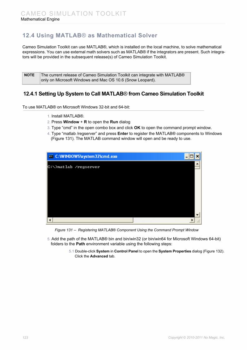
CAMEO SIMULATION TOOLKITMathematical Engine
12.4 Using MATLAB® as Mathematical Solver
Cameo Simulation Toolkit can use MATLAB®, which is installed on the local machine, to solve mathematical expressions. You can use external math solvers such as MATLAB® if the integrators are present. Such integra-tors will be provided in the subsequent release(s) of Cameo Simulation Toolkit.
12.4.1 Setting Up System to Call MATLAB® from Cameo Simulation Toolkit
To use MATLAB® on Microsoft Windows 32-bit and 64-bit:
1. Install MATLAB®.2. Press Window + R to open the Run dialog 3. Type “cmd” in the open combo box and click OK to open the command prompt window.4. Type “matlab /regserver” and press Enter to register the MATLAB® components to Windows
(Figure 131). The MATLAB command window will open and be ready to use.
Figure 131 -- Registering MATLAB® Component Using the Command Prompt Window
5. Add the path of the MATLAB® bin and bin/win32 (or bin/win64 for Microsoft Windows 64-bit) folders to the Path environment variable using the following steps:
5.1 Double-click System in Control Panel to open the System Properties dialog (Figure 132). Click the Advanced tab.
NOTE The current release of Cameo Simulation Toolkit can integrate with MATLAB® only on Microsoft Windows and Mac OS 10.6 (Snow Leopard).
123 Copyright © 2010-2011 No Magic, Inc..
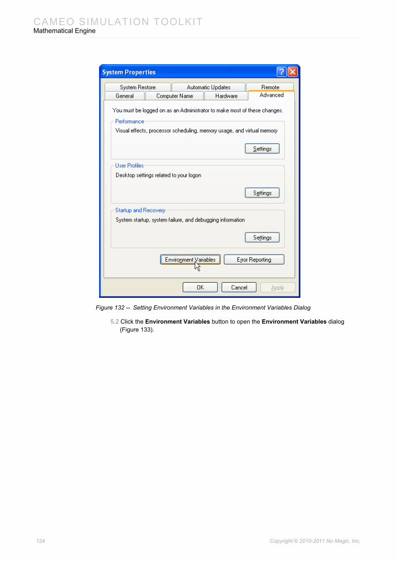
CAMEO SIMULATION TOOLKITMathematical Engine
Figure 132 -- Setting Environment Variables in the Environment Variables Dialog
5.2 Click the Environment Variables button to open the Environment Variables dialog (Figure 133).
124 Copyright © 2010-2011 No Magic, Inc..
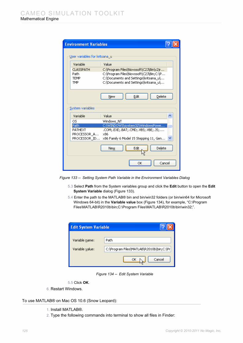
CAMEO SIMULATION TOOLKITMathematical Engine
Figure 133 -- Setting System Path Variable in the Environment Variables Dialog
5.3 Select Path from the System variables group and click the Edit button to open the Edit System Variable dialog (Figure 133).
5.4 Enter the path to the MATLAB® bin and bin/win32 folders (or bin/win64 for Microsoft Windows 64-bit) in the Variable value box (Figure 134), for example, “C:\Program Files\MATLAB\R2010b\bin;C:\Program Files\MATLAB\R2010b\bin\win32;”.
Figure 134 -- Edit System Variable
5.5 Click OK.
6. Restart Windows.
To use MATLAB® on Mac OS 10.6 (Snow Leopard):
1. Install MATLAB®.2. Type the following commands into terminal to show all files in Finder:
125 Copyright © 2010-2011 No Magic, Inc..
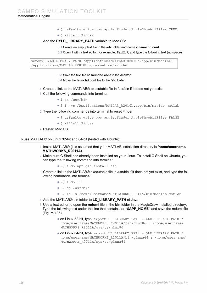
CAMEO SIMULATION TOOLKITMathematical Engine
• $ defaults write com.apple.finder AppleShowAllFiles TRUE
• $ killall Finder
3. Add the DYLD_LIBRARY_PATH variable to Mac OS:
3.1 Create an empty text file in the /etc folder and name it: launchd.conf.3.2 Open it with a text editor, for example, TextEdit, and type the following text (no space):
3.3 Save the text file as launchd.conf to the desktop.
3.4 Move the launchd.conf file to the /etc folder.
4. Create a link to the MATLAB® executable file in /usr/bin if it does not yet exist.5. Call the following commands into terminal:
• $ cd /usr/bin
• $ ln -s /Applications/MATLAB_R2010b.app/bin/matlab matlab
6. Type the following commands into terminal to reset Finder:
• $ defaults write com.apple.finder AppleShowAllFiles FALSE
• $ killall Finder
7. Restart Mac OS.
To use MATLAB® on Linux 32-bit and 64-bit (tested with Ubuntu):
1. Install MATLAB® (it is assumed that your MATLAB installation directory is /home/username/MATHWORKS_R2011A).
2. Make sure C Shell has already been installed on your Linux. To install C Shell on Ubuntu, you can type the following command into terminal:
• ~$ sudo apt-get install csh
3. Create a link to the MATLAB® executable file in /usr/bin if it does not yet exist, and type the fol-lowing commands into terminal:
• ~$ sudo -i
• ~$ cd /usr/bin
• ~$ ln -s /home/username/MATHWORKS_R2011A/bin/matlab matlab
4. Add the MATLAB® bin folder to LD_LIBRARY_PATH of Java.5. Use a text editor to open the mduml file in the bin folder in the MagicDraw installed directory.
Type the following text under the line that contains cd “$APP_HOME” and save the mduml file (Figure 135):
• on Linux 32-bit, type: export LD_LIBRARY_PATH = $LD_LIBRARY_PATH:/home/username/MATHWORKS_R2011A/bin/glnx86 : /home/username/MATHWORKS_R2011A/sys/os/glnx86
• on Linux 64-bit, type: export LD_LIBRARY_PATH = $LD_LIBRARY_PATH:/home/username/MATHWORKS_R2011A/bin/glnxa64 : /home/username/MATHWORKS_R2011A/sys/os/glnxa64
setenv DYLD_LIBRARY_PATH /Applications/MATLAB_R2010b.app/bin/maci64: /Applications/MATLAB_R2010b.app/runtime/maci64
126 Copyright © 2010-2011 No Magic, Inc..
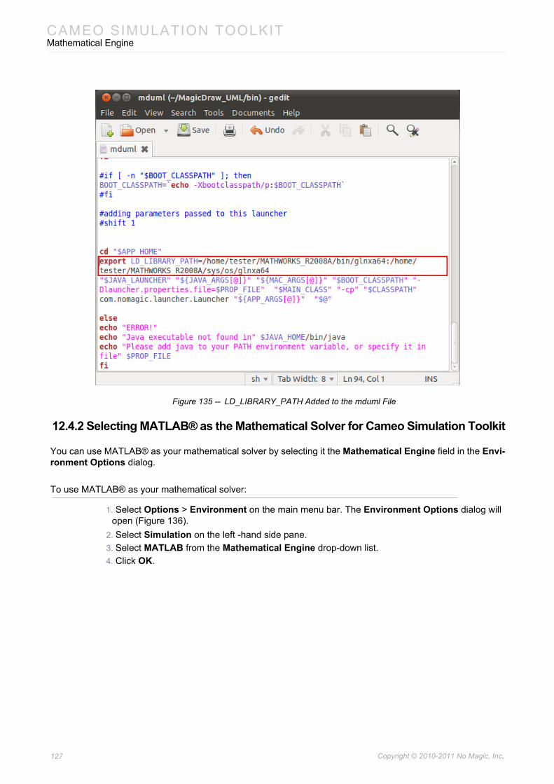
CAMEO SIMULATION TOOLKITMathematical Engine
Figure 135 -- LD_LIBRARY_PATH Added to the mduml File
12.4.2 Selecting MATLAB® as the Mathematical Solver for Cameo Simulation Toolkit
You can use MATLAB® as your mathematical solver by selecting it the Mathematical Engine field in the Envi-ronment Options dialog.
To use MATLAB® as your mathematical solver:
1. Select Options > Environment on the main menu bar. The Environment Options dialog will open (Figure 136).
2. Select Simulation on the left -hand side pane.3. Select MATLAB from the Mathematical Engine drop-down list.4. Click OK.
127 Copyright © 2010-2011 No Magic, Inc..
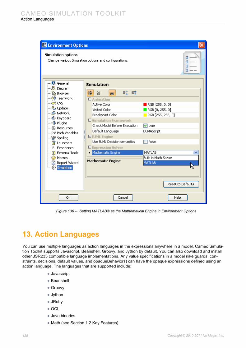
CAMEO SIMULATION TOOLKITAction Languages
Figure 136 -- Setting MATLAB® as the Mathematical Engine in Environment Options
13. Action LanguagesYou can use multiple languages as action languages in the expressions anywhere in a model. Cameo Simula-tion Toolkit supports Javascript, Beanshell, Groovy, and Jython by default. You can also download and install other JSR233 compatible language implementations. Any value specifications in a model (like guards, con-straints, decisions, default values, and opaqueBehaviors) can have the opaque expressions defined using an action language. The languages that are supported include:
• Javascript
• Beanshell
• Groovy
• Jython
• JRuby
• OCL
• Java binaries
• Math (see Section 1.2 Key Features)
128 Copyright © 2010-2011 No Magic, Inc..

CAMEO SIMULATION TOOLKITAction Languages
• Other additional downloadable JSR-223 script engines (see http://scripting.dev.java.net/)
129 Copyright © 2010-2011 No Magic, Inc..
Related Documents


![Simulation of Emergency Response Operations for a Static … · software suite named Computer-Aided Management of Emergency Operations (CAMEO) [2]. CAMEO is a system of software applications](https://static.cupdf.com/doc/110x72/5f431958c978194b5a3d1edd/simulation-of-emergency-response-operations-for-a-static-software-suite-named-computer-aided.jpg)


