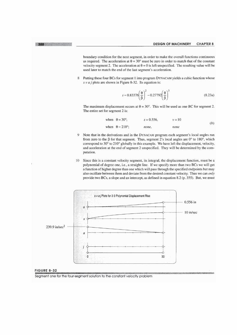
8.0 INTRODUCTION Cam-follower systems are frequently used in all kinds of machines. The valves in your automobile engine are opened by cams. Machines used in the manufacture of many con- sumer goods are full of cams. Compared to linkages, cams are easier to design to give a specific output function, but they are much more difficult and expensive to make than a linkage. Cams are a form of degenerate fourbar linkage in which the coupler link has been replaced by a half joint as shown in Figure 8-1. This topic was discussed in Sec- tion 2.9 (p. 40) on linkage transformation (see also Figure 2-10, p. 41). For anyone in- stantaneous position of earn and follower, we can substitute an effective linkage which will, for that instantaneous position, have the same motion as the original. In effect, the earn-follower is a fourbar linkage with variable-length (effective) links. It is this con- ceptual difference that makes the earn-follower such a flexible and useful function gen- erator. We can specify virtually any output function we desire and quite likely create a curved surface on the earn to generate that function in the motion of the follower. We are not limited to fixed-length links as we were in linkage synthesis. The earn-follower is an extremely useful mechanical device, without which the machine designer's tasks would be more difficult to accomplish. But, as with everything else in engineering, there are trade-offs. These will be discussed in later sections. A list of the variables used in this chapter is provided in Table 8-1. This chapter will present the proper approach to designing a earn-follower system, and in the process also present some less than proper designs as examples of the prob- lems which inexperienced earn designers often get into. Theoretical considerations of the mathematical functions commonly used for earn curves will be discussed. Methods for the derivation of custom polynomial functions, to suit any set of boundary conditions, will be presented. The task of sizing the earn with considerations of pressure angle and radius of curvature will be addressed, and manufacturing processes and their limitations

Welcome message from author
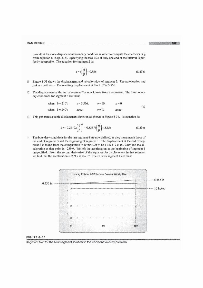
This document is posted to help you gain knowledge. Please leave a comment to let me know what you think about it! Share it to your friends and learn new things together.
Transcript
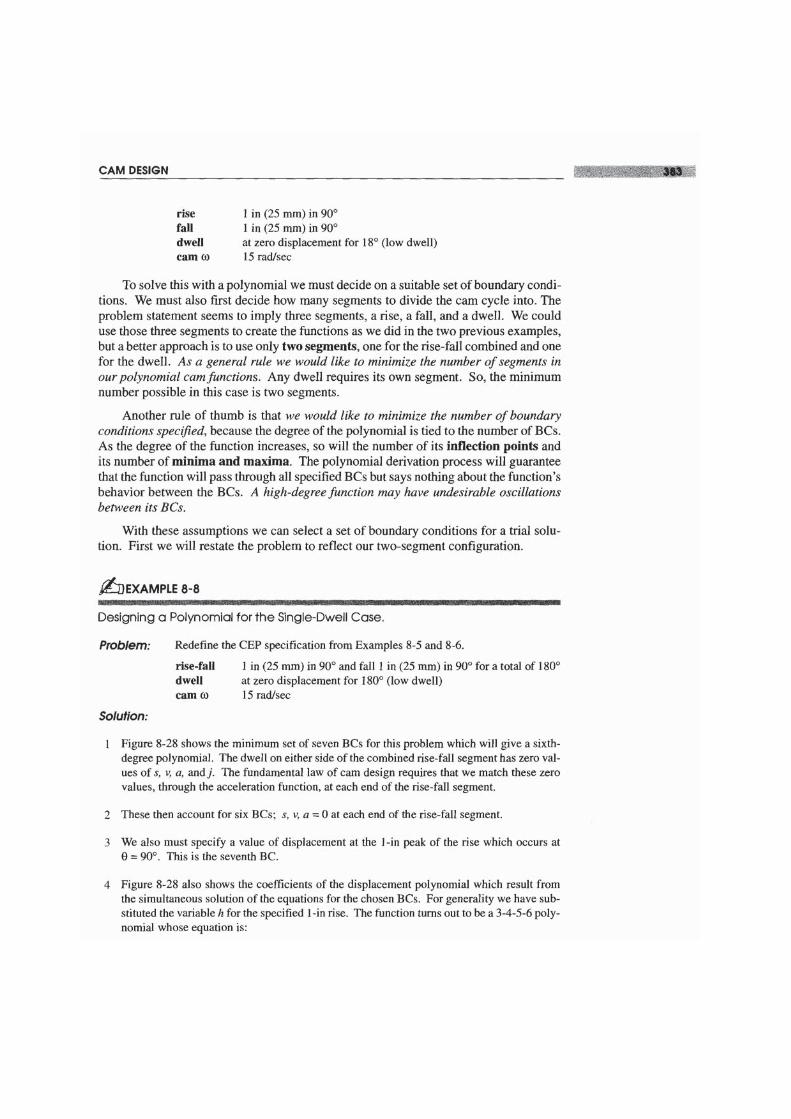
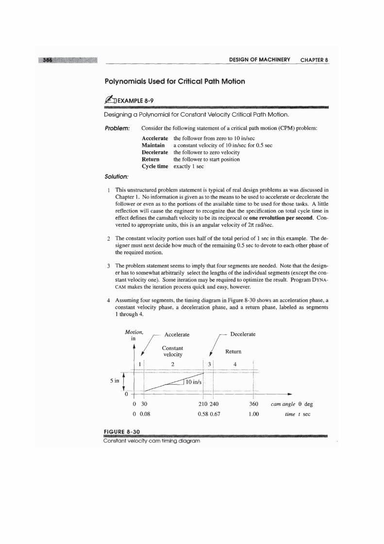
8.0 INTRODUCTION
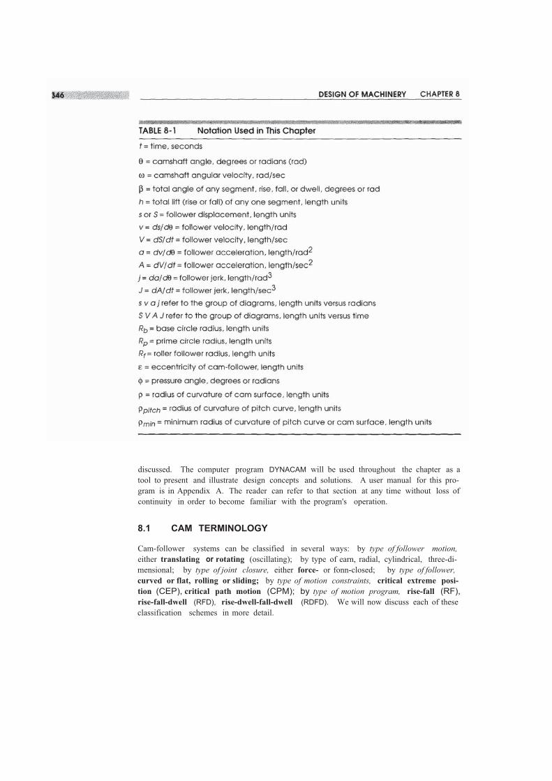
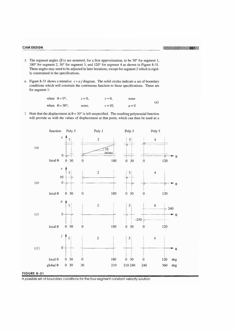
Cam-follower systems are frequently used in all kinds of machines. The valves in yourautomobile engine are opened by cams. Machines used in the manufacture of many con-sumer goods are full of cams. Compared to linkages, cams are easier to design to give aspecific output function, but they are much more difficult and expensive to make than alinkage. Cams are a form of degenerate fourbar linkage in which the coupler link hasbeen replaced by a half joint as shown in Figure 8-1. This topic was discussed in Sec-tion 2.9 (p. 40) on linkage transformation (see also Figure 2-10, p. 41). For anyone in-stantaneous position of earn and follower, we can substitute an effective linkage whichwill, for that instantaneous position, have the same motion as the original. In effect, theearn-follower is a fourbar linkage with variable-length (effective) links. It is this con-ceptual difference that makes the earn-follower such a flexible and useful function gen-erator. We can specify virtually any output function we desire and quite likely create acurved surface on the earn to generate that function in the motion of the follower. Weare not limited to fixed-length links as we were in linkage synthesis. The earn-followeris an extremely useful mechanical device, without which the machine designer's taskswould be more difficult to accomplish. But, as with everything else in engineering, thereare trade-offs. These will be discussed in later sections. A list of the variables used inthis chapter is provided in Table 8-1.
This chapter will present the proper approach to designing a earn-follower system,and in the process also present some less than proper designs as examples of the prob-lems which inexperienced earn designers often get into. Theoretical considerations ofthe mathematical functions commonly used for earn curves will be discussed. Methodsfor the derivation of custom polynomial functions, to suit any set of boundary conditions,will be presented. The task of sizing the earn with considerations of pressure angle andradius of curvature will be addressed, and manufacturing processes and their limitations
discussed. The computer program DYNACAM will be used throughout the chapter as atool to present and illustrate design concepts and solutions. A user manual for this pro-gram is in Appendix A. The reader can refer to that section at any time without loss ofcontinuity in order to become familiar with the program's operation.
8.1 CAM TERMINOLOGY
Cam-follower systems can be classified in several ways: by type of follower motion,either translating or rotating (oscillating); by type of earn, radial, cylindrical, three-di-mensional; by type of joint closure, either force- or fonn-closed; by type of follower,curved or flat, rolling or sliding; by type of motion constraints, critical extreme posi-tion (CEP), critical path motion (CPM); by type of motion program, rise-fall (RF),rise-fall-dwell (RFD), rise-dwell-fall-dwell (RDFD). We will now discuss each of theseclassification schemes in more detail.
Type of Follower Motion
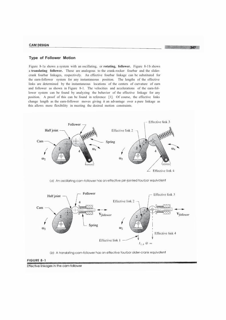
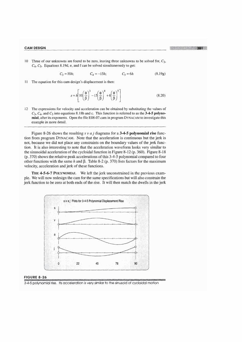
Figure 8-1a shows a system with an oscillating, or rotating, follower. Figure 8-1b showsa translating follower. These are analogous to the crank-rocker fourbar and the slider-crank fourbar linkages, respectively. An effective fourbar linkage can be substituted forthe earn-follower system for any instantaneous position. The lengths of the effectivelinks are determined by the instantaneous locations of the centers of curvature of earnand follower as shown in Figure 8-1. The velocities and accelerations of the earn-fol-lower system can be found by analyzing the behavior of the effective linkage for anyposition. A proof of this can be found in reference [1]. Of course, the effective linkschange length as the earn-follower moves giving it an advantage over a pure linkage asthis allows more flexibility in meeting the desired motion constraints.
The choice between these two forms of the earn-follower is usually dictated by thetype of output motion desired. If true rectilinear translation is required, then the trans-lating follower is dictated. If pure rotation output is needed, then the oscillator is theobvious choice. There are advantages to each of these approaches, separate from theirmotion characteristics, depending on the type of follower chosen. These will be dis-cussed in a later section.
Type of Joint Closure
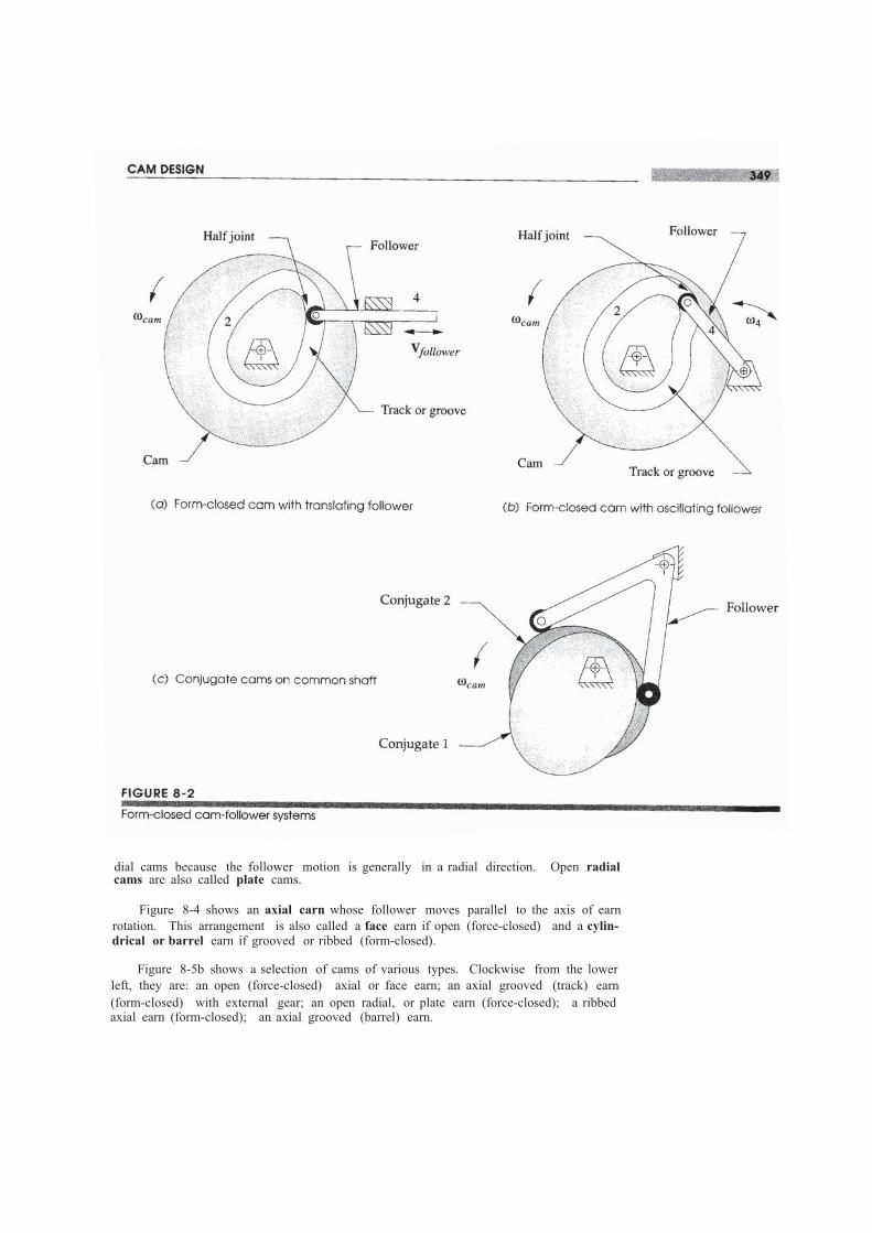
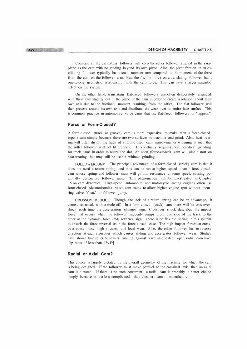
Force and form closure were discussed in Section 2.3 (p. 24) on the subject of jointsand have the same meaning here. Force closure, as shown in Figure 8-1 (p. 347), re-quires an external force be applied to the joint in order to keep the two links, cam andfollower, physically in contact. This force is usually provided by a spring. This force,defined as positive in a direction which closes the joint, cannot be allowed to becomenegative. If it does, the links have lost contact because aforce-closed joint can only push,not pull. Form closure, as shown in Figure 8-2, closes the joint by geometry. No exter-nal force is required. There are really two earn surfaces in this arrangement, one surfaceon each side of the follower. Each surface pushes, in its turn, to drive the follower inboth directions.
Figure 8-2a and b shows track or groove cams which capture a single follower inthe groove and both push and pull on the follower. Figure 8-2c shows another variety ofform-closed earn-follower arrangement, called conjugate cams. There are two camsfixed on a common shaft which are mathematical conjugates of one another. Two rollerfollowers, attached to a common arm, are each pushed in opposite directions by the con-jugate cams. When form-closed cams are used in automobile or motorcycle engine valvetrains, they are called desmodromic cams. There are advantages and disadvantages toboth force- and form-closed arrangements which will be discussed in a later section.
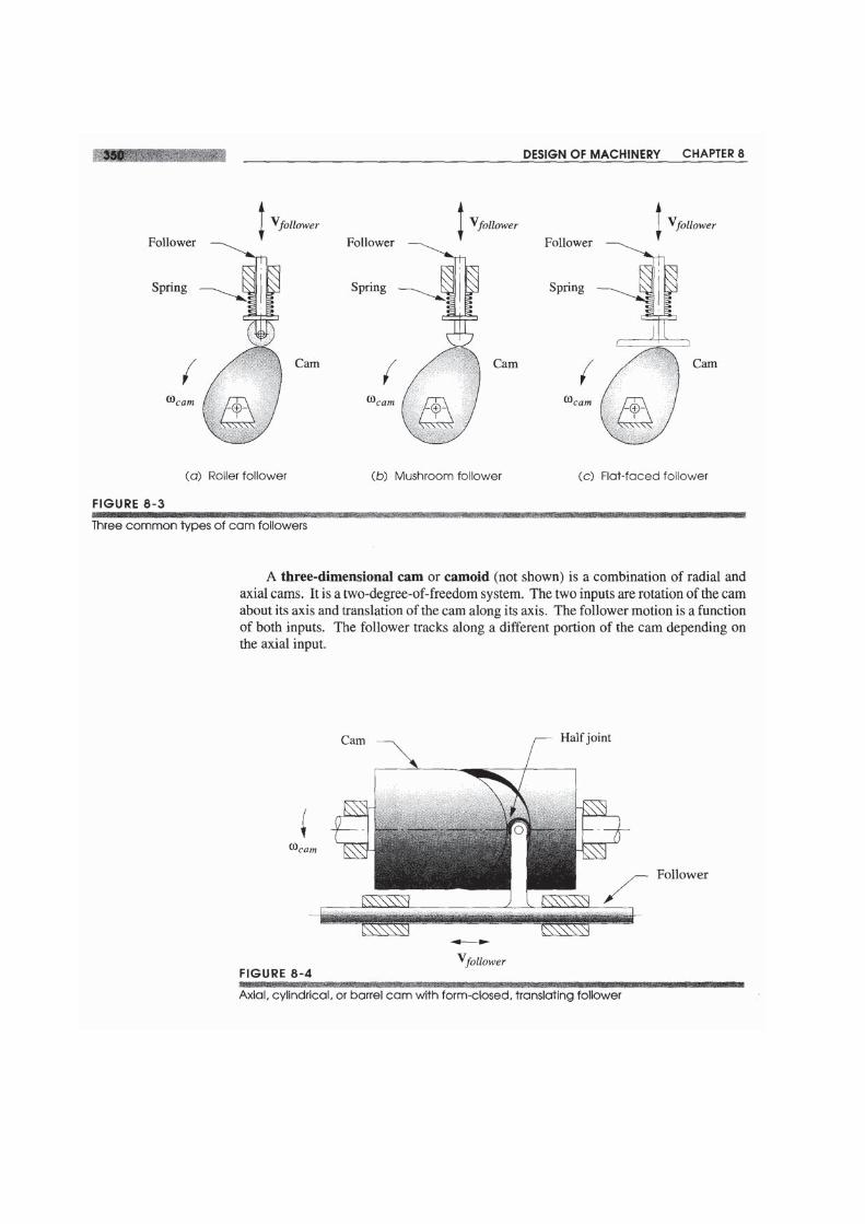
Type of Follower
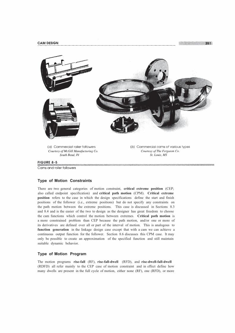
Follower, in this context, refers only to that part of the follower link which contacts theearn. Figure 8-3 shows three common arrangements, flat-faced, mushroom (curved),and roller. The roller follower has the advantage of lower (rolling) friction than the slid-ing contact of the other two but can be more expensive. Flat-faced followers can pack-age smaller than roller followers for some earn designs and are often favored for thatreason as well as cost for automotive valve trains. Roller followers are more frequentlyused in production machinery where their ease of replacement and availability from bear-ing manufacturers' stock in any quantities are advantages. Grooved or track cams requireroller followers. Roller followers are essentially ball or roller bearings with customizedmounting details. Figure 8-5a shows two common types of commercial roller follow-ers. Flat-faced or mushroom followers are usually custom designed and manufacturedfor each application. For high-volume applications such as automobile engines, thequantities are high enough to warrant a custom-designed follower.
Type of Cam
The direction of the follower's motion relative to the axis of rotation of the earn deter-mines whether it is a radial or axial earn. All cams shown in Figures 8-1 to 8-3 are ra-
dial cams because the follower motion is generally in a radial direction. Open radialcams are also called plate cams.
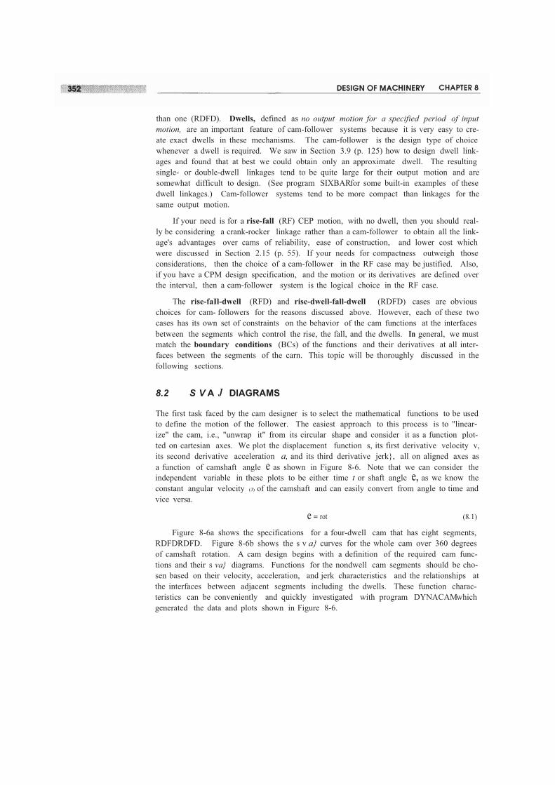
Figure 8-4 shows an axial carn whose follower moves parallel to the axis of earnrotation. This arrangement is also called a face earn if open (force-closed) and a cylin-drical or barrel earn if grooved or ribbed (form-closed).
Figure 8-5b shows a selection of cams of various types. Clockwise from the lowerleft, they are: an open (force-closed) axial or face earn; an axial grooved (track) earn(form-closed) with external gear; an open radial, or plate earn (force-closed); a ribbedaxial earn (form-closed); an axial grooved (barrel) earn.
Type of Motion Constraints
There are two general categories of motion constraint, critical extreme position (CEP;also called endpoint specification) and critical path motion (CPM). Critical extremeposition refers to the case in which the design specifications define the start and finishpositions of the follower (i.e., extreme positions) but do not specify any constraints onthe path motion between the extreme positions. This case is discussed in Sections 8.3and 8.4 and is the easier of the two to design as the designer has great freedom to choosethe cam functions which control the motion between extremes. Critical path motion isa more constrained problem than CEP because the path motion, and/or one or more ofits derivatives are defined over all or part of the interval of motion. This is analogous tofunction generation in the linkage design case except that with a cam we can achieve acontinuous output function for the follower. Section 8.6 discusses this CPM case. It mayonly be possible to create an approximation of the specified function and still maintainsuitable dynamic behavior.
Type of Motion Program
The motion programs rise-fall (RF), rise-fall-dwell (RFD), and rise-dwell-fall-dwell(RDFD) all refer mainly to the CEP case of motion constraint and in effect define howmany dwells are present in the full cycle of motion, either none (RF), one (RFD), or more
than one (RDFD). Dwells, defined as no output motion for a specified period of inputmotion, are an important feature of cam-follower systems because it is very easy to cre-ate exact dwells in these mechanisms. The cam-follower is the design type of choicewhenever a dwell is required. We saw in Section 3.9 (p. 125) how to design dwell link-ages and found that at best we could obtain only an approximate dwell. The resultingsingle- or double-dwell linkages tend to be quite large for their output motion and aresomewhat difficult to design. (See program SIXBARfor some built-in examples of thesedwell linkages.) Cam-follower systems tend to be more compact than linkages for thesame output motion.
If your need is for a rise-fall (RF) CEP motion, with no dwell, then you should real-ly be considering a crank-rocker linkage rather than a cam-follower to obtain all the link-age's advantages over cams of reliability, ease of construction, and lower cost whichwere discussed in Section 2.15 (p. 55). If your needs for compactness outweigh thoseconsiderations, then the choice of a cam-follower in the RF case may be justified. Also,if you have a CPM design specification, and the motion or its derivatives are defined overthe interval, then a cam-follower system is the logical choice in the RF case.
The rise-faIl-dwell (RFD) and rise-dwell-fall-dwell (RDFD) cases are obviouschoices for cam- followers for the reasons discussed above. However, each of these twocases has its own set of constraints on the behavior of the cam functions at the interfacesbetween the segments which control the rise, the fall, and the dwells. In general, we mustmatch the boundary conditions (BCs) of the functions and their derivatives at all inter-faces between the segments of the carn. This topic will be thoroughly discussed in thefollowing sections.
8.2 S V A J DIAGRAMS
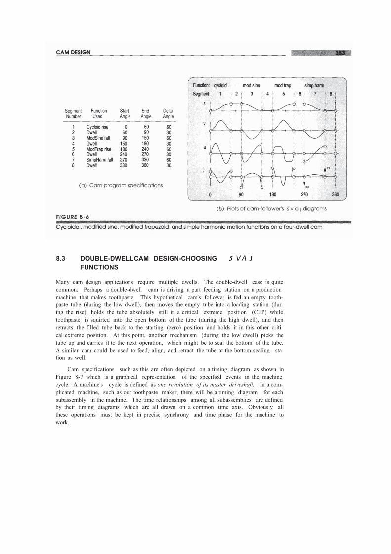
The first task faced by the cam designer is to select the mathematical functions to be usedto define the motion of the follower. The easiest approach to this process is to "linear-ize" the cam, i.e., "unwrap it" from its circular shape and consider it as a function plot-ted on cartesian axes. We plot the displacement function s, its first derivative velocity v,its second derivative acceleration a, and its third derivative jerk}, all on aligned axes asa function of camshaft angle e as shown in Figure 8-6. Note that we can consider theindependent variable in these plots to be either time t or shaft angle e, as we know theconstant angular velocity (J) of the camshaft and can easily convert from angle to time andvice versa.
e = rot (8.1)
Figure 8-6a shows the specifications for a four-dwell cam that has eight segments,RDFDRDFD. Figure 8-6b shows the s v a} curves for the whole cam over 360 degreesof camshaft rotation. A cam design begins with a definition of the required cam func-tions and their s va} diagrams. Functions for the nondwell cam segments should be cho-sen based on their velocity, acceleration, and jerk characteristics and the relationships atthe interfaces between adjacent segments including the dwells. These function charac-teristics can be conveniently and quickly investigated with program DYNACAMwhichgenerated the data and plots shown in Figure 8-6.
8.3 DOUBLE-DWELLCAM DESIGN-CHOOSING 5 VA JFUNCTIONS
Many cam design applications require multiple dwells. The double-dwell case is quitecommon. Perhaps a double-dwell cam is driving a part feeding station on a productionmachine that makes toothpaste. This hypothetical cam's follower is fed an empty tooth-paste tube (during the low dwell), then moves the empty tube into a loading station (dur-ing the rise), holds the tube absolutely still in a critical extreme position (CEP) whiletoothpaste is squirted into the open bottom of the tube (during the high dwell), and thenretracts the filled tube back to the starting (zero) position and holds it in this other criti-cal extreme position. At this point, another mechanism (during the low dwell) picks thetube up and carries it to the next operation, which might be to seal the bottom of the tube.A similar cam could be used to feed, align, and retract the tube at the bottom-sealing sta-tion as well.
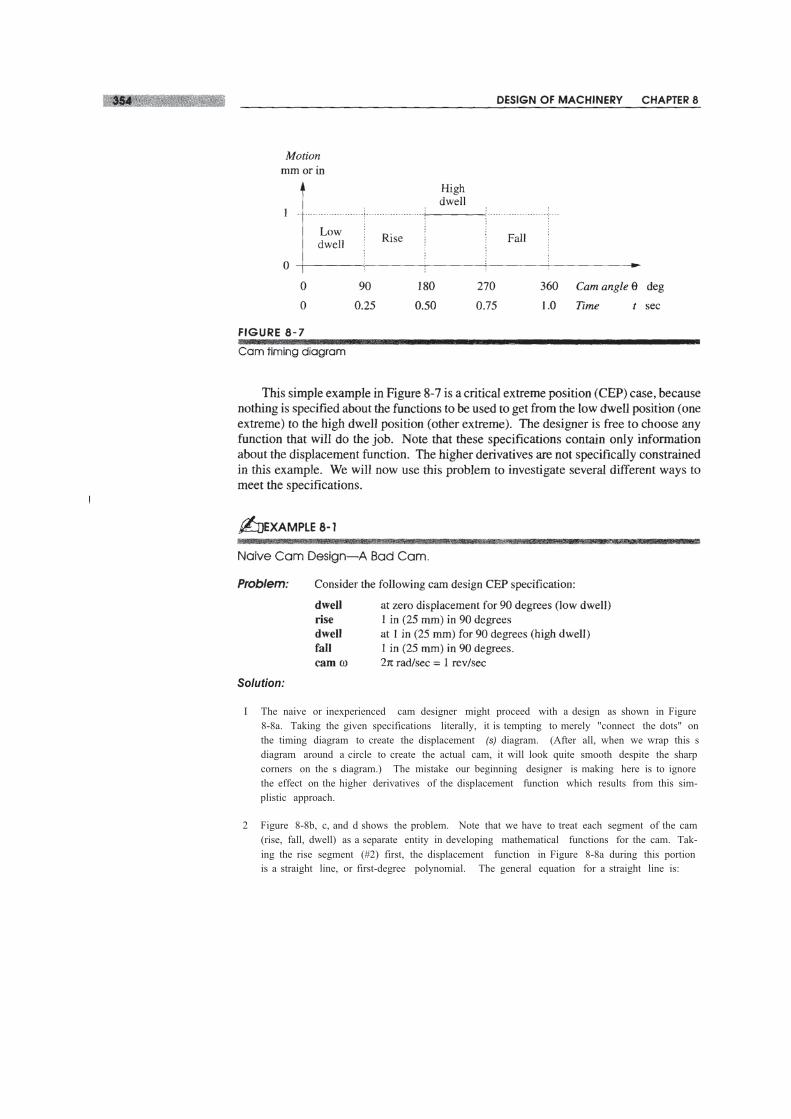
Cam specifications such as this are often depicted on a timing diagram as shown inFigure 8-7 which is a graphical representation of the specified events in the machinecycle. A machine's cycle is defined as one revolution of its master driveshaft. In a com-plicated machine, such as our toothpaste maker, there will be a timing diagram for eachsubassembly in the machine. The time relationships among all subassemblies are definedby their timing diagrams which are all drawn on a common time axis. Obviously allthese operations must be kept in precise synchrony and time phase for the machine towork.
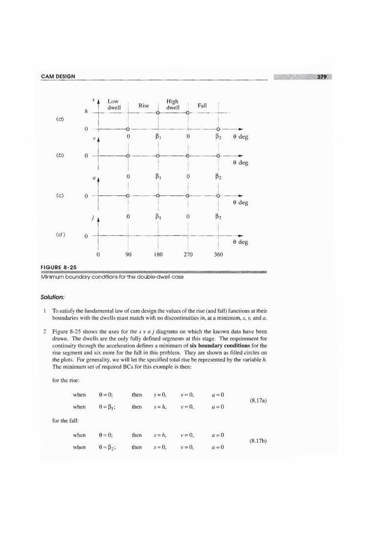
Solution:
I The naive or inexperienced cam designer might proceed with a design as shown in Figure8-8a. Taking the given specifications literally, it is tempting to merely "connect the dots" onthe timing diagram to create the displacement (s) diagram. (After all, when we wrap this sdiagram around a circle to create the actual cam, it will look quite smooth despite the sharpcorners on the s diagram.) The mistake our beginning designer is making here is to ignorethe effect on the higher derivatives of the displacement function which results from this sim-plistic approach.
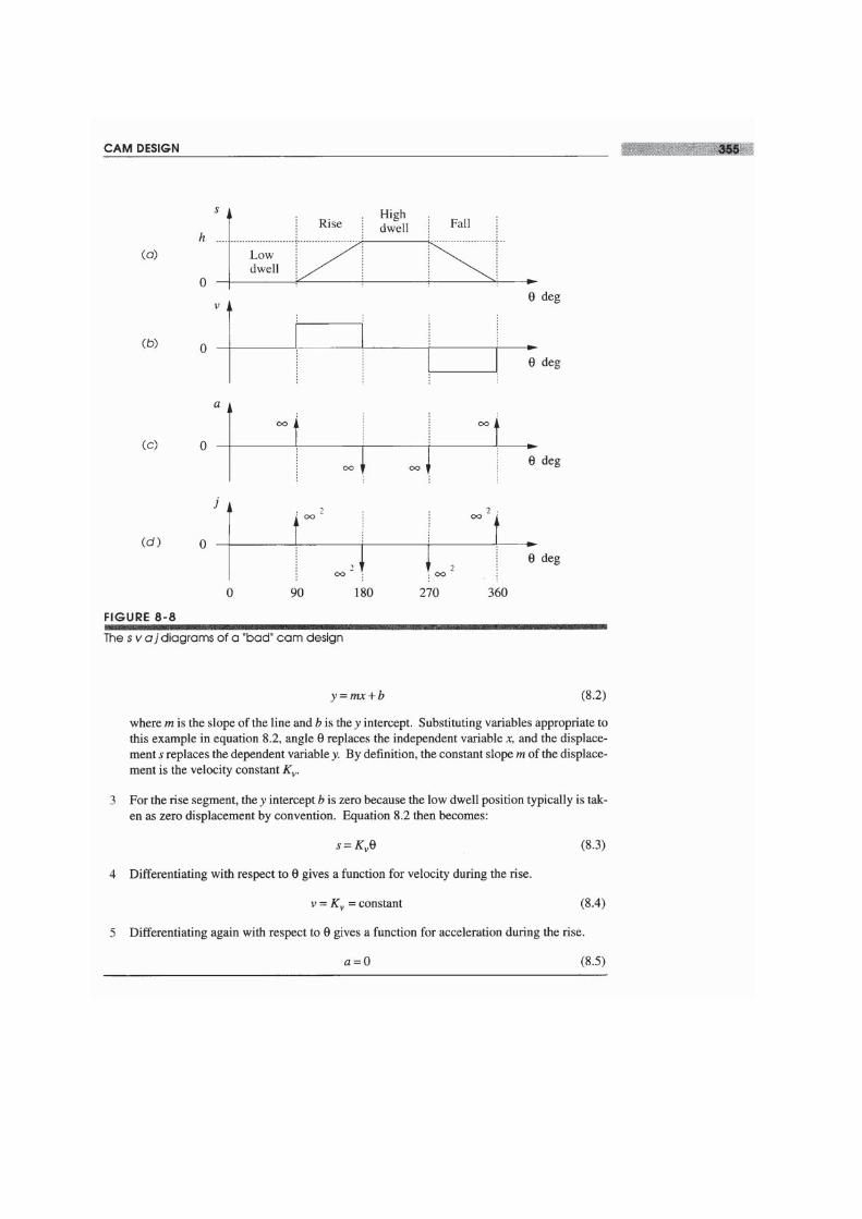
2 Figure 8-8b, c, and d shows the problem. Note that we have to treat each segment of the cam(rise, fall, dwell) as a separate entity in developing mathematical functions for the cam. Tak-ing the rise segment (#2) first, the displacement function in Figure 8-8a during this portionis a straight line, or first-degree polynomial. The general equation for a straight line is:
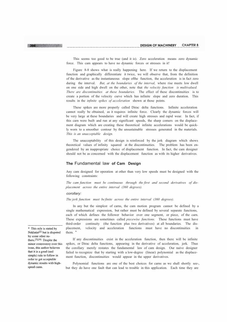
This seems too good to be true (and it is). Zero acceleration means zero dynamicforce. This cam appears to have no dynamic forces or stresses in it!
Figure 8-8 shows what is really happening here. If we return to the displacementfunction and graphically differentiate it twice, we will observe that, from the definitionof the derivative as the instantaneous slope ofthe function, the acceleration is in fact zeroduring the interval. But, at the boundaries of the interval, where rise meets low dwellon one side and high dwell on the other, note that the velocity function is multivalued.There are discontinuities at these boundaries. The effect of these discontinuities is tocreate a portion of the velocity curve which has infinite slope and zero duration. Thisresults in the infinite spikes of acceleration shown at those points.
These spikes are more properly called Dirac delta functions. Infinite accelerationcannot really be obtained, as it requires infinite force. Clearly the dynamic forces willbe very large at these boundaries and will create high stresses and rapid wear. In fact, ifthis carn were built and run at any significant speeds, the sharp comers on the displace-ment diagram which are creating these theoretical infinite accelerations would be quick-ly worn to a smoother contour by the unsustainable stresses generated in the materials.This is an unacceptable design.
The unacceptability of this design is reinforced by the jerk diagram which showstheoretical values of infinity squared at the discontinuities. The problem has been en-gendered by an inappropriate choice of displacement function. In fact, the cam designershould not be as concerned with the displacement function as with its higher derivatives.
The Fundamental law of Cam Design
Any cam designed for operation at other than very low speeds must be designed with thefollowing constraints:
The cam function must be continuous through the first and second derivatives of dis-placement across the entire interval (360 degrees).
corollary:
The jerk function must be finite across the entire interval (360 degrees).
In any but the simplest of carns, the cam motion program cannot be defined by asingle mathematical expression, but rather must be defined by several separate functions,each of which defines the follower behavior over one segment, or piece, of the carn.These expressions are sometimes called piecewise functions. These functions must havethird-order continuity (the function plus two derivatives) at all boundaries. The dis-placement, velocity and acceleration functions must have no discontinuities inthem. *
If any discontinuities exist in the acceleration function, then there will be infinitespikes, or Dirac delta functions, appearing in the derivative of acceleration, jerk. Thusthe corollary merely restates the fundamental law of cam design. Our naive designerfailed to recognize that by starting with a low-degree (linear) polynomial as the displace-ment function, discontinuities would appear in the upper derivatives.
Polynomial functions are one of the best choices for carns as we shall shortly see-,but they do have one fault that can lead to trouble in this application. Each time they are
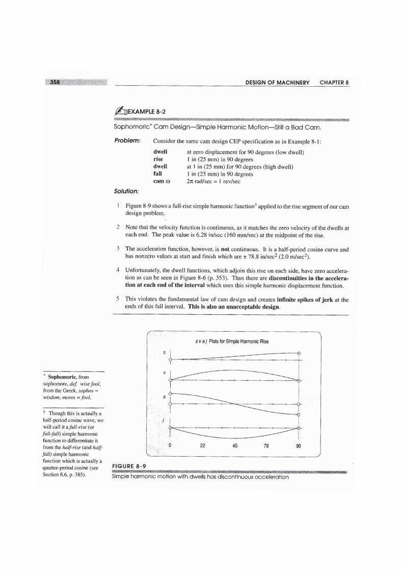
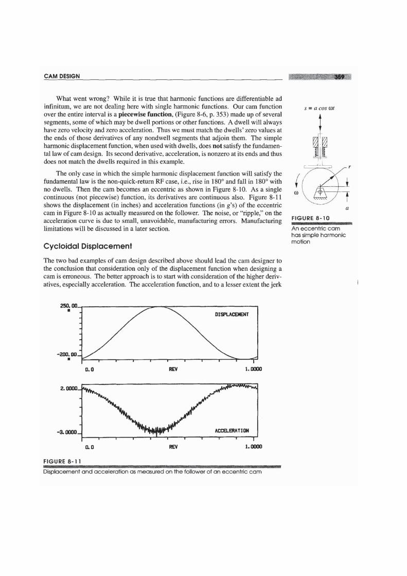
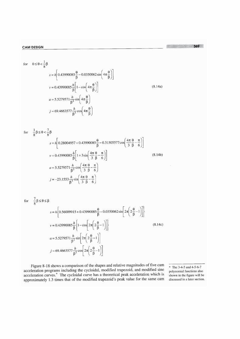
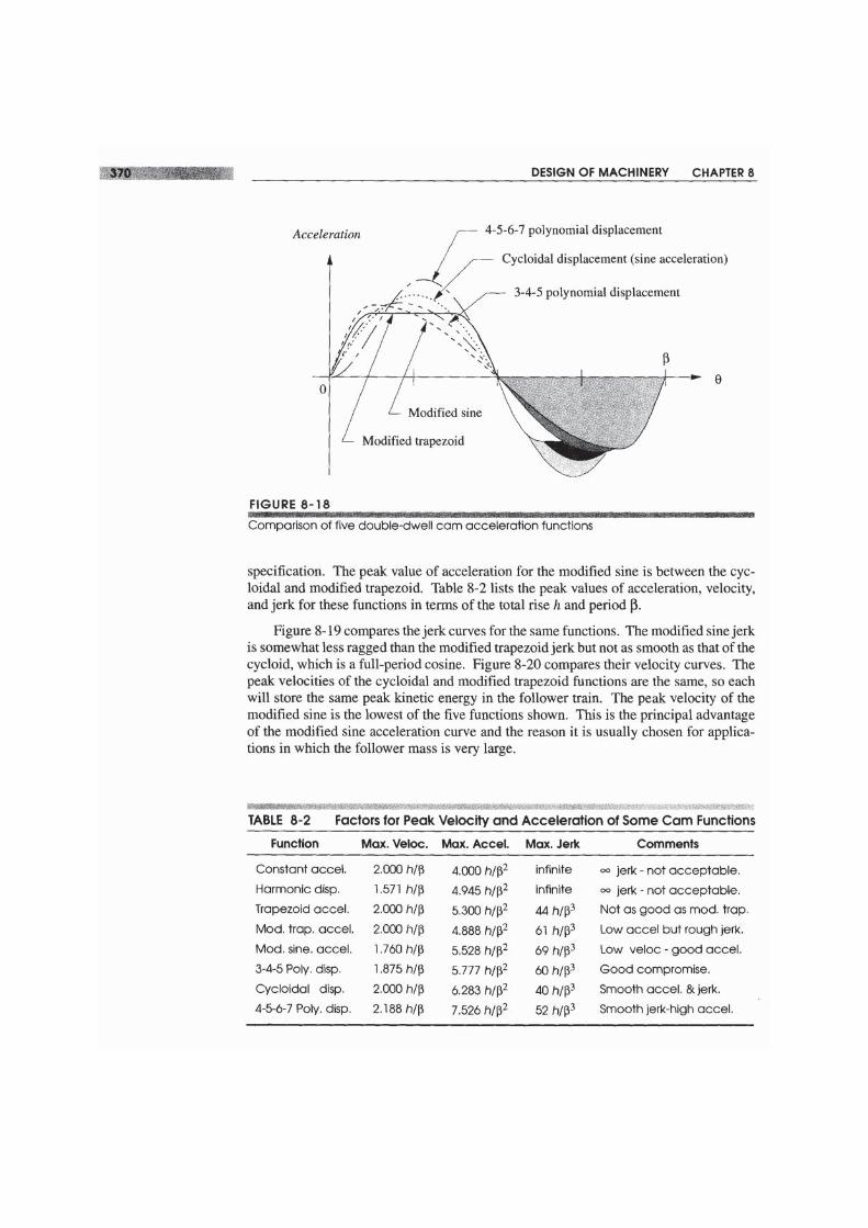
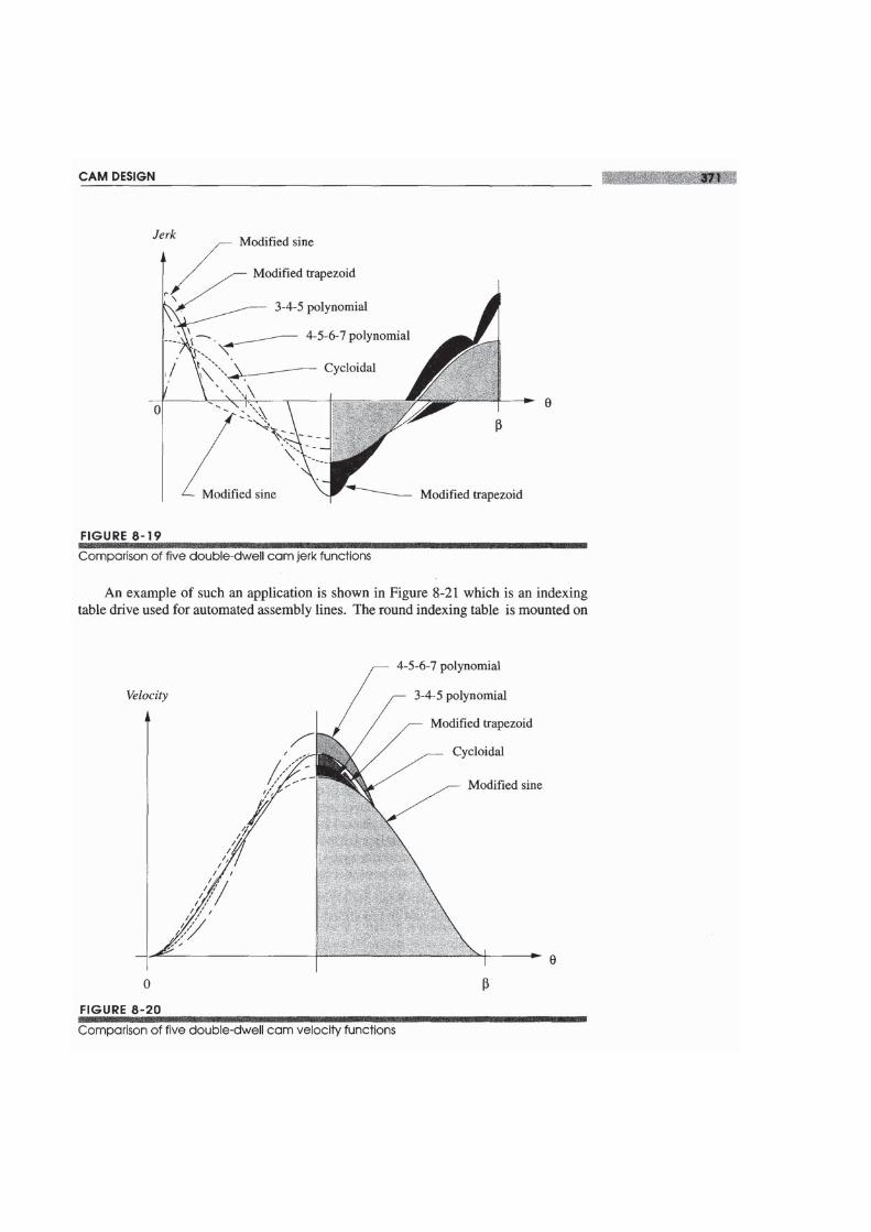
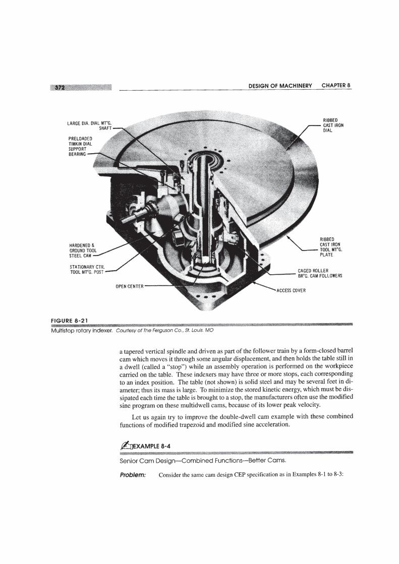
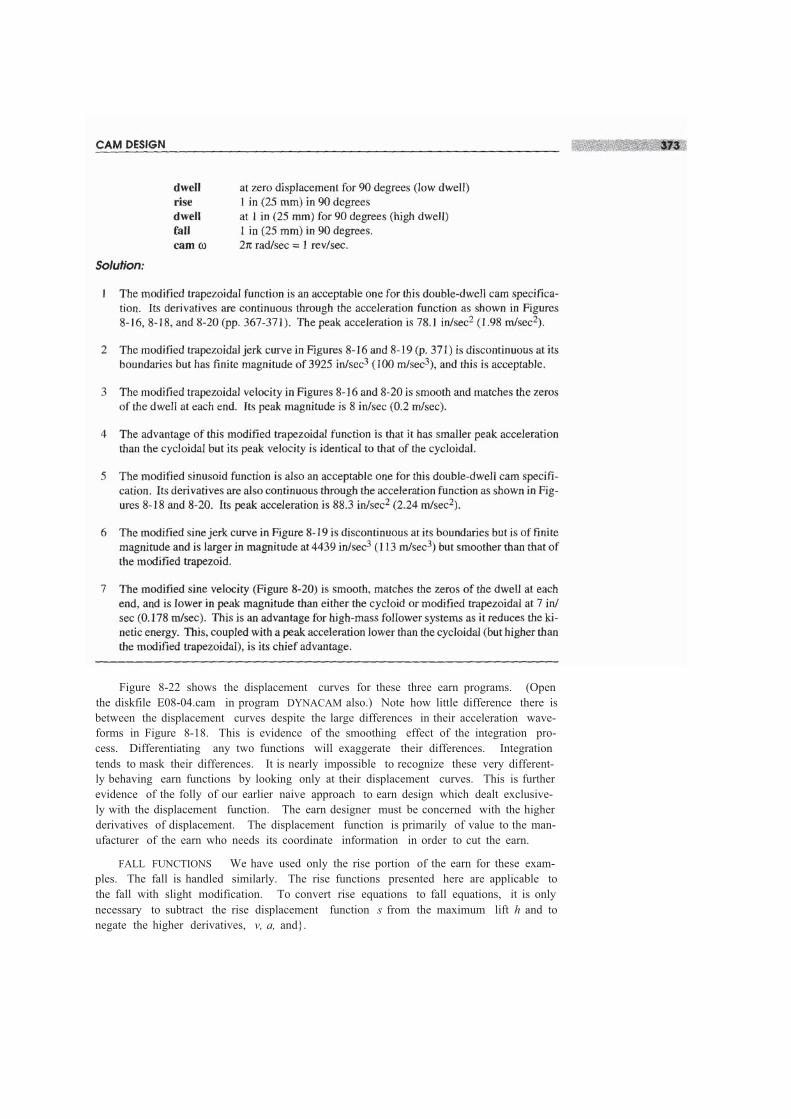
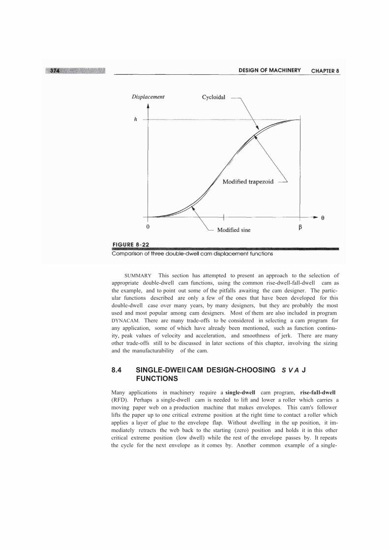
Figure 8-22 shows the displacement curves for these three earn programs. (Openthe diskfile E08-04.cam in program DYNACAM also.) Note how little difference there isbetween the displacement curves despite the large differences in their acceleration wave-forms in Figure 8-18. This is evidence of the smoothing effect of the integration pro-cess. Differentiating any two functions will exaggerate their differences. Integrationtends to mask their differences. It is nearly impossible to recognize these very different-ly behaving earn functions by looking only at their displacement curves. This is furtherevidence of the folly of our earlier naive approach to earn design which dealt exclusive-ly with the displacement function. The earn designer must be concerned with the higherderivatives of displacement. The displacement function is primarily of value to the man-ufacturer of the earn who needs its coordinate information in order to cut the earn.
FALL FUNCTIONS We have used only the rise portion of the earn for these exam-ples. The fall is handled similarly. The rise functions presented here are applicable tothe fall with slight modification. To convert rise equations to fall equations, it is onlynecessary to subtract the rise displacement function s from the maximum lift h and tonegate the higher derivatives, v, a, and}.
SUMMARY This section has attempted to present an approach to the selection ofappropriate double-dwell cam functions, using the common rise-dwell-fall-dwell cam asthe example, and to point out some of the pitfalls awaiting the cam designer. The partic-ular functions described are only a few of the ones that have been developed for thisdouble-dwell case over many years, by many designers, but they are probably the mostused and most popular among cam designers. Most of them are also included in programDYNACAM. There are many trade-offs to be considered in selecting a cam program forany application, some of which have already been mentioned, such as function continu-ity, peak values of velocity and acceleration, and smoothness of jerk. There are manyother trade-offs still to be discussed in later sections of this chapter, involving the sizingand the manufacturability of the cam.
8.4 SINGLE-DWEllCAM DESIGN-CHOOSING S V A JFUNCTIONS
Many applications in machinery require a single-dwell cam program, rise-faIl-dwell(RFD). Perhaps a single-dwell cam is needed to lift and lower a roller which carries amoving paper web on a production machine that makes envelopes. This cam's followerlifts the paper up to one critical extreme position at the right time to contact a roller whichapplies a layer of glue to the envelope flap. Without dwelling in the up position, it im-mediately retracts the web back to the starting (zero) position and holds it in this othercritical extreme position (low dwell) while the rest of the envelope passes by. It repeatsthe cycle for the next envelope as it comes by. Another common example of a single-
Solution:
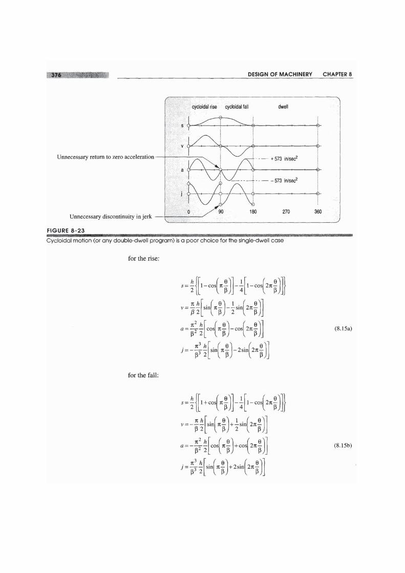
I Figure 8-23 shows a cycloidal displacement rise and separate cycloidal displacement fall ap-plied to this single-dwell example. Note that the displacement (s) diagram looks acceptablein that it moves the followerfrom the low to thehigh positionand back in the requiredintervals.
2 The velocity (v) also looks acceptable in shape in that it takes the follower from zero veloc-ity at the low dwell to a peak value of 19.1 in/sec (0.49 rn/sec) to zero again at the maximumdisplacement, where the glue is applied.
3 Figure 8-23 shows the acceleration function for this solution. Its maximum absolute valueis about 573 in/sec2.
4 The problem is that this acceleration curve has an unnecessary return to zero at the end ofthe rise. It is unnecessary because the acceleration during the first part of the fall is also neg-ative. It would be better to keep it in the negative region at the end of the rise.
5 This unnecessary oscillation to zero in the acceleration causes the jerk to have more abruptchanges and discontinuities. The only real justification for taking the acceleration to zero isthe need to change its sign (as is the case halfway through the rise or fall) or to match an ad-jacent segment which has zero acceleration.
The reader may input the file E08-0S.cam to program DYNACAMto investigate thisexample in more detail.
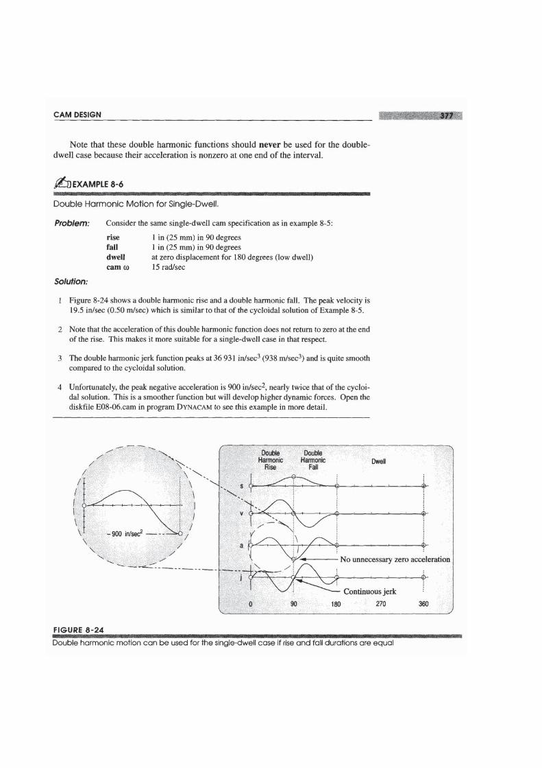
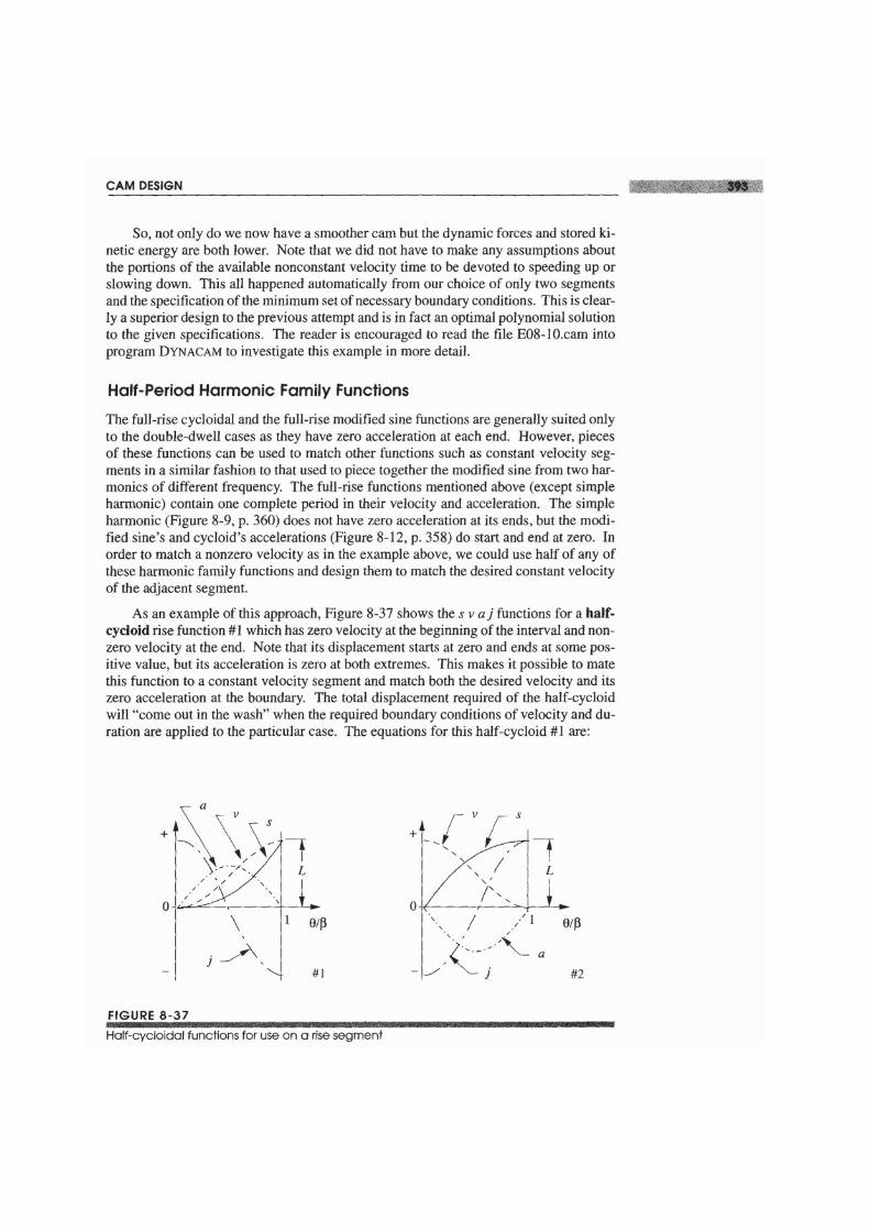
For the single-dwell case we would like a function for the rise which does not returnits acceleration to zero at the end of the interval. The function for the fall should beginwith the same nonzero acceleration value as ended the rise and then be zero at its termi-I1US to match the dwell. One function which meets those criteria is the double harmon-ic which gets its name from its two cosine terms, one of which is a half-period harmonicmd the other a full-period wave. The equations for the double harmonic functions are:

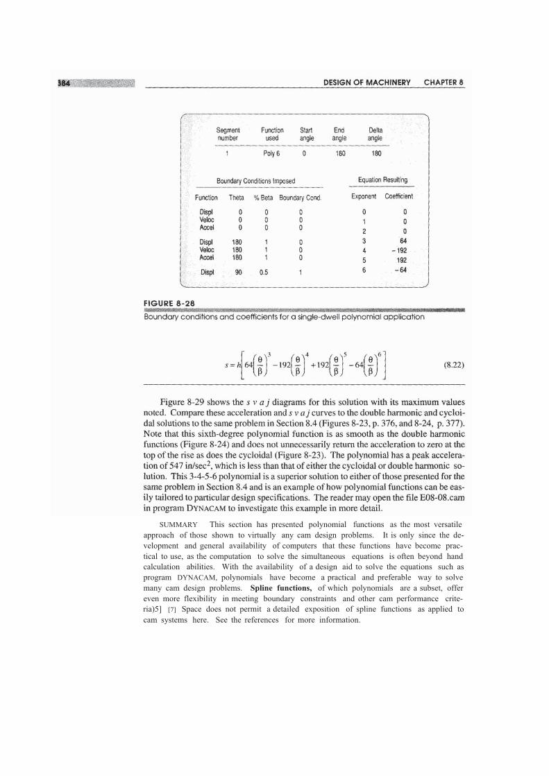
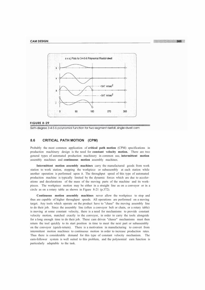
SUMMARY This section has presented polynomial functions as the most versatileapproach of those shown to virtually any cam design problems. It is only since the de-velopment and general availability of computers that these functions have become prac-tical to use, as the computation to solve the simultaneous equations is often beyond handcalculation abilities. With the availability of a design aid to solve the equations such asprogram DYNACAM, polynomials have become a practical and preferable way to solvemany cam design problems. Spline functions, of which polynomials are a subset, offereven more flexibility in meeting boundary constraints and other cam performance crite-ria)5] [7] Space does not permit a detailed exposition of spline functions as applied tocam systems here. See the references for more information.
8.6 CRITICAL PATH MOTION (CPM)
Probably the most common application of critical path motion (CPM) specifications inproduction machinery design is the need for constant velocity motion. There are twogeneral types of automated production machinery in common use, intermittent motionassembly machines and continuous motion assembly machines.
Intermittent motion assembly machines carry the manufactured goods from workstation to work station, stopping the workpiece or subassembly at each station whileanother operation is performed upon it. The throughput speed of this type of automatedproduction machine is typically limited by the dynamic forces which are due to acceler-ations and decelerations of the mass of the moving parts of the machine and its work-pieces. The workpiece motion may be either in a straight line as on a conveyor or in acircle as on a rotary table as shown in Figure 8-21 (p.372).
Continuous motion assembly machines never allow the workpiece to stop andthus are capable of higher throughput speeds. All operations are performed on a movingtarget. Any tools which operate on the product have to "chase" the moving assembly lineto do their job. Since the assembly line (often a conveyor belt or chain, or a rotary table)is moving at some constant velocity, there is a need for mechanisms to provide constantvelocity motion, matched exactly to the conveyor, in order to carry the tools alongsidefor a long enough time to do their job. These cam driven "chaser" mechanisms must thenreturn the tool quickly to its start position in time to meet the next part or subassemblyon the conveyor (quick-return). There is a motivation in manufacturing to convert fromintermittent motion machines to continuous motion in order to increase production rates.Thus there is considerable demand for this type of constant velocity mechanism. Theearn-follower system is well suited to this problem, and the polynomial earn function isparticularly adaptable to the task.
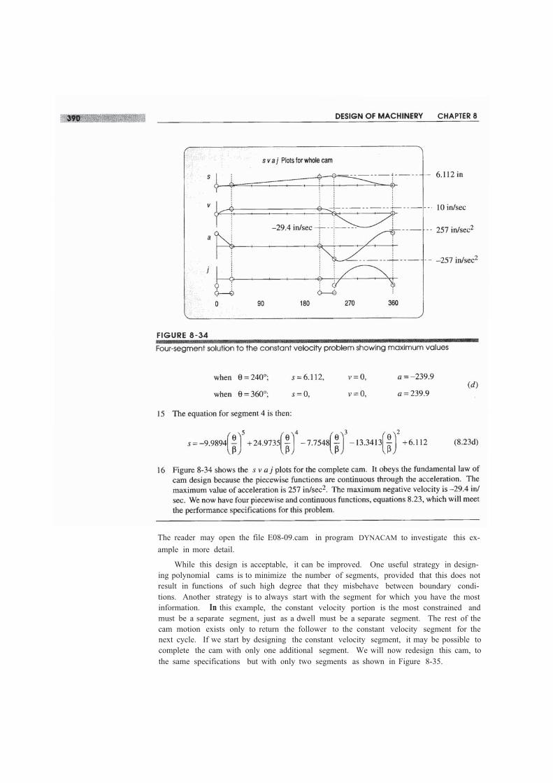
The reader may open the file E08-09.cam in program DYNACAM to investigate this ex-ample in more detail.
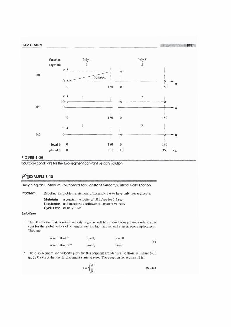
While this design is acceptable, it can be improved. One useful strategy in design-ing polynomial cams is to minimize the number of segments, provided that this does notresult in functions of such high degree that they misbehave between boundary condi-tions. Another strategy is to always start with the segment for which you have the mostinformation. In this example, the constant velocity portion is the most constrained andmust be a separate segment, just as a dwell must be a separate segment. The rest of thecam motion exists only to return the follower to the constant velocity segment for thenext cycle. If we start by designing the constant velocity segment, it may be possible tocomplete the cam with only one additional segment. We will now redesign this cam, tothe same specifications but with only two segments as shown in Figure 8-35.
For a fall instead of a rise, subtract the rise displacement expressions from the totalrise L and negate all the higher derivatives.
To fit these functions to a particular constant velocity situation, solve either equa-tion 8.25b or 8.26b (depending on which function is desired) for the value of L whichresults from the specification of the known constant velocity v to be matched at e = ~ ore = O. You will have to choose a value of ~ for the interval of this half-cycloid which isappropriate to the problem. In our example above, the value of ~ = 30° used for the firstsegment of the four-piece polynomial could be tried as a first iteration. Once L and ~ areknown, all the functions are defined.
The same approach can be taken with the modified sine and the simple harmonicfunctions. Either half of their full-rise functions can be sized to match with a constantvelocity segment. The half-modified sine function mated with a constant velocity seg-ment has the advantage of low peak velocity, useful with large inertia loads. Whenmatched to a constant velocity, the half simple harmonic has the same disadvantage of infi-nite jerk as its full-rise counterpart does when matched to a dwell, so it is not recommended.
We will now solve the previous constant velocity example problem using half-cyc-loid, constant velocity, and full-fall modified sine functions.
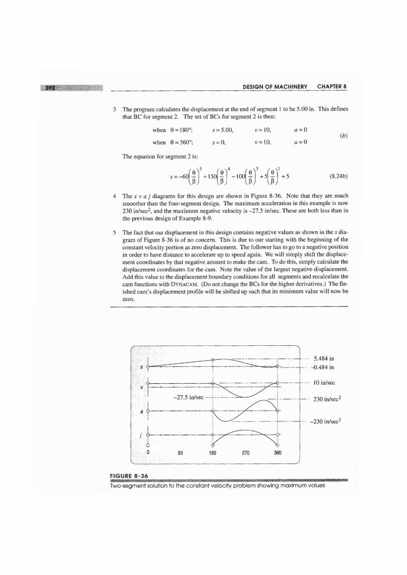
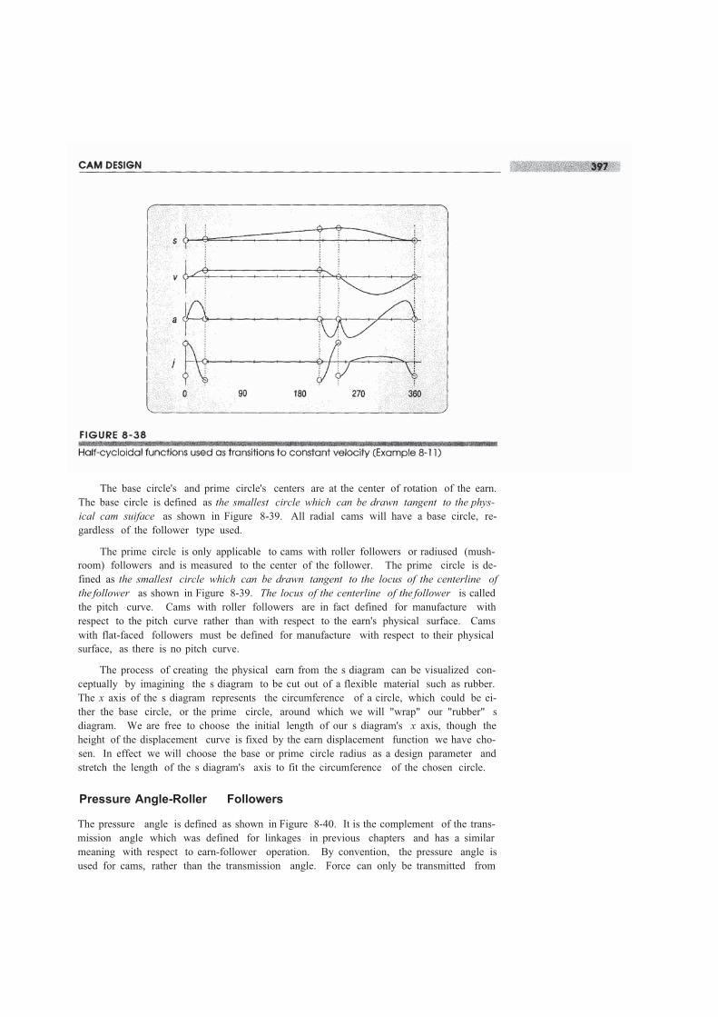
These results are nearly as low as the values from the two-segment polynomial so-lution in Example 8-10 (p. 391). The factor that makes this an inferior cam design toExample 8-10 is the unnecessary returns to zero in the acceleration waveform. This cre-ates a more "ragged" jerk function which will increase vibration problems. The polyno-mial approach is superior to the other solutions presented in this case as it often is in camdesign. The reader may open the file E08-ll.cam in program DYNACAM to investigatethis example in more detail.
8.7 SIZING THE CAM-PRESSURE ANGLE AND RADIUS OFCURVATURE
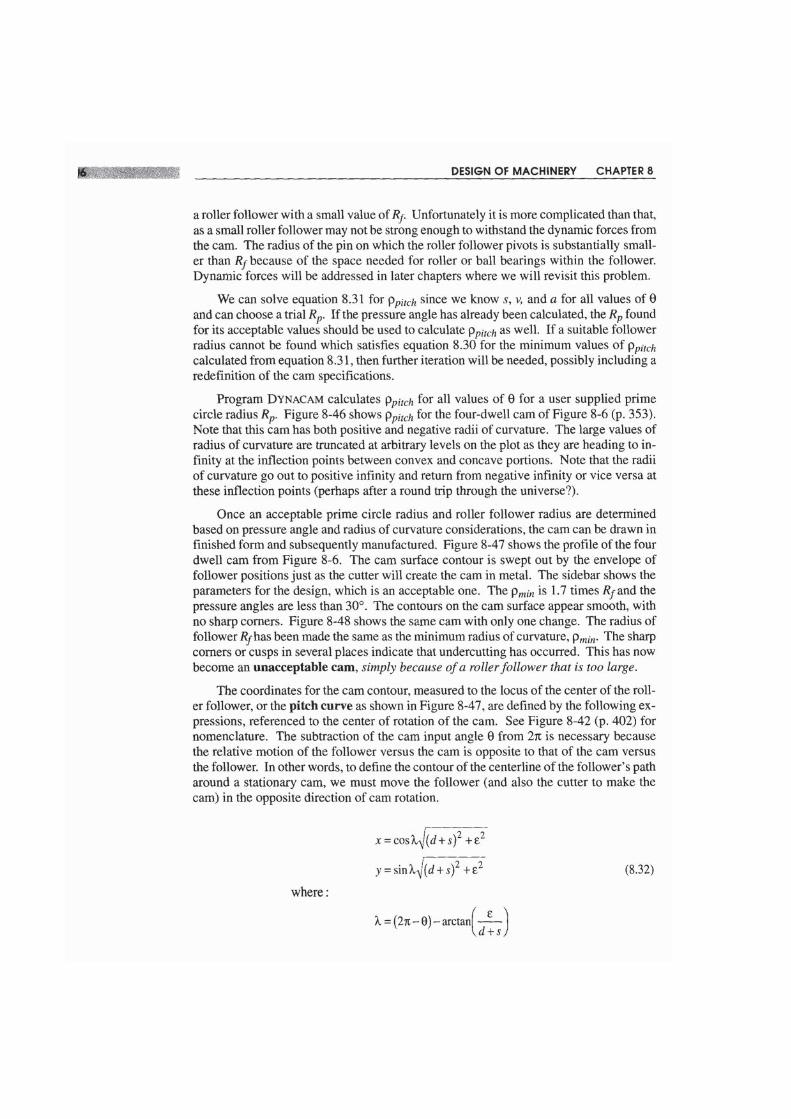
Once the s v a j functions have been defined, the next step is to size the cam. There aretwo major factors which affect cam size, the pressure angle and the radius of curva-ture. Both of these involve either the base circle radius on the cam (Rb) when usingflat-faced followers, or the prime circle radius on the cam (Rp) when using roller orcurved followers.
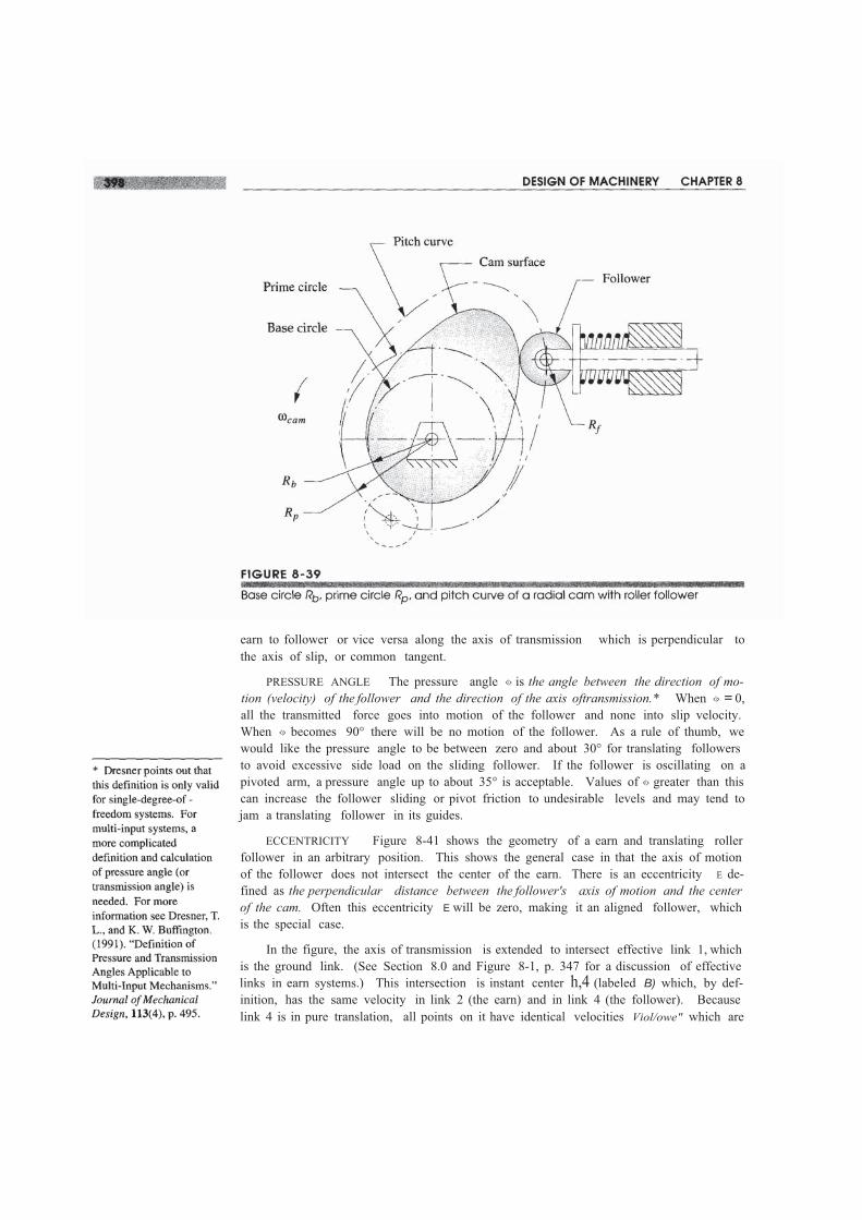
The base circle's and prime circle's centers are at the center of rotation of the earn.The base circle is defined as the smallest circle which can be drawn tangent to the phys-ical cam suiface as shown in Figure 8-39. All radial cams will have a base circle, re-gardless of the follower type used.
The prime circle is only applicable to cams with roller followers or radiused (mush-room) followers and is measured to the center of the follower. The prime circle is de-fined as the smallest circle which can be drawn tangent to the locus of the centerline ofthe follower as shown in Figure 8-39. The locus of the centerline of the follower is calledthe pitch curve. Cams with roller followers are in fact defined for manufacture withrespect to the pitch curve rather than with respect to the earn's physical surface. Camswith flat-faced followers must be defined for manufacture with respect to their physicalsurface, as there is no pitch curve.
The process of creating the physical earn from the s diagram can be visualized con-ceptually by imagining the s diagram to be cut out of a flexible material such as rubber.The x axis of the s diagram represents the circumference of a circle, which could be ei-ther the base circle, or the prime circle, around which we will "wrap" our "rubber" sdiagram. We are free to choose the initial length of our s diagram's x axis, though theheight of the displacement curve is fixed by the earn displacement function we have cho-sen. In effect we will choose the base or prime circle radius as a design parameter andstretch the length of the s diagram's axis to fit the circumference of the chosen circle.
Pressure Angle-Roller Followers
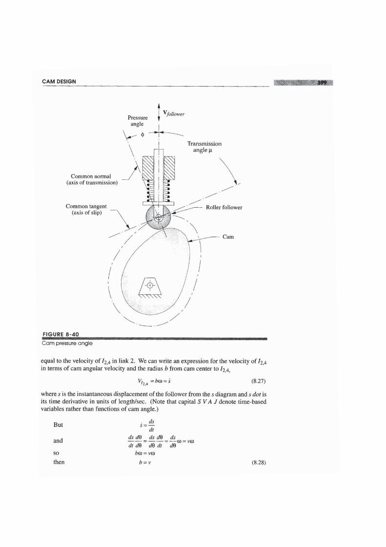
The pressure angle is defined as shown in Figure 8-40. It is the complement of the trans-mission angle which was defined for linkages in previous chapters and has a similarmeaning with respect to earn-follower operation. By convention, the pressure angle isused for cams, rather than the transmission angle. Force can only be transmitted from
earn to follower or vice versa along the axis of transmission which is perpendicular tothe axis of slip, or common tangent.
PRESSURE ANGLE The pressure angle <\> is the angle between the direction of mo-tion (velocity) of the follower and the direction of the axis oftransmission.* When <\> = 0,all the transmitted force goes into motion of the follower and none into slip velocity.When <\> becomes 90° there will be no motion of the follower. As a rule of thumb, wewould like the pressure angle to be between zero and about 30° for translating followersto avoid excessive side load on the sliding follower. If the follower is oscillating on apivoted arm, a pressure angle up to about 35° is acceptable. Values of <\> greater than thiscan increase the follower sliding or pivot friction to undesirable levels and may tend tojam a translating follower in its guides.
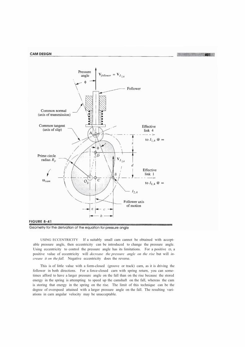
ECCENTRICITY Figure 8-41 shows the geometry of a earn and translating rollerfollower in an arbitrary position. This shows the general case in that the axis of motionof the follower does not intersect the center of the earn. There is an eccentricity E de-fined as the perpendicular distance between the follower's axis of motion and the centerof the cam. Often this eccentricity E will be zero, making it an aligned follower, whichis the special case.
In the figure, the axis of transmission is extended to intersect effective link 1, whichis the ground link. (See Section 8.0 and Figure 8-1, p. 347 for a discussion of effectivelinks in earn systems.) This intersection is instant center h,4 (labeled B) which, by def-inition, has the same velocity in link 2 (the earn) and in link 4 (the follower). Becauselink 4 is in pure translation, all points on it have identical velocities Viol/owe" which are
Choosing a Prime Circle Radius
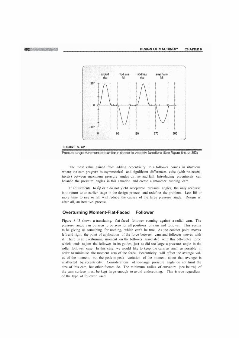
Both Rp and £ are within a transcendental expression in equation 8.29d, so they cannotbe conveniently solved for directly. The simplest approach is to assume a trial value forRp and an initial eccentricity of zero, and use program DYNACAM; your own program; oran equation solver such as Matlah, TKSolver or Mathcad to quickly calculate the valuesof <I> for the entire earn, and then adjust Rp and repeat the calculation until an acceptablearrangement is found. Figure 8-42 shows the calculated pressure angles for a four-dwellearn. Note the similarity in shape to the velocity functions for the same earn in Figure8-6 (p. 353), as that term is dominant in equation 8.29d.
USING ECCENTRICITY If a suitably small cam cannot be obtained with accept-able pressure angle, then eccentricity can be introduced to change the pressure angle.Using eccentricity to control the pressure angle has its limitations. For a positive co, apositive value of eccentricity will decrease the pressure angle on the rise but will in-crease it on the fall. Negative eccentricity does the reverse.
This is of little value with a form-closed (groove or track) carn, as it is driving thefollower in both directions. For a force-closed carn with spring return, you can some-times afford to have a larger pressure angle on the fall than on the rise because the storedenergy in the spring is attempting to speed up the camshaft on the fall, whereas the camis storing that energy in the spring on the rise. The limit of this technique can be thedegree of overspeed attained with a larger pressure angle on the fall. The resulting vari-ations in carn angular velocity may be unacceptable.
The most value gained from adding eccentricity to a follower comes in situationswhere the cam prograrn is asymmetrical and significant differences exist (with no eccen-tricity) between maximum pressure angles on rise and fall. Introducing eccentricity canbalance the pressure angles in this situation and create a smoother running cam.
If adjustments to Rp or E do not yield acceptable pressure angles, the only recourseis to return to an earlier stage in the design process and redefine the problem. Less lift ormore time to rise or fall will reduce the causes of the large pressure angle. Design is,after all, an iterative process.
Overturning Moment-Flat-Faced Follower
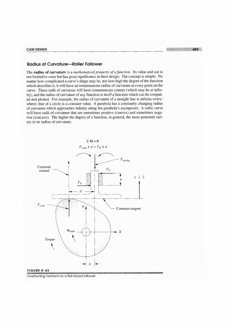
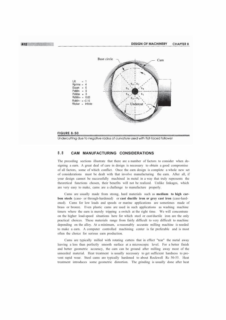
Figure 8-43 shows a translating, flat-faced follower running against a radial carn. Thepressure angle can be seen to be zero for all positions of cam and follower. This seemsto be giving us something for nothing, which can't be true. As the contact point movesleft and right, the point of application of the force between cam and follower moves withit. There is an overturning moment on the follower associated with this off-center forcewhich tends to jam the follower in its guides, just as did too large a pressure angle in theroller follower case. In this case, we would like to keep the carn as small as possible inorder to minimize the moment arm of the force. Eccentricity will affect the average val-ue of the moment, but the peak-to-peak variation of the moment about that average isunaffected by eccentricity. Considerations of too-large pressure angle do not limit thesize of this cam, but other factors do. The minimum radius of curvature (see below) ofthe cam surface must be kept large enough to avoid undercutting. This is true regardlessof the type of follower used.
8.8 CAM MANUFACTURING CONSIDERATIONS
The preceding sections illustrate that there are a number of factors to consider when de-signing a earn. A great deal of care in design is necessary to obtain a good compromiseof all factors, some of which conflict. Once the earn design is complete a whole new setof considerations must be dealt with that involve manufacturing the earn. After all, ifyour design cannot be successfully machined in metal in a way that truly represents thetheoretical functions chosen, their benefits will not be realized. Unlike linkages, whichare very easy to make, cams are a challenge to manufacture properly.
Cams are usually made from strong, hard materials such as medium to high car-bon steels (case- or through-hardened) or cast ductile iron or grey cast iron (case-hard-ened). Cams for low loads and speeds or marine applications are sometimes made ofbrass or bronze. Even plastic cams are used in such applications as washing machinetimers where the earn is merely tripping a switch at the right time. We will concentrateon the higher load-speed situations here for which steel or cast/ductile iron are the onlypractical choices. These materials range from fairly difficult to very difficult to machinedepending on the alloy. At a minimum, a reasonably accurate milling machine is neededto make a earn. A computer controlled machining center is far preferable and is mostoften the choice for serious earn production.
Cams are typically milled with rotating cutters that in effect "tear" the metal awayleaving a less than perfectly smooth surface at a microscopic level. For a better finishand better geometric accuracy, the cam can be ground after milling away most of theunneeded material. Heat treatment is usually necessary to get sufficient hardness to pre-vent rapid wear. Steel cams are typically hardened to about Rockwell Rc 50-55. Heattreatment introduces some geometric distortion. The grinding is usually done after heat
treatment to correct the contour as well as to improve the finish. * The grinding step near-ly doubles the cost of an already expensive part, so it is often skipped in order to savemoney. A hardened but unground cam will have some heat distortion error despite accu-rate milling before hardening. There are several methods of carn manufacture in com-mon use as shown in Table 8-3.
Geometric Generation
Geometric generation refers to the continuous "sweeping out" of a surface as in turninga cylinder on a lathe. This is perhaps the ideal way to make a cam because it creates atruly continuous surface with an accuracy limited only by the quality of the machine andtools used. Unfortunately there are very few types of cams that can be made by thismethod. The most obvious one is the eccentric cam (Figure 8-10, p. 359) which can beturned and ground on a lathe. A cycloid can also be geometrically generated. Very fewother curves can. The presence of dwells makes it extremely difficult to apply this meth-od. Thus, it is seldom used for cams. However, when it can be, as in the case of theeccentric cam of Figure 8-10, the resulting acceleration, though not perfect, is very closeto the theoretical cosine wave as seen in Figure 8-11 (p. 359). This eccentric cam wasmade by turning and grinding on a high-quality lathe. This is the best that can be ob-tained in cam manufacture. Note that the displacement function is virtually perfect. Theerrors are only visible in the more sensitive acceleration function measurement.
Manual or NC Machining to Cam Coordinates (Plunge-Cutting)
Computer-aided manufacturing (CAM) has become the virtual standard for high ac-curacy machining in the United States. Numerical control (NC) machinery comes inmany types. Lathes, milling machines, grinders, etc., are all available with on-boardcomputers which control either the position of the workpiece, the tool, or both. The sim-plest type of NC machine moves the tool (or workpiece) to a specified x,y location andthen drives the tool (say a drill) down through the workpiece to make a hole. This pro-cess is repeated as much as necessary to create the part. This simple process is referredto as NC to distinguish it from continuous numerical control (CNC).
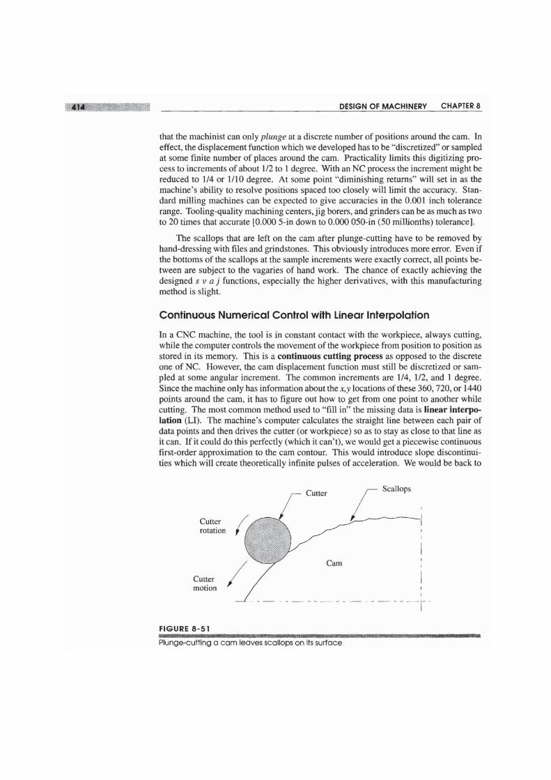
This NC process is sometimes used for cam manufacture, and even for master camsas described below. It is, in fact, merely a computerized version of the old manual meth-od of cam milling, which is often called plunge-cutting to refer to plunging the spin-ning milling cutter down through the workpiece. This is not the best way to machine aearn because it leaves "scallops" on the surface as shown in Figure 8-51, due to the fact
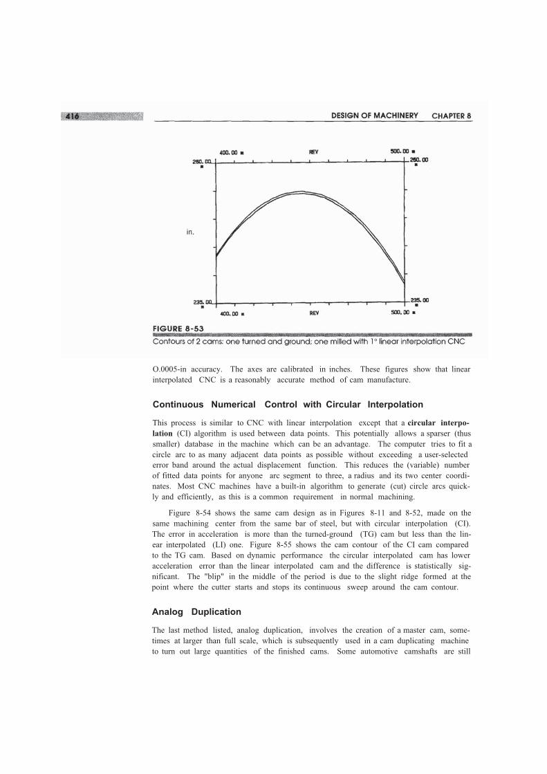
O.0005-in accuracy. The axes are calibrated in inches. These figures show that linearinterpolated CNC is a reasonably accurate method of cam manufacture.
Continuous Numerical Control with Circular Interpolation
This process is similar to CNC with linear interpolation except that a circular interpo-lation (CI) algorithm is used between data points. This potentially allows a sparser (thussmaller) database in the machine which can be an advantage. The computer tries to fit acircle arc to as many adjacent data points as possible without exceeding a user-selectederror band around the actual displacement function. This reduces the (variable) numberof fitted data points for anyone arc segment to three, a radius and its two center coordi-nates. Most CNC machines have a built-in algorithm to generate (cut) circle arcs quick-ly and efficiently, as this is a common requirement in normal machining.
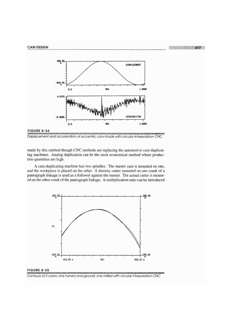
Figure 8-54 shows the same cam design as in Figures 8-11 and 8-52, made on thesame machining center from the same bar of steel, but with circular interpolation (CI).The error in acceleration is more than the turned-ground (TG) cam but less than the lin-ear interpolated (LI) one. Figure 8-55 shows the cam contour of the CI cam comparedto the TG cam. Based on dynamic performance the circular interpolated cam has loweracceleration error than the linear interpolated cam and the difference is statistically sig-nificant. The "blip" in the middle of the period is due to the slight ridge formed at thepoint where the cutter starts and stops its continuous sweep around the cam contour.
Analog Duplication
The last method listed, analog duplication, involves the creation of a master cam, some-times at larger than full scale, which is subsequently used in a cam duplicating machineto turn out large quantities of the finished cams. Some automotive camshafts are still
between the dummy follower and the cutter to size the finished cam versus the master.This allows master cams of larger size to be used which increases the accuracy. As themaster and slave slowly turn together, synchronous and in phase, the dummy cutter fol-lows the master's contour and the workpiece is cut to match. This process can be donewith either milling (cutting) or grinding of the cam surface. Typically the cam is roughcut first, and then heat treated and reground to finished size. Some cams are left as-milled with no post heat-treat grinding.
This analog duplication method can obviously create a cam that is only as good asthe master cam at best. Some errors will be introduced in the duplicating process due todeflections of the tool or machine parts, but the quality of the master cam ultimately lim-its the quality of the finished cams. The master cam is typically made by one of the oth-er methods listed in Table 8-3 (p. 413), each of which has its limitations. The master cammay require some hand-dressing with files or hand grindstones to smooth its surface. Aplunge-cut cam requires a lot of hand-dressing, the CNC cams less so. If hand-dressingis done, it will result in a very smooth surface but the chances that the resulting contouris an accurate representation of the designed s v a j functions, especially the higher de-rivatives, is slim. Thus the finished cam may not be an accurate representation of thedesign.
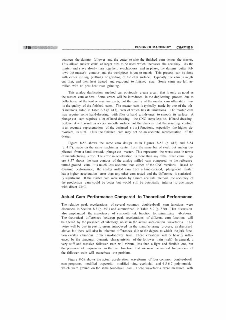
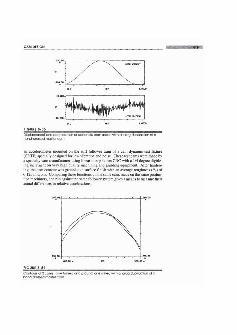
Figure 8-56 shows the same cam design as in Figures 8-52 (p. 415) and 8-54(p. 417), made on the same machining center from the same bar of steel, but analog du-plicated from a hand-dressed, plunge-cut master. This represents the worst case in termsof manufacturing error. The error in acceleration is more than any ofthe other cams. Fig-ure 8-57 shows the cam contour of the analog milled cam compared to the referenceturned-ground cam. It is much less accurate than either of the CNC versions. Based ondynamic performance, the analog milled cam from a hand-dressed, plunge-cut masterhas a higher acceleration error than any other cam tested and the difference is statistical-ly significant. If the master cam were made by a more accurate method, the accuracy ofthe production cam could be better but would still be potentially inferior to one madewith direct CNC.
Actual Cam Performance Compared to Theoretical Performance
The relative peak accelerations of several common double-dwell cam functions werediscussed in Section 8.3 (p. 353) and summarized in Table 8-2 (p. 370). That discussionalso emphasized the importance of a smooth jerk function for minimizing vibrations.The theoretical differences between peak accelerations of different cam functions willbe altered by the presence of vibratory noise in the actual acceleration waveforms. Thisnoise will be due in part to errors introduced in the manufacturing process, as discussedabove, but there will also be inherent differences due to the degree to which the jerk func-tion excites vibrations in the cam-follower train. These vibrations will be heavily influ-enced by the structural dynamic characteristics of the follower train itself. In general, avery stiff and massive follower train will vibrate less than a light and flexible one, butthe presence of frequencies in the cam function that are near the natural frequencies ofthe follower train will exacerbate the problem.
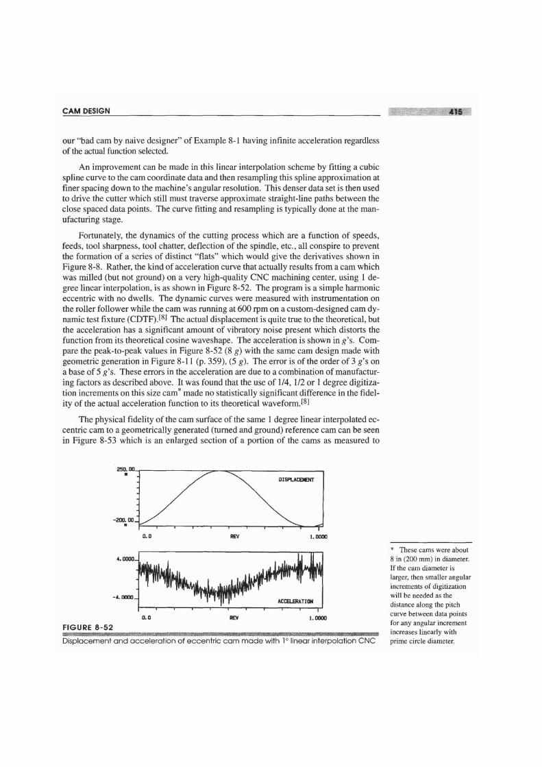
Figure 8-58 shows the actual acceleration waveforms of four common double-dwellcam programs, modified trapezoid, modified sine, cycloidal, and 4-5-6-7 polynomial,which were ground on the same four-dwell cam. These waveforms were measured with
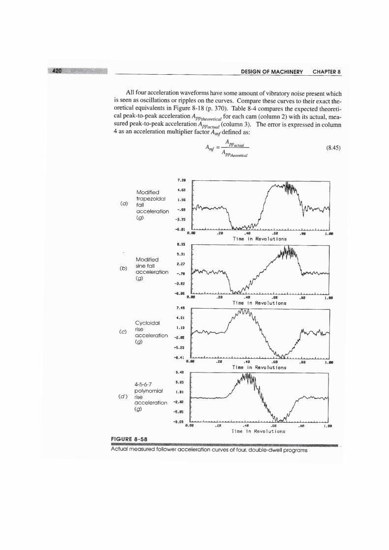
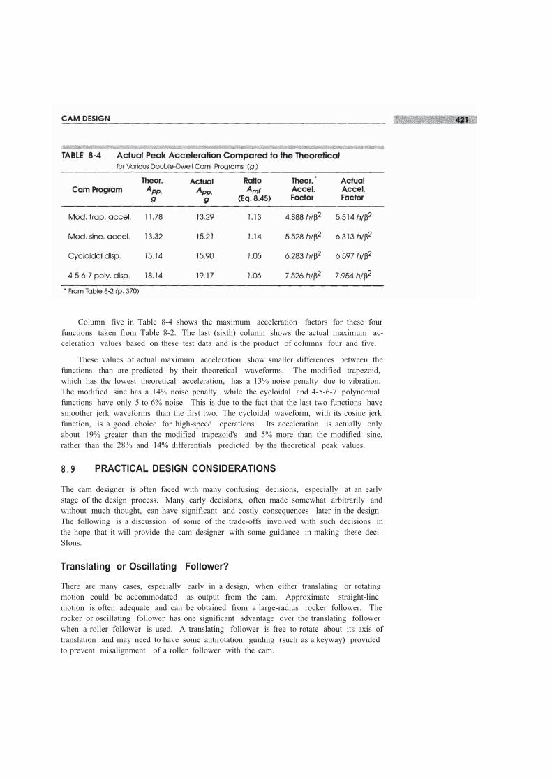
Column five in Table 8-4 shows the maximum acceleration factors for these fourfunctions taken from Table 8-2. The last (sixth) column shows the actual maximum ac-celeration values based on these test data and is the product of columns four and five.
These values of actual maximum acceleration show smaller differences between thefunctions than are predicted by their theoretical waveforms. The modified trapezoid,which has the lowest theoretical acceleration, has a 13% noise penalty due to vibration.The modified sine has a 14% noise penalty, while the cycloidal and 4-5-6-7 polynomialfunctions have only 5 to 6% noise. This is due to the fact that the last two functions havesmoother jerk waveforms than the first two. The cycloidal waveform, with its cosine jerkfunction, is a good choice for high-speed operations. Its acceleration is actually onlyabout 19% greater than the modified trapezoid's and 5% more than the modified sine,rather than the 28% and 14% differentials predicted by the theoretical peak values.
8.9 PRACTICAL DESIGN CONSIDERATIONS
The cam designer is often faced with many confusing decisions, especially at an earlystage of the design process. Many early decisions, often made somewhat arbitrarily andwithout much thought, can have significant and costly consequences later in the design.The following is a discussion of some of the trade-offs involved with such decisions inthe hope that it will provide the cam designer with some guidance in making these deci-SIons.
Translating or Oscillating Follower?
There are many cases, especially early in a design, when either translating or rotatingmotion could be accommodated as output from the cam. Approximate straight-linemotion is often adequate and can be obtained from a large-radius rocker follower. Therocker or oscillating follower has one significant advantage over the translating followerwhen a roller follower is used. A translating follower is free to rotate about its axis oftranslation and may need to have some antirotation guiding (such as a keyway) providedto prevent misalignment of a roller follower with the cam.
Conversely, the oscillating follower will keep the roller follower aligned in the sarneplane as the cam with no guiding beyond its own pivot. Also, the pivot friction in an os-cillating follower typically has a small moment arm compared to the moment of the forcefrom the cam on the follower arm. But, the friction force on a translating follower has aone-to-one geometric relationship with the cam force. This can have a larger parasiticeffect on the system.
On the other hand, translating flat-faced followers are often deliberately arrangedwith their axis slightly out of the plane of the cam in order to create a rotation about theirown axis due to the frictional moment resulting from the offset. The flat follower willthen precess around its own axis and distribute the wear over its entire face surface. Thisis common practice in automotive valve cams that use flat-faced followers or "tappets."
Force or Form-Closed?
A form-closed (track or groove) cam is more expensive to make than a force-closed(open) cam simply because there are two surfaces to machine and grind. Also, heat treat-ing will often distort the track of a form-closed cam, narrowing or widening it such thatthe roller follower will not fit properly. This virtually requires post heat-treat grindingfor track cams in order to resize the slot. An open (force-closed) cam will also distort onheat-treating but may still be usable without grinding.
FOLLOWERJUMP The principal advantage of a form-closed (track) cam is that itdoes not need a return spring, and thus can be run at higher speeds than a force-closedcam whose spring and follower mass will go into resonance at some speed, causing po-tentially destructive follower jump. This phenomenon will be investigated in Chapter15 on cam dynamics. High-speed automobile and motorcycle racing engines often useform-closed (desmodromic) valve cam trains to allow higher engine rpm without incur-ring valve "float," or follower jump.
CROSSOVERSHOCK Though the lack of a return spring can be an advantage, itcomes, as usual, with a trade-off. In a form-closed (track) cam there will be crossovershock each time the acceleration changes sign. Crossover shock describes the impactforce that occurs when the follower suddenly jumps from one side of the track to theother as the dynamic force (ma) reverses sign. There is no flexible spring in this systemto absorb the force reversal as in the force-closed case. The high impact forces at cross-over cause noise, high stresses, and local wear. Also, the roller follower has to reversedirection at each crossover which causes sliding and accelerates follower wear. Studieshave shown that roller followers running against a well-lubricated open radial carn haveslip rates of less than 1%.l9]
Radial or Axial Com?
This choice is largely dictated by the overall geometry of the machine for which the camis being designed. If the follower must move parallel to the camshaft axis, then an axialcarn is dictated. If there is no such constraint, a radial cam is probably a better choicesimply because it is a less complicated, thus cheaper, cam to manufacture.
Roller or Flat-Faced Follower?
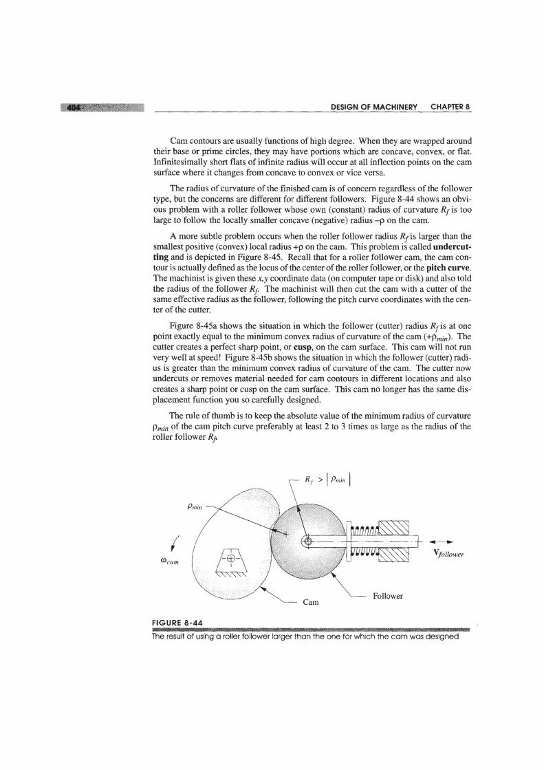
The roller follower is a better choice from a earn design standpoint simply because itaccepts negative radius of curvature on the earn. This allows more variety in the earnprogram. Also, for any production quantities, the roller follower has the advantage ofbeing available from several manufacturers in any quantity from one to a million. Forlow quantities it is not usually economical to design and build your own custom follow-er. In addition, replacement roller followers can be obtained from suppliers on shortnotice when repairs are needed. Also, they are not particularly expensive even in smallquantities.
Perhaps the largest users of flat-faced followers are automobile engine makers.Their quantities are high enough to allow any custom design they desire. It can be madeor purchased economically in large quantity and can be less expensive than a roller fol-lower in that case. Also with engine valve cams, a flat follower can save space over aroller. However, many manufacturers have switched to roller followers in automobileengines to reduce friction and improve fuel mileage. Diesel engines have long used roll-er followers (tappets) as have racers who "hop-up" engines for high performance.
Cams used in automated production line machinery use stock roller followers almostexclusively. The ability to quickly change a worn follower for a new one taken from thestockroom without losing much production time on the "line" is a strong argument in thisenvironment. Roller followers come in several varieties (see Figure 8-5a, p. 351). Theyare based on roller or ball bearings. Plain bearing versions are also available for low-noise requirements. The outer surface, which rolls against the earn can be either cylin-drical or spherical in shape. The "crown" on the spherical follower is slight, but it guar-antees that the follower will ride near the center of a flat earn regardless of the accuracyof alignment of the axes of rotation of earn and follower. If a cylindrical follower is cho-sen and care is not taken to align the axes of earn and roller follower, the follower willride on one edge and wear rapidly.
Commercial roller followers are typically made of high carbon alloy steel such asAISI 52100 and hardened to Rockwell Rc 60 - 62. The 52100 alloy is well suited to thinsections that must be heat-treated to a uniform hardness. Because the roller makes manyrevolutions for each earn rotation, its wear rate may be higher than that of the earn.Chrome plating the follower can markedly improve its life. Chrome is harder than steelat about Rc 70. Steel cams are typically hardened to a range of Rc 50 - 55.
To Dwell or Not to Dwell?
The need for a dwell is usually clear from the problem specifications. If the followermust be held stationary for any time, then a dwell is required. Some earn designers tendto insert dwells in situations where they are not specifically needed for follower stasis,in a mistaken belief that this is preferable to providing a rise-return motion when that iswhat is really needed. If the designer is attempting to use a double-dwell program in asingle-dwell case, then perhaps his or her motivation to "let the vibrations settle out" byproviding a "short dwell" at the end of the motion is justified. However, he or she prob-ably should be using another earn program, perhaps a polynomial tailored to the specifi-cations. Taking the acceleration to zero, whether for an instant or for a "short dwell," isgenerally unnecessary and undesirable. (See Examples 8-5, p. 375 , 8-6, p. 377, and 8-8,

Related Documents