MITS Design Pro . CAM-Auto for AutoLab

Welcome message from author
This document is posted to help you gain knowledge. Please leave a comment to let me know what you think about it! Share it to your friends and learn new things together.
Transcript

MITS Design Pro .
CAM-Auto
for AutoLab
1
Precautions
1. Intended Use
The intended use of the PCB Prototyping Machine is to process PCB by milling,
drilling and routing. Any other uses are strongly prohibited.
2. While Processing
Keep away from the machine especially the spindle head while
processing. Spindle head is constantly moving. Be sure to keep away and not
to get your caught in the machine. Make sure to wear eye protective
gear/goggle while processing.
3. Power Voltage
The allowable voltage for Auto Lab 90V-240V.If the voltage of your region is
out of range, be sure to use voltage regulator.
4. Working Area
The working area of Auto Lab is 229mm x 300mm. Be sure to process within
the working area of Auto Lab.
5. Dry Run and Milling Speed
Below is the optimal speed for Auto Lab.
Dry Run .. 20~30mm/sec
Milling Speed .. 12~18mm/sec
Routing Speed .. 1~2mm/sec
If the processing speed is too fast during processing or manual operation,
step-out could occur to the machine.
6. Milling/Drill/Routing Tool Settings
The machine will process with the settings in CAM Pref. >>Milling, Drill,
Routing. If the parameter in the setting is missing or unintended value, there
is a possibility of tools breaking or processing error occurring. Be sure to check
the parameter in the settings.
7. Vacuum Cleaner
While processing, if the dust from the PCB piles up, not only the processing
quality is affected by it, there also is a chance of spindle motor malfunction. Be
sure to use Vacuum Cleaner while processing.
2
8. CAD with Dongle Key
Make sure to remove Dongle key when you are using the prototyping machine.
Connection error may occur and prototyping machine may be unable to use.
9. Tools and RPM
For processing, set the RPM to 30-40. The unit in the software is x1000RPM. To
drill 0.3~0.4mm size holes, set the Lower2 3~4mm/sec.
IMPORTANT
To drill 0.3~0.4mm size holes, go to CAM Pref. >> Board Maker and set the
Lower2 3-4mm/sec. After setting the Lower2 speed slower, make sure to set
Drill Wait and Before Cutting longer than the default setting. If not, there is
a possibility of spindle head moving too early before the drilling is completely
penetrated.
10. Transportation
Since Auto Lab is a precision machine, use the container box which was used
for shipping. For long distant transportation using carrier, make sure to select
carrier with great handle care with the transportation.
Do not apply any force to the shaft, lead screw, spindle head while
transportation. It could result to have the accuracy to drop.
11. Spindle Motor Cleaning
Note that spindle motor and collet are ultra-precision component. In order to
keep the machine performance well, daily checkup and cleaning is necessary.
Spindle motor may result to malfunction when dust or debris are caught
between tool and collet, decreasing the holding power of the tools. Make sure
to check and clean the spindle motor before using.
12. Warranty
The term of warranty for PCB Prototyping Machine is 1 year with the intended
use. Note that spindle motor and consumable supplies are not included in the
warranty. Also note that even within the warranty period, below circumstances
will be considered as charged repair. Improper use, inappropriate assembly,
damage/breakage by carelessness, natural disaster, abrasion, modification,
use of non-genuine components/parts, use in undesignated voltage. Please
operate with great care when you are using the machine without any training.

3
CONTENTS
Introduction .............................................................................................. 4
Prototyping Machine Part Name ................................................................... 5
Installation of Software .............................................................................. 7
Setup Operation Check ............................................................................... 8
Communication Port Settings .................................................................... 10
Starting Up CAM-Auto .............................................................................. 15
CAM-Auto Screen Basic Operation .............................................................. 17
1. Procedures .......................................................................................... 18
2. Preparation ......................................................................................... 19
3. Setup Tools ......................................................................................... 22
4. Set Milling Sequences ........................................................................... 26
5. Adjustment ......................................................................................... 29
6. Process Top Layer ................................................................................ 43
7. Adjust/Align Bottom Layer .................................................................... 46
8. Process Bottom Layer ........................................................................... 51
9. After Completed .................................................................................. 55
Trouble Shooting (USB,RS232C Serial Connection) ....................................... 56
Trouble Shooting (Prototyping Machine) ...................................................... 58
4
Introduction
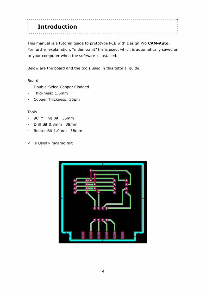
This manual is a tutorial guide to prototype PCB with Design Pro CAM-Auto.
For further explanation, “mdemo.mit” file is used, which is automatically saved on
to your computer when the software is installed.
Below are the board and the tools used in this tutorial guide.
Board
- Double-Sided Copper Cladded
- Thickness: 1.6mm
- Copper Thickness: 35μm
Tools
- 90°Milling Bit 36mm
- Drill Bit 0.8mm 38mm
- Router Bit 1.0mm 38mm
<File Used> mdemo.mit
5
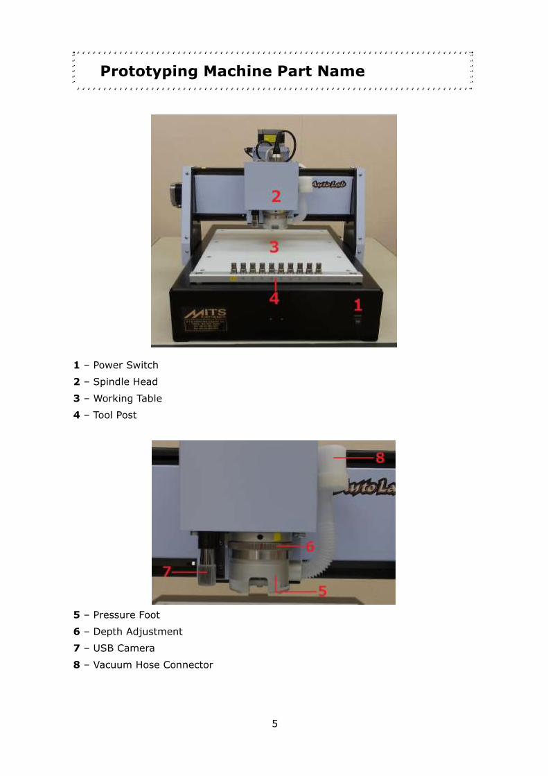
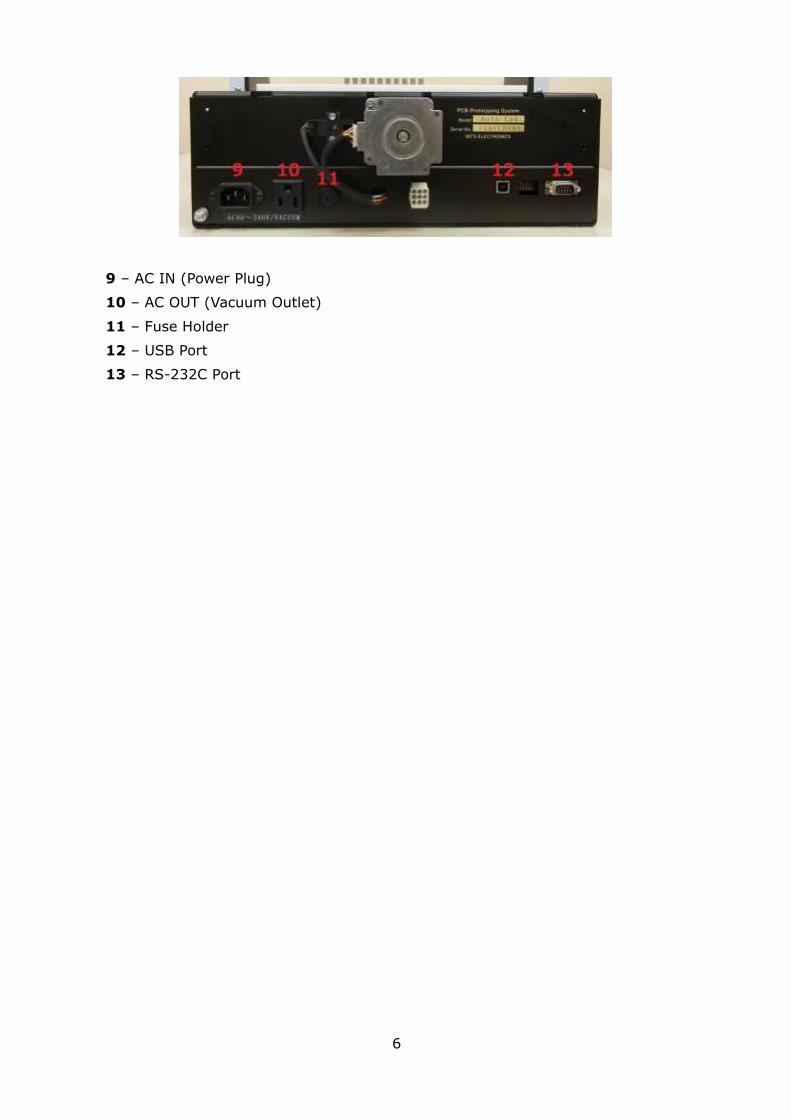
Prototyping Machine Part Name
1 – Power Switch
2 – Spindle Head
3 – Working Table
4 – Tool Post
5 – Pressure Foot
6 – Depth Adjustment
7 – USB Camera
8 – Vacuum Hose Connector
6
9 – AC IN (Power Plug)
10 – AC OUT (Vacuum Outlet)
11 – Fuse Holder
12 – USB Port
13 – RS-232C Port

7
Installation of Software
See “Setup Guide” in Software CD-ROM for your reference.
(PDF_manual >> Setup_Guide >> Auto Lab Setup Guide)
*Select Common Components, otherwise Converter and EASYCAD will not be
installed.
*Also, select “CAM-Auto” and “Design View”.

8
Setup Operation Check
1. Connect the power cable to the AC In (Power Plug).
2. Attach and hold the vacuum hose by fixing the plastic vacuum holder on the
backside of the machine with the screw.
3. Attach vacuum hose into the connector.
9
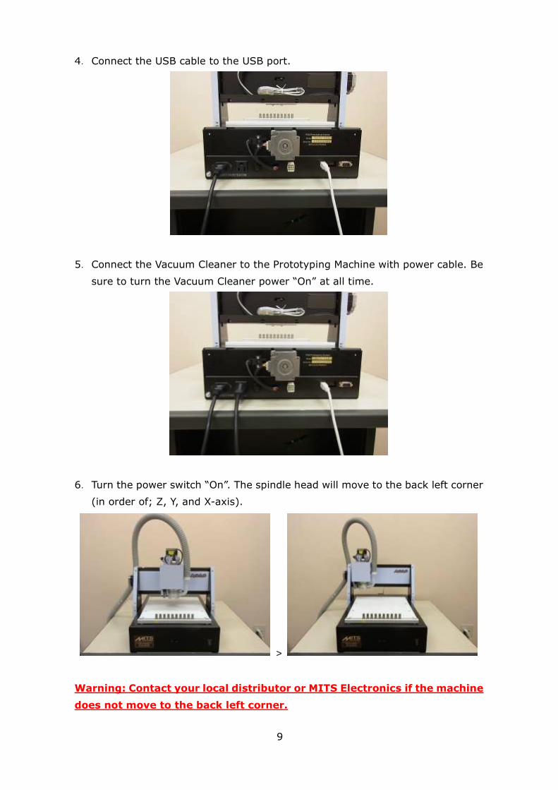
4. Connect the USB cable to the USB port.
5. Connect the Vacuum Cleaner to the Prototyping Machine with power cable. Be
sure to turn the Vacuum Cleaner power “On” at all time.
6. Turn the power switch “On”. The spindle head will move to the back left corner
(in order of; Z, Y, and X-axis).
>
Warning: Contact your local distributor or MITS Electronics if the machine
does not move to the back left corner.
10
Communication Port Settings
After you finished connecting your PC and PCB prototyping machine, set up the
correct communication between them for the correct operation.
1. Turn on your personal computer.
2. Turn on your PCB prototyping machine.
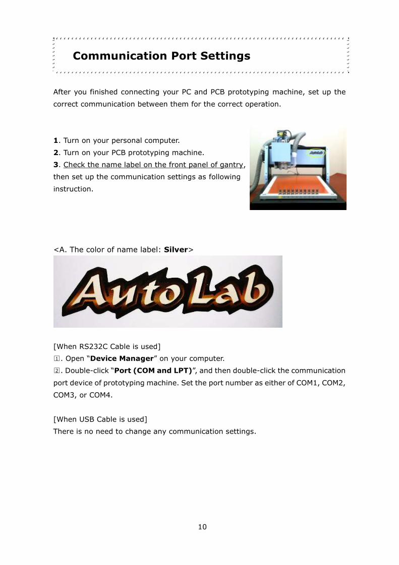
3. Check the name label on the front panel of gantry,
then set up the communication settings as following
instruction.
<A. The color of name label: Silver>
[When RS232C Cable is used]
□1 . Open “Device Manager” on your computer.
□2 . Double-click “Port (COM and LPT)”, and then double-click the communication
port device of prototyping machine. Set the port number as either of COM1, COM2,
COM3, or COM4.
[When USB Cable is used]
There is no need to change any communication settings.

11
<B. The color of name label: Gold>
[When RS232C Cable is used]
□1 . Open “Device Manager” on your computer.
□2 . Double-click “Port (COM and LPT)”, and then double-click the communication
port device of prototyping machine. Set the port number as either of COM1, COM2,
COM3, or COM4.
[When USB Cable (VCP: Virtual COM Port communication) is used]
□1 . Open “Device Manager”, and double-click “Ports (COM & LPT)”.

12
□2 . Double-Click “USB Serial Port (COMX)” (X = Number). Skip section 3 to 5 if
the COM port No. is set as either of COM1, COM2, COM3, or COM4.
□3Click “Port Settings”.

13
□4 . Click “Advanced…”.
□5Click pull-down menu of “COM Port Number”, then select either of COM1, COM2,
COM3, of COM4. There is no problem if you select a COM number marked as “(in
use)”.
Click “OK” to finish the settings.

14
4. Open MITS Design Pro.
Start >> Program >> Mits Design Pro >> Design Pro
Note: USB Drivers
USB driver for MITS PCB prototyping machines is already applied when you
installed Design Pro, and the driver will be automatically detected for the first time
you turn on your prototyping machine if PCB prototyping machine and your PC are
connected with USB cable.
Attention:
The communication fails sometimes if you start up your PC after turning on PCB
prototyping machine. In this case, retry the communication after you restart the
PCB prototyping machine.
>> Does the machine still have a problem?
See Trouble Shooting [Trouble Shooting (USB, RS232C Serial Connection) - p.59]

15
Starting Up CAM-Auto
CAM-Auto is one of the applications which operate on MITS Design Pro, and this
application controls Auto Lab.
This application is used when you prototype PCBs based on the data made by using
Converter or EASY CAD.
Click “Application” on the right of the window. Select “CAM-Auto”.
Click “CAM Prefs.” >> “Board Maker Settings”.

16
Click pull-down menu on the right of “RS232C port”. Select correct
Communication Port number as you set in the section, Communication Port
Settings (Page 10 – 14).
(If the name label of your prototyping machine is Silver, and the connection is USB
cable, select “USB” here)
Click “OK” and restart the software Design Pro, otherwise the settings are not
applied.
17
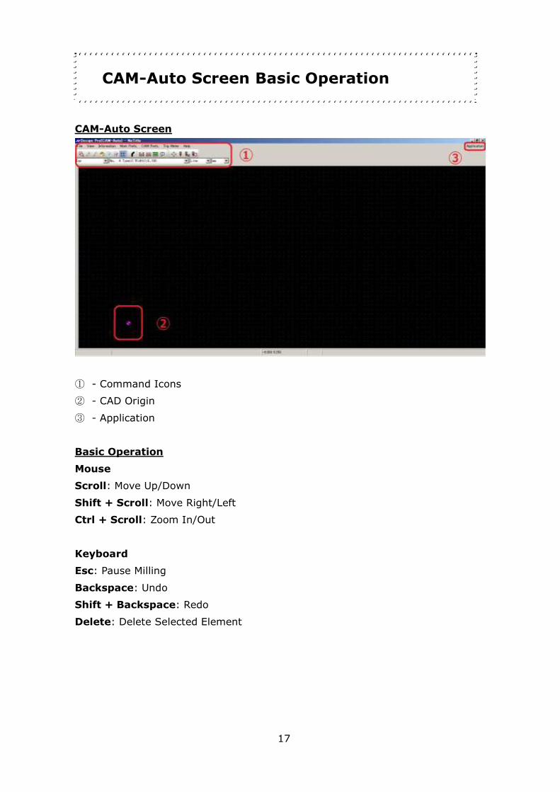
CAM-Auto Screen Basic Operation
CAM-Auto Screen
① - Command Icons
② - CAD Origin
③ - Application
Basic Operation
Mouse
Scroll: Move Up/Down
Shift + Scroll: Move Right/Left
Ctrl + Scroll: Zoom In/Out
Keyboard
Esc: Pause Milling
Backspace: Undo
Shift + Backspace: Redo
Delete: Delete Selected Element

18
1. Procedures
The below is the procedures to produce prototype PCB.
Preparation
- Open “mdemo.mit” file
- Setup underlay and PCB
:
Setup Tools
:
Set Milling Sequence
:
Adjustment
- Set P1P2
- Adjust Milling Width
- Drill Fiducial Holes
- Camera Offset
:
Process Top Layer
- Drill (Top)
- Mill (Top)
:
Adjustment before Bottom Layer
:
Process Bottom Layer
- Mill (Btm)
- Route (Btm)

19
2. Preparation
First you will begin with the below steps.
1 - Open mdemo.mit file (1~2)
2 - Set underlay and PCB on working table (3~4)
mdemo.mit file (below)
After setup (below)

20
1. Click on Application and select CAM-Auto
2. Open mdemo.mit file. The files are saved as below for each OS.
Windows 10:
Local Disk (C:) >> Users >> Public >> Documents >> Mits Software >> MT
Path >> Data >> mdemo.mit
Windows 7:
Local Disk (C:) >> Users >> Public >> Documents >> Mits Software >> MT
Path >> Data >> mdemo.mit
Windows Vista:
Public >> Documents >> Mits Software >> MT Path >> Data >> mdemo.mit
Windows XP:
Local Disc (C:) >> Documents and Settings >> All Users >> Shared
Document >> Mits Software >> MT Path >> Data >> mdemo.mit
21
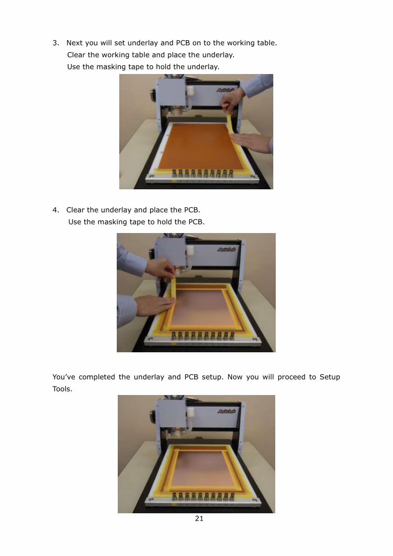
3. Next you will set underlay and PCB on to the working table.
Clear the working table and place the underlay.
Use the masking tape to hold the underlay.
4. Clear the underlay and place the PCB.
Use the masking tape to hold the PCB.
You’ve completed the underlay and PCB setup. Now you will proceed to Setup
Tools.

22
3. Setup Tools
Now you will prepare the tools. Below are the items you will use in this chapter.
-Simplified Ring Setter
-Tool Rings
-Ring Setter Tube 18mm, 20mm
-Tools
You will set the tool rings on to the tools and set them on the tool post.

23
1. Go to Information >> Tool List
2. Tool List window will appear. Scroll down to check Tool Size and Post No. for
each Layer Name and prepare appropriate tools for it.
The tools used for each layer is shown like below.
Mill Top: Milling Bit 90°
Mill Bottom: Milling Bit 90°
Routing: Router Bit 1.0mm
Drill: Drill Bit 0.8mm
24
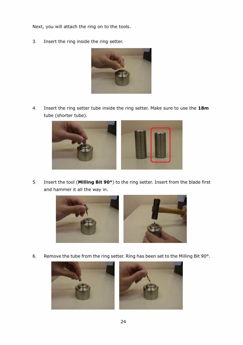
Next, you will attach the ring on to the tools.
3. Insert the ring inside the ring setter.
4. Insert the ring setter tube inside the ring setter. Make sure to use the 18m
tube (shorter tube).
5. Insert the tool (Milling Bit 90°) to the ring setter. Insert from the blade first
and hammer it all the way in.
6. Remove the tube from the ring setter. Ring has been set to the Milling Bit 90°.
25
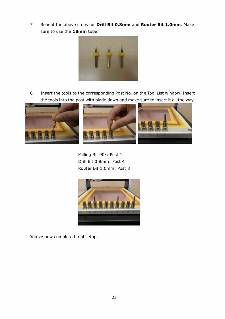
7. Repeat the above steps for Drill Bit 0.8mm and Router Bit 1.0mm. Make
sure to use the 18mm tube.
8. Insert the tools to the corresponding Post No. on the Tool List window. Insert
the tools into the post with blade down and make sure to insert it all the way.
Milling Bit 90°: Post 1
Drill Bit 0.8mm: Post 4
Router Bit 1.0mm: Post 8
You’ve now completed tool setup.

26
4. Set Milling Sequences
Now you will set Milling Sequence. The sequence will be as shown below.
- Drill (Top)
- Mill (Top)
- Mill (Btm)
- Routing (Btm)
27
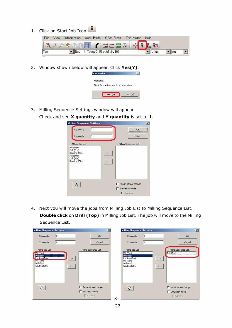
1. Click on Start Job Icon
2. Window shown below will appear. Click Yes(Y).
3. Milling Sequence Settings window will appear.
Check and see X quantity and Y quantity is set to 1.
4. Next you will move the jobs from Milling Job List to Milling Sequence List.
Double click on Drill (Top) in Milling Job List. The job will move to the Milling
Sequence List.
>>

28
5. Repeat the above and move the below jobs to the Milling Sequence List.
- Mill (Top)
- Mill (Btm)
- Routing (Btm)
6. Click OK and the machine will move.
Now Milling Sequence setting is completed. After you finish setting Milling
Sequence, “Board Top/Bottom Change window” will appear.
>> Read through next chapter to continue.
29
5. Adjustment
In this chapter, you will do the below steps.
1 - Set P1 P2 (2~5)
2 - Set Camera Offset (6~14)
3 - Set Milling Width (15~17)
4 - Drill Fiducial Holes (18~25)
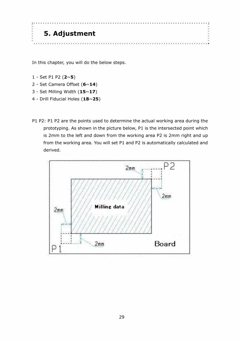
P1 P2: P1 P2 are the points used to determine the actual working area during the
prototyping. As shown in the picture below, P1 is the intersected point which
is 2mm to the left and down from the working area P2 is 2mm right and up
from the working area. You will set P1 and P2 is automatically calculated and
derived.
30
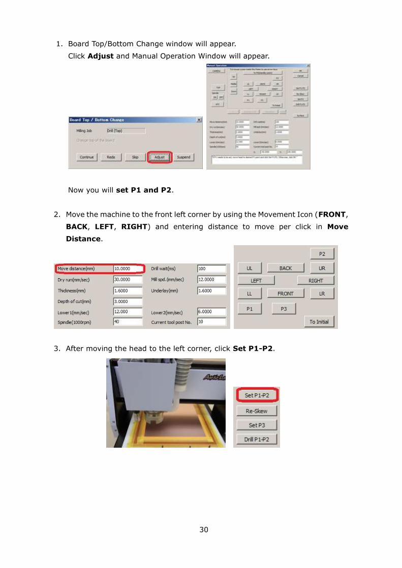
1. Board Top/Bottom Change window will appear.
Click Adjust and Manual Operation Window will appear.
Now you will set P1 and P2.
2. Move the machine to the front left corner by using the Movement Icon (FRONT,
BACK, LEFT, RIGHT) and entering distance to move per click in Move
Distance.
3. After moving the head to the left corner, click Set P1-P2.
31
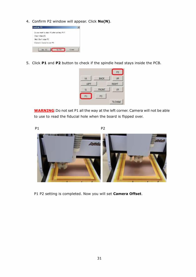
4. Confirm P2 window will appear. Click No(N).
5. Click P1 and P2 button to check if the spindle head stays inside the PCB.
WARNING:Do not set P1 all the way at the left corner. Camera will not be able
to use to read the fiducial hole when the board is flipped over.
P1 P2
P1 P2 setting is completed. Now you will set Camera Offset.

32
6. First, click P1 button.
7. Now you will change tools.
Click ATC button.
Auto Tool Change window will appear. Enter 1 in Pick up (At this time, Put back
to is masked and displayed as 10). Make sure to check tool post 10 on the
machine is empty and click OK.
The Machine will change the tool automatically. It will put the current tool to
Put back to post and pick up from Pick up post.
> >

33
> >
Tool Change is completed.
Use the depth adjustment screw to make the tip of the tool same height level
as the pressure foot. The tool will move down when the depth adjustment is
rotated clock-wise and up when rotated counter clock-wise.
IMPORTANT: The tool will move up/down 3μm with 1 click on depth adjustment
screw. 1 revolution will be 0.5mm.

34
8. Click ON to turn the spindle on and click DOWN to move the spindle head
down.
9. Click UP to move the spindle head back up and OFF to turn the spindle off.
10. Now you will check if the surface of the board has been milled. Repeat 8~10
until the board is milled.
11. When the surface of the board is milled, clicked CAMERA. The head will move
to camera position.
>>

35
12. Launch Design View.
If the Design View does not display image from the USB camera, click Source
and select appropriate camera.
13. Use the switch on the camera USB cable to adjust the light.
>>
14. Next you will set the camera.
Click Marker button and click on the checkbox for ON and Stay on top.
Marker will be displayed on the window and Marker setting will be shown below.
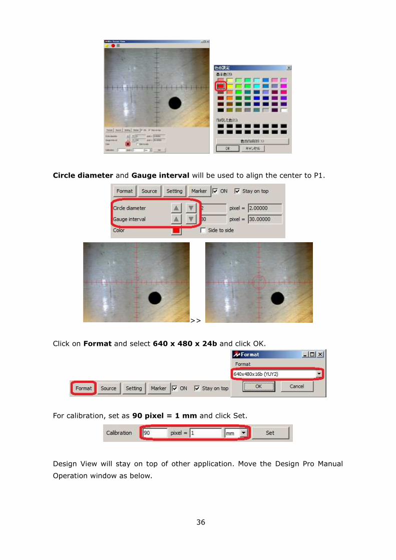
Click on the Black colored box and set the color of the marker. Click and select a
color which is easy for you to see, and click OK.
36
Circle diameter and Gauge interval will be used to align the center to P1.
>>
Click on Format and select 640 x 480 x 24b and click OK.
For calibration, set as 90 pixel = 1 mm and click Set.
Design View will stay on top of other application. Move the Design Pro Manual
Operation window as below.
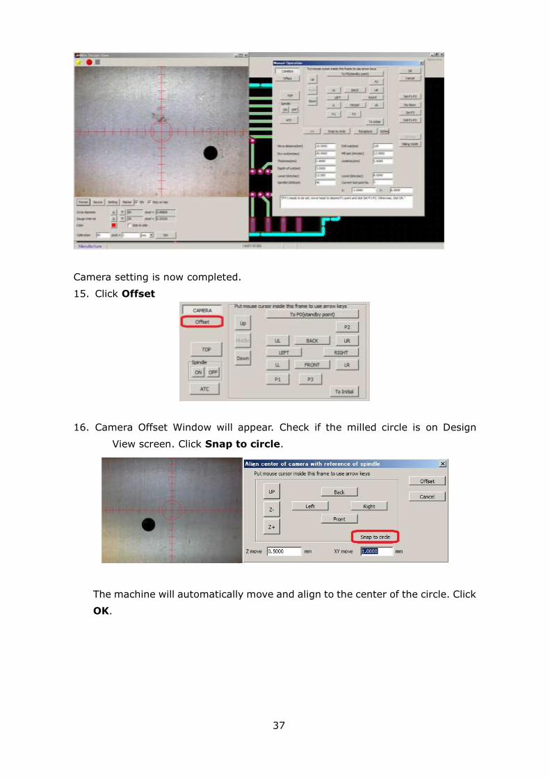
37
Camera setting is now completed.
15. Click Offset
16. Camera Offset Window will appear. Check if the milled circle is on Design
View screen. Click Snap to circle.
The machine will automatically move and align to the center of the circle. Click
OK.
38
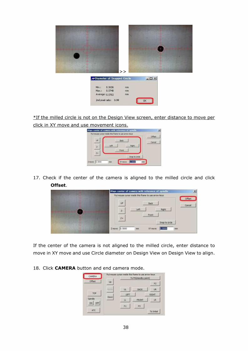
>>
*If the milled circle is not on the Design View screen, enter distance to move per
click in XY move and use movement icons.
17. Check if the center of the camera is aligned to the milled circle and click
Offset.
If the center of the camera is not aligned to the milled circle, enter distance to
move in XY move and use Circle diameter on Design View on Design View to align.
18. Click CAMERA button and end camera mode.

39
Camera offset is now completed. Now you will set milling width.
19. Click P2.
20. Move the spindle head 5mm to the right by entering the Move Distance 5 and
clicking RIGHT button once.
Click CAMERA button and click Milling Width.
21. Check Milling Width window will appear. Click Go.
22. The machine will automatically mill and measure the milling width. The result
will be shown soon after that. Use the depth adjustment screw to set it to

40
0.3mm. Rotate the depth adjustment screw clock wise to widen the milling
width and counter clockwise to thin it.
23. After depth adjustment screw is set, click Go again. The machine will
automatically move 1mm back and mill.
41
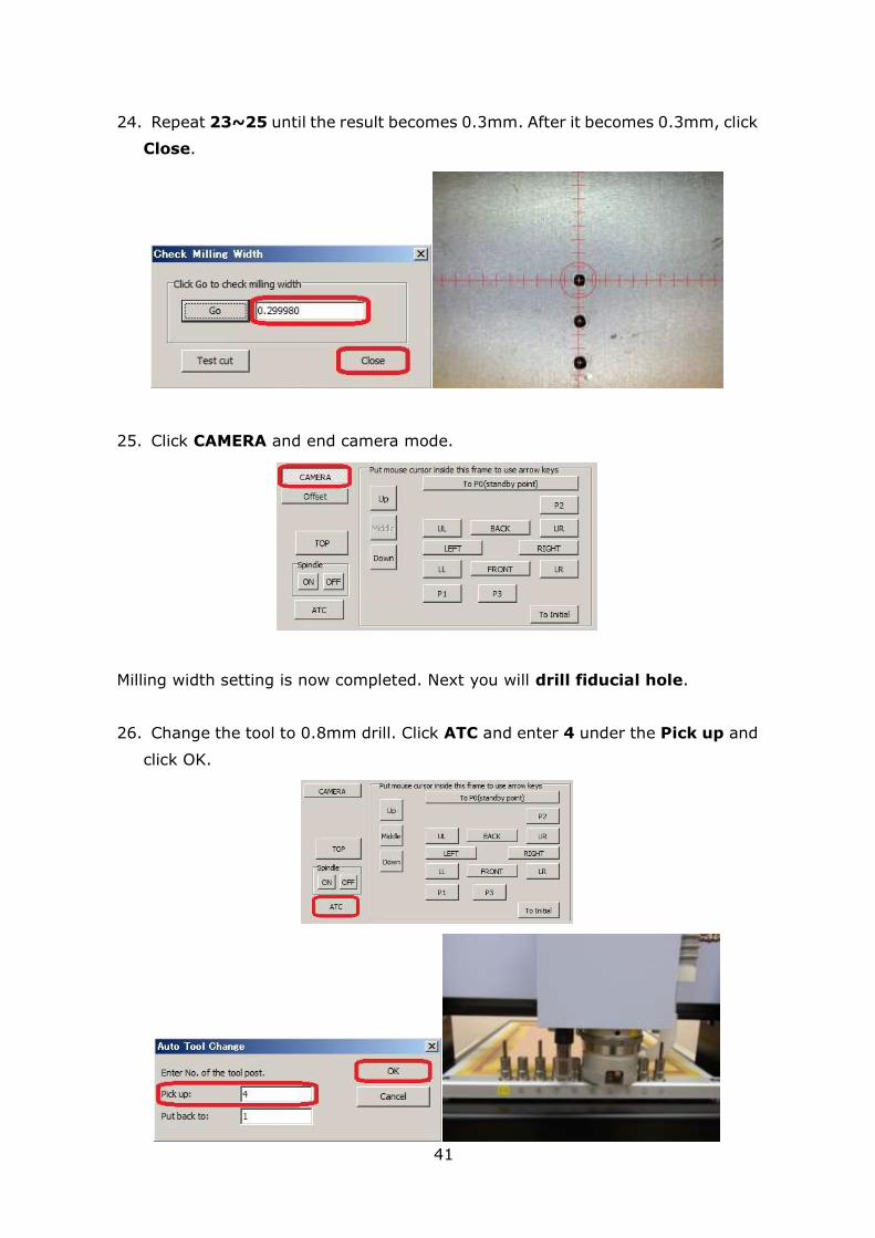
24. Repeat 23~25 until the result becomes 0.3mm. After it becomes 0.3mm, click
Close.
25. Click CAMERA and end camera mode.
Milling width setting is now completed. Next you will drill fiducial hole.
26. Change the tool to 0.8mm drill. Click ATC and enter 4 under the Pick up and
click OK.

42
27. Click Drill P1-P2. Confirmation of drilling holes window will appear.
Click Yes(Y). The machine will automatically move to P1P2 and drill holes.
28. Click CAMERA button to double-check the offset. If the P1 and the center of
the Design view is not aligned, repeat 16~18.
29. Click OK on the Manual Operation window.
Adjustment is now completed. You will now move on to Process Top Layer.

43
6. Process Top Layer
Next you will process Top layer of the PCB.
1 – Drill (Top) (1~3)
2 – Mill (Top) (4~5)
Drill Top (Below)
Mill Top (Below)
Top Layer Completed (Below)
44
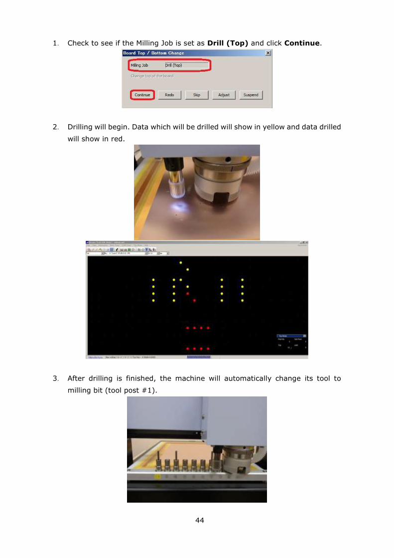
1. Check to see if the Milling Job is set as Drill (Top) and click Continue.
2. Drilling will begin. Data which will be drilled will show in yellow and data drilled
will show in red.
3. After drilling is finished, the machine will automatically change its tool to
milling bit (tool post #1).

45
4. Milling will begin. Data which will be milled will show in yellow and data milled
will show in red.
5. After milling, the spindle head will move backwards.
Top layer prototype is now completed. Next you will flip the board over and align
the fiducial points (P1 P2 points).
46
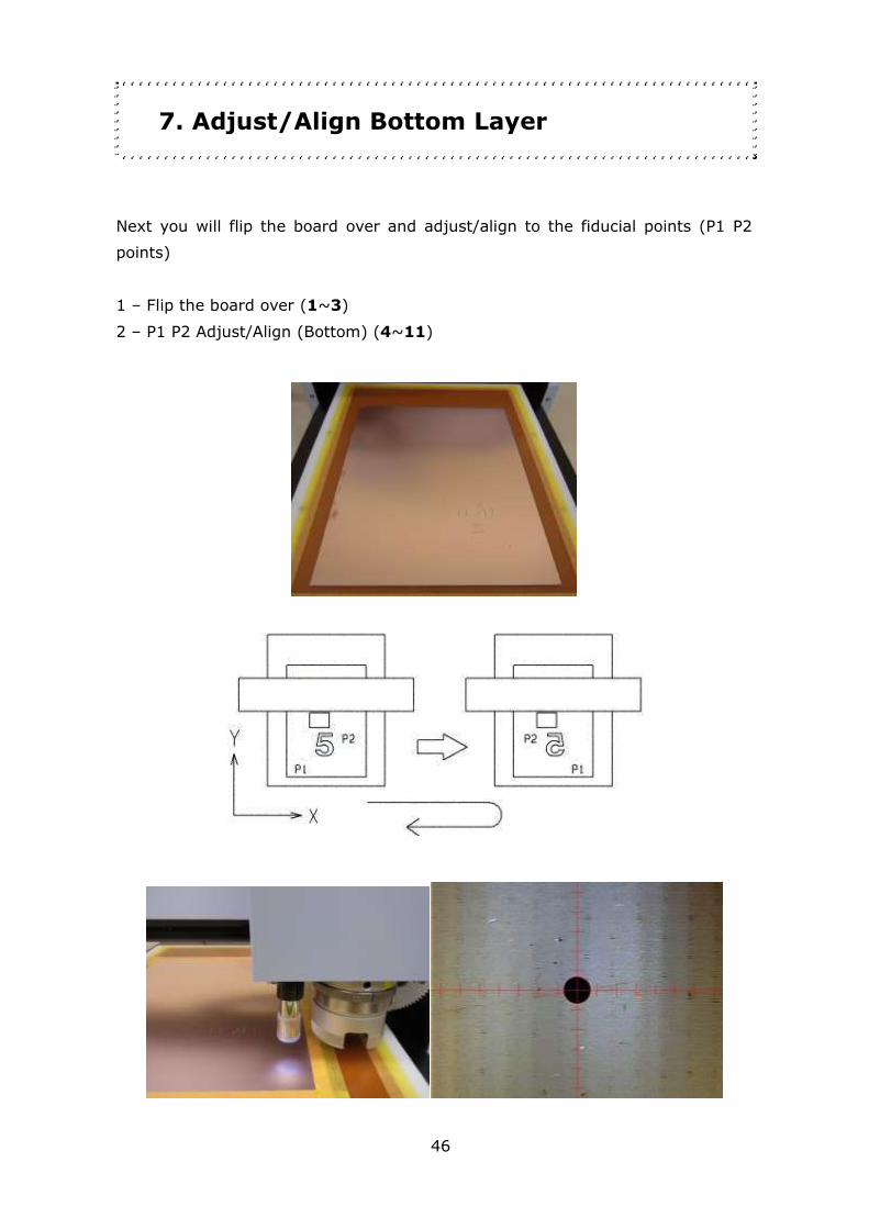
7. Adjust/Align Bottom Layer
Next you will flip the board over and adjust/align to the fiducial points (P1 P2
points)
1 – Flip the board over (1~3)
2 – P1 P2 Adjust/Align (Bottom) (4~11)

47
Remove the tape on the PCB. Do not throw them away, they will be reused.
1. Flip the board over. Bring the left side of the board to the right side when it is
flipped over.
>>
2. Move the PCB to the left side and reused the tape to hold it down.
>>
Next you will adjust/align P1 P2.

48
3. On Design Pro, Board Top / Bottom Change window is shown. Click Adjust.
4. Manual Operation window will show up. Click on P1.
5. Open Design View and click CAMERA button in Manual
Operation window.
6. Use the movement button (FRONT, BACK, RIGHT, LEFT) to find the P1 hole on
the Design View screen.
49
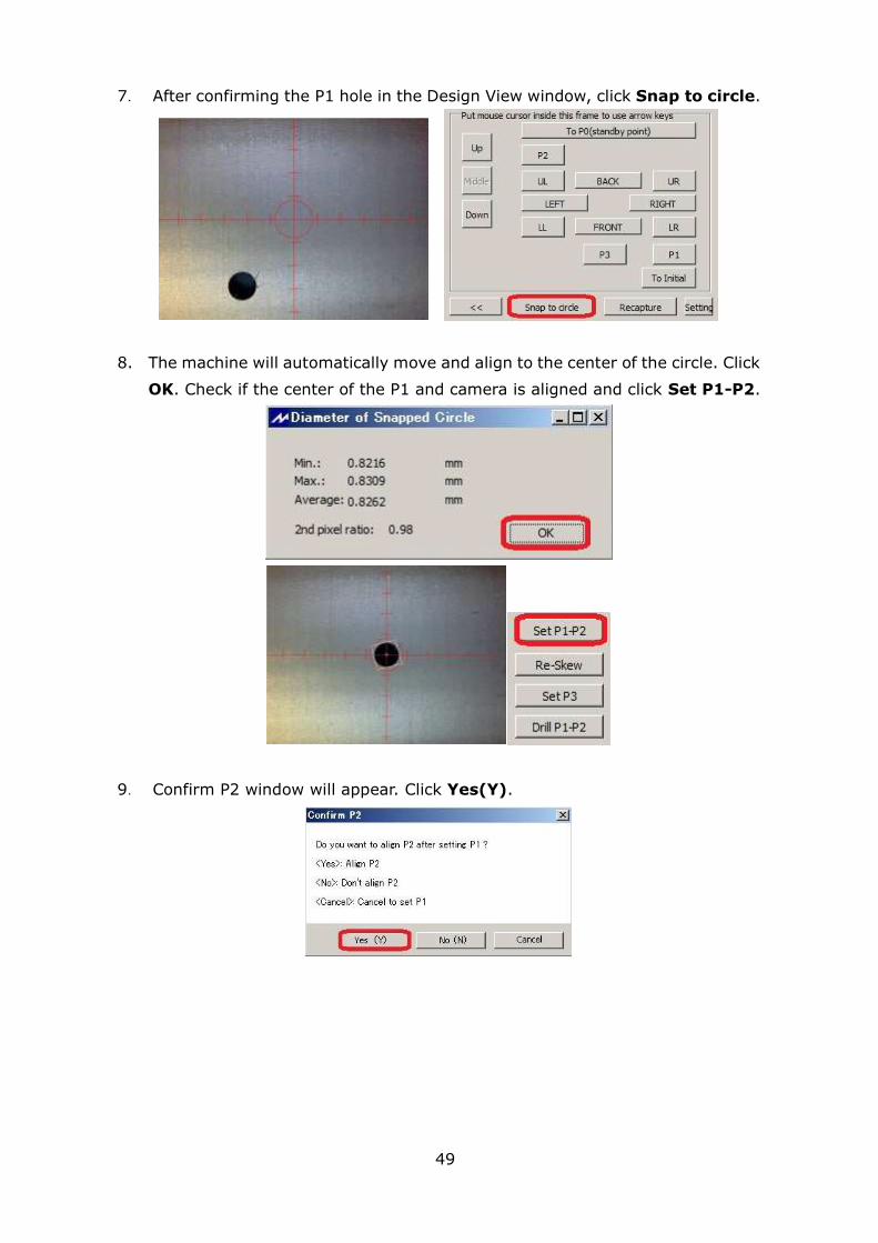
7. After confirming the P1 hole in the Design View window, click Snap to circle.
8. The machine will automatically move and align to the center of the circle. Click
OK. Check if the center of the P1 and camera is aligned and click Set P1-P2.
9. Confirm P2 window will appear. Click Yes(Y).

50
10. The machine will move to P2. Repeat 7~9 to use Snap to circle and align
center of the P2 to the camera and click Set P1-P2.
11. Click OK on the Manual Operation window.
Bottom layer adjust/align is completed.

51
8. Process Bottom Layer
Lastly, it is the prototyping of the bottom layer.
1 – Drill (Btm) (1~3)
2 – Routing (Btm) (4~6)
Milling Bottom (Below)
Routing Bottom (Below)
Bottom Layer Completed (Below)

52
1. Check to see if the Milling Job is set as Mill (Btm) and click Continue.
2. Milling will being. Data which will be milled will show in yellow and data milled
will show in red.
3. After drilling is finished, the machine will automatically change its tool to
router bit (tool post #8).
53
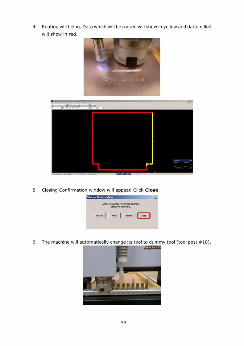
4. Routing will being. Data which will be routed will show in yellow and data milled
will show in red.
5. Closing Confirmation window will appear. Click Close.
6. The machine will automatically change its tool to dummy tool (tool post #10).
54
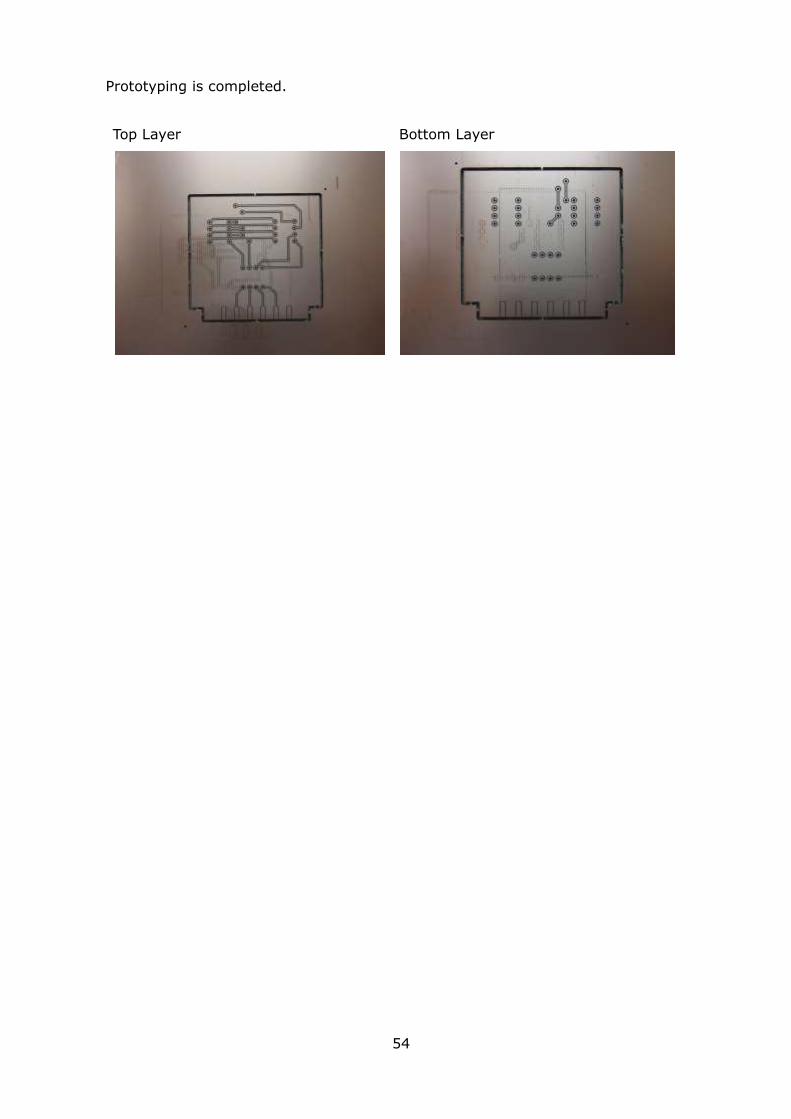
Prototyping is completed.
Top Layer Bottom Layer

55
9. After Completed
Remove the masking tape from the PCB and use the brush to scrub the PCB.
Use the cutter knife or nipper to separate the finished PCB from the blank PCB.
Turn the power switch off.
All operation is finished now.
56
Trouble Shooting (USB,RS232C Serial Connection)
1. Prototyping Machine does not activate after clicking Start Job icon
Enter SHIFT + ESC on the keyboard. Check the below points:
- Prototyping Machine Switch is On
- RS-232C Serial Cable/USB Cable is not connected
* For RS-232C Serial Cable, use Straight connection cable.
Do not use reverse/cross connection.
- If you are using USB, go to WINDOWS Device Manager in Control Panel.
Check MITS USB driver is properly installed.
* If the Prototyping Machine does not activate with properly installed MITS
USB driver, go to CAM Prefs. >> Board Maker in Design Pro. Set the
RS232C port to USB. Click OK on the Board Maker Setting window and
close Design Pro. The setting changed will be applied after the software is
closed.
2. Port Open Error message appears after clicking Start Job icon
- Go to CAM Prefs. >> Board Maker and select the port/cable you are
using on RS232C port.
- After selecting to the port, close Design Pro. The changes will be applied
after the software is closed.
Prototyping Machine does not activate after clicking Start Job icon.
If the connection does not suspend after entering SHIFT + ESC on the
keyboard;
- Turn the Power Switch Off and enter SHIFT + ESC again.
- Go to Control Panel >> Device Manager. Change the setting for USB Root
Hub. (See next page)

57
<USB Root Hub Setting>
Go to Device Manager. Right click on USB Root Hub and select Properties.
Select Power Management tab and remove the check mark in the box for
Allow the computer to turn off this device to save power.
Repeat the above for all of the USB Root Hub in Device Manager.
After setting has been changed, restart your computer.
If the connection trouble with USB cable does not resolve with the above,
please use the USB Serial converter cable. We kindly ask you to source
locally.

58
Trouble Shooting (Prototyping Machine)
- Working Area
When the machine moves out of the working area during processing or
manual operation, the error message will appear.
Hardware Limit Error: Recovery (Manual Operation)
Click Initial. The spindle head will move to initial position and recover from
hard limit error.
Hardware Limit Error: Recovery (While Processing)
Click Suspend.
If is shown and stays, enter SHIFT + ESC on the keyboard.
After doing so, turn the power switch off and back on.
- Step-Out (Losing step)
When step-out occurs, the software coordinates and the actual coordinates will
be misaligned. Click Initial button in Manual Operation window to move the
spindle head to initial position to realign the origin coordinates.
- Lubricate Lead Screw
Lubricate the lead screw using the oil when abnormal sounds occur from the X,
Y, Z-axis while processing. After coated with the oil, move the spindle head
with manual operation to coat evenly.
(Suggested Product: STP OIL TREATMENT)
Related Documents


