
Welcome message from author
This document is posted to help you gain knowledge. Please leave a comment to let me know what you think about it! Share it to your friends and learn new things together.
Transcript


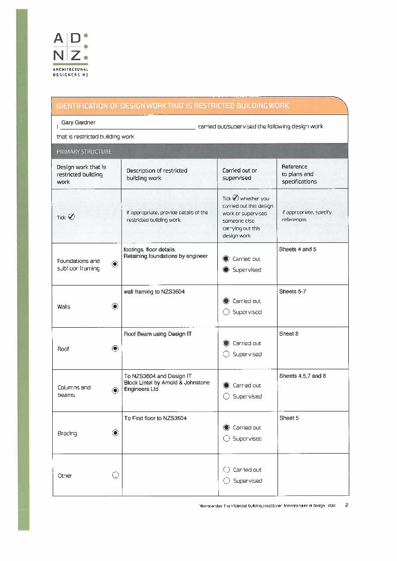
CALCULATIONS AND PRODUCT LITERATURE,
of work to be done and materials to be used in carrying
out the works shown on the accompanying drawings
M & C MAC DONALD
36 OMOKOROA ROAD
OMOKOROA
• GCG Design MOD • Risk Matrix Calculations • Bracing Calculations • Gib Bracing Literature • Design IT Producer Statement • Design Navigator H1 Calculations • SaniPlus Literature • Ardex X3000 Literature • Ardex WPM300 Hydrepoxy Literature
Job Number: GCG 2118 Date: 29th October 2018 GCG DESIGN LTD 79B BEACH ROAD MATUA TAURANGA 3110 Ph 07 5701386 Email [email protected]


G.C.GBUILDING RISK ASSESSMENT Design
Job DetailsName M & C MacDonaldStreet and Number 36 Omokoroa Road, OmokoroaCity/Town/District Western Bay DistrictNumber of storeys 2
Cladding Type:Ground Floor 7.5mm Hardiflex on 20mm Cavity BattensFirst Floor ex 200x25 Horizontal Rusticated Weatherboard n 20mm Cavity Battens
Existing Direct Fix Hardiflex
A: Wind zone: RISK NORTH WEST SOUTH EAST As described by NZS3604 Low or Medium (0)
High (1) 1 1Very High (2)
B: Number of Storeys:Single level (1 storey) Low (0) 0Two storeys in part Medium (1) 1Two storeys High (2)More than Two storeys Very High (4)
C: Roof / Wall intersection design:Hip and gable roof with eaves Low (0) 0 0Hip and gable roof: NO eaves Medium (1)Parapets or Eaves above 90° High (3)Roof elements finishing within boundaries Very High (5)formed by walls, eg lower ends of aprons or chimneys
D: Eaves width:Greater than 600 mm for single storey Low (0)451 - 600 at GL, over 600 at second level Medium (1)101 - 450 at GL, 451 - 600 at second level High (2) 20 - 100 at GL, 0 - 450 at second level Very High (5) 5or less than 600mm above 2 stories
E: Envelope complexity:Single cladding, Box L or T shape Low (0)Max 2 Claddings , angular/curved shapes Medium (1) 1 1Multiple cladding, complex shapes High (3)all others, Box windows, pergolas etc Very High (6)
F: Deck Design:No Deck, Timber slat deck at GL or porch Low (0) 0 0Fully covered in plan by roof, or at first floor Medium (2)Enclosed deck exposed or cant first flr High (4)Enclosed deck exposed or cantilevered at Very High (6)second floor level or above
TOTAL POINTS 8 4 0 0
Requirements Ground Floor 7.5mm Hardiflex on 20mm Cavity BattensFirst Floor ex 200x25 Horizontal Rusticated Weatherboard n 20mm Cavity Battens
Existing Direct Fix Hardiflex

WALL BRACING CALCULATION SHEET A G.C.GM & K MACDONALD Design
Job DetailsName M & K MACDONALDStreet and Number 36 Omokoroa Road, OmokoroaLot and DP Number Lot 12, DPS 4749City/Town/District Western Bay DistrictLocation of Storey: First FloorBuilding Height to apex 4.7 m Roof weight lightRoof height above eaves 1.4 m Cladding Weight lightStud height 2.4 m Room in roof space noAverage roof pitch 12.5 degreesBuilding length BL= 3.6 m Gross BuildingBuilding width BW= 7.9 m Plan Area GPA= 28.44 m2NOTE: When the average roof pitch is over 25 degrees, use the eaves length and width to determine BL and BW.NOTE: For heavy roofs use the roof plan at eaves level to determine GPA
Wind ZoneRegion: AHill Height/formation HillGradient MildTopography OuterExposure ExposedTopograpy Class T2
Wind Zone: High
Earthquake Zone
From figure EQ1 select Earthquake Zone: 1
BUs required for Wind BUs required for EarthquakeFrom Table W1A/W1B From Table EQ1
W along = 55 BUs/m E = 5.5 BUs/m2W across= 50 BUs/m Soil class type D(15x.5)Total wind load NOTE: For a room in the roof space use E + 1
W ALONG Total earthquake load,W along x BW = 434.5 BUs EQ ALONG and EQ ACROSSW ACROSSW across x BL = 180 BUs E x GPA BUs = 156.42 BUs

WALL BRACING CALCULATION SHEET B G.C.GFor M & K MACDONALD Design
AlongWall or
Bracing Line
Bracing Elements Provided Wind Earthquake
1 2 3 4 5 6W 7W 6E 7ELine Label Minimum
BUs RequiredBracing Element
No.
Bracing Type Length Element (m)
L
Rating BUs/m W
BUs Achieved (BU/m x L) W
Rating BUs/m E
BUs Achieved (BU/m x L) E
A 100 A1 BL1-H 1.4 120 168 105 147
B 100 B1 GS1-N 0.8 70 56 60 48B2 GS1-N 1.4 70 98 60 84
C 100 C1 BL1-H 0.8 90 72 100 80C2 BL1-H 0.7 90 63 100 70
Totals Achieved W 457 E 429
From Sheet A Totals Required W 434.5 E 156.42Wreq/Ereq = 2.78
AcrossWall or
Bracing Line
Bracing Elements Provided Wind Earthquake
1 2 3 4 5 6W 7W 6E 7ELine Label Minimum
BUs RequiredBracing Element
No.
Bracing Type Length Element (m)
L
Rating BUs/m W
BUs Achieved (BU/m x L) W
Rating BUs/m E
BUs Achieved (BU/m x L) E
M 100 M1 GS1-N 1.8 70 126 60 108
N 100 N1 GS1-N 1.7 70 119 60 102
O 100 O1 GS1-N 3.7 70 259 60 222
Totals Achieved W 504 E 432From Sheet A Totals Required W 180 E 156.42Wreq/Ereq = 1.15

EzyBrace® SystemsSpecification and installation manual
CBI 5113
AUGUST 2016
NATIONAL SUPPORTVISIT: Winstone Wallboards Limited
37 Felix Street, Penrose,
Auckland 1061, New Zealand
POST: PO Box 12 256, Penrose 1642,
Auckland, New Zealand
PHONE: +64 9 633 0100
FAX: +64 9 633 0101
Free Fax: 0800 229 222
EMAIL: [email protected]
WEB: gib.co.nz
GIB® HELPLINE
0800 100 442
GIB EZYBRACE® SYSTEMS2 CALL OUR HELPLINE 0800 100 442 OR VISIT GIB.CO.NZ FOR MORE INFO AUGUST 2016

Based on learnings derived from the 2011 Canterbury earthquakes GIB EzyBrace® Systems have been updated to offer improved design flexibility and further simplification of the bracing design and build process.
NEW GIB EZYBRACE® 2016 DESIGN SOFTWARE — Improved user interface with simplified bracing
design process. — Increased functionality including exterior line check
function, easy insert/deletion of bracing elements and built in software help function.
— Includes the new GIB® Bracing element GS2- NOM — Allows the GIBFix® Framing System to be used in
GIB EzyBrace® designs.
NEW GIB® BRACING ELEMENT GS2-NOM — Allows internal walls lined with GIB® plasterboard on
both sides and fastened off as per the standard fixing requirements of the current GIB® Site Guide to contribute to bracing resistance.
— Potentially reduces the amount of fasteners1 — Encourages more even bracing distribution throughout
the building.1 Actual savings dependent on building and bracing design
UPDATE TO OPENINGS IN BRACING ELEMENTS AND CEILING DIAPHRAGMS
— Large hole specification updated to use a more conservative methodology.
— Guidance included for fireplace flues and range hoods.
NEW — GIBFIX® FRAMING SYSTEM — Reduced potential for fastener pop and joint cracking as a
result of timber frame movement. — Reduced potential for on-site call backs. — Improved thermal performance. — Reinforced plasterboard junctions.
Appraisal No .928 [2016]
Appraisal No .928 [2016]
Appraisal No .928 [2016]
GIB EZYBRACE® SYSTEMS 3CALL OUR HELPLINE 0800 100 442 OR VISIT GIB.CO.NZ FOR MORE INFOAUGUST 2016

CONTENTS
System Summary 5GIB EzyBrace® Systems — August 2016 5GIB® Plasterboard Substitution Table 5
Introduction 6Scope of Use 6Finish Quality — Framing and Substrates 6New GIBFix® Framing Systems 6New GS2-NOM Bracing Element 6Compliance with the NZ Building Code 7CAD Design Detail 7Appraisal 7
Bracing Resistance and Demand 8Bracing Resistance 8Bracing Demand 9Software Functionality 10
Design and Construction 12GIB® Plasterboard Linings 12GIB EzyBrace® Systems in Water-Splash Areas 12Renovation 12Openings in Bracing Elements 12Timber Framing 13GIBFix® Framing System (Alternative Layout) 13Guidelines for Intersection Walls 13Top Plate Connections 14Parapets and Gable End Walls 14Bottom Plate Fixing 14Bracing Strap Installation 15GIB HandiBrac® Installation 16GIB HandiBrac® Placement with GIBFix® Framing System Layout 17Ceiling Diaphragms 18Ceiling Battens in Ceiling Diaphragms 19Openings in Ceiling Diaphragms 20Length of GIB EzyBrace® Elements ('N' Type) 21Length of GIB EzyBrace® Elements ('H' Type) 22
System Specifications 23GIB EzyBrace® Systems Specification — GS1-N 23GIB EzyBrace® Systems Specification — GS2-NOM 24GS2-NOM Adhesive Fixing Option at Door Jambs 25GIB EzyBrace® Systems Specification — GS2-N 26GIB EzyBrace® Systems Specification — GSP-H 27GIB EzyBrace® Systems Specification — BL1-H 28GIB EzyBrace® Systems Specification — BLG-H 29GIB EzyBrace® Systems Specification — BLP-H 30
Sustainability and the Environment 31
GIB EZYBRACE® SYSTEMS4 CALL OUR HELPLINE 0800 100 442 OR VISIT GIB.CO.NZ FOR MORE INFO AUGUST 2016

GIB EzyBrace® Systems — August 2016
Winstone Wallboards Ltd accepts no liability if GIB EzyBrace® Systems are not designed and installed in strict accordance with instructions contained in this publication.
USE ONLY THE CURRENT SPECIFICATIONThis publication may be superseded by a new publication at any time. Winstone Wallboards accepts no liability for reliance upon publications that have been superseded. Check for the current publication at gib.co.nz/library before using this publication. If you are unsure whether this is the current publication, call the GIB® Helpline on 0800 100 442.
GIB EzyBrace® 2011 software and specification literature remains valid until futher notice.
PATENTS GIBFix® Framing System and GIB EzyBrace® Systems, including componentry and design method, have patents pending (NZ Patent Number 596691, NZ Patent 709159 pending) and design and other IP rights reserved.
Beware of substitution
The performance of GIB® Systems are very sensitive to design detailing and construction practices. All GIB® Systems have been developed specifically for New Zealand conditions and independently tested or assessed to ensure the required level of performance. It is important to use only GIB® branded components where specified and to closely follow the specified design details and construction practices, to be confident that the required level of performance and quality is achieved on site.
For further information call our GIB® Helpline on 0800 100 442.
GIB EzyBrace® Systems have been designed and tested using only the products specified. When additional GIB® plasterboard properties are required the table below provides acceptable alternative options.
SYSTEM SUMMARY
Acceptable alternative GIB® plasterboards
Specified GIB® plasterboard
GIB® Standard
GIB Ultraline®
GIB Braceline/ Noiseline®
GIB Aqualine®
GIB Toughline®
GIB Fyreline®
10mm 13mm 16mm 19mm
GIB® Standard OK OK OK OK Note 1 and 3
GIB Braceline® X X Note 2 OK X Notes 1, 2 and 3
Note 1 The fastener type and length must be as required for the relevant FRR system using the perimeter fixing pattern illustrated for the relevant bracing specification.
Note 2 The element must be 900mm or longer. Decrease perimeter fastener centres to 100mm. The bracing corner fastening pattern, as illustrated for the relevant specification applies to all four corners of the element. Panel hold-down fixings are required.
Note 3 Specify traditional wall framing layout (see figure 1) where a Fire Resistance Rating (FRR) is required.
GIB EZYBRACE® SYSTEMS 5AUGUST 2016 CALL OUR HELPLINE 0800 100 442 OR VISIT GIB.CO.NZ FOR MORE INFO

Scope of use
This document is a guide to wall bracing of light timber frame (LTF) buildings constructed in accordance with NZS3604:2011 Timber Framed Buildings and presents a simple and efficient method for calculating and incorporating bracing resistance. This information draws on recent experiences from seismic activity in New Zealand and seeks to minimise earthquake damage to plasterboard linings in LTF buildings.
This document outlines the main principles of bracing design and construction using GIB® plasterboard products and systems. Further detailed information can be found in the GIB® Bracing Supplement by visiting gib.co.nz/library. This ‘live’ on-line document is updated continuously in response to market feedback and Winstone Wallboards’ development initiatives.
Finish quality — framing and substrates
Home owners are increasingly demanding a high quality of interior finish. Finish quality is heavily influenced by the substrate to which linings are fixed. Detailed information on ‘Levels of Finish’ is given in AS/NZS 2589 and the latest version of the GIB® Site Guide.
New GIBFix® Framing System
With increased NZ Building Code requirements and growing customer demand for thermal efficiency and high quality interior finishes, traditional framing practices present problems such as multiple framing members at wall intersections creating thermal ‘bridges’ and cavities where insulation cannot be installed effectively.
Figure 1 shows a traditional wall framing layout. Figure 2 shows the alternative GIBFix® Framing System layout.
Multiple timber framing members also take longer to dry resulting in an increased risk of fastener pops and blemishes resulting from timber frame movement.
The GIBFix® Framing System offers better thermal efficiencies and minimises potential joint imperfections resulting from interior linings being fixed to multiple timber framing members.
The GIBFix® Framing System can be used in conjunction with GIB EzyBrace® Systems.
Bracing resistance is not affected by the GIBFix® Framing System if the use of this alternative timber framing layout is preferred. Refer to the GIBFix® Framing System literature for more information.
Bracing ratings apply whether fixing is directly into timber or into the metal components, provided correct construction details, fastener types and centres are applied.
FIGURE 2: GIBFIX® FRAMING SYSTEM (ALTERNATIVE LAYOUT)
Insulation gaps using traditional framing layouts
Potential thermal bridging using traditional framing layouts
FIGURE 1: TRADITIONAL WALL FRAMING LAYOUT
GIBFix® Angle
INTRODUCTION
NEW GS2-NOM Bracing Element
The new GS2-NOM bracing element allows most homes to be braced with a single lining type and less fixings so that a high quality finish is maintained throughout.
GS2-NOM permits the contribution of ‘nominally fixed’ internal walls. Higher performance elements are commonly specified on external walls and where limited wall area is available or adjacent to significant openings.
Winstone Wallboards recommends the use of the GIBFix® Framing System in conjunction with GS2-NOM elements. Key benefits of this approach include:
— Reduced potential for fastener pop and joint cracking of plasterboard linings.
— Enhanced thermal performance. — Allows internal walls lined with GIB® plasterboard on
both sides and fastened off as per the standard fixing requirements of the current GIB® Site Guide to contribute bracing resistance.
— Potentially reduces the amount of fasteners1. — Encourages more even bracing distribution throughout
the building.
1. Actual savings dependent on building and bracing design.
GFS004
GFS005
GIB EZYBRACE® SYSTEMS6 AUGUST 2016CALL OUR HELPLINE 0800 100 442 OR VISIT GIB.CO.NZ FOR MORE INFO

Compliance with the NZ Building Code
NZBC CLAUSE B1 — STRUCTUREThe design and material specification for steel and timber framing used in conjunction with this literature must be in accordance with the performance requirements of NZBC Clause B1. GIB EzyBrace® Systems comply with the requirements of NZS 3604:2011, when designed and installed in accordance with this publication and relevant technical literature. NZS 3604:2011 is an acceptable solution to NZBC Clause B1.
NZBC CLAUSE B2 — DURABILITYUnder normal conditions of dry internal use GIB EzyBrace® Systems have a service life in excess of 50 years and satisfy the requirements of NZBC Clause B2. When in conditions of dry internal use, the components specified in this literature satisfy the requirements of NZBC Clause B2.
GIB® EzyBrace® Systems must not be specified in areas where 15 year durability applies and where linings are subject to direct water pressure, e.g. shower cubicle or shower over bath situations.
NZBC CLAUSE F2 — HAZARDOUS BUILDING MATERIALSUnder normal conditions of use, during handling, installation or serviceable life, the products detailed in GIB EzyBrace® Systems do not constitute a health hazard and meet the provisions of the NZBC Clause F2.
NZBC CLAUSE H1 — ENERGY EFFICIENCYBuildings must be constructed to achieve an adequate degree of energy efficiency and the building envelope must provide adequate thermal resistance. The required thermal resistance (R-value) of timber framed external walls depends on climate zone but is commonly in the range from R 1.9 to R 2.0.
CAD design details
Where applicable drawings related to GIB EzyBrace® Systems have been produced for CAD design. These are identified by a unique number in the bottom corner of each detail box. CAD design details can be found at gib.co.nz/library.
Appraisal
GIB EzyBrace® Systems 2016 have been appraised by the Building Research Association of New Zealand (BRANZ), Appraisal No. 928 (2016) GIB EzyBrace® Systems, 2016.
It is of prime importance to comply with the details of design, construction and workmanship in this document.
INTRODUCTION
GIB EZYBRACE® SYSTEMS 7AUGUST 2016 CALL OUR HELPLINE 0800 100 442 OR VISIT GIB.CO.NZ FOR MORE INFO
Bracing resistance
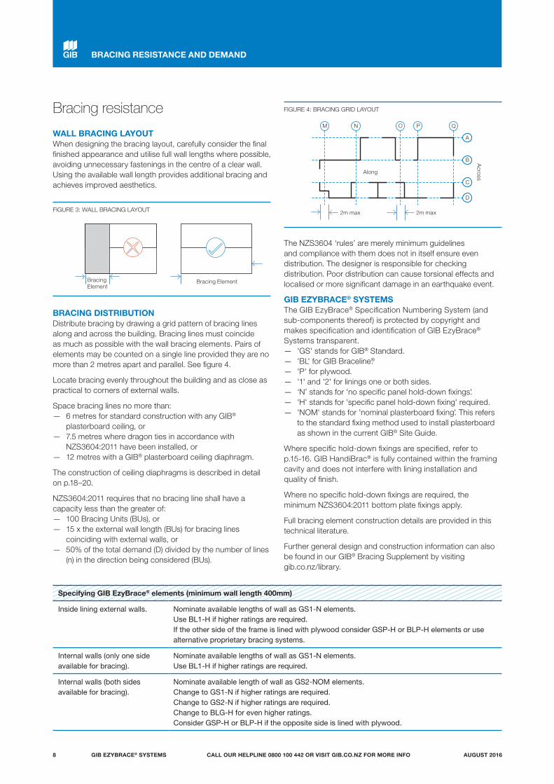
WALL BRACING LAYOUTWhen designing the bracing layout, carefully consider the final finished appearance and utilise full wall lengths where possible, avoiding unnecessary fastenings in the centre of a clear wall. Using the available wall length provides additional bracing and achieves improved aesthetics.
BRACING DISTRIBUTIONDistribute bracing by drawing a grid pattern of bracing lines along and across the building. Bracing lines must coincide as much as possible with the wall bracing elements. Pairs of elements may be counted on a single line provided they are no more than 2 metres apart and parallel. See figure 4.
Locate bracing evenly throughout the building and as close as practical to corners of external walls.
Space bracing lines no more than: — 6 metres for standard construction with any GIB®
plasterboard ceiling, or — 7.5 metres where dragon ties in accordance with
NZS3604:2011 have been installed, or — 12 metres with a GIB® plasterboard ceiling diaphragm.
The construction of ceiling diaphragms is described in detail on p.18–20.
NZS3604:2011 requires that no bracing line shall have a capacity less than the greater of:
— 100 Bracing Units (BUs), or — 15 x the external wall length (BUs) for bracing lines
coinciding with external walls, or — 50% of the total demand (D) divided by the number of lines
(n) in the direction being considered (BUs).
The NZS3604 ‘rules’ are merely minimum guidelines and compliance with them does not in itself ensure even distribution. The designer is responsible for checking distribution. Poor distribution can cause torsional effects and localised or more significant damage in an earthquake event.
GIB EZYBRACE® SYSTEMSThe GIB EzyBrace® Specification Numbering System (and sub-components thereof) is protected by copyright and makes specification and identification of GIB EzyBrace® Systems transparent.
— 'GS' stands for GIB® Standard. — 'BL' for GIB Braceline®. — 'P' for plywood. — '1' and '2' for linings one or both sides. — ‘N’ stands for 'no specific panel hold-down fixings'. — 'H' stands for 'specific panel hold-down fixing' required. — 'NOM' stands for 'nominal plasterboard fixing'. This refers
to the standard fixing method used to install plasterboard as shown in the current GIB® Site Guide.
Where specific hold-down fixings are specified, refer to p.15-16. GIB HandiBrac® is fully contained within the framing cavity and does not interfere with lining installation and quality of finish.
Where no specific hold-down fixings are required, the minimum NZS3604:2011 bottom plate fixings apply.
Full bracing element construction details are provided in this technical literature.
Further general design and construction information can also be found in our GIB® Bracing Supplement by visiting gib.co.nz/library.
BRACING RESISTANCE AND DEMAND
M N O P
A
Q
B
C
D
FIGURE 4: BRACING GRID LAYOUT
Specifying GIB EzyBrace® elements (minimum wall length 400mm)
Inside lining external walls. Nominate available lengths of wall as GS1-N elements.Use BL1-H if higher ratings are required. If the other side of the frame is lined with plywood consider GSP-H or BLP-H elements or use alternative proprietary bracing systems.
Internal walls (only one side available for bracing).
Nominate available lengths of wall as GS1-N elements.Use BL1-H if higher ratings are required.
Internal walls (both sides available for bracing).
Nominate available length of wall as GS2-NOM elements.Change to GS1-N if higher ratings are required.Change to GS2-N if higher ratings are required.Change to BLG-H for even higher ratings. Consider GSP-H or BLP-H if the opposite side is lined with plywood.
FIGURE 3: WALL BRACING LAYOUT
Bracing Element
Bracing Element
2m max 2m max
Along
Across
GIB EZYBRACE® SYSTEMS8 AUGUST 2016CALL OUR HELPLINE 0800 100 442 OR VISIT GIB.CO.NZ FOR MORE INFO
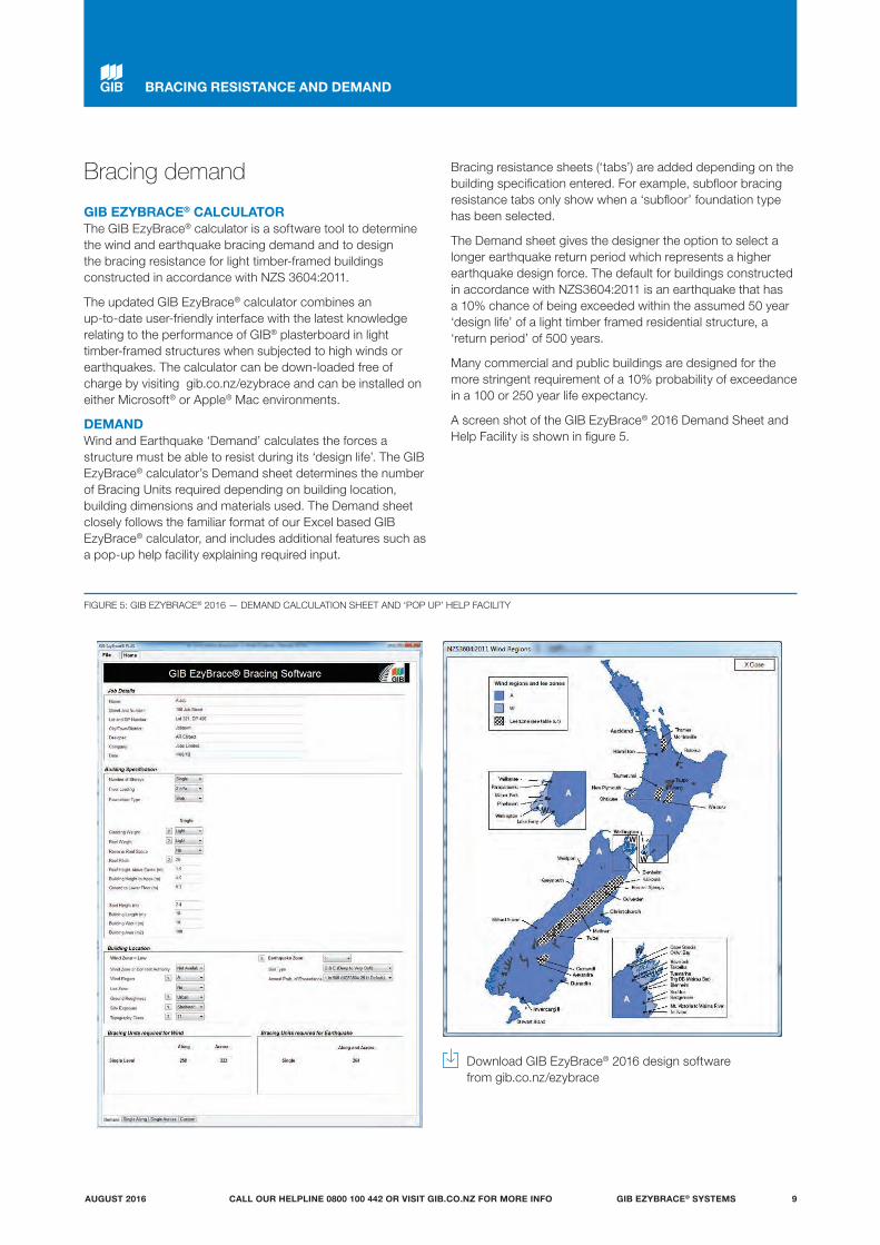
Bracing demand
GIB EZYBRACE® CALCULATORThe GIB EzyBrace® calculator is a software tool to determine the wind and earthquake bracing demand and to design the bracing resistance for light timber-framed buildings constructed in accordance with NZS 3604:2011.
The updated GIB EzyBrace® calculator combines an up-to-date user-friendly interface with the latest knowledge relating to the performance of GIB® plasterboard in light timber-framed structures when subjected to high winds or earthquakes. The calculator can be down-loaded free of charge by visiting gib.co.nz/ezybrace and can be installed on either Microsoft® or Apple® Mac environments.
DEMANDWind and Earthquake ‘Demand’ calculates the forces a structure must be able to resist during its ‘design life’. The GIB EzyBrace® calculator’s Demand sheet determines the number of Bracing Units required depending on building location, building dimensions and materials used. The Demand sheet closely follows the familiar format of our Excel based GIB EzyBrace® calculator, and includes additional features such as a pop-up help facility explaining required input.
Bracing resistance sheets (‘tabs’) are added depending on the building specification entered. For example, subfloor bracing resistance tabs only show when a ‘subfloor’ foundation type has been selected.
The Demand sheet gives the designer the option to select a longer earthquake return period which represents a higher earthquake design force. The default for buildings constructed in accordance with NZS3604:2011 is an earthquake that has a 10% chance of being exceeded within the assumed 50 year ‘design life’ of a light timber framed residential structure, a ‘return period’ of 500 years.
Many commercial and public buildings are designed for the more stringent requirement of a 10% probability of exceedance in a 100 or 250 year life expectancy.
A screen shot of the GIB EzyBrace® 2016 Demand Sheet and Help Facility is shown in figure 5.
FIGURE 5: GIB EZYBRACE® 2016 — DEMAND CALCULATION SHEET AND ‘POP UP’ HELP FACILITY
Download GIB EzyBrace® 2016 design software from gib.co.nz/ezybrace
BRACING RESISTANCE AND DEMAND
GIB EZYBRACE® SYSTEMS 9AUGUST 2016 CALL OUR HELPLINE 0800 100 442 OR VISIT GIB.CO.NZ FOR MORE INFO
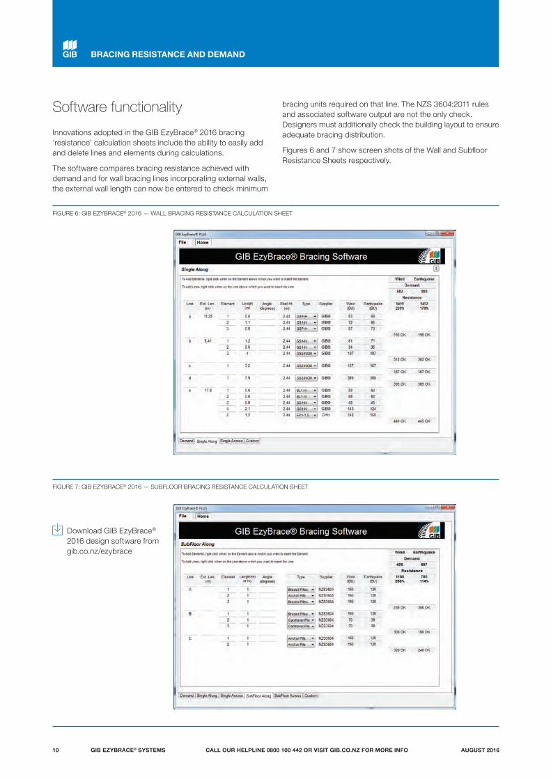
Software functionality
Innovations adopted in the GIB EzyBrace® 2016 bracing ‘resistance’ calculation sheets include the ability to easily add and delete lines and elements during calculations.
The software compares bracing resistance achieved with demand and for wall bracing lines incorporating external walls, the external wall length can now be entered to check minimum
bracing units required on that line. The NZS 3604:2011 rules and associated software output are not the only check. Designers must additionally check the building layout to ensure adequate bracing distribution.
Figures 6 and 7 show screen shots of the Wall and Subfloor Resistance Sheets respectively.
FIGURE 6: GIB EZYBRACE® 2016 — WALL BRACING RESISTANCE CALCULATION SHEET
FIGURE 7: GIB EZYBRACE® 2016 — SUBFLOOR BRACING RESISTANCE CALCULATION SHEET
Download GIB EzyBrace® 2016 design software from gib.co.nz/ezybrace
BRACING RESISTANCE AND DEMAND
GIB EZYBRACE® SYSTEMS10 AUGUST 2016CALL OUR HELPLINE 0800 100 442 OR VISIT GIB.CO.NZ FOR MORE INFO

Software functionality
Custom elements can be entered by accessing the 'custom' tab as shown in figure 8.
Help can be accessed by pressing the ? symbol which displays a window with further information.
The GIB EzyBrace® 2016 software has a number of options that can be accessed via the File tab at the top left hand corner of the window. The options include: New, Save, Save As, Open, Recent and Print.
— The New option closes any opened job ready for the input of a new job.
— The Save option saves the currently opened job to the same filename and the Save As option saves the job to a new filename.
— The Open option prompts for the name of an existing job. — The Recent option displays a list of the ten latest jobs and
allows for the selection of one of these jobs to be opened. — The Print option displays the print screen. In this screen, a
print preview is displayed. The print preview can be copied to the clipboard by clicking the right-hand mouse button. Also on the print screen is the option to choose which pages are to be printed and the option to print the output to a portable data format, PDF, file.
— The Print Screen View is shown in figure 9.
Download GIB EzyBrace® 2016 design software from gib.co.nz/ezybrace
BRACING RESISTANCE AND DEMAND
FIGURE 8: GIB EZYBRACE® 2016 — CUSTOM ELEMENTS SHEET
FIGURE 9: GIB EZYBRACE® 2016 — PRINT SCREEN VIEW
Note: Values and systems shown in Custom Elements Sheets are for illustrative purposes only.
GIB EZYBRACE® SYSTEMS 11AUGUST 2016 CALL OUR HELPLINE 0800 100 442 OR VISIT GIB.CO.NZ FOR MORE INFO

GIB® plasterboard linings
When fixing part sheets of GIB® plasterboard, a minimum sheet width of 300mm applies for bracing elements. Horizontal fixing is recommended. If fixing vertically, full height sheets shall be used where possible. Where sheet end butt joints are unavoidable they must be formed over nogs or over the studs and fastened at 200mm centres. Alternatively, and preferably, sheet end butt joints may be back-blocked.
When a GIB® Bracing element has been designated for a section of wall, BU ratings cannot be increased by incorporating additional proprietary bracing elements within that same section of wall.
LIMITATIONS — GIB® plasterboard must be stacked flat and protected from
the weather. — GIB® plasterboard must be handled as a finishing material. — GIB® plasterboard in use must not be exposed to liquid
water or be installed in situations where extended exposure to humidities above 90% RH can reasonably be expected.
— GIB EzyBrace® Systems must not be used in showers or behind baths.
— It is highly recommended not to install GIB® plasterboard in any situation where external claddings are not in place or the property is not adequately protected from the elements.
— If GIB® plasterboard is installed under these conditions, the risk of surface defects such as joint peaking or cracking is greatly increased.
GIB EzyBrace® Systems in water-splash areas
When GIB® plasterboard is installed in locations likely to be frequently exposed to liquid water it must have an impervious finish. Examples are adhesive fixed acrylic shower linings or ceramic tiles over an approved waterproof membrane over GIB Aqualine®. The NZBC requires 15 years durability in these situations. Bracing elements are required to have a durability of 50 years. Bracing elements are not to be located in shower cubicles or behind baths because of durability requirements, the likelihood of renovation, and practical issues associated with fixing bracing elements to perimeter framing members. Otherwise GIB EzyBrace® Systems can be used in water-splash areas as defined by NZBC Clause E3, provided these are maintained impervious for the life of the building.
For futher design details refer to the current GIB Aqualine® Wet Area Systems literature.
Renovation
When relining walls during the process of renovation, ensure that bracing elements are reinstated (check the building plans).
Openings in bracing elements
SMALL OPENINGSSmall openings (e.g. power outlets) of 90 x 90mm or less may be placed no closer than 90mm to the edge of the braced element. A block may need to be provided alongside the perimeter stud as shown below.
LARGE OPENINGSOpenings above 90 x 90mm such as switch boards, recessed cabinets and TV's etc. should be placed outside of the bracing element or locate bracing on the other side of the wall framing.
DESIGN AND CONSTRUCTION
FIGURE 10: SMALL OPENINGS IN BRACING ELEMENTS
GEB001
Stud
90mm
No Penetrations
90 x 90mm max.
90 x 90mm max.
90mm min.
Edge of bracing element
Small opening e.g. switch box
Block
FIGURE 11: LARGE OPENINGS AND BRACING ELEMENTS
Bracing Element
Opening
Bracing Element
GIB EZYBRACE® SYSTEMS12 AUGUST 2016CALL OUR HELPLINE 0800 100 442 OR VISIT GIB.CO.NZ FOR MORE INFO
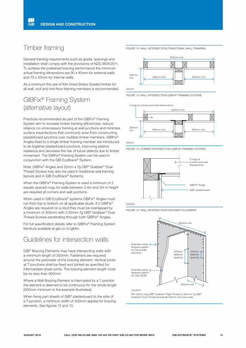
Timber framing
General framing requirements such as grade, spacings and installation shall comply with the provisions of NZS 3604:2011. To achieve the published bracing performance the minimum actual framing dimensions are 90 x 45mm for external walls and 70 x 45mm for internal walls.
As a minimum the use of Kiln Dried Stress Graded timber for all wall, roof and mid-floor framing members is recommended.
GIBFix® Framing System (alternative layout)
Practices recommended as part of the GIBFix® Framing System aim to increase timber framing efficiencies, reduce reliance on unnecessary framing at wall junctions and minimise surface imperfections that commonly arise from constructing plasterboard junctions over multiple timber members. GIBFix® Angles fixed to a single timber framing member are introduced to tie together plasterboard junctions, improving seismic resilience and decrease the risk of future defects due to timber movement. The GIBFix® Framing System can be used in conjunction with the GIB EzyBrace® System.
Note: GIBFix® Angles and 32mm x 7g GIB® Grabber® Dual Thread Screws may also be used in traditional wall framing layouts and in GIB EzyBrace® Systems.
When the GIBFix® Framing System is used a minimum of 2 equally spaced nogs for walls between 2.4m and 3m in height are required at corners and wall junctions.
When used in GIB EzyBrace® systems GIBFix® Angles must run from top to bottom on all applicable studs. If 2 GIBFix® Angles are required on a stud they must be overlapped by a minimum of 300mm with 2/32mm 7g GIB® Grabber® Dual Thread Screws penetrating through both GIBFix® Angles.
For full specification details refer to GIBFix® Framing System literature available at gib.co.nz/gibfix.
Guidelines for intersection walls
GIB® Bracing Elements may have intersecting walls with a minimum length of 200mm. Fasteners are required around the perimeter of the bracing element. Vertical joints at T-junctions shall be fixed and jointed as specified for intermediate sheet joints. The bracing element length must be no less than 900mm.
Where a Wall Bracing Element is interrupted by a T-junction the element is deemed to be continuous for the whole length (900mm minimum in the example illustrated).
When fixing part sheets of GIB® plasterboard to the side of a T-junction, a minimum width of 300mm applies for bracing elements. See figures 12 and 13.
DESIGN AND CONSTRUCTION
FIGURE 13: WALL INTERSECTION (GIBFIX® FRAMING SYSTEM)
300mm min
900mm min
200mm min 300mm min
FIGURE 12: WALL INTERSECTION (TRADITIONAL WALL FRAMING)
GIB® plasterboard
300mm min
GIBFix® Angle
900mm min
2 nogs at corners and wall intersections
200mm min
2 nogs at corners and wall intersections
300mm min
GEB003
FIGURE 14: CORNER INTERSECTION (GIBFIX® FRAMING SYSTEM)
GIBFix® AngleExample using fastener pattern for GS2-NOM
Example using fastener pattern for GS and BL elements
Junction
Min 32mm x 6g GIB® Grabber® High Thread or 32mm x 7g GIB® Grabber® Dual Thread Screws @ 300mm ctrs each side.
300mm fastener spacing
150mm fastener spacing
FIGURE 15: WALL INTERSECTION FASTENER PLACEMENT
900mm min
300mm min
GFS001
GEB002
GIB EZYBRACE® SYSTEMS 13AUGUST 2016 CALL OUR HELPLINE 0800 100 442 OR VISIT GIB.CO.NZ FOR MORE INFO

Top plate connections
For top plate connections refer to NZS3604:2011 section 8.7.3.
Parapets and gable end walls
Bracing elements must be fixed from top plate to bottom plate. Fixing to a row of nogs is not acceptable unless either:
A continuous member such as an ex 90 x 45mm ribbon plate is fixed across the studs just above a row of nogs at the ceiling line, as shown in figure 16.
or
GIBFix® Angle as shown in figure 17. The angle is fixed to a row of nogs with 30 x 2.5mm galv flat head nails or 32mm x 7g GIB® Grabber® Dual Thread Screws at 300mm centres.
Bottom plate fixing
TIMBER FLOORFor elements with an ‘N’ specification use 2/100 x 3.75mm hand or 3/90 x 3.15mm power-driven nails at 600mm centres.
In addition, for elements with an ‘H’ specification, use GIB HandiBrac® panel hold-down fixings at each end of the bracing element, see p.16.
CONCRETE FLOOR — EXTERNAL WALL BRACING ELEMENTSFor bracing elements with an ‘N’ specification fix external wall plates in accordance with NZS 3604:2011.
Use GIB HandiBrac® panel hold-down fixings at each end of bracing elements with an ‘H’ specification and minimum intermediate fixings as required by NZS 3604:2011.
CONCRETE FLOOR — INTERNAL WALL BRACING ELEMENTSFor bracing elements with an ‘N’ specification fix plates in accordance with NZS 3604:2011 or use 75 x 3.8mm shot-fired fasteners with 16mm discs spaced at 150 and 300mm from end-studs and 600mm centres thereafter.
For bracing elements with an ‘H’ specification use GIB HandiBrac® panel hold-down fixings at each end of the element and minimum intermediate fixings as required by NZS 3604:2011.
External Cladding
This side determines the length of the GS2 Bracing Element
Perimeter fasteners
External Cladding
This side determines the length of the GS2 Bracing Element
Perimeter fasteners
GIB® plasterboard
GIB® plasterboard
GIBFix® Angle
GIBFix® Angle (optional)
Parapet or gable end
Parapet or gable end
Ceiling Framing
Ribbon Plate
FIGURE 16: PARAPETS AND GABLE ENDS WITH RIBBON PLATE
FIGURE 17: PARAPETS AND GABLE ENDS WITH GIBFIX® ANGLE
GFS003
BOTTOM PLATE FIXINGS FOR GIB® BRACING ELEMENTS
Brace type Concrete slabs Timber floors
External wall Internal wall External and Internal walls
GS1-N As per NZS 3604:2011.No specific additional fastening required.
As per NZS 3604:2011.Alternatively use 75 x 3.8mm shot-fired fasteners with 16mm discs, 150mm and 300mm from each end of the bracing element and at 600mm thereafter.
Pairs of 100 x 3.75mm flat head hand driven nails or 3/90 x 3.15mm power driven nails at 600mm centres in accordance with NZS 3604:2011.
GS2-N Not applicable.
GS2-NOM
GSP-HBL1-HBLP-H
Intermediate fastenings to comply with NZS 3604:2011
In addition:GIB HandiBrac® fixings or metal wrap-around strap fixings and bolt as illustrated on p.15 and 16.
Pairs of 100 x 3.75mm flat head hand driven nails or 3/90 x 3.15mm power driven nails at 600mm centres in accordance with NZS 3604:2011.
In addition:GIB HandiBrac® fixings or metal wrap-around strap fixings and bolt as illustrated on p.15 and 16.
BLG-H Not applicable As for GSP-H, BL1-H, BLP-H on concrete slab as illustrated on p.15 and 16.
DESIGN AND CONSTRUCTION
GIB EZYBRACE® SYSTEMS14 AUGUST 2016CALL OUR HELPLINE 0800 100 442 OR VISIT GIB.CO.NZ FOR MORE INFO

Concrete floor Timber floor
400 x 25 x 0.9mm galvanised strap to pass under the plate and up the other side of the stud. Six 30 x 2.5mm flat head galvanised nails to each side of the stud. Three 30 x 2.5mm flat head galvanised nails to each side of the plate. Hold down bolt with 50 x 50 x 3mm washer to be fitted within 80mm of the end of the element.
Internal wall
External wall
Note: Where applicable drawings have been produced for CAD design. These are identified by a unique number in the bottom corner of each detail box that can be found at gib.co.nz/library.
2/300 x 25 x 0.9mm galvanised straps with six 30 x 2.5mm flat head galvanised nails to each stud and into the floor joist and three nails to the plate. Block to nog fixed with 3/100 x 3.75mm nails to stud.
Hold-down fastener requirements
Concrete floor Timber floor
A mechanical fastening with a minimum characteristic uplift capacity of 15kN fitted with a 50 x 50 x 3mm square washer within 80mm of the ends of the bracing element.
12 x 150mm galvanised coach screw fitted with a 50 x 50 x 3mm square washer within 80mm of the ends of the bracing element
80mmmaximum
80mmmaximum
80mmmaximum
80mmmaximum
GEB008
Bracing strap installation
Care needs to be taken with the installation of the bracing strap. It should be checked in to be flush with the face of the stud providing a flat substrate for the plasterboard and
positioned in such a way that the corner fastenings of the bracing element are not affected by it. Keeping the strap to the edge of the end stud as shown will allow the corner fastenings to be installed without having to penetrate the bracing strap.
GEB004
GEB006
DESIGN AND CONSTRUCTION
GEB005
GEB007
GIB EZYBRACE® SYSTEMS 15AUGUST 2016 CALL OUR HELPLINE 0800 100 442 OR VISIT GIB.CO.NZ FOR MORE INFO
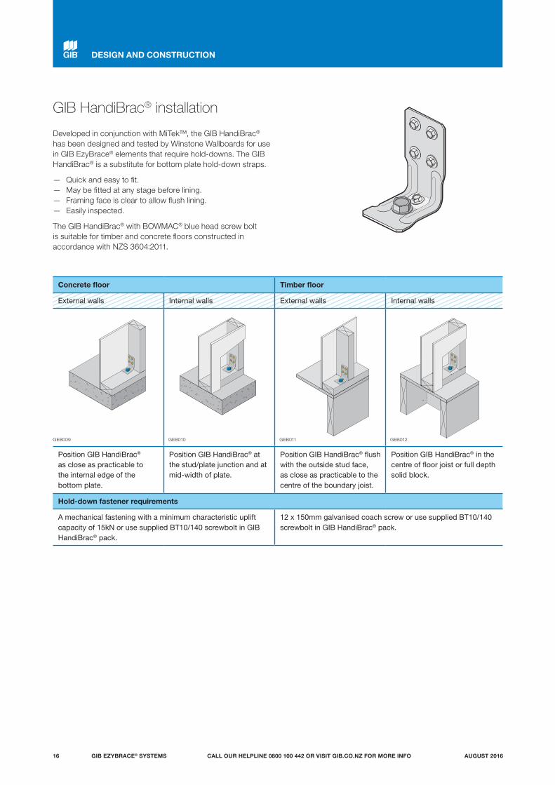
GIB HandiBrac® installation
Developed in conjunction with MiTek™, the GIB HandiBrac® has been designed and tested by Winstone Wallboards for use in GIB EzyBrace® elements that require hold-downs. The GIB HandiBrac® is a substitute for bottom plate hold-down straps.
— Quick and easy to fit. — May be fitted at any stage before lining. — Framing face is clear to allow flush lining. — Easily inspected.
The GIB HandiBrac® with BOWMAC® blue head screw bolt is suitable for timber and concrete floors constructed in accordance with NZS 3604:2011.
Concrete floor Timber floor
External walls Internal walls External walls Internal walls
Position GIB HandiBrac® as close as practicable to the internal edge of the bottom plate.
Position GIB HandiBrac® at the stud/plate junction and at mid-width of plate.
Position GIB HandiBrac® flush with the outside stud face, as close as practicable to the centre of the boundary joist.
Position GIB HandiBrac® in the centre of floor joist or full depth solid block.
Hold-down fastener requirements
A mechanical fastening with a minimum characteristic uplift capacity of 15kN or use supplied BT10/140 screwbolt in GIB HandiBrac® pack.
12 x 150mm galvanised coach screw or use supplied BT10/140 screwbolt in GIB HandiBrac® pack.
GEB009 GEB010 GEB011 GEB012
DESIGN AND CONSTRUCTION
GIB EZYBRACE® SYSTEMS16 AUGUST 2016CALL OUR HELPLINE 0800 100 442 OR VISIT GIB.CO.NZ FOR MORE INFO
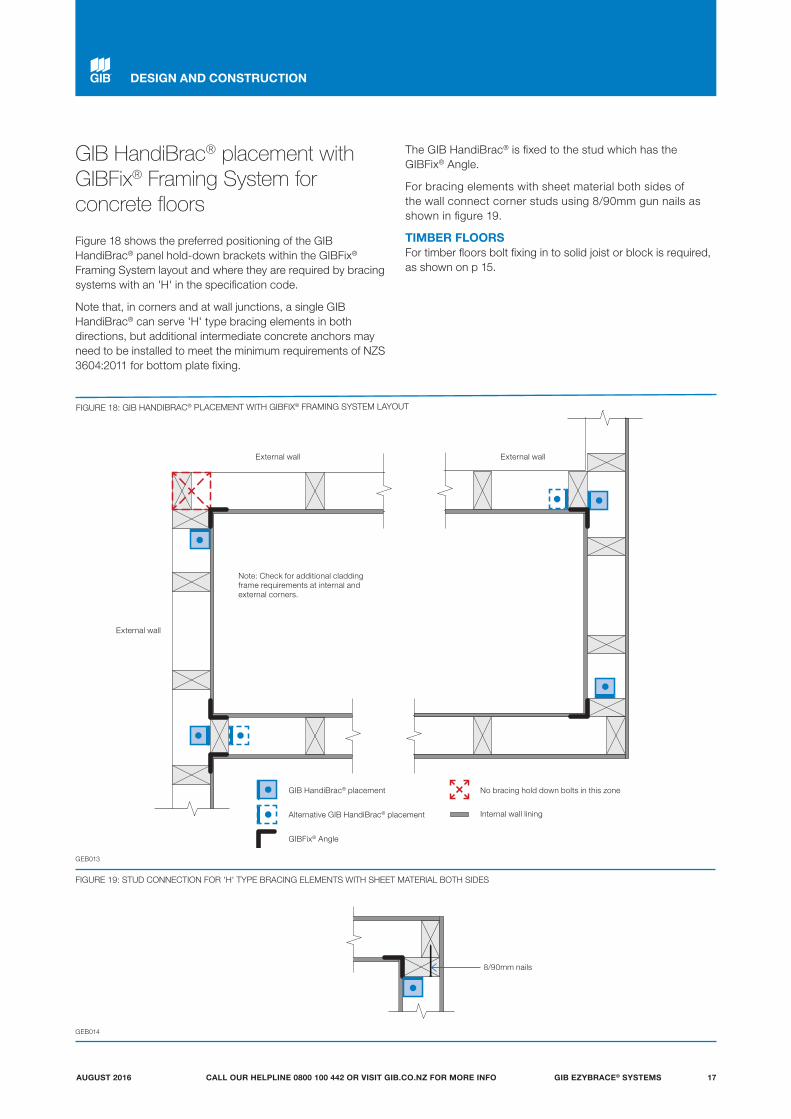
GIB HandiBrac® placement with GIBFix® Framing System for concrete floors
Figure 18 shows the preferred positioning of the GIB HandiBrac® panel hold-down brackets within the GIBFix® Framing System layout and where they are required by bracing systems with an 'H' in the specification code.
Note that, in corners and at wall junctions, a single GIB HandiBrac® can serve 'H' type bracing elements in both directions, but additional intermediate concrete anchors may need to be installed to meet the minimum requirements of NZS 3604:2011 for bottom plate fixing.
The GIB HandiBrac® is fixed to the stud which has the GIBFix® Angle.
For bracing elements with sheet material both sides of the wall connect corner studs using 8/90mm gun nails as shown in figure 19.
TIMBER FLOORSFor timber floors bolt fixing in to solid joist or block is required, as shown on p 15.
FIGURE 18: GIB HANDIBRAC® PLACEMENT WITH GIBFIX® FRAMING SYSTEM LAYOUT
GEB013
GIB HandiBrac® placement
External wall
External wall
External wall
No bracing hold down bolts in this zone
Alternative GIB HandiBrac® placement
GIBFix® Angle
Internal wall lining
Note: Check for additional cladding frame requirements at internal and external corners.
FIGURE 19: STUD CONNECTION FOR 'H' TYPE BRACING ELEMENTS WITH SHEET MATERIAL BOTH SIDES
8/90mm nails
GEB014
DESIGN AND CONSTRUCTION
GIB EZYBRACE® SYSTEMS 17AUGUST 2016 CALL OUR HELPLINE 0800 100 442 OR VISIT GIB.CO.NZ FOR MORE INFO
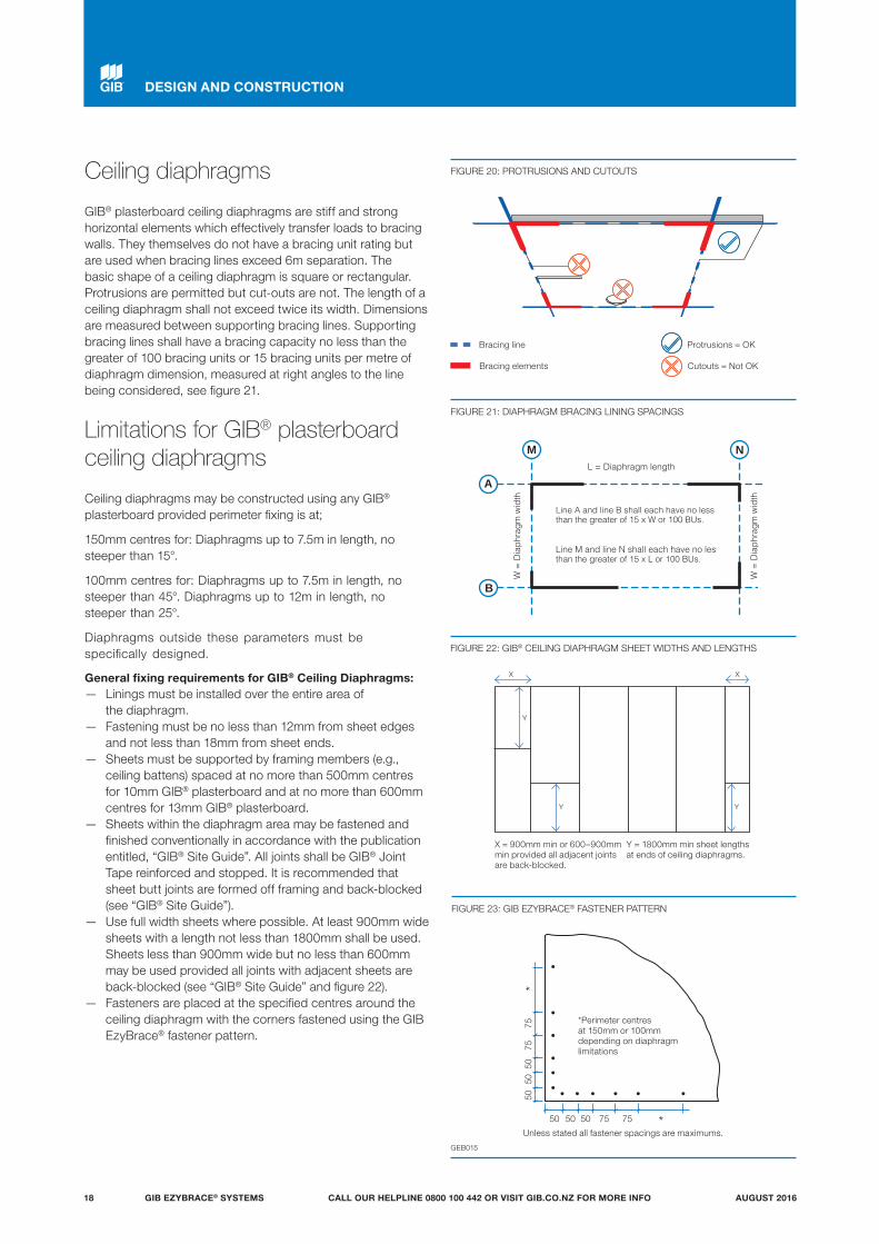
Line A and line B shall each have no less than the greater of 15 x W or 100 BUs. Line M and line N shall each have no less than the greater of 15 x L or 100 BUs.
W =
Dia
phra
gm w
idth
W =
Dia
phra
gm w
idth
L = Diaphragm length
M N
A
B
Y
Y
X X
X = 900mm min or 600–900mm min provided all adjacent joints are back-blocked.
Y = 1800mm min sheet lengths at ends of ceiling diaphragms.
Y
FIGURE 21: DIAPHRAGM BRACING LINING SPACINGS
FIGURE 22: GIB® CEILING DIAPHRAGM SHEET WIDTHS AND LENGTHS
FIGURE 23: GIB EZYBRACE® FASTENER PATTERN
50
50
50
75
75
*
50 50 50 75 75 *
*Perimeter centres at 150mm or 100mm depending on diaphragm limitations
GEB015
FIGURE 20: PROTRUSIONS AND CUTOUTS
Protrusions = OKBracing line
Cutouts = Not OKBracing elements
Ceiling diaphragms
GIB® plasterboard ceiling diaphragms are stiff and strong horizontal elements which effectively transfer loads to bracing walls. They themselves do not have a bracing unit rating but are used when bracing lines exceed 6m separation. The basic shape of a ceiling diaphragm is square or rectangular. Protrusions are permitted but cut-outs are not. The length of a ceiling diaphragm shall not exceed twice its width. Dimensions are measured between supporting bracing lines. Supporting bracing lines shall have a bracing capacity no less than the greater of 100 bracing units or 15 bracing units per metre of diaphragm dimension, measured at right angles to the line being considered, see figure 21.
Limitations for GIB® plasterboard ceiling diaphragms
Ceiling diaphragms may be constructed using any GIB® plasterboard provided perimeter fixing is at;
150mm centres for: Diaphragms up to 7.5m in length, no steeper than 15°.
100mm centres for: Diaphragms up to 7.5m in length, no steeper than 45°. Diaphragms up to 12m in length, no steeper than 25°.
Diaphragms outside these parameters must be specifically designed.
General fixing requirements for GIB® Ceiling Diaphragms: — Linings must be installed over the entire area of
the diaphragm. — Fastening must be no less than 12mm from sheet edges
and not less than 18mm from sheet ends. — Sheets must be supported by framing members (e.g.,
ceiling battens) spaced at no more than 500mm centres for 10mm GIB® plasterboard and at no more than 600mm centres for 13mm GIB® plasterboard.
— Sheets within the diaphragm area may be fastened and finished conventionally in accordance with the publication entitled, “GIB® Site Guide”. All joints shall be GIB® Joint Tape reinforced and stopped. It is recommended that sheet butt joints are formed off framing and back-blocked (see “GIB® Site Guide”).
— Use full width sheets where possible. At least 900mm wide sheets with a length not less than 1800mm shall be used. Sheets less than 900mm wide but no less than 600mm may be used provided all joints with adjacent sheets are back-blocked (see “GIB® Site Guide” and figure 22).
— Fasteners are placed at the specified centres around the ceiling diaphragm with the corners fastened using the GIB EzyBrace® fastener pattern.
Unless stated all fastener spacings are maximums.
DESIGN AND CONSTRUCTION
GIB EZYBRACE® SYSTEMS18 AUGUST 2016CALL OUR HELPLINE 0800 100 442 OR VISIT GIB.CO.NZ FOR MORE INFO

Ceiling battens in ceiling diaphragms
Ceiling diaphragms may be constructed using steel or timber ceiling battens.
Battens shall be spaced at a maximum of: — 500mm for 10mm GIB® plasterboard. — 600mm for 13mm GIB® plasterboard.
Timber battens shall be fixed in accordance with the requirements of NZS 3604:2011.
Metal battens shall be GIB® Rondo® battens with two external flanges of 8mm to allow direct screw fixing to roof framing.
GIB® Rondo® metal battens shall be fixed with 2/32mm x 8g GIB® Grabber® Wafer Head Self Tapping screws to supporting framing.
GIB® Rondo® metal battens must be fixed directly to the roof framing. If a clip system has been used, a timber block (min 300mm) or a continuous timber member can be fixed alongside the bottom chord to permit a direct connection to the batten, see figure 26.
For GIB® Rondo® metal battens, a GIB® Rondo® metal channel or metal angle is required at the perimeter of the diaphragm. The perimeter channel shall be fastened to the top plate with 32mm x 8g GIB® Grabber® Wafer Head Self Tapping screws or 32mm x 7g GIB® Grabber® Dual Thread screw at 300mm centres maximum.
Linings are fastened to metal using 25mm x 6g GIB® Grabber® Self Tapping screws and to timber framing using 32mm x 6g GIB® Grabber® High Thread screws. Alternatively 32mm x 7g GIB® Grabber® Dual Thread screws can be used in both cases. Fastener centres are specified on p.18.
Coved ceiling diaphragms can be achieved by using nominally 32 x 32 x 0.55mm proprietary galvanised metal angles ("back-flashing") at the changes in direction. These angles shall be:
— Fastened at 300mm on each edge to metal battens using 32mm x 8g GIB® Grabber® Wafer Head Self Tapping screws or 32mm x 7g GIB® Grabber® Dual Thread screws.
— Fastened to timber framing using 32mm x 7g GIB® Grabber® Dual Thread screws when linings are installed.
C OR
B (Recommended)
D
FIGURE 26: GIB® RONDO® METAL CEILING BATTEN INSTALLATION
FIGURE 27: GIB® RONDO® METAL CEILING BATTENS WITH CORNER ANGLES
GEB017
GEB016
GIB® Rondo® metal batten
GIB® plasterboard
GIBFix® Angle
GIB® Rondo® metal batten
GIB® Rondo® perimeter channel
GIB® plasterboard
0.55 BMT galvanised metal angle
A (Recommended)
GIB® Rondo® metal batten
GIB® plasterboard
GIBFix® Angle
GIB® Rondo® metal batten
GIB® plasterboard
GIB® Rondo® perimeter channel
FIGURE 28: TIMBER CEILING BATTENS*
Timber batten
GIB® plasterboard
GEB018
GIBFix® Angle recommended
Block or continuous timber member min 300mm fixed with min 4 x 90mm x 3.15 nails.
GIB® Rondo® Clip
GIB® Rondo® Clip
GIB® Rondo® metal batten
Batten ends secured to perimeter channel with 13mm x 8g wafer head self tapping screws.
DESIGN AND CONSTRUCTION
GIB EZYBRACE® SYSTEMS 19AUGUST 2016 CALL OUR HELPLINE 0800 100 442 OR VISIT GIB.CO.NZ FOR MORE INFO
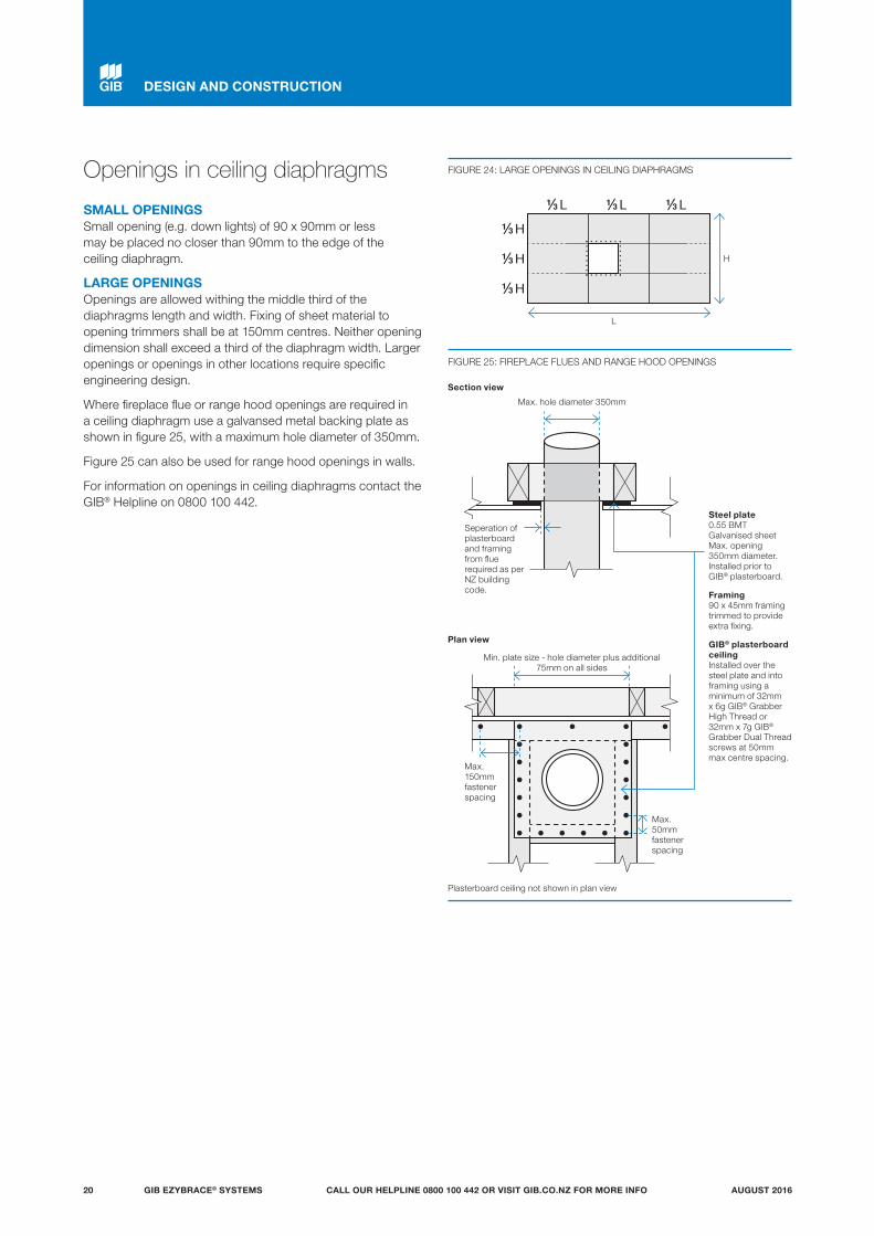
Steel plate0.55 BMT Galvanised sheet Max. opening 350mm diameter. Installed prior to GIB® plasterboard.
Framing 90 x 45mm framing trimmed to provide extra fixing.
GIB® plasterboard ceiling Installed over the steel plate and into framing using a minimum of 32mm x 6g GIB® Grabber High Thread or 32mm x 7g GIB® Grabber Dual Thread screws at 50mm max centre spacing.
FIGURE 24: LARGE OPENINGS IN CEILING DIAPHRAGMS
FIGURE 25: FIREPLACE FLUES AND RANGE HOOD OPENINGS
Openings in ceiling diaphragms
SMALL OPENINGSSmall opening (e.g. down lights) of 90 x 90mm or less may be placed no closer than 90mm to the edge of the ceiling diaphragm.
LARGE OPENINGSOpenings are allowed withing the middle third of the diaphragms length and width. Fixing of sheet material to opening trimmers shall be at 150mm centres. Neither opening dimension shall exceed a third of the diaphragm width. Larger openings or openings in other locations require specific engineering design.
Where fireplace flue or range hood openings are required in a ceiling diaphragm use a galvansed metal backing plate as shown in figure 25, with a maximum hole diameter of 350mm.
Figure 25 can also be used for range hood openings in walls.
For information on openings in ceiling diaphragms contact the GIB® Helpline on 0800 100 442.
H
H
HL L L
H
L
Plasterboard ceiling not shown in plan view
Section view
Max. hole diameter 350mm
Max. 50mm fastener spacing
Max. 150mm fastener spacing
Plan view
Min. plate size - hole diameter plus additional 75mm on all sides
DESIGN AND CONSTRUCTION
Seperation of plasterboard and framing from flue required as per NZ building code.
GIB EZYBRACE® SYSTEMS20 AUGUST 2016CALL OUR HELPLINE 0800 100 442 OR VISIT GIB.CO.NZ FOR MORE INFO

Length of GIB EzyBrace® elements ('N' Type)
The length of GIB EzyBrace® elements with an ‘N’ extension (requiring standard NZS3604:2011 plate connections) can be taken as the full frame length measured from the outside of the end-stud to the opening face as illustrated in figures 29-32.
'N' type GIB EzyBrace® elements are identified by GIB® specification numbers GS1-N, GS2-N and GS2-NOM
The dimension 'L' shall not be less than 400mm.
Perimeter bracing fixing for linings of both ‘H’ and ‘N’ type elements is along the top and bottom plates, end stud, and doubling stud immediately adjacent to the opening.
Fastener spacings and diagram scales shown in Figures 29–32 are indicative only. Refer to p.23–30 for construction details.
FIGURE 30: GS BRACING ELEMENTS (OPTION B)
GS1-N, GS2-N elements'L' indicates the length of the bracing element
GS1-N, GS2-N elements'L' indicates the length of the bracing element
GS1-N, GS2-N elements'L' indicates the length of the bracing element
FIGURE 31: GS BRACING ELEMENTS (OPTION C)
FIGURE 29: GS BRACING ELEMENTS (OPTION A)
Doubling stud
Opening
FIGURE 32: GS BRACING ELEMENTS (OPTION D)
GS1-N, GS2-N elements 'L' indicates the length of the bracing element
OpeningOpening
Opening
LL
LL
DESIGN AND CONSTRUCTION
GIB EZYBRACE® SYSTEMS 21AUGUST 2016 CALL OUR HELPLINE 0800 100 442 OR VISIT GIB.CO.NZ FOR MORE INFO

Length of GIB EzyBrace® elements ('H' Type)
GIB EzyBrace® elements with an ‘H’ extension (requiring special panel hold-down fixings) can be used when the dimension ‘L’ as illustrated in figures 33–36 is 400mm or more.
‘H’ type GIB EzyBrace® elements are identified by GIB® specification numbers GSP-H, BL1-H, BLG-H and BLP-H.
The length of an ‘H’ type element is not only determined by the sheet material, but also by the placement of the hold-down fixings.
Hold-down fixings cannot be placed closer together than what is shown for the standard panel in figure 33.
Hold-down fixings can be placed under windows provided sill trimming studs beneath the opening are connected to the bracing element using 8/90mm gun nails, as illustrated in figure 34.
Spike doubling stud to trimming stud using a minimum of 2/90mm gun nails at 600mm centres. Lintel straps (where required for wind uplift) should be checked in and be located away from the bracing element fasteners.
Perimeter bracing fixing for linings of both ‘H’ and ‘N’ type elements is along the top and bottom plates, end stud, and doubling stud immediately adjacent to the opening as indicated in figures 34-36.
When using bracing straps, installed in accordance with p.17, fix the strap to the same framing member as shown for the GIB Handibrac® below, and install the adjacent anchor bolt in the same position as the GIB HandiBrac® bolt.
Fastener spacings and diagram scales shown in figures 33–36 are indicative only. Refer to p.23–30 for construction details.
FIGURE 36: BL BRACING ELEMENTS (OPTION D)
‘H’ type elements with specific hold downs'L' indicates the length of the bracing element
‘H’ type elements with specific hold downs'L' indicates the length of the bracing element
‘H’ type elements with specific hold downs'L' indicates the length of the bracing element
FIGURE 35: BL BRACING ELEMENTS (OPTION C)
FIGURE 34: BL BRACING ELEMENTS (OPTION B)
‘H’ type elements with specific hold downs'L' indicates the length of the bracing element
FIGURE 33: BL BRACING ELEMENTS (OPTION A)
L
Opening
2/90mm nails at 600mm ctrs
2/90mm nails at 600mm ctrs
Opening
GIB HandiBrac®
GIB HandiBrac®GIB HandiBrac®
GIB HandiBrac®
Opening
8/90mm nails
2/90mm nails @ 600 ctrs
Opening
L L
L
DESIGN AND CONSTRUCTION
GIB EZYBRACE® SYSTEMS22 AUGUST 2016CALL OUR HELPLINE 0800 100 442 OR VISIT GIB.CO.NZ FOR MORE INFO
WALL FRAMINGWall framing to comply with;
— NZBC B1 — Structure B1/AS1 Clause 3 Timber (NZS 3604:2011).
— NZBC B2 — Durability B2/AS1 Clause 3.2 Timber (NZS 3602).
Framing dimensions and height as determined by NZS 3604:2011 stud and top plate tables for load bearing and non-bearing walls. The use of kiln dried stress graded timber is recommended.
BOTTOM PLATE FIXINGTimber floorPairs of hand driven 100 x 3.75mm nails at 600mm centres; or three power driven 90 x 3.15mm nails at 600mm centres.
Concrete floorInternal Wall Bracing Lines: In accordance with the requirements of NZS 3604:2011 for internal wall plate fixing or 75 x 3.8mm shot fired fasteners with 16mm discs spaced at 150mm and 300mm from end studs and 600mm centres thereafter.
External Wall Bracing Lines: In accordance with the requirements of NZS 3604:2011 for external wall bottom plate fixing.
WALL LINING — Any 10mm or 13mm GIB® plasterboard lining. — Sheets can be fixed vertically or horizontally. — Sheet joints shall be touch fitted. — Use full length sheets where possible.
PERMITTED ALTERNATIVESFor permitted GIB® plasterboard alternatives refer to p. 5 in GIB EzyBrace® Systems literature.
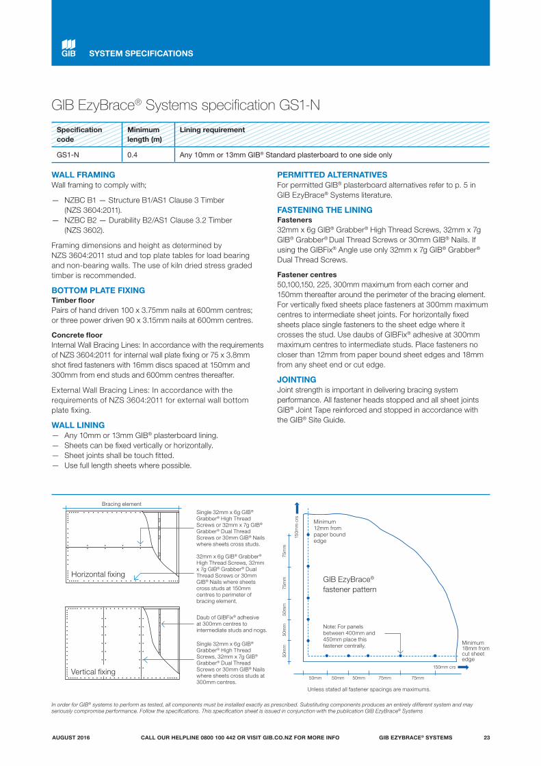
FASTENING THE LININGFasteners32mm x 6g GIB® Grabber® High Thread Screws, 32mm x 7g GIB® Grabber® Dual Thread Screws or 30mm GIB® Nails. If using the GIBFix® Angle use only 32mm x 7g GIB® Grabber®
Dual Thread Screws.
Fastener centres50,100,150, 225, 300mm maximum from each corner and 150mm thereafter around the perimeter of the bracing element. For vertically fixed sheets place fasteners at 300mm maximum centres to intermediate sheet joints. For horizontally fixed sheets place single fasteners to the sheet edge where it crosses the stud. Use daubs of GIBFix® adhesive at 300mm maximum centres to intermediate studs. Place fasteners no closer than 12mm from paper bound sheet edges and 18mm from any sheet end or cut edge.
JOINTINGJoint strength is important in delivering bracing system performance. All fastener heads stopped and all sheet joints GIB® Joint Tape reinforced and stopped in accordance with the GIB® Site Guide.
In order for GIB® systems to perform as tested, all components must be installed exactly as prescribed. Substituting components produces an entirely different system and may seriously compromise performance. Follow the specifications. This specification sheet is issued in conjunction with the publication GIB EzyBrace® Systems
Specification code
Minimum length (m)
Lining requirement
GS1-N 0.4 Any 10mm or 13mm GIB® Standard plasterboard to one side only
Unless stated all fastener spacings are maximums.
SYSTEM SPECIFICATIONS
Minimum 12mm from paper bound edge
Minimum 18mm from cut sheet edge
150m
m c
rs
150mm crs
50mm 50mm 50mm 75mm 75mm
50m
m50
mm
50m
m75
mm
75m
m
GIB EzyBrace® fastener pattern
Note: For panels between 400mm and 450mm place this fastener centrally.
32mm x 6g GIB® Grabber® High Thread Screws, 32mm x 7g GIB® Grabber® Dual Thread Screws or 30mm GIB® Nails where sheets cross studs at 150mm centres to perimeter of bracing element.
Single 32mm x 6g GIB® Grabber® High Thread Screws or 32mm x 7g GIB® Grabber® Dual Thread Screws or 30mm GIB® Nails where sheets cross studs.
Horizontal fixing
Vertical fixing
Daub of GIBFix® adhesive at 300mm centres to intermediate studs and nogs.
Single 32mm x 6g GIB® Grabber® High Thread Screws, 32mm x 7g GIB® Grabber® Dual Thread Screws or 30mm GIB® Nails where sheets cross studs at 300mm centres.
Bracing element
GIB EzyBrace® Systems specification GS1-N
GIB EZYBRACE® SYSTEMS 23AUGUST 2016 CALL OUR HELPLINE 0800 100 442 OR VISIT GIB.CO.NZ FOR MORE INFO
WALL FRAMINGWall framing to comply with;
— NZBC B1 — Structure B1/AS1 Clause 3 Timber (NZS 3604:2011).
— NZBC B2 — Durability B2/AS1 Clause 3.2 Timber (NZS 3602).
Framing dimensions and height as determined by NZS 3604:2011 stud and top plate tables for load bearing and non-bearing walls. The use of kiln dried stress graded timber is recommended.
BOTTOM PLATE FIXINGTimber floorPairs of hand driven 100mm x 3.75mm nails at 600mm centres; or three power driven 90mm x 3.15mm nails at 600mm centres.
Concrete floorInternal Wall Bracing Lines: In accordance with the requirements of NZS 3604:2011 for internal wall plate fixing or 75mm x 3.8mm shot fired fasteners with 16mm discs spaced at 150mm and 300mm from end studs and then 600mm centres thereafter.
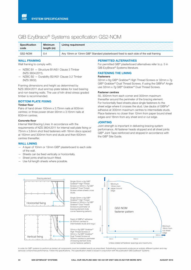
WALL LINING — A layer of 10mm or 13mm GIB® plasterboard to each side
of the wall. — Sheets can be fixed vertically or horizontally. — Sheet joints shall be touch fitted. — Use full length sheets where possible.
PERMITTED ALTERNATIVESFor permitted GIB® plasterboard alternatives refer to p. 5 in GIB EzyBrace® Systems literature.
FASTENING THE LININGFasteners32mm x 6g GIB® Grabber® High Thread Screws or 32mm x 7g GIB® Grabber® Dual Thread Screws. If using the GIBFix® Angle use 32mm x 7g GIB® Grabber® Dual Thread Screws.
Fastener centres50, 300mm from each corner and 300mm maximum thereafter around the perimeter of the bracing element. For horizontally fixed sheets place single fasteners to the sheet edge where it crosses the stud. Use daubs of GIBFix® adhesive at 300mm maximum centres to intermediate studs.Place fasteners no closer than 12mm from paper bound sheet edges and 18mm from any sheet end or cut edge.
JOINTINGJoint strength is important in delivering bracing system performance. All fastener heads stopped and all sheet joints GIB® Joint Tape reinforced and stopped in accordance with the GIB® Site Guide.
GIB EzyBrace® Systems specification GS2-NOMSpecification code
Minimum length (m)
Lining requirement
GS2-NOM 0.4 Any 10mm or 13mm GIB® Standard plasterboard fixed to each side of the wall framing
Minimum12mm from paper bound edge
Minimum 18mm from cut sheet edge
300m
m
300mm
50mm 250mm
50m
m25
0mm
GS2-NOM fastener pattern
In order for GIB® systems to perform as tested, all components must be installed exactly as prescribed. Substituting components produces an entirely different system and may seriously compromise performance. Follow the specifications. This specification sheet is issued in conjunction with the publication GIB EzyBrace® Systems
Single 32mm x 6g GIB® Grabber® High Thread Screws or 32mm x 7g GIB® Grabber® Dual Thread Screws to perimeter of bracing element (note corner fastening pattern).
Single 32mm x 6g GIB® Grabber® High Thread Screws or 32mm x 7g GIB® Grabber® Dual Thread Screws where sheets cross studs.
Horizontal fixing
Vertical fixing
Daub of GIBFix® adhesive at 300mm centres to intermediate studs and nog.s
32mm x 6g GIB® Grabber® High Thread Screws or 32mm x 7g GIB® Grabber® Dual Thread Screws at 300mm centres to perimeter of bracing element (note corner fastener pattern).
Bracing element
Unless stated all fastener spacings are maximums.
SYSTEM SPECIFICATIONS
GIB EZYBRACE® SYSTEMS24 AUGUST 2016CALL OUR HELPLINE 0800 100 442 OR VISIT GIB.CO.NZ FOR MORE INFO
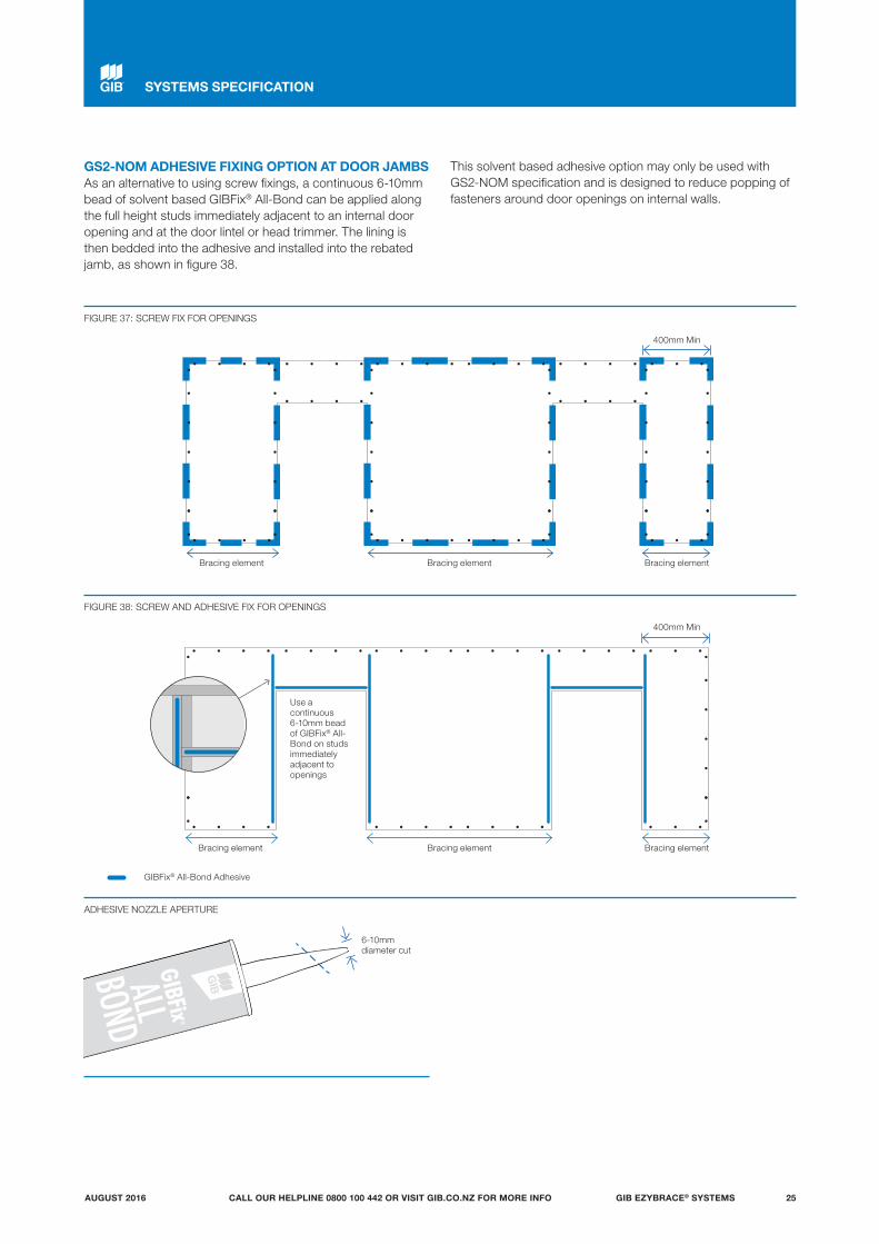
GS2-NOM ADHESIVE FIXING OPTION AT DOOR JAMBS As an alternative to using screw fixings, a continuous 6-10mm bead of solvent based GIBFix® All-Bond can be applied along the full height studs immediately adjacent to an internal door opening and at the door lintel or head trimmer. The lining is then bedded into the adhesive and installed into the rebated jamb, as shown in figure 38.
This solvent based adhesive option may only be used with GS2-NOM specification and is designed to reduce popping of fasteners around door openings on internal walls.
SYSTEMS SPECIFICATION
FIGURE 37: SCREW FIX FOR OPENINGS
FIGURE 38: SCREW AND ADHESIVE FIX FOR OPENINGS
ADHESIVE NOZZLE APERTURE
GIBFix® All-Bond Adhesive
Bracing element
Bracing element
Bracing element
Bracing element
Bracing element
Bracing element
400mm Min
400mm Min
6-10mm diameter cut
Use a continuous 6-10mm bead of GIBFix® All-Bond on studs immediately adjacent to openings
GIB EZYBRACE® SYSTEMS 25AUGUST 2016 CALL OUR HELPLINE 0800 100 442 OR VISIT GIB.CO.NZ FOR MORE INFO
WALL FRAMINGWall framing to comply with;
— NZBC B1 — Structure B1/AS1 Clause 3 Timber (NZS 3604:2011).
— NZBC B2 — Durability B2/AS1 Clause 3.2 Timber (NZS 3602).
Framing dimensions and height as determined by NZS 3604:2011 stud and top plate tables for load bearing and non-bearing walls. The use of kiln dried stress graded timber is recommended.
BOTTOM PLATE FIXINGTimber FloorPairs of hand driven 100 x 3.75mm nails at 600mm centres; or three power driven 90 x 3.15mm nails at 600mm centres.
Concrete floorInternal Wall Bracing Lines: In accordance with the requirements of NZS 3604:2011 for internal wall plate fixing or 75 x 3.8mm shot fired fasteners with 16mm discs spaced at 150mm and 300mm from end studs and then 600mm centres thereafter.
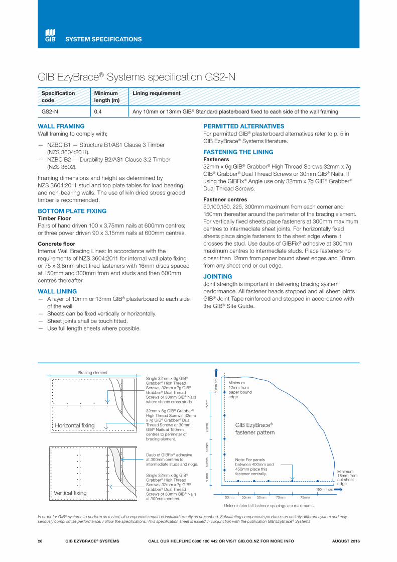
WALL LINING — A layer of 10mm or 13mm GIB® plasterboard to each side
of the wall. — Sheets can be fixed vertically or horizontally. — Sheet joints shall be touch fitted. — Use full length sheets where possible.
PERMITTED ALTERNATIVESFor permitted GIB® plasterboard alternatives refer to p. 5 in GIB EzyBrace® Systems literature.
FASTENING THE LININGFasteners32mm x 6g GIB® Grabber® High Thread Screws,32mm x 7g GIB® Grabber® Dual Thread Screws or 30mm GIB® Nails. If using the GIBFix® Angle use only 32mm x 7g GIB® Grabber®
Dual Thread Screws.
Fastener centres50,100,150, 225, 300mm maximum from each corner and 150mm thereafter around the perimeter of the bracing element. For vertically fixed sheets place fasteners at 300mm maximum centres to intermediate sheet joints. For horizontally fixed sheets place single fasteners to the sheet edge where it crosses the stud. Use daubs of GIBFix® adhesive at 300mm maximum centres to intermediate studs. Place fasteners no closer than 12mm from paper bound sheet edges and 18mm from any sheet end or cut edge.
JOINTINGJoint strength is important in delivering bracing system performance. All fastener heads stopped and all sheet joints GIB® Joint Tape reinforced and stopped in accordance with the GIB® Site Guide.
GIB EzyBrace® Systems specification GS2-N
In order for GIB® systems to perform as tested, all components must be installed exactly as prescribed. Substituting components produces an entirely different system and may seriously compromise performance. Follow the specifications. This specification sheet is issued in conjunction with the publication GIB EzyBrace® Systems
Specification code
Minimum length (m)
Lining requirement
GS2-N 0.4 Any 10mm or 13mm GIB® Standard plasterboard fixed to each side of the wall framing
Minimum 12mm from paper bound edge
Minimum 18mm from cut sheet edge
150m
m c
rs
150mm crs
50mm 50mm 50mm 75mm 75mm
50m
m50
mm
50m
m75
mm
75m
m
GIB EzyBrace® fastener pattern
Note: For panels between 400mm and 450mm place this fastener centrally.
32mm x 6g GIB® Grabber® High Thread Screws, 32mm x 7g GIB® Grabber® Dual Thread Screws or 30mm GIB® Nails at 150mm centres to perimeter of bracing element.
Single 32mm x 6g GIB® Grabber® High Thread Screws, 32mm x 7g GIB® Grabber® Dual Thread Screws or 30mm GIB® Nails where sheets cross studs.
Horizontal fixing
Vertical fixing
Daub of GIBFix® adhesive at 300mm centres to intermediate studs and nogs.
Single 32mm x 6g GIB® Grabber® High Thread Screws, 32mm x 7g GIB® Grabber® Dual Thread Screws or 30mm GIB® Nails at 300mm centres.
Bracing element
Unless stated all fastener spacings are maximums.
SYSTEM SPECIFICATIONS
GIB EZYBRACE® SYSTEMS26 AUGUST 2016CALL OUR HELPLINE 0800 100 442 OR VISIT GIB.CO.NZ FOR MORE INFO

SYSTEM SPECIFICATIONS
GIB EzyBrace® Systems specification GSP-H
Specification Code
Minimum length (m)
Lining requirement Other requirements
GSP-H 0.4 Any 10mm or 13mm GIB® plasterboard lining to one side of framing and minimum 7mm structural plywood manufactured to AS/NZ 2269.0 :2012 to the other side
Hold downs
WALL FRAMINGWall framing to comply with;
— NZBC B1 — Structure B1/AS1 Clause 3 Timber (NZS 3604:2011).
— NZBC B2 — Durability B2/AS1 Clause 3.2 Timber (NZS 3602).
Framing dimensions and height as determined by NZS 3604:2011 stud and top plate tables for load bearing and non-bearing walls. The use of kiln dried stress graded timber is recommended.
BOTTOM PLATE FIXINGTimber floorUse panel hold downs at each end of the bracing element. The GIB HandiBrac® is recommended. See details in GIB EzyBrace® Systems or GIB® Site Guide.
Pairs of hand driven 100 x 3.75mm nails at 600mm centres; or Three power driven 90 x 3.15mm nails at 600mm centres.
Concrete floorUse panel hold downs at each end of the bracing element. The GIB HandiBrac® is recommended. See details in GIB EzyBrace® Systems or GIB® Site Guide. Within the length of the bracing element bottom plates are to be fixed in accordance with the requirements of NZS 3604:2011.
WALL LINING — A layer of 10mm or 13mm GIB® plasterboard to one
side of the wall plus minimum 7mm structural plywood manufactured to AS/NZ 2269.0 :2012 to the other side.
— Sheets can be fixed vertically or horizontally, with edges supported.
— Sheet joints shall be touch fitted. — Use full length sheets where possible.
PERMITTED ALTERNATIVESFor permitted GIB® plasterboard alternatives refer to p. 5 in GIB EzyBrace® Systems literature.
FASTENING THE LININGFasteners32mm x 6g GIB® Grabber® High Thread Screws, 32mm x 7g GIB® Grabber® Dual Thread Screws or 30mm GIB® Nails.
If using the GIBFix® Framing System or if fastening through GIBFix® Angles use only 32mm x 7g GIB® Grabber® Dual Thread Screws. Plywood: 50 x 2.8mm Galv or Stainless steel annular grooved FH nails.
Fastener centresGIB® plasterboard side: 50,100,150, 225, 300mm maximum from each corner and 150mm thereafter around the perimeter of the bracing element. For vertically fixed sheets place fasteners at 300mm maximum centres to the intermediate sheet joints. For horizontally fixed sheets place single fasteners to the sheet edge where it crosses the stud. Use daubs of GIBFix® adhesive at 300mm maximum centres to intermediate studs. Place fasteners no closer than 12mm from paper bound sheet edges and 18mm from any sheet end or cut edge. Plywood side: 150mm centres to the perimeter of each sheet. GIB® corner fastener pattern does not apply to the plywood side. 300mm centres to intermediate studs.
JOINTINGJoint strength is important in delivering bracing system performance. All fastener heads stopped and all sheet joints GIB® Joint Tape reinforced and stopped in accordance with the GIB® Site Guide.
In order for GIB® systems to perform as tested, all components must be installed exactly as prescribed. Substituting components produces an entirely different system and may seriously compromise performance. Follow the specifications. This specification sheet is issued in conjunction with the publication GIB EzyBrace® Systems
Minimum 12mm from paper bound edge
Minimum 18mm from cut sheet edge
150m
m c
rs
150mm crs
50mm 50mm 50mm 75mm 75mm
50m
m50
mm
50m
m75
mm
75m
m
Vertical Fixing
Daub of GIBFix® adhesive at 300mm centres to intermediate studs and nogs.
Plasterboard side shown
Single 32mm x 6g GIB® Grabber® High Thread Screws, 32mm x 7g GIB® Grabber® Dual Thread Screws or 30mm GIB® Nails where sheets cross studs.
Bracing element
32mm x 6g GIB® Grabber® High Thread Screws only, 32mm x 7g GIB® Grabber® Dual Thread Screws or 30mm GIB® Nails.
Single 32mm x 6g GIB® Grabber® High Thread Screws, 32mm x 7g GIB® Grabber® Dual Thread Screws or 30mm GIB® Nails at 300mm centres.
Horizontal fixing
Vertical fixing
Hold downs required
Hold downs required
GIB EzyBrace® fastener pattern
Note: For panels between 400mm and 450mm place this fastener centrally.
Unless stated all fastener spacings are maximums.
GIB EZYBRACE® SYSTEMS 27AUGUST 2016 CALL OUR HELPLINE 0800 100 442 OR VISIT GIB.CO.NZ FOR MORE INFO
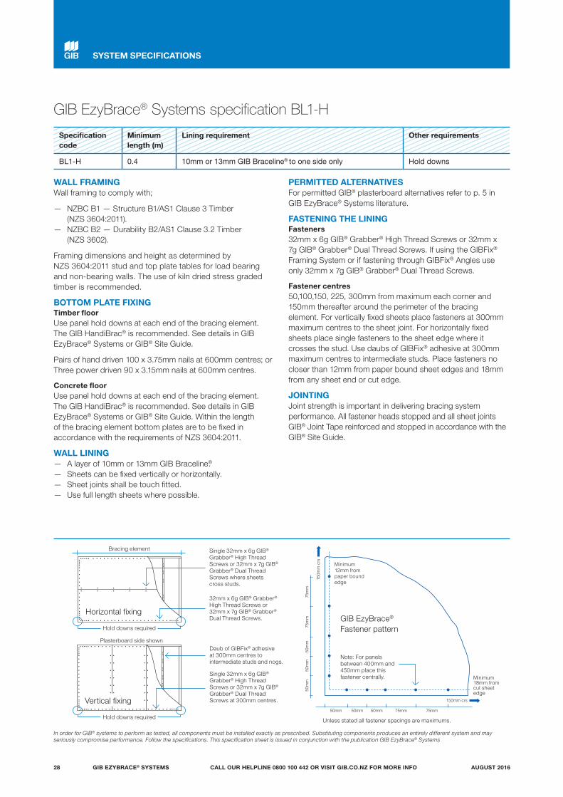
GIB EzyBrace® Systems specification BL1-H
Specification code
Minimum length (m)
Lining requirement Other requirements
BL1-H 0.4 10mm or 13mm GIB Braceline® to one side only Hold downs
WALL FRAMINGWall framing to comply with;
— NZBC B1 — Structure B1/AS1 Clause 3 Timber (NZS 3604:2011).
— NZBC B2 — Durability B2/AS1 Clause 3.2 Timber (NZS 3602).
Framing dimensions and height as determined by NZS 3604:2011 stud and top plate tables for load bearing and non-bearing walls. The use of kiln dried stress graded timber is recommended.
BOTTOM PLATE FIXINGTimber floorUse panel hold downs at each end of the bracing element. The GIB HandiBrac® is recommended. See details in GIB EzyBrace® Systems or GIB® Site Guide.
Pairs of hand driven 100 x 3.75mm nails at 600mm centres; or Three power driven 90 x 3.15mm nails at 600mm centres.
Concrete floorUse panel hold downs at each end of the bracing element. The GIB HandiBrac® is recommended. See details in GIB EzyBrace® Systems or GIB® Site Guide. Within the length of the bracing element bottom plates are to be fixed in accordance with the requirements of NZS 3604:2011.
WALL LINING — A layer of 10mm or 13mm GIB Braceline®. — Sheets can be fixed vertically or horizontally. — Sheet joints shall be touch fitted. — Use full length sheets where possible.
PERMITTED ALTERNATIVESFor permitted GIB® plasterboard alternatives refer to p. 5 in GIB EzyBrace® Systems literature.
FASTENING THE LININGFasteners32mm x 6g GIB® Grabber® High Thread Screws or 32mm x 7g GIB® Grabber® Dual Thread Screws. If using the GIBFix® Framing System or if fastening through GIBFix® Angles use only 32mm x 7g GIB® Grabber® Dual Thread Screws.
Fastener centres50,100,150, 225, 300mm from maximum each corner and 150mm thereafter around the perimeter of the bracing element. For vertically fixed sheets place fasteners at 300mm maximum centres to the sheet joint. For horizontally fixed sheets place single fasteners to the sheet edge where it crosses the stud. Use daubs of GIBFix® adhesive at 300mm maximum centres to intermediate studs. Place fasteners no closer than 12mm from paper bound sheet edges and 18mm from any sheet end or cut edge.
JOINTINGJoint strength is important in delivering bracing system performance. All fastener heads stopped and all sheet joints GIB® Joint Tape reinforced and stopped in accordance with the GIB® Site Guide.
In order for GIB® systems to perform as tested, all components must be installed exactly as prescribed. Substituting components produces an entirely different system and may seriously compromise performance. Follow the specifications. This specification sheet is issued in conjunction with the publication GIB EzyBrace® Systems
Minimum 12mm from paper bound edge
Minimum 18mm from cut sheet edge
150m
m c
rs
150mm crs
50mm 50mm 50mm 75mm 75mm
50m
m50
mm
50m
m75
mm
75m
m
Daub of GIBFix® adhesive at 300mm centres to intermediate studs and nogs.
Single 32mm x 6g GIB® Grabber® High Thread Screws or 32mm x 7g GIB® Grabber® Dual Thread Screws where sheets cross studs.
32mm x 6g GIB® Grabber® High Thread Screws or 32mm x 7g GIB® Grabber® Dual Thread Screws.
Single 32mm x 6g GIB® Grabber® High Thread Screws or 32mm x 7g GIB® Grabber® Dual Thread Screws at 300mm centres.
Plasterboard side shown
Bracing element
Horizontal fixing
Vertical fixing
Hold downs required
Hold downs required
GIB EzyBrace® Fastener pattern
Note: For panels between 400mm and 450mm place this fastener centrally.
Unless stated all fastener spacings are maximums.
SYSTEM SPECIFICATIONS
GIB EZYBRACE® SYSTEMS28 AUGUST 2016CALL OUR HELPLINE 0800 100 442 OR VISIT GIB.CO.NZ FOR MORE INFO
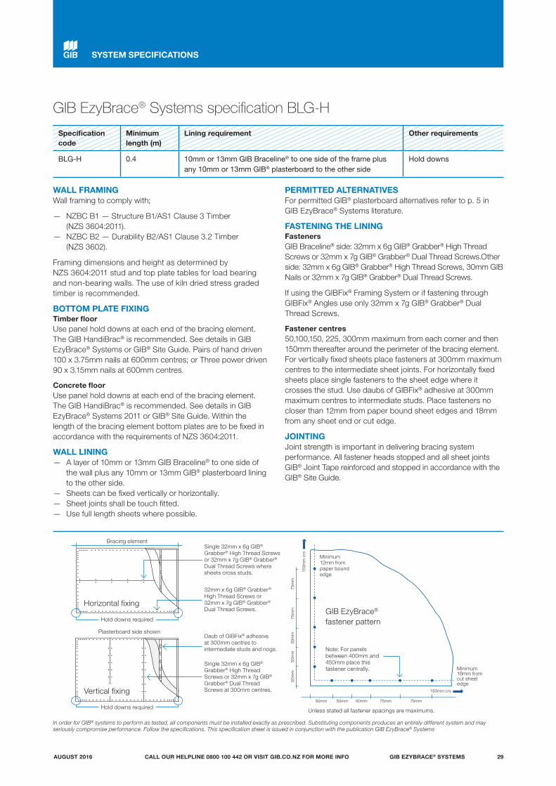
GIB EzyBrace® Systems specification BLG-H
Specification code
Minimum length (m)
Lining requirement Other requirements
BLG-H 0.4 10mm or 13mm GIB Braceline® to one side of the frame plus any 10mm or 13mm GIB® plasterboard to the other side
Hold downs
WALL FRAMINGWall framing to comply with;
— NZBC B1 — Structure B1/AS1 Clause 3 Timber (NZS 3604:2011).
— NZBC B2 — Durability B2/AS1 Clause 3.2 Timber (NZS 3602).
Framing dimensions and height as determined by NZS 3604:2011 stud and top plate tables for load bearing and non-bearing walls. The use of kiln dried stress graded timber is recommended.
BOTTOM PLATE FIXINGTimber floorUse panel hold downs at each end of the bracing element. The GIB HandiBrac® is recommended. See details in GIB EzyBrace® Systems or GIB® Site Guide. Pairs of hand driven 100 x 3.75mm nails at 600mm centres; or Three power driven 90 x 3.15mm nails at 600mm centres.
Concrete floorUse panel hold downs at each end of the bracing element. The GIB HandiBrac® is recommended. See details in GIB EzyBrace® Systems 2011 or GIB® Site Guide. Within the length of the bracing element bottom plates are to be fixed in accordance with the requirements of NZS 3604:2011.
WALL LINING — A layer of 10mm or 13mm GIB Braceline® to one side of
the wall plus any 10mm or 13mm GIB® plasterboard lining to the other side.
— Sheets can be fixed vertically or horizontally. — Sheet joints shall be touch fitted. — Use full length sheets where possible.
PERMITTED ALTERNATIVESFor permitted GIB® plasterboard alternatives refer to p. 5 in GIB EzyBrace® Systems literature.
FASTENING THE LININGFastenersGIB Braceline® side: 32mm x 6g GIB® Grabber® High Thread Screws or 32mm x 7g GIB® Grabber® Dual Thread Screws.Other side: 32mm x 6g GIB® Grabber® High Thread Screws, 30mm GIB Nails or 32mm x 7g GIB® Grabber® Dual Thread Screws.
If using the GIBFix® Framing System or if fastening through GIBFix® Angles use only 32mm x 7g GIB® Grabber® Dual Thread Screws.
Fastener centres50,100,150, 225, 300mm maximum from each corner and then 150mm thereafter around the perimeter of the bracing element. For vertically fixed sheets place fasteners at 300mm maximum centres to the intermediate sheet joints. For horizontally fixed sheets place single fasteners to the sheet edge where it crosses the stud. Use daubs of GIBFix® adhesive at 300mm maximum centres to intermediate studs. Place fasteners no closer than 12mm from paper bound sheet edges and 18mm from any sheet end or cut edge.
JOINTINGJoint strength is important in delivering bracing system performance. All fastener heads stopped and all sheet joints GIB® Joint Tape reinforced and stopped in accordance with the GIB® Site Guide.
In order for GIB® systems to perform as tested, all components must be installed exactly as prescribed. Substituting components produces an entirely different system and may seriously compromise performance. Follow the specifications. This specification sheet is issued in conjunction with the publication GIB EzyBrace® Systems
Minimum 12mm from paper bound edge
Minimum 18mm from cut sheet edge
150m
m c
rs
150mm crs
50mm 50mm 50mm 75mm 75mm
50m
m50
mm
50m
m75
mm
75m
m
Daub of GIBFix® adhesive at 300mm centres to intermediate studs and nogs.
Single 32mm x 6g GIB® Grabber® High Thread Screws or 32mm x 7g GIB® Grabber® Dual Thread Screws where sheets cross studs.
32mm x 6g GIB® Grabber® High Thread Screws or 32mm x 7g GIB® Grabber® Dual Thread Screws.
Single 32mm x 6g GIB® Grabber® High Thread Screws or 32mm x 7g GIB® Grabber® Dual Thread Screws at 300mm centres.
Plasterboard side shown
Bracing element
Horizontal fixing
Vertical fixing
Hold downs required
Hold downs requiredUnless stated all fastener spacings are maximums.
GIB EzyBrace® fastener pattern
Note: For panels between 400mm and 450mm place this fastener centrally.
SYSTEM SPECIFICATIONS
GIB EZYBRACE® SYSTEMS 29AUGUST 2016 CALL OUR HELPLINE 0800 100 442 OR VISIT GIB.CO.NZ FOR MORE INFO

GIB EzyBrace® Systems specification BLP-H
Specification code
Minimum length (m)
Lining requirement Other requirements
BLP-H 0.4 10mm or 13mm GIB Braceline® to one side of the frame plus minimum 7mm structural plywood manufactured to AS/NZ 2269.0 :2012 to the other side
Hold downs
WALL FRAMINGWall framing to comply with;
— NZBC B1 — Structure; B1/AS1 Clause 3 Timber (NZS 3604:2011).
— NZBC B2 — Durability B2/AS1 Clause 3.2 Timber (NZS 3602).
Framing dimensions and height as determined by NZS 3604:2011 stud and top plate tables for load bearing and non-bearing walls. The use of kiln dried stress graded timber is recommended.
BOTTOM PLATE FIXINGTimber floorUse panel hold downs at each end of the bracing element. The GIB® HandiBrac is recommended. See details in GIB EzyBrace® Systems or GIB® Site Guide.
Pairs of hand driven 100 x 3.75mm nails at 600mm centres; or Three power driven 90 x 3.15mm nails at 600mm centres.
Concrete floorUse panel hold downs at each end of the bracing element. The GIB HandiBrac® is recommended. See details in GIB EzyBrace® Systems or GIB® Site Guide. Within the length of the bracing element bottom plates are to be fixed in accordance with the requirements of AS/NZ 2269/0 :2012.
WALL LINING — A layer of 10mm or 13mm GIB Braceline® to one side of the
wall plus minimum 7mm structural plywood manufactured to AS/NZS 2269.0 :2012 to the other side.
— Sheets can be fixed vertically or horizontally. — Plywood is to be fixed vertically with edges supported. — Sheet joints shall be touch fitted. — Use full length sheets where possible.
PERMITTED ALTERNATIVESFor permitted GIB® plasterboard alternatives refer to p. 5 in GIB EzyBrace® Systems literature.
FASTENING THE LININGFastenersGIB Braceline® side: 32mm x 6g GIB® Grabber® High Thread Screws or 32mm x 7g GIB® Grabber® Dual Thread Screws. Plywood: 50 x 2.8mm Galv or Stainless steel annular grooved FH nails. If using the GIBFix® Framing System or if fastening through GIBFix® Angles use only 32mm x 7g GIB® Grabber® Dual Thread Screws.
Fastener centresGIB® Plasterboard side: 50,100,150, 225, 300mm from each corner and then 150mm thereafter around the perimeter of the bracing element. For vertically fixed sheets place fasteners at 300mm centres to the intermediate sheet joints. For horizontally fixed sheets place single fasteners to the sheet edge where it crosses the stud. Use daubs of GIBFix® adhesive at 300mm centres to intermediate studs. Place fasteners no closer than 12mm from paper bound sheet edges and 18mm from any sheet end or cut edge. Plywood side: 150mm centres to the perimeter of each sheet. GIB® corner fastener pattern does not apply to the plywood side. 300mm centres to intermediate studs.
JOINTINGJoint strength is important in delivering bracing system performance. All fastener heads stopped and all sheet joints GIB® Joint Tape reinforced and stopped in accordance with the GIB® Site Guide.
In order for GIB® systems to perform as tested, all components must be installed exactly as prescribed. Substituting components produces an entirely different system and may seriously compromise performance. Follow the specifications. This specification sheet is issued in conjunction with the publication GIB EzyBrace® Systems
Daub of GIBFix® adhesive at 300mm centres to intermediate studs and nogs.
Single 32mm x 6g GIB® Grabber® High Thread Screws or 32mm x 7g GIB® Grabber® Dual Thread Screws at 300mm centres.
Single 32mm x 6g GIB® Grabber® High Thread Screws or 32mm x 7g GIB® Grabber® Dual Thread Screws where sheets cross studs.32mm x 6g GIB® Grabber® High Thread Screws or 32mm x 7g GIB® Grabber® Dual Thread Screws.
Plasterboard side shown
Bracing element
Horizontal fixing
Vertical fixing
Hold downs required
Hold downs required
Minimum 12mm from paper bound edge
Minimum 18mm from cut sheet edge
150m
m c
rs
150mm crs
50mm 50mm 50mm 75mm 75mm
50m
m50
mm
50m
m75
mm
75m
m
GIB EzyBrace® fastener pattern
Note: For panels between 400mm and 450mm place this fastener centrally.
INSTALLATIONS — SYSTEM SPECIFICATIONS
Unless stated all fastener spacings are maximums.
GIB EZYBRACE® SYSTEMS30 AUGUST 2016CALL OUR HELPLINE 0800 100 442 OR VISIT GIB.CO.NZ FOR MORE INFO

Winstone Wallboards is committed to protecting the environment. Environmental matters are integrated into all business activities:
— Our operations strive to exceed all environmental regulatory requirements at all times.
— Protection of the environment is a day to day responsibility that we all must accept.
— We allocate appropriate management time and resources to address relevant environmental issues and continuously improve our activities in that area.
— We will achieve our standards of performance through positive action, employee involvement and constant communication with our neighbours, local authorities and customers.
Minimise on-site waste when designing and/or installing GIB® Systems. For larger projects give consideration to our cut-to-length service to reduce waste. GIB® plasterboard off-cuts, if separated from other waste building materials, can be readily recycled.
For larger projects waste can be diverted to compost manufacturers who grind up the GIB® plasterboard and use it in compost. For smaller projects, the GIB® plasterboard can be ground up and spread around the building site.
GLOBAL GREENTAGCERTTM
The Global GreenTagCertTM certified eco-label acknowledges product as meeting the GreenRate Standard set by Global GreenTag.CertTM
GIB® plasterboard has a Level B green rating.
DECLARE CERTIFICATIONDeclare is a database of non-toxic, sustainably sourced building products.
Many GIB® plasterboard products including GIB® Standard, GIB Braceline®®, GIB Noiseline® and GIB Aqualine® have achieved Red List Free status in Declare certification.
For more information on Winstone Wallboards sustainability commitments visit gib.co.nz.
COPYRIGHTCopyright © Winstone Wallboards Ltd 2016. All of the material contained in this brochure, including all text, tables, charts, graphs, drawings, images, diagrams are protected by copyright. These materials may not be reproduced, adapted or transmitted in any form by any process, without the permission of Winstone Wallboards Ltd.
Winstone Wallboards asserts its moral rights and reserves all other intellectual property rights in the materials contained in this brochure and related to GIBFix® Framing System and GIB EzyBrace® Systems.
TRADEMARKSThe names GIB®, GIB Fyreline®, GIB Ultraline®, GIB Braceline®, GIB Toughline®, GIB Noiseline®, GIB Aqualine®, GIB Nail®, GIB Tradeset®, GIB Plus 4®, GIB-Cove®, GIB Lite Blue®, GIBFix®, the colour mauve for GIB Toughline®, GIB HandiBrac®, GIB EzyBrace®, the colour blue for GIB Braceline®, the colour pink for GIB Fyreline®, the colour green for GIB Aqualine®, and the shield device are registered trademarks of Fletcher Building Holdings Limited.
PATENTS GIBFix® Framing System and GIB EzyBrace® Systems, including componentry and design method, have patents pending (NZ Patent Number 596691, NZ Patent 709159 pending) and design and other IP rights.
SUSTAINABILITY AND THE ENVIRONMENT
GIB EZYBRACE® SYSTEMS 31CALL OUR HELPLINE 0800 100 442 OR VISIT GIB.CO.NZ FOR MORE INFOAUGUST 2016

FOR MORE INFORMATION VISIT
gib.co.nzOR CALL THE GIB® HELPLINE
0800 100 442
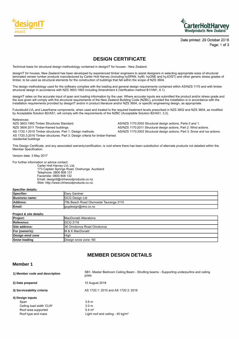
DESIGN CERTIFICATETechnical basis for structural design methodology contained in designIT for houses - New Zealand.
designIT for houses, New Zealand has been developed by experienced timber engineers to assist designers in selecting appropriate sizes of structurallaminated veneer lumber products manufactured by Carter Holt Harvey (including hySPAN, hy90, hyONE and hyJOIST) and other generic stress grades oftimber, to be used as structural elements for the construction of buildings that fall within the scope of NZS 3604.
The design methodology used for the software complies with the loading and general design requirements contained within AS/NZS 1170 and with timberstructural design in accordance with NZS 3603:1993 including Amendment 4 (Verification method B1/VM1, 6.1).
designIT relies on the accurate input of span and loading information by the user. Where accurate inputs are submitted the product and/or stress grade andthe size given will comply with the structural requirements of the New Zealand Building Code (NZBC), provided the installation is in accordance with theinstallation requirements provided by designIT and/or in product literature and/or NZS 3604, or specific engineering design, as appropriate.
Futurebuild LVL and Laserframe components, when used and treated to the required treatment levels prescribed in NZS 3602 and NZS 3604, as modifiedby Acceptable Solution B2/AS1, will comply with the requirements of the NZBC (Acceptable Solution B2/AS1, 3.2).
References:NZS 3603:1993 Timber Structures Standard. AS/NZS 1170:2002 Structural design actions, Parts 0 and 1.NZS 3604:2011 Timber-framed buildings. AS/NZS 1170:2011 Structural design actions, Part 2: Wind actions.AS 1720.1:2010 Timber structures. Part 1: Design methods. AS/NZS 1170:2003 Structural design actions, Part 3: Snow and ice actions.AS 1720.3:2016 Timber structures. Part 3: Design criteria for timber-framedresidential buildings
This Design Certificate, and any associated warranty/certification, is void where there has been substitution of alternate products not detailed within theMember Specification.
Version date: 3 May 2017
For further information or advice contact:Carter Holt Harvey LVL Ltd,173 Captain Springs Road, Onehunga. AucklandTelephone: 0800 808 131Facsimilie: 0800 808 132Email: [email protected]: http://www.chhwoodproducts.co.nz
Specifier details:Specifier: Gary GardnerBusiness name: GCG Design LtdAddress: 79b Beach Road Otumoetai Tauranga 3110Email: [email protected]
Project & site details:Project: MacDonald AlterationsReference: GCG 2118Site address: 36 Omokoroa Road OmokoroaFor (owner/s): M & K MacDonaldDesign wind zone HighSnow loading Design snow zone: N0
MEMBER DESIGN DETAILS
Member 1
1) Member code and description SB1- Master Bedroom Ceiling Beam - Strutting beams - Supporting underpurlins and ceilingjoists
2) Date prepared 15 August 2018
3) Serviceability criteria AS 1720.1: 2010 and AS 1720.3: 2016
4) Design inputsSpan 3.6 mCeiling load width 'CLW' 3.0 mRoof area supported 5.4 m²Roof type and mass Light roof and ceiling - 40 kg/m²
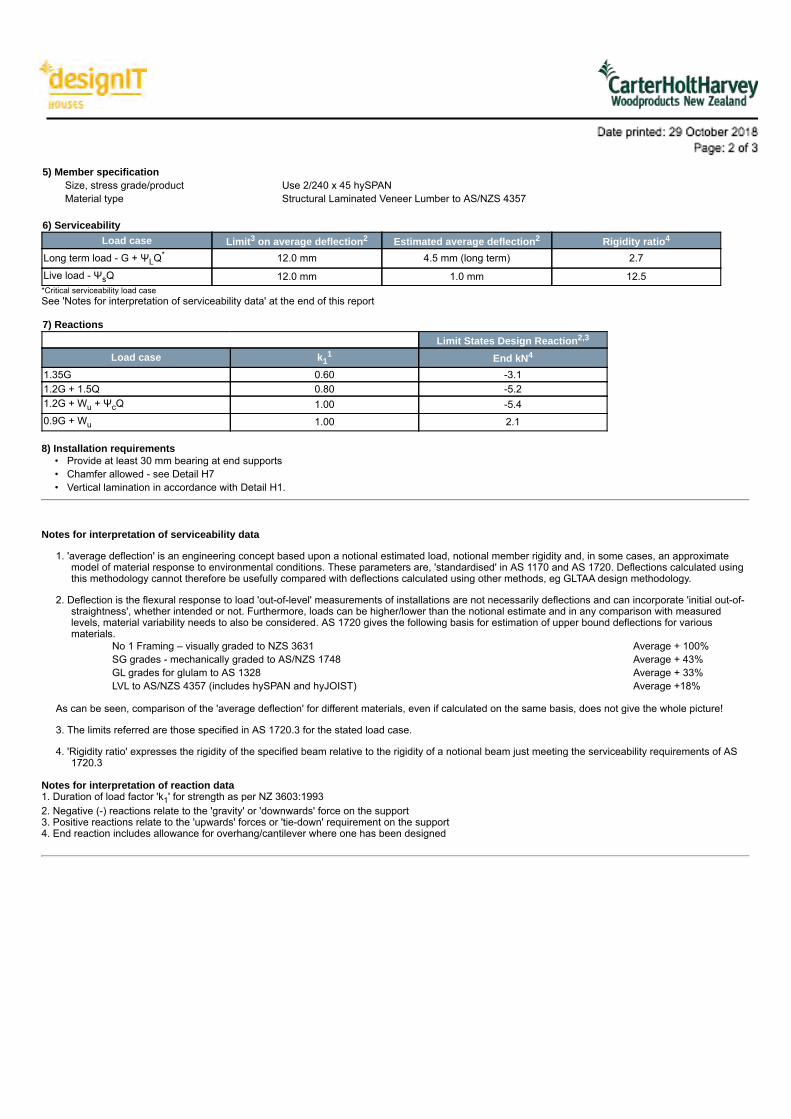
5) Member specificationSize, stress grade/product Use 2/240 x 45 hySPANMaterial type Structural Laminated Veneer Lumber to AS/NZS 4357
6) ServiceabilityLoad case Limit3 on average deflection2 Estimated average deflection2 Rigidity ratio4
Long term load - G + ΨLQ* 12.0 mm 4.5 mm (long term) 2.7Live load - ΨsQ 12.0 mm 1.0 mm 12.5*Critical serviceability load caseSee 'Notes for interpretation of serviceability data' at the end of this report
7) ReactionsLimit States Design Reaction2,3
Load case k11 End kN4
1.35G 0.60 -3.11.2G + 1.5Q 0.80 -5.21.2G + Wu + ΨcQ 1.00 -5.40.9G + Wu 1.00 2.1
8) Installation requirements • Provide at least 30 mm bearing at end supports• Chamfer allowed - see Detail H7• Vertical lamination in accordance with Detail H1.
Notes for interpretation of serviceability data
1. 'average deflection' is an engineering concept based upon a notional estimated load, notional member rigidity and, in some cases, an approximatemodel of material response to environmental conditions. These parameters are, 'standardised' in AS 1170 and AS 1720. Deflections calculated usingthis methodology cannot therefore be usefully compared with deflections calculated using other methods, eg GLTAA design methodology.
2. Deflection is the flexural response to load 'out-of-level' measurements of installations are not necessarily deflections and can incorporate 'initial out-of-straightness', whether intended or not. Furthermore, loads can be higher/lower than the notional estimate and in any comparison with measuredlevels, material variability needs to also be considered. AS 1720 gives the following basis for estimation of upper bound deflections for variousmaterials.
No 1 Framing – visually graded to NZS 3631 Average + 100%SG grades - mechanically graded to AS/NZS 1748 Average + 43%GL grades for glulam to AS 1328 Average + 33%LVL to AS/NZS 4357 (includes hySPAN and hyJOIST) Average +18%
As can be seen, comparison of the 'average deflection' for different materials, even if calculated on the same basis, does not give the whole picture!
3. The limits referred are those specified in AS 1720.3 for the stated load case.
4. 'Rigidity ratio' expresses the rigidity of the specified beam relative to the rigidity of a notional beam just meeting the serviceability requirements of AS1720.3
Notes for interpretation of reaction data 1. Duration of load factor 'k1' for strength as per NZ 3603:19932. Negative (-) reactions relate to the 'gravity' or 'downwards' force on the support3. Positive reactions relate to the 'upwards' forces or 'tie-down' requirement on the support4. End reaction includes allowance for overhang/cantilever where one has been designed
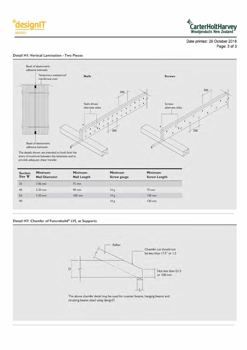

Report Number: 117431 ©Design Navigator Ltdprepared for M & C MacDonald Page 1
Design Navigator H1 Compliance Report
Project Summary
H1 Report created by: GCG Design Ltd
Project Name: MacDonald
Client: M & C MacDonald
Lot No: 36 Omokoroa RoadComment:Project Id: 117431
Report Date: 29/10/2018
Compliance Result
This report shows compliance of the design with Clause H1 Fourth edition Amendment 3 from January 2017 and the R-value targets of Clause E3 Second edition Amendment 6 from January 2017.This building complies with H1 via the following methods:
the Calculation Method in NZS4218:2009
H1 Compliance Details
NZS4218:2009 Calculation Method Compliance
The use of the Calculation Method is permitted .In order to comply the Actual Heat Loss must be the same or smaller than the Reference Heat Loss AND all component R-values must be the same or larger than 50% of the R-values in the '50% Rule' table below. This design complies with theNZS4218:2009 Calculation Method.
HeatLoss:
Referencebuilding
Proposedbuilding
139 104
Minimum R-values ("50% rule"):
PermittedMinimum
ProposedMinimum
Floor: 0.65 1.03
Non-solid Walls: 0.95 1.96
Roof: 1.45 3.65

Report Number: 117431 ©Design Navigator Ltdprepared for M & C MacDonald Page 2
The Reference building has the following areas and R-values.
Non-solid Solid Timber Other Solid100.0 0.0% 0.0%
Floor: Area: 34 m² R-values: 1.3 1.3 1.5
Walls excl. glazing: Area: 46.3 m² R-values: 1.9 1.2 1
Glazing (up to 30%): Area: 19.9 m² R-values: 0.26 0.26 0.26
Glazing (surplus of 30%): Area: 0 m² R-values: 0.4 0.34 0.31
Roof: Area: 34.3 m² R-values: 2.9 3.5 3.5
Heat Loss: 139 151 155
For mixed constructions the heat loss of the reference building is calculated as the sum of the heat losses for each type of wallconstruction multiplied by the fraction of the wall area of each type. This approach is based on clause 4.2.6 of NZS4218:2009.There are no skylights in the reference building. The reference building roof area is the sum of the proposed building roof and skylightareas.
Compliance with Clause E3
This building complies with the R-value targets in NZBC Clause E3 .
Component MinimumR-value
ProjectR-value
Framed wall constructions with cavities 1.5
Single skin masonry wall without a cavity 0.6
Solid timber wall no less than 60 mm thick 0.6
Roof or ceilings 1.5
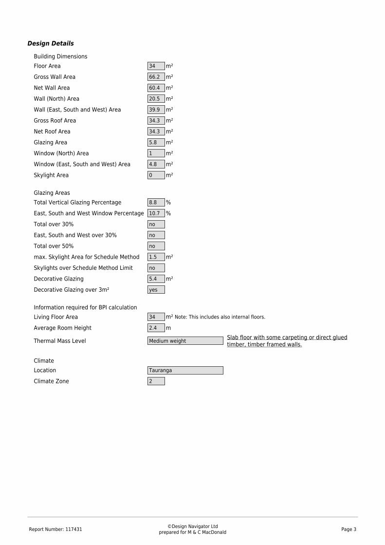
Report Number: 117431 ©Design Navigator Ltdprepared for M & C MacDonald Page 3
Design Details
Building DimensionsFloor Area m²34
Gross Wall Area m²66.2
Net Wall Area m²60.4
Wall (North) Area m²20.5
Wall (East, South and West) Area m²39.9
Gross Roof Area m²34.3
Net Roof Area m²34.3
Glazing Area m²5.8
Window (North) Area m²1
Window (East, South and West) Area m²4.8
Skylight Area m²0 Glazing AreasTotal Vertical Glazing Percentage %8.8
East, South and West Window Percentage %10.7
Total over 30% no
East, South and West over 30% no
Total over 50% no
max. Skylight Area for Schedule Method m²1.5
Skylights over Schedule Method Limit no
Decorative Glazing m²5.4
Decorative Glazing over 3m² yes Information required for BPI calculationLiving Floor Area m² Note: This includes also internal floors.34
Average Room Height m2.4
Thermal Mass Level Medium weight Slab floor with some carpeting or direct gluedtimber, timber framed walls.
ClimateLocation Tauranga
Climate Zone 2

Report Number: 117431 ©Design Navigator Ltdprepared for M & C MacDonald Page 4
Heat Loss Details
ID Orient. Width Height GrossArea
NetArea R-value* Heat
LossShad.
Coeff.**Solid
Wall***Floors
Floor 1 Rumpus and En 34.0 34.0 1.03 33.0
WallsWall 1 Ensuite N 2.6 1.2 3.1 2.8 3.30 0.8 C
Window 1-1 W22 0.6 0.6 0.4 0.26 1.4 0.00
Wall 2 Ensuite W 2.4 1.2 2.9 2.9 3.30 0.9 C
Wall 3 Ensuite S 2.6 1.2 3.1 3.1 3.30 0.9 C
Wall 4 Ensuite Blk N 2.6 1.5 3.9 3.9 1.96 2.0 C
Wall 5 Ensuite Blk W 2.4 1.5 3.6 3.6 1.96 1.8 C
Wall 6 Ensuite Blk S 2.6 1.5 3.9 3.9 1.96 2.0 C
Wall 7 Garage/Rumpu S 5.8 2.5 14.4 14.4 1.96 7.3 C
Wall 8 Rumpus E 4.7 2.5 11.8 7.0 1.96 3.6 C
Window 8-1 D03 2.4 2.0 4.8 0.17 28.2 0.00
Wall 9 Rumpus N 5.8 2.5 14.4 13.8 1.96 7.0 C
Window 9-1 W23 1.0 0.6 0.6 0.17 3.5 0.00
Wall 10 Rumpus W 2.0 2.5 5.0 5.0 1.96 2.6 C
RoofsRoof 1 Ensuite 6.3 6.3 3.92 1.6
Roof 2 Runpus 28.0 28.0 3.65 7.7
Total Heat Loss 104.4
* Any concrete slab-on-ground floor regardless of its dimensions can be assumed to have an R-value of at least R-1.3(H1/AS1 2.1.5).** The Shading Coefficient is only required for BPI calculations.*** C: Cavity Construction (any construction that is not solid), T: Solid Timber, S: Other Solid Construction (Note that theuse of solid timber and other solid construction types is discretional, i.e. solid timber walls and other solid walls can betreated as if they are non-solid (NZS4218:2009 section 4.1.3.).)
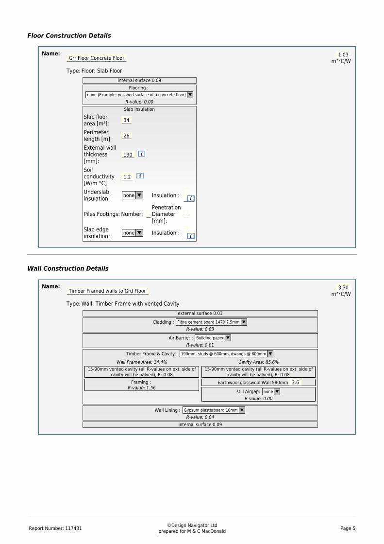
Report Number: 117431 ©Design Navigator Ltdprepared for M & C MacDonald Page 5
Floor Construction Details
Name: Grr Floor Concrete Floor 1.03
m²°C/WType: Floor: Slab Floor
internal surface 0.09Flooring :
none (Example: polished surface of a concrete floor) ▼
R-value: 0.00Slab Insulation
Slab floorarea [m²]: 34
Perimeterlength [m]: 26
External wallthickness[mm]:
190
Soilconductivity[W/m °C]
1.2
Underslabinsulation: none ▼ Insulation :
Piles Footings: Number: PenetrationDiameter[mm]:
Slab edgeinsulation: none ▼ Insulation :
Wall Construction Details
Name: Timber Framed walls to Grd Floor 3.30
m²°C/WType: Wall: Timber Frame with vented Cavity
external surface 0.03
Cladding : Fibre cement board 1470 7.5mm ▼
R-value: 0.03
Air Barrier : Building paper ▼
R-value: 0.01
Timber Frame & Cavity : 190mm, studs @ 600mm, dwangs @ 800mm ▼
Wall Frame Area: 14.4%15-90mm vented cavity (all R-values on ext. side of
cavity will be halved), R: 0.08Framing :
R-value: 1.56
Cavity Area: 85.6%15-90mm vented cavity (all R-values on ext. side of
cavity will be halved), R: 0.08Earthwool glasswool Wall 580mm 3.6
still Airgap: none ▼
R-value: 0.00
Wall Lining : Gypsum plasterboard 10mm ▼
R-value: 0.04internal surface 0.09
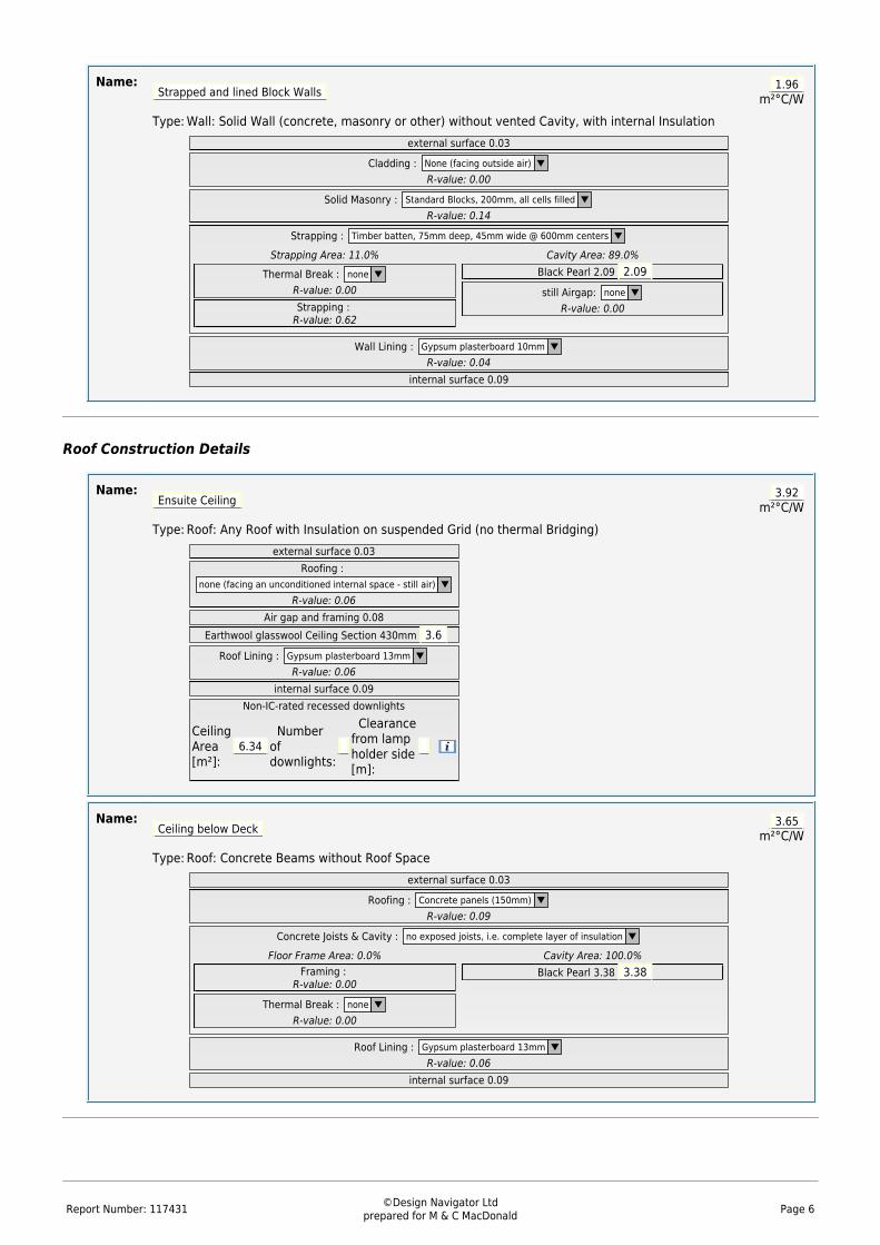
Report Number: 117431 ©Design Navigator Ltdprepared for M & C MacDonald Page 6
Name: Strapped and lined Block Walls 1.96
m²°C/WType: Wall: Solid Wall (concrete, masonry or other) without vented Cavity, with internal Insulation
external surface 0.03
Cladding : None (facing outside air) ▼
R-value: 0.00
Solid Masonry : Standard Blocks, 200mm, all cells filled ▼
R-value: 0.14
Strapping : Timber batten, 75mm deep, 45mm wide @ 600mm centers ▼
Strapping Area: 11.0%
Thermal Break : none ▼
R-value: 0.00Strapping :
R-value: 0.62
Cavity Area: 89.0%Black Pearl 2.09 2.09 still Airgap: none ▼
R-value: 0.00
Wall Lining : Gypsum plasterboard 10mm ▼
R-value: 0.04internal surface 0.09
Roof Construction Details
Name: Ensuite Ceiling 3.92
m²°C/WType: Roof: Any Roof with Insulation on suspended Grid (no thermal Bridging)
external surface 0.03Roofing :
none (facing an unconditioned internal space - still air) ▼
R-value: 0.06Air gap and framing 0.08
Earthwool glasswool Ceiling Section 430mm 3.6 Roof Lining : Gypsum plasterboard 13mm ▼
R-value: 0.06internal surface 0.09
Non-IC-rated recessed downlights
CeilingArea[m²]:
6.34 Numberofdownlights:
Clearancefrom lampholder side[m]:
Name: Ceiling below Deck 3.65
m²°C/WType: Roof: Concrete Beams without Roof Space
external surface 0.03
Roofing : Concrete panels (150mm) ▼
R-value: 0.09
Concrete Joists & Cavity : no exposed joists, i.e. complete layer of insulation ▼
Floor Frame Area: 0.0%Framing :
R-value: 0.00
Thermal Break : none ▼
R-value: 0.00
Cavity Area: 100.0%Black Pearl 3.38 3.38
Roof Lining : Gypsum plasterboard 13mm ▼
R-value: 0.06internal surface 0.09

PLUS 12.14
FR NOTICE D’INSTALLATION
UK INSTALLATION INSTRUCTIONS
DE INSTALLATIONSHINWEISE
IT STRUZIONI PER L’INSTALLAZIONE
ES MANUAL DE INSTALACIÓN
PT MANUAL DE INSTALAÇÃO
NL INSTALLATIE VOORSCHRIFTEN
SE INSTALLATIONSANVISNING
DK INSTALLATIONSVEJLEDNING
NO INSTALLASJONSANVISING
FI ASENNUSOHJEET
HU FELSZERELÉSI ÉS KEZELÉSI ÚTMUTATÓ
PL INSTRUKCJA INSTALACJI
RU ИнСтРукцИЯ пО мОнтажу И экСплуатацИИ
RO MANUAL DE INSTALARE
CZ NÁVOD K INSTALACI A POUŽÍVÁNÍ
TR KURULUM KILAVUZU
EL
422
SANIPLUS ®
ODHGIES EGKATASTASHS
CN
KR
SANIPLUS
EN 12050-3P 30220-240 V - 50 Hz 400 W - IP44 - 1,9A - (class 1) - 6,4 Kg
설치내용서
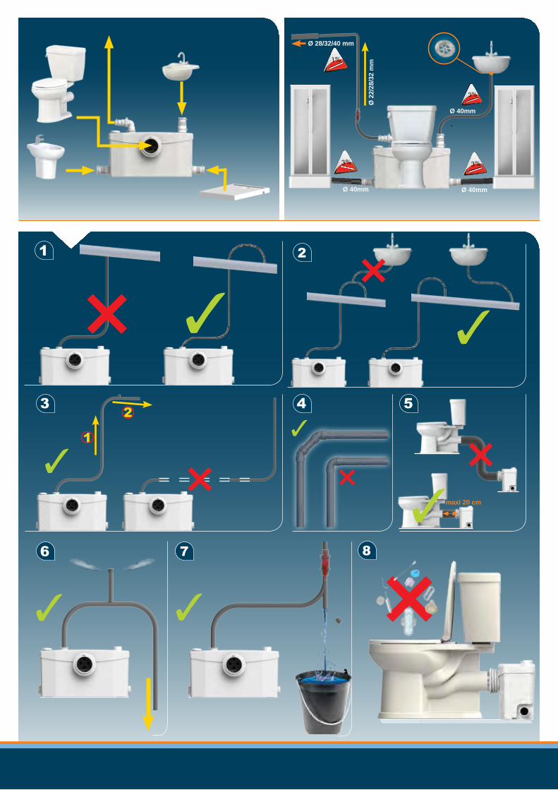
1 2
3
1
2 4 5
6 7 8
✓ ✓
✓ ✓
✓ ×✓
× ×
×
Ø 40mm Ø 40mm
Ø 40mm
Ø 28/32/40 mm
Ø 2
2/28
/32
mm
××
maxi 20 cm✓

1
E
x3
H
x2
G
x4
D
x2
E
x2
C
x0
B
x5
A
x1
F
x1
K
x1
L
x1
I
x2
J
x1
D
x1
C
x1
B
x8
A
x1 25x40
25x40
20x32
20x32
32x55
32x55
ONLY
ONLY
Ø22 mm
Ø28 mm
Ø32 mm
D
B
B
A
B A C/D
A D AD
A
D
C
Ø 32 mmØ 22 mm

3 4
2
6 5 Ø 40mm B
E
B
G
I I
HH
J
K
×
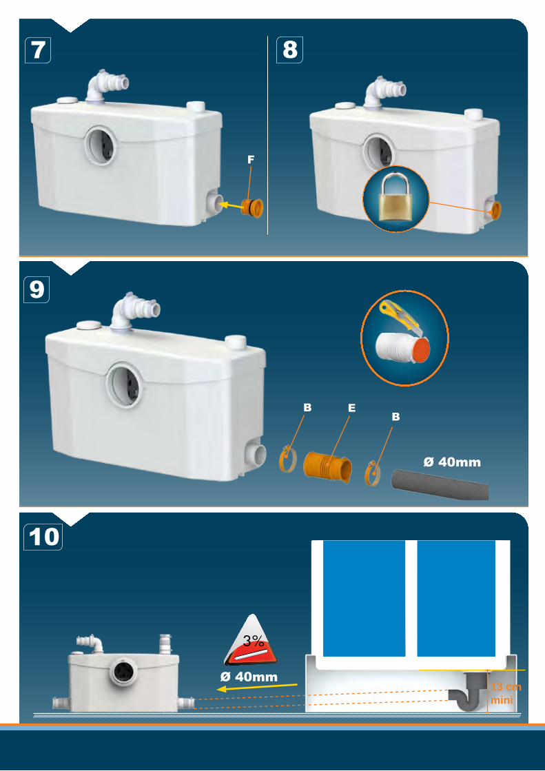
Ø 40mm
B EB
F
7
10
8
9
Ø 40mm13 cm mini

L
11 12
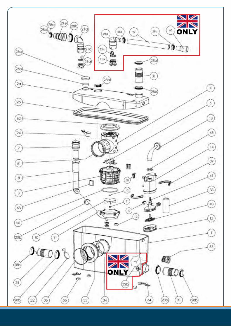
ONLY
ONLY

SERVICE HELPLINES
0
1
2
3
4
5
6
20 40 60 80 100
7
8
9
L/min
m
SANIPLUS
EN 12050-3P 30220-240 V - 50 Hz 400 W - IP44 - 1,9A - (class 1) - 6,4 Kg
EN12050-3
Service information : www.sfa.biz
263
510
65
40
248
41 327
233
178
185
35 46
Plan n°:
unitésmmFeuille: 1/1
NOMASSEMBLAGE
V.H-D
Echelle: 2:1
NUM
00/00/12
Dessinépar
Tel: 01.44.82.39.00
D'ASSAINISSEMENT
8 RUE D'ABOUKIR 75002 PARIS
in. date modifications SFA
CE DOCUMENT EST LA PROPRIETE DE SFA ET NE PEUT ETRE REPRODUIT OU COMMUNIQUE SANS AUTORISATION
SOCIETE FRANCAISE
00 CREATION DU PLAN
FRANCE
SOCIÉTÉ FRANçAISE D’ASSAINISSEMENT41 bis avenue Bosquet - 75007 ParisTél. +33 1 44 82 39 00Fax +33 1 44 82 39 01
UNITED KINGDOM
SANIFLO Ltd.,Howard House, The Runway South Ruislip Middx., HA4 6 SETel. +44 208 842 0033 Fax +44 208 842 1671
IRELAND
SANIRISH LtdIDA Industrial EstateEdenderry - County OffalyTel. + 353 46 9733 102Fax + 353 46 97 33 093
AUSTRALIA
SANIFLO (Australasia) Pty Ltd Unit 9/10, 25 Gibbes StreetChatswood NSW 2067Tel. +61 298 826 200 Fax +61 298 826 950
DEUTSCHLANDSFA SANIBROY GmbHWaldstr. 23 Geb. B5 - 63128 DietzenbachTel. (060 74) 30928-0 Fax (060 74) 30928-90
ITALIASFA ITALIA spa Via del Benessere, 927010 Siziano (PV)Tel. 03 82 61 81Fax 03 82 61 8200
ESPAÑASFA S.L.C/ Vinyalets,1 - P.I. Can Vinyalets08130 Sta. - Perpètua de Mogoda - Barcelona Tel. +34 93 544 60 76Fax +34 93 462 18 96
PORTUGALSFA, Lda. Sintra Business Park, ed.01-1ºP2710-089 SINTRA Tel. +35 21 911 27 85Fax +35 21 957 70 00
SUISSE SCHWEIZ SVIZZERASFA SANIBROY AG Vorstadt 43380 Wangen a. A.Tel. + 41 (0)32 631 04 74 Fax + 41 (0)32 631 04 75
BENELUXSFA BENELUX B.V.Voltaweg 46101 XK Echt (NL)Tel. +31 475 487100Fax +31 475 486515
SVERIGESANIFLO ABBOX 797 S-191 27 SollentunaTel. +46 (0)8-404 15 [email protected]
POLSKASFA POLAND Sp. z 0.0.ul. Kolejowa 3305-092 £omianki/Warszawa Tel. (+4822) 732 00 32Fax (+4822) 751 35 16
ČESKÁ REPUBLIKASFA-SANIBROY, spol. s r.o Na Košince č.ev. 681- 180 00 PRAHA8 - LibeňTel . +420 266 712 855Fax , +420 266 712 856
ROMANIASFA SANIFLO S.R.L.Strada Leonard Nicolae, nr. 2ATimişoara 300454Tel. +40 256 245 092Fax +40 256 245 029
TÜRKIYESFA SANIHYDRO LTD STIMecidiye Cad No:36-B Sevencan APT34394 MECIDIYEKÖY - ISTANBUL Tel . +90 212 275 30 88Fax , +90 212 275 90 58
KOREA
South Africa
SFA Africawww.saniflo.co.za
101000 Москва - Колпачный переулок 9a Тел. (495) 258 29 51Факс. (495) 258 29 51
SFA РОССИЯРОССИЯ
TEL FAX France 03 44 94 46 19 United Kingdom 08457 650011 (Call from a land line) 020 8842 1671 Ireland 1850 23 24 25 (LOW CALL) + 353 46 97 33 093 Australia +1300 554 779 +61.2.9882.6950 Deutschland 0800 82 27 82 0 (060 74) 30928-90 Italia 0382 6181 +39 0382 618200 España +34 93 544 60 76 +34 93 462 18 96 Portugal +35 21 911 27 85 +35 21 957 70 00 Suisse Schweiz Svizzera +41 (0)32 631 04 74 +41 (0)32 631 04 75
Benelux +31 475 487100 +31 475 486515 Sverige +46 (0)8-404 15 30 Norge +46 (0)8-404 15 30 Polska (+4822) 732 00 33 (+4822) 751 35 16 РОССИЯ (495) 258 29 51 (495) 258 29 51 Česká Republika +420 266 712 855 +420 266 712 856 România +40 256 245 092 +40 256 245 029 Türkiye +90 212 275 30 88 +90 212 275 90 58 中国 +86(0)21 6218 8969 +86(0)21 6218 8970 Brazil +55 11 3262 2903
CHINASFA 中国上海市静安区石门二路333弄3号振安广场恒安大厦27C (200041)Tel. +86(0)21 6218 8969 Fax. +86(0)21 6218 8970
BRAZILSANITRITRua Manuel da Nobrega 354Paraiso CEP 04001-001SAO PAULO / SPTel. + 55 11 3262 2903www.sanitrit.com.br
1m
2m
3m
4m
5m max 60m
max 70m
max 80m
max 90m
max 100m

1
FR INFORMATIONS COMPLÉMENTAIRES IMPORTANTES
UK IMPORTANT ADDITIONAL INFORMATION
DE WICHTIGE ZUSÄTZLICHE INFORMATIONEN
IT INFORMAZIONI AGGIUNTIVE IMPORTANTI
ES INFORMACIÓN COMPLEMENTARIA IMPORTANTE
PT INFORMAÇÕES COMPLEMENTARES IMPORTANTES
NL BELANGRIJKE EXTRA INFORMATIE
SE ANNAN VIKTIG INFORMATION
DK VIGTIGE SUPPLERENDE OPLYSNINGER
NO VIKTIG TILLEGGSINFORMASJON
FI TÄRKEITÄ LISÄTIETOJA
HU FONTOS KIEGÉSZÍTŐ INFORMÁCIÓK
PL WAŒNE INFORMACJE DODATKOWE
RU ВАЖНАЯ ДОПОЛНИТЕЛЬНАЯ ИНФОРМАЦИЯ
RO INFORMAŢII SUPLIMENTARE IMPORTANTE
CZ DŮLEŽITÉ DOPLŇUJÍCÍ INFORMACE
TR ÖNEMLİ EK BİLGİLER
CN 重要补充信息
KR 한국
BROY 3 09.14

2
FR
UK
DE
IT
ES
PT
NL
SE
DK
NO
FI
HU
PL
RU
RO
CZ
TR
CN
KR

3
1 AVERTISSEMENTCe broyeur est soumis à un contrôle qua-lité permanent dans une usine certifiée ISO 9001. Il bénéficie d’un haut niveau de per-formance, de sécurité et de fiabilité dans la mesure où toutes les règles d’installation et d’entretien décrites dans cette notice sont scrupuleusement respectées.
Cet appareil n’est pas destiné aux personnes (y compris les enfants) dont les capacités physiques, sensorielles ou mentales sont limi-tées, ou auxquelles l’expérience et les connaissances font défaut, excepté si elles sont sous surveillance et reçoivent les instructions nécessaires pour utiliser l’appareil, avec l’aide d’une personne responsable de leur sécu-rité. Surveiller les enfants et veiller à ce qu’ils ne jouent pas avec l’appareil.
2 APPLICATIONSCet appareil est une station de relevage com-pacte conçue pour évacuer les eaux usées provenant d'un WC à évacuation horizontale, d'un lavabo*,d'une douche*, d'un bidet*. (*:selon le modèle).
Cet appareil répond à la norme EN 12050-3 et aux normes Européennes sur la sécurité électrique et la compatibilité électromagnétique.
3 INSTALLATIONLe broyeur doit se trouver dans la même pièce que le WC et que les autres ins-tallations sanitaires éventuellement rac- cordées. L’appareil doit être d’accès aisé pour le contrôle et la maintenance.L’installation et le fonctionnement de votre appareil doivent respecter les réglementa-tions locales et la norme EN 12056-4.
Afin d'optimiser les derniers développements techniques en matière d'acoustique inclus dans cet appareil, il est important :
• d'installer la cuve en évitant que celle-ci ne touche une paroi de la pièce,• de positionner la cuve sur un sol parfai-tement plat afin de ne pas contrarier le bon fonctionnement des plots anti-vibratoires,• de fixer correctement la tuyauterie d'éva-cuation en évitant des distances entre les fixations supérieures à un mètre.
RACCORDEMENT ÉLECTRIQUEN’effectuer le branchement
électrique qu’une fois les rac- cordements définitifs terminés.L’installation électrique doit être réalisée par
un professionnel qualifié en électrotechnique.L’appareil doit être placé de façon telle que la fiche de prise de courant soit accessible.
Le circuit d’alimentation de l’appa-reil doit être relié à la terre (classe I) et protégé par un disjoncteur différen-tiel haute sensibilité (30mA).Le raccordement doit servir exclusivement à l’alimentation de l’appareil. Si le câble de cet appareil est endommagé, il doit être rem-placé par le fabricant ou son service après-vente.
RéglementationVeillez à respecter les dispositions de la norme en vigueur dans le pays d’utilisation (France : NF C 15-100) concernant les volumes de protection d’une salle de bains.
4 MISE EN SERVICEActionner plusieurs fois la chasse d’eau.Le passage cuvette doit être étanche. Véri-fier l’étanchéité des raccordements avec les appareils sanitaires : WC, douche*, bidet*, lavabo*. (*: selon le modèle).
5 MAINTENANCEATTENTION !!!En cas d’absence prolongée, il est impératif de couper l’alimentation générale en eau et de protéger l'installation contre le gel.
NETTOYAGE/DÉTARTRAGEPour détartrer et nettoyer le broyeur et la cuvette, utiliser régulièrement comme le détartrant spécial SANIBROYEUR de SFA, qui est conçu pour enlever le tartre tout en respectant les organes internes de votre appareil.
6 INTERVENTIONS ÉVENTUELLES
ANOMALIE CONSTATÉE CAUSES PROBABLES REMÈDES• Le moteur ne démarre pas • Appareil non branché
• Alimentation électrique défectueuse
• Problème moteur ou système de commande
• Brancher l’appareil.
• Vérifier l’alimentation électrique
• Consulter un dépanneur agréé
• Le moteur tourne avec un bruit de crécelle ou bourdonne et ne tourne pas
• Moteur bloqué par un corps étranger
• Problème moteur ou système de commande
• Enlever le corps étranger
• Sinon, consulter un dépanneur agréé
• L’appareil se remet en marche par intermittence
• Les appareils sanitaires raccordés fuient
• Le clapet anti-retour fuit
• Contrôler l’installation en amont
• Nettoyer ou changer le clapet anti-retour
• Le moteur tourne correctement mais ne s’arrête plus ou tourne très longtemps
• La hauteur ou longueur d’évacuation est trop importante (perte de charge)
• Problème hydraulique, colmatage
• Revoir l’installation
• Sinon, consulter un dépanneur agréé
• L’appareil s’arrête • L’appareil a fonctionné pendant trop longtemps (coupure thermique de sécurité)
• Attendre le réenclenchement.• Faites appel à un dépanneur agréé si nécessaire
• Le moteur tourne par à-coups et l’eau descend lentement dans la cuvette
• L’évent du couvercle est bouché• Problème moteur
• Déboucher le trou d’évent• Sinon, consulter un dépanneur
agréé
• Retour d’eau trouble dans la douche (appareils avec entrées latérales)
• Douche installée trop bas par rapport au broyeur
• Battants d’entrées latérales colmatés
• Revoir l’installation
• Nettoyer les battants
• Sinon, consulter un dépanneur agréé
DANS TOUS LES CAS, DÉBRANCHER LA PRISE ÉLECTRIQUE DU BROYEUR
7 CONDITIONS DE GARANTIEL’appareil est garanti deux ans à compter de sa date d’achat sous réserve d’une instal-lation et d’une utilisation conformes à la présente notice.
Ne sera prise en compte par la garantie que l'évacuation de papiers hygiéniques, matières fécales et eaux sanitaires.Tout dommage causé à l'appareil par le broyage de corps étrangers tels que coton, tam-pons périodiques, serviettes hygiéniques, lingettes, produits alimentaires, préservatifs, cheveux, objets en métal, en bois ou en plastique, ou le pompage de liquides tels que solvants ou huiles n'entrerait pas dans le cadre de la garantie.
FR

4
1 DESCRIPTIONThis macerator is (manufactured in a fac-tory which is quality) certified to ISO 9001. Installed and used correctly, the unit will give consistent and reliable service.
This device is not designed for persons (including child-ren) with limited physical, sensory or mental abilities, or those with minimal experience and knowledge, unless they are monitored and are given the necessary instructions for using the device, with the help of a person responsible for their safety. Monitor children and make sure they do not play with the device.
2 APPLICATIONSThis appliance is a compact lift pump unit designed for removing waste water from a horizontal outlet toilet*, shower*, bidet* or washbasin* (*: depending on the model).This appliance conforms to EN 12050-3 and the European standards concerning electrical safety and electromagnetic compatibility.
3 INSTALLATIONThe unit should be accessible for possible service.The fitting and working of your appliance must meet local regulations and the EN 12056-4 standard.
To optimise the latest technical develop-ments concerning soundproofing incorpo-rated into this unit, it is important to:• position the WC pan so that it is not in contact with a partition or wall of the room• place the WC pan on a perfectly level surface to ensure that the resilient mounts are fully efficient• fix the discharge pipe correctly, with distances of not more than one metre between the fastenings.
CONNECTION TO THE ELECTRICAL SUPPLYThe electrical installation should
be carried out by a qualified person. The unit requires a 220/240V single phase AC 50 Hz supply (UK specification).The power supply circuit of the ap-pliance must be earthed (Class I) and protected by a GFCI high sensitivity (30mA). Warning: Ensure the electri-city is turned OFF at the main switch board before wiring to connector.All wiring must conform to BS7671, 1992 requirements for electrical installations. Do not connect the unit to a conventional plug and socket. It must be wired into a fused, unswitched, fixed wiring connector fitted with a 5 amp fuse. The wires in the mains lead are coloured in accordance with
the following code:Brown - LiveBlue - NeutralGreen/Yellow - EarthThe connection must be used exclusively to power the device.All work on cable, pressure chamber and motor should only be carried out by a qualified Saniflo servicing agent, as spe-cial tools are required. Please do not cut/shorten the electrical supply cable which can make it very difficult to remove in the event of a service requirement.
4 C O M M I S S I O N I N G THE UNIT
Flush the WC checking that all seals, and connections are watertight.Check both the discharge pipework from the unit and the other sanitary appliances connections. Check the watertightness of connections to sanitary appliances:
toilet*, shower*, bidet* or washbasin* (*: depending on the model).
5 MAINTENANCEWARNING !!! In the event of prolonged absence it is essential to turn off the water supply to protect the installation against sub zero temperatures.
CARE OF YOUR UNITIn order to remove scale and clean the macerator and the bowl, use the SANIFLO Cleanser/Descalent..Disconnect the macerator power supply,.Pour an amount of cleanser into the pan.Leave it to stand for 1 or 2 hours,.Re-connect the macerator power supply,.Rinse by operating the flushing system twice.Carry out the operation once every 3 months on average, but the frequency may need to be changed depending on the hardness of the water.
6 FAULT FINDING / REMEDIES
SYMPTOMS PROBABLE CAUSES REMEDIES• The motor does not activate • The electrical power supply
is not active• The electrical power supply is
defective• The motor or the control system
is defective
• Restore the electrical supply
• Check the electrical power supply
• Otherwise, ask an approved repair agent to intervene
• The motor emits a rattling or crunching sound, hums, but does not run
• Foreign object into the box• Problem with the motor or the
control system
• Remove the foreign body • Otherwise, ask an approved
repair agent to intervene
• The motor intermittently activates
• The connected sanitary devices are dripping water
• The non-return valve is faulty
• Check the installation upstream
• Clean or replace the non-return valve
• The motor operates normally, but continues to run for a long time
• The length or height of the installation is over the specification, or there are too many bends/elbows
• The pump cover plate is partially obscured/blocked
• Check the installation
• Otherwise, ask an approved repair agent to intervene
• The unit stops • The unit has been running for too long (thermal cut-out)
• Wait for reset, then ask an approved repair agent to intervene
• Motor is surging and water in the WC pan goes down very slowly
• The air dispenser is clogged up• Problem with motor
• Clear the air relief hole• Otherwise, ask an approved
repair agent to intervene
• Cloudy water comes up into the shower basin (units with side inlets)
• Shower installed too low as compared with the macerator unit
• Hinged side inlet discs clogged up
• Check the installation
• Clean the hinged discs • Otherwise, ask an approved
repair agent to intervene
IN ALL CASES, YOU MUST DISCONNECT THE MACERATOR FROM THE POWER SUPPLY
7 GUARANTEE2 years guarantee as from its date of purchase subject to correct installation and correct use.
Only the disposal of toilet paper, faecal matter, and waste water will be under
guarantee.
Any damage due to foreign bodies such as cotton, condoms, sani-tary towels, wet wipes, food, hair, metal, wood or plastic objects, will not be under guarantee. Solvents, acids and other chemicals can also cause damage to the unit, and will invalidate the guarantee.
UK

5
1 BESCHREIBUNGDiese Kompakthebeanlage ist ein Gerät das in einem, vom ISO 9001 zertifizierten Werk fachge-recht entwickelt wurde und einer ständigen Qua-litätskontrolle unterzogen wird. Es verfügt über ein hohes Niveau bezüglich Leistung, Sicherheit und Zuverlässigkeit unter der Voraussetzung, dass die nachfolgenden Installations- und Wartungsanwei-sungen befolgt werden.
WARNUNG - Dieses Gerät ist nicht dafür bestimmt, durch Personen (einschließlich Kinder) mit eingeschränkten physischen, sensorischen oder geistigen Fähigkeiten oder mangels Erfahrungen und/oder mangels Wissen benutzt zu werden, es sei denn, sie werden durch eine für ihre Si-cherheit verantwortliche Person beaufsich-tigt oder erhielten von ihr eine Anweisung, wie das Gerät zu benutzen ist. Kinder sind zu beaufsichtigen und darauf achten, dass sie nicht mit dem Gerät spielen.
2 ANWENDUNGENDieses Gerät ist eine kompakte Hebeanlage zur Ab-leitung von Abwasser aus einem WC mit horizonta-ler Ableitung, aus einer Dusche*, aus einem Bidet*, aus einem Waschbecken*. (*: je nach Modell). Dieses Gerät entspricht der Norm EN 12050-3 und den europäischen Normen zur elektrischen Sicher-heit und zur elektromagnetischen Kompatibilität. Ihre Hebeanlage ist für den privaten Gebrauch bestimmt.
3 MONTAGEDie Anlage darf max. 50cm entfernt montiert werden, um jedoch ein einwandfreies Arbeiten gewährleis-ten zu können, sollte das Gerät direkt an das WC angeschlossen sein. Die Kleinhebeanlage darf nur unmittelbar an ein WC angeschlossen werden und muss sich zusammen mit den zu entsorgenden Sa-nitärobjekten im gleichen Raum befinden. Das Gerät muss zu Prüfungs- und Wartungszwecken leicht zugänglich sein.Die Montage und der Betrieb Ihres Geräts müssen den lokalen Bestimmungen und der Norm EN 12056-4/EN 12050-3 entsprechen sowie DIN 1986-100.Zur Optimierung der jüngsten technischen Entwick-lungen im Bereich der Akustik, die für dieses Gerät genutzt wurden, ist es wichtig:• das WC so zu installieren, dass es keine Wand des Raums berührt,• das WC auf einen vollkommen ebenen Boden zu stellen, damit die schwingungsdämpfenden Vorrich-tungen einwandfrei funktionieren können,• das Abgangsrohr korrekt zu befestigen und darauf zu achten, dass der Abstand zwischen den Befesti-gungen nicht größer ist als ein Meter.
ELEKTROINSTALLATIONDen elektrischen Anschluss erst
vornehmen, wenn die Wasseran- schlüsse komplett durchgeführt sind.
Die elektrischen Installationen müssen von einem Elektrotech-niker realisiert werden.Das Gerät muss so angebracht werden, dass die Steckdose zugänglich ist.Die Stromzufuhr darf ausschließlich der Hebe-anlage dienen und muss über einen FI-Schutz-schalter abgesichert sein! Der Anschluss muss ausschließlich der Stromzufuhr des Geräts dienen.Bestimmungen: Bitte beachten Sie die Ver-fügungen der im Benutzungsland geltenden Normen (Deutschland DIN VDE 0100) betreffend den Schutzbereich von Feucht- und Nassräu-men.
Überprüfen Sie die Dichtheit der Anschlüsse an den sanitären Anlagen: WC, Dusche*, Bidet*, Waschbecken*. (*:je nach Modell).
5 WARTUNGDas Gerät ist einmal jährlich einer Wartung bzw. Reinigung zu unterziehen. ACHTUNG !!! Bei längerer Abwesenheit muss unbedingt der Wasser-Haupthahn geschlos-sen und die Anlage gegen Frost geschützt werden.REINIGUNG/ENTKALKERUm die Kompakthebeanlage und die Toiletten-schüssel zu reinigen und zu entkalken, muss regelmäßig ein geeigneter Entkalker von SFA benutzt werden, der darauf ausgelegt ist, den Kalk zu entfernen, wobei die inneren Teile des Geräts geschont bleiben.
6 EVENTUELLE EINGRIFFE
FESTGESTELLTE FEHLFUNKTION
MÖGLICHE URSACHEN ABHILFEN
• Der Motor startet nicht. • Gerät nicht angesteckt• Stromspeisung defekt• Problem am Motor oder
Bediensystem
• Gerät einstecken• Die Stromspeisung überprüfen• Ansonsten, sich an einen zuge-
lassenen Kundendienst-fachmann wenden
• Der Motor gibt beim Laufen ein schnarrendes Geräusch ab oder brummt und läuft nicht
• Motor durch einen Fremdkörper blockiert
• Problem am Motor oder Bediensystem
• Den Fremdkörper entfernen
• Ansonsten, sich an einen zuge-lassenen Kundendienst-fachmann wenden
• Das Gerät funktioniert mit Unter-brechungen
• Die angeschlossenen Sanitärgeräte sind undicht
• Die Rückschlagklappe ist undicht
• Die vorlaufende Montage überprüfen
• Die Rückschlagklappe reinigenoder austauschen
• Der Motor läuft korrekt, hält jedoch nicht mehr an oder läuft sehr lange
• Die Abflusshöhe oder –länge ist zu groß oder zu viele Winkelstücke (Druckverlust)
• Hydraulikproblem, Verstopfung
• Montage überprüfen
• Ansonsten, sich an einen zuge-lassenen Kundendienst-fachmann wenden
• Das Gerät schaltet sich aus • Das Gerät funktioniert über einen zu langen Zeitraum (Wärmesicherung)
• Das Wiedereinschalten abwarten, dann sich gegebenenfalls an einen zugelassenen Kundendienstfach-mann wenden
• Der Motor läuft ruckartig und das Wasser fließt in der Toilettenschüs-sel langsam ab
• Die Deckelöffnung ist verstopft• Motorproblem
• Die Abflussöffnung frei legen• Ansonsten, sich an einen zuge-
lassenen Kundendienst-fachmann wenden
• Rückfluss von Schmutzwasser in der Dusche (Geräte mit seitlichem Zulauf)
• Dusche im Verhältnis zur Kompakthebeanlage zu niedrig installiert
• Seitliche Eingangsklappen verstopft
• Montage überprüfen
• Die Klappen reinigen• Ansonsten, sich an einen zuge-
lassenen Kundendienst-fachmann wenden
AUF JEDEN FALL DEN NETZSTECKER DER KOMPAKTHEBEANLAGE AUSZIEHEN
7 GARANTIEBESTIMMUNGENFür das Gerät gilt eine 2jährige Garantie ab Kaufdatum unter Einhaltung der geltenden Nor-men sowie dieser Montage- und Gebrauchsanweisung.
ACHTUNG: es dürfen über die Anlage keine Farben, Laugen, Lösungsmittel, Faserstoffe etc. die nach DIN 1986-3 und geltenden Abwasserverordnungen nicht in das Abwassersystem eingeleitet werden dürfen, entsorgt werden.
4 INBETRIEBNAHMENach Anschluss an die Wasser-und Stromversor-gung mehrmals die Toilettenspülung betätigen. Der Abfluss der Toilettenschüssel muss dicht sein.
DE
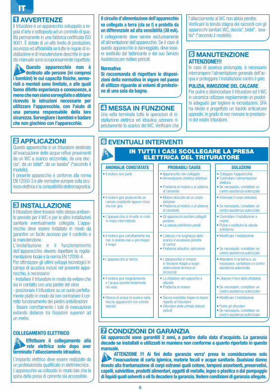
6
1 AVVERTENZEIl trituratore è un apparecchio sviluppato a re-gola d’arte e sottoposto ad un controllo di qua-lità permanente in una fabbrica certificata ISO 9001. È dotato di un alto livello di prestazioni, sicurezza ed affidabilità se tutte le regole di in-stallazione e di manutenzione descritte in que-sto manuale sono scrupolosamente rispettate.
Questo apparecchio non è destinato alle persone (ivi compresi i bambini) le cui capacità fisiche, senso-riali o mentali sono limitate, o alle quali fanno difetto esperienza e conoscenze, a meno che non siano sorvegliate o abbiano ricevuto le istruzioni necessarie per utilizzare l'apparecchio, con l'aiuto di una persona responsabile della loro sicurezza. Sorvegliare i bambini e badare che non giochino con l’apparecchio.
2 APPLICAZIONIQuesto apparecchio è un trituratore destinato all'evacuazione delle acque reflue provenienti da un WC a scarico orizzontale, da una doc-cia*, da un bidet*, da un lavabo* (*secondo il modello).Il presente apparecchio è conforme alla norma EN 12050-3 e alle normative europee sulla sicu-rezza elettrica e la compatibilità elettromagnetica.
3 INSTALLAZIONEIl trituratore deve trovarsi nello stesso ambien-te previsto per il WC e per le altre installazioni sanitarie eventualmente collegate. L’appa-recchio deve essere installato in modo da garantire un facile accesso per il controllo e la manutenzione.L’installazione e il funzionamento dell’apparecchio devono rispettare la regola- mentazione locale e la norma EN 12056-4.Per ottimizzare gli ultimi sviluppi tecnologici incampo di acustica inclusi nel presente appa-recchio, è necessario:- Installare il trituratore in modo da evitare che sia in contatto con una parete del vano- posizionare il trituratore su un suolo perfetta-mente piatto in modo da non contrariare il cor-retto funzionamento dei piedini antivibrazioni- fissare correttamente i tubi di evacuazione evitando distanze tra fissazioni superiori ad un metro.
COLLEGAMENTO ELETTRICOEffettuare il collegamento alla
rete elettrica solo dopo aver terminato l’allacciamento idraulico.L’impianto elettrico deve essere realizzato da un professionista qualificato in elettrotecnica.L’apparecchio va collocato in modo tale che la spina della presa di corrente sia accessibile.
Il circuito d’alimentazione dell’apparecchio va collegato a terra (cla se I) e protetto da un differenziale ad alta sensibilità (30 mA).Il collegamento deve servire esclusivamente all’alimentazione dell’apparecchio. Se il cavo di questo apparecchio è danneggiato, deve esse-re sostituito dal fabbricante o dal suo Servizio Assistenza per evitare pericoli.
NormativaSi raccomanda di rispettare le disposi-zioni della normativa in vigore nel paese di utilizzo riguardo ai volumi di protezio-ne di una sala da bagno.
l’allacciamento al WC non abbia perdite.Verificare la tenuta stagna dei raccordi con gli apparecchi sanitari: WC, doccia*, bidet*, lava-bo* (*secondo il modello).
5 MANUTENZIONEATTENZIONE!!!In caso di assenza prolungata, è necessario interrompere l'alimentazione generale dell'ac-qua e proteggere l'installazione contro il gelo.
PULIZIA, RIMOZIONE DEL CALCAREPer pulire e disincrostare il trituratore ed il WC in ceramica utilizzare regolarmente un prodot-to adeguato per togliere le incrostazioni. SFA ha ideato e progettato un liquido anticalcare apposito, in grado di non rovinare le prestazio-ni del vostro trituratore.
6 EVENTUALI INTERVENTI
ANOMALIE CONSTATATE PROBABILI CAUSE SOLUZIONI• Il motore non parte • Apparecchio non collegato
• Alimentazione elettrica difettosa
• Problema al motore o al sistema di comando
• Collegare l’apparecchio• Controllare l’alimentazione
elettrica• Se necessario, contattare un
centro assistenza autorizzato
• Il motore gira producendo un rumore crepitante oppure ronza ma non gira
• Motore bloccato da un corpo estraneo
• Problema al motore o al sistema di comando
• Eliminare il corpo estraneo
• Se necessario, contattare un centro assistenza autorizzato
• L’apparecchio si rimette in moto in modo intermittente
• Gli apparecchi sanitari collegati perdono
• La valvola antiritorno perde
• Controllare l’installazione a monte
• Pulire o sostituire la valvola antiritorno
• Il motore gira correttamente ma non si arresta mai o gira troppo a lungo
• L’altezza o la lunghezza dello scarico è eccessiva (perdita di carico)
• Problema idraulico, ostruzione
• Modificare l’installazione
• Se necessario, contattare un centro assistenza autorizzato
• L’apparecchio si ferma • L’apparecchio è rimasto in funzione troppo a lungo (interruzione termica di sicurezza)
• Attendere il ripristino e, se necessario, contattare un centro assistenza autorizzato
• Il motore gira irregolarmente e l’acqua scende lentamente nel vaso
• Lo sfiatatoio del coperchio è otturato
• Problema al motore
• Liberare il foro dello sfiatatoio
• Se necessario, contattare un centro assistenza autorizzato
• Ritorno di acque di scarico nella doccia (apparecchi con entrate laterali)
• Doccia installata troppo in basso rispetto al trituratore
• Otturatori delle entrate laterali ostruiti
• Modificare l’installazione
• Pulire gli otturatori • Se necessario, contattare un
centro assistenza autorizzato
IN TUTTI I CASI SCOLLEGARE LA PRESA ELETTRICA DEL TRITURATORE
7 CONDIZIONI DI GARANZIAGli apparecchi sono garantiti 2 anni, a partire dalla data d’acquisto. La garanzia decade se installati o utilizzati in maniera non conforme a quanto riportato in questo manuale.
ATTENZIONE !!! Ai fini della garanzia verra' presa in considezarione solo l’evacuazione di carta igienica, materie fecali e acque sanitarie. Qualsiasi danno dovuto alla frantumazione di corpi estranei quali cotone, tamponi assorbenti, preservativi, capelli, salviettine, prodotti alimentari, oggetti di metallo, legno o plastica o dal pompaggio di liquidi quali solventi o oli fa decadere la garanzia. Vedere condizioni di garanzia allegate.
4 MESSA IN FUNZIONEUna volta terminate tutte le operazioni di in-stallazione elettrica ed idraulica azionare ri-petutamente lo scarico del WC. Verificare che
IT

7
1 ADVERTENCIAEste triturador es un producto diseñado siguiendo un control de calidad perma-nente. Tiene la certificación ISO 9001. El aparato tiene un alto nivel de cualidades técnicas, seguridad y fiabilidad, siempre que se cumplan atentamente todas las reglas de instalación y mantenimiento descritas el presente manual.
Este aparato no está destinado a personas (incluidos niños) cuyas capacidades físicas, senso-riales o mentales estén limitadas, como tampoco a aquellas que carez-can de la experiencia o el conoci-miento del mismo, salvo que se en-cuentren bajo supervisión y reciban las instrucciones necesarias para utilizar el aparato, con la ayuda de una persona responsable de su segu-ridad. Supervisar a los niños y vigilar que no jueguen con el aparato.
2 ÁMBITO DE APLICACIÓNEste aparato es una estación compacta de elevación, diseñada para evacuar las aguas usadas procedentes de un WC con salida ho-rizontal, de una ducha*, de un bidet* o de un lavabo*. (*: Según el modelo).
Este aparato cumple la norma EN 12050-3 y normas europeas sobre la seguridad eléc-trica y la compatibilidad electromagnética.
3 INSTALACIÓNEl aparato debe de estar en la misma sala / habitación que el WC y los otros aparatos sanitarios. El aparato debe ser instalado de manera que el acceso sea facil para su con-trol y mantenimiento.La instalación y funcionamiento de su apa-rato deben respetar las reglamentaciones locales y la norma EN 12056-4.
Para optimizar los últimos desarrollos téc-nicos en materia acústica incluidos en este aparato, es importante :• instalar el depósito de forma que no toqueninguna pared de la sala / habitación,• posicionar el depósito sobre un suelo lo más plano posible, para permitir el adecuado fun-cionamiento de los contactos anti vibratorios,• fijar correctamente el tubo de evacuaciónevitando que las distancias entre las fijacio-nes sean superiores a un metro.
CONEXIÓN ELÉCTRICAEfectuar la conexión eléctrica
sólo una vez llevados a cabo todas las conexiónes definitivas. La instalación eléctrica debe ser realizada por un profesional cualificado en electrotécnica.
El aparato debe estar colocado de forma que el enchufe de corriente sea accesible.El circuito de alimentación eléctrico del aparato debe estar conectado a tierra (Clase I) y protegido por un disyuntor diferencial de alta sensibilidad (30 mA).La conexión debe servir exclusivamente para la alimentación del aparato.Si el cable de este aparato está dañado, debe ser reemplazado por el fabricante o por su servicio postventa, con el fin de evitar cualquier peligro.ReglamentaciónRespetar las disposiciones de la norma UNE 20.315 referente a las medidas de protección de un cuarto de baño.
El paso del inodoro debe ser estanco.Verificar la estanqueidad de las conexiones con los aparatos sanitarios: WC, ducha*, bidet*, lavabo*. (*:Según el modelo).
6 POSIBLES INTERVENCIONES
ANOMALÍAS CAUSAS REMEDIOS• El motor no arranca • Aparato no enchufado
• Alimentación eléctrica defectuosa
• Problema del motor o del sistema de control
• Enchufar el triturador a la corriente
• Comprobar la alimentación eléctrica
• Si no, consultar al SAT
• El motor gira con un ruido de carraca pero no gira
• Motor bloqueado por un cuerpo extraño
• Problema del motor o del sistema de control
• Extraiga el cuerpo extraño
• Si no, consultar al SAT
• El triturador se pone en marcha intermitentemente
• Los sanitarios conectados pierden agua
• La valvula anti-retorno pierde
• Revisar cada uno de los elementos conectados
• Limpiar o cambiar la válvula anti-retorno
• El motor gira correctamente pero no se para o gira lentamente
• La altura o la longitud de evacuación es muy larga o tiene muchos codos
• Problema hidráulico, taponamiento
• Mirar la instalación
• Si no, consultar al SAT
• El aparato se para • El aparato ha funcionado durante demasiado tiempo (corte térmico de seguridad)
• Esperar a que se vuelva a activar y consultar al SAT, si es necesario
• El motor funciona con sacudidas y el agua desciende lentamente en la taza
• El respiradero está tapado• Problema del motor
• Destapar el respiradero• Si no, consultar al SAT
• Retorno de agua turbia en la ducha (aparatos con entradas laterales)
• Ducha instalada demasiado baja con relación al aparato
• Clapetas de las entradas laterales obstruidas
• Revisar la instalación
• Limpiar las clapetas • Si no, consultar al SAT
EN CUALQUIER CASO, DESCONECTE LA TOMA ELÉCTRICA DE LA TRITURADORA
7 CONDICIONES DE GARANTÍALos aparatos SFA tienen una garantía de 2 años a partir de la fecha de compra siempre que la instalación y la utilización sean conformes al presente manual. A partir de los 6 meses, el cliente final deberá hacerse cargo de los gastos de desplazamiento del técnico SFA.
! ATENCION ! La garantía cubre únicamente la evacuación de papel higiénico, materia fecal y aguas sanitarias. Cualquier avería producida por el bombeo de cuerpos extraños tales como algodón, tampones higiénicos, compresas, toallitas, pro-ductos alimentarios, preservativos, cabellos, objetos de metal, de madera o de plástico, o bombeo de líquidos como disolventes o aceites no sera cubierta por la garantía.
4 PUESTA EN MARCHAUna vez efectuadas las conexiones eléctricas e hidráulicas, tirar varias veces de la cadena.
ES
5 MANTENIMIENTO¡ATENCIÓN!En caso de ausencia prolongada, es impera-tivo cortar la alimentación general de agua y proteger la instalación contra la congelación.
LIMPIEZA / DESINCRUSTACIÓN Para limpiar y desincrustar el triturador y la cubeta, utilizar frecuentemente un producto desincrustante sanitario, como el desincrus-tante especial SFA SANITRIT, que desincrusta sin afectar los órganos internos del aparato.
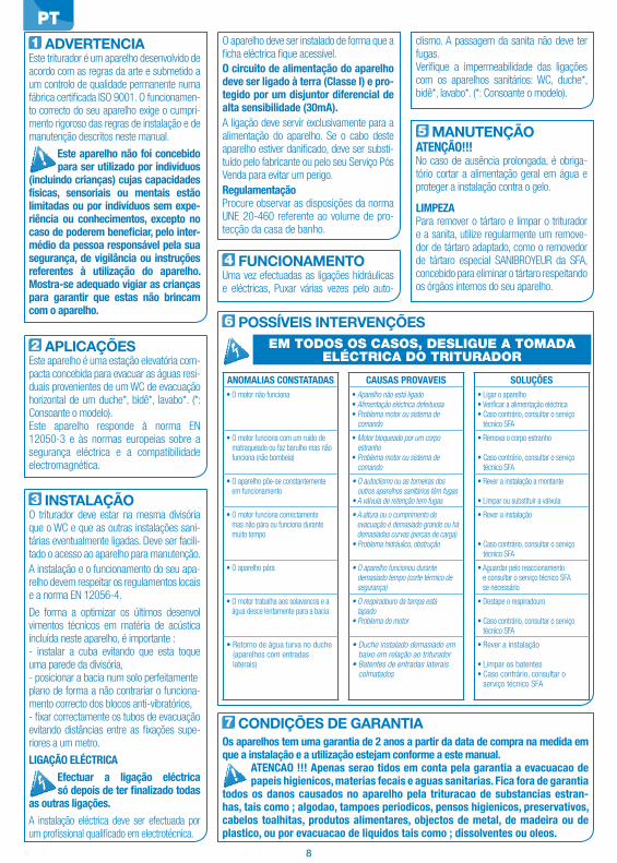
8
1 ADVERTENCIAEste triturador é um aparelho desenvolvido de acordo com as regras da arte e submetido a um controlo de qualidade permanente numa fábrica certificada ISO 9001. O funcionamen-to correcto do seu aparelho exige o cumpri-mento rigoroso das regras de instalação e de manutenção descritos neste manual.
Este aparelho não foi concebido para ser utilizado por indivíduos (incluindo crianças) cujas capacidades físicas, sensoriais ou mentais estão limitadas ou por indivíduos sem expe-riência ou conhecimentos, excepto no caso de poderem beneficiar, pelo inter-médio da pessoa responsável pela sua segurança, de vigilância ou instruções referentes à utilização do aparelho. Mostra-se adequado vigiar as crianças para garantir que estas não brincam com o aparelho.
2 APLICAÇÕESEste aparelho é uma estação elevatória com-pacta concebida para evacuar as águas resi-duais provenientes de um WC de evacuação horizontal de um duche*, bidê*, lavabo*. (*: Consoante o modelo).Este aparelho responde à norma EN 12050-3 e às normas europeias sobre a segurança eléctrica e a compatibilidade electromagnética.
3 INSTALAÇÃOO triturador deve estar na mesma divisória que o WC e que as outras instalações sani-tárias eventualmente ligadas. Deve ser facili-tado o acesso ao aparelho para manutenção.A instalação e o funcionamento do seu apa-relho devem respeitar os regulamentos locais e a norma EN 12056-4.
De forma a optimizar os últimos desenvol vimentos técnicos em matéria de acústica incluída neste aparelho, é importante :- instalar a cuba evitando que esta toque uma parede da divisória,- posicionar a bacia num solo perfeitamenteplano de forma a não contrariar o funciona-mento correcto dos blocos anti-vibratórios,- fixar correctamente os tubos de evacuaçãoevitando distâncias entre as fixações supe-riores a um metro.
LIGAÇÃO ELÉCTRICAEfectuar a ligação eléctrica
só depois de ter finalizado todas as outras ligações.A instalação eléctrica deve ser efectuada por um profissional qualificado em electrotécnica.
O aparelho deve ser instalado de forma que a ficha eléctrica fique acessível.O circuito de alimentação do aparelho deve ser ligado à terra (Classe I) e pro-tegido por um disjuntor diferencial de alta sensibilidade (30mA).A ligação deve servir exclusivamente para a alimentação do aparelho. Se o cabo deste aparelho estiver danificado, deve ser substi-tuído pelo fabricante ou pelo seu Serviço Pós Venda para evitar um perigo.RegulamentaçãoProcure observar as disposições da norma UNE 20-460 referente ao volume de pro-tecção da casa de banho.
clismo. A passagem da sanita não deve ter fugas. Verifique a impermeabilidade das ligações com os aparelhos sanitários: WC, duche*, bidê*, lavabo*. (*: Consoante o modelo).
5 MANUTENÇÃOATENÇÃO!!!No caso de ausência prolongada, é obriga-tório cortar a alimentação geral em água e proteger a instalação contra o gelo.
LIMPEZAPara remover o tártaro e limpar o triturador e a sanita, utilize regularmente um remove-dor de tártaro adaptado, como o removedor de tártaro especial SANIBROYEUR da SFA, concebido para eliminar o tártaro respeitando os órgãos internos do seu aparelho.
6 POSSÍVEIS INTERVENÇÕES
ANOMALIAS CONSTATADAS CAUSAS PROVAVEIS SOLUÇÕES• O motor não funciona • Aparelho não está ligado
• Alimentação eléctrica defeituosa• Problema motor ou sistema de
comando
• Ligar o aparelho• Verificar a alimentação eléctrica• Caso contrário, consultar o serviço
técnico SFA
• O motor funciona com um ruído de matraqueado ou faz barulho mas não funciona (não bombeia)
• Motor bloqueado por um corpo estranho
• Problema motor ou sistema de comando
• Remova o corpo estranho
• Caso contrário, consultar o serviço técnico SFA
• O aparelho põe-se constantemente em funcionamento
• O autoclismo ou as torneiras dos outros aparelhos sanitários têm fugas
• A válvula de retenção tem fugas
• Rever a instalação a montante
• Limpar ou substituir a válvula
• O motor funciona correctamente mas não pára ou funciona durante muito tempo
• A altura ou o cumprimento de evacuação é demasiado grande ou há demasiadas curvas (percas de carga)
• Problema hidráulico, obstrução
• Rever a instalação
• Caso contrário, consultar o serviço técnico SFA
• O aparelho pára • O aparelho funcionou durante demasiado tempo (corte térmico de segurança)
• Aguardar pelo reaccionamento e consultar o serviço técnico SFA se necessário
• O motor trabalha aos solavancos e a água desce lentamente para a bacia
• O respiradouro da tampa está tapado
• Problema do motor
• Destape o respiradouro
• Caso contrário, consultar o serviço técnico SFA
• Retorno de água turva no duche (aparelhos com entradas laterais)
• Duche instalado demasiado em baixo em relação ao triturador
• Batentes de entradas laterais colmatados
• Rever a instalação
• Limpar os batentes• Caso contrário, consultar o
serviço técnico SFA
EM TODOS OS CASOS, DESLIGUE A TOMADA ELÉCTRICA DO TRITURADOR
7 CONDIÇÕES DE GARANTIAOs aparelhos tem uma garantia de 2 anos a partir da data de compra na medida em que a instalação e a utilização estejam conforme a este manual.
ATENCAO !!! Apenas serao tidos em conta pela garantia a evacuacao de papeis higienicos, materias fecais e aguas sanitarias. Fica fora de garantia todos os danos causados no aparelho pela trituracao de substancias estran-has, tais como ; algodao, tampoes periodicos, pensos higienicos, preservativos, cabelos toalhitas, produtos alimentares, objectos de metal, de madeira ou de plastico, ou por evacuacao de liquidos tais como ; dissolventes ou oleos.
4 FUNCIONAMENTO Uma vez efectuadas as ligações hidráulicas e eléctricas, Puxar várias vezes pelo auto-
PT

9
1 ALGEMEENHet vermaalsysteem is in een speciale unit geïntegreerd en enkel geschikt voor WC’s met horizontale afvoer. Deze fecaliënvermaler is geproduceerd volgens kwaliteitsnormen ISO9001. De fecaliënvermaler levert hoge prestaties mits alle installatie- en onder-houdsvoorschriften worden opgevolgd.
Dit apparaat is niet bedoeld voor gebruik door personen (inclusief kinderen) met beperkte lichamelijke, zintuiglijke of mentale vaardigheden, of voor personen met ontoereikende kennis of ervaring. Uitzondering hierop vormen zij die onder toezicht staan van een voor hun veiligheid verantwoorde-lijke persoon, of zij die van die persoon de benodigde aanwijzingen ontvingen voor gebruik van het apparaat. In geval van kinderen dient er toezicht gehou-den te worden, om te voorkomen dat ze met het apparaat gaan spelen.
2 TOEPASSINGSMOGE-LIJKHEDEN
Dit apparaat is een compacte vermaler/vuil-waterpomp ontworpen voor de afvoer van vuil water afkomstig uit een WC met horizon-tale afvoerleiding, een douche*, een bidet*, een wastafel*. , een fonteintje* (*: Afhankelijk van het model). Dit apparaat voldoet aan de Europese Norm (EN) 12050-3 en aan de Eu-ropese normen betreffende elektrische veilig-heid en elektromagnetische compatibiliteit.
3 INSTALLATIEDe Sanibroyeur dient in dezelfde ruimte aangesloten te worden als de WC en de andere sanitaire toestellen. Voor inspectie en onderhoud dient het apparaat toegan-kelijk en bereikbaar te zijn.De installatie en het gebruik van dit ap-paraat dienen te voldoen aan de Europese installatienorm EN12056-4 en de plaatse-lijk geldende eisen.
Teneinde de laatste technische vernieu-wingen op gebied van geluid te optima-liseren, is het belangrijk:- de WC zodanig te installeren dat deze dewanden van het vertrek niet raakt- de WC op een volmaakt vlakke vloer teplaatsen, zodat de goede werking van deisolatiematjes niet verhinderd wordt.- de afvoerleidingen goed bevestigen en te zorgen dat de afstand tussen de sbe-vestigingsklemmen niet meer dan één meter bedraagt.ELEKTRISCHE INSTALLATIE
De elektriciteit dient pas aangesloten te worden nadat alle wateraanslui-tingen zijn bevestigd.
De elektrische installatie moet door een erkend vakman worden uitgevoerd. Het apparaat moet zodanig geplaatst worden dat de stekker toegankelijk is.De stroomkring van het apparaat moet geaard worden en beveiligd worden door een zeer nauwkeurige aardlekschakelaar(30mA).De aansluiting mag uitsluitend gebruikt worden voor de stroomvoorziening van het apparaat. Indien de kabel van dit apparaat beschadigd is, moet deze door de fabrikant of zijn servicedienst vervangen worden, om ieder gevaar uit te sluiten.NormenGelieve de bepalingen en normen van het betreffende land in acht te nemen betref-fende de zones van een badkamer.
aansluitingen geïnstalleerd zijn, dient u een paar keer door te spoelen. De verbinding dient waterdicht te zijn.Controleer of de aansluitingen van de sani-taire apparaten waterdicht zijn: WC, douche*, bidet*, wastafel* , een fonteintje*. (*: Afhanke-lijk van het model).
5 ONDERHOUDATTENTIE!!! Bij lange afwezigheid moet de hoofdwatertoevoer worden afgesloten en dient de installatie tegen vorst beveiligd te worden.
ONDERHOUD EN ONTKALKENDe vermaler en de WC kunnen met ieder in de handel verkrijgbaar schoonmaakmiddel worden onderhouden (geen schuimende wasmiddelen). Gebruik regelmatig de spe-ciale ontkalker van SFA Sanibroyeur, die ontworpen is voor het verwijderen van kalk-aanslag en vervuilingen zonder de inwendige onderdelen van uw apparaat te beschadigen.
6 OORZAKEN EN REMEDIES VAN STORINGEN
STORING VERMOEDELIJKE OORZAAK OPLOSSING• De motor slaat niet aan • De stroomtoevoer is niet
ingeschakeld• Elektrische aansluiting is defect
• Probleem met de motor of het bedieningssysteem
• Schakel de stroomtoevoer in
• Controleer de elektrische aansluiting
• Neem contact op met onze servicedienst
• De motor maakt een ratelend geluid, bromt maar draait niet
• Motor geblokkeerd door een vreemd voorwerp
• Probleem met de motor of het bedieningssysteem
• Het vreemde voorwerp verwijderen
• Neem contact op met onze servicedienst
• Het apparaat begint af en toe te werken
• Waterlekkage van de sanitaire aansluitingen
• De terugslagklep sluit niet voldoende af
• Controleer het sanitair op lekkage
• Controleer de terugslagklep of maak hem schoon
• De motor draait correct maar stopt niet meer of draait zeer lang
• De afvoerinstallatie voldoet niet aan de richtlijnen (opvoerhoogte/lengte)
• Hydraulisch probleem, verstopping
• Controleer de afvoer
• Neem contact op met onze servicedienst
• Het apparaat gaat uit (thermisch) • Het apparaat heeft te lang gewerkt (thermische beveiliging)
• Wacht tot het apparaat is afgekoeld. Neem daarna indien nodig contact op met een erkende monteur
• De motor draait onregelmatig en het water stroomt langzaam in de closetpot
• De beluchter is verstopt • Probleem met de motor
• Maak de beluchter schoon• Neem contact op met onze
servicedienst
• Er stroomt troebel water terug in de douche (apparaten met zij-ingangen)
• De douche is te laag geïnstalleerd ten opzichte van de fecaliënvermaler
• De terugslagkleppen van de zij-ingangen zijn verstopt
• Controleer de afvoer
• Reinig de terugslagkleppen • Neem contact op met onze
servicedienst
IN IEDER GEVAL DE STEKKER VAN DE VERMALER UIT HET STOPCONTACT HALEN.
7 GARANTIEWij verlenen 2 jaar garantie, vanaf de aankoopdatum, op voorwaarde dat het appa-raat correct geïnstalleerd en gebruikt wordt zoals in deze handleiding is aangegeven.
ATTENTIE!!! Schade aan het toestel kan worden voorkomen door volgende voorwerpen NIET in de WC te werpen: watten, maandverbanden, tampons, vochtige toiletdoekjes, keukenpapier, condooms maar ook harde voorwerpen, meta-len en houten of plastic voorwerpen. Ook oplosmiddelen, zuren of andere chemische middelen kunnen het apparaat aantasten en zullen niet onder de garantie vallen.
4 IN BEDRIJFSTELLINGWanneer alle hydraulische en elektrische
NL
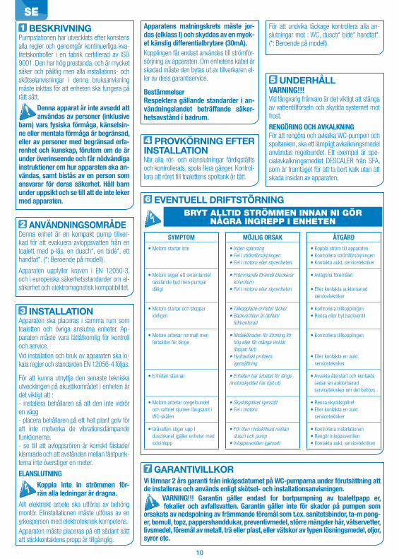
10
1 BESKRIVNINGPumpstationen har utvecklats efter konstens alla regler och genomgår kontinuerliga kva-litetskontroller i en fabrik certifierad av ISO 9001. Den har hög prestanda, och är mycket säker och pålitlig men alla installations- och skötselanvisningar i denna bruksanvisning måste iakttas för att enheten ska fungera på rätt sätt.
Denna apparat är inte avsedd att användas av personer (inklusive barn) vars fysiska förmåga, känselsin-ne eller mentala förmåga är begränsad, eller av personer med begränsad erfa-renhet och kunskap, förutom om de är under överinseende och får nödvändiga instruktioner om hur apparaten ska an-vändas, samt bistås av en person som ansvarar för deras säkerhet. Håll barn under uppsikt och se till att de inte leker med apparaten.
2 ANVÄNDNINGSOMRÅDEDenna enhet är en kompakt pump tillver-kad för att evakuera avloppsvatten från en toalett med p-lås, en dusch*, en bidé*, ett handfat*. (*: Beroende på modell).
Apparaten uppfyller kraven i EN 12050-3. och i europeiska säkerhetsstandarder om el-säkerhet och elektromagnetisk kompatibilitet.
3 INSTALLATIONApparaten ska placeras i samma rum som toaletten och övriga anslutna enheter. Ap-paraten måste vara lättåtkomlig för kontroll och service.Vid installation och bruk av apparaten ska lo-kala regler och standarden EN 12056-4 följas.
För att kunna utnyttja den senaste tekniska utvecklingen på akustikområdet i enheten är det viktigt att :- installera behållaren så att den inte vidrör en vägg- placera behållaren på ett helt plant golv för att inte motverka de vibrationsdämpande funktionerna.- se till att avloppsrören är korrekt fästade/klamrade och att avstånden mellan fästpunk-terna inte överstiger en meter.
ELANSLUTNINGKoppla inte in strömmen för-
rän alla ledningar är dragna. Allt elektriskt arbete ska utföras av behörig montör. Elinstallationen måste utföras av en yrkesperson med elektroteknisk kompetens.Apparaten måste placeras på ett sådant sätt att stickkontaktens propp är tillgänglig.
Apparatens matningskrets måste jor-das (elklass I) och skyddas av en myck-et känslig differentialbrytare (30mA).Kopplingen får endast användas till strömför-sörjning av apparaten. Om enhetens kabel är skadad måste den bytas ut av tillverkaren el-ler av dess garantiservice.
BestämmelserRespektera gällande standarder i an-vändningslandet beträffande säker-hetsavstånd i badrum.
För att undvika läckage kontrollera alla an-slutningar mot : WC, dusch* bidé* handfat*. (*: Beroende på modell).
5 UNDERHÅLLVARNING!!!Vid långvarig frånvaro är det viktigt att stänga av vattentillförseln och skydda systemet mot frost.
RENGÖRING OCH AVKALKNINGFör att rengöra och avkalka WC-pumpen och spoltanken, ska ett lämpligt avkalkningsmedel användas regelbundet. Ett exempel är spe-cialavkalkningsmedlet DESCALER från SFA, som är framtaget för att ta bort kalk utan att skada insidan av apparaten.
6 EVENTUELL DRIFTSTÖRNING
SYMPTOM MÖJLIG ORSAK ÅTGÄRD
• Motorn startar inte • Ingen spänning• Fel i strömförsörjningen• Fel i motorn eller styrenheten
• Koppla ström till apparaten• Kontrollera strömförsörjningen• Kontakta aukt. servicetekniker
• Motorn avger ett skramlande/rasslande ljud men pumpar dåligt
• Främmande föremål blockerar knivrotorn
• Fel i motorn eller styrenheten
• Avlägsna föremålet
• Eller kontakta auktoriserad servicetekniker
• Motorn startar och stoppar ideligen
• Tillkopplade enheter läcker• Backventilen är defekt/
felmonterad
• Kontrollera tillkopplingen• Rensa eller byt backventil
• Motorn arbetar normalt men fortsätter för länge
• Nivåskillnaden för tömning för hög eller får många vinklar (tappar fart)
• Hydrauliskt problem, igensättning
• Kontrollera tillkopplingen
• Eller kontakta en aukt. servicetekniker
• Enheten stannar • Enheten har arbetat för länge (motorskyddet har löst ut)
• Avvakta återstart och kontakta sedan en auktoriserad servicetekniker om det behövs.
• Motorn arbetar oregelbundet och vattnet sjunker långsamt i WC-skålen
• Skyddsgallret igensatt• Fel i motorn
• Rensa skyddsgallret• Eller kontakta en aukt.
servicetekniker
• Gråvatten stiger upp I duschkaret (gäller enheter med sidoinlopp
• För liten nivåskillnad mellan dusch och pump
• Inloppsventilen igensatt
• Kontrollera installationen• Rengör inloppsventilen• Kontakta aukt. servicetekniken
BRYT ALLTID STRÖMMEN INNAN NI GÖR NÅGRA INGREPP I ENHETEN
7 GARANTIVILLKORVi lämnar 2 års garanti från inköpsdatumet på WC-pumparna under förutsättning att de installeras och används enligt skötsel- och installationsanvisningen.
VARNING!!! Garantin gäller endast for bortpumpning av toalettpapp er, fekalier och avfallsvatten. Garantin gäller inte för skador på pumpen som orsakats av nedspolning av främmande föremål som t.ex. sanitetsbindor, ta-m pong-er, bomull, topz, pappershanddukar, preventivmedel, större mängder hår, våtservetter, livsmedel, föremål av metall, trä eller plast, eller vätskor av typen lösningsmedel, oljor, syror etc.
4 PROVKÖRNING EFTER INSTALLATIONNär alla rör- och elanslutningar färdigställts och kontrollerats, spola flera gånger. Kontrol-lera att röret till toalettens spoltank är tätt.
SE

11
1 ADVARSELDenne kværn/pumpe er udviklet og pro-duceret under konstant kvalitetskontrol på en fabrik, som er ISO 9001certificeret. Den har høj ydeevne, er sikker og pålidelig under forudsætning af overholdelse af reglerne vedrørende installation og vedligeholdelse beskrevet i denne brugsanvisning.
Dette apparat er ikke beregnet til at blive brugt af personer (herunder børn) hvis fysiske, sensori-ske eller mentale evner er svækkede eller personer blottet for erfaring eller kendskab, med mindre de er under op-syn eller har modtaget instruktioner ombrugen af apparatet af en person, der eransvarlig for deres sikkerhed. Børn skalvære under opsyn for at sikre, at de ikkeleger med apparatet.
2 ANVENDELSERDenne kværn/pumpe er beregnet til at bort-lede spildevandet fra et toilet med vandret afløb (Uni-lås), en brusekabine*, et bidet* eller en håndvask*. (*:Afhængigt af model). Dette ap-parat opfylder standarden EN 12050-3 og de europæiske standarder vedrørende elektrisk sikkerhed og elektromagnetisk kompatibilitet.
3 INSTALLATIONPumpestationen skal placeres i samme rumsom toilettet og andre eventuelt tilsluttede sa-nitære komponenter. Pumpen skal monteresså den er let tilgængelig for kontrol og ser-vice. Apparatets installation og virkemåde skal overholde nationale forskrifter og stan-darden EN 12056-4.De medfølgende fikseringsplader monteres –forhindrer at pumpen bevæger sig. Afløbsrørfikseres med rørbøjler – max afstand 1 meter.
ELEKTRISK TILSLUTNINGForetag ikke den elektriske
tilslutning, før alle installationens tilslutninger er endeligt udført.Den elektriske installation skal udføres af autoriseret installatør. Apparatet skal place-res således, at stikkontakten er let tilgæn-gelig.
Den elektriske tilslutning skal have jordforbindelse (klasse I) og være be-skyttet af et HPFI-relæ (30mA) .
Tilslutningen må udelukkende bruges til strømforsyning af apparatet. Ved beskadi-gelse af kabel etc. skal udskiftning udføres afautoriseret installatør.
ForskrifterSørg for at overholde alle bestem-melserne i den gældende standard i brugslandet vedrørende beskyttelse i et badeværelse.
5 VEDLIGEHOLDELSEVIGTIGT !!!Ved længere tids fravær skal der lukkes for vandforsyningen, og installationen skal be-skyttes mod frost.
RENGØRING/AFKALKNINGBrug regelmæssigt et velegnet afkalknings-middel for at undgå kalkaflejringer i kummen og pumpestationen, som f.eks. det særlige SANIBROYEUR afkalkningsmiddel fra SFA, som er beregnet til at fjerne kalk uden at ødelægge apparatets interne komponenter.
6 EVENTUELLE DRIFTSFORSTYRRELSER
KONSTATERET FEJL MULIG ÅRSAG UDBEDRING• Motoren starter ikke • Apparatet er ikke tilsluttet
• Der er fejl ved strømforsyningen • Problem med motoren eller
styresystemet
• Tilslut apparatet• Kontrollér strømforsyningen• Hvis ikke, kontakt en autoriseret reparatør
• Motoren går med en skramlende lyd eller summer, men drejer ikke rundt
• Motoren er blokeret af et fremmedlegeme
• Problem med motoren eller styresystemet
• Fjern fremmedlegemet
• Hvis ikke, kontakt en autoriseret reparatør
• Pumpen fungerer diskontinuerligt
• De tilsluttede sanitetsapparater lækker
• Kontraventilen lækker
• Kontrollér installationen ovenfor pumpen
• Rengør eller udskift kontraventilen
• Motoren går normalt, men stopper ikke eller går meget længe
• Afløbsrøret sidder for højt eller er for langt eller har for mange bøjninger (tryktab)
• Hydraulisk problem, tilstopning
• Kontrollér installationen
• Hvis ikke, kontakt en autoriseret reparatør
• Pumpen standser • Pumpen har fungeret for længe (termisk sikkerhedsafbrydelse)
• Vent indtil pumpen genindkobles, og kontakt om nødvendigt en autoriseret reparatør
• Motoren starter med ryk og vandet løber langsomt ned i kummen
• Lågets luftåbning er tilstoppet• Problem med motoren
• Rens luftåbningen• Hvis ikke, kontakt en autoriseret
reparatør
• Tilbageløb af grumset vand i brusekabinen (pumper med sideindløb)
• Brusekarets afløb er installeret for lavt i forhold til kværnen
• Klapperne i sideindløbene er tilstoppet
• Kontrollér installationen
• Rengør klapperne • Hvis ikke, kontakt en autoriseret
reparatør
UNDER ALLE OMSTÆNDIGHEDER SKAL KVÆRNENS STIK TAGES UD AF STIKKONTAKTEN
7 GARANTIBETINGELSERDette apparat er dækket af en 2-års garanti regnet fra købsdatoen under forbe-hold af en installation og en anvendelse i overensstemmelse med nærværendebrugsanvisning.
ADVARSEL!!! Kun bortledning af toiletpapir, fækalier og grå afløbsvand er dækket under garantien. Beskadigelse grundet fremmedlegemer som f.eks. menstruationsbind kondomer, papirhåndklæder. Mad, metal-, træ- eller plastikgenstande, hår eller væsker som olie, ætsende væsker dækkes ikke un-der garantien.
4 AFPRØVNING EFTER INSTALLATIONNår alle hydrauliske og elektriske tilslutninger er udført, skyl toilettet ud flere gange. Pas-sagen fra kummen skal være vandtæt.Tjek at tilsluttede enheder er tætte: toilet, bruser*, bidet*, håndvask*. (*:Afhængigt af model).
DK

12
1 BESKRIVELSEDenne klosettpumpen er produsert av en fabrikk med kvalitetssertifikat ifølge ISO 9001. Apparatet har et høyt prestasjons-, sikkerhets- og pålitelighetsnivå, så fremt reglene for montering og vedlikehold du finner i denne bruksanvisningen respek-teres nøye.
Dette apparatet er ikke beregnet for personer (herunder barn), med reduserte fysiske, sansemessi-ge eller mentale evner, eller som har mangelfunn kunnskap om bruken av apparatet, med mindre de overvåkes av og får tilstrekkelig opplæring i bruken av apparatet av en person som er ansvarlig for deres sikkerhet. Pass på barna og sørg for at de ikke leker med apparatet.
2 BRUKDette apparatet er et kompakt pumpean-legg som leder bort avløpsvann fra et toa-lett med vannrett avløpsrør, fra en dusj*, bidet*, vask*. (*: Avhengig av modell).Dette apparatet er i overensstemmelse med EN 12050-3 og europeiske normer angående elektrisk sikkerhet og elektro-magnetisk kompabilitet.
3 INSTALLASJONPumpen skal plasseres i samme rom som klosettet og de andre sanitære produk-tene som eventuelt er tilkoplet. Plasser ikke klosettet nærmere veggen enn at klosettpumpen enkelt kan demonteres for eventuell service.Installasjon og funksjon av apparatet må være i tråd med lokale regler og normen EN 12056-4.
For å få fullt utbytte av de siste teknolo-giske innovasjoner når det gjelder akus-tikk er det viktig :• å plassere tanken slik at den ikke berø-rer rommets vegger• å plassere klosettpumpen på et helt jevnt gulv slik at de vibrasjonshindrende anordningene ikke forstyrres• å sørge før at avløpsrørene er godt festet/ klamret og at avstanden mellom festepunktene ikke er større enn en meter.
EL-TILKOPLINGUtfør de elektriske koplingene
først når alle koplingene er av-sluttet.Den elektriske installeringen skal utføres av en kvalifisert elektrotekniker. Apparatet skal
plasseres slik at støpselet er tilgjengelig.Apparatets strømkrets skal kobles til jording (klasse I) og beskyttes med en overbelastningsbryter med høy følsomhet (30mA).Tilkoblingen skal kun brukes til strømtil-førsel til apparatet. Dersom ledningen til dette apparatet er skadet, skal den erstat-tes av produsenten eller dens kundeser-vice for å unngå enhver fare.
RegelverkSørg for å overholde bestemmelsene i gjeldende norm angående strøm-vern i baderom i det landet der ap-paratet brukes.
ninger og skjøter er tette.Kontroller også de eventuelle tilkoblede sanitærproduktene, som servant, dusjka-binett, bidet, etc., at det ikke sildrer vann fra disse inn i klosettpumpen.
5 VEDLIKEHOLDADVARSEL!!!Ved lengre fravær skal husets vanntilførsel alltid stenges.
RENGJØRING OG AVKALKINGFor innvendig rengjøring av kvernen og klosettskålen, bruk et egnet avkalkings-middel som Sanibroyeur fra SFA, laget for å fjerne kalk samtidig som det ikke skader apparatet.
6 EVENTUELLE DRIFTSFORSTYRRELSER
PROBLEM ÅRSAK UTBEDRING• Motoren starter ikke • Apparatet er ikke tilkoblet
• Defekt strømtilførsel• Problem i motoren eller
styresystemet
• Koble til apparatet• Kontroller strømtilførselen• Eller kontakt installatøren
• Motoren brummer, men går ikke. Pumper ikke ut.
• Motoren er blokkert av et fremmedlegeme
• Problem i motoren eller styresystemet
• Fjern fremmedlegemet
• Eller kontakt installatøren
• Motoren går med korte avbrudd • Lekkasje i et av de tilkoblede sanitærproduktene
• Lekkasje i tilbakeslagsventilen
• Kontroller installasjonen oppstrøms
• Rengjør eller skift ut tilbakeslagsventilen
• Motoren går normalt, men stopper ikke eller stopper først etter lang tid
• Lengden eller høyden på avløpsrøret er for stor, eller det er for mange bøyer på opplegget (trykktap)
• Hydraulisk problem, tiltetning
• Kontroller installasjon
• Eller kontakt installatøren
• Apparatet stanser • Apparatet har vært for lenge i drift (termisk beskyttelse utløst)
• Vent på automatisk tilbakekobling, og kontakt installatøren om nødvendig
• Motoren går ujevnt og vannet synker langsomt i klosettskålen
• Tett beskyttelsesgitter• Motorproblem
• Rens gitteret• Eller kontakt installatøren
• Uklart vann kommer opp i dusjkabinettet (klosettpumpe med sideinnløp)
• Dusjkabinettet er installert for lavt i forhold til klosettpumpen
• Sideinnløpsventilene er tilstoppet
• Kontroller installasjonen
• Rengjør ventilene• Eller kontakt installatøren
KOBLE ALLTID FRA STRØMTILFØRSELEN FØR DET GJØRES INNGREP
7 GARANTIBETINGELSERDet gis 2 års garanti fra kjøpsdato på klosettpumpene under forutsetning at de er installert og brukt i henhold til bruks- og installasjonsanvisningen.
ADVARSEL !!! Garantien gjelder kun for utpuming av toalettpapir, fekalier og avløpsvann. Garantien gjelder ikke for skader på pumpen som forårsakes av nedspylte fremmedlegemer, som f. eks. sanitetsbind, tamponger, Q-tips, papi-rhandklar, kondomer, større mengder hår, bomull, næringsmidler, gjenstander av metall, treverk eller plast eller væsker som løsemidler, oljer, syrer etc.
4 PRØVEKJØRINGNår alle de hydrauliske og elektriske kob-lingene er utført, spyler du ned klosettet flere ganger for å kontrollere at alle pak-
NO
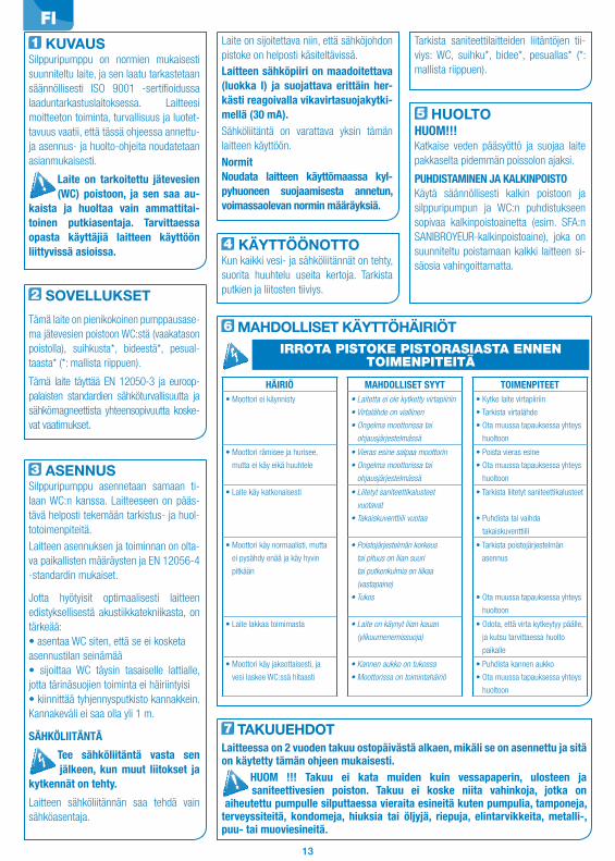
13
1 KUVAUSSilppuripumppu on normien mukaisesti suunniteltu laite, ja sen laatu tarkastetaan säännöllisesti ISO 9001 -sertifioidussa laaduntarkastuslaitoksessa. Laitteesi moitteeton toiminta, turvallisuus ja luotet-tavuus vaatii, että tässä ohjeessa annettu-ja asennus- ja huolto-ohjeita noudatetaan asianmukaisesti.
Laite on tarkoitettu jätevesien (WC) poistoon, ja sen saa au-kaista ja huoltaa vain ammattitai-toinen putkiasentaja. Tarvittaessa opasta käyttäjiä laitteen käyttöön liittyvissä asioissa.
2 SOVELLUKSET
Tämä laite on pienikokoinen pumppausase-ma jätevesien poistoon WC:stä (vaakatason poistolla), suihkusta*, bideestä*, pesual-taasta* (*: mallista riippuen).
Tämä laite täyttää EN 12050-3 ja euroop-palaisten standardien sähköturvallisuutta ja sähkömagneettista yhteensopivuutta koske-vat vaatimukset.
3 ASENNUSSilppuripumppu asennetaan samaan ti-laan WC:n kanssa. Laitteeseen on pääs-tävä helposti tekemään tarkistus- ja huol-totoimenpiteitä.
Laitteen asennuksen ja toiminnan on olta-va paikallisten määräysten ja EN 12056-4 -standardin mukaiset.
Jotta hyötyisit optimaalisesti laitteen edistyksellisestä akustiikkatekniikasta, on tärkeää:• asentaa WC siten, että se ei kosketaasennustilan seinämää• sijoittaa WC täysin tasaiselle lattialle, jotta tärinäsuojien toiminta ei häiriintyisi• kiinnittää tyhjennysputkisto kannakkein. Kannakeväli ei saa olla yli 1 m.
SÄHKÖLIITÄNTÄ
Tee sähköliitäntä vasta sen jälkeen, kun muut liitokset ja kytkennät on tehty.
Laitteen sähköliitännän saa tehdä vain sähköasentaja.
Laite on sijoitettava niin, että sähköjohdon pistoke on helposti käsiteltävissä.Laitteen sähköpiiri on maadoitettava (luokka I) ja suojattava erittäin her-kästi reagoivalla vikavirtasuojakytki-mellä (30 mA).Sähköliitäntä on varattava yksin tämän laitteen käyttöön.
NormitNoudata laitteen käyttömaassa kyl-pyhuoneen suojaamisesta annetun, voimassaolevan normin määräyksiä.
Tarkista saniteettilaitteiden liitäntöjen tii-viys: WC, suihku*, bidee*, pesuallas* (*: mallista riippuen).
5 HUOLTOHUOM!!!Katkaise veden pääsyöttö ja suojaa laite pakkaselta pidemmän poissolon ajaksi.
PUHDISTAMINEN JA KALKINPOISTOKäytä säännöllisesti kalkin poistoon ja silppuripumpun ja WC:n puhdistukseen sopivaa kalkinpoistoainetta (esim. SFA:n SANIBROYEUR-kalkinpoistoaine), joka on suunniteltu poistamaan kalkki laitteen si-säosia vahingoittamatta.
6 MAHDOLLISET KÄYTTÖHÄIRIÖT
HÄIRIÖ MAHDOLLISET SYYT TOIMENPITEET• Moottori ei käynnisty • Laitetta ei ole kytketty virtapiiriin
• Virtalähde on viallinen
• Ongelma moottorissa tai
ohjausjärjestelmässä
• Kytke laite virtapiiriin
• Tarkista virtalähde
• Ota muussa tapauksessa yhteys
huoltoon
• Moottori rämisee ja hurisee,
mutta ei käy eikä huuhtele
• Vieras esine salpaa moottorin
• Ongelma moottorissa tai
ohjausjärjestelmässä
• Poista vieras esine
• Ota muussa tapauksessa yhteys
huoltoon
• Laite käy katkonaisesti • Liitetyt saniteettikalusteet
vuotavat
• Takaiskuventtiili vuotaa
• Tarkista liitetyt saniteettikalusteet
• Puhdista tai vaihda
takaiskuventtiili
• Moottori käy normaalisti, mutta
ei pysähdy enää ja käy hyvin
pitkään
• Poistojärjestelmän korkeus
tai pituus on liian suuri
tai putkenkulmia on liikaa
(vastapaine)
• Tukos
• Tarkista poistojärjestelmän
asennus
• Ota muussa tapauksessa yhteys
huoltoon
• Laite lakkaa toimimasta • Laite on käynyt liian kauan
(ylikuumenemissuoja)
• Odota, että virta kytkeytyy päälle,
ja kutsu tarvittaessa huolto
paikalle
• Moottori käy jaksottaisesti, ja
vesi laskee WC:ssä hitaasti
• Kannen aukko on tukossa
• Moottorissa on toimintahäiriö
• Puhdista kannen aukko
• Ota muussa tapauksessa yhteys
huoltoon
IRROTA PISTOKE PISTORASIASTA ENNEN TOIMENPITEITÄ
7 TAKUUEHDOTLaitteessa on 2 vuoden takuu ostopäivästä alkaen, mikäli se on asennettu ja sitä on käytetty tämän ohjeen mukaisesti.
HUOM !!! Takuu ei kata muiden kuin vessapaperin, ulosteen ja saniteettivesien poiston. Takuu ei koske niita vahinkoja, jotka on aiheutettu pumpulle silputtaessa vieraita esineitä kuten pumpulia, tamponeja, terveyssiteitä, kondomeja, hiuksia tai öljyjä, riepuja, elintarvikkeita, metalli-, puu- tai muoviesineitä.
4 KÄYTTÖÖNOTTOKun kaikki vesi- ja sähköliitännät on tehty, suorita huuhtelu useita kertoja. Tarkista putkien ja liitosten tiiviys.
FI

14
1 FIGYELMEZTETÉSEzt az őrlőszerkezetet a vonatkozó szakmai előírások szerint fejlesztették ki, és állandó minőségi ellenőrzésnek vetik alá egy ISO 9001 minősítéssel rendelkező üzemben. A készülék magas színvonalú, biztonságos és üzembiztos működéséhez gondosan be kell tartani az ebben az utasításban leírt telepítési és karbantartási szabályokat.
Ez a készülék nem csökkent fizikai, érzékszervi vagy mentális képességekkel rendelkező személyek (és gyerekek), illetve tapasztalatlan vagy megfelelő ismeretekkel nem rendelkező személyek által történő használatra ké-szült, kivéve, ha biztonságukért felelős személy felügyelete alatt állnak, illetve ha ez a felelős személy előzetesen ellátta őket a készülék használatára vonatkozó információkkal. Vigyázzon a gyermekek-re, és ügyeljen arra, hogy ne játsszanak a készülékkel.
2 LEÍRÁSEz a készülék egy komplett szivattyúállomás, amelyet vízszintes elfolyású WC-csészéből, tuso-lóból*, bidéből* mosdóból* (*: modelltől függő-en) származó szennyvíz elvezetéséhez terveztek. Ez a készülék megfelel az EN 12050-3 szab-ványnak, valamint a villamos termékek biz-tonságáról és az elektromágneses összefér-hetőségről szóló európai előírásoknak.
3 TELEPÍTÉSAz őrlőberendezésnek a WC-vel és az esetleg csatlakoztatott egyéb szaniter berendezéssel azonos helyiségben kell lennie. A készülék le-gyen könnyen hozzáférhető az ellenőrzés és karbantartás érdekében.A készüléket a helyi előírások és az EN 12056-4 szabvány figyelembe vételével kell telepíteni és működtetni.
A készüléknél felhasznált legújabb akusztikai technikai fejlesztések optimalizálása érdeké-ben fontos, hogy :• a tartályt úgy helyezze el, hogy az ne érjen hozzá a helyiség egyik falához sem• a tartályt tökéletesen sima padlózaton helyezze el, hogy semmi se akadályozza a vibrációcsökkentö elemek müködését• az ürítö csöveket úgy helyezze el, hogy a felsö rögzítések közötti távolság ne haladja meg az egy métert.
VILLAMOS CSATLAKOZTATÁSA villamos bekötéseket a
készülék végleges csatlakoztatá-sa után kell elvégezni.Az elektromos szerelést elektrotechnikusi vég-zettséggel rendelkező szakember végezze. A készüléket úgy kell elhelyezni, hogy a hálózati
csatlakozó aljzat hozzáférhető maradjon.A készülék áramkörét földelni kell (I. érintésvédelmi osztály), és nagy érzé-kenységű (30 mA) differenciálmegszakí-tóval kell védeni.A bekötés kizárólag a készülék áramellátá-sára szolgálhat. Ha készülék kábele meg-hibásodik, akkor azt a gyártónál vagy a vevöszolgálatnál lehet kicserélni, a veszély elkerülése végett.ElőírásokA telepítés országában hatályos szab-vány fürdőszobai elektromos védelemre vonatkozó előírásait be kell tartani.
tartályt. A csésze átfolyó részének vízállónak kell lennie.Ellenőrizni kell, hogy szivárgásmentesek-e a szaniter készülékek (WC, tusoló*, bidé*, mos-dó* (*: modelltől függően) csatlakozásai.
5 KARBANTARTÁSFIGYELEM!!!Hosszas távollét esetén feltétlenül el kell zárni a fövizcsapot, és biztosítani kell a berendezés fagyvédelmét.TISZTÍTÁS/VÍZKŐMENTESÍTÉSAz őrlőkészülék és a tartály vízkőmentesítésé-hez és tisztításához használjon megfelelő víz-kőmentesítő szert, például SANIBROYEUR SFA vízkőoldót, amely a készülék belső egy-ségeit kímélve távolítja el a vízkövet.
6 ESETLEGES JAVÍTÁSOK
HIBALEÍRÁS LEHETSÉGES OKOK HIBAELHÁRÍTÁS• A motor nem indul el. • Rossz villamos csatlakozás
• Hibás áramellátás• Motor- vagy vezérlőmű hiba
• Csatlakoztassa a készüléket a hálózathoz
• Ellenőrizze az áramellátást• Forduljon engedéllyel rendelkező
szerelőhöz
• A motor zörög vagy zümmög, de nem forog
• A motor működését idegen test akadályozza
• Motor vagy vezérlőmű hibás
• Távolítsa el az idegen testet
• Forduljon engedéllyel rendelkező szerelőhöz
• A készülék időnként újraindul • A csatlakoztatott szaniter eszközök szivárognak
• A visszacsapó szelep szivárog
• Ellenőrizze az előtte lévő berendezéseket
• Tisztítsa meg vagy cserélje ki a visszacsapó szelepet
• A motor megfelelően működik, de nem áll le, vagy nagyon sokáig működik
• A szállítási magasság vagy távolság túl nagy, vagy túl sok könyök van a vezetékben (teljesítményveszteség)
• Hidraulikus probléma, eltömődés
• Vizsgálja át a berendezést
• Forduljon engedéllyel rendelkező szerelőhöz
• A készülék leáll • A készülék túl hosszú ideig működött (biztonsági hőkapcsoló)
• Várja meg, míg újra bekapcsolódik, szükség esetén forduljon engedéllyel rendelkező szerelőhöz
• A motor akadozva működik, a víz lassan folyik le a vécécsészében
• A fedél szellőzőnyílása eltömődött• Motorhiba
• Tisztítsa ki a szellőzőnyílást• Forduljon engedéllyel rendelkező
szerelőhöz
• Zavaros víz folyik vissza a zuhanyhoz (oldalsó bevezetésű készülékek)
• A zuhany túl alacsonyan helyezkedik el az őrlőkészülékhez képest
• Eltömődött oldalsó bemeneti csappantyúk
• Ellenőrizze a berendezést
• Tisztítsa ki a csappantyúkat• Forduljon engedéllyel rendelkező
szerelőhöz
MINDEN ESETBEN HÚZZA KI A KONNEKTORBÓL A KÉSZÜLÉKET.
7 JÓTÁLLÁSI FELTÉTELEKA készülékre a vásárlás napjától számított két év jótállás vonatkozik, feltéve, hogy a készülék telepítése és használata megfelel ennek a használati útmutatónak.
FIGYELEM !!! A Garancia csak vécepapirra, fekaliaanyagra és szennyvizre vonatkozik. Azokra a károkra, ami idegen tárgyak, pl. vatta, tampon, tisztaságibetét, pelenka, elelmiszerek, ovszer, haj, fem-, fa- vagy müanyagtárgyak örlésekor vagy olajok illetve oldoszerek szivattyuzasakor keletkeznek a készülékben, nem vonatkozik a garancia.
4 ÜZEMBE HELYEZÉSA hidraulikus és villamos csatlakozások kivi-telezése után húzza le többször a WC öblítő-
HU
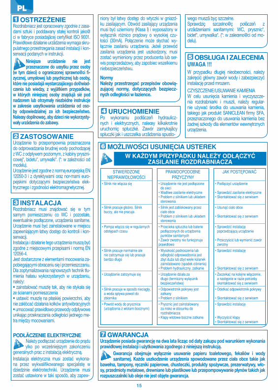
15
1 OSTRZEŒENIERozdrabniacz jest opracowany zgodnie z zasa-dami sztuki i poddawany stałej kontroli jako@ci w fabryce posiadajãcej certyfikat ISO 9001. Prawidłowe działanie urzãdzenia wymaga skru-pulatnego przestrzegania zasad instalacji i kon-serwacji podanych w instrukcji.
Niniejsze urzãdzenie nie jest przeznaczone do uœytku przez osoby (w tym dzieci) o ograniczonej sprawno@ci fi-zycznej, umysłowej lub psychicznej lub osoby, które nie posiadajã wystarczajãcego do@wiad-czenia lub wiedzy, z wyjãtkiem przypadków, w których niniejszej osoby znajdujã sié pod nadzorem lub otrzymały niezbédne instrukcje w zakresie uœytkowania urzãdzenia od oso-by odpowiedzialnej za ich bezpieczeñstwo. Naleœy dopilnowaç, aby dzieci nie wykorzysty-wały urzãdzenia do zabawy.
2 ZASTOSOWANIEUrządzenie to przepompownia przeznaczona do odprowadzania brudnej wody pochodzącej z WC z odpływem poziomym, z kabiny pryszni-cowej*, bidetu*, umywalki*. (*: w zależności od modelu).Urządzenie jest zgodne z normą europejską EN 12050-3 i z dyrektywami oraz nor-mami euro-pejskimi dotyczącymi bezpieczeństwa elek-trycznego i zgodności elektroma gnetycznej.
3 INSTALACJARozdrabniacz musi znajdować się w tym samym pomieszczeniu co WC i pozostałe, ewentualnie podłączone, urządzenia sanitarne. Urządzenie musi być zainstalowane w miejscu zapewniającym łatwy dostęp do kontroli i kon-serwacji.Instalacja i działanie tego urządzenia muszą być zgodne z miejscowymi przepisami i normą EN 12056-4.Jest dostarczone z elementami mocowania za-pobiegającymi obracaniu się i przemieszczaniu. Dla zoptymalizowania najnowszych technik tłu-mienia hałasu wykorzystanych w urządzeniu, należy:• zainstalować muszlę tak, aby nie stykała się ze ścianami pomieszczenia• ustawić muszlę na płaskiej powierzchni, aby nie zakłócać działania kołków antywibracyjnych• umocować prawidłowo przewody odpływoweunikając przekraczania odległości jednego me-tra między mocowaniami.
PODŁÃCZENIE ELEKTRYCZNENależy podłączać urządzenie do prądu
ylko po wcześniejszym zakończeniu generalnych prac z instalacją elektryczną. Instalacja elektryczna musi zostać wykona-na przez wykwalifikowanego specjalistę w dziedzi nie elektrotechniki. Urządzenie musi zostać ustawione w taki spo sób, aby zapew-
niony był łatwy dostęp do wtycz ki w gniazd-ku zasilającym. Obwód zasilający urządzenia musi być uzie miony (Klasa I) i wyposażony w wyłącznik różnico prądowy o wysokiej czu-łości (30mA). Połączenie może słychać wy-łącznie zasila niu urządzenia. Jeżeli przewód zasilania urządzenia jest uszkodzony, musi zostać wymieniony przez producenta lub ser-wis po sprzedażowy, aby zapobiec wszelkiemu niebezpieczeństwu.
Normy Należy przestrzegać przepisów obowią-zującej normy, dotyczących bezpiecz-nych odległości w łazience.
wego muszã byç szczelne.Sprawdziç szczelno@ç połãczeñ z urzãdzeniami sanitarnymi: WC, prysznic*, bidet*, umywalka*. (*: w zaleœno@ci od mo-delu).
5 OBSŁUGA I ZALECENIAUWAGA !!!W przypadku długiej nieobecności, należy zakręcić główny zawór wody i zabezpieczyć instalację przed mrozem.CZYSZCZENIE/USUWANIE KAMIENIAW celu usunięcia kamienia i wyczyszcze-nia rozdrabniarki i muszli, należy regular-nie używać środka do usuwania kamienia, takie go jak produkt SANICLEAN firmy SFA, przeznaczonego do usuwania kamienia bez żadnej szkody dla elementów wewnętrznych urządzenia.
6 MOŒLIWO#CI USUNIÉCIA USTEREK
STWIERDZONE NIEPRAWIDŁOWO#CI
PRAWDOPODOBNE PRZYCZYNY
JAK POSTÉPOWAÇ
• Silnik nie włãcza sié • Urzãdzenie nie jest podłãczone do sieci
• Wadliwe zasilanie elektryczne• Problem z silnikiem lub układem
sterowania
• Podłãczyç urzãdzenie
• Sprawdziç zasilanie elektryczne• Skontaktowaç sié z serwisem
• Silnik pracuje gło@no. Silnik buczy, ale nie pracuje.
• Silnik jest zablokowany przez ciało obce
• Problem z silnikiem lub układem sterowania
• Usunãç ciało obce
• Skontaktowaç sié z serwisem
• Pompa włãcza sié w regularnych odstépach czasu
• Przecieka spłuczka lub baterie podłãczonych do urzãdzenia punktów sanitarnych
• Zawór zwrotny nie funkcjonuje prawidłowo
• Sprawdziç instalacjé poprzedzajãcã urzãdzenie
• Przeczy@ciç lub wymieniç zawór zwrotny
• Silnik pracuje normalnie ale nie zatrzymuje sié lub pracuje bardzo długo
• Wysoko@ç podnoszenia lub odległo@ç odprowadzenia jest zbyt duœa lub zbyt wiele kolanek zainstalowano (spadek ci@nienia)
• Problem hydrauliczny, zatkanie
• Sprawdziç instalacjé
• Skontaktowaç sié z serwisem• Urzãdzenie zatrzymuje sié • Urzãdzenie działa za
długo (termiczny wyłãcznik bezpieczeñstwa)
• Zaczekaç na kolejne włãczenie, a nastépnie w razie potrzeby skontaktowaç sié z serwisem
• Silnik pracuje w sposób nieciãgły, a woda spływa powoli do zbiornika
• Odpowietrznik pokrywy jest zatkany
• Problem z silnikiem
• Odetkaç odpowietrznik pokrywy
• Skontaktowaç sié z serwisem• Powrót wody do prysznica
(urzãdzenia z wlotami bocznymi)• Prysznic jest zainstalowany
za nisko w stosunku do rozdrabniacza
• Klapy wlotowe boczne zatkane
• Sprawdziç instalacjé
• Wyczy@ciç klapy• Skontaktowaç sié z serwisem
W KAŒDYM PRZYPADKU NALEŒY ODŁÅCZYÇ ZASILANIE ROZDRABNIACZA
7 GWARANCJAUrządzenie posiada gwarancję na dwa lata licząc od daty zakupu pod warunkiem wykonania prawidłowej instalacji i użytkowania zgodnego z niniejszą instrukcją.
Gwarancja obejmuje wyłącznie usuwanie papieru toaletowego, fekaliów i wody sanitarnej. Każde uszkodzenie urządzenia spowodowane przez ciała obce takie jak bawełna, tampony, ręczniki papierowe, chusteczki, produkty spożywcze, pre zerwatywy, wło-sy, przedmioty metalowe, drewniane lub plastikowe lub przepompowywa nie płynów takich jak rozpuszczalniki lub oleje nie jest objęte gwarancja.
4 URUCHOMIENIEPo wykonaniu podłãczeñ hydraulicz-nych i elektrycznych, naleœy kilkakrotnie uruchomiç spłuczké. Zawór zamykajãcy spłuczki jak i uszczelka urzãdzenia spusto-
PL

16
1 ПРЕДУПРЕЖДЕНИЕДанная насосная станция разработана в соответствии с промышленными нор-мами. Она прошла постоянный контроль качества на заводе в соответствии cо стандартом ISO 9001. Для того чтобы ваш аппарат правильно функционировал, не-обходимо тщательно соблюдать правила установки и технического обслуживания, указанные в данной инструкции.
Этот аппарат не предназначен для лиц (в том числе детей) с ограниченными физическими, сен-сорными или умственными возмож-ностями, а также не имеющих опыта и знаний по обращению с ним, за исклю-чением тех случаев, когда они пользу-ются им под наблюдением и получа-ют указания по работе с ним от лица, ответственного за их безопасность. Следите за детьми и контролируйте, чтобы они не играли с аппаратом.
2 ПРИМЕНЕНИЕДанное устройство представляет собой компактную насосную станцию, предна-значенную для удаления отработанной воды из унитаза с горизонтальным сто-ком (выпуском), душа*, биде* или умы-вальника*. (*: В зависимости от модели).Данный аппарат соответствует норме EN 12050-3 и европейским нормам, каса-ющимся электрической безопасности и электромагнитной совместимости.
3 УСТАНОВКААппарат должен находиться в том же по-мещении, что и унитаз, а также прочее подключенное к нему санитарно-тех-ническое оборудование, если таковое имеется. Необходимо иметь свободный доступ к прибору для выполнения прове-рок и технического обслуживания.Установка и эксплуатация аппарата должны соответствовать местным нор-мам и стандарту EN 12056-4.Установить насос таким образом, чтобы он не касался перегородки помещения, поставить насос на совершенно плоскую поверхность пола во избежание наруше-ния правильной работы противовибра-ционных зажимов, правильно закрепить систему выводящих труб таким образом, чтобы расстояние между креплениями ями не превышало один метр.
ЭЛЕКТРИЧЕСКОЕ ПОДКЛЮЧЕНИЕЭлектрическое подключение
следует осуществить только по-сле окончательного выполнения всех необходимых соединений. Электроустановка должна осущест-вляться квалифицированным специали-стом. Прибор следует поместить таким образом, чтобы был обеспечен доступ к электрической розетке.
Данный аппарат должен быть обя-зательно подключен к заземлению (класс I) и дифференциальному авто-матическому выключателю высокой чувствительности (30mA).Розетка должна быть использована толь-ко для питания аппарата. В случае по-вреждения кабеля аппарата его следует заменить у производителя или в его после-продажной службе во избежание риска.Нормы и правилаСоблюдайте нормативы по электриче-ской безопасности в ванных комнатах, действующие в стране использования.
Проверить герметичность соединений с сантехникой: унитаз, душ*, биде*, умы-вальник*. (*: В зависимости от модели).
5 ТЕХНИЧЕСКОЕ ОБСЛУЖИ-ВАНИЕОСТОРОЖНО !!!В случае длительного отсутствия необ-ходимо перекрыть общую подачу воды и защитить установку от заморозков, слив воду из корпуса насоса.
ОЧИСТКА И УДАЛЕНИЕ ИЗВЕСТКОВО-ГО НАЛЕТАДля удаления известкового налета и очистки насосной станции и унитаза сле-дует регулярно использовать специально предназначенное для этого средство от накипи или раствор 1литр 9% уксуса на 5 литров воды.
7 УСЛОВИЯ ГАРАНТИИГарантийный срок аппарата 2,5 года (Для Украины – 2 года гарантии), начиная с даты по-купки, при условии установки и использования в соответствии с данной инструкцией.
ОСТОРОЖНО!!! Гарантия распространяется только на вывод туалетной бумаги, экскрементов и сточных вод. Гарантия не распространяется на ущерб, нанесенный прибору в результате проникновения инородных тел, как то: вата, тампоны, гигиенические салфетки, прокладки, продукты питания, презервативы, волосы, металлические, деревянные или пластмассовые предметы, а также в ре-зультате перекачки таких жидкостей, как масла или растворители.
4 ВВОД В ЭКСПЛУАТАЦИЮВыполнив электрические и гидравличе-ские соединения, следует несколько раз спустить воду. Унитаз не должен подтекать.
6 НЕИСПРАВНОСТИ, ИХ ПРИЧИНЫ И СПОСОБЫ УСТРАНЕНИЯ
ВЫЯВЛЕНИЕ НЕИСПРАВНОСТЕЙ
ВОЗМОЖНЫЕ ПРИЧИНЫ
ПОЧИНКА
• Мотор не включается • Прибор не включен в сеть• Неисправность системы
электроснабжения• Неисправность мотора или системы
управления
• Включить аппарат в сеть• Проверить систему электроснабжения• Если проблема не устранена,
обратиться в лицензированную службу ремонта
• Мотор трещит при работе или гудит, но не вращается
• Инородный предмет мешает вращению мотора
• Неисправность мотора или системы управления
• Изъять инородное тело• Если проблема не устранена,
обратиться в лицензированную службу ремонта
• Самопроизвольное включение прибора
• Подтекание запорных устройств санитарной техники, подключенной к прибору
• Пропускает обратный клапан
• Проверить оборудование, подключенное к прибору
• Прочистить или заменить обратный клапан
• Мотор вращается без нарушений, но не останавливается или вращается слишком длительное время
• Высота или длина вывода слишком велика или насчитывает слишком много патрубков (потеря нагрузки)
• Проблема гидравлики, закупорка
• Произвести осмотр напорного трубопровода
• Если проблема не устранена, обратиться в лицензированную службу ремонта
• Прибор останавливается • Прибор работал слишком длительное время (термическое отключение)
• Подождать повторного включения, затем при необходимости проконсультироваться в лицензированной службе ремонта
• Мотор работает с перерывами и вода медленно спускается в унитаз
• Вытяжное отверстие крышки закупорено
• Неисправность мотора
• Прочистить отверстие вытяжки• Если проблема не устранена,
обратиться в лицензированную службу ремонта
• Загрязненная вода выводится в душ (приборы с боковыми выходами)
• Душ установлен слишком низко относительно аппарата
• не работают створки боковых входов
• Произвести осмотр установки• очистить створки• Если проблема не устранена,
обратиться в лицензированную службу ремонта
ДО ВЫПОЛНЕНИЯ ВСЕХ ОПЕРАЦИЙ АППАРАТ СЛЕДУЕТ ОТКЛЮЧИТЬ ОТ СЕТИ
RU
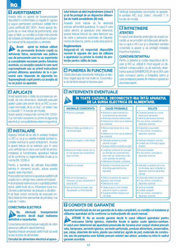
17
1 AVERTISMENTAcesta este un aparat de tocare-pompare dezvoltat în conformitate cu regulile în vigoare şi supus permanent controlului calităţii într-o uzină certificată ISO 9001. Acest aparat dis-pune de un nivel ridicat de performanţă, este sigur şi fiabil, cu condiţia ca toate instrucţiunile de instalare şi întreţinere specificate în prezen-tul manual să fie respectate cu stricteţe.
Acest aprat nu trebuie utilizat de persoanele (inclusiv copiii) cu deficienţe fizice, senzoriale sau psihice sau de persoanele care nu au experienţa şi cunoştinţele necesare pentru folosirea acestuia, cu excepţia cazului în care sunt supravegheate sau au primit instrucţiuni privind utilizarea aparatului de la o per-soană care răspunde de siguranţa lor. Supravegheaţi copiii pentru ca aceştia să nu se joace cu aparatul.
2 APLICAŢIIAcest aparat este o staţie de pompare pe ver-ticală, de mici dimensiuni, destinată evacuării apelor uzate care provin de la un WC cu eva-cuare orizontală, de la un duş*, un bideu* sau o chiuvetă* (*: în funcţie de model).Acest aparat corespunde normei EN 12050-3 şi normelor europene cu privire la siguranţa electrică şi compatibilitatea electromagnetică.
3 INSTALAREAparatul trebuie să se afle în aceeaşi încăpere cu WC-ul, ca şi cu celelalte instalaţii sanitare ra-cordate eventual la acest echipament. Accesul la aparat trebuie să se realizeze uşor, în cazul unor verificări sau în cazul unor lucrări de service.Instalarea şi funcţionarea aparatului trebuie să fie conforme cu reglementările locale şi cu norma EN 12056-4.Pentru a beneficia de ultimele îmbunătăţiri tehnice în domeniul acustic, aduse acestui aparat, este important:• să poziţionaţ rezervorul aparatului astfel încât acesta sa nu atingă vreun perete al încăperii• să amplasaţi rezervorul pe o suprafaţă perfect plană, astfel încât să nu influenţeze buna fun-cţionare a elementelor de preluare a vibraţiilor• să fixaţi corect conducta de evacuare evi-tând distanţe între elementele de prindere, mai mari de 1 metru.
CONECTAREA ELECTRICĂNu efectuaţi branşamentul
electric decât după realizarea definitivă a racordurilor. Conectarea electrică trebuie realizată de către personal calificat în electrotehnică.Aparatul trebuie amplasat astfel încât să aveţi acces la priza de alimentare.Circuitul de alimentare electrică al apara-
tului trebuie să aibă împământare (clasa I) şi să fie protejat de un disjunctor diferen-ţial de înaltă sensibilitate (30 mA).Această priză trebuie să fie destinată exclusiv alimentării aparatului. În cazul în care cablul electric al aparatului este deteriorat, acesta trebuie înlocuit de catre fabricant sau de catre o persoana autorizata de Departa-mentul de Service, pentru a evita orice pericol.ReglementareAsiguraţi-vă că respectaţi dispoziţiile normei în vigoare din ţara de utilizare a aparatului cu privire la nivelul de pro-tecţie pentru sălile de baie.
Verificaţi etanşeitatea racordurilor la aparate-le sanitare: WC, duş*, bideu*, chiuvetă* (*: în funcţie de model).
5 ÎNTREŢINEREATENŢIE!!!În cazul unei absenţe prelungite de acasă (va-canţă) va recomndăm să întrerupeţi alimenta-rea cu apă a WC-ului şi a obiectelor sanitare conectate la aparat şi să protejaţi instalaţia împotriva îngheţului.CURĂŢARE/DETARTRAJPentru a detartra şi curăţa dispozitivul de to-care şi WC-ul, utilizaţi în mod regulat un de-tartrant corespunzător, ca de exemplu detar-trantul special SANIBROYEUR de la SFA care este conceput pentru a îndepărta tartrul şi care protejează piesele din interiorul aparatului dumneavoastră.
6 INTERVENŢII EVENTUALE
ANOMALIE CONSTATATĂ CAUZE PROBABILE SOLUŢII• Motorul nu porneşte • Aparatul nu este conectat la o
sursă electrică de alimentare• Alimentare electrică defectuoasă• Defecţiuni la motor sau la sistemul de comandă
• Conectaţi aparatul la o sursă electrică de alimentare
• Verificaţi alimentarea electrică• În caz contrar, consultaţi un
depanator autorizat
• Motorul hârâie sau bâzâie şi nu mai funcţionează
• Motorul este blocat de un corp străin
• Defecţiuni la motor sau la sistemul de comandă
• Îndepărtaţi corpul străin• În caz contrar, consultaţi un
depanator autorizat
• Aparatul porneşte cu intermitenţe • Obiectele sanitare racordate prezintă scurgeri
• Supapa antiretur prezintă scurgeri
• Verificaţi instalaţia în amonte• Curăţaţi sau schimbaţi supapa
antiretur
• Motorul se învârte normal, dar nu se mai opreşte sau funcţionează prea mult timp
• Lungimea conductei de evacuare pe verticală sau orizontală este prea mare sau există prea multe coturi (pierdere de sarcină)
• Defecţiune hidraulică, colmatare
• Revizuiţi instalaţia• În caz contrar, consultaţi un
depanator autorizat
• Aparatul se opreşte • Aparatul a funcţionat prea mult timp (întrerupere termică de siguranţă)
• Așteptaţi ca aparatul să-şi reia funcţionarea, apoi contactaţi un depanator autorizat dacă este necesar
• Motorul funcţionează cu întreruperi, iar apa coboară lent în vasul de WC
• Orificiul de aerisire din capacul aparatului este înfundat• Defecţiuni la motor
• Desfundaţi orificiul de aerisire• În caz contrar, consultaţi un
depanator autorizat
• Apa se întoarce pe traseu spre duş (aparate cu intrări laterale)
• Cădiţa duşului a fost montată prea jos în raport cu aparatul
• Supapele intrărilor laterale sunt colmatate
• Verificaţi instalaţia• Curăţaţi supapele • În caz contrar, consultaţi un
depanator autorizat
ÎN TOATE CAZURILE, DECONECTAŢI MAI ÎNTÂI APARATUL DE LA SURSA ELECTRICĂ DE ALIMENTARE.
7 CONDIŢII DE GARANŢIEAparatul beneficiază de doi ani garanţie de la data cumpărării, cu condiţia ca instalarea şi utilizarea aparatului să fie conforme cu instrucţiunile din acest manual.
ATENIE !!!: Nu se acorda garanie decât în cazul utilizarii aparatului pentru evacuarea hârtiei igienice, materiilor fecale si apelor uzate igienico-sanitare. În cazul unor deteriorari ale aparatului provocate de: tocarea unor corpuri straine precum vata, tampoane, serveele igienice, serveele parfumate, produse alimentare, prezervative, par, cârpe, obiectele din lemn, plastic sau metal (ex: agrafe de par), materiale de constru-cie; sau de pomparea unor lichide precum solveni sau uleiuri, acestea nu intra în cadrul garaniei acordate.
4 PUNEREA ÎN FUNCŢIUNEOdată efectuate racordurile hidraulice și elec-trice, trageţi apa de mai multe ori. Cuva trebu-ie să rămână etanșă la trecerea apei.
RO

18
1 VŠEOBECNÉ INFORMACEToto sanitární kalové čerpadlo je přistroj vy-vinutý v souladu s technickými normami a podléhá neustálé kontrole kvality v továrně certifikované dle ISO 9001. Přistroj posky-tuje vysokou úroveň výkonu, bezpečnosti a spolehlivosti za předpokladu dodržení všech dále uvedených požadavků pro instalaci a používání.
Toto zařízení není určeno pro osoby (včetně dětí), jejichž těles-né, smyslové nebo duševní schopnosti jsou omezeny, nebo jimž chybí zkuše-nosti a znalosti, pokud nejsou pod do-hledem a nedostává se jim nezbytných pokynů pro používání zařízení od oso-by odpovídající za jejich bezpečnost. Děti je nutno mít pod dohledem a do-hlédnout, aby si s přístrojem nehrály.
2 POUŽITÍTento přístroj je kompaktní přečerpávací sta-nice určená k odvádění odpadních vod po-cházejících z WC s horizontálním odpadem, ze sprchy*, bidetu*, umyvadla*. (*: podle kon-krétního modelu).Tento přístroj odpovídá následujícím nor-mám: ČSN EN 12050-3 a evropským nor-mám o bezpečnosti elektrických přístrojů a elektromagnetické kompatibilitě.
3 INSTALACEPřístroj se musí nacházet ve stejné místnosti jako WC a případně další připojené zařizovací předměty. Přistroj musí byt volně přístupný pro případný servis či údržbu.Instalace a provoz tohoto přístroje musí od-povídat místním předpisům a normě EN 12056-4.Pro maximalizaci účinku nejnovějších výsled-ků vývoje v oblasti hlučnosti, které jsou v tom-to přistroji použity, je důležité:• instalovat WC tak, aby se nedotýkalo žádnéstěny• instalovat WC s přístrojem na zcela rovnou podlahu, aby prostředky pohlcující vibrace byly plně funkční• odpadní tlakové potrubí důkladně ukotvit s tím, že je třeba dodržet vzdálenost mezi kot-vami max. 1mELEKTRICKÁ INSTALACE
Připojení na elektrický rozvod smí být provedeno až po ukončení vlastní instalace přístroje!!!Zásuvku pro připojení přístroje musí instalovat oprávněný kvalifikovaný pracovník tak, aby byla volně přístupná, přičemž je nutné respek-tovat příslušné normy.Elektrický přívod přístroje musí být uzemněn (třída I) a musí být chráněn
vysoce citlivým proudovým chráničem s jmenovitým vybavovacím proudem ne-přesahujícím 30 mA. Elektrický přívod musí sloužit výhradně k napá-jení tohoto přístroje. Poškozený přívodní kabel musí být vyměněn a to pouze kvalifikovanou osobou. Před každým zásahem do přístroje odpojte přístroj od přívodu elektrického proudu.PředpisyČerpadla nejsou určena k umístění v zónách 1 a 2 definovaných prosto-rů v koupelnách a sprchách dle ČSN 332000-7-701.To platí pro čerpadlo i pro umístění zásuvky k jeho připojení na elektrický rozvod. Čerpadla lze instalovat v zóně 3 koupelny dle ČSN 332000-7-701 (min. 0,6 m od okraje vany či sprchové vanič-ky) a ve všech jiných místnostech.Čerpadla smějí být připojena na el. ob-vod odpovídající platným českým nor-mám a předpisům (ČSN 332000-4-41 a normy související).
5 ÚDRŽBAPOZOR !!! V případě dlouhodobé nepřítom-nosti je nezbytné uzavřít hlavní přívod vody a zajistit ochranu přístroje proti mrazu.ČIŠTĚNÍPro čištění WC mísy a povrchupřístroje dopo-ručujeme používat běžné neagresivní čistící prostředky.Pro čištění přístroje od vodního kamene dopo-ručujeme použít přípravek SFA® ANTIKALK.
6 NEJBĚŽNĚJŠÍ PROBLÉMY A JEJICH ODSTRANĚNÍ
ZJIŠTĚNÝ PROBLÉM MOŽNÉ PŘÍČINY VÁŠ POSTUP• Motor se neaktivuje • Přístroj není připojen
• Porucha el. přívodu • Porucha motoru nebo ovládacího
systému
• Připojte přistroj.• Prověřte el. přívod.• Kontaktujte autorizovaný servis
• Motor pracuje s rušivými zvuky nebo pouze bzučí a neotáčí se
• Motor je zablokovaný cizím tělesem
• Porucha motoru nebo ovládacího systému
• Odstraňte cizí těleso
• Kontaktujte autorizovaný servis
• Přistroj se samovolně aktivuje • Armatura WC nebo připojených zařizovacích předmětů netěsní
• Nefunkční zpětný ventil
• Zkontrolujte připojené zařizovací předměty
• Vyčistěte nebo vyměňte zpětný ventil
• Motor pracuje déle než jeobvyklé nebo nevypíná
• Příliš dlouhé nebo vysoké odpadní potrubí, nebo příliš mnoho ohybů
• Problémy hydrauliky, ucpání
• Zkontrolujte instalaci
• Kontaktujte autorizovaný servis
• Přístroj přestal pracovat • Přístroj pracoval příliš dlouho (aktivace tepelné pojistky)
• Počkejte na opětovné zapnutí, poté v případě potřeby kontaktujte autorizovaný servis
• Motor pracuje přerušovaně a voda v míse klesá pomalu
• Ucpaný ventil odvětrání• Porucha motoru
• Vyčistěte ventil odvětrání• Kontaktujte autorizovaný servis
• Odpadní voda se vrací do sprchy (přístroj s bočními vstupy)
• Sprcha nainstalovaná příliš nízko vzhledem přístroji
• Ucpaný boční vstup
• Zkontrolujte instalaci sprchy
• Vyčistěte boční vstup• Kontaktujte autorizovaný servis
VŽDY ODPOJTE PŘÍSTROJ OD PŘÍVODU ELEKTRICKÉHO PROUDU.
7 ZÁRUKANa přístroj se vztahuje záruka dva roky od data zakoupení pod podmínkou instalace a používání v souladu s tímto návodem a jeho přílohami.
POZOR!!! sanitární kalové čerpadlo slouží výhradně ke zpracování vody, fekálií a WC papíru. Záruka je poskytována pouze pro tyto účely. Odpady jako např. chemikálie (kyseliny, žiraviny, prostředky s vysokou koncentrací chloru apod.), oleje, barvy, tampony, prezervativy, hygienické vložky, textilie, tvrdé předměty, písek, kameny, abnormální množství vlasů, kosmetické ubrousky apod., mohou způsobit poruchu přístroje, na kterou se nevztahuje záruka.
4 UVEDENÍ DO PROVOZUPo dokončení celkové instalace přístroje vhoď-te do WC toaletní papír a WC spláchněte. To opakujte 2x – 3x. Poté uveďte do provozu armatury dalších připojených zařizovacích předmětů.Zkontrolujte těsnost všech propojení se zařizo-vacími předměty: WC, sprcha*, bidet*, umyva-dlo*. (*: podle konkrétního modelu).
CZ

19
1 UYARIBu öğütücü teknikte geçerli kurallara uygun şekilde geliştirilen ve tarafından ISO 9001 onaylı bir fabrikada sürekli kalite kontrole tabi tutulan bir cihazdır. Bu öğütücü, bu kullanım kılavuzunda tanımlanan tüm kurulum ve bakım kurallarına titizlikle uyulduğu takdirde, yüksek bir performans, güvenlik ve güvenilirlik sağlar.
Bu cihaz, fiziksel, duyusal veya zihinsel kapasiteleri sınırlı olan (bunlara çocuklar da dahildir), veya tecrübe ve bilgi sahibi olmayan kişilere yönelik değildir; bu tip kişiler gözetim altında bulunmaları ve cihazı kullanmak için gerekli talimatları almaları duru-munda, kendi güvenliklerinden sorumlu bir kişinin yardımıyla cihazı kullanabilir-ler. Çocukları gözetim altında tutun ve cihazla oynamalarına izin vermeyin.
2 UYGULAMALARBu cihaz, yatay çıkışlı klozet, duşakabin*, bide* ve lavabodan gelen atık suların tah-liyesi için tasarlanmış kompakt bir tahliye istasyonudur. (*: Modele göre).
Bu cihaz EN 12050-3 standardına ve elekt-rik güvenliği ve elektromanyetik uyumluluk ile ilgili Avrupa standartlarına uygundur.
3 KURULUMÖğütücü WC ve bağlı olabilecek diğer sıhhi tesisat üniteleri ile aynı yerde bulunmalıdır. Kontrol ve bakım için, cihaza erişim kolay olmalıdır.Cihazınızın kurulumu ve çalışması yerel mevzuata ve EN 12056-4 standardına uy-gun olmalıdır.Bu cihaz akustik alanında mevcut son teknik yenilikleri içermektedir. Bu son teknik gelişme-lerden en verimli düzeyde faydalanmak için:• Hazneyi duvara değmeyecek şekilde yer-leştirin.• Titreşim yalıtıcılarının düzgün işleyişine engel olmamak için, hazneyi düz bir zemin üzerine yerleştirin.• Sabitleme elemanları arasında bir metre-den fazla mesafe bırakmadan, tahliye boru-larını düzgün bir şekilde sabitleyin.ELEKTRİK BAĞLANTISI
Elektrik bağlantısını, tüm ni hai bağlantıları gerçekleştirdik-ten sonra yapın. Elektrik tesisatı elektroteknik alanında uz-man vasıflı bir profesyonel tarafından ku-rulmalıdır.Cihaz, elektrik fişine erişilebilecek şekilde yerleştirilmelidir.
Cihazın güç devresi topraklanmalı (sı-nıf 1 topraklama) ve çok hassas (30mA) bir diferansiyel devre kesici vasıtasıyla korunmalıdır.Bu bağlantı sadece cihaza güç sağlamak için kullanılmalıdır. Bu cihazın kablosu hasar görmüş ise, tehlikeli bir durumu ortadan kaldırmak için, imalatçısı veya satış sonrası servisi tarafından değiştirilmelidir.MevzuatBir banyodaki koruma hacimleri ile ilgili olarak, cihazın kullanıldığı ülkede yürür-lükte olan standardın hükümlerine uyma-ya dikkat edin.
Küvet geçişi sızdırmaz olmalıdır.Cihaz ile sıhhi tesisat ünitelerin (WC, duşa-kabin*, bide*, lavabo*) bağlantıların sızdır-mazlığını kontrol edin. (*: Modele göre).
5 BAKIMDİKKAT !!! Uzun süre evde bulunmaması halinde, evin ana su vanasını mutlaka kapa-tınız ve donma tehlikesine karşı tesisatınızı uygun bir şekilde koruyunuz.TEMİZLEME / KİREÇTEN ARINDIRMAÖğütücüyü ve klozeti kireçten arındırmak ve temizlemek için, düzenli aralıklarla, SFA'nın özel kireç çözücü SANIBROYEUR® gibi cihazınızın iç organlarına zarar vermemek üzere tasarlanmış uygun bir kireç çözücü kullanın.
6 OLASI MÜDAHALELER
TESPİT EDİLEN ANORMALLİK
MUHTEMEL NEDENLER ÇÖZÜMLER
• Motor devreye girmiyor • Cihazın bağlantısı yapılmamış• Kusurlu elektrik bağlantısı• Motor veya kumanda sistemi
sorunu
• Cihazı elektrik prizine bağlayın,• Elektrik bağlantısını kontrol edin• Aksi takdirde yetkili bir teknik
servise başvurun
• Motor gürültülü bir şekilde dönüyor veya uğultu çıkarıyor ve dönmüyor
• Yabancı bir cisim motoru bloke ediyor
• Motor veya kumanda sistemi problemi
• Yabancı cismi cıkarın
• Aksi takdirde yetkili bir teknik servise başvurun
• Cihaz zaman zaman calışmaya başlıyor
• Bağlı sıhhi tesisat ünitelerinde sızıntı var
• Çekvalfte sızıntı var
• Cihazın girişlerine bağlı olan tesisatı kotrol edin• Çekvalfi temizleyin veya değiştirin
• Motor düzgün bir şekilde dönüyor, ama durmuyor veya çok uzun süre dönüyor
• Tahliye kanalının yüksekliği veya uzunluğu çok fazla veya (basınç düşüşü)
• Hidrolik sorun, tıkanma
• Tesisatı kontrol edin
• Aksi takdirde yetkili bir teknik servise başvurun
• Cihaz duruyor • Cihaz uzun bir süre çalışmış (güvenlik termik koruması)
• Yeniden çalışmasını bekleyin, ardından gerekirse yetkili bir teknik servise başvurun
• Motor kesintili olarak dönüyor ve su klozetin içine yavaş iniyor
• Cihazın kapğında bulunan havalık tıkalı
• Motor sorunu
• Havalığı açın• Aksi takdirde yetkili bir teknik
servise başvurun
• Bulanık suyun duşa geri dönmesi (yan girişleri olan cihazlar)
• Duş öğütücüye göre alçak bir noktaya yerleştirilmiş
• Yan giriş klapesi tıkalı
• Tesisatı gözden geçirin
• Yan giriş klapesini temizleyin• Aksi takdirde yetkili bir teknik
servise başvurun
HER DURUMDA, ÖĞÜTÜCÜNÜN FİŞİNİ ELEKTRIK PRIZINDEN ÇEKİN
7 GARANTİ KOŞULLARICihaz, bu kurulum kılavuzuna uygun bir şekilde kurulması ve kullanılması kaydıyla satın alma tarihinden 2 yıl parça ve işçilik garantilidir.
DİKKAT!!! Garanti kapsamında, yalnızca tuvalet kağıdı, dışkı maddeleri ve sıhhi tesisat sularının tahliyesi dikkate alınacaktır. Pamuk, vajinal tampon, hijyenik ped, kucuk havlular, gıda maddeleri, prezervatif, sac teli, metal, ahşap veya plastik cisimler gibi yabancı cisimlerin öğütülmesi veya solvent veya yağ gibi sıvıların pompalanması sonucu cihazda oluşan hiçbir hasar garanti kapsamında değerlendirilmeyecektir.
4 HİZMETE ALMAHidrolik ve elektriksel bağlantılar gerçek-leştirildikten sonra sifonu birkaç kez çekin.
TR

20
1 描述 该设备通过了ISO9001认证,严格按照工艺规格设计制造。
只要严格按照本说明进行 安装及维护,此设备可保证安全可靠的高性能运行。
该设备不适用于包括儿童在内的一些特殊人群(精神或智力有障碍等)。除非在确保安全或有监护人的情况下安装此设备。
2 使用这个装置是一个设计紧凑的提升设备,它能将卫生间、浴缸、淋浴房、水槽里的污水从水平方向的出口排出。(视机型而定)
此设备符合EN 12050-3标准,并符合相关电气安全和电磁兼容性的欧洲标准。
3 安装机器的安装和使用须遵照EN 12056-4标准及当地法规进行。
本设备使用了先进的消音技术,能达到它最理想的效果,关键在于:
·座便器放置之处不能接触到房间的墙或隔板墙。
·座便器必须置于完全水平的平面上,确保弹力托架充分地高效运作。
·正确安装排水管,各固定点之间距离不超过1米。
电路连接电气的安装结束之前确
保电源关闭。设备安装必须由专业工程师完成。选择电源插头的位置应方便设备的安装。
电路应当接地线(一级),
本机所在电路中必须有30毫安的漏电保护开关。连接线必须只用于本设备供电。电机保护:该设备配备有一套温度保护系统,在过热之后,为了安全,必须切断机器电源,停机2小时。
规定V请遵守使用国的有关浴室保护容积的现行规定。
6 发现故障/修理
故障 原因 解决方法• 设备不启动 • 没有接电
• 供电问题• 电机或控制系统问题
• 给设备接电• 检查供电系统• 如不能解决,求助于授权维修人员
• 电机运转时发出卡嗒卡嗒声,或是只发出嗡嗡声而不运转
• 电机被异物阻滞• 电机或控制系统问题
• 取出异物• 如不能解决,求助于授权维修人员
• 设备间断性运转 • 连接的设备漏水• 止回阀漏水
• 检查设备上端安装• 清洁或更换止回阀
• 电机运行正常,但无法停止或持续时间过长
• 排水管过高或过长,或者管弯过多(能效损耗)
• 水流堵塞问题
• 重新调整安装• 如不能解决,求助于授权维修人员
• 设备停止运行 • 运行时间过长(热保护) • 等待重启,然后如有必要,求助于授权维修人员
• 电机间歇运行,排水缓慢 • 通气道堵塞• 电机问题
• 清理通气道• 如不能解决,求助于授权维修人员
• 污水回流入淋浴池内(带有边侧入水的设备)
• 淋浴相对于设备位置过低• 设备内底部两边的止阀片堵塞
• 重新调整安装• 清理止阀片• 如不能解决,求助于授权维修人员
在任何情况下,必须关闭机器电源
7 保修在安装及使用符合本说明书的条件下,设备自购买日起,保修两年。
保修范围只对针对卫生纸和粪便之类的污水所发生的故障。任何因外物造成的损坏,如棉球、避孕套、卫生巾、湿纸巾、食物、头发、金属、木头或塑胶物品等,都不在保修范围内。由溶剂、酸性物质和其它化学品所造成机器的故障,均不属于保修范围内
4 安装调试一旦电气与管道连接完成,启动多次马桶冲水,查看所有部分是否密封。仔细检查所有与卫浴设备间的连接口:马桶、淋浴房、净身盆、洗手盆。(视机型而定)。
CN5 维护警示:如果设备长时间不适用,请关闭总阀停止供水,以保护设备,防止霜冻。
清洁/除水垢使用家用除垢剂清除研磨机和马桶内的水垢(升利保除垢液),以便在除垢的同时保护您设备的内部系统不受损伤。

21
1 제품 개요 본 분쇄기 펌프(품질보증 공장에서 제조된)는 ISO 9001 인증을 받았다. 올바로 설치 및 사용되면 지속적이고 안정적인 작동을 할 것이다.
신체적, 감각적, 심리적 장애가 있는 사람이나(어린이 포함) 최소한의 경험 및 지식만 있는 사람은 본 장치를 사용하지 못하며, 보호자의 도움을 받거나 장치 사용에 필요한 모니터링과 필요 사항을 숙지한 다음에는 본 장치를 사용할 수 있다. 어린이가 사용할 때에는 모니터링을 하고 장난치지 못하도록 주의한다.
2 제품 사용본 가정 기기는 수평으로 설치된 변기, 샤워기, 비데나 세면대의 배출구에서 나오는 폐수 처리를 위해 만들어진 소형 리프트 펌프이다(*모델에 따라 상이). 본 기기는 EN 12050-3및 전기안전 및 전자기 적합성 관련 유럽 표준을 준수한다.
3 설치본 제품은 서비스를 받을 수 있도록 접근이 용이해야 한다. 귀하가 설치한 기기의 부품 및 작동은 해당 지역 규제 및 EN 12056-4 표준을 준수하여야 한다. 본 제품에 적용된 최첨단 방음기술의 최적 사용을 위해서는 아래 내용이 중요하다.· 양변기가 파티션 또는 벽에 닿지 않도록 위치를 정한다· 탄성 마운트가 효율을 충분히 발휘하도록 양변기와 완벽히 수평면에 놓는다· 결합부분간 거리가 1미터가 넘지 않도록 배출관을 올바로 고정시킨다
전기공급 연결 전기는 기술자가 설치해야 한다. 본 제품은 220/240 볼트 단상 전류 AC 60 Hz 전력을 사용한다(한국 사양). 본 기기의 전원 공급 회로는 GFCI 고감도(30mA) 에 의해 접지되고(Class I) 보호되어야 한다. 경고: 커넥터에 배선작업을 하기 전에 주 배전반에 전기가 모두 차단되었는지 확인할 것.
60Hz 주파수 사용가능.
모든 배선 작업은 1992년 전기설비 요건인 BS7671을 준수해야 한다. 본 제품을 종래의 플러그와 소켓에 연결하면 안 된다. 반드시 5 암페어 퓨즈 설비가 있는 직류전원출력단자이며 고정배선 타입의 커넥터에 배선작업을 해야 한다. 주도선의 전선은 아래 규칙에 따라 색깔 별로 표시되어 있다.갈색(Brown) – 활선(Live)파랑(Blue) – 중성선(Neutral)
초록/노랑(Green/Yellow)–접지선(Earth)이상의 연결은 장치의 전력공급 목적을 위해서만 사용되어야 한다. 모든 케이블, 가압실 및 모터 작업은 특수 도구가 필요한 관계로 반드시 Saniflo 기술 직원이 해야 한다. 향후 장치 제거 등의 서비스 요청이 있을 시 상당한 어려움이 있을 수 있으니 전기공급케이블을 절단하거나 줄이지 마시오.
6 고장점검 및 해결방안
증상 고장 원인 해결방안
•모터가 작동하지 않는다 •전원공급이 작동하지
않는다
•전원공급에 결함이 있다
•모터나 컨트롤 시스템에
결함이 있다
• 전원공급을 복원한다
•전원공급을 확인한다
•승인된 수리 대리점에
문의한다
•모터에서 덜거덕거리거나
부서지는 소리가 나고,
웅웅거리지만 돌아가지는
않는다.
•이물질이 박스 안에 있다
•모터나 컨트롤 시스템에
문제가 있다
•이물질을 제거한다
•승인된 수리 대리점에
문의한다
•모터가 불규칙적으로
작동한다
•연결된 위생 장치에서 물이
떨어진다
•역류방지밸브에 결함이
있다
•상류로 설치를 확인한다
•역류방지밸브를
세척하거나 교체한다
•모터가 정상적으로
작동하지만 오랫동안 계속
돌아간다
•설치 길이나 높이가
설치사양을 초과했거나 벤딩/
엘보우가 너무 많다.
•펌프 덮개판이 부분적으로
불투명/막혀있다
•설치상태를 확인한다
•승인된 수리 대리점에
문의한다
•제품이 멈췄다 •제품이 너무 오랫동안
돌아간다(열차폐장치)
•제품을 재가동 시켜서
결과를 보고 A/S 점검을
받는다
•모터에 물에 휘용돌이치고
양변기 물이 아주 느리게
내려간다
•공기변이 막혔다
•모터에 문제가 있다
•공기 방출 구멍을 청소한다
•승인된 수리 대리점에
문의한다
•탁한 물이 샤워대에서
올라온다(측면 유입구가
있는 제품)
•오수 펌프 제품에 비해
샤워기가 너무 낮게
설치되었다
•한쪽 유입구 디스크가 막혔다
•설치 상태를 확인한다
•유입체크변을 확인한다
•승인된 수리 대리점에
문의한다
모든 경우에, 오수펌프의 전원을 차단해야 한다.
7 제품 보증제품이 올바르게 설치되고 사용되었다면 본 제품의 품질보증은 구매일로부터 2년간이다.
화장실 휴지, 대변, 폐수만 품질보증 대상이 된다. 솜, 콘돔, 위생용 타월, 물티슈, 음 식물, 머리카락, 금속류, 나무, 플라스틱 물체 등과 같은 이물질을 버리면 품질보증을 받을 수 없다. 용해성 물질, 산성 물질 및 기타 화학물질은 제품에 손상을 입힐 수 있으며, 그런 경우 제품 보증은 무효화된다.
4 제품 작동 검증모든 밀봉 부위 및 연결부위에 물이 새지 않는 지 확인하면서 화장실 물을 내린다. 양변기*, 샤워기*, 비데*나 세면대*와 같은 위생 기기와의 연결부위에 물이 새지 않는 지 확인한다 (*모델에 따라 상이).
KR5 유지 보수경고!!! 장기간 부재 시 영하의 기온으로 인한 동파를 막기 위해 물 공급을 꼭 차단시켜둘 것.
제품 관리법
물때(석회)를 제거하고 오수펌프 및 좌변기를 청소하려면 SANIFLO 클렌저/ 디스케일링제를 사용하시오. . 오수펌프의 전원을 차단한다. 일정량의 클렌저를 양변기에 붓는다. 1-2시간 정도 둔다. 전원을 다시 연결한다. 플러시 시스템을 이용해 두 번 내려 씻어낸다이상의 순서를 평균 3개월마다 반복한다. 물의 경도에 따라 횟수는 변경될 수 있다.

22
Notes
____________________________________________________________________________________________________________________________________________________________________________________________
____________________________________________________________________________________________________________________________________________________________________________________________
____________________________________________________________________________________________________________________________________________________________________________________________
____________________________________________________________________________________________________________________________________________________________________________________________
____________________________________________________________________________________________________________________________________________________________________________________________
____________________________________________________________________________________________________________________________________________________________________________________________
____________________________________________________________________________________________________________________________________________________________________________________________
____________________________________________________________________________________________________________________________________________________________________________________________
____________________________________________________________________________________________________________________________________________________________________________________________
____________________________________________________________________________________________________________________________________________________________________________________________
____________________________________________________________________________________________________________________________________________________________________________________________
____________________________________________________________________________________________________________________________________________________________________________________________
____________________________________________________________________________________________________________________________________________________________________________________________
____________________________________________________________________________________________________________________________________________________________________________________________
____________________________________________________________________________________________________________________________________________________________________________________________
____________________________________________________________________________________________________________________________________________________________________________________________
____________________________________________________________________________________________________________________________________________________________________________________________
____________________________________________________________________________________________________________________________________________________________________________________________
____________________________________________________________________________________________________________________________________________________________________________________________
____________________________________________________________________________________________________________________________________________________________________________________________
____________________________________________________________________________________________________________________________________________________________________________________________
____________________________________________________________________________________________________________________________________________________________________________________________
____________________________________________________________________________________________________________________________________________________________________________________________
____________________________________________________________________________________________________________________________________________________________________________________________
____________________________________________________________________________________________________________________________________________________________________________________________
____________________________________________________________________________________________________________________________________________________________________________________________
____________________________________________________________________________________________________________________________________________________________________________________________
____________________________________________________________________________________________________________________________________________________________________________________________
____________________________________________________________________________________________________________________________________________________________________________________________
____________________________________________________________________________________________________________________________________________________________________________________________
____________________________________________________________________________________________________________________________________________________________________________________________
____________________________________________________________________________________________________________________________________________________________________________________________

23
Notes
____________________________________________________________________________________________________________________________________________________________________________________________
____________________________________________________________________________________________________________________________________________________________________________________________
____________________________________________________________________________________________________________________________________________________________________________________________
____________________________________________________________________________________________________________________________________________________________________________________________
____________________________________________________________________________________________________________________________________________________________________________________________
____________________________________________________________________________________________________________________________________________________________________________________________
____________________________________________________________________________________________________________________________________________________________________________________________
____________________________________________________________________________________________________________________________________________________________________________________________
____________________________________________________________________________________________________________________________________________________________________________________________
____________________________________________________________________________________________________________________________________________________________________________________________
____________________________________________________________________________________________________________________________________________________________________________________________
____________________________________________________________________________________________________________________________________________________________________________________________
____________________________________________________________________________________________________________________________________________________________________________________________
____________________________________________________________________________________________________________________________________________________________________________________________
____________________________________________________________________________________________________________________________________________________________________________________________
____________________________________________________________________________________________________________________________________________________________________________________________
____________________________________________________________________________________________________________________________________________________________________________________________
____________________________________________________________________________________________________________________________________________________________________________________________
____________________________________________________________________________________________________________________________________________________________________________________________
____________________________________________________________________________________________________________________________________________________________________________________________
____________________________________________________________________________________________________________________________________________________________________________________________
____________________________________________________________________________________________________________________________________________________________________________________________
____________________________________________________________________________________________________________________________________________________________________________________________
____________________________________________________________________________________________________________________________________________________________________________________________
____________________________________________________________________________________________________________________________________________________________________________________________
____________________________________________________________________________________________________________________________________________________________________________________________
____________________________________________________________________________________________________________________________________________________________________________________________
____________________________________________________________________________________________________________________________________________________________________________________________
____________________________________________________________________________________________________________________________________________________________________________________________
____________________________________________________________________________________________________________________________________________________________________________________________
____________________________________________________________________________________________________________________________________________________________________________________________
____________________________________________________________________________________________________________________________________________________________________________________________
FRANCE
SOCIÉTÉ FRANÇAISE D’ASSAINISSEMENT41bis, av Bosquet - 75007 PARIS Tél. + 33 1 44 82 39 00Fax + 33 1 44 82 39 01
UNITED KINGDOM
SANIFLO Ltd.,Howard House, The Runway South Ruislip Middx., HA4 6SETel. +44 208 842 0033Fax +44 208 842 1671
IRELAND
SANIRISH LtdIDA Industrial EstateEdenderry - County OffalyTel. + 353 46 9733 102Fax + 353 46 97 33 093
AUSTRALIA
SANIFLO (Australasia) Pty Ltd Unit 9-10, 25 Gibbes StreetChatswoodNSW 2067Tel. +61 298 826 200 Fax +61 298 826 950
DEUTSCHLAND
SFA SANIBROY GmbHWaldstr. 23 Geb. B5 - 63128 DietzenbachTel. (060 74) 30928-0 Fax (060 74) 30928-90
ITALIA
SFA ITALIA spa Via del Benessere, 927010 Siziano (PV)Tel. 03 82 61 81Fax 03 82 61 8200
ESPAÑA
SFA S.L.C/ Vinyalets,1 - P.I. Can Vinyalets08130 Sta. - Perpètua de Mogoda - Barcelona Tel. +34 93 544 60 76Fax +34 93 462 18 96
PORTUGAL
SFA, Lda.Sintra Business Park, ed.01-1ºP2710-089 SintraTel. +35 21 911 27 85Fax. +35 21 957 70 00
SUISSE SCHWEIZ SVIZZERA
SFA SANIBROY AGVorstadt 43380 Wangen a. A.Tel. + 41 (0)32 631 04 74Fax + 41 (0)32 631 04 75
BENELUX
SFA BENELUX B.V.Voltaweg 46101 XK Echt (NL)Tel. +31 475 487100Fax +31 475 486515
SVERIGE
SANIFLO ABBOX 797 S-191 27 Sollentuna+46 (0)8-404 15 [email protected]
POLSKA
SFA POLAND Sp.z.o.oul. Kolejowa 3305-092 £omianki/Warszawa Tel. (+4822) 732 00 32Fax (+4822) 751 35 16
êéëëàü
SFA êéëëàü 101000 åÓÒÍ‚‡ - äÓÎÔ‡˜Ì˚È переулок 9‡TeÎ. (495) 258 29 51Ù‡ÍÒ (495) 258 29 51
ČESKÁ REPUBLIKASFA-SANIBROY, spol. s r.oNa Košince č.ev. 681 - 180 00 PRAHA8 - LibeňTel : +420 266 712 855Fax : +420 266 712 856
ROMANIA
SFA SANIFLO S.R.L.Strada Leonard Nicolae, nr. 2ATimişoara 300454Tel. +40 256 245 092Fax +40 256 245 029
TÜRKIYE
SFA SANIHYDRO LTD ŞTİMecidiye Cad No:36-B Sevencan APT 34394 MECIDIYEKÖY - ISTANBUL Tel : +90 212 275 30 88Fax : +90 212 275 90 58
CHINA
SFA 中国 上海市静安区石门二路333弄3号振安广场恒安大厦27C室 (200041) Tel. +86(0)21 6218 8969 Fax +86(0)21 6218 8970
KOREA
www.SFA.biz [email protected]
SOUTH AFRICA
SFA Africa www.saniflo.co.za
TEL FAX France 03 44 94 46 19 United Kingdom 08457 650011 (Call from a land line) 020 8842 1671 Ireland 1850 23 24 25 (LOW CALL) + 353 46 97 33 093 Australia +1300 554 779 +61 2 9882 69 50 Deutschland 0800 82 27 82 0 (060 74) 30928-90 Italia 0382 6181 +39 0382 618200 España +34 93 544 60 76 +34 93 462 18 96 Portugal +35 21 911 27 85 +35 21 957 70 00 Suisse Schweiz Svizzera +41 (0)32 631 04 74 +41 (0)32 631 04 75 Benelux +31 475 487100 +31 475 486515 Sverige +46 (0)8-404 15 30 Norge +46 (0)8-404 15 30 Polska (+4822) 732 00 33 (+4822) 751 35 16 êÓÒÒËfl (495) 258 29 51 (495) 258 29 51 Česká republika +420 266 712 855 +420 266 712 856 România +40 256 245 092 +40 256 245 029 Türkiye +90 212 275 30 88 +90 212 275 90 58中国 +86(0)21 6218 8969 +86(0)21 6218 8970
Service information : www.sfa.biz
SERVICE HELPLINES
© S
FA 0
9/20
14 -
PRI
NTED
IN C
EE.
SOUS
RÉS
ERVE
DE
MOD
IFIC
ATIO
NS D
ANS
LE B
UT D
’AM
ÉLIO
RER
NOS
PROD
UITS
. WE
RESE
RVE
THE
RIGH
T TO
MAK
E M
ODIF
ICAT
IONS
IN T
HE F
URTH
ERAN
CE O
F TE
CHNI
CAL
DEVE
LOPM
ENT.
ÄN
DERU
NGEN
AUF
GRUN
D VO
N PR
ODUK
TWEI
TERE
NTW
ICKL
UNG
VORB
EHAL
TEN.
SUS
CEPT
IBLE
DE
CUAL
QUIE
R M
EJOR
A EN
NUE
STRO
S PR
ODUC
TOS.
ZON
DER
DAT
HIER
UIT
ENIG
E AA
NSPR
AAK
KAN
ONTS
TAAN
HEH
OUDE
N W
IJ O
NS H
ET R
ECHT
VOO
R PR
ODUK
TEN
TE M
ODIF
ICER
EN E
N/OF
AAN
TE
PASS
EN.
CON
LO S
COPO
DI M
IGLI
ORAR
E I N
OSTR
I PRO
DOTT
I, SI
RES
ERVA
IL D
IRIT
TO A
LLA
MOD
IFIC
AZIO
NE.
VI F
ÖRBE
HÅLL
ER O
SS R
ÅTTE
N TI
LL F
RAM
TIDA
TEK
NISK
A FÖ
RÅND
RING
AR. Ѕ
FА О
СТА
ВЛЯ
ЕТ З
А С
ОБО
Й П
РАВО
ВН
ОС
ИТЬ
ИЗМ
ЕНЕН
ИЯ
, УЛУ
ЧШАЮ
ЩИ
Е С
ВОЮ
ПРО
ДУКЦ
ИЮ
.
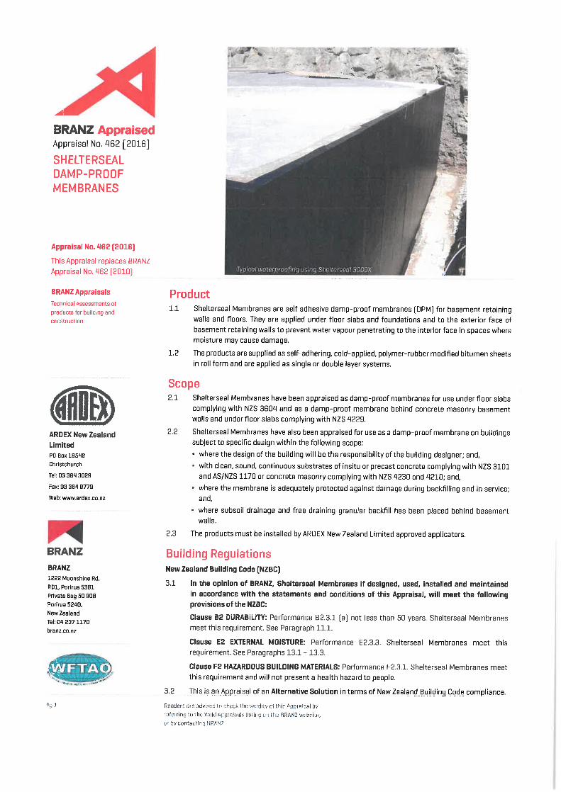


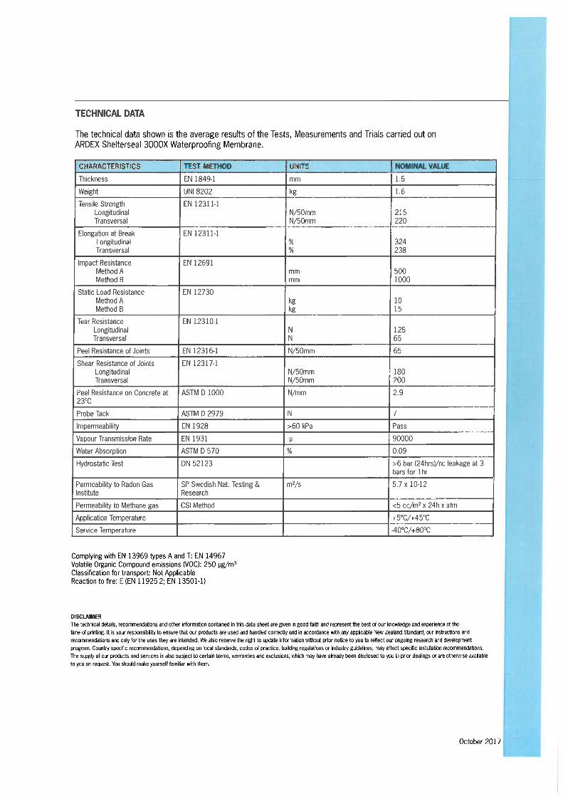

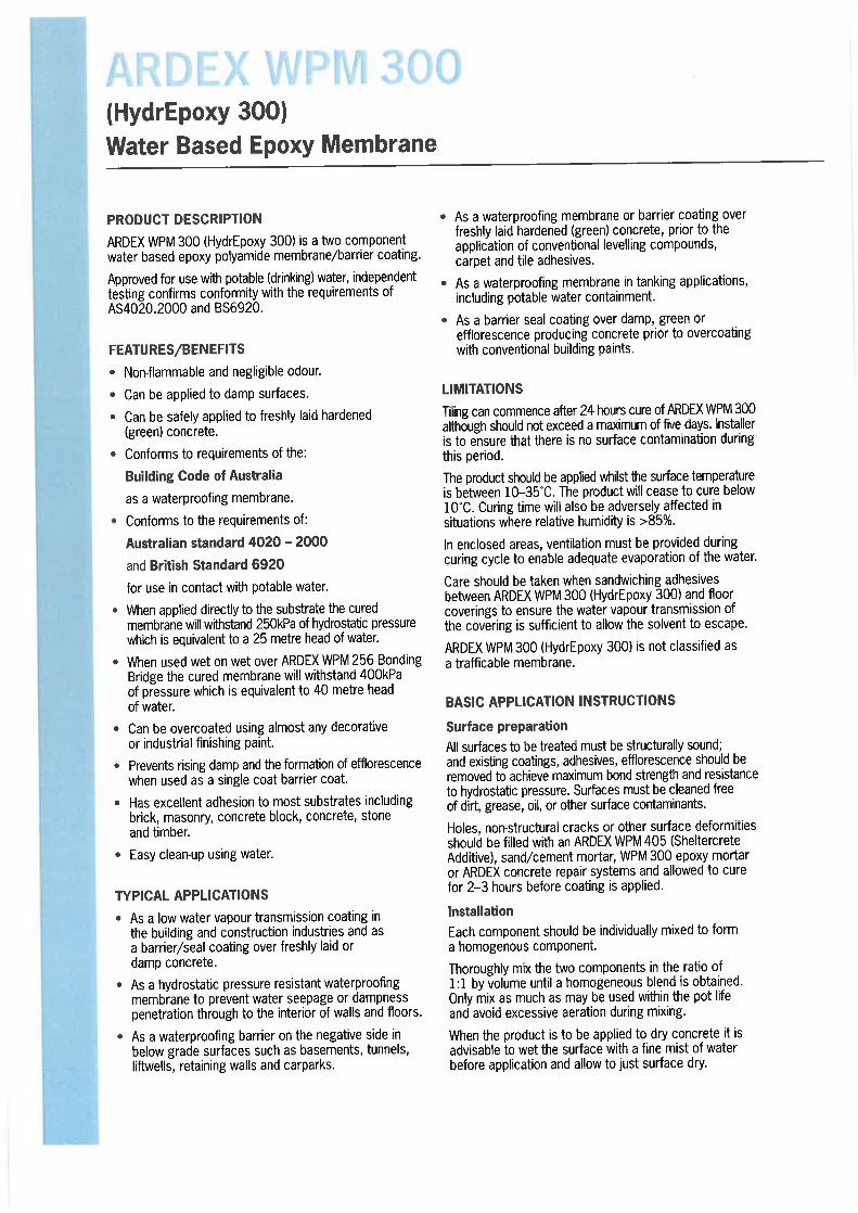
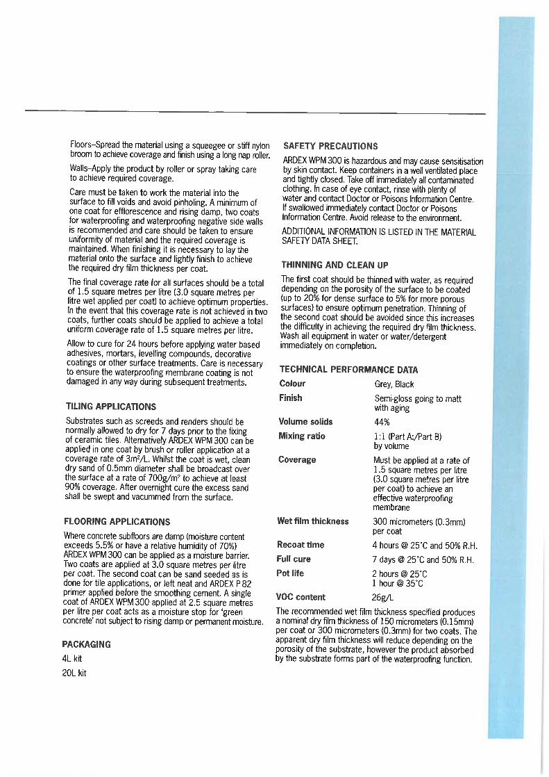


Page i
Proposed House Alterations
36 Omokoroa Road, Omokoroa
Structural Calculations
For Malcolm and Caron MacDonald
1 November 2018
Ref: 12509

Page ii
Contents Page
Timber retaining wall 1-2
Masonry retaining wall 3-5
Bearer check 6-7


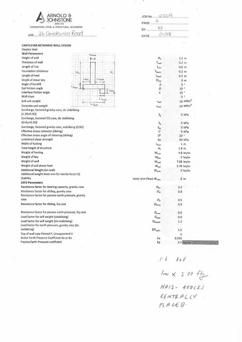

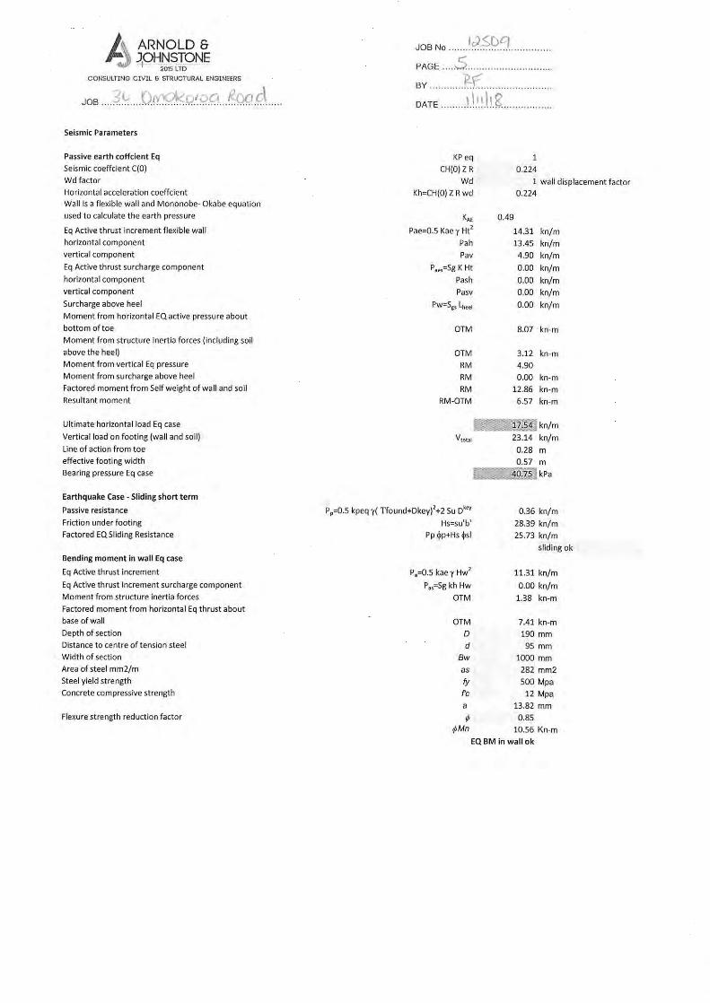

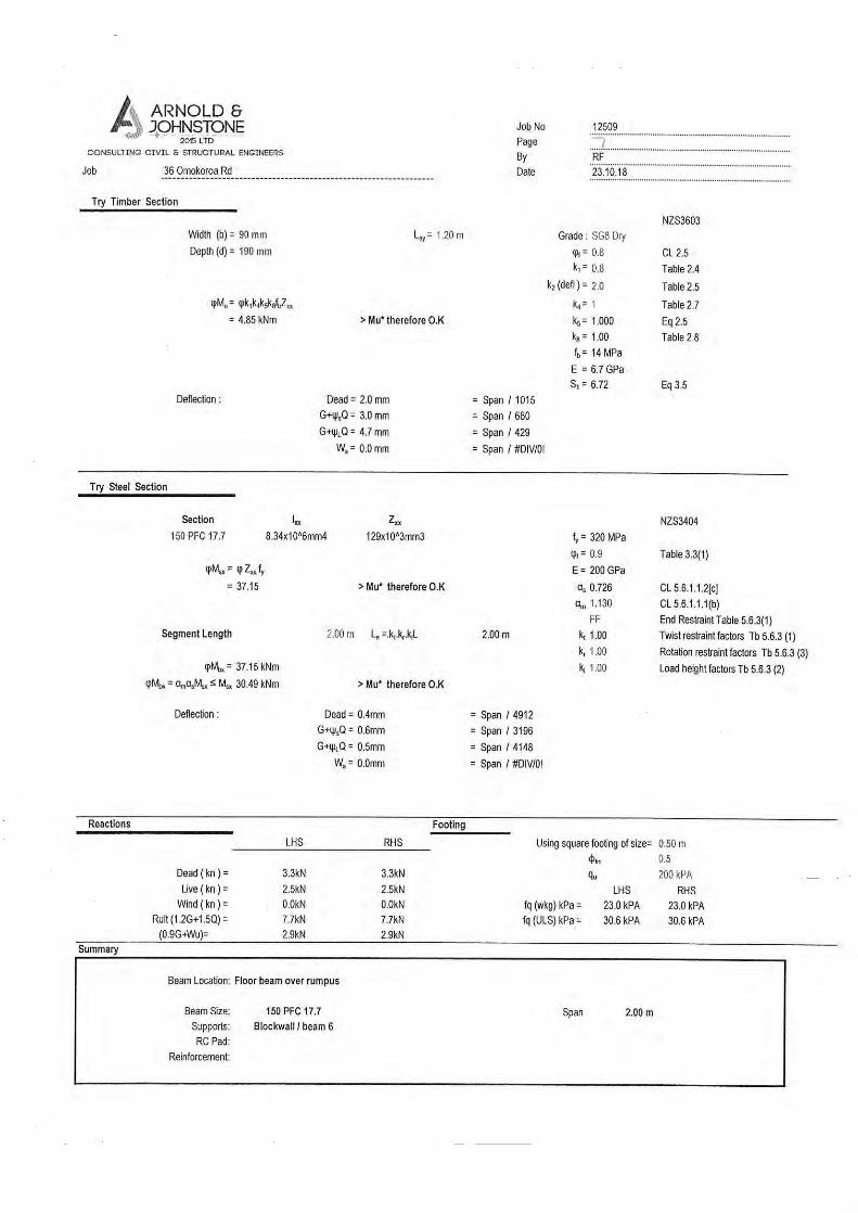

SPECIFICATIONof work to be done and materials to be used in carrying out the works shown on theaccompanying drawings
MacDonald AlterationsMacDonald Project Specification36 Omokoroa Road, Omokoroa, New ZealandProject Ref: GCG 2118
Printed: 30 October 2018
G C G Design Ltd
Specification built using Masterspec softwareProject ID: 165308 - 115050

TABLE OF CONTENTS1220 PROJECT1232 INTERPRETATION & DEFINITIONS1232S1 EXPLANATION OF SCHEDULE SECTIONS1233 REFERENCED DOCUMENTS1234 DOCUMENTATION1237 WARRANTIES1237S1 SCHEDULE OF WARRANTIES1270 CONSTRUCTION1270S1 SCHEDULE OF SAMPLES & PROTOTYPES1270S2 SCHEDULE OF SPARES & MAINTENANCE PRODUCTS3101 CONCRETE WORK - BASIC3321F FIRTH CONCRETE MASONRY3410 STRUCTURAL STEEL3820 CARPENTRY4131A ARDEX DAMP-PROOF MEMBRANES4161T THERMAKRAFT UNDERLAYS, FOILS & DPC4221TP TIMSPEC RADIATA PINE HORIZONTAL WEATHERBOARDS4231HH JAMES HARDIE® HARDIEFLEX™ SHEET CLADDING4521 ALUMINIUM WINDOWS AND DOORS4610MR METRO PERFORMANCE GLASS - RESIDENTIAL GLAZING4710K KNAUF INSULATION SYSTEMS4711KB KOOLFOAM BLACK PEARL® THERMAL INSULATION5113G GIB® PLASTERBOARD LININGS6700R RESENE PAINTING GENERAL6711R RESENE PAINTING EXTERIOR6721R RESENE PAINTING INTERIOR7123KP KEMPEX HOT & COLD WATER SYSTEM7421MO MARLEY OPTIM DWV SANITARY SYSTEM7701 ELECTRICAL BASIC
35789
14161726272832384347525763687680889197
103105108115120
Verified spec ID: 170497-115050This specification has been produced using Masterspec software and completed on 30/10/2018.Scan to verify or go to masterspec.co.nz/verify

1220 PROJECT
1 GENERAL
1.1 READ ALL SECTIONS TOGETHER
1.2 DESCRIPTION OF THE WORK
1.3 RESTRICTED BUILDING WORK
1.4 DESIGN CONSTRUCTION SAFETY MATTERS
1.5 PRINCIPAL'S KNOWN SITE HAZARDS
1.6 PRINCIPAL'S SITE HEALTH AND SAFETY PLAN
1.7 SITE
1.8 LEGAL DESCRIPTION
1.9 EXISTING BUILDINGS
This general section describes the project including:A description of the workDesign construction safetyPrincipal's Health & Safety mattersSite description, features and restrictionsDesign parameters for design by contractorArchaeological discovery
Read all general sections together with all other sections.
New Ensuite, Alter Bedrooms and Bathrooms
This project includes Restricted Building Work.
Design Construction Safety
The project has the following unusual or atypical features, which a reasonably experiencedcontractor may not be aware of, that may present an unexpected hazard or risk during a typicalconstruction process. ITEM COMMENTAsbestos wallcladding
Removal of existing cladding
Provide particular health and safety procedures and methods to mitigate these hazards or risks, andspecifically include them as well as any other health and safety matters in the site Health and SafetyPlan (refer to section 1260 PROJECT MANAGEMENT for Plan requirements). The Contractor isstill required to undertake its own assessment, to determine if they consider there are further safetymatters and provide for these in carrying out the construction of the work.
Principal's Health & Safety Matters
Site hazards known to the principal are:Asbestos based wall cladding
Obtain a copy of the principal's site health and safety plan.
Site
The site consists of: a 697 sqm residential siteAs shown on drawing: Sheet 1 of Drawings GCG 2118
The site of the works, the street address and the legal description are shown on the drawings.
Existing buildingsconsist of:
existing 3 storey dwelling
Refer drawing(s): Sheet 1 of Drawings GCG 2118
G C G Design Ltd MacDonald Alterations 165308
© CIL Masterspec Oct 2018 1220 PROJECT Page 3
1.10 EXISTING SERVICES
1.11 EXPOSURE ZONE
1.12 WIND DESIGN PARAMETERS - NON SPECIFIC DESIGN
1.13 EARTHQUAKE ZONE - NON SPECIFIC DESIGN
1.14 REPORT FINDING ANY ANTIQUITIES AND ITEMS OF VALUE
The following are the network utility services:Electrical: Communications: Water: Stormwater: existing to soak holesFoul water: existing The services are also shown on the drawings. Sheet 1 of Drawings GCG 2118
Site environment - Durability
The exposure zone is to NZS 3604, Section 4 Durability, 4.2 Exposure zones and NZBC E2/AS1.The site zone is: High
Site environment - Wind
The design wind pressures are to NZS 3604, Table 5.4 Determination of wind zone, up to andincluding Extra High Wind Zone.Building wind zone High (refer to NZS 3604, table 5.4)
Site environment - Seismic
The zone is to NZS 3604, Section 5 Bracing design, 5.3 Earthquake bracing demand.The earthquake zoneis:
Zone 1
Archaeological discovery
Report the finding of any fossils, antiquities and other items of value, to the Contract Administrator.All to remain undisturbed until approval is given for removal. Pre-1900, items or evidence of human activity on the site, come under the Heritage New ZealandPouhere Taonga Act 2014. If such items or evidence is discovered work must stop immediately andthe Contract Administrator must be notified immediately. The site may be classified as anArchaeological Site under the Act, and the Contract Administrator or Owner must contact theHeritage New Zealand for authority to proceed. Post-1900 items remain the property of the owner, pre-1900 items may remain the property of theowner or the Crown subject to what is found.
G C G Design Ltd MacDonald Alterations 165308
© CIL Masterspec Oct 2018 1220 PROJECT Page 4

1232 INTERPRETATION & DEFINITIONS
1 GENERAL
1.1 DEFINITIONS
1.2 PERSONNEL
This general section relates to definitions and interpretation that are used in this specification.
Definitions
Hold point: A stage of the construction where the contract administrator andany other nominated person requires notice to be given thatparticular work is to be carried out. Work may not proceed on thatparticular part until the contract administrator and any othernominated person has advised that work can continue. A noticeperiod of 2 Working Days is required unless stated otherwise.
Notification point: A stage of the construction where the contract administrator andany other nominated person requires notice to be given thatparticular work is to be carried out. Work may continue and thecontract administrator and any other nominated person maychoose whether or not they wish to witness the particular workbeing carried out. A notice period of 2 Working Days is requiredunless stated otherwise.
Product: A thing or substance produced by natural process or manufacture.Proprietary: Identifiable by naming the manufacturer, supplier, installer, trade
name, brand name, catalogue or reference number.Provide and fix: "Provide" or "fix" or "supply" or "fix" if used separately mean
provide and fix unless explicitly stated otherwise.Required: Required by the documents, the New Zealand Building Code or by
a statutory authority.Review: Review by the contract administrator and other consultants is for
general compliance only. Review does not remove the need forthe contractor to comply with the stated requirements, details andspecifications of the manufacturers and suppliers of individualcomponents, materials and finishes. Neither can the review beconstrued as authorising departures from the contract documents.
Working day: Working day means a calendar day other than any Saturday,Sunday, public holiday or any day falling within the period from 24December to 5 January, both days inclusive, irrespective of thedays on which work is actually carried out.
Workplace: Workplace means the place where work is being carried out, or iscustomarily carried out, for a business or undertaking including anyplace where a worker goes, or is likely to be, while at work (underHealth and Safety at Work Act 2015).
Principal: The person defined as "Principal" in the conditions of contract.Contractor: The person contracted by the principal to carry out the contract.Contract administrator: The person appointed by the principal to administer the contract on
the principal's behalf. Where no person has been appointed by theprincipal, it means the principal or the principal's representative.
G C G Design Ltd MacDonald Alterations 165308
© CIL Masterspec Oct 2018 1232 INTERPRETATION & DEFINITIONS Page 5

1.3 ABBREVIATIONS
1.4 DEFINED WORDS
1.5 WORDS IMPORTING PLURAL AND SINGULAR
The following abbreviations are used throughout the specification:AAMA American Architectural Manufacturers AssociationAS Australian StandardAS/NZS Joint Australian/New Zealand StandardASTM American Society for Testing and MaterialsAWCINZ Association of Wall and Ceiling Industries of New Zealand Inc.BCA Building Consent AuthorityBRANZ Building Research Association of New ZealandBS British StandardCOP Code of practiceCSIRO Commonwealth Scientific and Industrial Research OrganisationHERA Heavy Engineering Research AssociationLBP Licensed Building PractitionerMBIE Ministry of Business, Innovation and EmploymentMPNZA Master Painters New Zealand Association IncNZBC New Zealand Building CodeNZS New Zealand StandardNZS/AS Joint New Zealand/Australian StandardNZTA New Zealand Transport AgencyNUO Network Utility OperatorOSH Occupational Safety and HealthPCBU Person Conducting a Business or Undertaking (under Health and
Safety at Work Act 2015)RBW Restricted Building WorkSARNZ Scaffolding and Rigging New Zealand IncSED Specific Engineering DesignTA Territorial AuthorityTNZ Transit New Zealand (Transit New Zealand is now New Zealand Transport Agency NZTA
- some specifications are still prefixed TNZ)
Words defined in the conditions of contract, New Zealand Standards, or other reference documents,to have the same interpretation and meaning when used in their lower case, title case or upper caseform in the specification text.
Where the context requires, words importing singular only, also include plural and vice versa.
G C G Design Ltd MacDonald Alterations 165308
© CIL Masterspec Oct 2018 1232 INTERPRETATION & DEFINITIONS Page 6

1232S1 EXPLANATION OF SCHEDULE SECTIONS
1 GENERAL
1.1 EXPLANATION OF SCHEDULE SECTIONS
1.2 SCHEDULE SECTIONS
This General section provides an explanation of Schedule sections and their relationship to Generalsections and Work sections. Specific Schedule sections contained within this specification are alsoidentified.
A schedule section identifies Work sections that contain common requirements, as identified in thetitle of the Schedule section. For example 1235S1 SCHEDULE OF SHOP DRAWINGS identifiesWork sections that have requirements for shop drawings. Details of the requirements are containedin the identified Work sections with additional requirements contained in the General section 1235SHOP DRAWINGS. A Schedule section is identified by the 4 digit CBI (Co-ordinated Building Information) number of theGeneral section that it relates to, followed by the letter "S" followed by a numeral (1-9). The numeralallows for multiple schedule sections to be associated with the same General section.
The following Schedule sections are contained within the specification:1237S1 Schedule of Warranties 1270S1 Schedule of Samples & Prototypes 1270S2 Schedule of Spares & Maintenance Products
G C G Design Ltd MacDonald Alterations 165308
© CIL Masterspec Oct 2018 1232S1 EXPLANATION OF SCHEDULE SECTIONS Page 7
1233 REFERENCED DOCUMENTS
1 GENERAL
1.1 REFERENCED DOCUMENTS
1.2 DOCUMENTS
Throughout this specification, reference is made to various New Zealand Building Code ComplianceDocuments (NZBC __), acceptable solutions (__ AS_) and verification methods (__ VM_) for criteriaand/or methods used to establish compliance with the New Zealand Building Code. Reference is also made to various standards produced by Standards New Zealand (NZS, AS/NZS,NZS/AS), overseas standards and to listed Acts, Regulations and various industry codes of practiceand practice guides. The latest edition (including amendments and provisional editions) at the dateof this specification applies unless stated otherwise. It is the responsibility of the contractor to be familiar with the materials and expert in the techniquesquoted in these publications. Documents cited both directly and within other cited publications are deemed to form part of thisspecification. However, this specification takes precedence in the event of it being at variance withthe cited documents.
Documents referred to in the GENERAL sections are: NZBC F5/AS1 Construction and demolition hazardsAS/NZS 1170.2 Structural design actions - Wind loadsNZS 1170.5 Structural design actions - Earthquake actions - New ZealandAS/NZS 3012 Electrical installations - Construction and demolition sitesNZS 3109 Concrete constructionNZS 3114 Specification for concrete surface finishesNZS 3602 Timber and wood-based products for use in buildingNZS 3604 Timber-framed buildingsNZS 4210 Masonry construction: Materials and workmanshipAS/NZS 5131 Structural steelwork - Fabrication and erectionNZS 6803 Acoustics - Construction NoiseBuilding Act 2004Building Regulations 1992Health and Safety at Work Act 2015Health and Safety at Work (General Risk and Workplace Management) Regulations 2016Health and Safety at Work (Hazardous Substances) Regulations 2017Health and Safety in Employment Regulations 1995New Zealand Building CodeHeritage New Zealand Pouhere Taonga Act 2014Resource Management Act 1991Smoke-free Environments Act 1990WorkSafe NZ Guidelines for the provision of facilities and general safety in the
construction industryWorkSafe NZ Good Practice Guidelines - Excavation SafetyWorkSafe NZ Scaffolding in New Zealand - Good Practice Guidelines
G C G Design Ltd MacDonald Alterations 165308
© CIL Masterspec Oct 2018 1233 REFERENCED DOCUMENTS Page 8

1234 DOCUMENTATION
1 GENERAL
1.1 BUILDING CONSENT
1.2 BUILDING CONSENT COMPLIANCE
1.3 PROJECT PERSONNEL
This general section relates to documentation required by the Territorial Authority / Building ConsentAuthority for compliance with the New Zealand Building Code. It also includes documentationrelating to:
SubstitutionsManufacturers' documentsBranded work sectionsCare of construction documentsConfidentiality of documentsReceipt of construction documents
Building Consent Authority documentation
Obtain the original building consent forms and documents from the owner and keep them on site,preserve the condition of consent forms and documents. Liaise with the building consent authorityfor all notices to be given and all inspections required during construction to ensure compliance. Return the consent form and documents to the owner on completion.
It is an offence under the Building Act 2004to carry out any work not in accordance with the building consent.to carry out Restricted Building Work by anyone other than a Licensed Building Practitionerlicensed for that type of work.
The resolution of matters concerning building code compliance to be referred to the contractadministrator for a direction and then if required to the BCA for consent. Where any alteration is requested by the territorial authority or any other authority, do not undertakesuch alteration until the matter has been referred to the contract administrator for direction.
Provide names and contact details of the contractor's key personnel and tradespersons who areinvolved with the project. Review the list once a month and reissue it if changes have been made.
Licensed Building Practitioner documentation
G C G Design Ltd MacDonald Alterations 165308
© CIL Masterspec Oct 2018 1234 DOCUMENTATION Page 9

1.4 LICENSED BUILDING PRACTITIONERS
1.5 RECORD OF WORK
1.6 DOCUMENTATION REQUIRED FOR CODE COMPLIANCE
1.7 PRODUCER STATEMENTS
1.8 CHECKLIST
1.9 DISCLOSURE STATEMENT
Provide LBP details. Provide names, LBP numbers, areas of practice and contact information. Provide this information to the BCA before commencing work on the Restricted Building Work in theform required by the BCA. Advise the BCA of any change to an LPB previously advised. Include the following as applicable
Site LBPCarpenterFoundations 1 Concrete foundation walls and concrete slab-on-ground constructorFoundations 2 Concrete or timber pile foundations constructorBricklaying and block laying 1 Brick / masonry veneerBricklaying and block laying 2 Structural masonry - Bricklayer / BlocklayerRoofing 1 Concrete / clay tile rooferRoofing 2 Profiled metal roofer and/or wall cladding installerRoofing 3 Metal tile rooferRoofing 4 Membrane rooferRoofing 5 Torch on membrane rooferRoofing 6 Liquid membrane rooferRoofing 7 Shingle / slate rooferExternal plastering 1 Solid plastererExternal plastering 2 Proprietary Plaster Cladding Systems (PPCS) plasterer
Also provide names and contact details of the following
Registered drainlayerRegistered plumberRegistered gasfitterRegistered electrician
Where Restricted Building Work is carried out by a LBP, on completion provide a Record of Work. Provide copies to both the BCA and the Contract Administrator.
Compliance information
Information may be required either as a condition of the contract documents or as a condition of thebuilding consent. It may include the following:
Applicators approval certificate from the manufacturer / supplierManufacturer's / supplier's warrantyInstaller / applicator's warrantyProducer Statement (PS1) - DesignProducer Statement (PS3) - Construction from the applicator / installerProducer Statement (PS4) - Construction review from an acceptable suitably qualified person
Refer to the general sections for the requirements for compliance information to be provided by thecontractor. Refer to the building consent for the requirements for compliance information to be provided by thecontractor. Obtain required documents from the relevant parties for delivery to the contract administrator afterthe final inspection has been carried out by the BCA.
When producer statements verifying construction are required, provide copies to both the BuildingConsent Authority and the Contract Administrator. Provide producer statements in the form requiredby the BCA.
Residential building contract
If requested provide evidence of the prescribed checklist given to the residential client.
If requested provide evidence of the disclosure statement given to the residential client.
G C G Design Ltd MacDonald Alterations 165308
© CIL Masterspec Oct 2018 1234 DOCUMENTATION Page 10
1.10 BUILDING CONTRACT
1.11 DOCUMENTATION REQUIRED ON COMPLETION
1.12 ACCEPTABLE PRODUCT/MATERIAL SUPPLIERS
1.13 NO SUBSTITUTIONS
1.14 PROPOSED SUBSTITUTIONS
1.15 NOTIFICATION OF SUBSTITUTIONS
1.16 ACCEPTANCE OF SUBSTITUTIONS
If requested provide evidence of the written building contract that the residential customer hassigned.
As soon as practicable after completion of the building work, provide in writing the followinginformation and documentation to the client and the relevant territorial authority. Information and documentation relating to:
The identity of the building contractor and the subcontractors who carried out the work.Maintenance requirements for any products incorporated in the building.
If applicable also provide any guarantee or insurance obtained by the building contractor in relationto the building work.
Substitutions
Where a product or material supplier is named in SELECTIONS, the product/material must beprovided by the named supplier. Where more than one named supplier, any one of the namedsuppliers will be acceptable.
Substitutions are not permitted to any of the specified products and systems listed in a sectionunless specified otherwise. If a product is not available then immediately contact the contractadministrator for direction.
Substitution of products or systems contained within branded work sections is not allowed. Thecontractor may propose substitutions to products within non branded work sections, when thecontractor has determined that the proposed substitution is an alternative to the specified product. The Contract administrator is not bound to accept any substitutions. Submit a draft proposaldetailing the substitution to the contract administrator before proceeding with full notification.
Notify the contract administrator of proposed substitution of specified products. Notification toinclude but not be limited to:
Product identificationManufacturer's name, address, telephone number, website and email addressDetailed comparison between the properties and characteristics of the specified product andthe proposed substitutionStatement of NZBC compliance including durabilityDetails of manufacturer warranties
Plus an assessment of:
Any changes required to the programme including any extension of time requiredAny consequential effects of the proposed substitutionAny effect the substitution may have on Health & Safety requirementsAllowance for time and cost for re-design and documentation (if applicable)Allowance for time and cost for obtaining an amendment to the Building Consent (ifapplicable)Any change in cost associated with the proposed substitution
and if requested:
All current manufacturer's literature on the productAccreditations and appraisals availableReference standardsProduct limitationsSamplesList of existing installations in the vicinity of the project
Acceptance of any proposed substitutions will be given in writing by the contract administrator.
Amendments to issued Building Consent
G C G Design Ltd MacDonald Alterations 165308
© CIL Masterspec Oct 2018 1234 DOCUMENTATION Page 11
1.17 CONTRACTOR AMENDMENTS TO BUILDING CONSENT
1.18 PRINCIPAL AMENDMENTS TO BUILDING CONSENT
1.19 MANUFACTURER'S AND SUPPLIER'S INSTALLATION REQUIREMENTS
1.20 CONTRACTOR TO OBTAIN CURRENT DOCUMENTATION
1.21 DOCUMENTATION PROVIDED FOR BUILDING CONSENT
1.22 BRANDED PRODUCTS / SYSTEMS
1.23 CROSS REFERENCED WORK SECTIONS
1.24 CONSTRUCTION ISSUE
1.25 REVISIONS TO CONSTRUCTION ISSUE
Where the contractor has sought acceptance of a substitution or a variation which is for thecontractor's own convenience and the substitution or variation requires an amendment to theBuilding Consent, the contractor must apply for and obtain the required amendment. The contractor must:
Obtain approval for substitutions from the contract administrator.Prepare and provide to the BCA all documentation required for the amendment.Pay all fees and other costs associated with this amendment.Where the amendment affects other approved plans, also amend those plans.
Where the principal is proposing a substitution or a variation which requires an amendment to theBuilding Consent, the contractor must provide to the principal information that the contractor has thatis required for the amendment. The principal will:
Prepare and provide to the BCA all documentation required for the amendment.Pay all fees and other costs associated with this amendment.Where the amendment affects other approved plans, also amend those plans.
Manufacturer's documents
Manufacturer's and supplier's requirements, instructions, specifications or details mean those issuedby them for their particular product, material or component and are the latest edition.
Where manufacturer’s installation, application and execution requirements are referred to in thisspecification, the Contractor must ensure they are fully aware of this documentation. Whenevernecessary obtain and keep on site the relevant latest version of such documentation and make itavailable to workers carrying out that part of the work.
Documentation including manufacturer’s installation instructions, specification data sheets, producerstatements, BRANZ and similar appraisals may be included in the issued Building Consent. Thesedocuments have been provided only to demonstrate compliance with the NZBC.
Branded work sections
Where branded products and systems are specified, all products and components of the systemmust be as per the specification.
If any related work is cross referenced to a generic work section, but only the equivalent brandedsection is included in the specification, use that branded section. Confirm with the contractadministrator if there is any doubt.
Care of construction documents
Take receipt of the plans, specifications and other documents issued “for construction”. Keep atleast one copy on site available for use by all on site workers. Keep a record of copies provided toothers including subcontractors. Protect the documents as appropriate. Obtain replacement copiesfor documents that have become damaged.
Where revised plans and other documents are issued ensure that superseded documents aredeleted from the working sets. Ensure that subcontractors are provided with amended documents. Delete superseded documents by either:
removing them from the working copy of the construction issue; ormarking them as superseded
G C G Design Ltd MacDonald Alterations 165308
© CIL Masterspec Oct 2018 1234 DOCUMENTATION Page 12

1.26 RETURN DOCUMENTS ISSUED FOR CONSTRUCTION
1.27 CONFIDENTIALITY OF DOCUMENTS
2 SELECTIONS
2.1 INITIAL ISSUE & REVISIONS - HARD COPIES
2.2 DOCUMENT RECEIPT - HARD COPIES
2.3 DOCUMENT RECEIPT - ELECTRONIC DOCUMENTS
On completion of the contract works:Keep such copies of the plans, specification and other documents as reasonably required forcontractor’s record purposes.Retrieve all other copies no longer required by parties.Agree method of disposal of such documents with the Contract Administrator.
The Contract Administrator will advise whether such documents shall be:
delivered to the Contract Administrator/Owner; ordisposed of by normal waste disposal methods; ordisposed of by secure document disposal methods.
Confidentiality of documents
Documents shall not be given or copied to others who do not require them for carrying out servicesrequired for the construction of the works. Documents are only to be used for the contract. Maintainconfidentiality of documents.
Receipt of construction documents
Initial issue: 1 at full size, 1 at reduced size Revisions: 1 at full size, 1 at reduced size
Hard copies of plans, specifications and other documents issued for construction shall be collectedfrom GCG Design Ltd. 79b Beach Rd, Otumoetai, Tauranga
Electronic documents issued for construction shall beObtained as an email attachment sent to an agreed address.
G C G Design Ltd MacDonald Alterations 165308
© CIL Masterspec Oct 2018 1234 DOCUMENTATION Page 13
1237 WARRANTIES
1 GENERAL
1.1 SCHEDULE SECTION
1.2 PROVIDE WARRANTIES
1.3 WARRANTIES - INSTALLER/APPLICATOR
1.4 WARRANTIES - MANUFACTURER/SUPPLIER
1.5 REVIEW BY CONTRACTOR
This general section refers to the requirements for warranties/guarantees, referred to within thisspecification and referred to within separate specifications/documents relating to this project. Itincludes:
Warranties for parts of the work required by the principal in a required formInstaller/applicator warranties for parts of the work in the installer's/applicator's standard formManufacturer/supplier warranties provided with products, appliances and the like in themanufacturer's/supplier's standard formGuarantees provided by contractor in the contractor's standard form
These guarantees/warranties are in addition to any warranties, implied warranties, or guaranteesthat are required by the Building Act, the Building Regulations, or the building consent.
Refer to 1237S1 SCHEDULE OF WARRANTIES for work sections contained in this specificationthat have requirements for warranties.
Warranties
Provide executed warranties in favour of the principal in respect of, but not limited to, materials,components, service, application, installation and finishing called for in that specified section ofwork. The terms and conditions of the warranty in no case negate the minimum remedies availableunder common law as if no warranty had been offered. Failure to provide the warranty does notreduce liability under the terms of the warranty called for in that specified section of work.
Conform to the WARRANTY AGREEMENT form included in the specification/conditions ofcontract.Commence warranties from the date of practical completion of the contract works (unlessotherwise stated).Maintain their effectiveness for the times stated.Provide executed warranties prior to practical completion.
Where installer/applicator warranties are offered covering execution and materials of proprietaryproducts or complete installations, provide such warranties to the contract administrator. Thesewarranties may be provided in lieu of the warranties that are otherwise required provided that thesewarranties are subject to similar conditions and periods. Provide warranties in favour of the principal. The terms and conditions of such warranties in nocase negate the minimum remedies available under common law as if no warranty had beenoffered. Failure to provide the warranty does not reduce liability for execution and materials for thatpart of the work.
Where warranties are offered covering materials, equipment, appliances or proprietary products,provide all such warranties to the contract administrator. Provide warranties in favour of the principal. The terms and conditions of such warranties in nocase negate the minimum remedies available under common law as if no warranty had beenoffered. Failure to provide the warranty does not reduce liability for execution and materials for thatpart of the work.
Submission
Obtain the warranties from the installers, applicators, manufacturers and suppliers at the earliestpossible date and review to ensure that they are correctly filled out and executed. Where warrantiesare executed as a deed, ensure that a duplicate copy is provided for execution by theowner/principal. Keep safe and secure until required for submission.
G C G Design Ltd MacDonald Alterations 165308
© CIL Masterspec Oct 2018 1237 WARRANTIES Page 14
1.6 WARRANTIES - REQUIRED BY BUILDING CONSENT AUTHORITY
1.7 WARRANTIES - REQUIRED BY CONTRACT
1.8 WARRANTIES - SUBMISSION NZS3910:2013 CONTRACT
2 SELECTIONS
2.1 MASTER BUILD SERVICES LTD - 10 YEAR KIWI GUARANTEE
2.2 WEATHERTIGHTNESS AND WATERTIGHTNESS WARRANTY
Obtain copies of warranties required as a condition of the building consent in the form required forsubmission to the BCA. Keep safe and secure until required at the time of the BCA final inspectionand Code Compliance Certificate.
Obtain copies of warranties listed in the contract documents. Provide all warranties at the sametime. If the project has an operations and maintenance documentation provision, present thewarranties with the operations and maintenance information. If no operations and maintenancedocumentation provision exists, present the warranties to the contract administrator in a loose-leafbinder with a contents index suitably labelled and including the project name and details. Provide atitle on the binder edge "Warranties for (project name)"
Refer to NZS 3910 Conditions of Contract for building and civil engineering construction, clauses11.5 and 11.6 for requirements relating to the time for submission of warranties and guarantees.Submit all warranties/guarantees to the engineer no later than the date that the contractor notifiesthat it believes the contract works qualify for practical completion.
Project warranties / guarantees
Guarantees - Contractor - Master Build Services Ltd
Provide a 10 Year Kiwi Guarantee, include all costs in the contract price. Detach the guaranteeapplication form from the guarantee agreement. Complete the form, obtain all required signatures(builder and owner). Send the completed form to Master Build Services for approval along with acopy of the building contract (include a full scope of work for any addition/alteration work), prior toany work commencing. Obtain the Master build Services acceptance letter and provide this to theowner along with the guarantee document. On completion of the building work complete the noticeof practical completion form, obtain all required signatures (builder and owner) and forward the formto Master Build Services.
Weathertightness and watertightness warranty
A warranty is required from the contractor for a minimum period of 2 years, covering theweathertightness of the complete building envelope and the watertightness of all liquid supply anddisposal systems and fittings. This general warranty is in addition to any specific warrantiesrequired. Provide this warranty in favour of the principal. The terms and conditions of this warranty in no casenegate the minimum remedies available under common law as if no warranty had been offered. Failure to provide the warranty does not reduce liability for execution and materials for that part ofthe work.
Conform to the standard form WARRANTY AGREEMENT included in the contract documents.Commence the warranty from the date of Practical Completion.Maintain its effectiveness for the time stated.
G C G Design Ltd MacDonald Alterations 165308
© CIL Masterspec Oct 2018 1237 WARRANTIES Page 15

1237S1 SCHEDULE OF WARRANTIES
1 GENERAL
1.1 ASSOCIATED SECTIONS
1.2 WARRANTIES
1.3 PROJECT WARRANTIES
1.4 WARRANTIES - ADDITIONAL ITEMS
This schedule section identifies work sections in the specification that have requirements forwarranties.
Read in conjunction with:1232S1 EXPLANATION OF SCHEDULE SECTIONS1237 WARRANTIESIdentified Work Sections
Warranties
Refer to the following sections:4131A Ardex Damp-Proof Membranes 4161T Thermakraft Underlays, Foils & DPC 4231HH James Hardie® Hardieflex™ Sheet Cladding 4521 Aluminium Windows & Doors 4610MR Metro Performance Glass - Residential Glazing 4710K Knauf Insulation Systems 4711KB Koolfoam Black Pearl Thermal Insulation 6700R Resene Painting General 7123KP KemPex Hot & Cold Water System 7421MO Marley Optim DWV Sanitary System 7701 Electrical Basic
Refer to section 1237 WARRANTIES for project warranties.
Refer to separate documentation for warranties not contained within this specification.
G C G Design Ltd MacDonald Alterations 165308
© CIL Masterspec Oct 2018 1237S1 SCHEDULE OF WARRANTIES Page 16

1270 CONSTRUCTION
1 GENERAL
1.1 SCHEDULE SECTION
1.2 QUALITY ASSURANCE
1.3 PROVIDE QUALITY PLAN
This GENERAL section relates to common requirements for construction issues including:
Quality control and assuranceNoise and nuisanceSet-out and tolerancesCommon execution requirementsQualificationsCommon product requirementsCommon requirements for samples and prototypesCommon requirements for spare and maintenance productsCleaning during the worksRemoval of protectionCompletion requirementsCommissioningPractical completion submissionDefects period submissionsCompletion submissions
Refer to 1270S1 SCHEDULE OF SAMPLES & PROTOTYPES for work sections contained in thisspecification that have requirements for samples and prototypes. Refer to 1270S2 SCHEDULE OF SPARES & MAINTENANCE PRODUCTS for work sectionscontained in this specification that have requirements for spares and maintenance products.
Quality control and assurance
Carry out and record regular checks of material quality and accuracy, including:Concrete quality and finish.Dimensional accuracy of structural column locations (following completion of foundations).All perimeter columns and frames for plumb.Levels of all floors relative to the site datum.Framing timber moisture content.
Where any material, quality or dimension falls outside specified or required tolerances, obtainwritten direction from the contract administrator. Where building consent approval is affected,confirm remedial action with the Building Consent Authority. Provide all materials, plant, attendances, supervision, inspections and programming to ensure therequired quality standards are met by all project personnel.
Prepare a quality plan for the execution of the contract works and submit a copy of the quality planto the Contract Administrator within 10 Working Days of the date of award of the contract. Thequality plan shall describe the procedures for meeting the requirements of the contract in respect of:
Materials and workmanshipMonitoring and maintaining subcontractors’ performanceRecord keepingThe level of documentation for signing off the contract works as completeProcedures to ensure that all persons engaged in undertaking the contract works arequalified, experienced and trained for the work they are undertakingInspection and testing required by the contractAuditing the quality plan
G C G Design Ltd MacDonald Alterations 165308
© CIL Masterspec Oct 2018 1270 CONSTRUCTION Page 17

1.4 REVIEW OF QUALITY PLAN
1.5 COMMENCEMENT OF WORK
1.6 NOTICE
1.7 NOTIFIABLE WORK
1.8 LIMIT CONSTRUCTION NOISE
1.9 ACCEPTABLE NOISE LEVELS
1.10 PROVIDE INFORMATION TO NEIGHBOURS
1.11 INCONVENIENCE TO OTHERS
1.12 ROADWAY AND FOOTPATH
Within 5 working days of the contractor submitting a quality plan to the contract administrator forreview, the contract administrator may advise that:-they have completed their final review, or-that they have undertaken a review and require resubmission of the quality plan. Review by the contract administrator of the quality plan does not make the quality plan a contractdocument. The contractor at all times remains responsible for the construction of the Works. Ifresubmission of a quality plan is required, the contract administrator will give their reasons. Thecontractor shall take account of the reasons and resubmit a revised quality plan within a period of 5working days.
Do not commence any part of the contract works, other than establishment, setting out and sitepreparation until the contract administrator has completed their final review of the quality plan.
Give notice to the contract administrator and any other nominated person of hold points andnotification points. Refer to work sections and 1260 PROJECT MANAGEMENT for hold points andnotification points required.
Lodge notice of the intention to commence any notifiable work and any work that will at any timeinclude any notifiable work, in accordance with Health and Safety in Employment Regulations 1995.
Noise and nuisance
Minimise the effects of noise generation by including in the planning of the work such factors asplacing of plant, programming the sequence of operations and other management functions. Limitconstruction noise to comply with the requirements of NZS 6803, the requirements of the ResourceManagement Act sections 326, 327 and 328 and the Health and Safety in Employment Regulations1995 clause 11.
Refer to NZS 6803 Tables 2 and 3 for the upper limits of construction work noise received inresidential zones, dwellings in rural areas, industrial areas and commercial areas, note also theallowed adjustments. Do not exceed these limits or any limits imposed by regional councils orterritorial authorities.
Provide information to neighbours of any noise generation from the site liable to constitute aproblem. Explain to them the means being used to minimise excessive noise and establish withthem the timings most suitable for the noise generating work to be carried on. Discuss with any complainant the measures being used to minimise noise. Where possible modifythese measures to accommodate particular circumstances. Finally, determine the sound level at thelocation under discussion using methods and observation reporting as laid down in NZS 6803. If thenoise level is above the upper limits of NZS 6803, table 2 and table 3, cease the noise generatingoperation and remedy the problem.
When the works are to be carried out in or around occupied premises, ascertain the nature andtimes of occupation and use. Carry out the works in a manner to minimise inconvenience, nuisanceand danger to occupants and users.
Keep the adjacent footpath and road clear at all times. Where work must be carried out in theroadway or footpath, obtain required consents from the territorial authority. Where temporary use ismade of the footpath or roadway for deliveries and the like ensure that public safety is protected andthe goods and materials moved as soon as practicable. Sweep, wash and otherwise clean theroadway/footpath and restore it to its previous condition.
G C G Design Ltd MacDonald Alterations 165308
© CIL Masterspec Oct 2018 1270 CONSTRUCTION Page 18

1.13 VEHICLE CROSSING
1.14 DIRT AND DROPPINGS
1.15 DAMAGE AND NUISANCE
1.16 SMOKE FREE REQUIREMENTS
1.17 RESTRICTIONS
1.18 SURVEY INFORMATION
1.19 DATUM
1.20 SET-OUT
1.21 USE OF SET-OUT INSTRUMENTS
1.22 CHECK DIMENSIONS
Make good damage that has occurred as a result of carrying out the contract works. Where therehas been significant damage, contact the territorial authority and obtain instructions for makinggood. Pay the territorial authority costs associated with making good.
Remove dirt and droppings deposited on public or private thoroughfares from vehicles servicing thesite to the satisfaction of the appropriate authorities and the contract administrator.
Take precautions to prevent damage and nuisance from water, fire, smoke, dust, rubbish and allother causes resulting from the construction works.
In accordance with the Smoke Free Environments Act 1990 smoking is not allowed on site.
Do not:light rubbish fires on the site.bring dogs on to or near the site.bring radios/audio players on to the site.
Set-out and tolerances
Locate and verify survey marks and datum points required to set out the works. Where these do notexist or cannot be located advise the contract administrator who will arrange for the required pointsto be established. Record and maintain their position. Re-establish and replace disturbed or obliterated marks.
Establish a permanent site datum to confirm the proposed levels and their relationship to all otherexisting and new levels.
Set out the work to conform with the drawings.
Permit without charge, the use of instruments already on site for checking, setting out and levels.
Check all dimensions both on drawings and site, particularly the correlation between componentsand work in place. Take all dimensions on drawings to be between structural elements beforelinings or finishes, unless clearly stated otherwise.
G C G Design Ltd MacDonald Alterations 165308
© CIL Masterspec Oct 2018 1270 CONSTRUCTION Page 19
1.23 TOLERANCES
1.24 EXAMINE PREVIOUS WORK
1.25 REPORT DEFECTIVE PREVIOUS WORK
1.26 EXECUTION GENERALLY
1.27 EXECUTION - NO DETAIL IS PROVIDED
1.28 EXECUTION - ACCEPTABLE SOLUTION IS REFERRED TO
1.29 MINIMISE DELAYS DUE TO WEATHER
1.30 DEFECTIVE OR DAMAGED WORK
All work to be level, plumb, and true to line and face. Unless otherwise specified in specific worksections of this specification, tolerances for structural work shall comply with the following: Concreteconstruction:
To NZS 3109 Concrete constructionClause 3.9 Tolerances for reinforcementTable 5.1 Tolerance for precast componentsTable 5.2 Tolerance for in situ constructionTo NZS 3114 Concrete surface finishes
Masonryconstruction:
To NZS 4210 Masonry construction: Materials and workmanshipClause 2.6.5 TolerancesTable 2.2 Maximum tolerances
Structural steelwork: To NZS 3404.1:1997 Steel structures standardSection 14.4 Tolerances (after fabrication)Section 15.3 Tolerances (erection)
Timber framing: To NZS 3604 Timber-framed buildingsClause 2.2 TolerancesTable 2.1 Timber framing tolerances
Refer to work sections for tolerance requirements for finishes.
Execution
Before commencing any part of the work carefully examine the previous work on which it depends,to ensure it is of the required standard.
Refer defects to the contractor to be remedied, if the remedy is outside the scope of the contractdocuments the contractor shall obtain direction from the contract administrator. Do not carry outwork over previous work that is defective and will affect the required standard.
Construct the work in accordance with the documents issued for construction including any directionthat may have been given by the contract administrator that varies the construction document.
The documents issued for construction will not include all details relating to every material, junctionand interface with other materials. Where the detail provided is of a general nature, or where no detail is provided, refer to themanufacturer's documents for information relating to installation and execution of that part of thework. Where there is more than one method or detail appropriate to the part of the work in question, referthe options to the Contract Administrator for direction as to which detail or method to use.
Where a NZBC Acceptable Solution is referred to in the specification but not shown on the plans,obtain a copy of that Acceptable Solution and make it available to the workers carrying out that partof the work.
Use appropriate techniques and methods to prevent damage and minimise delays due to weather.
Defective or damaged work
Repair defective, damaged and marked elements, or replace them where repair is not possible orwill not be acceptable. Adjust operation of equipment and moving parts not working correctly. Referto individual work sections for any special requirements.
Qualifications
G C G Design Ltd MacDonald Alterations 165308
© CIL Masterspec Oct 2018 1270 CONSTRUCTION Page 20

1.31 QUALIFICATIONS GENERALLY
1.32 QUALIFICATIONS – RESTRICTED BUILDING WORK
1.33 QUALIFICATIONS – APPROVED/LICENSED APPLICATORS/INSTALLERS
1.34 QUALIFICATIONS – WORKERS LICENSED UNDER STATUTE
1.35 QUALIFICATIONS – PRODUCER STATEMENTS
1.36 REPLACEMENT OF PERSON
1.37 NEW PRODUCTS
1.38 COMPATIBILITY OF PRODUCTS
1.39 DELIVERY, STORAGE & HANDLING OF PRODUCTS
1.40 SUBSTRATE CONDITIONS
The work is to be carried out by workers (trades people, installers and applicators) who areexperienced, competent and familiar with the materials and the techniques specified. Workers mustalso be familiar with the manufacturers' and suppliers' installation and application instructions andstandard details provided by them in relation to the use of the products for this project. If requestedprovide evidence of qualification / experience.
Where restricted building work forms part of the contract works, workers, or supervisors of that workmust be licensed building practitioners holding current licenses for the particular restricted buildingwork.
Where required by a manufacturer or supplier, applicators/installers must be specifically trained/approved / accredited / registered / licensed / certified by them. Refer to individual work sectionsfor details.
Where workers or supervisors of work are required to be licensed, registered or similar underlegislation, they must have a current license before they start the work and maintain currency untiltheir part of the work has been completed and all documentation that is required has been provided.
Where producer statements are required for parts of the work, ensure that person is suitablyqualified and authorized to issue such producer statements.
Should it be necessary to replace a person, ensure that records of work, producer statements,warranties and the like required for the part of the work they have carried out are obtained. Ensure that the replacement person takes responsibility for the work they carry out and that they areable to provide such records of work, producer statements, warranties and the like required as acondition of the contract and the building consent.
Products
Products to be new unless stated otherwise, of the specified standard, and complying with all citeddocuments.
Ensure all parts of a construction or finish are compatible and their individual use approved by themanufacturers and suppliers of other parts of the system. Source all parts of a system from a singlemanufacturer or supplier.
Protect products during transit and delivery on site and / or off site. Reject and replace goods thatare defective or damaged or will not provide the required finish. Handle products carefully to avoid damage and distortion and in accordance with codes of practiceand the manufacturer's or supplier's requirements. Avoid any contact with potentially damagingsurfaces or conditions. Store products to avoid visual damage, environmental damage, mechanical damage and distortion. Store in accordance with codes of practice and the product manufacturer's or supplier'srequirements. Maintain the proper condition of any protective packaging, wrapping and support. Refer to individual work sections for any special requirements.
Ensure substrate conditions are within the manufacturer's or supplier's stated guidelines both beforeand during the installation of any material, product or system. Obtain written instructions on thenecessary action to rectify unsatisfactory conditions.
G C G Design Ltd MacDonald Alterations 165308
© CIL Masterspec Oct 2018 1270 CONSTRUCTION Page 21

1.41 INSTALLING PRODUCTS
1.42 COMPLY WITH STANDARDS
1.43 CONDITION OF PRODUCTS
1.44 INCOMPATIBLE PRODUCTS
1.45 SAMPLES FOR REVIEW
1.46 CONTROL SAMPLES
1.47 OTHER SAMPLE REQUIREMENTS
Install in accordance with the manufacturer's or supplier's technical literature. Ensure that allinstallers are familiar with the required substrate conditions and the manufacturer's or supplier'sspecified preparation, fixing and finishing techniques.
Comply with the relevant and/or cited Standard for any material or component. Obtain certificates ofcompliance when requested by the contract administrator.
To be in perfect condition when incorporated into the work.
Separate incompatible materials and metals with separation layers, sleeves or gaskets of plasticfilm, bituminous felt or mastic or paint coatings, installed so that none are visible on exposedsurfaces.
Samples
Where specified in the work sections submit samples and any nominated supporting documentationto the named reviewer and notify the contract administrator of the submission. Where no person isnamed as the reviewer, submit to the contract administrator. Samples for review may be described as a portable sample for review, portable control sample, fixedsample for review or fixed control sample. A portable sample refers to a sample that is easilymovable, convenient for carrying. A fixed sample refers to a sample that is not portable. If thelocation of a fixed sample is not defined in the work section, obtain direction from the contractadministrator. For samples that are located on site, or by agreement with the contract administrator are located offsite, notify the reviewer and contract administrator of their location and availability for review. Timing for the provision and review of samples is to be included in the contract programme. Whereno time is stated in a work section allow 10 working days for each review. Allow for suchresubmission and further review as may be required. No extension of time will be allowed forresubmission and further review. Obtain written instructions in relation to the samples from the contract administrator. Do not proceedfurther with related work items until advised to continue. Samples may be incorporated in the finished work if confirmed in writing by the contractadministrator, otherwise allow to completely remove any fixed samples. Remove from the site anyrejected samples. Refer to SAMPLES clauses in work sections for further detail.
Samples become control samples if an instruction is given by the contract administrator to thateffect. Control samples will be used for comparison purposes throughout the contract. Controlsamples may be portable or fixed in place, refer to SAMPLES clauses in work sections for furtherdetail. Control samples that are to remain on site, or otherwise in the care of the contractor, are to bemaintained in original condition. If confirmed by the contract administrator, fixed control samples may be incorporated in the finishedwork, otherwise allow to remove fixed control samples from site when instructed by the contractadministrator.
Where specified in the work sections obtain samples for the purposes described.
Prototypes
G C G Design Ltd MacDonald Alterations 165308
© CIL Masterspec Oct 2018 1270 CONSTRUCTION Page 22
1.48 PROTOTYPES - TESTING
1.49 PROTOTYPES - REVIEW
1.50 PROTOTYPES - GENERAL
1.51 SPARES & MAINTENANCE PRODUCTS
1.52 PERIODIC SITE CLEANING
1.53 TRADE CLEANING
1.54 SPECIAL SITE CLEANING
Where specified in the work sections provide and test prototypes. Timing for the provision, testing,disassembling, re-assembling, retesting and review of prototypes and test results is to be included inthe contract programme. Where no time is stated in a work section allow 10 working days for eachreview of test results. Submit test results to the named reviewer and to the contract administrator. Where no person is named as the reviewer submit test results to the contract administrator. Obtain written instructions in relation to the prototype from the contract administrator. Do notproceed further with related work items until advised to continue. Refer to PROTOTYPES - TESTING clauses in work sections for further detail.
Where specified in the work sections provide prototypes for review. Timing for the provision,disassembling, re-assembling and review of prototypes is to be included in the contract programme. Where no time is stated in a work section allow 10 working days for review by the named reviewer. Where no person is named as the reviewer notify the contract administrator for direction. Obtain written instructions in relation to the prototype from the contract administrator. Do notproceed further with related work items until advised to continue. Refer to PROTOTYPES - REVIEW clauses in work sections for further detail.
Refer to the PROTOTYPES - TESTING and PROTOTYPES - REVIEW clauses in work section fordetails on what is to happen after the review and or testing of the prototype is complete. Where noinformation is provided refer to the contract administrator for direction. Prototypes may become control samples if an instruction is given by the contract administrator tothat effect.
Spares & maintenance products
Collect, protect, package, label and store safely all spares and maintenance products specified inthe work sections. Give the contract administrator an inventory of all spares and maintenanceproducts. If no instruction is given within a work section for the location of spares and maintenance products,then deliver to the owner ~.If no instruction is given within a work section for timing in relation to the provision of spares andmaintenance products, then provide at practical completion. Refer to SPARES & MAINTENANCE PRODUCTS clauses in work sections for further detail.
Cleaning during the works
Carry out periodic site cleaning during the contract period. Place waste material in appropriatestorage pending removal from the site. Keep food waste separate from construction waste.
Keep the work area clean, remove of all debris, unused and temporary materials and elements fromthe site as work progresses and on completion. Refer to individual work sections for any specificrequirements.
~
Remove protection
G C G Design Ltd MacDonald Alterations 165308
© CIL Masterspec Oct 2018 1270 CONSTRUCTION Page 23

1.55 REMOVE PROTECTION
1.56 SPECIAL REQUIREMENTS
1.57 LEAVE WORK
1.58 COMPLETION - TESTS & CERTIFICATION
1.59 REMOVE CONSTRUCTION WASTE
1.60 COMPLETE ALL SERVICES
1.61 CLEANING BY CONTRACTOR
1.62 SPECIAL REQUIREMENTS
1.63 MOVING PARTS
1.64 COMMISSIONING - TESTS & CERTIFICATION
Remove all temporary markings, labels, packaging and coverings to products unless instructedotherwise, or where they are required for protection. Maintain temporary protection until removal is required by the manufacturer/supplier, the executionof the work or the requirements of individual work sections. Re-establish protection as necessary. Remove temporary protection and special protection immediately prior to practical completion orbefore when there is no further risk of damage. Refer to individual work sections for any special removal requirements.
Completion
Refer to individual work sections for any special completion requirements.
Leave work to the standard required for the following procedures.
Carry out tests as detailed in the work sections. If testing identifies a failure to meet performancerequirements, notify the contract administrator and any nominated recipient, identify and correct thecause of failure and repeat the test. Submit test results and certification documentation to thecontract administrator and any nominated recipient.
Remove all debris, unused materials and the like from the site. Arrange for material to be recycled tobe collected or delivered to the recycler.
Ensure all services are complete and operational, with all temporary labelling removed, requiredlabelling fixed and service instructions provided.
Clear the contract works of all construction materials, waste, dirt and debris. Clean the contractworks including:
Wipe all surfaces to remove construction dust.Clean out service ducts and accessible concealed spaces.Clean out all gutters and rainwater heads.Wipe dust from both sides of glass. Take particular care when removing paint or cementitiousmaterials to not damage the glass. Do not use metal scrappers that may damage the glass.Remove adhesive residue left by labels and other temporary protection/markings.Clean out the interior of all cabinetry.Wash down external concrete including driveways and concrete masonry. Take care whenwaterblasting to not cause damage to the surface or allow water to enter the building.Remove rubbish and building material from the area immediately adjacent to the contractworks.
Commissioning
Refer to individual work sections for any special commissioning requirements.
Adjust, ease and lubricate all doors, windows, drawers, hardware, appliances, controls and allmoving parts to give easy and efficient operation.
Carry out tests as detailed in the work sections. If testing identifies a failure to meet performancerequirements, notify the contract administrator and any nominated recipient, identify and correct thecause of failure and repeat the test. Submit test results and certification documentation to thecontract administrator and any nominated recipient.
G C G Design Ltd MacDonald Alterations 165308
© CIL Masterspec Oct 2018 1270 CONSTRUCTION Page 24

1.65 INSTRUCTION AND DEMONSTRATION
1.66 SECURITY AT COMPLETION
1.67 ADDITIONAL PRACTICAL COMPLETION INFORMATION
1.68 DEFECTS REMEDIATION - SUBMISSIONS
1.69 FINAL COMPLETION - SUBMISSIONS
Provide instruction and demonstration to the owner/occupier to the extent that is listed below and asrequired for them to reasonably occupy and use the building. This is to include at least the following:
Location and isolation of all services connections.Operation of all emergency systems.Locking and security arrangements.Operation of basic building services including lighting, heating, mechanical ventilation, airconditioning and security.Special cleaning requirements and procedures.Any other features that the owner/occupier needs to know about.
Remove any temporary lock cylinders and complete final keying prior to handing over keys to theprincipal on completion of the works. Leave the works secure with all accesses locked. Account forall keys/cards/codes and hand to the principal along with an itemised schedule, retaining a duplicateschedule signed by the principal as a receipt.
Practical completion submission
In addition to requirements in the contract and contained elsewhere in the specification provide thefollowing information submissions for practical completion:
All documents which the contractor has obtained on behalf of the owner/occupier.Information required by the owner/occupier to be able to use the building.Advice that NUO accounts in the contractor’s name have been closed and as appropriatechanged to be in the name of the owner/occupier.A list of persons to be contacted to carry out any emergency or remedial work including 24hour/7 day contact details.
Defects period submissions
Provide the following at periods required by the contract administrator, where no period is stated,provide this information monthly:
A copy of the contractor’s check list identifying remaining defects and omissions to becompleted recording progress made in completing and correcting the items.A copy of lists issued by the principal/employer identifying omissions and defects recordingprogress made in completing and correcting the items.A copy of lists issued by the contract administrator identifying omissions and minor defectsrecording progress made in completing and correcting the items.
Completion submissions
In addition to requirements in the contract and contained elsewhere in the specification provide:Contractors advice that all defects have been corrected and omissions and deferred workcompleted.All documents which the contractor has obtained on behalf of the owner/occupier.
G C G Design Ltd MacDonald Alterations 165308
© CIL Masterspec Oct 2018 1270 CONSTRUCTION Page 25

1270S1 SCHEDULE OF SAMPLES & PROTOTYPES
1 GENERAL
1.1 ASSOCIATED SECTIONS
1.2 SAMPLES
1.3 SAMPLES - ADDITIONAL ITEMS
1.4 PROTOTYPES - REVIEW
1.5 PROTOTYPES - TESTING
1.6 PROTOTYPES - ADDITIONAL ITEMS
This schedule section identifies work sections in the specification that have requirements for:
The submission of samplesThe submission of prototypes for reviewThe provision and testing of prototypes
Read in conjunction with:1232S1 EXPLANATION OF SCHEDULE SECTIONS1270 CONSTRUCTIONIdentified Work Sections
Samples
There are no work section requirements.
Refer to separate documentation for sample requirements not contained within this specification.
Prototypes
There are no work section requirements.
There are no work section requirements.
Refer to separate documentation for prototype requirements not contained within this specification.
G C G Design Ltd MacDonald Alterations 165308
© CIL Masterspec Oct 2018 1270S1 SCHEDULE OF SAMPLES & PROTOTYPES Page 26

1270S2 SCHEDULE OF SPARES & MAINTENANCEPRODUCTS
1 GENERAL
1.1 ASSOCIATED SECTIONS
1.2 SPARES & MAINTENANCE PRODUCTS
1.3 SPARES & MAINTENANCE PRODUCTS - ADDITIONAL ITEMS
This schedule section identifies work sections in the specification that have requirements for sparesand maintenance products.
Read in conjunction with:1232S1 EXPLANATION OF SCHEDULE SECTIONS1270 CONSTRUCTIONIdentified Work Sections
Spares & maintenance products
There are no work section requirements.
Refer to separate documentation for sample requirements not contained within this specification.
G C G Design Ltd MacDonald Alterations 165308
© CIL Masterspec Oct 2018 1270S2 SCHEDULE OF SPARES & MAINTENANCE PRODUCTS Page 27
3101 CONCRETE WORK - BASIC
1 GENERAL
1.1 ABBREVIATIONS AND DEFINITIONS
1.2 DOCUMENTS
1.3 QUALIFICATIONS
1.4 STEEL REINFORCING COMPLIANCE
2 PRODUCTS
2.1 NORMAL CONCRETE
2.2 REINFORCEMENT
This section relates to formwork, reinforcement, concrete mixes and the placing of concrete.
The following definitions apply specifically to this section:ACRS Australian Certification Authority for Reinforcing Steels - An
independent certification scheme for reinforcing steel and structuralsteel, by product and manufacturer/processor. Certifies compliancewith Australia/New Zealand Standards.
ACRS web site - www.steelcertification.com
Documents
Refer to the general section 1233 REFERENCED DOCUMENTS. The following documents arespecifically referred to in this section:NZBC B1/AS1 StructureNZBC B1/VM1 StructureNZBC E2/AS3 External moistureAS 1366.3 Rigid cellular plastics for thermal insulation - Rigid cellular
polystyrene - Moulded (RC/PS - M)NZS 3101.1 Concrete structures standardNZS 3104 Specification for concrete productionNZS 3109 Concrete constructionNZS 3114 Specification for concrete surface finishesNZS 3604 Timber-framed buildingsNZS 4229 Concrete masonry buildings not requiring specific engineering
designAS/NZS 4671 Steel reinforcing materialsAS/NZS 4858 Wet area membranesCCANZ CP 01 Code of practice for weathertight concrete and concrete masonry
construction
Requirements
Workers to be experienced, competent trades people familiar with the materials and techniquesspecified.
Steel reinforcing materials for concrete to AS/NZS 4671. Steel to be manufactured in New Zealand,or by an overseas manufacturer holding a current valid (or equivalent) NZ S Mark or ACRScertificate for that type of steel. Confirm compliance and provide evidence if requested.
Normal concrete 17.5 to 50 MPa grade, (refer to SELECTIONS), maximum aggregate size 19mmready-mixed to NZS 3104. Provide delivery dockets listing mix and despatch details.
Bars to AS/NZS 4671. Grade 300E deformed, other than for ties, stirrups and spirals, unless shownotherwise on the drawings. Welded reinforcing mesh Class E to AS/NZS 4671, and 500E mesh toAS/NZS 4671 as modified by NZS B1/VM1.
G C G Design Ltd MacDonald Alterations 165308
© CIL Masterspec Oct 2018 3101 CONCRETE WORK - BASIC Page 28
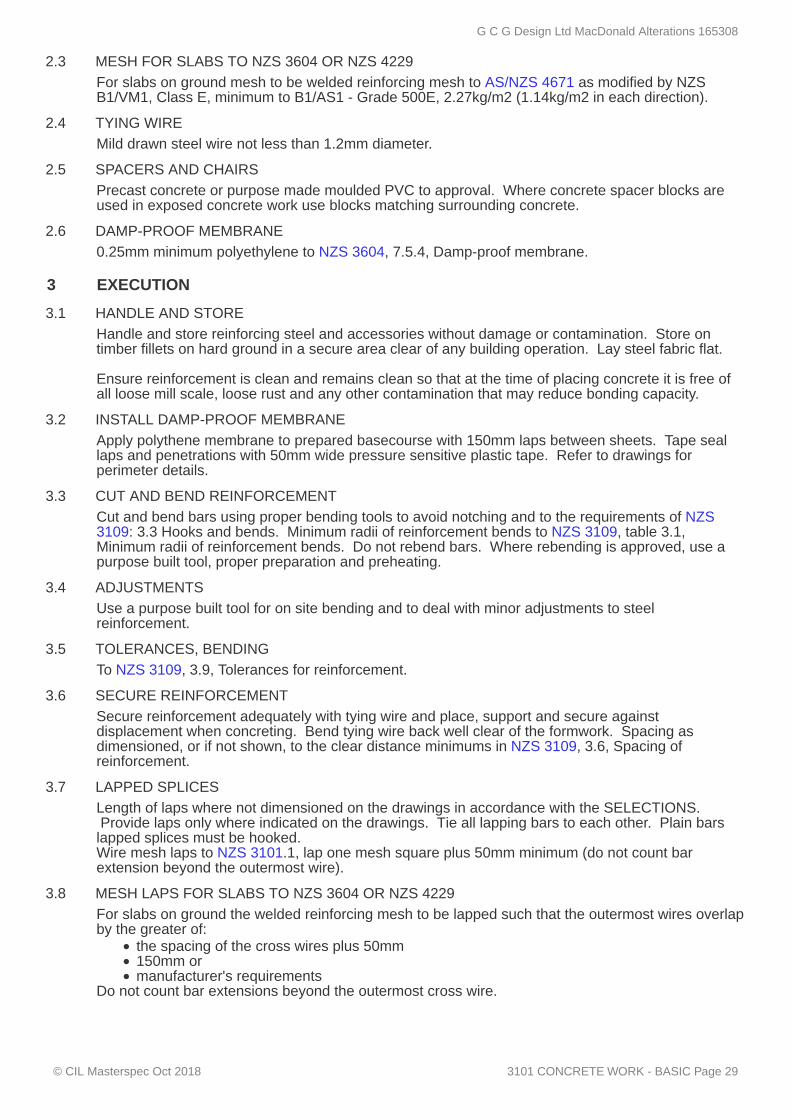
2.3 MESH FOR SLABS TO NZS 3604 OR NZS 4229
2.4 TYING WIRE
2.5 SPACERS AND CHAIRS
2.6 DAMP-PROOF MEMBRANE
3 EXECUTION
3.1 HANDLE AND STORE
3.2 INSTALL DAMP-PROOF MEMBRANE
3.3 CUT AND BEND REINFORCEMENT
3.4 ADJUSTMENTS
3.5 TOLERANCES, BENDING
3.6 SECURE REINFORCEMENT
3.7 LAPPED SPLICES
3.8 MESH LAPS FOR SLABS TO NZS 3604 OR NZS 4229
For slabs on ground mesh to be welded reinforcing mesh to AS/NZS 4671 as modified by NZSB1/VM1, Class E, minimum to B1/AS1 - Grade 500E, 2.27kg/m2 (1.14kg/m2 in each direction).
Mild drawn steel wire not less than 1.2mm diameter.
Precast concrete or purpose made moulded PVC to approval. Where concrete spacer blocks areused in exposed concrete work use blocks matching surrounding concrete.
0.25mm minimum polyethylene to NZS 3604, 7.5.4, Damp-proof membrane.
Handle and store reinforcing steel and accessories without damage or contamination. Store ontimber fillets on hard ground in a secure area clear of any building operation. Lay steel fabric flat. Ensure reinforcement is clean and remains clean so that at the time of placing concrete it is free ofall loose mill scale, loose rust and any other contamination that may reduce bonding capacity.
Apply polythene membrane to prepared basecourse with 150mm laps between sheets. Tape seallaps and penetrations with 50mm wide pressure sensitive plastic tape. Refer to drawings forperimeter details.
Cut and bend bars using proper bending tools to avoid notching and to the requirements of NZS3109: 3.3 Hooks and bends. Minimum radii of reinforcement bends to NZS 3109, table 3.1,Minimum radii of reinforcement bends. Do not rebend bars. Where rebending is approved, use apurpose built tool, proper preparation and preheating.
Use a purpose built tool for on site bending and to deal with minor adjustments to steelreinforcement.
To NZS 3109, 3.9, Tolerances for reinforcement.
Secure reinforcement adequately with tying wire and place, support and secure againstdisplacement when concreting. Bend tying wire back well clear of the formwork. Spacing asdimensioned, or if not shown, to the clear distance minimums in NZS 3109, 3.6, Spacing ofreinforcement.
Length of laps where not dimensioned on the drawings in accordance with the SELECTIONS. Provide laps only where indicated on the drawings. Tie all lapping bars to each other. Plain barslapped splices must be hooked.Wire mesh laps to NZS 3101.1, lap one mesh square plus 50mm minimum (do not count barextension beyond the outermost wire).
For slabs on ground the welded reinforcing mesh to be lapped such that the outermost wires overlapby the greater of:
the spacing of the cross wires plus 50mm150mm ormanufacturer's requirements
Do not count bar extensions beyond the outermost cross wire.
G C G Design Ltd MacDonald Alterations 165308
© CIL Masterspec Oct 2018 3101 CONCRETE WORK - BASIC Page 29
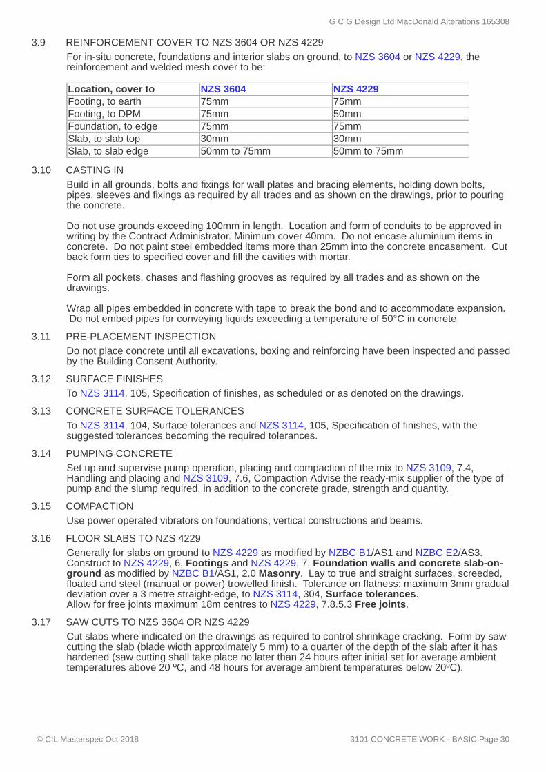
3.9 REINFORCEMENT COVER TO NZS 3604 OR NZS 4229
3.10 CASTING IN
3.11 PRE-PLACEMENT INSPECTION
3.12 SURFACE FINISHES
3.13 CONCRETE SURFACE TOLERANCES
3.14 PUMPING CONCRETE
3.15 COMPACTION
3.16 FLOOR SLABS TO NZS 4229
3.17 SAW CUTS TO NZS 3604 OR NZS 4229
For in-situ concrete, foundations and interior slabs on ground, to NZS 3604 or NZS 4229, thereinforcement and welded mesh cover to be: Location, cover to NZS 3604 NZS 4229Footing, to earth 75mm 75mmFooting, to DPM 75mm 50mmFoundation, to edge 75mm 75mmSlab, to slab top 30mm 30mmSlab, to slab edge 50mm to 75mm 50mm to 75mm
Build in all grounds, bolts and fixings for wall plates and bracing elements, holding down bolts,pipes, sleeves and fixings as required by all trades and as shown on the drawings, prior to pouringthe concrete. Do not use grounds exceeding 100mm in length. Location and form of conduits to be approved inwriting by the Contract Administrator. Minimum cover 40mm. Do not encase aluminium items inconcrete. Do not paint steel embedded items more than 25mm into the concrete encasement. Cutback form ties to specified cover and fill the cavities with mortar. Form all pockets, chases and flashing grooves as required by all trades and as shown on thedrawings. Wrap all pipes embedded in concrete with tape to break the bond and to accommodate expansion. Do not embed pipes for conveying liquids exceeding a temperature of 50°C in concrete.
Do not place concrete until all excavations, boxing and reinforcing have been inspected and passedby the Building Consent Authority.
To NZS 3114, 105, Specification of finishes, as scheduled or as denoted on the drawings.
To NZS 3114, 104, Surface tolerances and NZS 3114, 105, Specification of finishes, with thesuggested tolerances becoming the required tolerances.
Set up and supervise pump operation, placing and compaction of the mix to NZS 3109, 7.4,Handling and placing and NZS 3109, 7.6, Compaction Advise the ready-mix supplier of the type ofpump and the slump required, in addition to the concrete grade, strength and quantity.
Use power operated vibrators on foundations, vertical constructions and beams.
Generally for slabs on ground to NZS 4229 as modified by NZBC B1/AS1 and NZBC E2/AS3.Construct to NZS 4229, 6, Footings and NZS 4229, 7, Foundation walls and concrete slab-on-ground as modified by NZBC B1/AS1, 2.0 Masonry. Lay to true and straight surfaces, screeded,floated and steel (manual or power) trowelled finish. Tolerance on flatness: maximum 3mm gradualdeviation over a 3 metre straight-edge, to NZS 3114, 304, Surface tolerances.Allow for free joints maximum 18m centres to NZS 4229, 7.8.5.3 Free joints.
Cut slabs where indicated on the drawings as required to control shrinkage cracking. Form by sawcutting the slab (blade width approximately 5 mm) to a quarter of the depth of the slab after it hashardened (saw cutting shall take place no later than 24 hours after initial set for average ambienttemperatures above 20 ºC, and 48 hours for average ambient temperatures below 20ºC).
G C G Design Ltd MacDonald Alterations 165308
© CIL Masterspec Oct 2018 3101 CONCRETE WORK - BASIC Page 30
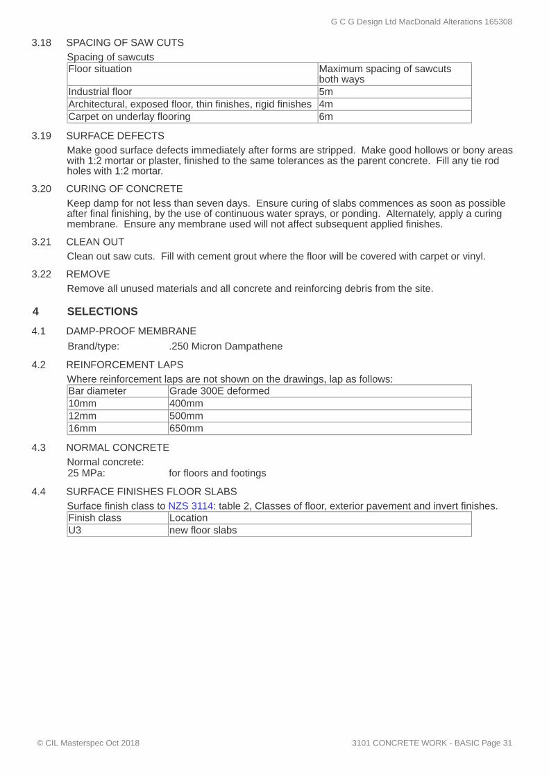
3.18 SPACING OF SAW CUTS
3.19 SURFACE DEFECTS
3.20 CURING OF CONCRETE
3.21 CLEAN OUT
3.22 REMOVE
4 SELECTIONS
4.1 DAMP-PROOF MEMBRANE
4.2 REINFORCEMENT LAPS
4.3 NORMAL CONCRETE
4.4 SURFACE FINISHES FLOOR SLABS
Spacing of sawcutsFloor situation Maximum spacing of sawcuts
both waysIndustrial floor 5mArchitectural, exposed floor, thin finishes, rigid finishes 4mCarpet on underlay flooring 6m
Make good surface defects immediately after forms are stripped. Make good hollows or bony areaswith 1:2 mortar or plaster, finished to the same tolerances as the parent concrete. Fill any tie rodholes with 1:2 mortar.
Keep damp for not less than seven days. Ensure curing of slabs commences as soon as possibleafter final finishing, by the use of continuous water sprays, or ponding. Alternately, apply a curingmembrane. Ensure any membrane used will not affect subsequent applied finishes.
Clean out saw cuts. Fill with cement grout where the floor will be covered with carpet or vinyl.
Remove all unused materials and all concrete and reinforcing debris from the site.
Brand/type: .250 Micron Dampathene
Where reinforcement laps are not shown on the drawings, lap as follows:Bar diameter Grade 300E deformed10mm 400mm12mm 500mm16mm 650mm
Normal concrete:25 MPa: for floors and footings
Surface finish class to NZS 3114: table 2, Classes of floor, exterior pavement and invert finishes.Finish class LocationU3 new floor slabs
G C G Design Ltd MacDonald Alterations 165308
© CIL Masterspec Oct 2018 3101 CONCRETE WORK - BASIC Page 31

3321F FIRTH CONCRETE MASONRY
1 GENERAL
1.1 ABBREVIATIONS AND DEFINITIONS
1.2 DOCUMENTS
1.3 MANUFACTURER/SUPPLIER DOCUMENTS
1.4 NO SUBSTITUTIONS
1.5 QUALIFICATIONS
This section relates to the laying, reinforcing and grouting of Firth hollow concrete masonry. Itincludes:
Firth hollow block masonryFirth HotBloc®including mortar, reinforcement and ready-mix grout
Refer to the general section 1232 INTERPRETATION & DEFINITIONS for abbreviations anddefinitions used throughout the specification. The following definitions apply specifically to this section:ACRS Australian Certification Authority for Reinforcing Steels - An
independent certification scheme for reinforcing steel and structuralsteel, by product and manufacturer/processor. Certifies compliancewith Australia/New Zealand Standards.
ACRS Web site - www.steelcertification.com
Refer to the general section 1233 REFERENCED DOCUMENTS. The following documents arespecifically referred to in this section:NZS 3104 Specification for concrete productionNZS 3109 Concrete constructionNZS 3112.1 Methods of test for concrete - Tests relating to fresh concreteNZS 4210 Masonry construction - Materials and workmanshipAS/NZS 4455.1 Masonry units, pavers, flags, and segmental retaining wall units -
Masonry unitsAS/NZS 4671 Steel reinforcing materialsCCANZ CP 01 Code of Practice for Weathertight Concrete and Concrete Masonry
Construction
Manufacturer's and supplier's documents relating to this part of the work:Firth Industries documents relating to work in this section are:Firth Masonry Homes Construction ManualFirth Cantilever Masonry Retaining Walls ManualFirth Hollow Masonry DocumentFirth Energy Efficiency Masonry ConstructionFirth Masonry Insulation SolutionsFirth Design Masonry Control Joint Specification Manufacturer/supplier contact detailsCompany: Firth IndustriesEmail: [email protected]: www.firth.co.nzTelephone: 0800 800 576Facsimile: 0800 800 530
Requirements
Substitutions are not permitted to any specified Firth hollow concrete masonry or associatedproducts.
All work to be installed or supervised by a licensed building practitioner: Licensed for Bricklaying andBlocklaying 2: Structural Masonry.
G C G Design Ltd MacDonald Alterations 165308
© CIL Masterspec Oct 2018 3321F FIRTH CONCRETE MASONRY Page 32

1.6 CONSTRUCTION OBSERVATION BY ENGINEER
1.7 QUALITY RECORDS
1.8 SELECTED MASONRY
1.9 STEEL REINFORCING COMPLIANCE
1.10 TESTS
1.11 RECORDS OF TESTS
1.12 TESTING PROCEDURES
1.13 SPREAD OF GROUT
1.14 COMPRESSIVE STRENGTH OF GROUT
1.15 COMPRESSIVE STRENGTH OF MORTAR
1.16 EXPANSION OF GROUT
2 PRODUCTS
2.1 MASONRY
2.2 REINFORCEMENT
Where required as a condition of the building consent, advise the engineer when inspections arerequired. Obtain the producer statements required from the engineer relating to the masonry construction andkeep with the building consent documentation.
Keep accurate records relating to strength and quality of materials used in the construction, andmake the information available to the Building Consent Authority inspector on request.
Refer to the drawings for areas of masonry, which require select quality blocks to both sides,self-insulating masonry, water resistant masonry or mortarless masonry.
Steel reinforcing materials for concrete to AS/NZS 4671. Steel to be manufactured in New Zealand,or by an overseas manufacturer holding a current valid (or equivalent) NZ S Mark or ACRScertificate for that type of steel. Confirm compliance and provide evidence if requested.
Performance - tests
Carry out all required tests to NZS 4210: appendix 2A, Compressive strength tests for mortar andgrout.
To NZS 4210 and kept on site:spread of grout testsgrout supplier's test certificates.mortar
Provide advance notice of cell filling work. If requested maintain on site all equipment necessary fortaking and preparing samples for test. Retain records of test results and supply on request.
If requested, carry out tests to NZS 3112.1, to the requirements of NZS 4210.
If requested, carry out tests to NZS 4210: appendix 2A, Compressive strength tests for mortar andgrout, with 3 specimens per test.
If requested, carry out tests to NZS 4210: appendix 2A, Compressive strength tests for mortar andgrout, with 3 specimens per test.
If requested, carry out tests to NZS 4210: appendix 2C, Test for expansion of grout.
Materials
Firth masonry blocks to AS/NZS 4455.1. Use appropriate masonry for intermittently filledconstruction where vertical reinforcement is placed prior to laying of masonry. Refer toSELECTIONS for type, size and bond.
To AS/NZS 4671, deformed mild steel except for ties in plain round mild steel.
Accessories
G C G Design Ltd MacDonald Alterations 165308
© CIL Masterspec Oct 2018 3321F FIRTH CONCRETE MASONRY Page 33

2.3 MORTAR
2.4 FINE AGGREGATE GROUT
3 EXECUTION
3.1 COMPLIANCE
3.2 TOLERANCES
3.3 CHECK BASE
3.4 CONSTRUCTION JOINTS
3.5 COVER
3.6 STARTER POSITIONS
3.7 MOISTURE CONTENT
3.8 PROTECTION
3.9 WEATHER PRECAUTIONS
Dricon Trade Mortar to NZS 4210: 2.2 Mortar. Refer to SELECTIONS for colour.
Firth Certified ready-mixed grout to NZS 4210: 2.3 and NZS 3104.Strength: 17.5 MPa (unless subject to seaspray zone)Aggregate: 4.75mm to 6mm maximum
Conditions
Comply with NZS 4210.
Construct within the tolerances set out in NZS 4210: clause 2.6.5, Tolerances and clause 2.7, Layingthe units, unless specified otherwise on the drawings or in this specification. Lay blocks with jointingof consistent thickness throughout. Lay masonry to an even, plane surface with no deviation exceeding 3mm in 3 metres on any surfacein view in the finished work.
Check that the base concrete on which masonry is being built is true to line and level, to ensure thatwork can be taken up true and plumb with 10mm thick bed and perpendicular joints. If more than20mm thickness of mortar bed is needed to correct inaccuracies obtain written direction on remedialaction.
Ensure the structural integration of all masonry with adjacent concrete work by providing wellroughened, retarded construction joints at all junctions. Vertical joints between masonry and concrete to achieve full structural integration across the joints. Allow to construct concrete work first with prepared vertical construction joints at block junctions thesame as for horizontal construction joints. Lay masonry so that all courses have open ends abuttingthe existing concrete work.
All cover shall be in accordance with NZS 3109: 3.8 Cover and 3.9 Tolerances for reinforcement.
Check the location of starter reinforcement before block laying commences, or by a dry trial lay up ofthe first course. Do not attempt to correct misplacement by cranking bars. Where misplacementexceeds the location tolerance obtain written directions before proceeding further.
Ensure that blocks are air-dry prior to laying. If necessary to reduce excess absorption of waterfrom the mortar, some dampening of the surface is permissible but no surface water may be presentat the time of placing mortar. Keep masonry on the pallet and protected from the weather prior touse.
Keep fair face block walls clean of mortar droppings, grout splashes, or stains of any kind as thework proceeds and before any droppings set and protected from weathering prior to sealing to avoidinstances of efflorescence and staining.
When extreme temperatures prevail, either below 4°C or above 27°C, make adjustments toconstruction as listed in NZS 4210: clause 2.18, Cold weather construction, and clause 2.19, Hotweather construction. Do not use expansive grout for filling in temperatures below 5°C.
Application
G C G Design Ltd MacDonald Alterations 165308
© CIL Masterspec Oct 2018 3321F FIRTH CONCRETE MASONRY Page 34
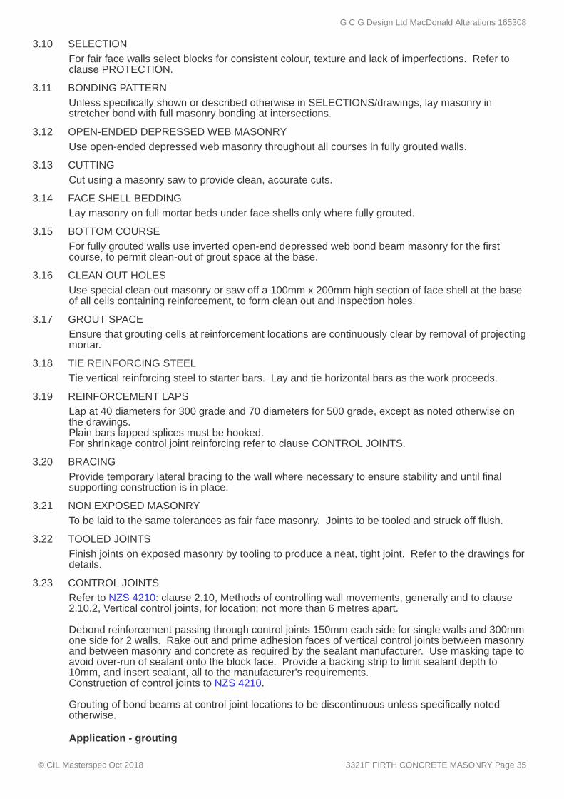
3.10 SELECTION
3.11 BONDING PATTERN
3.12 OPEN-ENDED DEPRESSED WEB MASONRY
3.13 CUTTING
3.14 FACE SHELL BEDDING
3.15 BOTTOM COURSE
3.16 CLEAN OUT HOLES
3.17 GROUT SPACE
3.18 TIE REINFORCING STEEL
3.19 REINFORCEMENT LAPS
3.20 BRACING
3.21 NON EXPOSED MASONRY
3.22 TOOLED JOINTS
3.23 CONTROL JOINTS
For fair face walls select blocks for consistent colour, texture and lack of imperfections. Refer toclause PROTECTION.
Unless specifically shown or described otherwise in SELECTIONS/drawings, lay masonry instretcher bond with full masonry bonding at intersections.
Use open-ended depressed web masonry throughout all courses in fully grouted walls.
Cut using a masonry saw to provide clean, accurate cuts.
Lay masonry on full mortar beds under face shells only where fully grouted.
For fully grouted walls use inverted open-end depressed web bond beam masonry for the firstcourse, to permit clean-out of grout space at the base.
Use special clean-out masonry or saw off a 100mm x 200mm high section of face shell at the baseof all cells containing reinforcement, to form clean out and inspection holes.
Ensure that grouting cells at reinforcement locations are continuously clear by removal of projectingmortar.
Tie vertical reinforcing steel to starter bars. Lay and tie horizontal bars as the work proceeds.
Lap at 40 diameters for 300 grade and 70 diameters for 500 grade, except as noted otherwise onthe drawings.Plain bars lapped splices must be hooked.For shrinkage control joint reinforcing refer to clause CONTROL JOINTS.
Provide temporary lateral bracing to the wall where necessary to ensure stability and until finalsupporting construction is in place.
To be laid to the same tolerances as fair face masonry. Joints to be tooled and struck off flush.
Finish joints on exposed masonry by tooling to produce a neat, tight joint. Refer to the drawings fordetails.
Refer to NZS 4210: clause 2.10, Methods of controlling wall movements, generally and to clause2.10.2, Vertical control joints, for location; not more than 6 metres apart. Debond reinforcement passing through control joints 150mm each side for single walls and 300mmone side for 2 walls. Rake out and prime adhesion faces of vertical control joints between masonryand between masonry and concrete as required by the sealant manufacturer. Use masking tape toavoid over-run of sealant onto the block face. Provide a backing strip to limit sealant depth to10mm, and insert sealant, all to the manufacturer's requirements.Construction of control joints to NZS 4210. Grouting of bond beams at control joint locations to be discontinuous unless specifically notedotherwise.
Application - grouting
G C G Design Ltd MacDonald Alterations 165308
© CIL Masterspec Oct 2018 3321F FIRTH CONCRETE MASONRY Page 35

3.24 INSPECTION
3.25 GROUTING, LOW LIFT
3.26 LIMIT RATE
3.27 HOLES AND CUT MASONRY
3.28 BUILT IN ELEMENTS
3.29 BUILT IN FIXINGS
3.30 ELECTRICAL WORK
3.31 PROGRESSIVE CLEANING
3.32 FINAL CLEANING
3.33 REPLACE
3.34 REMOVE
4 SELECTIONS
4.1 FIRTH - STANDARD MASONRY UNITS
4.2 MORTAR
Inspect clean-out holes prior to grouting. Ensure that cells are clean and reinforcement is correctlyplaced. Mortar back the clean-out hole shell. If holes are covered in the completed work, boxingacross the face may replace the shell infill. Brace hole infills to prevent blowouts during grouting. Notify when work is ready for inspection.
Fill masonry walls to NZS 4210: clause 2.14, The low lift grouting method, up to a maximum heightof 1200mm. Consolidate by rodding and then prepare a construction joint to NZS 4210: clause 2.16,Horizontal construction joints, before repeating the sequence.
Limit rate of pour to avoid hydrostatic blowouts.
Application - ancillary work
Provide all necessary holes, pockets and chases. Cut blocks when non-standard shapes arerequired. When cut masonry units are used, ensure vertical joints in adjacent courses are no closerthan 100mm. Subsequent cutting away of masonry to form holes is not permitted.
As the work proceeds, mortar in place elements such as sills, copings, lintels, and steps.
Build in all necessary plugs, bolts, ties, metal flashings, dowels, fastenings and fixings required bythis and other work sections. Co-operate with others to meet this requirement. Fixings onlypermitted into filled cells.
Ensure that provision for and fitting of boxes, conduit and pre-wiring are made and done as the workproceeds under the direction of the electrician.
Completion
Clean off mortar splashes and grout spills as they occur.
At completion, clean down block work, remove efflorescence and remove waste materials fromadjoining surfaces and floors.
Replace damaged, cracked or marked elements.
Remove debris, unused materials and elements from the site.
For further details on selections go to www.firth.co.nz.Substitutions are not permitted to the following, unless stated otherwise.
Brand: FirthSeries: 20Type/size: 390mm x 190mm x 190mmBonding pattern: Stretcher bond
Type/colour: Dricon Trade MortarColour: Natural
G C G Design Ltd MacDonald Alterations 165308
© CIL Masterspec Oct 2018 3321F FIRTH CONCRETE MASONRY Page 36

4.3 FIRTH MASONRY BLOCKFILL
Type: Firth Fine aggregate grout. Strength: 25MPaAggregate: Fine aggregate grout 4.75mm to 6mm maximum. Refer to the
design engineer for advice.
G C G Design Ltd MacDonald Alterations 165308
© CIL Masterspec Oct 2018 3321F FIRTH CONCRETE MASONRY Page 37

3410 STRUCTURAL STEEL
1 GENERAL
1.1 ABBREVIATIONS AND DEFINITIONS
1.2 DOCUMENTS
1.3 QUALIFICATIONS
1.4 TOLERANCES
This section relates to the fabrication, erection and specialist coating of structural steelwork of ageneral nature, for Construction Category CC1 or CC2 (to AS/NZS 5131). Refer to SELECTIONS for project Construction Category.
Refer to the general section 1232 INTERPRETATION & DEFINITIONS for abbreviations anddefinitions used throughout the specification. The following abbreviations apply specifically to this section:AESS: Architecturally Exposed Structural SteelworkCC: Construction CategoryNDE: Non-Destructive Examination
Refer to the general section 1233 REFERENCED DOCUMENTS. The following documents arespecifically referred to in this section:NZBC F5/AS1 Construction and demolition hazardsAS 1111.1 ISO metric hexagon bolts and screws - Product grade C - BoltsAS/NZS 1163 Cold-formed structural steel hollow sectionsAS/NZS 1214 Hot-dip galvanized coatings on threaded fasteners (ISO metric
coarse thread series)AS/NZS 1252.1 High-strength steel fastener assemblies for structural engineering -
Bolts, nuts and washers - Technical requirementsAS 1397 Continuous hot-dip metallic coated steel sheet and strip - Coatings
of zinc and zinc alloyed with aluminium and magnesiumAS/NZS 1554.1 Structural steel welding - Welding of steel structuresAS/NZS 1554.2 Stud welding (steel studs to steel)AS/NZS 1594 Hot-rolled steel flat productsAS 1627.4 Metal finishing - Preparation and pretreatment of surfaces -
Abrasive blast cleaningAS 1627.9 Metal finishing - Preparation and pretreatment of surfaces -
Pictorial surface preparation standards for painting steel surfacesAS/NZS 2312:2002 Guide to the protection of iron and steel against atmospheric
corrosion by the use of protective coatingsNZS 3404.1:1997 Steel Structures StandardAS 3597 Structural and pressure vessel steel – Quenched and tempered
plateAS/NZS 3678 Structural steel - Hot-rolled plates, floorplates and slabsAS/NZS 3679.1 Structural steel - Hot-rolled bars and sectionsAS/NZS 3679.2 Structural steel - Welded I sectionsAS/NZS 4680 Hot-dip galvanized (zinc) coatings on fabricated ferrous articlesAS/NZS 5131 Structural steelwork - Fabrication and erectionGANZ: Galvanizing Association of New Zealand - After-Fabrication Hot Dip
Galvanizing. A practical reference for designers, specifiers,engineers, consultants, manufacturers and users
Requirements
Welding operators (and supervisors) to be experienced, competent workers, qualified to AS/NZS5131, Table 7.4, to suit relevant Construction Category and weld category.
To AS/NZS 5131 Section 12 and Appendix F, Tolerance Class 1.
G C G Design Ltd MacDonald Alterations 165308
© CIL Masterspec Oct 2018 3410 STRUCTURAL STEEL Page 38
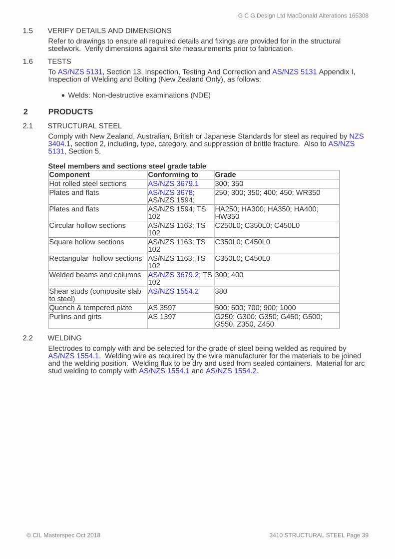
1.5 VERIFY DETAILS AND DIMENSIONS
1.6 TESTS
2 PRODUCTS
2.1 STRUCTURAL STEEL
2.2 WELDING
Refer to drawings to ensure all required details and fixings are provided for in the structuralsteelwork. Verify dimensions against site measurements prior to fabrication.
To AS/NZS 5131, Section 13, Inspection, Testing And Correction and AS/NZS 5131 Appendix I,Inspection of Welding and Bolting (New Zealand Only), as follows:
Welds: Non-destructive examinations (NDE)
Comply with New Zealand, Australian, British or Japanese Standards for steel as required by NZS3404.1, section 2, including, type, category, and suppression of brittle fracture. Also to AS/NZS5131, Section 5. Steel members and sections steel grade tableComponent Conforming to GradeHot rolled steel sections AS/NZS 3679.1 300; 350Plates and flats AS/NZS 3678;
AS/NZS 1594;250; 300; 350; 400; 450; WR350
Plates and flats AS/NZS 1594; TS102
HA250; HA300; HA350; HA400;HW350
Circular hollow sections AS/NZS 1163; TS102
C250L0; C350L0; C450L0
Square hollow sections AS/NZS 1163; TS102
C350L0; C450L0
Rectangular hollow sections AS/NZS 1163; TS102
C350L0; C450L0
Welded beams and columns AS/NZS 3679.2; TS102
300; 400
Shear studs (composite slabto steel)
AS/NZS 1554.2 380
Quench & tempered plate AS 3597 500; 600; 700; 900; 1000Purlins and girts AS 1397 G250; G300; G350; G450; G500;
G550, Z350, Z450
Electrodes to comply with and be selected for the grade of steel being welded as required byAS/NZS 1554.1. Welding wire as required by the wire manufacturer for the materials to be joinedand the welding position. Welding flux to be dry and used from sealed containers. Material for arcstud welding to comply with AS/NZS 1554.1 and AS/NZS 1554.2.
G C G Design Ltd MacDonald Alterations 165308
© CIL Masterspec Oct 2018 3410 STRUCTURAL STEEL Page 39

2.3 BOLTS, NUTS AND WASHERS
2.4 GROUT
3 EXECUTION
3.1 GENERALLY
3.2 SURFACE FINISH
3.3 CUTTING
3.4 HOLING
3.5 WELDING GENERALLY
3.6 NON-DESTRUCTIVE WELD EXAMINATION
3.7 MECHANICAL FASTENING GENERALLY
Grade 4.6, screws AS 1111.2 and bolts to AS 1111.1. Grade 4.6 nuts to comply with AS 1112.1. Property Class 8.8 bolts and equivalent nuts and washers (high strength structural quality only) tocomply with AS/NZS 1252.1. Hot-dip galvanize to AS/NZS 4680 (and AS/NZS 1214), bolts, nutsand washers forming a permanent part of a structure subject to a protective coating. Bolt Categories and tensioningBoltingcategory
Bolt standard PropertyClass
Tensionmethod
Tensioned joint type
4.6/S AS 1111.1 4.6 Snug tight 8.8/S AS/NZS
1252.18.8 Snug tight
8.8/TB AS/NZS1252.1
8.8 Full tension Bearing
8.8/TF AS/NZS1252.1
8.8 Full tension Friction
In bearing type connections where the thread position relative to the shear plane is to be controlled.N - threads included in shear planeX - threads excluded from shear planeF - friction type joints - prepare faying surfaces
To AS/NZS 5131, 5.8.
Preparation, assembly and Fabrication
To AS/NZS 5131, Section 6.
Grind off all burrs and sharp arrises.
To AS/NZS 5131, Section 6.5.
To AS/NZS 5131, Section 6.7Do not use slotted holes for connections, other than those documented.
Welding
To AS/NZS 5131, Section 7 and AS/NZS 1554.1. Equipment to comply with AS/NZS 1554.1, clause1.8.2.Site weld only when correct alignment and preset or camber have been achieved.Weld types as documented elsewhere or on drawingsWeld categories not documented elsewhere or on drawings to be Category GP.
Non-destructive weld examination (NDE) to AS/NZS 5131, clause 13.6.2 and AS/NZS 5131Appendix I, Inspection of Welding and Bolting (New Zealand Only).If non-visual NDE is required, use a third party testing authority.Repair any welds revealed as faulty by NDE and repeat the examination.
Mechanical fastening
To AS/NZS 5131.Connection contact surfaces to AS/NZS 1554.1, 8.4.1.Category 8.8/TF bolting to be clean, as rolled and free from applied finishes.For washers, place one washer under the part rotated during tightening process (nut or bolt head).Permanent bolt only when correct alignment and preset or camber have been achieved.
G C G Design Ltd MacDonald Alterations 165308
© CIL Masterspec Oct 2018 3410 STRUCTURAL STEEL Page 40

3.8 TENSIONING BOLTS
3.9 THREADS EXCLUDED FROM SHEAR PLANE
3.10 ERECTION GENERALLY
3.11 BOLTS AND ANCHORAGES
3.12 TEMPORARY WORK
3.13 SITE WORK
3.14 GROUTING SUPPORTS
3.15 DRIFTING
3.16 ENCASED STEELWORK
3.17 POWER TOOL CLEANING
For tensioning of bolting categories 8.8/TB and 8.8/TF, use part-turn method or a direct tensionindicator device. Ensure clear thread run out beneath the nut after tensioning is to New Zealandrequirement of AS/NZS 1554.1, 8.2.2.
Select length of bolts such that the threaded portion does not occur within the shear plane betweenjoined parts.
Erection of structural steel
To AS/NZS 5131, Section 11.Make sure every part of the structure has sufficient design capacity and is stable under constructionloads produced by the construction procedure.Comply with NZBC F5/AS1: Construction and demolition hazards, and the WorkSafe NZ publication:Guidelines for the provision of facilities and general safety in the construction industry.
For each group of anchor bolts, provide a template with set-out lines clearly marked for positioningthe bolts when casting in.Start erection only when the holding down bolts and anchorages have been cast-in-place longenough to achieve sufficient strength.
Provide temporary bracing, propping and restraint as required to make structure safe. Fix anytemporary members so as not to weaken or deface permanent steelwork. Leave temporary bracingand restraint in place until the erection is sufficiently advanced to allow safe removal of temporarybracing.
Other than work shown on the shop detail documentation as site work, do not fabricate, modify orweld structural steel on-site.
Before grouting steelwork supported by concrete or masonry, set steelwork on packing or wedgesas follows:
Permanent packing or wedges - Form with solid steel or grout of similar strength to thepermanent grout.Temporary packing or wedges - Remove before completion of grouting.
Grout at supports before constructing supported floors, walls and roofing.Do not grout if the base plate or the footing surface temperature are outside the range 3°C to 35°Cor to manufacturer's requirements.Fill the space beneath the base plate with grout, if necessary hammered in tight to ensure completefilling of space.
Use drifting only to bring members into position, without enlarging holes or distorting components.
Finishing - preparation
Clean the steelwork to be encased in concrete to remove all loose mill scale, rust, dirt and othermatter affecting bond with concrete. Achieve this by wire brushing and the use of suitable solvents.
To AS/NZS 5131, Section 9.Remove oil and grease by the use of solvents. Scrape, wire brush and power tool clean to aminimum Class 2 finish to AS 1627.9. Clean to bright metal, but avoid producing a polished surface. Check that no burrs or sharp arrises remain which may prevent the full coating thickness beingattained.
Finishing - paint and protective coatings
G C G Design Ltd MacDonald Alterations 165308
© CIL Masterspec Oct 2018 3410 STRUCTURAL STEEL Page 41

3.18 UNPAINTED SURFACES
3.19 PRIMING GENERALLY
3.20 PATCH PRIMING
3.21 COATING SYSTEMS
3.22 TOUCH-UP
3.23 TEMPORARY CONNECTIONS
3.24 GENERAL REPAIRS
4 SELECTIONS
4.1 CONSTRUCTION CATEGORY
4.2 STEEL PREPARATION
Do not paint:faying face of high strength friction grip bolted jointsareas for site welding, keeping 75mm clear all roundsurfaces being embedded in concrete.
Where steel is only partly encased then extend priming 50mm minimum into the concreteencasement area.
Coat steelwork, unless specifically noted otherwise, with the specified priming paint, including patchpriming on site after erection.
Clean areas of damaged priming and areas left clear for site jointing to a standard comparable withthat specified for shop cleaning. Wash off chemical deposits from welding fumes. Apply primingcoats to the same standard as shop primers, ensuring thorough coating of bolts, nuts andconnection areas. Reprime if more than 4 weeks elapse before the final coating system is applied.
Apply all coatings in accordance with the coating manufacturer's requirements. Apply coatings tosteel within 4 hours of cleaning and before condensation or light rusting can occur. Ensure steel isdry and atmospheric conditions warm and dry, with an air temperature of greater than 12°C andrelative humidity less than 85%.
Touch up primer. Apply protective coatings as specified.
Repairs & removal of temporary work
Remove temporary elements on completion and restore the surface.
Repair finishes to restore the full integrity of any coating.
Completion
Construction category (to AS/NZS 5131) LocationCC 1 Door lintel to Ensuite
Finishing - preparation
Item: Lintel BeamPreparation: Power tool clean
G C G Design Ltd MacDonald Alterations 165308
© CIL Masterspec Oct 2018 3410 STRUCTURAL STEEL Page 42

3820 CARPENTRY
1 GENERAL
1.1 RELATED WORK
1.2 DOCUMENTS
1.3 QUALIFICATIONS
1.4 DIMENSIONS
2 PRODUCTS
2.1 TIMBER FRAMING, TREATED
2.2 ENGINEERED WOOD
2.3 EXTERIOR CAVITY WALL BATTENS - TIMBER - NON-STRUCTURAL
2.4 EXTERIOR CAVITY WALL BATTENS - PROPRIETARY - NON-STRUCTURAL
This section relates to the supply and erection of timber framing, as a framed structure, or aspartitioning. It includes prefabricated timber and engineered wood.
Refer to 4161 UNDERLAYS, FOIL AND DPC for underlays, foils and DPC.
Refer to the general section 1233 REFERENCED DOCUMENTS. The following documents arespecifically referred to in this section:NZBC B2/AS1 DurabilityAS/NZS 1328.1 Glued laminated structural timber - Performance requirements and
minimum production requirementsAS/NZS 1604.4 Specification for preservative treatment - Laminated veneer lumber
(LVL)AS/NZS 1604.5 Specification for preservative treatment - Glue laminated timber
productsNZS 3602 Timber and wood-based products for use in buildingNZS 3603 Timber structures standardNZS 3604 Timber-framed buildingsNZS 3622 Verification of timber propertiesNZS 3640 Chemical preservation of round and sawn timberAS/NZS 4357.0 Structural laminated veneer lumber - SpecificationFTMA CoP Frame and Truss Manufacturers Association Code of Practice*A copy of NZS 3604 Timber-framed buildings, must be held on site.
Workers to be experienced, competent trades people familiar with the materials and techniquesspecified.
All timber sizes except for battens are actual minimum dried sizes.
Species, grade and in service moisture content to NZS 3602, NZBC B2/AS1 and treatment to NZS3640, NZBC B2/AS1. Structural grade (SG) to NZS 3604, NZS 3622 with properties to NZS 3603.
LVL members to AS/NZS 4357.0, to required sizes and lengths and the manufacturer's designproperties.Treatment to NZS 3640 and AS/NZS 1604.4.
H3.1 or H3.2 Radiata pine battens, minimum 20mm thickness, width and height to match timberframing studs. Temporary fix battens before being fixed into the framing with the cladding fixings. To NZS 3602, table 1, reference 1D.10, Requirements for wood-based building components toachieve a 50-year durability performance.
Extruded polypropylene battens, size approximately 45mm wide x 18mm thickness. Temporary fixbattens before being fixed into the framing with the cladding fixings. To the scope limitations ofNZBC E2/AS1, and NZS 3604 Building Wind Zones up to, and including "Extra High".
Components
G C G Design Ltd MacDonald Alterations 165308
© CIL Masterspec Oct 2018 3820 CARPENTRY Page 43

2.5 NAILS
2.6 BOLTS AND SCREWS
2.7 NAIL PLATES
2.8 CONNECTORS
2.9 CORROSION RISKS
2.10 DPC
3 EXECUTION
3.1 EXECUTION GENERALLY
3.2 SEPARATION
3.3 ATTENDANCE
3.4 MOISTURE CONTENT
3.5 SET-OUT
3.6 FRAMING SUB-FLOOR
3.7 FRAMING FLOORS
Type to NZS 3604, section 4, Durability, and of the size and number for each particular types ofjoint as laid down in the nailing schedules of NZS 3604, sections 6-10.
Bolts and screws of engineering and/or coach type complete with washers, to the requirements ofNZS 3604, section 4, Durability, and of the number and form required for each particular junction toNZS 3604, sections 6-10.
Comply with the requirements of NZS 3604, section 4, Durability, and of the number and formrequired for each particular junction to NZS 3604, sections 6-10. Plates to the plate manufacturer'sdesign for the particular locations as shown on the drawings.
Comply with the requirements of NZS 3604, section 4, Durability, and of the number and formrequired for each particular junction to NZS 3604, sections 6-10. Connectors and structuralbrackets to the connector manufacturer's design for particular locations shown on drawings.
For interior timber, treated with copper-based timber preservatives (H3.2 or higher), use a minimumof hot-dipped galvanized steel fixings and fasteners. For exterior timber, timber in damp areas and timber subject to occasional wetting, use onlystainless steel (or equivalent) fixings and connectors, when the timber is treated with; Copper Azole(CuAz, Preservative code 58), Alkaline Copper Quaternary (ACQ, Preservative code 90), MicroniseCopper Azole (code 88) or Micronised Copper Quaternary (code 89).
Refer to 4161 UNDERLAYS, FOIL AND DPC section
To NZS 3604 except as varied in this specification. Execution to include those methods, practicesand processes contained in the unit standards for the National Certificate in Carpentry and theNational Certificate in Joinery (cabinetry, exterior joinery, stairs).
Separate all timber framing timbers from concrete, masonry and brick by: -a full length bituminous damp-proof membrane overlapping timber by at least 6mm; ora 12mm minimum free draining air space
Provide and fix blocks, nogs, openings and other items as required by other trades.
Maximum allowable equilibrium moisture content (EMC) for non air-conditioned or centrally heatedbuildings for framing to which linings are attached.Framing at erection: 24% maximum Framing at enclosure: 20% maximum Framing at lining: 16% maximum
Set out framing in accordance with the requirements of NZS 3604 and as required to support sheetlinings and claddings. When necessary provide framing to suit any required cladding/lining controljoints.
Frame up off foundation walls and piles, all fabricated, fastened and braced to NZS 3604, section6.10, Framed subfloor walls.
Framed and fastened to NZS 3604, section 7, Floors.
G C G Design Ltd MacDonald Alterations 165308
© CIL Masterspec Oct 2018 3820 CARPENTRY Page 44
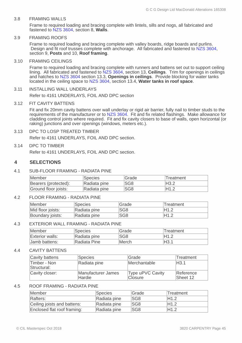
3.8 FRAMING WALLS
3.9 FRAMING ROOFS
3.10 FRAMING CEILINGS
3.11 INSTALLING WALL UNDERLAYS
3.12 FIT CAVITY BATTENS
3.13 DPC TO LOSP TREATED TIMBER
3.14 DPC TO TIMBER
4 SELECTIONS
4.1 SUB-FLOOR FRAMING - RADIATA PINE
4.2 FLOOR FRAMING - RADIATA PINE
4.3 EXTERIOR WALL FRAMING - RADIATA PINE
4.4 CAVITY BATTENS
4.5 ROOF FRAMING - RADIATA PINE
Frame to required loading and bracing complete with lintels, sills and nogs, all fabricated andfastened to NZS 3604, section 8, Walls.
Frame to required loading and bracing complete with valley boards, ridge boards and purlins. Design and fit roof trusses complete with anchorage. All fabricated and fastened to NZS 3604,section 9, Posts and 10, Roof framing.
Frame to required loading and bracing complete with runners and battens set out to support ceilinglining. All fabricated and fastened to NZS 3604, section 13, Ceilings. Trim for openings in ceilingsand hatches to NZS 3604 section 13.3, Openings in ceilings. Provide blocking for water tankslocated in the ceiling space to NZS 3604, section 13.4, Water tanks in roof space.
Refer to 4161 UNDERLAYS, FOIL AND DPC section
Fit and fix 20mm cavity battens over wall underlay or rigid air barrier, fully nail to timber studs to therequirements of the manufacturer or to NZS 3604. Fit and fix related flashings. Make allowance forcladding control joints where required. Fit and fix cavity closers to base of walls, open horizontal (orraking) junctions and over openings (windows, meters etc.).
Refer to 4161 UNDERLAYS, FOIL AND DPC section.
Refer to 4161 UNDERLAYS, FOIL AND DPC section.
Member Species Grade TreatmentBearers (protected): Radiata pine SG8 H3.2Ground floor joists: Radiata pine SG8 H1.2
Member Species Grade TreatmentMid floor joists: Radiata pine SG8 H1.2Boundary joists: Radiata pine SG8 H1.2
Member Species Grade TreatmentExterior walls: Radiata pine SG8 H1.2Jamb battens: Radiata Pine Merch H3.1
Cavity battens Species Grade TreatmentTimber - NonStructural:
Radiata pine Merchantable H3.1
Cavity closer: Manufacturer JamesHardie
Type uPVC CavityClosure
ReferenceSheet 12
Member Species Grade TreatmentRafters: Radiata pine SG8 H1.2Ceiling joists and battens: Radiata pine SG8 H1.2Enclosed flat roof framing: Radiata pine SG8 H1.2
G C G Design Ltd MacDonald Alterations 165308
© CIL Masterspec Oct 2018 3820 CARPENTRY Page 45
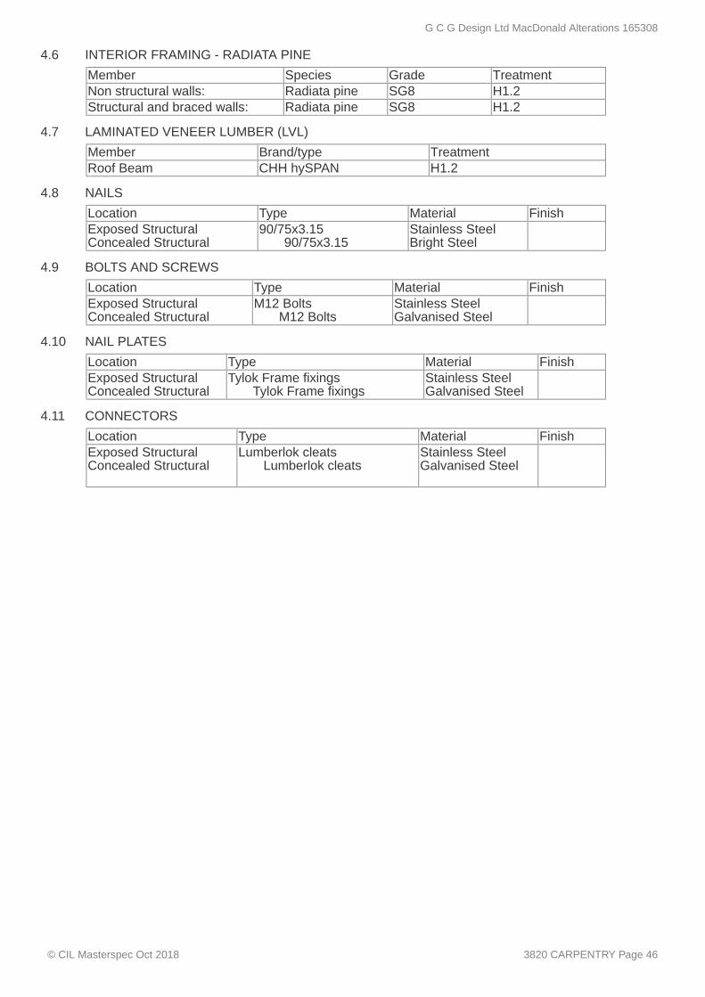
4.6 INTERIOR FRAMING - RADIATA PINE
4.7 LAMINATED VENEER LUMBER (LVL)
4.8 NAILS
4.9 BOLTS AND SCREWS
4.10 NAIL PLATES
4.11 CONNECTORS
Member Species Grade TreatmentNon structural walls: Radiata pine SG8 H1.2Structural and braced walls: Radiata pine SG8 H1.2
Member Brand/type TreatmentRoof Beam CHH hySPAN H1.2
Location Type Material FinishExposed StructuralConcealed Structural
90/75x3.15 90/75x3.15
Stainless SteelBright Steel
Location Type Material FinishExposed StructuralConcealed Structural
M12 Bolts M12 Bolts
Stainless SteelGalvanised Steel
Location Type Material FinishExposed StructuralConcealed Structural
Tylok Frame fixings Tylok Frame fixings
Stainless SteelGalvanised Steel
Location Type Material FinishExposed StructuralConcealed Structural
Lumberlok cleats Lumberlok cleats
Stainless SteelGalvanised Steel
G C G Design Ltd MacDonald Alterations 165308
© CIL Masterspec Oct 2018 3820 CARPENTRY Page 46

4131A ARDEX DAMP-PROOF MEMBRANES
1 GENERAL
1.1 ABBREVIATIONS AND DEFINITIONS
1.2 DOCUMENTS
1.3 MANUFACTURER'S DOCUMENTS
1.4 WARRANTY - MANUFACTURER/SUPPLIER
1.5 WARRANTY - INSTALLER/APPLICATOR
This section relates to the application of the following ARDEX damp-proof membranes:
ARDEX WPM 3000X (Shelterseal) self adhesive SBS modified bituminous membraneARDEX WPM 5000HD (Shelterseal HD) self adhesive SBS modified bituminous membrane
Refer to the general section 1232 INTERPRETATION & DEFINITIONS for abbreviations anddefinitions used throughout the specification. The following abbreviations apply specifically to this section:SBS Styrene-butadiene-styrene rubber
Documents
Refer to the general section 1233 REFERENCED DOCUMENTS. Documents cited in the clauses that follow are part of this specification. However, this specificationtakes precedence in the event of it being at variance with the cited document.
Manufacturer's and supplier's documents relating to work in this section are:ARDEX Waterproofing ManualARDEX Below Ground ManualARDEX WPM 3000X Datasheet and Safety Data SheetARDEX WPM 5000HD Datasheet and Safety Data SheetBRANZ Appraisal 462 - Shelterseal Damp-Proof Membranes Copies of the above literature are available from:Company: ARDEX New Zealand LimitedWeb: www.ardex.co.nzEmail: [email protected]: 0800 2 ARDEX (27339) 09 636 0005 Auckland 04 568 5949 Wellington 03 373 6900 Christchurch
Warranties
Provide a material manufacturer/supplier warranty:10 years: For walls only20 years: For wall, footing and slab
Provide this warranty on the ARDEX manufacturer/supplier standard form.Commence the warranty from the date of practical completion of the contract works.
Refer to the general section 1237 WARRANTIES for additional requirements.For project specific warranty requirements contact ARDEX.
Provide an installer/applicator warranty:5 years: For wall, footing and slab application
ARDEX approved installer to provide this warranty on the ARDEX installer/applicator standardform.Commence the warranty from the date of practical completion of the contract works.
Refer to the general section 1237 WARRANTIES for additional requirements.
G C G Design Ltd MacDonald Alterations 165308
© CIL Masterspec Oct 2018 4131A ARDEX DAMP-PROOF MEMBRANES Page 47
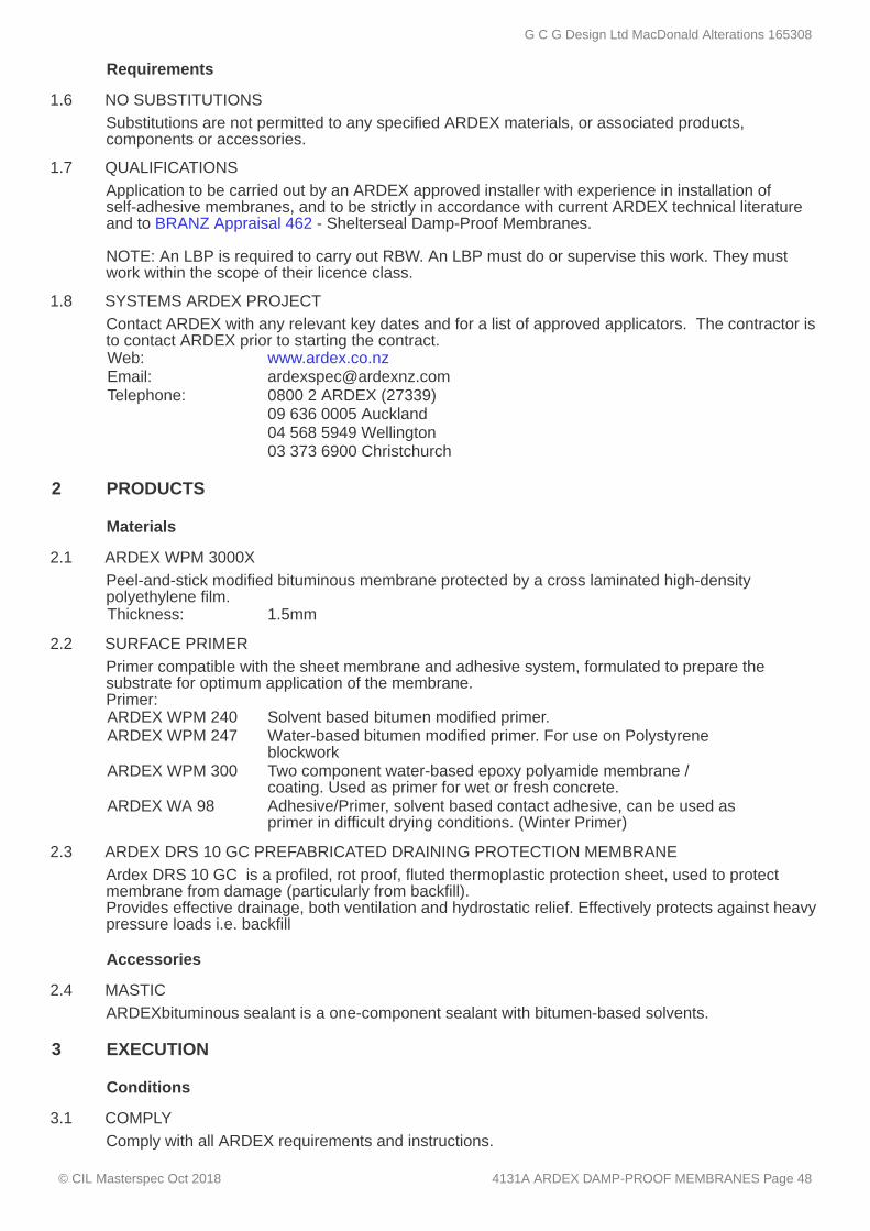
1.6 NO SUBSTITUTIONS
1.7 QUALIFICATIONS
1.8 SYSTEMS ARDEX PROJECT
2 PRODUCTS
2.1 ARDEX WPM 3000X
2.2 SURFACE PRIMER
2.3 ARDEX DRS 10 GC PREFABRICATED DRAINING PROTECTION MEMBRANE
2.4 MASTIC
3 EXECUTION
3.1 COMPLY
Requirements
Substitutions are not permitted to any specified ARDEX materials, or associated products,components or accessories.
Application to be carried out by an ARDEX approved installer with experience in installation ofself-adhesive membranes, and to be strictly in accordance with current ARDEX technical literatureand to BRANZ Appraisal 462 - Shelterseal Damp-Proof Membranes. NOTE: An LBP is required to carry out RBW. An LBP must do or supervise this work. They mustwork within the scope of their licence class.
Contact ARDEX with any relevant key dates and for a list of approved applicators. The contractor isto contact ARDEX prior to starting the contract.Web: www.ardex.co.nzEmail: [email protected]: 0800 2 ARDEX (27339) 09 636 0005 Auckland 04 568 5949 Wellington 03 373 6900 Christchurch
Materials
Peel-and-stick modified bituminous membrane protected by a cross laminated high-densitypolyethylene film.Thickness: 1.5mm
Primer compatible with the sheet membrane and adhesive system, formulated to prepare thesubstrate for optimum application of the membrane.Primer:ARDEX WPM 240 Solvent based bitumen modified primer.ARDEX WPM 247 Water-based bitumen modified primer. For use on Polystyrene
blockworkARDEX WPM 300 Two component water-based epoxy polyamide membrane /
coating. Used as primer for wet or fresh concrete.ARDEX WA 98 Adhesive/Primer, solvent based contact adhesive, can be used as
primer in difficult drying conditions. (Winter Primer)
Ardex DRS 10 GC is a profiled, rot proof, fluted thermoplastic protection sheet, used to protectmembrane from damage (particularly from backfill).Provides effective drainage, both ventilation and hydrostatic relief. Effectively protects against heavypressure loads i.e. backfill
Accessories
ARDEXbituminous sealant is a one-component sealant with bitumen-based solvents.
Conditions
Comply with all ARDEX requirements and instructions.
G C G Design Ltd MacDonald Alterations 165308
© CIL Masterspec Oct 2018 4131A ARDEX DAMP-PROOF MEMBRANES Page 48

3.2 STORE
3.3 WEATHER CONDITIONS
3.4 CHECK SUBSTRATE
3.5 CURING OF NEW CONCRETE
3.6 CONCRETE SLAB-ON-GROUND
3.7 ENSURE SUBSTRATE
3.8 PREPARE SUBSTRATE
3.9 TURN UPS
3.10 TURN DOWNS
3.11 CLEAN SURFACES
3.12 REMOVE OTHER FORMWORK
3.13 PRIMING
3.14 CONTROL JOINTS
Store membranes and accessory materials under conditions that ensure no deterioration ordamage. Store rolls in an upright position on a smooth floor and protected from sunlight, UVradiation and moisture.
Apply damp-proof membranes only in fair weather with air temperature above 5°C.
Check that the substrate will allow work of the required standard. Complete any remedial workidentified before commencing any work.
Allow concrete and masonry to dry to ARDEX requirements before applying membranes. Recommended minimum curing of new concrete and concrete-filled masonry: 28 days. Alternativelyuse WPM 300 primer for wet or fresh concrete.
Membrane must be laid on minimum 75mm thick site concrete.
Application - Preparation
Ensure all surfaces are free from voids, spalled areas, loose particles, and sharp protrusions. Ensure no projections of sharp materials exist that will cause damage to membrane. Check thatconcrete block joints are struck off flush. Ensure form oils or release agents and curing compounds are completely removed.
Remove projections, wire-brush and remove all debris, leaving the surface dust-free, oil-free andclean, with nothing that could diminish the adhesion of primers. Fill tie holes flush and smooth withmortar. Grind off steps or sharp protrusions caused by formwork joints.
Where damp-proofing is turned up against hardened concrete, ensure the surface is smooth andfree of all sharp projections. Fill internal corners with a fillet of latex-modified cement mortar, orepoxy mortar.
Where damp-proofing is turned over an external corner, first grind the corner to produce a smooth25mm radius or chamfer.
Clean surfaces with a broom or oil free compressed air to remove dust, loose particles and materialthat could affect bonding.
Ensure that formwork has been removed or partially removed from the other face(s) to themembrane face, to the extent that it allows moisture to escape from the concrete to ensure novapour pressure develops beneath the membrane.
Ensure concrete or masonry substrates are sufficiently cured and dry to permit the intendedperformance of the primer. Apply ARDEX-approved primer by brush, roller or airless spray at amaximum coverage rate of 5m² per litre. Apply water borne WPM 247 primer to polystyrene blocks. Ensure that the surface is clean.
Where control or construction joints are formed in the substrate, ARDEX must be consulted for useof the membranes over these joints.
Application
G C G Design Ltd MacDonald Alterations 165308
© CIL Masterspec Oct 2018 4131A ARDEX DAMP-PROOF MEMBRANES Page 49
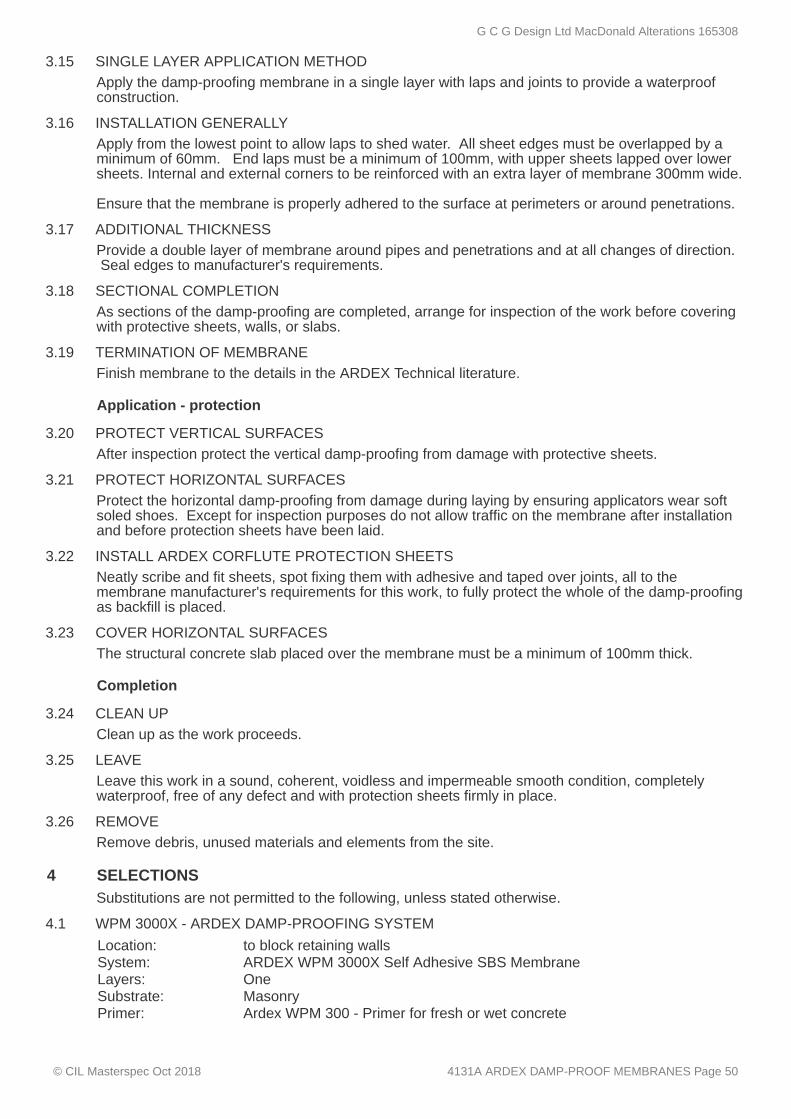
3.15 SINGLE LAYER APPLICATION METHOD
3.16 INSTALLATION GENERALLY
3.17 ADDITIONAL THICKNESS
3.18 SECTIONAL COMPLETION
3.19 TERMINATION OF MEMBRANE
3.20 PROTECT VERTICAL SURFACES
3.21 PROTECT HORIZONTAL SURFACES
3.22 INSTALL ARDEX CORFLUTE PROTECTION SHEETS
3.23 COVER HORIZONTAL SURFACES
3.24 CLEAN UP
3.25 LEAVE
3.26 REMOVE
4 SELECTIONS
4.1 WPM 3000X - ARDEX DAMP-PROOFING SYSTEM
Apply the damp-proofing membrane in a single layer with laps and joints to provide a waterproofconstruction.
Apply from the lowest point to allow laps to shed water. All sheet edges must be overlapped by aminimum of 60mm. End laps must be a minimum of 100mm, with upper sheets lapped over lowersheets. Internal and external corners to be reinforced with an extra layer of membrane 300mm wide. Ensure that the membrane is properly adhered to the surface at perimeters or around penetrations.
Provide a double layer of membrane around pipes and penetrations and at all changes of direction. Seal edges to manufacturer's requirements.
As sections of the damp-proofing are completed, arrange for inspection of the work before coveringwith protective sheets, walls, or slabs.
Finish membrane to the details in the ARDEX Technical literature.
Application - protection
After inspection protect the vertical damp-proofing from damage with protective sheets.
Protect the horizontal damp-proofing from damage during laying by ensuring applicators wear softsoled shoes. Except for inspection purposes do not allow traffic on the membrane after installationand before protection sheets have been laid.
Neatly scribe and fit sheets, spot fixing them with adhesive and taped over joints, all to themembrane manufacturer's requirements for this work, to fully protect the whole of the damp-proofingas backfill is placed.
The structural concrete slab placed over the membrane must be a minimum of 100mm thick.
Completion
Clean up as the work proceeds.
Leave this work in a sound, coherent, voidless and impermeable smooth condition, completelywaterproof, free of any defect and with protection sheets firmly in place.
Remove debris, unused materials and elements from the site.
Substitutions are not permitted to the following, unless stated otherwise.
Location: to block retaining wallsSystem: ARDEX WPM 3000X Self Adhesive SBS MembraneLayers: OneSubstrate: MasonryPrimer: Ardex WPM 300 - Primer for fresh or wet concrete
G C G Design Ltd MacDonald Alterations 165308
© CIL Masterspec Oct 2018 4131A ARDEX DAMP-PROOF MEMBRANES Page 50

4.2 SEALER FOR ADDITIONAL THICKNESS
4.3 ARDEX PROTECTION MEMBRANE
Location: internal/external cornersProduct: Check any special requirements with ARDEX.
Manufacturer: ARDEXBrand: ARDEX DRS 10 GC prefabricated drainage protection membrane
G C G Design Ltd MacDonald Alterations 165308
© CIL Masterspec Oct 2018 4131A ARDEX DAMP-PROOF MEMBRANES Page 51

4161T THERMAKRAFT UNDERLAYS, FOILS & DPC
1 GENERAL
1.1 ABBREVIATIONS AND DEFINITIONS
1.2 DOCUMENTS
This section relates to the application of Thermakraft Ltd, DPC, DPM, wall underlays, roofingunderlays and accessories.
Refer to the general section 1232 INTERPRETATION & DEFINITIONS for abbreviations anddefinitions used throughout the specification. The following abbreviations apply specifically to this section:NZMRM New Zealand Metal Roofing Manufacturers Inc. The following definitions apply specifically to this section:Wall underlay the same meaning as defined in NZBC E2/AS1, covering kraft
based and synthetic wall underlays, sometimes called, wall wraps,building wraps or building papers.
Documents
Refer to the general section 1233 REFERENCED DOCUMENTS. The following documents arespecifically referred to in this section:NZBC C/AS1-AS7 Protection from fireNZBC E2/AS1 External moistureAS 1530.2 Methods for fire tests on building materials, components and
structures - Test for flammability of materialsNZS 2295 Pliable, permeable building underlaysAS/NZS 2904 Damp-proof courses and flashingsNZS 3604 Timber-framed buildingsNZS 4214 Methods of determining the total thermal resistance of parts of
buildingsAS/NZS 4389 Roof safety meshAS/NZS 4534 Zinc and zinc/aluminium-alloy coatings on steel wireNZMRM CoP NZ metal roof and wall cladding Code of Practice
G C G Design Ltd MacDonald Alterations 165308
© CIL Masterspec Oct 2018 4161T THERMAKRAFT UNDERLAYS, FOILS & DPC Page 52
1.3 MANUFACTURER/SUPPLIER DOCUMENTS
1.4 WARRANTY - MANUFACTURER/SUPPLIER
1.5 NO SUBSTITUTIONS
1.6 INSTALLATION SKILL LEVELS
2 PRODUCTS
2.1 EMBOSSED POLYETHYLENE
Thermakraft documents relating to work in this section are:Thermakraft product manual and technical data sheets.BRANZ Appraisal 329 - Supercourse 500™ Damp-Proof Course and Concealed FlashingBRANZ Appraisal 651 - Thermakraft Covertek™ 407 Fire Retardant Self-Supporting Roof UnderlayBRANZ Appraisal 695 - Watergate-Plus 295™ Fire Retardant Wall UnderlayBRANZ Appraisal 743 - Thermakraft Covertek 405™ Plus Fire Retardant Self-Supporting RoofUnderlayBRANZ Appraisal 867 - Thermakraft Steelwrap 290™ Fire Retardant Wall UnderlayBRANZ Appraisal 878 - Thermakraft Aluband™ Window Flashing TapeBRANZ Appraisal 912 - Thermakraft 220™ Wall UnderlayBRANZ Appraisal 917 - Thermakraft Covertek 403™ Plus Fire Retardant Roof UnderlayBRANZ Appraisal 918 - Thermakraft Covertek 403™ Plus Fire Retardant Wall UnderlayBRANZ Appraisal 919 - Thermakraft Aluband™ Acrylic Window Flashing TapeBRANZ Appraisal 942 - Multi-Fit Penetration SealsBRANZ Appraisal 943 - Thermakraft 401™ Roof UnderlayBRANZ Appraisal 947 - Aluband XTREME Flashing TapeBRANZ Appraisal 962 - The Thermakraft One Wrap SystemBRANZ Appraisal 1000 - Thermakraft Thermabar 397 Light Diffusing Reflective Underlay Code Mark Certificate 30069 - Thermakraft Covertek 403™ Plus Absorbent Breathable RoofUnderlayCode Mark Certificate 30030 - Thermakraft Covertek 405™ Absorbent Breathable Roof UnderlayCode Mark Certificate 30028 - Thermakraft Covertek 407™ Absorbent Breathable Roof Underlay Manufacturer/supplier contact details Company: Thermakraft LtdWeb: www.thermakraft.co.nzEmail: [email protected]: 0800 806 595
Warranties
Warrant this work under normal environmental and use conditions against failure of materials andexecution. Thermakraft Ltd warrant performance of products if design and installation complies withrelevant technical literature, NZBC, and recognised industry Codes of Practice. Copy ofThermakraft ™ Product Warranty available on request.
Requirements
Substitutions are not permitted to any specified materials, or associated products, components oraccessories.
Installers to be experienced in the installation of Thermakraft ™ products and familiar withThermakraft ™ technical literature and the related documents listed in this design i.e. NZMRM CoPNZ metal roof and wall cladding Code of Practice.
Materials
DPC
Supercourse 500™ hi-impact polyethylene film to AS/NZS 2904 and embossed on both sides. Thickness 500 microns minimum, manufactured for use as a damp-proof course and concealedflashings around doors and windows and to BRANZ Appraisal 329. Refer to SELECTIONS for typeof jointing tape.
G C G Design Ltd MacDonald Alterations 165308
© CIL Masterspec Oct 2018 4161T THERMAKRAFT UNDERLAYS, FOILS & DPC Page 53
2.2 DAMP-PROOF MEMBRANE - MEDIUM DUTY, BLACK
2.3 SYNTHETIC BREATHER TYPE FILM COATED WALL UNDERLAY
2.4 WINDOW AND DOOR SEALING TAPE - ALUBAND™
2.5 WINDOW AND DOOR SEALING TAPE - ALUBAND™ ACRYLIC
2.6 WINDOW AND DOOR SEALING TAPE - ALUBAND™ XTREME
2.7 MULTI-FIT SEALS FOR UNDERLAY PENETRATIONS
2.8 STUD STRAPS - POLYETHYLENE
2.9 STUD STRAPS - POLYPROPYLENE
2.10 TAPE
3 EXECUTION
3.1 GENERAL REQUIREMENTS
DPM
Thermathene Black™, a minimum of 250 microns polyethylene film. Complies with NZS 3604,7.5.4, Damp-proof Membrane, to NZBC E2/AS1. Refer to SELECTIONS for type of jointing tape.
Wall underlays
Watergate-Plus™ 295, absorbent breathable spun bonded non-woven polyolefin type buildingmembrane, coated with a water resistant vapour permeable film. A fire retardant membrane, withFlammability Index of ≤ 5, when tested to AS 1530.2. The product has a BRANZ Appraisal 695.
Accessories
Thermakraft Aluband™ Window Sealing Tape system consists of synthetic faced reinforcedbituminous window sealing tape, in widths of 75mm, 150mm and 200mm, Thermakraft Aluband™Corner Moulding™ piece, used in conjunction with the Thermakraft Aluband™ Hand Tool to ensuregood adhesion and a tight fit into corners. Refer to Thermakraft Data Sheet for installation detailsand BRANZ Appraisal 878.
Thermakraft Aluband™ Acrylic Window Sealing Tape system is a high strength pressure sensitiveacrylic adhesive on a Polyolefin film, in widths of 75mm, 150mm and 200mm, ideal for use when incontact with sealants, used in conjunction with Thermakraft Aluband™ Corner Moulding™ piece,and Thermakraft Aluband™ Hand Tool to ensure good adhesion and a tight fit into corners. Refer toThermakraft Data Sheet for installation details and BRANZ Appraisal 919.
Thermakraft Aluband™ Xtreme Flashing Tape window sealing tape system is a high strength thinsection pressure sensitive co-polymer adhesive tape, in widths of 75mm, 150mm and 200mm, idealfor use when in contact with sealants, used in conjunction with Thermakraft Aluband™ CornerMoulding™ piece, and the Thermakraft Aluband™ Hand Tool to ensure good adhesion and a tight fitinto corners. Refer to Thermakraft Data Sheet for installation details and BRANZ Appraisal 947.
Thermakraft™ Multi-Fit seals are a UV resistant EPDM material which forms a weathertight air sealfor pipes and penetrations with a high strength acrylic adhesive suitable for use on all underlaysystems. Available for use with pipes 15-110mm and cables 7-22mm both are pre-punchedensuring a tight accurate fit. No special tools required for installation.
Thermastrap™ 201, 19mm wide polyethylene straps.
Thermakraft StudStrap™, 25mm wide polypropylene strap.
Thermakraft™ tapes to compliment the underlay. Pressure sensitive aluminium foil tapes for joiningfoil insulation and vapour barriers. These include:
Thermakraft™ White General Purpose Underlay TapeThermakraft™ Foil Tape 150Thermakraft™ Window Sealing Tapes, used to repair damaged bituminous underlays
Conditions
Design application and installation of Thermakraft Building products to NZBC E2/AS1, BRANZAppraisals, Thermakraft Technical Literature and Industry Codes of Practice.
G C G Design Ltd MacDonald Alterations 165308
© CIL Masterspec Oct 2018 4161T THERMAKRAFT UNDERLAYS, FOILS & DPC Page 54
3.2 STORAGE
3.3 INSPECTION
3.4 DPC TO LOSP/CCA TREATED TIMBER
3.5 DPC TO TIMBER / STEEL
3.6 DPC TO MASONRY AND BRICK VENEER
3.7 DPM TO CONCRETE FLOOR
3.8 WALL UNDERLAY
3.9 INSTALL STUD STRAPS
3.10 METAL CLADDING ON TIMBER CAVITY BATTENS
3.11 CLEAN UP
3.12 LEAVE
3.13 REMOVE
4 SELECTIONS
Store building underlays and accessory materials, under conditions that ensure no deterioration ordamage. Store rolls in an upright position on a smooth floor and protected from sunlight, UVradiation and moisture.
Before starting work, check that the building construction phase will allow work of the requiredstandard. Carry out remedial work identified before laying underlay.
Application DPC
Lay Supercourse 500™ DPC under LOSP or CCA treated bottom plate of all timber framed walls onconcrete, in a single layer with 50mm overlaps at joints to provide a waterproof barrier.
Lay Supercourse 500™ DPC under the bottom plate of all timber / steel framed walls on concrete, ina single layer with 50mm overlaps at joints to provide a waterproof barrier. Refer to SELECTIONSfor type.
Lay Supercourse 500™ DPC along based of cavity and fix top edge to studs with galvanized clouts. Turn DPC out over concrete rebate under bottom course of veneer.
Application - DPM
Lay DPM under concrete floor substrate over sand blinding, in a single layer with 150mm overlaps atjoints to provide a waterproof barrier. Refer to SELECTIONS for type. Tape all joints andpenetrations with Thermakraft ™ White GP Tape 60mm.
Application - wall underlay
Fix horizontally to outside face of framing in true alignment, with succeeding sheets overlapping150mm to NZBC E2/AS1, 9.1.7, Wall underlay, and refer to Thermakraft ™ for requirement forfastenings. Fix to Thermakraft ™ Technical Data specifications. Scribe neatly around penetrationsand openings to leave no gaps. Tape all penetrations. Keep clean, undamaged and without visibleweather deterioration until closed in.
Over underlay, install Thermastrap 201™ 19mm wide polyethylene straps horizontally at 300mmcentres, draw taut and fix to studs with stainless steel staples.
Fix strip of Thermakraft ™ Supercourse 500 DPC as a separator between the timber and metalcladding.
Completion
Clean up as the work proceeds.
Leave work to the standard required by following procedures.
Remove debris, unused materials and elements from the site.
For further details on selections go to www.thermakraft.co.nz.Substitutions are not permitted to the following, unless stated otherwise.
G C G Design Ltd MacDonald Alterations 165308
© CIL Masterspec Oct 2018 4161T THERMAKRAFT UNDERLAYS, FOILS & DPC Page 55

4.1 THERMAKRAFT - SUPERCOURSE 500™ DPC
4.2 THERMATHENE BLACK™
4.3 THERMAKRAFT WATERGATE-PLUS™ 295
4.4 THERMAKRAFT - ALUBAND™ ACRYLIC™
4.5 THERMASTRAP
Damp Proof Course
Location: between timber framing and masonry/concreteType: Supercourse 500™ DPCJointing tape: Thermakraft™ window sill tape 75mm Aluband™
Damp Proof Membrane
Location: under new floor slabsType: Thermathene Black™Jointing tape: Thermakraft™ White General Purpose Underlay Tape
Wall Underlays
Location: to new/ relined exterior wallsType: Thermakraft Watergate-Plus™ 295Jointing tape: Thermakraft™ white GP tape 60mm
Window / Door Sealing System
Location: window surroundsSill/head tape: 150mm Thermakraft Aluband™ Acrylic (for 90mm framing)Sill second layer: 75mm Thermakraft Aluband™ Acrylic (on top of sill over first layer)Sill corners: Thermakraft Aluband™ Corner Moulding™Butterfly corners: 75mm Thermakraft Aluband™ Acrylic (across head corners)
Stud Straps
Location: to new/ relined exterior walls Type: Thermastrap™ 201, 19mm blue polypropylene tape
G C G Design Ltd MacDonald Alterations 165308
© CIL Masterspec Oct 2018 4161T THERMAKRAFT UNDERLAYS, FOILS & DPC Page 56

4221TP TIMSPEC RADIATA PINE HORIZONTALWEATHERBOARDS
1 GENERAL
1.1 RELATED WORK
1.2 ABBREVIATIONS AND DEFINITIONS
1.3 DOCUMENTS
This section relates to the supply and fixing of Timber Specialists Ltd (Timspec) CertClad®,horizontal radiata pine weatherboard cladding systems over drained cavity.It includes:
Bevel back weatherboardsRusticated weatherboardsWeatherboard trimCavity batten systemsFixingsFlashingsPre-finishing
Refer to 4161 UNDERLAYS, FOILS & DPC for wall underlaysRefer to 3821 TIMBER FRAMING for wall framing and cavity battensRefer to 6700 PAINTING GENERAL & 6711 PAINTING EXTERIOR for on-site finishes toweatherboard cladding.
Refer to the general section 1232 INTERPRETATION & DEFINITIONS for abbreviations anddefinitions used throughout the specification. The following abbreviations apply specifically to this section:FSC Forest Stewardship CouncilNASH National Association of Steel Framed HousingPEFC Programme for the Endorsement of Forest Certification Schemes
Documents
Refer to the general section 1233 REFERENCED DOCUMENTS. The following documents arespecifically referred to in this section:NZBC B2/AS1 DurabilityNZBC E2/AS1 External moistureNZS 3602 Timber and wood-based products for use in buildingNZS 3604 Timber-framed buildingsBRANZ BU 582 Structurally fix cavity battensNASH Standard Residential and low-rise steel framing Part 1: Design Criteria & Part
2: Light steel framed buildings
G C G Design Ltd MacDonald Alterations 165308
© CIL Masterspec Oct 2018 4221TP TIMSPEC RADIATA PINE HORIZONTAL WEATHERBOARDS Page 57

1.4 MANUFACTURER/SUPPLIER DOCUMENTS
1.5 QUALIFICATIONS
1.6 NO SUBSTITUTIONS
1.7 COMPLIANCE - RUSTICATED WEATHERBOARDS
1.8 PERFORMANCE
1.9 DESIGN PARAMETERS WIND - DESIGN BY CONTRACTOR
2 PRODUCTS
2.1 TIMBER SPECIES - RADIATA PINE
Timspec CertClad® documents relating to this part of the work:Timspec CertClad® Bevel Back Cavity System, Radiata Pine Installation Manual - V3Timspec CertClad® Rusticated Cavity System, Radiata Pine Installation Manual - V3FSC and PEFC Forestry Sustainable Certification - contact Timspec CertClad®CodeMark CMA-CM40053- Timspec CertClad® Rusticated Cavity SystemCodeMark CMA-CM40010- Timspec CertClad® Bevel Back WeatherboardsBranz Appraisal 524 - Cavibat Cavity Battens Manufacturer/supplier contact detailsCompany: Timber Specialists Ltd (Timspec)Contacts: Auckland - Chris Wiffen or Jonathan Rugg (09 620 0260) Christchurch - Gareth Goodman Jones or Stephen Norris (03 341
0242)Web: www.certclad.co.nz www.timspec.co.nzEmail: [email protected]: 09 620 0260 Auckland 03 341 0242 Christchurch
Requirements
Installers to be experienced, competent trades people familiar with the materials and techniquesspecified.
Substitutions are not permitted to any of the specified systems, components and associatedproducts listed in this section.
To meet the requirements of the CodeMark certificate CodeMark CMA-CM40053:-Risk Score to E2/AS1 no greater than 20Wind zone to NZS 3604 no greater than Very High (without special provisions).Installation to; Timspec CertClad® Rusticated Cavity System, Radiata Pine InstallationManual.
Performance
Accept responsibility for the weather-tight performance of the completed cladding system, includingall penetrations. To NZBC B2/AS1 Durability and NZBC E2/AS1 External moisture.
Performance - Wind (design by contractor)
Design the installation to the manufacturer's requirements and as appropriate for the project winddesign stated in the general section 1220 PROJECT.
Materials
Timspec CertClad® Radiata pine, grading to NZS 3602, NZS 3631, treatment H3.1 or H3.2 to NZS3602, table 2, reference 2A.1, Requirements for wood-based building components to achieve a15-year durability performance. Weatherboards in long lengths, with all knots excluded. Timspec CertClad® Radiata pine is supplied from New Zealand forest sources, a mixture of FSCcertified and non-contentious resources.Refer to Timspec CertClad® details.
G C G Design Ltd MacDonald Alterations 165308
© CIL Masterspec Oct 2018 4221TP TIMSPEC RADIATA PINE HORIZONTAL WEATHERBOARDS Page 58

2.2 WEATHERBOARD PROFILE - RUSTICATED
2.3 COVER BOARDS, MOULDINGS AND SCRIBERS
2.4 WALL UNDERLAYS
2.5 CAVITY BATTENS - TIMBER NON-STRUCTURAL
2.6 EXTERIOR CAVITY CLOSER/VERMIN-PROOFING
2.7 NAILS, STAINLESS STEEL
2.8 FLASHINGS
2.9 ADHESIVE
2.10 SEALANT
2.11 FACTORY PRE-FINISHING - OIL BASED PRIMER & UNDERCOAT
3 EXECUTION
3.1 GENERALLY
Timspec CertClad® profiles P67 or P68 Radiata pine and additional profiles P835 - P839. Weatherboards in lengths relevant to profile selection and application, with all unsound and opensplit knots excluded by cross cut removal prior to fixing into position. Refer to SELECTIONS.
To Timspec CertClad® profiles as detailed, with species and grading to NZS 3602, but with allunsound and open split knots excluded by cross cut removal prior to fixing into position. To NZS3602, table 2, reference 2A.3, Requirements for wood-based building components to achieve a15-year durability performance.
For flexible wall underlays and rigid wall underlays, refer to the appropriate separate section(s).
Non-Structural Fixing: Radiata pine minimum H3.1 battens, minimum 20mm thickness, width andheight to match timber framing studs.Temporary fix battens before being fixed into the framing with the cladding fixings. Treatment toNZBC B2/AS1 and NZS 3602, table 1, reference 1D.10, Requirements for wood-based buildingcomponents to achieve a 50-year durability performance.
Aluminium with upstands. Upstand one side 10mm and the other 75mm. Length and width to suitcavity. To NZBC E2/AS1: clause 9.1.8.3 and figure 66.
Components
Timspec Jolt Head, Annular Grooved Shank Grade 316 Stainless steel fixings to NZBC E2/AS1Table 24. Refer to Timspec CertClad® construction details for fixing details and to SELECTIONSfor fixing sizes.
To NZBC E2/AS1, 4.0 Flashings. Material, grade and colour as detailed and scheduled and toNZBC E2/AS1; Table 21: Compatibility of materials in contact and Table 22: Compatibility ofmaterials subject to run-off. Ensure that materials used for flashings are compatible with thewindow frame materials and fixings and cladding materials and fixings.
Adhesives / sealants
Two-part epoxy adhesive, suitable for exterior use with timber, metals and plastics.
Polyureathane or silane terminated polymers (PU-hybrid technology) construction sealant.
Finishes
Factory spray application of selected solvent based oil primer and undercoat (only) on to timbersurface. Refer to SELECTIONS for brand and type. Top coat site applications to manufacturer's specifications. Refer to painting sections.
Conditions
Execution to Timspec CertClad® CodeMark, NZBC E2/AS1: 3.0 Weathertightness risk factors,and 9.0 Wall claddings, 9.1.8 Drained cavities and 9.4 Timber weatherboards.
G C G Design Ltd MacDonald Alterations 165308
© CIL Masterspec Oct 2018 4221TP TIMSPEC RADIATA PINE HORIZONTAL WEATHERBOARDS Page 59
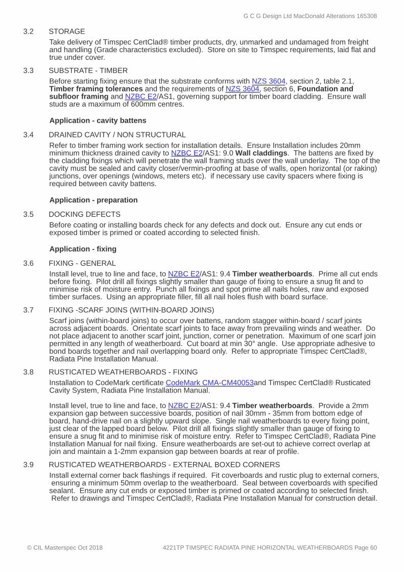
3.2 STORAGE
3.3 SUBSTRATE - TIMBER
3.4 DRAINED CAVITY / NON STRUCTURAL
3.5 DOCKING DEFECTS
3.6 FIXING - GENERAL
3.7 FIXING -SCARF JOINS (WITHIN-BOARD JOINS)
3.8 RUSTICATED WEATHERBOARDS - FIXING
3.9 RUSTICATED WEATHERBOARDS - EXTERNAL BOXED CORNERS
Take delivery of Timspec CertClad® timber products, dry, unmarked and undamaged from freightand handling (Grade characteristics excluded). Store on site to Timspec requirements, laid flat andtrue under cover.
Before starting fixing ensure that the substrate conforms with NZS 3604, section 2, table 2.1,Timber framing tolerances and the requirements of NZS 3604, section 6, Foundation andsubfloor framing and NZBC E2/AS1, governing support for timber board cladding. Ensure wallstuds are a maximum of 600mm centres.
Application - cavity battens
Refer to timber framing work section for installation details. Ensure Installation includes 20mmminimum thickness drained cavity to NZBC E2/AS1: 9.0 Wall claddings. The battens are fixed bythe cladding fixings which will penetrate the wall framing studs over the wall underlay. The top of thecavity must be sealed and cavity closer/vermin-proofing at base of walls, open horizontal (or raking)junctions, over openings (windows, meters etc). if necessary use cavity spacers where fixing isrequired between cavity battens.
Application - preparation
Before coating or installing boards check for any defects and dock out. Ensure any cut ends orexposed timber is primed or coated according to selected finish.
Application - fixing
Install level, true to line and face, to NZBC E2/AS1: 9.4 Timber weatherboards. Prime all cut endsbefore fixing. Pilot drill all fixings slightly smaller than gauge of fixing to ensure a snug fit and tominimise risk of moisture entry. Punch all fixings and spot prime all nails holes, raw and exposedtimber surfaces. Using an appropriate filler, fill all nail holes flush with board surface.
Scarf joins (within-board joins) to occur over battens, random stagger within-board / scarf jointsacross adjacent boards. Orientate scarf joints to face away from prevailing winds and weather. Donot place adjacent to another scarf joint, junction, corner or penetration. Maximum of one scarf joinpermitted in any length of weatherboard. Cut board at min 30° angle. Use appropriate adhesive tobond boards together and nail overlapping board only. Refer to appropriate Timspec CertClad®,Radiata Pine Installation Manual.
Installation to CodeMark certificate CodeMark CMA-CM40053and Timspec CertClad® RusticatedCavity System, Radiata Pine Installation Manual. Install level, true to line and face, to NZBC E2/AS1: 9.4 Timber weatherboards. Provide a 2mmexpansion gap between successive boards, position of nail 30mm - 35mm from bottom edge ofboard, hand-drive nail on a slightly upward slope. Single nail weatherboards to every fixing point,just clear of the lapped board below. Pilot drill all fixings slightly smaller than gauge of fixing toensure a snug fit and to minimise risk of moisture entry. Refer to Timspec CertClad®, Radiata PineInstallation Manual for nail fixing. Ensure weatherboards are set-out to achieve correct overlap atjoin and maintain a 1-2mm expansion gap between boards at rear of profile.
Install external corner back flashings if required. Fit coverboards and rustic plug to external corners, ensuring a minimum 50mm overlap to the weatherboard. Seal between coverboards with specifiedsealant. Ensure any cut ends or exposed timber is primed or coated according to selected finish. Refer to drawings and Timspec CertClad®, Radiata Pine Installation Manual for construction detail.
G C G Design Ltd MacDonald Alterations 165308
© CIL Masterspec Oct 2018 4221TP TIMSPEC RADIATA PINE HORIZONTAL WEATHERBOARDS Page 60

3.10 RUSTICATED WEATHERBOARDS - INTERNAL CORNER MOULDING
3.11 INSTALL FLASHINGS
3.12 PRE-FINISHED BOARDS - FINAL COAT
3.13 COMPLETE
3.14 ROUTINE CLEANING
3.15 DEFECTIVE OR DAMAGED WORK
4 SELECTIONS
4.1 TIMSPEC CERTCLAD - WEATHERBOARDS - RUSTICATED
4.2 TIMSPEC CERTCLAD - TRIMS AND SCRIBERS
4.3 FIXINGS - RUSTICATED
Install internal corner back flashing. Trim weatherboard ends to butt up tightly to a D4S 40x40mm or20x20mm moulding. Seal between weatherboards and moulding with specified sealant. Ensureany cut ends or exposed timber is primed or coated according to selected finish. Refer to drawings and Timspec CertClad®, Radiata Pine Installation Manual for construction detail.
Install flashings, covers and soakers as detailed on the drawings or Timspec CertClad®, RadiataPine Installation Manual and to NZBC E2/AS1. Ensure minimum flashing cover to weatherboards ismaintained depending on corner option selected.
All pre-finished boards and trim will require a final finishing coat to the manufacturer's specifications. Allow to touch up and repair any damage before the final coating is applied.
Ensure the work is complete with all flashings, finishings and trim properly installed so the claddingsystem is completely weathertight.
Completion
Carry out routine trade cleaning of this part of the work including periodic removal of all debris,unused and temporary materials and elements from the site.
Repair damaged or marked elements. Replace damaged or marked elements where repair is notpossible or will not be acceptable. Leave work to the standard required for following procedures.
For further details on selections go to www.certclad.co.nz.Substitutions are not permitted to the following, unless stated otherwise.
Weatherboards and trim
Location: as noted on plansSpecies: Timspec CertClad® Radiata PineGrade: Radiata Pine No 2 clears gradeTreatment: H3.2 CCA. Profile: check to match existingCover dimensions: 165mm-check to match existingThickness: 19mm-check to match existingMoisture content: 14 - 18% at fixingPre-finish: oil based primer and undercoat, acrylic finish coat (with primer &
undercoat)
Location: Soffit moulds and window scribersSpecies: Timspec CertClad® Radiata PineGrade: Radiata Pine No 2 clears gradeExternal corners: Boxed corner with coverboards P101 70x19mm & P102 90x19mm
Internal corners: Rusticated D4S moulding 19x19mm Other trims: scotiaPre-finish: oil based primer and undercoat, acrylic finish coat (with primer &
undercoat) Moisture content: 14 - 18% at fixing
Nails: 75 x 3.15mm jolt head stainless steel, annular grooved shank,punched and filled
G C G Design Ltd MacDonald Alterations 165308
© CIL Masterspec Oct 2018 4221TP TIMSPEC RADIATA PINE HORIZONTAL WEATHERBOARDS Page 61

4.4 FIXINGS - TRIMS
4.5 CAVITY BATTENS
4.6 CAVITY CLOSER/VERMIN-PROOFING
4.7 TIMSPEC CERTCLAD - INTERNAL AND EXTERNAL CORNER BACK FLASHINGS
4.8 SEALANT
4.9 ADHESIVE
4.10 FACTORY PRE-FINISH COAT - OIL BASED PRIMER AND UNDERCOAT
4.11 SITE COATING - ACRYLIC PAINT FINISH COATS
Nails: Stainless steel headless nail gun brad
Flashings and accessories
Type: Timber non-structural - Radiata Pine min H3.1 min 45x20mm
Note: Refer to timber framing specification
Material: AluminiumNote: Refer to timber framing section for details.
Type: 75x75mm internal corne Material: Aluminium
Sealants & Adhesives
Type/brand: Sikaflex 11FC
Type/brand: Two-part epoxy adhesive,
Finishes - factory applied
Brand/ type: DULUX Ultra Prime (both coats) Coating process: Spray Application Primer colour: TIMSPEC Beige Undercoat colour: TIMSPEC Beige Factory coats - Primer: One Factory coats - Undercoat: One On-Site manual coats: Refer to FACTORY FINISH COAT - ACRYLIC FINISH
COAT clause
Finishes - site applied only
Brand/type: Refer to painting section/s
G C G Design Ltd MacDonald Alterations 165308
© CIL Masterspec Oct 2018 4221TP TIMSPEC RADIATA PINE HORIZONTAL WEATHERBOARDS Page 62

4231HH JAMES HARDIE® HARDIEFLEX™ SHEETCLADDING
1 GENERAL
1.1 RELATED WORK
1.2 DOCUMENTS
1.3 MANUFACTURER/SUPPLIER DOCUMENTS
1.4 WARRANTY - MANUFACTURER/SUPPLIER
1.5 NO SUBSTITUTIONS
1.6 SAFE WORKING
1.7 INFORMATION FOR OPERATION AND MAINTENANCE
This section relates to the supply and fixing of James Hardie® HardieFlex™ Sheet claddingsystems.
Refer to painting section/s for the protective coating required to meet the NZBC durabilityrequirements.
Documents
Refer to the general section 1233 REFERENCED DOCUMENTS. The following documents arespecifically referred to in this section:NZBC E2/AS1 External moistureAS/NZS 1170.2 Structural design actions - Wind actionsAS/NZS 2908.2 Cellulose-cement products - Flat sheetNZS 3602 Timber and wood-based products for use in buildingNZS 3604 Timber-framed buildings
James Hardie® documents relating to this part of the work:HardieFlex™ Sheet technical specificationJames Hardie® Fire and Acoustic Design Manual Manufacturer/supplier contact detailsCompany: James Hardie® New ZealandWeb: www.jameshardie.co.nzEmail: [email protected]: Ask James Hardie™ on 0800 808 868.
Warranties
Provide a material manufacturer/supplier warranty:15 years: For James Hardie® HardieFlex™ Sheet cladding (refer to James Hardie® product warranty)
15 year: For accessories supplied by James Hardie® (refer to JamesHardie® product warranty)
From: Date of purchase
Provide this warranty on the manufacturer's standard form. Refer to the general section 1237 WARRANTIES for additional requirements.
Requirements
Substitutions are not permitted to any specified system, or associated components and products.
To James Hardie® requirements for safe working practices with James Hardie® products,particularly with regards to cutting and drilling.
Provide relevant James Hardie® maintenance requirements at completion of the work.
G C G Design Ltd MacDonald Alterations 165308
© CIL Masterspec Oct 2018 4231HH JAMES HARDIE® HARDIEFLEX™ SHEET CLADDING Page 63

1.8 PERFORMANCE - WIND
2 PRODUCTS
2.1 WALL UNDERLAY
2.2 EXTERIOR CAVITY BATTENS
2.3 EXTERIOR CAVITY CLOSER/VERMIN-PROOFING
2.4 HARDIEFLEX™ SHEET
2.5 FASTENER TYPE
2.6 GALVANIZED NAILS
2.7 STAINLESS STEEL NAILS
2.8 JOINTERS AND CAPPING MOULDS
2.9 FLASHING TAPES
2.10 SEALANT
3 EXECUTION
Performance
The design wind speeds/zones are to NZS 3604, up to and including Extra High Wind Zone. JamesHardie® Technical Specifications are suitable for these conditions.
Materials
For flexible wall underlays and rigid wall underlays, refer to the appropriate separate section(s).
Radiata pine battens, minimum 45mm wide x 18mm thick, H3.1 treated, height to match timberframing studs. To NZS 3602, Table 1, reference 1D.10, Requirements for wood-based buildingcomponents to achieve a 50-year durability performance.
Perforated uPVC, with upstands.
James Hardie® HardieFlex™ Sheet, medium density autoclaved sheet, 7.5mm and 6mm thickmanufactured from treated cellulose fibre, Portland cement, sand and water. Cured by highpressure autoclaving and manufactured to AS/NZS 2908.2.
Components
Fasteners to minimum durability requirements of the NZBC. Refer to NZS 3604, section 4,Durability, for requirements for fixing's material to be used in relation to the exposure conditions. Refer to NZBC E2/AS1, Table 20, Material selection for fixing material, and NZBC E2/AS1, Table 21,Compatibility of materials in contact, for selection of suitable fixing materials and their compatibilitywith other materials. Zone Fixings MaterialZone D, Zone E / Microclimates (incl. Geothermal) Grade 316 StainlessZone B, Zone C Hot-dipped galvanizedBracing - All zones Grade 316 StainlessCheck against SED (specific engineering design) requirements for microclimate conditions.
Hot-dip galvanized HardieFlex™ nails for HardieFlex™ Sheet.60mm x 3.15mm diameter or 40mm x 2.8mm diameter.
316 Stainless steel HardieFlex™ nails for HardieFlex™ Sheet fixing.60mm x 3.15mm diameter or 40mm x 2.8mm diameter.
Extruded uPVC jointer, 2 way jointer, capping and scotia mould.
Accessories
Inseal® 3259, 1.5mm thick x 50mm wide black compressible medium density closed cell foam tape.
Sika AT Facade sealant or similar. Refer to the sheet manufacturer's technical literature forselection and use requirements.
G C G Design Ltd MacDonald Alterations 165308
© CIL Masterspec Oct 2018 4231HH JAMES HARDIE® HARDIEFLEX™ SHEET CLADDING Page 64
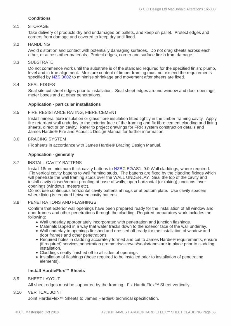
3.1 STORAGE
3.2 HANDLING
3.3 SUBSTRATE
3.4 SEAL EDGES
3.5 FIRE RESISTANCE RATING, FIBRE CEMENT
3.6 BRACING SYSTEM
3.7 INSTALL CAVITY BATTENS
3.8 PENETRATIONS AND FLASHINGS
3.9 SHEET LAYOUT
3.10 VERTICAL JOINT
Conditions
Take delivery of products dry and undamaged on pallets, and keep on pallet. Protect edges andcorners from damage and covered to keep dry until fixed.
Avoid distortion and contact with potentially damaging surfaces. Do not drag sheets across eachother, or across other materials. Protect edges, corner and surface finish from damage.
Do not commence work until the substrate is of the standard required for the specified finish; plumb,level and in true alignment. Moisture content of timber framing must not exceed the requirementsspecified by NZS 3602 to minimise shrinkage and movement after sheets are fixed.
Seal site cut sheet edges prior to installation. Seal sheet edges around window and door openings,meter boxes and at other penetrations.
Application - particular installations
Install mineral fibre insulation or glass fibre insulation fitted tightly in the timber framing cavity. Applyfire retardant wall underlay to the exterior face of the framing and fix fibre cement cladding and liningsheets, direct or on cavity. Refer to project drawings for FRR system construction details andJames Hardie® Fire and Acoustic Design Manual for further information.
Fix sheets in accordance with James Hardie® Bracing Design Manual.
Application - generally
Install 18mm minimum thick cavity battens to NZBC E2/AS1: 9.0 Wall claddings, where required. Fix vertical cavity battens to wall framing studs. The battens are fixed by the cladding fixings whichwill penetrate the wall framing studs over the WALL UNDERLAY. Seal the top of the cavity andinstall cavity closer/vermin-proofing at base of walls, open horizontal (or raking) junctions, overopenings (windows, meters etc).Do not use continuous horizontal cavity battens at nogs or at bottom plate. Use cavity spacerswhere fixing is required between cavity battens.
Confirm that exterior wall openings have been prepared ready for the installation of all window anddoor frames and other penetrations through the cladding. Required preparatory work includes thefollowing:
Wall underlay appropriately incorporated with penetration and junction flashings.Materials lapped in a way that water tracks down to the exterior face of the wall underlay.Wall underlay to openings finished and dressed off ready for the installation of window anddoor frames and other penetrationsRequired holes in cladding accurately formed and cut to James Hardie® requirements, ensure(if required) services penetration grommets/sleeves/seals/tapes are in place prior to claddinginstallation.Claddings neatly finished off to all sides of openingsInstallation of flashings (those required to be installed prior to installation of penetratingelements).
Install HardieFlex™ Sheets
All sheet edges must be supported by the framing. Fix HardieFlex™ Sheet vertically.
Joint HardieFlex™ Sheets to James Hardie® technical specification.
G C G Design Ltd MacDonald Alterations 165308
© CIL Masterspec Oct 2018 4231HH JAMES HARDIE® HARDIEFLEX™ SHEET CLADDING Page 65
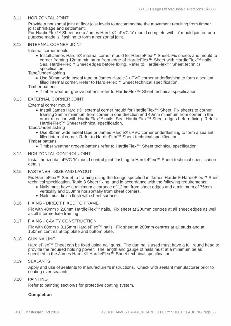
3.11 HORIZONTAL JOINT
3.12 INTERNAL CORNER JOINT
3.13 EXTERNAL CORNER JOINT
3.14 HORIZONTAL CONTROL JOINT
3.15 FASTENER - SIZE AND LAYOUT
3.16 FIXING - DIRECT FIXED TO FRAME
3.17 FIXING - CAVITY CONSTRUCTION
3.18 GUN NAILING
3.19 SEALANTS
3.20 PAINTING
Provide a horizontal joint at floor joist levels to accommodate the movement resulting from timberjoist shrinkage and settlement.For HardieFlex™ Sheet use a James Hardie® uPVC 'h' mould complete with 'h' mould jointer, or apurpose made 'z' flashing to form a horizontal joint.
Internal corner mouldInstall James Hardie® internal corner mould for HardieFlex™ Sheet. Fix sheets and mould tocorner framing 12mm minimum from edge of HardieFlex™ Sheet with HardieFlex™ nails.Seal HardieFlex™ Sheet edges before fixing. Refer to HardieFlex™ Sheet technicalspecification.
Tape/UnderflashingUse 80mm wide Inseal tape or James Hardie® uPVC corner underflashing to form a sealantfilled internal corner. Refer to HardieFlex™ Sheet technical specification.
Timber battensTimber weather groove battens refer to HardieFlex™ Sheet technical specification.
External corner mouldInstall James Hardie® external corner mould for HardieFlex™ Sheet. Fix sheets to cornerframing 35mm minimum from corner in one direction and 40mm minimum from corner in theother direction with HardieFlex™ nails. Seal HardieFlex™ Sheet edges before fixing. Refer toHardieFlex™ Sheet technical specification.
Tape/UnderflashingUse 80mm wide Inseal tape or James Hardie® uPVC corner underflashing to form a sealantfilled internal corner. Refer to HardieFlex™ Sheet technical specification.
Timber battensTimber weather groove battens refer to HardieFlex™ Sheet technical specification.
Install horizontal uPVC 'h' mould control joint flashing to HardieFlex™ Sheet technical specificationdetails.
Fix HardieFlex™ Sheet to framing using the fixings specified in James Hardie® HardieFlex™ Sheettechnical specification, Table 3 Sheet fixing, and in accordance with the following requirements:
Nails must have a minimum clearance of 12mm from sheet edges and a minimum of 75mmvertically and 150mm horizontally from sheet corners.Nails must finish flush with sheet surface.
Fix with 40mm x 2.8mm HardieFlex™ nails. Fix sheet at 200mm centres at all sheet edges as wellas all intermediate framing
Fix with 60mm x 3.15mm HardieFlex™ nails. Fix sheet at 200mm centres at all studs and at150mm centres at top plate and bottom plate.
HardieFlex™ Sheet can be fixed using nail guns. The gun nails used must have a full round head toprovide the required holding power. The length and gauge of nails must at a minimum be asspecified in the James Hardie® HardieFlex™ Sheet technical specification.
Apply and use of sealants to manufacturer's instructions. Check with sealant manufacturer prior tocoating over sealants.
Refer to painting section/s for protective coating system.
Completion
G C G Design Ltd MacDonald Alterations 165308
© CIL Masterspec Oct 2018 4231HH JAMES HARDIE® HARDIEFLEX™ SHEET CLADDING Page 66
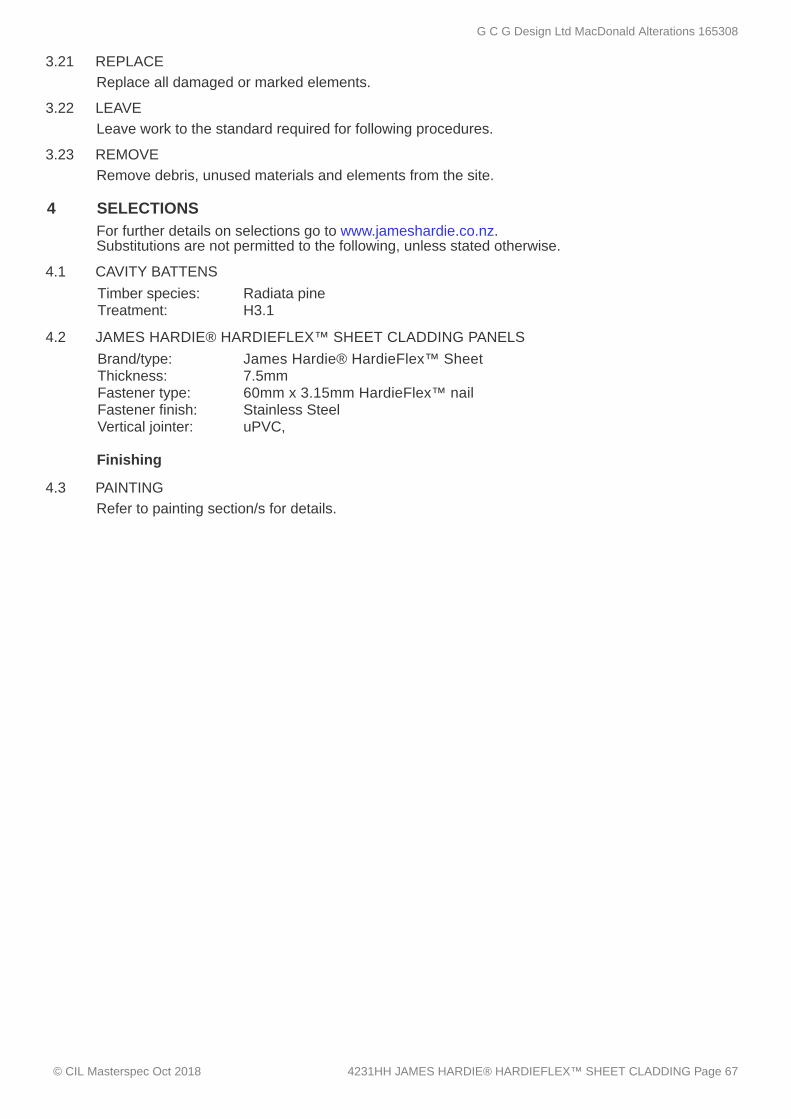
3.21 REPLACE
3.22 LEAVE
3.23 REMOVE
4 SELECTIONS
4.1 CAVITY BATTENS
4.2 JAMES HARDIE® HARDIEFLEX™ SHEET CLADDING PANELS
4.3 PAINTING
Replace all damaged or marked elements.
Leave work to the standard required for following procedures.
Remove debris, unused materials and elements from the site.
For further details on selections go to www.jameshardie.co.nz.Substitutions are not permitted to the following, unless stated otherwise.
Timber species: Radiata pineTreatment: H3.1
Brand/type: James Hardie® HardieFlex™ SheetThickness: 7.5mmFastener type: 60mm x 3.15mm HardieFlex™ nail Fastener finish: Stainless SteelVertical jointer: uPVC,
Finishing
Refer to painting section/s for details.
G C G Design Ltd MacDonald Alterations 165308
© CIL Masterspec Oct 2018 4231HH JAMES HARDIE® HARDIEFLEX™ SHEET CLADDING Page 67

4521 ALUMINIUM WINDOWS AND DOORS
1 GENERAL
1.1 RELATED WORK
1.2 ABBREVIATIONS AND TERMS
This section relates to the manufacture, supply, and installation of:
aluminium windowsaluminium doors and frameshardware and furnitureoverhead glazingflashings
Refer to glazing sections for glass types
SLS Serviceability limit stateULS Ultimate limit stateWANZ Windows Association of New ZealandPQAS Powder Coating Quality Assurance System
Documents
G C G Design Ltd MacDonald Alterations 165308
© CIL Masterspec Oct 2018 4521 ALUMINIUM WINDOWS AND DOORS Page 68
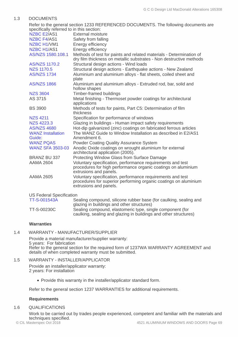
1.3 DOCUMENTS
1.4 WARRANTY - MANUFACTURER/SUPPLIER
1.5 WARRANTY - INSTALLER/APPLICATOR
1.6 QUALIFICATIONS
Refer to the general section 1233 REFERENCED DOCUMENTS. The following documents arespecifically referred to in this section:NZBC E2/AS1 External moistureNZBC F4/AS1 Safety from fallingNZBC H1/VM1 Energy efficiencyNZBC H1/AS1 Energy efficiencyAS/NZS 1580.108.1 Methods of test for paints and related materials - Determination of
dry film thickness on metallic substrates - Non destructive methodsAS/NZS 1170.2 Structural design actions - Wind loadsNZS 1170.5 Structural design actions - Earthquake actions - New ZealandAS/NZS 1734 Aluminium and aluminium alloys - flat sheets, coiled sheet and
plateAS/NZS 1866 Aluminium and aluminium alloys - Extruded rod, bar, solid and
hollow shapesNZS 3604 Timber-framed buildingsAS 3715 Metal finishing - Thermoset powder coatings for architectural
applicationsBS 3900 Methods of tests for paints, Part C5: Determination of film
thicknessNZS 4211 Specification for performance of windowsNZS 4223.3 Glazing in buildings - Human impact safety requirementsAS/NZS 4680 Hot-dip galvanized (zinc) coatings on fabricated ferrous articlesWANZ InstallationGuide:
The WANZ Guide to Window Installation as described in E2/AS1Amendment 6.
WANZ PQAS Powder Coating Quality Assurance SystemWANZ SFA 3503-03 Anodic Oxide coatings on wrought aluminium for external
architectural application (2005).BRANZ BU 337 Protecting Window Glass from Surface DamageAAMA 2604 Voluntary specification, performance requirements and test
procedures for high performance organic coatings on aluminiumextrusions and panels.
AAMA 2605 Voluntary specification, performance requirements and testprocedures for superior performing organic coatings on aluminiumextrusions and panels.
US Federal SpecificationTT-S-001543A Sealing compound, silicone rubber base (for caulking, sealing and
glazing in buildings and other structures)TT-S-00230C Sealing compound, elastomeric type, single component (for
caulking, sealing and glazing in buildings and other structures)
Warranties
Provide a material manufacturer/supplier warranty:5 years: For fabricationRefer to the general section for the required form of 1237WA WARRANTY AGREEMENT anddetails of when completed warranty must be submitted.
Provide an installer/applicator warranty:2 years: For installation
Provide this warranty in the installer/applicator standard form. Refer to the general section 1237 WARRANTIES for additional requirements.
Requirements
Work to be carried out by trades people experienced, competent and familiar with the materials andtechniques specified.
G C G Design Ltd MacDonald Alterations 165308
© CIL Masterspec Oct 2018 4521 ALUMINIUM WINDOWS AND DOORS Page 69
1.7 COMPLIANCE
1.8 CERTIFICATION
1.9 PERFORMANCE - WINDOWS AND DOORS
1.10 PERFORMANCE - STRUCTURAL/WEATHER-TIGHTNESS
1.11 WIND - NON SPECIFIC DESIGN
1.12 CERTIFY COATINGS - POWDER COATING
2 PRODUCTS
2.1 WINDOWS
2.2 DOORS
2.3 ALUMINIUM EXTRUSIONS
2.4 ALUMINIUM SHEET AND STRIP
2.5 STAINLESS STEEL SHEET AND STRIP
2.6 GLASS
2.7 REVEALS - TIMBER PAINTED
Windows and doors to be manufactured and installed to NZBC E2/AS1.
Provide evidence of a certificate by a laboratory accredited by International Accreditation of NewZealand that the windows and doors offered comply with the requirements of NZS 4211.
Performance
To NZS 4211, including:deflection, opening sashes, air infiltration, water penetration, ultimate strength, torsionalstrength of sashes, marking.
Refer to SELECTIONS.
The structural and weather-tight performance of the completed joinery, the glazing and infill panels isthe responsibility of the window manufacturer.
Performance - Wind (design by contractor)
Design the installation to the wind zone parameters of NZS 3604, table 5.4.Refer to SELECTIONS for wind zone.
Finishes
Certify on request, compliance with this specification and support with control and sampling records. Test for film thickness to BS 3900, part C5, method No. 4, using method (b) or to AS/NZ 1580.108.1for certifying thickness and method (a) where any dispute arises as to the thickness provided.The coating should be applied by an applicator who can certify that the coating has been applied inaccordance with the specification.
Materials
Refer to SELECTIONS for type and finish.
Refer to SELECTIONS for type and finish.
Alloy designation to comply with AS/NZS 1866. Branded and extruded for anodising or powdercoating.
Complying with AS/NZS 1734 of suitable thickness. Rolled for anodising or powder coating.Alloy designation: 5251 - H16 or 5005 - H16
Type: 316 austenitic steelFinish grade: 2B (satin lustre)
Refer to the glazing section for glass types and installation.
Timber reveals for paint finish with all sides primed grooved for wall linings or flush finished forarchitraves.
G C G Design Ltd MacDonald Alterations 165308
© CIL Masterspec Oct 2018 4521 ALUMINIUM WINDOWS AND DOORS Page 70
2.8 FLASHINGS GENERALLY
2.9 SILL PAN FLASHING
2.10 WANZ SUPPORT ANGLE
2.11 STANDARD CAVITY CLOSER
2.12 WANZ SUPPORT BAR
2.13 GLAZING GASKETS
2.14 HARDWARE AND FURNITURE
2.15 SAFETY STAYS
2.16 STRUCTURAL SEALANT
2.17 WEATHERING/INSTALLATION SEALANT
2.18 FOAM TAPE
2.19 POWDER COATED ALUMINIUM - EXTRA DURABLE
2.20 POWDER COATED ALUMINIUM - HIGH DUTY
To NZBC E2/AS1, 9.1.10 Windows and Doors. Material, grade and colour of head flashings tomatch the window frames. Ensure that materials used for head, jamb and sill flashings arecompatible with the window frame materials and fixings and cladding materials.
Components - for direct fix systems
To NZBC E2/AS1, 9.1.10.5 Window and Door Sills. Flashing for direct fix claddings to collect anddrain water that may penetrate through the window or door unit. Size to extend from the inner mostpoint of the aluminium frame out over the external face of the cladding.
Support angle, for use below the sill pan, for deeper claddings to transfer the weight of the windowback to the frame. Size to suit cladding thickness.
Components - for cavity systems
A perforated device constructed from either aluminium or PVC to close the cavity above the windowor door unit, between the cladding and head flashing, to provide ventilation in accordance withNZBC E2/AS1 to the spaces above the window or door.
Extruded aluminium support bar with built in drainage and ventilation to NZBC E2/AS1, to providecontinuous support to the window unit. Size to suit cladding type.
Components
Thermoplastic rubber. Do not stretch glazing gaskets during installation. Measure and cut gaskets5-10% over length before installation.
Hinges, stays, catches, fasteners, latches, locks and furniture as offered by the window and doormanufacturer. Refer to SELECTIONS for type and finish. Key alike all lockable window hardwareable to be keyed alike.
Stainless steel non releasable restrictors to limit window opening to NZBC F4/AS1, Table 2,Acceptable opening sizes for barriers.
Sealants
Silicone chemically curing sealant specifically formulated and tested or approved equivalent with notless than a ± 40% movement factor complying with US Federal Specification TT S 001543A.
Building sealant used in accordance with manufacturer's instructions for weather sealing aluminiumframes to the cladding, complying with US Federal Specification TT S 0011534A, or a one-partpolyurethane moisture curing, elastic joint sealant of medium modulus (± 25% movement) to USFederal Specification TT S 00230C.
Foam tape to NZBC E2/AS1, 9.1.10.7 Closed cell foam tape.
Finishes
Polyester powder organic coating in accordance with WANZ PQAS and AS 3715.
Polyester powder coating in accordance with WANZ PQAS and AAMA 2604.
G C G Design Ltd MacDonald Alterations 165308
© CIL Masterspec Oct 2018 4521 ALUMINIUM WINDOWS AND DOORS Page 71

2.21 POWDER COATED ALUMINIUM - SUPER DUTY
3 EXECUTION
3.1 DO NOT DELIVER
3.2 UNLOAD WINDOW JOINERY
3.3 AVOID DISTORTION
3.4 PREVENT DAMAGE
3.5 PROPRIETARY ELEMENTS
3.6 PROTECTIVE COVERINGS
3.7 ADDITIONAL PROTECTION
3.8 SUPPLY OF FIXINGS
3.9 INSTALLATION FIXING
3.10 FABRICATION
3.11 TIMBER / PVC REVEALS
3.12 HARDWARE GENERALLY
PVF² fluoropolymer powder coating in accordance with AAMA 2605 and WANZ PQAS.
Conditions - generally
Do not deliver to site any elements which cannot be unloaded immediately into suitable conditions ofstorage.
Unload, handle and store elements in accordance with the window manufacturer's requirements.
Avoid distortion of elements during transit, storage and handling.
Prevent prefinished surfaces rubbing together, and contact with mud, plaster and cement. Keeppaper and cardboard wrappings dry.
Fix in accordance with the window manufacturer's requirements.
Retain protective coverings and coatings to BRANZ BU 337 and keep in place during the fixingprocess. Provide protective coverings and coatings where required to prevent marking of surfacesvisible in the completed work and to protect aluminium joinery from following trades. Removeprotection on completion.
Supply and fix additional protection as necessary to prevent marking of surfaces which will be visibleon completed work.
Conditions - fixings and fastenings
Use only fixings and fastenings recommended by the manufacturer of the component being fixedand to comply with the ULS wind pressure stated in SELECTIONS. Ensure fixings and fasteningsexposed to the weather are of aluminium, or Type 316 stainless steel or if not exposed to theweather may they be hot-dip galvanized steel with a coating weight of 610 g/m² complying withAS/NZS 4680.
To NZBC E2/AS1, 9.1.10.8, Attachments for windows and doors. Fix windows/doors throughreveal to frame with a pair of 75 x 3.15mm minimum galvanised jolt head nails or a pair of 8 gauge x65mm minimum stainless steel screws. Fix at a maximum of 450 centres along all reveals and amaximum of 150mm from reveal ends. Ensure fixings do not penetrate metal flashings.Install packers between reveals and framing at fixing points, except at the head.
Assembly
Fabricate frames as detailed on shop drawings. Install glazing, hinges, stays and running gear asscheduled. Provide temporary bracing and protection. Temporarily secure all opening elements fortransportation.
Before fixing to aluminium frames, ensure that timber reveals which are being painted have beenprimed on all surfaces.
Factory fit all required and scheduled hardware. Account for all keys and deliver separately to thesite manager.
G C G Design Ltd MacDonald Alterations 165308
© CIL Masterspec Oct 2018 4521 ALUMINIUM WINDOWS AND DOORS Page 72

3.13 SAFETY STAYS
3.14 CORROSION PROTECTION
3.15 CONFIRM PREPARATION OF EXTERIOR WALL OPENINGS
3.16 INSTALLATION
3.17 INSTALLATION DIRECT FIX
3.18 INSTALLATION CAVITY CONSTRUCTION
3.19 INSTALL FLASHINGS
3.20 COMPLETE AIR SEAL
3.21 FIX HARDWARE
3.22 SEAL FRAMES ON SITE
3.23 PREPARE JOINTS
Factory fit safety stays to all windows scheduled for safety stays and to all windows where safetystays are required to comply with NZBC F4/AS1 4.0, Opening windows.
Installation - windows and doors
Before fixing, apply suitable barriers of bituminous coatings, stops or underlays between dissimilarmetals in contact, or between aluminium in contact with concrete.
Confirm that exterior wall openings have been prepared ready for the installation of all window anddoor frames. Do not proceed with the window and door installation until required preparatory workhas been completed. Required preparatory work includes the following:
wall underlay/building wrap to openings finished and dressed off ready for the installation ofwindow and door frames to NZBC E2/AS1:9.1.5 Wall underlays to wall openings.Full height 20mm jamb battens to NZBC E2/AS1 figure 72A (direct fix only)claddings neatly finished off to all sides of openingsinstallation of flashings (those which are required to be installed prior to frames).
Fix to comply with the reviewed shop drawings and installation details including flashings andbedding compounds, pointing sealants and weathering sealants.
Install to window manufacturers details and drawings including sill pans to window and door units.
Install to WANZ Installation Guide details and drawings including WANZ sill support bars.For thresholds with support bars fixed through membranes, pre-fill support bar screw holes withsilicone sealant to NZBC E2/AS1, figure 62(d).
Install flashings to heads, jambs and sills of frames as supplied and required by the windowmanufacturer and as detailed on the drawings. Finish head flashings to match window finish. Place all flashings so that the head flashing weathers the jamb flashings, which in turn weathersover the upstand of the sill flashing. Ensure that sill flashings drain to the outside air. Except where window/door frames are recessed, ensure that head flashings over-sail unit by 20mmminimum plus any jamb scriber width at each end.
To NZBC E2/AS1:9.1.6 Air seals. Form an air-tight seal by means of a proprietary expanding foamor sealants used with backing rods, applied between the window / door reveal and structural framingto a depth of 10 - 20mm, to provide a continuous air tight seal to the perimeter of the window ordoor.
Fix all sash and door hardware and furniture as scheduled.
Application - jointing and sealing
Seal frames to each other and to adjoining structure and finishes, all as required by the windowmanufacturer and to make the installation weathertight. In very high and extra high or greater windzones, seal between the window head and the head flashing. Do not seal the junction between thesill member and the cladding or sill flashing which must remain open.
Ensure joints are dry. Remove loose material, dust and grease. Prepare joints in accordance withthe sealant manufacturer's requirements, using required solvents and primers where necessary. Mask adjoining surfaces which would be difficult to clean if smeared with sealant.
G C G Design Ltd MacDonald Alterations 165308
© CIL Masterspec Oct 2018 4521 ALUMINIUM WINDOWS AND DOORS Page 73

3.24 BACK UP
3.25 SEALANT FINISH
3.26 REMOVE TRADE DEBRIS
3.27 TRADE CLEAN
3.28 PROTECTIVE COVERINGS
3.29 SAFETY
3.30 IN SITU TOUCH-UP TO POWDER COATED ALUMINIUM
3.31 REMOVE
3.32 REPLACE
4 SELECTIONS
4.1 THERMAL PERFORMANCE
4.2 WIND - NON SPECIFIC DESIGN
4.3 ALUMINIUM WINDOWS
When using back-up materials do not reduce depth of joint for sealant to less than the minimumrequired by the manufacturer of the sealant. Insert polyethylene rod or tape back-up behind jointsbeing pointed with sealant.
Tool sealant to form a smooth fillet with a profile and dimensions required by the sealantmanufacturer. Remove excess sealant from adjoining surfaces, using the cleaning materialsnominated by the sealant manufacturer and leave clean.
Completion - cleaning
Remove trade debris by appropriate means on a floor by floor basis as each floor is completed andagain before any work is covered up by others. Arrange for general removal.
Trade clean window frames, operable windows and doors, glass and other related surfaces insideand out at the time of installation to remove marks, dust and dirt, to enable a visual inspection of allsurfaces.
Completion
Retain protective coverings and coatings and keep in place during the fixing process. Provideprotective coverings and coatings where required to prevent marking of surfaces visible in thecompleted work and to protect aluminium joinery from following trades.
Indicate the presence of transparent glasses for the remainder of the contract period, with whiting,tape or signs compatible with the glass type. Indicators other than whiting must not be applied tothe glass surface. Masking tape must not be used for this purpose.
In situ touch-up of polyester or fluoropolymer coated aluminium is only permitted only to minorsurface scratching. Otherwise replace all damaged material.
At the appropriate stage of the project, remove safety indicators and protective coverings and wipedown all joinery thoroughly.
Replace damaged, cracked or marked elements.
Performance
R-value: 0.26 (as determined from NZBC H1/VM1 or H1/AS1)
Performance - Wind (design by contractor)
Building wind zone High (refer to NZS 3604, table 5.4)
Window and door system
Manufacturer: to be confirmedType/location: Residential Suite
G C G Design Ltd MacDonald Alterations 165308
© CIL Masterspec Oct 2018 4521 ALUMINIUM WINDOWS AND DOORS Page 74
4.4 ALUMINIUM DOORS
4.5 TIMBER REVEALS
4.6 ORGANIC POWDER COATING FINISH
4.7 FLASHINGS
4.8 WEATHERING SEALANT
4.9 HARDWARE
Manufacturer: to be confirmedType/location: Residential Suite
Timber species: Radiata PineGrade/treatment: H3.1Thickness: 19mmReveals: ArchitravedFinish: Paint
Finishes
Type: Polyester organic powder coating Extra DurableSystem integrity: Minimum 10 years film integrity, 7 years colour integrity Thickness: Average of 80 microns with a minimum of 50 micronsColour: to be confirmed
Material/type: 5000 Grade Powdercoated AluminiumPattern: Formed to suit details provided
Brand/type: MS 1-part polyurethane moisture curing, elastic joint sealantColour: to match joinery
Brand/style Material/finishSash fasteners: Miro Powder coated AluminiumDoor furniture: Miro Powder coated Aluminium
G C G Design Ltd MacDonald Alterations 165308
© CIL Masterspec Oct 2018 4521 ALUMINIUM WINDOWS AND DOORS Page 75
4610MR METRO PERFORMANCE GLASS -RESIDENTIAL GLAZING
1 GENERAL
1.1 ABBREVIATIONS AND DEFINITIONS
1.2 DOCUMENTS
1.3 MANUFACTURER/SUPPLIER DOCUMENTS
This section relates to the supply and fixing of Metro Performance Glass (Metro) products forexternal and internal joinery in residential type buildings and includes:
windows and doorsframeless shower and bath screenssplashbacks, wall liningsbalustrade systems, pool fencesmirrors and mirror frames
Refer to the general section 1232 INTERPRETATION & DEFINITIONS for abbreviations anddefinitions used throughout the specification. The following abbreviations apply specifically to this section:PVB Polyvinyl ButyralCIP Cast in PlaceEVA Ethylene Vinyl AcetateIGU Insulating Glass UnitLSG Laminated Safety GlassTSG Toughened Safety GlassTLSG Toughened Laminated Safety GlassMFG Metro Frameless Glass
Documents
Refer to the general section 1233 REFERENCED DOCUMENTS. The following documents arespecifically referred to in this section:NZBC F4/AS1 Safety from fallingNZBC F9/AS1 Means of restricting access to residential poolsNZBC H1/AS1 Energy EfficiencyAS/NZS 1170.2 Structural design actions - Wind loadsAS/NZS 2208 Safety glazing materials in buildingsNZS 3604 Timber-framed buildingsNZS 4211 Specification for performance of windowsNZS 4218 Thermal insulation - Housing and Small BuildingsNZS 4223.1 Glazing in buildings - Glass selection and glazingNZS 4223. Supp1 Glazing in buildings - Supplement 1 to NZS 4223.1:2008 and NZS
4223.4:2008NZS 4223.2 Glazing in buildings - Insulating glass unitsNZS 4223.3 Glazing in buildings - Human impact safety requirementsNZS 4223.4 Glazing in buildings - Wind, dead, snow and live actionAS/NZS 4666 Insulating glass unitsBRANZ BU 337 Protecting window glass from damage
Manufacturer's and supplier's documents relating to this part of the work:Metro GlassTech Catalogue & Reference and Guide - 6th edition Manufacturer/supplier contact detailsCompany: Metro Performance GlassWeb: www.metroglass.co.nzEmail: [email protected]: 0800 65 89 45
Warranties
G C G Design Ltd MacDonald Alterations 165308
© CIL Masterspec Oct 2018 4610MR METRO PERFORMANCE GLASS - RESIDENTIAL GLAZING Page 76
1.4 WARRANTY - MANUFACTURER/SUPPLIER
1.5 ENERGY EFFICIENCY
2 PRODUCTS
2.1 NO SUBSTITUTIONS
2.2 LAMINATED SAFETY GLASS (LSG)
2.3 TOUGHENED SAFETY GLASS (TSG)
2.4 TINTED FLOAT GLASS
2.5 GLASS SCREENS BATH & SHOWER
2.6 JOINTING, PUTTY AND SEALING MATERIALS
2.7 GLAZING TAPE AND GASKETS
2.8 SETTING BLOCKS
3 EXECUTION
Provide a material manufacturer/supplier warranty:10 years: for GlassTech Insulating Glass Units (IGU)10 years: for SafeLite Laminated Safety Glass (LSG)10 years: for TempaFloat Toughened Safety Glass (TSG)10 years: for TempaScreen, TempaClad and TempaPrint digital printed glass
Provide this warranty on the manufacturer/supplier standard form.Commence the warranty from the date of completion of this part of the contract work.
Refer to the general section for the required form of 1237WA WARRANTY AGREEMENT anddetails of when completed warranty must be submitted.
Performance
Provide glazing to meet the energy requirements of NZS 4218 and NZBC H1/AS1 for housing smallbuildings.Refer to SELECTIONS and schedules for location and type of glazing.
Substitutions are not permitted to any specified Metro Performance Glass, products or systems.
Materials
SafeLite Grade A Lamiated Safety Glass to AS/NZS 2208 with PVB, EVA or CIP resin interlayer.
TempaFloat Grade A Toughened Safety Glass to AS/NZS 2208.Heat soaked toughened glass to NZS 4223.1, Appendix E, required for critical areas.Refer to SELECTIONS.
Body tinted float glass.
Materials, bath and shower screens
Proprietary shower/bath screens, and doors shall be TempaFloat TSG complete with MFGhardware.
Components, general
Ensure jointing, putty and sealing materials are compatible with glass substrates. Confirmcompatibility with laminated glass, IGUs and coatings.
Components, aluminium and uPVC glazing
Single/double sided pressure sensitive self-adhesive low/medium/high density foam tapes/butyltapes selected to suit the glazing detail to window manufacturers' requirements.
Santoprene/Neoprene, 80-90 Shore A hardness, set at quarter points or to detail, to support theweight of glass panes.
Conditions
G C G Design Ltd MacDonald Alterations 165308
© CIL Masterspec Oct 2018 4610MR METRO PERFORMANCE GLASS - RESIDENTIAL GLAZING Page 77

3.1 GENERAL REQUIREMENTS
3.2 DELIVERY
3.3 GLASS CONDITION
3.4 GLASS THICKNESS
3.5 REBATE DIMENSIONS
3.6 SAFETY GLAZING, GENERAL REQUIREMENTS
3.7 SAFETY GLAZING MATERIAL
3.8 CONTAINMENT
3.9 WORKING OF GLASS
3.10 EDGE WORK AND BEVELLING
3.11 SURFACE TREATMENT
3.12 SURFACE CUTTING
3.13 INSTALL GLASS TO ALUMINIUM FRAMES
3.14 INSTALL SAFETY GLASS
To NZS 4223.1, NZS 4223.2, NZS 4223.3 as modified by NZBC B1/AS1, 7.3.1, and NZS 4223.4. Allexternal glazing to be wind and watertight on completion.
Keep glass dry and clean during delivery and bring on to site when ready to glaze directly into place. Comply also with the storage requirements set out in BRANZ BU 337, and AS/NZS 4666 for IGUs.
All glass and panes shall have undamaged edges and surfaces.
If not specifically stated in the glazing schedule determine the minimum thickness of glass for eachpane as required by NZS 4223.1, NZS 4223.3, NZS 4223.4.Determine the final glass thickness based on whether wind loading or human impact considerationsgovern.
Provide rebates for glazing to the widths and depths necessary for each situation including minimumglass edge cover to NZS 4223.1, Section 4 Glazing.
Conditions - human impact safety requirements
Glazing of doors, side panels, low level and window seat glazing, bathrooms, stairwell landings andsimilar locations, to NZS 4223.3 as modified by NZBC B1/AS1, 7.3.1, for thickness and maximumareas of panel Safety Glass.
Use only safety glazing materials defined in NZS 4223.3, as modified by NZBC B1/AS1, 7.3.1, thatalso comply with the relevant requirements of AS/NZS 2208. Ensure material is permanentlymarked and if cut by the distributor or installer mark each piece to NZS 4223.3, 2.8 Identification.
Edge cover to comply with NZS 4223.1, Section 4 Glazing, table 5. Otherwise to NZS 4223.3, 2.3Edge cover.
Assembly
All working of glass as required in NZS 4223.1.
All edges shall be clean cut unless specified in SELECTIONS or as shown on drawings.
Refer to SELECTIONS/drawings for finish.
Refer to SELECTIONS/drawings for finish.
Application aluminium
Install glass to NZS 4223.1.Bead glaze to Section 4 Glazing.Channel glaze to Section 4 Glazing, and Section 5 for Framed, Unframed, Partly FramedGlass Assemblies.
To NZS 4223.3.
Application miscellaneous
G C G Design Ltd MacDonald Alterations 165308
© CIL Masterspec Oct 2018 4610MR METRO PERFORMANCE GLASS - RESIDENTIAL GLAZING Page 78
3.15 INSTALL GLASS BATH & SHOWER SCREENS
3.16 SAFETY
3.17 TRADE CLEAN
3.18 REPLACE
3.19 LEAVE
3.20 REMOVE
4 SELECTIONS
4.1 WIND ZONE - NON-SPECIFIC DESIGN
4.2 METRO PERFORMANCE GLASS - TINTED FLOAT GLASS
4.3 METRO PERFORMANCE GLASS - LAMINATED SAFETY GLASS (LSG)
4.4 METRO PERFORMANCE GLASS - FRAMELESS SHOWER SCREENS AND DOORS
Install shower and bath screens and doors to manufacturer's requirements.
Finishing
Indicate the presence of transparent glass for the construction period, with tape or signs compatiblewith the glass type.
Completion
Remove safety indicators and trade clean at completion of the building as required by the contractdocuments.
Replace damaged, cracked or marked glass that occurs during glazing.
Leave work to the standard required by following procedures.
Remove debris, unused materials and elements from the site.
For further details on selections go to www.metroglass.co.nz.Substitutions are not permitted to the following, unless stated otherwise.
Performance - wind
Building wind zone: High as determined from NZS 3604, NZS 4223.4 or NZS 4211.
Glass by type
Location: New windowsBrand/type: Metro Tinted FloatTint: GreyThickness: to be confirmed
Location: Bathroom and windows/doors with panels over 1 sqmBrand/type: SafeliteTint:: SafeLite PVB - Grey, Thickness: to comply with NZS 4223
Glass shower & bath screens
Location: shower doors and screensBrand/type: Metro GlassGlass: TempaFloatThickness: 10 mmHardware: MFG type
G C G Design Ltd MacDonald Alterations 165308
© CIL Masterspec Oct 2018 4610MR METRO PERFORMANCE GLASS - RESIDENTIAL GLAZING Page 79
4710K KNAUF INSULATION SYSTEMS
1 GENERAL
1.1 RELATED WORK
1.2 DOCUMENTS
This section relates to Knauf Insulation thermal and acoustic glasswool insulation systemsincluding installation.It includes:Earthwool® glasswool insulation
Earthwool® glasswool insulation: wall battEarthwool® glasswool insulation: ceiling batt / rollsEarthwool® glasswool insulation: quilted underfloor battEarthwool® glasswool insulation: underfloor roll with a wind wash barrierEarthwool® glasswool insulation: acoustic battEarthwool® glasswool insulation: DriTherm® masonry slab
Jet Stream® MAX blow-in glasswool insulation
Jet Stream® MAX wall cavityJet Stream® MAX floorJet Stream® MAX ceilingJet Stream® MAX skillion roofJet Stream® MAX internal wallJet Stream® MAX mid-floor
Refer to 4161 UNDERLAYS, FOIL AND DPC for wall underlay and roofing underlay.
Documents
Refer to the general section 1233 REFERENCED DOCUMENTS. The following documents arespecifically referred to in this section:NZBC H1/AS1 Energy efficiencyAS 1530.1 Combustibility Test for MaterialsAS/NZS 3000 Electrical installationsAS/NZS 4859.1 Materials for the thermal insulation of buildings - General criteria
and technical provisionsAS/NZS 5110 Recessed Luminaire BarriersAS/NZS60598.2.2:2001
Luminaires- Particular Requirements - Recessed luminaires
AS/NZS 60695.11.5 Fire hazard testing - Test flames - Needle-flame test method -Apparatus, conformity test arrangement and guidance
NZS 4214 Methods of determining the total thermal resistance of parts ofbuildings
NZS 4218 Thermal insulation - Housing and small buildingsNZS 4220 Code of practice for energy conservation in non-residential
buildingsNZS 4243.1 Energy efficiency - Large buildings - Building thermal envelopeNZS 4246 Energy efficiency - Installing bulk thermal insulation in residential
buildings
G C G Design Ltd MacDonald Alterations 165308
© CIL Masterspec Oct 2018 4710K KNAUF INSULATION SYSTEMS Page 80
1.3 MANUFACTURER/SUPPLIER DOCUMENTS
1.4 WARRANTY - MANUFACTURER/SUPPLIER
1.5 QUALIFICATIONS - EARTHWOOL® GLASSWOOL INSULATION
1.6 NO SUBSTITUTIONS
1.7 FIRE PROPERTIES - EARTHWOOL® GLASSWOOL INSULATION
2 PRODUCTS
Manufacturer's and supplier's documents relating to this part of the work:Knauf Insulation Product Guide New ZealandEarthwool® glasswool insulation: wall and ceiling roll and batt DatasheetsEarthwool® glasswool insulation: acoustic batt DatasheetEarthwool® glasswool insulation: ceiling roll DatasheetEarthwool® glasswool insulation: quilted underfloor batt DatasheetEarthwool® glasswool insulation: quilted underfloor batt installation instructionsEarthwool® glasswool insulation: underfloor roll with a wind wash barrier DatasheetEarthwool® glasswool insulation: DriTherm® masonry slabEarthwool® glasswool insulation: Installation InstructionsJet Stream® MAX Walls, floors and skillion roofs DatasheetJet Stream® MAX Walls, floors and skillion roofs Application GuidelinesJet Stream® MAX Ceilings DatasheetJet Stream® MAX Ceilings Application GuidelinesBRANZ Appraisal 648 - Earthwool® glasswool InsulationBRANZ Appraisal 975 - Earthwool® glasswool insulation: quilted underfloor battCodeMark Certificate: Jet Stream® MAX and Supafil Cavity Insulation 30067CodeMark Certificate: Jet Stream® MAX ceiling insulation 30068Manufacturer/supplier contact detailsCompany: Knauf Insulation New ZealandWeb: www.knaufinsulation.co.nzEmail: [email protected]: 0800 KNAUFI (562 834)Technical support: [email protected] service: [email protected]
Warranties
Provide a material manufacturer/supplier warranty:50 years: For unfaced Earthwool® glasswool insulation materials15 years: For Earthwool® glasswool insulation: quilted underfloor batt50 years: For Jet Stream® MAX glasswool materials
Provide this warranty on the manufacturer/supplier standard form.Commence the warranty from the date of practical completion of the contract works.
Refer to the general section 1237 WARRANTIES for additional requirements.
Requirements
Work to be carried out by trades people experienced, competent and familiar with the KnaufInsulation materials and techniques specified.
Substitutions are not permitted to any specified Knauf Insulation, associated products, componentsor accessories.
Performance - Fire properties
Earthwool® glasswool insulation is non-combustible to AS1530.1. Earthwool® glasswool insulationmeets the 30's Needle Flame test to AS/NZS 60695.11.5.
Materials - thermal insulation
G C G Design Ltd MacDonald Alterations 165308
© CIL Masterspec Oct 2018 4710K KNAUF INSULATION SYSTEMS Page 81
2.1 EARTHWOOL® GLASSWOOL INSULATION: CEILING
2.2 EARTHWOOL® GLASSWOOL INSULATION: WALL
2.3 TAPES
3 EXECUTION
3.1 STORAGE - EARTHWOOL® GLASSWOOL INSULATION
3.2 HANDLING - EARTHWOOL® GLASSWOOL INSULATION
3.3 INSPECTION - EARTHWOOL® GLASSWOOL INSULATION
3.4 INSTALL INSULATION - GENERAL
3.5 PREPARATION - EARTHWOOL® GLASSWOOL INSULATION
Earthwool® glasswool insulation: ceiling batt and rolls to AS/NZS 4859.1, NZS 4218, NZS 4243.1and NZS 4220. Rectangular insulation ceiling batt and rolls made using recycled glass and withECOSE® Technology.Refer to SELECTIONS for location, type, R-value and thickness.
Earthwool® glasswool insulation: wall batt to AS/NZS 4859.1, NZS 4218, NZS 4243.1 and NZS4220. Rectangular insulation wall batt and rolls made using recycled glass and with ECOSE®Technology.Refer to SELECTIONS for location, type, R-value and thickness.
Components - Earthwool® glasswool insulation
Polypropylene or similar strapping stapled across framing to retain insulation in wall and ceilingapplications.
Conditions - Earthwool® glasswool insulation
Accept materials undamaged and dry and store in a location that protects them from the weatherand damage. Avoid distortion, stretching, puncturing and compression. Do not use damaged or wetinsulation material.
Wear protective clothing as necessary and when handling, avoid delamination or distortion of therectangular form. Maintain full thickness unless compression is an installation system requirement.
Before starting installation of Earthwool® glasswool insulation check that the location and framingare dry, that the cavities are not interconnected and that mesh, wall and roof underlays and vapourbarriers are in place. Install when the building is enclosed and when the construction materials haveachieved the maximum permitted moisture content or less.
Application - general
Lay, install, fit and fix to NZBC H1/AS1: Energy efficiency, 2.0 Building thermal envelope, and tomanufacturer's requirements. Install in housing to NZS 4218 and NZS 4246. Install in largebuildings to NZS 4243.1 and NZS 4220. Do not cover vents. Allow a clear gap around metal fluesas recommended by the fireplace manufacturer. Refer to manufacturer's installation instructionsand NZS 4246 for further details.
Allow insulation to re-loft/relax prior to installation. Where possible lift up electrical wires, lightingtransformers/controllers and lay the insulation underneath.
G C G Design Ltd MacDonald Alterations 165308
© CIL Masterspec Oct 2018 4710K KNAUF INSULATION SYSTEMS Page 82

3.6 RECESSED LIGHT FITTINGS - CLEARANCENon-residential applications;The clearance between insulation and recessed downlights
100mm gap to AS/NZS 3000, figure 4.9.For Jet Stream® MAX (loose fill), provide a barrier complying with AS/NZS 5110 aroundrecessed light fittings in accordance with AS/NZS 3000, figure 4.9 and clause 4.5.2.3.3 e,unless specifically stated by the luminaire's manufacturer.Provide larger clearances where required by the light manufacturer.
Residential applications;
Ensure new recessed downlights are one of the new classes classified in AS/NZS 60598.2.2;CA 80, CA 135, IC and IC - FClassification type CA 80, CA 135, to AS/NZS 60598.2.2; insulation can abut the sidesClassification type IC and IC - F, to AS/NZS 60598.2.2; insulation can abut and cover over thetop of the downlightClassification type NON IC to AS/NZS 60598.2.2; insulation cannot abut or cover thedownlight. This class of downlights is banned from residential applications.For Jet Stream® MAX (loose fill), maintain 100mm gap and provide a barrier complying withAS/NZS 5110 around recessed light fittings in accordance with AS/NZS 3000, figure 4.9 andclause 4.5.2.3.3 e, unless specifically stated otherwise by the luminaire's manufacturer.Provide larger clearances where required by the light manufacturer.In a retrofit situation where recessed downlights are unclassified or unknown, ensure 100mmclearance between insulation and downlights to AS/NZS 3000, figure 4.9.
G C G Design Ltd MacDonald Alterations 165308
© CIL Masterspec Oct 2018 4710K KNAUF INSULATION SYSTEMS Page 83
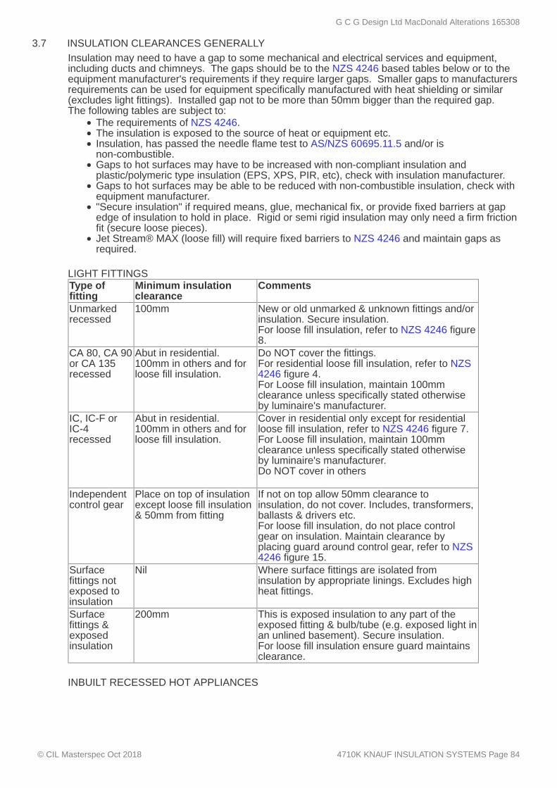
3.7 INSULATION CLEARANCES GENERALLYInsulation may need to have a gap to some mechanical and electrical services and equipment,including ducts and chimneys. The gaps should be to the NZS 4246 based tables below or to theequipment manufacturer's requirements if they require larger gaps. Smaller gaps to manufacturersrequirements can be used for equipment specifically manufactured with heat shielding or similar(excludes light fittings). Installed gap not to be more than 50mm bigger than the required gap.The following tables are subject to:
The requirements of NZS 4246.The insulation is exposed to the source of heat or equipment etc.Insulation, has passed the needle flame test to AS/NZS 60695.11.5 and/or isnon-combustible.Gaps to hot surfaces may have to be increased with non-compliant insulation andplastic/polymeric type insulation (EPS, XPS, PIR, etc), check with insulation manufacturer.Gaps to hot surfaces may be able to be reduced with non-combustible insulation, check withequipment manufacturer."Secure insulation" if required means, glue, mechanical fix, or provide fixed barriers at gapedge of insulation to hold in place. Rigid or semi rigid insulation may only need a firm frictionfit (secure loose pieces).Jet Stream® MAX (loose fill) will require fixed barriers to NZS 4246 and maintain gaps asrequired.
LIGHT FITTINGSType offitting
Minimum insulationclearance
Comments
Unmarkedrecessed
100mm New or old unmarked & unknown fittings and/orinsulation. Secure insulation.For loose fill insulation, refer to NZS 4246 figure8.
CA 80, CA 90or CA 135recessed
Abut in residential.100mm in others and forloose fill insulation.
Do NOT cover the fittings.For residential loose fill insulation, refer to NZS4246 figure 4.For Loose fill insulation, maintain 100mmclearance unless specifically stated otherwiseby luminaire's manufacturer.
IC, IC-F orIC-4recessed
Abut in residential.100mm in others and forloose fill insulation.
Cover in residential only except for residentialloose fill insulation, refer to NZS 4246 figure 7.For Loose fill insulation, maintain 100mmclearance unless specifically stated otherwiseby luminaire's manufacturer.Do NOT cover in others
Independentcontrol gear
Place on top of insulationexcept loose fill insulation& 50mm from fitting
If not on top allow 50mm clearance toinsulation, do not cover. Includes, transformers,ballasts & drivers etc.For loose fill insulation, do not place controlgear on insulation. Maintain clearance byplacing guard around control gear, refer to NZS4246 figure 15.
Surfacefittings notexposed toinsulation
Nil Where surface fittings are isolated frominsulation by appropriate linings. Excludes highheat fittings.
Surfacefittings &exposedinsulation
200mm This is exposed insulation to any part of theexposed fitting & bulb/tube (e.g. exposed light inan unlined basement). Secure insulation.For loose fill insulation ensure guard maintainsclearance.
INBUILT RECESSED HOT APPLIANCES
G C G Design Ltd MacDonald Alterations 165308
© CIL Masterspec Oct 2018 4710K KNAUF INSULATION SYSTEMS Page 84

Appliance Minimuminsulationclearance
Comments
Electricalheaters
100mm Clearance may be able to be reduced with non-combustibleinsulation. Secure insulation. For loose fill insulation ensureguard maintains clearance.
Gasapplianceexposedflame
200mm Clearance may be able to be reduced with non-combustibleinsulation or with specific details from the appliancemanufacturer. Excludes uncommon appliances, refer NZS 4246. For loose fill insulation ensure guard maintains clearance.
Gasapplianceflues
75mm Clearance may be able to be reduced with non-combustibleinsulation. Secure insulation. Excludes uncommon appliancesrefer NZS 4246. For loose fill insulation ensure guard maintainsclearance.
Oil-firedappliancesand flues
230mm Clearance may be able to be reduced with non-combustibleinsulation or with specific details from the appliancemanufacturer. Secure insulation. For loose fill insulation ensureguard maintains clearance.
Openfireplaceopening
200mm Clearance may be able to be reduced with non-combustibleinsulation. Secure insulation. For loose fill insulation ensureguard maintains clearance.
Brickmasonrychimneys
50mm Clearance may be able to be reduced with non-combustibleinsulation. Secure insulation. For loose fill insulation ensureguard maintains clearance.
Metalchimneys &flues
75mm Clearance may be able to be reduced with non-combustibleinsulation or with specific details from the appliancemanufacturer. Secure insulation. For loose fill insulation ensureguard maintains clearance.
Solid fuelappliance
600mm Clearance may be able to be reduced with non-combustibleinsulation or with specific details from the appliancemanufacturer. Secure insulation. For loose fill insulation ensureguard maintains clearance.
Solid fuelapplianceflue
600mm Clearance may be able to be reduced with non-combustibleinsulation or with specific details from the appliancemanufacturer. Secure insulation. For loose fill insulation ensureguard maintains clearance.
EXTRACTS, VENTS, PIPES & ROOF UNDERLAY
G C G Design Ltd MacDonald Alterations 165308
© CIL Masterspec Oct 2018 4710K KNAUF INSULATION SYSTEMS Page 85

3.8 CHECK WALL AND ROOF UNDERLAYS
3.9 FIT EARTHWOOL® GLASSWOOL INSULATION - TIMBER FRAMING
3.10 FIT EARTHWOOL® GLASSWOOL INSULATION CEILING - BETWEEN CEILING FRAMING
3.11 CEILING INSULATION EDGE DETAIL
3.12 CLEAN UP
3.13 LEAVE
3.14 REMOVE
Application Minimuminsulationclearance
Comments
Ducted fan motors 50mm Includes ducted rangehoods, extractors etc. Applies tothe motor unit and electrical enclosures (not the ducts). For loose fill insulation ensure guard maintainsclearance.
Ducted fan ducts Abut Excludes motor unit and electrical enclosures.Unducted fan motorsusually discharging toceiling space
200mm Includes unducted, rangehoods, extractors etc,discharging into roof space.To prevent debris falling into motor.Clearance may be able to be reduced, by providing afixed barrier around the vent.For loose fill insulation ensure guard maintainsclearance.
Passive vents (still inuse)
200mm To prevent debris falling through. Clearance may beable to be reduced, with more cohesive insulation, likesome of the rigid plastic types or providing a fixedbarrier around the vent.For loose fill insulation ensure guard maintainsclearance.
Plumbingpenetrations throughfloors
100mm Keep gap between pipe penetration and floor insulationin case of leaks. For loose fill insulation ensure guardmaintains clearance.
Roofingmaterial/underlay
25mm From underside of roofing or flexible roofing underlay, toprevent wicking.
Ensure these are dry, clean, undamaged and free of debris before being covered.
Application walls - Earthwool® glasswool insulation
Friction fit Earthwool® glasswool insulation: wall batt between framing members and linings. Cut onsite to fill cavity and provide a close even fit. When cutting to fill a void, oversize by up to 10mm toensure a tight fit. Ensure there is a friction fit on all faces of the insulation. If cavity depth is greaterthan the insulation nominal thickness, fix or strap the product to secure in accordance withinstallation instructions. Cut into smaller pieces for smaller spaces and around penetrations toachieve efficient thermal performance. Do not fold, tuck or compress the insulation. Refer to NZS4246 for installation guidelines and Earthwool® glasswool insulation Product Data Sheets, fordetailed installation instructions.
Friction fit Earthwool® glasswool insulation: ceiling batt between framing members. Cut across theroll to fit nogs and small spaces around penetrations. Leave no gaps and maintain full thickness ofinsulation over the whole of the installation. Leave gap around metal flues to the manufacturesrequirements.
Where perimeter of ceiling space is too low to allow full depth of insulation plus the 25mm air gap tothe underlay, provide reduced perimeter insulation to NZS 4246.6.2 and maintain the 25mm gap.
Completion
Clean up as the work proceeds. Ensure no spare off cuts or any other materials remain behindcladdings or linings.
Leave work to the standard required by following procedures.
Remove debris, unused materials and elements from the site. Earthwool® glasswool insulationpackaging is recyclable.
G C G Design Ltd MacDonald Alterations 165308
© CIL Masterspec Oct 2018 4710K KNAUF INSULATION SYSTEMS Page 86

4 SELECTIONS
4.1 EARTHWOOL® GLASSWOOL INSULATION: WALL
4.2 EARTHWOOL® GLASSWOOL INSULATION: CEILING
For further details on selections go to www.knaufinsulation.co.nzSubstitutions are not permitted to the following, unless stated otherwise.
Wall insulation
Location: new and relined exterior wallsBrand: Earthwool® glasswoolR-value: R2.8 and R3.6Thickness: 90mm and 140mmDimensions: 580mm x 1160mm
Ceiling insulation
Location: Ensuite and refurbished existing bedroomBrand: Earthwool® glasswoolR-value: R3.6Thickness: 175mmDimensions: 430mm x 1160mm
G C G Design Ltd MacDonald Alterations 165308
© CIL Masterspec Oct 2018 4710K KNAUF INSULATION SYSTEMS Page 87

4711KB KOOLFOAM BLACK PEARL® THERMALINSULATION
1 GENERAL
1.1 DOCUMENTS
1.2 MANUFACTURER/SUPPLIER DOCUMENTS
1.3 WARRANTY - MANUFACTURER/SUPPLIER
This section relates to Koolfoam underfloor and thermal insulation range of pre-cut rigid polystyrenefoam slabs.It includes:
Black Pearl® slab insulationBlack Pearl® cavity insulation, for walls, roofs and floors
Documents
Refer to the general section 1233 REFERENCED DOCUMENTS. The following documents arespecifically referred to in this section:NZBC B1/VM1 StructureNZBC H1/AS1 Energy efficiencyAS/NZS 3000 Electrical installationsAS 1366.3 Rigid cellular plastic sheets for thermal insulation - Rigid cellular
polystyrene - Moulded (RC/PS - M)NZS 3604 Timber-framed buildingsNZS 4218 Thermal insulation - Housing and small buildingsNZS 4243.1 Energy efficiency - Large buildings - Building thermal envelopeNZS 4246 Energy efficiency - Installing bulk thermal insulation in residential
buildingsAS/NZS 4671 Steel reinforcing materialsAS/NZS 4859.1 Materials for the thermal insulation of buildings - General criteria
and technical provisionsDIN 13164 Thermal insulation products for buildings - Factory made products
of extruded polystyrene foam (XPS)
Manufacturer's and supplier's documents relating to this part of the work:Koolfoam Black Pearl®Koolfoam Black Pearl® Slab Insulation/Thermalock® jointing systemKoolfoam Black Pearl® Cavity InsulationKoolfoam Black Pearl® PerformanceKoolfoam Thermal ChartKoolfoam Black Pearl® Roof Cavity Insulation Installation Instructions Manufacturer/supplier contact details;Company: KoolfoamWeb: www.koolfoam.co.nzEmail: [email protected]: 09 279 9611/ 0800 636 767Facsimile: 09 277 6704
Warranties
Provide a material manufacturer/supplier warranty:50 years: For Koolfoam Black Pearl®
Provide this warranty on the manufacturer/supplier standard form.Commence the warranty from the date of practical completion of the contract works.
Refer to the general section WARRANTIES for additional requirements.
Requirements
G C G Design Ltd MacDonald Alterations 165308
© CIL Masterspec Oct 2018 4711KB KOOLFOAM BLACK PEARL® THERMAL INSULATION Page 88

1.4 QUALIFICATIONS
1.5 NO SUBSTITUTIONS
1.6 ENERGY EFFICIENCY
2 PRODUCTS
2.1 BLACK PEARL INSULATION
3 EXECUTION
3.1 DELIVERY, STORAGE AND HANDLING
3.2 PROTECT
3.3 INSTALL INSULATION - GENERAL
3.4 RECESSED LIGHT FITTINGS – CLEARANCE
3.5 INSTALL CAVITY INSULATION - WALL
Installers to be experienced, competent trades people familiar with the materials and techniquesspecified.
Substitutions are not permitted to any of the Koolfoam specified systems, components andassociated products listed in this section.
Performance
Maintain the energy efficiency requirements to NZBC H1/AS1: Energy efficiency, 2.0 Buildingthermal envelope. Install to NZS 4218 for small buildings, to NZS 4243.1 for large buildings and tothe Koolfoam technical requirements.
Materials
Koolfoam Black Pearl® manufactured to AS 1366.3 and made from the raw material Neopor® withflame retardant.
Conditions
Take delivery of materials and goods and store on site and protect from damage.Protect finished surfaces, edges and corners from damage.Move/handle goods in accordance with manufactures requirements.Reject and replace goods that are damaged or will not provide the required finish.
Do not subject the polystyrene to prolonged saturation or exposure to sunlight. Do not allow thepolystyrene come into contact with solvents.
Installation - generally
Lay, install, fit and fix to NZBC H1/AS1: Energy efficiency, 2.0 Building thermal envelope, and tomanufacturer's requirements. Install in housing to NZS 4218 and NZS 4246. Install in largebuildings to NZS 4243.1 and NZS 4220. Allow insulation to re-loft/relax prior to installation. Do notcover vents. Allow a clear gap around metal flues as recommended by the fireplace manufacturer. Lift up electrical wires, lighting transformers/controllers and lay the insulation underneath.
For clearance around recessed lights refer to ‘Koolfoam Black Pearl® Roof Cavity InsulationInstallation Instructions’ and to AS/NZS 3000. A clearance of 200mm is recommended betweenKoolfoam insulation and recessed lights.
Installation - Black Pearl® wall/roof/floor panel
Cut Koolfoam Black Pearl® insulating sheets to required width to ensure a friction fit betweenframing members. The sheets can be cut to common sizes with concertina edges on two sides, toensure a snug fit between panels; available in either 1.2 or 2.7 metre lengths. Ensure a tight fit atsheet panel ends. Fill gaps around windows and doors with off-cuts. Insulate around vents (not overthem) to allow unhindered ventilation. Refer to NZS 4246 for installation guidelines and Koolfoam Black Pearl® Product Data Sheets, fordetailed installation instructions.
G C G Design Ltd MacDonald Alterations 165308
© CIL Masterspec Oct 2018 4711KB KOOLFOAM BLACK PEARL® THERMAL INSULATION Page 89

3.6 INSTALL CAVITY INSULATION - ROOF
3.7 PIPES AND PLUMBING
3.8 ELECTRICAL CABLES
3.9 CHECK FOILS
3.10 CHECK WALL AND ROOF UNDERLAYS
3.11 CHECK VAPOUR BARRIERS
3.12 ROUTINE CLEANING
3.13 PROTECT
4 SELECTIONS
4.1 BLACK PEARL ROOF/WALL/FLOOR INSULATION
Cut Koolfoam Black Pearl® insulating sheets to required width to ensure a friction fit betweenframing members. The sheets can be cut to common sizes with concertina edges on two sides, toensure a snug fit between panels. Ensure a tight fit at sheet panel ends. Install flush to theunderside of roof framing ensuring a minimum gap of 25mm is maintained between the insulationand the underside of the roof (or underlay) to NZS 4246, 6, Ceilings and Roofs.
Cut holes in the polystyrene with a sharp knife and notch around obstacles such as pipes andplumbing.
Fit Koolfoam Black Pearl® behind or in front of electrical wiring and plumbing. Ensure there are nogaps or undesirable compression at edges.Ensure there is no direct contact between PVC coated cables and the polystyrene sheets. Useextreme caution when working around electrical cables.
Ensure foils are dry, clean, bright, undamaged and free of debris before being covered.
Ensure these are dry, clean, undamaged and free of debris before being covered.
Ensure these form one homogeneous sheet vapour barrier and remain as such throughout theensuing construction process.
Completion
Carry out routine trade cleaning of this part of the work including periodic removal all debris, unusedmaterials and elements from the site.
Protect new work from damage.
Substitutions are not permitted to the following, unless stated otherwise.
Materials
Location: strapped block walls and ceiling below existing concrete deckType: Koolfoam Black Pearl® Cavity InsulationSize: 555mm x 2.4metres longThickness: 65mm and 105mmR value: R2.09 and R3.38
G C G Design Ltd MacDonald Alterations 165308
© CIL Masterspec Oct 2018 4711KB KOOLFOAM BLACK PEARL® THERMAL INSULATION Page 90

5113G GIB® PLASTERBOARD LININGS
1 GENERAL
1.1 ABBREVIATIONS AND DEFINITIONS
1.2 DOCUMENTS
This section relates to the supply, fixing and jointing of GIB® plasterboard linings and accessories totimber and steel framed walls and ceilings to form:
standard systemssuperior finish quality systemsbracing systemsfire rated garage boundary wall systemswet area systemsGIBFix® Framing systems
Refer to the general section 1232 INTERPRETATION & DEFINITIONS for abbreviations anddefinitions used throughout the specification. The following abbreviations apply specifically to this section:AWCINZ Association of Wall and Ceiling Industries New Zealand
Documents
Refer to the general section 1233 REFERENCED DOCUMENTS. The following documents arespecifically referred to in this section:NZBC C/AS2-AS6 Protection from fireNZBC E2/AS1 External moistureAS 1397 Continuous hot-dip metallic coated steel sheet and strip - Coatings
of zinc and zinc alloyed with aluminium and magnesiumAS/NZS 2588 Gypsum plasterboardAS/NZS 2589 Gypsum linings - Application and finishingNZS 3604 Timber-framed buildingsAS/NZS 4600:2005 Cold-formed steel structuresISO 5660.1 Reaction-to-fire tests - Heat release, smoke production and mass
loss rate - Part 1: Heat release rate (cone calorimeter method)ISO 5660.2 Reaction-to-fire tests - Heat release, smoke production and mass
loss rate - Part 2: Smoke production rate (dynamic measurement) BRANZ TechnicalPaper P21
BRANZ Technical Paper P21: A wall bracing test and evaluationprocedure (2010)
NASH Residential and Low-Rise Steel Framing Part 1 2010 DesignCriteria
G C G Design Ltd MacDonald Alterations 165308
© CIL Masterspec Oct 2018 5113G GIB® PLASTERBOARD LININGS Page 91

1.3 MANUFACTURER/SUPPLIER DOCUMENTS
1.4 NO SUBSTITUTIONS
1.5 INSTALLER WORK SKILLS AND QUALIFICATIONS
1.6 INSPECTIONS AND ACCEPTANCE
1.7 BRACING REQUIREMENTS
Manufacturer’s and supplier’s documents relating to this part of the work:GIB® Site Guide (Dec 2014)GIB® Noise Control Systems (March 2006)GIB® Fire Rated Systems (Oct 2012)GIB Aqualine® Wet Area Systems (March 2007)GIB Superline® (June 2013)GIB® Ezybrace® Systems (2016)GIB Ezybrace® Bracing Software (2016)GIB Ezybrace® Systems (June 2011), with amendments (Dec 2014)GIB Ezybrace® for Steel Frame Housing (NASH) Software (2011)GIBFix® Framing System (2016)GIB® Rondo® Metal Ceiling Batten SystemsGIB-Cove®GIB® Goldline™ Platinum Tape-on Trims (Jan 2006)GIB® UltraFlex® high impact corner mould (Sept 2004)GIB® Tough Systems (Nov 2014)
BRANZ Appraisal 294 (2011) - GIB Ezybrace® SystemsBRANZ Appraisal 427 (2007) - GIB Aqualine® Wet Area SystemsBRANZ Appraisal 928 (2016) - GIB Ezybrace® Systems 2016 GreenTag Certification WWLCG001-001-A-2015 - GreenTag™ GreenRate/Level B for:
GIB® Standard (10mm & 13mm)GIB Fyreline®(10mm, 13mm, 16mm &19mm)GIB Braceline® (10mm & 13mm)GIB® Noiseline® (10mm & 13mm)GIB Toughline® (13mm)GIB Wideline® (10mm & 13mm)
Copies of the above literature are available atCompany: Winstone WallboardsWeb: www.gib.co.nzTelephone: 0800 100 442
Requirements
Substitutions are not permitted to any specified GIB® systems, GIB® system components, GIB®plasterboard, associated GIB® products or GIB® accessories.
GIB® plasterboard fixers and plasterers to be experienced competent workers, familiar with GIB®plasterboard lining systems installation and finishing techniques. Submit evidence of experience onrequest. For example:
National Certificate of Interior Systems; orCertified Business member of AWCINZ.
Performance
Allow for inspection of the finished plasterboard surface:before applying sealer andbefore applying finish coatings or decorative papers,
so that after assessment of the type and/or angle of illumination and its effect on the completeddecorative treatment, group approval and acceptance of the surface can be given.
Braced wall systems to NZS 3604 when tested to BRANZ Technical Paper P21, using:GIB Ezybrace® Systems (2016) and/or GIB Ezybrace® Bracing Software (2016)GIB Ezybrace® Systems (2011)GIB Ezybrace® for Steel Frame Housing (NASH) Software 2011 (to NASH Residential andLow-Rise Steel Framing Part 1 2010 Design Criteria)
Refer to drawings for location and type.
G C G Design Ltd MacDonald Alterations 165308
© CIL Masterspec Oct 2018 5113G GIB® PLASTERBOARD LININGS Page 92

2 PRODUCTS
2.1 GIB® PLASTERBOARD
2.2 CEILING BATTENS
2.3 GIBFIX® ANGLES
2.4 SCREWS
2.5 NAILS
2.6 TAPE ON TRIMS AND EDGES
2.7 METAL ANGLE TRIMS
2.8 CONTROL JOINTS
2.9 ADHESIVE
Materials
Gypsum plaster core encased in a face and backing paper formed for standard and water resistanceuse to AS/NZS 2588. Refer to SELECTIONS for location, type, thickness and finish.GIB® Standard plasterboardGIB Wideline® plasterboardGIB Ultraline® high quality surface plasterboardGIB Fyreline® fire resistant plasterboardGIB Braceline® & GIB® Noiseline® dual purpose wall bracing & noise control plasterboardGIB Aqualine® wet area plasterboardGIB Toughline®GIB Superline®
Components
GIB® Rondo® metal ceiling battens, batten joiners and perimeter channel.
GIBFix® Angles, 45mm x 45mm angles, 2.4m or 2.7m long.
GIB® Grabber® drywall type screws as follows:Grabber® type Used for fixing:High Thread GIB Ezybrace® or Standard systems to timberSelf Tapping Standard systems to light gauge steel or timberDual Thread Screws GIBFix®, GIB Ezybrace®, or Standard systems, to light gauge
steel or timberWafer Head NeedleTip
Light gauge metal to timber not directly under plasterboard
Pancake Head DrillTip
Light gauge metal to light gauge metal directly under plasterboard
Refer to GIB® requirements for appropriate details.
GIB® Nails (gold passivated).Size: 30mm, 40mm
GIB® Goldline™ tape-on trimsGIB® UltraFlex® high impact corner mouldGIB® Levelline® Tape on Trim
GIB® galvanized steel slim angle trims.
GIB® Rondo® P35 control joints.GIB® Goldline™ tape-on trimsGIB® plastic smooth control joints.GIB® plastic W-profile control joints.
Accessories
Timber frame and/or steel frame:GIBFix® One ultra low VOC water based wallboard adhesiveGIBFix® All-Bond solvent based wallboard adhesive
G C G Design Ltd MacDonald Alterations 165308
© CIL Masterspec Oct 2018 5113G GIB® PLASTERBOARD LININGS Page 93

2.10 JOINTING COMPOUND
2.11 JOINTING TAPE
2.12 GAP FILLER
3 EXECUTION
3.1 STORAGE
3.2 LEVELS OF PLASTERBOARD FINISH
3.3 CONFIRM LEVELS OF PLASTERBOARD FINISH ACCEPTANCE
3.4 SUBSTRATE
3.5 TIMBER FRAMING - GIBFIX® FRAMING SYSTEM
3.6 TIMBER FRAME MOISTURE CONTENT
3.7 PROTECTION
Bedding compound: GIB Tradeset®, GIB Lite Blue®, GIB MaxSet®, GIB ProMix® AllPurpose, GIB Plus 4®
Finishing compound: GIB ProMix® All Purpose, GIB® Trade Finish®, GIB® TradeFinish® Lite, GIB ProMix® Lite, GIB® U-Mix, GIB Plus 4®, GIBTrade Finish® Multi
Cove: GIB-Cove® Bond
GIB® paper jointing tape.
GIB® Gap Filler ultra low VOC multi-purpose acrylic flexible filler
Conditions
Store GIB® plasterboard sheets and accessories in dry conditions stored indoors out of directsunlight in neat flat stacks on either an impervious plastic sheet or clear of the floor with no saggingand avoiding damage to ends, edges and surfaces. Reject damaged material. Refer to GIB® SiteGuide (Dec 2014).
Provide the selected plasterboard surfaces to the pre decorative levels of finish specified in AS/NZS2589.
Before commencing work, agree in writing upon the surface finish assessment procedure towardsensuring that the quality of finish expectations are reasonable and are subsequently obtained andacceptable. Do not apply decorative treatment until it is agreed in writing by the contractor,subcontractors and decorator that the specified plasterboard Level of Finish has beenachieved. "Levels of plasterboard finish" is a tool for specifying the required quality of finish when installing andflush stopping GIB® plasterboard prior to the application of a range of decorative finishes undervarious lighting conditions. Refer to AS/NZS 2589.
Do not commence work until the substrate is plumb, level and to the standard required by the sheetmanufacturer's requirements. Refer to GIB® Site Guide (Dec 2014).
Ensure that the timber framing is to the manufacturers requirements for the GIBFix® FramingSystem. If GIB EzyBrace® systems are used in conjunction with GIBFix® Framing System, ensure that thepositioning of the GIB HandiBrac® panel hold-down brackets are to the manufacturersrecommended placements for the GIBFix® Framing System.
Maximum allowable moisture content to AS/NZS 2589 for timber framing at lining: 18% or less forplasterboard linings. Refer to NZBC E2/AS1 and GIB® Site Guide (Dec 2014).
Protect surfaces; cabinetwork, fittings, equipment and finishes already in place from the possibility ofwater staining and stopping damage. Refer to GIB® Site Guide (Dec 2014).
Application
G C G Design Ltd MacDonald Alterations 165308
© CIL Masterspec Oct 2018 5113G GIB® PLASTERBOARD LININGS Page 94
3.8 INSTALL CEILING BATTENS
3.9 INSTALL GIBFIX® ANGLES
3.10 LINING WALLS AND CEILINGS GENERALLY
3.11 BOARD ORIENTATION
3.12 BOARD INSTALLATION FOR GIBFIX® SYSTEM
3.13 FORM WET AREA SYSTEMS
3.14 FORM BRACING SYSTEMS
3.15 FORM CONTROL JOINTS
3.16 INSTALL TAPE-ON TRIMS
3.17 FINISHING GENERALLY
3.18 REPLACE
3.19 CLEAN DOWN
3.20 REMOVE
3.21 LEAVE
4 SELECTIONS
Install to GIB® Rondo® Ceiling Batten Systems requirements.
Install GIBFix® Angles to the wall and ceiling junctions to the GIBFix® Framing Systemrequirements. Install GIBFix® Angles before installation of GIB® plasterboard linings.Run GIBFix® Angles as continuous lengths between framing members. If joints are necessary forthe GIBFix® Angles, overlap the angles by a minimum of 300mm and fix as per manufacturersrequirements. When jointing GIBFix® Angles, locate the shorter section at the top of the stud.
Form to GIB® Site Guide (Dec 2014). Ensure bulk insulation thickness shall not exceed that of thewall framing.
Minimise joints by careful sheet layout using the largest sheet sizes possible, and generally fixinghorizontally. Where part sheets are required for various stud heights they should be positioned sothe cut sheet is as low as possible to keep joints below eye level.
Fix the GIB® plasterboard to the GIBFix® Angle side over the stud first and then fix the GIB®plasterboard to the GIBFix® Angle only side (not over the stud). If the GIBFix® Angle only sidemust be fastened off first, provide additional fixings for the GIBFix® Angle to the stud, to themanufacturers requirements.
Form to GIB Aqualine® Wet Area Systems requirements.
Form bracing systems to:GIB Ezybrace® Systems (2016)GIB Ezybrace® Systems (2011)
Form control joints to GIB® Site Guide (Dec 2014) requirements.
Install to GIB® Goldline™ Tape-on trims literature and/or GIB® Ultraflex high impact corner mouldliterature.
Finishing
To GIB® Site Guide (Dec 2014) and AS/NZS 2589.
Completion
Replace damaged sheets or elements.
Clean down completed surfaces to remove irregularities and finally sand down with fine paper to thesheet manufacturer's requirements, to leave completely smooth and clean.
Remove debris, unused materials and elements from the site.
Leave work to the standard required by following procedures.
Plasterboard
G C G Design Ltd MacDonald Alterations 165308
© CIL Masterspec Oct 2018 5113G GIB® PLASTERBOARD LININGS Page 95

4.1 GIB® STANDARD SYSTEMS WALLS
4.2 GIB® WATER RESISTANT SYSTEMS WALLS
4.3 GIB® STANDARD SYSTEMS CEILINGS
4.4 GIB® WATER RESISTANT SYSTEMS CEILINGS
4.5 GIB® BRACING SYSTEMS
4.6 GIB® RONDO® CEILING BATTENS
4.7 GIBFIX® FRAMING SYSTEM COMPONENTS
4.8 GIB® TAPE ON EDGE OR CORNER TRIMS
Location Plasterboard type / Liningrequirements
Thickness Finish Level
new and relined existingwalls
GIB® Standard plasterboard 10mm 4
Location Plasterboard type / Liningrequirements
Thickness Finish Level
Ensuite, Bathroom andLdry
GIB Aqualine® plasterboard 10mm 4
Location Plasterboard type / Liningrequirements
Thickness Finish Level
as noted onplans
GIB® Standard plasterboard 13mm 4
Location Plasterboard type / Liningrequirements
Thickness Finish Level
Ensuite andBathrooms
GIB Aqualine® plasterboard 13mm 4
Refer to:GIB Ezybrace® Systems (2016)GIB Ezybrace® Systems (2011)
For bracing element location refer to drawn documentation.
Accessories
Brand/type: GIB® Rondo® Ceiling battens
Brand/type: GIBFix® AnglesFixings: GIB® Grabber® Dual Head Screws
Brand/type: Gib Goldline
G C G Design Ltd MacDonald Alterations 165308
© CIL Masterspec Oct 2018 5113G GIB® PLASTERBOARD LININGS Page 96

6700R RESENE PAINTING GENERAL
1 GENERAL
1.1 RELATED WORK
1.2 ABBREVIATIONS AND DEFINITIONS
1.3 DOCUMENTS
1.4 MANUFACTURER/SUPPLIER DOCUMENTS
1.5 WARRANTY - MANUFACTURER/SUPPLIER
1.6 NO SUBSTITUTIONS
This section relates to the general matters related to Resene painting work.
Refer to 6721R RESENE PAINTING INTERIORRefer to 6711R RESENE PAINTING EXTERIORRefer to 6721RE RESENE ENVIRONMENTAL PAINTING INTERIORRefer to 6711RE RESENE ENVIRONMENTAL PAINTING EXTERIOR
Refer to the general section 1232 INTERPRETATION & DEFINITIONS for abbreviations anddefinitions used throughout the specification. The following abbreviations apply specifically to this section:MPNZA Master Painters New Zealand Association Inc.SIPDS Surface Information & Preparation Data Sheets
Documents
Refer to the general section 1233 REFERENCED DOCUMENTS. The following documents arespecifically referred to in this section:Health and Safety at Work Act 2015AS/NZS ISO 9001 Quality management systems - RequirementsMPNZA Health and Safety Programme
Manufacturer's and supplier's documents related to this section are: Resene Surface Information & Preparation Data Sheets (SIPDS) (hard copy or at www.resene.co.nz)Resene Product Data Sheets (hard copy or at www.resene.co.nz)Resene Putting your safety firstCopies of the above literature are available from ReseneTelephone: 0800 RESENE (0800 737 363)
Warranties
Warrant this work under normal conditions of use against failure referring to the Resene Promise ofQuality in the Resene One-Line specifications and product data manual.
Requirements
This painting specification is written based on information available at the time of writing.
Substitutions are not permitted to any specified Resene coating system, or associated componentsand products. Do not combine paints from different manufacturers in a paint system. If in the applicator's own expertise and judgement an amendment to this specification is required, orwhere a substrate preparation, or required painting system is not covered in this specification, thisshall be brought to the attention of the contract administrator and any amendment agreed beforework proceeds any further.
G C G Design Ltd MacDonald Alterations 165308
© CIL Masterspec Oct 2018 6700R RESENE PAINTING GENERAL Page 97

1.7 QUALIFICATIONS
1.8 PRIOR TO WORK COMMENCING
1.9 INFORMATION FOR OPERATION AND MAINTENANCE
1.10 HEALTH AND SAFETY
1.11 SAFETY DATA SHEETS
1.12 RESENE INSPECTION
1.13 INSPECTION OF THE WORK
2 PRODUCTS
2.1 MATERIALS GENERALLY
Painters to be experienced competent workers, familiar with the materials and the techniquesspecified and with the Resene coating systems and be members of the Master Painters NewZealand Association Inc. The applicator is to have the necessary skill, experience and equipment to undertake the work. Theapplicator remains responsible for ensuring proper completion of the work. Painters to be selected from the Resene Eco.Decorator programme. The Resene Eco.Decoratorprogramme is designed to recognise a nationwide network of environmentally responsible, qualityfocussed painting contractors.Refer to www.resene.co.nz/ecodecorator.htm for a list of Eco.Decorators in your area.
Before any work commences painters should verify, with Architects or specifying authority, that theirpaint matches a previously supplied standard card or panel. Differently coloured paints will vary inprice, opacity and durability. Resene normally only specify two coats of colour but with certaincolours, such as yellows and oranges, three coats may be needed. Refer to SELECTIONS forlocation and type.
Refer to the general section 1239 OPERATION & MAINTENANCE for provision of the followinggeneral operation and maintenance information as electronic PDF format documents:Maintenance guide for Resene paint finishes www.resene.co.nz/comn/services/maintenance.htm.Provide this information prior to practical completion.
Refer to and comply with the requirements of the Health and Safety at Work Act 2015 including theobligation to:
Eliminate hazards and if hazards cannot be eliminated or isolated, then minimise the hazardsin this work by using the proper equipment and techniques as required by the MPNZA Healthand Safety Programme.Supply protective clothing and equipment.Inform the contractor as well as the employees and others on site of those hazards and put inplace procedures for dealing with emergencies.
Obtain from Resene (phone 0800 RESENE, or www.resene.co.nz) the safety data sheet for eachproduct used and comply with the required safety procedures. Keep sheets on site.
Performance
Permit representatives of Resene to inspect the work in progress and to take samples of theirproducts from site if requested. Resene will take care when inspecting the work, but does notaccept any responsibility for the proper completion of the work before or after such inspection.
Inspection of the whole of the work at each of the stages set out in SELECTIONS may be made. Agree on a programme that will facilitate such inspection, including notification when each part andstage of the work is ready for inspection.
Materials
Do not combine paints from different manufacturers in a paint system. Use only Resene products (which are guaranteed for consistency and performance under AS/NZSISO 9001 and APAS) prepared, mixed and applied as directed in the Resene One-LineSpecifications and Product Data Manual. This specification has been written using where practicaland available both low/no VOC and Environmental Choice approved products.
G C G Design Ltd MacDonald Alterations 165308
© CIL Masterspec Oct 2018 6700R RESENE PAINTING GENERAL Page 98
2.2 DARK COLOURS
2.3 THINNERS/ADDITIVES
2.4 ACCESSORIES
3 EXECUTION
3.1 EXECUTION
3.2 TREATED SURFACES
3.3 BACK PAINTING
3.4 ANCILLARY SURFACES
3.5 HARDWARE
3.6 PROTECTION
Darker colours in areas of high sun exposure place significant stress on the coating and substrate. Resene 'CoolColour' technology reduces heat absorption of a wide range of colours. Contact yourlocal Resene Representative or visit www.resene.co.nz for more information or visitwww.resene.co.nz/coolcolour. View a list of Resene colours that can be made using ReseneCoolColour technology at www.resene.co.nz/colourlibrary.
Use only if and when expressly directed by Resene for their particular product in a particularapplication. Always wear gloves when handling any solvents including turpentine as harmfulchemicals may be absorbed into the body through the skin.
Accessories
Contact your local Resene ColorShop for a full range of accessories and usage advice.
Conditions
To conform to required trade practice, which shall be deemed to include those methods, practicesand techniques contained in the Master Painters New Zealand Association Inc. Specificationmanual.
Where surfaces have been treated with preservatives or fire retardants, check with the treatmentmanufacturer that coating materials are compatible with the treatment and do not inhibit itsperformance. If they are not compatible, obtain instructions before proceeding.
Co-ordinate with cladding and/or lining installer as to who will do the work and timing. ExteriorFor exterior cladding and trim that require on site finishing, paint the back and exposed bottomedges at the base of the cladding (generally, bottom plate overhang and horizontal flashings) to themanufacturer's requirements, but at least to 150mm up from base. Coating to match front finish,generally apply 2 coats or 1 coat if pre-primed.Refer to appropriate exterior paint sections SELECTION clauses for claddings to be back painted. InteriorFor lining and trim that require on site finishing and/or back painting (usually wet areas), paint theback and exposed bottom edges at the base of the lining, to the manufacturer's requirements, but atleast to 150mm up from base. Coating to match front finish, generally apply 2 coats or 1 coat ifpre-primed, or if no front finish, seal to manufacturer's requirements.Refer to appropriate interior paint sections SELECTION clauses for linings to be back painted.
The descriptions of areas in schedules and elsewhere are of necessity simplified. Coat ancillaryexposed surfaces to match similar or adjacent materials or areas, except where a fair-faced naturalfinish is required or items are completely prefinished. In cases of doubt obtain written instructionsbefore proceeding.
Do not paint hinges or hardware that cannot be removed. Before commencing work carefullyremove hardware, fixtures and fittings, set aside where they cannot be damaged or misplaced andreplace on completion. Refer to SELECTIONS for hardware, fixtures and fittings for removal.
Supply, lay and fix drop sheets, coverings and masking necessary to protect adjoining, fixtures,fittings and spaces from paint drops, spots, spray and damage.
Application - preparatory work
G C G Design Ltd MacDonald Alterations 165308
© CIL Masterspec Oct 2018 6700R RESENE PAINTING GENERAL Page 99

3.7 SURFACE PREPARATION
3.8 LEAD-BASED PAINT, ASBESTOS
3.9 SHARP EDGES, CRACKS AND HOLES
3.10 REMEDIAL WORK
3.11 GAP FILLING
3.12 OFF-SITE WORK
3.13 PRIMING JOINERY
3.14 CONCEALED JOINERY SURFACES
3.15 CONCEALED METAL SURFACES
3.16 EXTERNAL DOORS
3.17 BEAD GLAZING
3.18 PUTTY FRONTING - LINSEED GLAZING PUTTIES
Refer to the Resene Surface Information & Preparation Data Sheets (SIPDS) and product datamanual for surface preparation sheets (or obtain them by phoning 0800 RESENE, or atwww.resene.co.nz) listed in the materials systems schedule clauses. Carry out the preparatorywork required by them for each of the substrates.
Handle cautiously lead-based paint and asbestos, if present, as outlined in the Resene SIPDSSurface Information & Preparation Data Sheets 3:4B/3 Cement and Roofing Claddings containingasbestos or SIPDS Surface Information & Preparation Data Sheet 2:1/3 Note V Lead containingpaints, and the Putting your safety first brochure.
Remove and/or repair sharp edges, cracks and holes if present, as outlined in the preamble of theResene One-Line specifications and product data manual. Elastomeric sealants, if used, should not be painted. The paint film will not match the flexibility ofthe sealant and may severely limit its effectiveness.
If any substrate or surface, that even with the preparation work called for in this section, cannot bebrought up to a standard that will allow painting or clear finishing of the required standard then donot proceed until remedial work is carried out.
Make good cracks, holes, indented and damaged surfaces. Use suitable gap fillers to match thesurface being prepared. Any special priming requirements of the fillers must be satisfied. Allow todry or set before sanding back level with the surface. Prime or seal timber before using putty. Exterior and wet areas: Use only Portland cement base or water-insoluble organic base gap fillers.
Carry out this work under cover in a suitable environment with suitable lighting. Store items, bothbefore and after coating, in a clean, dry area protected from the weather and mechanical damage,properly stacked and spaced to allow air circulation and to prevent sticking. Specific instructions fortransport to site to avoid damage to the factory applied paint system may be required particularly formetallic top coat paints.
Pre-treat any cut surfaces of preservative treated timber before priming. Ensure L.O.S.P. treatedjoinery has dried sufficiently to lose solvent odour. Pre-treat bare timber with Resene TimberLock(see Data Sheet D48) to improve the durability of subsequent coats. Liberally coat end grain, allow to soak in and then recoat.
Where off-site coatings are specified they must be applied to surfaces including those concealedwhen incorporated into the building.
Apply primer to suit the coating system to surfaces which will be concealed when incorporated intothe building.
Prime or seal and paint bottom edges before hanging.
Stained, varnished, or painted joinery to have the first two coats of a suitable primer and oneundercoat, applied to rebates and beads before glazing.
According to the putty manufacturer's instructions allow putty to set, then prime with Resene WoodPrimer (see Data Sheet D40) or Resene Enamel Undercoat (see Data Sheet D44). Fully protect theputty by completing the Resene coating system as soon as it is sufficiently firm.Glazing putties not based on linseed oil to be over coated according to the putty manufacturer’sinstruction.
G C G Design Ltd MacDonald Alterations 165308
© CIL Masterspec Oct 2018 6700R RESENE PAINTING GENERAL Page 100
3.19 PAINTING GENERALLY
3.20 MIXING
3.21 ENVIRONMENT
3.22 SEQUENCE OF OPERATIONS
3.23 APPLICATION
3.24 LIGHTLY SAND
3.25 DEFECTIVE WORK
3.26 EACH COAT
Application - generally
Comply with the Resene SIPDS Surface Information & Preparation Data Sheets or Resene One-Line specifications and product data manual data sheets and the additional requirements ofthis work section.Ensure large wall areas that require more than one container of paint per coat, have enough paintboxed (mixed) together to complete the final coat. This will not apply if a single factory batch ofpaint, rather than shop tinted paint, is applied.
Although generally supplied ready to use, all paints must be thoroughly mixed to lift any settledpigment and ensure the paint is homogeneous.
Defer painting of exterior surfaces until weather conditions are favourable - warm dry days withoutfrost or heavy dews. Avoid painting in direct sunlight any surfaces that absorb heat excessively. Asfar as possible apply paint in the temperature range 15°C to 25°C. If temperatures fall outside therange of 10°C and 35°C do not paint unless paints with the necessary temperature tolerance havebeen specified. Resene Hot Weather Additive can be added to most Resene waterborne top coatsto extend open time when application is undertaken at elevated temperatures or conditions that willcause rapid loss of water from the applied wet film. Do not apply solvent borne paint if moisture ispresent on the surface.
Painting work to generally follow the following sequences:Back painting and pre-installation painting, then post-installation exposed-face paintingComplete surface preparation before commencing painting.Apply primers, sealers, stains, undercoats, paints and clear coatings in the sequences laiddown by Resene.Allow the full drying time between coats laid down by Resene.Do not expose primers, undercoats and intermediate coats beyond Resene'srecommendations before applying the next coat.Finish broad areas before painting trim.Ensure batch numbers of tins are matched for whole areas.Internally, paint ceilings before walls and walls before joinery, trim and other items.
Select brush, roller, or pad and apply coatings to the requirements of Resene to obtain a smooth,even coating of the specified thickness, uniform gloss and colour.
Lightly sand primers, sealers, undercoats and intermediate coats to remove dust pick-up, protrudingfibres and coarse particles. A more thorough sanding to provide a mechanical key for the new paintsystem may be required depending upon the condition or age of the existing paint system..
Correct defective work immediately and recoat as required, following precisely the Resene systembeing applied. The same applies to transportation damage to site of factory painted items.
Each coat of paint and the completed paint system to have the following qualities and properties:Uniform finish, colour, texture, sheen and hiding power and the proper number of coatsapplied.No blemishes such as runs, sags, crinkling, fat edges, entrained paint skins, hairs, dust, bareor starved patches, cracks, significant brush marks, ladder marks and blistering.Proper covering of corners, crannies, thin edges, cracks, end grain and other difficult places ofapplication.
Completion
G C G Design Ltd MacDonald Alterations 165308
© CIL Masterspec Oct 2018 6700R RESENE PAINTING GENERAL Page 101

3.27 CLEAN
3.28 LEAVE
3.29 REMOVE
3.30 REPLACE
3.31 DISPOSAL OF PAINTS AND THINNERS
3.32 MAINTENANCE
4 SELECTIONS
4.1 SELECTIONS
Clean adjoining surfaces, glass and fittings of any paint contamination. Clean off glass indicators atthe completion of the building works. Clean glass inside and out to a shining finish. Use theResene Washwise on site 'paint equipment clean-up water' reclamation system to minimise theenvironmental impact of cleaning paint application tools.
Leave the whole of this work uniform in gloss and colour, of correct thickness, free from paintingdefects, clean and unmarked and to the standard required by following procedures.
Remove drop sheets, coverings and masking to leave surrounding surfaces and areas clean, tidyand undamaged. Remove debris, unused materials and elements from the site.
Replace hardware without damage to it or the adjoining surface and leave hardware properly fittedand in working order.
Note: The use and disposal of paint and thinners represents a significant environmental hazard.Ensure all paint and thinners are disposed of in the following manner:
When requested hand over part used paint containers to client for maintenance touch ups.Recycle leftover paint at a Resene ColorShop as part of the Resene "Paintwise programme". Contact your local Resene ColorShop for details or view information online atwww.resene.co.nz/paintwise.htm.Donate left over paint to local community groups.Solvent based paints, paint thinners, turpentine, mineral spirits and solvents require specialdisposal procedures. Do not pour down sewer or stormwater drains, sinks or into the ground. If they cannot be recycled they must be disposed of in a refuse dump licensed to take toxicwaste.
Good maintenance of coating systems involves a routine of regular cleaning as well as regularinspections. Regular inspections of the coating systems are recommended to identify breakdown,accidental damage to or undesirable deterioration of the paint.Wash down of exterior coatings should be undertaken on an annual basis using Resene Paint Prepand Housewash (see Data Sheet D812). Refer the Resene Caring for your paint finish brochure and the Resene website,www.resene.co.nz/comn/services/maintenance.htm.
Refer to 6711R RESENE PAINTING EXTERIOR and 6721R RESENE PAINTING INTERIOR forselections.Refer to 6711RE RESENE ENVIRONMENTAL PAINTING EXTERIOR and 6721RE RESENEENVIRONMENTAL PAINTING INTERIOR for selections.
G C G Design Ltd MacDonald Alterations 165308
© CIL Masterspec Oct 2018 6700R RESENE PAINTING GENERAL Page 102
6711R RESENE PAINTING EXTERIOR
1 GENERAL
1.1 RELATED WORK
2 PRODUCTS
2.1 PAINT TYPES GENERALLY/ THINNERS AND ADDITIVES
3 EXECUTION
3.1 EXECUTION
4 SELECTIONS
4.1 RESENE NEW EXTERIOR IN-SITU CONCRETE – WEATHERTIGHT MEMBRANE
4.2 RESENE NEW EXTERIOR CONCRETE BLOCK/MASONRY- WEATHERTIGHT MEMBRANE
4.3 RESENE EXISTING EXTERIOR CONCRETE BLOCK/MASONRY
This section relates to the surface preparation, painting and clear finishing of new and existingexterior substrates using Resene architectural and decorative coating systems.
Related work
Refer to 6700R RESENE PAINTING GENERAL for general matters related to painting work.Refer to 6721R RESENE PAINTING INTERIOR for interior paint systems.Refer to 6721RE RESENE ENVIRONMENTAL PAINTING INTERIOR for interior paint systems.
Materials
Refer to 6700R RESENE PAINTING GENERAL for product clauses.
Conditions
Refer to 6700R RESENE PAINTING GENERAL for execution clauses.
Substitutions are not permitted to the following, unless stated otherwise.
Paint system schedules
Resene exterior paint systems
Exterior cementitious - new
Surface Prep: Resene SIPDS No3 and Spec Sheet 3: 3/11st coat Resene Concrete Primer D405, Acrylic Concrete Primer2nd coat: Resene X-200 D62, Acrylic Weathertight Membrane3rd coat: Resene X-200 D62, Acrylic Weathertight Membrane
Surface Prep: Resene SIPDS No3 and Spec Sheet 3: 2/11st coat Resene X-200 D62, Acrylic Weathertight Membrane2nd coat: Resene X-200 D62, Acrylic Weathertight Membrane3rd coat: Resene X-200 D62, Acrylic Weathertight Membrane
Exterior cementitious - existing
Surface Prep: Resene SIPDS No3 and Spec Sheet 3: 2/3Spot prime: Resene Sureseal D42, Solvent borne pigment sealer (NEC)1st coat Resene Lumbersider D34, Low Sheen Acrylic2nd coat: Resene Lumbersider D34, Low Sheen Acrylic
Exterior timber - new
G C G Design Ltd MacDonald Alterations 165308
© CIL Masterspec Oct 2018 6711R RESENE PAINTING EXTERIOR Page 103

4.4 RESENE NEW EXTERIOR TIMBER, WEATHERBOARDS - FACTORY PRIMED
4.5 RESENE NEW EXTERIOR PINE TIMBER DECK
4.6 RESENE EXISTING EXTERIOR TIMBER, PLYWOOD, WEATHERBOARDS
4.7 RESENE EXISTING EXTERIOR PINE DECK
4.8 RESENE NEW EXTERIOR FIBRE CEMENT CLADDING
4.9 RESENE NEW EXTERIOR FIBRE CEMENT SOFFITS
4.10 RESENE EXISTING EXTERIOR FIBRE CEMENT CLADDING
4.11 RESENE EXISTING EXTERIOR FIBRE CEMENT SOFFITS
Surface Prep: Resene SIPDS No2 and Spec Sheet 2: 2/11st coat: Resene Wood Primer D40, Solvent-borne Primer (NEC)2nd coat: Resene Sonyx 101 D30, Semi-Gloss Acrylic3rd coat: Resene Sonyx 101 D30, Semi-Gloss Acrylic
Surface Prep: Resene SIPDS No2 and Spec Sheet 2: 6/11st coat: Resene Wood Primer D40, Solvent-borne Primer (NEC)2nd coat: Resene Walk-On Flooring & Paving Paint – D322, Waterborne3rd coat: Resene Walk-On Flooring & Paving Paint – D322, Waterborne
Exterior timber - existing
Surface Prep: Resene SIPDS No2 and Spec Sheet 2: 1/3Spot Prime: Resene Quick Dry D45, Waterborne Acrylic Primer Undercoat1st coat: Resene Sonyx 101 D30, Semi-Gloss Acrylic2nd coat: Resene Sonyx 101 D30, Semi-Gloss Acrylic
Surface Prep: Resene SIPDS No2 and Spec Sheet 2: 6/3Spot Prime: Resene Wood Primer D40, Solvent-borne Primer (NEC)1st coat: Resene Walk-On Flooring & Paving Paint – D322, Waterborne2nd coat: Resene Walk-On Flooring & Paving Paint – D322, Waterborne
Exterior fibre cement cladding - new
Surface Prep: Resene SIPDS No3 and Spec Sheet 3: 4/11st coat: Resene Concrete Primer D405, Acrylic Concrete Primer (NEC)2nd coat: Resene Lumbersider D34, Low Sheen Acrylic3rd coat: Resene Lumbersider D34, Low Sheen Acrylic
Surface Prep: Resene SIPDS No3 and Spec Sheet 3: 4/11st coat: Resene Concrete Primer D405, Acrylic Concrete Primer2nd coat: Resene Sonyx 101 D30, Semi-Gloss Acrylic3rd coat: Resene Sonyx 101 D30, Semi-Gloss Acrylic
Exterior fibre cement cladding - existing
Surface Prep: Resene SIPDS No3 and Spec Sheet 3: 4/3Spot Prime: Resene Concrete Primer D405, Acrylic Concrete Primer1st coat: Resene Lumbersider D34, Low Sheen Acrylic2nd coat: Resene Lumbersider D34, Low Sheen Acrylic
Surface Prep: Resene SIPDS No3 and Spec Sheet 3: 4/3Spot Prime: Resene Concrete Primer D405, Acrylic Concrete Primer1st coat: Resene Sonyx 101 D30, Semi-Gloss Acrylic2nd coat: Resene Sonyx 101 D30, Semi-Gloss Acrylic
G C G Design Ltd MacDonald Alterations 165308
© CIL Masterspec Oct 2018 6711R RESENE PAINTING EXTERIOR Page 104

6721R RESENE PAINTING INTERIOR
1 GENERAL
1.1 RELATED WORK
2 PRODUCTS
2.1 PAINT TYPES GENERALLY/ THINNERS AND ADDITIVES
3 EXECUTION
3.1 EXECUTION
4 SELECTIONS
4.1 HARDWARE
4.2 RESENE NEW INTERIOR PLASTERBOARD, WALLS - DRY AREAS (LEVEL 4 FINISH)
4.3 RESENE NEW INTERIOR PLASTERBOARD, WALLS - WET AREAS
This section relates to the surface preparation, painting and clear finishing of new and existinginterior substrates using Resene architectural and decorative coating systems.
Related work
Refer to 6700R RESENE PAINTING GENERAL for general matters related to painting work.Refer to 6711R RESENE PAINTING EXTERIOR for exterior paint systems.Refer to 6711RE RESENE ENVIRONMENTAL PAINTING EXTERIOR for exterior paint systems.
Materials
Refer to 6700R RESENE PAINTING GENERAL for product clauses.
Conditions
Refer to 6700R RESENE PAINTING GENERAL for execution clauses.
Substitutions are not permitted to the following, unless stated otherwise.
Hardware forremoval:
Door Hardware
Resene interior paint systems
Plasterboard - new
Surface Prep: Resene SIPDS No1 and Spec Sheet 1: 1/1Fire rating: Group 1-S. Test Report FH49671st coat Resene Broadwall D403, Waterborne Wallboard Sealer2nd coat: Resene Zylone Sheen D302, Waterborne Low Sheen3rd coat: Resene Zylone Sheen D302, Waterborne Low Sheen
Surface Prep: Resene SIPDS No1 and Spec Sheet 1A: 1/1Fire rating: Group 1-S. Test Report 7-593235-CO1st coat: Resene Sureseal D42, solvent-borne Pigmented Sealer (NEC)2nd coat: Resene SpaceCote Low Sheen Kitchen & Bathroom D311K
Waterborne Enamel3rd coat: Resene SpaceCote Low Sheen Kitchen & Bathroom D311K
Waterborne Enamel
G C G Design Ltd MacDonald Alterations 165308
© CIL Masterspec Oct 2018 6721R RESENE PAINTING INTERIOR Page 105

4.4 RESENE NEW INTERIOR PLASTERBOARD, CEILINGS - DRY AREAS (LEVEL 4 FINISH)
4.5 RESENE NEW INTERIOR PLASTERBOARD, CEILINGS - WET AREAS
4.6 RESENE EXISTING INTERIOR PLASTERBOARD, WALLS - DRY AREAS
4.7 RESENE EXISTING INTERIOR PLASTERBOARD, WALLS - WET AREAS
4.8 RESENE EXISTING INTERIOR PLASTERBOARD, CEILINGS - DRY AREAS
4.9 RESENE EXISTING INTERIOR PLASTERBOARD, CEILINGS - WET AREAS
4.10 RESENE NEW INTERIOR TIMBER JOINERY - SKIRTING
Surface Prep: Resene SIPDS No1 and Spec Sheet 1: 1/1Fire rating: Group 1-S, Test Report FH49671st coat: Resene Broadwall D403, Waterborne Wallboard Sealer2nd coat: Resene Ceiling Paint D305, Waterborne Flat3rd coat: Resene Ceiling Paint D305, Waterborne Flat Where durable easily cleaned coating is required substitute 2nd & 3rd coats with:
Surface Prep: Resene SIPDS No1 and Spec Sheet 1A: 1/1Fire rating: Group 1-S, Test Report 7-593235-CO1st coat: Resene Sureseal D42, solvent-borne Pigmented Sealer (NEC)2nd coat: Resene SpaceCote Flat Kitchen & Bathroom D314K, Waterborne
Enamel3rd coat: Resene SpaceCote Flat Kitchen & Bathroom D314K, Waterborne
Enamel
Plasterboard - existing
Surface Prep: Resene SIPDS No1 and Spec Sheet 1: 1/3Spot Prime: Resene Broadwall D403, Waterborne Wallboard Sealer1st coat: Resene Zylone Sheen D302, Waterborne Low Sheen2nd coat: Resene Zylone Sheen D302, Waterborne Low Sheen
Surface Prep: Resene SIPDS No1 and Spec Sheet 1A: 1/3Spot Prime: Resene Sureseal D42, solvent-borne Pigmented Sealer (NEC)1st coat: Resene SpaceCote Low Sheen Kitchen & Bathroom D311K,
Waterborne Enamel2nd coat: Resene SpaceCote Low Sheen Kitchen & Bathroom D311K,
Waterborne Enamel
Surface Prep: Resene SIPDS No1 and Spec Sheet 1: 1/3Spot Prime: Resene Broadwall D403, Waterborne Wallboard Sealer1st coat: Resene Ceiling Paint D305, Waterborne Flat2nd coat: Resene Ceiling Paint D305, Waterborne Flat
Surface Prep: Resene SIPDS No1 and Spec Sheet 1A: 1/3Spot Prime: Resene Sureseal D42, solvent-borne Pigmented Sealer (NEC)1st coat: Resene SpaceCote Flat Kitchen & Bathroom D314K, Waterborne
Enamel2nd coat: Resene SpaceCote Flat Kitchen & Bathroom D314K, Waterborne
Enamel
Interior timber - new
Surface Prep: Resene SIPDS No2 and Spec Sheet 2: 9/11st coat: Resene Quick Dry D45, Waterborne Acrylic Primer Undercoat2nd coat: Resene Lustacryl D310, Waterborne Enamel3rd coat: Resene Lustacryl D310, Waterborne Enamel
Interior timber - existing
G C G Design Ltd MacDonald Alterations 165308
© CIL Masterspec Oct 2018 6721R RESENE PAINTING INTERIOR Page 106

4.11 RESENE EXISTING INTERIOR TIMBER JOINERY, SKIRTING
Surface Prep: Resene SIPDS No2 and Spec Sheet 2: 9/3Spot Prime: Resene Quick Dry D45, Waterborne Acrylic Primer Undercoat1st coat: Resene Lustacryl D310, Waterborne Enamel2nd coat: Resene Lustacryl D310, Waterborne Enamel Note: This section assumes the existing coating is enamel (which must be thoroughly abraded)
G C G Design Ltd MacDonald Alterations 165308
© CIL Masterspec Oct 2018 6721R RESENE PAINTING INTERIOR Page 107

7123KP KEMPEX HOT & COLD WATER SYSTEM
1 GENERAL
1.1 RELATED WORK
This section relates to the KemPex PEX Hot and Cold Water Piping Systems from MM Kembla NZLtd (hereafter referred to as Kembla), for domestic,commercial and industrial applications.It includes:
KemPex PEX piped cold water distribution from the network utility supply authority water mainto designated points and appliancesKemPex PEX piped hot water distribution to other appliances and the installation of hot waterheating appliances, the installation of valves and other accessory items to complete thesystemKemPress™ Copper piped hot water distribution pipe work for hot water re-circulatingsystems and larger diameter pipe sizes, the installation of valves, pipe clamps, pipe insulationand other accessory items to complete the piping systemFlow and return KemPress™ Copper piping to any solar water heating system or uncontrolledheat source (e.g. wood fired), and around hot water cylinders for a minimum of 1metre prior tothe installation of the KemPex piping system. Refer to Kembla for the connection fittingsystems.
Refer to 7151 SANITARY FIXTURES, TAPWARE & ACCESSORIES for tapware supply.
Documents
G C G Design Ltd MacDonald Alterations 165308
© CIL Masterspec Oct 2018 7123KP KEMPEX HOT & COLD WATER SYSTEM Page 108

1.2 DOCUMENTS
1.3 MANUFACTURER/SUPPLIER DOCUMENTS
Refer to the general section 1233 REFERENCED DOCUMENTS. The following documents arespecifically referred to in this section.NZBC B2/AS1 DurabilityNZBC C/AS1-AS7 Protection from fireNZBC G4/AS1 VentilationNZBC G12/AS1 Water suppliesNZBC H1/AS1 Energy EfficiencyAS 1432 Copper tubes for plumbing, gas fitting and drainage applicationsAS 1530.3 Method for fire tests on building materials, components and
structures - Simultaneous determination of ignitability, flamepropagation, heat release and smoke release
AS/NZS 2492 Cross-linked polyethylene (PE-X) pipes for pressure applicationsAS/NZS 2537.2 Mechanical joining fittings for use with cross linked Polyethylene
(PE-X) for pressure applications - Plastics piping systems for hotand cold water installations - Cross linked Polyethylene (PE-X) -Fittings
AS/NZS 2845.1 Water supply - Backflow prevention devices - Materials, design andperformance requirements
AS 2845.3 Water supply - Backflow prevention devices - Field testing andmaintenance
AS/NZS 3500.1:2015 Plumbing and drainage - Water servicesAS/NZS 3500.4:2015 Plumbing and drainage - Heated water servicesAS/NZS 3500.5 Plumbing and drainage - Housing installationsAS 3688 Water supply and gas systems - Metallic fittings and end
connectorsNZS 4305 Energy efficiency domestic type hot water systemsNZS 4607 Installation of thermal storage electric water heaters: valve vented
SystemsNZS 4617 Tempering (3-port mixing) valvesAS/NZS 4859.1 Materials for the thermal insulation of buildings - General criteria
and technical provisionsAS/NZS 5601.1 Gas installations - general installationsSAI Global Watermark Certificate WMK 25757 - KemPex PipeSAI Global Watermark Certificate WMK 25717 - KemPex FittingsSAI Global Watermark Certificate WMK A0945 - KemPress™ AS 1432
Copper TubeAustralian Cert Services Watermark Certificate 23087 - KemPress™ Copper FittingsGas (Safety and Measurement) Regulations 2010Plumbers, Gasfitters and Drainlayers Act 2006NZ Backflow TestingStandard:
NZ Backflow Testing Standard 2011, Field testing of backflowprevention devices and verification of air gaps
Manufacturer's and supplier's documents relating to this part of the work:KemPex Slide™ (Sliding Sleeve) Product CatalogueKemPex Crimp™ (Copper Crimp) Product CatalogueKemPress™ Copper Press Fit Design & Installation GuideKembla Plumbers Handbook
Manufacturer/supplier contact detailsCompany: MM Kembla NZ LtdWeb: www.kembla.co.nzEmail: [email protected]: 09 274 0111
Warranties
G C G Design Ltd MacDonald Alterations 165308
© CIL Masterspec Oct 2018 7123KP KEMPEX HOT & COLD WATER SYSTEM Page 109

1.4 WARRANTY - MANUFACTURER/SUPPLIER
1.5 TRAINING & SITE SUPPORT
1.6 NO SUBSTITUTIONS
1.7 QUALIFICATIONS
1.8 PIPEWORK LAYOUTS
1.9 DURABILITY
1.10 SYSTEM DESIGN
1.11 TESTING
2 PRODUCTS
Kembla warrants that the KemPex and KemPress™ pipe fitting systems are free frommanufacturing defects, including materials and workmanship, and are suitable for use in potable hotand cold water systems (Black Pex), underfloor central heating (Pink Pex), recycled water (LilacPex) and rainwater (Green Pex) for a period of 25 years, with the following conditions:
KemPex and KemPress™ products must be inspected by the installer on site beforeinstallation to determine that no damage has occurred whilst in transit, stored or duringinstallation.KemPex and KemPress™products have been installed in strict accordance with themanufacturer's documents, copies of which are available from all Kembla distributors togetherwith the practices and procedures contained in AS/NZS 3500.1, AS/NZS 3500.4, AS/NZS3500.5.
Warranty period: 25 years, against faults caused by defective manufacture of theKemPex and KemPress™ tube and fittings (does not cover faultsarising from incorrect installation)
From: Date of completion of system testing.
Requirements
Kembla requires that prior to any work undertaken on site the appropriate training shall be carriedout by one of Kembla's qualified trainers. KemPex and KemPress® Certificates of Training areissued to each trained installer.
Substitutions are not permitted to any specified KemPex and KemPress™ brand products,components or accessories.
Installers to be experience competent trades people, familiar with the materials and the techniquesspecified. Carry out all work under the direct supervision of a certifying plumber under thePlumbers, Gasfitters and Drainlayers Act 2006.
Pipework layouts to be in accordance with the manufacturer's documents and with AS/NZS 3500.1and AS/NZS 3500.4, or NZBC G12/AS1.
To achieve a durability of 50 years, the design and installation work covered by this part of thespecification must comply with NZBC B2/AS1, table 1.
Performance
Planning, installation and commissioning to comply with AS/NZS 3500.1, AS/NZS 3500.4, AS/NZS3500.5 and to KemPex and KemPress™ technical information. Size the pipe branches and straightruns to deliver the acceptable flow rate at each outlet to NZBC G12/AS1: Water supplies, table 3,acceptable flow rates to sanitary fixtures. Allow for the expected concurrent use of adjoining fixturesand size the piping layout to eliminate loss of pressure at any point by simultaneous draw off.
Testing method and compliance to AS/NZS 3500.1, section 18. Supply potable water and theapparatus needed. Flush system of all foreign material, pressure test the water filled system(without air pockets) at 1500kPa for 30 minutes.
Materials
G C G Design Ltd MacDonald Alterations 165308
© CIL Masterspec Oct 2018 7123KP KEMPEX HOT & COLD WATER SYSTEM Page 110
2.1 KEMPEX PE-XA PN20 POLYETHYLENE PIPE
2.2 FITTINGS
2.3 FIXINGS AND TOOLS
2.4 ELECTRIC HOT WATER CYLINDER, MAINS PRESSURE
2.5 VALVES
2.6 TEMPERING VALVE
2.7 PIPE INSULATION
2.8 PROTECTIVE TAPE
2.9 SEALANT
To AS/NZS 2492, cross-linked HD Polyethylene, designated as PE-Xa, complete with dezincificationresistant (DZR) brass fittings to AS 3688 and accessories brand matched to the pipe manufacturer'srequirements with durability to NZBC B2/AS1, table 1 and NZBC G12/AS1, table1.KemPex hot and cold water pipes are suitable for use in potable water and heating, in residentialand commercial applications. The working pressure and temperature for the KemPex is 1 MPa or10 bar at 70°C. The maximum short-term temperature in case of malfunction is 100°C. Hot watersystems to operate with a tempering valve to limit the maximum operating pressure of 10 bars at70°C for a period of 50 years for the PN20 PE-Xa system. KemPex piping classified as follows:KemPex Black PE-Xa with an outer black PE layer for UV protection for hot and
cold water servicesKemPex Conduit PE-Xa Black pipe in plastic HDPE conduit allows for easy removal
of the pipe when installed under a concrete slab and for long termUV protection
KemPex Lilac PE-Xa with a Lilac PE layer to identify for re-cycled water systemsKemPex Pink PE-Xa with an oxygen layer for underfloor heating, cooling and
central heating systemsKemPex Green PE-Xa with a Green PE layer to identify for rainwater systems KemPex carries the SAI Global Watermark Certificate WMK 25757 for KemPex Pipe and WMK25717 for KemPex Fittings.
KemPex DZR brass sliding sleeve and copper crimp fittings are made of forged brass to AS 3688and comply with AS/NZS 2537.2
Brackets, clips and KemPex and KemPress™ battery tools complete with accessories are availablefor system installation.
Materials - hot water heating appliances
To NZS 4305, ceramic-coated steel thermal storage cylinder, insulated and complete with requiredfittings.
Components
Pressure reducing or limiting valve, filter, non-return valve, cold water expansion valve, pressurerelief or temperature valve, pressure relief valve and isolating valves to NZBC G12/AS1: Watersupplies.
Tempering valve to NZS 4617 and to NZBC G12/AS1: Water supplies.
Kembla K-Flex Pipe Insulation, a closed cell Nitrile rubber insulation material that meets the NZBuilding Code fire requirements to AS 1530.3 and AS/NZS 4859.1. Kembla pipe insulation is sizedto specifically fit the KemPress™ AS 1432 Copper tube outside tube diameters as a completesystem to NZBC H1/AS1 and to AS/NZS 3500.4, section 8 Energy efficiency.
Kembla K-Flex Pipe Insulation tape for valves and protective PVC or Duct tape system and thepetroleum based DENSO tape.
BRANZ appraised modified MS neutral cure sealant.
G C G Design Ltd MacDonald Alterations 165308
© CIL Masterspec Oct 2018 7123KP KEMPEX HOT & COLD WATER SYSTEM Page 111

2.10 FIXINGS AND SUPPORT
3 EXECUTION
3.1 HANDLE AND STORE
3.2 CORE HOLES AND SLEEVES
3.3 CONCEALED
3.4 PIPE PROTECTION
3.5 IN GROUND PIPE INSTALLATION
3.6 UV PROTECTION FOR INSTALLED PIPEWORK
3.7 CORROSION
3.8 THERMAL MOVEMENT
3.9 PIPE SIZE
3.10 JOINING KEMPEX PE-XA PIPE
KemPex and KemPress™ pipe clips and pipe supports are specifically sized to the outside diameterof the PE-Xa and AS 1432 Type B copper pipe, hinged or two bolt pipe clamps including protectiveEPDM insert. For pipe support spacing and system installation refer to manufacturer's literature andAS/NZS 3500.1.
Conditions
Handle and store pipes, fittings and accessories to avoid damage. Store on site, under cover out ofdirect UV radiation, stacked to eliminate movement and away from work in progress. Store fittings and tapware in a shelved, dry and securely locked area. Retain tapware in themanufacturer's original packaging, complete with all fixings and installation instructions. Label eachunit separately with its space/fixture number to match.
Review location and fit core holes and sleeves as needed throughout the structure in conjunctionwith the boxing, reinforcing and placing of concrete. Strip core holes and make good afterinstallation of pipework.
Concealed pipework within the fabric of the building unless detailed otherwise.
Pipework to be protected by shielding with a suitable protective sleeve, timber or metal, where thereis the possibility of penetration by a mechanically driven fixing.
The requirements of AS/NZS 3500.1, AS/NZS 3500.4, AS/NZS 3500.5 for below groundinstallations to be followed. Fittings must be adequately protected with an inert water proof material.In soil conditions in which chemical attack or permeation is possible, a suitable protective sleevemust be installed using KemPex Conduit.
UV radiation (e.g. sunlight or some types of fluorescent lights) may damage the PE-Xa pipes. Pipesinstalled in areas where they could be exposed to UV radiation must be completely covered toprotect them, e.g. by using a protective sleeve such as Kempex Conduit. Copper tube does notrequire UV protection.
Separate all metals subject to electrolytic action from each other and from treated timber, concreteand other lime substances by space, taping, or separator strips.
Accommodate movement in pipes resulting from temperature change through the layout of the piperuns, expansion joints and by installing sleeving through penetrations using the KemPex Conduitsystem. For long runs in the hot water service an offset bend or an expansion joint may be required. Refer to Kembla for details.
Flow rates to each outlet to be no less than those given in AS/NZS 3500.1 and NZBC G12/AS1:Water supplies, table 3, Acceptable flow rates to sanitary fixtures. Pipe size as determined in table4, Tempering valve and nominal pipe diameters or for Manifold Eco - Flow system IRC 2003.
Application - jointing
Seal joints by sliding the brass sleeve over the joint with an axial press tool or by crimping copper tobrass fittings to NZBC G12/AS1, depending on the fitting system selected. Refer to SELECTIONSfor preferred jointing system.
G C G Design Ltd MacDonald Alterations 165308
© CIL Masterspec Oct 2018 7123KP KEMPEX HOT & COLD WATER SYSTEM Page 112

3.11 JOINING KEMPRESS™ COPPER PIPE
3.12 CONNECTION TO OTHER PIPE SYSTEMS
3.13 POTABLE WATER SUPPLY PIPEWORK INSTALLATION
3.14 HOT WATER PIPEWORK
3.15 EQUIPOTENTIAL BONDING
3.16 HOT WATER CYLINDER INSTALLATION GENERALLY
3.17 SEISMIC RESTRAINTS - NON-GAS WATER HEATING APPLIANCES
3.18 INSTALL TEMPERING VALVE
3.19 INSTALLING APPLIANCE ISOLATING VALVES - CONCEALED
3.20 INSTALLING TAPWARE
3.21 LABEL
Seal joints by inserting the copper tube into the copper press fit fittings which has an o ring sealingelement and press together using a hydraulic battery tool. The press tool is specifically designedand manufactured for securing the press fit products onto the pipe.Refer to SELECTIONS for preferred jointing system.
When connecting to other pipe systems use either a flange for large sizes or a threaded connectionto provide a clear separation between both systems.
Application - pipework installation
To AS/NZS 3500.1. From connection point, run pipes complete with all fittings, supports and fixingsand join in accordance with the manufacturer's documents. Pipework support spacing to be firmlyfixed and buffered to eliminate noise and water hammer, complete with KemPex fittings andnecessary valves. Conceal pipework and pressure test before the wall linings are fixed. Do not install PE-Xa cross linked polyethylene pipe for flow and return piping to any solar waterheating system. Use the KemPress™ Copper around hot water cylinders and for all Solar anduncontrolled heat sources (e.g. wood fired heaters) use Kembla compression fittings with copperolives. Refer to Kembla.
To AS/NZS 3500.4. Use a take-off spigot to give separate branches to each fitting, lay out pipeswith support spacing to AS/NZS 3500.4 and NZBC G12/AS1, table 7 Water supply pipework supportspacing. Pipework support spacing to be firmly fixed and buffered to eliminate noise and waterhammer, complete with KemPex fittings and necessary valves. Lag all pipes with rigid or flexiblepipe insulation to the manufacturer's requirements, AS/NZS 3500.4 and NZBC G12/AS1.
Earth metallic water supply pipe and metallic sanitary fixtures to NZBC G12/AS1, 9.0.
Application - hot water systems
Install hot water cylinders complete to the manufacturer's requirements and to NZBC G12/AS1,6.11, Water heater installation. Valve-vented systems to NZS 4607. Install KemPress™ Copperaround the hot water cylinder to a minimum of 1 metre prior to the installation of the KemPex pipingsystem.
For non-gas appliances NZBC G12/AS1 provides restraint options, one option for storage cylindersof up to 360 litres, is NZBC G12/AS1, figure 14, which is an easily understood solution.
Install one metre minimum from outlet of hot water cylinder and to manufacturer's instructions.
Installation - tapware
Install isolating valves for appliances in accessible positions. Locate in adjacent cupboards andposition to allow for easy connection and operation.
Install tapware supplied under 7151 SANITARY FIXTURES, TAPWARE & ACCESSORIES. Installin accordance with the manufacturer's requirements.
Completion
Label all pipework with permanent adhesive markers at 3 metre minimum intervals.
G C G Design Ltd MacDonald Alterations 165308
© CIL Masterspec Oct 2018 7123KP KEMPEX HOT & COLD WATER SYSTEM Page 113

3.22 REPLACE
3.23 LEAVE
3.24 REMOVE
4 SELECTIONS
4.1 KEMPEX PE-XA CROSS-LINKED POLYETHYLENE PLUMBING WATER SYSTEM
4.2 KEMPEX DZR BRASS JOINING SYSTEM
4.3 KEMPRESS™ PRESS FIT COPPER PIPES
4.4 PIPEWORK FLEXIBLE INSULATION
4.5 ELECTRIC HOT WATER CYLINDER, MAINS PRESSURE
4.6 MAIN ISOLATING VALVE
4.7 APPLIANCE ISOLATING VALVES - EXPOSED
4.8 TEMPERING VALVE
Replace damaged or marked elements.
Leave work to the standard required by following procedures.
Remove debris, unused materials and building elements from the site.
For further details on selections go to www.kembla.co.nzSubstitutions are not permitted to the following, unless stated otherwise.
Pipework
Brand: KemPex - BlackPipe sizes: 25mm OD
Type: KemPex Slide™ or KemPex Crimp™ fitting
Manufacturer:: MM Kembla NZ LtdBrand: Kempress™Type: Press-Fit CopperAccessories: Kembla AVG Valves, Pipe Clamps, Insulation Exposed pipe Chrome plated copper pipe
Brand: Kembla K-FlexMaterial: Nitrile Flexible FoamWall thickness: 13mmFinish: Black
Hot water systems
Brand: ExistingModel size: Existing
Valves and accessories
Location: Existing Brand/type: Existing
Appliance: Washing machineBrand/type: Refer to tapware selections
Location: Existing Brand/type: Existing
G C G Design Ltd MacDonald Alterations 165308
© CIL Masterspec Oct 2018 7123KP KEMPEX HOT & COLD WATER SYSTEM Page 114
7421MO MARLEY OPTIM DWV SANITARY SYSTEM
1 GENERAL
1.1 RELATED WORK
1.2 DOCUMENTS
1.3 MANUFACTURER/SUPPLIER DOCUMENTS
1.4 WARRANTY - MANUFACTURER/SUPPLIER
This section relates to the supply and laying of Marley New Zealand Limited above ground gravityflow PVC-U sanitary systems for residential and commercial applications.It includes:
foul watersanitary fixtures to first underground drain connectionsystem wastes, floor wastes, floor waste gullies, traps, vents and valvesassociated components and accessories to make the system work.
Refer to 7151 SANITARY FIXTURES, TAPWARE & ACCESSORIES for sanitary fixtures.Refer to 7123 HOT AND COLD WATER SYSTEM for potable water systems.Refer to 7420MD MARLEY DBLUE® ACOUSTIC SANITARY SYSTEM for acoustic sanitary system.Refer to 7142 GREYWATER SYSTEMS for greywater systems.
Documents
Refer to the general section 1233 REFERENCED DOCUMENTS. The following documents arespecifically referred to in this section:NZBC G1/AS1 Personal hygieneNZBC G13/AS1 Foul water - Sanitary plumbingAS 2887 Plastic waste fittingsAS/NZS 1260 PVC-U pipes and fittings for drain, waste and vent applicationsAS/NZS 1462.22 Methods for test for plastic pipes and fittings - Method 22: Method
for determination of pipe stiffnessAS/NZS 1462.3 Methods for test for plastic pipes and fittings - Method for
determining the impact characteristics of pipesAS/NZS 2032 Installation of PVC pipe systemsAS/NZS 3500.2:2015 Plumbing and drainage - Sanitary plumbing and drainagePlumbers, Gasfitters and Drainlayers Act 2006
Manufacturer's and supplier's documents relating to this part of the work:Marley OPTIM DWV Technical Design ManualMarley Material Safety Data Sheets Manufacturer/supplier contact detailsCompany: Marley New Zealand LimitedWeb: www.marley.co.nzEmail: [email protected]: 09 279 2799
Provide a material manufacturer/supplier warranty:15 years: For defects in materials and manufacture Refer to Marley New Zealand Ltd for warranty conditions and
details
Provide this warranty on Marley New Zealand Ltd standard form. Refer to the general section 1237 WARRANTIES for additional requirements.
G C G Design Ltd MacDonald Alterations 165308
© CIL Masterspec Oct 2018 7421MO MARLEY OPTIM DWV SANITARY SYSTEM Page 115
1.5 WARRANTY - INSTALLER
1.6 QUALIFICATIONS
1.7 NO SUBSTITUTIONS
1.8 AS BUILT DOCUMENTS
1.9 INFORMATION REQUIRED FOR CODE COMPLIANCE
1.10 TESTING
2 PRODUCTS
2.1 PVC-U DWV PIPEWORK - RESIDENTIAL
2.2 PVC-U VENT PIPES
Provide an installer warranty:2 years: For installation
Provide this warranty on the installer standard form.Commence the warranty from the date of practical completion of the contract works.
Refer to the general section 1237 WARRANTIES for additional requirements.
Requirements
Plumbers to be experienced competent workers, familiar with the materials and the techniquesspecified. Carry out all work under the direct supervision of a certifying plumber under thePlumbers, Gasfitters and Drainlayers Act 2006.
Substitutions are not permitted to any of the specified systems, components and associatedproducts listed in this section.
Refer to the general section 1238 AS BUILT DOCUMENTATION for the requirements for submissionand review of as built documents and records. Provide the following as built documents and records:Stormwater and Sewer Drainage
Provide draft as built information prior to practical completion.Provide final as built information prior to the end of the defects liability period.
Compliance information
Provide the following compliance documentation: -Installer's approval certificate from the manufacturer / importer / distributorManufacturer's, importer's or distributor's Certificate of ConformanceInstaller's warrantyProducer Statement - Construction from the installerProducer Statement - Construction Review from an acceptable suitably qualified personOther information required by the BCA in the Building Consent Approval documents.
Performance
Confirm timing before carrying out any tests. Supply potable water and apparatus needed. Sealopenings below the section being tested and slowly raise the water level to a minimum of 3 metresabove the highest point of the section. Do not exceed 6 metres of head above the lowest point. Carry out and record a visual inspection that each joint showed no evidence of leaks.
Materials
Marley PVC-U DWV pipework comprised of unplasticised PVC waste pipes, traps and fittingsmanufactured to AS/NZS 1260, tested to AS/NZS 1462.22 and AS/NZS 1462.3, and compliant withAS/NZS 3500.2. Available in a range of pipe types with nominal size DN20 to DN150 and stiffnessclass SN4 and SN6. Refer to SELECTIONS for options.
Marley PVC-U vent pipes comprised of unplasticised PVC including fittings and accessoriesmanufactured to AS/NZS 1260, tested to AS/NZS 1462.22 and AS/NZS 1462.3, and compliant withAS/NZS 3500.2. Available in a range of pipe types with nominal size DN 40 to DN 100 and stiffnessclass SN4 to SN10. Refer to SELECTIONS for options.
G C G Design Ltd MacDonald Alterations 165308
© CIL Masterspec Oct 2018 7421MO MARLEY OPTIM DWV SANITARY SYSTEM Page 116

2.3 EXPOSED PIPES AND TRAPS - CHROME
2.4 FLOOR WASTE
2.5 GULLY TRAP
2.6 PROTECTIVE TAPE
3 EXECUTION
3.1 EXECUTION GENERALLY - NZBC G13/AS1
3.2 ELECTROLYTIC ACTION
3.3 HANDLE AND STORE
3.4 SETTING OUT
3.5 CORE HOLES AND SLEEVES
3.6 PIPE ACCESS
3.7 FITTINGS ACCESS
3.8 CONFIRM LOCATION
3.9 CORROSION
3.10 TRAPS AND WASTES - CONCEALED
3.11 TRAPS AND WASTES - EXPOSED CHROME
To AS/NZS 3500.2. Satin chrome plated exposed pipes, traps and wastes including all associatedfittings refer to SELECTIONS.
Vinyl Rite Floor Waste System, with solvent joint and standard white PVC grate. Available in arange sizes and grate types, refer to SELECTIONS for options.
Refer to 7461 FOUL WATER DRAINAGE for gully traps.
Components
Plasticised PVC tape system with primer, mastic fixing and outer coating.
Conditions
Carry out this work and complete all tests to NZBC G1/AS1: 2.0, 3.0 and NZBC G13/AS1.
Avoid electrolytic action by eliminating actual contact or continuity of water between dissimilarmetals.
Handle and store pipes, fittings and accessories to avoid damage. Store on site under cover on aclean level area, stacked to eliminate movement and away from work in progress.
Set out location of all stacks, discharge pipes, fittings and vent pipes and the completeness of theirdischarge into the drainage system.
Fit core holes and sleeves as needed throughout the structure in conjunction with the boxing,reinforcing and placing of concrete. Sleeve diameter to be 25mm larger than outside diameter ofpipe accommodated. Strip core holes and make good after installation of pipework.
Fit and fix stacks, wastes and pipes in ducts independent of all other services so they are easilyreplaceable for their full length. Wrap or tape pipes buried in concrete.
Fit and fix traps and wastes to enable access for cleaning and for maintaining the total system.
Unless the location and height are clearly delineated on the drawings, confirm installation height andplan locations of sanitary fittings before commencing the piping installation.
Separate metals subject to electrolytic action from each other and from treated timber, concrete andother lime substances by space, painting of surfaces, taping, or separator strips.
Installation - traps and wastes
Conceal traps and wastes in the fabric of the building in accordance with manufacturer'srequirements.
Fit and fix satin chrome plated exposed pipes, traps and wastes in accordance with manufacturer'srequirements.
G C G Design Ltd MacDonald Alterations 165308
© CIL Masterspec Oct 2018 7421MO MARLEY OPTIM DWV SANITARY SYSTEM Page 117
3.12 INSTALL GULLY TRAPS
3.13 JOINTING PVC-U PIPE - SOLVENT WELDED JOINTS
3.14 THERMAL MOVEMENT
3.15 TRAPS AND FIXTURE DISCHARGE PIPES
3.16 DISCHARGE STACKS AND VENTS
3.17 ROUTINE CLEANING
3.18 DEFECTIVE OR DAMAGED WORK
3.19 TESTING
4 SELECTIONS
4.1 MARLEY PVC DWV PIPEWORK, RESIDENTIAL
Refer to 7461 FOUL WATER DRAINAGE for installation of gully traps.
Installation - jointing
Prime and solvent weld joints using spigots and sockets to Marley requirements.Jointing to be in accordance with Marley OPTIM DWV jointing procedures as shown in the MarleyOPTIM technical manual.
Installation - fixing
Accommodate longitudinal movement in pipes resulting from temperature changes. Incorporateexpansion joints in PVC-U pipes. Install PVC pipes to AS/NZS 2032. Take particular care to allowfor movement at horizontal take-off locations from stacks.
Size traps and pipes as required for each fixture or appliance. Establish the developed length ofwaste pipes. Vent and allow access for cleaning as required. Follow the most direct line with theleast number of bends to NZBC G13/AS1: Foul water sanitary plumbing, table 4, Discharge unitloading for stacks and graded discharge pipes and table 7, Distance between supports.
Size stacks and vents to NZBC G13/AS1: Foul water sanitary plumbing, table 2, Fixture dischargepipe sizes and discharge units and table 6, Vent pipe sizes. Extend up past the highest branch toform a discharge stack vent terminating to NZBC G13/AS1: Foul water sanitary plumbing, figure 12and finishing at the base with a 45 degree bend. Support system to NZBC G13/AS1: Foul watersanitary plumbing, table 7, Distances between supports.
Completion
Carry out routine trade cleaning of this part of the work including periodic removal of all debris,unused materials and elements from the site.
Repair damaged or marked elements. Replace damaged or marked elements where repair is notpossible or will not be acceptable.
Commissioning
Pre-test all pipework during construction. On completion of the work and before approval foracceptance of the pipework, carry out a final test to the approval of the engineer and if requiredwitnessed by the representative of the territorial authority.
For further details on selections go to www.marley.co.nzSubstitutions are not permitted to the following, unless stated otherwise.
Materials - sanitary systems
Location: Sewer and Stormwater DrainsManufacturer: Marley New Zealand LimitedPipe brand/type: Marley OptimPipe diameter: 32-100mmJointing: SolventStiffness class: SN4Fittings: Marley~
G C G Design Ltd MacDonald Alterations 165308
© CIL Masterspec Oct 2018 7421MO MARLEY OPTIM DWV SANITARY SYSTEM Page 118

4.2 MARLEY PVC-U VENT PIPE
Location: EnsuiteManufacturer: Marley New Zealand LimitedPipe brand/type: Marley OptimPipe diameter: 80mmJointing: SolventStiffness class: SN4Fittings: Marley Optim
G C G Design Ltd MacDonald Alterations 165308
© CIL Masterspec Oct 2018 7421MO MARLEY OPTIM DWV SANITARY SYSTEM Page 119

7701 ELECTRICAL BASIC
1 GENERAL
1.1 ABBREVIATIONS AND DEFINITIONS
This section relates to the wiring for domestic and small scale commercial installations, including:
powerlightingelectrical automationsecurity systemcomplete with componentryelectrically-powered fittingsfire rated sealers, liners and accessories
Refer to the general section 1232 INTERPRETATION & DEFINITIONS for abbreviations anddefinitions used throughout the specification.The following abbreviations apply specifically to this section:CFL compact fluorescent lampELV extra low voltageGLS general lighting serviceIP international (ingress) protection classificationLCD liquid crystal displayLED light emitting diodeMCB miniature circuit breakerNUO Network Utility OperatorPCB printed circuit boardPIR passive infraredRCBO residual current-operated circuit breaker with over current
protectionRCCB residual current-operated circuit breakersRCD residual current deviceSIA security integration architectureTPS tough plastic sheathedTCF Telecommunications Carriers' Forum
Documents
G C G Design Ltd MacDonald Alterations 165308
© CIL Masterspec Oct 2018 7701 ELECTRICAL BASIC Page 120

1.2 DOCUMENTS
1.3 WARRANTY
1.4 COMPLY
1.5 QUALIFICATIONS
Refer to the general section 1233 REFERENCED DOCUMENTS. The following documents arespecifically referred to in this section:NZBC E2/AS1 External moistureNZBC F6/AS1 Visibility in escape routesNZBC F7/AS1 Warning systemsNZBC G4/AS1 VentilationAS/NZS 1125 Conductors in insulated electric cables and flexible cordAS/NZS 1768 Lightning protectionAS/NZS 2201.1 Intruder alarm systems - Client's premises - Design, installation,
commissioning and maintenanceAS 2293.1:2005 Emergency escape lighting and exit signs for buildings - System
design, installation and operationAS 2293.3:2005 Emergency escape lighting and exit signs for buildings -
Emergency escape luminaires and exit signsAS/NZS 3000 Electrical installations (known as the Australian/New Zealand
Wiring Rules)AS/NZS 3008.1.2 Electrical installations - Selection of cables - Cables for alternating
voltages up to and including 0.6/1 kV - Typical New Zealandinstallation conditions
AS/NZS 3100:2009 Approval and test specification-general requirements for electricalequipment
AS/NZS 3112 Approval and test specification - Plugs and socket-outletsAS/NZS 3113 Approval and test specification - Ceiling rosesAS/NZS 3190 Approval and test specification - Residual current devices (current-
operated earth-leakage devices)AS/NZS 3439.3 Low-voltage switchgear and controlgear assemblies - Particular
requirements for low-voltage switchgear and controlgearassemblies intended to be installed in places where unskilledpersons have access for their use - Distribution boards
AS 3786 Smoke alarmsNZS 4514 Interconnected smoke alarms for housesAS/NZS 5000.2 Electric cables - Polymeric insulated - for working voltages up to
and including 450/750vAS/NZS 60335.1 Household and similar electrical appliances - Safety - General
requirementsAS/NZS60598.2.2:2001
Luminaires - Particular requirements - Recessed luminaires
IEC 61643 Components for low voltage surge protection devicesElectricity (Safety) Regulations 2010 (Reprint as at 4 April 2016)TCF Premises Wiring Code of Practice 2011
Warranties
Warrant the complete electrical installation under normal environmental and use conditions againstfailure of materials and execution.1 year: Warranty period Refer to the general section for the required form of 1237WA WARRANTY AGREEMENT anddetails of when completed warranty must be submitted.
Requirements
Comply with the Electricity (Safety) Regulations 2010, AS/NZS 3000, AS/NZS 3008.1.2 and TCFPremises Wiring Code of Practice for listed and prescribed work and with the utility networkoperator's requirements. Apply for the service connection. Arrange for the required inspections oflisted work. Pay all fees.
Carry out work under the supervision of an electrical licensed supervisor.
G C G Design Ltd MacDonald Alterations 165308
© CIL Masterspec Oct 2018 7701 ELECTRICAL BASIC Page 121
1.6 ELECTRICAL CERTIFICATE OF COMPLIANCE
1.7 ELECTRICAL SAFETY CERTIFICATE
2 PRODUCTS
2.1 CABLES
2.2 WALL BOXES
2.3 SWITCH UNITS
2.4 SWITCHED SOCKET UNITS
2.5 SMOKE ALARMS
2.6 CEILING ROSES
2.7 BATTEN HOLDERS
Supply a certificate of compliance (CoC) to the owner, and if required the NUO, as required by theElectricity (Safety) Regulations (2010), prior to connection.
Arrange for the NUO to inspect before the meter installation, listed work inspection, polaritycheck and supply becoming live.Arrange for an inspector to inspect as required by regulation 70.
Provide an Electrical Safety Certificate (ESC), as required by the Electrical (Safety) Regulations2010, to the owner and when required the BCA. To be provided no later than 20 working days afterconnection and prior to Practical Completion.
Tough plastic sheathed copper conductors to AS/NZS 5000.2, stranded above 1.0mm², and toAS/NZS 3008.1.2. Minimum sizes as below. Increase sizes if the method of installation, thermalinsulation, cable length or load will reduce the cable rating below that of the MCB rating, or producean excessive voltage drop.Lighting circuits: Domestic: 1.5mm² on 10 amp MCBs Lighting circuits: Commercial: 1.5mm² on 16 amp MCBs Power circuits: 2.5mm² on 16 amp MCBs for domestic and unenclosed
or unfilled cavity construction
2.5mm² on 16 amp MCBs for domestic insulatedconstruction, or filled cavity
2.5mm² on 20 amp MCBs for unenclosed or unfilledcavity construction
2.5mm² on 16 amp MCBs for insulated construction, orfilled cavity, or lengths over 30 metres
Hot water cylinder circuits: Single phase: 2.5mm² on 20 amp MCBs Range/oven/hob circuits: Single phase: 6mm² on 32 amp MCBs Heat resistant cable for final connections to all heated appliances, and high temperature cable inambient conditions that may be above 35°C.
Standard grid size or equivalent to be manufactured from plastic or metal, with 2 or more gang sizeto be metal with steel inserts for accessory securing screws. Screw fixed.
Single pole switches to be 16 amp minimum rated, double pole or intermediate to be 16 ampminimum rated. All switches to be 230 volt a.c. polycarbonate flushplate units. Refer todrawings/schedules for number of switches per unit, dimmer units, neon (indicator or toggle) unitsand 2 way units.
10 amp, 230 volt flat 3 pin socket outlets fitted with safety shutters and manufactured to AS/NZS3100, AS/NZS 3112 and AS/NZS 3113, single or multi gang as detailed.
Type 1 domestic smoke alarm to NZBC F7/AS1. 1.2 Descriptions of alarm systems. Alarm to AS3786. A wired 230 volt ionised smoke detector type.
White plastic mounting base with screwed cover, manufactured to AS/NZS 3113. Terminal type. Cylindrical section TPS for suspended fittings.
Standard white plastic bayonet cap, with cap angled where wall mounted. Brass liners.
G C G Design Ltd MacDonald Alterations 165308
© CIL Masterspec Oct 2018 7701 ELECTRICAL BASIC Page 122

2.8 LIGHT FITTINGS
2.9 RESIDENTIAL RECESSED LIGHT FITTINGS
2.10 OUTDOOR SWITCHES & SOCKETS
3 EXECUTION
3.1 EARTH BONDS
3.2 MAIN EARTH
3.3 RCD - SPECIFIC INSTALLATIONS
3.4 SET-OUT
3.5 CABLING
3.6 CABLING CIRCUITS
3.7 WALL BOXES
Fluorescent and High Intensity Discharge fittings with low loss control gear and power factorcorrected to 0.95 minimum. Control gear suitable for dimming if this is required. All fittings completewith lamps; Incandescent GLS lamps pearl, coiled-coil 230v rated, bayonet cap; Fluorescenttriphosphor 2700K; CFL; halogen ELV 12v dichroic reflector with cover glass unless detailedotherwise; integral/non-integral LEDs, reflectors, lenses, heatsinks and drivers - 3,000K to 4,000K,CRI >80, L70.
Residential recessed luminaires to AS/NZS 60598.2.2, types IC-F, IC, CA-80 or CA-135 only.
Using materials with superior UV protection, impact strength, and addition chemical resistance whencompared with interior polycarbonate fittings. Weather protected, switches to IP56 minimum, andsockets to IP53 minimum. Sockets fitted with safety shutters behind socket pins, and all productsable to be padlocked off or on.
Bond together and to earth all plumbing fittings not adequately isolated, to AS/NZS 3000, theElectricity (Safety) Regulations 2010 and the fitting manufacturer's requirements.
Provide a plastic toby box to contain and protect the earth electrode. Fix the connecting earth wiringclosely and securely against wall surfaces.
Install 30mA RCDs at the distribution board.Install fixed wired RCD protected outlets (SRCD) in the following areas:
Wet areas: bathrooms, laundries, kitchens.Near pools and water features.Where intended for use with cleaning equipment.Hand-held tools subject to movement in use, i.e. work-shops, garages.
The position of outlets and equipment shown on drawings is indicative of requirements. Confirmdocuments and site conditions are not in conflict with other services or features. Resolve conflictsand discrepancies before proceeding with work affected. Confirm on site the exact location,disposition and mounting heights of all outlets, fittings, equipment, penetrations, and use of exposedwiring. Fix outlet items level, plumb and in line.
Install wiring systems to AS/NZS 3000. All cabling run concealed. No TPS cable laid directly inconcrete. Locate holes in timber framing for the passage of cables at the centre line of the timbermember. Install cable in conduits where required to pass through concrete or underground. In wallsrun cabling horizontally and vertically in straight lines. In ceilings either run cabling along ceilingframing or attached to catenary wires. Clip cabling to ceiling framing/catenary wires.
Install all circuits with the appropriately rated cable and circuit protection. Install with a maximum of8 light switch units or 4 double or single switched socket units on any circuit. Minimum 2 lightingcircuits per floor. Separate circuits for all electric heating appliances. Kitchen sockets to be on atleast two different circuits.
Mount flush in cavity construction size to fit products selected. Fix vertically mounted wall boxes tostuds. Screw fix horizontally mounted switched socket outlet wall boxes to solid blocking or nogs. Fix switch panel wall boxes to solid blocking.
G C G Design Ltd MacDonald Alterations 165308
© CIL Masterspec Oct 2018 7701 ELECTRICAL BASIC Page 123

3.8 SWITCH AND SOCKET UNITS
3.9 ISOLATING SWITCHES
3.10 LIGHT FITTINGS
3.11 EXTRA LOW VOLTAGE LIGHTING
3.12 RECESSED LIGHT FITTINGS - CLEARANCE TO INSULATION
3.13 SMOKE ALARMS
3.14 ELECTRIC POWERED FITTINGS AND EQUIPMENT
3.15 OUTDOOR/EXTERIOR SERVICES
Fit all single and double switch units, all sockets to the following heights (to the centre of the unit)unless shown otherwise on the drawings.Switch Units: 1000mm above finished floorSocket Units: 150mm above work benches 400mm above finished floorMount light switches and switch socket outlets vertically and socket units horizontally. Label allswitch units that control electrical equipment or special lighting circuits by colour filled engraving onthe switch. Use proprietary engraved switch mechanisms where applicable.
Locate isolating switches in positions as confirmed by the owner, when not specifically shown on thedrawings.
Install light fittings in locations and at heights specified and confirmed by the owner, in accordancewith the fitting manufacturer's requirements.
Use electronic, transformers (halogen) or drivers (LED) for ELV lamps, one transformer/driver perlamp. Locate to manufacturer's requirements and as close as practicable to the lamp. Ensuretransformers/drivers and rear of light fittings are adequately ventilated and appropriately clear of anybuilding elements, to AS/NZS 3000.
Non-residential applications;The clearance between insulation and recessed downlights;
Leave 100mm gap to AS/NZS 3000, figure 4.9Provide larger gaps where required by the downlight manufacturer
Residential applications;
Ensure new recessed downlights are one of the new classes classified in AS/NZS 60598.2.2;CA 80, CA 135, IC and IC - F.Classification type CA 80, CA 135, to AS/NZS 60598.2.2; insulation can abut the sides(wrapping around the sides)Classification type IC and IC - F, to AS/NZS 60598.2.2; insulation can abut and cover over thetop of the downlightProvide larger gaps where required by the light manufacturerIn a retrofit situation where the insulation is non-approved or unknown, ensure 100mmclearance from the insulation to AS/NZS 3000, figure 4.9.
Install Type 1 domestic smoke alarm system to NZBC F7/AS1 3.0 Domestic smoke alarms, NZS4514 and to the alarm manufacturer's requirements. Fit neatly and without damage to thesurrounding finish.
Install and wire fittings and equipment to individual fittings and equipment manufacturer'srequirements. Refer to the drawings for required layouts and locations for equipment. Refer toSELECTIONS for schedules of fittings.
Install all wiring systems in accordance with AS/NZS 3000 and in accordance with themanufacturer's recommendations:Provide circuits and connections for exterior installations, including ELV 12/24 Volt path lighting andelectronic irrigation systems. Refer to drawings for connection points. Where underground, ensureappropriate protection, such as thickness of sheathing, conduit, depth of cabling, and proximity toother services.Use the appropriate rated fittings for power control and power supply. Weather protected switchesto IP56, and sockets to IP53 as a minimum. Install to manufacturer's specifications usingrecommended fittings and sealants to maintain the products integrity.Earth leakage protection to be provided for in areas where there is increased risk to human safety inthe form of either RCDs at the distribution board, or socket outlet. RCDs are recommended forvisible awareness of protection.
G C G Design Ltd MacDonald Alterations 165308
© CIL Masterspec Oct 2018 7701 ELECTRICAL BASIC Page 124

3.16 LABELLING
3.17 COMPLETION
4 SELECTIONS
Include label under each controller, switch and circuit breaker on distribution boards. Include awarning notice if light dimmers are used in the installation. List the rating of each circuit.
Completion
Leave installation operating correctly, with equipment clean and operational.
G C G Design Ltd MacDonald Alterations 165308
© CIL Masterspec Oct 2018 7701 ELECTRICAL BASIC Page 125
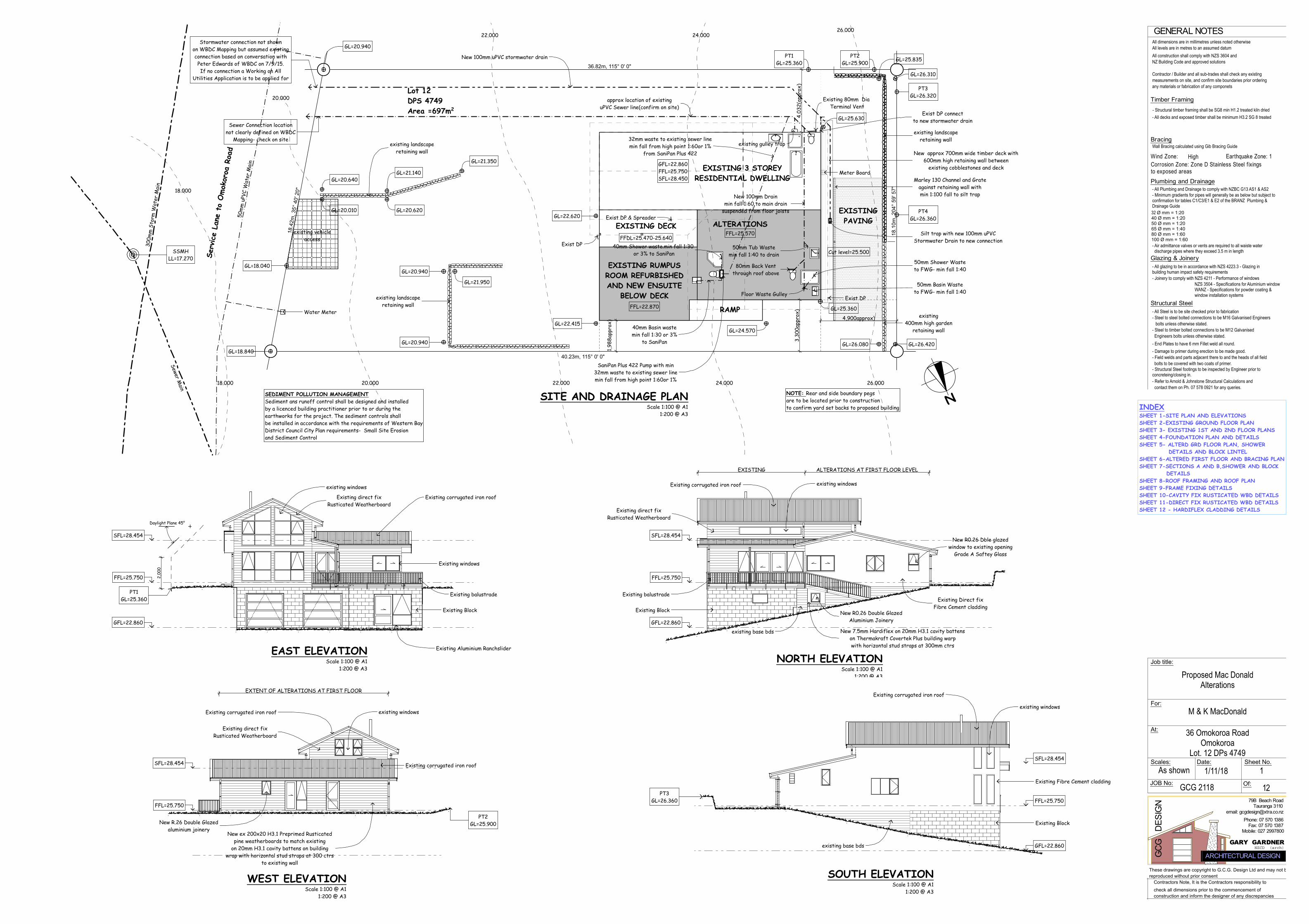
Bracing
Timber Framing
GENERAL NOTES
Wind Zone: Earthquake Zone: 1
Structural Steel
Of:
GCG
D
ESIG
N
GARY GARDNER
79B Beach Road
Scales:As shown
All dimensions are in millimetres unless noted otherwiseAll levels are in metres to an assumed datumAll construction shall comply with NZS 3604 andNZ Building Code and approved solutions
Contractor / Builder and all sub-trades shall check any existingmeasurements on site, and confirm site boundaries prior orderingany materials or fabrication of any componets
Wall Bracing calculated using Gib Bracing Guide
- All Steel is to be site checked prior to fabrication- Steel to steel bolted connections to be M16 Galvanised Engineers bolts unless otherwise stated.- Steel to timber bolted connections to be M12 Galvanised Engineers bolts unless otherwise stated.- End Plates to have 6 mm Fillet weld all round.- Damage to primer during erection to be made good.- Field welds and parts adjacent there to and the heads of all field bolts to be covered with two coats of primer.- Structural Steel footings to be inspected by Engineer prior toconcreteing/closing in.
Sheet No.Date:
Tauranga 3110email: [email protected]
Fax: 07 570 1387Phone: 07 570 1386
Contractors Note, It is the Contractors responsibility tocheck all dimensions prior to the commencement ofconstruction and inform the designer of any discrepancies
These drawings are copyright to G.C.G. Design Ltd and may not bereproduced without prior consent
ARCHITECTURAL DESIGNNZCD (arch)
JOB No:
Job title:
For:
At:
M & K MacDonald
Proposed Mac DonaldAlterations
High
36 Omokoroa RoadOmokoroa
Lot. 12 DPs 4749
GCG 2118 12
1/11/18
- Structural timber framing shall be SG8 min H1.2 treated kiln dried- All decks and exposed timber shall be minimum H3.2 SG 8 treated
Corrosion Zone: Zone D Stainless Steel f ixingsto exposed areas
Glazing & Joinery- All glazing to be in accordance with NZS 4223.3 - Glazing inbuilding human impact safety requirements- Joinery to comply with NZS 4211 - Performance of windows
NZS 3504 - Specifications for Aluminium windowWANZ - Specifications for powder coating &window installation systems
Plumbing and Drainage- All Plumbing and Drainage to comply with NZBC G13 AS1 & AS2- Minimum gradients for pipes will generally be as below but subject toconfirmation for tables C1/C3/E1 & E2 of the BRANZ Plumbing &Drainage Guide32 Ø mm = 1:2040 Ø mm = 1:2050 Ø mm = 1:2065 Ø mm = 1:4080 Ø mm = 1:60100 Ø mm = 1:60- Air admittance valves or vents are required to all waiste water discharge pipes where they exceed 3.5 m in length
- Refer to Arnold & Johnstone Structural Calculations and contact them on Ph. 07 578 0921 for any queries.
1
Mobile: 027 2997800
36.82m, 115° 0' 0"
18.4
2m, 3
5° 4
0' 2
0"
40.23m, 115° 0' 0"
18.1
0m, 2
04° 5
9' 5
7"
N
4,03
2(ap
prox
)
4,900approx)
3,30
0app
rox)
1,98
8app
rox)
existing400mm high garden
retaining wall
existing landscaperetaining wall
existing landscaperetaining wall
GL=20.940
GL=18.040
GL=20.010
GL=20.640
GL=21.350
GL=21.140
GL=20.620
GL=21.950
GL=20.940
GL=20.940
GL=22.620
GL=22.415GL=24.570
GL=25.360
GL=26.420GL=26.080
GL=26.310
GL=25.835
GL=25.630
GL=18.840
Water Meter
SSMHLL=17.270
Meter Board
Exist DP
Exist DP & Spreader
Exist DP
PT1GL=25.360
PT3GL=26.320
PT4GL=26.360
PT2GL=25.900
approx location of existinguPVC Sewer line(confirm on site)
existing gulley trap
Existing 80mm Dia Terminal Vent
New 100mm uPVC stormwater drain
Sewer Connection locationnot clearly defined on WBDC
Mapping- check on site
Stormwater connection not shownon WBDC Mapping but assumed existingconnection based on conversation withPeter Edwards of WBDC on 7/9/15.If no connection a Working on All
Utilities Application is to be applied for
existing landscaperetaining wall
SaniPan Plus 422 Pump with min32mm waste to existing sewer linemin fall from high point 1:60or 1%
32mm waste to existing sewer linemin fall from high point 1:60or 1%
from SaniPan Plus 422
40mm Basin wastemin fall 1:30 or 3%
to SaniPan
40mm Shower waste.min fall 1:30 or 3% to SaniPan
Floor Waste Gulley
50mm Basin Wasteto FWG- min fall 1:40
50mm Shower Wasteto FWG- min fall 1:40
New 100mm Drainmin fall 1:60 to main drain
suspended from floor joists
50mm Tub Wastemin fall 1:40 to drain
80mm Back Ventthrough roof above
Exist DP connectto new stormwater drain
Marley 130 Channel and Grateagainst retaining wall withmin 1:100 fall to silt trap
New approx 700mm wide timber deck with600mm high retaining wall between
existing cobblestones and deck
Silt trap with new 100mm uPVCStormwater Drain to new connection
SITE AND DRAINAGE PLANScale 1:100 @ A1
1:200 @ A3
SEDIMENT POLLUTION MANAGEMENTSediment ans runoff control shall be designed and installedby a licenced building practitioner prior to or during theearthworks for the project. The sediment controls shallbe installed in accordance with the requirements of Western BayDistrict Council City Plan requirements- Small Site Erosionand Sediment Control
GFL=22.860FFL=25.750SFL=28.450
FFDL=25.470-25.640FFL=25.570
EXISTING 3 STOREYRESIDENTIAL DWELLING
EXISTING DECK
RAMP
Lot 12DPS 4749Area =697m2
50m
m u
PVC
Wat
er M
ain
300m
m S
torm
Wat
er M
ain
Sewer Main
26.00024.00022.000
20.000
18.000
26.00024.00022.00020.00018.000
Serv
ice
Lane
to
Omok
oroa
Roa
dexisting vehicle
access
Cut level=25.500
NOTE: Rear and side boundary pegsare to be located prior to constructionto confirm yard set backs to proposed building
ALTERATIONS
EXISTINGPAVING
EXISTING RUMPUSROOM REFURBISHEDAND NEW ENSUITE
BELOW DECKFFL=22.870
Daylight Plane 45°
2,00
0
PT1GL=25.360
FFL=25.750
GFL=22.860
SFL=28.454
Existing windows
Existing Block
Existing balustrade
Existing direct fixRusticated Weatherboard
Existing corrugated iron roof
existing windows
Existing Aluminium RanchsliderEAST ELEVATIONScale 1:100 @ A1
1:200 @ A3
EXISTING ALTERATIONS AT FIRST FLOOR LEVEL
GFL=22.860
SFL=28.454
FFL=25.750
Existing Block
Existing balustrade
Existing direct fixRusticated Weatherboard
Existing corrugated iron roof existing windows
Existing Direct fixFibre Cement cladding
existing base bds
New R0.26 Double GlazedAluminium Joinery
New R0.26 Dble glazedwindow to existing opening
Grade A Saftey Glass
New 7.5mm Hardiflex on 20mm H3.1 cavity battenson Thermakraft Covertek Plus building warpwith horizontal stud straps at 300mm ctrs
NORTH ELEVATIONScale 1:100 @ A1
1:200 @ A3
PT3GL=26.360
GFL=22.860
SFL=28.454
FFL=25.750
Existing Block
Existing corrugated iron roof
existing windows
Existing Fibre Cement cladding
existing base bds
SOUTH ELEVATIONScale 1:100 @ A1
1:200 @ A3
EXTENT OF ALTERATIONS AT FIRST FLOOR
PT2GL=25.900
SFL=28.454
FFL=25.750
New R.26 Double Glazedaluminium joinery
Existing direct fixRusticated Weatherboard
Existing corrugated iron roof existing windows
New ex 200x20 H3.1 Preprimed Rusticatedpine weatherboards to match existing
on 20mm H3.1 cavity battens on buildingwrap with horizontal stud straps at 300 ctrs
to existing wall
Existing corrugated iron roof
WEST ELEVATIONScale 1:100 @ A1
1:200 @ A3
INDEXSHEET 1-SITE PLAN AND ELEVATIONSSHEET 2-EXISTING GROUND FLOOR PLANSHEET 3- EXISTING 1ST AND 2ND FLOOR PLANSSHEET 4-FOUNDATION PLAN AND DETAILSSHEET 5- ALTERD GRD FLOOR PLAN, SHOWER DETAILS AND BLOCK LINTELSHEET 6-ALTERED FIRST FLOOR AND BRACING PLANSHEET 7-SECTIONS A AND B,SHOWER AND BLOCK DETAILSSHEET 8-ROOF FRAMING AND ROOF PLANSHEET 9-FRAME FIXING DETAILSSHEET 10-CAVITY FIX RUSTICATED WBD DETAILSSHEET 11-DIRECT FIX RUSTICATED WBD DETAILSSHEET 12 - HARDIFLEX CLADDING DETAILS
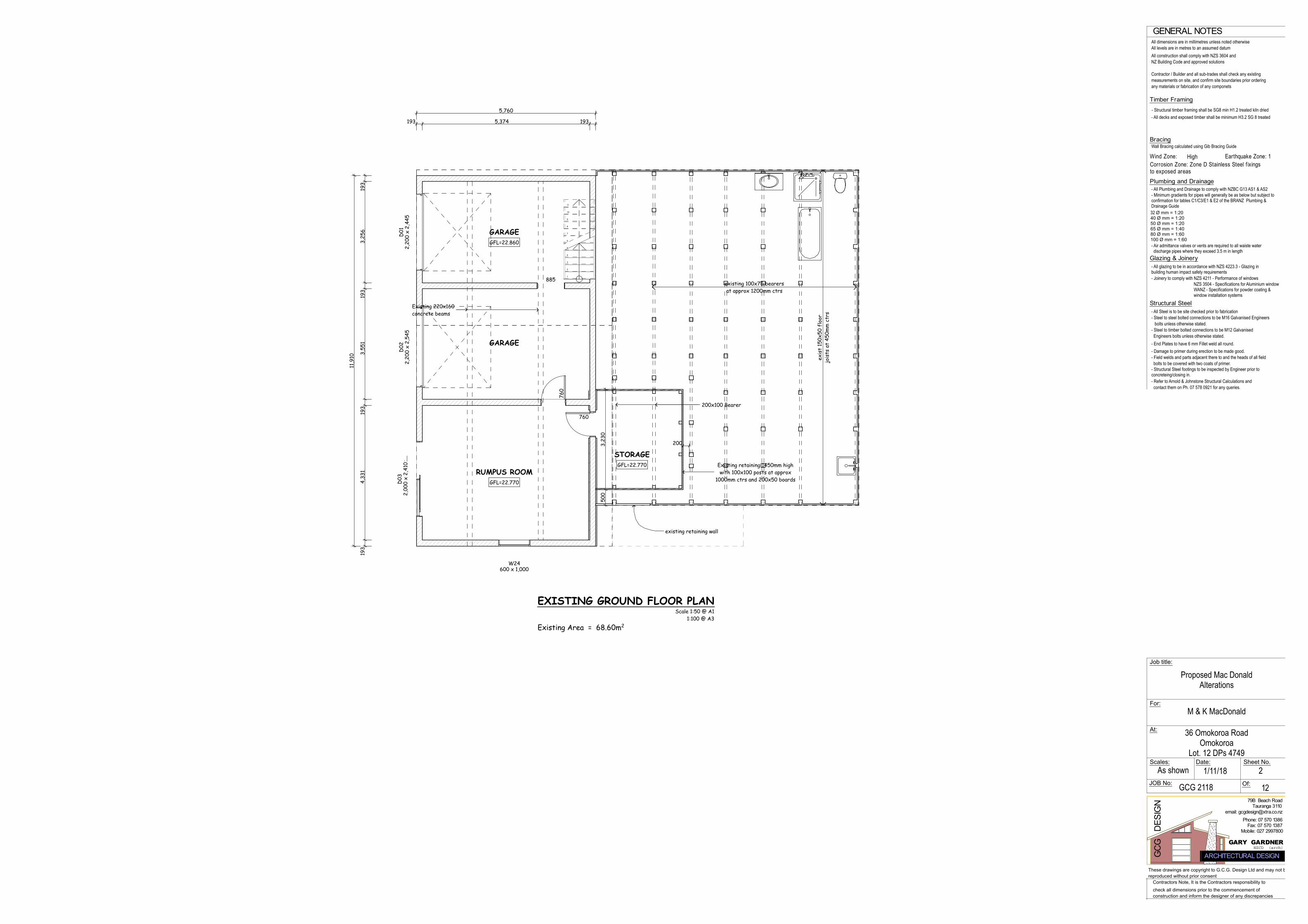
Bracing
Timber Framing
GENERAL NOTES
Wind Zone: Earthquake Zone: 1
Structural Steel
Of:
GCG
D
ESIG
N
GARY GARDNER
79B Beach Road
Scales:As shown
All dimensions are in millimetres unless noted otherwiseAll levels are in metres to an assumed datumAll construction shall comply with NZS 3604 andNZ Building Code and approved solutions
Contractor / Builder and all sub-trades shall check any existingmeasurements on site, and confirm site boundaries prior orderingany materials or fabrication of any componets
Wall Bracing calculated using Gib Bracing Guide
- All Steel is to be site checked prior to fabrication- Steel to steel bolted connections to be M16 Galvanised Engineers bolts unless otherwise stated.- Steel to timber bolted connections to be M12 Galvanised Engineers bolts unless otherwise stated.- End Plates to have 6 mm Fillet weld all round.- Damage to primer during erection to be made good.- Field welds and parts adjacent there to and the heads of all field bolts to be covered with two coats of primer.- Structural Steel footings to be inspected by Engineer prior toconcreteing/closing in.
Sheet No.Date:
Tauranga 3110email: [email protected]
Fax: 07 570 1387Phone: 07 570 1386
Contractors Note, It is the Contractors responsibility tocheck all dimensions prior to the commencement ofconstruction and inform the designer of any discrepancies
These drawings are copyright to G.C.G. Design Ltd and may not bereproduced without prior consent
ARCHITECTURAL DESIGNNZCD (arch)
JOB No:
Job title:
For:
At:
M & K MacDonald
Proposed Mac DonaldAlterations
High
36 Omokoroa RoadOmokoroa
Lot. 12 DPs 4749
GCG 2118 12
1/11/18
- Structural timber framing shall be SG8 min H1.2 treated kiln dried- All decks and exposed timber shall be minimum H3.2 SG 8 treated
Corrosion Zone: Zone D Stainless Steel f ixingsto exposed areas
Glazing & Joinery- All glazing to be in accordance with NZS 4223.3 - Glazing inbuilding human impact safety requirements- Joinery to comply with NZS 4211 - Performance of windows
NZS 3504 - Specifications for Aluminium windowWANZ - Specifications for powder coating &window installation systems
Plumbing and Drainage- All Plumbing and Drainage to comply with NZBC G13 AS1 & AS2- Minimum gradients for pipes will generally be as below but subject toconfirmation for tables C1/C3/E1 & E2 of the BRANZ Plumbing &Drainage Guide32 Ø mm = 1:2040 Ø mm = 1:2050 Ø mm = 1:2065 Ø mm = 1:4080 Ø mm = 1:60100 Ø mm = 1:60- Air admittance valves or vents are required to all waiste water discharge pipes where they exceed 3.5 m in length
- Refer to Arnold & Johnstone Structural Calculations and contact them on Ph. 07 578 0921 for any queries.
2
Mobile: 027 2997800
D02
2,20
0 x
2,54
5D
012,
200
x 2,
445
W24600 x 1,000
885
760
760
D03
2,00
0 x
2,41
0
1
2
3
4
5
6
7
8
9
10
11
11,9
10
193
4,33
119
33,
551
193
3,25
619
3
5,760
193 5,374 193
200
500
3,23
0
Existing 220x160concrete beams
existing retaining wall
200x100 Bearer
Existing retaining 1450mm highwith 100x100 posts at approx
1000mm ctrs and 200x50 boards
EXISTING GROUND FLOOR PLANScale 1:50 @ A1 1:100 @ A3
Existing Area = 68.60m2
existing 100x75 bearersat approx 1200mm ctrs
exis
t 15
0x50
flo
orjo
ists
at
450m
m c
trs
STORAGE
RUMPUS ROOM
GARAGE
GARAGE
GFL=22.770
GFL=22.860
GFL=22.770

Bracing
Timber Framing
GENERAL NOTES
Wind Zone: Earthquake Zone: 1
Structural Steel
Of:
GCG
D
ESIG
N
GARY GARDNER
79B Beach Road
Scales:As shown
All dimensions are in millimetres unless noted otherwiseAll levels are in metres to an assumed datumAll construction shall comply with NZS 3604 andNZ Building Code and approved solutions
Contractor / Builder and all sub-trades shall check any existingmeasurements on site, and confirm site boundaries prior orderingany materials or fabrication of any componets
Wall Bracing calculated using Gib Bracing Guide
- All Steel is to be site checked prior to fabrication- Steel to steel bolted connections to be M16 Galvanised Engineers bolts unless otherwise stated.- Steel to timber bolted connections to be M12 Galvanised Engineers bolts unless otherwise stated.- End Plates to have 6 mm Fillet weld all round.- Damage to primer during erection to be made good.- Field welds and parts adjacent there to and the heads of all field bolts to be covered with two coats of primer.- Structural Steel footings to be inspected by Engineer prior toconcreteing/closing in.
Sheet No.Date:
Tauranga 3110email: [email protected]
Fax: 07 570 1387Phone: 07 570 1386
Contractors Note, It is the Contractors responsibility tocheck all dimensions prior to the commencement ofconstruction and inform the designer of any discrepancies
These drawings are copyright to G.C.G. Design Ltd and may not bereproduced without prior consent
ARCHITECTURAL DESIGNNZCD (arch)
JOB No:
Job title:
For:
At:
M & K MacDonald
Proposed Mac DonaldAlterations
High
36 Omokoroa RoadOmokoroa
Lot. 12 DPs 4749
GCG 2118 12
1/11/18
- Structural timber framing shall be SG8 min H1.2 treated kiln dried- All decks and exposed timber shall be minimum H3.2 SG 8 treated
Corrosion Zone: Zone D Stainless Steel f ixingsto exposed areas
Glazing & Joinery- All glazing to be in accordance with NZS 4223.3 - Glazing inbuilding human impact safety requirements- Joinery to comply with NZS 4211 - Performance of windows
NZS 3504 - Specifications for Aluminium windowWANZ - Specifications for powder coating &window installation systems
Plumbing and Drainage- All Plumbing and Drainage to comply with NZBC G13 AS1 & AS2- Minimum gradients for pipes will generally be as below but subject toconfirmation for tables C1/C3/E1 & E2 of the BRANZ Plumbing &Drainage Guide32 Ø mm = 1:2040 Ø mm = 1:2050 Ø mm = 1:2065 Ø mm = 1:4080 Ø mm = 1:60100 Ø mm = 1:60- Air admittance valves or vents are required to all waiste water discharge pipes where they exceed 3.5 m in length
- Refer to Arnold & Johnstone Structural Calculations and contact them on Ph. 07 578 0921 for any queries.
3
Mobile: 027 2997800
W08
1,91
0 x
1,92
0W
091,
910
x 1,
920
W072,000 x 4,180
W22
1,06
0 x
1,80
0W
231,
900
x 1,
560
W211,060 x 1,800
W201,060 x 1,180
W191,130 x 710
W18
760
x 1,
120
W16
1,84
0 x
1,50
0W
171,
900
x 81
0
W14660 x 360
W131,060 x 590
610
610
760
760
580
610
810
610
610
760
760
W111,910 x 520
W101,910 x 520
W121,070 x 1,790
460
W15
1,84
0 x
1,50
0
1
2
3
4
5
6
7
8
9
10
11
F
WD
R
94 1,698 100 4,396 100 3,266 55 667 100 2,541 100 997 100
14,214
10,7
73
100
2,33
210
05,
244
5593
310
01,
809
100
100
3,35
710
03,
199
100
920
100
2,79
710
0
6,288 100 2,520 100 620 100 2,547 100 1,739 100
6,288 7,926
5,77
994
4,80
694
5,77
94,
994
100
1,24
910
080
910
01,
099
100
4,21
910
02,
797
100
existing Meter Bd
Scale 1:50 @ A1 1:100 @ A3
Existing Area = 116.79m2
Addition Area = 00.00m2
Total Area = 116.79m2
Deck Area = 44.77m2
EXISTING FIRST FLOOR PLAN
LOUNGE
BEDROOM 2 BATHROOM
WC
PASSAGE
KITCHENDINING
BEDROOM 3BEDROOM 4
LDRY
DECKrobe
robe
robe
robe
hwc stSTAIRS
RAMP
FFL=25.750
FDL=25.485 FDL=25.640
FDL=25.485FDL=25.470
FFL=25.750
W01
1,12
0 x
1,80
0
W061,420 x 520
W051,420 x 520
W03
2,54
0 x
1,92
0W
042,
540
x 1,
920
W02520 x 4,010
1
2
3
4
5
6
7
8
9
10
11
9,243
94 9,055 94
944,
806
94
4,99
4
941,
151
941,
766
941,
701
94
944,
806
94
94 1,704 94 3,820 94 3,343 94
BEDROOM 1VOIDMEZZANINE
Existing Area including Mezzanine = 31.07m2
Scale 1:50 @ A1 1:100 @ A3
EXISTING SECOND FLOOR PLAN
STAIRS
robeSFL=28.026 SFL=28.454
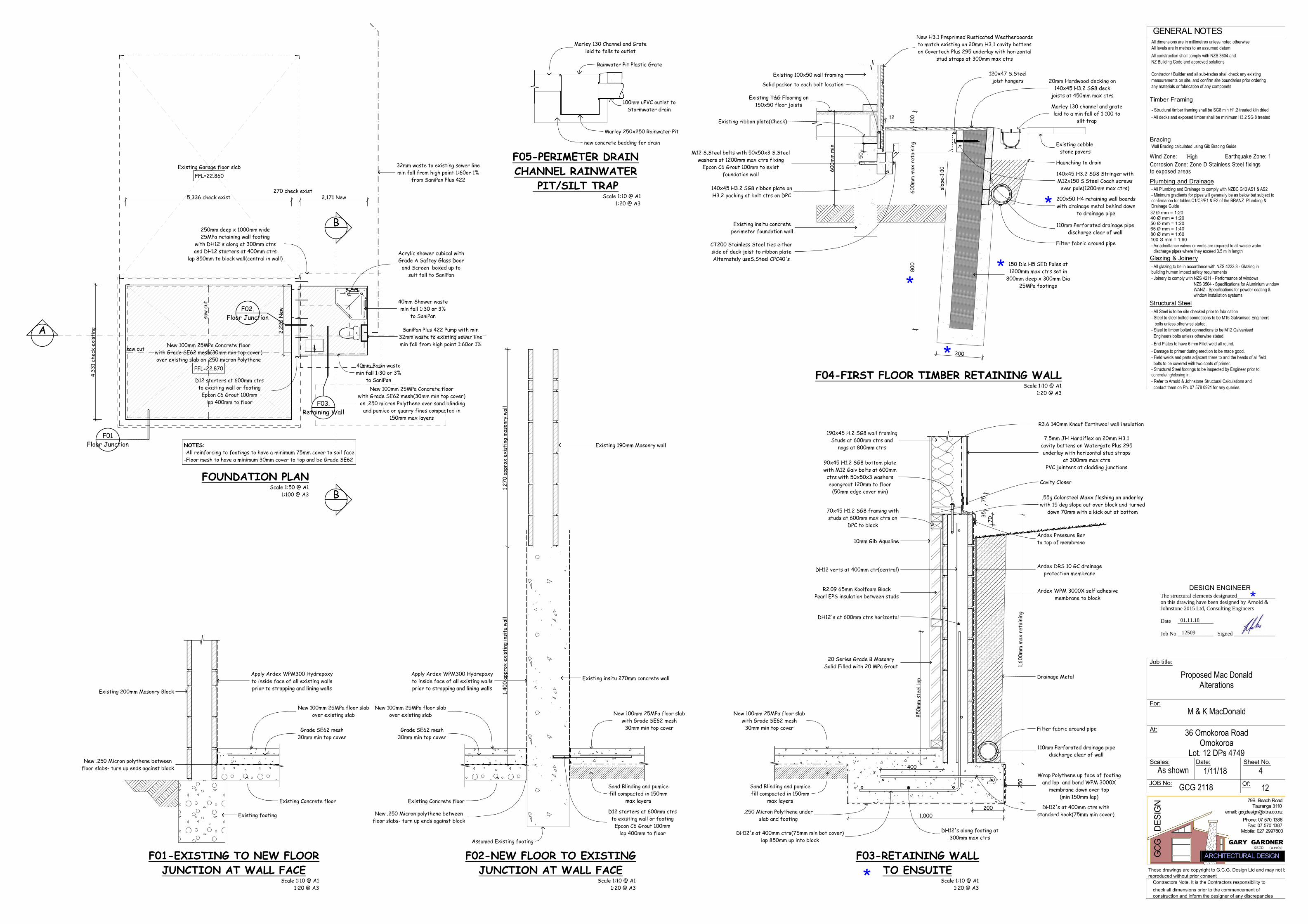
Bracing
Timber Framing
GENERAL NOTES
Wind Zone: Earthquake Zone: 1
Structural Steel
Of:
GCG
D
ESIG
N
GARY GARDNER
79B Beach Road
Scales:As shown
All dimensions are in millimetres unless noted otherwiseAll levels are in metres to an assumed datumAll construction shall comply with NZS 3604 andNZ Building Code and approved solutions
Contractor / Builder and all sub-trades shall check any existingmeasurements on site, and confirm site boundaries prior orderingany materials or fabrication of any componets
Wall Bracing calculated using Gib Bracing Guide
- All Steel is to be site checked prior to fabrication- Steel to steel bolted connections to be M16 Galvanised Engineers bolts unless otherwise stated.- Steel to timber bolted connections to be M12 Galvanised Engineers bolts unless otherwise stated.- End Plates to have 6 mm Fillet weld all round.- Damage to primer during erection to be made good.- Field welds and parts adjacent there to and the heads of all field bolts to be covered with two coats of primer.- Structural Steel footings to be inspected by Engineer prior toconcreteing/closing in.
Sheet No.Date:
Tauranga 3110email: [email protected]
Fax: 07 570 1387Phone: 07 570 1386
Contractors Note, It is the Contractors responsibility tocheck all dimensions prior to the commencement ofconstruction and inform the designer of any discrepancies
These drawings are copyright to G.C.G. Design Ltd and may not bereproduced without prior consent
ARCHITECTURAL DESIGNNZCD (arch)
JOB No:
Job title:
For:
At:
M & K MacDonald
Proposed Mac DonaldAlterations
High
36 Omokoroa RoadOmokoroa
Lot. 12 DPs 4749
GCG 2118 12
1/11/18
- Structural timber framing shall be SG8 min H1.2 treated kiln dried- All decks and exposed timber shall be minimum H3.2 SG 8 treated
Corrosion Zone: Zone D Stainless Steel f ixingsto exposed areas
Glazing & Joinery- All glazing to be in accordance with NZS 4223.3 - Glazing inbuilding human impact safety requirements- Joinery to comply with NZS 4211 - Performance of windows
NZS 3504 - Specifications for Aluminium windowWANZ - Specifications for powder coating &window installation systems
Plumbing and Drainage- All Plumbing and Drainage to comply with NZBC G13 AS1 & AS2- Minimum gradients for pipes will generally be as below but subject toconfirmation for tables C1/C3/E1 & E2 of the BRANZ Plumbing &Drainage Guide32 Ø mm = 1:2040 Ø mm = 1:2050 Ø mm = 1:2065 Ø mm = 1:4080 Ø mm = 1:60100 Ø mm = 1:60- Air admittance valves or vents are required to all waiste water discharge pipes where they exceed 3.5 m in length
- Refer to Arnold & Johnstone Structural Calculations and contact them on Ph. 07 578 0921 for any queries.
4
Mobile: 027 2997800
F01Floor Junction
F02.Floor Junction
F03.Retaining Wall
5,336 check exist270 check exist
2,171 New
4,33
1 ch
eck
exis
ting 2,
220
New
SaniPan Plus 422 Pump with min32mm waste to existing sewer linemin fall from high point 1:60or 1%
32mm waste to existing sewer linemin fall from high point 1:60or 1%
from SaniPan Plus 422
D12 starters at 600mm ctrsto existing wall or footing
Epcon C6 Grout 100mmlap 400mm to floor
40mm Basin wastemin fall 1:30 or 3%
to SaniPan
40mm Shower wastemin fall 1:30 or 3%
to SaniPan
Acrylic shower cubical withGrade A Saftey Glass Door
and Screen boxed up tosuit fall to SaniPan
250mm deep x 1000mm wide25MPa retaining wall footing
with DH12's along at 300mm ctrsand DH12 starters at 400mm ctrs
lap 850mm to block wall(central in wall)
FOUNDATION PLANScale 1:50 @ A1 1:100 @ A3
NOTES:-All reinforcing to footings to have a minimum 75mm cover to soil face-Floor mesh to have a minimum 30mm cover to top and be Grade SE62
Existing Garage floor slabFFL=22.860
New 100mm 25MPa Concrete floorwith Grade SE62 mesh(30mm min top cover)over existing slab on .250 micron Polythene
FFL=22.870
saw
cut
saw cut
B
B
New 100mm 25MPa Concrete floorwith Grade SE62 mesh(30mm min top cover) on .250 micron Polythene over sand blinding
and pumice or quarry fines compacted in150mm max layers
A
850m
m s
teel
lap
400
250
1,60
0mm
max
ret
aini
ng
1,000200
3575
70
800
600m
m m
ax r
etai
ning
600m
m m
in
10012
300
1,40
0 ap
prox
exi
stin
g in
situ
wal
l1,
270
appr
ox e
xist
ing
mas
onry
wal
l
50
90x45 H1.2 SG8 bottom platewith M12 Galv bolts at 600mm
ctrs with 50x50x3 washersepongrout 120mm to floor
(50mm edge cover min)
Existing 200mm Masonry Block
Apply Ardex WPM300 Hydrepoxyto inside face of all existing wallsprior to strapping and lining walls
Existing insitu 270mm concrete wallApply Ardex WPM300 Hydrepoxyto inside face of all existing wallsprior to strapping and lining walls
Existing footing
Existing Concrete floor
New .250 Micron polythene betweenfloor slabs- turn up ends against block
New 100mm 25MPa floor slabover existing slab
Assumed Existing footing
Existing Concrete floor
New .250 Micron polythene betweenfloor slabs- turn up ends against block
New 100mm 25MPa floor slabover existing slab New 100mm 25MPa floor slab
with Grade SE62 mesh30mm min top cover
D12 starters at 600mm ctrsto existing wall or footing
Epcon C6 Grout 100mmlap 400mm to floor
Sand Blinding and pumicefill compacted in 150mm
max layers
New 100mm 25MPa floor slabwith Grade SE62 mesh
30mm min top cover
Sand Blinding and pumicefill compacted in 150mm
max layers
Wrap Polythene up face of footingand lap and bond WPM 3000X
membrane down over top(min 150mm lap)
Ardex WPM 3000X self adhesivemembrane to block
Ardex Pressure Barto top of membrane
110mm Perforated drainage pipedischarge clear of wall
Filter fabric around pipe
.55g Colorsteel Maxx flashing on underlaywith 15 deg slope out over block and turned
down 70mm with a kick out at bottom
190x45 H.2 SG8 wall framingStuds at 600mm ctrs and
nogs at 800mm ctrs
R3.6 140mm Knauf Earthwool wall insulation
Marley 250x250 Rainwater Pit
100mm uPVC outlet toStormwater drain
Rainwater Pit Plastic Grate
Marley 130 Channel and Gratelaid to falls to outlet
new concrete bedding for drain
Existing 100x50 wall framing
Marley 130 channel and gratelaid to a min fall of 1:100 to
silt trap
110mm Perforated drainage pipedischarge clear of wall
Filter fabric around pipe
Existing 190mm Masonry wall
.250 Micron Polythene underslab and footing
DH12's at 400mm ctrs(75mm min bot cover)lap 850mm up into block
Ardex DRS 10 GC drainageprotection membrane
Drainage Metal
150 Dia H5 SED Poles at1200mm max ctrs set in
800mm deep x 300mm Dia25MPa footings
Existing insitu concreteperimeter foundation wall
Haunching to drain
Existing cobble stone pavers
DH12 verts at 400mm ctr(central)
DH12's at 400mm ctrs withstandard hook(75mm min cover)
DH12's along footing at300mm max ctrs
DH12's at 600mm ctrs horizontal
10mm Gib Aqualine
70x45 H1.2 SG8 framing withstuds at 600mm max ctrs on
DPC to block
R2.09 65mm Koolfoam BlackPearl EPS insulation between studs
20 Series Grade B MasonrySolid Filled with 20 MPa Grout
7.5mm JH Hardiflex on 20mm H3.1cavity battens on Watergate Plus 295underlay with horizontal stud straps
at 300mm max ctrsPVC jointers at cladding junctions
Cavity Closer
200x50 H4 retaining wall boardswith drainage metal behind down
to drainage pipe
140x45 H3.2 SG8 Stringer withM12x150 S.Steel Coach screws
ever pole(1200mm max ctrs)
CT200 Stainless Steel ties eitherside of deck joist to ribbon plateAlternately useS.Steel CPC40's
120x47 S.Steeljoist hangers
Existing ribbon plate(Check)
Existing T&G Flooring on150x50 floor joists
20mm Hardwood decking on140x45 H3.2 SG8 deck
joists at 450mm max ctrs
New H3.1 Preprimed Rusticated Weatherboardsto match existing on 20mm H3.1 cavity battenson Covertech Plus 295 underlay with horizontal
stud straps at 300mm max ctrs
Solid packer to each bolt location
140x45 H3.2 SG8 ribbon plate onH3.2 packing at bolt ctrs on DPC
M12 S.Steel bolts with 50x50x3 S.Steelwashers at 1200mm max ctrs fixing
Epcon C6 Grout 100mm to existfoundation wall
Scale 1:10 @ A1 1:20 @ A3
F01-EXISTING TO NEW FLOORJUNCTION AT WALL FACE
Scale 1:10 @ A1 1:20 @ A3
F02-NEW FLOOR TO EXISTINGJUNCTION AT WALL FACE
Scale 1:10 @ A1 1:20 @ A3
F03-RETAINING WALLTO ENSUITE
Scale 1:10 @ A1 1:20 @ A3
F04-FIRST FLOOR TIMBER RETAINING WALL
F05-PERIMETER DRAINCHANNEL RAINWATER
PIT/SILT TRAPScale 1:10 @ A1 1:20 @ A3
slop
e-1:
10
Grade SE62 mesh30mm min top cover
Grade SE62 mesh30mm min top cover
DESIGN ENGINEERThe structural elements designated______________on this drawing have been designed by Arnold &Johnstone 2015 Ltd, Consulting Engineers
Date _____________
Job No _____________ Signed _______________
*
12509
01.11.18
*
**
*
*

Bracing
Timber Framing
GENERAL NOTES
Wind Zone: Earthquake Zone: 1
Structural Steel
Of:
GCG
D
ESIG
N
GARY GARDNER
79B Beach Road
Scales:As shown
All dimensions are in millimetres unless noted otherwiseAll levels are in metres to an assumed datumAll construction shall comply with NZS 3604 andNZ Building Code and approved solutions
Contractor / Builder and all sub-trades shall check any existingmeasurements on site, and confirm site boundaries prior orderingany materials or fabrication of any componets
Wall Bracing calculated using Gib Bracing Guide
- All Steel is to be site checked prior to fabrication- Steel to steel bolted connections to be M16 Galvanised Engineers bolts unless otherwise stated.- Steel to timber bolted connections to be M12 Galvanised Engineers bolts unless otherwise stated.- End Plates to have 6 mm Fillet weld all round.- Damage to primer during erection to be made good.- Field welds and parts adjacent there to and the heads of all field bolts to be covered with two coats of primer.- Structural Steel footings to be inspected by Engineer prior toconcreteing/closing in.
Sheet No.Date:
Tauranga 3110email: [email protected]
Fax: 07 570 1387Phone: 07 570 1386
Contractors Note, It is the Contractors responsibility tocheck all dimensions prior to the commencement ofconstruction and inform the designer of any discrepancies
These drawings are copyright to G.C.G. Design Ltd and may not bereproduced without prior consent
ARCHITECTURAL DESIGNNZCD (arch)
JOB No:
Job title:
For:
At:
M & K MacDonald
Proposed Mac DonaldAlterations
High
36 Omokoroa RoadOmokoroa
Lot. 12 DPs 4749
GCG 2118 12
1/11/18
- Structural timber framing shall be SG8 min H1.2 treated kiln dried- All decks and exposed timber shall be minimum H3.2 SG 8 treated
Corrosion Zone: Zone D Stainless Steel f ixingsto exposed areas
Glazing & Joinery- All glazing to be in accordance with NZS 4223.3 - Glazing inbuilding human impact safety requirements- Joinery to comply with NZS 4211 - Performance of windows
NZS 3504 - Specifications for Aluminium windowWANZ - Specifications for powder coating &window installation systems
Plumbing and Drainage- All Plumbing and Drainage to comply with NZBC G13 AS1 & AS2- Minimum gradients for pipes will generally be as below but subject toconfirmation for tables C1/C3/E1 & E2 of the BRANZ Plumbing &Drainage Guide32 Ø mm = 1:2040 Ø mm = 1:2050 Ø mm = 1:2065 Ø mm = 1:4080 Ø mm = 1:60100 Ø mm = 1:60- Air admittance valves or vents are required to all waiste water discharge pipes where they exceed 3.5 m in length
- Refer to Arnold & Johnstone Structural Calculations and contact them on Ph. 07 578 0921 for any queries.
5
Mobile: 027 2997800
D02
2,20
0 x
2,54
5D
012,
200
x 2,
445
W24600 x 1,000
Existing Fixed Window
885
760
D03
2,00
0 x
2,41
0Ex
isti
ng R
anch
slid
er
760
W22620 x 620
2/90x45 LintelsGrade A Saftey Glass
1
2
3
4
5
6
7
8
9
10
11
F04.Timber Retaining Wall
F05Silt Trap
F06Tiled Shower
S01Block Lintel
11,9
10
260
4,19
626
03,
551
193
3,25
619
3
5,760
193 5,374 193
5,760 check 2,400 check
2,140 190 70
2,60
0
260
2,08
026
0
B
B
Existing 220x160concrete beams
existing retaining wall to be dismantledback fill to new Masonry Retaining wall
all round
existing subfloor battens
approx location of existinguPVC Sewer line(confirm on site) existing gulley trap
80mm Dia Terminal Vent
Lay .250 micron polythene to groundbelow existing timber subfloor
where ground level less than 600mmbelow floor level(hatched area approx)
smoke detector
20mm Hardwood deckingon 140x45 H3.2 joists at
450mm max ctrs
New 600mm high retaining wallwith 150mm Dia SED poles at1200mm ctrs
set in 800mm deep x 300mm Dia25 MPa footings.
200x50 H4 T&G Boards behind
Marley 130 Channel and Grateagainst retaining wall
Floor Waste Gulley
50mm Basin Wasteto FWG- min fall 1:40
50mm Shower Wasteto FWG- min fall 1:40
100mm WC Wastemin fall 1:60 to drain
New 100mm Drainmin fall 1:60 to main drain
suspended from floor joists
50mm Tub Wastemin fall 1:40 to drain
80mm Back Ventthrough roof above
32mm waste to existing sewer linemin fall from high point 1:60or 1%
from SaniPan Plus 422
New 125x125 H5 pile setin 450x450x450 25MPa footing
(under point load from roof beam)
Existing Insitu Concrete foundation wall
Existing 200x100 bearer overensuite. Ensure a min of 2/190x45H1.2 SG8 under studs in new walls
each end of beam
Acrylic shower cubical withGrade A Saftey Glass Door
and Screen boxed up tosuit fall to SaniPan
ALTERED GROUND FLOORAND FOUNDATION PLAN
Scale 1:50 @ A1 1:100 @ A3
Existing Area = 68.60m2
Ensuite Area = 6.23m2
Total Area = 74.83m2
WALL FRAMING MOISTURE CONTENT24% at ERECTION20% at ENCLOSURE16% at LINING
Wall Legend
New Exterior Walls: 190 x 45 framing,Studs @ 600crs with Nogs @ 800crsfrom 1600mm to ceiling height190mm Masonry up to 1600mm high with 70x45 H1.2strapping. R2.09 65mm Koolfoam Black Pearl insulationto cavityInt Lining: 10mm Gib Aqualine to Wet AreasInsulation: R3.6 140mm Knauf Earthwool InsulationCladding: 7.5mm JH Hardiflex wall claddingon 20mm H3.1 battens on building wrap supported withhorizontal strapping at 300mm ctrs.
EXTERIOR
existing 100x75 bearersat approx 1200mm ctrs
exis
t 15
0x50
flo
orjo
ists
at
450m
m c
trs
ENSUITE(tiled floor)
RUMPUS/BEDROOM ROOM
GARAGE
GARAGE
GFL=22.770
GFL=22.860
W01
Width Span/LoadedDimension
Lintel Size
From Lintel FixingType
900 E620 2/90 x 45 SG8 NZS 3604 : 2011. Table 8.10
LINTEL SIZE TABLE: Light roofTrimming Stud
( NZS 3604: Table 8.5 )45mm
Existing Exterior Walls: 190mm Masonry full height with new 70x45 H1.2strapping on DPC to inside face.Apply ArdexWPM300 Hydrepoxy to inside face of all existingwalls prior to strapping and lining wallsInt Lining: 10mm Gib BoardInsulation: R2.09 65mm Koolfoam Black Pearl insulationto cavity.Cladding: Existing Block painted
EXTERNAL WINDOWS AND DOORS-The nominated External Joinery Contractor is to provide site specific structural information relating to dead load,live load, wind, snow, earthquake and any otherrelevant details complying with NZS3504, Specifications for Aluminium Windows and NZS4211- Performance of windows and submit to the Territorial Authorityon completions of the project.- All Glazing is to comply with NZS4223.3- Glazing in Building Human and Impact Safety Requirements Glazing panels over 1 square meter and in bathrooms to have a min Grade A Safety Glass- All windows shall comply with requirements of G7- Natural Lighting providing an luminance to each Room of no less than 30 lux at floor level for 75% of theyear and have openings to give awareness of the outside that are transparent
G8-ARTIFICIAL LIGHTING-Artificial Lighting is to comply with G8 with a minimum of 20 lux at floor level within buildings which when activated in the absence of natural light, will enable safe movement.- The lighting designer or Electrician shall provide and submit documentation supporting this to the Territorial Authority on completions of the project
Existing opening cut in foundations andblock wall with new 180x75 PFC at lintel
height- 2/M16 Bolts at 200mm ctrsEpcon C6 grout 120mm
Allow to replace existing flooring with19mm H3 CCA Ply to Ensuite and Ldry areas
AA
SaniPan Plus 422 Pump with min32mm waste to existing sewer linemin fall from high point 1:60or 1%
exis
ting
ope
ning
che
ck h
eigh
tre
tri
m if
nec
essa
ry30
200
100
100
30
100 200 3030 100Existing Masonry lintel
Masonry wall beyond opening
Existing Masonry wall
Existing Masonry wall
Masonry lintel overopening
Existing Masonry wall
Existing Insitu 270mmconcrete wall beyond
Existing Insitu 270mmconcrete wall beyond
Existing Insitu 270mmconcrete wall beyond
New 100mm Concrete floorthrough existing opening
180x75 PFC fixed to existingMasonry wall with M16 Bolts
at 200mm ctrs- Epcon C6 Grout125mm
180x75 PFC fixed to existingMasonry wall with M16 Bolts
at 200mm ctrs- Epcon C6 Grout125mm
180x75 PFC fixed to existingMasonry wall with M16 Bolts
at 200mm ctrs- Epcon C6 Grout125mm
S01- BLOCK LINTEL DETAILScale 1:25 @ A1 1:50 @ A3
SIDE VIEW
PLAN VIEW
FRONT ON VIEW
120
135 checkto suit fall required
for waste pipe
Acrylic Shower Tray
Easyclean trapAcrylic Shower Tray
Sanipan 422 Plus Pump
35mm Waste to existing sewer drain
40mm Shower Wastemin fall 1:30 to Sanipan
Concrete Floor
90x45 H1.2 nog
H1.2 bottom plate
10mm Gib Bd Aqualine
10mm Gib Bd Aqualine
Acrylic Shower liner
Adhesive
Silicone between top ofshower tray and Gib Bd
Allow to apply sealant to top of showerliner to prevent moisture penetrating
behind wall linings
Tiles and Adhesive
18mm H3 CCA Ply to supportshower tray with H1.2 Sub framing
on DPC at 400mm max ctrs
SH01-RAISED ACRYLIC SHOWER TRAY AND LINERScale 1:5 @ A1 1:10 @ A3
Refer to Manufacturers Literaturefor full installation instructions
SH02-RAISED ACRYLIC SHOWER TRAYSANIPAN DIAGRAM- INDICATIVE ONLY
Scale 1:5 @ A1 1:10 @ A3
DESIGN ENGINEERThe structural elements designated______________on this drawing have been designed by Arnold &Johnstone 2015 Ltd, Consulting Engineers
Date _____________
Job No _____________ Signed _______________
*
12509
01.11.18
*
*
*
*
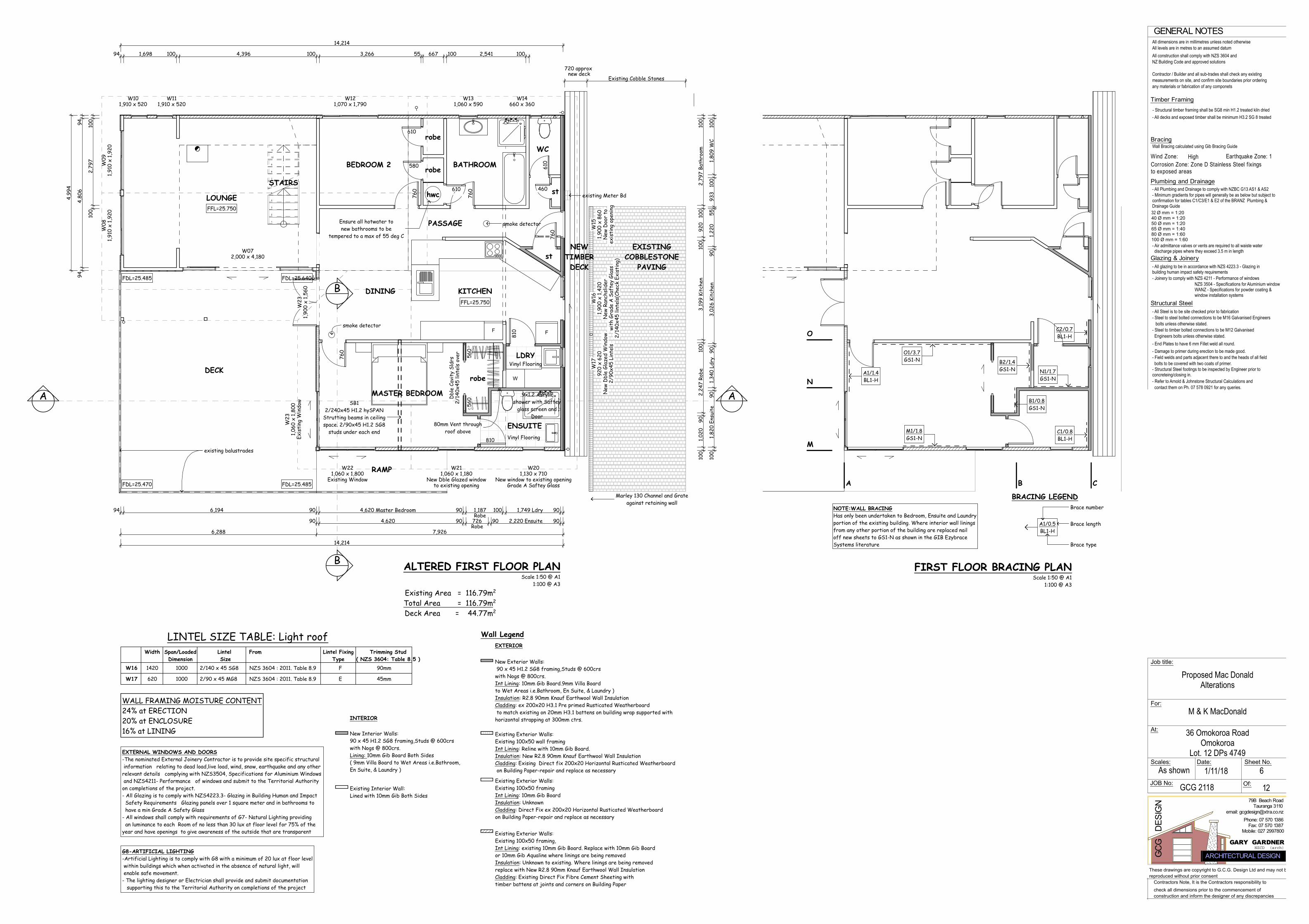
Bracing
Timber Framing
GENERAL NOTES
Wind Zone: Earthquake Zone: 1
Structural Steel
Of:
GCG
D
ESIG
N
GARY GARDNER
79B Beach Road
Scales:As shown
All dimensions are in millimetres unless noted otherwiseAll levels are in metres to an assumed datumAll construction shall comply with NZS 3604 andNZ Building Code and approved solutions
Contractor / Builder and all sub-trades shall check any existingmeasurements on site, and confirm site boundaries prior orderingany materials or fabrication of any componets
Wall Bracing calculated using Gib Bracing Guide
- All Steel is to be site checked prior to fabrication- Steel to steel bolted connections to be M16 Galvanised Engineers bolts unless otherwise stated.- Steel to timber bolted connections to be M12 Galvanised Engineers bolts unless otherwise stated.- End Plates to have 6 mm Fillet weld all round.- Damage to primer during erection to be made good.- Field welds and parts adjacent there to and the heads of all field bolts to be covered with two coats of primer.- Structural Steel footings to be inspected by Engineer prior toconcreteing/closing in.
Sheet No.Date:
Tauranga 3110email: [email protected]
Fax: 07 570 1387Phone: 07 570 1386
Contractors Note, It is the Contractors responsibility tocheck all dimensions prior to the commencement ofconstruction and inform the designer of any discrepancies
These drawings are copyright to G.C.G. Design Ltd and may not bereproduced without prior consent
ARCHITECTURAL DESIGNNZCD (arch)
JOB No:
Job title:
For:
At:
M & K MacDonald
Proposed Mac DonaldAlterations
High
36 Omokoroa RoadOmokoroa
Lot. 12 DPs 4749
GCG 2118 12
1/11/18
- Structural timber framing shall be SG8 min H1.2 treated kiln dried- All decks and exposed timber shall be minimum H3.2 SG 8 treated
Corrosion Zone: Zone D Stainless Steel f ixingsto exposed areas
Glazing & Joinery- All glazing to be in accordance with NZS 4223.3 - Glazing inbuilding human impact safety requirements- Joinery to comply with NZS 4211 - Performance of windows
NZS 3504 - Specifications for Aluminium windowWANZ - Specifications for powder coating &window installation systems
Plumbing and Drainage- All Plumbing and Drainage to comply with NZBC G13 AS1 & AS2- Minimum gradients for pipes will generally be as below but subject toconfirmation for tables C1/C3/E1 & E2 of the BRANZ Plumbing &Drainage Guide32 Ø mm = 1:2040 Ø mm = 1:2050 Ø mm = 1:2065 Ø mm = 1:4080 Ø mm = 1:60100 Ø mm = 1:60- Air admittance valves or vents are required to all waiste water discharge pipes where they exceed 3.5 m in length
- Refer to Arnold & Johnstone Structural Calculations and contact them on Ph. 07 578 0921 for any queries.
6
Mobile: 027 2997800
W08
1,91
0 x
1,92
0W
091,
910
x 1,
920
W072,000 x 4,180
W23
1,06
0 x
1,80
0Ex
isti
ng W
indo
wW
231,
900
x 1,
560
W14660 x 360
W131,060 x 590
610
610
760
760
580
610
W111,910 x 520
W101,910 x 520
W121,070 x 1,790
460
W17
920
x 62
0N
ew D
ble
Glaz
ed W
indo
w2/
90x4
5 Li
ntel
s
W16
1,90
0 x
1,42
0N
ew R
anch
slid
erwi
th G
rade
A S
afte
y Gl
ass
2/14
0x45
lint
els(
Chec
k Ex
isti
ng)
W15
1,90
0 x
860
New
Doo
r to
exis
ting
ope
ning
760
W221,060 x 1,800
Existing Window
W211,060 x 1,180
New Dble Glazed windowto existing opening
W201,130 x 710
New window to existing openingGrade A Saftey Glass
760
810
Dbl
e Ca
vity
Sld
rs2/
140x
45 li
ntel
s ov
er
560
560
810
1
2
3
4
5
6
7
8
9
10
11
F F
B
B
W
94 1,698 100 4,396 100 3,266 55 667 100 2,541 100
14,214
14,214
944,
806
94
4,99
4
100
2,79
710
0
94 6,194 90 4,620 Master Bedroom 90 1,187Robe
100 1,749 Ldry 90
90 4,620 90 726Robe
90 2,220 Ensuite 90
100
1,82
0 En
suit
e90
1,34
0 Ld
ry90
3,02
6 Ki
tche
n90
1,22
055
933
100
1,80
9 W
C10
0
100
1,02
090
2,24
7 Ro
be10
03,
199
Kitc
hen
100
920
100
2,79
7 Ba
thro
om10
0
6,288 7,926
720 approx new deck
Existing Cobble Stones
existing balustrades
smoke detector
smoke detector
existing Meter Bd
80mm Vent throughroof above
SB12/240x45 H1.2 hySPAN
Strutting beams in ceilingspace. 2/90x45 H1.2 SG8
studs under each end
Marley 130 Channel and Grateagainst retaining wall
WALL FRAMING MOISTURE CONTENT24% at ERECTION20% at ENCLOSURE16% at LINING
Existing Interior Wall:Lined with 10mm Gib Both Sides
New Interior Walls:90 x 45 H1.2 SG8 framing,Studs @ 600crswith Nogs @ 800crs.Lining: 10mm Gib Board Both Sides( 9mm Villa Board to Wet Areas i.e.Bathroom,En Suite, & Laundry )
Existing Exterior Walls:Existing 100x50 framingInt Lining: 10mm Gib BoardInsulation: UnknownCladding: Direct Fix ex 200x20 Horizontal Rusticated Weatherboardon Building Paper-repair and replace as necessary
Wall Legend
Existing Exterior Walls:Existing 100x50 framing,Int Lining: existing 10mm Gib Board. Replace with 10mm Gib Boardor 10mm Gib Aqualine where linings are being removedInsulation: Unknown to existing. Where linings are being removedreplace with New R2.8 90mm Knauf Earthwool Wall InsulationCladding: Existing Direct Fix Fibre Cement Sheeting withtimber battens at joints and corners on Building Paper
New Exterior Walls: 90 x 45 H1.2 SG8 framing,Studs @ 600crswith Nogs @ 800crs.Int Lining: 10mm Gib Board.9mm Villa Boardto Wet Areas i.e.Bathroom, En Suite, & Laundry )Insulation: R2.8 90mm Knauf Earthwool Wall InsulationCladding: ex 200x20 H3.1 Pre primed Rusticated Weatherboard to match existing on 20mm H3.1 battens on building wrap supported withhorizontal strapping at 300mm ctrs.
EXTERIOR
INTERIOR
W16
W17
Width Span/LoadedDimension
Lintel Size
From Lintel FixingType
620 1000 E
1000 F1420 2/140 x 45 SG8
2/90 x 45 MG8
NZS 3604 : 2011. Table 8.9
LINTEL SIZE TABLE: Light roofTrimming Stud
( NZS 3604: Table 8.5 )90mm
45mmNZS 3604 : 2011. Table 8.9
Scale 1:50 @ A1 1:100 @ A3
Existing Area = 116.79m2
Total Area = 116.79m2
Deck Area = 44.77m2
ALTERED FIRST FLOOR PLAN
LOUNGE
BEDROOM 2 BATHROOM
WC
PASSAGE
KITCHENDINING
DECK
robe
robe
hwc stSTAIRS
RAMP
FFL=25.750
FDL=25.485 FDL=25.640
FDL=25.485FDL=25.470
FFL=25.750
ENSUITE
MASTER BEDROOM
robe
LDRYVinyl Flooring
st
Existing Exterior Walls:Existing 100x50 wall framingInt Lining: Reline with 10mm Gib Board.Insulation: New R2.8 90mm Knauf Earthwool Wall InsulationCladding: Exising Direct fix 200x20 Horizontal Rusticated Weatherboard on Building Paper-repair and replace as necessary
Vinyl Flooring
.9x1.2 Acrylicshower with Saftey
glass screen andDoor
EXISTINGCOBBLESTONE
PAVING
NEWTIMBERDECK
EXTERNAL WINDOWS AND DOORS-The nominated External Joinery Contractor is to provide site specific structural information relating to dead load,live load, wind, snow, earthquake and any otherrelevant details complying with NZS3504, Specifications for Aluminium Windows and NZS4211- Performance of windows and submit to the Territorial Authorityon completions of the project.- All Glazing is to comply with NZS4223.3- Glazing in Building Human and Impact Safety Requirements Glazing panels over 1 square meter and in bathrooms to have a min Grade A Safety Glass- All windows shall comply with requirements of G7- Natural Lighting providing an luminance to each Room of no less than 30 lux at floor level for 75% of theyear and have openings to give awareness of the outside that are transparent
G8-ARTIFICIAL LIGHTING-Artificial Lighting is to comply with G8 with a minimum of 20 lux at floor level within buildings which when activated in the absence of natural light, will enable safe movement.- The lighting designer or Electrician shall provide and submit documentation supporting this to the Territorial Authority on completions of the project
Ensure all hotwater tonew bathrooms to be
tempered to a max of 55 deg C
AA
Brace number
Brace length
Brace type
A1/0.5BL1-H
A1/1.4BL1-H
B1/0.8GS1-N
B2/1.4GS1-N
C2/0.7BL1-H
C1/0.8BL1-H
M1/1.8GS1-N
N1/1.7GS1-N
O1/3.7GS1-N
BRACING LEGEND
FIRST FLOOR BRACING PLANScale 1:50 @ A1
1:100 @ A3
A B C
M
N
O
NOTE:WALL BRACINGHas only been undertaken to Bedroom, Ensuite and Laundryportion of the existing building. Where interior wall liningsfrom any other portion of the building are replaced nailoff new sheets to GS1-N as shown in the GIB EzybraceSystems literature

Bracing
Timber Framing
GENERAL NOTES
Wind Zone: Earthquake Zone: 1
Structural Steel
Of:
GCG
D
ESIG
N
GARY GARDNER
79B Beach Road
Scales:As shown
All dimensions are in millimetres unless noted otherwiseAll levels are in metres to an assumed datumAll construction shall comply with NZS 3604 andNZ Building Code and approved solutions
Contractor / Builder and all sub-trades shall check any existingmeasurements on site, and confirm site boundaries prior orderingany materials or fabrication of any componets
Wall Bracing calculated using Gib Bracing Guide
- All Steel is to be site checked prior to fabrication- Steel to steel bolted connections to be M16 Galvanised Engineers bolts unless otherwise stated.- Steel to timber bolted connections to be M12 Galvanised Engineers bolts unless otherwise stated.- End Plates to have 6 mm Fillet weld all round.- Damage to primer during erection to be made good.- Field welds and parts adjacent there to and the heads of all field bolts to be covered with two coats of primer.- Structural Steel footings to be inspected by Engineer prior toconcreteing/closing in.
Sheet No.Date:
Tauranga 3110email: [email protected]
Fax: 07 570 1387Phone: 07 570 1386
Contractors Note, It is the Contractors responsibility tocheck all dimensions prior to the commencement ofconstruction and inform the designer of any discrepancies
These drawings are copyright to G.C.G. Design Ltd and may not bereproduced without prior consent
ARCHITECTURAL DESIGNNZCD (arch)
JOB No:
Job title:
For:
At:
M & K MacDonald
Proposed Mac DonaldAlterations
High
36 Omokoroa RoadOmokoroa
Lot. 12 DPs 4749
GCG 2118 12
1/11/18
- Structural timber framing shall be SG8 min H1.2 treated kiln dried- All decks and exposed timber shall be minimum H3.2 SG 8 treated
Corrosion Zone: Zone D Stainless Steel f ixingsto exposed areas
Glazing & Joinery- All glazing to be in accordance with NZS 4223.3 - Glazing inbuilding human impact safety requirements- Joinery to comply with NZS 4211 - Performance of windows
NZS 3504 - Specifications for Aluminium windowWANZ - Specifications for powder coating &window installation systems
Plumbing and Drainage- All Plumbing and Drainage to comply with NZBC G13 AS1 & AS2- Minimum gradients for pipes will generally be as below but subject toconfirmation for tables C1/C3/E1 & E2 of the BRANZ Plumbing &Drainage Guide32 Ø mm = 1:2040 Ø mm = 1:2050 Ø mm = 1:2065 Ø mm = 1:4080 Ø mm = 1:60100 Ø mm = 1:60- Air admittance valves or vents are required to all waiste water discharge pipes where they exceed 3.5 m in length
- Refer to Arnold & Johnstone Structural Calculations and contact them on Ph. 07 578 0921 for any queries.
7
Mobile: 027 2997800
+22,8603 Ground Floor
+22,8603 Ground Floor
+25,7504 First Floor
+25,7504 First Floor
+28,4545 Second Floor
+28,4545 Second Floor
+29,8076 Roof
+29,8076 Roof
1,60
01,
216
appr
ox
1,000200
2,71
6 ap
prox
100
2,54
5 ap
prox
2,37
0 ap
prox
2,44
2 ap
prox
103 60
0
Existing windowsex 200x20 H3.1 Preprimed Rusticatedpine weatherboards to match existing
on 20mm H3.1 cavity battens on buildingwrap with horizontal stud straps at 300 ctrs
10mm Gib Bd wall linings
New 13mm Gib Bd ceiling liningson Rondo ceiling battens
at 600mm max ctrs
R3.6 Knauf Earthwool175mm Ceiling Insulation
R2.8 90mm Knauf Eartwool wall insulation
100mm 25 MPa conc floor withgrade SE62 mesh(30mm top cover)
to top of existing slab
90x45 H1.2 SG8 wall framing with studsat 600mm ctrs and nogs at 800mm ctrs
Existing footings assumed
Marley 130 Channel and Grateagainst retaining wall
Existing long run roofing on purlins and100x50 rafters
Existing concrete deck
Existing Concrete slab Existing approx 270mm wideinsitu foundation with 190mm
block wall above. Strap and line both sides
Existing 20mm T&G Flooringon 150x50 floor joistsat approx 450mm ctrs
on 100x75 bearers and piles
Existing exterior joinery
Existing balustrade
Existing insituconcrete wall
Existing ceiling joists
Existing retaining wall 100x100 postsat approx 1.0m ctrs with 200x50 boardsto be removed and pumice fill back filledand compacted against new retaining wall
New 100mm 25MPa Concrete floorwith Grade SE62 mesh(30mm min top cover) on .250 micron Polythene over sand blinding
and pumice or quarry fines compacted in150mm max layers
New 190mm Block retaining wall1600mm high
New 600mm high retaining wallwith 150mm Dia SED poles at1200mm ctrs
set in 800mm deep x 300mm Dia25 MPa footings.
200x50 H4 T&G Boards behind
20mm Hardwood deckingon 90x45 H3.2 joists at
400mm max ctrs
Existing Cobblestone paving
SB12/240x45 H1.2 hySPAN
Strutting beams in ceilingspace. 2/90x45 H1.2 SG8
studs under each end
Existing Block190x45 H1.2 SG8 wall framing with
7.5mm H/flex cladding on 20mmH3.1 cavity battens. R3.6 140mm
Knauf wall insulation to cavity
strap inside of existing block wall with 70x45 H1.2 framing on DPCR2.09 65mm Koolfoam Black Pearl insulation and
10mm Gib Aqualine interior wall linings. Apply Ardex WPM300Hydrepoxy to inside face of all existing walls prior to strapping and lining walls
New 90x45 H3.2 SG8 ceiling joists on DPCbetween existing beams at 600mm ctrs
with R 3.38 105mm Koolfoam BlackPearl insulation between joists
13mm Gib Ceiling linings or 13mm GibAqualine to Ensuite Ceiling
R3.6 Knauf Earthwoolceiling insulation to
floor cavity
SECTION A-AScale 1:50@ A1
1:100 @ A3
RUMPUS ROOM ENSUITE
DECK MASTER BEDROOM ROBE ENSUITE
+22,8603 Ground Floor
+22,8603 Ground Floor
+25,7504 First Floor
+25,7504 First Floor
+28,4545 Second Floor
+28,4545 Second Floor
+29,8076 Roof
+29,8076 Roof
1,60
0 Re
tain
ing
1,21
6 ch
eck
exis
t
100
2,45
5
261 check
1,000
200
Existing retaining wall 100x100 postsat approx 1.0m ctrs with 200x50 boardsto be removed and pumice fill back filledand compacted against new retaining wall
New 190mm Block retaining wall 1600mm highstrap inside with 70x45 H1.2 framing on DPCR2.09 65mm Koolfoam Black Pearl insulationand 10mm Gib Aqualine interior wall linings
New 13mm Gib Bd ceiling liningson Rondo ceiling battens
at 600mm max ctrs
R3.6 Knauf Earthwool175mm Ceiling Insulation
New 100mm 25 MPa conc floor withgrade SE62 mesh(30mm top cover)
Existing 20mm T&G Flooringon 150x50 floor joistsat approx 450mm ctrs
on 100x75 bearers and piles
Existing long run roofing on purlins and100x50 rafters
Existing ceiling joists
190x45 H1.2 SG8 wall framing with7.5mm H/flex cladding on 20mmH3.1 cavity battens. R3.6 140mm
Knauf wall insulation to cavity
Existing concrete ramp
New R0.26 Double GlazedAluminium Joinery
SECTION B-BScale 1:50 @ A1
1:100 @ A3
MASTER BEDROOMDINING
ENSUITE
Note:Where impact noise from pipes isan issue, fix all pipes on resilient brackets.
PENETRATION DETAILTILED WALLS
VANITY TOP DETAILTILED WALLS
Gib Aqualine or 9mm Villa Board
Tap Body
Gib Aqualine or 9mm Villa Board
Ceramic Tiles or Acrylic panelabove vanity unit
Vanity Top
Acrylic Shower Tray
Silicone sealant
Vinyl flooring orTiles and Adhesive
Silicone sealant
Silicone sealant
Silicone sealant betweenvanity and wall
Acrylic Shower liner
Adhesive
Silicone between top ofshower tray and Gib Bd
10mm Gib Bd Aqualine
H1.2 bottom plate
90x45 H1.2 nog
Allow to apply sealant to top of showerliner to prevent moisture penetrating
behind wall linings
Concrete orTimber Floor
Acrylic Shower liner
Scale 1:5 @ A1 1:10 @ A3
Scale 1:5 @ A1 1:10 @ A3
F06-ACRYLIC SHOWER TRAY AND LINERScale 1:5 @ A1 1:10 @ A3
Refer to Manufacturers Literaturefor full installation instructions
337
50
5mm min gap
50
5mm min gap
2 coats of Mulseal Plus or similarwaterproofing membrane to window
sill, head and jamb
Resene X200 Paint System
Masonary Block
Aluminum Joinery
H3.1 Pine timber sill
10mm Gib Board wall linings
70x45 H1.2 SG8 framingon DPC to block wall
R2.09 65mm Black PearlPolystyrene Insulation
Ecofoam
Backing Rod
H3.1 packer
4-5mm gap between aluminium and plaster
H3.1 Pine timber head/jamb
10mm Gib Board wall linings
R2.09 65mm Black PearlPolystyrene Insulation
70x45 H1.2 SG8 framingon DPC to block wall
Ecofoam
Backing Rod
Aluminum Joinery
4-5mm gap between aluminium andplaster and seal MS Sealant
Masonary Block
Form drip edge with plaster
20x20 Aluminium angle
Resene X200 Paint System
Scale 1:5 @ A1 1:10 @ A3
BLOCK WINDOW/DOOR HEAD AND JAMB
Scale 1:5 @ A1 1:10 @ A3
BLOCK WINDOW/DOOR SILL
5mm gap

Bracing
Timber Framing
GENERAL NOTES
Wind Zone: Earthquake Zone: 1
Structural Steel
Of:
GCG
D
ESIG
N
GARY GARDNER
79B Beach Road
Scales:As shown
All dimensions are in millimetres unless noted otherwiseAll levels are in metres to an assumed datumAll construction shall comply with NZS 3604 andNZ Building Code and approved solutions
Contractor / Builder and all sub-trades shall check any existingmeasurements on site, and confirm site boundaries prior orderingany materials or fabrication of any componets
Wall Bracing calculated using Gib Bracing Guide
- All Steel is to be site checked prior to fabrication- Steel to steel bolted connections to be M16 Galvanised Engineers bolts unless otherwise stated.- Steel to timber bolted connections to be M12 Galvanised Engineers bolts unless otherwise stated.- End Plates to have 6 mm Fillet weld all round.- Damage to primer during erection to be made good.- Field welds and parts adjacent there to and the heads of all field bolts to be covered with two coats of primer.- Structural Steel footings to be inspected by Engineer prior toconcreteing/closing in.
Sheet No.Date:
Tauranga 3110email: [email protected]
Fax: 07 570 1387Phone: 07 570 1386
Contractors Note, It is the Contractors responsibility tocheck all dimensions prior to the commencement ofconstruction and inform the designer of any discrepancies
These drawings are copyright to G.C.G. Design Ltd and may not bereproduced without prior consent
ARCHITECTURAL DESIGNNZCD (arch)
JOB No:
Job title:
For:
At:
M & K MacDonald
Proposed Mac DonaldAlterations
High
36 Omokoroa RoadOmokoroa
Lot. 12 DPs 4749
GCG 2118 12
1/11/18
- Structural timber framing shall be SG8 min H1.2 treated kiln dried- All decks and exposed timber shall be minimum H3.2 SG 8 treated
Corrosion Zone: Zone D Stainless Steel f ixingsto exposed areas
Glazing & Joinery- All glazing to be in accordance with NZS 4223.3 - Glazing inbuilding human impact safety requirements- Joinery to comply with NZS 4211 - Performance of windows
NZS 3504 - Specifications for Aluminium windowWANZ - Specifications for powder coating &window installation systems
Plumbing and Drainage- All Plumbing and Drainage to comply with NZBC G13 AS1 & AS2- Minimum gradients for pipes will generally be as below but subject toconfirmation for tables C1/C3/E1 & E2 of the BRANZ Plumbing &Drainage Guide32 Ø mm = 1:2040 Ø mm = 1:2050 Ø mm = 1:2065 Ø mm = 1:4080 Ø mm = 1:60100 Ø mm = 1:60- Air admittance valves or vents are required to all waiste water discharge pipes where they exceed 3.5 m in length
- Refer to Arnold & Johnstone Structural Calculations and contact them on Ph. 07 578 0921 for any queries.
8
Mobile: 027 2997800
RF01Beam/Ceiling Junction
RF02Beam/top plate fixing
check location of existing piles belowand that new beam is within 300mm of
line of subfloor bearers
check location of existing piles belowand that new beam is within 300mm of
line of subfloor bearersOutline of existing roof
dashed lines denotewall framing below
existing 300x100 beams
SB12/240x45 H1.2 hySPAN
Strutting beams in ceilingspace. 2/90x45 H1.2 SG8
studs under each end.Type G Lumberlok fixing
to bottom plate
ROOF FRAMING PLANScale 1:50 @ A1 1:100 @ A3
LEGEND
Stud to Top Plate Fixings(from Lumberlok fixing selection chart)Type "B" 6kN (min 4.7kN required by NZS3604) -either 2/90x3.15 steel nails driven vertically into studs + Lumberlok Stud Strapor 2/90x3.15 steel nails driven vertically into studs + Lumberlok 6kN Stud Anchoror 2/90x3.15 steel nails driven vertically into studs + 2/Lumberlok CPC 40's
Exis
ting
100
x50
conv
enti
onal
lyfr
amed
roo
f
Existing Second FloorRoof Framing
Corrugated profileroofing
Back flashing
Pipe penetration
Fasten and seal
Seal and rivet
Dektite flashingdiagonal to run
Self drilling fastener with25mm embossed washer
Screw to purlin
Ridge
Soft edge .55g Colorsteel Maxxflashing dressed over
corrugation
Existing ceiling joists
Existing struts reattached to newstrutting beam(check on site)
2/90x45 H1.2 under studswith Lumberlok Type G
bottom plate fixing
existing 100x50 top plate
CPC80 either side of beamto top plate
2/240x45 H1.2 hySPAN strutting beams
90x47 Joist hanger to beamNew 13mm Gib Board ceiling liningson GIB Rondo ceiling battens at
600mm max ctrs
2/100x3.15 FH nails plusCT160 ceiling tie either sideof strut to strutting beam
2/240x45 H1.2 hySPAN strutting beams
Fall
R01- PIPE PENETRATIONScale 1:10 @ A1 1:20 @ A3
RF01- STRUTTING BEAM/CEILING JOIST JUNCTION
Scale 1:10 @ A1 1:20 @ A3
RF02- STRUTTING BEAM/TOP PLATE JUNCTION
Scale 1:10 @ A1 1:20 @ A3
80mm Dia Ventback flash to ridge with
.55g Colorsteel Maxx flashing
Scale 1:50 @ A1 1:100 @ A3
ROOF PLAN
existing 25 degreecorrugated iron roof
existing 25 degreecorrugated iron roof
existing 12.5 degreecorrugated iron roof
existing 12.5 degreecorrugated iron roof
R01.Roof Penetration
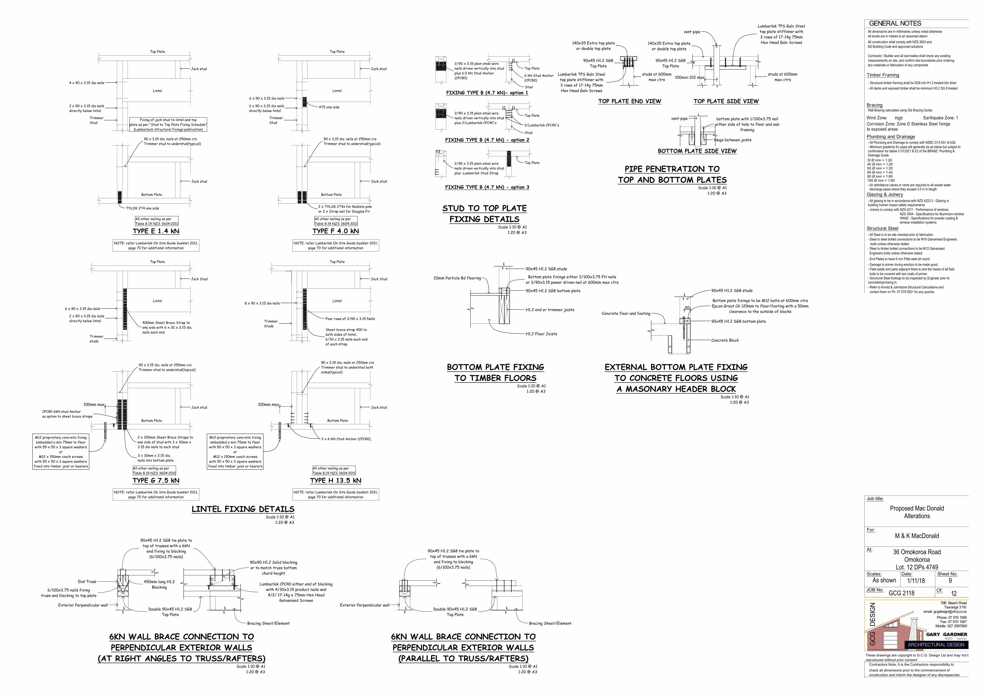
Bracing
Timber Framing
GENERAL NOTES
Wind Zone: Earthquake Zone: 1
Structural Steel
Of:
GCG
D
ESIG
N
GARY GARDNER
79B Beach Road
Scales:As shown
All dimensions are in millimetres unless noted otherwiseAll levels are in metres to an assumed datumAll construction shall comply with NZS 3604 andNZ Building Code and approved solutions
Contractor / Builder and all sub-trades shall check any existingmeasurements on site, and confirm site boundaries prior orderingany materials or fabrication of any componets
Wall Bracing calculated using Gib Bracing Guide
- All Steel is to be site checked prior to fabrication- Steel to steel bolted connections to be M16 Galvanised Engineers bolts unless otherwise stated.- Steel to timber bolted connections to be M12 Galvanised Engineers bolts unless otherwise stated.- End Plates to have 6 mm Fillet weld all round.- Damage to primer during erection to be made good.- Field welds and parts adjacent there to and the heads of all field bolts to be covered with two coats of primer.- Structural Steel footings to be inspected by Engineer prior toconcreteing/closing in.
Sheet No.Date:
Tauranga 3110email: [email protected]
Fax: 07 570 1387Phone: 07 570 1386
Contractors Note, It is the Contractors responsibility tocheck all dimensions prior to the commencement ofconstruction and inform the designer of any discrepancies
These drawings are copyright to G.C.G. Design Ltd and may not bereproduced without prior consent
ARCHITECTURAL DESIGNNZCD (arch)
JOB No:
Job title:
For:
At:
M & K MacDonald
Proposed Mac DonaldAlterations
High
36 Omokoroa RoadOmokoroa
Lot. 12 DPs 4749
GCG 2118 12
1/11/18
- Structural timber framing shall be SG8 min H1.2 treated kiln dried- All decks and exposed timber shall be minimum H3.2 SG 8 treated
Corrosion Zone: Zone D Stainless Steel f ixingsto exposed areas
Glazing & Joinery- All glazing to be in accordance with NZS 4223.3 - Glazing inbuilding human impact safety requirements- Joinery to comply with NZS 4211 - Performance of windows
NZS 3504 - Specifications for Aluminium windowWANZ - Specifications for powder coating &window installation systems
Plumbing and Drainage- All Plumbing and Drainage to comply with NZBC G13 AS1 & AS2- Minimum gradients for pipes will generally be as below but subject toconfirmation for tables C1/C3/E1 & E2 of the BRANZ Plumbing &Drainage Guide32 Ø mm = 1:2040 Ø mm = 1:2050 Ø mm = 1:2065 Ø mm = 1:4080 Ø mm = 1:60100 Ø mm = 1:60- Air admittance valves or vents are required to all waiste water discharge pipes where they exceed 3.5 m in length
- Refer to Arnold & Johnstone Structural Calculations and contact them on Ph. 07 578 0921 for any queries.
9
Mobile: 027 2997800
100mm max100mm max
50
100min-102 max
Trimmerstuds
Four rows of 2/90 x 3.15 Nails
Jack Stud
TrimmerStuds
Jack Stud
Sheet brace strap 400 toboth sides of lintel,6/30 x 3.15 nails each endof each strap.
Jack stud
TrimmerStud
TrimmerStud
6 x 90 x 3.15 dia nails
M12 proprietary concrete fixingembedded a min 75mm to floor
with 50 x 50 x 3 square washersor
M12 x 150mm coach screwswith 50 x 50 x 3 square washers
fixed into timber joist or bearers
Jack stud
2 x 200mm Sheet Brace Straps toone side of stud with 3 x 30mm x3.15 dia nails to each stud
90 x 3.15 dia. nails at 250mm crsTrimmer stud to understud(typical)
2 x 6 kN Stud Anchor (CPC80),
Jack stud
Jack stud
6 x 90 x 3.15 dia nails
Jack stud
Jack stud
2 x TYLOK 2T4s for Radiata pineor 2 x Strap nail for Douglas Fir
4 x 90 x 3.15 dia nails
2/90 x 3.15 plain steel wirenails driven vertically into studplus 6.0 kN Stud Anchor(CPC80)
6 kN Stud Anchor(CPC80)
Stud
Top Plate
2 x 90 x 3.15 dia nailsdirectly below lintel
2 x 90 x 3.15 dia nailsdirectly below lintel
TYLOK 2T4 one side
4T5 one side
2 x 90 x 3.15 dia nailsdirectly below lintel 400mm Sheet Brace Strap to
one side with 6 x 30 x 3.15 dia.nails each end
90 x 3.15 dia. nails at 250mm crsTrimmer stud to understud(typical)
90 x 3.15 dia. nails at 250mm crsTrimmer stud to understud(typical)
3 x 30mm x 3.15 dia.nails into bottom plate
90 x 3.15 dia. nails at 250mm crsTrimmer stud to understud bothsides(typical)
8 x 90 x 3.15 dia nails
CPC80 6kN stud Anchoras option to sheet brace straps
2/90 x 3.15 plain steel wirenails driven vertically into studplus 2/Lumberlok CPC40's 2/Lumberlok CPC40's
Stud
Top Plate
2/90 x 3.15 plain steel wirenails driven vertically into studplus Lumberlok Stud Strap
Top Plate
M12 proprietary concrete fixingembedded a min 75mm to floor
with 50 x 50 x 3 square washersor
M12 x 150mm coach screwswith 50 x 50 x 3 square washers
fixed into timber joist or bearers
20mm Particle Bd flooring
90x45 H1.2 SG8 bottom plate
90x45 H1.2 SG8 studs
H1.2 end or trimmer joists
H1.2 Floor Joists
Bottom plate fixings either 2/100x3.75 FH nailsor 3/90x3.15 power driven nail at 600mm max ctrs
90x45 H1.2 SG8 bottom plate
90x45 H1.2 SG8 studs
Concrete Block
Bottom plate fixings to be M12 bolts at 600mm ctrsEpcon Grout C6 120mm to floor/footing with a 50mm
clearance to the outside of blocksConcrete floor and footing
studs at 600mmmax ctrs
90x45 H1.2 SG8Top Plate
140x35 Extra top plateor double top plate
Lumberlok TPS Galv Steeltop plate stiffener with3 rows of 17-14g 75mmHex Head Galv Screws
vent pipeLumberlok TPS Galv Steeltop plate stiffener with3 rows of 17-14g 75mmHex Head Galv Screws
90x45 H1.2 SG8Top Plate
140x35 Extra top plateor double top plate
studs at 600mmmax ctrs
bottom plate with 1/100x3.75 naileither side of hole to floor and sub
framing
vent pipe
Nogs between joists
Bracing Sheet/Element
90x90 H1.2 Solid blockingor to match truss bottom
chord height
90x45 H1.2 SG8 tie plate totop of trusses with a 6kN
end fixing to blocking(6/100x3.75 nails)
Double 90x45 H1.2 SG8Top Plate
Exterior Perpendicular wall
End Truss Lumberlok CPC40 either end of blockingwith 4/30x3.15 product nails and4/2/ 17-14g x 75mm Hex Head
Galvanised Screws
450mm long H1.2Blocking
6/100x3.75 nails fixingtruss and blocking to top plate
Bracing Sheet/Element
90x45 H1.2 SG8 tie plate totop of trusses with a 6kN
end fixing to blocking(6/100x3.75 nails)
Double 90x45 H1.2 SG8Top Plate
Exterior Perpendicular wall
Lintel
Top Plate
Lintel
Top Plate
LINTEL FIXING DETAILS
Bottom Plate
All other nailing as perTable 8.19 NZS 3604:2011
All other nailing as perTable 8.19 NZS 3604:2011
Bottom Plate
Lintel
All other nailing as perTable 8.19 NZS 3604:2011
Bottom Plate
All other nailing as perTable 8.19 NZS 3604:2011
Top Plate
Fixing of jack stud to lintel and topplate as per "Stud to Top Plate Fixing Schedule"
(Lumberlock Structural fixings publication)
Lintel
Bottom Plate
Top Plate
FIXING TYPE B (4.7 kN)- option 1
STUD TO TOP PLATEFIXING DETAILS
TYPE G 7.5 kN TYPE H 13.5 kN
TYPE E 1.4 kN TYPE F 4.0 kN
NOTE: refer Lumberlok On Site Guide booklet 2011,page 70 for additional information
FIXING TYPE B (4.7 kN) - option 2
FIXING TYPE B (4.7 kN) - option 3
NOTE: refer Lumberlok On Site Guide booklet 2011,page 70 for additional information
NOTE: refer Lumberlok On Site Guide booklet 2011,page 70 for additional information
NOTE: refer Lumberlok On Site Guide booklet 2011,page 70 for additional information
BOTTOM PLATE FIXINGTO TIMBER FLOORS
Scale 1:10 @ A1 1:20 @ A3
EXTERNAL BOTTOM PLATE FIXINGTO CONCRETE FLOORS USINGA MASONARY HEADER BLOCK
Scale 1:10 @ A1 1:20 @ A3
PIPE PENETRATION TOTOP AND BOTTOM PLATES
TOP PLATE END VIEW TOP PLATE SIDE VIEW
BOTTOM PLATE SIDE VIEW
Scale 1:10 @ A1 1:20 @ A3
6KN WALL BRACE CONNECTION TOPERPENDICULAR EXTERIOR WALLS
(AT RIGHT ANGLES TO TRUSS/RAFTERS)Scale 1:10 @ A1 1:20 @ A3
6KN WALL BRACE CONNECTION TOPERPENDICULAR EXTERIOR WALLS(PARALLEL TO TRUSS/RAFTERS)
Scale 1:10 @ A1 1:20 @ A3
Scale 1:10 @ A1 1:20 @ A3
Scale 1:10 @ A1 1:20 @ A3

Bracing
Timber Framing
GENERAL NOTES
Wind Zone: Earthquake Zone: 1
Structural Steel
Of:
GCG
D
ESIG
N
GARY GARDNER
79B Beach Road
Scales:As shown
All dimensions are in millimetres unless noted otherwiseAll levels are in metres to an assumed datumAll construction shall comply with NZS 3604 andNZ Building Code and approved solutions
Contractor / Builder and all sub-trades shall check any existingmeasurements on site, and confirm site boundaries prior orderingany materials or fabrication of any componets
Wall Bracing calculated using Gib Bracing Guide
- All Steel is to be site checked prior to fabrication- Steel to steel bolted connections to be M16 Galvanised Engineers bolts unless otherwise stated.- Steel to timber bolted connections to be M12 Galvanised Engineers bolts unless otherwise stated.- End Plates to have 6 mm Fillet weld all round.- Damage to primer during erection to be made good.- Field welds and parts adjacent there to and the heads of all field bolts to be covered with two coats of primer.- Structural Steel footings to be inspected by Engineer prior toconcreteing/closing in.
Sheet No.Date:
Tauranga 3110email: [email protected]
Fax: 07 570 1387Phone: 07 570 1386
Contractors Note, It is the Contractors responsibility tocheck all dimensions prior to the commencement ofconstruction and inform the designer of any discrepancies
These drawings are copyright to G.C.G. Design Ltd and may not bereproduced without prior consent
ARCHITECTURAL DESIGNNZCD (arch)
JOB No:
Job title:
For:
At:
M & K MacDonald
Proposed Mac DonaldAlterations
High
36 Omokoroa RoadOmokoroa
Lot. 12 DPs 4749
GCG 2118 12
1/11/18
- Structural timber framing shall be SG8 min H1.2 treated kiln dried- All decks and exposed timber shall be minimum H3.2 SG 8 treated
Corrosion Zone: Zone D Stainless Steel f ixingsto exposed areas
Glazing & Joinery- All glazing to be in accordance with NZS 4223.3 - Glazing inbuilding human impact safety requirements- Joinery to comply with NZS 4211 - Performance of windows
NZS 3504 - Specifications for Aluminium windowWANZ - Specifications for powder coating &window installation systems
Plumbing and Drainage- All Plumbing and Drainage to comply with NZBC G13 AS1 & AS2- Minimum gradients for pipes will generally be as below but subject toconfirmation for tables C1/C3/E1 & E2 of the BRANZ Plumbing &Drainage Guide32 Ø mm = 1:2040 Ø mm = 1:2050 Ø mm = 1:2065 Ø mm = 1:4080 Ø mm = 1:60100 Ø mm = 1:60- Air admittance valves or vents are required to all waiste water discharge pipes where they exceed 3.5 m in length
- Refer to Arnold & Johnstone Structural Calculations and contact them on Ph. 07 578 0921 for any queries.
10
Mobile: 027 2997800
25m
m2m
m
27m
m
30-3
5mm
Finshed Ground Level
50m
m m
in
25mm min
Expansion/contractiongap between weatherboards
Framing
Cavity Battens
Building wrap
75 x 3.15mm HP Jolt Headstainless steel nail punched andfilled(or as per E2/AS1 - Table 24)
Cavity battens
Cavity base closurepositioned to give 15mm min.drip edge to cladding
Building wrap dressed into openingwith flexible flashing tape installedover wrap to corners at head and100mm min up the jamb from the sill
Air seal overPEF rod
Packers
Additional building wrap fromoverlap above lapped overflashing
20mm stopends to head flashing
Packers
Air seal overPEF rod
Building wrap and flexible flashing tape.Flashing tape to be installed continuousalong sill, 100mm min up each jamb and50mm on to face of building wrap.
Cavity battens
Packers
Air seal over PEF rod
Line of head flashing over
Internal lining
Internal lining
Internal lining
Building wrap dressed into openingwith flexible flashing tape installedover wrap to corners at head
Cavity battens
Head flashing with 15° slope
Stud
Building wrap
Soffit Lining
Cavity batten75 x 75 Aluminium HemedInternal Corner Flashing
Internal lining
Building wrap
18x18 H3.1 PPInternal corner
Framing
Cavity Battens
Internal lining
Cavity Battens
Framing
H3.1 External Corner Moulding
Insulation
Building wrap
Cavity batten
Concrete slabor blockwork
D.P.C
Internal lining
Insulation
Stud
Bottom Plate
Cavity closureSlide cut square of flexibleflashing tape over pipe. Extend100mm beyond edge of pipe
Rusticated Weatherboard
20mm H3.1 cavity Battens
Building wrap dressed into opening with flexible flashing tape installed over wrapto corners at head
Cavity base closure positioned to give15mm min. drip edge to cladding
PVC Pipe
Flange with sealant over backing rod
Building wrap andflexible flashingtape
Additional building wrap fromoverlap above lapped overflashing
Building wrap dressed into opening withflexible flashing tape installed overwrap to corners at head
Flashing
Cavity base closure positioned to give 15mm min. dripedge to cladding
Meter box
Seal and rivet metal angle toall sides of meter box
WANZ Sill support bar
H3.1 Eaves Moulding
ex 200x25 H3.1 PreprimedRusticated weatherboard
ex 200x25 H3.1 PreprimedRusticated weatherboard
ex 200x25 H3.1 PreprimedRusticated weatherboard
ex 200x25 H3.1 PreprimedRusticated weatherboard
ex 200x25 H3.1 PreprimedRusticated weatherboard
H3.1 Scriber and Plug to suit boardsprofile sealed to Weatherboard
ex 200x25 H3.1 PreprimedRusticated weatherboard
Rusticated Weatherboard
20mm H3.1 cavity Battens
Reba
te
Lap
35 mm min.cover to flashing
5 mm10 mm min. coverto joinery
10mm min. joinery cover
NOTE:1. Window profile to be selected to achieve covershown in details.2. Make allowances between packer at sills forsupport brackets for large windows. Such bracketsrequire specific design, and shall be supplied by thewindow manufacturer.
20mm 10mm min. cover
150m
m m
in t
o pe
rman
ent
pavi
ng o
r 22
5mm
min
to
unpa
ved
grou
nd t
o cl
ause
9.1.
3 of
E2/
AS1
5mm
RUSTICATED WEATHERBOARD ONCAVITY BARGE AND SOFFIT DETAIL
Scale 1:2 @ A11:4 @ A3
RUSTICATED WEATHERBOARDON CAVITY TYPICAL FIXING
Scale 1:2 @ A11:4 @ A3
RUSTICATED WEATHERBOARDON CAVITY WALL BASE
Scale 1:2 @ A11:4 @ A3
RUSTICATED WEATHERBOARD ONCAVITY WINDOW HEAD DETAIL
Scale 1:2 @ A11:4 @ A3
RUSTICATED WEATHERBOARD ONCAVITY WINDOW SILL DETAIL
Scale 1:2 @ A11:4 @ A3
RUSTICATED WEATHERBOARDON CAVITY INTERNAL CORNER DETAIL
Scale 1:2 @ A11:4 @ A3
RUSTICATED WEATHERBOARD ONCAVITY EXTERNAL CORNER DETAIL
Scale 1:2 @ A11:4 @ A3
RUSTICATED WEATHERBOARD ONCAVITY PIPE PENETRATION DETAIL
Scale 1:2 @ A11:4 @ A3
RUSTICATED WEATHERBOARD ONCAVITY METER BOX DETAIL
Scale 1:2 @ A11:4 @ A3
Building wrap
Rustic Plug fitted and sealed intoscallop between boards
75 x 75 Aluminium HemedExternal Corner Flashing
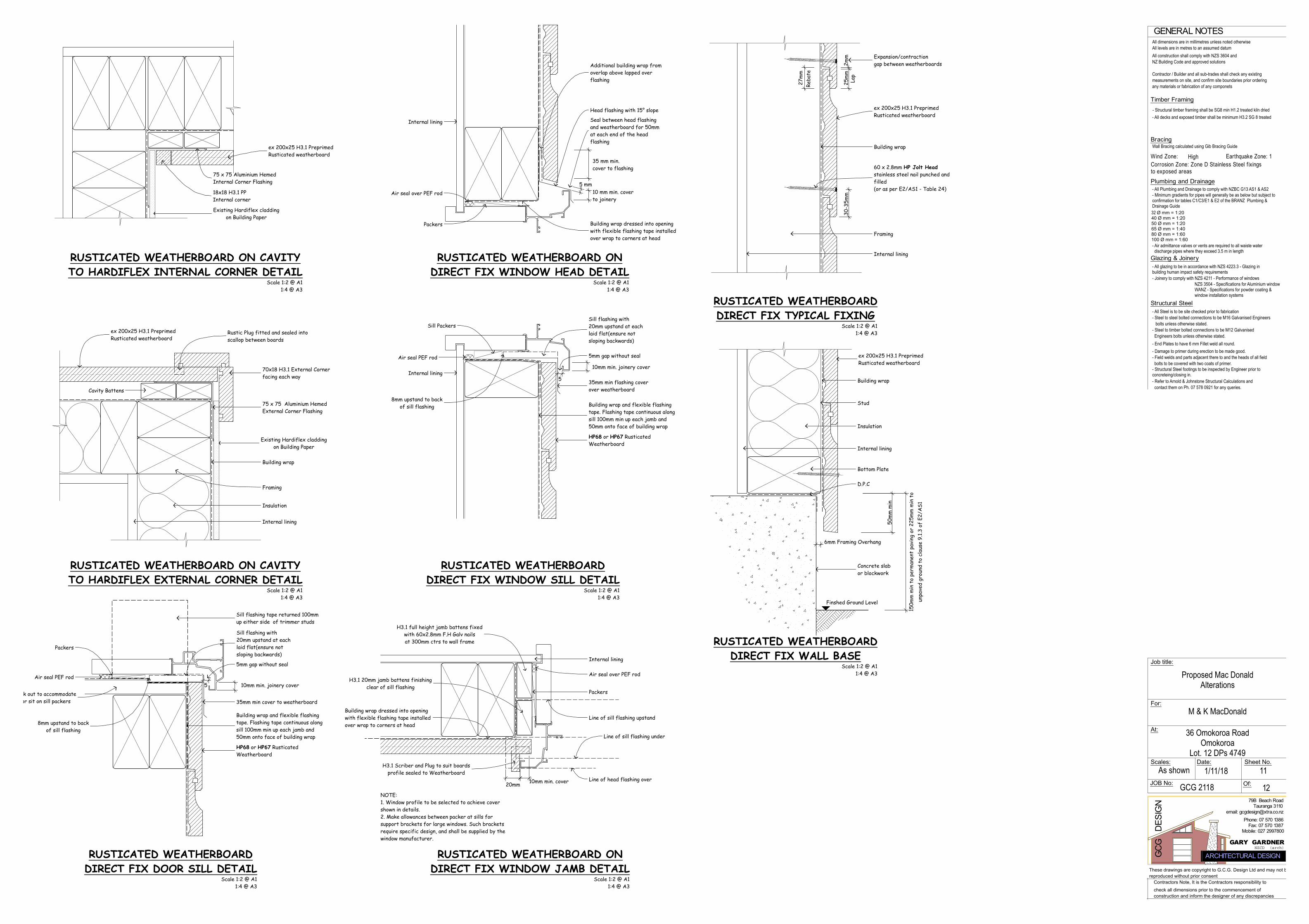
Bracing
Timber Framing
GENERAL NOTES
Wind Zone: Earthquake Zone: 1
Structural Steel
Of:
GCG
D
ESIG
N
GARY GARDNER
79B Beach Road
Scales:As shown
All dimensions are in millimetres unless noted otherwiseAll levels are in metres to an assumed datumAll construction shall comply with NZS 3604 andNZ Building Code and approved solutions
Contractor / Builder and all sub-trades shall check any existingmeasurements on site, and confirm site boundaries prior orderingany materials or fabrication of any componets
Wall Bracing calculated using Gib Bracing Guide
- All Steel is to be site checked prior to fabrication- Steel to steel bolted connections to be M16 Galvanised Engineers bolts unless otherwise stated.- Steel to timber bolted connections to be M12 Galvanised Engineers bolts unless otherwise stated.- End Plates to have 6 mm Fillet weld all round.- Damage to primer during erection to be made good.- Field welds and parts adjacent there to and the heads of all field bolts to be covered with two coats of primer.- Structural Steel footings to be inspected by Engineer prior toconcreteing/closing in.
Sheet No.Date:
Tauranga 3110email: [email protected]
Fax: 07 570 1387Phone: 07 570 1386
Contractors Note, It is the Contractors responsibility tocheck all dimensions prior to the commencement ofconstruction and inform the designer of any discrepancies
These drawings are copyright to G.C.G. Design Ltd and may not bereproduced without prior consent
ARCHITECTURAL DESIGNNZCD (arch)
JOB No:
Job title:
For:
At:
M & K MacDonald
Proposed Mac DonaldAlterations
High
36 Omokoroa RoadOmokoroa
Lot. 12 DPs 4749
GCG 2118 12
1/11/18
- Structural timber framing shall be SG8 min H1.2 treated kiln dried- All decks and exposed timber shall be minimum H3.2 SG 8 treated
Corrosion Zone: Zone D Stainless Steel f ixingsto exposed areas
Glazing & Joinery- All glazing to be in accordance with NZS 4223.3 - Glazing inbuilding human impact safety requirements- Joinery to comply with NZS 4211 - Performance of windows
NZS 3504 - Specifications for Aluminium windowWANZ - Specifications for powder coating &window installation systems
Plumbing and Drainage- All Plumbing and Drainage to comply with NZBC G13 AS1 & AS2- Minimum gradients for pipes will generally be as below but subject toconfirmation for tables C1/C3/E1 & E2 of the BRANZ Plumbing &Drainage Guide32 Ø mm = 1:2040 Ø mm = 1:2050 Ø mm = 1:2065 Ø mm = 1:4080 Ø mm = 1:60100 Ø mm = 1:60- Air admittance valves or vents are required to all waiste water discharge pipes where they exceed 3.5 m in length
- Refer to Arnold & Johnstone Structural Calculations and contact them on Ph. 07 578 0921 for any queries.
11
Mobile: 027 2997800
25m
m2m
m
27m
m
30-3
5mm
5
5
Finshed Ground Level
50m
m m
in
6mm Framing Overhang
Building wrap
Internal lining
Framing
Expansion/contractiongap between weatherboards
60 x 2.8mm HP Jolt Headstainless steel nail punched andfilled(or as per E2/AS1 - Table 24)
Additional building wrap fromoverlap above lapped overflashing
Air seal over PEF rod
Packers
Sill Packers
Air seal PEF rod
Building wrap and flexible flashingtape. Flashing tape continuous alongsill 100mm min up each jamb and50mm onto face of building wrap
HP68 or HP67 RusticatedWeatherboard
5mm gap without seal
Building wrap dressed into openingwith flexible flashing tape installedover wrap to corners at head
Packers
Air seal over PEF rod
Line of head flashing over
Line of sill flashing upstand
Line of sill flashing under
Internal lining
Internal lining
Internal lining
Building wrap dressed into openingwith flexible flashing tape installedover wrap to corners at head
Head flashing with 15° slope
Seal between head flashingand weatherboard for 50mmat each end of the headflashing
Sill flashing with20mm upstand at eachlaid flat(ensure notsloping backwards)
35mm min flashing coverover weatherboard
Packers
Air seal PEF rod
Building wrap and flexible flashingtape. Flashing tape continuous alongsill 100mm min up each jamb and50mm onto face of building wrap
HP68 or HP67 RusticatedWeatherboard
5mm gap without seal
Flooring check out to accommodate sill flashing or sit on sill packers 35mm min cover to weatherboard
D.P.C
Bottom Plate
Building wrap
Stud
Insulation
Internal lining
Concrete slabor blockwork
Sill flashing tape returned 100mmup either side of trimmer studs
75 x 75 Aluminium HemedInternal Corner Flashing
18x18 H3.1 PPInternal corner
Internal lining
Cavity Battens
Framing
70x18 H3.1 External Cornerfacing each way
Insulation
ex 200x25 H3.1 PreprimedRusticated weatherboard
Existing Hardiflex claddingon Building Paper
8mm upstand to backof sill flashing
H3.1 Scriber and Plug to suit boardsprofile sealed to Weatherboard
H3.1 20mm jamb battens finishingclear of sill flashing
H3.1 full height jamb battens fixedwith 60x2.8mm F.H Galv nailsat 300mm ctrs to wall frame
Sill flashing with20mm upstand at eachlaid flat(ensure notsloping backwards)
8mm upstand to backof sill flashing
ex 200x25 H3.1 PreprimedRusticated weatherboard
ex 200x25 H3.1 PreprimedRusticated weatherboard
ex 200x25 H3.1 PreprimedRusticated weatherboard
Existing Hardiflex claddingon Building Paper
Reba
te
Lap
5 mm10 mm min. coverto joinery
35 mm min.cover to flashing
NOTE:1. Window profile to be selected to achieve covershown in details.2. Make allowances between packer at sills forsupport brackets for large windows. Such bracketsrequire specific design, and shall be supplied by thewindow manufacturer.
20mm
10mm min. joinery cover
10mm min. cover
10mm min. joinery cover
150m
m m
in t
o pe
rman
ent
pavi
ng o
r 22
5mm
min
to
unpa
ved
grou
nd t
o cl
ause
9.1.
3 of
E2/
AS1
RUSTICATED WEATHERBOARD ONDIRECT FIX WINDOW JAMB DETAIL
Scale 1:2 @ A11:4 @ A3
RUSTICATED WEATHERBOARD ON CAVITYTO HARDIFLEX INTERNAL CORNER DETAIL
Scale 1:2 @ A11:4 @ A3
Scale 1:2 @ A11:4 @ A3
RUSTICATED WEATHERBOARD ON CAVITYTO HARDIFLEX EXTERNAL CORNER DETAIL
RUSTICATED WEATHERBOARDDIRECT FIX WINDOW SILL DETAIL
Scale 1:2 @ A11:4 @ A3
RUSTICATED WEATHERBOARD ONDIRECT FIX WINDOW HEAD DETAIL
Scale 1:2 @ A11:4 @ A3
RUSTICATED WEATHERBOARDDIRECT FIX DOOR SILL DETAIL
Scale 1:2 @ A11:4 @ A3
RUSTICATED WEATHERBOARDDIRECT FIX TYPICAL FIXING
Scale 1:2 @ A11:4 @ A3
RUSTICATED WEATHERBOARDDIRECT FIX WALL BASE
Scale 1:2 @ A11:4 @ A3
Building wrap
Rustic Plug fitted and sealed intoscallop between boards
75 x 75 Aluminium HemedExternal Corner Flashing

Bracing
Timber Framing
GENERAL NOTES
Wind Zone: Earthquake Zone: 1
Structural Steel
Of:
GCG
D
ESIG
N
GARY GARDNER
79B Beach Road
Scales:As shown
All dimensions are in millimetres unless noted otherwiseAll levels are in metres to an assumed datumAll construction shall comply with NZS 3604 andNZ Building Code and approved solutions
Contractor / Builder and all sub-trades shall check any existingmeasurements on site, and confirm site boundaries prior orderingany materials or fabrication of any componets
Wall Bracing calculated using Gib Bracing Guide
- All Steel is to be site checked prior to fabrication- Steel to steel bolted connections to be M16 Galvanised Engineers bolts unless otherwise stated.- Steel to timber bolted connections to be M12 Galvanised Engineers bolts unless otherwise stated.- End Plates to have 6 mm Fillet weld all round.- Damage to primer during erection to be made good.- Field welds and parts adjacent there to and the heads of all field bolts to be covered with two coats of primer.- Structural Steel footings to be inspected by Engineer prior toconcreteing/closing in.
Sheet No.Date:
Tauranga 3110email: [email protected]
Fax: 07 570 1387Phone: 07 570 1386
Contractors Note, It is the Contractors responsibility tocheck all dimensions prior to the commencement ofconstruction and inform the designer of any discrepancies
These drawings are copyright to G.C.G. Design Ltd and may not bereproduced without prior consent
ARCHITECTURAL DESIGNNZCD (arch)
JOB No:
Job title:
For:
At:
M & K MacDonald
Proposed Mac DonaldAlterations
High
36 Omokoroa RoadOmokoroa
Lot. 12 DPs 4749
GCG 2118 12
1/11/18
- Structural timber framing shall be SG8 min H1.2 treated kiln dried- All decks and exposed timber shall be minimum H3.2 SG 8 treated
Corrosion Zone: Zone D Stainless Steel f ixingsto exposed areas
Glazing & Joinery- All glazing to be in accordance with NZS 4223.3 - Glazing inbuilding human impact safety requirements- Joinery to comply with NZS 4211 - Performance of windows
NZS 3504 - Specifications for Aluminium windowWANZ - Specifications for powder coating &window installation systems
Plumbing and Drainage- All Plumbing and Drainage to comply with NZBC G13 AS1 & AS2- Minimum gradients for pipes will generally be as below but subject toconfirmation for tables C1/C3/E1 & E2 of the BRANZ Plumbing &Drainage Guide32 Ø mm = 1:2040 Ø mm = 1:2050 Ø mm = 1:2065 Ø mm = 1:4080 Ø mm = 1:60100 Ø mm = 1:60- Air admittance valves or vents are required to all waiste water discharge pipes where they exceed 3.5 m in length
- Refer to Arnold & Johnstone Structural Calculations and contact them on Ph. 07 578 0921 for any queries.
12
Mobile: 027 2997800
7
10m
m m
in
20m
m
5
31
5
35m
m m
in
15
10
13
10m
m m
in
12m
m m
in.
6 - 8
mm
gap
min
. 35
min 40
Min. 12
12
min. 45
50
150
20mm nominal cavity
40
8mm gap nominal To allow for
head deflection and airseal
25m
m35
mm
min
10 m
m
8mm gapnominal
35m
mm
in c
over
8mm gapnominal
10m
m m
in
20mm past window toend of flashing
Selected interior linings
H3.1 Window liner
Building Wrap
Flashing tape 100mm upstandon jambsLine of head flashing
Window frame(refer to window manufacturer
for method of support and fixing)
Selected interior linings
Building Wrap
5mm gap
H3.1 Window liner
For flashing tape detail refer toFigures 72 and 115 of NZBC clause E2/AS1.
Profile of sill flashing upstand 20mm min
Sill flashing with 5° slope to extend beyondthe aluminium window profile with hem to back
edge and 20mm upstand at ends.Cut sill plate or add sloping packer to suit
Window frame(refer to window manufacturer
for method of support and fixing)
H3.1 Window liner
Selected interior linings
Lintel
Window frame(refer to window manufacturer
for method of support and fixing)
Flashing tape over underlay required in corners only
One Piece Head flashing
Proprietary tape or alternativelyadditional layer of building underlay
over head flashing
Building Wrap
Waterproof air seal
HardieFlexTM SheetSelected finish- Edge of sheet
to be sealed before windowis installed
Continuous sealant
Inseal min 19mmthick x10mm wide 3109
Waterproof airseal to perimeterof trim cavity with expandable foam or sealant as per section
9.1.6 of E2/AS1
Selected finish- Edge of sheetto be sealed before window
is installed
HardieFlexTM Sheet
Waterproof airseal to perimeter oftrim cavity with expandable foam or
sealant as per section 9.1.6 of E2/AS1
HardieFlexTM Sheet
H3.1 20mm Jamb Battenfinish clear of sill flashing
Note:1. When 50 year durability is required refer table 20 of NZBC E2/AS1 document.2. Joints may also be formed using options as per vertical joints see Figure 20 or 21.
CAVITY EXTERNAL CORNER JOINT
nom
inal
7.5m
m g
ap
Flashing tape 100mm min upstand on jambWindow liner
Selected interiorlining
HardiFlex® sheet orFeatureBoard® sheetSelected finish
Inseal min 19mm thick x10mm wide 3109
Window frame (refer towindow manufacturer formethod of support &fixing)
Edge of sheet to be sealed beforewindow is installed.
Cavity batten
Waterproofairseal
Building wrap
Also refer Fig 116 NZBCclause E2/AS1 document forhead & jamb details.
Sealant
Line of headflashing over
past
win
dow
to e
ndof
fla
shin
g
Note:1. When 50 year durability is required refer table 20 of NZBC E2/AS1 document.2. Joints may also be formed using Inseal 80mm wide or James hardie uPVC underflashing as per vertical joints see Figure 21.
*
* This dimension must bechecked on site withjoinery manufacturer
nom
inal
7.5m
m g
ap
25
Selected interiorlining
HardiFlex® sheet orFeatureBoard® sheet
To allow for headdeflection & airseal
5mm
gap
Waterproofairseal
One piece head flashingcomplete with stop ends &15° slope
Selected finish sealbottom edge of sheet.
Flashing tape over wrap required incorners only
Lintel
Window frame (refer towindow manufacturer formethod of support & fixing)
Window liner
Cavity batten
Proprietary tape oralternatively additional layerof building wrap over headflashing
James Hardie uPVCvent strip
Building wrap
Also refer Fig 116 NZBCclause E2/AS1 document forhead & jamb details.
10m
m c
over
Stop end profile
Cavity batten
7.5m
m g
apno
min
al
Selected interiorlining
HardiFlex® sheet orFeatureBoard® sheet
Waterproof airseal to perimeterof trim cavity with expandablefoam or sealant as per section9.1.6 of E2/AS1
Selected finish
Window frame (refer towindow manufacturer formethod of support &fixing)
For flashing tape detail refer to Figs. 72 & 116 ofNZBC clause E2/AS1.
General notes for materials selection1. Flashing materials must be selected based on environmental exposure, refer to NZS 3604 & table 20 of NZBC clause 'E2/AS1'.2. Building wrap must comply with acceptable solution NZBC clause 'E2/AS1' & NZS 3604.3. Flashing tape must have proven compatibility with the selected building wrap & other materials with which it comes into contact as per table 21 of NZBC clause 'E2/AS1'.
Refer to the manufacturer or supplier for technical information for these these materials.
Window liner
Edge of sheet & verticalsection under windowflange to be sealed beforewindow is installed.
Building wrap
Soffit
Building wrap
Provide sealant oreaves mould
Nog
Stud
Vertical batten
Offset nog to block airflowinto roof space from claddingcavity.
Continuous packers
Fit bond breaker tapeif sealant used
Seal face of sheet behindeaves mould
HardiFlex® sheet or FeatureBoard® sheet,edges to be sealed before fixing
CAVITY INTERNAL CORNER JOINT
Building wrap.
HardiFlex® nails
Selected finish
Studs
HardiFlex® sheet or FeatureBoard® sheet,edges to be sealed before fixing
James Hardie two piece external cornermould for 7.5mm thick HardiFlex® sheet orFeatureBoard® sheet or one piece mould for6mm thick HardiFlex® sheet.
James Hardie two piece internal cornermould for 7.5mm thick HardiFlex® sheet orFeatureBoard® sheet or one piece mould for6mm thick HardiFlex® sheet.
HardiFlex® sheet or FeatureBoard® sheet,edges to be sealed before fixing
Note double studs
HardiFlex® sheet orFeatureBoard® sheet12
mm
min
HardiFlex® nails
Selected finishBuilding wrap
CAVITY VERTICAL P.V.C. JOINT
Scale 1:2 @ A11:4 @ A3
Single stud ordouble stud
Building wrap.
HardiFlex® sheet orFeatureBoard® sheet
12mm min12mm min
HardiFlex® nails
P.V.C. Hardijointer.
Selected finish
Min gap to suit jointer
Note:1. When 50 year durability is required refer table 20 of NZBC E2/AS1 document.
50m
m
Finished groundlevel
150m
m m
in t
o pe
rman
ent
pavi
ng o
r 22
5mm
min
to
unpa
ved
grou
nd t
o cl
ause
9.1.
3 of
E2/
AS1
D P C
Stud
Bottom plate
HardiFlex® sheet orFeatureBoard® sheet
Selected finish tocontinue under bottomedge of sheet
Building wrap must becontinuous & fittedbehind vent strip.
James HardieuPVC vent strip. Mitreat corners. Keep clearof debris
Concrete slab orblockwork
Vertical Batten
35m
m
100mm long horizontalbatten beyond
CAVITY WINDOW JAMB CAVITY CONCRETE FOOTING
CAVITY SOFFIT DETAIL
CAVITY WINDOW SILL
CAVITY WINDOW HEADScale 1:2 @ A1
1:4 @ A3
Scale 1:2 @ A11:4 @ A3
Scale 1:2 @ A11:4 @ A3
Scale 1:2 @ A11:4 @ A3
Scale 1:2 @ A11:4 @ A3
Scale 1:2 @ A11:4 @ A3
Scale 1:2 @ A11:4 @ A3
Scale 1:2 @ A11:4 @ A3
5mm
gap
Selected finishseal bottom edgeof sheet. 5mm gap
to sheet
min
cov
erto
join
ery
DIRECT FIX WINDOW HEADScale 1:2 @ A1 1:4 @ A3
Note:Sill flashing tray to have a min10mm upstand at each end
General notes for materials selection1. Flashing materials must be selected based on environmental exposure, refer to NZS 3604 and Table 20 of NZBC E2/AS1.2. Building underlay must comply with acceptable solution E2/AS1 and NZS 3604.3. Flashing tape must have proven compatibility with the selected building underlay and other materials with which it comes into contact as per Table 21 of E2/AS1.
Refer to the manufacturer or supplier for technical information for these materials.
10m
m m
in
DIRECT FIX WINDOW SILL
5mm gapwindow tosheet
DIRECT FIX WINDOW JAMB
Scale 1:2 @ A1 1:4 @ A3
Scale 1:2 @ A1 1:4 @ A3
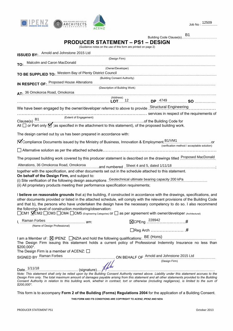
PRODUCER STATEMENT PS1 October 2013
Building Code Clause(s)…………………………….
PRODUCER STATEMENT – PS1 – DESIGN (Guidance notes on the use of this form are printed on page 2)
ISSUED BY:...........................................................................................................................................................................
(Design Firm)
TO:………………………………………………………..……………………………………………………………………………… (Owner/Developer)
TO BE SUPPLIED TO:…………………………………………………………………………………………………….…………… (Building Consent Authority)
IN RESPECT OF:………………………………………………………………………………………………………………………. (Description of Building Work)
AT:………………………………………………………………………………………………………………………….…………….. (Address)
……………………………..……………………………… LOT…………………… DP ………..………… SO …………….
We have been engaged by the owner/developer referred to above to provide ……………………………………… ………………….……………………………………………………..… services in respect of the requirements of (Extent of Engagement) Clause(s) ……………………………………………………………………………..of the Building Code for All or Part only (as specified in the attachment to this statement), of the proposed building work. The design carried out by us has been prepared in accordance with:
Compliance Documents issued by the Ministry of Business, Innovation & Employment………………..……………….or (verification method / acceptable solution)
Alternative solution as per the attached schedule…………………….…………………………………………… The proposed building work covered by this producer statement is described on the drawings titled ……………………….. …………………………………………………………and numbered ………………….…………………………………………….; together with the specification, and other documents set out in the schedule attached to this statement. On behalf of the Design Firm, and subject to: (i) Site verification of the following design assumptions ………………….………………………………………..………… (ii) All proprietary products meeting their performance specification requirements; I believe on reasonable grounds that a) the building, if constructed in accordance with the drawings, specifications, and other documents provided or listed in the attached schedule, will comply with the relevant provisions of the Building Code and that b), the persons who have undertaken the design have the necessary competency to do so. I also recommend the following level of construction monitoring/observation:
CM1 CM2 CM3 CM4 CM5 (Engineering Categories) or as per agreement with owner/developer (Architectural) I, …………..………..………………….…… am: CPEng …..……..…..………# (Name of Design Professional)
Reg Arch …………………. .# I am a Member of : IPENZ NZIA and hold the following qualifications:…………………………….…..………………… The Design Firm issuing this statement holds a current policy of Professional Indemnity Insurance no less than $200,000*. The Design Firm is a member of ACENZ:
SIGNED BY ………………….…………………………………. ON BEHALF OF ……..…………………..……………………… (Design Firm) Date……..……………...………...…… (signature)…………………………..…...……..……………………………….………..… Note: This statement shall only be relied upon by the Building Consent Authority named above. Liability under this statement accrues to the Design Firm only. The total maximum amount of damages payable arising from this statement and all other statements provided to the Building Consent Authority in relation to this building work, whether in contract, tort or otherwise (including negligence), is limited to the sum of $200,000*. This form is to accompany Form 2 of the Building (Forms) Regulations 2004 for the application of a Building Consent.
THIS FORM AND ITS CONDITIONS ARE COPYRIGHT TO ACENZ, IPENZ AND NZIA
Job No : ..................
Arnold and Johnstone 2015 Ltd
B1
Structural Engineering
B1
B1/VM1
Raman Forbes 228942
Arnold and Johnstone 2015 Ltd
BE (Hons)
Raman Forbes
1/11/18
Western Bay of Plenty District Council
Proposed House Alterations
36 Omokoroa Road, Omokoroa
12 4749
Alterations, 36 Omokoroa Road, Omokoroa Sheet 4 and 5, dated 1/11/18
Geotechnical ultimate bearing capacity 200 kPa
12509
Proposed MacDonald
Malcolm and Caron MacDonald
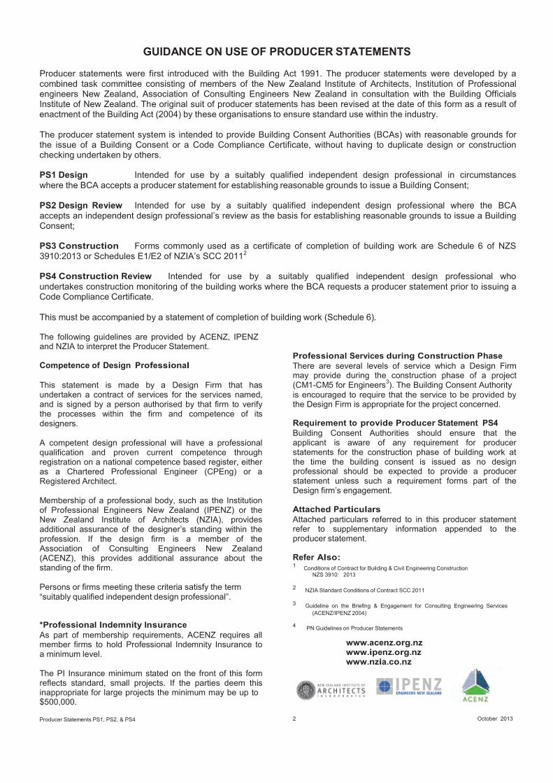
GUIDANCE ON USE OF PRODUCER STATEMENTS
Producer statements were first introduced with the Building Act 1991. The producer statements were developed by acombined task committee consisting of members of the New Zealand Institute of Architects, Institution of Professionalengineers New Zealand, Association of Consulting Engineers New Zealand in consultation with the Building OfficialsInstitute of New Zealand. The original suit of producer statements has been revised at the date of this form as a result ofenactment of the Building Act (2004) by these organisations to ensure standard use within the industry.
The producer statement system is intended to provide Building Consent Authorities (BCAs) with reasonable grounds forthe issue of a Building Consent or a Code Compliance Certificate, without having to duplicate design or constructionchecking undertaken by others.
PS1 Design Intended for use by a suitably qualified independent design professional in circumstanceswhere the BCA accepts a producer statement for establishing reasonable grounds to issue a Building Consent;
PS2 Design Review Intended for use by a suitably qualified independent design professional where the BCAaccepts an independent design professional’s review as the basis for establishing reasonable grounds to issue a BuildingConsent;
PS3 Construction Forms commonly used as a certificate of completion of building work are Schedule 6 of NZS3910:2013 or Schedules E1/E2 of NZIA’s SCC 20112
PS4 Construction Review Intended for use by a suitably qualified independent design professional whoundertakes construction monitoring of the building works where the BCA requests a producer statement prior to issuing aCode Compliance Certificate.
This must be accompanied by a statement of completion of building work (Schedule 6).
The following guidelines are provided by ACENZ, IPENZand NZIA to interpret the Producer Statement.
Competence of Design Professional
This statement is made by a Design Firm that hasundertaken a contract of services for the services named,and is signed by a person authorised by that firm to verifythe processes within the firm and competence of itsdesigners.
A competent design professional will have a professionalqualification and proven current competence throughregistration on a national competence based register, eitheras a Chartered Professional Engineer (CPEng) or aRegistered Architect.
Membership of a professional body, such as the Institutionof Professional Engineers New Zealand (IPENZ) or theNew Zealand Institute of Architects (NZIA), providesadditional assurance of the designer’s standing within theprofession. If the design firm is a member of theAssociation of Consulting Engineers New Zealand(ACENZ), this provides additional assurance about thestanding of the firm.
Persons or firms meeting these criteria satisfy the term“suitably qualified independent design professional”.
Professional Services during Construction PhaseThere are several levels of service which a Design Firmmay provide during the construction phase of a project(CM1-CM5 for Engineers3). The Building Consent Authorityis encouraged to require that the service to be provided bythe Design Firm is appropriate for the project concerned. Requirement to provide Producer Statement PS4Building Consent Authorities should ensure that theapplicant is aware of any requirement for producerstatements for the construction phase of building work atthe time the building consent is issued as no designprofessional should be expected to provide a producerstatement unless such a requirement forms part of theDesign firm’s engagement. Attached ParticularsAttached particulars referred to in this producer statementrefer to supplementary information appended to theproducer statement. Refer Also:1 Conditions of Contract for Building & Civil Engineering Construction
NZS 3910: 2013 2 NZIA Standard Conditions of Contract SCC 2011
3 Guideline on the Briefing & Engagement for Consulting Engineering Services(ACENZ/IPENZ 2004)
*Professional Indemnity InsuranceAs part of membership requirements, ACENZ requires allmember firms to hold Professional Indemnity Insurance toa minimum level.
The PI Insurance minimum stated on the front of this formreflects standard, small projects. If the parties deem thisinappropriate for large projects the minimum may be up to$500,000.
Producer Statements PS1, PS2, & PS4
4 PN Guidelines on Producer Statements
www.acenz.org.nz www.ipenz.org.nz www.nzia.co.nz
2 October 2013
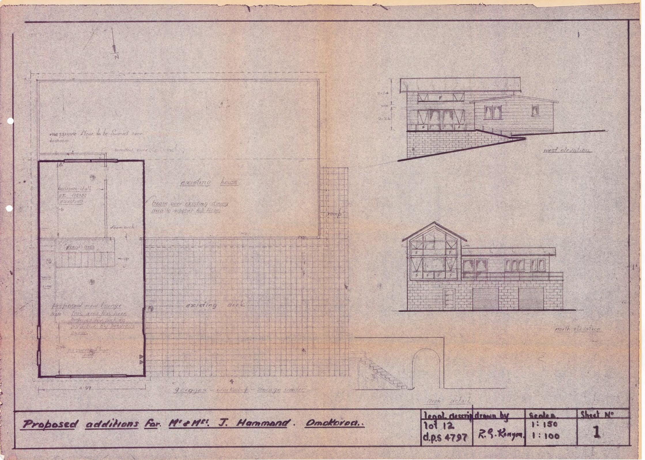
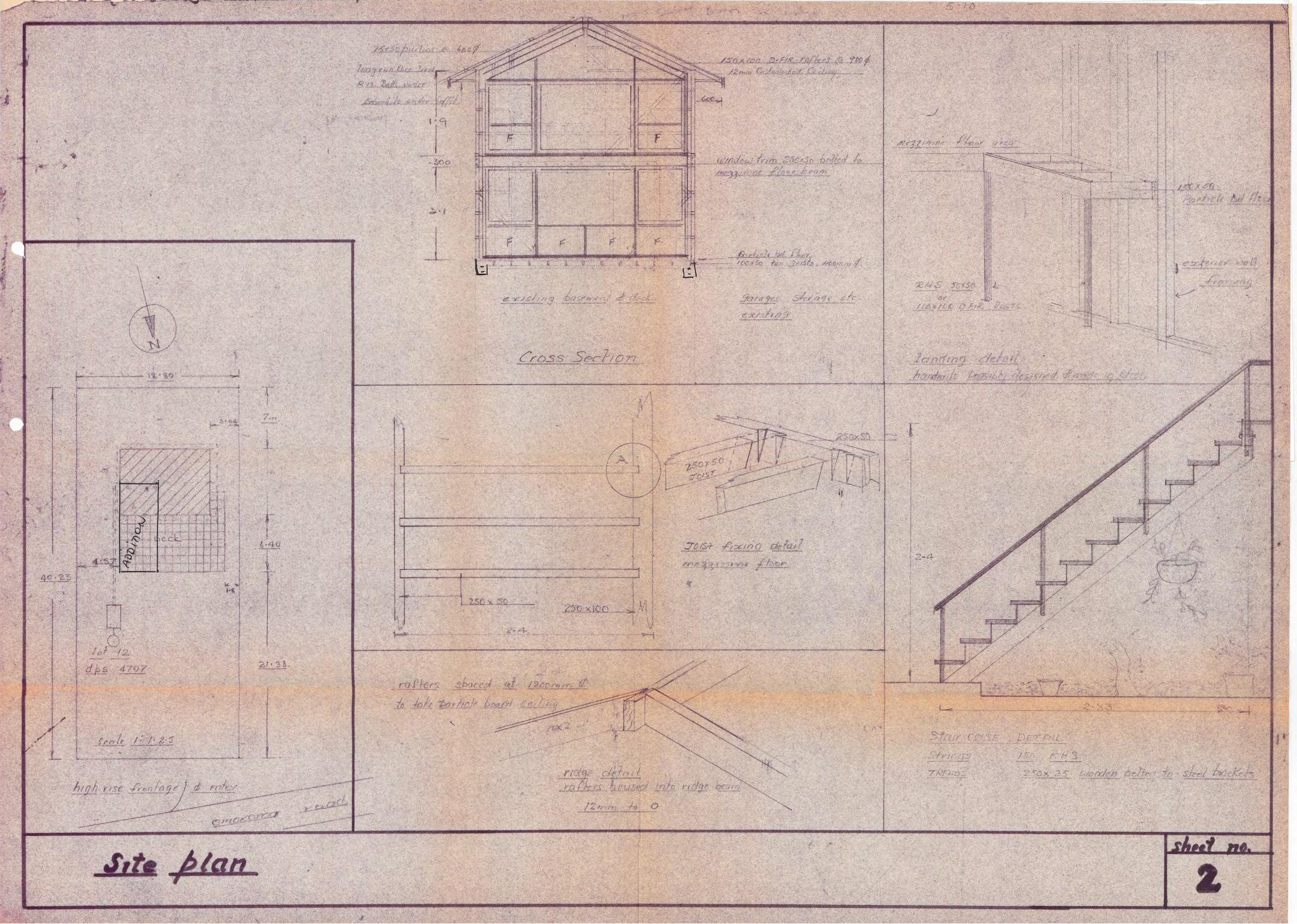
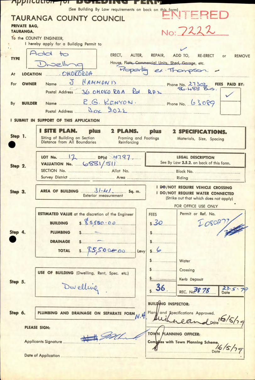
ESTIMATED VALUE at the discretion of the Engineer
BUILDING $.... ҟ..5 TC).................................. St.p 4. . PLUMBING $
DRAINAGE $ ...... ... ............ ҟ.....................................
TOTAL $ Lev
tIILU Li iir— w EIM IIi_ (See Building By Law requirements on back on this form) ..
TAIIRAMi'A CCIlMTY rrIIMrit , I ' U I
PRIVATE BAG, TAIJRANGA. No: ----------- To the COUNTY ENGINEER,
I hereby apply for a Buildipg Permit to
TYPE ҟERECT, ҟALTER, ҟREPAIR, ҟADD TO, ҟRE-ERECT ҟor ҟREMOVE
Hou, FLa*&- c ҟecia[Unj, Shed,Grirrige, etc.
At ҟLOCATION ........................................................................................
For ҟOWNER Name ........................ ±P."'................................................................... ... Phone No. ,,.2..1 FEES PAID BY:
Postal Address ҟO.Iht..
By ҟBUILDER Name .................... ҟ E...G........ (0 4...' ....................................... Phone No. .....(i ... ҟ..ü
Postal Address ........... ..... ....Q....
I SUBMIT IN SUPPORT OF THIS APPLICATION
Step 1. . Step 2.
SITE PLAN. pIus 2 PLANS. pIus 2 SPECIFICATIONS. Siting of Building on Section ҟFraming and Footings ҟMaterials, Size, Spacing Distance from All Boundaries ҟReinforcing
LOT No ............. ...................... ...... DP(s) . 1. q LEGAL DESCRIPTION
VALUATION No i.i........................ ..... .... .See By Law 2.5.2. on back of this form.
SECTIONNo . ҟ................................... .................. ҟAllot ҟNo. ҟ.................................. ҟ..... ..... ......... ..Block ҟNo. ҟ............................................. SurveyDistrict ҟ.............................................. ............ ..Area ҟ...... ... ...... ............................ .................. ҟRiding ҟ.. ҟ.
I /NOT REQUIRE VEHICLE CROSSING Step 3 AREA OF BUILDING ..... ............ 3.1.4'.L.. ................ Sq. m. I DO/NOT REQUIRE WATER CONNECTED Exterior measurement ҟ
(Strike out that which does not apply)
FOR OFFICE USE ONlY
p
FEES Permit or Ref. No.
icc7
$.............. ................. Water
$.... ... .........................
..
Crossing
Kerb Deposit
3.6............... .. REC. Nct ..g . 7
BUIL#IG INSPECTOR:
Planj/and ҟpecifications Approved.
te............ .......
TO N LANNING OFFICER:
Corn es with Town Planning Scheme.
ҟ
. ҟDat71'T
USE OF BUILDING (Dwelling, Rent, Spec. etc.)
Step 5. uJe1tL
Step 6. PLUMBING AND DRAINAGE ON SEPARATE FORM
PLEASE SIGN:
Applicants Signature ...........................................................................
Date of Application. ҟ. .

Extracts from:—
N.Z. STANDARD MODEL BUILDING BY LAW NZSS 1900 CHAPTER TWO - BUILDING PERMITS
(Adopted by Tauranga County Council as County By Law, June 6th, 1968(
"ERECTION OF A BUILDING" includes the re-erection of a building and the reconditioning of a building and the making of any alteration, repair, or addition to any building heretofore or hereafter erected and the removal, either in whole or in part, of a building from any place within or without the Council disrict to any place within such district or from one position to another position on the same lot of land, and "ERECT" has a corresponding meoning: Provided that maintenance work other than structural shall not be deemed a repair.
BUILDING PERMIT REQUIRED
2.1.1 No person shall erect or Commence to erect any building without first obtaining a building permit from the Engineer.
2.1.2 No person shall cause or permit the commencement of the erection of or the erection of any building if a building permit in that behalf has not first been obtained from the Engineer.
APPLICATION FOR PERMIT 2.3.1 Any person desiring to obtain a building permit shall make application at the office of the Engineer on the form provided
for that purposs. The applicant or person acting on his behalf shall complete the form by filling in the particulars and signing the form.
CONTENTS OF APPUCATION 2.4.1 Every opplica'ion shall set out
'I The legal descripition and particulars of the site. II The full name and address of the applicant, and of the person for whom the work is to be done, the locality of the
proposed work, and the estimated value of the work.
2.4.2 Where not clearly shown or stated in the drawings and specifications required under clause 2.5, the following information shall be given as a signed statement on, or a.ttached to the application form.
(i) The proposed use or occupancy of every part of the building.
PLANS AND SPECIFICATIONS 2.5.1 Together with every application there shall be submitted io the Engineer, in duplicate, detailed plans, elevations, cross-
sections, and specifications, which shall together furnish complete details of design and qualities and descriptions of all materials of construction and workmanship, and which shall be of sufficIent clarity to show to the satisfaction of the Engineer the exact nature and character of the praposel undertaking and the provision made for full compliance with the requirements of this bylaw and any .$+Ser csI.vee y4.w -for #se t3me being in force.
il For every building, except as set out in clause 2.6, with a framework or bearing-wall system wholly or partly sublect to structural design under this bylaw, and in every other case where the Engineer may reasonably require it, there shall also be submitted to the Engineer such stress diagrams, computations, and other data as are necessary to show that the design complies with all the requirements of this bylaw and any other relevant bylaw in force:
liil Computations shall be preceded by a brief report describing the bracing system and integration of the Structure and the manner in which the designer expects it to function with a clear statement of all assumptions such as materials, stresses appropriate to the standard of supervision, and live, wind, and seismic loadings. Computations shall include a sum-mation of dead, live, seismic, and other required loadings, floor by floor, and calculations of bents (or the equivalent) in each direction, and of any special features:
liiil Drawings of reinforced concrete work shall show clearly the dimensions of all members and the size, length, shape, posi-tion, and overlap of all relnforcem.nt:
(V) Drawings of structual steelwork shall be complete working drawings showing in figured dimensions the exact length and position of each part in such detail that the steel may be supplied and the work fabricated from such drawings: Detailed drawings shall be in such form and on such scale as the Engineer may consider necessary to ensure certainty of interpretation
All drawings other than detailed drawings shall be accurately, clearly, and indelibly executed to scale and shall be drawn is in ink upon drawing paper or tracing cloth, or printed upon cloth or approved paper. Except in the case of detailed draw-ings all drawings shall be to scale of tin. or I in, to the foot.
2.5.2 The drawings shall be accompanied by a kcality plan. This Iccolity plan shall be drawn to scale and shall show the site of the building, together with the land, streets, private streets, public places, private ways, public reserves and bi'ildings Immed-iately surrounding the site, and shall be sufficient to enable the Engineer to locate the precise situation of the site not only relative to the boundaries of its own land, but also relative to any buildings erected upon immediately adjoining lands.
2.5.5 In addition to the structural details, etc. required, the plans and sections shall show as regards every floor of the proposed building the dimensions of rooms, the situation of flues, fireplaces, stoves, and chimneys, and the position of all the several parts of the building and every water closet, fuel store, washhouse, and all other appurtenances. The plan and section shall further show the proposed means of water supply, and the level of the lowest floor of the intended building and of the yard and ground belonging thereto, and also the means whereby it is proposed to deal with all stormwat.r and drainage.
2.5.6 When lodged, the application and drawings and other documents accompanying the application shall isecome the absolute property of the Council.
NOTE—Specifi cations should cover types, grading, spacing (centres) and sizes of materials. It is important that the position of existing foul drainage lespecially gully traps, terminal vent, etc.l should be shown on the plans.
PERMIT MAY BE WITHHELD (without further notIce) until Applicant fully complies with the above requirements. /
D. Kale Print
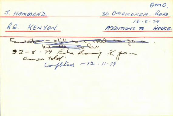
i
+ i4"EN Yo'V
U
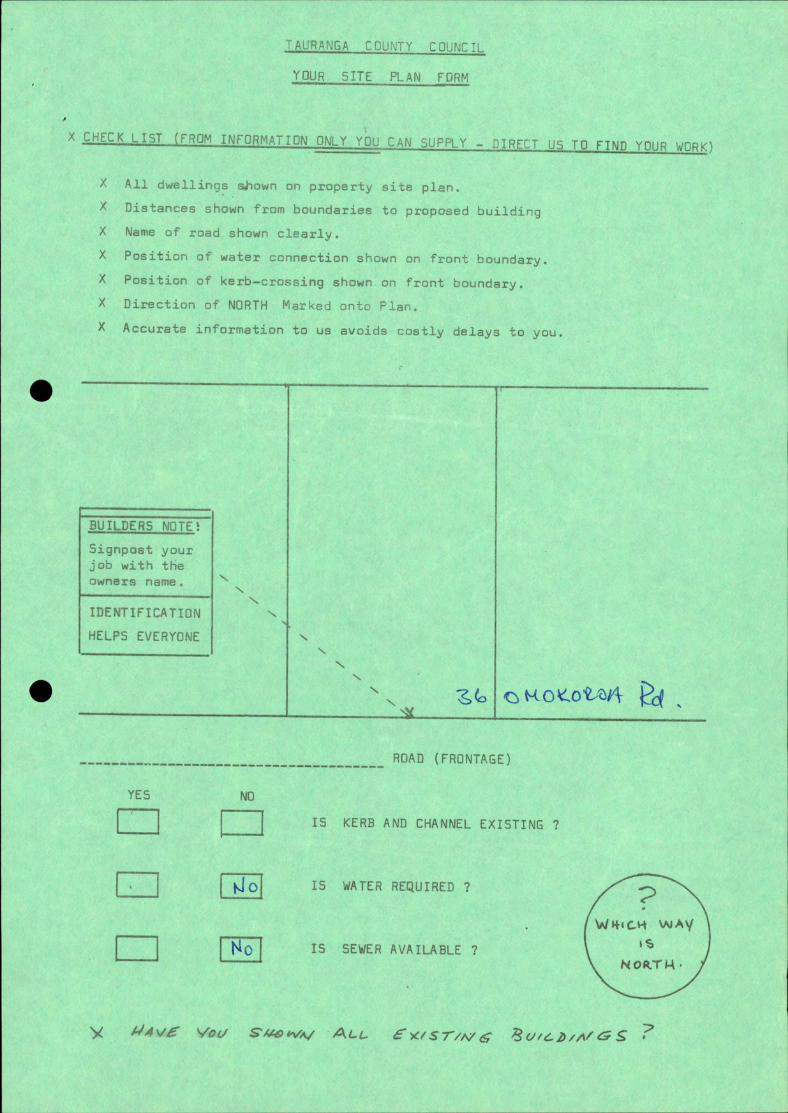
IUR SITE PLAN FORM
2K LiST (FROM INFORMA7ION ONLY YOu LAN SUFFL)' - J1RELT US TO FIND YOUR WORK)
All dwellings shown on property site plan.
Distances shown from boundarieo ti proposed bUIlCJ
Name of road shown clearly.
X Position of water connection shrwn or, front bourdar1.
X Position of kerb—crossing shown on front houndr2
X Direction of NORTH Marked onto Plan
X A'- rtT - t•r :j . -
UILDER5 NOTES
Signpost your
job with the
owners name.
N IDENTIFICATION N
HELPS EVERYONE
NX
1P (FPflNTi'
Nr
00
IS WATER REQUIRED 7
LI] Is SEWER AVAILABLE 7 is
•• //vç
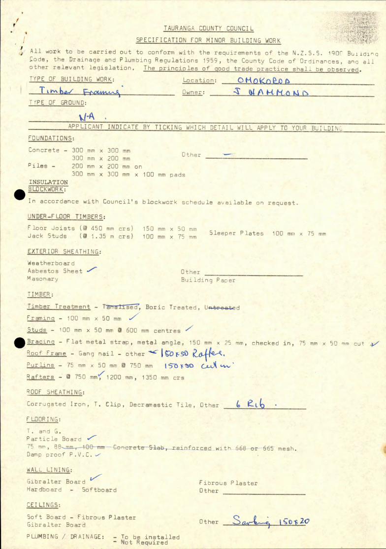
/ t
TAURANGA COUNT( COUNCIL
SPECIFICATION FOR MINOR BUILDING WORK
All work to be carried out to conform with the requirements of the N.Z.5.5. IROn Buiidin de, the Drainage and Plumbing Regulations 1959, the County Code of Ordinances, ano all
:iber relevant legislation. The principles of good trade practice shall be observed.
OF BUILDING WORK: Location:
Trv.L./ Owner: '
T'PE OF GROUND:
APPLICANT INDICATE BY TICKING WHICH DETAIL WILL APPLY TO YOUR BUILDIN -
FOUNDATIONS:
Concrete - 300 mm x 300 mm uthar
300 mm x 200 mm
i1ee - 200 mm x 200 mm on
300 mm x 300 mm x 100 mm pads
INSULATION 5LOCKWORK:
in accordance with Council's blockwork schedule available on request.
UNDER-FLOOR TIMBERS:
Floor Jojgts A 450 mm crs) 150 mm x 50 mm
Jack Studs ( 1.35 m crs) 100 mm x 75 mm Sleeper Plates 100 mm 75 mm
EXTERIOR SHEATHING:
We a the r b o ar d
Asbestos Sheet
Other Mason ar v Building Paper
TIMBER:
Timber Treatment - Boric Treated, Uo-trootd
Framing - 100 mm x 50 mm
Studs - 100 mm x 50 mm 0 600 mm centres
49 Bracing - Flat metal strap, metal angle, 150 mm x 25 mm, checked in,
nof Frame - Gang nail - other
nurLins - 75 mm x 50 mm @ 750 mm tbO
afters - 750 mm'"1200 mm, 1350 mm crs
200F SHEATHING:
Dorrugated Iron, T. Clip, Decramastic Tile, Other ti
LOORING:
75 mm x 50 mm cut/
and G.
article Board "
75 mm, 88mm-4-8&-mm- Cor re±e-51eb,.i.einforced with 668 or665 mesh. Damp proof P.V.C.
tdALL LINING:
fr iibralter Board
1ardbpard - Softboard
EI LINGS:
Soft Board - Fibrous Plaster
Dibralter Board
Fibrous Plaster
Other
Other Sa-L_ c2o T V- be installed
- Nr:t Required

..EClx_l;
'iâs Specifiction to cover all aspects for tht nc',ditl.ons to the fiesidence of r. 1 JiO 0
work shall comply with the local authority by-lavs. arkhship shall be of the highest quality and Lhe best available materials used. uilder' s Risk insurnce shall be teken out by the owner andshall be for the
durvion of the ork. The owner shall purchase and supply all me Lcrials and sub-trades when reuired
he builder shall charge Labour and mileage and shall keep e daily record of such costs. Th€ builder shall bupply a schedule of quantities and costs for Une 0jier' uidaze, but. such costs shall not auio for any eculntior, in mntcrivl ori e.
The basis of the work shall be on labèur only undcrtnkir.
- The •wner shall o",ply for and obtain the necessrry permits TIMBER SCiEJULF
Joists 1007-50 ran. G. s;c OOmm % Plates 100C !.T. Pine or Douglas Fir. studs lOOx'O ft ' ('Oiujn ' icogs 100.360 " " ft " 3 rows. raoing 10040 " plae:d
iifters 150x50 " " 1200z C," i.idge 3d. 2UxlO0 H che--Ked to
Mczinirie Flour. 250x100 frontbber.. floor joists 250x50 checked : sho"r. uffit Fxamirg 75x 32 wrlina 75x50 If " sp Ld vt 1 2C
iiscia 3d. Bds.
200x32 llutt-loc. arge 200x32 ". oists over Bed Rtn. 200x50 looring p. :.
Li xticle ord fixed uc .he to o the r: R06FLG
Corrugated Iron on Light 'ceit building paper.
Th dimensions shown on plan and in Alinmin-Jum of c repuabie !flYke,
Construct steirs as shown on plan detall. cleeed wooden treads bolted to steel urackets vveldod to K.H.S. strin 'c. Top fixing lus to be welded to top of strings for fixing to the lantliw.
bLLV5TRE ;ner to select botceen timber and steel vt iitr detc.
iii:'' i;oR.
'fl ; •J. :,..
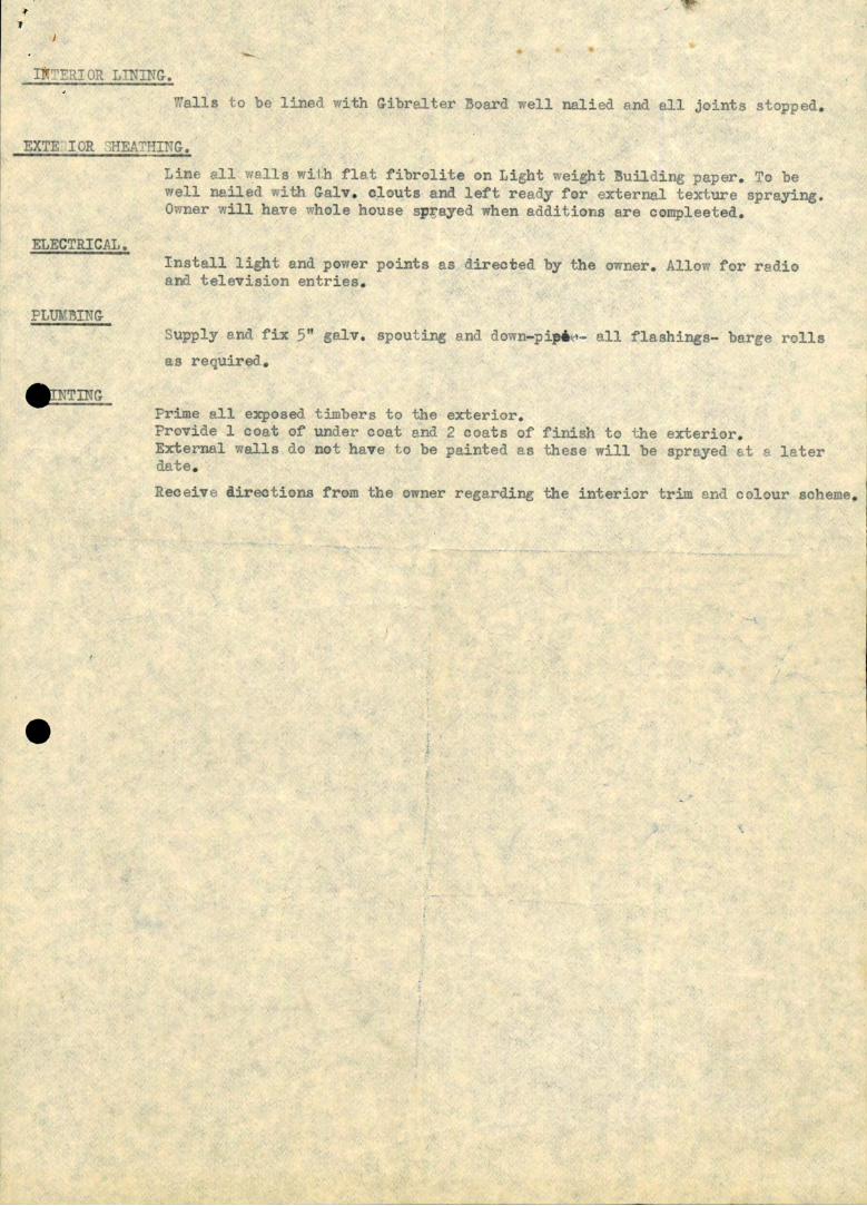
--
- ҟ ,-, -- ҟ;---,
EXTE ICR
fiJroliCe or L1ht €IhI u±1 .ix, i. "eli nailed with G-alv. olouts and left reedy for external texture sprayi
i' 1, cr'''l.
C'S'IC: 5:
-.:pa' -..
- rpr'uirT
Erovide 1 coat of under coat and 2 coats of finish to the ex External walls do not have to be painted as these will be sprayed iat€c date.
dirS the interior trim nnJ clur so
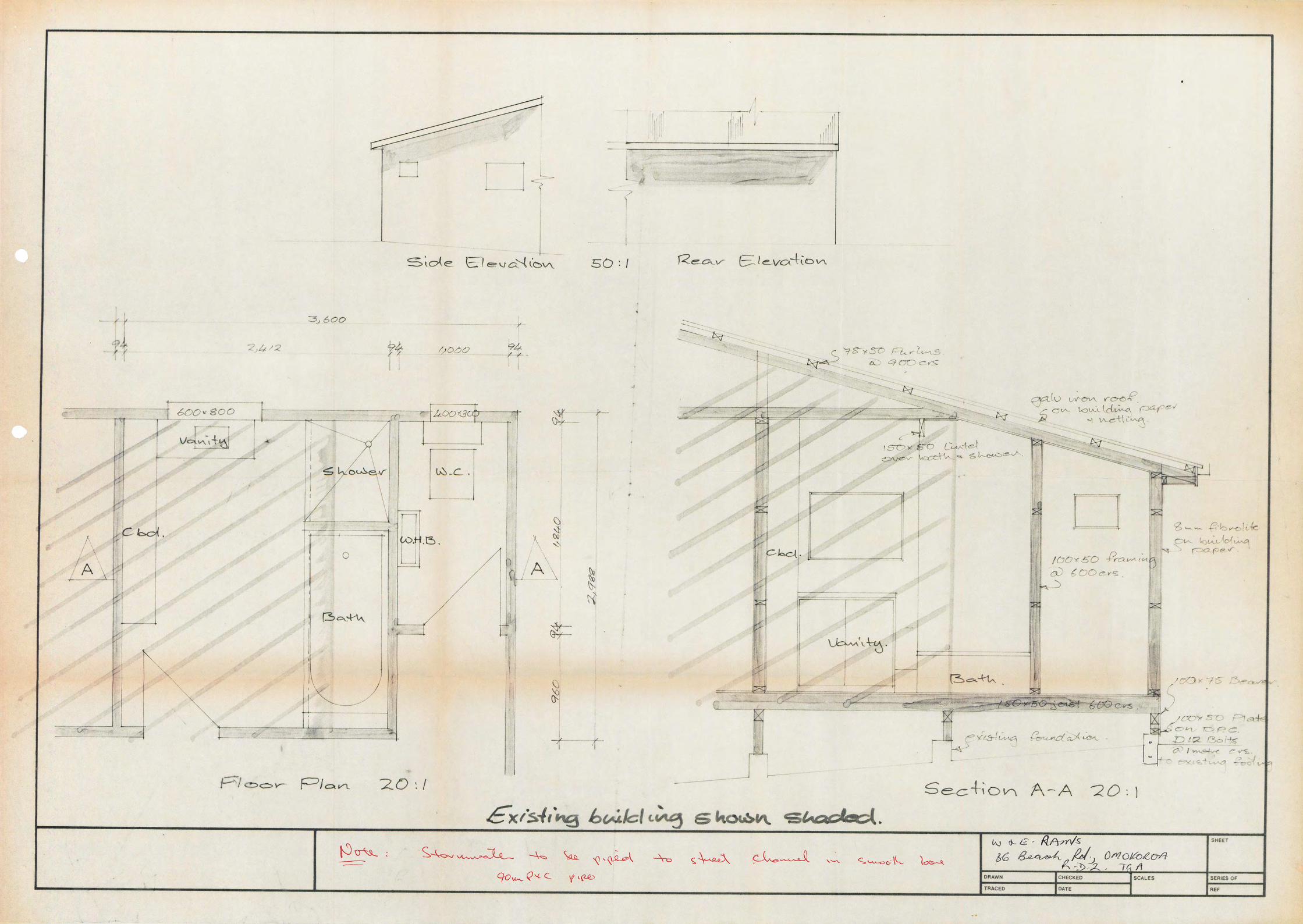
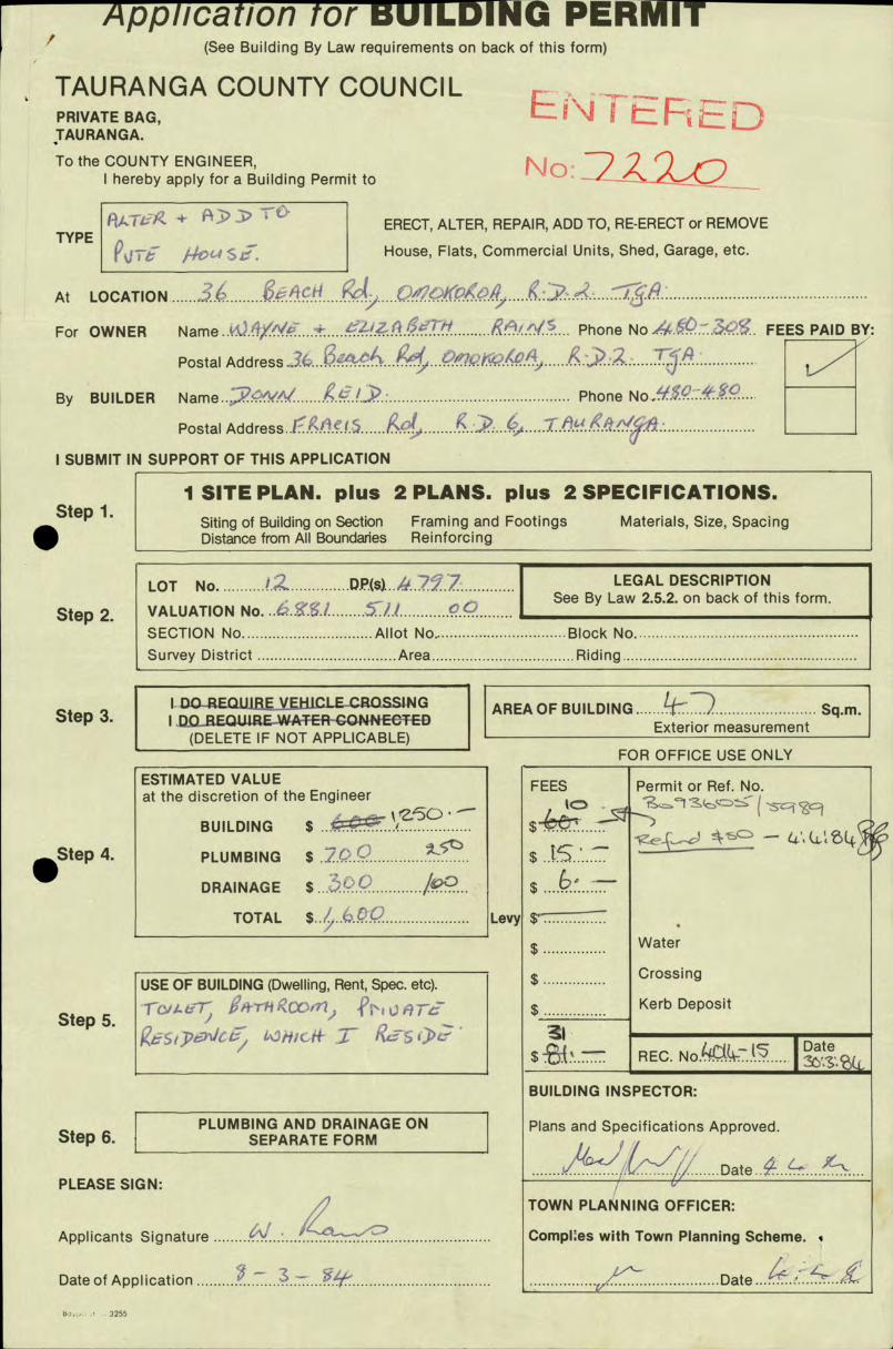
/ Application tor BUILDING PERMIT (See Building By Law requirements on back of this form)
* TAURANGA COUNTY COUNCIL PRIVATE BAG, K TAURANGA.
To the COUNTY ENGINEER,
I hereby apply for a Building Permit to
TYPE +
A ERECT, ALTER, REPAIR, ADD TO, RE-ERECT or REMOVE
42 j -j ,4 c House, Flats, Commercial Units, Shed, Garage, etc.
AtLOCATION ..............................................................
For OWNER Name '... Phone No .... .>S. FEES PAID BY:
Postal Address -3(,... j *i~.,Z.........................
By BUILDER Name...XV/'/.......g.CL . Phone ....
Postal Address..L.ft!.? 7t I SUBMIT IN SUPPORT OF THIS APPLICATION
Step 1. .
I SITE PLAN. pIus 2 PLANS. pIus 2 SPECIFICATIONS. Siting of Building on Section Framing and Footings Materials, Size, Spacing Distance from All Boundanes Reinforcing
LOT No. .......... IZ .............. D(s).../'..2j..Z.............I
LEGAL DESCRIPTION See By Law 2.5.2. on back of this form.
Step 2. VALUATION No. ..................................... SECTION No...............................Allot No................................Block No............................................... SurveyDistrict .................................Area..................................Riding..................................................
I. DOR.EQLIIREVEH.ICLE CROSSING 1
AREAOF BUILDING ....... tT) ........................ Sq.m. Step 3. I.00 REQJJiREWATER-ONNEC-T-ED (DELETE IF NOT APPLICABLE) Exterior measurement
FOR OFFICE USE ONLY
.SteP 4.
Lev
ESTIMATED VALUE at the discretion of the Engineer
BUILDING $ .. ........
PLUMBING $ .....................
DRAINAGE $ ... .'!-?P............... TOTAL $..1...c.....................
FEES Permit or Ref. No.
- $ 15 . $ ....6
$ ................ Water $ ................
$ ................ Crossing
$ Kerb Deposit
REC. No!'C(.......... Date
BUILDING INSPECTOR:
Plans and Specifications Approved.
Date.. .............
TOWN PLANNING OFFICER:
CompIes with Town Planning Scheme.
Date.%...
USE OF BUILDING (Dwelling, Rent, Spec. etc).
Step 5. rCILL7,, ,pm1ct, :z- RslL-
PLUMBING AND DRAINAGE ON Step 6. SEPARATE FORM
PLEASE SIGN:
Applicants Signature .............................
Date of Application
, or
5 25

Extracts from:— N.Z. STANDARD MODEL BUILDING BY LAW NZSS 1900
CHAPTER TWO - BUILDING PERMITS (Adopted by Tauranga County Council as County By Law, June 6th, 1968)
"ERECTION OF A BUILDING" includes the re-erection of a building and the reconditioning of a building and the making of any alteration, repair, or addition to any building heretofore or hereafter erected and the removal, either in whole or in part, of a building from any place within or without the Council district to any place within such district or from one position to another position on the same lot of land, and "ERECT" has a corresponding meaning. Provided that maintenance work other than structural shall not be deemed a repair.
BUILDING PERMIT REQUIRED 2.1.1 No person shall erect or commence to erect any building without first obtaining a building permit from the Engineer. 2.1.2. No person shall cause or permit the commencement of the erection of or the erection of any building if a building permit in that
behalf has not first been obtained from the Engineer.
APPLICATION FOR PERMIT 2.3.1 Any person desiring to obtain a building permit shall make application at the office of the Engineer on the form provided for
that purpose. The applicant or person acting on his behalf shall complete the form by filling in the particulars and signing the form.
CONTENTS OF APPLICATION 2.4.1 Every application shall set out:
(I) The legal description and particulars of the site. (ii) The full name and address of the applicant, and of the person for whom the work is to be done, the locality of the proposed
work, and the estimated value of the work. 2.4.2. Where not clearly shown or stated in the drawings and specifications required under clause 2.5, the following information shall
be given as a signed statement on, or attached to the application form. (i) The proposed use or occupancy of every part of the building.
PLANS AND SPECIFICATIONS 2.5.1 Together with every application there shall be submitted to the Engineer, in duplicate, detailed plans, elevations, cross-sections
and specifications, which shall together furnish complete details of design and qualities and descriptions of all materials of construction and workmanship, and which shall be of sufficient clarity to show to the satisfaction of the Engineer the exact nature and character of the proposed undertaking and the provision made for full compliance with the requirements of this bylaw and any other relevant bylaw for the time being in force.
For every building, except as set Out in clause 2.6, with a framework or bearing-wall system wholly or partly subject to structural design under this bylaw, and in every other case where the Engineer may reasonably require it, there shall also be uhmitted to the Engineer such stress diagrams, computations, and other data as are necessary to show that the design
complies with all the requirements of this bylaw and any other relevant bylaw in force: Computations shall be preceded by a brief report describing the bracing system and integration of the structure and the manner in which the esigner expects it to function with a clear statement of all assumptions such as materials, stresses appropriate to the standard of supervision, and live, wind, and seismic loadings. Computations shall include a summation of dead, live, seismic, and other required loadings, floor by floor, and calculations of bents (or the equivalent) in each direction, and of any special features: Drawings of reinforced concrete work shall show clearly the dimensions of all members and the size, length, shape, position, and overlap of all reinforcement: Drawings of structural steelwork shall be complete working drawings showing in figured dimensions the exact length and position of each part in such detail that the steel may be supplied and the work fabricated from such drawings: Detailed drawings shall be in such form and on such scale as the Engineer may consider necessary to ensure certainty of interpretation. All drawings other than detailed drawings shall be accurately, clearly, and indelibly executed to scale and shall be drawn in ink upon drawing paper or tracing cloth, or printed upon cloth or approved paper. Except in the case of detailed drawings all drawings shall be to scale of ¼in. or ¼in. to the foot.
2.5.2. The drawings shall be accompanied by a locality plan. This locality plan shall be drawn to scale and shall show the site of the building, together, with the land, streets, private streets, public places, private ways, public reserves and buildings immediately surrounding the site, and shall be sufficient to enable the Engineer to locate the precise situation of the site not only relative to the boundaries of its own land, but also relative to any buildings erected upon immediately adjoining lands.
2.5.5. In addition to the structural details, etc. required, the plans and sections shall show as regards every floor of the proposed building, the dimensions of rooms, the situation of flues, fireplaces, stoves, and chimneys, and the position of all the several parts of the building and every water closet, fuel store, washhouse, and all other appurtenances. The plan and section shall further show the proposed means of water supply, and the level of the lowest floor of the intended building and of the yard and ground belonging thereto, and also the means whereby it is proposed to deal with all stormwater and drainage.
2.5.6. When lodged, the application and drawings and other documents accompanying the application shall become the absolute property of the Council.
NOTE—Specifications should cover types, grading, spacing (centres) and sizes of materials. It is important that the position of existing foul drainage (especially gully traps, terminal vent, etc.) should be shown on the plans.
PERMIT MAY BE WITHHEI,D (without further notice) until Applicant fully complies with the above requirements.

Application for PLUMBING — DRAINAGE PERMIT To the COUNTY ENGINEER, TAURANGA COUNTY COUNCIL, Private Bag, GREERTON, TAURANGA.
I hereby apply for a permit to carry out Sanitary Plumbing and/or Drainage Work described below:—
tick
I OWNERS NAME .&.L1V).(kI*., Phone
Postal Address ..: (.)4Q/
PLUMBER ................................... ............ ..... ........................... Phone No.. .:..3.' ....
Postal Address ... 2.....................................................7TA .... DRAIN LAYER .................. ..4 ............. ct..<VT71.......................... Phone No..4-..
Postal Address .. .......
1]
PERMIT FEES PAYABLE BY....
2 JOB LOCATION
Address
Lot No. .................................. DP(s) No .................................Val. No. (Rate Demand)
3 DESCRIPTION OF WORK
- tick I Sanitary Plumbing and/or Drainage of new dwelling
Sanitary Plumbing and/or Drainage for alterations
or (describe) 4j.........bkTll
OFFICE USE ONLY
FEES PERMIT Nos.
$ (
$ ( -
APPLICATION WORK INSPECTED APPROVED APPROVED
Inspector ............... Inspector .................
Date........................ Date ........................
4 ESTIMATED COST of
PLUMBING $ 5t 25b
DRAINAGE $
Applicants Signature ........................................
Date ...........................
Bayprinl-9886
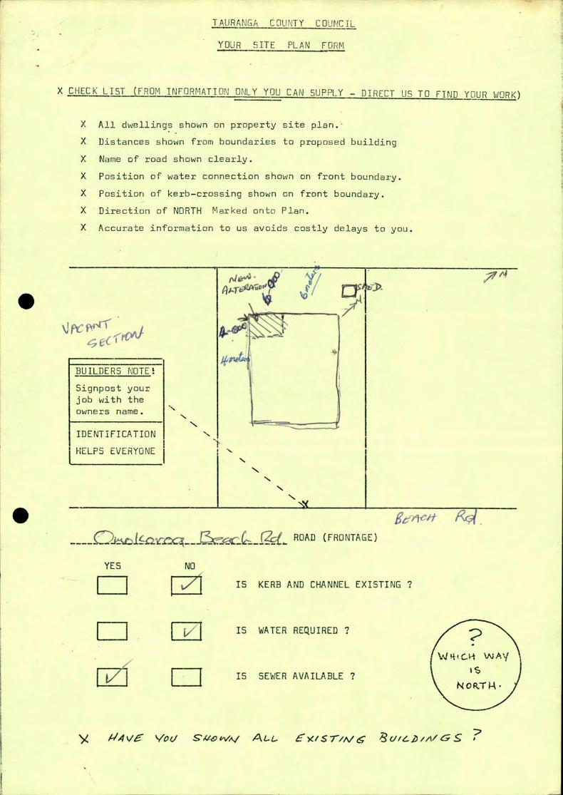
rA;c?
0
N N
N N
N
TAURANGA COUNTY COUNCIL
YOUR SITE PLAN FORM
X CHECK LIST (FROM INFORMATION ONLY YOU CAN SUPPLY - DIRECT US TO FIND YOUR WORK)
X All dwellings shown on property site plan.
X Distances shown from boundaries to proposed building
X Name of road shown clearly.
X Position of water connection shown on front boundary.
X Position of kerb—crossing shown on front boundary.
X Direction of NORTH Marked onto Plan.
X Accurate information to us avoids costly delays to you.
BUILDERS NOTE
Signpost your
job with the
Owners name.
IDENTIFICATION
[ELPS EVERYONE
fl ROAD (FRONTAGE)
YES NO
IS KERB AND CHANNEL EXISTING ?
I I I v I IS WATER REQUIRED 7
WAV
IS SEWER AVAILABLE 7 CJ
A1 4V Vou S7140WAl 4L-. 'Sr,',v& ,L2,,,VS 7
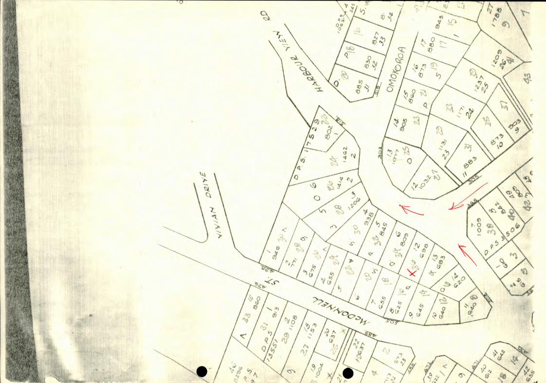

TAURANGA COUNTY COUNCIL
SPECIFICATION FOR MINOR BUILDING WORK
All work to be carried out to conform with the requirements of the N.Z.5.5. 1900 Building
Code, the Drainage and Plumbing Regulations 1959, the CoLinty Code of Ordinances, and all
other relevant legislation. jjrinciplos of good trade practice shall be observed.
TYPE OF flU I LDI NE WORK: Location:
Owner:
TYPE OF GROUND:
APPLICANT INDICATE BY TICKINE WHiCH DETAIL WILL APPLY TO YOUR BUILDING -
FOUNDATIONS:
Concrete - 300 mm x 300 mm Other
300 mm x 200 mm
Piles - 200 mm x 200 mm on
300 mm x 300 mm x 100 mads
INSULATION B LU CKW[]R K:
In accordance with Council' s blockoork schedule available on request.
UNDER-FLOOR TIMBERS:
Floor Joists (P 450 mm crs) 150 mm O mm
Jack Studs ( 1.35 incrc) 100 mm x 75 Sleeper Plates 1mm x 75 mm
EXTERIOR SHEATHING:
Weatherboard
Asbestos Sheet Other
Masonari,' Building Rer
TIMBER:
Timber Treatment - Tanalisec(Bor Treated, Untreated
- 100 mm x 50 mm -
Studs - 100 mm x 50 mm @ 600 Fn< centres Bracing - Flat metal strap, metagle, 150 mm x 25 mm, checked in, 75 mm x 50 mm cLit in
Roof Frame - Gang nail - other /OQ
Purlins - 75 mm x 50 mm @ 750 mm
Rafters - 750 mm, 1200 mm, 1350 mm crc
ROOF SHEATHING:
Corrugated IronL,--r Clip, Decramastic Tile, Other FLOORING:
T. and G.
Particle Board
75 mm, 88 mm, 100 mm Concrete Slab, reinforced with 660 or 665 mesh.
Damp proof P.V.C.
WALL LINING:
Gibralter Board
Hardboard - Softhoard
CEI LINES:
Soft Board -- Fibrous Plaster
Gibrolter Board
PLUMBING / DRAINAGE: - To be installed - Not; Runuired
Fibrous Plaster
Other
Other

Application for PLUMBING - DRAINAGE Ekl- RMfl To the COUNTY ENGINEER, TAIIRANGA COUNTY COUNCIL, Private Bag, 7 frZ• 2 TAURANGA.
I hereby apply for a permit to carry out Sanitary Plumbing and/or Drain- age Work described below:—
I tick
PERMIT FEES PAYA8LE BY
I JOB LOCATION
Address.......... ........................... ................(...........................
Lo.t No. .................... ..................... .............DP(s) No. ......................................... .Val. No. (Rate Demand) ....
3 DESCRIPTION OF WORK
I tick Sanitary Plumbing and/or Drainage of new dwelling
Sanitary Plumbing and/or Drainage for alterations
or (describe) ................................. c.....
OFFICE USE ONLY 4 ESTIMATED COST of
PLUMBING
DRAINAGE $
Applicants Signature ...
Date .........22..
D. Kale Print
FEES ,..-, PERMIT Nos.
$
$
APPLICATION WORK INSPECTED
APPROV! APPROVED
inspectorL .... inspector ........................ Date Z4 Date ...................................

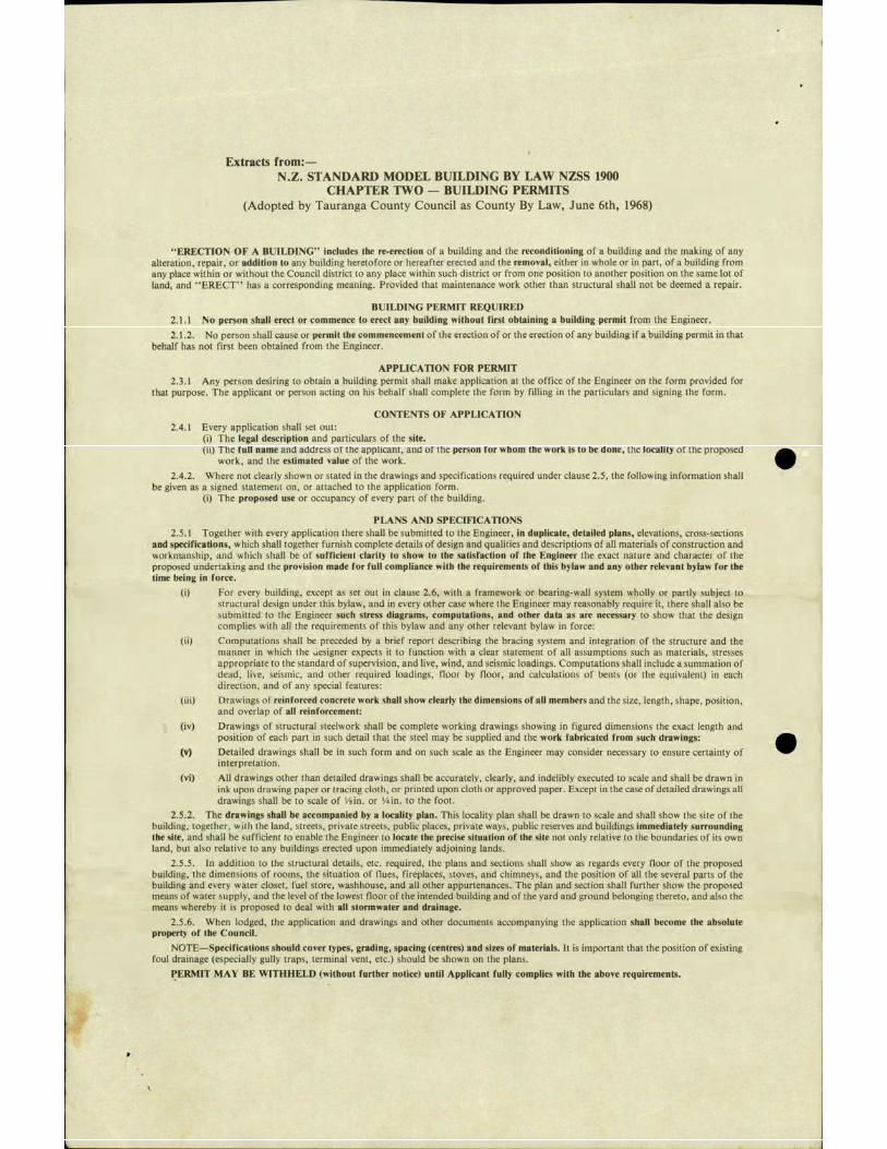
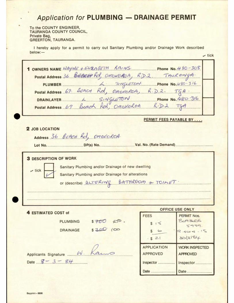

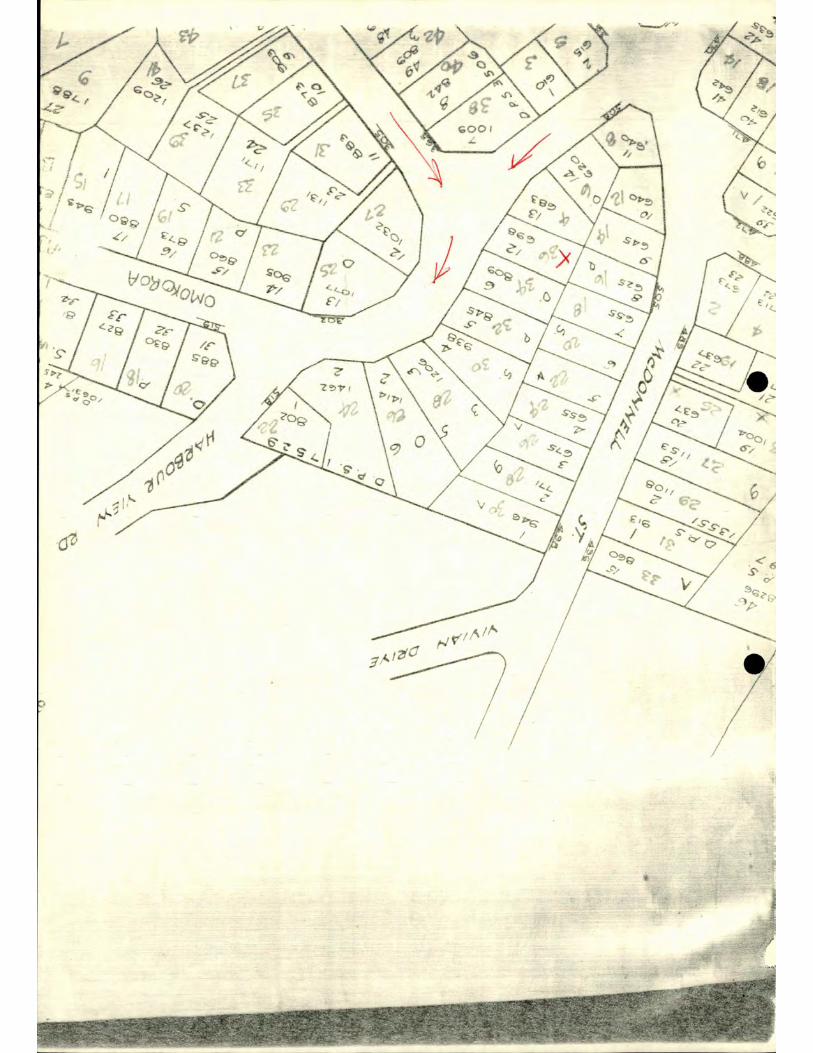
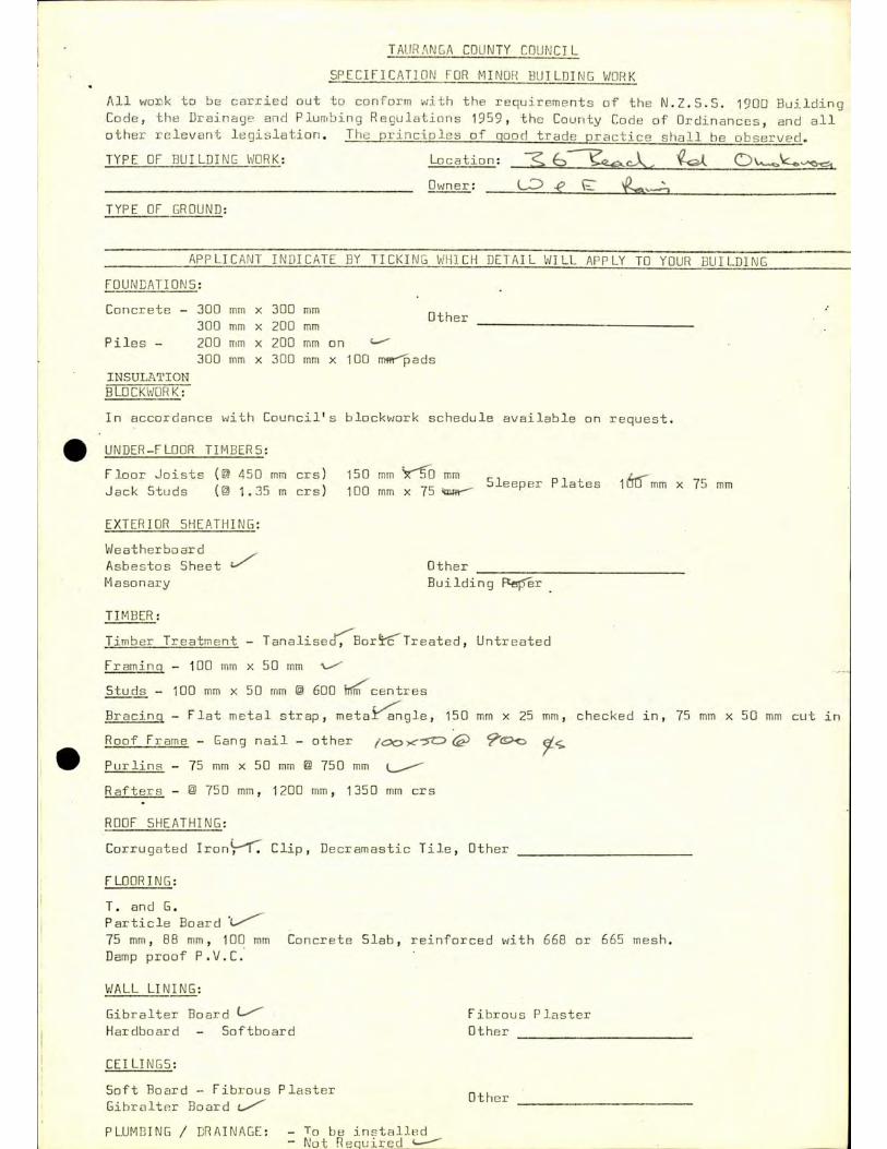
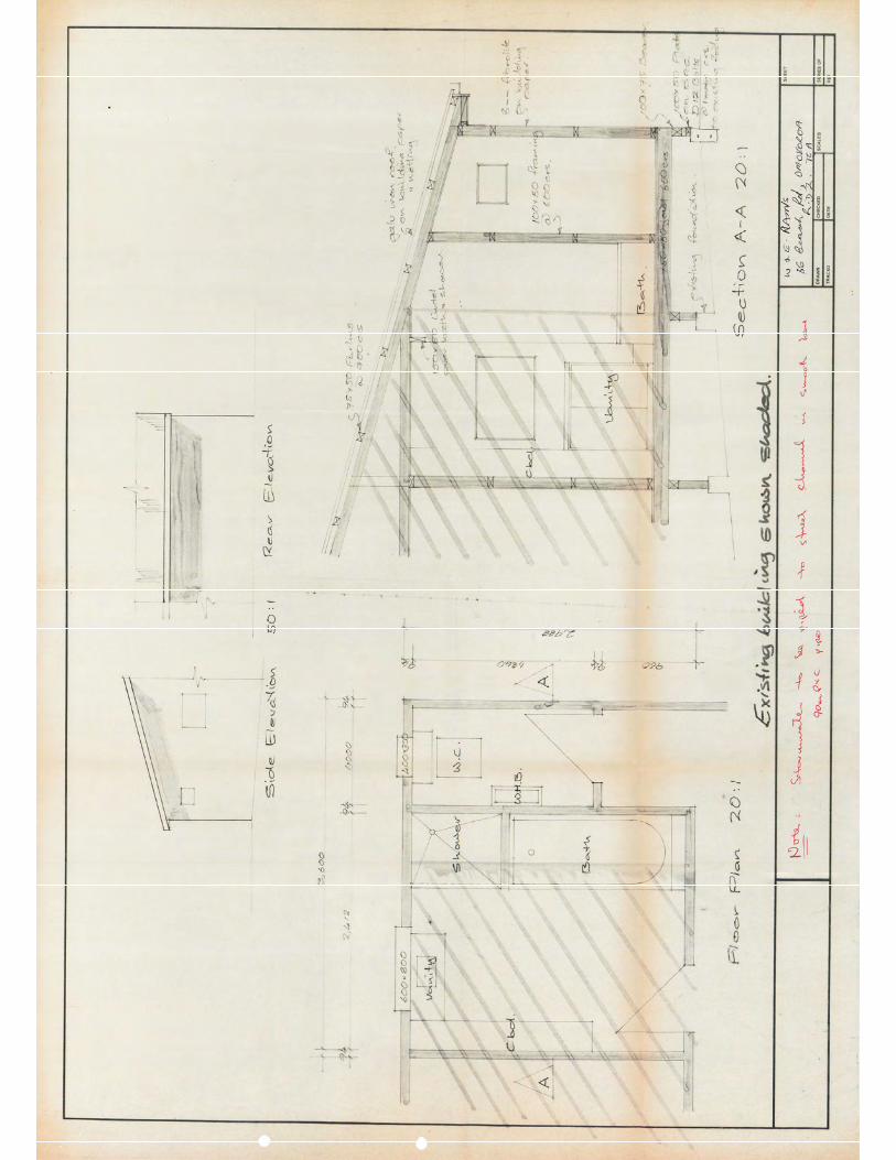
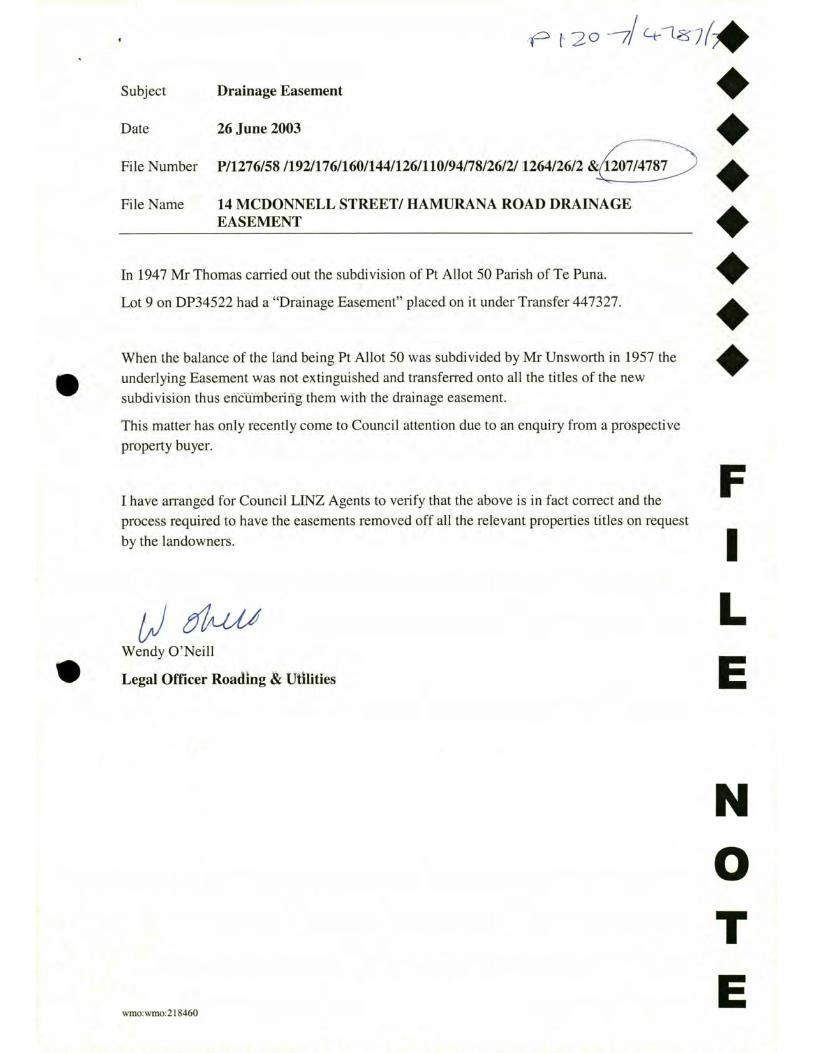

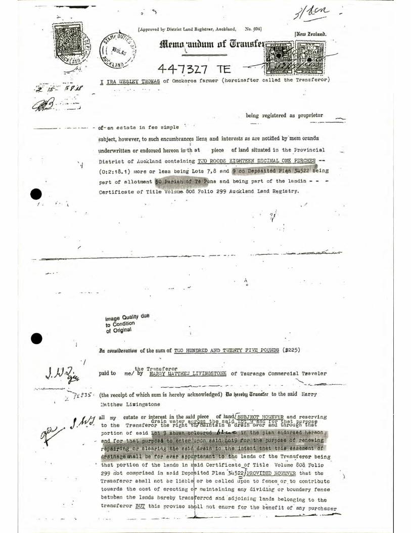
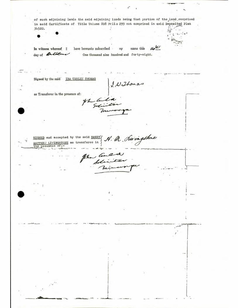
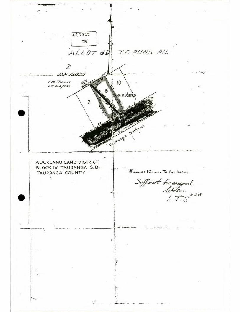


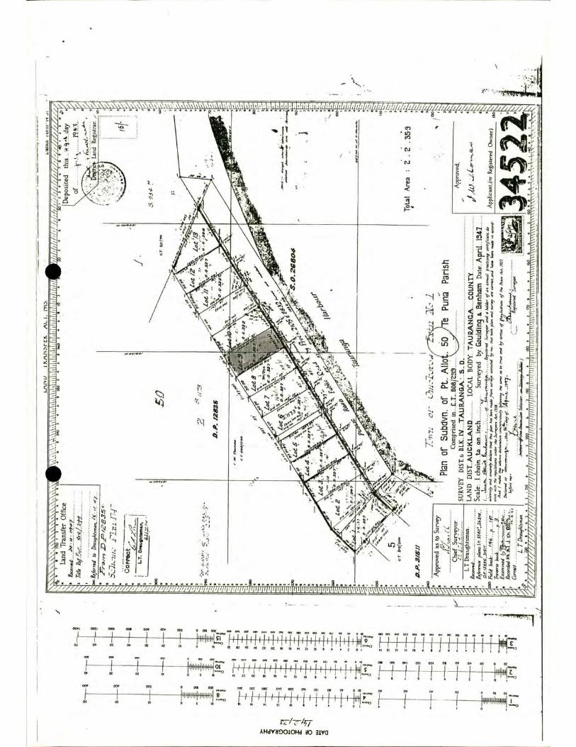
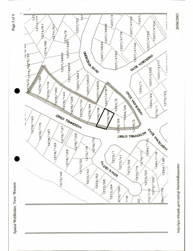
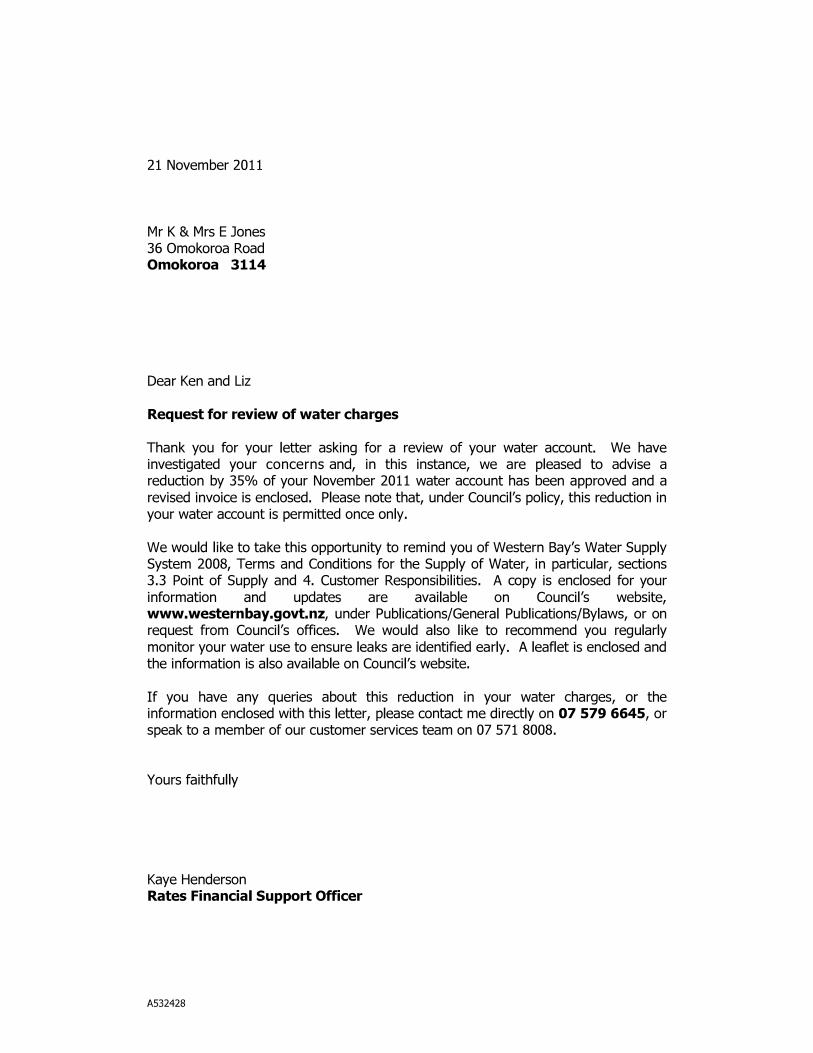
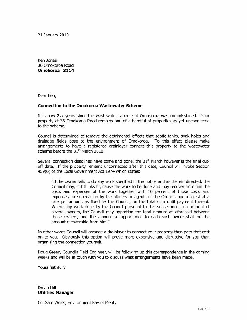
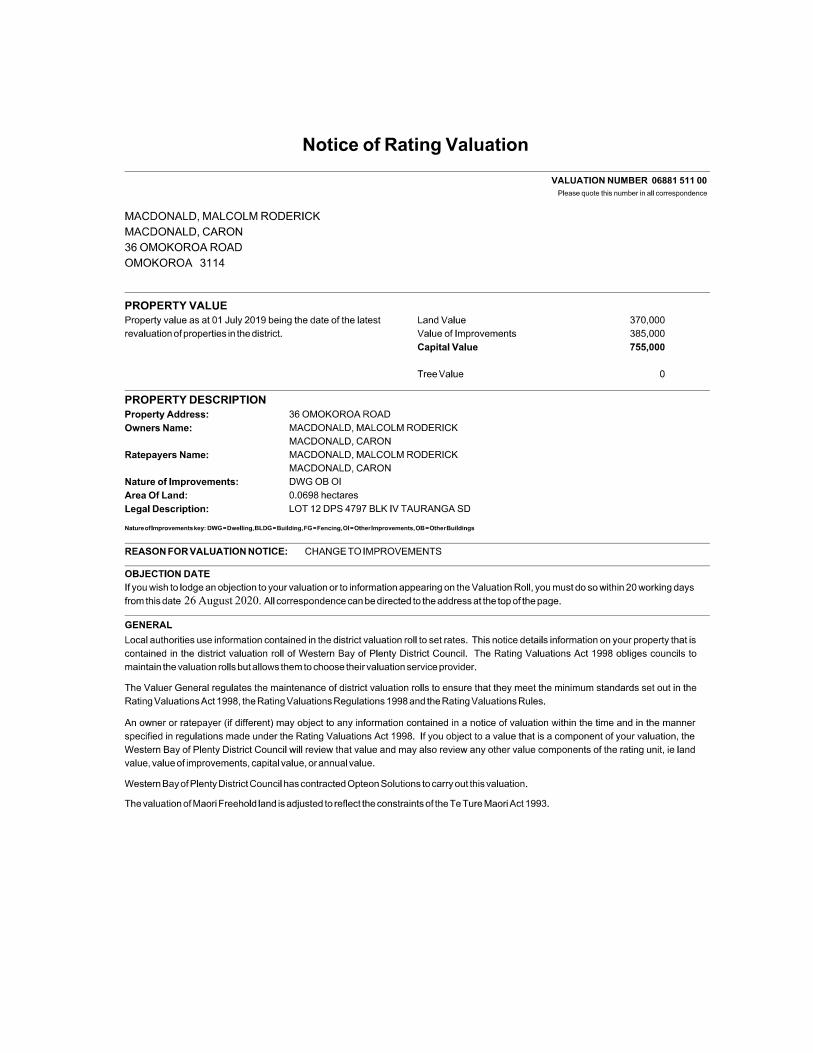
Related Documents


![Welcome [tc18.tableau.com] · 2020-01-06 · Alteryx or Snowflake Turn on AWS Cost & Usage Report Create Lambda Exclude Totals & PayerLineItem Use Calculations to convert date and](https://static.cupdf.com/doc/110x72/5e903bfc7b19413a3d7517da/welcome-tc18-2020-01-06-alteryx-or-snowflake-turn-on-aws-cost-usage.jpg)
