...................................................................................................... Cahier technique no. 172 R. Calvas B. Lacroix Collection Technique System earthings in LV Building a New Electric World

Welcome message from author
This document is posted to help you gain knowledge. Please leave a comment to let me know what you think about it! Share it to your friends and learn new things together.
Transcript
......................................................................................................
Cahier technique no. 172
R. CalvasB. Lacroix
Collection Technique
System earthings in LV
Building a New Electric World
Abdel
"Cahiers Techniques" is a collection of documents intended for engineersand technicians, people in the industry who are looking for more in-depthinformation in order to complement that given in product catalogues.
Furthermore, these "Cahiers Techniques" are often considered as helpful"tools" for training courses.They provide knowledge on new technical and technological develop-ments in the electrotechnical field and electronics. They also providebetter understanding of various phenomena observed in electricalinstallations, systems and equipments.Each "Cahier Technique" provides an in-depth study of a precise subjectin the fields of electrical networks, protection devices, monitoring andcontrol and industrial automation systems.
The latest publications can be downloaded from the Schneider Electricinternet web site.Code: http://www.schneider-electric.comSection: Press
Please contact your Schneider Electric representative if you want either a"Cahier Technique" or the list of available titles.
The "Cahiers Techniques" collection is part of the Schneider Electric’s"Collection technique".
ForewordThe author disclaims all responsibility subsequent to incorrect use ofinformation or diagrams reproduced in this document, and cannot be heldresponsible for any errors or oversights, or for the consequences of usinginformation and diagrams contained in this document.
Reproduction of all or part of a "Cahier Technique" is authorised with theprior consent of the Scientific and Technical Division. The statement"Extracted from Schneider Electric "Cahier Technique" no. ....." (pleasespecify) is compulsory.
Scientific and Technical DivisionTechnical Communication
Best Regards
Schneider Electric SACentre de Recherches A22, rue VoltaF- 38050 Grenoble Cedex 9Tél. 33 (0)4 76 57 79 68Fax 33 (0)4 76 57 98 60
Abdel
Abdel

Bernard LACROIX
An ESPCI 74 graduate engineer (from the Ecole Supérieurede Physique et Chimie Industrielle de Paris), he then worked5 years for Jeumont Schneider, where his activities includeddevelopment of the TGV chopper.After joining Merlin Gerin in 1981, he was then in turn SalesEngineer for UPS and sales manager for protection ofpersons.Since 1991 he is in charge of prescription for LV powerdistribution.
no. 172System earthings in LV
ECT 172 updated December 2004
Roland CALVAS
An ENSERG 1964 graduate engineer (from the EcoleNationale Supérieure d'Electronique et Radioélectricité deGrenoble) and an Institut d'Administration des Entreprisesgraduate, he joined Merlin Gerin in 1966.During his professional career, he was sales manager,marketing manager in the field of equipment for protection ofpersons, then Technical Communication manager.
Abdel
Abdel
Cahier Technique Schneider Electric no. 172 / p.2
Lexicon
Earthing system -grounding system (US)-60050-604 IEC: An arrangement of connections and devicesnecessary to earth equipment or a system separately or jointly.
Electric Shock: Application of a voltage between two parts of thebody
Electrocution: Electric Shock resulting in death
EMC: Electro Magnetic Compatibility
I∆n: Operating threshold of a RCD
IMD: Insulation Monitoring Device
GFLD: Insulation Fault Location Device
MV/HV: Medium Voltage: 1 to 35 kV as in CENELEC (circular ofthe 27.07.92)High Voltage: 1 to 50 kV as in french standard (14.11.88)
(power) System earthing -(power) system grounding (US)-60050-195 IEC: Functional earthing and protective earthing of apoint or points in an electric power system.
RCD: Residual Current Device
SCPD: Short-Circuit Protection Device (circuit-breakers or fuses)
STD: Short Time Delay protection (protection against short-circuitovercurrents by circuit-breaker with rapid trip release)
TBM: Technical Building Management
TEM: Technical Electrical Power Distribution Management
UL: Conventional limit voltage (maximum acceptable contactvoltage) known as the "safety" voltage
Abdel
Abdel
Cahier Technique Schneider Electric no. 172 / p.3
System earthings in LV
This «Cahier Technique» proposes a survey of potential hazardsthat insulation faults may create for safety of persons andproperty. It emphasises the influence of system earthings on theavailability of electrical power. It presents the three most commonsystem earthings defined in standard IEC 60364 and used tovarying degrees in all countries.
Each system earthing is analysed in terms of dependability(safety, maintenability and availability).All system earthings are equivalent as far as safety of persons isconcerned, but each system earthing has its own advantagesand disadvantages regarding the operation of electricalinstallation. The user must therefore be guided according to hisneeds, with the exception, however, of prescription or of standardor legislative bans.
Readers interested in the practices of various countries and inevolution of system earthings should read «Cahier Technique»No 173: System earthings worldwide and evolutions.
Contents
1 Introduction ............................................................................................................................ p. 4
1.1 Evolution of needs................................................................................................................. p. 4
1.2 Causes of insulation faults .................................................................................................... p. 4
1.3 Hazards linked to insulation faults......................................................................................... p. 5
2 System earthings and protection of persons ...................................................................... p. 8
2.1 TN system ............................................................................................................................. p. 9
2.2 TT system ............................................................................................................................. p. 10
2.3 IT system............................................................................................................................... p. 11
3 System earthings confronted with fire and electrical power unavailability hazards....... p. 15
3.1 Fire ........................................................................................................................................ p. 15
3.2 Electrical power unavailability ............................................................................................... p. 15
4 Influences of MV on BV, according to the system earthings............................................. p. 17
4.1 Lightning................................................................................................................................ p. 17
4.2 Operating overvoltages ......................................................................................................... p. 18
4.3 MV-frame disruptive breakdown of the transformer .............................................................. p. 18
4.4 MV-LV disruptive breakdown inside the transformer ............................................................ p. 19
5 Switchgear linked to choice of system earthing ................................................................. p. 20
5.1 TN system ............................................................................................................................. p. 20
5.2 TT system ............................................................................................................................. p. 21
5.3 IT system............................................................................................................................... p. 21
5.4 Neutral protection according to the system earthing ............................................................. p. 23
6 Choice of system earthing and conclusion ......................................................................... p. 25
6.1 Methods for choosing the system earthing ........................................................................... p. 25
6.2 Conclusion ............................................................................................................................ p. 26
Bibliography .............................................................................................................................. p. 27
Abdel
Abdel
Cahier Technique Schneider Electric no. 172 / p.4
1 Introduction
1.1 Evolution of needs Today the 3 system earthings such as defined in IEC 60364 andFrench standard NF C 15-100, are:
c Exposed-conductive parts connected to neutral -TN-
c Earthed neutral -TT-
c Unearthed (or impedance-earthed) neutral -IT-
The purpose of these three earthings is identical as regardsprotection of persons and property: Mastery of insulation faulteffects. They are considered to be equivalent with respect tosafety of persons against indirect contacts.However, the same is not necessarily true for dependability of theLV electrical installation with respect to:
c Electrical power availability
c Installation maintenance
These quantities, which can be calculated, are subjected toincreasingly exacting requirements in factories and tertiarybuildings. Moreover, the control and monitoring systems ofbuildings -TBM- and electrical power distribution managementsystems -TEM- play an increasingly important role inmanagement and dependability.
This evolution in dependability requirements therefore affects thechoice of system earthing.
It should be borne in mind that the concern with continuity ofservice (keeping a sound network in public distribution bydisconnecting consumers with insulation faults) played a rolewhen system earthings first emerged.
1.2 Causes of insulationfaults
In order to ensure protection of persons and continuity of service,conductors and live parts of electrical installations are "insulated"from the frames connected to the earth.
Insulation is achieved by:c Use of insulating materialsc Distancing, which calls for clearances in gases (e.g. in air) andcreepage distances (concerning switchgear, e.g. an insulator flashover path)
Insulation is characterised by specified voltages which, inaccordance with standards, are applied to new products andequipment:c Insulating voltage (highest network voltage)c Lightning impulse withstand voltage (1.2; 50 ms wave)c Power frequency withstand voltage(2 U + 1,000 V/1mn)
Example for a LV PRISMA type switchboard:c Insulating voltage: 1,000 Vc Impulse voltage: 12 kV
When a new installation is commissioned, produced as per properpractices with products manufactured as in standards, the risk ofinsulation faults is extremely small; as the installation ages,however, this risk increases.
In point of fact, the installation is subject to various aggressionswhich give rise to insulation faults, for example:c During installationv Mechanical damage to a cable insulator
c During operationv Conductive dustv Thermal ageing of insulators due to excessive temperaturecaused by- Climate- Too many cables in a duct- A poorly ventilated cubicle- Harmonics- Overcurrents, etc.v The electrodynamic forces developed during a short-circuitwhich may damage a cable or reduce a clearancev The operating and lightning overvoltagesv The 50 Hz return overvoltages, resulting from an insulation faultin MV
It is normally a combination of these primary causes which resultsin the insulation fault. The latter is:
c Either of differential mode (between live conductors) andbecomes a short-circuit
Abdel
Abdel
Cahier Technique Schneider Electric no. 172 / p.5
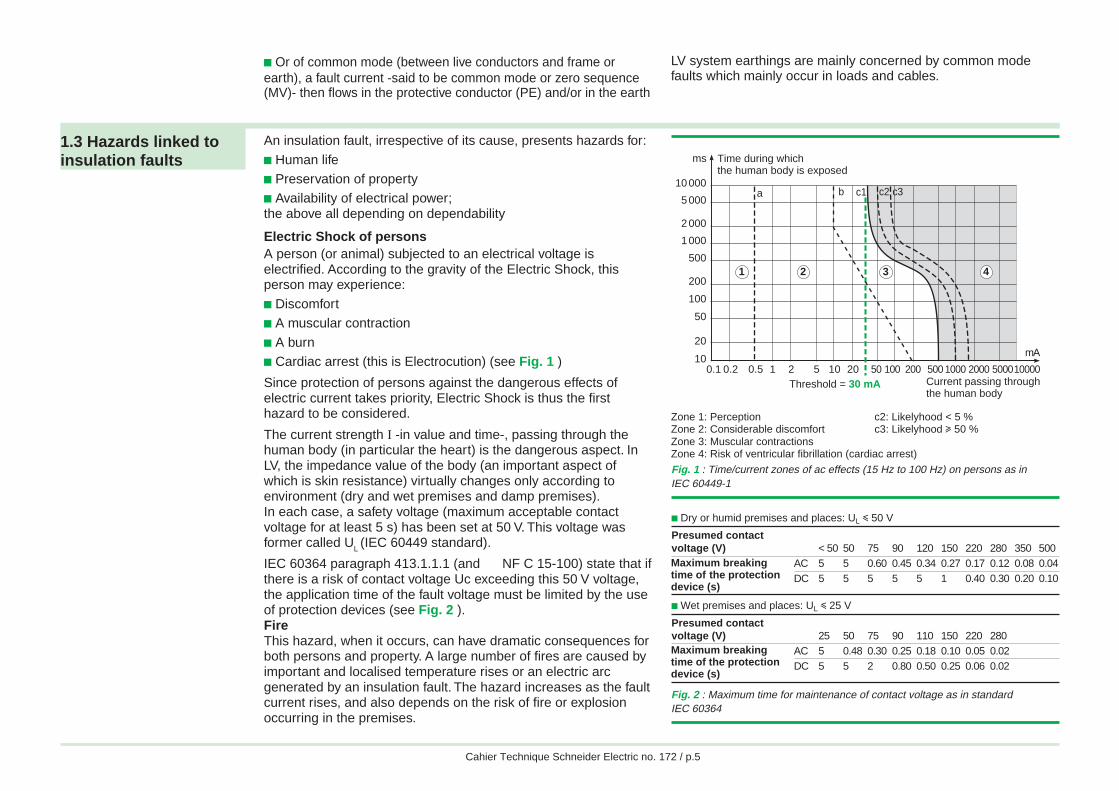
0.1 0.2 0.5 1 2 5 10 20Threshold = 30 mA
50 100 200 500 1000 2000 500010000
mA10
20
50
100
200
500
1 000
2 000
5 000
10 000
ms Time during whichthe human body is exposed
a b c2c1 c3
1 2 3
Current passing throughthe human body
4
Zone 1: Perception c2: Likelyhood < 5 %Zone 2: Considerable discomfort c3: Likelyhood u 50 %Zone 3: Muscular contractionsZone 4: Risk of ventricular fibrillation (cardiac arrest)
Fig. 2 : Maximum time for maintenance of contact voltage as in standardIEC 60364
c Or of common mode (between live conductors and frame orearth), a fault current -said to be common mode or zero sequence(MV)- then flows in the protective conductor (PE) and/or in the earth
LV system earthings are mainly concerned by common modefaults which mainly occur in loads and cables.
An insulation fault, irrespective of its cause, presents hazards for:
c Human lifec Preservation of propertyc Availability of electrical power;the above all depending on dependability
Electric Shock of personsA person (or animal) subjected to an electrical voltage iselectrified. According to the gravity of the Electric Shock, thisperson may experience:
c Discomfortc A muscular contraction
c A burnc Cardiac arrest (this is Electrocution) (see Fig. 1 )
Since protection of persons against the dangerous effects ofelectric current takes priority, Electric Shock is thus the firsthazard to be considered.
The current strength I -in value and time-, passing through thehuman body (in particular the heart) is the dangerous aspect. InLV, the impedance value of the body (an important aspect ofwhich is skin resistance) virtually changes only according toenvironment (dry and wet premises and damp premises).In each case, a safety voltage (maximum acceptable contactvoltage for at least 5 s) has been set at 50 V. This voltage wasformer called U
L (IEC 60449 standard).
IEC 60364 paragraph 413.1.1.1 (and NF C 15-100) state that ifthere is a risk of contact voltage Uc exceeding this 50 V voltage,the application time of the fault voltage must be limited by the useof protection devices (see Fig. 2 ).FireThis hazard, when it occurs, can have dramatic consequences forboth persons and property. A large number of fires are caused byimportant and localised temperature rises or an electric arcgenerated by an insulation fault. The hazard increases as the faultcurrent rises, and also depends on the risk of fire or explosionoccurring in the premises.
Fig. 1 : Time/current zones of ac effects (15 Hz to 100 Hz) on persons as inIEC 60449-1
1.3 Hazards linked toinsulation faults
c Dry or humid premises and places: UL i 50 V
Presumed contactvoltage (V) < 50 50 75 90 120 150 220 280 350 500
AC 5 5 0.60 0.45 0.34 0.27 0.17 0.12 0.08 0.04DC 5 5 5 5 5 1 0.40 0.30 0.20 0.10
c Wet premises and places: UL i 25 V
Presumed contactvoltage (V) 25 50 75 90 110 150 220 280
AC 5 0.48 0.30 0.25 0.18 0.10 0.05 0.02DC 5 5 2 0.80 0.50 0.25 0.06 0.02
Maximum breakingtime of the protectiondevice (s)
Maximum breakingtime of the protectiondevice (s)
Abdel
Abdel
Cahier Technique Schneider Electric no. 172 / p.6
Unavailability of electrical powerIt is increasingly vital to master this hazard. In actual fact if thefaulty part is automatically disconnected to eliminate the fault, theresult is:c A risk for persons, for examplev Sudden absence of lightingv Placing out of operation of equipment required for safetypurposesc An economic risk due to production loss. This risk must bemastered in particular in process industries, which are lengthyand costly to restart
Moreover, if the fault current is high:c Damage, in the installation or the loads, may be considerableand increase repair costs and timesc Circulation of high fault currents in the common mode (betweennetwork and earth) may also disturb sensitive equipment, inparticular if these are part of a "low current" systemgeographically distributed with galvanic links
Finally, on de-energising, the occurrence of overvoltages and/orelectromagnetic radiation phenomena may lead to malfunctioningor even damage of sensitive equipment.
Direct and indirect contactsBefore beginning to study the system earthings, a review ofElectric Shock by direct and indirect contacts will certainly beuseful.
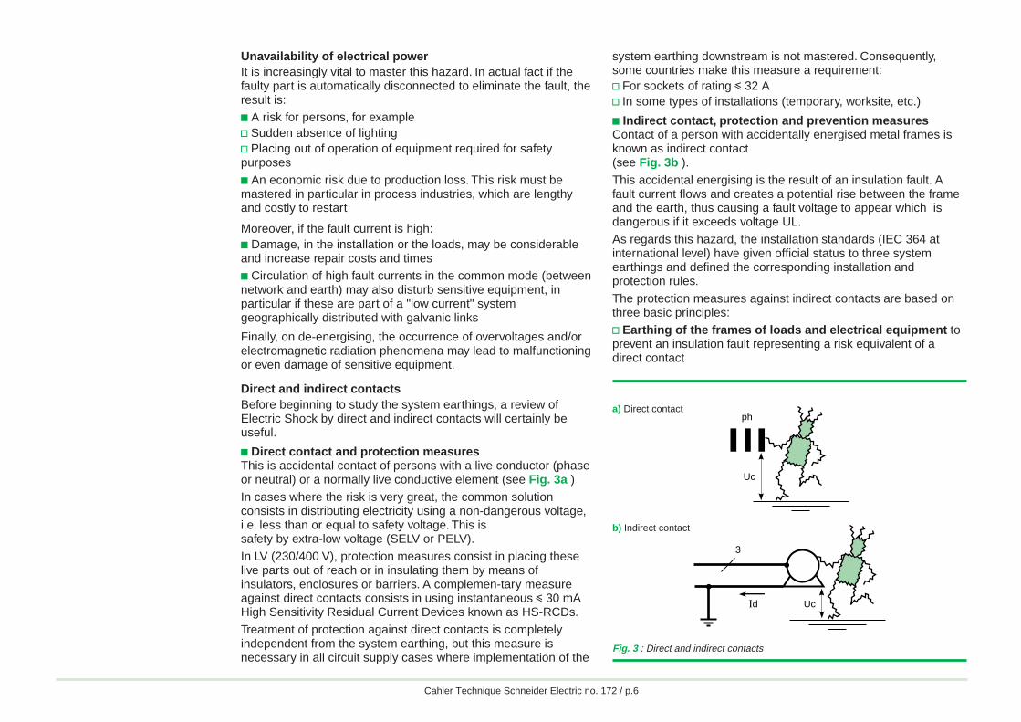
c Direct contact and protection measuresThis is accidental contact of persons with a live conductor (phaseor neutral) or a normally live conductive element (see Fig. 3a )In cases where the risk is very great, the common solutionconsists in distributing electricity using a non-dangerous voltage,i.e. less than or equal to safety voltage. This issafety by extra-low voltage (SELV or PELV).In LV (230/400 V), protection measures consist in placing theselive parts out of reach or in insulating them by means ofinsulators, enclosures or barriers. A complemen-tary measureagainst direct contacts consists in using instantaneous i 30 mAHigh Sensitivity Residual Current Devices known as HS-RCDs.Treatment of protection against direct contacts is completelyindependent from the system earthing, but this measure isnecessary in all circuit supply cases where implementation of the
system earthing downstream is not mastered. Consequently,some countries make this measure a requirement:v For sockets of rating i 32 Av In some types of installations (temporary, worksite, etc.)
c Indirect contact, protection and prevention measuresContact of a person with accidentally energised metal frames isknown as indirect contact(see Fig. 3b ).This accidental energising is the result of an insulation fault. Afault current flows and creates a potential rise between the frameand the earth, thus causing a fault voltage to appear which isdangerous if it exceeds voltage UL.As regards this hazard, the installation standards (IEC 364 atinternational level) have given official status to three systemearthings and defined the corresponding installation andprotection rules.The protection measures against indirect contacts are based onthree basic principles:v Earthing of the frames of loads and electrical equipment toprevent an insulation fault representing a risk equivalent of adirect contact
Uc
ph
3
Id Uc
Fig. 3 : Direct and indirect contacts
b) Indirect contact
a) Direct contact
Abdel
Abdel
Cahier Technique Schneider Electric no. 172 / p.7
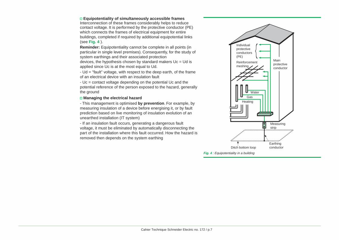
v Equipotentiality of simultaneously accessible framesInterconnection of these frames considerably helps to reducecontact voltage. It is performed by the protective conductor (PE)which connects the frames of electrical equipment for entirebuildings, completed if required by additional equipotential links(see Fig. 4 ).Reminder: Equipotentiality cannot be complete in all points (inparticular in single level premises). Consequently, for the study ofsystem earthings and their associated protectiondevices, the hypothesis chosen by standard makers Uc = Ud isapplied since Uc is at the most equal to Ud.- Ud = "fault" voltage, with respect to the deep earth, of the frameof an electrical device with an insulation fault- Uc = contact voltage depending on the potential Uc and thepotential reference of the person exposed to the hazard, generallythe ground
v Managing the electrical hazard- This management is optimised by prevention. For example, bymeasuring insulation of a device before energising it, or by faultprediction based on live monitoring of insulation evolution of anunearthed installation (IT system)- If an insulation fault occurs, generating a dangerous faultvoltage, it must be eliminated by automatically disconnecting thepart of the installation where this fault occurred. How the hazard isremoved then depends on the system earthing
Fig. 4 : Equipotentiality in a building
Heating
Mainprotectiveconductor
Individualprotectiveconductors(PE)
Reinforcementmeshing
Measuring strip
Gas
Earthing conductorDitch bottom loop
Water
Abdel
Abdel
Cahier Technique Schneider Electric no. 172 / p.8
2 System earthings and protection of persons
This section defines the Electric Shock and Electrocutionhazards for the various system earthings, such as specified by theInternational Electrotechnical Committee in standard IEC 60364.
A LV system earthing characterises the earthing mode of thesecondary of the MV/LV transformer and the means of earthingthe installation frames.
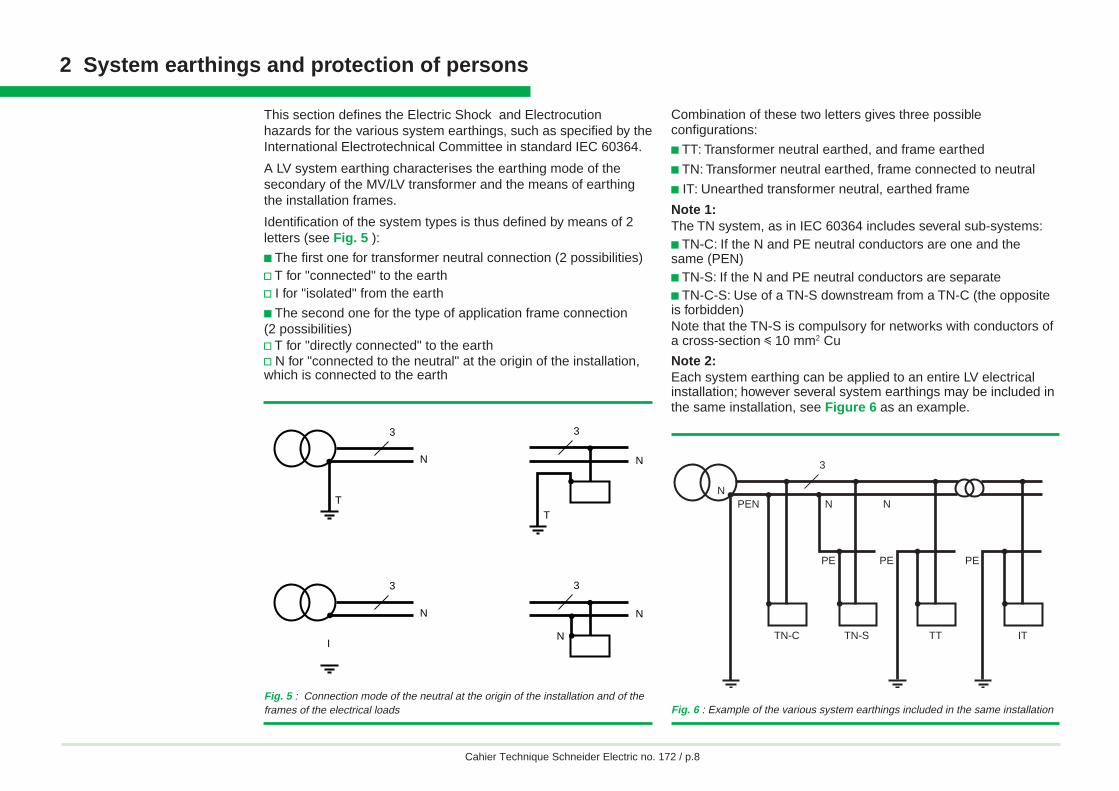
Identification of the system types is thus defined by means of 2letters (see Fig. 5 ):
c The first one for transformer neutral connection (2 possibilities)v T for "connected" to the earthv I for "isolated" from the earth
c The second one for the type of application frame connection(2 possibilities)v T for "directly connected" to the earthv N for "connected to the neutral" at the origin of the installation,which is connected to the earth
N
T
N
3
T
3
I
N
3
N
N
3
Fig. 5 : Connection mode of the neutral at the origin of the installation and of theframes of the electrical loads
PEN
TN-C TN-S TT
NN
PE PE
IT
PE
3
N
Fig. 6 : Example of the various system earthings included in the same installation
Combination of these two letters gives three possibleconfigurations:
c TT: Transformer neutral earthed, and frame earthed
c TN: Transformer neutral earthed, frame connected to neutral
c IT: Unearthed transformer neutral, earthed frame
Note 1:The TN system, as in IEC 60364 includes several sub-systems:c TN-C: If the N and PE neutral conductors are one and thesame (PEN)c TN-S: If the N and PE neutral conductors are separatec TN-C-S: Use of a TN-S downstream from a TN-C (the oppositeis forbidden)Note that the TN-S is compulsory for networks with conductors ofa cross-section i 10 mm2 Cu
Note 2:Each system earthing can be applied to an entire LV electricalinstallation; however several system earthings may be included inthe same installation, see Figure 6 as an example.
Abdel
Abdel
Cahier Technique Schneider Electric no. 172 / p.9
Note 3:In France, as in standard NF C 13-100 concerning deliverysubstations, in order to prevent hazards originating in MV, theLV system earthing is expressed by an additional letter accordingto interconnection of the various earth connections (see Fig. 7 ).
Let us now see how to protect persons in each case.
2.1 TN system When an insulating fault is present, the fault current Id is onlylimited by the impedance of the fault loop cables (see Fig. 8 ):
Id = Uo
Rph1 + +Rd RPE
For a feeder and as soon as Rd ≈ 0:
Id = 0.8 Uo
Rph1 +RPE
In point of fact, when a short-circuit occurs, it is accepted that theimpedances upstream from the relevant feeder cause a voltagedrop of around 20 % on phase-to-neutral voltage Uo, which is thenominal voltage between phase and earth.
Id thus induces a fault voltage with respect to earth:Ud = R dPE I
i.e.
Ud = 0.8 Uo R
RphPE
1 +RPE
For 230/400 V networks, this voltage of around Uo/2 (if RPE
= Rph)is dangerous since it exceeds the limit safety voltage, even in dryatmospheres (U
L = 50 V). The installation
or part of the installation must then be automatically and promptlyde-energised (see Fig. 9 ).
As the insulation fault resembles a phase-neutral short-circuit,breaking is achieved by the Short-Circuit Protection Device(SCPD) with a maximum specified breaking time dependingon U
L.
Implementation
To be sure that the protection device really is activated, thecurrent Id must be greater than the operating threshold of theprotection device Ia (Id > Ia) irrespective of where the fault
Fig. 7 : Linking of LV earth connections with that of the MV/LV substation
Additional Earthing of the Earthing of the Earthing of theletter MV/LV substation LV neutral LV applicationR (connected) c c cN (of neutral) c c vS (separated) v v v(c = Interconnected, v = Separate)
Fig. 8 : Fault current and voltage in TN system
Uo (volts) Breaking time Breaking timephase/neutral voltage (seconds) UL = 50 V (seconds) UL = 25 V
127 0.8 0.35230 0.4 0.2400 0.2 0.05> 400 0.1 0.02
Fig. 9 : Breaking time in TN system (taken from IEC 60364 tables 41 and 48A)
UdRd
N
A
BC
D
PE
Id
d = Uo
R Rd R0.8 Uo
Rph+RAB CD PE+ +⇒IUd
0.8 Uo2
if R = Rph and Rd = 0PE≈
Abdel
Abdel
Cahier Technique Schneider Electric no. 172 / p.10
occurs. This condition must be verified at the installation designstage by calculating the fault currents for all the distributioncircuits.
If the same path is taken by the protective conductor - PE- andthe live conductors, this will simplify the calculation. Certaincountry standards recommend this.
To guarantee this condition, another approach consists inimposing a maximum impedance value on the fault loopsaccording to the type and rating of the SCPDs chosen (see Britishstandard BS 7671). This approach may result in increasing thecross-section of the live and/or protective conductors.
Another means of checking that the device will ensure protectionof persons is to calculate the maximum length not to be exceededby each feeder for a given protection threshold Ia.
To calculate Id and Lmax, three simple methods can be used (see"Cahier Technique" no. 158):c The impedance methodc The composition methodc The conventional methodThe latter gives the following equation:
Id = 0.8 Uo
Z =
0.8 UoRph+R
= 0.8 Uo Sph
(1+m) PE ρ L
For the protection device to perform its function properly, Ia mustbe less than Id, hence the expression of Lmax, the maximumlength authorised by the protection device with a threshold Ia:
Lmax = 0.8 Uo Sph
(1+m) aρ I
c Lmax: Maximum length in m
c Uo: Phase-to-neutral voltage 230 V for a three-phase 400 Vnetwork
c ρ: Resistivity to normal operating temperature
c Ia: Automatic breaking currentv For a circuit-breaker Ia = Im (Im operating current of themagnetic or short time delay trip release)v For a fuse, current such that total breaking time of the fuse(prearcing time + arcing time) complies with the standard(see Fig. 9 )
c m = SphSPE
If the line is longer than Lmax, either conductor cross-sectionmust be increased or it must be protected using a ResidualCurrent Device (RCD).
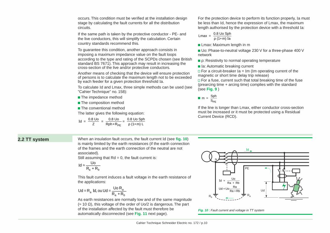
2.2 TT system When an insulation fault occurs, the fault current Id (see fig. 10)is mainly limited by the earth resistances (if the earth connectionof the frames and the earth connection of the neutral are notassociated).Still assuming that Rd = 0, the fault current is:
ba R+RUo
d ≈I
This fault current induces a fault voltage in the earth resistance ofthe applications:
ba
aa RR
RUoUdoudRUd
+== ,I
As earth resistances are normally low and of the same magnitude(≈ 10 Ω), this voltage of the order of Uo/2 is dangerous. The partof the installation affected by the fault must therefore beautomatically disconnected (see Fig. 11 next page).
Ud
N
PE
RbRa
Id
Fig. 10 : Fault current and voltage in TT system
Id Uo
Ra + Rb≈
=+
Ud UoRa
Ra Rb
Abdel
Abdel
Cahier Technique Schneider Electric no. 172 / p.11
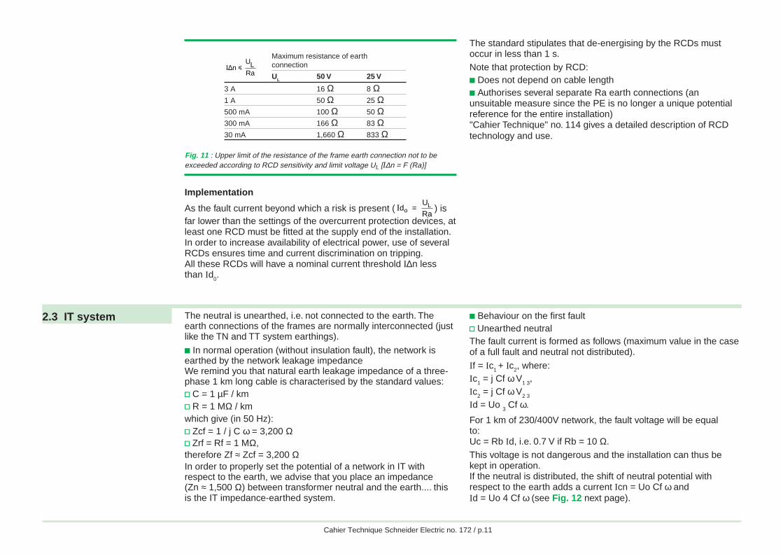
Fig. 11 : Upper limit of the resistance of the frame earth connection not to beexceeded according to RCD sensitivity and limit voltage UL [I∆n = F (Ra)]
Implementation
As the fault current beyond which a risk is present ( Id = U
RaoL ) is
far lower than the settings of the overcurrent protection devices, atleast one RCD must be fitted at the supply end of the installation.In order to increase availability of electrical power, use of severalRCDs ensures time and current discrimination on tripping.All these RCDs will have a nominal current threshold I∆n lessthan Id
0.
2.3 IT system The neutral is unearthed, i.e. not connected to the earth. Theearth connections of the frames are normally interconnected (justlike the TN and TT system earthings).
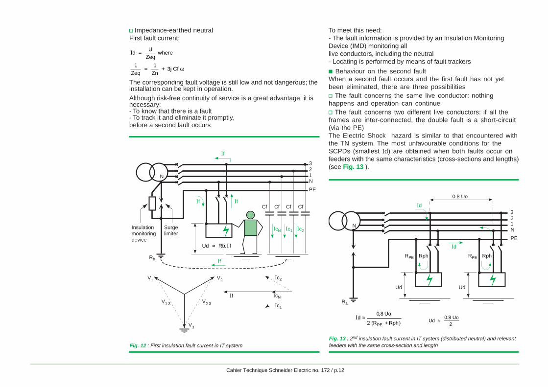
c In normal operation (without insulation fault), the network isearthed by the network leakage impedanceWe remind you that natural earth leakage impedance of a three-phase 1 km long cable is characterised by the standard values:v C = 1 µF / kmv R = 1 MΩ / kmwhich give (in 50 Hz):v Zcf = 1 / j C ω = 3,200 Ωv Zrf = Rf = 1 MΩ,therefore Zf ≈ Zcf = 3,200 ΩIn order to properly set the potential of a network in IT withrespect to the earth, we advise that you place an impedance(Zn ≈ 1,500 Ω) between transformer neutral and the earth.... thisis the IT impedance-earthed system.
c Behaviour on the first faultv Unearthed neutralThe fault current is formed as follows (maximum value in the caseof a full fault and neutral not distributed).
If = Ic1 + Ic
2, where:
Ic1 = j Cf ω V
1 3,
Ic2 = j Cf ω V
2 3
Id = Uo 3 Cf ω.
For 1 km of 230/400V network, the fault voltage will be equalto:Uc = Rb Id, i.e. 0.7 V if Rb = 10 Ω.This voltage is not dangerous and the installation can thus bekept in operation.If the neutral is distributed, the shift of neutral potential withrespect to the earth adds a current Icn = Uo Cf ω andId = Uo 4 Cf ω (see Fig. 12 next page).
The standard stipulates that de-energising by the RCDs mustoccur in less than 1 s.Note that protection by RCD:c Does not depend on cable lengthc Authorises several separate Ra earth connections (anunsuitable measure since the PE is no longer a unique potentialreference for the entire installation)"Cahier Technique" no. 114 gives a detailed description of RCDtechnology and use.
Maximum resistance of earthconnection
UL 50 V 25 V
3 A 16 Ω 8 Ω1 A 50 Ω 25 Ω500 mA 100 Ω 50 Ω300 mA 166 Ω 83 Ω30 mA 1,660 Ω 833 Ω
I∆n
ULRa
i
Abdel
Abdel
Cahier Technique Schneider Electric no. 172 / p.12
v Impedance-earthed neutralFirst fault current:
Id U
Zeq where
1Zeq
= 1
Zn + 3j Cf
=
ω
The corresponding fault voltage is still low and not dangerous; theinstallation can be kept in operation.Although risk-free continuity of service is a great advantage, it isnecessary:- To know that there is a fault- To track it and eliminate it promptly,before a second fault occurs
To meet this need:- The fault information is provided by an Insulation MonitoringDevice (IMD) monitoring alllive conductors, including the neutral- Locating is performed by means of fault trackers
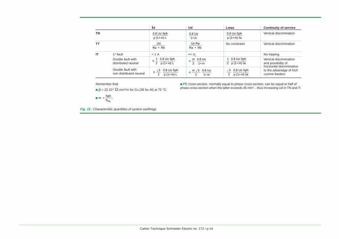
c Behaviour on the second faultWhen a second fault occurs and the first fault has not yetbeen eliminated, there are three possibilitiesv The fault concerns the same live conductor: nothinghappens and operation can continuev The fault concerns two different live conductors: if all theframes are inter-connected, the double fault is a short-circuit(via the PE)The Electric Shock hazard is similar to that encountered withthe TN system. The most unfavourable conditions for theSCPDs (smallest Id) are obtained when both faults occur onfeeders with the same characteristics (cross-sections and lengths)(see Fig. 13 ).
Fig. 12 : First insulation fault current in IT systemFig. 13 : 2nd insulation fault current in IT system (distributed neutral) and relevantfeeders with the same cross-section and length
N
Id
Ra
RPE RphRPE Rph
Id
Ud Ud
321N
PE
0.8 Uo
)(
,I
RphR2
Uo80d
PE +≈
Ud 0.8 Uo
2 ≈
N
If
If If
Rb
If
321N
PE
Cf
IcN Ic1 Ic2
Cf Cf Cf
Insulationmonitoringdevice
Surgelimiter
V1 V2
V2 3V1 3
V3
IcNIf
Ic2
Ic1
Ud Rb f . I≈
Abdel
Abdel

Cahier Technique Schneider Electric no. 172 / p.13
The SCPDs have to comply with the following relationships:- If the neutral is distributed andone of the two faulty conductors is the neutral
Ia
0.8 Uo2 Z
i
- Or if the neutral is not distributed
Ia
0.8 Uo 3i2Z
Note that if one of the two faults is on the neutral, the faultcurrent and fault voltage are twice as low as in the TNsystem. This has resulted in standard makers authorisinglonger SCPD operating times (see Fig. 14 ).
Just as in the TN system earthing, protection by SCPD onlyapplies to maximum cable lengths:- Distributed neutral
Lmax = 0.8 Uo Sph
(1+m) a12 ρ I
- Non-distributed neutral
Lmax = 0.8 Uo Sph
(1+m) a3
2 ρ I
This is provided that the neutral is protected and its cross-section equal to phase cross-section... This is the mainreason why certain country standards advise againstdistributing the neutral.v Case where all frames are not interconnected. For framesearthed individually or in groups, each circuit or group ofcircuits must be protected by a RCD.
Should an insulation fault occur in groups connected to twodifferent earthing arrangements, the protective device's reactionto the insulation fault (Id, Ud) is similar to that of a TT system (thefault current flows through the earth).
Protection of persons against indirect contacts is thus ensured inthe same manner
I∆n
U
RaLi (see table in Figure 11).
Note that in view of the times specified by the standard,horizontal time discrimination can be achieved to give priorityto continuity of service on certain feeders.
Note: In order to protect LV unearthed networks (IT) againstvoltage rises (arcing in the MV/LVtransformer, accidental contact with a network of highervoltage, lightning on the MV network),French standard NF C 15-100 stipulates that a surge limitermust be installed between the neutral point of the MV/LVtransformer and the earth (R
b).
Readers wishing to study the IT system earthings in greater detailshould read "Cahier Technique" no. 178.
So as to obtain a concise overview of the quantitiescharacterising the various system earthings, as regards protectionof persons, the main formulas are listed in the table in Figure 15next page.
Fig. 14 : Maximum breaking times specified in IT system (as in IEC 60364 tables 41B and 48A)
Uo/U (volts) Breaking time (seconds)Uo: Phase/neutral voltage UL = 50 V UL = 25 VU: Phase to phase voltage Neutral Neutral Neutral Neutral
not distributed distributed not distributed distributed
127/220 0.8 5 0.4 1.00
230/400 0.4 0.8 0.2 0.5
400/690 0.2 0.4 0.06 0.2
580/1000 0.1 0.2 0.02 0.08
Abdel
Abdel
Cahier Technique Schneider Electric no. 172 / p.14
Fig. 15 : Characteristic quantities of system earthings
32
0.8 Uo Sph
(1+m) Li
ρ i
m 32
0.8 Uo1+m
32
0.8 Uo Sph
(1+m) aρ I
i
12
0.8 Uo Sph
(1+m) Lρ i
m2
0.8 Uo1+m
12
0.8 Uo Sph
(1+m) aρ I
Id Ud Lmax Continuity of service
TN Vertical discrimination
TT No constraint Vertical discrimination
IT 1st fault < 1 A << UL No tripping
Double fault with Vertical discriminationdistributed neutral and possibility of
Double fault withnon distributed neutral
UoRa + Rb
Uo RaRa + Rb
0.8 Uo Sph (1+m) Lρ
0.8 Uo1+m
0.8 Uo Sph (1+m) aρ I
horizontal discriminationto the advantage of hichcurrent feeders
Remember that:
c ρ = 22 10-3 Ω.mm2/m for Cu (36 for Al) at 75 °C;
c m =SphSPE
;
c PE cross-section, normally equal to phase cross-section, can be equal to half ofphase cross-section when the latter exceeds 35 mm2... thus increasing Ud in TN and IT.
Abdel
Abdel
Cahier Technique Schneider Electric no. 172 / p.15
MDT MUT MDT MUT MDT
Restorationof voltage
De-energisingon fault
De-energisingon fault
Restorationof voltage
De-energisingon fault
Restorationof voltage
Time
Failure status Operating status
3 System earthings confronted with fire and electrical power unavailability hazards
3.1 Fire It has been proved, then accepted by standard makers, thatcontact between a conductor and a metal part can cause fire tobreak out, in particularly vulnerable premises, when the faultcurrent exceeds 300 mA.
To give an example:c Premises particularly at risk: Petrochemical factories, farms;c Premises averagely at risks, but where consequences may bevery serious: Very high buildings receiving the general public...In the unearthed neutral system, the risk of "fire":c Is very small on the first faultc Is as important as in TN on the second fault
For the TT and TN system earthings, the fault current isdangerous given the power developed (P = Rd I2):c In TT = 5A < Id < 50 Ac In TN = 1 kA < Id < 100 kA
The power present where the fault has occurred is considerable,particularly in the TN system, and prompt action is vital as fromthe lowest current levels in order to limit the dissipated energy (∫Rd i2 dt).
This protection, specified by the IEC and a requirement of Frenchstandards (NF C 15-100, paragraph 482-2-10) is provided by aninstantaneous RCD with threshold i 300 mA, regardless of thesystem earthing.
When risk of fire is especially high (manufacture/storage ofinflammable materials....) it is necessary and indeed compulsoryto use a system earthing with earthed frames which naturallyminimises this hazard (TT or IT).
Note that the TN-C is banned in certain countries when a risk offire and/or explosion is present: As the PE and neutral conductorsare one and the same, RCDs cannot be used.
3.2 Electrical powerunavailability
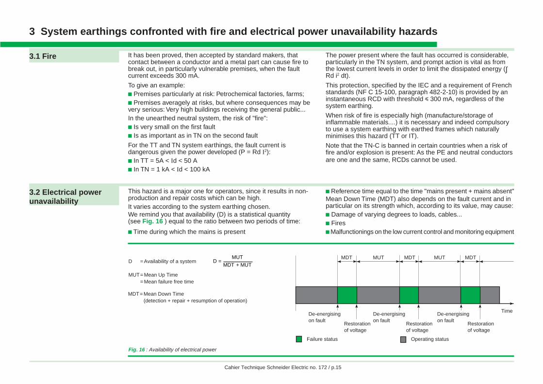
This hazard is a major one for operators, since it results in non-production and repair costs which can be high.It varies according to the system earthing chosen.We remind you that availability (D) is a statistical quantity(see Fig. 16 ) equal to the ratio between two periods of time:
c Time during which the mains is present
c Reference time equal to the time "mains present + mains absent"Mean Down Time (MDT) also depends on the fault current and inparticular on its strength which, according to its value, may cause:c Damage of varying degrees to loads, cables...c Firesc Malfunctionings on the low current control and monitoring equipment
Fig. 16 : Availability of electrical power
D = Availability of a system
MUT= Mean Up Time= Mean failure free time
MDT= Mean Down Time(detection + repair + resumption of operation)
MUTMDT
MUTD
+=
Abdel
Abdel
Cahier Technique Schneider Electric no. 172 / p.16
Each system earthing must therefore be examined as regardsavailability of electrical power, with special emphasis on the ITsystem earthing since it is the only one that authorises non-tripping in the presence of a fault.
c The IT system earthingIn order to retain the advantage of this system, i.e. not interruptingelectrical distribution on the first fault, the second fault must beprevented, since this then presents the same high risks as the TNsystem. The first fault must therefore be eliminated before asecond fault occurs. The use of efficient detection and locatingmethods and the presence of a reactive maintenance teamconsiderably reduces the likelihood of the "double fault".Moreover, monitoring devices are currently available whichmonitor in time the evolution in insulation of the various feeders,perform fault prediction and thus anticipate maintenance of thefirst fault.This ensures maximum availability with the IT system earthing.
c The TN and TT system earthingsThese systems use discrimination on tripping.In TN, this is acquired with short-circuit protection devices if theinstallation protection plan has been properly designed(disrimination by current and duration selectivity).In TT, it is easy to implement thanks to the RCDs which ensurecurrent and time discrimination.Remember that, in TN system, repair time according to ∫ i2 dt, maybe longer than in TT system, wich also affects availability.c For all the system earthingsIt is always useful to anticipate insulation faults and in particularthose of certain motors before startup.Bear in mind that 20% of motor failures are due to an insulationfault which occurs on energising. In point of fact, an insulationloss, even small, on a hot motor cooling down in a dampatmosphere (condensation) degenerates into a full fault onrestarting, causing both considerable damage to windings andproduction loss and even major risks if the motor has a safetyfunction (drainage, fire, fan pump motor, etc.).This type of incident can be prevented, whatever the systemearthing, by an Insulation Monitoring Device monitoring the loadwith power off. If a fault occurs, startup is then prevented.To roundoff this section on "the hazard presented by electrical power
unavailability" it is clear that, regarding proper electrical poweravailability, the system earthings can be listed in the followingorder of preference: IT, TT, TN.
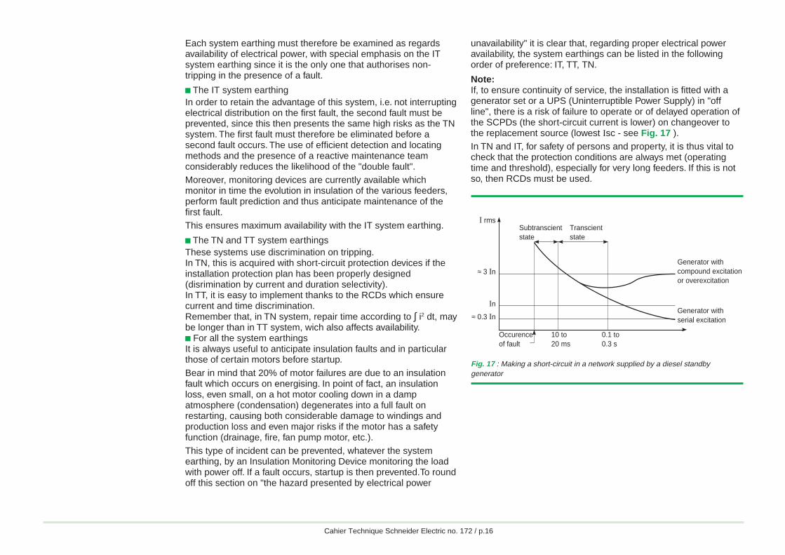
Note:If, to ensure continuity of service, the installation is fitted with agenerator set or a UPS (Uninterruptible Power Supply) in "offline", there is a risk of failure to operate or of delayed operation ofthe SCPDs (the short-circuit current is lower) on changeover tothe replacement source (lowest Isc - see Fig. 17 ).In TN and IT, for safety of persons and property, it is thus vital tocheck that the protection conditions are always met (operatingtime and threshold), especially for very long feeders. If this is notso, then RCDs must be used.
Fig. 17 : Making a short-circuit in a network supplied by a diesel standbygenerator
Occurenceof fault
10 to20 ms
0.1 to0.3 s
Generator with compound excitation or overexcitation
Subtranscientstate
Transcientstate
Generator with serial excitation≈ 0.3 In
In
≈ 3 In
I rms
Abdel
Abdel
Cahier Technique Schneider Electric no. 172 / p.17
4 Influences of MV on LV, according to the system earthings
LV networks, unless a replacement uninterruptible power supply(with galvanic insulation) or a LV/LV transformer is used, areinfluenced by MV.
This influence takes the form of:c Capacitive coupling: Transmission of overvoltage from MVwindings to LV windingsc Galvanic coupling, should disruptive breakdown occur betweenthe MV and LV windingsc Common impedance, if the various earth connections areconnected and a MV current flows off to earth
This results in LV disturbances, often overvoltages, whosegenerating phenomena are MV incidents:c Lightningc Operating overvoltagesc MV-frame disruptive breakdown inside the transformerc MV-LV disruptive breakdown inside the transformer
Their most common consequence is destruction of LV insulatorswith the resulting risks of Electric Shock of persons anddestruction of equipment.
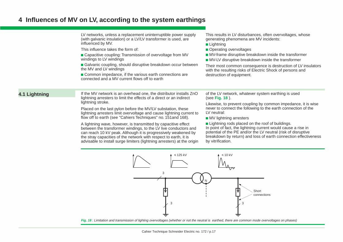
4.1 Lightning If the MV network is an overhead one, the distributor installs ZnOlightning arresters to limit the effects of a direct or an indirectlightning stroke.
Placed on the last pylon before the MV/LV substation, theselightning arresters limit overvoltage and cause lightning current toflow off to earth (see "Cahiers Techniques" no. 151and 168).
A lightning wave, however, is transmitted by capacitive effectbetween the transformer windings, to the LV live conductors andcan reach 10 kV peak. Although it is progressively weakened bythe stray capacities of the network with respect to earth, it isadvisable to install surge limiters (lightning arresters) at the origin
of the LV network, whatever system earthing is used(see Fig. 18 ).
Likewise, to prevent coupling by common impedance, it is wisenever to connect the following to the earth connection of theLV neutral:c MV lightning arrestersc Lightning rods placed on the roof of buildings.In point of fact, the lightning current would cause a rise inpotential of the PE and/or the LV neutral (risk of disruptivebreakdown by return) and loss of earth connection effectivenessby vitrification.
Fig. 18 : Limitation and transmission of lighting overvoltages (whether or not the neutral is earthed, there are common mode overvoltages on phases)
3
3 3
N
y 125 kV y 10 kV
Shortconnections
Abdel
Abdel
Cahier Technique Schneider Electric no. 172 / p.18
4.2 Operatingovervoltages
Some MV switchgear (e.g. vacuum circuit-breakers) causeconsiderable overvoltages when operated (see "CahierTechnique" no. 143).
Unlike lightning which is a common mode disturbance (betweennetwork and earth), these overvoltages are, in LV, differential
mode disturbances (between live conductors) and are transmittedto the LV network by capacitive and magnetic coupling.Just like all differential mode phenomena, operating overvoltagesdo not interfere, or only very slightly, with any of the systemearthings.
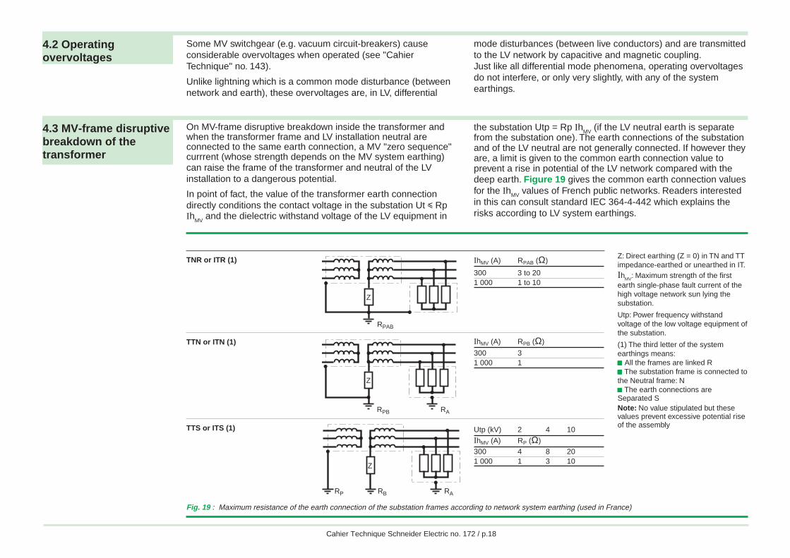
4.3 MV-frame disruptivebreakdown of thetransformer
On MV-frame disruptive breakdown inside the transformer andwhen the transformer frame and LV installation neutral areconnected to the same earth connection, a MV "zero sequence"currrent (whose strength depends on the MV system earthing)can raise the frame of the transformer and neutral of the LVinstallation to a dangerous potential.
In point of fact, the value of the transformer earth connectiondirectly conditions the contact voltage in the substation Ut i RpIh
MV and the dielectric withstand voltage of the LV equipment in
the substation Utp = Rp IhMV
(if the LV neutral earth is separatefrom the substation one). The earth connections of the substationand of the LV neutral are not generally connected. If however theyare, a limit is given to the common earth connection value toprevent a rise in potential of the LV network compared with thedeep earth. Figure 19 gives the common earth connection valuesfor the Ih
MV values of French public networks. Readers interested
in this can consult standard IEC 364-4-442 which explains therisks according to LV system earthings.
Fig. 19 : Maximum resistance of the earth connection of the substation frames according to network system earthing (used in France)
TNR or ITR (1)
TTN or ITN (1)
TTS or ITS (1)
IhMV (A) RPAB (Ω)
300 3 to 201 000 1 to 10
IhMV (A) RPB (Ω)
300 31 000 1
Utp (kV) 2 4 10
IhMV (A) RP (Ω)
300 4 8 201 000 1 3 10
Z: Direct earthing (Z = 0) in TN and TTimpedance-earthed or unearthed in IT.IhMV: Maximum strength of the firstearth single-phase fault current of thehigh voltage network sun lying thesubstation.
Utp: Power frequency withstandvoltage of the low voltage equipment ofthe substation.
(1) The third letter of the systemearthings means:ccccc All the frames are linked Rccccc The substation frame is connected tothe Neutral frame: Nccccc The earth connections areSeparated SNote: No value stipulated but thesevalues prevent excessive potential riseof the assembly
RPAB
Z
RPB RA
Z
RBRP RA
Z
Abdel
Abdel
Cahier Technique Schneider Electric no. 172 / p.19
Still for public networks (except for Australia and the USA wherethe fault current can be very high), values encountered rangefrom 10 A in Ireland (an impedance compensates the capacitivecurrent) to 1,000 A in France (underground networks) and inGreat Britain.MV industrial networks are normally run in impedance-earthed ITand have a zero sequence current Ih
MV of a few dozens of amps
(see "Cahier Technique" no. 62).
The maximum value authorised for the earth connectionresistance depends on the equipotentiality conditions of theframes of the LV network, i.e. on its system earthing.
4.4 MV-LV disruptivebreakdown insidethe transformer
To prevent potential with respect to the earth of the LV networkfrom rising to the phase-to-neutral voltage of the MV network onMV-LV disruptive breakdown inside the transformer, the LVnetwork must be earthed.
The consequences of this fault are:
c In TNThe entire LV network, including the PE, is subjected to voltageIhMV RPAB or IhMV RAB.If this overvoltage exceeds the dielectric withstand of the LVnetwork (in practice of the order of 1,500 V), LV disruptivebreakdowns are possible if the equipotentiality of all the frames,electrical or not, of the building is not complete;
c In TTWhereas the load frames are at the potential of the deep earth,the entire LV network is subjected to IhMV RPB or IhMV RB: There is arisk of disruptive breakdown "by return" of loadsif the voltage developed in RPB or RB exceeds their dielectricwithstand;
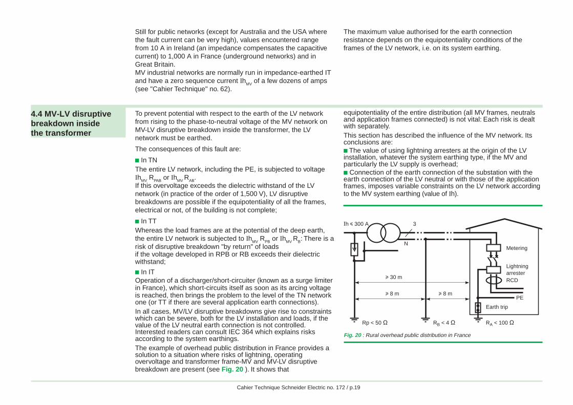
c In ITOperation of a discharger/short-circuiter (known as a surge limiterin France), which short-circuits itself as soon as its arcing voltageis reached, then brings the problem to the level of the TN networkone (or TT if there are several application earth connections).In all cases, MV/LV disruptive breakdowns give rise to constraintswhich can be severe, both for the LV installation and loads, if thevalue of the LV neutral earth connection is not controlled.Interested readers can consult IEC 364 which explains risksaccording to the system earthings.The example of overhead public distribution in France provides asolution to a situation where risks of lightning, operatingovervoltage and transformer frame-MV and MV-LV disruptivebreakdown are present (see Fig. 20 ). It shows that
equipotentiality of the entire distribution (all MV frames, neutralsand application frames connected) is not vital: Each risk is dealtwith separately.This section has described the influence of the MV network. Itsconclusions are:c The value of using lightning arresters at the origin of the LVinstallation, whatever the system earthing type, if the MV andparticularly the LV supply is overhead;c Connection of the earth connection of the substation with theearth connection of the LV neutral or with those of the applicationframes, imposes variable constraints on the LV network accordingto the MV system earthing (value of Ih).
Fig. 20 : Rural overhead public distribution in France
3Ih i 300 A
Metering
Earth trip
RA < 100 ΩRB < 4 ΩRp < 50 Ω
LightningarresterRCD
PE
u 30 m
u 8 m u 8 m
N
Abdel
Abdel
Cahier Technique Schneider Electric no. 172 / p.20
5 Switchgear linked to the choice of system earthing
Choice of system earthing affects not only dependability (in thelargest sense) but also installation, in particular with respect to theswitchgear to be implemented.
5.1 TN system In this system the SCPDs (circuit-breaker or fuses) generallyprovide protection against insulation faults, with automatic trippingaccording to a specified maximum breaking time (depending onphase-to-neutral voltage Uo: See Fig. 9).c With circuit-breakerCircuit-breaker tripping occurs at a level determined by the type ofthe tripping release (see Fig. 21 ). As soon as the fault currentexceeds the threshold of the short-circuit protection trip release(generally "instantaneous"), opening occurs in a time far shorterthan specified maximum breaking time, for example 5 s fordistribution circuits and 0.4 s for terminal circuits.When impedance of the source and cables is high, either lowthreshold trip releases must be used or RCDs associated with theSCPDs. These RCDs may be separate residual current devices orbe combined with circuit-breakers (residual current circuit-breakers) of low sensitivity. Their threshold must be:
I∆n < 0.8 Uo
Rph RPE+
Use of a RCD has the advantage of making loop impedancechecking unnecessary, a fact which is of particular value when theinstallation is modified or extended.This solution is clearly not applicable with aTN-C type system earthing (the protective conductor being thesame as the neutral one).c With fusesThe fuses used for short-circuit protection are of the gG type andtheir time/current characteristics (see Fig. 22 ) are defined bystandards (household fuses: IEC 60241, industrial fuses:IEC 60269). Checking suitability with the maximum specifiedbreaking time therefore calls for individual validation of the ratingsprovided for each protection device. If they are not suitable, eitherfault loop impedance must be reduced (increased cross-sections)or the fuse must be replaced by a low threshold or a residualcurrent circuit-breaker.
In gG (A) Imin. 10 s Imax. 5 s Imin. 0.1 s Imax. 0.1 s
63 160 320 450 82080 215 425 610 110100 290 580 820 1450
Fig. 22 : Example of fuse operating threshold limits (as in IEC 60269 paragraph 5-6-3)
Fig. 21 : Tripping current (magnetic or short time delay) of LV circuit-breakers
Trip release type Operatingthreshold
Household B 3 In i Ia i 5 In(EN 60898) C 5 In i Ia i 10 In
D 10 In i Ia i 20 InIndustrial G (low threshold) 2 In i Ia i 5 In(IEC 60947-2) D 5 In i Ia i 10 In
MA (for motor starter) 6.3 In i Ia i 12.5 In
Abdel
Abdel
Cahier Technique Schneider Electric no. 172 / p.21
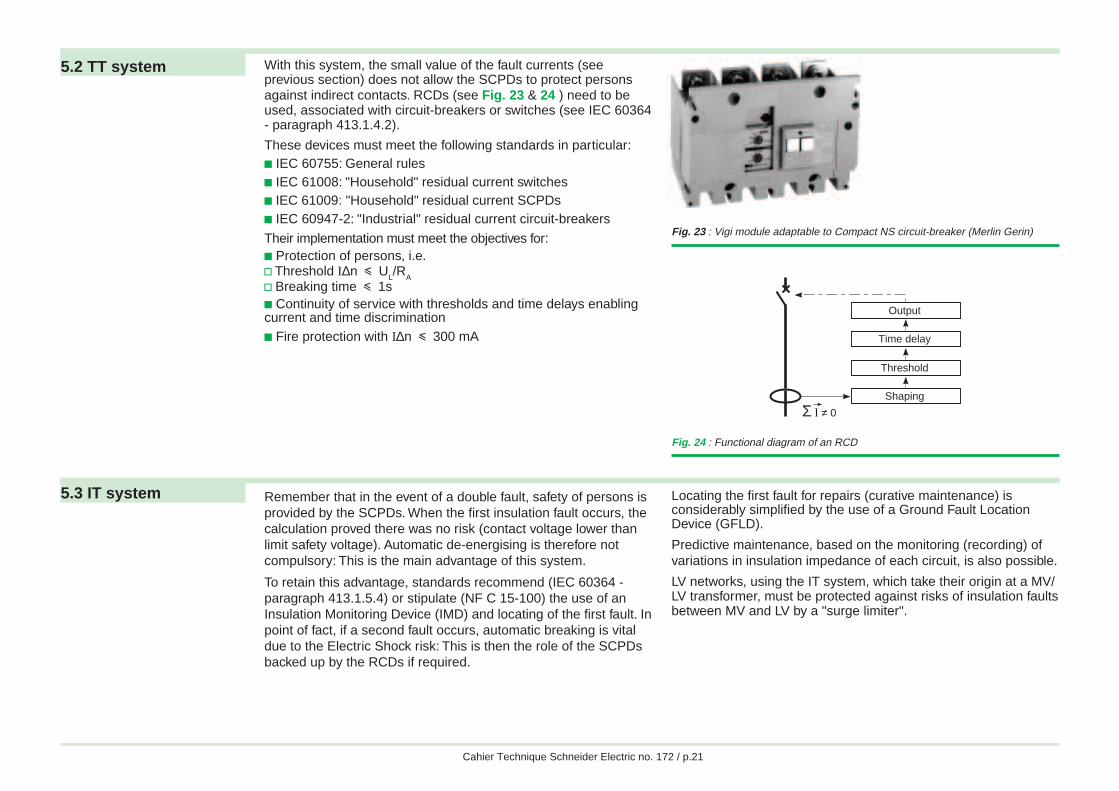
5.2 TT system With this system, the small value of the fault currents (seeprevious section) does not allow the SCPDs to protect personsagainst indirect contacts. RCDs (see Fig. 23 & 24 ) need to beused, associated with circuit-breakers or switches (see IEC 60364- paragraph 413.1.4.2).
These devices must meet the following standards in particular:c IEC 60755: General rulesc IEC 61008: "Household" residual current switchesc IEC 61009: "Household" residual current SCPDsc IEC 60947-2: "Industrial" residual current circuit-breakers
Their implementation must meet the objectives for:c Protection of persons, i.e.v Threshold I∆n i U
L/R
Av Breaking time i 1sc Continuity of service with thresholds and time delays enablingcurrent and time discriminationc Fire protection with I∆n i 300 mA
Fig. 23 : Vigi module adaptable to Compact NS circuit-breaker (Merlin Gerin)
Fig. 24 : Functional diagram of an RCD
Shaping
Threshold
Time delay
Output
Σ I ≠ 0
5.3 IT system Remember that in the event of a double fault, safety of persons isprovided by the SCPDs. When the first insulation fault occurs, thecalculation proved there was no risk (contact voltage lower thanlimit safety voltage). Automatic de-energising is therefore notcompulsory: This is the main advantage of this system.
To retain this advantage, standards recommend (IEC 60364 -paragraph 413.1.5.4) or stipulate (NF C 15-100) the use of anInsulation Monitoring Device (IMD) and locating of the first fault. Inpoint of fact, if a second fault occurs, automatic breaking is vitaldue to the Electric Shock risk: This is then the role of the SCPDsbacked up by the RCDs if required.
Locating the first fault for repairs (curative maintenance) isconsiderably simplified by the use of a Ground Fault LocationDevice (GFLD).
Predictive maintenance, based on the monitoring (recording) ofvariations in insulation impedance of each circuit, is also possible.
LV networks, using the IT system, which take their origin at a MV/LV transformer, must be protected against risks of insulation faultsbetween MV and LV by a "surge limiter".
Abdel
Abdel
Cahier Technique Schneider Electric no. 172 / p.22
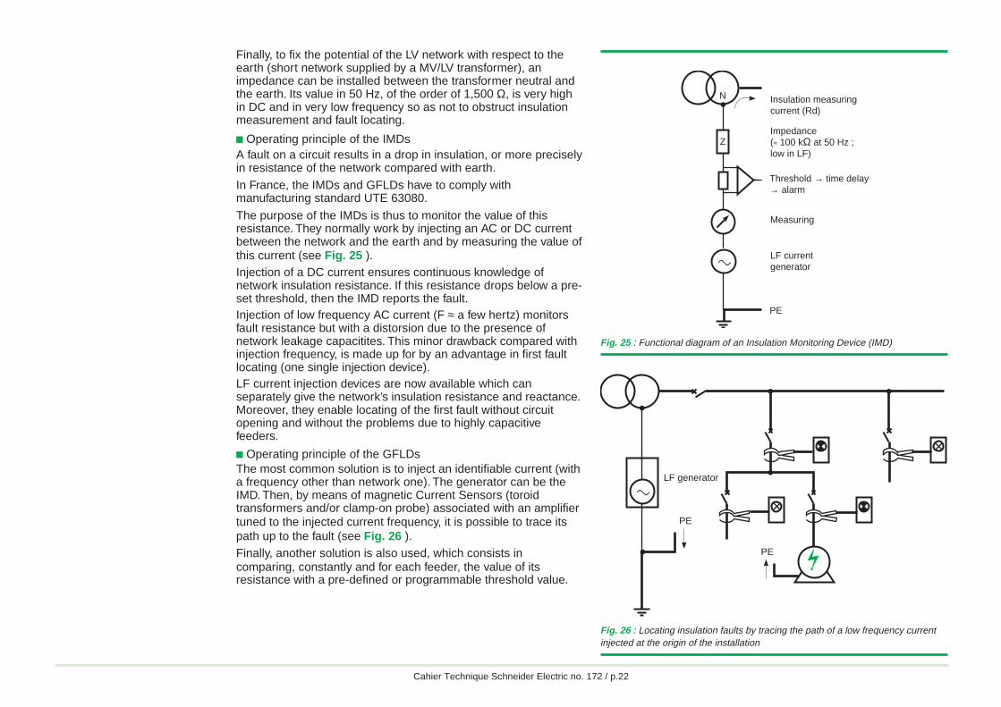
Finally, to fix the potential of the LV network with respect to theearth (short network supplied by a MV/LV transformer), animpedance can be installed between the transformer neutral andthe earth. Its value in 50 Hz, of the order of 1,500 Ω, is very highin DC and in very low frequency so as not to obstruct insulationmeasurement and fault locating.
c Operating principle of the IMDsA fault on a circuit results in a drop in insulation, or more preciselyin resistance of the network compared with earth.
In France, the IMDs and GFLDs have to comply withmanufacturing standard UTE 63080.
The purpose of the IMDs is thus to monitor the value of thisresistance. They normally work by injecting an AC or DC currentbetween the network and the earth and by measuring the value ofthis current (see Fig. 25 ).Injection of a DC current ensures continuous knowledge ofnetwork insulation resistance. If this resistance drops below a pre-set threshold, then the IMD reports the fault.Injection of low frequency AC current (F ≈ a few hertz) monitorsfault resistance but with a distorsion due to the presence ofnetwork leakage capacitites. This minor drawback compared withinjection frequency, is made up for by an advantage in first faultlocating (one single injection device).LF current injection devices are now available which canseparately give the network’s insulation resistance and reactance.Moreover, they enable locating of the first fault without circuitopening and without the problems due to highly capacitivefeeders.
c Operating principle of the GFLDsThe most common solution is to inject an identifiable current (witha frequency other than network one). The generator can be theIMD. Then, by means of magnetic Current Sensors (toroidtransformers and/or clamp-on probe) associated with an amplifiertuned to the injected current frequency, it is possible to trace itspath up to the fault (see Fig. 26 ).Finally, another solution is also used, which consists incomparing, constantly and for each feeder, the value of itsresistance with a pre-defined or programmable threshold value.
Fig. 26 : Locating insulation faults by tracing the path of a low frequency currentinjected at the origin of the installation
Fig. 25 : Functional diagram of an Insulation Monitoring Device (IMD)
N
ZImpedance(≈ 100 kΩ at 50 Hz ; low in LF)
Insulation measuringcurrent (Rd)
Threshold → time delay→ alarm
PE
Measuring
LF current generatora
PE
PE
a
LF generator
Abdel
Abdel
Cahier Technique Schneider Electric no. 172 / p.23
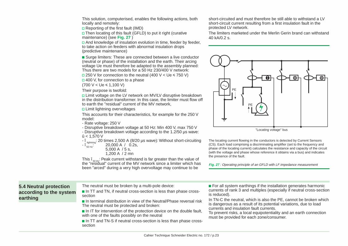
The locating current flowing in the conductors is detected by Current Sensors(CS). Each load comprising a discriminating amplifier (set to the frequency andphase of the locating current) calculates the resistance and capacity of the circuit(with the voltage and phase whose reference it obtains via a bus) and indicatesthe presence of the fault.
Fig. 27 : Operating principle of an GFLD with LF impedance measurement
This solution, computerised, enables the following actions, bothlocally and remotely:v Reporting of the first fault (IMD)v Then locating of this fault (GFLD) to put it right (curativemaintenance) (see Fig. 27 )v And knowledge of insulation evolution in time, feeder by feeder,to take action on feeders with abnormal insulation drops(predictive maintenance)
c Surge limiters: These are connected between a live conductor(neutral or phase) of the installation and the earth. Their arcingvoltage Ue must therefore be adapted to the assembly planned:Thus there are two models for a 50 Hz 230/400 V network:v 250 V for connection to the neutral (400 V < Ue i 750 V)v 400 V, for connection to a phase(700 V < Ue i 1,100 V)Their purpose is twofold:v Limit voltage on the LV network on MV/LV disruptive breakdownin the distribution transformer. In this case, the limiter must flow offto earth the "residual" current of the MV network,v Limit lightning overvoltagesThis accounts for their characteristics, for example for the 250 Vmodel:- Rate voltage: 250 V- Disruptive breakdown voltage at 50 Hz: Min 400 V, max 750 V- Disruptive breakdown voltage according to the 1.2/50 µs wave:û < 1,570 V- î
lightning: 20 times 2,500 A (8/20 µs wave): Without short-circuiting
- î 50 Hz
: 20,000 A / 0.2s,5,000 A / 5 s,1,200 A / 2 mn
This î 50 Hz
: Peak current withstand is far greater than the value ofthe "residual" current of the MV network since a limiter which hasbeen "arced" during a very high overvoltage may continue to be
short-circuited and must therefore be still able to withstand a LVshort-circuit current resulting from a first insulation fault in theprotected LV network.The limiters marketed under the Merlin Gerin brand can withstand40 kA/0.2 s.
5.4 Neutral protectionaccording to the systemearthing
The neutral must be broken by a multi-pole device:c In TT and TN, if neutral cross-section is less than phase cross-sectionc In terminal distribution in view of the Neutral/Phase reversal riskThe neutral must be protected and broken:c In IT for intervention of the protection device on the double fault,with one of the faults possibly on the neutralc In TT and TN-S if neutral cross-section is less than phase cross-section
c For all system earthings if the installation generates harmoniccurrents of rank 3 and multiples (especially if neutral cross-sectionis reduced).In TN-C the neutral, which is also the PE, cannot be broken whichis dangerous as a result of its potential variations, due to loadcurrents and insulation fault currents.To prevent risks, a local equipotentiality and an earth connectionmust be provided for each zone/consumer.
PE
PEa
"Locating voltage" bus
Abdel
Abdel
Cahier Technique Schneider Electric no. 172 / p.24
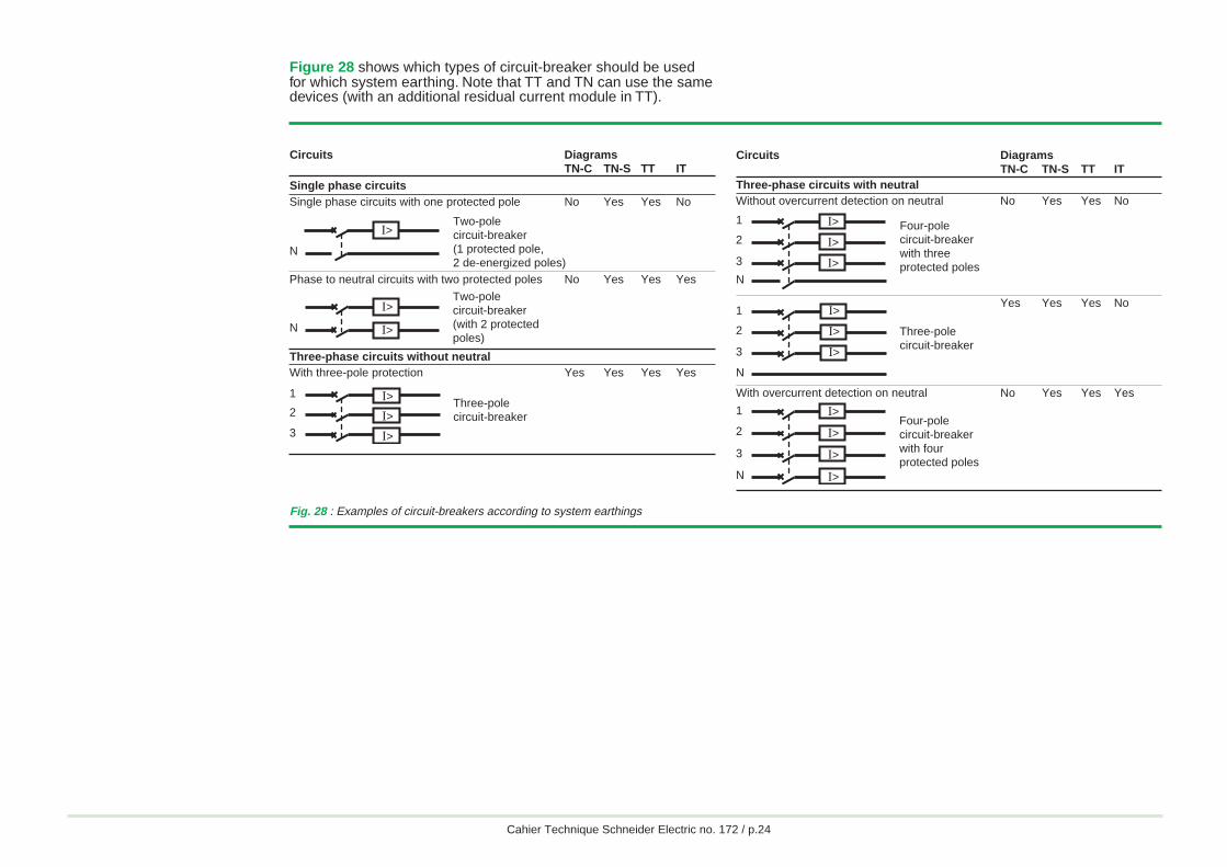
Circuits DiagramsTN-C TN-S TT IT
Three-phase circuits with neutralWithout overcurrent detection on neutral No Yes Yes No
Yes Yes Yes No
With overcurrent detection on neutral No Yes Yes Yes
2
3
N
1 I>
I>
I>
Four-polecircuit-breakerwith threeprotected poles
Fig. 28 : Examples of circuit-breakers according to system earthings
Circuits DiagramsTN-C TN-S TT IT
Single phase circuitsSingle phase circuits with one protected pole No Yes Yes No
Phase to neutral circuits with two protected poles No Yes Yes Yes
Three-phase circuits without neutralWith three-pole protection Yes Yes Yes Yes
I>
N
Two-polecircuit-breaker(1 protected pole,2 de-energized poles)
N
I>
I>
Two-polecircuit-breaker(with 2 protected poles)
Three-polecircuit-breaker2
3
1 I>
I>
I>
Three-polecircuit-breaker
2
3
N
1 I>
I>
I>
2
3
N
1 I>
I>
I>
I>
Four-polecircuit-breakerwith fourprotected poles
Figure 28 shows which types of circuit-breaker should be usedfor which system earthing. Note that TT and TN can use the samedevices (with an additional residual current module in TT).
Abdel
Abdel
Cahier Technique Schneider Electric no. 172 / p.25
6 Choice of system earthing and conclusion
The three system earthings internationally used and standardisedby IEC 60364 have as their common objective the quest foroptimum safety.
As regards protection of persons, the 3 systems are equivalent ifall installation and operating rules are complied with. In view ofthe characteristics specific to each system, no one system can bepreferred over another.
Rather, choice of system earthing must result from a concertationbetween the network user and designer (engineering firm,contractor, etc.) on:
c Installation characteristics
c Operating conditions and requirements
6.1 Methods forchoosing the systemearthing
c Firstly do not forget that the three system earthings can allbe included in the same electrical installation: This guaranteesthe best possible answer to safety and availability needs
c Then check that the choice is not specified or stipulated bystandards or legislation (decrees, ministerial decisions)
c Then dialogue with the user to get to know his requirementsand resourcesv Need for continuity of servicev Whether or not there is a maintenance servicev Fire hazard
Generally:v Continuity of service andmaintenance service: the IT will be chosenv Continuity of service and no maintenance service: No fullysatisfactory solution: Prefer the TT whose discrimination ontripping is easier to implement and which minimises damage withrespect to the TN. The installation of additionnal output is easilyachieved without the necessity of further calculations.v Continuity of service not essential and compent maintenanceservice: prefer the TN-S (rapid repairs and extensions performedaccording to rules)v Continuity of service not essentialand no maintenance service: Prefer the TTv Fire hazard: IT if maintenance service and use of 0.5 A RCD orTT
c Finally allow for the special features of network and loadsv Very long network or, even more important, leakage current:Prefer the TN-Sv Use of replacement or standby power supplies: Prefer the TTv Loads sensitive to high fault currents (motors): Prefer the TT orITv Loads with low natural insulation (furnaces) or with large HFfilter (large computers): Prefer the TN-Sv Supply of control and monitoring systems: Perfer the IT(continuity of service) or the TT (enhanced equipotentiality ofcommunicating devices)
Abdel
Abdel
Cahier Technique Schneider Electric no. 172 / p.26
6.2 Conclusion As there is no ideal choice with a single system earthing, it is thusadvisable, in many cases, to implement several system earthingsin the same installation.As a rule, a radial network installation, with a clear distinctionbetween priority and non-priority circuits and using standbysources or uninterruptible power supplies, is preferable to anarborescent monolithic installation.
The purpose of this "Cahier Technique" was to perfect yourknowledge of system earthings;we hope it will enable you to optimise the dependability of yourinstallations.
"Cahier Technique" no. 173 which provides an insight into use ofsystem earthings worldwide and their evolution will usefullycomplete this first document.Please note that the Electrical Installation Guide has beenupdated in 2005 (Ed. CITEF S.A.S.). It may be helpful for thepractical implementation of system earthings.The French version exists and is in compliance with NF C 15-100standard.
Abdel
Abdel
Cahier Technique Schneider Electric no. 172 / p.27
Bibliography
Standards
c IEC 60241: Fuses for domestic and similar purposes.
c IEC 60269: Low voltage fuses.
c IEC 60364: Electrical installation of buildings.
c IEC 60479: Effects of currents flowing through the human body.
c IEC 60755: General rules for residual current devices
c IEC 60947-2: Low voltage switchgear2nd part: circuit-breakers.
c IEC 61008: Residual current operated circuit-breakers withoutintegral overcurrent protection for household and similar uses(RCCB's)
c IEC 61009: Residual current operated circuit-breakers withintegral overcurrent protection for household and similar uses(RCBO's)
c NF C 15-100: Installations électriques à basse tension.
c French decree of the 14.11.88.
Schneider Electric's Cahiers Techniques
c Earthing of the neutral in a HV industrial network, F. SAUTRIAU,Cahier Technique no. 62.
c Residual current devices, R. CALVAS,Cahier Technique no.114.
c Uninterruptible static power supplies and the protection ofpersons, J.-N. FIORINA, Cahier Technique no. 129.
c Electrical disturbances in LV,R. CALVAS, Cahier Technique no. 141.
c Introduction to dependability design,P. BONNEFOI, Cahier Technique no. 144.
c EMC: Electromagnetic compatibility,F. VAILLANT, Cahier Technique no. 149.
c Overvoltages and insulation coordination in MV and HV, D.FULCHIRON,Cahier Technique no. 151.
c Lightning and HV electrical installations,B. DE METZ NOBLAT,Cahier Technique no. 168.
c System earthings worldwide and evolutions,B. LACROIX and R. CALVAS,Cahier Technique no. 173.
c The IT system earthing (unearthed neutral) in LV,F. JULLIEN et I. HERITIER,Cahier Technique no. 178.
Other publications
c Guide de l’installation electriqueEd. CITEF S.A.S. Paris - 2003.c Electrical installation guideEd. CITEF S.A.S. Paris - 2005.
c Guide de l’ingénierie électriqueEd. ELECTRA 1986.
c Electrical ReviewNov. 1991 - Oct. 1992.
Abdel
Abdel
© 2
004
Sch
neid
er E
lect
r ic
12-04
Schneider Electric Direction Scientifique et Technique,Service Communication TechniqueF-38050 Grenoble cedex 9Télécopie : 33 (0)4 76 57 98 60E-mail : [email protected]
DTP: Axess (26)Editor: Schneider Electric
- 20 € -
Abdel
Related Documents